WO2020032119A1 - Electronic control device, vehicular electronic control system, difference data consistency determination method, and difference data consistency determination program - Google Patents
Electronic control device, vehicular electronic control system, difference data consistency determination method, and difference data consistency determination program Download PDFInfo
- Publication number
- WO2020032119A1 WO2020032119A1 PCT/JP2019/031174 JP2019031174W WO2020032119A1 WO 2020032119 A1 WO2020032119 A1 WO 2020032119A1 JP 2019031174 W JP2019031174 W JP 2019031174W WO 2020032119 A1 WO2020032119 A1 WO 2020032119A1
- Authority
- WO
- WIPO (PCT)
- Prior art keywords
- data
- ecu
- cgw
- rewriting
- write data
- Prior art date
Links
Images


Classifications
-
- B—PERFORMING OPERATIONS; TRANSPORTING
- B60—VEHICLES IN GENERAL
- B60R—VEHICLES, VEHICLE FITTINGS, OR VEHICLE PARTS, NOT OTHERWISE PROVIDED FOR
- B60R16/00—Electric or fluid circuits specially adapted for vehicles and not otherwise provided for; Arrangement of elements of electric or fluid circuits specially adapted for vehicles and not otherwise provided for
- B60R16/02—Electric or fluid circuits specially adapted for vehicles and not otherwise provided for; Arrangement of elements of electric or fluid circuits specially adapted for vehicles and not otherwise provided for electric constitutive elements
-
- G—PHYSICS
- G06—COMPUTING; CALCULATING OR COUNTING
- G06F—ELECTRIC DIGITAL DATA PROCESSING
- G06F8/00—Arrangements for software engineering
- G06F8/60—Software deployment
- G06F8/65—Updates
Definitions
- the present disclosure relates to an electronic control device, an electronic control system for a vehicle, a difference data consistency determination method, and a difference data consistency determination program.
- Patent Document 1 discloses that a difference between programs before and after rewriting is extracted and applied.
- the rewriting target ECU restores the new program from the difference data received from the vehicle master device and the old program stored in the memory, and writes the restored new program into the nonvolatile memory.
- a problem may occur in operations such as vehicle control and diagnosis.
- the present disclosure has been made in view of the above circumstances, and an object of the present disclosure is to provide an electronic control apparatus, a vehicle electronic control system, and a method for matching difference data that can appropriately execute a program rewrite using difference data.
- An object of the present invention is to provide a gender determination method and a difference data consistency determination program.
- the difference data acquisition unit acquires difference data indicating data between old data and new data, which is data for rewriting the data storage area of the electronic control device.
- the consistency determining unit is configured to store the difference data in the data storage area or based on the first determination information regarding the storage data stored in the data storage area and the second determination information acquired in a form associated with the difference data. It is determined whether the data matches the stored data.
- the update data restoring unit restores the update data, which is new data, using the difference data and the stored data.
- the data writing unit writes the restored update data into the data storage area.
- FIG. 1 is a diagram showing an overall configuration of an embodiment
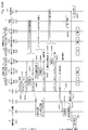
- FIG. 2 is a diagram showing an electrical configuration of the CGW.
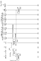
- FIG. 3 is a diagram showing an electrical configuration of the DCM.
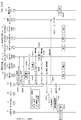
- FIG. 4 is a diagram showing an electrical configuration of the ECU.
- FIG. 5 is a diagram showing a connection mode of a power supply line;
- FIG. 6 is a diagram showing a mode of packaging the reprolog data and the distribution specification data,
- FIG. 7 is a diagram showing rewrite specification data for DCM.
- FIG. 8 is a diagram showing rewrite specification data for CGW.
- FIG. 9 is a diagram showing distribution specification data.
- FIG. 1 is a diagram showing an overall configuration of an embodiment
- FIG. 2 is a diagram showing an electrical configuration of the CGW.
- FIG. 3 is a diagram showing an electrical configuration of the DCM.
- FIG. 4 is a diagram showing an electrical configuration of the ECU.
- FIG. 5 is a diagram showing a connection mode of a power
- FIG. 10 is a diagram showing a mode of unpackaging a distribution package.
- FIG. 11 is a diagram illustrating an aspect of a normal operation in the embedded single-sided single memory
- FIG. 12 is a diagram showing a mode at the time of a rewriting operation in the embedded single-sided single memory
- FIG. 13 is a diagram showing an aspect of the download-type single-sided single memory during normal operation
- FIG. 14 is a diagram showing a mode at the time of a rewriting operation in a download-type single-sided single memory
- FIG. 15 is a diagram illustrating an aspect of a normal operation in the embedded single-sided suspend memory
- FIG. 16 is a diagram showing an aspect of a rewriting operation in the embedded single-sided suspend memory
- FIG. 11 is a diagram illustrating an aspect of a normal operation in the embedded single-sided single memory
- FIG. 12 is a diagram showing a mode at the time of a rewriting operation in the embedded single-sided single memory
- FIG. 13 is a
- FIG. 17 is a diagram illustrating an aspect of a normal operation in the download type one-sided suspend memory
- FIG. 18 is a diagram showing a mode at the time of a rewriting operation in the download type one-sided suspend memory
- FIG. 19 is a diagram illustrating an aspect of a normal operation in the embedded two-sided memory.
- FIG. 20 is a diagram showing an aspect of a rewriting operation in the embedded two-sided memory.
- FIG. 21 is a diagram showing an aspect of the download-type two-sided memory during normal operation.
- FIG. 22 is a diagram showing an aspect at the time of a rewriting operation in a download type two-sided memory;
- FIG. 23 is a diagram showing a mode of rewriting an application program.
- FIG. 24 is a diagram showing a mode of rewriting an application program.
- FIG. 25 is a diagram showing a mode of rewriting an application program.
- FIG. 26 is a timing chart showing a mode in which an application program is rewritten by power control.
- FIG. 27 is a timing chart showing a mode of rewriting an application program by power control.
- FIG. 28 is a timing chart showing a mode in which the application program is rewritten by self-holding of the power supply.
- FIG. 29 is a timing chart showing a mode of rewriting an application program by self-holding of a power supply.
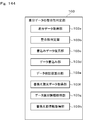
- FIG. 30 is a diagram showing phases.
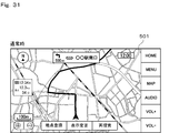
- FIG. 31 is a diagram showing a screen in a normal state.
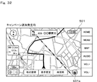
- FIG. 32 is a diagram showing a screen when a campaign notification occurs, FIG.
- FIG. 33 is a diagram showing a screen at the time of campaign notification.
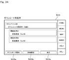
- FIG. 34 is a diagram showing a screen at the time of accepting the download.
- FIG. 35 is a diagram showing a screen at the time of accepting the download.
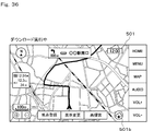
- FIG. 36 is a diagram showing a screen during download execution.
- FIG. 37 is a diagram illustrating a screen during download execution.
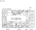
- FIG. 38 is a diagram showing a screen when the download is completed.
- FIG. 39 is a diagram showing a screen when accepting the installation.
- FIG. 40 is a diagram showing a screen at the time of accepting the installation.
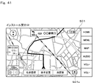
- FIG. 41 is a diagram showing a screen during the execution of installation.
- FIG. 42 is a diagram showing a screen during the execution of installation.
- FIG. 43 is a diagram showing a screen when accepting activation.
- FIG. 34 is a diagram showing a screen at the time of accepting the download.
- FIG. 35 is a diagram showing a screen at the time of accepting the download.
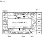
- FIG. 44 is a diagram showing a screen when the IG is on
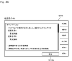
- FIG. 45 is a diagram showing a screen at the time of a confirmation operation
- FIG. 46 is a diagram showing a screen at the time of a confirmation operation
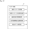
- FIG. 47 is a functional block diagram of the center device
- FIG. 48 is a functional block diagram of the DCM.
- FIG. 49 is a functional block diagram of the CGW
- FIG. 50 is a functional block diagram of the CGW.
- FIG. 51 is a functional block diagram of the ECU
- FIG. 52 is a functional block diagram of the vehicle-mounted display
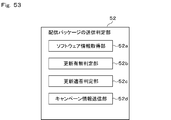
- FIG. 53 is a functional block diagram of a transmission package transmission determination unit.
- FIG. 54 is a flowchart showing transmission package transmission determination processing;
- FIG. 54 is a flowchart showing transmission package transmission determination processing
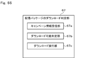
- FIG. 55 is a functional block diagram of a distribution package download determination unit;
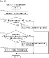
- FIG. 56 is a flowchart showing a distribution package download determination process;
- FIG. 57 is a functional block diagram of a write data transfer determination unit,
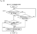
- FIG. 58 is a flowchart showing write data transfer determination processing.
- FIG. 59 is a functional block diagram of a write data acquisition determination unit;
- FIG. 60 is a flowchart showing a write data acquisition determination process;
- FIG. 61 is a functional block diagram of an installation instruction determination unit;
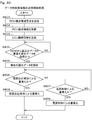
- FIG. 62 is a flowchart showing an installation instruction determination process.
- FIG. 63 is a diagram showing a mode of instructing installation.
- FIG. 64 is a diagram showing a mode of instructing installation.
- FIG. 65 is a diagram illustrating a mode of generating a random value.
- FIG. 66 is a functional block diagram of a security access key management unit.
- FIG. 67 is a flowchart showing a security access key generation process.
- FIG. 68 is a diagram showing an aspect of generating a security access key.
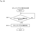
- FIG. 69 is a flowchart showing the security access key erasing process.
- FIG. 70 is a diagram showing a flow of processing related to verification of write data
- FIG. 71 is a functional block diagram of a write data verification unit
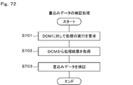
- FIG. 72 is a flowchart showing write data verification processing;
- FIG. 73 is a diagram showing an aspect in which processing related to verification of write data is distributed.
- FIG. 74 is a diagram showing an aspect in which processing related to verification of write data is distributed.
- FIG. 75 is a diagram illustrating an aspect in which processing related to verification of write data is dispersed.
- FIG. 76 is a diagram showing an aspect in which processing related to verification of write data is distributed,
- FIG. 77 is a diagram showing a flow of verification of write data and rewriting of an application program.
- FIG. 78 is a diagram showing a flow of verification of write data and rewriting of an application program.
- FIG. 79 is a functional block diagram of a data storage surface information transmission control unit;
- FIG. 80 is a flowchart showing a data storage surface information transmission control process;
- FIG. 81 is a sequence diagram showing a mode of notifying double-sided rewriting information.
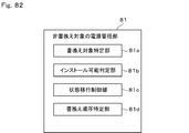
- FIG. 82 is a functional block diagram of a power management unit to be rewritten
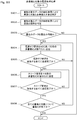
- FIG. 83 is a flowchart showing a power management process for a non-rewrite target.
- FIG. 84 is a diagram showing transition of a start state, a stop state, and a sleep state
- FIG. 85 is a diagram showing transition of a start state, a stop state, and a sleep state
- FIG. 86 is a diagram showing a connection mode of the power supply line
- FIG. 87 is a flowchart showing a process of monitoring the remaining battery charge.
- FIG. 88 is a functional block diagram of a file transfer control unit.
- FIG. 89 is a flowchart showing a file transfer control process.
- FIG. 90 is a diagram showing a mode of transferring files.
- FIG. 90 is a diagram showing a mode of transferring files.
- FIG. 91 is a diagram showing a mode of transferring files.
- FIG. 92 is a diagram showing a divided file and a write file.
- FIG. 93 is a diagram illustrating a mode in which the CGW transmits a transfer request to the DCM;
- FIG. 94 is a diagram illustrating a mode in which the CGW transmits a transfer request to the DCM.
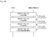
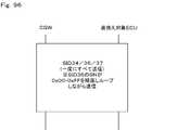
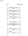
- FIG. 95 is a diagram illustrating a mode in which the CGW distributes the write data to the rewrite target ECU;
- FIG. 96 is a diagram illustrating a mode in which the CGW distributes the write data to the rewrite target ECU.
- FIG. 97 is a diagram illustrating a mode in which the CGW distributes the write data to the rewrite target ECU;
- FIG. 98 is a diagram showing a connection mode of the ECU
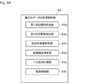
- FIG. 99 is a functional block diagram of a write data distribution control unit
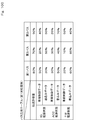
- FIG. 100 is a diagram showing a bus load table
- FIG. 101 is a diagram showing a rewriting target ECU belonging table
- FIG. 102 is a flowchart showing write data distribution control processing
- FIG. 103 is a diagram showing a mode of distributing write data
- FIG. 104 is a diagram showing a mode of distributing write data
- FIG. 105 is a diagram illustrating an aspect of distributing write data while the vehicle is traveling.
- FIG. 106 is a diagram showing a mode of distributing the writing data during parking.
- FIG. 107 is a diagram showing a distribution amount of write data;
- FIG. 108 is a diagram showing a distribution amount of write data;
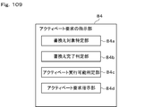
- FIG. 109 is a functional block diagram of an activation request instruction unit.
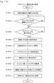
- FIG. 110 is a flowchart showing an activation request instruction process.
- FIG. 111 is a diagram showing a mode of instructing an activation request,
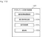
- FIG. 112 is a functional block diagram of an activation execution control unit.
- FIG. 113 is a flowchart showing the rewriting process.
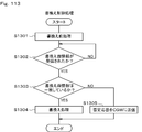
- FIG. 114 is a flowchart showing activation control processing.
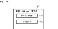
- FIG. 115 is a functional block diagram of a grouping unit to be rewritten;
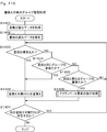
- FIG. 116 is a flowchart showing the group management process for rewriting,
- FIG. 117 is a flowchart showing a group management process for rewriting.
- FIG. 118 is a diagram showing an aspect of grouping rewrite targets.
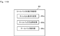
- FIG. 119 is a functional block diagram of a rollback execution control unit.
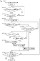
- FIG. 120 is a flowchart showing a specific process of the rollback method.
- FIG. 121 is a flowchart showing a cancellation request determination process;
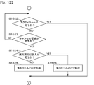
- FIG. 122 is a flowchart showing a cancellation request determination process;
- FIG. 123 is a flowchart showing the cancellation request determination process.
- FIG. 124 is a flowchart showing a cancel request determination process.
- FIG. 125 is a flowchart showing the cancellation request determination process.
- FIG. 126 is a diagram showing a mode of executing rollback
- FIG. 127 is a diagram illustrating an aspect of executing rollback.
- FIG. 128 is a diagram showing an aspect of executing rollback.
- FIG. 129 is a diagram illustrating an aspect of executing rollback.
- FIG. 130 is a diagram showing a mode of executing rollback;
- FIG. 131 is a functional block diagram of a display control unit for rewriting progress status;
- FIG. 132 is a flowchart showing a rewriting progress display control process.
- FIG. 133 is a flowchart showing a display control process of rewriting progress status;
- FIG. 134 is a diagram showing a rewriting progress screen.
- FIG. 135 is a diagram showing a rewriting progress screen.
- FIG. 136 is a diagram showing a screen of the rewriting progress status.
- FIG. 137 is a diagram showing a rewriting progress screen.
- FIG. 129 is a diagram illustrating an aspect of executing rollback.
- FIG. 130 is a diagram showing a mode of executing rollback;
- FIG. 131 is
- FIG. 138 is a diagram showing a screen of the rewriting progress status.
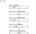
- FIG. 139 is a diagram showing transition of the progress graph display.
- FIG. 140 is a diagram showing the transition of the progress graph display.
- FIG. 141 is a diagram showing transition of the progress graph display.
- FIG. 142 is a diagram showing the transition of the progress graph display.
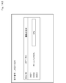
- FIG. 143 is a diagram showing a rewriting progress screen.
- FIG. 144 is a functional block diagram of a difference data consistency determination unit;
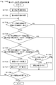
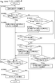
- FIG. 145 is a flowchart showing a difference data consistency determination process;
- FIG. 146 is a diagram illustrating a mode of determining consistency of difference data.
- FIG. 147 is a diagram illustrating a mode of determining consistency of difference data.
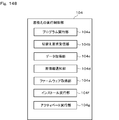
- FIG. 148 is a functional block diagram of a rewrite execution control unit.
- FIG. 149 is a flowchart showing a normal operation process.
- FIG. 150 is a flowchart showing the rewriting operation process.
- FIG. 151 is a flowchart showing an information notification process.
- FIG. 152 is a flowchart showing the verification processing of the rewrite program.
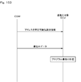
- FIG. 153 is a diagram illustrating a mode of transmitting identification information and write data
- FIG. 154 is a diagram illustrating a mode of transmitting identification information and write data
- FIG. 155 is a flowchart showing the installation instruction process.
- FIG. 156 is a functional block diagram of a session establishing unit;
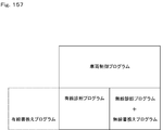
- FIG. 157 is a diagram showing the configuration of the program.
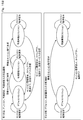
- FIG. 158 is a diagram showing a state transition.
- FIG. 159 is a diagram showing a state transition.
- FIG. 160 is a diagram showing a state transition;
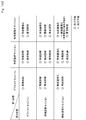
- FIG. 161 is a diagram showing arbitration of a session;
- FIG. 162 illustrates session arbitration,
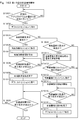
- FIG. 163 is a flowchart illustrating a state transition management process of the first state.
- FIG. 164 is a flowchart showing a state transition management process in the first state.
- FIG. 165 is a flowchart showing a state transition management process in the first state.
- FIG. 166 is a flowchart showing a state transition management process of the second state.
- FIG. 167 is a flowchart showing a state transition management process in the second state.
- FIG. 168 is a diagram showing the configuration of the program.
- FIG. 168 is a diagram showing the configuration of the program.
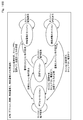
- FIG. 169 is a diagram showing a state transition.
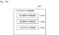
- FIG. 170 is a functional block diagram of a specifying unit of a retry point.
- FIG. 171 is a diagram showing the configuration of the flash memory.
- FIG. 172 is a flowchart showing processing for setting a processing flag.
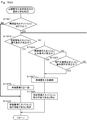
- FIG. 173 is a flowchart showing processing for determining a processing flag.
- FIG. 174 is a flowchart showing processing for determining a processing flag.
- FIG. 175 is a functional block diagram of a progress state synchronization control unit;
- FIG. 176 is a functional block diagram of the synchronization control unit in the progress state.
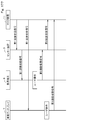
- FIG. 177 is a diagram illustrating a mode of transmitting and receiving a progress status signal.
- FIG. 178 is a flowchart showing the progress state synchronization control process.
- FIG. 179 is a flowchart illustrating the progress state synchronization control process.
- FIG. 180 is a flowchart showing a progress status display process.
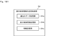
- FIG. 181 is a functional block diagram of a display control information transmission control unit;
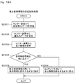
- FIG. 182 is a flowchart illustrating transmission control processing of display control information.
- FIG. 183 is a functional block diagram of a display control information reception control unit;
- FIG. 184 is a flowchart showing a display control information reception control process.
- FIG. 185 is a diagram showing information included in the distribution specification data.
- FIG. 186 is a functional block diagram of a screen display control unit for displaying progress.
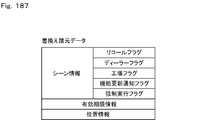
- FIG. 187 is a diagram showing rewrite specification data.
- FIG. 188 is a diagram showing a screen at the time of menu selection.
- FIG. 189 is a diagram illustrating a screen at the time of user selection.
- FIG. 190 is a diagram showing a screen at the time of user registration.
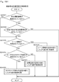
- FIG. 191 is a flowchart showing a screen display control process of progress display;
- FIG. 192 is a flowchart showing a screen display control process of the progress display.
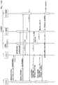
- FIG. 193 is a diagram showing a message frame.
- FIG. 194 is a diagram showing a screen when accepting activation.
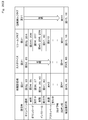
- FIG. 195 is a diagram showing the setting of whether to display an item.
- FIG. 196 is a diagram showing the setting of whether or not to display an item;
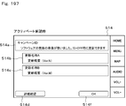
- FIG. 197 is a diagram showing a screen when accepting activation.
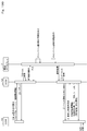
- FIG. 198 is a diagram showing an aspect of data communication.
- FIG. 199 is a diagram showing a message frame at the time of campaign notification.
- FIG. 200 is a diagram showing a message frame at the time of accepting the download.
- FIG. 201 is a diagram showing a message frame at the time of accepting the installation.
- FIG. 202 is a diagram showing a message frame at the time of accepting activation.
- FIG. 203 is a diagram showing screen transitions.
- FIG. 204 is a diagram showing a screen when a campaign notification is generated.
- FIG. 205 is a diagram showing a screen at the time of accepting the download.
- FIG. 206 is a diagram showing a screen at the time of accepting the download.
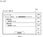
- FIG. 207 is a diagram illustrating a screen during download execution.
- FIG. 207 is a diagram illustrating a screen during download execution.
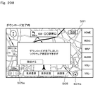
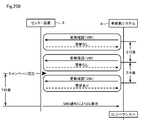
- FIG. 208 is a diagram showing a screen at the time of completion of download.
- FIG. 209 is a diagram showing a screen when accepting the installation.
- FIG. 210 is a diagram showing a screen when accepting the activation.
- FIG. 211 is a functional block diagram of a program update notification control unit;
- FIG. 212 is a flowchart showing a program update notification control process;
- FIG. 213 is a diagram showing a notification mode of the indicator;
- FIG. 214 is a diagram showing a transition of the notification mode when the rewrite target is a two-sided memory;
- FIG. 215 is a diagram illustrating a transition of a notification mode when the rewrite target is a one-sided suspend memory;
- FIG. 216 is a diagram showing the transition of the notification mode when the rewrite target is a single-sided single memory;
- FIG. 217 is a diagram showing a connection mode.
- FIG. 218 is a functional block diagram of a power control self-holding execution control unit in the CGW;
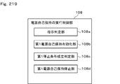
- FIG. 219 is a functional block diagram of a power supply self-holding execution control unit in the ECU.
- FIG. 220 is a flowchart showing a power control self-holding execution control process in the CGW.
- FIG. 221 is a flowchart showing a power supply self-holding execution control process in the ECU.
- FIG. 222 is a diagram showing a period during which power supply self-holding is required,
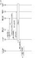
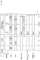
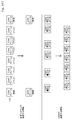
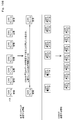
- FIG. 223 is an overall sequence diagram illustrating a mode of rewriting an application program.
- FIG. 224 is an overall sequence diagram showing a mode of rewriting an application program.
- FIG. 225 is an overall sequence diagram showing a mode of rewriting an application program.
- FIG. 226 is an overall sequence diagram illustrating an aspect of rewriting an application program.
- FIG. 227 is an overall sequence diagram illustrating an aspect of rewriting an application program.
- FIG. 228 is an overall sequence diagram illustrating a mode of rewriting an application program.
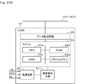
- FIG. 229 is an overall sequence diagram illustrating an aspect of rewriting an application program.
- FIG. 230 is an overall sequence diagram showing a mode of rewriting an application program.
- FIG. 231 is an overall sequence diagram illustrating a mode of rewriting an application program.
- FIG. 232 is an overall sequence diagram showing a mode of rewriting an application program.
- FIG. 232 is an overall sequence diagram showing a mode of rewriting an application program.
- FIG. 233 is an overall sequence diagram illustrating a mode of rewriting an application program.
- FIG. 234 is a diagram illustrating an overall configuration of a vehicle information communication system according to the first embodiment.
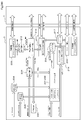
- FIG. 235 is a diagram illustrating an electrical configuration of the CGW.
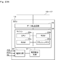
- FIG. 236 is a diagram showing an electric configuration of the ECU,
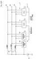
- FIG. 237 is a diagram showing a connection mode of the power supply line;
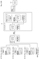
- FIG. 238 is a diagram illustrating a mode of packaging the reprolog data and the delivery specification data,
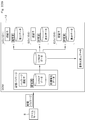
- FIG. 239 is a diagram illustrating an aspect of unpackaging a distribution package.
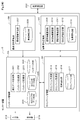
- FIG. 240 is a diagram illustrating, in a block diagram, a portion mainly related to each function of the server in the center device.
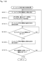
- FIG. 241 is an image diagram showing a flow of processing in the center device.
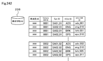
- FIG. 242 is a diagram illustrating an example of vehicle configuration information registered in the configuration information DB.
- FIG. 243 is a diagram illustrating an example of programs and data registered in the ECU repro data DB.
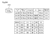
- FIG. 244 is a diagram illustrating an example of specification data registered in the ECU metadata DB.
- FIG. 245 is a diagram illustrating an example of vehicle configuration information registered in the individual vehicle information DB.
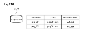
- FIG. 246 is a diagram illustrating an example of distribution package data registered in the package DB.
- FIG. 247 is a diagram illustrating an example of campaign data registered in the campaign DB.
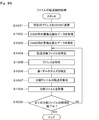
- FIG. 248 is a flowchart showing processing for generating a program and data registered in the ECU repro data DB.
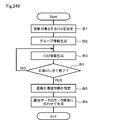
- FIG. 249 is a flowchart illustrating a process of generating an example of the specification data registered in the ECU metadata DB.
- FIG. 250 is a diagram showing an example of the specification data.
- FIG. 251 is a diagram illustrating an example of a bus load table.
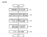
- FIG. 252 is a flowchart illustrating a process of generating a distribution package registered in the package DB.
- FIG. 253 is a diagram schematically illustrating the contents of the package file
- FIG. 254 is a sequence diagram showing a processing procedure executed between the center device and the vehicle-side system in the second embodiment
- FIG. 255 is a flowchart illustrating processing performed by the center device.
- FIG. 256 is a diagram conceptually showing the processing contents performed in steps D6 and D7 of the flowchart shown in FIG. 248,
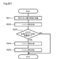
- FIG. 257 is a flowchart illustrating processing when a hash value is transmitted from the vehicle-side system to the center device;
- FIG. 258 is a sequence diagram illustrating a processing procedure executed between the center device and the vehicle-side system in the third embodiment.
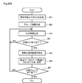
- FIG. 259 is a flowchart illustrating processing performed by the center device.
- FIG. 260 is a sequence diagram illustrating a state in which the center device notifies each of the EV vehicle and the conveyor vehicle by SMS,
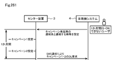
- FIG. 261 is a sequence diagram illustrating a processing procedure executed between the center device and the vehicle-side system in the fourth embodiment.
- FIG. 262 is a diagram schematically illustrating processing performed between the supplier, the center device, and the vehicle-side system in the fifth embodiment.
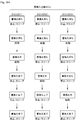
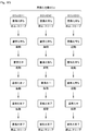
- FIG. 263 is a sequence diagram (part 1) illustrating a processing procedure performed between the supplier, the center device, and the vehicle-side system.
- FIG. 264 is a sequence diagram (part 2) illustrating a processing procedure performed between the supplier, the center device, and the vehicle-side system.
- FIG. 265 is a sequence diagram (part 3) illustrating a processing procedure performed between the supplier, the center device, and the vehicle-side system.
- FIG. 266 is a modification (part 1) of the first embodiment, and shows a data format of a package DB in a case where a plurality of packages correspond to one campaign.
- FIG. 1 is a sequence diagram (part 1) illustrating a processing procedure performed between the supplier, the center device, and the vehicle-side system.
- FIG. 267 is a diagram illustrating a data format of the campaign DB in a case where a plurality of packages correspond to one campaign.
- FIG. 268 is a diagram corresponding to FIG. 242 when the specification data is generated for each group
- FIG. 269 is a diagram corresponding to FIG. 245 when a distribution package is generated for each group.
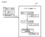
- FIG. 270 is a modification (part 2) of the first embodiment, and is a diagram illustrating processing contents of the package generation tool.
- a vehicle program rewriting system (corresponding to a vehicle electronic control system) is a program for controlling an application, such as vehicle control and diagnosis, installed in an electronic control unit (hereinafter referred to as an ECU (Electronic Control Unit)). It is a rewritable system by Air).
- an application program is rewritten by wire or wireless.
- Rewriting the application program by wire is not only obtaining and rewriting the application program from outside the vehicle via a wire, but also obtaining various data used when the application program is executed from the vehicle via the wire Also includes rewriting.
- Rewriting of the application program by wireless means that in addition to acquiring and rewriting the application program from outside the vehicle via wireless, various data used when the application program is executed is acquired from outside of the vehicle via wireless Also includes rewriting.
- the vehicle program rewriting system 1 includes a center device 3 on the communication network 2, a vehicle system 4 on the vehicle, and a display terminal 5.
- the communication network 2 includes, for example, a mobile communication network such as a 4G line, the Internet, WiFi (Wireless Fidelity) (registered trademark), and the like.
- WiFi Wireless Fidelity
- the configuration of the vehicle is mainly described, and the configuration of the center device 3 will be described in detail with reference to FIGS. 234 to 270.
- the display terminal 5 is a terminal having a function of receiving an operation input from the user and a function of displaying various screens.
- the display terminal 5 is a mobile terminal 6 such as a smartphone or tablet that can be carried by the user, and an in-vehicle display disposed in the vehicle compartment. 7
- the portable terminal 6 can perform data communication with the center device 3 via the communication network 2 within a communication range of the mobile communication network.
- the in-vehicle display 7 is connected to the vehicle-side system 4 and may be configured to also serve as a navigation function.
- the in-vehicle display 7 may be an in-vehicle display ECU having an ECU function, or may have a function of controlling display on a center display, a meter display, or the like.
- the user When the user is outside the vehicle compartment and is within the communication range of the mobile communication network, the user performs an operation input while confirming various screens involved in the rewriting of the application program with the mobile terminal 6 and performs a procedure involved in the rewriting of the application program. It is possible. In the vehicle interior, the user can perform an operation input while confirming various screens involved in rewriting the application program on the in-vehicle display 7 to perform a procedure involved in rewriting the application program. That is, the user can use the portable terminal 6 and the in-vehicle display 7 separately outside the vehicle compartment and inside the vehicle compartment, and perform a procedure involved in rewriting the application program.
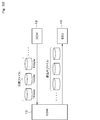
- the center device 3 controls the program update function of the communication network 2 in the vehicle program rewriting system 1 and functions as an OTA center.
- the center device 3 has a file server 8, a web server 9, and a management server 10, and each of the servers 8 to 10 is configured to be able to perform data communication with each other. That is, the center device 3 is configured to include a plurality of servers that are different for each function.
- the file server 8 is a server that manages application program files distributed from the center device 3 to the vehicle-side system 4.
- the file server 8 includes update data (hereinafter, also referred to as “replog data” and “write data”) provided by a supplier or the like, which is a provider of an application program distributed from the center device 3 to the vehicle-side system 4, and an OEM (Original Equipment Manufacturer). ) And the vehicle state acquired from the vehicle-side system 4 and the like.
- the file server 8 can perform data communication with the vehicle-side system 4 via the communication network 2, and when a distribution package download request is generated, the relog data and the distribution specification data are packaged into one file. The distribution package is transmitted to the vehicle system 4.
- the web server 9 is a server that manages web information.
- the web server 9 transmits web data managed by itself in response to a request from a web browser of the mobile terminal 6 or the like.
- the management server 10 is a server that manages personal information of a user registered in a service for rewriting an application program, a rewriting history of an application program for each vehicle, and the like.
- the vehicle-side system 4 has a master device 11 (corresponding to a vehicle master device).
- the master device 11 has a DCM (Data Communication Module) 12 (corresponding to an in-vehicle communication device) and a CGW (Central Gate Way) 13 (corresponding to a vehicle gateway device).
- the DCM 12 and the CGW 13 are connected via a first bus 14 so that data communication is possible.
- the DCM 12 performs data communication with the center device 3 via the communication network 2.
- the DCM 12 downloads the distribution package from the file server 8
- the DCM 12 extracts write data from the downloaded distribution package and transfers the extracted write data to the CGW 13.
- the CGW 13 has a data relay function and, when acquiring the write data from the DCM 12, instructs the rewrite target ECU that is the rewrite target of the application program to write the acquired write data, and distributes the write data to the rewrite target ECU.
- the CGW 13 instructs the rewriting target ECU to activate the application program after the rewriting is completed.
- the master device 11 controls the vehicle-side program update function in the vehicle program rewriting system 1 and functions as an OTA master.
- FIG. 1 illustrates a configuration in which the DCM 12 and the vehicle-mounted display 7 are connected to the same first bus 14, a configuration in which the DCM 12 and the vehicle-mounted display 7 are connected to different buses may be used.
- the CGW 13 may have a configuration in which some or all of the functions of the DCM 12 are provided, or a configuration in which the DCMs 12 have some or all of the functions of the CGW 13. That is, in the master device 11, the function sharing between the DCM 12 and the CGW 13 may be configured in any manner.
- Master device 11 may be composed of two ECUs, DCM 12 and CGW 13, or may be composed of one integrated ECU having the functions of DCM 12 and CGW 13.
- a second bus 15 to the CGW 13, in addition to the first bus 14, a second bus 15, a third bus 16, a fourth bus 17, and a fifth bus 18 are connected as buses inside the vehicle.
- Various ECUs 19 are connected via a bus 18 and a power management ECU 20 is connected via a bus 18.
- the second bus 15 is, for example, a bus of a body network.
- the ECU 19 connected to the second bus 15 is an ECU that controls a body system.
- ECUs that control the body system include, for example, a door ECU that controls locking / unlocking of a door, a meter ECU that controls display on a meter display, an air conditioner ECU that controls driving of an air conditioner, and a window ECU that controls opening and closing of windows. , A security ECU or the like that is driven to prevent the vehicle from being stolen.
- the third bus 16 is, for example, a bus of a traveling system network.
- the ECU 19 connected to the third bus 16 is an ECU that controls a traveling system.
- the ECU that controls the driving system includes, for example, an engine ECU that controls the driving of the engine, a brake ECU that controls the driving of the brake, an ECT (Electronic Controlled Transmission) ECU that controls the driving of the automatic transmission, and controls the driving of the power steering. Power steering ECU.
- the fourth bus 17 is, for example, a multimedia network bus.
- the ECU 19 connected to the fourth bus 17 is an ECU that controls a multimedia system.
- the ECU that controls the multimedia system is, for example, a navigation ECU for controlling a navigation system, an ETC ECU for controlling an electronic toll collection system (ETC (Electronic Toll Collection System), or a registered trademark).
- the buses 15 to 17 may be buses of a system other than the bus of the body network, the bus of the traveling network, and the bus of the multimedia network. Further, the number of buses and the number of ECUs 19 are not limited to the illustrated configuration.
- the power management ECU 20 is an ECU that manages power supplied to the DCM 12, the CGW 13, the various ECUs 19, and the like.
- the sixth bus 21 is connected to the CGW 13 as a bus outside the vehicle.
- the sixth bus 21 is connected to a DLC (Data @ Link @ Coupler) connector 22 to which a tool 23 (corresponding to a service tool) is detachably connected.
- the buses 14 to 18 inside the vehicle and the bus 21 outside the vehicle are constituted by, for example, a CAN (Controller Area Network, registered trademark) bus, and the CGW 13 is a CAN data communication standard or a diagnostic communication standard (UDS (Unified Diagnosis Services). ): Data communication is performed between the DCM 12, the various ECUs 19, and the tool 23 according to ISO14229).
- the DCM 12 and the CGW 13 may be connected by Ethernet, or the DLC connector 22 and the CGW 13 may be connected by Ethernet.
- the rewrite target ECU 19 Upon receiving the write data from the CGW 13, the rewrite target ECU 19 writes the received write data in a flash memory (corresponding to a non-volatile memory) to rewrite the application program.
- the CGW 13 upon receiving a write data acquisition request from the rewrite target ECU 19, the CGW 13 functions as a relog master that distributes the write data to the rewrite target ECU 19.
- the rewrite target ECU 19 Upon receiving the write data from the CGW 13, the rewrite target ECU 19 writes the received write data into the flash memory and functions as a reprogram slave that rewrites the application program.
- the mode in which the application program is rewritten by wire is a mode in which the ECU 19 to be rewritten is rewritten by using an application program acquired from outside the vehicle via a wire.
- the tool 23 transfers the write data to the CGW 13.
- the CGW 13 functions as a gateway, transmits a wire rewrite request to the rewrite target ECU 19, instructs the rewrite target ECU 19 to write (install) write data, and distributes the write data transferred from the tool 23 to the rewrite target ECU 19. Distributing the write data to the rewrite target ECU 19 means relaying the write data.
- the mode in which the application program is rewritten wirelessly is a mode in which the ECU 19 to be rewritten is rewritten using an application program acquired from outside the vehicle via wireless.
- the DCM 12 upon downloading the distribution package from the file server 8, the DCM 12 extracts write data from the downloaded distribution package and transfers the write data to the CGW 13.
- the CGW 13 functions as a rewrite tool, instructs the rewrite target ECU 19 to write (install) the write data, and distributes the write data transferred from the DCM 12 to the rewrite target ECU 19.
- the mode of diagnosing by wire is a mode of diagnosing the ECU 19 from outside of the vehicle via a wire.
- the CGW 13 functions as a gateway, transmits a diagnosis request to the diagnosis target ECU 19, and distributes the diagnosis command transferred from the tool 23 to the diagnosis target ECU 19.
- the diagnosis target ECU 19 performs a diagnosis process according to the diagnosis command received from the CGW 13.
- the mode of diagnosing wirelessly is a mode of diagnosing the ECU 19 from outside the vehicle via wireless. Specifically, when a diagnostic command is transmitted from the center device 3 to the DCM 12 as a diagnostic request, the DCM 12 transfers the diagnostic command to the CGW 13.
- the CGW 13 functions as a gateway, and delivers a diagnosis command to the diagnosis target ECU 19 as a diagnosis request.
- the diagnosis target ECU performs a diagnosis process according to the diagnosis command received from the CGW 13.
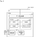
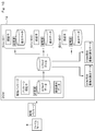
- the CGW 13 includes a microcomputer (hereinafter, referred to as a microcomputer) 24, a data transfer circuit 25, a power supply circuit 26, and a power supply detection circuit 27 as electrical functional blocks.
- the microcomputer 24 has a CPU (Central Processing Unit) 24a, a ROM (Read Only Memory) 24b, a RAM (Random Access Memory) 24c, and a flash memory 24d.
- the flash memory 24d includes a secure area from which information cannot be read from outside the CGW 13.
- the microcomputer 24 executes various control programs stored in the non-transitional substantive storage medium to perform various processes, and controls the operation of the CGW 13.
- the data transfer circuit 25 controls data communication with the buses 14 to 18 and 21 in accordance with the CAN data communication standard and the diagnostic communication standard.
- the power supply circuit 26 receives a battery power supply (hereinafter referred to as + B power supply), an accessory power supply (hereinafter referred to as ACC power supply), and an ignition power supply (hereinafter referred to as IG power supply).
- the power supply detection circuit 27 detects the voltage value of the + B power supply, the voltage value of the ACC power supply, and the voltage value of the IG power supply input to the power supply circuit 26, compares these detected voltage values with a predetermined voltage threshold, and compares the detected voltage values. The result is output to the microcomputer 24.
- the microcomputer 24 determines whether the + B power supply, the ACC power supply, and the IG power supply externally supplied to the CGW 13 are normal or abnormal based on the comparison result input from the power supply detection circuit 27.
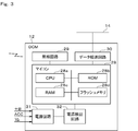
- the DCM 12 includes a microcomputer 28, a wireless circuit 29, a data transfer circuit 30, a power supply circuit 31, and a power supply detection circuit 32 as electrical functional blocks.
- the microcomputer 28 has a CPU 28a, a ROM 28b, a RAM 28c, and a flash memory 28d.
- the flash memory 28d includes a secure area from which information cannot be read from outside the DCM 12.
- the microcomputer 28 executes various control programs stored in the non-transitional substantive storage medium to perform various processes, and controls the operation of the DCM 12.
- a flash memory for storing data downloaded from the center device 3 may be arranged in the CGW 13.
- the wireless circuit 29 controls data communication with the center device 3 via the communication network 2.
- the data transfer circuit 30 controls data communication with the bus 14 in accordance with the CAN data communication standard.
- the power supply circuit 31 inputs a + B power supply, an ACC power supply, and an IG power supply.
- the power supply detection circuit 32 detects the voltage value of the + B power supply, the voltage value of the ACC power supply, and the voltage value of the IG power supply, which are input to the power supply circuit 31, and compares the detected voltage values with a predetermined voltage threshold value. The result is output to the microcomputer 28.
- the microcomputer 28 determines whether the + B power supply, the ACC power supply, and the IG power supply externally supplied to the DCM 12 are normal or abnormal based on the comparison result input from the power supply detection circuit 32.
- the DCM 12 has a vehicle position detecting function of detecting a vehicle position by, for example, GPS (Global Positioning System).
- the flash memory 28d of the DCM 12 has a sufficient memory capacity to store the distribution package downloaded from the center device 3, and has a larger memory capacity than the flash memory 24d of the CGW 13. That is, since the flash memory 28d of the DCM 12 has a configuration having a sufficient memory capacity, even if the flash memory 24d of the CGW 13 does not have a configuration having a sufficient memory capacity, the distribution package can be transmitted from the center device 3 in the master device 11. It is possible to download and store the downloaded distribution package in the DCM 12.
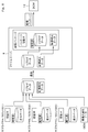
- the ECU 19 has a microcomputer 33, a data transfer circuit 34, a power supply circuit 35, and a power supply detection circuit 36 as electrical functional blocks.
- the microcomputer 33 has a CPU 28a, a ROM 28b, a RAM 33c, and a flash memory 28d.
- the flash memory 28d includes a secure area from which information cannot be read from outside the ECU 19.
- the microcomputer 33 executes various control programs stored in the non-transitional substantial storage medium to perform various processes, and controls the operation of the ECU 19.
- the data transfer circuit 34 controls data communication with the buses 15 to 17 in accordance with the CAN data communication standard.
- the power supply circuit 35 receives a + B power supply, an ACC power supply, and an IG power supply.
- the power supply detection circuit 36 detects the voltage value of the + B power supply, the voltage value of the ACC power supply, and the voltage value of the IG power supply input to the power supply circuit 35, compares these detected voltage values with a predetermined voltage threshold value, and compares the detected voltage values.
- the result is output to the microcomputer 33.
- the microcomputer 33 determines whether the + B power supply, the ACC power supply, and the IG power supply externally supplied to the ECU 19 are normal or abnormal, based on the comparison result input from the power supply detection circuit 27.
- the ECUs 19 are different in the load of, for example, sensors and actuators to which they are connected, and have basically the same configuration.
- the vehicle-mounted display 7 has the same configuration as the ECU 19 shown in FIG.
- the power management ECU 20 has the same configuration as the ECU 19 shown in FIG.
- the power management ECU 20 is connected to be able to perform data communication with a power control circuit 43 described later.
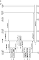
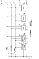
- the power management ECU 20, CGW 13, and ECU 19 are connected to + B power line 37, ACC power line 38, and IG power line 39, which are power supply lines.
- + B power supply line 37 is connected to the positive electrode of vehicle battery 40.
- the ACC power line 38 is connected to the positive electrode of the vehicle battery 40 via the ACC switch 41. When the user performs the ACC operation, the ACC switch 41 is switched from off to on, and the output voltage of the vehicle battery 40 is applied to the ACC power supply line 38.
- the ACC operation is, for example, in the case of a vehicle in which a key is inserted into an insertion slot, an operation in which a key is inserted into the insertion slot and the key is turned from the “OFF” position to the “ACC” position.
- the operation is to press the start button once.
- the IG power supply line 39 is connected to the positive electrode of the vehicle battery 40 via the IG switch 42.
- the IG switch 42 is switched from off to on, and the output voltage of the vehicle battery 40 is applied to the IG power supply line 39.
- the IG operation is, for example, in the case of a vehicle in which a key is inserted into an insertion slot, an operation in which a key is inserted into the insertion slot and the key is turned from the “OFF” position to the “ON” position. In the case of a press-type vehicle, the operation is to press the start button twice.
- the negative electrode of the vehicle battery 40 is grounded.
- both the ACC switch 41 and the IG switch 42 are off, only the + B power is supplied to the vehicle-side system 4.
- a state in which only the + B power supply is supplied to the vehicle-side system 4 is referred to as a + B power supply state.
- ACC switch 41 is on and the IG switch 42 is off, ACC power and + B power are supplied to the vehicle-side system 4.
- a state in which the ACC power supply and the + B power supply are supplied to the vehicle-side system 4 is referred to as an ACC power supply state.
- the + B power supply, the ACC power supply, and the IG power supply are supplied to the vehicle-side system 4.
- a state in which the + B power supply, the ACC power supply, and the IG power supply are supplied to the vehicle-side system 4 is referred to as an IG power supply state.
- a power supply state that provides a power supply suitable for wirelessly updating a program may be considered.
- the starting conditions of the ECU 19 differ depending on the power supply state.
- the ECU 19 is divided into a + B power supply ECU that starts in the + B power supply state, an ACC ECU that starts in the ACC power supply state, and an IG ECU that starts in the IG power supply state.
- the ECU 19 that is driven for the purpose of vehicle theft and the like is classified into a + B power supply system ECU.
- the ECU 19 that is driven for non-traveling purposes such as audio is classified into an ACC ECU.
- the ECU 19 that is driven for a traveling system such as engine control is classified into an IG ECU.
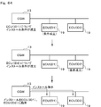
- the + B power supply ECU is connected to the + B power line 37, the ACC power line 38, and the IG power line 39, selects the + B power line 37 when in the + B power state, and selects the ACC power line 38 when in the ACC power state.
- the IG power supply line 39 is selected.
- the ACC ECU is connected to the ACC power supply line 38 and the IG power supply line 39, and is configured to select the ACC power supply line 38 in the ACC power supply state and to select the IG power supply line 39 in the IG power supply state.
- the IG ECU is connected to an IG power supply line 39.
- the CGW 13 transmits the activation request to the ECU 19 in the sleep state, thereby shifting the transmission destination ECU 19 from the sleep state to the activation state. Further, the CGW 13 transmits a sleep request to the ECU 19 in the activated state, thereby shifting the sleep destination ECU 19 from the activated state to the sleep state.
- the CGW 13 can shift a specific ECU 19 to a startup state or a sleep state, for example, by changing the waveform of a transmission signal transmitted to the buses 15 to 17.
- a start request waveform and a sleep request waveform are predetermined for each ECU 19, and when the ECU 19 receives a start request waveform suitable for itself, the ECU 19 shifts from the sleep state to the start state, and the sleep request suitable for itself is received from the CGW 13. When a waveform is received, the state shifts from the activation state to the sleep state.
- the CGW 13 transmits the first waveform when the ECU (ID1) and the ECU (ID2) are in the activated state, thereby shifting the ECU (ID1) from the activated state to the sleep state, and bringing the ECU (ID2) into the activated state. Hold. Further, the CGW 13 transmits the second waveform when the ECU (ID1) and the ECU (ID2) are in the activated state, thereby holding the ECU (ID1) in the activated state, and changing the ECU (ID2) from the activated state to the sleep state. Move to
- the power control circuit 43 is connected in parallel to the ACC switch 41 and the IG switch 42.
- the CGW 13 transmits a power control request to the power management ECU 20, and causes the power management ECU 20 to control the power control circuit 43. That is, the CGW 13 connects the ACC power line 38 or the IG power line 39 to the positive electrode of the vehicle battery 40 within the power control circuit 43 by transmitting a power activation request as a power control request to the power management ECU 20. In this state, ACC power and IG power are supplied to the vehicle-side system 4 even when the ACC switch 41 and the IG switch 42 are off.
- the CGW 13 transmits a power stop request as a power control request to the power management ECU 20 to interrupt the ACC power line 38 and the IG power line 39 and the positive electrode of the vehicle battery 40 inside the power control circuit 43.
- the DCM 12, the CGW 13, the ECU 19, and the power management ECU 20 each have a power self-holding circuit, and have a power self-holding function of holding power supply from the vehicle battery 40. That is, when the vehicle power is switched from the ACC power supply or the IG power supply to the + B power supply while the power supply management ECU 20 is in the start-up state, the DCM 12, the CGW 13, and the ECU 19 immediately switch from the start-up state to the stop state or the sleep state. Instead, the driving state is maintained for a predetermined time (for example, several minutes) by the power supply from the vehicle battery 40, and the driving power is self-held.
- a predetermined time for example, several minutes
- the DCM 12, the CGW 13, the ECU 19, and the power management ECU 20 shift from the start state to the stop state or the sleep state after a predetermined time has elapsed immediately after the vehicle power supply is switched from the ACC power supply or the IG power supply to the + B power supply.
- the power supply self-holding function operates after the vehicle power supply is switched from the ACC power supply or the IG power supply to the + B power supply, so that various data related to the engine control acquired during the vehicle running are recorded as logs.
- a distribution package distributed from the center device 3 to the master device 11 will be described.
- the vehicle program rewriting system 1 write data provided from a supplier who is a provider of an application program, and rewrite specification data (equivalent to specification data) provided from an OEM.
- Reprog data is generated from.
- the rewrite specification data may be generated by the center device 3.
- the write data provided by the supplier includes difference data corresponding to the difference between the old application program and the new application program, and all data corresponding to the entire new application program.
- the difference data and all data may be compressed by a known data compression technique.
- difference data is provided as write data from the suppliers A to C, and the encrypted difference data of the ECU (ID1) provided from the supplier A and the authenticator, and the encryption of the ECU (ID2) provided from the supplier B are provided.
- An example is shown in which the reprolog data is generated from the already used difference data and authenticator, the encrypted difference data and authenticator of the ECU (ID3) provided from the supplier C, and the rewrite specification data provided from the OEM. I have.
- the authenticator is data provided for each write data in order to verify the integrity of the difference data, and is generated from, for example, an ECU (ID), key information associated with the ECU (ID), and difference data. You.
- ECU ECU
- ID key information associated with the ECU
- difference data difference data.
- the rewrite specification data provided by the OEM includes, as information related to the rewriting of the application program, information that can specify the rewriting target ECU 19, information that can specify the rewriting order when there are a plurality of rewriting target ECUs 19, and rollback described later. Includes information that can identify the method.
- the rewrite specification data is data that defines operations related to rewrite in the DCM 12, the CGW 13, the rewrite target ECU 19, and the like.
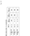
- the rewrite specification data is divided into rewrite specification data for DCM used by the DCM 12 and rewrite specification data for CGW used by the CGW 13.
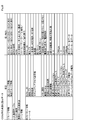
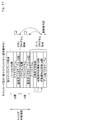
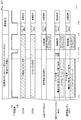
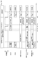
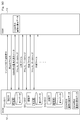
- the rewrite specification data for DCM includes specification data information and ECU information.
- the specification data information includes address information and a file name.
- the ECU information includes the address information and the like to be referred to when transmitting the update program (write data) of each rewrite target ECU 19 to the CGW 13 by the number of rewrite target ECUs.
- the ECU information includes an ID for identifying the ECU (ECU (ID)), a reference address for acquiring the update program (update program acquisition address), an update program size, and a rollback program.
- ECU (ID) ID for identifying the ECU
- a reference address for acquiring the update program update program acquisition address
- an update program size an update program size
- a rollback program At this time, at least a reference address (rollback program acquisition address) and a rollback program size are included.
- the rollback program is a program (write data) for returning the application program to the original version when the rewriting of the application program is canceled in the middle.
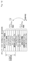
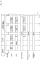
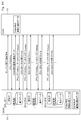
- the rewrite specification data for CGW includes group information, a bus load table, a battery load, a vehicle state at the time of rewrite, and ECU information.
- the rewrite specification data for the CGW may include rewrite procedure information, display scene information, and the like in addition to the above.
- the group information is information indicating the group to which the rewriting target ECU 19 belongs and the rewriting order. For example, as the first group information, the application program is rewritten in the order of ECU (ID1), ECU (ID2), and ECU (ID3).
- the second group information specifies that the application program is rewritten in the order of ECU (ID4), ECU (ID5), and ECU (ID6).
- the bus load table is a table shown in FIG. 100 described later, and the details will be described later.
- the battery load is information indicating a lower limit value of the remaining battery level of the vehicle battery 40 that is allowable in the vehicle.
- the vehicle state at the time of rewriting is information indicating when the vehicle state is to be rewritten.
- the ECU information is information on the ECU 19 to be rewritten, and includes ECU_ID (corresponding to device identification information), connection bus (corresponding to bus identification information), connection power supply, security access key information, memory type, and rewriting.
- ECU_ID corresponding to device identification information
- connection bus corresponding to bus identification information
- connection power supply corresponding to bus identification information
- security access key information corresponding to memory type
- Method power supply self-holding time, rewrite surface information, update program version, update program acquisition address, update program size, rollback program version, rollback program acquisition address, rollback program size, and write At least the data type.
- the connection bus indicates a bus to which the ECU 19 is connected.
- the connection power supply indicates a power supply line to which the ECU 19 is connected.
- the security access key information indicates key information used for authentication for the CGW 13 to access the rewrite target ECU 19, and includes a random number value or unique information, a key pattern, and a decryption operation pattern.
- the memory type indicates whether the memory mounted on the rewrite target ECU 19 is a single-sided single memory, a single-sided suspend memory (also called a pseudo-two-sided memory), or a two-sided memory.
- the rewriting method indicates whether rewriting is performed by self-holding of the power supply or rewriting by power supply control.
- the power supply self-holding time indicates a time during which power supply self-holding is continued when the rewriting method is rewriting by power supply self-holding.
- the rewrite side information indicates which side is the operation side and which side is the non-operation side.
- the operation side is also called an activation side, and the non-operation side is also called a rewriting side.
- Update program version indicates the version of the update program.
- the update program acquisition address indicates the address of the update program.
- the update program size indicates the data size of the update program.
- the rollback program version indicates the version of the rollback program.
- the rollback program acquisition address indicates the address of the rollback program.
- the rollback program size indicates the data size of the rollback program.
- the write data type indicates whether the write data is differential data or all data. Note that the rewrite specification data can include information uniquely defined by the system in addition to the above information.
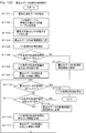
- the DCM 12 When the DCM 12 acquires the rewrite specification data for DCM, the DCM 12 analyzes the obtained rewrite specification data for DCM. When the DCM 12 analyzes the rewrite specification data for DCM, the DCM 12 obtains write data from the address where the update program of the rewrite target ECU 19 is stored, and performs operations related to rewrite such as transferring the obtained write data to the CGW 13. Control.
- the CGW 13 When the CGW 13 acquires the rewrite specification data for the CGW, the CGW 13 analyzes the acquired rewrite specification data for the CGW. When analyzing the rewrite specification data for CGW, the CGW 13 requests the DCM 12 to transfer a predetermined size of the update program of the rewrite target ECU 19 to the rewrite target ECU 19 according to the analysis result, or writes the write data to the rewrite target ECU 19 in the specified order. Controls operations related to rewriting such as distribution.
- the distribution specification data provided by the OEM is registered.
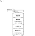
- the delivery specification data provided by the OEM is data that defines an operation related to display of various screens on the display terminal 5.
- the distribution specification data includes language information, display text, package information, image data, display patterns, a display control program, and the like.
- the display terminal 5 Upon acquiring the distribution specification data from the CGW 13, the display terminal 5 analyzes the obtained distribution specification data and controls the display of various screens according to the analysis result. The display terminal 5 superimposes a display word acquired from the distribution specification data on a display frame held in advance, for example, and executes a display control program acquired from the distribution specification data.
- the distribution specification data can include information uniquely defined by the system in addition to the above information.
- the file server 8 When the replog data and the distribution specification data are registered, the file server 8 encrypts the registered replog data and authenticates the package, a package authenticator for encrypting the package, the encrypted replog data, and the distribution specification. Generate a distribution package that stores data.
- the authenticator is data provided for verifying the integrity of the replog data and the distribution specification data, and is generated from, for example, key information associated with the CGW 13, the replog data, and the distribution specification data.
- the file server 8 Upon receiving a distribution package download request from the outside, the file server 8 transmits the distribution package to the DCM 12.
- the file server 8 exemplifies a case where the file server 8 generates a distribution package storing the replog data and the distribution specification data, and simultaneously transmits the replog data and the distribution specification data to the DCM 12 as one file.
- the re-log data and the distribution specification data may be transmitted to the DCM 12 as separate files. That is, the file server 8 may transmit the distribution specification data to the DCM 12 first and then transmit the re-log data to the DCM 12 later. In this case, it is preferable to assign an authenticator to each of the distribution specification data and the re-prog data.
- the DCM 12 verifies the integrity of the encrypted replog data using the package authenticator stored in the downloaded distribution package. If the verification result is positive, the DCM 12 decrypts the encrypted replog data. When the DCM 12 decrypts the encrypted replog data, the DCM 12 unpacks the decrypted replog data (hereinafter, also referred to as “unpackaging”). And extract it into rewrite specification data.
- the encrypted difference data and the authenticator of the ECU (ID1), the encrypted difference data and the authenticator of the ECU (ID2), the encrypted difference data and the authenticator of the ECU (ID3), and the rewriting for the DCM are shown. This example illustrates a case where the data is extracted by being divided into specification data and CGW rewrite specification data.
- the flash memory 33d of the ECU 19 has, according to the memory configuration, a single memory having one flash surface, a one-suspend memory having two pseudo flash surfaces, and substantially two flash surfaces. It is divided into two-sided memory.
- the ECU 19 having the one-sided single memory is referred to as a one-sided single memory ECU
- the ECU 19 having the one-sided suspend memory is referred to as a one-sided suspend memory ECU
- the ECU 19 having the two-sided memory is referred to as a two-sided memory ECU. Name.
- the single-sided memory has a single flash side, there is no concept of an operation side or a non-operation side, and the application program cannot be rewritten during the execution of the application program.
- the one-sided suspend memory and the two-sided memory have a configuration having two flash surfaces, there is a concept of an operation side and a non-operation side, and the non-operation side application program is executed while the operation side application program is being executed. Program can be rewritten. Since the two-sided memory has a configuration in which the flash side is completely separated from the two sides, the application program can be rewritten at an arbitrary timing such as while the vehicle is running.
- the one-sided suspend memory has a configuration in which the one-sided single memory is pseudo-divided into two sides, so there is a restriction on the timing at which reading and writing can be performed normally, and the application program cannot be rewritten while the vehicle is running.
- the application program can be rewritten during parking with the IG power supply off.
- the one-side single memory, the one-side suspend memory, and the two-sided memory are respectively a built-in type of reprog firmware incorporating the reprog firmware (hereinafter, referred to as a built-in type), and a replog firmware download type that downloads the reprog firmware from outside. (Hereinafter, referred to as download type).
- Reprog firmware is firmware for rewriting an application program.
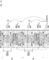
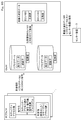
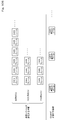
- the embedded single-sided single memory has a difference engine work area, an application program area, and a boot program area.
- version information, parameter data, an application program, firmware, and a normal time vector table are arranged.
- boot program, a progress status point 2, a progress status point 1, start determination information, wireless reprog firmware, wired reprog firmware, a start determination program, and a boot time vector table are arranged. ing.
- the microcomputer 33 executes a startup determination program during a normal operation for executing an application process such as a vehicle control process or a diagnosis process, and refers to a boot time vector table and a normal time vector table.
- the start address is searched, and a predetermined address of the application program is executed.
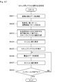
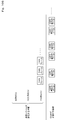
- FIG. 12 shows an operation of rewriting an application program using difference data as an update program.
- the microcomputer 33 temporarily saves the application program as old data in the difference engine work area.
- the microcomputer 33 reads the old data once saved in the difference engine work area, and restores the new data from the read old data and the difference data stored in the RAM 33c by the difference engine included in the built-in replog firmware. I do.
- the microcomputer 33 When the microcomputer 33 generates new data from the old data and the difference data, the microcomputer 33 writes the new data to a predetermined address of the memory and rewrites the application program.
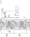
- a download-type single-side single memory will be described with reference to FIGS.
- the download type differs from the built-in type described above in that the wireless replog firmware and the wired replog firmware are downloaded from the outside, the application program is rewritten, and then the wireless replog firmware and the wired replog firmware are deleted.
- the wireless replog firmware executed by each ECU 19 is included in the replog data shown in FIG.
- the ECU 19 receives the wireless reprogram firmware for the own ECU from the CGW 13 and stores the received wireless reprogram firmware for the own ECU in the RAM.
- the microcomputer 33 executes the startup determination program during the normal operation of executing the application processing such as the vehicle control processing and the diagnosis processing, similarly to the built-in type, and stores the boot time vector table and the normal time.
- the start address is searched with reference to the vector table, and a predetermined address of the application program is executed.
- the microcomputer 33 temporarily saves the application program as old data in the difference engine work area.
- the microcomputer 33 reads out the old data once saved in the difference engine work area, and uses the difference engine included in the replog firmware downloaded from the outside to transfer new data from the read out old data and the difference data stored in the RAM 33c. Restore.
- the microcomputer 33 When the microcomputer 33 generates new data from the old data and the difference data, the microcomputer 33 writes the new data and rewrites the application program.
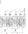
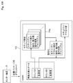
- the built-in single-suspend memory has a difference engine work area, an application program area, and a boot program area.
- the reprogram firmware for updating the program is located in the boot program area similarly to the single-sided single memory, and is not subject to the program update.
- the application program area to be updated has a pseudo-surface A and a surface B. On the surface A and the surface B, version information, an application program, and a normal vector table are arranged, respectively. .
- a boot program, re-prog firmware, a re-prog vector table, a start plane determination function, start plane determination information, and a boot vector table are arranged.
- the microcomputer 33 executes a boot program and performs a start-up surface determination function to determine each of the start-up surfaces A and B during a normal operation in which an application process such as a vehicle control process or a diagnostic process is performed. It is determined from the information which of the side A and the side B is the operation side.
- the microcomputer 33 determines that the side A is the operation side, the microcomputer 33 searches for the start address with reference to the normal time vector table of the side A, and executes the application program of the side A.
- the microcomputer 33 determines that the side B is the operation side, the microcomputer 33 refers to the normal vector table of the side B, searches for the start address, and executes the application program of the side B.
- the re-program firmware is arranged in the boot program area. However, the re-program firmware may also be configured as an object of the program update and arranged in each area of the A-side or the B-side.
- the microcomputer 33 temporarily saves the non-operational application program as old data in the difference engine work area.
- the microcomputer 33 reads out the old data once saved in the difference engine work area, and restores new data from the read out old data and the difference data stored in the RAM 33c by the difference engine in the built-in replog firmware. .
- the microcomputer 33 When the microcomputer 33 generates new data from the old data and the difference data, the microcomputer 33 writes the new data on the non-operation side and rewrites the non-operation side application program.
- FIG. 16 illustrates a case where the side A is the operation side and the side B is the non-operation side.
- the download type one-surface suspend memory will be described with reference to FIGS.
- the download type differs from the built-in type in that the replog firmware and the replog vector table are downloaded from the outside, the application program is rewritten, and then the replog firmware and the replog vector table are deleted.
- the microcomputer 33 executes a boot program and executes a boot program and performs a boot surface determination function in the same manner as the built-in type.
- the old and new sides are determined from the activation plane determination information of the sides, and which of the sides A and B is the operation side is determined.
- the microcomputer 33 determines that the side A is the operation side, the microcomputer 33 searches for the start address with reference to the normal time vector table of the side A, and executes the application program of the side A.
- the microcomputer 33 determines that the side B is the operation side, the microcomputer 33 refers to the normal vector table of the side B, searches for the start address, and executes the application program of the side B.
- the microcomputer 33 temporarily saves the non-operational application program as old data in the difference engine work area.
- the microcomputer 33 reads the old data once saved in the difference engine work area, and restores the new data from the read old data and the difference data stored in the RAM 33c by the difference engine in the replog firmware downloaded from the outside. I do.
- the microcomputer 33 When the microcomputer 33 generates new data from the old data and the difference data, the microcomputer 33 writes the new data and rewrites the application program.
- FIG. 18 illustrates a case where the side A is the operation side and the side B is the non-operation side. As described above, in the one-sided suspend memory, the application program on the B-side can be rewritten in the background while the application program on the A-side is being executed.
- the embedded two-sided memory will be described with reference to FIGS. 19 and 20.
- the embedded single-sided single memory has an application program area and a rewrite program area on the side A, an application program area and a rewrite program area on the side B, and a boot program area.
- a boot program is arranged so as not to be rewritten.
- the boot program includes a boot swap function and a boot time vector table.
- version information, parameter data, an application program, firmware, and a normal vector table are arranged.
- each rewrite program area a program for controlling rewrite, replog progress management information 2, replog progress management information 1, start plane determination information, wireless replog firmware, wired replog firmware, and a boot time vector table are stored. Are located.
- a boot program, a boot swap function, and a boot time vector table are arranged.
- the microcomputer 33 executes the boot program at the time of the normal operation for executing the application process such as the vehicle control process and the diagnostic process, and at the time of the rewrite operation for executing the rewrite process of the non-operational application program.
- the boot swap function is used to determine the old and new sides from the activation plane determination information on the A side and the B side, and it is determined which of the A side and the B side is the operation side. If the microcomputer 33 determines that the side A is the operation side, the microcomputer 33 searches the start address by referring to the boot vector table and the normal vector table of the side A, and executes the application program of the side A. Similarly, when the microcomputer 33 determines that the side B is the operation side, the microcomputer 33 searches for the start address with reference to the boot vector table and the normal vector table of the side B, and executes the application program of the side B. .
- the microcomputer 33 temporarily saves the non-operational application program as old data in the difference engine work area during the rewriting operation for executing the non-operational application program rewriting process.
- the microcomputer 33 reads out the old data once saved in the difference engine work area, and restores new data from the read out old data and the difference data stored in the RAM 33c by the difference engine in the built-in replog firmware. .
- the microcomputer 33 When the microcomputer 33 generates new data from the old data and the difference data, the microcomputer 33 writes the new data on the non-operation side and rewrites the non-operation side application program.
- the old data that is temporarily saved in the difference engine work area may be an application program on the operation side or an application program on the non-operation side.
- FIG. 20 illustrates a case where the A side is the operation side and the B side is the non-operation side.
- the old data that is temporarily saved in the difference engine work area may be an application program on the operation side or an application program on the non-operation side.
- C-2 Download Type Two-Side Memory
- the download type two-side memory will be described with reference to FIGS. 21 and 22.
- the download type differs from the built-in type described above in that the wireless replog firmware and the wired replog firmware are downloaded from the outside, the application program is rewritten, and then the wireless replog firmware and the wired replog firmware are deleted.
- the microcomputer 33 performs the normal operation of executing the application processing such as the vehicle control processing and the diagnostic processing and the rewriting operation of executing the non-operation side application program rewriting operation in the same manner as the built-in type.
- the boot program is executed, the boot swap function is used to determine the new or old from the start-up surface determination information on the A-side and the B-side, and it is determined which of the A-side and the B-side is the operation side. To execute the application process.
- the microcomputer 33 temporarily saves the non-operational application program as old data in the difference engine work area.
- the microcomputer 33 reads the old data once saved in the difference engine work area, and restores the new data from the read old data and the difference data stored in the RAM 33c by the externally downloaded replog firmware.
- the microcomputer 33 When the microcomputer 33 generates new data from the old data and the difference data, the microcomputer 33 writes the new data on the non-operation side and rewrites the non-operation side application program.
- the old data that is temporarily saved in the difference engine work area may be an application program on the operation side or an application program on the non-operation side.
- FIG. 22 illustrates a case where the side A is the operation side and the side B is the non-operation side.
- the old data that is temporarily saved in the difference engine work area may be an application program on the operation side or an application program on the non-operation side.
- the application program on the B-side can be rewritten in the background while the application program on the A-side is being executed.
- an application program and a rewriting program for rewriting the application program are arranged in each application area.
- the application program is shown as a reprog target, but a rewrite program may also be made a reprog target.
- the rewriting program may be arranged in the boot area.
- a program for wire rewriting may be arranged in the boot area so that a dealer or the like can reliably perform wire rewriting via the tool 23.
- the distribution package transmitted from the center device 3 to the DCM 12 stores the write data of one or more rewrite target ECUs 19. That is, if there is one rewriting target ECU 19, one write data directed to the one rewriting target ECU 19 is stored. If there are a plurality of rewriting target ECUs 19, the plurality of rewriting target ECU 19 A plurality of write data for each is stored.
- rewrite target ECUs 19 there are two rewrite target ECUs 19, and the two rewrite target ECUs 19 are referred to as a rewrite target ECU (ID1) and a rewrite target ECU (ID2).
- the ECUs 19 other than the rewrite target ECU (ID1) and the rewrite target ECU (ID2) are referred to as other ECUs.
- the rewrite target ECU (ID1) and the rewrite target ECU (ID2) each determine that the transmission request of the version notification signal is received from the master device 11, for example, it determines that the transmission condition of the version notification signal is satisfied.
- the rewrite target ECU (ID1) transmits to the master device 11 a version notification signal including the version information of the application program stored therein and the ECU (ID) capable of identifying itself. I do.
- master device 11 transmits the received version notification signal to center device 3.
- the rewrite target ECU (ID2) transmits the version notification signal including the version of the application program stored therein and the ECU (ID) capable of identifying itself to the master device. Send to 11.
- master device 11 transmits the received version notification signal to center device 3.
- the center device 3 When receiving the version notification signal from the rewrite target ECU (ID1) and the rewrite target ECU (ID2), the center device 3 specifies the version of the application program and the ECU (ID) included in the received version notification signal, and It is determined whether or not there is write data to be delivered to the rewrite target ECU 19 that is the source of the notification signal. The center device 3 specifies the current version of the application program of the rewrite target ECU 19 from the version notification signal received from the rewrite target, and compares the current version of the application program with the latest version managed.
- the center device 3 If the version specified from the version notification signal has the same value as the latest version managed, the center device 3 has no write data to be delivered to the rewrite target ECU 19 that is the source of the version notification signal, and It is determined that there is no need to update the application program stored in the ECU 19. On the other hand, if the version specified from the version notification signal is smaller than the latest version managed, the center device 3 has write data to be delivered to the rewrite target ECU 19 that is the source of the version notification signal. It is determined that the application program stored in the rewrite target ECU 19 needs to be updated.
- the center device 3 determines that the application program stored in the rewrite target ECU 19 needs to be updated, the center device 3 notifies the portable terminal 6 that the update is necessary.
- the mobile terminal 6 displays a distribution availability screen (A1).
- the distribution availability screen is the same as a campaign notification screen described later. The user can confirm that the update is necessary on the distribution availability screen displayed on the mobile terminal 6, and can select whether or not to update.
- the mobile terminal 6 When the user selects updating in the mobile terminal 6 (A2), the mobile terminal 6 notifies the center device 3 of a download request for the distribution package.
- the center device 3 transmits the distribution package to the master device 11 when notified of the distribution package download request from the mobile terminal 6.
- the master device 11 When the master device 11 downloads the distribution package from the center device 3, the master device 11 starts a package authentication process for the downloaded distribution package (B1). The master device 11 authenticates the distribution package, and upon completing the package authentication process, starts the write data extraction process (B2). The master device 11 extracts the write data from the distribution package, and upon completion of the write data extraction process, transmits a download completion notification signal to the center device 3.
- the center device 3 Upon receiving the download completion notification signal from the master device 11, the center device 3 notifies the portable terminal 6 of the completion of the download.
- the mobile terminal 6 displays a download completion notification screen (A3). The user can confirm that the download has been completed on the download completion notification screen displayed on the mobile terminal 6, and can set the rewriting start time of the application program on the vehicle side.
- the portable terminal 6 When the user sets the rewriting start time of the application program on the vehicle side in the portable terminal 6 (A4), the portable terminal 6 notifies the center device 3 of the rewriting start time. When notified of the rewrite start time from the portable terminal 6, the center device 3 stores the rewrite start time set by the user as the set start time. When the current time reaches the set start time (A5), the center device 3 transmits a rewrite instruction signal to the master device 11.
- the master device 11 When receiving the rewrite instruction signal from the center device 3, the master device 11 transmits a power activation request to the power management ECU 20, and stops the rewrite target ECU (ID1), the rewrite target ECU (ID2), and other ECUs in the stop state or the sleep state. (X1).
- the master device 11 starts distribution of the write data to the rewrite target ECU (ID1), and instructs the rewrite target ECU (ID1) to write the write data.
- the rewrite target ECU (ID1) starts receiving write data from the master device 11, and when instructed to write the write data, starts writing the write data and starts a program rewriting process (C1).
- the rewrite target ECU (ID1) completes the reception of the write data from the master device 11, completes the writing of the write data, and completes the program rewriting process, it sends a rewrite completion notification signal to the master device 11.
- the master device 11 When receiving the rewrite completion notification signal from the rewrite target ECU (ID1), the master device 11 starts distributing write data to the rewrite target ECU (ID2), and instructs the rewrite target ECU (ID2) to write the write data. .
- the rewrite target ECU (ID2) starts receiving write data from the master device 11, and when instructed to write the write data, starts writing the write data and starts a program rewriting process (D1).
- the rewrite target ECU (ID2) transmits a rewrite completion notification signal to the master device 11 when completing the reception of the write data from the master device 11, completing the writing of the write data, and completing the program rewriting process.
- master device 11 When receiving the rewriting completion notification signal from the rewriting target ECU (ID2), master device 11 transmits a rewriting completion notification signal to center device 3.
- the center device 3 Upon receiving the rewrite completion notification signal from the master device 11, the center device 3 notifies the portable terminal 6 of the completion of the rewriting of the application program.
- the mobile terminal 6 displays a rewriting completion notification screen (A6). The user can confirm that the rewriting of the application program has been completed on the rewriting completion notification screen displayed on the mobile terminal 6, and can set the execution of synchronization as activation.
- the rewrite target ECU (ID1) and the rewrite target ECU (ID2) Upon receiving the synchronization switching instruction signal from the master device 11, the rewrite target ECU (ID1) and the rewrite target ECU (ID2) start a program switching process for switching the next application program to be started from the old application program to the new application program. (C2, D2).
- the rewrite target ECU (ID1) and the rewrite target ECU (ID2) respectively complete the program switching process, they transmit a switch completion notification signal to the master device 11.
- the master device 11 When the master device 11 receives the switching completion notification signal from the rewriting target ECU (ID1) and the rewriting target ECU (ID2), the master device 11 distributes the version read signal to the rewriting target ECU (ID1) and the rewriting target ECU (ID2).
- the rewrite target ECU (ID1) and the rewrite target ECU (ID2) Upon receiving the version read signal from the master device 11, the rewrite target ECU (ID1) and the rewrite target ECU (ID2) read the version of the application program operated thereafter (C3, D3) and include the read version.
- the latest version notification signal is transmitted to the master device 11.
- the master device 11 receives a version notification signal from the rewrite target ECU (ID1) and the rewrite target ECU (ID2) to check the software version and perform rollback as necessary.
- the master device 11 When receiving the version notification signal from the rewrite target ECU (ID1) and the rewrite target ECU (ID2), the master device 11 transmits a power stop request to the power management ECU 20, and the rewrite target ECU (ID1) and the rewrite target ECU (ID2). Then, the other ECUs are shifted from the start state to the stop state or the sleep state (X2).
- the master device 11 transmits the latest version notification signal to the center device 3.
- the center device 3 receives the latest version notification signal from the master device 11, the center device 3 specifies the latest version of the application program of the rewrite target ECU (ID1) and the rewrite target ECU (ID2) from the received latest version notification signal.
- the portable terminal 6 is notified of the specified latest version.
- the mobile terminal 6 displays a latest version notification screen indicating the notified latest version on the mobile terminal 6 (A8). The user can confirm the latest version on the latest version notification screen displayed on the mobile terminal 6, and can confirm that the activation has been completed.
- (A) Rewriting Application Program by Power Control A case of rewriting an application program by power control will be described with reference to FIGS. 26 and 27.
- the rewriting of the application program by the power control means a configuration in which the rewriting operation is controlled according to the switching of the power without using the power self-holding circuit.
- the vehicle power source is switched from the + B power source to the IG power source by the user switching the IG switch from off to on, the DCM 12, the CGW 13, the two-side memory ECU, the one-side suspend memory ECU, and the one-side single memory ECU operate normally. Is started (t1).
- the DCM 12 When the DCM 12 is notified of the start of the download from the center device 3, the DCM 12 shifts from the normal operation to the download operation and starts downloading the distribution package from the center device 3 (t2).
- the DCM 12 may download the distribution package in the background while performing the normal operation.
- the DCM 12 returns from the download operation to the normal operation (t3).
- the DCM 12 When the DCM 12 is notified of the rewrite instruction signal (install instruction signal) from the center device 3 or the CGW 13, the DCM 12 shifts from the normal operation to the data transfer / center communication operation and starts the data transfer / center communication operation (t4). That is, the DCM 12 extracts the write data from the distribution package, starts the transfer of the write data to the CGW 13, acquires the progress of the rewrite from the CGW 13, and starts notifying the center device 3 of the progress of the rewrite. .
- the CGW 13 When the CGW 13 starts acquiring the write data from the DCM 12, the CGW 13 shifts from the normal operation to the replog master operation, starts the replog master operation, starts the distribution of the write data to the two-side memory ECU, and instructs the writing of the write data. I do.
- the two-sided memory ECU starts a programming phase (hereinafter, also referred to as an installation phase) in a normal operation. That is, the two-sided memory ECU performs the installation of the application program in the background while performing the normal operation.
- the two-sided memory ECU starts writing the received write data to the flash memory, and starts rewriting the application program.
- the DCM 12 suspends the data transfer / center communication operation
- the CGW 13 suspends the reprogram master operation
- the two-surface memory ECU suspends the installation phase and suspends rewriting of the application program (t5).
- the DCM 12 restarts the data transfer / center communication operation
- the CGW 13 restarts the re-log master operation
- the two-sided memory ECU restarts the installation phase and restarts rewriting the application program (t6). That is, when the user switches the IG switch from on to off, the vehicle power is switched from the IG power to the + B power, and thereafter, when the user switches from the IG switch off to on, the vehicle power is switched from the + B power to the IG power. Instead, every time a trip occurs, the two-sided memory ECU repeats interruption and restart of rewriting of the application program (t7, t8).
- the two-sided memory ECU completes the writing of the write data and completes the rewriting of the application program, it ends the installation phase and shifts from the normal operation to the wait for activation. That is, the two-sided memory ECU does not start on the new side (side B) in which the application program has been rewritten and does not start the old side (side A) when the activation phase is not performed (t9).
- the CGW 13 A power activation request is transmitted to the power management ECU 20.
- the vehicle power source is switched from the + B power source to the IG power source by transmitting the power activation request to the power management ECU 20 by the CGW 13
- the DCM 12 resumes the data transfer / center communication operation
- the CGW 13 resumes the re-log master operation.
- the distribution of the write data to the one-side suspend memory ECU and the one-side single memory ECU is started.
- the one-side suspend memory ECU and the one-side single memory ECU respectively start receiving the write data from the CGW 13
- the one-side suspend memory ECU shifts from the normal operation to the boot process, and starts the installation phase in the boot process (t11). That is, the one-side suspend memory ECU and the one-side single memory ECU do not perform the installation in parallel with the normal operation, but perform the installation in the boot process in which the application program is not operating.
- the one-side suspend memory ECU suspends the rewriting of the application program.
- the one-sided suspend memory ECU returns from the non-operational side (Side B) where the rewriting of the application program has been interrupted to the operation side (Side A) as the start-up side.
- the one-side single memory ECU continues to rewrite the application program even if the IG switch 42 is switched from off to on by a user operation before the rewriting of the application program is completed.
- the one-side single memory ECU is interrupted in the middle of rewriting the application program, it cannot be restored as a normal operation.
- the operation of the IG switch 42 by the user is invalidated until the rewriting of the application program is completed.
- the one-sided suspend memory ECU completes the writing of the write data and completes the rewriting of the application program, it ends the installation phase in the boot process and shifts from the boot process to the activation wait state. That is, the one-side suspend memory ECU does not start on the new side (side B) in which the application program has been rewritten and does not start the old side (side A) when the activation phase is not performed.
- the one-plane independent memory ECU completes the writing of the write data and completes the rewriting of the application program, it ends the installation phase in the boot process and waits for activation (t12).
- the two-sided memory ECU and the one-sided suspended memory ECU switch from the old side to the new side, respectively, and start up on the new side. Then, a post-programming phase (hereinafter, also referred to as an “activate phase”) is started in the new surface activation.
- the one-sided independent memory ECU starts the restart, and starts the activate phase in the restart after the installation is completed (t13, t14). In the activation, confirmation that the new program is started correctly and notification of version information to the CGW 13 are performed.
- the DCM 12 shifts from the data transfer / center communication operation to the sleep / stop operation, and the sleep / stop operation.
- the CGW 13 shifts from the re-program master operation to the sleep / stop operation, and starts the sleep / stop operation.
- the two-sided memory ECU, the one-sided suspend memory ECU, and the one-sided single memory ECU shift from the new-side activation to the sleep / stop operation, respectively (t15).
- the two-side memory ECU and the one-side suspend memory ECU respectively activate the new side (side B). And the one-side single memory ECU starts the new application program (t16).
- Rewriting of an application program by self-holding of power means a configuration in which a rewriting operation is controlled using a self-holding circuit of power.
- the DCM 12 When the DCM 12 is notified of the start of download from the center device 3, that is, notified of the update by the new program, the DCM 12 shifts from the normal operation to the download operation, and starts downloading the distribution package from the center device 3 ( t22). When the download of the distribution package from the center device 3 is completed, the DCM 12 returns from the download operation to the normal operation (t23).
- the DCM 12 When the DCM 12 receives the rewrite instruction signal (install instruction signal) from the center device 3 or the CGW 13, the DCM 12 shifts from the normal operation to the data transfer / center communication operation, and starts the data transfer / center communication operation (t24). That is, the DCM 12 extracts the write data from the distribution package, starts the transfer of the write data to the CGW 13, acquires the progress of the rewrite from the CGW 13, and starts notifying the center device 3 of the progress of the rewrite. .
- install instruction signal install instruction signal
- the CGW 13 When the CGW 13 starts acquiring the write data from the DCM 12, the CGW 13 shifts from the normal operation to the replog master operation, starts the replog master operation, starts the distribution of the write data to the two-side memory ECU, and instructs the writing of the write data. I do.
- the two-sided memory ECU starts a programming phase (hereinafter, also referred to as an installation phase) in a normal operation. That is, the two-sided memory ECU performs the installation of the application program in the background while performing the normal operation.
- the two-sided memory ECU starts writing the received write data to the flash memory, and starts rewriting the application program.
- the vehicle power is switched from the IG power to the + B power by the user switching from the IG switch on to the off during the rewriting of the application program in the two-sided memory ECU (t25), the vehicle power is switched from the IG power to the + B power.
- the DCM 12 continues the data transfer / center communication operation
- the CGW 13 continues the re-program master operation
- the two-sided memory ECU continues the installation phase, and continues to rewrite the application program.
- the DCM 12 suspends the data transfer / center communication operation
- the CGW 13 suspends the relog master operation
- the two-sided memory ECU suspends the installation phase and suspends rewriting of the application program (t26). That is, the installation is continued by the power supply from the vehicle battery 40 until a predetermined time elapses after the IG switch 42 is turned off.
- the DCM 12 restarts the data transfer / center communication operation
- the CGW 13 restarts the re-log master operation
- the two-sided memory ECU restarts the installation phase and restarts rewriting the application program (t27). That is, when the user switches the IG switch from on to off, the vehicle power is switched from the IG power to the + B power, and thereafter, when the user switches from the IG switch off to on, the vehicle power is switched from the + B power to the IG power.
- the two-sided memory ECU repeats interruption and restart of rewriting of the application program (t28 to t30). However, until the self-holding period elapses after the vehicle power supply is switched from the IG power supply to the + B power supply, the DCM 12 continues the data transfer / center communication operation, the CGW 13 continues the re-log master operation, and the two-sided memory. The ECU continues the installation phase and continues rewriting the application program.
- the two-sided memory ECU completes the writing of the write data and completes the rewriting of the application program, it ends the installation phase and shifts from the normal operation to the wait for activation. That is, the two-sided memory ECU does not start on the new side (side B) in which the application program has been rewritten and does not start the old side (side A) at the time when the activation phase is not performed (t31).
- the vehicle power supply is switched from the IG power supply to the + B power supply.
- the one-sided suspended memory ECU and the one-sided suspended memory ECU The surface-only memory ECU shifts from the normal operation to the boot process, starts the boot process, and starts the installation phase in the boot process (t32).
- the installation phase ends in the boot process (t33).
- the CGW 13 transmits the power activation request to the power management ECU 20 and the vehicle power is switched from the + B power to the IG power, the DCM 12 restarts the data transfer / center communication operation (t34).
- the one-sided suspend memory ECU completes the writing of the write data and completes the rewriting of the application program, it shifts from the boot process to the activation wait state. That is, the one-side suspend memory ECU does not start on the new side (side B) in which the application program has been rewritten and does not start the old side (side A) when the activation phase is not performed.
- the one-side single memory ECU completes the writing of the write data and completes the rewriting of the application program, it ends the installation phase in the boot process and waits for activation (t35).
- the power management ECU 20 switches the vehicle power supply from the IG power supply to the + B power supply in response to an activation instruction from the CGW 13, the two-sided memory ECU and the one-sided suspended memory ECU switch from the old side to the new side, respectively, and start up on the new side. Then, the activation phase is started in the new surface activation.
- the one-sided independent memory ECU starts the restart, and starts the activate phase in the restart after the installation is completed (t36, t37).
- the DCM 12 shifts from the data transfer / center communication operation to the sleep / stop operation, and the sleep / stop operation.
- the CGW 13 shifts from the re-program master operation to the sleep / stop operation, and starts the sleep / stop operation.
- the two-sided memory ECU, the one-sided suspended memory ECU, and the one-sided single memory ECU shift from the start of the new side to the sleep / stop operation (t38).
- the two-side memory ECU and the one-side suspend memory ECU respectively activate the new side (side B).
- the single-screen independent memory ECU starts the new application program (t39).
- the CGW 13 performs the following check before downloading the distribution package from the center device 3 and before distributing the write data to the rewrite target ECU 19.
- the CGW 13 checks the radio wave environment, the remaining battery power of the vehicle battery 40, and the memory capacity of the DCM 12 so that the download can be performed normally.
- the CGW 13 checks the presence of an intrusion sensor and checks the door lock as a check of a manned environment so as not to make the installation environment unstable so that the write data can be normally delivered.
- Detection, curtain detection, and IG-off detection are performed, and as a check as to whether or not the rewriting target ECU 19 is writable, a version and occurrence of an abnormality are checked.
- the CGW 13 performs a falsification check, an access authentication, a version check, and the like before starting the installation as a check of the write data to be delivered to the rewrite target ECU 19, and performs a communication interruption check, an abnormality occurrence during the installation.
- a version check, an integrity check, a DTC (Diagnostic Trouble Code, error code) check, and the like are performed.
- the campaign notice is a notice of program update.
- the master device 11 downloads distribution specification data and the like as a campaign notification.
- the display terminal 5 displays a screen in each phase as the rewriting of the application program progresses.
- the screen displayed by the in-vehicle display 7 will be described.
- the CGW 13 causes the in-vehicle display 7 to display a navigation screen 501 such as a well-known route guidance screen, which is one of the navigation functions, at the normal time before the campaign notification, for example.
- a campaign notification occurs in this state, the CGW 13 displays a campaign notification icon 501a indicating the occurrence of a campaign notification at the lower right of the navigation screen 501, as shown in FIG.
- the user can grasp the occurrence of the campaign notification regarding the update of the application program.
- the CGW 13 displays the campaign notification screen 502 on the navigation screen 501 as a pop-up, as shown in FIG.
- the CGW 13 is not limited to displaying the campaign notification screen 502 in a pop-up manner, and may adopt another display mode.
- the CGW 13 displays, for example, a guidance of “there is an available software update” to notify the user of the occurrence of the campaign notification, and displays a “confirm” button 502a and a “later” button 502b. Wait for user operation. In this case, by operating the “confirm” button 502a, the user can proceed to the next screen for starting the rewriting of the application program.
- the CGW 13 deletes the pop-up display on the campaign notification screen 502 and returns to the screen displaying the campaign notification icon 501a shown in FIG.
- the CGW 13 switches the display from the navigation screen 501 to the download approval screen 503, and displays the download approval screen 503 on the in-vehicle display 7, as shown in FIG.
- the CGW 13 notifies the user of the campaign ID and the update name, and displays a “download start” button 503a, a “detailed confirmation” button 503b, and a “return” button 503c, and waits for a user operation.
- the user can start the download by operating the “download start” button 503a, and can display the details of the download by operating the “confirm details” button 503b, and click “return”.
- By displaying the "" button 503c it is possible to reject the download and return to the previous screen.
- the “return” button 503c has been operated, the user can proceed to the screen for starting the download by operating the campaign notification icon 501a.
- the CGW 13 switches the display contents of the download approval screen 503 as shown in FIG. To be displayed.
- the CGW 13 displays the details of the update, the time required for the update, the restrictions on the vehicle functions involved in the update, and the like using the received distribution specification data as the details of the download.
- the CGW 13 starts downloading the distribution package via the DCM 12.
- the CGW 13 switches the display from the download consent screen 503 to the navigation screen 501 as shown in FIG.
- a download-in-progress icon 501b indicating that the download is being performed is displayed at the lower right of 501.
- the CGW 13 switches the display from the navigation screen 501 to the download execution screen 504, and displays the download execution screen 504 on the in-vehicle display 7, as shown in FIG. .
- the CGW 13 notifies the user of the execution of the download on the download execution screen 504, and displays a “detailed confirmation” button 504a, a “return” button 504b, and a “cancel” button 504c, and waits for a user operation.
- the user can display details during the execution of the download by operating the “details confirmation” button 504a, and can interrupt the download by operating the “cancel” button 504c.
- the CGW 13 displays a download completion notification screen 505 on the navigation screen 501 as a pop-up, as shown in FIG.
- the CGW 13 displays, for example, a guidance of “download completed. 505b is displayed and the operation of the user is waited. In this case, by operating the “confirm” button 505a, the user can proceed to a screen for starting installation.
- the CGW 13 switches the display from the navigation screen 501 to the installation consent screen 506, and displays the installation consent screen 506 on the in-vehicle display 7, as shown in FIG.
- the CGW 13 informs the user of the time required for installation, restrictions and schedule settings on the installation consent screen 506, and displays an "immediate update” button 506a, a "reserve and update” button 506b, and a "return” button 506c. Wait for user operation. In this case, the user can start the installation immediately by operating the “immediate update” button 506a.
- the user can set the time at which the installation is to be executed, and operate the “Reserve and Update” button 506b to reserve and start the installation.
- the “reserve and Update” button 506c By operating the “return” button 506c, the user can reject the installation and return to the previous screen. In the case where the “return” button 506c has been operated, the user can proceed to the screen for starting the installation by operating the download execution icon 501b.
- the CGW 13 switches the display contents of the installation approval screen 506 as shown in FIG.
- the CGW 13 accepts the request for installation on the installation approval screen 506 and informs the user that the installation is to be started.
- the CGW 13 switches the display from the installation approval screen 506 to the navigation screen 501 as shown in FIG. Is displayed during installation.
- the user can grasp that the installation is being performed by checking the display of the installation-in-progress icon 501c.
- the CGW 13 switches the display from the navigation screen 501 to the installation execution screen 507, and displays the installation execution screen 507 on the in-vehicle display 7, as shown in FIG. .
- the CGW 13 notifies the user that the installation is being executed on the installation execution screen 507.
- the CGW 13 may display, for example, the remaining installation time and the progress percentage on the installation-in-progress screen 507.
- the display is switched from the navigation screen 501 to the activation approval screen 508 as shown in FIG. 43, and the activation approval screen 508 is displayed on the in-vehicle display 7.
- the CGW 13 notifies the user of the content of the activation, and displays a “return” button 508a and an “OK” button 508b, and waits for the user's operation.
- the user can operate the "return” button 508a to reject the activation and return to the previous screen. Further, the user can accept the activation by operating the “OK” button 508b.
- the CGW 13 displays an activation completion notification screen 509 on the navigation screen 501 as a pop-up, as shown in FIG.
- the CGW 13 displays, for example, a guidance “Software update completed” to notify the user of the completion of activation, and displays an “OK” button 509a and a “Details confirmation” button 509b. Wait for user operation.
- the user can delete the pop-up display of the activation completion notification screen 509 by operating the “OK” button 509a, and can display the details of the activation completion by operating the “confirm details” button 509b. Can be displayed.
- the CGW 13 switches the display from the navigation screen 501 to the confirmation operation screen 510 and causes the in-vehicle display 7 to display the confirmation operation screen 510 as shown in FIG.
- the CGW 13 notifies the user of the completion of the activation on the confirmation operation screen 510, and displays a “detailed confirmation” button 510a and an “OK” button 510b to wait for the user's operation.
- the user can display the details of the activation completion by operating the “details confirmation” button 510a.
- the CGW 13 switches the display contents of the confirmation operation screen 510 and displays details of activation completion on the in-vehicle display 7 as shown in FIG.
- the CGW 13 displays functions added by the update, changed functions, and the like as update details, and displays an “OK” button 510b.
- the CGW 13 determines that the user has confirmed the completion of the software update by operating the “OK” buttons 509a and 510b.
- the vehicle-side system 4 controls each operation phase of campaign notification, download, installation, activation, and update completion, and presents a display corresponding to each operation phase to the user.
- the CGW 13 is configured to control the display.
- the in-vehicle display 7 may be configured to receive the operation phase and the distribution specification data from the CGW 13 and perform the display.
- the vehicle program rewriting system 1 performs the following characteristic processing.
- (1) Transmission package transmission determination processing (2) Distribution package download determination processing (3) Write data transfer determination processing (4) Write data acquisition determination processing (5) Installation instruction determination processing (6) Security access key (7) Write data verification processing (8) Data storage surface information transmission control processing (9) Non-rewrite target power supply management processing (10) File transfer control processing (11) Write data distribution control processing ( 12) Activation request instruction processing (13) Activation execution control processing (14) Rewriting target group management processing (15) Rollback execution control processing (16) Rewriting progress display control processing (17) Difference data matching Sex determination processing (18) Rewriting execution control processing (19) Session establishment processing (20) Retry Point specification processing (21) Progress control synchronization control processing (22) Display control information transmission control processing (23) Display control information reception control processing (24) Progress display screen display control processing (25) Program update notification Control processing (26) Power supply self-holding execution control processing
- the center device 3, the DCM 12, the CGW 13, the ECU 19, and the in-vehicle display 7 have the following functional blocks as components for performing the above-described characteristic processes (1) to (26).
- the center device 3 has a distribution package transmitting unit 51.
- the distribution package transmission unit 51 Upon receiving the distribution package download request from the DCM 12, the distribution package transmission unit 51 transmits the distribution package to the DCM 12.
- the center device 3 includes, as a configuration for performing a characteristic process, a transmission package transmission determination unit 52, a progress state synchronization control unit 53, a display control information transmission control unit 54, and a write data A selection unit 55 (corresponding to an update data selection unit) is provided.
- the write data selection unit 55 (corresponding to the update data selection unit) performs the non-operation based on the software version and operation specified by the received data storage surface information. Select write data that matches the surface. That is, the distribution package transmission unit 51 transmits the distribution package including the write data selected by the write data selection unit 55 to the DCM 12. Functional blocks for performing characteristic processing will be described later.
- the DCM 12 includes a download request transmission unit 61, a distribution package download unit 62, a write data extraction unit 63, a write data transfer unit 64, a rewrite specification data extraction unit 65, a rewrite specification A data transfer unit 66.
- the download request transmitting unit 61 transmits a download request for a distribution package to the center device 3.
- the distribution package download unit 62 downloads a distribution package from the center device 3.
- the write data extraction unit 63 extracts the write data from the downloaded distribution package.
- the write data transfer unit 64 transfers the extracted write data to the CGW 13.
- the rewriting specification data extracting unit 65 extracts the rewriting specification data from the downloaded distribution package.
- the rewriting specification data transfer unit 66 transfers the extracted rewrite specification data to the CGW 13.
- the DCM 12 includes a distribution package download determination unit 67 and a write data transfer determination unit 68 as a configuration for performing characteristic processing in addition to the configuration described above. Functional blocks for performing characteristic processing will be described later.
- the CGW 13 includes an acquisition request transmission unit 71, a write data acquisition unit 72 (corresponding to an update data storage unit), and a write data distribution unit 73 (corresponding to an update data distribution unit). And a rewrite specification data acquisition unit 74 and a rewrite specification data analysis unit 75.
- the write data acquisition unit 72 acquires the write data from the DCM 12 by transferring the write data from the DCM 12.
- the write data distribution unit 73 distributes the acquired write data to the rewrite target ECU 19 at the timing of delivering the write data.
- the rewrite specification data obtaining unit 74 obtains the rewrite specification data from the DCM 12 by transferring the rewrite specification data from the DCM 12.
- the rewrite specification data analysis unit 75 analyzes the obtained rewrite specification data.
- the CGW 13 includes a configuration for performing a characteristic process, such as a write data acquisition determination unit 76, an installation instruction determination unit 77, a security access key management unit 78, and a write data verification unit 79.
- a characteristic process such as a write data acquisition determination unit 76, an installation instruction determination unit 77, a security access key management unit 78, and a write data verification unit 79.
- a control unit 90, a program update notification control unit 91, and a power supply self-holding execution control unit 92 are provided. Functional blocks for performing characteristic processing will be described later.
- the ECU 19 has a write data receiving unit 101 and a program rewriting unit 102.
- the write data receiving unit 101 receives write data from the CGW 13.
- the program rewrite unit 102 writes the received write data into the flash memory to rewrite the application program.
- the ECU 19 includes, in addition to the above-described configuration, a configuration that performs characteristic processing, a difference data consistency determination unit 103, a rewrite execution control unit 104, a session establishment unit 105, and a retry point identification unit 106. , An activation execution control unit 107 and a power supply self-holding execution control unit 108. Functional blocks for performing characteristic processing will be described later.
- the in-vehicle display 7 has a distribution specification data reception control unit 111.
- the distribution specification data reception control unit 111 controls reception of the distribution specification data.
- each of the processes (1) to (26) will be sequentially described.
- the center device 3 includes a software information acquisition unit 52a, an update presence / absence determination unit 52b, an update suitability determination unit 52c, and a campaign information transmission unit 52d in the distribution package transmission determination unit 52.
- the software information acquisition unit 52a acquires software information of each ECU 19 from the vehicle. Specifically, the software information acquisition unit 52a acquires ECU configuration information including software information such as a version and a writing surface and hardware information from the vehicle side.
- the software information acquisition unit 52a may acquire vehicle status information such as a failure code, the setting of an anti-theft alarm function, and license contract information from the vehicle side together with the ECU configuration information.
- the update presence / absence determination unit 52b determines the presence / absence of update data for the vehicle based on the acquired software information. That is, the update presence / absence determination unit 52b compares the acquired version of the software information with the version of the latest software information managed by itself, determines whether or not they match, and determines whether or not there is update data for the vehicle. Is determined. The update presence / absence determination unit 52b determines that there is no update data for the vehicle when determining that both match, and determines that there is update data for the vehicle when determining that they do not match.
- the update suitability determination unit 52c determines whether the vehicle state is suitable for updating a program or the like using a distribution package. Specifically, the update suitability determination unit 52c determines whether or not a license contract has been established, whether or not the vehicle position is within a predetermined range registered in advance by the user, and the setting of the alarm function of the vehicle is enabled. It is determined whether or not the failure information of the ECU 19 has occurred, and it is determined whether or not the vehicle state is suitable for downloading the distribution package. That is, the update suitability determination unit 52c determines whether or not the vehicle may be an update contrary to the user's intention, or if the download is successful, the vehicle may fail in the installation after the download. judge.
- the update suitability determination unit 52c determines that the license contract has been established, the vehicle position is within a predetermined range registered in advance by the user, the setting of the alarm function of the vehicle is enabled, and failure information of the ECU 19 is generated. If it is determined that the vehicle is not in the state, the vehicle state is determined to be a state suitable for updating a program or the like using the distribution package.
- the update propriety determining unit 52c determines that the license agreement has not been established, the vehicle position is not within the predetermined range registered in advance by the user, the setting of the alarm function of the vehicle has not been enabled, and failure information of the ECU 19 has been generated. If it is determined that the vehicle state is at least one of the states, it is determined that the vehicle state is not a state suitable for updating a program or the like using the distribution package.
- the campaign information transmission unit 52d transmits the campaign information to the master device 11 when the update suitability determination unit 52c determines that the vehicle state is suitable for updating a program or the like using the distribution package.
- the campaign information transmitting unit 52d does not transmit the campaign information to the master device 11 if the update suitability determination unit 52c determines that the vehicle state is not in a state suitable for updating the program or the like using the distribution package.
- the campaign information transmitting unit 52d performs the above-described determination, and stores information about the vehicle that did not transmit the campaign information to the master device 11.
- the center device 3 may display information about vehicles whose campaign information has not been transmitted to the master device 11.
- the center device 3 executes a distribution package transmission determination program to perform a distribution package transmission determination process.
- the center device 3 When the center device 3 starts the transmission package transmission determination process, the center device 3 acquires software information from the vehicle side (S101, corresponding to a software information acquisition procedure). That is, the center device 3 determines whether there is software update for the vehicle. The center device 3 determines the presence or absence of update data for the vehicle based on the acquired software information (S102, corresponding to the update presence / absence determination procedure). When determining that there is update data for the vehicle (S102: YES), the center device 3 determines whether the vehicle state is suitable for updating a program or the like using the distribution package (S103, update suitability determination procedure). Equivalent to).
- the center device 3 determines that the vehicle state is in a state suitable for updating a program or the like using the distribution package (S103: YES)
- the center device 3 transmits campaign information to the master device 11 (S104, corresponding to a campaign information transmission procedure).
- the transmission package transmission determination processing ends.
- the center device 3 determines that there is no update data for the vehicle (S102: NO)
- the center device 3 transmits to the master device 11 that the distribution package is not to be transmitted, that is, there is no update of the application program (S105). Is completed.
- the center device 3 determines that the vehicle state is not a state suitable for updating the program or the like using the distribution package (S103: NO)
- the center device 3 transmits to the master device 11 a message indicating that the vehicle state is not suitable for updating the program or the like (S106). ),
- the transmission package transmission determination processing ends.
- the master device 11 displays on the in-vehicle display 7 a message indicating that the program or the like is not suitable for updating the program and the like.
- the master device 11 displays, for example, "The program cannot be updated because the license is invalid. Please consult your dealer.” As a result, it is possible to present to the user a reason that the program or the like is not suitable for updating, and it is possible to present appropriate information to the user.
- the center device 3 performs the transmission package transmission determination processing before transmitting the distribution package to the master device 11 and before transmitting the campaign information, thereby executing the program using the distribution package. It can be determined whether or not the state is suitable for updating. Then, the center device 3 can transmit the campaign information to the master device 11 so as to transmit the distribution package to the master device 11 only when it is determined that the distribution package is in a state suitable for updating the program or the like using the distribution package. it can.
- the center device 3 In the case where the center device 3 is suitable for updating a program or the like using the distribution package, a license contract has been established, the vehicle position is within a predetermined range registered in advance by the user, and the setting of the alarm function of the vehicle is not performed.
- the campaign information can be transmitted to the master device 11 when it is activated and no failure information of the ECU 19 is generated. That is, in the center device 3, the license contract has not been concluded, the vehicle position is out of a predetermined range such as a position far away from home, the alarm function setting of the vehicle has been disabled, or the ECU 19 has failed.
- the center device 3 transmits the campaign information to the master device 11 for a vehicle that may be updated against the user's intention or a vehicle that may fail to be installed even if the download is successful. You can choose not to send.
- the center device 3 may perform transmission package transmission determination processing during transmission of the distribution package. In this case, if the center device 3 determines that the vehicle state is in a state suitable for updating a program or the like using the distribution package during transmission of the distribution package, the center device 3 continues transmission of the distribution package. If it is determined that the vehicle state is not a state suitable for updating a program or the like using the distribution package, the transmission of the distribution package is interrupted. That is, for example, if failure information of the ECU 19 occurs during transmission of the distribution package, the center device 3 suspends transmission of the distribution package.
- the download determination process of the distribution package in the master device 11 will be described with reference to FIGS.
- the master device 11 performs a download package download determination process.
- the (1) transmission package transmission determination process described above is a determination process performed by the center device 3 in the campaign notification phase before the download phase, whereas the distribution package download determination process is performed by the master device 11 in the download phase. Processing.
- the case where the DCM 12 performs the download determination process of the distribution package in the master device 11 will be described.
- the CGW 13 may perform the download determination process of the distribution package because the CGW 13 has the function of the DCM 12. .
- the DCM 12 includes a campaign information receiving unit 67a, a download possibility determining unit 67b, and a download executing unit 67c in the distribution package download determining unit 67.
- the campaign information receiving section 67a receives the campaign information from the center device 3.
- the campaign notification icon 501a shown in FIG. 32 is displayed.
- the downloadable determination unit 67b determines whether the vehicle state is a state in which the distribution package can be downloaded.
- the download possibility determination unit 67b determines whether the radio wave environment for communicating with the center device 3 is good, whether the remaining battery level of the vehicle battery 40 is equal to or more than a predetermined capacity, and whether the free memory capacity of the DCM 12 is It is determined whether or not the vehicle capacity is equal to or more than a predetermined capacity, and it is determined whether or not the vehicle state is a state where the distribution package can be downloaded.
- the vehicle status indicates that the distribution package is downloaded. It is determined that the state is possible. If the radio wave environment is not good, the remaining battery capacity of the vehicle battery 40 is not more than the predetermined capacity, and the available memory capacity of the DCM 12 is not more than the predetermined capacity, the downloadable determination unit 67b determines the vehicle state. It is determined that the distribution package is not in a downloadable state.
- the download possibility determination unit 67b determines whether there is a possibility that the download cannot be completed normally. Note that the determination by the download possibility determination unit 67b is performed on the condition that the “download start” button 503a is operated by the user on the download approval screen 503 shown in FIGS. 34 and 35. Further, the download possibility determination unit 67b may be configured to determine the determination item in the center device 3 as well. That is, the download possibility determination unit 67b determines that the download is possible, for example, when the setting of the alarm function of the vehicle is enabled or when no failure information of the ECU 19 is generated.
- the download execution unit 67c downloads the distribution package from the center device 3 when the download possibility determination unit 67b determines that the vehicle state is a state in which the distribution package can be downloaded. That is, the download execution unit 67c executes the download of the distribution package after confirming that the download can be normally completed.
- the download execution unit 67c does not download the distribution package from the center device 3 when the download possibility determination unit 67b determines that the vehicle state is not a state in which the distribution package can be downloaded. That is, when there is a possibility that the download cannot be completed normally, the download execution unit 67c does not execute the download of the distribution package. In this case, the download execution unit 67c instructs the in-vehicle display 7 to display a pop-up screen on the navigation screen 501 indicating that download could not be started and the reason thereof.
- the master device 11 executes a distribution package download determination program and performs a distribution package download determination process.
- the master device 11 When the master device 11 starts the distribution package download determination process, the master device 11 receives campaign information from the center device 3 (S201, corresponding to a campaign information receiving procedure). The master device 11 determines whether or not the vehicle state is a state in which the distribution package can be downloaded (S202, corresponding to a downloadable determination procedure). When determining that the vehicle state is such that the distribution package can be downloaded (S202: YES), master device 11 downloads the distribution package corresponding to the campaign from center device 3 (S203, corresponding to a download execution procedure). Then, the distribution package download determination processing ends. When the master device 11 determines that the vehicle state is not in a state in which the distribution package can be downloaded (S202: NO), the master device 11 does not download the distribution package from the center device 3, and ends the distribution package download determination process.
- S202 a state in which the distribution package can be downloaded
- the master device 11 performs the distribution package download determination process before downloading the distribution package from the center device 3 to determine whether or not the vehicle state is a state in which the distribution package can be downloaded. Can be determined. Then, master device 11 can download the distribution package only when the vehicle state is such that the distribution package can be downloaded.
- the master device 11 is suitable for downloading the distribution package, assuming that the radio wave environment is favorable, the remaining battery capacity of the vehicle battery 40 is equal to or more than a predetermined capacity, and the free memory capacity of the DCM 12 is equal to or more than a predetermined capacity.
- the distribution package can be downloaded from the center device 3. That is, when the radio wave environment is not good, the remaining battery capacity of the vehicle battery 40 is less than a predetermined capacity, or the available memory capacity of the DCM 12 is less than a predetermined capacity, the distribution package is downloaded from the center device 3. Things can be avoided.
- the master device 11 may perform a download determination process of the distribution package while downloading the distribution package. In this case, when the master device 11 determines that the vehicle state is such that the distribution package can be downloaded while the distribution package is being downloaded, the master device 11 continues to download the distribution package from the center device 3. If it is determined that the vehicle state is not a state in which the distribution package can be downloaded, the download of the distribution package from the center device 3 is interrupted. In other words, during the download of the distribution package, for example, if the radio wave environment is not good, the battery remaining amount of the vehicle battery 40 becomes less than the predetermined amount, or the free memory capacity of the DCM 12 becomes less than the predetermined amount, the master device 11 transmits the distribution. Stop downloading a package.
- the center device 3 determines whether or not the vehicle may be an update contrary to the user's intention or a vehicle that may fail to install. By determining whether or not there is a possibility of performing the campaign, transmission of unnecessary campaign information and distribution packages from the center apparatus 3 to the master apparatus 11 can be suppressed.
- the center device 3 has the following configuration.
- a software information acquisition unit 52a that acquires software information of the electronic control device from the vehicle side, and an update presence / absence determination unit 52b that determines presence / absence of update data for the vehicle based on the software information acquired by the software information acquisition unit.
- an update suitability determination unit 52c that determines whether the vehicle state is a state suitable for update
- an update suitability determination unit 52c that determines whether the vehicle state is suitable for update.
- a campaign information transmitting unit 52d that transmits campaign information regarding the update to the vehicular master device when determined by the update suitability determining unit.
- the master device 11 has the following configuration.
- a campaign information receiving unit 67a for receiving campaign information from the center device, and downloadable for determining whether the vehicle state is in a state where the distribution package can be downloaded when the campaign information is received by the campaign information receiving unit. It includes a determination unit 67b and a download execution unit 67c that downloads the distribution package from the center device when the download possibility determination unit determines that the vehicle state is a state where the distribution package can be downloaded.
- the DCM 12 includes an acquisition request receiving unit 68a and a communication state determining unit 68b in the write data transfer determining unit 68.
- the acquisition request receiving unit 68a receives a write data acquisition request from the CGW 13.
- the communication state determination unit 68b Of the data communication between the two.
- the transfer enable / disable determination flag is, for example, 1 (first predetermined value) when a predetermined condition is checked at the time of installation, and is 0 (second predetermined value) when the check is omitted.
- the write data transfer unit 64 transfers the write data to the CGW 13 on condition that the communication state determination unit 68b determines that the data communication between the center device 3 and the DCM 12 is in a connected state.
- the DCM 12 executes a write data transfer determination program to perform a write data transfer determination process.
- a process in the case where the CGW 13 requests the DCM 12 to acquire write data in accordance with an installation instruction from the center device 3 will be described.
- the DCM 12 determines a transfer enable / disable determination flag (S301, S302).
- the DCM 12 determines the state of the data communication between the center device 3 and itself (S303).
- the DCM 12 transfers the write data to the CGW 13 (S304), and ends the write data transfer determination process. If the DCM 12 determines that the data communication between the center device 3 and the center device 3 is not connected but interrupted (S303: NO), the DCM 12 does not transfer the write data to the CGW 13, and ends the write data transfer determination process. .
- the DCM 12 determines that the transfer permission / inhibition flag is the second predetermined value (S302: YES)
- the DCM 12 transfers the write data to the CGW 13 without determining the state of data communication between the center device 3 and itself. Then, the write data transfer determination process ends.
- the DCM 12 performs the transfer determination process of the write data before the transfer of the write data to the CGW 13 so that the transfer between the center device 3 and itself can be performed when the transfer enable / disable determination flag is the first predetermined value.
- the state of the data communication is determined.
- the DCM 12 determines that the data communication is in the connected state, the DCM 12 starts the transfer of the write data.
- the DCM 12 determines that the data communication is in the interrupted state, the DCM 12 waits without starting the transfer of the write data. In a situation where data communication with the center device 3 is possible, the write data can be transferred to the CGW 13 and the rewrite target ECU 19 can execute the installation.
- the in-vehicle system 4 can notify the center device 3 of the progress of the installation, and the progress can be displayed on the mobile terminal 6 one by one. it can.
- the DCM 12 may perform the write data transfer determination process during the transfer of the write data. In this case, if the DCM 12 determines that the data communication is in the connected state during the transfer of the write data, the DCM 12 continues the transfer of the write data. Interrupt data transfer.
- the CGW 13 performs a write data acquisition determination process.
- the (3) write data transfer determination process described above is a determination process performed by the DCM 12 in the installation phase
- the write data acquisition determination process is a determination process performed by the CGW 13 in the installation phase.
- the CGW 13 includes an event occurrence determination unit 76a and a communication state determination unit 76b in the write data acquisition determination unit 76.
- the event occurrence determination unit 76a determines the occurrence of an event of a write data acquisition request (installation instruction) from the center device 3.
- the communication state determination unit 76b sets the center device 3 The state of the data communication between the and the DCM 12 is determined.
- the acquisition availability flag is, for example, 1 (first predetermined value) when a predetermined condition is checked at the time of installation, and is 0 (second predetermined value) when the check is omitted.
- the event occurrence determination unit 76a may determine that an event has occurred based on the user instructing the installation. For example, the event occurrence determining unit 76a indicates that the user has performed an installation instruction operation on the in-vehicle display 7 (see FIG. 39). Upon receiving the notification, it is determined that an event of a write data acquisition request has occurred.
- the CGW 13 executes a write data acquisition determination program and performs write data acquisition determination processing.
- the CGW 13 determines an acquisition enable / disable determination flag (S401, S402).
- the CGW 13 determines the state of data communication between the center device 3 and the DCM 12 (S403: The CGW 13 communicates with the center device 3). If it is determined that the data communication with the DCM 12 is a connection (S403: YES), a write data acquisition request is transmitted to the DCM 12 (S404), and the write data acquisition determination process ends.
- the transferred write data is delivered to the rewrite target ECU 19.
- the CGW 13 determines that the data communication between the center device 3 and the DCM 12 is not a connection but is interrupted (S403). : NO), a write data acquisition request is not transmitted to the DCM 12, and the write data acquisition determination process is performed. To the end.
- the CGW 13 determines that the acquisition permission / inhibition flag is the second predetermined value (S402: YES)
- the CGW 13 sends the write data acquisition request to the DCM 12 without determining the state of data communication between the center apparatus 3 and the DCM 12. And ends the write data acquisition determination process.
- the CGW 13 performs the write data acquisition determination process before the acquisition of the write data from the DCM 12, so that the CGW 13 determines whether the center device 3 and the DCM 12 can communicate with each other when the acquisition determination flag is the first predetermined value.
- the state of the data communication is determined.
- the CGW 13 starts obtaining the write data, and when determining that the data communication is in the interrupted state, the CGW 13 waits without starting the obtainment of the write data.
- write data can be acquired from the DCM 12 and installation can be executed in the rewrite target ECU 19.
- the in-vehicle system 4 can notify the center device 3 of the progress of the installation, and the progress can be displayed on the mobile terminal 6 one by one. it can.
- the CGW 13 may perform the write data acquisition determination process during the acquisition of the write data. In this case, if the CGW 13 determines that the data communication is in the connected state during the acquisition of the write data, the CGW 13 continues the acquisition of the write data. Suspend data acquisition.
- the vehicle program rewriting system 1 performs an installation instruction determination process in the CGW 13.
- the above-described (1) transmission package transmission determination processing and (2) distribution package download determination processing are determination processing performed in the download phase, and (3) write data transfer determination processing, and (4) write data acquisition determination.
- the process is a process performed in the installation phase after the download is completed.
- the installation instruction determination process is a process performed in the installation phase and the activate phase.
- the distribution package is downloaded to the DCM 12 and the write data (update data, difference data) to the write target ECU 19 is unpackaged as shown in FIG.
- the installation condition determining unit 77a determines whether the first condition, the second condition, the third condition, the fourth condition, and the fifth condition are satisfied.
- the first condition is that user consent for installation has been obtained.
- the user's consent for the installation indicates, for example, a user's consent operation for the installation (for example, pressing the "update immediately" button 506a) on the screen shown in FIG.
- the process from download to activation may be regarded as one update, and the user may accept the update.
- the second condition is that the CGW 13 can perform data communication with the center device 3.
- the third condition is that the vehicle state can be installed.
- the fourth condition is that the rewrite target ECU 19 can be installed.
- the fourth condition includes not only that the rewrite target ECU 19 to be installed can be installed, but also that the rewrite target ECU 19 that cooperates with the rewrite target ECU 19 to be installed can be installed.
- the fifth condition is that the write data is normal data.
- the normal data includes data suitable for the ECU 19 to be rewritten, data that has not been falsified, and the like.
- the installation instruction unit 77b rewrites the installation of the application program. Instruct the target ECU 19. That is, the installation instructing unit 77b has obtained the user's consent regarding the installation, the CGW 13 can perform data communication with the center device 3, the vehicle state can be installed, and the rewrite target ECU 19 can be installed.
- the installation condition determining unit 77a determines that the write data is normal data, it instructs the rewrite target ECU 19 to install the application program.
- the installation instruction unit 77b acquires the write data from the DCM 12, and transfers the acquired write data to the rewrite target ECU 19.
- the installation instruction unit 77b installs the application program. Is not instructed to the rewriting target ECU 19, and the fact that the standby or installation cannot be started and the reason therefor are presented to the user.
- the vehicle state information acquisition unit 77c acquires vehicle state information from the center device 3.
- the activation condition determination unit 77d determines whether the sixth condition, the seventh condition, and the eighth condition are satisfied when the installation of the application program is completed in all of the ECUs 19 to be rewritten.
- the sixth condition is a condition that user consent regarding activation has been obtained.
- the user's consent regarding activation refers to, for example, a user's consent operation for activation (for example, pressing an “OK” button 508b) on the screen shown in FIG.
- the process from download to activation may be regarded as one update, and the user may accept the update.
- the seventh condition is a condition that the vehicle state is a state in which the vehicle can be activated.
- the eighth condition is a condition that the rewrite target ECU 19 can be activated.
- the activation instructing unit 77e instructs the rewriting target ECU 19 to activate the application program when the activation condition determining unit 77d determines that all of the sixth condition, the seventh condition, and the eighth condition are satisfied. Specifically, this will be described in (12) Activation request instruction processing described later. That is, when the activation instruction determining unit 77e determines that the user consent for the activation has been obtained, the vehicle state is in a state in which the vehicle can be activated, and the rewrite target ECU 19 is in a state in which the activation is possible, The activation of the application program is instructed to the rewriting target ECU 19. By performing the activation, the update program written in the rewrite target ECU 19 is activated.
- the activation instruction unit 77e When the activation condition determining unit 77d determines that at least one of the sixth condition, the seventh condition, and the eighth condition is not satisfied, the activation instruction unit 77e does not instruct the ECU 19 to activate the application program to the rewriting target ECU 19. , The fact that the waiting or activation cannot be started and the reason therefor are presented to the user.
- the CGW 13 executes an installation instruction determination program, and performs an installation instruction determination process.
- the CGW 13 determines whether the first condition is satisfied and determines whether the user consent for the installation has been obtained (S501, a part of the installation condition determination procedure). Equivalent to).
- the CGW 13 determines whether the second condition is satisfied, and determines whether data communication with the center device 3 is possible. (S502, which corresponds to a part of the installation condition determination procedure). The CGW 13 determines whether or not data communication with the center device 3 is possible based on the communication radio wave condition in the DCM 12.
- the CGW 13 determines whether the third condition is satisfied and determines whether the vehicle state is installable (S503). , Which corresponds to a part of the installation condition determination procedure).
- the CGW 13 is a vehicle state, for example, whether or not the remaining battery level of the vehicle battery 40 is equal to or more than a predetermined capacity. It is determined whether or not the vehicle state is installable.
- vehicle state conditions may be configured to refer to the received rewrite specification data (see FIG. 8).
- the CGW 13 has, for example, the remaining battery capacity of the vehicle battery 40 equal to or greater than a predetermined capacity specified by the rewrite specification data, and the vehicle state specified by the rewrite specification data (only the parking state is permitted, or only the traveling state is permitted, or the parking state is determined. If both the state and the running state match, the vehicle state is determined to be installable.
- the CGW 13 determines whether the fourth condition is satisfied, and determines whether the rewrite target ECU 19 is installable (S504, This corresponds to a part of the installation condition determination procedure).
- the CGW 13 determines that the rewrite target ECU 19 can be installed, for example, when a failure code has not occurred in the rewrite target ECU 19 and security access to the rewrite target ECU 19 has been successful.
- the presence / absence of the occurrence of the failure code may be confirmed not only for the ECU 19 to be rewritten for writing the write data but also for the ECU 19 that performs cooperative control with the ECU 19 for rewriting. That is, the CGW 13 determines whether or not a failure code has occurred not only for the ECU 19 to be rewritten but also for the ECU 19 that performs cooperative control with the ECU 19 to be rewritten.
- the CGW 13 determines whether the fifth condition is satisfied, and determines whether the write data is normal data (S505, This corresponds to a part of the installation condition determination procedure). The CGW 13 determines that the write data is normal if the write data matches the write side (non-operational side) of the rewrite target ECU 19 and the result of verifying the integrity of the write data is normal. .
- the CGW 13 determines that the write data is normal data (S505: YES)
- the CGW 13 instructs the rewrite target ECU 19 to install the application program (S506, corresponding to an installation instruction procedure).
- the second and subsequent conditions are determined on condition that the condition is satisfied.
- the CGW 13 finally determines the fifth condition. When determining that all of the first to fifth conditions are satisfied, the CGW 13 instructs the rewrite target ECU 19 to install the application program.
- the CGW 13 When the CGW 13 instructs the rewrite target ECU 19 to install the application program, the CGW 13 distributes the write data to the rewrite target ECU 19 (S507), and determines whether the installation has been completed (S508). When the CGW 13 determines that the installation has been completed (S508: YES), the CGW 13 determines whether or not the sixth condition is satisfied, and determines whether or not user consent regarding activation has been obtained (S509). When the CGW 13 determines that the user's consent for activation has been obtained (S509: YES), the CGW 13 determines whether the seventh condition is satisfied and determines whether the vehicle state is in a state in which the vehicle can be activated. (S510).
- the CGW 13 determines whether the eighth condition is satisfied, and determines whether the rewrite target ECU 19 is in a state in which it can be activated. (S511).
- the CGW 13 instructs the rewriting target ECU 19 to activate (S512).
- the CGW 13 determines that all of the sixth to eighth conditions are satisfied. If it is determined that the condition is established, the activation is instructed to the rewriting target ECU 19.
- the CGW 13 may instruct the installation individually or collectively.
- the CGW 13 determines whether or not the installation condition is satisfied for the ECU (ID1) as shown in FIG. I do.
- the CGW 13 instructs the ECU (ID1) to perform the installation.
- the CGW 13 determines whether or not the installation condition is satisfied for the ECU (ID2).
- the CGW 13 may determine whether the fourth condition and the fifth condition are satisfied for the ECU (ID2) as the installation condition.
- the CGW 13 instructs the ECU (ID2) to perform the installation.
- the CGW 13 determines whether the installation condition is satisfied for the ECU (ID1) as shown in FIG. I do. That is, the CGW 13 determines the first to third conditions, and the fourth and fifth conditions for the ECU (ID1).
- the CGW 13 determines whether the installation condition is satisfied for the ECU (ID1)
- the CGW 13 determines whether the installation condition is satisfied for the ECU (ID2). That is, the CGW 13 determines the fourth condition and the fifth condition for the ECU (ID2).
- the CGW 13 instructs the ECU (ID1) and the ECU (ID2) to perform the installation.
- the CGW 13 performs, for example, the transfer of the rewrite data to the ECU (ID1) and the transfer of the rewrite data to the ECU (ID2) simultaneously in parallel. As described above, in the mode in which the installation is collectively instructed, the CGW 13 determines the first to third conditions, and the fourth and fifth conditions for all the ECUs to be rewritten. Then, the CGW 13 instructs installation after satisfying all these conditions.
- the CGW 13 performs the installation instruction determination process before instructing the rewriting target ECU 19 to perform the installation, whereby the first condition that the user consent regarding the installation has been obtained, the data communication with the center apparatus 3 is possible. All of the second condition, the third condition that the vehicle state can be installed, the fourth condition that the rewrite target ECU 19 can be installed, and the fifth condition that the write data is normal data are satisfied.
- the ECU 19 is instructed to install the application program to the rewrite target ECU 19. It is possible to appropriately instruct the rewriting target ECU 19 to install the application program.
- the security access key management process will be described with reference to FIGS.
- the security access key is a key for performing device authentication when the CGW 13 accesses the rewrite target ECU 19 before installing write data.
- the vehicle program rewriting system 1 performs security access key management processing in the CGW 13.
- a description will be given on the assumption that the CGW 13 is in a state in which the CGW 13 can acquire write data from the DCM 12 by the above-described (3) write data transfer determination processing or (4) write data acquisition determination processing.
- the device authentication using the security access key corresponds to the fourth condition (step S505) in the (5) installation instruction determination process described above.
- the CGW 13 When the CGW 13 distributes the write data to the rewrite target ECU 19, the CGW 13 needs to perform security access (device authentication) with the rewrite target ECU 19 using a security access key. In this case, the CGW 13 requests the rewrite target ECU 19 to generate a random number value, obtains the random number value generated by the rewrite target ECU 19 from the rewrite target ECU 19, calculates the obtained random number value, and generates the security access key.
- a method is conceivable. However, in such a method, even if the application program is not rewritten, if the random number value is obtained from the rewriting target ECU 19, the security access key can be held, so that the security access key may be leaked.
- the CGW 13 is configured to transmit the random number value obtained from the rewrite target ECU 19 to the center device 3 and calculate the random number value to generate the security access key, the security access key is not held. As a result, the risk of leaking the security access key can be reduced.
- the center device 3 calculates the random value
- the waiting time until the rewriting target ECU 19 acquires the random value from the center device 3 becomes long, and it becomes difficult to satisfy the time regulation of the diagnostic communication. Under such circumstances, the present embodiment employs the following configuration.
- the supplier encrypts the security access key of each rewrite target ECU 19 using the encryption / decryption key of the security access key to generate a random number value.
- the random number value here includes both a value different from the value used in the past and the same value as the value used in the past, and means a random value.
- the random value is an encrypted security access key.
- the supplier provides the generated random value together with the re-prog data.
- the security access key, the encryption / decryption key of the security access key, and the random number are unique keys for each ECU 19.
- the OEM associates the provided random number with the ECU (ID) for identifying the ECU 19 and stores the random number in the rewrite specification data for CGW shown in FIG. I do.
- the OEM also stores the key pattern and the decryption operation pattern necessary for decrypting the random value in the rewrite specification data for CGW.
- a key pattern a method such as a common key / public key, a key length, and the like are stored.
- a decryption operation pattern the type of an algorithm used for the decryption operation is stored.
- the OEM When the OEM stores the random number value, the key pattern, and the decryption operation pattern in the CGW rewrite specification data, the OEM provides the CGW rewrite specification data storing the random number value to the center device 3 together with the re-log data. Information provided by these suppliers is stored in an ECU repro data DB and an ECU metadata DB which will be described later.
- the center device 3 converts the provided rewrite specification data and replog data.
- the distribution package including the content is transmitted to the master device 11.
- the DCM 12 transfers the rewrite specification data and the write data to the CGW 13.
- the CGW 13 includes a secure area 78a (corresponding to a decryption key storage unit), a random number value extraction unit 78b (corresponding to a key derived value extraction unit), It has a key pattern extraction unit 78c, a decryption operation pattern extraction unit 78d, a key generation unit 78e, a security access execution unit 78f, a session transfer request unit 78g, and a key deletion unit 78h.
- the secure area 78a information cannot be read from outside the ECU 19, and an encryption / decryption key of a security access key and a decryption operation algorithm are arranged.
- the random number value extraction unit 78b extracts a random number value (key derived value) included in the rewrite specification data from the analysis result of the rewrite specification data for CGW.
- the random number value is an encrypted value associated with the ECU (ID) of the ECU 19 to be rewritten.
- the key pattern extraction unit 78c extracts the key pattern included in the rewrite specification data from the analysis result of the rewrite specification data for CGW.
- the decoding operation pattern extraction unit 78d extracts a decoding operation pattern included in the rewrite specification data from the analysis result of the CGW rewrite specification data.
- the key generation unit 78e searches the secure area 78a, and uses the extracted random number value as the decryption key of the security access key located in the secure area 78a. From the bundle, decryption is performed using a decryption key corresponding to the ECU (ID) to generate a security access key.
- the key generation unit 78e specifies the key derivation value by the decryption operation pattern extracted by the decryption operation pattern extraction unit 78d using the decryption key specified by the key pattern extracted by the key pattern extraction unit 78c.
- the decoding is performed according to the decoding operation method.
- a plurality of key patterns and a plurality of decryption operation patterns are prepared, and the key pattern and the decryption operation pattern are specified by the rewrite specification data for the CGW, so that the key generation unit 78 e A security access key is generated using the operation pattern.
- the security access execution unit 78f executes a security access to the rewrite target ECU 19 using the generated security access key. Specifically, the security access execution unit 78f transmits, for example, encrypted data obtained by encrypting an ECU (ID) using a security access key, and requests the rewriting target ECU 19 for access. Upon receiving the encrypted data, the rewrite target ECU 19 decrypts the received encrypted data using the security access key held by itself. Then, the rewriting target ECU 19 compares the decrypted data generated by the decryption with its own ECU (ID), and if the two match, permits access to itself. Do not allow access to.
- ID ECU
- the session shift request unit 78g requests a shift to a rewrite session.
- the security access execution unit 78f executes security access. Note that the security access may be performed after shifting to a session other than the default session (for example, a diagnostic session), and then the process may shift to a rewrite session.
- the key erasing unit 78h erases the security access key generated by the key generating unit 78e after the security access to the rewriting target ECU 19 is executed by the security access executing unit 78f and the rewriting of the application program of the rewriting target ECU 19 is completed. .
- the CGW 13 executes a security access key management program and performs security access key management processing.
- the CGW 13 performs security access key generation processing and security access key deletion processing as security access key management processing.
- each process will be described sequentially.
- the CGW 13 analyzes the rewrite specification data acquired from the DCM 12 (S601, corresponding to the rewrite specification data analysis procedure), and A random number value, a key pattern, and a decryption operation pattern are extracted from the rewrite specification data for use (S602, corresponding to a key derived value extraction procedure).
- the CGW 13 searches the secure area 78a, and converts the random number value extracted from the rewrite specification data for the CGW to the ECU (ID) from the bundle of the decryption keys of the security access keys arranged in the secure area 78a. Decrypt using the decryption key to generate a security access key (S603, corresponding to a key generation procedure)
- the CGW 13 generates a security access key from the rewrite specification data for the CGW.
- the CGW 13 issues a session shift request to a rewrite session in which write data can be written (S604), and executes security access to the rewrite target ECU 19 using the security access key (S605).
- the CGW 13 executes the security access
- the write data is delivered to the rewrite target ECU 19 (S606), and a session maintenance request is made (S607).
- the CGW 13 determines that the installation has been completed (S608: YES)
- the CGW 13 ends the security access key generation process.
- (6-2) Security Access Key Erasing Process Upon starting the security access key erasing process, the CGW 13 determines whether the rewriting of the application program of the ECU 19 to be rewritten has been completed (S611). When the CGW 13 determines that the rewriting of the application program of the rewriting target ECU 19 has been completed (S611: YES), the CGW 13 executes a security access key generation process to delete the generated security access key (S612), and deletes the security access key. The process ends.
- the CGW 13 performs a security access key management process to extract a random value corresponding to the rewrite target ECU 19 from the analysis result of the rewrite specification data, and stores the random number in the secure area 78a.
- the decryption is performed using the decryption key corresponding to the rewriting target ECU 19 to generate the security access key.
- the CGW 13 performs a security access key generation process immediately before installing each write data. That is, if the rewriting target ECU 19 is the ECU (ID1), the ECU (ID2), and the ECU (ID3), the CGW 13 generates the security access key of the ECU (ID1), and installs the write data in the ECU (ID1). The processing of generating the security access key of the ECU (ID2), installing the write data to the ECU (ID2), generating the security access key of the ECU (ID3), and installing the write data to the ECU (ID3) are performed in this order. It is desirable. For example, as shown in FIG.
- the CGW 13 performs a security access process as one of the conditions for installing the ECU (ID1), and when the access is normally permitted, the CGW 13 transmits the ECU (ID1) to the ECU (ID1). To install. Thereafter, the CGW 13 performs security access processing as one of the conditions for installing the ECU (ID2), and instructs the ECU (ID2) to install when the access is normally permitted.
- the rewrite target ECU 19 releases the security access by receiving a session shift request from the CGW 13, and writes the write data to the flash memory. Make it possible.
- the session transfer request is, for example, a “rewrite session transfer request” in the second state shown in FIG. If the rewrite target ECU 19 does not receive a session transfer request from the CGW 13 within a predetermined time (for example, 5 seconds) after permitting access to itself, it times out, locks security access, and accepts the reception of the session transfer request. Absent.
- the CGW 13 If the CGW 13 does not transmit a session transfer request to the rewrite target ECU 19 within a predetermined time after specifying permission to access the rewrite target ECU 19, the CGW 13 transmits a session maintenance request to the rewrite target ECU 19, and the rewrite target ECU 19 It is necessary to hold the session transfer request and transmit the session shift request to the rewrite target ECU 19.
- a version 1.0 application program is written on the operation side due to a cancel operation during rewriting
- a version 2.0 application program is written on the non-operation side.
- the CGW 13 performs write data verification processing.
- the CGW 13 may perform the write data verification process described in the present embodiment before acquiring the access permission in the above-described (6) security access key management process, or may perform the process after the access permission is acquired. good.
- the supplier or the OEM when the supplier or the OEM generates the write data, the supplier or the OEM generates a data verification value by applying a data verification value calculation algorithm to the generated write data.
- the write data may be a new program to be updated, or may be difference data from an old program to a new program.
- the supplier or OEM generates an authenticator by applying encryption using a predetermined key (key value) to the data verification value, and associates the write data with the authenticator and registers it in the center device 3. . Specifically, these data are stored for each ECU 19 in a repro data DB described later. Then, the center device 3 generates a distribution package including the write data and the authenticator, and stores the distribution package in the package DB.
- the center device 3 transmits a distribution package including write data and an authenticator to the master device 11 in accordance with the download request.
- the write data transmitted from the center device 3 to the master device 11 is a ciphertext
- the authenticator transmitted from the center device 3 to the master device 11 is also a ciphertext.
- the authenticator transmitted from the center device 3 to the master device 11 may be plain text.
- a decryption process described later is not necessary.
- the master device 11 When the master device 11 downloads the distribution package from the center device 3, the master device 11 extracts the write data of the rewrite target ECU 19 from the downloaded distribution package, and checks the validity of the write data before distributing the write data to the rewrite target ECU 19. Verify That is, the master device 11 sequentially executes the decryption process, the first verification value calculation process, the second verification value calculation process, the comparison process, and the determination process to verify the write data.
- the decryption process is a process for decrypting the authenticator transmitted in the ciphertext.
- the first verification value calculation process is a process of calculating a first data verification value, which is an expected value, from a decrypted authenticator using a key (key value).
- the second verification value calculation process is a process of calculating a second data verification value from write data using a data verification value calculation algorithm.
- the comparison process is a process of comparing the first data verification value with the second data verification value.
- the determination process is a process of determining the validity of the write data from the comparison result of the comparison process.
- the CGW 13 includes a write enable determination unit 79a, a processing execution requesting unit 79b, a processing result acquisition unit 79c, and a verification unit 79d in the write data verification unit 79.
- the write enable determination unit 79a determines whether the write data can be written in the rewrite target ECU 19.
- the process execution request unit 79b notifies the DCM 12 of the process execution request and requests the DCM 12 to execute the process. .
- the processing execution request unit 68b notifies the DCM 12 of at least one of the decoding processing, the first verification value calculation processing, the second verification value calculation processing, the comparison processing, and the determination processing.
- the processing result acquisition unit 68c acquires the processing result from the DCM 12 by being notified of the processing result from the DCM 12.
- the verification unit 79d verifies the write data using the processing result. That is, in the above-described configuration, the CGW 13 corresponds to the first device and the first function unit, and the DCM 12 corresponds to the second device and the second function unit.
- the CGW 13 executes a write data verification program and performs write data verification processing.
- the CGW 13 Upon starting the write data verification process, the CGW 13 notifies the DCM 12 of a process execution request and requests the DCM 12 to execute the process (S701, corresponding to a process execution request procedure). The CGW 13 notifies the DCM 12 of at least one of the above-described decryption processing, first verification value calculation processing, second verification value calculation processing, comparison processing, and determination processing. Upon obtaining the processing result from the DCM 12 (S702, corresponding to a processing result obtaining procedure), the CGW 13 verifies the write data using the obtained processing result (S703, corresponding to the verifying procedure).
- the CGW 13 notifies the DCM 12 of a processing execution request.
- the CGW 13 notifies the DCM 12 of a process execution request for the decoding process, the first verification value calculation process, and the second verification value calculation process.
- the DCM 12 sequentially executes the decoding process, the first verification value calculation process, and the second verification value calculation process. I do.
- the DCM 12 executes the processing result notification processing, and notifies the CGW 13 of the first data verification value calculated by the first verification value calculation processing and the second data verification value calculated by the second verification value calculation processing as the processing result.
- the CGW 13 executes the processing result acquisition processing, and when acquiring the first data verification value and the second data verification value from the DCM 12, uses the first data verification value and the second data verification value to sequentially perform the comparison processing and the determination processing. Execute.
- the CGW 13 verifies the write data based on whether the result of the determination process is correct.
- the DCM 12 holds a key for calculating the first data verification value.
- the CGW 13 notifies the DCM 12 of a process execution request for the decryption process and the second verification value calculation process.
- the DCM 12 sequentially executes the decoding process and the second verification value calculation process, and the second data calculated by the second verification value calculation process.
- the verification value is notified to the CGW 13.
- the CGW 13 executes the processing result acquisition processing and acquires the second data verification value from the DCM 12
- the CGW 13 executes the first verification value calculation processing, and calculates the first data verification value calculated by the first verification value calculation processing
- the comparison process and the determination process are sequentially performed using the data verification value.
- the CGW 13 verifies the write data based on whether the result of the determination process is correct. In this example, the CGW 13 holds a key for calculating the first data verification value.
- the CGW 13 notifies the DCM 12 of a process execution request of the decryption process, the first verification value calculation process, the second verification value calculation process, and the comparison process.
- the DCM 12 is notified by the CGW 13 of a request to execute a decoding process, a first verification value calculation process, a second verification value calculation process, and a comparison process, the decoding process, the first verification value calculation process, and the second verification value calculation process .
- the comparison process is sequentially performed.
- the DCM 12 executes the processing result notification processing, and notifies the CGW 13 of the comparison result of the comparison processing as the processing result.
- the CGW 13 executes a processing result acquisition process, and when acquiring a comparison result from the DCM 12, uses the comparison result to execute a determination process.
- the CGW 13 verifies the write data based on whether the result of the determination process is correct.
- the DCM 12 holds a key for calculating the first data verification value.
- the CGW 13 notifies the DCM 12 of a process execution request of the decryption process, the first verification value calculation process, the second verification value calculation process, the comparison process, and the determination process.
- the DCM 12 is notified by the CGW 13 of a processing execution request for the decoding processing, the first verification value calculation processing, the second verification value calculation processing, the comparison processing, and the determination processing, the decoding processing, the first verification value calculation processing, and the second verification
- the value calculation process, the comparison process, and the determination process are sequentially performed.
- the DCM 12 executes a process result notification process, and notifies the CGW 13 of a result of the determination process as a process result.
- the CGW 13 executes the processing result acquisition processing and acquires the processing result from the DCM 12, the CGW 13 verifies the write data based on whether or not the determination result indicated by the processing result is correct.
- the DCM 12 holds a key for calculating the first data verification value.
- the CGW 13 When there are a plurality of rewrite target ECUs 19, the CGW 13 performs a process of verifying the write data for the plurality of rewrite target ECUs 19 as follows. When there are a plurality of rewrite target ECUs 19, the CGW 13 has a method of collectively verifying the write data with respect to the plurality of rewrite target ECUs 19 and a method of individually verifying the write data.
- the CGW 13 uses, for example, the write data of the ECU (ID1), the write data of the ECU (ID2), and the write data of the ECU (ID3) as shown in FIG.
- the write data is collectively verified, the write data of the ECU (ID1) is delivered to the write target ECU (ID1), and the write data of the ECU (ID2) is delivered to the write target ECU (ID2).
- the write data of ID3) is delivered to the writing target ECU (ID3).
- the time required from the start of the write data verification for the plurality of rewrite target ECUs 19 to the completion of the rewriting of the program can be reduced. That is, the time required from the start of the verification of the write data for the plurality of rewrite target ECUs 19 to the completion of the rewrite of the program can be reduced as compared with the configuration in which the write data is individually verified for the plurality of rewrite target ECUs 19.
- the CGW 13 verifies the write data of the ECU (ID1) and writes the write data of the ECU (ID1), as shown in FIG.
- the target ECU (ID1) verify the write data of the ECU (ID2), distribute the write data of the ECU (ID2) to the target ECU (ID2), and verify the write data of the ECU (ID3).
- the write data of the ECU (ID3) is distributed to the write target ECU (ID2).
- unauthorized access can be avoided and reliability can be improved.
- the time from the completion of the verification in the rewrite order to the delivery of the write data differs depending on the rewrite order. If the time required to distribute the data increases, there is a concern that the risk of tampering due to unauthorized access may occur during that time. Can be avoided.
- the CGW 13 performs the verification process of the write data so that the DCM 12 that downloads the distribution package from the center device 3 executes at least a part of the process related to the verification of the write data. did. Even if an area for storing write data cannot be secured in the CGW 13 or the rewrite target ECU 19, or a calculation program for verification cannot be installed, before the write data is written in the rewrite target ECU 19, The verification of the write data can be appropriately performed.
- the CGW 13 In the configuration in which the CGW 13 performs the first verification value calculation process illustrated in FIG. 74, the CGW 13 holds the key (key value) and performs the verification process without transmitting the key to the DCM 12, so that the DCM 12 Security can be improved as compared with a configuration in which calculation processing is performed.
- the first verification value calculation process may be performed using a common key (key value) common to the plurality of rewriting target ECUs 19, or different individual rewriting target ECUs 19 may be used.
- the first verification value calculation process may be performed using a key (key value).
- the configuration in which the CGW 13 notifies the DCM 12 of the processing execution request has been exemplified.
- an ECU other than the rewrite target ECU 19 may be used to notify a processing execution request to a navigation device or an ECU other than the rewrite target ECU 19.
- the processing execution request may be sent to the own processing execution unit. For example, it may be performed between different soft components in the same ECU.
- the above configuration may be applied to the master device 11 configured as one integrated ECU having the functions of the DCM 12 and the CGW 13. For example, in FIGS.
- the processing function in the CGW 13 is a first function unit
- the processing function in the DCM 12 is a second function unit
- a processing execution request is notified from the first function unit to the second function unit. Returns the execution result to the first function unit.
- the ECU other than the navigation device and the rewriting target ECU 19 is used instead of the second functional unit. May be notified of the processing execution request.
- a single data verification value may be calculated for the entire application program, or a plurality of values may be calculated for each block of the application program. If the write data is all data, it can be used in integrity verification after completion of the write data.
- the security access is a method for verifying whether or not the CGW 13 and the rewrite target ECU 19 may be connected.
- the verification of the write data is performed by the center device 3 to which the write data is distributed. (Connection by TLS communication, mutual authentication), the communication path for downloading the write data from the center device 3 is legitimate (concealment and encryption of the communication path), and the write data downloaded from the center device 3 has been falsified.
- the concept includes that there is no falsification (falsification detection) and that the write data downloaded from the center device 3 cannot be falsified (encryption).
- the CGW 13 may verify the write data at the time of rollback at the time of downloading from the center device 3, but distributes the write data for rollback to the rewrite target ECU 19 due to the occurrence of the write cancel request. It is good to verify just before.
- the transmission control process of data storage surface information will be described with reference to FIGS.
- the vehicle program rewriting system 1 performs transmission control processing of data storage surface information in the CGW 13.
- the CGW 13 includes a data storage surface information acquisition unit 80a, a data storage surface information transmission unit 80b, a rewrite method identification unit 80c, a rewrite method instruction unit 80d.
- the data storage surface information acquisition unit 80a acquires information on hardware and software from each ECU 19 as ECU configuration information. Specifically, in the case of a two-sided memory ECU and a one-sided suspend memory ECU having a plurality of data storage surfaces, a software ID including version information of each data storage surface and information capable of specifying an operation surface are replaced with two-surface rewriting information ( Hereinafter, this is referred to as surface information).
- the data storage surface information transmission unit 80b transmits the acquired surface information as one of the ECU configuration information from the DCM 12 to the center device 3. Send.
- the data storage surface information transmitting unit 80b may transmit the ECU configuration information to the center device 3 every time the IG switch 42 is turned on or off, or may transmit the ECU configuration information to the center device 3 in response to a request from the center device 3. May be transmitted. Further, the data storage surface information transmitting unit 80b may transmit not only the two-surface memory ECU and the one-surface suspend memory ECU but also the one-side single memory ECU together with the ECU configuration including the surface information.
- the rewriting method specifying unit 80c specifies the rewriting method from the analysis result of the rewriting specification data for the CGW 13.
- the rewriting method indicates a power supply switching method in the rewriting target ECU 19 at the time of installation.
- the rewriting method instructing unit 80d instructs the rewriting target ECU 19 to rewrite the application program according to the specified rewriting method. That is, when the rewriting method by self-holding of the power is specified by the rewriting method specifying unit 80c, the rewriting method instructing unit 80d instructs the rewriting target ECU 19 to rewrite the application program by self-holding of the power.
- the rewriting method instructing unit 80d instructs the rewriting target ECU 19 to rewrite the application program by the power control without using the power self-holding.
- the CGW 13 executes a data storage surface information transmission control program, and performs a data storage surface information transmission control process.
- the CGW 13 transmits an ECU configuration information request including the surface information to all the ECUs 19 (S801), and acquires the ECU configuration information including the surface information from all the ECUs 19 (S802, data This corresponds to a storage surface information acquisition procedure).
- the CGW 13 transmits the acquired ECU configuration information to the DCM 12 (S803, corresponding to a data storage surface information transmission procedure), and writes the write data from the DCM 12 and the rewrite specification data.
- the process waits for the acquisition of (S804).
- the CGW 13 may acquire surface information or the like only from the specified rewrite target ECU 19.
- the DCM 12 When the DCM 12 receives the ECU configuration information from the CGW 13, the DCM 12 temporarily stores the received ECU configuration information, and when it is time to transmit (upload) the ECU configuration information to the center device 3, the DCM 12 transmits the ECU configuration information to the center device. Send to 3.
- the center device 3 When receiving the ECU configuration information from the DCM 12, the center device 3 stores and analyzes the received ECU configuration information.
- the center device 3 specifies the version of the application program on each side of each ECU 19, which is the source of the side information, and which side is the operation side, and determines the version and operation side of the specified two sides of the application program. Is specified (corresponding to an update data selection procedure).
- the A side is the operation side
- the application program stored in the operation side is version 2.0
- the B side is the non-operation side
- the center device 3 specifies difference data to be updated from version 1.0 to version 3.0.
- the center device 3 transmits a distribution package including the specified write data and rewrite specification data to the DCM 12 (corresponding to a distribution package transmission procedure).
- the center device 3 may statically select a distribution package to be transmitted to the DCM 12, or may dynamically generate the distribution package.
- the center device 3 manages a plurality of distribution packages in which the write data is stored.
- the distribution package storing the selected write data is selected from a plurality of distribution packages and transmitted to the DCM 12.
- the center device 3 specifies write data that conforms to the non-operational aspect, generates a distribution package storing the specified write data, and transmits the distribution package to the DCM 12. I do.
- the DCM 12 When the DCM 12 downloads the distribution package from the center device 3, the DCM 12 extracts write data and rewrite specification data from the downloaded distribution package, and transfers the extracted write data and rewrite specification data to the CGW 13.
- the CGW 13 determines that the write data and the rewrite specification data have been obtained from the DCM 12 (S804: YES)
- the CGW 13 analyzes the obtained rewrite specification data (S805), and based on the analysis result of the rewrite specification data, the ECU 19 to be rewritten. (S806, S807).
- the CGW 13 determines that the rewriting method is rewriting by self-holding of the power supply (S806: YES)
- the CGW 13 transmits a write data acquisition request to the DCM 12 on condition that the vehicle is in an installable vehicle state, and acquires the write data from the DCM 12.
- the obtained write data is delivered to the rewrite target ECU 19, the application program is rewritten by self-holding of the power supply (S808), and the data storage surface information transmission control process ends.
- the method of rewriting the application program by self-holding the power is the same as that described in the case of (a) rewriting the application program by self-holding the power with reference to FIGS. 28 and 29 described above.
- the CGW 13 determines that the rewriting method is rewriting by power control (S807: YES)
- the CGW 13 transmits a write data acquisition request to the DCM 12 on condition that the vehicle is parked, acquires write data from the DCM 12, and acquires the acquired write data.
- the write data is delivered to the rewriting target ECU 19, the application program is rewritten by power control (S809), and the transmission control process of the data storage surface information is ended.
- the method of rewriting the application program by power control is the same as that described in (A) Rewriting of Application Program by Power Control with reference to FIGS. 26 and 27 described above.
- the CGW 13 notifies the center device 3 of the ECU configuration information including the surface information by performing the transmission control process of the data storage surface information, and transmits the distribution package including the write data conforming to the ECU configuration information. From the center device 3 to the DCM 12. The CGW 13 acquires write data conforming to the surface information from the DCM 12 and distributes the write data to the rewrite target ECU 19. When the ECU 19 on which the flash memory having two data storage surfaces is mounted is to be rewritten, the application program can be appropriately rewritten.
- the center device 3 distributes the distribution package, for example, one distribution package that stores version 2.0 write data for side A and version 2.0 write data for side B.
- the DCM 12 extracts the version 2.0 write data for the side A and the version 2.0 write data for the side B from the distribution package downloaded from the center device 3, and transfers the extracted write data to the CGW 13.
- the CGW 13 selects one of them and distributes it to the rewrite target ECU 19. That is, write data corresponding to each data storage surface is included in the distribution package, and the master device 11 selects rewrite data suitable for the rewrite target ECU 19.
- the center device 3 stores, for example, one of a distribution package that stores version 2.0 write data for side A and a distribution package that stores version 2.0 write data for side B. Select and deliver.
- the DCM 12 extracts write data from the distribution package downloaded from the center device 3 and transfers the extracted write data to the CGW 13.
- the CGW 13 distributes the write data transferred from the DCM 12 to the rewrite target ECU 19. That is, the configuration is such that the center device 3 selects the distribution package including the write data for the non-operation side based on the side information uploaded from the DCM 12.
- the center device 3 distributes, for example, a distribution package that stores shared version 2.0 write data for A-side and B-side.
- the DCM 12 extracts the shared version 2.0 write data for the side A and the side B from the distribution package downloaded from the center device 3, and transfers the extracted write data to the CGW 13.
- the CGW 13 distributes the shared version 2.0 write data for the side A and the side B transferred from the DCM 12 to the rewrite target ECU 19.
- the rewrite target ECU 19 receives the shared version 2.0 write data for the A side and the B side from the CGW 13, the rewrite target ECU 19 writes the received write data to either the A side or the B side.
- the address resolution function of the microcomputer works, so that the write data can be properly written to either the A side or the B side. That is, the microcomputer of the writing target ECU 19 resolves the difference in the execution address due to the difference in the surface, so that the center device 3 and the master device 11 can operate without being conscious of the surface.
- the ECU configuration information including the surface information transmitted from the CGW 13 to the center device 3 via the DCM 12 includes vehicle identification information, system identification information, and ECU identification information in addition to information that can identify the version and operation aspect of the application program for the two surfaces. Specific information, usage environment information, and the like may be included.
- the vehicle identification information is unique information for identifying the distribution destination vehicle of the distribution package, and is, for example, VIN (Vehicle Identification Number).
- VIN Vehicle Identification Number
- Vehicles that comply with the OBD (On-board diagnostics) regulation can use VIN according to the provisions of the OBD regulation.
- vehicles that do not comply with the OBD regulation such as EV vehicles, cannot use VIN. What is necessary is just to employ the individual vehicle identification information instead of VIN.
- the system identification information is unique information for identifying what kind of reprog system is.
- the CGW 13 is wirelessly rewritable to a system that can perform wired rewriting using diagnostic communication managed by itself, but is not wirelessly rewritable to other unique systems. That is, this is a system for updating a program acquired via wireless by utilizing a mechanism for updating a program acquired via a wire. Therefore, it is necessary to determine which distribution package should be distributed to which system in the center device 3, and to manage which system is installed in the vehicle by using the system identification information. Is possible.
- the center device 3 can determine the rewriting method for each system, the rewriting order when a plurality of systems are to be rewritten, and the like.
- the ECU specifying information is unique information for specifying the rewriting target ECU 19, and includes a software version for uniquely specifying the rewriting ECU, an application program written in the rewriting target ECU 19, and a hardware version.
- the information includes:
- the ECU specifying information also corresponds to the ECU part number. When writing the latest software with all data, only the hardware version may be used. It is also possible to define information that can be specified by the application program, such as a specification version and a configuration version. Is also possible.
- Usage environment information is unique information for specifying an environment in which a user uses a vehicle.
- the center device 3 can distribute an application program suitable for the environment in which the user uses the vehicle. For example, an application program specializing in acceleration is distributed to a user who prefers rapid acceleration driving after a stop, and an application program specialized in eco-driving, which is inferior in acceleration performance, is distributed to a user who prefers eco-driving.
- an application program suitable for an environment in which a user uses a vehicle is possible to distribute an application program suitable for an environment in which a user uses a vehicle.
- the flash memory is mounted on the microcomputer of the ECU 19 to be rewritten.
- the external memory is equivalent to the two-sided memory.
- the write data is written by dividing the write area of the external memory into two.
- a flash memory is mounted on the microcomputer of the rewrite target ECU 19 and an external memory is connected, a process of temporarily copying (copying) a program stored in the external memory to the memory of the microcomputer is performed.
- the external memory is generally used as a storage area for the operation log of the ECU, when the writing of the write data to the external memory is started, the storage of the operation log is interrupted and the external memory is transferred to the external memory. It is desirable to restart the storage of the operation log when the writing of the write data is completed.
- map data such as, for example, map data or the like, which has the property of being updated one by one, because there is a concept of two sides and a version.
- the power control process of the non-rewrite target ECU 19 will be described with reference to FIGS.
- the vehicle program rewriting system 1 performs a power management process of the non-rewritable ECU 19 in the CGW 13.
- the download of the distribution package is completed by the DCM 12, the CGW 13 acquires the rewrite specification data, and the CGW 13 distributes the write data to the rewrite target ECU 19 when the vehicle is parked.
- the CGW 13 requests the power management ECU 20 to turn on the IG power, and makes all the ECUs 19 active.
- the CGW 13 includes, in the power management unit 81 of the non-rewrite target ECU 19, a rewrite target specifying unit 81a, an installability determining unit 81b, a state transition control unit 81c, and a rewrite order specifying unit 81d.
- the rewrite target specifying unit 81a specifies the rewrite target ECU 19 and the non-rewrite target ECU 19 from the analysis result of the rewrite specification data.
- the installability determining unit 81b determines whether the rewrite target ECU 19 can be installed.
- the state transition control unit 81c is capable of transitioning the state of the ECU 19, transitioning the ECU 19 in the stopped state or the sleep state to the activated state (wake-up state), transitioning the activated ECU 19 to the stopped state or the sleep state, and the like. I do. Further, the state transition control unit 81c transitions the ECU 19 in the normal operation state to the power saving operation state, or transitions the ECU 19 in the power saving operation state to the normal operation state. When the installation possibility determination unit 81b determines that the installation is possible, the state transition control unit 81c controls at least one or more non-rewrite target ECUs 19 to be in the stop state, the sleep state, or the power saving operation state. .
- the rewriting order specifying unit 81d specifies the rewriting order of the rewriting target ECU 19 from the analysis result of the rewriting specification data.
- the CGW 13 executes a non-rewrite target power management program and performs a non-rewrite target power management process.
- a case where all the ECUs 19 to be managed by the CGW 13 are activated will be described.
- the CGW 13 specifies the rewrite target ECU 19 and the non-rewrite target ECU 19 based on the analysis result of the CGW rewrite specification data (S901), and based on the rewrite specification data analysis result.
- the rewriting order of one or more rewriting target ECUs 19 is specified (S902).
- the CGW 13 determines whether or not write data can be written (S903, corresponding to a write enable determination procedure).
- the power off request (S903: YES) A stop request) is transmitted to the non-rewritable ECU 19 of the ACC system and the non-rewritable ECU 19 of the IG system, and the non-rewritable ECU 19 of the ACC system and the non-rewritable ECU 19 of the IG system are shifted from the activated state to the stopped state (S904, This corresponds to a state transition control procedure).
- the CGW 13 determines whether the transmission of the power-off request has been completed to all of the corresponding ECUs 19 (S905), and determines that the transmission of the power-off request has been completed to all of the corresponding ECUs 19 (S905: YES). Is transmitted to the non-rewrite target ECU 19 of the + B power supply system, and the non-rewrite target ECU 19 of the + B power supply system is shifted from the activated state to the sleep state (S906, corresponding to a state transition control procedure).
- the CGW 13 determines whether transmission of the sleep request has been completed to all of the corresponding ECUs 19 (S907), and determines that transmission of the sleep request has been completed to all of the corresponding ECUs 19 (S907: YES). It is determined whether the rewriting of the application program for the ECU 19 has been completed (S908). When the CGW 13 determines that the rewriting of the application program has been completed for all the rewriting target ECUs 19 (S908: YES), the power management process of the non-rewriting target ECU 19 ends. If the CGW 13 determines that the rewriting of the application program has not been completed for all the rewriting target ECUs 19 (S908: NO), the process returns to step S904, and repeats the steps from step S904.
- FIG. 83 illustrates a process in which the CGW 13 transmits a power-off request or a sleep request to the non-rewritable ECU 19.
- 84 and 85 described below, a case will be described in which, in addition to the power management process for the non-rewrite target ECU 19, the power supply management process for the rewrite target ECU 19 is performed.
- the rewriting target ECU 19 is an ECU (ID1), an ECU (ID2), and an ECU (ID3), and the ECUs (ID1), the ECUs (ID2), and the ECUs (ID3) are arranged in the order of rewriting in the order of decreasing order.
- the CGW 13 causes all of the ECUs (ID1), ECUs (ID2), and ECUs (ID3) to transition from the stopped state or the sleep state to the activated state.
- the CGW 13 holds the ECU (ID1) to be rewritten first in the activated state, shifts the ECU (ID2) and the ECU (ID3) from the activated state to the stopped state or the sleep state, and distributes the write data to the ECU (ID1). I do.
- the CGW 13 shifts the ECU (ID1) from the start state to the stop state or the sleep state, and starts the ECU (ID2) to be rewritten second from the stop state or the sleep state.
- the state is shifted to the state, the ECU (ID3) is kept in the stopped state or the sleep state, and the write data is delivered to the ECU (ID2).
- the CGW 13 When completing the distribution of the write data to the ECU (ID2), the CGW 13 keeps the ECU (ID1) in the stopped state or the sleep state, shifts the ECU (ID2) from the activated state to the stopped state or the sleep state, The ECU (ID3) to be rewritten first is shifted from the stopped state or the sleep state to the activated state, and the write data is delivered to the ECU (ID3).
- the CGW 13 holds the ECU (ID1) and the ECU (ID2) in a stopped state or a sleep state, and puts the ECU (ID3) from a start state to a stopped state or a sleep state. Move to In this way, the CGW 13 controls so that only the ECU 19 that is currently being rewritten among the plurality of rewriting target ECUs 19 is in the activated state.
- the rewriting target ECUs 19 are the ECU (ID1), the ECU (ID2), and the ECU (ID3), and the ECUs (ID1), the ECUs (ID2), and the ECUs (ID3) are arranged in the order of rewriting.
- the case where the rewriting target ECU 19 specified in the above is rewritten during parking will be described.
- the CGW 13 causes all of the ECUs (ID1), ECUs (ID2), and ECUs (ID3) to transition from the stopped state or the sleep state to the activated state.
- the CGW 13 keeps all of the ECUs (ID1), ECUs (ID2), and ECUs (ID3) in the activated state, and distributes the write data to the ECUs (ID1).
- the CGW 13 distributes the write data to the ECU (ID2).
- the CGW 13 distributes the write data to the ECU (ID3).
- the CGW 13 When the distribution of the write data to the ECU (ID3) is completed, the CGW 13 causes all of the ECUs (ID1), the ECUs (ID2), and the ECUs (ID3) to transition from the start state to the stop state or the sleep state. As described above, the CGW 13 controls all of the plurality of rewrite target ECUs 19 to be in the activated state until all the installation is completed. Here, the CGW 13 may simultaneously and concurrently distribute the write data to the ECU (ID1), the ECU (ID2), and the ECU (ID3).
- the environment in which the supply voltage to the rewriting target ECU 19 is not necessarily stable is not necessarily an environment. You.
- the time required for rewriting the application program becomes longer, and the possibility that the vehicle battery 40 runs out of battery during the rewriting of the application program increases.
- the non-rewrite target ECU 19 by setting the non-rewrite target ECU 19 to the stop state or the sleep state as described above, a situation in which the battery level of the vehicle battery 40 becomes insufficient during the rewriting of the program is avoided.
- the power consumption can be further reduced.
- the case where the application program of the rewriting target ECU 19 is rewritten during parking has been described above, the case where the application program of the rewriting target ECU 19 is rewritten while the vehicle is traveling will be described.
- the supply voltage to the rewriting target ECU 19 is in an environment in which the vehicle battery 40 runs out during the rewriting of the application program.
- the remaining battery level of the vehicle battery 40 may be low. Under such circumstances, it is desirable that the ECU 19 which does not need to operate be shifted to a stop state or a sleep state while the vehicle is running. As shown in FIG.
- the CGW 13 when the ECU 44 which does not need to operate while the vehicle is running is connected to the + B power supply line 37 but is not connected to the ACC power supply line 38 and the IG power supply line 39, the CGW 13 Then, the ECU 44 that does not need to operate during the traveling of the vehicle is shifted from the start state to the stop state or the sleep state.
- the ECU 44 is, for example, an ECU having a function of preventing theft.
- the CGW 13 causes the ECUs 44 that do not need to operate and are not to be rewritten to transition to the stop state or the sleep state. As a result, an increase in power consumption due to installation while the vehicle is running can be suppressed.
- the CGW 13 monitors the remaining battery power of the vehicle battery 40 and performs the above-described power management process for the non-rewrite target.
- the monitoring process of the remaining battery level will be described with reference to FIG.
- the CGW 13 monitors the battery remaining amount while delivering the write data to the rewriting target ECU 19 (S911), and determines whether the battery remaining amount is equal to or greater than the first predetermined capacity or the battery remaining amount is not larger than the first predetermined amount. It is determined whether it is less than the first predetermined capacity and not less than the second predetermined capacity, and whether the remaining battery power is less than the second predetermined capacity (S912 to S914).
- the CGW 13 determines that the remaining battery charge is equal to or greater than the first predetermined capacity (S912: YES), the CGW 13 keeps the non-rewrite target ECU 19 in the activated state, and continues to deliver the write data to the rewrite target ECU 19 (S915). . If the CGW 13 determines that the remaining battery level is less than the first predetermined capacity and is equal to or more than the second predetermined capacity (S913: YES), the ECUs that do not need to operate during traveling among the non-rewritable ECUs 19 are in a stopped state or a sleep state. And the distribution of the write data to the rewriting target ECU 19 is continued (S916). When determining that the remaining battery level is less than the second predetermined capacity (S914: YES), the CGW 13 determines whether rewriting can be interrupted (S917).
- the CGW 13 determines that the rewriting can be interrupted (S917: YES)
- the CGW 13 interrupts the distribution of the write data (S918).
- the CGW 13 determines that the rewriting cannot be interrupted (S917: NO)
- the CGW 13 causes all of the non-rewriting target ECUs 19 that can shift to the stop state or the sleep state to shift to the stop state or the sleep state (S919).
- the CGW 13 determines whether or not the rewriting has been completed (S920). If it is determined that the rewriting has not been completed (S920: NO), the CGW 13 returns to Step S911 and repeats Step S911 and the subsequent steps. When the CGW 13 determines that rewriting has been completed (S920: YES), the CGW 13 shifts the rewriting target ECU 19 in the stopped state or the sleep state to the activated state (S921), and ends the remaining battery level monitoring process.
- the values of the first predetermined capacity and the second predetermined capacity may be held in the CGW 13 in advance, or values specified by the rewrite specification data may be used.
- the CGW 13 excludes the ECU 19 having a specific function such as an alarm function from the targets to be shifted to the stop state or the sleep state, and activates the non-rewritable ECU 19 except the ECU 19 having the specific function. May be shifted to a stop state or a sleep state.
- the CGW 13 may set the non-rewrite target ECU 19 except the ECU 19 that can communicate with the rewrite target ECU 19 to the stop state or the sleep state.
- the CGW 13 stops the rewrite target ECU 19.
- the state may be shifted from the sleep state to the activation state.
- the CGW 13 determines whether the rewriting target ECU 19 or the non-rewriting target ECU 19 is one of a start-up power supply (+ B power supply system ECU, ACC system ECU, IG system ECU), a domain group (body system, traveling system, multimedia system), and synchronization timing.
- the rewriting target ECUs 19 may be grouped as a reference, and the rewriting target ECUs 19 may be activated in a group unit, or the non-rewriting target ECUs 19 may be stopped or sleep state in a group unit.
- the CGW 13 may be configured to control the power supply on a bus basis. That is, when the CGW 13 determines that all the ECUs 19 connected to the specific bus are the non-rewrite target ECUs 19, the CGW 13 turns off the power of the specific bus, thereby all of the ECUs connected to the specific bus are turned off.
- the non-rewrite target ECU 19 may be shifted to a stop state or a sleep state.
- the CGW 13 determines that the non-rewrite target ECU 19 can be installed in the rewrite target ECU 19 by performing the non-rewrite target power supply management process
- the CGW 13 puts at least one or more non-rewrite target ECU 19 into the stopped state and the sleep state. State or power saving operation state. A situation in which the remaining battery power of the vehicle battery 40 becomes insufficient during the rewriting of the application program can be avoided.
- the non-rewrite target ECU 19 since the non-rewrite target ECU 19 enters the stop state, the sleep state, or the power saving operation state, it is possible to suppress an increase in the communication load.
- the file transfer control process will be described with reference to FIGS.
- the vehicle program rewriting system 1 performs a file transfer control process in the CGW 13.
- the rewrite data held by the DCM 12 (corresponding to the first device) is transmitted to the rewrite target ECU 19 (corresponding to the third device) via the CGW 13 (corresponding to the second device). This is the process.
- the CGW 13 uses the file transfer control unit 82 to specify a transfer target file specifying unit 82a, a first data size specifying unit 82b, an acquisition information specifying unit 82c, and a second data size specifying unit 82d.
- the transfer target file specifying unit 82a specifies, as a transfer target file, a file including write data to be written to the rewrite target ECU 19 using the analysis result of the rewrite specification data.
- the transfer target file specifying unit 82a determines the ECU (ID1), the ECU (ID2) from the rewriting specification data for CGW shown in FIG. ) And ECU information of the ECU (ID3) are acquired, and a file including write data is specified as a transfer target file from the acquired ECU information.
- a transfer target file an address or an index at the time of acquiring the file may be specified, or a file name of the file may be specified.
- the first data size specifying unit 82b specifies the first data size for acquiring the transfer target file.
- the acquisition information specifying unit 82c specifies an address as obtainment information for obtaining the transfer target file.
- the address is specified as the acquisition information for acquiring the transfer target file.
- the acquisition information for acquiring the transfer target file is not limited to the address, but may be a file name or an ECU (ID). And so on.
- the second data size specifying unit 82d specifies a second data size for delivering the write data to the rewrite target ECU 19. That is, the first data size is a data transfer size from the DCM 12 to the CGW 13, and the second data size is a data transfer size from the CGW 13 to the rewrite target ECU 19.
- the divided file transfer requesting unit 82e specifies the address and the first data size to the DCM 12, It requests the DCM 12 to transfer the divided file. For example, when the data amount of the write file to be distributed to the ECU (ID1) is 1 Mbyte, the divided file transfer request unit 82e requests that the write data be transferred from the address 0x10000000 every 1 kbyte.
- the CGW 13 executes a file transfer control program and performs a file transfer control process.
- the CGW 13 determines that the unpackaging completion notification signal has been received from the DCM 12, the CGW 13 starts the file transfer control process.
- the unpackaging is a process of dividing the distribution package file into data for each ECU and rewrite specification data as shown in FIG.
- the CGW 13 transmits a predetermined address to the DCM 12 (S1001).
- the DCM 12 transfers the rewrite specification data for the CGW to the CGW 13 upon receiving the predetermined address.
- the CGW 13 acquires the CGW rewrite specification data by transferring the CGW rewrite specification data from the DCM 12 (S1002).
- the CGW 13 When the CGW 13 acquires the rewrite specification data for CGW from the DCM 12, the CGW 13 analyzes the acquired rewrite specification data for CGW (S1003), and specifies the transfer target file from the analysis result of the rewrite specification data (S1004, This is equivalent to the transfer target file identification procedure).
- the CGW 13 specifies the address corresponding to the transfer target file (S1005, corresponding to the acquisition information specifying procedure), and specifies the first data size corresponding to the transfer target file (S1006, the first data size specifying procedure). Equivalent to).
- the CGW 13 transmits the specified address and data size to the DCM 12 according to the specification of the SID (Service @ Identifier) 35, specifies the address and data size in the memory area, and requests the DCM 12 to transfer the divided file (S1007). .
- SID Service @ Identifier
- the DCM 12 When the DCM 12 receives the address and the data size from the CGW 13, the DCM 12 analyzes the rewrite specification data for the DCM and transfers a file corresponding to the address and the data size to the CGW 13 as a divided file.
- the CGW 13 acquires the divided file by transferring the divided file from the DCM 12 (S1008). In this case, the CGW 13 may store the acquired file in the RAM after storing the acquired file in the RAM.
- the CGW 13 determines whether acquisition of all the divided files to be acquired has been completed (S1009). For example, when the data amount of the write file to be distributed to the ECU (ID1) is 1 Mbyte, the CGW 13 obtains a divided file of 1 Kbyte, and repeats the acquisition of the divided file of 1 Kbyte to reduce the data amount of 1 Mbyte. It is determined whether acquisition has been completed. If the CGW 13 determines that acquisition of all the divided files to be acquired has not been completed (S1009: NO), the process returns to step S1004, and repeats the steps from step S1004. When the CGW 13 determines that all the files to be acquired have been acquired (S1009: YES), the CGW 13 ends the file transfer control process. When there are a plurality of rewriting target ECUs 19, the CGW 13 repeats the above-described file transfer control processing for each rewriting target ECU 19.
- the CGW 13 when the rewriting target ECU 19 is the ECU (ID1), the ECU (ID2), and the ECU (ID3), when the distribution of the write data to the ECU (ID1) is completed, the CGW 13 notifies the ECU (ID2). When the file transfer control process is performed and the distribution of the write data to the ECU (ID2) is completed, the file transfer control process is performed to the ECU (ID3).
- the CGW 13 may perform the transfer control process for the plurality of rewrite target ECUs 19 sequentially or in parallel.
- a write data file of the ECU (ID1) is stored in the memory of the DCM 12 at addresses “1000” to “3999”, and a write data file of the ECU (ID2) is stored in the addresses “4000” to “6999”. , And the case where the write data file of the ECU (ID3) is stored from the address “7000”.
- the CGW 13 upon receiving the unpackaging completion notification signal from the DCM 12, the CGW 13 transmits the address “0000” to the DCM 12, and acquires the rewrite specification data from the DCM 12. That is, the DCM 12 determines that the reception of the address “0000” is a request for obtaining the CGW rewrite data, and transmits the CGW rewrite specification data to the CGW 13.
- the CGW 13 designates the ECU (ID1) as the transfer target of the write data, designates the address "1000" and the data size "1 kbyte", and designates the ECU (ID1) stored in the addresses "1000" to "1999".
- a divided file including write data is acquired from the DCM 12.
- the CGW 13 distributes the write data included in the divided file to the ECU (ID1).
- the CGW 13 similarly designates the ECU (ID1) as the transfer target of the write data, designates the address “2000” and the data size “1 kbyte”, and stores the ECU (ID) stored in the addresses “2000” to “2999”.
- the divided file including the write data of ID1) is acquired from the DCM 12.
- the CGW 13 distributes the write data included in the divided file to the ECU (ID1).
- the CGW 13 repeatedly acquires the divided file every 1 kbyte from the DCM 12 until the writing of the write data to the ECU (ID1) is completed, and distributes the write data included in the divided file to the ECU (ID1). Repeat.
- the CGW 13 when the CGW 13 obtains 1 kbyte of write data from the DCM 12, the CGW 13 transmits the 1 kbyte of write data to the rewrite target ECU 19, and when the transmission to the rewrite target ECU 19 is completed, the CGW 13 transmits the next 1 kbyte of write data from the DCM 12. get. The CGW 13 repeats these processes until all the writing is completed.
- the CGW 13 When the writing of the write data is normally completed in the ECU (ID1), the CGW 13 specifies the ECU (ID2) as the transfer target of the write data, specifies the address “4000” and the data size “1 kbyte”, and sets the address “4000”.
- the divided file including the write data of the ECU (ID2) stored in “1” to “4999” is acquired from the DCM 12.
- the CGW 13 distributes the write data included in the divided file to the ECU (ID2).
- the CGW 13 When the writing of the write data is completed normally in the ECU (ID2), the CGW 13 specifies the ECU (ID3) as the transfer target of the write data, specifies the address “7000”, the data size “1 kbyte”, and the address “7000”. ”To“ 7999 ”and obtains the divided file including the write data of the ECU (ID2) from the DCM 12. Upon acquiring the divided file from the DCM 12, the CGW 13 distributes the write data included in the divided file to the ECU (ID2).
- the CGW 13 specifies the transfer target file from the analysis result of the rewrite specification data, and specifies the address and the data size corresponding to the transfer target file.
- the CGW 13 specifies the address and the data size to the DCM 12, requests the DCM 12 to transfer a divided file obtained by dividing the transfer target file, and acquires the divided file from the DCM 12.
- the write data can be distributed to the ECU 19 while the large-volume write data is held in the memory of the DCM 12. That is, the CGW 13 does not need to prepare a memory for storing a file having a large capacity, and the memory capacity of the CGW 13 can be reduced.
- the relationship between the data amount of the divided file transferred from the DCM 12 to the CGW 13 and the data amount of the write file delivered from the CGW 13 to the rewrite target ECU 19 will be described.
- the case where the data amount of the divided file transferred from the DCM 12 to the CGW 13 is 1 kbyte, but the data amount of the divided file transferred from the DCM 12 to the CGW 13 and the CGW 13 The relationship with the data amount of the write file distributed from the to the rewrite target ECU 19 may be any.
- the CGW 13 distributes the write file data amount to the rewrite target ECU 19 in units of 4 kbytes if the rewrite target ECU 19 receives the write data in 4 kbytes for CAN communication reasons, for example.
- the CGW 13 obtains four divided files from the DCM 12 and then distributes 4 kbytes to the rewriting target ECU 19. That is, the data amount of the divided file transferred from the DCM 12 to the CGW 13 is smaller than the data amount of the write file distributed from the CGW 13 to the rewrite target ECU 19.
- acquisition of the divided file from the DCM 12 and distribution of the write data to the rewrite target ECU 19 can be performed in parallel while suppressing an increase in the memory capacity.
- the acquisition of the divided file from the DCM 12 and the delivery of the write data to the rewrite target ECU 19 are performed in parallel with the memory of the CGW 13.
- the capacity needs to be 8 kbytes.
- the memory capacity of the CGW 13 is ensured to be 5 kbytes, and the CGW 13 distributes the completed 4 kbytes from the DCM 12 to the rewriting target ECU 19, and acquires the next 1 kbyte from the DCM 12. Then, after the distribution of 4 kbytes to the rewrite target ECU 19 is completed, the CGW 13 acquires the next 1 kbyte from the DCM 12.
- the CGW 13 distributes the write data to the rewrite target ECU 19 in 128 bytes if the rewrite target ECU 19 receives the write data in 128 bytes, for example, for the reason of CAN communication.
- the CGW 13 obtains one divided file from the DCM 12 and distributes the data to the rewrite target ECU 19 in 128-byte units. That is, the data amount of the divided file transferred from the DCM 12 to the CGW 13 is larger than the data amount of the write file distributed from the CGW 13 to the rewriting target ECU 19.
- the memory capacity of the CGW 13 is ensured to be 2 kbytes, and the CGW 13 distributes the 1 kbyte obtained from the DCM 12 to the rewrite target ECU 19 in units of 128 bytes, and obtains the next 1 kbyte from the DCM 12. Then, after the distribution of 128 bytes ⁇ 8 times to the rewriting target ECU 19 is completed, the CGW 13 further acquires the next 1 kbyte from the DCM 12.
- the data amount of the divided file transferred from the DCM 12 to the CGW 13 is a fixed value (for example, 1 kbyte), and the data amount of the write file delivered from the CGW 13 to the rewriting target ECU 19 is a variable value according to the specification of the rewriting target ECU 19. It is good.
- the CGW 13 may determine the data amount to be delivered to the rewrite target ECU 19, for example, using the data transfer size of each ECU specified in the rewrite specification data.
- the CGW 13 transmits a transfer request to the DCM 12 and requests the DCM 12 to transfer the divided file. There are a first request mode and a second request mode as the modes for requesting the DCM 12 to transfer the divided file.
- the rewrite target ECU 19 Upon completion of the reception of the write data, the rewrite target ECU 19 transmits a reception completion notification indicating that the reception of the write data has been completed to the CGW 13, and upon completion of the writing of the write data, indicates that the writing of the write data has been completed.
- a write completion notification is transmitted to the CGW 13.
- the first distribution mode will be described with reference to FIG.
- the CGW 13 acquires the divided file from the DCM 12, the CGW 13 distributes the acquired divided file to the rewriting target ECU 19 as write data.
- the rewrite target ECU 19 transmits a reception completion notification to the CGW 13 and starts the write data write process.
- the CGW 13 transmits a transfer request to the DCM 12, and requests the DCM 12 to transfer the next divided file.
- the CGW 13 distributes the acquired next divided file to the rewrite target ECU 19 as write data.
- the CGW 13 acquires the next write data from the DCM 12 and distributes it to the rewrite target ECU 19 without waiting for the completion of the writing of the write data in the rewrite target ECU 19. Therefore, in the first distribution mode, in the CGW 13, if the rewrite target ECU 19 has not completed writing of the write data, the next divided file is acquired from the DCM 12 and the next write data is distributed to the rewrite target ECU 19, There is a possibility that the rewrite target ECU 19 cannot receive the next write data. However, if the rewrite target ECU 19 has completed the writing of the write data, the next divided file can be promptly acquired from the DCM 12 and the next write data can be promptly delivered to the rewrite target ECU 19.
- the second distribution mode will be described with reference to FIG.
- the CGW 13 acquires the divided file from the DCM 12, the CGW 13 distributes the acquired divided file to the rewriting target ECU 19 as write data.
- the rewrite target ECU 19 transmits a reception completion notification to the CGW 13 and starts the write data write process.
- the rewrite target ECU 19 transmits a write completion notification to the CGW 13.
- the CGW 13 Upon receiving the write completion notification from the rewrite target ECU 19, the CGW 13 transmits a transfer request to the DCM 12, and requests the DCM 12 to transfer the next divided file.
- the CGW 13 distributes the acquired next divided file to the rewrite target ECU 19 as write data.
- the CGW 13 waits until the writing of the write data in the rewrite target ECU 19 is completed, and then acquires the next write data from the DCM 12 and distributes the next write data to the rewrite target ECU 19. Therefore, in the second distribution mode, it takes time for the CGW 13 to acquire the next divided file from the DCM 12, but the CGW 13 requests the DCM 12 to transfer the divided file in a state where the rewrite target ECU 19 has completed writing the write data. Can be. Therefore, when the next divided file is acquired from the DCM 12 and the next write data is delivered to the rewrite target ECU 19, the next write data can be reliably delivered to the rewrite target ECU 19.
- the CGW 13 distributes the write data to the rewrite target ECU 19 by using the SIDs 34, 36, and 37. There are a first distribution mode and a second distribution mode for distributing the write data to the rewrite target ECU 19.
- the first distribution mode as shown in FIG. 95, the CGW 13 distributes the write data to be distributed by dividing it by a predetermined data amount (for example, 1 kbyte).
- the second distribution mode as shown in FIG. 96, the CGW 13 collectively distributes write data to be distributed without dividing it.
- the CGW 13 selects either the first delivery mode or the second delivery mode based on the SID 34 that is first delivered to the rewrite target ECU 19. As shown in FIG.
- the CGW 13 specifies the reception of the write data in the rewrite target ECU 19 by receiving the ACK (SID74) for the SID 37 finally delivered to the rewrite target ECU 19.
- the ACK for the SID 37 corresponds to the write data reception completion notification described above with reference to FIGS. 93 and 94. That is, in the first distribution mode, when the CGW 13 receives the ACK for the SID 37 finally distributed to the rewrite target ECU 19, the CGW 13 distributes the next write data to the rewrite target ECU 19 by incrementing the address of the next write data. , And the next write data is acquired from the DCM 12.
- addresses and files are associated with each other.
- a folder structure is devised, and the specification data is stored in a folder 1;
- the file 1 may be stored in the folder 2 and the file 2 may be stored and managed in the folder 3, or may be managed in the order of the file name.
- the rewrite specification data for DCM and the rewrite specification data for CGW are stored in the folder 1
- the authenticator and the difference data of the ECU (ID1) are stored in the folder 2
- 3 stores and manages the authenticator of the ECU (ID2) and the difference data.
- the CGW 13 acquires from the rewrite target ECU 19 information capable of specifying an address at which the write data has been written, It requests the DCM 12 to transfer the divided file containing the write data from the point where the writing has not been completed. Alternatively, the CGW 13 may request the DCM 12 to transfer a divided file including write data from the beginning.
- the CGW 13 specifies the file including the write data to be written to the rewrite target ECU 19 as the transfer target file, and obtains the address and the address for acquiring the transfer target file.
- the first data size is specified, the transfer of the divided file is requested to the DCM 12, and when the divided file is transferred from the DCM 12, the write data is delivered to the rewriting ECU.
- the transfer of the write data from the DCM 12 to the CGW 13 and the delivery of the write data from the CGW 13 to the rewrite target ECU 19 can be efficiently performed.
- the write data distribution control processing will be described with reference to FIGS.
- the vehicle program rewriting system 1 performs distribution control processing of write data in the CGW 13. Since the CGW 13 transmits the write data to the ECU 19 via the bus in the vehicle, the CGW 13 performs write data distribution control processing so that the bus load during distribution of the write data does not become unnecessarily high.
- the + B power supply system ECU, the ACC system ECU, and the IG system ECU are activated, and vehicle control data of the + B power system ECU, the ACC system ECU, and the IG system ECU are transmitted to the bus. . That is, the transmission amount of the vehicle control data becomes the IG power state, the ACC power state, and the + B power state in descending order.
- the CGW 13 includes a first correspondence specification unit 83a, a second correspondence specification unit 83b, an allowable transmission amount specification unit 83c, and a distribution frequency specification unit 83d. And a bus load measuring unit 83e and a distribution control unit 83f.
- the first correspondence specifying unit 83a specifies the first correspondence indicating the relationship between the power supply state and the allowable transmission amount of the bus from the analysis result of the rewrite specification data, and specifies the bus load table illustrated in FIG.
- the permissible transmission amount is a value of a transmission load at which data can be transmitted and received in a situation where no data collision or delay occurs.
- the bus load table is a table showing a correspondence relationship between a power supply state and an allowable transmission amount of the bus, and is defined for each bus.
- the transmission allowance is the sum of the transmission amounts of the vehicle control data and the write data that can be transmitted with respect to the maximum transmission allowance.
- the transmission allowance for the first bus is “80%” with respect to the maximum transmission allowance. Is allowed, and "30%” is allowed as the maximum allowable transmission amount of the write data.
- the CGW 13 In the ACC power supply state, the CGW 13 allows “30%” of the maximum allowable transmission amount of the vehicle control data to the maximum allowable transmission amount, and sets the maximum allowable transmission amount of the write data to the maximum allowable transmission amount of the write data. On the other hand, “50%” is allowed.
- the CGW 13 allows “20%” as the allowable transmission amount of the vehicle control data with respect to the maximum allowable transmission amount, and sets the maximum allowable transmission amount as the allowable transmission amount of the write data.
- "60%” is allowed.
- the second bus and the third bus are similarly defined.
- the second correspondence specifying unit 83b specifies a second correspondence indicating the relationship between the bus to which the rewrite target ECU 19 belongs and the power supply system from the analysis result of the rewrite specification data, and stores the rewrite target ECU belonging table shown in FIG. Identify.
- the rewriting target ECU assignment table is a table indicating a bus to which the rewriting target ECU 19 belongs and a power supply system.
- the CGW 13 is connected to the first bus for the first rewrite target ECU 19, and is activated in any of the + B power supply state, the ACC power supply state, and the IG power supply state. And specify. Further, the CGW 13 is connected to the second bus and the second rewrite target ECU 19 is stopped in the + B power supply state, but is started in the ACC power supply state and the IG power supply state. . The CGW 13 is connected to the third bus for the third ECU 19 to be rewritten, and stops in the + B power state and the ACC power state, but starts in the IG power state. The ECU is specified.
- the CGW 13 uses the data of “connection bus” and “connection power supply” in the rewrite specification data shown in FIG. 8 to determine which bus the rewrite target ECU 19 is connected to and which power supply system Identify. If these pieces of information can be specified, it is not always necessary to hold them in the form of a table.
- the transmission allowable amount specifying unit 83c is a transmission allowable amount of the bus to which the rewrite target ECU 19 belongs according to the specification result of the first correspondence relationship and the specification result of the second correspondence relationship. Is specified. More specifically, the allowable transmission amount specifying unit 83c specifies the bus to which the rewrite target ECU 19 belongs by using the rewrite target ECU belonging table that is the second correspondence relationship, and uses the bus load table that is the first correspondence relationship. Then, for the specified bus, the transmission allowance for each power supply state is specified.
- the distribution frequency specifying unit 83d specifies the distribution frequency of the write data corresponding to the power state at the time of installation by using a predetermined relationship between the power state and the distribution frequency of the write data. More specifically, the distribution frequency specifying unit 83d uses the bus load table to determine the transmission allowance assigned to distribute the write data among the transmission allowances specified by the transmission allowance specifying unit 83c. Identify and specify the distribution frequency of the write data.
- the distribution frequency specifying unit 83d specifies, for example, that the bus to which the rewrite target ECU 19 belongs is the first bus, and specifies that the power state at the time of installation is the IG power state, and specifies the allowable transmission amount as “80%”.
- the transmission frequency of the write data is specified by specifying the transmission allowance allocated to distribute the write data as “30%”.
- the transmission allowance allocated to distribute the write data corresponds to the transmission constraint information.
- the bus load measuring unit 83e measures the bus load of the bus to which the rewrite target ECU 19 belongs.
- the bus load measuring unit 83e measures the bus load by counting, for example, the number of frames or bits received per unit time.
- the distribution control unit 83f controls the distribution of the write data according to the distribution frequency specified by the distribution frequency specifying unit 83d.
- the CGW 13 executes a write data distribution control program and performs write data distribution control processing.
- the CGW 13 When the CGW 13 receives the unpackaging completion notification signal from the DCM 12, the CGW 13 starts the write data distribution control process.
- the CGW 13 acquires the rewrite specification data for the CGW from the DCM 12 (S1101), and specifies the bus load table and the relocation target ECU belonging table from the rewrite specification data for the CGW (S1102).
- the CGW 13 specifies the bus to which the rewrite target ECU 19 belongs from the rewrite target ECU assignment table (S1103).
- the CGW 13 specifies, from the bus load table, an allowable transmission amount corresponding to the power supply state of the vehicle at the time of updating, which is the bus to which the rewrite target ECU 19 belongs.
- the CGW 13 specifies the distribution frequency of the write data in consideration of the specified transmission allowance (S1104, corresponding to a distribution frequency specifying procedure).
- the CGW 13 refers to the transmission allowance of the first bus in the IG power supply state.
- the transmission allowance of the first bus in the IG power supply state is “80%”, of which “50%” transmission is permitted in vehicle control data and “30%” transmission in write data. Permissible. It should be noted that the transmission allowance is merely a value indicating an example, and the numerical value is set within an allowable range according to the specification of the communication to be applied.
- the CGW 13 determines the distribution frequency of the write data by determining the interrupt that occurs on the bus.
- the CGW 13 starts measuring the number of frames received per unit time, starts measuring the bus load (S1105), determines whether or not the measured bus load exceeds the allowable transmission amount (S1106), and distributes the data.
- the distribution interval is a time interval from when the CGW 13 distributes the write data to the rewrite target ECU 19, receives a write completion notification (ACK) from the rewrite target ECU 19, and transmits the next write data to the rewrite target ECU 19.
- ACK write completion notification
- the CGW 13 determines that the measured bus load does not exceed the transmission allowable amount (S1106: NO)
- the CGW 13 sets the distribution interval of the write data to the preset shortest interval, and as shown in FIG.
- the distribution of the data to the rewrite target ECU 19 is started (S1107, corresponding to a distribution control procedure). That is, the CGW 13 sets the distribution interval of one frame on the CAN to a preset shortest interval, and starts distribution of the write data to the rewrite target ECU 19.
- One frame on the CAN includes write data having a data amount of 8 bytes.
- one frame on CAN FD (CAN with Flexible Data-Rate) includes write data with a data amount of 64 bytes.
- the CGW 13 determines that the measured bus load exceeds the allowable transmission amount (S1106: YES), the CGW 13 calculates an interval at which the bus load does not exceed the allowable transmission amount (S1108), and determines the distribution interval of the write data.
- the calculated interval is set and distribution of the write data to the rewriting target ECU 19 is started as shown in FIG. 104 (S1109, corresponding to a distribution control procedure).
- the CGW 13 determines whether or not the bus load exceeds the transmission allowance “80%” with respect to the first bus, and determines that the bus load does not exceed the transmission allowance.
- the distribution interval T1 at which the transmission allowance of the write data becomes “30%” is set. That is, as shown in the bus load table of FIG. 100, the CGW 13 sets the distribution interval T1 using “30%” which is the allowable transmission amount of the write data on the first bus in the IG power supply state. The CGW 13 sets the distribution interval T1 so that the maximum transmission amount is allowed.
- the CGW 13 may measure the bus load by narrowing down the measurement target to the frame of the write data, and determine whether the bus load due to the write data exceeds the allowable transmission amount of the write data “30%”. .
- the CGW 13 determines that the bus load exceeds the transmission allowance, the CGW 13 sets the delivery interval T2 (> T1) in which the bus load does not exceed the transmission allowance according to the amount that the bus load exceeds the transmission allowance. change.
- T2 > T1 in which the bus load does not exceed the transmission allowance according to the amount that the bus load exceeds the transmission allowance. change.
- the CGW 13 waits until the set distribution interval is reached and distributes the write data to the rewrite target ECU 19.
- the CGW 13 determines whether the distribution of the write data to the rewrite target ECU 19 has been completed, and determines whether or not the measured bus load exceeds the allowable transmission amount. Is continuously determined (S1110, S1011). When the CGW 13 determines that the measured bus load does not exceed the transmission allowable amount (S1111: NO), the CGW 13 sets the distribution interval of the write data to the shortest interval set in advance and sends the write data to the ECU 19 to be rewritten. The distribution interval is changed (S1112).
- the CGW 13 determines that the measured bus load exceeds the allowable transmission amount (S1111: YES)
- the CGW 13 calculates an interval at which the bus load does not exceed the allowable transmission amount (S1113), and determines the distribution interval of the write data.
- the calculated interval is set, and the distribution interval of the write data to the rewrite target ECU 19 is changed (S1114).
- the CGW 13 When determining that the distribution of the write data to the rewrite target ECU 19 is completed (S1110: YES), the CGW 13 stops measuring the number of frames received per unit time, stops measuring the bus load (S1115), and Ends the distribution control process.
- the CGW 13 performs write data distribution control processing for installation in all the rewrite target ECUs 19.
- the CGW 13 performs the write data distribution control process to distribute the write data to the rewrite target ECU 19 using the correspondence between the predetermined power supply state and the distribution frequency of the write data.
- the frequency is specified, and the distribution of the write data is controlled according to the distribution frequency. Data collisions and delays during installation can be suppressed. Further, the distribution of the write data can be made to coexist without obstructing the distribution of the vehicle control data on the same bus.
- the configuration in which the bus load table is specified from the analysis result of the rewrite specification data in the CGW 13 has been described above, the configuration in which the bus load table is held in advance may be used. Further, the configuration in which the CGW 13 specifies the rewriting target ECU assignment table from the analysis result of the rewriting specification data is illustrated, but a configuration in which the rewriting target ECU assignment table is held in advance may be used.
- the distribution amount of the write data may be relatively reduced in the power supply state when the vehicle is traveling, and the distribution amount of the write data may be relatively increased in the power supply state while the vehicle is parked.
- the CGW 13 transmits the CAN frame by the IG ECU, the ACC ECU, and the + B power supply ECU to perform vehicle control, diagnosis, and the like. Since the transmission amount of the application data is relatively large, the distribution amount of the write data is relatively reduced. Also, as shown in FIG.
- the CGW 13 adjusts the distribution amount of the write data within a free space that does not hinder the transmission of application data such as vehicle control and diagnosis.
- the frequency of interruption increases by receiving the event frame, and the bus load increases.
- the distribution amount may be made relatively small, and when the event frame is no longer transmitted from the rewrite target ECU 19, the distribution amount of the write data may be made relatively large.
- the transmission interval of the application data for vehicle control, diagnosis, and the like is increased to the maximum allowable interval.
- the bus load may be reduced.
- the delivery amount of the write data may be relatively increased by reducing the bus load by increasing the transmission interval of the application data by the vehicle system.
- the bus load table incorporated in the rewrite specification data is, for example, uniformly set by the vehicle maker regardless of the type and grade of the vehicle. For example, if the equipment of the ECU greatly differs depending on the vehicle type and grade, the bus load greatly differs. This is to avoid such troublesome work.
- the distribution control process of the write data is also performed in the case where the installation is performed while the vehicle is parked.
- the rewrite target ECU 19 is a + B power supply ECU
- the update can be performed in the + B power supply state. Therefore, the transmission allowable amount of the + B power supply state in the bus load table is referred to.
- the rewrite target ECU 19 is an IG-related ECU
- the installation is performed in the IG power supply state, so the transmission allowable amount of the IG power supply state in the bus load table is referred to.
- the installation can be performed in the IG power supply state.
- the transmission allowable amount of the IG power state in the bus load table is referred to.
- the vehicle program rewriting system 1 performs an activation request instruction process in the CGW 13.
- the CGW 13 issues an activation request to the plurality of rewriting target ECUs 19 that have completed the rewriting of the application program in order to validate the rewritten program.
- the CGW 13 analyzes the rewrite specification data for the CGW, so that the CGW 13 grasps the group of the ECU 19 to be rewritten. Note that the CGW 13 makes an activation request only during parking, and does not make an activation request while the vehicle is running.
- the CGW 13 includes, in the activation request instructing unit 84, a rewriting target specifying unit 84a, a rewriting completion determining unit 84b, an activation executable determining unit 84c, and an activation request instructing unit 84d.
- the rewrite target specifying unit 84a targets the plurality of rewrite target ECUs 19 to be controlled in cooperation, and specifies the plurality of rewrite target ECUs 19.
- the rewriting completion determining unit 84b determines whether or not the rewriting of the program has been completed in all of the specified plurality of rewriting target ECUs 19.
- the activation executable determining unit 84c determines whether the activation can be performed.
- the activation executable determination unit 84c determines that activation can be performed when the activation is approved by the user and the vehicle is parked.
- the activation request instructing unit 84d instructs an activation request when the activation executable determination unit 84c determines that activation can be performed. Specifically, the activation request instructing unit 84d issues an activation request by instructing a reset request, monitoring a session shift timeout, or monitoring an internal reset of the rewrite target ECU 19 after instructing a switch to a new surface. Indicate the request.
- the application program is activated by starting up on the new side (non-operational side) in which the application program is written.
- the one-side single memory ECU activates the application program by restarting.
- the rewrite target ECU 19 may be configured to reset itself after receiving an instruction to switch to a new surface, without depending on the activate request.
- the CGW 13 executes an activation request instruction program, and performs activation request instruction processing.
- the CGW 13 When starting the activation request instruction process, the CGW 13 specifies a plurality of rewrite target ECUs 19 (S1201, corresponding to a rewrite target specifying procedure). Specifically, the CGW 13 specifies the rewrite target ECU 19 by referring to the ECU (ID) described in the rewrite specification data. The CGW 13 determines whether or not the rewriting of the application program has been completed in all of the specified plurality of rewriting target ECUs 19 (S1202, corresponding to a rewriting completion determining procedure). The CGW 13 sequentially installs the ECUs to be rewritten 19 in accordance with, for example, the order of the ECUs (IDs) described in the rewrite specification data. It is determined that the writing has been completed.
- the CGW 13 determines whether activation can be performed (S1203, activation executability determination procedure). Equivalent). Specifically, the CGW 13 determines whether or not the user's consent has been obtained for the update, whether the vehicle is parked, and the like. If these conditions are satisfied, the CGW 13 determines that the activation can be executed.
- the user consent may be consent for the entire update process or consent for activation.
- the CGW 13 When the CGW 13 determines that the activation can be executed (S1203: YES), the CGW 13 subsequently issues an activation request to a plurality of rewrite target ECUs 19 simultaneously (corresponding to an activation request instruction procedure).
- the ECU (ID1), the ECU (ID2), and the ECU (ID3) are the rewrite target ECUs 19 in the same group.
- the CGW 13 determines that activation can be performed on the ECU (ID1), the ECU (ID2), and the ECU (ID3), the CGW 13 starts an activation request instruction process.
- the CGW 13 instructs the rewrite target ECU 19 to request switching to a new surface (S1204).
- the CGW 13 requests the power management ECU 20 to switch the IG power from off to on (S1205).
- the CGW 13 switches the IG power from off to on in order to perform activation, although the vehicle is parked and the IG switch 42 is off.
- the CGW 13 performs activation following installation, since the IG power is on, the CGW 13 does not perform S1205, but issues a startup request (wakeup request) to the rewrite target ECU 19 in the sleep state.
- the CGW 13 transmits a software reset request to the rewrite target ECU 19, and instructs the software reset request to the rewrite target ECU 19 (S1206). If the specification corresponding to the software reset request is received, the rewrite target ECU 19 resets and restarts the software upon receiving the software reset request from the CGW 13, and activates the application program. When the rewrite target ECU 19 is a single-sided single memory ECU, the rewrite target ECU 19 switches from the old application program to the new application program by restarting with the new application program.
- the rewrite target ECU 19 When the rewrite target ECU 19 is a one-side suspend memory ECU or a two-side memory ECU, the rewrite target ECU 19 updates the operation surface information (side A or B) stored in the flash memory, and the new application pro program By switching the written surface to the operation surface, the old application program is switched to the new application program.
- the operation surface information side A or B
- the CGW 13 requests the power management ECU 20 to switch the IG power supply from on to off, and to switch the IG power supply from off to on, instructs the power supply reset request to the rewrite target ECU 19, and issues a restart to the rewrite target ECU 19.
- An instruction is given (S1207).
- the rewriting target ECU 19 resets itself and restarts when the IG power is switched from on to off, and when the IG power is switched from off to on, even if the rewriting target ECU 19 does not support the software reset request. Activate. Also in this case, when the rewrite target ECU 19 is a single-sided single memory ECU, the rewrite target ECU 19 switches from the old application program to the new application program by restarting with the new application program.
- the rewrite target ECU 19 When the rewrite target ECU 19 is a one-side suspend memory ECU or a two-side memory ECU, the rewrite target ECU 19 updates the operation surface information (side A or B) stored in the flash memory, and the new application pro program By switching the written surface to the operation surface, the old application program is switched to the new application program.
- the CGW 13 monitors the session shift timeout (S1208), and monitors the internal reset of the rewrite target ECU 19 (S1209).
- the CGW 13 cannot instruct activation even if the software reset request is transmitted to the rewrite target ECU 19.
- the rewriting target ECU 19 that does not correspond to the software reset request is activated.
- an IG ECU such as an engine ECU is configured to always be reset when the power is turned on and off, and thus often does not respond to a software reset request. From the viewpoint of the rewrite target ECU 19, activation (starting with a new program) is performed by any of the instruction of the software reset request from the CGW 13, the instruction of the power reset from the CGW 13, the session shift timeout, and the internal reset. Do.
- the rewrite target ECU 19 corresponding to the software reset request forcibly resets itself and activates.
- the power supply to the rewrite target ECU 19 of the ACC system or IG system ECU is forcibly stopped.
- the rewriting target ECU 19 of the + B power supply system ECU is always supplied with power, unlike the rewriting target ECU 19 of the ACC or IG system ECU.
- the activation method for each rewrite target ECU 19 is specified by the rewrite specification data.
- the CGW 13 When the CGW 13 is notified by all the rewrite target ECUs 19 that the new application program has started normally, the CGW 13 transmits a switch completion notification to the DCM 12 (S1210).
- the DCM 12 notifies the center device 3 that the activation of the update program has been completed.
- the CGW 13 requests the power management ECU 20 to switch the IG power from on to off, and ends the activation synchronization instruction processing of the application.
- the CGW 13 When the IG power is switched from off to on by a user operation, the CGW 13 transmits the program version, the start plane, and the like of each ECU to the DCM 12.
- the DCM 12 notifies the information of each ECU 19 received from the CGW 13 to the center device 3.
- FIG. 111 shows a case where the rewriting target ECU 19 is a two-sided memory ECU or a one-sided suspended memory ECU.
- the CGW 13 performs the activation request instructing process, so that the plurality of rewriting target ECUs 19 that have completed the rewriting of the application program switch from the old program to the new program at their own timing. Is avoided in advance, and the timing of switching from the old program to the new program is appropriately adjusted in the plurality of rewrite target ECUs 19. That is, it is possible to avoid a situation in which the program versions of the plurality of rewriting target ECUs 19 that cooperate with each other are in an inconsistent state, thereby causing inconvenience in the cooperative processing.
- the activation execution control process is a process performed by the rewrite target ECU 19 to which the activation request has been instructed from the CGW 13 in conjunction with the CGW 13 performing the above-described (12) activation request instructing process.
- the rewriting target ECU 19 performs an activation execution control process.
- the rewriting target ECU 19 has a plurality of data storage surfaces such as a one-side suspend type memory and a two-side memory.
- the rewrite target ECU 19 has a first data storage surface and a second data storage surface, and is in a state where installation of rewrite data has been completed on a non-operation surface (new surface).
- the ECU 19 of the activation execution control unit 107 includes an operation surface information update unit 107a, an execution condition determination unit 107b, an execution control unit 107c, and a notification unit 107d.
- the operation surface information updating unit 107a updates the activation surface determination information (operation surface information) of the flash memory for the next restart.
- the operation side information updating unit 107a for example, is currently running on the side A and updates the operation side information from the side A to the side B when a new program is written on the side B.
- the execution condition determining unit 107b determines whether activation of the software is requested by the CGW 13, whether the power management ECU 20 is instructed to reset the power by the CGW 13, and whether the communication with the CGW 13 is interrupted. It is determined whether or not the time has continued. The execution condition determination unit 107b determines that the activation execution condition is satisfied when any one of the conditions is satisfied. Whether or not the power reset request has been instructed may be detected by the power detection circuit 36 instead of the instruction from the CGW 13. When the execution condition determining unit 107b determines that the execution condition of the activation is satisfied, the execution control unit 107c changes the startup surface from the old surface (currently operating surface) to the new surface (currently operating) according to the operation surface information. Performs a new surface switch (activate) to switch to the (non-active surface). The notification unit 107d notifies the CGW 13 of notification information such as operational information and version information.
- the rewrite target ECU 19 executes the activation execution control program, and performs the activation execution control process.
- (13-1) Rewriting Process When the rewriting process is started, the rewriting target ECU 19 performs a process immediately before a memory deletion such as a part number reading or an authentication as a pre-rewriting process (S1301). The rewrite target ECU 19 determines whether or not rewrite surface information has been received from the center device 3 (S1302). The rewrite target ECU 19 determines whether or not the rewrite surface information has been received based on, for example, whether or not the rewrite surface information described in the rewrite specification data included in the distribution package has been acquired from the CGW 13.
- the rewrite target ECU 19 determines that the rewrite surface information has been received from the center device 3 (S1302: YES)
- the rewrite target ECU 19 compares the rewrite surface information with the rewrite surface information (operation surface information) managed by itself, and both of them are compared. It is determined whether they match (S1303).
- the rewrite surface information is described in, for example, rewrite specification data transmitted from the center device 3.
- the rewriting side information described in the rewriting specification data is the non-operation side (B)
- the rewrite side information described in the specification data indicates the operation side (side A)
- the rewrite process performs memory erasure, writing of write data, and verification (S1304), and ends the rewrite process. Verification is, for example, verification of the integrity of data written in a flash memory.
- the rewrite target ECU 19 transmits a negative response to the CGW 13 (S1305), and ends the rewrite processing.
- the rewriting target ECU 19 sets the non-operation side as a rewriting plane and determines whether or not the rewriting of the application program to the rewriting plane has been completed ( S1311).
- the rewriting target ECU 19 determines that the rewriting of the application program on the rewriting surface has been completed (S1311: YES)
- the rewriting target ECU 19 verifies the integrity of the application program written in the flash memory, and determines whether the data verification after the rewriting is correct or not. (S1312).
- the rewrite target ECU 19 determines that the data verification after the rewrite is positive (S1312: YES)
- the rewrite target ECU 19 sets the new surface rewrite completion flag to “OK” and stores it (S1313).
- the rewrite target ECU 19 determines whether or not an activation request has been instructed by the CGW 13 (S1314).
- the rewrite target ECU 19 determines whether the new side rewrite completion flag is “OK” (S1315), and sets the new side rewrite completion flag to “OK”.
- the operation side information is updated (S1316, corresponding to the operation side information update procedure). That is, for example, when the operation side is the side A and the non-operation side is the side B, the rewriting target ECU 19 completes the rewriting of the application program to the rewriting side with the side B as the rewriting side.
- the operation side information indicating that the A side and the non-operation side are the B side is updated to the operation side information indicating that the operation side is the B side and the non-operation side is the A side.
- the rewrite target ECU 19 determines whether a software reset request has been received from the CGW 13, whether the CGW 13 has issued a power reset request to the power management ECU 20, and whether or not the software reset request has been issued. It is determined whether or not the communication with the CGW 13 has been interrupted for a predetermined time, and it is determined whether or not the activation execution condition has been satisfied (S1317, corresponding to an execution condition determination procedure).
- the rewriting target ECU 19 is restarted when any of these activation execution conditions is satisfied, or the restart condition is determined by each ECU.
- the rewrite target ECU 19 may be one of: a request for a software reset from the CGW 13; a request for a power reset from the CGW 13 to the power management ECU 20; Is determined (S1317: YES), restart (reset) is executed.
- the rewriting target ECU 19 starts the new side (Side B) as a start plane according to the updated operation plane information (S1318, corresponding to a start control procedure), and executes the activation execution control processing. finish. That is, after the restart, the rewriting target ECU 19 starts on the side B on which the application program is installed.
- the rewrite target ECU 19 determines that the rewriting of the application program to the new side has not been completed (S1311: NO), or determines that the data verification after the rewriting has not been performed (S1312: NO), the activation request is instructed. It is determined whether or not the activation has been instructed (S1319), and if it is determined that the activation request has been instructed (S1319: YES), a negative response is transmitted to CGW 13 (S1320), and the process returns to step S1311. If the rewrite target ECU 19 determines that the data verification after the rewrite is negative, the rewrite target ECU 19 may terminate the activation execution control process and perform a process such as rollback. If the rewrite target ECU 19 determines that the rewrite completion flag of the new surface is not “OK” (S1315: NO), it transmits a negative response to the CGW 13 (S1321), and returns to step S1311.
- the rewrite target ECU 19 performs the activation execution control process, and when an activation request is instructed from the CGW 13, the operation target information is updated for the next restart, and the activation execution condition is set. Is established, after the restart, a new plane is switched to switch the boot plane from the old plane to the new plane according to the operation plane information. That is, even if the installation of the update program is completed, the rewrite target ECU 19 does not start with the update program unless the CGW 13 instructs activation. For example, even if the rewriting target ECU 19 is restarted due to the user operating the IG switch off 42 from off to on, if the activation is not instructed by the CGW 13, the ECU 19 starts up on the same operation side.
- the CGW 13 simultaneously instructs the plurality of rewrite target ECUs 19 to activate, and then performs a restart by software reset, power supply reset, or session timeout, whereby the update programs of the plurality of rewrite target ECUs 19 can be simultaneously activated. .
- the case where the number of data storage surfaces is two has been described, but the same applies to the case where there are three or more data storage surfaces.
- the CGW 13 performs the activation request instructing process on the plurality of rewriting target ECUs 19 that have completed the rewriting of the application program, thereby completing the rewriting of the application program.
- the group management processing for rewriting will be described with reference to FIGS.
- the vehicle program rewriting system 1 performs a group management process for rewriting in the CGW 13.
- the CGW 13 simultaneously instructs at least one rewrite target ECU 19 belonging to the same group to activate the application program. Further, the CGW 13 performs control from installation to activation in units of groups.
- the ECU (ID1) and the ECU (ID2) are the rewrite target ECUs 19 of the first group
- the ECU (ID11), the ECU (ID12), and the ECU (ID13) are the rewrite target ECUs 19 of the second group. .
- the CGW 13 includes a group generation unit 85a and an instruction execution unit 85b in the group management unit 85 to be rewritten.
- the group generation unit 85a groups the rewrite target ECUs 19 to be upgraded at the same time according to the analysis result of the rewrite specification data for CGW, and generates a group.
- the instruction execution unit 85b instructs installation in a predetermined order in units of the group, and when installation is completed, instructs activation in units of the group.
- the CGW 13 executes a rewriting target grouping program and performs a rewriting target group management process.
- the CGW 13 acquires rewrite specification data for CGW from the DCM 12 (S1401, corresponding to a rewrite specification data acquisition procedure), and analyzes the acquired rewrite specification data (S1401).
- S1402 which corresponds to the rewrite specification data analysis procedure, and determines the group to which the current rewrite target ECU 19 belongs.
- the CGW 13 may, for example, refer to the information on the ECU of the rewrite specification data to specify which group it belongs to, or refer to the information on the group of the rewrite specification data, and determine which ECU belongs to the group. You may specify whether you belong.
- the CGW 13 determines whether the rewriting of the first rewriting target ECU 19 is performed for one group (S1403), and determines whether the rewriting of the rewriting target ECU 19 belonging to the same group as the previous rewriting target ECU 19 is performed. Then, it is determined whether the rewrite target ECU 19 belongs to a different group from the previous rewrite target ECU 19 (S1405, corresponding to a group generation procedure).
- the application program is executed. Is instructed to the rewriting target ECU 19, and the application program of the rewriting target ECU 19 is rewritten (S1406). Then, the CGW 13 determines whether or not the next next rewrite target ECU 19 exists (S1407). When the CGW 13 determines that the next rewrite target ECU 19 in the same group exists (S1407: YES), the CGW 13 returns to the above steps S1403 to S1405 and repeats S1403 to S1405.
- the CGW 13 When the CGW 13 determines that the rewrite target ECU 19 belonging to a different group from the previous rewrite target ECU 19 is to be rewritten (S1405: YES), the CGW 13 shifts to an activation request instruction process (S1408, corresponding to an instruction execution procedure).
- the CGW 13 determines whether or not the next rewrite target ECU 19 exists (S1411). That is, the CGW 13 determines whether there is a group whose installation has not been completed.
- the CGW 13 issues an activation request to the rewrite target ECU 19 belonging to the group for which rewrite has been completed (S1412). That is, when the installation is not yet performed on the rewrite target ECU 19 belonging to the second group, the CGW 13 instructs the rewrite target ECU (ID1) and the ECU (ID2) of the first group that have already been rewritten to activate.
- the CGW 13 instructs the rewriting target ECU 19 to issue a software reset request, switches the power supply from on to off via the power management ECU 20, and instructs the rewriting target ECU 19 to restart by switching from off to on.
- the application programs of the ECU (ID1) and the ECU (ID2) are started simultaneously.
- the CGW 13 determines the rewrite timing of the next rewrite target ECU 19 (S1413, S1314). That is, the CGW 13 determines the rewrite timing of the rewrite target ECU 19 belonging to the second group. If the CGW 13 determines that the next rewrite timing of the rewrite target ECU 19 is the next switchover from the user boarding to the getting off (S1413: YES), the CGW 13 switches the IG power from on to off (S1415), and issues an activation request instruction process. Is completed, and the process returns to the group management process for rewriting.
- the CGW 13 sets, for example, a time period in which the execution of the update of the application program is permitted by the user in advance. Installation will be performed in the parking state. In this case, the CGW 13 instructs the power management ECU 20 to turn off the IG power so as to return to the original parking state.
- the CGW 13 determines whether or not the remaining battery level of the vehicle battery 40 is equal to or larger than a threshold value (S1414).
- the threshold value may be a value set in advance or a value acquired from rewrite specification data for CGW. If the CGW 13 determines that the remaining battery level of the vehicle battery 40 is not equal to or greater than the threshold (S1416: NO), the CGW 13 instructs the power management ECU 20 to switch the IG power from on to off (S1415), and terminates the activation request instruction process.
- the process returns to the group management process for rewriting. If the CGW 13 determines that the remaining battery level of the vehicle battery 40 is equal to or greater than the threshold (S1416: YES), the CGW 13 continues to turn on the IG power (S1417), terminates the activation request instruction processing, and performs the rewriting target group management processing. Return to The CGW 13 rewrites the application program of the rewrite target ECU 19 belonging to the second group, as shown in FIG.
- the CGW 13 determines that the next rewrite target ECU 19 does not exist (S1411: NO)
- the CGW 13 instructs the rewrite target ECU 19 belonging to the rewrite completed group to activate (S1418), and switches the IG power supply from on to off (S1419). )
- the activation request instructing process is terminated, and the process returns to the rewriting target group management process.
- the CGW 13 instructs the ECU (ID11), the ECU (ID12), and the ECU (ID12) to activate the update program, and instructs the power management ECU 20 to turn off the IG power after the activation is completed.
- the relationship between the ECU (ID1) and the ECU (ID2) is controlled in cooperation. If the ECUs (ID11), the ECUs (ID12), and the ECUs (ID13) are in a relationship of cooperative control, in the distribution package, the ECU (ID1) and the ECU (ID2) belong to the rewriting target ECU 19 as a first group. The ECU (ID11), the ECU (ID12), and the ECU (ID13) belong to two groups as the rewrite target ECU 19.
- the CGW 13 When the ECU (ID1) and the ECU (ID2) belonging to the first group complete the rewriting of the application program, the CGW 13 simultaneously issues an activation request to the ECU (ID1) and the ECU (ID2). After that, the CGW 13 rewrites the application program in the ECU (ID11), the ECU (ID12), and the ECU (ID13) belonging to the second group, and when all are completed, the ECU (ID11), the ECU (ID12), and the ECU (ID13). ) Instruct an activation request. It should be noted that the rewriting target ECU 19, which is a single-sided memory, is instructed to be restarted to be an activation instruction.
- the CGW 13 instructs the activation request on a group-by-group basis by performing the group management process of the ECU 19 whose activation request is rewritten. It is possible to simultaneously upgrade the versions of a plurality of ECUs that are involved in the cooperative control. In other words, it is possible to avoid a situation in which the versions of the application programs of the plurality of rewrite target ECUs 19 that are related to the cooperative control are inconsistent and the process of performing the cooperative control is inconvenient.
- the CGW 13 performs installation in a predetermined order on a group basis. That is, the CGW 13 controls so that the process from installation to activation is performed in group units.
- the activation of the rewriting target ECU 19 belonging to the first group is performed, and then the installation of the rewriting target ECU 19 belonging to the second group is completed. Then, the rewriting target ECU 19 belonging to the second group is activated.
- the activation for the rewriting target ECU 19 belonging to the first group and the activation for the rewriting target ECU 19 belonging to the second group may be continuously performed.
- the installation of the rewriting target ECU 19 belonging to the first group is completed, the installation of the rewriting target ECU 19 belonging to the second group is completed, and then the rewriting target ECU 19 belonging to the first group is activated to belong to the second group.
- the rewriting target ECU 19 may be activated. In this case, the activation for the rewrite target ECU 19 belonging to the first group and the second group may be performed simultaneously.
- the instruction to install the one-sided single-memory ECU may be the last instruction in the group.
- the installation is instructed to the rewriting target ECU 19 that is in a cooperative operation relation, the installation is instructed first to the rewriting target ECU 19 that operates as the data transmission side, and then to the rewriting target ECU 19 that operates as the data reception side. Installation may be instructed.
- the CGW 13 refers to the memory type of the rewrite specification data, and determines the installation order according to the memory type of the ECU 19 to be rewritten. For example, a two-sided memory, a one-sided suspend memory, and a one-sided single memory are assumed. Further, the CGW 13 has in advance information as to which of the data transmission side and the data reception side as the information of the ECUs 19 that are in a cooperative relationship, and determines the installation order of the rewrite target ECUs 19 based on the information.
- the order of installation may be determined based on, for example, urgency, safety, function, time, and the like.
- the degree of urgency is an indicator of whether or not it is necessary to install immediately.If the necessity of installation is relatively high that could lead to man-made disasters or accidents, the degree of urgency is high, and If there is a relatively low possibility of causing a man-made disaster or an accident even if left unattended, a group with a low urgency and a group with a high urgency are installed with priority.
- the safety level is an index of a constraint depending on the type of the microcomputer at the time of installation, and installation is performed in the order of least constraint, that is, two-sided memory, one-sided suspend memory, and one-sided single memory.
- the function is an index of convenience for the user, and is installed with priority given to a group having high convenience for the user. Time is an indicator of the time required for installation, and the group that takes less time to install is installed first
- the CGW 13 instructs the first rewrite target ECU 19 and the second rewrite target ECU 19 belonging to the same group to install, the CGW 13 succeeds in installation in the first rewrite target ECU 19 and fails in installation in the second rewrite target ECU 19. Then, a rollback is instructed to the second rewrite target ECU 19 and a rollback is instructed to the first rewrite target ECU 19.
- the CGW 13 When the CGW 13 instructs the rewrite target ECU 19 belonging to the first group and the rewrite target ECU 19 belonging to the second group to perform the installation, the CGW 13 performs the second The rewriting target ECU 19 belonging to the group is instructed. For example, in FIG. 116, when the rewriting of the second group is performed in the state where the installation failed in the rewriting target ECU 19 belonging to the first group (S1405; YES), the CGW 13 instructs the activation request to the first group (S1408). ) Is skipped, and the process proceeds to step S1407. Then, the CGW 13 returns to step S1403, starts installation of the second group, and when the installation is completed, performs an activation request instruction process for the second group (S1408). That is, the CGW 13 executes the update for the second group even if the update for the first group has failed.
- the user's consent operation for the campaign and the user's consent operation for the download are performed once, and the user's consent operation for the installation and the user's consent for the activation are performed.
- the approval operation is performed twice for each group. That is, when the function changed by the update differs for each group, it is desirable to perform the user's consent operation for installation and the user's consent operation for activation for each function.
- the user's consent operation for the installation and the user's consent operation for the activation may be one group. It is good also as times.
- the CGW 13 may store the group to which the rewrite target ECU 19 belongs.
- Rollback Execution Control Process The rollback execution control process will be described with reference to FIGS. 119 to 130.
- the vehicle program rewriting system 1 performs a rollback execution control process in the CGW 13.
- Rollback is writing or rewriting for restoring the memory of the rewriting target ECU 19 to a predetermined state, such as returning the application program to the original version when rewriting of the application program is interrupted.
- the purpose is to return the state of the target ECU 19 to the state before the writing of the write data is started.
- the CGW 13 includes, in the rollback execution control unit 86, a cancel request determination unit 86a, a rollback method specifying unit 86b, and a rollback execution unit 86c.
- the cancellation request determination unit 86a determines whether a rewriting cancellation request has occurred during the rewriting of the application program. For example, when the user operates the mobile terminal 6 and selects the cancellation of the program rewriting, the center device 3 that has acquired the cancellation information notifies the CGW 13 via the DCM 12 of the program rewriting cancellation request.
- the center device 3 when an error occurs in the system and the center device 3 is notified of the system error, the center device 3 notifies the CGW 13 via the DCM 12 of a request to cancel the rewriting of the program.
- An abnormality in the system is, for example, a case where writing to one rewriting target ECU 19 is successful but writing to another rewriting target ECU 19 that is controlled in cooperation with the one rewriting target ECU 19 is failed. If writing fails even in one of the plurality of rewriting target ECUs 19 that cooperatively control in this way, it is determined that the system is abnormal, and the center device 3 sends the program to the CGW 13 via the DCM 12 from the center device 3 to the rewriting target ECU 19 that has succeeded in writing.
- a rewrite cancellation request is notified. That is, factors that cause the cancellation request include a user operation and occurrence of a system abnormality.
- the rollback method specifying unit 86b changes the state of the rewriting target ECU 19 according to the memory type of the flash memory mounted on the rewriting target ECU 19 and the data type of the writing data of the new program or the old program, and the writing of the writing data starts. Identify a rollback method to return to the state before the operation was performed. That is, the rollback method specifying unit 86b specifies, as the memory type of the rewrite target ECU 19, whether the flash memory is one-side single memory, one-side suspend memory, or two-sided memory, and specifies the data type of the write data. , Specify whether the write data is all data or difference data.
- the rollback method specifying unit 86b specifies the first rollback processing, the second rollback processing, or the third rollback processing according to the memory type and the data type.
- the rollback execution unit 86c instructs the rewrite target ECU 19 to perform rollback according to the rollback method, and operates the rewrite target ECU 19 with the old program. That is, the rollback execution unit 86c performs a rollback to return the operation state of the rewrite target ECU 19 to a state before the start of the rewriting of the application program.
- the CGW 13 executes a rollback execution control program and performs a rollback execution control process.
- the CGW 13 performs rollback method identification processing and cancel request determination processing as rollback execution control processing.
- each process will be described.
- the CGW 13 analyzes the CGW rewrite specification data acquired from the DCM 12 (S1501), and determines the rollback method from the analysis result.
- the rollback method is specified (S1502), and the rollback method specifying process ends.
- the CGW 13 acquires the memory type and the data type of the rollback program from the rewrite specification data shown in FIG. 8 and specifies the rollback method. If the operation is such that the data type is the same for both the new program and the old program (rollback program), the rollback method may be specified using the data type of the new program.
- the CGW 13 immediately stops distribution of all data as a rollback method when a cancel request occurs,
- the rewriting target ECU 19 specifies a method (first rollback processing) of writing the data of the old application program into the rewriting area and rewriting the old application program into the old application program.
- the old application program (rollback rewrite data) for the single-sided single memory is included in the distribution package together with the update program, and the CGW 13 distributes the old application program to the rewrite target ECU 19 in the same manner as the new application program. I do.
- the CGW 13 continues to deliver the differential data as a rollback method when a cancel request occurs, and After the ECU 19 writes the difference data in the rewriting area and rewrites the new application program, the ECU 19 distributes the difference data of the old application program, and the rewriting target ECU 19 writes the old data in the rewriting area and rewrites the old application program ( (2nd rollback processing).
- the rewrite target ECU 19 restores the new application program using the current application program written in the flash memory and the difference data acquired from the CGW 13, and writes the new application program. .
- the writing target ECU 19 cannot restore the new application program from the difference data. Therefore, in the single-sided memory, a process of temporarily rewriting the new application program is required.
- the rewrite program (rewrite data) is a difference for updating version 1.0 to version 2.0.
- the rollback rewrite data is difference data for updating version 2.0 from version 2.0 to version 1.0.
- the CGW 13 continues distribution of the write data.
- the new application program is installed by writing the write data to the non-operation side B, and a method (third rollback processing) for suppressing the switching of the operation side from the side A to the side B is specified.
- the CGW 13 determines that a cancel request has occurred before the rewriting of the application program is completed, that is, that the cancel request has occurred during the installation (S1512: YES), the CGW 13 specifies the rewriting target ECU 19 to be rolled back (S1513).
- the rewriting target ECUs 19 belonging to the same group are the ECU (ID1), the ECU (ID2) and the ECU (ID3), the ECU (ID1) is a single-sided memory, and the ECU (ID2) and the ECU (ID3) are a two-sided memory.
- the CGW 13 determines whether rollback is necessary for all the rewrite target ECUs 19 belonging to the first group.
- the CGW 13 specifies that the ECU (ID1) in which the application program has been completely rewritten and the ECU (ID2) in which the application program has been partially rewritten are to be rolled back.
- the CGW 13 determines the memory type of the flash memory of the rewrite target ECU 19 to be rolled back, and determines whether the flash memory is a single-sided single memory, a single-sided suspend memory, or a double-sided memory (S1514). , S1515).
- the CGW 13 determines that the flash memory is a single-sided single memory (S1514: YES)
- the CGW 13 determines the data type of the rollback program, and determines whether the rollback write data is all data or difference data. (S1516, S1517).
- the CGW 13 When the CGW 13 determines that the rollback write data is all data (S1516: YES), the CGW 13 shifts to a first rollback process (S1518, corresponding to a rollback execution procedure). Upon starting the first rollback process, the CGW 13 immediately suspends the distribution of the write data as the new program (S1531). Then, the CGW 13 acquires the rollback write data (old program), which is all data, from the DCM 12 and distributes the rollback write data to the ECU 19 to be rewritten. The rewrite target ECU 19 writes the data of the old application program acquired from the CGW 13 into the flash memory and rewrites the old application program (S1532), terminates the first rollback processing, and returns to the cancellation request determination processing.
- S1518 corresponding to a rollback execution procedure
- the CGW 13 determines that the rollback write data is difference data (S1517: YES)
- the CGW 13 shifts to a second rollback process (S1519, corresponding to a rollback execution procedure).
- the CGW 13 continues to distribute the write data as the new program (S1541), restores the difference data in the rewrite target ECU 19, writes the difference data in the flash memory, and rewrites the new application program. (S1542).
- the CGW 13 delivers the write data of the old application program acquired from the DCM 12 to the rewriting target ECU 19 (S1543).
- the rewrite target ECU 19 restores the difference data that is the write data of the old application program, writes the difference data in the flash memory and rewrites the old application program (S1544), ends the second rollback processing, and returns to the cancellation request determination processing.
- the CGW 13 determines that the rewrite target ECU 19 is the one-side suspended memory ECU or the two-sided memory ECU (S1515: YES)
- the CGW 13 shifts to a third rollback process (S1520, corresponding to a rollback execution procedure).
- the CGW 13 shifts to the third rollback process irrespective of the rewrite data type.
- the CGW 13 continues to deliver the write data (S1551), and writes the write data to the non-operation side (Side B) in the rewrite target ECU 19 and rewrites the new application program (S1552). ).
- the CGW 13 suppresses switching of the operation side from the old side (the operation side: the side A) to the new side (the non-operation side: the side B) (S1553), ends the third rollback processing, and determines the cancellation request.
- the CGW 13 suppresses the switching of the operation surface and, as shown in FIG. 126, the state before the non-operation surface on which the version 2.0 is written is rewritten to the new application program (for example, version 1.0). You may write it back.
- the CGW 13 determines whether the rollback process has been performed for all the rollback target rewrite target ECUs 19 (S1521). For example, in the case where the rewriting target ECU 19 is the ECU (ID1), the ECU (ID2), and the ECU (ID3), the CGW 13 first rolls the ECU (ID1) of the single-sided single memory that is being installed. The first rollback processing or the second rollback processing is performed according to the type of the back data. Thereafter, the CGW 13 performs a third rollback process on the ECU (ID2) of the two-sided memory for which the installation has been completed.
- the CGW 13 performs the first rollback process or the second rollback process on the ECU (ID1), which is a single-sided single memory, according to the type of rewrite data.
- ID1 which is a single-sided single memory
- the CGW 13 determines that the rollback process has not been performed for all the rewrite target ECUs 19 to be rolled back (S1521: NO)
- the process returns to step S1513, and repeats the steps from step S1513.
- the CGW 13 determines that the rollback process has been performed on all the rewrite target ECUs 19 to be rolled back (S1521: YES)
- the CGW 13 ends the cancel request determination process.
- the CGW 13 simultaneously instructs the ECU (ID1), the ECU (ID2), and the ECU (ID3) belonging to the first group that have performed the rollback processing to activate the old application program.
- the ECU (ID1) which is a single-sided memory, switches to the old application program by restarting.
- the ECUs (ID2) and ECUs (ID3) which are two-side memories, are activated not on the non-operation side (Side B) where the update program is written, but on the same operation side (Side A) as before.
- the new application program is written in the ECU (ID1) and the ECU (ID3), but the non-operational surface is already written in the ECU (ID2). Since the new application program has already been installed, writing is omitted.
- the CGW 13 determines whether activation has been completed (S1522), and determines whether a cancel request has occurred. (S1523).
- the CGW 13 determines whether a cancel request has occurred before the activation is completed, that is, if a cancel request has occurred during the activation (S1523: YES). If the CGW 13 determines whether the activation instruction has reached the ECU 19 to be rewritten. Then, it is determined whether the switching of the operation side is completed (S1524).
- the CGW 13 determines that the activation instruction has not reached the rewrite target ECU 19 and determines that the operation side switching has not been completed (S1524: NO), the CGW 13 performs a fourth rollback process (S1525).
- the CGW 13 does not switch the operation side as the fourth rollback process.
- the CGW 13 may return to the state before rewriting the non-operation side to the new application program without switching the operation side.
- the CGW 13 keeps the surface on which the version 1.0 is written as the operation surface and leaves the surface on which the version 2.0 is written as shown in FIG. Leave as operational.
- the CGW 13 When returning the non-operation side to the state before rewriting the new application program without switching the operation side, the CGW 13 leaves the side on which the version 1.0 is written as the operation side as shown in FIG. Then, the non-operational side, on which the version 2.0 is written, is written back (version 1.0) to the state before rewriting to the new application program.
- the CGW 13 determines that the activation instruction has reached the rewrite target ECU 19 and determines that the switching of the operation side has been completed (S1524: YES)
- the CGW 13 performs a fifth rollback process.
- the completion of the switching of the operation surface means that the surface on which the version 2.0 is written is switched from the non-operation surface to the operation surface, and the version 1.0 surface is changed from the operation surface to the non-operation surface. Indicates a switched state.
- the CGW 13 switches the operation side, or switches the operation side after returning the non-operation side to the state before rewriting the new application program.
- the CGW 13 When switching the operation surface, the CGW 13 switches the surface on which version 2.0 is written from the operation surface to the non-operation surface, and switches the surface on which version 1.0 is written, as shown in FIG. Is switched from the non-operation side to the operation side.
- the CGW 13 operates the operation surface which has been written with version 2.0 as shown in FIG. Is rewritten to the state before rewriting to the new application program (for example, version 1.0), and the surface returned to the state before rewriting to the new application program is switched from the operation side to the non-operation side.
- the written surface is switched from the non-operation surface to the operation surface.
- the CGW 13 performs the rollback execution control process, and when a rewrite cancellation request occurs during the rewriting of an application program, the CGW 13 checks the operation state of the rewriting target ECU 19 from the user's perspective. Is restored to the state before the start of the rewriting of. As a result, all the rewrite target ECUs 19 belonging to the same group can be simultaneously returned to the original program version. Further, even when the difference data is used in the next program update, the write data can be correctly restored.
- FIG. 16 Rewriting Progress Display Control Processing
- the vehicle program rewriting system 1 performs a display control process of the rewriting progress in the CGW 13.
- the mobile terminal 6 As the display terminal 5 and the in-vehicle display 7 display the progress.
- the progress status to be displayed includes not only a case where the program is updated, but also a case where a rollback is performed due to, for example, a user's cancel operation or update failure.
- the CGW 13 includes a cancel detection unit 87a, a writing instruction unit 87b, and a notification instruction unit 87c in the rewriting progress display control unit 87.
- the cancel detection unit 87a detects cancellation with respect to rewriting of a program for rewriting the first write data stored in the rewrite target ECU 19 to the second write data acquired from the center device 3.
- the cancel detection unit 87a detects an abnormality such as a cancel operation by a user or a failure in writing to the rewrite target ECU 19, for example.
- the cancel detection unit 87a also detects a predetermined abnormality, such as when the write data is incompatible with the rewrite target ECU 19, when falsification is detected in the write data, or when a write error occurs in the rewrite target ECU 19. Since rollback processing is performed, detection of these abnormalities is also regarded as detection of cancellation.
- a predetermined abnormality such as when the write data is incompatible with the rewrite target ECU 19, when falsification is detected in the write data, or when a write error occurs in the rewrite target ECU 19. Since rollback processing is performed, detection of these abnormalities is also regarded as detection of cancellation.
- the write instruction unit 87b distributes the second write data to the rewrite target ECU 19, and instructs the write of the second write data.
- the notification instruction unit 87c instructs notification of the progress regarding the rewriting of the application program.
- the notification instructing unit 87c instructs to notify the progress of the rewriting of the application program in the first mode while distributing the second writing data by the writing instructing unit 87b in the first mode.
- An instruction is given to notify the progress of the rewriting of the program in the second mode.
- the write instructing unit 87b continues the distribution of the second write data when the cancel detection unit 87a detects the cancellation during the distribution of the second write data.
- the CGW 13 specifies rewriting of the application program in the rewriting target ECU 19 by specifying any of the internal state of the rewriting target ECU 19, specifying an instruction from the center device 3, and specifying a user operation.
- the CGW 13 determines whether the rewrite is a normal rewrite (install) or a rollback rewrite (uninstall).
- the CGW 13 specifies the internal state of the ECU 19 to be rewritten, specifies an instruction from the center device 3, or specifies a user operation.
- the rewriting progress at the time of normal or rollback is calculated based on the result of the determination, and the display of the calculated progress is instructed to the display terminal 5.
- the CGW 13 instructs the display terminal 5 to display the normal progress status or the rollback progress status according to the rewrite determination result indicating whether the normal rewrite or the rollback rewrite is performed.
- the CGW 13 instructs the display so as to distinguish between the progress display indicating the normal rewrite progress and the progress display indicating the rewrite progress during rollback. That is, the CGW 13 displays the progress in the first mode in the case of normal rewriting, and displays the progress in the second mode different from the first mode in the case of rewriting during rollback.
- the CGW 13 distinguishes characters, items, colors, numerical values, blinking, and the like on the display screen between a normal state and a rollback state as a mode relating to the display when displaying the progress state.
- Time progress display is distinguished.
- the CGW 13 distinguishes the sound, vibration, and the like between the normal time and the rollback time, so that the normal progress display and the rollback progress display can be performed. Distinguish.
- the CGW 13 executes a rewriting progress display control program to perform a rewriting progress display control process.
- the CGW 13 When the CGW 13 receives the rewrite start signal indicating that the rewriting of the program has been started in the rewriting target ECU 19 (when the installation in the rewriting target ECU 19 is started), the CGW 13 starts the rewriting progress display control process.
- the CGW 13 analyzes the rewriting specification data for the CGW, specifies the memory type and the write data type of the flash memory of the rewriting target ECU 19, and specifies the normal rewriting target ECU 19. (S1601).
- the CGW 13 When the CGW 13 specifies the memory type, the write data type, and the size of the update program of the flash memory of the rewrite target ECU 19 (S1602), the CGW 13 calculates the normal rewrite progress according to the specified result, and performs the calculated normal rewrite. The display of the progress is instructed (S1603).
- the display terminal 5 displays in a normal rewrite display mode according to an instruction from the CGW 13.
- the CGW 13 determines whether or not the rewriting of the application program has been completed (S1604), and determines whether or not a cancel request has occurred (S1605, corresponding to a cancel detection procedure).
- the CGW 13 repeats S1604 and S1605, for example, during installation on the rewriting target ECU (ID1), and updates and displays the progress status as needed.
- the CGW 13 When the CGW 13 receives the rewrite completion signal indicating that the rewriting of the application program has been completed in the rewriting target ECU 19, and determines that the rewriting of the application program has been completed without generating the cancel request (S1604: YES), the normal operation is performed. The display of the rewriting progress status is ended (S1606), and it is determined whether or not the rewriting has been completed for all the rewriting target ECUs 19 (S1607). For example, when the installation of the rewriting target ECU (ID1) is completed, the CGW 13 displays the progress of the ECU (ID1) as 100%.
- the CGW 13 determines that rewriting has not been completed for all the rewriting target ECUs 19 (S1607: NO), the CGW 13 returns to step S1601, and repeats the steps from step S1601.
- the CGW 13 displays the progress of the rewriting target ECU (ID2) to be installed next, for example, after S1601.
- the CGW 13 determines that the cancel request has occurred before the rewriting of the application program is completed (S1605: YES), the CGW 13 ends the display of the normal rewriting progress status (S1608), and proceeds to the display control process during rollback. The process proceeds (S1609, corresponding to a notification instruction procedure).
- the cancellation request includes a cancellation request by the user and a cancellation request by the system based on a failure in writing to the rewrite target ECU 19 or the like.
- the CGW 13 When the CGW 13 starts the display control process at the time of rollback, the CGW 13 specifies the ECU 19 to be rewritten at the time of rollback (S1611), and the memory type of the flash memory, the data type of the rollback program, and the like of the ECU 19 at the time of rollback.
- the size is specified (S1612).
- the rewriting target ECUs 19 belonging to the same group are the ECU (ID1), the ECU (ID2), and the ECU (ID3), the installation of the ECU (ID1) and the ECU (ID2) is completed, and the installation of the ECU (ID3) is completed. It is assumed that a cancel request occurs on the way.
- the CGW 13 specifies the necessity of rollback and the rollback method according to the memory type and the write data type of each rewrite target ECU 19.
- the CGW 13 specifies the memory type and the write data type of the flash memory of the rewrite target ECU 19 to be rolled back, and specifies whether or not to perform rollback and the rollback method (the first rollback process of S1518 described above, the first rollback process of S1519). Second rollback processing, third rollback processing in S1520).
- the CGW 13 calculates the progress according to the specified result, displays the progress, and instructs the display of the rewrite progress at the time of rollback (S1613).
- the CGW 13 differs in the amount of data to be written depending on each of the first to third rollback processes.
- the CGW 13 determines the total amount of write data according to the first to third rollback processes, and calculates the progress (what percentage has been written) from the ratio with the amount of data written. The CGW 13 determines whether or not the rewriting of the application program as the rollback processing has been completed (S1614).
- the CGW 13 distributes the write data to the rewrite target ECU 19 until the rewrite as the rollback process is completed, and repeats the above-described calculation of the progress and the display instruction.
- the CGW 13 displays the calculated progress in the display mode during rollback.
- the CGW 13 determines, for example, whether the rollback of the ECU (ID3) that was being rewritten was completed normally.
- the CGW 13 determines that the rollback of the rollback target rewrite target ECU 19 has been completed (S1614: YES)
- the CGW 13 ends the display of the rewrite progress at the time of rollback (S1615).
- the CGW 13 continues to display, for example, that the rollback has been completed 100% for the ECU (ID3).
- the CGW 13 determines whether or not the rewriting at the time of rollback has been completed for all the rollback target ECUs 19 (S1616). When the CGW 13 determines that the rewrite at the time of rollback has not been completed for all rollback target ECUs 19 (S1616: NO), the CGW 13 returns to step S1611 and repeats step S1611 and subsequent steps.
- the CGW 13 displays the rewrite progress at the time of rollback (S1613).
- the installed ECU (ID2) is a two-sided memory and does not require rollback
- the ECU (ID2) is excluded from the rewrite target at the time of rollback.
- the CGW 13 completes the rewrite for all the rewrite target ECUs 19 to be rolled back (S1616: YES), and ends the rollback display control process.
- the CGW 13 performs the display control process at the time of rollback.
- the in-vehicle display ECU 7 and the center device 3 perform the display control process at the time of rollback while acquiring necessary information from the CGW 13. It may be configured as follows.
- the CGW 13 may perform rewriting or progress calculation at the time of rollback, and the display control at the time of rollback may be performed by the in-vehicle display ECU 7 or the center device 3. That is, the function of the display control device is not limited to the configuration having only the CGW 13, and the function of the display control device may be distributed between the CGW 13 and the in-vehicle display ECU 7. And a configuration in which the components are dispersed.
- the display terminal 5 displays the overall progress as “normal rewrite” as shown in FIG. 134, and allows the user to recognize that the display is the normal rewrite progress. . “Normal rewrite” may be displayed as “install”. As a first mode, the display terminal 5 displays a normal rewriting progress status.
- the display terminal 5 completes the rewriting of the application program, displays the progress status of the rewriting target ECU 19 in the state of waiting for the synchronization instruction to activate the update program as “waiting for synchronization instruction”, and displays the progress of the rewriting target in the state of the rewriting.
- the progress state is displayed as "normal rewriting”.
- “Synchronization wait instruction” may be displayed as “activation wait”.
- “Normal rewriting” may be displayed as “installing”.
- FIG. 134 illustrates a case where the ECU (ID0001) and the ECU (ID0002) have completed the rewriting of the application program and are waiting for a synchronization instruction, and the ECU (ID0003) is in a state of normal rewriting.
- the display terminal 5 pops up a message such as “accepted. Canceled. Restore to the state before rewriting. Let the user know that the cancellation has been accepted.
- the display terminal 5 displays, as a second mode, that the cancellation has been accepted.
- the display terminal 5 When the display terminal 5 completes the preparation for rewriting at the time of rollback by the CGW 13, the display progress is displayed as "rollback rewriting” as shown in FIG. Let the user know. “Rollback rewriting” may be displayed as “uninstall”. The display terminal 5 displays the progress status of all the rewriting target ECUs 19 as “rollback waiting”, and displays the numerical value of the progress graph indicating the progress of the rewriting status as “0%”. “Waiting for rollback” may be displayed as “waiting for uninstallation”.
- the ECU (ID0001) and the ECU (ID0002) are examples of a single-sided memory ECU, and the ECU (ID0003) is an example of a two-sided memory ECU. ID0001) and the ECU (ID0002) also need to be rolled back.
- FIG. 136 shows an aspect in which one overall progress is shown and the progress of each rewrite target ECU 19 is displayed.
- the display terminal 5 displays the rewrite progress status at the time of rollback.
- FIG. 137 illustrates a case in which the ECU (ID0003) is in a state of being rewritten in rollback.
- the display terminal 5 sets the progress status to “rollback completed” and displays the progress status at 100% as shown in FIG. 138 for the rewrite target ECU 19.
- the display terminal 5 changes the display of the progress graph as shown in FIG. 139. That is, when the rollback target ECU 19 is a single-sided single memory ECU and the rewriting of all data is performed, the distribution of all data is immediately interrupted, and the rewriting target ECU 19 writes the data of the old application program to the flash memory. Rewrite the old application program (first rollback process).
- FIG. 139 (a) when a cancel request is generated at the stage where normal rewriting is completed to “50%” (FIG. 139 (a)), the display terminal 5 displays the numerical value of the progress graph as “0%” (FIG. 139 (b)). Then, the numerical value of the progress graph is increased according to the progress of writing the data of the old application program, and the old application program is rewritten (FIGS. 139 (c), (d), (e)). When the rewriting to the old application program is completed 100%, the display terminal 5 displays that the rewriting target ECU 19 has “rolled back completed”. Note that FIG. 139 and FIGS. 140 to 142 described below show the progress display of each ECU.
- the display terminal 5 changes the display of the progress graph as shown in FIG. 140 or 141. That is, when the rollback target ECU 19 is a single-sided single memory and the rewriting of the difference data is performed, the CGW 13 continues the distribution of the difference data, and writes the difference data to the flash memory in the rewriting target ECU 19 to write the new application program. Rewrite to The CGW 13 distributes the data of the old application program to the rewrite target ECU 19, and writes the old data to the flash memory in the rewrite target ECU 19 to rewrite the old application program (second rollback process).
- the display terminal 5 sets the numerical value of the progress graph to “0%” when a cancel request is generated at the stage where the normal rewriting (installation) is completed up to “50%” (FIGS. 140A and 141A). It is displayed (FIG. 140 (b), FIG. 141 (b)).
- the rewrite target ECU 19 validates the difference data that has been written so far, and continues to write the difference data distributed from the CGW 13. That is, the display corresponding to the validated “50%” is switched from the display “0%” to the progress display indicating that the installation is completed (FIG. 140 (c), FIG. 141 (c)).
- the display terminal 5 increases the numerical value of the progress graph in accordance with the progress of the writing of the difference data of the new program distributed from the CGW 13 by the rewriting target ECU 19 (FIGS. 140 (d), (e), FIG. 141 (d), (E)). After the rewriting target ECU 19 completes the rewriting of the new application program, the display terminal 5 changes the numerical value of the progress graph according to the progress of the rewriting target ECU 19 writing the difference data of the old application program distributed from the CGW 13. It is increased (FIGS. 140 (f) and (g), and FIGS. 141 (f) and (g)).
- the display terminal 5 displays the progress of the writing of the new program and the progress of the writing of the old program so that the progress of the writing of the new program and the progress of the writing of the old program can be understood in accordance with the occurrence of the continuous installation of the new program and the installation of the old program.
- the display terminal 5 displays the progress graph on the left as “100%” as the rewrite of the new application program, and displays the progress graph on the right as “100%” as the rewrite of the old application program. ", The entire width of the progress graph may be set to” 200% ".
- the display terminal 5 calculates the progress percentage of the new application program from the file size of the new application program and the accumulated data size of the written new application program, and calculates the file size of the old application program and the written old application program.
- the progress percentage of the old application program is calculated from the cumulative data size of the program, and the progress is displayed.
- the display terminal 5 sets the rewrite portion of the new application program to “50%” and the rewrite portion of the old application program to “50%” as shown in FIG. 100% ".
- the display terminal 5 calculates the sum of the file size of the new application program and the file size of the old application program, and the sum of the accumulated data size of the written new application program and the accumulated data size of the old application program. Calculates and displays the progress percentage.
- the display terminal 5 changes the display of the progress graph as shown in FIG. That is, when the rollback target ECU 19 is a rewrite of the one-sided suspend memory ECU or the two-sided memory ECU, the CGW 13 continues to deliver the write data to the rewrite target ECU 19, and writes the write data to the non-operational surface in the rewrite target ECU 19. And rewrite the new application program (third rollback process).
- the display terminal 5 displays the numerical value of the progress graph as “0%” when a cancel request is generated at the stage where the normal rewriting (installation) is completed up to “50%” (FIG. 142 (a)) (FIG. 142 (a)). b)).
- the rewrite target ECU 19 validates the difference data that has been written so far, and continues to write the difference data distributed from the CGW 13. That is, the display corresponding to the validated “50%” is switched from the display “0%” to a progress display indicating that the installation is completed (FIG. 142 (c)).
- the display terminal 5 increases the numerical value of the progress graph in accordance with the progress of the writing of the write data distributed from the CGW 13 by the rewriting target ECU 19 (FIGS. 142 (d) and (e)).
- the CGW 13 has been described to perform the display control process of the rewriting progress status.
- the display terminal 5 may be configured to perform the display control process of the rewriting progress status.
- the display terminal 5 performs the display control process of the rewriting progress status, and based on the rollback process, determines whether the rewriting of the application program is a normal rewriting (installation) or a rollback.
- the progress is displayed in a display mode that distinguishes whether it is rewriting (uninstalling) at the time. The user can understand that the cancellation of the update program is accepted and the rollback is in progress.
- a configuration for displaying the progress status for each rewrite target ECU 19 has been described above, a configuration for displaying the progress status collectively for the rewrite target ECUs 19 as shown in FIG. 143 may be employed.
- the display terminal 5 displays the progress display for the three rewrite target ECUs 19 as one progress state, not individually.
- the CGW 13 calculates the progress from the ratio of the written data amount to the total written data amount generated in the three rewrite target ECUs 19 as the rollback processing.
- the difference data consistency determination process will be described with reference to FIGS. 144 to 147.
- the vehicle program rewriting system 1 performs the consistency determination process of the difference data before starting the installation in the rewriting target ECU 19.
- the ECU 19 determines that the difference data acquisition unit 103a, the consistency determination unit 103b, the write data restoration unit 103c, the data writing unit 103d, It has a calculation unit 103e, a rewrite specification data acquisition unit 103f, a data identification information acquisition unit 103g, and a rewrite surface information acquisition unit 103h.
- the difference data obtaining unit 103a obtains difference data indicating a difference between old data and new data, which is data for rewriting the data storage area of the electronic control device of the ECU 19 to be rewritten. Based on the first determination information regarding the storage data stored in the data storage area of the flash memory and the second determination information acquired in a form linked to the difference data, the consistency determination unit 103 b It is determined whether the data matches the storage area or the stored data.
- the first determination information is a data verification value for stored data
- the second determination information is a data verification value for old data or a data verification value for new data.
- the write data restoration unit 103c restores the write data using the difference data and the stored data, and determines whether the consistency of the difference data is Is determined by the consistency determination unit 103b, the write data is not restored.
- the data writing unit 103d stores the restored write data in the data storage area.
- the data verification value calculation unit 103e calculates a data verification value for each block obtained by dividing the stored data into one or more. Further, the data verification value calculation unit 103e acquires a data verification value for each block received together with the difference data.
- the rewrite specification data acquisition unit 103f obtains, from the CGW 13, the rewrite specification data corresponding to itself among the rewrite specification data for CGW.
- the data identification information acquisition unit 103g acquires the data identification information stored in the difference data and the data identification information of the old application program that is the old data.
- the data identification information is information capable of identifying whether or not the difference data is data for itself, and is, for example, data calculated by applying a predetermined algorithm to old data.
- the rewrite surface information acquisition unit 103h acquires the rewrite surface information stored in the rewrite specification data acquired from the CGW 13 and the rewrite surface information of the old application program that is the old data.
- the rewrite surface information is information indicating on which surface of the flash memory the difference data that is the write data is data to be written.
- Side A or side B is specified.
- the consistency determination unit 103b determines the consistency of the difference data by at least one of data identification information, a data verification value, and rewrite surface information. Is determined using
- the rewrite target ECU 19 executes a difference data consistency determination program to perform difference data consistency determination processing.
- the rewrite target ECU 19 acquires data identification information, data verification value, and rewrite surface information regarding the difference data as first determination information for determining the consistency of the difference data ( S1701).
- the rewriting target ECU 19 acquires the data identification information, the data verification value of the old data, the data verification value of the new data, and the rewriting surface information as the second determination information (S1702).
- the rewrite target ECU 19 determines whether the data identification information of the first determination information matches the data identification information of the second determination information, and whether the rewrite surface information of the first determination information matches the rewrite surface information of the second determination information. It is determined whether or not it is (S1703). The rewrite target ECU 19 determines that the data identification information of the first determination information does not match the data identification information of the second determination information, or that the rewrite surface information of the first determination information does not match the rewrite surface information of the second determination information. If it is determined (S1703: NO), it is determined that the data is inappropriate write data, error information is notified to the CGW 13, and the difference data consistency determination processing ends.
- the rewrite target ECU 19 determines that the data identification information of the first determination information matches the data identification information of the second determination information, and that the rewrite surface information of the first determination information matches the rewrite surface information of the second determination information. Then (S1703: YES), the data verification value of the first determination information is compared with the data verification value of the new data of the second determination information, and it is determined whether or not both match (S1704, consistency determination procedure). Equivalent to). If the rewriting target ECU 19 determines that the two do not match (S1704: NO), the ECU 19 checks the data verification value of the first determination information against the data verification value of the old data of the second determination information, and determines whether the two match. (S1705, corresponding to a consistency determination procedure).
- the rewrite target ECU 19 determines that the two match (S1705: YES)
- the rewrite target ECU 19 restores the write data (S1706, corresponding to the write data restoration procedure), and writes the restored write data to the flash memory (S1707, data write). It is determined whether or not all writing has been completed (S1708). If the rewrite target ECU 19 determines that all writing has not been completed (S1708: NO), the process returns to step S1703, and repeats step S1703 and subsequent steps.
- the rewriting target ECU 19 determines that all writing has been completed (S1708: YES)
- the rewriting target ECU 19 ends the difference data consistency determination processing.
- the rewrite target ECU 19 determines that the data verification value of the first determination information does not match the data verification value of the new data of the second determination information (S1704: NO), and determines that the data verification value of the first determination information is not equal to the second data. If it is determined that the data verification value of the old data in the determination information does not match (S1705: NO), it is determined whether or not the writing is for the first block (S1709).
- the writing for the first block is not completed, so it is determined whether or not all the writing has been completed (S1708). ).
- the rewriting target ECU 19 determines that the writing is not for the first block, that is, the writing is for the second and subsequent blocks (S1709: NO)
- the writing is retried (S1710), and it is determined whether or not all writing has been completed. (S1708).
- the difference data distributed from the CGW 13 includes data identification information (old) and a CRC value (data verification value) calculated for each block of the old data.
- the data identification information (old) is data calculated by applying a predetermined algorithm to old data (old application program).
- the rewrite target ECU 19 uses the data identification information (old) attached to the difference data and the data identification information (old data) of the program (old data) stored in the flash memory. ) Is checked to determine the consistency of the difference data.
- the data identification information (old) stored in the flash memory is information that is also stored when a program is written in the flash memory of the ECU 19 to be rewritten.
- a predetermined number of bits from the head address of the program written in the flash memory may be regarded as data identification information (old).
- the rewrite target ECU 19 calculates a CRC value for each block of the program stored in the flash memory, and calculates a CRC value (CRC (CRC) for the old data attached to the received difference data. B1 to Bn)) and the CRC value (CRC (B1 ′ to Bn ′)) for the new data are compared with the calculated CRC value to determine the consistency of the difference data. In a state where the new program has not been written, the received CRC value and the calculated CRC value match in all the blocks.
- CRC CRC
- the write process (S1706, S1707) is skipped because it matches with RC (B1 ′ to Bn ′), and the rewrite target ECU 19 reads the CRC value (CRC (B1 to Bn)) for the old data from block m + 1.
- a write process (S1706, S1707) is performed upon checking for a match.
- data identification information (new) of a new program (new data) and a CRC value for each block (CRC (B1 'to Bn')) may be attached to the difference data.
- the rewrite target ECU 19 writes the difference data to the flash memory, and when the installation of the new program is completed, also stores the data identification information (new) and uses it for the consistency determination in the next program update.
- the rewrite target ECU 19 reads out the new program written in the flash memory for each block, calculates the CRC value, compares the CRC with the CRC value attached to the difference data, and writes the correct value. Verify that it has been inserted.
- the rewrite target ECU 19 is a two-sided memory ECU will be described with reference to FIG. Also in this case, when the data verification value is used as the determination information, the rewrite target ECU 19 calculates a CRC value for each block of the program stored in the flash memory, and performs a CRC on the old data attached to the received difference data. The value (CRC (B1 to Bn)) and the CRC value (CRC (B1 'to Bn') for the new data are compared with the calculated CRC value to determine the consistency of the difference data.
- the rewrite target ECU 19 In the state in which is not written, the received CRC value and the calculated CRC value in all the blocks match, and the rewrite target ECU 19 writes the new program up to m ( ⁇ n) blocks of the flash memory.
- blocks 1 to m The write process (S1706, S1707) is skipped because it matches the RC value (CRC (B1 'to Bn'). Then, the rewrite target ECU 19 starts the CRC value (CRC (B1 to Bn) for old data from block m + 1. ), And performs write processing (S1706, S1707).
- the side A of the flash memory is the operation side and version 2.0
- the side B is the non-operation side and version 1.0
- the difference data is the difference data (version 1) for updating the side B to version 3.0. 2.0 and version 3.0).
- the differential data distributed from the CGW 13 includes data identification information (information indicating the old (version 1.0)), a CRC value calculated for each block of the old data (old program (version 1.0)), and a new value.
- a CRC value calculated for each block of data (new program (version 3.0)) is attached.
- the rewrite specification data includes rewrite surface information indicating to which surface of the flash memory the difference data for the rewrite target ECU 19 is to be written.
- the rewrite target ECU 19 collates the rewrite target information acquired from the rewrite specification data with the non-operational surface information (side B) of the rewrite target ECU 19, and checks the consistency of the difference data. judge.
- the rewrite target ECU 19 uses the data identification information as the determination information, the rewrite target ECU 19 stores the data identification information (old (version 1.0)) attached to the difference data and the non-operation side (side B) of the flash memory.
- the data is compared with the data identification information (old) of the old program (version 1.0), and the consistency of the difference data is determined.
- the rewrite target ECU 19 calculates a CRC value for each block of the old program (version 1.0) stored on the non-operation side (side B) of the flash memory, and calculates the difference data Is compared with the calculated CRC value (CRC (B1 to Bn)) attached thereto, and the consistency of the difference data is determined.
- the data identification information and the data verification value are attached to the difference data and are distributed from the CGW 13 together with the difference data.
- the data identification information and the data verification value may be attached as header information of the difference data, and the header information may be delivered to the rewrite target ECU 19 before the CGW 13 delivers the difference data to the rewrite target ECU 19.
- the rewrite target ECU 19 determines the consistency of the difference data using the data identification information and the data verification value.
- the rewrite target ECU 19 performs the process of determining the consistency of the difference data, so that the writing of the write data generated based on the difference data is performed only when the consistency of the difference data is positive.
- the present invention prevents the situation in which the write data generated based on the difference data is written when the consistency of the difference data is negative. For example, if the distribution package contains difference data to be written to the A-side with respect to the rewriting target ECU 19 in which the B-side of the flash memory is the non-operation side, the mismatch is detected before writing the difference data to the flash memory. Can be detected. Further, when difference data for other ECUs or difference data whose versions do not match is included in the distribution package as difference data for itself, the mismatch can be detected before writing the difference data to the flash memory.
- the rewriting target ECU 19 suspends the writing of the writing data and resumes the writing, the data verification value for the data stored in the flash memory, the data verification value of the old data attached to the received difference data, and the data of the new data
- the consistency of the difference data is determined based on the verification value.
- the rewrite target ECU 19 determines the consistency of the difference data based on the data verification value for the stored data and the verification value of the received new data, and determines the consistency of the stored data from the last block determined to be negative. May be determined based on the data verification value of the received data and the data verification value of the received old data.
- the rewrite target ECU 19 skips writing of the write data up to at least the preceding block of the last block determined to be inconsistent with the difference data, and writes the write data from the last block or the subsequent block of the last block. Resume. If the block size is equal to the data size of the write area of the write data, the write of the write data has been completed up to the last block. Should be resumed. On the other hand, if the block size is not equal to the data size of the write area of the write data, the write of the write data may have been interrupted in the last block, so it is necessary to restart the write from the last block. .
- the rewriting execution control process will be described with reference to FIGS. 148 to 155.
- the vehicle program rewriting system 1 performs rewriting execution control processing in the ECU 19.
- the program execution unit 104a executes the operation rewriting program to rewrite the non-operation side while executing the operation application program and the parameter data.
- the switching request receiving unit 104b receives an activation request from the CGW 13.
- the data acquisition unit 104c externally acquires write data of a non-operational area that requires rewriting.
- the surface information notifying unit 104d notifies two-side rewriting information (hereinafter, referred to as surface information) to the outside.
- the firmware acquisition unit 104e acquires the firmware of the rewrite program from outside.
- the installation executing unit 104f writes the write data into the flash memory and executes the installation.
- the activation executing unit 104g executes the activation for switching the operation surface in preparation for the restart.
- the rewrite target ECU 19 executes a rewrite execution control program and performs rewrite execution control processing.
- the rewrite target ECU 19 performs normal operation processing, rewrite operation processing, information notification processing, and application program verification processing as rewrite execution control processing.
- each process will be described.
- a case where the rewrite target ECU 19 is a two-sided memory ECU or a one-sided suspended memory ECU will be described.
- the rewrite target ECU 19 starts the normal operation process when the IG power is turned on or the like, and the transition from the stop state or the sleep state to the activation state is made. Upon starting the normal operation process, the rewrite target ECU 19 specifies a start-up surface based on the start-up surface determination information for the A-side and the B-side (S1801), and starts up on the start-up surface (S1802). The rewrite target ECU 19 verifies the integrity of the program stored in the startup plane (operation side), and determines whether the startup plane is positive (S1803).
- the rewrite target ECU 19 determines that the result of the verification of the integrity of the startup surface is negative, and determines that the verification of the integrity of the startup surface is negative (S1803: NO).
- the error information is transmitted to the CGW 13 (S1804), and the normal operation process ends.
- the CGW 13 transmits the error information to the DCM 12.
- the DCM 12 receives the error information from the CGW 13, the DCM 12 uploads the received error information to the center device 3. That is, when the rewrite target ECU 19 determines that the verification result of the integrity of the startup surface is no, the CGW 13, the DCM 12, and the center device 3 are notified of the determination.
- the rewrite target ECU 19 determines that the verification result of the integrity of the startup surface is positive, and determines that the startup surface is positive (S1803: YES). The integrity is verified, and it is determined whether or not the rewrite surface is positive (S1805).
- the rewrite target ECU 19 determines that the verification result of the rewrite surface is negative, and determines that the rewrite surface is negative (S1805: NO), it determines that the verification result of the rewrite surface integrity is negative.
- the error information is transmitted to the CGW 13 (S1806).
- the CGW 13 Upon receiving the error information from the rewrite target ECU 19, the CGW 13 transmits the error information to the DCM 12.
- the DCM 12 receives the error information from the CGW 13, the DCM 12 uploads the received error information to the center device 3. That is, when the rewrite target ECU 19 determines that the result of verifying the integrity of the rewrite surface is negative, the fact is notified to the CGW 13, the DCM 12, and the center device 3.
- the rewrite target ECU 19 specifies the allocation address of the boot vector table (S1807), specifies the allocation address of the normal vector table (S1808), and specifies the start address of the application program (S1809). Then, the application program is executed, and the normal operation process ends.
- the rewriting target ECU 19 Upon receiving a rewriting request from the CGW 13, the rewriting target ECU 19 starts the rewriting operation processing.
- the rewriting target ECU 19 starts the rewriting operation process, it performs authentication with the CGW 13 using the security access key (S1811).
- the rewrite target ECU 19 waits for reception of the write data (S1813).
- the rewrite target ECU 19 is arranged on the rewrite surface (non-operation surface) while executing the application program arranged on the startup surface (operation surface).
- the existing application program is rewritten (S1814).
- the rewrite target ECU 19 determines whether or not the rewriting of the application program has been completed (S1815). If it is determined that the rewriting of the application program has been completed (S1815: YES), the ECU 19 determines whether or not the verification is positive (S1815). S1816). If the rewrite target ECU 19 determines that the verification is positive (S1816: YES), it sets the rewrite completion flag to “OK” (S1817). Verification is the verification of the integrity of the application program written on the non-operational side.
- the rewrite target ECU 19 determines whether an activation request has been received from the CGW 13 (S1818). When the rewrite target ECU 19 determines that the activation request has been received from the CGW 13 (S1818: YES), for example, it increments the numerical value of the rewriting surface start-up surface information and updates the rewriting surface start-up surface information (S1819). That is, thereafter, the information is updated to the information indicating that the rewriting is started. The rewrite target ECU 19 determines whether a version read signal has been received from the CGW 13 (S1820), and determines that a version read signal has been received (S1820: YES).
- the rewrite target ECU 19 may execute the application program on the operation side (old side) before the switching, in all the processes from S1811 to S1821. Also, the rewriting target ECU 19 executes the processing from S1811 to S1819 by the application program on the operation side (old side) before switching, and restarts after performing S1819, so that the processing from S1820 to S1821 is switched. May be executed by the application program of the operation side (new side).
- the rewrite target ECU 19 starts the information notification processing when the state changes from the stop state or the sleep state to the activation state, or when, for example, the IG power is turned on or a notification request is received from the CGW 13. .
- the rewriting target ECU 19 starts the information notification process, the rewriting target ECU 19 uniquely identifies the identification information capable of uniquely identifying the application program and the parameter data relating to the operation side and the non-operation side, and the location of the operation side and the non-operation side in the memory.
- the CGW 13 is notified of possible identification information.
- the rewrite target ECU 19 acquires the start-up surface information on the start-up surface (S1831), and transmits the start-up surface information to the CGW 13 (S1832).
- the rewrite target ECU 19 transmits, to the CGW 13, information as to which one of the side A and the side B is the start plane, the version information of the start plane, and the like, as the start plane information.
- the rewrite target ECU 19 When the transmission of the activation surface information to the CGW 13 is completed, the rewrite target ECU 19 obtains rewrite surface information (hereinafter, also referred to as surface information) relating to the rewrite surface (S1833), and transmits the obtained rewrite surface information to the CGW 13 (S1833). S1834).
- the rewrite target ECU 19 transmits, to the CGW 13, information as to which one of the side A and the side B is the rewrite side, version information of the rewrite side, and the like, as the rewrite side information.
- the rewriting target ECU 19 When the rewriting target ECU 19 completes the transmission of the rewriting surface information to the CGW 13, the rewriting target ECU 19 transmits identification information capable of specifying the start-up surface and the rewriting surface arrangement address in the memory to the CGW 13 (S1835), and ends the information notification process.
- the rewrite target ECU 19 transmits, for example, the start address and the end address of the side A and the start address and the end address of the side B in the flash memory to the CGW 13 as identification information that can specify the address.
- the rewriting target ECU 19 determines whether or not identification information that can specify an address for executing the rewriting program has been acquired (S1841). . If the rewrite target ECU 19 determines that the identification information capable of specifying the address for executing the rewrite program has been acquired (S1841: YES), the rewrite target ECU 19 determines whether or not the identification information matches the activation surface information of the rewrite target ECU 19. Is determined (S1842). Specifically, the rewrite target ECU 19 determines whether or not the surface information indicating the activation surface of the activation surface information matches the identification information.
- the rewriting target ECU 19 determines that the identification information and the activation surface information of the rewriting target ECU 19 match (S1842: YES)
- the rewriting target ECU 19 acquires the rewriting program (S1843), and specifies an address for rewriting the application program. It is determined whether possible identification information has been acquired (S1844). If the rewriting target ECU 19 has a built-in configuration in which the rewriting program is pre-installed in the flash memory, in S1843, the rewriting target ECU 19 acquires the start-up surface writing program from the flash memory and executes the program on the RAM.
- the rewrite target ECU 19 downloads the rewrite program to the RAM and executes the rewrite program in S1843 if the rewrite program is not incorporated in the flash memory in advance and has a download type configuration in which the rewrite program is externally downloaded.
- the rewriting target ECU 19 determines whether or not the identification information matches the activation surface information of the rewriting target ECU 19. Is determined (S1845). Specifically, the rewrite target ECU 19 determines whether or not the surface information indicating the non-activated surface of the activated surface information matches the identification information. If the rewrite target ECU 19 determines that the identification information and the activation surface information of the ECU 19 match (S1845: YES), the rewrite target ECU 19 rewrites the application program (S1846), and ends the rewrite program verification processing.
- the rewriting target ECU 19 determines that the identification information does not match the activation surface information of the ECU 19 (S1842: NO), or determines that the identification information does not match the activation surface information of the rewriting target ECU 19 (S1845: NO), it is determined that it is not an application program or parameter data that can be executed in operation or non-operation, and a negative response is transmitted to the CGW 13 (S1847), and the rewrite program verification processing ends.
- the address for executing the rewriting program is the address of the side A which is the operation side
- the address of the application program is The address for rewriting is the address of the non-operation side B side.
- the rewrite target ECU 19 may acquire identification information capable of specifying an address from the CGW 13 before acquiring write data from the CGW 13.
- the rewrite target ECU 19 may acquire identification information that can specify an address when acquiring write data from the CGW 13.
- the rewrite target ECU 19 receives the rewrite specification data from the CGW 13 before acquiring the write data, for example, and acquires the rewrite surface information.
- the rewritable surface information includes data that can identify which surface is the start surface and which surface is the rewritable surface. Used as
- the rewrite target ECU 19 performs the above-described (18-2) rewrite operation process in response to the CGW 13 performing the install instruction process.
- an installation instruction process performed by the CGW 13 will be described.
- the CGW 13 Upon starting the installation instruction process, the CGW 13 identifies the rewrite specification data (S1851), and designates that all of the rewrite target ECUs 19 are installed during parking or that all of the rewrite target ECUs 19 are installed during vehicle running. It is determined whether or not installation has been specified for each memory type of the ECU 19 to be rewritten (S1852 to S1854).
- the memory type is two-sided memory, one-sided suspend memory, or one-sided single memory according to the rewrite specification data. Is determined (S1857, S1858).
- the CGW 13 determines that the memory type of the rewrite target ECU 19 is a two-sided memory and satisfies the first predetermined condition (S1857: YES)
- the CGW 13 assumes that the installation consent has been obtained and that the vehicle is running. Then, the installation is instructed to the rewriting target ECU 19 (S1859). If the CGW 13 determines that the memory type of the rewrite target ECU 19 is one-side suspend memory or one-side only memory, and determines that the second predetermined condition is satisfied (S1858: YES), the consent of installation has been obtained and the vehicle is parked. On condition that there is, the installation is instructed to the rewriting target ECU 19 (S1860).
- the CGW 13 determines whether or not the installation has been completed in all of the rewrite target ECUs 19 (S1861). If the CGW 13 determines that the installation has not been completed in all of the rewrite target ECUs 19 (S1861: NO), the process returns to step S1851. S1851 and subsequent steps are repeated.
- the CGW 13 instructs the installation while the vehicle is running.
- the two-sided memory ECU performs the installation while the vehicle is running (corresponding to an installation execution procedure).
- the CGW 13 instructs the installation during parking.
- the one-side suspend memory ECU and the one-side single memory ECU perform installation during parking (corresponding to an installation execution procedure) when an installation instruction is issued from the CGW 13 during parking.
- the CGW 13 determines whether or not the vehicle is parked (S1862), and determines that the vehicle is parked (S1862: YES). During the activation, the ECU 19 instructs the rewrite target ECU 19 (S1863), and terminates the installation instruction processing.
- the rewriting target ECU 19 performs activation by receiving an activation instruction from the CGW 13 during parking (corresponding to an activation execution procedure).
- the rewriting target ECU 19 executes the operation rewriting program while executing the operation application program in the configuration having a plurality of data storage surfaces by performing the rewriting execution control process. And rewrite non-operational aspects.
- the period in which the application program can be rewritten is not limited to the parking state, and the application program can be rewritten even while the vehicle is running. If the rewrite target ECU 19 is a two-sided memory ECU, the installation is instructed by the CGW 13 while the vehicle is running, so that the installation can be performed while the vehicle is running. If the rewrite target ECU 19 is a one-side suspended memory ECU or a one-side single memory ECU, the installation can be performed during parking by instructing the installation from the CGW 13 during parking.
- the session establishment process will be described with reference to FIGS. 156 to 169.
- the vehicle program rewriting system 1 performs a session establishment process in the rewriting target ECU 19.
- the ECU 19 includes, in the session establishing unit 105, an application executing unit 105a, a wireless rewriting request specifying unit 105b, and a wire rewriting request specifying unit 105c.
- the application execution unit 105a has a function of arbitrating execution of each program.
- the wireless rewrite request specifying unit 105b has a function of specifying a program rewrite request via wireless.
- the wire rewrite request specifying unit 105c has a function of specifying a program rewrite request via a wire.
- FIG. 157 shows the configuration of each program stored in the flash memory.
- the vehicle control program is a program for implementing a vehicle control function (for example, a steering control function) mounted on the ECU 19 itself.
- the wired diagnosis program is a program for diagnosing the ECU 19 from outside the vehicle via a wired connection.
- the wireless diagnosis program is a program for diagnosing the ECU 19 from outside the vehicle via wireless communication.
- the wireless rewriting program is a program for rewriting a program acquired from outside the vehicle via wireless.
- the wire rewriting program is a program for rewriting a program acquired from outside the vehicle via a wire.
- the vehicle control program is arranged as a first program in the application area.
- the wire diagnosis program and the wire rewriting program are arranged as a second program in the application area.
- the wireless diagnostic program and the wireless rewriting program are arranged as a third program in the application area.
- the second program is a program for performing special processing via a wire other than the vehicle control
- the third program is a program for performing special processing via a radio other than the vehicle control.
- the wired rewriting program may be arranged in the boot area as the fourth program without being arranged in the application area.
- the application execution unit 105a controls (executes non-exclusive control) such that the first program, the second program, and the third program can be simultaneously executed.
- the application execution unit 105a can simultaneously execute, for example, a vehicle control program, a wired diagnosis program, and a wireless diagnosis program. That is, the application execution unit 105a can simultaneously execute the vehicle control, the wired ECU 19 diagnosis, and the wireless ECU 19 diagnosis.
- the application execution unit 105a enables the vehicle control program, the wired diagnostic program, and the wireless rewriting program to be simultaneously executable, and enables the vehicle control program, the wired rewriting program, and the wireless diagnostic program to be simultaneously executable. Control is performed so that the control program, the wired rewriting program, and the wireless rewriting program can be executed simultaneously.
- the application execution unit 105a performs exclusive control so that the programs in the second program cannot be executed simultaneously. Similarly, exclusive control is performed so that each program in the third program cannot be executed simultaneously.
- the application execution unit 105a exclusively controls, for example, the wired diagnostic program and the wired rewriting program, and exclusively controls the wireless diagnostic program and the wireless rewriting program. That is, the application execution unit 105a executes only one program in the special processing via the wire. Similarly, the application execution unit 105a executes only one program in the special processing via wireless.
- the wireless rewriting program is arranged inside the wireless diagnostic program, and can be said to be incorporated as a part of the wireless diagnostic program. That is, the application execution unit 105a performs the wireless rewriting session from the default session or the wireless diagnostic session as described later while the vehicle control program and the wired diagnostic program are being executed by the configuration in which the wireless rewriting program is arranged inside the wireless diagnostic program. When the state transition is made, the control is performed so that the wireless rewriting program is executed while the execution of the vehicle control program and the wired diagnosis program is continued.
- the application execution unit 105a starts the execution of the wireless rewriting program while continuing to execute the vehicle control program and the wired diagnostic program, so that the vehicle control program, the wired diagnostic program, and the wireless rewriting program can be simultaneously executed. I do. That is, the application executing unit 105a controls so that vehicle control, diagnosis of the ECU 19 by wire, and rewriting of the application program by wireless can be simultaneously executed.
- the application execution unit 105a exclusively controls the wired diagnostic program and the wireless diagnostic program and exclusively controls the wired rewriting program and the wireless rewriting program according to the specific contents of the processing and the request.
- the application execution unit 105a performs arbitration control to make the vehicle control program stand by and execute the wired or wireless diagnostic program.
- the application executing unit 105a performs arbitration control partially different from the above.
- the wire rewriting program is arranged as a fourth program outside the wire diagnosis program, and is not incorporated as a part of the wire diagnosis program.
- the application executing unit 105a performs exclusive control so as to end the first to third programs. That is, the application execution unit 105a switches from the mode for executing the first to third programs to the dedicated mode for executing the fourth program.
- the wired rewriting program has a configuration in which the wired rewriting program is arranged outside the wired diagnostic program, and the state is changed from the wired diagnostic session to the wired rewriting session during execution of the vehicle control program and the wireless diagnostic program as described later.
- the control is performed so that the execution of the vehicle control program and the wireless diagnosis program is stopped, and the execution of the wired rewriting program is started.
- the application execution unit 105a stops execution of the vehicle control program and the wireless diagnostic program, and starts execution of the wired rewrite program, so that the vehicle control program, the wireless diagnostic program, and the wired rewrite program cannot be simultaneously executed.
- Only the wired rewriting program can be executed. That is, the application execution unit 105a does not allow the vehicle control, the diagnosis of the ECU 19 by wireless, and the rewriting of the application program by wire at the same time, but only the rewriting of the application program by wire. Control.
- the application execution unit 105a includes a default state (default session), a wired diagnosis state (wired diagnosis session), and a wired rewriting state (wired rewriting session) as the first state related to the wired special processing. ) To manage. In addition, as a second state related to the special processing in wireless, a default state (default session), a state of wireless rewriting (wireless rewriting session) are managed, and an internal state of operation is managed.
- the application execution unit 105a includes, as the state transition of the first state, a default session capable of controlling the vehicle in accordance with the diagnostic communication standard, a wired diagnostic session capable of performing a diagnosis of the ECU 19 from outside the vehicle via a cable, A state transition is exclusively performed between a wired rewriting session in which an application program acquired from the PC and a wired rewriting session can be rewritten.
- Exclusively performing a state transition of a session means that the session cannot be simultaneously established, and non-exclusively performing a state transition of the session means that a session can be simultaneously established.
- the default session in the first state is a mode indicating a state in which special processing by wire is not performed, and is a state in which vehicle control can be executed. It can be said that the default session is a mode in which a process that does not affect the vehicle control at all, for example, a diagnostic program that is not related to the vehicle control may be executed.
- the diagnostic program not related to vehicle control is a program for reading information such as a failure code.
- the wired diagnostic session is a mode in which a diagnostic program related to the diagnosis of the ECU 19 is executed. At least, when the execution of the diagnostic program results in a state in which vehicle control can be affected, a transition is made from the default session to the wired diagnostic session.
- the diagnostic program related to the diagnosis of the ECU 19 is a program for stopping communication, performing a diagnostic mask, driving an actuator, and the like.
- the wire rewriting session is a mode for executing rewriting of an application program acquired from outside the vehicle via a wire.
- the application execution unit 105a performs the state transition of the session in the first state as follows.
- a wired diagnosis request is issued in the state of the first default session
- the application execution unit 105a shifts from the first default session to a wired diagnostic session by a diagnostic session shift request, and executes wired diagnostic processing.
- a session return request occurs, a timeout occurs, the power is turned off, or a legal service is received in the state of the wired diagnostic session, the application execution unit 105a shifts from the wired diagnostic session to the first default session.
- the application execution unit 105a shifts from the first default session to the wire diagnostic session by a diagnostic session shift request, and then changes the wire diagnostic session from the wire diagnostic session by a rewrite session shift request. Shift to the session and execute the wire rewriting process.
- a session return request occurs, a timeout occurs, the power is turned off, or a legal service is received in the state of the wire rewriting session
- the application execution unit 105a shifts from the wire rewriting session to the first default session. Further, the application execution unit 105a maintains the current session without shifting the current session in response to the session maintenance request.
- the application execution unit 105a performs, as the state transition of the second state, a default session capable of controlling the vehicle in accordance with the diagnostic communication standard and a wireless rewriting session related to rewriting the application program acquired from outside the vehicle via wireless. Make state transition exclusively.
- the wireless rewriting session is a mode for executing rewriting of an application program acquired from outside the vehicle via wireless.
- the application execution unit 105a performs the state transition of the session in the second state as follows.
- a wireless rewrite request is generated in the state of the second default session
- the application execution unit 105a shifts from the second default session to the wireless rewrite session by a rewrite session shift request, and executes a wireless rewrite process.
- a session return request occurs, a timeout occurs, or the power is turned off in the state of the wireless rewriting session
- the application execution unit 105a shifts from the wireless rewriting session to the second default session. Further, the application execution unit 105a maintains the current session without shifting the current session in response to the session maintenance request.
- the application execution unit 105a manages the first state related to the special processing by wire and the second state related to the special processing by wireless while executing the vehicle control program as the first program. For example, when a wired diagnosis request occurs in the default session in both the first state and the second state, the application execution unit 105a shifts the first state to the wired diagnosis session while continuing the vehicle control program, and Start execution. In this state, when a wireless rewriting request is generated, the application executing unit 105a shifts the second state to a wireless rewriting session while continuing to execute the vehicle control program and the wired diagnostic program, and starts executing the wireless rewriting program. I do.
- the application execution unit 105a ends, for example, execution of the wireless rewrite program, shifts the second state to the default session, ends execution of the wire diagnostic program, and terminates the first state. Is shifted to a wired rewriting session, and the execution of the wired rewriting program is started.
- the application execution unit 105a exclusively makes a state transition so that the wired rewriting session in the first state and the wireless rewriting session in the second state are not established at the same time in order to prevent a collision in the writing process to the same memory area. (Exclusively controlled).
- the wireless rewrite request specifying unit 105b determines the identification information of the rewrite request received from the outside, and specifies the wireless rewrite request. That is, when the replay data is downloaded from the center device 3 to the DCM 12, and the CGW 13 distributes the replay data transferred from the DCM 12 to the rewrite target ECU 19, the wireless rewrite request specifying unit 105b identifies the wireless rewrite request together with the rewrite data from the CGW 13. The wireless rewrite request is specified by receiving the information.
- the wire rewrite request specifying unit 105c determines the identification information of the rewrite request received from the outside, and specifies the wire rewrite request. That is, when the tool 23 is connected to the DLC connector 22 and the CGW 13 distributes the rewrite data transferred from the tool 23 to the rewrite target ECU 19, the wire rewrite request specifying unit 105c transmits identification information indicating the wire rewrite request together with the relog data from the CGW 13. , The wired rewrite request is specified.
- the identification information may be, for example, information corresponding to a different identification ID between the wire rewrite request and the wireless rewrite request, or information corresponding to the same ID but different data for the wire rewrite request and the wireless rewrite request. There may be. That is, any information may be used as long as it is possible to distinguish between a wired rewrite request and a wireless rewrite request.
- the second state may be configured to manage three states: a default session, a wireless diagnosis session, and a wireless rewrite session.
- the wireless diagnostic session is a mode in which a wireless diagnostic program for performing a diagnosis of the ECU 19 from outside the vehicle via wireless is executed. At least when executing a wireless diagnostic program that can affect vehicle control, the process is shifted to a wireless diagnostic session.
- the application execution unit 105a performs the state transition of the second state as follows.
- the application execution unit 105a shifts from the second default session to the wireless diagnosis session in response to the request for shifting the diagnostic session, and executes wireless diagnosis processing.
- a session return request occurs in the state of the wireless diagnostic session, a timeout occurs, or the power is turned off, the application execution unit 105a shifts from the wireless diagnostic session to the second default session.
- the application execution unit 105a shifts from the second default session to the wireless diagnostic session by the diagnostic session shift request, and then changes the wireless diagnostic session from the wireless diagnostic session by the rewrite session shift request. Shift to a session and execute wireless rewriting processing.
- a session return request occurs in the state of the wireless rewrite session, a timeout occurs, or the power is turned off, the application execution unit 105a shifts from the wireless rewrite session to the second default session.
- the application execution unit 105a performs the state transition of the second state as follows.
- the application execution unit 105a shifts from the second default session to the wireless diagnosis session in response to the request for shifting the diagnostic session, and executes wireless diagnosis processing.
- a session return request occurs in the state of the wireless diagnostic session, a timeout occurs, or the power is turned off, the application execution unit 105a shifts from the wireless diagnostic session to the second default session.
- the application execution unit 105a shifts the wireless default session from the second default session to the wireless diagnostic session by the diagnostic session shift request, and then changes the wireless diagnostic session from the wireless diagnostic session by the rewrite session shift request.
- the session is shifted to the session or the second default session is shifted to the wireless rewriting session by the rewriting session shift request, and the wireless rewriting process is executed.
- a session return request occurs in the state of the wireless rewrite session, a timeout occurs, or the power is turned off, the application execution unit 105a shifts from the wireless rewrite session to the second default session.
- the wired diagnostic session in the first state and the wireless diagnostic session in the second state may execute the same diagnostic program or may execute different diagnostic programs.
- the wired rewriting session in the first state and the wireless rewriting session in the second state may execute the same rewriting program or may execute different rewriting programs. For example, it may execute a common rewriting program such as erasing or writing of a memory.
- the application executing unit 105a executes the vehicle rewriting program while executing the vehicle control program.
- the application execution unit 105a simultaneously executes the wireless rewriting program and the wired diagnostic program while executing the vehicle control program.
- the application executing unit 105a ends the vehicle control program and executes only the wire-based rewriting program.
- the application execution unit 105a ends the wireless diagnostic program and the vehicle control program, and executes only the wired rewriting program. That is, the application executing unit 105a exclusively controls the first to third programs as a dedicated mode for executing only the fourth program, that is, the wired rewriting program.
- the arbitration of each program is partially different from that in FIG. That is, in a configuration in which the wireless rewriting program is incorporated as a part of the wireless diagnostic program and the wired rewriting program is incorporated as a part of the wired diagnostic program, the program execution in each session in the first state and the second state is performed.
- the arbitration is as shown in FIG.
- the application execution unit 105a executes the vehicle rewriting program while executing the vehicle control program.
- the application execution unit 105a simultaneously executes the wired rewrite program and the wireless diagnostic program while executing the vehicle control program.
- the microcomputer 33 executes a session establishment program to perform a session establishment process.
- the microcomputer 33 When the microcomputer 33 detects and activates the power-on, the microcomputer 33 executes a session establishment program to perform a state transition management process, and manages a state transition management process for managing a first state transition and a state transition management process for managing a second state transition. And state transition management processing.
- a state transition management process For managing a first state transition and a state transition management process for managing a second state transition.
- state transition management processing state transition management processing.
- each state transition management process will be described.
- the application execution unit 105a manages the second state by the configuration shown in FIG. 158, that is, the configuration having no wireless diagnostic session.
- the microcomputer 33 detects power-on and starts up.
- the microcomputer 33 determines a rewrite completion flag and determines the last application program. It is determined whether the rewriting has been completed normally (S1901).
- the microcomputer 33 determines that the rewriting completion flag is positive and determines that the previous rewriting of the application program has been completed normally (S1901: YES)
- the microcomputer 33 shifts the first state to the default session (S1902). That is, the microcomputer 33 starts the vehicle control process by shifting the first state to the default session.
- the microcomputer 33 determines whether a wire diagnosis request has been issued during the vehicle control process (S1903), and determines whether a wire rewrite request has been issued. Is determined (S1904), and it is determined whether the completion condition of the state transition management is satisfied (S1905). If the microcomputer 33 determines that a wired diagnosis request has occurred during the execution of the vehicle control process (S1903: YES), the microcomputer 33 shifts the first state from the default session to the wired diagnostic session (S1906) and executes the wired diagnostic program. Then, the wired diagnosis process is started (S1907).
- the microcomputer 33 determines that the completion condition of the wire diagnosis process is satisfied (S1908), and determines that the completion condition of the wire diagnosis process is satisfied (S1908: YES), ends the wire diagnosis program, and ends the wire diagnosis process. (S1909), the first state is shifted from the wired diagnostic session to the default session (S1910).
- the microcomputer 33 determines that a wire rewrite request has occurred during the execution of the vehicle control process (S1904: YES)
- the microcomputer 33 starts a rewrite exclusion process when a wire rewrite request occurs (S1911). That is, this is a process for performing exclusive control so that the wired rewriting process and the wireless rewriting process do not collide.
- the microcomputer 33 starts the rewrite exclusion process at the time of the occurrence of the wire rewrite request, the microcomputer 33 determines whether the second state is in transition to the wireless rewrite session, that is, whether the second state is the wireless rewrite session. (S1921).
- the microcomputer 33 determines that it is not shifting to the wireless rewriting session in the second state (S1921: NO), the microcomputer 33 specifies that the first state can shift to the wired rewriting session (S1922). The microcomputer 33 ends the rewrite exclusion process when the wired rewrite request is generated, and returns to the first state transition management process.
- the microcomputer 33 determines which of the wired rewriting session and the wireless rewriting session is to be prioritized for performing exclusive control. Specifically, the microcomputer 33 determines whether any of the wired rewrite session priority condition, the wireless rewrite session priority condition, and the rewriting session in transition priority condition is satisfied (S1923 to S1925).
- the wired rewriting session priority condition is a condition that prioritizes a wired rewriting session over a wireless rewriting session.
- the wireless rewriting session priority condition is a condition that gives priority to a wireless rewriting session over a wired rewriting session.
- the rewriting session priority condition during transfer is a condition that gives priority to the rewriting session during transfer, that is, a condition that gives priority to the session that has been transferred earlier. Which of these priority conditions is to be adopted is set in advance. For example, a priority condition flag may be set for the vehicle, or a priority condition flag may be set for each rewriting ECU.
- the microcomputer 33 When the microcomputer 33 determines that the wired rewriting session priority condition is satisfied (S1923: YES), the microcomputer 33 shifts the wireless rewriting session to the default session in response to the session return request in the second state, and suspends the wireless rewriting (S1926). It is specified that the first state can be shifted to the wired rewriting session (S1922).
- the microcomputer 33 ends the wireless rewriting program with the shift to the default session.
- the microcomputer 33 ends the rewrite exclusion process when the wired rewrite request is generated, and returns to the first state transition management process.
- the microcomputer 33 determines that the wireless rewriting session priority condition is satisfied (S1924: YES)
- the microcomputer 33 discards the wired rewriting request and continues wireless rewriting (S1927). That is, the microcomputer 33 maintains the second state in the wireless rewriting session, continues the execution of the wireless rewriting program, and specifies that the first state cannot be shifted to the wired rewriting session (S1928).
- the microcomputer 33 ends the rewrite exclusion process when the wired rewrite request is generated, and returns to the first state transition management process.
- the microcomputer 33 determines that the in-transition rewriting session priority condition is satisfied (S1925: YES), the microcomputer 33 also discards the wired rewriting request and continues wireless rewriting (S1927). That is, the microcomputer 33 maintains the second state in the wireless rewriting session, continues the execution of the wireless rewriting program, and specifies that the first state cannot be shifted to the wired rewriting session (S1928).
- the microcomputer 33 ends the rewrite exclusion process when the wired rewrite request is generated, and returns to the first state transition management process.
- the microcomputer 33 executes the rewrite exclusion process at the time of the occurrence of the wire rewrite request in this way, thereby exclusively controlling the wire rewrite session and the wireless rewrite session, and preventing the session from being established at the same time.
- the microcomputer 33 determines whether or not it is possible to shift to a wired rewriting session as a result of the rewriting exclusion processing when a wired rewriting request is generated (S1912).
- the microcomputer 33 determines that the transfer is possible (S1912: YES)
- the microcomputer 33 determines that the transfer can be made to the wired rewrite session by the rewrite exclusion process when the wire rewrite request is generated (S1912: YES).
- the process is shifted to the wire rewriting session via the session (S1913), the vehicle control process is interrupted, and the wire rewriting process is started (S1914).
- the microcomputer 33 ends the vehicle control program in accordance with the transition to the wired rewriting session.
- the microcomputer 33 determines that the condition for completing the wire rewriting process is satisfied (S1915), and determines that the condition for completing the wire rewriting process is satisfied (S1915: YES). Is shifted from the wired rewriting session to the default session (S1917).
- the completion condition of the wired rewriting process is, for example, a case where the writing of the application program is completely completed and the integrity verification is executed.
- the microcomputer 33 determines that the transfer cannot be made to the wired rewrite session by specifying that the transfer cannot be made to the wired rewrite session by the rewrite exclusion process when the wire rewrite request is generated (S1912: NO)
- the microcomputer 33 changes the first state from the default session to the wired diagnostic session. Does not transition to a wired rewrite session via. That is, the microcomputer 33 maintains the first state in the default session.
- the microcomputer 33 determines that the completion condition of the state transition management is satisfied (S1905: YES)
- the microcomputer 33 completes the state transition management processing of the first state.
- the microcomputer 33 determines in the rewrite exclusion process at the time of the occurrence of the wired rewrite request that the microcomputer 33 is in transition to the wireless rewrite session in the second state and determines that the wired rewrite session priority condition is satisfied.
- the wireless rewriting is interrupted in the second state
- it may be determined whether or not to interrupt the wireless rewriting session according to the remaining amount of wireless rewriting that has not been rewritten.
- the microcomputer 33 determines that the wireless rewriting session is being shifted to the wireless rewriting session in the second state (S1921: YES), and determines that the wired rewriting session priority condition is satisfied (S1923: YES). In the session, it is determined whether the unrewritten remaining amount of the wireless rewriting is equal to or more than a predetermined amount (for example, 20% or more) (S1931). If the microcomputer 33 determines that the remaining amount of unrewritten wireless rewrite is equal to or more than the predetermined amount (S1931: YES), the microcomputer 33 shifts the second state from the wireless rewrite session to the default session and suspends the wireless rewrite (S1926).
- a predetermined amount for example, 20% or more
- the microcomputer 33 ends the wireless rewriting program with the shift to the default session.
- the microcomputer 33 determines that the remaining amount of unrewritten wireless rewriting is not equal to or larger than the predetermined amount (S1931: NO)
- the microcomputer 33 discards the wired rewriting request and continues wireless rewriting (S1927). That is, the microcomputer 33 suspends the wireless rewriting session if the remaining time until the completion of the wireless rewriting is relatively long, but suspends the wireless rewriting session if the remaining time before the completion of the wireless rewriting is relatively short. To be continued.
- the microcomputer 33 starts up upon detecting power-on and starts the state transition management process in the second state, determines the rewrite completion flag, and determines the last application program. It is determined whether the rewriting has been completed normally (S1941). When the microcomputer 33 determines that the rewriting completion flag is positive and determines that the previous rewriting of the application program has been normally completed (S1941: YES), the microcomputer 33 shifts the second state to the default session (S1942). That is, the microcomputer 33 executes the vehicle control program by shifting the second state to the default session, and starts the vehicle control processing.
- the microcomputer 33 determines whether a wireless rewrite request has occurred (S1943), and determines whether the completion condition of the state transition management is satisfied (S1944). If the microcomputer 33 determines that a wireless rewrite request has occurred during execution of the vehicle control process (S1943: YES), the microcomputer 33 starts a rewrite exclusion process when a wireless rewrite request occurs (S1944). When the microcomputer 33 starts the rewrite exclusion process when a wireless rewrite request is generated, the microcomputer 33 determines whether or not the first state is in transition to the wired rewrite session, that is, whether or not the first state is the wired rewrite session. (S1961).
- microcomputer 33 determines in the first state that it is not shifting to the wired rewriting session (S1961: NO), it specifies that it is possible to shift to the wireless rewriting session (S1962).
- the microcomputer 33 ends the rewrite exclusion process when the wireless rewrite request is generated, and returns to the second state transition management process.
- the microcomputer 33 determines which of the wire rewriting session and the wireless rewriting session is to be preferentially controlled for exclusive control. Specifically, the microcomputer 33 determines whether any of the wireless rewriting session priority condition, the wired rewriting session priority condition, and the rewriting session priority condition during transition is satisfied (S1963 to S1965).
- the microcomputer 33 When the microcomputer 33 determines that the wireless rewriting session priority condition is satisfied (S1963: YES), the microcomputer 33 shifts the wire rewriting session to the default session by a session return request in the first state, and suspends the wire rewriting (S1966). It is specified that the second state can be shifted to the wireless rewriting session (S1962). The microcomputer 33 ends the wired rewriting program with the shift to the default session. The microcomputer 33 ends the rewrite exclusion process when the wireless rewrite request is generated, and returns to the second state transition management process.
- the microcomputer 33 determines that the wired rewriting session priority condition is satisfied (S1964: YES)
- the microcomputer 33 discards the wireless rewriting request and continues the wired rewriting (S1967). That is, the microcomputer 33 maintains the first state in the wired rewriting session, continues the execution of the wired rewriting program, and specifies that the second state cannot be shifted to the wireless rewriting session (S1968).
- the microcomputer 33 ends the rewrite exclusion process when the wireless rewrite request is generated, and returns to the second state transition management process.
- the microcomputer 33 determines that the transitional rewriting session priority condition is satisfied (S1965: YES), the microcomputer 33 also discards the wireless rewriting request and continues the wire rewriting (S1967). That is, the microcomputer 33 maintains the first state in the wired rewriting session, continues the execution of the wired rewriting program, and specifies that the second state cannot be shifted to the wireless rewriting session (S1968).
- the microcomputer 33 ends the rewrite exclusion process when the wireless rewrite request is generated, and returns to the second state transition management process.
- the microcomputer 33 executes the rewrite exclusion process when a wireless rewrite request is generated in this way, thereby exclusively controlling the wired rewrite session and the wireless rewrite session, and does not simultaneously establish a session.
- the microcomputer 33 determines whether it is possible to shift to a wireless rewriting session as a result of the rewriting exclusion processing when a wireless rewriting request is generated (S1945).
- the microcomputer 33 determines that transfer is possible (S1945: YES) by specifying that transfer to the wireless rewrite session is possible by rewrite exclusion processing when a wireless rewrite request occurs (S1945: YES)
- the microcomputer 33 changes the second state from the default session to wireless rewrite.
- the session is shifted to the session (S1946), the wireless rewriting program is executed, and the wireless rewriting process is started (S1847).
- the microcomputer 33 determines that the wireless rewriting process completion condition is satisfied (S1948), and determines that the wireless rewriting process completion condition is satisfied (S1948: YES), ends the wireless rewriting process (S1949), and returns to the second state. Is shifted from the wireless rewriting session to the default session (S1950). The microcomputer 33 ends the wireless rewriting program with the shift to the default session.
- the completion condition of the wireless rewriting process is, for example, a case where all writing of the application program is completed and integrity verification is executed.
- the microcomputer 33 determines that transfer to the wireless rewrite session is not possible by performing the rewrite exclusion process when a wireless rewrite request is generated (S1945: NO)
- the microcomputer 33 changes the second state from the default session to the wireless rewrite session. Do not transfer to. That is, the microcomputer 33 maintains the second state in the default session. If the microcomputer 33 determines that the completion condition of the state transition management is satisfied (S1951: YES), the microcomputer 33 ends the state transition management processing of the second state.
- the configuration may be such that the diagnostic program and the wireless diagnostic program are shared.
- the vehicle control program is arranged as a first program in an application area, and a diagnostic program (a wired diagnostic program and a wireless diagnostic program) and a wireless rewrite program are arranged as a second program in the application area.
- the wired rewriting program may be arranged in the application area as the second program, or may be arranged in the boot area as the third program.
- the application execution unit 105a causes the first program and the second program to be executed simultaneously.
- the application execution unit 105a performs control so that the vehicle control program and the shared diagnosis program can be simultaneously executed.
- the application execution unit 105a exclusively controls the execution of each program constituting the second program. That is, control is performed such that only one of the wired diagnostic program, the wireless diagnostic program, the wireless rewriting program, and the wired rewriting program operates.
- the application execution unit 105a includes, as states, a default state (default session), a diagnosis state (diagnosis session), a wire rewriting state (wired rewriting session), and a wireless rewriting state (wireless rewriting session). ) And the internal state of the operation.
- the states managed here do not independently manage the wired and wireless states, but manage the states in a mixed state.
- the application execution unit 105a starts executing the diagnostic program while executing the vehicle control program.
- the application execution unit 105a starts executing the wireless rewriting program and the wired rewriting program while executing the vehicle control program.
- the application execution unit 105a exclusively controls the execution of the wireless diagnostic program and the wired diagnostic program.
- the application executing unit 105a also exclusively controls the execution of the wired diagnostic program and the wireless diagnostic program, and the execution of the wired rewrite program and the wireless rewrite program. That is, the application execution unit 105a exclusively controls the execution of each program constituting the second program.
- the application execution unit 105a exclusively controls the execution of the third program and the first and second programs. That is, when executing the wired rewriting program, the first program and the second program are terminated, and the operation is performed in the dedicated mode.
- the application execution unit 105a shifts to a diagnosis session while continuing to execute the vehicle control program, and starts executing the diagnosis program.
- the application execution unit 105a ends the diagnostic program, shifts to a wireless rewriting session, and starts executing the wireless rewriting program. Execution of the vehicle control program continues.
- the application execution unit 105a ends the diagnosis program and the vehicle control program, shifts to a wire rewriting session, and starts executing the wire rewriting program.
- the application execution unit 105a performs the vehicle control program and the diagnostic program when the state transition from the diagnostic session to the wireless rewriting session is performed during the execution of the vehicle control program and the diagnostic program. Is interrupted, and then the execution of the wireless rewriting program is started. If no session is involved, the processing can be continued.
- the application executing unit 105a may execute the vehicle control program and the wireless diagnostic when the state transition from the diagnostic session to the wired rewriting session is performed during the execution of the vehicle control program and the diagnostic program. The execution of the program is stopped, and the wired rewriting program starts executing. That is, the application execution unit 105a cannot simultaneously execute vehicle control, wired or wireless diagnosis of the ECU 19, and rewrite the application program by wire, and can only execute rewriting of the application program by wire. Become.
- the ECU 19 performs the session establishment processing to execute the first state transition management processing and the second state transition management processing, and performs each of the first state and the second state.
- the state transition of the session is managed, and the default session or the wired diagnostic session in the first state and the wireless rewriting session in the second state are non-exclusively established.
- the vehicle control program or the diagnostic program of the ECU 19 and the wireless rewriting program are controlled to be executed in a non-exclusive manner. It can mediate requests appropriately.
- the wired rewriting session and the wireless rewriting session are exclusively established.
- the wired rewriting program and the wireless rewriting program are executed exclusively.
- the rewriting of the wired program and the rewriting of the wireless program can be appropriately arbitrated.
- the wired rewriting session priority condition when the wired rewriting session priority condition is satisfied, the wired rewriting session is prioritized over the wireless rewriting session.
- the wired rewriting session priority condition it is possible to execute the program rewriting by wire in preference to the program rewriting by wireless. For example, the rewriting of a wired program instructed by a mechanic at a dealer or the like can be executed with priority over the rewriting of a wireless program instructed by a user of the vehicle.
- the wireless rewriting session priority condition when the wireless rewriting session priority condition is satisfied, the wireless rewriting session is prioritized over the wired rewriting session.
- the wireless rewriting session priority condition it is possible to execute the rewriting of the program wirelessly in preference to the rewriting of the program wired. For example, the rewriting of a wireless program instructed by the user of the vehicle can be executed prior to the rewriting of a wired program instructed by a mechanic at a dealer or the like.
- the rewriting session during transition is prioritized.
- the rewriting session priority condition during transfer By setting the rewriting session priority condition during transfer, rewriting during transfer can be executed with priority. That is, it is possible to continue the previously started one of the wired rewriting and the wireless rewriting without interruption.
- a vehicle control program, a diagnostic program, and a wireless rewriting program are arranged in each application area, and the vehicle control program or the diagnostic program and the wireless rewriting program are arranged in parallel. (At the same time).
- the vehicle control program or the diagnostic program and the wireless rewriting program can be executed in parallel.
- the rewriting program is executed by using the firmware arranged in the application area.
- the non-operational application program can be rewritten without downloading the reprogram firmware from the outside.
- the rewriting program is executed by using the firmware downloaded from the outside. After the capacity of the rewriting program in the application area is reduced, the non-operational application program rewriting process can be executed.
- the present invention can also be applied to a one-sided suspend type memory having two pseudo-sided application areas or an external memory.
- the present invention can also be applied to the case of deleting all the old data and writing the new data.
- the present invention is also applicable to the case where the application program of the CGW 13 is rewritten. That is, the flash memory 26d of the CGW 13 may have a two-sided configuration and a configuration equivalent to the flash memory 30d of the ECU 19, and the microcomputer 26 may have the same function as the microcomputer 33 of the ECU 19.
- the vehicle program rewriting system 1 performs a retry point specifying process in the rewriting target ECU 19.
- the retry point is the point at which the processing is completed in order to restart the writing of the interrupted write data in the case where the writing of the write data is interrupted when writing the write data in a plurality of times. This is the information to be shown.
- the writing of the write data is interrupted, there are, for example, a case where a cancellation by a user operation occurs, a case where an abnormality such as a communication interruption occurs, and a case where the ignition is switched from off to on in a parking state.
- the program rewriting section 102 shares a series of processes related to rewriting the application program with a plurality of rewriting programs.
- the program rewriting unit 102 has a first rewriting program for performing a first process and a second rewriting program for performing a second process, and sequentially executes each rewriting program.
- the first processing performed by the first rewriting program is, for example, a memory erasing processing for erasing data in a flash memory, a data writing processing for writing write data, and the like.
- the second process performed by the second rewrite program is, for example, a verify process, a falsification check process, or the like.
- the ECU 19 includes a first processing flag setting unit 106a, a second processing flag setting unit 106b, and a retry point specifying unit 106c in the retry point specifying unit 106.
- the first processing flag setting unit 106a determines whether or not the program rewriting unit 102 has completed the first processing by the first rewriting program, and determines the determination result.
- the first processing flag shown is set.
- the first process flag setting unit 106a sets the first process flag to “OK”.
- the second processing flag setting section 106b determines whether or not the program rewriting section 102 has completed the second processing by the second rewriting program, and determines the determination result.
- the second processing flag shown is set.
- the second processing flag setting unit 106b sets the second processing flag to “OK”.
- the retry point specifying unit 106c sets the retry point when the program rewriting unit 102 retries the rewriting of the application program in the case where a part of the process related to the program rewriting is interrupted, by using the first processing flag and the second processing flag. Specify according to the flag. Further, the retry point specifying unit 106c stores the amount of update data written up to the time of interruption, and when resuming a process related to program rewriting, updates based on the stored amount of update data write. It requests the CGW 13 to transmit data. As shown in FIG. 171, the first processing flag and the second processing flag are stored in the same block of the flash memory of the ECU 19 to be rewritten.
- the rewrite target ECU 19 executes a program for specifying a retry point, and performs a process for specifying a retry point.
- the rewrite target ECU 19 performs a process flag setting process and a process flag determination process as a process of specifying a retry point.
- each process will be described.
- the rewriting target ECU 19 determines whether or not the pre-processing before rewriting the application program has been completed (S2001). When the rewriting target ECU 19 determines that the pre-processing before rewriting the application program is completed (S2001: YES), the rewriting target ECU 19 sets the first processing flag to “NG” and sets the second processing flag to “NG”. (S2002, corresponding to a first processing flag setting procedure and a second processing flag setting procedure).
- the rewrite target ECU 19 Upon receiving the write data from the CGW 13, the rewrite target ECU 19 starts the first process (S2003), and determines whether the first process has been completed (S2004). When the rewrite target ECU 19 determines that the first process has been completed (S2004: YES), the first process flag is set to “OK” while the second process flag is maintained at “NG” and stored (S2005, This corresponds to a first processing flag setting procedure and a second processing flag setting procedure). In addition, the rewrite target ECU 19 stores a write completion address indicating how far the writing in the flash memory has been completed.
- the rewrite target ECU 19 starts a second process such as a notification of completion of writing to the CGW 13 (S2006), and determines whether the second process has been completed (S2007).
- S2007 determines whether the second process has been completed
- the rewrite target ECU 19 sets and stores the second process flag to “OK” while maintaining the first process flag at “OK” (S2008, This corresponds to the first processing flag setting procedure and the second processing flag setting procedure), and the processing for setting the processing flag ends.
- the rewriting target ECU 19 determines that the first processing flag is “NG” and the second processing flag is “NG” (S2012: YES)
- the rewriting target ECU 19 specifies the retry point as the head of the first processing, and A retry request from the beginning of the process is notified to the CGW 13 (S2016, corresponding to a retry point specifying procedure), and the retry point specifying process is terminated. That is, the rewrite target ECU 19 requests the CGW 13 to distribute the write data.
- the rewrite target ECU 19 also notifies the CGW 13 of the write completion address read from the flash memory, so that the CGW 13 specifies which of the write data to be divided and distributed should be distributed.
- the rewriting target ECU 19 When determining that the first processing flag is “NG” and the second processing flag is “OK” (S2013: YES), the rewriting target ECU 19 also specifies the retry point at the beginning of the first processing. Then, a retry request from the beginning of the first process is notified to the CGW 13 (S2017, corresponding to the retry point specifying procedure) (S2017), and the process of determining the process flag ends.
- the rewriting target ECU 19 determines that the first processing flag is “OK” and the second processing flag is “NG” (S2014: YES)
- the rewriting target ECU 19 specifies the retry point as the head of the second processing (S2018, This corresponds to a retry point specifying procedure), and notifies the CGW 13 of a retry request from the beginning of the second processing (S2019), and ends the processing flag determination processing.
- the ECU 19 notifies the CGW 13 of, for example, to which address the writing has been completed as the second processing.
- the rewriting target ECU 19 When determining that the first processing flag is “OK” and the second processing flag is “OK” (S2015: YES), the rewriting target ECU 19 notifies the CGW 13 of the completion of the processing related to the rewriting of the application program. (S2020), and ends the processing for determining the processing flag.
- the CGW 13 divides and distributes the write data
- the rewrite target ECU 19 sets the retry point described above in units of the divided write data.
- the rewriting target ECU 19 sets the first processing flag indicating whether or not the first processing has been completed by performing the processing for specifying the retry point, and determines whether or not the second processing has been completed. Is set, and the retry point is specified according to the first processing flag and the second processing flag. For example, when the rewriting target ECU 19 is restarted in a state where the first processing is completed and the second processing is not completed, it is possible to suppress rewriting of the same write data.
- the rewrite target ECU 19 stores the data amount of the write data that has been written, that is, how many bytes of the write data have been written. To the CGW 13 to transmit from the write data. The rewrite target ECU 19 stores how many bytes of the write data have been written, and when resuming, by requesting the CGW 13 to transmit from the byte of the write data, when restarting, , CGW 13 can avoid waste of retransmitting the transmitted write data, and the rewrite target ECU 19 can write the write data from the next write area where the writing of the write data is completed. Note that the rewrite target ECU 19 that does not have a function of storing how many bytes of the write data have been written to the CGW 13 so that the write data is transmitted from the first write data when restarting the write data. Request.
- the vehicle program rewriting system 1 performs a synchronous control process of the progress state in the CGW 13 and the center device 3.
- the vehicle program rewriting system 1 has a mobile terminal 6 and an in-vehicle display 7 as a display terminal 5 on which a user can perform an input operation.
- the in-vehicle display 7 displays a progress screen indicating the progress of rewriting in cooperation with the CGW 13.
- the mobile terminal 6 displays a progress screen indicating the progress of the rewriting provided by the center device 3.
- the CGW 13 and the center device 3 perform a progress state synchronization control process to synchronize information displayed on the mobile terminal 6 and the on-vehicle display 7.
- a campaign notification phase for notifying rewriting of the application program and obtaining the user's consent
- a download phase for executing download of write data
- an installation phase for executing distribution of write data from the CGW 13 to the ECU 19 to be rewritten
- an activate phase for switching a start plane at the next start from the old plane to the new plane, rewriting the application program.
- the CGW 13 uses the progress status synchronization control unit 88 to perform a first progress status determination unit 88a, a first progress status transmission unit 88b, a second progress status acquisition unit 88c, and a first display instruction.
- the first progress state determination unit 88a determines a first progress state related to rewriting of a program, and determines, for example, progress states such as a campaign notification phase, a download phase, an installation phase, and an activate phase.
- the campaign notification phase is a phase from receiving a campaign, displaying the screens shown in FIGS. 32 to 33, and obtaining user consent.
- the download phase is a phase in which the screens shown in FIGS.
- the installation phase is a phase in which the download is completed, the screens shown in FIGS. 38 to 42 are displayed, and the installation is executed with the user's consent.
- the activation phase is a phase in which the screen shown in FIG. 43 is displayed and activation is performed with the consent of the user.
- the first progress state determination unit 88a outputs a user operation signal when the user is on board and the user selects “accept execution of program update” on the in-vehicle display 7 and performs an operation to proceed to the next phase.
- the operation performed by the user on the in-vehicle display 7 is specified, and the first progress state is determined.
- selecting “accept execution of program update” means selecting “download start” button 503a shown in FIG. 34, “immediate update” button 506a or “reserved and updated” button 506b shown in FIG. This corresponds to operating any one of the “OK” buttons 508b shown in FIG.
- the first progress state determination unit 88a manages the determined first progress state as the current progress state.
- the first progress status transmission unit 88b transmits the determined first progress status to the center device 3 and simultaneously transmits the first progress status to the center device 3.
- the second progress status acquisition unit 88c acquires the second progress status related to the rewriting of the program from the center device 3.
- the first display instruction unit 88d determines the first progress status and the determined first progress status. Based on the acquired second progress status, the user instructs creation of content that can be displayed on the in-vehicle display 7.
- the first progress status determination unit 88a determines that the second progress status is a phase earlier than the current progress status.
- the second progress status is managed as the current progress status. That is, the first progress status is updated with the value of the second progress status.
- the first progress status transmission unit 88b transmits the first progress status, which is the current progress status, to the center device 3.
- the second progress state acquiring unit 88c acquires the “downloading phase” from the center device 3 as the second progress state. I do.
- the first progress state determination unit 88a determines the first progress state that is the current progress state with the value of the second progress state. At the same time as updating, the updated first progress status is transmitted to the center device 3 and to various in-vehicle display devices such as the in-vehicle display 7. As the first progress state, “download completion X%” indicating the degree of download progress may be transmitted in addition to the “download execution phase”.
- the first display instruction unit 88d instructs creation of a content based on the first progress state determined by the first progress state determination unit 88a. Further, when a user operation signal is generated in the portable terminal 6, the first display instruction unit 88d instructs creation of a content based on the second progress status acquired by the second progress status acquisition unit 88c. If the first progress state determined by the first progress state determination unit 88a is managed so that the first progress state is always the current progress state, that is, if the master device 11 manages the current progress state, the first display instruction is issued. The unit 88d may instruct creation of content based on the first progress state.
- the center apparatus 3 includes a second progress state determination unit 53a, a second progress state transmission unit 53b, a first progress state acquisition unit 53c, and a second progress state acquisition unit 53c.
- the second progress state determination unit 53a determines a second progress state related to the rewriting of the program, and determines, for example, progress states such as a campaign notification phase, a download phase, an install phase, and an activate phase.
- the second progress state determination unit 53a In an environment where data communication is possible between the terminal 6 and the center device 3, a user operation signal transmitted from the mobile terminal 6 is received.
- the second progress status determination unit 53a performs the second progress status based on the current progress status, which is the first progress status received from the master device 11 by the first progress status acquisition unit 53c before this, and the user operation signal. Determine the status. For example, when the current progress state is the “installation waiting phase” and the user operation signal indicating “accept” is received, the second progress state determination unit 53a determines the second progress state to be the “installation executing phase”. . or,. The second progress state determination unit 53a may determine that “the user has consent in the installation waiting phase”.
- the user operation signal in the mobile terminal 6 is transmitted from the center device 3 to the DCM 12 in an environment where the center device 3 and the DCM 12 can perform data communication. Then, by transmitting the user operation signal from the DCM 12 to the CGW 13, the CGW 13 can determine the operation performed by the user on the mobile terminal 6 and determine the progress state.
- the second progress status transmission unit 53b transmits the determined second progress status to the master device 11.
- the first progress status acquisition unit 53c acquires the first progress status related to the rewriting of the program from the master device 11, and manages the first progress status as the current progress status.
- the second progress status may be updated with the value of the first progress status as the current progress status.
- the second display instruction unit 53d determines the determined second progress status. And instructs creation of content that can be displayed on the mobile terminal 6 based on the obtained first progress status.
- the second display instruction unit 53d may instruct the creation of the content based on the second progress state. Thereafter, when a user operation signal on the in-vehicle display 7 is generated, the second display instruction unit 53d instructs the creation of the content based on the acquired first progress state.
- the mobile terminal 6 receives the SMS as the progress status signal from the center device 3, the user selects the URL described in the SMS and connects to the center device 3 to display the screen of the predetermined phase provided by the center device 3. indicate.
- the master device 11 and the center device 3 transmit and receive the first progress status signal and the second progress status signal, thereby synchronizing the display of the progress status of the phase on the portable terminal 6 and the on-vehicle display 7. Let it. That is, when the master device 11 updates the first progress status, which is the current progress status, the master device 11 transmits the first progress status signal to the center device 3 and transmits the first progress status signal to various in-vehicle display devices such as the in-vehicle display 7. Send. The center device 3 transmits the first progress status signal to the mobile terminal 6 as the current progress status.
- the display of the progress status of the phase on the mobile terminal 6 and the on-vehicle display 7 is synchronized.
- the center device 3 transmits the second progress status signal to the master device 11 based on the user's consent operation on the mobile terminal 6, and if the mobile terminal 6 can access the center device 3, the mobile terminal 6 and the on-vehicle The display of the progress status of the phase on the display 7 is synchronized.
- the master device 11 that has obtained the second progress status signal updates the first progress status, which is the current progress status, and then transmits the first progress status to each of the vehicle-mounted display devices such as the center device 3 and the vehicle-mounted display 7. good. That is, the master device 11 functions as a phase management device by transmitting the current progress status to each of the vehicle-mounted display devices such as the center device 3 and the vehicle-mounted display 7.
- the second progress status signal transmitted from the mobile terminal 6, the in-vehicle display 7, and the center device 3 may be a notification indicating any phase, but may be a notification indicating that a user consent operation has been performed. The notification may indicate the meaning of the operated button.
- the CGW 13 transmits the distribution specification data to the in-vehicle display 7 (S2101).
- the distribution specification data includes texts and contents that the in-vehicle display 7 displays for the user.
- the CGW 13 determines whether or not the user has performed an operation on the in-vehicle display 7 or the mobile terminal 6 based on the notification from the in-vehicle display 7 or the center device 3 (S2102).
- the CGW 13 determines which phase the operation is based on the first progress state (S2103 to S2106). , A first progress state determination procedure).
- the CGW 13 determines that it is the campaign notification phase (S2103: YES), it performs the processing of the campaign notification phase (S2107), and sends the first progress status signal indicating the progress status of the processing of the campaign notification phase to the in-vehicle display 7 and The data is transmitted to the center device 3 (S2111).
- the processing in the campaign notification phase refers to, for example, acquiring a user's input operation on the in-vehicle display 7 or the mobile terminal 6.
- the CGW 13 acquires, for example, from the in-vehicle display 7 or the mobile terminal 6 via the center device 3, accepting or rejecting the update of the program, and acquiring conditions such as date and time and place where execution is permitted.
- the CGW 13 obtains from the center device 3 via the DCM 12 that the user has performed an input operation to consent on the portable terminal 6, the CGW 13 notifies the in-vehicle display 7 of the progress that the consent has been completed.
- the CGW 13 obtains from the in-vehicle display 7 that the user has performed an input operation to consent on the in-vehicle display 7, the CGW 13 notifies the center device 3 of the progress to the effect that the consent has been completed.
- the CGW 13 determines that it is the download phase (S2104: YES), it performs the process of the download phase (S2108), and sends a first progress signal indicating the progress of the process of the download phase to the in-vehicle display 7 and the center device. It is transmitted (S2111).
- the processing in the download phase is, for example, calculating what percentage of the download of the distribution package has been completed.
- the CGW 13 determines what percentage of the download has been completed based on the notification from the center device 3.
- the CGW 13 notifies the in-vehicle display 7 and the center device 3 of the progress indicating what percentage of the download has been completed.
- the CGW 13 repeats these processes until the download of the distribution package is completed.
- the CGW 13 notifies the in-vehicle display 7 and the center device 3 of the progress of the completion of the download phase.
- the CGW 13 determines that it is the installation phase (S2104: YES)
- the CGW 13 performs the processing of the installation phase (S2108), and transmits a progress signal indicating the progress of the processing of the installation phase to the in-vehicle display 7 and the DCM 12 ( S2111).
- the process of the install phase is to calculate, for example, what percentage of the installation to the rewrite target ECU 19 has been completed.
- the CGW 13 determines what percentage of the installation has been completed based on the notification from the rewrite target ECU 19.
- the CGW 13 notifies the in-vehicle display 7 and the center device 3 of progress indicating what percentage of the installation has been completed.
- the CGW 13 repeats these processes until the installation for all the rewrite target ECUs 19 is completed.
- the CGW 13 notifies the in-vehicle display 7 and the center device 3 of the progress of the completion of the installation phase.
- the CGW 13 determines that it is the activation phase (S2104: YES), it performs the processing of the activation phase (S2108), and transmits a progress signal indicating the progress of the processing of the activation phase to the vehicle-mounted display 7 and the DCM 12. (S2111, corresponding to a first progress status transmission procedure).
- the processing of the activation phase is to calculate, for example, what percentage of the activation of one or more rewrite target ECUs 19 belonging to the same group has been completed.
- the CGW 13 determines what percentage of activation has been completed based on the notification from the rewriting target ECU 19.
- the CGW 13 notifies the in-vehicle display 7 and the center device of progress indicating what percentage of activation has been completed.
- the CGW 13 determines whether or not the activation phase has been completed (S2112). When determining that the activation phase has been completed (S2112: YES), the CGW 13 ends the progress state synchronization control process. When the CGW 13 determines that the activation phase has not been completed (S2112: NO), the process returns to S2102. Then, the CGW 13 advances the processing of each phase and calculates what percentage of the processing has been completed (S2107 to S2110). The CGW 13 periodically transmits the completion of the phase and X% as the first progress state to the center device 3 (S2111).
- the center device 3 When the center device 3 transmits the distribution specification data and starts the progress state synchronization control process, it monitors the reception of the first progress state signal transmitted from the DCM 12 (S2121). When the center device 3 determines that the first progress status signal has been received from the DCM 12 (S2121: YES), the center device 3 permits access from the mobile terminal 6 (S2122), and in which phase specified by the first progress status signal. It is determined whether there is (S2123 to S2126).
- the center device 3 determines that the current time is the campaign notification phase (S2123: YES)
- the center device 3 performs the process of the campaign notification phase (S2127). That is, the center device 3 creates a screen of the campaign notification phase, transmits a display instruction signal for instructing display of the screen of the campaign notification phase to the mobile terminal 6, and connects the mobile device 6 to the center device 3. Display the campaign notification phase screen.
- the center device 3 determines that the download phase is in progress (S2124: YES)
- the center device 3 performs the process of the download phase (S2128). That is, the center device 3 creates a screen of the download phase and transmits a display instruction signal for instructing display of the screen of the download phase to the mobile terminal 6, and the mobile terminal 6 connects to the center device 3 to connect to the center device 3. Display the screen.
- the center device 3 updates the screen of the download phase when notified of the progress indicating what percentage of the download has been completed from the DCM 12.
- the center device 3 determines that the installation phase is in progress (S2125: YES)
- the center device 3 performs the processing of the installation phase (S2129). That is, the center device 3 creates a screen of the installation phase, transmits a display instruction signal for instructing display of the screen of the installation phase to the mobile terminal 6, and connects to the center device 3 in the mobile terminal 6, thereby causing the installation of the installation phase. Display the screen.
- the center device 3 updates the screen of the installation phase when notified of the progress indicating what percentage of the installation has been completed from the DCM 12.
- the center device 3 determines that the activation phase is in effect (S2126: YES)
- the center device 3 performs the processing of the activation phase (S2130). That is, the center device 3 creates a screen of the activation phase, transmits a display instruction signal for instructing display of the screen of the activation phase to the mobile terminal 6, and connects to the center device 3 in the mobile terminal 6 to activate the activation phase. Display the screen.
- the center apparatus 3 updates the screen of the activation phase when notified of the progress indicating the activation completion percentage from the DCM 12.
- the center device 3 transmits a second progress status signal to the master device 11 (S2131), and ends the progress status synchronization control process. I do.
- the in-vehicle display 7 Upon receiving the distribution specification data from the CGW 13, the in-vehicle display 7 starts a progress display process and monitors the reception of the progress status signal transmitted from the CGW 13 (S2141). When the in-vehicle display 7 determines that the progress status signal has been received from the CGW 13 (S2141: YES), the in-vehicle display 7 permits the user operation on the in-vehicle display 7 (S2142), and determines which phase is specified by the progress status signal. (S2143 to S2146).
- the in-vehicle display 7 determines that it is the campaign notification phase (S2143: YES)
- the in-vehicle display 7 displays the screen of the campaign notification phase using the text, contents, and the like included in the distribution specification data (S2147). If it is determined that the download phase is in the download phase (S2144: YES), the in-vehicle display 7 displays a screen of the download phase (S2148). The in-vehicle display 7 updates the screen of the download phase when notified from the CGW 13 of the progress indicating what percentage of the download has been completed.
- the in-vehicle display 7 determines that the installation phase is in progress (S2145: YES), the in-vehicle display 7 displays a screen for the installation phase (S2149). The in-vehicle display 7 updates the screen of the installation phase when being notified from the CGW 13 of the progress indicating what percentage of the installation has been completed. If the in-vehicle display 7 determines that it is in the activation phase (S2146: YES), the in-vehicle display 7 displays a screen of the activation phase (S2150). The in-vehicle display 7 updates the screen of the activation phase when being notified from the CGW 13 of the progress indicating what percentage of the activation has been completed.
- the first progress status and the second progress status are transmitted and received between the master device 11 and the center device 3. For example, even if the portable terminal 6 can access the center apparatus 3 and the in-vehicle display 7 cannot access the center apparatus 3, the first progress state and the second progress state between the master apparatus 11 and the center apparatus 3 can be obtained. By transmitting and receiving the progress status, the progress status and the like of rewriting the application program can be appropriately synchronized between the plurality of display terminals.
- the center device 3 includes a write data storage unit 54a (corresponding to an update data storage unit), a display control information storage unit 54b, and an information transmission unit 54c.
- the write data storage unit 54a stores the rewriting of the application program for the plurality of rewrite target ECUs 19 as one campaign, and stores the write data for the plurality of rewrite target ECUs 19.
- the display control information storage unit 54b stores delivery specification data including display control information.
- the display control information is information necessary for displaying display information related to the rewriting of the application program in the rewriting target ECU 19 on the in-vehicle display 7, and is a display control program and property information.
- Display information is data constituting various screens (a campaign notification screen, an installation screen, etc.) involved in rewriting an application program.
- the display control program is a program that implements a function equivalent to a web browser.
- the property information is information that defines a display character, a display position, a color, and the like.
- the information transmitting unit 54c transmits the write data stored in the write data storage unit 54a and the display control information stored in the display control information storage unit 54b to the master device 11.
- the information transmitting unit 54c transmits the write data to the plurality of rewrite target ECUs 19 to the master device 11 as one package.
- the display control information may include phase identification information indicating in which phase the information is to be displayed. For example, the phase identification information indicates which phase of the campaign notification phase, the download phase, the installation phase, and the activate phase to display.
- the center device 3 executes a display control information transmission control program and performs a display control information transmission control process.
- the center device 3 When the center device 3 starts the display control information transmission control process, the center device 3 transmits the distribution specification data to the CGW 13 via the DCM 12 (S2201, corresponding to a control information transmission procedure), and transmits the write data to the CGW 13 via the DCM 12. It is transmitted (S2202). The center device 3 transmits the display information to the CGW 13 via the DCM 12 (S2203, corresponding to a display information transmission procedure), and ends the display control information transmission control process. When transmitting the display control information corresponding to each of the campaign notification phase, the download phase, the install phase, and the activate phase, the center device 3 collects the display control information corresponding to each phase into one file.
- the display control information may be transmitted to the vehicle-mounted display 7, or the display control information corresponding to the next phase may be transmitted to the vehicle-mounted display 7 each time the phase ends.
- the timing at which the center device 3 transmits the distribution specification data may be configured to be transmitted in response to a request from the master device 11.
- the CGW 13 includes, in the display control information reception control unit 89, an information reception unit 89a, a rewrite instruction unit 89b, and a display instruction unit 89c.
- the information receiving unit 89a receives write data and display control information from the center device 3.
- the rewrite instruction unit 89b instructs the rewrite target ECU 19 to write the received write data.
- the display instruction unit 89c uses the display control information to instruct the in-vehicle display 7 to display information about the campaign before the rewrite instruction unit 89b instructs the rewrite target ECU 19 to write the write data. Note that the display instruction unit 89c may instruct to display information about the campaign as history information after all the writing of the writing data is completed.
- the CGW 13 executes a display control information reception control program and performs a display control information reception control process.
- the display forms can be made closer to each other, and the convenience for the user can be improved.
- the CGW 13 When the CGW 13 starts the reception control processing of the display control information, the CGW 13 receives the distribution specification data from the center device 3 via the DCM 12 (S2301, corresponding to a control information receiving procedure). Write data is received from the center device 3 via the DCM 12 (S2302). The CGW 13 receives display information from the center device 3 via the DCM 12 (S2303, corresponding to a display information receiving procedure). The CGW 13 determines whether to use the display control information included in the distribution specification data from the center device 3 (S2304). When determining that the display control information is to be used (S2304: YES), the CGW 13 instructs the in-vehicle display 7 to display the display information using the display control information (S2305).
- the CGW 13 instructs the in-vehicle display 7 to display a screen involved in rewriting the application program using the display control information.
- the in-vehicle display 7 displays display information using display control information in accordance with an instruction from the CGW 13.
- the CGW 13 determines that the display control information is not used (S2304: NO)
- the CGW 13 instructs the in-vehicle display 7 to display the display information using the content held in advance (S2306). That is, the CGW 13 instructs the in-vehicle display 7 to display a screen involved in rewriting the application program using the content held in advance.
- the in-vehicle display 7 displays the display information using the content held in advance according to the instruction from the CGW 13.
- the in-vehicle display 7 collects the display control information corresponding to each phase from the center device 3. Alternatively, the display control information corresponding to the next phase may be received from the center device 3 every time the phase is completed.
- the in-vehicle display 7 does not have a web browser function, and the property information is included in the distribution specification data transmitted from the center device 3 to the in-vehicle display 7 via the DCM 12 and the CGW 13. However, if the display control program is not included, the in-vehicle display 7 displays the property information on a simple screen using the content or frame stored in advance.
- the property information is data such as text, its display position, size, and the like, and is the same as the property information used on the screen created by the center device 3. That is, the screen image displayed by the in-vehicle display 7 is the same as the screen image created by the center device 3, although there are differences in the background, the bitmap, and the like from the screen image created by the center device 3.
- the in-vehicle display 7 does not have a web browser function and the distribution specification data transmitted from the center device 3 to the in-vehicle display 7 via the DCM 12 and the CGW 13 includes the display control program and the property information
- the in-vehicle display 7 displays the display information on a screen equivalent to the center device 3.
- the display control program and the property information included in the distribution specification data are the same as those used on the screen created by the center device 3.
- the in-vehicle display 7 displays the display information on a screen equivalent to that of the center device 3.
- the version of the display control program held by the in-vehicle display 7 is different from the version of the display control program used on the screen created by the center device 3, for example.
- the in-vehicle display 7 displays the display information on the same screen as the center device 3 by connecting to the center device.
- the center device 3 transmits the display control information to the in-vehicle display 7 by performing the transmission control process of the display control information, and causes the in-vehicle display 7 to display the display information according to the display control information.
- the CGW 13 receives the display control information from the center device 3, receives the display information from the center device 3, and displays the display information according to the display control information by performing the reception control process of the display control information.
- the CGW 13 includes a mode determination unit 90a and a screen display instruction unit 90b in the screen display control unit 90 for progress display.
- the mode determination unit 90a determines whether or not the customization mode is set by a user's customization operation. Further, the mode determination unit 90a determines whether or not the external mode is set from the outside based on the scene information included in the rewrite specification data. That is, the mode determination unit 90a refers to the scene information included in the rewrite specification data shown in FIG. As shown in FIGS. 8 and 187, the rewrite specification data stores scene information, expiration date information, and position information. The scene information indicates the scene (type, scene, etc.) of the main update and also specifies the screen display of the main update. Specifically, there are a recall flag, a dealer flag, a factory flag, a function update notification flag, and a forced execution flag.
- the recall flag is a flag for specifying a screen display when the application program is rewritten according to the recall. Recall means that if a product is found to be defective due to design or manufacturing errors, etc., measures such as gratuitous repair, replacement or collection are taken at the discretion of the law or at the discretion of the manufacturer or seller. .
- the dealer flag is a flag for specifying a screen display when the dealer rewrites the application program.
- the factory flag is a flag for specifying a screen display when the application program is rewritten at the factory.
- the function update notification flag is a flag for specifying a screen display when the application program is rewritten according to the function update notification.
- the function update notification is to update a specific function.
- the function update notification flag is a flag that specifies a screen display in a program update for adding a new function for a fee (or free of charge).
- the forced execution flag is a flag for specifying a screen display when the application program is rewritten according to the forced execution.
- the forced execution means that the campaign notification is repeated a predetermined number of times, but the application program is not rewritten, thereby forcibly rewriting the application program.
- the forced execution flag is a flag for specifying a screen display when the program is forcibly updated.
- These flags indicating the scene information are set so that all are 0 (flag is not established) when there is no corresponding, and are set to 1 (flag is established) when there is applicable.
- the mode determination unit 90a determines that the recall mode is set.
- the dealer flag is established, the mode determination unit 90a determines that the dealer mode is set.
- it is established it is determined that the factory mode is set, when the function update notification flag is established, it is determined that the function update mode is set, and when the forced execution flag is established, It is determined that the forced execution mode is set.
- Expiration date information is information indicating an expiration date, and is information serving as a criterion for determining whether or not to rewrite an application program.
- the CGW 13 executes rewriting of the application program if the current time is within the expiration date indicated by the expiration date information, and does not execute rewriting of the application program if the current time is outside the expiration date indicated by the expiration date information. . That is, after downloading the distribution package, the CGW 13 refers to the expiration date information when installing the program, and if the current time is outside the expiration date, the CGW 13 does not execute the program installation and discards the distribution package. .
- the position information is information indicating a position, which is a criterion for determining whether or not to rewrite an application program, and includes a permitted area and a prohibited area.
- the CGW 13 executes rewriting of the application program if the current position of the vehicle is within the permission area indicated by the position information, and determines whether the current position of the vehicle is based on the position information. If it is outside the indicated permission area, the application program is not rewritten.
- the prohibited area is designated as the position information, the CGW 13 executes rewriting of the application program if the current position of the vehicle is outside the prohibited area indicated by the position information, and determines whether the current position of the vehicle is based on the position information.
- the application program is not rewritten.
- the CGW 13 refers to the position information when installing the program, and if the current position is outside the permitted area, the CGW 13 does not execute the program installation until the current position is within the permitted area. Wait for installation.
- the screen display instruction unit 90b instructs the display terminal 5 to display a screen according to the rewriting of the application program.
- the screen display instructing unit 90b instructs whether to display the screen corresponding to the rewriting phase of the application program, instructs whether to display the screen item, and instructs to change the display content of the screen item.
- the screen display is instructed to the display terminal 5.
- the CGW 13 displays a menu selection screen 511 on the vehicle-mounted display 7 as shown in FIG.
- the CGW 13 displays a “software update” button 511a, an “update result check” button 511b, a “software version list” button 511c, an “update history” button 511d, and a “user information registration” button 511e on the menu selection screen 511. Wait for user operation.
- the CGW 13 displays the user selection screen 512 on the in-vehicle display 7, as shown in FIG. 189.
- the CGW 13 displays “user” buttons 512a to 512c on the user selection screen 512, and waits for a user operation.
- the CGW 13 displays the user registration screen 513 on the in-vehicle display 7 as shown in FIG.
- the CGW 13 displays an input field of a mail address and VIN information (individual vehicle identification information) as personal information registration, and displays input fields of a credit card number and an expiration date as charging information registration.
- "ON / OFF" buttons 513a to 513d for campaign notification, download, installation, and activation are displayed, and a "detailed information" button 513e is displayed, and the user waits for an operation.
- buttons 513 a to 513 d for campaign notification, download, installation, and activation are buttons for selecting whether to display a screen for campaign notification, download, installation, and activation. Specifically, upon receiving a campaign notification, when starting download, when starting installation, and when activating, a button for allowing the user to select in advance whether or not to perform content display requesting user consent. It is.
- the “detailed information” button 513e is a button for registering the expiration date information and the position information described above. The information set by the user is transmitted to the center device 3 via the DCM 12. When the user sets these pieces of information on the mobile terminal 6, the CGW 13 acquires these pieces of information from the center device 3 via the DCM 12.
- the user may set the corresponding "on / off" buttons 513a to 513d to off. By setting it to off, the display of the content that requires the user's consent is omitted. If the user does not bother with the display of the campaign notification or the activation screen, for example, but feels that the download or the installation screen display is bothersome, the user sets the campaign notification to ON using the “ON / OFF” button 513a and turns the download “ON / OFF”.
- the button 513b may be set to off, the installation may be set to off by the "on / off” button 513c, and the activate may be set to on by the "on / off” button 513d.
- the display terminal 5 displays the campaign notification screen according to the rewriting phase of the application program, for example, if the campaign notification is on, the download is off, the installation is off, and the activation is on, for example.
- the activation screen is displayed without displaying the screen and the download execution screen, and not displaying the installation approval screen and the installation execution screen. That is, if the user sets on in the campaign notification, download, installation, and activation phases, the screen of the phase set to on is displayed, and if set to off, the screen of the phase set to off is displayed. No display is made and the screen display can be customized.
- Such on / off setting of screen display may be set individually for each phase, or may be set collectively for all phases at once.
- the user may operate the “detailed information” button 513e to set the expiration date, the permitted area, and the prohibited area.
- the user can customize the expiration date for permitting the rewriting of the application program as the expiration date information, and can customize the permitted area where the rewriting of the application program is permitted and the prohibited area where the rewriting of the application program is prohibited as the position information.
- the CGW 13 executes a progress display screen display control program, and performs a progress display screen display control process.
- the CGW 13 determines whether expiration date information is stored in the rewrite specification data and whether expiration date information is set in the customization information (S2401). .
- the CGW 13 determines whether the current time satisfies the expiration date information (S2402).
- validity period information stored in the rewrite specification data and validity period information set as the customization information exist, the CGW 13 determines whether both are satisfied.
- the CGW 13 determines that the current time is outside the expiration date indicated by the expiration date information and the current time does not satisfy the expiration date information (S2402: NO)
- the CGW 13 ends the screen display control process of the progress display.
- the CGW 13 determines whether the scene information is stored in the rewrite specification data. Is determined (S2403). When the CGW 13 determines that the scene information is stored in the rewrite specification data (S2403: YES), it determines that the external mode is set, and shifts to a display instruction process according to the setting of the scene information ( S2404), instructs the in-vehicle display 7 to display a screen according to the rewriting of the application program in accordance with the established flag mode.
- the CGW 13 instructs the on-vehicle display 7 to perform a screen display according to the recall mode while the application program is being rewritten.
- the CGW 13 instructs the in-vehicle display 7 to perform a screen display according to the dealer mode while the application program is being rewritten.
- the CGW 13 determines whether or not the customization mode is set by the user's customization operation (S2405, corresponding to a customization mode determination procedure). Do).
- the CGW 13 determines that the customization mode is set (S2405: YES)
- the CGW 13 shifts to display instruction processing according to the setting content of the customization operation (S2406, corresponding to a screen display instruction procedure), and responds to the rewriting of the application program.
- the in-vehicle display 7 is instructed to perform the screen display according to the customization mode.
- the CGW 13 When the CGW 13 determines that the customization mode is not set (S2405: NO), the CGW 13 shifts to a display instruction process according to the initial settings (S2407, corresponding to a screen display instruction procedure), and responds to the rewriting of the application program.
- the in-vehicle display 7 is instructed to perform the screen display according to the customization mode. That is, the CGW 13 preferentially applies the scene information stored in the rewrite specification data, and applies the customization mode when the scene information is not stored. If neither the scene information nor the customization mode exists, the initial setting is applied.
- the initial setting is a value set in advance. For example, a setting that turns on any of the settings of campaign notification, download, installation, and activation is set as the initial setting.
- the screen display instruction processing in S2404, S2406 and S2407 will be described with reference to FIG.
- the screen display instruction processing in the installation phase is exemplified, but the same applies to other phases.
- the CGW 13 shifts to the display instruction process, the CGW 13 sets whether to display a screen (S2411), sets whether to display a screen item (S2412), and instructs to change the display content of the screen item (S2413).
- the CGW 13 transmits a screen display request notification to the DCM 12, transmits a screen display request from the DCM 12 to the vehicle-mounted display 7 (S2414), and waits for reception of operation result information from the DCM 12 (S2415).
- the operation result information is information indicating which button the user has operated. Note that the CGW 13 may directly transmit the screen display request notification to the in-vehicle display 7 and receive the operation result information.
- the CGW 13 determines that the operation result information has been received from the DCM 12 by transmitting the operation result from the vehicle-mounted display 7 to the DCM 12 (S2415: YES), the CGW 13 confirms the consent based on the operation result information, and It is determined whether the rewriting of the program has been accepted (S2416).
- the CGW 13 determines whether or not the location information is stored in the rewriting specification data (S2417).
- the CGW 13 determines that the current position of the vehicle satisfies the position information (S2418: YES) and continues rewriting the application program. (S2419).
- the CGW 13 determines that the current position of the vehicle does not satisfy the position information, stops the rewriting of the application program without continuing, and ends the screen display instruction process. I do. If the position information is in the prohibited area and the current position of the vehicle is outside the prohibited area, the CGW 13 determines that the current position of the vehicle satisfies the position information (S2418: YES) and continues rewriting the application program. (S2419), and terminates the screen display instruction process. If the current position of the vehicle is within the prohibited area, the CGW 13 determines that the current position of the vehicle does not satisfy the position information, stops rewriting the application program without continuing, and ends the display instruction process.
- a screen display request notification transmitted from the CGW 13 to the DCM 12 and operation result information transmitted from the DCM 12 to the CGW 13 will be described.
- the screen display request notification transmitted from the CGW 13 to the DCM 12 includes a phase ID, a scene ID, and screen configuration information.
- the phase ID is an ID for identifying each phase of campaign notification, download, installation, and activation.
- the scene ID is an ID for identifying the scene information shown in FIG. 187.
- the operation result information transmitted from the DCM 12 to the CGW 13 includes transmission source information, a phase ID, a scene ID, an operation result, and additional information.
- the CGW 13 checks the phase ID and the scene ID stored in the screen display request notification with the phase ID and the scene ID stored in the operation result information, and confirms a deviation or arbitration.
- the phase ID and the scene ID stored in the screen display request notification transmitted to the DCM 12 match the phase ID and the scene ID stored in the operation result information received from the DCM 12, It is determined that the screen display request notification and the operation result information match, the screen display request notification and the operation result information do not differ, and it is not necessary to perform arbitration.
- the phase ID and the scene ID stored in the screen display request notification transmitted to the DCM 12 do not match the phase ID and the scene ID stored in the operation result information received from the DCM 12, The screen display request notification and the operation result information do not match, the screen display request notification and the operation result information are diverged, and it is determined that arbitration is required.
- the CGW 13 arbitrates whether or not to perform processing according to the operation result information received from the DCM 12.
- the screen configuration information is information indicating the components of the screen. As shown in FIG. 194, for example, on the activation consent screen 514, a "campaign ID " button 514a, an "update name A ! button 514b, and an "update name B" .. "Button 514c,” Details confirmation “button 514d,” Return “button 514e, and” OK “button 514f. In this case, as shown in FIG. 195, if all of the six items of the screen configuration information are set to “display”, all of the six items are displayed on the activate acceptance screen 514 as shown in FIG. 194. .
- the user can select the “campaign ID ...” button 514a, the “update name A ...” button 514b, the “update name B ...” button 514c, the “detailed confirmation” button 514d, the “return” button 514e, and the “OK” button 514f. Either can be operated.
- a “campaign ID ...” button 514a among the six items of the screen configuration information, a “campaign ID ...” button 514a, an “update name A ...” button 514b, an “update name B ...” button 514c, a “detailed information” button 514d, If the "OK” button 514f is set to “display” and the “return” button 514e is set to non-display, the "campaign ID ?” button 514a and the "update” are displayed on the activation acceptance screen 514 as shown in FIG. The name A ...
- the “return” button 514e is not displayed. That is, the user can operate any one of the “campaign ID ...” button 514a, the “update name A ...” button 514b, the “update name B ...” button 514c, the “detailed confirmation” button 514d, and the “OK” button 514f. However, since the “return” button 514e is not displayed, the “return” button 514e cannot be operated. For example, it is not desirable to reject activation of an application program whose relevance or urgency is relatively high due to a recall or the like. Therefore, by disabling the "return” button 514e as described above, the activation is performed. Can be set so as not to reject. In this case, when the user operates the “OK” button 514f, the activation is accepted.
- a screen display transmitted and received between the CGW 13, the DCM 12, the in-vehicle display 7, the center device 3, and the meter device 45, and a message framework related to user operations will be described.
- the CGW 13 and the DCM 12 are connected by CAN or Ethernet, and the DCM 12 and the in-vehicle display 7 are connected by USB.
- the CGW 13 performs data communication with the center device 3 via the DCM 12.
- the data transmitted from the CGW 13 by the diagnostic communication is protocol-converted by the DCM 12 and received by the center device 3 from the DCM 12 by the HTTP communication.
- the CGW 13 transmits data indicating the current progress status such as the current phase and the progress ratio to the center device 3 via the DCM 12.
- Data transmitted from the center device 3 by HTTP communication is subjected to protocol conversion by the DCM 12 and received by the CGW 13 from the DCM 12 by diagnostic communication.
- the CGW 13 performs data communication with the in-vehicle display 7 via the DCM 12.
- the data transmitted by the diagnostic communication from the CGW 13 is subjected to protocol conversion by the DCM 12 and received by the in-vehicle display 7 from the DCM 12 by USB communication.
- Data transmitted from the in-vehicle display 7 by USB communication is subjected to protocol conversion by the DCM 12 and received by the CGW 13 from the DCM 12 by diagnostic communication.
- the CGW 13 acquires information on a user operation on the in-vehicle display 7 via the DCM 12.
- the DCM 12 is provided with a protocol conversion function, and the portable terminal 6 and the in-vehicle display 7 can be handled by the CGW 13 similarly.
- the CGW 13 can arbitrate the results of user operations on a plurality of operation terminals and manage the current progress.
- phase ID is set to "03" in the campaign notification and the phase ID is set in the download. "04”, the phase ID is "05" for installation, and the phase ID is "06" for activation.
- the order of transmitting and receiving the message frames is the same, and the phases are divided by different phase IDs.
- FIG. 199 illustrates the campaign notification phase.
- the CGW 13 manages the current progress status, specifies a phase ID, a scene ID, and screen configuration information, and transmits a screen display request notification to the DCM 12.
- the DCM 12 transmits a screen display request to the in-vehicle display 7.
- the in-vehicle display 7 displays a screen at the time of the campaign notification, and when the user performs a confirmation operation of the campaign notification, transmits the operation result to the DCM 12.
- the DCM 12 transmits the operation result information to the CGW 13.
- the operation result information received by the CGW 13 specifies transmission source information, a phase ID, a scene ID, an operation result, and additional information.
- the CGW 13 updates the current progress state based on the operation result information received from the DCM 12. Here, when there is an acceptance operation in the campaign notification phase, the CGW 13 updates the current progress state to the download phase. I do.
- FIG. 200 illustrates the download phase.
- the CGW 13 manages the current progress status, specifies a phase ID, a scene ID, and screen configuration information, and transmits a screen display request notification to the DCM 12.
- the DCM 12 transmits a screen display request to the vehicle-mounted display 7.
- the in-vehicle display 7 displays a screen at the time of accepting the download, and when the user performs an operation of accepting the download, transmits the operation result to the DCM 12.
- the DCM 12 transmits the operation result information to the CGW 13.
- the operation result information received by the CGW 13 specifies transmission source information, a phase ID, a scene ID, an operation result, and additional information.
- the CGW 13 updates the current progress state based on the operation result information received from the DCM 12. Here, when there is an approval operation in the download phase, the CGW 13 updates the current progress state to the install phase.
- FIG. 201 illustrates the installation phase.
- the CGW 13 manages the current progress status, specifies a phase ID, a scene ID, and screen configuration information, and transmits a screen display request notification to the DCM 12.
- the DCM 12 transmits a screen display request to the vehicle-mounted display 7.
- the in-vehicle display 7 displays a screen at the time of accepting the installation, and when the user performs an operation of accepting the installation, transmits the operation result to the DCM 12.
- the DCM 12 transmits the operation result information to the CGW 13.
- the operation result information received by the CGW 13 specifies transmission source information, a phase ID, a scene ID, an operation result, and additional information.
- the CGW 13 updates the current progress state based on the operation result information received from the DCM 12. Here, when an acceptance operation is performed in the installation phase, the CGW 13 updates the current progress state to the activation phase.
- FIG. 202 illustrates the activate phase.
- the CGW 13 manages the current progress status, specifies a phase ID, a scene ID, and screen configuration information, and transmits a screen display request notification to the DCM 12.
- the DCM 12 transmits a screen display request to the vehicle-mounted display 7.
- the in-vehicle display 7 displays a screen at the time of accepting the activation, and when the user performs the act of accepting the activation, transmits the operation result to the DCM 12.
- the DCM 12 transmits the operation result information to the CGW 13.
- the operation result information received by the CGW 13 specifies transmission source information, a phase ID, a scene ID, an operation result, and additional information.
- the CGW 13 updates the current progress state based on the operation result information received from the DCM 12.
- the CGW 13 displays a screen display according to the rewriting of the application program according to the contents of the initial setting.
- the terminal 5 is instructed (S2407). If the CGW 13 sets the initial setting to turn on all of campaign notification, download, installation, and activation, the CGW 13 sets the navigation screen 501, the campaign notification screen 502, The download approval screen 503, the download execution screen 504, the download completion notification screen 505, the installation approval screen 506, the installation execution screen 507, the activation approval screen 508, the activation completion notification screen 509, and the confirmation operation screen 510 are sequentially displayed.
- the screen display is instructed to the display terminal 5. At this time, the content for obtaining the user's consent (OK) is displayed on the campaign notification screen 502, the download consent screen 503, the installation consent screen 506, the activate consent screen 508, and the confirmation operation screen 510.
- the CGW 13 instructs the display terminal 5 to display a screen according to the rewriting of the application program according to the contents of the customization mode (S2406).
- the CGW 13 displays the campaign notification screen 502, and then displays the download approval screen 503, the download execution screen 504, The screen display is instructed to the display terminal 5 to display the activation consent screen 508 without displaying the download completion notification screen 505, the installation consent screen 506, and the installation executing screen 507.
- the CGW 13 instructs the display terminal 5 to display a screen according to the rewrite of the application program in accordance with the content of the recall mode (S2404).
- the CGW 13 does not display the “later” button 502a on the campaign notification screen 502.
- the CGW 13 does not display the “return” button 503c on the download approval screen 503.
- the CGW 13 does not display the “return” button 504b on the download execution screen 504.
- the CGW 13 does not display the “return” button 505b on the installation approval screen 505.
- the CGW 13 does not display the “return” button on the activation consent screen 518.
- the recall flag when the recall flag is set in the scene information of the rewrite specification data, the “later” button and the “return” button are set to non-display as described above, and the “later” button is set. Or the “back” button should not be displayed.
- the display of the install consent screen 505 and the activate consent screen 518 may be omitted.
- the recall flag is set in the scene information of the rewrite specification data has been described above, but the dealer flag, the factory flag, the function update notification flag, and the forced execution flag are set in the scene information of the rewrite specification data.
- a dedicated screen display in the repair process is required in the dealer environment. It is only necessary to display a dedicated screen for use. That is, since the user does not perform the operation relating to the rewriting of the application program, but the operator of the dealer performs the operation relating to the rewriting of the application program, the "later" button and the “return” button are set to display for the operation of the dealer. By doing so, a “later” button or a “back” button may be displayed. For example, guidance such as "Please carry out rewriting at the dealer" may be displayed to prompt the dealer to enter the vehicle.
- a screen display is required to reliably notify the user of the change even if the user has set the display to be unnecessary by customizing. Therefore, a screen for the user may be displayed regardless of the customization setting. That is, even when the user determines that the consent is unnecessary, the consent may be forcibly performed and the consent screen may be forcibly displayed.
- the forced execution flag is set in the scene information of the rewrite specification data, the user has set the display required by customization, and even if the user does not consent, the software update of the vehicle is reliably performed Therefore, a screen for the user may be displayed regardless of the customization setting.
- the application program is rewritten even if the user does not need to give consent even if the user determines that the consent is necessary.
- the "" button and the "Back” button should not be displayed.
- rewriting may be executed assuming that consent has been obtained without displaying the screen itself.
- the CGW 13 instructs the display terminal 5 to perform the screen display according to the setting content of the customization mode when the customization mode is set. I made it.
- the user can customize the screen display according to the progress of the rewriting.
- the CGW 13 includes a phase identification unit 91a, a display instruction unit 91b, an indicator display control unit 91c, an icon display control unit 91d, and a detailed information display control unit in the program update notification control unit 91. 91e and an invalidation instruction section 91f.
- the phase specifying unit 91a specifies a phase as the progress of the program update.
- the phase specifying unit 91a specifies, as the program update phase, campaign notification, download approval, download execution, installation approval, installation execution, activation approval, activation execution, and update completion.
- the display instructing unit 91b instructs to display the indicator in a form corresponding to the specified program update phase.
- the indicator display control unit 91c controls the display of the indicator according to the instruction. Specifically, the indicator display control section 91c controls the lighting of the indicator 46 in the meter device 45.
- the icon display control unit 91d controls the display of the icons on the in-vehicle display 7 following the display control of the indicator by the indicator display control unit 91c.
- the detailed information display control section 91e follows the display control of the indicator by the indicator display control section 91c, and controls the display of the icon and the detailed information related to the program update on the in-vehicle display 7 or the mobile terminal 6.
- the icon is a campaign notification icon 501a shown in FIG. 32, and the detailed information is, for example, a campaign notification screen 502 displayed as a pop-up shown in FIG. 33, a download approval screen shown in FIGS. 34 and 35, and the like.
- the detailed information display control unit 91e instructs to display an icon in a mode corresponding to the program update phase specified by the phase specifying unit 91a, or displays a detailed information screen according to the phase and user operation. Or instruct.
- the invalidation instructing unit 91f instructs the power management ECU 20 and the ECUs 19 related to the user operation to invalidate the reception of the user operation even when the power management ECU 20 performs the power control by performing the program update during parking. I do. For example, by instructing the engine ECU 47 (see FIG. 217) to invalidate the reception of a user operation, when the rewriting target ECU 19 has a one-sided memory structure and performs installation during parking, the user starts the engine. Even if an operation for causing the engine to be performed, the reception is invalidated and the engine is prevented from starting.
- the memory structure of the rewrite target ECU 19 is a one-sided memory, and when the IG power is turned on during parking and installation is performed, the user turns off the IG power. Even if the operation of turning off is performed, the reception is invalidated and the IG power is suppressed so as not to be turned off.
- the invalidation instruction unit 91f may instruct the in-vehicle display 7 to notify that the reception of the user operation has been invalidated.
- the CGW 13 executes a program update notification control program, and executes a program update notification control process.
- the CGW 13 determines whether a program update campaign has occurred (S2501).
- the CGW 13 determines that a program update campaign has occurred (S2501: YES)
- the CGW 13 identifies a program update phase and a memory configuration (S2502, corresponding to a phase identification procedure).
- the CGW 13 instructs the meter device 45 to display the indicator 46 in a mode according to the specified program update phase (S2503, corresponding to a display instruction procedure).
- the in-vehicle display 7 is instructed to display an icon corresponding to the specified program update phase (S2504).
- the CGW 13 determines whether there is a detail display request (S2505), and determines that there is a detail display request (S2505: YES), and determines whether data communication with the in-vehicle display 7 is possible (S2506). For example, when the user presses a campaign notification icon 501a shown in FIG. 32, a “confirm” button 502a shown in FIG. 33, a “details confirmation” button 503b shown in FIG. . When the CGW 13 determines that data communication with the in-vehicle display 7 is possible (S2506: YES), the CGW 13 acquires detailed information (S2507), instructs the in-vehicle display 7 to display the detailed information (S2508), and transmits the detailed information. The center device 3 is instructed to display (S2509).
- the CGW 13 acquires the notification content received together with the campaign notification and the notification content of the distribution specification data, notifies the in-vehicle display 7, and instructs the vehicle-mounted display 7 to display detailed information. Also, the CGW 13 notifies the center device 3 of the phase and the user's operation as a display instruction of the detailed information so that the same content as the in-vehicle display 7 is also displayed on the portable terminal 6.
- the CGW 13 determines whether or not the program update event has ended (S2510). For example, when the user confirms that the activation has been completed and the program update has been completed, the CGW 13 determines that the event has ended. If the CGW 13 determines that the program update event has not ended (S2510: NO), the CGW 13 returns to Step S2502 and repeats Step S2502 and subsequent steps. The CGW 13 repeats step S2502 and subsequent steps in the campaign notification, download approval, download execution, installation approval, installation execution, activation approval, activation execution, and update completion phases. If the CGW 13 determines that the program update event has ended (S2510: YES), the CGW 13 ends the program update notification control process.
- the meter device 45 has an indicator 46 disposed at a predetermined position that can be confirmed by the user, and upon receiving a notification request notification from the CGW 13, turns on or blinks the indicator 46 as notification that the application program is being rewritten.
- a lighting display that is more emphasized than a normal lighting display such as changing the color of the indicator 46 or increasing the luminance may be used. That is, any display may be used as long as the display is emphasized more than the normal display.
- there is one indicator 46 relating to the program update and is constituted by one design.
- the meter device 45 changes the notification mode of the indicator in each phase depending on whether the application program is to be rewritten in a two-sided memory, a one-sided suspend memory, or a one-sided single memory. Specifically, the meter device 45 specifies the notification mode of the indicator 46 according to the phase and the memory configuration specified by the CGW 13, and notifies according to the specified notification mode. Further, instead of the meter device 45, the indicator display control unit 91c may control the notification mode of the indicator 46, and the indicator display control unit 91c specifies the notification mode of the indicator 46, and lights the indicator 46 in the notification mode. You may instruct the meter device 45 to control.
- the indicator display control unit 91c blinks the indicator 46 in green, for example, in a phase in which the running of the vehicle such as installation or activation may be restricted.
- the indicator display control unit 91c blinks only in the phase during which activation is being performed.
- the indicator display control unit 91c blinks during the installation execution phase while the IG is off, the activation acceptance phase, and the activation execution phase.
- the indicator display control unit 91c blinks during the phase of executing the installation, the phase of accepting the activation, and the phase of executing the activation. That is, the display of the indicator 46 in the campaign notification phase, the download phase, and the phase after the activation is completed (IG off, IG on, confirmation operation) is common regardless of the memory configuration, but in the installation phase and the activation phase.
- the display of the indicator 46 has a different display mode depending on the memory configuration.
- “IG off” shown in FIG. 213 is a display mode when the activation is executed during parking and the IG power is turned off upon completion of the activation, and the indicator 46 is turned off with the IG power off.
- the indicator 46 is turned on. This is to notify the user that all the program updates have been completed.
- the user presses an "OK" button 510b on the confirmation operation screen 510 shown in FIG. 45 it is determined that the confirmation operation has been performed, and the indicator 46 is turned off.
- FIG. 214 shows the notification mode of the indicator when the memory type of the rewrite target ECU 19 is a two-sided memory.
- the meter device 45 turns on the indicator 46 in the phase from the campaign notification to the activation consent, and blinks the indicator 46 in the phase during activation. After that, the meter device 45 turns off the indicator 46 when the IG is off, turns on the indicator 46 when the IG is on, and turns off the indicator 46 when the user performs a confirmation operation for the update completion.
- the meter device 45 blinks the indicator 46 in the phase during the activation.
- the indicator here is a predetermined design, and is displayed in green when progressing normally.
- FIG. 215 shows a notification mode of the indicator when the memory type of the rewrite target ECU 19 is the one-sided suspend memory.
- the meter device 45 turns on the indicator 46 in the phase from the campaign notification to the acceptance of the installation when the rewriting target of the application program is the one-sided suspend memory, and turns on the IG on during the execution of the installation. 46 is turned on, and the indicator 46 flashes when the IG is off. That is, the meter device 45 turns on the indicator 46 because the writing to the flash memory of the one-sided suspend memory ECU is not executed in the IG on state. However, the writing to the flash memory is executed in the IG off state. The indicator 46 flashes.
- the meter device 45 blinks the indicator 46 in the phase from the activation acceptance to the activation execution. After that, the indicator 46 is turned off when the IG is off, the indicator 46 is turned on when the IG is on, and the indicator 46 is turned off when the user performs a confirmation operation for the update completion. That is, in the case of the one-sided suspend memory, there is a possibility that the traveling of the vehicle may be restricted during the execution of the installation with the IG off and during the execution of the activation. Therefore, the meter device 45 blinks the indicator 46 in these phases.
- the meter device 45 blinks the indicator 46 in these phases.
- the blinking display may be performed only during the activation in which the vehicle cannot be driven.
- FIG. 216 shows an indicator notification mode when the memory type of the rewrite target ECU 19 is a one-sided memory.
- the meter device 45 turns on the indicator 46 in the phase from the campaign notification to the acceptance of the installation when the rewriting target of the application program is the single-sided single memory, and during the execution from the installation to the activation.
- the indicator 46 flashes.
- the indicator 46 is turned off when the IG is off, the indicator 46 is turned on when the IG is on, and the indicator 46 is turned off when the user performs a confirmation operation for the update completion. That is, in the case of the one-sided memory, there is a possibility that the travel of the vehicle may be restricted during the execution of the installation to the execution of the activation. Therefore, the meter device 45 blinks the indicator 46 in these phases.
- the meter device 45 includes a two-sided memory, a one-sided suspend memory, and a two-sided memory, a one-sided suspend memory, and a one-sided single memory ECU 19 when the program rewrite target ECU 19 includes a single-sided memory 19 in one campaign notification.
- the application program of the ECU 19 is rewritten according to the order of the single-sided memory.
- the CGW 13 performs the process from accepting the download to the ECU 19 in the two-sided memory until the installation is being performed, and the meter device 45 turns on the indicator 46 during this period.
- the process from accepting the download to the ECU 19 of the one-sided suspend memory to the execution of the installation is performed, and the meter device 45 turns on the indicator 46 during this period.
- the CGW 13 finishes the phase during the execution of the installation on the ECU 19 of the one-side suspend memory the CGW 13 performs the process from accepting the download to the ECU 19 of the one-side single memory to accepting the installation, and the meter device 45 turns on the indicator 46 during this period.
- the meter device 45 blinks the indicator 46 from the time when the installation of the single-sided memory is being executed to the time when the activation is being executed for the three ECUs 19 having different memory types.
- the meter device 45 turns off the indicator 46 when the IG is turned off, turns on the indicator 46 when the IG is turned on, and turns off the indicator 46 when the user performs a confirmation operation for the update completion.
- the meter device 45 may perform the following control when the ECU 19 of the two-sided memory, the one-sided suspended memory, and the one-sided single memory is included as the program rewriting target ECU 19 in one campaign notification.
- the meter device 45 rewrites the application program of the ECU 19 according to the order of the two-side memory, the one-side suspend memory, and the one-side single memory.
- the CGW 13 instructs to turn on a predetermined green design as the indicator 46 indicating that the distribution package including the update data of the rewrite target ECU 19 has been approved and that the download is being executed. Thereafter, the CGW 13 instructs to turn on a predetermined green design as the installation approval indicator 46.
- the installation consent here also serves as the activation consent because the ECU 19 of the single-sided memory is included.
- the CGW 13 first installs the two-sided memory in the ECU 19.
- the meter device 45 turns on the indicator 46.
- the CGW 13 finishes the phase of the installation of the two-sided memory into the ECU 19
- the CGW 13 executes the installation of the one-sided suspended memory on the ECU 19.
- the meter device 45 turns on the indicator 46 while the one-side suspend memory is installed in the ECU 19.
- the CGW 13 executes the installation of the one-sided single memory to the ECU 19 after completing the phase during the execution of the one-sided suspended memory to the ECU 19.
- the meter device 45 causes the indicator 46 to blink while the one-sided suspend memory is installed in the ECU 19.
- the CGW 13 executes the activation while keeping the indicator 46 blinking.
- the CGW 13 instructs the meter device 45 to turn off the indicator 46 when the IG is turned off, and instructs the meter device 45 to turn on the indicator 46 when the IG is turned on. Is instructed to turn off the light.
- the CGW 13 also instructs the vehicle-mounted display 7 to display an icon.
- the CGW 13 instructs to display the campaign notification icon 501a shown in FIG.
- the CGW 13 continues to display the campaign notification icon 501a even in the download approval phase.
- the CGW 13 instructs to display the download execution icon 501b shown in FIG.
- the CGW 13 may continue to display the download-in-progress icon 501b, or may instruct to display the campaign notification icon 501a again.
- the CGW 13 instructs to display the installation execution icon 501c shown in FIG.
- the CGW 13 may continue to display the installation-in-progress icon 501c, or may instruct the campaign notification icon 501a to be displayed again.
- the CGW 13 does not display an icon during the activation execution phase and during the subsequent IG off.
- the CGW 13 may instruct to display the campaign notification icon 501a again, or may display an activation completion notification screen 509 as a pop-up as shown in FIG.
- the CGW 13 does not display an icon. It should be noted that there is only one icon display relating to the program update, and it is composed of designs corresponding to each phase.
- the CGW 13 sets a notification mode different from the normal mode when an abnormality occurs during the rewriting of the application program.
- the CGW 13 instructs a light-on display or blinking display in green, for example, and when an abnormality occurs, instructs a light-on display or blinking display in yellow or red, for example.
- the CGW 13 may change the color in accordance with the degree of the abnormality. For example, when the degree of the abnormality is relatively large, the CGW 13 gives an instruction to display or blink in red when the degree of the abnormality is relatively small. Flashing display may be instructed.
- abnormalities include a state in which the distribution package cannot be downloaded, a state in which the write data cannot be installed, a state in which the write data cannot be written in the rewrite target ECU 19, a state in which the write data is incorrect, and the like.
- the in-vehicle display 7 has the above-described campaign notification screen 502, download approval screen 503, download execution screen 504, download completion notification screen 505, installation approval 506, installation execution screen 507, activate approval screen 508, and IG on as detailed displays.
- a time screen 509 and a confirmation operation time screen 510 for update completion are sequentially displayed based on a user operation.
- the same detailed display as the in-vehicle display 7 can also be displayed on the portable terminal 6 communicably connected to the center device 3.
- the CGW 13 requests the center device 3 to perform the detailed display via the DCM 12.
- the center device 3 creates the content of the detailed display, and the mobile terminal 6 displays the content, so that the user can check the detailed information on the mobile terminal 6.
- the CGW 13 forcibly activates the power management ECU 20 when rewriting the application program of the one-side suspend memory or the one-side single memory of the IG ECU or the ACC ECU during parking.
- the vehicle power is turned on.
- the operation of the power management ECU 20 activates the meter device 45 and the in-vehicle display 7. Therefore, the CGW 13 instructs the meter device 45 and the in-vehicle display 7 to suppress notification of the program update.
- the meter device 45 does not light or blink the indicator 46 described above when the CGW 13 instructs to suppress the notification of the program update.
- the in-vehicle display 7 When instructed by the CGW 13 to suppress notification of the program update, the in-vehicle display 7 does not perform the detailed display described above. That is, in the installation and activation performed during parking, in the case where the user is not in the vehicle, the notification related to the program update is unnecessary, and the control is performed so that the notification is not performed.
- the power management ECU 20 when the power management ECU 20 is forcibly activated and the vehicle power is turned on, the operation of the push switch from the user can be accepted and the engine can be controlled.
- the CGW 13 disables the reception of the user operation. It instructs the power management ECU 20 to notify the meter device 45, the in-vehicle display 7, and the ECU 19 related to the user operation of invalidating the reception of the user operation.
- meter device 45 invalidates the reception of the operation even if the user performs an operation on meter device 45.
- the in-vehicle display 7 invalidates the reception of the operation even if the user operates the in-vehicle display 7. Further, when instructed by the CGW 13 to invalidate the reception of a user operation, the engine ECU 47 invalidates the reception of the operation even if the user performs an operation of starting the engine by a push switch, so that the engine is not started. Suppress.
- the CGW 13 instructs the meter device 45 to be informed that the application program is being rewritten by performing the program update notification control process. Even in a situation where the user is not informed of the rewriting of the application program by the portable terminal 6 or the vehicle-mounted display 7, the user is properly informed of the rewriting of the application program by notifying the user of the rewriting of the application program by the meter device 45. be able to.
- the CGW 13 may change the notification mode according to the progress of the rewriting of the application program.
- the power supply self-holding execution control processing will be described with reference to FIGS.
- the CGW 13, the ECU 19, the in-vehicle display 7, and the power management ECU 20 perform an execution control process of self-holding of the power.
- the CGW 13 instructs the ECU 19, the in-vehicle display 7, and the power management ECU 20 to hold the power. That is, the CGW 13 corresponds to the vehicle master device, and the ECU 19, the in-vehicle display 7, and the power management ECU 20 correspond to the vehicle slave device.
- the CGW 13 has a second power supply self-holding circuit, and the vehicle slave device has a first power supply self-holding circuit.
- the CGW 13 includes a vehicle power supply determination unit 92a, a rewriting determination unit 92b, a first power supply self-holding determination unit 92c, and a power supply self-holding instruction unit 92d in the power supply self-holding execution control unit 92. And a second power supply self-holding determination unit 92e, a second power supply self-holding validation unit 92f, a second stop condition satisfaction determination unit 92g, and a second power supply self-holding stop unit 92h.
- the vehicle power supply determination unit 92a determines whether the vehicle power supply is on or off.
- the rewriting determination section 92b determines whether the application program is being rewritten.
- the rewriting determination section 95b also determines which rewriting target ECU 19 is rewriting.
- the first power supply self-holding enabling unit 92c determines whether the vehicle power supply is off by the vehicle power supply determination unit 92a, and determines that the program is being rewritten by the rewriting determination unit 92b. Determine the need to self-hold power. That is, the first power supply self-holding enabling unit 92c refers to the rewrite specification data shown in FIG.
- the power supply 8 self-holds the power supply if the rewriting method of the ECU information of the rewrite target ECU 19 is designated as the power supply self-holding. It is determined that there is a necessity, and if it is designated for power supply control, it is determined that there is no need to hold the power supply by itself.
- the vehicle power supply self-holding instruction unit 92d activates the first power supply self-holding circuit.
- the power supply self-holding instruction unit 92d is configured to instruct the activation of the first power supply self-holding circuit, to specify the completion time of the power supply self-holding, to specify the extension time of the power supply self-holding, There is a mode in which the data is continuously output to the slave device for use.
- the power supply self-holding instruction unit 92d refers to the rewrite specification data shown in FIG. 8 and activates the first power supply self-holding circuit according to the time specified by the power supply self-holding time in the ECU information of the ECU 19 to be rewritten. Instructs the vehicle slave device.
- the power self-holding instruction unit 92d specifies the completion time of the power self-holding
- the power self-holding instruction unit 92d specifies the time obtained by adding the time specified in the rewrite specification data from the current time as the completion time.
- the power supply self-holding instruction unit 92d specifies the extension time of the power supply self-holding
- the power supply self-holding instruction unit 92d specifies the time specified by the rewrite specification data as the extension time. If there is a mode in which the self-holding instruction unit 92d continuously outputs the self-holding request to the vehicle slave device, the power self-holding instruction unit 92d issues the self-holding request until the time specified by the rewrite specification data elapses. Continue to output periodically.
- the second power supply self-holding determination unit 92e self-holds the power when it is determined by the vehicle power supply determination unit 92a that the vehicle power supply is off and by the rewriting determination unit 92b that the program is being rewritten. Determine the need to do That is, the necessity of self-holding the power is determined in consideration of the configuration in which the CGW 13 is the IG power system or the ACC power system.
- the second power supply self-holding validating unit 92f activates the second power supply self-holding circuit when the second power supply self-holding determination unit 92e determines that it is necessary to hold the power supply by itself.
- the second power supply self-holding validating unit 92f activates the second power supply self-holding circuit when the second power supply self-holding circuit is stopped, thereby enabling the second power supply self-holding circuit. .
- the second power supply self-holding validating unit 92f extends the operation period of the second power supply self-holding circuit to enable the power supply self-holding circuit.
- the second stop condition satisfaction determination unit 92g determines whether a stop condition for self-holding of the second power supply self-holding circuit is satisfied. Specifically, the second stop condition satisfaction determination unit 92g monitors the remaining battery level of the vehicle battery 40, occurrence of a timeout, and completion of rewriting in the rewriting target ECU 19, and when the remaining battery level of the vehicle battery 40 becomes less than the predetermined capacity. When it is determined that the rewriting target ECU 19 has completed the rewriting, that the timeout has occurred, or that the rewriting target ECU 19 has completed the rewriting, it is determined that the condition for stopping the self-holding of the second power supply self-holding circuit has been satisfied. The second power supply self-holding stop unit 92h stops the second power supply self-holding circuit when the second power supply self-holding circuit 92g determines that the power supply self-holding stop condition of the second power supply self-holding circuit is satisfied. .
- the ECU 19 includes an instruction determination unit 108a, a first power supply self-holding enabling unit 108b, a first stop condition satisfaction determination unit 108c, and a first power supply And a self-holding stop 108d.
- the instruction determination unit 108a determines whether the CGW 13 has issued an instruction to activate the first power supply self-holding circuit.
- the first power supply self-holding enabling unit 108b enables the first power supply self-holding circuit when the instruction determination unit 108a determines that the activation of the first power supply self-holding circuit has been instructed.
- the first power supply self-holding enabling unit 108b activates the first power supply self-holding circuit until the designated completion time.
- the first power supply self-holding validating unit 108b activates the first power supply self-holding circuit from the current time until the designated extension time elapses.
- the first power-supply self-holding enabling unit 108b enables the first power-supply self-holding circuit as long as the self-holding request is being input.
- the first power supply self-holding validating unit 108b activates the first power supply self-holding circuit to activate the first power supply self-holding circuit when the first power supply self-holding circuit is stopped. .
- the first power supply self-holding validating unit 108b extends the operation period of the first power supply self-holding circuit, thereby enabling the first power supply self-holding circuit.
- the first power supply self-holding validating unit 108b holds a default power supply self-holding time. 1. Enable the power supply self-holding circuit.
- the first power supply self-holding validating unit 108b determines the longer of the default power supply self-holding time and the power supply self-holding time according to the instruction from the CGW 13. And the first power supply self-holding circuit is enabled.
- the first stop condition satisfaction determination unit 108c determines whether the first power supply self-holding circuit power supply self-holding stop condition is satisfied. Specifically, if the target of the power supply self-holding is the rewrite target ECU 19, the first stop condition satisfaction determination unit 108c monitors the occurrence of a timeout, a stop instruction from the CGW 13, and generates a timeout, If it is determined that a stop instruction has been received, it is determined that the power supply self-holding stop condition of the first power supply self-holding circuit has been satisfied.
- the first stop condition satisfaction determination unit 108c monitors the occurrence of a timeout, a user's getting off, and a stop instruction from the CGW 13 when the power source self-holding target is the in-vehicle display 7, and detects a timeout or a user's getting off. When it is determined that a stop instruction from the CGW 13 has been received or when a stop instruction from the CGW 13 has been received, it is determined that the stop condition of the first power supply self-holding circuit for self-holding power has been satisfied.
- the first stop condition satisfaction determination unit 108 c monitors a stop instruction from the CGW 13, and if it determines that the stop instruction from the CGW 13 has been received, the first power supply self-holding circuit It is determined that the power supply self-holding stop condition is satisfied.
- the first power supply self-holding stop unit 108d stops the first power supply self-holding circuit when the second stop condition satisfaction determination unit 108c determines that the power supply self-holding stop condition of the first power supply self-holding circuit is satisfied. .
- the CGW 13 and the rewrite target ECU 19 each execute a power supply self-holding execution control program to perform a power supply self-holding execution control process.
- the CGW 13 determines whether or not the vehicle power supply is off (S2601, corresponding to a vehicle power supply determination procedure).
- the CGW 13 determines whether the application program is being rewritten (S2602, corresponding to a rewriting determination procedure).
- the CGW 13 activates the second power supply self-holding circuit (S2603, corresponding to the second power supply self-holding activation procedure), and turns on the power supply in the rewriting target ECU 19.
- the necessity of self-holding is determined (S2604, corresponding to a power self-holding determination procedure).
- the CGW 13 determines whether or not the power supply self-holding stop condition is satisfied (S2606). If the CGW 13 determines that the power supply self-holding stop condition is satisfied (S2606: YES), the CGW 13 stops the second power supply self-holding circuit (S2606: YES). S2607), the power supply self-holding execution control process ends.
- the configuration described above is such that the CGW 13 activates the power supply self-holding circuit when it is determined that the application program is being rewritten. If it is determined that the power supply self-holding circuit is being rewritten, the operating time of the power supply self-holding circuit during the activation may be extended.
- the rewrite target ECU 19 When the rewrite target ECU 19 starts the power supply self-holding execution control process, it determines whether the vehicle power supply is off (S2611). When determining that the vehicle power supply is off (S2611: YES), the rewrite target ECU 19 activates the self-holding circuit (S2612), determines whether or not the stop condition of the power-supply self-holding is satisfied (S2613), and CGW13. It is determined whether or not the activation of the power supply self-holding circuit has been instructed from (S2614).
- the rewrite target ECU 19 determines that the activation of the power supply self-holding circuit has been instructed by the CGW 13 (S2614: YES)
- the rewrite target ECU 19 extends the operation period of the power supply self-holding circuit during startup (S2615).
- the rewrite target ECU 19 determines that the power supply self-holding stop condition is satisfied (S2613: YES)
- the rewrite target ECU 19 stops the power supply self-holding circuit (S2616), and ends the power self-holding execution control process.
- the rewrite target ECU 19 is configured to start the power supply self-holding circuit when it is determined that the vehicle power is off, but does not start the power supply self-holding circuit when it is determined that the vehicle power is off.
- the stopped power supply self-holding circuit may be activated.
- the vehicle slave device is the ECU 19 to be rewritten
- the operation of the power supply self-holding circuit is required during the period from the preparation for installation to the post-rewrite processing, and the in-vehicle display 7 waits for update acceptance, download acceptance, installation acceptance, The operation of the power supply self-holding circuit is required during the period of waiting for the acceptance of activation.
- the CGW 13 determines that the vehicle power is off and the application program is being rewritten by performing the power self-holding execution control process, the CGW 13 needs to self-hold the power in the rewriting target ECU 19.
- the ECU 19 is instructed to enable the power supply self-holding circuit to the rewriting target ECU 19.
- the power supply self-holding circuit is activated. By activating the power supply self-holding circuit, an operation power supply for rewriting the application program can be secured, and the rewriting of the application program can be appropriately completed.
- the entire program update sequence including the above-described characteristic processes (1) to (26) will be described with reference to FIGS. 223 to 233.
- the application programs of the ECU (ID1), ECU (ID2) and ECU (ID3) connected to the first bus are rewritten, and the ECU (ID4), ECU (ID5) and ECU (ID6) connected to the second bus are rewritten.
- An example will be described in which the application program is not rewritten.
- the ECU (ID1) and the ECU (ID4) are single-sided memories
- the ECU (ID5) is a single-sided suspend memory
- the ECUs (ID2), ECU (ID3) and the ECU (ID6) are two-sided memories.
- ECU (ID1), ECU (ID4), ECU (ID5), and ECU (ID6) are IG power supply ECUs
- ECU (ID2) is an ACC power supply ECU
- ECU (ID3) is a + B power supply ECU. It is.
- the user operates the mobile terminal 6 and the like, inputs personal information such as a vehicle number (vehicle identification number) and a mobile phone number, and registers an account with the center device 3 (S5001). Further, the user operates the portable terminal 6 or the like, inputs execution conditions, and designates a vehicle position, a time zone, and the like as conditions for permitting execution of program update.
- the center device 3 stores the personal information and the like received via the mobile terminal 6 in the database (S5002).
- the CGW 13 collects information about the vehicle (S5011), and uploads the information to the center device 3 via the DCM 12 (S5012). More specifically, the information includes a program version, a memory configuration of each ECU 19, operation surface information, electric components mounted on the vehicle, a vehicle position, a power state of the vehicle, and the like.
- the center device 3 stores the information received from the vehicle-side system 4 in the database (S5013).
- the center device 3 When the necessity of the program update arises, the center device 3 rewrites the rewrite specification data shown in FIGS. 7 and 8 from the write data provided by the supplier who is the provider of the application program and the information stored in the database. Generate Then, the center device 3 generates re-log data from the write data, the authenticator thereof, and the rewrite specification data. The center apparatus 3 packages the generated replog data, separately generated distribution specification data (FIG. 9), and the package authenticator into one file, and generates and registers a distribution package (S5021).
- the center device 3 After the preparation of the distribution package is completed, the center device 3 notifies the user of the program update.
- the center device 3 transmits the short message service (SMS) to the mobile terminal 6 with reference to the personal information stored in the database (S5031).
- SMS short message service
- the mobile terminal 6 connects to the URL (Uniform Resource Locator) described in the SMS and displays the content of the notification (S5032).
- the mobile terminal 6 notifies the center device 3 that the user has accepted the program update by the user operation or that he or she has not accepted the program update (S5033).
- the center device 3 registers the user's intention information (consent or disapproval) in the database (S5034).
- the CGW 13 receives the distribution specification data transmitted from the center device 3 via the DCM 12, and transfers the data to the in-vehicle display 7 (S5035).
- the in-vehicle display 7 analyzes the distribution specification data and displays a display wording or the like, which is the notification content (S5036). Further, the in-vehicle display 7 displays image data such as icons, and accepts an input as to whether or not the user accepts the program update.
- the CGW 13 receives the user's intention information from the in-vehicle display 7 and notifies the center device 3 via the DCM 12 (S5037).
- the vehicle-side system 4 downloads the distribution package from the center device 3.
- the center device 3 checks whether the execution conditions specified by the user are satisfied in advance (S5041). If at least one of the execution conditions is not satisfied, the center device 3 does not transmit the distribution package to the DCM 12. When all the execution conditions are satisfied, the center device 3 transmits the distribution package to the DCM 12 (S5042).
- the DCM 12 stores the downloaded distribution package in the flash memory. Then, the DCM 12 extracts the distribution package authenticator from the distribution package, and verifies the integrity of the re-log data and the distribution specification data (S5043).
- the DCM 12 calculates the authenticator of the re-log data and the distribution specification data using, for example, the key information stored in the CGW 13.
- the DCM 12 compares the calculated authenticator with the distribution package authenticator extracted from the distribution package. If the two match, the DCM 12 determines that the verification has succeeded, and if not, determines that the verification has failed. When the DCM 12 determines that the verification has failed, the DCM 12 deletes the distribution package and notifies the CGW 13 and the center apparatus 3 of the verification failure.
- the DCM 12 determines that the verification of the distribution package is successful, the DCM 12 unpackages the re-prog data included in the distribution package as shown in FIG. S5044).
- the rewrite specification data is divided into rewrite specification data for DCM and rewrite specification data for CGW.
- the DCM 12 transmits the rewrite specification data for CGW to the CGW 13 (S5045).
- the CGW 13 analyzes the rewrite specification data for the CGW received from the DCM 12, extracts necessary information, and authenticates the write data with the DCM 12 for each ECU 19 (S5046).
- the CGW 13 calculates an authenticator of write data (difference data) of the ECU (ID1) using, for example, key information of the ECU (ID1) stored therein.
- the CGW 13 compares the calculated authenticator with the authenticator extracted from the re-prog data, determines that the verification is successful if they match, and determines that the verification failed if they do not match.
- the CGW 13 determines that the verification has failed, the CGW 13 deletes the distribution package and notifies the DCM 12 and the center apparatus 3 of the verification failure. Here, the CGW 13 does not update the program for all the ECUs 19 when it is determined that any one of the write data has failed the verification.
- the CGW 13 determines that the verification of all the write data is successful, the CGW 13 receives the distribution specification data from the DCM 12 and transfers the received distribution specification data to the in-vehicle display 7 (S5047).
- the vehicle-mounted display 7 stores the distribution specification data transferred from the CGW 13.
- the CGW 13 notifies the center device 3 via the DCM 12 that the download has been completed (S5048).
- the center device 3 transmits an SMS to the portable terminal 6 (S5049).
- the mobile terminal 6 connects to the URL described in the SMS by a user operation and displays an installation reservation screen (S5050).
- the mobile terminal 6 notifies the center device 3 of the installation date and time input by the user operation (S5051).
- the center device 3 stores the installation date and time in the database in association with the personal information (S5052).
- the installation date and time can be reserved by the user using the in-vehicle display 7 instead of the portable terminal 6.
- the CGW 13 notifies the center apparatus 3 of the installation date and time received from the in-vehicle display 7 via the DCM 12 (S5055).
- the center device 3 instructs the vehicle-side system 4 to start installation (S5071).
- the DCM 12 checks installation execution conditions (S5072). The DCM 12 checks, for example, a vehicle position, a communication status with the center device 3, and the like. If all the execution conditions are satisfied, the DCM 12 authenticates the distribution package using the package authenticator (S5073). When the authentication is successful, the DCM 12 unpackages the distribution package (S5074), extracts the rewrite specification data for DCM and the rewrite specification data for CGW, divides the rewrite specification data for each ECU 19, and installs the data. The start is notified to the CGW 13 (S5075).
- the CGW 13 analyzes the CGW rewrite specification data acquired from the DCM 12, and determines which ECU 19 is to be rewritten and in which order (S5076).
- the ECU (ID1) is rewritten first, the ECU (ID2) second, and the ECU (ID3) third.
- the CGW 13 verifies all the write data for each rewrite target ECU 19 held by the DCM 12 using each authenticator (S5077).
- S5077 each authenticator
- the CGW 13 requests the power management ECU 20 to turn on the IG power (S5078).
- the IG switch 42 is off and the ACC switch 41 is off
- the rewrite target ECU 19 is an IG ECU or an ACC ECU
- the power management ECU 20 requests the power control circuit 43 to supply the same power as when the IG power is turned on (S5079).
- the IG ECU and the ACC ECU are activated (wake up).
- the CGW 13 requests the ECU (ID5), the ECU (ID5), and the ECU (ID6), which are the non-rewrite target ECUs 19, and the ECU (ID2) and the ECU (ID3) to be rewritten next to sleep.
- the first rewriting target ECU 19 is rewritten after the first rewriting target ECU 19 is rewritten.
- a plurality of rewriting target ECUs 19 may be rewritten in parallel. In this case, only the non-rewrite target ECU 19 is requested to sleep.
- the CGW 13 monitors the remaining battery level (S5081) and the communication load of the bus (S5082) in parallel with the installation in each ECU 19 to be rewritten.
- the CGW 13 refers to the value of the battery load and the value of the bus load (bus load table) extracted from the rewrite specification data for the CGW, and controls the installation within a range not exceeding the allowable value.
- the CGW 13 suspends the installation at that point.
- the CGW 14 delays the frequency of transmitting write data to the ECU (ID1).
- the monitoring is terminated when the installation to all the rewrite target ECUs 19 is completed. In the case of a single-sided memory, it is not possible to end the installation in the middle of the installation, so it is necessary to confirm that there is a sufficient remaining battery level before the start of the installation.
- the CGW 13 notifies the ECU (ID1) to be rewritten first of the start of the installation (S5101).
- the ECU (ID1) changes the state to the wireless program update mode (S5102). Since the ECU (ID1) is a single-sided memory ECU, it cannot execute an application program or perform a diagnostic process using a tool in parallel, and is in a mode exclusively for wirelessly updating a program.
- the CGW 13 performs access authentication using a security access key when installing the ECU (ID1) to be rewritten first (S5103).
- the CGW 13 transmits information on all data that is the write data to the ECU (ID1).
- the ECU (ID1) determines whether or not the write data matches the own ECU by using information of all the received data (S5104).
- the ECU (ID1) performs a writing process when it is determined that they match.
- the CGW 13 acquires a divided file of a predetermined size (for example, 1 kbyte) from the data written from the DCM 12 to the ECU (ID1) and distributes the divided file to the ECU (ID1) (S5105).
- the ECU (ID1) writes the divided file received from the CGW 13 into the flash memory 33d (S5106).
- the ECU (ID1) stores a retry point indicating a flash memory address indicating how far the writing has been performed so that the writing can be restarted halfway (S5107).
- a flag indicating how much of the erasing, writing, and subsequent processing of the flash memory has been executed may be stored.
- the ECU (ID1) notifies the CGW 13 of the write completion (S5108).
- the CGW 13 Upon receiving the write completion notification from the ECU (ID1), the CGW 13 notifies the center device 3 of the progress information of the rewrite status via the DCM 12 (S5109).
- the progress information is, for example, data indicating that the installation phase is in progress and how many bytes of writing data of the ECU (ID1) have been written.
- the center device 3 updates the web screen connectable from the mobile terminal 6 based on the progress information transmitted from the DCM 12 (S5110).
- the mobile terminal 6 is connected to the center device 3 and displays, for example, what percentage of the installation has progressed as the updated progress status (S5111). Thus, even when the vehicle is parked and the user is outside the vehicle, the mobile terminal 6 can grasp the progress of the installation.
- the progress can be displayed on the in-vehicle display 7 instead of the portable terminal 6.
- the CGW 13 Upon receiving the rewriting completion notification from the ECU (ID1), the CGW 13 notifies the in-vehicle display 7 of progress information on the rewriting status (S5112).
- the in-vehicle display 7 updates and displays the progress status screen (S5113).
- a two-sided memory configuration like the ECU (ID2) and the ECU (ID3), installation is possible even when the vehicle is running. Therefore, for example, when the vehicle is on the IG switch, the in-vehicle display 7 may display the progress.
- the CGW 13 When the CGW 13 receives the write completion notification from the ECU (ID1), the CGW 13 acquires the second divided file as the next write data and distributes the file to the ECU (ID1). Thereafter, the processing of S5105 to S5113 is repeated until the N-th divided file as the last write data.
- the ECU (ID1) verifies the integrity of the update program in the flash memory, and confirms whether or not the writing has been correctly performed (S5114).
- the CGW 13 Upon receiving the notification from the ECU (ID1) that writing of all the divided files has been completed and that the integrity verification has been successful, the CGW 13 requests the ECU (ID1) to sleep (S5115). The ECU (ID1) temporarily sleeps without being activated by the installed update program.
- the CGW 13 requests the ECU (ID2) to be rewritten second to wake up (S5201).
- the CGW 13 notifies the ECU (ID2) that the program update is to be performed wirelessly and that the installation is to be started (S5202).
- the ECU (ID2) transitions to the wireless program update mode as the internal state (S5203).
- the ECU (ID2) which is a two-sided memory, can execute an application program and execute diagnosis using a tool during a wireless program update mode.
- the CGW 13 performs access authentication to the ECU (ID2) (S5204).
- the ECU (ID2) determines whether the difference data that is the write data matches the own ECU (S5205).
- the ECU (ID2) is a two-sided memory, it is determined whether or not the write data matches the non-operational side of the flash memory. For example, if the side A of the ECU (ID2) is the operation side and the side B is the non-operation side, and if the write data is an address that does not match the side B, the CGW 13 writes the address without proceeding to the subsequent processing. The center device 3 is notified via the DCM 12 that the data is incorrect. Then, the CGW 13 performs a rollback process described later. When it is determined that the write data matches the own ECU, a write process to the ECU (ID2) is performed.
- the CGW 13 requests the third rewriting ECU (ID3) to wake up (S5301).
- the CGW 13 notifies the ECU (ID3) that the program update is to be performed by radio and that the installation is to be started (S5302).
- the ECU (ID3) transitions to the wireless program update mode as the internal state (S5303).
- the CGW 13 performs access authentication to the ECU (ID3) (S5304).
- the ECU (ID3) determines whether or not the difference data that is the write data matches the own ECU (S5305). If it is determined that the write data matches the own ECU, a write process to the ECU (ID3) is performed. Thereafter, the processing from S5306 to S5315 for the ECU (ID3) is the same as that from S5105 to S5114.
- the CGW 13 ends the monitoring of the remaining battery level and the monitoring of the communication load of the bus (S5316, S5317). Then, the CGW 13 requests the ECU (ID1) and the ECU (ID2) to wake up (S5401).
- the CGW 13 requests each ECU to activate the updated program so that the ECU (ID1), the ECU (ID2), and the ECU (ID3) are simultaneously activated by the updated program (S5402). If the ECU does not respond to the activation request, it is preferable to notify the power-off and power-on instead of the activation request, and to restart the ECU.
- the ECU (ID1) Upon receiving the activation request from the CGW 13, the ECU (ID1) restarts itself (S5403). Since the ECU (ID1) is a single-sided memory, the ECU (ID1) is started by the updated program by restarting. When the restart after the installation is completed, the ECU (ID1) notifies the CGW 13 of the activation completion and the updated program version (S5404).
- the ECU (ID2) When the ECU (ID2) receives the activation request from the CGW 13, the ECU (ID2) updates the stored operation side information from the side A to the side B (S5405), and restarts itself (S5406). When the ECU (ID2) starts up normally on the B side, the ECU (ID2) notifies the CGW 13 of activation completion together with the updated program version and operation side information (S5407).
- the ECU (ID3) When the ECU (ID3) receives the activation request from the CGW 13, the ECU (ID3) updates the stored operation side information from the side A to the side B (S5408) and restarts itself (S5409). When the ECU (ID3) starts up normally on the B side, the ECU (ID3) notifies the CGW 13 of activation completion together with the updated program version and operation side information (S5410).
- the CGW 13 Upon receiving the activation completion notification from the ECU (ID1), the ECU (ID2), and the ECU (ID3), the CGW 13 rewrites the ECU (ID1), the ECU (ID2), and the ECU (ID3) to the center device 3 via the DCM 12. Then, the update completion of the program is notified together with the updated program version and operation side information (S5411).
- the center device 3 registers the information notified from the DCM 12 in the database (S5412), and updates the web screen to a display indicating completion as the progress status (S5413).
- the mobile terminal 6 connects to the center device 3 and displays a web screen indicating that the program update has been completed (S5414).
- the CGW 13 upon receiving the activation completion notification from the ECU (ID1), the ECU (ID2), and the ECU (ID3), the CGW 13 notifies the in-vehicle display 7 that the program update has been completed as a progress status (S5415).
- the in-vehicle display 7 displays that the program update has been completed (S5416).
- the CGW 13 does not notify the in-vehicle display 7 of the progress.
- the CGW 13 requests the power management ECU 20 to turn off the IG power (S5418).
- the power management ECU 20 requests the power control circuit 43 to cut off the power supply to return to the power state in which the IG switch is turned off before the start of the installation.
- the ECU (ID1), the ECU (ID2), the ECU (ID4), the ECU (ID5), and the ECU (ID6) And becomes a stop state.
- the program update of the ECU (ID1) which is a single-sided memory since the program update of the ECU (ID1) which is a single-sided memory is included, it has been described that the process from installation to activation is performed continuously when the vehicle is parked. However, for example, when the rewriting target ECUs 19 are all two-sided memories, the installation can be performed in the background during traveling. Further, the configuration may be such that when the installation of the rewrite target ECU 19 is completed, the portable terminal 6 obtains the consent of the activation from the user.
- the center device 3 When notified of the cancellation of the program update from the portable terminal 6, the center device 3 instructs the vehicle-side system 4 to cancel the program update (S6001). Then, the center device 3 changes the web screen to a display mode of being rolled back as the progress (S6002). The mobile terminal 6 displays a web screen indicating the progress during the rollback (S6003).
- the CGW 13 determines which ECU is to be rewritten based on the memory configuration and the installation status of the rewrite target ECU (ID1), ECU (ID2) and ECU (ID3). Then, what kind of rollback processing is necessary is determined (S6004). In this example, it is determined that a rollback process of completing the installation on the ECU (ID2) and returning the ECU (ID1) to the original version is necessary.
- the CGW 13 notifies the in-vehicle display 7 of the progress for rollback (S6005).
- the in-vehicle display 7 changes the display mode to the rollback display mode and displays the progress (S6006).
- the in-vehicle display 7 displays, for example, "Rolling back", and displays 0% for the progress of the ECU (ID1) requiring rollback and 0% for the ECU (ID2).
- the CGW 13 continues installing the write data as a rollback process for the ECU (ID2). Since the ECU (ID2) is a two-sided memory, it is also possible to interrupt the installation on the B-side, which is the non-operating side, halfway and continue to operate the A-side as the operating side. However, if the side B is in an incomplete state in which the installation has been performed halfway, the difference cannot be correctly restored at the next installation using the difference data. Therefore, the installation is continued to the ECU (ID2) to the end.
- the CGW 13 acquires a divided file (for example, 1 kbyte) of the data to be written to the ECU (ID2) from the DCM 12, and distributes the file to the ECU (ID2) (S6007).
- the ECU (ID2) writes the divided file received from the CGW 13 into the flash memory 33d (S6008).
- the ECU (ID2) stores the retry point so that the writing can be restarted halfway (S6009), and notifies the CGW 13 of the completion of the writing (S6010).
- the CGW 13 When the CGW 13 receives the write completion notification from the ECU (ID2), the CGW 13 notifies the center device 3 of the rollback status progress information via the DCM 12 (S6011).
- the rollback status progress information is, for example, data indicating how many bytes need to be written as rollback of the ECU (ID2), and cumulatively how many bytes have been written.
- the center device 3 updates a web screen connectable from the mobile terminal 6 based on the progress information transmitted from the DCM 12 (S6012).
- the mobile terminal 6 displays a web screen indicating, for example, what percentage of the rollback has progressed as the updated progress status (S6013).
- the progress can be displayed on the in-vehicle display 7 instead of the portable terminal 6.
- the CGW 13 Upon receiving the rewriting completion notification from the ECU (ID2), the CGW 13 notifies the in-vehicle display 7 of the rollback status progress information (S6014). The vehicle-mounted display 7 updates and displays the progress status screen (S6015). Thereafter, the processing of S6007 to S6015 is repeated until the N-th divided file as the last write data.
- the ECU (ID2) After writing up to the N-th divided file, the ECU (ID2) verifies the integrity of the update program in the flash memory 33d (S6016). Upon receiving the notification of the completion of the installation from the ECU (ID2), the CGW 13 requests the ECU (ID2) to sleep (S6017). The ECU (ID2) sleeps without being activated by the update program installed on the non-operation side B.
- the CGW 13 requests a wake-up from the ECU (ID1) to perform a rollback process on the ECU (ID1) (S6101).
- the CGW 13 notifies the ECU (ID1) that installation for rollback is to be started (S6102).
- the ECU (ID1) changes the state to the wireless program update mode (S6103).
- the CGW 13 performs access authentication with the ECU (ID1) (S6104).
- the ECU (ID1) determines whether the rollback write data matches the own ECU (S6105). When it is determined that the rollback write data matches the own ECU, a write process to the ECU (ID1) is performed.
- the CGW 13 acquires a divided file of a predetermined size (for example, 1 kbyte) from the write data for rollback from the DCM 12 to the ECU (ID1) and distributes the divided file to the ECU (ID1) (S6016).
- the ECU (ID1) writes the divided file received from the CGW 13 into the flash memory 33d (S6107).
- the ECU (ID1) stores a retry point indicating a flash memory address indicating how far the writing has been performed so that the writing can be restarted halfway (S6108). After storing the retry point, the ECU (ID1) notifies the CGW 13 of the completion of writing (S6109).
- the CGW 13 Upon receiving the write completion notification from the ECU (ID1), the CGW 13 notifies the center device 3 of the progress information on the rewrite status via the DCM 12 (S6110).
- the center device 3 updates a web screen connectable from the mobile terminal 6 based on the progress information transmitted from the DCM 12 (S6111).
- the mobile terminal 6 connects to the center device 3 and displays, for example, what percentage of the rollback has progressed as the updated progress status (S6112).
- the progress can be displayed on the in-vehicle display 7 instead of the portable terminal 6.
- the CGW 13 Upon receiving the write completion notification from the ECU (ID1), the CGW 13 notifies the in-vehicle display 7 of progress information on the rewrite status (S6113).
- the in-vehicle display 7 updates and displays the rollback progress screen (S6114).
- the CGW 13 Upon receiving the write completion notification from the ECU (ID1), the CGW 13 acquires the second divided file as the next write data and distributes the file to the ECU (ID1). Thereafter, the processing of S6106 to S6114 is repeated until the N-th divided file as the last write data.
- the ECU (ID1) verifies the integrity of the rollback program in the flash memory, and checks whether the program has been written correctly (S6115).
- the CGW 13 completes the writing of all the divided files from the ECU (ID1) and receives a notification that the integrity verification has succeeded, the CGW 13 ends the monitoring of the remaining battery level and the monitoring of the bus communication load (S6116, S6117). ).
- the CGW 13 requests the ECU (ID2) and the ECU (ID3) to wake up (S6201).
- the CGW 13 requests the ECU (ID1), the ECU (ID2), and the ECU (ID3) to activate for rollback in order to start with the old version before the installation (S6202).
- the ECU (ID1) which is a single-sided memory, starts the old version of the program by restarting, similarly to the normal rewriting.
- the ECU (ID2) and the ECU (ID3) which are two-side memories, start the program on the A-side, which is the current operation side, without switching the operation side, unlike the normal rewriting.
- the ECU (ID1) Upon receiving the rollback activation request from the CGW 13, the ECU (ID1) restarts itself (S6203). When the restart is completed, the ECU (ID1) notifies the CGW 13 of the program version together with the completion of the rollback activation (S6204).
- the ECU (ID2) When the ECU (ID2) receives the rollback activation request from the CGW 13, the ECU (ID2) restarts itself without updating the stored operation surface information (S6205).
- the ECU (ID2) When the ECU (ID2) continuously starts normally on the operation side A, the ECU (ID2) notifies the CGW 13 of the program version and operation side information together with the completion of the rollback activation (S6206).
- the ECU (ID3) When the ECU (ID3) receives the rollback activation request from the CGW 13, the ECU (ID3) restarts itself without updating the stored operation surface information (S6207).
- the ECU (ID3) When the ECU (ID3) continuously starts normally on the operation side A, the ECU (ID3) notifies the CGW 13 of the program version and operation side information together with the completion of the rollback activation (S6208).
- the CGW 13 Upon receiving the rollback activation completion notification from the ECU (ID1), the ECU (ID2), and the ECU (ID3), the CGW 13 notifies the center device 3 of the rollback completion via the DCM 12 (S6209). Here, the CGW 13 also notifies the ECU (ID1), the ECU (ID2), and the program version and operation side information regarding the ECU (ID3).
- the center device 3 registers the information notified from the DCM 12 in the database (S6210), and updates the web screen to a display indicating the completion of the cancellation as the progress status (S6211).
- the mobile terminal 6 connects to the center apparatus 3 and displays a web screen indicating that the cancellation has been completed (S6212).
- the CGW 13 upon receiving the notification of the completion of the activation for rollback from the ECU (ID1), the ECU (ID2), and the ECU (ID3), the CGW 13 notifies the in-vehicle display 7 that the rollback has been completed as a progress status (S6213). .
- the in-vehicle display 7 displays that the rollback has been completed (S6214).
- the CGW 13 requests the power management ECU 20 to turn off the IG power (S6215).
- the power management ECU 20 requests the power control circuit 43 to cut off the power supply to return to the IG switch off state before the start of the installation.
- the ECU (ID1), the ECU (ID2), the ECU (ID4), the ECU (ID5), and the ECU (ID6) And becomes a stop state.
- the application program is rewritten with the ECU (ID1), the ECU (ID2), and the ECU (ID3) as one group.
- the application program is rewritten for the ECU (ID6).
- installation and activation are performed for the second group of ECUs 19.
- application programs such as the DCM 12, the CGW 13, the in-vehicle display device 7, and the power management ECU 20 can be similarly rewritten.
- these ECUs need to be able to operate the application program during the program update, it is desirable that these ECUs be configured with a two-sided memory.
- the vehicle program rewriting system is a system capable of rewriting an application program for vehicle control and diagnosis of an ECU mounted on a vehicle by OTA.
- the vehicle program rewriting system 1 includes a center device 3 on the communication network 2, a vehicle system 4 on the vehicle, and a display terminal 5.
- the communication network 2 includes, for example, a mobile communication network such as a 4G line, the Internet, and WiFi (Wireless Fidelity) (registered trademark).
- the display terminal 5 is a terminal having a function of receiving an operation input from a user and a function of displaying various screens. And a vehicle-mounted display 7 such as a meter display.
- the mobile terminal 6 can be connected to the communication network 2 within a communication range of the mobile communication network.
- the in-vehicle display 7 is connected to the vehicle-side system 4.
- the user performs an operation input while confirming various screens involved in the rewriting of the application program on the mobile terminal 6 if the user is outside the vehicle compartment and within the communication range of the mobile communication network, and performs a procedure involved in the rewriting of the application program. It is possible. In the vehicle interior, the user can perform an operation input while confirming various screens involved in the rewriting of the application program on the in-vehicle display 7 to perform a procedure involved in the rewriting of the application program. That is, the user can use the portable terminal 6 and the in-vehicle display 7 separately outside the vehicle compartment and inside the vehicle compartment, and perform a procedure involved in rewriting the application program.
- the center device 3 controls the OTA function on the communication network 2 side in the vehicle program rewriting system 1 and functions as an OTA center.
- the center device 3 has a file server 8, a web server 9, and a management server 10, and each of the servers 8 to 10 is configured to be able to perform data communication with each other.
- the file server 8 has a function of managing an application program transmitted from the center device 3 to the vehicle-side system 4.
- the file server 8 provides an ECU program provided from a supplier or the like, which is a provider of the application program, information accompanying the ECU program, and an OEM (Original). It is a server that manages distribution specification data provided from Equipment Manufacturer), vehicle status acquired from the vehicle-side system 4, and the like.
- the file server 8 can perform data communication with the vehicle-side system 4 via the communication network 2, and when a download request of the distribution package is generated, a distribution package in which the relog data and the distribution specification data are packaged is transmitted to the vehicle side. Send to system 4.
- the web server 9 is a server that manages web information, and provides the mobile terminal 6 with various screens involved in rewriting the application program.
- the management server 10 manages personal information and the like of the user registered in the application program rewriting service, and manages the rewriting history of the application program for each vehicle.
- the vehicle-side system 4 has a master device 11.
- the master device 11 has a DCM 12 and a CGW 13, and the DCM 12 and the CGW 13 are connected via a first bus 14 so that data communication is possible.
- the DCM 12 is an in-vehicle communication device that performs data communication with the center device 3 via the communication network 2, and downloads a distribution package from the file server 8, extracts write data from the distribution package, and transfers it to the CGW 13. .
- the CGW 13 is a vehicular gateway device having a data relay function, and upon receiving write data from the DCM 12, distributes the write data to a rewrite target ECU that rewrites an application program.
- the master device 11 controls the OTA function on the vehicle side in the vehicle program rewriting system 1 and functions as an OTA master.
- FIG. 234 illustrates a configuration in which the DCM 12 and the in-vehicle display 7 are connected to the same first bus 14, a configuration in which the DCM 12 and the in-vehicle display 7 are connected to different buses may be used.
- a second bus 15 In addition to the first bus 14, a second bus 15, a third bus 16, a fourth bus 17, and a fifth bus 18 are connected to the CGW 13 as buses inside the vehicle. Are connected, and a power management ECU 20 is connected via a bus 18.
- the second bus 15 is, for example, a bus of a body network.
- the ECU 19 connected to the second bus 15 includes, for example, a door ECU that controls locking / unlocking of a door, a meter ECU that controls a meter display, an air conditioner ECU that controls driving of an air conditioner, and a window ECU that controls opening and closing of a window. It is an ECU that controls the body system such as
- the third bus 16 is, for example, a bus of a traveling system network.
- the ECU 19 connected to the third bus 16 includes, for example, an engine ECU that controls the driving of the engine, a brake ECU that controls the driving of the brake, and an ECT (Electronic Toll Collection System (ETC) (registered trademark) that controls the driving of the automatic transmission. ))
- An ECU that controls a traveling system such as an ECU and a power steering ECU that controls driving of the power steering.
- the fourth bus 17 is, for example, a multimedia network bus.
- the ECU 19 connected to the fourth bus 17 is an ECU that controls a multimedia system such as a navigation ECU for controlling a navigation system and an electronic toll collection system, that is, an ETC ECU for controlling an ECT system.
- the buses 15 to 17 may be buses of a system other than the bus of the body network, the bus of the traveling network, and the bus of the multimedia network. Further, the number of buses and the number of ECUs 19 are not limited to the illustrated configuration.
- the power management ECU 20 is an ECU having a function of performing power management of the DCM 12, the CGW 13, the various ECUs 19, and the like.
- the sixth bus 21 is connected to the CGW 13 as a bus outside the vehicle.
- a DLC (Data @ Link @ Coupler) connector 22 to which a tool 23 is detachably connected is connected to the sixth bus 21.
- the buses 14 to 18 on the inside of the vehicle and the bus 21 on the outside of the vehicle are configured by, for example, a CAN (Controller Area Network, registered trademark) bus. Therefore, data communication is performed between the DCM 12, the various ECUs 19, and the tool 23.
- the DCM 12 and the CGW 13 may be connected by Ethernet, or the DLC connector 22 and the CGW 13 may be connected by Ethernet.
- the rewrite target ECU 19 Upon receiving the write data from the CGW 13, the rewrite target ECU 19 writes the write data into the flash memory to rewrite the application program.
- the CGW 13 upon receiving a write data acquisition request from the rewrite target ECU 19, the CGW 13 functions as a relog master that distributes the write data to the rewrite target ECU 19.
- the rewrite target ECU 19 Upon receiving the write data from the CGW 13, the rewrite target ECU 19 functions as a reprogram slave that writes the write data to the flash memory and rewrites the application program.
- the CGW 13 includes a microcomputer (hereinafter, referred to as a microcomputer) 24, a data transfer circuit 25, a power supply circuit 26, and a power supply detection circuit 27 as electrical functional blocks.
- the microcomputer 24 has a CPU (Central Processing Unit) 24a, a ROM (Read Only Memory) 24b, a RAM (Random Access Memory) 24c, and a flash memory 24d.
- the microcomputer 24 executes various control programs stored in the non-transitional substantive storage medium to perform various processes, and controls the operation of the CGW 13.
- the data transfer circuit 25 controls data communication with the buses 14 to 18 and 21 in accordance with the CAN data communication standard and the diagnostic communication standard.
- the power supply circuit 26 receives a battery power supply (hereinafter referred to as + B power supply), an accessory power supply (hereinafter referred to as ACC power supply), and an ignition power supply (hereinafter referred to as IG power supply).
- the power supply detection circuit 27 detects the voltage value of the + B power supply, the voltage value of the ACC power supply, and the voltage value of the IG power supply input to the power supply circuit 26, compares these detected voltage values with a predetermined voltage threshold, and compares the detected voltage values. The result is output to the microcomputer 24.
- the microcomputer 24 determines whether the + B power supply, the ACC power supply, and the IG power supply externally supplied to the CGW 13 are normal or abnormal based on the comparison result input from the power supply detection circuit 27.
- the ECU 19 has a microcomputer 28, a data transfer circuit 29, a power supply circuit 30, and a power supply detection circuit 31 as electrical functional blocks.
- the microcomputer 28 has a CPU 28a, a ROM 28b, a RAM 28c, and a flash memory 28d.
- the microcomputer 28 executes various control programs stored in the non-transitional substantive storage medium to perform various processes and controls the operation of the ECU 19.
- the data transfer circuit 29 controls data communication with the buses 15 to 17 in accordance with the CAN data communication standard.
- the power supply circuit 30 receives a + B power supply, an ACC power supply, and an IG power supply.
- the power supply detection circuit 31 detects the voltage value of the + B power supply, the voltage value of the ACC power supply, and the voltage value of the IG power supply input to the power supply circuit 30, compares these detected voltage values with a predetermined voltage threshold value, and compares the detected voltage values.
- the result is output to the microcomputer 28.
- the microcomputer 28 determines whether the + B power supply, the ACC power supply, and the IG power supply externally supplied to the ECU 19 are normal or abnormal based on the comparison result input from the power supply detection circuit 27.
- the ECUs 19 are connected to different loads, such as sensors and actuators, and have basically the same configuration.
- the DCM 12, the in-vehicle display 7, and the power management ECU have the same basic configuration as the ECU 19 shown in FIG.
- the power management ECU 20, the CGW 13, and the ECU 19 are connected to the + B power line 32, the ACC power line 33, and the IG power line 34.
- + B power supply line 32 is connected to the positive electrode of vehicle battery 35.
- the ACC power line 33 is connected to the positive electrode of the vehicle battery 35 via the ACC switch 36.
- the ACC switch 36 is switched from off to on, and the output voltage of the vehicle battery 35 is applied to the ACC power supply line 33.
- the ACC operation is, for example, in the case of a vehicle in which a key is inserted into an insertion slot, an operation in which a key is inserted into the insertion slot and the key is turned from the “OFF” position to the “ACC” position.
- the operation is to press the start button once.
- the IG power supply line 34 is connected to the positive electrode of the vehicle battery 35 via the IG switch 37.
- the IG switch 37 is switched from off to on, and the output voltage of the vehicle battery 35 is applied to the IG power supply line 34.
- the IG operation is, for example, in the case of a vehicle in which a key is inserted into an insertion slot, an operation in which a key is inserted into the insertion slot and the key is turned from the “OFF” position to the “ON” position. In the case of a press-type vehicle, the operation is to press the start button twice.
- the negative electrode of the vehicle battery 35 is grounded.
- both the ACC switch 36 and the IG switch 37 are off, only + B power is supplied to the vehicle-side system 4.
- a state in which only the + B power supply is supplied to the vehicle-side system 4 is referred to as a + B power supply state.
- ACC switch 36 is on and the IG switch 37 is off, ACC power and + B power are supplied to the vehicle-side system 4.
- a state in which the ACC power supply and the + B power supply are supplied to the vehicle-side system 4 is referred to as an ACC power supply state.
- the + B power, the ACC power, and the IG power are supplied to the vehicle-side system 4.
- a state in which the + B power supply, the ACC power supply, and the IG power supply are supplied to the vehicle-side system 4 is referred to as an IG power supply state.
- the starting conditions of the ECU 19 vary depending on the power supply state.
- the ECU 19 is classified into a + B ECU that starts in the + B power state, an ACC ECU that starts in the ACC power state, and an IG ECU that starts in the IG power state.
- the ECU 19 that is driven for the purpose of theft of a vehicle is a + B system ECU.
- the ECU 19 that is driven for non-traveling applications such as audio is an ACC ECU.
- the ECU 19 that is driven for use in a traveling system such as engine control is an IG ECU.
- the CGW 13 transmits an activation request to the ECU 19 in the sleep state, thereby shifting the transmission destination ECU 19 from the sleep state to the activation state.
- the CGW 13 transmits a sleep request to the ECU 19 in the activated state, thereby shifting the sleep destination ECU 19 from the activated state to the sleep state.
- the CGW 13 selects the ECU 19 to which the activation request and the sleep request are transmitted from among a plurality of ECUs, for example, by making the waveforms of the transmission signals transmitted to the buses 15 to 17 different.
- a power control circuit 38 is connected in parallel to the ACC switch 36 and the IG switch 37.
- the CGW 13 transmits a power control request to the power management ECU 20, and causes the power management ECU 20 to control the power control circuit 38. That is, the CGW 13 transmits a power activation request as a power control request to the power management ECU 20, and connects the ACC power line 33 or the IG power line 34 to the positive electrode of the vehicle battery 35 inside the power control circuit 38. In this state, ACC power and IG power are supplied to the vehicle-side system 4 even when the ACC switch 36 and the IG switch 37 are off.
- the CGW 13 transmits a power stop request as a power control request to the power management ECU 20, and disconnects the ACC power line 33, the IG power line 34, and the positive electrode of the vehicle battery 35 inside the power control circuit 38.
- the DCM 12, the CGW 13, and the ECU 19 have a power supply self-holding function. That is, when the vehicle power is switched from the ACC power supply or the IG power supply to the + B power supply in the activated state, the DCM 12, the CGW 13, and the ECU 19 shift from the activated state to the sleep state or the stopped state immediately after the switching. Instead, even immediately after the switching, the driving state is maintained for a predetermined period of time and the driving power source is held by itself.
- the DCM 12, the CGW 13, and the ECU 19 shift from the activation state to the sleep state or the stop state after a lapse of a predetermined time (for example, several seconds) immediately after the vehicle power supply is switched from the ACC power supply or the IG power supply to the + B power supply.
- a predetermined time for example, several seconds
- relog data is generated from write data provided from a supplier who is a provider of an application program and rewrite specification data mainly provided from an OEM.
- the write data provided by the supplier includes difference data corresponding to the difference between the old application program and the new application program, and all data corresponding to the entire new application program.
- the difference data and all data may be compressed by a known data compression technique.
- the difference data is provided as write data from the suppliers A to C, the encrypted difference data of the ECU (ID1) provided from the supplier A and the authenticator, and the encryption of the ECU (ID2) provided from the supplier B are provided.
- reprolog data is generated from already-acquired difference data and authenticator, encrypted difference data and authenticator of ECU (ID3) provided by supplier C, and rewrite specification data provided by OEM.
- ID3 encrypted difference data and authenticator of ECU
- rewrite specification data provided by OEM. I have.
- An authenticator is provided for each write data.
- FIG. 238 shows the difference data when updating from the old application program to the new application program. It is good also as composition which includes.
- the rollback difference data is included in the relog data.
- the rewrite specification data provided by the OEM includes information that can specify the rewrite target ECU 19, information that can specify the rewrite order when there are a plurality of rewrite target ECUs 19, and a role that will be described later.
- the data includes information that can specify the backing method and the like, and defines data related to rewriting in the DCM 12, the CGW 13, and the rewriting target ECU 19.
- the rewrite specification data is divided into rewrite specification data for DCM used by the DCM 12 and rewrite specification data for CGW used by the CGW 13.
- the CGW rewrite specification data describes information necessary for controlling rewrite in the rewrite target ECU 19.
- the DCM 12 When the DCM 12 acquires the rewrite specification data for DCM, the DCM 12 analyzes the rewrite specification data for DCM, and controls operations related to rewrite such as transfer of write data to the CGW 13 according to the analysis result.
- the CGW 13 acquires the rewrite specification data for the CGW, the CGW 13 analyzes the rewrite specification data for the CGW, and obtains the write data from the DCM 12 and distributes the write data to the rewrite target ECU 19 according to the analysis result. Controls operations related to rewriting.
- the file server 8 the above-described re-log data is registered, and the distribution specification data provided by the OEM is registered.
- the delivery specification data provided by the OEM is data that defines an operation related to display of various screens on the display terminal 5.
- the file server 8 When the replog data and the distribution specification data are registered, the file server 8 encrypts the replog data and authenticates the package, a package authenticator for encrypting the package, the encrypted replog data, and the distribution specification data into one. Generate a distribution package packaged in a file. Upon receiving a distribution package download request from the outside, the file server 8 transmits the distribution package to the DCM 12. Note that, in FIG. 238, the file server 8 generates a distribution package in which the re-log data and the distribution data are stored, and transmits the re-log data and the distribution data to the DCM 12 at the same time. And the distribution specification data may be separately transmitted to the DCM 12.
- the file server 8 may transmit the distribution specification data to the DCM 12 first and then transmit the re-log data to the DCM 12 later. Further, the file server 8 may make the reprolog data and the distribution specification data into one distribution package as one file, and transmit the distribution package and the package authenticator to the DCM 12.
- the DCM 12 downloads the distribution package from the file server 8
- the DCM 12 verifies the package authenticator stored in the distribution package and the encrypted replog data. If the verification result is positive, the DCM 12 deletes the encrypted replog data. Decrypt.
- the DCM 12 decrypts the encrypted replog data
- the DCM 12 unpackages the decrypted replog data, and encrypts the differential data and the authenticator for each ECU, the rewrite specification data for the DCM, and the rewrite data for the CGW. Generate the original data.
- FIG. 240 is a block diagram showing a portion related to each function of the servers 8 to 10 in the center device 3.
- FIG. 241 shows an outline of processing performed by the center device 3 for updating the program of the ECU.
- “database” may be referred to as “DB”.
- the center device 3 includes a package management unit 3A, a configuration information management unit 3B, an individual vehicle information management unit 3C, and a campaign management unit 3D.
- the package management unit 3A includes a specification data generation unit 201, a package generation unit 202, and a package distribution unit 203, an ECU repro data DB 204, an ECU metadata DB 205, and a package DB 206.
- the configuration information management unit 3B has a configuration information registration unit 207 and a configuration information DB 208.
- the supplier registers ECU-specific data using the input unit 218 and the display unit 219, which are user interface (UI) functions of the management server 10.
- the ECU-specific data includes a program file such as a new program and difference data, verification data and size of the program file, program file-related information such as an encryption method, and data relating to ECU attribute information such as a memory structure of the ECU 19.
- the program file is stored in the ECU repro data DB 204.
- the ECU attribute information is stored in the ECU metadata DB 205.
- the program file related information may be stored in the ECU repro data DB 204 or may be stored in the ECU metadata DB 205.
- the ECU relog data DB 204 is an example of an update data storage unit.
- the ECU metadata DB 205 is an example of a device-related information storage unit.
- the OEM registers the regular configuration information in the configuration information DB 208 for each vehicle model via the configuration information registration unit 207.
- the regular configuration information is the configuration information of the vehicle that has been approved by a public organization.
- the configuration information is identification information relating to hardware and software of the ECU 19 mounted on the vehicle, and is an example of vehicle-related information.
- the configuration information includes identification information of a system configuration including a plurality of ECUs 19 and identification information of a vehicle configuration including a plurality of systems. Further, as the configuration information, vehicle constraint information on updating the program may be registered. For example, ECU group information, bus load table, information on battery load, and the like described in the rewrite specification data may be registered.
- the ECU metadata DB 205 is an example of a device-related information storage unit.
- the configuration information DB 208 is an example of a vehicle information storage unit.
- the specification data generation unit 201 generates rewrite specification data with reference to each DB.
- the package generation unit 202 generates a distribution package including the rewrite specification data and the re-log data, and registers the distribution package in the package DB 206.
- the package generation unit 202 may generate a distribution package including distribution specification data.
- the package distribution unit 203 distributes the registered distribution package to the vehicle-side system 4. A distribution package corresponds to a file.
- the vehicle information management unit 3C includes a vehicle information registration unit 209, a configuration information confirmation unit 210, an update presence / absence confirmation unit 211, an SMS transmission control unit 212, and a vehicle information DB 213.
- the individual vehicle information registration unit 209 registers the individual vehicle information uploaded from each individual vehicle in the individual vehicle information DB 213.
- the private vehicle information registration unit 209 may register private vehicle information at the time of vehicle production or sale in the private vehicle information DB 213 as an initial value.
- the configuration information confirmation unit 210 collates the individual vehicle information with the configuration information of the same model vehicle registered in the configuration information DB 208.
- the update presence / absence confirmation unit 211 confirms whether the individual vehicle information has been updated by a new program, that is, whether there is a campaign.
- the SMS transmission control unit 212 transmits a message related to the update to the corresponding vehicle by SMS (Short Message Service).
- the campaign management unit 3D includes a campaign generation unit 214, a campaign distribution unit 215, an instruction notification unit 216, and a campaign DB 217.
- the OEM generates campaign information, which is information related to program update, by the campaign generation unit 214 and registers the campaign information in the campaign DB 217.
- the campaign information here corresponds to the above-mentioned “distribution specification data”, and is mainly information relating to the update contents displayed by the vehicle-side system 4.
- the campaign distribution unit 215 distributes campaign information to vehicles.
- the instruction notification unit 216 notifies the vehicle of an instruction necessary for updating the program. In the vehicle-side system 4, for example, the user determines whether to download the update program based on the campaign information transmitted from the center device 3, and downloads the update program if necessary.
- the portions of each of the management units 3A to 3D except for the databases are functions realized by computer hardware and software.
- the vehicle communication unit 222 is a functional block for wirelessly performing data communication between the center device 3 and the vehicle-side
- Vehicle type indicates a vehicle type.
- Vehicle ⁇ SW ⁇ ID is a software ID for the entire vehicle, and corresponds to a vehicle software ID. Only one "Vehicle SW ID” is given to each vehicle, and is updated as the version of the application program of one or more ECUs is updated.
- Syns @ ID is an ID of a system when a group of a plurality of ECUs 19 mounted on each vehicle is a "system".
- the group of the body ECU 19 is a body system
- the group of the travel ECU 19 is a travel system.
- “Sys @ ID” is updated as the version of the application program of any one or more ECUs constituting the system is updated.
- “ECU @ ID” is an ID for device identification indicating the type of each ECU.
- “ECU SW ID” is a software ID for each ECU, and corresponds to the ECU software ID.
- ECU @ ID is shown with a software version added.
- the “ECU SW ID” is updated as the version of the application program of the ECU is updated. Even if the same "ECU @ ID" and the same program version are used, if the hardware configuration is different, a different "ECU @ SW @ ID” is used. That is, “ECU SW ID” is also information indicating the product number of the ECU.
- ADS automatic driving ECU
- ENG engine ECU
- BK brake ECU
- EPS electric power steering ECU
- the initial value is registered in the configuration information DB 208 at the time of production or sale of the vehicle, and thereafter, is updated as the version of the application program of one or more ECUs is updated. That is, the configuration information DB 208 indicates, for each vehicle model, configuration information that is normally present in the market.
- FIG. 243 exemplifies an automatic driving ECU (ADS), a brake ECU (BRK), and an electric power steering ECU (EPS) as the ECUs 19 whose application programs are updated among the ECUs 19 mounted on a certain vehicle model.
- ADS automatic driving ECU
- BK brake ECU
- EPS electric power steering ECU
- the rollback data file which is also difference data, the rollback data integrity verification data, and the like are registered.
- the integrity verification data is a hash value obtained by applying a hash function to the data value.
- FIG. 243 shows the data structure of the latest "ECU @ SW @ ID". However, if data of the old "ECU @ SW @ ID" is stored, the old program file is replaced with the oldest "ECU @ SW @ ID”. The new program file of "ID" may be referred to. Further, each integrity verification data may be in a form in which a value calculated by the supplier is registered, or in a form in which the center device 3 calculates and registers.
- the following ECU-specific data is registered in the ECU metadata DB 205 as an example.
- the latest "ECU ⁇ SW ⁇ ID” when the size of the update data file, the size of the rollback data file, and the flash memory 28d included in the ECU 19 has two or more surfaces, any of the A surface, the B surface, the C surface, etc.
- the information includes surface information indicating whether the program is a surface program, a transfer size, a program file read address, and the like. These are examples of update data related information.
- Attribute information indicating the attributes of the ECU 19 is also registered in the ECU metadata DB 205.
- the attribute information is information indicating a hardware attribute and a software attribute of the ECU.
- the “transfer size” is a transfer size when dividing and transferring the rewrite data from the CGW 13 to the ECU 19, and the “key” is a key used when the CGW 13 accesses the ECU 19 securely.
- the "vehicle model” and "ECU @ ID” also include the memory configuration of the flash memory 28d included in the ECU 19, the type of bus to which the ECU 19 is connected, the type of power supply connected to the ECU 19, and the like. These are examples of hardware attribute information.
- the memory configuration “one side” is a single-sided memory having one flash side
- a “two sided” is a two-sided memory having two flash sides
- the “suspend” is a flash side.
- This is a one-sided suspend type memory having two pseudo sides.
- the hardware attribute information and the software attribute information are information used for rewriting control of each ECU 19 in the vehicle-side system 4.
- the hardware attribute information can be stored in the CGW 13 in advance, but in the present embodiment, the center device 3 manages the hardware attribute information in order to reduce the management load on the vehicle-side system 4.
- the software attribute information is data for directly specifying the rewriting operation of each ECU 19.
- the center device 3 manages the control so that the vehicle-side system 4 can realize flexible control.
- the following data for each individual vehicle is registered in the individual vehicle information DB 213 as an example.
- configuration information for each individual vehicle and status information of the individual vehicle for the program update are registered. More specifically, the configuration information “Vehicle SW ID”, “Sys ID”, “ECU ID”, “ECU SW ID”, etc., for the “VIN” that is the ID of each vehicle.
- the “Digest” value which is a hash value for these pieces of configuration information, is also calculated by the center device 3 and stored.
- the “operation surface” is a surface in which the program currently operated by the ECU 19 is written when the memory configuration is two, and the uploaded value is registered together with the configuration information.
- the “access log” is the date and time when the vehicle uploaded the individual vehicle information to the center device 3.
- the “repro status” indicates the status of the reprog in the vehicle, and includes, for example, “campaign issued”, “activation completed”, “download completed”, and the like. In other words, the progress status indicates to which phase the replog in the vehicle has progressed and at which phase the stagnation has stopped.
- configuration information and the like are uploaded from the vehicle-side system 4 to the center device 3, "VIN" of each vehicle is added to the information and the like.
- the package DB 206 registers a distribution package ID, a distribution package file, and data for verifying the integrity of the distribution package.
- the following data is registered in the campaign DB 217.
- Campaign information ID distribution package ID
- message information such as a text message indicating specific update content as the campaign content
- a list of "VIN” which is the ID of the vehicle to be campaigned
- “Vehicle SW ID” before and after the update
- the “target VIN” list can be registered by comparing the individual vehicle information DB 213 with the campaign DB 217.
- the campaign information may be registered together with the package DB 206.
- FIG. 248 a process of registering in the ECU repro data DB 204 by the package management unit 3A will be described.
- the display unit 219 and the input unit 218 activate a screen for repro data registration of the management server 10, and receive input of a new and old program file of the ECU 19 from a supplier worker (A1).
- a UI or the like for registering a file in which configuration information is entered in a CSV format or the like as a file may be used.
Abstract
This electronic control device (19) is equipped with: a difference data acquisition unit (103a) that acquires difference data which indicates a difference between old data and new data and which is data to be used for rewriting a data storage region of the electronic control device; a consistency determination unit (103b) that, on the basis of first determination information related to stored data stored in the data storage region and second determination information acquired in a format associated with the difference data, determines whether the difference data is consistent with the data storage region or the stored data; an update data restoration unit (103c) that, when the consistency determination unit has determined that the difference data is consistent with the data storage region or the stored data, uses the difference data and the stored data to restore update data, which is new data; and a data writing unit (103d) that writes the update data, which has been restored by the update data restoration unit, to the data storage region.
Description
本出願は、2018年8月10日に出願された日本出願番号2018-151421号及び2019年7月12日に出願された日本出願番号2019-129963号に基づくもので、ここにその記載内容を援用する。
This application is based on Japanese Patent Application No. 2018-151421 filed on August 10, 2018 and Japanese Patent Application No. 2019-129996 filed on July 12, 2019, the contents of which are hereby incorporated by reference. Invite.
本開示は、電子制御装置、車両用電子制御システム、差分データの整合性判定方法及び差分データの整合性判定プログラムに関する。
The present disclosure relates to an electronic control device, an electronic control system for a vehicle, a difference data consistency determination method, and a difference data consistency determination program.
近年、運転支援機能や自動運転機能等の車両制御の多様化に伴い、車両の電子制御装置(以下、ECU(Electronic Control Unit)と称する)に搭載される車両制御や診断等のプログラムの規模が増大している。又、機能改善等によるバージョンアップに伴い、ECUのプログラムを書換える(リプログする)機会も増えつつある。一方、通信ネットワークの進展等に伴い、コネクッテッドカーの技術も普及している。このような事情から、例えば特許文献1には、車両側に中継装置としての車両用マスタ装置が設けられ、車両用マスタ装置がセンター装置から無線で受信した更新データを書換え対象ECUに配信することで、書換え対象ECUのプログラムをOTA(Over The Air)により書換える技術が提案されている。
In recent years, with the diversification of vehicle control such as driving support functions and automatic driving functions, the scale of vehicle control and diagnostic programs mounted on a vehicle electronic control unit (hereinafter referred to as an ECU (Electronic Control Unit)) has been increasing. Is growing. Also, with the version upgrade due to functional improvement and the like, opportunities for rewriting (reprologging) ECU programs are increasing. On the other hand, with the development of communication networks and the like, the technology of connected cars has become widespread. Under such circumstances, for example, in Patent Document 1, a vehicle master device is provided as a relay device on the vehicle side, and the vehicle master device distributes update data wirelessly received from the center device to the ECU to be rewritten. Thus, a technique for rewriting a program of an ECU to be rewritten by OTA (Over the Air) has been proposed.
特許文献1では、書換え前後のプログラム間の差分を抽出し、これを適用することが開示されている。書換え対象ECUは、車両用マスタ装置から受信した差分データと、メモリに記憶されている旧プログラムとから新プログラムを復元し、その復元した新プログラムを不揮発性メモリに書込む。この場合、書換え対象ECUにおいて、正規でない差分データに基づいて復元された新プログラムを不揮発性メモリに書込んでしまうと、車両制御や診断等の動作に不具合が発生する虞がある。
Patent Document 1 discloses that a difference between programs before and after rewriting is extracted and applied. The rewriting target ECU restores the new program from the difference data received from the vehicle master device and the old program stored in the memory, and writes the restored new program into the nonvolatile memory. In this case, if the rewriting target ECU writes the new program restored based on the irregular difference data into the non-volatile memory, a problem may occur in operations such as vehicle control and diagnosis.
本開示は、上記した事情に鑑みてなされたものであり、その目的は、差分データを用いたプログラムの書換えを適切に実行することができる電子制御装置、車両用電子制御システム、差分データの整合性判定方法及び差分データの整合性判定プログラムを提供することにある。
The present disclosure has been made in view of the above circumstances, and an object of the present disclosure is to provide an electronic control apparatus, a vehicle electronic control system, and a method for matching difference data that can appropriately execute a program rewrite using difference data. An object of the present invention is to provide a gender determination method and a difference data consistency determination program.
本開示の一態様によれば、差分データ取得部は、電子制御装置のデータ格納領域を書換えるためのデータであって旧データと新データとの差分を示す差分データを取得する。整合性判定部は、データ格納領域に記憶されている格納データに関する第1判定情報と、差分データに紐づく形で取得された第2判定情報とに基づいて、当該差分データがデータ格納領域又は格納データに整合するか否かを判定する。更新データ復元部は、差分データの整合性が正であると整合性判定部により判定されると、差分データと格納データとを用いて新データである更新データを復元する。データ書込み部は、更新データが更新データ復元部により復元されると、その復元された更新データをデータ格納領域に書込む。
According to an embodiment of the present disclosure, the difference data acquisition unit acquires difference data indicating data between old data and new data, which is data for rewriting the data storage area of the electronic control device. The consistency determining unit is configured to store the difference data in the data storage area or based on the first determination information regarding the storage data stored in the data storage area and the second determination information acquired in a form associated with the difference data. It is determined whether the data matches the stored data. When the consistency determining unit determines that the consistency of the difference data is positive, the update data restoring unit restores the update data, which is new data, using the difference data and the stored data. When the update data is restored by the update data restoring unit, the data writing unit writes the restored update data into the data storage area.
差分データの整合性を判定し、差分データの整合性が正であると判定すると、その差分データと格納データとを用いて更新データを復元し、その復元した更新データを書込むようにした。差分データを用いたプログラムの書換えを適切に実行することができる。
(4) When the consistency of the difference data is determined and the consistency of the difference data is determined to be positive, the update data is restored using the difference data and the stored data, and the restored update data is written. It is possible to appropriately execute the rewriting of the program using the difference data.
本開示についての上記目的及びその他の目的、特徴や利点は、添付の図面を参照しながら下記の詳細な記述により、より明確になる。その図面は、
図1は、一実施形態の全体構成を示す図であり、
図2は、CGWの電気的な構成を示す図であり、
図3は、DCMの電気的な構成を示す図であり、
図4は、ECUの電気的な構成を示す図であり、
図5は、電源ラインの接続態様を示す図であり、
図6は、リプログデータ及び配信諸元データをパッケージ化する態様を示す図であり、
図7は、DCM用の書換え諸元データを示す図であり、
図8は、CGW用の書換え諸元データを示す図であり、
図9は、配信諸元データを示す図であり、
図10は、配信パッケージをアンパッケージ化する態様を示す図であり、
図11は、組込み型の1面単独メモリにおける通常動作時の態様を示す図であり、
図12は、組込み型の1面単独メモリにおける書換え動作時の態様を示す図であり、
図13は、ダウンロード型の1面単独メモリにおける通常動作時の態様を示す図であり、
図14は、ダウンロード型の1面単独メモリにおける書換え動作時の態様を示す図であり、
図15は、組込み型の1面サスペンドメモリにおける通常動作時の態様を示す図であり、
図16は、組込み型の1面サスペンドメモリにおける書換え動作時の態様を示す図であり、
図17は、ダウンロード型の1面サスペンドメモリにおける通常動作時の態様を示す図であり、
図18は、ダウンロード型の1面サスペンドメモリにおける書換え動作時の態様を示す図であり、
図19は、組込み型の2面メモリにおける通常動作時の態様を示す図であり、
図20は、組込み型の2面メモリにおける書換え動作時の態様を示す図であり、
図21は、ダウンロード型の2面メモリにおける通常動作時の態様を示す図であり、
図22は、ダウンロード型の2面メモリにおける書換え動作時の態様を示す図であり、
図23は、アプリプログラムを書換える態様を示す図であり、
図24は、アプリプログラムを書換える態様を示す図であり、
図25は、アプリプログラムを書換える態様を示す図であり、
図26は、電源制御によりアプリプログラムを書換える態様を示すタイミングチャートであり、
図27は、電源制御によりアプリプログラムを書換える態様を示すタイミングチャートであり、
図28は、電源自己保持によりアプリプログラムを書換える態様を示すタイミングチャートであり、
図29は、電源自己保持によりアプリプログラムを書換える態様を示すタイミングチャートであり、
図30は、フェーズを示す図であり、
図31は、通常時の画面を示す図であり、
図32は、キャンペーン通知発生時の画面を示す図であり、
図33は、キャンペーン通知時の画面を示す図であり、
図34は、ダウンロード承諾時の画面を示す図であり、
図35は、ダウンロード承諾時の画面を示す図であり、
図36は、ダウンロード実行中の画面を示す図であり、
図37は、ダウンロード実行中の画面を示す図であり、
図38は、ダウンロード完了時の画面を示す図であり、
図39は、インストール承諾時の画面を示す図であり、
図40は、インストール承諾時の画面を示す図であり、
図41は、インストール実行中の画面を示す図であり、
図42は、インストール実行中の画面を示す図であり、
図43は、アクティベート承諾時の画面を示す図であり、
図44は、IGオン時の画面を示す図であり、
図45は、確認操作時の画面を示す図であり、
図46は、確認操作時の画面を示す図であり、
図47は、センター装置の機能ブロック図であり、
図48は、DCMの機能ブロック図であり、
図49は、CGWの機能ブロック図であり、
図50は、CGWの機能ブロック図であり、
図51は、ECUの機能ブロック図であり、
図52は、車載ディスプレイの機能ブロック図であり、
図53は、配信パッケージの送信判定部の機能ブロック図であり、
図54は、配信パッケージの送信判定処理を示すフローチャートであり、
図55は、配信パッケージのダウンロード判定部の機能ブロック図であり、
図56は、配信パッケージのダウンロード判定処理を示すフローチャートであり、
図57は、書込みデータの転送判定部の機能ブロック図であり、
図58は、書込みデータの転送判定処理を示すフローチャートであり、
図59は、書込みデータの取得判定部の機能ブロック図であり、
図60は、書込みデータの取得判定処理を示すフローチャートであり、
図61は、インストールの指示判定部の機能ブロック図であり、
図62は、インストールの指示判定処理を示すフローチャートであり、
図63は、インストールを指示する態様を示す図であり、
図64は、インストールを指示する態様を示す図であり、
図65は、乱数値を生成する態様を示す図であり、
図66は、セキュリティアクセス鍵の管理部の機能ブロック図であり、
図67は、セキュリティアクセス鍵の生成処理を示すフローチャートであり、
図68は、セキュリティアクセス鍵を生成する態様を示す図であり、
図69は、セキュリティアクセス鍵の消去処理を示すフローチャートであり、
図70は、書込みデータの検証に関与する処理の流れを示す図であり、
図71は、書込みデータの検証部の機能ブロック図であり、
図72は、書込みデータの検証処理を示すフローチャートであり、
図73は、書込みデータの検証に関与する処理を分散した態様を示す図であり、
図74は、書込みデータの検証に関与する処理を分散した態様を示す図であり、
図75は、書込みデータの検証に関与する処理を分散した態様を示す図であり、
図76は、書込みデータの検証に関与する処理を分散した態様を示す図であり、
図77は、書込みデータの検証及びアプリプログラムの書換えの流れを示す図であり、
図78は、書込みデータの検証及びアプリプログラムの書換えの流れを示す図であり、
図79は、データ格納面情報の送信制御部の機能ブロック図であり、
図80は、データ格納面情報の送信制御処理を示すフローチャートであり、
図81は、2面書換え情報を通知する態様を示すシーケンス図であり、
図82は、非書換え対象の電源管理部の機能ブロック図であり、
図83は、非書換え対象の電源管理処理を示すフローチャートであり、
図84は、起動状態、停止状態、スリープ状態の遷移を示す図であり、
図85は、起動状態、停止状態、スリープ状態の遷移を示す図であり、
図86は、電源ラインの接続態様を示す図であり、
図87は、バッテリ残量の監視処理を示すフローチャートであり、
図88は、ファイルの転送制御部の機能ブロック図であり、
図89は、ファイルの転送制御処理を示すフローチャートであり、
図90は、ファイルを授受する態様を示す図であり、
図91は、ファイルを授受する態様を示す図であり、
図92は、分割ファイル及び書込みファイルを示す図であり、
図93は、CGWが転送要求をDCMに送信する態様を示す図であり、
図94は、CGWが転送要求をDCMに送信する態様を示す図であり、
図95は、CGWが書込みデータを書換え対象ECUに配信する態様を示す図であり、
図96は、CGWが書込みデータを書換え対象ECUに配信する態様を示す図であり、
図97は、CGWが書込みデータを書換え対象ECUに配信する態様を示す図であり、
図98は、ECUの接続態様を示す図であり、
図99は、書込みデータの配信制御部の機能ブロック図であり、
図100は、バス負荷テーブルを示す図であり、
図101は、書換え対象ECU所属テーブルを示す図であり、
図102は、書込みデータの配信制御処理を示すフローチャートであり、
図103は、書込みデータを配信する態様を示す図であり、
図104は、書込みデータを配信する態様を示す図であり、
図105は、車両が走行中の書込みデータを配信する態様を示す図であり、
図106は、駐車中の書込みデータを配信する態様を示す図であり、
図107は、書込みデータの配信量を示す図であり、
図108は、書込みデータの配信量を示す図であり、
図109は、アクティベート要求の指示部の機能ブロック図であり、
図110は、アクティベート要求の指示処理を示すフローチャートであり、
図111は、アクティベート要求を指示する態様を示す図であり、
図112は、アクティベートの実行制御部の機能ブロック図であり、
図113は、書換え処理を示すフローチャートであり、
図114は、アクティベートの実行制御処理を示すフローチャートであり、
図115は、書換え対象のグループ化部の機能ブロック図であり、
図116は、書換え対象のグループ管理処理を示すフローチャートであり、
図117は、書換え対象のグループ管理処理を示すフローチャートであり、
図118は、書換え対象をグループ化する態様を示す図であり、
図119は、ロールバックの実行制御部の機能ブロック図であり、
図120は、ロールバック方法の特定処理を示すフローチャートであり、
図121は、キャンセル要求の判定処理を示すフローチャートであり、
図122は、キャンセル要求の判定処理を示すフローチャートであり、
図123は、キャンセル要求の判定処理を示すフローチャートであり、
図124は、キャンセル要求の判定処理を示すフローチャートであり、
図125は、キャンセル要求の判定処理を示すフローチャートであり、
図126は、ロールバックを実行する態様を示す図であり、
図127は、ロールバックを実行する態様を示す図であり、
図128は、ロールバックを実行する態様を示す図であり、
図129は、ロールバックを実行する態様を示す図であり、
図130は、ロールバックを実行する態様を示す図であり、
図131は、書換え進捗状況の表示制御部の機能ブロック図であり、
図132は、書換え進捗状況の表示制御処理を示すフローチャートであり、
図133は、書換え進捗状況の表示制御処理を示すフローチャートであり、
図134は、書換え進捗状況の画面を示す図であり、
図135は、書換え進捗状況の画面を示す図であり、
図136は、書換え進捗状況の画面を示す図であり、
図137は、書換え進捗状況の画面を示す図であり、
図138は、書換え進捗状況の画面を示す図であり、
図139は、進捗グラフ表示の遷移を示す図であり、
図140は、進捗グラフ表示の遷移を示す図であり、
図141は、進捗グラフ表示の遷移を示す図であり、
図142は、進捗グラフ表示の遷移を示す図であり、
図143は、書換え進捗状況の画面を示す図であり、
図144は、差分データの整合性判定部の機能ブロック図であり、
図145は、差分データの整合性判定処理を示すフローチャートであり、
図146は、差分データの整合性を判定する態様を示す図であり、
図147は、差分データの整合性を判定する態様を示す図であり、
図148は、書換えの実行制御部の機能ブロック図であり、
図149は、通常動作処理を示すフローチャートであり、
図150は、書換え動作処理を示すフローチャートであり、
図151は、情報通知処理を示すフローチャートであり、
図152は、書換えプログラムの検証処理を示すフローチャートであり、
図153は、識別情報及び書込みデータを送信する態様を示す図であり、
図154は、識別情報及び書込みデータを送信する態様を示す図であり、
図155は、インストール指示処理を示すフローチャートであり、
図156は、セッションの確立部の機能ブロック図であり、
図157は、プログラムの構成を示す図であり、
図158は、状態遷移を示す図であり、
図159は、状態遷移を示す図であり、
図160は、状態遷移を示す図であり、
図161は、セッションの調停を示す図であり、
図162は、セッションの調停を示す図であり、
図163は、第1状態の状態遷移管理処理を示すフローチャートであり、
図164は、第1状態の状態遷移管理処理を示すフローチャートであり、
図165は、第1状態の状態遷移管理処理を示すフローチャートであり、
図166は、第2状態の状態遷移管理処理を示すフローチャートであり、
図167は、第2状態の状態遷移管理処理を示すフローチャートであり、
図168は、プログラムの構成を示す図であり、
図169は、状態遷移を示す図であり、
図170は、リトライポイントの特定部の機能ブロック図であり、
図171は、フラッシュメモリの構成を示す図であり、
図172は、処理フラグの設定処理を示すフローチャートであり、
図173は、処理フラグの判定処理を示すフローチャートであり、
図174は、処理フラグの判定処理を示すフローチャートであり、
図175は、進捗状態の同期制御部の機能ブロック図であり、
図176は、進捗状態の同期制御部の機能ブロック図であり、
図177は、進捗状態信号を送受信する態様を示す図であり、
図178は、進捗状態の同期制御処理を示すフローチャートであり、
図179は、進捗状態の同期制御処理を示すフローチャートであり、
図180は、進捗状態の表示処理を示すフローチャートであり、
図181は、表示制御情報の送信制御部の機能ブロック図であり、
図182は、表示制御情報の送信制御処理を示すフローチャートであり、
図183は、表示制御情報の受信制御部の機能ブロック図であり、
図184は、表示制御情報の受信制御処理を示すフローチャートであり、
図185は、配信諸元データに含まれる情報を示す図であり、
図186は、進捗表示の画面表示制御部の機能ブロック図であり、
図187は、書換え諸元データを示す図であり、
図188は、メニュー選択時の画面を示す図であり、
図189は、ユーザ選択時の画面を示す図であり、
図190は、ユーザ登録時の画面を示す図であり、
図191は、進捗表示の画面表示制御処理を示すフローチャートであり、
図192は、進捗表示の画面表示制御処理を示すフローチャートであり、
図193は、メッセージフレームを示す図であり、
図194は、アクティベート承諾時の画面を示す図であり、
図195は、項目の表示有無の設定を示す図であり、
図196は、項目の表示有無の設定を示す図であり、
図197は、アクティベート承諾時の画面を示す図であり、
図198は、データ通信の態様を示す図であり、
図199は、キャンペーン通知時のメッセージフレームを示す図であり、
図200は、ダウンロード承諾時のメッセージフレームを示す図であり、
図201は、インストール承諾時のメッセージフレームを示す図であり、
図202は、アクティベート承諾時のメッセージフレームを示す図であり、
図203は、画面の遷移を示す図であり、
図204は、キャンペーン通知発生時の画面を示す図であり、
図205は、ダウンロード承諾時の画面を示す図であり、
図206は、ダウンロード承諾時の画面を示す図であり、
図207は、ダウンロード実行中の画面を示す図であり、
図208は、ダウンロード完了時の画面を示す図であり、
図209は、インストール承諾時の画面を示す図であり、
図210は、アクティベート承諾時の画面を示す図であり、
図211は、プログラム更新の報知制御部の機能ブロック図であり、
図212は、プログラム更新の報知制御処理を示すフローチャートであり、
図213は、インジケータの報知態様を示す図であり、
図214は、書換え対象が2面メモリの場合の報知態様の遷移を示す図であり、
図215は、書換え対象が1面サスペンドメモリの場合の報知態様の遷移を示す図であり、
図216は、書換え対象が1面単独メモリの場合の報知態様の遷移を示す図であり、
図217は、接続態様を示す図であり、
図218は、CGWにおける電源自己保持の実行制御部の機能ブロックであり、
図219は、ECUにおける電源自己保持の実行制御部の機能ブロックであり、
図220は、CGWにおける電源自己保持の実行制御処理を示すフローチャートであり、
図221は、ECUにおける電源自己保持の実行制御処理を示すフローチャートであり、
図222は、電源自己保持を必要とする期間を示す図であり、
図223は、アプリプログラムを書換える態様を示す全体シーケンス図であり、
図224は、アプリプログラムを書換える態様を示す全体シーケンス図であり、
図225は、アプリプログラムを書換える態様を示す全体シーケンス図であり、
図226は、アプリプログラムを書換える態様を示す全体シーケンス図であり、
図227は、アプリプログラムを書換える態様を示す全体シーケンス図であり、
図228は、アプリプログラムを書換える態様を示す全体シーケンス図であり、
図229は、アプリプログラムを書換える態様を示す全体シーケンス図であり、
図230は、アプリプログラムを書換える態様を示す全体シーケンス図であり、
図231は、アプリプログラムを書換える態様を示す全体シーケンス図であり、
図232は、アプリプログラムを書換える態様を示す全体シーケンス図であり、
図233は、アプリプログラムを書換える態様を示す全体シーケンス図であり、
図234は、第1実施形態において、車両情報通信システムの全体構成を示す図であり、
図235は、CGWの電気的な構成を示す図であり、
図236は、ECUの電気的な構成を示す図であり、
図237は、電源ラインの接続態様を示す図であり、
図238は、リプログデータ及び配信緒元データをパッケージ化する態様を示す図であり、
図239は、配信パッケージをアンパッケージ化する態様を示す図であり、
図240は、センター装置における主としてサーバの各機能に係る部分をブロック図化して示す図であり、
図241は、センター装置における処理の流れを示すイメージ図であり、
図242は、構成情報DBに登録される車両の構成情報の一例を示す図であり、
図243は、ECUリプロデータDBに登録されるプログラムやデータの一例を示す図であり、
図244は、ECUメタデータDBに登録される諸元データの一例を示す図であり、
図245は、個車情報DBに登録される車両の構成情報の一例を示す図であり、
図246は、パッケージDBに登録される配信パッケージデータの一例を示す図であり、
図247は、キャンペーンDBに登録されるキャンペーンデータの一例を示す図であり、
図248は、ECUリプロデータDBに登録されるプログラムやデータを生成する処理を示すフローチャートであり、
図249は、ECUメタデータDBに登録される諸元データの一例を生成する処理を示すフローチャートであり、
図250は、諸元データの一例を示す図であり、
図251は、バス負荷テーブルの一例を示す図であり、
図252は、パッケージDBに登録される配信パッケージを生成する処理を示すフローチャートであり、
図253は、パッケージファイルの内容をイメージ的に示す図であり、
図254は、第2実施形態において、センター装置と車両側システムとの間で実行される処理手順を示すシーケンス図であり、
図255は、センター装置が行う処理を示すフローチャートであり、
図256は、図248に示すフローチャートのステップD6,D7で行う処理内容をイメージ的に示す図であり、
図257は、車両側システムからセンター装置にハッシュ値を送信する場合の処理を示すフローチャートであり、
図258は、第3実施形態において、センター装置と車両側システムとの間で実行される処理手順を示すシーケンス図であり、
図259は、センター装置が行う処理を示すフローチャートであり、
図260は、センター装置がSMSにより、EV車とコンベ車とにそれぞれ通知を行う状態を示すシーケンス図であり、
図261は、第4実施形態において、センター装置と車両側システムとの間で実行される処理手順を示すシーケンス図であり、
図262は、第5実施形態において、サプライヤ、センター装置、車両側システム間で行う処理をイメージ的に示す図であり、
図263は、サプライヤ、センター装置、車両側システム間で行う処理手順を示すシーケンス図(その1)であり、
図264は、サプライヤ、センター装置、車両側システム間で行う処理手順を示すシーケンス図(その2)であり、
図265は、サプライヤ、センター装置、車両側システム間で行う処理手順を示すシーケンス図(その3)であり、
図266は、第1実施形態の変形(その1)であり、1つのキャンペーンに複数のパッケージを対応させる場合のパッケージDBのデータフォーマットを示す図
図267は、1つのキャンペーンに複数のパッケージを対応させる場合のキャンペーンDBのデータフォーマットを示す図であり、
図268は、諸元データをグループ毎に生成する場合の図242相当図であり、
図269は、配信パッケージをグループ毎に生成する場合の図245相当図であり、
図270は、第1実施形態の変形(その2)であり、パッケージ生成ツールの処理内容を示す図である。
The above and other objects, features, and advantages of the present disclosure will become more apparent from the following detailed description with reference to the accompanying drawings. The drawing is
FIG. 1 is a diagram showing an overall configuration of an embodiment, FIG. 2 is a diagram showing an electrical configuration of the CGW. FIG. 3 is a diagram showing an electrical configuration of the DCM. FIG. 4 is a diagram showing an electrical configuration of the ECU. FIG. 5 is a diagram showing a connection mode of a power supply line; FIG. 6 is a diagram showing a mode of packaging the reprolog data and the distribution specification data, FIG. 7 is a diagram showing rewrite specification data for DCM. FIG. 8 is a diagram showing rewrite specification data for CGW. FIG. 9 is a diagram showing distribution specification data. FIG. 10 is a diagram showing a mode of unpackaging a distribution package. FIG. 11 is a diagram illustrating an aspect of a normal operation in the embedded single-sided single memory, FIG. 12 is a diagram showing a mode at the time of a rewriting operation in the embedded single-sided single memory, FIG. 13 is a diagram showing an aspect of the download-type single-sided single memory during normal operation, FIG. 14 is a diagram showing a mode at the time of a rewriting operation in a download-type single-sided single memory, FIG. 15 is a diagram illustrating an aspect of a normal operation in the embedded single-sided suspend memory, FIG. 16 is a diagram showing an aspect of a rewriting operation in the embedded single-sided suspend memory, FIG. 17 is a diagram illustrating an aspect of a normal operation in the download type one-sided suspend memory, FIG. 18 is a diagram showing a mode at the time of a rewriting operation in the download type one-sided suspend memory, FIG. 19 is a diagram illustrating an aspect of a normal operation in the embedded two-sided memory. FIG. 20 is a diagram showing an aspect of a rewriting operation in the embedded two-sided memory. FIG. 21 is a diagram showing an aspect of the download-type two-sided memory during normal operation. FIG. 22 is a diagram showing an aspect at the time of a rewriting operation in a download type two-sided memory; FIG. 23 is a diagram showing a mode of rewriting an application program. FIG. 24 is a diagram showing a mode of rewriting an application program. FIG. 25 is a diagram showing a mode of rewriting an application program. FIG. 26 is a timing chart showing a mode in which an application program is rewritten by power control. FIG. 27 is a timing chart showing a mode of rewriting an application program by power control. FIG. 28 is a timing chart showing a mode in which the application program is rewritten by self-holding of the power supply. FIG. 29 is a timing chart showing a mode of rewriting an application program by self-holding of a power supply. FIG. 30 is a diagram showing phases. FIG. 31 is a diagram showing a screen in a normal state. FIG. 32 is a diagram showing a screen when a campaign notification occurs, FIG. 33 is a diagram showing a screen at the time of campaign notification. FIG. 34 is a diagram showing a screen at the time of accepting the download. FIG. 35 is a diagram showing a screen at the time of accepting the download. FIG. 36 is a diagram showing a screen during download execution. FIG. 37 is a diagram illustrating a screen during download execution. FIG. 38 is a diagram showing a screen when the download is completed. FIG. 39 is a diagram showing a screen when accepting the installation. FIG. 40 is a diagram showing a screen at the time of accepting the installation. FIG. 41 is a diagram showing a screen during the execution of installation. FIG. 42 is a diagram showing a screen during the execution of installation. FIG. 43 is a diagram showing a screen when accepting activation. FIG. 44 is a diagram showing a screen when the IG is on, FIG. 45 is a diagram showing a screen at the time of a confirmation operation; FIG. 46 is a diagram showing a screen at the time of a confirmation operation, FIG. 47 is a functional block diagram of the center device, FIG. 48 is a functional block diagram of the DCM. FIG. 49 is a functional block diagram of the CGW, FIG. 50 is a functional block diagram of the CGW. FIG. 51 is a functional block diagram of the ECU, FIG. 52 is a functional block diagram of the vehicle-mounted display, FIG. 53 is a functional block diagram of a transmission package transmission determination unit. FIG. 54 is a flowchart showing transmission package transmission determination processing; FIG. 55 is a functional block diagram of a distribution package download determination unit; FIG. 56 is a flowchart showing a distribution package download determination process; FIG. 57 is a functional block diagram of a write data transfer determination unit, FIG. 58 is a flowchart showing write data transfer determination processing. FIG. 59 is a functional block diagram of a write data acquisition determination unit; FIG. 60 is a flowchart showing a write data acquisition determination process; FIG. 61 is a functional block diagram of an installation instruction determination unit; FIG. 62 is a flowchart showing an installation instruction determination process. FIG. 63 is a diagram showing a mode of instructing installation. FIG. 64 is a diagram showing a mode of instructing installation. FIG. 65 is a diagram illustrating a mode of generating a random value. FIG. 66 is a functional block diagram of a security access key management unit. FIG. 67 is a flowchart showing a security access key generation process. FIG. 68 is a diagram showing an aspect of generating a security access key. FIG. 69 is a flowchart showing the security access key erasing process. FIG. 70 is a diagram showing a flow of processing related to verification of write data, FIG. 71 is a functional block diagram of a write data verification unit; FIG. 72 is a flowchart showing write data verification processing; FIG. 73 is a diagram showing an aspect in which processing related to verification of write data is distributed. FIG. 74 is a diagram showing an aspect in which processing related to verification of write data is distributed. FIG. 75 is a diagram illustrating an aspect in which processing related to verification of write data is dispersed. FIG. 76 is a diagram showing an aspect in which processing related to verification of write data is distributed, FIG. 77 is a diagram showing a flow of verification of write data and rewriting of an application program. FIG. 78 is a diagram showing a flow of verification of write data and rewriting of an application program. FIG. 79 is a functional block diagram of a data storage surface information transmission control unit; FIG. 80 is a flowchart showing a data storage surface information transmission control process; FIG. 81 is a sequence diagram showing a mode of notifying double-sided rewriting information. FIG. 82 is a functional block diagram of a power management unit to be rewritten, FIG. 83 is a flowchart showing a power management process for a non-rewrite target. FIG. 84 is a diagram showing transition of a start state, a stop state, and a sleep state; FIG. 85 is a diagram showing transition of a start state, a stop state, and a sleep state; FIG. 86 is a diagram showing a connection mode of the power supply line; FIG. 87 is a flowchart showing a process of monitoring the remaining battery charge. FIG. 88 is a functional block diagram of a file transfer control unit. FIG. 89 is a flowchart showing a file transfer control process. FIG. 90 is a diagram showing a mode of transferring files. FIG. 91 is a diagram showing a mode of transferring files. FIG. 92 is a diagram showing a divided file and a write file. FIG. 93 is a diagram illustrating a mode in which the CGW transmits a transfer request to the DCM; FIG. 94 is a diagram illustrating a mode in which the CGW transmits a transfer request to the DCM. FIG. 95 is a diagram illustrating a mode in which the CGW distributes the write data to the rewrite target ECU; FIG. 96 is a diagram illustrating a mode in which the CGW distributes the write data to the rewrite target ECU. FIG. 97 is a diagram illustrating a mode in which the CGW distributes the write data to the rewrite target ECU; FIG. 98 is a diagram showing a connection mode of the ECU, FIG. 99 is a functional block diagram of a write data distribution control unit; FIG. 100 is a diagram showing a bus load table; FIG. 101 is a diagram showing a rewriting target ECU belonging table; FIG. 102 is a flowchart showing write data distribution control processing; FIG. 103 is a diagram showing a mode of distributing write data, FIG. 104 is a diagram showing a mode of distributing write data, FIG. 105 is a diagram illustrating an aspect of distributing write data while the vehicle is traveling. FIG. 106 is a diagram showing a mode of distributing the writing data during parking. FIG. 107 is a diagram showing a distribution amount of write data; FIG. 108 is a diagram showing a distribution amount of write data; FIG. 109 is a functional block diagram of an activation request instruction unit. FIG. 110 is a flowchart showing an activation request instruction process. FIG. 111 is a diagram showing a mode of instructing an activation request, FIG. 112 is a functional block diagram of an activation execution control unit. FIG. 113 is a flowchart showing the rewriting process. FIG. 114 is a flowchart showing activation control processing. FIG. 115 is a functional block diagram of a grouping unit to be rewritten; FIG. 116 is a flowchart showing the group management process for rewriting, FIG. 117 is a flowchart showing a group management process for rewriting. FIG. 118 is a diagram showing an aspect of grouping rewrite targets. FIG. 119 is a functional block diagram of a rollback execution control unit. FIG. 120 is a flowchart showing a specific process of the rollback method. FIG. 121 is a flowchart showing a cancellation request determination process; FIG. 122 is a flowchart showing a cancellation request determination process; FIG. 123 is a flowchart showing the cancellation request determination process. FIG. 124 is a flowchart showing a cancel request determination process. FIG. 125 is a flowchart showing the cancellation request determination process. FIG. 126 is a diagram showing a mode of executing rollback, FIG. 127 is a diagram illustrating an aspect of executing rollback. FIG. 128 is a diagram showing an aspect of executing rollback. FIG. 129 is a diagram illustrating an aspect of executing rollback. FIG. 130 is a diagram showing a mode of executing rollback; FIG. 131 is a functional block diagram of a display control unit for rewriting progress status; FIG. 132 is a flowchart showing a rewriting progress display control process. FIG. 133 is a flowchart showing a display control process of rewriting progress status; FIG. 134 is a diagram showing a rewriting progress screen. FIG. 135 is a diagram showing a rewriting progress screen. FIG. 136 is a diagram showing a screen of the rewriting progress status. FIG. 137 is a diagram showing a rewriting progress screen. FIG. 138 is a diagram showing a screen of the rewriting progress status. FIG. 139 is a diagram showing transition of the progress graph display. FIG. 140 is a diagram showing the transition of the progress graph display. FIG. 141 is a diagram showing transition of the progress graph display. FIG. 142 is a diagram showing the transition of the progress graph display. FIG. 143 is a diagram showing a rewriting progress screen. FIG. 144 is a functional block diagram of a difference data consistency determination unit; FIG. 145 is a flowchart showing a difference data consistency determination process; FIG. 146 is a diagram illustrating a mode of determining consistency of difference data. FIG. 147 is a diagram illustrating a mode of determining consistency of difference data. FIG. 148 is a functional block diagram of a rewrite execution control unit. FIG. 149 is a flowchart showing a normal operation process. FIG. 150 is a flowchart showing the rewriting operation process. FIG. 151 is a flowchart showing an information notification process. FIG. 152 is a flowchart showing the verification processing of the rewrite program. FIG. 153 is a diagram illustrating a mode of transmitting identification information and write data, FIG. 154 is a diagram illustrating a mode of transmitting identification information and write data, FIG. 155 is a flowchart showing the installation instruction process. FIG. 156 is a functional block diagram of a session establishing unit; FIG. 157 is a diagram showing the configuration of the program. FIG. 158 is a diagram showing a state transition. FIG. 159 is a diagram showing a state transition. FIG. 160 is a diagram showing a state transition; FIG. 161 is a diagram showing arbitration of a session; FIG. 162 illustrates session arbitration, FIG. 163 is a flowchart illustrating a state transition management process of the first state. FIG. 164 is a flowchart showing a state transition management process in the first state. FIG. 165 is a flowchart showing a state transition management process in the first state. FIG. 166 is a flowchart showing a state transition management process of the second state. FIG. 167 is a flowchart showing a state transition management process in the second state. FIG. 168 is a diagram showing the configuration of the program. FIG. 169 is a diagram showing a state transition. FIG. 170 is a functional block diagram of a specifying unit of a retry point. FIG. 171 is a diagram showing the configuration of the flash memory. FIG. 172 is a flowchart showing processing for setting a processing flag. FIG. 173 is a flowchart showing processing for determining a processing flag. FIG. 174 is a flowchart showing processing for determining a processing flag. FIG. 175 is a functional block diagram of a progress state synchronization control unit; FIG. 176 is a functional block diagram of the synchronization control unit in the progress state. FIG. 177 is a diagram illustrating a mode of transmitting and receiving a progress status signal. FIG. 178 is a flowchart showing the progress state synchronization control process. FIG. 179 is a flowchart illustrating the progress state synchronization control process. FIG. 180 is a flowchart showing a progress status display process. FIG. 181 is a functional block diagram of a display control information transmission control unit; FIG. 182 is a flowchart illustrating transmission control processing of display control information. FIG. 183 is a functional block diagram of a display control information reception control unit; FIG. 184 is a flowchart showing a display control information reception control process. FIG. 185 is a diagram showing information included in the distribution specification data. FIG. 186 is a functional block diagram of a screen display control unit for displaying progress. FIG. 187 is a diagram showing rewrite specification data. FIG. 188 is a diagram showing a screen at the time of menu selection. FIG. 189 is a diagram illustrating a screen at the time of user selection. FIG. 190 is a diagram showing a screen at the time of user registration. FIG. 191 is a flowchart showing a screen display control process of progress display; FIG. 192 is a flowchart showing a screen display control process of the progress display. FIG. 193 is a diagram showing a message frame. FIG. 194 is a diagram showing a screen when accepting activation. FIG. 195 is a diagram showing the setting of whether to display an item. FIG. 196 is a diagram showing the setting of whether or not to display an item; FIG. 197 is a diagram showing a screen when accepting activation. FIG. 198 is a diagram showing an aspect of data communication. FIG. 199 is a diagram showing a message frame at the time of campaign notification. FIG. 200 is a diagram showing a message frame at the time of accepting the download. FIG. 201 is a diagram showing a message frame at the time of accepting the installation. FIG. 202 is a diagram showing a message frame at the time of accepting activation. FIG. 203 is a diagram showing screen transitions. FIG. 204 is a diagram showing a screen when a campaign notification is generated. FIG. 205 is a diagram showing a screen at the time of accepting the download. FIG. 206 is a diagram showing a screen at the time of accepting the download. FIG. 207 is a diagram illustrating a screen during download execution. FIG. 208 is a diagram showing a screen at the time of completion of download. FIG. 209 is a diagram showing a screen when accepting the installation. FIG. 210 is a diagram showing a screen when accepting the activation. FIG. 211 is a functional block diagram of a program update notification control unit; FIG. 212 is a flowchart showing a program update notification control process; FIG. 213 is a diagram showing a notification mode of the indicator; FIG. 214 is a diagram showing a transition of the notification mode when the rewrite target is a two-sided memory; FIG. 215 is a diagram illustrating a transition of a notification mode when the rewrite target is a one-sided suspend memory; FIG. 216 is a diagram showing the transition of the notification mode when the rewrite target is a single-sided single memory; FIG. 217 is a diagram showing a connection mode. FIG. 218 is a functional block diagram of a power control self-holding execution control unit in the CGW; FIG. 219 is a functional block diagram of a power supply self-holding execution control unit in the ECU. FIG. 220 is a flowchart showing a power control self-holding execution control process in the CGW. FIG. 221 is a flowchart showing a power supply self-holding execution control process in the ECU. FIG. 222 is a diagram showing a period during which power supply self-holding is required, FIG. 223 is an overall sequence diagram illustrating a mode of rewriting an application program. FIG. 224 is an overall sequence diagram showing a mode of rewriting an application program. FIG. 225 is an overall sequence diagram showing a mode of rewriting an application program. FIG. 226 is an overall sequence diagram illustrating an aspect of rewriting an application program. FIG. 227 is an overall sequence diagram illustrating an aspect of rewriting an application program. FIG. 228 is an overall sequence diagram illustrating a mode of rewriting an application program. FIG. 229 is an overall sequence diagram illustrating an aspect of rewriting an application program. FIG. 230 is an overall sequence diagram showing a mode of rewriting an application program. FIG. 231 is an overall sequence diagram illustrating a mode of rewriting an application program. FIG. 232 is an overall sequence diagram showing a mode of rewriting an application program. FIG. 233 is an overall sequence diagram illustrating a mode of rewriting an application program. FIG. 234 is a diagram illustrating an overall configuration of a vehicle information communication system according to the first embodiment. FIG. 235 is a diagram illustrating an electrical configuration of the CGW. FIG. 236 is a diagram showing an electric configuration of the ECU, FIG. 237 is a diagram showing a connection mode of the power supply line; FIG. 238 is a diagram illustrating a mode of packaging the reprolog data and the delivery specification data, FIG. 239 is a diagram illustrating an aspect of unpackaging a distribution package. FIG. 240 is a diagram illustrating, in a block diagram, a portion mainly related to each function of the server in the center device. FIG. 241 is an image diagram showing a flow of processing in the center device. FIG. 242 is a diagram illustrating an example of vehicle configuration information registered in the configuration information DB. FIG. 243 is a diagram illustrating an example of programs and data registered in the ECU repro data DB. FIG. 244 is a diagram illustrating an example of specification data registered in the ECU metadata DB. FIG. 245 is a diagram illustrating an example of vehicle configuration information registered in the individual vehicle information DB. FIG. 246 is a diagram illustrating an example of distribution package data registered in the package DB. FIG. 247 is a diagram illustrating an example of campaign data registered in the campaign DB. FIG. 248 is a flowchart showing processing for generating a program and data registered in the ECU repro data DB. FIG. 249 is a flowchart illustrating a process of generating an example of the specification data registered in the ECU metadata DB. FIG. 250 is a diagram showing an example of the specification data. FIG. 251 is a diagram illustrating an example of a bus load table. FIG. 252 is a flowchart illustrating a process of generating a distribution package registered in the package DB. FIG. 253 is a diagram schematically illustrating the contents of the package file, FIG. 254 is a sequence diagram showing a processing procedure executed between the center device and the vehicle-side system in the second embodiment, FIG. 255 is a flowchart illustrating processing performed by the center device. FIG. 256 is a diagram conceptually showing the processing contents performed in steps D6 and D7 of the flowchart shown in FIG. 248, FIG. 257 is a flowchart illustrating processing when a hash value is transmitted from the vehicle-side system to the center device; FIG. 258 is a sequence diagram illustrating a processing procedure executed between the center device and the vehicle-side system in the third embodiment. FIG. 259 is a flowchart illustrating processing performed by the center device. FIG. 260 is a sequence diagram illustrating a state in which the center device notifies each of the EV vehicle and the conveyor vehicle by SMS, FIG. 261 is a sequence diagram illustrating a processing procedure executed between the center device and the vehicle-side system in the fourth embodiment. FIG. 262 is a diagram schematically illustrating processing performed between the supplier, the center device, and the vehicle-side system in the fifth embodiment. FIG. 263 is a sequence diagram (part 1) illustrating a processing procedure performed between the supplier, the center device, and the vehicle-side system. FIG. 264 is a sequence diagram (part 2) illustrating a processing procedure performed between the supplier, the center device, and the vehicle-side system. FIG. 265 is a sequence diagram (part 3) illustrating a processing procedure performed between the supplier, the center device, and the vehicle-side system. FIG. 266 is a modification (part 1) of the first embodiment, and shows a data format of a package DB in a case where a plurality of packages correspond to one campaign. FIG. 267 is a diagram illustrating a data format of the campaign DB in a case where a plurality of packages correspond to one campaign. FIG. 268 is a diagram corresponding to FIG. 242 when the specification data is generated for each group, FIG. 269 is a diagram corresponding to FIG. 245 when a distribution package is generated for each group. FIG. 270 is a modification (part 2) of the first embodiment, and is a diagram illustrating processing contents of the package generation tool.
以下、一実施形態について図面を参照して説明する。車両用プログラム書換えシステム(車両用電子制御システムに相当する)は、電子制御装置(以下、ECU(Electronic Control Unit)と称する)に搭載されている車両制御や診断等のアプリプログラムをOTA(Over The Air)により書換え可能なシステムである。本実施形態では、アプリプログラムを有線又は無線で書換える場合について説明するが、例えば地図アプリで使用される地図データ、ECUで使用される制御パラメータ等、各種アプリで使用されるデータを有線又は無線で書換える場合にも適用することができる。
Hereinafter, an embodiment will be described with reference to the drawings. A vehicle program rewriting system (corresponding to a vehicle electronic control system) is a program for controlling an application, such as vehicle control and diagnosis, installed in an electronic control unit (hereinafter referred to as an ECU (Electronic Control Unit)). It is a rewritable system by Air). In the present embodiment, a case in which an application program is rewritten by wire or wireless will be described. For example, map data used by a map application, control parameters used by an ECU, and the like, data used by various applications, such as wired or wireless It can also be applied when rewriting with.
有線でのアプリプログラムの書換えは、アプリプログラムを車両外部から有線を介して取得して書換えることに加え、アプリプログラムが実行される際に使用される各種データを車両外部から有線を介して取得して書換えることも含む。無線でのアプリプログラムの書換えは、アプリプログラムを車両外部から無線を介して取得して書換えることに加え、アプリプログラムが実行される際に使用される各種データを車両外部から無線を介して取得して書換えることも含む。
Rewriting the application program by wire is not only obtaining and rewriting the application program from outside the vehicle via a wire, but also obtaining various data used when the application program is executed from the vehicle via the wire Also includes rewriting. Rewriting of the application program by wireless means that in addition to acquiring and rewriting the application program from outside the vehicle via wireless, various data used when the application program is executed is acquired from outside of the vehicle via wireless Also includes rewriting.
図1に示すように、車両用プログラム書換えシステム1は、通信ネットワーク2側のセンター装置3と、車両側の車両側システム4と、表示端末5とを有する。通信ネットワーク2は、例えば4G回線等による移動体通信ネットワーク、インターネット、WiFi(Wireless Fidelity)(登録商標)等を含んで構成される。尚、本実施形態では、主として車両側の構成について説明し、センター装置3の構成については図234から図270において詳述する。
As shown in FIG. 1, the vehicle program rewriting system 1 includes a center device 3 on the communication network 2, a vehicle system 4 on the vehicle, and a display terminal 5. The communication network 2 includes, for example, a mobile communication network such as a 4G line, the Internet, WiFi (Wireless Fidelity) (registered trademark), and the like. In the present embodiment, the configuration of the vehicle is mainly described, and the configuration of the center device 3 will be described in detail with reference to FIGS. 234 to 270.
表示端末5は、ユーザからの操作入力を受付ける機能や各種画面を表示する機能を有する端末であり、例えばユーザが携帯可能なスマートフォンやタブレット等の携帯端末6、車室内に配置されている車載ディスプレイ7である。携帯端末6は、移動体通信ネットワークの通信圏内であれば、通信ネットワーク2を介してセンター装置3とデータ通信可能である。車載ディスプレイ7は、車両側システム4に接続されており、ナビゲーション機能を兼用する構成であっても良い。又、車載ディスプレイ7は、ECUの機能を有する車載ディスプレイECUであっても良し、センターディスプレイやメータディスプレイ等への表示を制御する機能を有していても良い。
The display terminal 5 is a terminal having a function of receiving an operation input from the user and a function of displaying various screens. For example, the display terminal 5 is a mobile terminal 6 such as a smartphone or tablet that can be carried by the user, and an in-vehicle display disposed in the vehicle compartment. 7 The portable terminal 6 can perform data communication with the center device 3 via the communication network 2 within a communication range of the mobile communication network. The in-vehicle display 7 is connected to the vehicle-side system 4 and may be configured to also serve as a navigation function. The in-vehicle display 7 may be an in-vehicle display ECU having an ECU function, or may have a function of controlling display on a center display, a meter display, or the like.
ユーザは、車室外であって移動体通信ネットワークの通信圏内であれば、アプリプログラムの書換えに関与する各種画面を携帯端末6により確認しながら操作入力を行い、アプリプログラムの書換えに関与する手続きを可能である。ユーザは、車室内では、アプリプログラムの書換えに関与する各種画面を車載ディスプレイ7により確認しながら操作入力を行い、アプリプログラムの書換えに関与する手続きを可能である。即ち、ユーザは、車室外と車室内で携帯端末6と車載ディスプレイ7を使い分け、アプリプログラムの書換えに関与する手続きを可能である。
When the user is outside the vehicle compartment and is within the communication range of the mobile communication network, the user performs an operation input while confirming various screens involved in the rewriting of the application program with the mobile terminal 6 and performs a procedure involved in the rewriting of the application program. It is possible. In the vehicle interior, the user can perform an operation input while confirming various screens involved in rewriting the application program on the in-vehicle display 7 to perform a procedure involved in rewriting the application program. That is, the user can use the portable terminal 6 and the in-vehicle display 7 separately outside the vehicle compartment and inside the vehicle compartment, and perform a procedure involved in rewriting the application program.
センター装置3は、車両用プログラム書換えシステム1において通信ネットワーク2側のプログラム更新機能を統括し、OTAセンターとして機能する。センター装置3は、ファイルサーバ8と、ウェブサーバ9と、管理サーバ10とを有し、各サーバ8~10が相互にデータ通信可能に構成されている。即ち、センター装置3は、機能毎に異なる複数のサーバを含んで構成されている。
The center device 3 controls the program update function of the communication network 2 in the vehicle program rewriting system 1 and functions as an OTA center. The center device 3 has a file server 8, a web server 9, and a management server 10, and each of the servers 8 to 10 is configured to be able to perform data communication with each other. That is, the center device 3 is configured to include a plurality of servers that are different for each function.
ファイルサーバ8は、センター装置3から車両側システム4に配信されるアプリプログラムのファイルを管理するサーバである。ファイルサーバ8は、センター装置3から車両側システム4に配信されるアプリプログラムの提供事業者であるサプライヤ等から提供される更新データ(以下、リプログデータ、書込みデータとも称する)、OEM(Original Equipment Manufacturer)から提供される配信諸元データ、車両側システム4から取得する車両状態等を管理する。ファイルサーバ8は、通信ネットワーク2を介して車両側システム4との間でデータ通信可能であり、配信パッケージのダウンロード要求が発生すると、リプログデータと配信諸元データとが1つのファイルにパッケージ化された配信パッケージを車両側システム4に送信する。
The file server 8 is a server that manages application program files distributed from the center device 3 to the vehicle-side system 4. The file server 8 includes update data (hereinafter, also referred to as “replog data” and “write data”) provided by a supplier or the like, which is a provider of an application program distributed from the center device 3 to the vehicle-side system 4, and an OEM (Original Equipment Manufacturer). ) And the vehicle state acquired from the vehicle-side system 4 and the like. The file server 8 can perform data communication with the vehicle-side system 4 via the communication network 2, and when a distribution package download request is generated, the relog data and the distribution specification data are packaged into one file. The distribution package is transmitted to the vehicle system 4.
ウェブサーバ9は、ウェブ情報を管理するサーバである。ウェブサーバ9は、携帯端末6等が有するウェブブラウザからの要求に応じて自己が管理するウェブデータを送信する。管理サーバ10は、アプリプログラムの書換えのサービスに登録しているユーザの個人情報、車両毎のアプリプログラムの書換え履歴等を管理するサーバである。
The web server 9 is a server that manages web information. The web server 9 transmits web data managed by itself in response to a request from a web browser of the mobile terminal 6 or the like. The management server 10 is a server that manages personal information of a user registered in a service for rewriting an application program, a rewriting history of an application program for each vehicle, and the like.
車両側システム4は、マスタ装置11(車両用マスタ装置に相当する)を有する。マスタ装置11は、DCM(Data Communication Module)12(車載通信機に相当する)と、CGW(Central Gate Way)13(車両用ゲートウェイ装置に相当する)とを有する。DCM12とCGW13とは、第1バス14を介してデータ通信可能に接続されている。DCM12は、センター装置3との間で通信ネットワーク2を介してデータ通信を行う。DCM12は、ファイルサーバ8から配信パッケージをダウンロードすると、そのダウンロードした配信パッケージから書込みデータを抽出し、その抽出した書込みデータをCGW13に転送する。
The vehicle-side system 4 has a master device 11 (corresponding to a vehicle master device). The master device 11 has a DCM (Data Communication Module) 12 (corresponding to an in-vehicle communication device) and a CGW (Central Gate Way) 13 (corresponding to a vehicle gateway device). The DCM 12 and the CGW 13 are connected via a first bus 14 so that data communication is possible. The DCM 12 performs data communication with the center device 3 via the communication network 2. When the DCM 12 downloads the distribution package from the file server 8, the DCM 12 extracts write data from the downloaded distribution package and transfers the extracted write data to the CGW 13.
CGW13は、データ中継機能を有し、DCM12から書込みデータを取得すると、その取得した書込みデータの書込みをアプリプログラムの書換え対象である書換え対象ECUに指示し、書込みデータを書換え対象ECUに配信する。又、CGW13は、書換え対象ECUにおいて書込みデータの書込みが完了し、アプリプログラムの書換えが完了すると、その書換え完了後のアプリプログラムを有効とするアクティベートを書換え対象ECUに指示する。
The CGW 13 has a data relay function and, when acquiring the write data from the DCM 12, instructs the rewrite target ECU that is the rewrite target of the application program to write the acquired write data, and distributes the write data to the rewrite target ECU. When the writing of the write data is completed in the rewriting target ECU and the rewriting of the application program is completed, the CGW 13 instructs the rewriting target ECU to activate the application program after the rewriting is completed.
マスタ装置11は、車両用プログラム書換えシステム1において車両側のプログラム更新機能を統括し、OTAマスタとして機能する。尚、図1では、DCM12と車載ディスプレイ7が同一の第1バス14に接続されている構成を例示しているが、DCM12と車載ディスプレイ7とが別々のバスに接続されている構成でも良い。又、DCM12の機能の一部又は全体をCGW13が有する構成でも良いし、CGW13の機能の一部又は全体をDCM12が有する構成でも良い。即ち、マスタ装置11において、DCM12とCGW13との機能分担がどのように構成されていても良い。マスタ装置11は、DCM12及びCGW13の2つのECUから構成されても良いし、DCM12の機能とCGW13の機能とを有する1つの統合ECUで構成されても良い。
The master device 11 controls the vehicle-side program update function in the vehicle program rewriting system 1 and functions as an OTA master. Although FIG. 1 illustrates a configuration in which the DCM 12 and the vehicle-mounted display 7 are connected to the same first bus 14, a configuration in which the DCM 12 and the vehicle-mounted display 7 are connected to different buses may be used. Further, the CGW 13 may have a configuration in which some or all of the functions of the DCM 12 are provided, or a configuration in which the DCMs 12 have some or all of the functions of the CGW 13. That is, in the master device 11, the function sharing between the DCM 12 and the CGW 13 may be configured in any manner. Master device 11 may be composed of two ECUs, DCM 12 and CGW 13, or may be composed of one integrated ECU having the functions of DCM 12 and CGW 13.
CGW13には、第1バス14に加え、第2バス15と、第3バス16と、第4バス17と、第5バス18とが車内側のバスとして接続されており、バス15~17を介して各種ECU19が接続されていると共に、バス18を介して電源管理ECU20が接続されている。
To the CGW 13, in addition to the first bus 14, a second bus 15, a third bus 16, a fourth bus 17, and a fifth bus 18 are connected as buses inside the vehicle. Various ECUs 19 are connected via a bus 18 and a power management ECU 20 is connected via a bus 18.
第2バス15は、例えばボディ系ネットワークのバスである。第2バス15に接続されているECU19は、ボディ系の制御を行うECUである。ボディ系の制御を行うECUは、例えばドアのロック/アンロックを制御するドアECU、メータディスプレイへの表示を制御するメータECU、エアコンの駆動を制御するエアコンECU、ウィンドウの開閉を制御するウィンドウECU、車両の盗難防止のために駆動するセキュリティECU等である。
The second bus 15 is, for example, a bus of a body network. The ECU 19 connected to the second bus 15 is an ECU that controls a body system. ECUs that control the body system include, for example, a door ECU that controls locking / unlocking of a door, a meter ECU that controls display on a meter display, an air conditioner ECU that controls driving of an air conditioner, and a window ECU that controls opening and closing of windows. , A security ECU or the like that is driven to prevent the vehicle from being stolen.
第3バス16は、例えば走行系ネットワークのバスである。第3バス16に接続されているECU19は、走行系の制御を行うECUである。走行系の制御を行うECUは、例えばエンジンの駆動を制御するエンジンECU、ブレーキの駆動を制御するブレーキECU、自動変速機の駆動を制御するECT(Electronic Controlled Transmission)ECU、パワーステアリングの駆動を制御するパワーステアリングECU等である。
The third bus 16 is, for example, a bus of a traveling system network. The ECU 19 connected to the third bus 16 is an ECU that controls a traveling system. The ECU that controls the driving system includes, for example, an engine ECU that controls the driving of the engine, a brake ECU that controls the driving of the brake, an ECT (Electronic Controlled Transmission) ECU that controls the driving of the automatic transmission, and controls the driving of the power steering. Power steering ECU.
第4バス17は、例えばマルチメディア系ネットワークのバスである。第4バス17に接続されているECU19は、マルチメディア系の制御を行うECUである。マルチメディア系の制御を行うECUは、例えばナビゲーションシステムを制御するためのナビゲーションECU、電子式料金収受システム(ETC(Electronic Toll Collection System、登録商標))を制御するETCECU等である。バス15~17は、ボディ系ネットワークのバス、走行系ネットワークのバス、マルチメディア系ネットワークのバス以外の系統のバスであっても良い。又、バスの本数やECU19の個数は例示した構成に限らない。電源管理ECU20は、DCM12、CGW13、各種ECU19等に供給する電源を管理するECUである。
The fourth bus 17 is, for example, a multimedia network bus. The ECU 19 connected to the fourth bus 17 is an ECU that controls a multimedia system. The ECU that controls the multimedia system is, for example, a navigation ECU for controlling a navigation system, an ETC ECU for controlling an electronic toll collection system (ETC (Electronic Toll Collection System), or a registered trademark). The buses 15 to 17 may be buses of a system other than the bus of the body network, the bus of the traveling network, and the bus of the multimedia network. Further, the number of buses and the number of ECUs 19 are not limited to the illustrated configuration. The power management ECU 20 is an ECU that manages power supplied to the DCM 12, the CGW 13, the various ECUs 19, and the like.
CGW13には、第6バス21が車外側のバスとして接続されている。第6バス21には、ツール23(サービスツールに相当する)が着脱可能に接続されるDLC(Data Link Coupler)コネクタ22が接続されている。車内側のバス14~18及び車外側のバス21は、例えばCAN(Controller Area Network、登録商標)バスにより構成されており、CGW13は、CANのデータ通信規格や診断通信規格(UDS(Unified Diagnosis Services):ISO14229)にしたがってDCM12と、各種ECU19と、ツール23との間でデータ通信を行う。尚、DCM12とCGW13とがイーサーネットにより接続されていても良いし、DLCコネクタ22とCGW13とがイーサーネットにより接続されても良い。
The sixth bus 21 is connected to the CGW 13 as a bus outside the vehicle. The sixth bus 21 is connected to a DLC (Data @ Link @ Coupler) connector 22 to which a tool 23 (corresponding to a service tool) is detachably connected. The buses 14 to 18 inside the vehicle and the bus 21 outside the vehicle are constituted by, for example, a CAN (Controller Area Network, registered trademark) bus, and the CGW 13 is a CAN data communication standard or a diagnostic communication standard (UDS (Unified Diagnosis Services). ): Data communication is performed between the DCM 12, the various ECUs 19, and the tool 23 according to ISO14229). The DCM 12 and the CGW 13 may be connected by Ethernet, or the DLC connector 22 and the CGW 13 may be connected by Ethernet.
書換え対象ECU19は、CGW13から書込みデータを受信すると、その受信した書込みデータをフラッシュメモリ(不揮発性メモリに相当する)に書込んでアプリプログラムを書換える。上記した構成では、CGW13は、書換え対象ECU19から書込みデータの取得要求を受信すると、書込みデータを書換え対象ECU19に配信するリプログマスタとして機能する。書換え対象ECU19は、CGW13から書込みデータを受信すると、その受信した書込みデータをフラッシュメモリに書込んでアプリプログラムを書換えるリプログスレーブとして機能する。
(4) Upon receiving the write data from the CGW 13, the rewrite target ECU 19 writes the received write data in a flash memory (corresponding to a non-volatile memory) to rewrite the application program. In the above-described configuration, upon receiving a write data acquisition request from the rewrite target ECU 19, the CGW 13 functions as a relog master that distributes the write data to the rewrite target ECU 19. Upon receiving the write data from the CGW 13, the rewrite target ECU 19 writes the received write data into the flash memory and functions as a reprogram slave that rewrites the application program.
アプリプログラムを書換える態様としては、有線で書換える態様と、無線で書換える態様とがある。アプリプログラムを有線で書換える態様とは、車両外部から有線を介して取得したアプリプログラムを用いて書換え対象ECU19を書換える態様である。具体的には、ツール23がDLCコネクタ22に接続されると、ツール23は、書込みデータをCGW13に転送する。CGW13は、ゲートウェイとして機能し、有線書換え要求を書換え対象ECU19に送信し、書込みデータの書込み(インストール)を書換え対象ECU19に指示し、ツール23から転送された書込みデータを書換え対象ECU19に配信する。書込みデータを書換え対象ECU19に配信することは、書込みデータを中継することである。
(2) There are two modes of rewriting the application program: a mode of rewriting by wire and a mode of rewriting by wireless. The mode in which the application program is rewritten by wire is a mode in which the ECU 19 to be rewritten is rewritten by using an application program acquired from outside the vehicle via a wire. Specifically, when the tool 23 is connected to the DLC connector 22, the tool 23 transfers the write data to the CGW 13. The CGW 13 functions as a gateway, transmits a wire rewrite request to the rewrite target ECU 19, instructs the rewrite target ECU 19 to write (install) write data, and distributes the write data transferred from the tool 23 to the rewrite target ECU 19. Distributing the write data to the rewrite target ECU 19 means relaying the write data.
アプリプログラムを無線で書換える態様とは、車両外部から無線を介して取得したアプリプログラムを用いて書換え対象ECU19を書換える態様である。具体的には、DCM12は、ファイルサーバ8から配信パッケージをダウンロードすると、そのダウンロードした配信パッケージから書込みデータを抽出し、その書込みデータをCGW13に転送する。CGW13は、書換えツールとして機能し、書込みデータの書込み(インストール)を書換え対象ECU19に指示し、DCM12から転送された書込みデータを書換え対象ECU19に配信する。
(4) The mode in which the application program is rewritten wirelessly is a mode in which the ECU 19 to be rewritten is rewritten using an application program acquired from outside the vehicle via wireless. Specifically, upon downloading the distribution package from the file server 8, the DCM 12 extracts write data from the downloaded distribution package and transfers the write data to the CGW 13. The CGW 13 functions as a rewrite tool, instructs the rewrite target ECU 19 to write (install) the write data, and distributes the write data transferred from the DCM 12 to the rewrite target ECU 19.
ECU19を診断する態様としては、有線で診断する態様と、無線で診断する態様とがある。有線で診断する態様とは、車両外部から有線を介してECU19を診断する態様である。具体的には、ツール23がDLCコネクタ22に接続されると、ツール23は、診断要求をCGW13に転送する。CGW13は、ゲートウェイとして機能し、診断要求を診断対象ECU19に送信し、ツール23から転送された診断コマンドを診断対象ECU19に配信する。診断対象ECU19は、CGW13から受信した診断コマンドに応じた診断処理を行う。
(4) There are two modes of diagnosing the ECU 19: a mode of diagnosing by wire and a mode of diagnosing wirelessly. The mode of diagnosing by wire is a mode of diagnosing the ECU 19 from outside of the vehicle via a wire. Specifically, when the tool 23 is connected to the DLC connector 22, the tool 23 transfers a diagnosis request to the CGW 13. The CGW 13 functions as a gateway, transmits a diagnosis request to the diagnosis target ECU 19, and distributes the diagnosis command transferred from the tool 23 to the diagnosis target ECU 19. The diagnosis target ECU 19 performs a diagnosis process according to the diagnosis command received from the CGW 13.
無線で診断する態様とは、車両外部から無線を介してECU19を診断する態様である。具体的には、センター装置3からDCM12に診断要求として診断コマンドが送信されると、DCM12は、診断コマンドをCGW13に転送する。CGW13は、ゲートウェイとして機能し、診断要求として診断コマンドを診断対象ECU19に配信する。診断対象ECUは、CGW13から受信した診断コマンドに応じた診断処理を行う。
態 様 The mode of diagnosing wirelessly is a mode of diagnosing the ECU 19 from outside the vehicle via wireless. Specifically, when a diagnostic command is transmitted from the center device 3 to the DCM 12 as a diagnostic request, the DCM 12 transfers the diagnostic command to the CGW 13. The CGW 13 functions as a gateway, and delivers a diagnosis command to the diagnosis target ECU 19 as a diagnosis request. The diagnosis target ECU performs a diagnosis process according to the diagnosis command received from the CGW 13.
図2に示すように、CGW13は、電気的な機能ブロックとして、マイクロコンピュータ(以下、マイコンと称する)24と、データ転送回路25と、電源回路26と、電源検出回路27とを有する。マイコン24は、CPU(Central Processing Unit)24aと、ROM(Read Only Memory)24bと、RAM(Random Access Memory)24cと、フラッシュメモリ24dとを有する。フラッシュメモリ24dには、CGW13の外部から情報の読出しが不可であるセキュア領域が含まれる。マイコン24は、非遷移的実体的記憶媒体に格納されている各種制御プログラムを実行して各種処理を行い、CGW13の動作を制御する。
(2) As shown in FIG. 2, the CGW 13 includes a microcomputer (hereinafter, referred to as a microcomputer) 24, a data transfer circuit 25, a power supply circuit 26, and a power supply detection circuit 27 as electrical functional blocks. The microcomputer 24 has a CPU (Central Processing Unit) 24a, a ROM (Read Only Memory) 24b, a RAM (Random Access Memory) 24c, and a flash memory 24d. The flash memory 24d includes a secure area from which information cannot be read from outside the CGW 13. The microcomputer 24 executes various control programs stored in the non-transitional substantive storage medium to perform various processes, and controls the operation of the CGW 13.
データ転送回路25は、バス14~18,21との間のCANのデータ通信規格や診断通信規格に準拠したデータ通信を制御する。電源回路26は、バッテリ電源(以下、+B電源と称する)、アクセサリ電源(以下、ACC電源と称する)、イグニッション電源(以下、IG電源と称する)を入力する。電源検出回路27は、電源回路26が入力する+B電源の電圧値、ACC電源の電圧値、IG電源の電圧値を検出し、これらの検出した電圧値を所定の電圧閾値と比較し、その比較結果をマイコン24に出力する。マイコン24は、電源検出回路27から入力する比較結果により、外部からCGW13に供給されている+B電源、ACC電源、IG電源が正常であるか異常であるかを判定する。
The data transfer circuit 25 controls data communication with the buses 14 to 18 and 21 in accordance with the CAN data communication standard and the diagnostic communication standard. The power supply circuit 26 receives a battery power supply (hereinafter referred to as + B power supply), an accessory power supply (hereinafter referred to as ACC power supply), and an ignition power supply (hereinafter referred to as IG power supply). The power supply detection circuit 27 detects the voltage value of the + B power supply, the voltage value of the ACC power supply, and the voltage value of the IG power supply input to the power supply circuit 26, compares these detected voltage values with a predetermined voltage threshold, and compares the detected voltage values. The result is output to the microcomputer 24. The microcomputer 24 determines whether the + B power supply, the ACC power supply, and the IG power supply externally supplied to the CGW 13 are normal or abnormal based on the comparison result input from the power supply detection circuit 27.
図3に示すように、DCM12は、電気的な機能ブロックとして、マイコン28と、無線回路29と、データ転送回路30と、電源回路31と、電源検出回路32とを有する。マイコン28は、CPU28aと、ROM28bと、RAM28cと、フラッシュメモリ28dとを有する。フラッシュメモリ28dには、DCM12の外部から情報の読出しが不可であるセキュア領域が含まれる。マイコン28は、非遷移的実体的記憶媒体に格納されている各種制御プログラムを実行して各種処理を行い、DCM12の動作を制御する。センター装置3からダウンロードするデータを保存するためのフラッシュメモリは、CGW13に配置しても良い。
As shown in FIG. 3, the DCM 12 includes a microcomputer 28, a wireless circuit 29, a data transfer circuit 30, a power supply circuit 31, and a power supply detection circuit 32 as electrical functional blocks. The microcomputer 28 has a CPU 28a, a ROM 28b, a RAM 28c, and a flash memory 28d. The flash memory 28d includes a secure area from which information cannot be read from outside the DCM 12. The microcomputer 28 executes various control programs stored in the non-transitional substantive storage medium to perform various processes, and controls the operation of the DCM 12. A flash memory for storing data downloaded from the center device 3 may be arranged in the CGW 13.
無線回路29は、センター装置3との通信ネットワーク2を介したデータ通信を制御する。データ転送回路30は、バス14との間のCANのデータ通信規格に準拠したデータ通信を制御する。電源回路31は、+B電源、ACC電源、IG電源を入力する。電源検出回路32は、電源回路31が入力する+B電源の電圧値、ACC電源の電圧値、IG電源の電圧値を検出し、これらの検出した電圧値を所定の電圧閾値と比較し、その比較結果をマイコン28に出力する。マイコン28は、電源検出回路32から入力する比較結果により、外部からDCM12に供給されている+B電源、ACC電源、IG電源が正常であるか異常であるかを判定する。
The wireless circuit 29 controls data communication with the center device 3 via the communication network 2. The data transfer circuit 30 controls data communication with the bus 14 in accordance with the CAN data communication standard. The power supply circuit 31 inputs a + B power supply, an ACC power supply, and an IG power supply. The power supply detection circuit 32 detects the voltage value of the + B power supply, the voltage value of the ACC power supply, and the voltage value of the IG power supply, which are input to the power supply circuit 31, and compares the detected voltage values with a predetermined voltage threshold value. The result is output to the microcomputer 28. The microcomputer 28 determines whether the + B power supply, the ACC power supply, and the IG power supply externally supplied to the DCM 12 are normal or abnormal based on the comparison result input from the power supply detection circuit 32.
又、DCM12は、例えばGPS(Global Positioning System)により車両位置を検出する車両位置検出機能を有する。DCM12のフラッシュメモリ28dは、センター装置3からダウンロードした配信パッケージを記憶可能な十分なメモリ容量を有し、CGW13のフラッシュメモリ24dよりも大きいメモリ容量を有する。即ち、DCM12のフラッシュメモリ28dが十分なメモリ容量を有する構成であることにより、CGW13のフラッシュメモリ24dが十分なメモリ容量を有する構成でなくても、マスタ装置11において、センター装置3から配信パッケージをダウンロードし、そのダウンロードした配信パッケージをDCM12に蓄積しておくことが可能である。
The DCM 12 has a vehicle position detecting function of detecting a vehicle position by, for example, GPS (Global Positioning System). The flash memory 28d of the DCM 12 has a sufficient memory capacity to store the distribution package downloaded from the center device 3, and has a larger memory capacity than the flash memory 24d of the CGW 13. That is, since the flash memory 28d of the DCM 12 has a configuration having a sufficient memory capacity, even if the flash memory 24d of the CGW 13 does not have a configuration having a sufficient memory capacity, the distribution package can be transmitted from the center device 3 in the master device 11. It is possible to download and store the downloaded distribution package in the DCM 12.
図4に示すように、ECU19は、電気的な機能ブロックとして、マイコン33と、データ転送回路34と、電源回路35と、電源検出回路36とを有する。マイコン33は、CPU28aと、ROM28bと、RAM33cと、フラッシュメモリ28dとを有する。フラッシュメモリ28dには、ECU19の外部から情報の読出しが不可であるセキュア領域が含まれる。マイコン33は、非遷移的実体的記憶媒体に格納されている各種制御プログラムを実行して各種処理を行い、ECU19の動作を制御する。
As shown in FIG. 4, the ECU 19 has a microcomputer 33, a data transfer circuit 34, a power supply circuit 35, and a power supply detection circuit 36 as electrical functional blocks. The microcomputer 33 has a CPU 28a, a ROM 28b, a RAM 33c, and a flash memory 28d. The flash memory 28d includes a secure area from which information cannot be read from outside the ECU 19. The microcomputer 33 executes various control programs stored in the non-transitional substantial storage medium to perform various processes, and controls the operation of the ECU 19.
データ転送回路34は、バス15~17との間のCANのデータ通信規格に準拠したデータ通信を制御する。電源回路35は、+B電源、ACC電源、IG電源を入力する。電源検出回路36は、電源回路35が入力する+B電源の電圧値、ACC電源の電圧値、IG電源の電圧値を検出し、これらの検出した電圧値を所定の電圧閾値と比較し、その比較結果をマイコン33に出力する。マイコン33は、電源検出回路27から入力する比較結果により、外部からECU19に供給されている+B電源、ACC電源、IG電源が正常であるか異常であるかを判定する。尚、ECU19は、自己が接続する例えばセンサやアクチュエータ等の負荷が異なり、基本的には同等の構成である。
The data transfer circuit 34 controls data communication with the buses 15 to 17 in accordance with the CAN data communication standard. The power supply circuit 35 receives a + B power supply, an ACC power supply, and an IG power supply. The power supply detection circuit 36 detects the voltage value of the + B power supply, the voltage value of the ACC power supply, and the voltage value of the IG power supply input to the power supply circuit 35, compares these detected voltage values with a predetermined voltage threshold value, and compares the detected voltage values. The result is output to the microcomputer 33. The microcomputer 33 determines whether the + B power supply, the ACC power supply, and the IG power supply externally supplied to the ECU 19 are normal or abnormal, based on the comparison result input from the power supply detection circuit 27. Note that the ECUs 19 are different in the load of, for example, sensors and actuators to which they are connected, and have basically the same configuration.
車載ディスプレイ7は、図4に示すECU19と同様の構成を有する。電源管理ECU20は、図4に示すECU19と同様の構成を有する。電源管理ECU20は、後述する電源制御回路43との間でデータ通信可能に接続される。
The vehicle-mounted display 7 has the same configuration as the ECU 19 shown in FIG. The power management ECU 20 has the same configuration as the ECU 19 shown in FIG. The power management ECU 20 is connected to be able to perform data communication with a power control circuit 43 described later.
図5に示すように、電源管理ECU20、CGW13、ECU19は、電源供給ラインである+B電源ライン37、ACC電源ライン38、IG電源ライン39に接続されている。+B電源ライン37は、車両バッテリ40の正極に接続されている。ACC電源ライン38は、ACCスイッチ41を介して車両バッテリ40の正極に接続されている。ユーザがACC操作を行うと、ACCスイッチ41がオフからオンに切替わり、車両バッテリ40の出力電圧がACC電源ライン38に印加される。ACC操作とは、例えばキーを差込口に挿入する型の車両であれば、キーを差込口に挿入して「OFF」位置から「ACC」位置に回動する操作であり、スタートボタンを押下する型の車両であれば、スタートボタンを1回押下する操作である。
As shown in FIG. 5, the power management ECU 20, CGW 13, and ECU 19 are connected to + B power line 37, ACC power line 38, and IG power line 39, which are power supply lines. + B power supply line 37 is connected to the positive electrode of vehicle battery 40. The ACC power line 38 is connected to the positive electrode of the vehicle battery 40 via the ACC switch 41. When the user performs the ACC operation, the ACC switch 41 is switched from off to on, and the output voltage of the vehicle battery 40 is applied to the ACC power supply line 38. The ACC operation is, for example, in the case of a vehicle in which a key is inserted into an insertion slot, an operation in which a key is inserted into the insertion slot and the key is turned from the “OFF” position to the “ACC” position. In the case of a press-type vehicle, the operation is to press the start button once.
IG電源ライン39は、IGスイッチ42を介して車両バッテリ40の正極に接続されている。ユーザがIG操作を行うと、IGスイッチ42がオフからオンに切替わり、車両バッテリ40の出力電圧がIG電源ライン39に印加される。IG操作とは、例えばキーを差込口に挿入する型の車両であれば、キーを差込口に挿入して「OFF」位置から「ON」位置に回動する操作であり、スタートボタンを押下する型の車両であれば、スタートボタンを2回押下する操作である。車両バッテリ40の負極は接地されている。
The IG power supply line 39 is connected to the positive electrode of the vehicle battery 40 via the IG switch 42. When the user performs the IG operation, the IG switch 42 is switched from off to on, and the output voltage of the vehicle battery 40 is applied to the IG power supply line 39. The IG operation is, for example, in the case of a vehicle in which a key is inserted into an insertion slot, an operation in which a key is inserted into the insertion slot and the key is turned from the “OFF” position to the “ON” position. In the case of a press-type vehicle, the operation is to press the start button twice. The negative electrode of the vehicle battery 40 is grounded.
ACCスイッチ41とIGスイッチ42との両方がオフであるときには、+B電源だけが車両側システム4に供給される。+B電源だけが車両側システム4に供給されている状態を+B電源状態と称する。ACCスイッチ41がオンであり、IGスイッチ42がオフであるときには、ACC電源と+B電源とが車両側システム4に供給される。ACC電源と+B電源とが車両側システム4に供給されている状態をACC電源状態と称する。ACCスイッチ41とIGスイッチ42との両方がオンであるときには、+B電源とACC電源とIG電源とが車両側システム4に供給される。+B電源とACC電源とIG電源とが車両側システム4に供給されている状態をIG電源状態と称する。又、上記した各電源状態に加え、無線によるプログラム更新に適した電源を与える電源状態等も考えられる。
When both the ACC switch 41 and the IG switch 42 are off, only the + B power is supplied to the vehicle-side system 4. A state in which only the + B power supply is supplied to the vehicle-side system 4 is referred to as a + B power supply state. When the ACC switch 41 is on and the IG switch 42 is off, ACC power and + B power are supplied to the vehicle-side system 4. A state in which the ACC power supply and the + B power supply are supplied to the vehicle-side system 4 is referred to as an ACC power supply state. When both the ACC switch 41 and the IG switch 42 are on, the + B power supply, the ACC power supply, and the IG power supply are supplied to the vehicle-side system 4. A state in which the + B power supply, the ACC power supply, and the IG power supply are supplied to the vehicle-side system 4 is referred to as an IG power supply state. In addition to the above-described power supply states, a power supply state that provides a power supply suitable for wirelessly updating a program may be considered.
ECU19は、電源状態に応じて起動条件が異なり、+B電源状態で起動する+B電源系ECU、ACC電源状態で起動するACC系ECU、IG電源状態で起動するIG系ECUに区分される。例えば車両盗難等の用途で駆動するECU19は、+B電源系ECUに区分される。例えばオーディオ等の非走行系の用途で駆動するECU19は、ACC系ECUに区分される。例えばエンジン制御等の走行系の用途で駆動するECU19は、IG系ECUに区分される。
The starting conditions of the ECU 19 differ depending on the power supply state. The ECU 19 is divided into a + B power supply ECU that starts in the + B power supply state, an ACC ECU that starts in the ACC power supply state, and an IG ECU that starts in the IG power supply state. For example, the ECU 19 that is driven for the purpose of vehicle theft and the like is classified into a + B power supply system ECU. For example, the ECU 19 that is driven for non-traveling purposes such as audio is classified into an ACC ECU. For example, the ECU 19 that is driven for a traveling system such as engine control is classified into an IG ECU.
+B電源系ECUは、+B電源ライン37、ACC電源ライン38及びIG電源ライン39に接続され、+B電源状態のときには+B電源ライン37を選択し、ACC電源状態のときにはACC電源ライン38を選択し、IG電源状態のときにはIG電源ライン39を選択するように構成される。ACC系ECUは、ACC電源ライン38及びIG電源ライン39に接続され、ACC電源状態のときにはACC電源ライン38を選択し、IG電源状態のときにはIG電源ライン39を選択するように構成される。IG系ECUは、IG電源ライン39に接続される。
The + B power supply ECU is connected to the + B power line 37, the ACC power line 38, and the IG power line 39, selects the + B power line 37 when in the + B power state, and selects the ACC power line 38 when in the ACC power state. In the IG power supply state, the IG power supply line 39 is selected. The ACC ECU is connected to the ACC power supply line 38 and the IG power supply line 39, and is configured to select the ACC power supply line 38 in the ACC power supply state and to select the IG power supply line 39 in the IG power supply state. The IG ECU is connected to an IG power supply line 39.
CGW13は、スリープ状態にあるECU19に起動要求を送信することで、その起動要求の送信先のECU19をスリープ状態から起動状態に移行させる。又、CGW13は、起動状態にあるECU19にスリープ要求を送信することで、そのスリープ要求の送信先のECU19を起動状態からスリープ状態に移行させる。CGW13は、例えばバス15~17に送信する送信信号の波形を異ならせることで、特定のECU19を起動状態又はスリープ状態に移行させることが可能である。即ち、ECU19毎に起動要求波形及びスリープ要求波形が予め定められており、ECU19は、自己に適合する起動要求波形を受信すると、スリープ状態から起動状態に移行し、CGW13から自己に適合するスリープ要求波形を受信すると、起動状態からスリープ状態に移行する。
The CGW 13 transmits the activation request to the ECU 19 in the sleep state, thereby shifting the transmission destination ECU 19 from the sleep state to the activation state. Further, the CGW 13 transmits a sleep request to the ECU 19 in the activated state, thereby shifting the sleep destination ECU 19 from the activated state to the sleep state. The CGW 13 can shift a specific ECU 19 to a startup state or a sleep state, for example, by changing the waveform of a transmission signal transmitted to the buses 15 to 17. That is, a start request waveform and a sleep request waveform are predetermined for each ECU 19, and when the ECU 19 receives a start request waveform suitable for itself, the ECU 19 shifts from the sleep state to the start state, and the sleep request suitable for itself is received from the CGW 13. When a waveform is received, the state shifts from the activation state to the sleep state.
CGW13は、例えばECU(ID1)及びECU(ID2)が起動状態の場合に第1波形を送信することで、ECU(ID1)を起動状態からスリープ状態に移行させ、ECU(ID2)を起動状態に保持する。又、CGW13は、ECU(ID1)及びECU(ID2)が起動状態の場合に第2波形を送信することで、ECU(ID1)を起動状態に保持し、ECU(ID2)を起動状態からスリープ状態に移行させる。
For example, the CGW 13 transmits the first waveform when the ECU (ID1) and the ECU (ID2) are in the activated state, thereby shifting the ECU (ID1) from the activated state to the sleep state, and bringing the ECU (ID2) into the activated state. Hold. Further, the CGW 13 transmits the second waveform when the ECU (ID1) and the ECU (ID2) are in the activated state, thereby holding the ECU (ID1) in the activated state, and changing the ECU (ID2) from the activated state to the sleep state. Move to
ACCスイッチ41及びIGスイッチ42に対して電源制御回路43が並列接続されている。CGW13は、電源制御要求を電源管理ECU20に送信し、電源管理ECU20に電源制御回路43を制御させる。即ち、CGW13は、電源制御要求として電源起動要求を電源管理ECU20に送信することで、ACC電源ライン38やIG電源ライン39と車両バッテリ40の正極を電源制御回路43の内部で接続させる。この状態では、ACCスイッチ41やIGスイッチ42がオフであってもACC電源やIG電源が車両側システム4に供給される。又、CGW13は、電源制御要求として電源停止要求を電源管理ECU20に送信することで、ACC電源ライン38やIG電源ライン39と車両バッテリ40の正極を電源制御回路43の内部で途絶させる。
The power control circuit 43 is connected in parallel to the ACC switch 41 and the IG switch 42. The CGW 13 transmits a power control request to the power management ECU 20, and causes the power management ECU 20 to control the power control circuit 43. That is, the CGW 13 connects the ACC power line 38 or the IG power line 39 to the positive electrode of the vehicle battery 40 within the power control circuit 43 by transmitting a power activation request as a power control request to the power management ECU 20. In this state, ACC power and IG power are supplied to the vehicle-side system 4 even when the ACC switch 41 and the IG switch 42 are off. In addition, the CGW 13 transmits a power stop request as a power control request to the power management ECU 20 to interrupt the ACC power line 38 and the IG power line 39 and the positive electrode of the vehicle battery 40 inside the power control circuit 43.
DCM12、CGW13、ECU19、電源管理ECU20は、それぞれ電源自己保持回路を有し、車両バッテリ40からの電源供給を保持する電源自己保持機能を有する。即ち、DCM12、CGW13、ECU19は、電源管理ECU20は、起動状態にあるときに車両電源がACC電源又はIG電源から+B電源に切替わると、その切替わった直後に起動状態から停止状態又はスリープ状態に移行するのではなく、車両バッテリ40からの電源供給により起動状態を所定時間(例えば数分間)に亘って継続して駆動電源を自己保持する。DCM12、CGW13、ECU19、電源管理ECU20は、車両電源がACC電源又はIG電源から+B電源に切替わった直後から所定時間が経過した後に起動状態から停止状態又はスリープ状態に移行する。例えばエンジン制御系のECU19であれば、車両電源がACC電源又はIG電源から+B電源に切替わった後に電源自己保持機能が作動することで、車両走行中に取得したエンジン制御に関する各種データをログとして記憶する。
The DCM 12, the CGW 13, the ECU 19, and the power management ECU 20 each have a power self-holding circuit, and have a power self-holding function of holding power supply from the vehicle battery 40. That is, when the vehicle power is switched from the ACC power supply or the IG power supply to the + B power supply while the power supply management ECU 20 is in the start-up state, the DCM 12, the CGW 13, and the ECU 19 immediately switch from the start-up state to the stop state or the sleep state. Instead, the driving state is maintained for a predetermined time (for example, several minutes) by the power supply from the vehicle battery 40, and the driving power is self-held. The DCM 12, the CGW 13, the ECU 19, and the power management ECU 20 shift from the start state to the stop state or the sleep state after a predetermined time has elapsed immediately after the vehicle power supply is switched from the ACC power supply or the IG power supply to the + B power supply. For example, in the case of the ECU 19 of the engine control system, the power supply self-holding function operates after the vehicle power supply is switched from the ACC power supply or the IG power supply to the + B power supply, so that various data related to the engine control acquired during the vehicle running are recorded as logs. Remember.
次に、センター装置3からマスタ装置11に配信される配信パッケージについて説明する。図6に示すように、車両用プログラム書換えシステム1においては、アプリプログラムの提供事業者であるサプライヤから提供される書込みデータと、OEMから提供される書換え諸元データ(諸元データに相当する)とからリプログデータが生成される。書換え諸元データについては、センター装置3で生成しても良い。サプライヤから提供される書込みデータとしては、旧アプリプログラムと新アプリプログラムとの差分に相当する差分データと、新アプリプログラムの全体に相当する全データとがある。差分データや全データは周知のデータ圧縮技術により圧縮されていても良い。図6では、サプライヤA~Cから書込みデータとして差分データが提供され、サプライヤAから提供されるECU(ID1)の暗号済みの差分データと認証子、サプライヤBから提供されるECU(ID2)の暗号済みの差分データと認証子、サプライヤCから提供されるECU(ID3)の暗号済みの差分データと認証子、OEMから提供される書換え諸元データからリプログデータが生成されている場合を例示している。
Next, a distribution package distributed from the center device 3 to the master device 11 will be described. As shown in FIG. 6, in the vehicle program rewriting system 1, write data provided from a supplier who is a provider of an application program, and rewrite specification data (equivalent to specification data) provided from an OEM. Reprog data is generated from. The rewrite specification data may be generated by the center device 3. The write data provided by the supplier includes difference data corresponding to the difference between the old application program and the new application program, and all data corresponding to the entire new application program. The difference data and all data may be compressed by a known data compression technique. In FIG. 6, difference data is provided as write data from the suppliers A to C, and the encrypted difference data of the ECU (ID1) provided from the supplier A and the authenticator, and the encryption of the ECU (ID2) provided from the supplier B are provided. An example is shown in which the reprolog data is generated from the already used difference data and authenticator, the encrypted difference data and authenticator of the ECU (ID3) provided from the supplier C, and the rewrite specification data provided from the OEM. I have.
認証子は、差分データの完全性を検証するために書込みデータ毎に付与されるデータであり、例えばECU(ID)と、そのECU(ID)に紐付く鍵情報と、差分データとから生成される。ここで、アプリプログラムの書換えが途中でキャンセルされる場合に備え、旧バージョンへの書戻し(ロールバック)用の書込みデータがリプログデータに含まれていても良い。
The authenticator is data provided for each write data in order to verify the integrity of the difference data, and is generated from, for example, an ECU (ID), key information associated with the ECU (ID), and difference data. You. Here, in the case where the rewriting of the application program is canceled in the middle, write data for rewriting (rolling back) to the old version may be included in the relog data.
OEMから提供される書換え諸元データは、アプリプログラムの書換えに関与する情報として、書換え対象ECU19を特定可能な情報、書換え対象ECU19が複数の場合の書換え順序を特定可能な情報、後述するロールバック方法を特定可能な情報等を含む。書換え諸元データは、DCM12、CGW13、書換え対象ECU19等における書換えに関与する動作を定義するデータである。書換え諸元データは、DCM12が使用するDCM用の書換え諸元データと、CGW13が使用するCGW用の書換え諸元データとに区分される。
The rewrite specification data provided by the OEM includes, as information related to the rewriting of the application program, information that can specify the rewriting target ECU 19, information that can specify the rewriting order when there are a plurality of rewriting target ECUs 19, and rollback described later. Includes information that can identify the method. The rewrite specification data is data that defines operations related to rewrite in the DCM 12, the CGW 13, the rewrite target ECU 19, and the like. The rewrite specification data is divided into rewrite specification data for DCM used by the DCM 12 and rewrite specification data for CGW used by the CGW 13.
図7に示すように、DCM用の書換え諸元データは、諸元データ情報と、ECU情報とを含む。諸元データ情報は、アドレス情報と、ファイル名とを含む。ECU情報は、各書換え対象ECU19の更新プログラム(書込みデータ)をCGW13に送信する際に参照するアドレス情報等を書換え対象ECU19の個数分だけ含む。具体的には、ECU情報は、ECUを識別するID(ECU(ID))と、更新プログラムを取得する際の参照アドレス(更新プログラム取得アドレス)と、更新プログラムサイズと、ロールバックプログラムを取得する際の参照アドレス(ロールバックプログラム取得アドレス)と、ロールバックプログラムサイズとを少なくとも含む。ロールバックプログラムは、アプリプログラムの書換えが途中でキャンセルされた際に、アプリプログラムを元のバージョンに戻すためのプログラム(書込みデータ)である。
As shown in FIG. 7, the rewrite specification data for DCM includes specification data information and ECU information. The specification data information includes address information and a file name. The ECU information includes the address information and the like to be referred to when transmitting the update program (write data) of each rewrite target ECU 19 to the CGW 13 by the number of rewrite target ECUs. Specifically, the ECU information includes an ID for identifying the ECU (ECU (ID)), a reference address for acquiring the update program (update program acquisition address), an update program size, and a rollback program. At this time, at least a reference address (rollback program acquisition address) and a rollback program size are included. The rollback program is a program (write data) for returning the application program to the original version when the rewriting of the application program is canceled in the middle.
図8に示すように、CGW用の書換え諸元データは、グループ情報と、バス負荷テーブルと、バッテリ負荷と、書換え時の車両状態と、ECU情報とを含む。CGW用の書換え諸元データは、これらの他に、書き換え手順情報や表示のシーン情報等を含んでいても良い。グループ情報は、書換え対象ECU19の属するグループ及び書換え順序を示す情報であり、例えば第1グループ情報として、ECU(ID1)、ECU(ID2)、ECU(ID3)の順序でアプリプログラムを書換える旨、第2グループ情報として、ECU(ID4)、ECU(ID5)、ECU(ID6)の順序でアプリプログラムを書換える旨が規定されている。バス負荷テーブルは、後述する図100に示すテーブルであり、詳細については後述する。バッテリ負荷は、車両において許容可能な車両バッテリ40のバッテリ残量の下限値を示す情報である。書換え時の車両状態は、車両状態がどのような場合に書換えを行うかを示す情報である。
As shown in FIG. 8, the rewrite specification data for CGW includes group information, a bus load table, a battery load, a vehicle state at the time of rewrite, and ECU information. The rewrite specification data for the CGW may include rewrite procedure information, display scene information, and the like in addition to the above. The group information is information indicating the group to which the rewriting target ECU 19 belongs and the rewriting order. For example, as the first group information, the application program is rewritten in the order of ECU (ID1), ECU (ID2), and ECU (ID3). The second group information specifies that the application program is rewritten in the order of ECU (ID4), ECU (ID5), and ECU (ID6). The bus load table is a table shown in FIG. 100 described later, and the details will be described later. The battery load is information indicating a lower limit value of the remaining battery level of the vehicle battery 40 that is allowable in the vehicle. The vehicle state at the time of rewriting is information indicating when the vehicle state is to be rewritten.
ECU情報は、書換え対象ECU19に関する情報であり、ECU_ID(装置識別情報に相当する)と、接続バス(バス識別情報に相当する)と、接続電源と、セキュリティアクセス鍵情報と、メモリ種別と、書換え方法と、電源自己保持時間と、書換え面情報と、更新プログラムバージョンと、更新プログラム取得アドレスと、更新プログラムサイズと、ロールバックプログラムバージョンと、ロールバックプログラム取得アドレスと、ロールバックプログラムサイズと、書込みデータ種別とを少なくとも含む。
The ECU information is information on the ECU 19 to be rewritten, and includes ECU_ID (corresponding to device identification information), connection bus (corresponding to bus identification information), connection power supply, security access key information, memory type, and rewriting. Method, power supply self-holding time, rewrite surface information, update program version, update program acquisition address, update program size, rollback program version, rollback program acquisition address, rollback program size, and write At least the data type.
接続バスは、ECU19が接続されるバスを示す。接続電源は、ECU19が接続される電源ラインを示す。セキュリティアクセス鍵情報は、CGW13が書換え対象ECU19にアクセスするための認証に用いる鍵情報を示し、乱数値又はユニークな情報、鍵パターン、復号演算パターンを含む。メモリ種別は、書換え対象ECU19に搭載されているメモリが1面単独メモリ、1面サスペンドメモリ(疑似2面メモリとも称する)、2面メモリの何れであるかを示す。書換え方法は、電源自己保持による書換え又は電源制御による書換えの何れであるかを示す。電源自己保持時間は、書換え方法が電源自己保持による書換えである場合に、電源自己保持を継続する時間を示す。書換え面情報は、何れの面が運用面であり、何れの面が非運用面であるかを示す。運用面は起動面とも称し、非運用面は書換え面とも称する。
The connection bus indicates a bus to which the ECU 19 is connected. The connection power supply indicates a power supply line to which the ECU 19 is connected. The security access key information indicates key information used for authentication for the CGW 13 to access the rewrite target ECU 19, and includes a random number value or unique information, a key pattern, and a decryption operation pattern. The memory type indicates whether the memory mounted on the rewrite target ECU 19 is a single-sided single memory, a single-sided suspend memory (also called a pseudo-two-sided memory), or a two-sided memory. The rewriting method indicates whether rewriting is performed by self-holding of the power supply or rewriting by power supply control. The power supply self-holding time indicates a time during which power supply self-holding is continued when the rewriting method is rewriting by power supply self-holding. The rewrite side information indicates which side is the operation side and which side is the non-operation side. The operation side is also called an activation side, and the non-operation side is also called a rewriting side.
更新プログラムバージョンは、更新プログラムのバージョンを示す。更新プログラム取得アドレスは、更新プログラムのアドレスを示す。更新プログラムサイズは、更新プログラムのデータサイズを示す。ロールバックプログラムバージョンは、ロールバックプログラムのバージョンを示す。ロールバックプログラム取得アドレスは、ロールバックプログラムのアドレスを示す。ロールバックプログラムサイズは、ロールバックプログラムのデータサイズを示す。書込みデータ種別は、書込みデータが差分データ又は全データの何れの種別であるかを示す。尚、書換え諸元データには、これらの情報の他に、システムで独自に定義した情報を含むことが可能である。
Update program version indicates the version of the update program. The update program acquisition address indicates the address of the update program. The update program size indicates the data size of the update program. The rollback program version indicates the version of the rollback program. The rollback program acquisition address indicates the address of the rollback program. The rollback program size indicates the data size of the rollback program. The write data type indicates whether the write data is differential data or all data. Note that the rewrite specification data can include information uniquely defined by the system in addition to the above information.
DCM12は、DCM用の書換え諸元データを取得すると、その取得したDCM用の書換え諸元データを解析する。DCM12は、DCM用の書換え諸元データを解析すると、書換え対象ECU19の更新プログラムが格納されるアドレスから書込みデータを取得し、その取得した書込みデータをCGW13に転送する等の書換えに関与する動作を制御する。
When the DCM 12 acquires the rewrite specification data for DCM, the DCM 12 analyzes the obtained rewrite specification data for DCM. When the DCM 12 analyzes the rewrite specification data for DCM, the DCM 12 obtains write data from the address where the update program of the rewrite target ECU 19 is stored, and performs operations related to rewrite such as transferring the obtained write data to the CGW 13. Control.
CGW13は、CGW用の書換え諸元データを取得すると、その取得したCGW用の書換え諸元データを解析する。CGW13は、CGW用の書換え諸元データを解析すると、その解析結果にしたがって書換え対象ECU19の更新プログラムの所定サイズ分の転送をDCM12に要求したり、書込みデータを指定された順序で書換え対象ECU19に配信したりする等の書換えに関与する動作を制御する。
When the CGW 13 acquires the rewrite specification data for the CGW, the CGW 13 analyzes the acquired rewrite specification data for the CGW. When analyzing the rewrite specification data for CGW, the CGW 13 requests the DCM 12 to transfer a predetermined size of the update program of the rewrite target ECU 19 to the rewrite target ECU 19 according to the analysis result, or writes the write data to the rewrite target ECU 19 in the specified order. Controls operations related to rewriting such as distribution.
ファイルサーバ8には、上記したリプログデータが登録されると共に、OEMから提供される配信諸元データが登録される。OEMから提供される配信諸元データは、表示端末5における各種画面の表示に関与する動作を定義するデータである。図9に示すように、配信諸元データは、言語情報と、表示文言と、パッケージ情報と、画像データと、表示パターンと、表示制御プログラム等を含む。
(4) In the file server 8, the above-described re-log data is registered, and the distribution specification data provided by the OEM is registered. The delivery specification data provided by the OEM is data that defines an operation related to display of various screens on the display terminal 5. As shown in FIG. 9, the distribution specification data includes language information, display text, package information, image data, display patterns, a display control program, and the like.
表示端末5は、CGW13から配信諸元データを取得すると、その取得した配信諸元データ解析し、その解析結果にしたがって各種画面の表示を制御する。表示端末5は、例えば予め保持している表示用フレームに対し、配信諸元データから取得した表示文言を重畳して表示したり、配信諸元データから取得した表示制御プログラムを実行したりする。尚、配信諸元データには、これらの情報の他に、システムで独自に定義した情報を含めることが可能である。
(4) Upon acquiring the distribution specification data from the CGW 13, the display terminal 5 analyzes the obtained distribution specification data and controls the display of various screens according to the analysis result. The display terminal 5 superimposes a display word acquired from the distribution specification data on a display frame held in advance, for example, and executes a display control program acquired from the distribution specification data. In addition, the distribution specification data can include information uniquely defined by the system in addition to the above information.
ファイルサーバ8は、リプログデータと配信諸元データとが登録されると、その登録されたリプログデータを暗号化し、パッケージを認証するためのパッケージ認証子と、暗号済みのリプログデータと、配信諸元データとを格納した配信パッケージを生成する。認証子は、リプログデータ及び配信諸元データの完全性を検証するために付与されるデータであり、例えばCGW13に紐付く鍵情報、リプログデータ及び配信諸元データから生成される。ファイルサーバ8は、外部から配信パッケージのダウンロード要求を受信すると、その配信パッケージをDCM12に送信する。尚、ファイルサーバ8は、図6では、リプログデータと配信諸元データとを格納した配信パッケージを生成し、リプログデータと配信諸元データを1つのファイルとして同時にDCM12に送信する場合を例示しているが、リプログデータと配信諸元データとを別々のファイルとしてDCM12に送信しても良い。即ち、ファイルサーバ8は、先に配信諸元データをDCM12に送信し、後からリプログデータをDCM12に送信しても良い。その場合、配信諸元データ、リプログデータのそれぞれに対して認証子を付与すると良い。
When the replog data and the distribution specification data are registered, the file server 8 encrypts the registered replog data and authenticates the package, a package authenticator for encrypting the package, the encrypted replog data, and the distribution specification. Generate a distribution package that stores data. The authenticator is data provided for verifying the integrity of the replog data and the distribution specification data, and is generated from, for example, key information associated with the CGW 13, the replog data, and the distribution specification data. Upon receiving a distribution package download request from the outside, the file server 8 transmits the distribution package to the DCM 12. FIG. 6 exemplifies a case where the file server 8 generates a distribution package storing the replog data and the distribution specification data, and simultaneously transmits the replog data and the distribution specification data to the DCM 12 as one file. However, the re-log data and the distribution specification data may be transmitted to the DCM 12 as separate files. That is, the file server 8 may transmit the distribution specification data to the DCM 12 first and then transmit the re-log data to the DCM 12 later. In this case, it is preferable to assign an authenticator to each of the distribution specification data and the re-prog data.
図10に示すように、DCM12は、ファイルサーバ8から配信パッケージをダウンロードすると、そのダウンロードした配信パッケージに格納されているパッケージ認証子を用い、暗号済みのリプログデータの完全性を検証する。DCM12は、検証結果が正であると、暗号済みのリプログデータを復号化する。DCM12は、暗号済みのリプログデータを復号化すると、その復号化したリプログデータをアンパック(以下、アンパッケージングとも称する)し、暗号済みの差分データと認証子、DCM用の書換え諸元データ、CGW用の書換え諸元データに分割して抽出する。図10では、ECU(ID1)の暗号済みの差分データと認証子、ECU(ID2)の暗号済みの差分データと認証子、ECU(ID3)の暗号済みの差分データと認証子、DCM用の書換え諸元データ、CGW用の書換え諸元データに分割して抽出する場合を例示している。
As shown in FIG. 10, when the distribution package is downloaded from the file server 8, the DCM 12 verifies the integrity of the encrypted replog data using the package authenticator stored in the downloaded distribution package. If the verification result is positive, the DCM 12 decrypts the encrypted replog data. When the DCM 12 decrypts the encrypted replog data, the DCM 12 unpacks the decrypted replog data (hereinafter, also referred to as “unpackaging”). And extract it into rewrite specification data. In FIG. 10, the encrypted difference data and the authenticator of the ECU (ID1), the encrypted difference data and the authenticator of the ECU (ID2), the encrypted difference data and the authenticator of the ECU (ID3), and the rewriting for the DCM are shown. This example illustrates a case where the data is extracted by being divided into specification data and CGW rewrite specification data.
次に、ECU19のフラッシュメモリ33dについて図11から図22を参照して説明する。ECU19のフラッシュメモリ33dは、メモリ構成に応じて、フラッシュ面を1面で持つ1面単独メモリ、フラッシュ面を疑似的な2面で持つ1面サスペンドメモリ、フラッシュ面を実質的な2面で持つ2面メモリに区分される。これ以降、1面単独メモリを搭載するECU19を1面単独メモリECUと称し、1面サスペンドメモリを搭載するECU19を1面サスペンドメモリECUと称し、2面メモリを搭載するECU19を2面メモリECUと称する。
Next, the flash memory 33d of the ECU 19 will be described with reference to FIGS. The flash memory 33d of the ECU 19 has, according to the memory configuration, a single memory having one flash surface, a one-suspend memory having two pseudo flash surfaces, and substantially two flash surfaces. It is divided into two-sided memory. Hereinafter, the ECU 19 having the one-sided single memory is referred to as a one-sided single memory ECU, the ECU 19 having the one-sided suspend memory is referred to as a one-sided suspend memory ECU, and the ECU 19 having the two-sided memory is referred to as a two-sided memory ECU. Name.
1面単独メモリは、フラッシュ面を1面で持つ構成であるので、運用面及び非運用面と言う概念はなく、アプリプログラムを実行中にアプリプログラムを書換え不可である。一方、1面サスペンドメモリや2面メモリは、フラッシュ面を2面で持つ構成であるので、運用面及び非運用面と言う概念があり、運用面のアプリプログラムを実行中に非運用面のアプリプログラムを書換え可能である。2面メモリは、フラッシュ面を完全に分離した2面で持つ構成であるので、車両走行中等の任意のタイミングでアプリプログラムを書換え可能である。1面サスペンドメモリは、1面単独メモリを疑似的に2面で区切っている構成であるので、読出しや書込みを正常に行えるタイミングに制約があり、車両走行中でアプリプログラムを書換え不能であり、IG電源がオフされている駐車中にアプリプログラムを書換え可能である。
(1) Since the single-sided memory has a single flash side, there is no concept of an operation side or a non-operation side, and the application program cannot be rewritten during the execution of the application program. On the other hand, since the one-sided suspend memory and the two-sided memory have a configuration having two flash surfaces, there is a concept of an operation side and a non-operation side, and the non-operation side application program is executed while the operation side application program is being executed. Program can be rewritten. Since the two-sided memory has a configuration in which the flash side is completely separated from the two sides, the application program can be rewritten at an arbitrary timing such as while the vehicle is running. The one-sided suspend memory has a configuration in which the one-sided single memory is pseudo-divided into two sides, so there is a restriction on the timing at which reading and writing can be performed normally, and the application program cannot be rewritten while the vehicle is running. The application program can be rewritten during parking with the IG power supply off.
又、1面単独メモリ、1面サスペンドメモリ、2面メモリは、それぞれリプログファームウェアが組込まれているリプログファームウェア組込み型(以下、組込み型と称する)と、リプログファームウェアを外部からダウンロードするリプログファームウェアダウンロード型(以下、ダウンロード型と称する)とがある。リプログファームウェアは、アプリプログラムを書換えるためのファームウェアである。
The one-side single memory, the one-side suspend memory, and the two-sided memory are respectively a built-in type of reprog firmware incorporating the reprog firmware (hereinafter, referred to as a built-in type), and a replog firmware download type that downloads the reprog firmware from outside. (Hereinafter, referred to as download type). Reprog firmware is firmware for rewriting an application program.
以下、各フラッシュメモリの構成について順次説明する。
(A)1面単独メモリ
(A-1)組込み型の1面単独メモリ
組込み型の1面単独メモリについて図11及び図12を参照して説明する。組込み型の1面単独メモリは、差分エンジンワーク領域と、アプリプログラム領域と、ブートプログラム領域とを有する。アプリプログラム領域には、バージョン情報と、パラメータデータと、アプリプログラムと、ファームウェアと、通常時ベクタテーブルとが配置されている。ブート領域には、ブートプログラムと、進捗状態ポイント2と、進捗状態ポイント1と、起動判定情報と、無線リプログファームウェアと、有線リプログファームウェアと、起動判定用プログラムと、ブート時ベクタテーブルとが配置されている。 Hereinafter, the configuration of each flash memory will be sequentially described.
(A) Single-sided single memory (A-1) Embedded single-sided single memory The embedded single-sided single memory will be described with reference to FIGS. The embedded single-sided single memory has a difference engine work area, an application program area, and a boot program area. In the application program area, version information, parameter data, an application program, firmware, and a normal time vector table are arranged. In the boot area, a boot program, aprogress status point 2, a progress status point 1, start determination information, wireless reprog firmware, wired reprog firmware, a start determination program, and a boot time vector table are arranged. ing.
(A)1面単独メモリ
(A-1)組込み型の1面単独メモリ
組込み型の1面単独メモリについて図11及び図12を参照して説明する。組込み型の1面単独メモリは、差分エンジンワーク領域と、アプリプログラム領域と、ブートプログラム領域とを有する。アプリプログラム領域には、バージョン情報と、パラメータデータと、アプリプログラムと、ファームウェアと、通常時ベクタテーブルとが配置されている。ブート領域には、ブートプログラムと、進捗状態ポイント2と、進捗状態ポイント1と、起動判定情報と、無線リプログファームウェアと、有線リプログファームウェアと、起動判定用プログラムと、ブート時ベクタテーブルとが配置されている。 Hereinafter, the configuration of each flash memory will be sequentially described.
(A) Single-sided single memory (A-1) Embedded single-sided single memory The embedded single-sided single memory will be described with reference to FIGS. The embedded single-sided single memory has a difference engine work area, an application program area, and a boot program area. In the application program area, version information, parameter data, an application program, firmware, and a normal time vector table are arranged. In the boot area, a boot program, a
図11に示すように、マイコン33は、車両制御処理や診断処理等のアプリ処理を実行する通常動作時では、起動判定用プログラムを実行し、ブート時ベクタテーブルと通常時ベクタテーブルを参照して先頭アドレスを探索し、アプリプログラムの所定アドレスを実行する。
As shown in FIG. 11, the microcomputer 33 executes a startup determination program during a normal operation for executing an application process such as a vehicle control process or a diagnosis process, and refers to a boot time vector table and a normal time vector table. The start address is searched, and a predetermined address of the application program is executed.
マイコン33は、アプリプログラムの書換え処理を実行する書換え動作時では、アプリプログラムでなく無線又は有線リプログファームウェアを実行する。図12は、更新プログラムとして差分データを用いてアプリプログラムを書換える動作を示す。図12に示すように、マイコン33は、アプリプログラムを旧データとして差分エンジンワーク領域に一旦退避させる。マイコン33は、差分エンジンワーク領域に一旦退避させた旧データを読出し、組込んでいるリプログファームウェアに含まれる差分エンジンにより、その読出した旧データと、RAM33cに記憶した差分データとから新データを復元する。マイコン33は、旧データと差分データから新データを生成すると、その新データをメモリの所定アドレスに書込んでアプリプログラムを書換える。
(4) At the time of the rewriting operation for executing the rewriting process of the application program, the microcomputer 33 executes the wireless or wired re-program firmware instead of the application program. FIG. 12 shows an operation of rewriting an application program using difference data as an update program. As shown in FIG. 12, the microcomputer 33 temporarily saves the application program as old data in the difference engine work area. The microcomputer 33 reads the old data once saved in the difference engine work area, and restores the new data from the read old data and the difference data stored in the RAM 33c by the difference engine included in the built-in replog firmware. I do. When the microcomputer 33 generates new data from the old data and the difference data, the microcomputer 33 writes the new data to a predetermined address of the memory and rewrites the application program.
(A-2)ダウンロード型の1面単独メモリ
ダウンロード型の1面単独メモリについて図13及び図14を参照して説明する。ダウンロード型は、上記した組込み型と比較し、無線リプログファームウェアや有線リプログファームウェアを外部からダウンロードし、アプリプログラムを書換えた後に、その無線リプログファームウェアや有線リプログファームウェアを削除する点で異なる。アプリプログラムを無線で更新する場合、例えば図6に示したリプログデータの中に、各ECU19で実行する無線リプログファームウェアを含めておく。ECU19は、CGW13から自ECU向け無線リプログファームウェアを受信し、その受信した自ECU向け無線リプログファームウェアをRAMに保存する。 (A-2) Download-Type Single-Side Single Memory A download-type single-side single memory will be described with reference to FIGS. The download type differs from the built-in type described above in that the wireless replog firmware and the wired replog firmware are downloaded from the outside, the application program is rewritten, and then the wireless replog firmware and the wired replog firmware are deleted. When the application program is wirelessly updated, for example, the wireless replog firmware executed by eachECU 19 is included in the replog data shown in FIG. The ECU 19 receives the wireless reprogram firmware for the own ECU from the CGW 13 and stores the received wireless reprogram firmware for the own ECU in the RAM.
ダウンロード型の1面単独メモリについて図13及び図14を参照して説明する。ダウンロード型は、上記した組込み型と比較し、無線リプログファームウェアや有線リプログファームウェアを外部からダウンロードし、アプリプログラムを書換えた後に、その無線リプログファームウェアや有線リプログファームウェアを削除する点で異なる。アプリプログラムを無線で更新する場合、例えば図6に示したリプログデータの中に、各ECU19で実行する無線リプログファームウェアを含めておく。ECU19は、CGW13から自ECU向け無線リプログファームウェアを受信し、その受信した自ECU向け無線リプログファームウェアをRAMに保存する。 (A-2) Download-Type Single-Side Single Memory A download-type single-side single memory will be described with reference to FIGS. The download type differs from the built-in type described above in that the wireless replog firmware and the wired replog firmware are downloaded from the outside, the application program is rewritten, and then the wireless replog firmware and the wired replog firmware are deleted. When the application program is wirelessly updated, for example, the wireless replog firmware executed by each
図13に示すように、マイコン33は、車両制御処理や診断処理等のアプリ処理を実行する通常動作時では、組込み型と同様に、起動判定用プログラムを実行し、ブート時ベクタテーブルと通常時ベクタテーブルを参照して先頭アドレスを探索し、アプリプログラムの所定アドレスを実行する。
As shown in FIG. 13, the microcomputer 33 executes the startup determination program during the normal operation of executing the application processing such as the vehicle control processing and the diagnosis processing, similarly to the built-in type, and stores the boot time vector table and the normal time. The start address is searched with reference to the vector table, and a predetermined address of the application program is executed.
図14に示すように、マイコン33は、アプリプログラムの書換え処理を実行する書換え動作時では、アプリプログラムを旧データとして差分エンジンワーク領域に一旦退避させる。マイコン33は、差分エンジンワーク領域に一旦退避させた旧データを読出し、外部からダウンロードされたリプログファームウェアに含まれる差分エンジンにより、その読出した旧データと、RAM33cに記憶した差分データとから新データを復元する。マイコン33は、旧データと差分データから新データを生成すると、その新データを書込んでアプリプログラムを書換える。
As shown in FIG. 14, during the rewriting operation for executing the rewriting process of the application program, the microcomputer 33 temporarily saves the application program as old data in the difference engine work area. The microcomputer 33 reads out the old data once saved in the difference engine work area, and uses the difference engine included in the replog firmware downloaded from the outside to transfer new data from the read out old data and the difference data stored in the RAM 33c. Restore. When the microcomputer 33 generates new data from the old data and the difference data, the microcomputer 33 writes the new data and rewrites the application program.
(B)1面サスペンドメモリ
(B-1)組込み型の1面サスペンドメモリ
組込み型の1面サスペンドメモリについて図15及び図16を参照して説明する。組込み型の1面サスペンドメモリは、差分エンジンワーク領域と、アプリプログラム領域と、ブートプログラム領域とを有する。プログラム更新を行うリプログファームウェアは、1面単独メモリと同様、ブートプログラム領域に配置され、プログラム更新の対象外である。プログラム更新の対象であるアプリプログラム領域は、A面とB面を疑似的に有し、A面とB面には、それぞれバージョン情報と、アプリプログラムと、通常時ベクタテーブルとが配置されている。ブート領域には、ブートプログラムと、リプログファームウェアと、リプログ時ベクタテーブルと、起動面判定機能と、起動面判定情報と、ブート時ベクタテーブルとが配置されている。 (B) Single-Surface Suspend Memory (B-1) Built-in Single-Suspend Memory The built-in single-suspend memory will be described with reference to FIGS. 15 and 16. The built-in one-sided suspend memory has a difference engine work area, an application program area, and a boot program area. The reprogram firmware for updating the program is located in the boot program area similarly to the single-sided single memory, and is not subject to the program update. The application program area to be updated has a pseudo-surface A and a surface B. On the surface A and the surface B, version information, an application program, and a normal vector table are arranged, respectively. . In the boot area, a boot program, re-prog firmware, a re-prog vector table, a start plane determination function, start plane determination information, and a boot vector table are arranged.
図15に示すように、マイコン33は、車両制御処理や診断処理等のアプリ処理を実行する通常動作時では、ブートプログラムを実行して起動面判定機能によりA面とB面の各起動面判定情報からA面及びB面のうち何れが運用面であるかを判定する。マイコン33は、A面を運用面とすると判定すると、A面の通常時ベクタテーブルを参照して先頭アドレスを探索し、A面のアプリプログラムを実行する。同様に、マイコン33は、B面を運用面とすると判定すると、B面の通常時ベクタテーブルを参照して先頭アドレスを探索し、B面のアプリプログラムを実行する。尚、図15では、リプログファームウェアをブートプログラム領域に配置したが、リプログファームウェアもプログラム更新の対象とし、A面又はB面のそれぞれの領域に配置するように構成しても良い。
As shown in FIG. 15, the microcomputer 33 executes a boot program and performs a start-up surface determination function to determine each of the start-up surfaces A and B during a normal operation in which an application process such as a vehicle control process or a diagnostic process is performed. It is determined from the information which of the side A and the side B is the operation side. When the microcomputer 33 determines that the side A is the operation side, the microcomputer 33 searches for the start address with reference to the normal time vector table of the side A, and executes the application program of the side A. Similarly, when the microcomputer 33 determines that the side B is the operation side, the microcomputer 33 refers to the normal vector table of the side B, searches for the start address, and executes the application program of the side B. In FIG. 15, the re-program firmware is arranged in the boot program area. However, the re-program firmware may also be configured as an object of the program update and arranged in each area of the A-side or the B-side.
図16に示すように、マイコン33は、非運用面のアプリプログラムの書換え処理を実行する書換え動作時では、非運用面のアプリプログラムを旧データとして差分エンジンワーク領域に一旦退避させる。マイコン33は、差分エンジンワーク領域に一旦退避させた旧データを読出し、組込んでいるリプログファームウェア内の差分エンジンにより、その読出した旧データと、RAM33cに記憶した差分データとから新データを復元する。マイコン33は、旧データと差分データから新データを生成すると、その新データを非運用面に書込んで非運用面のアプリプログラムを書換える。図16では、A面が運用面であり、B面が非運用面である場合を例示している。
As shown in FIG. 16, at the time of the rewriting operation for executing the rewriting process of the non-operational application program, the microcomputer 33 temporarily saves the non-operational application program as old data in the difference engine work area. The microcomputer 33 reads out the old data once saved in the difference engine work area, and restores new data from the read out old data and the difference data stored in the RAM 33c by the difference engine in the built-in replog firmware. . When the microcomputer 33 generates new data from the old data and the difference data, the microcomputer 33 writes the new data on the non-operation side and rewrites the non-operation side application program. FIG. 16 illustrates a case where the side A is the operation side and the side B is the non-operation side.
(B-2)ダウンロード型の1面サスペンドメモリ
ダウンロード型の1面サスペンドメモリについて図17及び図18を参照して説明する。ダウンロード型は、上記した組込み型と比較し、リプログファームウェアとリプログ時ベクタテーブルを外部からダウンロードし、アプリプログラムを書換えた後に、そのリプログファームウェアとリプログ時ベクタテーブルを削除する点で異なる。 (B-2) Download Type One-Surface Suspend Memory The download type one-surface suspend memory will be described with reference to FIGS. The download type differs from the built-in type in that the replog firmware and the replog vector table are downloaded from the outside, the application program is rewritten, and then the replog firmware and the replog vector table are deleted.
ダウンロード型の1面サスペンドメモリについて図17及び図18を参照して説明する。ダウンロード型は、上記した組込み型と比較し、リプログファームウェアとリプログ時ベクタテーブルを外部からダウンロードし、アプリプログラムを書換えた後に、そのリプログファームウェアとリプログ時ベクタテーブルを削除する点で異なる。 (B-2) Download Type One-Surface Suspend Memory The download type one-surface suspend memory will be described with reference to FIGS. The download type differs from the built-in type in that the replog firmware and the replog vector table are downloaded from the outside, the application program is rewritten, and then the replog firmware and the replog vector table are deleted.
図17に示すように、マイコン33は、車両制御処理や診断処理等のアプリ処理を実行する通常動作時では、組込み型と同様に、ブートプログラムを実行して起動面判定機能によりA面とB面の各起動面判定情報から新旧を判定し、A面及びB面のうち何れが運用面であるかを判定する。マイコン33は、A面を運用面とすると判定すると、A面の通常時ベクタテーブルを参照して先頭アドレスを探索し、A面のアプリプログラムを実行する。同様に、マイコン33は、B面を運用面とすると判定すると、B面の通常時ベクタテーブルを参照して先頭アドレスを探索し、B面のアプリプログラムを実行する。
As shown in FIG. 17, during a normal operation in which an application process such as a vehicle control process or a diagnostic process is performed, the microcomputer 33 executes a boot program and executes a boot program and performs a boot surface determination function in the same manner as the built-in type. The old and new sides are determined from the activation plane determination information of the sides, and which of the sides A and B is the operation side is determined. When the microcomputer 33 determines that the side A is the operation side, the microcomputer 33 searches for the start address with reference to the normal time vector table of the side A, and executes the application program of the side A. Similarly, when the microcomputer 33 determines that the side B is the operation side, the microcomputer 33 refers to the normal vector table of the side B, searches for the start address, and executes the application program of the side B.
図18に示すように、マイコン33は、アプリプログラムの書換え処理を実行する書換え動作時では、非運用面のアプリプログラムを旧データとして差分エンジンワーク領域に一旦退避させる。マイコン33は、差分エンジンワーク領域に一旦退避させた旧データを読出し、外部からダウンロードされたリプログファームウェア内の差分エンジンにより、その読出した旧データと、RAM33cに記憶した差分データとから新データを復元する。マイコン33は、旧データと差分データから新データを生成すると、その新データを書込んでアプリプログラムを書換える。図18では、A面が運用面であり、B面が非運用面である場合を例示している。このように1面サスペンドメモリでは、A面のアプリプログラムを実行しつつ、B面のアプリプログラムの書換えをバックグラウンドで実行することができる。
As shown in FIG. 18, during the rewriting operation for executing the rewriting process of the application program, the microcomputer 33 temporarily saves the non-operational application program as old data in the difference engine work area. The microcomputer 33 reads the old data once saved in the difference engine work area, and restores the new data from the read old data and the difference data stored in the RAM 33c by the difference engine in the replog firmware downloaded from the outside. I do. When the microcomputer 33 generates new data from the old data and the difference data, the microcomputer 33 writes the new data and rewrites the application program. FIG. 18 illustrates a case where the side A is the operation side and the side B is the non-operation side. As described above, in the one-sided suspend memory, the application program on the B-side can be rewritten in the background while the application program on the A-side is being executed.
(C)2面メモリ
(C-1)組込み型の2面メモリ
組込み型の2面メモリについて図19及び図20を参照して説明する。組込み型の1面単独メモリは、A面のアプリプログラム領域及び書換えプログラム領域と、B面のアプリプログラム領域及び書換えプログラム領域と、ブートプログラム領域とを有する。ブート領域には、ブートプログラムが書換え不能として配置されている。ブートプログラムは、ブートスワップ機能と、ブート時ベクタテーブルを含む。各アプリプログラム領域には、バージョン情報と、パラメータデータと、アプリプログラムと、ファームウェアと、通常時ベクタテーブルとが配置されている。各書換えプログラム領域には、書換えを制御するプログラムと、リプログ進捗管理情報2と、リプログ進捗管理情報1と、起動面判定情報と、無線リプログファームウェアと、有線リプログファームウェアと、ブート時ベクタテーブルとが配置されている。ブート領域には、ブートプログラムと、ブートスワップ機能と、ブート時ベクタテーブルとが配置されている。 (C) Two-sided memory (C-1) Embedded two-sided memory The embedded two-sided memory will be described with reference to FIGS. 19 and 20. The embedded single-sided single memory has an application program area and a rewrite program area on the side A, an application program area and a rewrite program area on the side B, and a boot program area. In the boot area, a boot program is arranged so as not to be rewritten. The boot program includes a boot swap function and a boot time vector table. In each application program area, version information, parameter data, an application program, firmware, and a normal vector table are arranged. In each rewrite program area, a program for controlling rewrite, replogprogress management information 2, replog progress management information 1, start plane determination information, wireless replog firmware, wired replog firmware, and a boot time vector table are stored. Are located. In the boot area, a boot program, a boot swap function, and a boot time vector table are arranged.
(C-1)組込み型の2面メモリ
組込み型の2面メモリについて図19及び図20を参照して説明する。組込み型の1面単独メモリは、A面のアプリプログラム領域及び書換えプログラム領域と、B面のアプリプログラム領域及び書換えプログラム領域と、ブートプログラム領域とを有する。ブート領域には、ブートプログラムが書換え不能として配置されている。ブートプログラムは、ブートスワップ機能と、ブート時ベクタテーブルを含む。各アプリプログラム領域には、バージョン情報と、パラメータデータと、アプリプログラムと、ファームウェアと、通常時ベクタテーブルとが配置されている。各書換えプログラム領域には、書換えを制御するプログラムと、リプログ進捗管理情報2と、リプログ進捗管理情報1と、起動面判定情報と、無線リプログファームウェアと、有線リプログファームウェアと、ブート時ベクタテーブルとが配置されている。ブート領域には、ブートプログラムと、ブートスワップ機能と、ブート時ベクタテーブルとが配置されている。 (C) Two-sided memory (C-1) Embedded two-sided memory The embedded two-sided memory will be described with reference to FIGS. 19 and 20. The embedded single-sided single memory has an application program area and a rewrite program area on the side A, an application program area and a rewrite program area on the side B, and a boot program area. In the boot area, a boot program is arranged so as not to be rewritten. The boot program includes a boot swap function and a boot time vector table. In each application program area, version information, parameter data, an application program, firmware, and a normal vector table are arranged. In each rewrite program area, a program for controlling rewrite, replog
図19に示すように、マイコン33は、車両制御処理や診断処理等のアプリ処理を実行する通常動作時及び非運用面のアプリプログラムの書換え処理を実行する書換え動作時とも、ブートプログラムを実行してA面とB面の各起動面判定情報からブートスワップ機能により新旧を判定し、A面及びB面の何れが運用面であるかを判定する。マイコン33は、A面を運用面とすると判定すると、A面のブート時ベクタテーブルとA面の通常時ベクタテーブルを参照して先頭アドレスを探索し、A面のアプリプログラムを実行する。同様に、マイコン33は、B面を運用面とすると判定すると、B面のブート時ベクタテーブルとB面の通常時ベクタテーブルを参照して先頭アドレスを探索し、B面のアプリプログラムを実行する。
As shown in FIG. 19, the microcomputer 33 executes the boot program at the time of the normal operation for executing the application process such as the vehicle control process and the diagnostic process, and at the time of the rewrite operation for executing the rewrite process of the non-operational application program. The boot swap function is used to determine the old and new sides from the activation plane determination information on the A side and the B side, and it is determined which of the A side and the B side is the operation side. If the microcomputer 33 determines that the side A is the operation side, the microcomputer 33 searches the start address by referring to the boot vector table and the normal vector table of the side A, and executes the application program of the side A. Similarly, when the microcomputer 33 determines that the side B is the operation side, the microcomputer 33 searches for the start address with reference to the boot vector table and the normal vector table of the side B, and executes the application program of the side B. .
図20に示すように、マイコン33は、非運用面のアプリプログラムの書換え処理を実行する書換え動作時では、非運用面のアプリプログラムを旧データとして差分エンジンワーク領域に一旦退避させる。マイコン33は、差分エンジンワーク領域に一旦退避させた旧データを読出し、組込んでいるリプログファームウェア内の差分エンジンにより、その読出した旧データと、RAM33cに記憶した差分データとから新データを復元する。マイコン33は、旧データと差分データから新データを生成すると、その新データを非運用面に書込んで非運用面のアプリプログラムを書換える。尚、差分エンジンワーク領域に一旦退避させる旧データは、運用面のアプリプログラムを対象としても良いし、非運用面のアプリプログラムを対象としても良い。この時、運用面のアプリプログラムを対象とする場合は、新データの書込み前に非運用面のデータを消去する。ここで、車両外部から取得したリプログデータが差分データでなく全データ(フルデータ)である場合、取得したリプログデータを新データとして非運用面に書込むこととなる。図20では、A面が運用面であり、B面が非運用面である場合を例示している。尚、差分エンジンワーク領域に一旦退避させる旧データは、運用面のアプリプログラムを対象としても良いし、非運用面のアプリプログラムを対象としても良い。アプリプログラムの実行アドレスを合致させる必要がある場合には、非運用面のアプリプログラムを旧データとして退避させる。
As shown in FIG. 20, the microcomputer 33 temporarily saves the non-operational application program as old data in the difference engine work area during the rewriting operation for executing the non-operational application program rewriting process. The microcomputer 33 reads out the old data once saved in the difference engine work area, and restores new data from the read out old data and the difference data stored in the RAM 33c by the difference engine in the built-in replog firmware. . When the microcomputer 33 generates new data from the old data and the difference data, the microcomputer 33 writes the new data on the non-operation side and rewrites the non-operation side application program. The old data that is temporarily saved in the difference engine work area may be an application program on the operation side or an application program on the non-operation side. At this time, when the application program on the operation side is targeted, the data on the non-operation side is deleted before writing the new data. Here, in a case where the replog data acquired from outside the vehicle is not difference data but all data (full data), the acquired replog data is written as new data on the non-operation side. FIG. 20 illustrates a case where the A side is the operation side and the B side is the non-operation side. The old data that is temporarily saved in the difference engine work area may be an application program on the operation side or an application program on the non-operation side. When it is necessary to match the execution address of the application program, the non-operational application program is saved as old data.
(C-2)ダウンロード型の2面メモリ
ダウンロード型の2面メモリについて図21及び図22を参照して説明する。ダウンロード型は、上記した組込み型と比較し、無線リプログファームウェアや有線リプログファームウェアを外部からダウンロードし、アプリプログラムを書換えた後に、その無線リプログファームウェアや有線リプログファームウェアを削除する点で異なる。 (C-2) Download Type Two-Side Memory The download type two-side memory will be described with reference to FIGS. 21 and 22. The download type differs from the built-in type described above in that the wireless replog firmware and the wired replog firmware are downloaded from the outside, the application program is rewritten, and then the wireless replog firmware and the wired replog firmware are deleted.
ダウンロード型の2面メモリについて図21及び図22を参照して説明する。ダウンロード型は、上記した組込み型と比較し、無線リプログファームウェアや有線リプログファームウェアを外部からダウンロードし、アプリプログラムを書換えた後に、その無線リプログファームウェアや有線リプログファームウェアを削除する点で異なる。 (C-2) Download Type Two-Side Memory The download type two-side memory will be described with reference to FIGS. 21 and 22. The download type differs from the built-in type described above in that the wireless replog firmware and the wired replog firmware are downloaded from the outside, the application program is rewritten, and then the wireless replog firmware and the wired replog firmware are deleted.
図21に示すように、マイコン33は、車両制御処理等のアプリ処理や診断処理を実行する通常動作時及び非運用面のアプリプログラムの書換え処理を実行する書換え動作時とも、組込み型と同様に、ブートプログラムを実行してA面とB面の各起動面判定情報からブートスワップ機能により新旧を判定し、A面及びB面の何れが運用面であるかを判定し、運用面のアプリプログラムを実行してアプリ処理を実行する。
As shown in FIG. 21, the microcomputer 33 performs the normal operation of executing the application processing such as the vehicle control processing and the diagnostic processing and the rewriting operation of executing the non-operation side application program rewriting operation in the same manner as the built-in type. The boot program is executed, the boot swap function is used to determine the new or old from the start-up surface determination information on the A-side and the B-side, and it is determined which of the A-side and the B-side is the operation side. To execute the application process.
図22に示すように、マイコン33は、アプリプログラムの書換え処理を実行する書換え動作時では、非運用面のアプリプログラムを旧データとして差分エンジンワーク領域に一旦退避させる。マイコン33は、差分エンジンワーク領域に一旦退避させた旧データを読出し、その読出した旧データと、外部からダウンロードされたリプログファームウェアによりRAM33cに記憶した差分データとから新データを復元する。マイコン33は、旧データと差分データから新データを生成すると、その新データを非運用面に書込んで非運用面のアプリプログラムを書換える。尚、差分エンジンワーク領域に一旦退避させる旧データは、運用面のアプリプログラムを対象としても良いし、非運用面のアプリプログラムを対象としても良い。この時、運用面のアプリプログラムを対象とする場合は、新データの書込み前に非運用面のデータを消去する。ここで、車両外部から取得したリプログデータが差分データでなく全データ(フルデータ)である場合、取得したリプログデータを新データとして非運用面に書込むこととなる。図22では、A面が運用面であり、B面が非運用面の場合を例示している。尚、差分エンジンワーク領域に一旦退避させる旧データは、運用面のアプリプログラムを対象としても良いし、非運用面のアプリプログラムを対象としても良い。このように2面メモリでは、A面のアプリプログラムを実行しつつ、B面のアプリプログラムの書換えをバックグラウンドで実行することができる。
As shown in FIG. 22, at the time of the rewriting operation for executing the rewriting process of the application program, the microcomputer 33 temporarily saves the non-operational application program as old data in the difference engine work area. The microcomputer 33 reads the old data once saved in the difference engine work area, and restores the new data from the read old data and the difference data stored in the RAM 33c by the externally downloaded replog firmware. When the microcomputer 33 generates new data from the old data and the difference data, the microcomputer 33 writes the new data on the non-operation side and rewrites the non-operation side application program. The old data that is temporarily saved in the difference engine work area may be an application program on the operation side or an application program on the non-operation side. At this time, when the application program on the operation side is targeted, the data on the non-operation side is deleted before writing the new data. Here, in a case where the replog data acquired from outside the vehicle is not difference data but all data (full data), the acquired replog data is written as new data on the non-operation side. FIG. 22 illustrates a case where the side A is the operation side and the side B is the non-operation side. The old data that is temporarily saved in the difference engine work area may be an application program on the operation side or an application program on the non-operation side. As described above, in the two-sided memory, the application program on the B-side can be rewritten in the background while the application program on the A-side is being executed.
上記したように、組込み型及びダウンロード型の何れの構成でも、各アプリ領域に、アプリプログラムと、アプリプログラムを書換えるための書換えプログラムが配置されている。尚、図20及び図22では、アプリプログラムをリプログ対象として示したが、書換えプログラムもリプログ対象としても良い。又、書換えプログラムを書換え不能としたい場合には、書換えプログラムをブート領域に配置しても良い。例えばディーラー等においてツール23を介した有線での書換えが確実に実施可能となるように有線書換えのためのプログラムをブート領域に配置して良い。
As described above, in each of the built-in type and download type configurations, an application program and a rewriting program for rewriting the application program are arranged in each application area. In FIGS. 20 and 22, the application program is shown as a reprog target, but a rewrite program may also be made a reprog target. If it is desired to make the rewriting program unrewritable, the rewriting program may be arranged in the boot area. For example, a program for wire rewriting may be arranged in the boot area so that a dealer or the like can reliably perform wire rewriting via the tool 23.
次に、アプリプログラムを書換える全体シーケンスについて図23から図25を参照して説明する。尚、ここでは、ユーザが表示端末5として携帯端末6を操作して駐車中にアプリプログラムを書換える場合について説明するが、車載ディスプレイ7を操作して駐車中にアプリプログラムを書換える場合についても同様である。センター装置3からDCM12に送信される配信パッケージには、1つ以上の書換え対象ECU19の書込みデータが格納される。即ち、配信パッケージには、書換え対象ECU19が1つであれば、その1つの書換え対象ECU19に向けた1つの書込みデータが格納され、書換え対象ECU19が複数であれば、その複数の書換え対象ECU19の個々に向けた複数の書込みデータが格納される。ここでは、書換え対象ECU19が2個であり、2つの書換え対象ECU19を書換え対象ECU(ID1)及び書換え対象ECU(ID2)と称する。又、書換え対象ECU(ID1)及び書換え対象ECU(ID2)以外のECU19を、その他のECUと称する。
Next, the entire sequence of rewriting the application program will be described with reference to FIGS. Here, a case will be described in which the user operates the mobile terminal 6 as the display terminal 5 to rewrite the application program during parking. However, a case in which the user operates the in-vehicle display 7 to rewrite the application program during parking is also described. The same is true. The distribution package transmitted from the center device 3 to the DCM 12 stores the write data of one or more rewrite target ECUs 19. That is, if there is one rewriting target ECU 19, one write data directed to the one rewriting target ECU 19 is stored. If there are a plurality of rewriting target ECUs 19, the plurality of rewriting target ECU 19 A plurality of write data for each is stored. Here, there are two rewrite target ECUs 19, and the two rewrite target ECUs 19 are referred to as a rewrite target ECU (ID1) and a rewrite target ECU (ID2). The ECUs 19 other than the rewrite target ECU (ID1) and the rewrite target ECU (ID2) are referred to as other ECUs.
書換え対象ECU(ID1)及び書換え対象ECU(ID2)は、それぞれ例えばバージョン通知信号の送信要求をマスタ装置11から受信したと判定すると、バージョン通知信号の送信条件が成立したと判定する。書換え対象ECU(ID1)は、バージョン通知信号の送信条件が成立すると、自己が記憶しているアプリプログラムのバージョン情報と自己を識別可能なECU(ID)を含むバージョン通知信号をマスタ装置11に送信する。マスタ装置11は、書換え対象ECU(ID1)からバージョン通知信号を受信すると、その受信したバージョン通知信号をセンター装置3に送信する。同様に、書換え対象ECU(ID2)は、バージョン通知信号の送信条件が成立すると、自己が記憶しているアプリプログラムのバージョンと自己を識別可能なECU(ID)とを含むバージョン通知信号をマスタ装置11に送信する。マスタ装置11は、書換え対象ECU(ID2)からバージョン通知信号を受信すると、その受信したバージョン通知信号をセンター装置3に送信する。
(4) When the rewrite target ECU (ID1) and the rewrite target ECU (ID2) each determine that the transmission request of the version notification signal is received from the master device 11, for example, it determines that the transmission condition of the version notification signal is satisfied. When the transmission condition of the version notification signal is satisfied, the rewrite target ECU (ID1) transmits to the master device 11 a version notification signal including the version information of the application program stored therein and the ECU (ID) capable of identifying itself. I do. When receiving the version notification signal from the rewrite target ECU (ID1), master device 11 transmits the received version notification signal to center device 3. Similarly, when the transmission condition of the version notification signal is satisfied, the rewrite target ECU (ID2) transmits the version notification signal including the version of the application program stored therein and the ECU (ID) capable of identifying itself to the master device. Send to 11. When receiving the version notification signal from the rewrite target ECU (ID2), master device 11 transmits the received version notification signal to center device 3.
センター装置3は、書換え対象ECU(ID1)及び書換え対象ECU(ID2)からバージョン通知信号を受信すると、その受信したバージョン通知信号に含まれるアプリプログラムのバージョンとECU(ID)を特定し、そのバージョン通知信号の送信元の書換え対象ECU19に配信すべき書込みデータの有無を判定する。センター装置3は、書換え対象から受信したバージョン通知信号から書換え対象ECU19の現在のアプリプログラムのバージョンを特定し、その現在のアプリプログラムのバージョンと、管理している最新のバージョンとを照合する。
When receiving the version notification signal from the rewrite target ECU (ID1) and the rewrite target ECU (ID2), the center device 3 specifies the version of the application program and the ECU (ID) included in the received version notification signal, and It is determined whether or not there is write data to be delivered to the rewrite target ECU 19 that is the source of the notification signal. The center device 3 specifies the current version of the application program of the rewrite target ECU 19 from the version notification signal received from the rewrite target, and compares the current version of the application program with the latest version managed.
センター装置3は、バージョン通知信号から特定したバージョンが、管理している最新のバージョンと同じ値であれば、そのバージョン通知信号の送信元の書換え対象ECU19に配信すべき書込みデータがなく、書換え対象ECU19に記憶されているアプリプログラムをアップデートする必要がないと判定する。一方、センター装置3は、バージョン通知信号から特定したバージョンが、管理している最新のバージョンよりも小さい値であれば、そのバージョン通知信号の送信元の書換え対象ECU19に配信すべき書込みデータがあり、書換え対象ECU19に記憶されているアプリプログラムをアップデートする必要があると判定する。
If the version specified from the version notification signal has the same value as the latest version managed, the center device 3 has no write data to be delivered to the rewrite target ECU 19 that is the source of the version notification signal, and It is determined that there is no need to update the application program stored in the ECU 19. On the other hand, if the version specified from the version notification signal is smaller than the latest version managed, the center device 3 has write data to be delivered to the rewrite target ECU 19 that is the source of the version notification signal. It is determined that the application program stored in the rewrite target ECU 19 needs to be updated.
センター装置3は、書換え対象ECU19に記憶されているアプリプログラムをアップデートする必要があると判定すると、アップデートする必要がある旨を携帯端末6に通知する。携帯端末6は、アップデートする必要がある旨を通知されると、配信可否画面を表示する(A1)。配信可否画面は、後述するキャンペーン通知画面と同等である。ユーザは、携帯端末6に表示される配信可否画面によりアップデートする必要がある旨を確認することができ、アップデートするか否かを選択することができる。
When the center device 3 determines that the application program stored in the rewrite target ECU 19 needs to be updated, the center device 3 notifies the portable terminal 6 that the update is necessary. When notified that the mobile terminal 6 needs to be updated, the mobile terminal 6 displays a distribution availability screen (A1). The distribution availability screen is the same as a campaign notification screen described later. The user can confirm that the update is necessary on the distribution availability screen displayed on the mobile terminal 6, and can select whether or not to update.
ユーザがアップデートする旨を携帯端末6において選択すると(A2)、携帯端末6は、配信パッケージのダウンロード要求をセンター装置3に通知する。センター装置3は、携帯端末6から配信パッケージのダウンロード要求が通知されると、配信パッケージをマスタ装置11に送信する。
(4) When the user selects updating in the mobile terminal 6 (A2), the mobile terminal 6 notifies the center device 3 of a download request for the distribution package. The center device 3 transmits the distribution package to the master device 11 when notified of the distribution package download request from the mobile terminal 6.
マスタ装置11は、センター装置3から配信パッケージをダウンロードすると、そのダウンロードした配信パッケージに対してパッケージ認証処理を開始する(B1)。マスタ装置11は、配信パッケージを認証し、パッケージ認証処理を完了すると、書込みデータ抽出処理を開始する(B2)。マスタ装置11は、配信パッケージから書込みデータを抽出し、書込みデータ抽出処理を完了すると、ダウンロード完了通知信号をセンター装置3に送信する。
When the master device 11 downloads the distribution package from the center device 3, the master device 11 starts a package authentication process for the downloaded distribution package (B1). The master device 11 authenticates the distribution package, and upon completing the package authentication process, starts the write data extraction process (B2). The master device 11 extracts the write data from the distribution package, and upon completion of the write data extraction process, transmits a download completion notification signal to the center device 3.
センター装置3は、マスタ装置11からダウンロード完了通知信号を受信すると、ダウンロードの完了を携帯端末6に通知する。携帯端末6は、センター装置3からダウンロードの完了が通知されると、ダウンロード完了通知画面を表示する(A3)。ユーザは、携帯端末6に表示されるダウンロード完了通知画面によりダウンロードが完了した旨を確認することができ、車両側におけるアプリプログラムの書換え開始時刻を設定することができる。
(4) Upon receiving the download completion notification signal from the master device 11, the center device 3 notifies the portable terminal 6 of the completion of the download. When the completion of download is notified from the center device 3, the mobile terminal 6 displays a download completion notification screen (A3). The user can confirm that the download has been completed on the download completion notification screen displayed on the mobile terminal 6, and can set the rewriting start time of the application program on the vehicle side.
ユーザが車両側におけるアプリプログラムの書換え開始時刻を携帯端末6において設定すると(A4)、携帯端末6は、書換え開始時刻をセンター装置3に通知する。センター装置3は、携帯端末6から書換え開始時刻が通知されると、そのユーザが設定した書換え開始時刻を設定開始時刻として記憶する。センター装置3は、現在時刻が設定開始時刻に到達すると(A5)、書換え指示信号をマスタ装置11に送信する。
(4) When the user sets the rewriting start time of the application program on the vehicle side in the portable terminal 6 (A4), the portable terminal 6 notifies the center device 3 of the rewriting start time. When notified of the rewrite start time from the portable terminal 6, the center device 3 stores the rewrite start time set by the user as the set start time. When the current time reaches the set start time (A5), the center device 3 transmits a rewrite instruction signal to the master device 11.
マスタ装置11は、センター装置3から書換え指示信号を受信すると、電源起動要求を電源管理ECU20に送信し、書換え対象ECU(ID1)、書換え対象ECU(ID2)、その他のECUを停止状態又はスリープ状態から起動状態に移行させる(X1)。
When receiving the rewrite instruction signal from the center device 3, the master device 11 transmits a power activation request to the power management ECU 20, and stops the rewrite target ECU (ID1), the rewrite target ECU (ID2), and other ECUs in the stop state or the sleep state. (X1).
マスタ装置11は、書換え対象ECU(ID1)への書込みデータの配信を開始し、書込みデータの書込みを書換え対象ECU(ID1)に指示する。書換え対象ECU(ID1)は、マスタ装置11からの書込みデータの受信を開始し、書込みデータの書込みが指示されると、書込みデータの書込みを開始し、プログラム書換え処理を開始する(C1)。書換え対象ECU(ID1)は、マスタ装置11からの書込みデータの受信を完了し、書込みデータの書込みを完了し、プログラム書換え処理を完了すると、書換え完了通知信号をマスタ装置11に送信する。
The master device 11 starts distribution of the write data to the rewrite target ECU (ID1), and instructs the rewrite target ECU (ID1) to write the write data. The rewrite target ECU (ID1) starts receiving write data from the master device 11, and when instructed to write the write data, starts writing the write data and starts a program rewriting process (C1). When the rewrite target ECU (ID1) completes the reception of the write data from the master device 11, completes the writing of the write data, and completes the program rewriting process, it sends a rewrite completion notification signal to the master device 11.
マスタ装置11は、書換え対象ECU(ID1)から書換え完了通知信号を受信すると、書換え対象ECU(ID2)への書込みデータの配信を開始し、書込みデータの書込みを書換え対象ECU(ID2)に指示する。書換え対象ECU(ID2)は、マスタ装置11からの書込みデータの受信を開始し、書込みデータの書込みが指示されると、書込みデータの書込みを開始し、プログラム書換え処理を開始する(D1)。書換え対象ECU(ID2)は、マスタ装置11からの書込みデータの受信を完了し、書込みデータの書込みを完了し、プログラム書換え処理を完了すると、書換え完了通知信号をマスタ装置11に送信する。マスタ装置11は、書換え対象ECU(ID2)から書換え完了通知信号を受信すると、書換え完了通知信号をセンター装置3に送信する。
When receiving the rewrite completion notification signal from the rewrite target ECU (ID1), the master device 11 starts distributing write data to the rewrite target ECU (ID2), and instructs the rewrite target ECU (ID2) to write the write data. . The rewrite target ECU (ID2) starts receiving write data from the master device 11, and when instructed to write the write data, starts writing the write data and starts a program rewriting process (D1). The rewrite target ECU (ID2) transmits a rewrite completion notification signal to the master device 11 when completing the reception of the write data from the master device 11, completing the writing of the write data, and completing the program rewriting process. When receiving the rewriting completion notification signal from the rewriting target ECU (ID2), master device 11 transmits a rewriting completion notification signal to center device 3.
センター装置3は、マスタ装置11から書換え完了通知信号を受信すると、アプリプログラムの書換え完了を携帯端末6に通知する。携帯端末6は、センター装置3からアプリプログラムの書換え完了が通知されると、書換え完了通知画面を表示する(A6)。ユーザは、携帯端末6に表示される書換え完了通知画面によりアプリプログラムの書換えが完了した旨を確認することができ、アクティベートとして同期の実施を設定することができる。
(4) Upon receiving the rewrite completion notification signal from the master device 11, the center device 3 notifies the portable terminal 6 of the completion of the rewriting of the application program. When notified of the completion of the rewriting of the application program from the center device 3, the mobile terminal 6 displays a rewriting completion notification screen (A6). The user can confirm that the rewriting of the application program has been completed on the rewriting completion notification screen displayed on the mobile terminal 6, and can set the execution of synchronization as activation.
ユーザが同期の実施を携帯端末6において設定すると(A7)、即ち、ユーザが新プログラムのアクティベートに対する承諾を設定すると、携帯端末6は、同期の実施をセンター装置3に通知する。センター装置3は、携帯端末6から同期の実施が通知されると、同期切替え指示信号をマスタ装置11に送信する。マスタ装置11は、センター装置3から同期切替え指示信号を受信すると、その受信した同期切替え指示信号を書換え対象ECU(ID1)及び書換え対象ECU(ID2)に配信する。
{Circle around (2)} When the user sets synchronization to be performed on the mobile terminal 6 (A7), that is, when the user sets acceptance of activation of the new program, the mobile terminal 6 notifies the center device 3 of the synchronization. When notified of the execution of the synchronization from the portable terminal 6, the center device 3 transmits a synchronization switching instruction signal to the master device 11. When receiving the synchronization switching instruction signal from center device 3, master device 11 distributes the received synchronization switching instruction signal to the rewriting target ECU (ID1) and the rewriting target ECU (ID2).
書換え対象ECU(ID1)及び書換え対象ECU(ID2)は、それぞれマスタ装置11から同期切替え指示信号を受信すると、次回に起動するアプリプログラムを旧アプリプログラムから新アプリプログラムに切替えるプログラム切替え処理を開始する(C2,D2)。書換え対象ECU(ID1)及び書換え対象ECU(ID2)は、それぞれプログラム切替え処理を完了すると、切替え完了通知信号をマスタ装置11に送信する。
Upon receiving the synchronization switching instruction signal from the master device 11, the rewrite target ECU (ID1) and the rewrite target ECU (ID2) start a program switching process for switching the next application program to be started from the old application program to the new application program. (C2, D2). When the rewrite target ECU (ID1) and the rewrite target ECU (ID2) respectively complete the program switching process, they transmit a switch completion notification signal to the master device 11.
マスタ装置11は、書換え対象ECU(ID1)及び書換え対象ECU(ID2)から切替え完了通知信号を受信すると、バージョン読出信号を書換え対象ECU(ID1)及び書換え対象ECU(ID2)に配信する。書換え対象ECU(ID1)及び書換え対象ECU(ID2)は、それぞれマスタ装置11からバージョン読出信号を受信すると、これ以降に運用するアプリプログラムのバージョンを読出し(C3,D3)、その読出したバージョンを含む最新バージョン通知信号をマスタ装置11に送信する。マスタ装置11は、書換え対象ECU(ID1)及び書換え対象ECU(ID2)からバージョン通知信号を受信することで、ソフトウェアのバージョンをチェックしたり、必要に応じてロールバックを行ったりする。
When the master device 11 receives the switching completion notification signal from the rewriting target ECU (ID1) and the rewriting target ECU (ID2), the master device 11 distributes the version read signal to the rewriting target ECU (ID1) and the rewriting target ECU (ID2). Upon receiving the version read signal from the master device 11, the rewrite target ECU (ID1) and the rewrite target ECU (ID2) read the version of the application program operated thereafter (C3, D3) and include the read version. The latest version notification signal is transmitted to the master device 11. The master device 11 receives a version notification signal from the rewrite target ECU (ID1) and the rewrite target ECU (ID2) to check the software version and perform rollback as necessary.
マスタ装置11は、書換え対象ECU(ID1)及び書換え対象ECU(ID2)からバージョン通知信号を受信すると、電源停止要求を電源管理ECU20に送信し、書換え対象ECU(ID1)、書換え対象ECU(ID2)、その他のECUを起動状態から停止状態又はスリープ状態に移行させる(X2)。
When receiving the version notification signal from the rewrite target ECU (ID1) and the rewrite target ECU (ID2), the master device 11 transmits a power stop request to the power management ECU 20, and the rewrite target ECU (ID1) and the rewrite target ECU (ID2). Then, the other ECUs are shifted from the start state to the stop state or the sleep state (X2).
マスタ装置11は、最新バージョン通知信号をセンター装置3に送信する。センター装置3は、マスタ装置11から最新バージョン通知信号を受信すると、その受信した最新バージョン通知信号から書換え対象ECU(ID1)及び書換え対象ECU(ID2)のアプリプログラムの最新のバージョンを特定し、その特定した最新のバージョンを携帯端末6に通知する。携帯端末6は、センター装置3から最新のバージョンが通知されると、その通知された最新のバージョンを示す最新バージョン通知画面を携帯端末6において表示する(A8)。ユーザは、携帯端末6に表示される最新バージョン通知画面により最新のバージョンを確認することができ、アクティベートが完了した旨を確認することができる。
The master device 11 transmits the latest version notification signal to the center device 3. When the center device 3 receives the latest version notification signal from the master device 11, the center device 3 specifies the latest version of the application program of the rewrite target ECU (ID1) and the rewrite target ECU (ID2) from the received latest version notification signal. The portable terminal 6 is notified of the specified latest version. When the latest version is notified from the center device 3, the mobile terminal 6 displays a latest version notification screen indicating the notified latest version on the mobile terminal 6 (A8). The user can confirm the latest version on the latest version notification screen displayed on the mobile terminal 6, and can confirm that the activation has been completed.
次に、アプリプログラムを書換える場合におけるDCM12、CGW13、書換え対象ECU19の動作のタイミングチャートについて図26から図29を参照して説明する。尚、ここでは、ユーザ操作によりIGスイッチ42がオンされている期間中、即ち、車両が走行可能中に2面メモリECUのアプリプログラムを書換え、ユーザ操作によりIGスイッチ42がオフされた以降の駐車中に1面サスペンドメモリECU及び1面単独メモリECUのアプリプログラムを書換える場合について説明する。又、電源制御によりアプリプログラムを書換える場合と、電源自己保持によりアプリプログラムを書換える場合とについて説明する。
Next, a timing chart of the operations of the DCM 12, the CGW 13, and the ECU 19 to be rewritten when the application program is rewritten will be described with reference to FIGS. Here, during the period when the IG switch 42 is turned on by the user operation, that is, while the vehicle is running, the application program of the two-sided memory ECU is rewritten, and the parking after the IG switch 42 is turned off by the user operation is performed. A case in which the application programs of the one-side suspend memory ECU and the one-side single memory ECU are rewritten will be described. Also, a case where the application program is rewritten by power control and a case where the application program is rewritten by self-holding the power will be described.
(ア)電源制御によりアプリプログラムを書換える場合
電源制御によりアプリプログラムを書換える場合について図26及び図27を参照して説明する。電源制御によるアプリプログラムの書換えとは、電源自己保持回路を用いず、電源の切り替わりに応じて書換え動作を制御する構成を意味する。ユーザがIGスイッチオフからオンに切替えたことで車両電源が+B電源からIG電源に切替わると、DCM12、CGW13、2面メモリECU、1面サスペンドメモリECU、1面単独メモリECUは、それぞれ通常動作を開始する(t1)。 (A) Rewriting Application Program by Power Control A case of rewriting an application program by power control will be described with reference to FIGS. 26 and 27. The rewriting of the application program by the power control means a configuration in which the rewriting operation is controlled according to the switching of the power without using the power self-holding circuit. When the vehicle power source is switched from the + B power source to the IG power source by the user switching the IG switch from off to on, theDCM 12, the CGW 13, the two-side memory ECU, the one-side suspend memory ECU, and the one-side single memory ECU operate normally. Is started (t1).
電源制御によりアプリプログラムを書換える場合について図26及び図27を参照して説明する。電源制御によるアプリプログラムの書換えとは、電源自己保持回路を用いず、電源の切り替わりに応じて書換え動作を制御する構成を意味する。ユーザがIGスイッチオフからオンに切替えたことで車両電源が+B電源からIG電源に切替わると、DCM12、CGW13、2面メモリECU、1面サスペンドメモリECU、1面単独メモリECUは、それぞれ通常動作を開始する(t1)。 (A) Rewriting Application Program by Power Control A case of rewriting an application program by power control will be described with reference to FIGS. 26 and 27. The rewriting of the application program by the power control means a configuration in which the rewriting operation is controlled according to the switching of the power without using the power self-holding circuit. When the vehicle power source is switched from the + B power source to the IG power source by the user switching the IG switch from off to on, the
DCM12は、センター装置3からダウンロード開始が通知されると、通常動作からダウンロード動作に移行し、センター装置3からの配信パッケージのダウンロードを開始する(t2)。DCM12は、通常動作を行いつつ、配信パッケージのダウンロードをバックグラウンドで行うと良い。DCM12は、センター装置3からの配信パッケージのダウンロードを完了すると、ダウンロード動作から通常動作に復帰する(t3)。
When the DCM 12 is notified of the start of the download from the center device 3, the DCM 12 shifts from the normal operation to the download operation and starts downloading the distribution package from the center device 3 (t2). The DCM 12 may download the distribution package in the background while performing the normal operation. When the download of the distribution package from the center device 3 is completed, the DCM 12 returns from the download operation to the normal operation (t3).
DCM12は、センター装置3又はCGW13から書換え指示信号(インストール指示信号)が通知されると、通常動作からデータ転送/センター通信動作に移行し、データ転送/センター通信動作を開始する(t4)。即ち、DCM12は、配信パッケージから書込みデータを抽出し、CGW13への書込みデータの転送を開始すると共に、書換えの進捗状況をCGW13から取得し、センター装置3への書換えの進捗状況の通知を開始する。
When the DCM 12 is notified of the rewrite instruction signal (install instruction signal) from the center device 3 or the CGW 13, the DCM 12 shifts from the normal operation to the data transfer / center communication operation and starts the data transfer / center communication operation (t4). That is, the DCM 12 extracts the write data from the distribution package, starts the transfer of the write data to the CGW 13, acquires the progress of the rewrite from the CGW 13, and starts notifying the center device 3 of the progress of the rewrite. .
CGW13は、DCM12から書込みデータの取得を開始すると、通常動作からリプログマスタ動作に移行し、リプログマスタ動作を開始し、2面メモリECUへの書込みデータの配信を開始し、書込みデータの書込みを指示する。2面メモリECUは、CGW13からの書込みデータの受信を開始すると、通常動作においてプログラミングフェーズ(以下、インストールフェーズとも称する)を開始する。即ち、2面メモリECUは、通常動作を行いつつ、アプリプログラムのインストールをバックグラウンドで行う。2面メモリECUは、受信した書込みデータのフラッシュメモリへの書込みを開始し、アプリプログラムの書換えを開始する。
When the CGW 13 starts acquiring the write data from the DCM 12, the CGW 13 shifts from the normal operation to the replog master operation, starts the replog master operation, starts the distribution of the write data to the two-side memory ECU, and instructs the writing of the write data. I do. When starting to receive write data from the CGW 13, the two-sided memory ECU starts a programming phase (hereinafter, also referred to as an installation phase) in a normal operation. That is, the two-sided memory ECU performs the installation of the application program in the background while performing the normal operation. The two-sided memory ECU starts writing the received write data to the flash memory, and starts rewriting the application program.
2面メモリECUにおいてアプリプログラムの書換え中に、ユーザがIGスイッチオンからオフに切替えたことで車両電源がIG電源から+B電源に切替わると、DCM12は、データ転送/センター通信動作を中断し、CGW13は、リプログマスタ動作を中断し、2面メモリECUは、インストールフェーズを中断し、アプリプログラムの書換えを中断する(t5)。
When the user switches the IG switch from on to off while the application program is being rewritten in the two-sided memory ECU and the vehicle power supply switches from the IG power supply to the + B power supply, the DCM 12 suspends the data transfer / center communication operation, The CGW 13 suspends the reprogram master operation, and the two-surface memory ECU suspends the installation phase and suspends rewriting of the application program (t5).
その後、ユーザがIGスイッチオフからオンに切替えたことで車両電源が+B電源からIG電源に切替わると、DCM12は、データ転送/センター通信動作を再開し、CGW13は、リプログマスタ動作を再開し、2面メモリECUは、インストールフェーズを再開し、アプリプログラムの書換えを再開する(t6)。即ち、ユーザがIGスイッチオンからオフに切替えたことで車両電源がIG電源から+B電源に切替わり、その後、ユーザがIGスイッチオフからオンに切替えたことで車両電源が+B電源からIG電源に切替わり、トリップが発生する毎に、2面メモリECUは、アプリプログラムの書換えの中断と再開を繰返す(t7,t8)。
Thereafter, when the vehicle power supply is switched from the + B power supply to the IG power supply by the user switching the IG switch from the off state to the on state, the DCM 12 restarts the data transfer / center communication operation, the CGW 13 restarts the re-log master operation, The two-sided memory ECU restarts the installation phase and restarts rewriting the application program (t6). That is, when the user switches the IG switch from on to off, the vehicle power is switched from the IG power to the + B power, and thereafter, when the user switches from the IG switch off to on, the vehicle power is switched from the + B power to the IG power. Instead, every time a trip occurs, the two-sided memory ECU repeats interruption and restart of rewriting of the application program (t7, t8).
2面メモリECUは、書込みデータの書込みを完了し、アプリプログラムの書換えを完了すると、インストールフェーズを終了し、通常動作からアクティベート待ちに移行する。即ち、2面メモリECUは、アクティベートフェーズを行っていない時点ではアプリプログラムを書換えた新面(B面)では起動せず、旧面(A面)起動のままとする(t9)。
(2) When the two-sided memory ECU completes the writing of the write data and completes the rewriting of the application program, it ends the installation phase and shifts from the normal operation to the wait for activation. That is, the two-sided memory ECU does not start on the new side (side B) in which the application program has been rewritten and does not start the old side (side A) when the activation phase is not performed (t9).
ユーザがIGスイッチオンからオフに切替えたことで車両電源がIG電源から+B電源に切替わった後に(t10)、その時点で2面メモリECUがアプリプログラムの書換えを完了していると、CGW13が電源起動要求を電源管理ECU20に送信する。CGW13が電源起動要求を電源管理ECU20に送信したことで車両電源が+B電源からIG電源に切替わると、DCM12は、データ転送/センター通信動作を再開し、CGW13は、リプログマスタ動作を再開し、1面サスペンドメモリECU及び1面単独メモリECUへの書込みデータの配信を開始する。1面サスペンドメモリECU及び1面単独メモリECUは、それぞれCGW13からの書込みデータの受信を開始すると、通常動作からブート処理に移行し、ブート処理においてインストールフェーズを開始する(t11)。即ち、1面サスペンドメモリECU及び1面単独メモリECUは、通常動作と並行してインストールを行うことはなく、アプリプログラムが動作していないブート処理においてインストールを行う。
After the vehicle power supply is switched from the IG power supply to the + B power supply due to the user switching from the IG switch on to the off state (t10), if the two-sided memory ECU has completed rewriting the application program at that time, the CGW 13 A power activation request is transmitted to the power management ECU 20. When the vehicle power source is switched from the + B power source to the IG power source by transmitting the power activation request to the power management ECU 20 by the CGW 13, the DCM 12 resumes the data transfer / center communication operation, and the CGW 13 resumes the re-log master operation. The distribution of the write data to the one-side suspend memory ECU and the one-side single memory ECU is started. When the one-side suspend memory ECU and the one-side single memory ECU respectively start receiving the write data from the CGW 13, the one-side suspend memory ECU shifts from the normal operation to the boot process, and starts the installation phase in the boot process (t11). That is, the one-side suspend memory ECU and the one-side single memory ECU do not perform the installation in parallel with the normal operation, but perform the installation in the boot process in which the application program is not operating.
1面サスペンドメモリECUは、アプリプログラムの書換えを開始すると、アプリプログラムの書換えを完了する前にユーザ操作によりIGスイッチ42がオフからオンに切替えられた場合には、アプリプログラムの書換えを中断する。1面サスペンドメモリECUは、アプリプログラムの書換えを中断した非運用面(B面)でなく、運用面(A面)を起動面として復帰する。1面単独メモリECUは、アプリプログラムの書換えを開始すると、アプリプログラムの書換えを完了する前にユーザ操作によりIGスイッチ42がオフからオンに切替えられたとしても、アプリプログラムの書換えを継続する。1面単独メモリECUは、アプリプログラムの書換え途中で中断してしまうと、通常動作として復帰不能であるからである。好ましくは、1面単独メモリECUのアプリプログラムの書換えを開始した以降は、アプリプログラムの書換えを完了するまでユーザによるIGスイッチ42操作を無効とするのが良い。
When the rewriting of the application program is started, if the IG switch 42 is switched from off to on by a user operation before the rewriting of the application program is completed, the one-side suspend memory ECU suspends the rewriting of the application program. The one-sided suspend memory ECU returns from the non-operational side (Side B) where the rewriting of the application program has been interrupted to the operation side (Side A) as the start-up side. When the rewriting of the application program is started, the one-side single memory ECU continues to rewrite the application program even if the IG switch 42 is switched from off to on by a user operation before the rewriting of the application program is completed. This is because if the one-side single memory ECU is interrupted in the middle of rewriting the application program, it cannot be restored as a normal operation. Preferably, after the rewriting of the application program of the one-side single memory ECU is started, the operation of the IG switch 42 by the user is invalidated until the rewriting of the application program is completed.
1面サスペンドメモリECUは、書込みデータの書込みを完了し、アプリプログラムの書換えを完了すると、ブート処理においてインストールフェーズを終了し、ブート処理からアクティベート待ちに移行する。即ち、1面サスペンドメモリECUは、アクティベートフェーズを行っていない時点ではアプリプログラムを書換えた新面(B面)では起動せず、旧面(A面)起動のままとする。1面単独メモリECUは、書込みデータの書込みを完了し、アプリプログラムの書換えを完了すると、ブート処理においてインストールフェーズを終了し、アクティベート待ちとする(t12)。
(1) When the one-sided suspend memory ECU completes the writing of the write data and completes the rewriting of the application program, it ends the installation phase in the boot process and shifts from the boot process to the activation wait state. That is, the one-side suspend memory ECU does not start on the new side (side B) in which the application program has been rewritten and does not start the old side (side A) when the activation phase is not performed. When the one-plane independent memory ECU completes the writing of the write data and completes the rewriting of the application program, it ends the installation phase in the boot process and waits for activation (t12).
CGW13からのアクティベート指示により電源管理ECU20が車両電源をIG電源から+B電源に切替えると、2面メモリECU及び1面サスペンドメモリECUは、それぞれ旧面から新面への切替えを行い、新面で起動し、新面起動においてポストプログラミングフェーズ(以下、アクティベートフェーズとも称する)を開始する。1面単独メモリECUは、再起動を開始し、インストール完了後の再起動においてアクティベートフェーズを開始する(t13,t14)。アクティベートでは、新プログラムで正しく起動することの確認やCGW13へのバージョン情報の通知等を行う。
When the power management ECU 20 switches the vehicle power supply from the IG power supply to the + B power supply in response to an activation instruction from the CGW 13, the two-sided memory ECU and the one-sided suspended memory ECU switch from the old side to the new side, respectively, and start up on the new side. Then, a post-programming phase (hereinafter, also referred to as an “activate phase”) is started in the new surface activation. The one-sided independent memory ECU starts the restart, and starts the activate phase in the restart after the installation is completed (t13, t14). In the activation, confirmation that the new program is started correctly and notification of version information to the CGW 13 are performed.
アクティベートが完了し、CGW13からのアクティベート完了指示により電源管理ECU20が車両電源をIG電源から+B電源に切替えると、DCM12は、データ転送/センター通信動作からスリープ/停止動作に移行し、スリープ/停止動作を開始する。CGW13は、リプログマスタ動作からスリープ/停止動作に移行し、スリープ/停止動作を開始する。2面メモリECU、1面サスペンドメモリECU、1面単独メモリECUは、それぞれ新面起動からスリープ/停止動作に移行する(t15)。
When the activation is completed and the power management ECU 20 switches the vehicle power supply from the IG power supply to the + B power supply according to the activation completion instruction from the CGW 13, the DCM 12 shifts from the data transfer / center communication operation to the sleep / stop operation, and the sleep / stop operation. To start. The CGW 13 shifts from the re-program master operation to the sleep / stop operation, and starts the sleep / stop operation. The two-sided memory ECU, the one-sided suspend memory ECU, and the one-sided single memory ECU shift from the new-side activation to the sleep / stop operation, respectively (t15).
これ以降、ユーザがIGスイッチオフからオンに切替えたことで車両電源が+B電源からIG電源に切替わると、2面メモリECU及び1面サスペンドメモリECUは、それぞれ新面(B面)を起動面として新アプリプログラムを起動し、1面単独メモリECUは、新アプリプログラムを起動する(t16)。
Thereafter, when the vehicle power supply is switched from the + B power supply to the IG power supply due to the user switching the IG switch from the off state to the on state, the two-side memory ECU and the one-side suspend memory ECU respectively activate the new side (side B). And the one-side single memory ECU starts the new application program (t16).
(イ)電源自己保持によりアプリプログラムを書換える場合
電源自己保持によりアプリプログラムを書換える場合について図28及び図29を参照して説明する。電源自己保持によるアプリプログラムの書換えとは、電源自己保持回路を用いて、書換え動作を制御する構成を意味する。ユーザがIGスイッチオフからオンに切替えたことで車両電源が+B電源からIG電源に切替わると、DCM12、CGW13、2面メモリECU、1面サスペンドメモリECU、1面単独メモリECUは、それぞれ通常動作を開始する(t21)。 (A) Rewriting of an application program by self-holding of power A case of rewriting of an application program by self-holding of power will be described with reference to FIGS. 28 and 29. Rewriting an application program by self-holding of power means a configuration in which a rewriting operation is controlled using a self-holding circuit of power. When the vehicle power source is switched from the + B power source to the IG power source by the user switching the IG switch from off to on, theDCM 12, the CGW 13, the two-side memory ECU, the one-side suspend memory ECU, and the one-side single memory ECU operate normally. Is started (t21).
電源自己保持によりアプリプログラムを書換える場合について図28及び図29を参照して説明する。電源自己保持によるアプリプログラムの書換えとは、電源自己保持回路を用いて、書換え動作を制御する構成を意味する。ユーザがIGスイッチオフからオンに切替えたことで車両電源が+B電源からIG電源に切替わると、DCM12、CGW13、2面メモリECU、1面サスペンドメモリECU、1面単独メモリECUは、それぞれ通常動作を開始する(t21)。 (A) Rewriting of an application program by self-holding of power A case of rewriting of an application program by self-holding of power will be described with reference to FIGS. 28 and 29. Rewriting an application program by self-holding of power means a configuration in which a rewriting operation is controlled using a self-holding circuit of power. When the vehicle power source is switched from the + B power source to the IG power source by the user switching the IG switch from off to on, the
DCM12は、センター装置3からダウンロード開始が通知されると、即ち、新プログラムによる更新有りと通知されると、通常動作からダウンロード動作に移行し、センター装置3からの配信パッケージのダウンロードを開始する(t22)。DCM12は、センター装置3からの配信パッケージのダウンロードを完了すると、ダウンロード動作から通常動作に復帰する(t23)。
When the DCM 12 is notified of the start of download from the center device 3, that is, notified of the update by the new program, the DCM 12 shifts from the normal operation to the download operation, and starts downloading the distribution package from the center device 3 ( t22). When the download of the distribution package from the center device 3 is completed, the DCM 12 returns from the download operation to the normal operation (t23).
DCM12は、センター装置3又はCGW13から書換え指示信号(インストール指示信号)が通知されると、通常動作からデータ転送/センター通信動作に移行し、データ転送/センター通信動作を開始する(t24)。即ち、DCM12は、配信パッケージから書込みデータを抽出し、CGW13への書込みデータの転送を開始すると共に、書換えの進捗状況をCGW13から取得し、センター装置3への書換えの進捗状況の通知を開始する。
When the DCM 12 receives the rewrite instruction signal (install instruction signal) from the center device 3 or the CGW 13, the DCM 12 shifts from the normal operation to the data transfer / center communication operation, and starts the data transfer / center communication operation (t24). That is, the DCM 12 extracts the write data from the distribution package, starts the transfer of the write data to the CGW 13, acquires the progress of the rewrite from the CGW 13, and starts notifying the center device 3 of the progress of the rewrite. .
CGW13は、DCM12から書込みデータの取得を開始すると、通常動作からリプログマスタ動作に移行し、リプログマスタ動作を開始し、2面メモリECUへの書込みデータの配信を開始し、書込みデータの書込みを指示する。2面メモリECUは、CGW13からの書込みデータの受信を開始すると、通常動作においてプログラミングフェーズ(以下、インストールフェーズとも称する)を開始する。即ち、2面メモリECUは、通常動作を行いつつ、アプリプログラムのインストールをバックグラウンドで行う。2面メモリECUは、受信した書込みデータのフラッシュメモリへの書込みを開始し、アプリプログラムの書換えを開始する。
When the CGW 13 starts acquiring the write data from the DCM 12, the CGW 13 shifts from the normal operation to the replog master operation, starts the replog master operation, starts the distribution of the write data to the two-side memory ECU, and instructs the writing of the write data. I do. When starting to receive write data from the CGW 13, the two-sided memory ECU starts a programming phase (hereinafter, also referred to as an installation phase) in a normal operation. That is, the two-sided memory ECU performs the installation of the application program in the background while performing the normal operation. The two-sided memory ECU starts writing the received write data to the flash memory, and starts rewriting the application program.
2面メモリECUにおいてアプリプログラムの書換え中に、ユーザがIGスイッチオンからオフに切替えたことで車両電源がIG電源から+B電源に切替わると(t25)、車両電源がIG電源から+B電源に切替わった直後では、DCM12は、データ転送/センター通信動作を継続し、CGW13は、リプログマスタ動作を継続し、2面メモリECUは、インストールフェーズを継続し、アプリプログラムの書換えを継続する。車両電源がIG電源から+B電源に切替わってから予め設定された時間である自己保持期間が経過すると、DCM12は、データ転送/センター通信動作を中断し、CGW13は、リプログマスタ動作を中断し、2面メモリECUは、インストールフェーズを中断し、アプリプログラムの書換えを中断する(t26)。即ち、IGスイッチ42がオフされてから所定時間が経過するまでは車両バッテリ40からの電力供給によりインストールを継続する。
When the vehicle power is switched from the IG power to the + B power by the user switching from the IG switch on to the off during the rewriting of the application program in the two-sided memory ECU (t25), the vehicle power is switched from the IG power to the + B power. Immediately after the switching, the DCM 12 continues the data transfer / center communication operation, the CGW 13 continues the re-program master operation, the two-sided memory ECU continues the installation phase, and continues to rewrite the application program. When the self-holding period, which is a preset time, elapses after the vehicle power supply is switched from the IG power supply to the + B power supply, the DCM 12 suspends the data transfer / center communication operation, the CGW 13 suspends the relog master operation, The two-sided memory ECU suspends the installation phase and suspends rewriting of the application program (t26). That is, the installation is continued by the power supply from the vehicle battery 40 until a predetermined time elapses after the IG switch 42 is turned off.
その後、ユーザがIGスイッチオフからオンに切替えたことで車両電源が+B電源からIG電源に切替わると、DCM12は、データ転送/センター通信動作を再開し、CGW13は、リプログマスタ動作を再開し、2面メモリECUは、インストールフェーズを再開し、アプリプログラムの書換えを再開する(t27)。即ち、ユーザがIGスイッチオンからオフに切替えたことで車両電源がIG電源から+B電源に切替わり、その後、ユーザがIGスイッチオフからオンに切替えたことで車両電源が+B電源からIG電源に切替わり、トリップが発生する毎に、2面メモリECUは、アプリプログラムの書換えの中断と再開を繰返す(t28~t30)。ただし、車両電源がIG電源から+B電源に切替わってから自己保持期間が経過するまでは、DCM12は、データ転送/センター通信動作を継続し、CGW13は、リプログマスタ動作を継続し、2面メモリECUは、インストールフェーズを継続し、アプリプログラムの書換えを継続する。
Thereafter, when the vehicle power supply is switched from the + B power supply to the IG power supply by the user switching the IG switch from the off state to the on state, the DCM 12 restarts the data transfer / center communication operation, the CGW 13 restarts the re-log master operation, The two-sided memory ECU restarts the installation phase and restarts rewriting the application program (t27). That is, when the user switches the IG switch from on to off, the vehicle power is switched from the IG power to the + B power, and thereafter, when the user switches from the IG switch off to on, the vehicle power is switched from the + B power to the IG power. Instead, every time a trip occurs, the two-sided memory ECU repeats interruption and restart of rewriting of the application program (t28 to t30). However, until the self-holding period elapses after the vehicle power supply is switched from the IG power supply to the + B power supply, the DCM 12 continues the data transfer / center communication operation, the CGW 13 continues the re-log master operation, and the two-sided memory. The ECU continues the installation phase and continues rewriting the application program.
2面メモリECUは、書込みデータの書込みを完了し、アプリプログラムの書換えを完了すると、インストールフェーズを終了し、通常動作からアクティベート待ちに移行する。即ち、2面メモリECUは、アクティベートフェーズを行っていない時点ではアプリプログラムを書換えた新面(B面)では起動せず、旧面(A面)起動のままとする(t31)。
(2) When the two-sided memory ECU completes the writing of the write data and completes the rewriting of the application program, it ends the installation phase and shifts from the normal operation to the wait for activation. That is, the two-sided memory ECU does not start on the new side (side B) in which the application program has been rewritten and does not start the old side (side A) at the time when the activation phase is not performed (t31).
ユーザがIGスイッチオンからオフに切替えたことで車両電源がIG電源から+B電源に切替わり、その時点で2面メモリECUにおいてアプリプログラムの書換えを完了していると、1面サスペンドメモリECU及び1面単独メモリECUは、それぞれ通常動作からブート処理に移行し、ブート処理を開始し、ブート処理においてインストールフェーズを開始する(t32)。
When the user switches the IG switch from on to off, the vehicle power supply is switched from the IG power supply to the + B power supply. At this point, if the rewriting of the application program is completed in the two-sided memory ECU, the one-sided suspended memory ECU and the one-sided suspended memory ECU The surface-only memory ECU shifts from the normal operation to the boot process, starts the boot process, and starts the installation phase in the boot process (t32).
1面サスペンドメモリECU及び単独メモリECUは、それぞれ書込みデータの書込みを完了し、アプリプログラムの書換えを完了すると、ブート処理においてインストールフェーズを終了する(t33)。CGW13が電源起動要求を電源管理ECU20に送信したことで車両電源が+B電源からIG電源に切替わると、DCM12は、データ転送/センター通信動作を再開する(t34)。
(1) When the one-side suspend memory ECU and the single memory ECU complete writing of the write data and complete rewriting of the application program, the installation phase ends in the boot process (t33). When the CGW 13 transmits the power activation request to the power management ECU 20 and the vehicle power is switched from the + B power to the IG power, the DCM 12 restarts the data transfer / center communication operation (t34).
1面サスペンドメモリECUは、書込みデータの書込みを完了し、アプリプログラムの書換えを完了すると、ブート処理からアクティベート待ちに移行する。即ち、1面サスペンドメモリECUは、アクティベートフェーズを行っていない時点ではアプリプログラムを書換えた新面(B面)では起動せず、旧面(A面)起動のままとする。1面単独メモリECUは、書込みデータの書込みを完了し、アプリプログラムの書換えを完了すると、ブート処理においてインストールフェーズを終了し、アクティベート待ちとする(t35)。
(4) When the one-sided suspend memory ECU completes the writing of the write data and completes the rewriting of the application program, it shifts from the boot process to the activation wait state. That is, the one-side suspend memory ECU does not start on the new side (side B) in which the application program has been rewritten and does not start the old side (side A) when the activation phase is not performed. When the one-side single memory ECU completes the writing of the write data and completes the rewriting of the application program, it ends the installation phase in the boot process and waits for activation (t35).
CGW13からのアクティベート指示により電源管理ECU20が車両電源をIG電源から+B電源に切替えると、2面メモリECU及び1面サスペンドメモリECUは、それぞれ旧面から新面への切替えを行い、新面で起動し、新面起動においてアクティベートフェーズを開始する。1面単独メモリECUは、再起動を開始し、インストール完了後の再起動においてアクティベートフェーズを開始する(t36,t37)。
When the power management ECU 20 switches the vehicle power supply from the IG power supply to the + B power supply in response to an activation instruction from the CGW 13, the two-sided memory ECU and the one-sided suspended memory ECU switch from the old side to the new side, respectively, and start up on the new side. Then, the activation phase is started in the new surface activation. The one-sided independent memory ECU starts the restart, and starts the activate phase in the restart after the installation is completed (t36, t37).
アクティベートが完了し、CGW13からのアクティベート完了指示により電源管理ECU20が車両電源をIG電源から+B電源に切替えると、DCM12は、データ転送/センター通信動作からスリープ/停止動作に移行し、スリープ/停止動作を開始する。CGW13は、リプログマスタ動作からスリープ/停止動作に移行し、スリープ/停止動作を開始する。2面メモリECU、1面サスペンドメモリECU及び1面単独メモリECUは、それぞれ新面起動からスリープ/停止動作に移行する(t38)。
When the activation is completed and the power management ECU 20 switches the vehicle power supply from the IG power supply to the + B power supply according to the activation completion instruction from the CGW 13, the DCM 12 shifts from the data transfer / center communication operation to the sleep / stop operation, and the sleep / stop operation. To start. The CGW 13 shifts from the re-program master operation to the sleep / stop operation, and starts the sleep / stop operation. The two-sided memory ECU, the one-sided suspended memory ECU, and the one-sided single memory ECU shift from the start of the new side to the sleep / stop operation (t38).
これ以降、ユーザがIGスイッチオフからオンに切替えたことで車両電源が+B電源からIG電源に切替わると、2面メモリECU及び1面サスペンドメモリECUは、それぞれ新面(B面)を起動面として新アプリプログラムを起動し、1面単独メモリECUは、新アプリプログラムを起動する(t39)。
Thereafter, when the vehicle power supply is switched from the + B power supply to the IG power supply due to the user switching the IG switch from the off state to the on state, the two-side memory ECU and the one-side suspend memory ECU respectively activate the new side (side B). And the single-screen independent memory ECU starts the new application program (t39).
CGW13は、センター装置3から配信パッケージをダウンロードする前、書込みデータの書換え対象ECU19に配信する前には、以下のチェックを行う。CGW13は、センター装置3から配信パッケージをダウンロードする前では、ダウンロードを正常に行えるように、電波環境、車両バッテリ40のバッテリ残量、DCM12のメモリ容量のチェックを行う。CGW13は、書込みデータの書換え対象ECU19に配信する前には、書込みデータの配信を正常に行えるように、インストール環境を不安定にしないための有人環境のチェックとして、侵入センサの検知、ドアロックの検知、カーテンの検知、IGオフの検知を行い、書換え対象ECU19が書込み可能であるか否かのチェックとして、バージョン、異常発生のチェックを行う。又、CGW13は、書換え対象ECU19に配信する書込みデータのチェックとして、インストールを開始する前には、改ざんチェック、アクセス認証、バージョンチェック等を行い、インストールを実行中には、通信途絶チェック、異常発生のチェック等を行い、インストールを完了後には、バージョンチェック、完全性チェック、DTC(Diagnostic Trouble Code、エラーコード)チェック等を行う。
The CGW 13 performs the following check before downloading the distribution package from the center device 3 and before distributing the write data to the rewrite target ECU 19. Before downloading the distribution package from the center device 3, the CGW 13 checks the radio wave environment, the remaining battery power of the vehicle battery 40, and the memory capacity of the DCM 12 so that the download can be performed normally. Before delivering the write data to the rewrite target ECU 19, the CGW 13 checks the presence of an intrusion sensor and checks the door lock as a check of a manned environment so as not to make the installation environment unstable so that the write data can be normally delivered. Detection, curtain detection, and IG-off detection are performed, and as a check as to whether or not the rewriting target ECU 19 is writable, a version and occurrence of an abnormality are checked. In addition, the CGW 13 performs a falsification check, an access authentication, a version check, and the like before starting the installation as a check of the write data to be delivered to the rewrite target ECU 19, and performs a communication interruption check, an abnormality occurrence during the installation. After the installation is completed, a version check, an integrity check, a DTC (Diagnostic Trouble Code, error code) check, and the like are performed.
次に、表示端末5が表示する画面について図30から図46を参照して説明する。図30に示すように、書換え対象ECU19のアプリプログラムをOTAにより書換える構成では、キャンペーン通知、ダウンロード、インストール、アクティベートのフェーズがある。キャンペーン通知とは、プログラム更新のお知らせである。例えばセンター装置3においてアプリプログラムの更新有りと判断されたことを受けて、配信諸元データ等をマスタ装置11がダウンロードすることがキャンペーン通知である。表示端末5は、アプリプログラムの書換えが進行するにしたがって各フェーズにおいて画面を表示する。尚、ここでは、車載ディスプレイ7が表示する画面について説明する。
Next, the screen displayed by the display terminal 5 will be described with reference to FIGS. As shown in FIG. 30, in the configuration in which the application program of the rewrite target ECU 19 is rewritten by OTA, there are phases of campaign notification, download, installation, and activation. The campaign notice is a notice of program update. For example, in response to the center device 3 determining that the application program has been updated, the master device 11 downloads distribution specification data and the like as a campaign notification. The display terminal 5 displays a screen in each phase as the rewriting of the application program progresses. Here, the screen displayed by the in-vehicle display 7 will be described.
CGW13は、図31に示すように、キャンペーン通知前の通常時では、例えばナビゲーション機能の1つである周知の経路案内画面等のナビゲーション画面501を車載ディスプレイ7に表示させる。この状態からキャンペーン通知が発生すると、CGW13は、図32に示すように、ナビゲーション画面501の右下にキャンペーン通知の発生を示すキャンペーン通知アイコン501aを表示させる。ユーザは、キャンペーン通知アイコン501aの表示を確認することで、アプリプログラムの更新に関するキャンペーン通知の発生を把握することができる。
As shown in FIG. 31, the CGW 13 causes the in-vehicle display 7 to display a navigation screen 501 such as a well-known route guidance screen, which is one of the navigation functions, at the normal time before the campaign notification, for example. When a campaign notification occurs in this state, the CGW 13 displays a campaign notification icon 501a indicating the occurrence of a campaign notification at the lower right of the navigation screen 501, as shown in FIG. By confirming the display of the campaign notification icon 501a, the user can grasp the occurrence of the campaign notification regarding the update of the application program.
この状態からユーザがキャンペーン通知アイコン501aを操作すると、CGW13は、図33に示すように、ナビゲーション画面501上にキャンペーン通知画面502をポップアップ表示させる。尚、CGW13は、キャンペーン通知画面502をポップアップ表示させることに限らず、他の表示態様を採用しても良い。CGW13は、キャンペーン通知画面502では、例えば「利用できるソフトウェア更新があります」のガイダンスを表示してキャンペーン通知の発生をユーザに知らせると共に、「確認する」ボタン502a、「後で」ボタン502bを表示させ、ユーザの操作を待機する。この場合、ユーザは、「確認する」ボタン502aを操作することで、アプリプログラムの書換えを開始させるための次の画面へ進むことができる。尚、CGW13は、ユーザが「後で」ボタン502bを操作した場合には、キャンペーン通知画面502のポップアップ表示を消去させ、図32に示すキャンペーン通知アイコン501aを表示する画面に戻す。
When the user operates the campaign notification icon 501a from this state, the CGW 13 displays the campaign notification screen 502 on the navigation screen 501 as a pop-up, as shown in FIG. Note that the CGW 13 is not limited to displaying the campaign notification screen 502 in a pop-up manner, and may adopt another display mode. On the campaign notification screen 502, the CGW 13 displays, for example, a guidance of “there is an available software update” to notify the user of the occurrence of the campaign notification, and displays a “confirm” button 502a and a “later” button 502b. Wait for user operation. In this case, by operating the “confirm” button 502a, the user can proceed to the next screen for starting the rewriting of the application program. When the user operates the “later” button 502b, the CGW 13 deletes the pop-up display on the campaign notification screen 502 and returns to the screen displaying the campaign notification icon 501a shown in FIG.
この状態からユーザが「確認する」ボタン502aを操作すると、CGW13は、図34に示すように、ナビゲーション画面501からダウンロード承諾画面503に表示を切替え、ダウンロード承諾画面503を車載ディスプレイ7に表示させる。CGW13は、ダウンロード承諾画面503では、キャンペーンIDや更新名称をユーザに知らせると共に、「ダウンロード開始」ボタン503a、「詳細確認」ボタン503b、「戻る」ボタン503cを表示させ、ユーザの操作を待機する。この場合、ユーザは、「ダウンロード開始」ボタン503aを操作することで、ダウンロードを開始させることができ、「詳細確認」ボタン503bを操作することで、ダウンロードの詳細を表示させることができ、「戻る」ボタン503cを表示させることで、ダウンロードを拒否し、前の画面に戻ることができる。「戻る」ボタン503cを操作した場合であって、ユーザは、キャンペーン通知アイコン501aを操作することにより、ダウンロードを開始するための画面に進むことができる。
When the user operates the “confirm” button 502a from this state, the CGW 13 switches the display from the navigation screen 501 to the download approval screen 503, and displays the download approval screen 503 on the in-vehicle display 7, as shown in FIG. On the download consent screen 503, the CGW 13 notifies the user of the campaign ID and the update name, and displays a “download start” button 503a, a “detailed confirmation” button 503b, and a “return” button 503c, and waits for a user operation. In this case, the user can start the download by operating the “download start” button 503a, and can display the details of the download by operating the “confirm details” button 503b, and click “return”. By displaying the "" button 503c, it is possible to reject the download and return to the previous screen. In the case where the “return” button 503c has been operated, the user can proceed to the screen for starting the download by operating the campaign notification icon 501a.
このダウンロード承諾画面503を表示させた状態からユーザが「詳細確認」ボタン503bを操作すると、CGW13は、図35に示すように、ダウンロード承諾画面503の表示内容を切替え、ダウンロードの詳細を車載ディスプレイ7に表示させる。CGW13は、ダウンロードの詳細として、受信した配信諸元データを用いて、更新内容や、更新にかかる時間、更新に伴う車両機能の制約等を表示させる。又、ユーザが「ダウンロード開始」ボタン503aを操作すると、CGW13は、DCM12を介して配信パッケージのダウンロードを開始する。CGW13は、配信パッケージのダウンロードを開始することと並行して、図36に示すように、ダウンロード承諾画面503からナビゲーション画面501に表示を切替え、ナビゲーション画面501を車載ディスプレイ7に再度表示させ、ナビゲーション画面501の右下にダウンロード実行中を示すダウンロード実行中アイコン501bを表示させる。ユーザは、ダウンロード実行中アイコン501bの表示を確認することで、配信パッケージのダウンロード実行中を把握することができる。
When the user operates the “Details Confirmation” button 503b from the state in which the download approval screen 503 is displayed, the CGW 13 switches the display contents of the download approval screen 503 as shown in FIG. To be displayed. The CGW 13 displays the details of the update, the time required for the update, the restrictions on the vehicle functions involved in the update, and the like using the received distribution specification data as the details of the download. When the user operates the “download start” button 503a, the CGW 13 starts downloading the distribution package via the DCM 12. In parallel with starting the download of the distribution package, the CGW 13 switches the display from the download consent screen 503 to the navigation screen 501 as shown in FIG. A download-in-progress icon 501b indicating that the download is being performed is displayed at the lower right of 501. By confirming the display of the download-in-progress icon 501b, the user can grasp that the download of the distribution package is being performed.
この状態からユーザがダウンロード実行中アイコン501bを操作すると、CGW13は、図37に示すように、ナビゲーション画面501からダウンロード実行中画面504に表示を切替え、ダウンロード実行中画面504を車載ディスプレイ7に表示させる。CGW13は、ダウンロード実行中画面504では、ダウンロードの実行中をユーザに知らせると共に、「詳細確認」ボタン504a、「戻る」ボタン504b及び「キャンセル」ボタン504cを表示させ、ユーザの操作を待機する。この場合、ユーザは、「詳細確認」ボタン504aを操作することで、ダウンロード実行中の詳細を表示させることができ、「キャンセル」ボタン504cを操作させることで、ダウンロードを中断させることができる。
When the user operates the download execution icon 501b from this state, the CGW 13 switches the display from the navigation screen 501 to the download execution screen 504, and displays the download execution screen 504 on the in-vehicle display 7, as shown in FIG. . The CGW 13 notifies the user of the execution of the download on the download execution screen 504, and displays a “detailed confirmation” button 504a, a “return” button 504b, and a “cancel” button 504c, and waits for a user operation. In this case, the user can display details during the execution of the download by operating the “details confirmation” button 504a, and can interrupt the download by operating the “cancel” button 504c.
CGW13は、ダウンロードを完了すると、図38に示すように、ナビゲーション画面501上にダウンロード完了通知画面505をポップアップ表示させる。CGW13は、ダウンロード完了通知画面505では、例えば「ダウンロードが完了しました ソフトウェア更新ができます」のガイダンスを表示してダウンロードの完了をユーザに知らせると共に、「確認する」ボタン505a、「後で」ボタン505bを表示させ、ユーザの操作を待機する。この場合、ユーザは、「確認する」ボタン505aを操作することで、インストールを開始するための画面に進むことができる。
When the download is completed, the CGW 13 displays a download completion notification screen 505 on the navigation screen 501 as a pop-up, as shown in FIG. On the download completion notification screen 505, the CGW 13 displays, for example, a guidance of “download completed. 505b is displayed and the operation of the user is waited. In this case, by operating the “confirm” button 505a, the user can proceed to a screen for starting installation.
この状態からユーザが「確認する」ボタン505aを操作すると、CGW13は、図39に示すように、ナビゲーション画面501からインストール承諾画面506に表示を切替え、インストール承諾画面506を車載ディスプレイ7に表示させる。CGW13は、インストール承諾画面506では、インストールに関する所要時間や制約事項及びスケジュールの設定をユーザに知らせると共に、「すぐ更新」ボタン506a、「予約して更新」ボタン506b、「戻る」ボタン506cを表示させ、ユーザの操作を待機する。この場合、ユーザは、「すぐ更新」ボタン506aを操作することで、インストールを直ぐに開始させることができる。又、ユーザは、インストールを実行したい時刻を設定し、「予約して更新」ボタン506bを操作することで、インストールを予約して開始させることができる。又、ユーザは、「戻る」ボタン506cを操作することで、インストールを拒否し、前の画面に戻ることができる。「戻る」ボタン506cを操作した場合であって、ユーザは、ダウンロード実行中アイコン501bを操作することにより、インストールを開始するための画面に進むことができる。
When the user operates the “confirm” button 505a from this state, the CGW 13 switches the display from the navigation screen 501 to the installation consent screen 506, and displays the installation consent screen 506 on the in-vehicle display 7, as shown in FIG. The CGW 13 informs the user of the time required for installation, restrictions and schedule settings on the installation consent screen 506, and displays an "immediate update" button 506a, a "reserve and update" button 506b, and a "return" button 506c. Wait for user operation. In this case, the user can start the installation immediately by operating the “immediate update” button 506a. Further, the user can set the time at which the installation is to be executed, and operate the “Reserve and Update” button 506b to reserve and start the installation. By operating the “return” button 506c, the user can reject the installation and return to the previous screen. In the case where the “return” button 506c has been operated, the user can proceed to the screen for starting the installation by operating the download execution icon 501b.
この状態からユーザが「すぐ更新」ボタン506aを操作すると、CGW13は、図40に示すように、インストール承諾画面506の表示内容を切替え、インストールの詳細を車載ディスプレイ7に表示させる。CGW13は、ここでのインストール承諾画面506では、インストールの要求を受付け、インストールを開始する旨をユーザに知らせる。
When the user operates the “immediate update” button 506a from this state, the CGW 13 switches the display contents of the installation approval screen 506 as shown in FIG. The CGW 13 accepts the request for installation on the installation approval screen 506 and informs the user that the installation is to be started.
CGW13は、インストールを開始すると、図41に示すように、インストール承諾画面506からナビゲーション画面501に表示を切替え、ナビゲーション画面501を車載ディスプレイ7に再度表示させ、ナビゲーション画面501の右下にインストール実行中を示すインストール実行中アイコン501cを表示させる。ユーザは、インストール実行中アイコン501cの表示を確認することで、インストール実行中を把握することができる。
When starting the installation, the CGW 13 switches the display from the installation approval screen 506 to the navigation screen 501 as shown in FIG. Is displayed during installation. The user can grasp that the installation is being performed by checking the display of the installation-in-progress icon 501c.
この状態からユーザがインストール実行中アイコン501cを操作すると、CGW13は、図42に示すように、ナビゲーション画面501からインストール実行中画面507に表示を切替え、インストール実行中画面507を車載ディスプレイ7に表示させる。CGW13は、インストール実行中画面507では、インストールの実行中をユーザに知らせる。CGW13は、例えばインストールの所要残り時間や進捗パーセントをインストール実行中画面507に表示させても良い。
When the user operates the installation execution icon 501c from this state, the CGW 13 switches the display from the navigation screen 501 to the installation execution screen 507, and displays the installation execution screen 507 on the in-vehicle display 7, as shown in FIG. . The CGW 13 notifies the user that the installation is being executed on the installation execution screen 507. The CGW 13 may display, for example, the remaining installation time and the progress percentage on the installation-in-progress screen 507.
CGW13は、インストールを完了すると、図43に示すように、ナビゲーション画面501からアクティベート承諾画面508に表示を切替え、アクティベート承諾画面508を車載ディスプレイ7に表示させる。CGW13は、アクティベート承諾画面508では、アクティベートの内容をユーザに知らせると共に、「戻る」ボタン508a及び「OK」ボタン508bを表示させ、ユーザの操作を待機する。この場合、ユーザは、「戻る」ボタン508aを操作することで、アクティベートを拒否し、前の画面に戻ることができる。又、ユーザは、「OK」ボタン508bを操作することで、アクティベートを承諾することができる。尚、「戻る」ボタン508aを操作した場合であって、ユーザは、インストール実行中アイコン501cを操作することにより、アクティベートを実行するための画面に進むことができる。尚、これらの表示や承諾については、ユーザの設定やプログラムのシーンにより表示させずに省略することも可能である。
When the CGW 13 completes the installation, the display is switched from the navigation screen 501 to the activation approval screen 508 as shown in FIG. 43, and the activation approval screen 508 is displayed on the in-vehicle display 7. On the activation consent screen 508, the CGW 13 notifies the user of the content of the activation, and displays a “return” button 508a and an “OK” button 508b, and waits for the user's operation. In this case, the user can operate the "return" button 508a to reject the activation and return to the previous screen. Further, the user can accept the activation by operating the “OK” button 508b. Note that, in the case where the “return” button 508a is operated, the user can proceed to the screen for executing activation by operating the installation execution icon 501c. It should be noted that these displays and consents can be omitted without being displayed depending on the settings of the user or the scene of the program.
ユーザが「OK」ボタン508bを操作した後の状態からユーザがIG電源をオンすると、CGW13は、図44に示すように、ナビゲーション画面501上にアクティベート完了通知画面509をポップアップ表示させる。CGW13は、アクティベート完了通知画面509では、例えば「ソフトウェア更新が完了しました」のガイダンスを表示してアクティベートの完了をユーザに知らせると共に、「OK」ボタン509a、「詳細確認」ボタン509bを表示させ、ユーザの操作を待機する。この場合、ユーザは、「OK」ボタン509aを操作することで、アクティベート完了通知画面509のポップアップ表示を消去させることができ、「詳細確認」ボタン509bを操作することで、アクティベートの完了の詳細を表示させることができる。
(4) When the user turns on the IG power from the state after the user operates the “OK” button 508b, the CGW 13 displays an activation completion notification screen 509 on the navigation screen 501 as a pop-up, as shown in FIG. On the activation completion notification screen 509, the CGW 13 displays, for example, a guidance “Software update completed” to notify the user of the completion of activation, and displays an “OK” button 509a and a “Details confirmation” button 509b. Wait for user operation. In this case, the user can delete the pop-up display of the activation completion notification screen 509 by operating the “OK” button 509a, and can display the details of the activation completion by operating the “confirm details” button 509b. Can be displayed.
この状態からユーザが「OK」ボタン509aを操作すると、CGW13は、図45に示すように、ナビゲーション画面501から確認操作画面510に表示を切替え、確認操作画面510を車載ディスプレイ7に表示させる。CGW13は、確認操作画面510では、アクティベートの完了をユーザに知らせると共に、「詳細確認」ボタン510a、「OK」ボタン510bを表示させ、ユーザの操作を待機する。この場合、ユーザは、「詳細確認」ボタン510aを操作することで、アクティベートの完了の詳細を表示させることができる。
When the user operates the “OK” button 509a from this state, the CGW 13 switches the display from the navigation screen 501 to the confirmation operation screen 510 and causes the in-vehicle display 7 to display the confirmation operation screen 510 as shown in FIG. The CGW 13 notifies the user of the completion of the activation on the confirmation operation screen 510, and displays a “detailed confirmation” button 510a and an “OK” button 510b to wait for the user's operation. In this case, the user can display the details of the activation completion by operating the “details confirmation” button 510a.
この状態からユーザが「詳細確認」ボタン510aを操作すると、CGW13は、図46に示すように、確認操作画面510の表示内容を切替え、アクティベートの完了の詳細を車載ディスプレイ7に表示させる。CGW13は、更新により追加された機能や変更された機能等を更新詳細として表示すると共に、「OK」ボタン510bを表示する。CGW13は、ユーザが「OK」ボタン509a、510bを操作したことをもって、ソフトウェア更新完了をユーザが確認したと判断する。
When the user operates the “Details Confirmation” button 510a from this state, the CGW 13 switches the display contents of the confirmation operation screen 510 and displays details of activation completion on the in-vehicle display 7 as shown in FIG. The CGW 13 displays functions added by the update, changed functions, and the like as update details, and displays an “OK” button 510b. The CGW 13 determines that the user has confirmed the completion of the software update by operating the “OK” buttons 509a and 510b.
以上に説明したように、車両側システム4は、キャンペーン通知、ダウンロード、インストール、アクティベート、更新完了という各動作フェーズを制御すると共に、各動作フェーズに合わせた表示をユーザへ提示する。尚、上述した説明では、CGW13が表示の制御を行う構成としたが、車載ディスプレイ7がCGW13から動作フェーズや配信諸元データを受信し、表示を行うように構成しても良い。
As described above, the vehicle-side system 4 controls each operation phase of campaign notification, download, installation, activation, and update completion, and presents a display corresponding to each operation phase to the user. In the above description, the CGW 13 is configured to control the display. However, the in-vehicle display 7 may be configured to receive the operation phase and the distribution specification data from the CGW 13 and perform the display.
次に、車両用プログラム書換えシステム1が行う特徴的な処理について図47から図233を参照して説明する。車両用プログラム書換えシステム1は、以下に示す特徴的な処理を行う。
(1)配信パッケージの送信判定処理
(2)配信パッケージのダウンロード判定処理
(3)書込みデータの転送判定処理
(4)書込みデータの取得判定処理
(5)インストールの指示判定処理
(6)セキュリティアクセス鍵の管理処理
(7)書込みデータの検証処理
(8)データ格納面情報の送信制御処理
(9)非書換え対象の電源管理処理
(10)ファイルの転送制御処理
(11)書込みデータの配信制御処理
(12)アクティベート要求の指示処理
(13)アクティベートの実行制御処理
(14)書換え対象のグループ管理処理
(15)ロールバックの実行制御処理
(16)書換え進捗状況の表示制御処理
(17)差分データの整合性判定処理
(18)書換えの実行制御処理
(19)セッションの確立処理
(20)リトライポイントの特定処理
(21)進捗状態の同期制御処理
(22)表示制御情報の送信制御処理
(23)表示制御情報の受信制御処理
(24)進捗表示の画面表示制御処理
(25)プログラム更新の報知制御処理
(26)電源自己保持の実行制御処理 Next, characteristic processes performed by the vehicleprogram rewriting system 1 will be described with reference to FIGS. The vehicle program rewriting system 1 performs the following characteristic processing.
(1) Transmission package transmission determination processing (2) Distribution package download determination processing (3) Write data transfer determination processing (4) Write data acquisition determination processing (5) Installation instruction determination processing (6) Security access key (7) Write data verification processing (8) Data storage surface information transmission control processing (9) Non-rewrite target power supply management processing (10) File transfer control processing (11) Write data distribution control processing ( 12) Activation request instruction processing (13) Activation execution control processing (14) Rewriting target group management processing (15) Rollback execution control processing (16) Rewriting progress display control processing (17) Difference data matching Sex determination processing (18) Rewriting execution control processing (19) Session establishment processing (20) Retry Point specification processing (21) Progress control synchronization control processing (22) Display control information transmission control processing (23) Display control information reception control processing (24) Progress display screen display control processing (25) Program update notification Control processing (26) Power supply self-holding execution control processing
(1)配信パッケージの送信判定処理
(2)配信パッケージのダウンロード判定処理
(3)書込みデータの転送判定処理
(4)書込みデータの取得判定処理
(5)インストールの指示判定処理
(6)セキュリティアクセス鍵の管理処理
(7)書込みデータの検証処理
(8)データ格納面情報の送信制御処理
(9)非書換え対象の電源管理処理
(10)ファイルの転送制御処理
(11)書込みデータの配信制御処理
(12)アクティベート要求の指示処理
(13)アクティベートの実行制御処理
(14)書換え対象のグループ管理処理
(15)ロールバックの実行制御処理
(16)書換え進捗状況の表示制御処理
(17)差分データの整合性判定処理
(18)書換えの実行制御処理
(19)セッションの確立処理
(20)リトライポイントの特定処理
(21)進捗状態の同期制御処理
(22)表示制御情報の送信制御処理
(23)表示制御情報の受信制御処理
(24)進捗表示の画面表示制御処理
(25)プログラム更新の報知制御処理
(26)電源自己保持の実行制御処理 Next, characteristic processes performed by the vehicle
(1) Transmission package transmission determination processing (2) Distribution package download determination processing (3) Write data transfer determination processing (4) Write data acquisition determination processing (5) Installation instruction determination processing (6) Security access key (7) Write data verification processing (8) Data storage surface information transmission control processing (9) Non-rewrite target power supply management processing (10) File transfer control processing (11) Write data distribution control processing ( 12) Activation request instruction processing (13) Activation execution control processing (14) Rewriting target group management processing (15) Rollback execution control processing (16) Rewriting progress display control processing (17) Difference data matching Sex determination processing (18) Rewriting execution control processing (19) Session establishment processing (20) Retry Point specification processing (21) Progress control synchronization control processing (22) Display control information transmission control processing (23) Display control information reception control processing (24) Progress display screen display control processing (25) Program update notification Control processing (26) Power supply self-holding execution control processing
センター装置3、DCM12、CGW13、ECU19、車載ディスプレイ7は、それぞれ上記した(1)~(26)の特徴的な処理を行う構成として以下の機能ブロックを有する。
The center device 3, the DCM 12, the CGW 13, the ECU 19, and the in-vehicle display 7 have the following functional blocks as components for performing the above-described characteristic processes (1) to (26).
図47に示すように、センター装置3は、配信パッケージ送信部51を有する。配信パッケージ送信部51は、DCM12から配信パッケージのダウンロード要求を受信すると、配信パッケージをDCM12に送信する。センター装置3は、上記した構成に加え、特徴的な処理を行う構成として、配信パッケージの送信判定部52と、進捗状態の同期制御部53と、表示制御情報の送信制御部54と、書込みデータ選定部55(更新データ選定部に相当する)を有する。書込みデータ選定部55(更新データ選定部に相当する)は、マスタ装置11からデータ格納面情報を受信すると、その受信したデータ格納面情報により特定されるソフトウェアバージョン及び運用面に基づいて、非運用面に適合する書込みデータを選定する。即ち、配信パッケージ送信部51は、書込みデータ選定部55により選定された書込みデータを含む配信パッケージをDCM12に送信する。特徴的な処理を行う機能ブロックについては後述する。
セ ン タ ー As shown in FIG. 47, the center device 3 has a distribution package transmitting unit 51. Upon receiving the distribution package download request from the DCM 12, the distribution package transmission unit 51 transmits the distribution package to the DCM 12. In addition to the above-described configuration, the center device 3 includes, as a configuration for performing a characteristic process, a transmission package transmission determination unit 52, a progress state synchronization control unit 53, a display control information transmission control unit 54, and a write data A selection unit 55 (corresponding to an update data selection unit) is provided. Upon receiving the data storage surface information from the master device 11, the write data selection unit 55 (corresponding to the update data selection unit) performs the non-operation based on the software version and operation specified by the received data storage surface information. Select write data that matches the surface. That is, the distribution package transmission unit 51 transmits the distribution package including the write data selected by the write data selection unit 55 to the DCM 12. Functional blocks for performing characteristic processing will be described later.
図48に示すように、DCM12は、ダウンロード要求送信部61と、配信パッケージダウンロード部62と、書込みデータ抽出部63と、書込みデータ転送部64と、書換え諸元データ抽出部65と、書換え諸元データ転送部66とを有する。ダウンロード要求送信部61は、配信パッケージのダウンロード要求をセンター装置3に送信する。配信パッケージダウンロード部62は、センター装置3から配信パッケージをダウンロードする。書込みデータ抽出部63は、センター装置3から配信パッケージが配信パッケージダウンロード部62によりダウンロードされると、そのダウンロードされた配信パッケージから書込みデータを抽出する。
As shown in FIG. 48, the DCM 12 includes a download request transmission unit 61, a distribution package download unit 62, a write data extraction unit 63, a write data transfer unit 64, a rewrite specification data extraction unit 65, a rewrite specification A data transfer unit 66. The download request transmitting unit 61 transmits a download request for a distribution package to the center device 3. The distribution package download unit 62 downloads a distribution package from the center device 3. When the distribution package is downloaded from the center device 3 by the distribution package download unit 62, the write data extraction unit 63 extracts the write data from the downloaded distribution package.
書込みデータ転送部64は、配信パッケージから書込みデータが書込みデータ抽出部63により抽出されると、その抽出された書込みデータをCGW13に転送する。書換え諸元データ抽出部65は、センター装置3から配信パッケージが配信パッケージダウンロード部62によりダウンロードされると、そのダウンロードされた配信パッケージから書換え諸元データを抽出する。書換え諸元データ転送部66は、配信パッケージから書換え諸元データが書換え諸元データ抽出部56により抽出されると、その抽出された書換え諸元データをCGW13に転送する。DCM12は、上記した構成に加え、特徴的な処理を行う構成として、配信パッケージのダウンロード判定部67と、書込みデータの転送判定部68とを有する。特徴的な処理を行う機能ブロックについては後述する。
When the write data extracting unit 63 extracts the write data from the distribution package, the write data transfer unit 64 transfers the extracted write data to the CGW 13. When the distribution package is downloaded from the center device 3 by the distribution package download unit 62, the rewriting specification data extracting unit 65 extracts the rewriting specification data from the downloaded distribution package. When the rewriting specification data extracting unit 56 extracts the rewriting specification data from the distribution package, the rewriting specification data transfer unit 66 transfers the extracted rewrite specification data to the CGW 13. The DCM 12 includes a distribution package download determination unit 67 and a write data transfer determination unit 68 as a configuration for performing characteristic processing in addition to the configuration described above. Functional blocks for performing characteristic processing will be described later.
図49及び図50に示すように、CGW13は、取得要求送信部71と、書込みデータ取得部72(更新データ記憶部に相当する)と、書込みデータ配信部73(更新データ配信部に相当する)と、書換え諸元データ取得部74と、書換え諸元データ解析部75とを有する。書込みデータ取得部72は、DCM12から書込みデータが転送されることで、DCM12から書込みデータを取得する。書込みデータ配信部73は、書込みデータが書込みデータ取得部72により取得されると、その書込みデータの配信タイミングになると、その取得された書込みデータを書換え対象ECU19に配信する。書換え諸元データ取得部74は、DCM12から書換え諸元データが転送されることで、DCM12から書換え諸元データを取得する。書換え諸元データ解析部75は、書換え諸元データが書換え諸元データ取得部74により取得されると、その取得された書換え諸元データを解析する。
As shown in FIGS. 49 and 50, the CGW 13 includes an acquisition request transmission unit 71, a write data acquisition unit 72 (corresponding to an update data storage unit), and a write data distribution unit 73 (corresponding to an update data distribution unit). And a rewrite specification data acquisition unit 74 and a rewrite specification data analysis unit 75. The write data acquisition unit 72 acquires the write data from the DCM 12 by transferring the write data from the DCM 12. When the write data is acquired by the write data acquisition unit 72, the write data distribution unit 73 distributes the acquired write data to the rewrite target ECU 19 at the timing of delivering the write data. The rewrite specification data obtaining unit 74 obtains the rewrite specification data from the DCM 12 by transferring the rewrite specification data from the DCM 12. When the rewrite specification data acquisition unit 74 acquires the rewrite specification data, the rewrite specification data analysis unit 75 analyzes the obtained rewrite specification data.
CGW13は、上記した構成に加え、特徴的な処理を行う構成として、書込みデータの取得判定部76と、インストールの指示判定部77と、セキュリティアクセス鍵の管理部78と、書込みデータの検証部79と、データ格納面情報の送信制御部80と、非書換え対象の電源管理部81と、ファイルの転送制御部82と、書込みデータの配信制御部83と、アクティベート要求の指示部84と、書換え対象のグループ管理部85と、ロールバックの実行制御部86と、書換え進捗状況の表示制御部87と、進捗状態の同期制御部88と、表示制御情報の受信制御部89と、進捗表示の画面表示制御部90と、プログラム更新の報知制御部91と、電源自己保持の実行制御部92とを有する。特徴的な処理を行う機能ブロックについては後述する。
In addition to the above-described configuration, the CGW 13 includes a configuration for performing a characteristic process, such as a write data acquisition determination unit 76, an installation instruction determination unit 77, a security access key management unit 78, and a write data verification unit 79. A data storage surface information transmission control unit 80, a non-rewrite target power management unit 81, a file transfer control unit 82, a write data distribution control unit 83, an activation request instruction unit 84, a rewrite target Group management unit 85, rollback execution control unit 86, rewriting progress display control unit 87, progress synchronization control unit 88, display control information reception control unit 89, and progress display screen display A control unit 90, a program update notification control unit 91, and a power supply self-holding execution control unit 92 are provided. Functional blocks for performing characteristic processing will be described later.
図51に示すように、ECU19は、書込みデータ受信部101と、プログラム書換え部102とを有する。書込みデータ受信部101は、CGW13から書込みデータを受信する。プログラム書換え部102は、CGW13から書込みデータが書込みデータ受信部101により受信されると、その受信された書込みデータをフラッシュメモリに書込んでアプリプログラムを書換える。ECU19は、上記した構成に加え、特徴的な処理を行う構成として、差分データの整合性判定部103と、書換えの実行制御部104と、セッションの確立部105と、リトライポイントの特定部106と、アクティベートの実行制御部107と、電源自己保持の実行制御部108とを有する。特徴的な処理を行う機能ブロックについては後述する。
As shown in FIG. 51, the ECU 19 has a write data receiving unit 101 and a program rewriting unit 102. The write data receiving unit 101 receives write data from the CGW 13. When the write data receiving unit 101 receives the write data from the CGW 13, the program rewrite unit 102 writes the received write data into the flash memory to rewrite the application program. The ECU 19 includes, in addition to the above-described configuration, a configuration that performs characteristic processing, a difference data consistency determination unit 103, a rewrite execution control unit 104, a session establishment unit 105, and a retry point identification unit 106. , An activation execution control unit 107 and a power supply self-holding execution control unit 108. Functional blocks for performing characteristic processing will be described later.
図52に示すように、車載ディスプレイ7は、配信諸元データの受信制御部111を有する。配信諸元データの受信制御部111は、配信諸元データの受信を制御する。
以下、上記した(1)~(26)の各処理について順次説明する。 As shown in FIG. 52, the in-vehicle display 7 has a distribution specification data reception control unit 111. The distribution specification data reception control unit 111 controls reception of the distribution specification data.
Hereinafter, each of the processes (1) to (26) will be sequentially described.
以下、上記した(1)~(26)の各処理について順次説明する。 As shown in FIG. 52, the in-
Hereinafter, each of the processes (1) to (26) will be sequentially described.
(1)配信パッケージの送信判定処理、(2)配信パッケージのダウンロード判定処理
センター装置3における配信パッケージの送信判定処理について図53及び図54を参照して説明し、マスタ装置11における配信パッケージのダウンロード判定処理について図55及び図56を参照して説明する。 (1) Transmission package transmission determination processing, (2) Distribution package download determination processing The distribution package transmission determination processing in thecenter device 3 will be described with reference to FIGS. The determination process will be described with reference to FIGS.
センター装置3における配信パッケージの送信判定処理について図53及び図54を参照して説明し、マスタ装置11における配信パッケージのダウンロード判定処理について図55及び図56を参照して説明する。 (1) Transmission package transmission determination processing, (2) Distribution package download determination processing The distribution package transmission determination processing in the
図53に示すように、センター装置3は、配信パッケージの送信判定部52において、ソフトウェア情報取得部52aと、更新有無判定部52bと、更新適否判定部52cと、キャンペーン情報送信部52dと有する。ソフトウェア情報取得部52aは、車両側から各ECU19のソフトウェア情報を取得する。具体的には、ソフトウェア情報取得部52aは、バージョンや書込み面等のソフトウェア情報とハードウェア情報とを含むECU構成情報を車両側から取得する。ソフトウェア情報取得部52aは、これらECU構成情報と合わせて、故障コード、盗難防止アラーム機能の設定、ライセンス契約情報等の車両状態情報を車両側から取得しても良い。
As shown in FIG. 53, the center device 3 includes a software information acquisition unit 52a, an update presence / absence determination unit 52b, an update suitability determination unit 52c, and a campaign information transmission unit 52d in the distribution package transmission determination unit 52. The software information acquisition unit 52a acquires software information of each ECU 19 from the vehicle. Specifically, the software information acquisition unit 52a acquires ECU configuration information including software information such as a version and a writing surface and hardware information from the vehicle side. The software information acquisition unit 52a may acquire vehicle status information such as a failure code, the setting of an anti-theft alarm function, and license contract information from the vehicle side together with the ECU configuration information.
更新有無判定部52bは、ソフトウェア情報がソフトウェア情報取得部52aにより取得されると、その取得されたソフトウェア情報に基づいて、車両に対する更新データの有無を判定する。即ち、更新有無判定部52bは、その取得されたソフトウェア情報のバージョンと自己の管理する最新のソフトウェア情報のバージョンとを比較し、両者が一致するか否かを判定し、車両に対する更新データの有無を判定する。更新有無判定部52bは、両者が一致すると判定すると、車両に対する更新データが無いと判定し、両者が一致しないと判定すると、車両に対する更新データが有ると判定する。
When the software information is acquired by the software information acquisition unit 52a, the update presence / absence determination unit 52b determines the presence / absence of update data for the vehicle based on the acquired software information. That is, the update presence / absence determination unit 52b compares the acquired version of the software information with the version of the latest software information managed by itself, determines whether or not they match, and determines whether or not there is update data for the vehicle. Is determined. The update presence / absence determination unit 52b determines that there is no update data for the vehicle when determining that both match, and determines that there is update data for the vehicle when determining that they do not match.
更新適否判定部52cは、車両に対する更新データが有ることが更新有無判定部52bにより判定されると、車両状態が配信パッケージを用いたプログラム等の更新に適する状態であるか否かを判定する。具体的には、更新適否判定部52cは、ライセンス契約が成立しているか否か、車両位置がユーザにより予め登録された所定範囲内であるか否か、車両のアラーム機能の設定が有効化されているか否か、ECU19の故障情報が発生しているか否かを判定し、車両状態が配信パッケージのダウンロードに適する状態であるか否かを判定する。即ち、更新適否判定部52cは、ユーザの意に反する更新となる可能性のある車両や、仮にダウンロードが成功したとしても、ダウンロード後のインストールで失敗する可能性のある車両であるか否かを判定する。
When the update presence / absence determination unit 52b determines that there is update data for the vehicle, the update suitability determination unit 52c determines whether the vehicle state is suitable for updating a program or the like using a distribution package. Specifically, the update suitability determination unit 52c determines whether or not a license contract has been established, whether or not the vehicle position is within a predetermined range registered in advance by the user, and the setting of the alarm function of the vehicle is enabled. It is determined whether or not the failure information of the ECU 19 has occurred, and it is determined whether or not the vehicle state is suitable for downloading the distribution package. That is, the update suitability determination unit 52c determines whether or not the vehicle may be an update contrary to the user's intention, or if the download is successful, the vehicle may fail in the installation after the download. judge.
更新適否判定部52cは、ライセンス契約が成立しており、車両位置がユーザにより予め登録された所定範囲内であり、車両のアラーム機能の設定が有効化されており、ECU19の故障情報が発生していない状態であると判定すると、車両状態が配信パッケージを用いたプログラム等の更新に適する状態であると判定する。更新適否判定部52cは、ライセンス契約が成立していない、車両位置がユーザにより予め登録された所定範囲内でない、車両のアラーム機能の設定が有効化されていない、ECU19の故障情報が発生しているのうち少なくとも何れかであると判定すると、車両状態が配信パッケージを用いたプログラム等の更新に適する状態でないと判定する。
The update suitability determination unit 52c determines that the license contract has been established, the vehicle position is within a predetermined range registered in advance by the user, the setting of the alarm function of the vehicle is enabled, and failure information of the ECU 19 is generated. If it is determined that the vehicle is not in the state, the vehicle state is determined to be a state suitable for updating a program or the like using the distribution package. The update propriety determining unit 52c determines that the license agreement has not been established, the vehicle position is not within the predetermined range registered in advance by the user, the setting of the alarm function of the vehicle has not been enabled, and failure information of the ECU 19 has been generated. If it is determined that the vehicle state is at least one of the states, it is determined that the vehicle state is not a state suitable for updating a program or the like using the distribution package.
キャンペーン情報送信部52dは、車両状態が配信パッケージを用いたプログラム等の更新に適する状態であると更新適否判定部52cにより判定されると、キャンペーン情報をマスタ装置11に送信する。キャンペーン情報送信部52dは、車両状態が配信パッケージを用いたプログラム等の更新に適する状態でないと更新適否判定部52cにより判定されると、キャンペーン情報をマスタ装置11に送信しない。キャンペーン情報送信部52dは、上記した判定を行うことで、キャンペーン情報をマスタ装置11に送信しなかった車両に関する情報を記憶しておく。尚、センター装置3において、キャンペーン情報をマスタ装置11に送信しなかった車両に関する情報を表示しても良い。
The campaign information transmission unit 52d transmits the campaign information to the master device 11 when the update suitability determination unit 52c determines that the vehicle state is suitable for updating a program or the like using the distribution package. The campaign information transmitting unit 52d does not transmit the campaign information to the master device 11 if the update suitability determination unit 52c determines that the vehicle state is not in a state suitable for updating the program or the like using the distribution package. The campaign information transmitting unit 52d performs the above-described determination, and stores information about the vehicle that did not transmit the campaign information to the master device 11. Note that the center device 3 may display information about vehicles whose campaign information has not been transmitted to the master device 11.
次に、センター装置3における配信パッケージの送信判定部52の作用について図54を参照して説明する。センター装置3は、配信パッケージの送信判定プログラムを実行し、配信パッケージの送信判定処理を行う。
Next, the operation of the transmission package transmission determination unit 52 in the center device 3 will be described with reference to FIG. The center device 3 executes a distribution package transmission determination program to perform a distribution package transmission determination process.
センター装置3は、配信パッケージの送信判定処理を開始すると、車両側からソフトウェア情報を取得する(S101、ソフトウェア情報取得手順に相当する)。即ち、センター装置3は、車両に対するソフトウェア更新があるか否かを判定する。センター装置3は、その取得したソフトウェア情報に基づいて車両に対する更新データの有無を判定する(S102、更新有無判定手順に相当する)。センター装置3は、車両に対する更新データが有ると判定すると(S102:YES)、車両状態が配信パッケージを用いたプログラム等の更新に適する状態であるか否かを判定する(S103、更新適否判定手順に相当する)。センター装置3は、車両状態が配信パッケージを用いたプログラム等の更新に適する状態であると判定すると(S103:YES)、キャンペーン情報をマスタ装置11に送信し(S104、キャンペーン情報送信手順に相当する)、配信パッケージの送信判定処理を終了する。
When the center device 3 starts the transmission package transmission determination process, the center device 3 acquires software information from the vehicle side (S101, corresponding to a software information acquisition procedure). That is, the center device 3 determines whether there is software update for the vehicle. The center device 3 determines the presence or absence of update data for the vehicle based on the acquired software information (S102, corresponding to the update presence / absence determination procedure). When determining that there is update data for the vehicle (S102: YES), the center device 3 determines whether the vehicle state is suitable for updating a program or the like using the distribution package (S103, update suitability determination procedure). Equivalent to). When the center device 3 determines that the vehicle state is in a state suitable for updating a program or the like using the distribution package (S103: YES), the center device 3 transmits campaign information to the master device 11 (S104, corresponding to a campaign information transmission procedure). ), The transmission package transmission determination processing ends.
センター装置3は、車両に対する更新データが無いと判定すると(S102:NO)、配信パッケージの送信対象でない旨、即ち、アプリプログラムの更新がない旨をマスタ装置11に送信し(S105)、配信パッケージの送信判定処理を終了する。センター装置3は、車両状態が配信パッケージを用いたプログラム等の更新に適する状態でないと判定すると(S103:NO)、プログラム等の更新に適さない旨及びその理由をマスタ装置11に送信し(S106)、配信パッケージの送信判定処理を終了する。この場合、マスタ装置11は、プログラム等の更新に適さない旨及びその理由を車載ディスプレイ7に表示させる。マスタ装置11は、例えばライセンス契約が成立していなければ、例えば「ライセンスが無効なためプログラム更新ができません。ディーラーへご相談下さい。」等を車載ディスプレイ7に表示させる。これにより、プログラム等の更新に適さない旨の理由をユーザに提示することができ、適切な情報をユーザに提示することができる。
When the center device 3 determines that there is no update data for the vehicle (S102: NO), the center device 3 transmits to the master device 11 that the distribution package is not to be transmitted, that is, there is no update of the application program (S105). Is completed. When the center device 3 determines that the vehicle state is not a state suitable for updating the program or the like using the distribution package (S103: NO), the center device 3 transmits to the master device 11 a message indicating that the vehicle state is not suitable for updating the program or the like (S106). ), The transmission package transmission determination processing ends. In this case, the master device 11 displays on the in-vehicle display 7 a message indicating that the program or the like is not suitable for updating the program and the like. If, for example, a license agreement has not been established, the master device 11 displays, for example, "The program cannot be updated because the license is invalid. Please consult your dealer." As a result, it is possible to present to the user a reason that the program or the like is not suitable for updating, and it is possible to present appropriate information to the user.
以上に説明したように、センター装置3は、マスタ装置11への配信パッケージの送信前であり、キャンペーン情報の送信前に、配信パッケージの送信判定処理を行うことで、配信パッケージを用いたプログラム等の更新に適する状態であるか否かを判定することができる。そして、センター装置3は、配信パッケージを用いたプログラム等の更新に適する状態であると判定した場合に限って配信パッケージをマスタ装置11に送信すべく、キャンペーン情報をマスタ装置11に送信することができる。
As described above, the center device 3 performs the transmission package transmission determination processing before transmitting the distribution package to the master device 11 and before transmitting the campaign information, thereby executing the program using the distribution package. It can be determined whether or not the state is suitable for updating. Then, the center device 3 can transmit the campaign information to the master device 11 so as to transmit the distribution package to the master device 11 only when it is determined that the distribution package is in a state suitable for updating the program or the like using the distribution package. it can.
センター装置3は、配信パッケージを用いたプログラム等の更新に適した場合として、ライセンス契約が成立しており、車両位置がユーザにより予め登録された所定範囲内であり、車両のアラーム機能の設定が有効化されており、ECU19の故障情報が発生していない場合に、キャンペーン情報をマスタ装置11に送信することができる。即ち、センター装置3は、ライセンス契約が未成立であったり、車両位置が自宅から遠く離れた位置等の所定範囲外であったり、車両のアラーム機能の設定が無効化されていたり、ECU19の故障情報が発生していたりする場合に、キャンペーン情報をマスタ装置11に送信する事態を回避することができる。このようにセンター装置3は、ユーザの意に反する更新となる可能性のある車両や、仮にダウンロードに成功したとしても、インストールで失敗する可能性のある車両に対し、キャンペーン情報をマスタ装置11に送信しないようすることができる。
In the case where the center device 3 is suitable for updating a program or the like using the distribution package, a license contract has been established, the vehicle position is within a predetermined range registered in advance by the user, and the setting of the alarm function of the vehicle is not performed. The campaign information can be transmitted to the master device 11 when it is activated and no failure information of the ECU 19 is generated. That is, in the center device 3, the license contract has not been concluded, the vehicle position is out of a predetermined range such as a position far away from home, the alarm function setting of the vehicle has been disabled, or the ECU 19 has failed. When information is generated, it is possible to avoid a situation in which campaign information is transmitted to the master device 11. As described above, the center device 3 transmits the campaign information to the master device 11 for a vehicle that may be updated against the user's intention or a vehicle that may fail to be installed even if the download is successful. You can choose not to send.
尚、センター装置3は、配信パッケージの送信中に配信パッケージの送信判定処理を行っても良い。この場合、センター装置3は、配信パッケージの送信中に車両状態が配信パッケージを用いたプログラム等の更新に適する状態であると判定すると、配信パッケージの送信を継続するが、配信パッケージの送信中に車両状態が配信パッケージを用いたプログラム等の更新に適する状態でないと判定すると、配信パッケージの送信を中断する。即ち、センター装置3は、配信パッケージの送信中に例えばECU19の故障情報が発生すると、配信パッケージの送信を中断する。
Note that the center device 3 may perform transmission package transmission determination processing during transmission of the distribution package. In this case, if the center device 3 determines that the vehicle state is in a state suitable for updating a program or the like using the distribution package during transmission of the distribution package, the center device 3 continues transmission of the distribution package. If it is determined that the vehicle state is not a state suitable for updating a program or the like using the distribution package, the transmission of the distribution package is interrupted. That is, for example, if failure information of the ECU 19 occurs during transmission of the distribution package, the center device 3 suspends transmission of the distribution package.
次に、センター装置3から送信されたキャンペーン情報を受信したマスタ装置11の処理について説明する。マスタ装置11における配信パッケージのダウンロード判定処理について図55及び図56を参照して説明する。車両用プログラム書換えシステム1は、マスタ装置11において配信パッケージのダウンロード判定処理を行う。前述した(1)配信パッケージの送信判定処理は、センター装置3がダウンロードフェーズの前のキャンペーン通知フェーズで行う判定処理であるが、配信パッケージのダウンロード判定処理は、マスタ装置11がダウンロードフェーズで行う判定処理である。尚、本実施形態ではマスタ装置11において、DCM12が配信パッケージのダウンロード判定処理を行う場合を説明するが、CGW13がDCM12の機能を有することで、CGW13が配信パッケージのダウンロード判定処理を行っても良い。
Next, the processing of the master device 11 that has received the campaign information transmitted from the center device 3 will be described. The download determination process of the distribution package in the master device 11 will be described with reference to FIGS. In the vehicle program rewriting system 1, the master device 11 performs a download package download determination process. The (1) transmission package transmission determination process described above is a determination process performed by the center device 3 in the campaign notification phase before the download phase, whereas the distribution package download determination process is performed by the master device 11 in the download phase. Processing. In the present embodiment, the case where the DCM 12 performs the download determination process of the distribution package in the master device 11 will be described. However, the CGW 13 may perform the download determination process of the distribution package because the CGW 13 has the function of the DCM 12. .
図55に示すように、DCM12は、配信パッケージのダウンロード判定部67において、キャンペーン情報受信部67aと、ダウンロード可能判定部67bと、ダウンロード実行部67cとを有する。キャンペーン情報受信部67aは、センター装置3からキャンペーン情報を受信する。尚、センター装置3からキャンペーン情報を受信すると、図32に示したキャンペーン通知アイコン501aが表示される。ダウンロード可能判定部67bは、キャンペーン情報がキャンペーン情報受信部67aにより受信されると、車両状態が配信パッケージをダウンロード可能な状態であるか否かを判定する。即ち、ダウンロード可能判定部67bは、センター装置3と通信するための電波環境が良好であるか否か、車両バッテリ40のバッテリ残量が所定容量以上であるか否か、DCM12のメモリ空き容量が所定容量以上であるか否かを判定し、車両状態が配信パッケージをダウンロード可能な状態であるか否かを判定する。
As shown in FIG. 55, the DCM 12 includes a campaign information receiving unit 67a, a download possibility determining unit 67b, and a download executing unit 67c in the distribution package download determining unit 67. The campaign information receiving section 67a receives the campaign information from the center device 3. When the campaign information is received from the center device 3, the campaign notification icon 501a shown in FIG. 32 is displayed. When the campaign information is received by the campaign information receiving unit 67a, the downloadable determination unit 67b determines whether the vehicle state is a state in which the distribution package can be downloaded. That is, the download possibility determination unit 67b determines whether the radio wave environment for communicating with the center device 3 is good, whether the remaining battery level of the vehicle battery 40 is equal to or more than a predetermined capacity, and whether the free memory capacity of the DCM 12 is It is determined whether or not the vehicle capacity is equal to or more than a predetermined capacity, and it is determined whether or not the vehicle state is a state where the distribution package can be downloaded.
ダウンロード可能判定部67bは、電波環境が良好であり、車両バッテリ40のバッテリ残量が所定容量以上であり、DCM12のメモリ空き容量が所定容量以上であると判定すると、車両状態が配信パッケージをダウンロード可能な状態であると判定する。ダウンロード可能判定部67bは、電波環境が良好でなく、車両バッテリ40のバッテリ残量が所定容量以上でなく、DCM12のメモリ空き容量が所定容量以上でないのうち少なくとも何れかを判定すると、車両状態が配信パッケージをダウンロード可能な状態でないと判定する。
When the downloadable determination unit 67b determines that the radio wave environment is good, the remaining battery capacity of the vehicle battery 40 is equal to or more than a predetermined capacity, and the available memory capacity of the DCM 12 is equal to or more than the predetermined capacity, the vehicle status indicates that the distribution package is downloaded. It is determined that the state is possible. If the radio wave environment is not good, the remaining battery capacity of the vehicle battery 40 is not more than the predetermined capacity, and the available memory capacity of the DCM 12 is not more than the predetermined capacity, the downloadable determination unit 67b determines the vehicle state. It is determined that the distribution package is not in a downloadable state.
このようにダウンロード可能判定部67bは、ダウンロードを正常に完了することができない可能性があるか否かを判定する。尚、ダウンロード可能判定部67bによる判定は、図34及び図35に示すダウンロード承諾画面503において、ユーザにより「ダウンロード開始」ボタン503aを操作されたことを条件として行う。又、ダウンロード可能判定部67bは、センター装置3における判定項目についても判定するように構成しても良い。即ち、ダウンロード可能判定部67bは、例えば車両のアラーム機能の設定が有効化されている場合や、ECU19の故障情報が発生していない場合に、ダウンロード可能な状態であると判定する。
As described above, the download possibility determination unit 67b determines whether there is a possibility that the download cannot be completed normally. Note that the determination by the download possibility determination unit 67b is performed on the condition that the “download start” button 503a is operated by the user on the download approval screen 503 shown in FIGS. 34 and 35. Further, the download possibility determination unit 67b may be configured to determine the determination item in the center device 3 as well. That is, the download possibility determination unit 67b determines that the download is possible, for example, when the setting of the alarm function of the vehicle is enabled or when no failure information of the ECU 19 is generated.
ダウンロード実行部67cは、車両状態が配信パッケージをダウンロード可能な状態であるとダウンロード可能判定部67bにより判定されると、センター装置3から配信パッケージをダウンロードする。即ち、ダウンロード実行部67cは、ダウンロードを正常に完了することができることを確認した上で、配信パッケージのダウンロードを実行する。
The download execution unit 67c downloads the distribution package from the center device 3 when the download possibility determination unit 67b determines that the vehicle state is a state in which the distribution package can be downloaded. That is, the download execution unit 67c executes the download of the distribution package after confirming that the download can be normally completed.
ダウンロード実行部67cは、車両状態が配信パッケージをダウンロード可能な状態でないとダウンロード可能判定部67bにより判定されると、センター装置3から配信パッケージをダウンロードしない。即ち、ダウンロード実行部67cは、ダウンロードを正常に完了することができない可能性がある場合には、配信パッケージのダウンロードを実行しない。この場合、ダウンロード実行部67cは、ナビゲーション画面501にダウンロードを開始できなかった旨及びその理由を示すポップアップ画面を表示するように車載ディスプレイ7に指示する。
The download execution unit 67c does not download the distribution package from the center device 3 when the download possibility determination unit 67b determines that the vehicle state is not a state in which the distribution package can be downloaded. That is, when there is a possibility that the download cannot be completed normally, the download execution unit 67c does not execute the download of the distribution package. In this case, the download execution unit 67c instructs the in-vehicle display 7 to display a pop-up screen on the navigation screen 501 indicating that download could not be started and the reason thereof.
次に、マスタ装置11における配信パッケージのダウンロード判定部67の作用について図56を参照して説明する。マスタ装置11は、配信パッケージのダウンロード判定プログラムを実行し、配信パッケージのダウンロード判定処理を行う。
Next, the operation of the distribution package download determination unit 67 in the master device 11 will be described with reference to FIG. The master device 11 executes a distribution package download determination program and performs a distribution package download determination process.
マスタ装置11は、配信パッケージのダウンロード判定処理を開始すると、センター装置3からキャンペーン情報を受信する(S201、キャンペーン情報受信手順に相当する)。マスタ装置11は、車両状態が配信パッケージをダウンロード可能な状態であるか否かを判定する(S202、ダウンロード可能判定手順に相当する)。マスタ装置11は、車両状態が配信パッケージをダウンロード可能な状態であると判定すると(S202:YES)、センター装置3から当該キャンペーンに対応する配信パッケージをダウンロードし(S203、ダウンロード実行手順に相当する)、配信パッケージのダウンロード判定処理を終了する。マスタ装置11は、車両状態が配信パッケージをダウンロード可能な状態でないと判定すると(S202:NO)、センター装置3から配信パッケージをダウンロードせず、配信パッケージのダウンロード判定処理を終了する。
When the master device 11 starts the distribution package download determination process, the master device 11 receives campaign information from the center device 3 (S201, corresponding to a campaign information receiving procedure). The master device 11 determines whether or not the vehicle state is a state in which the distribution package can be downloaded (S202, corresponding to a downloadable determination procedure). When determining that the vehicle state is such that the distribution package can be downloaded (S202: YES), master device 11 downloads the distribution package corresponding to the campaign from center device 3 (S203, corresponding to a download execution procedure). Then, the distribution package download determination processing ends. When the master device 11 determines that the vehicle state is not in a state in which the distribution package can be downloaded (S202: NO), the master device 11 does not download the distribution package from the center device 3, and ends the distribution package download determination process.
以上に説明したように、マスタ装置11は、センター装置3からの配信パッケージのダウンロード前に、配信パッケージのダウンロード判定処理を行うことで、車両状態が配信パッケージをダウンロード可能な状態であるか否かを判定することができる。そして、マスタ装置11は、車両状態が配信パッケージをダウンロード可能な状態である場合に限って配信パッケージをダウンロードすることができる。
As described above, the master device 11 performs the distribution package download determination process before downloading the distribution package from the center device 3 to determine whether or not the vehicle state is a state in which the distribution package can be downloaded. Can be determined. Then, master device 11 can download the distribution package only when the vehicle state is such that the distribution package can be downloaded.
マスタ装置11は、配信パッケージのダウンロードに適した場合として、電波環境が良好であり、車両バッテリ40のバッテリ残量が所定容量以上であり、DCM12のメモリ空き容量が所定容量以上である場合に、センター装置3から配信パッケージをダウンロードすることができる。即ち、電波環境が良好でなかったり、車両バッテリ40のバッテリ残量が所定容量未満であったり、DCM12のメモリ空き容量が所定容量未満であったりする場合に、センター装置3から配信パッケージをダウンロードする事態を回避することができる。
The master device 11 is suitable for downloading the distribution package, assuming that the radio wave environment is favorable, the remaining battery capacity of the vehicle battery 40 is equal to or more than a predetermined capacity, and the free memory capacity of the DCM 12 is equal to or more than a predetermined capacity. The distribution package can be downloaded from the center device 3. That is, when the radio wave environment is not good, the remaining battery capacity of the vehicle battery 40 is less than a predetermined capacity, or the available memory capacity of the DCM 12 is less than a predetermined capacity, the distribution package is downloaded from the center device 3. Things can be avoided.
尚、マスタ装置11は、配信パッケージのダウンロード中に配信パッケージのダウンロード判定処理を行っても良い。この場合、マスタ装置11は、配信パッケージのダウンロード中に車両状態が配信パッケージをダウンロード可能な状態であると判定すると、センター装置3からの配信パッケージのダウンロードを継続するが、配信パッケージのダウンロード中に車両状態が配信パッケージをダウンロード可能な状態でないと判定すると、センター装置3からの配信パッケージのダウンロードを中断する。即ち、マスタ装置11は
、配信パッケージのダウンロード中に例えば電波環境が良好でなくなったり車両バッテリ40のバッテリ残量が所定容量未満になったりDCM12のメモリ空き容量が所定容量未満になったりすると、配信パッケージのダウンロードを中断する。 Note that themaster device 11 may perform a download determination process of the distribution package while downloading the distribution package. In this case, when the master device 11 determines that the vehicle state is such that the distribution package can be downloaded while the distribution package is being downloaded, the master device 11 continues to download the distribution package from the center device 3. If it is determined that the vehicle state is not a state in which the distribution package can be downloaded, the download of the distribution package from the center device 3 is interrupted. In other words, during the download of the distribution package, for example, if the radio wave environment is not good, the battery remaining amount of the vehicle battery 40 becomes less than the predetermined amount, or the free memory capacity of the DCM 12 becomes less than the predetermined amount, the master device 11 transmits the distribution. Stop downloading a package.
、配信パッケージのダウンロード中に例えば電波環境が良好でなくなったり車両バッテリ40のバッテリ残量が所定容量未満になったりDCM12のメモリ空き容量が所定容量未満になったりすると、配信パッケージのダウンロードを中断する。 Note that the
このようにセンター装置3において、ユーザの意に反する更新となる可能性のある車両や、インストールに失敗する可能性のある車両であるか否かを判定すると共に、マスタ装置11において、ダウンロードに失敗する可能性があるか否かを判定することにより、センター装置3からマスタ装置11への無用なキャンペーン情報や配信パッケージの送信を抑制することができる。
As described above, the center device 3 determines whether or not the vehicle may be an update contrary to the user's intention or a vehicle that may fail to install. By determining whether or not there is a possibility of performing the campaign, transmission of unnecessary campaign information and distribution packages from the center apparatus 3 to the master apparatus 11 can be suppressed.
センター装置3は、以下の構成を有する。車両側から電子制御装置のソフトウェア情報を取得するソフトウェア情報取得部52aと、前記ソフトウェア情報取得部により取得されたソフトウェア情報に基づいて、車両に対する更新データの有無を判定する更新有無判定部52bと、更新データが有ると前記更新有無判定部により判定された場合に、車両状態が更新に適する状態であるか否かを判定する更新適否判定部52cと、車両状態が更新に適する状態であると前記更新適否判定部により判定された場合に、更新に関するキャンペーン情報を車両用マスタ装置に送信するキャンペーン情報送信部52dと、を備える。
The center device 3 has the following configuration. A software information acquisition unit 52a that acquires software information of the electronic control device from the vehicle side, and an update presence / absence determination unit 52b that determines presence / absence of update data for the vehicle based on the software information acquired by the software information acquisition unit. When the update presence / absence determination unit determines that there is update data, an update suitability determination unit 52c that determines whether the vehicle state is a state suitable for update, and an update suitability determination unit 52c that determines whether the vehicle state is suitable for update. And a campaign information transmitting unit 52d that transmits campaign information regarding the update to the vehicular master device when determined by the update suitability determining unit.
マスタ装置11は、以下の構成を有する。センター装置からキャンペーン情報を受信するキャンペーン情報受信部67aと、キャンペーン情報が前記キャンペーン情報受信部により受信された場合に、車両状態が配信パッケージをダウンロード可能な状態であるか否かを判定するダウンロード可能判定部67bと、車両状態が配信パッケージをダウンロード可能な状態であると前記ダウンロード可能判定部により判定された場合に、センター装置から配信パッケージをダウンロードするダウンロード実行部67cと、を備える。
The master device 11 has the following configuration. A campaign information receiving unit 67a for receiving campaign information from the center device, and downloadable for determining whether the vehicle state is in a state where the distribution package can be downloaded when the campaign information is received by the campaign information receiving unit. It includes a determination unit 67b and a download execution unit 67c that downloads the distribution package from the center device when the download possibility determination unit determines that the vehicle state is a state where the distribution package can be downloaded.
(3)書込みデータの転送判定処理、(4)書込みデータの取得判定処理、(5)インストールの指示判定処理
書込みデータの転送判定処理について図57及び図58を参照して説明し、書込みデータの取得判定処理について図59及び図60を参照して説明し、インストールの指示判定処理について図61から図64を参照して説明する。車両用プログラム書換えシステム1は、DCM12において書込みデータの転送判定処理を行う。ここでは、センター装置3からDCM12に送信された配信パッケージがアンパッケージングされ、配信パッケージから書込みデータが抽出された状態とする。 (3) Write data transfer determination processing, (4) Write data acquisition determination processing, (5) Installation instruction determination processing Write data transfer determination processing will be described with reference to FIGS. 57 and 58. The acquisition determination process will be described with reference to FIGS. 59 and 60, and the installation instruction determination process will be described with reference to FIGS. The vehicleprogram rewriting system 1 performs a write data transfer determination process in the DCM 12. Here, it is assumed that the distribution package transmitted from the center device 3 to the DCM 12 is unpackaged, and the write data is extracted from the distribution package.
書込みデータの転送判定処理について図57及び図58を参照して説明し、書込みデータの取得判定処理について図59及び図60を参照して説明し、インストールの指示判定処理について図61から図64を参照して説明する。車両用プログラム書換えシステム1は、DCM12において書込みデータの転送判定処理を行う。ここでは、センター装置3からDCM12に送信された配信パッケージがアンパッケージングされ、配信パッケージから書込みデータが抽出された状態とする。 (3) Write data transfer determination processing, (4) Write data acquisition determination processing, (5) Installation instruction determination processing Write data transfer determination processing will be described with reference to FIGS. 57 and 58. The acquisition determination process will be described with reference to FIGS. 59 and 60, and the installation instruction determination process will be described with reference to FIGS. The vehicle
図57に示すように、DCM12は、書込みデータの転送判定部68において、取得要求受信部68aと、通信状態判定部68bとを有する。取得要求受信部68aは、CGW13から書込みデータの取得要求を受信する。通信状態判定部68bは、書込みデータの取得要求が取得要求受信部68aにより受信されると、例えばユーザが予め設定する転送可否判定フラグが第1所定値である場合に、センター装置3とDCM12との間のデータ通信の状態を判定する。転送可否判定フラグとは、例えばインストールの際に所定条件をチェックする場合は1(第1所定値)、チェックを省略する場合は0(第2所定値)である。書込みデータ転送部64は、センター装置3とDCM12との間のデータ通信が接続状態であると通信状態判定部68bにより判定されていることを条件として書込みデータをCGW13に転送する。
As shown in FIG. 57, the DCM 12 includes an acquisition request receiving unit 68a and a communication state determining unit 68b in the write data transfer determining unit 68. The acquisition request receiving unit 68a receives a write data acquisition request from the CGW 13. When the acquisition request of the write data is received by the acquisition request receiving unit 68a, for example, when the transfer permission / inhibition flag set by the user is the first predetermined value, the communication state determination unit 68b Of the data communication between the two. The transfer enable / disable determination flag is, for example, 1 (first predetermined value) when a predetermined condition is checked at the time of installation, and is 0 (second predetermined value) when the check is omitted. The write data transfer unit 64 transfers the write data to the CGW 13 on condition that the communication state determination unit 68b determines that the data communication between the center device 3 and the DCM 12 is in a connected state.
次に、DCM12における書込みデータの転送判定部68の作用について図58を参照して説明する。DCM12は、書込みデータの転送判定プログラムを実行し、書込みデータの転送判定処理を行う。ここでは、センター装置3からのインストール指示にしたがい、CGW13がDCM12に対して書込みデータの取得を要求した場合の処理について説明する。
Next, the operation of the write data transfer determination unit 68 in the DCM 12 will be described with reference to FIG. The DCM 12 executes a write data transfer determination program to perform a write data transfer determination process. Here, a process in the case where the CGW 13 requests the DCM 12 to acquire write data in accordance with an installation instruction from the center device 3 will be described.
DCM12は、CGW13から書込みデータの取得要求を受信したと判定すると、書込みデータの転送判定処理を開始する。DCM12は、書込みデータの転送判定処理を開始すると、転送可否判定フラグを判定する(S301,S302)。DCM12は、転送可否判定フラグが第1所定値であると判定すると(S301:YES)、センター装置3と自己との間のデータ通信の状態を判定する(S303)。DCM12は、センター装置3と自己との間のデータ通信が接続状態であると判定すると(S303:YES)、書込みデータをCGW13に転送し(S304)、書込みデータの転送判定処理を終了する。DCM12は、センター装置3と自己との間のデータ通信が接続状態でなく途絶状態であると判定すると(S303:NO)、書込みデータをCGW13に転送せず、書込みデータの転送判定処理を終了する。
When the DCM 12 determines that the acquisition request of the write data has been received from the CGW 13, the DCM 12 starts the transfer determination process of the write data. Upon starting the write data transfer determination process, the DCM 12 determines a transfer enable / disable determination flag (S301, S302). When the DCM 12 determines that the transfer permission / inhibition flag is the first predetermined value (S301: YES), the DCM 12 determines the state of the data communication between the center device 3 and itself (S303). When the DCM 12 determines that the data communication between the center apparatus 3 and itself is in the connected state (S303: YES), the DCM 12 transfers the write data to the CGW 13 (S304), and ends the write data transfer determination process. If the DCM 12 determines that the data communication between the center device 3 and the center device 3 is not connected but interrupted (S303: NO), the DCM 12 does not transfer the write data to the CGW 13, and ends the write data transfer determination process. .
又、DCM12は、転送可否判定フラグが第2所定値であると判定すると(S302:YES)、センター装置3と自己との間のデータ通信の状態を判定せずに書込みデータをCGW13に転送し、書込みデータの転送判定処理を終了する。
When the DCM 12 determines that the transfer permission / inhibition flag is the second predetermined value (S302: YES), the DCM 12 transfers the write data to the CGW 13 without determining the state of data communication between the center device 3 and itself. Then, the write data transfer determination process ends.
以上に説明したように、DCM12は、CGW13への書込みデータの転送前に書込みデータの転送判定処理を行うことで、転送可否判定グラグが第1所定値の場合にセンター装置3と自己との間のデータ通信の状態を判定する。DCM12は、データ通信が接続状態であると判定すると、書込みデータの転送を開始し、データ通信が途絶状態であると判定すると、書込みデータの転送を開始せずに待機する。センター装置3とのデータ通信が可能な状況下において、書込みデータをCGW13に転送することができ、書換え対象ECU19においてインストールを実行することができる。
As described above, the DCM 12 performs the transfer determination process of the write data before the transfer of the write data to the CGW 13 so that the transfer between the center device 3 and itself can be performed when the transfer enable / disable determination flag is the first predetermined value. The state of the data communication is determined. When the DCM 12 determines that the data communication is in the connected state, the DCM 12 starts the transfer of the write data. When the DCM 12 determines that the data communication is in the interrupted state, the DCM 12 waits without starting the transfer of the write data. In a situation where data communication with the center device 3 is possible, the write data can be transferred to the CGW 13 and the rewrite target ECU 19 can execute the installation.
例えば書換え対象ECU19が複数であり、インストールに時間を要する場合に、インストールの進捗状況を車載側システム4からセンター装置3に通知することができ、携帯端末6にて進捗状況を逐一表示することができる。尚、DCM12は、書込みデータの転送中に書込みデータの転送判定処理を行っても良い。この場合、DCM12は、書込みデータの転送中にデータ通信が接続状態であると判定すると、書込みデータの転送を継続するが、書込みデータの転送中にデータ通信が途絶状態であると判定すると、書込みデータの転送を中断する。
For example, when there are a plurality of rewriting target ECUs 19 and installation takes time, the in-vehicle system 4 can notify the center device 3 of the progress of the installation, and the progress can be displayed on the mobile terminal 6 one by one. it can. Note that the DCM 12 may perform the write data transfer determination process during the transfer of the write data. In this case, if the DCM 12 determines that the data communication is in the connected state during the transfer of the write data, the DCM 12 continues the transfer of the write data. Interrupt data transfer.
次に、書込みデータの取得判定処理について説明する。車両用プログラム書換えシステム1は、CGW13において書込みデータの取得判定処理を行う。前述した(3)書込みデータの転送判定処理は、インストールフェーズでDCM12が行う判定処理であり、書込みデータの取得判定処理は、同じくインストールフェーズでCGW13が行う判定処理である。
Next, the write data acquisition determination process will be described. In the vehicle program rewriting system 1, the CGW 13 performs a write data acquisition determination process. The (3) write data transfer determination process described above is a determination process performed by the DCM 12 in the installation phase, and the write data acquisition determination process is a determination process performed by the CGW 13 in the installation phase.
図59に示すように、CGW13は、書込みデータの取得判定部76において、イベント発生判定部76aと、通信状態判定部76bとを有する。イベント発生判定部76aは、センター装置3からの書込みデータの取得要求(インストール指示)のイベント発生を判定する。通信状態判定部76bは、書込みデータの取得要求のイベント発生がイベント発生判定部76aにより判定されると、例えばユーザが予め設定する取得可否判定フラグが第1所定値である場合に、センター装置3とDCM12との間のデータ通信の状態を判定する。取得可否判定フラグとは、例えばインストールの際に所定条件をチェックする場合は1(第1所定値)、チェックを省略する場合は0(第2所定値)である。ここで、イベント発生判定部76aは、ユーザがインストールを指示したことに基づいてイベント発生を判定しても良く、例えばユーザが車載ディスプレイ7にてインストールの指示操作(図39参照)をした旨の通知を受けると、書込みデータの取得要求のイベントが発生したと判定する。
As shown in FIG. 59, the CGW 13 includes an event occurrence determination unit 76a and a communication state determination unit 76b in the write data acquisition determination unit 76. The event occurrence determination unit 76a determines the occurrence of an event of a write data acquisition request (installation instruction) from the center device 3. When the event occurrence determination unit 76a determines that the event of the write data acquisition request event has occurred, the communication state determination unit 76b, for example, when the acquisition permission / inhibition flag set by the user is the first predetermined value, sets the center device 3 The state of the data communication between the and the DCM 12 is determined. The acquisition availability flag is, for example, 1 (first predetermined value) when a predetermined condition is checked at the time of installation, and is 0 (second predetermined value) when the check is omitted. Here, the event occurrence determination unit 76a may determine that an event has occurred based on the user instructing the installation. For example, the event occurrence determining unit 76a indicates that the user has performed an installation instruction operation on the in-vehicle display 7 (see FIG. 39). Upon receiving the notification, it is determined that an event of a write data acquisition request has occurred.
次に、CGW13における書込みデータの取得判定部76の作用について図60を参照して説明する。CGW13は、書込みデータの取得判定プログラムを実行し、書込みデータの取得判定処理を行う。
Next, the operation of the write data acquisition determining unit 76 in the CGW 13 will be described with reference to FIG. The CGW 13 executes a write data acquisition determination program and performs write data acquisition determination processing.
CGW13は、書込みデータの取得要求のイベント発生を判定すると、書込みデータの取得判定処理を開始する。CGW13は、書込みデータの取得判定処理を開始すると、取得可否判定フラグを判定する(S401,S402)。CGW13は、取得可否判定フラグが第1所定値であると判定すると(S401:YES)、センター装置3とDCM12との間のデータ通信の状態を判定する(S403:。CGW13は、センター装置3とDCM12との間のデータ通信が接続であると判定すると(S403:YES)、書込みデータの取得要求をDCM12に送信し(S404)、書込みデータの取得判定処理を終了する。これ以降、CGW13は、DCM12から書込みデータが転送されると、その転送された書込みデータを書換え対象ECU19に配信する。CGW13は、センター装置3とDCM12との間のデータ通信が接続でなく途絶であると判定すると(S403:NO)、書込みデータの取得要求をDCM12に送信せず、書込みデータの取得判定処理を終了する。
When the CGW 13 determines that an event of a write data acquisition request has occurred, the CGW 13 starts a write data acquisition determination process. When starting the write data acquisition determination process, the CGW 13 determines an acquisition enable / disable determination flag (S401, S402). When the CGW 13 determines that the acquisition permission / inhibition flag is the first predetermined value (S401: YES), the CGW 13 determines the state of data communication between the center device 3 and the DCM 12 (S403: The CGW 13 communicates with the center device 3). If it is determined that the data communication with the DCM 12 is a connection (S403: YES), a write data acquisition request is transmitted to the DCM 12 (S404), and the write data acquisition determination process ends. When the write data is transferred from the DCM 12, the transferred write data is delivered to the rewrite target ECU 19. The CGW 13 determines that the data communication between the center device 3 and the DCM 12 is not a connection but is interrupted (S403). : NO), a write data acquisition request is not transmitted to the DCM 12, and the write data acquisition determination process is performed. To the end.
又、CGW13は、取得可否判定フラグが第2所定値であると判定すると(S402:YES)、センター装置3とDCM12との間のデータ通信の状態を判定せずに書込みデータの取得要求をDCM12に送信し、書込みデータの取得判定処理を終了する。
When the CGW 13 determines that the acquisition permission / inhibition flag is the second predetermined value (S402: YES), the CGW 13 sends the write data acquisition request to the DCM 12 without determining the state of data communication between the center apparatus 3 and the DCM 12. And ends the write data acquisition determination process.
以上に説明したように、CGW13は、DCM12からの書込みデータの取得前に書込みデータの取得判定処理を行うことで、取得可否判定グラグが第1所定値の場合にセンター装置3とDCM12との間のデータ通信の状態を判定する。CGW13は、データ通信が接続状態であると判定すると、書込みデータの取得を開始し、データ通信が途絶状態であると判定すると、書込みデータの取得を開始せずに待機する。センター装置3との通信が可能な状況下において、DCM12から書込みデータを取得することができ、書換え対象ECU19においてインストールを実行することができる。
As described above, the CGW 13 performs the write data acquisition determination process before the acquisition of the write data from the DCM 12, so that the CGW 13 determines whether the center device 3 and the DCM 12 can communicate with each other when the acquisition determination flag is the first predetermined value. The state of the data communication is determined. When determining that the data communication is in the connected state, the CGW 13 starts obtaining the write data, and when determining that the data communication is in the interrupted state, the CGW 13 waits without starting the obtainment of the write data. In a situation where communication with the center device 3 is possible, write data can be acquired from the DCM 12 and installation can be executed in the rewrite target ECU 19.
例えば書換え対象ECU19が複数であり、インストールに時間を要する場合に、インストールの進捗状況を車載側システム4からセンター装置3に通知することができ、携帯端末6にて進捗状況を逐一表示することができる。尚、CGW13は、書込みデータの取得中に書込みデータの取得判定処理を行っても良い。この場合、CGW13は、書込みデータの取得中にデータ通信が接続状態であると判定すると、書込みデータの取得を継続するが、書込みデータの取得中にデータ通信が途絶状態であると判定すると、書込みデータの取得を中断する。
For example, when there are a plurality of rewriting target ECUs 19 and installation takes time, the in-vehicle system 4 can notify the center device 3 of the progress of the installation, and the progress can be displayed on the mobile terminal 6 one by one. it can. Note that the CGW 13 may perform the write data acquisition determination process during the acquisition of the write data. In this case, if the CGW 13 determines that the data communication is in the connected state during the acquisition of the write data, the CGW 13 continues the acquisition of the write data. Suspend data acquisition.
次に、前述した書込みデータの取得判定についてより詳細に説明する。書込みデータの取得は、インストールに関する処理の一つであり、ここでは、インストールの指示判定処理について図61から図64を参照して説明する。車両用プログラム書換えシステム1は、CGW13においてインストールの指示判定処理を行う。前述した(1)配信パッケージの送信判定処理、(2)配信パッケージのダウンロード判定処理は、ダウンロードフェーズで行う判定処理であり、(3)書込みデータの転送判定処理、(4)書込みデータの取得判定処理は、ダウンロード完了後のインストールフェーズで行う処理であり、(5)インストールの指示判定処理は、インストールフェーズ及びアクティベートフェーズで行う処理である。ここで、配信パッケージがDCM12にダウンロードされ、図10に示すように、書込み対象ECU19への書込みデータ(更新データ、差分データ)がアンパッケージングされた状態とする。
Next, the above-described determination of acquisition of write data will be described in more detail. Acquisition of the write data is one of the processes related to the installation. Here, the installation instruction determination process will be described with reference to FIGS. The vehicle program rewriting system 1 performs an installation instruction determination process in the CGW 13. The above-described (1) transmission package transmission determination processing and (2) distribution package download determination processing are determination processing performed in the download phase, and (3) write data transfer determination processing, and (4) write data acquisition determination. The process is a process performed in the installation phase after the download is completed. (5) The installation instruction determination process is a process performed in the installation phase and the activate phase. Here, it is assumed that the distribution package is downloaded to the DCM 12 and the write data (update data, difference data) to the write target ECU 19 is unpackaged as shown in FIG.
図61に示すように、CGW13は、インストールの指示判定部77において、インストール条件判定部77aと、インストール指示部77bと、車両状態情報取得部77cと、アクティベート条件判定部77dと、アクティベート指示部77eとを有する。インストール条件判定部77aは、第1条件、第2条件、第3条件、第4条件、第5条件が成立しているか否かを判定する。第1条件は、インストールに関するユーザ承諾が得られている、という条件である。インストールに関するユーザ承諾とは、例えば図39に示す画面において、インストールに対するユーザの承諾操作(例えば「すぐ更新」ボタン506aを押下)を示す。又は、ダウンロードからアクティベートまでを一つの更新とみなし、更新に対するユーザの承諾操作としても良い。
As shown in FIG. 61, in the installation instruction determination unit 77, the installation instruction determination unit 77a, the installation instruction unit 77b, the vehicle state information acquisition unit 77c, the activation condition determination unit 77d, and the activation instruction unit 77e And The installation condition determining unit 77a determines whether the first condition, the second condition, the third condition, the fourth condition, and the fifth condition are satisfied. The first condition is that user consent for installation has been obtained. The user's consent for the installation indicates, for example, a user's consent operation for the installation (for example, pressing the "update immediately" button 506a) on the screen shown in FIG. Alternatively, the process from download to activation may be regarded as one update, and the user may accept the update.
第2条件は、CGW13がセンター装置3とデータ通信可能である、という条件である。第3条件は、車両状態がインストール可能である、という条件である。第4条件は、書換え対象ECU19がインストール可能である、という条件である。ここで、第4条件は、インストール対象の書換え対象ECU19がインストール可能であることだけでなく、そのインストール対象の書換え対象ECU19と連携する書換え対象ECU19もインストール可能であることも含む。第5条件は、書込みデータが正常なデータである、という条件である。ここで、正常なデータとは、書換え対象ECU19に適したデータであること、改ざんされていないデータであること等を含む。
The second condition is that the CGW 13 can perform data communication with the center device 3. The third condition is that the vehicle state can be installed. The fourth condition is that the rewrite target ECU 19 can be installed. Here, the fourth condition includes not only that the rewrite target ECU 19 to be installed can be installed, but also that the rewrite target ECU 19 that cooperates with the rewrite target ECU 19 to be installed can be installed. The fifth condition is that the write data is normal data. Here, the normal data includes data suitable for the ECU 19 to be rewritten, data that has not been falsified, and the like.
インストール指示部77bは、第1条件、第2条件、第3条件、第4条件及び第5条件の全てが成立しているとインストール条件判定部77aにより判定されると、アプリプログラムのインストールを書換え対象ECU19に指示する。即ち、インストール指示部77bは、インストールに関するユーザ承諾が得られており、CGW13がセンター装置3とデータ通信可能であり、車両状態がインストール可能な状態であり、書換え対象ECU19がインストール可能な状態であり、書込みデータが正常なデータであるとインストール条件判定部77aにより判定されると、アプリプログラムのインストールを書換え対象ECU19に指示する。具体的には、インストール指示部77bは、書込みデータをDCM12から取得し、その取得した書込みデータを書換え対象ECU19に転送する。インストール指示部77bは、第1条件、第2条件、第3条件、第4条件及び第5条件の少なくとも何れかが成立していないとインストール条件判定部77aにより判定されると、アプリプログラムのインストールを書換え対象ECU19に指示せず、待機又はインストールを開始することができない旨及びその理由をユーザに提示する。
When the installation condition determining unit 77a determines that all of the first condition, the second condition, the third condition, the fourth condition, and the fifth condition are satisfied, the installation instruction unit 77b rewrites the installation of the application program. Instruct the target ECU 19. That is, the installation instructing unit 77b has obtained the user's consent regarding the installation, the CGW 13 can perform data communication with the center device 3, the vehicle state can be installed, and the rewrite target ECU 19 can be installed. When the installation condition determining unit 77a determines that the write data is normal data, it instructs the rewrite target ECU 19 to install the application program. Specifically, the installation instruction unit 77b acquires the write data from the DCM 12, and transfers the acquired write data to the rewrite target ECU 19. When the installation condition determining unit 77a determines that at least one of the first condition, the second condition, the third condition, the fourth condition, and the fifth condition is not satisfied, the installation instruction unit 77b installs the application program. Is not instructed to the rewriting target ECU 19, and the fact that the standby or installation cannot be started and the reason therefor are presented to the user.
車両状態情報取得部77cは、センター装置3から車両状態情報を取得する。アクティベート条件判定部77dは、書換え対象ECU19の全てにおいてアプリプログラムのインストールが完了した場合に、第6条件、第7条件、第8条件が成立しているか否かを判定する。第6条件は、アクティベートに関するユーザ承諾が得られている、という条件である。アクティベートに関するユーザ承諾とは、例えば図43に示す画面において、アクティベートに対するユーザの承諾操作(例えば「OK」ボタン508bを押下)を示す。又は、ダウンロードからアクティベートまでを一つの更新とみなし、更新に対するユーザの承諾操作としても良い。第7条件は、車両状態がアクティベート可能な状態である、という条件である。第8条件は、書換え対象ECU19がアクティベート可能な状態である、という条件である。
The vehicle state information acquisition unit 77c acquires vehicle state information from the center device 3. The activation condition determination unit 77d determines whether the sixth condition, the seventh condition, and the eighth condition are satisfied when the installation of the application program is completed in all of the ECUs 19 to be rewritten. The sixth condition is a condition that user consent regarding activation has been obtained. The user's consent regarding activation refers to, for example, a user's consent operation for activation (for example, pressing an “OK” button 508b) on the screen shown in FIG. Alternatively, the process from download to activation may be regarded as one update, and the user may accept the update. The seventh condition is a condition that the vehicle state is a state in which the vehicle can be activated. The eighth condition is a condition that the rewrite target ECU 19 can be activated.
アクティベート指示部77eは、第6条件、第7条件及び第8条件の全てが成立しているとアクティベート条件判定部77dにより判定されると、アプリプログラムのアクティベートを書換え対象ECU19に指示する。具体的には、後述する(12)アクティベート要求の指示処理において説明する。即ち、アクティベート指示部77eは、アクティベートに関するユーザ承諾が得られており、車両状態がアクティベート可能な状態であり、書換え対象ECU19がアクティベート可能な状態であるとアクティベート条件判定部77dにより判定されると、アプリプログラムのアクティベートを書換え対象ECU19に指示する。アクティベートを行うことにより、書換え対象ECU19に書込まれた更新プログラムが有効化される。アクティベート指示部77eは、第6条件、第7条件及び第8条件の少なくとも何れかが成立していないとアクティベート条件判定部77dにより判定されると、アプリプログラムのアクティベートを書換え対象ECU19に指示せず、待機又はアクティベートを開始ことができない旨及びその理由をユーザに提示する。
The activation instructing unit 77e instructs the rewriting target ECU 19 to activate the application program when the activation condition determining unit 77d determines that all of the sixth condition, the seventh condition, and the eighth condition are satisfied. Specifically, this will be described in (12) Activation request instruction processing described later. That is, when the activation instruction determining unit 77e determines that the user consent for the activation has been obtained, the vehicle state is in a state in which the vehicle can be activated, and the rewrite target ECU 19 is in a state in which the activation is possible, The activation of the application program is instructed to the rewriting target ECU 19. By performing the activation, the update program written in the rewrite target ECU 19 is activated. When the activation condition determining unit 77d determines that at least one of the sixth condition, the seventh condition, and the eighth condition is not satisfied, the activation instruction unit 77e does not instruct the ECU 19 to activate the application program to the rewriting target ECU 19. , The fact that the waiting or activation cannot be started and the reason therefor are presented to the user.
次に、CGW13におけるインストールの指示判定部77の作用について図62から図64を参照して説明する。CGW13は、インストールの指示判定プログラムを実行し、インストールの指示判定処理を行う。
Next, the operation of the installation instruction determination unit 77 in the CGW 13 will be described with reference to FIGS. The CGW 13 executes an installation instruction determination program, and performs an installation instruction determination process.
CGW13は、インストールの指示判定処理を開始すると、第1条件が成立しているか否かを判定し、インストールに関するユーザ承諾が得られているか否かを判定する(S501、インストール条件判定手順の一部に相当する)。CGW13は、インストールに関するユーザ承諾が得られていると判定すると(S501:YES)、第2条件が成立しているか否かを判定し、センター装置3とデータ通信可能であるか否かを判定する(S502、インストール条件判定手順の一部に相当する)。CGW13は、DCM12での通信電波状況に基づいて、センター装置3とデータ通信可能であるか否かを判定する。
When the CGW 13 starts the installation instruction determination process, the CGW 13 determines whether the first condition is satisfied and determines whether the user consent for the installation has been obtained (S501, a part of the installation condition determination procedure). Equivalent to). When the CGW 13 determines that the user's consent for the installation has been obtained (S501: YES), the CGW 13 determines whether the second condition is satisfied, and determines whether data communication with the center device 3 is possible. (S502, which corresponds to a part of the installation condition determination procedure). The CGW 13 determines whether or not data communication with the center device 3 is possible based on the communication radio wave condition in the DCM 12.
CGW13は、センター装置3とデータ通信可能であると判定すると(S502:YES)、第3条件が成立しているか否かを判定し、車両状態がインストール可能であるか否かを判定する(S503、インストール条件判定手順の一部に相当する)。CGW13は、車両状態として、例えば車両バッテリ40のバッテリ残量が所定容量以上であるか否か、書換え対象ECU19のメモリ構成が1面メモリの場合には車両が駐車状態(IGオフ状態)であるか否か等を判定し、車両状態がインストール可能であるか否かを判定する。これら車両状態の条件は、受信した書換え諸元データ(図8参照)を参照する構成としても良い。CGW13は、例えば車両バッテリ40のバッテリ残量が書換え諸元データで指定された所定容量以上であり、書換え諸元データで指定された車両状態(駐車状態のみ可、又は走行状態のみ可、又は駐車状態も走行状態も可)に合致する等の場合に、車両状態がインストール可能であると判定する。
When determining that data communication is possible with the center device 3 (S502: YES), the CGW 13 determines whether the third condition is satisfied and determines whether the vehicle state is installable (S503). , Which corresponds to a part of the installation condition determination procedure). The CGW 13 is a vehicle state, for example, whether or not the remaining battery level of the vehicle battery 40 is equal to or more than a predetermined capacity. It is determined whether or not the vehicle state is installable. These vehicle state conditions may be configured to refer to the received rewrite specification data (see FIG. 8). The CGW 13 has, for example, the remaining battery capacity of the vehicle battery 40 equal to or greater than a predetermined capacity specified by the rewrite specification data, and the vehicle state specified by the rewrite specification data (only the parking state is permitted, or only the traveling state is permitted, or the parking state is determined. If both the state and the running state match, the vehicle state is determined to be installable.
CGW13は、車両状態がインストール可能であると判定すると(S503:YES)、第4条件が成立しているか否かを判定し、書換え対象ECU19がインストール可能であるか否かを判定する(S504、インストール条件判定手順の一部に相当する)。CGW13は、例えば書換え対象ECU19に故障コードが発生しておらず、書換え対象ECU19へのセキュリティアクセスに成功した等の場合に、書換え対象ECU19がインストール可能であると判定する。ここで、故障コードの発生有無は、書込みデータを書込む書換え対象ECU19に加え、その書換え対象ECU19と連携制御を行うECU19についても確認すると良い。即ち、CGW13は、書換え対象ECU19に対してだけでなく、その書換え対象ECU19と連携制御を行うECU19に対しても、故障コードが発生しているか否かを判定する。
When the CGW 13 determines that the vehicle state is installable (S503: YES), the CGW 13 determines whether the fourth condition is satisfied, and determines whether the rewrite target ECU 19 is installable (S504, This corresponds to a part of the installation condition determination procedure). The CGW 13 determines that the rewrite target ECU 19 can be installed, for example, when a failure code has not occurred in the rewrite target ECU 19 and security access to the rewrite target ECU 19 has been successful. Here, the presence / absence of the occurrence of the failure code may be confirmed not only for the ECU 19 to be rewritten for writing the write data but also for the ECU 19 that performs cooperative control with the ECU 19 for rewriting. That is, the CGW 13 determines whether or not a failure code has occurred not only for the ECU 19 to be rewritten but also for the ECU 19 that performs cooperative control with the ECU 19 to be rewritten.
CGW13は、書換え対象ECU19がインストール可能であると判定すると(S504:YES)、第5条件成立しているか否かを判定し、書込みデータが正常なデータであるか否かを判定する(S505、インストール条件判定手順の一部に相当する)。CGW13は、書換え対象ECU19の書込み面(非運用面)に合致する書込みデータであり、書込みデータに対する完全性の検証結果が正常である等の場合に、書込みデータが正常なデータであると判定する。CGW13は、書込みデータが正常なデータであると判定すると(S505:YES)、アプリプログラムのインストールを書換え対象ECU19に指示する(S506、インストール指示手順に相当する)、このようにCGW13は、第1条件を満たしたことを条件として、第2条件以降の判定を行う。又、CGW13は、最後に第5条件の判定を行う。CGW13は、第1条件から第5条件の全てが成立していると判定すると、アプリプログラムのインストールを書換え対象ECU19に指示する。
When the CGW 13 determines that the rewrite target ECU 19 can be installed (S504: YES), the CGW 13 determines whether the fifth condition is satisfied, and determines whether the write data is normal data (S505, This corresponds to a part of the installation condition determination procedure). The CGW 13 determines that the write data is normal if the write data matches the write side (non-operational side) of the rewrite target ECU 19 and the result of verifying the integrity of the write data is normal. . When the CGW 13 determines that the write data is normal data (S505: YES), the CGW 13 instructs the rewrite target ECU 19 to install the application program (S506, corresponding to an installation instruction procedure). The second and subsequent conditions are determined on condition that the condition is satisfied. In addition, the CGW 13 finally determines the fifth condition. When determining that all of the first to fifth conditions are satisfied, the CGW 13 instructs the rewrite target ECU 19 to install the application program.
一方、CGW13は、インストールに関するユーザ承諾が得られていないと判定すると(S501:NO)、センター装置3とデータ通信可能でないと判定すると(S502:NO)、車両状態がインストール可能でないと判定すると(S503:NO、書換え対象ECU19がインストール可能でないと判定すると(S504:NO)、書込みデータが正常なデータでないと判定すると(S505:NO)、アプリプログラムのインストールを書換え対象ECU19に指示しない。尚、上記した処理では、インストールに関するユーザ承諾が得られている条件を、他の条件よりも先に判定する構成を説明したが、他の条件よりも後に判定する構成でも良い。
On the other hand, when the CGW 13 determines that the user's consent for the installation has not been obtained (S501: NO), determines that the data communication with the center device 3 is not possible (S502: NO), and determines that the vehicle state is not installable (S502: NO). S503: NO, if it is determined that the rewrite target ECU 19 cannot be installed (S504: NO), and if it is determined that the write data is not normal data (S505: NO), the installation of the application program is not instructed to the rewrite target ECU 19. In the above-described processing, the configuration in which the condition for obtaining the user's consent regarding the installation is determined earlier than the other conditions has been described. However, the configuration may be determined later than the other conditions.
CGW13は、アプリプログラムのインストールを書換え対象ECU19に指示すると、書込みデータを書換え対象ECU19に配信し(S507)、インストールを完了したか否かを判定する(S508)。CGW13は、インストールを完了したと判定すると(S508:YES)、第6条件が成立しているか否かを判定し、アクティベートに関するユーザ承諾が得られているか否かを判定する(S509)。CGW13は、アクティベートに関するユーザ承諾が得られていると判定すると(S509:YES)、第7条件が成立しているか否かを判定し、車両状態がアクティベート可能な状態であるか否かを判定する(S510)。
When the CGW 13 instructs the rewrite target ECU 19 to install the application program, the CGW 13 distributes the write data to the rewrite target ECU 19 (S507), and determines whether the installation has been completed (S508). When the CGW 13 determines that the installation has been completed (S508: YES), the CGW 13 determines whether or not the sixth condition is satisfied, and determines whether or not user consent regarding activation has been obtained (S509). When the CGW 13 determines that the user's consent for activation has been obtained (S509: YES), the CGW 13 determines whether the seventh condition is satisfied and determines whether the vehicle state is in a state in which the vehicle can be activated. (S510).
CGW13は、車両状態がアクティベート可能な状態であると判定すると(S510:YES)、第8条件が成立しているか否かを判定し、書換え対象ECU19がアクティベート可能な状態であるか否かを判定する(S511)。CGW13は、書換え対象ECU19がアクティベート可能な状態であると判定すると(S511:YES)、アクティベートを書換え対象ECU19に指示する(S512)、このようにCGW13は、第6条件から第8条件の全てが成立していると判定すると、アクティベートを書換え対象ECU19に指示する。
When the CGW 13 determines that the vehicle state is in a state in which it can be activated (S510: YES), the CGW 13 determines whether the eighth condition is satisfied, and determines whether the rewrite target ECU 19 is in a state in which it can be activated. (S511). When the CGW 13 determines that the rewriting target ECU 19 is in a state in which the rewriting target ECU 19 can be activated (S511: YES), the CGW 13 instructs the rewriting target ECU 19 to activate (S512). Thus, the CGW 13 determines that all of the sixth to eighth conditions are satisfied. If it is determined that the condition is established, the activation is instructed to the rewriting target ECU 19.
又、CGW13は、書換え対象ECU19が複数の場合には、インストールを個別に指示しても良いし纏めて指示しても良い。書換え対象ECU19がECU(ID1)、ECU(ID2)の場合、インストールを個別に指示する態様では、CGW13は、図63に示すように、ECU(ID1)についてインストール条件が成立するか否かを判定する。CGW13は、ECU(ID1)についてインストール条件が成立すると判定すると、インストールをECU(ID1)に指示する。次いで、CGW13は、ECU(ID2)についてインストール条件が成立するか否かを判定する。ここでは、CGW13は、インストール条件として、ECU(ID2)について第4条件及び第5条件が成立するか否かを判定すれば良い。CGW13は、ECU(ID2)についてインストール条件が成立すると判定すると、インストールをECU(ID2)に指示する。
If the rewriting target ECUs 19 are plural, the CGW 13 may instruct the installation individually or collectively. When the rewriting target ECU 19 is the ECU (ID1) or the ECU (ID2), in a mode in which installation is individually instructed, the CGW 13 determines whether or not the installation condition is satisfied for the ECU (ID1) as shown in FIG. I do. When determining that the installation condition is satisfied for the ECU (ID1), the CGW 13 instructs the ECU (ID1) to perform the installation. Next, the CGW 13 determines whether or not the installation condition is satisfied for the ECU (ID2). Here, the CGW 13 may determine whether the fourth condition and the fifth condition are satisfied for the ECU (ID2) as the installation condition. When determining that the installation condition is satisfied for the ECU (ID2), the CGW 13 instructs the ECU (ID2) to perform the installation.
書換え対象ECU19がECU(ID1)、ECU(ID2)の場合、インストールを纏めて指示する態様では、CGW13は、図64に示すように、ECU(ID1)についてインストール条件が成立するか否かを判定する。即ち、CGW13は、第1条件から第3条件と、ECU(ID1)についての第4条件及び第5条件を判定する。CGW13は、ECU(ID1)についてインストール条件が成立すると判定すると、ECU(ID2)についてインストール条件が成立するか否かを判定する。即ち、CGW13は、ECU(ID2)についての第4条件及び第5条件を判定する。CGW13は、ECU(ID2)についてインストール条件が成立すると、インストールをECU(ID1)及びECU(ID2)に指示する。CGW13は、例えばECU(ID1)への書換えデータの転送と、ECU(ID2)への書換えデータの転送とを同時に並行して行う。このようにCGW13は、インストールを纏めて指示する態様では、第1条件から第3条件と、書換え対象ECU全てについての第4条件及び第5条件を判定する。そして、CGW13は、これら全ての条件を満たした上で、インストールを指示する。
When the rewriting target ECU 19 is the ECU (ID1) or the ECU (ID2), in a mode in which the installation is collectively instructed, the CGW 13 determines whether the installation condition is satisfied for the ECU (ID1) as shown in FIG. I do. That is, the CGW 13 determines the first to third conditions, and the fourth and fifth conditions for the ECU (ID1). When determining that the installation condition is satisfied for the ECU (ID1), the CGW 13 determines whether the installation condition is satisfied for the ECU (ID2). That is, the CGW 13 determines the fourth condition and the fifth condition for the ECU (ID2). When the installation condition is satisfied for the ECU (ID2), the CGW 13 instructs the ECU (ID1) and the ECU (ID2) to perform the installation. The CGW 13 performs, for example, the transfer of the rewrite data to the ECU (ID1) and the transfer of the rewrite data to the ECU (ID2) simultaneously in parallel. As described above, in the mode in which the installation is collectively instructed, the CGW 13 determines the first to third conditions, and the fourth and fifth conditions for all the ECUs to be rewritten. Then, the CGW 13 instructs installation after satisfying all these conditions.
以上に説明したように、CGW13は、インストールを書換え対象ECU19に指示する前に、インストール指示判定処理を行うことで、インストールに関するユーザ承諾が得られている第1条件、センター装置3とデータ通信可能である第2条件、車両状態がインストール可能な状態である第3条件、書換え対象ECU19がインストール可能な状態である第4条件、書込みデータが正常なデータである第5条件の全てが成立していると判定すると、アプリプログラムのインストールを書換え対象ECU19に指示するようにした。書換え対象ECU19に対してアプリプログラムのインストールを適切に指示することができる。
As described above, the CGW 13 performs the installation instruction determination process before instructing the rewriting target ECU 19 to perform the installation, whereby the first condition that the user consent regarding the installation has been obtained, the data communication with the center apparatus 3 is possible. All of the second condition, the third condition that the vehicle state can be installed, the fourth condition that the rewrite target ECU 19 can be installed, and the fifth condition that the write data is normal data are satisfied. When it is determined that the application program is installed, the ECU 19 is instructed to install the application program to the rewrite target ECU 19. It is possible to appropriately instruct the rewriting target ECU 19 to install the application program.
(6)セキュリティアクセス鍵の管理処理
セキュリティアクセス鍵の管理処理について図65から図69を参照して説明する。セキュリティアクセス鍵とは、CGW13が書込みデータのインストールを行う前に書換え対象ECU19にアクセスする際の機器認証を行うための鍵である。車両用プログラム書換えシステム1は、CGW13においてセキュリティアクセス鍵の管理処理を行う。ここでは、前述した(3)書込みデータの転送判定処理、又は(4)書込みデータの取得判定処理により、CGW13がDCM12から書込みデータを取得可能な状態であることを前提として説明する。セキュリティアクセス鍵を用いた機器認証は、前述した(5)インストールの指示判定処理における第4条件(ステップS505)に相当する。 (6) Security Access Key Management Process The security access key management process will be described with reference to FIGS. The security access key is a key for performing device authentication when theCGW 13 accesses the rewrite target ECU 19 before installing write data. The vehicle program rewriting system 1 performs security access key management processing in the CGW 13. Here, a description will be given on the assumption that the CGW 13 is in a state in which the CGW 13 can acquire write data from the DCM 12 by the above-described (3) write data transfer determination processing or (4) write data acquisition determination processing. The device authentication using the security access key corresponds to the fourth condition (step S505) in the (5) installation instruction determination process described above.
セキュリティアクセス鍵の管理処理について図65から図69を参照して説明する。セキュリティアクセス鍵とは、CGW13が書込みデータのインストールを行う前に書換え対象ECU19にアクセスする際の機器認証を行うための鍵である。車両用プログラム書換えシステム1は、CGW13においてセキュリティアクセス鍵の管理処理を行う。ここでは、前述した(3)書込みデータの転送判定処理、又は(4)書込みデータの取得判定処理により、CGW13がDCM12から書込みデータを取得可能な状態であることを前提として説明する。セキュリティアクセス鍵を用いた機器認証は、前述した(5)インストールの指示判定処理における第4条件(ステップS505)に相当する。 (6) Security Access Key Management Process The security access key management process will be described with reference to FIGS. The security access key is a key for performing device authentication when the
CGW13が書込みデータを書換え対象ECU19に配信する際には、CGW13が書換え対象ECU19との間でセキュリティアクセス鍵を用いてセキュリティアクセス(機器認証)を行う必要がある。この場合、CGW13において、乱数値の生成を書換え対象ECU19に要求し、書換え対象ECU19により生成された乱数値を書換え対象ECU19から取得し、その取得した乱数値を計算してセキュリティアクセス鍵を生成する手法が考えられる。しかしながら、このような手法では、アプリプログラムの書換えを行わないときでも書換え対象ECU19から乱数値を取得すれば、セキュリティアクセス鍵を保持可能となるので、セキュリティアクセス鍵の漏洩リスクが生じ得る。
When the CGW 13 distributes the write data to the rewrite target ECU 19, the CGW 13 needs to perform security access (device authentication) with the rewrite target ECU 19 using a security access key. In this case, the CGW 13 requests the rewrite target ECU 19 to generate a random number value, obtains the random number value generated by the rewrite target ECU 19 from the rewrite target ECU 19, calculates the obtained random number value, and generates the security access key. A method is conceivable. However, in such a method, even if the application program is not rewritten, if the random number value is obtained from the rewriting target ECU 19, the security access key can be held, so that the security access key may be leaked.
又、CGW13において、書換え対象ECU19から取得した乱数値をセンター装置3に送信し、センター装置3が乱数値を計算してセキュリティアクセス鍵を生成する構成とすれば、セキュリティアクセス鍵を保持しなくて済むので、セキュリティアクセス鍵の漏洩リスクを低減可能となる。しかしながら、センター装置3が乱数値を計算する構成では、書換え対象ECU19がセンター装置3から乱数値を取得するまでの待機時間が長くなり、ダイアグ通信の時間規定を満たすことが難しくなる。このような事情から、本実施形態では以下の構成を採用している。
Further, if the CGW 13 is configured to transmit the random number value obtained from the rewrite target ECU 19 to the center device 3 and calculate the random number value to generate the security access key, the security access key is not held. As a result, the risk of leaking the security access key can be reduced. However, in the configuration in which the center device 3 calculates the random value, the waiting time until the rewriting target ECU 19 acquires the random value from the center device 3 becomes long, and it becomes difficult to satisfy the time regulation of the diagnostic communication. Under such circumstances, the present embodiment employs the following configuration.
図65に示すように、サプライヤは、書換え対象ECU19毎のセキュリティアクセス鍵を、セキュリティアクセス鍵の暗号・復号鍵を用いて暗号化して乱数値を生成する。ここでいう乱数値は、過去に使用した値と異なる値、過去に使用した値と同じ値の何れも含み、ランダムな値という意味である。乱数値は、暗号化されたセキュリティアクセス鍵である。サプライヤは、生成した乱数値をリプログデータと共に提供する。セキュリティアクセス鍵、セキュリティアクセス鍵の暗号・復号鍵、乱数値は、ECU19毎にユニークな鍵である。
As shown in FIG. 65, the supplier encrypts the security access key of each rewrite target ECU 19 using the encryption / decryption key of the security access key to generate a random number value. The random number value here includes both a value different from the value used in the past and the same value as the value used in the past, and means a random value. The random value is an encrypted security access key. The supplier provides the generated random value together with the re-prog data. The security access key, the encryption / decryption key of the security access key, and the random number are unique keys for each ECU 19.
OEMは、サプライヤからリプログデータと共に乱数値が提供されると、その提供された乱数値を、ECU19を識別するECU(ID)と対応付け、図8に示したCGW用の書換え諸元データに格納する。又、OEMは、乱数値を復号化するために必要な鍵パターンや復号演算パターンについても、CGW用の書換え諸元データに格納する。鍵パターンとしては、共通鍵/公開鍵等の方式や鍵長等を格納し、復号演算パターンとしては、復号演算に用いるアルゴリズムの種類等を格納する。OEMは、乱数値、鍵パターン及び復号演算パターンをCGW用の書換え諸元データに格納すると、その乱数値を格納したCGW用の書換え諸元データをリプログデータと共にセンター装置3に提供する。これらサプライヤから提供される情報は、後述するECUリプロデータDB及びECUメタデータDBに保存される。
When the random number is provided together with the re-prog data from the supplier, the OEM associates the provided random number with the ECU (ID) for identifying the ECU 19 and stores the random number in the rewrite specification data for CGW shown in FIG. I do. The OEM also stores the key pattern and the decryption operation pattern necessary for decrypting the random value in the rewrite specification data for CGW. As a key pattern, a method such as a common key / public key, a key length, and the like are stored. As a decryption operation pattern, the type of an algorithm used for the decryption operation is stored. When the OEM stores the random number value, the key pattern, and the decryption operation pattern in the CGW rewrite specification data, the OEM provides the CGW rewrite specification data storing the random number value to the center device 3 together with the re-log data. Information provided by these suppliers is stored in an ECU repro data DB and an ECU metadata DB which will be described later.
センター装置3は、OEMからリプログデータと共に書換え諸元データ(DCM用の書換え諸元データ及びCGW用の書換え諸元データ)が提供されると、その提供された書換え諸元データとリプログデータとを含む配信パッケージをマスタ装置11に送信する。マスタ装置11において、DCM12は、センター装置3から配信パッケージをダウンロードすると、書換え諸元データと書込みデータをCGW13に転送する。
When the rewrite specification data (rewrite specification data for DCM and rewrite specification data for CGW) is provided from the OEM together with the replog data, the center device 3 converts the provided rewrite specification data and replog data. The distribution package including the content is transmitted to the master device 11. In the master device 11, when the distribution package is downloaded from the center device 3, the DCM 12 transfers the rewrite specification data and the write data to the CGW 13.
図66に示すように、CGW13は、セキュリティアクセス鍵の管理部78において、セキュア領域78a(復号鍵記憶部に相当する)と、乱数値抽出部78b(鍵導出値抽出部に相当する)と、鍵パターン抽出部78cと、復号演算パターン抽出部78dと、鍵生成部78eと、セキュリティアクセス実行部78fと、セッション移行要求部78gと、鍵消去部78hとを有する。セキュア領域78aは、ECU19の外部から情報の読出しが不可であり、セキュリティアクセス鍵の暗号・復号鍵、復号演算アルゴリズムが配置されている。乱数値抽出部78bは、CGW用の書換え諸元データの解析結果から当該書換え諸元データに含まれている乱数値(鍵導出値)を抽出する。乱数値は、書換え対象ECU19のECU(ID)に対応付けられて暗号化された値である。
As shown in FIG. 66, in the security access key management unit 78, the CGW 13 includes a secure area 78a (corresponding to a decryption key storage unit), a random number value extraction unit 78b (corresponding to a key derived value extraction unit), It has a key pattern extraction unit 78c, a decryption operation pattern extraction unit 78d, a key generation unit 78e, a security access execution unit 78f, a session transfer request unit 78g, and a key deletion unit 78h. In the secure area 78a, information cannot be read from outside the ECU 19, and an encryption / decryption key of a security access key and a decryption operation algorithm are arranged. The random number value extraction unit 78b extracts a random number value (key derived value) included in the rewrite specification data from the analysis result of the rewrite specification data for CGW. The random number value is an encrypted value associated with the ECU (ID) of the ECU 19 to be rewritten.
鍵パターン抽出部78cは、CGW用の書換え諸元データの解析結果から当該書換え諸元データに含まれている鍵パターンを抽出する。復号演算パターン抽出部78dは、CGW用の書換え諸元データの解析結果から当該書換え諸元データに含まれている復号演算パターンを抽出する。
The key pattern extraction unit 78c extracts the key pattern included in the rewrite specification data from the analysis result of the rewrite specification data for CGW. The decoding operation pattern extraction unit 78d extracts a decoding operation pattern included in the rewrite specification data from the analysis result of the CGW rewrite specification data.
鍵生成部78eは、乱数値が乱数値抽出部78bにより抽出されると、セキュア領域78aを検索し、その抽出された乱数値を、セキュア領域78aに配置されているセキュリティアクセス鍵の復号鍵の束の中からECU(ID)に対応する復号鍵を用いて復号化し、セキュリティアクセス鍵を生成する。この場合、鍵生成部78eは、鍵導出値を、鍵パターン抽出部78cにより抽出された鍵パターンにより特定される復号鍵を用い、復号演算パターン抽出部78dにより抽出された復号演算パターンにより特定される復号演算方式にしたがって復号化する。即ち、複数の鍵パターン及び複数の復号演算パターンが用意されており、CGW用の書換え諸元データにより鍵パターン及び復号演算パターンが指定されることで、鍵生成部78eは、その鍵パターン及び復号演算パターンを用いてセキュリティアクセス鍵を生成する。
When the random number value is extracted by the random value extraction unit 78b, the key generation unit 78e searches the secure area 78a, and uses the extracted random number value as the decryption key of the security access key located in the secure area 78a. From the bundle, decryption is performed using a decryption key corresponding to the ECU (ID) to generate a security access key. In this case, the key generation unit 78e specifies the key derivation value by the decryption operation pattern extracted by the decryption operation pattern extraction unit 78d using the decryption key specified by the key pattern extracted by the key pattern extraction unit 78c. The decoding is performed according to the decoding operation method. That is, a plurality of key patterns and a plurality of decryption operation patterns are prepared, and the key pattern and the decryption operation pattern are specified by the rewrite specification data for the CGW, so that the key generation unit 78 e A security access key is generated using the operation pattern.
セキュリティアクセス実行部78fは、セキュリティアクセス鍵が鍵生成部78eにより生成されると、その生成されたセキュリティアクセス鍵を用いて書換え対象ECU19に対するセキュリティアクセスを実行する。具体的には、セキュリティアクセス実行部78fは、例えばセキュリティアクセス鍵を用いてECU(ID)を暗号化した暗号化データを送信し、書換え対象ECU19にアクセスを要求する。書換え対象ECU19は、暗号化データを受信すると、その受信した暗号化データを、自己が保持しているセキュリティアクセス鍵を用いて復号化する。そして、書換え対象ECU19は、復号化により生成した復号化データと自己のECU(ID)とを比較し、両者が一致する場合には自己へのアクセスを許可し、両者が一致しない場合には自己へのアクセスを許可しない。
When the security access key is generated by the key generation unit 78e, the security access execution unit 78f executes a security access to the rewrite target ECU 19 using the generated security access key. Specifically, the security access execution unit 78f transmits, for example, encrypted data obtained by encrypting an ECU (ID) using a security access key, and requests the rewriting target ECU 19 for access. Upon receiving the encrypted data, the rewrite target ECU 19 decrypts the received encrypted data using the security access key held by itself. Then, the rewriting target ECU 19 compares the decrypted data generated by the decryption with its own ECU (ID), and if the two match, permits access to itself. Do not allow access to.
セッション移行要求部78gは、書換えセッションへの移行を要求する。デフォルトセッションから書換えセッションへ移行した後に、セキュリティアクセス実行部78fがセキュリティアクセスを実行する。尚、デフォルトセッション以外のセッション(例えば診断セッション)に移行した上でセキュリティアクセスを行い、その後、書換えセッションに移行しても良い。鍵消去部78hは、書換え対象ECU19に対するセキュリティアクセスがセキュリティアクセス実行部78fにより実行されて書換え対象ECU19のアプリプログラムの書換えが完了された後に、鍵生成部78eにより生成されたセキュリティアクセス鍵を消去する。
The session shift request unit 78g requests a shift to a rewrite session. After shifting from the default session to the rewrite session, the security access execution unit 78f executes security access. Note that the security access may be performed after shifting to a session other than the default session (for example, a diagnostic session), and then the process may shift to a rewrite session. The key erasing unit 78h erases the security access key generated by the key generating unit 78e after the security access to the rewriting target ECU 19 is executed by the security access executing unit 78f and the rewriting of the application program of the rewriting target ECU 19 is completed. .
次に、CGW13におけるセキュリティアクセス鍵の管理部78の作用について図67から図69を参照して説明する。CGW13は、セキュリティアクセス鍵の管理プログラムを実行し、セキュリティアクセス鍵の管理処理を行う。CGW13は、セキュリティアクセス鍵の管理処理として、セキュリティアクセス鍵の生成処理、セキュリティアクセス鍵の消去処理を行う。以下、それぞれの処理について順次説明する。
Next, the operation of the security access key management unit 78 in the CGW 13 will be described with reference to FIGS. The CGW 13 executes a security access key management program and performs security access key management processing. The CGW 13 performs security access key generation processing and security access key deletion processing as security access key management processing. Hereinafter, each process will be described sequentially.
(6-1)セキュリティアクセス鍵の生成処理
CGW13は、セキュリティアクセス鍵の生成処理を開始すると、DCM12から取得した書換え諸元データを解析し(S601、書換え諸元データ解析手順に相当する)、CGW用の書換え諸元データから乱数値、鍵パターン、復号演算パターンを抽出する(S602、鍵導出値抽出手順に相当する)。 (6-1) Security Access Key Generation Process Upon starting the security access key generation process, theCGW 13 analyzes the rewrite specification data acquired from the DCM 12 (S601, corresponding to the rewrite specification data analysis procedure), and A random number value, a key pattern, and a decryption operation pattern are extracted from the rewrite specification data for use (S602, corresponding to a key derived value extraction procedure).
CGW13は、セキュリティアクセス鍵の生成処理を開始すると、DCM12から取得した書換え諸元データを解析し(S601、書換え諸元データ解析手順に相当する)、CGW用の書換え諸元データから乱数値、鍵パターン、復号演算パターンを抽出する(S602、鍵導出値抽出手順に相当する)。 (6-1) Security Access Key Generation Process Upon starting the security access key generation process, the
CGW13は、セキュア領域78aを検索し、CGW用の書換え諸元データから抽出した乱数値を、セキュア領域78aに配置されているセキュリティアクセス鍵の復号鍵の束の中からECU(ID)に対応する復号鍵を用いて復号化し、セキュリティアクセス鍵を生成する(S603、鍵生成手順に相当する)
The CGW 13 searches the secure area 78a, and converts the random number value extracted from the rewrite specification data for the CGW to the ECU (ID) from the bundle of the decryption keys of the security access keys arranged in the secure area 78a. Decrypt using the decryption key to generate a security access key (S603, corresponding to a key generation procedure)
CGW13は、図68示すように、CGW用の書換え諸元データからセキュリティアクセス鍵を生成する。CGW13は、書込みデータを書込み可能とする書換えセッションへのセッション移行要求を行い(S604)、セキュリティアクセス鍵を用い、書換え対象ECU19に対するセキュリティアクセスを実行する(S605)、CGW13は、セキュリティアクセスの実行を完了すると、書込みデータを書換え対象ECU19に配信し(S606)、セッション維持要求を行う(S607)。CGW13は、インストールを完了したと判定すると(S608:YES)、セキュリティアクセス鍵の生成処理を終了する。
As shown in FIG. 68, the CGW 13 generates a security access key from the rewrite specification data for the CGW. The CGW 13 issues a session shift request to a rewrite session in which write data can be written (S604), and executes security access to the rewrite target ECU 19 using the security access key (S605). The CGW 13 executes the security access Upon completion, the write data is delivered to the rewrite target ECU 19 (S606), and a session maintenance request is made (S607). When the CGW 13 determines that the installation has been completed (S608: YES), the CGW 13 ends the security access key generation process.
(6-2)セキュリティアクセス鍵の消去処理
CGW13は、セキュリティアクセス鍵の消去処理を開始すると、書換え対象ECU19のアプリプログラムの書換えを完了したか否かを判定する(S611)。CGW13は、書換え対象ECU19のアプリプログラムの書換えを完了したと判定すると(S611:YES)、セキュリティアクセス鍵の生成処理を実行して生成したセキュリティアクセス鍵を消去し(S612)、セキュリティアクセス鍵の消去処理を終了する。 (6-2) Security Access Key Erasing Process Upon starting the security access key erasing process, theCGW 13 determines whether the rewriting of the application program of the ECU 19 to be rewritten has been completed (S611). When the CGW 13 determines that the rewriting of the application program of the rewriting target ECU 19 has been completed (S611: YES), the CGW 13 executes a security access key generation process to delete the generated security access key (S612), and deletes the security access key. The process ends.
CGW13は、セキュリティアクセス鍵の消去処理を開始すると、書換え対象ECU19のアプリプログラムの書換えを完了したか否かを判定する(S611)。CGW13は、書換え対象ECU19のアプリプログラムの書換えを完了したと判定すると(S611:YES)、セキュリティアクセス鍵の生成処理を実行して生成したセキュリティアクセス鍵を消去し(S612)、セキュリティアクセス鍵の消去処理を終了する。 (6-2) Security Access Key Erasing Process Upon starting the security access key erasing process, the
以上に説明したように、CGW13は、セキュリティアクセス鍵の管理処理を行うことで、書換え諸元データの解析結果から書換え対象ECU19に対応する乱数値を抽出し、その乱数値をセキュア領域78aに記憶されている書換え対象ECU19に対応する復号鍵を用いて復号化し、セキュリティアクセス鍵を生成するようにした。セキュリティアクセス鍵を外部から取得せず、セキュリティアクセス鍵をCGW13において生成することで、セキュリティアクセス鍵の漏洩リスクを低減しつつ、書換え対象ECU19に対するセキュリティアクセスを適切に実行することができる。
As described above, the CGW 13 performs a security access key management process to extract a random value corresponding to the rewrite target ECU 19 from the analysis result of the rewrite specification data, and stores the random number in the secure area 78a. The decryption is performed using the decryption key corresponding to the rewriting target ECU 19 to generate the security access key. By generating the security access key in the CGW 13 without obtaining the security access key from the outside, the security access to the rewrite target ECU 19 can be appropriately performed while reducing the risk of leakage of the security access key.
尚、CGW13は、書換え対象ECU19が複数の場合には、それぞれの書込みデータのインストールを行う直前にセキュリティアクセス鍵の生成処理を行うことが望ましい。即ち、CGW13は、書換え対象ECU19がECU(ID1)、ECU(ID2)、ECU(ID3)の場合あれば、ECU(ID1)のセキュリティアクセス鍵の生成処理、ECU(ID1)への書込みデータのインストール、ECU(ID2)のセキュリティアクセス鍵の生成処理、ECU(ID2)への書込みデータのインストール、ECU(ID3)のセキュリティアクセス鍵の生成処理、ECU(ID3)への書込みデータのインストールの順序で行うことが望ましい。例えば図63に示すように、CGW13は、ECU(ID1)に対するインストール条件が成立したか否かの一つとしてセキュリティアクセス処理を行い、正常にアクセスが許可された場合に、ECU(ID1)に対してインストールを指示する。その後、CGW13は、ECU(ID2)に対するインストール条件が成立したか否かの一つとしてセキュリティアクセス処理を行い、正常にアクセスが許可された場合に、ECU(ID2)に対してインストールを指示する。
In the case where there are a plurality of rewrite target ECUs 19, it is desirable that the CGW 13 performs a security access key generation process immediately before installing each write data. That is, if the rewriting target ECU 19 is the ECU (ID1), the ECU (ID2), and the ECU (ID3), the CGW 13 generates the security access key of the ECU (ID1), and installs the write data in the ECU (ID1). The processing of generating the security access key of the ECU (ID2), installing the write data to the ECU (ID2), generating the security access key of the ECU (ID3), and installing the write data to the ECU (ID3) are performed in this order. It is desirable. For example, as shown in FIG. 63, the CGW 13 performs a security access process as one of the conditions for installing the ECU (ID1), and when the access is normally permitted, the CGW 13 transmits the ECU (ID1) to the ECU (ID1). To install. Thereafter, the CGW 13 performs security access processing as one of the conditions for installing the ECU (ID2), and instructs the ECU (ID2) to install when the access is normally permitted.
又、書換え対象ECU19は、CGW13が自己へのセキュリティアクセスを行ったことで自己へのアクセスを許可すると、CGW13からセッション移行要求を受信することでセキュリティアクセスを解除し、書込みデータのフラッシュメモリに書込み可能な状態とする。セッション移行要求とは、例えば図155に示す第2状態の中の「書換えセッション移行要求」である。書換え対象ECU19は、自己へのアクセスを許可してから所定時間(例えば5秒)以内にCGW13からセッション移行要求を受信しないと、タイムアウトになり、セキュリティアクセスをロックし、セッション移行要求の受信を受付けない。CGW13は、書換え対象ECU19へのアクセスの許可を特定してから所定時間以内にセッション移行要求を書換え対象ECU19に送信しない場合には、セッション維持要求を書換え対象ECU19に送信し、書換え対象ECU19がタイムアウトしないように保持し、セッション移行要求を書換え対象ECU19に送信する必要がある。
When the CGW 13 permits access to itself because the CGW 13 has performed security access to itself, the rewrite target ECU 19 releases the security access by receiving a session shift request from the CGW 13, and writes the write data to the flash memory. Make it possible. The session transfer request is, for example, a “rewrite session transfer request” in the second state shown in FIG. If the rewrite target ECU 19 does not receive a session transfer request from the CGW 13 within a predetermined time (for example, 5 seconds) after permitting access to itself, it times out, locks security access, and accepts the reception of the session transfer request. Absent. If the CGW 13 does not transmit a session transfer request to the rewrite target ECU 19 within a predetermined time after specifying permission to access the rewrite target ECU 19, the CGW 13 transmits a session maintenance request to the rewrite target ECU 19, and the rewrite target ECU 19 It is necessary to hold the session transfer request and transmit the session shift request to the rewrite target ECU 19.
又、例えば書換えの途中でキャンセル操作されたことで運用面にバージョン1.0のアプリププログラムが書込まれ、非運用面にバージョン2.0のアプリププログラムが書込まれており、その状態からバージョン2.0へのキャンペーン通知が発生すると、インストールを行わずにアクティベートだけを行えば良いので、セキュリティアクセス処理を省略しても良い。
Also, for example, a version 1.0 application program is written on the operation side due to a cancel operation during rewriting, and a version 2.0 application program is written on the non-operation side. When a campaign notification from Version 2.0 to Version 2.0 occurs, only activation is performed without performing installation, and the security access processing may be omitted.
(7)書込みデータの検証処理
書込みデータの検証処理について図70から図78を参照して説明する。車両用プログラム書換えシステム1は、CGW13において書込みデータの検証処理を行う。CGW13は、本実施形態で説明する書込みデータの検証処理を、前述した(6)セキュリティアクセス鍵の管理処理におけるアクセス許可を取得する前に行っても良いし、アクセス許可を取得した後に行っても良い。 (7) Write Data Verification Processing Write data verification processing will be described with reference to FIGS. In the vehicleprogram rewriting system 1, the CGW 13 performs write data verification processing. The CGW 13 may perform the write data verification process described in the present embodiment before acquiring the access permission in the above-described (6) security access key management process, or may perform the process after the access permission is acquired. good.
書込みデータの検証処理について図70から図78を参照して説明する。車両用プログラム書換えシステム1は、CGW13において書込みデータの検証処理を行う。CGW13は、本実施形態で説明する書込みデータの検証処理を、前述した(6)セキュリティアクセス鍵の管理処理におけるアクセス許可を取得する前に行っても良いし、アクセス許可を取得した後に行っても良い。 (7) Write Data Verification Processing Write data verification processing will be described with reference to FIGS. In the vehicle
図70に示すように、サプライヤやOEMは、書込みデータを生成すると、その生成した書込みデータに対してデータ検証値算出アルゴリズムを適用してデータ検証値を生成する。ここで、書込みデータは、更新する新プログラムであっても良いし、旧プログラムから新プログラムへの差分データであっても良い。サプライヤやOEMは、そのデータ検証値に対して所定の鍵(キー値)を用いた暗号化を適用して認証子を生成し、書込みデータと認証子とを対応付けてセンター装置3に登録する。具体的には、後述するリプロデータDBにECU19毎にこれらのデータを記憶する。そして、センター装置3は、書込みデータと認証子とを含む配信パッケージを生成し、パッケージDBに記憶する。
As shown in FIG. 70, when the supplier or the OEM generates the write data, the supplier or the OEM generates a data verification value by applying a data verification value calculation algorithm to the generated write data. Here, the write data may be a new program to be updated, or may be difference data from an old program to a new program. The supplier or OEM generates an authenticator by applying encryption using a predetermined key (key value) to the data verification value, and associates the write data with the authenticator and registers it in the center device 3. . Specifically, these data are stored for each ECU 19 in a repro data DB described later. Then, the center device 3 generates a distribution package including the write data and the authenticator, and stores the distribution package in the package DB.
センター装置3は、マスタ装置11からの配信パッケージのダウンロード要求が発生すると、そのダウンロード要求にしたがって書込みデータと認証子とを含む配信パッケージをマスタ装置11に送信する。この場合、センター装置3からマスタ装置11に送信される書込みデータは暗文であり、センター装置3からマスタ装置11に送信される認証子も暗文である。尚、センター装置3からマスタ装置11に送信される認証子は平文であっても良い。センター装置3からマスタ装置11に送信される認証子が平文である場合には、後述する復号処理は不要である。
(4) When a request to download a distribution package is issued from the master device 11, the center device 3 transmits a distribution package including write data and an authenticator to the master device 11 in accordance with the download request. In this case, the write data transmitted from the center device 3 to the master device 11 is a ciphertext, and the authenticator transmitted from the center device 3 to the master device 11 is also a ciphertext. The authenticator transmitted from the center device 3 to the master device 11 may be plain text. When the authenticator transmitted from the center device 3 to the master device 11 is a plain text, a decryption process described later is not necessary.
マスタ装置11は、センター装置3から配信パッケージをダウンロードすると、そのダウンロードした配信パッケージから書換え対象ECU19の書込みデータを抽出し、その書込みデータを書換え対象ECU19に配信する前に、その書込みデータの妥当性を検証する。即ち、マスタ装置11は、復号処理、第1検証値算出処理、第2検証値算出処理、比較処理、判定処理を順次実行し、書込みデータを検証する。復号処理は、暗文で送信された認証子を復号する処理である。第1検証値算出処理は、復号した認証子から鍵(キー値)を用いて期待値である第1データ検証値を算出する処理である。第2検証値算出処理は、データ検証値算出アルゴリズムを用いて書込みデータから第2データ検証値を算出する処理である。比較処理は、第1データ検証値と第2データ検証値とを比較する処理である。判定処理は、比較処理の比較結果から書込みデータの妥当性を判定する処理である。
When the master device 11 downloads the distribution package from the center device 3, the master device 11 extracts the write data of the rewrite target ECU 19 from the downloaded distribution package, and checks the validity of the write data before distributing the write data to the rewrite target ECU 19. Verify That is, the master device 11 sequentially executes the decryption process, the first verification value calculation process, the second verification value calculation process, the comparison process, and the determination process to verify the write data. The decryption process is a process for decrypting the authenticator transmitted in the ciphertext. The first verification value calculation process is a process of calculating a first data verification value, which is an expected value, from a decrypted authenticator using a key (key value). The second verification value calculation process is a process of calculating a second data verification value from write data using a data verification value calculation algorithm. The comparison process is a process of comparing the first data verification value with the second data verification value. The determination process is a process of determining the validity of the write data from the comparison result of the comparison process.
図71に示すように、CGW13は、書込みデータの検証部79において、書込み可能判定部79aと、処理実行要求部79bと、処理結果取得部79cと、検証部79dとを有する。書込み可能判定部79aは、書換え対象ECU19において書込みデータの書込みが可能であるか否かを判定する。処理実行要求部79bは、書換え対象ECU19において書込みデータの書込みが可能であると書込み可能判定部69aにより判定されると、処理実行要求をDCM12に通知し、DCM12に対して処理の実行を要求する。処理実行要求部68bは、復号処理、第1検証値算出処理、第2検証値算出処理、比較処理、判定処理のうち少なくとも何れかの処理実行要求をDCM12に通知する。処理結果取得部68cは、DCM12から処理結果が通知されることで、DCM12から処理結果を取得する。検証部79dは、処理結果が処理結果取得部68cにより取得されると、その処理結果を用いて書込みデータを検証する。即ち、上記した構成では、CGW13は第1装置及び第1機能部に相当し、DCM12は第2装置及び第2機能部に相当する。
As shown in FIG. 71, the CGW 13 includes a write enable determination unit 79a, a processing execution requesting unit 79b, a processing result acquisition unit 79c, and a verification unit 79d in the write data verification unit 79. The write enable determination unit 79a determines whether the write data can be written in the rewrite target ECU 19. When the write enable determination unit 69a determines that the write data can be written in the rewrite target ECU 19, the process execution request unit 79b notifies the DCM 12 of the process execution request and requests the DCM 12 to execute the process. . The processing execution request unit 68b notifies the DCM 12 of at least one of the decoding processing, the first verification value calculation processing, the second verification value calculation processing, the comparison processing, and the determination processing. The processing result acquisition unit 68c acquires the processing result from the DCM 12 by being notified of the processing result from the DCM 12. When the processing result is obtained by the processing result obtaining unit 68c, the verification unit 79d verifies the write data using the processing result. That is, in the above-described configuration, the CGW 13 corresponds to the first device and the first function unit, and the DCM 12 corresponds to the second device and the second function unit.
次に、CGW13における書込みデータの検証部79の作用について図72から図77を参照して説明する。CGW13は、書込みデータの検証プログラムを実行し、書込みデータの検証処理を行う。
Next, the operation of the write data verification unit 79 in the CGW 13 will be described with reference to FIGS. The CGW 13 executes a write data verification program and performs write data verification processing.
CGW13は、書込みデータの検証処理を開始すると、処理実行要求をDCM12に通知し、DCM12に対して処理の実行を要求する(S701、処理実行要求手順に相当する)。CGW13は、上記した復号処理、第1検証値算出処理、第2検証値算出処理、比較処理、判定処理のうち少なくとも何れかの処理実行要求をDCM12に通知する。CGW13は、DCM12から処理結果を取得すると(S702、処理結果取得手順に相当する)、その取得した処理結果を用いて書込みデータを検証する(S703、検証手順に相当する)。
Upon starting the write data verification process, the CGW 13 notifies the DCM 12 of a process execution request and requests the DCM 12 to execute the process (S701, corresponding to a process execution request procedure). The CGW 13 notifies the DCM 12 of at least one of the above-described decryption processing, first verification value calculation processing, second verification value calculation processing, comparison processing, and determination processing. Upon obtaining the processing result from the DCM 12 (S702, corresponding to a processing result obtaining procedure), the CGW 13 verifies the write data using the obtained processing result (S703, corresponding to the verifying procedure).
以下、CGW13が処理実行要求をDCM12に通知する幾つかの場合を例示する。図73の例示では、CGW13は、復号処理、第1検証値算出処理、第2検証値算出処理の処理実行要求をDCM12に通知する。DCM12は、CGW13から復号処理、第1検証値算出処理、第2検証値算出処理の処理実行要求が通知されると、復号処理、第1検証値算出処理、第2検証値算出処理を順次実行する。DCM12は、処理結果通知処理を実行し、第1検証値算出処理により算出した第1データ検証値、第2検証値算出処理により算出した第2データ検証値を処理結果としてCGW13に通知する。CGW13は、処理結果取得処理を実行し、DCM12から第1データ検証値、第2データ検証値を取得すると、その第1データ検証値、第2データ検証値を用い、比較処理、判定処理を順次実行する。CGW13は、判定処理の判定結果の正否により書込みデータを検証する。本例示では、第1データ検証値を算出するための鍵をDCM12が保持している。
Hereinafter, several examples in which the CGW 13 notifies the DCM 12 of a processing execution request will be described. In the example of FIG. 73, the CGW 13 notifies the DCM 12 of a process execution request for the decoding process, the first verification value calculation process, and the second verification value calculation process. When the DCM 12 is notified by the CGW 13 of a request to execute the decoding process, the first verification value calculation process, and the second verification value calculation process, the DCM 12 sequentially executes the decoding process, the first verification value calculation process, and the second verification value calculation process. I do. The DCM 12 executes the processing result notification processing, and notifies the CGW 13 of the first data verification value calculated by the first verification value calculation processing and the second data verification value calculated by the second verification value calculation processing as the processing result. The CGW 13 executes the processing result acquisition processing, and when acquiring the first data verification value and the second data verification value from the DCM 12, uses the first data verification value and the second data verification value to sequentially perform the comparison processing and the determination processing. Execute. The CGW 13 verifies the write data based on whether the result of the determination process is correct. In this example, the DCM 12 holds a key for calculating the first data verification value.
図74の例示では、CGW13は、復号処理、第2検証値算出処理の処理実行要求をDCM12に通知する。DCM12は、CGW13から復号処理、第2検証値算出処理の処理実行要求が通知されると、復号処理、第2検証値算出処理を順次実行し、第2検証値算出処理により算出した第2データ検証値をCGW13に通知する。CGW13は、処理結果取得処理を実行し、DCM12から第2データ検証値を取得すると、第1検証値算出処理を実行し、第1検証値算出処理により算出した第1データ検証値、その第2データ検証値を用い、比較処理、判定処理を順次実行する。CGW13は、判定処理の判定結果の正否により書込みデータを検証する。本例示では、第1データ検証値を算出するための鍵をCGW13が保持している。
In the example of FIG. 74, the CGW 13 notifies the DCM 12 of a process execution request for the decryption process and the second verification value calculation process. When the DCM 12 is notified by the CGW 13 of the execution request for the decoding process and the second verification value calculation process, the DCM 12 sequentially executes the decoding process and the second verification value calculation process, and the second data calculated by the second verification value calculation process. The verification value is notified to the CGW 13. When the CGW 13 executes the processing result acquisition processing and acquires the second data verification value from the DCM 12, the CGW 13 executes the first verification value calculation processing, and calculates the first data verification value calculated by the first verification value calculation processing, The comparison process and the determination process are sequentially performed using the data verification value. The CGW 13 verifies the write data based on whether the result of the determination process is correct. In this example, the CGW 13 holds a key for calculating the first data verification value.
図75の例示では、CGW13は、復号処理、第1検証値算出処理、第2検証値算出処理、比較処理の処理実行要求をDCM12に通知する。DCM12は、CGW13から復号処理、第1検証値算出処理、第2検証値算出処理、比較処理の処理実行要求が通知されると、復号処理、第1検証値算出処理、第2検証値算出処理、比較処理を順次実行する。DCM12は、処理結果通知処理を実行し、比較処理の比較結果を処理結果としてCGW13に通知する。CGW13は、処理結果取得処理を実行し、DCM12から比較結果を取得すると、その比較結果を用い、判定処理を実行する。CGW13は、判定処理の判定結果の正否により書込みデータを検証する。本例示では、第1データ検証値を算出するための鍵をDCM12が保持している。
In the example of FIG. 75, the CGW 13 notifies the DCM 12 of a process execution request of the decryption process, the first verification value calculation process, the second verification value calculation process, and the comparison process. When the DCM 12 is notified by the CGW 13 of a request to execute a decoding process, a first verification value calculation process, a second verification value calculation process, and a comparison process, the decoding process, the first verification value calculation process, and the second verification value calculation process , The comparison process is sequentially performed. The DCM 12 executes the processing result notification processing, and notifies the CGW 13 of the comparison result of the comparison processing as the processing result. The CGW 13 executes a processing result acquisition process, and when acquiring a comparison result from the DCM 12, uses the comparison result to execute a determination process. The CGW 13 verifies the write data based on whether the result of the determination process is correct. In this example, the DCM 12 holds a key for calculating the first data verification value.
図76の例示では、CGW13は、復号処理、第1検証値算出処理、第2検証値算出処理、比較処理、判定処理の処理実行要求をDCM12に通知する。DCM12は、CGW13から復号処理、第1検証値算出処理、第2検証値算出処理、比較処理、判定処理の処理実行要求が通知されると、復号処理、第1検証値算出処理、第2検証値算出処理、比較処理、判定処理を順次実行する。DCM12は、処理結果通知処理を実行し、判定処理の判定結果を処理結果としてCGW13に通知する。CGW13は、処理結果取得処理を実行し、DCM12から処理結果を取得すると、その処理結果により示される判定結果の正否により書込みデータを検証する。本例示では、第1データ検証値を算出するための鍵をDCM12が保持している。
In the example of FIG. 76, the CGW 13 notifies the DCM 12 of a process execution request of the decryption process, the first verification value calculation process, the second verification value calculation process, the comparison process, and the determination process. When the DCM 12 is notified by the CGW 13 of a processing execution request for the decoding processing, the first verification value calculation processing, the second verification value calculation processing, the comparison processing, and the determination processing, the decoding processing, the first verification value calculation processing, and the second verification The value calculation process, the comparison process, and the determination process are sequentially performed. The DCM 12 executes a process result notification process, and notifies the CGW 13 of a result of the determination process as a process result. When the CGW 13 executes the processing result acquisition processing and acquires the processing result from the DCM 12, the CGW 13 verifies the write data based on whether or not the determination result indicated by the processing result is correct. In this example, the DCM 12 holds a key for calculating the first data verification value.
CGW13は、書換え対象ECU19が複数の場合には、複数の書換え対象ECU19に対する書込みデータの検証処理を、以下のようにして行う。CGW13は、書換え対象ECU19が複数の場合には、書込みデータを複数の書換え対象ECU19に対して纏めて検証する手法と、個別に検証する手法とがある。
When there are a plurality of rewrite target ECUs 19, the CGW 13 performs a process of verifying the write data for the plurality of rewrite target ECUs 19 as follows. When there are a plurality of rewrite target ECUs 19, the CGW 13 has a method of collectively verifying the write data with respect to the plurality of rewrite target ECUs 19 and a method of individually verifying the write data.
CGW13は、書込みデータを複数の書換え対象ECU19に対して纏めて検証する手法では、図77に示すように、例えばECU(ID1)の書込みデータ、ECU(ID2)の書込みデータ、ECU(ID3)の書込みデータを纏めて検証し、ECU(ID1)の書込みデータの書込え対象ECU(ID1)に配信し、ECU(ID2)の書込みデータの書込え対象ECU(ID2)に配信し、ECU(ID3)の書込みデータの書込え対象ECU(ID3)に配信する。この場合、複数の書換え対象ECU19に対する書込みデータの検証を纏めることで、複数の書換え対象ECU19に対する書込みデータの検証の開始からプログラムの書換えの完了までに要する時間を短縮することができる。即ち、書込みデータを複数の書換え対象ECU19に対して個別に検証する構成よりも、複数の書換え対象ECU19に対する書込みデータの検証の開始からプログラムの書換えの完了までに要する時間を短縮することができる。
In the method of collectively verifying the write data with respect to a plurality of rewrite target ECUs 19, the CGW 13 uses, for example, the write data of the ECU (ID1), the write data of the ECU (ID2), and the write data of the ECU (ID3) as shown in FIG. The write data is collectively verified, the write data of the ECU (ID1) is delivered to the write target ECU (ID1), and the write data of the ECU (ID2) is delivered to the write target ECU (ID2). The write data of ID3) is delivered to the writing target ECU (ID3). In this case, by verifying the write data for the plurality of rewrite target ECUs 19, the time required from the start of the write data verification for the plurality of rewrite target ECUs 19 to the completion of the rewriting of the program can be reduced. That is, the time required from the start of the verification of the write data for the plurality of rewrite target ECUs 19 to the completion of the rewrite of the program can be reduced as compared with the configuration in which the write data is individually verified for the plurality of rewrite target ECUs 19.
CGW13は、書込みデータを複数の書換え対象ECU19に対して個別に検証する手法では、図78に示すように、例えばECU(ID1)の書込みデータを検証し、ECU(ID1)の書込みデータの書込え対象ECU(ID1)に配信し、ECU(ID2)の書込みデータを検証し、ECU(ID2)の書込みデータの書込え対象ECU(ID2)に配信し、ECU(ID3)の書込みデータを検証し、ECU(ID3)の書込みデータの書込え対象ECU(ID2)に配信する。この場合、書込みデータを配信する直前に書込みデータを検証することで、不正なアクセスを回避することができ、信頼性を高めることができる。即ち、書込みデータを複数の書換え対象ECU19に対して纏めて検証する構成では、書換え順序により検証を完了してから書込みデータを配信するまでの時間が書換え順序により異なり、検証を完了してから書込みデータを配信するまでの時間が長くなると、その間に不正なアクセスによる改ざんの危険性が発生することが懸念されるが、書込みデータを配信する直前に書込みデータを検証することで、そのような事態を回避することができる。
In the method of individually verifying the write data with respect to the plurality of rewrite target ECUs 19, the CGW 13 verifies the write data of the ECU (ID1) and writes the write data of the ECU (ID1), as shown in FIG. To the target ECU (ID1), verify the write data of the ECU (ID2), distribute the write data of the ECU (ID2) to the target ECU (ID2), and verify the write data of the ECU (ID3). Then, the write data of the ECU (ID3) is distributed to the write target ECU (ID2). In this case, by verifying the write data immediately before distributing the write data, unauthorized access can be avoided and reliability can be improved. That is, in the configuration in which the write data is collectively verified with respect to the plurality of rewrite target ECUs 19, the time from the completion of the verification in the rewrite order to the delivery of the write data differs depending on the rewrite order. If the time required to distribute the data increases, there is a concern that the risk of tampering due to unauthorized access may occur during that time. Can be avoided.
以上に説明したように、CGW13は、書込みデータの検証処理を行うことで、書込みデータの検証に関与する処理のうち少なくとも一部を、センター装置3から配信パッケージをダウンロードするDCM12に実行させるようにした。CGW13や書換え対象ECU19において、書込みデータを記憶するための領域が確保不能であったり、検証用の演算プログラムを搭載不能であったりしても、書込みデータを書換え対象ECU19にて書込む前に、書込みデータの検証を適切に行うことができる。
As described above, the CGW 13 performs the verification process of the write data so that the DCM 12 that downloads the distribution package from the center device 3 executes at least a part of the process related to the verification of the write data. did. Even if an area for storing write data cannot be secured in the CGW 13 or the rewrite target ECU 19, or a calculation program for verification cannot be installed, before the write data is written in the rewrite target ECU 19, The verification of the write data can be appropriately performed.
図74に例示したCGW13が第1検証値算出処理を行う構成では、CGW13が鍵(キー値)を保持し、その鍵をDCM12に送信することなく検証処理を行うので、DCM12が第1検証値算出処理を行う構成に比べ、セキュリティ性を高めることができる。又、書換え対象ECU19が複数の場合には、複数の書換え対象ECU19で共通する共通鍵(キー値)を用いて第1検証値算出処理を行っても良いし、複数の書換え対象ECU19で異なる個別鍵(キー値)を用いて第1検証値算出処理を行っても良い。
In the configuration in which the CGW 13 performs the first verification value calculation process illustrated in FIG. 74, the CGW 13 holds the key (key value) and performs the verification process without transmitting the key to the DCM 12, so that the DCM 12 Security can be improved as compared with a configuration in which calculation processing is performed. When there are a plurality of rewriting target ECUs 19, the first verification value calculation process may be performed using a common key (key value) common to the plurality of rewriting target ECUs 19, or different individual rewriting target ECUs 19 may be used. The first verification value calculation process may be performed using a key (key value).
尚、以上は、CGW13が処理実行要求をDCM12に通知する構成を例示したが、例えばDCM12において処理負荷が増大して本来の処理に支障が発生するような場合には、DCM12に代えてナビゲーション装置や書換え対象ECU19以外のECUを用い、処理実行要求をナビゲーション装置や書換え対象ECU19以外のECUに通知しても良い。又、DCM12とCGW13とが一体型の場合において、本来の処理に支障が発生せずに対応可能な場合は、処理実行要求を自身の処理実行部に要求しても良い。例えば同一ECU内で異なるソフトコンポーネント間で行っても良い。又、DCM12及びCGW13の機能を有する1つの統合ECUとして構成されるマスタ装置11に対し、上述の構成を適用しても良い。例えば図73から図76において、CGW13における処理機能を第1機能部、DCM12における処理機能を第2機能部とし、第1機能部から第2機能部へ処理実行要求を通知し、第2機能部から第1機能部へ実行結果を返す。統合ECUとして構成されるマスタ装置11において、処理負荷が増大して通信処理や中継処理に支障が発生するような場合には、第2機能部に代えて、ナビゲーション装置や書換え対象ECU19以外のECUに処理実行要求を通知しても良い。
In the above, the configuration in which the CGW 13 notifies the DCM 12 of the processing execution request has been exemplified. Alternatively, an ECU other than the rewrite target ECU 19 may be used to notify a processing execution request to a navigation device or an ECU other than the rewrite target ECU 19. When the DCM 12 and the CGW 13 are integrated, if the original processing can be performed without any trouble, the processing execution request may be sent to the own processing execution unit. For example, it may be performed between different soft components in the same ECU. Further, the above configuration may be applied to the master device 11 configured as one integrated ECU having the functions of the DCM 12 and the CGW 13. For example, in FIGS. 73 to 76, the processing function in the CGW 13 is a first function unit, the processing function in the DCM 12 is a second function unit, and a processing execution request is notified from the first function unit to the second function unit. Returns the execution result to the first function unit. In the case where the processing load increases in the master device 11 configured as an integrated ECU and a trouble occurs in the communication process and the relay process, the ECU other than the navigation device and the rewriting target ECU 19 is used instead of the second functional unit. May be notified of the processing execution request.
又、データ検証値は、アプリプログラム全体で1つの値を算出しても良いし、アプリプログラムのブロック単位で複数の値を算出しても良い。書込みデータが全データであれば、書込みデータの完了後に完全性検証で使うことができる。
In addition, a single data verification value may be calculated for the entire application program, or a plurality of values may be calculated for each block of the application program. If the write data is all data, it can be used in integrity verification after completion of the write data.
尚、セキュリティアクセスがCGW13と書換え対象ECU19とが接続しても良いか否かを検証する手法であるのに対し、書込みデータの検証は、書込みデータの配信先であるセンター装置3が正規であること(TLS通信による接続、相互認証)、センター装置3から書込みデータをダウンロードする通信路が正規であること(通信路の秘匿化、暗号化)、センター装置3からダウンロードした書込みデータが改ざんされていないこと(改ざん検知)、センター装置3からダウンロードした書込みデータが改ざん不能であること(暗号化)、という概念を含む。
The security access is a method for verifying whether or not the CGW 13 and the rewrite target ECU 19 may be connected. On the other hand, the verification of the write data is performed by the center device 3 to which the write data is distributed. (Connection by TLS communication, mutual authentication), the communication path for downloading the write data from the center device 3 is legitimate (concealment and encryption of the communication path), and the write data downloaded from the center device 3 has been falsified. The concept includes that there is no falsification (falsification detection) and that the write data downloaded from the center device 3 cannot be falsified (encryption).
又、新プログラムの書換え時の書込みデータについて説明したが、旧プログラムへ書き戻す際のロールバック時の書込みデータについても同様である。その場合、CGW13は、ロールバック時の書込みデータをセンター装置3からダウンロードした時点で検証しても良いが、書込みのキャンセル要求が発生したことでロールバック用の書込みデータを書換え対象ECU19に配信する直前に検証すると良い。
Although the write data at the time of rewriting the new program has been described, the same applies to the write data at the time of rollback when writing back to the old program. In this case, the CGW 13 may verify the write data at the time of rollback at the time of downloading from the center device 3, but distributes the write data for rollback to the rewrite target ECU 19 due to the occurrence of the write cancel request. It is good to verify just before.
(8)データ格納面情報の送信制御処理
データ格納面情報の送信制御処理について図79から図81を参照して説明する。車両用プログラム書換えシステム1は、CGW13においてデータ格納面情報の送信制御処理を行う。 (8) Transmission Control Process of Data Storage Surface Information The transmission control process of data storage surface information will be described with reference to FIGS. The vehicleprogram rewriting system 1 performs transmission control processing of data storage surface information in the CGW 13.
データ格納面情報の送信制御処理について図79から図81を参照して説明する。車両用プログラム書換えシステム1は、CGW13においてデータ格納面情報の送信制御処理を行う。 (8) Transmission Control Process of Data Storage Surface Information The transmission control process of data storage surface information will be described with reference to FIGS. The vehicle
図79に示すように、CGW13は、データ格納面情報の送信制御部80において、データ格納面情報取得部80aと、データ格納面情報送信部80bと、書換え方法特定部80cと、書換え方法指示部80dとを有する。データ格納面情報取得部80aは、ECU構成情報として、各ECU19からハードウェア及びソフトウェアに関する情報を取得する。詳細には、データ格納面を複数面で持つ2面メモリECU及び1面サスペンドメモリECUの場合、データ格納面それぞれのバージョン情報を含むソフトウェアID及び運用面を特定可能な情報を2面書換え情報(以下、面情報という)として取得する。
As shown in FIG. 79, in the data storage surface information transmission control unit 80, the CGW 13 includes a data storage surface information acquisition unit 80a, a data storage surface information transmission unit 80b, a rewrite method identification unit 80c, a rewrite method instruction unit 80d. The data storage surface information acquisition unit 80a acquires information on hardware and software from each ECU 19 as ECU configuration information. Specifically, in the case of a two-sided memory ECU and a one-sided suspend memory ECU having a plurality of data storage surfaces, a software ID including version information of each data storage surface and information capable of specifying an operation surface are replaced with two-surface rewriting information ( Hereinafter, this is referred to as surface information).
データ格納面情報送信部80bは、面情報を含むECU構成情報がデータ格納面情報取得部80aにより取得されると、その取得された面情報をECU構成情報の一つとしてDCM12からセンター装置3に送信させる。データ格納面情報送信部80bは、IGスイッチ42のオンオフが切替わる度にECU構成情報をセンター装置3に送信させても良いし、センター装置3からの要求に応じてECU構成情報をセンター装置3に送信させても良い。又、データ格納面情報送信部80bは、2面メモリECU及び1面サスペンドメモリECUだけでなく、1面単独メモリECUについても面情報を含むECU構成を合わせて送信しても良い。
When the ECU configuration information including the surface information is acquired by the data storage surface information acquisition unit 80a, the data storage surface information transmission unit 80b transmits the acquired surface information as one of the ECU configuration information from the DCM 12 to the center device 3. Send. The data storage surface information transmitting unit 80b may transmit the ECU configuration information to the center device 3 every time the IG switch 42 is turned on or off, or may transmit the ECU configuration information to the center device 3 in response to a request from the center device 3. May be transmitted. Further, the data storage surface information transmitting unit 80b may transmit not only the two-surface memory ECU and the one-surface suspend memory ECU but also the one-side single memory ECU together with the ECU configuration including the surface information.
書換え方法特定部80cは、CGW13用の書換え諸元データの解析結果から書換え方法を特定する。書換え方法は、書換え対象ECU19におけるインストール時の電源切替え方法を示す。書換え方法指示部80dは、書換え方法が書換え方法特定部80cにより特定されると、その特定された書換え方法によるアプリプログラムの書換えを書換え対象ECU19に指示する。即ち、書換え方法指示部80dは、電源自己保持による書換え方法が書換え方法特定部80cにより特定されると、電源自己保持によるアプリプログラムの書換えを書換え対象ECU19に指示する。書換え方法指示部80dは、電源制御による書換え方法が書換え方法特定部80cにより特定されると、電源自己保持を用いずに電源制御によるアプリプログラムの書換えを書換え対象ECU19に指示する。
(4) The rewriting method specifying unit 80c specifies the rewriting method from the analysis result of the rewriting specification data for the CGW 13. The rewriting method indicates a power supply switching method in the rewriting target ECU 19 at the time of installation. When the rewriting method is specified by the rewriting method specifying unit 80c, the rewriting method instructing unit 80d instructs the rewriting target ECU 19 to rewrite the application program according to the specified rewriting method. That is, when the rewriting method by self-holding of the power is specified by the rewriting method specifying unit 80c, the rewriting method instructing unit 80d instructs the rewriting target ECU 19 to rewrite the application program by self-holding of the power. When the rewriting method by the power control is specified by the rewriting method specifying unit 80c, the rewriting method instructing unit 80d instructs the rewriting target ECU 19 to rewrite the application program by the power control without using the power self-holding.
次に、CGW13におけるデータ格納面情報の送信制御部80の作用について図80及び図81を参照して説明する。CGW13は、データ格納面情報の送信制御プログラムを実行し、データ格納面情報の送信制御処理を行う。
Next, the operation of the data storage surface information transmission control unit 80 in the CGW 13 will be described with reference to FIGS. The CGW 13 executes a data storage surface information transmission control program, and performs a data storage surface information transmission control process.
CGW13は、データ格納面情報の送信制御処理を開始すると、面情報を含むECU構成情報要求を全ECU19に送信し(S801)、全ECU19から面情報を含むECU構成情報を取得する(S802、データ格納面情報取得手順に相当する)。CGW13は、各書換え対象ECU19からECU構成情報を取得すると、その取得したECU構成情報をDCM12に送信し(S803、データ格納面情報送信手順に相当する)、DCM12からの書込みデータと書換え諸元データの取得を待機する(S804)。ここで、CGW13は、書換え対象ECU19が予め特定している場合は、その特定している書換え対象ECU19だけから面情報等を取得しても良い。
When starting the transmission control processing of the data storage surface information, the CGW 13 transmits an ECU configuration information request including the surface information to all the ECUs 19 (S801), and acquires the ECU configuration information including the surface information from all the ECUs 19 (S802, data This corresponds to a storage surface information acquisition procedure). When acquiring the ECU configuration information from each rewrite target ECU 19, the CGW 13 transmits the acquired ECU configuration information to the DCM 12 (S803, corresponding to a data storage surface information transmission procedure), and writes the write data from the DCM 12 and the rewrite specification data. The process waits for the acquisition of (S804). Here, when the rewrite target ECU 19 has specified in advance, the CGW 13 may acquire surface information or the like only from the specified rewrite target ECU 19.
DCM12は、CGW13からECU構成情報を受信すると、その受信したECU構成情報を一時的に蓄積し、ECU構成情報をセンター装置3に送信する(アップロードする)タイミングになると、そのECU構成情報をセンター装置3に送信する。センター装置3は、DCM12からECU構成情報を受信すると、その受信したECU構成情報を保存し、解析する。
When the DCM 12 receives the ECU configuration information from the CGW 13, the DCM 12 temporarily stores the received ECU configuration information, and when it is time to transmit (upload) the ECU configuration information to the center device 3, the DCM 12 transmits the ECU configuration information to the center device. Send to 3. When receiving the ECU configuration information from the DCM 12, the center device 3 stores and analyzes the received ECU configuration information.
センター装置3は、面情報の送信元である各ECU19の各面のアプリプログラムのバージョン及び何れの面が運用面であるかを特定し、その特定した2面分のアプリプログラムのバージョン及び運用面に適合する書込みデータを特定する(更新データ選定手順に相当する)。センター装置3は、例えばA面が運用面であり、その運用面に格納されているアプリプログラムがバージョン2.0であり、B面が非運用面であり、その非運用面に格納されているアプリプログラムがバージョン1.0である場合には、書込みデータとしてB面用のバージョン3.0の書込みデータを特定する。センター装置3は、書込みデータが差分データである場合には、バージョン1.0からバージョン3.0に更新する差分データを特定する。センター装置3は、書込みデータを特定すると、その特定した書込みデータと書換え諸元データを含む配信パッケージをDCM12に送信する(配信パッケージ送信手順に相当する)。
The center device 3 specifies the version of the application program on each side of each ECU 19, which is the source of the side information, and which side is the operation side, and determines the version and operation side of the specified two sides of the application program. Is specified (corresponding to an update data selection procedure). In the center device 3, for example, the A side is the operation side, the application program stored in the operation side is version 2.0, the B side is the non-operation side, and is stored in the non-operation side. If the application program is version 1.0, the version 3.0 write data for side B is specified as the write data. When the write data is difference data, the center device 3 specifies difference data to be updated from version 1.0 to version 3.0. Upon specifying the write data, the center device 3 transmits a distribution package including the specified write data and rewrite specification data to the DCM 12 (corresponding to a distribution package transmission procedure).
センター装置3は、DCM12に送信する配信パッケージを静的に選択しても良いし、動的に生成しても良い。センター装置3は、DCM12に送信する配信パッケージを静的に選択する場合には、書込みデータが格納されている配信パッケージを複数管理しており、非運用面に適合する書込みデータを選定し、その選定した書込みデータが格納されている配信パッケージを複数の配信パッケージの中から選択してDCM12に送信する。センター装置3は、DCM12に送信する配信パッケージを動的に生成する場合には、非運用面に適合する書込みデータを特定すると、その特定した書込みデータを格納した配信パッケージを生成してDCM12に送信する。
The center device 3 may statically select a distribution package to be transmitted to the DCM 12, or may dynamically generate the distribution package. When the distribution device to be transmitted to the DCM 12 is statically selected, the center device 3 manages a plurality of distribution packages in which the write data is stored. The distribution package storing the selected write data is selected from a plurality of distribution packages and transmitted to the DCM 12. When dynamically generating a distribution package to be transmitted to the DCM 12, the center device 3 specifies write data that conforms to the non-operational aspect, generates a distribution package storing the specified write data, and transmits the distribution package to the DCM 12. I do.
DCM12は、センター装置3から配信パッケージをダウンロードすると、そのダウンロードした配信パッケージから書込みデータと書換え諸元データを抽出し、その抽出した書込みデータと書換え諸元データをCGW13に転送する。
When the DCM 12 downloads the distribution package from the center device 3, the DCM 12 extracts write data and rewrite specification data from the downloaded distribution package, and transfers the extracted write data and rewrite specification data to the CGW 13.
CGW13は、DCM12から書込みデータと書換え諸元データを取得したと判定すると(S804:YES)、その取得した書換え諸元データを解析し(S805)、その書換え諸元データの解析結果から書換え対象ECU19に対する書換え方法を判定する(S806,S807)。
When the CGW 13 determines that the write data and the rewrite specification data have been obtained from the DCM 12 (S804: YES), the CGW 13 analyzes the obtained rewrite specification data (S805), and based on the analysis result of the rewrite specification data, the ECU 19 to be rewritten. (S806, S807).
CGW13は、書換え方法が電源自己保持による書換えであると判定すると(S806:YES)、インストール可能な車両状態であることを条件として書込みデータ取得要求をDCM12に送信し、DCM12から書込みデータを取得し、その取得した書込みデータを書換え対象ECU19に配信し、アプリプログラムを電源自己保持により書換え(S808)、データ格納面情報の送信制御処理を終了する。アプリプログラムを電源自己保持により書換える方法については、前述した図28及び図29を用いて(イ)電源自己保持によりアプリプログラムを書換える場合において説明した通りである。
When the CGW 13 determines that the rewriting method is rewriting by self-holding of the power supply (S806: YES), the CGW 13 transmits a write data acquisition request to the DCM 12 on condition that the vehicle is in an installable vehicle state, and acquires the write data from the DCM 12. Then, the obtained write data is delivered to the rewrite target ECU 19, the application program is rewritten by self-holding of the power supply (S808), and the data storage surface information transmission control process ends. The method of rewriting the application program by self-holding the power is the same as that described in the case of (a) rewriting the application program by self-holding the power with reference to FIGS. 28 and 29 described above.
CGW13は、書換え方法が電源制御による書換えであると判定すると(S807:YES)、駐車中であることを条件として書込みデータ取得要求をDCM12に送信し、DCM12から書込みデータを取得し、その取得した書込みデータを書換え対象ECU19に配信し、アプリプログラムを電源制御により書換え(S809)、データ格納面情報の送信制御処理を終了する。アプリプログラムを電源制御により書換える方法については、前述した図26及び図27を用いて(ア)電源制御によりアプリプログラムを書換える場合において説明した通りである。
When the CGW 13 determines that the rewriting method is rewriting by power control (S807: YES), the CGW 13 transmits a write data acquisition request to the DCM 12 on condition that the vehicle is parked, acquires write data from the DCM 12, and acquires the acquired write data. The write data is delivered to the rewriting target ECU 19, the application program is rewritten by power control (S809), and the transmission control process of the data storage surface information is ended. The method of rewriting the application program by power control is the same as that described in (A) Rewriting of Application Program by Power Control with reference to FIGS. 26 and 27 described above.
以上に説明したように、CGW13は、データ格納面情報の送信制御処理を行うことで、面情報を含むECU構成情報をセンター装置3に通知し、ECU構成情報に適合する書込みデータを含む配信パッケージをセンター装置3からDCM12にダウンロードさせる。CGW13は、その面情報に適合する書込みデータをDCM12から取得し、その書込みデータを書換え対象ECU19に配信する。データ格納面を2面で持つフラッシュメモリが搭載されているECU19を書換え対象とする場合に、アプリプログラムを適切に書換えることができる。
As described above, the CGW 13 notifies the center device 3 of the ECU configuration information including the surface information by performing the transmission control process of the data storage surface information, and transmits the distribution package including the write data conforming to the ECU configuration information. From the center device 3 to the DCM 12. The CGW 13 acquires write data conforming to the surface information from the DCM 12 and distributes the write data to the rewrite target ECU 19. When the ECU 19 on which the flash memory having two data storage surfaces is mounted is to be rewritten, the application program can be appropriately rewritten.
尚、センター装置3が配信パッケージを配信する態様としては、以下に示す第1配信態様から第3配信態様がある。第1配信態様では、センター装置3は、例えばA面用のバージョン2.0の書込みデータとB面用のバージョン2.0の書込みデータを格納した1つの配信パッケージを配信する。DCM12は、センター装置3からダウンロードした配信パッケージからA面用のバージョン2.0の書込みデータとB面用のバージョン2.0の書込みデータを抽出し、その抽出した書込みデータをCGW13に転送する。CGW13は、DCM12からA面用のバージョン2.0の書込みデータとB面用のバージョン2.0の書込みデータが転送されると、そのうち何れかを選択して書換え対象ECU19に配信する。即ち、各データ格納面に対応する書込みデータが配信パッケージに含まれており、マスタ装置11において書換え対象ECU19に適した書換えデータを選択する構成である。
態 様 As a mode in which the center device 3 distributes the distribution package, there are a first distribution mode to a third distribution mode described below. In the first distribution mode, the center device 3 distributes, for example, one distribution package that stores version 2.0 write data for side A and version 2.0 write data for side B. The DCM 12 extracts the version 2.0 write data for the side A and the version 2.0 write data for the side B from the distribution package downloaded from the center device 3, and transfers the extracted write data to the CGW 13. When the write data of the A-side version 2.0 and the write data of the B-side version 2.0 are transferred from the DCM 12, the CGW 13 selects one of them and distributes it to the rewrite target ECU 19. That is, write data corresponding to each data storage surface is included in the distribution package, and the master device 11 selects rewrite data suitable for the rewrite target ECU 19.
第2配信形態では、センター装置3は、例えばA面用のバージョン2.0の書込みデータを格納した配信パッケージ又はB面用のバージョン2.0の書込みデータを格納した配信パッケージのうち何れかを選択して配信する。DCM12は、センター装置3からダウンロードした配信パッケージから書込みデータを抽出し、その抽出した書込みデータをCGW13に転送する。CGW13は、DCM12から転送された書込みデータを書換え対象ECU19に配信する。即ち、DCM12からアップロードされた面情報に基づいて、センター装置3が、非運用面用の書込みデータを含む配信パッケージを選択する構成である。
In the second distribution mode, the center device 3 stores, for example, one of a distribution package that stores version 2.0 write data for side A and a distribution package that stores version 2.0 write data for side B. Select and deliver. The DCM 12 extracts write data from the distribution package downloaded from the center device 3 and transfers the extracted write data to the CGW 13. The CGW 13 distributes the write data transferred from the DCM 12 to the rewrite target ECU 19. That is, the configuration is such that the center device 3 selects the distribution package including the write data for the non-operation side based on the side information uploaded from the DCM 12.
第3配信態様では、センター装置3は、例えばA面用及びB面用で共有のバージョン2.0の書込みデータを格納した配信パッケージを配信する。DCM12は、センター装置3からダウンロードした配信パッケージからA面用及びB面用で共有のバージョン2.0の書込みデータを抽出し、その抽出した書込みデータをCGW13に転送する。CGW13は、DCM12から転送されたA面用及びB面用で共有のバージョン2.0の書込みデータを書換え対象ECU19に配信する。書換え対象ECU19は、CGW13からA面用及びB面用で共有のバージョン2.0の書込みデータを受信すると、その受信した書込みデータをA面又はB面の何れかに書込む。この場合、書換え対象ECU19において、アプリプログラムを実行する際に、マイコンのアドレス解決機能が働くことで、書込みデータをA面又はB面の何れに書込んでも適切に動作する。即ち、書込み対象ECU19のマイコンが面の違いに伴う実行アドレスの相違を解決することにより、センター装置3及びマスタ装置11は、面を意識することなく動作することができる。
In the third distribution mode, the center device 3 distributes, for example, a distribution package that stores shared version 2.0 write data for A-side and B-side. The DCM 12 extracts the shared version 2.0 write data for the side A and the side B from the distribution package downloaded from the center device 3, and transfers the extracted write data to the CGW 13. The CGW 13 distributes the shared version 2.0 write data for the side A and the side B transferred from the DCM 12 to the rewrite target ECU 19. When the rewrite target ECU 19 receives the shared version 2.0 write data for the A side and the B side from the CGW 13, the rewrite target ECU 19 writes the received write data to either the A side or the B side. In this case, in the rewrite target ECU 19, when the application program is executed, the address resolution function of the microcomputer works, so that the write data can be properly written to either the A side or the B side. That is, the microcomputer of the writing target ECU 19 resolves the difference in the execution address due to the difference in the surface, so that the center device 3 and the master device 11 can operate without being conscious of the surface.
CGW13からDCM12を介してセンター装置3に送信される面情報を含むECU構成情報は、2面分のアプリプログラムのバージョン及び運用面を特定可能な情報に加え、車両特定情報、システム特定情報、ECU特定情報、利用環境情報等が含まれていても良い。
The ECU configuration information including the surface information transmitted from the CGW 13 to the center device 3 via the DCM 12 includes vehicle identification information, system identification information, and ECU identification information in addition to information that can identify the version and operation aspect of the application program for the two surfaces. Specific information, usage environment information, and the like may be included.
車両特定情報は、配信パッケージの配信先の車両を特定するためのユニークな情報であり、例えばVIN(Vehicle Identification Number)である。OBD(On-board diagnostics)法規に該当する車両では、OBD法規の規定によりVINを利用可能であるが、例えばEV車両のようにOBD法規に該当しない車両であれば、VINを利用可能でないので、VINに代わる個車識別情報を採用すれば良い。
The vehicle identification information is unique information for identifying the distribution destination vehicle of the distribution package, and is, for example, VIN (Vehicle Identification Number). Vehicles that comply with the OBD (On-board diagnostics) regulation can use VIN according to the provisions of the OBD regulation. However, for example, vehicles that do not comply with the OBD regulation, such as EV vehicles, cannot use VIN. What is necessary is just to employ the individual vehicle identification information instead of VIN.
システム特定情報は、どのようなリプログシステムであるかを特定するためのユニークな情報である。CGW13は、自己が管理するダイアグ通信を利用した有線書換えを可能なシステムに対して無線書換え可能であるが、それ以外の独自方式のシステムに対して無線書換え不能である。即ち、有線を介して取得したプログラム更新の仕組みを利用し、無線を介して取得したプログラム更新を行うシステムだからである。そのため、センター装置3において、何れのシステムに何れの配信パッケージを配信すれば良いかを判定する必要があり、システム特定情報を使うことで車両にどのようなシステムが搭載されているかを管理することが可能である。センター装置3は、システム特定情報を判定することで、システム毎の書換え方式、複数のシステムを書換え対象とする場合の書換え順序等を判定可能となる。
The system identification information is unique information for identifying what kind of reprog system is. The CGW 13 is wirelessly rewritable to a system that can perform wired rewriting using diagnostic communication managed by itself, but is not wirelessly rewritable to other unique systems. That is, this is a system for updating a program acquired via wireless by utilizing a mechanism for updating a program acquired via a wire. Therefore, it is necessary to determine which distribution package should be distributed to which system in the center device 3, and to manage which system is installed in the vehicle by using the system identification information. Is possible. By determining the system identification information, the center device 3 can determine the rewriting method for each system, the rewriting order when a plurality of systems are to be rewritten, and the like.
ECU特定情報は、書換え対象ECU19を特定するためのユニークな情報であり、書換えECUと、当該書換え対象ECU19に書込まれているアプリプログラムとを一意に特定するためのソフトウェアバージョンと、ハードウェアバージョンとを含む情報である。ECU特定情報は、ECU品番にも相当する。最新のソフトウェアを全データで書込む場合には、ハードウェアバージョンだけでも良い。又、仕様バージョン、コンフィグレーションバージョン等のアプリプログラムが特定可能な情報を定義することも可能であり、更に、マイコンID、サブマイコンID、フラッシュID、ソフトウェア子バージョン、ソフトウェア孫バージョン等を定義することも可能である。
The ECU specifying information is unique information for specifying the rewriting target ECU 19, and includes a software version for uniquely specifying the rewriting ECU, an application program written in the rewriting target ECU 19, and a hardware version. The information includes: The ECU specifying information also corresponds to the ECU part number. When writing the latest software with all data, only the hardware version may be used. It is also possible to define information that can be specified by the application program, such as a specification version and a configuration version. Is also possible.
利用環境情報は、ユーザが車両を利用する環境を特定するためのユニークな情報である。利用環境情報がCGW13からDCM12を介してセンター装置3に送信されることで、センター装置3は、ユーザが車両を利用する環境に適したアプリプログラムを配信することが可能となる。例えば停止時からの急加速運転を好むユーザには、加速に特化したアプリプログラムを配信し、エコ運転を好むユーザには、加速性能では劣るがエコ運転に特化したアプリプログラムを配信する等、ユーザが車両を利用する環境に適したアプリプログラムを配信することが可能となる。
Usage environment information is unique information for specifying an environment in which a user uses a vehicle. By transmitting the usage environment information from the CGW 13 to the center device 3 via the DCM 12, the center device 3 can distribute an application program suitable for the environment in which the user uses the vehicle. For example, an application program specializing in acceleration is distributed to a user who prefers rapid acceleration driving after a stop, and an application program specialized in eco-driving, which is inferior in acceleration performance, is distributed to a user who prefers eco-driving. In addition, it is possible to distribute an application program suitable for an environment in which a user uses a vehicle.
又、以上は、書換え対象ECU19のマイコンにフラッシュメモリが搭載されている場合について説明したが、書換え対象ECU19のマイコンに外付けメモリが接続されている場合は、外付けメモリを2面メモリと同等として処理を行い、外付けメモリの書込み領域を2つに区分して書込みデータを書込む。書換え対象ECU19のマイコンにフラッシュメモリが搭載されており、且つ外付けメモリが接続されている場合は、外付けメモリに格納されているプログラムをマイコンのメモリに一旦複製する(コピーする)処理を行う場合もある。外付けメモリは一般的にECUの動作ログの記憶領域として用いられることもあるので、外付けメモリへの書込みデータの書込みを開始した場合には、動作ログの記憶を中断し、外付けメモリへの書込みデータの書込みを完了した場合に、動作ログの記憶を再開することが望ましい。
In the above description, the flash memory is mounted on the microcomputer of the ECU 19 to be rewritten. However, when the external memory is connected to the microcomputer of the ECU 19 to be rewritten, the external memory is equivalent to the two-sided memory. The write data is written by dividing the write area of the external memory into two. When a flash memory is mounted on the microcomputer of the rewrite target ECU 19 and an external memory is connected, a process of temporarily copying (copying) a program stored in the external memory to the memory of the microcomputer is performed. In some cases. Since the external memory is generally used as a storage area for the operation log of the ECU, when the writing of the write data to the external memory is started, the storage of the operation log is interrupted and the external memory is transferred to the external memory. It is desirable to restart the storage of the operation log when the writing of the write data is completed.
アプリプログラムを書換える場合に限らず、例えば地図データ等の逐一更新される性質を有するデータについても、2面及びバージョンという概念があるので、地図データを書換える場合についても同様である。
限 ら Not only in the case of rewriting the application program, but also in the case of rewriting map data such as, for example, map data or the like, which has the property of being updated one by one, because there is a concept of two sides and a version.
(9)非書換え対象の電源管理処理
非書換え対象ECU19の電源管理処理について図82から図87を参照して説明する。車両用プログラム書換えシステム1は、CGW13において非書換え対象ECU19の電源管理処理を行う。本実施形態では、DCM12により配信パッケージのダウンロードが完了し、CGW13が書換え諸元データを取得し、車両が駐車状態においてCGW13が書込みデータを書換え対象ECU19に配信する状況とする。CGW13は、書込みデータを書換え対象ECU19に配信する場合に、IG電源オンを電源管理ECU20に要求し、全てのECU19を起動状態とする。 (9) Power Management Process of Non-Rewrite Target The power control process of thenon-rewrite target ECU 19 will be described with reference to FIGS. The vehicle program rewriting system 1 performs a power management process of the non-rewritable ECU 19 in the CGW 13. In the present embodiment, it is assumed that the download of the distribution package is completed by the DCM 12, the CGW 13 acquires the rewrite specification data, and the CGW 13 distributes the write data to the rewrite target ECU 19 when the vehicle is parked. When distributing the write data to the rewrite target ECU 19, the CGW 13 requests the power management ECU 20 to turn on the IG power, and makes all the ECUs 19 active.
非書換え対象ECU19の電源管理処理について図82から図87を参照して説明する。車両用プログラム書換えシステム1は、CGW13において非書換え対象ECU19の電源管理処理を行う。本実施形態では、DCM12により配信パッケージのダウンロードが完了し、CGW13が書換え諸元データを取得し、車両が駐車状態においてCGW13が書込みデータを書換え対象ECU19に配信する状況とする。CGW13は、書込みデータを書換え対象ECU19に配信する場合に、IG電源オンを電源管理ECU20に要求し、全てのECU19を起動状態とする。 (9) Power Management Process of Non-Rewrite Target The power control process of the
図82に示すように、CGW13は、非書換え対象ECU19の電源管理部81において、書換え対象特定部81aと、インストール可能判定部81bと、状態移行制御部81cと、書換え順序特定部81dとを備える。書換え対象特定部81aは、書換え諸元データの解析結果から書換え対象ECU19及び非書換え対象ECU19を特定する。インストール可能判定部81bは、書換え対象ECU19に対してインストール可能であるか否かを判定する。
As shown in FIG. 82, the CGW 13 includes, in the power management unit 81 of the non-rewrite target ECU 19, a rewrite target specifying unit 81a, an installability determining unit 81b, a state transition control unit 81c, and a rewrite order specifying unit 81d. . The rewrite target specifying unit 81a specifies the rewrite target ECU 19 and the non-rewrite target ECU 19 from the analysis result of the rewrite specification data. The installability determining unit 81b determines whether the rewrite target ECU 19 can be installed.
状態移行制御部81cは、ECU19の状態を移行可能であり、停止状態又はスリープ状態のECU19を起動状態(ウェイクアップ状態)に移行させたり、起動状態のECU19を停止状態又はスリープ状態に移行させたりする。又、状態移行制御部81cは、通常動作状態のECU19を省電力動作状態に移行させたり、省電力動作状態のECU19を通常動作状態に移行させたりする。状態移行制御部81cは、インストールが可能であるとインストール可能判定部81bにより判定されると、少なくとも一つ以上の非書換え対象ECU19を停止状態、スリープ状態又は省電力動作状態とするように制御する。書換え順序特定部81dは、書換え諸元データの解析結果から書換え対象ECU19の書換え順序を特定する。
The state transition control unit 81c is capable of transitioning the state of the ECU 19, transitioning the ECU 19 in the stopped state or the sleep state to the activated state (wake-up state), transitioning the activated ECU 19 to the stopped state or the sleep state, and the like. I do. Further, the state transition control unit 81c transitions the ECU 19 in the normal operation state to the power saving operation state, or transitions the ECU 19 in the power saving operation state to the normal operation state. When the installation possibility determination unit 81b determines that the installation is possible, the state transition control unit 81c controls at least one or more non-rewrite target ECUs 19 to be in the stop state, the sleep state, or the power saving operation state. . The rewriting order specifying unit 81d specifies the rewriting order of the rewriting target ECU 19 from the analysis result of the rewriting specification data.
次に、CGW13における非書換え対象ECU19の電源管理部81の作用について図83から図87を参照して説明する。CGW13は、非書換え対象の電源管理プログラムを実行し、非書換え対象の電源管理処理を行う。ここでは、CGW13が管理対象とする全てのECU19を起動状態とした場合について説明する。
Next, the operation of the power management unit 81 of the non-rewritable ECU 19 in the CGW 13 will be described with reference to FIGS. The CGW 13 executes a non-rewrite target power management program and performs a non-rewrite target power management process. Here, a case where all the ECUs 19 to be managed by the CGW 13 are activated will be described.
CGW13は、非書換え対象ECU19の電源管理処理を開始すると、CGW用の書換え諸元データの解析結果により書換え対象ECU19と非書換え対象ECU19を特定し(S901)、書換え諸元データの解析結果により一つ以上の書換え対象ECU19の書換え順序を特定する(S902)。CGW13は、書込みデータの書込みが可能であるか否かを判定し(S903、書込み可能判定手順に相当する)、書込みデータの書込みが可能であると判定すると(S903:YES)、電源オフ要求(停止要求)をACC系の非書換え対象ECU19及びIG系の非書換え対象ECU19に送信し、ACC系の非書換え対象ECU19及びIG系の非書換え対象ECU19を起動状態から停止状態に移行させる(S904、状態移行制御手順に相当する)。
When the power management process of the non-rewrite target ECU 19 is started, the CGW 13 specifies the rewrite target ECU 19 and the non-rewrite target ECU 19 based on the analysis result of the CGW rewrite specification data (S901), and based on the rewrite specification data analysis result. The rewriting order of one or more rewriting target ECUs 19 is specified (S902). The CGW 13 determines whether or not write data can be written (S903, corresponding to a write enable determination procedure). If it determines that write data can be written (S903: YES), the power off request (S903: YES) A stop request) is transmitted to the non-rewritable ECU 19 of the ACC system and the non-rewritable ECU 19 of the IG system, and the non-rewritable ECU 19 of the ACC system and the non-rewritable ECU 19 of the IG system are shifted from the activated state to the stopped state (S904, This corresponds to a state transition control procedure).
CGW13は、電源オフ要求を該当する全てのECU19に送信完了したか否かを判定し(S905)、電源オフ要求を該当する全てのECU19に送信完了したと判定すると(S905:YES)、スリープ要求を+B電源系の非書換え対象ECU19に送信し、+B電源系の非書換え対象ECU19を起動状態からスリープ状態に移行させる(S906、状態移行制御手順に相当する)。
The CGW 13 determines whether the transmission of the power-off request has been completed to all of the corresponding ECUs 19 (S905), and determines that the transmission of the power-off request has been completed to all of the corresponding ECUs 19 (S905: YES). Is transmitted to the non-rewrite target ECU 19 of the + B power supply system, and the non-rewrite target ECU 19 of the + B power supply system is shifted from the activated state to the sleep state (S906, corresponding to a state transition control procedure).
CGW13は、スリープ要求を該当する全てのECU19に送信完了したか否かを判定し(S907)、スリープ要求を該当する全てのECU19に送信完了したと判定すると(S907:YES)、全ての書換え対象ECU19についてアプリプログラムの書換えを完了したか否かを判定する(S908)。CGW13は、全ての書換え対象ECU19についてアプリプログラムの書換えを完了したと判定すると(S908:YES)、非書換え対象ECU19の電源管理処理を終了する。CGW13は、全ての書換え対象ECU19についてアプリプログラムの書換えを完了していないと判定すると(S908:NO)、ステップS904に戻り、ステップS904以降を繰返す。
The CGW 13 determines whether transmission of the sleep request has been completed to all of the corresponding ECUs 19 (S907), and determines that transmission of the sleep request has been completed to all of the corresponding ECUs 19 (S907: YES). It is determined whether the rewriting of the application program for the ECU 19 has been completed (S908). When the CGW 13 determines that the rewriting of the application program has been completed for all the rewriting target ECUs 19 (S908: YES), the power management process of the non-rewriting target ECU 19 ends. If the CGW 13 determines that the rewriting of the application program has not been completed for all the rewriting target ECUs 19 (S908: NO), the process returns to step S904, and repeats the steps from step S904.
CGW13は、書換え対象ECU19が複数の場合に、複数の書換え対象ECU19の状態を個別に移行させても良いし、複数の書換え対象ECU19の状態を纏めて移行させても良い。即ち、図83では、非書換え対象ECU19に対し、CGW13が電源オフ要求又はスリープ要求を送信する処理について示している。次に示す図84及び図85では、非書換え対象ECU19に対する電源管理処理に加え、書換え対象ECU19に対する電源管理処理を行う場合について説明する。
In the case where there are a plurality of rewrite target ECUs 19, the CGW 13 may individually transfer the states of the plurality of rewrite target ECUs 19, or may transfer the states of the plurality of rewrite target ECUs 19 collectively. That is, FIG. 83 illustrates a process in which the CGW 13 transmits a power-off request or a sleep request to the non-rewritable ECU 19. 84 and 85 described below, a case will be described in which, in addition to the power management process for the non-rewrite target ECU 19, the power supply management process for the rewrite target ECU 19 is performed.
まず、CGW13が複数の書換え対象ECU19の状態を個別に移行させる場合について図84を用いて説明する。図84に示すように、例えば書換え対象ECU19がECU(ID1)、ECU(ID2)、ECU(ID3)であり、書換え順序が早い方から順にECU(ID1)、ECU(ID2)、ECU(ID3)で指定されている書換え対象ECU19を駐車中に書換える場合について説明する。
First, a case where the CGW 13 individually shifts the states of the plurality of rewrite target ECUs 19 will be described with reference to FIG. As shown in FIG. 84, for example, the rewriting target ECU 19 is an ECU (ID1), an ECU (ID2), and an ECU (ID3), and the ECUs (ID1), the ECUs (ID2), and the ECUs (ID3) are arranged in the order of rewriting in the order of decreasing order. The case where the rewriting target ECU 19 specified in the above is rewritten during parking will be described.
CGW13は、ECU(ID1)、ECU(ID2)、ECU(ID3)の全てを停止状態又はスリープ状態から起動状態に移行させる。CGW13は、1番目に書き換えるECU(ID1)を起動状態のまま保持し、ECU(ID2)、ECU(ID3)を起動状態から停止状態又はスリープ状態に移行させ、書込みデータをECU(ID1)に配信する。CGW13は、ECU(ID1)への書込みデータの配信を完了すると、ECU(ID1)を起動状態から停止状態又はスリープ状態に移行させ、2番目に書き換えるECU(ID2)を停止状態又はスリープ状態から起動状態に移行させ、ECU(ID3)を停止状態又はスリープ状態のまま保持し、書込みデータをECU(ID2)に配信する。
The CGW 13 causes all of the ECUs (ID1), ECUs (ID2), and ECUs (ID3) to transition from the stopped state or the sleep state to the activated state. The CGW 13 holds the ECU (ID1) to be rewritten first in the activated state, shifts the ECU (ID2) and the ECU (ID3) from the activated state to the stopped state or the sleep state, and distributes the write data to the ECU (ID1). I do. When completing the distribution of the write data to the ECU (ID1), the CGW 13 shifts the ECU (ID1) from the start state to the stop state or the sleep state, and starts the ECU (ID2) to be rewritten second from the stop state or the sleep state. The state is shifted to the state, the ECU (ID3) is kept in the stopped state or the sleep state, and the write data is delivered to the ECU (ID2).
CGW13は、ECU(ID2)への書込みデータの配信を完了すると、ECU(ID1)を停止状態又はスリープ状態のまま保持し、ECU(ID2)を起動状態から停止状態又はスリープ状態に移行させ、3番目に書き換えるECU(ID3)を停止状態又はスリープ状態から起動状態に移行させ、書込みデータをECU(ID3)に配信する。CGW13は、ECU(ID3)への書込みデータの配信を完了すると、ECU(ID1)、ECU(ID2)を停止状態又はスリープ状態のまま保持し、ECU(ID3)を起動状態から停止状態又はスリープ状態に移行させる。このようにCGW13は、複数の書換え対象ECU19のうち現在書換え中のECU19のみが起動状態となるように制御する。
When completing the distribution of the write data to the ECU (ID2), the CGW 13 keeps the ECU (ID1) in the stopped state or the sleep state, shifts the ECU (ID2) from the activated state to the stopped state or the sleep state, The ECU (ID3) to be rewritten first is shifted from the stopped state or the sleep state to the activated state, and the write data is delivered to the ECU (ID3). When the distribution of the write data to the ECU (ID3) is completed, the CGW 13 holds the ECU (ID1) and the ECU (ID2) in a stopped state or a sleep state, and puts the ECU (ID3) from a start state to a stopped state or a sleep state. Move to In this way, the CGW 13 controls so that only the ECU 19 that is currently being rewritten among the plurality of rewriting target ECUs 19 is in the activated state.
次に、CGW13が複数の書換え対象ECU19の状態を纏めて移行させる場合について図85を用いて説明する。図85に示すように、例えば書換え対象ECU19がECU(ID1)、ECU(ID2)、ECU(ID3)であり、書換え順序が早い方から順にECU(ID1)、ECU(ID2)、ECU(ID3)で指定されている書換え対象ECU19を駐車中に書換える場合について説明する。
Next, a case where the CGW 13 collectively shifts the states of the plurality of rewrite target ECUs 19 will be described with reference to FIG. As shown in FIG. 85, for example, the rewriting target ECUs 19 are the ECU (ID1), the ECU (ID2), and the ECU (ID3), and the ECUs (ID1), the ECUs (ID2), and the ECUs (ID3) are arranged in the order of rewriting. The case where the rewriting target ECU 19 specified in the above is rewritten during parking will be described.
CGW13は、ECU(ID1)、ECU(ID2)、ECU(ID3)の全てを停止状態又はスリープ状態から起動状態に移行させる。CGW13は、ECU(ID1)、ECU(ID2)、ECU(ID3)の全てを起動状態のまま保持し、書込みデータをECU(ID1)に配信する。CGW13は、ECU(ID1)への書込みデータの配信を完了すると、書込みデータをECU(ID2)に配信する。CGW13は、ECU(ID2)への書込みデータの配信を完了すると、書込みデータをECU(ID3)に配信する。CGW13は、ECU(ID3)への書込みデータの配信を完了すると、ECU(ID1)、ECU(ID2)、ECU(ID3)の全てを起動状態から停止状態又はスリープ状態に移行させる。このようにCGW13は、インストールが全て完了するまで、複数の書換え対象ECU19の全てを起動状態となるように制御する。ここで、CGW13は、ECU(ID1)、ECU(ID2)、ECU(ID3)への書込みデータの配信を同時並行で行っても良い。
The CGW 13 causes all of the ECUs (ID1), ECUs (ID2), and ECUs (ID3) to transition from the stopped state or the sleep state to the activated state. The CGW 13 keeps all of the ECUs (ID1), ECUs (ID2), and ECUs (ID3) in the activated state, and distributes the write data to the ECUs (ID1). When completing the distribution of the write data to the ECU (ID1), the CGW 13 distributes the write data to the ECU (ID2). When completing the distribution of the write data to the ECU (ID2), the CGW 13 distributes the write data to the ECU (ID3). When the distribution of the write data to the ECU (ID3) is completed, the CGW 13 causes all of the ECUs (ID1), the ECUs (ID2), and the ECUs (ID3) to transition from the start state to the stop state or the sleep state. As described above, the CGW 13 controls all of the plurality of rewrite target ECUs 19 to be in the activated state until all the installation is completed. Here, the CGW 13 may simultaneously and concurrently distribute the write data to the ECU (ID1), the ECU (ID2), and the ECU (ID3).
駐車中に書換え対象ECU19がアプリプログラムを書換える場合には、必ずしも書換え対象ECU19への供給電圧が安定した環境ではないので、アプリプログラムの書換え中に車両バッテリ40がバッテリ上がりとなる事態が懸念される。特に書換え対象ECU19が複数であると、アプリプログラムの書換えに要する時間が長くなるので、アプリプログラムの書換え中に車両バッテリ40がバッテリ上がりとなる可能性が高まる。この点に関し、上記したように非書換え対象ECU19を停止状態又はスリープ状態とすることで、プログラムの書換え中に車両バッテリ40のバッテリ残量が不十分となる事態を未然に回避する。更に、書換え対象ECU19のうち現在書換え中でないECU19を停止状態又はスリープ状態とすることで、より消費電力を抑えることができる。
When the rewriting target ECU 19 rewrites the application program during parking, the environment in which the supply voltage to the rewriting target ECU 19 is not necessarily stable is not necessarily an environment. You. In particular, when there are a plurality of ECUs 19 to be rewritten, the time required for rewriting the application program becomes longer, and the possibility that the vehicle battery 40 runs out of battery during the rewriting of the application program increases. In this regard, by setting the non-rewrite target ECU 19 to the stop state or the sleep state as described above, a situation in which the battery level of the vehicle battery 40 becomes insufficient during the rewriting of the program is avoided. Further, by setting the ECU 19 of the rewriting target ECU 19 that is not currently being rewritten to the stop state or the sleep state, the power consumption can be further reduced.
以上は、駐車中に書換え対象ECU19のアプリプログラムを書換える場合について説明したが、車両走行中に書換え対象ECU19のアプリプログラムを書換える場合について説明する。車両走行中に書換え対象ECU19がアプリプログラムを書換える場合には、書換え対象ECU19への供給電圧が安定した環境にあるので、アプリプログラムの書換え中に車両バッテリ40がバッテリ上がりとなる事態が懸念されることはないが、車両バッテリ40のバッテリ残量が少ない場合もあり得る。このような事情から、車両走行中では、動作不要なECU19を停止状態又はスリープ状態に移行させておくことが望ましい。図86に示すように、車両走行中に動作不要なECU44が+B電源ライン37に接続されているが、ACC電源ライン38及びIG電源ライン39に接続されていない構成である場合には、CGW13は、その車両走行中に動作不要なECU44を起動状態から停止状態又はスリープ状態に移行させる。ECU44は、例えば盗難防止等の機能を有するECUである。即ち、CGW13は、車両走行中では全てのECU19が起動状態にある中、動作不要であり且つ書換え対象でないECU44に対し、停止状態又はスリープ状態に移行させる。これにより、車両走行中のインストールに伴う消費電力の増加を抑えることができる。
Although the case where the application program of the rewriting target ECU 19 is rewritten during parking has been described above, the case where the application program of the rewriting target ECU 19 is rewritten while the vehicle is traveling will be described. When the rewriting target ECU 19 rewrites the application program while the vehicle is traveling, the supply voltage to the rewriting target ECU 19 is in an environment in which the vehicle battery 40 runs out during the rewriting of the application program. However, the remaining battery level of the vehicle battery 40 may be low. Under such circumstances, it is desirable that the ECU 19 which does not need to operate be shifted to a stop state or a sleep state while the vehicle is running. As shown in FIG. 86, when the ECU 44 which does not need to operate while the vehicle is running is connected to the + B power supply line 37 but is not connected to the ACC power supply line 38 and the IG power supply line 39, the CGW 13 Then, the ECU 44 that does not need to operate during the traveling of the vehicle is shifted from the start state to the stop state or the sleep state. The ECU 44 is, for example, an ECU having a function of preventing theft. In other words, while all the ECUs 19 are in the active state while the vehicle is running, the CGW 13 causes the ECUs 44 that do not need to operate and are not to be rewritten to transition to the stop state or the sleep state. As a result, an increase in power consumption due to installation while the vehicle is running can be suppressed.
又、CGW13は、車両バッテリ40のバッテリ残量を監視し、上記した非書換え対象の電源管理処理を行う。ここで、バッテリ残量の監視処理について図87を用いて説明する。CGW13は、バッテリ残量の監視処理を開始すると、書込みデータを書換え対象ECU19に配信中においてバッテリ残量を監視し(S911)、バッテリ残量が第1所定容量以上であるか、バッテリ残量が第1所定容量未満であり且つ第2所定容量以上であるか、バッテリ残量が第2所定容量未満であるかを判定する(S912~S914)。
Also, the CGW 13 monitors the remaining battery power of the vehicle battery 40 and performs the above-described power management process for the non-rewrite target. Here, the monitoring process of the remaining battery level will be described with reference to FIG. When the CGW 13 starts the battery remaining amount monitoring process, the CGW 13 monitors the battery remaining amount while delivering the write data to the rewriting target ECU 19 (S911), and determines whether the battery remaining amount is equal to or greater than the first predetermined capacity or the battery remaining amount is not larger than the first predetermined amount. It is determined whether it is less than the first predetermined capacity and not less than the second predetermined capacity, and whether the remaining battery power is less than the second predetermined capacity (S912 to S914).
CGW13は、バッテリ残量が第1所定容量以上であると判定すると(S912:YES)、非書換え対象ECU19を起動状態のまま保持し、書込みデータの書換え対象ECU19への配信を継続する(S915)。CGW13は、バッテリ残量が第1所定容量未満であり且つ第2所定容量以上であると判定すると(S913:YES)、非書換え対象ECU19のうち走行中に動作不要なECUを停止状態又はスリープ状態に移行させ、書込みデータの書換え対象ECU19への配信を継続する(S916)。CGW13は、バッテリ残量が第2所定容量未満であると判定すると(S914:YES)、書換えを中断可能であるか否かを判定する(S917)。
If the CGW 13 determines that the remaining battery charge is equal to or greater than the first predetermined capacity (S912: YES), the CGW 13 keeps the non-rewrite target ECU 19 in the activated state, and continues to deliver the write data to the rewrite target ECU 19 (S915). . If the CGW 13 determines that the remaining battery level is less than the first predetermined capacity and is equal to or more than the second predetermined capacity (S913: YES), the ECUs that do not need to operate during traveling among the non-rewritable ECUs 19 are in a stopped state or a sleep state. And the distribution of the write data to the rewriting target ECU 19 is continued (S916). When determining that the remaining battery level is less than the second predetermined capacity (S914: YES), the CGW 13 determines whether rewriting can be interrupted (S917).
CGW13は、書換えを中断可能であると判定すると(S917:YES)、書込みデータの配信を中断する(S918)。CGW13は、書換えを中断可能でないと判定すると(S917:NO)、非書換え対象ECU19のうち停止状態又はスリープ状態に移行可能な全てのECUを停止状態又はスリープ状態に移行させる(S919)。
When the CGW 13 determines that the rewriting can be interrupted (S917: YES), the CGW 13 interrupts the distribution of the write data (S918). When the CGW 13 determines that the rewriting cannot be interrupted (S917: NO), the CGW 13 causes all of the non-rewriting target ECUs 19 that can shift to the stop state or the sleep state to shift to the stop state or the sleep state (S919).
CGW13は、書換えを完了したか否かを判定し(S920)、書換えを完了していないと判定すると(S920:NO)、ステップS911に戻り、ステップS911以降を繰返す。CGW13は、書換えを完了したと判定すると(S920:YES)、停止状態又はスリープ状態の書換え対象ECU19を起動状態に移行させ(S921)、バッテリ残量の監視処理を終了する。ここで、第1所定容量及び第2所定容量の値は、CGW13が予め保有していても良いし、書換え諸元データにより指定された値を用いても良い。
$ The CGW 13 determines whether or not the rewriting has been completed (S920). If it is determined that the rewriting has not been completed (S920: NO), the CGW 13 returns to Step S911 and repeats Step S911 and the subsequent steps. When the CGW 13 determines that rewriting has been completed (S920: YES), the CGW 13 shifts the rewriting target ECU 19 in the stopped state or the sleep state to the activated state (S921), and ends the remaining battery level monitoring process. Here, the values of the first predetermined capacity and the second predetermined capacity may be held in the CGW 13 in advance, or values specified by the rewrite specification data may be used.
又、CGW13は、ステップS919において、例えばアラーム機能等の特定の機能を有するECU19については停止状態又はスリープ状態に移行させる対象から除外し、特定の機能を有するECU19を除く非書換え対象ECU19を起動状態から停止状態又はスリープ状態に移行させても良い。CGW13は、書換え対象ECU19がアプリプログラムの書換え中にアプリ制御を実行可能である場合には、その書換え対象ECU19と通信可能なECU19を除く非書換え対象ECU19を停止状態又はスリープ状態としても良い。CGW13は、全てのECU19が停止状態又はスリープ状態にあるときに、例えば車両位置が所定位置になったり現在時刻が所定時刻になったりする等して書換え条件が成立すると、書換え対象ECU19を停止状態又はスリープ状態から起動状態に移行させても良い。
In step S919, the CGW 13 excludes the ECU 19 having a specific function such as an alarm function from the targets to be shifted to the stop state or the sleep state, and activates the non-rewritable ECU 19 except the ECU 19 having the specific function. May be shifted to a stop state or a sleep state. When the rewrite target ECU 19 can execute the application control while the application program is being rewritten, the CGW 13 may set the non-rewrite target ECU 19 except the ECU 19 that can communicate with the rewrite target ECU 19 to the stop state or the sleep state. When all the ECUs 19 are in the stop state or the sleep state and the rewrite condition is satisfied, for example, when the vehicle position is at a predetermined position or the current time is at a predetermined time, the CGW 13 stops the rewrite target ECU 19. Alternatively, the state may be shifted from the sleep state to the activation state.
CGW13は、書換え対象ECU19又は非書換え対象ECU19を、起動電源(+B電源系ECU、ACC系ECU、IG系ECU)、ドメイングループ(ボディ系、走行系、マルチメディア系)、同期タイミングの何れかを基準としてグループ化し、書換え対象ECU19をグループ単位で起動状態としたり、非書換え対象ECU19をグループ単位で停止状態又はスリープ状態としたりしても良い。
The CGW 13 determines whether the rewriting target ECU 19 or the non-rewriting target ECU 19 is one of a start-up power supply (+ B power supply system ECU, ACC system ECU, IG system ECU), a domain group (body system, traveling system, multimedia system), and synchronization timing. The rewriting target ECUs 19 may be grouped as a reference, and the rewriting target ECUs 19 may be activated in a group unit, or the non-rewriting target ECUs 19 may be stopped or sleep state in a group unit.
又、CGW13は、バス単位で電源制御する構成でも良い。即ち、CGW13は、特定のバスに接続されている全てのECU19が非書換え対象ECU19であると判定すると、その特定のバスの電源をオフすることで、その特定のバスに接続されている全ての非書換え対象ECU19を停止状態又はスリープ状態に移行させても良い。
The CGW 13 may be configured to control the power supply on a bus basis. That is, when the CGW 13 determines that all the ECUs 19 connected to the specific bus are the non-rewrite target ECUs 19, the CGW 13 turns off the power of the specific bus, thereby all of the ECUs connected to the specific bus are turned off. The non-rewrite target ECU 19 may be shifted to a stop state or a sleep state.
以上に説明したように、CGW13は、非書換え対象の電源管理処理を行うことで、書換え対象ECU19に対してインストール可能であると判定すると、少なくとも一つ以上の非書換え対象ECU19を停止状態、スリープ状態又は省電力動作状態とするようにした。アプリプログラムの書換え中に車両バッテリ40のバッテリ残量が不十分となる事態を未然に回避することができる。又、非書換え対象ECU19が停止状態、スリープ状態又は省電力動作状態となることで、通信負荷の増大を抑えることができる。
As described above, when the CGW 13 determines that the non-rewrite target ECU 19 can be installed in the rewrite target ECU 19 by performing the non-rewrite target power supply management process, the CGW 13 puts at least one or more non-rewrite target ECU 19 into the stopped state and the sleep state. State or power saving operation state. A situation in which the remaining battery power of the vehicle battery 40 becomes insufficient during the rewriting of the application program can be avoided. In addition, since the non-rewrite target ECU 19 enters the stop state, the sleep state, or the power saving operation state, it is possible to suppress an increase in the communication load.
(10)ファイルの転送制御処理
ファイルの転送制御処理について図88から図97を参照して説明する。車両用プログラム書換えシステム1は、CGW13においてファイルの転送制御処理を行う。本実施形態は、DCM12(第1装置が相当する)が保持している書換えデータを、CGW13(第2装置が相当する)を介して書換え対象ECU19(第3装置が相当する)に送信する際の処理である。 (10) File Transfer Control Process The file transfer control process will be described with reference to FIGS. The vehicleprogram rewriting system 1 performs a file transfer control process in the CGW 13. In the present embodiment, when the rewrite data held by the DCM 12 (corresponding to the first device) is transmitted to the rewrite target ECU 19 (corresponding to the third device) via the CGW 13 (corresponding to the second device). This is the process.
ファイルの転送制御処理について図88から図97を参照して説明する。車両用プログラム書換えシステム1は、CGW13においてファイルの転送制御処理を行う。本実施形態は、DCM12(第1装置が相当する)が保持している書換えデータを、CGW13(第2装置が相当する)を介して書換え対象ECU19(第3装置が相当する)に送信する際の処理である。 (10) File Transfer Control Process The file transfer control process will be described with reference to FIGS. The vehicle
図88に示すように、CGW13は、ファイルの転送制御部82において、転送対象ファイル特定部82aと、第1データサイズ特定部82bと、取得情報特定部82cと、第2データサイズ特定部82dと、分割ファイル転送要求部82eとを有する。転送対象ファイル特定部82aは、書換え諸元データの解析結果を用いて書換え対象ECU19に書込まれる書込みデータを含むファイルを転送対象ファイルとして特定する。転送対象ファイル特定部82aは、例えば書換え対象ECU19がECU(ID1)、ECU(ID2)及びECU(ID3)の場合、図8に示すCGW用の書換え諸元データからECU(ID1)、ECU(ID2)及びECU(ID3)のECU情報を取得し、その取得したECU情報から書込みデータを含むファイルを転送対象ファイルとして特定する。転送対象ファイルとして、そのファイルを取得する際のアドレスやインデックスを特定しても良いし、そのファイルのファイル名を特定しても良い。
As shown in FIG. 88, the CGW 13 uses the file transfer control unit 82 to specify a transfer target file specifying unit 82a, a first data size specifying unit 82b, an acquisition information specifying unit 82c, and a second data size specifying unit 82d. , A divided file transfer request unit 82e. The transfer target file specifying unit 82a specifies, as a transfer target file, a file including write data to be written to the rewrite target ECU 19 using the analysis result of the rewrite specification data. For example, when the rewriting target ECU 19 is the ECU (ID1), the ECU (ID2), and the ECU (ID3), the transfer target file specifying unit 82a determines the ECU (ID1), the ECU (ID2) from the rewriting specification data for CGW shown in FIG. ) And ECU information of the ECU (ID3) are acquired, and a file including write data is specified as a transfer target file from the acquired ECU information. As a transfer target file, an address or an index at the time of acquiring the file may be specified, or a file name of the file may be specified.
第1データサイズ特定部82bは、転送対象ファイルが転送対象ファイル特定部82aにより特定されると、その転送対象ファイルを取得するための第1データサイズを特定する。取得情報特定部82cは、転送対象ファイルが転送対象ファイル特定部82aにより特定されると、その転送対象ファイルを取得するための取得情報としてアドレスを特定する。尚、本実施形態では、転送対象ファイルを取得するための取得情報としてアドレスを特定するが、転送対象ファイルを取得するための取得情報であれば、アドレスに限らず、ファイル名称やECU(ID)等であっても良い。第2データサイズ特定部82dは、書込みデータを書換え対象ECU19に配信するための第2データサイズを特定する。即ち、第1データサイズは、DCM12からCGW13へのデータ転送サイズであり、第2データサイズは、CGW13から書換え対象ECU19へのデータ転送サイズである。
When the transfer target file is specified by the transfer target file specifying unit 82a, the first data size specifying unit 82b specifies the first data size for acquiring the transfer target file. When the transfer target file is specified by the transfer target file specifying unit 82a, the acquisition information specifying unit 82c specifies an address as obtainment information for obtaining the transfer target file. In the present embodiment, the address is specified as the acquisition information for acquiring the transfer target file. However, the acquisition information for acquiring the transfer target file is not limited to the address, but may be a file name or an ECU (ID). And so on. The second data size specifying unit 82d specifies a second data size for delivering the write data to the rewrite target ECU 19. That is, the first data size is a data transfer size from the DCM 12 to the CGW 13, and the second data size is a data transfer size from the CGW 13 to the rewrite target ECU 19.
分割ファイル転送要求部82eは、アドレスが取得情報特定部82cにより特定され、第1データサイズが第1データサイズ特定部82bにより特定されると、そのアドレス及び第1データサイズをDCM12に指定し、分割ファイルの転送をDCM12に要求する。分割ファイル転送要求部82eは、例えばECU(ID1)に配信すべき書込みファイルのデータ量が1Mバイトの場合、書込みデータをアドレス0x10000000から1kバイト毎に転送するように要求する。
When the address is specified by the acquisition information specifying unit 82c and the first data size is specified by the first data size specifying unit 82b, the divided file transfer requesting unit 82e specifies the address and the first data size to the DCM 12, It requests the DCM 12 to transfer the divided file. For example, when the data amount of the write file to be distributed to the ECU (ID1) is 1 Mbyte, the divided file transfer request unit 82e requests that the write data be transferred from the address 0x10000000 every 1 kbyte.
次に、CGW13におけるファイルの転送制御部82の作用について図89から図97を参照して説明する。CGW13は、ファイルの転送制御プログラムを実行し、ファイルの転送制御処理を行う。
Next, the operation of the file transfer control unit 82 in the CGW 13 will be described with reference to FIGS. The CGW 13 executes a file transfer control program and performs a file transfer control process.
CGW13は、DCM12からアンパッケージング完了通知信号を受信したと判定すると、ファイルの転送制御処理を開始する。アンパッケージングとは、図10に示すように、配信パッケージファイルをECU毎のデータ及び各書換え諸元データに分ける処理である。CGW13は、ファイルの転送制御処理を開始すると、所定のアドレスをDCM12に送信する(S1001)。DCM12は、CGW13から所定のアドレスを受信すると、その所定のアドレスの受信を契機としてCGW用の書換え諸元データをCGW13に転送する。CGW13は、DCM12からCGW用の書換え諸元データが転送されることで、CGW用の書換え諸元データを取得する(S1002)。
When the CGW 13 determines that the unpackaging completion notification signal has been received from the DCM 12, the CGW 13 starts the file transfer control process. The unpackaging is a process of dividing the distribution package file into data for each ECU and rewrite specification data as shown in FIG. Upon starting the file transfer control process, the CGW 13 transmits a predetermined address to the DCM 12 (S1001). When receiving the predetermined address from the CGW 13, the DCM 12 transfers the rewrite specification data for the CGW to the CGW 13 upon receiving the predetermined address. The CGW 13 acquires the CGW rewrite specification data by transferring the CGW rewrite specification data from the DCM 12 (S1002).
CGW13は、DCM12からCGW用の書換え諸元データを取得すると、その取得したCGW用の書換え諸元データを解析し(S1003)、書換え諸元データの解析結果から転送対象ファイルを特定する(S1004、転送対象ファイル特定手順に相当する)。CGW13は、その転送対象ファイルに対応するアドレスを特定し(S1005、取得情報特定手順に相当する)、その転送対象ファイルに対応する第1データサイズを特定する(S1006、第1データサイズ特定手順に相当する)。CGW13は、その特定したアドレスとデータサイズをSID(Service Identifier)35の規定にしたがってDCM12に送信し、そのアドレスとデータサイズをメモリ領域に指定し、分割ファイルの転送をDCM12に要求する(S1007)。
When the CGW 13 acquires the rewrite specification data for CGW from the DCM 12, the CGW 13 analyzes the acquired rewrite specification data for CGW (S1003), and specifies the transfer target file from the analysis result of the rewrite specification data (S1004, This is equivalent to the transfer target file identification procedure). The CGW 13 specifies the address corresponding to the transfer target file (S1005, corresponding to the acquisition information specifying procedure), and specifies the first data size corresponding to the transfer target file (S1006, the first data size specifying procedure). Equivalent to). The CGW 13 transmits the specified address and data size to the DCM 12 according to the specification of the SID (Service @ Identifier) 35, specifies the address and data size in the memory area, and requests the DCM 12 to transfer the divided file (S1007). .
DCM12は、CGW13からアドレスとデータサイズを受信すると、DCM用の書換え諸元データを解析し、そのアドレスとデータサイズに対応するファイルを分割ファイルとしてCGW13に転送する。CGW13は、DCM12から分割ファイルが転送されることで分割ファイルを取得する(S1008)。この場合、CGW13は、その取得したファイルをRAMに記憶した後、フラッシュメモリに記憶してもよい。
When the DCM 12 receives the address and the data size from the CGW 13, the DCM 12 analyzes the rewrite specification data for the DCM and transfers a file corresponding to the address and the data size to the CGW 13 as a divided file. The CGW 13 acquires the divided file by transferring the divided file from the DCM 12 (S1008). In this case, the CGW 13 may store the acquired file in the RAM after storing the acquired file in the RAM.
CGW13は、取得すべき全ての分割ファイルの取得を完了したか否かを判定する(S1009)。CGW13は、例えばECU(ID1)に配信すべき書込みファイルのデータ量が1Mバイトの場合、1kバイト毎の分割ファイルを取得し、1kバイト毎の分割ファイルの取得を繰返して1Mバイトのデータ量を取得完了したか否かを判定する。CGW13は、取得すべき全ての分割ファイルの取得を完了していないと判定すると(S1009:NO)、ステップS1004に戻り、ステップS1004以降を繰返す。CGW13は、取得すべき全てのファイルの取得を完了したと判定すると(S1009:YES)、ファイルの転送制御処理を終了する。尚、CGW13は、書換え対象ECU19が複数の場合には、上記したファイルの転送制御処理を各書換え対象ECU19に対して繰返す。
The CGW 13 determines whether acquisition of all the divided files to be acquired has been completed (S1009). For example, when the data amount of the write file to be distributed to the ECU (ID1) is 1 Mbyte, the CGW 13 obtains a divided file of 1 Kbyte, and repeats the acquisition of the divided file of 1 Kbyte to reduce the data amount of 1 Mbyte. It is determined whether acquisition has been completed. If the CGW 13 determines that acquisition of all the divided files to be acquired has not been completed (S1009: NO), the process returns to step S1004, and repeats the steps from step S1004. When the CGW 13 determines that all the files to be acquired have been acquired (S1009: YES), the CGW 13 ends the file transfer control process. When there are a plurality of rewriting target ECUs 19, the CGW 13 repeats the above-described file transfer control processing for each rewriting target ECU 19.
即ち、CGW13は、例えば書換え対象ECU19がECU(ID1)、ECU(ID2)及びECU(ID3)の場合には、ECU(ID1)への書込みデータの配信が完了すると、ECU(ID2)に対してファイルの転送制御処理を行い、ECU(ID2)への書込みデータの配信が完了すると、ECU(ID3)に対してファイルの転送制御処理を行う。尚、CGW13は、複数の書換え対象ECU19に対する転送制御処理を順次行っても良いし、並列して行っても良い。
That is, for example, when the rewriting target ECU 19 is the ECU (ID1), the ECU (ID2), and the ECU (ID3), when the distribution of the write data to the ECU (ID1) is completed, the CGW 13 notifies the ECU (ID2). When the file transfer control process is performed and the distribution of the write data to the ECU (ID2) is completed, the file transfer control process is performed to the ECU (ID3). The CGW 13 may perform the transfer control process for the plurality of rewrite target ECUs 19 sequentially or in parallel.
図90では、DCM12のメモリ内に、例えばECU(ID1)の書込みデータファイルがアドレス「1000」~「3999」に記憶されており、ECU(ID2)の書込みデータファイルがアドレス「4000」~「6999」に記憶されており、ECU(ID3)の書込みデータファイルがアドレス「7000」~に記憶されている場合を示している。
In FIG. 90, for example, a write data file of the ECU (ID1) is stored in the memory of the DCM 12 at addresses “1000” to “3999”, and a write data file of the ECU (ID2) is stored in the addresses “4000” to “6999”. , And the case where the write data file of the ECU (ID3) is stored from the address “7000”.
この場合、CGW13は、図91に示すように、DCM12からアンパッケージング完了通知信号を受信すると、アドレス「0000」をDCM12に送信し、DCM12から書換え諸元データを取得する。即ち、DCM12は、アドレス「0000」の受信をCGW用の書換えデータの取得要求であると判定し、CGW用の書換え諸元データをCGW13に送信する。CGW13は、書込みデータの転送対象としてECU(ID1)を指定し、アドレス「1000」とデータサイズ「1kバイト」を指定し、アドレス「1000」~「1999」に記憶されているECU(ID1)の書込みデータを含む分割ファイルをDCM12から取得する。CGW13は、DCM12から分割ファイルを取得すると、その分割ファイルに含まれる書込みデータをECU(ID1)に配信する。
In this case, as shown in FIG. 91, upon receiving the unpackaging completion notification signal from the DCM 12, the CGW 13 transmits the address “0000” to the DCM 12, and acquires the rewrite specification data from the DCM 12. That is, the DCM 12 determines that the reception of the address “0000” is a request for obtaining the CGW rewrite data, and transmits the CGW rewrite specification data to the CGW 13. The CGW 13 designates the ECU (ID1) as the transfer target of the write data, designates the address "1000" and the data size "1 kbyte", and designates the ECU (ID1) stored in the addresses "1000" to "1999". A divided file including write data is acquired from the DCM 12. Upon acquiring the divided file from the DCM 12, the CGW 13 distributes the write data included in the divided file to the ECU (ID1).
CGW13は、続いて書込みデータの転送対象として同じくECU(ID1)を指定し、アドレス「2000」とデータサイズ「1kバイト」を指定し、アドレス「2000」~「2999」に記憶されているECU(ID1)の書込みデータを含む分割ファイルをDCM12から取得する。CGW13は、DCM12から分割ファイルを取得すると、その分割ファイルに含まれる書込みデータをECU(ID1)に配信する。CGW13は、書込みデータのECU(ID1)への書込みが全て完了するまで、DCM12からの1kバイト毎に分割ファイルの取得を繰返し、その分割ファイルに含まれる書込みデータのECU(ID1)への配信を繰返す。即ち、CGW13は、DCM12から1kバイトの書込みデータを取得すると、その1kバイトの書込みデータを書換え対象ECU19に送信し、書換え対象ECU19への送信が完了すると、次の1kバイトの書込みデータをDCM12から取得する。これらの処理を書込みが全て完了するまでCGW13が繰返す。
Subsequently, the CGW 13 similarly designates the ECU (ID1) as the transfer target of the write data, designates the address “2000” and the data size “1 kbyte”, and stores the ECU (ID) stored in the addresses “2000” to “2999”. The divided file including the write data of ID1) is acquired from the DCM 12. Upon acquiring the divided file from the DCM 12, the CGW 13 distributes the write data included in the divided file to the ECU (ID1). The CGW 13 repeatedly acquires the divided file every 1 kbyte from the DCM 12 until the writing of the write data to the ECU (ID1) is completed, and distributes the write data included in the divided file to the ECU (ID1). Repeat. That is, when the CGW 13 obtains 1 kbyte of write data from the DCM 12, the CGW 13 transmits the 1 kbyte of write data to the rewrite target ECU 19, and when the transmission to the rewrite target ECU 19 is completed, the CGW 13 transmits the next 1 kbyte of write data from the DCM 12. get. The CGW 13 repeats these processes until all the writing is completed.
CGW13は、ECU(ID1)において書込みデータの書込みが正常に完了すると、書込みデータの転送対象としてECU(ID2)を指定し、アドレス「4000」とデータサイズ「1kバイト」を指定し、アドレス「4000」~「4999」に記憶されているECU(ID2)の書込みデータを含む分割ファイルをDCM12から取得する。CGW13は、DCM12から分割ファイルを取得すると、その分割ファイルに含まれる書込みデータをECU(ID2)に配信する。
When the writing of the write data is normally completed in the ECU (ID1), the CGW 13 specifies the ECU (ID2) as the transfer target of the write data, specifies the address “4000” and the data size “1 kbyte”, and sets the address “4000”. The divided file including the write data of the ECU (ID2) stored in “1” to “4999” is acquired from the DCM 12. Upon acquiring the divided file from the DCM 12, the CGW 13 distributes the write data included in the divided file to the ECU (ID2).
CGW13は、ECU(ID2)において書込みデータの書込みが正常に完了すると、書込みデータの転送対象としてECU(ID3)を指定し、アドレス「7000」とデータサイズ「1kバイト」を指定し、アドレス「7000」~「7999」に記憶されているECU(ID2)の書込みデータを含む分割ファイルをDCM12から取得する。CGW13は、DCM12から分割ファイルを取得すると、その分割ファイルに含まれる書込みデータをECU(ID2)に配信する。
When the writing of the write data is completed normally in the ECU (ID2), the CGW 13 specifies the ECU (ID3) as the transfer target of the write data, specifies the address “7000”, the data size “1 kbyte”, and the address “7000”. ”To“ 7999 ”and obtains the divided file including the write data of the ECU (ID2) from the DCM 12. Upon acquiring the divided file from the DCM 12, the CGW 13 distributes the write data included in the divided file to the ECU (ID2).
以上に説明したように、CGW13は、ファイルの転送制御処理を行うことで、書換え諸元データの解析結果から転送対象ファイルを特定し、その転送対象ファイルに対応するアドレスとデータサイズを特定する。CGW13は、そのアドレスとデータサイズをDCM12に指定し、転送対象ファイルを分割した分割ファイルの転送をDCM12に対して要求し、DCM12から分割ファイルを取得する。これにより、容量の大きい書込みデータをDCM12のメモリで保持したまま、ECU19への書込みデータの配信を行うことができる。即ち、CGW13では容量の大きいファイルを記憶するためのメモリを用意する必要がなくなり、CGW13のメモリ容量を削減することができる。
As described above, by performing the file transfer control process, the CGW 13 specifies the transfer target file from the analysis result of the rewrite specification data, and specifies the address and the data size corresponding to the transfer target file. The CGW 13 specifies the address and the data size to the DCM 12, requests the DCM 12 to transfer a divided file obtained by dividing the transfer target file, and acquires the divided file from the DCM 12. As a result, the write data can be distributed to the ECU 19 while the large-volume write data is held in the memory of the DCM 12. That is, the CGW 13 does not need to prepare a memory for storing a file having a large capacity, and the memory capacity of the CGW 13 can be reduced.
ここで、DCM12からCGW13に転送される分割ファイルのデータ量と、CGW13から書換え対象ECU19に配信される書込みファイルのデータ量との関係について説明する。上記した例示では、図92に示すように、DCM12からCGW13に転送される分割ファイルのデータ量が1kバイトである場合を説明したが、DCM12からCGW13に転送される分割ファイルのデータ量と、CGW13から書換え対象ECU19に配信される書込みファイルのデータ量との関係は、どのようであっても良い。
Here, the relationship between the data amount of the divided file transferred from the DCM 12 to the CGW 13 and the data amount of the write file delivered from the CGW 13 to the rewrite target ECU 19 will be described. In the above example, as shown in FIG. 92, the case where the data amount of the divided file transferred from the DCM 12 to the CGW 13 is 1 kbyte, but the data amount of the divided file transferred from the DCM 12 to the CGW 13 and the CGW 13 The relationship with the data amount of the write file distributed from the to the rewrite target ECU 19 may be any.
即ち、CGW13は、例えばCAN通信上の理由により書換え対象ECU19が書込みデータを4kバイトで受信する仕様であれば、書込みファイルのデータ量を4kバイト単位で書換え対象ECU19に配信する。この場合、DCM12からCGW13に転送される分割ファイルのデータ量が1kバイトであれば、CGW13は、分割ファイル4つ分をDCM12から取得した後、書換え対象ECU19への4kバイトの配信を行う。即ち、DCM12からCGW13に転送される分割ファイルのデータ量は、CGW13から書換え対象ECU19に配信される書込みファイルのデータ量よりも小さくなる。このような関係では、CGW13において、メモリ容量の増大を抑えつつ、DCM12からの分割ファイルの取得と、書込みデータの書換え対象ECU19への配信とを並列して行うことができる。
In other words, the CGW 13 distributes the write file data amount to the rewrite target ECU 19 in units of 4 kbytes if the rewrite target ECU 19 receives the write data in 4 kbytes for CAN communication reasons, for example. In this case, if the data amount of the divided file transferred from the DCM 12 to the CGW 13 is 1 kbyte, the CGW 13 obtains four divided files from the DCM 12 and then distributes 4 kbytes to the rewriting target ECU 19. That is, the data amount of the divided file transferred from the DCM 12 to the CGW 13 is smaller than the data amount of the write file distributed from the CGW 13 to the rewrite target ECU 19. In such a relationship, in the CGW 13, acquisition of the divided file from the DCM 12 and distribution of the write data to the rewrite target ECU 19 can be performed in parallel while suppressing an increase in the memory capacity.
即ち、DCM12からCGW13に転送される分割ファイルのデータ量が4kバイトとすると、DCM12からの分割ファイルの取得と、書込みデータの書換え対象ECU19への配信とを並列して行うには、CGW13のメモリ容量を8kバイトにする必要がある。DCM12からCGW13に転送される分割ファイルのデータ量が1kバイトとすることで、CGW13のメモリ容量を8kバイトにすることなく、DCM12からの分割ファイルの取得と、書込みデータの書換え対象ECU19への配信とを並列して行うことができる。例えばCGW13のメモリ容量を5kバイト確保しておき、CGW13は、DCM12から取得し終わった4kバイトを書換え対象ECU19に配信すると共に、DCM12から次の1kバイトの取得を行う。そして、CGW13は、書換え対象ECU19への4kバイトの配信が完了した後、DCM12から更に次の1kバイトの取得を行う。
That is, assuming that the data amount of the divided file transferred from the DCM 12 to the CGW 13 is 4 kbytes, the acquisition of the divided file from the DCM 12 and the delivery of the write data to the rewrite target ECU 19 are performed in parallel with the memory of the CGW 13. The capacity needs to be 8 kbytes. By setting the data amount of the divided file transferred from the DCM 12 to the CGW 13 to 1 kbyte, it is possible to obtain the divided file from the DCM 12 and distribute the write data to the rewriting target ECU 19 without reducing the memory capacity of the CGW 13 to 8 kbyte. And can be performed in parallel. For example, the memory capacity of the CGW 13 is ensured to be 5 kbytes, and the CGW 13 distributes the completed 4 kbytes from the DCM 12 to the rewriting target ECU 19, and acquires the next 1 kbyte from the DCM 12. Then, after the distribution of 4 kbytes to the rewrite target ECU 19 is completed, the CGW 13 acquires the next 1 kbyte from the DCM 12.
一方、CGW13は、例えばCAN通信上の理由により書換え対象ECU19が書込みデータを128バイトで受信する仕様であれば、書込みデータを128バイトで書換え対象ECU19に配信する。この場合、DCM12からCGW13に転送される分割ファイルのデータ量が1kバイトであれば、CGW13は、分割ファイル1つ分をDCM12から取得した後、書換え対象ECU19への128バイトずつの配信を行う。即ち、DCM12からCGW13に転送される分割ファイルのデータ量は、CGW13から書換え対象ECU19に配信される書込みファイルのデータ量よりも大きくなる。例えばCGW13のメモリ容量を2kバイト確保しておき、CGW13は、DCM12から取得し終わった1kバイトを、128バイト単位で書換え対象ECU19に配信すると共に、DCM12から次の1kバイトの取得を行う。そして、CGW13は、書換え対象ECU19への128バイト×8回の配信が完了した後、DCM12から更に次の1kバイトの取得を行う。
On the other hand, the CGW 13 distributes the write data to the rewrite target ECU 19 in 128 bytes if the rewrite target ECU 19 receives the write data in 128 bytes, for example, for the reason of CAN communication. In this case, if the data amount of the divided file transferred from the DCM 12 to the CGW 13 is 1 kbyte, the CGW 13 obtains one divided file from the DCM 12 and distributes the data to the rewrite target ECU 19 in 128-byte units. That is, the data amount of the divided file transferred from the DCM 12 to the CGW 13 is larger than the data amount of the write file distributed from the CGW 13 to the rewriting target ECU 19. For example, the memory capacity of the CGW 13 is ensured to be 2 kbytes, and the CGW 13 distributes the 1 kbyte obtained from the DCM 12 to the rewrite target ECU 19 in units of 128 bytes, and obtains the next 1 kbyte from the DCM 12. Then, after the distribution of 128 bytes × 8 times to the rewriting target ECU 19 is completed, the CGW 13 further acquires the next 1 kbyte from the DCM 12.
このようにDCM12からCGW13に転送される分割ファイルのデータ量を固定値(例えば1kバイト)とし、CGW13から書換え対象ECU19に配信される書込みファイルのデータ量を書換え対象ECU19の仕様に応じて可変値とすれば良い。CGW13は、例えば書換え諸元データに指定される各ECUのデータ転送サイズを用いて、書換え対象ECU19に配信するデータ量を決定しても良い。
As described above, the data amount of the divided file transferred from the DCM 12 to the CGW 13 is a fixed value (for example, 1 kbyte), and the data amount of the write file delivered from the CGW 13 to the rewriting target ECU 19 is a variable value according to the specification of the rewriting target ECU 19. It is good. The CGW 13 may determine the data amount to be delivered to the rewrite target ECU 19, for example, using the data transfer size of each ECU specified in the rewrite specification data.
CGW13は、転送要求をDCM12に送信し、分割ファイルの転送をDCM12に要求するが、分割ファイルの転送をDCM12に要求する態様として第1要求態様と第2要求態様がある。書換え対象ECU19は、書込みデータの受信を完了すると、書込みデータの受信を完了したことを示す受信完了通知をCGW13に送信し、書込みデータの書込みを完了すると、書込みデータの書込みを完了したことを示す書込み完了通知をCGW13に送信する。
The CGW 13 transmits a transfer request to the DCM 12 and requests the DCM 12 to transfer the divided file. There are a first request mode and a second request mode as the modes for requesting the DCM 12 to transfer the divided file. Upon completion of the reception of the write data, the rewrite target ECU 19 transmits a reception completion notification indicating that the reception of the write data has been completed to the CGW 13, and upon completion of the writing of the write data, indicates that the writing of the write data has been completed. A write completion notification is transmitted to the CGW 13.
第1配信態様について図93を用いて説明する。CGW13は、DCM12から分割ファイルを取得すると、その取得した分割ファイルを書込みデータとして書換え対象ECU19に配信する。書換え対象ECU19は、書込みデータの受信を完了すると、受信完了通知をCGW13に送信し、書込みデータの書込み処理を開始する。CGW13は、書換え対象ECU19から書込みデータの受信完了通知を受信すると、転送要求をDCM12に送信し、次の分割ファイルの転送をDCM12に要求する。CGW13は、DCM12から次の分割ファイルを取得すると、その取得した次の分割ファイルを書込みデータとして書換え対象ECU19に配信する。
The first distribution mode will be described with reference to FIG. When the CGW 13 acquires the divided file from the DCM 12, the CGW 13 distributes the acquired divided file to the rewriting target ECU 19 as write data. Upon completion of the reception of the write data, the rewrite target ECU 19 transmits a reception completion notification to the CGW 13 and starts the write data write process. Upon receiving the write data reception completion notification from the rewrite target ECU 19, the CGW 13 transmits a transfer request to the DCM 12, and requests the DCM 12 to transfer the next divided file. When acquiring the next divided file from the DCM 12, the CGW 13 distributes the acquired next divided file to the rewrite target ECU 19 as write data.
このようにCGW13は、第1配信態様では、書換え対象ECU19における書込みデータの書込み完了を待つことなく、次の書込みデータをDCM12から取得し、書換え対象ECU19に配信する。そのため、第1配信態様では、CGW13において、書換え対象ECU19が書込みデータの書込みを完了していないと、次の分割ファイルをDCM12から取得して次の書込みデータを書換え対象ECU19に配信しても、次の書込みデータを書換え対象ECU19が受信不能となる虞がある。しかしながら、書換え対象ECU19が書込みデータの書込みを完了していれば、次の分割ファイルをDCM12から速やかに取得して次の書込みデータを書換え対象ECU19に速やかに配信することができる。
As described above, in the first distribution mode, the CGW 13 acquires the next write data from the DCM 12 and distributes it to the rewrite target ECU 19 without waiting for the completion of the writing of the write data in the rewrite target ECU 19. Therefore, in the first distribution mode, in the CGW 13, if the rewrite target ECU 19 has not completed writing of the write data, the next divided file is acquired from the DCM 12 and the next write data is distributed to the rewrite target ECU 19, There is a possibility that the rewrite target ECU 19 cannot receive the next write data. However, if the rewrite target ECU 19 has completed the writing of the write data, the next divided file can be promptly acquired from the DCM 12 and the next write data can be promptly delivered to the rewrite target ECU 19.
第2配信態様について図94を用いて説明する。CGW13は、DCM12から分割ファイルを取得すると、その取得した分割ファイルを書込みデータとして書換え対象ECU19に配信する。書換え対象ECU19は、書込みデータの受信を完了すると、受信完了通知をCGW13に送信し、書込みデータの書込み処理を開始する。書換え対象ECU19は、書込みを完了すると、書込み完了通知をCGW13に送信する。CGW13は、書換え対象ECU19から書込み完了通知を受信すると、転送要求をDCM12に送信し、次の分割ファイルの転送をDCM12に要求する。CGW13は、DCM12から次の分割ファイルを取得すると、その取得した次の分割ファイルを書込みデータとして書換え対象ECU19に配信する。
The second distribution mode will be described with reference to FIG. When the CGW 13 acquires the divided file from the DCM 12, the CGW 13 distributes the acquired divided file to the rewriting target ECU 19 as write data. Upon completion of the reception of the write data, the rewrite target ECU 19 transmits a reception completion notification to the CGW 13 and starts the write data write process. Upon completion of the writing, the rewrite target ECU 19 transmits a write completion notification to the CGW 13. Upon receiving the write completion notification from the rewrite target ECU 19, the CGW 13 transmits a transfer request to the DCM 12, and requests the DCM 12 to transfer the next divided file. When acquiring the next divided file from the DCM 12, the CGW 13 distributes the acquired next divided file to the rewrite target ECU 19 as write data.
このようにCGW13は、第2配信態様では、書換え対象ECU19における書込みデータの書込み完了を待ってから、次の書込みデータをDCM12から取得し、書換え対象ECU19に配信する。そのため、第2配信態様では、CGW13において、次の分割ファイルをDCM12から取得するまでに時間を要するが、書換え対象ECU19が書込みデータの書込みを完了した状態で分割ファイルの転送をDCM12に要求することができる。よって、次の分割ファイルをDCM12から取得して次の書込みデータを書換え対象ECU19に配信すると、次の書込みデータを書換え対象ECU19に確実に配信することできる。
As described above, in the second distribution mode, the CGW 13 waits until the writing of the write data in the rewrite target ECU 19 is completed, and then acquires the next write data from the DCM 12 and distributes the next write data to the rewrite target ECU 19. Therefore, in the second distribution mode, it takes time for the CGW 13 to acquire the next divided file from the DCM 12, but the CGW 13 requests the DCM 12 to transfer the divided file in a state where the rewrite target ECU 19 has completed writing the write data. Can be. Therefore, when the next divided file is acquired from the DCM 12 and the next write data is delivered to the rewrite target ECU 19, the next write data can be reliably delivered to the rewrite target ECU 19.
又、CGW13は、書込みデータをSID34、36、37により書換え対象ECU19に配信するが、書込みデータを書換え対象ECU19に配信する態様として第1配信態様と第2配信態様がある。第1配信態様では、CGW13は、図95に示すように、配信すべき書込みデータを所定のデータ量(例えば1kバイト)で分割して配信する。第2配信態様では、CGW13は、図96に示すように、配信すべき書込みデータを分割せずに纏めて配信する。CGW13は、書換え対象ECU19に最初に配信するSID34により、第1配信態様又は第2配信態様の何れかを選択する。CGW13は、図97に示すように、書換え対象ECU19に最後に配信するSID37に対するACK(SID74)を受信することにより、書換え対象ECU19における書込みデータの受信を特定する。このSID37に対するACKが、図93及び図94にて前述した書込みデータの受信完了通知に相当する。即ち、第1配信態様では、CGW13は、書換え対象ECU19に最後に配信するSID37に対するACKを受信すると、次の書込みデータのアドレスをインクリメントすることで、次の書込みデータを書換え対象ECU19に配信すると同時に、更に次の書込みデータをDCM12から取得する。
The CGW 13 distributes the write data to the rewrite target ECU 19 by using the SIDs 34, 36, and 37. There are a first distribution mode and a second distribution mode for distributing the write data to the rewrite target ECU 19. In the first distribution mode, as shown in FIG. 95, the CGW 13 distributes the write data to be distributed by dividing it by a predetermined data amount (for example, 1 kbyte). In the second distribution mode, as shown in FIG. 96, the CGW 13 collectively distributes write data to be distributed without dividing it. The CGW 13 selects either the first delivery mode or the second delivery mode based on the SID 34 that is first delivered to the rewrite target ECU 19. As shown in FIG. 97, the CGW 13 specifies the reception of the write data in the rewrite target ECU 19 by receiving the ACK (SID74) for the SID 37 finally delivered to the rewrite target ECU 19. The ACK for the SID 37 corresponds to the write data reception completion notification described above with reference to FIGS. 93 and 94. That is, in the first distribution mode, when the CGW 13 receives the ACK for the SID 37 finally distributed to the rewrite target ECU 19, the CGW 13 distributes the next write data to the rewrite target ECU 19 by incrementing the address of the next write data. , And the next write data is acquired from the DCM 12.
又、DCM用の書換え諸元データではアドレスとファイルとが対応付けられているが、アドレスとファイルとが対応付けられる方法として、例えばフォルダ構成を工夫し、フォルダ1に諸元データを格納し、フォルダ2にファイル1を格納し、フォルダ3にファイル2を格納して管理しても良いし、ファイル名の順序で管理しても良い。例えば図10に示すアンパッケージングにおいて、フォルダ1にDCM用の書換え諸元データ及びCGW用の書換え諸元データを格納し、フォルダ2にECU(ID1)の認証子及び差分データを格納し、フォルダ3にECU(ID2)の認証子及び差分データを格納して管理する。
In the rewrite specification data for DCM, addresses and files are associated with each other. As a method of associating addresses with files, for example, a folder structure is devised, and the specification data is stored in a folder 1; The file 1 may be stored in the folder 2 and the file 2 may be stored and managed in the folder 3, or may be managed in the order of the file name. For example, in the unpackaging shown in FIG. 10, the rewrite specification data for DCM and the rewrite specification data for CGW are stored in the folder 1, the authenticator and the difference data of the ECU (ID1) are stored in the folder 2, 3 stores and manages the authenticator of the ECU (ID2) and the difference data.
又、CGW13は、例えば通信途絶等の何らかの理由により書込みデータの書換え対象ECU19への配信を中断した場合には、書込みデータの書込みを完了したアドレスを特定可能な情報を書換え対象ECU19から取得し、その書込みを完了していない時点からの書込みデータを含む分割ファイルの転送をDCM12に要求する。又は、CGW13は、先頭からの書込みデータを含む分割ファイルの転送をDCM12に要求しても良い。
Also, when the distribution of the write data to the rewrite target ECU 19 is interrupted for some reason such as a communication interruption, the CGW 13 acquires from the rewrite target ECU 19 information capable of specifying an address at which the write data has been written, It requests the DCM 12 to transfer the divided file containing the write data from the point where the writing has not been completed. Alternatively, the CGW 13 may request the DCM 12 to transfer a divided file including write data from the beginning.
以上に説明したように、CGW13は、ファイルの転送制御処理を行うことで、書換え対象ECU19に書込まれる書込みデータを含むファイルを転送対象ファイルとして特定し、転送対象ファイルを取得するためのアドレス及び第1データサイズを特定し、分割ファイルの転送をDCM12に要求し、DCM12から分割ファイルが転送されると、書込みデータを書換え対ECUに配信する。DCM12からCGW13への書込みデータの転送と、CGW13から書換え対象ECU19への書込みデータの配信を効率的に行うことができる。
As described above, by performing the file transfer control process, the CGW 13 specifies the file including the write data to be written to the rewrite target ECU 19 as the transfer target file, and obtains the address and the address for acquiring the transfer target file. The first data size is specified, the transfer of the divided file is requested to the DCM 12, and when the divided file is transferred from the DCM 12, the write data is delivered to the rewriting ECU. The transfer of the write data from the DCM 12 to the CGW 13 and the delivery of the write data from the CGW 13 to the rewrite target ECU 19 can be efficiently performed.
(11)書込みデータの配信制御処理
書込みデータの配信制御処理について図98から図108を参照して説明する。車両用プログラム書換えシステム1は、CGW13において書込みデータの配信制御処理を行う。CGW13は、書込みデータを車両内のバスを介してECU19に送信するので、書込みデータを配信中のバス負荷が必要以上に高くならないように書込みデータの配信制御処理を行う。 (11) Write Data Distribution Control Processing The write data distribution control processing will be described with reference to FIGS. The vehicleprogram rewriting system 1 performs distribution control processing of write data in the CGW 13. Since the CGW 13 transmits the write data to the ECU 19 via the bus in the vehicle, the CGW 13 performs write data distribution control processing so that the bus load during distribution of the write data does not become unnecessarily high.
書込みデータの配信制御処理について図98から図108を参照して説明する。車両用プログラム書換えシステム1は、CGW13において書込みデータの配信制御処理を行う。CGW13は、書込みデータを車両内のバスを介してECU19に送信するので、書込みデータを配信中のバス負荷が必要以上に高くならないように書込みデータの配信制御処理を行う。 (11) Write Data Distribution Control Processing The write data distribution control processing will be described with reference to FIGS. The vehicle
図98に示すように、+B電源系ECU、ACC系ECU、IG系ECUが同一バスに接続されている場合を想定する。この場合、+B電源状態では、+B電源系ECUのみが起動しており、ACC系ECUとIG系ECUが停止しているので、そのバスには+B電源系ECUのみの車両制御データが伝送される。ACC電源状態であるときには、+B電源系ECUとACC系ECUが起動しており、IG系ECUが停止しているので、そのバスには+B電源系ECUとACC系ECUの車両制御データが伝送される。IG電源状態であるときには、+B電源系ECUとACC系ECUとIG系ECUが起動しているので、そのバスには+B電源系ECUとACC系ECUとIG系ECUの車両制御データが伝送される。即ち、車両制御データの伝送量は、多い順にIG電源状態、ACC電源状態、+B電源状態となる。
す る As shown in FIG. 98, it is assumed that the + B power supply ECU, the ACC ECU, and the IG ECU are connected to the same bus. In this case, in the + B power supply state, only the + B power supply ECU is activated, and the ACC ECU and the IG ECU are stopped. Therefore, vehicle control data of only the + B power supply ECU is transmitted to the bus. . When the vehicle is in the ACC power supply state, the + B power supply ECU and the ACC ECU are activated, and the IG ECU is stopped. Therefore, vehicle control data of the + B power supply ECU and the ACC ECU is transmitted to the bus. You. When the vehicle is in the IG power supply state, the + B power supply system ECU, the ACC system ECU, and the IG system ECU are activated, and vehicle control data of the + B power system ECU, the ACC system ECU, and the IG system ECU are transmitted to the bus. . That is, the transmission amount of the vehicle control data becomes the IG power state, the ACC power state, and the + B power state in descending order.
図99に示すように、CGW13は、書込みデータの配信制御部83において、第1対応関係特定部83aと、第2対応関係特定部83bと、伝送許容量特定部83cと、配信頻度特定部83dと、バス負荷計測部83eと、配信制御部83fとを有する。
As shown in FIG. 99, in the write data distribution control unit 83, the CGW 13 includes a first correspondence specification unit 83a, a second correspondence specification unit 83b, an allowable transmission amount specification unit 83c, and a distribution frequency specification unit 83d. And a bus load measuring unit 83e and a distribution control unit 83f.
第1対応関係特定部83aは、書換え諸元データの解析結果から電源状態とバスの伝送許容量との関係を示す第1対応関係を特定し、図100に示すバス負荷テーブルを特定する。伝送許容量とは、データの衝突や遅延が発生しない状況下でデータを送受信可能な伝送負荷の値である。バス負荷テーブルは、電源状態とバスの伝送許容量との対応関係を示すテーブルであり、バス毎に規定される。伝送許容量は、最大伝送許容量に対して伝送可能な車両制御データと書込みデータとの伝送量の合計である。
The first correspondence specifying unit 83a specifies the first correspondence indicating the relationship between the power supply state and the allowable transmission amount of the bus from the analysis result of the rewrite specification data, and specifies the bus load table illustrated in FIG. The permissible transmission amount is a value of a transmission load at which data can be transmitted and received in a situation where no data collision or delay occurs. The bus load table is a table showing a correspondence relationship between a power supply state and an allowable transmission amount of the bus, and is defined for each bus. The transmission allowance is the sum of the transmission amounts of the vehicle control data and the write data that can be transmitted with respect to the maximum transmission allowance.
図100の例示では、第1バスについて、伝送許容量が最大伝送許容量に対して「80%」であるので、CGW13は、IG電源状態では、車両制御データの伝送許容量として最大伝送許容量に対して「50%」を許容し、書込みデータの伝送許容量として最大伝送許容量に対して「30%」を許容する。又、第1バスについて、CGW13は、ACC電源状態では、車両制御データの伝送許容量として最大伝送許容量に対して「30%」を許容し、書込みデータの伝送許容量として最大伝送許容量に対して「50%」を許容する。又、第1バスについて、CGW13は、+B電源状態では、車両制御データの伝送許容量として最大伝送許容量に対して「20%」を許容し、書込みデータの伝送許容量として最大伝送許容量に対して「60%」を許容する。図100に示すように、第2バス及び第3バスについても同様に規定される。
In the example of FIG. 100, the transmission allowance for the first bus is “80%” with respect to the maximum transmission allowance. Is allowed, and "30%" is allowed as the maximum allowable transmission amount of the write data. In the ACC power supply state, the CGW 13 allows "30%" of the maximum allowable transmission amount of the vehicle control data to the maximum allowable transmission amount, and sets the maximum allowable transmission amount of the write data to the maximum allowable transmission amount of the write data. On the other hand, "50%" is allowed. Also, for the first bus, in the + B power supply state, the CGW 13 allows “20%” as the allowable transmission amount of the vehicle control data with respect to the maximum allowable transmission amount, and sets the maximum allowable transmission amount as the allowable transmission amount of the write data. On the other hand, "60%" is allowed. As shown in FIG. 100, the second bus and the third bus are similarly defined.
第2対応関係特定部83bは、書換え諸元データの解析結果から書換え対象ECU19が所属するバスと電源系との関係を示す第2対応関係を特定し、図101に示す書換え対象ECU所属テーブルを特定する。書換え対象ECU所属テーブルは、書換え対象ECU19が所属するバスと電源系とを示すテーブルである。
The second correspondence specifying unit 83b specifies a second correspondence indicating the relationship between the bus to which the rewrite target ECU 19 belongs and the power supply system from the analysis result of the rewrite specification data, and stores the rewrite target ECU belonging table shown in FIG. Identify. The rewriting target ECU assignment table is a table indicating a bus to which the rewriting target ECU 19 belongs and a power supply system.
図101の例示では、CGW13は、第1書換え対象ECU19については、第1バスに接続されており、+B電源状態、ACC電源状態、IG電源状態の何れでも起動するので、+B電源系ECUであると特定する。又、CGW13は、第2書換え対象ECU19については、第2バスに接続されており、+B電源状態では停止するが、ACC電源状態、IG電源状態で起動するので、ACC系ECUであると特定する。又、CGW13は、第3書換え対象ECU19については、第3バスに接続されており、+B電源状態、ACC電源状態では停止するが、IG電源状態で起動するので、第3書換え対象ECU19をIG系ECUであると特定する。
In the example of FIG. 101, the CGW 13 is connected to the first bus for the first rewrite target ECU 19, and is activated in any of the + B power supply state, the ACC power supply state, and the IG power supply state. And specify. Further, the CGW 13 is connected to the second bus and the second rewrite target ECU 19 is stopped in the + B power supply state, but is started in the ACC power supply state and the IG power supply state. . The CGW 13 is connected to the third bus for the third ECU 19 to be rewritten, and stops in the + B power state and the ACC power state, but starts in the IG power state. The ECU is specified.
CGW13は、図8に示す書換え諸元データのうち、「接続バス」及び「接続電源」のデータを用いて、書換え対象ECU19が何れのバスに接続されており、何れの電源系であるかを特定する。尚、これらの情報が特定可能であれば、必ずしもテーブルの形で保有する必要はない。
The CGW 13 uses the data of “connection bus” and “connection power supply” in the rewrite specification data shown in FIG. 8 to determine which bus the rewrite target ECU 19 is connected to and which power supply system Identify. If these pieces of information can be specified, it is not always necessary to hold them in the form of a table.
伝送許容量特定部83cは、第1対応関係の特定結果及び第2対応関係の特定結果にしたがって書換え対象ECU19が属するバスの伝送許容量であって、プログラムの更新を行う際の車両の電源状態に対応する伝送許容量を特定する。具体的に説明すると、伝送許容量特定部83cは、第2対応関係である書換え対象ECU所属テーブルを用いて、書換え対象ECU19が属するバスを特定し、第1対応関係であるバス負荷テーブルを用いて、その特定したバスについて電源状態毎の伝送許容量を特定する。
The transmission allowable amount specifying unit 83c is a transmission allowable amount of the bus to which the rewrite target ECU 19 belongs according to the specification result of the first correspondence relationship and the specification result of the second correspondence relationship. Is specified. More specifically, the allowable transmission amount specifying unit 83c specifies the bus to which the rewrite target ECU 19 belongs by using the rewrite target ECU belonging table that is the second correspondence relationship, and uses the bus load table that is the first correspondence relationship. Then, for the specified bus, the transmission allowance for each power supply state is specified.
配信頻度特定部83dは、予め定められている電源状態と書込みデータの配信頻度との対応関係を用い、インストールする際の電源状態に対応する書込みデータの配信頻度を特定する。具体的に説明すると、配信頻度特定部83dは、バス負荷テーブルを用いて、伝送許容量特定部83cにより特定された伝送許容量のうち書込みデータを配信するために割当てられている伝送許容量を特定し、書込みデータの配信頻度を特定する。配信頻度特定部83dは、例えば書換え対象ECU19が属するバスが第1バスであると特定し、インストールする際の電源状態がIG電源状態であると特定すると、伝送許容量を「80%」と特定し、そのうち書込みデータを配信するために割当てられている伝送許容量を「30%」と特定することで、書込みデータの配信頻度を特定する。書込みデータを配信するために割当てられている伝送許容量が、伝送制約情報に相当する。
(4) The distribution frequency specifying unit 83d specifies the distribution frequency of the write data corresponding to the power state at the time of installation by using a predetermined relationship between the power state and the distribution frequency of the write data. More specifically, the distribution frequency specifying unit 83d uses the bus load table to determine the transmission allowance assigned to distribute the write data among the transmission allowances specified by the transmission allowance specifying unit 83c. Identify and specify the distribution frequency of the write data. The distribution frequency specifying unit 83d specifies, for example, that the bus to which the rewrite target ECU 19 belongs is the first bus, and specifies that the power state at the time of installation is the IG power state, and specifies the allowable transmission amount as “80%”. The transmission frequency of the write data is specified by specifying the transmission allowance allocated to distribute the write data as “30%”. The transmission allowance allocated to distribute the write data corresponds to the transmission constraint information.
バス負荷計測部83eは、書換え対象ECU19が属するバスのバス負荷を計測する。バス負荷計測部83eは、例えば単位時間で受信したフレーム数又はビット数をカウントすることでバス負荷を計測する。配信制御部83fは、配信頻度特定部83dにより特定された配信頻度にしたがって書込みデータの配信を制御する。
The bus load measuring unit 83e measures the bus load of the bus to which the rewrite target ECU 19 belongs. The bus load measuring unit 83e measures the bus load by counting, for example, the number of frames or bits received per unit time. The distribution control unit 83f controls the distribution of the write data according to the distribution frequency specified by the distribution frequency specifying unit 83d.
次に、CGW13における書込みデータの配信制御部83の作用について図102から図108を参照して説明する。CGW13は、書込みデータの配信制御プログラムを実行し、書込みデータの配信制御処理を行う。
Next, the operation of the write data distribution control unit 83 in the CGW 13 will be described with reference to FIGS. The CGW 13 executes a write data distribution control program and performs write data distribution control processing.
CGW13は、DCM12からアンパッケージング完了通知信号を受信すると、書込みデータの配信制御処理を開始する。CGW13は、DCM12からCGW用の書換え諸元データを取得し(S1101)、そのCGW用の書換え諸元データからバス負荷テーブル及び書換え対象ECU所属テーブルを特定する(S1102)。CGW13は、書換え対象ECU19が所属するバスを書換え対象ECU所属テーブルから特定する(S1103)。CGW13は、その書換え対象ECU19が所属するバスであって、更新を行う際の車両の電源状態に対応する伝送許容量をバス負荷テーブルから特定する。そして、CGW13は、特定した伝送許容量を考慮し、書込みデータの配信頻度を特定する(S1104、配信頻度特定手順に相当する)。CGW13は、例えば第1書換え対象ECU19であるECU(ID1)に対し、車両走行中に書込みデータを配信する場合、IG電源状態における第1バスの伝送許容量を参照する。図100の例示では、IG電源状態における第1バスの伝送許容量は「80%」であり、そのうち車両制御データで「50%」の伝送が許容され、書込みデータで「30%」の伝送が許容される。尚、伝送許容量は、あくまでも事例を示すための値であり、数値については、適用する通信の仕様にしたがった許容範囲内に設定される。
When the CGW 13 receives the unpackaging completion notification signal from the DCM 12, the CGW 13 starts the write data distribution control process. The CGW 13 acquires the rewrite specification data for the CGW from the DCM 12 (S1101), and specifies the bus load table and the relocation target ECU belonging table from the rewrite specification data for the CGW (S1102). The CGW 13 specifies the bus to which the rewrite target ECU 19 belongs from the rewrite target ECU assignment table (S1103). The CGW 13 specifies, from the bus load table, an allowable transmission amount corresponding to the power supply state of the vehicle at the time of updating, which is the bus to which the rewrite target ECU 19 belongs. Then, the CGW 13 specifies the distribution frequency of the write data in consideration of the specified transmission allowance (S1104, corresponding to a distribution frequency specifying procedure). When distributing the write data to the ECU (ID1), which is the first rewrite target ECU 19, for example, while the vehicle is running, the CGW 13 refers to the transmission allowance of the first bus in the IG power supply state. In the example of FIG. 100, the transmission allowance of the first bus in the IG power supply state is “80%”, of which “50%” transmission is permitted in vehicle control data and “30%” transmission in write data. Permissible. It should be noted that the transmission allowance is merely a value indicating an example, and the numerical value is set within an allowable range according to the specification of the communication to be applied.
CANの500[kbps]上での仕様では1フレーム250[μs]程度であるので、1秒間に割込みが4回発生すると、4個のフレームが発生し、バス負荷が100%になる。CGW13は、バスで発生する割込みを判定することで、書込みデータの配信頻度を特定する。CGW13は、単位時間で受信したフレーム数の計測を開始し、バス負荷の計測を開始し(S1105)、その計測したバス負荷が伝送許容量を超えているか否かを判定し(S1106)、配信間隔を設定する。配信間隔とは、CGW13において、書込みデータを書換え対象ECU19に配信し、書換え対象ECU19から書込み完了通知(ACK)を受信し、次の書込みデータを書換え対象ECU19に送信するまでの時間間隔である。
According to the specification of the CAN on 500 [kbps], one frame is about 250 [μs]. Therefore, if an interrupt occurs four times per second, four frames are generated and the bus load becomes 100%. The CGW 13 determines the distribution frequency of the write data by determining the interrupt that occurs on the bus. The CGW 13 starts measuring the number of frames received per unit time, starts measuring the bus load (S1105), determines whether or not the measured bus load exceeds the allowable transmission amount (S1106), and distributes the data. Set the interval. The distribution interval is a time interval from when the CGW 13 distributes the write data to the rewrite target ECU 19, receives a write completion notification (ACK) from the rewrite target ECU 19, and transmits the next write data to the rewrite target ECU 19.
CGW13は、その計測したバス負荷が伝送許容量を超えていないと判定すると(S1106:NO)、書込みデータの配信間隔を予め設定されている最短間隔に設定し、図103に示すように、書込みデータの書換え対象ECU19への配信を開始する(S1107、配信制御手順に相当する)。即ち、CGW13は、CAN上の1フレームの配信間隔を予め設定されている最短間隔に設定し、書込みデータの書換え対象ECU19への配信を開始する。尚、CAN上の1フレームは、データ量が8バイトの書込みデータを含む。尚、CAN FD(CAN with Flexible Data-Rate)上の1フレームは、データ量が64バイトの書込みデータを含む。
When the CGW 13 determines that the measured bus load does not exceed the transmission allowable amount (S1106: NO), the CGW 13 sets the distribution interval of the write data to the preset shortest interval, and as shown in FIG. The distribution of the data to the rewrite target ECU 19 is started (S1107, corresponding to a distribution control procedure). That is, the CGW 13 sets the distribution interval of one frame on the CAN to a preset shortest interval, and starts distribution of the write data to the rewrite target ECU 19. One frame on the CAN includes write data having a data amount of 8 bytes. Note that one frame on CAN FD (CAN with Flexible Data-Rate) includes write data with a data amount of 64 bytes.
一方、CGW13は、その計測したバス負荷が伝送許容量を超えていると判定すると(S1106:YES)、バス負荷が伝送許容量を超えない間隔を計算し(S1108)、書込みデータの配信間隔を当該計算した間隔に設定し、図104に示すように、書込みデータの書換え対象ECU19への配信を開始する(S1109、配信制御手順に相当する)。
On the other hand, if the CGW 13 determines that the measured bus load exceeds the allowable transmission amount (S1106: YES), the CGW 13 calculates an interval at which the bus load does not exceed the allowable transmission amount (S1108), and determines the distribution interval of the write data. The calculated interval is set and distribution of the write data to the rewriting target ECU 19 is started as shown in FIG. 104 (S1109, corresponding to a distribution control procedure).
CGW13は、例えばIG電源状態では第1バスに対してバス負荷が伝送許容量である「80%」を超えているか否かを判定し、バス負荷が伝送許容量を超えていないと判定すると、書込みデータの伝送許容量が「30%」となる配信間隔T1に設定する。即ち、図100のバス負荷テーブルに示すように、CGW13は、IG電源状態で第1バスにおける書込みデータの伝送許容量である「30%」を用いて、配信間隔T1を設定する。CGW13は、許容される最大伝送量となるように配信間隔T1を設定する。又、CGW13は、計測対象を書込みデータのフレームに絞ってバス負荷を計測し、書込みデータに依るバス負荷が書込みデータの伝送許容量「30%」を超えているか否かを判定しても良い。CGW13は、バス負荷が伝送許容量を超えていると判定すると、そのバス負荷が伝送許容量を超えている量に応じて、バス負荷が伝送許容量を超えない配信間隔T2(>T1)に変更する。このように、CGW13は、DCM12から書込みデータを取得した後に、設定した配信間隔に達するまで待機して書込みデータを書換え対象ECU19に配信する。
For example, in the IG power supply state, the CGW 13 determines whether or not the bus load exceeds the transmission allowance “80%” with respect to the first bus, and determines that the bus load does not exceed the transmission allowance. The distribution interval T1 at which the transmission allowance of the write data becomes “30%” is set. That is, as shown in the bus load table of FIG. 100, the CGW 13 sets the distribution interval T1 using “30%” which is the allowable transmission amount of the write data on the first bus in the IG power supply state. The CGW 13 sets the distribution interval T1 so that the maximum transmission amount is allowed. In addition, the CGW 13 may measure the bus load by narrowing down the measurement target to the frame of the write data, and determine whether the bus load due to the write data exceeds the allowable transmission amount of the write data “30%”. . When the CGW 13 determines that the bus load exceeds the transmission allowance, the CGW 13 sets the delivery interval T2 (> T1) in which the bus load does not exceed the transmission allowance according to the amount that the bus load exceeds the transmission allowance. change. Thus, after acquiring the write data from the DCM 12, the CGW 13 waits until the set distribution interval is reached and distributes the write data to the rewrite target ECU 19.
CGW13は、書込みデータの書換え対象ECU19への配信を開始すると、書込みデータの書換え対象ECU19への配信を完了したか否かを判定すると共に、その計測したバス負荷が伝送許容量を超えているか否かを継続して判定する(S1110,S1011)。CGW13は、その計測したバス負荷が伝送許容量を超えていないと判定すると(S1111:NO)、書込みデータの配信間隔を予め設定されている最短間隔に設定し、書込みデータの書換え対象ECU19への配信間隔を変更する(S1112)。一方、CGW13は、その計測したバス負荷が伝送許容量を超えていると判定すると(S1111:YES)、バス負荷が伝送許容量を超えない間隔を計算し(S1113)、書込みデータの配信間隔を当該計算した間隔に設定し、書込みデータの書換え対象ECU19への配信間隔を変更する(S1114)。
Upon starting the distribution of the write data to the rewrite target ECU 19, the CGW 13 determines whether the distribution of the write data to the rewrite target ECU 19 has been completed, and determines whether or not the measured bus load exceeds the allowable transmission amount. Is continuously determined (S1110, S1011). When the CGW 13 determines that the measured bus load does not exceed the transmission allowable amount (S1111: NO), the CGW 13 sets the distribution interval of the write data to the shortest interval set in advance and sends the write data to the ECU 19 to be rewritten. The distribution interval is changed (S1112). On the other hand, when the CGW 13 determines that the measured bus load exceeds the allowable transmission amount (S1111: YES), the CGW 13 calculates an interval at which the bus load does not exceed the allowable transmission amount (S1113), and determines the distribution interval of the write data. The calculated interval is set, and the distribution interval of the write data to the rewrite target ECU 19 is changed (S1114).
CGW13は、書込みデータの書換え対象ECU19への配信を完了したと判定すると(S1110:YES)、単位時間で受信したフレーム数の計測を停止し、バス負荷の計測を停止し(S1115)、書込みデータの配信制御処理を終了する。ここで、CGW13は、書換え対象ECU19が複数ある場合、全ての書換え対象ECU19へのインストールに対して、書込みデータの配信制御処理を行う。
When determining that the distribution of the write data to the rewrite target ECU 19 is completed (S1110: YES), the CGW 13 stops measuring the number of frames received per unit time, stops measuring the bus load (S1115), and Ends the distribution control process. Here, when there are a plurality of rewrite target ECUs 19, the CGW 13 performs write data distribution control processing for installation in all the rewrite target ECUs 19.
以上に説明したように、CGW13は、書込みデータの配信制御処理を行うことで、予め定められている電源状態と書込みデータの配信頻度との対応関係を用い、書換え対象ECU19への書込みデータの配信頻度を特定し、その配信頻度にしたがって書込みデータの配信を制御する。インストールを行う際の、データの衝突や遅延等を抑制することができる。又、同一バスにおける車両制御データの配信を妨げることなく、書込みデータの配信を共存させることができる。
As described above, the CGW 13 performs the write data distribution control process to distribute the write data to the rewrite target ECU 19 using the correspondence between the predetermined power supply state and the distribution frequency of the write data. The frequency is specified, and the distribution of the write data is controlled according to the distribution frequency. Data collisions and delays during installation can be suppressed. Further, the distribution of the write data can be made to coexist without obstructing the distribution of the vehicle control data on the same bus.
尚、以上は、CGW13において、書換え諸元データの解析結果からバス負荷テーブルを特定する構成を例示したが、バス負荷テーブルを予め保持する構成でも良い。又、CGW13において、書換え諸元データの解析結果から書換え対象ECU所属テーブルを特定する構成を例示したが、書換え対象ECU所属テーブルを予め保持する構成でも良い。
Although the configuration in which the bus load table is specified from the analysis result of the rewrite specification data in the CGW 13 has been described above, the configuration in which the bus load table is held in advance may be used. Further, the configuration in which the CGW 13 specifies the rewriting target ECU assignment table from the analysis result of the rewriting specification data is illustrated, but a configuration in which the rewriting target ECU assignment table is held in advance may be used.
車両が走行中の電源状態では書込みデータの配信量を相対的に少なくし、駐車中の電源状態では書込みデータの配信量を相対的に多くしても良い。即ち、CGW13は、図105に示すように、車両が走行中のIG電源がオンでは、IG系ECU、ACC系ECU、+B電源系ECUがCANフレームを送信することにより、車両制御や診断等のアプリデータの伝送量が相対的に多くなるので、書込みデータの配信量を相対的に少なくする。又、CGW13は、図106に示すように、駐車中のIG電源がオフでは、+B電源系ECUのみがCANフレームを送信することにより、車両制御や診断等のアプリデータの伝送量が相対的に少なくなるので、書込みデータの配信量を相対的に多くする。即ち、CGW13は、車両制御や診断等のアプリデータの伝送を妨げない空き容量内で書込みデータの配信量を調整する。
(4) The distribution amount of the write data may be relatively reduced in the power supply state when the vehicle is traveling, and the distribution amount of the write data may be relatively increased in the power supply state while the vehicle is parked. In other words, as shown in FIG. 105, when the IG power supply while the vehicle is running is ON, the CGW 13 transmits the CAN frame by the IG ECU, the ACC ECU, and the + B power supply ECU to perform vehicle control, diagnosis, and the like. Since the transmission amount of the application data is relatively large, the distribution amount of the write data is relatively reduced. Also, as shown in FIG. 106, when the IG power during parking is off, only the + B power supply ECU transmits the CAN frame, so that the transmission amount of the application data such as vehicle control and diagnosis is relatively small. Since the number of write data decreases, the amount of distribution of write data is relatively increased. That is, the CGW 13 adjusts the distribution amount of the write data within a free space that does not hinder the transmission of application data such as vehicle control and diagnosis.
又、図107に示すように、CGW13において、書換え対象ECU19からイベントフレームが送信されている場合は、イベントフレームを受信することで割込みの頻度が高くなり、バス負荷が高くなるので、書込みデータの配信量を相対的に少なくし、書換え対象ECU19からイベントフレームが送信されなくなった場合に、書込みデータの配信量を相対的に多くしても良い。
Also, as shown in FIG. 107, when an event frame is transmitted from the rewrite target ECU 19 in the CGW 13, the frequency of interruption increases by receiving the event frame, and the bus load increases. The distribution amount may be made relatively small, and when the event frame is no longer transmitted from the rewrite target ECU 19, the distribution amount of the write data may be made relatively large.
又、図108に示すように、車両システムにおいて、CGW13が書込みデータの配信中であることを特定した場合に、車両制御や診断等のアプリデータの送信間隔を、許容される最大間隔まで長くすることでバス負荷を低下させても良い。CGW13において、車両システムがアプリデータの送信間隔を長くしたことでバス負荷が低下されたことで、書込みデータの配信量を相対的に多くしても良い。
Further, as shown in FIG. 108, in the vehicle system, when the CGW 13 specifies that the write data is being distributed, the transmission interval of the application data for vehicle control, diagnosis, and the like is increased to the maximum allowable interval. Thus, the bus load may be reduced. In the CGW 13, the delivery amount of the write data may be relatively increased by reducing the bus load by increasing the transmission interval of the application data by the vehicle system.
書換え諸元データに組込まれるバス負荷テーブルは、例えば車両メーカが車種やグレード等に拘らず一律的に共通に設定される。例えば車種やグレード等によりECUの装備が大きく異なると、バス負荷が大きく異なり、車種やグレード等により個別に最適なバス負荷テーブルを設定してしまうと、その検証に工数を要する等の煩雑な手間を要してしまうので、そのような煩雑な手間を回避するためである。
(4) The bus load table incorporated in the rewrite specification data is, for example, uniformly set by the vehicle maker regardless of the type and grade of the vehicle. For example, if the equipment of the ECU greatly differs depending on the vehicle type and grade, the bus load greatly differs. This is to avoid such troublesome work.
上述したように車両が走行中にインストールを行う場合と同様に、車両が駐車中にインストールを行う場合についても、書込みデータの配信制御処理を行う。その場合、書換え対象ECU19が+B電源系ECUであれば、+B電源状態で更新を行うことも可能であるので、バス負荷テーブルにおける+B電源状態の伝送許容量を参照する。一方、書換え対象ECU19がIG系ECUの場合には、IG電源状態でインストールを行うので、バス負荷テーブルにおけるIG電源状態の伝送許容量を参照する。ここで、例えば書換え対象ECU19がACC系ECUの場合に、IG電源状態でインストールを行うことも可能である。この場合、バス負荷テーブルにおけるIG電源状態の伝送許容量を参照する。尚、バス負荷テーブルと書換え対象ECU所属テーブルを保持する構成を説明したが、電源状態毎の書込みデータの配信頻度を特定可能であれば、どのようなテーブルを保持する態様でも良い。
書 込 み As in the case where the installation is performed while the vehicle is running as described above, the distribution control process of the write data is also performed in the case where the installation is performed while the vehicle is parked. In this case, if the rewrite target ECU 19 is a + B power supply ECU, the update can be performed in the + B power supply state. Therefore, the transmission allowable amount of the + B power supply state in the bus load table is referred to. On the other hand, if the rewrite target ECU 19 is an IG-related ECU, the installation is performed in the IG power supply state, so the transmission allowable amount of the IG power supply state in the bus load table is referred to. Here, for example, when the rewriting target ECU 19 is an ACC ECU, the installation can be performed in the IG power supply state. In this case, the transmission allowable amount of the IG power state in the bus load table is referred to. Although the configuration in which the bus load table and the rewriting target ECU belonging table are stored has been described, any mode may be used as long as the distribution frequency of the write data for each power supply state can be specified.
(12)アクティベート要求の指示処理
アクティベート要求の指示処理について図109から図111を参照して説明する。車両用プログラム書換えシステム1は、CGW13においてアクティベート要求の指示処理を行う。CGW13は、アプリプログラムの書換えを完了した複数の書換え対象ECU19に対し、その書換えたプログラムを有効にするためにアクティベート要求を行う。本実施形態において、CGW13は、CGW用の書換え諸元データを解析することにより、書換え対象ECU19のグループを把握している状態とする。尚、CGW13は、駐車中においてのみアクティベート要求を行い、車両走行中ではアクティベート要求を行わない。 (12) Activation Request Instruction Processing Activation request instruction processing will be described with reference to FIGS. The vehicleprogram rewriting system 1 performs an activation request instruction process in the CGW 13. The CGW 13 issues an activation request to the plurality of rewriting target ECUs 19 that have completed the rewriting of the application program in order to validate the rewritten program. In the present embodiment, the CGW 13 analyzes the rewrite specification data for the CGW, so that the CGW 13 grasps the group of the ECU 19 to be rewritten. Note that the CGW 13 makes an activation request only during parking, and does not make an activation request while the vehicle is running.
アクティベート要求の指示処理について図109から図111を参照して説明する。車両用プログラム書換えシステム1は、CGW13においてアクティベート要求の指示処理を行う。CGW13は、アプリプログラムの書換えを完了した複数の書換え対象ECU19に対し、その書換えたプログラムを有効にするためにアクティベート要求を行う。本実施形態において、CGW13は、CGW用の書換え諸元データを解析することにより、書換え対象ECU19のグループを把握している状態とする。尚、CGW13は、駐車中においてのみアクティベート要求を行い、車両走行中ではアクティベート要求を行わない。 (12) Activation Request Instruction Processing Activation request instruction processing will be described with reference to FIGS. The vehicle
図109に示すように、CGW13は、アクティベート要求の指示部84において、書換え対象特定部84aと、書換え完了判定部84bと、アクティベート実行可能判定部84cと、アクティベート要求指示部84dとを有する。書換え対象特定部84aは、連携制御する複数の書換え対象ECU19を対象とし、複数の書換え対象ECU19を特定する。書換え完了判定部84bは、複数の書換え対象ECU19が書換え対象特定部84aにより特定されると、その特定された複数の書換え対象ECU19の全てにおいてプログラムの書換えが完了したか否かを判定する。
As shown in FIG. 109, the CGW 13 includes, in the activation request instructing unit 84, a rewriting target specifying unit 84a, a rewriting completion determining unit 84b, an activation executable determining unit 84c, and an activation request instructing unit 84d. The rewrite target specifying unit 84a targets the plurality of rewrite target ECUs 19 to be controlled in cooperation, and specifies the plurality of rewrite target ECUs 19. When the plurality of rewriting target ECUs 19 are specified by the rewriting target specifying unit 84a, the rewriting completion determining unit 84b determines whether or not the rewriting of the program has been completed in all of the specified plurality of rewriting target ECUs 19.
アクティベート実行可能判定部84cは、複数の書換え対象ECU19の全てにおいてプログラムの書換えが完了したと書換え完了判定部84bにより判定されると、アクティベートを実行可能であるか否かを判定する。アクティベート実行可能判定部84cは、ユーザによるアクティベート承諾が行われている場合であり、且つ車両が駐車状態の場合に、アクティベートを実行可能であると判定する。
(4) When the rewriting completion determining unit 84b determines that the rewriting of the program has been completed in all of the plurality of rewriting target ECUs 19, the activation executable determining unit 84c determines whether the activation can be performed. The activation executable determination unit 84c determines that activation can be performed when the activation is approved by the user and the vehicle is parked.
アクティベート要求指示部84dは、アクティベートを実行可能であるとアクティベート実行可能判定部84cにより判定されると、アクティベート要求を指示する。具体的には、アクティベート要求指示部84dは、新面への切替え要求を指示した後に、リセット要求を指示する、セッション移行タイムアウトを監視する、又は書換え対象ECU19の内部リセットを監視することで、アクティベート要求を指示する。2面メモリECU又は1面サスペンドメモリECUでは、アプリプログラムを書込んだ新面(非運用面)で起動することにより、アプリプログラムをアクティベートする。一方、1面単独メモリECUでは、再起動によりアプリプログラムをアクティベートする。尚、書換え対象ECU19は、新面への切替え要求が指示された後、アクティベート要求に依らず、自身にてリセットする構成としても良い。
The activation request instructing unit 84d instructs an activation request when the activation executable determination unit 84c determines that activation can be performed. Specifically, the activation request instructing unit 84d issues an activation request by instructing a reset request, monitoring a session shift timeout, or monitoring an internal reset of the rewrite target ECU 19 after instructing a switch to a new surface. Indicate the request. In the two-sided memory ECU or the one-sided suspend memory ECU, the application program is activated by starting up on the new side (non-operational side) in which the application program is written. On the other hand, the one-side single memory ECU activates the application program by restarting. Note that the rewrite target ECU 19 may be configured to reset itself after receiving an instruction to switch to a new surface, without depending on the activate request.
次に、CGW13におけるアクティベート要求の指示部の作用について図110及び図111を参照して説明する。CGW13は、アクティベート要求の指示プログラムを実行し、アクティベート要求の指示処理を行う。
Next, the operation of the activation request instructing unit in the CGW 13 will be described with reference to FIGS. The CGW 13 executes an activation request instruction program, and performs activation request instruction processing.
CGW13は、アクティベート要求の指示処理を開始すると、複数の書換え対象ECU19を特定する(S1201、書換え対象特定手順に相当する)。具体的には、CGW13は、書換え諸元データに記載されるECU(ID)を参照することで、書換え対象ECU19を特定する。CGW13は、その特定した複数の書換え対象ECU19の全てにおいてアプリプログラムの書換えが完了したか否かを判定する(S1202、書換え完了判定手順に相当する)。CGW13は、例えば書換え諸元データに記載されるECU(ID)の順序にしたがって書換え対象ECU19に対するインストールを順番に行い、最後に記載されるECU(ID)に対するインストールが完了したら全ての書換え対象ECU19において書込みが完了したと判定する。
When starting the activation request instruction process, the CGW 13 specifies a plurality of rewrite target ECUs 19 (S1201, corresponding to a rewrite target specifying procedure). Specifically, the CGW 13 specifies the rewrite target ECU 19 by referring to the ECU (ID) described in the rewrite specification data. The CGW 13 determines whether or not the rewriting of the application program has been completed in all of the specified plurality of rewriting target ECUs 19 (S1202, corresponding to a rewriting completion determining procedure). The CGW 13 sequentially installs the ECUs to be rewritten 19 in accordance with, for example, the order of the ECUs (IDs) described in the rewrite specification data. It is determined that the writing has been completed.
CGW13は、その特定した複数の書換え対象ECU19の全てにおいてアプリプログラムの書換えが完了したと判定すると(S1202:YES)、アクティベートを実行可能であるか否かを判定する(S1203、アクティベート実行可能判定手順に相当する)。具体的には、CGW13は、これまでに更新に対するユーザ承諾を得ているか、車両が駐車状態であるか等を判定し、これらの条件を満たすと、アクティベートを実行可能であると判定する。ユーザ承諾は、更新処理全体に対する承諾でも良いし、アクティベートに対する承諾でも良い。CGW13は、アクティベートを実行可能であると判定すると(S1203:YES)、これ以降、アクティベート要求を複数の書換え対象ECU19に同時に指示する(アクティベート要求指示手順に相当する)。ここでは、ECU(ID1)、ECU(ID2)及びECU(ID3)が同一グループの書換え対象ECU19であるとして説明する。
When the CGW 13 determines that the rewriting of the application program has been completed in all of the specified plurality of rewriting target ECUs 19 (S1202: YES), the CGW 13 determines whether activation can be performed (S1203, activation executability determination procedure). Equivalent). Specifically, the CGW 13 determines whether or not the user's consent has been obtained for the update, whether the vehicle is parked, and the like. If these conditions are satisfied, the CGW 13 determines that the activation can be executed. The user consent may be consent for the entire update process or consent for activation. When the CGW 13 determines that the activation can be executed (S1203: YES), the CGW 13 subsequently issues an activation request to a plurality of rewrite target ECUs 19 simultaneously (corresponding to an activation request instruction procedure). Here, a description will be given assuming that the ECU (ID1), the ECU (ID2), and the ECU (ID3) are the rewrite target ECUs 19 in the same group.
CGW13は、ECU(ID1)、ECU(ID2)及びECU(ID3)に対し、アクティベートを実行可能であると判定すると、アクティベート要求の指示処理を開始する。CGW13は、アクティベート要求の指示処理を開始すると、新面への切替え要求を書換え対象ECU19に指示する(S1204)。CGW13は、電源管理ECU20に対し、IG電源をオフからオンに切替えるように要求する(S1205)。CGW13は、車両が駐車状態であり、IGスイッチ42はオフの状態であるが、アクティベートを行うためにIG電源をオフからオンに切替える。尚、CGW13は、インストールに引続いてアクティベートを行う場合には、IG電源がオン状態であるので、S1205は行わず、スリープ状態の書換え対象ECU19に対し、起動要求(ウェイクアップ要求)を行う。
When the CGW 13 determines that activation can be performed on the ECU (ID1), the ECU (ID2), and the ECU (ID3), the CGW 13 starts an activation request instruction process. When starting the process of instructing the activation request, the CGW 13 instructs the rewrite target ECU 19 to request switching to a new surface (S1204). The CGW 13 requests the power management ECU 20 to switch the IG power from off to on (S1205). The CGW 13 switches the IG power from off to on in order to perform activation, although the vehicle is parked and the IG switch 42 is off. When the CGW 13 performs activation following installation, since the IG power is on, the CGW 13 does not perform S1205, but issues a startup request (wakeup request) to the rewrite target ECU 19 in the sleep state.
CGW13は、ソフトウェアのリセット要求を書換え対象ECU19に送信し、ソフトウェアのリセット要求を書換え対象ECU19に指示する(S1206)。書換え対象ECU19は、ソフトウェアのリセット要求に対応する仕様であれば、CGW13からソフトウェアのリセット要求を受信すると、ソフトウェアをリセットして再起動し、アプリプログラムをアクティベートする。書換え対象ECU19が1面単独メモリECUの場合には、書換え対象ECU19は、新アプリプログラムで再起動することで、旧アプリプログラムから新アプリプログラムに切替える。書換え対象ECU19が1面サスペンドメモリECU又は2面メモリECUの場合には、書換え対象ECU19は、フラッシュメモリに記憶している運用面情報(A面又はB面)を更新し、新アプリプロプログラムが書込まれた面を運用面に切替えることで、旧アプリプログラムから新アプリプログラムに切替える。
$ The CGW 13 transmits a software reset request to the rewrite target ECU 19, and instructs the software reset request to the rewrite target ECU 19 (S1206). If the specification corresponding to the software reset request is received, the rewrite target ECU 19 resets and restarts the software upon receiving the software reset request from the CGW 13, and activates the application program. When the rewrite target ECU 19 is a single-sided single memory ECU, the rewrite target ECU 19 switches from the old application program to the new application program by restarting with the new application program. When the rewrite target ECU 19 is a one-side suspend memory ECU or a two-side memory ECU, the rewrite target ECU 19 updates the operation surface information (side A or B) stored in the flash memory, and the new application pro program By switching the written surface to the operation surface, the old application program is switched to the new application program.
CGW13は、電源管理ECU20に対してIG電源をオンからオフに切替え、IG電源をオフからオンに切替える旨を要求し、電源のリセット要求を書換え対象ECU19に指示し、再起動を書換え対象ECU19に指示する(S1207)。書換え対象ECU19は、ソフトウェアのリセット要求に対応していない仕様でも、IG電源がオンからオフに切替わり、IG電源がオフからオンに切替わると、自己をリセットして再起動し、アプリプログラムをアクティベートする。この場合も、書換え対象ECU19が1面単独メモリECUの場合には、書換え対象ECU19は、新アプリプログラムで再起動することで、旧アプリプログラムから新アプリプログラムに切替える。書換え対象ECU19が1面サスペンドメモリECU又は2面メモリECUの場合には、書換え対象ECU19は、フラッシュメモリに記憶している運用面情報(A面又はB面)を更新し、新アプリプロプログラムが書込まれた面を運用面に切替えることで、旧アプリプログラムから新アプリプログラムに切替える。又、CGW13は、セッション移行タイムアウトを監視し(S1208)、書換え対象ECU19の内部リセットの監視する(S1209)。
The CGW 13 requests the power management ECU 20 to switch the IG power supply from on to off, and to switch the IG power supply from off to on, instructs the power supply reset request to the rewrite target ECU 19, and issues a restart to the rewrite target ECU 19. An instruction is given (S1207). The rewriting target ECU 19 resets itself and restarts when the IG power is switched from on to off, and when the IG power is switched from off to on, even if the rewriting target ECU 19 does not support the software reset request. Activate. Also in this case, when the rewrite target ECU 19 is a single-sided single memory ECU, the rewrite target ECU 19 switches from the old application program to the new application program by restarting with the new application program. When the rewrite target ECU 19 is a one-side suspend memory ECU or a two-side memory ECU, the rewrite target ECU 19 updates the operation surface information (side A or B) stored in the flash memory, and the new application pro program By switching the written surface to the operation surface, the old application program is switched to the new application program. In addition, the CGW 13 monitors the session shift timeout (S1208), and monitors the internal reset of the rewrite target ECU 19 (S1209).
即ち、CGW13は、書換え対象ECU19がソフトウェアのリセット要求に対応しない仕様であれば、ソフトウェアのリセット要求を書換え対象ECU19に送信してもアクティベートを指示することができないので、電源のリセット要求を書換え対象ECU19に指示することで、ソフトウェアのリセット要求に対応しない仕様の書換え対象ECU19のアクティベートを行う。例えばエンジンECU等のIG系ECUでは、電源オンオフで必ずリセットさせられる構成であるので、ソフトウェアのリセット要求に対応しない構成である場合が多い。書換え対象ECU19の観点では、CGW13からソフトウェアのリセット要求が指示されたこと、CGW13から電源のリセット要求が指示されたこと、セッション移行タイムアウト、内部リセットの何れかによりアクティベート(新プログラムでの起動)を行う。
In other words, if the rewrite target ECU 19 does not respond to the software reset request, the CGW 13 cannot instruct activation even if the software reset request is transmitted to the rewrite target ECU 19. By instructing the ECU 19, the rewriting target ECU 19 that does not correspond to the software reset request is activated. For example, an IG ECU such as an engine ECU is configured to always be reset when the power is turned on and off, and thus often does not respond to a software reset request. From the viewpoint of the rewrite target ECU 19, activation (starting with a new program) is performed by any of the instruction of the software reset request from the CGW 13, the instruction of the power reset from the CGW 13, the session shift timeout, and the internal reset. Do.
ソフトウェアのリセット要求に対応する書換え対象ECU19は、CGW13からソフトウェアのリセット要求が指示されると、自己で強制的にリセットを行い、アクティベートを行う。ACC系やIG系ECUの書換え対象ECU19は、CGW13から電源のリセット要求が指示されると、電源が強制的に供給されなくなるので、次回の電源の供給時にリセットを行い、アクティベートを行う。+B電源系ECUの書換え対象ECU19は、ACC系やIG系ECUの書換え対象ECU19とは異なり、電源が常時供給されているので、セッション移行タイムアウトや内部リセットにより、アクティベートを行う。尚、各書換え対象ECU19に対するアクティベートの方法は、書換え諸元データにより指定される。
(4) When the software reset request is instructed by the CGW 13, the rewrite target ECU 19 corresponding to the software reset request forcibly resets itself and activates. When the power reset request is instructed from the CGW 13, the power supply to the rewrite target ECU 19 of the ACC system or IG system ECU is forcibly stopped. The rewriting target ECU 19 of the + B power supply system ECU is always supplied with power, unlike the rewriting target ECU 19 of the ACC or IG system ECU. The activation method for each rewrite target ECU 19 is specified by the rewrite specification data.
CGW13は、全ての書換え対象ECU19から新アプリプログラムで正常起動した旨が通知されると、切替え完了通知をDCM12に送信する(S1210)。DCM12は、更新プログラムのアクティベートが完了した旨をセンター装置3に通知する。CGW13は、電源管理ECU20に対してIG電源をオンからオフに切替えるように要求し、アプリグラムのアクティベート同期指示処理を終了する。CGW13は、ユーザ操作によりIG電源がオフからオンに切替えられると、各ECUのプログラムバージョン、起動面等をDCM12に送信する。DCM12は、CGW13から受信した各ECU19の情報をセンター装置3に通知する。ここで、DCM12がアクティベート完了をセンター装置3に通知する際、各ECUのプログラムバージョン及び面情報を含むECU構成情報をセンター装置3に送信しても良い。図111は、書換え対象ECU19が2面メモリECU又は1面サスペンドメモリECUの場合を示している。
When the CGW 13 is notified by all the rewrite target ECUs 19 that the new application program has started normally, the CGW 13 transmits a switch completion notification to the DCM 12 (S1210). The DCM 12 notifies the center device 3 that the activation of the update program has been completed. The CGW 13 requests the power management ECU 20 to switch the IG power from on to off, and ends the activation synchronization instruction processing of the application. When the IG power is switched from off to on by a user operation, the CGW 13 transmits the program version, the start plane, and the like of each ECU to the DCM 12. The DCM 12 notifies the information of each ECU 19 received from the CGW 13 to the center device 3. Here, when the DCM 12 notifies the center device 3 of the activation completion, ECU configuration information including the program version and the surface information of each ECU may be transmitted to the center device 3. FIG. 111 shows a case where the rewriting target ECU 19 is a two-sided memory ECU or a one-sided suspended memory ECU.
以上に説明したように、CGW13は、アクティベート要求の指示処理を行うことで、アプリプログラムの書換えを完了した複数の書換え対象ECU19が旧プログラムから新プログラムへの切替えを独自のタイミングで行ってしまう事態を未然に回避し、その複数の書換え対象ECU19において旧プログラムから新プログラムへの切替えタイミングを適切に揃える。即ち、互いに連携し合う複数の書換え対象ECU19のプログラムバージョンが不整合な状態となり、連携した処理に不都合が生じることを回避する。
As described above, the CGW 13 performs the activation request instructing process, so that the plurality of rewriting target ECUs 19 that have completed the rewriting of the application program switch from the old program to the new program at their own timing. Is avoided in advance, and the timing of switching from the old program to the new program is appropriately adjusted in the plurality of rewrite target ECUs 19. That is, it is possible to avoid a situation in which the program versions of the plurality of rewriting target ECUs 19 that cooperate with each other are in an inconsistent state, thereby causing inconvenience in the cooperative processing.
(13)アクティベートの実行制御処理
アクティベートの実行制御処理について図112から図114を参照して説明する。アクティベートの実行制御処理は、CGW13が前述した(12)アクティベート要求の指示処理を行うことに伴い、CGW13からアクティベート要求が指示された書換え対象ECU19が行う処理である。車両用プログラム書換えシステム1は、書換え対象ECU19においてアクティベートの実行制御処理を行う。ここで、書換え対象ECU19は、1面サスペンド方式メモリや2面メモリのように複数のデータ格納面を有する。書換え対象ECU19は、第1データ格納面と第2データ格納面とを有し、非運用面(新面)において書換えデータのインストールが完了している状態とする。 (13) Activation Execution Control Process The activation execution control process will be described with reference to FIGS. The activation execution control process is a process performed by therewrite target ECU 19 to which the activation request has been instructed from the CGW 13 in conjunction with the CGW 13 performing the above-described (12) activation request instructing process. In the vehicle program rewriting system 1, the rewriting target ECU 19 performs an activation execution control process. Here, the rewriting target ECU 19 has a plurality of data storage surfaces such as a one-side suspend type memory and a two-side memory. The rewrite target ECU 19 has a first data storage surface and a second data storage surface, and is in a state where installation of rewrite data has been completed on a non-operation surface (new surface).
アクティベートの実行制御処理について図112から図114を参照して説明する。アクティベートの実行制御処理は、CGW13が前述した(12)アクティベート要求の指示処理を行うことに伴い、CGW13からアクティベート要求が指示された書換え対象ECU19が行う処理である。車両用プログラム書換えシステム1は、書換え対象ECU19においてアクティベートの実行制御処理を行う。ここで、書換え対象ECU19は、1面サスペンド方式メモリや2面メモリのように複数のデータ格納面を有する。書換え対象ECU19は、第1データ格納面と第2データ格納面とを有し、非運用面(新面)において書換えデータのインストールが完了している状態とする。 (13) Activation Execution Control Process The activation execution control process will be described with reference to FIGS. The activation execution control process is a process performed by the
図112に示すように、ECU19は、アクティベートの実行制御部107において、運用面情報更新部107aと、実行条件判定部107bと、実行制御部107cと、通知部107dとを有する。運用面情報更新部107aは、CGW13からアクティベート要求が指示されると、次回の再起動に向けてフラッシュメモリの起動面判定情報(運用面情報)を更新する。運用面情報更新部107aは、例えば現在A面で起動しており、B面に新プログラムを書込んだ場合、運用面情報をA面からB面に更新する。
As shown in FIG. 112, the ECU 19 of the activation execution control unit 107 includes an operation surface information update unit 107a, an execution condition determination unit 107b, an execution control unit 107c, and a notification unit 107d. When the activation request is instructed from the CGW 13, the operation surface information updating unit 107a updates the activation surface determination information (operation surface information) of the flash memory for the next restart. The operation side information updating unit 107a, for example, is currently running on the side A and updates the operation side information from the side A to the side B when a new program is written on the side B.
実行条件判定部107bは、アクティベートの実行条件として、CGW13からソフトウェアのリセット要求が指示されたか否か、CGW13から電源管理ECU20へ電源のリセット要求が指示されたか否か、CGW13との通信途絶が所定時間継続したか否かを判定する。実行条件判定部107bは、何れか1つの条件を満たす場合に、アクティベートの実行条件が成立したと判定する。電源のリセット要求が指示されたか否かは、CGW13からの指示でなく、電源検出回路36にて検出しても良い。実行制御部107cは、アクティベートの実行条件が成立したと実行条件判定部107bにより判定されると、運用面情報にしたがって起動面を旧面(現在運用している面)から新面(現在運用していない面)に切替える新面切替え(アクティベート)を行う。通知部107dは、運用面情報やバージョン情報等の通知情報をCGW13に通知する。
The execution condition determining unit 107b determines whether activation of the software is requested by the CGW 13, whether the power management ECU 20 is instructed to reset the power by the CGW 13, and whether the communication with the CGW 13 is interrupted. It is determined whether or not the time has continued. The execution condition determination unit 107b determines that the activation execution condition is satisfied when any one of the conditions is satisfied. Whether or not the power reset request has been instructed may be detected by the power detection circuit 36 instead of the instruction from the CGW 13. When the execution condition determining unit 107b determines that the execution condition of the activation is satisfied, the execution control unit 107c changes the startup surface from the old surface (currently operating surface) to the new surface (currently operating) according to the operation surface information. Performs a new surface switch (activate) to switch to the (non-active surface). The notification unit 107d notifies the CGW 13 of notification information such as operational information and version information.
次に、書換え対象ECU19におけるアクティベートの実行制御部107の作用について図113及び図114を参照して説明する。書換え対象ECU19は、アクティベートの実行制御プログラムを実行し、アクティベートの実行制御処理を行う。
Next, the operation of the activation execution control unit 107 in the rewrite target ECU 19 will be described with reference to FIGS. 113 and 114. The rewrite target ECU 19 executes the activation execution control program, and performs the activation execution control process.
(13-1)書換え処理
書換え対象ECU19は、書換え処理を開始すると、書換え前処理として品番読出しや認証等のメモリ消去の直前までの処理を行う(S1301)。書換え対象ECU19は、センター装置3から書換え面情報を受信したか否かを判定する(S1302)。書換え対象ECU19は、例えば配信パッケージに含まれる書換え諸元データに記載される書換え面情報をCGW13から取得したか否かにより、書換え面情報を受信したか否かを判定する。書換え対象ECU19は、センター装置3から書換え面情報を受信したと判定すると(S1302:YES)、その書換え面情報と自己が管理している書換え面情報(運用面情報)とを照合し、両者が一致しているか否かを判定する(S1303)。ここで、書換え面情報は、例えばセンター装置3から送信される書換え諸元データに記載されている。例えば自身が管理している書換え面情報が、運用面がA面であり且つ非運用面がB面である場合において、書換え諸元データに記載されている書換え面情報が、非運用面(B面)を示す場合には両者が一致すると判定し、諸元データに記載される書換え面情報が、運用面(A面)を示す場合、両者は不一致と判定する。 (13-1) Rewriting Process When the rewriting process is started, the rewritingtarget ECU 19 performs a process immediately before a memory deletion such as a part number reading or an authentication as a pre-rewriting process (S1301). The rewrite target ECU 19 determines whether or not rewrite surface information has been received from the center device 3 (S1302). The rewrite target ECU 19 determines whether or not the rewrite surface information has been received based on, for example, whether or not the rewrite surface information described in the rewrite specification data included in the distribution package has been acquired from the CGW 13. When the rewrite target ECU 19 determines that the rewrite surface information has been received from the center device 3 (S1302: YES), the rewrite target ECU 19 compares the rewrite surface information with the rewrite surface information (operation surface information) managed by itself, and both of them are compared. It is determined whether they match (S1303). Here, the rewrite surface information is described in, for example, rewrite specification data transmitted from the center device 3. For example, in the case where the rewriting side information managed by the user is the operation side A side and the non-operation side B side, the rewriting side information described in the rewriting specification data is the non-operation side (B When the rewrite side information described in the specification data indicates the operation side (side A), it is determined that they do not match.
書換え対象ECU19は、書換え処理を開始すると、書換え前処理として品番読出しや認証等のメモリ消去の直前までの処理を行う(S1301)。書換え対象ECU19は、センター装置3から書換え面情報を受信したか否かを判定する(S1302)。書換え対象ECU19は、例えば配信パッケージに含まれる書換え諸元データに記載される書換え面情報をCGW13から取得したか否かにより、書換え面情報を受信したか否かを判定する。書換え対象ECU19は、センター装置3から書換え面情報を受信したと判定すると(S1302:YES)、その書換え面情報と自己が管理している書換え面情報(運用面情報)とを照合し、両者が一致しているか否かを判定する(S1303)。ここで、書換え面情報は、例えばセンター装置3から送信される書換え諸元データに記載されている。例えば自身が管理している書換え面情報が、運用面がA面であり且つ非運用面がB面である場合において、書換え諸元データに記載されている書換え面情報が、非運用面(B面)を示す場合には両者が一致すると判定し、諸元データに記載される書換え面情報が、運用面(A面)を示す場合、両者は不一致と判定する。 (13-1) Rewriting Process When the rewriting process is started, the rewriting
書換え対象ECU19は、両者が一致していると判定すると(S1303:YES)、書換え処理としてメモリ消去、書込みデータの書込み、ベリファイを行い(S1304)、書換え処理を終了する。ベリファイとは、例えばフラッシュメモリに書込んだデータの完全性検証である。書換え対象ECU19は、両者が一致していないと判定すると(S1303:NO)、否定応答をCGW13に送信し(S1305)、書換え処理を終了する。
(4) When the rewrite target ECU 19 determines that the two match (S1303: YES), the rewrite process performs memory erasure, writing of write data, and verification (S1304), and ends the rewrite process. Verification is, for example, verification of the integrity of data written in a flash memory. When determining that the two do not match (S1303: NO), the rewrite target ECU 19 transmits a negative response to the CGW 13 (S1305), and ends the rewrite processing.
(13-2)アクティベートの実行制御処理
書換え対象ECU19は、アクティベートの実行制御処理を開始すると、非運用面を書換え面とし、アプリプログラムの書換え面への書換えを完了したか否かを判定する(S1311)。書換え対象ECU19は、アプリプログラムの書換え面への書換えを完了したと判定すると(S1311:YES)、フラッシュメモリに書込まれたアプリプログラムの完全性を検証し、書換え後のデータ検証の正否を判定する(S1312)。書換え対象ECU19は、書換え後のデータ検証が正であると判定すると(S1312:YES)、新面の書換え完了フラグを「OK」に設定し記憶する(S1313)。 (13-2) Activation Execution Control Processing When the activation execution control processing is started, the rewritingtarget ECU 19 sets the non-operation side as a rewriting plane and determines whether or not the rewriting of the application program to the rewriting plane has been completed ( S1311). When the rewriting target ECU 19 determines that the rewriting of the application program on the rewriting surface has been completed (S1311: YES), the rewriting target ECU 19 verifies the integrity of the application program written in the flash memory, and determines whether the data verification after the rewriting is correct or not. (S1312). When the rewrite target ECU 19 determines that the data verification after the rewrite is positive (S1312: YES), the rewrite target ECU 19 sets the new surface rewrite completion flag to “OK” and stores it (S1313).
書換え対象ECU19は、アクティベートの実行制御処理を開始すると、非運用面を書換え面とし、アプリプログラムの書換え面への書換えを完了したか否かを判定する(S1311)。書換え対象ECU19は、アプリプログラムの書換え面への書換えを完了したと判定すると(S1311:YES)、フラッシュメモリに書込まれたアプリプログラムの完全性を検証し、書換え後のデータ検証の正否を判定する(S1312)。書換え対象ECU19は、書換え後のデータ検証が正であると判定すると(S1312:YES)、新面の書換え完了フラグを「OK」に設定し記憶する(S1313)。 (13-2) Activation Execution Control Processing When the activation execution control processing is started, the rewriting
その後、書換え対象ECU19は、CGW13からアクティベート要求が指示されたか否かを判定する(S1314)。書換え対象ECU19は、アクティベート要求が指示されたと判定すると(S1314:YES)、新面の書換え完了フラグが「OK」であるか否かを判定し(S1315)、新面の書換え完了フラグが「OK」であると判定すると(S1315:YES)、運用面情報を更新する(S1316、運用面情報更新手順に相当する)。即ち、書換え対象ECU19は、例えば運用面がA面であり且つ非運用面がB面である場合にB面を書換え面としてアプリプログラムの書換え面への書換えを完了した場合には、運用面がA面であり且つ非運用面がB面であることを示す運用面情報を、運用面がB面であり且つ非運用面がA面であることを示す運用面情報に更新する。
(4) Thereafter, the rewrite target ECU 19 determines whether or not an activation request has been instructed by the CGW 13 (S1314). When determining that the activation request has been instructed (S1314: YES), the rewrite target ECU 19 determines whether the new side rewrite completion flag is “OK” (S1315), and sets the new side rewrite completion flag to “OK”. Is determined (S1315: YES), the operation side information is updated (S1316, corresponding to the operation side information update procedure). That is, for example, when the operation side is the side A and the non-operation side is the side B, the rewriting target ECU 19 completes the rewriting of the application program to the rewriting side with the side B as the rewriting side. The operation side information indicating that the A side and the non-operation side are the B side is updated to the operation side information indicating that the operation side is the B side and the non-operation side is the A side.
書換え対象ECU19は、運用面情報に更新すると、CGW13からソフトウェアのリセット要求が受付けたか否か、CGW13から電源管理ECU20へ電源のリセット要求が指示されたか否か、ソフトウェアのリセット要求が指示されてからCGW13との通信途絶が所定時間継続したか否かを判定し、アクティベートの実行条件が成立したか否かを判定する(S1317、実行条件判定手順に相当する)。ここで、書換え対象ECU19は、これらアクティベートの実行条件の何れが成立すると再起動するか、ECUそれぞれで再起動条件が定められている。
When the rewrite target ECU 19 is updated to the operation side information, the rewrite target ECU 19 determines whether a software reset request has been received from the CGW 13, whether the CGW 13 has issued a power reset request to the power management ECU 20, and whether or not the software reset request has been issued. It is determined whether or not the communication with the CGW 13 has been interrupted for a predetermined time, and it is determined whether or not the activation execution condition has been satisfied (S1317, corresponding to an execution condition determination procedure). Here, the rewriting target ECU 19 is restarted when any of these activation execution conditions is satisfied, or the restart condition is determined by each ECU.
書換え対象ECU19は、CGW13からソフトウェアのリセット要求が指示された、CGW13から電源管理ECU20へ電源のリセット要求が指示された、ソフトウェアのリセット要求が指示されてから所定時間が経過したことのうち何れかを判定し、アクティベートの実行条件が成立したと判定すると(S1317:YES)、再起動(リセット)を実行する。書換え対象ECU19は、再起動を実行したことで、更新された運用面情報にしたがって新面(B面)を起動面として起動し(S1318、起動制御手順に相当する)、アクティベートの実行制御処理を終了する。即ち、書換え対象ECU19は、再起動後は、アプリプログラムがインストールされたB面で起動する。
The rewrite target ECU 19 may be one of: a request for a software reset from the CGW 13; a request for a power reset from the CGW 13 to the power management ECU 20; Is determined (S1317: YES), restart (reset) is executed. By executing the restart, the rewriting target ECU 19 starts the new side (Side B) as a start plane according to the updated operation plane information (S1318, corresponding to a start control procedure), and executes the activation execution control processing. finish. That is, after the restart, the rewriting target ECU 19 starts on the side B on which the application program is installed.
書換え対象ECU19は、アプリプログラムの新面への書換えを完了していないと判定すると(S1311:NO)、又は書換え後のデータ検証が否であると判定すると(S1312:NO)、アクティベート要求が指示されたか否かを判定し(S1319)、アクティベート要求が指示されたと判定すると(S1319:YES)、否定応答をCGW13に送信し(S1320)、ステップS1311に戻る。尚、書換え対象ECU19は、書換え後のデータ検証が否であると判定した場合には、アクティベートの実行制御処理を終了し、ロールバック等の処理を行っても良い。又、書換え対象ECU19は、新面の書換え完了フラグが「OK」でないと判定すると(S1315:NO)、否定応答をCGW13に送信し(S1321)、ステップS1311に戻る。
If the rewrite target ECU 19 determines that the rewriting of the application program to the new side has not been completed (S1311: NO), or determines that the data verification after the rewriting has not been performed (S1312: NO), the activation request is instructed. It is determined whether or not the activation has been instructed (S1319), and if it is determined that the activation request has been instructed (S1319: YES), a negative response is transmitted to CGW 13 (S1320), and the process returns to step S1311. If the rewrite target ECU 19 determines that the data verification after the rewrite is negative, the rewrite target ECU 19 may terminate the activation execution control process and perform a process such as rollback. If the rewrite target ECU 19 determines that the rewrite completion flag of the new surface is not “OK” (S1315: NO), it transmits a negative response to the CGW 13 (S1321), and returns to step S1311.
以上に説明したように、書換え対象ECU19は、アクティベートの実行制御処理を行うことで、CGW13からアクティベート要求が指示されると、次回の再起動に向けて運用面情報を更新し、アクティベートの実行条件が成立すると、再起動後に運用面情報にしたがって起動面を旧面から新面に切替える新面切替えを行う。即ち、書換え対象ECU19は、更新プログラムのインストールが完了しても、CGW13からアクティベートを指示されない限り、更新プログラムで起動しない。例えばユーザがIGスイッチオフ42をオフからオンに操作したことに伴い、書換え対象ECU19が再起動したとしても、CGW13からアクティベートを指示されていなければ、同じ運用面にて起動する。CGW13が複数の書換え対象ECU19へ同時にアクティベートを指示し、その後、ソフトウェアリセット、電源リセット又はセッションタイムアウトにより再起動が実行されることにより、複数の書換え対象ECU19の更新プログラムを同時に有効化することができる。尚、上述した説明ではデータ格納面が2面である場合について説明したが、データ格納面が3面以上ある場合についても同様である。
As described above, the rewrite target ECU 19 performs the activation execution control process, and when an activation request is instructed from the CGW 13, the operation target information is updated for the next restart, and the activation execution condition is set. Is established, after the restart, a new plane is switched to switch the boot plane from the old plane to the new plane according to the operation plane information. That is, even if the installation of the update program is completed, the rewrite target ECU 19 does not start with the update program unless the CGW 13 instructs activation. For example, even if the rewriting target ECU 19 is restarted due to the user operating the IG switch off 42 from off to on, if the activation is not instructed by the CGW 13, the ECU 19 starts up on the same operation side. The CGW 13 simultaneously instructs the plurality of rewrite target ECUs 19 to activate, and then performs a restart by software reset, power supply reset, or session timeout, whereby the update programs of the plurality of rewrite target ECUs 19 can be simultaneously activated. . In the above description, the case where the number of data storage surfaces is two has been described, but the same applies to the case where there are three or more data storage surfaces.
尚、前述した(12)CGW13におけるアクティベート要求の指示処理において、アプリプログラムの書換えを完了した複数の書換え対象ECU19に対してCGW13がアクティベート要求の指示処理を行うことで、アプリプログラムの書換えを完了した複数の書換え対象ECU19が旧プログラムから新プログラムへの切替えを独自のタイミングで行ってしまう事態を未然に回避し、その複数の書換え対象ECU19において旧プログラムから新プログラムへの切替えタイミングを適切に揃えることができる。
In the activation request instructing process in the (12) CGW 13 described above, the CGW 13 performs the activation request instructing process on the plurality of rewriting target ECUs 19 that have completed the rewriting of the application program, thereby completing the rewriting of the application program. To prevent a situation in which a plurality of rewrite target ECUs 19 switch from an old program to a new program at an original timing beforehand, and to appropriately align the timing of switching from the old program to the new program in the plurality of rewrite target ECUs 19 Can be.
(14)書換え対象のグループ管理処理
書換え対象のグループ管理処理について図115から図118を参照して説明する。車両用プログラム書換えシステム1は、CGW13において書換え対象のグループ管理処理を行う。CGW13は、同一グループに属する1以上の書換え対象ECU19に対し、アプリプログラムのアクティベートを同時に指示する。又、CGW13は、インストールからアクティベートまでの制御をグループ単位で行う。ここでは、ECU(ID1)及びECU(ID2)が第1グループの書換え対象ECU19であり、ECU(ID11)、ECU(ID12)及びECU(ID13)が第2グループの書換え対象ECU19であるとして説明する。 (14) Group Management Processing for Rewriting The group management processing for rewriting will be described with reference to FIGS. The vehicleprogram rewriting system 1 performs a group management process for rewriting in the CGW 13. The CGW 13 simultaneously instructs at least one rewrite target ECU 19 belonging to the same group to activate the application program. Further, the CGW 13 performs control from installation to activation in units of groups. Here, it is assumed that the ECU (ID1) and the ECU (ID2) are the rewrite target ECUs 19 of the first group, and the ECU (ID11), the ECU (ID12), and the ECU (ID13) are the rewrite target ECUs 19 of the second group. .
書換え対象のグループ管理処理について図115から図118を参照して説明する。車両用プログラム書換えシステム1は、CGW13において書換え対象のグループ管理処理を行う。CGW13は、同一グループに属する1以上の書換え対象ECU19に対し、アプリプログラムのアクティベートを同時に指示する。又、CGW13は、インストールからアクティベートまでの制御をグループ単位で行う。ここでは、ECU(ID1)及びECU(ID2)が第1グループの書換え対象ECU19であり、ECU(ID11)、ECU(ID12)及びECU(ID13)が第2グループの書換え対象ECU19であるとして説明する。 (14) Group Management Processing for Rewriting The group management processing for rewriting will be described with reference to FIGS. The vehicle
図115に示すように、CGW13は、書換え対象のグループ管理部85において、グループ生成部85aと、指示実行部85bとを有する。グループ生成部85aは、CGW用の書換え諸元データの解析結果にしたがって同時にバージョンアップすべき書換え対象ECU19をグループ化してグループを生成する。指示実行部85bは、グループがグループ生成部85aにより生成されると、そのグループを単位として所定の順番でインストールの指示を行い、インストールが完了すると、そのグループを単位としてアクティベートの指示を行う。
As shown in FIG. 115, the CGW 13 includes a group generation unit 85a and an instruction execution unit 85b in the group management unit 85 to be rewritten. The group generation unit 85a groups the rewrite target ECUs 19 to be upgraded at the same time according to the analysis result of the rewrite specification data for CGW, and generates a group. When a group is generated by the group generation unit 85a, the instruction execution unit 85b instructs installation in a predetermined order in units of the group, and when installation is completed, instructs activation in units of the group.
次に、CGW13における書換え対象のグループ管理部85の作用について図116から図118を参照して説明する。CGW13は、書換え対象のグループ化プログラムを実行し、書換え対象のグループ管理処理を行う。CGW13は、書換え対象のグループ管理処理を開始すると、DCM12からCGW用の書換え諸元データを取得し(S1401、書換え諸元データ取得手順に相当する)、その取得した書換え諸元データを解析し(S1402、書換え諸元データ解析手順に相当する)、今回の書換え対象ECU19の所属グループを判定する。CGW13は、例えば書換え諸元データのECUに関する情報を参照し、何れのグループに所属するかを特定しても良いし、書換え諸元データのグループに関する情報を参照し、当該グループに何れのECUが所属するかを特定しても良い。CGW13は、1つのグループに対し、最初の書換え対象ECU19の書換えであるか否かを判定し(S1403)、前回の書換え対象ECU19と同じグループに属する書換え対象ECU19の書換えであるか否かを判定し(S1404)、前回の書換え対象ECU19と異なるグループに属する書換え対象ECU19の書換えであるか否かを判定する(S1405、グループ生成手順に相当する)。
Next, the operation of the group management unit 85 to be rewritten in the CGW 13 will be described with reference to FIGS. The CGW 13 executes a rewriting target grouping program and performs a rewriting target group management process. When the CGW 13 starts the rewrite target group management process, the CGW 13 acquires rewrite specification data for CGW from the DCM 12 (S1401, corresponding to a rewrite specification data acquisition procedure), and analyzes the acquired rewrite specification data (S1401). S1402, which corresponds to the rewrite specification data analysis procedure), and determines the group to which the current rewrite target ECU 19 belongs. The CGW 13 may, for example, refer to the information on the ECU of the rewrite specification data to specify which group it belongs to, or refer to the information on the group of the rewrite specification data, and determine which ECU belongs to the group. You may specify whether you belong. The CGW 13 determines whether the rewriting of the first rewriting target ECU 19 is performed for one group (S1403), and determines whether the rewriting of the rewriting target ECU 19 belonging to the same group as the previous rewriting target ECU 19 is performed. Then, it is determined whether the rewrite target ECU 19 belongs to a different group from the previous rewrite target ECU 19 (S1405, corresponding to a group generation procedure).
CGW13は、最初の書換え対象ECU19の書換えであると判定すると(S1403:YES)、又は前回の書換え対象ECU19と同じグループに属する書換え対象ECU19の書換えであると判定すると(S1404:YES)、アプリプログラムの書換えを書換え対象ECU19に指示し、書換え対象ECU19のアプリプログラムの書換えを行う(S1406)。そして、CGW13は、次次の書換え対象ECU19が存在するか否かを判定する(S1407)。CGW13は、同一グループ内の次の書換え対象ECU19が存在すると判定すると(S1407:YES)、上記したステップS1403~S1405に戻り、S1403~S1405を繰返す。
When the CGW 13 determines that the rewriting is the first rewriting of the rewriting target ECU 19 (S1403: YES), or determines that the rewriting is of the rewriting target ECU 19 belonging to the same group as the previous rewriting target ECU 19 (S1404: YES), the application program is executed. Is instructed to the rewriting target ECU 19, and the application program of the rewriting target ECU 19 is rewritten (S1406). Then, the CGW 13 determines whether or not the next next rewrite target ECU 19 exists (S1407). When the CGW 13 determines that the next rewrite target ECU 19 in the same group exists (S1407: YES), the CGW 13 returns to the above steps S1403 to S1405 and repeats S1403 to S1405.
CGW13は、前回の書換え対象ECU19と異なるグループに属する書換え対象ECU19の書換えであると判定すると(S1405:YES)、アクティベート要求の指示処理に移行する(S1408、指示実行手順に相当する)。
When the CGW 13 determines that the rewrite target ECU 19 belonging to a different group from the previous rewrite target ECU 19 is to be rewritten (S1405: YES), the CGW 13 shifts to an activation request instruction process (S1408, corresponding to an instruction execution procedure).
CGW13は、アクティベート要求の指示処理を開始すると、次の書換え対象ECU19が存在するか否かを判定する(S1411)。即ち、CGW13は、インストールが完了していないグループが存在するか否かを判定する。CGW13は、次の書換え対象ECU19が存在すると判定すると(S1411:YES)、書換えを完了したグループに属する書換え対象ECU19にアクティベート要求を指示する(S1412)。即ち、CGW13は、未だ第2グループに属する書換え対象ECU19に対するインストールを行っていない場合、既に書換えを完了した第1グループの書換え対象ECU(ID1)及びECU(ID2)に対してアクティベートを指示する。
When the CGW 13 starts the activation request instruction process, the CGW 13 determines whether or not the next rewrite target ECU 19 exists (S1411). That is, the CGW 13 determines whether there is a group whose installation has not been completed. When the CGW 13 determines that the next rewrite target ECU 19 exists (S1411: YES), the CGW 13 issues an activation request to the rewrite target ECU 19 belonging to the group for which rewrite has been completed (S1412). That is, when the installation is not yet performed on the rewrite target ECU 19 belonging to the second group, the CGW 13 instructs the rewrite target ECU (ID1) and the ECU (ID2) of the first group that have already been rewritten to activate.
CGW13は、ソフトウェアのリセット要求を書換え対象ECU19に指示し、電源管理ECU20を介して電源をオンからオフに切替え、オフからオンに切替えることによる再起動を書換え対象ECU19に指示することで、書換え対象ECU(ID1)及びECU(ID2)のアプリプログラムを同時に起動させる。
The CGW 13 instructs the rewriting target ECU 19 to issue a software reset request, switches the power supply from on to off via the power management ECU 20, and instructs the rewriting target ECU 19 to restart by switching from off to on. The application programs of the ECU (ID1) and the ECU (ID2) are started simultaneously.
CGW13は、次の書換え対象ECU19の書換えタイミングを判定する(S1413,S1314)。即ち、CGW13は、第2グループに属する書換え対象ECU19の書換えタイミングを判定する。CGW13は、次の書換え対象ECU19の書換えタイミングが次回のユーザ乗車から降車への切替え時であると判定すると(S1413:YES)、IG電源をオンからオフに切替え(S1415)、アクティベート要求の指示処理を終了し、書換え対象のグループ管理処理に戻る。CGW13は、例えばアプリプログラムの更新の実行を許容する時間帯をユーザが予め設定しており、その時間帯に第2グループに属する書換え対象ECU19へのインストールが完了しないと予測されるときは、次回の駐車状態にインストールを行うこととする。この場合、元の駐車状態に戻すべく、CGW13は、IG電源をオフするように電源管理ECU20に指示する。
$ The CGW 13 determines the rewrite timing of the next rewrite target ECU 19 (S1413, S1314). That is, the CGW 13 determines the rewrite timing of the rewrite target ECU 19 belonging to the second group. If the CGW 13 determines that the next rewrite timing of the rewrite target ECU 19 is the next switchover from the user boarding to the getting off (S1413: YES), the CGW 13 switches the IG power from on to off (S1415), and issues an activation request instruction process. Is completed, and the process returns to the group management process for rewriting. The CGW 13 sets, for example, a time period in which the execution of the update of the application program is permitted by the user in advance. Installation will be performed in the parking state. In this case, the CGW 13 instructs the power management ECU 20 to turn off the IG power so as to return to the original parking state.
CGW13は、次の書換え対象ECU19の書換えタイミングが今回の降車中(駐車状態)であると判定すると(S1414:YES)、車両バッテリ40のバッテリ残量が閾値以上であるか否かを判定する(S1417)。ここで、閾値は、予め設定した値でも良いし、CGW用の書換え諸元データから取得した値でも良い。CGW13は、車両バッテリ40のバッテリ残量が閾値以上でないと判定すると(S1416:NO)、IG電源をオンからオフに切替えるように電源管理ECU20に指示し(S1415)、アクティベート要求の指示処理を終了し、書換え対象のグループ管理処理に戻る。CGW13は、車両バッテリ40のバッテリ残量が閾値以上であると判定すると(S1416:YES)、IG電源のオンを継続し(S1417)、アクティベート要求の指示処理を終了し、書換え対象のグループ管理処理に戻る。CGW13は、図116に示した通り、第2グループに属する書換え対象ECU19のアプリプログラム書換えを行う。
When the CGW 13 determines that the next rewrite timing of the rewrite target ECU 19 is during the current getting off (parking state) (S1414: YES), the CGW 13 determines whether or not the remaining battery level of the vehicle battery 40 is equal to or larger than a threshold value (S1414). S1417). Here, the threshold value may be a value set in advance or a value acquired from rewrite specification data for CGW. If the CGW 13 determines that the remaining battery level of the vehicle battery 40 is not equal to or greater than the threshold (S1416: NO), the CGW 13 instructs the power management ECU 20 to switch the IG power from on to off (S1415), and terminates the activation request instruction process. Then, the process returns to the group management process for rewriting. If the CGW 13 determines that the remaining battery level of the vehicle battery 40 is equal to or greater than the threshold (S1416: YES), the CGW 13 continues to turn on the IG power (S1417), terminates the activation request instruction processing, and performs the rewriting target group management processing. Return to The CGW 13 rewrites the application program of the rewrite target ECU 19 belonging to the second group, as shown in FIG.
CGW13は、次の書換え対象ECU19が存在しないと判定すると(S1411:NO)、書換えを完了したグループに属する書換え対象ECU19にアクティベート要求を指示し(S1418)、IG電源をオンからオフに切替え(S1419)、アクティベート要求の指示処理を終了し、書換え対象のグループ管理処理に戻る。例えば第2グループに属する書換え対象ECU(ID11)、ECU(ID12)及びECU(ID13)の書換えを完了すると、次の書換え対象ECU19、即ち、次のグループは存在しない。この場合、CGW13は、ECU(ID11)、ECU(ID12)及びECU(ID12)に対し、更新プログラムのアクティベートを指示し、アクティベート完了後、電源管理ECU20へIG電源オフを指示する。
When the CGW 13 determines that the next rewrite target ECU 19 does not exist (S1411: NO), the CGW 13 instructs the rewrite target ECU 19 belonging to the rewrite completed group to activate (S1418), and switches the IG power supply from on to off (S1419). ), The activation request instructing process is terminated, and the process returns to the rewriting target group management process. For example, when rewriting of the rewriting target ECU (ID11), ECU (ID12) and ECU (ID13) belonging to the second group is completed, the next rewriting target ECU 19, that is, the next group does not exist. In this case, the CGW 13 instructs the ECU (ID11), the ECU (ID12), and the ECU (ID12) to activate the update program, and instructs the power management ECU 20 to turn off the IG power after the activation is completed.
図118に示すように、ECU(ID1)からECU(ID2)及びECU(ID11)からECU(ID13)のアプリプログラムを書換える場合に、ECU(ID1)、ECU(ID2)が連携制御する関係にあり、ECU(ID11)、ECU(ID12)、ECU(ID13)が連携制御する関係にあれば、配信パッケージにおいて、第1グループとしてECU(ID1)及びECU(ID2)が書換え対象ECU19として属し、第2グループとしてECU(ID11)、ECU(ID12)及びECU(ID13)が、書換え対象ECU19として属することとなる。CGW13は、第1グループに属するECU(ID1)、ECU(ID2)においてアプリプログラムの書換えを完了すると、ECU(ID1)、ECU(ID2)に対し、同時にアクティベート要求を指示する。その後、CGW13は、第2グループに属するECU(ID11)、ECU(ID12)及びECU(ID13)においてアプリプログラムの書換えを実行し、全て完了すると、ECU(ID11)、ECU(ID12)、ECU(ID13)に対し、アクティベート要求を指示する。尚、1面単独メモリである書換え対象ECU19に対しては、再起動を指示することで、アクティベート指示とする。
As shown in FIG. 118, when rewriting the application program from the ECU (ID1) to the ECU (ID2) and from the ECU (ID11) to the ECU (ID13), the relationship between the ECU (ID1) and the ECU (ID2) is controlled in cooperation. If the ECUs (ID11), the ECUs (ID12), and the ECUs (ID13) are in a relationship of cooperative control, in the distribution package, the ECU (ID1) and the ECU (ID2) belong to the rewriting target ECU 19 as a first group. The ECU (ID11), the ECU (ID12), and the ECU (ID13) belong to two groups as the rewrite target ECU 19. When the ECU (ID1) and the ECU (ID2) belonging to the first group complete the rewriting of the application program, the CGW 13 simultaneously issues an activation request to the ECU (ID1) and the ECU (ID2). After that, the CGW 13 rewrites the application program in the ECU (ID11), the ECU (ID12), and the ECU (ID13) belonging to the second group, and when all are completed, the ECU (ID11), the ECU (ID12), and the ECU (ID13). ) Instruct an activation request. It should be noted that the rewriting target ECU 19, which is a single-sided memory, is instructed to be restarted to be an activation instruction.
以上に説明したように、CGW13は、アクティベート要求の書換え対象ECU19のグループ管理処理を行うことで、そのグループを単位としてアクティベート要求を指示する。連携制御する関係にある複数のECUのバージョンアップを同時に行うことができる。即ち、連携制御する関係にある複数の書換え対象ECU19のアプリプログラムのバージョンが不整合な状態なって連携制御する処理に不都合が生じることを回避することができる。又、CGW13は、そのグループを単位として、所定の順番でインストールを行う。即ち、CGW13は、インストールからアクティベートまでをグループ単位で行うように制御する。
As described above, the CGW 13 instructs the activation request on a group-by-group basis by performing the group management process of the ECU 19 whose activation request is rewritten. It is possible to simultaneously upgrade the versions of a plurality of ECUs that are involved in the cooperative control. In other words, it is possible to avoid a situation in which the versions of the application programs of the plurality of rewrite target ECUs 19 that are related to the cooperative control are inconsistent and the process of performing the cooperative control is inconvenient. In addition, the CGW 13 performs installation in a predetermined order on a group basis. That is, the CGW 13 controls so that the process from installation to activation is performed in group units.
尚、本実施形態では、第1グループに属する書換え対象ECU19のインストールを完了した後、第1グループに属する書換え対象ECU19のアクティベートを行い、続いて、第2グループに属する書換え対象ECU19のインストールを完了した後、第2グループに属する書換え対象ECU19のアクティベートを行う構成である。しかしながら、第1グループに属する書換え対象ECU19に対するアクティベートと、第2グループに属する書換え対象ECU19に対するアクティベートとを続けて行っても良い。即ち、第1グループに属する書換え対象ECU19のインストールを完了し、第2グループに属する書換え対象ECU19のインストールを完了し、その後、第1グループに属する書換え対象ECU19のアクティベートを行い、第2グループに属する書換え対象ECU19のアクティベートを行っても良い。この場合、第1グループ及び第2グループに属する書換え対象ECU19に対するアクティベートを同時に行っても良い。
In the present embodiment, after the installation of the rewriting target ECU 19 belonging to the first group is completed, the activation of the rewriting target ECU 19 belonging to the first group is performed, and then the installation of the rewriting target ECU 19 belonging to the second group is completed. Then, the rewriting target ECU 19 belonging to the second group is activated. However, the activation for the rewriting target ECU 19 belonging to the first group and the activation for the rewriting target ECU 19 belonging to the second group may be continuously performed. That is, the installation of the rewriting target ECU 19 belonging to the first group is completed, the installation of the rewriting target ECU 19 belonging to the second group is completed, and then the rewriting target ECU 19 belonging to the first group is activated to belong to the second group. The rewriting target ECU 19 may be activated. In this case, the activation for the rewrite target ECU 19 belonging to the first group and the second group may be performed simultaneously.
又、書換え対象ECU19に1面単独メモリECUが含まれている場合に、その1面単独メモリECUへのインストールの指示をグループ内の最後としても良い。インストールを連携動作する関係にある書換え対象ECU19に指示する場合に、先にデータの送信側として動作する書換え対象ECU19に対してインストールを指示し、後からデータの受信側として動作する書換え対象ECUに対してインストールを指示しても良い。
In the case where the one-sided single memory ECU is included in the rewrite target ECU 19, the instruction to install the one-sided single-memory ECU may be the last instruction in the group. When the installation is instructed to the rewriting target ECU 19 that is in a cooperative operation relation, the installation is instructed first to the rewriting target ECU 19 that operates as the data transmission side, and then to the rewriting target ECU 19 that operates as the data reception side. Installation may be instructed.
CGW13は、書換え諸元データのメモリ種別を参照し、書換え対象ECU19のメモリ種別に応じてインストール順序を決定する。例えば2面メモリ、1面サスペンドメモリ、1面単独メモリの順とする。又、CGW13は、連携動作する関係にあるECU19の情報としてデータ送信側及びデータ受信側の何れであるかを予め保有しており、その情報に基づいて書換え対象ECU19のインストール順序を決定する。
The CGW 13 refers to the memory type of the rewrite specification data, and determines the installation order according to the memory type of the ECU 19 to be rewritten. For example, a two-sided memory, a one-sided suspend memory, and a one-sided single memory are assumed. Further, the CGW 13 has in advance information as to which of the data transmission side and the data reception side as the information of the ECUs 19 that are in a cooperative relationship, and determines the installation order of the rewrite target ECUs 19 based on the information.
又、複数のグループがある場合に、インストールする順序は、例えば緊急度、安全度、機能、時間等に基づいて決定しても良い。緊急度とは、直ちにインストールする必要があるか否かの指標であり、インストールせずに放置しておくと人災や事故等に繋がる可能性が比較的高い場合には緊急度が高く、インストールせずに放置しておいても人災や事故等に繋がる可能性が比較的低い場合には緊急度が低く、緊急度が高いグループを優先してインストールする。安全度とは、インストール時のマイコンの種類による制約の指標であり、制約が少ない順、即ち、2面メモリ、1面サスペンドメモリ、1面単独メモリの順序でインストールする。機能とは、ユーザにとっての利便性の指標であり、ユーザにとっての利便性が高いグループを優先してインストールする。時間とは、インストールに要する時間の指標であり、インストールに要する時間が短いグループを優先してインストールする
If there are a plurality of groups, the order of installation may be determined based on, for example, urgency, safety, function, time, and the like. The degree of urgency is an indicator of whether or not it is necessary to install immediately.If the necessity of installation is relatively high that could lead to man-made disasters or accidents, the degree of urgency is high, and If there is a relatively low possibility of causing a man-made disaster or an accident even if left unattended, a group with a low urgency and a group with a high urgency are installed with priority. The safety level is an index of a constraint depending on the type of the microcomputer at the time of installation, and installation is performed in the order of least constraint, that is, two-sided memory, one-sided suspend memory, and one-sided single memory. The function is an index of convenience for the user, and is installed with priority given to a group having high convenience for the user. Time is an indicator of the time required for installation, and the group that takes less time to install is installed first
又、CGW13は、インストールを同一グループに属する第1書換え対象ECU19及び第2書換え対象ECU19に指示する場合に、第1書換え対象ECU19においてインストールを成功し、第2書換え対象ECU19においてインストールを失敗した場合に、ロールバックを第2書換え対象ECU19に指示し、ロールバックを第1書換え対象ECU19に指示する。
When the CGW 13 instructs the first rewrite target ECU 19 and the second rewrite target ECU 19 belonging to the same group to install, the CGW 13 succeeds in installation in the first rewrite target ECU 19 and fails in installation in the second rewrite target ECU 19. Then, a rollback is instructed to the second rewrite target ECU 19 and a rollback is instructed to the first rewrite target ECU 19.
又、CGW13は、インストールを第1グループに属する書換え対象ECU19及び第2グループに属する書換え対象ECU19に指示する場合に、第1グループに属する書換え対象ECU19においてインストールを失敗した場合に、インストールを第2グループに属する書換え対象ECU19に指示する。CGW13は、例えば図116において、第1グループに属する書換え対象ECU19においてインストールを失敗した状態で、第2グループの書換えとなった場合(S1405;YES)、第1グループに対するアクティベート要求の指示処理(S1408)をスキップし、ステップS1407に進む。そして、CGW13は、ステップS1403に戻り、第2グループのインストールを開始し、インストールが完了した場合、第2グループに対してアクティベート要求の指示処理を行う(S1408)。即ち、CGW13は、第1グループに対する更新が失敗したとしても、第2グループに対する更新を実行する。
When the CGW 13 instructs the rewrite target ECU 19 belonging to the first group and the rewrite target ECU 19 belonging to the second group to perform the installation, the CGW 13 performs the second The rewriting target ECU 19 belonging to the group is instructed. For example, in FIG. 116, when the rewriting of the second group is performed in the state where the installation failed in the rewriting target ECU 19 belonging to the first group (S1405; YES), the CGW 13 instructs the activation request to the first group (S1408). ) Is skipped, and the process proceeds to step S1407. Then, the CGW 13 returns to step S1403, starts installation of the second group, and when the installation is completed, performs an activation request instruction process for the second group (S1408). That is, the CGW 13 executes the update for the second group even if the update for the first group has failed.
尚、1つのキャンペーン(1つの配信パッケージ内)に2グループがある場合には、キャンペーンに対するユーザの承諾操作及びダウンロードに対するユーザの承諾操作を1回とし、インストールに対するユーザの承諾操作及びアクティベートに対するユーザの承諾操作をグループ毎に2回行わせる。即ち、更新により変更される機能がグループ毎に異なる場合には、その機能毎にインストールに対するユーザの承諾操作及びアクティベートに対するユーザの承諾操作を行うことが望ましい。尚、インストールに対するユーザの承諾操作及びアクティベートに対するユーザの承諾操作をグループ毎に行うことを煩雑に感じるユーザも想定されるので、インストールに対するユーザの承諾操作及びアクティベートに対するユーザの承諾操作をグループ全体で1回としても良い。
When there are two groups in one campaign (within one distribution package), the user's consent operation for the campaign and the user's consent operation for the download are performed once, and the user's consent operation for the installation and the user's consent for the activation are performed. The approval operation is performed twice for each group. That is, when the function changed by the update differs for each group, it is desirable to perform the user's consent operation for installation and the user's consent operation for activation for each function. In addition, since it is assumed that a user may be troublesome to perform the user's consent operation for the installation and the user's consent operation for the activation for each group, the user's consent operation for the installation and the user's consent operation for the activation may be one group. It is good also as times.
書換え諸元データを利用して書換え対象ECU19の所属グループを判定する構成を例示したが、CGW13において、書換え対象ECU19の所属グループを記憶しておく構成でも良い。
Although the configuration in which the group to which the rewrite target ECU 19 belongs is determined using the rewrite specification data is exemplified, the CGW 13 may store the group to which the rewrite target ECU 19 belongs.
(15)ロールバックの実行制御処理
ロールバックの実行制御処理について図119から図130を参照して説明する。車両用プログラム書換えシステム1は、CGW13においてロールバックの実行制御処理を行う。ロールバックとは、アプリプログラムの書換えを中断する場合に、アプリプログラムを元のバージョンに戻す等、書換え対象ECU19のメモリを所定状態に復帰させるための書込み又は書戻しであり、ユーザから見て書換え対象ECU19の状態を書込みデータの書込みが開始される前の状態に戻すことである。 (15) Rollback Execution Control Process The rollback execution control process will be described with reference to FIGS. 119 to 130. The vehicleprogram rewriting system 1 performs a rollback execution control process in the CGW 13. Rollback is writing or rewriting for restoring the memory of the rewriting target ECU 19 to a predetermined state, such as returning the application program to the original version when rewriting of the application program is interrupted. The purpose is to return the state of the target ECU 19 to the state before the writing of the write data is started.
ロールバックの実行制御処理について図119から図130を参照して説明する。車両用プログラム書換えシステム1は、CGW13においてロールバックの実行制御処理を行う。ロールバックとは、アプリプログラムの書換えを中断する場合に、アプリプログラムを元のバージョンに戻す等、書換え対象ECU19のメモリを所定状態に復帰させるための書込み又は書戻しであり、ユーザから見て書換え対象ECU19の状態を書込みデータの書込みが開始される前の状態に戻すことである。 (15) Rollback Execution Control Process The rollback execution control process will be described with reference to FIGS. 119 to 130. The vehicle
図119に示すように、CGW13は、ロールバックの実行制御部86において、キャンセル要求判定部86aと、ロールバック方法特定部86bと、ロールバック実行部86cとを有する。キャンセル要求判定部86aは、アプリプログラムの書換え中に書換えのキャンセル要求が発生したか否かを判定する。例えばユーザが携帯端末6を操作し、プログラム書換えのキャンセルを選択すると、そのキャンセルの情報を取得したセンター装置3からDCM12を介してCGW13にプログラムの書換えのキャンセル要求が通知される。
As shown in FIG. 119, the CGW 13 includes, in the rollback execution control unit 86, a cancel request determination unit 86a, a rollback method specifying unit 86b, and a rollback execution unit 86c. The cancellation request determination unit 86a determines whether a rewriting cancellation request has occurred during the rewriting of the application program. For example, when the user operates the mobile terminal 6 and selects the cancellation of the program rewriting, the center device 3 that has acquired the cancellation information notifies the CGW 13 via the DCM 12 of the program rewriting cancellation request.
又、システムに異常が発生した場合に、システムの異常がセンター装置3に通知されると、センター装置3からDCM12を介してCGW13にプログラムの書換えのキャンセル要求が通知される。システムの異常とは、例えば一の書換え対象ECU19への書込みが成功したが、その一の書換え対象ECU19と連携制御する他の書換え対象ECU19への書込みに失敗した場合等である。このように連携制御する複数の書換え対象ECU19のうち1つでも書込みに失敗すると、システムの異常と判定し、書込みが成功した書換え対象ECU19に対し、センター装置3からDCM12を介してCGW13にプログラムの書換えのキャンセル要求が通知される。即ち、キャンセル要求が発生する要因には、ユーザによる操作と、システムの異常発生とが含まれる。
Also, when an error occurs in the system and the center device 3 is notified of the system error, the center device 3 notifies the CGW 13 via the DCM 12 of a request to cancel the rewriting of the program. An abnormality in the system is, for example, a case where writing to one rewriting target ECU 19 is successful but writing to another rewriting target ECU 19 that is controlled in cooperation with the one rewriting target ECU 19 is failed. If writing fails even in one of the plurality of rewriting target ECUs 19 that cooperatively control in this way, it is determined that the system is abnormal, and the center device 3 sends the program to the CGW 13 via the DCM 12 from the center device 3 to the rewriting target ECU 19 that has succeeded in writing. A rewrite cancellation request is notified. That is, factors that cause the cancellation request include a user operation and occurrence of a system abnormality.
ロールバック方法特定部86bは、書換え対象ECU19に搭載されているフラッシュメモリのメモリ種別と、新プログラム又は旧プログラムの書込みデータのデータ種別に応じて、書換え対象ECU19の状態を書込みデータの書込みが開始される前の状態に戻すためのロールバック方法を特定する。即ち、ロールバック方法特定部86bは、書換え対象ECU19のメモリ種別として、フラッシュメモリが1面単独メモリ、1面サスペンドメモリ又は2面メモリのうち何れであるかを特定し、書込みデータのデータ種別として、書込みデータが全データ又は差分データのうち何れであるかを特定する。
The rollback method specifying unit 86b changes the state of the rewriting target ECU 19 according to the memory type of the flash memory mounted on the rewriting target ECU 19 and the data type of the writing data of the new program or the old program, and the writing of the writing data starts. Identify a rollback method to return to the state before the operation was performed. That is, the rollback method specifying unit 86b specifies, as the memory type of the rewrite target ECU 19, whether the flash memory is one-side single memory, one-side suspend memory, or two-sided memory, and specifies the data type of the write data. , Specify whether the write data is all data or difference data.
そして、ロールバック方法特定部86bは、これらメモリ種別及びデータ種別に応じて、第1ロールバック処理、第2ロールバック処理又は第3ロールバック処理を特定する。ロールバック実行部86cは、ロールバック方法がロールバック方法特定部86bにより特定されると、そのロールバック方法に応じたロールバックを書換え対象ECU19に指示し、書換え対象ECU19を旧プログラムで動作させる。即ち、ロールバック実行部86cは、書換え対象ECU19の動作状態を、そのアプリプログラムの書換えを開始する前の状態に復帰させるロールバックを行う。
Then, the rollback method specifying unit 86b specifies the first rollback processing, the second rollback processing, or the third rollback processing according to the memory type and the data type. When the rollback method is specified by the rollback method specifying unit 86b, the rollback execution unit 86c instructs the rewrite target ECU 19 to perform rollback according to the rollback method, and operates the rewrite target ECU 19 with the old program. That is, the rollback execution unit 86c performs a rollback to return the operation state of the rewrite target ECU 19 to a state before the start of the rewriting of the application program.
次に、CGW13におけるロールバック実行制御部86の作用について図120から図130を参照して説明する。CGW13は、ロールバック実行制御プログラムを実行し、ロールバック実行制御処理を行う。CGW13は、ロールバックの実行制御処理として、ロールバック方法の特定処理、キャンセル要求の判定処理を行う。以下、それぞれの処理について説明する。
Next, the operation of the rollback execution control unit 86 in the CGW 13 will be described with reference to FIGS. The CGW 13 executes a rollback execution control program and performs a rollback execution control process. The CGW 13 performs rollback method identification processing and cancel request determination processing as rollback execution control processing. Hereinafter, each process will be described.
(15-1)ロールバック方法の特定処理
CGW13は、ロールバック方法の特定処理を開始すると、DCM12から取得したCGW用の書換え諸元データを解析し(S1501)、その解析結果からロールバック方法を特定し(S1502)、ロールバック方法の特定処理を終了する。CGW13は、図8に示す書換え諸元データからメモリ種別及びロールバックプログラムのデータ種別を取得し、ロールバック方法を特定する。データ種別が新プログラムも旧プログラム(ロールバックプログラム)も同じとする運用であるならば、新プログラムのデータ種別を用いて、ロールバック方法を特定しても良い。 (15-1) Rollback Method Identification Processing When the rollback method identification processing is started, theCGW 13 analyzes the CGW rewrite specification data acquired from the DCM 12 (S1501), and determines the rollback method from the analysis result. The rollback method is specified (S1502), and the rollback method specifying process ends. The CGW 13 acquires the memory type and the data type of the rollback program from the rewrite specification data shown in FIG. 8 and specifies the rollback method. If the operation is such that the data type is the same for both the new program and the old program (rollback program), the rollback method may be specified using the data type of the new program.
CGW13は、ロールバック方法の特定処理を開始すると、DCM12から取得したCGW用の書換え諸元データを解析し(S1501)、その解析結果からロールバック方法を特定し(S1502)、ロールバック方法の特定処理を終了する。CGW13は、図8に示す書換え諸元データからメモリ種別及びロールバックプログラムのデータ種別を取得し、ロールバック方法を特定する。データ種別が新プログラムも旧プログラム(ロールバックプログラム)も同じとする運用であるならば、新プログラムのデータ種別を用いて、ロールバック方法を特定しても良い。 (15-1) Rollback Method Identification Processing When the rollback method identification processing is started, the
即ち、CGW13は、書換え対象ECU19のフラッシュメモリが1面単独メモリであり、且つ書込みデータが全データであれば、キャンセル要求が発生したときのロールバック方法として、全データの配信を即時中断し、書換え対象ECU19において旧アプリプログラムのデータを書換え領域に書込んで旧アプリプログラムに書換える方法(第1ロールバック処理)を特定する。1面単独メモリのための旧アプリプログラム(ロールバック用書換えデータ)は、更新プログラムと共に配信パッケージに含まれており、CGW13は、新アプリプログラムと同様の方法で旧アプリプログラムを書換え対象ECU19に配信する。
In other words, if the flash memory of the rewrite target ECU 19 is a single-sided memory and the write data is all data, the CGW 13 immediately stops distribution of all data as a rollback method when a cancel request occurs, The rewriting target ECU 19 specifies a method (first rollback processing) of writing the data of the old application program into the rewriting area and rewriting the old application program into the old application program. The old application program (rollback rewrite data) for the single-sided single memory is included in the distribution package together with the update program, and the CGW 13 distributes the old application program to the rewrite target ECU 19 in the same manner as the new application program. I do.
CGW13は、書換え対象ECU19のフラッシュメモリが1面単独メモリであり、且つ書込みデータが差分データであれば、キャンセル要求が発生したときのロールバック方法として、その差分データの配信を継続し、書換え対象ECU19において差分データを書換え領域に書込んで新アプリプログラムに書換えた後に、旧アプリプログラムの差分データを配信し、書換え対象ECU19において旧データを書換え領域に書込んで旧アプリプログラムに書換える方法(第2ロールバック処理)を特定する。
If the flash memory of the rewrite target ECU 19 is a single-sided memory and the write data is differential data, the CGW 13 continues to deliver the differential data as a rollback method when a cancel request occurs, and After the ECU 19 writes the difference data in the rewriting area and rewrites the new application program, the ECU 19 distributes the difference data of the old application program, and the rewriting target ECU 19 writes the old data in the rewriting area and rewrites the old application program ( (2nd rollback processing).
書込みデータが差分データである場合、書換え対象ECU19は、フラッシュメモリに書込まれている現アプリプログラムとCGW13から取得した差分データとを用いて新アプリプログラムを復元し、新アプリプログラムの書込みを行う。フラッシュメモリに異なるアプリプログラムが書込まれている状態では、書込み対象ECU19は、差分データから新アプリプログラムを復元することができない。そのため、1面単独メモリでは、一旦新アプリプログラムに書換える処理が必要となる。ここで、例えば、現アプリプログラムがバージョン1.0であり、新アプリプログラムがバージョン2.0であると、書換えプログラム(書換えデータ)はバージョン1.0をバージョン2.0に更新するための差分データであり、ロールバック用書換えデータは、バージョン2.0をバージョン1.0に更新するための差分データである。
If the write data is difference data, the rewrite target ECU 19 restores the new application program using the current application program written in the flash memory and the difference data acquired from the CGW 13, and writes the new application program. . When a different application program is written in the flash memory, the writing target ECU 19 cannot restore the new application program from the difference data. Therefore, in the single-sided memory, a process of temporarily rewriting the new application program is required. Here, for example, if the current application program is version 1.0 and the new application program is version 2.0, the rewrite program (rewrite data) is a difference for updating version 1.0 to version 2.0. The rollback rewrite data is difference data for updating version 2.0 from version 2.0 to version 1.0.
CGW13は、書換え対象ECU19のフラッシュメモリが1面サスペンドメモリ又は2面メモリであれば、書込みデータの配信を継続し、書換え対象ECU19において運用面がA面であり、非運用面がB面であれば、書込みデータを非運用面であるB面に書込んで新アプリプログラムをインストールするが、A面からB面への運用面の切替えを抑制する方法(第3ロールバック処理)を特定する。
If the flash memory of the rewrite target ECU 19 is a one-sided suspend memory or a two-sided memory, the CGW 13 continues distribution of the write data. For example, the new application program is installed by writing the write data to the non-operation side B, and a method (third rollback processing) for suppressing the switching of the operation side from the side A to the side B is specified.
(15-2)キャンセル要求の判定処理
CGW13は、書換え対象ECU19においてアプリプログラムの書換えが開始されたと特定すると、キャンセル要求の判定処理を開始し、アプリプログラムの書換えが完了されたか否かを判定し(S1511)、キャンセル要求が発生したか否かを判定する(S1512)。即ち、CGW13は、上記したように、ユーザによる操作、システムの異常発生等によりキャンセル要求が発生したか否かを判定する。 (15-2) Cancellation Request Judgment Processing When theCGW 13 specifies that the rewriting of the application program has started in the rewriting target ECU 19, the CGW 13 starts the cancellation request judgment processing and judges whether or not the rewriting of the application program has been completed. (S1511), it is determined whether or not a cancel request has occurred (S1512). That is, as described above, the CGW 13 determines whether or not a cancel request has been generated due to a user operation, a system abnormality, or the like.
CGW13は、書換え対象ECU19においてアプリプログラムの書換えが開始されたと特定すると、キャンセル要求の判定処理を開始し、アプリプログラムの書換えが完了されたか否かを判定し(S1511)、キャンセル要求が発生したか否かを判定する(S1512)。即ち、CGW13は、上記したように、ユーザによる操作、システムの異常発生等によりキャンセル要求が発生したか否かを判定する。 (15-2) Cancellation Request Judgment Processing When the
CGW13は、アプリプログラムの書換えが完了される前にキャンセル要求が発生した、即ち、インストール中にキャンセル要求が発生したと判定すると(S1512:YES)、ロールバック対象の書換え対象ECU19を特定する(S1513)。同一グループに属する書換え対象ECU19がECU(ID1)、ECU(ID2)及びECU(ID3)であり、ECU(ID1)が1面単独メモリ、ECU(ID2)及びECU(ID3)が2面メモリであり、ECU(ID1)へのインストールが完了し、ECU(ID2)へのインストール途中でキャンセル要求が発生したとする。この場合、CGW13は、S1413において、第1グループに属する書換え対象ECU19全てについてロールバックの要否を判定する。
If the CGW 13 determines that a cancel request has occurred before the rewriting of the application program is completed, that is, that the cancel request has occurred during the installation (S1512: YES), the CGW 13 specifies the rewriting target ECU 19 to be rolled back (S1513). ). The rewriting target ECUs 19 belonging to the same group are the ECU (ID1), the ECU (ID2) and the ECU (ID3), the ECU (ID1) is a single-sided memory, and the ECU (ID2) and the ECU (ID3) are a two-sided memory. Assume that installation to the ECU (ID1) has been completed and a cancel request has occurred during installation to the ECU (ID2). In this case, in S1413, the CGW 13 determines whether rollback is necessary for all the rewrite target ECUs 19 belonging to the first group.
CGW13は、アプリプログラムの書換えが全部行われたECU(ID1)及び一部行われたECU(ID2)がロールバック対象であると特定する。CGW13は、その特定したロールバック対象の書換え対象ECU19のフラッシュメモリのメモリ種別を判定し、フラッシュメモリが1面単独メモリ、1面サスペンドメモリ及び2面メモリのうち何れであるかを判定する(S1514,S1515)。CGW13は、フラッシュメモリが1面単独メモリであると判定すると(S1514:YES)、ロールバックプログラムのデータ種別を判定し、ロールバック用書込みデータが全データ及び差分データのうち何れであるかを判定する(S1516,S1517)。
The CGW 13 specifies that the ECU (ID1) in which the application program has been completely rewritten and the ECU (ID2) in which the application program has been partially rewritten are to be rolled back. The CGW 13 determines the memory type of the flash memory of the rewrite target ECU 19 to be rolled back, and determines whether the flash memory is a single-sided single memory, a single-sided suspend memory, or a double-sided memory (S1514). , S1515). When the CGW 13 determines that the flash memory is a single-sided single memory (S1514: YES), the CGW 13 determines the data type of the rollback program, and determines whether the rollback write data is all data or difference data. (S1516, S1517).
CGW13は、ロールバック用書込みデータが全データであると判定すると(S1516:YES)、第1ロールバック処理に移行する(S1518、ロールバック実行手順に相当する)。CGW13は、第1ロールバック処理を開始すると、新プログラムである書込みデータの配信を即時中断する(S1531)。そして、CGW13は、DCM12から全データであるロールバック用書込みデータ(旧プログラム)を取得し、書換え対象ECU19に配信する。書換え対象ECU19は、CGW13から取得した旧アプリプログラムのデータをフラッシュメモリに書込んで旧アプリプログラムに書換え(S1532)、第1ロールバック処理を終了し、キャンセル要求の判定処理に戻る。
When the CGW 13 determines that the rollback write data is all data (S1516: YES), the CGW 13 shifts to a first rollback process (S1518, corresponding to a rollback execution procedure). Upon starting the first rollback process, the CGW 13 immediately suspends the distribution of the write data as the new program (S1531). Then, the CGW 13 acquires the rollback write data (old program), which is all data, from the DCM 12 and distributes the rollback write data to the ECU 19 to be rewritten. The rewrite target ECU 19 writes the data of the old application program acquired from the CGW 13 into the flash memory and rewrites the old application program (S1532), terminates the first rollback processing, and returns to the cancellation request determination processing.
CGW13は、ロールバック用書込みデータが差分データであると判定すると(S1517:YES)、第2ロールバック処理に移行する(S1519、ロールバック実行手順に相当する)。CGW13は、第2ロールバック処理を開始すると、新プログラムである書込みデータの配信を継続し(S1541)、書換え対象ECU19において差分データを復元してフラッシュメモリに書込んで、新アプリプログラムに書換える(S1542)。CGW13は、新アプリプログラムへに書換え完了後に、DCM12から取得した旧アプリプログラムの書込みデータを書換え対象ECU19に配信する(S1543)。書換え対象ECU19において旧アプリプログラムの書込みデータである差分データを復元し、フラッシュメモリに書込んで旧アプリプログラムに書換え(S1544)、第2ロールバック処理を終了し、キャンセル要求の判定処理に戻る。
When the CGW 13 determines that the rollback write data is difference data (S1517: YES), the CGW 13 shifts to a second rollback process (S1519, corresponding to a rollback execution procedure). When the second rollback process is started, the CGW 13 continues to distribute the write data as the new program (S1541), restores the difference data in the rewrite target ECU 19, writes the difference data in the flash memory, and rewrites the new application program. (S1542). After completing the rewriting to the new application program, the CGW 13 delivers the write data of the old application program acquired from the DCM 12 to the rewriting target ECU 19 (S1543). The rewrite target ECU 19 restores the difference data that is the write data of the old application program, writes the difference data in the flash memory and rewrites the old application program (S1544), ends the second rollback processing, and returns to the cancellation request determination processing.
CGW13は、書換え対象ECU19が1面サスペンドメモリECU又は2面メモリECUであると判定すると(S1515:YES)、第3ロールバック処理に移行する(S1520、ロールバック実行手順に相当する)。この場合、CGW13は、書換えデータ種別に依らず、第3ロールバック処理に移行する。CGW13は、第3ロールバック処理を開始すると、その書込みデータの配信を継続し(S1551)、書換え対象ECU19において書込みデータを非運用面(B面)に書込んで新アプリプログラムに書換える(S1552)。CGW13は、旧面(運用面:A面)から新面(非運用面:B面)への運用面の切替えを抑制し(S1553)、第3ロールバック処理を終了し、キャンセル要求の判定処理に戻る。尚、CGW13は、運用面の切替え抑制に加え、図126に示すように、バージョン2.0が書込まれている非運用面を新アプリプログラムに書換える前の状態(例えばバージョン1.0)に書き戻しても良い。
When the CGW 13 determines that the rewrite target ECU 19 is the one-side suspended memory ECU or the two-sided memory ECU (S1515: YES), the CGW 13 shifts to a third rollback process (S1520, corresponding to a rollback execution procedure). In this case, the CGW 13 shifts to the third rollback process irrespective of the rewrite data type. When the third rollback process starts, the CGW 13 continues to deliver the write data (S1551), and writes the write data to the non-operation side (Side B) in the rewrite target ECU 19 and rewrites the new application program (S1552). ). The CGW 13 suppresses switching of the operation side from the old side (the operation side: the side A) to the new side (the non-operation side: the side B) (S1553), ends the third rollback processing, and determines the cancellation request. Return to In addition, the CGW 13 suppresses the switching of the operation surface and, as shown in FIG. 126, the state before the non-operation surface on which the version 2.0 is written is rewritten to the new application program (for example, version 1.0). You may write it back.
CGW13は、キャンセル要求の判定処理に戻ると、全てのロールバック対象の書換え対象ECU19についてロールバック処理を行ったか否かを判定する(S1521)。CGW13は、例えば前述した書換え対象ECU19がECU(ID1)、ECU(ID2)及びECU(ID3)の場合の例示では、まず、インストール途中であった1面単独メモリのECU(ID1)に対し、ロールバック用データ種別に応じて、第1ロールバック処理又は第2ロールバック処理を行う。その後、CGW13は、インストールが完了していた2面メモリのECU(ID2)に対し、第3ロールバック処理を行う。
When the CGW 13 returns to the cancel request determination process, the CGW 13 determines whether the rollback process has been performed for all the rollback target rewrite target ECUs 19 (S1521). For example, in the case where the rewriting target ECU 19 is the ECU (ID1), the ECU (ID2), and the ECU (ID3), the CGW 13 first rolls the ECU (ID1) of the single-sided single memory that is being installed. The first rollback processing or the second rollback processing is performed according to the type of the back data. Thereafter, the CGW 13 performs a third rollback process on the ECU (ID2) of the two-sided memory for which the installation has been completed.
加えて、CGW13は、1面単独メモリであるECU(ID1)に対し、書換えデータ種別に応じて、第1ロールバック処理又は第2ロールバック処理を行う。CGW13は、全てのロールバック対象の書換え対象ECU19についてロールバック処理を行っていない判定すると(S1521:NO)、ステップS1513に戻り、ステップS1513以降を繰返す。CGW13は、全てのロールバック対象の書換え対象ECU19についてロールバック処理を行ったと判定すると(S1521:YES)、キャンセル要求の判定処理を終了する。CGW13は、ロールバック処理を行った第1グループに属するECU(ID1)、ECU(ID2)及びECU(ID3)に対し、旧アプリプログラムのアクティベートを同時に指示する。1面単独メモリであるECU(ID1)は、再起動することにより、旧アプリプログラムへ切替える。2面メモリであるECU(ID2)及びECU(ID3)は、更新プログラムが書込まれた非運用面(B面)でなく、これまでと同じ運用面(A面)にて起動する。尚、ユーザの意向が変化し、やはりプログラム更新を実行するとなった際は、ECU(ID1)及びECU(ID3)には新アプリプログラムを書込むが、ECU(ID2)には、既に非運用面に新アプリプログラムがインストール済みであるため、書込みは省略される。
In addition, the CGW 13 performs the first rollback process or the second rollback process on the ECU (ID1), which is a single-sided single memory, according to the type of rewrite data. When the CGW 13 determines that the rollback process has not been performed for all the rewrite target ECUs 19 to be rolled back (S1521: NO), the process returns to step S1513, and repeats the steps from step S1513. When the CGW 13 determines that the rollback process has been performed on all the rewrite target ECUs 19 to be rolled back (S1521: YES), the CGW 13 ends the cancel request determination process. The CGW 13 simultaneously instructs the ECU (ID1), the ECU (ID2), and the ECU (ID3) belonging to the first group that have performed the rollback processing to activate the old application program. The ECU (ID1), which is a single-sided memory, switches to the old application program by restarting. The ECUs (ID2) and ECUs (ID3), which are two-side memories, are activated not on the non-operation side (Side B) where the update program is written, but on the same operation side (Side A) as before. When the user's intention changes and the program is to be updated, the new application program is written in the ECU (ID1) and the ECU (ID3), but the non-operational surface is already written in the ECU (ID2). Since the new application program has already been installed, writing is omitted.
CGW13は、キャンセル要求が発生せずにアプリプログラムの書換えが完了されたと判定すると(S1511:YES)、アクティベートが完了されたか否かを判定し(S1522)、キャンセル要求が発生したか否かを判定する(S1523)。
When the CGW 13 determines that the rewriting of the application program has been completed without generating a cancel request (S1511: YES), the CGW 13 determines whether activation has been completed (S1522), and determines whether a cancel request has occurred. (S1523).
CGW13は、アクティベートが完了される前にキャンセル要求が発生した、即ち、アクティベート中にキャンセル要求が発生したと判定すると(S1523:YES)、アクティベートの指示が書換え対象ECU19に到達されたか否かを判定し、運用面の切替えが完了したか否かを判定する(S1524)。
If the CGW 13 determines that a cancel request has occurred before the activation is completed, that is, if a cancel request has occurred during the activation (S1523: YES), the CGW 13 determines whether the activation instruction has reached the ECU 19 to be rewritten. Then, it is determined whether the switching of the operation side is completed (S1524).
CGW13は、アクティベートの指示が書換え対象ECU19に到達されていないと判定し、運用面の切替えが完了していないと判定すると(S1524:NO)、第4ロールバック処理を行う(S1525)。CGW13は、第4ロールバック処理として、運用面を切替えないとする。又は、CGW13は、運用面を切替えずに非運用面を新アプリプログラムに書換える前の状態に戻しても良い。CGW13は、運用面を切替えない場合には、図127に示すように、バージョン1.0が書込まれている面を運用面のままとし、バージョン2.0が書込まれている面を非運用面のままとする。CGW13は、運用面を切替えずに非運用面を新アプリプログラムに書換える前の状態に戻す場合は、図128に示すように、バージョン1.0が書込まれている面を運用面のままとし、バージョン2.0が書込まれている面である非運用面を新アプリプログラムに書換える前の状態に(バージョン1.0)に書き戻す。
If the CGW 13 determines that the activation instruction has not reached the rewrite target ECU 19 and determines that the operation side switching has not been completed (S1524: NO), the CGW 13 performs a fourth rollback process (S1525). The CGW 13 does not switch the operation side as the fourth rollback process. Alternatively, the CGW 13 may return to the state before rewriting the non-operation side to the new application program without switching the operation side. When the operation surface is not switched, the CGW 13 keeps the surface on which the version 1.0 is written as the operation surface and leaves the surface on which the version 2.0 is written as shown in FIG. Leave as operational. When returning the non-operation side to the state before rewriting the new application program without switching the operation side, the CGW 13 leaves the side on which the version 1.0 is written as the operation side as shown in FIG. Then, the non-operational side, on which the version 2.0 is written, is written back (version 1.0) to the state before rewriting to the new application program.
CGW13は、アクティベートの指示が書換え対象ECU19に到達されたと判定し、運用面の切替えが完了したと判定すると(S1524:YES)、第5ロールバック処理を行う。運用面の切替えが完了とは、図129に示すように、バージョン2.0が書込まれた面が非運用面から運用面に切り替わり、バージョン1.0の面が運用面から非運用面に切り替わった状態を示す。CGW13は、第5ロールバック処理として、運用面を切替えるか、又は非運用面を新アプリプログラムに書換える前の状態に戻してから運用面を切替える。CGW13は、運用面を切替える場合には、図129に示すように、バージョン2.0が書込まれている面を運用面から非運用面に切替え、バージョン1.0が書込まれている面を非運用面から運用面に切替える。CGW13は、非運用面を新アプリプログラムに書換える前の状態に戻してから運用面を切替える場合には、図130に示すように、バージョン2.0が書込まれている面である運用面を新アプリプログラムに書換える前の状態(例えばバージョン1.0)に書き戻し、その新アプリプログラムに書換える前の状態に戻した面を運用面から非運用面に切替え、バージョン1.0が書込まれている面を非運用面から運用面に切替える。
When the CGW 13 determines that the activation instruction has reached the rewrite target ECU 19 and determines that the switching of the operation side has been completed (S1524: YES), the CGW 13 performs a fifth rollback process. As shown in FIG. 129, the completion of the switching of the operation surface means that the surface on which the version 2.0 is written is switched from the non-operation surface to the operation surface, and the version 1.0 surface is changed from the operation surface to the non-operation surface. Indicates a switched state. As a fifth rollback process, the CGW 13 switches the operation side, or switches the operation side after returning the non-operation side to the state before rewriting the new application program. When switching the operation surface, the CGW 13 switches the surface on which version 2.0 is written from the operation surface to the non-operation surface, and switches the surface on which version 1.0 is written, as shown in FIG. Is switched from the non-operation side to the operation side. When switching the operation surface after returning the non-operation surface to the state before rewriting the new application program, the CGW 13 operates the operation surface which has been written with version 2.0 as shown in FIG. Is rewritten to the state before rewriting to the new application program (for example, version 1.0), and the surface returned to the state before rewriting to the new application program is switched from the operation side to the non-operation side. The written surface is switched from the non-operation surface to the operation surface.
以上に説明したように、CGW13は、ロールバックの実行制御処理を行うことで、アプリプログラムの書換え中に書換えのキャンセル要求が発生すると、書換え対象ECU19の動作状態を、ユーザから見てそのアプリプログラムの書換えを開始する前の状態となるように復帰させる。これにより、同一グループに属する書換え対象ECU19全てを同時に、元のプログラムバージョンに戻すことができる。又、次のプログラム更新にて差分データを用いる場合であっても、正しく書込みデータを復元することができる。
As described above, the CGW 13 performs the rollback execution control process, and when a rewrite cancellation request occurs during the rewriting of an application program, the CGW 13 checks the operation state of the rewriting target ECU 19 from the user's perspective. Is restored to the state before the start of the rewriting of. As a result, all the rewrite target ECUs 19 belonging to the same group can be simultaneously returned to the original program version. Further, even when the difference data is used in the next program update, the write data can be correctly restored.
(16)書換え進捗状況の表示制御処理
書換え進捗状況の表示制御処理について図131から図143を参照して説明する。車両用プログラム書換えシステム1は、CGW13において書換え進捗状況の表示制御処理を行う。ユーザにアプリプログラムの書換えの進捗状況を伝えるため、表示端末5である携帯端末6や車載ディスプレイ7は、進捗状況を表示する。表示する進捗状況としては、プログラムを更新する場合だけでなく、例えばユーザのキャンセル操作や更新失敗等によりロールバックする場合も含む。 (16) Rewriting Progress Display Control Processing Rewriting progress display control processing will be described with reference to FIGS. 131 to 143. FIG. The vehicleprogram rewriting system 1 performs a display control process of the rewriting progress in the CGW 13. In order to inform the user of the progress of the rewriting of the application program, the mobile terminal 6 as the display terminal 5 and the in-vehicle display 7 display the progress. The progress status to be displayed includes not only a case where the program is updated, but also a case where a rollback is performed due to, for example, a user's cancel operation or update failure.
書換え進捗状況の表示制御処理について図131から図143を参照して説明する。車両用プログラム書換えシステム1は、CGW13において書換え進捗状況の表示制御処理を行う。ユーザにアプリプログラムの書換えの進捗状況を伝えるため、表示端末5である携帯端末6や車載ディスプレイ7は、進捗状況を表示する。表示する進捗状況としては、プログラムを更新する場合だけでなく、例えばユーザのキャンセル操作や更新失敗等によりロールバックする場合も含む。 (16) Rewriting Progress Display Control Processing Rewriting progress display control processing will be described with reference to FIGS. 131 to 143. FIG. The vehicle
図131に示すように、CGW13は、書換え進捗状況の表示制御部87において、キャンセル検出部87aと、書込み指示部87bと、報知指示部87cとを有する。キャンセル検出部87aは、書換え対象ECU19に記憶されている第1書込みデータを、センター装置3から取得された第2書込みデータに書換えるプログラムの書換えに関し、キャンセルを検出する。キャンセル検出部87aは、例えばユーザによるキャンセル操作や、書換え対象ECU19への書込み失敗等の異常を検出する。キャンセル検出部87aは、書換え対象ECU19に不適合な書込みデータであった場合や、書込みデータに改ざんを検知した場合、書換え対象ECU19への書込みエラーが発生した場合など、所定の異常を検出した場合もロールバック処理が行われるため、これら異常の検出もキャンセルの検出とみなす。
示 す As shown in FIG. 131, the CGW 13 includes a cancel detection unit 87a, a writing instruction unit 87b, and a notification instruction unit 87c in the rewriting progress display control unit 87. The cancel detection unit 87a detects cancellation with respect to rewriting of a program for rewriting the first write data stored in the rewrite target ECU 19 to the second write data acquired from the center device 3. The cancel detection unit 87a detects an abnormality such as a cancel operation by a user or a failure in writing to the rewrite target ECU 19, for example. The cancel detection unit 87a also detects a predetermined abnormality, such as when the write data is incompatible with the rewrite target ECU 19, when falsification is detected in the write data, or when a write error occurs in the rewrite target ECU 19. Since rollback processing is performed, detection of these abnormalities is also regarded as detection of cancellation.
書込み指示部87bは、第2書込みデータを書換え対象ECU19に配信し、第2書込みデータの書込みを指示する。報知指示部87cは、アプリプログラムの書換えに関する進捗状況の報知を指示する。報知指示部87cは、書込み指示部87bにより第2書込みデータを配信中に、アプリプログラムの書換えに関する進捗状況を第1態様により報知するように指示し、キャンセル検出部87aによりキャンセルを検出すると、アプリプログラムの書換えに関する進捗状況を第2態様により報知するように指示する。書込み指示部87bは、第2書込みデータを配信中に、キャンセル検出部87aによりキャンセルを検出すると、第2書込みデータの配信を継続する。
(4) The write instruction unit 87b distributes the second write data to the rewrite target ECU 19, and instructs the write of the second write data. The notification instruction unit 87c instructs notification of the progress regarding the rewriting of the application program. The notification instructing unit 87c instructs to notify the progress of the rewriting of the application program in the first mode while distributing the second writing data by the writing instructing unit 87b in the first mode. An instruction is given to notify the progress of the rewriting of the program in the second mode. The write instructing unit 87b continues the distribution of the second write data when the cancel detection unit 87a detects the cancellation during the distribution of the second write data.
CGW13は、書換え対象ECU19の内部状態を特定すること、センター装置3からの指示を特定すること、ユーザ操作を特定することのうち何れかにより、書換え対象ECU19におけるアプリプログラムの書換えを特定する。CGW13は、アプリプログラムの書換えが特定されると、通常時の書換え(インストール)であるかロールバック時の書換え(アンインストール)であるかを判定する。CGW13は、書換え対象ECU19の内部状態を特定すること、センター装置3からの指示を特定すること、ユーザ操作を特定することのうち何れかにより、通常時の書換えであるかロールバック時の書換えであるかを判定すると、その判定結果により通常時又はロールバック時の書換えの進捗状況を演算し、その演算した進捗状況の表示を表示端末5に指示する。
The CGW 13 specifies rewriting of the application program in the rewriting target ECU 19 by specifying any of the internal state of the rewriting target ECU 19, specifying an instruction from the center device 3, and specifying a user operation. When the rewrite of the application program is specified, the CGW 13 determines whether the rewrite is a normal rewrite (install) or a rollback rewrite (uninstall). The CGW 13 specifies the internal state of the ECU 19 to be rewritten, specifies an instruction from the center device 3, or specifies a user operation. When it is determined whether or not the rewriting is present, the rewriting progress at the time of normal or rollback is calculated based on the result of the determination, and the display of the calculated progress is instructed to the display terminal 5.
CGW13は、通常時の書換えかロールバック時の書換えかを示す書換え判定結果に応じて通常時の進捗状況又はロールバック時の進捗状況の表示を表示端末5に指示する。CGW13は、通常時の書換えの進捗状況を示す進捗表示と、ロールバック時の書換えの進捗状況を示す進捗表示とを区別するように表示を指示する。即ち、CGW13は、通常時の書換えの場合は第1の態様で進捗状況を表示し、ロールバック時の書換えの場合は、第1の態様と異なる第2の態様で進捗状況を表示する。CGW13は、進捗状況を表示させる際の表示に関する態様として、表示画面における文字、項目、色、数値、点滅等を通常時とロールバック時とで区別することで、通常時の進捗表示とロールバック時の進捗表示とを区別する。又、CGW13は、進捗表示を表示させる際の表示以外に関する態様として、音、振動等を通常時とロールバック時とで区別することで、通常時の進捗表示とロールバック時の進捗表示とを区別する。
The CGW 13 instructs the display terminal 5 to display the normal progress status or the rollback progress status according to the rewrite determination result indicating whether the normal rewrite or the rollback rewrite is performed. The CGW 13 instructs the display so as to distinguish between the progress display indicating the normal rewrite progress and the progress display indicating the rewrite progress during rollback. That is, the CGW 13 displays the progress in the first mode in the case of normal rewriting, and displays the progress in the second mode different from the first mode in the case of rewriting during rollback. The CGW 13 distinguishes characters, items, colors, numerical values, blinking, and the like on the display screen between a normal state and a rollback state as a mode relating to the display when displaying the progress state. Time progress display is distinguished. In addition, as an aspect other than the display when displaying the progress display, the CGW 13 distinguishes the sound, vibration, and the like between the normal time and the rollback time, so that the normal progress display and the rollback progress display can be performed. Distinguish.
次に、CGW13の作用について図132から図143を参照して説明する。CGW13は、書換え進捗状況の表示制御プログラムを実行し、書換え進捗状況の表示制御処理を行う。
Next, the operation of the CGW 13 will be described with reference to FIGS. The CGW 13 executes a rewriting progress display control program to perform a rewriting progress display control process.
CGW13は、書換え対象ECU19においてプログラムの書換えが開始された旨を示す書換え開始信号を受信すると(書換え対象ECU19へのインストールが開始されると)、書換え進捗状況の表示制御処理を開始する。CGW13は、書換え進捗状況の表示制御処理を開始すると、CGW用の書換え諸元データを解析し、書換え対象ECU19のフラッシュメモリのメモリ種別及び書込みデータ種別を特定し、通常時の書換え対象ECU19を特定する(S1601)。CGW13は、書換え対象ECU19のフラッシュメモリのメモリ種別、書込みデータ種別及び更新プログラムのサイズを特定すると(S1602)、その特定結果にしたがって通常時の書換え進捗状況を演算し、その演算した通常時の書換え進捗状況の表示を指示する(S1603)。表示端末5は、CGW13からの指示にしたがって通常時の書換え表示態様で表示する。
When the CGW 13 receives the rewrite start signal indicating that the rewriting of the program has been started in the rewriting target ECU 19 (when the installation in the rewriting target ECU 19 is started), the CGW 13 starts the rewriting progress display control process. When the CGW 13 starts the rewriting progress display control process, the CGW 13 analyzes the rewriting specification data for the CGW, specifies the memory type and the write data type of the flash memory of the rewriting target ECU 19, and specifies the normal rewriting target ECU 19. (S1601). When the CGW 13 specifies the memory type, the write data type, and the size of the update program of the flash memory of the rewrite target ECU 19 (S1602), the CGW 13 calculates the normal rewrite progress according to the specified result, and performs the calculated normal rewrite. The display of the progress is instructed (S1603). The display terminal 5 displays in a normal rewrite display mode according to an instruction from the CGW 13.
CGW13は、アプリプログラムの書換えが完了されたか否かを判定し(S1604)、キャンセル要求が発生したか否かを判定する(S1605、キャンセル検出手順に相当する)。CGW13は、例えば書換え対象ECU(ID1)へのインストール中において、S1604及びS1605を繰返し、進捗状況を随時更新して表示する。
The CGW 13 determines whether or not the rewriting of the application program has been completed (S1604), and determines whether or not a cancel request has occurred (S1605, corresponding to a cancel detection procedure). The CGW 13 repeats S1604 and S1605, for example, during installation on the rewriting target ECU (ID1), and updates and displays the progress status as needed.
CGW13は、書換え対象ECU19においてアプリプログラムの書換えが完了された旨を示す書換え完了信号を受信し、キャンセル要求が発生せずにアプリプログラムの書換えが完了されたと判定すると(S1604:YES)、通常時の書換え進捗状況の表示を終了し(S1606)、全ての書換え対象ECU19について書換えを完了したか否かを判定する(S1607)。CGW13は、例えば書換え対象ECU(ID1)のインストールが完了した場合、ECU(ID1)の進捗状況を100%として表示しておく。CGW13は、全ての書換え対象ECU19について未だ書換えを完了していないと判定すると(S1607:NO)、ステップS1601に戻り、ステップS1601以降を繰返す。CGW13は、例えばS1601以降において、次にインストールする書換え対象ECU(ID2)についての進捗表示を行う。
When the CGW 13 receives the rewrite completion signal indicating that the rewriting of the application program has been completed in the rewriting target ECU 19, and determines that the rewriting of the application program has been completed without generating the cancel request (S1604: YES), the normal operation is performed. The display of the rewriting progress status is ended (S1606), and it is determined whether or not the rewriting has been completed for all the rewriting target ECUs 19 (S1607). For example, when the installation of the rewriting target ECU (ID1) is completed, the CGW 13 displays the progress of the ECU (ID1) as 100%. If the CGW 13 determines that rewriting has not been completed for all the rewriting target ECUs 19 (S1607: NO), the CGW 13 returns to step S1601, and repeats the steps from step S1601. The CGW 13 displays the progress of the rewriting target ECU (ID2) to be installed next, for example, after S1601.
CGW13は、アプリプログラムの書換えが完了される前にキャンセル要求が発生したと判定すると(S1605:YES)、通常時の書換え進捗状況の表示を終了し(S1608)、ロールバック時の表示制御処理に移行する(S1609、報知指示手順に相当する)。ここで、キャンセル要求とは、ユーザによるキャンセル要求と、書換え対象ECU19への書込み失敗等に基づくシステムによるキャンセル要求とを含む。
If the CGW 13 determines that the cancel request has occurred before the rewriting of the application program is completed (S1605: YES), the CGW 13 ends the display of the normal rewriting progress status (S1608), and proceeds to the display control process during rollback. The process proceeds (S1609, corresponding to a notification instruction procedure). Here, the cancellation request includes a cancellation request by the user and a cancellation request by the system based on a failure in writing to the rewrite target ECU 19 or the like.
CGW13は、ロールバック時の表示制御処理を開始すると、ロールバック時の書換え対象ECU19を特定し(S1611)、そのロールバック時の書換え対象ECU19のフラッシュメモリのメモリ種別、ロールバックプログラムのデータ種別及びサイズを特定する(S1612)。CGW13は、例えば同一グループに属する書換え対象ECU19がECU(ID1)、ECU(ID2)及びECU(ID3)であり、ECU(ID1)及びECU(ID2)のインストールが完了し、ECU(ID3)のインストール途中でキャンセル要求が発生したとする。この場合、CGW13は、各書換え対象ECU19のメモリ種別及び書込みデータ種別に応じて、ロールバックの要否及びロールバック方法を特定する。
When the CGW 13 starts the display control process at the time of rollback, the CGW 13 specifies the ECU 19 to be rewritten at the time of rollback (S1611), and the memory type of the flash memory, the data type of the rollback program, and the like of the ECU 19 at the time of rollback. The size is specified (S1612). In the CGW 13, for example, the rewriting target ECUs 19 belonging to the same group are the ECU (ID1), the ECU (ID2), and the ECU (ID3), the installation of the ECU (ID1) and the ECU (ID2) is completed, and the installation of the ECU (ID3) is completed. It is assumed that a cancel request occurs on the way. In this case, the CGW 13 specifies the necessity of rollback and the rollback method according to the memory type and the write data type of each rewrite target ECU 19.
CGW13は、ロールバック対象となる書換え対象ECU19のフラッシュメモリのメモリ種別及び書込みデータ種別を特定し、ロールバックの要否及びロールバック方法を特定する(前述したS1518の第1ロールバック処理、S1519の第2ロールバック処理、S1520の第3ロールバック処理)。CGW13は、その特定結果にしたがって進捗状況を演算し、進捗状況を表示すると共に、ロールバック時の書換え進捗状況の表示を指示する(S1613)。CGW13は、第1~第3ロールバック処理のそれぞれによりって、書込むデータ量が異なってくる。そのため、CGW13は、第1~第3ロールバック処理に応じて書込みデータ総量を決定し、書込んだデータ量との割合から進捗(何%書込んだか)を演算する。CGW13は、ロールバック処理としてのアプリプログラムの書換えが完了されたか否かを判定する(S1614)。
The CGW 13 specifies the memory type and the write data type of the flash memory of the rewrite target ECU 19 to be rolled back, and specifies whether or not to perform rollback and the rollback method (the first rollback process of S1518 described above, the first rollback process of S1519). Second rollback processing, third rollback processing in S1520). The CGW 13 calculates the progress according to the specified result, displays the progress, and instructs the display of the rewrite progress at the time of rollback (S1613). The CGW 13 differs in the amount of data to be written depending on each of the first to third rollback processes. Therefore, the CGW 13 determines the total amount of write data according to the first to third rollback processes, and calculates the progress (what percentage has been written) from the ratio with the amount of data written. The CGW 13 determines whether or not the rewriting of the application program as the rollback processing has been completed (S1614).
CGW13は、ロールバック処理としての書換えが完了するまで書換え対象ECU19へ書込みデータを配信すると共に、前述した進捗の演算と表示指示とを繰返す。CGW13は、S1613において、ロールバック時の表示態様にて、演算した進捗状況を表示する。CGW13は、S1614において、例えば書換え途中であったECU(ID3)のロールバックが正常に完了したか否かを判定する。
The CGW 13 distributes the write data to the rewrite target ECU 19 until the rewrite as the rollback process is completed, and repeats the above-described calculation of the progress and the display instruction. In step S1613, the CGW 13 displays the calculated progress in the display mode during rollback. In S1614, the CGW 13 determines, for example, whether the rollback of the ECU (ID3) that was being rewritten was completed normally.
CGW13は、ロールバック対象の書換え対象ECU19に対するロールバックが完了したと判定すると(S1614:YES)、ロールバック時の書換え進捗状況の表示を終了する(S1615)。CGW13は、例えばECU(ID3)についてはロールバックが100%完了した旨の表示を継続する。
When the CGW 13 determines that the rollback of the rollback target rewrite target ECU 19 has been completed (S1614: YES), the CGW 13 ends the display of the rewrite progress at the time of rollback (S1615). The CGW 13 continues to display, for example, that the rollback has been completed 100% for the ECU (ID3).
CGW13は、全てのロールバック対象ECU19について、ロールバック時の書換えが完了したか否かを判定する(S1616)。CGW13は、全てのロールバック対象ECU19について、ロールバック時の書換えが完了していないと判定すると(S1616:NO)、ステップS1611に戻り、ステップS1611以降を繰返す。
The CGW 13 determines whether or not the rewriting at the time of rollback has been completed for all the rollback target ECUs 19 (S1616). When the CGW 13 determines that the rewrite at the time of rollback has not been completed for all rollback target ECUs 19 (S1616: NO), the CGW 13 returns to step S1611 and repeats step S1611 and subsequent steps.
CGW13は、例えばインストールが完了したECU(ID1)が1面単独メモリの場合、ロールバック時の書換え進捗状況の表示を行う(S1613)。一方、例えばインストールが完了したECU(ID2)が2面メモリでロールバックが不要な場合、ロールバック時の書換え対象からECU(ID2)を除外する。CGW13は、ECU(ID3)及びECU(ID1)のロールバックが完了すると、全てのロールバック対象の書換え対象ECU19について書換え完了となり(S1616:YES)、ロールバック時の表示制御処理を終了する。
For example, when the installed ECU (ID1) is a single-sided single memory, the CGW 13 displays the rewrite progress at the time of rollback (S1613). On the other hand, for example, when the installed ECU (ID2) is a two-sided memory and does not require rollback, the ECU (ID2) is excluded from the rewrite target at the time of rollback. When the rollback of the ECU (ID3) and the ECU (ID1) is completed, the CGW 13 completes the rewrite for all the rewrite target ECUs 19 to be rolled back (S1616: YES), and ends the rollback display control process.
尚、上述した説明では、CGW13がロールバック時の表示制御処理を行うこととしたが、CGW13から必要な情報を取得しつつ、車載ディスプレイECU7やセンター装置3がロールバック時の表示制御処理を行うように構成しても良い。又、ロールバック時の書換えや進捗演算等をCGW13で行い、ロールバック時の表示制御を車載ディスプレイECU7やセンター装置3で行うよう構成しても良い。即ち、表示制御装置の機能をCGW13だけが有する構成に限らず、表示制御装置の機能をCGW13と車載ディスプレイECU7とで分散して有する構成でも良いし、表示制御装置の機能をCGW13とセンター装置3とで分散して有する構成でも良い。
In the above description, the CGW 13 performs the display control process at the time of rollback. However, the in-vehicle display ECU 7 and the center device 3 perform the display control process at the time of rollback while acquiring necessary information from the CGW 13. It may be configured as follows. Alternatively, the CGW 13 may perform rewriting or progress calculation at the time of rollback, and the display control at the time of rollback may be performed by the in-vehicle display ECU 7 or the center device 3. That is, the function of the display control device is not limited to the configuration having only the CGW 13, and the function of the display control device may be distributed between the CGW 13 and the in-vehicle display ECU 7. And a configuration in which the components are dispersed.
以下、書換え進捗状況の表示について図134から図142を参照して説明する。表示端末5は、通常時の書換え進捗状況の表示では、図134に示すように、全体進捗状況を「通常書換え」として表示し、通常時の書換え進捗状況の表示であることをユーザに把握させる。「通常書換え」を「インストール」と表示しても良い。表示端末5は、第1態様として、通常時の書換え進捗状況の表示を行う。
Hereinafter, the display of the rewriting progress will be described with reference to FIGS. In the display of the normal rewrite progress, the display terminal 5 displays the overall progress as “normal rewrite” as shown in FIG. 134, and allows the user to recognize that the display is the normal rewrite progress. . “Normal rewrite” may be displayed as “install”. As a first mode, the display terminal 5 displays a normal rewriting progress status.
表示端末5は、アプリプログラムの書換えを完了し、更新プログラムをアクティベートする同期指示待ちの状態にある書換え対象ECU19については進捗状態を「同期指示待ち」として表示し、書換え中の状態にある書換え対象ECU19については進捗状態を「通常書換え中」として表示する。「同期待ち指示」を「アクティベート待ち」と表示しても良い。「通常書換え中」を「インストール中」と表示しても良い。図134は、ECU(ID0001)及びECU(ID0002)がアプリプログラムの書換えを完了して同期指示待ちの状態であり、ECU(ID0003)が通常書換え中の状態である場合を例示している。
The display terminal 5 completes the rewriting of the application program, displays the progress status of the rewriting target ECU 19 in the state of waiting for the synchronization instruction to activate the update program as “waiting for synchronization instruction”, and displays the progress of the rewriting target in the state of the rewriting. For the ECU 19, the progress state is displayed as "normal rewriting". “Synchronization wait instruction” may be displayed as “activation wait”. “Normal rewriting” may be displayed as “installing”. FIG. 134 illustrates a case where the ECU (ID0001) and the ECU (ID0002) have completed the rewriting of the application program and are waiting for a synchronization instruction, and the ECU (ID0003) is in a state of normal rewriting.
表示端末5は、この状態からキャンセル要求が発生すると、図135に示すように、例えば「キャンセルを受付けました。書換え前の状態に復元します。しばらくお待ちください。」というメッセージをポップアップ表示し、キャンセルを受付けたことをユーザに把握させる。表示端末5は、第2態様として、キャンセルを受付けた旨の表示を行う。
When a cancel request is generated from this state, the display terminal 5 pops up a message such as “accepted. Canceled. Restore to the state before rewriting. Let the user know that the cancellation has been accepted. The display terminal 5 displays, as a second mode, that the cancellation has been accepted.
表示端末5は、CGW13によりロールバック時の書換えの準備を完了すると、図136に示すように、全体進捗状況を「ロールバック書換え」として表示し、ロールバック時の書換え進捗状況の表示であることをユーザに把握させる。「ロールバック書換え」を「アンインストール」として表示しても良い。表示端末5は、全ての書換え対象ECU19について進捗状態を「ロールバック待ち」として表示し、書換え状況の進捗を示す進捗グラフの数値を「0%」として表示する。「ロールバック待ち」を「アンインストール待ち」と表示しても良い。ここでは、ECU(ID0001)及びECU(ID0002)が1面単独メモリECU、ECU(ID0003)が2面メモリECUの例であり、書換え途中だったECU(ID0003)に加え、インストールが完了したECU(ID0001)及びECU(ID0002)についてもロールバックが必要となる。図136では、全体進捗状況を1つ示すと共に、各書換え対象ECU19の進捗状況をそれぞれ表示する態様である。
When the display terminal 5 completes the preparation for rewriting at the time of rollback by the CGW 13, the display progress is displayed as "rollback rewriting" as shown in FIG. Let the user know. “Rollback rewriting” may be displayed as “uninstall”. The display terminal 5 displays the progress status of all the rewriting target ECUs 19 as “rollback waiting”, and displays the numerical value of the progress graph indicating the progress of the rewriting status as “0%”. “Waiting for rollback” may be displayed as “waiting for uninstallation”. Here, the ECU (ID0001) and the ECU (ID0002) are examples of a single-sided memory ECU, and the ECU (ID0003) is an example of a two-sided memory ECU. ID0001) and the ECU (ID0002) also need to be rolled back. FIG. 136 shows an aspect in which one overall progress is shown and the progress of each rewrite target ECU 19 is displayed.
CGW13は、ロールバック時の書換えを開始すると、図137に示すように、書換え中の状態にある書換え対象ECU19について進捗状態を「ロールバック書換え中(もしくはアンインストール中)」として表示する。表示端末5は、第3態様として、ロールバック時の書換え進捗状況の表示を行う。図137は、ECU(ID0003)がロールバック書換え中の状態にある場合を例示している。表示端末5は、書換え対象ECU19でのロールバックが完了すると、図138に示すように、書換えを完了した書換え対象ECU19について進捗状態を「ロールバック完了」として進捗状況を100%で表示する。
When the CGW 13 starts rewriting at the time of rollback, as shown in FIG. 137, the progress state of the rewriting target ECU 19 in the rewriting state is displayed as "rollback rewriting (or uninstalling)". As a third aspect, the display terminal 5 displays the rewrite progress status at the time of rollback. FIG. 137 illustrates a case in which the ECU (ID0003) is in a state of being rewritten in rollback. When the rollback in the rewrite target ECU 19 is completed, the display terminal 5 sets the progress status to “rollback completed” and displays the progress status at 100% as shown in FIG. 138 for the rewrite target ECU 19.
表示端末5は、ロールバック対象ECU19が1面単独メモリECUであり、全データの書換えである場合、図139に示すように、進捗グラフの表示を遷移させる。即ち、ロールバック対象ECU19が1面単独メモリECUであり、全データの書換えである場合には、全データの配信を即時中断し、書換え対象ECU19において旧アプリプログラムのデータをフラッシュメモリに書込んで旧アプリプログラムに書換える(第1ロールバック処理)。
If the rollback target ECU 19 is a single-sided single memory ECU and all the data is to be rewritten, the display terminal 5 changes the display of the progress graph as shown in FIG. 139. That is, when the rollback target ECU 19 is a single-sided single memory ECU and the rewriting of all data is performed, the distribution of all data is immediately interrupted, and the rewriting target ECU 19 writes the data of the old application program to the flash memory. Rewrite the old application program (first rollback process).
表示端末5は、例えば通常書換えが「50%」まで完了した段階でキャンセル要求が発生すると(図139(a))、進捗グラフの数値を「0%」として表示し(図139(b))、旧アプリプログラムのデータを書込む進捗に応じて進捗グラフの数値を増加させ、旧アプリプログラムに書換える(図139(c)、(d)、(e))。表示端末5は、旧アプリプログラムへの書換えが100%完了すると、その書換え対象ECU19が「ロールバック完了」した旨を表示する。尚、図139及び以降に説明する図140~142は、個々のECUの進捗表示を示すものである。
For example, when a cancel request is generated at the stage where normal rewriting is completed to “50%” (FIG. 139 (a)), the display terminal 5 displays the numerical value of the progress graph as “0%” (FIG. 139 (b)). Then, the numerical value of the progress graph is increased according to the progress of writing the data of the old application program, and the old application program is rewritten (FIGS. 139 (c), (d), (e)). When the rewriting to the old application program is completed 100%, the display terminal 5 displays that the rewriting target ECU 19 has “rolled back completed”. Note that FIG. 139 and FIGS. 140 to 142 described below show the progress display of each ECU.
表示端末5は、ロールバック対象ECU19が1面単独メモECUであり、差分データの書換えである場合、図140又は図141に示すように、進捗グラフの表示を遷移させる。即ち、ロールバック対象ECU19が1面単独メモリであり、差分データの書換えである場合には、CGW13は差分データの配信を継続し、書換え対象ECU19において差分データをフラッシュメモリに書込んで新アプリプログラムに書換える。CGW13は、旧アプリプログラムのデータを書換え対象ECU19に配信し、書換え対象ECU19において旧データをフラッシュメモリに書込んで旧アプリプログラムに書換える(第2ロールバック処理)。
In the case where the rollback target ECU 19 is the one-side single memo ECU and the rewriting of the difference data is performed, the display terminal 5 changes the display of the progress graph as shown in FIG. 140 or 141. That is, when the rollback target ECU 19 is a single-sided single memory and the rewriting of the difference data is performed, the CGW 13 continues the distribution of the difference data, and writes the difference data to the flash memory in the rewriting target ECU 19 to write the new application program. Rewrite to The CGW 13 distributes the data of the old application program to the rewrite target ECU 19, and writes the old data to the flash memory in the rewrite target ECU 19 to rewrite the old application program (second rollback process).
表示端末5は、例えば通常書換え(インストール)が「50%」まで完了した段階でキャンセル要求が発生すると(図140(a)、図141(a))、進捗グラフの数値を「0%」として表示する(図140(b)、図141(b))。書換え対象ECU19は、それまでに書込んでいた差分データを有効とし、CGW13から配信される差分データの書込みを引続き行う。即ち、「0%」の表示から、有効とされた「50%」に相当する割合はインストールが完了しているという進捗表示に切替える(図140(c)、図141(c))。表示端末5は、CGW13から配信される新プログラムの差分データを書換え対象ECU19が書込む進捗に応じて進捗グラフの数値を増加させる(図140(d)、(e)、図141(d)、(e))。表示端末5は、書換え対象ECU19が新アプリプログラムの書換えを完了した後に引続いて、CGW13から配信される旧アプリプログラムの差分データを書換え対象ECU19が書込む進捗に応じて、進捗グラフの数値を増加させる(図140(f)、(g)、図141(f)、(g))。即ち、表示端末5は、ロールバック処理として、新プログラムの継続インストール及び旧プログラムのインストールが発生することに合わせ、新プログラム書込みの進捗状況と旧プログラム書込みの進捗状況とが分かるように表示する。
The display terminal 5 sets the numerical value of the progress graph to “0%” when a cancel request is generated at the stage where the normal rewriting (installation) is completed up to “50%” (FIGS. 140A and 141A). It is displayed (FIG. 140 (b), FIG. 141 (b)). The rewrite target ECU 19 validates the difference data that has been written so far, and continues to write the difference data distributed from the CGW 13. That is, the display corresponding to the validated “50%” is switched from the display “0%” to the progress display indicating that the installation is completed (FIG. 140 (c), FIG. 141 (c)). The display terminal 5 increases the numerical value of the progress graph in accordance with the progress of the writing of the difference data of the new program distributed from the CGW 13 by the rewriting target ECU 19 (FIGS. 140 (d), (e), FIG. 141 (d), (E)). After the rewriting target ECU 19 completes the rewriting of the new application program, the display terminal 5 changes the numerical value of the progress graph according to the progress of the rewriting target ECU 19 writing the difference data of the old application program distributed from the CGW 13. It is increased (FIGS. 140 (f) and (g), and FIGS. 141 (f) and (g)). That is, the display terminal 5 displays the progress of the writing of the new program and the progress of the writing of the old program so that the progress of the writing of the new program and the progress of the writing of the old program can be understood in accordance with the occurrence of the continuous installation of the new program and the installation of the old program.
この場合、表示端末5は、図140に示すように、新アプリプログラムの書換え分として左側の進捗グラフを「100%」と表示し、旧アプリプログラムの書換え分として右側の進捗グラフを「100%」と表示することで、進捗グラフの幅全体を「200%」としても良い。この場合、表示端末5は、新アプリプログラムのファイルサイズと書込んだ新アプリプログラムの累積データサイズとから、新アプリプログラムの進捗パーセントを演算し、旧アプリプログラムのファイルサイズと書込んだ旧アプリプログラムの累積データサイズとから旧アプリプログラムの進捗パーセントを演算し、進捗状況を表示する。
In this case, as shown in FIG. 140, the display terminal 5 displays the progress graph on the left as “100%” as the rewrite of the new application program, and displays the progress graph on the right as “100%” as the rewrite of the old application program. ", The entire width of the progress graph may be set to" 200% ". In this case, the display terminal 5 calculates the progress percentage of the new application program from the file size of the new application program and the accumulated data size of the written new application program, and calculates the file size of the old application program and the written old application program. The progress percentage of the old application program is calculated from the cumulative data size of the program, and the progress is displayed.
又、表示端末5は、図141に示すように、新アプリプログラムの書換え分を「50%」とし、旧アプリプログラムの書換え分を「50%」とすることで、進捗グラフの幅全体を「100%」としても良い。この場合、表示端末5は、新アプリプログラムのファイルサイズと旧アプリプログラムのファイルサイズとの合算値と、書込んだ新アプリプログラムの累積データサイズと旧アプリプログラムの累積データサイズとの合算値とから、進捗パーセントを演算して表示する。
The display terminal 5 sets the rewrite portion of the new application program to “50%” and the rewrite portion of the old application program to “50%” as shown in FIG. 100% ". In this case, the display terminal 5 calculates the sum of the file size of the new application program and the file size of the old application program, and the sum of the accumulated data size of the written new application program and the accumulated data size of the old application program. Calculates and displays the progress percentage.
表示端末5は、ロールバック対象ECU19が1面サスペンドメモリECU又は2面メモリECUの書換えである場合、図142に示すように、進捗グラフの表示を遷移させる。即ち、ロールバック対象ECU19が1面サスペンドメモリECU又は2面メモリECUの書換えである場合、CGW13は、書換え対象ECU19に書込みデータの配信を継続し、書換え対象ECU19において書込みデータを非運用面に書込んで新アプリプログラムに書換える(第3ロールバック処理)。
If the rollback target ECU 19 is a rewrite of the one-side suspended memory ECU or the two-sided memory ECU, the display terminal 5 changes the display of the progress graph as shown in FIG. That is, when the rollback target ECU 19 is a rewrite of the one-sided suspend memory ECU or the two-sided memory ECU, the CGW 13 continues to deliver the write data to the rewrite target ECU 19, and writes the write data to the non-operational surface in the rewrite target ECU 19. And rewrite the new application program (third rollback process).
表示端末5は、例えば通常書換え(インストール)が「50%」まで完了した段階でキャンセル要求が発生すると(図142(a))、進捗グラフの数値を「0%」として表示する(図142(b))。書換え対象ECU19は、それまでに書込んでいた差分データを有効とし、CGW13から配信される差分データの書込みを引続き行う。即ち、「0%」の表示から、有効とされた「50%」に相当する割合はインストールが完了しているという進捗表示に切り替える(図142(c))。表示端末5は、CGW13から配信される書込みデータを書換え対象ECU19が書込む進捗に応じて進捗グラフの数値を増加させる(図142(d)、(e))。尚、本実施形態では、CGW13が書換え進捗状況の表示制御処理を行う旨を説明したが、表示端末5が書換え進捗状況の表示制御処理を行う構成でも良い。
The display terminal 5 displays the numerical value of the progress graph as “0%” when a cancel request is generated at the stage where the normal rewriting (installation) is completed up to “50%” (FIG. 142 (a)) (FIG. 142 (a)). b)). The rewrite target ECU 19 validates the difference data that has been written so far, and continues to write the difference data distributed from the CGW 13. That is, the display corresponding to the validated “50%” is switched from the display “0%” to a progress display indicating that the installation is completed (FIG. 142 (c)). The display terminal 5 increases the numerical value of the progress graph in accordance with the progress of the writing of the write data distributed from the CGW 13 by the rewriting target ECU 19 (FIGS. 142 (d) and (e)). In the present embodiment, the CGW 13 has been described to perform the display control process of the rewriting progress status. However, the display terminal 5 may be configured to perform the display control process of the rewriting progress status.
以上に説明したように、表示端末5は、書換え進捗状況の表示制御処理を行うことで、ロールバック処理をふまえた上で、アプリプログラムの書換えが通常時の書換え(インストール)であるかロールバック時の書換え(アンインストール)であるかを区別した表示態様にて進捗状況を表示する。ユーザは、更新プログラムのキャンセルが受け付けられ、ロールバックが進行していることを把握することができる。尚、以上は、書換え対象ECU19毎に進捗状態を表示する構成を説明したが、図143に示すように、書換え対象ECU19を纏めて進捗状態を表示する構成でも良い。この場合、表示端末5は、3個の書換え対象ECU19に対する進捗表示を個別でなく1つの進捗状態として表示する。CGW13は、ロールバック処理として3個の書換え対象ECU19で発生する書込みデータ総量に対する書込み済みデータ量の割合から進捗を演算する。
As described above, the display terminal 5 performs the display control process of the rewriting progress status, and based on the rollback process, determines whether the rewriting of the application program is a normal rewriting (installation) or a rollback. The progress is displayed in a display mode that distinguishes whether it is rewriting (uninstalling) at the time. The user can understand that the cancellation of the update program is accepted and the rollback is in progress. Although the configuration for displaying the progress status for each rewrite target ECU 19 has been described above, a configuration for displaying the progress status collectively for the rewrite target ECUs 19 as shown in FIG. 143 may be employed. In this case, the display terminal 5 displays the progress display for the three rewrite target ECUs 19 as one progress state, not individually. The CGW 13 calculates the progress from the ratio of the written data amount to the total written data amount generated in the three rewrite target ECUs 19 as the rollback processing.
(17)差分データの整合性判定処理
差分データの整合性判定処理について図144から図147を参照して説明する。車両用プログラム書換えシステム1は、書換え対象ECU19においてインストールを開始する前に差分データの整合性判定処理を行う。 (17) Difference Data Consistency Determination Process The difference data consistency determination process will be described with reference to FIGS. 144 to 147. The vehicleprogram rewriting system 1 performs the consistency determination process of the difference data before starting the installation in the rewriting target ECU 19.
差分データの整合性判定処理について図144から図147を参照して説明する。車両用プログラム書換えシステム1は、書換え対象ECU19においてインストールを開始する前に差分データの整合性判定処理を行う。 (17) Difference Data Consistency Determination Process The difference data consistency determination process will be described with reference to FIGS. 144 to 147. The vehicle
図144に示すように、ECU19は、差分データの整合性判定部103において、差分データ取得部103aと、整合性判定部103bと、書込みデータ復元部103cと、データ書込み部103dと、データ検証値算出部103eと、書換え諸元データ取得部103fと、データ識別情報取得部103gと、書換え面情報取得部103hとを有する。
As shown in FIG. 144, in the difference data consistency determination unit 103, the ECU 19 determines that the difference data acquisition unit 103a, the consistency determination unit 103b, the write data restoration unit 103c, the data writing unit 103d, It has a calculation unit 103e, a rewrite specification data acquisition unit 103f, a data identification information acquisition unit 103g, and a rewrite surface information acquisition unit 103h.
差分データ取得部103aは、書換え対象ECU19の電子制御装置のデータ格納領域を書換えるためのデータであって旧データと新データとの差分を示す差分データを取得する。整合性判定部103bは、フラッシュメモリのデータ格納領域に記憶されている格納データに関する第1判定情報と、差分データに紐づく形で取得された第2判定情報とに基づいて、差分データがデータ格納領域又は格納データに整合するか否かを判定する。例えば第1判定情報は格納データに対するデータ検証値であり、第2判定情報は旧データに対するデータ検証値又は新データに対するデータ検証値である。書込みデータ復元部103cは、差分データの整合性が正であると整合性判定部103bにより判定されると、差分データと格納データとを用いて書込みデータを復元し、差分データの整合性が否であると整合性判定部103bにより判定されると、書込みデータを復元しない。データ書込み部103dは、書込みデータが書込みデータ復元部103cにより復元されると、その復元された書込みデータをデータ格納領域に格納する。データ検証値算出部103eは、格納データを1以上に分割した各ブロックに対するデータ検証値を算出する。又、データ検証値算出部103eは、差分データと共に受信された各ブロックに対するデータ検証値を取得する。
The difference data obtaining unit 103a obtains difference data indicating a difference between old data and new data, which is data for rewriting the data storage area of the electronic control device of the ECU 19 to be rewritten. Based on the first determination information regarding the storage data stored in the data storage area of the flash memory and the second determination information acquired in a form linked to the difference data, the consistency determination unit 103 b It is determined whether the data matches the storage area or the stored data. For example, the first determination information is a data verification value for stored data, and the second determination information is a data verification value for old data or a data verification value for new data. When the consistency determination unit 103b determines that the consistency of the difference data is positive, the write data restoration unit 103c restores the write data using the difference data and the stored data, and determines whether the consistency of the difference data is Is determined by the consistency determination unit 103b, the write data is not restored. When the write data is restored by the write data restoration unit 103c, the data writing unit 103d stores the restored write data in the data storage area. The data verification value calculation unit 103e calculates a data verification value for each block obtained by dividing the stored data into one or more. Further, the data verification value calculation unit 103e acquires a data verification value for each block received together with the difference data.
書換え諸元データ取得部103fは、CGW13からCGW用の書換え諸元データのうち自己に該当する書換え諸元データを取得する。データ識別情報取得部103gは、差分データに格納されているデータ識別情報と、旧データである旧アプリプログラムのデータ識別情報とを取得する。データ識別情報とは、差分データが自己のためのデータであるか否かを識別可能な情報であり、例えば旧データに所定のアルゴリズムを適用して算出したデータである。
(4) The rewrite specification data acquisition unit 103f obtains, from the CGW 13, the rewrite specification data corresponding to itself among the rewrite specification data for CGW. The data identification information acquisition unit 103g acquires the data identification information stored in the difference data and the data identification information of the old application program that is the old data. The data identification information is information capable of identifying whether or not the difference data is data for itself, and is, for example, data calculated by applying a predetermined algorithm to old data.
書換え面情報取得部103hは、CGW13から取得した書換え諸元データに格納されている書換え面情報と、旧データである旧アプリプログラムの書換え面情報とを取得する。書換え面情報とは、書込みデータである差分データがフラッシュメモリの何れの面に書込むためのデータであるかを示す情報であり、書換え対象ECU19が2面メモリ又は1面サスペンドメモリの場合に、A面又はB面が指定される。書換え対象ECU19が1面単独メモリの場合には書換え面情報は使用しない。整合性判定部103bは、CGW13より配信される差分データが書込みデータ受信部101により受信されると、その差分データの整合性を、データ識別情報、データ検証値、書換え面情報の少なくとも何れか一つを用いて判定する。
The rewrite surface information acquisition unit 103h acquires the rewrite surface information stored in the rewrite specification data acquired from the CGW 13 and the rewrite surface information of the old application program that is the old data. The rewrite surface information is information indicating on which surface of the flash memory the difference data that is the write data is data to be written. When the rewrite target ECU 19 is a two-surface memory or a one-surface suspend memory, Side A or side B is specified. When the rewrite target ECU 19 is a single-sided single memory, the rewrite side information is not used. When the difference data distributed from the CGW 13 is received by the write data receiving unit 101, the consistency determination unit 103b determines the consistency of the difference data by at least one of data identification information, a data verification value, and rewrite surface information. Is determined using
次に、書換え対象ECU19における差分データの整合性判定部103の作用について図145から図147を参照して説明する。書換え対象ECU19は、差分データの整合性判定プログラムを実行し、差分データの整合性判定処理を行う。書換え対象ECU19は、差分データの整合性判定処理を開始すると、差分データの整合性を判定するための第1判定情報として、差分データに関するデータ識別情報、データ検証値及び書換え面情報を取得する(S1701)。書換え対象ECU19は、第2判定情報として、データ識別情報、旧データのデータ検証値、新データのデータ検証値及び書換え面情報を取得する(S1702)。
Next, the operation of the difference data consistency determination unit 103 in the rewrite target ECU 19 will be described with reference to FIGS. 145 to 147. The rewrite target ECU 19 executes a difference data consistency determination program to perform difference data consistency determination processing. When the rewrite target ECU 19 starts the difference data consistency determination process, the rewrite target ECU 19 acquires data identification information, data verification value, and rewrite surface information regarding the difference data as first determination information for determining the consistency of the difference data ( S1701). The rewriting target ECU 19 acquires the data identification information, the data verification value of the old data, the data verification value of the new data, and the rewriting surface information as the second determination information (S1702).
書換え対象ECU19は、第1判定情報のデータ識別情報と第2判定情報のデータ識別情報とが一致し、且つ第1判定情報の書換え面情報と第2判定情報の書換え面情報とが一致するか否かを判定する(S1703)。書換え対象ECU19は、第1判定情報のデータ識別情報と第2判定情報のデータ識別情報とが一致しない、又は第1判定情報の書換え面情報と第2判定情報の書換え面情報とが一致しないと判定すると(S1703:NO)、不適切な書込みデータであると判定し、エラー情報をCGW13に通知し、差分データの整合性判定処理を終了する。
The rewrite target ECU 19 determines whether the data identification information of the first determination information matches the data identification information of the second determination information, and whether the rewrite surface information of the first determination information matches the rewrite surface information of the second determination information. It is determined whether or not it is (S1703). The rewrite target ECU 19 determines that the data identification information of the first determination information does not match the data identification information of the second determination information, or that the rewrite surface information of the first determination information does not match the rewrite surface information of the second determination information. If it is determined (S1703: NO), it is determined that the data is inappropriate write data, error information is notified to the CGW 13, and the difference data consistency determination processing ends.
書換え対象ECU19は、第1判定情報のデータ識別情報と第2判定情報のデータ識別情報とが一致し、且つ第1判定情報の書換え面情報と第2判定情報の書換え面情報とが一致すると判定すると(S1703:YES)、第1判定情報のデータ検証値と、第2判定情報の新データのデータ検証値とを照合し、両者が一致するか否かを判定する(S1704、整合性判定手順に相当する)。書換え対象ECU19は、両者が一致しないと判定すると(S1704:NO)、第1判定情報のデータ検証値と、第2判定情報の旧データのデータ検証値とを照合し、両者が一致するか否かを判定する(S1705、整合性判定手順に相当する)。
The rewrite target ECU 19 determines that the data identification information of the first determination information matches the data identification information of the second determination information, and that the rewrite surface information of the first determination information matches the rewrite surface information of the second determination information. Then (S1703: YES), the data verification value of the first determination information is compared with the data verification value of the new data of the second determination information, and it is determined whether or not both match (S1704, consistency determination procedure). Equivalent to). If the rewriting target ECU 19 determines that the two do not match (S1704: NO), the ECU 19 checks the data verification value of the first determination information against the data verification value of the old data of the second determination information, and determines whether the two match. (S1705, corresponding to a consistency determination procedure).
書換え対象ECU19は、両者が一致すると判定すると(S1705:YES)、書込みデータを復元し(S1706、書込みデータを復元手順に相当する)、その復元した書込みデータをフラッシュメモリに書込み(S1707、データ書込み手順に相当する)、全ての書込みを完了したか否かを判定する(S1708)。書換え対象ECU19は、全ての書込みを完了していないと判定すると(S1708:NO)、ステップS1703に戻り、ステップS1703以降を繰返す。書換え対象ECU19は、全ての書込みを完了したと判定すると(S1708:YES)、差分データの整合性判定処理を終了する。
When the rewrite target ECU 19 determines that the two match (S1705: YES), the rewrite target ECU 19 restores the write data (S1706, corresponding to the write data restoration procedure), and writes the restored write data to the flash memory (S1707, data write). It is determined whether or not all writing has been completed (S1708). If the rewrite target ECU 19 determines that all writing has not been completed (S1708: NO), the process returns to step S1703, and repeats step S1703 and subsequent steps. When the rewriting target ECU 19 determines that all writing has been completed (S1708: YES), the rewriting target ECU 19 ends the difference data consistency determination processing.
書換え対象ECU19は、第1判定情報のデータ検証値と第2判定情報の新データのデータ検証値とが一致しないと判定し(S1704:NO)、且つ第1判定情報のデータ検証値と第2判定情報の旧データのデータ検証値とが一致しないと判定すると(S1705:NO)、1ブロック目に対する書込みであるか否かを判定する(S1709)。
The rewrite target ECU 19 determines that the data verification value of the first determination information does not match the data verification value of the new data of the second determination information (S1704: NO), and determines that the data verification value of the first determination information is not equal to the second data. If it is determined that the data verification value of the old data in the determination information does not match (S1705: NO), it is determined whether or not the writing is for the first block (S1709).
書換え対象ECU19は、1ブロック目に対する書込みであると判定すると(S1709:YES)、1ブロック目に対する書込みを完了していない状態であるので、全ての書込みを完了したか否かを判定する(S1708)。書換え対象ECU19は、1ブロック目に対する書込みでない、即ち、2ブロック目以降に対する書込みであると判定すると(S1709:NO)、書込みをリトライし(S1710)、全ての書込みを完了したか否かを判定する(S1708)。
When the rewriting target ECU 19 determines that the writing is for the first block (S1709: YES), the writing for the first block is not completed, so it is determined whether or not all the writing has been completed (S1708). ). When the rewriting target ECU 19 determines that the writing is not for the first block, that is, the writing is for the second and subsequent blocks (S1709: NO), the writing is retried (S1710), and it is determined whether or not all writing has been completed. (S1708).
書換え対象ECU19が1面単独メモリECUの場合について図146を参照して説明する。CGW13から配信される差分データには、データ識別情報(旧)と、旧データのブロック毎に計算されたCRC値(データ検証値)とが添付されている。データ識別情報(旧)とは、旧データ(旧アプリプログラム)に所定のアルゴリズムを適用して算出したデータである。書換え対象ECU19は、データ識別情報を判定情報とする場合には、差分データに添付されているデータ識別情報(旧)と、フラッシュメモリに記憶されているプログラム(旧データ)のデータ識別情報(旧)とを照合し、差分データの整合性を判定する。フラッシュメモリに記憶されているデータ識別情報(旧)は、書換え対象ECU19のフラッシュメモリにプログラムを書込む際に、合わせて記憶される情報である。又は、フラッシュメモリに書込まれたプログラムの先頭アドレスから所定ビット数をデータ識別情報(旧)とみなしても良い。
The case where the rewrite target ECU 19 is a single-sided single memory ECU will be described with reference to FIG. The difference data distributed from the CGW 13 includes data identification information (old) and a CRC value (data verification value) calculated for each block of the old data. The data identification information (old) is data calculated by applying a predetermined algorithm to old data (old application program). When using the data identification information as the determination information, the rewrite target ECU 19 uses the data identification information (old) attached to the difference data and the data identification information (old data) of the program (old data) stored in the flash memory. ) Is checked to determine the consistency of the difference data. The data identification information (old) stored in the flash memory is information that is also stored when a program is written in the flash memory of the ECU 19 to be rewritten. Alternatively, a predetermined number of bits from the head address of the program written in the flash memory may be regarded as data identification information (old).
書換え対象ECU19は、データ検証値を判定情報とする場合、フラッシュメモリに記憶されているプログラムのブロック毎のCRC値を計算し、受信した差分データに添付されている旧データに対するCRC値(CRC(B1~Bn))及び新データに対するCRC値(CRC(B1’~Bn’)と、その計算したCRC値とを照合し、差分データの整合性を判定する。フラッシュメモリに新プログラムが書込まれていない状態においては、全てのブロックにおいて受信したCRC値と計算したCRC値とが一致することとなる。書換え対象ECU19は、フラッシュメモリのm(<n)ブロックまで新プログラムが書込まれた状態において書込みが中断し、再開する場合においては、ブロック1~mまでは新データに対するCRC値(CRC(B1’~Bn’)と一致するので、書込み処理(S1706,S1707)をスキップする。そして、書換え対象ECU19は、ブロックm+1から、旧データに対するCRC値(CRC(B1~Bn))との一致を見て書込み処理(S1706,S1707)を行う。
When the data verification value is used as the determination information, the rewrite target ECU 19 calculates a CRC value for each block of the program stored in the flash memory, and calculates a CRC value (CRC (CRC) for the old data attached to the received difference data. B1 to Bn)) and the CRC value (CRC (B1 ′ to Bn ′)) for the new data are compared with the calculated CRC value to determine the consistency of the difference data. In a state where the new program has not been written, the received CRC value and the calculated CRC value match in all the blocks. In the case where the writing is interrupted and restarted in the above, the CRC value ( Therefore, the write process (S1706, S1707) is skipped because it matches with RC (B1 ′ to Bn ′), and the rewrite target ECU 19 reads the CRC value (CRC (B1 to Bn)) for the old data from block m + 1. A write process (S1706, S1707) is performed upon checking for a match.
尚、差分データには、新プログラム(新データ)のデータ識別情報(新)及びブロック毎のCRC値(CRC(B1‘~Bn’))を添付しておいても良い。書換え対象ECU19は、差分データをフラッシュメモリに書込み、新プログラムのインストールが完了した際、合わせてデータ識別情報(新)も記憶しておき、次回のプログラム更新における整合性判定に用いる。又、書換え対象ECU19は、新プログラムのインストールが完了した際、フラッシュメモリに書込んだ新プログラムをブロック毎に読出してCRC値を計算し、差分データに添付されたCRC値と比較し、正しく書込まれたか否かを検証する。
Note that data identification information (new) of a new program (new data) and a CRC value for each block (CRC (B1 'to Bn')) may be attached to the difference data. The rewrite target ECU 19 writes the difference data to the flash memory, and when the installation of the new program is completed, also stores the data identification information (new) and uses it for the consistency determination in the next program update. When the installation of the new program is completed, the rewrite target ECU 19 reads out the new program written in the flash memory for each block, calculates the CRC value, compares the CRC with the CRC value attached to the difference data, and writes the correct value. Verify that it has been inserted.
書換え対象ECU19が2面メモリECUの場合について図147を参照して説明する。この場合も、書換え対象ECU19は、データ検証値を判定情報とする場合、フラッシュメモリに記憶されているプログラムのブロック毎のCRC値を計算し、受信した差分データに添付されている旧データに対するCRC値(CRC(B1~Bn))及び新データに対するCRC値(CRC(B1’~Bn’)と、その計算したCRC値とを照合し、差分データの整合性を判定する。フラッシュメモリに新プログラムが書込まれていない状態においては、全てのブロックにおいて受信したCRC値と計算したCRC値とが一致することとなる。書換え対象ECU19は、フラッシュメモリのm(<n)ブロックまで新プログラムが書込まれた状態において書込みが中断し、再開する場合においては、ブロック1~mまでは新データに対するCRC値(CRC(B1’~Bn’)と一致するので、書込み処理(S1706,S1707)をスキップする。そして、書換え対象ECU19は、ブロックm+1から、旧データに対するCRC値(CRC(B1~Bn))との一致を見て書込み処理(S1706,S1707)を行う。
The case where the rewrite target ECU 19 is a two-sided memory ECU will be described with reference to FIG. Also in this case, when the data verification value is used as the determination information, the rewrite target ECU 19 calculates a CRC value for each block of the program stored in the flash memory, and performs a CRC on the old data attached to the received difference data. The value (CRC (B1 to Bn)) and the CRC value (CRC (B1 'to Bn') for the new data are compared with the calculated CRC value to determine the consistency of the difference data. In the state in which is not written, the received CRC value and the calculated CRC value in all the blocks match, and the rewrite target ECU 19 writes the new program up to m (<n) blocks of the flash memory. When writing is interrupted and resumed in the inserted state, blocks 1 to m The write process (S1706, S1707) is skipped because it matches the RC value (CRC (B1 'to Bn'). Then, the rewrite target ECU 19 starts the CRC value (CRC (B1 to Bn) for old data from block m + 1. ), And performs write processing (S1706, S1707).
フラッシュメモリのA面が運用面且つバージョン2.0であり、B面が非運用面かつバージョン1.0であり、差分データはB面をバージョン3.0へ更新するための差分データ(バージョン1.0とバージョン3.0との差分データ)であるとする。CGW13から配信される差分データには、データ識別情報(旧(バージョン1.0)を示す情報)と、旧データ(旧プログラム(バージョン1.0))のブロック毎に計算されたCRC値及び新データ(新プログラム(バージョン3.0))のブロック毎に計算されたCRC値とが添付されている。
The side A of the flash memory is the operation side and version 2.0, the side B is the non-operation side and version 1.0, and the difference data is the difference data (version 1) for updating the side B to version 3.0. 2.0 and version 3.0). The differential data distributed from the CGW 13 includes data identification information (information indicating the old (version 1.0)), a CRC value calculated for each block of the old data (old program (version 1.0)), and a new value. A CRC value calculated for each block of data (new program (version 3.0)) is attached.
又、書換え諸元データには、書換え対象ECU19に対する差分データがフラッシュメモリの何れの面に書込むデータかを示す書換え面情報が含まれている。書換え対象ECU19は、書換え面情報を判定情報とする場合、書換え諸元データから取得した書換え面情報と、書換え対象ECU19の非運用面情報(B面)とを照合し、差分データの整合性を判定する。書換え対象ECU19は、データ識別情報を判定情報とする場合、差分データに添付されているデータ識別情報(旧(バージョン1.0))と、フラッシュメモリの非運用面(B面)に記憶されている旧プログラム(バージョン1.0)のデータ識別情報(旧)とを照合し、差分データの整合性を判定する。書換え対象ECU19は、データ検証値を判定情報とする場合、フラッシュメモリの非運用面(B面)に記憶されている旧プログラム(バージョン1.0)のブロック毎のCRC値を計算し、差分データに添付されているCRC値(CRC(B1~Bn))と、その計算したCRC値とを照合し、差分データの整合性を判定する。
(4) The rewrite specification data includes rewrite surface information indicating to which surface of the flash memory the difference data for the rewrite target ECU 19 is to be written. When the rewrite target information is used as the determination information, the rewrite target ECU 19 collates the rewrite target information acquired from the rewrite specification data with the non-operational surface information (side B) of the rewrite target ECU 19, and checks the consistency of the difference data. judge. When the rewriting target ECU 19 uses the data identification information as the determination information, the rewrite target ECU 19 stores the data identification information (old (version 1.0)) attached to the difference data and the non-operation side (side B) of the flash memory. The data is compared with the data identification information (old) of the old program (version 1.0), and the consistency of the difference data is determined. When the data verification value is used as the determination information, the rewrite target ECU 19 calculates a CRC value for each block of the old program (version 1.0) stored on the non-operation side (side B) of the flash memory, and calculates the difference data Is compared with the calculated CRC value (CRC (B1 to Bn)) attached thereto, and the consistency of the difference data is determined.
上述した図143及び図144の例では、データ識別情報及びデータ検証値が差分データに添付されており、差分データと共にCGW13から配信されると説明した。しかしながら、これらデータ識別情報及びデータ検証値が差分データのヘッダ情報として添付され、CGW13が差分データを書換え対象ECU19に配信する前に、ヘッダ情報を書換え対象ECU19に配信しても良い。書換え対象ECU19は、ヘッダ情報をCGW13から受信した際、データ識別情報及びデータ検証値を用いて差分データの整合性を判定する。
例 In the examples of FIGS. 143 and 144 described above, it has been described that the data identification information and the data verification value are attached to the difference data and are distributed from the CGW 13 together with the difference data. However, the data identification information and the data verification value may be attached as header information of the difference data, and the header information may be delivered to the rewrite target ECU 19 before the CGW 13 delivers the difference data to the rewrite target ECU 19. When receiving the header information from the CGW 13, the rewrite target ECU 19 determines the consistency of the difference data using the data identification information and the data verification value.
尚、図143及び図144では、書換えデータが差分データである場合を例に説明したが、全データである場合も同様である。又、書換え対象ECU19が1面単独メモリの場合において、ロールバック用の差分データを用いて元のバージョンに戻す際も同様の整合性判定を行う。
In FIGS. 143 and 144, the case where the rewrite data is difference data has been described as an example, but the same applies to the case where the rewrite data is all data. In the case where the rewrite target ECU 19 is a single-sided single memory, the same consistency determination is performed when the original version is restored using the rollback difference data.
以上に説明したように、書換え対象ECU19は、差分データの整合性判定処理を行うことで、差分データの整合性が正である場合に限って差分データに基づいて生成された書込みデータの書込みを実行し、差分データの整合性が否である場合に差分データに基づいて生成された書込みデータを書込んでしまう事態を未然に回避する。例えばフラッシュメモリのB面が非運用面である書換え対象ECU19に対し、A面に書込むための差分データが配信パッケージに含まれた場合に、差分データをフラッシュメモリに書込む前に不整合を検知することができる。又、他ECU向けの差分データやバージョンが整合しない差分データが自己向けの差分データとして配信パッケージに含まれた場合に、差分データをフラッシュメモリに書込む前に不整合を検知することができる。
As described above, the rewrite target ECU 19 performs the process of determining the consistency of the difference data, so that the writing of the write data generated based on the difference data is performed only when the consistency of the difference data is positive. The present invention prevents the situation in which the write data generated based on the difference data is written when the consistency of the difference data is negative. For example, if the distribution package contains difference data to be written to the A-side with respect to the rewriting target ECU 19 in which the B-side of the flash memory is the non-operation side, the mismatch is detected before writing the difference data to the flash memory. Can be detected. Further, when difference data for other ECUs or difference data whose versions do not match is included in the distribution package as difference data for itself, the mismatch can be detected before writing the difference data to the flash memory.
尚、書換え対象ECU19は、書込みデータの書込みを中断した後に再開する場合には、フラッシュメモリの格納データに対するデータ検証値と、受信した差分データに付随する旧データのデータ検証値及び新データのデータ検証値に基づいて差分データの整合性を判定する。書換え対象ECU19は、格納データに対するデータ検証値と、受信した新データの検証値とに基づいて差分データの整合性を判定し、その判定結果が否であると判定された最終ブロックからは格納データに対するデータ検証値と受信した旧データのデータ検証値とに基づいて差分データの整合性を判定しても良い。
When the rewriting target ECU 19 suspends the writing of the writing data and resumes the writing, the data verification value for the data stored in the flash memory, the data verification value of the old data attached to the received difference data, and the data of the new data The consistency of the difference data is determined based on the verification value. The rewrite target ECU 19 determines the consistency of the difference data based on the data verification value for the stored data and the verification value of the received new data, and determines the consistency of the stored data from the last block determined to be negative. May be determined based on the data verification value of the received data and the data verification value of the received old data.
又、書換え対象ECU19は、差分データの整合性が否であると判定された最終ブロックの少なくとも前段ブロックまでは書込みデータの書込みをスキップし、最終ブロック又は当該終ブロックの後段ブロックから書込みデータの書込みを再開する。ブロックサイズと、書込みデータの書込み領域のデータサイズとが等しい場合には、最終ブロックまでは書込みデータの書込みを完了しているので、最終ブロックまでの書込みをスキップし、最終ブロックの後段ブロックから書込みを再開すれば良い。一方、ブロックサイズと、書込みデータの書込み領域のデータサイズとが等しくない場合には、最終ブロックでは書込みデータの書込みが中断している可能性があるので、最終ブロックから書込みを再開する必要がある。
Further, the rewrite target ECU 19 skips writing of the write data up to at least the preceding block of the last block determined to be inconsistent with the difference data, and writes the write data from the last block or the subsequent block of the last block. Resume. If the block size is equal to the data size of the write area of the write data, the write of the write data has been completed up to the last block. Should be resumed. On the other hand, if the block size is not equal to the data size of the write area of the write data, the write of the write data may have been interrupted in the last block, so it is necessary to restart the write from the last block. .
(18)書換えの実行制御処理
書換えの実行制御処理について図148から図155を参照して説明する。車両用プログラム書換えシステム1は、ECU19において書換えの実行制御処理を行う。 (18) Rewriting Execution Control Process The rewriting execution control process will be described with reference to FIGS. 148 to 155. The vehicleprogram rewriting system 1 performs rewriting execution control processing in the ECU 19.
書換えの実行制御処理について図148から図155を参照して説明する。車両用プログラム書換えシステム1は、ECU19において書換えの実行制御処理を行う。 (18) Rewriting Execution Control Process The rewriting execution control process will be described with reference to FIGS. 148 to 155. The vehicle
図148に示すように、ECU19は、書換えの実行制御部104において、プログラム実行部104aと、切替え要求受信部104bと、データ取得部104cと、面情報通知部104dと、ファームウェア取得部104eと、インストール実行部104fと、アクティベート実行部104gとを有する。プログラム実行部104aは、運用面のアプリプログラムやパラメータデータを実行中に、運用面の書換えプログラムを実行して非運用面を書換える。切替え要求受信部104bは、CGW13からアクティベート要求を受信する。データ取得部104cは、非運用面のうち書換えを必要とする領域の書込みデータを外部から取得する。面情報通知部104dは、2面書換え情報(以下、面情報と称する)を外部に通知する。ファームウェア取得部104eは、外部から書換えプログラムのファームウェアを取得する。インストール実行部104fは、CGW13からインストールが指示されると、書込みデータをフラッシュメモリに書込み、インストールを実行する。アクティベート実行部104gは、CGW13からアクティベートが指示されると、再起動時に備えて運用面を切替えるアクティベートを実行する。
As shown in FIG. 148, in the rewrite execution control unit 104, the program execution unit 104a, the switching request reception unit 104b, the data acquisition unit 104c, the surface information notification unit 104d, the firmware acquisition unit 104e, It has an installation execution unit 104f and an activation execution unit 104g. The program execution unit 104a executes the operation rewriting program to rewrite the non-operation side while executing the operation application program and the parameter data. The switching request receiving unit 104b receives an activation request from the CGW 13. The data acquisition unit 104c externally acquires write data of a non-operational area that requires rewriting. The surface information notifying unit 104d notifies two-side rewriting information (hereinafter, referred to as surface information) to the outside. The firmware acquisition unit 104e acquires the firmware of the rewrite program from outside. When the installation is instructed by the CGW 13, the installation executing unit 104f writes the write data into the flash memory and executes the installation. When the activation is instructed from the CGW 13, the activation executing unit 104g executes the activation for switching the operation surface in preparation for the restart.
次に、ECU19における書換えの実行制御部104の作用について図149から図155を参照して説明する。書換え対象ECU19は、書換えの実行制御プログラムを実行し、書換えの実行制御処理を行う。書換え対象ECU19は、書換えの実行制御処理として、通常動作処理、書換え動作処理、情報通知処理、アプリプログラムの検証処理を行う。以下、それぞれの処理について説明する。本実施形態では、書換え対象ECU19が2面メモリECU又は1面サスペンドメモリECUの場合について説明する。
Next, the operation of the rewriting execution control unit 104 in the ECU 19 will be described with reference to FIGS. 149 to 155. The rewrite target ECU 19 executes a rewrite execution control program and performs rewrite execution control processing. The rewrite target ECU 19 performs normal operation processing, rewrite operation processing, information notification processing, and application program verification processing as rewrite execution control processing. Hereinafter, each process will be described. In the present embodiment, a case where the rewrite target ECU 19 is a two-sided memory ECU or a one-sided suspended memory ECU will be described.
(18-1)通常動作処理
書換え対象ECU19は、IG電源オン等に伴い、停止状態又はスリープ状態から起動状態に移行すると、通常動作処理を開始する。書換え対象ECU19は、通常動作処理を開始すると、A面及びB面の起動面判定情報に基づいて起動面を特定し(S1801)、その起動面で起動する(S1802)。書換え対象ECU19は、起動面(運用面)に記憶されているプログラムの完全性を検証し、起動面が正であるか否かを判定する(S1803)。 (18-1) Normal Operation Process Therewrite target ECU 19 starts the normal operation process when the IG power is turned on or the like, and the transition from the stop state or the sleep state to the activation state is made. Upon starting the normal operation process, the rewrite target ECU 19 specifies a start-up surface based on the start-up surface determination information for the A-side and the B-side (S1801), and starts up on the start-up surface (S1802). The rewrite target ECU 19 verifies the integrity of the program stored in the startup plane (operation side), and determines whether the startup plane is positive (S1803).
書換え対象ECU19は、IG電源オン等に伴い、停止状態又はスリープ状態から起動状態に移行すると、通常動作処理を開始する。書換え対象ECU19は、通常動作処理を開始すると、A面及びB面の起動面判定情報に基づいて起動面を特定し(S1801)、その起動面で起動する(S1802)。書換え対象ECU19は、起動面(運用面)に記憶されているプログラムの完全性を検証し、起動面が正であるか否かを判定する(S1803)。 (18-1) Normal Operation Process The
書換え対象ECU19は、起動面の完全性の検証結果が否であると判定し、起動面が否であると判定すると(S1803:NO)、起動面の完全性の検証結果が否である旨を示すエラー情報をCGW13に送信し(S1804)、通常動作処理を終了する。CGW13は、書換え対象ECU19からエラー情報を受信すると、そのエラー情報をDCM12に送信する。DCM12は、CGW13からエラー情報を受信すると、その受信したエラー情報をセンター装置3にアップロードする。即ち、書換え対象ECU19において起動面の完全性の検証結果が否であると判定すると、その旨がCGW13、DCM12、センター装置3に通知される。
The rewrite target ECU 19 determines that the result of the verification of the integrity of the startup surface is negative, and determines that the verification of the integrity of the startup surface is negative (S1803: NO). The error information is transmitted to the CGW 13 (S1804), and the normal operation process ends. Upon receiving the error information from the rewrite target ECU 19, the CGW 13 transmits the error information to the DCM 12. When the DCM 12 receives the error information from the CGW 13, the DCM 12 uploads the received error information to the center device 3. That is, when the rewrite target ECU 19 determines that the verification result of the integrity of the startup surface is no, the CGW 13, the DCM 12, and the center device 3 are notified of the determination.
書換え対象ECU19は、起動面の完全性の検証結果が正であると判定し、起動面が正であると判定すると(S1803:YES)、書換え面(非運用面)に記憶されているプログラムの完全性を検証し、書換え面が正であるか否かを判定する(S1805)。
The rewrite target ECU 19 determines that the verification result of the integrity of the startup surface is positive, and determines that the startup surface is positive (S1803: YES). The integrity is verified, and it is determined whether or not the rewrite surface is positive (S1805).
書換え対象ECU19は、書換え面の完全性の検証結果が否であると判定し、書換え面が否であると判定すると(S1805:NO)、書換え面の完全性の検証結果が否である旨を示すエラー情報をCGW13に送信する(S1806)。CGW13は、書換え対象ECU19からエラー情報を受信すると、そのエラー情報をDCM12に送信する。DCM12は、CGW13からエラー情報を受信すると、その受信したエラー情報をセンター装置3にアップロードする。即ち、書換え対象ECU19において書換え面の完全性の検証結果が否であると判定すると、その旨がCGW13、DCM12、センター装置3に通知される。
The rewrite target ECU 19 determines that the verification result of the rewrite surface is negative, and determines that the rewrite surface is negative (S1805: NO), it determines that the verification result of the rewrite surface integrity is negative. The error information is transmitted to the CGW 13 (S1806). Upon receiving the error information from the rewrite target ECU 19, the CGW 13 transmits the error information to the DCM 12. When the DCM 12 receives the error information from the CGW 13, the DCM 12 uploads the received error information to the center device 3. That is, when the rewrite target ECU 19 determines that the result of verifying the integrity of the rewrite surface is negative, the fact is notified to the CGW 13, the DCM 12, and the center device 3.
上述した完全性検証の処理は、アプリプログラムを実行する前にブートプログラムが実行する。書換え対象ECU19は、完全性検証を終了すると、ブートベクタテーブルの配置アドレスを特定し(S1807)、通常時ベクタテーブルの配置アドレスを特定し(S1808)、アプリプログラムの先頭アドレスを特定し(S1809)、アプリプログラムを実行し、通常動作処理を終了する。
ブ ー ト The above-described integrity verification process is executed by the boot program before executing the application program. Upon completion of the integrity verification, the rewrite target ECU 19 specifies the allocation address of the boot vector table (S1807), specifies the allocation address of the normal vector table (S1808), and specifies the start address of the application program (S1809). Then, the application program is executed, and the normal operation process ends.
(18-2)書換え動作処理
書換え対象ECU19は、CGW13から書換え要求を受信すると、書換え動作処理を開始する。書換え対象ECU19は、書換え動作処理を開始すると、CGW13との間でセキュリティアクセス鍵を用いて認証を行う(S1811)。書換え対象ECU19は、認証結果が正であると判定すると(S1812:YES)、書込みデータの受信を待機する(S1813)。書換え対象ECU19は、CGW13から書込みデータを受信したと判定すると(S1813:YES)、起動面(運用面)に配置されているアプリプログラムを実行したまま、書換え面(非運用面)に配置されているアプリプログラムを書換える(S1814)。 (18-2) Rewriting Operation Processing Upon receiving a rewriting request from theCGW 13, the rewriting target ECU 19 starts the rewriting operation processing. When the rewriting target ECU 19 starts the rewriting operation process, it performs authentication with the CGW 13 using the security access key (S1811). When determining that the authentication result is positive (S1812: YES), the rewrite target ECU 19 waits for reception of the write data (S1813). When determining that the rewrite target ECU 19 has received the write data from the CGW 13 (S1813: YES), the rewrite target ECU 19 is arranged on the rewrite surface (non-operation surface) while executing the application program arranged on the startup surface (operation surface). The existing application program is rewritten (S1814).
書換え対象ECU19は、CGW13から書換え要求を受信すると、書換え動作処理を開始する。書換え対象ECU19は、書換え動作処理を開始すると、CGW13との間でセキュリティアクセス鍵を用いて認証を行う(S1811)。書換え対象ECU19は、認証結果が正であると判定すると(S1812:YES)、書込みデータの受信を待機する(S1813)。書換え対象ECU19は、CGW13から書込みデータを受信したと判定すると(S1813:YES)、起動面(運用面)に配置されているアプリプログラムを実行したまま、書換え面(非運用面)に配置されているアプリプログラムを書換える(S1814)。 (18-2) Rewriting Operation Processing Upon receiving a rewriting request from the
書換え対象ECU19は、アプリプログラムの書換えを完了したか否かを判定し(S1815)、アプリプログラムの書換えを完了したと判定すると(S1815:YES)、ベリファイが正であるか否かを判定する(S1816)。書換え対象ECU19は、ベリファイが正であると判定すると(S1816:YES)、書換え完了フラグを「OK」に設定する(S1817)。ベリファイとは、非運用面に書込んだアプリプログラムの完全性検証である。
The rewrite target ECU 19 determines whether or not the rewriting of the application program has been completed (S1815). If it is determined that the rewriting of the application program has been completed (S1815: YES), the ECU 19 determines whether or not the verification is positive (S1815). S1816). If the rewrite target ECU 19 determines that the verification is positive (S1816: YES), it sets the rewrite completion flag to “OK” (S1817). Verification is the verification of the integrity of the application program written on the non-operational side.
書換え対象ECU19は、CGW13からアクティベート要求を受信したか否かを判定する(S1818)。書換え対象ECU19は、CGW13からアクティベート要求を受信したと判定すると(S1818:YES)、例えば書換え面の起動面情報の数値をインクリメントし、書換え面の起動面情報を更新する(S1819)。即ち、これ以降はこの書換え面で起動することを示す情報に更新する。書換え対象ECU19は、CGW13からバージョン読出信号を受信したか否かを判定し(S1820)、バージョン読出信号を受信したと判定すると(S1820:YES)、運用面のバージョン情報、非運用面のバージョン情報、何れの面が運用面であるかを特定可能な識別情報をCGW13に送信し(S1821)、書換え動作処理を終了する。ここで、書換え対象ECU19は、S1811からS1821までの全ての処理を切替え前の運用面(旧面)のアプリプログラムが実行しても良い。又、書換え対象ECU19は、S1811からS1819までの処理を切替え前の運用面(旧面)のアプリプログラムが実行し、S1819を行った後に再起動することで、S1820からS1821までの処理を切替え後の運用面(新面)のアプリプログラムが実行しても良い。
(4) The rewrite target ECU 19 determines whether an activation request has been received from the CGW 13 (S1818). When the rewrite target ECU 19 determines that the activation request has been received from the CGW 13 (S1818: YES), for example, it increments the numerical value of the rewriting surface start-up surface information and updates the rewriting surface start-up surface information (S1819). That is, thereafter, the information is updated to the information indicating that the rewriting is started. The rewrite target ECU 19 determines whether a version read signal has been received from the CGW 13 (S1820), and determines that a version read signal has been received (S1820: YES). Then, the identification information that can specify which side is the operation side is transmitted to the CGW 13 (S1821), and the rewrite operation processing ends. Here, the rewrite target ECU 19 may execute the application program on the operation side (old side) before the switching, in all the processes from S1811 to S1821. Also, the rewriting target ECU 19 executes the processing from S1811 to S1819 by the application program on the operation side (old side) before switching, and restarts after performing S1819, so that the processing from S1820 to S1821 is switched. May be executed by the application program of the operation side (new side).
(18-3)情報通知処理
書換え対象ECU19は、停止状態又はスリープ状態から起動状態に移行する、又は例えばIG電源がオンになったりCGW13から通知要求を受信したりすると、情報通知処理を開始する。書換え対象ECU19は、情報通知処理を開始すると、運用面や非運用面に関するアプリプログラムやパラメータデータを一意に特定可能な識別情報と、運用面や非運用面のメモリ上の配置場所を一意に特定可能な識別情報とをCGW13に通知する。即ち、書換え対象ECU19は、起動面に関する起動面情報を取得し(S1831)、その起動面情報をCGW13に送信する(S1832)。書換え対象ECU19は、起動面情報として、A面及びB面のうち何れの面が起動面であるかの情報及び起動面のバージョン情報等をCGW13に送信する。 (18-3) Information Notification Processing Therewrite target ECU 19 starts the information notification processing when the state changes from the stop state or the sleep state to the activation state, or when, for example, the IG power is turned on or a notification request is received from the CGW 13. . When the rewriting target ECU 19 starts the information notification process, the rewriting target ECU 19 uniquely identifies the identification information capable of uniquely identifying the application program and the parameter data relating to the operation side and the non-operation side, and the location of the operation side and the non-operation side in the memory. The CGW 13 is notified of possible identification information. That is, the rewrite target ECU 19 acquires the start-up surface information on the start-up surface (S1831), and transmits the start-up surface information to the CGW 13 (S1832). The rewrite target ECU 19 transmits, to the CGW 13, information as to which one of the side A and the side B is the start plane, the version information of the start plane, and the like, as the start plane information.
書換え対象ECU19は、停止状態又はスリープ状態から起動状態に移行する、又は例えばIG電源がオンになったりCGW13から通知要求を受信したりすると、情報通知処理を開始する。書換え対象ECU19は、情報通知処理を開始すると、運用面や非運用面に関するアプリプログラムやパラメータデータを一意に特定可能な識別情報と、運用面や非運用面のメモリ上の配置場所を一意に特定可能な識別情報とをCGW13に通知する。即ち、書換え対象ECU19は、起動面に関する起動面情報を取得し(S1831)、その起動面情報をCGW13に送信する(S1832)。書換え対象ECU19は、起動面情報として、A面及びB面のうち何れの面が起動面であるかの情報及び起動面のバージョン情報等をCGW13に送信する。 (18-3) Information Notification Processing The
書換え対象ECU19は、起動面情報のCGW13への送信を完了すると、書換え面に関する書換え面情報(以下、面情報とも称する)を取得し(S1833)、その取得した書換え面情報をCGW13に送信する(S1834)。書換え対象ECU19は、書換え面情報として、A面及びB面のうち何れの面が書換え面であるかの情報及び書換え面のバージョン情報等をCGW13に送信する。書換え対象ECU19は、書換え面情報のCGW13への送信を完了すると、メモリ上の起動面及び書換え面の配置アドレスを特定可能な識別情報をCGW13に送信し(S1835)、情報通知処理を終了する。書換え対象ECU19は、アドレスを特定可能な識別情報として例えばフラッシュメモリにおけるA面の開始アドレスと終了アドレス及びB面の開始アドレスと終了アドレスをCGW13に送信する。
When the transmission of the activation surface information to the CGW 13 is completed, the rewrite target ECU 19 obtains rewrite surface information (hereinafter, also referred to as surface information) relating to the rewrite surface (S1833), and transmits the obtained rewrite surface information to the CGW 13 (S1833). S1834). The rewrite target ECU 19 transmits, to the CGW 13, information as to which one of the side A and the side B is the rewrite side, version information of the rewrite side, and the like, as the rewrite side information. When the rewriting target ECU 19 completes the transmission of the rewriting surface information to the CGW 13, the rewriting target ECU 19 transmits identification information capable of specifying the start-up surface and the rewriting surface arrangement address in the memory to the CGW 13 (S1835), and ends the information notification process. The rewrite target ECU 19 transmits, for example, the start address and the end address of the side A and the start address and the end address of the side B in the flash memory to the CGW 13 as identification information that can specify the address.
(18-4)書換えプログラムの検証処理
書換え対象ECU19は、書換えプログラムの検証処理を開始すると、書換えプログラムを実行するためのアドレスを特定可能な識別情報を取得したか否かを判定する(S1841)。書換え対象ECU19は、書換えプログラムを実行するためのアドレスを特定可能な識別情報を取得したと判定すると(S1841:YES)、その識別情報と書換え対象ECU19の起動面情報とが一致しているか否かを判定する(S1842)。具体的には、書換え対象ECU19は、起動面情報のうちの起動面を示す面情報と、その識別情報とが一致しているか否かを判定する。 (18-4) Rewriting Program Verification Process When the rewriting program verification process is started, the rewritingtarget ECU 19 determines whether or not identification information that can specify an address for executing the rewriting program has been acquired (S1841). . If the rewrite target ECU 19 determines that the identification information capable of specifying the address for executing the rewrite program has been acquired (S1841: YES), the rewrite target ECU 19 determines whether or not the identification information matches the activation surface information of the rewrite target ECU 19. Is determined (S1842). Specifically, the rewrite target ECU 19 determines whether or not the surface information indicating the activation surface of the activation surface information matches the identification information.
書換え対象ECU19は、書換えプログラムの検証処理を開始すると、書換えプログラムを実行するためのアドレスを特定可能な識別情報を取得したか否かを判定する(S1841)。書換え対象ECU19は、書換えプログラムを実行するためのアドレスを特定可能な識別情報を取得したと判定すると(S1841:YES)、その識別情報と書換え対象ECU19の起動面情報とが一致しているか否かを判定する(S1842)。具体的には、書換え対象ECU19は、起動面情報のうちの起動面を示す面情報と、その識別情報とが一致しているか否かを判定する。 (18-4) Rewriting Program Verification Process When the rewriting program verification process is started, the rewriting
書換え対象ECU19は、識別情報と書換え対象ECU19の起動面情報とが一致していると判定すると(S1842:YES)、書換えプログラムを取得し(S1843)、アプリプログラムの書換えを行うためのアドレスを特定可能な識別情報を取得したか否かを判定する(S1844)。ここで、書換え対象ECU19は、書換えプログラムが予めフラッシュメモリに組込まれている組込み型の構成であれば、S1843において、起動面の書込みプログラムをフラッシュメモリから取得してRAM上にて実行する。書換え対象ECU19は、書換えプログラムが予めフラッシュメモリに組込まれておらず、書換えプログラムを外部からダウンロードするダウンロード型の構成であれば、S1843において、書換えプログラムをRAMにダウンロードして実行する。
When the rewriting target ECU 19 determines that the identification information and the activation surface information of the rewriting target ECU 19 match (S1842: YES), the rewriting target ECU 19 acquires the rewriting program (S1843), and specifies an address for rewriting the application program. It is determined whether possible identification information has been acquired (S1844). If the rewriting target ECU 19 has a built-in configuration in which the rewriting program is pre-installed in the flash memory, in S1843, the rewriting target ECU 19 acquires the start-up surface writing program from the flash memory and executes the program on the RAM. The rewrite target ECU 19 downloads the rewrite program to the RAM and executes the rewrite program in S1843 if the rewrite program is not incorporated in the flash memory in advance and has a download type configuration in which the rewrite program is externally downloaded.
書換え対象ECU19は、アプリプログラムの書換えを行うためのアドレスを特定可能な識別情報を取得したと判定すると(S1844:YES)、その識別情報と書換え対象ECU19の起動面情報とが一致しているか否かを判定する(S1845)。具体的には、書換え対象ECU19は、起動面情報のうちの非起動面を示す面情報と、その識別情報とが一致しているか否かを判定する。書換え対象ECU19は、識別情報とECU19の起動面情報とが一致していると判定すると(S1845:YES)、アプリプログラムの書換えを行い(S1846)、書換えプログラムの検証処理を終了する。
When determining that the rewriting target ECU 19 has obtained the identification information capable of specifying the address for rewriting the application program (S1844: YES), the rewriting target ECU 19 determines whether or not the identification information matches the activation surface information of the rewriting target ECU 19. Is determined (S1845). Specifically, the rewrite target ECU 19 determines whether or not the surface information indicating the non-activated surface of the activated surface information matches the identification information. If the rewrite target ECU 19 determines that the identification information and the activation surface information of the ECU 19 match (S1845: YES), the rewrite target ECU 19 rewrites the application program (S1846), and ends the rewrite program verification processing.
書換え対象ECU19は、識別情報とECU19の起動面情報が一致していないと判定すると(S1842:NO)、又は識別情報と書換え対象ECU19の起動面情報とが一致していないと判定すると(S1845:NO)、運用面や非運用面で実行可能なアプリプログラムやパラメータデータでないと判定し、否定応答をCGW13に送信し(S1847)、書換えプログラムの検証処理を終了する。例えばフラッシュメモリのA面が運用面であり且つB面が非運用面である2面メモリECUの場合、書換えプログラムを実行するためのアドレスは運用面であるA面のアドレスであり、アプリプログラムの書換えを行うためのアドレスは非運用面であるB面のアドレスである。
The rewriting target ECU 19 determines that the identification information does not match the activation surface information of the ECU 19 (S1842: NO), or determines that the identification information does not match the activation surface information of the rewriting target ECU 19 (S1845: NO), it is determined that it is not an application program or parameter data that can be executed in operation or non-operation, and a negative response is transmitted to the CGW 13 (S1847), and the rewrite program verification processing ends. For example, in the case of a two-sided memory ECU in which the side A of the flash memory is the operation side and the side B is the non-operation side, the address for executing the rewriting program is the address of the side A which is the operation side, and the address of the application program is The address for rewriting is the address of the non-operation side B side.
尚、書換え対象ECU19は、図150に示すように、CGW13から書込みデータを取得する前に、CGW13からアドレスを特定可能な識別情報を取得しても良い。又、書換え対象ECU19は、図151に示すように、CGW13から書込みデータを取得する際にアドレスを特定可能な識別情報を取得しても良い。書換え対象ECU19は、例えば書込みデータを取得する前にCGW13から書換え諸元データを受信し、書換え面情報を取得する。書換え面情報には、何れの面が起動面であり、何れの面が書換え面であるかを識別可能なデータが含まれているので、その識別可能なデータを、アドレスを特定可能な識別情報として用いる。
As shown in FIG. 150, the rewrite target ECU 19 may acquire identification information capable of specifying an address from the CGW 13 before acquiring write data from the CGW 13. In addition, as shown in FIG. 151, the rewrite target ECU 19 may acquire identification information that can specify an address when acquiring write data from the CGW 13. The rewrite target ECU 19 receives the rewrite specification data from the CGW 13 before acquiring the write data, for example, and acquires the rewrite surface information. The rewritable surface information includes data that can identify which surface is the start surface and which surface is the rewritable surface. Used as
又、書換え対象ECU19は、CGW13がインストール指示処理を行うことに応じて前述した(18-2)書換え動作処理を行う。ここで、CGW13が行うインストール指示処理について説明する。
The rewrite target ECU 19 performs the above-described (18-2) rewrite operation process in response to the CGW 13 performing the install instruction process. Here, an installation instruction process performed by the CGW 13 will be described.
CGW13は、インストール指示処理を開始すると、書換え諸元データを識別し(S1851)、書換え対象ECU19の全てについて駐車中のインストールが指定されているか、書換え対象ECU19の全てについて車両走行中のインストールが指定されているか、書換え対象ECU19のメモリ種別毎にインストールが指定されているか否かを判定する(S1852~S1854)。
Upon starting the installation instruction process, the CGW 13 identifies the rewrite specification data (S1851), and designates that all of the rewrite target ECUs 19 are installed during parking or that all of the rewrite target ECUs 19 are installed during vehicle running. It is determined whether or not installation has been specified for each memory type of the ECU 19 to be rewritten (S1852 to S1854).
CGW13は、書換え対象ECU19の全てについて駐車中のインストールが指定されていると判定すると(S1852:YES)、インストールの承諾が得られており、且つ駐車中であることを条件とし、インストールを書換え対象ECU19に指示する(S1855)。CGW13は、書換え対象ECU19の全てについて車両走行中のインストールが指定されていると判定すると(S1853:YES)、インストールの承諾が得られており、且つ車両走行中であることを条件とし、インストールを書換え対象ECU19に指示する(S1856)。
When the CGW 13 determines that the installation during parking has been designated for all of the ECUs 19 to be rewritten (S1852: YES), the installation is rewritten under the condition that the consent of the installation has been obtained and the vehicle is parked. The ECU 19 is instructed (S1855). If the CGW 13 determines that installation during vehicle running is specified for all of the ECUs 19 to be rewritten (S1853: YES), the installation is performed on condition that consent for installation has been obtained and the vehicle is running. The rewriting target ECU 19 is instructed (S1856).
CGW13は、書換え対象ECU19のメモリ種別毎にインストールが指定されていると判定すると(S1854:YES)、書換え諸元データによりメモリ種別が2面メモリであるか、1面サスペンドメモリ又は1面単独メモリであるかを判定する(S1857,S1858)。
When the CGW 13 determines that the installation is designated for each memory type of the ECU 19 to be rewritten (S1854: YES), the memory type is two-sided memory, one-sided suspend memory, or one-sided single memory according to the rewrite specification data. Is determined (S1857, S1858).
CGW13は、書換え対象ECU19のメモリ種別が2面メモリであり、第1所定条件を満たすと判定すると(S1857:YES)、インストールの承諾が得られており、且つ車両走行中であることを条件とし、インストールを書換え対象ECU19に指示する(S1859)。CGW13は、書換え対象ECU19のメモリ種別が1面サスペンドメモリ又は1面単独メモリであり、第2所定条件を満たすと判定すると(S1858:YES)、インストールの承諾が得られており、且つ駐車中であることを条件とし、インストールを書換え対象ECU19に指示する(S1860)。
When the CGW 13 determines that the memory type of the rewrite target ECU 19 is a two-sided memory and satisfies the first predetermined condition (S1857: YES), the CGW 13 assumes that the installation consent has been obtained and that the vehicle is running. Then, the installation is instructed to the rewriting target ECU 19 (S1859). If the CGW 13 determines that the memory type of the rewrite target ECU 19 is one-side suspend memory or one-side only memory, and determines that the second predetermined condition is satisfied (S1858: YES), the consent of installation has been obtained and the vehicle is parked. On condition that there is, the installation is instructed to the rewriting target ECU 19 (S1860).
CGW13は、全ての書換え対象ECU19においてインストールが完了したか否かを判定し(S1861)、全ての書換え対象ECU19においてインストールが完了していないと判定すると(S1861:NO)、ステップS1851に戻り、ステップS1851以降を繰返す。
The CGW 13 determines whether or not the installation has been completed in all of the rewrite target ECUs 19 (S1861). If the CGW 13 determines that the installation has not been completed in all of the rewrite target ECUs 19 (S1861: NO), the process returns to step S1851. S1851 and subsequent steps are repeated.
即ち、CGW13は、書換え対象ECU19が2面メモリECUであれば、車両が走行可能中にインストールを指示する。2面メモリECUは、車両が走行可能中にCGW13からインストールが指示されることで、車両が走行可能中にインストールを行う(インストール実行手順に相当する)。CGW13は、書換え対象ECU19が1面サスペンドメモリECUや1面単独メモリECUであれば、駐車中にインストールを指示する。1面サスペンドメモリECUや1面単独メモリECUは、駐車中にCGW13からインストールが指示されることで、駐車中にインストールを行う(インストール実行手順に相当する)。
That is, if the rewriting target ECU 19 is a two-sided memory ECU, the CGW 13 instructs the installation while the vehicle is running. When the installation is instructed by the CGW 13 while the vehicle is running, the two-sided memory ECU performs the installation while the vehicle is running (corresponding to an installation execution procedure). If the rewrite target ECU 19 is the one-side suspended memory ECU or the one-side single memory ECU, the CGW 13 instructs the installation during parking. The one-side suspend memory ECU and the one-side single memory ECU perform installation during parking (corresponding to an installation execution procedure) when an installation instruction is issued from the CGW 13 during parking.
CGW13は、全ての書換え対象ECU19においてインストールが完了したと判定すると(S1861:YES)、駐車中であるか否かを判定し(S1862)、駐車中であると判定すると(S1862:YES)、駐車中にアクティベートを書換え対象ECU19に指示し(S1863)、インストール指示処理を終了する。書換え対象ECU19は、駐車中にCGW13からアクティベートが指示されることで、アクティベートを行う(アクティベート実行手順に相当する)。
When the CGW 13 determines that the installation has been completed in all the rewrite target ECUs 19 (S1861: YES), the CGW 13 determines whether or not the vehicle is parked (S1862), and determines that the vehicle is parked (S1862: YES). During the activation, the ECU 19 instructs the rewrite target ECU 19 (S1863), and terminates the installation instruction processing. The rewriting target ECU 19 performs activation by receiving an activation instruction from the CGW 13 during parking (corresponding to an activation execution procedure).
以上に説明したように、書換え対象ECU19は、書換えの実行制御処理を行うことで、データ格納面を複数面で持つ構成において、運用面のアプリプログラムを実行中に、運用面の書換えプログラムを実行して非運用面を書換える。アプリプログラムを書換え可能な期間が駐車状態に限定されず、車両走行中でもアプリプログラムを書換えることができる。書換え対象ECU19は、2面メモリECUであれば、車両が走行可能中にCGW13からインストールが指示されることで、車両が走行可能中にインストールを行うことができる。書換え対象ECU19は、1面サスペンドメモリECUや1面単独メモリECUであれば、駐車中にCGW13からインストールが指示されることで、駐車中にインストールを行うことができる。
As described above, the rewriting target ECU 19 executes the operation rewriting program while executing the operation application program in the configuration having a plurality of data storage surfaces by performing the rewriting execution control process. And rewrite non-operational aspects. The period in which the application program can be rewritten is not limited to the parking state, and the application program can be rewritten even while the vehicle is running. If the rewrite target ECU 19 is a two-sided memory ECU, the installation is instructed by the CGW 13 while the vehicle is running, so that the installation can be performed while the vehicle is running. If the rewrite target ECU 19 is a one-side suspended memory ECU or a one-side single memory ECU, the installation can be performed during parking by instructing the installation from the CGW 13 during parking.
(19)セッションの確立処理
セッションの確立処理について図156から図169を参照して説明する。車両用プログラム書換えシステム1は、書換え対象ECU19においてセッションの確立処理を行う。 (19) Session Establishment Process The session establishment process will be described with reference to FIGS. 156 to 169. The vehicleprogram rewriting system 1 performs a session establishment process in the rewriting target ECU 19.
セッションの確立処理について図156から図169を参照して説明する。車両用プログラム書換えシステム1は、書換え対象ECU19においてセッションの確立処理を行う。 (19) Session Establishment Process The session establishment process will be described with reference to FIGS. 156 to 169. The vehicle
図156に示すように、ECU19は、セッションの確立部105において、アプリ実行部105aと、無線書換え要求特定部105bと、有線書換え要求特定部105cとを有する。アプリ実行部105aは、各プログラムの実行を調停する機能を有する。無線書換え要求特定部105bは、無線を介したプログラム書換え要求を特定する機能を有する。有線書換え要求特定部105cは、有線を介したプログラム書換え要求を特定する機能を有する。
6 As shown in FIG. 156, the ECU 19 includes, in the session establishing unit 105, an application executing unit 105a, a wireless rewriting request specifying unit 105b, and a wire rewriting request specifying unit 105c. The application execution unit 105a has a function of arbitrating execution of each program. The wireless rewrite request specifying unit 105b has a function of specifying a program rewrite request via wireless. The wire rewrite request specifying unit 105c has a function of specifying a program rewrite request via a wire.
図157は、フラッシュメモリに記憶される各プログラムの構成を示す。車両制御プログラムは、ECU19自身に搭載されている車両制御機能(例えばステアリング制御機能)を実現するためのプログラムである。有線診断プログラムは、車両外部から有線を介してECU19自身の診断を行うためのプログラムである。無線診断プログラムは、車両外部から無線を介してECU19自身の診断を行うためのプログラムである。無線書換えプログラムは、車両外部から無線を介して取得されたプログラムの書換えを行うためのプログラムである。有線書換えプログラムは、車両外部から有線を介して取得されたプログラムの書換えを行うためのプログラムである。車両制御プログラムは、アプリ領域に第1プログラムとして配置される。有線診断プログラム及び有線書換えプログラムは、アプリ領域に第2プログラムとして配置される。無線診断プログラム及び無線書換えプログラムは、アプリ領域に第3プログラムとして配置される。換言すれば、第2プログラムは、車両制御以外の有線を介した特殊処理を行うプログラムであり、第3プログラムは、車両制御以外の無線を介した特殊処理を行うプログラムである。尚、有線書換えプログラムは、アプリ領域に配置せず、ブート領域に第4プログラムとして配置しても良い。
FIG. 157 shows the configuration of each program stored in the flash memory. The vehicle control program is a program for implementing a vehicle control function (for example, a steering control function) mounted on the ECU 19 itself. The wired diagnosis program is a program for diagnosing the ECU 19 from outside the vehicle via a wired connection. The wireless diagnosis program is a program for diagnosing the ECU 19 from outside the vehicle via wireless communication. The wireless rewriting program is a program for rewriting a program acquired from outside the vehicle via wireless. The wire rewriting program is a program for rewriting a program acquired from outside the vehicle via a wire. The vehicle control program is arranged as a first program in the application area. The wire diagnosis program and the wire rewriting program are arranged as a second program in the application area. The wireless diagnostic program and the wireless rewriting program are arranged as a third program in the application area. In other words, the second program is a program for performing special processing via a wire other than the vehicle control, and the third program is a program for performing special processing via a radio other than the vehicle control. Note that the wired rewriting program may be arranged in the boot area as the fourth program without being arranged in the application area.
アプリ実行部105aは、第1プログラムと、第2プログラムと、第3プログラムとを同時に実行可能となるように制御する(非排他制御する)。アプリ実行部105aは、例えば車両制御プログラムと、有線診断プログラムと、無線診断プログラムとを同時に実行可能とする。即ち、アプリ実行部105aは、車両制御と、有線でのECU19の診断と、無線でのECU19の診断とを同時に実行可能とする。同様に、アプリ実行部105aは、車両制御プログラムと、有線診断プログラムと、無線書換えプログラムとを同時に実行可能とし、車両制御プログラムと、有線書換えプログラムと、無線診断プログラムとを同時に実行可能とし、車両制御プログラムと、有線書換えプログラムと、無線書換えプログラムとを同時に実行可能とするように制御する。
(4) The application execution unit 105a controls (executes non-exclusive control) such that the first program, the second program, and the third program can be simultaneously executed. The application execution unit 105a can simultaneously execute, for example, a vehicle control program, a wired diagnosis program, and a wireless diagnosis program. That is, the application execution unit 105a can simultaneously execute the vehicle control, the wired ECU 19 diagnosis, and the wireless ECU 19 diagnosis. Similarly, the application execution unit 105a enables the vehicle control program, the wired diagnostic program, and the wireless rewriting program to be simultaneously executable, and enables the vehicle control program, the wired rewriting program, and the wireless diagnostic program to be simultaneously executable. Control is performed so that the control program, the wired rewriting program, and the wireless rewriting program can be executed simultaneously.
一方、アプリ実行部105aは、第2プログラム内の各プログラムを同時に実行不能となるよう排他制御する。同様に、第3プログラム内の各プログラムを同時に実行不能となるよう排他制御する。アプリ実行部105aは、例えば有線診断プログラムと、有線書換えプログラムとを排他制御し、無線診断プログラムと、無線書換えプログラムとを排他制御する。即ち、アプリ実行部105aは、有線を介した特殊処理のうち一のプログラムのみを実行する。同様に、アプリ実行部105aは、無線を介した特殊処理のうち一のプログラムのみを実行する。
On the other hand, the application execution unit 105a performs exclusive control so that the programs in the second program cannot be executed simultaneously. Similarly, exclusive control is performed so that each program in the third program cannot be executed simultaneously. The application execution unit 105a exclusively controls, for example, the wired diagnostic program and the wired rewriting program, and exclusively controls the wireless diagnostic program and the wireless rewriting program. That is, the application execution unit 105a executes only one program in the special processing via the wire. Similarly, the application execution unit 105a executes only one program in the special processing via wireless.
無線書換えプログラムは、換言すれば、無線診断プログラムの内部に配置されており、無線診断プログラムの一部として組込まれているとも言える。即ち、アプリ実行部105aは、無線書換えプログラムが無線診断プログラムの内部に配置されている構成により、車両制御プログラム及び有線診断プログラムを実行中に後述するようにデフォルトセッション又は無線診断セッションから無線書換えセッションへ状態遷移されると、車両制御プログラム及び有線診断プログラムの実行を継続したまま、無線書換えプログラムを実行するように制御する。アプリ実行部105aは、車両制御プログラム及び有線診断プログラムの実行を継続したまま、無線書換えプログラムの実行を開始することで、車両制御プログラムと、有線診断プログラムと、無線書換えプログラムとを同時に実行可能とする。即ち、アプリ実行部105aは、車両制御と、有線でのECU19の診断と、無線でのアプリプログラムの書換えとを同時に実行可能となるように制御する。
In other words, the wireless rewriting program is arranged inside the wireless diagnostic program, and can be said to be incorporated as a part of the wireless diagnostic program. That is, the application execution unit 105a performs the wireless rewriting session from the default session or the wireless diagnostic session as described later while the vehicle control program and the wired diagnostic program are being executed by the configuration in which the wireless rewriting program is arranged inside the wireless diagnostic program. When the state transition is made, the control is performed so that the wireless rewriting program is executed while the execution of the vehicle control program and the wired diagnosis program is continued. The application execution unit 105a starts the execution of the wireless rewriting program while continuing to execute the vehicle control program and the wired diagnostic program, so that the vehicle control program, the wired diagnostic program, and the wireless rewriting program can be simultaneously executed. I do. That is, the application executing unit 105a controls so that vehicle control, diagnosis of the ECU 19 by wire, and rewriting of the application program by wireless can be simultaneously executed.
ここで、診断処理や書換え処理の具体的な内容によっては、有線での診断と無線での診断及び有線での書換えと無線での書換えが同時に実行できない状況が生じる。例えば有線での書換えと無線での書換えとが同じ領域を書換える場合、両者の処理が衝突する。そのため、アプリ実行部105aは、処理や要求の具体内容に応じて有線診断プログラムと無線診断プログラムとを排他制御し、又、有線書換えプログラムと無線書換えプログラムとを排他制御する。又、診断処理の内容によっては、通常の車両制御が継続できない場合も生じ得る。例えばECUを動作させてその結果を読み出す診断処理の場合、通常の車両制御と同時に実行不能となる。その場合、アプリ実行部105aは、車両制御プログラムを待機させ、有線又は無線診断プログラムを実行する、という調停制御を行う。
Here, depending on the specific contents of the diagnostic processing and the rewriting processing, a situation may occur in which the wired diagnosis and the wireless diagnosis, and the wired rewriting and the wireless rewriting cannot be performed simultaneously. For example, when the rewriting by wire and the rewriting by wireless rewrite the same area, both processes collide. Therefore, the application execution unit 105a exclusively controls the wired diagnostic program and the wireless diagnostic program and exclusively controls the wired rewriting program and the wireless rewriting program according to the specific contents of the processing and the request. Further, depending on the contents of the diagnosis processing, there may be cases where normal vehicle control cannot be continued. For example, in the case of a diagnostic process in which the ECU is operated and the result is read out, it cannot be executed simultaneously with normal vehicle control. In that case, the application execution unit 105a performs arbitration control to make the vehicle control program stand by and execute the wired or wireless diagnostic program.
一方、有線書換えプログラムをアプリ領域に配置せず、ブート領域に第4プログラムとして配置した場合、アプリ実行部105aは、上述とは一部異なる調停制御を行う。有線書換えプログラムは、図157に破線で示すように、有線診断プログラムの外部に第4プログラムとして配置されており、有線診断プログラムの一部として組込まれていない。この場合、アプリ実行部105aは、第4プログラムを実行する際は、第1~第3プログラムを終了するよう排他制御を行う。即ち、アプリ実行部105aは、第1~第3プログラムを実行するモードから第4プログラムを実行する専用モードに切り替える。換言すれば、有線書換えプログラムは、有線書換えプログラムが有線診断プログラムの外部に配置されている構成により、車両制御プログラム及び無線診断プログラムを実行中に後述するように有線診断セッションから有線書換えセッションへ状態遷移されると、車両制御プログラム及び無線診断プログラムの実行を停止し、有線書換えプログラムの実行を開始するように制御する。アプリ実行部105aは、車両制御プログラム及び無線診断プログラムの実行を停止し、有線書換えプログラムの実行を開始することで、車両制御プログラムと、無線診断プログラムと、有線書換えプログラムとを同時に実行可能とせず、有線書換えプログラムのみを実行可能とする。即ち、アプリ実行部105aは、車両制御と、無線でのECU19の診断と、有線でのアプリプログラムの書換えとを同時に実行可能とせず、有線でのアプリプログラムの書換えのみを実行可能となるように制御する。
On the other hand, when the wired rewriting program is not arranged in the application area but is arranged as the fourth program in the boot area, the application executing unit 105a performs arbitration control partially different from the above. As shown by the broken line in FIG. 157, the wire rewriting program is arranged as a fourth program outside the wire diagnosis program, and is not incorporated as a part of the wire diagnosis program. In this case, when executing the fourth program, the application executing unit 105a performs exclusive control so as to end the first to third programs. That is, the application execution unit 105a switches from the mode for executing the first to third programs to the dedicated mode for executing the fourth program. In other words, the wired rewriting program has a configuration in which the wired rewriting program is arranged outside the wired diagnostic program, and the state is changed from the wired diagnostic session to the wired rewriting session during execution of the vehicle control program and the wireless diagnostic program as described later. When the transition is made, the control is performed so that the execution of the vehicle control program and the wireless diagnosis program is stopped, and the execution of the wired rewriting program is started. The application execution unit 105a stops execution of the vehicle control program and the wireless diagnostic program, and starts execution of the wired rewrite program, so that the vehicle control program, the wireless diagnostic program, and the wired rewrite program cannot be simultaneously executed. , Only the wired rewriting program can be executed. That is, the application execution unit 105a does not allow the vehicle control, the diagnosis of the ECU 19 by wireless, and the rewriting of the application program by wire at the same time, but only the rewriting of the application program by wire. Control.
図158に示すように、アプリ実行部105aは、有線での特殊処理に関する第1状態として、デフォルトの状態(デフォルトセッション)、有線診断の状態(有線診断セッション)、有線書換えの状態(有線書換えセッション)を管理する。又、無線での特殊処理に関する第2状態として、デフォルトの状態(デフォルトセッション)、無線書換えの状態(無線書換えセッション)を管理し、動作の内部状態を管理している。
As shown in FIG. 158, the application execution unit 105a includes a default state (default session), a wired diagnosis state (wired diagnosis session), and a wired rewriting state (wired rewriting session) as the first state related to the wired special processing. ) To manage. In addition, as a second state related to the special processing in wireless, a default state (default session), a state of wireless rewriting (wireless rewriting session) are managed, and an internal state of operation is managed.
アプリ実行部105aは、第1状態の状態遷移として、診断通信規格に準拠して車両制御を可能なデフォルトセッションと、車両外部から有線を介してECU19の診断を可能な有線診断セッションと、車両外部から有線を介して取得したアプリプログラムの書換えを可能な有線書換えセッションとを排他的に状態遷移させる。セッションを排他的に状態遷移させることは、セッションを同時に確立不能とすることであり、セッションを非排他的に状態遷移させることは、セッションを同時に確立可能とすることである。
The application execution unit 105a includes, as the state transition of the first state, a default session capable of controlling the vehicle in accordance with the diagnostic communication standard, a wired diagnostic session capable of performing a diagnosis of the ECU 19 from outside the vehicle via a cable, A state transition is exclusively performed between a wired rewriting session in which an application program acquired from the PC and a wired rewriting session can be rewritten. Exclusively performing a state transition of a session means that the session cannot be simultaneously established, and non-exclusively performing a state transition of the session means that a session can be simultaneously established.
第1状態におけるデフォルトセッションとは、有線での特殊処理が行われていない状態を示すモードであり、車両制御を実行可能な状態である。デフォルトセッションは、車両制御に全く影響を与えない処理、例えば、車両制御に関わらない診断プログラムを実行しても良いモードであるとも言える。車両制御に関わらない診断プログラムとは、故障コード等の情報の読出し等を行うためのプログラムである。有線診断セッションは、ECU19の診断に関わる診断プログラムを実行するモードである。少なくとも、診断プログラムを実行することにより車両制御に影響を与え得る状態となる場合は、デフォルトセッションから有線診断セッションに移行させる。ECU19の診断に関わる診断プログラムとは、通信停止、ダイアグマスク、アクチュエータ駆動等を行うためのプログラムである。有線書換えセッションは、車両外部から有線を介して取得されたアプリプログラムの書換えを実行するモードである。
デ フ ォ ル ト The default session in the first state is a mode indicating a state in which special processing by wire is not performed, and is a state in which vehicle control can be executed. It can be said that the default session is a mode in which a process that does not affect the vehicle control at all, for example, a diagnostic program that is not related to the vehicle control may be executed. The diagnostic program not related to vehicle control is a program for reading information such as a failure code. The wired diagnostic session is a mode in which a diagnostic program related to the diagnosis of the ECU 19 is executed. At least, when the execution of the diagnostic program results in a state in which vehicle control can be affected, a transition is made from the default session to the wired diagnostic session. The diagnostic program related to the diagnosis of the ECU 19 is a program for stopping communication, performing a diagnostic mask, driving an actuator, and the like. The wire rewriting session is a mode for executing rewriting of an application program acquired from outside the vehicle via a wire.
アプリ実行部105aは、第1状態においてセッションの状態遷移を以下のように行う。アプリ実行部105aは、第1デフォルトセッションの状態で有線での診断要求が発生すると、診断セッション移行要求により第1デフォルトセッションから有線診断セッションに移行させ、有線での診断処理を実行する。アプリ実行部105aは、有線診断セッションの状態でセッション復帰要求が発生する、タイムアウトが発生する、電源がオフになる又は法規サービスを受信すると、有線診断セッションから第1デフォルトセッションに移行させる。アプリ実行部105aは、第1デフォルトセッションの状態で有線書換え要求が発生すると、診断セッション移行要求により第1デフォルトセッションから有線診断セッションに移行させた後に、書換えセッション移行要求により有線診断セッションから有線書換えセッションに移行させ、有線書換え処理を実行する。アプリ実行部105aは、有線書換えセッションの状態でセッション復帰要求が発生する、タイムアウトが発生する、電源がオフになる又は法規サービスを受信すると、有線書換えセッションから第1デフォルトセッションに移行させる。又、アプリ実行部105aは、セッション維持要求により現在のセッションを移行させずに維持させる。
The application execution unit 105a performs the state transition of the session in the first state as follows. When a wired diagnosis request is issued in the state of the first default session, the application execution unit 105a shifts from the first default session to a wired diagnostic session by a diagnostic session shift request, and executes wired diagnostic processing. When a session return request occurs, a timeout occurs, the power is turned off, or a legal service is received in the state of the wired diagnostic session, the application execution unit 105a shifts from the wired diagnostic session to the first default session. When a wire rewrite request is generated in the state of the first default session, the application execution unit 105a shifts from the first default session to the wire diagnostic session by a diagnostic session shift request, and then changes the wire diagnostic session from the wire diagnostic session by a rewrite session shift request. Shift to the session and execute the wire rewriting process. When a session return request occurs, a timeout occurs, the power is turned off, or a legal service is received in the state of the wire rewriting session, the application execution unit 105a shifts from the wire rewriting session to the first default session. Further, the application execution unit 105a maintains the current session without shifting the current session in response to the session maintenance request.
アプリ実行部105aは、第2状態の状態遷移として、診断通信規格に準拠して車両制御を可能なデフォルトセッションと、車両外部から無線を介して取得したアプリプログラムの書換えに関わる無線書換えセッションとを排他的に状態遷移させる。無線書換えセッションは、車両外部から無線を介して取得されたアプリプログラムの書換えを実行するモードである。
The application execution unit 105a performs, as the state transition of the second state, a default session capable of controlling the vehicle in accordance with the diagnostic communication standard and a wireless rewriting session related to rewriting the application program acquired from outside the vehicle via wireless. Make state transition exclusively. The wireless rewriting session is a mode for executing rewriting of an application program acquired from outside the vehicle via wireless.
アプリ実行部105aは、第2状態においてセッションの状態遷移を以下のように行う。アプリ実行部105aは、第2デフォルトセッションの状態で無線書換え要求が発生すると、書換えセッション移行要求により第2デフォルトセッションから無線書換えセッションに移行させ、無線書換え処理を実行する。アプリ実行部105aは、無線書換えセッションの状態でセッション復帰要求が発生する、タイムアウトが発生する又は電源がオフになると、無線書換えセッションから第2デフォルトセッションに移行させる。又、アプリ実行部105aは、セッション維持要求により現在のセッションを移行させずに維持させる。
The application execution unit 105a performs the state transition of the session in the second state as follows. When a wireless rewrite request is generated in the state of the second default session, the application execution unit 105a shifts from the second default session to the wireless rewrite session by a rewrite session shift request, and executes a wireless rewrite process. When a session return request occurs, a timeout occurs, or the power is turned off in the state of the wireless rewriting session, the application execution unit 105a shifts from the wireless rewriting session to the second default session. Further, the application execution unit 105a maintains the current session without shifting the current session in response to the session maintenance request.
アプリ実行部105aは、第1プログラムとして車両制御プログラムを実行しつつ、有線での特殊処理に関する第1状態及び無線での特殊処理に関する第2状態を管理する。アプリ実行部105aは、例えば第1状態及び第2状態ともにデフォルトセッションにおいて、有線診断要求が発生すると、車両制御プログラムを継続させたまま、第1状態を有線診断セッションに移行させ、有線診断プログラムの実行を開始する。この状態において、アプリ実行部105aは、無線書換え要求が発生すると、車両制御プログラム及び有線診断プログラムの実行を継続させたまま、第2状態を無線書換えセッションに移行させ、無線書換えプログラムの実行を開始する。この状態において、アプリ実行部105aは、有線書換え要求が発生すると、例えば無線書換えプログラムの実行を終了し、第2状態をデフォルトセッションに移行させる共に、有線診断プログラムの実行を終了し、第1状態を有線書換えセッションに移行させ、有線書換えプログラムの実行を開始する。アプリ実行部105aは、同じメモリ領域への書込み処理が衝突するのを防ぐべく、第1状態の有線書換えセッションと、第2状態の無線書換えセッションとが、同時に確立しないよう排他的に状態遷移させる(排他的に制御する)。
The application execution unit 105a manages the first state related to the special processing by wire and the second state related to the special processing by wireless while executing the vehicle control program as the first program. For example, when a wired diagnosis request occurs in the default session in both the first state and the second state, the application execution unit 105a shifts the first state to the wired diagnosis session while continuing the vehicle control program, and Start execution. In this state, when a wireless rewriting request is generated, the application executing unit 105a shifts the second state to a wireless rewriting session while continuing to execute the vehicle control program and the wired diagnostic program, and starts executing the wireless rewriting program. I do. In this state, when a wire rewrite request is generated, the application execution unit 105a ends, for example, execution of the wireless rewrite program, shifts the second state to the default session, ends execution of the wire diagnostic program, and terminates the first state. Is shifted to a wired rewriting session, and the execution of the wired rewriting program is started. The application execution unit 105a exclusively makes a state transition so that the wired rewriting session in the first state and the wireless rewriting session in the second state are not established at the same time in order to prevent a collision in the writing process to the same memory area. (Exclusively controlled).
無線書換え要求特定部105bは、外部から受信した書換え要求の識別情報を判定し、無線書換え要求を特定する。即ち、センター装置3からDCM12にリプログデータがダウンロードされ、CGW13がDCM12から転送されたリプログデータを書換え対象ECU19に配信すると、無線書換え要求特定部105bは、CGW13からリプログデータと共に無線書換え要求を示す識別情報を受信することで、無線書換え要求を特定する。
The wireless rewrite request specifying unit 105b determines the identification information of the rewrite request received from the outside, and specifies the wireless rewrite request. That is, when the replay data is downloaded from the center device 3 to the DCM 12, and the CGW 13 distributes the replay data transferred from the DCM 12 to the rewrite target ECU 19, the wireless rewrite request specifying unit 105b identifies the wireless rewrite request together with the rewrite data from the CGW 13. The wireless rewrite request is specified by receiving the information.
有線書換え要求特定部105cは、外部から受信した書換え要求の識別情報を判定し、有線書換え要求を特定する。即ち、ツール23がDLCコネクタ22に接続され、CGW13がツール23から転送されたリプログデータを書換え対象ECU19に配信すると、有線書換え要求特定部105cは、CGW13からリプログデータと共に有線書換え要求を示す識別情報を受信することで、有線書換え要求を特定する。
(4) The wire rewrite request specifying unit 105c determines the identification information of the rewrite request received from the outside, and specifies the wire rewrite request. That is, when the tool 23 is connected to the DLC connector 22 and the CGW 13 distributes the rewrite data transferred from the tool 23 to the rewrite target ECU 19, the wire rewrite request specifying unit 105c transmits identification information indicating the wire rewrite request together with the relog data from the CGW 13. , The wired rewrite request is specified.
識別情報は、例えば有線書換え要求と無線書換え要求とで異なる識別IDに該当する情報であっても良いし、有線書換え要求と無線書換え要求とで同じ識別IDであるが異なるデータに該当する情報であっても良い。即ち、有線書換え要求と無線書換え要求とを識別可能であれば、どのような情報であっても良い。
The identification information may be, for example, information corresponding to a different identification ID between the wire rewrite request and the wireless rewrite request, or information corresponding to the same ID but different data for the wire rewrite request and the wireless rewrite request. There may be. That is, any information may be used as long as it is possible to distinguish between a wired rewrite request and a wireless rewrite request.
アプリ実行部105aにおいて、図158では、無線での特殊処理に関する第2状態として、デフォルトセッション、及び無線書換えセッションの2つの状態を管理する構成を説明したが、図159及び図160に示すように、第2状態として、デフォルトセッション、無線診断セッション及び無線書換えセッションの3つの状態を管理する構成でも良い。無線診断セッションは、車両外部から無線を介してECU19の診断を行うための無線診断プログラムを実行するモードである。少なくとも、車両制御に影響を与え得る無線診断プログラムを実行する場合は、無線診断セッションに移行させる。
In the application execution unit 105a, in FIG. 158, a configuration in which two states of a default session and a wireless rewrite session are managed as the second state relating to the special processing in wireless has been described, but as shown in FIGS. 159 and 160, The second state may be configured to manage three states: a default session, a wireless diagnosis session, and a wireless rewrite session. The wireless diagnostic session is a mode in which a wireless diagnostic program for performing a diagnosis of the ECU 19 from outside the vehicle via wireless is executed. At least when executing a wireless diagnostic program that can affect vehicle control, the process is shifted to a wireless diagnostic session.
図159に示す構成の場合には、アプリ実行部105aは、第2状態の状態遷移を以下のように行う。アプリ実行部105aは、第2デフォルトセッションの状態で無線での診断要求が発生すると、診断セッション移行要求により第2デフォルトセッションから無線診断セッションに移行させ、無線診断処理を実行する。アプリ実行部105aは、無線診断セッションの状態でセッション復帰要求が発生する、タイムアウトが発生する、電源がオフになると、無線診断セッションから第2デフォルトセッションに移行させる。アプリ実行部105aは、第2デフォルトセッションの状態で無線書換え要求が発生すると、診断セッション移行要求により第2デフォルトセッションから無線診断セッションに移行させた後に、書換えセッション移行要求により無線診断セッションから無線書換えセッションに移行させ、無線書換え処理を実行する。アプリ実行部105aは、無線書換えセッションの状態でセッション復帰要求が発生する、タイムアウトが発生する、電源がオフになると、無線書換えセッションから第2デフォルトセッションに移行させる。
に は In the case of the configuration shown in FIG. 159, the application execution unit 105a performs the state transition of the second state as follows. When a wireless diagnosis request is issued in the state of the second default session, the application execution unit 105a shifts from the second default session to the wireless diagnosis session in response to the request for shifting the diagnostic session, and executes wireless diagnosis processing. When a session return request occurs in the state of the wireless diagnostic session, a timeout occurs, or the power is turned off, the application execution unit 105a shifts from the wireless diagnostic session to the second default session. When a wireless rewrite request is generated in the state of the second default session, the application execution unit 105a shifts from the second default session to the wireless diagnostic session by the diagnostic session shift request, and then changes the wireless diagnostic session from the wireless diagnostic session by the rewrite session shift request. Shift to a session and execute wireless rewriting processing. When a session return request occurs in the state of the wireless rewrite session, a timeout occurs, or the power is turned off, the application execution unit 105a shifts from the wireless rewrite session to the second default session.
図160に示す構成の場合には、アプリ実行部105aは、第2状態の状態遷移を以下のように行う。アプリ実行部105aは、第2デフォルトセッションの状態で無線での診断要求が発生すると、診断セッション移行要求により第2デフォルトセッションから無線診断セッションに移行させ、無線診断処理を実行する。アプリ実行部105aは、無線診断セッションの状態でセッション復帰要求が発生する、タイムアウトが発生する、電源がオフになると、無線診断セッションから第2デフォルトセッションに移行させる。アプリ実行部105aは、第2デフォルトセッションの状態で無線書換え要求が発生すると、診断セッション移行要求により第2デフォルトセッションから無線診断セッションに移行させた後に、書換えセッション移行要求により無線診断セッションから無線書換えセッションに移行させるか、又は書換えセッション移行要求により第2デフォルトセッションから無線書換えセッションに移行させ、無線書換え処理を実行する。アプリ実行部105aは、無線書換えセッションの状態でセッション復帰要求が発生する、タイムアウトが発生する、電源がオフになると、無線書換えセッションから第2デフォルトセッションに移行させる。
In the case of the configuration shown in FIG. 160, the application execution unit 105a performs the state transition of the second state as follows. When a wireless diagnosis request is issued in the state of the second default session, the application execution unit 105a shifts from the second default session to the wireless diagnosis session in response to the request for shifting the diagnostic session, and executes wireless diagnosis processing. When a session return request occurs in the state of the wireless diagnostic session, a timeout occurs, or the power is turned off, the application execution unit 105a shifts from the wireless diagnostic session to the second default session. When a wireless rewrite request occurs in the state of the second default session, the application execution unit 105a shifts the wireless default session from the second default session to the wireless diagnostic session by the diagnostic session shift request, and then changes the wireless diagnostic session from the wireless diagnostic session by the rewrite session shift request. The session is shifted to the session or the second default session is shifted to the wireless rewriting session by the rewriting session shift request, and the wireless rewriting process is executed. When a session return request occurs in the state of the wireless rewrite session, a timeout occurs, or the power is turned off, the application execution unit 105a shifts from the wireless rewrite session to the second default session.
尚、第1状態の有線診断セッションと第2状態の無線診断セッションとは、同じ診断プログラムを実行するものであっても良いし、異なる診断プログラムを実行するものであっても良い。第1状態の有線書換えセッションと第2状態の無線書換えセッションとは、同じ書換えプログラムを実行するものであっても良いし、異なる書換えプログラムを実行するものであっても良い。例えばメモリの消去や書込み等、共通する書換えプログラムを実行するものであっても良い。
Note that the wired diagnostic session in the first state and the wireless diagnostic session in the second state may execute the same diagnostic program or may execute different diagnostic programs. The wired rewriting session in the first state and the wireless rewriting session in the second state may execute the same rewriting program or may execute different rewriting programs. For example, it may execute a common rewriting program such as erasing or writing of a memory.
図159及び図160に示した構成において、第1状態の各セッションと第2状態の各セッションの調停について説明する。図157で説明したように、有線診断プログラムが第2プログラムとしてアプリ領域に配置され、無線診断プログラムと無線書換えプログラムとが第3プログラムとしてアプリ領域に配置され、有線診断プログラムが第4プログラムとしてブート領域に配置される場合について説明する。換言すれば、無線書換えプログラムが無線診断プログラムの一部として組込まれている一方で有線書換えプログラムが有線診断プログラムの一部として組込まれていない構成についての説明である。この場合、第1状態及び第2状態の各セッションにおけるプログラム実行の調停は、図161に示す通りになる。
調 Arbitration of each session in the first state and each session in the second state in the configuration shown in FIGS. 159 and 160 will be described. As described with reference to FIG. 157, the wired diagnostic program is arranged in the application area as the second program, the wireless diagnostic program and the wireless rewriting program are arranged in the application area as the third program, and the wired diagnostic program is booted as the fourth program. The case of being arranged in the area will be described. In other words, the description is of a configuration in which the wireless rewriting program is incorporated as a part of the wireless diagnostic program, but the wired rewriting program is not incorporated as a part of the wired diagnostic program. In this case, arbitration of program execution in each session of the first state and the second state is as shown in FIG.
第2状態が無線書換えセッションであり、且つ第1状態がデフォルトセッションの場合、アプリ実行部105aは、車両制御プログラムを実行させつつ、無線書換えプログラムを実行させる。第2状態が無線書換えセッションであり、且つ第1状態が有線診断セッションの場合、アプリ実行部105aは、車両制御プログラムを実行させつつ、無線書換えプログラム、及び有線診断プログラムを同時に実行させる。
When the second state is a wireless rewriting session and the first state is a default session, the application executing unit 105a executes the vehicle rewriting program while executing the vehicle control program. When the second state is a wireless rewriting session and the first state is a wired diagnostic session, the application execution unit 105a simultaneously executes the wireless rewriting program and the wired diagnostic program while executing the vehicle control program.
一方、第1状態が有線書換えセッションであり、且つ第2状態がデフォルトセッションの場合、アプリ実行部105aは、車両制御プログラムを終了させ、有線書換えプログラムのみを実行させる。第1状態が有線書換えセッションであり、且つ第2状態が無線診断セッションの場合、アプリ実行部105aは、無線診断プログラム及び車両制御プログラムを終了させ、有線書換えプログラムのみを実行させる。即ち、アプリ実行部105aは、第4プログラムである有線書換えプログラムのみを実行する専用モードとして、第1~第3プログラムを排他制御する。
On the other hand, when the first state is a wire-based rewriting session and the second state is a default session, the application executing unit 105a ends the vehicle control program and executes only the wire-based rewriting program. When the first state is a wired rewriting session and the second state is a wireless diagnostic session, the application execution unit 105a ends the wireless diagnostic program and the vehicle control program, and executes only the wired rewriting program. That is, the application executing unit 105a exclusively controls the first to third programs as a dedicated mode for executing only the fourth program, that is, the wired rewriting program.
尚、有線診断プログラム及び有線書換えプログラムが第2プログラムとしてアプリ領域に配置される構成では、各プログラムの調停が図161とは一部相異する。即ち、無線書換えプログラムが無線診断プログラムの一部として組込まれている共に有線書換えプログラムが有線診断プログラムの一部として組込まれている構成では、第1状態及び第2状態の各セッションにおけるプログラム実行の調停は、図162に示す通りになる。この場合において、第1状態が有線書換えセッションであり、且つ第2状態がデフォルトセッションの場合、アプリ実行部105aは、車両制御プログラムを実行させつつ、有線書換えプログラムを実行させる。第1状態が有線書換えセッションであり、且つ第2状態が無線診断セッションの場合、アプリ実行部105aは、車両制御プログラムを実行させつつ、有線書換えプログラム及び無線診断プログラムを同時に実行させる。
In the configuration in which the wire diagnosis program and the wire rewriting program are arranged in the application area as the second program, the arbitration of each program is partially different from that in FIG. That is, in a configuration in which the wireless rewriting program is incorporated as a part of the wireless diagnostic program and the wired rewriting program is incorporated as a part of the wired diagnostic program, the program execution in each session in the first state and the second state is performed. The arbitration is as shown in FIG. In this case, if the first state is a wired rewriting session and the second state is a default session, the application execution unit 105a executes the vehicle rewriting program while executing the vehicle control program. When the first state is a wired rewrite session and the second state is a wireless diagnostic session, the application execution unit 105a simultaneously executes the wired rewrite program and the wireless diagnostic program while executing the vehicle control program.
次に、上記した構成の作用について図163から図167を参照して説明する。ECU19において、マイコン33は、セッションの確立プログラムを実行し、セッションの確立処理を行う。
Next, the operation of the above configuration will be described with reference to FIGS. 163 to 167. In the ECU 19, the microcomputer 33 executes a session establishment program to perform a session establishment process.
マイコン33は、電源投入を検知して起動すると、セッション確立プログラムを実行して状態遷移管理処理を行い、第1状態の状態遷移を管理する状態遷移管理処理と、第2状態の状態遷移を管理する状態遷移管理処理とを行う。以下、それぞれの状態遷移管理処理について説明する。尚、ここでは、アプリ実行部105aが第2状態を図158に示す構成、即ち、無線診断セッションを有しない構成により管理する場合を説明する。
When the microcomputer 33 detects and activates the power-on, the microcomputer 33 executes a session establishment program to perform a state transition management process, and manages a state transition management process for managing a first state transition and a state transition management process for managing a second state transition. And state transition management processing. Hereinafter, each state transition management process will be described. Here, a case will be described in which the application execution unit 105a manages the second state by the configuration shown in FIG. 158, that is, the configuration having no wireless diagnostic session.
(19-1)第1状態の状態遷移管理処理
マイコン33は、電源投入を検知して起動し、第1状態の状態遷移管理処理を開始すると、書換え完了フラグを判定し、前回のアプリプログラムの書換えを正常に完了したか否かを判定する(S1901)。マイコン33は、書換え完了フラグが正であると判定し、前回のアプリプログラムの書換えを正常に完了したと判定すると(S1901:YES)、第1状態をデフォルトセッションに移行させる(S1902)。即ち、マイコン33は、第1状態をデフォルトセッションに移行させることで、車両制御処理を開始する。 (19-1) State Transition Management Process of First State Themicrocomputer 33 detects power-on and starts up. When the state transition management process of the first state is started, the microcomputer 33 determines a rewrite completion flag and determines the last application program. It is determined whether the rewriting has been completed normally (S1901). When the microcomputer 33 determines that the rewriting completion flag is positive and determines that the previous rewriting of the application program has been completed normally (S1901: YES), the microcomputer 33 shifts the first state to the default session (S1902). That is, the microcomputer 33 starts the vehicle control process by shifting the first state to the default session.
マイコン33は、電源投入を検知して起動し、第1状態の状態遷移管理処理を開始すると、書換え完了フラグを判定し、前回のアプリプログラムの書換えを正常に完了したか否かを判定する(S1901)。マイコン33は、書換え完了フラグが正であると判定し、前回のアプリプログラムの書換えを正常に完了したと判定すると(S1901:YES)、第1状態をデフォルトセッションに移行させる(S1902)。即ち、マイコン33は、第1状態をデフォルトセッションに移行させることで、車両制御処理を開始する。 (19-1) State Transition Management Process of First State The
マイコン33は、車両制御プログラムを実行させて車両制御処理を開始すると、車両制御処理を実行中に、有線診断要求が発生したか否かを判定し(S1903)、有線書換え要求が発生したか否かを判定し(S1904)、状態遷移管理の完了条件の成立を判定する(S1905)。マイコン33は、車両制御処理を実行中に、有線診断要求が発生したと判定すると(S1903:YES)、第1状態をデフォルトセッションから有線診断セッションに移行させ(S1906)、有線診断プログラムを実行させて有線診断処理を開始する(S1907)。マイコン33は、有線診断処理の完了条件の成立を判定し(S1908)、有線診断処理の完了条件が成立したと判定すると(S1908:YES)、有線診断プログラムを終了させて有線診断処理を終了し(S1909)、第1状態を有線診断セッションからデフォルトセッションに移行させる(S1910)。
When the vehicle control process is started by executing the vehicle control program, the microcomputer 33 determines whether a wire diagnosis request has been issued during the vehicle control process (S1903), and determines whether a wire rewrite request has been issued. Is determined (S1904), and it is determined whether the completion condition of the state transition management is satisfied (S1905). If the microcomputer 33 determines that a wired diagnosis request has occurred during the execution of the vehicle control process (S1903: YES), the microcomputer 33 shifts the first state from the default session to the wired diagnostic session (S1906) and executes the wired diagnostic program. Then, the wired diagnosis process is started (S1907). The microcomputer 33 determines that the completion condition of the wire diagnosis process is satisfied (S1908), and determines that the completion condition of the wire diagnosis process is satisfied (S1908: YES), ends the wire diagnosis program, and ends the wire diagnosis process. (S1909), the first state is shifted from the wired diagnostic session to the default session (S1910).
マイコン33は、車両制御処理を実行中に、有線書換え要求が発生したと判定すると(S1904:YES)、有線書換え要求発生時の書換え排他処理を開始する(S1911)。即ち、有線書換え処理と無線書換え処理とが衝突しないよう、排他制御を行うための処理である。マイコン33は、有線書換え要求発生時の書換え排他処理を開始すると、第2状態において無線書換えセッションに移行中であるか否か、即ち、第2状態が無線書換えセッションであるか否かを判定する(S1921)。マイコン33は、第2状態において無線書換えセッションに移行中でないと判定すると(S1921:NO)、第1状態を有線書換えセッションに移行可能であると特定する(S1922)。マイコン33は、有線書換え要求発生時の書換え排他処理を終了し、第1状態の状態遷移管理処理に復帰する。
If the microcomputer 33 determines that a wire rewrite request has occurred during the execution of the vehicle control process (S1904: YES), the microcomputer 33 starts a rewrite exclusion process when a wire rewrite request occurs (S1911). That is, this is a process for performing exclusive control so that the wired rewriting process and the wireless rewriting process do not collide. When the microcomputer 33 starts the rewrite exclusion process at the time of the occurrence of the wire rewrite request, the microcomputer 33 determines whether the second state is in transition to the wireless rewrite session, that is, whether the second state is the wireless rewrite session. (S1921). If the microcomputer 33 determines that it is not shifting to the wireless rewriting session in the second state (S1921: NO), the microcomputer 33 specifies that the first state can shift to the wired rewriting session (S1922). The microcomputer 33 ends the rewrite exclusion process when the wired rewrite request is generated, and returns to the first state transition management process.
マイコン33は、第2状態において無線書換えセッションに移行中であると判定すると(S1921:YES)、有線書換えセッション及び無線書換えセッションの何れを優先して排他制御を行うかを判定する。具体的には、マイコン33は、有線書換えセッション優先条件、無線書換えセッション優先条件、移行中書換えセッション優先条件の何れが成立しているか否かを判定する(S1923~S1925)。有線書換えセッション優先条件は、有線書換えセッションを無線書換えセッションよりも優先する条件である。無線書換えセッション優先条件は、無線書換えセッションを有線書換えセッションよりも優先する条件である。移行中書換えセッション優先条件は、移行中の書換えセッションを優先する、即ち、先に移行していたセッションを優先する条件である。これらの優先条件のうち何れを採用するかは予め設定されており、例えば車両に対して優先条件フラグを設定しても良いし、書換えECU毎に優先条件フラグを設定しても良い。
(4) When the microcomputer 33 determines that a transition to a wireless rewriting session is being made in the second state (S1921: YES), the microcomputer 33 determines which of the wired rewriting session and the wireless rewriting session is to be prioritized for performing exclusive control. Specifically, the microcomputer 33 determines whether any of the wired rewrite session priority condition, the wireless rewrite session priority condition, and the rewriting session in transition priority condition is satisfied (S1923 to S1925). The wired rewriting session priority condition is a condition that prioritizes a wired rewriting session over a wireless rewriting session. The wireless rewriting session priority condition is a condition that gives priority to a wireless rewriting session over a wired rewriting session. The rewriting session priority condition during transfer is a condition that gives priority to the rewriting session during transfer, that is, a condition that gives priority to the session that has been transferred earlier. Which of these priority conditions is to be adopted is set in advance. For example, a priority condition flag may be set for the vehicle, or a priority condition flag may be set for each rewriting ECU.
マイコン33は、有線書換えセッション優先条件が成立していると判定すると(S1923:YES)、第2状態において無線書換えセッションをセッション復帰要求によりデフォルトセッションに移行させて無線書換えを中断させ(S1926)、第1状態を有線書換えセッションに移行可能であると特定する(S1922)。マイコン33は、デフォルトセッション移行に伴い、無線書換えプログラムを終了させる。マイコン33は、有線書換え要求発生時の書換え排他処理を終了し、第1状態の状態遷移管理処理に復帰する。
When the microcomputer 33 determines that the wired rewriting session priority condition is satisfied (S1923: YES), the microcomputer 33 shifts the wireless rewriting session to the default session in response to the session return request in the second state, and suspends the wireless rewriting (S1926). It is specified that the first state can be shifted to the wired rewriting session (S1922). The microcomputer 33 ends the wireless rewriting program with the shift to the default session. The microcomputer 33 ends the rewrite exclusion process when the wired rewrite request is generated, and returns to the first state transition management process.
マイコン33は、無線書換えセッション優先条件が成立していると判定すると(S1924:YES)、有線書換え要求を廃棄して無線書換えを継続させる(S1927)。即ち、マイコン33は、第2状態を無線書換えセッションで維持し、無線書換えプログラムの実行を継続し、第1状態を有線書換えセッションに移行不能であると特定する(S1928)。マイコン33は、有線書換え要求発生時の書換え排他処理を終了し、第1状態の状態遷移管理処理に復帰する。
If the microcomputer 33 determines that the wireless rewriting session priority condition is satisfied (S1924: YES), the microcomputer 33 discards the wired rewriting request and continues wireless rewriting (S1927). That is, the microcomputer 33 maintains the second state in the wireless rewriting session, continues the execution of the wireless rewriting program, and specifies that the first state cannot be shifted to the wired rewriting session (S1928). The microcomputer 33 ends the rewrite exclusion process when the wired rewrite request is generated, and returns to the first state transition management process.
マイコン33は、移行中書換えセッション優先条件が成立していると判定すると(S1925:YES)、この場合も、有線書換え要求を廃棄して無線書換えを継続させる(S1927)。即ち、マイコン33は、第2状態を無線書換えセッションで維持し、無線書換えプログラムの実行を継続し、第1状態を有線書換えセッションに移行不能であると特定する(S1928)。マイコン33は、有線書換え要求発生時の書換え排他処理を終了し、第1状態の状態遷移管理処理に復帰する。マイコン33は、このように有線書換え要求発生時の書換え排他処理を実行することで、有線書換えセッションと、無線書換えセッションとを排他的に制御し、同時にセッション確立しないようにする。
(4) If the microcomputer 33 determines that the in-transition rewriting session priority condition is satisfied (S1925: YES), the microcomputer 33 also discards the wired rewriting request and continues wireless rewriting (S1927). That is, the microcomputer 33 maintains the second state in the wireless rewriting session, continues the execution of the wireless rewriting program, and specifies that the first state cannot be shifted to the wired rewriting session (S1928). The microcomputer 33 ends the rewrite exclusion process when the wired rewrite request is generated, and returns to the first state transition management process. The microcomputer 33 executes the rewrite exclusion process at the time of the occurrence of the wire rewrite request in this way, thereby exclusively controlling the wire rewrite session and the wireless rewrite session, and preventing the session from being established at the same time.
マイコン33は、第1状態の状態遷移管理処理に復帰すると、有線書換え要求発生時の書換え排他処理の結果として有線書換えセッションに移行可能であるか否かを判定する(S1912)。マイコン33は、有線書換え要求発生時の書換え排他処理により有線書換えセッションに移行可能であると特定したことで、移行可能であると判定すると(S1912:YES)、第1状態をデフォルトセッションから有線診断セッションを介して有線書換えセッションに移行させ(S1913)、車両制御処理を中断して有線書換え処理を開始する(S1914)。マイコン33は、有線書換えセッション移行に伴い、車両制御プログラムを終了させる。
(4) When the microcomputer 33 returns to the state transition management processing of the first state, the microcomputer 33 determines whether or not it is possible to shift to a wired rewriting session as a result of the rewriting exclusion processing when a wired rewriting request is generated (S1912). When the microcomputer 33 determines that the transfer is possible (S1912: YES), the microcomputer 33 determines that the transfer can be made to the wired rewrite session by the rewrite exclusion process when the wire rewrite request is generated (S1912: YES). The process is shifted to the wire rewriting session via the session (S1913), the vehicle control process is interrupted, and the wire rewriting process is started (S1914). The microcomputer 33 ends the vehicle control program in accordance with the transition to the wired rewriting session.
マイコン33は、有線書換え処理の完了条件の成立を判定し(S1915)、有線書換え処理の完了条件が成立したと判定すると(S1915:YES)、有線書換え処理を完了し(S1916)、第1状態を有線書換えセッションからデフォルトセッションに移行させる(S1917)。ここで、有線書換え処理の完了条件とは、例えばアプリプログラムの書込みが全て完了し、完全性検証が実行された場合等である。
The microcomputer 33 determines that the condition for completing the wire rewriting process is satisfied (S1915), and determines that the condition for completing the wire rewriting process is satisfied (S1915: YES). Is shifted from the wired rewriting session to the default session (S1917). Here, the completion condition of the wired rewriting process is, for example, a case where the writing of the application program is completely completed and the integrity verification is executed.
マイコン33は、有線書換え要求発生時の書換え排他処理により有線書換えセッションに移行不能であると特定したことで、移行可能でないと判定すると(S1912:NO)、第1状態をデフォルトセッションから有線診断セッションを介して有線書換えセッションに移行させない。即ち、マイコン33は、第1状態をデフォルトセッションで維持する。マイコン33は、状態遷移管理の完了条件が成立したと判定すると(S1905:YES)、第1状態の状態遷移管理処理を完了する。
When the microcomputer 33 determines that the transfer cannot be made to the wired rewrite session by specifying that the transfer cannot be made to the wired rewrite session by the rewrite exclusion process when the wire rewrite request is generated (S1912: NO), the microcomputer 33 changes the first state from the default session to the wired diagnostic session. Does not transition to a wired rewrite session via. That is, the microcomputer 33 maintains the first state in the default session. When the microcomputer 33 determines that the completion condition of the state transition management is satisfied (S1905: YES), the microcomputer 33 completes the state transition management processing of the first state.
尚、以上は、マイコン33は、有線書換え要求発生時の書換え排他処理において、第2状態において無線書換えセッションに移行中であると判定し、有線書換えセッション優先条件が成立していると判定すると、第2状態において無線書換えを中断させる場合を説明したが、無線書換えの未書換え残量に応じて無線書換えセッションを中断させるか否かを判定しても良い。
In the above, the microcomputer 33 determines in the rewrite exclusion process at the time of the occurrence of the wired rewrite request that the microcomputer 33 is in transition to the wireless rewrite session in the second state and determines that the wired rewrite session priority condition is satisfied. Although the case where the wireless rewriting is interrupted in the second state has been described, it may be determined whether or not to interrupt the wireless rewriting session according to the remaining amount of wireless rewriting that has not been rewritten.
マイコン33は、第2状態において無線書換えセッションに移行中であると判定し(S1921:YES)、有線書換えセッション優先条件が成立していると判定すると(S1923:YES)、その移行中の無線書換えセッションにおいて無線書換えの未書換え残量が所定量以上(例えば20%以上)であるか否かを判定する(S1931)。マイコン33は、無線書換えの未書換え残量が所定量以上であると判定すると(S1931:YES)、第2状態を無線書換えセッションからデフォルトセッションに移行させて無線書換えを中断させる(S1926)。マイコン33は、デフォルトセッションへの移行に伴い、無線書換えプログラムを終了させる。マイコン33は、無線書換えの未書換え残量が所定量以上でないと判定すると(S1931:NO)、その有線書換え要求を廃棄して無線書換えを継続させる(S1927)。即ち、マイコン33は、無線書換えを完了するまでの残り時間が比較的長ければ、無線書換えセッションを中断させるが、無線書換えを完了するまでの残り時間が比較的短ければ、無線書換えセッションを中断させずに継続させる。
The microcomputer 33 determines that the wireless rewriting session is being shifted to the wireless rewriting session in the second state (S1921: YES), and determines that the wired rewriting session priority condition is satisfied (S1923: YES). In the session, it is determined whether the unrewritten remaining amount of the wireless rewriting is equal to or more than a predetermined amount (for example, 20% or more) (S1931). If the microcomputer 33 determines that the remaining amount of unrewritten wireless rewrite is equal to or more than the predetermined amount (S1931: YES), the microcomputer 33 shifts the second state from the wireless rewrite session to the default session and suspends the wireless rewrite (S1926). The microcomputer 33 ends the wireless rewriting program with the shift to the default session. When the microcomputer 33 determines that the remaining amount of unrewritten wireless rewriting is not equal to or larger than the predetermined amount (S1931: NO), the microcomputer 33 discards the wired rewriting request and continues wireless rewriting (S1927). That is, the microcomputer 33 suspends the wireless rewriting session if the remaining time until the completion of the wireless rewriting is relatively long, but suspends the wireless rewriting session if the remaining time before the completion of the wireless rewriting is relatively short. To be continued.
(19-2)第2状態の状態遷移管理処理
マイコン33は、電源投入を検知して起動し、第2状態の状態遷移管理処理を開始すると、書換え完了フラグを判定し、前回のアプリプログラムの書換えを正常に完了したか否かを判定する(S1941)。マイコン33は、書換え完了フラグが正であると判定し、前回のアプリプログラムの書換えを正常に完了したと判定すると(S1941:YES)、第2状態をデフォルトセッションに移行させる(S1942)。即ち、マイコン33は、第2状態をデフォルトセッションに移行させることで、車両制御プログラムを実行し、車両制御処理を開始する。 (19-2) State Transition Management Process in Second State Themicrocomputer 33 starts up upon detecting power-on and starts the state transition management process in the second state, determines the rewrite completion flag, and determines the last application program. It is determined whether the rewriting has been completed normally (S1941). When the microcomputer 33 determines that the rewriting completion flag is positive and determines that the previous rewriting of the application program has been normally completed (S1941: YES), the microcomputer 33 shifts the second state to the default session (S1942). That is, the microcomputer 33 executes the vehicle control program by shifting the second state to the default session, and starts the vehicle control processing.
マイコン33は、電源投入を検知して起動し、第2状態の状態遷移管理処理を開始すると、書換え完了フラグを判定し、前回のアプリプログラムの書換えを正常に完了したか否かを判定する(S1941)。マイコン33は、書換え完了フラグが正であると判定し、前回のアプリプログラムの書換えを正常に完了したと判定すると(S1941:YES)、第2状態をデフォルトセッションに移行させる(S1942)。即ち、マイコン33は、第2状態をデフォルトセッションに移行させることで、車両制御プログラムを実行し、車両制御処理を開始する。 (19-2) State Transition Management Process in Second State The
マイコン33は、車両制御処理を開始すると、無線書換え要求が発生したか否かを判定し(S1943)、状態遷移管理の完了条件の成立を判定する(S1944)。マイコン33は、車両制御処理を実行中に、無線書換え要求が発生したと判定すると(S1943:YES)、無線書換え要求発生時の書換え排他処理を開始する(S1944)。マイコン33は、無線書換え要求発生時の書換え排他処理を開始すると、第1状態において有線書換えセッションに移行中であるか否か、即ち、第1状態が有線書換えセッションであるか否かを判定する(S1961)。マイコン33は、第1状態において有線書換えセッションに移行中でないと判定すると(S1961:NO)、無線書換えセッションに移行可能であると特定する(S1962)。マイコン33は、無線書換え要求発生時の書換え排他処理を終了し、第2状態の状態遷移管理処理に復帰する。
(4) When the vehicle control process is started, the microcomputer 33 determines whether a wireless rewrite request has occurred (S1943), and determines whether the completion condition of the state transition management is satisfied (S1944). If the microcomputer 33 determines that a wireless rewrite request has occurred during execution of the vehicle control process (S1943: YES), the microcomputer 33 starts a rewrite exclusion process when a wireless rewrite request occurs (S1944). When the microcomputer 33 starts the rewrite exclusion process when a wireless rewrite request is generated, the microcomputer 33 determines whether or not the first state is in transition to the wired rewrite session, that is, whether or not the first state is the wired rewrite session. (S1961). If the microcomputer 33 determines in the first state that it is not shifting to the wired rewriting session (S1961: NO), it specifies that it is possible to shift to the wireless rewriting session (S1962). The microcomputer 33 ends the rewrite exclusion process when the wireless rewrite request is generated, and returns to the second state transition management process.
マイコン33は、第1状態において有線書換えセッションに移行中であると判定すると(S1961:YES)、有線書換えセッション及び無線書換えセッションの何れを優先して排他制御を行うかを判定する。具体的には、マイコン33は、無線書換えセッション優先条件、有線書換えセッション優先条件、移行中書換えセッション優先条件の何れが成立しているか否かを判定する(S1963~S1965)。
If the microcomputer 33 determines that the transition to the wire rewriting session is being performed in the first state (S1961: YES), the microcomputer 33 determines which of the wire rewriting session and the wireless rewriting session is to be preferentially controlled for exclusive control. Specifically, the microcomputer 33 determines whether any of the wireless rewriting session priority condition, the wired rewriting session priority condition, and the rewriting session priority condition during transition is satisfied (S1963 to S1965).
マイコン33は、無線書換えセッション優先条件が成立していると判定すると(S1963:YES)、第1状態において有線書換えセッションをセッション復帰要求によりデフォルトセッションに移行させて有線書換えを中断させ(S1966)、第2状態を無線書換えセッションに移行可能であると特定する(S1962)。マイコン33は、デフォルトセッションへの移行に伴い、有線書換えプログラムを終了させる。マイコン33は、無線書換え要求発生時の書換え排他処理を終了し、第2状態の状態遷移管理処理に復帰する。
When the microcomputer 33 determines that the wireless rewriting session priority condition is satisfied (S1963: YES), the microcomputer 33 shifts the wire rewriting session to the default session by a session return request in the first state, and suspends the wire rewriting (S1966). It is specified that the second state can be shifted to the wireless rewriting session (S1962). The microcomputer 33 ends the wired rewriting program with the shift to the default session. The microcomputer 33 ends the rewrite exclusion process when the wireless rewrite request is generated, and returns to the second state transition management process.
マイコン33は、有線書換えセッション優先条件が成立していると判定すると(S1964:YES)、無線換え要求を廃棄して有線書換えを継続させる(S1967)。即ち、マイコン33は、第1状態を有線書換えセッションで維持し、有線書換えプログラムの実行を継続させ、第2状態を無線書換えセッションに移行不能であると特定する(S1968)。マイコン33は、無線書換え要求発生時の書換え排他処理を終了し、第2状態の状態遷移管理処理に復帰する。
If the microcomputer 33 determines that the wired rewriting session priority condition is satisfied (S1964: YES), the microcomputer 33 discards the wireless rewriting request and continues the wired rewriting (S1967). That is, the microcomputer 33 maintains the first state in the wired rewriting session, continues the execution of the wired rewriting program, and specifies that the second state cannot be shifted to the wireless rewriting session (S1968). The microcomputer 33 ends the rewrite exclusion process when the wireless rewrite request is generated, and returns to the second state transition management process.
マイコン33は、移行中書換えセッション優先条件が成立していると判定すると(S1965:YES)、この場合も、無線換え要求を廃棄して有線書換えを継続させる(S1967)。即ち、マイコン33は、第1状態を有線書換えセッションで維持し、有線書換えプログラムの実行を継続させ、第2状態を無線書換えセッションに移行不能であると特定する(S1968)。マイコン33は、無線書換え要求発生時の書換え排他処理を終了し、第2状態の状態遷移管理処理に復帰する。マイコン33は、このように無線書換え要求発生時の書換え排他処理を実行することで、有線書換えセッションと、無線書換えセッションとを排他的に制御し、同時にセッション確立させない。
(4) If the microcomputer 33 determines that the transitional rewriting session priority condition is satisfied (S1965: YES), the microcomputer 33 also discards the wireless rewriting request and continues the wire rewriting (S1967). That is, the microcomputer 33 maintains the first state in the wired rewriting session, continues the execution of the wired rewriting program, and specifies that the second state cannot be shifted to the wireless rewriting session (S1968). The microcomputer 33 ends the rewrite exclusion process when the wireless rewrite request is generated, and returns to the second state transition management process. The microcomputer 33 executes the rewrite exclusion process when a wireless rewrite request is generated in this way, thereby exclusively controlling the wired rewrite session and the wireless rewrite session, and does not simultaneously establish a session.
マイコン33は、第2状態の状態遷移管理処理に復帰すると、無線書換え要求発生時の書換え排他処理の結果として無線書換えセッションに移行可能であるか否かを判定する(S1945)。マイコン33は、無線書換え要求発生時の書換え排他処理により無線書換えセッションに移行可能であると特定したことで、移行可能であると判定すると(S1945:YES)、第2状態をデフォルトセッションから無線書換えセッションに移行させ(S1946)、無線書換えプログラムを実行させて無線書換え処理を開始する(S1847)。マイコン33は、無線書換え処理の完了条件の成立を判定し(S1948)、無線書換え処理の完了条件が成立したと判定すると(S1948:YES)、無線書換え処理を終了し(S1949)、第2状態を無線書換えセッションからデフォルトセッションに移行させる(S1950)。マイコン33は、デフォルトセッションへの移行に伴い、無線書換えプログラムを終了させる。ここで、無線書換え処理の完了条件とは、例えばアプリプログラムの書込みが全て完了し、完全性検証が実行された場合等である。
(4) When the microcomputer 33 returns to the state transition management processing of the second state, the microcomputer 33 determines whether it is possible to shift to a wireless rewriting session as a result of the rewriting exclusion processing when a wireless rewriting request is generated (S1945). When the microcomputer 33 determines that transfer is possible (S1945: YES) by specifying that transfer to the wireless rewrite session is possible by rewrite exclusion processing when a wireless rewrite request occurs (S1945: YES), the microcomputer 33 changes the second state from the default session to wireless rewrite. The session is shifted to the session (S1946), the wireless rewriting program is executed, and the wireless rewriting process is started (S1847). The microcomputer 33 determines that the wireless rewriting process completion condition is satisfied (S1948), and determines that the wireless rewriting process completion condition is satisfied (S1948: YES), ends the wireless rewriting process (S1949), and returns to the second state. Is shifted from the wireless rewriting session to the default session (S1950). The microcomputer 33 ends the wireless rewriting program with the shift to the default session. Here, the completion condition of the wireless rewriting process is, for example, a case where all writing of the application program is completed and integrity verification is executed.
マイコン33は、無線書換え要求発生時の書換え排他処理により無線書換えセッションに移行不能であると特定したことで、移行可能でないと判定すると(S1945:NO)、第2状態をデフォルトセッションから無線書換えセッションに移行させない。即ち、マイコン33は、第2状態をデフォルトセッションで維持する。マイコン33は、状態遷移管理の完了条件が成立したと判定すると(S1951:YES)、第2状態の状態遷移管理処理を終了する。
When the microcomputer 33 determines that transfer to the wireless rewrite session is not possible by performing the rewrite exclusion process when a wireless rewrite request is generated (S1945: NO), the microcomputer 33 changes the second state from the default session to the wireless rewrite session. Do not transfer to. That is, the microcomputer 33 maintains the second state in the default session. If the microcomputer 33 determines that the completion condition of the state transition management is satisfied (S1951: YES), the microcomputer 33 ends the state transition management processing of the second state.
以上は、アプリ実行部105aにおいて、有線での特殊処理に関するプログラムと無線での特殊処理に関するプログラムとを独立して(同時に)実行可能である場合を説明したが、図165に示すように、有線診断プログラムと無線診断プログラムとを共通化する構成でも良い。車両制御プログラムを第1プログラムとしてアプリ領域に配置し、診断プログラム(有線診断プログラム及び無線診断プログラム)と、無線書換えプログラムとを第2プログラムとしてアプリ領域に配置する構成である。有線書換えプログラムは、第2プログラムとしてアプリ領域に配置しても良いし、第3プログラムとしてブート領域に配置しても良い。アプリ実行部105aは、第1プログラムと、第2プログラムとを同時に実行させる。即ち、アプリ実行部105aは、車両制御プログラムと、共通化した診断プログラムとを同時に実行可能となるように制御する。一方、アプリ実行部105aは、第2プログラムを構成する各プログラムの実行を排他制御する。即ち、有線診断プログラム、無線診断プログラム、無線書換えプログラム及び有線書換えプログラムのうち何れか1つのみが動作するように制御する。
The case has been described above where the application execution unit 105a can independently (simultaneously) execute the program related to the special processing in the wired mode and the program related to the special processing in the wireless mode. However, as illustrated in FIG. The configuration may be such that the diagnostic program and the wireless diagnostic program are shared. The vehicle control program is arranged as a first program in an application area, and a diagnostic program (a wired diagnostic program and a wireless diagnostic program) and a wireless rewrite program are arranged as a second program in the application area. The wired rewriting program may be arranged in the application area as the second program, or may be arranged in the boot area as the third program. The application execution unit 105a causes the first program and the second program to be executed simultaneously. That is, the application execution unit 105a performs control so that the vehicle control program and the shared diagnosis program can be simultaneously executed. On the other hand, the application execution unit 105a exclusively controls the execution of each program constituting the second program. That is, control is performed such that only one of the wired diagnostic program, the wireless diagnostic program, the wireless rewriting program, and the wired rewriting program operates.
アプリ実行部105aは、図166に示すように、状態として、デフォルトの状態(デフォルトセッション)、診断の状態(診断セッション)、有線書換えの状態(有線書換えセッション)、無線書換えの状態(無線書換えセッション)を管理し、動作の内部状態を管理することになる。ここで管理される状態は、有線と無線とで状態を独立して管理するものではなく、混在して1つの状態として管理するものである。
As illustrated in FIG. 166, the application execution unit 105a includes, as states, a default state (default session), a diagnosis state (diagnosis session), a wire rewriting state (wired rewriting session), and a wireless rewriting state (wireless rewriting session). ) And the internal state of the operation. The states managed here do not independently manage the wired and wireless states, but manage the states in a mixed state.
この構成においても、アプリ実行部105aは、車両制御プログラムを実行しつつ、診断プログラムの実行を開始する。又、アプリ実行部105aは、車両制御プログラムを実行しつつ、無線書換えプログラムや有線書換えプログラムの実行を開始する。一方、アプリ実行部105aは、無線診断プログラム及び有線診断プログラムの実行を排他的に制御する。又、アプリ実行部105aは、有線診断プログラム及び無線診断プログラムと、有線書換えプログラム及び無線書換えプログラムの実行も排他的に制御する。即ち、アプリ実行部105aは、第2プログラムを構成する各プログラムの実行を排他的に制御する。
に お い て Also in this configuration, the application execution unit 105a starts executing the diagnostic program while executing the vehicle control program. In addition, the application execution unit 105a starts executing the wireless rewriting program and the wired rewriting program while executing the vehicle control program. On the other hand, the application execution unit 105a exclusively controls the execution of the wireless diagnostic program and the wired diagnostic program. The application executing unit 105a also exclusively controls the execution of the wired diagnostic program and the wireless diagnostic program, and the execution of the wired rewrite program and the wireless rewrite program. That is, the application execution unit 105a exclusively controls the execution of each program constituting the second program.
ここで、有線書換えプログラムが第3プログラムとしてブート領域に配置される場合、アプリ実行部105aは、第3プログラムと、第1及び第2プログラムとを排他的に実行制御する。即ち、有線書換えプログラムを実行する場合、第1プログラム及び第2プログラムを終了させ、専用モードとして動作させる。
Here, when the wired rewriting program is arranged in the boot area as the third program, the application execution unit 105a exclusively controls the execution of the third program and the first and second programs. That is, when executing the wired rewriting program, the first program and the second program are terminated, and the operation is performed in the dedicated mode.
図166に示すように、アプリ実行部105aは、診断要求が発生すると、車両制御プログラムの実行を継続しつつ、診断セッションに移行させ、診断プログラムの実行を開始する。この状態において、アプリ実行部105aは、無線書換え要求が発生すると、診断プログラムを終了させ、無線書換えセッションに移行すると共に、無線書換えプログラムの実行を開始する。車両制御プログラムの実行は継続したままである。一方、有線書換え要求が発生した場合は、アプリ実行部105aは、診断プログラム及び車両制御プログラムを終了させ、有線書換えセッションに移行すると共に、有線書換えプログラムの実行を開始する。
ア プ リ As shown in FIG. 166, when a diagnosis request is issued, the application execution unit 105a shifts to a diagnosis session while continuing to execute the vehicle control program, and starts executing the diagnosis program. In this state, when a wireless rewriting request is generated, the application execution unit 105a ends the diagnostic program, shifts to a wireless rewriting session, and starts executing the wireless rewriting program. Execution of the vehicle control program continues. On the other hand, when a wire rewriting request is generated, the application execution unit 105a ends the diagnosis program and the vehicle control program, shifts to a wire rewriting session, and starts executing the wire rewriting program.
アプリ実行部105aは、無線書換えプログラムが診断プログラムの内部に配置されていても、車両制御プログラム及び診断プログラムを実行中に診断セッションから無線書換えセッションへ状態遷移されると、車両制御プログラム及び診断プログラムの実行を中断してから無線書換えプログラムの実行を開始する。尚、セッションを伴わない場合は処理を継続することが可能である。
Even if the wireless rewriting program is arranged inside the diagnostic program, the application execution unit 105a performs the vehicle control program and the diagnostic program when the state transition from the diagnostic session to the wireless rewriting session is performed during the execution of the vehicle control program and the diagnostic program. Is interrupted, and then the execution of the wireless rewriting program is started. If no session is involved, the processing can be continued.
アプリ実行部105aは、有線書換えプログラムが診断プログラムの外部に配置されていれば、車両制御プログラム及び診断プログラムを実行中に診断セッションから有線書換えセッションに状態遷移されると、車両制御プログラム及び無線診断プログラムの実行を停止し、有線書換えプログラムが実行を開始する。即ち、アプリ実行部105aは、車両制御と、有線又は無線でのECU19の診断と、有線でのアプリプログラムの書換えとを同時に実行可能とならず、有線でのアプリプログラムの書換えのみを実行可能となる。
If the wired rewriting program is arranged outside the diagnostic program, the application executing unit 105a may execute the vehicle control program and the wireless diagnostic when the state transition from the diagnostic session to the wired rewriting session is performed during the execution of the vehicle control program and the diagnostic program. The execution of the program is stopped, and the wired rewriting program starts executing. That is, the application execution unit 105a cannot simultaneously execute vehicle control, wired or wireless diagnosis of the ECU 19, and rewrite the application program by wire, and can only execute rewriting of the application program by wire. Become.
以上に説明したように、ECU19は、セッションの確立処理を行うことで、第1状態の状態遷移管理処理と第2状態の状態遷移管理処理を実行し、第1状態と第2状態とおける各セッションの状態遷移を管理し、第1状態のデフォルトセッション又は有線診断セッションと、第2状態の無線書換えセッションとを非排他的に確立するようにした。車両制御又はECU19の診断と、無線でのプログラムの書換えとの要求に対し、車両制御プログラム又はECU19の診断プログラムと、無線書換えプログラムとを非排他的に実行するように制御し、外部からの各種要求に対して適切に調停することができる。
As described above, the ECU 19 performs the session establishment processing to execute the first state transition management processing and the second state transition management processing, and performs each of the first state and the second state. The state transition of the session is managed, and the default session or the wired diagnostic session in the first state and the wireless rewriting session in the second state are non-exclusively established. In response to a request for vehicle control or diagnosis of the ECU 19 and wireless rewriting of the program, the vehicle control program or the diagnostic program of the ECU 19 and the wireless rewriting program are controlled to be executed in a non-exclusive manner. It can mediate requests appropriately.
又、ECU19において、有線書換えセッションと、無線書換えセッションとを排他的に確立するようにした。有線書換えプログラムと、無線書換えプログラムとを排他的に実行するように制御し、有線でのプログラムの書換えと、無線でのプログラムの書換えとを適切に調停することができる。
(4) In the ECU 19, the wired rewriting session and the wireless rewriting session are exclusively established. By controlling the wired rewriting program and the wireless rewriting program to be executed exclusively, the rewriting of the wired program and the rewriting of the wireless program can be appropriately arbitrated.
又、ECU19において、有線書換えセッション優先条件が成立していると、有線書換えセッションを無線書換えセッションよりも優先するようにした。有線書換えセッション優先条件を設定しておくことで、有線でのプログラムの書換えを無線でのプログラムの書換えよりも優先して実行することができる。例えばディーラー等で整備者が指示する有線でのプログラムの書換えを、車両のユーザが指示する無線でのプログラムの書換えをよりも優先して実行することができる。
Further, in the ECU 19, when the wired rewriting session priority condition is satisfied, the wired rewriting session is prioritized over the wireless rewriting session. By setting the wired rewriting session priority condition, it is possible to execute the program rewriting by wire in preference to the program rewriting by wireless. For example, the rewriting of a wired program instructed by a mechanic at a dealer or the like can be executed with priority over the rewriting of a wireless program instructed by a user of the vehicle.
又、ECU19において、無線書換えセッション優先条件が成立していると、無線書換えセッションを有線書換えセッションよりも優先するようにした。無線書換えセッション優先条件を設定しておくことで、無線でのプログラムの書換えを有線でのプログラムの書換えよりも優先して実行することができる。例えば車両のユーザが指示する無線でのプログラムの書換えを、ディーラー等で整備者が指示する有線でのプログラムの書換えよりも優先して実行することができる。
In addition, in the ECU 19, when the wireless rewriting session priority condition is satisfied, the wireless rewriting session is prioritized over the wired rewriting session. By setting the wireless rewriting session priority condition, it is possible to execute the rewriting of the program wirelessly in preference to the rewriting of the program wired. For example, the rewriting of a wireless program instructed by the user of the vehicle can be executed prior to the rewriting of a wired program instructed by a mechanic at a dealer or the like.
又、ECU19において、移行中書換えセッション優先条件が成立していると、移行中の書換えセッションを優先するようにした。移行中書換えセッション優先条件を設定しておくことで、移行中の書換えを優先して実行することができる。即ち、有線書換え及び無線書換えのうち先に開始した方を中断せず継続させることができる。
(4) In the ECU 19, if the rewriting session priority condition during transition is satisfied, the rewriting session during transition is prioritized. By setting the rewriting session priority condition during transfer, rewriting during transfer can be executed with priority. That is, it is possible to continue the previously started one of the wired rewriting and the wireless rewriting without interruption.
アプリ領域を2面で持つ構成において、各アプリ領域に車両制御プログラムと、診断プログラムと、無線書換えプログラムとが配置されている構成とし、車両制御プログラム又は診断プログラムと、無線書換えプログラムとを並列に(同時に)に実行するようにした。フラッシュメモリ30dのメモリ構成を工夫することで、車両制御プログラム又は診断プログラムと、無線書換えプログラムとを並列に実行することができる。
In a configuration having two application areas, a vehicle control program, a diagnostic program, and a wireless rewriting program are arranged in each application area, and the vehicle control program or the diagnostic program and the wireless rewriting program are arranged in parallel. (At the same time). By devising the memory configuration of the flash memory 30d, the vehicle control program or the diagnostic program and the wireless rewriting program can be executed in parallel.
車両制御プログラム又は有線診断プログラムを実行中に無線書換え要求を特定すると、車両制御プログラム又は有線診断プログラムの実行を継続し、無線書換えプログラムを実行するようにした。車両制御プログラム又は有線診断プログラムを実行中に無線書換え要求が発生したときに、車両制御プログラム又は有線診断プログラムと、無線書換えプログラムとを並列に(同時に)実行することができる。
(4) When a wireless rewrite request is specified during the execution of the vehicle control program or the wired diagnostic program, the execution of the vehicle control program or the wired diagnostic program is continued, and the wireless rewrite program is executed. When a wireless rewrite request is issued during the execution of the vehicle control program or the wired diagnostic program, the vehicle control program or the wired diagnostic program and the wireless rewrite program can be executed in parallel (simultaneously).
無線書換えプログラムを実行中に車両制御要求又は有線診断要求を特定すると、無線書換えプログラムの実行を継続し、車両制御プログラム又は有線診断プログラムを実行するようにした。無線書換えプログラムを実行中に車両制御要求又は有線診断要求が発生したときに、無線書換えプログラムと、車両制御プログラム又は有線診断プログラムとを並列に(同時に)実行することができる。
(4) When a vehicle control request or a wired diagnosis request is specified during the execution of the wireless rewriting program, the execution of the wireless rewriting program is continued, and the vehicle control program or the wired diagnostic program is executed. When a vehicle control request or a wired diagnosis request is generated during the execution of the wireless rewriting program, the wireless rewriting program and the vehicle control program or the wired diagnostic program can be executed in parallel (simultaneously).
車両制御プログラム又は無線診断プログラムを実行中に有線書換え要求を特定すると、車両制御プログラム又は無線診断プログラムの実行を停止し、有線書換えプログラムを実行するようにした。車両制御プログラム又は無線診断プログラムを実行中に有線書換え要求が発生したときに、有線書換えプログラムのみを排他的に実行することができる。
(4) When a wire rewrite request is specified during the execution of the vehicle control program or the wireless diagnostic program, the execution of the vehicle control program or the wireless diagnostic program is stopped, and the wired rewrite program is executed. When a wire rewrite request is issued during execution of the vehicle control program or the wireless diagnosis program, only the wire rewrite program can be executed exclusively.
リプログファームウェアが組込まれているリプログファームウェア組込み型の場合に、アプリ領域に配置されているファームウェアを用い、書換えプログラムを実行するようにした。リプログファームウェアを外部からダウンロードすることなく、非運用面のアプリプログラムの書換え処理を実行することができる。
(4) In the case of the built-in replog firmware that incorporates the replog firmware, the rewriting program is executed by using the firmware arranged in the application area. The non-operational application program can be rewritten without downloading the reprogram firmware from the outside.
リプログファームウェアを外部からダウンロードするリプログファームウェアダウンロード型の場合に、外部からダウンロードされたファームウェアを用い、書換えプログラムを実行するようにした。アプリ領域における書換えプログラムの容量を低減した上で、非運用面のアプリプログラムの書換え処理を実行することができる。
(4) In the case of the replog firmware download type in which the replog firmware is downloaded from the outside, the rewriting program is executed by using the firmware downloaded from the outside. After the capacity of the rewriting program in the application area is reduced, the non-operational application program rewriting process can be executed.
アプリ領域を実質的な2面で持つ2面メモリについて説明したが、アプリ領域を疑似的な2面で持つ1面サスペンド方式メモリや外付けメモリについても適用することができる。
Although the two-sided memory having substantially two application areas has been described, the present invention can also be applied to a one-sided suspend type memory having two pseudo-sided application areas or an external memory.
旧データと差分リプログデータから新データを生成する差分書換えする場合について説明したが、旧データを削除して新データを書込む全書換えする場合についても適用することができる。
Although the description has been given of the case of the difference rewriting for generating new data from the old data and the difference relog data, the present invention can also be applied to the case of deleting all the old data and writing the new data.
ECU19のアプリプログラムを書換える場合について説明したが、CGW13のアプリプログラムを書換える場合についても適用することができる。即ち、CGW13のフラッシュメモリ26dを2面構成としてECU19のフラッシュメモリ30dと同等の構成とし、マイコン26にECU19のマイコン33と同等の機能を持たせても良い。
Although the case where the application program of the ECU 19 is rewritten has been described, the present invention is also applicable to the case where the application program of the CGW 13 is rewritten. That is, the flash memory 26d of the CGW 13 may have a two-sided configuration and a configuration equivalent to the flash memory 30d of the ECU 19, and the microcomputer 26 may have the same function as the microcomputer 33 of the ECU 19.
(20)リトライポイントの特定処理
リトライポイントの特定処理について図170から図174を参照して説明する。車両用プログラム書換えシステム1は、書換え対象ECU19においてリトライポイントの特定処理を行う。リトライポイントとは、書込みデータを複数回に分けて書込む場合において、書込みデータの書込みを中断した場合に、その中断した書込みデータの書込みを途中から再開するために、どこまで処理を完了したかを示す情報である。書込みデータの書込みを中断する場合としては、例えばユーザ操作によるキャンセルが発生した場合、通信途絶等の異常が発生した場合、駐車状態においてイグニッションがオフからオンに切替わった場合等がある。 (20) Retry Point Specification Processing The retry point specification processing will be described with reference to FIGS. The vehicleprogram rewriting system 1 performs a retry point specifying process in the rewriting target ECU 19. The retry point is the point at which the processing is completed in order to restart the writing of the interrupted write data in the case where the writing of the write data is interrupted when writing the write data in a plurality of times. This is the information to be shown. As a case where the writing of the write data is interrupted, there are, for example, a case where a cancellation by a user operation occurs, a case where an abnormality such as a communication interruption occurs, and a case where the ignition is switched from off to on in a parking state.
リトライポイントの特定処理について図170から図174を参照して説明する。車両用プログラム書換えシステム1は、書換え対象ECU19においてリトライポイントの特定処理を行う。リトライポイントとは、書込みデータを複数回に分けて書込む場合において、書込みデータの書込みを中断した場合に、その中断した書込みデータの書込みを途中から再開するために、どこまで処理を完了したかを示す情報である。書込みデータの書込みを中断する場合としては、例えばユーザ操作によるキャンセルが発生した場合、通信途絶等の異常が発生した場合、駐車状態においてイグニッションがオフからオンに切替わった場合等がある。 (20) Retry Point Specification Processing The retry point specification processing will be described with reference to FIGS. The vehicle
ECU19において、プログラム書換え部102は、アプリプログラムの書換えに関与する一連の処理を複数の書換えプログラムで分担する。プログラム書換え部102は、第1処理を行う第1書換えプログラムと、第2処理を行う第2書換えプログラムとを有し、それぞれの書換えプログラムを順次実行する。第1書換えプログラムが行う第1処理は、例えばフラッシュメモリのデータを消去するメモリ消去処理、書込みデータを書込むデータ書込み処理等である。第2書換えプログラムが行う第2処理は、例えばベリファイ処理、改ざんチェック処理等である。
In the ECU 19, the program rewriting section 102 shares a series of processes related to rewriting the application program with a plurality of rewriting programs. The program rewriting unit 102 has a first rewriting program for performing a first process and a second rewriting program for performing a second process, and sequentially executes each rewriting program. The first processing performed by the first rewriting program is, for example, a memory erasing processing for erasing data in a flash memory, a data writing processing for writing write data, and the like. The second process performed by the second rewrite program is, for example, a verify process, a falsification check process, or the like.
図170に示すように、ECU19は、リトライポイントの特定部106において、第1処理フラグ設定部106aと、第2処理フラグ設定部106bと、リトライポイント特定部106cとを有する。第1処理フラグ設定部106aは、プログラム書換え部102が第1書換えプログラムを実行すると、そのプログラム書換え部102が第1書換えプログラムにより第1処理を完了したか否かを判定し、その判定結果を示す第1処理フラグを設定する。第1処理フラグ設定部106aは、プログラム書換え部102が第1処理を完了したと判定すると、第1処理フラグを「OK」に設定する。
As shown in FIG. 170, the ECU 19 includes a first processing flag setting unit 106a, a second processing flag setting unit 106b, and a retry point specifying unit 106c in the retry point specifying unit 106. When the program rewriting unit 102 executes the first rewriting program, the first processing flag setting unit 106a determines whether or not the program rewriting unit 102 has completed the first processing by the first rewriting program, and determines the determination result. The first processing flag shown is set. When determining that the program rewriting unit 102 has completed the first process, the first process flag setting unit 106a sets the first process flag to “OK”.
第2処理フラグ設定部106bは、プログラム書換え部102が第2書換えプログラムを実行すると、そのプログラム書換え部102が第2書換えプログラムにより第2処理を完了したか否かを判定し、その判定結果を示す第2処理フラグを設定する。第2処理フラグ設定部106bは、プログラム書換え部102が第2処理を完了したと判定すると、第2処理フラグを「OK」に設定する。
When the program rewriting section 102 executes the second rewriting program, the second processing flag setting section 106b determines whether or not the program rewriting section 102 has completed the second processing by the second rewriting program, and determines the determination result. The second processing flag shown is set. When determining that the program rewriting unit 102 has completed the second processing, the second processing flag setting unit 106b sets the second processing flag to “OK”.
リトライポイント特定部106cは、プログラムの書換えに関与する処理の一部が中断された場合において、プログラム書換え部102がアプリプログラムの書換えをリトライする際のリトライポイントを、第1処理フラグ及び第2処理フラグにしたがって特定する。又、リトライポイント特定部106cは、中断時までの更新データの書込み量を記憶しておき、プログラムの書換えに関与する処理を再開する場合において、その記憶している更新データの書込み量に基づく更新データの送信をCGW13に要求する。図171に示すように、第1処理フラグと第2処理フラグは、書換え対象ECU19のフラッシュメモリの同一のブロック内に記憶されている。
The retry point specifying unit 106c sets the retry point when the program rewriting unit 102 retries the rewriting of the application program in the case where a part of the process related to the program rewriting is interrupted, by using the first processing flag and the second processing flag. Specify according to the flag. Further, the retry point specifying unit 106c stores the amount of update data written up to the time of interruption, and when resuming a process related to program rewriting, updates based on the stored amount of update data write. It requests the CGW 13 to transmit data. As shown in FIG. 171, the first processing flag and the second processing flag are stored in the same block of the flash memory of the ECU 19 to be rewritten.
次に、書換え対象ECU19におけるリトライポイントの特定部106の作用について図172から図174を参照して説明する。書換え対象ECU19は、リトライポイントの特定プログラムを実行し、リトライポイントの特定処理を行う。書換え対象ECU19は、リトライポイントの特定処理として、処理フラグの設定処理、処理フラグの判定処理行う。以下、それぞれの処理について説明する。
Next, the operation of the retry point specifying unit 106 in the rewrite target ECU 19 will be described with reference to FIGS. 172 to 174. The rewrite target ECU 19 executes a program for specifying a retry point, and performs a process for specifying a retry point. The rewrite target ECU 19 performs a process flag setting process and a process flag determination process as a process of specifying a retry point. Hereinafter, each process will be described.
(20-1)処理フラグの設定処理
書換え対象ECU19は、処理フラグの設定処理を開始すると、アプリプログラムの書換え前の事前処理を完了しているか否かを判定する(S2001)。書換え対象ECU19は、アプリプログラムの書換え前の事前処理を完了していると判定すると(S2001:YES)、第1処理フラグを「NG」に設定し、第2処理フラグを「NG」に設定し、記憶する(S2002、第1処理フラグ設定手順、第2処理フラグ設定手順に相当する)。 (20-1) Processing Flag Setting Processing Upon starting the processing flag setting processing, therewriting target ECU 19 determines whether or not the pre-processing before rewriting the application program has been completed (S2001). When the rewriting target ECU 19 determines that the pre-processing before rewriting the application program is completed (S2001: YES), the rewriting target ECU 19 sets the first processing flag to “NG” and sets the second processing flag to “NG”. (S2002, corresponding to a first processing flag setting procedure and a second processing flag setting procedure).
書換え対象ECU19は、処理フラグの設定処理を開始すると、アプリプログラムの書換え前の事前処理を完了しているか否かを判定する(S2001)。書換え対象ECU19は、アプリプログラムの書換え前の事前処理を完了していると判定すると(S2001:YES)、第1処理フラグを「NG」に設定し、第2処理フラグを「NG」に設定し、記憶する(S2002、第1処理フラグ設定手順、第2処理フラグ設定手順に相当する)。 (20-1) Processing Flag Setting Processing Upon starting the processing flag setting processing, the
書換え対象ECU19は、CGW13から書込みデータを受信すると、第1処理を開始し(S2003)、第1処理を完了したか否かを判定する(S2004)。書換え対象ECU19は、第1処理を完了したと判定すると(S2004:YES)、第2処理フラグを「NG」に維持したまま、第1処理フラグを「OK」に設定し、記憶する(S2005、第1処理フラグ設定手順、第2処理フラグ設定手順に相当する)。合わせて、書換え対象ECU19は、フラッシュメモリのどこまで書込みが完了したかを示す書込み完了アドレスを記憶する。
(4) Upon receiving the write data from the CGW 13, the rewrite target ECU 19 starts the first process (S2003), and determines whether the first process has been completed (S2004). When the rewrite target ECU 19 determines that the first process has been completed (S2004: YES), the first process flag is set to “OK” while the second process flag is maintained at “NG” and stored (S2005, This corresponds to a first processing flag setting procedure and a second processing flag setting procedure). In addition, the rewrite target ECU 19 stores a write completion address indicating how far the writing in the flash memory has been completed.
書換え対象ECU19は、CGW13への書込み完了通知等の第2処理を開始し(S2006)、第2処理を完了したか否かを判定する(S2007)。書換え対象ECU19は、第2処理を完了したと判定すると(S2007:YES)、第1処理フラグを「OK」に維持したまま、第2処理フラグを「OK」に設定して記憶し(S2008、第1処理フラグ設定手順、第2処理フラグ設定手順に相当する)、処理フラグの設定処理を終了する。
(4) The rewrite target ECU 19 starts a second process such as a notification of completion of writing to the CGW 13 (S2006), and determines whether the second process has been completed (S2007). When determining that the second process has been completed (S2007: YES), the rewrite target ECU 19 sets and stores the second process flag to “OK” while maintaining the first process flag at “OK” (S2008, This corresponds to the first processing flag setting procedure and the second processing flag setting procedure), and the processing for setting the processing flag ends.
(20-2)処理フラグの判定処理
書換え対象ECU19は、スリープ又は停止状態から起動した際、処理フラグの判定処理を開始すると、ブートプログラムより起動し(S2011)、第1処理フラグ及び第2処理フラグをフラッシュメモリから読出して判定する(S2012~S2015)。 (20-2) Processing Flag Judgment Processing When therewriting target ECU 19 starts processing from a sleep or stopped state and starts processing processing for a processing flag, it is started from a boot program (S2011), and the first processing flag and the second processing are executed. The flag is read from the flash memory and determined (S2012 to S2015).
書換え対象ECU19は、スリープ又は停止状態から起動した際、処理フラグの判定処理を開始すると、ブートプログラムより起動し(S2011)、第1処理フラグ及び第2処理フラグをフラッシュメモリから読出して判定する(S2012~S2015)。 (20-2) Processing Flag Judgment Processing When the
書換え対象ECU19は、第1処理フラグが「NG」であり、且つ第2処理フラグが「NG」であると判定すると(S2012:YES)、リトライポイントを第1処理の先頭に特定し、第1処理の先頭からのリトライ要求をCGW13に通知し(S2016、リトライポイント特定手順に相当する)、リトライポイントの特定処理を終了する。即ち、書換え対象ECU19は、書込みデータの配信をCGW13に要求する。このとき、書換え対象ECU19がフラッシュメモリから読出した書込み完了アドレスもCGW13に通知することで、CGW13は、分割して配信する書込みデータのうち何れを配信すれば良いか特定する。書換え対象ECU19は、第1処理フラグが「NG」であり、且つ第2処理フラグが「OK」であると判定すると(S2013:YES)、この場合も、リトライポイントを第1処理の先頭に特定し(S2016、リトライポイント特定手順に相当する)、第1処理の先頭からのリトライ要求をCGW13に通知し(S2017)、処理フラグの判定処理を終了する。
When the rewrite target ECU 19 determines that the first processing flag is “NG” and the second processing flag is “NG” (S2012: YES), the rewriting target ECU 19 specifies the retry point as the head of the first processing, and A retry request from the beginning of the process is notified to the CGW 13 (S2016, corresponding to a retry point specifying procedure), and the retry point specifying process is terminated. That is, the rewrite target ECU 19 requests the CGW 13 to distribute the write data. At this time, the rewrite target ECU 19 also notifies the CGW 13 of the write completion address read from the flash memory, so that the CGW 13 specifies which of the write data to be divided and distributed should be distributed. When determining that the first processing flag is “NG” and the second processing flag is “OK” (S2013: YES), the rewriting target ECU 19 also specifies the retry point at the beginning of the first processing. Then, a retry request from the beginning of the first process is notified to the CGW 13 (S2017, corresponding to the retry point specifying procedure) (S2017), and the process of determining the process flag ends.
書換え対象ECU19は、第1処理フラグが「OK」であり、且つ第2処理フラグが「NG」であると判定すると(S2014:YES)、リトライポイントを第2処理の先頭に特定し(S2018、リトライポイント特定手順に相当する)、第2処理の先頭からのリトライ要求をCGW13に通知し(S2019)、処理フラグの判定処理を終了する。ECU19は、第2処理として例えば何れのアドレスまで書込みが完了したかをCGW13に通知する。
When the rewrite target ECU 19 determines that the first processing flag is “OK” and the second processing flag is “NG” (S2014: YES), the rewriting target ECU 19 specifies the retry point as the head of the second processing (S2018, This corresponds to a retry point specifying procedure), and notifies the CGW 13 of a retry request from the beginning of the second processing (S2019), and ends the processing flag determination processing. The ECU 19 notifies the CGW 13 of, for example, to which address the writing has been completed as the second processing.
書換え対象ECU19は、第1処理フラグが「OK」であり、且つ第2処理フラグが「OK」であると判定すると(S2015:YES)、アプリプログラムの書換えに関与する処理の完了をCGW13に通知し(S2020)、処理フラグの判定処理を終了する。尚、書換え対象ECU19は、CGW13が書込みデータを分割して配信する場合は、上述したリトライポイントの設定を分割された書込みデータ単位で行う。
When determining that the first processing flag is “OK” and the second processing flag is “OK” (S2015: YES), the rewriting target ECU 19 notifies the CGW 13 of the completion of the processing related to the rewriting of the application program. (S2020), and ends the processing for determining the processing flag. When the CGW 13 divides and distributes the write data, the rewrite target ECU 19 sets the retry point described above in units of the divided write data.
以上に説明したように、書換え対象ECU19は、リトライポイントの特定処理を行うことで、第1処理が完了したか否かを示す第1処理フラグを設定し、第2処理が完了したか否かを示す第2処理フラグを設定し、リトライポイントを第1処理フラグ及び第2処理フラグにしたがって特定する。例えば第1処理が完了し、且つ第2処理が完了していない状態で書換え対象ECU19が再起動された場合において、同じ書込みデータを再度書込むことを抑制することができる。
As described above, the rewriting target ECU 19 sets the first processing flag indicating whether or not the first processing has been completed by performing the processing for specifying the retry point, and determines whether or not the second processing has been completed. Is set, and the retry point is specified according to the first processing flag and the second processing flag. For example, when the rewriting target ECU 19 is restarted in a state where the first processing is completed and the second processing is not completed, it is possible to suppress rewriting of the same write data.
尚、書換え対象ECU19は、書込みを完了した書込みデータのデータ量、即ち、書込みデータの書込みを何バイトまで完了したかを記憶しておき、書込みデータの書込みを再開する場合には、何バイト目の書込みデータから送信するようにCGW13に対して要求する。書換え対象ECU19が書込みデータの書込みを何バイトまで完了したかを記憶しておき、再開する場合には、何バイト目の書込みデータから送信するようにCGW13に対して要求することで、再開時において、CGW13は、送信済みの書込みデータを再送する無駄を回避することができ、書換え対象ECU19は、書込みデータの書込みを完了した次の書込み領域から書込みデータを書込むことができる。尚、このような書込みデータの書込みを何バイトまで完了したかを記憶する機能を有しない書換え対象ECU19は
、書込みデータの書込みを再開する場合には、先頭の書込みデータから送信するようにCGW13に対して要求する。 Note that therewrite target ECU 19 stores the data amount of the write data that has been written, that is, how many bytes of the write data have been written. To the CGW 13 to transmit from the write data. The rewrite target ECU 19 stores how many bytes of the write data have been written, and when resuming, by requesting the CGW 13 to transmit from the byte of the write data, when restarting, , CGW 13 can avoid waste of retransmitting the transmitted write data, and the rewrite target ECU 19 can write the write data from the next write area where the writing of the write data is completed. Note that the rewrite target ECU 19 that does not have a function of storing how many bytes of the write data have been written to the CGW 13 so that the write data is transmitted from the first write data when restarting the write data. Request.
、書込みデータの書込みを再開する場合には、先頭の書込みデータから送信するようにCGW13に対して要求する。 Note that the
(21)進捗状態の同期制御処理
進捗状態の同期制御処理について図175から図180を参照して説明する。車両用プログラム書換えシステム1は、CGW13及びセンター装置3において進捗状態の同期制御処理を行う。車両用プログラム書換えシステム1は、ユーザの入力操作が可能な表示端末5として、携帯端末6及び車載ディスプレイ7を有する。車載ディスプレイ7は、CGW13との連携により書換えの進捗を示す進捗画面を表示する。携帯端末6は、センター装置3に接続することで、センター装置3が提供する書換えの進捗を示す進捗画面を表示する。CGW13及びセンター装置3は、これら携帯端末6及び車載ディスプレイ7で表示される情報を同期させるべく進捗状態の同期制御処理を行う。 (21) Synchronous Control Process of Progress Status The synchronous control process of the progress status will be described with reference to FIGS. The vehicleprogram rewriting system 1 performs a synchronous control process of the progress state in the CGW 13 and the center device 3. The vehicle program rewriting system 1 has a mobile terminal 6 and an in-vehicle display 7 as a display terminal 5 on which a user can perform an input operation. The in-vehicle display 7 displays a progress screen indicating the progress of rewriting in cooperation with the CGW 13. By connecting to the center device 3, the mobile terminal 6 displays a progress screen indicating the progress of the rewriting provided by the center device 3. The CGW 13 and the center device 3 perform a progress state synchronization control process to synchronize information displayed on the mobile terminal 6 and the on-vehicle display 7.
進捗状態の同期制御処理について図175から図180を参照して説明する。車両用プログラム書換えシステム1は、CGW13及びセンター装置3において進捗状態の同期制御処理を行う。車両用プログラム書換えシステム1は、ユーザの入力操作が可能な表示端末5として、携帯端末6及び車載ディスプレイ7を有する。車載ディスプレイ7は、CGW13との連携により書換えの進捗を示す進捗画面を表示する。携帯端末6は、センター装置3に接続することで、センター装置3が提供する書換えの進捗を示す進捗画面を表示する。CGW13及びセンター装置3は、これら携帯端末6及び車載ディスプレイ7で表示される情報を同期させるべく進捗状態の同期制御処理を行う。 (21) Synchronous Control Process of Progress Status The synchronous control process of the progress status will be described with reference to FIGS. The vehicle
前述した図30に示したように、例えば書換え対象ECU19が2面メモリを搭載したECU19であれば、アプリプログラムの書換えを告知してユーザの承諾を得るキャンペーン通知フェーズ、センター装置3からDCM12への書込みデータのダウンロードを実行させるダウンロードフェーズ、CGW13から書換え対象ECU19への書込みデータの配信を実行させるインストールフェーズ、次回起動時の起動面を旧面から新面に切替えるアクティベートフェーズにしたがい、アプリプログラムの書換えに関与する手順を行う。即ち、ユーザは、携帯端末6や車載ディスプレイ7を操作し、各フェーズの実行を承諾する等アプリプログラムの書換えに関与する一連の手順を進める。
As shown in FIG. 30 described above, for example, if the ECU 19 to be rewritten is an ECU 19 equipped with a two-sided memory, a campaign notification phase for notifying rewriting of the application program and obtaining the user's consent, In accordance with a download phase for executing download of write data, an installation phase for executing distribution of write data from the CGW 13 to the ECU 19 to be rewritten, and an activate phase for switching a start plane at the next start from the old plane to the new plane, rewriting the application program. Do the steps involved. That is, the user operates the mobile terminal 6 and the in-vehicle display 7 to advance a series of procedures involved in rewriting the application program, such as approving the execution of each phase.
図175に示すように、CGW13は、進捗状態の同期制御部88において、第1進捗状態判定部88aと、第1進捗状態送信部88bと、第2進捗状態取得部88cと、第1表示指示部88dとを有する。第1進捗状態判定部88aは、プログラムの書換えに係る第1進捗状態を判定し、例えばキャンペーン通知フェーズ、ダウンロードフェーズ、インストールフェーズ、アクティベートフェーズという進捗状態を判定する。キャンペーン通知フェーズは、キャンペーンを受信し、図32~図33に示す画面を表示し、ユーザ承諾を得るまでのフェーズである。ダウンロードフェーズは、図34~図37に示す画面を表示し、ユーザ承諾を得てダウンロードを実行するフェーズである。インストールフェーズは、ダウンロードが完了し、図38~図42に示す画面を表示し、ユーザ承諾を得てインストールを実行するフェーズである。アクティベートフェーズとは、図43に示す画面を表示し、ユーザの承諾を得てアクティベートを実行するフェーズである。
As shown in FIG. 175, the CGW 13 uses the progress status synchronization control unit 88 to perform a first progress status determination unit 88a, a first progress status transmission unit 88b, a second progress status acquisition unit 88c, and a first display instruction. A portion 88d. The first progress state determination unit 88a determines a first progress state related to rewriting of a program, and determines, for example, progress states such as a campaign notification phase, a download phase, an installation phase, and an activate phase. The campaign notification phase is a phase from receiving a campaign, displaying the screens shown in FIGS. 32 to 33, and obtaining user consent. The download phase is a phase in which the screens shown in FIGS. 34 to 37 are displayed and the download is executed with the user's consent. The installation phase is a phase in which the download is completed, the screens shown in FIGS. 38 to 42 are displayed, and the installation is executed with the user's consent. The activation phase is a phase in which the screen shown in FIG. 43 is displayed and activation is performed with the consent of the user.
第1進捗状態判定部88aは、ユーザが乗車中であり、ユーザが車載ディスプレイ7において「プログラム更新の実行を承諾する」を選択し、フェーズを次に進める操作を行うと、ユーザ操作信号が車載ディスプレイ7からCGW13に送信されることで、ユーザが車載ディスプレイ7において行った操作を特定し、第1進捗状態を判定する。この場合、「プログラム更新の実行を承諾する」を選択することは、図34に示す「ダウンロード開始」ボタン503a、図39に示す「すぐ更新」ボタン506aや「予約して更新」ボタン506b、図43に示す「OK」ボタン508bの何れかを操作することに該当する。第1進捗状態判定部88aは、第1進捗状態を判定すると、その判定した第1進捗状態を現在進捗状態として管理する。
The first progress state determination unit 88a outputs a user operation signal when the user is on board and the user selects “accept execution of program update” on the in-vehicle display 7 and performs an operation to proceed to the next phase. By being transmitted from the display 7 to the CGW 13, the operation performed by the user on the in-vehicle display 7 is specified, and the first progress state is determined. In this case, selecting “accept execution of program update” means selecting “download start” button 503a shown in FIG. 34, “immediate update” button 506a or “reserved and updated” button 506b shown in FIG. This corresponds to operating any one of the “OK” buttons 508b shown in FIG. When determining the first progress state, the first progress state determination unit 88a manages the determined first progress state as the current progress state.
第1進捗状態送信部88bは、第1進捗状態が第1進捗状態判定部88aにより判定されると、その判定された第1進捗状態をセンター装置3に送信すると共に、車載ディスプレイ7等の各車載表示機器に送信する。第2進捗状態取得部88cは、プログラムの書換えに係る第2進捗状態をセンター装置3から取得する。第1表示指示部88dは、第1進捗状態が第1進捗状態判定部88aにより判定され、第2進捗状態が第2進捗状態取得部により取得されると、その判定された第1進捗状態及び当該取得された第2進捗状態に基づいて車載ディスプレイ7において表示可能なコンテンツの作成を指示する。
When the first progress status is determined by the first progress status determination unit 88a, the first progress status transmission unit 88b transmits the determined first progress status to the center device 3 and simultaneously transmits the first progress status to the center device 3. Send to in-vehicle display device. The second progress status acquisition unit 88c acquires the second progress status related to the rewriting of the program from the center device 3. When the first progress status is determined by the first progress status determination unit 88a and the second progress status is acquired by the second progress status acquisition unit, the first display instruction unit 88d determines the first progress status and the determined first progress status. Based on the acquired second progress status, the user instructs creation of content that can be displayed on the in-vehicle display 7.
ここで、第2進捗状態取得部88cがセンター装置3から第2進捗状態を取得した場合、第1進捗状態判定部88aは、第2進捗状態が現在進捗状態よりも先のフェーズであるならば、第2進捗状態を現在進捗状態として管理する。即ち、第1進捗状態を第2進捗状態の値で更新する。そして、第1進捗状態送信部88bは、現在進捗状態である第1進捗状態をセンター装置3に送信する。例えば第1進捗状態が「ダウンロード待ちフェーズ」において、携帯端末6におけるユーザ承諾操作がなされた場合、第2進捗状態取得部88cがセンター装置3から第2進捗状態として「ダウンロード実行中フェーズ」を取得する。第1進捗状態判定部88aは、センター装置3から取得した「ダウンロード実行中フェーズ」が現在進捗状態より先のフェーズであるため、現在進捗状態である第1進捗状態を第2進捗状態の値で更新すると共に、その更新した第1進捗状態をセンター装置3に送信すると共に、車載ディスプレイ7等の各種車載表示機器に送信する。第1進捗状態として「ダウンロード実行中フェーズ」に加え、ダウンロードの進捗の程度を示す「ダウンロード完了X%」を送信しても良い。
Here, when the second progress status acquisition unit 88c acquires the second progress status from the center device 3, the first progress status determination unit 88a determines that the second progress status is a phase earlier than the current progress status. , The second progress status is managed as the current progress status. That is, the first progress status is updated with the value of the second progress status. Then, the first progress status transmission unit 88b transmits the first progress status, which is the current progress status, to the center device 3. For example, when the user's consent operation is performed on the mobile terminal 6 in the first progress state of the “download waiting phase”, the second progress state acquiring unit 88c acquires the “downloading phase” from the center device 3 as the second progress state. I do. Since the “download execution phase” acquired from the center device 3 is a phase earlier than the current progress state, the first progress state determination unit 88a determines the first progress state that is the current progress state with the value of the second progress state. At the same time as updating, the updated first progress status is transmitted to the center device 3 and to various in-vehicle display devices such as the in-vehicle display 7. As the first progress state, “download completion X%” indicating the degree of download progress may be transmitted in addition to the “download execution phase”.
第1表示指示部88dは、車載ディスプレイ7においてユーザ操作信号が発生した場合、第1進捗状態判定部88aが判定した第1進捗状態に基づいて、コンテンツの作成を指示する。又、第1表示指示部88dは、携帯端末6においてユーザ操作信号が発生した場合、第2進捗状態取得部88cにより取得した第2進捗状態に基づいて、コンテンツの作成を指示する。尚、第1進捗状態判定部88aが判定する第1進捗状態が常に現在進捗状態となるように管理する構成、即ち、マスタ装置11が現在進捗状態を管理する構成であれば、第1表示指示部88dは、第1進捗状態に基づいてコンテンツの作成を指示すれば良い。
(4) When a user operation signal is generated on the in-vehicle display 7, the first display instruction unit 88d instructs creation of a content based on the first progress state determined by the first progress state determination unit 88a. Further, when a user operation signal is generated in the portable terminal 6, the first display instruction unit 88d instructs creation of a content based on the second progress status acquired by the second progress status acquisition unit 88c. If the first progress state determined by the first progress state determination unit 88a is managed so that the first progress state is always the current progress state, that is, if the master device 11 manages the current progress state, the first display instruction is issued. The unit 88d may instruct creation of content based on the first progress state.
図176に示すように、センター装置3は、進捗状態の同期制御部53において、第2進捗状態判定部53aと、第2進捗状態送信部53bと、第1進捗状態取得部53cと、第2表示指示部53dとを有する。第2進捗状態判定部53aは、プログラムの書換えに係る第2進捗状態を判定し、例えばキャンペーン通知フェーズ、ダウンロードフェーズ、インストールフェーズ、アクティベートフェーズという進捗状態を判定する。第2進捗状態判定部53aは、ユーザが降車中(駐車中)であり、ユーザが携帯端末6において「プログラム更新の実行を承諾する」を選択し、フェーズを次に進める操作を行うと、携帯端末6とセンター装置3がデータ通信可能な環境であれば、携帯端末6から送信されるユーザ操作信号を受信する。
As shown in FIG. 176, in the progress state synchronization control unit 53, the center apparatus 3 includes a second progress state determination unit 53a, a second progress state transmission unit 53b, a first progress state acquisition unit 53c, and a second progress state acquisition unit 53c. A display instruction unit 53d. The second progress state determination unit 53a determines a second progress state related to the rewriting of the program, and determines, for example, progress states such as a campaign notification phase, a download phase, an install phase, and an activate phase. When the user is getting off (parking) and the user selects “accept the execution of the program update” on the mobile terminal 6 and performs an operation to proceed to the next phase, the second progress state determination unit 53a In an environment where data communication is possible between the terminal 6 and the center device 3, a user operation signal transmitted from the mobile terminal 6 is received.
第2進捗状態判定部53aは、これ以前に第1進捗状態取得部53cによりマスタ装置11から受信していた第1進捗状態である現在進捗状態と、ユーザ操作信号とに基づいて、第2進捗状態を判定する。第2進捗状態判定部53aは、例えば現在進捗状態が「インストール待ちフェーズ」であるときに、「承諾」を示すユーザ操作信号を受信すると、第2進捗状態として「インストール実行中フェーズ」と判定する。又、。第2進捗状態判定部53aは、「インストール待ちフェーズにおいてユーザ承諾あり」という判定でも良い。携帯端末6におけるユーザ操作信号は、センター装置3とDCM12がデータ通信可能な環境であれば、センター装置3からDCM12に送信される。そして、DCM12からCGW13にユーザ操作信号が転送されることで、CGW13は、ユーザが携帯端末6において行った操作を判定し、進捗状態を判定することができる。
The second progress status determination unit 53a performs the second progress status based on the current progress status, which is the first progress status received from the master device 11 by the first progress status acquisition unit 53c before this, and the user operation signal. Determine the status. For example, when the current progress state is the “installation waiting phase” and the user operation signal indicating “accept” is received, the second progress state determination unit 53a determines the second progress state to be the “installation executing phase”. . or,. The second progress state determination unit 53a may determine that “the user has consent in the installation waiting phase”. The user operation signal in the mobile terminal 6 is transmitted from the center device 3 to the DCM 12 in an environment where the center device 3 and the DCM 12 can perform data communication. Then, by transmitting the user operation signal from the DCM 12 to the CGW 13, the CGW 13 can determine the operation performed by the user on the mobile terminal 6 and determine the progress state.
第2進捗状態送信部53bは、第2進捗状態が第2進捗状態判定部53aにより判定されると、その判定された第2進捗状態をマスタ装置11に送信する。第1進捗状態取得部53cは、プログラムの書換えに係る第1進捗状態をマスタ装置11から取得し、現在進捗状態として管理する。現在進捗状態として第2進捗状態を第1進捗状態の値で更新しても良い。第2表示指示部53dは、第2進捗状態が第2進捗状態判定部53aにより判定され、第1進捗状態が第1進捗状態取得部53dにより取得されると、その判定された第2進捗状態及び当該取得された第1進捗状態に基づいて携帯端末6において表示可能なコンテンツの作成を指示する。
When the second progress status is determined by the second progress status determination unit 53a, the second progress status transmission unit 53b transmits the determined second progress status to the master device 11. The first progress status acquisition unit 53c acquires the first progress status related to the rewriting of the program from the master device 11, and manages the first progress status as the current progress status. The second progress status may be updated with the value of the first progress status as the current progress status. When the second progress status is determined by the second progress status determination unit 53a and the first progress status is acquired by the first progress status acquisition unit 53d, the second display instruction unit 53d determines the determined second progress status. And instructs creation of content that can be displayed on the mobile terminal 6 based on the obtained first progress status.
例えば携帯端末6におけるユーザ操作信号だけであれば、第2進捗状態判定部53aにより判定される第2進捗状態と、第1進捗状態取得部53dにより取得される第1進捗状態とは同じ進捗状態を示すこととなる。そのため、第2表示指示部53dは、第2進捗状態に基づいてコンテンツの作成を指示しても良い。その後、車載ディスプレイ7におけるユーザ操作信号が発生した場合は、第2表示指示部53dは、取得した第1進捗状態に基づいてコンテンツの作成を指示する。
For example, if there is only a user operation signal in the mobile terminal 6, the second progress state determined by the second progress state determination unit 53a is the same as the first progress state acquired by the first progress state acquisition unit 53d. Will be shown. Therefore, the second display instruction unit 53d may instruct the creation of the content based on the second progress state. Thereafter, when a user operation signal on the in-vehicle display 7 is generated, the second display instruction unit 53d instructs the creation of the content based on the acquired first progress state.
携帯端末6は、例えばセンター装置3から進捗状態信号としてSMSを受信すると、SMSに記載されるURLをユーザが選択することによりセンター装置3に接続し、センター装置3が提供する所定フェーズの画面を表示する。
For example, when the mobile terminal 6 receives the SMS as the progress status signal from the center device 3, the user selects the URL described in the SMS and connects to the center device 3 to display the screen of the predetermined phase provided by the center device 3. indicate.
次に、CGW13における進捗状態の同期制御部88及びセンター装置3における進捗状態の同期制御部53が行う作用について図177から図180を参照して説明する。
Next, the operation performed by the progress status synchronization control unit 88 in the CGW 13 and the progress status synchronization control unit 53 in the center device 3 will be described with reference to FIGS.
図177に示すように、マスタ装置11とセンター装置3とは、第1進捗状態信号及び第2進捗状態信号を送受信することで、携帯端末6と車載ディスプレイ7におけるフェーズの進捗状態の表示を同期させる。即ち、マスタ装置11は、現在進捗状態である第1進捗状態を更新すると、第1進捗状態信号をセンター装置3に送信すると共に、第1進捗状態信号を車載ディスプレイ7等の各種車載表示機器に送信する。センター装置3は、第1進捗状態信号を現在進捗状態として携帯端末6に送信する。これにより、携帯端末6がセンター装置3にアクセス可能であれば、携帯端末6と車載ディスプレイ7におけるフェーズの進捗状態の表示を同期させる。センター装置3は、携帯端末6におけるユーザ承諾操作に基づいて、第2進捗状態信号をマスタ装置11に送信させることで、携帯端末6がセンター装置3にアクセス可能であれば、携帯端末6と車載ディスプレイ7におけるフェーズの進捗状態の表示を同期させる。
As shown in FIG. 177, the master device 11 and the center device 3 transmit and receive the first progress status signal and the second progress status signal, thereby synchronizing the display of the progress status of the phase on the portable terminal 6 and the on-vehicle display 7. Let it. That is, when the master device 11 updates the first progress status, which is the current progress status, the master device 11 transmits the first progress status signal to the center device 3 and transmits the first progress status signal to various in-vehicle display devices such as the in-vehicle display 7. Send. The center device 3 transmits the first progress status signal to the mobile terminal 6 as the current progress status. As a result, if the mobile terminal 6 can access the center apparatus 3, the display of the progress status of the phase on the mobile terminal 6 and the on-vehicle display 7 is synchronized. The center device 3 transmits the second progress status signal to the master device 11 based on the user's consent operation on the mobile terminal 6, and if the mobile terminal 6 can access the center device 3, the mobile terminal 6 and the on-vehicle The display of the progress status of the phase on the display 7 is synchronized.
第2進捗状態信号を取得したマスタ装置11は、現在進捗状態である第1進捗状態を更新した後、第1進捗状態をセンター装置3及び車載ディスプレイ7等の各車載表示機器に送信しても良い。即ち、マスタ装置11が現在進捗状態をセンター装置3及び車載ディスプレイ7等の各車載表示機器に送信することで、フェーズの管理装置としての機能を果たす。ここで、携帯端末6、車載ディスプレイ7及びセンター装置3から送信される第2進捗状態信号は、何れかのフェーズを示す通知であっても良いが、ユーザ承諾操作があった旨を示す通知や操作されたボタンの意味を示す通知であっても良い。
The master device 11 that has obtained the second progress status signal updates the first progress status, which is the current progress status, and then transmits the first progress status to each of the vehicle-mounted display devices such as the center device 3 and the vehicle-mounted display 7. good. That is, the master device 11 functions as a phase management device by transmitting the current progress status to each of the vehicle-mounted display devices such as the center device 3 and the vehicle-mounted display 7. Here, the second progress status signal transmitted from the mobile terminal 6, the in-vehicle display 7, and the center device 3 may be a notification indicating any phase, but may be a notification indicating that a user consent operation has been performed. The notification may indicate the meaning of the operated button.
CGW13は、進捗状態の同期制御処理を開始すると、配信諸元データを車載ディスプレイ7に送信する(S2101)。配信諸元データには、車載ディスプレイ7がユーザに向けて表示するテキストやコンテンツが含まれている。CGW13は、ユーザが車載ディスプレイ7又は携帯端末6において操作を行ったか否かを、車載ディスプレイ7又はセンター装置3からの通知に基づいて判定する(S2102)。CGW13は、ユーザが車載ディスプレイ7又は携帯端末6において操作を行ったと判定すると(S2102:YES)、第1進捗状態に基づき、その操作が何れのフェーズの操作であるかを判定する(S2103~S2106、第1進捗状態判定手順に相当する)。
When starting the progress state synchronization control process, the CGW 13 transmits the distribution specification data to the in-vehicle display 7 (S2101). The distribution specification data includes texts and contents that the in-vehicle display 7 displays for the user. The CGW 13 determines whether or not the user has performed an operation on the in-vehicle display 7 or the mobile terminal 6 based on the notification from the in-vehicle display 7 or the center device 3 (S2102). When determining that the user has performed an operation on the in-vehicle display 7 or the mobile terminal 6 (S2102: YES), the CGW 13 determines which phase the operation is based on the first progress state (S2103 to S2106). , A first progress state determination procedure).
CGW13は、キャンペーン通知フェーズであると判定すると(S2103:YES)、キャンペーン通知フェーズの処理を実施し(S2107)、そのキャンペーン通知フェーズの処理の進捗状態を示す第1進捗状態信号を車載ディスプレイ7及びセンター装置3に送信する(S2111)。キャンペーン通知フェーズの処理とは、車載ディスプレイ7又は携帯端末6に対するユーザの入力操作を取得すること等である。
If the CGW 13 determines that it is the campaign notification phase (S2103: YES), it performs the processing of the campaign notification phase (S2107), and sends the first progress status signal indicating the progress status of the processing of the campaign notification phase to the in-vehicle display 7 and The data is transmitted to the center device 3 (S2111). The processing in the campaign notification phase refers to, for example, acquiring a user's input operation on the in-vehicle display 7 or the mobile terminal 6.
CGW13は、例えば車載ディスプレイ7、又は携帯端末6からセンター装置3を介して、プログラムの更新に承諾又は不承諾の他、実行を許可する日時、場所等の条件等を取得する。CGW13は、携帯端末6にて承諾する旨のユーザの入力操作があったことをセンター装置3からDCM12を介して取得すると、承諾が完了した旨の進捗を車載ディスプレイ7に通知する。一方、CGW13は、車載ディスプレイ7にて承諾する旨のユーザの入力操作があったことを車載ディスプレイ7から取得すると、承諾が完了した旨の進捗をセンター装置3に通知する。
The CGW 13 acquires, for example, from the in-vehicle display 7 or the mobile terminal 6 via the center device 3, accepting or rejecting the update of the program, and acquiring conditions such as date and time and place where execution is permitted. When the CGW 13 obtains from the center device 3 via the DCM 12 that the user has performed an input operation to consent on the portable terminal 6, the CGW 13 notifies the in-vehicle display 7 of the progress that the consent has been completed. On the other hand, when the CGW 13 obtains from the in-vehicle display 7 that the user has performed an input operation to consent on the in-vehicle display 7, the CGW 13 notifies the center device 3 of the progress to the effect that the consent has been completed.
CGW13は、ダウンロードフェーズであると判定すると(S2104:YES)、ダウンロードフェーズの処理を実施し(S2108)、そのダウンロードフェーズの処理の進捗状態を示す第1進捗状態信号を車載ディスプレイ7及びセンター装置に送信する(S2111)。ダウンロードフェーズの処理とは、例えば配信パッケージのダウンロードが何%完了したか算出することである。
When the CGW 13 determines that it is the download phase (S2104: YES), it performs the process of the download phase (S2108), and sends a first progress signal indicating the progress of the process of the download phase to the in-vehicle display 7 and the center device. It is transmitted (S2111). The processing in the download phase is, for example, calculating what percentage of the download of the distribution package has been completed.
CGW13は、センター装置3からの通知に基づいてダウンロードが何%完了したか決定する。CGW13は、ダウンロードが何%完了したかを示す進捗を車載ディスプレイ7及びセンター装置3に通知する。CGW13は、これらの処理を配信パッケージのダウンロードが完了するまで繰返す。CGW13は、ダウンロードが完了すると、ダウンロードフェーズが完了した旨の進捗を車載ディスプレイ7及びセンター装置3に通知する。
The CGW 13 determines what percentage of the download has been completed based on the notification from the center device 3. The CGW 13 notifies the in-vehicle display 7 and the center device 3 of the progress indicating what percentage of the download has been completed. The CGW 13 repeats these processes until the download of the distribution package is completed. When the download is completed, the CGW 13 notifies the in-vehicle display 7 and the center device 3 of the progress of the completion of the download phase.
CGW13は、インストールフェーズであると判定すると(S2104:YES)、インストールフェーズの処理を実施し(S2108)、そのインストールフェーズの処理の進捗状態を示す進捗状態信号を車載ディスプレイ7及びDCM12に送信する(S2111)。インストールフェーズの処理とは、例えば書換え対象ECU19へのインストールが何%完了したかを算出することである。
When the CGW 13 determines that it is the installation phase (S2104: YES), the CGW 13 performs the processing of the installation phase (S2108), and transmits a progress signal indicating the progress of the processing of the installation phase to the in-vehicle display 7 and the DCM 12 ( S2111). The process of the install phase is to calculate, for example, what percentage of the installation to the rewrite target ECU 19 has been completed.
CGW13は、書換え対象ECU19からの通知に基づいてインストールが何%完了したか決定する。CGW13は、インストールが何%完了したかを示す進捗を車載ディスプレイ7及びセンター装置3に通知する。CGW13は、これらの処理を全ての書換え対象ECU19に対するインストールが完了するまで繰返す。CGW13は、インストールが全て完了すると、インストールフェーズが完了した旨の進捗を車載ディスプレイ7及びセンター装置3に通知する。
$ The CGW 13 determines what percentage of the installation has been completed based on the notification from the rewrite target ECU 19. The CGW 13 notifies the in-vehicle display 7 and the center device 3 of progress indicating what percentage of the installation has been completed. The CGW 13 repeats these processes until the installation for all the rewrite target ECUs 19 is completed. When all the installations are completed, the CGW 13 notifies the in-vehicle display 7 and the center device 3 of the progress of the completion of the installation phase.
CGW13は、アクティベートフェーズであると判定すると(S2104:YES)、アクティベートフェーズの処理を実施し(S2108)、そのアクティベートフェーズフェーズの処理の進捗状態を示す進捗状態信号を車載ディスプレイ7及びDCM12に送信する(S2111、第1進捗状態送信手順に相当する)。アクティベートフェーズの処理とは、例えば同一グループに属する1以上の書換え対象ECU19のアクティベートが何%完了したかを算出することである。CGW13は、書換え対象ECU19からの通知に基づいてアクティベートが何%完了したか決定する。CGW13は、アクティベートが何%完了したかを示す進捗を車載ディスプレイ7及びセンター装置に通知する。
If the CGW 13 determines that it is the activation phase (S2104: YES), it performs the processing of the activation phase (S2108), and transmits a progress signal indicating the progress of the processing of the activation phase to the vehicle-mounted display 7 and the DCM 12. (S2111, corresponding to a first progress status transmission procedure). The processing of the activation phase is to calculate, for example, what percentage of the activation of one or more rewrite target ECUs 19 belonging to the same group has been completed. The CGW 13 determines what percentage of activation has been completed based on the notification from the rewriting target ECU 19. The CGW 13 notifies the in-vehicle display 7 and the center device of progress indicating what percentage of activation has been completed.
CGW13は、アクティベートフェーズを完了したか否かを判定し(S2112)、アクティベートフェーズを完了したと判定すると(S2112:YES)、進捗状態の同期制御処理を終了する。CGW13は、アクティベートフェーズを完了していないと判定すると(S2112:NO)、S2102に戻る。そして、CGW13は、各フェーズの処理を進めると共に、処理が何%完了したかを算出する(S2107~S2110)。CGW13は、第1進捗状態としてフェーズ及びX%完了した旨を定期的にセンター装置3に送信する(S2111)。
The CGW 13 determines whether or not the activation phase has been completed (S2112). When determining that the activation phase has been completed (S2112: YES), the CGW 13 ends the progress state synchronization control process. When the CGW 13 determines that the activation phase has not been completed (S2112: NO), the process returns to S2102. Then, the CGW 13 advances the processing of each phase and calculates what percentage of the processing has been completed (S2107 to S2110). The CGW 13 periodically transmits the completion of the phase and X% as the first progress state to the center device 3 (S2111).
センター装置3は、配信諸元データを送信し、進捗状態の同期制御処理を開始すると、DCM12から送信される第1進捗状態信号の受信を監視する(S2121)。センター装置3は、DCM12から第1進捗状態信号を受信したと判定すると(S2121:YES)、携帯端末6からのアクセスを許可し(S2122)、第1進捗状態信号により特定されるフェーズが何れであるかを判定する(S2123~S2126)。
When the center device 3 transmits the distribution specification data and starts the progress state synchronization control process, it monitors the reception of the first progress state signal transmitted from the DCM 12 (S2121). When the center device 3 determines that the first progress status signal has been received from the DCM 12 (S2121: YES), the center device 3 permits access from the mobile terminal 6 (S2122), and in which phase specified by the first progress status signal. It is determined whether there is (S2123 to S2126).
センター装置3は、キャンペーン通知フェーズであると判定すると(S2123:YES)、キャンペーン通知フェーズの処理を実施する(S2127)。即ち、センター装置3は、キャンペーン通知フェーズの画面を作成すると共に、このキャンペーン通知フェーズの画面の表示を指示する表示指示信号を携帯端末6に送信し、携帯端末6においてセンター装置3への接続によりキャンペーン通知フェーズの画面を表示させる。
(4) When the center device 3 determines that the current time is the campaign notification phase (S2123: YES), the center device 3 performs the process of the campaign notification phase (S2127). That is, the center device 3 creates a screen of the campaign notification phase, transmits a display instruction signal for instructing display of the screen of the campaign notification phase to the mobile terminal 6, and connects the mobile device 6 to the center device 3. Display the campaign notification phase screen.
センター装置3は、ダウンロードフェーズであると判定すると(S2124:YES)、ダウンロードフェーズの処理を実施する(S2128)。即ち、センター装置3は、ダウンロードフェーズの画面を作成すると共に、ダウンロードフェーズの画面の表示を指示する表示指示信号を携帯端末6に送信し、携帯端末6においてセンター装置3への接続によりダウンロードフェーズの画面を表示させる。センター装置3は、DCM12からダウンロードが何%完了したかを示す進捗を通知されると、ダウンロードフェーズの画面を更新する。
If the center device 3 determines that the download phase is in progress (S2124: YES), the center device 3 performs the process of the download phase (S2128). That is, the center device 3 creates a screen of the download phase and transmits a display instruction signal for instructing display of the screen of the download phase to the mobile terminal 6, and the mobile terminal 6 connects to the center device 3 to connect to the center device 3. Display the screen. The center device 3 updates the screen of the download phase when notified of the progress indicating what percentage of the download has been completed from the DCM 12.
センター装置3は、インストールフェーズであると判定すると(S2125:YES)、インストールフェーズの処理を実施する(S2129)。即ち、センター装置3は、インストールフェーズの画面を作成すると共に、インストールフェーズの画面の表示を指示する表示指示信号を携帯端末6に送信し、携帯端末6においてセンター装置3への接続によりインストールフェーズの画面を表示させる。センター装置3は、DCM12からインストールが何%完了したかを示す進捗を通知されると、インストールフェーズの画面を更新する。
If the center device 3 determines that the installation phase is in progress (S2125: YES), the center device 3 performs the processing of the installation phase (S2129). That is, the center device 3 creates a screen of the installation phase, transmits a display instruction signal for instructing display of the screen of the installation phase to the mobile terminal 6, and connects to the center device 3 in the mobile terminal 6, thereby causing the installation of the installation phase. Display the screen. The center device 3 updates the screen of the installation phase when notified of the progress indicating what percentage of the installation has been completed from the DCM 12.
センター装置3は、アクティベートフェーズであると判定すると(S2126:YES)、アクティベートフェーズの処理を実施する(S2130)。即ち、センター装置3は、アクティベートフェーズの画面を作成すると共に、アクティベートフェーズの画面の表示を指示する表示指示信号を携帯端末6に送信し、携帯端末6においてセンター装置3への接続によりアクティベートフェーズの画面を表示させる。センター装置3は、DCM12からアクティベートが何%完了したかを示す進捗を通知されると、アクティベートフェーズの画面を更新する。センター装置3は、S2127~S2130において表示した画面に対し、ユーザ承諾等の操作が行われた場合、第2進捗状態信号をマスタ装置11に送信し(S2131)、進捗状態の同期制御処理を終了する。
If the center device 3 determines that the activation phase is in effect (S2126: YES), the center device 3 performs the processing of the activation phase (S2130). That is, the center device 3 creates a screen of the activation phase, transmits a display instruction signal for instructing display of the screen of the activation phase to the mobile terminal 6, and connects to the center device 3 in the mobile terminal 6 to activate the activation phase. Display the screen. The center apparatus 3 updates the screen of the activation phase when notified of the progress indicating the activation completion percentage from the DCM 12. When an operation such as user consent is performed on the screen displayed in S2127 to S2130, the center device 3 transmits a second progress status signal to the master device 11 (S2131), and ends the progress status synchronization control process. I do.
車載ディスプレイ7は、CGW13から配信諸元データを受信すると、進捗表示処理を開始し、CGW13から送信される進捗状態信号の受信を監視する(S2141)。車載ディスプレイ7は、CGW13から進捗状態信号を受信したと判定すると(S2141:YES)、車載ディスプレイ7におけるユーザ操作を許可し(S2142)、進捗状態信号により特定されるフェーズが何れであるかを判定する(S2143~S2146)。
(4) Upon receiving the distribution specification data from the CGW 13, the in-vehicle display 7 starts a progress display process and monitors the reception of the progress status signal transmitted from the CGW 13 (S2141). When the in-vehicle display 7 determines that the progress status signal has been received from the CGW 13 (S2141: YES), the in-vehicle display 7 permits the user operation on the in-vehicle display 7 (S2142), and determines which phase is specified by the progress status signal. (S2143 to S2146).
車載ディスプレイ7は、キャンペーン通知フェーズであると判定すると(S2143:YES)、配信諸元データに含まれるテキスト、コンテンツ等を用いてキャンペーン通知フェーズの画面を表示する(S2147)。車載ディスプレイ7は、ダウンロードフェーズであると判定すると(S2144:YES)、ダウンロードフェーズの画面を表示する(S2148)。車載ディスプレイ7は、CGW13からダウンロードが何%完了したかを示す進捗を通知されると、ダウンロードフェーズの画面を更新する。
If the in-vehicle display 7 determines that it is the campaign notification phase (S2143: YES), the in-vehicle display 7 displays the screen of the campaign notification phase using the text, contents, and the like included in the distribution specification data (S2147). If it is determined that the download phase is in the download phase (S2144: YES), the in-vehicle display 7 displays a screen of the download phase (S2148). The in-vehicle display 7 updates the screen of the download phase when notified from the CGW 13 of the progress indicating what percentage of the download has been completed.
車載ディスプレイ7は、インストールフェーズであると判定すると(S2145:YES)、インストールフェーズの画面を表示する(S2149)。車載ディスプレイ7は、CGW13からインストールが何%完了したかを示す進捗を通知されると、インストールフェーズの画面を更新する。車載ディスプレイ7は、アクティベートフェーズであると判定すると(S2146:YES)、アクティベートフェーズの画面を表示する(S2150)。車載ディスプレイ7は、CGW13からアクティベートが何%完了したかを示す進捗を通知されると、アクティベートフェーズの画面を更新する。
(4) If the in-vehicle display 7 determines that the installation phase is in progress (S2145: YES), the in-vehicle display 7 displays a screen for the installation phase (S2149). The in-vehicle display 7 updates the screen of the installation phase when being notified from the CGW 13 of the progress indicating what percentage of the installation has been completed. If the in-vehicle display 7 determines that it is in the activation phase (S2146: YES), the in-vehicle display 7 displays a screen of the activation phase (S2150). The in-vehicle display 7 updates the screen of the activation phase when being notified from the CGW 13 of the progress indicating what percentage of the activation has been completed.
以上に説明したように、マスタ装置11とセンター装置3との間で第1進捗状態及び第2進捗状態を送受信するようにした。例えば携帯端末6がセンター装置3にアクセス可能であり、車載ディスプレイ7がセンター装置3にアクセス不能である構成であっても、マスタ装置11とセンター装置3との間で第1進捗状態及び第2進捗状態を送受信することで、アプリプログラムの書換えの進捗状態等を複数の表示端末で適切に同期させることができる。
As described above, the first progress status and the second progress status are transmitted and received between the master device 11 and the center device 3. For example, even if the portable terminal 6 can access the center apparatus 3 and the in-vehicle display 7 cannot access the center apparatus 3, the first progress state and the second progress state between the master apparatus 11 and the center apparatus 3 can be obtained. By transmitting and receiving the progress status, the progress status and the like of rewriting the application program can be appropriately synchronized between the plurality of display terminals.
(22)表示制御情報の送信制御処理、(23)表示制御情報の受信制御処理
センター装置3における表示制御情報の送信制御処理について図181及び図182を参照して説明し、マスタ装置11における表示制御情報の受信制御処理について図183から図185を参照して説明する。 (22) Transmission control processing of display control information, (23) Reception control processing of display control information The transmission control processing of display control information in thecenter device 3 will be described with reference to FIGS. Control information reception control processing will be described with reference to FIGS. 183 to 185.
センター装置3における表示制御情報の送信制御処理について図181及び図182を参照して説明し、マスタ装置11における表示制御情報の受信制御処理について図183から図185を参照して説明する。 (22) Transmission control processing of display control information, (23) Reception control processing of display control information The transmission control processing of display control information in the
図181に示すように、センター装置3は、表示制御情報の送信制御部54において、書込みデータ記憶部54a(更新データ記憶部に相当する)と、表示制御情報記憶部54bと、情報送信部54cとを有する。書込みデータ記憶部54aは、複数の書換え対象ECU19に対するアプリプログラムの書換えを一つのキャンペーンとし、複数の書換え対象ECU19に対する書込みデータを記憶する。表示制御情報記憶部54bは、表示制御情報を含む配信緒元データを記憶する。表示制御情報は、書換え対象ECU19におけるアプリプログラムの書換えに関与する表示情報が車載ディスプレイ7において表示されるのに必要な情報であり、表示制御プログラムやプロパティ情報である。
As shown in FIG. 181, in the display control information transmission control unit 54, the center device 3 includes a write data storage unit 54a (corresponding to an update data storage unit), a display control information storage unit 54b, and an information transmission unit 54c. And The write data storage unit 54a stores the rewriting of the application program for the plurality of rewrite target ECUs 19 as one campaign, and stores the write data for the plurality of rewrite target ECUs 19. The display control information storage unit 54b stores delivery specification data including display control information. The display control information is information necessary for displaying display information related to the rewriting of the application program in the rewriting target ECU 19 on the in-vehicle display 7, and is a display control program and property information.
表示情報とは、アプリプログラムの書換えに関与する各種画面(キャンペーン通知画面、インストール画面等)を構成するデータである。表示制御プログラムは、ウェブブラウザと同等の機能を実現するプログラムである。プロパティ情報は、表示文字、表示位置、色等を規定する情報である。情報送信部54cは、書込みデータ記憶部54aに記憶されている書込みデータと、表示制御情報記憶部54bに記憶されている表示制御情報とをマスタ装置11に送信する。情報送信部54cは、複数の書換え対象ECU19に対する書込みデータを1つのパッケージとしてマスタ装置11に送信する。ここで、表示制御情報として、何れのフェーズで表示する情報であるかを示すフェーズ識別情報を含めても良い。例えばキャンペーン通知フェーズ、ダウンロードフェーズ、インストールフェーズ、及びアクティベートフェーズのうち何れのフェーズで表示する情報であるかを示すフェーズ識別情報である。
Display information is data constituting various screens (a campaign notification screen, an installation screen, etc.) involved in rewriting an application program. The display control program is a program that implements a function equivalent to a web browser. The property information is information that defines a display character, a display position, a color, and the like. The information transmitting unit 54c transmits the write data stored in the write data storage unit 54a and the display control information stored in the display control information storage unit 54b to the master device 11. The information transmitting unit 54c transmits the write data to the plurality of rewrite target ECUs 19 to the master device 11 as one package. Here, the display control information may include phase identification information indicating in which phase the information is to be displayed. For example, the phase identification information indicates which phase of the campaign notification phase, the download phase, the installation phase, and the activate phase to display.
次に、センター装置3における表示制御情報の送信制御部54が行う作用について図182を参照して説明する。センター装置3は、表示制御情報の送信制御プログラムを実行し、表示制御情報の送信制御処理を行う。
Next, an operation performed by the display control information transmission control unit 54 in the center device 3 will be described with reference to FIG. The center device 3 executes a display control information transmission control program and performs a display control information transmission control process.
センター装置3は、表示制御情報の送信制御処理を開始すると、配信緒元データをDCM12を介してCGW13に送信し(S2201、制御情報送信手順に相当する)、書込みデータをDCM12を介してCGW13に送信する(S2202)。センター装置3は、表示情報をDCM12を介してCGW13に送信し(S2203、表示情報送信手順に相当する)、表示制御情報の送信制御処理を終了する。尚、センター装置3は、キャンペーン通知フェーズ、ダウンロードフェーズ、インストールフェーズ、アクティベートフェーズの各フェーズに対応する表示制御情報を送信する場合には、各フェーズに対応する表示制御情報を1つのファイルに纏めて車載ディスプレイ7に送信しても良いし、フェーズを終了する毎に次のフェーズに対応する表示制御情報を車載ディスプレイ7に送信しても良い。ここで、センター装置3が配信緒元データを送信するタイミングは、マスタ装置11からの求めに応じて送信する構成とすると良い。
When the center device 3 starts the display control information transmission control process, the center device 3 transmits the distribution specification data to the CGW 13 via the DCM 12 (S2201, corresponding to a control information transmission procedure), and transmits the write data to the CGW 13 via the DCM 12. It is transmitted (S2202). The center device 3 transmits the display information to the CGW 13 via the DCM 12 (S2203, corresponding to a display information transmission procedure), and ends the display control information transmission control process. When transmitting the display control information corresponding to each of the campaign notification phase, the download phase, the install phase, and the activate phase, the center device 3 collects the display control information corresponding to each phase into one file. The display control information may be transmitted to the vehicle-mounted display 7, or the display control information corresponding to the next phase may be transmitted to the vehicle-mounted display 7 each time the phase ends. Here, the timing at which the center device 3 transmits the distribution specification data may be configured to be transmitted in response to a request from the master device 11.
図183に示すように、CGW13は、表示制御情報の受信制御部89において、情報受信部89aと、書換え指示部89bと、表示指示部89cとを有する。情報受信部89aは、センター装置3から書込みデータと表示制御情報とを受信する。書換え指示部89bは、センター装置3から書込みデータが情報受信部89aにより受信されると、その受信された書込みデータの書込みを書換え対象ECU19に指示する。表示指示部89cは、書換え指示部89bが書込みデータの書込みを書換え対象ECU19に指示する前に、表示制御情報を用いて、キャンペーンに関する情報を表示するように車載ディスプレイ7に指示する。尚、表示指示部89cは、書込みデータの書込みが全て完了した後に、履歴情報としてキャンペーンに関する情報を表示するように指示しても良い。
3 As shown in FIG. 183, the CGW 13 includes, in the display control information reception control unit 89, an information reception unit 89a, a rewrite instruction unit 89b, and a display instruction unit 89c. The information receiving unit 89a receives write data and display control information from the center device 3. When the information receiving unit 89a receives the write data from the center device 3, the rewrite instruction unit 89b instructs the rewrite target ECU 19 to write the received write data. The display instruction unit 89c uses the display control information to instruct the in-vehicle display 7 to display information about the campaign before the rewrite instruction unit 89b instructs the rewrite target ECU 19 to write the write data. Note that the display instruction unit 89c may instruct to display information about the campaign as history information after all the writing of the writing data is completed.
次に、CGW13における表示制御情報の受信制御部89が行う作用について図184を参照して説明する。CGW13は、表示制御情報の受信制御プログラムを実行し、表示制御情報の受信制御処理を行う。これにより、表示端末として携帯端末6と車載ディスプレイ7とを有する場合に、これらの表示形態を近づけることができ、ユーザの利便性を向上させることができる。
Next, the operation performed by the display control information reception control unit 89 in the CGW 13 will be described with reference to FIG. The CGW 13 executes a display control information reception control program and performs a display control information reception control process. Thus, when the portable terminal 6 and the in-vehicle display 7 are provided as the display terminals, the display forms can be made closer to each other, and the convenience for the user can be improved.
CGW13は、表示制御情報の受信制御処理を開始すると、センター装置3からDCM12を介して配信緒元データを受信し(S2301、制御情報受信手順に相当する)。センター装置3からDCM12を介して書込みデータを受信する(S2302)。CGW13は、センター装置3からDCM12を介して表示情報を受信する(S2303、表示情報受信手順に相当する)。CGW13は、センター装置3から配信諸元データに含まれている表示制御情報を用いるか否かを判定する(S2304)。CGW13は、表示制御情報を用いると判定すると(S2304:YES)、表示制御情報を用いて表示情報を表示するように車載ディスプレイ7に指示する(S2305)。即ち、CGW13は、表示制御情報を用いてアプリプログラムの書換えに関与する画面を表示するように車載ディスプレイ7に指示する。車載ディスプレイ7は、CGW13からの指示にしたがい、表示制御情報を用いて表示情報を表示する。
When the CGW 13 starts the reception control processing of the display control information, the CGW 13 receives the distribution specification data from the center device 3 via the DCM 12 (S2301, corresponding to a control information receiving procedure). Write data is received from the center device 3 via the DCM 12 (S2302). The CGW 13 receives display information from the center device 3 via the DCM 12 (S2303, corresponding to a display information receiving procedure). The CGW 13 determines whether to use the display control information included in the distribution specification data from the center device 3 (S2304). When determining that the display control information is to be used (S2304: YES), the CGW 13 instructs the in-vehicle display 7 to display the display information using the display control information (S2305). That is, the CGW 13 instructs the in-vehicle display 7 to display a screen involved in rewriting the application program using the display control information. The in-vehicle display 7 displays display information using display control information in accordance with an instruction from the CGW 13.
CGW13は、表示制御情報を用いないと判定すると(S2304:NO)、予め保有するコンテンツを用いて表示情報を表示するように車載ディスプレイ7に指示する(S2306)。即ち、CGW13は、予め保有するコンテンツを用いてアプリプログラムの書換えに関与する画面を表示するように車載ディスプレイ7に指示する。車載ディスプレイ7は、CGW13からの指示にしたがい、予め保有するコンテンツを用いて表示情報を表示する。尚、車載ディスプレイ7は、キャンペーン通知フェーズ、ダウンロードフェーズ、インストールフェーズ、アクティベートフェーズの各フェーズに対応する表示情報を表示する場合には、各フェーズに対応する表示制御情報を纏めてセンター装置3から受信しても良いし、フェーズを終了する毎に次のフェーズに対応する表示制御情報をセンター装置3から受信しても良い。
When the CGW 13 determines that the display control information is not used (S2304: NO), the CGW 13 instructs the in-vehicle display 7 to display the display information using the content held in advance (S2306). That is, the CGW 13 instructs the in-vehicle display 7 to display a screen involved in rewriting the application program using the content held in advance. The in-vehicle display 7 displays the display information using the content held in advance according to the instruction from the CGW 13. When displaying the display information corresponding to each of the campaign notification phase, the download phase, the install phase, and the activate phase, the in-vehicle display 7 collects the display control information corresponding to each phase from the center device 3. Alternatively, the display control information corresponding to the next phase may be received from the center device 3 every time the phase is completed.
図185に示すように、車載ディスプレイ7がウェブブラウザの機能を有しておらず、センター装置3からDCM12及びCGW13を介して車載ディスプレイ7に送信される配信諸元データにプロパティ情報は含まれているが表示制御プログラムが含まれていなければ、車載ディスプレイ7は、予め保持するコンテンツやフレームを用いて表示情報を簡易的な画面でプロパティ情報を表示する。プロパティ情報とは、テキスト等のデータ及びその表示位置、サイズ等であり、センター装置3が作成する画面で用いるプロパティ情報と同一である。即ち、車載ディスプレイ7が表示する画面イメージは、センター装置3が作成する画面イメージと背景やビットマップ等の相違はあるものの、表示内容はセンター装置3と同等となる。
As shown in FIG. 185, the in-vehicle display 7 does not have a web browser function, and the property information is included in the distribution specification data transmitted from the center device 3 to the in-vehicle display 7 via the DCM 12 and the CGW 13. However, if the display control program is not included, the in-vehicle display 7 displays the property information on a simple screen using the content or frame stored in advance. The property information is data such as text, its display position, size, and the like, and is the same as the property information used on the screen created by the center device 3. That is, the screen image displayed by the in-vehicle display 7 is the same as the screen image created by the center device 3, although there are differences in the background, the bitmap, and the like from the screen image created by the center device 3.
車載ディスプレイ7がウェブブラウザの機能を有しておらず、センター装置3からDCM12及びCGW13を介して車載ディスプレイ7に送信される配信諸元データに表示制御プログラムとプロパティ情報が含まれていれば、車載ディスプレイ7は、表示情報をセンター装置3と同等な画面で表示する。ここで、配信諸元データに含まれる表示制御プログラムとプロパティ情報は、センター装置3が作成する画面で用いるものと同一である。
If the in-vehicle display 7 does not have a web browser function and the distribution specification data transmitted from the center device 3 to the in-vehicle display 7 via the DCM 12 and the CGW 13 includes the display control program and the property information, The in-vehicle display 7 displays the display information on a screen equivalent to the center device 3. Here, the display control program and the property information included in the distribution specification data are the same as those used on the screen created by the center device 3.
車載ディスプレイ7がウェブブラウザの機能を有していないが表示制御プログラムを保持しており、センター装置3から車載ディスプレイ7に送信される配信諸元データにプロパティ情報が含まれていれば、車載ディスプレイ7は、表示情報をセンター装置3と同等な画面で表示する。ここで、車載ディスプレイ7が保持している表示制御プログラムは、例えば、センター装置3が作成する画面で用いる表示制御プログラムとバージョン違いである。
If the in-vehicle display 7 does not have the function of a web browser but holds a display control program, and the distribution specification data transmitted from the center device 3 to the in-vehicle display 7 includes property information, the in-vehicle display 7 displays the display information on a screen equivalent to that of the center device 3. Here, the version of the display control program held by the in-vehicle display 7 is different from the version of the display control program used on the screen created by the center device 3, for example.
車載ディスプレイ7がウェブブラウザの機能を有していれば、車載ディスプレイ7は、センター装置へ接続することにより表示情報をセンター装置3と同一の画面で表示する。
(4) If the in-vehicle display 7 has a function of a web browser, the in-vehicle display 7 displays the display information on the same screen as the center device 3 by connecting to the center device.
以上に説明したように、センター装置3は、表示制御情報の送信制御処理を行うことで、表示制御情報を車載ディスプレイ7に送信し、車載ディスプレイ7において表示情報を表示制御情報にしたがって表示させる。これにより、表示端末として携帯端末6と車載ディスプレイ7とを有する場合に、これらの表示形態を近づけることができ、ユーザの利便性を高めることができる。CGW13は、表示制御情報の受信制御処理を行うことで、表示制御情報をセンター装置3から受信し、表示情報をセンター装置3から受信し、表示情報を表示制御情報にしたがって表示する。
セ ン タ ー As described above, the center device 3 transmits the display control information to the in-vehicle display 7 by performing the transmission control process of the display control information, and causes the in-vehicle display 7 to display the display information according to the display control information. Thereby, when the portable terminal 6 and the in-vehicle display 7 are provided as the display terminals, these display forms can be brought close to each other, and the convenience for the user can be improved. The CGW 13 receives the display control information from the center device 3, receives the display information from the center device 3, and displays the display information according to the display control information by performing the reception control process of the display control information.
(24)進捗表示の画面表示制御処理
進捗表示の画面表示制御処理について図186から図210を参照して説明する。車両用プログラム書換えシステム1は、CGW13において進捗表示の画面表示制御処理を行う。 (24) Screen display control processing of progress display The screen display control processing of progress display will be described with reference to FIGS. The vehicleprogram rewriting system 1 performs screen display control processing of progress display in the CGW 13.
進捗表示の画面表示制御処理について図186から図210を参照して説明する。車両用プログラム書換えシステム1は、CGW13において進捗表示の画面表示制御処理を行う。 (24) Screen display control processing of progress display The screen display control processing of progress display will be described with reference to FIGS. The vehicle
図186に示すように、CGW13は、進捗表示の画面表示制御部90において、モード判定部90aと、画面表示指示部90bとを有する。
18 As shown in FIG. 186, the CGW 13 includes a mode determination unit 90a and a screen display instruction unit 90b in the screen display control unit 90 for progress display.
モード判定部90aは、ユーザのカスタマイズ操作によりカスタマイズモードが設定されているか否かを判定する。又、モード判定部90aは、外部からの外部モードが設定されているか否かを書換え諸元データに含まれるシーン情報により判定する。即ち、モード判定部90aは、図8に示す書換え諸元データに含まれるシーン情報を参照する。図8及び図187に示すように、書換え諸元データには、シーン情報、有効期限情報、位置情報が格納されている。シーン情報は、本更新のシーン(種類、場面等)を示すと同時に、本更新の画面表示を指定するものである。具体的には、リコールフラグ、ディーラーフラグ、工場用フラグ、機能更新通知フラグ、強制実行フラグがある。
The mode determination unit 90a determines whether or not the customization mode is set by a user's customization operation. Further, the mode determination unit 90a determines whether or not the external mode is set from the outside based on the scene information included in the rewrite specification data. That is, the mode determination unit 90a refers to the scene information included in the rewrite specification data shown in FIG. As shown in FIGS. 8 and 187, the rewrite specification data stores scene information, expiration date information, and position information. The scene information indicates the scene (type, scene, etc.) of the main update and also specifies the screen display of the main update. Specifically, there are a recall flag, a dealer flag, a factory flag, a function update notification flag, and a forced execution flag.
リコールフラグは、リコールに応じてアプリプログラムの書換えを行う場合の画面表示を指定するフラグである。リコールとは、設計や製造上の過誤等により製品に欠陥があることが判明した場合に、法令の規定又は製造者や販売者の判断で無償修理や交換や回収等の措置を行うことである。
The recall flag is a flag for specifying a screen display when the application program is rewritten according to the recall. Recall means that if a product is found to be defective due to design or manufacturing errors, etc., measures such as gratuitous repair, replacement or collection are taken at the discretion of the law or at the discretion of the manufacturer or seller. .
ディーラーフラグは、ディーラーにおいてアプリプログラムの書換えを行う場合の画面表示を指定するフラグである。工場用フラグは、工場においてアプリプログラムの書換えを行う場合の画面表示を指定するフラグである。機能更新通知フラグは、機能更新通知に応じてアプリプログラムの書換えを行う場合の画面表示を指定するフラグである。機能更新通知とは、特定の機能を更新することである。例えば機能更新通知フラグは、新たな機能を有償(又は無償)で追加するためのプログラム更新における画面表示を指定するフラグである。
The dealer flag is a flag for specifying a screen display when the dealer rewrites the application program. The factory flag is a flag for specifying a screen display when the application program is rewritten at the factory. The function update notification flag is a flag for specifying a screen display when the application program is rewritten according to the function update notification. The function update notification is to update a specific function. For example, the function update notification flag is a flag that specifies a screen display in a program update for adding a new function for a fee (or free of charge).
強制実行フラグは、強制実行に応じてアプリプログラムの書換えを行う場合の画面表示を指定するフラグである。強制実行とは、キャンペーン通知を所定回数繰返しているが、そのアプリプログラムの書換えが行われないことにより、アプリプログラムの書換えを強制的に行うことである。例えば強制実行フラグは、プログラム更新を強制的に行う場合の画面表示を指定するフラグである。
The forced execution flag is a flag for specifying a screen display when the application program is rewritten according to the forced execution. The forced execution means that the campaign notification is repeated a predetermined number of times, but the application program is not rewritten, thereby forcibly rewriting the application program. For example, the forced execution flag is a flag for specifying a screen display when the program is forcibly updated.
これらシーン情報を示すフラグは、該当がない場合は全てが0(フラグ不成立)であり、該当がある場合は何れかが1(フラグ成立)となるよう設定される。モード判定部90aは、例えばリコールフラグが成立しているときには、リコールモードが設定されていると判定し、ディーラーフラグが成立しているときには、ディーラーモードが設定されていると判定し、工場フラグが成立しているときには、工場モードが設定されていると判定し、機能更新通知フラグが成立しているときには、機能更新モードが設定されていると判定し、強制実行フラグが成立しているときには、強制実行モードが設定されていると判定する。
These flags indicating the scene information are set so that all are 0 (flag is not established) when there is no corresponding, and are set to 1 (flag is established) when there is applicable. For example, when the recall flag is established, the mode determination unit 90a determines that the recall mode is set. When the dealer flag is established, the mode determination unit 90a determines that the dealer mode is set. When it is established, it is determined that the factory mode is set, when the function update notification flag is established, it is determined that the function update mode is set, and when the forced execution flag is established, It is determined that the forced execution mode is set.
有効期限情報は、有効期限を示す情報であり、アプリプログラムの書換えを実行するか否かの判定基準となる情報である。CGW13は、現在時刻が有効期限情報により示される有効期限内であれば、アプリプログラムの書換えを実行し、現在時刻が有効期限情報により示される有効期限外であれば、アプリプログラムの書換えを実行しない。即ち、CGW13は、配信パッケージをダウンロードした後、プログラムのインストールを行う際に有効期限情報を参照し、仮に現在時刻が有効期限外であれば、プログラムのインストールを実行せず、配信パッケージを破棄する。
Expiration date information is information indicating an expiration date, and is information serving as a criterion for determining whether or not to rewrite an application program. The CGW 13 executes rewriting of the application program if the current time is within the expiration date indicated by the expiration date information, and does not execute rewriting of the application program if the current time is outside the expiration date indicated by the expiration date information. . That is, after downloading the distribution package, the CGW 13 refers to the expiration date information when installing the program, and if the current time is outside the expiration date, the CGW 13 does not execute the program installation and discards the distribution package. .
位置情報は、位置を示す情報であり、アプリプログラムの書換えを実行するか否かの判定基準となる情報であり、許可エリアと禁止エリアがある。CGW13は、位置情報として許可エリアが指定されている場合には、車両の現在位置が位置情報により示される許可エリア内であれば、アプリプログラムの書換えを実行し、車両の現在位置が位置情報により示される許可エリア外であれば、アプリプログラムの書換えを実行しない。CGW13は、位置情報として禁止エリアが指定されている場合には、車両の現在位置が位置情報により示される禁止エリア外であれば、アプリプログラムの書換えを実行し、車両の現在位置が位置情報により示される禁止エリア内であれば、アプリプログラムの書換えを実行しない。即ち、CGW13は、配信パッケージをダウンロードした後、プログラムのインストールを行う際に位置情報を参照し、仮に現在位置が許可エリア外であれば、プログラムのインストールを実行せず、許可エリア内となるまでインストールを待機する。
(4) The position information is information indicating a position, which is a criterion for determining whether or not to rewrite an application program, and includes a permitted area and a prohibited area. When the permission area is specified as the position information, the CGW 13 executes rewriting of the application program if the current position of the vehicle is within the permission area indicated by the position information, and determines whether the current position of the vehicle is based on the position information. If it is outside the indicated permission area, the application program is not rewritten. When the prohibited area is designated as the position information, the CGW 13 executes rewriting of the application program if the current position of the vehicle is outside the prohibited area indicated by the position information, and determines whether the current position of the vehicle is based on the position information. If it is within the indicated prohibited area, the application program is not rewritten. In other words, after downloading the distribution package, the CGW 13 refers to the position information when installing the program, and if the current position is outside the permitted area, the CGW 13 does not execute the program installation until the current position is within the permitted area. Wait for installation.
画面表示指示部90bは、アプリプログラムの書換えに応じた画面表示を表示端末5に指示する。画面表示指示部90bは、アプリプログラムの書換えのフェーズに対応する画面の表示有無を指示すること、画面の項目の表示有無を指示すること、画面の項目の表示内容の変更を指示することにより、画面表示を表示端末5に指示する。
(4) The screen display instruction unit 90b instructs the display terminal 5 to display a screen according to the rewriting of the application program. The screen display instructing unit 90b instructs whether to display the screen corresponding to the rewriting phase of the application program, instructs whether to display the screen item, and instructs to change the display content of the screen item. The screen display is instructed to the display terminal 5.
ユーザのカスタマイズ操作について説明する。尚、ここでは、車載ディスプレイ7が表示する画面について説明するが、携帯端末6が表示する画面についても同様である。尚、後述する画面において、ボタンの個数や配置等のレイアウトは例示した以外であっても良い。ユーザが車載ディスプレイ7においてメニュー画面の表示操作を行うと、CGW13は、図188に示すように、メニュー選択画面511を車載ディスプレイ7に表示させる。CGW13は、メニュー選択画面511では、「ソフトウェアップデート」ボタン511a、「アップデート結果確認」ボタン511b、「ソフトウェアバージョン一覧」ボタン511c、「更新履歴」ボタン511d、「ユーザ情報登録」ボタン511eを表示させ、ユーザの操作を待機する。
カ ス タ マ イ ズ The customizing operation of the user will be described. Although the screen displayed by the in-vehicle display 7 will be described here, the same applies to the screen displayed by the mobile terminal 6. In the screen described later, the layout such as the number and arrangement of buttons may be other than the illustrated one. When the user performs a menu screen display operation on the vehicle-mounted display 7, the CGW 13 displays a menu selection screen 511 on the vehicle-mounted display 7 as shown in FIG. The CGW 13 displays a “software update” button 511a, an “update result check” button 511b, a “software version list” button 511c, an “update history” button 511d, and a “user information registration” button 511e on the menu selection screen 511. Wait for user operation.
この状態からユーザが「ユーザ情報登録」ボタン511eを操作すると、CGW13は、図189に示すように、ユーザ選択画面512を車載ディスプレイ7に表示させる。CGW13は、ユーザ選択画面512では、「ユーザ」ボタン512a~512cを表示させ、ユーザの操作を待機する。
ユ ー ザ When the user operates the “register user information” button 511e from this state, the CGW 13 displays the user selection screen 512 on the in-vehicle display 7, as shown in FIG. 189. The CGW 13 displays “user” buttons 512a to 512c on the user selection screen 512, and waits for a user operation.
この状態からユーザが「ユーザ」ボタン512aを操作すると、CGW13は、図190に示すように、ユーザ登録画面513を車載ディスプレイ7に表示させる。CGW13は、ユーザ登録画面513では、個人情報登録としてメールアドレス及びVIN情報(個車識別情報)の入力欄を表示させ、課金情報登録としてクレジットカード番号及び有効期限の入力欄を表示させ、アプリプログラムの書換え設定として、キャンペーン通知、ダウンロード、インストール、アクティベートの「オンオフ」ボタン513a~513dを表示させ、「詳細情報」ボタン513eを表示させ、ユーザの操作を待機する。
When the user operates the “user” button 512a from this state, the CGW 13 displays the user registration screen 513 on the in-vehicle display 7 as shown in FIG. On the user registration screen 513, the CGW 13 displays an input field of a mail address and VIN information (individual vehicle identification information) as personal information registration, and displays input fields of a credit card number and an expiration date as charging information registration. As rewriting settings, "ON / OFF" buttons 513a to 513d for campaign notification, download, installation, and activation are displayed, and a "detailed information" button 513e is displayed, and the user waits for an operation.
キャンペーン通知、ダウンロード、インストール、アクティベートの「オンオフ」ボタン513a~513dは、キャンペーン通知、ダウンロード、インストール、アクティベートについて画面表示を行うか否かを選択するボタンである。具体的には、キャンペーン通知を受信した際、ダウンロードを開始する際、インストールを開始する際、アクティベートを開始する際に、ユーザ承諾を求めるコンテンツ表示を行うか否かを、ユーザに予め選択させるボタンである。「詳細情報」ボタン513eは、上記した有効期限情報及び位置情報を登録するボタンである。これらユーザが設定した情報は、DCM12を介してセンター装置3に送信される。尚、これらの情報をユーザが携帯端末6で設定した場合、CGW13は、これらの情報をDCM12を介してセンター装置3から取得する。
The “ON / OFF” buttons 513 a to 513 d for campaign notification, download, installation, and activation are buttons for selecting whether to display a screen for campaign notification, download, installation, and activation. Specifically, upon receiving a campaign notification, when starting download, when starting installation, and when activating, a button for allowing the user to select in advance whether or not to perform content display requesting user consent. It is. The “detailed information” button 513e is a button for registering the expiration date information and the position information described above. The information set by the user is transmitted to the center device 3 via the DCM 12. When the user sets these pieces of information on the mobile terminal 6, the CGW 13 acquires these pieces of information from the center device 3 via the DCM 12.
ユーザは、キャンペーン通知、ダウンロード、インストール、アクティベートについて、画面を煩わしいと感じる場合であれば、該当する「オンオフ」ボタン513a~513dをオフに設定すれば良い。オフに設定することにより、ユーザ承諾を求めるコンテンツの表示は省略されることとなる。ユーザは、例えばキャンペーン通知やアクティベートの画面表示を煩わしくないが、ダウンロードやインストールの画面表示を煩わしいと感じる場合であれば、キャンペーン通知を「オンオフ」ボタン513aによりオンに設定し、ダウンロードを「オンオフ」ボタン513bによりオフに設定し、インストールを「オンオフ」ボタン513cによりオフに設定し、アクティベートを「オンオフ」ボタン513dによりオンに設定すれば良い。
If the user finds the screen inconvenient for campaign notification, download, installation, and activation, the user may set the corresponding "on / off" buttons 513a to 513d to off. By setting it to off, the display of the content that requires the user's consent is omitted. If the user does not bother with the display of the campaign notification or the activation screen, for example, but feels that the download or the installation screen display is bothersome, the user sets the campaign notification to ON using the “ON / OFF” button 513a and turns the download “ON / OFF”. The button 513b may be set to off, the installation may be set to off by the "on / off" button 513c, and the activate may be set to on by the "on / off" button 513d.
この場合、表示端末5は、例えばキャンペーン通知がオン、ダウンロードがオフ、インストールがオフ、アクティベートがオンに設定されていれば、アプリプログラムの書換えフェーズに応じて、キャンペーン通知画面を表示し、ダウンロード承諾画面及びダウンロード実行中画面を表示せず、インストール承諾画面及びインストール実行中画面を表示せず、アクティベート画面を表示する。即ち、ユーザは、キャンペーン通知、ダウンロード、インストール、アクティベートのフェーズにおいて、オンに設定すれば、そのオンに設定したフェーズの画面表示が行われ、オフに設定すれば、そのオフに設定したフェーズの画面表示が行われず、画面表示をカスタマイズすることができる。このような画面表示のオンオフの設定は、フェーズ毎に個別に設定可能でも良いし、全てのフェーズを一括して一度に設定可能でも良い。
In this case, the display terminal 5 displays the campaign notification screen according to the rewriting phase of the application program, for example, if the campaign notification is on, the download is off, the installation is off, and the activation is on, for example. The activation screen is displayed without displaying the screen and the download execution screen, and not displaying the installation approval screen and the installation execution screen. That is, if the user sets on in the campaign notification, download, installation, and activation phases, the screen of the phase set to on is displayed, and if set to off, the screen of the phase set to off is displayed. No display is made and the screen display can be customized. Such on / off setting of screen display may be set individually for each phase, or may be set collectively for all phases at once.
又、ユーザは、有効期限、許可エリア、禁止エリアを登録したい場合であれば、「詳細情報」ボタン513eを操作し、有効期限、許可エリア、禁止エリアを設定すれば良い。ユーザは、有効期限情報としてアプリプログラムの書換えを許可する有効期限をカスタマイズすることができ、位置情報としてアプリプログラムの書換えを許可する許可エリアや禁止する禁止エリアをカスタマイズすることができる。
If the user wants to register the expiration date, the permitted area, and the prohibited area, the user may operate the “detailed information” button 513e to set the expiration date, the permitted area, and the prohibited area. The user can customize the expiration date for permitting the rewriting of the application program as the expiration date information, and can customize the permitted area where the rewriting of the application program is permitted and the prohibited area where the rewriting of the application program is prohibited as the position information.
次に、上記した構成の作用について図191から図214を参照して説明する。CGW13は、進捗表示の画面表示制御プログラムを実行し、進捗表示の画面表示制御処理を行う。
Next, the operation of the above configuration will be described with reference to FIGS. The CGW 13 executes a progress display screen display control program, and performs a progress display screen display control process.
CGW13は、進捗表示の画面表示制御処理を開始すると、書換え諸元データに有効期限情報が格納されている否か、及びカスタマイズ情報に有効期限情報が設定されているか否かを判定する(S2401)。CGW13は、書換え諸元データに有効期限情報が格納されていると判定すると(S2401:YES)、現在時刻が有効期限情報を満たしているか否かを判定する(S2402)。CGW13は、書換え諸元データに格納された有効期限情報と、カスタマイズ情報として設定された有効期限情報とが存在する場合に、両方を満たしているか否かを判定する。CGW13は、現在時刻が有効期限情報により示される有効期限外であり、現在時刻が有効期限情報を満たしていないと判定すると(S2402:NO)、進捗表示の画面表示制御処理を終了する。
Upon starting the screen display control process of the progress display, the CGW 13 determines whether expiration date information is stored in the rewrite specification data and whether expiration date information is set in the customization information (S2401). . When the CGW 13 determines that the expiration date information is stored in the rewrite specification data (S2401: YES), the CGW 13 determines whether the current time satisfies the expiration date information (S2402). When validity period information stored in the rewrite specification data and validity period information set as the customization information exist, the CGW 13 determines whether both are satisfied. When the CGW 13 determines that the current time is outside the expiration date indicated by the expiration date information and the current time does not satisfy the expiration date information (S2402: NO), the CGW 13 ends the screen display control process of the progress display.
CGW13は、現在時刻が有効期限情報により示される有効期限内であり、現在時刻が有効期限情報を満たしていると判定すると(S2402:YES)、書換え諸元データにシーン情報が格納されている否かを判定する(S2403)。CGW13は、書換え諸元データにシーン情報が格納されていると判定すると(S2403:YES)、外部モードが設定されていると判定し、そのシーン情報の設定内容にしたがう表示指示処理に移行し(S2404)、アプリプログラムの書換えに応じた画面表示を、その成立しているフラグのモードにしたがって行うように車載ディスプレイ7に指示する。CGW13は、例えばリコールフラグが成立していれば、アプリプログラムの書換え中に応じた画面表示を、リコールモードにしたがって行うように車載ディスプレイ7に指示する。CGW13は、例えばディーラーフラグが成立していれば、アプリプログラムの書換え中に応じた画面表示を、ディーラーモードにしたがって行うように車載ディスプレイ7に指示する。
If the CGW 13 determines that the current time is within the expiration date indicated by the expiration date information and the current time satisfies the expiration date information (S2402: YES), the CGW 13 determines whether the scene information is stored in the rewrite specification data. Is determined (S2403). When the CGW 13 determines that the scene information is stored in the rewrite specification data (S2403: YES), it determines that the external mode is set, and shifts to a display instruction process according to the setting of the scene information ( S2404), instructs the in-vehicle display 7 to display a screen according to the rewriting of the application program in accordance with the established flag mode. For example, if the recall flag is established, the CGW 13 instructs the on-vehicle display 7 to perform a screen display according to the recall mode while the application program is being rewritten. For example, if the dealer flag is established, the CGW 13 instructs the in-vehicle display 7 to perform a screen display according to the dealer mode while the application program is being rewritten.
CGW13は、書換え諸元データにシーン情報が格納されていないと判定すると(S2403:NO)、ユーザのカスタマイズ操作によりカスタマイズモードが設定されているか否かを判定する(S2405、カスタマイズモード判定手順に相当する)。CGW13は、カスタマイズモードが設定されていると判定すると(S2405:YES)、カスタマイズ操作の設定内容にしたがう表示指示処理に移行し(S2406、画面表示指示手順に相当する)、アプリプログラムの書換えに応じた画面表示を、カスタマイズモードにしたがって行うように車載ディスプレイ7に指示する。
When the CGW 13 determines that the scene information is not stored in the rewrite specification data (S2403: NO), the CGW 13 determines whether or not the customization mode is set by the user's customization operation (S2405, corresponding to a customization mode determination procedure). Do). When the CGW 13 determines that the customization mode is set (S2405: YES), the CGW 13 shifts to display instruction processing according to the setting content of the customization operation (S2406, corresponding to a screen display instruction procedure), and responds to the rewriting of the application program. The in-vehicle display 7 is instructed to perform the screen display according to the customization mode.
CGW13は、カスタマイズモードが設定されていないと判定すると(S2405:NO)、初期設定の設定内容にしたがう表示指示処理に移行し(S2407、画面表示指示手順に相当する)、アプリプログラムの書換えに応じた画面表示を、カスタマイズモードにしたがって行うように車載ディスプレイ7に指示する。即ち、CGW13は、書換え諸元データに格納されたシーン情報を優先して適用し、シーン情報が格納されていないときに、カスタマイズモードを適用する。シーン情報及びカスタマイズモードのいずれも存在しない場合には、初期設定を適用する。ここで、初期設定とは、予め設定された値であり、例えばキャンペーン通知、ダウンロード、インストール及びアクティベートのいずれの設定もオンとする設定を初期設定とする。
When the CGW 13 determines that the customization mode is not set (S2405: NO), the CGW 13 shifts to a display instruction process according to the initial settings (S2407, corresponding to a screen display instruction procedure), and responds to the rewriting of the application program. The in-vehicle display 7 is instructed to perform the screen display according to the customization mode. That is, the CGW 13 preferentially applies the scene information stored in the rewrite specification data, and applies the customization mode when the scene information is not stored. If neither the scene information nor the customization mode exists, the initial setting is applied. Here, the initial setting is a value set in advance. For example, a setting that turns on any of the settings of campaign notification, download, installation, and activation is set as the initial setting.
続いて、図192を用いて、S2404、S2406及びS2407の画面表示指示処理について説明する。ここでは、インストールフェーズにおける画面表示指示処理について例示するが、他のフェーズについても同様である。CGW13は、表示指示処理に移行すると、画面の表示有無を設定し(S2411)、画面の項目の表示有無を設定し(S2412)、画面の項目の表示内容の変更を指示する(S2413)。CGW13は、画面表示要求通知をDCM12に送信し、画面表示要求をDCM12から車載ディスプレイ7に送信させ(S2414)、DCM12からの操作結果情報の受信を待機する(S2415)。操作結果情報とは、ユーザがいずれのボタンを操作したかを示す情報である。尚、CGW13が画面表示要求通知を車載ディスプレイ7に直接送信し、操作結果情報を受信するようにしても良い。
Next, the screen display instruction processing in S2404, S2406 and S2407 will be described with reference to FIG. Here, the screen display instruction processing in the installation phase is exemplified, but the same applies to other phases. When the CGW 13 shifts to the display instruction process, the CGW 13 sets whether to display a screen (S2411), sets whether to display a screen item (S2412), and instructs to change the display content of the screen item (S2413). The CGW 13 transmits a screen display request notification to the DCM 12, transmits a screen display request from the DCM 12 to the vehicle-mounted display 7 (S2414), and waits for reception of operation result information from the DCM 12 (S2415). The operation result information is information indicating which button the user has operated. Note that the CGW 13 may directly transmit the screen display request notification to the in-vehicle display 7 and receive the operation result information.
CGW13は、車載ディスプレイ7からDCM12に操作結果が送信されたことで、DCM12からの操作結果情報の受信を判定すると(S2415:YES)、その操作結果情報に基づいて承諾確認を行い、ユーザがアプリプログラムの書換えを承諾したか否かを判定する(S2416)。
When the CGW 13 determines that the operation result information has been received from the DCM 12 by transmitting the operation result from the vehicle-mounted display 7 to the DCM 12 (S2415: YES), the CGW 13 confirms the consent based on the operation result information, and It is determined whether the rewriting of the program has been accepted (S2416).
CGW13は、ユーザがアプリプログラムの書換えを承諾したと判定すると(S2416:YES)、書換え諸元データに位置情報が格納されている否かを判定する(S2417)。CGW13は、書換え諸元データに位置情報が格納されていると判定すると(S2417:YES)、車両の現在位置が位置情報を満たしているか否かを判定する(S2418)。尚、インストールフェーズ以外では、S2417及びS2418を省略しても良い。CGW13は、位置情報が許可エリアである場合、車両の現在位置が許可エリア内であれば、車両の現在位置が位置情報を満たしていると判定し(S2418:YES)、アプリプログラムの書換えを継続する(S2419)。
When the CGW 13 determines that the user has accepted the rewriting of the application program (S2416: YES), the CGW 13 determines whether or not the location information is stored in the rewriting specification data (S2417). When the CGW 13 determines that the location information is stored in the rewrite specification data (S2417: YES), the CGW 13 determines whether the current location of the vehicle satisfies the location information (S2418). Note that S2417 and S2418 may be omitted in phases other than the installation phase. If the position information is in the permitted area and the current position of the vehicle is within the permitted area, the CGW 13 determines that the current position of the vehicle satisfies the position information (S2418: YES) and continues rewriting the application program. (S2419).
一方、CGW13は、車両の現在位置が許可エリア外であれば、車両の現在位置が位置情報を満たしていないと判定し、アプリプログラムの書換えを継続せずに中止し、画面表示指示処理を終了する。CGW13は、位置情報が禁止エリアである場合、車両の現在位置が禁止エリア外であれば、車両の現在位置が位置情報を満たしていると判定し(S2418:YES)、アプリプログラムの書換えを継続し(S2419)、画面表示指示処理を終了する。CGW13は、車両の現在位置が禁止エリア内であれば、車両の現在位置が位置情報を満たしていないと判定し、アプリプログラムの書換えを継続せずに中止し、表示指示処理を終了する。
On the other hand, if the current position of the vehicle is outside the permitted area, the CGW 13 determines that the current position of the vehicle does not satisfy the position information, stops the rewriting of the application program without continuing, and ends the screen display instruction process. I do. If the position information is in the prohibited area and the current position of the vehicle is outside the prohibited area, the CGW 13 determines that the current position of the vehicle satisfies the position information (S2418: YES) and continues rewriting the application program. (S2419), and terminates the screen display instruction process. If the current position of the vehicle is within the prohibited area, the CGW 13 determines that the current position of the vehicle does not satisfy the position information, stops rewriting the application program without continuing, and ends the display instruction process.
CGW13からDCM12に送信される画面表示要求通知、DCM12からCGW13に送信される操作結果情報について説明する。図193に示すように、CGW13からDCM12に送信される画面表示要求通知には、フェーズID、シーンID、画面構成情報が含まれる。フェーズIDとは、キャンペーン通知、ダウンロード、インストール、アクティベートという各フェーズを識別するIDである。シーンIDとは、図187に示すシーン情報を識別するIDである。DCM12からCGW13に送信される操作結果情報には、送信元情報、フェーズID、シーンID、操作結果、追加情報が含まれる。CGW13は、画面表示要求通知に格納されているフェーズID及びシーンIDと、操作結果情報に格納されているフェーズID及びシーンIDとを照合し、乖離や調停の確認を行う。
A screen display request notification transmitted from the CGW 13 to the DCM 12 and operation result information transmitted from the DCM 12 to the CGW 13 will be described. As shown in FIG. 193, the screen display request notification transmitted from the CGW 13 to the DCM 12 includes a phase ID, a scene ID, and screen configuration information. The phase ID is an ID for identifying each phase of campaign notification, download, installation, and activation. The scene ID is an ID for identifying the scene information shown in FIG. 187. The operation result information transmitted from the DCM 12 to the CGW 13 includes transmission source information, a phase ID, a scene ID, an operation result, and additional information. The CGW 13 checks the phase ID and the scene ID stored in the screen display request notification with the phase ID and the scene ID stored in the operation result information, and confirms a deviation or arbitration.
即ち、CGW13は、DCM12に送信した画面表示要求通知に格納されているフェーズID及びシーンIDと、DCM12から受信した操作結果情報に格納されているフェーズID及びシーンIDとが一致していれば、画面表示要求通知と操作結果情報とが整合しており、画面表示要求通知と操作結果情報とが乖離しておらず、調停を行う必要がないと判定する。一方、CGW13は、DCM12に送信した画面表示要求通知に格納されているフェーズID及びシーンIDと、DCM12から受信した操作結果情報に格納されているフェーズID及びシーンIDとが一致していなければ、画面表示要求通知と操作結果情報とが整合しておらず、画面表示要求通知と操作結果情報とが乖離しており、調停を行う必要があると判定する。CGW13は、DCM12から受信した操作結果情報にしたがって処理を行うか否かの調停を行う。
That is, if the phase ID and the scene ID stored in the screen display request notification transmitted to the DCM 12 match the phase ID and the scene ID stored in the operation result information received from the DCM 12, It is determined that the screen display request notification and the operation result information match, the screen display request notification and the operation result information do not differ, and it is not necessary to perform arbitration. On the other hand, if the phase ID and the scene ID stored in the screen display request notification transmitted to the DCM 12 do not match the phase ID and the scene ID stored in the operation result information received from the DCM 12, The screen display request notification and the operation result information do not match, the screen display request notification and the operation result information are diverged, and it is determined that arbitration is required. The CGW 13 arbitrates whether or not to perform processing according to the operation result information received from the DCM 12.
画面構成情報は、画面の構成要素を示す情報であり、図194に示すように、例えばアクティベート承諾画面514では、「キャンペーンID…」ボタン514a、「更新名称A…」ボタン514b、「更新名称B…」ボタン514c、「詳細確認」ボタン514d、「戻る」ボタン514e、「OK」ボタン514fの6項目がある。この場合、図195に示すように、画面構成情報の6項目の全てが「表示」に設定されていれば、図194に示したように、アクティベート承諾画面514に6項目の全てが表示される。即ち、ユーザは、「キャンペーンID…」ボタン514a、「更新名称A…」ボタン514b、「更新名称B…」ボタン514c、「詳細確認」ボタン514d、「戻る」ボタン514e、「OK」ボタン514fの何れかを操作可能である。
The screen configuration information is information indicating the components of the screen. As shown in FIG. 194, for example, on the activation consent screen 514, a "campaign ID ..." button 514a, an "update name A ..." button 514b, and an "update name B" .. "Button 514c," Details confirmation "button 514d," Return "button 514e, and" OK "button 514f. In this case, as shown in FIG. 195, if all of the six items of the screen configuration information are set to “display”, all of the six items are displayed on the activate acceptance screen 514 as shown in FIG. 194. . That is, the user can select the “campaign ID ...” button 514a, the “update name A ...” button 514b, the “update name B ...” button 514c, the “detailed confirmation” button 514d, the “return” button 514e, and the “OK” button 514f. Either can be operated.
一方、図196に示すように、画面構成情報の6項目のうち「キャンペーンID…」ボタン514a、「更新名称A…」ボタン514b、「更新名称B…」ボタン514c、「詳細情報」ボタン514d、「OK」ボタン514fが「表示」に設定され、「戻る」ボタン514eが非表示に設定されていれば、図197に示すように、アクティベート承諾画面514に「キャンペーンID…」ボタン514a、「更新名称A…」ボタン514b、「更新名称B…」ボタン514c、「詳細情報」ボタン514d、「OK」ボタン514fが表示される一方で、「戻る」ボタン514eが表示されない。即ち、ユーザは、「キャンペーンID…」ボタン514a、「更新名称A…」ボタン514b、「更新名称B…」ボタン514c、「詳細確認」ボタン514d、「OK」ボタン514fの何れかを操作可能であるが、「戻る」ボタン514eが表示されていないので、「戻る」ボタン514eを操作不能である。例えばリコール等による重要度や緊急度が比較的高いアプリプログラムの書換えについては、そのアクティベートを拒否することが望ましくないので、上記したように「戻る」ボタン514eを操作不能とすることで、そのアクティベートを拒否することがないように設定可能となる。この場合、ユーザが「OK」ボタン514fを操作することで、アクティベートを承諾したこととなる。
On the other hand, as shown in FIG. 196, among the six items of the screen configuration information, a “campaign ID ...” button 514a, an “update name A ...” button 514b, an “update name B ...” button 514c, a “detailed information” button 514d, If the "OK" button 514f is set to "display" and the "return" button 514e is set to non-display, the "campaign ID ..." button 514a and the "update" are displayed on the activation acceptance screen 514 as shown in FIG. The name A ... button 514b, the "update name B ..." button 514c, the "detailed information" button 514d, and the "OK" button 514f are displayed, but the "return" button 514e is not displayed. That is, the user can operate any one of the “campaign ID ...” button 514a, the “update name A ...” button 514b, the “update name B ...” button 514c, the “detailed confirmation” button 514d, and the “OK” button 514f. However, since the “return” button 514e is not displayed, the “return” button 514e cannot be operated. For example, it is not desirable to reject activation of an application program whose relevance or urgency is relatively high due to a recall or the like. Therefore, by disabling the "return" button 514e as described above, the activation is performed. Can be set so as not to reject. In this case, when the user operates the “OK” button 514f, the activation is accepted.
CGW13、DCM12、車載ディスプレイ7、センター装置3、メータ装置45との間で送受信される画面表示、ユーザ操作に関するメッセージフレームワークについて説明する。図198に示すように、CGW13とDCM12はCANやイーサーネットで接続されており、DCM12と車載ディスプレイ7はUSBで接続されている。
A screen display transmitted and received between the CGW 13, the DCM 12, the in-vehicle display 7, the center device 3, and the meter device 45, and a message framework related to user operations will be described. As shown in FIG. 198, the CGW 13 and the DCM 12 are connected by CAN or Ethernet, and the DCM 12 and the in-vehicle display 7 are connected by USB.
CGW13は、DCM12を介してセンター装置3との間でデータ通信を行う。CGW13からダイアグ通信により送信されたデータは、DCM12でプロトコル変換され、DCM12からHTTP通信によりセンター装置3に受信される。例えばCGW13は、現在のフェーズや進捗割合等の現在進捗状態を示すデータを、DCM12を介してセンター装置3に送信する。センター装置3からHTTP通信により送信されたデータは、DCM12でプロトコル変換され、DCM12からダイアグ通信によりCGW13に受信される。
The CGW 13 performs data communication with the center device 3 via the DCM 12. The data transmitted from the CGW 13 by the diagnostic communication is protocol-converted by the DCM 12 and received by the center device 3 from the DCM 12 by the HTTP communication. For example, the CGW 13 transmits data indicating the current progress status such as the current phase and the progress ratio to the center device 3 via the DCM 12. Data transmitted from the center device 3 by HTTP communication is subjected to protocol conversion by the DCM 12 and received by the CGW 13 from the DCM 12 by diagnostic communication.
CGW13は、DCM12を介して車載ディスプレイ7との間でデータ通信を行う。CGW13からダイアグ通信により送信されたデータは、DCM12でプロトコル変換され、DCM12からUSB通信により車載ディスプレイ7に受信される。車載ディスプレイ7からUSB通信により送信されたデータは、DCM12でプロトコル変換され、DCM12からダイアグ通信によりCGW13に受信される。例えばCGW13は、車載ディスプレイ7におけるユーザ操作に関する情報を、DCM12を介して取得する。このように車両用プログラム書換えシステム1では、DCM12にプロトコル変換機能を持たせ、携帯端末6と車載ディスプレイ7とをCGW13が同様に扱えるよう構成する。又、ユーザ操作に関する情報をCGW13へ集約することにより、CGW13が複数の操作端末におけるユーザ操作結果を調停し、現在進捗状態を管理できるようにしている。
The CGW 13 performs data communication with the in-vehicle display 7 via the DCM 12. The data transmitted by the diagnostic communication from the CGW 13 is subjected to protocol conversion by the DCM 12 and received by the in-vehicle display 7 from the DCM 12 by USB communication. Data transmitted from the in-vehicle display 7 by USB communication is subjected to protocol conversion by the DCM 12 and received by the CGW 13 from the DCM 12 by diagnostic communication. For example, the CGW 13 acquires information on a user operation on the in-vehicle display 7 via the DCM 12. As described above, in the vehicle program rewriting system 1, the DCM 12 is provided with a protocol conversion function, and the portable terminal 6 and the in-vehicle display 7 can be handled by the CGW 13 similarly. Also, by gathering information on user operations into the CGW 13, the CGW 13 can arbitrate the results of user operations on a plurality of operation terminals and manage the current progress.
CGW13、DCM12、車載ディスプレイ7との間で送受信されるメッセージフレームのシーケンスについて説明する。図199から図206に示すように、CGW13からDCM12に送信される画面表示要求通知、DCM12からCGW13に送信される操作結果情報において、キャンペーン通知ではフェーズIDを「03」とし、ダウンロードではフェーズIDを「04」とし、インストールではフェーズIDを「05」とし、アクティベートではフェーズIDを「06」としている。キャンペーン通知、ダウンロード、インストール及びアクティベートの各フェーズにおいて、メッセージフレームの送受信の順序は同じとし、フェーズIDを異ならせることで、フェーズを区分している。
A sequence of message frames transmitted and received between the CGW 13, the DCM 12, and the vehicle-mounted display 7 will be described. As shown in FIGS. 199 to 206, in the screen display request notification transmitted from the CGW 13 to the DCM 12 and the operation result information transmitted from the DCM 12 to the CGW 13, the phase ID is set to "03" in the campaign notification and the phase ID is set in the download. "04", the phase ID is "05" for installation, and the phase ID is "06" for activation. In each of the campaign notification, download, installation, and activation phases, the order of transmitting and receiving the message frames is the same, and the phases are divided by different phase IDs.
図199では、キャンペーン通知フェーズを例示している。CGW13は、現在進捗状態を管理しており、フェーズID、シーンID及び画面構成情報を指定し、画面表示要求通知をDCM12に送信する。DCM12は、CGW13から画面表示要求通知を受信すると、画面表示要求を車載ディスプレイ7に送信する。車載ディスプレイ7は、DCM12から画面表示要求を受信すると、キャンペーン通知時の画面を表示し、ユーザがキャンペーン通知の確認操作を行うと、その操作結果をDCM12に送信する。DCM12は、車載ディスプレイ7から操作結果を受信すると、操作結果情報をCGW13に送信する。CGW13に受信される操作結果情報には、送信元情報、フェーズID、シーンID、操作結果及び追加情報が指定されている。CGW13は、DCM12から受信した操作結果情報に基づいて現在進捗状態を更新する。ここでは、CGW13は、キャンペーン通知フェーズにて承諾操作があった場合、現在進捗状態をダウンロードフェーズに更新する。
する。 FIG. 199 illustrates the campaign notification phase. TheCGW 13 manages the current progress status, specifies a phase ID, a scene ID, and screen configuration information, and transmits a screen display request notification to the DCM 12. When receiving the screen display request notification from the CGW 13, the DCM 12 transmits a screen display request to the in-vehicle display 7. Upon receiving the screen display request from the DCM 12, the in-vehicle display 7 displays a screen at the time of the campaign notification, and when the user performs a confirmation operation of the campaign notification, transmits the operation result to the DCM 12. When receiving the operation result from the in-vehicle display 7, the DCM 12 transmits the operation result information to the CGW 13. The operation result information received by the CGW 13 specifies transmission source information, a phase ID, a scene ID, an operation result, and additional information. The CGW 13 updates the current progress state based on the operation result information received from the DCM 12. Here, when there is an acceptance operation in the campaign notification phase, the CGW 13 updates the current progress state to the download phase.
I do.
する。 FIG. 199 illustrates the campaign notification phase. The
I do.
図200では、ダウンロードフェーズを例示している。CGW13は、現在進捗状態を管理しており、フェーズID、シーンID及び画面構成情報を指定し、画面表示要求通知をDCM12に送信する。DCM12は、CGW13から画面表示要求通知を受信すると、画面表示要求を車載ディスプレイ7に送信する。車載ディスプレイ7は、DCM12から画面表示要求を受信すると、ダウンロード承諾時の画面を表示し、ユーザがダウンロードの承諾操作を行うと、その操作結果をDCM12に送信する。DCM12は、車載ディスプレイ7から操作結果を受信すると、操作結果情報をCGW13に送信する。CGW13に受信される操作結果情報には、送信元情報、フェーズID、シーンID、操作結果及び追加情報が指定されている。CGW13は、DCM12から受信した操作結果情報に基づいて現在進捗状態を更新する。ここでは、CGW13は、ダウンロードフェーズにて承諾操作があった場合、現在進捗状態をインストールフェーズに更新する。
FIG. 200 illustrates the download phase. The CGW 13 manages the current progress status, specifies a phase ID, a scene ID, and screen configuration information, and transmits a screen display request notification to the DCM 12. When receiving the screen display request notification from the CGW 13, the DCM 12 transmits a screen display request to the vehicle-mounted display 7. When receiving the screen display request from the DCM 12, the in-vehicle display 7 displays a screen at the time of accepting the download, and when the user performs an operation of accepting the download, transmits the operation result to the DCM 12. When receiving the operation result from the in-vehicle display 7, the DCM 12 transmits the operation result information to the CGW 13. The operation result information received by the CGW 13 specifies transmission source information, a phase ID, a scene ID, an operation result, and additional information. The CGW 13 updates the current progress state based on the operation result information received from the DCM 12. Here, when there is an approval operation in the download phase, the CGW 13 updates the current progress state to the install phase.
図201では、インストールフェーズを例示している。CGW13は、現在進捗状態を管理しており、フェーズID、シーンID及び画面構成情報を指定し、画面表示要求通知をDCM12に送信する。DCM12は、CGW13から画面表示要求通知を受信すると、画面表示要求を車載ディスプレイ7に送信する。車載ディスプレイ7は、DCM12から画面表示要求を受信すると、インストール承諾時の画面を表示し、ユーザがインストールの承諾操作を行うと、その操作結果をDCM12に送信する。DCM12は、車載ディスプレイ7から操作結果を受信すると、操作結果情報をCGW13に送信する。CGW13に受信される操作結果情報には、送信元情報、フェーズID、シーンID、操作結果及び追加情報が指定されている。CGW13は、DCM12から受信した操作結果情報に基づいて現在進捗状態を更新する。ここでは、CGW13は、インストールフェーズにて承諾操作があった場合、現在進捗状態をアクティベートフェーズに更新する。
FIG. 201 illustrates the installation phase. The CGW 13 manages the current progress status, specifies a phase ID, a scene ID, and screen configuration information, and transmits a screen display request notification to the DCM 12. When receiving the screen display request notification from the CGW 13, the DCM 12 transmits a screen display request to the vehicle-mounted display 7. When receiving the screen display request from the DCM 12, the in-vehicle display 7 displays a screen at the time of accepting the installation, and when the user performs an operation of accepting the installation, transmits the operation result to the DCM 12. When receiving the operation result from the in-vehicle display 7, the DCM 12 transmits the operation result information to the CGW 13. The operation result information received by the CGW 13 specifies transmission source information, a phase ID, a scene ID, an operation result, and additional information. The CGW 13 updates the current progress state based on the operation result information received from the DCM 12. Here, when an acceptance operation is performed in the installation phase, the CGW 13 updates the current progress state to the activation phase.
図202では、アクティベートフェーズを例示している。CGW13は、現在進捗状態を管理しており、フェーズID、シーンID及び画面構成情報を指定し、画面表示要求通知をDCM12に送信する。DCM12は、CGW13から画面表示要求通知を受信すると、画面表示要求を車載ディスプレイ7に送信する。車載ディスプレイ7は、DCM12から画面表示要求を受信すると、アクティベート承諾時の画面を表示し、ユーザがアクティベートの承諾操作を行うと、その操作結果をDCM12に送信する。DCM12は、車載ディスプレイ7から操作結果を受信すると、操作結果情報をCGW13に送信する。CGW13に受信される操作結果情報には、送信元情報、フェーズID、シーンID、操作結果及び追加情報が指定されている。CGW13は、DCM12から受信した操作結果情報に基づいて現在進捗状態を更新する。
FIG. 202 illustrates the activate phase. The CGW 13 manages the current progress status, specifies a phase ID, a scene ID, and screen configuration information, and transmits a screen display request notification to the DCM 12. When receiving the screen display request notification from the CGW 13, the DCM 12 transmits a screen display request to the vehicle-mounted display 7. When receiving the screen display request from the DCM 12, the in-vehicle display 7 displays a screen at the time of accepting the activation, and when the user performs the act of accepting the activation, transmits the operation result to the DCM 12. When receiving the operation result from the in-vehicle display 7, the DCM 12 transmits the operation result information to the CGW 13. The operation result information received by the CGW 13 specifies transmission source information, a phase ID, a scene ID, an operation result, and additional information. The CGW 13 updates the current progress state based on the operation result information received from the DCM 12.
画面表示について図203から図210を参照して説明する。CGW13は、カスタマイズモードが設定されておらず、書換え諸元データのシーン情報に何れのフラグも設定されていない場合には、アプリプログラムの書換えに応じた画面表示を、初期設定の内容にしたがって表示端末5に指示する(S2407)。CGW13は、初期設定が、キャンペーン通知、ダウンロード、インストール、アクティベートの全てをオンする設定であれば、CGW13は、前述した図31から図46に示したように、ナビゲーション画面501、キャンペーン通知画面502、ダウンロード承諾画面503、ダウンロード実行中画面504、ダウンロード完了通知画面505、インストール承諾画面506、インストール実行中画面507、アクティベート承諾画面508、アクティベート完了通知画面509、確認操作画面510を順次表示するように、画面表示を表示端末5に指示する。このとき、キャンペーン通知画面502、ダウンロード承諾画面503、インストール承諾画面506、アクティベート承諾画面508、確認操作画面510では、ユーザの承諾(OK)を得るためのコンテンツを表示する。
The screen display will be described with reference to FIGS. When the customization mode is not set and no flag is set in the scene information of the rewriting specification data, the CGW 13 displays a screen display according to the rewriting of the application program according to the contents of the initial setting. The terminal 5 is instructed (S2407). If the CGW 13 sets the initial setting to turn on all of campaign notification, download, installation, and activation, the CGW 13 sets the navigation screen 501, the campaign notification screen 502, The download approval screen 503, the download execution screen 504, the download completion notification screen 505, the installation approval screen 506, the installation execution screen 507, the activation approval screen 508, the activation completion notification screen 509, and the confirmation operation screen 510 are sequentially displayed. The screen display is instructed to the display terminal 5. At this time, the content for obtaining the user's consent (OK) is displayed on the campaign notification screen 502, the download consent screen 503, the installation consent screen 506, the activate consent screen 508, and the confirmation operation screen 510.
CGW13は、ユーザのカスタマイズモードが設定されている場合には、アプリプログラムの書換えに応じた画面表示を、カスタマイズモードの内容にしたがって表示端末5に指示する(S2406)。ただし、シーン情報が指定されていない場合に限る。CGW13は、例えばカスタマイズモードにおいてキャンペーン通知がオン、ダウンロードがオフ、インストールがオフ、アクティベートがオンに設定されていれば、キャンペーン通知画面502を表示した後に、ダウンロード承諾画面503、ダウンロード実行中画面504、ダウンロード完了通知画面505、インストール承諾画面506及びインストール実行中画面507を表示せず、アクティベート承諾画面508を表示するように、画面表示を表示端末5に指示する。
When the user's customization mode is set, the CGW 13 instructs the display terminal 5 to display a screen according to the rewriting of the application program according to the contents of the customization mode (S2406). However, only when the scene information is not specified. For example, if the campaign notification is set to ON, the download is set to OFF, the installation is set to OFF, and the activation is set to ON in the customization mode, the CGW 13 displays the campaign notification screen 502, and then displays the download approval screen 503, the download execution screen 504, The screen display is instructed to the display terminal 5 to display the activation consent screen 508 without displaying the download completion notification screen 505, the installation consent screen 506, and the installation executing screen 507.
CGW13は、書換え諸元データのシーン情報にリコールフラグが設定されている場合には、アプリプログラムの書換えに応じた画面表示を、リコールモードの内容にしたがって表示端末5に指示する(S2404)。この場合、CGW13は、図204に示すように、キャンペーン通知画面502では、「後で」ボタン502aを非表示とする。又、CGW13は、図205及び図206に示すように、ダウンロード承諾画面503では、「戻る」ボタン503cを非表示とする。又、CGW13は、図207に示すように、ダウンロード実行中画面504では、「戻る」ボタン504bを非表示とする。又、CGW13は、図208及び図209に示すように、インストール承諾画面505では、「戻る」ボタン505bを非表示とする。又、CGW13は、図210に示すように、アクティベート承諾画面518では、「戻る」ボタンを非表示とする。
When the recall flag is set in the scene information of the rewrite specification data, the CGW 13 instructs the display terminal 5 to display a screen according to the rewrite of the application program in accordance with the content of the recall mode (S2404). In this case, as shown in FIG. 204, the CGW 13 does not display the “later” button 502a on the campaign notification screen 502. In addition, as shown in FIGS. 205 and 206, the CGW 13 does not display the “return” button 503c on the download approval screen 503. Further, as shown in FIG. 207, the CGW 13 does not display the “return” button 504b on the download execution screen 504. In addition, as shown in FIGS. 208 and 209, the CGW 13 does not display the “return” button 505b on the installation approval screen 505. Further, as shown in FIG. 210, the CGW 13 does not display the “return” button on the activation consent screen 518.
即ち、書換え諸元データのシーン情報にリコールフラグが設定されている場合には、上記したように「後で」ボタンや「戻る」ボタンが非表示に設定されることで、「後で」ボタンや「戻る」ボタンを表示しないようにすれば良い。又は、キャンペーン通知画面502を表示し、ダウンロード承諾画面503においてユーザの承諾を得た後は、インストール承諾画面505、アクティベート承諾画面518の表示を省略しても良い。以上は、書換え諸元データのシーン情報にリコールフラグが設定されている場合について説明したが、書換え諸元データのシーン情報にディーラーフラグ、工場用フラグ、機能更新通知フラグ、強制実行フラグが設定されている場合も同様であり、アプリプログラムの書換えを行う状況に応じてフェーズに対応する画面の表示有無、画面の項目の表示有無、画面の項目の表示内容の変更を指示すれば良い。
That is, when the recall flag is set in the scene information of the rewrite specification data, the “later” button and the “return” button are set to non-display as described above, and the “later” button is set. Or the "back" button should not be displayed. Alternatively, after displaying the campaign notification screen 502 and obtaining the user's consent on the download consent screen 503, the display of the install consent screen 505 and the activate consent screen 518 may be omitted. The case where the recall flag is set in the scene information of the rewrite specification data has been described above, but the dealer flag, the factory flag, the function update notification flag, and the forced execution flag are set in the scene information of the rewrite specification data. The same applies to the case where the application program is rewritten, and it suffices to instruct whether or not to display the screen corresponding to the phase, whether or not to display the screen item, and change the display content of the screen item according to the situation in which the application program is rewritten.
具体的に説明すると、書換え諸元データのシーン情報にディーラーフラグが設定されている場合には、ディーラー環境において修理工程での専用の画面表示が必要となるので、ユーザ用の画面ではなく、ディーラー用の専用の画面を表示すれば良い。即ち、ユーザがアプリプログラムの書換えに関する操作を行うのではなく、ディーラーの作業者がアプリプログラムの書換えに関する操作を行うので、ディーラーの作業用に「後で」ボタンや「戻る」ボタンが表示に設定されることで、「後で」ボタンや「戻る」ボタンを表示するようにすれば良い。尚、例えば「ディーラーでの書換えを実施してください」等のガイダンスを表示し、ディーラーへの車両の入庫を促しても良い。
More specifically, if a dealer flag is set in the scene information of the rewrite specification data, a dedicated screen display in the repair process is required in the dealer environment. It is only necessary to display a dedicated screen for use. That is, since the user does not perform the operation relating to the rewriting of the application program, but the operator of the dealer performs the operation relating to the rewriting of the application program, the "later" button and the "return" button are set to display for the operation of the dealer. By doing so, a "later" button or a "back" button may be displayed. For example, guidance such as "Please carry out rewriting at the dealer" may be displayed to prompt the dealer to enter the vehicle.
書換え諸元データのシーン情報に工場用フラグが設定されている場合には、工場環境での製造工程では画面表示を必要としないので、画面を表示しないようにすれば良い。
(4) When the factory flag is set in the scene information of the rewrite specification data, no screen display is required in the manufacturing process in the factory environment, so that the screen may not be displayed.
書換え諸元データのシーン情報に機能更新通知フラグが設定されている場合には、ユーザがカスタマイズで表示不要の設定をしていても、ユーザへ確実に変更内容を通知するための画面表示が必要となるので、カスタマイズの設定に拘らずユーザ向けの画面を表示すれば良い。即ち、ユーザが承諾を不要と判断している場合でも、承諾を強制的に実施させ、承諾画面を強制的に表示するようにすれば良いので、上記したように「後で」ボタンや「戻る」ボタンが表示に設定されることで、「後で」ボタンや「戻る」ボタンを表示するようにすれば良い。
When the function update notification flag is set in the scene information of the rewrite specification data, a screen display is required to reliably notify the user of the change even if the user has set the display to be unnecessary by customizing. Therefore, a screen for the user may be displayed regardless of the customization setting. That is, even when the user determines that the consent is unnecessary, the consent may be forcibly performed and the consent screen may be forcibly displayed. By setting the "" button to display, a "later" button or a "back" button may be displayed.
書換え諸元データのシーン情報に強制実行フラグが設定されている場合には、ユーザがカスタマイズで表示必要の設定をしており、ユーザが承諾を行わない場合でも、車両のソフトウェア更新を確実に実施するための強制実行が必要となるので、カスタマイズの設定に拘らずユーザ向けの画面を表示すれば良い。即ち、ユーザが承諾必要と判断していながら承諾不要でもアプリプログラムの書換えを実施するので、上記したように「後で」ボタンや「戻る」ボタンが非表示に設定されることで、「後で」ボタンや「戻る」ボタンを表示しないようにすれば良い。又、承諾をすることを前提とした機能となるので、画面自体を表示せず承諾を得たものとして書換えを実行しても良い。
If the forced execution flag is set in the scene information of the rewrite specification data, the user has set the display required by customization, and even if the user does not consent, the software update of the vehicle is reliably performed Therefore, a screen for the user may be displayed regardless of the customization setting. In other words, the application program is rewritten even if the user does not need to give consent even if the user determines that the consent is necessary. The "" button and the "Back" button should not be displayed. In addition, since the function is premised on giving consent, rewriting may be executed assuming that consent has been obtained without displaying the screen itself.
以上に説明したように、CGW13は、進捗表示の画面表示制御処理を行うことで、カスタマイズモードが設定されている場合に、カスタマイズモードの設定内容に応じた画面表示を表示端末5に指示するようにした。書換えの進捗に応じた画面表示をユーザがカスタマイズすることができる。
As described above, by performing the screen display control processing of the progress display, the CGW 13 instructs the display terminal 5 to perform the screen display according to the setting content of the customization mode when the customization mode is set. I made it. The user can customize the screen display according to the progress of the rewriting.
(25)プログラム更新の報知制御処理
プログラム更新の報知制御処理について図211から図217を参照して説明する。車両用プログラム書換えシステム1は、CGW13においてプログラム更新の報知制御処理を行う。 (25) Notification Control Processing of Program Update The notification control processing of program update will be described with reference to FIGS. 211 to 217. The vehicleprogram rewriting system 1 performs a program update notification control process in the CGW 13.
プログラム更新の報知制御処理について図211から図217を参照して説明する。車両用プログラム書換えシステム1は、CGW13においてプログラム更新の報知制御処理を行う。 (25) Notification Control Processing of Program Update The notification control processing of program update will be described with reference to FIGS. 211 to 217. The vehicle
図211に示すように、CGW13は、プログラム更新の報知制御部91において、フェーズ特定部91aと、表示指示部91bと、インジケータ表示制御部91cと、アイコン表示制御部91dと、詳細情報表示制御部91eと、無効化指示部91fと、を備える。フェーズ特定部91aは、プログラム更新の進捗状況としてのフェーズを特定する。フェーズ特定部91aは、プログラム更新のフェーズとして、キャンペーン通知、ダウンロード承諾、ダウンロード実行中、インストール承諾、インストール実行中、アクティベート承諾、アクティベート実行中及び更新完了を特定する。
As shown in FIG. 211, the CGW 13 includes a phase identification unit 91a, a display instruction unit 91b, an indicator display control unit 91c, an icon display control unit 91d, and a detailed information display control unit in the program update notification control unit 91. 91e and an invalidation instruction section 91f. The phase specifying unit 91a specifies a phase as the progress of the program update. The phase specifying unit 91a specifies, as the program update phase, campaign notification, download approval, download execution, installation approval, installation execution, activation approval, activation execution, and update completion.
表示指示部91bは、プログラム更新のフェーズがフェーズ特定部91aにより特定されると、その特定されたプログラム更新のフェーズに応じた態様でインジケータを表示するように指示する。インジケータ表示制御部91cは、表示指示部91からインジケータを表示するように指示されると、その指示にしたがってインジケータを表示制御する。具体的には、インジケータ表示制御部91cは、メータ装置45においてインジケータ46を点灯制御する。
When the phase of the program update is specified by the phase specifying unit 91a, the display instructing unit 91b instructs to display the indicator in a form corresponding to the specified program update phase. When instructed to display the indicator by the display instruction unit 91, the indicator display control unit 91c controls the display of the indicator according to the instruction. Specifically, the indicator display control section 91c controls the lighting of the indicator 46 in the meter device 45.
アイコン表示制御部91dは、インジケータ表示制御部91cがインジケータを表示制御することに追従し、車載ディスプレイ7においてアイコンを表示制御する。詳細情報表示制御部91eは、インジケータ表示制御部91cがインジケータを表示制御することに追従し、車載ディスプレイ7又は携帯端末6においてプログラム更新に係るアイコン及び詳細情報を表示制御する。アイコンとは、図32に示すキャンペーン通知アイコン501aであり、詳細情報とは、例えば図33に示すポップアップ表示されるキャンペーン通知画面502や、図34及び図35に示すダウンロード承諾画面等である。詳細情報表示制御部91eは、フェーズ特定部91aにより特定されたプログラム更新のフェーズに応じた態様でアイコンを表示するように指示したり、フェーズ及びユーザ操作に応じた詳細情報画面を表示するように指示したりする。
The icon display control unit 91d controls the display of the icons on the in-vehicle display 7 following the display control of the indicator by the indicator display control unit 91c. The detailed information display control section 91e follows the display control of the indicator by the indicator display control section 91c, and controls the display of the icon and the detailed information related to the program update on the in-vehicle display 7 or the mobile terminal 6. The icon is a campaign notification icon 501a shown in FIG. 32, and the detailed information is, for example, a campaign notification screen 502 displayed as a pop-up shown in FIG. 33, a download approval screen shown in FIGS. 34 and 35, and the like. The detailed information display control unit 91e instructs to display an icon in a mode corresponding to the program update phase specified by the phase specifying unit 91a, or displays a detailed information screen according to the phase and user operation. Or instruct.
無効化指示部91fは、駐車中にプログラム更新が行われることで電源管理ECU20が電源制御を行う場合であってもユーザ操作の受付の無効化を電源管理ECU20やユーザ操作に関わる各ECU19に指示する。例えばエンジンECU47(図217参照)にユーザ操作の受付の無効化を指示しておくことで、書換え対象ECU19のメモリ構造が1面メモリであり、駐車中にインストールを行う場合、ユーザがエンジンを始動させる操作を行ったとしても、受付を無効化し、エンジンが始動しないように抑制する。又、電源管理ECU20にユーザ操作の無効化を指示しておくことで、書換え対象ECU19のメモリ構造が1面メモリであり、駐車中にIG電源オンしてインストールを行う場合、ユーザがIG電源をオフする操作を行ったとしても、受付を無効化し、IG電源がオフされないように抑制する。このとき、無効化指示部91fは、車載ディスプレイ7にユーザ操作の受付が無効化されている旨の報知を行うように指示すると良い。
The invalidation instructing unit 91f instructs the power management ECU 20 and the ECUs 19 related to the user operation to invalidate the reception of the user operation even when the power management ECU 20 performs the power control by performing the program update during parking. I do. For example, by instructing the engine ECU 47 (see FIG. 217) to invalidate the reception of a user operation, when the rewriting target ECU 19 has a one-sided memory structure and performs installation during parking, the user starts the engine. Even if an operation for causing the engine to be performed, the reception is invalidated and the engine is prevented from starting. Also, by instructing the power management ECU 20 to invalidate the user operation, the memory structure of the rewrite target ECU 19 is a one-sided memory, and when the IG power is turned on during parking and installation is performed, the user turns off the IG power. Even if the operation of turning off is performed, the reception is invalidated and the IG power is suppressed so as not to be turned off. At this time, the invalidation instruction unit 91f may instruct the in-vehicle display 7 to notify that the reception of the user operation has been invalidated.
次に、上記した構成の作用について図212から図217を参照して説明する。CGW13は、プログラム更新の報知制御プログラムを実行し、プログラム更新の報知制御処理を実行する。
Next, the operation of the above configuration will be described with reference to FIGS. The CGW 13 executes a program update notification control program, and executes a program update notification control process.
CGW13は、プログラム更新の報知制御処理を開始すると、プログラム更新のキャンぺーンが発生しているか否かを判定する(S2501)。CGW13は、プログラム更新のキャンぺーンが発生していると判定すると(S2501:YES)、プログラム更新のフェーズ及びメモリ構成を特定する(S2502、フェーズ特定手順に相当する)。CGW13は、その特定したプログラム更新のフェーズに応じた態様でインジケータ46を表示するようにメータ装置45に指示し(S2503、表示指示手順に相当する)。その特定したプログラム更新のフェーズに応じたアイコンを表示するように車載ディスプレイ7に指示する(S2504)。
When the CGW 13 starts the program update notification control process, the CGW 13 determines whether a program update campaign has occurred (S2501). When the CGW 13 determines that a program update campaign has occurred (S2501: YES), the CGW 13 identifies a program update phase and a memory configuration (S2502, corresponding to a phase identification procedure). The CGW 13 instructs the meter device 45 to display the indicator 46 in a mode according to the specified program update phase (S2503, corresponding to a display instruction procedure). The in-vehicle display 7 is instructed to display an icon corresponding to the specified program update phase (S2504).
CGW13は、詳細表示要求の有無を判定し(S2505)、詳細表示要求の有りを判定すると(S2505:YES)、車載ディスプレイ7とデータ通信可能であるか否かを判定する(S2506)。CGW13は、例えば図32に示すキャンペーン通知アイコン501a、図33に示す「確認する」ボタン502a、図34に示す「詳細確認」ボタン503b等をユーザが押下した場合に、詳細表示要求有りと判定する。CGW13は、車載ディスプレイ7とデータ通信可能であると判定すると(S2506:YES)、詳細情報を取得し(S2507)、詳細情報を表示するように車載ディスプレイ7に指示し(S2508)、詳細情報を表示するようにセンター装置3に指示する(S2509)。
The CGW 13 determines whether there is a detail display request (S2505), and determines that there is a detail display request (S2505: YES), and determines whether data communication with the in-vehicle display 7 is possible (S2506). For example, when the user presses a campaign notification icon 501a shown in FIG. 32, a “confirm” button 502a shown in FIG. 33, a “details confirmation” button 503b shown in FIG. . When the CGW 13 determines that data communication with the in-vehicle display 7 is possible (S2506: YES), the CGW 13 acquires detailed information (S2507), instructs the in-vehicle display 7 to display the detailed information (S2508), and transmits the detailed information. The center device 3 is instructed to display (S2509).
CGW13は、キャンペーン通知と共に受信した報知内容や、配信諸元データの報知内容を取得し、車載ディスプレイ7に通知して詳細情報表示を指示する。又、CGW13は、車載ディスプレイ7と同様の内容が携帯端末6にも表示されるようにセンター装置3へ詳細情報の表示指示としてフェーズ及びユーザの操作内容を通知する。
The CGW 13 acquires the notification content received together with the campaign notification and the notification content of the distribution specification data, notifies the in-vehicle display 7, and instructs the vehicle-mounted display 7 to display detailed information. Also, the CGW 13 notifies the center device 3 of the phase and the user's operation as a display instruction of the detailed information so that the same content as the in-vehicle display 7 is also displayed on the portable terminal 6.
CGW13は、プログラム更新のイベントが終了したか否かを判定する(S2510)。
CGW13は、例えばアクティベートが完了し、プログラム更新が完了したことをユーザが確認したら、イベント終了と判定する。CGW13は、プログラム更新のイベントが終了していないと判定すると(S2510:NO)、ステップS2502に戻り、ステップS2502以降を繰り返す。CGW13は、キャンペーン通知、ダウンロード承諾、ダウンロード実行中、インストール承諾、インストール実行中、アクティベート承諾、アクティベート実行中及び更新完了の各フェーズにおいて、ステップS2502以降を繰り返す。
CGW13は、プログラム更新のイベントが終了したと判定すると(S2510:YES)、プログラム更新の報知制御処理を終了する。 TheCGW 13 determines whether or not the program update event has ended (S2510).
For example, when the user confirms that the activation has been completed and the program update has been completed, theCGW 13 determines that the event has ended. If the CGW 13 determines that the program update event has not ended (S2510: NO), the CGW 13 returns to Step S2502 and repeats Step S2502 and subsequent steps. The CGW 13 repeats step S2502 and subsequent steps in the campaign notification, download approval, download execution, installation approval, installation execution, activation approval, activation execution, and update completion phases.
If theCGW 13 determines that the program update event has ended (S2510: YES), the CGW 13 ends the program update notification control process.
CGW13は、例えばアクティベートが完了し、プログラム更新が完了したことをユーザが確認したら、イベント終了と判定する。CGW13は、プログラム更新のイベントが終了していないと判定すると(S2510:NO)、ステップS2502に戻り、ステップS2502以降を繰り返す。CGW13は、キャンペーン通知、ダウンロード承諾、ダウンロード実行中、インストール承諾、インストール実行中、アクティベート承諾、アクティベート実行中及び更新完了の各フェーズにおいて、ステップS2502以降を繰り返す。
CGW13は、プログラム更新のイベントが終了したと判定すると(S2510:YES)、プログラム更新の報知制御処理を終了する。 The
For example, when the user confirms that the activation has been completed and the program update has been completed, the
If the
メータ装置45は、ユーザが確認可能な所定位置にインジケータ46が配置されており、CGW13から報知要求通知を受信すると、アプリプログラムの書換え中の報知としてインジケータ46を点灯又は点滅させる。ここで、点滅に代えて、インジケータ46の色を変えたり輝度を挙げたりする等の通常の点灯表示よりも強調される点灯表示としても良い。即ち、通常の表示よりも強調される表示であれば良い。尚、プログラム更新に関するインジケータ46は一つであり、一の意匠で構成される。
The meter device 45 has an indicator 46 disposed at a predetermined position that can be confirmed by the user, and upon receiving a notification request notification from the CGW 13, turns on or blinks the indicator 46 as notification that the application program is being rewritten. Here, instead of blinking, a lighting display that is more emphasized than a normal lighting display such as changing the color of the indicator 46 or increasing the luminance may be used. That is, any display may be used as long as the display is emphasized more than the normal display. It should be noted that there is one indicator 46 relating to the program update, and is constituted by one design.
図213に示すように、メータ装置45は、アプリプログラムの書換え対象が2面メモリの場合、1面サスペンドメモリの場合、1面単独メモリの場合で、各フェーズにおけるインジケータの報知態様を異ならせる。具体的には、メータ装置45は、CGW13から指定されたフェーズ及びメモリ構成に応じて、インジケータ46の報知態様を特定し、その特定した報知態様にしたがって報知する。又、メータ装置45に代えて、インジケータ表示制御部91cがインジケータ46の報知態様を制御しても良く、インジケータ表示制御部91cがインジケータ46の報知態様を特定し、その報知態様でインジケータ46を点灯制御するようにメータ装置45へ指示しても良い。
13 As shown in FIG. 213, the meter device 45 changes the notification mode of the indicator in each phase depending on whether the application program is to be rewritten in a two-sided memory, a one-sided suspend memory, or a one-sided single memory. Specifically, the meter device 45 specifies the notification mode of the indicator 46 according to the phase and the memory configuration specified by the CGW 13, and notifies according to the specified notification mode. Further, instead of the meter device 45, the indicator display control unit 91c may control the notification mode of the indicator 46, and the indicator display control unit 91c specifies the notification mode of the indicator 46, and lights the indicator 46 in the notification mode. You may instruct the meter device 45 to control.
インジケータ表示制御部91cは、図213に示すように、インストールやアクティベート等の車両の走行に制約が生じ得るフェーズにおいて、インジケータ46を例えば緑色で点滅表示する。インジケータ表示制御部91cは、書換え対象ECU19が2面メモリの場合、アクティベート実行中のフェーズのみで点滅表示する。インジケータ表示制御部91cは、書換え対象ECU19が1面サスペンドメモリの場合、IGオフ中のインストール実行中のフェーズ、アクティベート承諾のフェーズ及びアクティベート実行中のフェーズで点滅表示する。インジケータ表示制御部91cは、書換え対象ECU19が1面メモリの場合、インストール実行中のフェーズ、アクティベート承諾のフェーズ、及びアクティベート実行中のフェーズで点滅表示する。即ち、キャンペーン通知フェーズ、ダウンロードフェーズ及びアクティベート完了後のフェーズ(IGオフ時、IGオン時、確認操作時)におけるインジケータ46の表示は、メモリ構成に依らず共通であるが、インストールフェーズ及びアクティベートフェーズにおけるインジケータ46の表示は、メモリ構成に依って異なる表示態様となる。ここで、図213に示すIGオフ時とは、駐車中にアクティベートが実行され、アクティベート完了に伴いIG電源をオフした際の表示態様であり、IG電源オフに伴いインジケータ46を消灯させる。その後、ユーザ操作によりIG電源オンされた際は、インジケータ46を点灯させる。これは、プログラム更新が全て完了したことをユーザに報知するためである。そして、図45に示す確認操作画面510において、ユーザが「OK」ボタン510bを押下すると、確認操作が行われたと判断し、インジケータ46を消灯させる。
As shown in FIG. 213, the indicator display control unit 91c blinks the indicator 46 in green, for example, in a phase in which the running of the vehicle such as installation or activation may be restricted. When the rewrite target ECU 19 is a two-sided memory, the indicator display control unit 91c blinks only in the phase during which activation is being performed. When the rewrite target ECU 19 is a one-sided suspend memory, the indicator display control unit 91c blinks during the installation execution phase while the IG is off, the activation acceptance phase, and the activation execution phase. When the rewrite target ECU 19 is a one-sided memory, the indicator display control unit 91c blinks during the phase of executing the installation, the phase of accepting the activation, and the phase of executing the activation. That is, the display of the indicator 46 in the campaign notification phase, the download phase, and the phase after the activation is completed (IG off, IG on, confirmation operation) is common regardless of the memory configuration, but in the installation phase and the activation phase. The display of the indicator 46 has a different display mode depending on the memory configuration. Here, “IG off” shown in FIG. 213 is a display mode when the activation is executed during parking and the IG power is turned off upon completion of the activation, and the indicator 46 is turned off with the IG power off. Thereafter, when the IG power is turned on by a user operation, the indicator 46 is turned on. This is to notify the user that all the program updates have been completed. When the user presses an "OK" button 510b on the confirmation operation screen 510 shown in FIG. 45, it is determined that the confirmation operation has been performed, and the indicator 46 is turned off.
以下、メータ装置45がインジケータ46の報知態様を制御する場合を説明するが、上記したようにインジケータ表示制御部91cがインジケータ46の報知態様を制御しても良い。図214には、書換え対象ECU19のメモリ種別が2面メモリの場合におけるインジケータの報知態様を示す。CGW13からの指示に基づき、メータ装置45は、キャンペーン通知からアクティベート承諾までのフェーズではインジケータ46を点灯させ、アクティベート実行中のフェーズではインジケータ46を点滅させる。メータ装置45は、その後、IGオフではインジケータ46を消灯させ、IGオンではインジケータ46を点灯させ、ユーザが更新完了に対する確認操作を行うと、インジケータ46を消灯させる。即ち、2面メモリの場合、車両の走行に制約が生じる可能性があるのは、アクティベート実行中だけである。アクティベートの実行だけは、車両が駐車状態において行うため、車両を走行させることができない期間となる。そのため、メータ装置45は、アクティベート実行中のフェーズではインジケータ46を点滅させる。尚、ここでのインジケータは、所定の意匠であり、正常に進捗している場合は緑色で表示する。
Hereinafter, the case where the meter device 45 controls the notification mode of the indicator 46 will be described. However, the indicator display control unit 91c may control the notification mode of the indicator 46 as described above. FIG. 214 shows the notification mode of the indicator when the memory type of the rewrite target ECU 19 is a two-sided memory. Based on the instruction from the CGW 13, the meter device 45 turns on the indicator 46 in the phase from the campaign notification to the activation consent, and blinks the indicator 46 in the phase during activation. After that, the meter device 45 turns off the indicator 46 when the IG is off, turns on the indicator 46 when the IG is on, and turns off the indicator 46 when the user performs a confirmation operation for the update completion. That is, in the case of the two-sided memory, there is a possibility that the travel of the vehicle may be restricted only during activation. Since only the activation is performed while the vehicle is parked, it is a period during which the vehicle cannot be driven. Therefore, the meter device 45 blinks the indicator 46 in the phase during the activation. Note that the indicator here is a predetermined design, and is displayed in green when progressing normally.
図215には、書換え対象ECU19のメモリ種別が1面サスペンドメモリの場合におけるインジケータの報知態様を示す。CGW13からの指示に基づき、メータ装置45は、アプリプログラムの書換え対象が1面サスペンドメモリの場合には、キャンペーン通知からインストール承諾までのフェーズではインジケータ46を点灯させ、インストール実行中ではIGオンでインジケータ46を点灯させ、IGオフでインジケータ46を点滅させる。即ち、メータ装置45は、IGオン状態では1面サスペンドメモリECUのフラッシュメモリへの書込みが実行されないため、インジケータ46を点灯させるが、IGオフ状態ではフラッシュメモリへの書込みが実行されているため、インジケータ46を点滅させる。メータ装置45は、アクティベート承諾からアクティベート実行中までのフェーズではインジケータ46を点滅させる。その後、IGオフではインジケータ46を消灯させ、IGオンではインジケータ46を点灯させ、ユーザが更新完了に対する確認操作を行うと、インジケータ46を消灯させる。即ち、1面サスペンドメモリの場合、車両の走行に制約が生じる可能性があるのは、IGオフでのインストール実行中からアクティベート実行中までである。そのため、メータ装置45は、これらのフェーズではインジケータ46を点滅させる。ここで、1面サスペンドメモリの場合、非運用面へのインストール実行中であっても、そのインストールを中断することで、運用面を起動して車両を走行制御することが可能である。そのため、2面メモリの場合と同様、車両を走行させることができないアクティベート実行中のみを点滅表示としても良い。
15 FIG. 215 shows a notification mode of the indicator when the memory type of the rewrite target ECU 19 is the one-sided suspend memory. Based on an instruction from the CGW 13, the meter device 45 turns on the indicator 46 in the phase from the campaign notification to the acceptance of the installation when the rewriting target of the application program is the one-sided suspend memory, and turns on the IG on during the execution of the installation. 46 is turned on, and the indicator 46 flashes when the IG is off. That is, the meter device 45 turns on the indicator 46 because the writing to the flash memory of the one-sided suspend memory ECU is not executed in the IG on state. However, the writing to the flash memory is executed in the IG off state. The indicator 46 flashes. The meter device 45 blinks the indicator 46 in the phase from the activation acceptance to the activation execution. After that, the indicator 46 is turned off when the IG is off, the indicator 46 is turned on when the IG is on, and the indicator 46 is turned off when the user performs a confirmation operation for the update completion. That is, in the case of the one-sided suspend memory, there is a possibility that the traveling of the vehicle may be restricted during the execution of the installation with the IG off and during the execution of the activation. Therefore, the meter device 45 blinks the indicator 46 in these phases. Here, in the case of the one-sided suspend memory, even if the installation on the non-operational side is being performed, the installation can be interrupted to activate the operation side and control the traveling of the vehicle. Therefore, similar to the case of the two-sided memory, the blinking display may be performed only during the activation in which the vehicle cannot be driven.
図216には、書換え対象ECU19のメモリ種別が1面メモリの場合におけるインジケータの報知態様を示す。CGW13からの指示に基づき、メータ装置45は、アプリプログラムの書換え対象が1面単独メモリの場合には、キャンペーン通知からインストール承諾までのフェーズではインジケータ46を点灯させ、インストール実行中からアクティベート実行中までのフェーズではインジケータ46を点滅させる。その後、IGオフではインジケータ46を消灯させ、IGオンではインジケータ46を点灯させ、ユーザが更新完了に対する確認操作を行うと、インジケータ46を消灯させる。即ち、1面メモリの場合、車両の走行に制約が生じる可能性があるのは、インストール実行中からアクティベート実行中までである。そのため、メータ装置45は、これらのフェーズではインジケータ46を点滅させる。
FIG. 216 shows an indicator notification mode when the memory type of the rewrite target ECU 19 is a one-sided memory. Based on the instruction from the CGW 13, the meter device 45 turns on the indicator 46 in the phase from the campaign notification to the acceptance of the installation when the rewriting target of the application program is the single-sided single memory, and during the execution from the installation to the activation. In this phase, the indicator 46 flashes. After that, the indicator 46 is turned off when the IG is off, the indicator 46 is turned on when the IG is on, and the indicator 46 is turned off when the user performs a confirmation operation for the update completion. That is, in the case of the one-sided memory, there is a possibility that the travel of the vehicle may be restricted during the execution of the installation to the execution of the activation. Therefore, the meter device 45 blinks the indicator 46 in these phases.
又、メータ装置45は、1回のキャンペーン通知でプログラムの書換え対象ECU19として2面メモリ、1面サスペンドメモリ、1面単独メモリのECU19が含まれる場合には、2面メモリ、1面サスペンドメモリ、1面単独メモリの順序にしたがってECU19のアプリプログラムの書換えを行う。CGW13は、キャンペーン通知後に、2面メモリのECU19に対するダウンロード承諾からインストール実行中までを行い、メータ装置45は、この期間でインジケータ46を点灯させる。CGW13は、2面メモリのECU19に対するインストール実行中のフェーズを終えると、1面サスペンドメモリのECU19に対するダウンロード承諾からインストール実行中までを行い、メータ装置45は、この期間でインジケータ46を点灯させる。CGW13は、1面サスペンドメモリのECU19に対するインストール実行中のフェーズを終えると、1面単独メモリのECU19に対するダウンロード承諾からインストール承諾までを行い、メータ装置45は、この期間でインジケータ46を点灯させる。
The meter device 45 includes a two-sided memory, a one-sided suspend memory, and a two-sided memory, a one-sided suspend memory, and a one-sided single memory ECU 19 when the program rewrite target ECU 19 includes a single-sided memory 19 in one campaign notification. The application program of the ECU 19 is rewritten according to the order of the single-sided memory. After the notification of the campaign, the CGW 13 performs the process from accepting the download to the ECU 19 in the two-sided memory until the installation is being performed, and the meter device 45 turns on the indicator 46 during this period. When the CGW 13 finishes the phase during the execution of the installation on the ECU 19 of the two-sided memory, the process from accepting the download to the ECU 19 of the one-sided suspend memory to the execution of the installation is performed, and the meter device 45 turns on the indicator 46 during this period. When the CGW 13 finishes the phase during the execution of the installation on the ECU 19 of the one-side suspend memory, the CGW 13 performs the process from accepting the download to the ECU 19 of the one-side single memory to accepting the installation, and the meter device 45 turns on the indicator 46 during this period.
メータ装置45は、1面単独メモリのインストール実行中から、これらのメモリ種別が異なる3種のECU19に対するアクティベート実行中まではインジケータ46を点滅させる。メータ装置45は、その後のIGオフではインジケータ46を消灯させ、IGオンではインジケータ46を点灯させ、ユーザが更新完了に対する確認操作を行うと、インジケータ46を消灯させる。
The meter device 45 blinks the indicator 46 from the time when the installation of the single-sided memory is being executed to the time when the activation is being executed for the three ECUs 19 having different memory types. The meter device 45 turns off the indicator 46 when the IG is turned off, turns on the indicator 46 when the IG is turned on, and turns off the indicator 46 when the user performs a confirmation operation for the update completion.
又、メータ装置45は、1回のキャンペーン通知でプログラムの書換え対象ECU19として2面メモリ、1面サスペンドメモリ、1面単独メモリのECU19が含まれる場合に、以下のように制御しても良い。メータ装置45は、2面メモリ、1面サスペンドメモリ、1面単独メモリの順序にしたがってECU19のアプリプログラムの書換えを行う。CGW13は、キャンペーン通知後に、これら書換え対象ECU19の更新データが含まれる配信パッケージのダウンロード承諾及びダウンロード実行中のインジケータ46として、緑色の所定意匠を点灯させるように指示する。その後、CGW13は、インストール承諾のインジケータ46として、緑色の所定意匠を点灯させるように指示する。尚、ここでのインストール承諾は、1面単独メモリのECU19が含まれている都合上、アクティベート承諾も兼ねる。インストールに対するユーザの承諾が得られると、CGW13は、1番目として2面メモリのECU19へのインストールを実行する。2面メモリのECU19へのインストールを実行する間、メータ装置45は、インジケータ46を点灯させる。CGW13は、2面メモリのECU19に対するインストール実行中のフェーズを終えると、1面サスペンドメモリのECU19へのインストールを実行する。1面サスペンドメモリのECU19へのインストールを実行する間、メータ装置45は、インジケータ46を点灯させる。CGW13は、1面サスペンドメモリのECU19に対するインストール実行中のフェーズを終えると、1面単独メモリのECU19に対するインストールを実行する。1面サスペンドメモリのECU19へのインストールを実行する間、メータ装置45は、インジケータ46を点滅させる。CGW13は、これら書換え対象ECU19のインストールが全て完了すると、インジケータ46の点滅を継続させたまま、アクティベートを実行する。CGW13は、その後のIGオフではインジケータ46を消灯させるようメータ装置45へ指示し、IGオンではインジケータ46を点灯させるようメータ装置45へ指示し、ユーザが更新完了に対する確認操作を行うと、インジケータ46を消灯させるようにメータ装置46へ指示する。
The meter device 45 may perform the following control when the ECU 19 of the two-sided memory, the one-sided suspended memory, and the one-sided single memory is included as the program rewriting target ECU 19 in one campaign notification. The meter device 45 rewrites the application program of the ECU 19 according to the order of the two-side memory, the one-side suspend memory, and the one-side single memory. After the notification of the campaign, the CGW 13 instructs to turn on a predetermined green design as the indicator 46 indicating that the distribution package including the update data of the rewrite target ECU 19 has been approved and that the download is being executed. Thereafter, the CGW 13 instructs to turn on a predetermined green design as the installation approval indicator 46. Note that the installation consent here also serves as the activation consent because the ECU 19 of the single-sided memory is included. When the user's consent to the installation is obtained, the CGW 13 first installs the two-sided memory in the ECU 19. During the installation of the two-sided memory in the ECU 19, the meter device 45 turns on the indicator 46. When the CGW 13 finishes the phase of the installation of the two-sided memory into the ECU 19, the CGW 13 executes the installation of the one-sided suspended memory on the ECU 19. The meter device 45 turns on the indicator 46 while the one-side suspend memory is installed in the ECU 19. The CGW 13 executes the installation of the one-sided single memory to the ECU 19 after completing the phase during the execution of the one-sided suspended memory to the ECU 19. The meter device 45 causes the indicator 46 to blink while the one-sided suspend memory is installed in the ECU 19. When all the installation of the rewriting target ECU 19 is completed, the CGW 13 executes the activation while keeping the indicator 46 blinking. The CGW 13 instructs the meter device 45 to turn off the indicator 46 when the IG is turned off, and instructs the meter device 45 to turn on the indicator 46 when the IG is turned on. Is instructed to turn off the light.
図214~図216に示した各フェーズにおいて、CGW13は、車載ディスプレイ7へアイコン表示の指示も行う。CGW13は、キャンペーン通知フェーズでは、図32に示すキャンペーン通知アイコン501aを表示するように指示する。CGW13は、ダウンロード承諾フェーズでも、このキャンペーン通知アイコン501aの表示を継続する。CGW13は、ダウンロード実行中フェーズでは、図36に示すダウンロード実行中アイコン501bを表示するように指示する。CGW13は、インストール承諾フェーズでは、このダウンロード実行中アイコン501bの表示を継続しても良いし、キャンペーン通知アイコン501aを再度表示するように指示しても良い。CGW13は、インストール実行中フェーズでは、図41に示すインストール実行中アイコン501cを表示するように指示する。CGW13は、アクティベート承諾フェーズでは、このインストール実行中アイコン501cの表示を継続しても良いし、キャンペーン通知アイコン501aを再度表示するように指示しても良い。CGW13は、アクティベート実行中フェーズ及びその後のIGオフ時では、アイコン表示を行わない。CGW13は、IGオン時には、キャンペーン通知アイコン501aを再度表示するように指示しても良いし、図44に示すようにアクティベート完了通知画面509をポップアップ表示させても良い。CGW13は、ユーザが更新完了に対する確認操作を行うと、アイコン表示を行わない。尚、プログラム更新に関するアイコン表示は一つであり、各フェーズに応じた意匠で構成される。
に お い て In each of the phases shown in FIGS. 214 to 216, the CGW 13 also instructs the vehicle-mounted display 7 to display an icon. In the campaign notification phase, the CGW 13 instructs to display the campaign notification icon 501a shown in FIG. The CGW 13 continues to display the campaign notification icon 501a even in the download approval phase. In the download execution phase, the CGW 13 instructs to display the download execution icon 501b shown in FIG. In the installation consent phase, the CGW 13 may continue to display the download-in-progress icon 501b, or may instruct to display the campaign notification icon 501a again. In the installation execution phase, the CGW 13 instructs to display the installation execution icon 501c shown in FIG. In the activation consent phase, the CGW 13 may continue to display the installation-in-progress icon 501c, or may instruct the campaign notification icon 501a to be displayed again. The CGW 13 does not display an icon during the activation execution phase and during the subsequent IG off. When the IG is ON, the CGW 13 may instruct to display the campaign notification icon 501a again, or may display an activation completion notification screen 509 as a pop-up as shown in FIG. When the user performs a confirmation operation for update completion, the CGW 13 does not display an icon. It should be noted that there is only one icon display relating to the program update, and it is composed of designs corresponding to each phase.
CGW13は、上記したようにアプリプログラムの書換え中の報知をインジケータ46に指示する際に、アプリプログラムの書換え中に異常が発生したときには、正常時とは異なる報知態様とする。CGW13は、アプリプログラムの書換えが正常に進んでいるときには、例えば緑色で点灯表示や点滅表示を指示し、異常が発生したときには、例えば黄色や赤色で点灯表示や点滅表示を指示する。CGW13は、異常の程度に応じて色を異ならせても良く、例えば異常の程度が比較的大きいときには赤色で点灯表示や点滅表示を指示し、異常の程度が比較的小さいときには黄色で点灯表示や点滅表示を指示しても良い。ここでいう、異常とは、配信パッケージをダウンロード不能な状態、書込みデータをインストール不能な状態、書換え対象ECU19において書込みデータを書込み不能な状態、書込みデータが不正な状態等を含む。
As described above, when instructing the indicator 46 to rewrite the application program to the indicator 46 as described above, the CGW 13 sets a notification mode different from the normal mode when an abnormality occurs during the rewriting of the application program. When the rewriting of the application program proceeds normally, the CGW 13 instructs a light-on display or blinking display in green, for example, and when an abnormality occurs, instructs a light-on display or blinking display in yellow or red, for example. The CGW 13 may change the color in accordance with the degree of the abnormality. For example, when the degree of the abnormality is relatively large, the CGW 13 gives an instruction to display or blink in red when the degree of the abnormality is relatively small. Flashing display may be instructed. Here, abnormalities include a state in which the distribution package cannot be downloaded, a state in which the write data cannot be installed, a state in which the write data cannot be written in the rewrite target ECU 19, a state in which the write data is incorrect, and the like.
車載ディスプレイ7は、詳細表示として、前述したキャンペーン通知画面502、ダウンロード承諾画面503、ダウンロード実行中画面504、ダウンロード完了通知画面505、インストール承諾506、インストール実行中画面507、アクティベート承諾画面508、IGオン時画面509、更新完了に対する確認操作時画面510を、ユーザの操作に基づいて順次表示する。車載ディスプレイ7と同様の詳細表示は、センター装置3と通信可能に接続された携帯端末6でも表示可能である。例えば車載ディスプレイ7が搭載されていない車両では、ハンドルスイッチの操作等によりユーザが詳細表示を要求した場合、CGW13は、DCM12を介してセンター装置3に詳細表示を要求する。センター装置3は、詳細表示のコンテンツを作成し、そのコンテンツを携帯端末6が表示することで、ユーザは携帯端末6にて詳細情報を確認することができる。
The in-vehicle display 7 has the above-described campaign notification screen 502, download approval screen 503, download execution screen 504, download completion notification screen 505, installation approval 506, installation execution screen 507, activate approval screen 508, and IG on as detailed displays. A time screen 509 and a confirmation operation time screen 510 for update completion are sequentially displayed based on a user operation. The same detailed display as the in-vehicle display 7 can also be displayed on the portable terminal 6 communicably connected to the center device 3. For example, in a vehicle in which the in-vehicle display 7 is not mounted, when the user requests a detailed display by operating a steering wheel switch or the like, the CGW 13 requests the center device 3 to perform the detailed display via the DCM 12. The center device 3 creates the content of the detailed display, and the mobile terminal 6 displays the content, so that the user can check the detailed information on the mobile terminal 6.
図217に示すように、CGW13は、駐車中にIG系ECUやACC系ECUの1面サスペンドメモリや1面単独メモリのアプリプログラムを書換える場合には、電源管理ECU20を強制的に起動し、車両電源をオンの状態とする。この場合、電源管理ECU20が強制的に起動すると、電源管理ECU20の動作によりメータ装置45や車載ディスプレイ7が起動することになる。そのため、CGW13は、プログラム更新に関する報知の抑制をメータ装置45や車載ディスプレイ7に指示する。メータ装置45は、CGW13からプログラム更新の報知の抑制が指示されると、前述したインジケータ46の点灯や点滅を行わない。車載ディスプレイ7は、CGW13からプログラム更新の報知の抑制が指示されると、前述した詳細表示を行わない。即ち、駐車中に行うインストールやアクティベートにおいて、ユーザが乗車していない状況の場合は、プログラム更新に関する報知は不要であるため、報知が行われないように制御する。
As shown in FIG. 217, the CGW 13 forcibly activates the power management ECU 20 when rewriting the application program of the one-side suspend memory or the one-side single memory of the IG ECU or the ACC ECU during parking. The vehicle power is turned on. In this case, when the power management ECU 20 is forcibly activated, the operation of the power management ECU 20 activates the meter device 45 and the in-vehicle display 7. Therefore, the CGW 13 instructs the meter device 45 and the in-vehicle display 7 to suppress notification of the program update. The meter device 45 does not light or blink the indicator 46 described above when the CGW 13 instructs to suppress the notification of the program update. When instructed by the CGW 13 to suppress notification of the program update, the in-vehicle display 7 does not perform the detailed display described above. That is, in the installation and activation performed during parking, in the case where the user is not in the vehicle, the notification related to the program update is unnecessary, and the control is performed so that the notification is not performed.
又、電源管理ECU20が強制的に起動し、車両電源をオンの状態とすると、ユーザからのプッシュスイッチの操作を受付けてエンジン制御を可能となるが、CGW13は、ユーザ操作の受付の無効化を電源管理ECU20に指示し、ユーザ操作の受付の無効化の報知をメータ装置45や車載ディスプレイ7及びユーザ操作に関わるECU19に指示する。メータ装置45は、CGW13からユーザ操作の受付の無効化が指示されると、ユーザがメータ装置45にて操作を行っても、その操作の受付を無効化する。同様に、車載ディスプレイ7は、CGW13からユーザ操作の受付の無効化が指示されると、ユーザが車載ディスプレイ7にて操作を行っても、その操作の受付を無効化する。又、エンジンECU47は、CGW13からユーザ操作の受付の無効化が指示されると、ユーザがプッシュスイッチによりエンジンを始動させる操作を行っても、その操作の受付を無効化し、エンジンが始動しないように抑制する。
Also, when the power management ECU 20 is forcibly activated and the vehicle power is turned on, the operation of the push switch from the user can be accepted and the engine can be controlled. However, the CGW 13 disables the reception of the user operation. It instructs the power management ECU 20 to notify the meter device 45, the in-vehicle display 7, and the ECU 19 related to the user operation of invalidating the reception of the user operation. When instructed by CGW 13 to invalidate the reception of a user operation, meter device 45 invalidates the reception of the operation even if the user performs an operation on meter device 45. Similarly, when the CGW 13 instructs the reception of the user operation to be invalidated, the in-vehicle display 7 invalidates the reception of the operation even if the user operates the in-vehicle display 7. Further, when instructed by the CGW 13 to invalidate the reception of a user operation, the engine ECU 47 invalidates the reception of the operation even if the user performs an operation of starting the engine by a push switch, so that the engine is not started. Suppress.
以上に説明したように、CGW13は、プログラム更新の報知制御処理を行うことで、アプリプログラムの書換え中の報知をメータ装置45に指示するようにした。アプリプログラムの書換え中を携帯端末6や車載ディスプレイ7によりユーザに知らせることができない状況でも、アプリプログラムの書換え中をメータ装置45によりユーザに知らせることで、アプリプログラムの書換え中をユーザに適切に知らせることができる。尚、CGW13は、アプリプログラムの書換えの進捗状況に応じて報知態様を変化させても良い。
As described above, the CGW 13 instructs the meter device 45 to be informed that the application program is being rewritten by performing the program update notification control process. Even in a situation where the user is not informed of the rewriting of the application program by the portable terminal 6 or the vehicle-mounted display 7, the user is properly informed of the rewriting of the application program by notifying the user of the rewriting of the application program by the meter device 45. be able to. In addition, the CGW 13 may change the notification mode according to the progress of the rewriting of the application program.
(26)電源自己保持の実行制御処理
電源自己保持の実行制御処理について図218から図222を参照して説明する。車両用プログラム書換えシステム1は、CGW13、ECU19、車載ディスプレイ7、電源管理ECU20において電源自己保持の実行制御処理を行う。この場合、CGW13がECU19、車載ディスプレイ7、電源管理ECU20に対して電源自己保持を指示する。即ち、CGW13が車両用マスタ装置に対応し、ECU19、車載ディスプレイ7、電源管理ECU20が車両用スレーブ装置に対応する。CGW13は、第2電源自己保持回路を有しており、車両用スレーブ装置は、第1電源自己保持回路を有している。 (26) Power supply self-holding execution control processing The power supply self-holding execution control processing will be described with reference to FIGS. In the vehicleprogram rewriting system 1, the CGW 13, the ECU 19, the in-vehicle display 7, and the power management ECU 20 perform an execution control process of self-holding of the power. In this case, the CGW 13 instructs the ECU 19, the in-vehicle display 7, and the power management ECU 20 to hold the power. That is, the CGW 13 corresponds to the vehicle master device, and the ECU 19, the in-vehicle display 7, and the power management ECU 20 correspond to the vehicle slave device. The CGW 13 has a second power supply self-holding circuit, and the vehicle slave device has a first power supply self-holding circuit.
電源自己保持の実行制御処理について図218から図222を参照して説明する。車両用プログラム書換えシステム1は、CGW13、ECU19、車載ディスプレイ7、電源管理ECU20において電源自己保持の実行制御処理を行う。この場合、CGW13がECU19、車載ディスプレイ7、電源管理ECU20に対して電源自己保持を指示する。即ち、CGW13が車両用マスタ装置に対応し、ECU19、車載ディスプレイ7、電源管理ECU20が車両用スレーブ装置に対応する。CGW13は、第2電源自己保持回路を有しており、車両用スレーブ装置は、第1電源自己保持回路を有している。 (26) Power supply self-holding execution control processing The power supply self-holding execution control processing will be described with reference to FIGS. In the vehicle
図218に示すように、CGW13は、電源自己保持の実行制御部92において、車両電源判定部92aと、書換え中判定部92bと、第1電源自己保持判定部92cと、電源自己保持指示部92dと、第2電源自己保持判定部92eと、第2電源自己保持有効化部92fと、第2停止条件成立判定部92gと、第2電源自己保持停止部92hとを有する。
As shown in FIG. 218, the CGW 13 includes a vehicle power supply determination unit 92a, a rewriting determination unit 92b, a first power supply self-holding determination unit 92c, and a power supply self-holding instruction unit 92d in the power supply self-holding execution control unit 92. And a second power supply self-holding determination unit 92e, a second power supply self-holding validation unit 92f, a second stop condition satisfaction determination unit 92g, and a second power supply self-holding stop unit 92h.
車両電源判定部92aは、車両電源のオンオフを判定する。書換え中判定部92bは、アプリプログラムの書換え中であるか否かを判定する。書換え中判定部95bは、どの書換え対象ECU19が書換え中であるかも判定する。第1電源自己保持有効化部92cは、車両電源がオフであると車両電源判定部92aにより判定され、プログラムの書換え中であると書換え中判定部92bにより判定されると、車両用スレーブ装置において電源を自己保持する必要性を判定する。即ち、第1電源自己保持有効化部92cは、図8に示す書換え諸元データを参照し、書換え対象ECU19のECU情報の書換え方法が電源自己保持に指定されていれば、電源を自己保持する必要性が有ると判定し、電源制御に指定されていれば、電源を自己保持する必要性が無いと判定する。
The vehicle power supply determination unit 92a determines whether the vehicle power supply is on or off. The rewriting determination section 92b determines whether the application program is being rewritten. The rewriting determination section 95b also determines which rewriting target ECU 19 is rewriting. The first power supply self-holding enabling unit 92c determines whether the vehicle power supply is off by the vehicle power supply determination unit 92a, and determines that the program is being rewritten by the rewriting determination unit 92b. Determine the need to self-hold power. That is, the first power supply self-holding enabling unit 92c refers to the rewrite specification data shown in FIG. 8 and self-holds the power supply if the rewriting method of the ECU information of the rewrite target ECU 19 is designated as the power supply self-holding. It is determined that there is a necessity, and if it is designated for power supply control, it is determined that there is no need to hold the power supply by itself.
電源自己保持指示部92dは、車両用スレーブ装置において電源を自己保持する必要が有ると第1電源自己保持判定部92cにより判定されると、第1電源自己保持回路の有効化を車両用スレーブ装置に指示する。電源自己保持指示部92dは、第1電源自己保持回路の有効化を指示する態様として、電源自己保持の完了時刻を指定する態様、電源自己保持の延長時間を指示する態様、自己保持要求を車両用スレーブ装置に定期的に出力し続ける態様がある。電源自己保持指示部92dは、図8に示す書換え諸元データを参照し、書換え対象ECU19のECU情報の電源自己保持時間で指定されている時間にしたがい、第1電源自己保持回路の有効化を車両用スレーブ装置に指示する。
When the first power supply self-holding determination unit 92c determines that the power supply self-holding instruction unit 92d needs to self-hold the power supply, the vehicle power supply self-holding instruction unit 92d activates the first power supply self-holding circuit. To instruct. The power supply self-holding instruction unit 92d is configured to instruct the activation of the first power supply self-holding circuit, to specify the completion time of the power supply self-holding, to specify the extension time of the power supply self-holding, There is a mode in which the data is continuously output to the slave device for use. The power supply self-holding instruction unit 92d refers to the rewrite specification data shown in FIG. 8 and activates the first power supply self-holding circuit according to the time specified by the power supply self-holding time in the ECU information of the ECU 19 to be rewritten. Instructs the vehicle slave device.
即ち、電源自己保持指示部92dは、電源自己保持の完了時刻を指定する態様であれば、現在時刻から書換え諸元データで指定されている時間を加算した時刻を完了時刻として指定する。電源自己保持指示部92dは、電源自己保持の延長時間を指定する態様であれば、書換え諸元データで指定されている時間を延長時間として指定する。電源自己保持指示部92dは、自己保持要求を車両用スレーブ装置に定期的に出力し続ける態様があれば、書換え諸元データで指定されている時間が経過するまで自己保持要求を車両用スレーブ装置に定期的に出力し続ける。
In other words, if the power self-holding instruction unit 92d specifies the completion time of the power self-holding, the power self-holding instruction unit 92d specifies the time obtained by adding the time specified in the rewrite specification data from the current time as the completion time. If the power supply self-holding instruction unit 92d specifies the extension time of the power supply self-holding, the power supply self-holding instruction unit 92d specifies the time specified by the rewrite specification data as the extension time. If there is a mode in which the self-holding instruction unit 92d continuously outputs the self-holding request to the vehicle slave device, the power self-holding instruction unit 92d issues the self-holding request until the time specified by the rewrite specification data elapses. Continue to output periodically.
第2電源自己保持判定部92eは、車両電源がオフであると車両電源判定部92aにより判定され、プログラムの書換え中であると書換え中判定部92bにより判定されると、自己において電源を自己保持する必要性を判定する。即ち、CGW13がIG電源系又はACC電源系である構成を考慮し、電源を自己保持する必要性を判定する。第2電源自己保持有効化部92fは、自己において電源を自己保持する必要が有ると第2電源自己保持判定部92eにより判定されると、第2電源自己保持回路の有効化する。
The second power supply self-holding determination unit 92e self-holds the power when it is determined by the vehicle power supply determination unit 92a that the vehicle power supply is off and by the rewriting determination unit 92b that the program is being rewritten. Determine the need to do That is, the necessity of self-holding the power is determined in consideration of the configuration in which the CGW 13 is the IG power system or the ACC power system. The second power supply self-holding validating unit 92f activates the second power supply self-holding circuit when the second power supply self-holding determination unit 92e determines that it is necessary to hold the power supply by itself.
この場合、第2電源自己保持有効化部92fは、第2電源自己保持回路が停止中の場合には、第2電源自己保持回路を起動することで、第2電源自己保持回路を有効化する。第2電源自己保持有効化部92fは、第2電源自己保持回路が起動中の場合には、第2電源自己保持回路の動作期間を延長することで、電源自己保持回路を有効化する。
In this case, the second power supply self-holding validating unit 92f activates the second power supply self-holding circuit when the second power supply self-holding circuit is stopped, thereby enabling the second power supply self-holding circuit. . When the second power supply self-holding circuit is in operation, the second power supply self-holding validating unit 92f extends the operation period of the second power supply self-holding circuit to enable the power supply self-holding circuit.
第2停止条件成立判定部92gは、第2電源自己保持回路の電源自己保持の停止条件が成立したか否かを判定する。具体的には、第2停止条件成立判定部92gは、車両バッテリ40のバッテリ残量、タイムアウトの発生、書換え対象ECU19における書換え完了を監視し、車両バッテリ40のバッテリ残量が所定容量未満になったり、タイムアウトが発生したり、書換え対象ECU19が書換えを完了したと判定すると、第2電源自己保持回路の電源自己保持の停止条件が成立したと判定する。第2電源自己保持停止部92hは、第2電源自己保持回路の電源自己保持の停止条件が成立したと第2停止条件成立判定部92gにより判定されると、第2電源自己保持回路を停止させる。
The second stop condition satisfaction determination unit 92g determines whether a stop condition for self-holding of the second power supply self-holding circuit is satisfied. Specifically, the second stop condition satisfaction determination unit 92g monitors the remaining battery level of the vehicle battery 40, occurrence of a timeout, and completion of rewriting in the rewriting target ECU 19, and when the remaining battery level of the vehicle battery 40 becomes less than the predetermined capacity. When it is determined that the rewriting target ECU 19 has completed the rewriting, that the timeout has occurred, or that the rewriting target ECU 19 has completed the rewriting, it is determined that the condition for stopping the self-holding of the second power supply self-holding circuit has been satisfied. The second power supply self-holding stop unit 92h stops the second power supply self-holding circuit when the second power supply self-holding circuit 92g determines that the power supply self-holding stop condition of the second power supply self-holding circuit is satisfied. .
図219に示すように、ECU19は、電源自己保持の実行制御部108において、指示判定部108aと、第1電源自己保持有効化部108bと、第1停止条件成立判定部108cと、第1電源自己保持停止部108dとを有する。指示判定部108aは、CGW13から第1電源自己保持回路の有効化が指示されたか否かを判定する。
As shown in FIG. 219, the ECU 19 includes an instruction determination unit 108a, a first power supply self-holding enabling unit 108b, a first stop condition satisfaction determination unit 108c, and a first power supply And a self-holding stop 108d. The instruction determination unit 108a determines whether the CGW 13 has issued an instruction to activate the first power supply self-holding circuit.
第1電源自己保持有効化部108bは、第1電源自己保持回路の有効化が指示されたと指示判定部108aにより判定されると、第1電源自己保持回路を有効化する。第1電源自己保持有効化部108bは、電源自己保持の完了時刻が指定された場合には、その指定された完了時刻まで第1電源自己保持回路を有効化する。第1電源自己保持有効化部108bは、電源自己保持の延長時間が指定された場合には、現在時刻から当該指定された延長時間が経過するまで第1電源自己保持回路を有効化する。第1電源自己保持有効化部108bは、CGW13から自己保持要求を入力する場合には、自己保持要求を入力し続けている限り第1電源自己保持回路を有効化する。
The first power supply self-holding enabling unit 108b enables the first power supply self-holding circuit when the instruction determination unit 108a determines that the activation of the first power supply self-holding circuit has been instructed. When the completion time of the power supply self-holding is designated, the first power supply self-holding enabling unit 108b activates the first power supply self-holding circuit until the designated completion time. When the extension time of the power supply self-holding is designated, the first power supply self-holding validating unit 108b activates the first power supply self-holding circuit from the current time until the designated extension time elapses. When inputting a self-holding request from the CGW 13, the first power-supply self-holding enabling unit 108b enables the first power-supply self-holding circuit as long as the self-holding request is being input.
この場合、第1電源自己保持有効化部108bは、第1電源自己保持回路が停止中の場合には、第1電源自己保持回路を起動することで、第1電源自己保持回路を有効化する。第1電源自己保持有効化部108bは、第1電源自己保持回路が起動中の場合には、第1電源自己保持回路の動作期間を延長することで、第1電源自己保持回路を有効化する。尚、第1電源自己保持有効化部108bは、デフォルトの電源自己保持時間を保持しており、第1電源自己保持回路の有効化が指示されなくても、そのデフォルトの電源自己保持時間だけ第1電源自己保持回路を有効化する。即ち、第1電源自己保持有効化部108bは、第1電源自己保持回路の有効化が指示されると、デフォルトの電源自己保持時間と、CGW13からの指示による電源自己保持時間とのうち長い方を優先して第1電源自己保持回路を有効化する。
In this case, the first power supply self-holding validating unit 108b activates the first power supply self-holding circuit to activate the first power supply self-holding circuit when the first power supply self-holding circuit is stopped. . When the first power supply self-holding circuit is activated, the first power supply self-holding validating unit 108b extends the operation period of the first power supply self-holding circuit, thereby enabling the first power supply self-holding circuit. . Note that the first power supply self-holding validating unit 108b holds a default power supply self-holding time. 1. Enable the power supply self-holding circuit. That is, when the activation of the first power supply self-holding circuit is instructed, the first power supply self-holding validating unit 108b determines the longer of the default power supply self-holding time and the power supply self-holding time according to the instruction from the CGW 13. And the first power supply self-holding circuit is enabled.
第1停止条件成立判定部108cは、第1電源自己保持回路の電源自己保持の停止条件が成立したか否かを判定する。具体的には、第1停止条件成立判定部108cは、電源自己保持の対象が書換え対象ECU19であれば、タイムアウトの発生、CGW13からの停止指示を監視し、タイムアウトが発生したり、CGW13からの停止指示を受信したりしたと判定すると、第1電源自己保持回路の電源自己保持の停止条件が成立したと判定する。第1停止条件成立判定部108cは、電源自己保持の対象が車載ディスプレイ7であれば、タイムアウトの発生、ユーザの降車、CGW13からの停止指示を監視し、タイムアウトが発生したり、ユーザの降車を判定したり、CGW13からの停止指示を受信したりしたと判定すると、第1電源自己保持回路の電源自己保持の停止条件が成立したと判定する。第1停止条件成立判定部108cは、電源自己保持の対象が電源管理ECU20であれば、CGW13からの停止指示を監視し、CGW13からの停止指示を受信したと判定すると、第1電源自己保持回路の電源自己保持の停止条件が成立したと判定する。第1電源自己保持停止部108dは、第1電源自己保持回路の電源自己保持の停止条件が成立したと第2停止条件成立判定部108cにより判定されると、第1電源自己保持回路を停止させる。
The first stop condition satisfaction determination unit 108c determines whether the first power supply self-holding circuit power supply self-holding stop condition is satisfied. Specifically, if the target of the power supply self-holding is the rewrite target ECU 19, the first stop condition satisfaction determination unit 108c monitors the occurrence of a timeout, a stop instruction from the CGW 13, and generates a timeout, If it is determined that a stop instruction has been received, it is determined that the power supply self-holding stop condition of the first power supply self-holding circuit has been satisfied. The first stop condition satisfaction determination unit 108c monitors the occurrence of a timeout, a user's getting off, and a stop instruction from the CGW 13 when the power source self-holding target is the in-vehicle display 7, and detects a timeout or a user's getting off. When it is determined that a stop instruction from the CGW 13 has been received or when a stop instruction from the CGW 13 has been received, it is determined that the stop condition of the first power supply self-holding circuit for self-holding power has been satisfied. If the power supply self-holding target is the power management ECU 20, the first stop condition satisfaction determination unit 108 c monitors a stop instruction from the CGW 13, and if it determines that the stop instruction from the CGW 13 has been received, the first power supply self-holding circuit It is determined that the power supply self-holding stop condition is satisfied. The first power supply self-holding stop unit 108d stops the first power supply self-holding circuit when the second stop condition satisfaction determination unit 108c determines that the power supply self-holding stop condition of the first power supply self-holding circuit is satisfied. .
次に、上記した構成の作用について図220から図222を参照して説明する。ここでは、車両用スレーブ装置が書換え対象ECU19の場合を説明する。CGW13及び書換え対象ECU19は、それぞれ電源自己保持の実行制御プログラムを実行し、電源自己保持の実行制御処理を行う。
Next, the operation of the above configuration will be described with reference to FIGS. Here, the case where the vehicle slave device is the rewrite target ECU 19 will be described. The CGW 13 and the rewrite target ECU 19 each execute a power supply self-holding execution control program to perform a power supply self-holding execution control process.
CGW13は、電源自己保持の実行制御処理を開始すると、車両電源がオフであるか否かを判定する(S2601、車両電源判定手順に相当する)。CGW13は、車両電源がオフであると判定すると(S2601:YES)、アプリプログラムの書換え中であるか否かを判定する(S2602、書換え中判定手順に相当する)。CGW13は、アプリプログラムの書換え中であると判定すると(S2602:YES)、第2電源自己保持回路を起動し(S2603、第2電源自己保持有効化手順に相当する)、書換え対象ECU19において電源を自己保持する必要性を判定する(S2604、電源自己保持判定手順に相当する)。
When the CGW 13 starts the power supply self-holding execution control process, the CGW 13 determines whether or not the vehicle power supply is off (S2601, corresponding to a vehicle power supply determination procedure). When the CGW 13 determines that the vehicle power supply is off (S2601: YES), the CGW 13 determines whether the application program is being rewritten (S2602, corresponding to a rewriting determination procedure). When the CGW 13 determines that the application program is being rewritten (S2602: YES), the CGW 13 activates the second power supply self-holding circuit (S2603, corresponding to the second power supply self-holding activation procedure), and turns on the power supply in the rewriting target ECU 19. The necessity of self-holding is determined (S2604, corresponding to a power self-holding determination procedure).
CGW13は、書換え対象ECU19において電源自己を保持する必要が有ると判定すると(S2604:YES)、第1電源自己保持回路の有効化を書換え対象ECU19に指示する(S2605、電源自己保持指示手順に相当する)。CGW13は、電源自己保持の停止条件が成立したか否かを判定し(S2606)、電源自己保持の停止条件が成立したと判定すると(S2606:YES)、第2電源自己保持回路を停止させ(S2607)、電源自己保持の実行制御処理を終了する。
When the CGW 13 determines that the power supply self needs to be held in the rewrite target ECU 19 (S2604: YES), the CGW 13 instructs the rewrite target ECU 19 to activate the first power supply self holding circuit (S2605, corresponding to a power supply self hold instruction procedure). Do). The CGW 13 determines whether or not the power supply self-holding stop condition is satisfied (S2606). If the CGW 13 determines that the power supply self-holding stop condition is satisfied (S2606: YES), the CGW 13 stops the second power supply self-holding circuit (S2606: YES). S2607), the power supply self-holding execution control process ends.
以上は、CGW13は、アプリプログラムの書換え中であると判定した場合に電源自己保持回路を起動する構成であるが、車両電源がオフであると判定すると、電源自己保持回路を起動し、アプリプログラムの書換え中であると判定すると、その起動中の電源自己保持回路の動作時間を延長する構成でも良い。
The configuration described above is such that the CGW 13 activates the power supply self-holding circuit when it is determined that the application program is being rewritten. If it is determined that the power supply self-holding circuit is being rewritten, the operating time of the power supply self-holding circuit during the activation may be extended.
書換え対象ECU19は、電源自己保持の実行制御処理を開始すると、車両電源がオフであるか否かを判定する(S2611)。書換え対象ECU19は、車両電源がオフであると判定すると(S2611:YES)、自己保持回路を起動し(S2612)、電源自己保持の停止条件が成立したか否かを判定し(S2613)、CGW13から電源自己保持回路の有効化が指示されたか否かを判定する(S2614)。書換え対象ECU19は、CGW13から電源自己保持回路の有効化が指示されたと判定すると(S2614:YES)、その起動中の電源自己保持回路の動作期間を延長する(S2615)。書換え対象ECU19は、電源自己保持の停止条件が成立したと判定すると(S2613:YES)、電源自己保持回路を停止させ(S2616)、電源自己保持の実行制御処理を終了する。
When the rewrite target ECU 19 starts the power supply self-holding execution control process, it determines whether the vehicle power supply is off (S2611). When determining that the vehicle power supply is off (S2611: YES), the rewrite target ECU 19 activates the self-holding circuit (S2612), determines whether or not the stop condition of the power-supply self-holding is satisfied (S2613), and CGW13. It is determined whether or not the activation of the power supply self-holding circuit has been instructed from (S2614). When the rewrite target ECU 19 determines that the activation of the power supply self-holding circuit has been instructed by the CGW 13 (S2614: YES), the rewrite target ECU 19 extends the operation period of the power supply self-holding circuit during startup (S2615). When the rewriting target ECU 19 determines that the power supply self-holding stop condition is satisfied (S2613: YES), the rewrite target ECU 19 stops the power supply self-holding circuit (S2616), and ends the power self-holding execution control process.
以上は、書換え対象ECU19は、車両電源がオフであると判定した場合に電源自己保持回路を起動する構成であるが、車両電源がオフであると判定した場合に電源自己保持回路を起動せず、車両電源がオフであると判定し、且つCGW13から電源自己保持回路の有効化が指示されたと判定すると、停止中の電源自己保持回路を起動させる構成でも良い。
In the above description, the rewrite target ECU 19 is configured to start the power supply self-holding circuit when it is determined that the vehicle power is off, but does not start the power supply self-holding circuit when it is determined that the vehicle power is off. Alternatively, when it is determined that the vehicle power supply is off, and it is determined that the activation of the power supply self-holding circuit is instructed by the CGW 13, the stopped power supply self-holding circuit may be activated.
以上は、車両用スレーブ装置が書換え対象ECU19の場合を説明したが、車両用スレーブ装置が車載ディスプレイ7や電源管理ECU20の場合も同様である。図222に示すように、書換え対象ECU19では、インストール準備から書換え後処理までの期間で電源自己保持回路の動作が必要であり、車載ディスプレイ7では、更新承諾待ち、ダウンロード承諾待ち、インストール承諾待ち、アクティベート承諾待ちの期間で電源自己保持回路の動作が必要である。
Although the case where the vehicle slave device is the ECU 19 to be rewritten has been described above, the same applies to the case where the vehicle slave device is the vehicle-mounted display 7 or the power management ECU 20. As shown in FIG. 222, in the rewrite target ECU 19, the operation of the power supply self-holding circuit is required during the period from the preparation for installation to the post-rewrite processing, and the in-vehicle display 7 waits for update acceptance, download acceptance, installation acceptance, The operation of the power supply self-holding circuit is required during the period of waiting for the acceptance of activation.
以上に説明したように、CGW13は、電源自己保持の実行制御処理を行うことで、車両電源がオフであり、アプリプログラムの書換え中であると判定すると、書換え対象ECU19において電源を自己保持する必要性を判定し、電源を自己保持する必要が有ると判定すると、電源自己保持回路の有効化を書換え対象ECU19に指示するようにした。書換え対象ECU19において、CGW13から電源自己保持回路の有効化が指示されたと判定すると、電源自己保持回路を有効化するようにした。電源自己保持回路を有効化することで、アプリプログラムの書換えを行うための動作電源を確保することができ、アプリプログラムの書換えを適切に完了することができる。
As described above, if the CGW 13 determines that the vehicle power is off and the application program is being rewritten by performing the power self-holding execution control process, the CGW 13 needs to self-hold the power in the rewriting target ECU 19. When it is determined that it is necessary to hold the power supply by itself, the ECU 19 is instructed to enable the power supply self-holding circuit to the rewriting target ECU 19. When the rewrite target ECU 19 determines that the CGW 13 instructs the activation of the power supply self-holding circuit, the power supply self-holding circuit is activated. By activating the power supply self-holding circuit, an operation power supply for rewriting the application program can be secured, and the rewriting of the application program can be appropriately completed.
上述した特徴的な処理(1)~(26)を含め、プログラム更新の全体シーケンスについて図223から図233を参照して説明する。ここでは、第1バスに接続されるECU(ID1)、ECU(ID2)及びECU(ID3)のアプリプログラムを書換え、第2バスに接続されるECU(ID4)、ECU(ID5)及びECU(ID6)のアプリプログラムを書換えない例について説明する。ECU(ID1)とECU(ID4)が1面単独メモリであり、ECU(ID5)が1面サスペンドメモリであり、ECU(ID2)、ECU(ID3)及びECU(ID6)が2面メモリである。又、ECU(ID1)、ECU(ID4)、ECU(ID5)及びECU(ID6)はIG電源系ECUであり、ECU(ID2)はACC電源系ECUであり、ECU(ID3)は+B電源系ECUである。
全体 The entire program update sequence including the above-described characteristic processes (1) to (26) will be described with reference to FIGS. 223 to 233. Here, the application programs of the ECU (ID1), ECU (ID2) and ECU (ID3) connected to the first bus are rewritten, and the ECU (ID4), ECU (ID5) and ECU (ID6) connected to the second bus are rewritten. An example will be described in which the application program is not rewritten. The ECU (ID1) and the ECU (ID4) are single-sided memories, the ECU (ID5) is a single-sided suspend memory, and the ECUs (ID2), ECU (ID3) and the ECU (ID6) are two-sided memories. ECU (ID1), ECU (ID4), ECU (ID5), and ECU (ID6) are IG power supply ECUs, ECU (ID2) is an ACC power supply ECU, and ECU (ID3) is a + B power supply ECU. It is.
まず、事前準備として、ユーザは携帯端末6等を操作し、車両番号(車両の識別番号)や携帯電話番号等の個人情報を入力し、センター装置3に対してアカウントを登録する(S5001)。又、ユーザは携帯端末6等を操作し、実行条件を入力し、プログラム更新の実行を許可する条件として、車両位置や時間帯等を指定する。センター装置3は、携帯端末6を介して受信した個人情報等をデータベースに記憶する(S5002)。
First, as advance preparation, the user operates the mobile terminal 6 and the like, inputs personal information such as a vehicle number (vehicle identification number) and a mobile phone number, and registers an account with the center device 3 (S5001). Further, the user operates the portable terminal 6 or the like, inputs execution conditions, and designates a vehicle position, a time zone, and the like as conditions for permitting execution of program update. The center device 3 stores the personal information and the like received via the mobile terminal 6 in the database (S5002).
又、車両側システム4は、車両に関する情報をCGW13が収集し(S5011)、DCM12を介してセンター装置3へアップロードする(S5012)。具体的には、プログラムバージョン、各ECU19のメモリ構成、運用面情報、車両に搭載される電装部品、車両位置、車両の電源状態等の情報である。センター装置3は、車両側システム4から受信した情報をデータベースに記憶する(S5013)。
{Circle around (4)} In the vehicle system 4, the CGW 13 collects information about the vehicle (S5011), and uploads the information to the center device 3 via the DCM 12 (S5012). More specifically, the information includes a program version, a memory configuration of each ECU 19, operation surface information, electric components mounted on the vehicle, a vehicle position, a power state of the vehicle, and the like. The center device 3 stores the information received from the vehicle-side system 4 in the database (S5013).
プログラム更新の必要性が生じると、センター装置3は、アプリプログラムの提供事業者であるサプライヤから提供される書込みデータと、データベースに記憶した情報とから、図7及び図8に示す書換え諸元データを生成する。そして、センター装置3は、これら書込みデータ及びその認証子と、書換え諸元データとから、リプログデータを生成する。センター装置3は、生成したリプログデータと、別途生成される配信諸元データ(図9)と、パッケージ認証子とを1つのファイルにパッケージングし、配信パッケージを生成し、登録する(S5021)。
When the necessity of the program update arises, the center device 3 rewrites the rewrite specification data shown in FIGS. 7 and 8 from the write data provided by the supplier who is the provider of the application program and the information stored in the database. Generate Then, the center device 3 generates re-log data from the write data, the authenticator thereof, and the rewrite specification data. The center apparatus 3 packages the generated replog data, separately generated distribution specification data (FIG. 9), and the package authenticator into one file, and generates and registers a distribution package (S5021).
センター装置3は、配信パッケージの準備が整った後、ユーザに対してプログラム更新の告知を行う。センター装置3は、データベースに記憶した個人情報を参照し、携帯端末6に対し、ショートメッセージサービス(SMS)を送信する(S5031)。ユーザ操作により、携帯端末6は、SMSに記載されたURL(Uniform Resource Locator)に接続し、告知内容を表示する(S5032)。携帯端末6は、ユーザ操作によるプログラム更新に承諾する旨、又は不承諾の旨をセンター装置3に通知する(S5033)。センター装置3は、ユーザの意思情報(承諾又は不承諾)をデータベースに登録する(S5034)。ここで、携帯端末6に代えて、車載ディスプレイ7を用いて、ユーザへの告知を行うことも可能である。
(4) After the preparation of the distribution package is completed, the center device 3 notifies the user of the program update. The center device 3 transmits the short message service (SMS) to the mobile terminal 6 with reference to the personal information stored in the database (S5031). By the user's operation, the mobile terminal 6 connects to the URL (Uniform Resource Locator) described in the SMS and displays the content of the notification (S5032). The mobile terminal 6 notifies the center device 3 that the user has accepted the program update by the user operation or that he or she has not accepted the program update (S5033). The center device 3 registers the user's intention information (consent or disapproval) in the database (S5034). Here, it is also possible to notify the user using the in-vehicle display 7 instead of the mobile terminal 6.
CGW13は、センター装置3から送信された配信諸元データを、DCM12を介して受信し、車載ディスプレイ7に転送する(S5035)。車載ディスプレイ7は、配信諸元データを解析し、告知内容である表示文言等を表示する(S5036)。又、車載ディスプレイ7は、アイコン等の画像データを表示し、ユーザがプログラム更新に承諾するか否かの入力を受け付ける。CGW13は、ユーザの意思情報を車載ディスプレイ7から受信し、DCM12を介してセンター装置3に通知する(S5037)。
The CGW 13 receives the distribution specification data transmitted from the center device 3 via the DCM 12, and transfers the data to the in-vehicle display 7 (S5035). The in-vehicle display 7 analyzes the distribution specification data and displays a display wording or the like, which is the notification content (S5036). Further, the in-vehicle display 7 displays image data such as icons, and accepts an input as to whether or not the user accepts the program update. The CGW 13 receives the user's intention information from the in-vehicle display 7 and notifies the center device 3 via the DCM 12 (S5037).
ユーザからプログラム更新の承諾を得た場合、車両側システム4は、センター装置3から配信パッケージをダウンロードする。まず、センター装置3は、予めユーザに指定された実行条件を充足しているかチェックする(S5041)。センター装置3は、実行条件のうち1つでも充足していない場合、配信パッケージをDCM12に送信しない。センター装置3は、全ての実行条件を充足している場合、配信パッケージをDCM12に送信する(S5042)。DCM12は、センター装置3から配信パッケージをダウンロードすると、そのダウンロードした配信パッケージをフラッシュメモリに保存する。そして、DCM12は、配信パッケージから配信パッケージ認証子を抽出し、リプログデータ及び配信諸元データの完全性を検証する(S5043)。
(4) When the user obtains the program update consent, the vehicle-side system 4 downloads the distribution package from the center device 3. First, the center device 3 checks whether the execution conditions specified by the user are satisfied in advance (S5041). If at least one of the execution conditions is not satisfied, the center device 3 does not transmit the distribution package to the DCM 12. When all the execution conditions are satisfied, the center device 3 transmits the distribution package to the DCM 12 (S5042). When downloading the distribution package from the center device 3, the DCM 12 stores the downloaded distribution package in the flash memory. Then, the DCM 12 extracts the distribution package authenticator from the distribution package, and verifies the integrity of the re-log data and the distribution specification data (S5043).
DCM12は、例えばCGW13が記憶する鍵情報を用いて、リプログデータ及び配信諸元データの認証子を演算する。DCM12は、演算した認証子と、配信パッケージから抽出した配信パッケージ認証子とを比較し、一致する場合は検証成功と判定し、一致しない場合は検証失敗と判定する。DCM12は、検証失敗と判定すると、配信パッケージを削除すると共に、CGW13及びセンター装置3に検証失敗の旨を通知する。
The DCM 12 calculates the authenticator of the re-log data and the distribution specification data using, for example, the key information stored in the CGW 13. The DCM 12 compares the calculated authenticator with the distribution package authenticator extracted from the distribution package. If the two match, the DCM 12 determines that the verification has succeeded, and if not, determines that the verification has failed. When the DCM 12 determines that the verification has failed, the DCM 12 deletes the distribution package and notifies the CGW 13 and the center apparatus 3 of the verification failure.
DCM12は、配信パッケージに対する検証成功と判定した場合、配信パッケージに含まれるリプログデータを、図10に示すようにアンパッケージングし、各書換え対象ECU19に対する書込みデータ及び書換え諸元データとに分割する(S5044)。書換え諸元データは、DCM用の書換え諸元データと、CGW用の書換え諸元データとに分割しておく。
If the DCM 12 determines that the verification of the distribution package is successful, the DCM 12 unpackages the re-prog data included in the distribution package as shown in FIG. S5044). The rewrite specification data is divided into rewrite specification data for DCM and rewrite specification data for CGW.
DCM12は、CGW用の書換え諸元データをCGW13に送信する(S5045)。CGW13は、DCM12から受信したCGW用の書換え諸元データを解析し、必要な情報を抽出した後、DCM12との間で各ECU19に対する書込みデータの認証を行う(S5046)。CGW13は、例えば自己が記憶するECU(ID1)の鍵情報を用いて、ECU(ID1)の書込みデータ(差分データ)の認証子を演算する。CGW13は、演算した認証子と、リプログデータから抽出した認証子とを比較し、一致する場合は検証成功と判定し、一致しない場合は検証失敗と判定する。CGW13は、検証失敗と判定すると、配信パッケージを削除すると共に、DCM12及びセンター装置3に検証失敗の旨を通知する。ここで、CGW13は、何れか1つの書込みデータに対して検証失敗と判定された場合、全てのECU19に対してプログラム更新を行わないとする。
The DCM 12 transmits the rewrite specification data for CGW to the CGW 13 (S5045). The CGW 13 analyzes the rewrite specification data for the CGW received from the DCM 12, extracts necessary information, and authenticates the write data with the DCM 12 for each ECU 19 (S5046). The CGW 13 calculates an authenticator of write data (difference data) of the ECU (ID1) using, for example, key information of the ECU (ID1) stored therein. The CGW 13 compares the calculated authenticator with the authenticator extracted from the re-prog data, determines that the verification is successful if they match, and determines that the verification failed if they do not match. If the CGW 13 determines that the verification has failed, the CGW 13 deletes the distribution package and notifies the DCM 12 and the center apparatus 3 of the verification failure. Here, the CGW 13 does not update the program for all the ECUs 19 when it is determined that any one of the write data has failed the verification.
CGW13は、全ての書込みデータに対して検証成功と判定すると、DCM12から配信諸元データを受信し、その受信した配信緒元データを車載ディスプレイ7に転送する(S5047)。車載ディスプレイ7は、CGW13から転送された配信諸元データを記憶する。以上のダウンロード処理が完了すると、CGW13は、DCM12を介してセンター装置3にダウンロード完了の旨を通知する(S5048)。
If the CGW 13 determines that the verification of all the write data is successful, the CGW 13 receives the distribution specification data from the DCM 12 and transfers the received distribution specification data to the in-vehicle display 7 (S5047). The vehicle-mounted display 7 stores the distribution specification data transferred from the CGW 13. When the above download process is completed, the CGW 13 notifies the center device 3 via the DCM 12 that the download has been completed (S5048).
センター装置3は、車両側システム4からダウンロード完了が通知されると、携帯端末6に対し、SMSを送信する(S5049)。携帯端末6は、ユーザ操作により、SMSに記載されたURLに接続し、インストール予約画面を表示する(S5050)。携帯端末6は、ユーザ操作により入力されたインストール日時をセンター装置3に通知する(S5051)。センター装置3は、個人情報と紐付けて、インストール日時をデータベースに記憶する(S5052)。ここで、携帯端末6に代えて、車載ディスプレイ7を用いて、ユーザにインストール日時を予約させることも可能である。車載ディスプレイ7は、CGW13からダウンロード完了を通知されると(S5053)、インストール予約画面を表示する(S5054)。CGW13は、車載ディスプレイ7から受信したインストール日時を、DCM12を介してセンター装置3に通知する(S5055)。
(4) When the completion of the download is notified from the vehicle-side system 4, the center device 3 transmits an SMS to the portable terminal 6 (S5049). The mobile terminal 6 connects to the URL described in the SMS by a user operation and displays an installation reservation screen (S5050). The mobile terminal 6 notifies the center device 3 of the installation date and time input by the user operation (S5051). The center device 3 stores the installation date and time in the database in association with the personal information (S5052). Here, the installation date and time can be reserved by the user using the in-vehicle display 7 instead of the portable terminal 6. When the completion of download is notified from the CGW 13 (S5053), the in-vehicle display 7 displays an installation reservation screen (S5054). The CGW 13 notifies the center apparatus 3 of the installation date and time received from the in-vehicle display 7 via the DCM 12 (S5055).
センター装置3は、現在日時がデータベースに登録したインストール日時になった場合、インストール開始を車両側システム4に指示する(S5071)。DCM12は、センター装置3からインストールが指示されると、インストール実行条件をチェックする(S5072)。DCM12は、例えば車両位置やセンター装置3との通信状況等をチェックする。DCM12は、全ての実行条件を充足している場合、パッケージ認証子を用いて配信パッケージを認証する(S5073)。DCM12は、認証に成功すると、配信パッケージをアンパッケージングし(S5074)、DCM用の書換え諸元データ及びCGW用の書換え諸元データを抽出し、ECU19毎の書込みデータに分割した上で、インストール開始をCGW13に通知する(S5075)。
If the current date and time is the installation date and time registered in the database, the center device 3 instructs the vehicle-side system 4 to start installation (S5071). When installation is instructed from the center device 3, the DCM 12 checks installation execution conditions (S5072). The DCM 12 checks, for example, a vehicle position, a communication status with the center device 3, and the like. If all the execution conditions are satisfied, the DCM 12 authenticates the distribution package using the package authenticator (S5073). When the authentication is successful, the DCM 12 unpackages the distribution package (S5074), extracts the rewrite specification data for DCM and the rewrite specification data for CGW, divides the rewrite specification data for each ECU 19, and installs the data. The start is notified to the CGW 13 (S5075).
CGW13は、DCM12からインストール開始が通知されると、DCM12から取得したCGW用の書換え諸元データを解析し、どのECU19をどの順序で書換えるか判定する(S5076)。ここでは、1番目にECU(ID1)を、2番目にECU(ID2)を、3番目にECU(ID3)を書換える順序とする。CGW13は、DCM12が保持する書換え対象ECU19毎の書込みデータを、各認証子を用いて全て検証する(S5077)。ここで、バージョンアップのための書込みデータだけでなく、ロールバックのための書込みデータについても、検証しておくと良い。
When the installation start is notified from the DCM 12, the CGW 13 analyzes the CGW rewrite specification data acquired from the DCM 12, and determines which ECU 19 is to be rewritten and in which order (S5076). Here, the ECU (ID1) is rewritten first, the ECU (ID2) second, and the ECU (ID3) third. The CGW 13 verifies all the write data for each rewrite target ECU 19 held by the DCM 12 using each authenticator (S5077). Here, not only write data for version upgrade but also write data for rollback should be verified.
CGW13は、書込みデータの検証に成功すると、電源管理ECU20に対し、IG電源オンを要求する(S5078)。駐車中(IGスイッチ42がオフ且つACCスイッチ41がオフ)にインストールする際、書換え対象ECU19がIG系ECU又はACC系ECUである場合、電力を供給して書換え対象ECU19を起動させる必要がある。電源管理ECU20は、IG電源オンと同じ電力供給を行うように電源制御回路43に要求する(S5079)。電源制御回路43によりIG電源ライン39へ電力供給がなされると、IG系ECU及びACC系ECUが起動(ウェイクアップ)する。
When the write data is successfully verified, the CGW 13 requests the power management ECU 20 to turn on the IG power (S5078). When installing while parking (the IG switch 42 is off and the ACC switch 41 is off), if the rewrite target ECU 19 is an IG ECU or an ACC ECU, it is necessary to supply power to activate the rewrite target ECU 19. The power management ECU 20 requests the power control circuit 43 to supply the same power as when the IG power is turned on (S5079). When power is supplied to the IG power supply line 39 by the power supply control circuit 43, the IG ECU and the ACC ECU are activated (wake up).
その後、CGW13は、非書換え対象ECU19であるECU(ID5)、ECU(ID5)及びECU(ID6)と、2番目以降に書換えるECU(ID2)及びECU(ID3)に対し、スリープするように要求する(S5080)。尚、ここでは、1番目の書換え対象ECU19を書換えた後に2番目の書換え対象ECU19を書換えることとしたが、複数の書換え対象ECU19を同時並行して書換えても良い。この場合、非書換え対象ECU19に対してのみ、スリープするように要求する。
After that, the CGW 13 requests the ECU (ID5), the ECU (ID5), and the ECU (ID6), which are the non-rewrite target ECUs 19, and the ECU (ID2) and the ECU (ID3) to be rewritten next to sleep. (S5080). Here, the first rewriting target ECU 19 is rewritten after the first rewriting target ECU 19 is rewritten. However, a plurality of rewriting target ECUs 19 may be rewritten in parallel. In this case, only the non-rewrite target ECU 19 is requested to sleep.
CGW13は、各書換え対象ECU19へのインストールと並行して、バッテリ残量の監視(S5081)及びバスの通信負荷の監視(S5082)を行う。CGW13は、CGW用の書換え諸元データから抽出したバッテリ負荷の値、バス負荷の値(バス負荷テーブル)を参照し、許容値を超えない範囲でインストールを制御する。CGW13は、例えば駐車状態において、バッテリ負荷が許容値に達したら、その時点でインストールを中断する。
The CGW 13 monitors the remaining battery level (S5081) and the communication load of the bus (S5082) in parallel with the installation in each ECU 19 to be rewritten. The CGW 13 refers to the value of the battery load and the value of the bus load (bus load table) extracted from the rewrite specification data for the CGW, and controls the installation within a range not exceeding the allowable value. When the battery load reaches an allowable value in a parking state, for example, the CGW 13 suspends the installation at that point.
又、CGW14は、例えば書換え対象ECU(ID1)が接続される第1バスのバス負荷が許容値に達したら書込みデータをECU(ID1)へ送信する頻度を遅くする。これらの監視は、全ての書換え対象ECU19へのインストールが完了したら終了する。尚、1面単独メモリの場合、インストールの途中で終了することはできないため、インストール開始前に十分なバッテリ残量があることを確認する必要がある。
Also, when the bus load of the first bus to which the rewrite target ECU (ID1) is connected reaches an allowable value, the CGW 14 delays the frequency of transmitting write data to the ECU (ID1). The monitoring is terminated when the installation to all the rewrite target ECUs 19 is completed. In the case of a single-sided memory, it is not possible to end the installation in the middle of the installation, so it is necessary to confirm that there is a sufficient remaining battery level before the start of the installation.
CGW13は、1番目に書換えるECU(ID1)へインストール開始を通知する(S5101)。ECU(ID1)は、CGW13からインストール開始を通知されると、無線によるプログラム更新モードへ状態を遷移する(S5102)。ECU(ID1)は1面単独メモリメモリECUであるため、並行してアプリプログラムの実行やツールを用いた診断処理を行うことはできず、無線によるプログラム更新専用モードとなる。
The CGW 13 notifies the ECU (ID1) to be rewritten first of the start of the installation (S5101). When notified of the installation start from the CGW 13, the ECU (ID1) changes the state to the wireless program update mode (S5102). Since the ECU (ID1) is a single-sided memory ECU, it cannot execute an application program or perform a diagnostic process using a tool in parallel, and is in a mode exclusively for wirelessly updating a program.
CGW13は、1番目に書換えるECU(ID1)へのインストールを行うにあたり、セキュリティアクセス鍵を用いてアクセス認証を行う(S5103)。ECU(ID1)へのアクセス認証に成功すると、CGW13は、書込みデータである全データの情報をECU(ID1)へ送信する。ECU(ID1)は、受信した全データの情報を用いて、書込みデータが自ECUに整合するか否かを判定する(S5104)。ECU(ID1)は、整合すると判定した場合、書込み処理を行う。
The CGW 13 performs access authentication using a security access key when installing the ECU (ID1) to be rewritten first (S5103). When the access authentication to the ECU (ID1) succeeds, the CGW 13 transmits information on all data that is the write data to the ECU (ID1). The ECU (ID1) determines whether or not the write data matches the own ECU by using information of all the received data (S5104). The ECU (ID1) performs a writing process when it is determined that they match.
CGW13は、DCM12からECU(ID1)への書込みデータのうち所定サイズ(例えば1kバイト)の分割ファイルを取得し、ECU(ID1)へ配信する(S5105)。ECU(ID1)は、CGW13から受信した分割ファイルをフラッシュメモリ33dに書込む(S5106)。ECU(ID1)は、書込みが完了すると、途中から書込みを再開できるよう、どこまで書込んだかのフラッシュメモリアドレスを示すリトライポイントを記憶する(S5107)。リトライポイントとして、フラッシュメモリの消去、書込み、及びそれ以降の処理のうちどこまで実行されたかを示すフラグを記憶しても良い。ECU(ID1)は、リトライポイントを記憶すると、CGW13に書込み完了を通知する(S5108)。
The CGW 13 acquires a divided file of a predetermined size (for example, 1 kbyte) from the data written from the DCM 12 to the ECU (ID1) and distributes the divided file to the ECU (ID1) (S5105). The ECU (ID1) writes the divided file received from the CGW 13 into the flash memory 33d (S5106). When the writing is completed, the ECU (ID1) stores a retry point indicating a flash memory address indicating how far the writing has been performed so that the writing can be restarted halfway (S5107). As the retry point, a flag indicating how much of the erasing, writing, and subsequent processing of the flash memory has been executed may be stored. After storing the retry point, the ECU (ID1) notifies the CGW 13 of the write completion (S5108).
CGW13は、ECU(ID1)から書込み完了の通知を受けると、DCM12を介してセンター装置3へ書換え状況の進捗情報を通知する(S5109)。進捗情報とは、例えばインストールフェーズであること及びECU(ID1)の書込みデータが累積で何バイト書込みを完了したか等のデータである。センター装置3は、DCM12から送信された進捗情報に基づいて、携帯端末6から接続可能なウェブ画面を更新する(S5110)。携帯端末6は、センター装置3に接続し、更新された進捗状況として、例えば現在何%までインストールが進んだか等を表示する(S5111)。これにより、車両が駐車状態であり、ユーザが車外に居る場合であっても、携帯端末6によりインストールの進捗状況を把握することができる。ここで、携帯端末6に代えて、車載ディスプレイ7で進捗を表示することも可能である。CGW13は、ECU(ID1)から書換え完了の通知を受けると、車載ディスプレイ7へ書換え状況の進捗情報を通知する(S5112)。車載ディスプレイ7は、進捗状況の画面を更新して表示する(S5113)。ECU(ID2)、ECU(ID3)のように2面メモリ構成の場合は、車両が走行状態であってもインストールが可能である。そのため、例えば車両がIGスイッチオンである場合には、車載ディスプレイ7が進捗状況を表示すると良い。
Upon receiving the write completion notification from the ECU (ID1), the CGW 13 notifies the center device 3 of the progress information of the rewrite status via the DCM 12 (S5109). The progress information is, for example, data indicating that the installation phase is in progress and how many bytes of writing data of the ECU (ID1) have been written. The center device 3 updates the web screen connectable from the mobile terminal 6 based on the progress information transmitted from the DCM 12 (S5110). The mobile terminal 6 is connected to the center device 3 and displays, for example, what percentage of the installation has progressed as the updated progress status (S5111). Thus, even when the vehicle is parked and the user is outside the vehicle, the mobile terminal 6 can grasp the progress of the installation. Here, the progress can be displayed on the in-vehicle display 7 instead of the portable terminal 6. Upon receiving the rewriting completion notification from the ECU (ID1), the CGW 13 notifies the in-vehicle display 7 of progress information on the rewriting status (S5112). The in-vehicle display 7 updates and displays the progress status screen (S5113). In the case of a two-sided memory configuration like the ECU (ID2) and the ECU (ID3), installation is possible even when the vehicle is running. Therefore, for example, when the vehicle is on the IG switch, the in-vehicle display 7 may display the progress.
CGW13は、ECU(ID1)から書込み完了の通知を受けると、次の書込みデータとして2番目の分割ファイルを取得し、ECU(ID1)に配信する。以降、最後の書込みデータとしてN番目の分割ファイルまで、S5105~S5113の処理を繰返す。ECU(ID1)は、N番目の分割ファイルまで書込みを完了すると、フラッシュメモリの更新プログラムに対して完全性検証を行い、正しく書込まれたか否かを確認する(S5114)。CGW13は、ECU(ID1)から全ての分割ファイルの書込みを完了し、完全性検証に成功した旨の通知を受けると、ECU(ID1)に対してスリープするように要求する(S5115)。ECU(ID1)は、インストールされた更新プログラムで起動することなく、一旦スリープする。
When the CGW 13 receives the write completion notification from the ECU (ID1), the CGW 13 acquires the second divided file as the next write data and distributes the file to the ECU (ID1). Thereafter, the processing of S5105 to S5113 is repeated until the N-th divided file as the last write data. When the writing to the N-th divided file is completed, the ECU (ID1) verifies the integrity of the update program in the flash memory, and confirms whether or not the writing has been correctly performed (S5114). Upon receiving the notification from the ECU (ID1) that writing of all the divided files has been completed and that the integrity verification has been successful, the CGW 13 requests the ECU (ID1) to sleep (S5115). The ECU (ID1) temporarily sleeps without being activated by the installed update program.
CGW13は、2番目に書換えるECU(ID2)に対し、ウェイクアップするように要求する(S5201)。CGW13は、無線によるプログラム更新であって、インストールを開始する旨をECU(ID2)に通知する(S5202)。ECU(ID2)は、内部状態として、無線によるプログラム更新モードへ状態を遷移する(S5203)。2面メモリであるECU(ID2)は、無線によるプログラム更新モードの間、アプリプログラムの実行やツールによる診断の実行が可能である。CGW13は、ECU(ID2)にアクセス認証を行う(S5204)。ECU(ID2)は、書込みデータである差分データが自ECUに整合するか否かを判定する(S5205)。ECU(ID2)は2面メモリであるため、フラッシュメモリの非運用面に整合する書込みデータか否かを含め、判定する。例えばECU(ID2)のA面が運用面であり、B面が非運用面であるとすると、書込みデータがB面に合致しないアドレスだった場合、以降の処理に進むことなく、CGW13は、書込みデータが誤っている旨をDCM12を介してセンター装置3に通知する。そして、CGW13は、後述するロールバックの処理を行う。書込みデータが自ECUに整合すると判定された場合、ECU(ID2)への書込み処理を行う。以降、ECU(ID2)に関するS5206~S5216までの処理は、S5105~S5115と同様である。S5207において、2面メモリであるECU(ID2)へ差分データを書込む際は、図18に示すように、旧データと差分データとから差分を復元して新データを生成し、フラッシュメモリ33dに書込む。
$ The CGW 13 requests the ECU (ID2) to be rewritten second to wake up (S5201). The CGW 13 notifies the ECU (ID2) that the program update is to be performed wirelessly and that the installation is to be started (S5202). The ECU (ID2) transitions to the wireless program update mode as the internal state (S5203). The ECU (ID2), which is a two-sided memory, can execute an application program and execute diagnosis using a tool during a wireless program update mode. The CGW 13 performs access authentication to the ECU (ID2) (S5204). The ECU (ID2) determines whether the difference data that is the write data matches the own ECU (S5205). Since the ECU (ID2) is a two-sided memory, it is determined whether or not the write data matches the non-operational side of the flash memory. For example, if the side A of the ECU (ID2) is the operation side and the side B is the non-operation side, and if the write data is an address that does not match the side B, the CGW 13 writes the address without proceeding to the subsequent processing. The center device 3 is notified via the DCM 12 that the data is incorrect. Then, the CGW 13 performs a rollback process described later. When it is determined that the write data matches the own ECU, a write process to the ECU (ID2) is performed. Thereafter, the processing from S5206 to S5216 for the ECU (ID2) is the same as that from S5105 to S5115. In S5207, when writing the difference data to the ECU (ID2), which is a two-sided memory, as shown in FIG. Write.
CGW13は、ECU(ID2)に対するインストールが全て完了し、ECU(ID2)をスリープさせると、3番目に書換えるECU(ID3)に対し、ウェイクアップするように要求する(S5301)。CGW13は、無線によるプログラム更新であって、インストールを開始する旨をECU(ID3)に通知する(S5302)。ECU(ID3)は、内部状態として、無線によるプログラム更新モードへ状態を遷移する(S5303)。CGW13は、ECU(ID3)にアクセス認証を行う(S5304)。ECU(ID3)は、書込みデータである差分データが自ECUに整合するか否かを判定する(S5305)。書込みデータが自ECUに整合すると判定された場合、ECU(ID3)への書込み処理を行う。以降、ECU(ID3)に関するS5306~S5315までの処理は、S5105~S5114と同様である。
When all the installation to the ECU (ID2) is completed and the ECU (ID2) is put to sleep, the CGW 13 requests the third rewriting ECU (ID3) to wake up (S5301). The CGW 13 notifies the ECU (ID3) that the program update is to be performed by radio and that the installation is to be started (S5302). The ECU (ID3) transitions to the wireless program update mode as the internal state (S5303). The CGW 13 performs access authentication to the ECU (ID3) (S5304). The ECU (ID3) determines whether or not the difference data that is the write data matches the own ECU (S5305). If it is determined that the write data matches the own ECU, a write process to the ECU (ID3) is performed. Thereafter, the processing from S5306 to S5315 for the ECU (ID3) is the same as that from S5105 to S5114.
CGW13は、ECU(ID3)に対するインストールが全て完了すると、バッテリ残量の監視及びバスの通信負荷の監視を終了する(S5316、S5317)。そして、CGW13は、ECU(ID1)及びECU(ID2)に対してウェイクアップするように要求する(S5401)。
When all the installations to the ECU (ID3) are completed, the CGW 13 ends the monitoring of the remaining battery level and the monitoring of the communication load of the bus (S5316, S5317). Then, the CGW 13 requests the ECU (ID1) and the ECU (ID2) to wake up (S5401).
CGW13は、ECU(ID1)、ECU(ID2)及びECU(ID3)を、更新したプログラムで同時に起動させるべく、それぞれのECUに対し、更新したプログラムをアクティベートするように要求する(S5402)。尚、アクティベートの要求に対応しないECUである場合は、アクティベート要求に代えて、電源オフ及び電源オンを通知し、再起動を行わせると良い。
The CGW 13 requests each ECU to activate the updated program so that the ECU (ID1), the ECU (ID2), and the ECU (ID3) are simultaneously activated by the updated program (S5402). If the ECU does not respond to the activation request, it is preferable to notify the power-off and power-on instead of the activation request, and to restart the ECU.
ECU(ID1)は、CGW13からのアクティベート要求を受けると、自己を再起動させる(S5403)。ECU(ID1)は1面単独メモリであるため、再起動により、更新したプログラムで起動されることとなる。ECU(ID1)は、インストール後の再起動が完了すると、CGW13へアクティベート完了と共に更新後のプログラムバージョンを通知する(S5404)。
(4) Upon receiving the activation request from the CGW 13, the ECU (ID1) restarts itself (S5403). Since the ECU (ID1) is a single-sided memory, the ECU (ID1) is started by the updated program by restarting. When the restart after the installation is completed, the ECU (ID1) notifies the CGW 13 of the activation completion and the updated program version (S5404).
ECU(ID2)は、CGW13からのアクティベート要求を受けると、記憶している運用面情報をA面からB面に更新し(S5405)、自己を再起動させる(S5406)。そして、ECU(ID2)は、B面で正常に起動すると、CGW13へ更新後のプログラムバージョン及び運用面情報と共にアクティベート完了を通知する(S5407)。
When the ECU (ID2) receives the activation request from the CGW 13, the ECU (ID2) updates the stored operation side information from the side A to the side B (S5405), and restarts itself (S5406). When the ECU (ID2) starts up normally on the B side, the ECU (ID2) notifies the CGW 13 of activation completion together with the updated program version and operation side information (S5407).
ECU(ID3)は、CGW13からのアクティベート要求を受けると、記憶している運用面情報をA面からB面に更新し(S5408)、自己を再起動させる(S5409)。そして、ECU(ID3)は、B面で正常に起動すると、CGW13へ更新後のプログラムバージョン及び運用面情報と共にアクティベート完了を通知する(S5410)。
When the ECU (ID3) receives the activation request from the CGW 13, the ECU (ID3) updates the stored operation side information from the side A to the side B (S5408) and restarts itself (S5409). When the ECU (ID3) starts up normally on the B side, the ECU (ID3) notifies the CGW 13 of activation completion together with the updated program version and operation side information (S5410).
CGW13は、ECU(ID1)、ECU(ID2)及びECU(ID3)からのアクティベート完了通知を受けると、DCM12を介してセンター装置3へ書換え対象ECU(ID1)、ECU(ID2)及びECU(ID3)に関する更新後のプログラムバージョン及び運用面情報と共にプログラムの更新完了を通知する(S5411)。センター装置3は、DCM12から通知された情報をデータベースへ登録すると共に(S5412)、進捗状況として完了を示す表示にウェブ画面を更新する(S5413)。携帯端末6は、センター装置3へ接続し、プログラム更新が完了した旨のウェブ画面を表示する(S5414)。又、CGW13は、ECU(ID1)、ECU(ID2)及びECU(ID3)からのアクティベート完了通知を受けると、車載ディスプレイ7へ進捗状況としてプログラム更新が完了した旨を通知する(S5415)。車載ディスプレイ7は、プログラム更新が完了した旨を表示する(S5416)。尚、車両が駐車状態等、進捗表示が不要な場合、CGW13は、車載ディスプレイ7へ進捗を通知しない。
Upon receiving the activation completion notification from the ECU (ID1), the ECU (ID2), and the ECU (ID3), the CGW 13 rewrites the ECU (ID1), the ECU (ID2), and the ECU (ID3) to the center device 3 via the DCM 12. Then, the update completion of the program is notified together with the updated program version and operation side information (S5411). The center device 3 registers the information notified from the DCM 12 in the database (S5412), and updates the web screen to a display indicating completion as the progress status (S5413). The mobile terminal 6 connects to the center device 3 and displays a web screen indicating that the program update has been completed (S5414). Further, upon receiving the activation completion notification from the ECU (ID1), the ECU (ID2), and the ECU (ID3), the CGW 13 notifies the in-vehicle display 7 that the program update has been completed as a progress status (S5415). The in-vehicle display 7 displays that the program update has been completed (S5416). When the progress display is unnecessary such as when the vehicle is parked, the CGW 13 does not notify the in-vehicle display 7 of the progress.
最後に、CGW13は、電源管理ECU20に対し、IG電源オフを要求する(S5418)。電源管理ECU20は、インストール開始前のIGスイッチオフの電源状態に戻すべく電力供給を遮断するように電源制御回路43に要求する。電源制御回路43により、IG電源ライン39及びACC電源ライン38への電力供給が遮断されると、ECU(ID1)、ECU(ID2)、ECU(ID4)、ECU(ID5)及びECU(ID6)は、停止状態となる。
Finally, the CGW 13 requests the power management ECU 20 to turn off the IG power (S5418). The power management ECU 20 requests the power control circuit 43 to cut off the power supply to return to the power state in which the IG switch is turned off before the start of the installation. When power supply to the IG power supply line 39 and the ACC power supply line 38 is cut off by the power supply control circuit 43, the ECU (ID1), the ECU (ID2), the ECU (ID4), the ECU (ID5), and the ECU (ID6) , And becomes a stop state.
上述の例では、1面単独メモリであるECU(ID1)のプログラム更新を含むため、車両が駐車状態のときに、インストールからアクティベートまでを連続して行うものとして説明した。しかしながら、例えば書換え対象ECU19が全て2面メモリである場合には、走行中にバックグラウンドでインストールを行うことも可能である。又、書換え対象ECU19のインストールが完了した時点で、携帯端末6によりユーザからアクティベートの承諾を得るように構成しても良い。
In the above example, since the program update of the ECU (ID1) which is a single-sided memory is included, it has been described that the process from installation to activation is performed continuously when the vehicle is parked. However, for example, when the rewriting target ECUs 19 are all two-sided memories, the installation can be performed in the background during traveling. Further, the configuration may be such that when the installation of the rewrite target ECU 19 is completed, the portable terminal 6 obtains the consent of the activation from the user.
次に、アプリプログラムのインストール中において、ユーザによりプログラム更新のキャンセルが選択された場合のロールバックシーケンスについて図230から図233を参照して説明する。具体的には、ECU(ID1)に対してインストールが完了し、ECU(ID2)に対してインストール途中の時点でユーザによりキャンセルが選択された場合について説明する。
Next, a rollback sequence when the user selects to cancel the program update during the installation of the application program will be described with reference to FIGS. 230 to 233. Specifically, a case will be described in which the installation has been completed for the ECU (ID1) and the user has selected to cancel the installation of the ECU (ID2) during the installation.
センター装置3は、携帯端末6よりプログラム更新のキャンセルを通知された場合、車両側システム4へプログラム更新をキャンセルするように指示する(S6001)。そして、センター装置3は、進捗状況としてロールバック中の表示態様にウェブ画面を変更する(S6002)。携帯端末6は、ロールバック中の進捗状況を示すウェブ画面を表示する(S6003)。
(4) When notified of the cancellation of the program update from the portable terminal 6, the center device 3 instructs the vehicle-side system 4 to cancel the program update (S6001). Then, the center device 3 changes the web screen to a display mode of being rolled back as the progress (S6002). The mobile terminal 6 displays a web screen indicating the progress during the rollback (S6003).
CGW13は、DCM12を介してセンター装置3からプログラム更新のキャンセルが指示されると、書換え対象ECU(ID1)、ECU(ID2)及びECU(ID3)のメモリ構成及びインストール状況に基づき、どのECUに対してどのようなロールバック処理が必要か判定する(S6004)。この例においては、ECU(ID2)へのインストールを完了させると共に、ECU(ID1)を元のバージョンに戻すというロールバック処理が必要となる旨を判定する。
When the cancellation of the program update is instructed from the center device 3 via the DCM 12, the CGW 13 determines which ECU is to be rewritten based on the memory configuration and the installation status of the rewrite target ECU (ID1), ECU (ID2) and ECU (ID3). Then, what kind of rollback processing is necessary is determined (S6004). In this example, it is determined that a rollback process of completing the installation on the ECU (ID2) and returning the ECU (ID1) to the original version is necessary.
そして、CGW13は、車載ディスプレイ7へロールバック用の進捗を通知する(S6005)。車載ディスプレイ7は、CGW13からロールバック用の進捗が通知されると、ロールバック用の表示態様に変更して進捗を表示する(S6006)。車載ディスプレイ7は、例えば「ロールバック中」と表示させると共に、ロールバックが必要なECU(ID1)の進捗を0%、ECU(ID2)の進捗を0%と表示する。
Then, the CGW 13 notifies the in-vehicle display 7 of the progress for rollback (S6005). When the progress of the rollback is notified from the CGW 13, the in-vehicle display 7 changes the display mode to the rollback display mode and displays the progress (S6006). The in-vehicle display 7 displays, for example, "Rolling back", and displays 0% for the progress of the ECU (ID1) requiring rollback and 0% for the ECU (ID2).
CGW13は、ECU(ID2)に対するロールバック処理として、書込みデータのインストールを継続する。ECU(ID2)は2面メモリであるため、非運用面であるB面へのインストールを途中までで中断し、引き続きA面を運用面として動作することも可能である。しかしながら、B面が途中までインストールされた不完全な状態である場合、次回の差分データを用いたインストール時に、差分を正しく復元できなくなる。よって、ECU(ID2)に対しては最後までインストールを継続する。
The CGW 13 continues installing the write data as a rollback process for the ECU (ID2). Since the ECU (ID2) is a two-sided memory, it is also possible to interrupt the installation on the B-side, which is the non-operating side, halfway and continue to operate the A-side as the operating side. However, if the side B is in an incomplete state in which the installation has been performed halfway, the difference cannot be correctly restored at the next installation using the difference data. Therefore, the installation is continued to the ECU (ID2) to the end.
具体的には、CGW13は、DCM12からECU(ID2)に対する書込みデータの分割ファイル(例えば1kバイト分)を取得し、ECU(ID2)に配信する(S6007)。ECU(ID2)は、CGW13から受信した分割ファイルをフラッシュメモリ33dに書込む(S6008)。書込みが完了すると、ECU(ID2)は、途中から書込みを再開できるようにリトライポイントを記憶し(S6009)、CGW13に書込み完了を通知する(S6010)。
{Specifically, the CGW 13 acquires a divided file (for example, 1 kbyte) of the data to be written to the ECU (ID2) from the DCM 12, and distributes the file to the ECU (ID2) (S6007). The ECU (ID2) writes the divided file received from the CGW 13 into the flash memory 33d (S6008). When the writing is completed, the ECU (ID2) stores the retry point so that the writing can be restarted halfway (S6009), and notifies the CGW 13 of the completion of the writing (S6010).
CGW13は、ECU(ID2)から書込み完了の通知を受けると、DCM12を介してセンター装置3へロールバック状況の進捗情報を通知する(S6011)。ロールバック状況の進捗情報とは、例えばECU(ID2)のロールバックとして何バイトの書込みが必要で、そのうち累積で何バイト書込みを完了したか等のデータである。センター装置3は、DCM12から送信された進捗情報に基づいて、携帯端末6から接続可能なウェブ画面を更新する(S6012)。携帯端末6は、更新された進捗状況として例えば現在何%までロールバックが進んだか等のウェブ画面を表示する(S6013)。ここで、携帯端末6に代えて、車載ディスプレイ7で進捗を表示することも可能である。CGW13は、ECU(ID2)から書換え完了の通知を受けると、車載ディスプレイ7へロールバック状況の進捗情報を通知する(S6014)。車載ディスプレイ7は、進捗状況の画面を更新し、表示する(S6015)。以降、最後の書込みデータとしてN番目の分割ファイルまで、S6007~S6015の処理を繰返す。
When the CGW 13 receives the write completion notification from the ECU (ID2), the CGW 13 notifies the center device 3 of the rollback status progress information via the DCM 12 (S6011). The rollback status progress information is, for example, data indicating how many bytes need to be written as rollback of the ECU (ID2), and cumulatively how many bytes have been written. The center device 3 updates a web screen connectable from the mobile terminal 6 based on the progress information transmitted from the DCM 12 (S6012). The mobile terminal 6 displays a web screen indicating, for example, what percentage of the rollback has progressed as the updated progress status (S6013). Here, the progress can be displayed on the in-vehicle display 7 instead of the portable terminal 6. Upon receiving the rewriting completion notification from the ECU (ID2), the CGW 13 notifies the in-vehicle display 7 of the rollback status progress information (S6014). The vehicle-mounted display 7 updates and displays the progress status screen (S6015). Thereafter, the processing of S6007 to S6015 is repeated until the N-th divided file as the last write data.
ECU(ID2)は、N番目の分割ファイルまで書込むと、フラッシュメモリ33dの更新プログラムの完全性を検証する(S6016)。CGW13は、ECU(ID2)からインストール完了の通知を受けると、ECU(ID2)に対してスリープするように要求する(S6017)。ECU(ID2)は、非運用面であるB面にインストールされた更新プログラムで起動することなく、スリープする。
After writing up to the N-th divided file, the ECU (ID2) verifies the integrity of the update program in the flash memory 33d (S6016). Upon receiving the notification of the completion of the installation from the ECU (ID2), the CGW 13 requests the ECU (ID2) to sleep (S6017). The ECU (ID2) sleeps without being activated by the update program installed on the non-operation side B.
続いて、CGW13は、ECU(ID1)に対するロールバック処理を行うべくECU(ID1)に対してウェイクアップを要求する(S6101)。CGW13は、ロールバックのためのインストールを開始する旨をECU(ID1)に通知する(S6102)。ECU(ID1)は、CGW13からインストール開始が通知されると、無線によるプログラム更新モードへ状態を遷移する(S6103)。CGW13は、ECU(ID1)とアクセス認証を行う(S6104)。ECU(ID1)は、アクセス認証に成功すると、ロールバック用の書込みデータが自ECUに整合するか否かを判定する(S6105)。ロールバック用の書込みデータが自ECUに整合すると判定された場合、ECU(ID1)への書込み処理を行う。
Next, the CGW 13 requests a wake-up from the ECU (ID1) to perform a rollback process on the ECU (ID1) (S6101). The CGW 13 notifies the ECU (ID1) that installation for rollback is to be started (S6102). When notified of the installation start from the CGW 13, the ECU (ID1) changes the state to the wireless program update mode (S6103). The CGW 13 performs access authentication with the ECU (ID1) (S6104). When the access authentication is successful, the ECU (ID1) determines whether the rollback write data matches the own ECU (S6105). When it is determined that the rollback write data matches the own ECU, a write process to the ECU (ID1) is performed.
CGW13は、DCM12からECU(ID1)へのロールバック用の書込みデータのうち所定サイズ(例えば1kバイト)の分割ファイルを取得し、ECU(ID1)へ配信する(S6016)。ECU(ID1)は、CGW13から受信した分割ファイルをフラッシュメモリ33dに書込む(S6107)。ECU(ID1)は、書込みが完了すると、途中から書込みを再開できるよう、どこまで書込んだかのフラッシュメモリアドレスを示すリトライポイントを記憶する(S6108)。ECU(ID1)は、リトライポイントを記憶すると、CGW13に書込み完了を通知する(S6109)。
The CGW 13 acquires a divided file of a predetermined size (for example, 1 kbyte) from the write data for rollback from the DCM 12 to the ECU (ID1) and distributes the divided file to the ECU (ID1) (S6016). The ECU (ID1) writes the divided file received from the CGW 13 into the flash memory 33d (S6107). When the writing is completed, the ECU (ID1) stores a retry point indicating a flash memory address indicating how far the writing has been performed so that the writing can be restarted halfway (S6108). After storing the retry point, the ECU (ID1) notifies the CGW 13 of the completion of writing (S6109).
CGW13は、ECU(ID1)から書込み完了の通知を受けると、DCM12を介してセンター装置3へ書換え状況の進捗情報を通知する(S6110)。センター装置3は、DCM12から送信された進捗情報に基づいて、携帯端末6から接続可能なウェブ画面を更新する(S6111)。携帯端末6は、センター装置3に接続し、更新された進捗状況として、例えば現在何%までロールバックが進んだか等を表示する(S6112)。ここで、携帯端末6に代えて、車載ディスプレイ7で進捗を表示することも可能である。CGW13は、ECU(ID1)から書込み完了の通知を受けると、車載ディスプレイ7へ書換え状況の進捗情報を通知する(S6113)。車載ディスプレイ7は、ロールバックの進捗状況の画面を更新し、表示する(S6114)。CGW13は、ECU(ID1)から書込み完了の通知を受けると、次の書込みデータとして2番目の分割ファイルを取得し、ECU(ID1)に配信する。以降、最後の書込みデータとしてN番目の分割ファイルまで、S6106~S6114の処理を繰返す。
Upon receiving the write completion notification from the ECU (ID1), the CGW 13 notifies the center device 3 of the progress information on the rewrite status via the DCM 12 (S6110). The center device 3 updates a web screen connectable from the mobile terminal 6 based on the progress information transmitted from the DCM 12 (S6111). The mobile terminal 6 connects to the center device 3 and displays, for example, what percentage of the rollback has progressed as the updated progress status (S6112). Here, the progress can be displayed on the in-vehicle display 7 instead of the portable terminal 6. Upon receiving the write completion notification from the ECU (ID1), the CGW 13 notifies the in-vehicle display 7 of progress information on the rewrite status (S6113). The in-vehicle display 7 updates and displays the rollback progress screen (S6114). Upon receiving the write completion notification from the ECU (ID1), the CGW 13 acquires the second divided file as the next write data and distributes the file to the ECU (ID1). Thereafter, the processing of S6106 to S6114 is repeated until the N-th divided file as the last write data.
ECU(ID1)は、N番目の分割ファイルまで書込みを完了すると、フラッシュメモリのロールバック用プログラムに対して完全性検証を行い、正しく書込まれたか否かを確認する(S6115)。CGW13は、ECU(ID1)から全ての分割ファイルの書込みを完了し、完全性検証に成功した旨の通知を受けると、バッテリ残量の監視及びバスの通信負荷の監視を終了する(S6116、S6117)。
(4) When writing to the N-th divided file is completed, the ECU (ID1) verifies the integrity of the rollback program in the flash memory, and checks whether the program has been written correctly (S6115). When the CGW 13 completes the writing of all the divided files from the ECU (ID1) and receives a notification that the integrity verification has succeeded, the CGW 13 ends the monitoring of the remaining battery level and the monitoring of the bus communication load (S6116, S6117). ).
続いて、CGW13は、ECU(ID2)及びECU(ID3)に対してウェイクアップするように要求する(S6201)。CGW13は、インストールを行う前の旧バージョンで起動すべく、ECU(ID1)、ECU(ID2)及びECU(ID3)に対し、ロールバック用のアクティベートを要求する(S6202)。1面単独メモリであるECU(ID1)は、通常時の書換えと同様、再起動により旧バージョンのプログラムを起動する。2面メモリであるECU(ID2)及びECU(ID3)は、通常時の書換えと異なり、運用面を切り替えることなく、現運用面であるA面のプログラムを起動する。
Next, the CGW 13 requests the ECU (ID2) and the ECU (ID3) to wake up (S6201). The CGW 13 requests the ECU (ID1), the ECU (ID2), and the ECU (ID3) to activate for rollback in order to start with the old version before the installation (S6202). The ECU (ID1), which is a single-sided memory, starts the old version of the program by restarting, similarly to the normal rewriting. The ECU (ID2) and the ECU (ID3), which are two-side memories, start the program on the A-side, which is the current operation side, without switching the operation side, unlike the normal rewriting.
ECU(ID1)は、CGW13からロールバック用のアクティベート要求を受けると、自己を再起動させる(S6203)。ECU(ID1)は、再起動が完了すると、CGW13へロールバック用のアクティベート完了と共にプログラムバージョンを通知する(S6204)。
(4) Upon receiving the rollback activation request from the CGW 13, the ECU (ID1) restarts itself (S6203). When the restart is completed, the ECU (ID1) notifies the CGW 13 of the program version together with the completion of the rollback activation (S6204).
ECU(ID2)は、CGW13からロールバック用のアクティベート要求を受けると、記憶している運用面情報を更新することなく、自己を再起動させる(S6205)。ECU(ID2)は、引き続き運用面であるA面で正常に起動すると、CGW13へロールバック用のアクティベート完了と共にプログラムバージョン及び運用面情報を通知する(S6206)。
When the ECU (ID2) receives the rollback activation request from the CGW 13, the ECU (ID2) restarts itself without updating the stored operation surface information (S6205). When the ECU (ID2) continuously starts normally on the operation side A, the ECU (ID2) notifies the CGW 13 of the program version and operation side information together with the completion of the rollback activation (S6206).
ECU(ID3)は、CGW13からロールバック用のアクティベート要求を受けると、記憶している運用面情報を更新することなく、自己を再起動させる(S6207)。ECU(ID3)は、引き続き運用面であるA面で正常に起動すると、CGW13へロールバック用のアクティベート完了と共にプログラムバージョン及び運用面情報を通知する(S6208)。
When the ECU (ID3) receives the rollback activation request from the CGW 13, the ECU (ID3) restarts itself without updating the stored operation surface information (S6207). When the ECU (ID3) continuously starts normally on the operation side A, the ECU (ID3) notifies the CGW 13 of the program version and operation side information together with the completion of the rollback activation (S6208).
CGW13は、ECU(ID1)、ECU(ID2)及びECU(ID3)からロールバック用のアクティベート完了通知を受けると、DCM12を介してセンター装置3へロールバック完了を通知する(S6209)。ここで、CGW13は、ECU(ID1)、ECU(ID2)及びECU(ID3)に関するプログラムバージョン及び運用面情報も合わせて通知する。センター装置3は、DCM12から通知された情報をデータベースへ登録すると共に(S6210)、進捗状況としてキャンセル完了を示す表示にウェブ画面を更新する(S6211)。携帯端末6は、センター装置3へ接続し、キャンセルが完了した旨のウェブ画面を表示する(S6212)。
Upon receiving the rollback activation completion notification from the ECU (ID1), the ECU (ID2), and the ECU (ID3), the CGW 13 notifies the center device 3 of the rollback completion via the DCM 12 (S6209). Here, the CGW 13 also notifies the ECU (ID1), the ECU (ID2), and the program version and operation side information regarding the ECU (ID3). The center device 3 registers the information notified from the DCM 12 in the database (S6210), and updates the web screen to a display indicating the completion of the cancellation as the progress status (S6211). The mobile terminal 6 connects to the center apparatus 3 and displays a web screen indicating that the cancellation has been completed (S6212).
又、CGW13は、ECU(ID1)、ECU(ID2)及びECU(ID3)からアロールバック用のアクティベート完了通知を受けると、車載ディスプレイ7へ進捗状況としてロールバックが完了した旨を通知する(S6213)。車載ディスプレイ7は、ロールバックが完了した旨を表示する(S6214)。
Further, upon receiving the notification of the completion of the activation for rollback from the ECU (ID1), the ECU (ID2), and the ECU (ID3), the CGW 13 notifies the in-vehicle display 7 that the rollback has been completed as a progress status (S6213). . The in-vehicle display 7 displays that the rollback has been completed (S6214).
最後に、CGW13は、電源管理ECU20に対し、IG電源オフを要求する(S6215)。電源管理ECU20は、インストール開始前のIGスイッチオフの状態に戻すべく、電力供給を遮断するよう、電源制御回路43に要求する。電源制御回路43により、IG電源ライン39及びACC電源ライン38への電力供給が遮断されると、ECU(ID1)、ECU(ID2)、ECU(ID4)、ECU(ID5)及びECU(ID6)は、停止状態となる。
Finally, the CGW 13 requests the power management ECU 20 to turn off the IG power (S6215). The power management ECU 20 requests the power control circuit 43 to cut off the power supply to return to the IG switch off state before the start of the installation. When power supply to the IG power supply line 39 and the ACC power supply line 38 is cut off by the power supply control circuit 43, the ECU (ID1), the ECU (ID2), the ECU (ID4), the ECU (ID5), and the ECU (ID6) , And becomes a stop state.
以上のように、CGW13をリプログマスタとして複数の書換え対象ECU19に対するプログラムの更新を行うことができる。本実施形態では、ECU(ID1)、ECU(ID2)及びECU(ID3)を1つのグループとしてアプリプログラムを書換える旨を説明したが、2つ目のグループとしてECU(ID4)、ECU(ID5)及びECU(ID6)についてアプリプログラムを書換える際も同様である。この場合、第1グループのECU19に対してインストール及びアクティベートした後、第2グループのECU19に対してインストール及びアクティベートを行う。
As described above, it is possible to update the program for the plurality of rewrite target ECUs 19 by using the CGW 13 as the replay master. In the present embodiment, it has been described that the application program is rewritten with the ECU (ID1), the ECU (ID2), and the ECU (ID3) as one group. However, the ECU (ID4), the ECU (ID5) as the second group. The same applies when the application program is rewritten for the ECU (ID6). In this case, after installing and activating the first group of ECUs 19, installation and activation are performed for the second group of ECUs 19.
又、DCM12、CGW13、車載ディスプレイ装置7及び電源管理ECU20等のアプリプログラムについても、同様に書換え可能である。ただし、これらのECUは、プログラム更新中にアプリプログラムが動作できる必要があるため、2面メモリで構成されることが望ましい。
Also, application programs such as the DCM 12, the CGW 13, the in-vehicle display device 7, and the power management ECU 20 can be similarly rewritten. However, since these ECUs need to be able to operate the application program during the program update, it is desirable that these ECUs be configured with a two-sided memory.
次に、センター装置3の構成について図234から図270を参照して説明する。尚、第1実施形態から第5実施形態を説明する。
Next, the configuration of the center device 3 will be described with reference to FIGS. Note that the first to fifth embodiments will be described.
(第1実施形態)
以下、第1実施形態について図234から図253を参照して説明する。車両用プログラム書換えシステムは、車両に搭載されているECUの車両制御や診断等のアプリプログラムをOTAにより書換え可能なシステムである。図234に示すように、車両用プログラム書換えシステム1は、通信ネットワーク2側のセンター装置3と、車両側の車両側システム4と、表示端末5とを有する。通信ネットワーク2は、例えば4G回線等による移動体通信ネットワークやインターネットやWiFi(Wireless Fidelity)(登録商標)等を含んで構成される。 (1st Embodiment)
Hereinafter, the first embodiment will be described with reference to FIGS. 234 to 253. The vehicle program rewriting system is a system capable of rewriting an application program for vehicle control and diagnosis of an ECU mounted on a vehicle by OTA. As shown in FIG. 234, the vehicleprogram rewriting system 1 includes a center device 3 on the communication network 2, a vehicle system 4 on the vehicle, and a display terminal 5. The communication network 2 includes, for example, a mobile communication network such as a 4G line, the Internet, and WiFi (Wireless Fidelity) (registered trademark).
以下、第1実施形態について図234から図253を参照して説明する。車両用プログラム書換えシステムは、車両に搭載されているECUの車両制御や診断等のアプリプログラムをOTAにより書換え可能なシステムである。図234に示すように、車両用プログラム書換えシステム1は、通信ネットワーク2側のセンター装置3と、車両側の車両側システム4と、表示端末5とを有する。通信ネットワーク2は、例えば4G回線等による移動体通信ネットワークやインターネットやWiFi(Wireless Fidelity)(登録商標)等を含んで構成される。 (1st Embodiment)
Hereinafter, the first embodiment will be described with reference to FIGS. 234 to 253. The vehicle program rewriting system is a system capable of rewriting an application program for vehicle control and diagnosis of an ECU mounted on a vehicle by OTA. As shown in FIG. 234, the vehicle
表示端末5は、ユーザからの操作入力を受付ける機能や各種画面を表示する機能を有する端末であり、例えばユーザが携帯可能なスマートフォンやタブレット等の携帯端末6、車室内に配置されているナビゲーション機能を兼用するディスプレイやメータディスプレイ等の車載ディスプレイ7である。携帯端末6は、移動体通信ネットワークの通信圏内であれば、通信ネットワーク2に接続可能である。車載ディスプレイ7は、車両側システム4に接続されている。
The display terminal 5 is a terminal having a function of receiving an operation input from a user and a function of displaying various screens. And a vehicle-mounted display 7 such as a meter display. The mobile terminal 6 can be connected to the communication network 2 within a communication range of the mobile communication network. The in-vehicle display 7 is connected to the vehicle-side system 4.
ユーザは、車室外であって移動体通信ネットワークの通信圏内であれば、アプリプログラムの書換えに関与する各種画面を携帯端末6で確認しながら操作入力を行い、アプリプログラムの書換えに関与する手続きを可能である。ユーザは、車室内では、アプリプログラムの書換えに関与する各種画面を車載ディスプレイ7で確認しながら操作入力を行い、アプリプログラムの書換えに関与する手続きを可能である。即ち、ユーザは、車室外と車室内で携帯端末6と車載ディスプレイ7を使い分け、アプリプログラムの書換えに関与する手続きを可能である。
The user performs an operation input while confirming various screens involved in the rewriting of the application program on the mobile terminal 6 if the user is outside the vehicle compartment and within the communication range of the mobile communication network, and performs a procedure involved in the rewriting of the application program. It is possible. In the vehicle interior, the user can perform an operation input while confirming various screens involved in the rewriting of the application program on the in-vehicle display 7 to perform a procedure involved in the rewriting of the application program. That is, the user can use the portable terminal 6 and the in-vehicle display 7 separately outside the vehicle compartment and inside the vehicle compartment, and perform a procedure involved in rewriting the application program.
センター装置3は、車両用プログラム書換えシステム1において通信ネットワーク2側のOTAの機能を統括し、OTAセンターとして機能する。センター装置3は、ファイルサーバ8と、ウェブサーバ9と、管理サーバ10とを有し、各サーバ8~10が相互にデータ通信可能に構成されている。
The center device 3 controls the OTA function on the communication network 2 side in the vehicle program rewriting system 1 and functions as an OTA center. The center device 3 has a file server 8, a web server 9, and a management server 10, and each of the servers 8 to 10 is configured to be able to perform data communication with each other.
ファイルサーバ8は、センター装置3から車両側システム4に送信されるアプリプログラムの管理機能を備え、アプリプログラムの提供事業者であるサプライヤ等から提供されるECUプログラム及びそれに付随する情報、OEM(Original Equipment Manufacturer)から提供される配信諸元データ、車両側システム4から取得する車両状態等を管理するサーバである。ファイルサーバ8は、通信ネットワーク2を介して車両側システム4との間でデータ通信可能であり、配信パッケージのダウンロード要求が発生すると、リプログデータと配信諸元データをパッケージ化した配信パッケージを車両側システム4に送信する。ウェブサーバ9は、ウェブ情報を管理するサーバであり、携帯端末6に対し、アプリプログラムの書換えに関与する各種画面を提供する。管理サーバ10は、アプリプログラムの書換えのサービスに登録しているユーザの個人情報等を管理し、車両毎のアプリプログラムの書換え履歴等を管理する。
The file server 8 has a function of managing an application program transmitted from the center device 3 to the vehicle-side system 4. The file server 8 provides an ECU program provided from a supplier or the like, which is a provider of the application program, information accompanying the ECU program, and an OEM (Original). It is a server that manages distribution specification data provided from Equipment Manufacturer), vehicle status acquired from the vehicle-side system 4, and the like. The file server 8 can perform data communication with the vehicle-side system 4 via the communication network 2, and when a download request of the distribution package is generated, a distribution package in which the relog data and the distribution specification data are packaged is transmitted to the vehicle side. Send to system 4. The web server 9 is a server that manages web information, and provides the mobile terminal 6 with various screens involved in rewriting the application program. The management server 10 manages personal information and the like of the user registered in the application program rewriting service, and manages the rewriting history of the application program for each vehicle.
車両側システム4は、マスタ装置11を有する。マスタ装置11は、DCM12とCGW13を有し、DCM12とCGW13が第1バス14を介してデータ通信可能に接続されている。DCM12は、センター装置3との間で通信ネットワーク2を介してデータ通信を行う車載通信機であり、ファイルサーバ8から配信パッケージをダウンロードすると、その配信パッケージから書込みデータを抽出してCGW13に転送する。
The vehicle-side system 4 has a master device 11. The master device 11 has a DCM 12 and a CGW 13, and the DCM 12 and the CGW 13 are connected via a first bus 14 so that data communication is possible. The DCM 12 is an in-vehicle communication device that performs data communication with the center device 3 via the communication network 2, and downloads a distribution package from the file server 8, extracts write data from the distribution package, and transfers it to the CGW 13. .
CGW13は、データ中継機能を有する車両用ゲートウェイ装置であり、DCM12から書込みデータを取得すると、その書込みデータを、アプリプログラムを書換える書換え対象ECUに配信する。マスタ装置11は、車両用プログラム書換えシステム1において車両側のOTAの機能を統括し、OTAマスタとして機能する。尚、図234では、DCM12と車載ディスプレイ7が同一の第1バス14に接続されている構成を例示しているが、DCM12と車載ディスプレイ7が別々のバスに接続されている構成でも良い。
The CGW 13 is a vehicular gateway device having a data relay function, and upon receiving write data from the DCM 12, distributes the write data to a rewrite target ECU that rewrites an application program. The master device 11 controls the OTA function on the vehicle side in the vehicle program rewriting system 1 and functions as an OTA master. Although FIG. 234 illustrates a configuration in which the DCM 12 and the in-vehicle display 7 are connected to the same first bus 14, a configuration in which the DCM 12 and the in-vehicle display 7 are connected to different buses may be used.
CGW13には、第1バス14に加え、第2バス15、第3バス16、第4バス17、第5バス18が車内側のバスとして接続されており、バス15~17を介して各種ECU19が接続されていると共に、バス18を介して電源管理ECU20が接続されている。
In addition to the first bus 14, a second bus 15, a third bus 16, a fourth bus 17, and a fifth bus 18 are connected to the CGW 13 as buses inside the vehicle. Are connected, and a power management ECU 20 is connected via a bus 18.
第2バス15は、例えばボディ系ネットワークのバスである。第2バス15に接続されているECU19は、例えばドアのロック/アンロックを制御するドアECU、メータ表示を制御するメータECU、エアコンの駆動を制御するエアコンECU、ウィンドウの開閉を制御するウィンドウECU等のボディ系の制御を行うECUである。第3バス16は、例えば走行系ネットワークのバスである。第3バス16に接続されているECU19は、例えばエンジンの駆動を制御するエンジンECU、ブレーキの駆動を制御するブレーキECU、自動変速機の駆動を制御するECT(ETC(Electronic Toll Collection System、登録商標))ECU、パワーステアリングの駆動を制御するパワーステアリングECU等の走行系の制御を行うECUである。
The second bus 15 is, for example, a bus of a body network. The ECU 19 connected to the second bus 15 includes, for example, a door ECU that controls locking / unlocking of a door, a meter ECU that controls a meter display, an air conditioner ECU that controls driving of an air conditioner, and a window ECU that controls opening and closing of a window. It is an ECU that controls the body system such as The third bus 16 is, for example, a bus of a traveling system network. The ECU 19 connected to the third bus 16 includes, for example, an engine ECU that controls the driving of the engine, a brake ECU that controls the driving of the brake, and an ECT (Electronic Toll Collection System (ETC) (registered trademark) that controls the driving of the automatic transmission. )) An ECU that controls a traveling system such as an ECU and a power steering ECU that controls driving of the power steering.
第4バス17は、例えばマルチメディア系ネットワークのバスである。第4バス17に接続されているECU19は、例えばナビゲーションシステムを制御するためのナビゲーションECU、電子式料金収受システム,すなわちECTシステムを制御するETCECU等のマルチメディア系の制御を行うECUである。バス15~17は、ボディ系ネットワークのバス、走行系ネットワークのバス、マルチメディア系ネットワークのバス以外の系統のバスであっても良い。又、バスの本数やECU19の個数は例示した構成に限らない。
The fourth bus 17 is, for example, a multimedia network bus. The ECU 19 connected to the fourth bus 17 is an ECU that controls a multimedia system such as a navigation ECU for controlling a navigation system and an electronic toll collection system, that is, an ETC ECU for controlling an ECT system. The buses 15 to 17 may be buses of a system other than the bus of the body network, the bus of the traveling network, and the bus of the multimedia network. Further, the number of buses and the number of ECUs 19 are not limited to the illustrated configuration.
電源管理ECU20は、DCM12、CGW13、各種ECU19等の電源管理を行う機能を有するECUである。
(4) The power management ECU 20 is an ECU having a function of performing power management of the DCM 12, the CGW 13, the various ECUs 19, and the like.
CGW13には、第6バス21が車外側のバスとして接続されている。第6バス21には、ツール23が着脱可能に接続されるDLC(Data Link Coupler)コネクタ22が接続されている。車内側のバス14~18及び車外側のバス21は、例えばCAN(Controller Area Network、登録商標)バスにより構成されており、CGW13は、CANのデータ通信規格や診断通信規格(UDS:ISO14229)にしたがってDCM12、各種ECU19、ツール23との間でデータ通信を行う。尚、DCM12とCGW13がイーサーネットにより接続されていても良いし、DLCコネクタ22とCGW13がイーサーネットにより接続されても良い。
The sixth bus 21 is connected to the CGW 13 as a bus outside the vehicle. A DLC (Data @ Link @ Coupler) connector 22 to which a tool 23 is detachably connected is connected to the sixth bus 21. The buses 14 to 18 on the inside of the vehicle and the bus 21 on the outside of the vehicle are configured by, for example, a CAN (Controller Area Network, registered trademark) bus. Therefore, data communication is performed between the DCM 12, the various ECUs 19, and the tool 23. The DCM 12 and the CGW 13 may be connected by Ethernet, or the DLC connector 22 and the CGW 13 may be connected by Ethernet.
書換え対象ECU19は、CGW13から書込みデータを受信すると、その書込みデータをフラッシュメモリに書込んでアプリプログラムを書換える。上記した構成では、CGW13は、書換え対象ECU19から書込みデータの取得要求を受信すると、書込みデータを書換え対象ECU19に配信するリプログマスタとして機能する。書換え対象ECU19は、CGW13から書込みデータを受信すると、その書込みデータをフラッシュメモリに書込んでアプリプログラムを書換えるリプログスレーブとして機能する。
(4) Upon receiving the write data from the CGW 13, the rewrite target ECU 19 writes the write data into the flash memory to rewrite the application program. In the above-described configuration, upon receiving a write data acquisition request from the rewrite target ECU 19, the CGW 13 functions as a relog master that distributes the write data to the rewrite target ECU 19. Upon receiving the write data from the CGW 13, the rewrite target ECU 19 functions as a reprogram slave that writes the write data to the flash memory and rewrites the application program.
アプリプログラムを書換える態様としては、有線で書換える態様と、無線で書換える態様とがある。アプリプログラムを有線で書換える態様では、ツール23がDLCコネクタ22に接続されると、ツール23は、書込みデータをCGW13に転送する。CGW13は、ツール23から転送された書込みデータを書換え対象ECU19に中継又は配信する。アプリプログラムを無線で書換える態様では、上記したように、DCM12は、ファイルサーバ8から配信パッケージをダウンロードすると、その配信パッケージから書込みデータを抽出し、その書込みデータをCGW13に転送する。
(2) There are two modes of rewriting the application program: a mode of rewriting by wire and a mode of rewriting by wireless. In a mode in which the application program is rewritten by wire, when the tool 23 is connected to the DLC connector 22, the tool 23 transfers write data to the CGW 13. The CGW 13 relays or distributes the write data transferred from the tool 23 to the rewrite target ECU 19. In the aspect in which the application program is rewritten wirelessly, as described above, upon downloading the distribution package from the file server 8, the DCM 12 extracts write data from the distribution package and transfers the write data to the CGW 13.
図235に示すように、CGW13は、電気的な機能ブロックとして、マイクロコンピュータ(以下、マイコンと称する)24と、データ転送回路25と、電源回路26と、電源検出回路27とを有する。マイコン24は、CPU(Central Processing Unit)24aと、ROM(Read Only Memory)24bと、RAM(Random Access Memory)24cと、フラッシュメモリ24dとを有する。マイコン24は、非遷移的実体的記憶媒体に格納されている各種制御プログラムを実行して各種処理を行い、CGW13の動作を制御する。
As shown in FIG. 235, the CGW 13 includes a microcomputer (hereinafter, referred to as a microcomputer) 24, a data transfer circuit 25, a power supply circuit 26, and a power supply detection circuit 27 as electrical functional blocks. The microcomputer 24 has a CPU (Central Processing Unit) 24a, a ROM (Read Only Memory) 24b, a RAM (Random Access Memory) 24c, and a flash memory 24d. The microcomputer 24 executes various control programs stored in the non-transitional substantive storage medium to perform various processes, and controls the operation of the CGW 13.
データ転送回路25は、バス14~18,21との間のCANのデータ通信規格や診断通信規格に準拠したデータ通信を制御する。電源回路26は、バッテリ電源(以下、+B電源と称する)、アクセサリ電源(以下、ACC電源と称する)、イグニッション電源(以下、IG電源と称する)を入力する。電源検出回路27は、電源回路26が入力する+B電源の電圧値、ACC電源の電圧値、IG電源の電圧値を検出し、これらの検出した電圧値を所定の電圧閾値と比較し、その比較結果をマイコン24に出力する。マイコン24は、電源検出回路27から入力する比較結果により、外部からCGW13に供給されている+B電源、ACC電源、IG電源が正常であるか異常であるかを判定する。
The data transfer circuit 25 controls data communication with the buses 14 to 18 and 21 in accordance with the CAN data communication standard and the diagnostic communication standard. The power supply circuit 26 receives a battery power supply (hereinafter referred to as + B power supply), an accessory power supply (hereinafter referred to as ACC power supply), and an ignition power supply (hereinafter referred to as IG power supply). The power supply detection circuit 27 detects the voltage value of the + B power supply, the voltage value of the ACC power supply, and the voltage value of the IG power supply input to the power supply circuit 26, compares these detected voltage values with a predetermined voltage threshold, and compares the detected voltage values. The result is output to the microcomputer 24. The microcomputer 24 determines whether the + B power supply, the ACC power supply, and the IG power supply externally supplied to the CGW 13 are normal or abnormal based on the comparison result input from the power supply detection circuit 27.
図236に示すように、ECU19は、電気的な機能ブロックとして、マイコン28と、データ転送回路29と、電源回路30と、電源検出回路31とを有する。マイコン28は、CPU28aと、ROM28bと、RAM28cと、フラッシュメモリ28dとを有する。マイコン28は、非遷移的実体的記憶媒体に格納されている各種制御プログラムを実行して各種処理を行い、ECU19の動作を制御する。
36 As shown in FIG. 236, the ECU 19 has a microcomputer 28, a data transfer circuit 29, a power supply circuit 30, and a power supply detection circuit 31 as electrical functional blocks. The microcomputer 28 has a CPU 28a, a ROM 28b, a RAM 28c, and a flash memory 28d. The microcomputer 28 executes various control programs stored in the non-transitional substantive storage medium to perform various processes and controls the operation of the ECU 19.
データ転送回路29は、バス15~17との間のCANのデータ通信規格に準拠したデータ通信を制御する。電源回路30は、+B電源、ACC電源、IG電源を入力する。電源検出回路31は、電源回路30が入力する+B電源の電圧値、ACC電源の電圧値、IG電源の電圧値を検出し、これらの検出した電圧値を所定の電圧閾値と比較し、その比較結果をマイコン28に出力する。マイコン28は、電源検出回路27から入力する比較結果により、外部からECU19に供給されている+B電源、ACC電源、IG電源が正常であるか異常であるかを判定する。尚、ECU19は、接続する例えばセンサやアクチュエータ等の負荷が異なり、基本的には同等の構成である。又、DCM12、車載ディスプレイ7、及び電源管理ECUも、基本構成は図236に示すECU19と同様である。
The data transfer circuit 29 controls data communication with the buses 15 to 17 in accordance with the CAN data communication standard. The power supply circuit 30 receives a + B power supply, an ACC power supply, and an IG power supply. The power supply detection circuit 31 detects the voltage value of the + B power supply, the voltage value of the ACC power supply, and the voltage value of the IG power supply input to the power supply circuit 30, compares these detected voltage values with a predetermined voltage threshold value, and compares the detected voltage values. The result is output to the microcomputer 28. The microcomputer 28 determines whether the + B power supply, the ACC power supply, and the IG power supply externally supplied to the ECU 19 are normal or abnormal based on the comparison result input from the power supply detection circuit 27. The ECUs 19 are connected to different loads, such as sensors and actuators, and have basically the same configuration. The DCM 12, the in-vehicle display 7, and the power management ECU have the same basic configuration as the ECU 19 shown in FIG.
図237に示すように、電源管理ECU20、CGW13、ECU19は、+B電源ライン32、ACC電源ライン33、IG電源ライン34に接続されている。+B電源ライン32は、車両バッテリ35の正極に接続されている。ACC電源ライン33は、ACCスイッチ36を介して車両バッテリ35の正極に接続されている。ユーザがACC操作を行うと、ACCスイッチ36がオフからオンに切替わり、車両バッテリ35の出力電圧がACC電源ライン33に印加される。ACC操作とは、例えばキーを差込口に挿入する型の車両であれば、キーを差込口に挿入して「OFF」位置から「ACC」位置に回動する操作であり、スタートボタンを押下する型の車両であれば、スタートボタンを1回押下する操作である。
37 As shown in FIG. 237, the power management ECU 20, the CGW 13, and the ECU 19 are connected to the + B power line 32, the ACC power line 33, and the IG power line 34. + B power supply line 32 is connected to the positive electrode of vehicle battery 35. The ACC power line 33 is connected to the positive electrode of the vehicle battery 35 via the ACC switch 36. When the user performs the ACC operation, the ACC switch 36 is switched from off to on, and the output voltage of the vehicle battery 35 is applied to the ACC power supply line 33. The ACC operation is, for example, in the case of a vehicle in which a key is inserted into an insertion slot, an operation in which a key is inserted into the insertion slot and the key is turned from the “OFF” position to the “ACC” position. In the case of a press-type vehicle, the operation is to press the start button once.
IG電源ライン34は、IGスイッチ37を介して車両バッテリ35の正極に接続されている。ユーザがIG操作を行うと、IGスイッチ37がオフからオンに切替わり、車両バッテリ35の出力電圧がIG電源ライン34に印加される。IG操作とは、例えばキーを差込口に挿入する型の車両であれば、キーを差込口に挿入して「OFF」位置から「ON」位置に回動する操作であり、スタートボタンを押下する型の車両であれば、スタートボタンを2回押下する操作である。車両バッテリ35の負極は接地されている。
The IG power supply line 34 is connected to the positive electrode of the vehicle battery 35 via the IG switch 37. When the user performs the IG operation, the IG switch 37 is switched from off to on, and the output voltage of the vehicle battery 35 is applied to the IG power supply line 34. The IG operation is, for example, in the case of a vehicle in which a key is inserted into an insertion slot, an operation in which a key is inserted into the insertion slot and the key is turned from the “OFF” position to the “ON” position. In the case of a press-type vehicle, the operation is to press the start button twice. The negative electrode of the vehicle battery 35 is grounded.
ACCスイッチ36とIGスイッチ37の両方がオフであるときには、+B電源だけが車両側システム4に供給される。+B電源だけが車両側システム4に供給されている状態を+B電源状態と称する。ACCスイッチ36がオンであり、IGスイッチ37がオフであるときには、ACC電源と+B電源が車両側システム4に供給される。ACC電源と+B電源が車両側システム4に供給されている状態をACC電源状態と称する。ACCスイッチ36とIGスイッチ37の両方がオンであるときには、+B電源とACC電源とIG電源が車両側システム4に供給される。+B電源とACC電源とIG電源が車両側システム4に供給されている状態をIG電源状態と称する。
When both the ACC switch 36 and the IG switch 37 are off, only + B power is supplied to the vehicle-side system 4. A state in which only the + B power supply is supplied to the vehicle-side system 4 is referred to as a + B power supply state. When the ACC switch 36 is on and the IG switch 37 is off, ACC power and + B power are supplied to the vehicle-side system 4. A state in which the ACC power supply and the + B power supply are supplied to the vehicle-side system 4 is referred to as an ACC power supply state. When both the ACC switch 36 and the IG switch 37 are on, the + B power, the ACC power, and the IG power are supplied to the vehicle-side system 4. A state in which the + B power supply, the ACC power supply, and the IG power supply are supplied to the vehicle-side system 4 is referred to as an IG power supply state.
ECU19は、電源状態に応じて起動条件が異なり、+B電源状態で起動する+B系ECU、ACC電源状態で起動するACC系ECU、IG電源状態で起動するIG系ECUに区分される。例えば車両盗難等の用途で駆動するECU19は+B系ECUである。例えばオーディオ等の非走行系の用途で駆動するECU19はACC系ECUである。例えばエンジン制御等の走行系の用途で駆動するECU19はIG系ECUである。
The starting conditions of the ECU 19 vary depending on the power supply state. The ECU 19 is classified into a + B ECU that starts in the + B power state, an ACC ECU that starts in the ACC power state, and an IG ECU that starts in the IG power state. For example, the ECU 19 that is driven for the purpose of theft of a vehicle is a + B system ECU. For example, the ECU 19 that is driven for non-traveling applications such as audio is an ACC ECU. For example, the ECU 19 that is driven for use in a traveling system such as engine control is an IG ECU.
CGW13は、スリープ状態にあるECU19に対して起動要求を送信することで、その起動要求の送信先のECU19をスリープ状態から起動状態に移行させる。又、CGW13は、起動状態にあるECU19に対してスリープ要求を送信することで、そのスリープ要求の送信先のECU19を起動状態からスリープ状態に移行させる。CGW13は、例えばバス15~17に送信する送信信号の波形を異ならせることで、起動要求やスリープ要求の送信先のECU19を複数のECUの中から選択する。
The CGW 13 transmits an activation request to the ECU 19 in the sleep state, thereby shifting the transmission destination ECU 19 from the sleep state to the activation state. In addition, the CGW 13 transmits a sleep request to the ECU 19 in the activated state, thereby shifting the sleep destination ECU 19 from the activated state to the sleep state. The CGW 13 selects the ECU 19 to which the activation request and the sleep request are transmitted from among a plurality of ECUs, for example, by making the waveforms of the transmission signals transmitted to the buses 15 to 17 different.
ACCスイッチ36及びIGスイッチ37に対して電源制御回路38が並列接続されている。CGW13は、電源制御要求を電源管理ECU20に送信し、電源管理ECU20に電源制御回路38を制御させる。即ち、CGW13は、電源制御要求として電源起動要求を電源管理ECU20に送信し、ACC電源ライン33やIG電源ライン34と車両バッテリ35の正極を電源制御回路38の内部で接続させる。この状態では、ACCスイッチ36やIGスイッチ37がオフであってもACC電源やIG電源が車両側システム4に供給される。CGW13は、電源制御要求として電源停止要求を電源管理ECU20に送信し、ACC電源ライン33やIG電源ライン34と車両バッテリ35の正極を電源制御回路38の内部で途絶させる。
A power control circuit 38 is connected in parallel to the ACC switch 36 and the IG switch 37. The CGW 13 transmits a power control request to the power management ECU 20, and causes the power management ECU 20 to control the power control circuit 38. That is, the CGW 13 transmits a power activation request as a power control request to the power management ECU 20, and connects the ACC power line 33 or the IG power line 34 to the positive electrode of the vehicle battery 35 inside the power control circuit 38. In this state, ACC power and IG power are supplied to the vehicle-side system 4 even when the ACC switch 36 and the IG switch 37 are off. The CGW 13 transmits a power stop request as a power control request to the power management ECU 20, and disconnects the ACC power line 33, the IG power line 34, and the positive electrode of the vehicle battery 35 inside the power control circuit 38.
DCM12、CGW13、ECU19は、電源自己保持機能を有する。即ち、DCM12、CGW13、ECU19は、起動状態にあるときに車両電源がACC電源又はIG電源から+B電源に切替わると、その切替わった直後に起動状態からスリープ状態又は停止状態に移行するのではなく、その切替わった直後でも起動状態を所定時間に亘って継続して駆動電源を自己保持する。DCM12、CGW13、ECU19は、車両電源がACC電源又はIG電源から+B電源に切替わった直後から所定時間(例えば数秒)が経過した後に起動状態からスリープ状態又は停止状態に移行する。
(4) The DCM 12, the CGW 13, and the ECU 19 have a power supply self-holding function. That is, when the vehicle power is switched from the ACC power supply or the IG power supply to the + B power supply in the activated state, the DCM 12, the CGW 13, and the ECU 19 shift from the activated state to the sleep state or the stopped state immediately after the switching. Instead, even immediately after the switching, the driving state is maintained for a predetermined period of time and the driving power source is held by itself. The DCM 12, the CGW 13, and the ECU 19 shift from the activation state to the sleep state or the stop state after a lapse of a predetermined time (for example, several seconds) immediately after the vehicle power supply is switched from the ACC power supply or the IG power supply to the + B power supply.
次に、センター装置3からマスタ装置11に配信される配信パッケージについて図238から図239を参照して説明する。車両用プログラム書換えシステム1においては、アプリプログラムの提供事業者であるサプライヤから提供される書込みデータと、主にOEMから提供される書換え諸元データとからリプログデータが生成される。サプライヤから提供される書込みデータとしては、旧アプリプログラムと新アプリプログラムとの差分に相当する差分データと、新アプリプログラムの全体に相当する全データとがある。差分データや全データは周知のデータ圧縮技術により圧縮されていても良い。図238では、サプライヤA~Cから書込みデータとして差分データが提供され、サプライヤAから提供されるECU(ID1)の暗号済みの差分データと認証子、サプライヤBから提供されるECU(ID2)の暗号済みの差分データと認証子、サプライヤCから提供されるECU(ID3)の暗号済みの差分データと認証子、OEMから提供される書換え諸元データからリプログデータが生成されている場合を例示している。認証子は書込みデータ毎に付与されている。
Next, a distribution package distributed from the center device 3 to the master device 11 will be described with reference to FIGS. 238 to 239. In the vehicle program rewriting system 1, relog data is generated from write data provided from a supplier who is a provider of an application program and rewrite specification data mainly provided from an OEM. The write data provided by the supplier includes difference data corresponding to the difference between the old application program and the new application program, and all data corresponding to the entire new application program. The difference data and all data may be compressed by a known data compression technique. In FIG. 238, the difference data is provided as write data from the suppliers A to C, the encrypted difference data of the ECU (ID1) provided from the supplier A and the authenticator, and the encryption of the ECU (ID2) provided from the supplier B are provided. An example is shown in which reprolog data is generated from already-acquired difference data and authenticator, encrypted difference data and authenticator of ECU (ID3) provided by supplier C, and rewrite specification data provided by OEM. I have. An authenticator is provided for each write data.
尚、図238では、旧アプリプログラムから新アプリプログラムに更新する際の差分データを示しているが、新アプリプログラムから旧アプリプログラムに書き戻すためのロールバック用差分データを、合わせてリプログデータに含める構成としても良い。例えば、書換え対象ECU19が1面メモリの場合、リプログデータにロールバック用差分データを含める。
Note that FIG. 238 shows the difference data when updating from the old application program to the new application program. It is good also as composition which includes. For example, when the rewriting target ECU 19 is a one-sided memory, the rollback difference data is included in the relog data.
OEMから提供される書換え諸元データは、アプリプログラムの書換えに関与する情報として、書換え対象ECU19を特定可能な情報、書換え対象ECU19が複数であるときの書換え順序を特定可能な情報、後述するロールバック方法を特定可能な情報等を含み、DCM12やCGW13や書換え対象ECU19における書換えに関与する動作を定義するデータである。書換え諸元データは、DCM12が使用するDCM用の書換え諸元データと、CGW13が使用するCGW用の書換え諸元データとに区分される。DCM用の書換え諸元データには、書換え対象ECU19に対応するファイルの読出しに必要な情報が記載されている。CGW用書換え諸元データには、上述のように、書換え対象ECU19における書換えを制御するために必要な情報が記載されている。
The rewrite specification data provided by the OEM includes information that can specify the rewrite target ECU 19, information that can specify the rewrite order when there are a plurality of rewrite target ECUs 19, and a role that will be described later. The data includes information that can specify the backing method and the like, and defines data related to rewriting in the DCM 12, the CGW 13, and the rewriting target ECU 19. The rewrite specification data is divided into rewrite specification data for DCM used by the DCM 12 and rewrite specification data for CGW used by the CGW 13. In the rewrite specification data for DCM, information necessary for reading a file corresponding to the rewrite target ECU 19 is described. As described above, the CGW rewrite specification data describes information necessary for controlling rewrite in the rewrite target ECU 19.
DCM12は、DCM用の書換え諸元データを取得すると、そのDCM用の書換え諸元データを解析し、その解析結果にしたがってCGW13への書込みデータの転送等の書換えに関与する動作を制御する。CGW13は、CGW用の書換え諸元データを取得すると、そのCGW用の書換え諸元データを解析し、その解析結果にしたがってDCM12からの書込みデータの取得や書換え対象ECU19への書込みデータの配信等の書換えに関与する動作を制御する。
When the DCM 12 acquires the rewrite specification data for DCM, the DCM 12 analyzes the rewrite specification data for DCM, and controls operations related to rewrite such as transfer of write data to the CGW 13 according to the analysis result. When the CGW 13 acquires the rewrite specification data for the CGW, the CGW 13 analyzes the rewrite specification data for the CGW, and obtains the write data from the DCM 12 and distributes the write data to the rewrite target ECU 19 according to the analysis result. Controls operations related to rewriting.
ファイルサーバ8には、上記したリプログデータが登録されると共に、OEMから提供される配信諸元データが登録される。OEMから提供される配信諸元データは、表示端末5における各種画面の表示に関与する動作を定義するデータである。
(4) In the file server 8, the above-described re-log data is registered, and the distribution specification data provided by the OEM is registered. The delivery specification data provided by the OEM is data that defines an operation related to display of various screens on the display terminal 5.
ファイルサーバ8は、リプログデータと配信諸元データが登録されると、リプログデータを暗号化し、パッケージを認証するためのパッケージ認証子と、暗号済みのリプログデータと、配信諸元データとを1つのファイルにパッケージングした配信パッケージを生成する。ファイルサーバ8は、外部から配信パッケージのダウンロード要求を受信すると、その配信パッケージをDCM12に送信する。尚、ファイルサーバ8は、図238では、リプログデータと配信諸元データを格納した配信パッケージを生成し、リプログデータと配信諸元データを同時にDCM12に送信する場合を例示しているが、リプログデータと配信諸元データを別々にDCM12に送信しても良い。即ち、ファイルサーバ8は、先に配信諸元データをDCM12に送信し、後からリプログデータをDCM12に送信しても良い。又、ファイルサーバ8は、リプログデータと配信諸元データとを1つのファイルである配信パッケージとし、配信パッケージとパッケージ認証子とをDCM12へ送信しても良い。
When the replog data and the distribution specification data are registered, the file server 8 encrypts the replog data and authenticates the package, a package authenticator for encrypting the package, the encrypted replog data, and the distribution specification data into one. Generate a distribution package packaged in a file. Upon receiving a distribution package download request from the outside, the file server 8 transmits the distribution package to the DCM 12. Note that, in FIG. 238, the file server 8 generates a distribution package in which the re-log data and the distribution data are stored, and transmits the re-log data and the distribution data to the DCM 12 at the same time. And the distribution specification data may be separately transmitted to the DCM 12. That is, the file server 8 may transmit the distribution specification data to the DCM 12 first and then transmit the re-log data to the DCM 12 later. Further, the file server 8 may make the reprolog data and the distribution specification data into one distribution package as one file, and transmit the distribution package and the package authenticator to the DCM 12.
DCM12は、ファイルサーバ8から配信パッケージをダウンロードすると、その配信パッケージに格納されているパッケージ認証子と、暗号済みのリプログデータとを検証し、検証結果が正であると、暗号済みのリプログデータを復号化する。DCM12は、暗号済みのリプログデータを復号化すると、その復号化したリプログデータをアンパッケージングし、ECU毎の暗号済みの差分データと認証子、DCM用の書換え諸元データ、CGW用の書換え諸元データを生成する。図239では、ECU(ID1)の暗号済みの差分データと認証子、ECU(ID2)の暗号済みの差分データと認証子、ECU(ID3)の暗号済みの差分データと認証子、書換え諸元データを生成する場合を例示している。
When the DCM 12 downloads the distribution package from the file server 8, the DCM 12 verifies the package authenticator stored in the distribution package and the encrypted replog data. If the verification result is positive, the DCM 12 deletes the encrypted replog data. Decrypt. When the DCM 12 decrypts the encrypted replog data, the DCM 12 unpackages the decrypted replog data, and encrypts the differential data and the authenticator for each ECU, the rewrite specification data for the DCM, and the rewrite data for the CGW. Generate the original data. In FIG. 239, the encrypted difference data and the authenticator of the ECU (ID1), the encrypted difference data and the authenticator of the ECU (ID2), the encrypted difference data and the authenticator of the ECU (ID3), and the rewriting specification data are shown. Is generated.
図240は、センター装置3における主としてサーバ8~10の各機能に係る部分をブロック図化して示す。又、図241は、センター装置3がECUのプログラム更新に関して行う処理の概要を示す。尚、以下では「データベース」を「DB」と表記することがある。図240に示すように、センター装置3は、パッケージ管理部3A,構成情報管理部3B,個車情報管理部3C及びキャンペーン管理部3Dを備えている。パッケージ管理部3Aは、諸元データ生成部201,パッケージ生成部202及びパッケージ配信部203と、ECUリプロデータDB204,ECUメタデータDB205及びパッケージDB206とを有している。構成情報管理部3Bは、構成情報登録部207及び構成情報DB208を有している。
240 FIG. 240 is a block diagram showing a portion related to each function of the servers 8 to 10 in the center device 3. FIG. 241 shows an outline of processing performed by the center device 3 for updating the program of the ECU. In the following, “database” may be referred to as “DB”. As shown in FIG. 240, the center device 3 includes a package management unit 3A, a configuration information management unit 3B, an individual vehicle information management unit 3C, and a campaign management unit 3D. The package management unit 3A includes a specification data generation unit 201, a package generation unit 202, and a package distribution unit 203, an ECU repro data DB 204, an ECU metadata DB 205, and a package DB 206. The configuration information management unit 3B has a configuration information registration unit 207 and a configuration information DB 208.
サプライヤは、管理サーバ10のユーザインターフェイス(UI)機能である入力部218及び表示部219を用いて、ECU個別のデータを登録する。ECU個別のデータとして、新プログラムや差分データ等のプログラムファイル、プログラムファイルの検証データやサイズ、暗号化方式等のプログラムファイル関連情報、及びECU19のメモリ構造などECU属性情報に関するものなどがある。プログラムファイルは、ECUリプロデータDB204に記憶される。ECU属性情報は、ECUメタデータDB205に記憶される。プログラムファイル関連情報は、ECUリプロデータDB204に記憶されてもよいし、ECUメタデータDB205に記憶されても良い。ECUリプログデータDB204は、更新データ記憶部の一例である。又、ECUメタデータDB205は、装置関連情報記憶部の一例である。
(4) The supplier registers ECU-specific data using the input unit 218 and the display unit 219, which are user interface (UI) functions of the management server 10. The ECU-specific data includes a program file such as a new program and difference data, verification data and size of the program file, program file-related information such as an encryption method, and data relating to ECU attribute information such as a memory structure of the ECU 19. The program file is stored in the ECU repro data DB 204. The ECU attribute information is stored in the ECU metadata DB 205. The program file related information may be stored in the ECU repro data DB 204 or may be stored in the ECU metadata DB 205. The ECU relog data DB 204 is an example of an update data storage unit. The ECU metadata DB 205 is an example of a device-related information storage unit.
OEMは、構成情報登録部207を介して、車両型式ごとに、正規の構成情報を構成情報DB208に登録する。正規の構成情報とは、公的な機関により認可された車両の構成情報である。構成情報は、車両に搭載されるECU19のハードウェア及びソフトウェアに関する識別情報であり、車両関連情報の一例である。構成情報には、複数のECU19から成るシステム構成の識別情報や、複数のシステムから成る車両構成の識別情報も含まれる。又、構成情報として、プログラムの更新に関する車両の制約情報を登録しても良い。例えば、書換え諸元データに記載されるECUのグループ情報,バス負荷テーブル,バッテリ負荷に関する情報等を登録しても良い。ECUメタデータDB205は、装置関連情報記憶部の一例である。又、構成情報DB208は、車両情報記憶部の一例である。
The OEM registers the regular configuration information in the configuration information DB 208 for each vehicle model via the configuration information registration unit 207. The regular configuration information is the configuration information of the vehicle that has been approved by a public organization. The configuration information is identification information relating to hardware and software of the ECU 19 mounted on the vehicle, and is an example of vehicle-related information. The configuration information includes identification information of a system configuration including a plurality of ECUs 19 and identification information of a vehicle configuration including a plurality of systems. Further, as the configuration information, vehicle constraint information on updating the program may be registered. For example, ECU group information, bus load table, information on battery load, and the like described in the rewrite specification data may be registered. The ECU metadata DB 205 is an example of a device-related information storage unit. The configuration information DB 208 is an example of a vehicle information storage unit.
諸元データ生成部201は、各DBを参照し、書換え諸元データを生成する。パッケージ生成部202は、書換え諸元データとリプログデータとを含む配信パッケージを生成し、パッケージDB206に登録する。パッケージ生成部202は、配信諸元データを含めて配信パッケージを生成しても良い。パッケージ配信部203は、登録された配信パッケージを車両側システム4に配信する。配信パッケージはファイルに相当する。
The specification data generation unit 201 generates rewrite specification data with reference to each DB. The package generation unit 202 generates a distribution package including the rewrite specification data and the re-log data, and registers the distribution package in the package DB 206. The package generation unit 202 may generate a distribution package including distribution specification data. The package distribution unit 203 distributes the registered distribution package to the vehicle-side system 4. A distribution package corresponds to a file.
個車情報管理部3Cは、個車情報登録部209,構成情報確認部210,更新有無確認部211及びSMS送信制御部212と、個車情報DB213とを有している。個車情報登録部209は、個々の車両よりアップロードされる個車情報を個車情報DB213に登録する。個車情報登録部209は、初期値として、車両生産又は販売時点での個車情報を、個車情報DB213に登録しても良い。構成情報確認部210は、アップロードされる個車情報の登録を行う際に、個車情報を、構成情報DB208に登録されている同一型式車両の構成情報と照合。更新有無確認部211は、個車情報について新たなプログラムによる更新の有無、すなわちキャンペーンの有無を確認する。SMS送信制御部212は、個車情報が更新されている場合は、更新に関するメッセージを対応する車両にSMS(Short Message Service)により送信する。
The vehicle information management unit 3C includes a vehicle information registration unit 209, a configuration information confirmation unit 210, an update presence / absence confirmation unit 211, an SMS transmission control unit 212, and a vehicle information DB 213. The individual vehicle information registration unit 209 registers the individual vehicle information uploaded from each individual vehicle in the individual vehicle information DB 213. The private vehicle information registration unit 209 may register private vehicle information at the time of vehicle production or sale in the private vehicle information DB 213 as an initial value. When registering the uploaded individual vehicle information, the configuration information confirmation unit 210 collates the individual vehicle information with the configuration information of the same model vehicle registered in the configuration information DB 208. The update presence / absence confirmation unit 211 confirms whether the individual vehicle information has been updated by a new program, that is, whether there is a campaign. When the individual vehicle information is updated, the SMS transmission control unit 212 transmits a message related to the update to the corresponding vehicle by SMS (Short Message Service).
キャンペーン管理部3Dは、キャンペーン生成部214,キャンペーン配信部215及び指示通知部216とキャンペーンDB217とを備えている。OEMは、キャンペーン生成部214によりプログラム更新に関する情報であるキャンペーン情報を生成して、キャンペーンDB217に登録する。尚、ここでのキャンペーン情報は、前述した「配信諸元データ」に相当し、主に車両側システム4で表示する更新内容に関する情報である。キャンペーン配信部215は、キャンペーン情報を車両に配信する。指示通知部216は、プログラム更新に関連して必要な指示を車両に通知する。車両側システム4では、センター装置3より送信されたキャンペーン情報に基づいて、更新プログラムのダウンロードを行うか否かを例えばユーザが判断し、必要であればダウンロードを行う。尚、各管理部3A~3Dの各データベースを除く部分は、コンピュータのハードウェア及びソフトウェアにより実現されている機能である。車両通信部222は、センター装置3と車両側システム4との間で無線により相互にデータ通信を行うための機能ブロックである。
The campaign management unit 3D includes a campaign generation unit 214, a campaign distribution unit 215, an instruction notification unit 216, and a campaign DB 217. The OEM generates campaign information, which is information related to program update, by the campaign generation unit 214 and registers the campaign information in the campaign DB 217. Note that the campaign information here corresponds to the above-mentioned “distribution specification data”, and is mainly information relating to the update contents displayed by the vehicle-side system 4. The campaign distribution unit 215 distributes campaign information to vehicles. The instruction notification unit 216 notifies the vehicle of an instruction necessary for updating the program. In the vehicle-side system 4, for example, the user determines whether to download the update program based on the campaign information transmitted from the center device 3, and downloads the update program if necessary. The portions of each of the management units 3A to 3D except for the databases are functions realized by computer hardware and software. The vehicle communication unit 222 is a functional block for wirelessly performing data communication between the center device 3 and the vehicle-side system 4.
以下、上記の処理についてより詳細に説明するが、先ず各データベースに登録されるデータの内容を説明する。図242に示すように、構成情報DB208には、一例として以下のデータが登録される。「車両型式」は車種を示す。「Vehicle SW ID」は、車両全体に対するソフトウェアIDであり、車両ソフトウェアIDに相当する。「Vehicle SW ID」は各車両に1つだけ付与され、何れか1つ以上のECUのアプリプログラムのバージョンが更新されるのに伴い更新される。「Sys ID」は、各車両に搭載されている複数のECU19のグループを「システム」とすると、そのシステムのIDである。
Hereinafter, the above processing will be described in more detail. First, the contents of data registered in each database will be described. As shown in FIG. 242, the following data is registered in the configuration information DB 208 as an example. "Vehicle type" indicates a vehicle type. "Vehicle \ SW \ ID" is a software ID for the entire vehicle, and corresponds to a vehicle software ID. Only one "Vehicle SW ID" is given to each vehicle, and is updated as the version of the application program of one or more ECUs is updated. "Sys @ ID" is an ID of a system when a group of a plurality of ECUs 19 mounted on each vehicle is a "system".
例えば、図234において、ボディ系ECU19のグループがボディ系システム、走行系ECU19のグループが走行系システムである。「Sys ID」は、システムを構成する何れか1つ以上のECUのアプリプログラムのバージョンが更新されるのに伴い更新される。「ECU ID」は、各ECUの種別を示す装置識別用のIDである。「ECU SW ID」は、各ECUに対するソフトウェアIDであり、ECUソフトウェアIDに相当する。ここでは便宜上、「ECU ID」にソフトウェアのバージョンを付したもので示している。「ECU SW ID」は、当該ECUのアプリプログラムのバージョンが更新されるのに伴い更新される。又、同一の「ECU ID」で同一のプログラムバージョンであったとしても、ハードウェア構成が異なる場合は、異なる「ECU SW ID」を用いる。即ち、「ECU SW ID」はECUの品番を示す情報でもある。
For example, in FIG. 234, the group of the body ECU 19 is a body system, and the group of the travel ECU 19 is a travel system. “Sys @ ID” is updated as the version of the application program of any one or more ECUs constituting the system is updated. “ECU @ ID” is an ID for device identification indicating the type of each ECU. “ECU SW ID” is a software ID for each ECU, and corresponds to the ECU software ID. Here, for convenience, "ECU @ ID" is shown with a software version added. The “ECU SW ID” is updated as the version of the application program of the ECU is updated. Even if the same "ECU @ ID" and the same program version are used, if the hardware configuration is different, a different "ECU @ SW @ ID" is used. That is, “ECU SW ID” is also information indicating the product number of the ECU.
図242では、「車両型式」=「aaa」の車両に関する構成情報を示している。車両に搭載されるECU19のうち、自動運転ECU(ADS)、エンジンECU(ENG)、ブレーキECU(BRK)、及び電動パワーステアリングECU(EPS)を例示している。例えば、「Vehicle SW ID」=「0001」の「ECU SW ID」が、「ads_001」,「eng_010」,「brk_001」,「eps_010」であるのに対し、「Vehicle SW ID」=「0002」の「ECU SW ID」は、「ads_002」,「eng_010」,「brk_005」,「eps_011」であり、3つのソフトウェアバージョンが更新されている。これに伴い、「Sys ID」=「SA01」は「SA02」に更新され、「Sys ID」=「SA02」は「SA03」に更新される。このように、構成情報DB208には、車両の生産又は販売時点で初期値が登録され、その後、何れか1つ以上のECUのアプリプログラムのバージョンが更新されるのに伴い更新される。すなわち、構成情報DB208は、各車両型式について、市場で正規に存在する構成情報を示す。
FIG. 242 shows the configuration information relating to the vehicle of “vehicle type” = “aaa”. Among the ECUs 19 mounted on the vehicle, an automatic driving ECU (ADS), an engine ECU (ENG), a brake ECU (BRK), and an electric power steering ECU (EPS) are illustrated. For example, while the “ECU SW ID” of “Vehicle SW ID” = “0001” is “ads_001”, “eng_010”, “brk_001”, and “eps_010”, “Vehicle SW ID” = “0002” The “ECU SW ID” is “ads — 002”, “eng — 010”, “brk — 005”, and “eps — 011”, and three software versions have been updated. Accordingly, “Sys @ ID” = “SA01” is updated to “SA02”, and “Sys @ ID” = “SA02” is updated to “SA03”. As described above, the initial value is registered in the configuration information DB 208 at the time of production or sale of the vehicle, and thereafter, is updated as the version of the application program of one or more ECUs is updated. That is, the configuration information DB 208 indicates, for each vehicle model, configuration information that is normally present in the market.
図243に示すように、ECUリプロデータDB204には、一例として以下のプログラムやデータが登録される。図243では、ある車両型式に搭載されるECU19のうち、アプリプログラムが更新されるECU19として、自動運転ECU(ADS)、ブレーキECU(BRK)、及び電動パワーステアリングECU(EPS)を例示している。これら更新対象ECU19の最新の「ECU SW ID」について、ECUの旧プログラム及び新プログラムファイル,新プログラムの完全性検証データ,新プログラムと旧プログラムとの差分データである更新データファイル,更新データの完全性検証データ,同じく差分データであるロールバックデータファイル,ロールバックデータの完全性検証データ等が登録される。完全性検証データは、データ値にハッシュ関数を適用して得られるハッシュ値である。尚、更新データを、差分データに替えて新プログラムの全データとする際には、更新データの完全性検証データは、新プログラムの同データに等しくなる。
As shown in FIG. 243, the following programs and data are registered in the ECU repro data DB 204 as an example. FIG. 243 exemplifies an automatic driving ECU (ADS), a brake ECU (BRK), and an electric power steering ECU (EPS) as the ECUs 19 whose application programs are updated among the ECUs 19 mounted on a certain vehicle model. . Regarding the latest "ECU @ SW @ ID" of the update target ECU 19, the old program and new program file of the ECU, the integrity verification data of the new program, the update data file which is the difference data between the new program and the old program, and the completeness of the update data The rollback data file, which is also difference data, the rollback data integrity verification data, and the like are registered. The integrity verification data is a hash value obtained by applying a hash function to the data value. When the update data is replaced with the difference data to be all data of the new program, the integrity verification data of the update data is equal to the same data of the new program.
尚、図243では、最新の「ECU SW ID」についてのデータ構造を示したが、古い「ECU SW ID」についてのデータが保存されている場合、旧プログラムファイルについては、1つ古い「ECU SW ID」の新プログラムファイルを参照するよう構成しても良い。又、各完全性検証データは、サプライヤにて演算した値を登録する形式としても良いし、センター装置3が演算して登録する形式としても良い。
Note that FIG. 243 shows the data structure of the latest "ECU @ SW @ ID". However, if data of the old "ECU @ SW @ ID" is stored, the old program file is replaced with the oldest "ECU @ SW @ ID". The new program file of "ID" may be referred to. Further, each integrity verification data may be in a form in which a value calculated by the supplier is registered, or in a form in which the center device 3 calculates and registers.
図244に示すように、ECUメタデータDB205には、一例として以下に示すECU個別の諸元データが登録される。最新の「ECU SW ID」について、更新データファイルのサイズ,ロールバックデータファイルのサイズ,ECU19が備えるフラッシュメモリ28dが2面以上の構成である場合に、A面,B面,C面等何れの面用のプログラムであるかを示す面情報,転送サイズ,プログラムファイルの読出し用アドレス等である。これらは更新データ関連情報の一例である。
As shown in FIG. 244, the following ECU-specific data is registered in the ECU metadata DB 205 as an example. Regarding the latest "ECU \ SW \ ID", when the size of the update data file, the size of the rollback data file, and the flash memory 28d included in the ECU 19 has two or more surfaces, any of the A surface, the B surface, the C surface, etc. The information includes surface information indicating whether the program is a surface program, a transfer size, a program file read address, and the like. These are examples of update data related information.
又、ECUメタデータDB205には、ECU19の属性を示す属性情報も登録される。属性情報とは、ECUに関するハードウェア属性、及びソフトウェア属性を示す情報である。「転送サイズ」は、CGW13からECU19へ書換えデータを分割して転送する際の転送サイズ、「鍵」は、CGW13がECU19へセキュアにアクセスする際に用いる鍵である。これらは、ソフトウェア属性情報の一例である。又、「車両型式」及び「ECU ID」について、ECU19が備えるフラッシュメモリ28dのメモリ構成,ECU19が接続されているバス種別,ECU19に接続されている電源の種類なども含まれる。これらは、ハードウェア属性情報の一例である。
属性 Attribute information indicating the attributes of the ECU 19 is also registered in the ECU metadata DB 205. The attribute information is information indicating a hardware attribute and a software attribute of the ECU. The “transfer size” is a transfer size when dividing and transferring the rewrite data from the CGW 13 to the ECU 19, and the “key” is a key used when the CGW 13 accesses the ECU 19 securely. These are examples of software attribute information. The "vehicle model" and "ECU @ ID" also include the memory configuration of the flash memory 28d included in the ECU 19, the type of bus to which the ECU 19 is connected, the type of power supply connected to the ECU 19, and the like. These are examples of hardware attribute information.
ここで、メモリ構成「1面」はフラッシュ面を1面で持つ1面単独方式メモリであり、「2面」はフラッシュ面を2面で持つ2面メモリであり、「サスペンド」はフラッシュ面を疑似的な2面で持つ1面サスペンド方式メモリである。ハードウェア属性情報及びソフトウェア属性情報は、車両側システム4において、個々のECU19の書換え制御に用いられる情報である。ハードウェア属性情報は、予めCGW13が記憶しておくことも可能であるが、本実施例では、車両側システム4での管理負荷を軽減するため、センター装置3にて管理することとした。又、ソフトウェア属性情報は、個々のECU19の書換え動作を直接指定するデータである。車両側システム4における柔軟な制御が実現できるよう、センター装置3にて管理することとした。
Here, the memory configuration “one side” is a single-sided memory having one flash side, a “two sided” is a two-sided memory having two flash sides, and the “suspend” is a flash side. This is a one-sided suspend type memory having two pseudo sides. The hardware attribute information and the software attribute information are information used for rewriting control of each ECU 19 in the vehicle-side system 4. The hardware attribute information can be stored in the CGW 13 in advance, but in the present embodiment, the center device 3 manages the hardware attribute information in order to reduce the management load on the vehicle-side system 4. The software attribute information is data for directly specifying the rewriting operation of each ECU 19. The center device 3 manages the control so that the vehicle-side system 4 can realize flexible control.
図245に示すように、個車情報DB213には、一例として以下に示す個車毎のデータが登録される。主に、個車毎の構成情報や、プログラム更新に対する個車のステータス情報が登録される。具体的には、各車両のIDである「VIN」について、構成情報である「Vehicle SW ID」,「Sys ID」,「ECU ID」,「ECU SW ID」等である。これら構成情報についてのハッシュ値である「Digest」値も、センター装置3にて演算され、記憶される。「運用面」は、メモリ構成が2面である場合に、ECU19が現在運用しているプログラムが書き込まれている面であり、構成情報とともにアップロードされた値が登録される。
45 As shown in FIG. 245, the following data for each individual vehicle is registered in the individual vehicle information DB 213 as an example. Mainly, configuration information for each individual vehicle and status information of the individual vehicle for the program update are registered. More specifically, the configuration information “Vehicle SW ID”, “Sys ID”, “ECU ID”, “ECU SW ID”, etc., for the “VIN” that is the ID of each vehicle. The “Digest” value, which is a hash value for these pieces of configuration information, is also calculated by the center device 3 and stored. The “operation surface” is a surface in which the program currently operated by the ECU 19 is written when the memory configuration is two, and the uploaded value is registered together with the configuration information.
「アクセスログ」は、車両が個車情報をセンター装置3にアップロードした年月日及び時刻である。「リプロステータス」は、車両におけるリプログのステータスを示し、例えば「キャンペーン発行済み」,「アクティベート完了」,「ダウンロード完了」等がある。つまり、この進捗ステータスにより、車両におけるリプログが、どのフェーズまで進み、どのフェーズで停滞しているかが分かる。尚、車両側システム4よりセンター装置3に対して構成情報等がアップロードされる際には、その情報等に各車両の「VIN」が付与される。
The “access log” is the date and time when the vehicle uploaded the individual vehicle information to the center device 3. The “repro status” indicates the status of the reprog in the vehicle, and includes, for example, “campaign issued”, “activation completed”, “download completed”, and the like. In other words, the progress status indicates to which phase the replog in the vehicle has progressed and at which phase the stagnation has stopped. When configuration information and the like are uploaded from the vehicle-side system 4 to the center device 3, "VIN" of each vehicle is added to the information and the like.
図246に示すように、パッケージDB206には、配信パッケージのID,配信パッケージファイル及び配信パッケージの完全性検証用のデータが登録される。図247に示すように、キャンペーンDB217には、以下のデータが登録される。キャンペーン情報のID,配信パッケージID,キャンペーン内容として具体的な更新内容を示すテキスト文等のメッセージ情報,キャンペーンの対象となる車両のIDである「VIN」のリスト,更新前後の「Vehicle SW ID」,更新前後の「ECU SW ID」のリスト等である。「対象VIN」リストは、個車情報DB213とキャンペーンDB217とを照合して登録することができる。尚、これらのキャンペーン情報は、パッケージDB206に併せて登録しても良い。
As shown in FIG. 246, the package DB 206 registers a distribution package ID, a distribution package file, and data for verifying the integrity of the distribution package. As shown in FIG. 247, the following data is registered in the campaign DB 217. Campaign information ID, distribution package ID, message information such as a text message indicating specific update content as the campaign content, a list of "VIN" which is the ID of the vehicle to be campaigned, and "Vehicle SW ID" before and after the update , And a list of “ECU \ SW \ ID” before and after updating. The “target VIN” list can be registered by comparing the individual vehicle information DB 213 with the campaign DB 217. The campaign information may be registered together with the package DB 206.
次に、本実施形態の作用について説明する。図248では、パッケージ管理部3AにおけるECUリプロデータDB204への登録処理について説明する。図248に示すように、表示部219及び入力部218は、管理サーバ10のリプロデータ登録用の画面を起動し、サプライヤの作業者からECU19の新旧プログラムファイルの入力を受け付ける(A1)。例えば、構成情報をCSV形式等で記入したファイルを、ファイルとして登録させるUI等を用いても良い。続いて、パッケージ管理部3Aは、新プログラムの完全性検証データを生成し(A2)、更新用の差分データとして旧プログラムをベースとして新プログラムへ更新する際の差分データファイル及び更新用差分データの完全性検証データを生成する(A3,A4)。
Next, the operation of the present embodiment will be described. In FIG. 248, a process of registering in the ECU repro data DB 204 by the package management unit 3A will be described. As shown in FIG. 248, the display unit 219 and the input unit 218 activate a screen for repro data registration of the management server 10, and receive input of a new and old program file of the ECU 19 from a supplier worker (A1). For example, a UI or the like for registering a file in which configuration information is entered in a CSV format or the like as a file may be used. Subsequently, the package management unit 3A generates the integrity verification data of the new program (A2), and generates the difference data file and the update difference data of the difference data file when updating to the new program based on the old program as the update difference data. The integrity verification data is generated (A3, A4).
次に、ロールバック用の差分データとして新プログラムをベースとして旧プログラムへ更新する際の差分データファイル及び当該データの完全性検証データを生成する(A5,A6)。これらのプログラムファイル及び検証データをECUリプロデータDB204に登録すると共に、1つ古い「ECU SW ID」に基づいて新たな「ECU SW ID」を生成し、登録する(A7)。ここで、差分でなく全データを配信する場合は、差分データに関するステップは省略可能である。
Next, a difference data file for updating the old program based on the new program as rollback difference data and integrity verification data of the data are generated (A5, A6). These program files and verification data are registered in the ECU repro data DB 204, and a new "ECU SW ID" is generated and registered based on the one old "ECU SW ID" (A7). Here, when distributing not the difference but all the data, the step related to the difference data can be omitted.
完全性検証データは、例えばハッシュ関数を適用して生成されるハッシュ値である。例えばハッシュ関数としてSHA-256(Secure Hash Algorithm 256-bit)を用いる場合は、データ値を64バイト毎にメッセージブロックに区切る。そして、初期ハッシュ値に対して最初のメッセージブロックのデータ値を適用し、32バイト長のハッシュ値を得ると、そのハッシュ値に次のメッセージブロックのデータ値を適用し、同様に32バイト長のハッシュ値を得ることを順次繰り返す。
The integrity verification data is a hash value generated by applying a hash function, for example. For example, when SHA-256 (Secure \ Hash \ Algorithm \ 256-bit) is used as the hash function, the data value is divided into message blocks every 64 bytes. When the data value of the first message block is applied to the initial hash value and a 32-byte hash value is obtained, the data value of the next message block is applied to the hash value, and similarly, the 32-byte data value is applied. Obtaining the hash value is sequentially repeated.
図249では、諸元データ生成部201における書換え諸元データの生成処理について説明する。ここでは、「車両型式」=「aaa」の車両に対する書換え諸元データの生成処理について説明するが、他の車両についても同様である。
In FIG. 249, a description will be given of a process of generating rewrite specification data in the specification data generation unit 201. Here, a description will be given of a process of generating rewrite specification data for a vehicle of “vehicle type” = “aaa”, but the same applies to other vehicles.
センター装置3は、諸元データ生成部201の諸元データ生成プログラムを起動し、表示部219及び入力部218を介してOEMの作業者からの入力を受付ける。先ず、諸元データ生成部201は、更新対象とするECU19を決定する。図249に示すように、諸元データ生成部201は、ECUリプロデータDB204にアクセスして、登録されている「ECU SW ID」のうち、更新対象とするものを選択できる表示画面を表示部219に出力する。諸元データ生成部201は、入力部218を介してOEMの作業者により選択された1以上の「ECU SW ID」を、特定のECU順序で保持する(B1)。ここでECU順序とは、車両側システム4におけるECU19の書換え順序を示すものである。諸元データ生成部201は、OEMの作業者により指定された順番を特定のECU順序とする。
The center device 3 activates the specification data generation program of the specification data generation unit 201 and receives an input from an OEM worker via the display unit 219 and the input unit 218. First, the specification data generation unit 201 determines the ECU 19 to be updated. As shown in FIG. 249, the specification data generation unit 201 accesses the ECU repro data DB 204 to display a display screen on which the registered “ECU SW ID” can be selected from among the registered “ECU SW IDs”. Output to The specification data generation unit 201 holds one or more “ECU SW ID” selected by the OEM operator via the input unit 218 in a specific ECU order (B1). Here, the ECU order indicates a rewriting order of the ECU 19 in the vehicle-side system 4. The specification data generation unit 201 sets the order specified by the OEM operator as the specific ECU order.
又、諸元データ生成部201は、構成情報DB208にアクセスして、OEMの作業者からの入力を受けることなく、更新対象とするECU19を決定しても良い。諸元データ生成部201は、最新の「Vehicle SW ID」に対する「ECU SW ID」と、1つ古い「Vehicle SW ID」に対する「ECU SW ID」とを参照し、更新のあったECU19を抽出する。例えば、図242において、「ADS」「BRK」「EPS」が更新対象ECU19である。諸元データ生成部201は、構成情報DB208に登録されている順番を、特定のECU順序とする。
The specification data generation unit 201 may access the configuration information DB 208 and determine the ECU 19 to be updated without receiving an input from the OEM worker. The specification data generation unit 201 refers to the “ECU SWID” for the latest “Vehicle SW ID” and the “ECU SWID” for the one older “Vehicle SW ID”, and extracts the updated ECU 19. . For example, in FIG. 242, “ADS”, “BRK”, and “EPS” are the update target ECUs 19. The specification data generation unit 201 sets the order registered in the configuration information DB 208 as a specific ECU order.
そして、諸元データ生成部201は、更新対象とする複数の「ECU SW ID」を有するECUについてグループ情報を生成する(B2)。ここでは、構成情報DB208を参照し、「Sys ID」を用い、例えばグループ1を「Sys ID」が「SA01_02」である「ECU ID」でまとめ、グループ2を「Sys ID」が「SA02_02」である「ECU ID」でまとめる。例えば、図242において、グループ1を「ADS」とし、グループ2を1番目が「BRK」、2番目が「EPS」とする。このように、諸元データ生成部201は、更新対象とするECUと、ECUの属するグループと、グループ内のECU順序とを決定する。
{Specification data generation section 201 generates group information about ECUs having a plurality of “ECU SW IDs” to be updated (B2). Here, with reference to the configuration information DB 208, “Sys @ ID” is used, for example, group 1 is summarized with “ECU @ ID” whose “Sys @ ID” is “SA01_02”, and group 2 is grouped with “Sys @ ID” of “SA02_02”. It is summarized by a certain "ECU @ ID". For example, in FIG. 242, group 1 is “ADS”, group 2 is “BRK” for the first group, and “EPS” for the second group. As described above, the specification data generation unit 201 determines the ECU to be updated, the group to which the ECU belongs, and the ECU order within the group.
次に、諸元データ生成部201は、ECUメタデータDB205にアクセスして、更新対象としたECU19に関する諸元データとして、更新データ関連情報、ハードウェア属性情報、及びソフトウェア属性情報を取得する(B3)。例えば図250に示すように、更新データ関連情報は、「更新プログラムバージョン」「更新プログラム取得アドレス」「更新プログラムサイズ」「ロールバックプログラムバージョン」「ロールバックプログラム取得アドレス」「ロールバックプログラムサイズ」「書込みデータ種別」「書込み面」である。ハードウェア属性情報は、「接続バス」「接続電源」「メモリ種別」である。ソフトウェア属性情報は、「書換え面情報」「セキュリティアクセス鍵情報」「書換え方法」「転送サイズ」である。「書換え方法」とは、IGオンからオフに切り替わった際、電源自己保持回路を有効として書換えを行うか(電源自己保持)、それとも、IGオン及びIGオフに従って書換えを行うか(電源制御)、を示すデータである。「セキュリティアクセス鍵情報」として、鍵以外の情報を含めても良い。
Next, the specification data generation unit 201 accesses the ECU metadata DB 205 to acquire update data related information, hardware attribute information, and software attribute information as specification data relating to the ECU 19 to be updated (B3). ). For example, as shown in FIG. 250, the update data related information includes “update program version”, “update program acquisition address”, “update program size”, “rollback program version”, “rollback program acquisition address”, “rollback program size”, Write data type "and" write surface ". The hardware attribute information is “connection bus”, “connection power supply”, and “memory type”. The software attribute information is “rewrite surface information”, “security access key information”, “rewrite method”, and “transfer size”. The “rewriting method” means that when the IG is switched from on to off, rewriting is performed with the power supply self-holding circuit enabled (power supply self-holding) or rewriting according to IG on and IG off (power supply control) Is the data indicating Information other than the key may be included as the “security access key information”.
以下、各情報について説明する。
・「書込みデータ種別」は、プログラムが差分データか全データかを示す種別である。更新プログラムに対する書込みデータ種別と、ロールバックプログラムに対する書込みデータ種別とを別々に記載しても良い。
・「書込み面」は、2面メモリのECU19に対し、いずれの面に書込むためのプログラムかを示す情報である。
・「接続バス」は、ECU19が接続されるバスを識別する情報である。
・「接続電源」は、ECU19が接続される電源状態を示す情報であり、バッテリ電源(+B電源)、アクセサリ電源(ACC電源)、及びイグニッション電源(IG電源)のいずれかを示す値が記載される。
・「メモリ種別」は、ECU19のメモリ構成を識別する情報であり、2面メモリ、1面サスペンド方式メモリ(疑似2面メモリ)、及び1面メモリ等を示す値が記載される。
・「書換え面情報」は、ECU19のいずれの面が起動面(運用面)で、いずれの面が書換え面(非運用面)であるかを示す情報である。
・「セキュリティアクセス鍵情報」は、鍵を用いてECU19へのアクセス認証を行うための情報であり、鍵導出鍵、鍵パターン、及び復号演算パターンの情報を含む。
・「転送サイズ」は、ECU19へプログラムを分割して転送する際のデータサイズである。 Hereinafter, each information will be described.
"Write data type" is a type indicating whether the program is difference data or all data. The write data type for the update program and the write data type for the rollback program may be described separately.
"Writing side" is information indicating which side is a program for writing to theECU 19 of the two-sided memory.
"Connection bus" is information for identifying a bus to which theECU 19 is connected.
The “connection power supply” is information indicating a power supply state to which theECU 19 is connected, and a value indicating any one of a battery power supply (+ B power supply), an accessory power supply (ACC power supply), and an ignition power supply (IG power supply) is described. You.
The "memory type" is information for identifying the memory configuration of theECU 19, and describes values indicating a two-sided memory, a one-sided suspend type memory (pseudo-two-sided memory), a one-sided memory, and the like.
The “rewriting surface information” is information indicating which surface of theECU 19 is the activation surface (operation surface) and which surface is the rewriting surface (non-operation surface).
The “security access key information” is information for performing access authentication to theECU 19 using a key, and includes information on a key derivation key, a key pattern, and a decryption operation pattern.
“Transfer size” is the data size when the program is divided and transferred to theECU 19.
・「書込みデータ種別」は、プログラムが差分データか全データかを示す種別である。更新プログラムに対する書込みデータ種別と、ロールバックプログラムに対する書込みデータ種別とを別々に記載しても良い。
・「書込み面」は、2面メモリのECU19に対し、いずれの面に書込むためのプログラムかを示す情報である。
・「接続バス」は、ECU19が接続されるバスを識別する情報である。
・「接続電源」は、ECU19が接続される電源状態を示す情報であり、バッテリ電源(+B電源)、アクセサリ電源(ACC電源)、及びイグニッション電源(IG電源)のいずれかを示す値が記載される。
・「メモリ種別」は、ECU19のメモリ構成を識別する情報であり、2面メモリ、1面サスペンド方式メモリ(疑似2面メモリ)、及び1面メモリ等を示す値が記載される。
・「書換え面情報」は、ECU19のいずれの面が起動面(運用面)で、いずれの面が書換え面(非運用面)であるかを示す情報である。
・「セキュリティアクセス鍵情報」は、鍵を用いてECU19へのアクセス認証を行うための情報であり、鍵導出鍵、鍵パターン、及び復号演算パターンの情報を含む。
・「転送サイズ」は、ECU19へプログラムを分割して転送する際のデータサイズである。 Hereinafter, each information will be described.
"Write data type" is a type indicating whether the program is difference data or all data. The write data type for the update program and the write data type for the rollback program may be described separately.
"Writing side" is information indicating which side is a program for writing to the
"Connection bus" is information for identifying a bus to which the
The “connection power supply” is information indicating a power supply state to which the
The "memory type" is information for identifying the memory configuration of the
The “rewriting surface information” is information indicating which surface of the
The “security access key information” is information for performing access authentication to the
“Transfer size” is the data size when the program is divided and transferred to the
これらの情報は、例えば図250に示すように、「ECU ID」をキーとして、上述した特定のECU順序として保持する。諸元データ生成部201は、全てのECUについて情報を取得すると(B4;YES)、更新対象となる車両について「書換え環境情報」を指定する(B5)。「書換え環境情報」とは、ECUのグループ又は車両全体を対象とした、車両側システム4における書換え制御に用いられる情報であって、書換え動作を直接指定するデータである。例えば、車両全体を対象とした書換え環境情報としては、車両側システム4におけるプログラム更新を車両の走行中(IGスイッチのオン中)に行うか駐車中(IGスイッチのオフ中)に行うかを示す「車両状態」、車両側システム4においてプログラム更新を実行可能なバッテリ残量の制約を示す「バッテリ負荷(バッテリの残量)」,車両側システム4において書込みデータを転送可能なバス負荷の制約を示すバス負荷テーブル情報等である。
As shown in FIG. 250, these pieces of information are stored as the above-described specific ECU order using “ECU「 ID ”as a key. When the specification data generation unit 201 acquires information on all ECUs (B4; YES), the specification data generation unit 201 specifies "rewrite environment information" for the vehicle to be updated (B5). The “rewriting environment information” is information used for rewriting control in the vehicle-side system 4 for a group of ECUs or the entire vehicle, and is data that directly specifies a rewriting operation. For example, the rewriting environment information for the entire vehicle indicates whether the program update in the vehicle-side system 4 is performed while the vehicle is running (the IG switch is on) or is parked (the IG switch is off). The “vehicle state”, the “battery load (remaining battery level)” indicating the restriction on the remaining battery level in which the program update can be executed in the vehicle-side system 4, and the restriction on the bus load that can transfer the write data in the vehicle-side system 4. Bus load table information and the like.
又、グループを対象とした書換え環境情報としては、そのグループに属するECU19及びグループ内のECU順序等である。車両側システム4では、プログラム更新がグループ単位で同期するよう制御し、指定されたECU順序でECU19への書込みを実行する。諸元データ生成部201は、書換え環境情報登録用の画面を起動し,OEMの作業者から入力を受付ける。又は、書換え環境情報が入力されたエクセル(登録商標)をインポートする形式としても良い。又は、構成情報DB208に登録された制約情報を抽出する形式としても良い。尚、諸元データ生成部201は、グループを対象とした書換え環境情報としては、上述したステップB2の生成結果を用いる。
The rewriting environment information for a group includes the ECUs 19 belonging to the group and the order of the ECUs in the group. The vehicle-side system 4 controls the program update to be synchronized on a group basis, and executes writing to the ECU 19 in the designated ECU order. The specification data generation unit 201 activates a screen for registering rewrite environment information, and receives an input from an OEM worker. Alternatively, Excel (registered trademark) into which rewriting environment information is input may be imported. Alternatively, a format for extracting the constraint information registered in the configuration information DB 208 may be used. Note that the specification data generation unit 201 uses the generation result of step B2 described above as the rewrite environment information for the group.
バス負荷テーブルは、電源状態とバスの伝送許容量との対応関係を示すテーブルである。図251に示すように、伝送許容量は、最大伝送許容量に対して伝送可能な車両制御データと書込みデータとの伝送量の合計である。この例示では、第1バスについて、伝送許容量が最大伝送許容量に対して「80%」であるので、CGW13は、IG電源状態では、車両制御データの伝送許容量として最大伝送許容量に対して「50%」を許容し、書込みデータの伝送許容量として最大伝送許容量に対して「30%」を許容する。又、CGW13は、ACC電源状態では、車両制御データの伝送許容量として最大伝送許容量に対して「30%」を許容し、書込みデータの伝送許容量として最大伝送許容量に対して「50%」を許容する。又、CGW13は、+B電源状態では、車両制御データの伝送許容量として最大伝送許容量に対して「20%」を許容し、書込みデータの伝送許容量として最大伝送許容量に対して「60%」を許容する。第2バス及び第3バスについても同様である。
The bus load table is a table showing the correspondence between the power state and the permissible bus transmission amount. As shown in FIG. 251, the allowable transmission amount is the sum of the transmission amounts of the vehicle control data and the write data that can be transmitted with respect to the maximum allowable transmission amount. In this example, regarding the first bus, the allowable transmission amount is “80%” with respect to the maximum allowable transmission amount. Therefore, in the IG power supply state, the CGW 13 sets the allowable transmission amount of the vehicle control data to the maximum allowable transmission amount. In this case, “50%” is allowed, and “30%” is allowed as the maximum allowable transmission amount of the write data. Also, in the ACC power supply state, the CGW 13 allows “30%” as the allowable transmission amount of the vehicle control data with respect to the maximum allowable transmission amount, and “50%” as the allowable transmission amount of the write data relative to the maximum allowable transmission amount. "Is allowed. In addition, in the + B power supply state, the CGW 13 allows “20%” as the allowable transmission amount of the vehicle control data with respect to the maximum allowable transmission amount, and “60%” as the allowable transmission amount of the write data relative to the maximum allowable transmission amount. "Is allowed. The same applies to the second bus and the third bus.
最後に、諸元データ生成部201は、生成又は取得した各データを、予め定められた所定のデータ構造に合せて配置し、図250に示すような書換え諸元データを生成する(B6)。すなわち、諸元データ生成部201は、車両側システム4で解釈可能なデータ構造にて書換え諸元データを生成する。尚、各ECU情報については、グループの若い順かつグループ内ECU順序に従って書換え諸元データに記載すると良い。例えば、図242において、グループ1を「ADS」とし、グループ2を1番目が「BRK」、2番目が「EPS」とする場合、諸元データのECU情報欄は、最初に「ADS」のECU情報、次に「BRK」のECU情報、最後に「EPS」のECU情報が並ぶこととなる。
(4) Finally, the specification data generation unit 201 arranges the generated or obtained data in accordance with a predetermined data structure, and generates rewrite specification data as shown in FIG. 250 (B6). That is, the specification data generation unit 201 generates rewrite specification data in a data structure that can be interpreted by the vehicle-side system 4. Note that each ECU information may be described in the rewrite specification data according to the youngest group and the ECU order within the group. For example, in FIG. 242, when the group 1 is “ADS” and the group 2 is “BRK” for the first group and “EPS” for the second group, the ECU information column of the specification data first shows the ECU of “ADS”. Information, then "BRK" ECU information, and finally "EPS" ECU information.
図250に示す諸元データにおいて、ECU情報の「ECU ID」~「転送サイズ」は、対象ECU19の種別を含む対象装置関連情報の一例であり、上述したハードウェア属性情報及びソフトウェア属性情報に対応する。又、「更新プログラムバージョン」~「書込み面」は更新データ関連情報の一例である。又、ECUのグループ又は車両全体を対象とした「書換え環境」は、車両における更新処理を指定する更新処理情報の一例である。
In the specification data shown in FIG. 250, “ECU @ ID” to “transfer size” of the ECU information are examples of target device-related information including the type of the target ECU 19, and correspond to the above-described hardware attribute information and software attribute information. I do. “Update program version” to “write side” are examples of update data related information. The “rewrite environment” for a group of ECUs or the entire vehicle is an example of update process information that specifies an update process in the vehicle.
図252では、パッケージ生成部202におけるパッケージ生成処理について説明する。前述と同様、ここでは、「車両型式」=「aaa」の車両に対するパッケージ生成処理について説明する。図252に示すように、作業者の指示を契機として、センター装置3はパッケージ管理部3Aのパッケージ生成部202を起動する。パッケージ生成部202は、ステップB1と同様に更新対象とする「ECU SW ID」を決定する(C1)。パッケージ生成部202は、更新対象とする「ECU SW ID」に対応する各データをECUリプロデータDB204より取得して1つのリプログデータを生成する(C2)。例えば、図243において、パッケージ生成部201は、新プログラムの完全性検証データ、差分データである更新データ、更新データの完全性検証データ、旧プログラムの完全性検証データ、差分データであるロールバックデータ、及びロールバックデータの完全性検証データを取得し、リプログデータを生成する。そして、生成したリプログデータとステップB1~B6にて説明した、対応する書換え諸元データとを統合して一つの配信パッケージファイルを生成する(C3)。次に、生成したパッケージファイルについての完全性検証データを生成し(C4)、パッケージファイルと共にパッケージDB206に登録する(C5)。
FIG. 252 describes the package generation processing in the package generation unit 202. As described above, here, the package generation processing for the vehicle of “vehicle type” = “aaa” will be described. As shown in FIG. 252, the center device 3 activates the package generation unit 202 of the package management unit 3A in response to an instruction from the worker. The package generation unit 202 determines the “ECU SW ID” to be updated as in step B1 (C1). The package generation unit 202 acquires each piece of data corresponding to “ECU SWID” to be updated from the ECU repro data DB 204 and generates one piece of relog data (C2). For example, in FIG. 243, the package generation unit 201 includes integrity verification data of a new program, update data that is difference data, integrity verification data of update data, integrity verification data of an old program, and rollback data that is difference data. , And rollback data integrity acquisition data to generate re-log data. Then, the generated replog data and the corresponding rewrite specification data described in steps B1 to B6 are integrated to generate one distribution package file (C3). Next, integrity verification data for the generated package file is generated (C4), and registered in the package DB 206 together with the package file (C5).
図253は、上記のように生成されたパッケージファイルの内容をイメージ的に示したものである。更新対象とする「ADS」、「BRK」及び「EPS」に対応する更新データや完全性検証データを、ECU順序に従って1つのリプログデータに統合し、さらに書換え諸元データと統合して一つの配信パッケージファイルを生成するイメージを示している。ここで、ロールバックデータは、更新対象とするECU19のメモリ構成が1面の場合にのみ、リプログデータへ含めるとしても良い。メモリ構成が2面又はサスペンドの場合、運用面に対する書換えは行わないため、旧プログラムであるロールバックデータは省略可能である。
FIG. 253 is an image showing the contents of the package file generated as described above. Update data and integrity verification data corresponding to "ADS", "BRK", and "EPS" to be updated are integrated into one replog data according to the ECU order, and further integrated with rewrite specification data to deliver one data. This shows an image for generating a package file. Here, the rollback data may be included in the relog data only when the memory configuration of the ECU 19 to be updated is one. When the memory configuration is two-sided or suspended, rewriting is not performed on the operation side, so that the rollback data as the old program can be omitted.
以上のように本実施形態によれば、センター装置3のECUリプロデータDB204には、車両に搭載される複数のECU19のうち、アプリプログラムを更新する対象となるECU19の更新プログラムのデータが記憶される。構成情報DB208には、車両に搭載される複数のECU19それぞれに対する「ECU ID」及びECU19に記憶されるアプリプログラムの「ECU SW ID」等の車両関連情報が、車両の種別と共に記憶される。ECUメタデータDB205には、書換え対象ECU19の属性及び更新データに関連する更新データ関連情報が記憶される。
As described above, according to the present embodiment, in the ECU repro data DB 204 of the center device 3, the data of the update program of the ECU 19 to be updated with the application program among the plurality of ECUs 19 mounted on the vehicle is stored. You. In the configuration information DB 208, vehicle-related information such as "ECU @ ID" for each of the plurality of ECUs 19 mounted on the vehicle and "ECU @ SW @ ID" of the application program stored in the ECU 19 are stored together with the type of the vehicle. The ECU metadata DB 205 stores update data related information related to the attribute of the rewrite target ECU 19 and the update data.
そして、諸元データ生成部201は、対象ECU19に書込む更新データと共に車両へ送信する諸元データを、構成情報DB208及びECUメタデータDB205に記憶された情報に基づいて、対象ECU19についての種別、属性、更新データ関連情報、及びデータ更新に関する書換え環境を示す情報を含むように生成する。更に、パッケージ生成部202は、諸元データとリプログデータとを含む配信パッケージを生成し、パッケージDB206に登録する。そして、パッケージ配信部203は、登録された配信パッケージを車両側システム4に配信する。これにより、車両側システム4は、更新データと共に送信される諸元データを受信することで、その諸元データに基づいて、対象ECU19を適切に選択し、更新データを用いた書き込み処理を適切に制御することが可能になる。
Then, the specification data generation unit 201 transmits the specification data to be transmitted to the vehicle together with the update data to be written to the target ECU 19, based on the information stored in the configuration information DB 208 and the ECU metadata DB 205, It is generated so as to include the attribute, the update data related information, and the information indicating the rewrite environment related to the data update. Further, the package generation unit 202 generates a distribution package including the specification data and the re-log data, and registers the distribution package in the package DB 206. Then, the package distribution unit 203 distributes the registered distribution package to the vehicle-side system 4. Thereby, the vehicle-side system 4 receives the specification data transmitted together with the update data, appropriately selects the target ECU 19 based on the specification data, and appropriately performs the writing process using the update data. It becomes possible to control.
そして、諸元データ生成部201は、複数のECU19に対する諸元データを1つのファイルとして生成し、さらにパッケージ生成部202が複数のECU19に対するリプログデータとともに1つのファイルとしてパッケージ化するので、車両側システム4は、1つの配信パッケージを受信すれば複数のECU19に更新データを書き込むことができる。
Then, the specification data generating unit 201 generates the specification data for the plurality of ECUs 19 as one file, and further, the package generation unit 202 packages the data together with the relog data for the plurality of ECUs 19 as one file. 4 can write update data to a plurality of ECUs 19 upon receiving one distribution package.
又、諸元データとしての車両関連情報には、複数のECU19の一部をグルーピングしたグループ情報を含むので、車両側システム4は、グループ情報で規定される順序に従って対象となるECU19を選択し、更新データを書き込むことができる。例えば、ある機能改善の対象となるECU19が多数ある場合、グループ1をボディ系ECU19、グループ2を走行系ECU19、グループ3をMM系ECU19とすることで、車両側システム4におけるプログラム更新を、3回に分けて実行させることが可能となる。そのため、プログラム更新を全ECUまとめて実行する場合に比べ、回ごとのユーザの待ち時間を短縮することができる。
In addition, since the vehicle-related information as the specification data includes group information obtained by grouping a part of the plurality of ECUs 19, the vehicle-side system 4 selects the target ECU 19 according to the order defined by the group information, Update data can be written. For example, when there are a large number of ECUs 19 to be improved, a group 1 is a body ECU 19, a group 2 is a traveling ECU 19, and a group 3 is an MM ECU 19, so that the program update in the vehicle-side system 4 can be performed by three. It is possible to execute the program separately. Therefore, the waiting time of the user every time can be reduced as compared with the case where the program update is executed collectively by all ECUs.
又、書換え環境情報には、車両に関する「車両状態(IGオン状態)」及び「バッテリ負荷」と、ECU19に関する「バス負荷テーブル」とを含むので、車両側システム4は、これらの情報に基づいて更新データを書き込むタイミング等を決定できる。つまり、OEM又はセンター装置3を用いたサービス事業者は、書換え環境情報として、車両に対する実行制約条件を指定することにより、柔軟なプログラム更新を運用可能となる。
In addition, the rewriting environment information includes the “vehicle state (IG ON state)” and “battery load” for the vehicle, and the “bus load table” for the ECU 19, so that the vehicle-side system 4 performs processing based on these information. The timing of writing the update data and the like can be determined. In other words, the service provider using the OEM or the center device 3 can operate the program flexibly by specifying the execution constraint condition for the vehicle as the rewriting environment information.
加えて、諸元データ生成部201は、予め設定された書換え順番の早いECU19に関する情報から順に、予め定められたデータ構造に従って諸元データを生成するので、車両側システム4は、諸元データにおけるECU IDの配置順に従って更新データを書き込むことができる。つまり、互いに連携し合う処理を有するECU19を1つのグループにグルーピングし、その連携し合う処理の内容を考慮し、ECU順序を規定することで、車両側システム4において、新プログラムへの更新タイミングが完全に同期しなかった場合でも、不都合なくプログラム更新を完了させることができる。例えば、ECU(ID1)の新プログラムが、ECU(ID2)へ所定メッセージを送信する処理を有しており、ECU(ID2)の新プログラムが、ECU(ID1)から送信される所定メッセージが受信できない場合にタイムアウトエラーとなる処理を有している場合、ECU(ID1)を先に更新し、ECU(ID2)を後から更新するようECU順序を規定すると良い。
In addition, the specification data generation unit 201 generates the specification data in accordance with a predetermined data structure in order from the information on the ECU 19 having a preset rewriting order, so that the vehicle-side system 4 performs Update data can be written in accordance with the arrangement order of the ECU #ID. That is, the ECUs 19 having the processes cooperating with each other are grouped into one group, and the ECU sequence is defined in consideration of the content of the cooperating processes, so that the update timing of the new program in the vehicle-side system 4 is improved. Even when synchronization is not completely completed, the program update can be completed without inconvenience. For example, the new program of the ECU (ID1) has a process of transmitting a predetermined message to the ECU (ID2), and the new program of the ECU (ID2) cannot receive the predetermined message transmitted from the ECU (ID1). In such a case, if there is a process that causes a timeout error, the ECU order may be defined so that the ECU (ID1) is updated first and the ECU (ID2) is updated later.
(第2実施形態)
図254に示すように、第2実施形態は、図241において車両側システム4が最初にセンター装置3に送信を行う「車両構成情報同期」に関するものである。車両側でIGスイッチ37がオンされると、それを契機としてCGW13は、DCM12に対して「同期開始要求」を送信する。DCM12はそれを受けて「構成情報収集要求」をCGW13に返信する。すると、CGW13は、各ECU19に対してプログラムバージョンの問い合わせを行う。各ECU19は、「ECU SW ID」をCGW13に返信する。又、メモリ構成が2面又はサスペンドのECU19は、複数ある面のうち何れが運用面であって、何れが非運用面であるかを示す面情報も、合わせてCGW13へ返信する。更に、各ECU19は、制御対象となるアクチュエータ等のキャリブレーション情報や、プログラム更新サービスを受けるためのライセンス情報や、ECU19に発生している故障コードを、合わせてCGW13へ送信しても良い。 (2nd Embodiment)
As shown in FIG. 254, the second embodiment relates to “vehicle configuration information synchronization” in which the vehicle-side system 4 first transmits to the center device 3 in FIG. When the IG switch 37 is turned on on the vehicle side, the CGW 13 transmits a “synchronization start request” to the DCM 12 as a trigger. Upon receiving the request, the DCM 12 returns a “configuration information collection request” to the CGW 13. Then, the CGW 13 inquires each ECU 19 about the program version. Each ECU 19 returns an “ECU SW ID” to the CGW 13. In addition, the ECU 19 having the memory configuration of two surfaces or the suspend also returns to the CGW 13 surface information indicating which of the plurality of surfaces is the operation surface and which is the non-operation surface. Further, each ECU 19 may transmit to the CGW 13 together calibration information of an actuator to be controlled, license information for receiving a program update service, and a failure code generated in the ECU 19.
図254に示すように、第2実施形態は、図241において車両側システム4が最初にセンター装置3に送信を行う「車両構成情報同期」に関するものである。車両側でIGスイッチ37がオンされると、それを契機としてCGW13は、DCM12に対して「同期開始要求」を送信する。DCM12はそれを受けて「構成情報収集要求」をCGW13に返信する。すると、CGW13は、各ECU19に対してプログラムバージョンの問い合わせを行う。各ECU19は、「ECU SW ID」をCGW13に返信する。又、メモリ構成が2面又はサスペンドのECU19は、複数ある面のうち何れが運用面であって、何れが非運用面であるかを示す面情報も、合わせてCGW13へ返信する。更に、各ECU19は、制御対象となるアクチュエータ等のキャリブレーション情報や、プログラム更新サービスを受けるためのライセンス情報や、ECU19に発生している故障コードを、合わせてCGW13へ送信しても良い。 (2nd Embodiment)
As shown in FIG. 254, the second embodiment relates to “vehicle configuration information synchronization” in which the vehicle-
CGW13は、各ECU19からの「ECU SW ID」の受信を完了すると、それらの全てを「VIN」と共にDCM12に送信する。このとき、CGW13で管理している「Vehicle SW ID」及び「Sys ID」も合わせてDCM12へ送信しても良い。DCM12はそれを受けて、全ての「ECU SW ID」を対象とし、例えばハッシュ関数を用いてダイジェスト値であるハッシュ値を1つ生成する。前述のように、ハッシュ関数としてSHA-256を用いる場合は、全ての「ECU SW ID」の値をシリアルに連結したデータ値を64バイト毎にメッセージブロックに区切り、初期ハッシュ値に対して最初のメッセージブロックのデータ値を適用し32バイト長のハッシュ値を得て、そのハッシュ値に順次後続のメッセージブロックのデータ値を適用し、最終的に32バイト長のハッシュ値を得る。ここで、DCM12は、全ての「ECU SW ID」だけでなく「Vehicle SW ID」、「Sys ID」、面情報及びキャリブレーション情報を含む値を対象とし、1つのハッシュ値を生成しても良い。
Upon completing the reception of the “ECU SWID” from each ECU 19, the CGW 13 transmits all of them to the DCM 12 together with “VIN”. At this time, the “Vehicle SW ID” and the “Sys ID” managed by the CGW 13 may be transmitted to the DCM 12 together. In response, the DCM 12 generates one hash value as a digest value by using, for example, a hash function for all “ECU @ SW @ ID”. As described above, when SHA-256 is used as a hash function, a data value obtained by serially concatenating all the values of “ECU SW ID” is divided into message blocks every 64 bytes, and the first hash value is set to the initial hash value. A 32-byte hash value is obtained by applying the data value of the message block, and a data value of a subsequent message block is sequentially applied to the hash value, thereby finally obtaining a 32-byte hash value. Here, the DCM 12 may generate one hash value not only for all “ECU SW ID” but also for values including “Vehicle SW ID”, “Sys ID”, surface information and calibration information. .
DCM12は、上記のようにして得た「ECU SW ID」のダイジェスト値を、「VIN」と共にセンター装置3に送信する。又、DCM12は、故障コードやライセンス情報を、ダイジェスト値と合わせて送信しても良い。以下では、前記ダイジェスト値を「構成情報ダイジェスト」と称し、その元である「ECU SW ID」の全てのデータ値を「構成情報オール」と称する場合がある。「構成情報オール」には、「Vehicle SW ID」、「Sys ID」、面情報、及びキャリブレーション情報を含めるとしても良い。
The $ DCM 12 transmits the digest value of "ECU $ SW ID" obtained as described above to the center device 3 together with "VIN". Further, the DCM 12 may transmit the failure code and the license information together with the digest value. Hereinafter, the digest value may be referred to as “configuration information digest”, and all the data values of the original “ECU SWID” may be referred to as “configuration information all”. “Configuration information all” may include “Vehicle SW ID”, “Sys ID”, surface information, and calibration information.
センター装置3は、後述するように、ダイジェスト値の比較や個車情報DB213の更新を行う。構成情報を同期させたセンター装置3は、プログラム更新の有無を確認し、更新がある場合はキャンペーン情報を車両側システム4へ通知する。その後、車両側システム4が、配信パッケージをダウンロードし、対象となるECU19へのインストールを行い、新プログラムのアクティベートを行う。これら更新処理が完了したことを契機として、CGW13は、DCM12に対して「同期開始要求」を送信し、以降、同期完了通知まで前述と同様の処理を行う。又、IGスイッチ37がオンされたことを契機として行われる上述の処理を、プログラムの更新後にも行っても良い。
The center device 3 compares the digest values and updates the individual vehicle information DB 213 as described later. The center device 3 that has synchronized the configuration information checks whether or not the program has been updated, and notifies the vehicle-side system 4 of the campaign information if the program has been updated. After that, the vehicle-side system 4 downloads the distribution package, installs it in the target ECU 19, and activates the new program. Upon completion of these update processes, the CGW 13 transmits a “synchronization start request” to the DCM 12, and thereafter performs the same processes as described above until a synchronization completion notification. Further, the above-described processing performed when the IG switch 37 is turned on may be performed even after the program is updated.
図255に示すように、センター装置3の個車情報管理部3Cは、車両側システム4より「構成情報ダイジェスト」を受信すると(D1)、その時点で個車情報DB213に登録されている対応する車両の「構成情報ダイジェスト」と照合し、両者が一致するか否かを判断する(D2)。「個車情報ダイジェスト」は、個車情報DB213に予め演算した値を登録しておいても良いし、車両側システム4から受信した時点で、個車情報DB213に登録されている構成情報を用いてダイジェスト値を演算しても良い。両者が一致すれば(YES)、車両の個車情報が構成情報DB208に登録されている正規の組み合わせに適合するか否かを判断する(D6)。尚、構成情報DB208が所定のタイミングで更新される可能性もあるため、ステップD2において両者が一致した場合も(YES)、両者が不一致の場合も(NO)、ステップD6の判断は行うこととする。
As shown in FIG. 255, when the individual vehicle information management unit 3C of the center device 3 receives the “configuration information digest” from the vehicle system 4 (D1), the corresponding vehicle information registered in the individual vehicle information DB 213 at that time. It is compared with the “configuration information digest” of the vehicle to determine whether or not both match (D2). As the “personal vehicle information digest”, a value calculated in advance in the private vehicle information DB 213 may be registered, or at the time of receiving from the vehicle-side system 4, the configuration information registered in the private vehicle information DB 213 may be used. May be used to calculate the digest value. If both match (YES), it is determined whether or not the individual vehicle information of the vehicle matches the legal combination registered in the configuration information DB 208 (D6). Since the configuration information DB 208 may be updated at a predetermined timing, the determination in step D6 is performed whether the two match in step D2 (YES) or the two do not match (NO). I do.
ここで、上記の適合するか否かの判断は、例えば図256に示すように、車両側システム4からアップロードされた構成情報の「Vehicle SW ID」と「ECU SW ID」との組み合わせが正規か否かをチェックする。同図に示すリストにおいて、構成情報DB208に登録されている「Vehicle SW ID=0001」に対応する「ECU ID=ADS」の「ECU SW ID」は「ads_001」,「ECU ID=BRK」の「ECU SW ID」は「brk_001」、「ECU ID=EPS」の「ECU SW ID」は「eps_010」である。
Here, the determination as to whether or not the above is appropriate is made, for example, as shown in FIG. 256, by determining whether the combination of “Vehicle SW ID” and “ECU SW ID” of the configuration information uploaded from the vehicle-side system 4 is normal. Check if not. In the list shown in the figure, the “ECU SWID” of “ECU ID = ADS” corresponding to “Vehicle SW ID = 0001” registered in the configuration information DB 208 is “ads_001”, and “ECU ID = BRK” The "ECU @ ID" is "brk_001", and the "ECU @ ID" of "ECU @ ID = EPS" is "eps_010".
これに対して、VIN=300の車両Cは同じく「Vehicle SW ID=0001」であるが、「ECU ID=ADS」の「ECU SW ID」は「ads_002」,「ECU ID=BRK」の「ECU SW ID」は「brk_003」であり、これら2つのECU19は、構成情報DB208に登録されている構成情報とは異なっている。したがって、ステップD6では「NO」,つまり非正規であり「NG」と判断し、構成情報確認部210が車両側システム4及びOEM等の生産した車両の情報を管理する装置である、図241に示す管理装置220に異常を通知する(D12)。異常の通知は、例えばSMS送信制御部212によりSMSを用いて行う。SMS送信制御部212は通信部の一例である。仮に、これら2つのECU19が、新プログラムによる更新対象ECUでなかったとしても、センター装置3は、当該車両を非正規と判断し、ステップD7以降の処理を行わないものとする。
On the other hand, the vehicle C with VIN = 300 is also “Vehicle SW ID = 0001”, but the “ECU SW ID” of “ECU ID = ADS” is “ads — 002” and the “ECU ID of BRK” is “ECU SW”. “SW @ ID” is “brk_003”, and these two ECUs 19 are different from the configuration information registered in the configuration information DB 208. Therefore, in step D6, it is determined as “NO”, that is, irregular and “NG”, and the configuration information confirmation unit 210 is a device that manages information on the vehicle-side system 4 and the vehicles produced by the OEM or the like. Then, the abnormality is notified to the indicated management device 220 (D12). The notification of the abnormality is performed by the SMS transmission control unit 212 using the SMS, for example. The SMS transmission control unit 212 is an example of a communication unit. Even if these two ECUs 19 are not the ECUs to be updated by the new program, the center device 3 determines that the vehicle is non-regular and does not perform the processing after step D7.
一方、VIN=100の車両Aは「Vehicle SW ID=0001」であり、「ECU ID=ADS」の「ECU SW ID」は「ads_001」,「ECU ID=BRK」の「ECU SW ID」は「brk_001」であり、構成情報DB208に登録されている構成情報と全て一致している。したがって、ステップD6では「YES」、つまり正規であり「OK」と判断し、ステップD7へ進む。ここで、構成情報確認部210は、車両Cの「ECU SW ID」の組合せが構成情報DB208に存在するか否かで、正規か非正規かを判断しても良い。又、「Vehicle SW ID」に加え、「Sys ID」を判断の材料に加えても良い。
On the other hand, the vehicle A with VIN = 100 is “Vehicle SW ID = 0001”, the “ECU SW ID” of “ECU ID = ADS” is “ads — 001”, and the “ECU SW ID” of “ECU ID = BRK” is “ECU SW ID”. brk — 001 ”, and all match the configuration information registered in the configuration information DB 208. Therefore, in step D6, it is determined to be "YES", that is, normal and "OK", and the process proceeds to step D7. Here, the configuration information confirmation unit 210 may determine whether the combination of “ECU SW ID” of the vehicle C exists in the configuration information DB 208, whether the combination is valid or not. In addition, "Sys @ ID" may be added to the judgment material in addition to "Vehicle @ SW @ ID".
次に、更新有無確認部211がキャンペーン管理部3Dを介してキャンペーンDB217にアクセスし、新プログラムによる更新の有無を確認する(D7)。更新の有無は、車両側システム4からアップロードされた「Vehicle SW ID」と、キャンペーンDB217の「更新前Vehicle SW ID」とを比較して判断する。例えば図23に示すように、VIN=100の車両Aは更新前の「Vehicle SW ID=0001」であるから、更新有りと判断される(YES)。この場合、更新有無確認部211は、対応するキャンペーンID「Cpn_001」を上記車両Aの車両側システム4に通知する(D8)。キャンペーン情報は更新通知情報に相当し、キャンペーンDB217は、更新通知情報記憶部の一例である。
Next, the update presence / absence confirmation unit 211 accesses the campaign DB 217 via the campaign management unit 3D, and confirms whether there is any update by the new program (D7). Whether or not the vehicle is updated is determined by comparing “Vehicle SW ID” uploaded from the vehicle-side system 4 and “Vehicle SW ID before update” in the campaign DB 217. For example, as shown in FIG. 23, since the vehicle A with VIN = 100 has “Vehicle \ SW \ ID = 0001” before the update, it is determined that there is an update (YES). In this case, the update presence / absence confirmation unit 211 notifies the corresponding campaign ID “Cpn_001” to the vehicle-side system 4 of the vehicle A (D8). The campaign information corresponds to the update notification information, and the campaign DB 217 is an example of an update notification information storage unit.
尚、キャンペーンDB217に更新前後の「Sys ID」を持たせるようにすれば、「Sys ID」により更新の有無を確認することも可能である。又、「Vehicle SW ID」に代えて、アップロードされた「ECU SW ID」リストと、キャンペーンDB217の「更新前ECU SW IDリスト」とを比較して、更新有無を判断しても良い。
Note that if the “Sys @ ID” before and after the update is provided in the campaign DB 217, it is also possible to confirm the presence or absence of the update based on the “Sys @ ID”. Further, instead of the “Vehicle SW ID”, the uploaded “ECU SW ID” list may be compared with the “ECU SW ID ID list before update” of the campaign DB 217 to determine whether or not the update has been performed.
車両側システム4は、通知されたキャンペーンIDをキーとしてセンター装置3から前記IDに対応するキャンペーンファイルを取得する(D9)。キャンペーンファイルには、キャンペーン内容を説明するテキスト文や、プログラム更新を実行する際の制約事項等が含まれている。制約事項とは、ダウンロードやインストールを実行する際の条件であり、例えば、バッテリ残量、配信パッケージのダウンロードに必要なRAMの空き容量、車両の現在位置等である。車両側システム4は、キャンペーンファイルを解析し、車載ディスプレイ7を用いてキャンペーン内容等を表示する。ユーザは、キャンペーン内容に応じて車載ディスプレイ7に表示されるメッセージを参照し、ECU19のアプリプログラムを更新するか否かを決定する。車載ディスプレイ7を介してユーザの承諾操作を受付けると、CGW13は、DCM12を介して、センター装置3に更新を承諾する旨を通知する。すると、センター装置3は、前記キャンペーンIDに対応するパッケージIDの配信パッケージファイル及び完全性検証データを車両側システム4に送信する(D10)。
(4) The vehicle-side system 4 acquires the campaign file corresponding to the ID from the center device 3 using the notified campaign ID as a key (D9). The campaign file includes texts explaining the contents of the campaign, restrictions on executing the program update, and the like. The restrictions are conditions for executing download and installation, and include, for example, the remaining battery power, the free space in RAM required for downloading the distribution package, and the current position of the vehicle. The vehicle-side system 4 analyzes the campaign file and displays the contents of the campaign and the like using the in-vehicle display 7. The user refers to the message displayed on the in-vehicle display 7 according to the content of the campaign, and determines whether to update the application program of the ECU 19 or not. When accepting the user's consent operation via the in-vehicle display 7, the CGW 13 notifies the center apparatus 3 via the DCM 12 that the update is to be accepted. Then, the center device 3 transmits the distribution package file of the package ID corresponding to the campaign ID and the integrity verification data to the vehicle-side system 4 (D10).
又、ステップD7において更新が無ければ(NO)、車両側システム4に「更新なし」を通知する(D11)。例えば図256に示すように、VIN=200の車両Aは更新後の「Vehicle SW ID=0002」であり、キャンペーンDB217の「更新前Vehicle SW ID」いずれにも合致しないから、更新無しと判断される。
If there is no update in step D7 (NO), "no update" is notified to the vehicle-side system 4 (D11). For example, as shown in FIG. 256, the vehicle A with VIN = 200 has the updated “Vehicle SW ID = 0002” and does not match any of the “Before Update Vehicle SW ID” in the campaign DB 217, so it is determined that there is no update. You.
一方、ステップD2において「構成情報ダイジェスト」の照合結果が不一致であれば(NO)、センター装置3は、車両側システム4に「構成情報オール」の送信を要求する(D3)。この送信が「全データ送信要求の通知」に対応する。それに応じて、車両側システム4が「構成情報オール」を送信すると、センター装置3はそれを受信する(D4)。そして、センター装置3の個車情報管理部3Cは、個車情報DB213に登録されている当該車両の情報を更新する(D4)。それから、ステップD6に移行する。個車情報DB213は、車両側構成情報記憶部の一例である。尚、CGW13による「同期開始要求」の送信は、IGスイッチ37がオフされたタイミング等に行っても良い。
On the other hand, if the collation result of the “configuration information digest” does not match in step D2 (NO), the center device 3 requests the vehicle-side system 4 to transmit “all configuration information” (D3). This transmission corresponds to “notification of all data transmission request”. In response, when the vehicle-side system 4 transmits "Configuration information all", the center device 3 receives it (D4). Then, the individual vehicle information management unit 3C of the center device 3 updates the information of the vehicle registered in the individual vehicle information DB 213 (D4). Then, the process proceeds to step D6. The individual vehicle information DB 213 is an example of a vehicle-side configuration information storage unit. The transmission of the “synchronization start request” by the CGW 13 may be performed at a timing when the IG switch 37 is turned off.
以上のように第2実施形態によれば、車両側システム4は、複数のECU19より、各ECU19の構成に関する構成情報を受信すると、複数の構成情報のデータ値に基づいたハッシュ値を生成し、そのハッシュ値をセンター装置3に送信する。センター装置3は、個車情報DB213を有し、車両側システム4より送信されたハッシュ値と個車情報DB213に記憶されている車両の構成情報のハッシュ値とを比較する。そして、両者が不一致であれば、車両側システム4に「構成情報オール」の送信を要求する。すると、車両側システム4は、その送信を受けて、「構成情報オール」をセンター装置3に送信し、センター装置3は、「構成情報オール」を受信すると、そのデータ値に基づいて個車情報DB213に記憶されている構成情報を更新する。
As described above, according to the second embodiment, when the vehicle-side system 4 receives configuration information on the configuration of each ECU 19 from the multiple ECUs 19, the vehicle-side system 4 generates a hash value based on the data values of the multiple configuration information, The hash value is transmitted to the center device 3. The center device 3 has a private vehicle information DB 213, and compares the hash value transmitted from the vehicle-side system 4 with the hash value of the vehicle configuration information stored in the private vehicle information DB 213. If the two do not match, a request is sent to the vehicle-side system 4 for transmitting “configuration information all”. Then, the vehicle-side system 4 receives the transmission and transmits “configuration information all” to the center device 3. When the center device 3 receives “configuration information all”, the vehicle-side system 4 outputs the individual vehicle information based on the data value. The configuration information stored in the DB 213 is updated.
このように構成すれば、車両側システム4は、当初はセンター装置3に構成情報のハッシュ値を送信し、センター装置3におけるハッシュ値の比較結果が不一致であった際にだけ、構成情報の全てのデータ値をセンター装置3に送信する。これにより、車両側システム4が送信するデータのサイズを縮減できるので、車両側システム4が多数の車両に搭載されたとしても、通信量を総じて削減できる。特に、車両側システム4において、IGオン時など予め定められたタイミングで構成情報をアップロードする場合、その通信が集中する時間帯が発生し得る。そのため、ハッシュ値を用いて送信データ量を削減することで、通信負荷を低減することができる。
With this configuration, the vehicle-side system 4 initially transmits the hash value of the configuration information to the center device 3, and only when the comparison result of the hash values in the center device 3 does not match, all of the configuration information Is transmitted to the center device 3. As a result, the size of the data transmitted by the vehicle-side system 4 can be reduced, so that even if the vehicle-side system 4 is mounted on a large number of vehicles, the communication amount can be reduced overall. In particular, when the vehicle-side system 4 uploads the configuration information at a predetermined timing such as when the IG is turned on, a time zone during which the communication is concentrated may occur. Therefore, the communication load can be reduced by reducing the amount of transmission data using the hash value.
又、CGW13は、更新データの書換え対象となる全てのECU19より構成情報を受信し、それら全てのデータ値に基づいたハッシュ値を生成し、DCM12は、車両のイグニッションスイッチ37がオン又はオフされたタイミングでハッシュ値を送信するので、車両の走行が開始される又は終了するタイミングで、センター装置3にハッシュ値を送信できる。そのため、センター装置3は、個車情報DB213の構成情報を、適切に車両と同期させることができる。
Further, the CGW 13 receives configuration information from all the ECUs 19 to be rewritten of the update data, generates a hash value based on all the data values, and the DCM 12 turns on or off the ignition switch 37 of the vehicle. Since the hash value is transmitted at the timing, the hash value can be transmitted to the center device 3 at the timing when the running of the vehicle starts or ends. Therefore, the center device 3 can appropriately synchronize the configuration information of the individual vehicle information DB 213 with the vehicle.
又、車両側システム4は、複数のECU19より各ECU19の「ECU SW ID」を受信すると、それらに「Vehicle SW ID」を組み合わせた構成情報リストをセンター装置3に送信する。センター装置3は、車両側システム4より送信された「ECU SW ID」リストと、構成情報DB208に記憶されている対応する車両の正規のECU SW ID」リストとを比較して、送信されたリストの組合せが非正規であると判断すると異常検知を車両側システム4及び管理装置220に送信する。
In addition, when the vehicle-side system 4 receives the “ECU SWID” of each ECU 19 from the plurality of ECUs 19, the vehicle-side system 4 transmits to the center device 3 a configuration information list obtained by combining the “ECU SWID” with the “Vehicle SW ID”. The center device 3 compares the “ECU SWID” list transmitted from the vehicle-side system 4 with the formal ECU SWID of the corresponding vehicle stored in the configuration information DB 208, and transmits the list. When the combination is determined to be invalid, an abnormality detection is transmitted to the vehicle-side system 4 and the management device 220.
このように構成すれば、センター装置3は、車両の構成情報の組み合わせが、複数のECU19が協働できず車両の走行に支障を来すような状態にあることを異常として検知し、車両側システム4に通知できる。これにより、車両側システム4は、車両の走行を禁止する等の対応を行うことが可能になる。
With this configuration, the center device 3 detects as an abnormality that the combination of the configuration information of the vehicle is in a state where the plurality of ECUs 19 cannot cooperate with each other and hinders the traveling of the vehicle. The system 4 can be notified. Thus, the vehicle-side system 4 can take measures such as prohibiting the running of the vehicle.
センター装置3は、車両の構成情報の組合せが非正規の車両に対しては、更新有無の確認処理(D7)を実施しない。そのため、正規でない車両においてプログラム更新が実行されることを防ぐことができる。仮に、正規でないECU19が、新プログラムによる更新対象ECUではなかったとしても、センター装置3は、更新有無の確認処理(D7)を実施しない。車両側システム4において、プログラム更新を実行する際、更新対象でないECU19に対する制御も発生する。そのため、正規でないECU19を有する車両では、プログラム更新が正常に完了しない可能性があるため、センター装置3は、当該車両に対してプログラム更新が実行されないようにする。
(4) The center device 3 does not perform the update presence / absence confirmation process (D7) on a vehicle in which the combination of the vehicle configuration information is irregular. For this reason, it is possible to prevent the program update from being executed in an unauthorized vehicle. Even if the unauthorized ECU 19 is not the ECU to be updated by the new program, the center device 3 does not execute the update presence / absence confirmation process (D7). In the vehicle-side system 4, when the program is updated, control for the ECU 19 not to be updated also occurs. Therefore, in a vehicle having an unauthorized ECU 19, the program update may not be completed normally, and the center device 3 prevents the program update from being performed on the vehicle.
又、センター装置3は、新プログラムによる更新が発生したことを車両側に通知するために使用するキャンペーン情報が記憶されているキャンペーンDB217を備え、正規と判断された車両に対しては、対応する車両のキャンペーン情報の有無を確認する。更新が有れば、そのキャンペーン情報を車両側システム4に送信する。これにより、ユーザに対してキャンペーン情報を提示し、アプリプログラムの更新を促すことができる。これら構成情報の同期、正規の構成情報か否かの判断、及び更新有無の確認を、車両からの構成情報アップロードを契機とし、センター装置3が一連の処理として実行することで、適切な車両に対してプログラムの更新を速やかに通知することができる。
In addition, the center device 3 includes a campaign DB 217 in which campaign information used to notify the vehicle that the update by the new program has occurred is stored. Check if there is campaign information for the vehicle. If there is an update, the campaign information is transmitted to the vehicle-side system 4. Thereby, the campaign information can be presented to the user, and the update of the application program can be prompted. The synchronization of these configuration information, the determination as to whether or not the configuration information is correct, and the confirmation of the update are performed by the center device 3 as a series of processes triggered by the upload of the configuration information from the vehicle. It is possible to promptly notify the user of a program update.
尚、第2実施形態を以下のように変形して実施しても良い。
・「同期開始要求」の送信は、センター装置3が車両側システム4に対して行うようにし、「同期開始要求」を受信するとDCM12がCGW13に対して「構成情報収集要求」を送信しても良い。例えば、「車両型式=aaa」の構成情報DB208が更新された際に、センター装置3は、当該車両型式の車両に対し、「同期開始要求」を送信する。
・又、更新データの書換え対象となったECU19において、書換えが完了したタイミングでハッシュ値をセンター装置3に送信しても良い。すなわち、書換え対象となったECU19全てのプログラム更新が完了したタイミングにおいても、図255に示すステップD1~D12のフローチャートを実行する。
・センター装置3は、双方のハッシュ値の比較結果が一致であった際に、車両側システム4に対して各ECU16の構成情報の組合せリストの送信を要求する。そして、前記組合せリストを受信すると、ステップD6~D12の処理を行っても良い。
・センター装置3は、双方のハッシュ値の比較結果が一致であった際にもキャンペーンDB217を参照し、対応する車両のキャンペーン情報の有無を確認しても良い。 The second embodiment may be modified as follows.
Thecenter device 3 transmits the “synchronization start request” to the vehicle-side system 4. Even when the DCM 12 receives the “synchronization start request”, the DCM 12 transmits the “configuration information collection request” to the CGW 13. good. For example, when the configuration information DB 208 of “vehicle type = aaa” is updated, the center device 3 transmits a “synchronization start request” to the vehicle of the vehicle type.
The hash value may be transmitted to thecenter device 3 at the timing when the rewriting is completed in the ECU 19 that is the target of rewriting the update data. That is, the flowchart of steps D1 to D12 shown in FIG. 255 is executed even at the timing when the program update of all the ECUs 19 to be rewritten has been completed.
Thecenter device 3 requests the vehicle-side system 4 to transmit a combination list of the configuration information of each ECU 16 when the comparison results of the two hash values match. Then, upon receiving the combination list, the processing of steps D6 to D12 may be performed.
Thecenter device 3 may refer to the campaign DB 217 and confirm whether there is campaign information of the corresponding vehicle even when the comparison results of both hash values match.
・「同期開始要求」の送信は、センター装置3が車両側システム4に対して行うようにし、「同期開始要求」を受信するとDCM12がCGW13に対して「構成情報収集要求」を送信しても良い。例えば、「車両型式=aaa」の構成情報DB208が更新された際に、センター装置3は、当該車両型式の車両に対し、「同期開始要求」を送信する。
・又、更新データの書換え対象となったECU19において、書換えが完了したタイミングでハッシュ値をセンター装置3に送信しても良い。すなわち、書換え対象となったECU19全てのプログラム更新が完了したタイミングにおいても、図255に示すステップD1~D12のフローチャートを実行する。
・センター装置3は、双方のハッシュ値の比較結果が一致であった際に、車両側システム4に対して各ECU16の構成情報の組合せリストの送信を要求する。そして、前記組合せリストを受信すると、ステップD6~D12の処理を行っても良い。
・センター装置3は、双方のハッシュ値の比較結果が一致であった際にもキャンペーンDB217を参照し、対応する車両のキャンペーン情報の有無を確認しても良い。 The second embodiment may be modified as follows.
The
The hash value may be transmitted to the
The
The
車両側システム4からセンター装置3へのハッシュ値の送信を、図256に示すように行っても良い。図256は、CGW13の処理を示すフローチャートである。例えば、IGスイッチ37がオンされた際に、CGW13が各ECU19より構成情報を収集し(D21)、収集した構成情報のデータ値についてハッシュ値を生成する(D22)。そして、生成したハッシュ値をフラッシュメモリ24dに記憶しているハッシュ値(前回生成値)と比較し、差異があるか否かを判断する(D23)。差異があれば(YES)、今回生成したハッシュ値をフラッシュメモリ24dに記憶し(D24)、前記ハッシュ値をセンター装置3に送信する。ステップD23において、双方のハッシュ値に差異が無ければ(NO)処理を終了する。尚、フラッシュメモリ24dには、構成情報の初期値に対するハッシュ値は予め記憶されているものとする。これにより、車両側システム4が、センター装置3へ、構成情報をアップロードする回数を削減することができる。
The transmission of the hash value from the vehicle-side system 4 to the center device 3 may be performed as shown in FIG. FIG. 256 is a flowchart showing the processing of the CGW 13. For example, when the IG switch 37 is turned on, the CGW 13 collects configuration information from each ECU 19 (D21), and generates a hash value for the data value of the collected configuration information (D22). Then, the generated hash value is compared with the hash value (previous generated value) stored in the flash memory 24d to determine whether there is a difference (D23). If there is a difference (YES), the hash value generated this time is stored in the flash memory 24d (D24), and the hash value is transmitted to the center device 3. In step D23, if there is no difference between the two hash values (NO), the process ends. It is assumed that the hash value for the initial value of the configuration information is stored in the flash memory 24d in advance. Thus, the number of times that the vehicle-side system 4 uploads the configuration information to the center device 3 can be reduced.
(第3実施形態)
第3実施形態は、車両側システム4におけるアプリプログラムの更新率を向上させるため、センター装置3のキャンペーン管理部3Dが実行する機能に関する。図258に示すように、例えば車両側システム4において、ユーザがConfigファイルによりHTTPポーリングのインターバルを3日程度に設定しておくことで、車両側システム4がセンター装置3に対して周期的にアプリプログラムの更新有無を確認する。これにより、キャンペーンDB217に対応する車両;VINのキャンペーン情報が設定された後に更新確認が行われた時点で、センター装置3より車両側システム4に「更新あり」が通知される。すなわち、第2実施形態にて説明したように、車両側システム4からHTTPを用いて構成情報がアップロードされることを契機として、センター装置3が更新確認を行うという処理が、3日経過後のIGオンのタイミングで実行されることとなる。 (Third embodiment)
The third embodiment relates to a function executed by the campaign management unit 3D of thecenter device 3 to improve the update rate of the application program in the vehicle-side system 4. As shown in FIG. 258, for example, in the vehicle-side system 4, when the user sets the interval of the HTTP polling to about three days by the Config file, the vehicle-side system 4 periodically transmits the application to the center device 3. Check for program updates. As a result, when the update is confirmed after the campaign information of the vehicle; VIN corresponding to the campaign DB 217 is set, the center apparatus 3 notifies the vehicle-side system 4 of "updated". That is, as described in the second embodiment, when the configuration information is uploaded from the vehicle-side system 4 using the HTTP, the center device 3 performs an update check on the IG after three days. It is executed at the ON timing.
第3実施形態は、車両側システム4におけるアプリプログラムの更新率を向上させるため、センター装置3のキャンペーン管理部3Dが実行する機能に関する。図258に示すように、例えば車両側システム4において、ユーザがConfigファイルによりHTTPポーリングのインターバルを3日程度に設定しておくことで、車両側システム4がセンター装置3に対して周期的にアプリプログラムの更新有無を確認する。これにより、キャンペーンDB217に対応する車両;VINのキャンペーン情報が設定された後に更新確認が行われた時点で、センター装置3より車両側システム4に「更新あり」が通知される。すなわち、第2実施形態にて説明したように、車両側システム4からHTTPを用いて構成情報がアップロードされることを契機として、センター装置3が更新確認を行うという処理が、3日経過後のIGオンのタイミングで実行されることとなる。 (Third embodiment)
The third embodiment relates to a function executed by the campaign management unit 3D of the
このように車両からの通知を契機として更新有無を行うよう構成すれば、センター装置3は、キャンペーン情報が設定された時点でそのキャンペーンの対象となる全ての車両にセンター装置3からキャンペーン情報を送信する必要がなくなる。しかしながら、ユーザが長期に渡り車両を使用しない場合、その間ずっとHTTPを用いた更新有無の確認が行われない。そのため、ユーザは新たなキャンペーンが発行されたことを知らず、アプリプログラムの更新が行われない車両が発生することも想定される。
If the update is performed in response to the notification from the vehicle as described above, the center device 3 transmits the campaign information from the center device 3 to all vehicles targeted for the campaign when the campaign information is set. You don't have to. However, when the user does not use the vehicle for a long period of time, the update presence / absence confirmation using HTTP is not performed during that time. For this reason, it is assumed that the user does not know that a new campaign has been issued, and a vehicle in which the application program is not updated may occur.
そこで、図259に示すように、センター装置3のSMS送信制御部212は、定期的又は所定のタイミングで、個車情報DB213を参照して各車両のアクセスログをチェックする(E1)。そして、センター装置3へのアクセス,つまりアプリプログラムの更新確認のための構成情報の送信を所定期間行っていない車両があるか否かを判断する(E2)。所定期間は、キャンペーンDB217に新たなキャンペーンが設定された日を起算日として、例えば7日間程度とする。つまり、SMS送信制御部212は、個車情報DB213の「Vehicle SW ID」がキャンペーンDB217の「更新前Vehicle SW ID」に該当する車両を対象として、更新確認が7日間行われていない車両を特定する。尚、SMS送信制御部212は、全ての車両を対象として、更新確認が所定期間行われていない車両を特定してもよい。
Therefore, as shown in FIG. 259, the SMS transmission control unit 212 of the center device 3 checks the access log of each vehicle periodically or at a predetermined timing with reference to the individual vehicle information DB 213 (E1). Then, it is determined whether or not there is a vehicle that has not been accessing the center device 3, that is, transmitting configuration information for confirming the update of the application program for a predetermined period (E 2). The predetermined period is, for example, about seven days starting from the day when a new campaign is set in the campaign DB 217 as a starting date. In other words, the SMS transmission control unit 212 identifies a vehicle for which update confirmation has not been performed for seven days for a vehicle in which “Vehicle SW ID” in the individual vehicle information DB 213 corresponds to “Vehicle SW ID before update” in the campaign DB 217. I do. In addition, the SMS transmission control unit 212 may specify a vehicle for which update confirmation has not been performed for a predetermined period for all vehicles.
尚、個車情報DB213には、車両が工場で生産された際にOEMによって初期データが登録されるが、その後、例えば車両が販売されたことに伴うOEMからの通知によって最初のアクセスログを入力する。このアクセスログは、実質的には以降のプログラムの更新を有効化するための通知に相当する。アクセスログが入力されていない車両は、ステップE2の判断対象外とする。
In the individual vehicle information DB 213, initial data is registered by the OEM when the vehicle is manufactured at the factory, and thereafter, the first access log is input by, for example, a notification from the OEM when the vehicle is sold. I do. This access log substantially corresponds to a notification for validating the subsequent update of the program. Vehicles for which no access log has been input are excluded from the determination in step E2.
更新確認を所定期間行っていない車両があれば(YES)、SMS送信制御部212は、その車両の特性を個車情報DB213の型式や装備情報等より判断する(E3)。ここでの特性として、SMS送信制御部212は、電気自動車;SMS(Short Message Service)受信可能なEVであるか、SMS受信可能な従来のガソリンエンジン車,つまりコンベンショナルエンジン車;コンベ車か、SMSを受信困難な車両か否かを判断する。例えば、車両に搭載されるDCM12が、SMSを受信する機能を有していない場合やSMSを受信する契約をしていない場合には、SMSを受信困難な車両と判断する。
If there is a vehicle for which update confirmation has not been performed for a predetermined period (YES), the SMS transmission control unit 212 determines the characteristics of the vehicle from the model and equipment information of the individual vehicle information DB 213 (E3). Here, the characteristics of the SMS transmission control unit 212 include: an electric vehicle; an EV capable of receiving SMS (Short Message Service); a conventional gasoline engine vehicle capable of receiving SMS; that is, a conventional engine vehicle; It is determined whether or not the vehicle is difficult to receive. For example, if the DCM 12 mounted on the vehicle does not have the function of receiving SMS or does not have a contract for receiving SMS, it is determined that the vehicle is difficult to receive SMS.
EVであれば、その車両のECU19を起動させて構成情報送信シーケンスを開始させるSMSを送信する(E5,図260参照)。DCM12がSMSを受信し、SMSに記載されたコマンドを実行すると、IGオン電源状態となり、起動したCGW13は、DCM12を介してセンター装置3へ構成情報を送信する。その後、図255に示したステップD1~D12のように、更新確認が行われ、配信パッケージのダウンロード等が実行される。EVの場合、バッテリの容量が大きいため、駐車状態のままIGオン電源状態としてプログラムのダウンロードを行うことが十分可能であると考えられる。したがって、SMSを用いてECU19を起動させて自動的に更新確認及びダウンロード以降のシーケンスを開始させる。
If it is EV, an SMS is transmitted to activate the ECU 19 of the vehicle and start the configuration information transmission sequence (E5, see FIG. 260). When the DCM 12 receives the SMS and executes the command described in the SMS, the IG-ON power state is entered, and the activated CGW 13 transmits the configuration information to the center device 3 via the DCM 12. Thereafter, as in steps D1 to D12 shown in FIG. 255, the update is confirmed, and the distribution package is downloaded. In the case of EV, since the capacity of the battery is large, it is considered that it is sufficiently possible to download the program in the IG-on power supply state in the parked state. Therefore, the ECU 19 is activated by using the SMS to automatically start the sequence after the update confirmation and the download.
仮に、EV車のバッテリの残量が少ない場合は、車両側システム4において、図250に示す書換え諸元データを参照し、指定されたバッテリ残量を下回る状態の場合は、インストールを開始しないよう制御される。又は、センター装置3がステップD9にて送信するキャンペーンファイルに制約事項として記載されるバッテリ残量を参照し、指定されたバッテリ残量を下回る状態の場合は、車両側システム4において配信パッケージのダウンロードを開始しないよう制御される。
If the battery level of the EV vehicle is low, the vehicle-side system 4 refers to the rewrite specification data shown in FIG. 250. If the battery level is lower than the specified battery level, the installation is not started. Controlled. Alternatively, referring to the remaining battery level described as a restriction in the campaign file transmitted by the center device 3 in step D9, if the remaining battery level is lower than the specified remaining battery level, the vehicle-side system 4 downloads the distribution package. Is controlled not to start.
コンベ車において、DCM12が間欠的に起動している期間に当たりSMSを受信可能な状態にある車両には、SMS送信制御部212が車載ディスプレイ7に表示可能なSMSを送信する(E4,図260参照)。例えば、CGW13は、受信したSMSに記載されたテキスト文を、次回IGオンのタイミングで車載ディスプレイ7へ表示指示する。又、個車情報DB213にユーザの携帯端末6の情報が登録されている場合は、その携帯端末6にSMSを送信しても良い。例えば、「キャンペーン情報があります。IG-ONしてください。」といった文字メッセージを表示させる。個車情報DB213は、ユーザ情報記憶部の一例である。一方、SMSを受信困難な状態にある車両には何もせず、別途ユーザに郵送を行うなどして対応する(E6)。
The SMS transmission control unit 212 transmits an SMS that can be displayed on the in-vehicle display 7 to a vehicle that is in a state where it can receive SMS during a period when the DCM 12 is intermittently activated in the conveyor vehicle (E4, see FIG. 260). ). For example, the CGW 13 instructs the in-vehicle display 7 to display the text text described in the received SMS at the next IG ON timing. When the information of the user's portable terminal 6 is registered in the individual car information DB 213, the SMS may be transmitted to the portable terminal 6. For example, a character message such as “There is campaign information. IG-ON please” is displayed. The individual vehicle information DB 213 is an example of a user information storage unit. On the other hand, no action is taken for the vehicle in a state in which it is difficult to receive the SMS, and a mail is separately sent to the user to cope with the situation (E6).
以上のように第3実施形態によれば、車両側システム4は、複数のECU19の構成情報をセンター装置3に送信し、個車情報DB213には、各車両より送信された構成情報が送信日と共に記憶される。又、キャンペーンDB217には、キャンペーン情報として、キャンペーンID及びデータ更新の対象車両を識別可能な対象VINリストが記憶される。そして、センター装置3は、個車構成DB213を参照し、対象車両に紐づく送信日から所定期間内に構成情報の送信がなければ、対象車両の車両側システム4にデータ更新を促すためのメッセージをSMSにより送信する。
As described above, according to the third embodiment, the vehicle-side system 4 transmits the configuration information of the plurality of ECUs 19 to the center device 3, and the individual vehicle information DB 213 stores the configuration information transmitted from each vehicle on the transmission date. It is stored with. The campaign DB 217 stores, as campaign information, a campaign ID and a target VIN list capable of identifying a target vehicle for data update. Then, the center device 3 refers to the individual vehicle configuration DB 213 and, if the configuration information is not transmitted within a predetermined period from the transmission date associated with the target vehicle, a message for prompting the vehicle-side system 4 of the target vehicle to update the data. Is transmitted by SMS.
このように構成すれば、ユーザが車両に乗車する機会が無いため、構成情報がセンター装置3に送信されない状況が継続された場合でも、センター装置3が、個車情報DB213に記憶されている送信日から所定期間を経過すると、対象車両の車両側システム4にデータ更新を促すためのメッセージを送信する。したがって、ユーザは、そのメッセージを参照することでデータ更新が必要であることを認識できる。
With this configuration, the center device 3 transmits the information stored in the individual vehicle information DB 213 even when the situation in which the configuration information is not transmitted to the center device 3 is continued because the user has no opportunity to get on the vehicle. After a lapse of a predetermined period from the date, a message for urging data update is transmitted to the vehicle-side system 4 of the target vehicle. Therefore, the user can recognize that the data needs to be updated by referring to the message.
そして、センター装置3は、個車情報DB213とキャンペーンDB217とを参照することでプログラム更新の対象車両を決定する。すなわち、個車情報DB213には、各車両より構成情報が送信された日付が記憶されており、キャンペーンDB217には、対象VINリストが記憶されている。したがって、センター装置3は、各車両からの構成情報の送信日と対象VINリストとによりプログラム更新の対象車両を決定できる。
{Circle around (3)} The center device 3 determines the target vehicle for the program update by referring to the individual vehicle information DB 213 and the campaign DB 217. That is, the date when the configuration information was transmitted from each vehicle is stored in the individual vehicle information DB 213, and the target VIN list is stored in the campaign DB 217. Therefore, the center device 3 can determine the target vehicle for the program update based on the transmission date of the configuration information from each vehicle and the target VIN list.
又、車両側システム4は、車両のイグニッションスイッチ37がオンされたことを契機として、各ECU19よりそれぞれの構成情報を受信すると、構成情報をセンター装置3に送信する。したがって、ユーザが車両に乗車した際には、構成情報を確実にセンター装置3に送信できる。
In addition, when the vehicle-side system 4 receives the respective configuration information from each ECU 19 when the ignition switch 37 of the vehicle is turned on, the vehicle-side system 4 transmits the configuration information to the center device 3. Therefore, when the user gets on the vehicle, the configuration information can be reliably transmitted to the center device 3.
そして、センター装置3は、対象車両が電気自動車であれば、その対象車両のECUを起動させる指令をメッセージに含ませて送信し、そのメッセージを受信した車両側システム4は、ECU19を起動させ、データ更新に関する処理を実行させる。すなわち、電気自動車はバッテリの容量に比較的余裕があるため、ユーザの操作を待つことなくECU19にデータ更新に関する処理を実行させることが可能である。したがって、データ更新を効率的に実行させることができる。
Then, if the target vehicle is an electric vehicle, the center device 3 transmits a command for activating the ECU of the target vehicle included in the message, and the vehicle-side system 4 having received the message activates the ECU 19, Execute the process related to data update. That is, since the electric vehicle has a relatively large capacity of the battery, it is possible to cause the ECU 19 to execute the processing related to the data update without waiting for the operation of the user. Therefore, the data can be updated efficiently.
又、センター装置3は、対象車両がコンベ車であれば、メッセージとして、少なくとも対象車両の車載ディスプレイ7に表示可能な文字情報を送信する。したがって、コンベ車のユーザは、車載ディスプレイ7に表示された文字情報を参照することで、データ更新が必要であることを認識できる。
If the target vehicle is a conveyor vehicle, the center device 3 transmits at least character information that can be displayed on the vehicle-mounted display 7 of the target vehicle as a message. Therefore, the user of the convenience vehicle can recognize that the data update is necessary by referring to the character information displayed on the in-vehicle display 7.
又、センター装置3は、個車情報DB213にユーザの携帯端末6の送信先が記憶されている際には、メッセージとして携帯端末6に表示可能な文字情報を送信する。これにより、ユーザは、車両に乗車する機会が無くても、携帯端末6に表示された文字情報を参照することで、データ更新が必要であることを認識できる。
In addition, when the destination of the user's portable terminal 6 is stored in the individual vehicle information DB 213, the center device 3 transmits character information that can be displayed on the portable terminal 6 as a message. Accordingly, the user can recognize that the data update is necessary by referring to the character information displayed on the mobile terminal 6 even if there is no opportunity to get on the vehicle.
更に、ユーザが携帯端末6を介して、予めキャンペーンの送信日と送信先とをセンター装置3に送信すると、センター装置3は、その送信日及び送信先を個車情報DB213に記憶する。例えば、ユーザは、送信日としてキャンペーン発行の翌日を指定し、送信先として車載ディスプレイ7でなく携帯端末6を指定する。又、ユーザは、送信日として乗車しない所定時刻を指定し、送信先として車両を指定し、自動的にプログラム更新されることへの承諾操作を行う。これにより、センター装置3は、構成情報の送信の有無にかかわらず、キャンペーン情報を、前記送信日に前記送信先に対して送信する。したがって、ユーザが車両に乗車する機会が暫くないことを予め把握している際には、ユーザが設定した送信日にキャンペーン情報を受信するように設定できる。
(4) Further, when the user transmits the transmission date and the transmission destination of the campaign to the center device 3 via the mobile terminal 6 in advance, the center device 3 stores the transmission date and the transmission destination in the individual vehicle information DB 213. For example, the user designates the day after the issuance of the campaign as the transmission date, and designates the mobile terminal 6 instead of the in-vehicle display 7 as the transmission destination. In addition, the user specifies a predetermined time at which the user will not get on the vehicle as the transmission date, specifies the vehicle as the transmission destination, and performs an acceptance operation for automatically updating the program. Thus, the center device 3 transmits the campaign information to the transmission destination on the transmission date regardless of whether the configuration information is transmitted. Therefore, when the user knows in advance that there is no chance to get on the vehicle, it can be set to receive the campaign information on the transmission date set by the user.
尚、第3実施形態を以下のように変形して実施しても良い。
・ユーザ情報記憶部を、個車情報DB213と別個に設けても良い。
・キャンペーン情報の送信には、SMS以外を用いても良い。
・センター装置3が、送信日を個車情報DB213に記憶する替わりに、例えば車両側からの送信が無かった日を記憶し、その日が7日間連続した際にデータ更新を促すメッセージを送信しても良い。 Note that the third embodiment may be modified and implemented as follows.
-The user information storage unit may be provided separately from the individualvehicle information DB 213.
-Other than SMS may be used for transmission of campaign information.
-Instead of storing the transmission date in the individualvehicle information DB 213, the center device 3 stores, for example, a date when there is no transmission from the vehicle side, and transmits a message prompting data update when the date has continued for seven consecutive days. Is also good.
・ユーザ情報記憶部を、個車情報DB213と別個に設けても良い。
・キャンペーン情報の送信には、SMS以外を用いても良い。
・センター装置3が、送信日を個車情報DB213に記憶する替わりに、例えば車両側からの送信が無かった日を記憶し、その日が7日間連続した際にデータ更新を促すメッセージを送信しても良い。 Note that the third embodiment may be modified and implemented as follows.
-The user information storage unit may be provided separately from the individual
-Other than SMS may be used for transmission of campaign information.
-Instead of storing the transmission date in the individual
(第4実施形態)
第4実施形態は、ユーザがキャンペーン情報,メッセージの通知方法を指定する場合を示す。例えば、ユーザが1か月間程度乗車せず、IGスイッチ37をONにする機会が無いことが予め確定している場合を想定する。図261に示すように、ユーザは、携帯端末6によりセンター装置3にキャンペーン発生時の通知先及び通知する日時の設定を送信する。例えば、1か月後にキャンペーン情報を携帯端末6に通知する、といった設定を行う。これにより、個車情報管理部3Cは、前記通知先及び通知日時の情報を個車情報DB213に記憶させ、設定に従いユーザに通知を行う。例えば、その1か月の間にキャンペーン(1,2)の2つが設定されたとすれば、SMS送信制御部212が、1か月後にキャンペーン(1,2)の情報をユーザの携帯端末6に通知して、プログラム更新を促す。 (Fourth embodiment)
The fourth embodiment shows a case where a user designates a method of notifying campaign information and a message. For example, it is assumed that the user does not get on for about one month and it is determined in advance that there is no opportunity to turn on theIG switch 37. As shown in FIG. 261, the user transmits to the center apparatus 3 the notification destination when the campaign has occurred and the setting of the date and time of the notification by using the mobile terminal 6. For example, a setting is made such that the campaign information is notified to the mobile terminal 6 one month later. Thereby, the individual vehicle information management unit 3C stores the information of the notification destination and the notification date and time in the individual vehicle information DB 213, and notifies the user according to the setting. For example, if two campaigns (1, 2) are set during the month, the SMS transmission control unit 212 sends the information of the campaign (1, 2) to the user's mobile terminal 6 one month later. Notify and urge program update.
第4実施形態は、ユーザがキャンペーン情報,メッセージの通知方法を指定する場合を示す。例えば、ユーザが1か月間程度乗車せず、IGスイッチ37をONにする機会が無いことが予め確定している場合を想定する。図261に示すように、ユーザは、携帯端末6によりセンター装置3にキャンペーン発生時の通知先及び通知する日時の設定を送信する。例えば、1か月後にキャンペーン情報を携帯端末6に通知する、といった設定を行う。これにより、個車情報管理部3Cは、前記通知先及び通知日時の情報を個車情報DB213に記憶させ、設定に従いユーザに通知を行う。例えば、その1か月の間にキャンペーン(1,2)の2つが設定されたとすれば、SMS送信制御部212が、1か月後にキャンペーン(1,2)の情報をユーザの携帯端末6に通知して、プログラム更新を促す。 (Fourth embodiment)
The fourth embodiment shows a case where a user designates a method of notifying campaign information and a message. For example, it is assumed that the user does not get on for about one month and it is determined in advance that there is no opportunity to turn on the
以上のように第4実施形態によれば、ユーザが携帯端末6を介して、キャンペーン情報の送信日と送信先とをセンター装置3に送信すると、センター装置3は、前記送信日及び送信先を個車情報DB213に記憶する。そして、センター装置3は、記憶した送信日に送信先に対してキャンペーン情報を送信する。これにより、ユーザが一定期間車両に乗車しないことが確定している場合に、センター装置3からの不要なキャンペーン情報の送信を停止できる。
As described above, according to the fourth embodiment, when the user transmits the transmission date and the transmission destination of the campaign information to the center device 3 via the mobile terminal 6, the center device 3 sets the transmission date and the transmission destination to It is stored in the individual vehicle information DB 213. Then, the center device 3 transmits the campaign information to the transmission destination on the stored transmission date. Thus, when it is determined that the user will not get on the vehicle for a certain period, transmission of unnecessary campaign information from the center device 3 can be stopped.
(第5実施形態)
第5実施形態は、センター装置3が車両側システム4に更新プログラムのデータを送信する際に、車両側システム4がデータの完全性を検証するために用いる検証データを付与する機能について示す。図262及び図263に示すように、サプライヤは、パッケージ管理部3Aを用い、ECUリプロデータDB204に登録するデータを作成する。具体的には、パッケージ管理部3Aは、更新データとして旧プログラムを新プログラムに書き換えるための新差分データを作成し(Y1)、ECU19の新プログラムに対する完全性検証データであるハッシュ値、及び新差分データに対するハッシュ値を作成する(Y2)。ここで、ECUが1面メモリの場合、ロールバックデータとして新プログラムを旧プログラムに書き換えるための旧差分データを作成し、ECU19の旧プログラムに対するハッシュ値、及び旧差分データに対するハッシュ値を作成しても良い。 (Fifth embodiment)
The fifth embodiment shows a function of adding verification data used by the vehicle-side system 4 to verify data integrity when the center device 3 transmits data of the update program to the vehicle-side system 4. As shown in FIGS. 262 and 263, the supplier creates data to be registered in the ECU repro data DB 204 using the package management unit 3A. Specifically, the package management unit 3A creates new difference data for rewriting the old program as the new program as the update data (Y1), and the hash value, which is the integrity verification data for the new program of the ECU 19, and the new difference data. A hash value for the data is created (Y2). Here, when the ECU is a one-sided memory, old difference data for rewriting a new program to an old program is created as rollback data, and a hash value for the old program of the ECU 19 and a hash value for the old difference data are created. Is also good.
第5実施形態は、センター装置3が車両側システム4に更新プログラムのデータを送信する際に、車両側システム4がデータの完全性を検証するために用いる検証データを付与する機能について示す。図262及び図263に示すように、サプライヤは、パッケージ管理部3Aを用い、ECUリプロデータDB204に登録するデータを作成する。具体的には、パッケージ管理部3Aは、更新データとして旧プログラムを新プログラムに書き換えるための新差分データを作成し(Y1)、ECU19の新プログラムに対する完全性検証データであるハッシュ値、及び新差分データに対するハッシュ値を作成する(Y2)。ここで、ECUが1面メモリの場合、ロールバックデータとして新プログラムを旧プログラムに書き換えるための旧差分データを作成し、ECU19の旧プログラムに対するハッシュ値、及び旧差分データに対するハッシュ値を作成しても良い。 (Fifth embodiment)
The fifth embodiment shows a function of adding verification data used by the vehicle-
パッケージ管理部3Aは、各ハッシュ値に対して所定の鍵であるキー値を用いた暗号化を適用して認証子を生成する(Y3)。そして、パッケージ管理部3Aは、更新データ及び各認証子付き完全性検証データを送信し、ECUリプロデータDB204に記憶する(Y4)。パッケージ管理部3Aは前述したように、パッケージを生成し、パッケージに対する完全性検証データを生成し、車両側システム4へ送信する(Y5)。
The package management unit 3A generates an authenticator by applying encryption using a key value that is a predetermined key to each hash value (Y3). Then, the package management unit 3A transmits the update data and the integrity verification data with each authenticator, and stores them in the ECU repro data DB 204 (Y4). As described above, the package management unit 3A generates a package, generates integrity verification data for the package, and transmits the data to the vehicle-side system 4 (Y5).
マスタ装置(OTAマスタ)11は、パッケージに対する完全性検証データを演算し、その演算値と受信したパッケージの完全性検証データとを比較し、パッケージの完全性検証を行う(Y6)。パッケージの完全性検証に成功すると、マスタ装置11は、ECUの更新データ及び完全性検証データを書換え対象ECU(ターゲットECU)19へ送信する(Y7)。
The master device (OTA master) 11 calculates integrity verification data for the package, compares the calculated value with the received package integrity verification data, and verifies the package integrity (Y6). If the package integrity verification is successful, the master device 11 transmits the ECU update data and the integrity verification data to the rewrite target ECU (target ECU) 19 (Y7).
書換え対象ECU19は、更新データに対する完全性検証データを演算し、その演算値と受信した更新データの完全性検証データとを比較し、更新データの完全性検証を行う(Y8)。更新データの完全性検証に成功すると、書換え対象ECU19は、更新データである差分データを復元し、フラッシュメモリ28dへの書込みを行う(Y9)。書込みが完了すると、書換え対象ECU19は、フラッシュメモリ28dへ書込まれたデータに対する完全性検証データを演算し、その演算値と受信した新プログラムの完全性検証データとを比較し、フラッシュメモリ28dの完全性検証を行う(Y10)。書換え対象ECU19は、その検証結果をマスタ装置11へ送信し(Y11)、マスタ装置11は、受信したその検証結果をインストール結果通知としてセンター装置3へ送信する(Y12)。
(4) The rewriting target ECU 19 calculates the integrity verification data for the update data, compares the calculated value with the integrity verification data of the received update data, and verifies the integrity of the update data (Y8). When the integrity verification of the update data is successful, the rewrite target ECU 19 restores the difference data, which is the update data, and writes the difference data into the flash memory 28d (Y9). When the writing is completed, the rewriting target ECU 19 calculates the integrity verification data for the data written to the flash memory 28d, compares the calculated value with the received integrity verification data of the new program, and stores the data in the flash memory 28d. Completeness verification is performed (Y10). The rewrite target ECU 19 transmits the verification result to the master device 11 (Y11), and the master device 11 transmits the received verification result to the center device 3 as an installation result notification (Y12).
例えば図243に示したように、パッケージ管理部3Aは、最新の「ECU SW ID」について、以下の完全性検証データを生成する。ECUのメモリ構成が2面メモリ又はサスペンドの場合、以下(3)(4)は省略可能である。
(1)ECUの新プログラムに対する完全性検証データであるハッシュ値を生成する。この処理を行う機能部分が、第1検証値生成部(ステップA1)の一例である。
(2)ECUの旧プログラムをベースに新プログラムへ更新するための差分データである更新データ,その更新データの完全性検証データであるハッシュ値を生成する。この処理を行う機能部分が、第2検証値生成部(ステップA4)の一例である。
(3)ECUの旧プログラムに対する完全性検証データであるハッシュ値を生成する。この処理を行う機能部分が、第4検証値生成部(ステップA5)の一例である。
(4)ECUの新プログラムをベースに旧プログラムへ更新するための差分データである更新データ,その更新データの完全性検証データであるハッシュ値を生成する。この処理を行う機能部分が、第5検証値生成部(ステップA7)の一例である。 For example, as shown in FIG. 243, the package management unit 3A generates the following integrity verification data for the latest “ECU SW ID”. When the memory configuration of the ECU is a two-sided memory or suspend, the following (3) and (4) can be omitted.
(1) A hash value that is integrity verification data for a new program of the ECU is generated. The functional part that performs this processing is an example of the first verification value generation unit (Step A1).
(2) Generate update data as difference data for updating to a new program based on the old program of the ECU, and a hash value as integrity verification data of the update data. The functional part that performs this processing is an example of the second verification value generation unit (Step A4).
(3) Generate a hash value as integrity verification data for the old program of the ECU. The functional part that performs this processing is an example of the fourth verification value generation unit (Step A5).
(4) Based on the new program of the ECU, update data as difference data for updating to the old program and a hash value as integrity verification data of the update data are generated. The functional part that performs this processing is an example of the fifth verification value generation unit (Step A7).
尚、「プログラム」にはプログラム中で使用する定数データ等も含む。「ECU SW ID=ads_002」であれば、更新データ「Adsfile001-002」に対して、そのハッシュ値x1を生成する。ハッシュ関数には、前述したように例えばSHA-256を用いる。ハッシュ値は検証値に相当する。ここで、パッケージ管理部3Aは、ハッシュ値に対して所定の鍵であるキー値を用いた暗号化を適用して認証子を生成することで認証子付き完全性検証データを生成するよう構成しても良い。
「The" program "also includes constant data used in the program. If “ECU SW ID = ads — 002”, the hash value x1 is generated for the update data “Adsfile001-002”. As the hash function, for example, SHA-256 is used as described above. The hash value corresponds to the verification value. Here, the package management unit 3A is configured to generate the authenticator-completed integrity verification data by generating an authenticator by applying encryption using a key value that is a predetermined key to the hash value. May be.
次に、サプライヤは、完全性検証データに対して所定の鍵であるキー値を用いた暗号化を適用して認証子を生成することで認証子付き完全性検証データを生成し、更新データと認証子付き完全性検証データとを対応付けてOEMに提供する。つまり、パッケージ管理部3Aにより、各プログラムとそれに対する認証子付き完全性検証データがECUリプロデータDB204へ登録されることをもって、OEMに提供となる。OEMの指示により、パッケージ管理部3Aは、ECUリプロデータDB204等を用いて、前述のように書換え諸元データを生成し、配信パッケージを生成し、パッケージDB206に登録する。センター装置3は、車両側システム4から更新データのダウンロード要求が発生すると、そのダウンロード要求に従って更新データと認証子付き完全性検証データとを含む配信パッケージを車両側システム4に配信する。尚、特許請求の範囲における「完全性検証データ」は、ハッシュ値のみのものと、鍵による暗号化を含む認証子付き完全性検証データの何れをも含む。
Next, the supplier applies the encryption using the key value that is a predetermined key to the integrity verification data to generate an authenticator, thereby generating the integrity verification data with the authenticator, and updating the data with the update data. The data is provided to the OEM in association with the integrity verification data with the authenticator. That is, each program and the integrity verification data with an authenticator corresponding thereto are registered in the ECU repro data DB 204 by the package management unit 3A, and are provided to the OEM. In response to the OEM's instruction, the package management unit 3A generates the rewrite specification data using the ECU repro data DB 204 and the like as described above, generates a distribution package, and registers it in the package DB 206. When a request to download update data is issued from the vehicle-side system 4, the center device 3 distributes a distribution package including the update data and the integrity verification data with an authenticator to the vehicle-side system 4 according to the download request. It should be noted that the "integrity verification data" in the claims includes both hash value-only data and authenticator-completed integrity verification data including encryption using a key.
車両側システム4のマスタ装置11は、配信パッケージを受信すると、配信パッケージに付与された完全性検証データ(第3検証値)を用いて、配信パッケージの妥当性を検証する。具体的には、配信パッケージを用いて演算した完全性検証データと、受信した完全性検証データとを比較し、合致すれば正常と判断する。検証の結果、正常と確認された場合、マスタ装置11は、配信パッケージをECU毎のデータにアンパッケージングする(図239参照)。そして、マスタ装置11は、更新データ及び認証子付き完全性検証データを書込み先のECU19に転送する。
(4) Upon receiving the distribution package, the master device 11 of the vehicle-side system 4 verifies the validity of the distribution package by using the integrity verification data (third verification value) assigned to the distribution package. Specifically, the integrity verification data calculated using the distribution package is compared with the received integrity verification data, and if they match, it is determined to be normal. As a result of the verification, when it is confirmed that the distribution is normal, the master device 11 unpackages the distribution package into data for each ECU (see FIG. 239). Then, the master device 11 transfers the update data and the integrity verification data with the authenticator to the ECU 19 of the writing destination.
ECU19は、認証子付き完全性検証データ(第2検証値)を用いて、更新データの妥当性を検証する。具体的には、受信した更新データを用いて演算した完全性検証データと、受信した完全性検証データとを比較し、合致すれば正常と判断する。検証の結果、正常と確認された場合、ECU19のCPU28aはフラッシュメモリ28dへの書込み処理を行う。書込み処理が完了すると、ECU19は、認証子付き完全性検証データ(第1検証値)を用いて、フラッシュメモリ28dに書込んだデータを読み出して、その妥当性を検証する。具体的には、読み出したデータを用いて演算した完全性検証データと、受信した完全性検証データとを比較し、合致すれば正常と判断する。尚、ここでの完全性検証データは、ECU19の起動時にも使用するため、フラッシュメモリ28dの所定領域へ記憶しておく。ECU19は、これらの処理が完了すると、検証結果を含め、書込み応答をマスタ装置11に送信する。マスタ装置11は、センター装置3にインストール結果を通知する。尚、図中の「ターゲットECU」は「対象ECU」と同義であり、「OTAマスタ」は「DCM」と同義である。CPU28aは書き込み処理部の一例である。
(4) The ECU 19 verifies the validity of the update data using the integrity verification data with authenticator (second verification value). Specifically, the integrity verification data calculated using the received update data is compared with the received integrity verification data, and if they match, it is determined to be normal. As a result of the verification, when it is confirmed that the operation is normal, the CPU 28a of the ECU 19 performs a writing process to the flash memory 28d. When the writing process is completed, the ECU 19 reads the data written to the flash memory 28d using the integrity verification data with authenticator (first verification value) and verifies its validity. Specifically, the integrity verification data calculated using the read data and the received integrity verification data are compared, and if they match, it is determined to be normal. Note that the integrity verification data here is stored in a predetermined area of the flash memory 28d so as to be used when the ECU 19 is started. When these processes are completed, the ECU 19 sends a write response including the verification result to the master device 11. The master device 11 notifies the center device 3 of the installation result. Note that “target ECU” in the drawing is synonymous with “target ECU”, and “OTA master” is synonymous with “DCM”. The CPU 28a is an example of a write processing unit.
ここで、インストールの途中に、プログラム更新のキャンセルが発生した場合、ECU19はロールバック処理を行うこととなる。ECU19は、更新データを書込むとともに、認証子付き完全性検証データ(第5検証値)を用いて、ロールバック用差分データの妥当性を検証する。具体的には、ロールバック用差分データを用いて演算した完全性検証データと、受信した完全性検証データとを比較し、合致すれば正常と判断する。検証の結果、正常と確認された場合、ECU19は、更新データの書込みを完了した後、ロールバック用差分データを用いた書込みを開始する。そして、書込みを完了した後、ECU19は、認証子付き完全性検証データ(第4検証値)を用いて、フラッシュメモリ28dに書込んだデータを読み出して、その妥当性を検証する。尚、受信した差分データ(更新データ、ロールバック用差分データ)の完全性検証は、ECU19でなく、マスタ装置11が行う構成としても良い。
Here, if a program update is canceled during installation, the ECU 19 performs a rollback process. The ECU 19 writes the update data and verifies the validity of the rollback difference data by using the integrity verification data with authenticator (fifth verification value). Specifically, the integrity verification data calculated using the rollback difference data is compared with the received integrity verification data, and if they match, it is determined to be normal. As a result of the verification, when it is confirmed that the data is normal, the ECU 19 starts writing using the rollback difference data after completing writing of the update data. Then, after completing the writing, the ECU 19 reads the data written in the flash memory 28d using the integrity verification data with authenticator (fourth verification value) and verifies its validity. The integrity verification of the received difference data (update data, rollback difference data) may be performed by the master device 11 instead of the ECU 19.
図264に示すように、その後、上記車両のIGスイッチ37がONされると、それを契機としてECU19は、起動時のデータ検証を行う。ECU19は、認証子付き完全性検証データ(第1検証値又は第4検証値)を用いて起動するプログラム等の完全性を検証する。先ず、フラッシュメモリ28dにおいて、更新されたプログラムや定数データが書き込まれている評価対象領域のデータ値に対してハッシュ関数を適用し、ハッシュ値を取得する。次に、認証子付き完全性検証データを復号し、復号結果に含まれているハッシュ値(期待値)と取得したハッシュ値(演算値)とを照合し、フラッシュメモリ28dに書き込まれたプログラム等が改竄されているか否かを判断する。双方のハッシュ値が一致して「OK」であれば、ECU19は通常通り起動処理を行う。各ECU19について同様の処理が行われ、全ての評価対象ECU19の結果が「OK」であれば、処理を終了する。
そ の 後 As shown in FIG. 264, when the IG switch 37 of the vehicle is thereafter turned on, the ECU 19 performs data verification at the time of startup when the IG switch 37 of the vehicle is turned on. The ECU 19 verifies the integrity of a program or the like to be started using the integrity verification data with authenticator (first verification value or fourth verification value). First, in the flash memory 28d, a hash function is applied to the data value of the evaluation target area in which the updated program or constant data is written, and a hash value is obtained. Next, the integrity verification data with the authenticator is decrypted, the hash value (expected value) included in the decryption result is checked against the obtained hash value (operation value), and the program or the like written in the flash memory 28d is read. Is determined to be falsified. If the two hash values match and "OK", the ECU 19 performs the startup processing as usual. Similar processing is performed for each ECU 19, and if the results of all the evaluation target ECUs 19 are "OK", the processing is terminated.
一方、何れかのECU19について検証の結果が異常;「NG」であれば、ECU19は、処理のログを保存してマスタ装置11にエラーを通知する。マスタ装置11は、同様にログを保存してセンター装置3にエラーを通知する。センター装置3は、同様にログを保存してOEM等の管理装置220にエラーを通知する。管理装置220への通知は、例えばSMS送信制御部212によりSMSを用いて行ったり、インターネット回線を介した電子メールの送信等により行う。
On the other hand, if the result of verification of any of the ECUs 19 is abnormal; if the result is “NG”, the ECU 19 saves a processing log and notifies the master device 11 of the error. The master device 11 similarly saves the log and notifies the center device 3 of the error. The center apparatus 3 similarly saves the log and notifies the management apparatus 220 such as an OEM of the error. The notification to the management device 220 is performed, for example, by using the SMS by the SMS transmission control unit 212 or by transmitting an e-mail via the Internet line.
上述した実施例では、車両側システム4において、完全性の検証を行う構成とした。図265では、完全性の検証(期待値との比較)をセンター装置3にて行う場合について説明する。図265は、例えばIGオン等のタイミングにおいて、ECU19は、マスタ装置11に更新したアプリプログラムのバージョン情報を送信する際に、バージョン情報と共に上記と同様に認証子付き完全性検証データを生成して送信する(X1)。ECU19は、フラッシュメモリ28dのデータに対する完全性検証データを演算し、その演算値をマスタ装置11へ送信する。マスタ装置11は、構成情報として認証子付き完全性検証データを含めてセンター装置3に送信する(X2)。
In the above-described embodiment, the vehicle system 4 is configured to verify the integrity. FIG. 265 illustrates a case where the integrity verification (comparison with the expected value) is performed by the center device 3. FIG. 265 shows that, for example, at a timing such as when the IG is turned on, when transmitting the updated version information of the application program to the master device 11, the ECU 19 generates integrity verification data with an authenticator together with the version information in the same manner as described above. Send (X1). The ECU 19 calculates the integrity verification data for the data in the flash memory 28d, and transmits the calculated value to the master device 11. The master device 11 transmits the configuration information including the integrity verification data with the authenticator to the center device 3 (X2).
センター装置3は、ECUリプロデータDB204にアクセスし、ターゲットECU19の「ECU SW ID」に合致する認証子付き完全性検証データを取得し(X3,X4)、車両側よりアップロードされた完全性検証データと照合する(X5)。具体的には、ECUリプロデータDBより、「ECU SW ID」に対応する新プログラムの完全性検証データを取得し、照合する。照合の結果が不一致;NGであれば(X6;NG)、OEMの管理装置220に対して異常を通知する(X7)。この処理部分の機能が異常報知部に相当する。
The center device 3 accesses the ECU repro data DB 204, acquires integrity verification data with an authenticator that matches the “ECU SW ID” of the target ECU 19 (X3, X4), and uploads the integrity verification data uploaded from the vehicle side. (X5). Specifically, completeness verification data of a new program corresponding to "ECU @ SW @ ID" is acquired from the ECU repro data DB and collated. If the result of the comparison is inconsistent; NG (X6; NG), an error is notified to the OEM management device 220 (X7). The function of this processing part corresponds to the abnormality notification unit.
センター装置3は、照合結果を、マスタ装置11へ送信し(X8)、マスタ装置11は受信した照合結果を書換え対象ECU19へ送信する(X9)。書換え対象ECU19は、照合結果がOKの場合、通常通りアプリプログラムを動作させ、照合結果がNGの場合、アプリプログラムを動作させない。尚、本実施例において、パッケージ管理部3Aは、新プログラムの完全性検証データ生成(ステップA1)や旧ECUプログラムの完全性検証データ生成(ステップA5)を省略可能となる。
(4) The center device 3 transmits the verification result to the master device 11 (X8), and the master device 11 transmits the received verification result to the rewriting target ECU 19 (X9). The rewrite target ECU 19 operates the application program as usual when the collation result is OK, and does not operate the application program when the collation result is NG. In this embodiment, the package management unit 3A can omit the generation of the integrity verification data of the new program (Step A1) and the generation of the integrity verification data of the old ECU program (Step A5).
尚、上記では、ECU19は、更新データの書き込みを行った後、車両のIGスイッチ37がONされたタイミングで更新データの完全性を検証するが、それに替えて、更新データの書き込みを行った直後に完全性を検証しても良い。
In the above description, after writing the update data, the ECU 19 verifies the completeness of the update data at the timing when the IG switch 37 of the vehicle is turned on, but instead, immediately after writing the update data, May be verified for completeness.
又、上記の実施形態では、更新データのみについて認証子付き完全性検証データを付与しているが、これを以下のように実施しても良い。
・ECUリプロデータDB204より、新プログラム及び対応する更新データを取得する(データ取得手順;ステップA1)。
・第1検証値生成部は、新プログラムについて第1ハッシュ値を生成する(第1検証値生成手順;ステップA2)。
・第2検証値生成部は、更新データについて第2ハッシュ値を生成する(第2検証値生成手順;ステップA4)。パッケージ生成部202は、配信パッケージに、更新データ、諸元データ並びに第1及び第2ハッシュ値を含ませる(配信パッケージ生成手順)。更新データは新差分データに対応する。
・第3検証値生成部は、配信パッケージについて第3ハッシュ値を生成する(第3検証値生成手順;ステップC4)。
・パッケージ配信部203は、配信パッケージ及び第3ハッシュ値を車両側システム4に送信する(送信手順)。
尚、認証子については、配信パッケージ及び第3ハッシュ値についてのみ付与しても良いし、各ハッシュ値を生成する段階毎に付与しても良い。パッケージ配信部203は送信部に相当する。 Further, in the above embodiment, the integrity verification data with the authenticator is given only to the update data, but this may be carried out as follows.
Acquire a new program and corresponding update data from the ECU repro data DB 204 (data acquisition procedure; step A1).
The first verification value generation unit generates a first hash value for the new program (first verification value generation procedure; step A2).
The second verification value generation unit generates a second hash value for the updated data (second verification value generation procedure; step A4). Thepackage generating unit 202 causes the distribution package to include the update data, the specification data, and the first and second hash values (distribution package generation procedure). The update data corresponds to the new difference data.
The third verification value generation unit generates a third hash value for the distribution package (third verification value generation procedure; Step C4).
Thepackage distribution unit 203 transmits the distribution package and the third hash value to the vehicle-side system 4 (transmission procedure).
The authenticator may be assigned only to the distribution package and the third hash value, or may be assigned at each stage of generating each hash value. Thepackage distribution unit 203 corresponds to a transmission unit.
・ECUリプロデータDB204より、新プログラム及び対応する更新データを取得する(データ取得手順;ステップA1)。
・第1検証値生成部は、新プログラムについて第1ハッシュ値を生成する(第1検証値生成手順;ステップA2)。
・第2検証値生成部は、更新データについて第2ハッシュ値を生成する(第2検証値生成手順;ステップA4)。パッケージ生成部202は、配信パッケージに、更新データ、諸元データ並びに第1及び第2ハッシュ値を含ませる(配信パッケージ生成手順)。更新データは新差分データに対応する。
・第3検証値生成部は、配信パッケージについて第3ハッシュ値を生成する(第3検証値生成手順;ステップC4)。
・パッケージ配信部203は、配信パッケージ及び第3ハッシュ値を車両側システム4に送信する(送信手順)。
尚、認証子については、配信パッケージ及び第3ハッシュ値についてのみ付与しても良いし、各ハッシュ値を生成する段階毎に付与しても良い。パッケージ配信部203は送信部に相当する。 Further, in the above embodiment, the integrity verification data with the authenticator is given only to the update data, but this may be carried out as follows.
Acquire a new program and corresponding update data from the ECU repro data DB 204 (data acquisition procedure; step A1).
The first verification value generation unit generates a first hash value for the new program (first verification value generation procedure; step A2).
The second verification value generation unit generates a second hash value for the updated data (second verification value generation procedure; step A4). The
The third verification value generation unit generates a third hash value for the distribution package (third verification value generation procedure; Step C4).
The
The authenticator may be assigned only to the distribution package and the third hash value, or may be assigned at each stage of generating each hash value. The
この場合、車両側システム4では、
・受信処理部であるDCM12が、配信パッケージ及び第3ハッシュ値を受信する。
・第3検証処理部は、配信パッケージデータより生成したハッシュ値と受信した第3ハッシュ値とを比較して、配信パッケージデータの完全性を検証する。
・第2検証処理部は、更新データより生成したハッシュ値と受信した第2ハッシュ値とを比較して、更新データの完全性を検証する。
・書込み処理部の一例であるCPU28aは、更新データをフラッシュメモリ28dに書き込む。
・第1検証処理部は、更新データを書込むことで新プログラムとなったフラッシュメモリ28d内のデータ値についてハッシュ値を生成し、受信した第1ハッシュ値と比較して、新プログラムの完全性を検証する。
更新データの検証結果がNGであれば、フラッシュメモリ28dへの書き込みは中止する。又、フラッシュメモリ28dに書き込んだ新プログラムの検証結果がNGであれば、新プログラムを無効とし、必要に応じてロールバック処理を行う。尚、第1~第3検証処理部は、CPU28aにより実現されても良い。又、第1~第3検証処理部の何れかの検証結果がNGであれば、送信処理部としてのDCM12は、センター装置3に異常を通知する。 In this case, in the vehicle-side system 4,
-TheDCM 12, which is a reception processing unit, receives the distribution package and the third hash value.
The third verification processing unit verifies the integrity of the distribution package data by comparing the hash value generated from the distribution package data with the received third hash value.
The second verification processing unit verifies the integrity of the update data by comparing the hash value generated from the update data with the received second hash value.
TheCPU 28a, which is an example of the write processing unit, writes the update data to the flash memory 28d.
The first verification processing unit generates a hash value for the data value in theflash memory 28d that has become the new program by writing the update data, compares the hash value with the received first hash value, and checks the integrity of the new program. Verify
If the verification result of the update data is NG, the writing to theflash memory 28d is stopped. If the verification result of the new program written in the flash memory 28d is NG, the new program is invalidated and rollback processing is performed as necessary. Note that the first to third verification processing units may be realized by the CPU 28a. If the verification result of any one of the first to third verification processing units is NG, the DCM 12 as the transmission processing unit notifies the center device 3 of the abnormality.
・受信処理部であるDCM12が、配信パッケージ及び第3ハッシュ値を受信する。
・第3検証処理部は、配信パッケージデータより生成したハッシュ値と受信した第3ハッシュ値とを比較して、配信パッケージデータの完全性を検証する。
・第2検証処理部は、更新データより生成したハッシュ値と受信した第2ハッシュ値とを比較して、更新データの完全性を検証する。
・書込み処理部の一例であるCPU28aは、更新データをフラッシュメモリ28dに書き込む。
・第1検証処理部は、更新データを書込むことで新プログラムとなったフラッシュメモリ28d内のデータ値についてハッシュ値を生成し、受信した第1ハッシュ値と比較して、新プログラムの完全性を検証する。
更新データの検証結果がNGであれば、フラッシュメモリ28dへの書き込みは中止する。又、フラッシュメモリ28dに書き込んだ新プログラムの検証結果がNGであれば、新プログラムを無効とし、必要に応じてロールバック処理を行う。尚、第1~第3検証処理部は、CPU28aにより実現されても良い。又、第1~第3検証処理部の何れかの検証結果がNGであれば、送信処理部としてのDCM12は、センター装置3に異常を通知する。 In this case, in the vehicle-
-The
The third verification processing unit verifies the integrity of the distribution package data by comparing the hash value generated from the distribution package data with the received third hash value.
The second verification processing unit verifies the integrity of the update data by comparing the hash value generated from the update data with the received second hash value.
The
The first verification processing unit generates a hash value for the data value in the
If the verification result of the update data is NG, the writing to the
更に、上記に加えて、図243に示したように、更新データを書き加える前の旧プログラムの状態に戻すためのロールバックデータが存在する際には、以下のように実施しても良い。
・第4検証値生成部は、旧プログラムについて第4ハッシュ値を生成する(第4検証値生成手順;ステップA5)。
・第5検証値生成部は、新プログラムを旧プログラムに戻すためのロールバックデータについて第5ハッシュ値を生成する(第5検証値生成手順;ステップA7)。ロールバックデータは、ロールバック用差分データを示しており、旧差分データに対応する。
・パッケージ生成部202は、配信パッケージに、更新データ、ロールバック用差分データ、書換え諸元データ並びに第1及、第2、第3及び第4ハッシュ値を含ませる(配信パッケージ生成手順)。 Furthermore, in addition to the above, as shown in FIG. 243, when there is rollback data for returning to the state of the old program before the update data is added, the following may be performed.
The fourth verification value generation unit generates a fourth hash value for the old program (fourth verification value generation procedure; step A5).
The fifth verification value generation unit generates a fifth hash value for rollback data for returning the new program to the old program (fifth verification value generation procedure; step A7). The rollback data indicates rollback difference data, and corresponds to old difference data.
Thepackage generation unit 202 causes the distribution package to include update data, rollback difference data, rewrite specification data, and first, second, third, and fourth hash values (distribution package generation procedure).
・第4検証値生成部は、旧プログラムについて第4ハッシュ値を生成する(第4検証値生成手順;ステップA5)。
・第5検証値生成部は、新プログラムを旧プログラムに戻すためのロールバックデータについて第5ハッシュ値を生成する(第5検証値生成手順;ステップA7)。ロールバックデータは、ロールバック用差分データを示しており、旧差分データに対応する。
・パッケージ生成部202は、配信パッケージに、更新データ、ロールバック用差分データ、書換え諸元データ並びに第1及、第2、第3及び第4ハッシュ値を含ませる(配信パッケージ生成手順)。 Furthermore, in addition to the above, as shown in FIG. 243, when there is rollback data for returning to the state of the old program before the update data is added, the following may be performed.
The fourth verification value generation unit generates a fourth hash value for the old program (fourth verification value generation procedure; step A5).
The fifth verification value generation unit generates a fifth hash value for rollback data for returning the new program to the old program (fifth verification value generation procedure; step A7). The rollback data indicates rollback difference data, and corresponds to old difference data.
The
この場合、車両側システム4において、フラッシュメモリ28dに更新データを書換えている間に、例えばユーザにより書換え中止が指示されると書き換えキャンセルとなり、旧プログラムへの復旧,つまりロールバックが行われる。これは、ECU19のメモリ構成が1面メモリの場合のみである。
・第2検証処理部が、配信パッケージに含まれるロールバックデータに対するハッシュ値を算出し、算出したハッシュ値と第5ハッシュ値とを比較してロールバックデータの完全性を検証する。
・CPU28aは、ロールバックデータを用いてフラッシュメモリ28dへの書込みを行う。
・第1検証処理部が、フラッシュメモリ28dへの書込みにより復旧された旧プログラムについてハッシュ値を算出し、算出したハッシュ値と第4ハッシュ値とを比較して旧プログラムの完全性を検証する。 In this case, in the vehicle-side system 4, for example, when the user instructs to stop rewriting while rewriting the update data in the flash memory 28d, the rewriting is canceled, and restoration to the old program, that is, rollback is performed. This is only when the memory configuration of the ECU 19 is a one-sided memory.
The second verification processing unit calculates a hash value for the rollback data included in the distribution package, and compares the calculated hash value with the fifth hash value to verify the integrity of the rollback data.
-TheCPU 28a performs writing to the flash memory 28d using the rollback data.
The first verification processing unit calculates a hash value for the old program restored by writing to theflash memory 28d, and compares the calculated hash value with the fourth hash value to verify the integrity of the old program.
・第2検証処理部が、配信パッケージに含まれるロールバックデータに対するハッシュ値を算出し、算出したハッシュ値と第5ハッシュ値とを比較してロールバックデータの完全性を検証する。
・CPU28aは、ロールバックデータを用いてフラッシュメモリ28dへの書込みを行う。
・第1検証処理部が、フラッシュメモリ28dへの書込みにより復旧された旧プログラムについてハッシュ値を算出し、算出したハッシュ値と第4ハッシュ値とを比較して旧プログラムの完全性を検証する。 In this case, in the vehicle-
The second verification processing unit calculates a hash value for the rollback data included in the distribution package, and compares the calculated hash value with the fifth hash value to verify the integrity of the rollback data.
-The
The first verification processing unit calculates a hash value for the old program restored by writing to the
以上のように第5実施形態によれば、ECUリプロデータDB204には、書換え対象であるターゲットECU19の新プログラム、旧プログラム、及び旧プログラムから新プログラムに更新するための新差分データである更新データが記憶される。第1検証値生成部は、新プログラムを用いて第1ハッシュ値を生成し、第2検証値生成部は、更新データを用いて第2ハッシュ値を生成する。パッケージ生成部202は、複数のターゲットECU19に対する更新データと第1及び第2検証値並びに諸元データを含むパッケージを生成する。第3検証値生成部は、配信パッケージを用いて第3ハッシュ値を生成し、パッケージ配信部203は、配信パッケージを第3ハッシュ値と共に車両側システム4に送信する。
As described above, according to the fifth embodiment, the ECU repro data DB 204 stores, in the target ECU 19 to be rewritten, the new program, the old program, and the update data that is the new difference data for updating the old program to the new program. Is stored. The first verification value generation unit generates a first hash value using the new program, and the second verification value generation unit generates a second hash value using the update data. The package generation unit 202 generates a package including update data for the plurality of target ECUs 19, first and second verification values, and specification data. The third verification value generation unit generates a third hash value using the distribution package, and the package distribution unit 203 transmits the distribution package to the vehicle-side system 4 together with the third hash value.
車両側システム4は、配信パッケージ及び第3ハッシュ値を受信すると、第3検証処理部が、配信パッケージに対するハッシュ値を算出し、第3ハッシュ値と比較して配信パッケージの完全性を検証する。第2検証処理部は、配信パッケージに含まれるターゲットECU19に対応する更新データについてハッシュ値を算出し、配信パッケージに含まれる第2ハッシュ値とを比較して更新データの完全性を検証する。
When the vehicle-side system 4 receives the distribution package and the third hash value, the third verification processing unit calculates a hash value for the distribution package and compares the calculated hash value with the third hash value to verify the integrity of the distribution package. The second verification processing unit calculates a hash value for the update data corresponding to the target ECU 19 included in the distribution package, and verifies the integrity of the update data by comparing the hash value with the second hash value included in the distribution package.
CPU28aは、更新データをフラッシュメモリ28dに書込み、第1検証処理部は、フラッシュメモリ28dの更新された新プログラムのデータに対するハッシュ値を算出し、第1ハッシュ値とを比較して、新プログラムのデータの完全性を検証する。このように、各ハッシュ値を用いて複数段階で各データ値の完全性を検証できる。そして、新プログラムについては完全性を3重に検証できることになり、車両側システム4が不完全な新プログラムを書込むこと、不正な新プログラムで動作することを回避させることができる。
The CPU 28a writes the update data to the flash memory 28d, and the first verification processing unit calculates a hash value for the updated data of the new program in the flash memory 28d, compares the hash value with the first hash value, and Verify data integrity. In this way, the integrity of each data value can be verified in multiple stages using each hash value. Then, the integrity of the new program can be verified three times, and it is possible to prevent the vehicle-side system 4 from writing an incomplete new program and operating with an incorrect new program.
又、ECUリプロデータDB204にロールバックデータが存在する際に、第4検証値生成部が旧プログラムについて第4ハッシュ値を生成し、第5検証値生成部がロールバックデータについて第5ハッシュ値を生成する。パッケージ生成部202は、配信パッケージに、更新データ、第1及び第2ハッシュ値、ロールバックデータ、第4及び第5ハッシュ値を含ませる。
Further, when rollback data exists in the ECU repro data DB 204, the fourth verification value generation unit generates a fourth hash value for the old program, and the fifth verification value generation unit generates a fifth hash value for the rollback data. Generate. The package generation unit 202 causes the distribution package to include the update data, the first and second hash values, the rollback data, and the fourth and fifth hash values.
そして、車両側システム4においてロールバックが行われる際には、第2検証処理部が、配信パッケージに含まれるロールバックデータに対するハッシュ値を算出し、第5ハッシュ値と比較してロールバックデータの完全性を検証する。CPU28aは、ロールバックデータを用いてフラッシュメモリ28dへの書込みを行う。第1検証処理部は、フラッシュメモリ28dへの書込みにより復旧された旧プログラムについてハッシュ値を算出し、第4ハッシュ値と比較して旧プログラムの完全性を検証する。これにより、書き戻された旧プログラムについても完全性を検証できる。上記において、第1~第5検証値生成部は、センター装置3のパッケージ管理部3A内の機能ブロックである。第1、第2、第4及び第5検証処理部は、車両側システム4のターゲットECU19内の機能ブロックである。又、第3検証処理部は、車両側システム4のマスタ装置11(OTAマスタ11)内の機能ブロックである。
Then, when the rollback is performed in the vehicle-side system 4, the second verification processing unit calculates a hash value for the rollback data included in the distribution package, compares the hash value with the fifth hash value, and compares the hash value with the fifth hash value. Verify completeness. The CPU 28a performs writing to the flash memory 28d using the rollback data. The first verification processing unit calculates a hash value for the old program restored by writing to the flash memory 28d, and verifies the integrity of the old program by comparing it with the fourth hash value. Thus, the integrity of the rewritten old program can be verified. In the above description, the first to fifth verification value generation units are functional blocks in the package management unit 3A of the center device 3. The first, second, fourth, and fifth verification processing units are functional blocks in the target ECU 19 of the vehicle-side system 4. Further, the third verification processing unit is a functional block in the master device 11 (OTA master 11) of the vehicle-side system 4.
(第1実施形態の変形その1)
図266及び図267に示すように、1つのキャンペーン「cpn_001」について複数のパッケージ「pkg_001_1」及び「pkg_001_2」を対応させても良い。又複数のパッケージを複数のグループとしても良い。前述の実施例では、1つのパッケージの中に、複数のグループを含む構成とした。本変形例では、1つのグループで1つのパッケージを生成し、1つのキャンペーンに対して複数のパッケージを配信する。例えば、パッケージ「pkg_001_1」には、グループ1に所属するECUである「ADS」及び「BRK」が含まれ、パッケージ「pkg_001_2」には、グループ2に所属するECUである「EPS」が含まれる。 (Modification 1 of the first embodiment)
As shown in FIGS. 266 and 267, a plurality of packages “pkg_001_1” and “pkg_001_2” may be associated with one campaign “cpn_001”. Also, a plurality of packages may be formed into a plurality of groups. In the above embodiment, one package includes a plurality of groups. In the present modified example, one package is generated in one group, and a plurality of packages are distributed to one campaign. For example, the package “pkg_001_1” includes ECUs “ADS” and “BRK” belonging togroup 1, and the package “pkg_001_2” includes “EPS” which is an ECU belonging to group 2.
図266及び図267に示すように、1つのキャンペーン「cpn_001」について複数のパッケージ「pkg_001_1」及び「pkg_001_2」を対応させても良い。又複数のパッケージを複数のグループとしても良い。前述の実施例では、1つのパッケージの中に、複数のグループを含む構成とした。本変形例では、1つのグループで1つのパッケージを生成し、1つのキャンペーンに対して複数のパッケージを配信する。例えば、パッケージ「pkg_001_1」には、グループ1に所属するECUである「ADS」及び「BRK」が含まれ、パッケージ「pkg_001_2」には、グループ2に所属するECUである「EPS」が含まれる。 (
As shown in FIGS. 266 and 267, a plurality of packages “pkg_001_1” and “pkg_001_2” may be associated with one campaign “cpn_001”. Also, a plurality of packages may be formed into a plurality of groups. In the above embodiment, one package includes a plurality of groups. In the present modified example, one package is generated in one group, and a plurality of packages are distributed to one campaign. For example, the package “pkg_001_1” includes ECUs “ADS” and “BRK” belonging to
この場合、図268及び図269に示すように、諸元データ及び配信パッケージを、グループ毎に個別に生成する。図268において、諸元データ生成部201は、グループ1の諸元データとして、例えば「ADS」及び「BRK」のECU情報を記載した第1諸元データを生成する。諸元データ生成部201は、グループ2の諸元データとして、例えば「EPS」のECU情報を記載した第2諸元データを生成する。そして、図269において、パッケージ生成部202は、例えばグループ1に所属する「ADS」及び「BRK」の更新データ等をECU順序に従って統合したリプログデータを生成し、第1諸元データと統合してパッケージファイル「pkg001_1.dat」を生成する。パッケージ生成部202は、グループ2に所属する「EPS」の更新データ等を用いてリプログデータを生成し、第2諸元データと統合してパッケージファイル「pkg001_2.dat」を生成する。
In this case, as shown in FIGS. 268 and 269, the specification data and the distribution package are individually generated for each group. In FIG. 268, the specification data generation unit 201 generates, as specification data of the group 1, first specification data in which, for example, ECU information of “ADS” and “BRK” is described. The specification data generation unit 201 generates, as specification data of the group 2, second specification data in which, for example, ECU information of “EPS” is described. Then, in FIG. 269, the package generation unit 202 generates, for example, replog data in which update data of “ADS” and “BRK” belonging to group 1 are integrated according to the ECU order, and is integrated with the first specification data. Generate a package file "pkg001_1.dat". The package generation unit 202 generates re-log data using update data of “EPS” belonging to the group 2 and integrates the re-log data with the second specification data to generate a package file “pkg001_2.dat”.
(第1実施形態の変形その2)
図270は、諸元データ生成部201及びパッケージ生成部202の機能を統合して1つのパッケージ生成ツール221を構成した場合の処理内容を示す。以下、各処理について改めて説明する。 (Modification 2 of the first embodiment)
FIG. 270 shows processing contents when the functions of the specificationdata generation unit 201 and the package generation unit 202 are integrated to form one package generation tool 221. Hereinafter, each process will be described again.
図270は、諸元データ生成部201及びパッケージ生成部202の機能を統合して1つのパッケージ生成ツール221を構成した場合の処理内容を示す。以下、各処理について改めて説明する。 (
FIG. 270 shows processing contents when the functions of the specification
諸元データ生成処理では、諸元データ情報として作業者により入力された値を、ビット数や並び順が予め定められたデータ構造で出力し、諸元データ生成する。諸元データ情報としては、例えば図250に例示した値であり、ECU(ID1),ECU(ID2),ECU(ID3)といったECU単位の情報に加え、車両単位又はシステム(グループ)単位の情報を入力する。車両単位の情報とは、例えば図250に示す書換え環境情報であり、システム単位の情報とは、例えば図250に示すグループ情報やECU順序の情報である。車両単位、システム単位の入力情報は、それぞれを別ファイルとしても良い。諸元データ生成処理に、更新データのファイルサイズ等、一部の値を自動的に計算して諸元データに反映させる機能を持たせても良い。
パッケージ生成処理では、生成された諸元データや各ECUの更新データ,各ECUの完全性検証データとして入力された値やファイルを、ビット数や並び順が予め定められたデータ構造で出力し配信パッケージのファイルを生成する。各ECUの更新データ及び完全性検証データは、グループの若い順、ECU順序の若い順に並べる。ここで、更新データ(新差分データ)に加え、ロールバック用データ(旧差分データ)も入力に加えて良い。完全性検証データとしては、「ECUプログラム(新)の完全性検証データ」「更新データの完全性検証データ」が入力される。ロールバックデータも加える場合は、「ECU旧プログラムの完全性検証データ」「旧差分データの完全性検証データ」も入力に加える。
完全性検証データ生成処理では、図252のステップC4について述べたように、生成されたパッケージファイルについて完全性検証データを生成する。
生成されたパッケージファイルやパッケージファイルについて生成された完全性検証データは、作業者がパッケージDB206に登録する。 In the specification data generation process, the value input by the operator as the specification data information is output in a data structure in which the number of bits and the arrangement order are predetermined, and the specification data is generated. The specification data information is, for example, a value illustrated in FIG. 250. In addition to the information in ECU units such as ECU (ID1), ECU (ID2), and ECU (ID3), information in vehicle units or system (group) units is included. input. The vehicle unit information is, for example, rewrite environment information shown in FIG. 250, and the system unit information is, for example, group information or ECU order information shown in FIG. The input information for each vehicle and each system may be stored as separate files. The specification data generation process may have a function of automatically calculating a part of the value, such as the file size of the update data, and reflecting the calculated value on the specification data.
In the package generation process, the generated specification data, the update data of each ECU, and the values and files input as the integrity verification data of each ECU are output and distributed in a data structure in which the number of bits and arrangement order are predetermined. Generate package files. The update data and the integrity verification data of each ECU are arranged in ascending order of group and in ascending order of ECU. Here, in addition to the update data (new difference data), rollback data (old difference data) may be added to the input. As the integrity verification data, "the integrity verification data of the ECU program (new)" and "the integrity verification data of the updated data" are input. When rollback data is also added, “ECU old program integrity verification data” and “old difference data integrity verification data” are also added to the input.
In the integrity verification data generation processing, as described in step C4 in FIG. 252, the integrity verification data is generated for the generated package file.
The operator registers the generated package file and the integrity verification data generated for the package file in thepackage DB 206.
パッケージ生成処理では、生成された諸元データや各ECUの更新データ,各ECUの完全性検証データとして入力された値やファイルを、ビット数や並び順が予め定められたデータ構造で出力し配信パッケージのファイルを生成する。各ECUの更新データ及び完全性検証データは、グループの若い順、ECU順序の若い順に並べる。ここで、更新データ(新差分データ)に加え、ロールバック用データ(旧差分データ)も入力に加えて良い。完全性検証データとしては、「ECUプログラム(新)の完全性検証データ」「更新データの完全性検証データ」が入力される。ロールバックデータも加える場合は、「ECU旧プログラムの完全性検証データ」「旧差分データの完全性検証データ」も入力に加える。
完全性検証データ生成処理では、図252のステップC4について述べたように、生成されたパッケージファイルについて完全性検証データを生成する。
生成されたパッケージファイルやパッケージファイルについて生成された完全性検証データは、作業者がパッケージDB206に登録する。 In the specification data generation process, the value input by the operator as the specification data information is output in a data structure in which the number of bits and the arrangement order are predetermined, and the specification data is generated. The specification data information is, for example, a value illustrated in FIG. 250. In addition to the information in ECU units such as ECU (ID1), ECU (ID2), and ECU (ID3), information in vehicle units or system (group) units is included. input. The vehicle unit information is, for example, rewrite environment information shown in FIG. 250, and the system unit information is, for example, group information or ECU order information shown in FIG. The input information for each vehicle and each system may be stored as separate files. The specification data generation process may have a function of automatically calculating a part of the value, such as the file size of the update data, and reflecting the calculated value on the specification data.
In the package generation process, the generated specification data, the update data of each ECU, and the values and files input as the integrity verification data of each ECU are output and distributed in a data structure in which the number of bits and arrangement order are predetermined. Generate package files. The update data and the integrity verification data of each ECU are arranged in ascending order of group and in ascending order of ECU. Here, in addition to the update data (new difference data), rollback data (old difference data) may be added to the input. As the integrity verification data, "the integrity verification data of the ECU program (new)" and "the integrity verification data of the updated data" are input. When rollback data is also added, “ECU old program integrity verification data” and “old difference data integrity verification data” are also added to the input.
In the integrity verification data generation processing, as described in step C4 in FIG. 252, the integrity verification data is generated for the generated package file.
The operator registers the generated package file and the integrity verification data generated for the package file in the
センター装置3が実行する機能は、ハードウェアで実現しても良いし、ソフトウェアで実現しても良い。又、ハードウェアとソフトウェアとの協働により実現しても良い。
書換えるデータは、アプリプログラムだけでなく、地図等のデータや、制御パラメータ等のデータであっても良い。
構成情報の内容は例示したものに限ることなく、個別の設計に応じて適宜選択すれば良い。
諸元データの内容についても、例示したものに限ることはない。
キャンペーン情報,配信諸元データについては、配信パッケージに含めて車両側に送信しても良く、配信パッケージとは別個に車両側に送信しても良い。
第5実施形態において、予め配信パッケージ及び第3検証値をパッケージ記憶部に記憶しておき、パッケージ送信部213は、車載側システム4からの要求に応じて、当該要求に紐づく配信パッケージ及び第3検証値を車載側システム4に送信しても良い。 The function executed by thecenter device 3 may be realized by hardware or may be realized by software. Further, it may be realized by cooperation between hardware and software.
The data to be rewritten is not limited to an application program, but may be data such as a map or data such as a control parameter.
The contents of the configuration information are not limited to those illustrated, and may be appropriately selected according to individual designs.
The contents of the specification data are not limited to those illustrated.
The campaign information and the distribution specification data may be included in the distribution package and transmitted to the vehicle side, or may be transmitted to the vehicle side separately from the distribution package.
In the fifth embodiment, the distribution package and the third verification value are stored in the package storage unit in advance, and thepackage transmission unit 213 responds to the request from the in-vehicle system 4 by using the distribution package and the third verification value. The three verification values may be transmitted to the vehicle-side system 4.
書換えるデータは、アプリプログラムだけでなく、地図等のデータや、制御パラメータ等のデータであっても良い。
構成情報の内容は例示したものに限ることなく、個別の設計に応じて適宜選択すれば良い。
諸元データの内容についても、例示したものに限ることはない。
キャンペーン情報,配信諸元データについては、配信パッケージに含めて車両側に送信しても良く、配信パッケージとは別個に車両側に送信しても良い。
第5実施形態において、予め配信パッケージ及び第3検証値をパッケージ記憶部に記憶しておき、パッケージ送信部213は、車載側システム4からの要求に応じて、当該要求に紐づく配信パッケージ及び第3検証値を車載側システム4に送信しても良い。 The function executed by the
The data to be rewritten is not limited to an application program, but may be data such as a map or data such as a control parameter.
The contents of the configuration information are not limited to those illustrated, and may be appropriately selected according to individual designs.
The contents of the specification data are not limited to those illustrated.
The campaign information and the distribution specification data may be included in the distribution package and transmitted to the vehicle side, or may be transmitted to the vehicle side separately from the distribution package.
In the fifth embodiment, the distribution package and the third verification value are stored in the package storage unit in advance, and the
本実施形態によれば、前述した(17)差分データの整合性判定処理を行うことで以下に示す作用効果を得ることができる。書換え対象ECU19において、差分データの整合性を判定し、差分データの整合性が正であると判定すると、その差分データと格納データとを用いて書込みデータを復元し、その復元した書込みデータを書込むようにした。差分データを用いたプログラムの書換えを適切に実行することができる。
According to the present embodiment, the following operational effects can be obtained by performing the above-described (17) difference data consistency determination processing. In the rewrite target ECU 19, the consistency of the difference data is determined, and if it is determined that the consistency of the difference data is positive, the write data is restored using the difference data and the stored data, and the restored write data is written. I tried to insert it. It is possible to appropriately execute the rewriting of the program using the difference data.
書換え対象ECU19において、データ検証値を算出し、そのデータ検証値を用いて差分データの整合性を判定するようにした。データ検証値により差分データの整合性を判定することができる。
(4) In the rewrite target ECU 19, the data verification value is calculated, and the consistency of the difference data is determined using the data verification value. The consistency of the difference data can be determined based on the data verification value.
書換え対象ECU19において、書込みデータの書込みを中断した後に再開する場合には、データ検証値と、新データのデータ検証値とに基づいて差分データの整合性を判定し、その判定結果が否であると判定された最終ブロックからはデータ検証値と旧データのデータ検証値とに基づいて差分データの整合性を判定し、差分データの整合性が否であると判定された最終ブロックの少なくとも前段ブロックまでは書込みデータの書込みをスキップし、最終ブロック又は当該終ブロックの後段ブロックから書込みデータの書込みを再開するようにした。ブロックサイズと、書込みデータの書込み領域のデータサイズとが等しい場合には、最終ブロックまでは書込みデータの書込みを完了しているので、最終ブロックまでの書込みをスキップし、最終ブロックの後段ブロックから書込みを再開することができる。ブロックサイズと、書込みデータの書込み領域のデータサイズとが等しくない場合には、最終ブロックでは書込みデータの書込みが中断している可能性があるので、最終ブロックから書込みを再開することができる。
When rewriting the write data is interrupted and then restarted, the rewrite target ECU 19 determines the consistency of the difference data based on the data verification value and the data verification value of the new data, and the determination result is negative. From the final block determined as above, the consistency of the difference data is determined based on the data verification value and the data verification value of the old data, and at least the preceding block of the final block determined to be inconsistent with the difference data. Until the writing of the writing data is skipped, writing of the writing data is restarted from the last block or a block subsequent to the last block. If the block size is equal to the data size of the write area for the write data, the write of the write data has been completed up to the last block. Can be resumed. If the block size is not equal to the data size of the write area of the write data, the write of the write data may be interrupted in the last block, so that the write can be restarted from the last block.
本開示は、実施例に準拠して記述されたが、当該実施例や構造に限定されるものではないと理解される。本開示は、様々な変形例や均等範囲内の変形をも包含する。加えて、様々な組み合わせや形態、更には、それらに一要素のみ、それ以上、或いはそれ以下を含む他の組み合わせや形態をも、本開示の範疇や思想範囲に入るものである。
Although the present disclosure has been described based on the embodiments, it is understood that the present disclosure is not limited to the embodiments and the structure. The present disclosure also encompasses various modifications and variations within an equivalent range. In addition, various combinations and forms, and other combinations and forms including one element, more elements, or less elements are also included in the scope and spirit of the present disclosure.
本開示に記載の制御部及びその手法は、コンピュータプログラムにより具体化された一つ乃至は複数の機能を実行するようにプログラムされたプロセッサ及びメモリを構成することにより提供された専用コンピュータにより実現されても良い。或いは、本開示に記載の制御部及びその手法は、一つ以上の専用ハードウェア論理回路によりプロセッサを構成することにより提供された専用コンピュータにより実現されても良い。若しくは、本開示に記載の制御部及びその手法は、一つ乃至は複数の機能を実行するようにプログラムされたプロセッサ及びメモリと一つ以上のハードウェア論理回路により構成されたプロセッサとの組み合わせにより構成された一つ以上の専用コンピュータにより実現されても良い。又、コンピュータプログラムは、コンピュータにより実行されるインストラクションとして、コンピュータ読み取り可能な非遷移有形記録媒体に記憶されていても良い。
The control unit and the method according to the present disclosure are realized by a dedicated computer provided by configuring a processor and a memory programmed to execute one or a plurality of functions embodied by a computer program. May be. Alternatively, the control unit and the technique described in the present disclosure may be implemented by a dedicated computer provided by configuring a processor with one or more dedicated hardware logic circuits. Alternatively, the control unit and the method according to the present disclosure are implemented by a combination of a processor and a memory programmed to perform one or more functions and a processor configured with one or more hardware logic circuits. It may be realized by one or more dedicated computers configured. Further, the computer program may be stored in a computer-readable non-transitional tangible recording medium as instructions to be executed by a computer.
Claims (10)
- 電子制御装置のデータ格納領域を書換えるためのデータであって旧データと新データとの差分を示す差分データを取得する差分データ取得部(103a)と、
前記データ格納領域に記憶されている格納データに関する第1判定情報と、前記差分データに紐付く形で取得された第2判定情報とに基づいて、当該差分データが前記データ格納領域又は前記格納データに整合するか否かを判定する整合性判定部(103b)と、
前記差分データの整合性が正であると前記整合性判定部により判定された場合に、前記差分データと前記格納データとを用いて前記新データである更新データを復元する更新データ復元部(103c)と、
前記更新データ復元部により復元された前記更新データを前記データ格納領域に書込むデータ書込み部(103d)と、を備える電子制御装置。 A difference data acquisition unit (103a) for acquiring data for rewriting a data storage area of the electronic control device and indicating difference between old data and new data;
Based on first determination information regarding storage data stored in the data storage area and second determination information acquired in a form associated with the difference data, the difference data is stored in the data storage area or the storage data. A consistency judging unit (103b) for judging whether or not to match
When the consistency determining unit determines that the consistency of the difference data is positive, the update data restoring unit (103c) restores the update data as the new data using the difference data and the stored data. )When,
A data writing unit (103d) for writing the update data restored by the update data restoration unit into the data storage area. - 前記第2判定情報は、前記旧データの判定情報と、前記新データの判定情報とを含み、
前記整合性判定部は、前記第1判定情報と前記旧データの判定情報とが一致し、前記第1判定情報と前記新データの判定情報とが一致しない場合に、前記差分データの整合性が正であると判定する請求項1に記載した電子制御装置。 The second determination information includes determination information of the old data and determination information of the new data,
When the first determination information and the old data determination information match and the first determination information does not match the new data determination information, the consistency determination unit determines that the difference data is consistent. The electronic control device according to claim 1, wherein the electronic control device determines that the value is positive. - 前記格納データを1以上に分割した各ブロックに対するデータ検証値を算出するデータ検証値算出部(103e)を備え、
前記整合性判定部は、前記データ検証値算出部により算出された前記データ検証値と、前記第2判定情報を示すデータ検証値とに基づいて前記差分データの整合性を判定する請求項1又は2に記載した電子制御装置。 A data verification value calculation unit (103e) for calculating a data verification value for each block obtained by dividing the storage data into at least one;
The said consistency judgment part judges the consistency of the said difference data based on the said data verification value calculated by the said data verification value calculation part, and the data verification value which shows the said 2nd determination information. Electronic control device described in 2. - 前記格納データを1以上に分割した各ブロックに対するデータ検証値を算出するデータ検証値算出部(103e)を備え、
前記第1判定情報は、前記データ格納領域に記憶されている格納データを識別可能なデータ識別情報、前記更新データを書込むデータ格納領域を識別可能な書込み面情報及び前記データ検証値算出部により算出したデータ検証値を含み、
前記第2判定情報は、前記旧データを識別可能なデータ識別情報、前記新データを書込むべきデータ格納領域を識別可能な書込み面情報及び前記旧データを1以上に分割した各ブロックに対するデータ検証値を含み、
前記整合性判定部は、前記第1判定情報のデータ識別情報と前記第2判定情報のデータ識別情報とが一致し、且つ前記第1判定情報の書込み面情報と前記第2判定情報の書込み面情報とが一致し、且つ前記第1判定情報のデータ検証値と前記第2判定情報のデータ検証値とが一致する場合に、前記差分データの整合性が正であると判定する請求項1又は2に記載した電子制御装置。 A data verification value calculation unit (103e) for calculating a data verification value for each block obtained by dividing the storage data into at least one;
The first determination information includes data identification information capable of identifying storage data stored in the data storage area, writing surface information capable of identifying a data storage area in which the update data is to be written, and the data verification value calculation unit. Including the calculated data verification value,
The second determination information includes data identification information capable of identifying the old data, writing surface information capable of identifying a data storage area in which the new data is to be written, and data verification for each block obtained by dividing the old data into one or more. Contains the value,
The consistency determination unit is configured to determine that the data identification information of the first determination information matches the data identification information of the second determination information, and that the writing surface information of the first determination information and the writing surface of the second determination information 2. If the information matches and the data verification value of the first determination information and the data verification value of the second determination information match, it is determined that the consistency of the difference data is positive. Electronic control device described in 2. - 前記整合性判定部は、前記データ書込み部が書込みを中断した後に再開する場合に、前記データ検証値算出部により算出されたデータ検証値と、第2判定情報に含まれる旧データのデータ検証値及び新データのデータ検証値とに基づいて差分データの整合性を判定する請求項3に記載した電子制御装置。 The data judging unit, when resuming after the data writing unit interrupts the writing, rewriting the data verification value calculated by the data verification value calculation unit and the data verification value of the old data included in the second judgment information 4. The electronic control device according to claim 3, wherein the consistency of the difference data is determined based on the data verification value of the new data.
- 前記整合性判定部は、前記データ書込み部が書込みを中断した後に再開する場合に、前記データ検証値算出部により算出されたデータ検証値と、第2判定情報に含まれる新データのデータ検証値とに基づいて差分データの整合性を判定し、その判定結果が否であると判定された最終ブロックからは前記データ検証値算出部により算出されたデータ検証値と判定情報に含まれる旧データのデータ検証値とに基づいて差分データの整合性を判定する請求項5に記載した電子制御装置。 When the data writing unit restarts after interrupting the writing, the consistency determination unit includes a data verification value calculated by the data verification value calculation unit and a data verification value of new data included in the second determination information. And the consistency of the difference data is determined on the basis of the data verification value calculated by the data verification value calculation unit and the old data included in the determination information from the last block determined to be negative. The electronic control device according to claim 5, wherein consistency of the difference data is determined based on the data verification value.
- 前記データ書込み部は、前記データ書込み部が書込みを中断した後に再開する場合に、前記整合性判定部により差分データの整合性が否であると判定された最終ブロックの少なくとも前段ブロックまでは更新データの書込みをスキップし、最終ブロック又は当該終ブロックの後段ブロックから更新データの書込みを再開する請求項6に記載した電子制御装置。 When the data writing unit restarts after interrupting the writing, the data writing unit updates at least the preceding block of the last block of the last block determined to be inconsistent with the difference data by the consistency determination unit. 7. The electronic control unit according to claim 6, wherein the writing of the update data is skipped, and the writing of the update data is restarted from the last block or a block subsequent to the last block.
- 更新データを電子制御装置に配信する車両用マスタ装置(11)と、前記車両用マスタ装置から受信した更新データを不揮発性メモリに書込む電子制御装置(19)と、を備える車両用電子制御システム(1)において、
前記電子制御装置は、前記車両用マスタ装置から更新データとして受信した差分データの整合性を判定し、
前記車両用マスタ装置は、更新データの書込みを前記電子制御装置に指示する前に、差分データの整合性の判定を前記電子制御装置に指示する車両用電子制御システム。 A vehicle electronic control system comprising: a vehicle master device (11) for delivering update data to an electronic control device; and an electronic control device (19) for writing update data received from the vehicle master device to a non-volatile memory. In (1),
The electronic control unit determines the consistency of the difference data received as update data from the vehicle master device,
An electronic control system for a vehicle, wherein the vehicle master device instructs the electronic control device to determine consistency of difference data before instructing the electronic control device to write update data. - 電子制御装置(19)において、
データ格納領域に記憶されている格納データに関する第1判定情報と、前記データ格納領域を書換えるためのデータであって旧データと新データとの差分を示す差分データに紐づく形で取得された第2判定情報とに基づいて、当該差分データが前記データ格納領域又は前記格納データに整合するか否かを判定する整合性判定手順と、
前記差分データの整合性が正であると前記整合性判定手順により判定した場合に、前記差分データと前記格納データとを用いて前記新データである更新データを復元する更新データ復元手順と、
前記更新データ復元手順により復元した前記更新データを前記データ格納領域に書込むデータ書込み手順と、を行う差分データの整合性判定方法。 In the electronic control unit (19),
The first determination information relating to the storage data stored in the data storage area and the data for rewriting the data storage area, which are obtained in a form associated with the difference data indicating the difference between the old data and the new data. A consistency determination procedure for determining whether the difference data matches the data storage area or the storage data based on the second determination information;
When the consistency of the difference data is determined to be positive by the consistency determination procedure, an update data restoration procedure for restoring the update data that is the new data using the difference data and the stored data,
A data write procedure of writing the update data restored by the update data restoration procedure into the data storage area, and a difference data consistency determination method. - 電子制御装置(19)に、
データ格納領域に記憶されている格納データに関する第1判定情報と、前記データ格納領域を書換えるためのデータであって旧データと新データとの差分を示す差分データに紐づく形で取得された第2判定情報とに基づいて、当該差分データが前記データ格納領域又は前記格納データに整合するか否かを判定する整合性判定手順と、
前記差分データの整合性が正であると前記整合性判定手順により判定した場合に、前記差分データと前記格納データとを用いて前記新データである更新データを復元する更新データ復元手順と、
前記更新データ復元手順により復元した前記更新データを前記データ格納領域に書込むデータ書込み手順と、を実行させる差分データの整合性判定プログラム。 The electronic control unit (19)
The first determination information relating to the storage data stored in the data storage area and the data for rewriting the data storage area, which are obtained in a form associated with the difference data indicating the difference between the old data and the new data. A consistency determination procedure for determining whether the difference data matches the data storage area or the storage data based on the second determination information;
When the consistency of the difference data is determined to be positive by the consistency determination procedure, an update data restoration procedure for restoring the update data that is the new data using the difference data and the stored data,
A data write procedure for writing the update data restored by the update data restoration procedure into the data storage area;
Priority Applications (3)
| Application Number | Priority Date | Filing Date | Title |
|---|---|---|---|
| DE112019004025.1T DE112019004025T5 (en) | 2018-08-10 | 2019-08-07 | ELECTRONIC CONTROL UNIT, ELECTRONIC VEHICLE CONTROL SYSTEM, DIFFERENTIAL DATA CONSISTENCY METHOD AND DIFFERENTIAL DATA CONSISTENCY PROGRAM |
| CN201980052896.9A CN112543913A (en) | 2018-08-10 | 2019-08-07 | Electronic control device, electronic control system for vehicle, method for determining matching of differential data, and program for determining matching of differential data |
| US17/170,155 US11604637B2 (en) | 2018-08-10 | 2021-02-08 | Electronic control unit, vehicle electronic control system, difference data consistency determination method and computer program product |
Applications Claiming Priority (4)
| Application Number | Priority Date | Filing Date | Title |
|---|---|---|---|
| JP2018151421 | 2018-08-10 | ||
| JP2018-151421 | 2018-08-10 | ||
| JP2019129963A JP7354631B2 (en) | 2018-08-10 | 2019-07-12 | Electronic control device, electronic control system for vehicle, method for determining consistency of differential data, and program for determining consistency of differential data |
| JP2019-129963 | 2019-07-12 |
Related Child Applications (1)
| Application Number | Title | Priority Date | Filing Date |
|---|---|---|---|
| US17/170,155 Continuation US11604637B2 (en) | 2018-08-10 | 2021-02-08 | Electronic control unit, vehicle electronic control system, difference data consistency determination method and computer program product |
Publications (1)
| Publication Number | Publication Date |
|---|---|
| WO2020032119A1 true WO2020032119A1 (en) | 2020-02-13 |
Family
ID=69413584
Family Applications (1)
| Application Number | Title | Priority Date | Filing Date |
|---|---|---|---|
| PCT/JP2019/031174 WO2020032119A1 (en) | 2018-08-10 | 2019-08-07 | Electronic control device, vehicular electronic control system, difference data consistency determination method, and difference data consistency determination program |
Country Status (1)
| Country | Link |
|---|---|
| WO (1) | WO2020032119A1 (en) |
Citations (3)
| Publication number | Priority date | Publication date | Assignee | Title |
|---|---|---|---|---|
| JP2006518059A (en) * | 2002-12-18 | 2006-08-03 | ビットフォン コーポレイション | Mobile handset with fault-tolerant update agent |
| JP2015153160A (en) * | 2014-02-14 | 2015-08-24 | シャープ株式会社 | Program update system and program update method |
| WO2016121442A1 (en) * | 2015-01-26 | 2016-08-04 | 日立オートモティブシステムズ株式会社 | Vehicle-mounted control device, program writing device, program generating device and program |
-
2019
- 2019-08-07 WO PCT/JP2019/031174 patent/WO2020032119A1/en active Application Filing
Patent Citations (3)
| Publication number | Priority date | Publication date | Assignee | Title |
|---|---|---|---|---|
| JP2006518059A (en) * | 2002-12-18 | 2006-08-03 | ビットフォン コーポレイション | Mobile handset with fault-tolerant update agent |
| JP2015153160A (en) * | 2014-02-14 | 2015-08-24 | シャープ株式会社 | Program update system and program update method |
| WO2016121442A1 (en) * | 2015-01-26 | 2016-08-04 | 日立オートモティブシステムズ株式会社 | Vehicle-mounted control device, program writing device, program generating device and program |
Similar Documents
| Publication | Publication Date | Title |
|---|---|---|
| WO2020032196A1 (en) | Vehicle information communication system | |
| WO2020032200A1 (en) | Central device, specification data generation method, and program for generating specification data | |
| JP2020027627A (en) | Vehicle electronic control system, vehicle master device, and data storage surface information transmission control method and data storage surface information transmission control program | |
| JP2020028121A (en) | Vehicle master device, update data delivery control method, update data delivery control program, and data structure of specifications data | |
| JP2020027631A (en) | Vehicle program rewriting system, vehicle master device, method for controlling synchronization of progress state, and program for controlling synchronization of progress state | |
| WO2020032122A1 (en) | Electronic control device, vehicular electronic control system, rewriting execution control method, rewriting execution control program, and data structure of specification data | |
| JP2020027628A (en) | Electronic control system for vehicle, method for determining download of distribution package, and program for determining download of distribution package | |
| JP2020027636A (en) | Master device for vehicle, method for verifying update data, and program for verifying update data | |
| JP2020027640A (en) | Electronic control device, method for controlling execution of rewriting, and program for controlling execution of rewriting | |
| JP2020027630A (en) | Master device for vehicle, method for controlling execution of roll back, program for controlling execution of roll back, and data structure of specification data | |
| JP2020027634A (en) | Electronic control device, electronic control system for vehicle, method for determining consistency in difference data, and program for determining consistency in difference data | |
| JP2020027629A (en) | Master device for vehicle, and method and program for determining instruction to install | |
| JP2020027638A (en) | Master device for vehicle, electronic control system for vehicle, method for instructing activation request, and program for instructing activation request | |
| WO2020032046A1 (en) | Vehicular electronic control system, file transfer control method, file transfer control program, and data structure of specification data | |
| JP2020027635A (en) | Electronic control device, method for specifying retry point, and program for specifying retry point | |
| WO2020032043A1 (en) | Vehicle electronic control system, download determination method for distribution package, and download determination program for distribution package | |
| WO2020032199A1 (en) | Vehicle information communication system | |
| JP2020027633A (en) | Master device for vehicle, method for managing group to be re-written, program for managing group to be re-written, and data structure of specification data | |
| WO2020032047A1 (en) | Vehicular electronic control system, center device, vehicular master device, display control information transmission control method, display control information reception control method, display control information transmission control program, and display control information reception control program | |
| JP2020028120A (en) | Vehicle master device, security access key management method, security access key management program, and data structure of specification data | |
| JP2020027632A (en) | Electronic control device, electronic control system for vehicle, method for controlling execution of activation, and program for controlling execution of activation | |
| JP2020027641A (en) | Vehicle electronic control system, center device, vehicle master device, display control information transmission control method, display control information reception control method, display control information transmission control program, and display control information reception control program | |
| WO2020032115A1 (en) | Vehicular master device, rollback execution control method, rollback execution control program, and data structure of specification data | |
| WO2020032045A1 (en) | Vehicular master device, group management method for objects for which rewriting is to be carried out, group management program for objects for which rewriting is to be carried out, and data structure of specification data | |
| WO2020032120A1 (en) | Electronic control device, retry point identification method, and retry point specification program |
Legal Events
| Date | Code | Title | Description |
|---|---|---|---|
| 121 | Ep: the epo has been informed by wipo that ep was designated in this application |
Ref document number: 19847608 Country of ref document: EP Kind code of ref document: A1 |
|
| 122 | Ep: pct application non-entry in european phase |
Ref document number: 19847608 Country of ref document: EP Kind code of ref document: A1 |