WO2020032092A1 - 細胞培養用基板、製造方法、及び予測方法 - Google Patents
細胞培養用基板、製造方法、及び予測方法 Download PDFInfo
- Publication number
- WO2020032092A1 WO2020032092A1 PCT/JP2019/031073 JP2019031073W WO2020032092A1 WO 2020032092 A1 WO2020032092 A1 WO 2020032092A1 JP 2019031073 W JP2019031073 W JP 2019031073W WO 2020032092 A1 WO2020032092 A1 WO 2020032092A1
- Authority
- WO
- WIPO (PCT)
- Prior art keywords
- cell
- region
- substrate
- cells
- defect
- Prior art date
- Legal status (The legal status is an assumption and is not a legal conclusion. Google has not performed a legal analysis and makes no representation as to the accuracy of the status listed.)
- Ceased
Links
Images

Classifications
-
- C—CHEMISTRY; METALLURGY
- C12—BIOCHEMISTRY; BEER; SPIRITS; WINE; VINEGAR; MICROBIOLOGY; ENZYMOLOGY; MUTATION OR GENETIC ENGINEERING
- C12M—APPARATUS FOR ENZYMOLOGY OR MICROBIOLOGY; APPARATUS FOR CULTURING MICROORGANISMS FOR PRODUCING BIOMASS, FOR GROWING CELLS OR FOR OBTAINING FERMENTATION OR METABOLIC PRODUCTS, i.e. BIOREACTORS OR FERMENTERS
- C12M3/00—Tissue, human, animal or plant cell, or virus culture apparatus
Definitions
- the present invention relates to a cell culture substrate, a manufacturing method, and a prediction method.
- a defect can be a factor that inhibits the homogeneity of the cell sheet structure.
- defects are inevitably created. Further, defects cannot be completely removed (for example, see Non-Patent Document 1).
- the defect Since the defect is formed in a self-organizing manner, it is considered difficult to estimate the position of the defect. It is considered that the point at which the defect is generated is a point at which the elastic free energy is minimized (see, for example, Non-Patent Document 1), but this point cannot be solved analytically, Does not exist. That is, it is impossible to systematically estimate the defect generation position for an arbitrary closed region pattern.
- One embodiment of the present invention has a substrate and a cell-migrating region and a cell-migrating region formed on one main surface of the substrate.
- the cell-migrating region is surrounded by the cell-migrating region.
- the cell migration-possible region is a cell culture substrate having an anisotropic shape.
- the cell-migration area is elliptical.
- one embodiment of the present invention is the above-described cell culture substrate, wherein the cell non-migrating region is coated with a cell repellent.
- One embodiment of the present invention is the above-described substrate for cell culture, in which a position at which a structural defect is formed is specified, and the structural defect, when a cell is grown, an orientation angle of the cell. Cannot be defined.
- Another aspect of the present invention is the above-described method for producing a cell culture substrate, including forming a cell-migration-possible region and a cell-migratory-impossible region on a substrate surface by using a microfabrication technique.
- the non-migrating region is formed by patterning a cell repellent.
- one main surface of the substrate is defined as an xy plane, and the elastic energy given by the following equation (1) in the cell migration area ⁇ having an anisotropic shape on the xy plane.
- F is the minimum position (x i, y i) and determining the said position comprises a predicting that the position where a structural defect is formed, wherein the structural defects were grown cells
- the method is a method for predicting the position of the structural defect, in which the orientation angle of the cell cannot be defined.
- ⁇ is an orientation angle given as a solution of the following formula (2), [Where ⁇ (xx i , yy i ) is a delta function, N is the number of structural defects existing in the cell migration-possible region, q i is a rotation angle obtained by making a round around the defect i given by the following equation (3); [In the formula (3), k is an integer other than 0. ]]]]
- one embodiment of the present invention is the method for producing a cell culture substrate, wherein the cells are cultured in the cell migration area of the cell culture substrate, and the structural defect is generated at a specific position.
- the present invention it is possible to provide a cell culture substrate having a cell migration-possible region and a cell non-migration-possible region, and a method for producing the same. Further, according to the present invention, it is possible to provide a method for predicting a defect generation position in which the orientation angle of a cell cannot be defined.
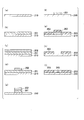
- FIG. 1A is a cross-sectional view schematically illustrating an example of a cell culture substrate having a region 1 and a region 2 on a flat substrate (hereinafter, referred to as a substrate 1).
- (B) is a top view schematically showing an example of a cell culture substrate.
- (C) is a cross-sectional view schematically showing a process in which cells are seeded on a cell culture substrate and the orientation of the cells is induced on the substrate.
- D is a top view schematically showing a process in which cells are seeded on a cell culture substrate and the orientation of the cells is induced on the substrate.
- A) is sectional drawing which shows a glass substrate typically.
- (B) is a cross-sectional view schematically showing a state in which the thin film 1 is deposited.
- C is a sectional view schematically showing a state where the thin film 2 is formed.
- D is a sectional view schematically showing a state after the thin film 2 has been etched.
- E is a sectional view schematically showing a state after the thin film 1 has been etched.
- F is a sectional view schematically showing a state in which the residual resist has been removed.
- (G) is a sectional view schematically showing a state where the thin film 3 is formed.
- H is a sectional view schematically showing a state after etching.
- I is a cross-sectional view schematically showing a state after coating with fibronectin.
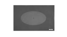
- FIG. 3 is a diagram in which a cell migration-possible region is visualized by increasing the fluorescence intensity of a portion where no MPC polymer is applied.
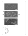
- A is a diagram showing a state in which cells have adhered and migrated only to region 1 where no MPC polymer has been applied.
- B is a diagram showing a state in which the cells are oriented at the boundary between the region 1 and the region 2 in the tangential direction of the boundary and the defect is generated by the proliferation of the seeded cells.
- C is a diagram in which the orientation angle of a cell is calculated by the structure tensor method, and the angle direction is represented by lightness.
- D is a diagram showing the correspondence between the orientation angle and the brightness.
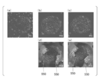
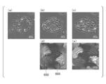
- (A) is a diagram showing a state immediately after seeding of NIH-3T3 cells in a region 1 in which the major axis is 800 ⁇ m and the minor axis is 690 ⁇ m.
- (B) is a diagram showing a state 50 hours after seeding the cells.
- (C) is a diagram showing a state 64 hours after seeding the cells.
- (D) is a diagram illustrating the orientation angle of the cell shown in (b) calculated by the structure tensor method, showing the angular direction by the brightness, and showing the position of the defect.
- (E) is a diagram illustrating the orientation angle of the cell shown in (c), calculated by the structure tensor method, expressing the angular direction by brightness, and indicating the position of the defect.
- (A) is a diagram showing a state immediately after seeding HFF cells in a region 1 in which the major axis is 600 ⁇ m and the minor axis is 400 ⁇ m.
- (B) is a diagram showing a state 50 hours after seeding the cells.
- (C) is a diagram showing a state 64 hours after seeding the cells.
- (D) is a diagram in which the orientation angle of the cell shown in (b) is calculated by the structure tensor method, the angle direction is represented by lightness, and the position of the defect is shown.
- (E) is a diagram in which the orientation angle of the cell shown in (c) is calculated by the structure tensor method, and the angle direction is represented by lightness.
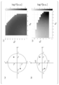
- (A) is a figure which shows the position of two defects in a perfect circle.
- (B) is a figure which shows the position of two defects in an ellipse.
- (C) is a diagram showing the value of logF at coordinates of a defect within a perfect circle.
- (D) is a diagram showing the value of logF at coordinates of a defect in the ellipse.
- the cell migratable region (hereinafter, referred to as “region 1”) is a region whose surface has been processed so that cells can adhere thereto.
- the cell non-migrating region (hereinafter, referred to as “region 2”) is a region into which cells cannot enter or cannot adhere, and as a result, cells cannot migrate and proliferate.
- the shape of a certain region having anisotropy means that the region has a different shape depending on the direction.
- that the shape of a certain region is isotropic means that the region has the same shape depending on the direction. For example, it can be said that the shape of an ellipse in a certain two-dimensional plane has anisotropy, and the shape of a perfect circle in a certain two-dimensional plane has isotropy.
- Defect or structural defect means that when cells are grown, a population of cells is oriented at a specific angle, and at some point, the cells cannot be oriented at this angle. At this point, the angle of the cell cannot be defined.
- the position where the structural defect is formed may be specified.
- the shape of the cell migration-possible region is an ellipse, and the size of the cell, the scale of the ellipse, and the ratio of the length of the major axis to the length of the minor axis of the ellipse (hereinafter, referred to as “aspect ratio”) If) is set appropriately, defects will be generated on the major axis of the ellipse.
- FIG. 1A is a cross-sectional view schematically illustrating an example of a cell culture substrate having a region 1 and a region 2 on a flat substrate (hereinafter, referred to as “substrate 1”).
- FIG. 1B is a top view schematically illustrating an example of the cell culture substrate.
- the substrate 1 As a material of the substrate 1, for example, a glass substrate can be used, but the type of the material and the thickness of the material are not limited thereto. However, since the adherent cells are often observed using an inverted phase-contrast microscope, the substrate 1 preferably has high transparency.
- the region 1 may take any form as long as cells can adhere thereto. However, when cells are likely to adhere to the region 1, a defect is generated at a predetermined position in a shorter time, so that the region 1 preferably has high cell adhesion.
- a cationic polymer such as polyethyleneimine or polylysine, or an extracellular matrix such as fibronectin or collagen may be applied to the region 1.
- the region 2 may take any form as long as no cells are present.
- the area 2 may be formed by patterning a cell repellent on the substrate, or by creating a sufficiently high barrier to the size of the cell and limiting the migration area of the cell. May be formed.
- the region 1 only needs to be surrounded by the region 2, and a plurality of the regions 1 may exist in the same substrate. However, when the interval between the regions 1 is small, the cells migrate over the region 2 and the plurality of regions 1 interact with each other, thereby affecting the cell orientation. Therefore, the interval between the regions 1 is preferably several hundreds ⁇ m or more.
- the shapes of the regions 1 and 2 are not particularly limited as long as they have anisotropy. However, as the size of the region 1 becomes larger, the time until a defect is generated at a predetermined position becomes longer. Therefore, it is preferable that the region 1 be within 1 mm square.
- FIG. 1 (c) is a cross-sectional view schematically showing a process in which cells are seeded on the above-described cell culture substrate and the orientation of the cells is induced on the substrate.
- FIG. 1D is a top view schematically showing a process in which cells are seeded on the cell culture substrate and the orientation of the cells is induced on the substrate.
- the area 1 may be, for example, elliptical.
- the ratio of the length of the major axis to the length of the minor axis of the ellipse (hereinafter referred to as “aspect ratio”) is preferably 1.5 to 4. Further, it is preferable that the length of the major axis of the ellipse be 500 ⁇ m to 1000 ⁇ m.
- the substrate 1, the region 1, and the region 2 are not limited to flat surfaces, and may have a three-dimensional curvature.
- Region 2 can also be formed by applying a cell repellent.
- the cell repellent include 2-methacryloyloxyethyl phosphorylcholine (MPC polymer).
- the method for manufacturing the region 1 and the region 2 is not particularly limited, and as described later in the examples, a photolithography method may be used, a soft lithography method such as microcontact printing may be used, 1 may be physically cut.
- a positive photoresist is mentioned as described later in Examples, but is not limited thereto.
- the shape of the region 1 is, for example, an ellipse and the aspect ratio of the ellipse and the length of the major axis are appropriate, a defect is generated in the major axis direction of the region 1. be able to.
- the shape of the above-mentioned region 1 is not particularly limited as long as it has anisotropy.
- the position of the finally formed cell defect can be estimated by numerical calculation as follows, based on the nematic liquid crystal theory.
- ⁇ (x, y) follows the following two-dimensional Poisson equation. However, ⁇ (x-x i, y-y i) becomes 0 in the area other than the (x i, y i), a delta function.
- the elastic free energy F of the liquid crystal in the region 1 is obtained by the following area.
- K is an elastic constant.
- the boundary of region 1 is a smooth boundary that can be differentiated and is a simply connected region, if the constraint that the sum of the rotation angles q i around the defect is 2 ⁇ is satisfied, Gauss-Bonnet's theorem states that the defect the number N and the rotation angle q i of may of any type. However, when the number of defects is large, the defects are expected to move and annihilate, eventually resulting in two defects having a rotation angle of ⁇ .
- the number of generated defects is expected to be larger than two, the number of defects is set to a value that minimizes the elastic free energy of the above equation (3) by performing simulation using the Markov chain Monte Carlo method. It is also possible to estimate the approximate generation position.
- the defect position of the cell can be estimated in advance by numerical calculation. Therefore, it is not necessary to actually create and evaluate a pattern by trial and error, and it is possible to efficiently design and evaluate a desired orientation structure by numerical calculation.
- the position of a cell defect can be estimated by numerical calculation, but the time until a defect is generated at a predetermined position depends on the size of the cell to be handled and the aspect ratio of the cell at the time of orientation.
- the above-described substrate for cell culture has a simple structure including a cell-migrating region and a cell-migrating region, it can be easily combined with a microfluidic device, a microelectrode array, or the like.
- the position of the defect can be predicted by numerical calculation, it is possible to arrange electrodes, various sensors, actuators, and the like in advance at the point where the defect is generated.
- a sensor in advance at a point where a defect is generated, it is possible to measure a specific life phenomenon occurring in the defect. Further, for example, by applying a stimulus to the defect from the outside, actuation such as moving or eliminating the defect becomes possible.
- FIG. 2A is a cross-sectional view schematically illustrating a glass substrate. Aluminum was thermally deposited on the surface of the substrate 1 to form a thin film 1.
- FIG. 2B is a cross-sectional view schematically illustrating a state in which the thin film 1 is deposited.
- FIG. 2C is a cross-sectional view schematically illustrating a state where the thin film 2 is formed. Thereafter, the resist and aluminum were etched.
- FIG. 2D is a cross-sectional view schematically showing a state after the thin film 2 has been etched.
- FIG. 2E is a cross-sectional view schematically showing a state after the thin film 1 has been etched. Then, the remaining resist was removed with acetone.
- FIG. 2F is a cross-sectional view schematically showing a state where the residual resist has been removed.
- FIG. 2G is a cross-sectional view schematically showing a state where the thin film 3 is formed. Then, the pattern of MPC polymer was formed by etching the aluminum again.
- FIG. 2H is a cross-sectional view schematically showing a state after the etching.
- FIG. 2 (i) is a cross-sectional view schematically showing a state after coating with fibronectin.
- FIG. 3 is a diagram in which a cell migration-possible region is visualized by increasing the fluorescence intensity of a portion where the MPC polymer is not applied.
- NIH-3T3 cells were seeded on the cell culture substrate described above, and the positions of defects formed in the elliptical region 1 were observed. The manner in which cells migrate, proliferate, and form defects is shown in FIG.
- FIG. 4 (a) is a diagram showing a state in which cells have adhered and migrated only to the region 1 where the MPC polymer has not been applied.
- FIG. 4B is a diagram showing a state in which the seeded cells proliferate and the cells are oriented in the tangential direction of the boundary at the boundary between the region 1 and the region 2 to generate a defect.
- the orientation angle of the cells was calculated as follows.
- the luminance of the image at the pixel position (x, y) is represented by I (x, y).
- the structure tensor J of the image was defined as follows.
- delta x I and delta y I is defined as follows.
- the orientation angle ⁇ (x, y) at the pixel position (x, y) can be calculated using the structure tensor J as follows. However, the orientation angle ⁇ was calculated after spatially smoothing the structure tensor J by a Gaussian function.
- FIG. 4 (c) is a diagram in which the orientation angle of the cell is calculated by the structure tensor method, and the angle direction is represented by the brightness.
- FIG. 4D is a diagram showing the correspondence between the orientation angle and the brightness.
- FIG. 5A is a diagram showing a state immediately after seeding of NIH-3T3 cells.
- FIG. 5B is a diagram showing a state 50 hours after seeding the cells.
- FIG. 5C is a diagram showing a state 64 hours after seeding the cells.
- FIG. 5D is a diagram illustrating the orientation angles of the cells shown in FIG. 5B calculated by the structure tensor method, indicating the angular direction by the brightness, and indicating the position of the defect.
- FIG. 5E is a diagram showing the orientation of the cells shown in FIG.
- FIG. 6A is a diagram showing a state immediately after seeding of HFF cells.
- FIG. 6B is a diagram showing a state 50 hours after seeding the cells.
- FIG. 6C is a diagram showing a state 64 hours after seeding the cells.
- FIG. 6D is a diagram showing the orientation angle of the cell shown in FIG. 6B calculated by the structure tensor method, showing the angular direction by the brightness, and showing the position of the defect.
- FIG. 6E is a diagram in which the orientation angle of the cell shown in FIG. 6C is calculated by the structure tensor method, and the angle direction is represented by lightness. It was found that when HFF cells were seeded in region 1 which was an ellipse with a relatively small area, the defect eventually disappeared.
- the shape of the region 1 in which no defect is generated can be screened in a short time by forming the region 1 of various scales into a two-dimensional array on the same substrate.
- FIG. 7A is a diagram showing the positions of these two defects.
- FIG. 7 (c) is a diagram showing the value of logF at a defective coordinate. It was found that the defect at which the elastic free energy (F) was minimal was spread isotropically. That is, when the shape of the region 1 is a perfect circle, it is considered that it is difficult to guide a defect to a specific position.
- FIG. 7B is a diagram showing the positions of these two defects.
- FIG. 7D is a diagram showing the value of logF at a defective coordinate. It was found that the defect where the elastic free energy (F) was minimized was on the major axis of the ellipse. Therefore, it was predicted that a defect could be induced in the major axis direction by increasing the aspect ratio of the ellipse. This result is consistent with Experimental Example 2.
- the present invention it is possible to provide a cell culture substrate having a cell migration-possible region and a cell non-migration-possible region, and a method for producing the same. Further, according to the present invention, it is possible to provide a method for predicting a defect generation position in which the orientation angle of a cell cannot be defined.
Landscapes
- Life Sciences & Earth Sciences (AREA)
- Engineering & Computer Science (AREA)
- Health & Medical Sciences (AREA)
- Wood Science & Technology (AREA)
- Biomedical Technology (AREA)
- Organic Chemistry (AREA)
- Bioinformatics & Cheminformatics (AREA)
- Chemical & Material Sciences (AREA)
- Zoology (AREA)
- Virology (AREA)
- Sustainable Development (AREA)
- Microbiology (AREA)
- Biotechnology (AREA)
- Biochemistry (AREA)
- General Engineering & Computer Science (AREA)
- General Health & Medical Sciences (AREA)
- Genetics & Genomics (AREA)
- Cell Biology (AREA)
- Apparatus Associated With Microorganisms And Enzymes (AREA)
- Micro-Organisms Or Cultivation Processes Thereof (AREA)
Abstract
細胞培養用基板の製造方法であって、前記細胞培養用基板の前記細胞遊走可能領域において、細胞を培養することと、前記構造欠陥を特定位置に生成させることと、を含み、前記特定位置が、上記の予測方法により予測される位置であり、前記細胞培養用基板が上記の細胞培養用基板である、細胞がパターニングされた細胞培養用基板の製造方法である。
Description
本発明は、細胞培養用基板、製造方法、及び予測方法に関する。
近年、再生医療や創薬分野において、培養細胞を用いた組織再構成に関する技術が広く研究されている。例えば、骨格筋芽細胞や心筋細胞を温度感受性培養皿上に培養し、製造された細胞シートを心臓に移植して、心臓病の治療を行う等の試みがなされている。このような培養細胞による2次元組織を製造するためには、2次元組織の構造の再現性や均質性を保証する必要がある。
骨格筋芽細胞のような紡錘形の細胞は、増殖して細胞密度が高くなると、細胞の運動は徐々に停止し、特定の角度に配向する。しかし、この角度に配向できない点(以下、「欠陥」又は「構造欠陥」と呼ぶ)が生成される。
このような欠陥は、細胞シートの構造の均質性を阻害する要因となり得る。培養皿のような閉領域で細胞を培養する場合、欠陥は不可避的に生成される。また、欠陥を完全に除くことはできない(例えば、非特許文献1を参照)。
Duclos G., et al., Topological defects in confined populations of spindle-shaped cells. Nature Physics, 13, 58-62, 2017.
Saw TB., et al., Topological defects in epithelia govern cell death and extrusion. Nature, 544, 212-216, 2017.
培養細胞による2次元組織の均質性を高めるためには、欠陥が生成される位置を制御することが有効であると考えられる。しかしながら、欠陥が生成される位置を制御することは不可能であった。
欠陥は自己組織的に形成されるため、欠陥の位置を推定することは、困難であると考えられる。また、欠陥が生成する点は、弾性自由エネルギーを最小にする点であると考えられているが(例えば、非特許文献1を参照)、この点を解析的に解くことはできず、数値解を示した例も存在しない。すなわち、任意の閉領域パターンに対し、系統的に欠陥の生成位置を推定することは不可能であった。
また、欠陥の生成位置が推定できないため、欠陥に対して電場等の外部刺激を与えるアクチュエータ、欠陥周囲の化学種を計測するセンサ等を、予め配置することは不可能であった。
さらに、培養細胞による2次元組織を形成するためには、数日~数週間の時間を要する。そのため、実験による試行錯誤のみにより、高い均質性の2次元組織を形成するように、基板形状を最適化することは困難である。
上記事情に鑑み、本発明は、細胞遊走可能領域及び細胞遊走不可能領域を有する細胞培養用基板、及びその製造方法を提供することを目的とする。また、本発明は、細胞の配向角度が定義できない、欠陥の生成位置の予測方法を提供することを目的とする。
本発明の一態様は、基板と、基板の一方の主面に形成された、細胞遊走可能領域及び細胞遊走不可能領域を有し、前記細胞遊走可能領域は前記細胞遊走不可能領域に囲まれており、前記細胞遊走可能領域は異方性の形状である、細胞培養用基板である。
また、本発明の一態様は、上記の細胞培養用基板であって、前記細胞遊走可能領域が楕円形である。
また、本発明の一態様は、上記の細胞培養用基板であって、前記細胞遊走不可能領域が細胞忌避剤でコートされている。
また、本発明の一態様は、上記の細胞培養用基板であって、構造欠陥が形成される位置が特定されており、前記構造欠陥は、細胞を増殖させた場合に、前記細胞の配向角度が定義できないことである。
また、本発明の一態様は、上記の細胞培養用基板の製造方法であって、基板表面に微細加工技術を用いて、細胞遊走可能領域及び細胞遊走不可能領域を形成することを含む。
また、本発明の一態様は、上記の製造方法であって、細胞遊走不可能領域を形成することが細胞忌避剤をパターニングすることにより行われる。
また、本発明の一態様は、基板の一方の主面をxy平面とし、前記xy平面上の、異方性の形状を有する細胞遊走可能領域Ωにおいて、下記式(1)で与えられる弾性エネルギーFが最小となる位置(xi,yi)を求めることと、前記位置が、構造欠陥が形成される位置であると予測することと、を含み、前記構造欠陥は、細胞を増殖させた場合に、前記細胞の配向角度が定義できないことである、前記構造欠陥の位置の予測方法である。

[(1)式中、φは下記式(2)の解として与えられた配向角度であり、

[(2)式中、δ(x-xi,y-yi)はデルタ関数であり、
Nは、前記細胞遊走可能領域内に存在する構造欠陥の個数であり、
qiは、下記式(3)により与えられる、欠陥iのまわりで一周したときの回転角度であり、

[(3)式中、kは0以外の整数である。]]]
Nは、前記細胞遊走可能領域内に存在する構造欠陥の個数であり、
qiは、下記式(3)により与えられる、欠陥iのまわりで一周したときの回転角度であり、
また、本発明の一態様は、上記の細胞培養用基板の製造方法であって、前記細胞培養用基板の前記細胞遊走可能領域において、細胞を培養することと、前記構造欠陥を特定位置に生成させることと、を含み、前記特定位置が、上記の予測方法により予測される位置であり、前記細胞培養用基板が上記の細胞培養用基板である、細胞がパターニングされた細胞培養用基板の製造方法である。
本発明によれば、細胞遊走可能領域及び細胞遊走不可能領域を有する細胞培養用基板、及びその製造方法を提供することができる。また、本発明によれば、細胞の配向角度が定義できない、欠陥の生成位置の予測方法を提供することができる。
[基板]
細胞遊走可能領域(以下、「領域1」という)とは、細胞が接着できるように、表面を加工した領域である。細胞遊走不可能領域(以下、「領域2」という)とは、細胞が入り込めないか、又は細胞が接着できず、結果として、細胞が遊走し、増殖することができない領域である。
細胞遊走可能領域(以下、「領域1」という)とは、細胞が接着できるように、表面を加工した領域である。細胞遊走不可能領域(以下、「領域2」という)とは、細胞が入り込めないか、又は細胞が接着できず、結果として、細胞が遊走し、増殖することができない領域である。
ある領域の形状が異方性を持つとは、その領域が、方向によって異なる形状を持つことをいう。逆に、ある領域の形状が等方性を持つとは、その領域が、方向によって同一の形状を持つことをいう。例えば、ある2次元平面における楕円の形状は異方性を持ち、ある2次元平面における真円の形状は等方性を持つ、ということができる。
欠陥又は構造欠陥とは、細胞を増殖させた場合に、細胞の集団が特定の角度に配向し、ある点において、細胞がこの角度に配向できないことをいう。このような点においては、細胞の角度を定義することができない。
本実施形態の細胞培養用基板は、構造欠陥が形成される位置が特定されていてもよい。
実施例において後述するように、細胞遊走可能領域の形状が楕円であり、細胞のサイズ、楕円のスケール、楕円の短軸の長さに対する長軸の長さの比(以下、「アスペクト比」という)を適切に設定した場合、欠陥は楕円の長軸上に生成する。
[製造方法]
図1(a)は、平坦な基板(以下、「基板1」という)の上に、領域1と領域2を有する、細胞培養用基板の一例を模式的に示す断面図である。図1(b)は、細胞培養用基板の一例を模式的に示す上面図である。
図1(a)は、平坦な基板(以下、「基板1」という)の上に、領域1と領域2を有する、細胞培養用基板の一例を模式的に示す断面図である。図1(b)は、細胞培養用基板の一例を模式的に示す上面図である。
基板1の材質としては、例えば、ガラス基板を用いることができるが、材質の種類、材質の厚さはこれに限定されない。ただし、倒立型の位相差顕微鏡を用いて、接着性細胞を観察することが多いため、基板1は高い透明性を有することが好ましい。
領域1は、細胞が接着することができる限り、どのような形態をとってもよい。ただし、領域1に細胞が接着しやすい場合、より短時間で所定の位置に欠陥が生成されるため、領域1は高い細胞接着性を有するほうが望ましい。
領域1に高い細胞接着性を付与するために、例えば、ポリエチレンイミン、ポリリジン等のカチオン性のポリマー、フィブロネクチン、コラーゲン等の細胞外マトリックスを、領域1に塗布してもよい。
領域2は、細胞が存在しない限り、どのような形態をとってもよい。例えば、細胞忌避剤を基板上にパターニングすることにより、領域2を形成してもよいし、細胞のサイズに対して十分に高い障壁を作成し、細胞の遊走領域を制限することにより、領域2を形成してもよい。
領域1は領域2に囲まれていればよく、領域1が同一基板内に複数個存在してもよい。
ただし、領域1の間隔が小さい場合、細胞が領域2を乗り越えて遊走し、複数の領域1が相互作用するため、細胞の配向に影響を与える。したがって、領域1の間隔は数100μm以上であることが好ましい。
ただし、領域1の間隔が小さい場合、細胞が領域2を乗り越えて遊走し、複数の領域1が相互作用するため、細胞の配向に影響を与える。したがって、領域1の間隔は数100μm以上であることが好ましい。
領域1および領域2の形状は、異方性を持っていれば、特に形状は限定されない。ただし、領域1のサイズが大きくなるほど、所定の位置に欠陥が生成されるまでの時間が長くなるため、領域1は1mm四方角以内に収まることが好ましい。
図1(c)は、上述の細胞培養用基板に細胞を播種し、その基板上で細胞の配向を誘導する過程を模式的に示した断面図である。図1(d)は、上述の細胞培養用基板に細胞を播種し、その基板上で細胞の配向を誘導する過程を模式的に示した上面図である。
上述の細胞培養用基板に細胞を播種すると、細胞は増殖するとともに、領域1と領域2の境界において、細胞は境界の接線方向に配向する。細胞が領域1内でコンフルエントになった後、局所的に細胞の配向がそろうことにより、細胞の配向方向が定まらない点(以下、「欠陥」又は「構造欠陥」という)が生じる。
効率よく欠陥の位置を誘導するため、領域1を、例えば、楕円形とすることもできる。
領域1を楕円形とした場合、楕円の短軸の長さに対する長軸の長さの比(以下、「アスペクト比」という)を、1.5から4とすることが好ましい。また、楕円の長軸の長さは、500μmから1000μmとすることが好ましい。
領域1を楕円形とした場合、楕円の短軸の長さに対する長軸の長さの比(以下、「アスペクト比」という)を、1.5から4とすることが好ましい。また、楕円の長軸の長さは、500μmから1000μmとすることが好ましい。
基板1、領域1、及び領域2は平面に限定されず、3次元的な曲率をもっていてもよい。
領域2は、細胞忌避剤を塗布することによっても形成することができる。細胞忌避剤としては、例えば、2-メタクリロイルオキシエチルホスホリルコリン(MPCポリマー)が挙げられる。
領域1と領域2を製造する方法は、特に限定されず、実施例において後述するように、フォトリソグラフィ法を用いてもよいし、マイクロコンタクトプリンティング等のソフトリソグラフィ法を用いてもよいし、基板1を物理的に切削してもよい。
フォトリソグラフィに用いられる、フォトレジストとしては、実施例で後述するように、例えば、ポジ型フォトレジストが挙げられるが、これに限定されない。
実施例において後述するように、領域1の形状が、例えば、楕円であり、その楕円のアスペクト比と長軸の長さが適切である場合に、領域1の長軸方向に、欠陥を生成させることができる。
[予測方法]
上述の領域1の形状は、異方性を持つ限り、特に限定されない。領域1の形状が異方性を持つ場合、ネマチック液晶理論に基づき、最終的に形成される細胞の欠陥の位置は、次のように、数値計算により推定することができる。
上述の領域1の形状は、異方性を持つ限り、特に限定されない。領域1の形状が異方性を持つ場合、ネマチック液晶理論に基づき、最終的に形成される細胞の欠陥の位置は、次のように、数値計算により推定することができる。
領域1内のある点(x,y)における細胞の配向角度をφ(x,y)とする。領域内に欠陥がN個あるとし、欠陥i(i=1,2,…N)のまわりで1周したときの回転角度をqiとする。0以外の整数kを用いて、qiは次のように表すことができる。

このとき、φ(x,y)は、次の2次元ポアソン方程式にしたがう。

ただし、δ(x-xi,y-yi)は、(xi,yi)以外の領域で0となる、デルタ関数である。
この方程式の解を用いて、領域1内の液晶がもつ弾性自由エネルギーFは、次の面積分によって求められる。

ただし、Kは弾性定数である。
欠陥の位置を変化させたとき、上記式(2)、上記式(3)に従って、弾性自由エネルギーが変化する。欠陥は、弾性自由エネルギーが極小となるように、生成されると推定される。Kは正の定数であるため、弾性自由エネルギーFを最小化する条件は、Kの値に依存しない。したがって、Kの正確な値を求める必要はなく、便宜的に1として計算してよい。
領域1の境界が微分可能な滑らかな境界であり、かつ単連結な領域である場合、欠陥のまわりの回転角度qiの和が2πとなる制約を満たせば、ガウス・ボンネの定理より、欠陥の個数Nと回転角度qiは、どのようなものでもよい。ただし、欠陥の個数が多いときは、欠陥が移動し対消滅することで、最終的には回転角度がπとなる欠陥が2個となることが期待される。
したがって、領域1内に回転角度がπとなる欠陥を2個配置し、弾性自由エネルギーを計算することを繰り返し、弾性自由エネルギーが極小となる点を探すことで、欠陥が生成される位置を推定することができる。
なお、生成される欠陥の個数が2個よりも多いと期待される場合は、マルコフ連鎖モンテカルロ法を用いてシミュレーションすることにより、上記式(3)の弾性自由エネルギーを極小とする、欠陥の個数とおおよその生成位置を、推定することも可能である。
ただし、モンテカルロ法によるシミュレーションは計算量が多いという欠点があるため、生成位置を精密に推定したい場合は、上記式(3)の弾性自由エネルギーを直接最小化するほうが望ましい。
上述のように、細胞の欠陥位置は数値計算により、予め推定することができる。したがって、試行錯誤的にパターンを実際に作成して評価する必要がなく、数値計算により、所望の配向構造を効率よく設計・評価することが可能となる。
細胞欠陥の位置は、数値計算により推定可能であるが、所定の位置に欠陥が生成されるまでの時間は、扱う細胞の大きさや配向時の細胞のアスペクト比に依存する。様々なスケールの細胞遊走可能領域パターンを、アレイ状に同一基板上にパターニングし、細胞を培養することによって、どのスケールが最適かを効率よく評価することが可能である。
上述の細胞培養用基板は、細胞遊走可能領域と細胞遊走不可能領域を含む単純な構造を持つため、マイクロ流体デバイスや微小電極アレイ等と組み合わせることが容易である。
また、欠陥の位置を数値計算により予測することができるため、欠陥が生成される点に、電極、各種センサ、アクチュエータ等を、予め配置することが可能である。
また、欠陥の位置を数値計算により予測することができるため、欠陥が生成される点に、電極、各種センサ、アクチュエータ等を、予め配置することが可能である。
したがって、例えば、欠陥が生成される点にセンサを予め配置することにより、欠陥において生じる特有の生命現象を、計測することが可能になると考えられる。また、例えば、欠陥に外部から刺激を与えることにより、欠陥を移動、消失させる等のアクチュエーションが可能になる。
欠陥の位置を誘導することにより、欠陥間では細胞の配向が一様となることが保証される。これにより、配向性を有する組織へ細胞を分化させる効率が上昇することが期待される。また、欠陥の位置を誘導することにより、合成された組織の均質性が保証されるため、創薬等において行われる、スクリーニングの高精度化、高効率化を実現すると考えられる。
以上、この発明の実施形態について図面を参照して詳述してきたが、具体的な構成はこの実施形態に限られるものではなく、この発明の要旨を逸脱しない範囲の設計等も含まれる。
以下、実施例により本発明を説明するが、本発明は以下の実施例に限定されるものではない。
[実験例1]
領域1および領域2を備えた細胞培養用基板を製造した。
領域1および領域2を備えた細胞培養用基板を製造した。
まず、基板1として厚さ100μmのガラス基板を用意した。図2(a)はガラス基板を模式的に示す断面図である。この基板1の表面にアルミニウムを熱蒸着させて、薄膜1を形成させた。図2(b)は、薄膜1が蒸着された状態を模式的に示す断面図である。
次に、フォトレジストを塗布し、紫外光を照射して物理マスク(薄膜2)を形成させた。図2(c)は、薄膜2が形成された状態を模式的に示す断面図である。その後、レジストおよびアルミニウムをエッチングした。図2(d)は、薄膜2をエッチングした後の状態を模式的に示す断面図である。図2(e)は、薄膜1をエッチングした後の状態を模式的に示す断面図である。そして、残留レジストをアセトンによって除去した。図2(f)は、残留レジストを除去した状態を模式的に示す断面図である。
その後、MPCポリマーを塗布し、ベークすることで薄膜3を形成させた。図2(g)は、薄膜3を形成させた状態を模式的に示す断面図である。その後、再びアルミニウムをエッチングすることにより、MPCポリマーのパターンを形成させた。図2(h)は、エッチングした後の状態を模式的に示す断面図である。
最後に、フィブロネクチンをコートすることにより、培養基板を完成させた。図2(i)は、フィブロネクチンをコートした後の状態を模式的に示す断面図である。
作成した透明な培養基板を可視化するために、蛍光色素を吸着させた。図3は、MPCポリマーが塗布されていない部分の蛍光強度を高くすることにより、細胞遊走可能領域を可視化した図である。
[実験例2]
NIH-3T3細胞を上述の細胞培養用基板に播種し、楕円形の領域1において形成される欠陥の位置を観察した。細胞が遊走し、増殖し、欠陥が形成される様子を、図4に示す。
NIH-3T3細胞を上述の細胞培養用基板に播種し、楕円形の領域1において形成される欠陥の位置を観察した。細胞が遊走し、増殖し、欠陥が形成される様子を、図4に示す。
図4(a)は、MPCポリマーが塗布されていない領域1にのみ細胞が接着し、遊走した状態を示す図である。図4(b)は、播種した細胞が増殖することにより、領域1と領域2の境界において細胞が境界の接線方向に配向し、欠陥が生成された状態を示す図である。
細胞の配向角度は次のように算出した。ピクセル位置(x,y)における画像の輝度をI(x,y)とあらわす。このとき、画像の構造テンソルJを次のように定義した。

ただし、ΔxIおよびΔyIは、次のように定義される。


ピクセル位置(x,y)における配向角度φ(x,y)は、構造テンソルJを用いて、次式のように算出できる。

ただし、構造テンソルJをガウス関数によって空間的に平滑化した後に、配向角度φを算出した。
図4(c)は、細胞の配向角度を構造テンソル法によって算出し、明度によって角度方向を表した図である。図4(d)は、配向角度と明度の対応関係を示した図である。
実験例3において詳述するが、数値例で推定した通り、楕円の形状を持つ領域1の長軸上に欠陥が生成されることが明らかになった。また、2つの欠陥の間では細胞の配向角度が揃う傾向にあることが確認された。
したがって、異方的な形状を持つ細胞遊走可能領域に、細胞を播種し培養することによって、特定の位置に細胞の欠陥の生成位置を誘導できることが明らかになった。
長軸が800μmであり、短軸が690μmである領域1に、NIH-3T3細胞を播種し、解析を行った結果を図5に示す。図5(a)は、NIH-3T3細胞を播種した直後の様子を示す図である。図5(b)は、細胞を播種してから50時間後の様子を示す図である。図5(c)は、細胞を播種してから64時間後の様子を示す図である。図5(d)は、図5(b)に示される細胞の配向角度を構造テンソル法によって算出し、明度によって角度方向を表し、欠陥の位置を示した図である。図5(e)は、図5(c)に示される細胞の配向角度を、構造テンソル法によって算出し、明度によって角度方向を表し、欠陥の位置を示した図である。NIH-3T3細胞を播種した場合も、播種後2日程度で、欠陥が楕円の長軸方向に2つ生成されることが確認された。
長軸が600μmであり、短軸が400μmである領域1に、Human foreskin fibroblast(HFF)細胞を播種し、解析を行った結果を図6に示す。図6(a)は、HFF細胞を播種した直後の様子を示す図である。図6(b)は、細胞を播種してから50時間後の様子を示す図である。図6(c)は、細胞を播種してから64時間後の様子を示す図である。図6(d)は、図6(b)に示される細胞の配向角度を構造テンソル法によって算出し、明度によって角度方向を表し、欠陥の位置を示した図である。図6(e)は、図6(c)に示される細胞の配向角度を、構造テンソル法によって算出し、明度によって角度方向を表した図である。HFF細胞を、比較的面積の小さい楕円である領域1に播種した場合、欠陥は最終的に消失することが明らかになった。
欠陥が消失した原因は、楕円の面積に対して、細胞のサイズ、および、楕円の短軸の長さに対する長軸の長さの比(アスペクト比)が大きく、回転数+πの配向パターンを実現できなかったためであると考えられる。この結果から、扱う細胞のサイズ、領域1の面積、アスペクト比によって、欠陥を生成しない領域1のスケールは異なると考えられる。
欠陥を生成しない領域1の形状は、様々なスケールの領域1を同一基板上に2次元アレイ化することによって、短時間でスクリーニングすることが可能であると考えられる。
[実験例3]
楕円の細胞遊走可能領域を設けた基板において、細胞配向の欠陥が生成する点を、数値計算によって推定した。
楕円の細胞遊走可能領域を設けた基板において、細胞配向の欠陥が生成する点を、数値計算によって推定した。
まず、領域1の形状が半径1の真円である場合について、推定を行った。この真円内に回転角度πの欠陥が2つあり、2つの点が対称な位置(+xp,+yp)と(-xp,-yp)に存在すると仮定した(ただし、0<xp,yp<1である)。図7(a)は、これら2つの欠陥の位置を示す図である。
真円上にこれら2つの欠陥がある場合について、上記(1)~(3)式を用いて、弾性自由エネルギー(F)を計算した。ただし、数値積分の発散を防止するため、欠陥から半径0.01以内の領域については面積分の領域から除外した。
図7(c)は、欠陥のある座標において、logFの値を示した図である。弾性自由エネルギー(F)が極小となる欠陥は、等方的に広がっていることが明らかになった。すなわち、領域1の形状が真円である場合には、特定の位置に欠陥を誘導することが難しいと考えられる。
次に、領域1の形状が、長軸の長さが1、短軸の長さが0.5である、楕円である場合について、推定を行った。この楕円内に回転角度πの欠陥が2つあり、2つの点が対称な位置(+xp,+yp)と(-xp,-yp)に存在すると仮定した(ただし、0<xp、yp<1である)。図7(b)は、これら2つの欠陥の位置を示す図である。
楕円上にこれら2つの欠陥がある場合について、上記(1)~(3)式を用いて、弾性自由エネルギー(F)を計算した。ただし、数値積分の発散を防止するため、欠陥から半径0.01以内の領域については面積分の領域から除外した。
図7(d)は、欠陥のある座標において、logFの値を示した図である。弾性自由エネルギー(F)が極小となる欠陥は、この楕円の長軸上にあることが明らかになった。したがって、楕円のアスペクト比を大きくすることで、長軸方向に欠陥を誘導することができると予測された。この結果は実験例2と整合的である。
以上の結果を小括すると、上述の数値計算による推定から、欠陥の生成位置を予測できることが明らかになった。
本発明によれば、細胞遊走可能領域及び細胞遊走不可能領域を有する細胞培養用基板、及びその製造方法を提供することができる。また、本発明によれば、細胞の配向角度が定義できない、欠陥の生成位置の予測方法を提供することができる。
100…細胞培養用基板、101…領域1、102…領域2、110…基板1、140…細胞、150…欠陥、201…薄膜1、202…薄膜2、203…薄膜3、210…基板1、240…フィブロネクチン、450…欠陥、550…欠陥、650…欠陥
Claims (8)
- 基板と、基板の一方の主面に形成された、細胞遊走可能領域及び細胞遊走不可能領域を有し、
前記細胞遊走可能領域は前記細胞遊走不可能領域に囲まれており、
前記細胞遊走可能領域は異方性の形状である、
細胞培養用基板。 - 前記細胞遊走可能領域が楕円形である、請求項1に記載の細胞培養用基板。
- 前記細胞遊走不可能領域が細胞忌避剤でコートされている、請求項1又は2に記載の細胞培養用基板。
- 構造欠陥の形成される位置が特定されており、
前記構造欠陥は、細胞を増殖させた場合に、前記細胞の配向角度が定義できないことである、
請求項1~3のいずれか一項に記載の細胞培養用基板。 - 基板表面に微細加工技術を用いて、細胞遊走可能領域及び細胞遊走不可能領域を形成することを含む、
請求項1~4のいずれか一項に記載の細胞培養用基板の製造方法。 - 前記細胞遊走不可能領域を形成することが細胞忌避剤をパターニングすることにより行われる、請求項5に記載の製造方法。
- 基板の一方の主面をxy平面とし、前記xy平面上の、異方性の形状を有する細胞遊走可能領域Ωにおいて、
下記式(1)で与えられる弾性エネルギーFが最小となる位置(xi,yi)を求めることと、
前記位置が、構造欠陥が形成される位置であると予測することと、を含み、
前記構造欠陥は、細胞を増殖させた場合に、前記細胞の配向角度が定義できないことである、
前記構造欠陥の位置の予測方法。


Nは、前記細胞遊走可能領域内に存在する構造欠陥の個数であり、
qiは、下記式(3)により与えられる、欠陥iのまわりで一周したときの回転角度であり、

- 前記細胞培養用基板の前記細胞遊走可能領域において、細胞を培養することと、
前記構造欠陥を特定位置に生成させることと、を含み、
前記特定位置が、請求項7に記載の予測方法により予測される位置であり、
前記細胞培養用基板が請求項1~4のいずれか一項に記載の細胞培養用基板である、
細胞がパターニングされた細胞培養用基板の製造方法。
Applications Claiming Priority (2)
| Application Number | Priority Date | Filing Date | Title |
|---|---|---|---|
| JP2018151894A JP2020025496A (ja) | 2018-08-10 | 2018-08-10 | 細胞培養用基板、製造方法、及び予測方法 |
| JP2018-151894 | 2018-08-10 |
Publications (1)
| Publication Number | Publication Date |
|---|---|
| WO2020032092A1 true WO2020032092A1 (ja) | 2020-02-13 |
Family
ID=69413813
Family Applications (1)
| Application Number | Title | Priority Date | Filing Date |
|---|---|---|---|
| PCT/JP2019/031073 Ceased WO2020032092A1 (ja) | 2018-08-10 | 2019-08-07 | 細胞培養用基板、製造方法、及び予測方法 |
Country Status (2)
| Country | Link |
|---|---|
| JP (1) | JP2020025496A (ja) |
| WO (1) | WO2020032092A1 (ja) |
Families Citing this family (1)
| Publication number | Priority date | Publication date | Assignee | Title |
|---|---|---|---|---|
| JPWO2022118977A1 (ja) * | 2020-12-01 | 2022-06-09 |
Citations (2)
| Publication number | Priority date | Publication date | Assignee | Title |
|---|---|---|---|---|
| JP2011101638A (ja) * | 2009-10-16 | 2011-05-26 | Dainippon Printing Co Ltd | 細胞遊走測定用基板および細胞遊走試験法 |
| WO2016208777A1 (ja) * | 2015-06-26 | 2016-12-29 | 国立研究開発法人国立循環器病研究センター | 細胞培養器 |
-
2018
- 2018-08-10 JP JP2018151894A patent/JP2020025496A/ja active Pending
-
2019
- 2019-08-07 WO PCT/JP2019/031073 patent/WO2020032092A1/ja not_active Ceased
Patent Citations (2)
| Publication number | Priority date | Publication date | Assignee | Title |
|---|---|---|---|---|
| JP2011101638A (ja) * | 2009-10-16 | 2011-05-26 | Dainippon Printing Co Ltd | 細胞遊走測定用基板および細胞遊走試験法 |
| WO2016208777A1 (ja) * | 2015-06-26 | 2016-12-29 | 国立研究開発法人国立循環器病研究センター | 細胞培養器 |
Non-Patent Citations (2)
| Title |
|---|
| KAWAGUCHI, K. ET AL.: "Topological defects control collective dynamics in neural progenitor cell cultures", NATURE, vol. 545, 2017, pages 327 - 331, XP055685723 * |
| MIYAZAKO, HIROKI ET AL.: "Systematic Direction of Topological Defects in Cell Population by Computer-aided-design of Geometrical Boundary", LECTURE ABSTRACTS OF STUDY GROUP OF SOCIETY FOR CHEMISTRY AND MICRO-NANO SYSTEMS, vol. 38, 30 October 2018 (2018-10-30) * |
Also Published As
| Publication number | Publication date |
|---|---|
| JP2020025496A (ja) | 2020-02-20 |
Similar Documents
| Publication | Publication Date | Title |
|---|---|---|
| Callens et al. | Emergent collective organization of bone cells in complex curvature fields | |
| Nawroth et al. | Automated fabrication of photopatterned gelatin hydrogels for organ-on-chips applications | |
| Liu et al. | Extracellular-controlled breast cancer cell formation and growth using non-UV patterned hydrogels via optically-induced electrokinetics | |
| Serra-Picamal et al. | Mapping forces and kinematics during collective cell migration | |
| JP2011523199A (ja) | 2d光子リソグラフィ及びナノインプリントを使用してサブミクロン3d構造を製造するための3d鋳型ならびにそのプロセス | |
| EP2014763A1 (en) | Cell culture container and method of producing the same | |
| Badie et al. | A method to replicate the microstructure of heart tissue in vitro using DTMRI-based cell micropatterning | |
| Yang et al. | Selective pattern of cancer cell accumulation and growth using UV modulating printing of hydrogels | |
| Tang et al. | Influence of engineered surface on cell directionality and motility | |
| McCracken et al. | Deterministic integration of biological and soft materials onto 3D microscale cellular frameworks | |
| Kim et al. | Enriching libraries of high-aspect-ratio micro-or nanostructures by rapid, low-cost, benchtop nanofabrication | |
| Vedaraman et al. | Anisometric microstructures to determine minimal critical physical cues required for neurite alignment | |
| Nelson et al. | Growth-induced buckling of an epithelial layer | |
| Ebata et al. | Avoiding tensional equilibrium in cells migrating on a matrix with cell-scale stiffness-heterogeneity | |
| Liu et al. | 3D-printed low-voltage-driven ciliary hydrogel microactuators | |
| JP2020025496A (ja) | 細胞培養用基板、製造方法、及び予測方法 | |
| Rathod et al. | Engineered ridge and micropillar array detectors to quantify the directional migration of fibroblasts | |
| Zhang et al. | Effects of biomimetic micropatterned surfaces on the adhesion and morphology of cervical cancer cells | |
| Zhang et al. | Nuclear deformation and cell division of single cell on elongated micropatterned substrates fabricated by DMD lithography | |
| Nara et al. | Precise patterning of biopolymers and cells by direct write technique | |
| Kandere-Grzybowska et al. | Short-term molecular polarization of cells on symmetric and asymmetric micropatterns | |
| Wei et al. | Uniform, stable supply of medium for in vitro cell culture using a robust chamber | |
| Deguchi et al. | Development of motorized plasma lithography for cell patterning | |
| Webster et al. | Simulating muscular thin films using thermal contraction capabilities in finite element analysis tools | |
| Tran et al. | Accessible dynamic micropatterns in monolayer cultures via modified desktop xurography |
Legal Events
| Date | Code | Title | Description |
|---|---|---|---|
| 121 | Ep: the epo has been informed by wipo that ep was designated in this application |
Ref document number: 19847043 Country of ref document: EP Kind code of ref document: A1 |
|
| NENP | Non-entry into the national phase |
Ref country code: DE |
|
| 122 | Ep: pct application non-entry in european phase |
Ref document number: 19847043 Country of ref document: EP Kind code of ref document: A1 |