WO2020031977A1 - Image display device, image display system, and mobile body - Google Patents
Image display device, image display system, and mobile body Download PDFInfo
- Publication number
- WO2020031977A1 WO2020031977A1 PCT/JP2019/030773 JP2019030773W WO2020031977A1 WO 2020031977 A1 WO2020031977 A1 WO 2020031977A1 JP 2019030773 W JP2019030773 W JP 2019030773W WO 2020031977 A1 WO2020031977 A1 WO 2020031977A1
- Authority
- WO
- WIPO (PCT)
- Prior art keywords
- image
- sub
- display
- frame
- eye
- Prior art date
Links
- 230000004888 barrier function Effects 0.000 claims abstract description 173
- 230000015572 biosynthetic process Effects 0.000 claims description 18
- 238000000034 method Methods 0.000 claims description 3
- 230000001360 synchronised effect Effects 0.000 claims description 2
- 238000002834 transmittance Methods 0.000 description 24
- 238000010586 diagram Methods 0.000 description 9
- 239000004973 liquid crystal related substance Substances 0.000 description 8
- 230000006870 function Effects 0.000 description 4
- 238000005401 electroluminescence Methods 0.000 description 3
- 206010047571 Visual impairment Diseases 0.000 description 2
- 238000010276 construction Methods 0.000 description 2
- 230000009467 reduction Effects 0.000 description 2
- 238000003786 synthesis reaction Methods 0.000 description 2
- 239000011230 binding agent Substances 0.000 description 1
- 230000008859 change Effects 0.000 description 1
- 230000007423 decrease Effects 0.000 description 1
- 230000006866 deterioration Effects 0.000 description 1
- 230000004048 modification Effects 0.000 description 1
- 238000012986 modification Methods 0.000 description 1
- 230000010363 phase shift Effects 0.000 description 1
- 230000008569 process Effects 0.000 description 1
- 239000004065 semiconductor Substances 0.000 description 1
Images


Classifications
-
- H—ELECTRICITY
- H04—ELECTRIC COMMUNICATION TECHNIQUE
- H04N—PICTORIAL COMMUNICATION, e.g. TELEVISION
- H04N13/00—Stereoscopic video systems; Multi-view video systems; Details thereof
- H04N13/30—Image reproducers
- H04N13/302—Image reproducers for viewing without the aid of special glasses, i.e. using autostereoscopic displays
- H04N13/31—Image reproducers for viewing without the aid of special glasses, i.e. using autostereoscopic displays using parallax barriers
- H04N13/315—Image reproducers for viewing without the aid of special glasses, i.e. using autostereoscopic displays using parallax barriers the parallax barriers being time-variant
-
- G—PHYSICS
- G02—OPTICS
- G02B—OPTICAL ELEMENTS, SYSTEMS OR APPARATUS
- G02B27/00—Optical systems or apparatus not provided for by any of the groups G02B1/00 - G02B26/00, G02B30/00
- G02B27/01—Head-up displays
- G02B27/0101—Head-up displays characterised by optical features
-
- B—PERFORMING OPERATIONS; TRANSPORTING
- B60—VEHICLES IN GENERAL
- B60K—ARRANGEMENT OR MOUNTING OF PROPULSION UNITS OR OF TRANSMISSIONS IN VEHICLES; ARRANGEMENT OR MOUNTING OF PLURAL DIVERSE PRIME-MOVERS IN VEHICLES; AUXILIARY DRIVES FOR VEHICLES; INSTRUMENTATION OR DASHBOARDS FOR VEHICLES; ARRANGEMENTS IN CONNECTION WITH COOLING, AIR INTAKE, GAS EXHAUST OR FUEL SUPPLY OF PROPULSION UNITS IN VEHICLES
- B60K35/00—Arrangement of adaptations of instruments
-
- G—PHYSICS
- G02—OPTICS
- G02B—OPTICAL ELEMENTS, SYSTEMS OR APPARATUS
- G02B30/00—Optical systems or apparatus for producing three-dimensional [3D] effects, e.g. stereoscopic images
- G02B30/20—Optical systems or apparatus for producing three-dimensional [3D] effects, e.g. stereoscopic images by providing first and second parallax images to an observer's left and right eyes
- G02B30/26—Optical systems or apparatus for producing three-dimensional [3D] effects, e.g. stereoscopic images by providing first and second parallax images to an observer's left and right eyes of the autostereoscopic type
- G02B30/30—Optical systems or apparatus for producing three-dimensional [3D] effects, e.g. stereoscopic images by providing first and second parallax images to an observer's left and right eyes of the autostereoscopic type involving parallax barriers
- G02B30/31—Optical systems or apparatus for producing three-dimensional [3D] effects, e.g. stereoscopic images by providing first and second parallax images to an observer's left and right eyes of the autostereoscopic type involving parallax barriers involving active parallax barriers
-
- H—ELECTRICITY
- H04—ELECTRIC COMMUNICATION TECHNIQUE
- H04N—PICTORIAL COMMUNICATION, e.g. TELEVISION
- H04N13/00—Stereoscopic video systems; Multi-view video systems; Details thereof
- H04N13/30—Image reproducers
- H04N13/302—Image reproducers for viewing without the aid of special glasses, i.e. using autostereoscopic displays
- H04N13/31—Image reproducers for viewing without the aid of special glasses, i.e. using autostereoscopic displays using parallax barriers
-
- H—ELECTRICITY
- H04—ELECTRIC COMMUNICATION TECHNIQUE
- H04N—PICTORIAL COMMUNICATION, e.g. TELEVISION
- H04N13/00—Stereoscopic video systems; Multi-view video systems; Details thereof
- H04N13/30—Image reproducers
- H04N13/361—Reproducing mixed stereoscopic images; Reproducing mixed monoscopic and stereoscopic images, e.g. a stereoscopic image overlay window on a monoscopic image background
-
- B60K35/23—
-
- G—PHYSICS
- G02—OPTICS
- G02B—OPTICAL ELEMENTS, SYSTEMS OR APPARATUS
- G02B27/00—Optical systems or apparatus not provided for by any of the groups G02B1/00 - G02B26/00, G02B30/00
- G02B27/01—Head-up displays
- G02B27/0101—Head-up displays characterised by optical features
- G02B2027/0132—Head-up displays characterised by optical features comprising binocular systems
- G02B2027/0136—Head-up displays characterised by optical features comprising binocular systems with a single image source for both eyes
Definitions
- the present disclosure relates to an image display device, an image display system, and a moving object.
- the image display device includes a display panel, a barrier panel, and a controller.
- the display panel is configured to display a plurality of frames.
- the barrier panel is positioned so as to overlap the display panel, and divides a traveling direction of at least a part of image light emitted from the display panel into a right eye and a left eye of a user. And can be formed.
- the controller is configured to control the display panel and the barrier panel.
- the display panel is configured to form a first display area and a second display area.
- the display panel is configured to be able to display a right-eye image visually recognized by a right eye of a user in a right-eye viewing area of the first display area.
- the display panel is configured to display a left-eye image visually recognized by a left eye of the user in a left-eye viewing area of the first display area.
- the display panel is configured to be able to display a planar image visually recognized by both eyes of a user in the second display area.
- the barrier panel is configured such that a first barrier region corresponding to the first display region and a second barrier region corresponding to the second display region can be formed.
- the barrier panel is configured to form the translucent portion and the dimming portion such that the right-eye viewing region and the left-eye viewing region are at different positions in the first display region.
- the barrier panel is configured to form the translucent portion and the dimming portion in the second barrier region according to the planar image displayed in the second display region.
- the controller When displaying two consecutive frames on the display panel, the controller displays a portion located in the first display area as one parallax image frame including a first sub-frame and a second sub-frame. It is configured as follows. When displaying two consecutive frames on the display panel, the controller is configured to display a portion located in the second display area as two planar image frames. The controller displays the display so that a user visually recognizes, as a single parallax image, a combined image displayed in each of the first subframe and the second subframe included in the one parallax image frame.
- the panel and the barrier panel are configured to be controllable.
- the controller is configured to be able to control display of a parallax image in the first display area and formation of the translucent section and the dimming section in the first barrier area for each parallax image frame.
- the controller is configured to be able to control the display of the planar image in the second display region and the formation of the light transmitting portion and the light reducing portion in the second barrier region for each planar image frame.
- the frame rate of a sub-frame included in the parallax image frame and the frame rate of the planar image frame are configured to be the same.
- the image display system includes an image display device and a reflection member.
- the image display device includes a display panel, a barrier panel, and a controller.
- the display panel is configured to display a plurality of frames.
- the barrier panel is positioned so as to overlap the display panel, and divides a traveling direction of at least a part of image light emitted from the display panel into a right eye and a left eye of a user. And can be formed.
- the controller is configured to control the display panel and the barrier panel.
- the display panel is configured to form a first display area and a second display area.
- the display panel is configured to be able to display a right-eye image visually recognized by a right eye of a user in a right-eye viewing area of the first display area.
- the display panel is configured to display a left-eye image visually recognized by a left eye of the user in a left-eye viewing area of the first display area.
- the display panel is configured to be able to display a planar image visually recognized by both eyes of a user in the second display area.
- the barrier panel is configured such that a first barrier region corresponding to the first display region and a second barrier region corresponding to the second display region can be formed.
- the barrier panel is configured to form the translucent portion and the dimming portion such that the right-eye viewing region and the left-eye viewing region are at different positions in the first display region.
- the barrier panel is configured to form the translucent portion and the dimming portion in the barrier region according to the planar image displayed in the second display region.
- the controller When displaying two consecutive frames on the display panel, the controller displays a portion located in the first display area as one parallax image frame including a first sub-frame and a second sub-frame. It is configured as follows. When displaying two consecutive frames on the display panel, the controller is configured to display a portion located in the second display area as two planar image frames. The controller displays the display so that a user visually recognizes, as a single parallax image, a combined image displayed in each of the first subframe and the second subframe included in the one parallax image frame.
- the panel and the barrier panel are configured to be controllable.
- the controller is configured to be able to control display of a parallax image in the first display area and formation of the translucent section and the dimming section in the first barrier area for each parallax image frame.
- the controller is configured to be able to control the display of the planar image in the second display region and the formation of the light transmitting portion and the light reducing portion in the second barrier region for each planar image frame.
- the frame rate of a sub-frame included in the parallax image frame and the frame rate of the planar image frame are configured to be the same.
- the reflection member is configured to reflect the image light and reach the left eye and the right eye of the user.
- a moving object is equipped with an image display system.
- the image display system includes an image display device and a reflection member.
- the image display device includes a display panel, a barrier panel, and a controller.
- the display panel is configured to display a plurality of frames.
- the barrier panel is positioned so as to overlap the display panel, and divides a traveling direction of at least a part of image light emitted from the display panel into a right eye and a left eye of a user. And can be formed.
- the controller is configured to control the display panel and the barrier panel.
- the display panel is configured to form a first display area and a second display area.
- the display panel is configured to be able to display a right-eye image visually recognized by a right eye of a user in a right-eye viewing area of the first display area.
- the display panel is configured to display a left-eye image visually recognized by a left eye of the user in a left-eye viewing area of the first display area.
- the display panel is configured to be able to display a planar image visually recognized by both eyes of a user in the second display area.
- the barrier panel is configured such that a first barrier region corresponding to the first display region and a second barrier region corresponding to the second display region can be formed.
- the barrier panel is configured to form the translucent portion and the dimming portion such that the right-eye viewing region and the left-eye viewing region are at different positions in the first display region.
- the barrier panel is configured to form the translucent portion and the dimming portion in the barrier region according to the planar image displayed in the second display region.
- the controller displays a portion located in the first display area as one parallax image frame including a first sub-frame and a second sub-frame. It is configured as follows.
- the controller is configured to display a portion located in the second display area as two planar image frames. The display is performed such that a user visually recognizes a single parallax image by combining images displayed in the first subframe and the second subframe included in the one parallax image frame.
- the panel and the barrier panel are configured to be controllable.
- the controller is configured to be able to control display of a parallax image in the first display area and formation of the translucent portion and the dimming portion in the first barrier region for each parallax image frame.
- the controller is configured to be able to control the display of the planar image in the second display area and the formation of the translucent portion and the dimming portion in the second barrier region for each planar image frame.
- the frame rate of the sub-frame included in the parallax image frame and the frame rate of the planar image frame are configured to be the same.
- the reflection member is configured to reflect the image light and reach the left and right eyes of the user.
- FIG. 1 is a side view illustrating a configuration example of an image display device according to an embodiment.
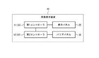
- FIG. 2 is a block diagram illustrating a configuration example of the image display device according to the embodiment.
- FIG. 3 is a plan view illustrating a configuration example of the display panel.
- FIG. 4 is a plan view illustrating a configuration example of the barrier panel.
- FIG. 5 is a diagram illustrating an example of how the image display device looks from a user.
- FIG. 6 is a diagram illustrating an example of a sub-left-eye image included in the left-eye image.
- FIG. 7 is a diagram illustrating an example of the sub-right image included in the right-eye image.
- FIG. 8 is a diagram illustrating a display example of the display panel in the first sub-frame.
- FIG. 9 is a diagram illustrating a display example of the display panel in the second sub-frame.
- FIG. 10 is a diagram illustrating a configuration example of an image display system according to an embodiment.
- the image display device 10 includes a display panel 20, a barrier panel 30, and a controller 50.
- the display panel 20 is configured to be able to display an image to be visually recognized by a user.
- the barrier panel 30 allows a part of the image light emitted from the display panel 20 to reach one of the left eye 5L and the right eye 5R of the user, and the other part of the image light to the other of the user. It is configured to reach the eye. That is, the barrier panel 30 is configured to divide at least a part of the traveling direction of the image light into the left eye 5L and the right eye 5R of the user.
- the barrier panel 30 may be located closer to the user than the display panel 20 or may be located farther from the user.
- the image light traveling in the direction limited by the barrier panel 30 can reach the left eye 5L and the right eye 5R of the user as different image lights.
- the image display device 10 can be configured to project a parallax image to both eyes of the user.
- the parallax image is an image including separate images projected to the left eye 5L and the right eye 5R of the user, and is an image that provides parallax to both eyes of the user.
- the user can stereoscopically view the image by viewing the parallax image with the left eye 5L and the right eye 5R.
- the direction in which parallax is given to both eyes of a user is also referred to as a parallax direction.
- the parallax direction corresponds to a direction in which the left eye 5L and the right eye 5R of the user are arranged.
- the controller 50 is connected to each component of the image display device 10 and configured to control each component.
- the controller 50 may include a first controller 51 and a second controller 52.
- the first controller 51 may be configured to control the display panel 20.
- the second controller 52 may be configured to control the barrier panel 30.
- the first controller 51 and the second controller 52 may be configured to be able to synchronize.
- the first controller 51 and the second controller 52 may be configured to be controllable as a master-slave relationship.
- One of the first controller 51 and the second controller 52 may be configured to be controllable as a master, and the other may be configured to be controllable as a slave.
- the controller 50 may be located above the first controller 51 and the second controller 52, and may further include a higher-level controller that controls the first controller 51 and the second controller 52.
- the controller 50 may be configured as, for example, a processor. Controller 50 may include one or more processors.
- the processor may include a general-purpose processor that reads a specific program and executes a specific function, and a dedicated processor specialized for a specific process.
- the dedicated processor may include an application specific integrated circuit (ASIC: Application Specific Integrated Circuit).
- the processor may include a programmable logic device (PLD: Programmable Logic Device).
- the PLD may include an FPGA (Field-Programmable ⁇ Gate ⁇ Array).
- the controller 50 may be any one of an SoC (System-on-a-Chip) in which one or a plurality of processors cooperate, and a SiP (System ⁇ In ⁇ a ⁇ Package).
- the controller 50 may include a storage unit, and may be configured to store various information, a program for operating each component of the image display device 10, and the like in the storage unit.
- the storage unit may be composed of, for example, a semiconductor memory or the like.
- the storage unit may be configured to function as a work memory of the controller 50.
- the display panel 20 includes a plurality of left-eye images 23L (see FIG. 6) to be visually recognized by the left eye 5L of the user, and a plurality of right-eye images 23R (see FIG. 7) to be visually recognized by the right eye 5R of the user.
- a flat image 24 (see FIG. 8) to be visually recognized by both eyes of the user can be displayed.
- the display panel 20 may be, for example, a liquid crystal device such as an LCD (Liquid Crystal Display).
- the display panel 20 may be a self-luminous device such as an organic EL (Electro-Luminescence) or an inorganic EL. When the display panel 20 is a self-luminous device, the barrier panel 30 is located closer to the user than the display panel 20.
- the display panel 20 is configured so that a first display area 21 and a second display area 22 can be formed.
- the first display area 21 includes a plurality of left-eye viewing areas 21L viewed by the user's left eye 5L, and a plurality of right-eye viewing areas 21R viewed by the user's right eye 5R.
- the display panel 20 is configured to be able to display a left-eye image 23L in each left-eye viewing area 21L, and to be able to display a right-eye image 23R in each right-eye viewing area 21R. That is, the display panel 20 is configured to be able to display parallax images in the plurality of left-eye viewing areas 21L and the plurality of right-eye viewing areas 21R.
- the plurality of left-eye viewing areas 21L and the plurality of right-eye viewing areas 21R are arranged in the X-axis direction.
- the parallax direction is associated with the X-axis direction.
- the X-axis direction is also referred to as a horizontal direction or a first direction.
- the Y-axis direction is also referred to as a vertical direction or a second direction.
- the left-eye viewing area 21L and the right-eye viewing area 21R may be located at an interval as illustrated in FIG. 3 or may be adjacent to each other.
- the display panel 20 is configured to display a planar image 24 in the second display area 22.
- the plurality of left-eye viewing areas 21L and the plurality of right-eye viewing areas 21R may extend along the Y-axis direction, as shown in FIG. 3, or may be inclined at a predetermined angle with respect to the Y-axis direction. May be extended. In other words, the plurality of left-eye viewing areas 21L and the plurality of right-eye viewing areas 21R may extend along a direction intersecting the parallax direction. The plurality of left-eye viewing areas 21L and the plurality of right-eye viewing areas 21R may be alternately arranged along a predetermined direction including a component in the parallax direction.
- the pitch at which the left-eye viewing area 21L and the right-eye viewing area 21R are alternately arranged is also referred to as a parallax image pitch.
- the barrier panel 30 is configured to cause the image light related to the plurality of left-eye images 23L to reach the left eye 5L of the user, and to apply the image light related to the plurality of right-eye images 23R to the right eye 5R of the user. It is configured to reach.
- the barrier panel 30 is configured to function as an active barrier.
- the barrier panel 30 is configured so that a first barrier region 31 and a second barrier region 32 can be formed.
- the barrier panel 30 is configured to be able to control the transmittance of image light emitted from the display panel 20.
- the first barrier region 31 corresponds to the first display region 21 and is configured to be able to control the transmittance of image light emitted from the first display region 21.
- the first barrier region 31 is configured to be capable of forming a plurality of light transmitting portions 31T and a plurality of light reducing portions 31S.
- the plurality of translucent portions 31T are configured to transmit light incident on the barrier panel 30 from the display panel 20.
- the plurality of light transmitting portions 31T may be configured to transmit light at a transmittance equal to or higher than the first transmittance.
- the first transmittance may be, for example, 100% or a value close to 100%.
- the plurality of dimming units 31S are configured to reduce light incident on the barrier panel 30 from the display panel 20.
- the plurality of dimming units 31S may be configured to transmit light at a transmittance equal to or less than the second transmittance.
- the second transmittance may be, for example, 0% or a value close to 0%.
- the first transmittance is higher than the second transmittance.
- the first transmittance may be a value smaller than 50%, for example, 10%, as long as sufficient contrast with light transmitted through the plurality of light reduction portions 31S can be ensured.
- the second transmittance may be a value larger than near 0%, for example, 10% as long as sufficient contrast with light transmitted through the plurality of light transmitting portions 31T can be ensured.
- the barrier panel 30 is configured to control the transmittance of light incident on the display panel 20.
- the plurality of light transmitting portions 31T are configured to transmit light incident on the display panel 20.
- the plurality of dimming units 31S are configured to reduce light incident on the display panel 20.
- the first barrier region 31 is configured to be able to control the transmittance of light incident on the first display region 21.
- the intensity of image light emitted from the display panel 20 is controlled based on the intensity of incident light.
- the traveling direction of the image light emitted from the display panel 20 is controlled based on the traveling direction of the incident light.
- the barrier panel 30 is configured to cause the image light related to the plurality of left-eye images 23L to reach the left eye 5L of the user, and to apply the image light related to the plurality of right-eye images 23R to the right eye 5R of the user. It is configured to form a plurality of translucent portions 31T so as to reach.
- the barrier panel 30 prevents or hardly causes the image light related to the plurality of left-eye images 23L to reach the right eye 5R of the user, and the image light related to the plurality of right-eye images 23R to the left eye 5L of the user.
- a plurality of dimming portions 31S are formed so as not to reach or hard to reach.
- the barrier panel 30 may be configured so that the user visually recognizes the plurality of right-eye images 23R with the right eye 5R, but does not or hardly recognizes the plurality of right-eye images 23R with the left eye 5L.
- the barrier panel 30 may be configured so that the user visually recognizes the plurality of left-eye images 23L with the left eye 5L, but does not or hardly recognizes the plurality of left-eye images 23L with the right eye 5R.
- the barrier panel 30 forms a plurality of translucent portions 31T and a plurality of dimming portions 31S so as to define the direction of image light relating to a parallax image including the plurality of left-eye images 23L and the plurality of right-eye images 23R. It is composed of
- the barrier panel 30 is configured to form the plurality of light transmitting portions 31T and the plurality of light reducing portions 31S such that the plurality of light transmitting portions 31T and the plurality of light reducing portions 31S are alternately arranged in the X-axis direction. You.
- the boundaries between the plurality of light transmitting portions 31T and the plurality of light reducing portions 31S extend along the Y-axis direction or in a direction inclined at a predetermined angle with respect to the Y-axis direction as illustrated in FIG.
- a plurality of light transmitting portions 31T and a plurality of light reducing portions 31S may be formed so as to extend along.
- the barrier panel 30 forms the plurality of translucent portions 31T and the plurality of dimming portions 31S so that the boundaries between the plurality of translucent portions 31T and the plurality of dimming portions 31S are along the direction intersecting the parallax direction. May be configured.
- the barrier panel 30 includes the plurality of translucent portions 31T and the plurality of dimming portions such that the plurality of translucent portions 31T and the plurality of dimming portions 31S are alternately arranged along a predetermined direction including a component in the parallax direction. It may be configured to form a portion 31S.
- the shapes of the plurality of light transmitting portions 31T and the plurality of light reducing portions 31S may be determined based on the shapes of the plurality of left-eye viewing regions 21L and the plurality of right-eye viewing regions 21R. Conversely, the shapes of the plurality of left-eye viewing regions 21L and the plurality of right-eye viewing regions 21R may be determined based on the shapes of the plurality of light transmitting portions 31T and the plurality of light reducing portions 31S.
- the second barrier region 32 corresponds to the second display region 22, and is configured to be able to control the transmittance of image light emitted from the second display region 22.
- the barrier panel 30 may be constituted by a liquid crystal shutter.
- the liquid crystal shutter can be configured to be able to control the light transmittance based on the applied voltage.
- the liquid crystal shutter may include a plurality of pixels, and may be configured to be able to control the light transmittance of each pixel.
- the liquid crystal shutter may be configured such that a region having a high light transmittance or a region having a low light transmittance can be formed in an arbitrary shape.
- the plurality of light transmitting portions 31T may have a transmittance equal to or higher than the first transmittance.
- the plurality of light reduction units 31S may have a transmittance equal to or less than the second transmittance.
- the display panel 20 and the barrier panel 30 each have a plurality of pixels.
- the arrangement pitch of the plurality of pixels of the display panel 20 and the arrangement pitch of the plurality of pixels of the barrier panel 30 may be the same or different. In the present embodiment, it is assumed that the arrangement pitch of the plurality of pixels of the display panel 20 is the same as the arrangement pitch of the plurality of pixels of the barrier panel 30. In this case, each pixel of the display panel 20 is associated with each pixel of the barrier panel 30.
- Each pixel of the barrier panel 30 may be configured to be controllable by any one of the plurality of translucent portions 31T and the plurality of dimming portions 31S.
- the controller 50 may be configured to be able to synchronize control of each pixel of the display panel 20 and control of each pixel of the barrier panel 30 associated therewith. Since the control of each pixel of the display panel 20 and the barrier panel 30 associated with each other is configured to be synchronized, image quality can be improved.
- At least some of the plurality of pixels included in the second display area 22 may be configured to be able to display black.
- a region formed by pixels displaying black is also referred to as a black display region.
- the controller 50 may be configured to form the plurality of dimming portions 31S in a region of the barrier panel 30 corresponding to the black display region included in the second display region 22. By doing so, the transmittance of image light in the black display area is further reduced. As a result, the black display area looks blacker when viewed from the user.
- the barrier panel 30 is located between the left and right eyes 5L and 5R of the user and the display panel 20.
- the barrier panel 30 may be located on the side farther from the display panel 20 as viewed from the user.
- the barrier panel 30 is located along the display panel 20. It can be said that the barrier panel 30 is positioned so as to overlap the display panel 20.
- the distance between the left eye 5L and the right eye 5R of the user and the barrier panel 30 is also called an observation distance, and is represented as P.
- the pitch at which the light transmitting portions 31T and the light reducing portions 31S are alternately arranged in the X-axis direction is also referred to as a barrier pitch.
- the distance between the left eye 5L and the right eye 5R is also referred to as the interocular distance and is represented as E.
- the distance between the barrier panel 30 and the display panel 20 is also called a gap, and is expressed as g.
- the display panel 20 cannot be visually recognized from the left eye 5L of the user by the plurality of left-eye viewing areas 21L that can be visually recognized from the left eye 5L of the user via the plurality of light-transmitting portions 31T and the plurality of light-reducing portions 31S. It is configured to form a plurality of left-eye non-viewing areas 22L that are left or hard to see.
- the display panel 20 includes a plurality of left-eye viewing areas 21L and a plurality of left-eye non-viewing areas 22L such that the plurality of left-eye viewing areas 21L and the plurality of left-eye non-viewing areas 22L are alternately arranged in the X-axis direction. It is configured to form.
- the position of the boundary between the left-eye viewing area 21L and the left-eye non-viewing area 22L is determined by the position of the boundary between the translucent section 31T and the dimming section 31S and the distance from the barrier panel 30 to both eyes of the user ( P) and the gap (g).
- the display panel 20 cannot be visually recognized from the right eye 5R of the user by the plurality of right-eye viewing regions 21R visible from the right eye 5R of the user via the plurality of light transmitting portions 31T and the plurality of dimming portions 31S. It is configured to form a plurality of right-eye non-viewing regions 22R that are invisible or difficult to view.
- the display panel 20 includes a plurality of right-eye viewing regions 21R and a plurality of right-eye viewing regions 22R such that the plurality of right-eye viewing regions 21R and the plurality of right-eye non-viewing regions 22R are alternately arranged in the X-axis direction. It is configured to form.
- the position of the boundary between the right-eye viewing region 21R and the right-eye non-viewing region 22R is determined by the position of the boundary between the light-transmitting portion 31T and the light-reducing portion 31S and the distance from the barrier panel 30 to both eyes of the user ( P) and the gap (g).
- the display panel 20 may be configured to display a parallax image such that each left-eye image 23L matches each left-eye viewing area 21L.
- the display panel 20 may be configured to display a parallax image so that each right-eye image 23R matches each right-eye viewing area 21R. That is, the display panel 20 is based on the position of the boundary between the light transmitting part 31T and the light reducing part 31S, the distance (P) from the barrier panel 30 to both eyes of the user, and the gap (g). , A parallax image may be displayed.
- the left eye 5L can view only the plurality of left-eye images 23L and the right eye.
- 5R can visually recognize only the plurality of right-eye images 23R.
- the barrier panel 30 includes a plurality of light transmitting portions 31T and a plurality of light transmitting portions 31T in the first barrier region 31 such that the plurality of left-eye viewing regions 21L and the plurality of right-eye viewing regions 21R are located at different positions in the first display region 21. It is configured to form a plurality of dimming portions 31S. In this case, crosstalk can be reduced.
- the state where the left eye 5L and the right eye 5R can see only the plurality of left-eye images 23L and the plurality of right-eye images 23R, respectively, is realized when the observation distance (P) is an optimal viewing distance (OVD: Optimal Viewing Distance). Can be done.
- the suitable viewing distance is determined based on the interocular distance (E), the gap (g), the barrier pitch, and the parallax image pitch.
- the controller 50 may be configured to be able to control the display panel 20 and the barrier panel 30 so that the observation distance (P) is OVD.
- the controller 50 controls the shapes and positions of the plurality of translucent portions 31T and the plurality of dimming portions 31S in the barrier panel 30 and the plurality of right-eye images to be displayed on the display panel 20 so that the observation distance (P) becomes OVD.
- the configuration and the positions of the 23R and the plurality of left-eye images 23L may be controllable.
- the image display device 10 may further include a configuration such as a camera that acquires the position of the user's eye.
- the controller 50 may be configured to be able to control the display panel 20 and the barrier panel 30 based on the position of the user's eyes. Since the controller 50 is configured to control the first display region 21 and the first barrier region 31 based on the position of the user's eyes, crosstalk can be further reduced. Since the controller 50 is configured to be able to control the second display region 22 and the second barrier region 32 based on the position of the user's eyes, the black display region looks blacker when viewed from the user.
- the display panel 20 is configured to be capable of sequentially updating an image to be displayed.
- the display panel 20 updates a display image
- the display panel 20 can display a moving image by being configured to sequentially display a plurality of frames.
- the entire display area of the display panel 20 is regarded as one frame.
- the display panel 20 is configured to be able to sequentially display a plurality of frames by sequentially updating an image displayed on the entire display surface.
- the number of frames displayed by the display panel 20 per unit time is also called a frame rate.
- the frame rate may be expressed as the number of frames displayed by the display panel 20 per second.
- the display panel 20 combines the parallax image including the plurality of right-eye images 23R and the plurality of left-eye images 23L displayed in the first display area 21 with the planar image 24 displayed in the second display area 22 to obtain 1 It is configured to be displayed as a single frame.
- the parallax image includes at least a part of the plurality of left-eye images 23L illustrated in FIG. 6 and at least a part of the plurality of right-eye images 23R illustrated in FIG.
- the plurality of left-eye images 23L illustrated in FIG. 6 include a plurality of first sub-left images 231L and a plurality of second sub-left images 232L.
- the plurality of first sub-left images 231L and the plurality of second sub-left images 232L do not overlap with each other.
- the plurality of first sub-left images 231L and the plurality of second sub-left images 232L extend in the Y-axis direction and are alternately arranged in the X-axis direction in each left-eye image 23L.
- the number of pixels in the X-axis direction of each of the first sub-left image 231L and the second sub-left image 232L is 1 / or less of the number of pixels in the X-axis direction of the left-eye image 23L.
- the full-pixel left-eye image 23L is divided into a first sub-left-eye image 231L and a second sub-left-eye image 232L having a number of pixels equal to or less than half of the full pixels.
- the number of pixels of the first sub left eye image 231L may be different from the number of pixels of the second sub left eye image 232L.
- the plurality of right-eye images 23R illustrated in FIG. 7 include a plurality of first sub-right images 231R and a plurality of second sub-right images 232R.
- the plurality of first sub-right images 231R and the plurality of second sub-right images 232R do not overlap with each other.
- the plurality of first sub-right images 231R and the plurality of second sub-right images 232R extend in the Y-axis direction and are alternately arranged in the X-axis direction in each right-eye image 23R.
- the number of pixels in the X-axis direction of each of the first sub-right image 231R and the second sub-right image 232R is 1 / or less of the number of pixels in the X-axis direction of the right-eye image 23R.
- the right-eye image 23R of a full pixel is divided into a first sub-right image 231R and a second sub-right image 232R having the number of pixels equal to or less than half of the full pixel.
- the number of pixels of the first sub-right image 231R may be different from the number of pixels of the second sub-right image 232R.
- the plurality of first sub-left images 231L and the plurality of first sub-right images 231R do not overlap with each other.
- the display panel 20 is configured to be able to simultaneously display the plurality of first sub-left images 231L and the plurality of first sub-right images 231R.
- the plurality of second sub-left images 232L and the plurality of second sub-right images 232R do not overlap with each other.
- the display panel 20 is configured to be able to simultaneously display the plurality of second sub-left images 232L and the plurality of second sub-right images 232R.
- the controller 50 displays the plurality of first sub-left images 231L and the plurality of first sub-right images 231R on the display panel 20 as one parallax image in the first display area 21. It is configured to display a frame including the same.
- the display region of the plurality of first sub-left images 231L includes the plurality of left-eye viewing regions 21L
- the display region of the plurality of first sub-right images 231R is the right region.
- the first barrier region 31 of the barrier panel 30 is configured to be controllable so as to include the eye viewing region 21R.
- the controller 50 controls the barrier so that the display areas of the plurality of first sub-left images 231L and the plurality of first sub-right images 231R match the left-eye viewing areas 21L and the right-eye viewing areas 21R.
- the panel 30 may be configured to be controllable.
- the controller 50 controls the barrier panel such that the plurality of left-eye viewing regions 21L and the plurality of right-eye viewing regions 21R include the display regions of the plurality of first sub-left image 231L and the plurality of first sub-right images 231R, respectively. 30 may be configured to be controllable.
- the controller 50 displays the plurality of second sub-left images 232L and the plurality of second sub-right images 232R on the display panel 20 as one parallax image in the first display area 21. It is configured to display a frame including the same.
- the display area of the plurality of second sub-left-eye images 232L includes the plurality of left-eye viewing areas 21L
- the display area of the plurality of second sub-right-eye images 232R is displayed on the display panel 20.
- the first barrier region 31 of the barrier panel 30 is configured to be controllable so as to include the eye viewing region 21R.
- the controller 50 controls the barrier so that the display areas of the plurality of second sub-left images 232L and the plurality of second sub-right images 232R match the plurality of left-eye viewing areas 21L and the plurality of right-eye viewing areas 21R.
- the panel 30 may be configured to be controllable.
- the controller 50 controls the barrier panel so that the plurality of left-eye viewing areas 21L and the plurality of right-eye viewing areas 21R include the display areas of the plurality of second sub-left image 232L and the plurality of second sub-right images 232R, respectively. 30 may be configured to be controllable.
- the user sets the plurality of first sub-left images 231L and the plurality of second sub-left images as the plurality of left-eye images 23L.
- One of the images 232L is visually recognized.
- the user visually recognizes one of the plurality of first sub-right images 231R and the plurality of second sub-right images 232R as the plurality of right-eye images 23R.
- the number of pixels in the X-axis direction of each of the plurality of left-eye images 23L and the plurality of right-eye images 23R visually recognized by the user is equal to or less than half the number of full pixels.
- the user may combine the plurality of first sub-left images 231L and the plurality of second sub-left images 232L.
- the plurality of left eye images 23L visually recognized by the user may be pixels larger than each of the plurality of first sub left eye images 231L and the plurality of second sub left eye images 232L.
- the plurality of left-eye images 23L visually recognized by the user may be full pixels.
- the user can visually recognize the right-eye image 23R obtained by combining the plurality of first sub-right images 231R and the plurality of second sub-right images 232R.
- the plurality of right-eye images 23R visually recognized by the user may be larger pixels than each of the plurality of first sub-right images 231R and the plurality of second sub-right images 232R.
- the plurality of right-eye images 23R visually recognized by the user may be full pixels.
- the controller 50 is configured to control the display panel 20 and the barrier panel 30 so that the display panel 20 displays the frame of FIG. 8 and the frame of FIG. 9 as two continuous frames on the display panel 20 so that the user can visually recognize the frame. Is done. In this way, the user can visually recognize the afterimage of the first frame and the image of the second frame as a single image. As a result, in one embodiment, the user can recognize that both the full pixel left eye image 23L and the full pixel right eye image 23R are displayed. Image synthesis using an afterimage in the user's eyes is also referred to as human synthesis.
- the controller 50 When displaying the frame of FIG. 8 and the frame of FIG. 9 on the display panel 20 as two consecutive frames, the controller 50 displays the portion located in the first display area 21 as two sub-frames. It is composed of The sub-frame includes a parallax image.
- the part located in the first display area 21 in the frame of FIG. 8 is also referred to as a first sub-frame.
- the portion located in the first display area 21 is also referred to as a second sub-frame.
- the controller 50 is configured to display the frames on the display panel 20 such that one frame includes two sub-frames. That is, the controller 50 causes the display panel 20 to display two frames continuously displayed in the first display area 21 as one parallax image frame including the first sub-frame and the second sub-frame.
- the controller 50 may be configured to be able to control the first barrier region 31 in accordance with the parallax image displayed in the first display region 21.
- the controller 50 is configured to be able to control a parallax image to be displayed in the first display area 21 in accordance with the plurality of right-eye viewing areas 21R and the plurality of left-eye viewing areas 21L formed by the first barrier area 31. Good.
- the controller 50 displays the plurality of second sub-left images 232L in the area where the plurality of first sub-right images 231R are displayed at the timing of changing the display from the first sub-frame to the second sub-frame. May be configured.
- the controller 50 may be configured to display the plurality of second sub-right images 232R in the area where the plurality of first sub-left images 231L are displayed at the same timing. By doing so, the display positions of the plurality of left-eye images 23L and the plurality of right-eye images 23R can be exchanged.
- the display positions of the plurality of left-eye images 23L are included in the display attributes of the plurality of left-eye images 23L.
- the display positions of the plurality of right-eye images 23R are included in the display attributes of the plurality of right-eye images 23R.
- the controller 50 is configured to display a planar image frame including the planar image 24 in a portion of the displayed frame located in the second display area 22.
- the controller 50 is configured to be able to control the second barrier region 32 of the barrier panel 30 according to the planar image 24 displayed in the second display region 22.
- the controller 50 converts the portion located in the second display area 22 into two continuous planar image frames. It is configured to be controllable as
- One frame is configured to be simultaneously displayed in the first display area 21 and the second display area 22. That is, the frame rate in the portion displayed in the first display area 21 is the same as the frame rate in the portion displayed in the second display area 22.
- the frame rate of the sub-frame of the parallax image frame displayed in the first display area 21 is configured to be the same as the frame rate of the planar image frame displayed in the second display area 22. In other words, the frame rate of the parallax image frame displayed in the first display area 21 is configured to be half the frame rate of the planar image frame displayed in the second display area 22.
- the image display device 10 can be configured to allow each user's eyes to visually recognize a parallax image with little pixel deterioration from full pixels in the first display region 21 and the second display region 22.
- the configuration may be such that the user visually recognizes the planar image 24 having a large frame rate. As a result, the image quality of the image display device 10 is improved.
- the controller 50 controls the plurality of translucent portions 31T and the plurality of dimming portions of the barrier panel 30 such that a plurality of right-eye viewing regions 21R are formed in the first display region 21 in each of the first sub-frame and the second sub-frame.
- the unit 31S is configured to be controllable.
- the controller 50 can control the barrier panel 30 so that the plurality of right-eye viewing regions 21R formed in the first sub-frame and the plurality of right-eye viewing regions 21R formed in the second sub-frame do not overlap each other. May be configured.
- the controller 50 controls the plurality of translucent portions 31T and the plurality of dimming portions of the barrier panel 30 such that a plurality of left-eye viewing regions 21L are formed in the first display region 21 in each of the first sub-frame and the second sub-frame.
- the unit 31S is configured to be controllable.
- the controller 50 can control the barrier panel 30 so that the plurality of left-eye viewing areas 21L formed in the first sub-frame and the plurality of left-eye viewing areas 21L formed in the second sub-frame do not overlap each other. May be configured.
- the controller 50 is configured to display the plurality of right-eye images 23R and the plurality of left-eye images 23L on the display panel 20 in accordance with the formed plurality of right-eye viewing regions 21R and the plurality of left-eye viewing regions 21L. May be.
- the controller 50 determines that the position of the user's eyes is the same until a new parallax image frame is displayed, and assumes that the display panel 20 and the barrier panel 30 may be configured to be controllable. That is, when the positions of the eyes of the user are different between the first sub-frame and the second sub-frame, the plurality of right-eye viewing regions 21R are formed assuming that the positions of the eyes in the respective sub-frames are the same. May be configured.
- the controller 50 When the controller 50 causes the display panel 20 to display the second sub-frame included in the same parallax image frame following the first sub-frame, the controller 50 performs the second operation based on the positions of the plurality of right-eye viewing regions 21R in the first sub-frame.
- the configuration may be such that the positions of the plurality of right-eye viewing regions 21R in two subframes can be determined.
- the controller 50 is configured to be able to determine the positions of the plurality of right-eye viewing areas 21R without being based on the positions of the eyes of the user.
- the controller 50 causes the display panel 20 to display the first sub-frame of the new parallax image frame following the second sub-frame, the first sub-frame is not based on the positions of the plurality of right-eye viewing regions 21R in the second sub-frame.
- the configuration may be such that the positions of the plurality of right-eye viewing regions 21R in the sub-frame can be determined.
- the controller 50 determines the position of the plurality of right-eye viewing areas 21R based on the position of the user's eyes, not based on the positions of the plurality of right-eye viewing areas 21R in the second sub-frame displayed immediately before. Is determined.
- a plurality of right-eye viewing regions 21R can be formed based on the positions of the eyes in each sub-frame. I do.
- at least one of the plurality of first sub-right images 231R displayed in the first sub-frame and the plurality of second sub-right images 232R displayed in the second sub-frame is viewed by a plurality of right-eye viewers.
- a phenomenon that the display is shifted from the area 21R may occur. This phenomenon is caused by the fact that the plurality of first sub-right images 231R and the plurality of second sub-right images 232R do not overlap each other. When this phenomenon occurs, crosstalk occurs.
- the plurality of second sub-right images 232R are changed in accordance with a change in the position of the user's eye, at least one of the plurality of first sub-right images 231R and the plurality of second sub-right images 232R is changed. Duplicate in part. As a result, the image quality of the plurality of right-eye images 23R as viewed from the user decreases.
- the display mode of the plurality of right-eye images 23R in the plurality of right-eye viewing regions 21R has been described above as the description of the right eye 5R, but the display of the plurality of left-eye images 23L in the plurality of left-eye viewing regions 21L has been described. Aspects can be described the same as or similar to the description for the right eye 5R.
- the controller 50 can control the display panel 20 and the barrier panel 30 assuming that the position of the user's eye is the same. It is composed of By doing so, crosstalk is less likely to occur, and the quality of the image as seen by the user is less likely to deteriorate.
- the image display system 1 includes an image display device 10 and a reflection member 60.
- the image display system 1 is configured to display an image on the image display device 10 and emit the image light.
- the image light is configured to be reflected by the reflection member 60 along the path 62 indicated by the broken line and reach the left eye 5L and the right eye 5R of the user.
- the user can visually recognize the image displayed on the image display device 10.
- the user visually recognizes the image displayed on the image display device 10 as a virtual image 10Q by visually recognizing the image light reflected by the reflection member 60.
- the virtual image 10 ⁇ / b> Q is located ahead of a path that extends a path 62 connecting the left eye 5 ⁇ / b> L and the right eye 5 ⁇ / b> R of the user to the reflection member 60 to the opposite side of the reflection member 60.
- the image display system 1 may be a head-up display (HUD).
- the image display system 1 and the image display device 10 may provide a stereoscopic view to the user by being directly viewed by the user.
- the image display system 1 may be mounted on a moving object.
- the user of the image display system 1 may be a driver or an operator of the moving object or a fellow passenger.
- a part of the configuration of the image display system 1 may be configured to be able to be used also with other devices and components included in the moving body.
- the windshield of the moving object may be configured to be able to be used as a part of the configuration of the image display system 1.
- the reflecting member 60 shown in FIG. 1 may be replaced by a windshield of a moving object.
- ⁇ “ Moving object ”in the present disclosure includes vehicles, ships, and aircraft.
- the “vehicle” in the present disclosure includes an automobile and an industrial vehicle, but is not limited thereto, and may include a railway vehicle, a living vehicle, and a fixed-wing aircraft traveling on a runway.
- Automobiles include, but are not limited to, passenger cars, trucks, buses, motorcycles, trolley buses, and the like, and may include other vehicles traveling on roads.
- Industrial vehicles include industrial vehicles for agriculture and construction.
- Industrial vehicles include, but are not limited to, forklifts and golf carts.
- Industrial vehicles for agriculture include, but are not limited to, tractors, tillers, transplanters, binders, combines, and lawnmowers.
- Industrial vehicles for construction include, but are not limited to, bulldozers, scrapers, excavators, crane trucks, dump trucks, and road rollers. Vehicles include those that run manually.
- the classification of the vehicle is not limited to the above.
- an automobile may include an industrial vehicle that can travel on a road, and a plurality of classifications may include the same vehicle.
- Ships in the present disclosure include marine jets, boats, and tankers.
- the aircraft according to the present disclosure includes a fixed wing aircraft and a rotary wing aircraft.
- descriptions such as “first” and “second” are identifiers for distinguishing the configuration.
- the numbers in the configurations can be exchanged.
- the first area can exchange “first” and “second” as identifiers with the second area.
- the exchange of identifiers takes place simultaneously.
- the configuration is distinguished.
- the identifier may be deleted.
- the configuration from which the identifier is deleted is distinguished by a code. Do not use the interpretation of the order of the configuration or the grounds for the existence of an identifier with a small number based only on the description of the identifier such as “first” and “second” in the present disclosure.
- the X axis, the Y axis, and the Z axis are provided for convenience of description, and may be interchanged with each other.
- the configuration according to the present disclosure has been described using an orthogonal coordinate system including the X axis, the Y axis, and the Z axis.
- the positional relationship between the components according to the present disclosure is not limited to the orthogonal relationship.
Abstract
This image display device comprises a display panel, a barrier panel, and a controller. The display panel is configured to be: capable of forming a first display area and a second display area; capable of displaying a right-eye image in a right-eye viewing area of the first display area; capable of displaying a left-eye image in a left-eye viewing area of the first display area; and capable of displaying a planar image in the second display area. The barrier panel is configured to be capable of forming a first barrier area and a second barrier area, and capable of forming a light-transmitting section and a light-dimming section in the first barrier area and the second barrier area. The controller is configured to cause the display panel to display a portion located in the first display area as a single parallax image frame containing two sub-frames. The controller is configured to cause the display panel to display a portion located in the second display area as a planar image frame. The frame rate of the sub-frames contained in the parallax image frame and the frame rate of the planar image frame are configured to be the same.
Description
本出願は、日本国特許出願2018-149164号(2018年8月8日出願)の優先権を主張するものであり、当該出願の開示全体を、ここに参照のために取り込む。
This application claims the priority of Japanese Patent Application No. 2018-149164 (filed on August 8, 2018), the entire disclosure of which is incorporated herein by reference.
本開示は、画像表示装置、画像表示システム、及び移動体に関する。
The present disclosure relates to an image display device, an image display system, and a moving object.
従来、アクティブバリアによって利用者の両眼に対して視差画像を投影し、立体視を提供する画像表示装置が知られている。利用者の左眼及び右眼に投影される視差画像の有効画素数は、表示パネルの有効画素数の半分以下である。そこで、1セットで表示される偶数フレームと奇数フレームとで、利用者の左右の眼にそれぞれ投影される画像が交換されるようにアクティブバリアを駆動することによって、視差画像の有効画素数を増やす構成が知られている。この技術は、例えば、以下の論文に記載されている。
Ayuki Hayashishita, Hideki Kakeya, "Time-Division Multiplexing Parallax Barrier with Sub-Subpixel Phase Shift", SID 2018 DIGEST, P-88, 1515-1518 2. Description of the Related Art Conventionally, there has been known an image display device that provides a stereoscopic view by projecting a parallax image to both eyes of a user using an active barrier. The number of effective pixels of the parallax image projected to the left and right eyes of the user is equal to or less than half the number of effective pixels of the display panel. Therefore, the number of effective pixels of the parallax image is increased by driving the active barrier so that the images projected to the left and right eyes of the user are exchanged between the even frame and the odd frame displayed in one set. The configuration is known. This technique is described, for example, in the following article.
Ayuki Hayashishita, Hideki Kakeya, "Time-Division Multiplexing Parallax Barrier with Sub-Subpixel Phase Shift", SID 2018 DIGEST, P-88, 1515-1518
本開示の一実施形態に係る画像表示装置は、表示パネルと、バリアパネルと、コントローラとを備える。前記表示パネルは、複数のフレームを表示可能に構成される。前記バリアパネルは、前記表示パネルに重なって位置し、前記表示パネルから射出される画像光の少なくとも一部の進行方向を利用者の右眼と左眼とに分ける、透光部と減光部とを形成可能に構成される。前記コントローラは、前記表示パネル及び前記バリアパネルを制御可能に構成される。前記表示パネルは、第1表示領域及び第2表示領域を形成可能に構成される。前記表示パネルは、利用者の右眼で視認される右眼画像を前記第1表示領域の右眼視認領域に表示可能に構成される。前記表示パネルは、前記利用者の左眼で視認される左眼画像を前記第1表示領域の左眼視認領域に表示可能に構成される。前記表示パネルは、利用者の両眼で視認される平面画像を前記第2表示領域に表示可能に構成される。前記バリアパネルは、前記第1表示領域に対応する第1バリア領域及び前記第2表示領域に対応する第2バリア領域を形成可能に構成される。前記バリアパネルは、前記右眼視認領域及び前記左眼視認領域が前記第1表示領域の異なる位置となるように、前記透光部及び前記減光部を形成するように構成される。前記バリアパネルは、前記第2表示領域に表示されている前記平面画像に合わせて、前記第2バリア領域に前記透光部及び前記減光部を形成するように構成される。前記コントローラは、前記表示パネルに連続する2枚のフレームを表示させる場合、前記第1表示領域に位置する部分を、第1サブフレーム及び第2サブフレームを含む1枚の視差画像フレームとして表示させるように構成される。前記コントローラは、前記表示パネルに連続する2枚のフレームを表示させる場合、前記第2表示領域に位置する部分を、2枚の平面画像フレームとして表示させるように構成される。前記コントローラは、利用者が前記1枚の視差画像フレームに含まれる前記第1サブフレーム及び前記第2サブフレームそれぞれで表示される画像を合わせて1枚の視差画像として視認するように、前記表示パネル及び前記バリアパネルを制御可能に構成される。前記コントローラは、前記第1表示領域における視差画像の表示、及び、前記第1バリア領域における前記透光部及び前記減光部の形成を、前記視差画像フレーム毎に制御可能に構成される。前記コントローラは、前記第2表示領域における平面画像の表示、及び、前記第2バリア領域における前記透光部及び前記減光部の形成を、前記平面画像フレーム毎に制御可能に構成される。前記視差画像フレームに含まれるサブフレームのフレームレート、及び、前記平面画像フレームのフレームレートは、同一となるように構成される。
画像 The image display device according to an embodiment of the present disclosure includes a display panel, a barrier panel, and a controller. The display panel is configured to display a plurality of frames. The barrier panel is positioned so as to overlap the display panel, and divides a traveling direction of at least a part of image light emitted from the display panel into a right eye and a left eye of a user. And can be formed. The controller is configured to control the display panel and the barrier panel. The display panel is configured to form a first display area and a second display area. The display panel is configured to be able to display a right-eye image visually recognized by a right eye of a user in a right-eye viewing area of the first display area. The display panel is configured to display a left-eye image visually recognized by a left eye of the user in a left-eye viewing area of the first display area. The display panel is configured to be able to display a planar image visually recognized by both eyes of a user in the second display area. The barrier panel is configured such that a first barrier region corresponding to the first display region and a second barrier region corresponding to the second display region can be formed. The barrier panel is configured to form the translucent portion and the dimming portion such that the right-eye viewing region and the left-eye viewing region are at different positions in the first display region. The barrier panel is configured to form the translucent portion and the dimming portion in the second barrier region according to the planar image displayed in the second display region. When displaying two consecutive frames on the display panel, the controller displays a portion located in the first display area as one parallax image frame including a first sub-frame and a second sub-frame. It is configured as follows. When displaying two consecutive frames on the display panel, the controller is configured to display a portion located in the second display area as two planar image frames. The controller displays the display so that a user visually recognizes, as a single parallax image, a combined image displayed in each of the first subframe and the second subframe included in the one parallax image frame. The panel and the barrier panel are configured to be controllable. The controller is configured to be able to control display of a parallax image in the first display area and formation of the translucent section and the dimming section in the first barrier area for each parallax image frame. The controller is configured to be able to control the display of the planar image in the second display region and the formation of the light transmitting portion and the light reducing portion in the second barrier region for each planar image frame. The frame rate of a sub-frame included in the parallax image frame and the frame rate of the planar image frame are configured to be the same.
本開示の一実施形態に係る画像表示システムは、画像表示装置と反射部材とを備える。前記画像表示装置は、表示パネルと、バリアパネルと、コントローラとを備える。前記表示パネルは、複数のフレームを表示可能に構成される。前記バリアパネルは、前記表示パネルに重なって位置し、前記表示パネルから射出される画像光の少なくとも一部の進行方向を利用者の右眼と左眼とに分ける、透光部と減光部とを形成可能に構成される。前記コントローラは、前記表示パネル及び前記バリアパネルを制御可能に構成される。前記表示パネルは、第1表示領域及び第2表示領域を形成可能に構成される。前記表示パネルは、利用者の右眼で視認される右眼画像を前記第1表示領域の右眼視認領域に表示可能に構成される。前記表示パネルは、前記利用者の左眼で視認される左眼画像を前記第1表示領域の左眼視認領域に表示可能に構成される。前記表示パネルは、利用者の両眼で視認される平面画像を前記第2表示領域に表示可能に構成される。前記バリアパネルは、前記第1表示領域に対応する第1バリア領域及び前記第2表示領域に対応する第2バリア領域を形成可能に構成される。前記バリアパネルは、前記右眼視認領域及び前記左眼視認領域が前記第1表示領域の異なる位置となるように、前記透光部及び前記減光部を形成するように構成される。前記バリアパネルは、前記第2表示領域に表示されている前記平面画像に合わせて、前記バリア領域に前記透光部及び前記減光部を形成するように構成される。前記コントローラは、前記表示パネルに連続する2枚のフレームを表示させる場合、前記第1表示領域に位置する部分を、第1サブフレーム及び第2サブフレームを含む1枚の視差画像フレームとして表示させるように構成される。前記コントローラは、前記表示パネルに連続する2枚のフレームを表示させる場合、前記第2表示領域に位置する部分を、2枚の平面画像フレームとして表示させるように構成される。前記コントローラは、利用者が前記1枚の視差画像フレームに含まれる前記第1サブフレーム及び前記第2サブフレームそれぞれで表示される画像を合わせて1枚の視差画像として視認するように、前記表示パネル及び前記バリアパネルを制御可能に構成される。前記コントローラは、前記第1表示領域における視差画像の表示、及び、前記第1バリア領域における前記透光部及び前記減光部の形成を、前記視差画像フレーム毎に制御可能に構成される。前記コントローラは、前記第2表示領域における平面画像の表示、及び、前記第2バリア領域における前記透光部及び前記減光部の形成を、前記平面画像フレーム毎に制御可能に構成される。前記視差画像フレームに含まれるサブフレームのフレームレート、及び、前記平面画像フレームのフレームレートは、同一となるように構成される。前記反射部材は、前記画像光を反射し、前記利用者の左眼及び右眼に到達させるように構成される。
画像 The image display system according to an embodiment of the present disclosure includes an image display device and a reflection member. The image display device includes a display panel, a barrier panel, and a controller. The display panel is configured to display a plurality of frames. The barrier panel is positioned so as to overlap the display panel, and divides a traveling direction of at least a part of image light emitted from the display panel into a right eye and a left eye of a user. And can be formed. The controller is configured to control the display panel and the barrier panel. The display panel is configured to form a first display area and a second display area. The display panel is configured to be able to display a right-eye image visually recognized by a right eye of a user in a right-eye viewing area of the first display area. The display panel is configured to display a left-eye image visually recognized by a left eye of the user in a left-eye viewing area of the first display area. The display panel is configured to be able to display a planar image visually recognized by both eyes of a user in the second display area. The barrier panel is configured such that a first barrier region corresponding to the first display region and a second barrier region corresponding to the second display region can be formed. The barrier panel is configured to form the translucent portion and the dimming portion such that the right-eye viewing region and the left-eye viewing region are at different positions in the first display region. The barrier panel is configured to form the translucent portion and the dimming portion in the barrier region according to the planar image displayed in the second display region. When displaying two consecutive frames on the display panel, the controller displays a portion located in the first display area as one parallax image frame including a first sub-frame and a second sub-frame. It is configured as follows. When displaying two consecutive frames on the display panel, the controller is configured to display a portion located in the second display area as two planar image frames. The controller displays the display so that a user visually recognizes, as a single parallax image, a combined image displayed in each of the first subframe and the second subframe included in the one parallax image frame. The panel and the barrier panel are configured to be controllable. The controller is configured to be able to control display of a parallax image in the first display area and formation of the translucent section and the dimming section in the first barrier area for each parallax image frame. The controller is configured to be able to control the display of the planar image in the second display region and the formation of the light transmitting portion and the light reducing portion in the second barrier region for each planar image frame. The frame rate of a sub-frame included in the parallax image frame and the frame rate of the planar image frame are configured to be the same. The reflection member is configured to reflect the image light and reach the left eye and the right eye of the user.
本開示の一実施形態に係る移動体は、画像表示システムを搭載している。前記画像表示システムは、画像表示装置と反射部材とを備える。前記画像表示装置は、表示パネルと、バリアパネルと、コントローラとを備える。前記表示パネルは、複数のフレームを表示可能に構成される。前記バリアパネルは、前記表示パネルに重なって位置し、前記表示パネルから射出される画像光の少なくとも一部の進行方向を利用者の右眼と左眼とに分ける、透光部と減光部とを形成可能に構成される。前記コントローラは、前記表示パネル及び前記バリアパネルを制御可能に構成される。前記表示パネルは、第1表示領域及び第2表示領域を形成可能に構成される。前記表示パネルは、利用者の右眼で視認される右眼画像を前記第1表示領域の右眼視認領域に表示可能に構成される。前記表示パネルは、前記利用者の左眼で視認される左眼画像を前記第1表示領域の左眼視認領域に表示可能に構成される。前記表示パネルは、利用者の両眼で視認される平面画像を前記第2表示領域に表示可能に構成される。前記バリアパネルは、前記第1表示領域に対応する第1バリア領域及び前記第2表示領域に対応する第2バリア領域を形成可能に構成される。前記バリアパネルは、前記右眼視認領域及び前記左眼視認領域が前記第1表示領域の異なる位置となるように、前記透光部及び前記減光部を形成するように構成される。前記バリアパネルは、前記第2表示領域に表示されている前記平面画像に合わせて、前記バリア領域に前記透光部及び前記減光部を形成するように構成される。前記コントローラは、前記表示パネルに連続する2枚のフレームを表示させる場合、前記第1表示領域に位置する部分を、第1サブフレーム及び第2サブフレームを含む1枚の視差画像フレームとして表示させるように構成される。前記コントローラは、前記表示パネルに連続する2枚のフレームを表示させる場合、前記第2表示領域に位置する部分を、2枚の平面画像フレームとして表示させるように構成される。前記コントローラは、利用者が前記1枚の視差画像フレームに含まれる前記第1サブフレーム及び前記第2サブフレームそれぞれで表示される画像を合わせて1枚の視差画像として視認するように、前記表示パネル及び前記バリアパネルを制御可能に構成される。前記コントローラは、前記第1表示領域における視差画像の表示、及び、前記第1バリア領域における前記透光部及び前記減光部の形成を、前記視差画像フレーム毎に制御可能に構成される。前記コントローラは、前記第2表示領域における平面画像の表示、及び、前記第2バリア領域における前記透光部及び前記減光部の形成を、前記平面画像フレーム毎に制御可能に構成される。前記視差画像フレームに含まれるサブフレームのフレームレート、及び、前記平面画像フレームのフレームレートは、同一となるように構成される。前記反射部材は、前記画像光を反射し、前記利用者の左眼及び右眼に到達させるように構成される。
移動 A moving object according to an embodiment of the present disclosure is equipped with an image display system. The image display system includes an image display device and a reflection member. The image display device includes a display panel, a barrier panel, and a controller. The display panel is configured to display a plurality of frames. The barrier panel is positioned so as to overlap the display panel, and divides a traveling direction of at least a part of image light emitted from the display panel into a right eye and a left eye of a user. And can be formed. The controller is configured to control the display panel and the barrier panel. The display panel is configured to form a first display area and a second display area. The display panel is configured to be able to display a right-eye image visually recognized by a right eye of a user in a right-eye viewing area of the first display area. The display panel is configured to display a left-eye image visually recognized by a left eye of the user in a left-eye viewing area of the first display area. The display panel is configured to be able to display a planar image visually recognized by both eyes of a user in the second display area. The barrier panel is configured such that a first barrier region corresponding to the first display region and a second barrier region corresponding to the second display region can be formed. The barrier panel is configured to form the translucent portion and the dimming portion such that the right-eye viewing region and the left-eye viewing region are at different positions in the first display region. The barrier panel is configured to form the translucent portion and the dimming portion in the barrier region according to the planar image displayed in the second display region. When displaying two consecutive frames on the display panel, the controller displays a portion located in the first display area as one parallax image frame including a first sub-frame and a second sub-frame. It is configured as follows. When displaying two consecutive frames on the display panel, the controller is configured to display a portion located in the second display area as two planar image frames. The display is performed such that a user visually recognizes a single parallax image by combining images displayed in the first subframe and the second subframe included in the one parallax image frame. The panel and the barrier panel are configured to be controllable. The controller is configured to be able to control display of a parallax image in the first display area and formation of the translucent portion and the dimming portion in the first barrier region for each parallax image frame. The controller is configured to be able to control the display of the planar image in the second display area and the formation of the translucent portion and the dimming portion in the second barrier region for each planar image frame. The frame rate of the sub-frame included in the parallax image frame and the frame rate of the planar image frame are configured to be the same. The reflection member is configured to reflect the image light and reach the left and right eyes of the user.
図1及び図2に示されるように、一実施形態に係る画像表示装置10は、表示パネル20と、バリアパネル30と、コントローラ50とを備える。表示パネル20は、利用者に視認させる画像を表示可能に構成される。バリアパネル30は、表示パネル20から射出される画像光の一部を利用者の左眼5L及び右眼5Rのうち一方の眼に到達させ、画像光の他の一部を利用者の他方の眼に到達させるように構成される。つまり、バリアパネル30は、画像光の少なくとも一部の進行方向を利用者の左眼5Lと右眼5Rとに分けるように構成される。バリアパネル30は、利用者から見て、表示パネル20よりも近い側に位置してよいし、遠い側に位置してもよい。バリアパネル30によって限定された方向に進む画像光は、利用者の左眼5L及び右眼5Rそれぞれに異なる画像光として到達しうる。その結果、利用者は、左眼5L及び右眼5Rそれぞれで異なる画像を視認しうる。つまり、画像表示装置10は、利用者の両眼に対して視差画像を投影するように構成されうる。視差画像は、利用者の左眼5L及び右眼5Rそれぞれに投影される別々の画像を含む画像であって、利用者の両眼に視差を与える画像であるとする。利用者は、左眼5Lと右眼5Rとで視差画像を見ることによって、画像を立体視できる。利用者の両眼に視差を与える方向は、視差方向ともいう。視差方向は、利用者の左眼5L及び右眼5Rが並ぶ方向に対応する。
As shown in FIGS. 1 and 2, the image display device 10 according to one embodiment includes a display panel 20, a barrier panel 30, and a controller 50. The display panel 20 is configured to be able to display an image to be visually recognized by a user. The barrier panel 30 allows a part of the image light emitted from the display panel 20 to reach one of the left eye 5L and the right eye 5R of the user, and the other part of the image light to the other of the user. It is configured to reach the eye. That is, the barrier panel 30 is configured to divide at least a part of the traveling direction of the image light into the left eye 5L and the right eye 5R of the user. The barrier panel 30 may be located closer to the user than the display panel 20 or may be located farther from the user. The image light traveling in the direction limited by the barrier panel 30 can reach the left eye 5L and the right eye 5R of the user as different image lights. As a result, the user can visually recognize different images with each of the left eye 5L and the right eye 5R. That is, the image display device 10 can be configured to project a parallax image to both eyes of the user. The parallax image is an image including separate images projected to the left eye 5L and the right eye 5R of the user, and is an image that provides parallax to both eyes of the user. The user can stereoscopically view the image by viewing the parallax image with the left eye 5L and the right eye 5R. The direction in which parallax is given to both eyes of a user is also referred to as a parallax direction. The parallax direction corresponds to a direction in which the left eye 5L and the right eye 5R of the user are arranged.
コントローラ50は、画像表示装置10の各構成部に接続され、各構成部を制御可能に構成される。コントローラ50は、第1コントローラ51と第2コントローラ52とを含んでよい。第1コントローラ51は、表示パネル20を制御可能に構成されてよい。第2コントローラ52は、バリアパネル30を制御可能に構成されてよい。第1コントローラ51と第2コントローラ52とは、同期可能に構成されてよい。第1コントローラ51及び第2コントローラ52は、マスタ及びスレーブの関係として制御可能に構成されてよい。第1コントローラ51及び第2コントローラ52の一方がマスタとして制御可能に構成されるとともに、他方がスレーブとして制御可能に構成されてよい。コントローラ50は、第1コントローラ51及び第2コントローラ52の上位に位置し、第1コントローラ51及び第2コントローラ52を制御する上位コントローラをさらに含んでもよい。
The controller 50 is connected to each component of the image display device 10 and configured to control each component. The controller 50 may include a first controller 51 and a second controller 52. The first controller 51 may be configured to control the display panel 20. The second controller 52 may be configured to control the barrier panel 30. The first controller 51 and the second controller 52 may be configured to be able to synchronize. The first controller 51 and the second controller 52 may be configured to be controllable as a master-slave relationship. One of the first controller 51 and the second controller 52 may be configured to be controllable as a master, and the other may be configured to be controllable as a slave. The controller 50 may be located above the first controller 51 and the second controller 52, and may further include a higher-level controller that controls the first controller 51 and the second controller 52.
コントローラ50は、例えばプロセッサとして構成されてよい。コントローラ50は、1以上のプロセッサを含んでよい。プロセッサは、特定のプログラムを読み込ませて特定の機能を実行する汎用のプロセッサ、及び特定の処理に特化した専用のプロセッサを含んでよい。専用のプロセッサは、特定用途向けIC(ASIC:Application Specific Integrated Circuit)を含んでよい。プロセッサは、プログラマブルロジックデバイス(PLD:Programmable Logic Device)を含んでよい。PLDは、FPGA(Field-Programmable Gate Array)を含んでよい。コントローラ50は、1つ又は複数のプロセッサが協働するSoC(System-on-a-Chip)、及びSiP(System In a Package)のいずれかであってよい。コントローラ50は、記憶部を備え、記憶部に各種情報、又は画像表示装置10の各構成部を動作させるためのプログラム等を格納するように構成されてよい。記憶部は、例えば半導体メモリ等で構成されてよい。記憶部は、コントローラ50のワークメモリとして機能するように構成されてよい。
The controller 50 may be configured as, for example, a processor. Controller 50 may include one or more processors. The processor may include a general-purpose processor that reads a specific program and executes a specific function, and a dedicated processor specialized for a specific process. The dedicated processor may include an application specific integrated circuit (ASIC: Application Specific Integrated Circuit). The processor may include a programmable logic device (PLD: Programmable Logic Device). The PLD may include an FPGA (Field-Programmable {Gate} Array). The controller 50 may be any one of an SoC (System-on-a-Chip) in which one or a plurality of processors cooperate, and a SiP (System \ In \ a \ Package). The controller 50 may include a storage unit, and may be configured to store various information, a program for operating each component of the image display device 10, and the like in the storage unit. The storage unit may be composed of, for example, a semiconductor memory or the like. The storage unit may be configured to function as a work memory of the controller 50.
表示パネル20は、利用者の左眼5Lに視認させる複数の左眼画像23L(図6参照)と、利用者の右眼5Rに視認させる複数の右眼画像23R(図7参照)と、利用者の両眼に視認させる平面画像24(図8参照)とを表示可能に構成される。表示パネル20は、例えば、LCD(Liquid Crystal Display)等の液晶デバイスであってよい。表示パネル20は、有機EL(Electro-Luminescence)又は無機EL等の自発光デバイスであってもよい。表示パネル20が自発光デバイスである場合、バリアパネル30は、表示パネル20よりも利用者に近い側に位置する。
The display panel 20 includes a plurality of left-eye images 23L (see FIG. 6) to be visually recognized by the left eye 5L of the user, and a plurality of right-eye images 23R (see FIG. 7) to be visually recognized by the right eye 5R of the user. A flat image 24 (see FIG. 8) to be visually recognized by both eyes of the user can be displayed. The display panel 20 may be, for example, a liquid crystal device such as an LCD (Liquid Crystal Display). The display panel 20 may be a self-luminous device such as an organic EL (Electro-Luminescence) or an inorganic EL. When the display panel 20 is a self-luminous device, the barrier panel 30 is located closer to the user than the display panel 20.
図3に示されるように、表示パネル20は、第1表示領域21と、第2表示領域22とを形成可能に構成される。第1表示領域21は、利用者の左眼5Lで視認される複数の左眼視認領域21Lと、利用者の右眼5Rで視認される複数の右眼視認領域21Rとを含む。表示パネル20は、各左眼視認領域21Lに左眼画像23Lを表示可能に構成され、各右眼視認領域21Rに右眼画像23Rを表示可能に構成される。つまり、表示パネル20は、複数の左眼視認領域21Lと複数の右眼視認領域21Rとに視差画像を表示可能に構成される。複数の左眼視認領域21Lと複数の右眼視認領域21Rとは、X軸方向に並んでいる。本実施形態において、視差方向は、X軸方向に対応づけられるとする。X軸方向は、水平方向又は第1方向ともいう。Y軸方向は、垂直方向又は第2方向ともいう。左眼視認領域21Lと右眼視認領域21Rとは、図3に例示されているように間隔をあけて位置していてもよいし、互いに隣接していてもよい。表示パネル20は、第2表示領域22に平面画像24を表示可能に構成される。
(3) As shown in FIG. 3, the display panel 20 is configured so that a first display area 21 and a second display area 22 can be formed. The first display area 21 includes a plurality of left-eye viewing areas 21L viewed by the user's left eye 5L, and a plurality of right-eye viewing areas 21R viewed by the user's right eye 5R. The display panel 20 is configured to be able to display a left-eye image 23L in each left-eye viewing area 21L, and to be able to display a right-eye image 23R in each right-eye viewing area 21R. That is, the display panel 20 is configured to be able to display parallax images in the plurality of left-eye viewing areas 21L and the plurality of right-eye viewing areas 21R. The plurality of left-eye viewing areas 21L and the plurality of right-eye viewing areas 21R are arranged in the X-axis direction. In the present embodiment, it is assumed that the parallax direction is associated with the X-axis direction. The X-axis direction is also referred to as a horizontal direction or a first direction. The Y-axis direction is also referred to as a vertical direction or a second direction. The left-eye viewing area 21L and the right-eye viewing area 21R may be located at an interval as illustrated in FIG. 3 or may be adjacent to each other. The display panel 20 is configured to display a planar image 24 in the second display area 22.
複数の左眼視認領域21L及び複数の右眼視認領域21Rは、図3に示されるように、Y軸方向に沿って延在してよいし、Y軸方向に対して所定角度で傾斜する方向に延在してもよい。言い換えれば、複数の左眼視認領域21L及び複数の右眼視認領域21Rは、視差方向に交差する方向に沿って延在してよい。複数の左眼視認領域21L及び複数の右眼視認領域21Rは、視差方向の成分を含む所定方向に沿って交互に並んでもよい。左眼視認領域21Lと右眼視認領域21Rとが交互に並ぶピッチは、視差画像ピッチともいう。
The plurality of left-eye viewing areas 21L and the plurality of right-eye viewing areas 21R may extend along the Y-axis direction, as shown in FIG. 3, or may be inclined at a predetermined angle with respect to the Y-axis direction. May be extended. In other words, the plurality of left-eye viewing areas 21L and the plurality of right-eye viewing areas 21R may extend along a direction intersecting the parallax direction. The plurality of left-eye viewing areas 21L and the plurality of right-eye viewing areas 21R may be alternately arranged along a predetermined direction including a component in the parallax direction. The pitch at which the left-eye viewing area 21L and the right-eye viewing area 21R are alternately arranged is also referred to as a parallax image pitch.
バリアパネル30は、複数の左眼画像23Lに係る画像光を利用者の左眼5Lに到達させるように構成されるとともに、複数の右眼画像23Rに係る画像光を利用者の右眼5Rに到達させるように構成される。バリアパネル30は、アクティブバリアとして機能するように構成される。
The barrier panel 30 is configured to cause the image light related to the plurality of left-eye images 23L to reach the left eye 5L of the user, and to apply the image light related to the plurality of right-eye images 23R to the right eye 5R of the user. It is configured to reach. The barrier panel 30 is configured to function as an active barrier.
図4に示されるように、バリアパネル30は、第1バリア領域31と、第2バリア領域32とを形成可能に構成される。バリアパネル30が利用者から見て表示パネル20よりも近い側に位置する場合、バリアパネル30は、表示パネル20から射出される画像光の透過率を制御可能に構成される。第1バリア領域31は、第1表示領域21に対応し、第1表示領域21から射出される画像光の透過率を制御可能に構成される。第1バリア領域31は、複数の透光部31Tと、複数の減光部31Sとを形成可能に構成される。複数の透光部31Tは、表示パネル20からバリアパネル30に入射する光を透過させるように構成される。複数の透光部31Tは、第1透過率以上の透過率で光を透過させるように構成されてよい。第1透過率は、例えば100%であってよいし、100%に近い値であってよい。複数の減光部31Sは、表示パネル20からバリアパネル30に入射する光を減じるように構成される。複数の減光部31Sは、第2透過率以下の透過率で光を透過させるように構成されてよい。第2透過率は、例えば0%であってよいし、0%に近い値であってよい。第1透過率は、第2透過率よりも大きい。第1透過率は、複数の減光部31Sを透過した光と十分なコントラストが確保できる範囲であれば、50%より小さい値、例えば、10%などであってよい。第2透過率は、複数の透光部31Tを透過した光と十分なコントラストが確保できる範囲であれば、0%近傍より大きい値、例えば、10%などであってよい。十分なコントラストの比は、例えば100:1であってよい。
バ リ ア As shown in FIG. 4, the barrier panel 30 is configured so that a first barrier region 31 and a second barrier region 32 can be formed. When the barrier panel 30 is located closer to the user than the display panel 20, the barrier panel 30 is configured to be able to control the transmittance of image light emitted from the display panel 20. The first barrier region 31 corresponds to the first display region 21 and is configured to be able to control the transmittance of image light emitted from the first display region 21. The first barrier region 31 is configured to be capable of forming a plurality of light transmitting portions 31T and a plurality of light reducing portions 31S. The plurality of translucent portions 31T are configured to transmit light incident on the barrier panel 30 from the display panel 20. The plurality of light transmitting portions 31T may be configured to transmit light at a transmittance equal to or higher than the first transmittance. The first transmittance may be, for example, 100% or a value close to 100%. The plurality of dimming units 31S are configured to reduce light incident on the barrier panel 30 from the display panel 20. The plurality of dimming units 31S may be configured to transmit light at a transmittance equal to or less than the second transmittance. The second transmittance may be, for example, 0% or a value close to 0%. The first transmittance is higher than the second transmittance. The first transmittance may be a value smaller than 50%, for example, 10%, as long as sufficient contrast with light transmitted through the plurality of light reduction portions 31S can be ensured. The second transmittance may be a value larger than near 0%, for example, 10% as long as sufficient contrast with light transmitted through the plurality of light transmitting portions 31T can be ensured. A sufficient contrast ratio may be, for example, 100: 1.
バリアパネル30が利用者から見て表示パネル20よりも遠い側に位置する場合、バリアパネル30は、表示パネル20に入射する光の透過率を制御可能に構成される。複数の透光部31Tは、表示パネル20に入射する光を透過させるように構成される。複数の減光部31Sは、表示パネル20に入射する光を減じるように構成される。このようにすることで、第1バリア領域31は、第1表示領域21に入射する光の透過率を制御可能に構成される。表示パネル20から射出される画像光の強度は、入射する光の強度に基づいて制御される。表示パネル20から射出される画像光の進行方向は、入射する光の進行方向に基づいて制御される。
(4) When the barrier panel 30 is located farther from the user than the display panel 20, the barrier panel 30 is configured to control the transmittance of light incident on the display panel 20. The plurality of light transmitting portions 31T are configured to transmit light incident on the display panel 20. The plurality of dimming units 31S are configured to reduce light incident on the display panel 20. By doing so, the first barrier region 31 is configured to be able to control the transmittance of light incident on the first display region 21. The intensity of image light emitted from the display panel 20 is controlled based on the intensity of incident light. The traveling direction of the image light emitted from the display panel 20 is controlled based on the traveling direction of the incident light.
バリアパネル30は、複数の左眼画像23Lに係る画像光を利用者の左眼5Lに到達させるように構成されるとともに、複数の右眼画像23Rに係る画像光を利用者の右眼5Rに到達させるように、複数の透光部31Tを形成するように構成される。バリアパネル30は、複数の左眼画像23Lに係る画像光を利用者の右眼5Rに到達させない又は到達させにくくするとともに、複数の右眼画像23Rに係る画像光を利用者の左眼5Lに到達させない又は到達させにくくするように複数の減光部31Sを形成するように構成される。バリアパネル30は、利用者が右眼5Rで複数の右眼画像23Rを視認する一方で、左眼5Lで複数の右眼画像23Rを視認しない又は視認しにくくなるように構成されうる。バリアパネル30は、利用者が左眼5Lで複数の左眼画像23Lを視認する一方で、右眼5Rで複数の左眼画像23Lを視認しない又は視認しにくくなるように構成されうる。バリアパネル30は、複数の左眼画像23L及び複数の右眼画像23Rを含む視差画像に係る画像光の方向を規定するように複数の透光部31T及び複数の減光部31Sを形成するように構成される。
The barrier panel 30 is configured to cause the image light related to the plurality of left-eye images 23L to reach the left eye 5L of the user, and to apply the image light related to the plurality of right-eye images 23R to the right eye 5R of the user. It is configured to form a plurality of translucent portions 31T so as to reach. The barrier panel 30 prevents or hardly causes the image light related to the plurality of left-eye images 23L to reach the right eye 5R of the user, and the image light related to the plurality of right-eye images 23R to the left eye 5L of the user. A plurality of dimming portions 31S are formed so as not to reach or hard to reach. The barrier panel 30 may be configured so that the user visually recognizes the plurality of right-eye images 23R with the right eye 5R, but does not or hardly recognizes the plurality of right-eye images 23R with the left eye 5L. The barrier panel 30 may be configured so that the user visually recognizes the plurality of left-eye images 23L with the left eye 5L, but does not or hardly recognizes the plurality of left-eye images 23L with the right eye 5R. The barrier panel 30 forms a plurality of translucent portions 31T and a plurality of dimming portions 31S so as to define the direction of image light relating to a parallax image including the plurality of left-eye images 23L and the plurality of right-eye images 23R. It is composed of
バリアパネル30は、複数の透光部31Tと複数の減光部31SとがX軸方向に交互に並ぶように複数の透光部31Tと複数の減光部31Sとを形成するように構成される。バリアパネル30は、複数の透光部31Tと複数の減光部31Sとの境界が図4に例示されているようにY軸方向に沿ったりY軸方向に対して所定角度で傾斜する方向に沿ったりするように複数の透光部31Tと複数の減光部31Sとを形成するように構成されてもよい。バリアパネル30は、複数の透光部31Tと複数の減光部31Sとの境界が視差方向に交差する方向に沿うように複数の透光部31Tと複数の減光部31Sとを形成するように構成されてもよい。言い換えれば、バリアパネル30は、複数の透光部31Tと複数の減光部31Sとが視差方向の成分を含む所定方向に沿って交互に並ぶように複数の透光部31Tと複数の減光部31Sとを形成するように構成されてよい。
The barrier panel 30 is configured to form the plurality of light transmitting portions 31T and the plurality of light reducing portions 31S such that the plurality of light transmitting portions 31T and the plurality of light reducing portions 31S are alternately arranged in the X-axis direction. You. In the barrier panel 30, the boundaries between the plurality of light transmitting portions 31T and the plurality of light reducing portions 31S extend along the Y-axis direction or in a direction inclined at a predetermined angle with respect to the Y-axis direction as illustrated in FIG. A plurality of light transmitting portions 31T and a plurality of light reducing portions 31S may be formed so as to extend along. The barrier panel 30 forms the plurality of translucent portions 31T and the plurality of dimming portions 31S so that the boundaries between the plurality of translucent portions 31T and the plurality of dimming portions 31S are along the direction intersecting the parallax direction. May be configured. In other words, the barrier panel 30 includes the plurality of translucent portions 31T and the plurality of dimming portions such that the plurality of translucent portions 31T and the plurality of dimming portions 31S are alternately arranged along a predetermined direction including a component in the parallax direction. It may be configured to form a portion 31S.
複数の透光部31T及び複数の減光部31Sの形状は、複数の左眼視認領域21L及び複数の右眼視認領域21Rの形状に基づいて定まってよい。逆に言えば、複数の左眼視認領域21L及び複数の右眼視認領域21Rの形状は、複数の透光部31T及び複数の減光部31Sの形状に基づいて定まってよい。
形状 The shapes of the plurality of light transmitting portions 31T and the plurality of light reducing portions 31S may be determined based on the shapes of the plurality of left-eye viewing regions 21L and the plurality of right-eye viewing regions 21R. Conversely, the shapes of the plurality of left-eye viewing regions 21L and the plurality of right-eye viewing regions 21R may be determined based on the shapes of the plurality of light transmitting portions 31T and the plurality of light reducing portions 31S.
第2バリア領域32は、第2表示領域22に対応し、第2表示領域22から射出される画像光の透過率を制御可能に構成される。
The second barrier region 32 corresponds to the second display region 22, and is configured to be able to control the transmittance of image light emitted from the second display region 22.
バリアパネル30は、液晶シャッターで構成されてよい。液晶シャッターは、印加する電圧に基づいて光の透過率を制御可能に構成されうる。液晶シャッターは、複数の画素で構成され、各画素における光の透過率を制御可能に構成されてよい。液晶シャッターは、光の透過率が高い領域又は光の透過率が低い領域を任意の形状に形成可能に構成されてよい。バリアパネル30が液晶シャッターで構成される場合、複数の透光部31Tは、第1透過率以上の透過率を有してよい。バリアパネル30が液晶シャッターで構成される場合、複数の減光部31Sは、第2透過率以下の透過率を有してよい。
The barrier panel 30 may be constituted by a liquid crystal shutter. The liquid crystal shutter can be configured to be able to control the light transmittance based on the applied voltage. The liquid crystal shutter may include a plurality of pixels, and may be configured to be able to control the light transmittance of each pixel. The liquid crystal shutter may be configured such that a region having a high light transmittance or a region having a low light transmittance can be formed in an arbitrary shape. When the barrier panel 30 is configured by a liquid crystal shutter, the plurality of light transmitting portions 31T may have a transmittance equal to or higher than the first transmittance. When the barrier panel 30 is configured by a liquid crystal shutter, the plurality of light reduction units 31S may have a transmittance equal to or less than the second transmittance.
表示パネル20及びバリアパネル30はそれぞれ、複数の画素を有する。表示パネル20の複数の画素の配列ピッチと、バリアパネル30の複数の画素の配列ピッチとは、同じであってよいし、異なっていてもよい。本実施形態において、表示パネル20の複数の画素の配列ピッチと、バリアパネル30の複数の画素の配列ピッチとは同じであるとする。この場合、表示パネル20の各画素とバリアパネル30の各画素とが対応づけられる。バリアパネル30の各画素は、複数の透光部31T及び複数の減光部31Sのいずれかに制御可能に構成されてよい。コントローラ50は、表示パネル20の各画素の制御と、それに対応づけられるバリアパネル30の各画素の制御とを同期可能に構成されてよい。互いに対応づけられる表示パネル20及びバリアパネル30の各画素の制御が同期可能に構成されることによって、画質が向上しうる。
The display panel 20 and the barrier panel 30 each have a plurality of pixels. The arrangement pitch of the plurality of pixels of the display panel 20 and the arrangement pitch of the plurality of pixels of the barrier panel 30 may be the same or different. In the present embodiment, it is assumed that the arrangement pitch of the plurality of pixels of the display panel 20 is the same as the arrangement pitch of the plurality of pixels of the barrier panel 30. In this case, each pixel of the display panel 20 is associated with each pixel of the barrier panel 30. Each pixel of the barrier panel 30 may be configured to be controllable by any one of the plurality of translucent portions 31T and the plurality of dimming portions 31S. The controller 50 may be configured to be able to synchronize control of each pixel of the display panel 20 and control of each pixel of the barrier panel 30 associated therewith. Since the control of each pixel of the display panel 20 and the barrier panel 30 associated with each other is configured to be synchronized, image quality can be improved.
第2表示領域22に含まれる複数の画素の少なくとも一部は、黒を表示可能に構成されてもよい。黒を表示している画素で形成される領域は、黒表示領域ともいう。コントローラ50は、バリアパネル30において、第2表示領域22に含まれる黒表示領域に対応する領域に複数の減光部31Sを形成させるように構成されてよい。このようにすることで、黒表示領域における画像光の透過率がより一層低くなる。その結果、黒表示領域は、利用者から見てより一層黒く見える。
少 な く と も At least some of the plurality of pixels included in the second display area 22 may be configured to be able to display black. A region formed by pixels displaying black is also referred to as a black display region. The controller 50 may be configured to form the plurality of dimming portions 31S in a region of the barrier panel 30 corresponding to the black display region included in the second display region 22. By doing so, the transmittance of image light in the black display area is further reduced. As a result, the black display area looks blacker when viewed from the user.
図5に例示される構成において、バリアパネル30は、利用者の左眼5L及び右眼5Rと、表示パネル20との間に位置する。バリアパネル30は、利用者から見て表示パネル20より遠い側に位置してもよい。バリアパネル30は、表示パネル20に沿って位置する。バリアパネル30は、表示パネル20に重なって位置するともいえる。
In the configuration illustrated in FIG. 5, the barrier panel 30 is located between the left and right eyes 5L and 5R of the user and the display panel 20. The barrier panel 30 may be located on the side farther from the display panel 20 as viewed from the user. The barrier panel 30 is located along the display panel 20. It can be said that the barrier panel 30 is positioned so as to overlap the display panel 20.
利用者の左眼5L及び右眼5Rとバリアパネル30との間の距離は、観察距離ともいい、Pとして表されている。透光部31Tと減光部31SとがX軸方向に交互に並ぶピッチは、バリアピッチともいう。左眼5Lと右眼5Rとの間の距離は、眼間距離ともいい、Eとして表されている。バリアパネル30と表示パネル20との間の距離は、ギャップともいい、gとして表されている。
距離 The distance between the left eye 5L and the right eye 5R of the user and the barrier panel 30 is also called an observation distance, and is represented as P. The pitch at which the light transmitting portions 31T and the light reducing portions 31S are alternately arranged in the X-axis direction is also referred to as a barrier pitch. The distance between the left eye 5L and the right eye 5R is also referred to as the interocular distance and is represented as E. The distance between the barrier panel 30 and the display panel 20 is also called a gap, and is expressed as g.
表示パネル20は、複数の透光部31Tを介して利用者の左眼5Lから視認可能な複数の左眼視認領域21Lと、複数の減光部31Sによって利用者の左眼5Lから視認できなくなっている又は視認しにくくなっている複数の左眼非視認領域22Lとを形成するように構成される。表示パネル20は、複数の左眼視認領域21Lと複数の左眼非視認領域22LとがX軸方向に交互に並ぶように複数の左眼視認領域21Lと複数の左眼非視認領域22Lとを形成するように構成される。左眼視認領域21Lと左眼非視認領域22Lとの境界の位置は、透光部31Tと減光部31Sとの間の境界の位置と、バリアパネル30から利用者の両眼までの距離(P)と、ギャップ(g)とによって定まる。
The display panel 20 cannot be visually recognized from the left eye 5L of the user by the plurality of left-eye viewing areas 21L that can be visually recognized from the left eye 5L of the user via the plurality of light-transmitting portions 31T and the plurality of light-reducing portions 31S. It is configured to form a plurality of left-eye non-viewing areas 22L that are left or hard to see. The display panel 20 includes a plurality of left-eye viewing areas 21L and a plurality of left-eye non-viewing areas 22L such that the plurality of left-eye viewing areas 21L and the plurality of left-eye non-viewing areas 22L are alternately arranged in the X-axis direction. It is configured to form. The position of the boundary between the left-eye viewing area 21L and the left-eye non-viewing area 22L is determined by the position of the boundary between the translucent section 31T and the dimming section 31S and the distance from the barrier panel 30 to both eyes of the user ( P) and the gap (g).
表示パネル20は、複数の透光部31Tを介して利用者の右眼5Rから視認可能な複数の右眼視認領域21Rと、複数の減光部31Sによって利用者の右眼5Rから視認できなくなっている又は視認しにくくなっている複数の右眼非視認領域22Rとを形成するように構成される。表示パネル20は、複数の右眼視認領域21Rと複数の右眼非視認領域22RとがX軸方向に交互に並ぶように複数の右眼視認領域21Rと複数の右眼被視認領域22Rとを形成するように構成される。右眼視認領域21Rと右眼非視認領域22Rとの境界の位置は、透光部31Tと減光部31Sとの間の境界の位置と、バリアパネル30から利用者の両眼までの距離(P)と、ギャップ(g)とによって定まる。
The display panel 20 cannot be visually recognized from the right eye 5R of the user by the plurality of right-eye viewing regions 21R visible from the right eye 5R of the user via the plurality of light transmitting portions 31T and the plurality of dimming portions 31S. It is configured to form a plurality of right-eye non-viewing regions 22R that are invisible or difficult to view. The display panel 20 includes a plurality of right-eye viewing regions 21R and a plurality of right-eye viewing regions 22R such that the plurality of right-eye viewing regions 21R and the plurality of right-eye non-viewing regions 22R are alternately arranged in the X-axis direction. It is configured to form. The position of the boundary between the right-eye viewing region 21R and the right-eye non-viewing region 22R is determined by the position of the boundary between the light-transmitting portion 31T and the light-reducing portion 31S and the distance from the barrier panel 30 to both eyes of the user ( P) and the gap (g).
表示パネル20は、各左眼画像23Lが各左眼視認領域21Lに一致するように、視差画像を表示可能に構成されてよい。表示パネル20は、各右眼画像23Rが各右眼視認領域21Rに一致するように、視差画像を表示可能に構成されてよい。つまり、表示パネル20は、透光部31Tと減光部31Sとの間の境界の位置と、バリアパネル30から利用者の両眼までの距離(P)と、ギャップ(g)とに基づいて、視差画像を表示可能に構成されてよい。
The display panel 20 may be configured to display a parallax image such that each left-eye image 23L matches each left-eye viewing area 21L. The display panel 20 may be configured to display a parallax image so that each right-eye image 23R matches each right-eye viewing area 21R. That is, the display panel 20 is based on the position of the boundary between the light transmitting part 31T and the light reducing part 31S, the distance (P) from the barrier panel 30 to both eyes of the user, and the gap (g). , A parallax image may be displayed.
複数の左眼視認領域21Lと複数の右眼視認領域21RとがX軸方向に沿って少なくとも一部で重複する場合、複数の左眼画像23Lの一部が右眼5Rに投影されたり、複数の右眼画像23Rの一部が左眼5Lに投影されたりする、クロストークが発生しうる。クロストークは、利用者に対して投影される視差画像の画質を悪化させる。
When the plurality of left-eye viewing areas 21L and the plurality of right-eye viewing areas 21R overlap at least partially along the X-axis direction, some of the plurality of left-eye images 23L are projected to the right eye 5R, , Or a part of the right eye image 23R is projected on the left eye 5L. Crosstalk deteriorates the image quality of a parallax image projected to a user.
複数の左眼視認領域21Lと複数の右眼視認領域21Rとが互いに重複せずにX軸方向に交互に並ぶ場合、左眼5Lが複数の左眼画像23Lだけを視認しうるとともに、右眼5Rが複数の右眼画像23Rだけを視認しうる。つまり、バリアパネル30は、複数の左眼視認領域21Lと複数の右眼視認領域21Rとが第1表示領域21の異なる位置となるように、第1バリア領域31に複数の透光部31T及び複数の減光部31Sを形成するように構成される。この場合、クロストークが低減されうる。左眼5L及び右眼5Rがそれぞれ複数の左眼画像23L及び複数の右眼画像23Rだけを視認できる状態は、観察距離(P)が適視距離(OVD:Optimal Viewing Distance)である場合に実現されうる。適視距離は、眼間距離(E)とギャップ(g)とバリアピッチと視差画像ピッチとに基づいて決定される。言い換えれば、コントローラ50は、観察距離(P)がOVDとなるように、表示パネル20とバリアパネル30とを制御可能に構成されてよい。コントローラ50は、観察距離(P)がOVDとなるように、バリアパネル30における複数の透光部31T及び複数の減光部31Sの形状及び位置と、表示パネル20に表示させる複数の右眼画像23R及び複数の左眼画像23Lの形状及び位置とを制御可能に構成されてよい。
When the plurality of left-eye viewing areas 21L and the plurality of right-eye viewing areas 21R are alternately arranged in the X-axis direction without overlapping each other, the left eye 5L can view only the plurality of left-eye images 23L and the right eye. 5R can visually recognize only the plurality of right-eye images 23R. That is, the barrier panel 30 includes a plurality of light transmitting portions 31T and a plurality of light transmitting portions 31T in the first barrier region 31 such that the plurality of left-eye viewing regions 21L and the plurality of right-eye viewing regions 21R are located at different positions in the first display region 21. It is configured to form a plurality of dimming portions 31S. In this case, crosstalk can be reduced. The state where the left eye 5L and the right eye 5R can see only the plurality of left-eye images 23L and the plurality of right-eye images 23R, respectively, is realized when the observation distance (P) is an optimal viewing distance (OVD: Optimal Viewing Distance). Can be done. The suitable viewing distance is determined based on the interocular distance (E), the gap (g), the barrier pitch, and the parallax image pitch. In other words, the controller 50 may be configured to be able to control the display panel 20 and the barrier panel 30 so that the observation distance (P) is OVD. The controller 50 controls the shapes and positions of the plurality of translucent portions 31T and the plurality of dimming portions 31S in the barrier panel 30 and the plurality of right-eye images to be displayed on the display panel 20 so that the observation distance (P) becomes OVD. The configuration and the positions of the 23R and the plurality of left-eye images 23L may be controllable.
画像表示装置10は、利用者の眼の位置を取得するカメラ等の構成をさらに備えてもよい。コントローラ50は、利用者の眼の位置に基づいて、表示パネル20とバリアパネル30とを制御可能に構成されてよい。コントローラ50が利用者の眼の位置に基づいて第1表示領域21と第1バリア領域31とを制御可能に構成されることによって、クロストークがより一層低減されうる。コントローラ50が利用者の眼の位置に基づいて第2表示領域22と第2バリア領域32とを制御可能に構成されることによって、黒表示領域が利用者から見てより一層黒く見える。
The image display device 10 may further include a configuration such as a camera that acquires the position of the user's eye. The controller 50 may be configured to be able to control the display panel 20 and the barrier panel 30 based on the position of the user's eyes. Since the controller 50 is configured to control the first display region 21 and the first barrier region 31 based on the position of the user's eyes, crosstalk can be further reduced. Since the controller 50 is configured to be able to control the second display region 22 and the second barrier region 32 based on the position of the user's eyes, the black display region looks blacker when viewed from the user.
表示パネル20は、表示する画像を逐次更新可能に構成される。表示パネル20が表示画像を更新する場合、表示パネル20が動画を表示しているとみなされうる。表示パネル20は、複数のフレームを順次表示可能に構成されることによって、動画を表示しうる。本実施形態において、表示パネル20の表示領域全体が1枚のフレームとみなされる。表示領域全体が1枚のフレームである場合、表示パネル20は、表示面の全面に表示する画像を順次更新可能に構成されることによって、複数のフレームを順次表示可能に構成される。表示パネル20が単位時間に表示するフレームの数は、フレームレートともいう。フレームレートは、表示パネル20が1秒間に表示するフレームの数として表されてよい。
(4) The display panel 20 is configured to be capable of sequentially updating an image to be displayed. When the display panel 20 updates a display image, it can be considered that the display panel 20 is displaying a moving image. The display panel 20 can display a moving image by being configured to sequentially display a plurality of frames. In the present embodiment, the entire display area of the display panel 20 is regarded as one frame. When the entire display area is one frame, the display panel 20 is configured to be able to sequentially display a plurality of frames by sequentially updating an image displayed on the entire display surface. The number of frames displayed by the display panel 20 per unit time is also called a frame rate. The frame rate may be expressed as the number of frames displayed by the display panel 20 per second.
表示パネル20は、第1表示領域21に表示する複数の右眼画像23Rと複数の左眼画像23Lとを含む視差画像と、第2表示領域22に表示する平面画像24とを合わせて、1枚のフレームとして表示可能に構成される。
The display panel 20 combines the parallax image including the plurality of right-eye images 23R and the plurality of left-eye images 23L displayed in the first display area 21 with the planar image 24 displayed in the second display area 22 to obtain 1 It is configured to be displayed as a single frame.
視差画像は、図6に例示される複数の左眼画像23Lの少なくとも一部と、図7に例示される複数の右眼画像23Rの少なくとも一部とを含む。
The parallax image includes at least a part of the plurality of left-eye images 23L illustrated in FIG. 6 and at least a part of the plurality of right-eye images 23R illustrated in FIG.
図6に例示される複数の左眼画像23Lは、複数の第1サブ左眼画像231Lと複数の第2サブ左眼画像232Lとを含む。複数の第1サブ左眼画像231Lと複数の第2サブ左眼画像232Lとは、互いに重ならない。本実施形態において、複数の第1サブ左眼画像231Lと複数の第2サブ左眼画像232Lとは、Y軸方向に延在し、各左眼画像23Lの中でX軸方向に交互に並ぶとする。第1サブ左眼画像231L及び第2サブ左眼画像232LそれぞれのX軸方向の画素数は、左眼画像23LのX軸方向の画素数に対して、1/2以下になっているとする。言い換えると、フル画素の左眼画像23Lは、フル画素の半分以下の画素数の、第1サブ左眼画像231Lと第2サブ左眼画像232Lとに分けられる。第1サブ左眼画像231Lの画素数は、第2サブ左眼画像232Lの画素数と異なりうる。
The plurality of left-eye images 23L illustrated in FIG. 6 include a plurality of first sub-left images 231L and a plurality of second sub-left images 232L. The plurality of first sub-left images 231L and the plurality of second sub-left images 232L do not overlap with each other. In the present embodiment, the plurality of first sub-left images 231L and the plurality of second sub-left images 232L extend in the Y-axis direction and are alternately arranged in the X-axis direction in each left-eye image 23L. And It is assumed that the number of pixels in the X-axis direction of each of the first sub-left image 231L and the second sub-left image 232L is 1 / or less of the number of pixels in the X-axis direction of the left-eye image 23L. . In other words, the full-pixel left-eye image 23L is divided into a first sub-left-eye image 231L and a second sub-left-eye image 232L having a number of pixels equal to or less than half of the full pixels. The number of pixels of the first sub left eye image 231L may be different from the number of pixels of the second sub left eye image 232L.
図7に例示される複数の右眼画像23Rは、複数の第1サブ右眼画像231Rと複数の第2サブ右眼画像232Rとを含む。複数の第1サブ右眼画像231Rと複数の第2サブ右眼画像232Rとは、互いに重ならない。本実施形態において、複数の第1サブ右眼画像231Rと複数の第2サブ右眼画像232Rとは、Y軸方向に延在し、各右眼画像23Rの中でX軸方向に交互に並ぶとする。第1サブ右眼画像231R及び第2サブ右眼画像232RそれぞれのX軸方向の画素数は、右眼画像23RのX軸方向の画素数に対して、1/2以下になっているとする。言い換えると、フル画素の右眼画像23Rは、フル画素の半分以下の画素数の、第1サブ右眼画像231Rと第2サブ右眼画像232Rとに分けられる。第1サブ右眼画像231Rの画素数は、第2サブ右眼画像232Rの画素数と異なりうる。
複数 The plurality of right-eye images 23R illustrated in FIG. 7 include a plurality of first sub-right images 231R and a plurality of second sub-right images 232R. The plurality of first sub-right images 231R and the plurality of second sub-right images 232R do not overlap with each other. In the present embodiment, the plurality of first sub-right images 231R and the plurality of second sub-right images 232R extend in the Y-axis direction and are alternately arranged in the X-axis direction in each right-eye image 23R. And It is assumed that the number of pixels in the X-axis direction of each of the first sub-right image 231R and the second sub-right image 232R is 1 / or less of the number of pixels in the X-axis direction of the right-eye image 23R. . In other words, the right-eye image 23R of a full pixel is divided into a first sub-right image 231R and a second sub-right image 232R having the number of pixels equal to or less than half of the full pixel. The number of pixels of the first sub-right image 231R may be different from the number of pixels of the second sub-right image 232R.
複数の第1サブ左眼画像231Lと複数の第1サブ右眼画像231Rとは、互いに重ならない。このようにすることで、表示パネル20は、複数の第1サブ左眼画像231Lと複数の第1サブ右眼画像231Rとを同時に表示可能に構成される。複数の第2サブ左眼画像232Lと複数の第2サブ右眼画像232Rとは、互いに重ならない。このようにすることで、表示パネル20は、複数の第2サブ左眼画像232Lと複数の第2サブ右眼画像232Rとを同時に表示可能に構成される。
The plurality of first sub-left images 231L and the plurality of first sub-right images 231R do not overlap with each other. By doing so, the display panel 20 is configured to be able to simultaneously display the plurality of first sub-left images 231L and the plurality of first sub-right images 231R. The plurality of second sub-left images 232L and the plurality of second sub-right images 232R do not overlap with each other. By doing so, the display panel 20 is configured to be able to simultaneously display the plurality of second sub-left images 232L and the plurality of second sub-right images 232R.
図8に示されるように、コントローラ50は、表示パネル20に、複数の第1サブ左眼画像231Lと複数の第1サブ右眼画像231Rとを1枚の視差画像として第1表示領域21に含むフレームを表示させるように構成される。コントローラ50は、表示パネル20において、複数の第1サブ左眼画像231Lの表示領域が複数の左眼視認領域21Lを含み、且つ、複数の第1サブ右眼画像231Rの表示領域が複数の右眼視認領域21Rを含むように、バリアパネル30の第1バリア領域31を制御可能に構成される。コントローラ50は、複数の第1サブ左眼画像231L及び複数の第1サブ右眼画像231Rそれぞれの表示領域が複数の左眼視認領域21L及び複数の右眼視認領域21Rと一致するように、バリアパネル30を制御可能に構成されてよい。コントローラ50は、複数の左眼視認領域21L及び複数の右眼視認領域21Rが複数の第1サブ左眼画像231L及び複数の第1サブ右眼画像231Rそれぞれの表示領域を含むように、バリアパネル30を制御可能に構成されてよい。
As shown in FIG. 8, the controller 50 displays the plurality of first sub-left images 231L and the plurality of first sub-right images 231R on the display panel 20 as one parallax image in the first display area 21. It is configured to display a frame including the same. In the display panel 20, the display region of the plurality of first sub-left images 231L includes the plurality of left-eye viewing regions 21L, and the display region of the plurality of first sub-right images 231R is the right region. The first barrier region 31 of the barrier panel 30 is configured to be controllable so as to include the eye viewing region 21R. The controller 50 controls the barrier so that the display areas of the plurality of first sub-left images 231L and the plurality of first sub-right images 231R match the left-eye viewing areas 21L and the right-eye viewing areas 21R. The panel 30 may be configured to be controllable. The controller 50 controls the barrier panel such that the plurality of left-eye viewing regions 21L and the plurality of right-eye viewing regions 21R include the display regions of the plurality of first sub-left image 231L and the plurality of first sub-right images 231R, respectively. 30 may be configured to be controllable.
図9に示されるように、コントローラ50は、表示パネル20に、複数の第2サブ左眼画像232Lと複数の第2サブ右眼画像232Rとを1枚の視差画像として第1表示領域21に含むフレームを表示させるように構成される。コントローラ50は、表示パネル20において、複数の第2サブ左眼画像232Lの表示領域が複数の左眼視認領域21Lを含み、且つ、複数の第2サブ右眼画像232Rの表示領域が複数の右眼視認領域21Rを含むように、バリアパネル30の第1バリア領域31を制御可能に構成される。コントローラ50は、複数の第2サブ左眼画像232L及び複数の第2サブ右眼画像232Rそれぞれの表示領域が複数の左眼視認領域21L及び複数の右眼視認領域21Rと一致するように、バリアパネル30を制御可能に構成されてよい。コントローラ50は、複数の左眼視認領域21L及び複数の右眼視認領域21Rが複数の第2サブ左眼画像232L及び複数の第2サブ右眼画像232Rそれぞれの表示領域を含むように、バリアパネル30を制御可能に構成されてよい。
As illustrated in FIG. 9, the controller 50 displays the plurality of second sub-left images 232L and the plurality of second sub-right images 232R on the display panel 20 as one parallax image in the first display area 21. It is configured to display a frame including the same. In the display panel 20, the display area of the plurality of second sub-left-eye images 232L includes the plurality of left-eye viewing areas 21L, and the display area of the plurality of second sub-right-eye images 232R is displayed on the display panel 20. The first barrier region 31 of the barrier panel 30 is configured to be controllable so as to include the eye viewing region 21R. The controller 50 controls the barrier so that the display areas of the plurality of second sub-left images 232L and the plurality of second sub-right images 232R match the plurality of left-eye viewing areas 21L and the plurality of right-eye viewing areas 21R. The panel 30 may be configured to be controllable. The controller 50 controls the barrier panel so that the plurality of left-eye viewing areas 21L and the plurality of right-eye viewing areas 21R include the display areas of the plurality of second sub-left image 232L and the plurality of second sub-right images 232R, respectively. 30 may be configured to be controllable.
利用者が図8のフレームと図9のフレームとをそれぞれ単独で見た場合、利用者は、複数の左眼画像23Lとして、複数の第1サブ左眼画像231L及び複数の第2サブ左眼画像232Lの一方を視認する。利用者は、複数の右眼画像23Rとして、複数の第1サブ右眼画像231R及び複数の第2サブ右眼画像232Rの一方を視認する。この場合、利用者が視認する複数の左眼画像23L及び複数の右眼画像23RそれぞれのX軸方向の画素数は、フル画素の1/2倍以下になっている。
When the user views the frame of FIG. 8 and the frame of FIG. 9 independently, the user sets the plurality of first sub-left images 231L and the plurality of second sub-left images as the plurality of left-eye images 23L. One of the images 232L is visually recognized. The user visually recognizes one of the plurality of first sub-right images 231R and the plurality of second sub-right images 232R as the plurality of right-eye images 23R. In this case, the number of pixels in the X-axis direction of each of the plurality of left-eye images 23L and the plurality of right-eye images 23R visually recognized by the user is equal to or less than half the number of full pixels.
利用者が図8のフレームと図9のフレームとを合わせて見ることができる場合、利用者は、複数の第1サブ左眼画像231Lと複数の第2サブ左眼画像232Lとを合わせた複数の左眼画像23Lを視認できる。利用者が視認する複数の左眼画像23Lは、複数の第1サブ左眼画像231L及び複数の第2サブ左眼画像232Lの各々より大きな画素とされうる。利用者が視認する複数の左眼画像23Lはフル画素とされうる。利用者は、複数の第1サブ右眼画像231Rと複数の第2サブ右眼画像232Rとを合わせた右眼画像23Rを視認できる。利用者が視認する複数の右眼画像23Rは、複数の第1サブ右眼画像231R及び複数の第2サブ右眼画像232Rの各々より大きな画素とされうる。利用者が視認する複数の右眼画像23Rはフル画素とされうる。
When the user can view the frame of FIG. 8 and the frame of FIG. 9 together, the user may combine the plurality of first sub-left images 231L and the plurality of second sub-left images 232L. Can be visually recognized. The plurality of left eye images 23L visually recognized by the user may be pixels larger than each of the plurality of first sub left eye images 231L and the plurality of second sub left eye images 232L. The plurality of left-eye images 23L visually recognized by the user may be full pixels. The user can visually recognize the right-eye image 23R obtained by combining the plurality of first sub-right images 231R and the plurality of second sub-right images 232R. The plurality of right-eye images 23R visually recognized by the user may be larger pixels than each of the plurality of first sub-right images 231R and the plurality of second sub-right images 232R. The plurality of right-eye images 23R visually recognized by the user may be full pixels.
コントローラ50は、図8のフレームと図9のフレームとを連続する2枚のフレームとして表示パネル20に表示させることによって利用者に視認させるように、表示パネル20及びバリアパネル30を制御可能に構成される。このようにすることで、利用者は、1枚目に表示されたフレームの残像と、2枚目に表示されているフレームの画像とを合わせて1枚の画像として視認しうる。その結果、ある実施形態において、利用者は、フル画素の左眼画像23Lとフル画素の右眼画像23Rとが両方とも表示されているように認識しうる。利用者の眼における残像を利用した画像の合成は、人感合成ともいう。
The controller 50 is configured to control the display panel 20 and the barrier panel 30 so that the display panel 20 displays the frame of FIG. 8 and the frame of FIG. 9 as two continuous frames on the display panel 20 so that the user can visually recognize the frame. Is done. In this way, the user can visually recognize the afterimage of the first frame and the image of the second frame as a single image. As a result, in one embodiment, the user can recognize that both the full pixel left eye image 23L and the full pixel right eye image 23R are displayed. Image synthesis using an afterimage in the user's eyes is also referred to as human synthesis.
コントローラ50は、図8のフレームと図9のフレームとを、連続する2枚のフレームとして表示パネル20に表示させる場合、第1表示領域21に位置する部分を2枚のサブフレームとして表示させるように構成される。サブフレームは、視差画像を含む。図8のフレームのうち、第1表示領域21に位置する部分は、第1サブフレームともいう。図9のフレームのうち、第1表示領域21に位置する部分は、第2サブフレームともいう。コントローラ50は、1枚のフレームが2枚のサブフレームを含むように、表示パネル20にフレームを表示させるように構成される。つまり、コントローラ50は、第1表示領域21に連続して表示する2枚のフレームを、第1サブフレームと第2サブフレームとを含む1枚の視差画像フレームとして表示パネル20に表示させるように構成される。コントローラ50は、第1表示領域21に表示されている視差画像に合わせて、第1バリア領域31を制御可能に構成されてよい。コントローラ50は、第1バリア領域31によって形成されている複数の右眼視認領域21R及び複数の左眼視認領域21Lに合わせて、第1表示領域21に表示させる視差画像を制御可能に構成されてよい。
When displaying the frame of FIG. 8 and the frame of FIG. 9 on the display panel 20 as two consecutive frames, the controller 50 displays the portion located in the first display area 21 as two sub-frames. It is composed of The sub-frame includes a parallax image. The part located in the first display area 21 in the frame of FIG. 8 is also referred to as a first sub-frame. In the frame of FIG. 9, the portion located in the first display area 21 is also referred to as a second sub-frame. The controller 50 is configured to display the frames on the display panel 20 such that one frame includes two sub-frames. That is, the controller 50 causes the display panel 20 to display two frames continuously displayed in the first display area 21 as one parallax image frame including the first sub-frame and the second sub-frame. Be composed. The controller 50 may be configured to be able to control the first barrier region 31 in accordance with the parallax image displayed in the first display region 21. The controller 50 is configured to be able to control a parallax image to be displayed in the first display area 21 in accordance with the plurality of right-eye viewing areas 21R and the plurality of left-eye viewing areas 21L formed by the first barrier area 31. Good.
コントローラ50は、第1サブフレームから第2サブフレームに表示を変更するタイミングにおいて、複数の第1サブ右眼画像231Rを表示していた領域に複数の第2サブ左眼画像232Lを表示させるように構成されてよい。コントローラ50は、同じタイミングで、複数の第1サブ左眼画像231Lを表示していた領域に複数の第2サブ右眼画像232Rを表示させるように構成されてよい。このようにすることで、複数の左眼画像23L及び複数の右眼画像23Rそれぞれの表示位置が交換されうる。複数の左眼画像23Lの表示位置は、複数の左眼画像23Lの表示属性に含まれる。複数の右眼画像23Rの表示位置は、複数の右眼画像23Rの表示属性に含まれる。
The controller 50 displays the plurality of second sub-left images 232L in the area where the plurality of first sub-right images 231R are displayed at the timing of changing the display from the first sub-frame to the second sub-frame. May be configured. The controller 50 may be configured to display the plurality of second sub-right images 232R in the area where the plurality of first sub-left images 231L are displayed at the same timing. By doing so, the display positions of the plurality of left-eye images 23L and the plurality of right-eye images 23R can be exchanged. The display positions of the plurality of left-eye images 23L are included in the display attributes of the plurality of left-eye images 23L. The display positions of the plurality of right-eye images 23R are included in the display attributes of the plurality of right-eye images 23R.
コントローラ50は、表示するフレームのうち、第2表示領域22に位置する部分に平面画像24を含む平面画像フレームを表示させるように構成される。コントローラ50は、第2表示領域22に表示されている平面画像24に合わせて、バリアパネル30の第2バリア領域32を制御可能に構成される。
The controller 50 is configured to display a planar image frame including the planar image 24 in a portion of the displayed frame located in the second display area 22. The controller 50 is configured to be able to control the second barrier region 32 of the barrier panel 30 according to the planar image 24 displayed in the second display region 22.
コントローラ50は、図8のフレームと図9のフレームとを、連続する2枚のフレームとして表示パネル20に表示させる場合、第2表示領域22に位置する部分を、連続する2枚の平面画像フレームとして制御可能に構成される。
When displaying the frame of FIG. 8 and the frame of FIG. 9 on the display panel 20 as two continuous frames, the controller 50 converts the portion located in the second display area 22 into two continuous planar image frames. It is configured to be controllable as
1枚のフレームは、第1表示領域21と第2表示領域22とに同時に表示されるように構成される。つまり、第1表示領域21に表示する部分におけるフレームレートと、第2表示領域22に表示する部分におけるフレームレートとは同一となるように構成される。第1表示領域21に表示される視差画像フレームのサブフレームのフレームレートは、第2表示領域22に表示される平面画像フレームのフレームレートと同一となるように構成される。言い換えれば、第1表示領域21に表示される視差画像フレームのフレームレートは、第2表示領域22に表示される平面画像フレームのフレームレートの1/2倍となるように構成される。
One frame is configured to be simultaneously displayed in the first display area 21 and the second display area 22. That is, the frame rate in the portion displayed in the first display area 21 is the same as the frame rate in the portion displayed in the second display area 22. The frame rate of the sub-frame of the parallax image frame displayed in the first display area 21 is configured to be the same as the frame rate of the planar image frame displayed in the second display area 22. In other words, the frame rate of the parallax image frame displayed in the first display area 21 is configured to be half the frame rate of the planar image frame displayed in the second display area 22.
本実施形態に係る画像表示装置10は、第1表示領域21において、利用者の各々の眼にフル画素からの画素劣化が少ない視差画像を視認させるように構成されうるとともに、第2表示領域22において、利用者に大きいフレームレートの平面画像24を視認させるように構成されうる。その結果、画像表示装置10の画質が向上する。
The image display device 10 according to the present embodiment can be configured to allow each user's eyes to visually recognize a parallax image with little pixel deterioration from full pixels in the first display region 21 and the second display region 22. In the above, the configuration may be such that the user visually recognizes the planar image 24 having a large frame rate. As a result, the image quality of the image display device 10 is improved.
コントローラ50は、第1サブフレーム及び第2サブフレームそれぞれにおいて第1表示領域21で複数の右眼視認領域21Rが形成されるように、バリアパネル30の複数の透光部31T及び複数の減光部31Sを制御可能に構成される。コントローラ50は、第1サブフレームで形成される複数の右眼視認領域21Rと第2サブフレームで形成される複数の右眼視認領域21Rとが互いに重ならないように、バリアパネル30を制御可能に構成されてよい。コントローラ50は、第1サブフレーム及び第2サブフレームそれぞれにおいて第1表示領域21で複数の左眼視認領域21Lが形成されるように、バリアパネル30の複数の透光部31T及び複数の減光部31Sを制御可能に構成される。コントローラ50は、第1サブフレームで形成される複数の左眼視認領域21Lと第2サブフレームで形成される複数の左眼視認領域21Lとが互いに重ならないように、バリアパネル30を制御可能に構成されてよい。コントローラ50は、形成された複数の右眼視認領域21R及び複数の左眼視認領域21Lに合わせて、表示パネル20に複数の右眼画像23R及び複数の左眼画像23Lを表示させるように構成されてよい。
The controller 50 controls the plurality of translucent portions 31T and the plurality of dimming portions of the barrier panel 30 such that a plurality of right-eye viewing regions 21R are formed in the first display region 21 in each of the first sub-frame and the second sub-frame. The unit 31S is configured to be controllable. The controller 50 can control the barrier panel 30 so that the plurality of right-eye viewing regions 21R formed in the first sub-frame and the plurality of right-eye viewing regions 21R formed in the second sub-frame do not overlap each other. May be configured. The controller 50 controls the plurality of translucent portions 31T and the plurality of dimming portions of the barrier panel 30 such that a plurality of left-eye viewing regions 21L are formed in the first display region 21 in each of the first sub-frame and the second sub-frame. The unit 31S is configured to be controllable. The controller 50 can control the barrier panel 30 so that the plurality of left-eye viewing areas 21L formed in the first sub-frame and the plurality of left-eye viewing areas 21L formed in the second sub-frame do not overlap each other. May be configured. The controller 50 is configured to display the plurality of right-eye images 23R and the plurality of left-eye images 23L on the display panel 20 in accordance with the formed plurality of right-eye viewing regions 21R and the plurality of left-eye viewing regions 21L. May be.
本実施形態において、コントローラ50は、1枚の視差画像フレームを表示している間、新たな視差画像フレームを表示するまで、利用者の眼の位置が同じであるとして、表示パネル20及びバリアパネル30を制御可能に構成されてよい。つまり、第1サブフレームと第2サブフレームとで利用者の眼の位置が異なる場合において、それぞれのサブフレームにおける眼の位置が同じであるとして、複数の右眼視認領域21Rが形成されるように構成されてよい。
In the present embodiment, while displaying one parallax image frame, the controller 50 determines that the position of the user's eyes is the same until a new parallax image frame is displayed, and assumes that the display panel 20 and the barrier panel 30 may be configured to be controllable. That is, when the positions of the eyes of the user are different between the first sub-frame and the second sub-frame, the plurality of right-eye viewing regions 21R are formed assuming that the positions of the eyes in the respective sub-frames are the same. May be configured.
コントローラ50は、表示パネル20に第1サブフレームに続いて同じ視差画像フレームに含まれる第2サブフレームを表示させる場合、第1サブフレームにおける複数の右眼視認領域21Rの位置に基づいて、第2サブフレームにおける複数の右眼視認領域21Rの位置を決定可能に構成されてよい。この場合、コントローラ50は、利用者の眼の位置に基づかずに、複数の右眼視認領域21Rの位置を決定可能に構成される。
When the controller 50 causes the display panel 20 to display the second sub-frame included in the same parallax image frame following the first sub-frame, the controller 50 performs the second operation based on the positions of the plurality of right-eye viewing regions 21R in the first sub-frame. The configuration may be such that the positions of the plurality of right-eye viewing regions 21R in two subframes can be determined. In this case, the controller 50 is configured to be able to determine the positions of the plurality of right-eye viewing areas 21R without being based on the positions of the eyes of the user.
コントローラ50は、表示パネル20に第2サブフレームに続いて新たな視差画像フレームの第1サブフレームを表示させる場合、第2サブフレームにおける複数の右眼視認領域21Rの位置に基づかず、第1サブフレームにおける複数の右眼視認領域21Rの位置を決定可能に構成されてよい。この場合、コントローラ50は、直前に表示していた第2サブフレームにおける複数の右眼視認領域21Rの位置に基づかず、利用者の眼の位置に基づいて、複数の右眼視認領域21Rの位置を決定可能に構成される。
When the controller 50 causes the display panel 20 to display the first sub-frame of the new parallax image frame following the second sub-frame, the first sub-frame is not based on the positions of the plurality of right-eye viewing regions 21R in the second sub-frame. The configuration may be such that the positions of the plurality of right-eye viewing regions 21R in the sub-frame can be determined. In this case, the controller 50 determines the position of the plurality of right-eye viewing areas 21R based on the position of the user's eyes, not based on the positions of the plurality of right-eye viewing areas 21R in the second sub-frame displayed immediately before. Is determined.
仮に、第1サブフレームと第2サブフレームとで利用者の眼の位置が異なる場合において、それぞれのサブフレームにおける眼の位置に基づいて複数の右眼視認領域21Rが形成可能に構成されるとする。この場合、第1サブフレームで表示される複数の第1サブ右眼画像231R、及び、第2サブフレームで表示される複数の第2サブ右眼画像232Rの少なくとも一方は、複数の右眼視認領域21Rに対してずれて表示される現象が起こりうる。この現象は、複数の第1サブ右眼画像231Rと複数の第2サブ右眼画像232Rとが互いに重ならないことに起因する。この現象が発生した場合、クロストークが発生する。
If the positions of the eyes of the user are different between the first sub-frame and the second sub-frame, a plurality of right-eye viewing regions 21R can be formed based on the positions of the eyes in each sub-frame. I do. In this case, at least one of the plurality of first sub-right images 231R displayed in the first sub-frame and the plurality of second sub-right images 232R displayed in the second sub-frame is viewed by a plurality of right-eye viewers. A phenomenon that the display is shifted from the area 21R may occur. This phenomenon is caused by the fact that the plurality of first sub-right images 231R and the plurality of second sub-right images 232R do not overlap each other. When this phenomenon occurs, crosstalk occurs.
利用者の眼の位置の変化に応じて、複数の第2サブ右眼画像232Rが変更される場合、複数の第1サブ右眼画像231Rと複数の第2サブ右眼画像232Rとが少なくとも一部で重複する。その結果、利用者から見た複数の右眼画像23Rの画質が低下する。
When the plurality of second sub-right images 232R are changed in accordance with a change in the position of the user's eye, at least one of the plurality of first sub-right images 231R and the plurality of second sub-right images 232R is changed. Duplicate in part. As a result, the image quality of the plurality of right-eye images 23R as viewed from the user decreases.
ここまで、右眼5Rに関する説明として、複数の右眼視認領域21Rにおける複数の右眼画像23Rの表示態様が説明されてきたが、複数の左眼視認領域21Lにおける複数の左眼画像23Lの表示態様は、右眼5Rに関する説明と同一又は類似に説明されうる。
The display mode of the plurality of right-eye images 23R in the plurality of right-eye viewing regions 21R has been described above as the description of the right eye 5R, but the display of the plurality of left-eye images 23L in the plurality of left-eye viewing regions 21L has been described. Aspects can be described the same as or similar to the description for the right eye 5R.
本実施形態に係る画像表示装置10によれば、1枚の視差画像フレームが表示されている間、利用者の眼の位置が同じであるとしてコントローラ50が表示パネル20及びバリアパネル30を制御可能に構成される。このようにすることで、クロストークが発生しにくくなるとともに、利用者から見た画像の質が低下しにくくなる。
According to the image display device 10 according to the present embodiment, while one parallax image frame is displayed, the controller 50 can control the display panel 20 and the barrier panel 30 assuming that the position of the user's eye is the same. It is composed of By doing so, crosstalk is less likely to occur, and the quality of the image as seen by the user is less likely to deteriorate.
図10に示されるように、一実施形態に係る画像表示システム1は、画像表示装置10と、反射部材60とを備える。画像表示システム1は、画像表示装置10に画像を表示させ、その画像光を射出可能に構成される。画像光は、破線で示されている経路62に沿って、反射部材60で反射し、利用者の左眼5L及び右眼5Rに到達するように構成される。画像光が利用者の眼に入射可能に構成されることによって、利用者は、画像表示装置10に表示されている画像を視認しうる。利用者は、反射部材60で反射された画像光を視認することによって、画像表示装置10に表示される画像を虚像10Qとして視認する。虚像10Qは、利用者の左眼5L及び右眼5Rと反射部材60とを結ぶ経路62を、反射部材60の反対側に延長した経路の先に位置する。画像表示システム1は、ヘッドアップディスプレイ(HUD:Head Up Display)であってもよい。画像表示システム1及び画像表示装置10は、利用者に直視されることによって、利用者に立体視を提供してもよい。
As shown in FIG. 10, the image display system 1 according to one embodiment includes an image display device 10 and a reflection member 60. The image display system 1 is configured to display an image on the image display device 10 and emit the image light. The image light is configured to be reflected by the reflection member 60 along the path 62 indicated by the broken line and reach the left eye 5L and the right eye 5R of the user. By being configured so that the image light can enter the user's eyes, the user can visually recognize the image displayed on the image display device 10. The user visually recognizes the image displayed on the image display device 10 as a virtual image 10Q by visually recognizing the image light reflected by the reflection member 60. The virtual image 10 </ b> Q is located ahead of a path that extends a path 62 connecting the left eye 5 </ b> L and the right eye 5 </ b> R of the user to the reflection member 60 to the opposite side of the reflection member 60. The image display system 1 may be a head-up display (HUD). The image display system 1 and the image display device 10 may provide a stereoscopic view to the user by being directly viewed by the user.
本実施形態に係る画像表示システム1は、移動体に搭載されてよい。画像表示システム1が移動体に搭載される場合、画像表示システム1の利用者は、移動体の運転者若しくは操作者、又は、同乗者であってよい。画像表示システム1が移動体に搭載される場合、画像表示システム1の構成の一部は、移動体が備える他の装置、部品と兼用可能に構成されてよい。例えば、移動体のウインドシールドは、画像表示システム1の構成の一部として兼用可能に構成されてよい。例えば図1に示されている反射部材60は、移動体のウインドシールドによって置き換えられてよい。
画像 The image display system 1 according to the present embodiment may be mounted on a moving object. When the image display system 1 is mounted on a moving object, the user of the image display system 1 may be a driver or an operator of the moving object or a fellow passenger. When the image display system 1 is mounted on a moving body, a part of the configuration of the image display system 1 may be configured to be able to be used also with other devices and components included in the moving body. For example, the windshield of the moving object may be configured to be able to be used as a part of the configuration of the image display system 1. For example, the reflecting member 60 shown in FIG. 1 may be replaced by a windshield of a moving object.
本開示における「移動体」には、車両、船舶、航空機を含む。本開示における「車両」には、自動車および産業車両を含むが、これに限られず、鉄道車両および生活車両、滑走路を走行する固定翼機を含めてよい。自動車は、乗用車、トラック、バス、二輪車、およびトロリーバス等を含むがこれに限られず、道路上を走行する他の車両を含んでよい。産業車両は、農業および建設向けの産業車両を含む。産業車両には、フォークリフト、およびゴルフカートを含むがこれに限られない。農業向けの産業車両には、トラクター、耕耘機、移植機、バインダー、コンバイン、および芝刈り機を含むが、これに限られない。建設向けの産業車両には、ブルドーザー、スクレーバー、ショベルカー、クレーン車、ダンプカー、およびロードローラを含むが、これに限られない。車両は、人力で走行するものを含む。なお、車両の分類は、上述に限られない。例えば、自動車には、道路を走行可能な産業車両を含んでよく、複数の分類に同じ車両が含まれてよい。本開示における船舶には、マリンジェット、ボート、タンカーを含む。本開示における航空機には、固定翼機、回転翼機を含む。
「“ Moving object ”in the present disclosure includes vehicles, ships, and aircraft. The “vehicle” in the present disclosure includes an automobile and an industrial vehicle, but is not limited thereto, and may include a railway vehicle, a living vehicle, and a fixed-wing aircraft traveling on a runway. Automobiles include, but are not limited to, passenger cars, trucks, buses, motorcycles, trolley buses, and the like, and may include other vehicles traveling on roads. Industrial vehicles include industrial vehicles for agriculture and construction. Industrial vehicles include, but are not limited to, forklifts and golf carts. Industrial vehicles for agriculture include, but are not limited to, tractors, tillers, transplanters, binders, combines, and lawnmowers. Industrial vehicles for construction include, but are not limited to, bulldozers, scrapers, excavators, crane trucks, dump trucks, and road rollers. Vehicles include those that run manually. The classification of the vehicle is not limited to the above. For example, an automobile may include an industrial vehicle that can travel on a road, and a plurality of classifications may include the same vehicle. Ships in the present disclosure include marine jets, boats, and tankers. The aircraft according to the present disclosure includes a fixed wing aircraft and a rotary wing aircraft.
本開示に係る構成は、以上説明してきた実施形態にのみ限定されるものではなく、幾多の変形又は変更が可能である。例えば、各構成部等に含まれる機能等は論理的に矛盾しないように再配置可能であり、複数の構成部等を1つに組み合わせたり、或いは分割したりすることが可能である。
構成 The configuration according to the present disclosure is not limited to the embodiments described above, and various modifications or changes are possible. For example, the functions and the like included in each component can be rearranged so as not to be logically inconsistent, and a plurality of components and the like can be combined into one or divided.
本開示に係る構成を説明する図は、模式的なものである。図面上の寸法比率等は、現実のものと必ずしも一致しない。
図 The diagram describing the configuration according to the present disclosure is a schematic diagram. The dimensional ratios and the like in the drawings do not always match actual ones.
本開示において「第1」及び「第2」等の記載は、当該構成を区別するための識別子である。本開示における「第1」及び「第2」等の記載で区別された構成は、当該構成における番号を交換することができる。例えば、第1領域は、第2領域と識別子である「第1」と「第2」とを交換することができる。識別子の交換は同時に行われる。識別子の交換後も当該構成は区別される。識別子は削除してよい。識別子を削除した構成は、符号で区別される。本開示における「第1」及び「第2」等の識別子の記載のみに基づいて、当該構成の順序の解釈、小さい番号の識別子が存在することの根拠に利用してはならない。
に お い て In the present disclosure, descriptions such as “first” and “second” are identifiers for distinguishing the configuration. In the configurations distinguished by the description such as “first” and “second” in the present disclosure, the numbers in the configurations can be exchanged. For example, the first area can exchange "first" and "second" as identifiers with the second area. The exchange of identifiers takes place simultaneously. Even after the exchange of the identifier, the configuration is distinguished. The identifier may be deleted. The configuration from which the identifier is deleted is distinguished by a code. Do not use the interpretation of the order of the configuration or the grounds for the existence of an identifier with a small number based only on the description of the identifier such as “first” and “second” in the present disclosure.
本開示において、X軸、Y軸、及びZ軸は、説明の便宜上設けられたものであり、互いに入れ替えられてよい。本開示に係る構成は、X軸、Y軸、及びZ軸によって構成される直交座標系を用いて説明されてきた。本開示に係る各構成の位置関係は、直交関係にあると限定されるものではない。
に お い て In the present disclosure, the X axis, the Y axis, and the Z axis are provided for convenience of description, and may be interchanged with each other. The configuration according to the present disclosure has been described using an orthogonal coordinate system including the X axis, the Y axis, and the Z axis. The positional relationship between the components according to the present disclosure is not limited to the orthogonal relationship.
1 画像表示システム
5L 左眼
5R 右眼
10 画像表示装置
10Q 虚像
20 表示パネル
21L 左眼視認領域
21R 右眼視認領域
22L 左眼非視認領域
22R 右眼非視認領域
30 バリアパネル
31 第1バリア領域
31T 透光部
31S 減光部
32 第2バリア領域
50 コントローラ
60 反射部材
62 経路Reference Signs List 1 image display system 5L left eye 5R right eye 10 image display device 10Q virtual image 20 display panel 21L left eye viewing area 21R right eye viewing area 22L left eye non-viewing area 22R right eye non-viewing area 30 barrier panel 31 first barrier area 31T Light transmitting part 31S Light reducing part 32 Second barrier area 50 Controller 60 Reflecting member 62 Path
5L 左眼
5R 右眼
10 画像表示装置
10Q 虚像
20 表示パネル
21L 左眼視認領域
21R 右眼視認領域
22L 左眼非視認領域
22R 右眼非視認領域
30 バリアパネル
31 第1バリア領域
31T 透光部
31S 減光部
32 第2バリア領域
50 コントローラ
60 反射部材
62 経路
Claims (21)
- 複数のフレームを表示可能に構成される表示パネルと、
前記表示パネルに重なって位置し、前記表示パネルから射出される画像光の少なくとも一部の進行方向を利用者の右眼と左眼とに分ける、透光部と減光部とを形成可能に構成されるバリアパネルと、
前記表示パネル及び前記バリアパネルを制御可能に構成されるコントローラと
を備え、
前記表示パネルは、
第1表示領域及び第2表示領域を形成可能に構成され、
利用者の右眼で視認される右眼画像を前記第1表示領域の右眼視認領域に表示可能に構成され、且つ、前記利用者の左眼で視認される左眼画像を前記第1表示領域の左眼視認領域に表示可能に構成される左眼視認領域を表示可能に構成され、並びに
利用者の両眼で視認される平面画像を前記第2表示領域に表示可能に構成され、
前記バリアパネルは、
前記第1表示領域に対応する第1バリア領域、及び、前記第2表示領域に対応する第2バリア領域を形成可能に構成され、
前記右眼視認領域及び前記左眼視認領域が前記第1表示領域の異なる位置となるように、前記第1バリア領域に前記透光部及び前記減光部を形成するように構成され、
前記第2表示領域に表示されている前記平面画像に合わせて、前記第2バリア領域に前記透光部及び前記減光部を形成するように構成され、
前記コントローラは、前記表示パネルに連続する2枚のフレームを表示させる場合、
前記第1表示領域に位置する部分を、第1サブフレーム及び第2サブフレームを含む1枚の視差画像フレームとして表示させるように構成され、
前記第2表示領域に位置する部分を、2枚の平面画像フレームとして表示させるように構成され、
前記コントローラは、
利用者が前記1枚の視差画像フレームに含まれる前記第1サブフレーム及び前記第2サブフレームそれぞれで表示される画像を合わせて1枚の視差画像として視認するように、前記第1表示領域における視差画像の表示、及び、前記第1バリア領域における前記透光部及び前記減光部の形成を、前記視差画像フレーム毎に制御可能に構成され、
前記第2表示領域における平面画像の表示、及び、前記第2バリア領域における前記透光部及び前記減光部の形成を、前記平面画像フレーム毎に制御可能に構成され、
前記視差画像フレームに含まれるサブフレームのフレームレート、及び、前記平面画像フレームのフレームレートは、同一となるように構成される、画像表示装置。 A display panel configured to display a plurality of frames;
Positioned to overlap the display panel, divides at least a part of the traveling direction of the image light emitted from the display panel into a right eye and a left eye of a user, and can form a light transmitting part and a light reducing part. A configured barrier panel;
A controller configured to control the display panel and the barrier panel,
The display panel includes:
A first display area and a second display area are formed;
A right-eye image visually recognized by the right eye of the user is configured to be displayed in a right-eye viewing area of the first display area, and a left-eye image visually recognized by the left eye of the user is displayed in the first display. A left-eye viewing area configured to be able to be displayed in the left-eye viewing area of the area is configured to be able to be displayed, and a planar image visually recognized by both eyes of the user is configured to be able to be displayed in the second display area;
The barrier panel,
A first barrier region corresponding to the first display region, and a second barrier region corresponding to the second display region are formed;
The light-transmitting portion and the dimming portion are formed in the first barrier region such that the right-eye viewing region and the left-eye viewing region are located at different positions in the first display region.
According to the planar image displayed in the second display area, the light transmitting section and the light reducing section are formed in the second barrier area,
The controller, when displaying two consecutive frames on the display panel,
A portion positioned in the first display area is configured to be displayed as one parallax image frame including a first sub-frame and a second sub-frame,
A portion positioned in the second display area is configured to be displayed as two planar image frames;
The controller is
In the first display area, the user visually recognizes the images displayed in the first sub-frame and the second sub-frame included in the one parallax image frame together as one parallax image. Display of a parallax image, and the formation of the light-transmitting portion and the dimming portion in the first barrier region are configured to be controllable for each parallax image frame,
The display of the planar image in the second display area, and the formation of the light-transmitting portion and the dimming portion in the second barrier region are configured to be controllable for each planar image frame,
An image display device, wherein a frame rate of a sub-frame included in the parallax image frame and a frame rate of the planar image frame are configured to be the same. - 前記コントローラは、前記右眼視認領域と前記左眼視認領域とが前記第1サブフレームと前記第2サブフレームとで異なる位置となるように、前記第1表示領域における視差画像の表示と、前記第1バリア領域における前記透光部及び前記減光部の形成とを制御可能に構成される、請求項1に記載の画像表示装置。 Displaying the parallax image in the first display area so that the right-eye viewing area and the left-eye viewing area are located at different positions in the first sub-frame and the second sub-frame; The image display device according to claim 1, wherein the image forming apparatus is configured to control formation of the light-transmitting portion and the light-reducing portion in a first barrier region.
- 前記右眼画像は、第1サブ右眼画像と、第2サブ右眼画像とを含み、
前記左眼画像は、第1サブ左眼画像と、第2サブ左眼画像とを含み、
前記コントローラは、前記第1サブフレームにおいて、前記第1表示領域に、前記第1サブ右眼画像と、前記第1サブ左眼画像とを表示させるように構成され、
前記コントローラは、前記第2サブフレームにおいて、前記第1表示領域に、前記第2サブ右眼画像と、前記第2サブ左眼画像とを表示させるように構成され、
前記コントローラは、前記第1サブフレーム及び前記第2サブフレームそれぞれの表示に合わせて、前記右眼画像が表示されている領域が前記右眼視認領域を含み、且つ、前記左眼画像が表示されている領域が前記左眼視認領域を含むように、前記第1バリア領域の前記透光部と前記減光部とを制御可能に構成され、請求項1又は2に記載の画像表示装置。 The right-eye image includes a first sub-right image and a second sub-right image,
The left-eye image includes a first sub-left image and a second sub-left image,
The controller is configured to display the first sub-right image and the first sub-left image in the first display area in the first sub-frame,
The controller is configured to display the second sub-right image and the second sub-left image in the first display area in the second sub-frame,
The controller displays an area where the right-eye image is displayed includes the right-eye viewing area, and displays the left-eye image according to the display of each of the first sub-frame and the second sub-frame. 3. The image display device according to claim 1, wherein the light-transmitting portion and the light-reducing portion of the first barrier region are configured to be controllable such that a region including the left-eye viewing region is included. 4. - 前記コントローラは、前記第1サブフレームから前記第2サブフレームに表示を変更するタイミングにおいて、前記第1サブ右眼画像を表示していた領域に前記第2サブ左眼画像を表示可能に構成され、前記第1サブ左眼画像を表示していた領域に前記第2サブ右眼画像を表示可能に構成される、請求項3に記載の画像表示装置。 The controller is configured to be able to display the second sub-left image in an area where the first sub-right image was displayed at a timing of changing display from the first sub-frame to the second sub-frame. The image display device according to claim 3, wherein the second sub-right image is configured to be displayed in an area where the first sub-left image is displayed.
- 前記コントローラは、前記第1サブフレームにおける前記右眼視認領域と前記第2サブフレームにおける前記右眼視認領域とが互いに重ならず、且つ、前記第1サブフレームにおける前記左眼視認領域と前記第2サブフレームにおける前記左眼視認領域とが互いに重ならないように、前記第1バリア領域を制御可能に構成される、請求項1に記載の画像表示装置。 The controller may be configured such that the right-eye viewing area in the first sub-frame and the right-eye viewing area in the second sub-frame do not overlap each other, and that the left-eye viewing area and the second The image display device according to claim 1, wherein the first barrier region is configured to be controllable so that the left-eye viewing region in two sub-frames does not overlap each other.
- 前記第2表示領域の少なくとも一部は、黒表示領域を含み、
前記コントローラは、前記バリアパネルに、前記第2バリア領域のうち前記黒表示領域に対応する領域に前記減光部を形成させるように構成される、請求項1乃至5のいずれか一項に記載の画像表示装置。 At least a part of the second display area includes a black display area,
The controller according to claim 1, wherein the controller is configured to cause the barrier panel to form the dimming portion in a region of the second barrier region corresponding to the black display region. Image display device. - 前記コントローラは、
前記第1表示領域に、前記第1サブフレームに続いて前記第2サブフレームを表示させる場合、前記第1サブフレームにおける前記右眼視認領域及び前記左眼視認領域それぞれの位置に基づいて、前記第2サブフレームにおける前記右眼視認領域及び前記左眼視認領域それぞれの位置を決定可能に構成され、
前記第1表示領域に、前記第2サブフレームに続いて前記第1サブフレームを表示させる場合、直前に表示させていた前記第2サブフレームにおける前記右眼視認領域及び前記左眼視認領域それぞれの位置に基づかず、利用者の眼の位置に基づいて、前記第2サブフレームにおける前記右眼視認領域及び前記左眼視認領域それぞれの位置を決定可能に構成される、請求項1乃至6のいずれか一項に記載の画像表示装置。 The controller is
When displaying the second sub-frame following the first sub-frame in the first display area, based on respective positions of the right-eye viewing area and the left-eye viewing area in the first sub-frame, It is configured to be able to determine the position of each of the right-eye viewing area and the left-eye viewing area in a second sub-frame,
In the case where the first sub-frame is displayed in the first display area following the second sub-frame, each of the right-eye viewing area and the left-eye viewing area in the second sub-frame displayed immediately before is displayed. 7. The apparatus according to claim 1, wherein the position of each of the right-eye viewing area and the left-eye viewing area in the second sub-frame is determined based on the position of the user's eye without being based on the position. 8. The image display device according to claim 1. - 前記コントローラは、前記平面画像フレーム毎に、利用者の眼の位置に基づいて、前記第2バリア領域における前記透光部及び前記減光部の形成を制御可能に構成される、請求項7に記載の画像表示装置。 8. The controller according to claim 7, wherein the controller is configured to control formation of the light transmitting portion and the light reducing portion in the second barrier region based on a position of a user's eye for each of the planar image frames. 9. The image display device as described in the above.
- 前記コントローラは、前記表示パネルを制御する第1コントローラと、前記バリアパネルを制御する第2コントローラとを含み、
前記第1コントローラと前記第2コントローラとは、同期可能に構成される、請求項1乃至8のいずれか一項に記載の画像表示装置。 The controller includes a first controller that controls the display panel and a second controller that controls the barrier panel,
The image display device according to claim 1, wherein the first controller and the second controller are configured to be able to be synchronized. - 複数のフレームを表示可能に構成される表示パネルと、
前記表示パネルに重なって位置し、前記表示パネルから射出される画像光の少なくとも一部の進行方向を利用者の右眼と左眼とに分ける、透光部と減光部とを形成可能に構成されるバリアパネルと、
前記表示パネル及び前記バリアパネルを制御可能に構成されるコントローラと
を備える画像表示装置と、
反射部材と
を含み、
前記表示パネルは、
第1表示領域及び第2表示領域を形成可能に構成され、
利用者の右眼で視認される右眼画像を前記第1表示領域の右眼視認領域に表示可能に構成され、且つ、前記利用者の左眼で視認される左眼画像を前記第1表示領域の左眼視認領域に表示可能に構成され、並びに、
利用者の両眼で視認される平面画像を前記第2表示領域に表示可能に構成され、
前記バリアパネルは、
前記第1表示領域に対応する第1バリア領域、及び、前記第2表示領域に対応する第2バリア領域を形成可能に構成され、
前記右眼視認領域及び前記左眼視認領域が前記第1表示領域の異なる位置となるように、前記第1バリア領域に前記透光部及び前記減光部を形成するように構成され、
前記第2表示領域に表示されている前記平面画像に合わせて、前記第2バリア領域に前記透光部及び前記減光部を形成するように構成され、
前記コントローラは、前記表示パネルに連続する2枚のフレームを表示させる場合、
前記第1表示領域に位置する部分を、第1サブフレーム及び第2サブフレームを含む1枚の視差画像フレームとして表示させるように構成され、
前記第2表示領域に位置する部分を、2枚の平面画像フレームとして表示させるように構成され、
前記コントローラは、
利用者が前記1枚の視差画像フレームに含まれる前記第1サブフレーム及び前記第2サブフレームそれぞれで表示される画像を合わせて1枚の視差画像として視認するように、前記第1表示領域における視差画像の表示、及び、前記第1バリア領域における前記透光部及び前記減光部の形成を、前記視差画像フレーム毎に制御可能に構成され、
前記第2表示領域における平面画像の表示、及び、前記第2バリア領域における前記透光部及び前記減光部の形成を、前記平面画像フレーム毎に制御可能に構成され、
前記視差画像フレームに含まれるサブフレームのフレームレート、及び、前記平面画像フレームのフレームレートは、同一となるように構成され、
前記反射部材は、前記画像光を反射し、前記利用者の左眼及び右眼に到達させるように構成される
画像表示システム。 A display panel configured to display a plurality of frames;
Positioned to overlap the display panel, divides at least a part of the traveling direction of the image light emitted from the display panel into a right eye and a left eye of a user, and can form a light transmitting part and a light reducing part. A configured barrier panel;
An image display device comprising: a controller configured to control the display panel and the barrier panel; and
Including a reflecting member,
The display panel includes:
A first display area and a second display area can be formed;
A right-eye image visually recognized by the right eye of the user is configured to be displayed in a right-eye viewing area of the first display area, and a left-eye image visually recognized by the left eye of the user is displayed in the first display. Is configured to be able to be displayed in the left eye viewing area of the area, and
It is configured to be able to display a plane image visually recognized by both eyes of the user in the second display area,
The barrier panel,
A first barrier region corresponding to the first display region, and a second barrier region corresponding to the second display region are formed;
The light-transmitting portion and the dimming portion are formed in the first barrier region such that the right-eye viewing region and the left-eye viewing region are located at different positions in the first display region.
According to the planar image displayed in the second display area, the light transmitting section and the light reducing section are formed in the second barrier area,
The controller, when displaying two consecutive frames on the display panel,
A portion positioned in the first display area is configured to be displayed as one parallax image frame including a first sub-frame and a second sub-frame,
A portion positioned in the second display area is configured to be displayed as two planar image frames,
The controller is
In the first display area, the user visually recognizes the images displayed in the first sub-frame and the second sub-frame included in the one parallax image frame together as one parallax image. Display of a parallax image, and the formation of the light-transmitting portion and the dimming portion in the first barrier region are configured to be controllable for each parallax image frame,
The display of the planar image in the second display area, and the formation of the light-transmitting portion and the dimming portion in the second barrier region are configured to be controllable for each planar image frame,
The frame rate of the sub-frame included in the parallax image frame, and the frame rate of the planar image frame is configured to be the same,
The image display system, wherein the reflection member is configured to reflect the image light so as to reach the left eye and the right eye of the user. - 前記コントローラは、前記右眼視認領域と前記左眼視認領域とが前記第1サブフレームと前記第2サブフレームとで異なる位置となるように、前記第1表示領域における視差画像の表示と、前記第1バリア領域における前記透光部及び前記減光部の形成とを制御可能に構成される、請求項10に記載の画像表示システム。 Displaying the parallax image in the first display area so that the right-eye viewing area and the left-eye viewing area are located at different positions in the first sub-frame and the second sub-frame; The image display system according to claim 10, wherein the image display system is configured to be able to control the formation of the light transmitting portion and the light reducing portion in a first barrier region.
- 前記右眼画像は、第1サブ右眼画像と、第2サブ右眼画像とを含み、
前記左眼画像は、第1サブ左眼画像と、第2サブ左眼画像とを含み、
前記コントローラは、前記第1サブフレームにおいて、前記第1表示領域に、前記第1サブ右眼画像と、前記第1サブ左眼画像とを表示させるように構成され、
前記コントローラは、前記第2サブフレームにおいて、前記第1表示領域に、前記第2サブ右眼画像と、前記第2サブ左眼画像とを表示させるように構成され、
前記コントローラは、前記第1サブフレーム及び前記第2サブフレームそれぞれの表示に合わせて、前記右眼画像が表示されている領域が前記右眼視認領域を含み、且つ、前記左眼画像が表示されている領域が前記左眼視認領域を含むように、前記第1バリア領域の前記透光部と前記減光部とを制御可能に構成され、請求項10又は11に記載の画像表示システム。 The right-eye image includes a first sub-right image and a second sub-right image,
The left-eye image includes a first sub-left image and a second sub-left image,
The controller is configured to display the first sub-right image and the first sub-left image in the first display area in the first sub-frame,
The controller is configured to display the second sub-right image and the second sub-left image in the first display area in the second sub-frame,
The controller displays an area where the right-eye image is displayed includes the right-eye viewing area, and displays the left-eye image according to the display of each of the first sub-frame and the second sub-frame. The image display system according to claim 10, wherein the light-transmitting portion and the dimming portion of the first barrier region are configured to be controllable such that a region including the left-eye viewing region is included. - 前記コントローラは、前記第1サブフレームにおける前記右眼視認領域と前記第2サブフレームにおける前記右眼視認領域とが互いに重ならず、且つ、前記第1サブフレームにおける前記左眼視認領域と前記第2サブフレームにおける前記左眼視認領域とが互いに重ならないように、前記第1バリア領域を制御可能に構成される、請求項10に記載の画像表示システム。 The controller may be configured such that the right-eye viewing area in the first sub-frame and the right-eye viewing area in the second sub-frame do not overlap each other, and that the left-eye viewing area and the second The image display system according to claim 10, wherein the first barrier region is configured to be controllable so that the left-eye viewing region in two subframes does not overlap each other.
- 前記第2表示領域の少なくとも一部は、黒表示領域を含み、
前記コントローラは、前記バリアパネルに、前記第2バリア領域のうち前記黒表示領域に対応する領域に前記減光部を形成させるように構成される、請求項10乃至13のいずれか一項に記載の画像表示システム。 At least a part of the second display area includes a black display area,
The controller according to any one of claims 10 to 13, wherein the controller is configured to cause the barrier panel to form the dimming portion in a region of the second barrier region corresponding to the black display region. Image display system. - 前記コントローラは、
前記第1表示領域に、前記第1サブフレームに続いて前記第2サブフレームを表示させる場合、前記第1サブフレームにおける前記右眼視認領域及び前記左眼視認領域それぞれの位置に基づいて、前記第2サブフレームにおける前記右眼視認領域及び前記左眼視認領域それぞれの位置を決定可能に構成され、
前記第1表示領域に、前記第2サブフレームに続いて前記第1サブフレームを表示させる場合、直前に表示させていた前記第2サブフレームにおける前記右眼視認領域及び前記左眼視認領域それぞれの位置に基づかず、利用者の眼の位置に基づいて、前記第2サブフレームにおける前記右眼視認領域及び前記左眼視認領域それぞれの位置を決定可能に構成される、請求項10乃至14のいずれか一項に記載の画像表示システム。 The controller is
When displaying the second sub-frame following the first sub-frame in the first display area, based on respective positions of the right-eye viewing area and the left-eye viewing area in the first sub-frame, It is configured to be able to determine the position of each of the right-eye viewing area and the left-eye viewing area in a second sub-frame,
In the case where the first sub-frame is displayed in the first display area following the second sub-frame, each of the right-eye viewing area and the left-eye viewing area in the second sub-frame displayed immediately before is displayed. The method according to any one of claims 10 to 14, wherein a position of each of the right-eye viewing area and the left-eye viewing area in the second sub-frame is determined based on a position of a user's eye without being based on the position. An image display system according to claim 1. - 複数のフレームを表示可能に構成される表示パネルと、
前記表示パネルに重なって位置し、前記表示パネルから射出される画像光の少なくとも一部の進行方向を利用者の右眼と左眼とに分ける、透光部と減光部とを形成可能に構成されるバリアパネルと、
前記表示パネル及び前記バリアパネルを制御可能に構成されるコントローラと
を備える画像表示装置と、
反射部材と
を含み、
前記表示パネルは、
第1表示領域及び第2表示領域を形成可能に構成され、
利用者の右眼で視認される右眼画像を前記第1表示領域の右眼視認領域に表示可能に構成され、且つ、前記利用者の左眼で視認される左眼画像を前記第1表示領域の左眼視認領域に表示可能に構成され、並びに、
利用者の両眼で視認される平面画像を前記第2表示領域に表示可能に構成され、
前記バリアパネルは、
前記第1表示領域に対応する第1バリア領域、及び、前記第2表示領域に対応する第2バリア領域を形成可能に構成され、
前記右眼視認領域及び前記左眼視認領域が前記第1表示領域の異なる位置となるように、前記第1バリア領域に前記透光部及び前記減光部を形成するように構成され、
前記第2表示領域に表示されている前記平面画像に合わせて、前記第2バリア領域に前記透光部及び前記減光部を形成するように構成され、
前記コントローラは、前記表示パネルに連続する2枚のフレームを表示させる場合、
前記第1表示領域に位置する部分を、第1サブフレーム及び第2サブフレームを含む1枚の視差画像フレームとして表示させるように構成され、
前記第2表示領域に位置する部分を、2枚の平面画像フレームとして表示させるように構成され、
前記コントローラは、
利用者が前記1枚の視差画像フレームに含まれる前記第1サブフレーム及び前記第2サブフレームそれぞれで表示される画像を合わせて1枚の視差画像として視認するように、前記第1表示領域における視差画像の表示、及び、前記第1バリア領域における前記透光部及び前記減光部の形成を、前記視差画像フレーム毎に制御可能に構成され、
前記第2表示領域における平面画像の表示、及び、前記第2バリア領域における前記透光部及び前記減光部の形成を、前記平面画像フレーム毎に制御可能に構成され、
前記視差画像フレームに含まれるサブフレームのフレームレート、及び、前記平面画像フレームのフレームレートは、同一となるように構成され、
前記反射部材は、前記画像光を反射し、前記利用者の左眼及び右眼に到達させるように構成される
画像表示システムを搭載している移動体。 A display panel configured to display a plurality of frames;
Positioned to overlap the display panel, divides at least a part of the traveling direction of the image light emitted from the display panel into a right eye and a left eye of a user, and can form a light transmitting part and a light reducing part. A configured barrier panel;
An image display device comprising: a controller configured to control the display panel and the barrier panel; and
Including a reflecting member,
The display panel includes:
A first display area and a second display area are formed;
A right-eye image visually recognized by the right eye of the user is configured to be displayed in a right-eye viewing area of the first display area, and a left-eye image visually recognized by the left eye of the user is displayed in the first display. Is configured to be able to be displayed in the left eye viewing area of the area, and
It is configured to be able to display a plane image visually recognized by both eyes of the user in the second display area,
The barrier panel,
A first barrier region corresponding to the first display region, and a second barrier region corresponding to the second display region are formed;
The light-transmitting portion and the light-reducing portion are formed in the first barrier region such that the right-eye viewing region and the left-eye viewing region are located at different positions in the first display region,
According to the planar image displayed in the second display area, the light transmitting section and the light reducing section are formed in the second barrier area,
The controller, when displaying two consecutive frames on the display panel,
A portion positioned in the first display area is configured to be displayed as one parallax image frame including a first sub-frame and a second sub-frame,
A portion positioned in the second display area is configured to be displayed as two planar image frames;
The controller is
In the first display area, the user visually recognizes the images displayed in the first sub-frame and the second sub-frame included in the one parallax image frame together as one parallax image. Display of a parallax image, and the formation of the light-transmitting portion and the dimming portion in the first barrier region are configured to be controllable for each parallax image frame,
The display of the planar image in the second display area, and the formation of the light-transmitting portion and the dimming portion in the second barrier region are configured to be controllable for each planar image frame,
The frame rate of the sub-frame included in the parallax image frame, and the frame rate of the planar image frame is configured to be the same,
A moving object equipped with an image display system configured to reflect the image light and reach the left and right eyes of the user. - 前記コントローラは、前記右眼視認領域と前記左眼視認領域とが前記第1サブフレームと前記第2サブフレームとで異なる位置となるように、前記第1表示領域における視差画像の表示と、前記第1バリア領域における前記透光部及び前記減光部の形成とを制御可能に構成される、請求項16に記載の移動体。 Displaying the parallax image in the first display area so that the right-eye viewing area and the left-eye viewing area are located at different positions in the first sub-frame and the second sub-frame; 17. The moving body according to claim 16, wherein the moving body is configured to be able to control the formation of the light transmitting portion and the light reducing portion in a first barrier region.
- 前記右眼画像は、第1サブ右眼画像と、第2サブ右眼画像とを含み、
前記左眼画像は、第1サブ左眼画像と、第2サブ左眼画像とを含み、
前記コントローラは、前記第1サブフレームにおいて、前記第1表示領域に、前記第1サブ右眼画像と、前記第1サブ左眼画像とを表示させるように構成され、
前記コントローラは、前記第2サブフレームにおいて、前記第1表示領域に、前記第2サブ右眼画像と、前記第2サブ左眼画像とを表示させるように構成され、
前記コントローラは、前記第1サブフレーム及び前記第2サブフレームそれぞれの表示に合わせて、前記右眼画像が表示されている領域が前記右眼視認領域を含み、且つ、前記左眼画像が表示されている領域が前記左眼視認領域を含むように、前記第1バリア領域の前記透光部と前記減光部とを制御可能に構成され、請求項16又は17に記載の移動体。 The right-eye image includes a first sub-right image and a second sub-right image,
The left-eye image includes a first sub-left image and a second sub-left image,
The controller is configured to display the first sub-right image and the first sub-left image in the first display area in the first sub-frame,
The controller is configured to display the second sub-right image and the second sub-left image in the first display area in the second sub-frame,
The controller displays an area where the right-eye image is displayed includes the right-eye viewing area, and displays the left-eye image according to the display of each of the first sub-frame and the second sub-frame. The moving body according to claim 16, wherein the light-transmitting portion and the light-reducing portion of the first barrier region are configured to be controllable so that a region including the left-eye viewing region includes the left-eye viewing region. - 前記コントローラは、前記第1サブフレームにおける前記右眼視認領域と前記第2サブフレームにおける前記右眼視認領域とが互いに重ならず、且つ、前記第1サブフレームにおける前記左眼視認領域と前記第2サブフレームにおける前記左眼視認領域とが互いに重ならないように、前記第1バリア領域を制御可能に構成される、請求項16に記載の移動体。 The controller may be configured such that the right-eye viewing area in the first sub-frame and the right-eye viewing area in the second sub-frame do not overlap each other, and that the left-eye viewing area and the second 17. The moving body according to claim 16, wherein the first barrier region is configured to be controllable so that the left-eye viewing region in two subframes does not overlap each other.
- 前記第2表示領域の少なくとも一部は、黒表示領域を含み、
前記コントローラは、前記バリアパネルに、前記第2バリア領域のうち前記黒表示領域に対応する領域に前記減光部を形成させるように構成される、請求項16乃至19のいずれか一項に記載の移動体。 At least a part of the second display area includes a black display area,
20. The controller according to claim 16, wherein the controller is configured to cause the barrier panel to form the dimming portion in a region of the second barrier region corresponding to the black display region. Moving body. - 前記コントローラは、
前記第1表示領域に、前記第1サブフレームに続いて前記第2サブフレームを表示させる場合、前記第1サブフレームにおける前記右眼視認領域及び前記左眼視認領域それぞれの位置に基づいて、前記第2サブフレームにおける前記右眼視認領域及び前記左眼視認領域それぞれの位置を決定可能に構成され、
前記第1表示領域に、前記第2サブフレームに続いて前記第1サブフレームを表示させる場合、直前に表示させていた前記第2サブフレームにおける前記右眼視認領域及び前記左眼視認領域それぞれの位置に基づかず、利用者の眼の位置に基づいて、前記第2サブフレームにおける前記右眼視認領域及び前記左眼視認領域それぞれの位置を決定可能に構成される、請求項16乃至20のいずれか一項に記載の移動体。 The controller is
When displaying the second sub-frame following the first sub-frame in the first display area, based on respective positions of the right-eye viewing area and the left-eye viewing area in the first sub-frame, It is configured to be able to determine the position of each of the right-eye viewing area and the left-eye viewing area in a second sub-frame,
In the case where the first sub-frame is displayed in the first display area following the second sub-frame, each of the right-eye viewing area and the left-eye viewing area in the second sub-frame displayed immediately before is displayed. 21. The apparatus according to claim 16, wherein a position of each of the right-eye viewing area and the left-eye viewing area in the second sub-frame is determined based on a position of a user's eye without being based on the position. A moving object according to claim 1.
Priority Applications (4)
| Application Number | Priority Date | Filing Date | Title |
|---|---|---|---|
| JP2020535766A JP7227977B2 (en) | 2018-08-08 | 2019-08-05 | Image display device, image display system, and moving body |
| EP19848356.2A EP3835850A4 (en) | 2018-08-08 | 2019-08-05 | Image display device, image display system, and mobile body |
| US17/265,274 US11885961B2 (en) | 2018-08-08 | 2019-08-05 | Image display device, image display system, and mobile body |
| CN201980051756.XA CN112534338A (en) | 2018-08-08 | 2019-08-05 | Image display device, image display system, and moving object |
Applications Claiming Priority (2)
| Application Number | Priority Date | Filing Date | Title |
|---|---|---|---|
| JP2018149164 | 2018-08-08 | ||
| JP2018-149164 | 2018-08-08 |
Publications (1)
| Publication Number | Publication Date |
|---|---|
| WO2020031977A1 true WO2020031977A1 (en) | 2020-02-13 |
Family
ID=69413541
Family Applications (1)
| Application Number | Title | Priority Date | Filing Date |
|---|---|---|---|
| PCT/JP2019/030773 WO2020031977A1 (en) | 2018-08-08 | 2019-08-05 | Image display device, image display system, and mobile body |
Country Status (5)
| Country | Link |
|---|---|
| US (1) | US11885961B2 (en) |
| EP (1) | EP3835850A4 (en) |
| JP (1) | JP7227977B2 (en) |
| CN (1) | CN112534338A (en) |
| WO (1) | WO2020031977A1 (en) |
Citations (7)
| Publication number | Priority date | Publication date | Assignee | Title |
|---|---|---|---|---|
| JPH05284542A (en) * | 1992-04-03 | 1993-10-29 | Nippon Telegr & Teleph Corp <Ntt> | Three-dimensional picture/two-dimensional picture coexistence type display device |
| JPH10224825A (en) * | 1997-02-10 | 1998-08-21 | Canon Inc | Image display system, image display device in the system, information processing unit, control method and storage medium |
| JP2005164916A (en) * | 2003-12-02 | 2005-06-23 | Canon Inc | Stereoscopic display device |
| JP2007072217A (en) * | 2005-09-07 | 2007-03-22 | Hunet Inc | Stereoscopic image display apparatus |
| JP2010181854A (en) * | 2009-02-05 | 2010-08-19 | Samsung Mobile Display Co Ltd | Electronic imaging device and driving method thereof |
| US20110159929A1 (en) * | 2009-12-31 | 2011-06-30 | Broadcom Corporation | Multiple remote controllers that each simultaneously controls a different visual presentation of a 2d/3d display |
| JP2014068331A (en) * | 2012-09-06 | 2014-04-17 | Nippon Seiki Co Ltd | Stereoscopic display device and display method of the same |
Family Cites Families (22)
| Publication number | Priority date | Publication date | Assignee | Title |
|---|---|---|---|---|
| JPH07236164A (en) * | 1994-02-24 | 1995-09-05 | Sanyo Electric Co Ltd | Stereoscopic picture display device |
| JPH08334730A (en) * | 1995-06-05 | 1996-12-17 | Canon Inc | Stereoscopic picture reproducing device |
| JPH0973049A (en) | 1995-06-29 | 1997-03-18 | Canon Inc | Image display method and image display device using the same |
| JPH0915532A (en) | 1995-06-29 | 1997-01-17 | Canon Inc | Stereoscopic image display method and stereoscopic image display device using the method |
| JPH09304739A (en) | 1996-05-17 | 1997-11-28 | Canon Inc | Stereoscopic picture display method and stereoscopic picture display device using it |
| JPH10186277A (en) * | 1996-12-26 | 1998-07-14 | Canon Inc | Method of displaying stereo image and stereo image display device using it |
| JPH11285030A (en) * | 1998-03-26 | 1999-10-15 | Mr System Kenkyusho:Kk | Stereoscopic image display method and stereoscopic image display device |
| US20090267868A1 (en) * | 2005-03-07 | 2009-10-29 | Sharp Kabushiki Kaisha | Display device |
| KR100839429B1 (en) | 2007-04-17 | 2008-06-19 | 삼성에스디아이 주식회사 | Electronic display device and the method thereof |
| KR100918065B1 (en) * | 2008-03-31 | 2009-09-18 | 삼성모바일디스플레이주식회사 | Display device and the driving method thereof |
| JP5375489B2 (en) * | 2009-09-29 | 2013-12-25 | ソニー株式会社 | Image signal processing apparatus, image signal processing method, program, and image signal processing system |
| US20130201417A1 (en) * | 2010-10-13 | 2013-08-08 | Sharp Kabushiki Kaisha | Display device |
| EP2663081A4 (en) | 2011-01-04 | 2016-12-21 | Samsung Electronics Co Ltd | 3d display device and method |
| KR101461186B1 (en) * | 2011-07-07 | 2014-11-13 | 엘지디스플레이 주식회사 | Stereoscopic image display device and driving method the same |
| JP2013140277A (en) * | 2012-01-05 | 2013-07-18 | Sony Corp | Display device |
| JP2013231933A (en) * | 2012-05-02 | 2013-11-14 | Sony Corp | Display device and electronic apparatus |
| KR101380517B1 (en) * | 2012-09-28 | 2014-04-01 | 엘지디스플레이 주식회사 | Multi-view autostereoscopic image display and method of controlling optimal viewing distance |
| BR112015011996B1 (en) * | 2012-12-24 | 2022-11-22 | Interdigital Madison Patent Holdings, Sas | COMPUTER READABLE NON-TRANSITORY STORAGE MEDIA AND ELECTRONIC APPARATUS FOR ROTATINGLY DISPLAYING AN AUTOSTEREOSCOPIC PRESENTATION |
| KR102141520B1 (en) * | 2014-02-21 | 2020-08-05 | 삼성전자주식회사 | Autostereoscopic multi-view image display apparatus |
| KR102205553B1 (en) * | 2014-07-02 | 2021-01-21 | 삼성디스플레이 주식회사 | 3d display device |
| KR101855937B1 (en) * | 2016-08-30 | 2018-05-09 | 엘지전자 주식회사 | Display Apparatus for Vehicle |
| WO2018139611A1 (en) * | 2017-01-27 | 2018-08-02 | 公立大学法人大阪市立大学 | 3d display device, 3d display system, head-up display, head-up display system, 3d display device design method, and moving body |
-
2019
- 2019-08-05 JP JP2020535766A patent/JP7227977B2/en active Active
- 2019-08-05 CN CN201980051756.XA patent/CN112534338A/en active Pending
- 2019-08-05 WO PCT/JP2019/030773 patent/WO2020031977A1/en unknown
- 2019-08-05 EP EP19848356.2A patent/EP3835850A4/en active Pending
- 2019-08-05 US US17/265,274 patent/US11885961B2/en active Active
Patent Citations (7)
| Publication number | Priority date | Publication date | Assignee | Title |
|---|---|---|---|---|
| JPH05284542A (en) * | 1992-04-03 | 1993-10-29 | Nippon Telegr & Teleph Corp <Ntt> | Three-dimensional picture/two-dimensional picture coexistence type display device |
| JPH10224825A (en) * | 1997-02-10 | 1998-08-21 | Canon Inc | Image display system, image display device in the system, information processing unit, control method and storage medium |
| JP2005164916A (en) * | 2003-12-02 | 2005-06-23 | Canon Inc | Stereoscopic display device |
| JP2007072217A (en) * | 2005-09-07 | 2007-03-22 | Hunet Inc | Stereoscopic image display apparatus |
| JP2010181854A (en) * | 2009-02-05 | 2010-08-19 | Samsung Mobile Display Co Ltd | Electronic imaging device and driving method thereof |
| US20110159929A1 (en) * | 2009-12-31 | 2011-06-30 | Broadcom Corporation | Multiple remote controllers that each simultaneously controls a different visual presentation of a 2d/3d display |
| JP2014068331A (en) * | 2012-09-06 | 2014-04-17 | Nippon Seiki Co Ltd | Stereoscopic display device and display method of the same |
Non-Patent Citations (1)
| Title |
|---|
| See also references of EP3835850A4 * |
Also Published As
| Publication number | Publication date |
|---|---|
| EP3835850A1 (en) | 2021-06-16 |
| EP3835850A4 (en) | 2022-04-20 |
| US20210302730A1 (en) | 2021-09-30 |
| CN112534338A (en) | 2021-03-19 |
| JPWO2020031977A1 (en) | 2021-09-09 |
| US11885961B2 (en) | 2024-01-30 |
| JP7227977B2 (en) | 2023-02-22 |
Similar Documents
| Publication | Publication Date | Title |
|---|---|---|
| JP7100523B2 (en) | Display devices, display systems and moving objects | |
| CN112888990B (en) | Image display device, image display system, and moving object | |
| WO2020095731A1 (en) | Three-dimensional display device, three-dimensional display system, head-up display, and mobile object | |
| WO2021065825A1 (en) | Three-dimensional display device, three-dimensional display system, head-up display, and mobile body | |
| WO2020090629A1 (en) | Image display device, image display system, and movable body | |
| WO2020031977A1 (en) | Image display device, image display system, and mobile body | |
| WO2020031979A1 (en) | Image display device, image display system, and mobile body | |
| JP7189228B2 (en) | Image display device, image display system, and moving object | |
| CN113016178B (en) | Head-up display, head-up display system, moving object, and method for designing head-up display | |
| WO2021106689A1 (en) | Head-up display system and moving body | |
| WO2020130047A1 (en) | Three-dimensional display device, three-dimensional display system, head-up display, and moving object | |
| WO2020031978A1 (en) | Image display device, image display system, and mobile body | |
| WO2019163717A1 (en) | Head-up display and mobile object | |
| US11961429B2 (en) | Head-up display, head-up display system, and movable body | |
| WO2022149599A1 (en) | Three-dimensional display device | |
| US20220402361A1 (en) | Head-up display module, head-up display system, and movable body | |
| CN114761857A (en) | Head-up display, head-up display system, and moving object |
Legal Events
| Date | Code | Title | Description |
|---|---|---|---|
| ENP | Entry into the national phase |
Ref document number: 2020535766 Country of ref document: JP Kind code of ref document: A |
|
| NENP | Non-entry into the national phase |
Ref country code: DE |
|
| ENP | Entry into the national phase |
Ref document number: 2019848356 Country of ref document: EP Effective date: 20210309 |
|
| 121 | Ep: the epo has been informed by wipo that ep was designated in this application |
Ref document number: 19848356 Country of ref document: EP Kind code of ref document: A1 |