WO2020031898A1 - 監視装置 - Google Patents
監視装置 Download PDFInfo
- Publication number
- WO2020031898A1 WO2020031898A1 PCT/JP2019/030518 JP2019030518W WO2020031898A1 WO 2020031898 A1 WO2020031898 A1 WO 2020031898A1 JP 2019030518 W JP2019030518 W JP 2019030518W WO 2020031898 A1 WO2020031898 A1 WO 2020031898A1
- Authority
- WO
- WIPO (PCT)
- Prior art keywords
- image
- unit
- position information
- reference image
- monitoring
- Prior art date
- Legal status (The legal status is an assumption and is not a legal conclusion. Google has not performed a legal analysis and makes no representation as to the accuracy of the status listed.)
- Ceased
Links
Images



Classifications
-
- B—PERFORMING OPERATIONS; TRANSPORTING
- B61—RAILWAYS
- B61K—AUXILIARY EQUIPMENT SPECIALLY ADAPTED FOR RAILWAYS, NOT OTHERWISE PROVIDED FOR
- B61K13/00—Other auxiliaries or accessories for railways
-
- B—PERFORMING OPERATIONS; TRANSPORTING
- B61—RAILWAYS
- B61L—GUIDING RAILWAY TRAFFIC; ENSURING THE SAFETY OF RAILWAY TRAFFIC
- B61L23/00—Control, warning or like safety means along the route or between vehicles or trains
-
- G—PHYSICS
- G06—COMPUTING OR CALCULATING; COUNTING
- G06T—IMAGE DATA PROCESSING OR GENERATION, IN GENERAL
- G06T7/00—Image analysis
-
- H—ELECTRICITY
- H04—ELECTRIC COMMUNICATION TECHNIQUE
- H04N—PICTORIAL COMMUNICATION, e.g. TELEVISION
- H04N7/00—Television systems
- H04N7/18—Closed-circuit television [CCTV] systems, i.e. systems in which the video signal is not broadcast
Definitions
- the embodiment of the present invention relates to a monitoring device.
- railway managers need to know immediately if there is an abnormality in railway equipment installed on the ground.
- an image including railway equipment is captured and stored by a camera installed forward in a railway vehicle, and an observer looks at the image to check for an abnormality in the railway equipment.
- the above-described method has a problem that it takes time and effort since the observer looks at the image to check for an abnormality in the railway equipment.
- an object of the present embodiment is to provide a monitoring device capable of detecting an abnormality of railway equipment installed on the ground.
- the monitoring device includes a storage unit, a monitoring image acquisition unit, a position information acquisition unit, a reference image selection unit, a difference area detection unit, and a detection image generation unit.
- the storage unit associates a plurality of images including the railroad equipment installed on the ground, which are previously captured by the imaging unit installed forward in the railway vehicle, with a plurality of images, It is stored as a reference image.
- the monitoring image acquisition unit acquires an image captured by the imaging unit as a monitoring image.
- the position information obtaining unit obtains position information of a current position of the railway vehicle.
- the reference image selection unit selects a reference image corresponding to the position information acquired by the position information acquisition unit from the plurality of reference images stored in the storage unit.
- the difference area detection unit detects a difference area in which the difference in luminance between the monitoring image and the reference image selected by the reference image selection unit is a predetermined value or more.
- the detection image generation unit generates the detection image by embedding the difference area in the monitoring image so as to be displayable.
- FIG. 1 is a diagram illustrating a schematic configuration of the railway vehicle according to the first embodiment.
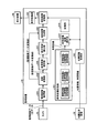
- FIG. 2 is a block diagram illustrating a functional configuration of the monitoring device according to the first embodiment.
- FIG. 3 is a flowchart illustrating a process performed by the monitoring device according to the first embodiment.
- FIG. 4 is an explanatory diagram of the operation of the difference area detection unit in the first embodiment.
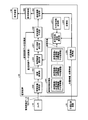
- FIG. 5 is a block diagram illustrating a functional configuration of the monitoring device according to the second embodiment.
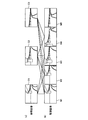
- FIG. 6 is a diagram illustrating the operation of the reference image selection unit according to the second embodiment.
- FIG. 7 is a block diagram illustrating a functional configuration of the monitoring device according to the third embodiment.
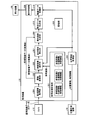
- FIG. 8 is a block diagram illustrating a functional configuration of the monitoring device according to the fourth embodiment.
- FIG. 9 is a flowchart illustrating a process performed by the monitoring device according to the fourth embodiment.
- FIG. 1 is a diagram illustrating a schematic configuration of the railway vehicle RV of the first embodiment.
- the railway vehicle RV includes a camera 10 (an imaging unit), a monitoring device 20, a position measurement device 30, and a display device 40.
- the camera 10 is installed in the traveling direction (forward) of the railway vehicle RV, and captures and stores an image including railway equipment installed on the ground when the railway vehicle RV runs on the track R.
- the monitoring device 20 is a computer device capable of detecting an abnormality in the railway equipment (details will be described later).
- the type of the camera 10 is not limited, but is preferably a high-resolution camera.
- the position measuring device 30 is a unit that measures the current position of the railway vehicle RV and transmits the position information to the monitoring device 20.
- the position measuring device 30 is, for example, a GNSS (Global Navigation Satellite System) device.
- the GNSS device receives a radio wave from a plurality of artificial satellites via an antenna and measures the current position of the railway vehicle RV. Note that, for example, when the railway vehicle RV is in a tunnel, the GNSS device cannot receive radio waves from artificial satellites. Therefore, a device that measures the current position of the railway vehicle RV based on the output of a speed generator (tach generator) provided on the axle of the railway vehicle RV may be used as the position measurement device 30.
- the position measuring device 30 a device that detects the acceleration in the traveling direction of the railway vehicle RV using an acceleration sensor or a gyro sensor, and measures the current position of the railway vehicle RV by calculating the position by integrating the acceleration twice. May be used together or substituted.
- the display device 40 is a unit for displaying various information, and is, for example, an LCD (Liquid Crystal Display).
- FIG. 2 is a block diagram illustrating a functional configuration of the monitoring device 20 according to the first embodiment.
- the monitoring device 20 includes a reference image storage unit 201, a detected image storage unit 202, a position information acquisition unit 203, a monitoring image acquisition unit 204, an image conversion unit 205, a reference image selection unit 206, a difference area detection A storage unit 220; a detection image generation unit 208; a display control unit 209; Part or all of the units 203 to 209 are realized by a processor such as a CPU (Central Processing Unit) of the railway vehicle RV executing software stored in the storage unit 220.
- a processor such as a CPU (Central Processing Unit) of the railway vehicle RV executing software stored in the storage unit 220.
- CPU Central Processing Unit
- some or all of the units 203 to 209 may be realized by hardware which is a circuit board such as an LSI (Large Scale Integration), an ASIC (Application Specific Integrated Circuit), and an FPGA (Field Programmable Gate Array). Good.
- LSI Large Scale Integration
- ASIC Application Specific Integrated Circuit
- FPGA Field Programmable Gate Array
- the storage unit 220 is realized by, for example, a RAM (Random Access Memory), a ROM (Read Only Memory), a flash memory, or the like. Further, the reference image storage unit 201 and the detected image storage unit 202 are realized by, for example, an HDD (Hard Disk Drive), a flash memory, or the like.
- the storage unit 220 stores various information such as a program executed by a processor of the railway vehicle RV.
- the reference image storage unit 201 previously stores a plurality of images including the railway equipment captured by the camera 10 when the railroad vehicle RV is running as a plurality of reference images in association with the position information and the time information of the railroad vehicle RV. .
- the reference image is a reference image used for comparison with the monitoring image.
- FIG. 2 shows that reference images 1, 2,..., N are stored in the reference image storage unit 201.
- the position information is measured by the position measuring device 30. The position information is used for matching between the monitoring image and the reference image (details will be described later).
- the time information is, for example, information indicating a time of day.
- the time information is used as auxiliary information when comparing the monitoring image with the reference image. For example, if the monitoring image is a daytime image and the reference image is a nighttime image, the difference in luminance is large even if the shooting target is the same, but the difference in the shooting time zone of both images can be grasped by using time information. And can respond. Further, in addition to the position information and the time information, information such as the weather at the time of shooting (clear, cloudy, rain, snow, etc.) may be associated with the reference image. Note that essential information associated with the reference image is position information, and information such as time information and weather is not essential.
- the detected image storage unit 202 stores the detected image generated by the detected image generation unit 208. It is preferable that the monitoring device 20 be configured so that the detection image stored in the detection image storage unit 202 can be transferred to an external device. Then, the detected image can be viewed on the external device.
- the position information acquisition unit 203 acquires, from the position measurement device 30, the position information and the time information of the current position of the running railway vehicle RV.
- the monitoring image acquisition unit 204 acquires an image captured by the camera 10 when the railway vehicle RV is traveling as a monitoring image.
- the image conversion unit 205 converts the monitoring image into the same format as the reference image (image conversion). Note that if the format of the monitoring image is originally the same as the format of the reference image, conversion (image conversion) by the image conversion unit 205 is unnecessary.
- the reference image selection unit 206 selects a reference image corresponding to the position information acquired by the position information acquisition unit 203 from the plurality of reference images stored in the reference image storage unit 201 (for example, a reference image whose position information is closest to each other). ). Note that the reference image selection unit 206 may also use time information when selecting a reference image.
- the difference area detection unit 207 detects a difference area between the monitoring image and the reference image selected by the reference image selection unit 206, where the difference in luminance is equal to or more than a predetermined value.
- FIG. 4 is an explanatory diagram of the operation of the difference area detection unit 207 in the first embodiment.
- the difference area detection unit 207 performs the following processes (1) to (6) on the monitoring image (FIG. 4A) and the reference image (FIG. 4B).
- the monitoring image and the reference image are divided into the same grid shape.
- the average brightness value of each grid is calculated for each of the monitoring image and the reference image.
- the average brightness value of the monitoring image and the reference are calculated for each grid. Calculate the difference between the average brightness values of the images.
- Output the area information for example, the coordinates of the upper left corner, the vertical width, and the horizontal width of the grid in the case of a rectangle) of the detected difference area (grid or a combination of a plurality of grids).
- a portion having no difference is black. That is, the grid portion that is not black is the difference area.
- the difference in the average luminance value becomes a predetermined value or more and the difference area May be detected as
- the foreign substance for example, a tree or the like which is tilted or fallen can be considered.
- the detected image generation unit 208 generates a detection image by embedding the difference area detected by the difference area detection unit 207 in the monitor image after the image conversion so that it can be displayed, and stores the detection image in the detection image storage unit 202.
- the detected image generation unit 208 also stores the position information and the time information in association with each other.
- the format of the detected image is arbitrary.
- the display control unit 209 causes the display device 40 to display the detected image stored in the detected image storage unit 202 based on a user operation or the like. As a result, the detection image in which the difference area is clearly displayed is displayed on the display device 40, and the user can easily recognize the difference area. Then, the user can easily recognize, for example, that a foreign object is attached to the railway facility, that a tree is approaching or falls down, and the like.
- FIG. 3 is a flowchart showing processing by the monitoring device 20 of the first embodiment.
- the monitoring image acquisition unit 204 acquires an image captured by the camera 10 during traveling of the railway vehicle RV as a monitoring image
- the position information acquisition unit 203 transmits the position of the current position of the railway vehicle RV from the position measurement device 30. Get information and time information.
- the reference image selection unit 206 selects a reference image based on the position information and the time information. Specifically, the reference image selection unit 206 selects a reference image corresponding to the position information and the time information acquired in step S1, from a plurality of reference images stored in the reference image storage unit 201.
- step S3 the image conversion unit 205 converts the monitoring image into the same format as the reference image.
- step S4 the difference area detection unit 207 calculates the average luminance value of the monitoring image and the reference image in grid units (the number of grids N).
- the difference area detection unit 207 performs the processing of steps S5 to S7 for all the grids.
- the difference area detection unit 207 calculates a difference between the average luminance value of the monitoring image and the average luminance value of the reference image for one grid.
- step S6 it is determined whether or not the difference between the average luminance values of the grid is equal to or larger than a predetermined value. If Yes, the process proceeds to step S7. If No, the process returns to step S5.
- step S7 the difference area detection unit 207 stores the grid in the storage unit 220 as a difference area.
- step S8 the detected image generation unit 208 determines whether or not a difference area exists. If Yes, the process proceeds to step S9, and if No, the process ends.
- step S9 the detection image generation unit 208 generates a detection image by embedding the difference area in the monitoring image so as to be displayed, and stores the detection image in the detection image storage unit 202. After step S9, the process ends.
- the monitoring device 20 of the first embodiment it is possible to detect an abnormality of the railway equipment installed on the ground. That is, the detected image storage unit 202 stores the detected image in which the difference area is embedded so as to be displayed. Therefore, the user can easily recognize abnormality of the railway equipment (for example, attachment of foreign matter to the railway equipment, approach of a tree, or the like) based on the difference area by looking at the detection image clearly indicating the difference area.
- abnormality of the railway equipment for example, attachment of foreign matter to the railway equipment, approach of a tree, or the like
- FIG. 5 is a block diagram illustrating a functional configuration of the monitoring device 20 according to the second embodiment.
- the monitoring device 20 of FIG. 5 is different from the monitoring device 20 of FIG. 2 in that a reference image candidate selection unit 210 is provided and that the operation content of the reference image selection unit 206 is different.
- the reference image candidate selection unit 210 selects a plurality of reference images corresponding to the position information (or time information) acquired by the position information acquisition unit from the plurality of reference images stored in the reference image storage unit 201. . Further, the reference image selection unit 206 generates a normalized cross-correlation (NCC (Normalized Cross Cross Correlation): -1.0 to 1.0) between the monitoring image and each of the plurality of reference images selected by the reference image candidate selection unit 210. Is calculated, and the reference image having the largest normalized cross-correlation is selected.
- NCC Normalized Cross Cross Correlation
- FIG. 6 is an explanatory diagram of the operation of the reference image selection unit 206 according to the second embodiment.
- the plurality of reference images C1 to C3 shown in FIG. 6A are acquired by the reference image candidate selection unit 210 from the plurality of reference images stored in the reference image storage unit 201 by the position information acquisition unit. This is selected according to the position information.
- the reference image selection unit 206 calculates, for example, the normalized cross-correlation of the monitoring image M1 shown in FIG. 6B with each of the plurality of reference images C1 to C3 shown in FIG. Select the reference image with the largest cross-correlation. The same applies to the monitoring images M2 to M5.
- the reference image selecting unit 206 has the maximum normalized cross-correlation with the monitoring image among the plurality of reference images selected by the reference image candidate selecting unit 210.
- the matching between the monitoring image and the reference image can be made more accurate.
- the normalized cross-correlation since the image is calculated as a vector, there is an advantage that it is strong against an error in luminance due to the environment.
- FIG. 7 is a block diagram illustrating a functional configuration of the monitoring device 20 according to the third embodiment.
- the monitoring device 20 of FIG. 7 is different from the monitoring device 20 of FIG. 5 in that a kilometer information storage unit 211 is provided and that the operation content of the reference image candidate selection unit 210 is different.
- the kilometer is information owned by a railway manager or the like, and is information indicating a position of a station, a railway facility, or the like based on a certain position of the track R (FIG. 1).
- the reference image storage unit 201 stores kilometer information.
- the reference image storage unit 201 stores the reference image in association with the position information, the time information, and the kilometer information of the railway vehicle RV.
- the reference image candidate selection unit 210 is configured to obtain a position information acquisition unit from the plurality of reference images stored in the reference image storage unit 201 based on the position information, time information, and kilometer information of each reference image. A plurality of reference images corresponding to the position information acquired by 203 are selected.
- the reference image candidate selection unit 210 stores the reference image storage unit 201 by using the kilometer information in addition to the position information and the time information. More appropriate plural reference images can be selected from the plural reference images.
- FIG. 8 is a block diagram illustrating a functional configuration of the monitoring device 20 according to the fourth embodiment.
- the monitoring device 20 of FIG. 8 is different from the monitoring device 20 of FIG. 2 in that a moving image data generation unit 212 is provided and that the detected image storage unit 202 is replaced with a video data storage unit 213. I do.
- the moving image data generation unit 212 generates moving image data by encoding a plurality of detected images generated by the detected image generation unit 208.
- H.264 is used for image coding.
- a standard such as H.264 may be used.
- the moving image data storage unit 213 stores the moving image data generated by the moving image data generation unit 212.
- FIG. 9 is a flowchart illustrating a process performed by the monitoring device 20 according to the fourth embodiment. Steps S1 to S8 are the same as in FIG. In the case of Yes in step S8, in step S10, the detection image generation unit 208 generates a detection image by embedding the difference area in the monitoring image so as to be displayable. Hereinafter, it is assumed that a plurality of detected images are accumulated at the time of step S11.
- step S11 the moving image data generating unit 212 generates moving image data by encoding a plurality of detected images, and stores the moving image data in the moving image data storage unit 213. After step S11, the process ends.
- the moving image data storage unit 213 stores the moving image data generated from a plurality of detected images in which the difference area is embedded so as to be displayed. Therefore, the user can easily recognize the abnormality of the railway equipment (for example, the attachment of a foreign object to the railway equipment, the approach of a tree, or the like) based on the difference area by viewing the moving image data indicating the difference area. Since the data is moving image data, by reproducing the data, the user can check how the difference area changes over time. Note that a dedicated player capable of decoding corresponding to the encoding may be used for reproducing the moving image data.
- the brightness and color of the image may change depending on the shooting time zone, weather, and the like. Or the difference in color may be reduced.
- a GPS (Global Positioning System) device may be used instead of the GNSS device.
Landscapes
- Engineering & Computer Science (AREA)
- Mechanical Engineering (AREA)
- Multimedia (AREA)
- Signal Processing (AREA)
- Computer Vision & Pattern Recognition (AREA)
- Physics & Mathematics (AREA)
- General Physics & Mathematics (AREA)
- Theoretical Computer Science (AREA)
- Train Traffic Observation, Control, And Security (AREA)
- Closed-Circuit Television Systems (AREA)
- Image Analysis (AREA)
Abstract
実施形態の監視装置は、記憶部と、監視画像取得部と、位置情報取得部と、参照画像選択部と、差分領域検出部と、検知画像生成部と、を備える。記憶部は、予め、鉄道車両において前方に向けて設置された撮影部によって撮影された、地上に設置してある鉄道設備を含む複数の画像を、前記鉄道車両の位置情報と関連付けて、複数の参照画像として記憶する。監視画像取得部は、前記撮影部によって撮影された画像を、監視画像として取得する。位置情報取得部は、前記鉄道車両の現在位置の位置情報を取得する。参照画像選択部は、前記記憶部に記憶されている複数の前記参照画像から、前記位置情報取得部によって取得された位置情報に対応する参照画像を選択する。差分領域検出部は、前記監視画像と前記参照画像選択部によって選択された前記参照画像の間で輝度の差分が所定値以上ある領域である差分領域を検出する。検知画像生成部は、前記監視画像に前記差分領域を表示可能に埋め込んで検知画像を生成する。
Description
本発明の実施形態は、監視装置に関する。
従来から、鉄道管理者は、地上に設置してある鉄道設備に異常があればその異常を速やかに知る必要がある。そのために、例えば、鉄道車両において前方に向けて設置されたカメラによって鉄道設備を含む画像を撮影して記憶し、監視員がその画像を見ることで鉄道設備の異常を調べる手法がある。
しかしながら、上述の手法では、監視員が画像を見て鉄道設備の異常を調べるので手間がかかるという問題がある。
そこで、本実施形態の課題は、地上に設置してある鉄道設備の異常を検知可能な監視装置を提供することである。
実施形態の監視装置は、記憶部と、監視画像取得部と、位置情報取得部と、参照画像選択部と、差分領域検出部と、検知画像生成部と、を備える。記憶部は、予め、鉄道車両において前方に向けて設置された撮影部によって撮影された、地上に設置してある鉄道設備を含む複数の画像を、前記鉄道車両の位置情報と関連付けて、複数の参照画像として記憶する。監視画像取得部は、前記撮影部によって撮影された画像を、監視画像として取得する。位置情報取得部は、前記鉄道車両の現在位置の位置情報を取得する。参照画像選択部は、前記記憶部に記憶されている複数の前記参照画像から、前記位置情報取得部によって取得された位置情報に対応する参照画像を選択する。差分領域検出部は、前記監視画像と前記参照画像選択部によって選択された前記参照画像の間で輝度の差分が所定値以上ある領域である差分領域を検出する。検知画像生成部は、前記監視画像に前記差分領域を表示可能に埋め込んで検知画像を生成する。
以下、添付の図面を参照して、第1実施形態~第4実施形態の監視装置について説明する。なお、第2実施形態以降の説明において、それまでに説明した実施形態と同様の事項については説明を適宜省略する。
(第1実施形態)
図1は、第1実施形態の鉄道車両RVの概略構成を示す図である。図1に示すように、鉄道車両RVは、カメラ10(撮影部)、監視装置20、位置計測装置30、および、表示装置40を備える。カメラ10は、鉄道車両RVにおいて進行方向(前方)に向けて設置され、鉄道車両RVが線路R上を走行するときに、地上に設置してある鉄道設備を含む画像を撮影して記憶する。監視装置20は、鉄道設備の異常を検知可能なコンピュータ装置である(詳細は後述)。なお、カメラ10の種別は限定されないが、高解像度のカメラであることが好ましい。
図1は、第1実施形態の鉄道車両RVの概略構成を示す図である。図1に示すように、鉄道車両RVは、カメラ10(撮影部)、監視装置20、位置計測装置30、および、表示装置40を備える。カメラ10は、鉄道車両RVにおいて進行方向(前方)に向けて設置され、鉄道車両RVが線路R上を走行するときに、地上に設置してある鉄道設備を含む画像を撮影して記憶する。監視装置20は、鉄道設備の異常を検知可能なコンピュータ装置である(詳細は後述)。なお、カメラ10の種別は限定されないが、高解像度のカメラであることが好ましい。
位置計測装置30は、鉄道車両RVの現在位置を計測し、その位置情報を監視装置20に送信する手段である。位置計測装置30は、例えば、GNSS(Global Navigation Satellite System)装置である。GNSS装置は、アンテナによって複数の人工衛星から電波を受信して、鉄道車両RVの現在位置を計測する。なお、鉄道車両RVがトンネルに入っているとき等の場合、GNSS装置は人工衛星から電波を受信できない。そこで、位置計測装置30として、鉄道車両RVの車軸に設けられる速度発電機(タコジェネレータ)の出力に基いて鉄道車両RVの現在位置を計測する装置を併用してもよい。また、位置計測装置30として、加速度センサやジャイロセンサを用いて鉄道車両RVの進行方向の加速度を検出し、加速度を二階積分して位置を算出することで鉄道車両RVの現在位置を計測する装置を併用や代用してもよい。また、表示装置40は、各種情報を表示する手段であり、例えば、LCD(Liquid Crystal Display)である。
図2は、第1実施形態の監視装置20の機能構成を示すブロック図である。図2に示すように、監視装置20は、参照画像記憶部201、検知画像記憶部202、位置情報取得部203、監視画像取得部204、画像変換部205、参照画像選択部206、差分領域検出部207、検知画像生成部208、表示制御部209、および、記憶部220を備える。なお、各部203~209のうちの一部または全部は、鉄道車両RVが有するCPU(Central Processing Unit)等のプロセッサが記憶部220に記憶されるソフトウェアを実行することによって実現される。また、各部203~209のうちの一部または全部は、LSI(Large Scale Integration)、ASIC(Application Specific Integrated Circuit)、FPGA(Field Programmable Gate Array)等の回路基板であるハードウェアによって実現されてもよい。
記憶部220は、例えば、RAM(Random Access Memory)、ROM(Read Only Memory)、フラッシュメモリ等により実現される。また、参照画像記憶部201および検知画像記憶部202は、例えば、HDD(Hard Disk Drive)、フラッシュメモリ等により実現される。
記憶部220は、鉄道車両RVが有するプロセッサが実行するプログラム等の各種情報を記憶する。
参照画像記憶部201は、予め、鉄道車両RVの走行時にカメラ10によって撮影された鉄道設備を含む複数の画像を、鉄道車両RVの位置情報および時間情報と関連付けて、複数の参照画像として記憶する。参照画像とは、監視画像との比較に用いられる基準画像である。図2では、参照画像記憶部201に、参照画像1、2、・・・、nが記憶されていることを示している。位置情報は、位置計測装置30によって計測される。位置情報は、監視画像と参照画像のマッチングに用いられる(詳細は後述)。
時間情報は、例えば、1日のうちの時刻を示す情報である。時間情報は、監視画像と参照画像を比較する際の補助情報として用いられる。例えば、監視画像が日中の画像で、参照画像が夜の画像であれば、撮影対象物が同一でも輝度の違いが大きいが、時間情報を用いることで両画像の撮影時間帯の違いを把握し、対応することができる。また、参照画像に対して、位置情報と時間情報のほかに、撮影時の天候(晴れ、曇り、雨、雪等)等の情報を関連付けておいてもよい。なお、参照画像に対して関連付けておく必須の情報は位置情報であり、時間情報や天候等の情報は必須ではない。
検知画像記憶部202は、検知画像生成部208によって生成された検知画像を記憶する。なお、検知画像記憶部202に記憶された検知画像を外部装置に転送できるように監視装置20を構成しておくことが好ましい。そうすれば、外部装置において検知画像を見ることができる。
位置情報取得部203は、位置計測装置30から、走行している鉄道車両RVの現在位置の位置情報と時間情報を取得する。
監視画像取得部204は、鉄道車両RVの走行時にカメラ10によって撮影された画像を、監視画像として取得する。
画像変換部205は、監視画像を、参照画像と同じフォーマットに変換(画像変換)する。なお、監視画像のフォーマットが元から参照画像のフォーマットと同じであれば、画像変換部205による変換(画像変換)は不要である。
参照画像選択部206は、参照画像記憶部201に記憶されている複数の参照画像から、位置情報取得部203によって取得された位置情報に対応する参照画像(例えば、位置情報同士が最も近い参照画像)を選択する。なお、参照画像選択部206は、参照画像を選択するときに時間情報を併せて用いてもよい。
差分領域検出部207は、監視画像と参照画像選択部206によって選択された参照画像の間で輝度の差分が所定値以上ある領域である差分領域を検出する。ここで、図4は、第1実施形態における差分領域検出部207の動作説明図である。差分領域検出部207は、監視画像(図4(a))と参照画像(図4(b))に関して、以下の(1)~(6)の処理を行う。
(1)監視画像、参照画像を同一の格子状に分割
(2)監視画像、参照画像のそれぞれについて、格子ごとの輝度平均値を算出
(3)各格子について、監視画像の輝度平均値と参照画像の輝度平均値の差分を算出
(4)輝度平均値の差分が所定値(閾値)以上か否か判定
(5)輝度平均値の差分が所定値以上の領域(格子)を差分領域として検出
(6)検出した差分領域(格子。または複数の格子を連結したもの)の領域情報(例えば矩形であれば格子の左上の座標と縦幅と横幅)を出力
(2)監視画像、参照画像のそれぞれについて、格子ごとの輝度平均値を算出
(3)各格子について、監視画像の輝度平均値と参照画像の輝度平均値の差分を算出
(4)輝度平均値の差分が所定値(閾値)以上か否か判定
(5)輝度平均値の差分が所定値以上の領域(格子)を差分領域として検出
(6)検出した差分領域(格子。または複数の格子を連結したもの)の領域情報(例えば矩形であれば格子の左上の座標と縦幅と横幅)を出力
なお、図4(c)に示す差分画像では、差分の無い部分を黒色としている。つまり、真っ黒でない格子部分が差分領域である。例えば、監視画像において鉄道設備(例えば架線等)にビニール袋等の異物が付着していて、参照画像におけるその部分にその異物が無いと、輝度平均値の差分が所定値以上となって差分領域として検出される可能性がある。また、異物としては、ほかに、例えば、傾いたり倒れたりした樹木等が考えられる。
図2に戻って、検知画像生成部208は、画像変換後の監視画像に、差分領域検出部207によって検出された差分領域を表示可能に埋め込んで検知画像を生成して検知画像記憶部202に記憶する。また、検知画像生成部208は、検知画像を検知画像記憶部202に記憶する際、位置情報や時間情報も関連付けて記憶する。なお、検知画像のフォーマットは任意である。
表示制御部209は、ユーザの操作等に基いて、検知画像記憶部202に記憶された検知画像を表示装置40に表示させる。これにより、表示装置40に、差分領域を明示した検知画像が表示され、ユーザは、当該差分領域を容易に認識できる。そして、ユーザは、例えば、鉄道設備に対して異物が付着していることや樹木が近付いたり倒れ込んだりしていること等を容易に認識できる。
図3は、第1実施形態の監視装置20による処理を示すフローチャートである。ステップS1において、監視画像取得部204は、鉄道車両RVの走行時にカメラ10によって撮影された画像を監視画像として取得し、位置情報取得部203は位置計測装置30から鉄道車両RVの現在位置の位置情報と時間情報を取得する。
次に、ステップS2において、参照画像選択部206は、位置情報と時間情報に基いて参照画像を選択する。具体的には、参照画像選択部206は、参照画像記憶部201に記憶されている複数の参照画像から、ステップS1で取得された位置情報と時間情報に対応する参照画像を選択する。
次に、ステップS3において、画像変換部205は、監視画像を、参照画像と同じフォーマットに変換する。
次に、ステップS4において、差分領域検出部207は、監視画像と参照画像の格子単位(格子数N)での輝度平均値を算出する。
次に、差分領域検出部207は、全格子についてステップS5~S7の処理を実行する。ステップS5において、差分領域検出部207は、1つの格子について、監視画像と参照画像の輝度平均値の差分を算出する。
次に、ステップS6において、その格子について、輝度平均値の差分が所定値以上か否かを判定し、Yesの場合はステップS7に進み、Noの場合はステップS5に戻る。
ステップS7において、差分領域検出部207は、その格子を差分領域として記憶部220に記憶する。
ステップS5~S7が終了した後、ステップS8において、検知画像生成部208は、差分領域が存在するか否かを判定し、Yesの場合はステップS9に進み、Noの場合は処理を終了する。
ステップS9において、検知画像生成部208は、監視画像に差分領域を表示可能に埋め込んで検知画像を生成して検知画像記憶部202に記憶する。ステップS9の後、処理を終了する。
このように、第1実施形態の監視装置20によれば、地上に設置してある鉄道設備の異常を検知することができる。つまり、検知画像記憶部202には、差分領域が表示可能に埋め込んである検知画像が記憶される。したがって、ユーザはその差分領域を明示した検知画像を見ることで差分領域に基いて鉄道設備の異常(例えば、鉄道設備に対する異物の付着や樹木の接近等)を容易に認識することができる。
(第2実施形態)
次に、第2実施形態の監視装置20について説明する。図5は、第2実施形態の監視装置20の機能構成を示すブロック図である。図5の監視装置20は、図2の監視装置20と比較して、参照画像候補選択部210を備えている点と、参照画像選択部206の動作内容が異なる点で相違する。
次に、第2実施形態の監視装置20について説明する。図5は、第2実施形態の監視装置20の機能構成を示すブロック図である。図5の監視装置20は、図2の監視装置20と比較して、参照画像候補選択部210を備えている点と、参照画像選択部206の動作内容が異なる点で相違する。
参照画像候補選択部210は、参照画像記憶部201に記憶されている複数の参照画像から、位置情報取得部によって取得された位置情報(あるいは時間情報も)に対応する複数の参照画像を選択する。また、参照画像選択部206は、監視画像と、参照画像候補選択部210によって選択された複数の参照画像それぞれとの正規化相互相関(NCC(Normalized Cross Correlation):-1.0~1.0の間の値)を算出し、正規化相互相関が最大の参照画像を選択する。
ここで、図6は、第2実施形態における参照画像選択部206の動作説明図である。まず、図6(a)に示す複数の参照画像C1~C3は、参照画像候補選択部210が、参照画像記憶部201に記憶されている複数の参照画像から、位置情報取得部によって取得された位置情報に対応して選択したものである。
そして、参照画像選択部206は、例えば、図6(b)に示す監視画像M1について、図6(a)に示す複数の参照画像C1~C3それぞれとの正規化相互相関を算出し、正規化相互相関が最大の参照画像を選択する。監視画像M2~M5についても同様である。
このように、第2実施形態の監視装置20によれば、参照画像選択部206が、参照画像候補選択部210によって選択された複数の参照画像のうち、監視画像との正規化相互相関が最大の参照画像を選択することにより、監視画像と参照画像のマッチングをより高精度にすることができる。また、正規化相互相関を算出する際、画像をベクトルとして計算するため、環境による輝度の誤差に対して強いという長所もある。
(第3実施形態)
次に、第3実施形態の監視装置20について説明する。図7は、第3実施形態の監視装置20の機能構成を示すブロック図である。図7の監視装置20は、図5の監視装置20と比較して、キロ程情報記憶部211を備えている点と、参照画像候補選択部210の動作内容が異なる点で相違する。なお、キロ程とは、鉄道管理者等が所有する情報で、線路R(図1)のある位置を基準として駅や鉄道設備等の位置を示す情報である。
次に、第3実施形態の監視装置20について説明する。図7は、第3実施形態の監視装置20の機能構成を示すブロック図である。図7の監視装置20は、図5の監視装置20と比較して、キロ程情報記憶部211を備えている点と、参照画像候補選択部210の動作内容が異なる点で相違する。なお、キロ程とは、鉄道管理者等が所有する情報で、線路R(図1)のある位置を基準として駅や鉄道設備等の位置を示す情報である。
キロ程情報記憶部211は、キロ程情報を記憶している。そして、参照画像記憶部201は、参照画像を、鉄道車両RVの位置情報、時間情報、および、キロ程情報と関連付けて記憶している。また、参照画像候補選択部210は、参照画像記憶部201に記憶されている複数の参照画像から、それぞれの参照画像の位置情報、時間情報、および、キロ程情報に基いて、位置情報取得部203によって取得された位置情報に対応する複数の参照画像を選択する。
このように、第3実施形態の監視装置20によれば、参照画像候補選択部210は、位置情報や時間情報に加えてキロ程情報も用いることで、参照画像記憶部201に記憶されている複数の参照画像からより適切な複数の参照画像を選択することができる。
(第4実施形態)
次に、第4実施形態の監視装置20について説明する。図8は、第4実施形態の監視装置20の機能構成を示すブロック図である。図8の監視装置20は、図2の監視装置20と比較して、動画データ生成部212を備えている点と、検知画像記憶部202が動画データ記憶部213に置き換えられている点で相違する。
次に、第4実施形態の監視装置20について説明する。図8は、第4実施形態の監視装置20の機能構成を示すブロック図である。図8の監視装置20は、図2の監視装置20と比較して、動画データ生成部212を備えている点と、検知画像記憶部202が動画データ記憶部213に置き換えられている点で相違する。
動画データ生成部212は、検知画像生成部208によって生成された複数の検知画像を符号化して動画データを生成する。画像の符号化には、例えば、H.264等の標準規格を使用すればよい。動画データ記憶部213は、動画データ生成部212によって生成された動画データを記憶する。
図9は、第4実施形態の監視装置20による処理を示すフローチャートである。ステップS1~S8は図3と同様である。ステップS8でYesの場合、ステップS10において、検知画像生成部208は、監視画像に差分領域を表示可能に埋め込んで検知画像を生成する。以下、ステップS11の時点では、複数の検知画像が蓄積されているものとする。
次に、ステップS11において、動画データ生成部212は、複数の検知画像を符号化して動画データを生成し、動画データ記憶部213に記憶する。ステップS11の後、処理を終了する。
このように、第4実施形態の監視装置20によれば、動画データ記憶部213は、差分領域が表示可能に埋め込んである複数の検知画像から生成された動画データを記憶する。したがって、ユーザは差分領域を明示したその動画データを見ることで差分領域に基いて鉄道設備の異常(例えば、鉄道設備に対する異物の付着や樹木の接近等)を容易に認識することができる。そして、動画データであるので、再生することで、ユーザは、差分領域の経時的変化の様子を確認することができる。なお、動画データの再生には、符号化に対応した復号化が可能な専用のプレイヤーを用いればよい。
本発明のいくつかの実施形態を説明したが、これらの実施形態は、例として提示したものであり、発明の範囲を限定することは意図していない。これら新規な実施形態は、その他の様々な形態で実施されることが可能であり、発明の要旨を逸脱しない範囲で、種々の省略、置き換え、変更を行うことができる。これら実施形態やその変形は、発明の範囲や要旨に含まれるとともに、請求の範囲に記載された発明とその均等の範囲に含まれる。
例えば、カメラ10によって撮影される画像がカラーの場合、撮影の時間帯や天候等によって画像の輝度や色味が変わることがあるため、画像にモノクロ化やγ補正等の処理を行って、輝度や色味の違いを減らすようにしてもよい。
また、位置計測装置30として、GNSS装置の代わりにGPS(Global Positioning System)装置を用いてもよい。
Claims (4)
- 予め、鉄道車両において前方に向けて設置された撮影部によって撮影された、地上に設置してある鉄道設備を含む複数の画像を、前記鉄道車両の位置情報と関連付けて、複数の参照画像として記憶する記憶部と、
前記撮影部によって撮影された画像を、監視画像として取得する監視画像取得部と、
前記鉄道車両の現在位置の位置情報を取得する位置情報取得部と、
前記記憶部に記憶されている複数の前記参照画像から、前記位置情報取得部によって取得された位置情報に対応する参照画像を選択する参照画像選択部と、
前記監視画像と前記参照画像選択部によって選択された前記参照画像の間で輝度の差分が所定値以上ある領域である差分領域を検出する差分領域検出部と、
前記監視画像に前記差分領域を表示可能に埋め込んで検知画像を生成する検知画像生成部と、
を備える監視装置。 - 予め、鉄道車両において前方に向けて設置された撮影部によって撮影された、地上に設置してある鉄道設備を含む複数の画像を、前記鉄道車両の位置情報と関連付けて、複数の参照画像として記憶する記憶部と、
前記撮影部によって撮影された画像を、監視画像として取得する監視画像取得部と、
前記鉄道車両の現在位置の位置情報を取得する位置情報取得部と、
前記記憶部に記憶されている複数の前記参照画像から、前記位置情報取得部によって取得された位置情報に対応する複数の前記参照画像を選択する参照画像候補選択部と、
前記監視画像と、前記参照画像候補選択部によって選択された前記複数の前記参照画像それぞれとの正規化相互相関を算出し、前記正規化相互相関が最大の前記参照画像を選択する参照画像選択部と、
前記監視画像と前記参照画像選択部によって選択された前記参照画像の間で輝度の差分が所定値以上ある領域である差分領域を検出する差分領域検出部と、
前記監視画像に前記差分領域を表示可能に埋め込んで検知画像を生成する検知画像生成部と、
を備える監視装置。 - 前記記憶部は、前記参照画像を、前記鉄道車両の位置情報およびキロ程情報と関連付けて記憶しており、
前記参照画像候補選択部は、前記記憶部に記憶されている複数の参照画像から、それぞれの前記参照画像の前記位置情報および前記キロ程情報に基いて、前記位置情報取得部によって取得された位置情報に対応する複数の参照画像を選択する、請求項2に記載の監視装置。 - 前記検知画像生成部によって生成された複数の検知画像を符号化して動画データを生成する動画データ生成部を、さらに備える、請求項1から請求項3のいずれか一項に記載の監視装置。
Applications Claiming Priority (2)
| Application Number | Priority Date | Filing Date | Title |
|---|---|---|---|
| JP2018-149569 | 2018-08-08 | ||
| JP2018149569A JP2020023285A (ja) | 2018-08-08 | 2018-08-08 | 監視装置 |
Publications (1)
| Publication Number | Publication Date |
|---|---|
| WO2020031898A1 true WO2020031898A1 (ja) | 2020-02-13 |
Family
ID=69413582
Family Applications (1)
| Application Number | Title | Priority Date | Filing Date |
|---|---|---|---|
| PCT/JP2019/030518 Ceased WO2020031898A1 (ja) | 2018-08-08 | 2019-08-02 | 監視装置 |
Country Status (2)
| Country | Link |
|---|---|
| JP (1) | JP2020023285A (ja) |
| WO (1) | WO2020031898A1 (ja) |
Cited By (1)
| Publication number | Priority date | Publication date | Assignee | Title |
|---|---|---|---|---|
| JP2021190850A (ja) * | 2020-05-29 | 2021-12-13 | 株式会社東芝 | 監視装置、及び監視方法 |
Citations (3)
| Publication number | Priority date | Publication date | Assignee | Title |
|---|---|---|---|---|
| JP2005125709A (ja) * | 2003-10-27 | 2005-05-19 | Sumitomo Heavy Ind Ltd | 金型監視装置、方法及びプログラム |
| JP2008186246A (ja) * | 2007-01-30 | 2008-08-14 | Aisin Seiki Co Ltd | 移動物体認識装置 |
| JP2016088325A (ja) * | 2014-11-06 | 2016-05-23 | 三菱重工業株式会社 | 進行方向監視装置、進行方向監視方法およびプログラム |
-
2018
- 2018-08-08 JP JP2018149569A patent/JP2020023285A/ja active Pending
-
2019
- 2019-08-02 WO PCT/JP2019/030518 patent/WO2020031898A1/ja not_active Ceased
Patent Citations (3)
| Publication number | Priority date | Publication date | Assignee | Title |
|---|---|---|---|---|
| JP2005125709A (ja) * | 2003-10-27 | 2005-05-19 | Sumitomo Heavy Ind Ltd | 金型監視装置、方法及びプログラム |
| JP2008186246A (ja) * | 2007-01-30 | 2008-08-14 | Aisin Seiki Co Ltd | 移動物体認識装置 |
| JP2016088325A (ja) * | 2014-11-06 | 2016-05-23 | 三菱重工業株式会社 | 進行方向監視装置、進行方向監視方法およびプログラム |
Cited By (2)
| Publication number | Priority date | Publication date | Assignee | Title |
|---|---|---|---|---|
| JP2021190850A (ja) * | 2020-05-29 | 2021-12-13 | 株式会社東芝 | 監視装置、及び監視方法 |
| CN115699727A (zh) * | 2020-05-29 | 2023-02-03 | 株式会社东芝 | 监视装置以及监视方法 |
Also Published As
| Publication number | Publication date |
|---|---|
| JP2020023285A (ja) | 2020-02-13 |
Similar Documents
| Publication | Publication Date | Title |
|---|---|---|
| JP5776545B2 (ja) | 路面調査プログラム及び路面調査装置 | |
| JP6950832B2 (ja) | 位置座標推定装置、位置座標推定方法およびプログラム | |
| JP7343054B2 (ja) | 位置推定方法、位置推定装置、および位置推定プログラム | |
| US12292388B2 (en) | Deterioration diagnosis device, deterioration diagnosis method, and recording medium | |
| US20190360820A1 (en) | Method and device for executing at least one measure for increasing the safety of a vehicle | |
| JP2024013788A (ja) | プログラム、方法、システム、道路マップ、および道路マップの作成方法 | |
| JP2018128265A (ja) | サーバ装置、判別プログラム及び判別システム | |
| JP7610741B2 (ja) | 地物管理システム | |
| JP2018116004A (ja) | データ圧縮装置、制御方法、プログラム及び記憶媒体 | |
| TW201836891A (zh) | 車載裝置、局側裝置及校正方法 | |
| US12565230B2 (en) | Vehicle environment sensor reliability determination | |
| WO2020031898A1 (ja) | 監視装置 | |
| US20250322575A1 (en) | Apparatus for generating a pseudo-reproducing image, and non-transitory computer-readable medium | |
| CN115023384B (zh) | 设施诊断系统 | |
| JP6727032B2 (ja) | モバイル端末およびこれを用いた自己位置推定システム並びにサーバおよび自己位置推定方法 | |
| JP6414954B2 (ja) | 道路画像管理システム | |
| JP2024157029A (ja) | 情報処理装置 | |
| JP7058817B1 (ja) | 距離標距離判定装置、距離標距離判定方法、および距離標距離判定プログラム | |
| JP7185786B2 (ja) | 測位システム及び端末 | |
| JP2022190173A (ja) | 位置推定装置 | |
| JP5230354B2 (ja) | 位置特定装置及び異動建物検出装置 | |
| JP5409451B2 (ja) | 3次元変化検出装置 | |
| CN114268788A (zh) | 车载车辆图像采集装置功能符合性的监测 | |
| EP4647800A1 (en) | Augmented reality device calibration using distance measurements | |
| JP7342499B2 (ja) | タグ付与装置 |
Legal Events
| Date | Code | Title | Description |
|---|---|---|---|
| 121 | Ep: the epo has been informed by wipo that ep was designated in this application |
Ref document number: 19846158 Country of ref document: EP Kind code of ref document: A1 |
|
| NENP | Non-entry into the national phase |
Ref country code: DE |
|
| 122 | Ep: pct application non-entry in european phase |
Ref document number: 19846158 Country of ref document: EP Kind code of ref document: A1 |