WO2020031884A1 - Communication system, communication terminal, and base station - Google Patents
Communication system, communication terminal, and base station Download PDFInfo
- Publication number
- WO2020031884A1 WO2020031884A1 PCT/JP2019/030445 JP2019030445W WO2020031884A1 WO 2020031884 A1 WO2020031884 A1 WO 2020031884A1 JP 2019030445 W JP2019030445 W JP 2019030445W WO 2020031884 A1 WO2020031884 A1 WO 2020031884A1
- Authority
- WO
- WIPO (PCT)
- Prior art keywords
- trp
- information
- gnb
- communication
- switching
- Prior art date
Links
- 238000004891 communication Methods 0.000 title claims abstract description 630
- 238000000034 method Methods 0.000 claims abstract description 172
- 230000008569 process Effects 0.000 claims abstract description 71
- 238000012545 processing Methods 0.000 claims description 65
- 230000005540 biological transmission Effects 0.000 abstract description 260
- 238000005516 engineering process Methods 0.000 abstract description 11
- 230000001360 synchronised effect Effects 0.000 abstract description 7
- 230000001747 exhibiting effect Effects 0.000 abstract 1
- 230000011664 signaling Effects 0.000 description 159
- 230000004044 response Effects 0.000 description 125
- 238000005259 measurement Methods 0.000 description 122
- 238000010586 diagram Methods 0.000 description 86
- 230000004048 modification Effects 0.000 description 79
- 238000012986 modification Methods 0.000 description 78
- 239000000969 carrier Substances 0.000 description 60
- 230000010076 replication Effects 0.000 description 44
- 238000012546 transfer Methods 0.000 description 37
- 230000008859 change Effects 0.000 description 25
- 230000000694 effects Effects 0.000 description 25
- 206010062282 Silver-Russell syndrome Diseases 0.000 description 22
- 230000006870 function Effects 0.000 description 22
- 201000001845 syndromic X-linked intellectual disability Snyder type Diseases 0.000 description 22
- 238000007726 management method Methods 0.000 description 21
- 238000007792 addition Methods 0.000 description 18
- 238000011084 recovery Methods 0.000 description 17
- 238000001514 detection method Methods 0.000 description 15
- 101100150275 Caenorhabditis elegans srb-3 gene Proteins 0.000 description 14
- 230000004913 activation Effects 0.000 description 14
- 230000009849 deactivation Effects 0.000 description 11
- 238000013461 design Methods 0.000 description 9
- 238000013468 resource allocation Methods 0.000 description 9
- 238000012937 correction Methods 0.000 description 7
- 238000013146 percutaneous coronary intervention Methods 0.000 description 6
- 101100465000 Mus musculus Prag1 gene Proteins 0.000 description 5
- 230000007257 malfunction Effects 0.000 description 5
- 230000000737 periodic effect Effects 0.000 description 5
- 102100032489 Heat shock 70 kDa protein 13 Human genes 0.000 description 4
- 101001016638 Homo sapiens Heat shock 70 kDa protein 13 Proteins 0.000 description 4
- 101000720079 Stichodactyla helianthus DELTA-stichotoxin-She4a Proteins 0.000 description 4
- 238000006243 chemical reaction Methods 0.000 description 4
- 101150096310 SIB1 gene Proteins 0.000 description 3
- 230000002776 aggregation Effects 0.000 description 3
- 238000004220 aggregation Methods 0.000 description 3
- 230000009977 dual effect Effects 0.000 description 3
- 230000007774 longterm Effects 0.000 description 3
- 230000002093 peripheral effect Effects 0.000 description 3
- 239000000725 suspension Substances 0.000 description 3
- 208000037918 transfusion-transmitted disease Diseases 0.000 description 3
- 230000006978 adaptation Effects 0.000 description 2
- 230000008901 benefit Effects 0.000 description 2
- 125000004122 cyclic group Chemical group 0.000 description 2
- 238000012217 deletion Methods 0.000 description 2
- 230000037430 deletion Effects 0.000 description 2
- 230000002452 interceptive effect Effects 0.000 description 2
- 238000013507 mapping Methods 0.000 description 2
- 239000011159 matrix material Substances 0.000 description 2
- 238000010295 mobile communication Methods 0.000 description 2
- 230000002085 persistent effect Effects 0.000 description 2
- 230000009467 reduction Effects 0.000 description 2
- 101100148830 Arabidopsis thaliana SCI1 gene Proteins 0.000 description 1
- 241001229889 Metis Species 0.000 description 1
- 101100054266 Saccharomyces cerevisiae (strain ATCC 204508 / S288c) SNF4 gene Proteins 0.000 description 1
- 238000013459 approach Methods 0.000 description 1
- 230000001174 ascending effect Effects 0.000 description 1
- 238000004364 calculation method Methods 0.000 description 1
- 230000001413 cellular effect Effects 0.000 description 1
- 238000012508 change request Methods 0.000 description 1
- 239000000470 constituent Substances 0.000 description 1
- 230000001934 delay Effects 0.000 description 1
- 208000018910 keratinopathic ichthyosis Diseases 0.000 description 1
- 230000008520 organization Effects 0.000 description 1
- 238000000926 separation method Methods 0.000 description 1
- 238000001774 stimulated Raman spectroscopy Methods 0.000 description 1
- 238000010408 sweeping Methods 0.000 description 1
Images


Classifications
-
- H—ELECTRICITY
- H04—ELECTRIC COMMUNICATION TECHNIQUE
- H04W—WIRELESS COMMUNICATION NETWORKS
- H04W56/00—Synchronisation arrangements
- H04W56/001—Synchronization between nodes
- H04W56/0015—Synchronization between nodes one node acting as a reference for the others
-
- H—ELECTRICITY
- H04—ELECTRIC COMMUNICATION TECHNIQUE
- H04W—WIRELESS COMMUNICATION NETWORKS
- H04W56/00—Synchronisation arrangements
- H04W56/004—Synchronisation arrangements compensating for timing error of reception due to propagation delay
- H04W56/0045—Synchronisation arrangements compensating for timing error of reception due to propagation delay compensating for timing error by altering transmission time
-
- H—ELECTRICITY
- H04—ELECTRIC COMMUNICATION TECHNIQUE
- H04W—WIRELESS COMMUNICATION NETWORKS
- H04W74/00—Wireless channel access, e.g. scheduled or random access
- H04W74/002—Transmission of channel access control information
- H04W74/006—Transmission of channel access control information in the downlink, i.e. towards the terminal
-
- H—ELECTRICITY
- H04—ELECTRIC COMMUNICATION TECHNIQUE
- H04W—WIRELESS COMMUNICATION NETWORKS
- H04W74/00—Wireless channel access, e.g. scheduled or random access
- H04W74/08—Non-scheduled or contention based access, e.g. random access, ALOHA, CSMA [Carrier Sense Multiple Access]
- H04W74/0833—Non-scheduled or contention based access, e.g. random access, ALOHA, CSMA [Carrier Sense Multiple Access] using a random access procedure
-
- H—ELECTRICITY
- H04—ELECTRIC COMMUNICATION TECHNIQUE
- H04W—WIRELESS COMMUNICATION NETWORKS
- H04W76/00—Connection management
- H04W76/30—Connection release
- H04W76/34—Selective release of ongoing connections
-
- H—ELECTRICITY
- H04—ELECTRIC COMMUNICATION TECHNIQUE
- H04W—WIRELESS COMMUNICATION NETWORKS
- H04W36/00—Hand-off or reselection arrangements
- H04W36/0005—Control or signalling for completing the hand-off
- H04W36/0055—Transmission or use of information for re-establishing the radio link
- H04W36/0069—Transmission or use of information for re-establishing the radio link in case of dual connectivity, e.g. decoupled uplink/downlink
-
- H—ELECTRICITY
- H04—ELECTRIC COMMUNICATION TECHNIQUE
- H04W—WIRELESS COMMUNICATION NETWORKS
- H04W76/00—Connection management
- H04W76/10—Connection setup
- H04W76/14—Direct-mode setup
-
- H—ELECTRICITY
- H04—ELECTRIC COMMUNICATION TECHNIQUE
- H04W—WIRELESS COMMUNICATION NETWORKS
- H04W76/00—Connection management
- H04W76/10—Connection setup
- H04W76/15—Setup of multiple wireless link connections
-
- H—ELECTRICITY
- H04—ELECTRIC COMMUNICATION TECHNIQUE
- H04W—WIRELESS COMMUNICATION NETWORKS
- H04W76/00—Connection management
- H04W76/10—Connection setup
- H04W76/19—Connection re-establishment
-
- H—ELECTRICITY
- H04—ELECTRIC COMMUNICATION TECHNIQUE
- H04W—WIRELESS COMMUNICATION NETWORKS
- H04W88/00—Devices specially adapted for wireless communication networks, e.g. terminals, base stations or access point devices
- H04W88/02—Terminal devices
- H04W88/06—Terminal devices adapted for operation in multiple networks or having at least two operational modes, e.g. multi-mode terminals
-
- H—ELECTRICITY
- H04—ELECTRIC COMMUNICATION TECHNIQUE
- H04W—WIRELESS COMMUNICATION NETWORKS
- H04W88/00—Devices specially adapted for wireless communication networks, e.g. terminals, base stations or access point devices
- H04W88/08—Access point devices
- H04W88/085—Access point devices with remote components
-
- Y—GENERAL TAGGING OF NEW TECHNOLOGICAL DEVELOPMENTS; GENERAL TAGGING OF CROSS-SECTIONAL TECHNOLOGIES SPANNING OVER SEVERAL SECTIONS OF THE IPC; TECHNICAL SUBJECTS COVERED BY FORMER USPC CROSS-REFERENCE ART COLLECTIONS [XRACs] AND DIGESTS
- Y02—TECHNOLOGIES OR APPLICATIONS FOR MITIGATION OR ADAPTATION AGAINST CLIMATE CHANGE
- Y02D—CLIMATE CHANGE MITIGATION TECHNOLOGIES IN INFORMATION AND COMMUNICATION TECHNOLOGIES [ICT], I.E. INFORMATION AND COMMUNICATION TECHNOLOGIES AIMING AT THE REDUCTION OF THEIR OWN ENERGY USE
- Y02D30/00—Reducing energy consumption in communication networks
- Y02D30/70—Reducing energy consumption in communication networks in wireless communication networks
Definitions
- the present invention relates to wireless communication technology.
- a radio section is called Long Term Evolution (LTE), and a core network and a radio access network (hereinafter collectively referred to as a network).
- LTE Long Term Evolution
- network a radio access network
- SAE System Architecture Evolution
- Non-Patent Documents 1 to 5 This communication system is also called a 3.9G (3.9@Generation) system.
- OFDM Orthogonal Frequency Division Multiplexing
- SC-FDMA Single Carrier Frequency Division Multiple Access
- LTE does not include circuit switching and uses only a packet communication method.
- FIG. 1 is an explanatory diagram showing the configuration of a radio frame used in the LTE communication system.
- one radio frame (Radio @ frame) is 10 ms.
- the radio frame is divided into ten equal-sized subframes (Subframes).
- a subframe is divided into two equally sized slots.
- the downlink synchronization signal (Downlink @ Synchronization @ Signal) is included in the first and sixth subframes for each radio frame.
- the synchronization signal includes a first synchronization signal (Primary @ Synchronization @ Signal: P-SS) and a second synchronization signal (Secondary @ Synchronization @ Signal: S-SS).
- Non-Patent Document 1 (Chapter 5) describes the decision items regarding the channel configuration in the LTE system in 3GPP. It is assumed that a CSG (Closed Subscriber Group) cell uses the same channel configuration as a non-CSG cell.
- CSG Cell Subscriber Group
- a physical broadcast channel (Physical Broadcast Channel: PBCH) is a communication terminal device such as a base station device (hereinafter sometimes simply referred to as “base station”) to a mobile terminal device (hereinafter sometimes simply referred to as “communication terminal”). (Hereinafter simply referred to as “communication terminal”).
- the BCH transport block (transport @ block) is mapped to four subframes in a 40 ms interval. There is no apparent signaling at 40 ms timing.
- the ⁇ Physical Control Format Indicator Channel (PCFICH) ⁇ is a channel for downlink transmission from the base station to the communication terminal.
- PCFICH reports the number of OFDM (Orthogonal Frequency Division Multiplexing) symbols used for PDCCHs from a base station to a communication terminal.
- PCFICH is transmitted for each subframe.
- the Physical Downlink Control Channel is a channel for downlink transmission from a base station to a communication terminal.
- the PDCCH includes resource allocation (allocation) information of a downlink shared channel (DL-SCH), which is one of the transport channels described later, and a paging channel (Paging @ Channel: PCH), which is one of the transport channels described later. ), And HARQ (Hybrid Automatic Repeat Repeat reQuest) information on DL-SCH.
- the PDCCH carries an uplink scheduling grant (Uplink ⁇ Scheduling ⁇ Grant).
- the PDCCH carries Ack (Acknowledgement) / Nack (Negative @ Acknowledgement), which is a response signal to uplink transmission.
- the PDCCH is also called an L1 / L2 control signal.
- the Physical Downlink Shared Channel is a channel for downlink transmission from the base station to the communication terminal.
- the Physical Multicast Channel is a channel for downlink transmission from a base station to a communication terminal.
- a multicast channel (Multicast @ Channel: MCH) which is a transport channel is mapped to the PMCH.
- PUCCH Physical Uplink Control Channel
- Ack / Nack which is a response signal (response @ signal) for downlink transmission.
- PUCCH carries CSI (Channel ⁇ State ⁇ Information).
- the CSI includes an RI (Rank @ Indicator), a PMI (Precoding @ Matrix @ Indicator), and a CQI (Channel @ Quality @ Indicator) report.
- RI is rank information of a channel matrix in MIMO.
- PMI is information on a precoding weight matrix used in MIMO.
- the CQI is quality information indicating the quality of received data or communication channel quality.
- PUCCH also carries a scheduling request (Scheduling @ Request: SR).
- Physical Uplink Shared Channel is a channel for uplink transmission from a communication terminal to a base station.
- an uplink shared channel (Uplink @ Shared @ Channel: UL-SCH), which is one of the transport channels, is mapped.
- the Physical HARQ indicator channel (Physical Hybrid ARQ Indicator Channel: PHICH) is a channel for downlink transmission from the base station to the communication terminal. PHICH carries Ack / Nack which is a response signal to uplink transmission.
- the physical random access channel (Physical Random Access Channel: PRACH) is a channel for uplink transmission from a communication terminal to a base station.
- the PRACH carries a random access preamble (random access preamble).
- the ⁇ downlink reference signal (Reference Signal (Reference Signal): RS) is a symbol known as an LTE communication system.
- the following five types of downlink reference signals are defined.
- Data demodulation reference signal (DM-RS) which is a cell-specific reference signal (Cell-specific Reference Signal: CRS), MBSFN reference signal (MBSFN Reference Signal), and UE-specific reference signal (UE-specific Reference Signal)
- CRS Cell-specific Reference Signal
- MBSFN reference signal MBSFN reference signal
- UE-specific Reference Signal UE-specific Reference Signal
- PRS Position determination reference signal
- CSI-RS Channel State Information Reference Signal
- As a measurement of the physical layer of the communication terminal there is a reference signal received power (Reference / Signal / Received / Power: RSRP) measurement.
- RSRP reference signal received power
- the uplink reference signal is a symbol known as an LTE communication system.
- the following two types of uplink reference signals are defined. These are a data demodulation reference signal (Demodulation Reference Signal: DM-RS) and a sounding reference signal (Sounding Reference Signal: SRS).
- DM-RS Data demodulation Reference Signal
- SRS Sounding Reference Signal
- Non-Patent Document 1 The transport channel (Transport channel) described in Non-Patent Document 1 (Chapter 5) will be described.
- a broadcast channel (Broadcast @ Channel: BCH) is broadcast to the entire coverage of the base station (cell).
- the BCH is mapped to a physical broadcast channel (PBCH).
- PBCH physical broadcast channel
- HARQ Hybrid ARQ
- DL-SCH Downlink Shared Channel
- the DL-SCH can broadcast to the entire coverage of the base station (cell).
- the DL-SCH supports dynamic or semi-static resource allocation. Semi-static resource allocation is also referred to as persistent scheduling (Persistent @ Scheduling).
- the DL-SCH supports discontinuous reception (DRX) of the communication terminal to reduce the power consumption of the communication terminal.
- DL-SCH is mapped to a physical downlink shared channel (PDSCH).
- the paging channel supports DRX of the communication terminal to enable low power consumption of the communication terminal.
- the PCH is required to notify the entire coverage of the base station (cell).
- the PCH is dynamically mapped to a physical resource such as a physical downlink shared channel (PDSCH) that can be used for traffic.
- PDSCH physical downlink shared channel
- the multicast channel (Multicast Channel: MCH) is used for broadcasting to the entire coverage of the base station (cell).
- the MCH supports SFN combining of MBMS (Multimedia Broadcast Multicast Service) services (MTCH and MCCH) in multi-cell transmission.
- MCH supports quasi-static resource allocation.
- MCH is mapped to PMCH.
- Retransmission control by HARQ is applied to an uplink shared channel (UL-SCH) among the uplink transport channels.
- UL-SCH supports dynamic or semi-static resource allocation.
- UL-SCH is mapped to a physical uplink shared channel (PUSCH).
- the Random Access Channel is limited to control information. RACH is at risk of collision.
- the RACH is mapped to a physical random access channel (PRACH).
- PRACH physical random access channel
- HARQ is a technique for improving the communication quality of a transmission path by a combination of an automatic repeat request (Automatic Repeat Request) (ARQ) and error correction (Forward Error Correction).
- ARQ Automatic Repeat Request
- FEC Correction Forward Error Correction
- the broadcast control channel (Broadcast Control Channel: BCCH) is a downlink channel for broadcast system control information.
- BCCH Broadcast Control Channel
- the BCCH that is a logical channel is mapped to a broadcast channel (BCH) that is a transport channel or a downlink shared channel (DL-SCH).
- the paging control channel (Paging Control Channel: PCCH) is a downlink channel for transmitting changes in paging information (Paging Information) and system information (System Information).
- the PCCH is used when the network does not know the cell location of the communication terminal.
- the PCCH that is a logical channel is mapped to a paging channel (PCH) that is a transport channel.
- PCH paging channel
- the shared control channel (Common Control Channel: CCCH) is a channel for transmission control information between the communication terminal and the base station.
- the CCCH is used when the communication terminal does not have an RRC connection (connection) with the network.
- the CCCH is mapped to a downlink shared channel (DL-SCH), which is a transport channel.
- DL-SCH downlink shared channel
- UL-SCH uplink shared channel
- the Multicast Control Channel is a downlink channel for one-to-many transmission.
- the MCCH is used for transmission of MBMS control information for one or several MTCHs from a network to a communication terminal.
- MCCH is used only for communication terminals receiving MBMS.
- the MCCH is mapped to a multicast channel (MCH) which is a transport channel.
- Dedicated Control Channel is a channel for transmitting dedicated control information between a communication terminal and a network on a one-to-one basis.
- the DCCH is used when the communication terminal has an RRC connection (connection).
- the DCCH is mapped to the uplink shared channel (UL-SCH) in the uplink, and is mapped to the downlink shared channel (DL-SCH) in the downlink.
- DTCH Dedicated Traffic Channel
- DL-SCH downlink shared channel
- Multicast Traffic Channel is a downlink channel for transmitting traffic data from the network to the communication terminal.
- MTCH is a channel used only for communication terminals receiving MBMS.
- the MTCH is mapped to a multicast channel (MCH).
- CGI is a cell global identifier (Cell Global Identifier).
- ECGI is an E-UTRAN cell global identifier (E-UTRAN Cell Global Identifier).
- LTE Long Term Evolution Advanced
- UMTS Universal Mobile Telecommunication System
- CSG Cell Subscriber Group
- the location tracking of communication terminals is performed in units of one or more cells.
- the position tracking is performed to track the position of the communication terminal even in the standby state and call the communication terminal, in other words, to enable the communication terminal to receive a call.
- the area for tracking the position of the communication terminal is called a tracking area.
- LTE-A Long Term Evolution Advanced
- CC component carriers
- aggregation In an LTE-A system, two or more component carriers (CC) are aggregated (also referred to as “aggregation") to support a wider frequency bandwidth (transmission bandwidth) up to 100 MHz.
- Carrier aggregation (CA) is being studied.
- Non-patent document 1 describes CA.
- the UE When $ CA is configured, the UE has a network (Network: NW) and only one RRC connection (RRC @ connection). In an RRC connection, one serving cell provides NAS mobility information and security inputs. This cell is called a primary cell (Primary @ Cell: PCell).
- PCell Primary Cell
- the carrier corresponding to PCell is a downlink primary component carrier (Downlink Primary Component Carrier: DL PCC).
- DL PCC Downlink Primary Component Carrier
- UL @ PCC uplink primary component carrier
- a secondary cell is configured to form a set of serving cells together with the PCell according to the capability (capability) of the UE.
- the carrier corresponding to SCell is a downlink secondary component carrier (Downlink ⁇ Secondary ⁇ Component ⁇ Carrier: DL ⁇ SCC).
- a carrier corresponding to the SCell is an uplink secondary component carrier (UL @ SCC).
- a set of serving cells including one PCell and one or more SCells is configured for one UE.
- Non-Patent Document 1 describes CoMP studied for LTE-A in 3GPP.
- small base station devices used in 3GPP.
- small base station devices For example, a technology for installing a large number of small eNBs and configuring a large number of small cells to increase the frequency use efficiency and increase the communication capacity has been studied.
- dual connectivity Dual @ Connectivity; abbreviated as DC
- DC is described in Non-Patent Document 1.
- One of the eNBs that perform dual connectivity may be referred to as one “master eNB (abbreviated as MeNB)” and the other as “secondary eNB (abbreviated as SeNB)”.
- MeNB master eNB
- SeNB secondary eNB
- 5G fifth generation wireless access system which aims to start a service in 2020 or later for mobile communication that is becoming more sophisticated is being studied.
- METIS has compiled 5G requirements (see Non-Patent Document 5).
- the system capacity is 1000 times
- the data transmission speed is 100 times
- the data processing delay is 1/10 (1/10)
- the number of simultaneous connection of the communication terminal is 100 times that of the LTE system.
- 3GPP is studying the 5G standard as Release 15 (see Non-Patent Documents 6 to 18).
- the technology of the 5G wireless section is referred to as “New Radio Access Technology” (“New Radio” is abbreviated as “NR”).
- the NR system is being studied based on the LTE system and the LTE-A system, but changes and additions from the LTE system and the LTE-A system are made in the following points.
- OFDM is used for the downlink
- OFDM is used for the uplink
- DFT-s-OFDM DFT-spread-OFDM
- cell coverage is ensured by forming a narrow beam-shaped transmission / reception range (beam forming) and changing the beam direction (beam sweeping).
- various subcarrier intervals that is, various numerologies are supported.
- one subframe is 1 millisecond regardless of numerology, and one slot is composed of 14 symbols.
- the number of slots included in one subframe is one in a numerology with a subcarrier interval of 15 kHz, and increases in other numerologies in proportion to the subcarrier interval (Non-Patent Document 13 (TS38.211 v15 .0.0)).
- the downlink synchronization signal in the NR is transmitted from the base station as a synchronization signal burst (Synchronization Signal Burst; hereinafter, sometimes referred to as an SS burst) at a predetermined period and for a predetermined duration.
- the SS burst is composed of a synchronization signal block (Synchronization Signal Block) for each beam of the base station.
- the base station changes the beam and transmits the SS block of each beam within the duration of the SS burst.
- the SS block is composed of P-SS, S-SS, and PBCH.
- phase tracking reference signal a phase tracking reference signal
- the PTRS is added to the uplink reference signal as in the downlink.
- a slot configuration notification (Slot Format Indication: SFI) has been added to the information included in the PDCCH in order to flexibly perform DL / UL switching within a slot.
- SFI Slot Format Indication
- the base station presets a part of the carrier frequency band (hereinafter, sometimes referred to as Bandwidth @ Part (BWP)) for the UE, and the UE transmits and receives the BWP to and from the base station. , Power consumption in the UE is reduced.
- BWP Bandwidth @ Part
- 3GPP is considering several new technologies. For example, the communication reliability is improved by supporting multiple TRPs (Transmission Reception Points) in the base station (see Non-Patent Document 20), quick recovery from an MCG (Master Cell Group) failure in DC (see Non-Patent Document 21), A method of setting a plurality of carriers in the side link (see Non-Patent Document 22) is being studied.
- TRPs Transmission Reception Points
- MCG Master Cell Group
- Non-Patent Document 21 A method of setting a plurality of carriers in the side link
- the base station communicates with the UE using a plurality of TRPs
- the backhaul delay from the base station body to each TRP and the propagation delay from each TRP to the UE differ for each TRP.
- it does not disclose how the UE synchronizes with each TRP. Therefore, the UE cannot switch between TRPs under the control of the base station and / or cannot perform simultaneous communication with a plurality of TRPs. As a result, reliability and throughput are reduced.
- ⁇ Multi-carrier operation is supported in a side link (SL) supported for D2D (Device to Device) communication and V2V (Vehicle to Vehicle) communication.
- SL side link
- D2D Device to Device
- V2V Vehicle to Vehicle
- PSCCH Physical side link control channel
- PSSCH Physical side link shared channel
- an object of the present invention is to provide a wireless communication technology with high reliability, a high transmission rate, and low power consumption in at least one of NR and side link communication. I do.
- a communication terminal having a plurality of transceivers configured to be able to wirelessly communicate with the communication terminal, wireless communication with the communication terminal using a part or all of the plurality of transceivers
- a communication system comprising: a base station configured to perform the above-mentioned operation, wherein the communication terminal receives a downlink synchronization signal from at least one first transceiver to be newly connected, and uses the downlink synchronization signal to perform the at least A communication system is provided, wherein downlink communication is established with one first transceiver, and the communication terminal establishes uplink synchronization with the at least one first transceiver by random access processing.
- a communication terminal configured to perform wireless communication via a base station having a plurality of transceivers and a part or all of the plurality of transceivers, wherein the communication terminal is Receiving a downlink synchronization signal from at least one first transceiver to be newly connected, establishing downlink synchronization with the at least one first transceiver using the downlink synchronization signal, A communication terminal is provided that establishes uplink synchronization with the at least one first transceiver by processing.
- a base station configured to be capable of wireless communication with a communication terminal, wherein the base station has a plurality of transceivers, and uses a part or all of the plurality of transceivers. Is configured to perform wireless communication with the communication terminal, and when the communication terminal starts random access processing, the base station, via at least one first transceiver newly connected to the communication terminal, A base station that performs the random access process with the communication terminal is provided.
- FIG. 2 is an explanatory diagram illustrating a configuration of a radio frame used in the LTE communication system.
- FIG. 1 is a block diagram illustrating an overall configuration of an LTE communication system 200 discussed in 3GPP.
- FIG. 2 is a block diagram illustrating an overall configuration of an NR communication system 210 under discussion in 3GPP. It is a block diagram of DC by eNB and gNB connected to EPC. It is a block diagram of DC by gNB connected to NG core. It is a block diagram of DC by eNB and gNB connected to NG core. It is a block diagram of DC by eNB and gNB connected to NG core.
- FIG. 3 is a block diagram illustrating a configuration of a mobile terminal 202 illustrated in FIG. 2.
- FIG. 3 is a block diagram illustrating a configuration of a mobile terminal 202 illustrated in FIG. 2.
- FIG. 3 is a block diagram illustrating a configuration of a base station 203 illustrated in FIG. 2.
- FIG. 3 is a block diagram illustrating a configuration of an MME. It is a block diagram which shows the structure of 5GC.
- 5 is a flowchart illustrating an outline from a cell search to a standby operation performed by a communication terminal (UE) in an LTE communication system.
- FIG. 2 is a diagram illustrating an example of a cell configuration in an NR system.
- FIG. 7 is a diagram illustrating an operation of switching a connection TRP of a UE according to the first embodiment.
- FIG. 6 is a diagram illustrating an operation of switching a connection TRP of a UE according to the first embodiment.
- FIG. 7 is a diagram illustrating an operation of switching a connection TRP by a UE connected to a plurality of TRPs in the first embodiment.
- FIG. 7 is a diagram illustrating an operation of switching a connection TRP by a UE connected to a plurality of TRPs in the first embodiment.
- FIG. 9 is a diagram illustrating an operation of adding a connection TRP in the UE according to the first embodiment.
- FIG. 9 is a diagram illustrating an operation of adding a connection TRP in the UE according to the first embodiment.
- FIG. 9 is a diagram illustrating an operation of adding a plurality of TRPs connected to a UE collectively in the first embodiment.
- FIG. 9 is a diagram illustrating an operation of adding a plurality of TRPs connected to a UE collectively in the first embodiment.
- FIG. 9 is a diagram illustrating an operation of releasing a connection TRP in the UE according to the first embodiment.
- FIG. 14 is a diagram illustrating an operation of switching a TRP for downlink communication in a UE according to a first modification of the first embodiment.
- FIG. 14 is a diagram illustrating an operation of switching a TRP for downlink communication in a UE according to a first modification of the first embodiment.
- FIG. 17 is a diagram illustrating another example of the operation of switching the TRP for downlink communication in the UE in Modification Example 1 of Embodiment 1.
- FIG. 19 is a diagram illustrating another example of the operation of switching the TRP for downlink communication in the UE in Modification Example 1 of Embodiment 1.
- FIG. 19 is a diagram illustrating another example of the operation of switching the TRP for downlink communication in the UE in Modification Example 1 of Embodiment 1.
- FIG. 14 is a diagram illustrating an operation of switching a TRP for uplink communication in a UE according to a second modification of the first embodiment.
- FIG. 14 is a diagram illustrating an operation of switching a TRP for uplink communication in a UE according to a second modification of the first embodiment.
- FIG. 21 is a diagram illustrating another example of the operation of switching the TRP for uplink communication in the UE in Modification Example 2 of Embodiment 1.
- FIG. 19 is a diagram illustrating another example of the operation of switching the TRP for uplink communication in the UE in Modification 2 of Embodiment 1.
- FIG. 19 is a diagram illustrating another example of the operation of switching the TRP for uplink communication in the UE in Modification 2 of Embodiment 1.
- FIG. 19 is a diagram illustrating another example of the operation of switching the TRP for uplink communication in the UE in Modification 2 of Embodiment 1.
- FIG. 15 is a diagram illustrating an operation of applying role switching to recovery from an MCG failure according to the fourth embodiment.
- FIG. 21 is a diagram illustrating an operation of applying role switching for recovery from an MCG failure in a first modification of the fourth embodiment.
- FIG. 18 is a diagram illustrating the operation of multicarrier in SL according to the fifth embodiment.
- 20 is an example of a sequence for setting PSCCH and PSSCH at the same timing on a plurality of carriers according to Embodiment 5.
- 20 is an example of a sequence for setting PSCCH and PSSCH at the same timing on a plurality of carriers according to Embodiment 5.
- 20 is an example of a sequence for setting a PSCCH and a PSSCH at the same timing on a plurality of carriers according to a first modification of the fifth embodiment.
- FIG. 16 is a conceptual diagram for describing PC5-based V2V in the sixth embodiment.
- FIG. 18 is a conceptual diagram for describing a Uu-based V2V according to a sixth embodiment.
- FIG. 18 is a conceptual diagram for describing packet replication using PC5-based V2V and Uu-based V2V according to the sixth embodiment.
- FIG. 27 is a diagram illustrating packet replication in UE_tx according to the sixth embodiment.
- FIG. 27 is a diagram illustrating an example of packet duplication using PC5-based V2V communication and Uu-based V2V communication according to the sixth embodiment.
- 33 is a diagram illustrating an example of a sequence for setting a bearer for packet duplication according to Embodiment 6.
- FIG. 33 is a diagram illustrating an example of a sequence for setting a bearer for packet duplication according to Embodiment 6.
- FIG. 33 is a diagram illustrating an example of a sequence for setting a bearer for packet duplication according to Embodiment 6.
- FIG. 33 is a diagram illustrating an example of a sequence for setting a bearer for
- FIG. 33 is a diagram illustrating an example of packet duplication using PC5-based V2V communication and Uu-based V2V communication according to Modification Example 1 of Embodiment 6.
- FIG. 33 is a diagram illustrating an example of a sequence for setting a bearer for packet duplication according to Modification Example 1 of Embodiment 6.
- FIG. 33 is a diagram illustrating an example of a sequence for setting a bearer for packet duplication according to Modification Example 1 of Embodiment 6.
- FIG. 33 is a diagram illustrating an example of packet duplication using PC5-based V2V communication and Uu-based V2V communication according to Modification Example 2 of Embodiment 6.
- FIG. 33 is a diagram illustrating an example of a sequence for split bearer setting in Modification Example 2 of Embodiment 6.
- FIG. 33 is a diagram illustrating an example of a sequence for split bearer setting in Modification Example 2 of Embodiment 6.
- FIG. 2 is a block diagram illustrating an overall configuration of an LTE communication system 200 discussed in 3GPP.
- the radio access network is called an E-UTRAN (Evolved Universal Terrestrial Radio Access Network) 201.
- a mobile terminal device hereinafter referred to as “mobile equipment (User Equipment: UE)”
- UE Mobile Equipment
- base station E-UTRAN NodeB: eNB
- the “communication terminal device” includes not only a mobile terminal device such as a movable mobile phone terminal device but also a non-movable device such as a sensor.
- the “communication terminal device” may be simply referred to as “communication terminal”.
- a control protocol for the mobile terminal 202 for example, RRC (Radio Resource Control) and a user plane (hereinafter sometimes referred to as U-Plane), for example, PDCP (Packet Data Convergence Protocol), RLC (Radio Link Control), MAC (Medium) If Access @ Control) and PHY (Physical @ layer) terminate at the base station 203, the E-UTRAN includes one or more base stations 203.
- RRC Radio Resource Control
- U-Plane for example, PDCP (Packet Data Convergence Protocol), RLC (Radio Link Control), MAC (Medium) If Access @ Control) and PHY (Physical @ layer) terminate at the base station 203, the E-UTRAN includes one or more base stations 203.
- the control protocol RRC Radio Resource Control
- RRC connection management RRC connection management
- the states of the base station 203 and the mobile terminal 202 in RRC include RRC_IDLE and RRC_CONNECTED.
- RRC_IDLE PLMN (Public Land Mobile Network) selection, system information (System Information: SI) notification, paging, cell reselection (cell re-selection), mobility, and the like are performed.
- RRC_CONNECTED the mobile terminal has an RRC connection and can transmit and receive data to and from the network.
- handover Handover: HO
- measurement of a neighboring cell Neighbor @ cell
- the base station 203 is configured by one or a plurality of eNBs 207.
- a system including an EPC (Evolved @ Packet @ Core) as a core network and an E-UTRAN 201 as a radio access network is referred to as an EPS (Evolved @ Packet @ System).
- the EPC, which is a core network, and the E-UTRAN 201, which is a radio access network may be collectively referred to as a “network”.
- the eNB 207 includes a mobility management entity (Mobility @ Management @ Entity: MME), an S-GW (Serving @ Gateway), or an MME / S-GW unit including an MME and an S-GW (hereinafter may be referred to as "MME unit") 204 and Control information is communicated between the eNB 207 and the MME unit 204 via the S1 interface.
- MME unit Mobility Management Entity
- a plurality of MME units 204 may be connected to one eNB 207.
- the eNBs 207 are connected by an X2 interface, and control information is communicated between the eNBs 207.
- the MME unit 204 is a higher-level device, specifically, a higher-level node, and controls connection between the eNB 207 that is a base station and the mobile terminal (UE) 202.
- the MME unit 204 forms an EPC that is a core network.
- the base station 203 configures the E-UTRAN 201.
- the base station 203 may configure one cell or a plurality of cells. Each cell has a predetermined range as a coverage that can communicate with the mobile terminal 202, and performs wireless communication with the mobile terminal 202 within the coverage. When one base station 203 configures a plurality of cells, each cell is configured to be able to communicate with the mobile terminal 202.
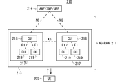
- FIG. 3 is a block diagram showing an overall configuration of a 5G communication system 210 discussed in 3GPP.
- the wireless access network is referred to as NG-RAN (Next ⁇ Generation ⁇ Radio ⁇ Access ⁇ Network) 211.
- the UE 202 can wirelessly communicate with an NR base station device (hereinafter, referred to as an “NR base station (NG-RAN @ NodeB: gNB)”) 213, and transmits and receives signals by wireless communication.
- the core network is called a 5G core (5G @ Core: 5GC).
- a control protocol for the UE 202 for example, RRC (Radio Resource Control) and a user plane (hereinafter sometimes referred to as U-Plane), for example, SDAP (Service Data Adaptation Protocol), PDCP (Packet Data Convergence Protocol), RLC (Radio Link) If Control, MAC (Medium Access Control), and PHY (Physical Layer) terminate at the NR base station 213, the NG-RAN is configured by one or a plurality of NR base stations 213.
- RRC Radio Resource Control
- U-Plane for example, SDAP (Service Data Adaptation Protocol), PDCP (Packet Data Convergence Protocol), RLC (Radio Link)
- MAC Medium Access Control
- PHY Physical Layer
- the function of the control protocol RRC (Radio Resource Control) between the UE 202 and the NR base station 213 is the same as that of LTE.
- the states of the NR base station 213 and the UE 202 in RRC include RRC_IDLE, RRC_CONNECTED, and RRC_INACTIVE.
- RRC_IDLE and RRC_CONNECTED are the same as in the LTE system.
- RRC_INACTIVE performs notification of system information (System @ Information: SI), paging, cell reselection (cell @ re-selection), mobility, and the like while maintaining the connection between the 5G core and the NR base station 213. .
- the gNB 217 has an access / mobility management function (Access / Mobility / Management / Function: AMF), a session management function (Session / Management / Function: SMF), or UPF (User / Plane / Function), or AMF / SMF / UPF including AMF, SMF and UPF.
- AMF Access / Mobility / Management / Function
- SMF session management function
- UPF User / Plane / Function
- the NG interface is a general term for an N2 interface between gNB 217 and AMF, an N3 interface between gNB 217 and UPF, an N11 interface between AMF and SMF, and an N4 interface between UPF and SMF.
- a plurality of 5GC units 214 may be connected to one gNB 217.
- the gNBs 217 are connected by an Xn interface, and control information and / or user data is communicated between the gNBs 217.
- the NR base station 213 may configure one or a plurality of cells similarly to the base station 203. When one NR base station 213 forms a plurality of cells, each cell is configured to be able to communicate with the UE 202.
- the $ gNB 217 may be divided into a central unit (hereinafter sometimes referred to as a CU) 218 and a distributed unit (hereinafter sometimes referred to as a DU) 219.
- a central unit hereinafter sometimes referred to as a CU
- a distributed unit hereinafter sometimes referred to as a DU
- One CU 218 is configured in the gNB 217.
- One or a plurality of DUs 219 are configured in the gNB 217.
- the CU 218 is connected to the DU 219 by an F1 interface, and control information and / or user data is communicated between the CU 218 and the DU 219.
- FIG. 4 is a diagram showing a configuration of a DC including an eNB and a gNB connected to the EPC.
- a solid line indicates a U-Plane connection
- a broken line indicates a C-Plane connection.
- eNB 223-1 is a master base station
- gNB 224-2 is a secondary base station (this DC configuration may be referred to as EN-DC in some cases).
- FIG. 4 shows an example in which the U-Plane connection between the MME unit 204 and the gNB 224-2 is performed via the eNB 223-1. However, the U-Plane connection may be directly performed between the MME unit 204 and the gNB 224-2. Good.
- FIG. 5 is a diagram showing a configuration of a DC using a gNB connected to an NG core.
- a solid line indicates a U-Plane connection
- a dashed line indicates a C-Plane connection.
- gNB224-1 is a master base station
- gNB224-2 is a secondary base station (this DC configuration may be referred to as NR-DC in some cases).
- FIG. 5 shows an example in which the U-Plane connection between the 5GC unit 214 and the gNB 224-2 is performed via the gNB 224-1, but the U-Plane connection may be directly performed between the 5GC unit 214 and the gNB 224-2. Good.
- FIG. 6 is a diagram showing a configuration of a DC including an eNB and a gNB connected to the NG core.
- a solid line indicates a U-Plane connection
- a broken line indicates a C-Plane connection.
- eNB 226-1 becomes a master base station
- gNB 224-2 becomes a secondary base station (this DC configuration may be referred to as NG-EN-DC in some cases).
- FIG. 6 illustrates an example in which the U-Plane connection between the 5GC unit 214 and the gNB 224-2 is performed via the eNB 226-1, but the U-Plane connection may be directly performed between the 5GC unit 214 and the gNB 224-2. Good.
- FIG. 7 is a diagram showing another configuration of the DC using the eNB and the gNB connected to the NG core.
- a solid line indicates a U-Plane connection
- a broken line indicates a C-Plane connection.
- gNB 224-1 is a master base station
- eNB 226-2 is a secondary base station (this DC configuration may be referred to as NE-DC).
- FIG. 7 illustrates an example in which the U-Plane connection between the 5GC unit 214 and the eNB 226-2 is performed via the gNB 224-1, but the U-Plane connection may be directly performed between the 5GC unit 214 and the eNB 226-2. Good.
- FIG. 8 is a block diagram showing a configuration of the mobile terminal 202 shown in FIG. The transmission process of the mobile terminal 202 shown in FIG. 8 will be described.
- control data from the protocol processing unit 301 and user data from the application unit 302 are stored in the transmission data buffer unit 303.
- the data stored in the transmission data buffer unit 303 is passed to the encoder unit 304 and subjected to encoding processing such as error correction.
- the data encoded by the encoder unit 304 is subjected to modulation processing by the modulation unit 305.
- Modulation section 305 may perform precoding in MIMO.
- FIG. 8 illustrates the case where the number of antennas is four, but the number of antennas is not limited to four.
- the receiving process of the mobile terminal 202 is executed as follows. Radio signals from the base station 203 are received by the antennas 307-1 to 307-4. The received signal is converted from a wireless reception frequency to a baseband signal by frequency conversion section 306, and demodulation processing is performed by demodulation section 308. Weight calculation and multiplication processing may be performed in demodulation section 308. The demodulated data is passed to the decoder unit 309, where decoding processing such as error correction is performed. Of the decoded data, control data is passed to the protocol processing unit 301, and user data is passed to the application unit 302. A series of processes of the mobile terminal 202 is controlled by the control unit 310. Therefore, the control unit 310 is connected to each of the units 301 to 309, although not shown in FIG. In FIG. 8, the number of antennas used for transmission and the number of antennas used for reception by mobile terminal 202 may be the same or different.
- FIG. 9 is a block diagram showing a configuration of base station 203 shown in FIG. The transmission process of the base station 203 shown in FIG. 9 will be described.
- EPC communication section 401 performs data transmission and reception between base station 203 and EPC (MME section 204 and the like).
- 5GC communication section 412 transmits and receives data between base station 203 and 5GC (5GC section 214 and the like).
- the other base station communication unit 402 transmits and receives data to and from another base station.
- EPC communication section 401, 5GC communication section 412, and other base station communication section 402 exchange information with protocol processing section 403, respectively. Control data from the protocol processing unit 403 and user data and control data from the EPC communication unit 401, the 5GC communication unit 412, and the other base station communication unit 402 are stored in the transmission data buffer unit 404.
- the data stored in the transmission data buffer unit 404 is passed to the encoder unit 405 and subjected to encoding processing such as error correction. There may be data directly output from the transmission data buffer unit 404 to the modulation unit 406 without performing the encoding process.
- the encoded data is subjected to a modulation process in a modulation unit 406.
- Modulation section 406 may perform precoding in MIMO.
- the modulated data is converted to a baseband signal and then output to the frequency conversion unit 407, where it is converted to a radio transmission frequency. Thereafter, a transmission signal is transmitted to one or more mobile terminals 202 from antennas 408-1 to 408-4.
- FIG. 9 illustrates the case where the number of antennas is four, but the number of antennas is not limited to four.
- the receiving process of the base station 203 is executed as follows. Radio signals from one or more mobile terminals 202 are received by antenna 408. The received signal is converted from a wireless reception frequency to a baseband signal by a frequency conversion unit 407, and demodulation processing is performed by a demodulation unit 409. The demodulated data is passed to a decoder unit 410, where decoding processing such as error correction is performed. Among the decoded data, the control data is passed to the protocol processing unit 403 or the 5GC communication unit 412 or the EPC communication unit 401 and the other base station communication unit 402, and the user data is sent to the 5GC communication unit 412, the EPC communication unit 401 and the other base station communication unit. It is passed to the station communication unit 402.
- a series of processes of the base station 203 is controlled by the control unit 411. Therefore, the control unit 411 is connected to each of the units 401 to 410, although omitted in FIG. In FIG. 9, the number of antennas used for transmission and the number of antennas used for reception by base station 203 may be the same or different.
- FIG. 9 is a block diagram showing the configuration of base station 203, but base station 213 may have a similar configuration. 8 and 9, the number of antennas of mobile terminal 202 and the number of antennas of base station 203 may be the same or different.
- FIG. 10 is a block diagram showing the configuration of the MME.
- FIG. 10 shows the configuration of MME 204a included in MME section 204 shown in FIG.
- PDN @ GW communication section 501 transmits and receives data between MME 204a and PDN @ GW.
- the base station communication unit 502 transmits and receives data between the MME 204a and the base station 203 using the S1 interface. If the data received from the PDN @ GW is user data, the user data is passed from the PDN @ GW communication unit 501 to the base station communication unit 502 via the user plane communication unit 503, and to one or more base stations 203. Sent. If the data received from the base station 203 is user data, the user data is passed from the base station communication unit 502 to the PDN @ GW communication unit 501 via the user plane communication unit 503, and transmitted to the PDN @ GW.
- control data is passed from the PDN @ GW communication unit 501 to the control plane control unit 505.
- control data is passed from the base station communication unit 502 to the control plane control unit 505.
- the control plane control unit 505 includes a NAS security unit 505-1, an SAE bearer control unit 505-2, an idle state (Idle @ State) mobility management unit 505-3, and the like, and a control plane (hereinafter, referred to as C-Plane). In some cases).
- the NAS security unit 505-1 performs security of a NAS (Non-Access @ Stratum) message and the like.
- the SAE bearer control unit 505-2 manages a bearer of SAE (System @ Architecture @ Evolution) and the like.
- the idle state mobility management unit 505-3 manages mobility in a standby state (idle state (Idle @ State); also referred to as LTE-IDLE state or simply idle), generates and controls a paging signal in the standby state, and is controlled by the idle state mobility management unit 505-3. Add, delete, update, search, and track area list management of one or more mobile terminals 202.
- the MME 204a distributes a paging signal to one or a plurality of base stations 203. Further, the MME 204a performs mobility control (Mobility @ control) in a standby state (Idle @ State). The MME 204a manages a tracking area (Tracking @ Area) list when the mobile terminal is in a standby state and in an active state (Active @ State). The MME 204a starts a paging protocol by transmitting a paging message to a cell belonging to a tracking area (tracking area: Tracking @ Area) where the UE is registered. The management of the CSG, the management of the CSG @ ID, and the management of the whitelist of the eNB 207 connected to the MME 204a may be performed by the idle state mobility management unit 505-3.
- FIG. 11 is a block diagram showing the configuration of 5GC.
- FIG. 11 shows the configuration of 5GC section 214 shown in FIG.
- FIG. 11 illustrates a case where the 5GC unit 214 illustrated in FIG. 5 includes the configuration of the AMF, the configuration of the SMF, and the configuration of the UPF.
- the Data @ Network communication unit 521 transmits and receives data between the 5GC unit 214 and the Data @ Network.
- Base station communication section 522 transmits and receives data via the S1 interface between 5GC section 214 and base station 203 and / or the NG interface between 5GC section 214 and base station 213.
- the user data is passed from the Data @ Network communication unit 521 to the base station communication unit 522 via the user plane communication unit 523, and one or more base stations 203 And / or transmitted to base station 213.
- the user data is passed from the base station communication unit 522 to the Data @ Network communication unit 521 via the user plane communication unit 523, and the Data @ Network is transmitted. Sent to
- the control data is passed from the Data ⁇ Network communication unit 521 to the session management unit 527 via the user plane control unit 523.
- the session management unit 527 passes the control data to the control plane control unit 525.
- the control data is passed from the base station communication unit 522 to the control plane control unit 525.
- the control plane control unit 525 passes the control data to the session management unit 527.
- the control plane control unit 525 includes a NAS security unit 525-1, a PDU session control unit 525-2, an idle state (Idle @ State) mobility management unit 525-3, and the like, and a control plane (hereinafter, also referred to as C-Plane). )).
- the NAS security unit 525-1 performs security of a NAS (Non-Access @ Stratum) message and the like.
- the PDU session control unit 525-2 manages a PDU session between the mobile terminal 202 and the 5GC unit 214, and the like.
- the idle state mobility management unit 525-3 manages mobility in a standby state (idle state (Idle State); RRC_IDLE state, or simply idle), generates and controls a paging signal in the standby state, It performs addition, deletion, update, search, and tracking area list management of one or more mobile terminals 202.
- Idle State Idle State
- RRC_IDLE state or simply idle
- # 5GC section 214 distributes a paging signal to one or a plurality of base stations 203 and / or base stations 213.
- the 5GC unit 214 performs mobility control (Mobility Control) in a standby state (Idle State).
- the 5GC unit 214 manages a tracking area (Tracking @ Area) list when the mobile terminal is in a standby state, an inactive state (Inactive @ State), and an active state (Active @ State).
- the 5GC unit 214 starts a paging protocol by transmitting a paging message to a cell belonging to a tracking area (tracking area: Tracking @ Area) in which the UE is registered.
- FIG. 12 is a flowchart illustrating an outline from a cell search to a standby operation performed by a communication terminal (UE) in an LTE communication system.
- the communication terminal starts cell search, in step ST601, it uses the first synchronization signal (P-SS) and the second synchronization signal (S-SS) transmitted from the surrounding base stations to perform slot timing, frame Synchronize timing.
- P-SS first synchronization signal
- S-SS second synchronization signal
- synchronization signal (Synchronization @ Signal: SS).
- the synchronization signal (SS) is assigned a synchronization code corresponding to the PCI assigned to each cell on a one-to-one basis.
- the number of PCIs is 504. Synchronization is performed using the 504 types of PCI, and the PCI of the synchronized cell is detected (identified).
- a cell-specific reference signal which is a reference signal (reference signal: RS) transmitted from the base station for each cell, is detected for the synchronized cell.
- RS received power Reference / Signal / Received / Power: RSRP
- RS reference signal
- a code corresponding to one-to-one with PCI is used. By taking a correlation with the code, it can be separated from other cells. By deriving the RS code of the cell from the PCI identified in step ST601, it becomes possible to detect the RS and measure the received power of the RS.
- a cell with the best RS reception quality for example, a cell with the highest RS reception power, that is, a best cell, is selected from one or more cells detected up to step ST602.
- the base station receives the PBCH of the best cell and obtains BCCH as broadcast information.
- MIB Master @ Information @ Block
- the MIB information includes, for example, a DL (downlink) system bandwidth (also referred to as a transmission bandwidth configuration (transmission-bandwidth configuration: dl-bandwidth)), the number of transmission antennas, and an SFN (System-Frame-Number).
- step ST605 the DL-SCH of the cell is received based on the cell configuration information of the MIB, and the SIB (System Information Block) 1 in the broadcast information BCCH is obtained.
- SIB1 includes information on access to the cell, information on cell selection, and scheduling information on another SIB (SIBk; k ⁇ 2, an integer).
- SIB1 includes a tracking area code (Tracking Area Code: TAC).
- the communication terminal compares the TAC of SIB1 received in step ST605 with the TAC part of the tracking area identifier (Tracking @ Area ⁇ Identity: TAI) already held by the communication terminal.
- the tracking area list is also called a TAI list (TAI @ list).
- the TAI is identification information for identifying a tracking area, and is composed of MCC (Mobile Network Code), MNC (Mobile Network Code), and TAC (Tracking Area Code).
- MCC Mobile Network Code
- MNC Mobile Network Code
- TAC Track Area Code
- step ST605 If the TAC received in step ST605 is the same as the TAC included in the tracking area list as a result of the comparison in step ST606, the communication terminal enters a standby operation in the cell. By comparison, if the TAC received in step ST605 is not included in the tracking area list, the communication terminal transmits a TAU (Tracking Area Update) to the core network (Core Network, EPC) including the MME or the like through the cell.
- TAU Track Area Update
- EPC Core Network
- the best beam may be selected in addition to the best cell in step ST603.
- beam information for example, a beam identifier may be obtained.
- scheduling information of Remaining Minimum SI RMSI
- RMSI may be received in step ST605.
- a device constituting the core network performs tracking based on the identification number (UE-ID, etc.) of the communication terminal sent from the communication terminal together with the TAU request signal. Update the area list.
- the core network side device transmits the updated tracking area list to the communication terminal.
- the communication terminal rewrites (updates) the TAC list held by the communication terminal based on the received tracking area list. Thereafter, the communication terminal enters a standby operation in the cell.
- a cell configured by an eNB has a relatively wide range of coverage.
- a cell is configured to cover a certain area by a relatively wide coverage of a plurality of cells configured by a plurality of eNBs.
- the cell constituted by the eNB has a smaller coverage than the coverage of the cell constituted by the conventional eNB. Therefore, as in the conventional case, in order to cover a certain area, a large number of small cell eNBs are required as compared with the conventional eNB.
- a cell having relatively large coverage such as a cell configured by a conventional eNB
- a macro cell such as a cell configured by a conventional eNB
- an eNB configuring the macro cell is referred to as a “macro eNB”.
- a cell having relatively small coverage such as a small cell
- an eNB configuring the small cell is referred to as a “small eNB”.
- the macro eNB may be, for example, a “wide area base station (Wide Area Base Station)” described in Non-Patent Document 7.
- the small eNB may be, for example, a low power node, a local area node, a hot spot, or the like. Further, the small eNB is a pico eNB constituting a pico cell, a femto eNB constituting a femtocell, a HeNB, a RRH (Remote Radio Unit), an RRU (Remote Radio Unit), an RRE (Remote Radio Equipment) or an RN (Relay Node). There may be. Further, the small eNB may be a “local area base station (Local Area Base Station)” or a “home base station (Home Base Station)” described in Non-Patent Document 7.
- FIG. 13 shows an example of a cell configuration in NR.
- a narrow beam is formed and transmitted in different directions.
- the base station 750 performs transmission and reception with the mobile terminal using the beam 751-1 at a certain time. At other times, base station 750 transmits and receives to and from the mobile terminal using beam 751-2. Similarly, the base station 750 performs transmission and reception with the mobile terminal using one or more of the beams 751-3 to 751-8. By doing so, the base station 750 configures a wide range of cells.
- FIG. 13 shows an example in which the number of beams used by the base station 750 is eight, but the number of beams may be different from eight. Further, in the example shown in FIG. 13, the number of beams used simultaneously by base station 750 is one, but a plurality may be used.
- a plurality of TRPs (Transmission Reception Points) under the gNB may be used in the connection between the UE and the NR base station (hereinafter sometimes referred to as gNB).
- the base station 750 in FIG. 13 may be one of the TRPs under the control of the gNB.
- the TRP may be referred to as a transmitter-receiver.
- the plurality of TRPs described above may be asynchronous with each other. That is, the subframe boundaries of signals transmitted and received by each TRP may be different from each other. Said asynchronousness may be due to, for example, different backhaul delays.
- the gNB may perform transmission / reception using a plurality of TRPs to subordinate UEs at the same time, or may perform transmission / reception at a different timing for each TRP.
- the UE may transmit and receive the gNB to and from the plurality of TRPs simultaneously or at different timings.
- the UE may switch the transmission and reception destination TRP under the gNB.
- the UE uses the fact that the communication quality with other TRPs under the same gNB becomes better than the currently connected TRP, and uses the above-mentioned TRP with the improved communication quality as the connection destination TRP. May be switched.
- the gNB When connecting the UE to the TRP, for example, when switching the TRP to which the UE connects, the gNB instructs the UE to start random access processing.
- the indication may be notified using L1 / L2 signaling, for example, using PDCCH. That is, the random access process may be a PDCCH indication RA (PDCCH-order @ Random @ Access). This allows, for example, the base station to issue a quick random access instruction to the UE.
- PDCCH indication RA PDCCH-order @ Random @ Access
- the indication may be notified using MAC signaling. This allows, for example, the base station to put more information in the instruction.
- the indication may be notified using RRC signaling. This allows, for example, the base station to put more information in the instruction.
- the gNB may issue the instruction using the TRP to be switched (for example, the TRP before switching) or may use a TRP different from the switching target.
- the above-described instruction using a TRP different from the switching target may be used, for example, when the gNB communicates with the UE using a plurality of TRPs. Accordingly, for example, by using a TRP having a better communication quality than the TRP to be switched, it is possible to improve the reliability in the TRP switching instruction from the gNB to the UE.
- the instruction may be used for switching the SCell TRP.
- the gNB may transmit the switching instruction from a cell different from the SCell, for example, a PCell, a PSCell, or an SCell that can transmit a PDCCH.
- the instruction may include information on a cell in which TRP switching is performed (for example, a cell identifier).
- the gNB can issue a TRP switching instruction for a different cell.
- the indication may be used for switching the TRP between cells.
- the gNB may transmit the switching instruction from a cell before and after the switching, or may transmit the switching instruction from a cell different from the cell.
- the instruction may include information on a cell in which TRP switching between cells is performed (for example, an identifier of a cell before and / or after switching).
- the gNB can issue a TRP switching instruction between cells.
- the gNB may determine the TRP after switching using the measurement result notification from the UE.
- the gNB may determine a beam used for communication with the UE in the TRP. Thereby, for example, it is possible to ensure reliability in communication after TRP switching between the UE and the gNB.
- the measurement result in the UE may be the measurement result of the CSI-RS or the measurement result of the SS block.
- the gNB may determine the TRP after the switching by using the signal strength of the aforementioned signal received by the UE, for example, the RSRP.
- the gNB may determine the TRP after switching using the above-described signal reception quality, for example, RSRQ.
- the gNB may determine the TRP after switching using the signal-to-noise ratio.
- the gNB may instruct the UE to measure the above signal.
- the measurement instruction may be performed using RRC signaling.
- RRC signaling the MeasConfig described in Non-Patent Document 26 (3GPP @ TS38.331 @ V15.2.1) may be used, or another signaling may be used.
- the measurement instruction may be performed using MAC signaling, or may be performed using L1 / L2 signaling.
- a CSI report indication may be used, or other signaling may be used. This allows, for example, the gNB to promptly notify the UE of the measurement instruction.
- the gNB may include information on a TRP to be measured, for example, an identifier of the TRP, in the measurement instruction to the UE.
- the gNB may include information on the beam to be measured, for example, an identifier of the beam, in the measurement instruction.
- the gNB may include information on the number of measurement results reported from the UE to the gNB in the measurement instruction.
- the gNB may include a list of TRPs and / or beams to be measured in the measurement instruction.
- the information on the beam to be measured may be, for example, an identifier of a CSI-RS transmitted using the beam or an identifier of an SS block transmitted using the beam.
- the TRP identifier may be uniquely provided in the gNB, may be uniquely provided in the cell, or may be provided for each UE, for example, for each virtual cell identifier (Virtual ⁇ Cell ⁇ ID). .
- the TRP identifier may include a cell identifier, a UE identifier, or a virtual cell identifier.
- the identifier of the beam may be the same as the identifier of the TRP, or may be uniquely given in the TRP.
- the identifier of the beam may include the identifier of the TRP.
- the UE may report the measurement result to the gNB.
- the report may include information about the measured TRP.
- the report may include information about the beam in the TRP, for example, a CSI-RS identifier and / or an SS block identifier in the beam.
- the report may include received signal strength, received quality, and / or signal to noise ratio for the beam.
- the report may include measurements of the connected TRP and / or beam.
- the above-described connected TRP and / or beam may be a TRP and / or beam that is not included as a measurement target in the measurement instruction from the gNB to the UE.
- the UE may measure the connected TRP and / or beam even if it is not included in the measurement target of the measurement instruction. This allows, for example, the gNB to select the optimal connection destination TRP and / or beam including the TRP and / or beam to which the UE is currently connected, and as a result, it is possible to improve communication reliability.
- RRC signaling may be used for reporting the above measurement result.
- MeasurementReport described in Non-Patent Document 26 3GPP @ TS38.331 @ V15.2.1
- MAC signaling may be used, and L1 / L2 signaling may be used.
- CSI reporting (CSI @ reporting) may be used. The above-mentioned CSI report may be included in the PUCCH or may be included in the PUSCH.
- the above-mentioned CSI report may be a periodic CSI report, a semi-persistent CSI report, or an aperiodic CSI report.
- RACH may be used and SRS may be used.
- information on the measurement result may be included as a sequence of RACH preambles.
- information on the TRP and / or the beam to be measured may be included as the time and / or frequency resource of the SRS, or the information on the measurement result may be the time and / or frequency of the SRS. It may be included as a resource, may be included as an SRS sequence, or may be the combination described above.
- the identifier of the beam may be unique within the gNB.
- the gNB may report information on the correspondence between the TRP and the beam to UEs under its control, or may individually notify the UE.
- the UE may include the beam identifier in the report of the measurement result. This makes it possible to reduce the amount of signaling in the report, for example.
- RRC dedicated signaling may be used
- MAC signaling may be used
- L1 / L2 signaling may be used.
- the identifier of the beam may be unique within the TRP.
- the UE may notify the gNB including the identifier of the TRP in the report of the measurement result. Thereby, for example, it is possible to increase the number of beams that can be supported in one TRP, and as a result, it is possible to improve flexibility in the communication system.
- the gNB may notify the UE of information on the identifier of the TRP or may individually notify the UE.
- PBCH may be used
- RMSI Remaining ⁇ System ⁇ Information
- RRC dedicated signaling may be used
- MAC signaling may be used
- L1 / L2 signaling may be used.
- the UE may notify the gNB of the candidate for the TRP after the switching.
- the gNB may determine the TRP after switching from the candidates.
- the gNB may notify the UE of the determined TRP.
- the notification may be, for example, the same method as the method in which the gNB determines the TRP after switching using the measurement result notification from the UE.
- the gNB can select the TRP after switching using the load status of the TRP, and as a result, the communication system can be operated efficiently.
- the UE may measure the peripheral TRP including the connection destination TRP.
- the measurement may be performed using a measurement instruction from the gNB, or may be performed without the measurement instruction.
- the measurement may be performed periodically, or may be performed when a predetermined condition is satisfied.
- the condition may be, for example, a condition relating to communication quality with a connected TRP.
- a threshold value related to a reception error rate for example, BER or BLER may be used
- a threshold value related to RSRP of RS transmitted from the TRP may be used. May be used, a threshold value for RSRQ may be used, and a threshold value for SINR may be used.
- the RS may be, for example, a DMRS, a CSI-RS, or a PTRS.
- An SS block may be used instead of the RS.
- the condition may be, for example, that the UE starts the measurement when the communication quality of the UE is equal to or less than the above-described threshold value or less. Thus, for example, it is possible to reduce the amount of signaling between the UE and the gNB while ensuring the communication quality between the UE and the gNB.
- the threshold value described above may be determined in advance by a standard, or may be reported or notified from the gNB to the UE.
- a standard for example, RRC signaling may be used, MAC signaling may be used, or L1 / L2 signaling may be used.
- RSRP of a signal received from a peripheral TRP may be used, RSRQ may be used, SINR may be used, or the combination described above may be used.
- RSRQ may be used
- SINR may be used, or the combination described above may be used.
- a predetermined number of TRPs and / or beams may be used as the candidates in the descending order of RSRP, and TRPs and / or beams having an RSRP equal to or more than a predetermined threshold value may be used as the candidates.
- up to a predetermined number of TRPs and / or beams may be set as the candidates in the descending order of the RSRP, RSRQ, or SINR. This can prevent, for example, an increase in the signaling amount between the UE and the gNB.
- at least one TRP and / or beam may be considered as the candidate, regardless of whether it is above or above a predetermined threshold.
- the above-described threshold used for selecting the candidate may be the same as or different from the threshold used for starting measurement of the UE.
- a method of determining a threshold used for selecting the candidate may be determined in the same manner as the threshold used for starting measurement of the UE, or may be notified or notified to the UE in a similar manner. This makes it possible, for example, to avoid complexity in the design of the communication system.
- the predetermined number described above may be determined by a standard, or may be reported or notified from the gNB to the UE.
- RRC signaling may be used
- MAC signaling may be used
- L1 / L2 signaling may be used.
- the UE may determine the TRP after switching.
- the UE may measure, for example, peripheral TRPs including the connection destination TRP.
- the measurement may be performed using a measurement instruction from the gNB, may be performed periodically without the measurement instruction, or may be performed using a TRP switching instruction from the gNB to the UE. May be.
- the TRP switching instruction from the gNB to the UE there may be no information on the switching destination TRP.
- the UE may notify the gNB of information on the determined TRP.
- the indication may include information about the beam in the TRP.
- the information about the beam may be, for example, a CSI-RS identifier and / or an SS block identifier for the beam.
- RRC signaling may be used
- MAC signaling may be used
- L1 / L2 signaling may be used, or the above-described combination may be used.
- the UE can quickly notify the base station of the information on the determined TRP to the gNB.
- the UE may determine the TRP after the switch using the signal strength of the above-mentioned signal received by the UE, for example, the RSRP.
- the UE may determine the TRP after the switching by using the reception quality of the signal, for example, the RSRQ.
- the UE may determine the TRP after the switch using the signal-to-noise ratio. Thereby, for example, it is possible to improve the reliability of communication between the UE and the gNB after TRP switching.
- the following (1) to (14) are disclosed as examples of information included in the random access start instruction from the gNB to the UE.
- the information (1) described above may be, for example, an identifier of a TRP of a connection destination, or may be information on a beam used by the TRP.
- the beam information for example, information on the SS block may be used, information on the CSI-RS may be used, or both of the above may be used.
- the UE can quickly acquire the beam of the connection destination.
- the information on the SS block described above may be, for example, an identifier of the SS block.
- the information on the CSI-RS described above may be, for example, an identifier of a CSI-RS resource.
- the information of the above (1) may be one or plural.
- the information of the above (1) may be a plurality.
- one or more TRPs may be connected. Thereby, for example, it is possible to reduce the amount of signaling from the base station to the UE when a plurality of TRPs and / or beams are added as a connection destination of the UE.
- the information of (1) above may include information on the number of TRPs and / or beams at the connection destination.
- the UE can quickly acquire the number of TRPs and / or beams to be connected to, and as a result, the UE can quickly execute the TRP and / or beam connection processing.
- the information in (1) above may be only information on the number of TRPs and / or beams at the connection destination.
- the UE may determine the above-mentioned number of TRPs and / or beams as a new connection destination from TRPs and / or beams that can be transmitted and received.
- the UE may use the strength of the signal received from the TRP and / or the beam, or may use the PRACH transmission timing for the TRP and / or the beam in determining the new destination TRP and / or the beam, Other indices (eg, the signal-to-noise ratio of the received signal) may be used.
- the UE can communicate with the base station using the TRP and / or the beam with high communication quality, and as a result, the communication quality between the UE and the base station can be improved. Also, for example, the UE can use the TRP and / or the beam with the early PRACH transmission timing, and as a result, the TRP and / or the beam can be quickly switched and / or added in the UE.
- the UE may use this information to determine whether to switch or add a TRP to which the UE connects. For example, if the information in (2) above indicates that the connection is not broken, the UE may add a TRP to be connected using the content. Thus, for example, the UE can quickly determine whether to add or switch the connection destination TRP.
- the above information (3) may be the same as the above information (1), for example.
- the information may be information on a TRP and / or a beam before switching, for example, a TRP and / or a beam to be disconnected from a UE, or may include information on the number of the TRP and / or a beam. Good. Thereby, for example, an effect similar to the above (1) can be obtained.
- the information of the above (3) may be notified from the gNB to the UE by signaling different from the random access start instruction.
- the information may be signaled from the gNB to the UE as a TRP release indication.
- the gNB does not need to transmit a random access start instruction to the UE, and as a result, the signaling amount between the gNB and the UE can be reduced.
- the TRP release instruction may be, for example, L1 / L2 signaling. This allows, for example, a quick notification from the gNB to the UE.
- the signaling may be MAC signaling or RRC signaling. Thereby, for example, a lot of information can be notified.
- the information of (4) above may be the same as the information of (1), for example.
- the information may be information on a TRP and / or a beam for maintaining a connection with the UE, or may include information on the number of the TRP and / or the beam. Thereby, for example, an effect similar to the above (1) can be obtained.
- the information of the above (4) may be notified from the gNB to the UE by signaling different from the random access start instruction.
- the information of the above (4) may be included in the above-mentioned TRP release instruction.
- the information of (5) above may be the same as the information of (1), for example.
- the information may be information on TRPs and / or beams that are candidates for connection with the UE.
- the UE may select a TRP and / or beam to be newly connected from among the TRPs and / or beams to be connected included in the above (5).
- the UE may select the number of TRPs and / or beams included in the above (1).
- the UE may use the method disclosed with respect to the above information (1) in determining a new connection destination TRP and / or beam.
- the UE can select a TRP and / or a beam having a high communication quality and / or an early PRACH transmission timing.
- communication quality between the UE and the base station can be improved.
- the information in (6) above may be, for example, information on the timing at which the UE should transmit the PRACH to the TRP and / or beam after switching.
- the UE may transmit the PRACH to the connected TRP and / or beam using the information. As a result, the UE can quickly execute the random access process for the TRP and / or beam of the connection destination.
- the information of the above (6) may be information indicating the correspondence between the SS block and the PRACH transmission enable timing (for example, the PRACH occasion (occasion)) in the TRP after switching.
- the SS block in the information may be, for example, an SS block index (SSB index).
- the UE may not acquire the system information in the TRP after switching by acquiring the information. This allows, for example, the UE to quickly execute TRP switching.
- the UE may acquire the information of (6) from the broadcast information of the gNB.
- the broadcast information may be transmitted from, for example, the TRP of the connection destination. Thereby, for example, it is possible to reduce the signaling amount of the random access instruction from the gNB to the UE.
- the preamble included in the above information (7) may be a preamble individually given to the UE.
- the UE may start random access processing with a newly connected TRP and / or beam using the notified information of the RA preamble. As a result, random access processing between the UE and the gNB can be quickly performed.
- the preamble included in the information of the above (7) may be uniquely provided in the TRP, or may be uniquely provided in each beam used by the TRP. As a result, for example, it is possible to prevent the depletion of the RA preamble, and as a result, it is possible to increase the number of storable UEs.
- the preamble included in the information of the above (7) may be uniquely given in the gNB.
- the TRP and / or beam to which the UE should connect may be uniquely determined from the preamble information included in the above (7). Thereby, for example, it is possible to reduce the signaling amount in the random access instruction from the base station to the UE.
- the information of the above (7) may be information indicating the correspondence between the SS block and the preamble in the TRP after switching.
- the SS block in the information may be, for example, an SS block index (SSB index).
- the UE may not acquire the system information in the TRP after switching by acquiring the information. This allows, for example, the UE to quickly execute TRP switching.
- the RA preamble used by the UE for connection with the gNB, the RA preamble may be uniquely determined from the information on the above (1). Thereby, for example, it is possible to reduce the signaling amount in the random access instruction from the base station to the UE.
- the information in (8) above may be, for example, information measured by the gNB, or information measured by the UE and reported to the gNB.
- the UE may not perform the random access process on the TRP after the switching, for example, when the TRP before the switching and the TRP after the switching are synchronized using the information of (8) described above. Thereby, for example, TRP switching in the UE can be quickly performed.
- the information (9) described above may be, for example, information on a difference in frame timing between the TRP before switching and the TRP after switching.
- the information may be, for example, one measured by the gNB, or one measured by the UE and reported to the gNB.
- the UE may transmit the PRACH at the PRACH reception timing of the TRP after switching using the information.
- the UE does not need to wait for the SS burst from the TRP after switching, and as a result, the UE can quickly execute RACH transmission to the TRP after switching.
- the information (10) described above may be, for example, information on a difference between a backhaul delay in a TRP before switching and a backhaul delay in a TRP after switching.
- the information may be, for example, one measured by the gNB, or one measured by the UE and reported to the gNB.
- the UE may perform PRACH transmission on the TRP after switching using the information. Thereby, for example, it is possible to reduce the value of TA (Timing ⁇ ⁇ ⁇ ⁇ Advance) in the RA response, and as a result, it is possible to reduce the processing amount of the UE after receiving the RA response.
- TA Timing ⁇ ⁇ ⁇ ⁇ Advance
- the information in (11) above may be, for example, the identifier of the primary TRP.
- the above-mentioned information (11) may be an identifier indicating whether or not the primary TRP is switched, or may be an identifier indicating whether the switched TRP is the primary TRP.
- the gNB and the UE may determine a TRP other than the TRP as a secondary TRP.
- the UE may switch the primary TRP using the information on the above (11). Thus, for example, when the primary TRP is set for the UE, the UE can quickly switch the primary TRP.
- the information of (12) above may be, for example, an identifier of a TRP transmitting the primary PDCCH and / or the secondary PDCCH.
- the above-mentioned TRP identifier may be one or plural. There may be no identifier of the TRP transmitting the secondary PDCCH. When there is no TRP identifier for transmitting the secondary PDCCH, the secondary PDCCH may not be transmitted.
- the information of the above (12) may not include the identifier of the primary TRP.
- the primary PDCCH may be transmitted from at least the primary TRP.
- the UE may perform the receiving operation of the primary PDCCH and / or the secondary PDCCH using the information of (12) described above. The UE may stop the receiving operation for the TRP that is not included in the information of (12). Thereby, for example, power consumption in the UE can be reduced.
- the information in (13) above may be, for example, scheduling information for transmission and reception performed by the UE with the TRP after switching.
- the UE may transmit and receive signals and / or data to and from the TRP after switching using the information of (13) described above.
- the UE can quickly execute data transmission and reception after synchronization is established with the TRP after switching.
- the information may be included in the RA response.
- the UE can quickly execute data transmission and reception after establishing synchronization with the TRP after switching, and can reflect the communication environment of the UE at the time of TRP switching in scheduling. For this reason, the transmission and reception efficiency in the communication system can be improved.
- the information may be included in both the random access instruction and the RA response.
- information on periodic and / or semi-persistent scheduling may be included in the random access indication
- information on dynamic scheduling may be included in the RA response.
- the UE can quickly execute data transmission and reception after establishing synchronization with the TRP after switching, and can reduce the amount of signaling in the RA response.
- the information of (13) above may include information of PDSCH scheduled by the primary PDCCH, may include information of PUCCH, may include information of PUSCH, and may include information of SRS. Information may be included.
- the PDSCH, PUCCH, PUSCH, and / or SRS information described above may include TRP information for transmitting and receiving the channel and / or signal, for example, a TRP identifier.
- a plurality of TRPs may be included in the PDSCH, PUCCH, PUSCH, and / or SRS information described above.
- the UE may transmit and receive the channel and / or the signal using the information of (13) described above. This enables, for example, flexible scheduling in communication using a plurality of TRPs.
- the UE performs random access with the connection destination TRP by using a random access instruction from the gNB.
- the UE may start the random access process using the frame timing of the TRP after switching.
- the UE may establish downlink synchronization with the TRP after switching using the random access instruction.
- the UE may establish the downlink synchronization by using the reception of the SS block transmitted from the connection destination TRP. This makes it possible to prevent interference in the TRP after switching, for example.
- the UE may obtain downlink synchronization with the connection destination TRP in advance. For example, the UE may maintain the downlink synchronization established at the time of measuring the connection destination TRP.
- the above-described measurement may be, for example, the measurement of the CSI-RS or the measurement of the SS block. Thereby, for example, the UE can quickly transmit the PRACH to the gNB.
- the UE may start the random access process using the frame timing of the TRP before switching.
- the UE may derive the frame timing of the post-switch TRP using the information on the above (9).
- the UE may transmit the PRACH at the PRACH reception timing of the TRP after switching using the derived frame timing.
- the UE does not need to wait for the SS burst from the TRP after switching, and as a result, the UE can quickly execute RACH transmission to the TRP after switching.
- the UE may acquire system information from the gNB in the random access process.
- the UE may obtain a PRACH transmission timing (eg, a PRACH occasion) using the system information. Accordingly, for example, the gNB does not need to individually notify the information of the above (6) to the UE, and as a result, the amount of signaling between the gNB and the UE can be reduced.
- the UE does not have to acquire the system information from the gNB in the random access process.
- the gNB may notify the UE of the information of the above (6).
- the UE may acquire the PRACH transmission timing (for example, the PRACH occasion) using the information of (6) described above.
- the UE does not need to acquire system information, and as a result, the UE can quickly perform random access.
- the gNB may notify the UE of the information of the above (7) in advance.
- the UE may perform a random access process using the preamble included in the information (7). This makes it possible to prevent, for example, collision with another UE in random access, and as a result, the UE can execute random access quickly.
- the correspondence between the SS block and the PRACH transmittable timing may be uniquely given in the TRP.
- the correspondence may be different between TRPs.
- the allocation of the PRACH transmittable timing in the gNB can be flexibly performed.
- the correspondence between the SS block and the PRACH transmittable timing may be uniquely given in a cell. That is, the correspondence may be unique among the TRPs. This makes it possible, for example, to avoid complexity in the communication system.
- System information transmitted from the gNB may be different for each TRP of the transmission source.
- the system information may be only system information on the TRP.
- the system information on the TRP may include, for example, the correspondence between the above-mentioned SS block and the PRACH transmission enable timing in the TRP.
- the amount of system information transmitted by the gNB can be reduced.
- the system information transmitted from the gNB may include system information on all or a part of the TRPs under the gNB.
- the system information on the TRP may include, for example, the correspondence between the above-mentioned SS block and the PRACH transmission enable timing in the TRP.
- the UE can acquire the system information used in the switching destination TRP at the time of the TRP switching, so that the UE can quickly execute the TRP switching.
- the UE may stop transmission / reception of signals and / or data via the TRP before switching using the random access instruction from the gNB.
- the UE may resume transmission and reception of signals and / or data via the switched TRP using the RA response received from the gNB via the switched TRP.
- gNB the same applies to gNB.
- it is possible to prevent interference with the TRP before and / or after switching during TRP switching.
- the UE may transmit a HARQ response to the random access instruction from the gNB to the TRP before switching.
- the transmission of the HARQ response may be performed, for example, when the random access instruction is performed using RRC signaling or MAC signaling.
- the UE can notify the HARQ-Nack to the gNB, and the gNB notifies the UE of the HARQ-Nack.
- the random access instruction can be retransmitted.
- the UE may transmit a HARQ response to downlink data from the gNB to the TRP before switching.
- the transmission of the HARQ response to the TRP before switching may be performed, for example, before the transmission of the HARQ response to the above-described random access instruction. Accordingly, for example, even when the HARQ decoding result of the downlink data in the UE becomes NG, the UE can notify the gNB of the HARQ-Nack, and the gNB can The downlink data can be retransmitted.
- the UE may transmit a HARQ response to downlink data from the gNB to the TRP after switching.
- the transmission of the HARQ response to the TRP after the switching may be performed, for example, after the transmission of the HARQ response to the above-described random access instruction.
- the UE may suspend the HARQ response until the timing of transmitting the PRACH to the TRP after switching. Thereby, for example, the same effect as described above can be obtained.
- the UE may receive the HARQ response to the uplink data to the gNB from the TRP before the switching.
- the reception of the HARQ response from the TRP before switching may be performed, for example, before the transmission of the HARQ response to the above-described random access instruction.
- the UE can receive the HARQ-Nack from the gNB, and the UE sends the HARQ-Nack to the gNB.
- Uplink data can be retransmitted.
- the UE may receive the HARQ response to the uplink data to the gNB from the switched TRP.
- the reception of the HARQ response from the TRP after the switching may be performed, for example, before the transmission of the HARQ response to the above-described random access instruction.
- the UE may suspend the reception of the HARQ response until after the timing of receiving the RA response from the TRP after switching. Thereby, for example, the same effect as described above can be obtained.
- the UE does not have to assume downlink data reception after the random access instruction or after the random access instruction.
- the UE may not receive downlink data after the random access instruction or after the random access instruction.
- Downlink data transmission to the UE may be resumed after an RA response from the TRP after switching. This makes it possible, for example, to avoid design complexity in the communication system.
- the UE may not perform uplink data transmission after the random access instruction or after the random access instruction. Uplink data transmission from the UE may be resumed after the RA response from the TRP after switching. This makes it possible, for example, to avoid design complexity in the communication system.
- the UE may reselect or determine the connection destination TRP.
- the above operation may be performed, for example, when the UE has failed in the process of switching to the TRP after switching.
- the failure of the switching process may be, for example, a failure of a random access process or a failure of capturing an SS block.
- the UE may notify the gNB of the reselection or redetermination of the connection destination TRP, including information indicating that the TRP switching process has failed. Thereby, for example, it is possible to avoid a communication disabled state between the gNB and the UE when the TRP switching process fails. As a result, the robustness of the communication system can be improved.
- FIGS. 14 and 15 are diagrams illustrating an operation of switching the connection TRP of the UE.
- FIG. 14 and FIG. 15 are connected at the position of the boundary line BL1415.
- the TRP connected to the UE switches from TRP # 1 to TRP # 2.
- 14 and 15 show an operation example in which the UE measures the CSI-RS, and the gNB determines the connection destination TRP using the measurement result.
- Step ST1401 shows data transmission and reception between UE and TRP # 1
- step ST1402 shows data transmission and reception between TRP # 1 and gNB.
- steps ST1405 and ST1406 shown in FIG. 14 gNB instructs UE to measure CSI-RS via TRP # 1.
- Step ST1405 shows a measurement instruction from gNB to TRP # 1
- step ST1406 shows a measurement instruction from TRP # 1 to the UE.
- the measurement instruction shown in steps ST1405 and ST1406 may be performed by RRC signaling, may be performed by MAC signaling, or may be performed by L1 / L2 signaling.
- Step ST1410 and ST1411 shown in FIG. 14, TRP # 1 and TRP # 2 transmit a CSI-RS to the UE.
- Step ST1410 shows CSI-RS transmission from TRP # 1
- step ST1411 shows CSI-RS transmission from TRP # 2.
- the UE receives the CSI-RS shown in Steps ST1410 and ST1411, and measures the signal.
- Step ST1415 indicates a measurement result notification from the UE to TRP # 1
- step ST1416 indicates a measurement result notification from TRP # 1 to the gNB.
- the measurement result notification shown in steps ST1415 and ST1416 may be performed by RRC signaling, may be performed by MAC signaling, or may be performed by L1 / L2 signaling.
- step ST1420 shown in FIG. 14 the gNB determines to switch the TRP of the connection destination of the UE from TRP # 1 to TRP # 2 using the measurement result in step ST1416.
- Step ST1425 and ST1426 shown in FIG. 14 the gNB instructs the UE to start RACH via TRP # 1.
- Step ST1425 shows the instruction from gNB to TRP # 1
- step ST1426 shows the instruction from TRP # 1 to the UE.
- the indication may be transmitted using the PDCCH.
- the instruction includes information indicating switching from TRP # 1 to TRP # 2.
- the instruction may include information on the RA preamble.
- the UE releases the connection with TRP # 1 in step ST1427 shown in FIG. 15 using step ST1426.
- step ST1428 shown in FIG. 15 an SS block is transmitted from TRP # 2 to the UE, and in step ST1429 shown in FIG.
- the UE uses the SS block in step ST1428 to perform downlink synchronization with TRP # 2. To establish. After transmitting the instruction in Step ST1425, the gNB stops the downlink data transmission via the TRP # 1. After receiving the instruction in Step ST1426, the UE stops uplink data transmission via TRP # 1.
- the UE transmits the PRACH to the gNB via TRP # 2.
- Step ST1430 shows PRACH transmission from UE to TRP # 2
- step ST1431 shows PRACH transmission from TRP # 2 to gNB.
- the RA preamble in the PRACH transmission may be the RA preamble included in step ST1426, or may be different.
- Step ST1435 and ST1436 shown in FIG. 15 the gNB notifies the UE of a random access response via TRP # 2.
- Step ST1435 indicates a random access response notification from the gNB to TRP # 2
- step ST1436 indicates a random access response notification from TRP # 2 to the UE.
- the UE establishes uplink synchronization with TRP # 2 using the response.
- the gNB After transmitting the instruction in Step ST1435, the gNB starts downlink data transmission via TRP # 2.
- the UE starts uplink data transmission via TRP # 2.
- steps ST1440 and ST1441 shown in FIG. 15 transmission / reception of uplink / downlink data via TRP # 2 is performed between the UE and the gNB.
- Step ST1440 shows data transmission and reception between UE and TRP # 2
- step ST1441 shows data transmission and reception between TRP # 2 and gNB.
- the CSI-RS is measured is shown, but the SS block may be measured.
- the gNB may instruct the UE to measure the SS block in steps ST1405 and ST1406.
- the UE may notify the gNB of the measurement result of the SS block in Steps ST1415 and ST1416.
- the UE can directly use the signal used for synchronization of the measurement target TRP as the measurement target, so that quick measurement can be performed in the UE.
- FIGS. 14 and 15 show an example in which the TRP # 1 connection release in the UE is performed before the PRACH transmission in step ST1430, as shown in step ST1427.
- TRP # 1 connection release may be performed after the random access response in step ST1436.
- the example has been described in which the UE establishes uplink synchronization after the random access response in step ST1436, but the UE may transmit a random access message 3 to the gNB.
- the gNB may transmit a random access message 4 to the UE.
- the above-described transmission and reception of the random access message 3 and the message 4 may be applied, for example, when the UE uses an RA preamble different from the RA preamble notified from the gNB in step ST1431. This enables, for example, random access on the assumption of collision in TRP switching between the UE and the gNB, and as a result, the number of UEs accommodated in the gNB can be increased.
- the UE autonomously starts a random access process. That is, the UE may start the random access process without the above-described random access instruction transmitted from the gNB.
- the above-mentioned random access instruction may be, for example, a TRP switching instruction.
- the gNB may not send a rejection response to the autonomous random access process by the UE.
- the base station instructing the UE to switch the TRP and / or release the TRP may be performed as an operation of rejecting the autonomous random access processing in the gNB.
- the gNB may send a rejection response to the autonomous random access process performed by the UE.
- the response may be, for example, that no RA response is made during a predetermined period. This makes it possible, for example, to avoid design complexity in the communication system.
- the random access processing described above may be random access without contention (Contention-free @ RandomAccess). That is, the UE may use the RA preamble allocated in advance from the gNB. Thereby, for example, the random access processing can be completed quickly.
- the above-described random access processing may be collision-based random access (Contention-based @ Random @ Access). Thereby, for example, it is possible to prevent the resource of the RA preamble from being depleted in the gNB, and as a result, it is possible to increase the number of accommodated UEs in the gNB.
- the method disclosed in the first embodiment may be applied to switching of TRP when UE performs transmission / reception with a plurality of TRPs.
- one TRP may be switched, or a plurality of TRPs may be switched.
- the TRPs may be switched one by one, or a plurality of TRPs may be switched at a time. For example, by performing switching of a plurality of TRPs at once, TRP switching can be quickly performed.
- the UE may notify the gNB of information on a combination of TRPs with which the UE can perform simultaneous communication.
- the information may be information on a combination of beams with which the own UE can perform simultaneous communication.
- the UE may notify the information by including it in the signaling of the measurement result report described above, or may notify the UE using different signaling.
- the gNB may use the information to determine the switching destination TRP in the UE.
- the gNB can easily determine the TRP with which the UE can perform simultaneous communication.
- the communication rate between the UE and the gNB can be improved, and the reliability between the UE and the gNB can be improved.
- a TRP used for PCell communication may be used, a TRP used for PSCell communication may be used, or a SCell capable of PDCCH transmission may be used.
- a TRP used for communication may be used.
- FIGS. 16 and 17 are diagrams showing an operation in which a UE connected to a plurality of TRPs switches connection TRPs.
- FIG. 16 and FIG. 17 are connected at the position of the boundary line BL1617.
- FIGS. 16 and 17 show an operation example in which the UE measures the CSI-RS and the gNB determines the connection destination TRP using the measurement result.
- the same parts as those in FIGS. 14 and 15 are denoted by the same reference numerals, and the common description will be omitted.
- Steps ST1401 and ST1402 in FIG. 16 are the same as those in FIG.
- steps ST1501 and ST1502 shown in FIG. 16 transmission / reception of uplink / downlink data via TRP # 2 is performed between the UE and the gNB.
- Step ST1501 shows data transmission and reception between UE and TRP # 2
- step ST1502 shows data transmission and reception between TRP # 2 and gNB.
- Steps ST1405 to ST1411 in FIG. 16 are the same as those in FIG.
- TRP # 3 transmits a CSI-RS to the UE.
- the UE receives the CSI-RS shown in Steps ST1410, ST1411, and ST1503, and measures the signal.
- Steps ST1415 and ST1416 in FIG. 16 are the same as those in FIG.
- step ST1504 shown in FIG. 16 the gNB determines to switch the TRP of the connection destination of the UE from TRP # 1, # 2 to TRP # 1, # 3 using the measurement result of step ST1416.
- Step ST1505 shows the instruction from gNB to TRP # 1
- step ST1506 shows the instruction from TRP # 1 to the UE.
- the indication may be transmitted using the PDCCH.
- the UE releases the connection with TRP # 2 in step ST1527 shown in FIG. 17 using step ST1506.
- Step ST1525 and ST1526 shown in FIG. 17 the gNB starts RACH instruction to the UE via TRP # 1.
- Step ST1525 indicates the instruction from the gNB to TRP # 1
- step ST1526 indicates the instruction from TRP # 1 to the UE.
- the indication may be transmitted using the PDCCH.
- the instruction includes information indicating the addition of TRP # 3.
- the instruction may include information on the RA preamble.
- the UE starts the operation of receiving the SS block transmitted from TRP # 3 to the UE in Step ST1528 illustrated in FIG. 17 using Step ST1526.
- Step ST1529 shown in FIG. 17 the UE establishes downlink synchronization with TRP # 3 using the SS block in Step ST1528.
- the UE transmits the PRACH to the gNB via TRP # 3.
- Step ST1507 shows PRACH transmission from UE to TRP # 3
- step ST1508 shows PRACH transmission from TRP # 3 to gNB.
- the RA preamble in the PRACH transmission may be the RA preamble included in step ST1526, or may be different.
- Step ST1509 indicates a random access response notification from the gNB to TRP # 3
- step ST1510 indicates a random access response notification from TRP # 3 to the UE.
- the UE establishes uplink synchronization with TRP # 3 using the response.
- the gNB After transmitting the response in Step ST1509, the gNB starts downlink data transmission via TRP # 3.
- the UE starts uplink data transmission via TRP # 3.
- steps ST1511, ST1512 shown in FIG. 17 transmission / reception of uplink / downlink data via TRP # 1 is performed between the UE and the gNB.
- Step ST1511 shows data transmission and reception between UE and TRP # 1
- step ST1512 shows data transmission and reception between TRP # 1 and gNB.
- steps ST1513 and ST1514 shown in FIG. 17 transmission / reception of uplink / downlink data is performed between the UE and the gNB via TRP # 3.
- Step ST1513 shows data transmission and reception between UE and TRP # 3
- step ST1514 shows data transmission and reception between TRP # 3 and gNB.
- the UE may instruct the UE to measure the SS block in steps ST1405 and ST1406.
- the UE may notify the gNB of the measurement result of the SS block in Steps ST1415 and ST1416.
- the UE can directly use the signal used for synchronization of the measurement target TRP as the measurement target, so that quick measurement can be performed in the UE.
- an instruction to release TRP # 2 from the gNB to the UE shown in steps ST1505 and ST1506 and a release of TRP # 2 connection in the UE shown in step ST1527 are shown in steps ST1525 and ST1526.
- the gNB may instruct the UE to release TRP # 2 and release the TRP # 2 connection in the UE after the random access response in steps ST1509 and ST1510.
- the UE may transmit a random access message 3 to the gNB.
- the gNB may transmit a random access message 4 to the UE.
- the transmission and reception of the random access messages 3 and 4 described above may be applied, for example, when the UE uses an RA preamble different from the RA preamble notified from the gNB in step ST1508. This enables, for example, random access on the assumption of collision in TRP switching between the UE and the gNB, and as a result, the number of UEs accommodated in the gNB can be increased.
- FIGS. 16 and 17 an example is shown in which the release of TRP # 2 shown as steps ST1505 and ST1506 is performed via TRP # 1, but it may be performed via TRP # 2.
- the gNB and the UE can transmit and receive data to and from each other using the resources of TRP # 1, and as a result, the efficiency of the communication system can be improved.
- an autonomous random access process by the UE may be performed.
- the switching of the TRP may be performed one by one.
- the TRP before switching may be, for example, a TRP used for PCell communication, a TRP used for PSCell communication, or an SCell capable of PDCCH transmission.
- the PRACH may include information on the TRP before switching.
- the RA preamble may be determined using the identifier of the TRP before switching.
- the gNB may not send a rejection response to the autonomous random access process by the UE.
- the base station instructing the UE to switch the TRP and / or release the TRP may be performed as an operation of rejecting the autonomous random access processing in the gNB.
- the gNB may send a rejection response to the autonomous random access process performed by the UE.
- the response may be, for example, that no RA response is made during a predetermined period. This makes it possible, for example, to avoid design complexity in the communication system.
- the method disclosed in the first embodiment may be applied to the addition of a connection TRP in the UE.
- one TRP may be added, or a plurality of TRPs may be added.
- the TRPs may be switched one by one, or a plurality of TRPs may be switched at a time. For example, by switching a plurality of TRPs at once, TRP switching can be quickly performed.
- the UE may notify the gNB of information on a combination of TRPs with which the UE can perform simultaneous communication.
- the contents included in the information and / or the notification method may be the same as those in the case of TRP switching when the UE is transmitting and receiving with a plurality of TRPs. Thereby, for example, the same effect as described above can be obtained.
- FIGS. 18 and 19 are diagrams showing an additional operation of the connection TRP in the UE.
- FIG. 18 and FIG. 19 are connected at the position of the boundary line BL1819.
- the example shown in FIGS. 18 and 19 shows a case where TRP # 2 is added as a connection destination for a UE connected to TRP # 1.
- 18 and 19 show an operation example in which the UE measures the CSI-RS, and the gNB uses the measurement result to determine the addition of the connection destination TRP.
- the same portions as those in FIGS. 14, 15, 16 and 17 are denoted by the same reference numerals, and the common description is omitted.
- Steps ST1401 to ST1416 in FIG. 18 are the same as those in FIG.
- step ST1601 shown in FIG. 18 the gNB determines to add TRP # 2 to the TRP to which the UE is connected, using the measurement result in step ST1416.
- Step ST1625 and ST1626 in FIG. 18 the gNB starts RACH instruction to the UE via TRP # 1.
- Step ST1625 shows the instruction from gNB to TRP # 1
- step ST1626 shows the instruction from TRP # 1 to the UE.
- the indication may be transmitted using the PDCCH.
- the instruction includes information indicating the addition of TRP # 2.
- the instruction may include information on the RA preamble.
- the UE starts the receiving operation of the SS block transmitted from TRP # 2 to the UE in Step ST1428 shown in FIG. 19 using Step ST1626.
- Step ST1429 shown in FIG. 19 the UE establishes downlink synchronization with TRP # 2 using the SS block in Step ST1428.
- Steps ST1430, ST1431, ST1435, and ST1436 in FIG. 19 are the same as those in FIG.
- Steps ST1511 and ST1512 shown in FIG. 19 are the same as those in FIG.
- Steps ST1440 and ST1441 shown in FIG. 19 are the same as those in FIG.
- CSI-RS measurement is performed, but SS block measurement may be performed.
- the gNB may instruct the UE to measure the SS block in steps ST1405 and ST1406.
- the UE may notify the gNB of the measurement result of the SS block in Steps ST1415 and ST1416.
- the UE can directly use the signal used for synchronization of the measurement target TRP as the measurement target, so that quick measurement can be performed in the UE.
- the example has been described in which the UE establishes uplink synchronization after the random access response in step ST1435, but the UE may transmit a random access message 3 to the gNB.
- the gNB may transmit a random access message 4 to the UE.
- the above-described transmission and reception of the random access message 3 and the message 4 may be applied, for example, when the UE uses an RA preamble different from the RA preamble notified from the gNB in step ST1431. This enables, for example, random access on the assumption of collision in TRP switching between the UE and the gNB, and as a result, the number of UEs accommodated in the gNB can be increased.
- autonomous random access processing by the UE may be performed.
- the addition of the TRP may be performed one by one.
- the operation (for example, switching of TRP, addition of TRP) performed by autonomous random access processing by the UE may be statically determined by a standard, or may be reported or notified from the gNB to the UE. .
- information on the operation may be included in the PRACH.
- the RA preamble may be determined using the identifier of the TRP before switching. Thereby, for example, the process of adding the TRP can be quickly executed.
- the gNB may not send a rejection response to the autonomous random access process by the UE.
- the base station instructing the UE to switch the TRP and / or release the TRP may be performed as an operation of rejecting the autonomous random access processing in the gNB.
- the gNB may send a rejection response to the autonomous random access process performed by the UE.
- the response may be, for example, that no RA response is made during a predetermined period. This makes it possible, for example, to avoid design complexity in the communication system.
- FIGS. 20 and 21 are diagrams showing an operation of adding a plurality of TRPs connected to the UE collectively.
- FIG. 20 and FIG. 21 are connected at the position of the boundary line BL2021.
- the examples shown in FIGS. 20 and 21 show a case where TRP # 2 and # 3 are added as connection destinations for UEs connected to TRP # 1.
- 20 and 21 show an operation example in a case where the UE measures the CSI-RS, and the gNB uses the measurement result to determine the addition of the connection destination TRP.
- the same parts as those in FIGS. 14, 15, 16, and 17 are denoted by the same reference numerals, and the common description will be omitted.
- Steps ST1401 to ST1411 in FIG. 20 are the same as those in FIG. Step ST1503 in FIG. 20 is the same as that in FIG. Steps ST1413 to ST1416 in FIG. 20 are the same as those in FIG.
- step ST1701 shown in FIG. 20 the gNB determines that TRP # 2 and TRP # 3 are to be added as TRPs to which the UE is connected, using the measurement result in step ST1416.
- Step ST1725 and ST1726 shown in FIG. 20 the gNB starts RACH instruction to the UE via TRP # 1.
- Step ST1725 shows the instruction from gNB to TRP # 1
- step ST1726 shows the instruction from TRP # 1 to the UE.
- the indication may be transmitted using the PDCCH.
- the instruction includes information indicating the addition of TRP # 2 and TRP # 3.
- the instruction may include information on the RA preamble. Information on the RA preamble may be different from each other for TRP # 2 and TRP # 3, or may be the same.
- the UE starts the operation of receiving the SS block transmitted from TRP # 2 to the UE in Step ST1428 shown in FIG. 21 using Step ST1726.
- Step ST1429 shown in FIG. 21 the UE establishes downlink synchronization with TRP # 2 using the SS block in Step ST1428.
- the UE transmits the PRACH to the gNB via TRP # 2.
- the PRACH transmission is the same as in FIG.
- the UE starts the operation of receiving the SS block transmitted from TRP # 3 to the UE in step ST1528 without waiting for the RA response in steps ST1435 and ST1436 shown in FIG. 21 using step ST1726.
- Step ST1529 shown in FIG. 21 the UE establishes downlink synchronization with TRP # 3 using the SS block in Step ST1528.
- the UE transmits the PRACH to the gNB via TRP # 3 in steps ST1507 and ST1508 without waiting for the RA response in steps ST1435 and ST1436 shown in FIG.
- the PRACH transmission is the same as in FIG.
- the gNB notifies the UE of a random access response via TRP # 2.
- the random access response is the same as in FIG.
- the gNB notifies the UE of a random access response via TRP # 3.
- the random access response is the same as in FIG.
- Steps ST1511 and ST1512 shown in FIG. 21 are the same as those in FIG. Steps ST1440 and ST1441 shown in FIG. 21 are the same as those in FIG. Steps ST1513 and ST1513 shown in FIG. 21 are the same as those in FIG.
- the UE may instruct the UE to measure the SS block in steps ST1405 and ST1406.
- the UE may notify the gNB of the measurement result of the SS block in Steps ST1415 and ST1416.
- the UE can directly use the signal used for synchronization of the measurement target TRP as the measurement target, so that quick measurement can be performed in the UE.
- the UE may transmit a random access message 3 to the gNB.
- the gNB may transmit a random access message 4 to the UE.
- the above-described transmission and reception of the random access message 3 and the message 4 may be applied, for example, when the UE uses an RA preamble different from the RA preamble notified from the gNB in step ST1726. This enables, for example, random access on the assumption of collision in TRP switching between the UE and the gNB, and as a result, the number of UEs accommodated in the gNB can be increased.
- the reception of the SS block from TRP # 2, the establishment of downlink synchronization with TRP # 2, and the transmission of PRACH via TRP # 2 shown in steps ST1428 to ST1431, are shown in steps ST1528, ST1529, ST1507, and ST1508.
- An example has been described in which an SS block is received from TRP # 3, downlink synchronization is established with TRP # 3, and PRACH is transmitted via TRP # 3.
- the above-described operation performed later may be performed, for example, when the SS block transmission timing from TRP # 3 is earlier than the SS block transmission timing from TRP # 2. This allows, for example, a quick TRP addition process in the UE according to the SS block transmission timings of TRP # 2 and # 3.
- the method disclosed in the first embodiment may be applied to release of a connected TRP in a UE.
- one or more TRPs may be released.
- the TRPs When releasing a plurality of TRPs, the TRPs may be released one by one, or a plurality of TRPs may be released at a time. For example, by releasing a plurality of TRPs at once, TRP release can be quickly performed.
- the above-described TRP release instruction may be used.
- the gNB may notify the UE of a TRP release instruction.
- the UE may release the connected TRP using the indication.
- $ GNB may notify the UE of the TRP release instruction via the TRP to be released.
- the number of TRPs described above may be one or more.
- the above-described TRP may be all or a part of the TRP to be released.
- the UE may determine the TRP that has transmitted the instruction as a TRP to be released. As a result, for example, the amount of information included in the TRP release instruction transmitted from the gNB to the UE can be reduced. After receiving the instruction, the UE may not perform transmission / reception with the TRP. This makes it possible to prevent a malfunction such as data transmission / reception using the TRP after the release of the TRP.
- the gNB may notify the UE of the TRP release instruction via a TRP that is not a release target.
- the above-described TRP may be, for example, a TRP having the best communication quality with the UE.
- the UE may release the connection with the TRP indicated by the release instruction. Thereby, for example, it is possible to ensure the reliability of the notification of the release instruction.
- the UE may stop the beam of the own UE used for communication of the TRP to be released using the release instruction.
- the UE may stop the operation of uplink transmission and downlink reception to the release target TRP.
- the UE may stop the SRS transmission to the release target TRP, may stop the PDCCH reception operation from the TRP, or may stop the SS block reception operation from the TRP.
- the operation of a combination of two or more of the above may be performed. Thereby, for example, power consumption in the UE can be reduced.
- FIG. 22 is a diagram illustrating an operation of releasing the connection TRP in the UE.
- the example illustrated in FIG. 22 illustrates a case where the connection to TRP # 2 is released for UEs connected to TRP # 1 and # 2.
- FIG. 22 shows an operation example in which the UE measures the CSI-RS, and the gNB determines release of the connection destination TRP using the measurement result.
- FIG. 22 illustrates a case in which the gNB notifies the UE of the release of the connected TRP by using a TRP different from the release target.
- the same parts as those in FIGS. 14, 15, 16 and 17 are denoted by the same reference numerals, and the common description will be omitted.
- Steps ST1401 and ST1402 in FIG. 22 are the same as those in FIG.
- Steps ST1501 and ST1502 are the same as those in FIG.
- Steps ST1405 to ST1416 in FIG. 22 are the same as those in FIG.
- step ST1801 shown in FIG. 22 the gNB determines to release TRP # 2 among the TRPs to which the UE is connected, using the measurement result in step ST1416.
- Step ST1805 indicates the instruction from the gNB to TRP # 1
- step ST1806 indicates the instruction from TRP # 1 to the UE.
- the indication may be transmitted using the PDCCH.
- the UE releases the connection with TRP # 2 in step ST1802 shown in FIG.22 using step ST1806.
- Steps ST1511 and ST1512 in FIG. 22 are the same as those in FIG.
- FIG. 22 shows an example in which the CSI-RS is measured, but the SS block may be measured as in the description of FIG. 14 and FIG.
- the UE can directly use the signal used for synchronization of the measurement target TRP as the measurement target, so that quick measurement can be performed in the UE.
- FIG. 22 shows an example in which the release of TRP # 2 shown as steps ST1805 and ST1806 is performed via TRP # 1, but may be performed via TRP # 2.
- the gNB and the UE can transmit and receive data to and from each other using the resources of TRP # 1, and as a result, the efficiency of the communication system can be improved.
- the method disclosed in the first embodiment may be used in the initial access of the UE.
- the UE may connect to a plurality of TRPs in the initial access to the gNB. This makes it possible, for example, to improve the reliability in the connection procedure between the UE and the gNB.
- the method disclosed in Embodiment 1 may be used for cell reselection.
- the method may be applied to the connection destination TRP switching of the UE in the RRC_INACTIVE state.
- Paging from the gNB to the UE may be performed using all the TRPs under the gNB or may be performed from some of the TRPs.
- the number of TRPs used for paging from the gNB to the UE may be one or more. Accordingly, for example, even when the UE moves in the coverage of another TRP under the same gNB in the RRC_INACTIVE state, the gNB can execute paging for the UE.
- the method disclosed in Embodiment 1 may be used for handover.
- the handover instruction from the gNB to the UE may include information on the connection destination TRP of the handover destination base station.
- the UE may make a connection to the TRP using the information.
- the reliability of communication after the handover can be improved.
- the method disclosed in the first embodiment may be used for beam failure recovery.
- the gNB may notify the UE of information on the TRP and / or beam to be reconnected.
- the information may be included in a beam failure recovery configuration (BeamFailureRecoveryConfig) from the gNB to the UE and notified.
- BeamFailureRecoveryConfig a beam failure recovery configuration from the gNB to the UE and notified.
- a different primary TRP and / or secondary TRP may be used for each cell.
- the primary TRP and / or the secondary TRP can be flexibly set according to the use frequency of each cell and the like, and as a result, the reliability of communication in the communication system can be improved.
- a different primary PDCCH and / or secondary PDCCH may be used for each cell.
- a different primary TRP and / or secondary TRP may be used for each network slice.
- a primary TRP and / or a secondary TRP may be determined using the QCI.
- the primary and / or secondary TRP can be flexibly set according to the communication requirements of each network slice, and as a result, the reliability of communication in the communication system can be improved.
- a different primary PDCCH and / or secondary PDCCH may be used for each network slice.
- TRP to which the UE can connect may be previously reported or notified from the gNB to the UE.
- information on a TRP switching condition in the UE for example, a parameter and a threshold used by the UE for determining TRP switching
- the UE may perform TRP switching using the information.
- synchronization can be quickly established in inter-TRP mobility.
- Modification 1 of Embodiment 1 In the first embodiment, switching, addition, and deletion of TRP for uplink and downlink communication are disclosed, but TRP may be switched only for downlink communication.
- the gNB may notify the UE of a downlink synchronization instruction.
- the notification of the downlink synchronization instruction may be performed using the TRP before switching.
- the downlink synchronization instruction may be performed using, for example, L1 / L2 signaling. Thereby, for example, the base station can promptly notify the UE of the downlink synchronization instruction.
- the downlink synchronization instruction may be performed using MAC signaling or may be performed using RRC signaling. Thereby, for example, it becomes possible to notify the UE including a lot of information in the downlink synchronization instruction.
- the information included in the downlink synchronization instruction from the gNB to the UE may be the same as (1) to (14) disclosed as examples of the information included in the random access start instruction in the first embodiment.
- the UE may use the downlink synchronization instruction to establish downlink synchronization with a TRP included in the downlink synchronization instruction.
- the UE may not transmit an uplink signal and / or uplink data to the TRP.
- the TRP used before the switching of the TRP for downlink communication may be continuously used for uplink communication from the UE. Thereby, for example, the UE can perform uplink communication and downlink communication using different TRPs. As a result, for example, when the radio wave environment of the uplink and the downlink are different, it becomes possible to communicate the uplink communication and the downlink communication by using the optimal communication paths.
- the UE may maintain downlink synchronization with the TRP used for uplink communication. Thereby, for example, the UE can maintain uplink synchronization with the TRP, and as a result, it is possible to improve reliability in uplink communication.
- the UE may transmit the SR to the TRP before switching.
- Information necessary for SR transmission to the TRP before switching for example, information on the PUCCH resource setting for SR may be information used before receiving the downlink synchronization instruction.
- GNB may transmit the uplink grant for the SR to the UE via the switched downlink communication TRP.
- a setting necessary for the UE to receive the uplink grant for example, a setting related to mapping of DCI transmitted from the downlink communication TRP after switching (for example, setting of a search space in the PDCCH) is notified from the gNB to the UE in advance. Or may be included in the downlink synchronization instruction.
- the UE can receive the signal earlier than the TRP for downlink communication after the switching.
- the UE may use the uplink grant to report information indicating that downlink synchronization with the TRP has been established.
- the downlink communication TRP after the switching may be used.
- L1 / L2 signaling may be used. Thereby, for example, the UE can promptly notify that the downlink synchronization has been established.
- MAC signaling or RRC signaling may be used. Thereby, for example, the UE can notify the gNB of a lot of the information.
- the PRACH may be used to notify that downlink synchronization has been established.
- the UE may transmit the PRACH to the TRP after the switching.
- the gNB may not transmit an RA response to the PRACH to the UE.
- the UE may not receive an RA response to the PRACH transmission.
- the UE may acquire the PRACH transmission timing from the broadcast information from the gNB, or may acquire the PRACH transmission timing from the above-described downlink synchronization instruction.
- (6) disclosed as an example of information included in the random access start instruction from the gNB to the UE may be used.
- the information may include information on a TRP for which downlink synchronization has been established.
- the gNB may start downlink data transmission using the TRP using the information.
- the information may include a plurality of TRPs. This makes it possible to reduce the amount of signaling from the UE to the base station, for example.
- the information may not include information on the TRP for which downlink synchronization has been established.
- the fact that the information does not include information on the TRP for which downlink synchronization has been established may indicate that the UE has completed establishment of downlink synchronization with all TRPs after switching. This makes it possible to reduce the amount of signaling from the UE to the base station, for example.
- the UE may transmit the information to the gNB via the TRP before switching.
- the TRP before the switching may be, for example, a TRP for uplink transmission.
- the timing of the HARQ response to the downlink data in the UE may be derived based on the slot number of the uplink TRP at the time of receiving the downlink data.
- the slot offset from the reception of the downlink data to the transmission of the HARQ response may be a slot offset in units of the slot length in the TRP for uplink communication.
- the slot offset may be quasi-statically reported from the gNB to the UE, may be dynamically reported, or may be a combination of both.
- the UE may transmit the HARQ response at the slot number obtained by adding the slot offset to the slot number of the TRP for uplink communication at the time of receiving the downlink data.
- the gNB may derive the slot number of the uplink TRP for the UE at the time of receiving the downlink data, using the difference of the TA and / or the backhaul delay with each TRP in each TRP.
- the UE can transmit a HARQ response to a TRP that is asynchronous with the TRP for downlink communication.
- the same method as the timing of HARQ response to downlink data may be used. Thereby, for example, the same effect as described above can be obtained.
- the UE may not switch the TRP for downlink communication. For example, when the UE fails to switch the TRP for downlink communication from the gNB, the UE may not switch the TRP for downlink communication. In the above description, the UE may notify the gNB of information indicating that TRP switching for downlink communication has failed. In the above description, the TRP before switching may be used in the downlink communication between the gNB and the UE. Accordingly, for example, even when the switching of the downlink communication TRP fails, communication between the UE and the gNB can be continued.
- FIGS. 23 and 24 are diagrams showing the operation of switching the TRP for downlink communication in the UE.
- FIGS. 23 and 24 are connected at the position of the boundary line BL2324.
- FIG. 23 and FIG. 24 show a case where, for a UE connected to TRP # 1, the TRP for downlink communication is switched to TRP # 2, and TRP # 1 becomes the TRP for uplink communication.
- FIGS. 23 and 24 show an operation example in which the UE measures the CSI-RS and the gNB uses the measurement result to determine switching of the TRP for downlink communication. 23 and FIG. 24, the same parts as those in FIG. 14 and FIG.
- Steps ST1401 to ST1416 in FIG. 23 are the same as those in FIG.
- step ST2501 shown in FIG. 23 the gNB determines to switch the TRP for downlink communication of the UE from TRP # 1 to TRP # 2 using the measurement result of step ST1416.
- Step ST2502 shows the instruction from gNB to TRP # 1
- step ST2503 shows the instruction from TRP # 1 to the UE.
- the indication may be transmitted using the PDCCH.
- the instruction includes information indicating switching of the TRP for downlink communication from TRP # 1 to TRP # 2.
- the UE starts the operation of receiving the SS block transmitted from TRP # 2 to the UE in Step ST1428 shown in FIG. 24 using Step ST2503.
- Step ST1429 shown in FIG. 24 the UE establishes downlink synchronization with TRP # 2 using the SS block in Step ST1428.
- Step ST2504 shows the notification from the UE to TRP # 1
- step ST2505 shows the notification from TRP # 1 to the gNB.
- the gNB recognizes the completion of the switching of the downlink communication TRP in the UE using ST2505.
- Step ST2507 indicates data transmission from the UE to TRP # 1
- step ST2508 indicates data transmission from TRP # 1 to the gNB.
- Step ST2509 indicates data transmission from the gNB to TRP # 2
- step ST2510 indicates data transmission from TRP # 2 to the UE.
- FIGS. 23 and 24 an example in which the CSI-RS is measured is shown. However, similarly to the description of FIGS. 14 and 15, the SS block may be measured. Thus, for example, the UE can directly use the signal used for synchronization of the measurement target TRP as the measurement target, so that quick measurement can be performed in the UE.
- FIGS. 25 and 26 are diagrams showing another example of the operation of switching the TRP for downlink communication in the UE.
- FIG. 25 and FIG. 26 are connected at the position of the boundary line BL2526.
- the examples shown in FIGS. 25 and 26 show the case where the TRP for downlink communication switches from TRP # 2 to TRP # 3 for a UE that performs uplink communication with TRP # 1 and performs downlink communication with TRP # 2. I have.
- FIGS. 25 and 26 show an operation example in which the UE measures the CSI-RS, and the gNB uses the measurement result to determine switching of the downlink TRP.
- the same parts as those in FIGS. 14 and 15 are denoted by the same reference numerals, and the common description will be omitted.
- Step ST2601 indicates data transmission from the UE to TRP # 1
- step ST2602 indicates data transmission from TRP # 1 to the gNB.
- Step ST2603 indicates data transmission from the gNB to TRP # 2
- step ST2604 indicates data transmission from TRP # 2 to the UE.
- Steps ST1405 to ST1411 in FIG. 25 are the same as those in FIG. Step ST1503 in FIG. 25 is the same as that in FIG. Steps ST1413 to ST1416 in FIG. 25 are the same as those in FIG.
- step ST2611 shown in FIG. 25 the gNB determines to switch the TRP for downlink communication of the UE from TRP # 2 to TRP # 3 using the measurement result of step ST1416.
- Step ST2605 and ST2606 in FIG. 25 the gNB starts an instruction to switch TRP for downlink communication to the UE via TRP # 2.
- Step ST2605 shows the instruction from gNB to TRP # 2
- step ST2606 shows the instruction from TRP # 2 to the UE.
- the indication may be transmitted using the PDCCH.
- the instruction includes information indicating switching of the TRP for downlink communication from TRP # 2 to TRP # 3.
- the UE starts the operation of receiving an SS block transmitted from TRP # 3 to the UE in Step ST1528 illustrated in FIG. 26 using Step ST2606.
- Step ST1529 shown in FIG. 26 the UE establishes downlink synchronization with TRP # 3 using the SS block in Step ST1528.
- Steps ST2504 and ST2505 shown in FIG. 26 are the same as those in FIG.
- Steps ST2507 and ST2508 shown in FIG. 26 are the same as those in FIG.
- Step ST2609 indicates data transmission from the gNB to TRP # 3
- step ST2610 indicates data transmission from TRP # 3 to the UE.
- the UE can directly use the signal used for synchronization of the measurement target TRP as the measurement target, so that quick measurement can be performed in the UE.
- the first modification of the first embodiment may be applied to a case where the TRP for uplink communication and the TRP for downlink communication are the same after the switching of the TRP for downlink communication.
- the UE may maintain the downlink synchronization state necessary for the ongoing uplink communication using the downlink TRP switching instruction.
- the UE may not perform the downlink synchronization completion notification to the gNB. Thereby, for example, TRP switching for downlink communication in the UE can be performed quickly.
- FIGS. 27 and 28 are diagrams illustrating another example of the operation of switching the TRP for downlink communication in the UE.
- FIGS. 27 and 28 are connected at the position of the boundary line BL2728.
- the TRP for downlink communication is switched from TRP # 2 to TRP # 1, and TRP # 1 And the case of performing uplink and downlink communication.
- FIGS. 27 and 28 show an operation example in which the UE measures the CSI-RS, and the gNB uses the measurement result to determine switching of the TRP for downlink communication.
- portions common to FIGS. 14, 15, 25, and 26 are denoted by the same reference numerals, and common description is omitted.
- Steps ST2601 to ST2604 in FIG. 27 are the same as those in FIG.
- Steps ST1405 to ST1416 in FIG. 27 are the same as those in FIG.
- step ST2701 shown in FIG. 27 the gNB determines to switch the TRP for downlink communication of the UE from TRP # 2 to TRP # 1 using the measurement result of step ST1416.
- Step ST2705 and ST2706 in FIG. 27 the gNB starts an instruction to switch TRP for downlink communication to the UE via TRP # 2.
- Step ST2705 shows the instruction from gNB to TRP # 2
- step ST2706 shows the instruction from TRP # 2 to the UE.
- the indication may be transmitted using the PDCCH.
- the instruction includes information indicating switching of the TRP for downlink communication from TRP # 2 to TRP # 1.
- the UE starts the operation of receiving an SS block transmitted from TRP # 1 to the UE in Step ST2702 shown in FIG. 28 using Step ST2706.
- Step ST2703 shown in FIG. 28 the UE establishes downlink synchronization with TRP # 1 using the SS block in Step ST2702.
- Steps ST2504 and ST2505 shown in FIG. 28 are the same as those in FIG.
- Steps ST1511 and ST1512 shown in FIG. 28 are the same as those in FIG.
- the UE can directly use the signal used for synchronization of the measurement target TRP as the measurement target, so that quick measurement can be performed in the UE.
- the UE may maintain a downlink synchronization state required for ongoing uplink communication.
- the UE may not perform the downlink synchronization completion notification in steps ST2504 and ST2505. Thereby, for example, TRP switching for downlink communication in the UE can be performed quickly.
- the UE can perform uplink communication and downlink communication using different TRPs.
- the radio wave environment of the uplink and the downlink are different, it becomes possible to communicate the uplink communication and the downlink communication by using the optimal communication paths.
- TRP is switched only for downlink communication.
- TRP may be switched only for uplink communication.
- the gNB may notify the UE of an uplink synchronization instruction.
- the notification of the uplink synchronization instruction may be performed using the TRP before switching.
- the uplink synchronization instruction may be the random access start instruction disclosed in the first embodiment, or may be another signaling.
- the uplink synchronization instruction may be performed using, for example, L1 / L2 signaling.
- the base station can promptly notify the UE of the uplink synchronization instruction.
- the uplink synchronization instruction may be performed using MAC signaling or may be performed using RRC signaling. Thereby, for example, it becomes possible to notify the UE including a lot of information in the uplink synchronization instruction.
- the random access start instruction may include information indicating that only the TRP for uplink communication is switched.
- an identifier indicating that only the TRP for uplink communication is switched may be included in the random access start instruction.
- information indicating that the TRP for downlink communication is not switched may be included.
- an identifier indicating that the TRP for downlink communication is not switched may be included, or information of the original TRP (for example, an identifier of the original TRP) may be included as the TRP for downlink communication.
- the UE may transmit a HARQ response to the uplink synchronization instruction to the uplink TRP before switching. Thereby, for example, even when the HARQ decoding result of the uplink synchronization instruction in the UE becomes NG, the UE can notify the gNB of the HARQ-Nack.
- the information included in the uplink synchronization instruction from the gNB to the UE may be the same as (1) to (14) disclosed as examples of the information included in the random access start instruction in the first embodiment.
- the UE may use the uplink synchronization instruction to establish uplink synchronization with a TRP included in the uplink synchronization instruction.
- the process of establishing uplink synchronization may be, for example, a random access process.
- the TRP used before the switching of the uplink communication TRP may be continuously used. Thereby, for example, the UE can perform uplink communication and downlink communication using different TRPs. As a result, for example, when the radio wave environment of the uplink and the downlink are different, it becomes possible to communicate the uplink communication and the downlink communication by using the optimal communication paths.
- the gNB may notify the UE of information indicating that uplink synchronization between the UE and the TRP has been established.
- the notification may be, for example, a random access response from the gNB to the UE.
- the timing of the HARQ response to the downlink data in the UE may be derived based on the slot number of the uplink TRP at the time of receiving the downlink data.
- the slot offset from the reception of the downlink data to the transmission of the HARQ response may be a slot offset in units of the slot length in the TRP for uplink communication.
- the slot offset may be quasi-statically reported from the gNB to the UE, may be dynamically reported, or may be a combination of both.
- the UE may transmit the HARQ response at the slot number obtained by adding the slot offset to the slot number of the TRP for uplink communication at the time of receiving the downlink data.
- the gNB may derive the slot number of the uplink TRP for the UE at the time of receiving the downlink data, using the difference of the TA and / or the backhaul delay with each TRP in each TRP.
- the UE can transmit a HARQ response to a TRP that is asynchronous with the TRP for downlink communication.
- the same method as the timing of HARQ response to downlink data may be used. Thereby, for example, the same effect as described above can be obtained.
- FIGS. 29 and 30 are diagrams showing the operation of switching the TRP for uplink communication in the UE.
- FIG. 29 and FIG. 30 are connected at the position of the boundary line BL2930.
- the examples shown in FIG. 29 and FIG. 30 show a case in which, for a UE connected to TRP # 1, the TRP for uplink communication is switched to TRP # 2, and TRP # 1 becomes the TRP for downlink communication.
- 29 and 30 show an operation example in which the UE measures the CSI-RS, and the gNB uses the measurement result to determine switching of the TRP for uplink communication.
- portions common to FIGS. 14 and 15 are denoted by the same reference numerals, and common description is omitted.
- Steps ST1401 to ST1416 in FIG. 29 are the same as those in FIG.
- step ST3100 shown in FIG. 29 the gNB determines to switch the TRP for uplink communication of the UE from TRP # 1 to TRP # 2 using the measurement result of step ST1416.
- Step ST3101 and ST3102 in FIG. 29 the gNB starts an instruction to switch TRP for uplink communication to the UE via TRP # 1.
- Step ST3101 shows the instruction from gNB to TRP # 1
- step ST3102 shows the instruction from TRP # 1 to the UE.
- the indication may be transmitted using the PDCCH.
- the instruction includes information indicating switching of the TRP for uplink communication from TRP # 1 to TRP # 2.
- the instruction may include information on the RA preamble.
- the UE starts the operation of receiving the SS block transmitted from TRP # 2 to the UE in Step ST1428 illustrated in FIG. 30 using Step ST3102.
- Step ST1429 shown in FIG. 30 the UE establishes downlink synchronization with TRP # 2 using the SS block in Step ST1428.
- the UE transmits the PRACH to the gNB via TRP # 2.
- Step ST3103 shows PRACH transmission from UE to TRP # 2
- step ST3104 shows PRACH transmission from TRP # 2 to gNB.
- the RA preamble in the PRACH transmission may be the RA preamble included in step ST3102, or may be different.
- Step ST3105 shows a random access response notification from the gNB to TRP # 1
- step ST3106 shows a random access response notification from TRP # 1 to the UE.
- the UE establishes uplink synchronization with TRP # 2 using the response.
- uplink data is transmitted from the UE to the gNB via TRP # 2.
- Step ST3107 shows data transmission from UE to TRP # 2
- step ST3108 shows data transmission from TRP # 2 to gNB.
- steps ST3109 and ST3110 shown in FIG. 30 downlink data is transmitted from the gNB to the UE via TRP # 1.
- Step ST3109 shows data transmission from the gNB to TRP # 1
- step ST3110 shows data transmission from TRP # 1 to the UE.
- the UE can directly use the signal used for synchronization of the measurement target TRP as the measurement target, so that quick measurement can be performed in the UE.
- FIGS. 29 and 30 show an example in which the UE establishes uplink synchronization after a random access response.
- the UE transmits a random access message 3 to the gNB. Is also good.
- the gNB may transmit a random access message 4 to the UE. This enables, for example, random access on the assumption of collision in TRP switching between the UE and the gNB, and as a result, the number of UEs accommodated in the gNB can be increased.
- FIGS. 31 and 32 are diagrams showing another example of the operation of switching the TRP for uplink communication in the UE.
- FIG. 31 and FIG. 32 are connected at the position of the boundary line BL3132.
- the examples shown in FIG. 31 and FIG. 32 show a case where the TRP for uplink communication is switched from TRP # 2 to TRP # 3 for a UE that performs downlink communication with TRP # 1 and performs uplink communication with TRP # 2.
- FIGS. 31 and 32 show an operation example in which the UE measures the CSI-RS, and the gNB uses the measurement result to determine switching of the TRP for uplink communication.
- the same parts as those in FIGS. 14, 15, 16, 17, 29, and 30 are denoted by the same reference numerals, and common description is omitted.
- Steps ST3201 and ST3202 shown in FIG. 31 are the same as steps ST3107 and ST3108 shown in FIG.
- Steps ST3203 and ST3204 are the same as steps ST3109 and ST3110 shown in FIG.
- Steps ST1405 to ST1411 shown in FIG. 31 are the same as those in FIG. Step ST1503 shown in FIG. 31 is the same as that in FIG. Step ST1413 shown in FIG. 31 is the same as that in FIG.
- steps ST3205 and ST3206 shown in FIG. 31 the UE notifies the gNB of the CSI-RS measurement result via TRP # 2.
- the information included in steps ST3205 and ST3206 may be the same as steps ST1415 and ST1416 shown in FIG.
- the signaling used in steps ST3205 and ST3206 may be the same as steps ST1415 and ST1416 shown in FIG.
- step ST3200 shown in FIG. 31 the gNB determines to switch the TRP for uplink communication of the UE from TRP # 2 to TRP # 3 using the measurement result in step ST3206.
- Step ST3211 and ST3212 in FIG. 31 the gNB starts an instruction to switch TRP for uplink communication to the UE via TRP # 1.
- Step ST3211 shows the instruction from gNB to TRP # 1
- step ST3212 shows the instruction from TRP # 1 to the UE.
- the indication may be transmitted using the PDCCH.
- the instruction includes information indicating switching of the TRP for uplink communication from TRP # 2 to TRP # 3.
- the instruction may include information on the RA preamble.
- the UE starts the operation of receiving the SS block transmitted from TRP # 3 to the UE in Step ST1528 illustrated in FIG. 32 using Step ST3212.
- Step ST1529 shown in FIG. 32 the UE establishes downlink synchronization with TRP # 3 using the SS block in Step ST1528.
- the UE transmits the PRACH to the gNB via TRP # 3.
- Step ST3207 shows PRACH transmission from UE to TRP # 3
- step ST3208 shows PRACH transmission from TRP # 3 to gNB.
- the RA preamble in the PRACH transmission may be the RA preamble included in step ST3212, or may be different.
- Steps ST3105 and ST3106 shown in FIG. 32 are the same random access responses as in FIG.
- the UE establishes uplink synchronization with TRP # 3 using the response.
- Step ST3209 and ST3210 shown in FIG. 32 transmission of uplink data from the UE to the gNB via TRP # 3 is performed.
- Step ST3209 shows data transmission from UE to TRP # 3
- step ST3210 shows data transmission from TRP # 3 to gNB.
- Steps ST3109 and ST3110 shown in FIG. 32 are the same as those in FIG. 32 are the same as those in FIG. 32.
- FIGS. 31 and 32 an example in which the CSI-RS is measured is shown.
- the SS block may be measured.
- the UE can directly use the signal used for synchronization of the measurement target TRP as the measurement target, so that quick measurement can be performed in the UE.
- FIGS. 31 and 32 show an example in which the UE establishes uplink synchronization after a random access response, but as in the description of FIGS. 14 and 15, the UE transmits a random access message 3 to the gNB. Is also good.
- the gNB may transmit a random access message 4 to the UE. This enables, for example, random access on the assumption of collision in TRP switching between the UE and the gNB, and as a result, the number of UEs accommodated in the gNB can be increased.
- the second modification of the first embodiment may be applied to a case where the TRP for uplink communication and the TRP for downlink communication become the same after the switching of the TRP for uplink communication.
- the UE may use the uplink TRP switching instruction to maintain the downlink synchronization state necessary for ongoing downlink communication. Thereby, for example, TRP switching for uplink communication in the UE can be performed quickly.
- FIGS. 33 and 34 are diagrams showing another example of the operation of switching the TRP for uplink communication in the UE.
- FIG. 33 and FIG. 34 are connected at the position of the boundary line BL3334.
- the TRP for uplink communication is switched from TRP # 2 to TRP # 1, and TRP # 1 And the case of performing uplink and downlink communication.
- FIGS. 33 and 34 show an operation example in which the UE measures the CSI-RS, and the gNB uses the measurement result to determine switching of the TRP for uplink communication.
- the same parts as those in FIGS. 14, 15, 17, 18, and 29 to 32 are denoted by the same reference numerals, and common description is omitted.
- Steps ST3201 to ST3204 shown in FIG. 33 are the same as those in FIG. 33.
- Steps ST1405 to ST1413 shown in FIG. 33 are the same as those in FIG.
- Steps ST3205 and ST3206 shown in FIG. 33 are the same as those in FIG.
- step ST3300 shown in FIG. 33 the gNB determines to switch the TRP for uplink communication of the UE from TRP # 2 to TRP # 1 using the measurement result of step ST3206.
- Step ST3101 and ST3102 in FIG. 33 the gNB starts an instruction to switch TRP for uplink communication to the UE via TRP # 1.
- Step ST3101 shows the instruction from gNB to TRP # 1
- step ST3102 shows the instruction from TRP # 1 to the UE.
- the indication may be transmitted using the PDCCH.
- the instruction includes information indicating switching of the TRP for uplink communication from TRP # 2 to TRP # 1.
- the instruction may include information on the RA preamble.
- the UE starts the operation of receiving the SS block transmitted from TRP # 1 to the UE in Step ST2702 shown in FIG. 34 using Step ST3102.
- Step ST2506 shown in FIG. 34 the UE establishes downlink synchronization with TRP # 1 using the SS block in Step ST2702.
- Step ST3301 shows PRACH transmission from UE to TRP # 1
- step ST3302 shows PRACH transmission from TRP # 1 to gNB.
- the RA preamble in the PRACH transmission may be the RA preamble included in step ST3102, or may be different.
- Steps ST3105 and ST3106 shown in FIG. 34 are random access responses similar to those in FIG.
- the UE establishes uplink synchronization with TRP # 1 using the response.
- Steps ST1511, ST1512 shown in FIG. 34 are the same as those in FIG.
- the UE can directly use the signal used for synchronization of the measurement target TRP as the measurement target, so that quick measurement can be performed in the UE.
- FIGS. 33 and 34 show an example in which the UE establishes uplink synchronization after a random access response.
- the UE transmits a random access message 3 to the gNB. Is also good.
- the gNB may transmit a random access message 4 to the UE. This enables, for example, random access on the assumption of collision in TRP switching between the UE and the gNB, and as a result, the number of UEs accommodated in the gNB can be increased.
- the UE may maintain the downlink synchronization state in the ongoing downlink communication. Thereby, for example, TRP switching for downlink communication in the UE can be performed quickly.
- the switching of the TRP disclosed in the first embodiment may be performed by a combination of the first modification of the first embodiment and the second modification. That is, the switching of the TRP may be performed separately for the switching of the TRP for uplink communication and the switching of the TRP for downlink communication.
- the TRP for uplink communication may be switched first. For example, in switching from a TRP capable of high power transmission (hereinafter sometimes referred to as high power TRP) to a TRP performing low power transmission (hereinafter sometimes referred to as low power TRP), the UE and the high power TRP are switched.
- the uplink communication TRP may be switched to the low power TRP first.
- the TRP for downlink communication may be switched to the low power TRP.
- communication quality can be ensured for both uplink and downlink.
- the TRP for downlink communication may be switched first.
- the downlink communication TRP may be switched to the high-power TRP first.
- the uplink communication TRP may be switched to the high power TRP when the distance between the UE and the high power TRP is further reduced.
- a TRP for uplink communication may be added or released.
- the method disclosed in Embodiment 1 may be applied. This allows, for example, improved flexibility in the communication system.
- the UE can perform uplink communication and downlink communication using different TRPs.
- the radio wave environment of the uplink and the downlink are different, it becomes possible to communicate the uplink communication and the downlink communication by using the optimal communication paths.
- Modification 3 of Embodiment 1 When a plurality of TRPs are added at the same time, the following problem occurs. That is, when the UE transmits the PRACH to some TRPs to be added, the RA preamble interferes with another TRP to be added, and as a result, a problem occurs in that the communication quality of the PRACH is reduced. In addition, another TRP to be added erroneously detects the RA preamble.
- a different RA preamble is allocated in the PRACH for each TRP.
- the gNB may be able to assign a plurality of RA preambles to the UE.
- the gNB may notify the UE of information combining the TRP and / or the beam and the RA preamble to be allocated.
- the UE may use the information to transmit the RA preamble included in the information to the TRP and / or the beam included in the information.
- the gNB may receive only the RA preamble included in the information in the TRP and / or beam included in the information transmitted to the UE.
- the information may be included in the random access instruction disclosed in the first embodiment and notified, or may be included in the uplink synchronization instruction disclosed in the second modification of the first embodiment and notified. Good.
- the PRACH transmission timing for each TRP is made different from each other.
- the gNB may be able to assign a plurality of PRACH transmission timings to the UE.
- the gNB may notify the UE of information combining the TRP and / or the beam and the PRACH transmission timing.
- the UE may use the information to transmit the PRACH to the TRP and / or the beam included in the information at the PRACH transmission timing included in the information.
- the gNB may receive the PRACH only at the PRACH transmission timing included in the information, in the TRP and / or beam included in the information transmitted to the UE. This makes it possible to prevent a decrease in the communication quality of the PRACH due to, for example, a PRACH for the TRP interfering with a PRACH for another TRP.
- the information may be included in the random access instruction disclosed in the first embodiment and notified, or may be included in the uplink synchronization instruction disclosed in the second modification of the first embodiment and notified. Good.
- the gNB may notify the UE of only information on the TRP and / or the beam.
- the UE may acquire the PRACH transmission timing in the TRP and / or the beam using the broadcast information from the gNB. This makes it possible to reduce the amount of signaling from the gNB to the UE, for example.
- both the RA preamble and the PRACH transmission timing for each TRP may be different from each other. This makes it possible to further prevent a decrease in the communication quality of the PRACH caused by, for example, a PRACH for the TRP interfering with a PRACH for another TRP.
- the UE may not add multiple TRPs simultaneously. For example, the UE may not transmit a PRACH to another TRP before receiving an RA response from one TRP. As a result, for example, it is possible to prevent a decrease in the communication quality of the PRACH due to interference with a PRACH for another TRP, and prevent erroneous detection of the PRACH in another TRP. At the same time, the complexity of the processing of the UE can be avoided.
- the gNB may be able to receive a PRACH transmitted for one TRP in any TRP.
- the UE may be capable of receiving an RA response at any of the above-described RA response reception timings corresponding to each TRP. As a result, for example, it is possible to increase the chance of RA connection in the UE, and as a result, it is possible to realize quick RA processing from the UE.
- the third modification of the first embodiment when switching and / or adding a plurality of TRPs, it is possible to reduce interference of PRACH between the TRPs and prevent erroneous detection. As a result, the reliability of the random access processing can be improved.
- Modification 4 of Embodiment 1 The following problems occur in the measurement of TRP by the UE. That is, when the connected TRP and the TRP to be measured are asynchronous, the UE cannot measure the TRP to be measured.
- the UE measures each TRP using the measurement gap.
- the UE may establish synchronization with the TRP to be measured during the measurement gap.
- the TRP and / or beam measured by the UE using the measurement gap may be only the TRP and / or beam that is asynchronous with the connected TRP and / or beam.
- the gNB may notify the UE of information on the TRP and / or beam that is out of synchronization with the connected TRP and / or beam.
- This information may be, for example, the same as (1) disclosed as information included in the random access start instruction from the gNB to the UE in the first embodiment.
- the UE may use this information to obtain information on the TRP being connected and / or the TRP that is asynchronous with the beam.
- the UE may measure the TRP and / or beam synchronized with the connected TRP and / or beam at a timing different from the measurement gap.
- the synchronization may be, for example, that a difference between a transmission delay (for example, a backhaul delay) in each TRP from the gNB is equal to or less than a time of a cyclic prefix.
- the gNB may notify the UE of information on the TRP and / or the beam synchronized with the connected TRP and / or the beam.
- the information may be the same information as described above.
- the information may be information indicating whether or not each TRP and / or beam has a QCL (Quasi-CoLocated) relationship with the connected TRP and / or beam.
- the UE can measure both the TRP and / or the beam synchronized with the connected TRP and / or the beam and the asynchronous TRP and / or the beam for a short time. It becomes executable. As a result, efficiency in the communication system can be improved.
- the switching of the primary TRP may be performed without switching the TRP to which the UE connects.
- the primer TRP may be a TRP to which the UE connects at the time of initial access.
- the primary TRP may be a TRP that transmits control plane data with priority over other TRPs.
- the primary TRP may be only one of the TRPs connected to the UE, or may be a plurality.
- the secondary TRP may be a TRP to which the UE connects, other than the primary TRP.
- the gNB may instruct the UE to switch the primary TRP.
- the UE may switch the primary TRP using the indication.
- the UE may set a connection destination TRP other than the primary TRP after the switching as the secondary TRP.
- the indication may be notified using L1 / L2 signaling, for example, PDCCH. This allows, for example, the gNB to quickly switch the primary TRP to the UE.
- the indication may be notified by MAC signaling.
- MAC signaling For example, a large amount of information can be transmitted by multi-level modulation while enabling quick notification from the gNB to the UE.
- the indication may be notified by RRC signaling. This allows, for example, a larger amount of information to be transmitted from the gNB to the UE.
- the indication may be notified by RRC signaling. This allows, for example, a larger amount of information to be transmitted from the gNB to the UE.
- the instruction may be notified as the combination described above.
- the gNB notifies the UE in advance of information that associates a switching destination TRP candidate with a predetermined serial number by RRC signaling, and transmits the aforementioned serial number corresponding to the switching destination TRP to the UE using L1 / L2 signaling. May be notified.
- quick TRP switching becomes possible while enabling a large amount of information to be transmitted from the gNB to the UE.
- the same information as (1) disclosed as the information included in the random access start instruction from the gNB to the UE in Embodiment 1 may be used.
- the switching of the TRP transmitting the primary and / or secondary PDCCH may be performed without switching the TRP connected to the UE.
- the primary PDCCH may be a PDCCH transmitted from the primary TRP.
- the secondary PDCCH may be a PDCCH other than the primary PDCCH.
- the primary PDCCH may be a PDCCH that schedules control plane data with priority over other PDCCHs.
- the gNB may instruct the UE to switch the TRP for transmitting the primary and / or secondary PDCCH. This instruction may be notified by the same signaling as the primary TRP switching instruction.
- the TRP switching instruction for transmitting the primary PDCCH and the TRP switching instruction for transmitting the secondary PDCCH may be performed using the same signaling, or may be performed using different signalings. Thereby, for example, the flexibility of scheduling can be improved.
- the number of TRPs transmitting the secondary PDCCH may be one or more. There may be no TRP transmitting the secondary PDCCH. If there is no TRP transmitting the secondary PDCCH, the secondary PDCCH may be deactivated. Each TRP may not be able to transmit both the primary PDCCH and the secondary PDCCH. As another example, each TRP may be able to transmit both a primary PDCCH and a secondary PDCCH. This makes it possible to avoid the complexity of TRP control in a communication system, for example.
- the same information as (12) disclosed as the information included in the random access start instruction from the gNB to the UE in Embodiment 1 is used as the information included in the instruction for switching the TRP for transmitting the primary and / or secondary PDCCH. You may be.
- Switching of activation / deactivation of the secondary PDCCH may be performed without switching of the TRP to which the UE connects.
- the primary PDCCH may always operate.
- the gNB may instruct the UE to switch the activation / deactivation of the secondary PDCCH. This instruction may be notified by the same signaling as the primary TRP switching instruction.
- the TRP switching instruction for transmitting the primary PDCCH and the TRP switching instruction for transmitting the secondary PDCCH may be performed using the same signaling, or may be performed using different signalings. Thereby, for example, the flexibility of scheduling can be improved.
- the switching of the TRP transmitting the primary and / or secondary PDSCH may be performed without switching the TRP to which the UE is connected.
- the primary PDSCH may be a PDSCH transmitted from the primary TRP, or may be a PDSCH scheduled by the primary PDCCH.
- the secondary PDSCH may be a PDSCH scheduled by the secondary PDCCH.
- the primary PDSCH may be a PDSCH to which control plane data is mapped with higher priority than other PDSCHs.
- the gNB may instruct the UE to switch the TRP for transmitting the primary and / or secondary PDSCH. This instruction may be notified by the same signaling as the primary TRP switching instruction.
- the TRP switching instruction for transmitting the primary PDSCH and the TRP switching instruction for transmitting the secondary PDSCH may be performed using the same signaling, or may be performed using different signalings. Thereby, for example, the flexibility of scheduling can be improved.
- the same information as (13) disclosed as the information included in the random access start instruction from the gNB to the UE in Embodiment 1 is used as the information included in the instruction for switching the TRP for transmitting the primary and / or secondary PDSCH. You may be.
- the same method as the switching of the TRP transmitting the primary and / or secondary PDSCH may be applied to the switching of the TRP in which the UE transmits the primary and / or secondary PUCCH.
- the primary PUCCH may be a PUCCH transmitted to the primary TRP, or may be a PUCCH scheduled by the primary PDCCH.
- the secondary PUCCH may be a PUCCH scheduled by the secondary PDCCH, or may be a PUCCH different from the primary PUCCH among PUCCHs transmitted by the UE.
- the same method as the switching of the TRP for transmitting the primary and / or secondary PDSCH may be applied to the switching of the TRP for transmitting the primary and / or secondary PUSCH by the UE.
- the primary PUSCH may be a PUSCH to be transmitted to the primary TRP, or may be a PUSCH scheduled by the primary PDCCH.
- the secondary PUSCH may be a PUSCH scheduled by the secondary PDCCH, or may be a PUSCH different from the primary PUSCH among PUSCHs transmitted by the UE.
- the primary PUSCH may be a PUSCH to which control plane information is mapped with priority over other PUSCHs.
- the same method as the switching of the TRP for transmitting the primary and / or secondary PDSCH may be applied to the switching of the TRP for transmitting the primary and / or secondary SRS by the UE.
- the primary SRS may be an SRS to be transmitted to the primary TRP, or may be an SRS scheduled by the primary PDCCH.
- the secondary SRS may be an SRS scheduled by the secondary PDCCH, or may be an SRS different from the primary SRS among SRSs transmitted by the UE.
- the timing of the HARQ response to the downlink data in the UE may be derived based on the slot number of the uplink TRP at the time of receiving the downlink data.
- the slot offset from the reception of the downlink data to the transmission of the HARQ response may be a slot offset in units of the slot length in the TRP for uplink communication.
- the slot offset may be quasi-statically reported from the gNB to the UE, may be dynamically reported, or may be a combination of both.
- the UE may transmit the HARQ response at the slot number obtained by adding the slot offset to the slot number of the TRP for uplink communication at the time of receiving the downlink data.
- the gNB may derive the slot number of the uplink TRP for the UE at the time of receiving the downlink data, using the difference of the TA and / or the backhaul delay with each TRP in each TRP.
- the UE can transmit a HARQ response to a TRP that is asynchronous with the TRP for downlink communication.
- the same method as the timing of HARQ response to downlink data may be used. Thereby, for example, the same effect as described above can be obtained.
- Each instruction described in the fifth modification of the first embodiment may be included in the same signaling and transmitted, or may be notified using different signalings.
- a plurality of signaling may be transmitted in combination. Thereby, for example, the number of times of signaling from the gNB to the UE can be reduced, and as a result, quick scheduling from the gNB to the UE can be performed.
- the UE may use only one MAC entity or one or more MAC entities for one gNB. For example, the UE may use as many MAC entities as the number of primary PDCCHs and secondary PDCCHs. Alternatively, for example, the UE may use one MAC entity for the primary PDCCH and use one MAC entity for the secondary PDCCH. Thereby, for example, the flexibility of scheduling in communication using a plurality of TRPs can be improved.
- the deactivation of the secondary PDCCH may be used for diversity using a plurality of TRPs, for example. Thereby, for example, communication quality between the UE and the gNB can be improved.
- Activation of the secondary PDCCH may be used, for example, for packet duplication using a plurality of PDCCHs.
- the plurality of PDCCHs may be, for example, a primary PDCCH and a secondary PDCCH.
- the UE may transmit each of the copied PDCP packets using the PUSCH scheduled by each PDCCH. Thereby, for example, the reliability of communication between the UE and the gNB can be improved.
- flexible scheduling can be performed without switching the connection TRP. Further, the reliability of communication can be improved.
- Embodiment 2 FIG.
- the UE may communicate with multiple TRPs and / or beams in parallel.
- the UE may communicate with different TRPs and / or beams using different beams controlled by the UE.
- the following problems occur.
- the UE may communicate with the aforementioned plurality of TRPs and / or beams in parallel. Can not.
- interference occurs between the plurality of TRPs, which causes a problem that communication reliability is reduced and throughput is reduced.
- the UE notifies the gNB of information on whether communication is possible with a plurality of TRPs and / or beams in parallel.
- the UE notifies the gNB of information on whether it is possible to communicate with a plurality of TRPs and / or beams in parallel.
- the information may be, for example, a flag indicating whether the UE can perform parallel communication on a plurality of TRPs and / or beams.
- the information may be, for example, information on whether the UE supports a plurality of transmission / reception circuits.
- the information may be, for example, information about a positional relationship between the UE and a connected TRP and / or beam.
- the information on the positional relationship described above may be, for example, information on TRPs and / or beams belonging to the same UE control beam.
- the information may be information on a combination of TRPs and / or beams that the UE can transmit and receive in parallel, or information on a combination of TRPs and / or beams that the UE cannot transmit and receive in parallel. It may be information.
- LL1 / L2 signaling may be used for notification of the information.
- UCI for CSI reporting may be used, or a new UCI may be provided.
- the UE can promptly notify the gNB of the information.
- the UE may notify the notification using MAC signaling or may notify using RRC signaling. Thereby, for example, the UE can notify the gNB of a lot of information.
- ⁇ ⁇ A combination of the above notification methods may be used. For example, information on the presence or absence of support for multiple transmission / reception circuits in the UE may be notified from the UE to the gNB using RRC signaling (for example, included in the UE capability), or the TRP and / or beam to which the UE is connected Information about the positional relationship between the UE and the UE may be notified from the UE to the gNB using L1 / L2 signaling. This makes it possible to reduce the amount of signaling from the UE to the gNB, for example.
- RRC signaling for example, included in the UE capability
- Information about the positional relationship between the UE and the UE may be notified from the UE to the gNB using L1 / L2 signaling. This makes it possible to reduce the amount of signaling from the UE to the gNB, for example.
- the gNB may perform scheduling for the UE using the notification from the UE.
- the gNB may notify the downlink allocation and / or uplink grant notification to the UE by including information on the TRP and / or beam used by the gNB for downlink data and / or uplink data.
- the information for example, the same information as (1) disclosed as an example of the information included in the random access start instruction from the gNB to the UE in the first embodiment may be used.
- the UE may use the information to control the beam of the own UE and perform transmission / reception with the gNB. Thereby, for example, it is possible to improve communication reliability when the UE performs transmission / reception with the gNB using a plurality of TRPs and / or beams.
- information on a beam controlled by the UE may be used.
- information on the TRP of the communication destination of the UE may be included in the information.
- the UE may notify the base station of information on usable beams (for example, the number of usable beams) in advance. Thereby, for example, the same effect as described above can be obtained.
- the second embodiment it is possible to reduce interference between TRPs in transmission and reception between the UE and a plurality of TRPs. As a result, the reliability and the throughput can be improved.
- Embodiment 3 As the gNB communicates with the UE using multiple TRPs, interference between different TRPs and / or beams increases. As a result, there arises a problem that reliability and throughput in communication between the UE and the gNB are reduced.
- the gNB stops some of a plurality of subordinate TRPs.
- the TRP to be stopped may be, for example, a TRP to which a UE under the control of the gNB is not connected.
- the above-mentioned stop may be performed by not stopping some signals.
- the transmission of the SS burst may not be stopped.
- the gNB may be able to restart the TRP when the UE is within the communication range of the TRP while allowing the power consumption of the TRP to be reduced, so that the UE can use the TRP to perform the gNB.
- Communication with the server can be continued.
- the UE may measure the SS burst.
- the UE may notify the gNB of the measurement result of the SS burst.
- the signal that does not stop may be, for example, a CSI-RS. The same effect as described above can be obtained.
- the transmission frequency of the SS burst may be reduced.
- the power consumption of the TRP can be further reduced.
- the signal that does not stop may be, for example, a CSI-RS. The same effect as described above can be obtained.
- all transmission and reception in the TRP may be suspended.
- the base station may resume operation of the TRP using the location of the UE in the TRP and / or beam near the TRP. Thereby, for example, the power consumption of the TRP can be further reduced.
- the candidate of the TRP to be stopped may be determined in advance.
- the gNB may determine the TRP to be stopped from the candidates. TRPs that do not belong to the candidate may not stop.
- the TRP not belonging to the candidate may be, for example, a TRP having a large communication range. Thereby, for example, it is possible to secure the stability of communication in the TRP under the gNB while enabling the power consumption of the TRP to be reduced.
- the gNB may notify the UE under its control of the information regarding the TRP stop or may individually notify the UE.
- the following (1) to (4) are disclosed as information on TPR suspension.
- the identifier of the TRP may be used. This makes it possible to reduce the amount of signaling from the gNB to the UE, for example.
- information on the beam in the TRP may be used. In the above description, the identifier of the beam may be uniquely given through the gNB. The UE may use this information to determine a TRP to connect to. Thus, for example, when the UE receives both SS blocks of the stopped TRP and the non-stopped TRP, the UE can start the connection to the non-stopped TRP. As a result, the UE can quickly execute the connection to the TRP.
- the information of (2) above may be the same as the information of (1) above. Thereby, for example, an effect similar to the above (1) can be obtained.
- the information of the above (3) may be, for example, information on the type of the signal (for example, SS block, CSI-RS), or information on the cycle and / or timing offset at which the signal is transmitted. You may.
- the UE may perform the operation of receiving the signal in the stopped TRP using the information. Thereby, for example, power consumption in the UE can be reduced.
- the method disclosed in the third embodiment may be applied to stopping a panel in a TRP.
- the gNB may notify the UEs under its control of the information about the panel stop or may individually notify the UE.
- Information obtained by replacing TRP in (1) to (4) of information on TPR stop disclosed in the third embodiment with a panel may be used as the information regarding stop of the panel. Thereby, for example, the interference power in the communication system can be reduced.
- the third embodiment it is possible to reduce interference between TRPs in transmission and reception between the UE and a plurality of TRPs. As a result, it is possible to improve the reliability and the throughput between the UE and the gNB.
- Embodiment 4 FIG. A UE using the DC configuration may transmit information on an MCG failure to the SCG.
- a split bearer may be used.
- the SCG may send the information to the MN.
- the MN may perform recovery from the MCG failure using the information.
- Role switching may be performed, for example, by applying the method used in handover disclosed in Non-Patent Document 23 (R2-1802473) to recovery from an MCG failure. Thereby, for example, it is possible to reduce signaling between base stations in MCG restoration, and as a result, quick MCG restoration is possible.
- the $ MN may determine whether or not the role switching is performed. The determination may be made using, for example, information on the MCG failure notified from the UE via the SCG. Thus, for example, after an MCG failure, the MCG recovery operation can be started quickly.
- the $ MN may notify the SN of a role switch request (role @ change @ request).
- the notification may include information on the MN setting used by the MN to connect to the UE.
- the SN may perform connection setting with the UE after the role switching using the information.
- the SN may notify the MN of a role switching response (role @ change @ response).
- the notification may include information on the SN setting used by the SN to connect to the UE.
- the MN may perform connection setting with the UE after the role switching using the information.
- the SN may not use the MN as the SN after the switching.
- the SN may use the role switching request from the MN to determine whether to use the MN as the SN after the switching.
- the SN may notify the MN of information on whether or not to use the MN as the SN after the switching, by including the information in a role switching response for notifying the MN.
- the MN may release the connection with the UE by using the fact that the information is negative. This allows, for example, a flexible network configuration in the communication system, and allows the UE to quickly release the MN before switching.
- the SN may notify the MN of an SN release request (SN @ release @ request) included in the role switching response.
- the SN release request may be notified using signaling different from the role switching response. Thereby, for example, it is possible to reduce inter-base station signaling in releasing the MN before switching.
- the MN may transmit a setting change instruction to the UE, for example, signaling of RRC connection reconfiguration via the SCG.
- a split SRB may be used.
- the MN can issue a setting change instruction to the UE, and as a result, the UE can quickly execute the MCG recovery.
- the UE may transmit a configuration change instruction, for example, a response to RRC connection reconfiguration to the SN.
- the SN may operate as the MN after the switching upon receiving the response.
- the SN may transmit a setting change instruction to the UE, for example, signaling of RRC connection reconfiguration to the UE.
- the SN may perform the connection setting with the UE after the role switching.
- an SRB terminated by the SN for example, SRB3 may be used.
- the UE may transmit a configuration change instruction, for example, a response to the RRC connection reconfiguration to the SN.
- signaling between base stations can be reduced.
- FIG. 35 is a diagram showing an operation of applying role switching for recovery from an MCG failure. The example illustrated in FIG. 35 illustrates a case where release of the MN after switching is not performed.
- step ST4001 shown in FIG. 35 the UE detects an MCG failure (MCG @ failure).
- MCG failure MCG @ failure
- the reason for MCG failure detection may be, for example, RLF in MCG.
- Step ST4003 the UE transmits an MCG failure notification (MCG @ failure @ indication) to the SN. It is assumed that split SRB is used in step ST4003.
- Step ST4004 the SN transfers the MCG failure notification received in Step ST4003 to the MN.
- the MN determines to switch roles of the master base station and the secondary base station with the SN.
- the MN transmits a role switching request (Role @ change @ request) to the SN.
- the role switching request may include UE configuration information in the MN.
- the SN notifies the MN of a role switching response (Role @ change @ response).
- the role switching response may include UE setting information in the SN, or may include information indicating whether the secondary base station can maintain the role after the role switching. In the example shown in FIG. 35, it is assumed that the secondary base station after the role switching is maintained.
- step ST4011 shown in FIG. 35 the MN transmits, to the SN, RRC connection reconfiguration signaling to notify the UE.
- the SN transmits the signaling of the RRC connection reconfiguration received in Step ST4011, to the UE.
- a split SRB may be used.
- the UE uses step 4012 to make settings related to switching of the roles of the MN and SN.
- Step ST4013 the UE notifies the SN, that is, the master base station after the role switching, of the completion of the RRC connection reconfiguration.
- Step ST4015 the SN notifies the MN, that is, the secondary base station after the role switching, that the secondary base station has been completely reconfigured (SN reconfiguration complete).
- step ST4017 shown in FIG. 35 the UE transmits an RA preamble to the MN.
- Step ST4019 the MN transmits an RA response to the UE.
- the SN transmits a path switch request (Path Switch Request) to the AMF.
- the AMF transmits a path switching response (Path ⁇ Switch ⁇ Response) to the SN.
- the amount of signaling in the operation of MCG restoration can be reduced, and as a result, the MCG restoration operation in the UE can be quickly performed.
- Modification 1 of Embodiment 4 an example in which the notification of the information of the MCG failure in the DC configuration is performed using the split SRB is disclosed, but the SRB terminated at the SN, that is, the SRB3 may be used.
- the UE may notify the SN of the information of the MCG failure.
- the SN initiates a role switch.
- the SN determines whether or not role switching is performed. The determination may be made, for example, using information on the MCG failure notified from the UE to the SN. Thus, for example, after an MCG failure, the MCG recovery operation can be started quickly.
- the $ SN may notify the MN of a role change request (role @ change @ request).
- the notification may include information on the SN setting used by the SN to connect to the UE.
- the SN may not use the MN as the SN after switching.
- the SN may use the MCG failure information notification from the UE to determine whether to use the MN as the SN after switching.
- the SN may notify the MN by including information on whether or not to use the MN as the SN after switching in a role switching request for notifying the MN. This allows, for example, a flexible network configuration in the communication system, and allows the UE to quickly release the MN before switching.
- the SN may notify the MN of an SN release request (SN @ release @ request) included in the role switching response.
- the SN release request may be notified using signaling different from the role switching response. Thereby, for example, it is possible to reduce inter-base station signaling in releasing the MN before switching.
- the $ MN may notify the SN of a role change response (role @ change @ response).
- the notification may include information on the MN setting used by the MN to connect to the UE.
- the SN may perform connection setting with the UE after the role switching using the information.
- the SN may transmit a setting change instruction to the UE, for example, signaling of RRC connection reconfiguration.
- a setting change instruction for example, signaling of RRC connection reconfiguration.
- SRB3 may be used.
- the UE may transmit a configuration change instruction, for example, a response to RRC connection reconfiguration to the SN.
- the SN may operate as the MN after the switching upon receiving the response.
- the MN may transmit a setting change instruction to the UE, for example, signaling of RRC connection reconfiguration to the UE via the SCG.
- the MN may perform the connection setting with the UE after the role switching.
- a split SRB may be used.
- the UE may transmit a configuration change instruction, for example, a response to the RRC connection reconfiguration to the SN. This makes it possible, for example, to avoid design complexity in the communication system.
- FIG. 36 is a diagram showing an operation of applying role switching for recovery from an MCG failure.
- the example illustrated in FIG. 36 illustrates a case where the MN is not released after the switching. 36, the same steps as those in FIG. 35 are denoted by the same step numbers, and the common description will be omitted.
- Step ST4001 shown in FIG. 36 is the same as that in FIG.
- Step ST4103 the UE transmits an MCG failure notification (MCG failure indication) to the SN. It is assumed that SRB3 is used in step ST4103.
- Step ST4105 the SN determines to perform role switching between the MN and the secondary base station and the master base station.
- Step ST4107 the SN transmits a role switch request (Role @ change @ request) to the MN.
- the role switching request may include UE setting information in the SN, or may include information indicating whether the secondary base station can maintain the role after the role switching. In the example shown in FIG. 36, it is assumed that the secondary base station after the role switching is maintained.
- Step ST4109 the MN notifies the SN of a role switch response (Role @ change @ response).
- the role switching response may include UE configuration information in the MN.
- the SN transmits signaling of RRC connection reconfiguration to the UE.
- SRB3 may be used.
- the UE uses step 4111 to make settings for switching the roles of the MN and SN.
- Steps ST4013 to ST4023 shown in FIG. 36 are the same as those in FIG.
- Embodiment 4 and Modification 1 of Embodiment 4 may be used in combination.
- which bearer of split SRB or SRB3 is used for the MCG failure notification from the UE may be statically determined by a standard. This makes it possible, for example, to avoid complexity in the communication system.
- a split SRB may be used.
- the split SRB may be used when both of the split SRB and the SRB 3 are set and / or when only the split SRB is set. This makes it possible to avoid, for example, the complexity of implementing the MCG failure notification function in the communication system.
- SRB3 may be used.
- SRB3 may be used in the DC setting of the UE.
- SRB3 may be used in the DC setting of the UE.
- SRB3 may be used in the DC setting of the UE.
- the base station may determine the bearer to be used and notify the UE of the bearer to be used. Thereby, for example, flexibility in a communication system can be improved.
- the notification may be notified using, for example, RRC signaling.
- the RRC signaling may be, for example, signaling used for initial connection between a UE and a master base station, or signaling used for handover of the UE to the master base station.
- the RRC signaling may be signaling used for SN addition, signaling used for SN change (SN @ modification), or signaling used for SN switching (SN @ change). It may be.
- either the split SRB or the SRB3 is used for signaling of RRC connection reconfiguration from the network side (master base station or secondary base station) to the UE. May be determined similarly to the MCG failure notification from the UE. Thereby, for example, the same effect as described above can be obtained.
- the same bearer as the MCG failure notification from the UE may be used, or a different bearer from the MCG failure notification from the UE may be used.
- the amount of signaling in the operation of MCG restoration can be reduced, and as a result, the MCG restoration operation in the UE can be quickly executed.
- Embodiment 5 In 3GPP, a side link (SL) is supported for D2D (Device to Device) communication and V2V (Vehicle to Vehicle) communication (see Non-Patent Document 1). SL is defined by the PC5 interface.
- a physical channel (see Non-Patent Document 1) used for SL will be described.
- a physical sidelink broadcast channel (PSBCH) carries information related to the system and synchronization, and is transmitted from the UE.
- the Physical Sidelink Discovery Channel (PSDCH) carries a Sidelink Discovery message from the UE.
- the Physical Sidelink Control Channel (PSCCH) carries control information from the UE for sidelink and V2X sidelink communication.
- the Physical Sidelink Shared Channel (PSSCH) carries data from UEs for sidelink and V2X sidelink communications.
- the side link broadcast channel (SL-BCH: Sidelink @ broadcast @ channel) has a predetermined transport format and is mapped to a physical channel PSBCH.
- the Sidelink Discovery Channel has a periodic broadcast transmission of a fixed size and a predetermined format.
- the SL-DCH also supports both UE automatic resource selection (UE @ autonomous @ resource @ selection) and resource allocation scheduled by the eNB. There is a collision risk in the UE automatic resource selection, and there is no collision when individual resources are allocated to the UE by the eNB.
- SL-DCH supports HARQ combining. However, SL-DCH does not support HARQ feedback.
- SL-DCH is mapped to PSDCH which is a physical channel.
- the sidelink shared channel (SL-SCH: Sidelink ⁇ shared channel) supports broadcast transmission.
- the SL-SCH supports both UE automatic resource selection (UE ⁇ autonomous ⁇ resource ⁇ selection) and resource allocation scheduled by the eNB. There is a collision risk in the UE automatic resource selection, and there is no collision when individual resources are allocated to the UE by the eNB.
- the SL-SCH supports HARQ combining. However, SL-SCH does not support HARQ feedback.
- the SL-SCH supports dynamic link adaptation by changing transmission power, modulation, and coding. SL-SCH is mapped to PSSCH which is a physical channel.
- the side link broadcast control channel (SBCCH; Sidelink Broadcast Control Channel) is a side link channel for broadcasting side link system information from one UE to another UE.
- the SBCCH is mapped to the transport channel SL-BCH.
- a sidelink traffic channel (STCH; Sidelink Traffic Channel) is a one-to-many sidelink traffic channel for transmitting user information from one UE to another UE.
- STCH is used only by UEs having side link communication capability and UEs having V2X side link communication capability.
- One-to-one communication between UEs having two sidelink communication capabilities is also realized on STCH.
- STCH is mapped to SL-SCH which is a transport channel.
- FIG. 37 is a conceptual diagram showing multicarrier operation in SL. Communication is performed between the eNB and the UE via the interface Uu. Uplink communication from the UE to the eNB is performed on the uplink (Uplink), and downlink communication from the eNB to the UE is performed on the downlink (Downlink). Communication is performed between the UE and the UE via the interface PC5.
- Uplink communication from the UE to the eNB is performed on the uplink (Uplink)
- Downlink communication from the eNB to the UE is performed on the downlink (Downlink).
- Communication is performed between the UE and the UE via the interface PC5.
- one or more carriers (Carrier # 0 to Carrier # n) are used, and communication from one UE (UE # 1) to one or more UEs (UE # 2 to UE # 4) is performed.
- PSCCH and PSSCH resources are set on one carrier of SL.
- PSCCH timing and PSSCH timing on each carrier are different because resources for PSCCH and PSSCH are individually set on each carrier.
- the transmission side UE (UE_tx) in SL transmits at the PSCCH timing and the PSSCH timing on each carrier. If the PSCCH timing and the PSSCH timing on each carrier are different, the receiving UE (UE_rx) in the SL needs to receive the PSCCH and the PSSCH on each carrier with different timing, so that the power consumption increases. .
- Embodiment 5 discloses a method for solving such a problem.
- the transmission timing of the PSSCH is set to be the same on a plurality of carriers in the SL.
- a setting method will be disclosed.
- the resource timing of the PSSCH of each carrier is set to be the same.
- the same parameter is set in the time axis direction.
- the scheduling information of the resources of the PSSCH is included in the SCI, and is notified from the UE_tx to the UE_rx on the PSCCH.
- the PSCCH and PSSCH are transmitted on each carrier, and the PSCCH and PSSCH are transmitted on the same carrier.
- the scheduling information of the PSCCH of each carrier is included in the DCI, and is notified from the eNB to UE_tx on the PDCCH.
- UE_tx can receive the PSCCH scheduling information of each carrier by receiving the PDCCH.
- UE_tx may select a resource to be used for the PSCCH and / or PSSCH of each carrier.
- the eNB notifies UE_tx of resources available for the PSCCH and / or PSSCH for each carrier in advance.
- the available resources may be notified as a resource pool.
- UE_tx may select a resource to be used from resources available for each carrier notified from the eNB.
- ⁇ Resources available for the PSCCH and / or PSSCH of each carrier may be preset in UE_tx.
- information of the available resources may be stored by the operator in the SIM of UE_tx.
- UE_tx may select a resource to be used from among the resources that can be set in advance for each carrier.
- the UE_tx may perform a sensing process as a method of selecting resources used for the PSCCH and PSSCH of each carrier. As the sensing process, the UE_tx measures the received power and the received signal strength of resources available for the PSSCH that have been notified in advance from the eNB or set in advance in the UE_tx. A predetermined threshold may be provided for the measurement result for resource selection.
- resources available for the PSSCH are measured for each RB, and RBs whose measurement results exceed a predetermined threshold are not selectable, and RBs below a predetermined threshold are selectable.
- the measurement may be performed for each RB, or may be performed for each of a plurality of RBs. By doing so, it becomes possible for UE_tx to select the resources used for the PSCCH and PSSCH of each carrier.
- FIGS. 38 and 39 show an example of a sequence for setting a PSSCH at the same timing on a plurality of carriers.
- FIG. 38 and FIG. 39 are connected at the position of the boundary line BL3839.
- 38 and 39 show a case where four carriers are used as carriers for SL communication.
- the eNB notifies the UE_tx and UE_rx of the resource setting of the PC5.
- the resource setting of the PC 5 includes a carrier list including one or a plurality of carrier information, and a resource pool setting of each carrier. It is preferable to include frequency information of each carrier in the carrier list.
- the resource setting of the PC 5 may be broadcast by being included in the system information, or may be reported by dedicated RRC signaling by being included in the RRC information.
- UE_tx in which data to be transmitted by PC5 has occurred requests the eNB for resources to be used for PC5 communication.
- the request is included in the RRC information and notified by dedicated RRC signaling.
- the request message may be notified by including the SR or the BSR. Thereby, the eNB recognizes that UE_tx has data to be transmitted on PC5.
- the eNB notifies UE_tx of carrier information and PSCCH scheduling information on the PDCCH.
- Such information may be included in the DCI and notified.
- a format for DCI including such information may be newly provided.
- such information may be included in the existing DCI 5A and notified.
- As the carrier information an identifier or a number for specifying the carrier may be used.
- the carrier information may be associated with each carrier in the carrier list. A carrier in the carrier list in step ST4901 can be specified.
- the scheduling information of the PSCCH may include the scheduling information of the resource of the PSCCH transmitted on the carrier number 0.
- UE_tx recognizes that carrier number 0 can be transmitted, and can specify a PSCCH resource on the carrier.
- the eNB notifies UE_tx of the carrier information and the PSCCH scheduling information on the PDCCH.
- UE_tx recognizes that carrier number 1 can be transmitted, and can specify a PSCCH resource on the carrier.
- the eNB notifies UE_tx of the carrier information and the PSCCH scheduling information on the PDCCH.
- UE_tx recognizes that carrier number 2 can be transmitted, and can specify a PSCCH resource on the carrier.
- the eNB notifies UE_tx of carrier information and PSCCH scheduling information on the PDCCH.
- UE_tx recognizes that carrier number 3 can be transmitted, and can specify a PSCCH resource on the carrier.
- the eNB transmitted carrier information and PSCCH resource scheduling information for each carrier to UE_tx on the PDCCH.
- the carrier information of each carrier and the scheduling information of the PSCCH resource may be transmitted on one PDCCH.
- the eNB includes carrier information of one carrier and scheduling information of a PSCCH resource in one DCI, and includes DCIs for a plurality of carriers in one PDCCH. Thereby, the eNB notifies UE_tx of the carrier information of the one carrier and the scheduling information of the PSCCH resource on the one PDCCH.
- UE_tx only needs to receive one PDCCH, so that the above information of each carrier can be received early. Also, by reducing the number of receptions, it is possible to reduce the power consumption of UE_tx.
- the DCI of each carrier is individually included in the PDCCH, but the information of a plurality of carriers and the scheduling information of the PSCCH resource for each carrier may be included in one DCI.
- the eNB may notify the UE_tx of the information on one PDCCH by including the information in one DCI and including the one DCI in one PDCCH. By doing so, it is not necessary to receive a plurality of DCIs, so that DCI information can be received early.
- a bitmap may be used as a method of indicating a plurality of pieces of carrier information with one DCI.
- a bit map of the number of carriers in the carrier list shown in step ST4901 may be provided, and information on which carrier may be indicated using bits corresponding to the carrier. For example, correspondence may be made from the LSB of the bitmap in ascending order of the carrier list. By doing so, it is possible to indicate information of a plurality of carriers with a small number of bits.
- the UE_tx performs a sensing process to search for a PSSCH resource on each carrier (carrier number 0, carrier number 1, carrier number 2, and carrier number 3).
- a sensing process for example, resources that are not used by other UEs for SL communication are detected.
- UE_tx may use the resource pool setting of each carrier notified in step ST4901.
- UE_tx specifies a resource that can be used by the sensing process.
- ENB may notify UE_tx of the scheduling information of PSSCH from step ST4903 to step ST4906. Thereby, UE_tx can specify the scheduling information of the PSSCH. In this case, it is possible to omit the sensing processing in each carrier in step ST4907.
- the eNB may set and notify the PSSCH transmission resource of the same timing in each carrier. This allows UE_tx to set the PSSCH transmission resource at the same timing in each carrier.
- Steps ST4902 to ST4906 of notifying UE_tx from the eNB may be omitted.
- UE_tx may perform the sensing process on each carrier in step ST4907 using the resource pool of each carrier received from the eNB in step ST4901. By doing so, UE_tx can select resources and carriers at the same timing for PSSCH transmission.
- the UE_tx selects a resource with the same timing on a plurality of carriers from the specified available resources.
- the UE_tx may select a carrier having the same timing resource from among the specified available resources. By doing so, UE_tx selects a plurality of carriers having resources of the same timing.
- carriers having the same timing resources are three carriers of carrier number 0, carrier number 1, and carrier number 3.
- step ST4909 the UE_tx notifies the UE_rx of the PSSCH scheduling information on the PSCCH of the carrier number 0. Similarly, in step ST4910, UE_tx notifies UE_rx of PSSCH scheduling information on the PSCCH of carrier number 1. Similarly, in step ST4911, UE_tx notifies UE_rx of PSSCH scheduling information on the PSCCH of carrier number 3.
- PSSCH scheduling information may be resource scheduling information of the same timing selected in step ST4908.
- the scheduling information of the resource on the time axis is the same as the other carriers.
- the scheduling information of the resources on the frequency axis may be the same as other carriers or may be different.
- PSSCH resource timing may be periodic. Also, the resource timing of the PSSCH may be semi-persistent.
- step ST4912 UE_tx performs data transmission on PSSCH with carrier number 0.
- Step ST4913 the UE_tx performs data transmission on the PSSCH of the carrier number 1.
- Step ST4914 the UE_tx performs data transmission on the PSSCH of the carrier number 3.
- UE_rx receives PSCCH on carriers with carrier numbers 0, 1, and 3 in steps ST4909, ST4910, and ST4911, and receives data from UE_tx on each carrier according to PSCCH scheduling information included in the PSCCH of each carrier. I do.
- Modification 1 of Embodiment 5 In the method disclosed in the fifth embodiment, it is necessary to set the same resource timing scheduling for each of a plurality of carriers used for SL. Therefore, the amount of information increases, and the amount of resources required for control increases. The overhead required for data transmission increases.
- the first modification discloses a method for solving such a problem.
- the eNB notifies UE_tx of candidate carrier information.
- the candidate carrier information may be included in the DCI and notified on the PDCCH.
- Candidate carrier information can be dynamically set as needed for UE_tx.
- the candidate carrier information may be notified as RRC information by RRC signaling.
- the candidate carrier information may be notified as MAC information by MAC signaling. Since the retransmission control is performed, the reception error rate can be reduced.
- PSCCH carrier information for performing PSSCH scheduling. This is referred to as PSCCH carrier information.
- PSCCH carrier information is information of the one carrier transmitting the PSCCH.
- the eNB notifies the UE_tx of PSCCH carrier information.
- the notification method a method similar to the candidate carrier information may be applied.
- UE_tx notifies UE_rx of the used carrier information.
- the used carrier information may be included in the SCI and notified on the PSCCH.
- the PSSCH scheduling information is reported on the PSCCH of the PSCCH carrier.
- the scheduling information of the PSSCH the scheduling information of the PSSCH with the same resource timing set for a plurality of carriers may be used.
- UE_tx may include the information in the SCI and notify UE_rx on the PSCCH of the PSCCH carrier.
- the resource timing not only the resource timing but also the resource on the frequency axis may be set the same.
- An offset in the frequency direction and a resource from the offset may be set.
- the offset may be set based on the lowest subcarrier in the carrier.
- the setting unit may be, for example, a subcarrier unit, a PRB unit, or the like.
- the scheduling information the scheduling information of the PSSCH of the same resource set for a plurality of carriers may be used. By making the resource setting of the PSSCH the same for all the used carriers, it is possible to reduce the amount of information that needs to be notified from UE_tx to UE_rx. The amount of information that needs to be notified on the PSCCH can be reduced.
- FIG. 40 shows an example of a sequence for setting a PSCCH and a PSSCH at the same timing on a plurality of carriers in this modification of the fifth embodiment.
- the example in FIG. 40 illustrates a case where four carriers are used as carriers for SL communication.
- Steps ST5001 and ST5002 are the same as steps ST4901 and ST4902 in FIGS. 38 and 39, and thus description thereof is omitted here.
- the eNB notifies the UE_tx of candidate carrier information, PSCCH carrier information, and PSCCH scheduling information on the PDCCH.
- Such information may be included in the DCI and notified.
- a format for DCI including such information may be newly provided.
- such information may be included in the existing DCI 5A and notified.
- As the candidate carrier information an identifier or number for specifying a carrier may be used.
- the candidate carrier information may be associated with each carrier in the carrier list.
- a carrier in the carrier list in step ST5001 can be specified.
- the candidate carrier information is assumed to be carrier numbers 0, 1, 2, and 3.
- the carrier information for PSCCH is set to carrier number 0.
- PSCCH scheduling information includes PSCCH resource scheduling information transmitted on carrier number 0.
- UE_tx recognizes from the candidate carrier information that four carriers with carrier numbers 0, 1, 2, and 3 can be transmitted. UE_tx also recognizes from the PSCCH carrier information that PSCCH transmission is performed on the carrier with carrier number 0. Further, UE_tx recognizes the PSCCH resource on the carrier with the carrier number 0 from the PSCCH scheduling information.
- the UE_tx performs a sensing process to search for a PSSCH resource on a candidate carrier (carrier number 0, carrier number 1, carrier number 2, and carrier number 3).
- UE_tx may use the resource pool setting of each carrier notified in step ST5001.
- UE_tx specifies a resource that can be used by the sensing process.
- ENB may notify UE_tx of the used carrier information in step ST5003. Also, the eNB may notify UE_tx of the scheduling information of the PSSCH in Step ST5003. Thereby, UE_tx can specify the scheduling information of the PSSCH. In this case, the sensing processing in each carrier in step ST5004 can be omitted.
- the eNB may set and notify the PSSCH transmission resource of the same timing in each carrier. This allows UE_tx to set the PSSCH transmission resource at the same timing in each carrier.
- Steps ST5002 to ST5003 of notifying UE_tx from the eNB may be omitted.
- UE_tx may perform the sensing process on each carrier in step ST5004 using the resource pool of each carrier received from the eNB in step ST5001. By doing so, UE_tx can select resources and carriers at the same timing for PSSCH transmission.
- the UE_tx selects a resource of the same timing on a plurality of carriers from the specified available resources.
- the UE_tx may select a carrier having the same timing resource from among the specified available resources. By doing so, UE_tx selects a plurality of carriers having resources of the same timing.
- the carriers having the resources of the same timing are three carriers of carrier number 0, carrier number 1, and carrier number 3.
- UE_tx notifies UE_rx of used carrier information.
- UE_tx notifies UE_rx of PSSCH scheduling information on the PSCCH of carrier number 0.
- carrier number 0, carrier number 1, and carrier number 3 are notified as used carrier information.
- the scheduling information of the PSSCH the scheduling information of the resources at the same timing selected in step ST5005 may be used.
- the resources on the time axis should be the same for all carriers used. Only one piece of scheduling information on the time axis is required. Resources on the frequency axis may be the same for all carriers used, or may be different. In the same case, only one piece of scheduling information on the frequency axis is required. If they are different, it is preferable to associate each carrier with the scheduling information on each carrier.
- PSSCH resource timing may be periodic. Also, the resource timing of the PSSCH may be semi-persistent.
- UE_tx has shown to transmit PSCCH of the carrier for PSCCH to UE_rx.
- UE_rx may receive the PSCCH of a carrier in the carrier list in order to receive the PSCCH carrier.
- UE_rx can recognize the carrier for PSCCH by receiving the PSCCH including the used carrier information and the PSSCH scheduling information.
- the UE_rx may stop receiving the PSCCH of the further carrier.
- the eNB may notify the PSCCH carrier information by including the carrier information in step ST5001.
- the PSCCH carrier information may be included in the SIB and broadcast. Both UE_tx and UE_rx can recognize the PSCCH carrier information.
- UE_tx can specify the PUCCH carrier in step ST5006.
- UE_rx only needs to receive the PSCCH of the PSCCH carrier only in step ST5006.
- the eNB may notify the PSCCH scheduling information by including it in the information notified in step ST5001.
- the PSCCH scheduling information may be broadcast by being included in the SIB.
- Both UE_tx and UE_rx can recognize the PSCCH scheduling information.
- Both UE_tx and UE_rx can recognize PSCCH resources used on the PUCCH carrier in step ST5006.
- the eNB may notify the candidate carrier information by including the candidate carrier information in the information notified in step ST5001.
- the eNB may include the candidate carrier information in the SIB for notification.
- UE_tx can recognize candidate carrier information.
- UE_tx can be sensed in each carrier of the candidate carriers in step ST5004.
- the eNB notifies UE_tx and UE_rx of the carrier information for PSCCH, the PSCCH scheduling information, and the candidate carrier information in step ST5001, whereby the signaling in steps ST5002 to ST5003 can be omitted.
- the present invention is applicable when UE_tx selects resources to be used for the PSSCH of each carrier.
- step ST5007 UE_tx performs data transmission on PSSCH of carrier number 0. Also, in step ST5008, UE_tx performs data transmission on the PSSCH of carrier number 1. Also, in step ST5009, UE_tx performs data transmission on the PSSCH of carrier number 3.
- UE_rx receives the PSCCH of the PSCCH carrier in step ST5006, and receives data from UE_tx on the carriers with carrier numbers 0, 1, and 3 according to the PSCCH scheduling information included in the PSCCH.
- UE_rx discloses another method for obtaining PSSCH scheduling information of a used carrier.
- the used carrier information and the PSSCH scheduling information may be notified on the PSCCHs of all the carriers included in the candidate carriers. If UE_rx receives any of the PSCCHs of the candidate carriers, it becomes possible to obtain the used carrier and the scheduling information of the PSSCH.
- UE_rx reception processing can be reduced, and power consumption can be reduced.
- the fifth embodiment and the first modification of the fifth embodiment have disclosed that the UE_tx performs sensing on each carrier. This is because the resources for SL communication may be used by another UE_tx. If the resource for SL communication is used by another UE_tx, it becomes impossible to select a resource with the same timing on a plurality of carriers. In V2V communication and V2P communication, it is assumed that many UEs communicate. For example, when a large number of these UEs use the resources for SL communication, a situation occurs in which a plurality of carriers cannot select resources at the same timing.
- a resource pool dedicated to setting the same timing resource in a plurality of carriers is provided.
- the distinction from the conventional resource pool facilitates the selection of the same timing resource on multiple carriers.
- a resource pool setting dedicated to the same timing resource setting in a plurality of carriers may be notified in step ST4901 in the examples of FIGS. 38 and 39 and in step ST5001 in the example of FIG.
- the resource pool setting may be set and notified separately from the resource pool setting of each carrier in step ST4901 in the example of FIG. 38 and in step ST5001 in the example of FIG.
- the eNB sets the PSCCH carrier and notifies the UE_tx.
- the UE may set a carrier for the PSCCH. The eNB does not need to notify the UE_tx of the PSCCH carrier.
- UE_tx discloses selecting multiple carriers having the same timing resources. UE_tx selects a carrier for PSCCH from the selected carriers. For example, in FIG. 40, the process may be performed in step ST5005.
- UE_tx is a carrier for PSCCH selected by itself, and notifies UE_rx of used carrier information and PSSCH scheduling information. Such information may be included in the SCI1 of the PSCCH of the selected PSCCH carrier and notified. For example, in FIG. 40, the process may be performed in step ST5006.
- the UE can select a carrier for transmitting the PSCCH, and thus can select a carrier for SL with good communication quality.
- the communication quality of the communication control channel in the SL it is possible to improve the reliability of data communication in the SL.
- NR supports SUL (Supplementary Uplink) (see Non-Patent Document 16).
- SL may be configured on SUL.
- a carrier set as SUL may be used as a carrier used for SL.
- the carrier set as the SUL is set as the carrier used for the PC5.
- information indicating SUL may be provided.
- a number as a carrier for SUL may be given, and the number may be used as information indicating that the carrier is SUL.
- a corresponding SUL carrier may be provided for each non-SUL carrier.
- the non-SUL carrier number may be associated with the SUL carrier number.
- PSCCH and PSSCH may be allocated on a carrier set as SUL.
- the method disclosed in the fifth embodiment and the first modification of the fifth embodiment may be applied to SL communication using SUL.
- SSUL and non-SUL may be used for SL communication.
- SL communication is performed using a SUL carrier and a non-SUL carrier.
- SUL and non-SUL may be switched.
- the switching may be performed, for example, dynamically.
- the method of setting the same resource timing of the PSSCH in a plurality of carriers in the fifth embodiment and the first modification of the fifth embodiment may be appropriately applied. As a result, the resource timing of the PSCCH becomes the same, so that it is possible to dynamically switch between SUL and non-SUL.
- Switching between SUL and non-SUL may be performed on a control channel on any one carrier.
- the switching may be performed on the PSCCH of the PSCCH carrier.
- Information indicating switching between SUL and non-SUL may be included in the SCI.
- the SCI is notified from UE_tx to UE_rx on the PSCCH of the PSCCH carrier.
- the setting of the carrier to be used may be used as the information indicating the switching between SUL and non-SUL.
- the carrier setting of SUL is used as information indicating switching.
- non-SUL carrier setting is used as information indicating switching.
- resource allocation information may be included in the SCI together with information indicating switching between SUL and non-SUL.
- the SCI of the PSCCH of the PSCCH carrier in step ST5006 of FIG. The UE_tx determines whether to use the SUL or the non-SUL, and includes the information in the SCI and notifies the UE_rx on the PSCCH of the PSCCH carrier.
- UE_rx that has received the PSCCH of the PSCCH carrier can switch between SUL and non-SUL, that is, recognize which carrier, SUL or non-SUL, transmits the PSSCH.
- UE_rx can receive the PSCCH by receiving the PSCCH scheduling information.
- notification of information indicating switching between SUL and non-SUL may be performed on the PSCCH of the PSCCH carrier.
- the information indicating the switching may be notified on the PSCCH of one of a plurality of carriers that actually communicate with the SL.
- information indicating the switching may be notified on the PSCCH of carrier number 0 shown in step ST4909 of FIG. This is also effective when a corresponding SUL carrier is provided for each non-SUL carrier.
- SL when SUL is set in NR, SL can be configured on the carrier for which SUL has been set, and SL communication can be performed.
- SUL the coverage of communication in SL can be expanded.
- the reliability of SL communication can be improved.
- SUL may be used for SL communication
- SUL may be used for V2X communication using the Uu interface.
- SUL may be used for the uplink of V2X communication using Uu.
- switching between SUL and non-SUL may be performed in the uplink of V2X communication using Uu.
- the fifth embodiment and the first modification of the fifth embodiment have disclosed that the resource timings of the PSSCHs of a plurality of carriers are made the same.
- the timings need not be the same. You may make it align within a predetermined range.
- the predetermined range may be determined in advance by a standard or the like.
- a predetermined range may be used as the timing window.
- the setting unit may be, for example, a symbol unit, a minislot unit, a slot unit, a subframe unit, a TTI unit, a short TTI unit, or the like. This provides flexibility in scheduling.
- UE_rx only needs to perform reception within the predetermined range, and has an effect of reducing power consumption.
- an eNB is used as a base station, but a gNB may be used. Even when the NR supports the SL, the method disclosed in the fifth embodiment and the first modification of the fifth embodiment may be appropriately applied. A similar effect can be obtained.
- Embodiment 6 In 3GPP, two routes are being considered for V2V communication within the coverage of an eNB. PC2 based V2V and Uu based V2V (see Non-Patent Document 24 (TR36.885V14.0.0)).
- FIG. 41 and FIG. 42 are conceptual diagrams for explaining PC2 based V2V and Uu based V2V.
- FIG. 41 is a conceptual diagram of PC5 based V2V.
- communication is performed directly from the V2V UE (UE # 1) to the V2V UE (UE # 2, UE # 3, UE # 4) using the SL5102.
- FIG. 42 is a conceptual diagram of Uu-based V2V.
- communication is performed from a V2V UE (UE # 1) to a V2V UE (UE # 2, UE # 3, UE # 4) via the eNB 5103.
- Communication from the V2V UE (UE # 1) to the eNB 5103 is performed using the UL 5104.
- Communication from the eNB 5103 to the V2V UE (UE # 2, UE # 3, UE # 4) is performed using the DL5105.
- VV2X communication including V2V is used for automatic driving. It is assumed to be used for safety measures such as collision avoidance between vehicles at intersections, collision avoidance with suddenly braking vehicles or emergency stop vehicles, and collision avoidance with pedestrians and bicycles. Therefore, high reliability is required for V2X communication.
- CA-based packet duplication of PC5 is being discussed in 3GPP (see Non-Patent Document 25 (R2-1708062)). This is a method in which CA (Carrier Aggregation) is performed in SL, and data copied by PDCP is transmitted using different component carriers.
- CA Carrier Aggregation
- FIG. 43 is a conceptual diagram for explaining packet duplication using PC5-based V2V and Uu-based V2V.
- the V2V UE (UE # 1) duplicates transmission data and transmits one of the duplicated data directly to the V2V UE (UE # 2, UE # 3, UE # 4) using the SL5203.
- the UE for V2V (UE # 1) transmits the other data to the UE for V2V (UE # 2, UE # 3, UE # 4) via the eNB5201. Communication from the V2V UE (UE # 1) to the eNB 5201 is performed using the UL 5202. Communication from the eNB 5201 to the V2V UEs (UE # 2, UE # 3, UE # 4) is performed using the DL5204.
- a detailed method for implementing packet replication using PC5 based V2V and Uu based V2V is disclosed.
- the transmitting side UE of V2V communication is UE_tx
- the receiving side UE is UE_rx.
- a protocol stack for PC5 and a protocol stack for Uu are provided in UE_tx.
- ⁇ ⁇ ⁇ ⁇ Perform packet duplication in the upper layer of PDCP of UE_tx.
- One of the duplicated data is transmitted to UE_rx through the protocol stack of PC5.
- the other data is transmitted to the eNB through the Uu protocol stack.
- FIG. 44 is a diagram showing packet duplication in UE_tx.
- UE_tx includes an application layer, an IP layer, a layer for PC5 (PDCP, RLC, MAC, PHY) and a layer for Uu (PDCP, RLC, MAC, PHY).
- the packet duplication function is provided in an upper layer of PDCP for PC5 and PDCP for Uu.
- a layer for packet duplication may be provided.
- packet duplication may be performed in the IP layer.
- packet duplication may be performed in the application layer.
- UE_tx duplicates data at the packet duplication layer, transmits one data to UE_rx through the protocol stack of PC5, and transmits the other data to the eNB through the Uu protocol stack.
- the eNB transfers the duplicated data received from the UE_tx from the receiving side to the transmitting side in the upper layer of the PDCP, and transmits the copied data to the UE_rx.
- the UE_rx detects whether or not the duplicated data received from the eNB is duplicated in the upper layer of the PDCP, and discards the duplicated data if the duplicated data is duplicated.
- the eNB terminates the received data at the eNB when the received data is for V2X, and transfers the received data from the receiving side to the transmitting side when the received data is for V2V. Disclosed is a method for enabling the eNB to determine whether the received data is for V2X or V2V.
- UE_tx gives information indicating whether it is for V2V or V2X to data transmitted by Uu. For example, information indicating that the data is V2V data is added to the V2V data. Alternatively, information indicating that the data is V2X data may be added to the V2X data by UE_tx. Alternatively, both of these may be used.
- the addition of the information indicating whether it is for V2V or V2X may be performed in the packet duplication layer. High affinity with packet duplication and easy control. Alternatively, the information may be provided in the IP layer or the application layer. The information may be added in a layer that determines whether the data is for V2X or V2V.
- the addition of information indicating whether it is for V2V or V2X may be performed by PDCP of Uu. This is effective when determining whether the AS (access @ stratum) of UE_tx is for V2V or V2X. For example, this is effective when the AS of UE_tx performs packet duplication.
- the eNB that has received the data transmitted from the UE_tx by Uu determines whether the data is for V2X or V2V using information indicating whether the data is for V2V or V2X. . This determination may be made in the upper layer of PDCP.
- the eNB terminates the received data at the eNB when the received data is for V2X, and transfers the received data from the receiving side to the transmitting side when the received data is for V2V. By doing so, it becomes possible to avoid the problem that the data received by the eNB from UE_tx at Uu is unknown for V2V or V2X.
- the eNB may transfer the data received by the UE from the UE_tx from the receiving side to the transmitting side in the IP layer or the application layer of the eNB. For example, when UE_tx performs packet duplication at the IP layer, the eNB may transfer received data from the receiving side to the transmitting side at its own IP layer. Further, for example, when UE_tx performs packet duplication in the application layer, the eNB may transfer received data from the receiving side to the transmitting side in its own application layer.
- the SN of the IP packet data changes when the data is transferred from the receiving side to the transmitting side. If the SN changes, UE_rx will not be able to detect duplication of duplicate data for V2V data received from the eNB. A method for solving such a problem will be disclosed.
- UE_tx gives the V2V transmission data an SN dedicated to the V2V transmission data.
- UE_tx gives an SN dedicated to V2V transmission data separately from the SN given to normal IP packet data.
- UE_tx assigns an SN exclusively for V2V transmission data to data for V2V transmission in the IP layer or the application layer, and attaches an SN for IP packet data to data to which the SN dedicated to V2V transmission data is assigned, and transmits V2V transmission data.
- the data to which the SN dedicated to the credit data and the SN dedicated to the IP packet data are transmitted.
- the eNB When the eNB receives the data for V2V from UE_tx, the eNB transfers the data to which the SN dedicated to the data for V2V transmission is added from the receiving side to the transmitting side in the IP layer or the application layer.
- the UE_rx recognizes the SN at the IP layer or the application layer from the data to which the SN dedicated to the data for V2V transmission received from the eNB is added.
- UE_rx also recognizes a dedicated SN for V2V transmission data added to V2V data transmitted from UE_tx using SL.
- UE_rx uses the SN dedicated to V2V transmission data assigned to the data for V2V received from the eNB and the SN dedicated to V2V transmission data assigned to the data for V2V received from UE_tx. Detect duplicates. Duplicate data is discarded.
- UE_rx is a duplication of V2V data transmitted from UE_tx. Can be detected.
- FIG. 45 is a diagram showing an example of packet duplication using PC5-based V2V communication and Uu-based V2V communication.
- FIG. 45 discloses an example in which a packet duplication layer (may be a protocol) having a packet duplication function is provided in an upper layer of PDCP of UE_tx.
- UE_tx performs packet duplication by attaching information indicating whether it is for V2V or V2X to V2V data at the packet duplication layer.
- One of the duplicated packet data is input to PDCP of PC5, processed by RLC, MAC, and PHY, and transmitted to UE_rx.
- the other of the duplicated packet data is input to the PDCP of Uu, processed by RLC, MAC, PHY, and transmitted to the eNB.
- information indicating whether it is for V2V or V2X may be added to data transmitted by Uu.
- the eNB can determine whether the data is for V2V or V2X. Further, since it is not necessary to add information indicating whether the data is for V2V or V2X to the data transmitted by the PC 5, it is possible to reduce data overhead.
- the eNB receives the V2V data transmitted from the UE_tx, and performs PHY, MAC, RLC, and PDCP processes on the reception side on the received data.
- the eNB detects a duplicate packet and transfers the data output from the PDCP on the receiving side to the transmitting side from the receiving side.
- the detection process and the transfer process of the duplicated packet are performed in the upper layer of PDCP.
- a layer may be a protocol
- the eNB determines whether the data is for V2V or V2X by using information indicating whether the data is for V2V or V2X added to the data output from the PDCP. If the received data is for V2X, the eNB transfers the data to the core network, executes the processing of the IP layer and the application layer in the core network, and obtains the data for V2X. If the received data is for V2V, the eNB transfers the data from the receiving side to the transmitting side.
- information indicating whether it is for V2V or V2X may be added. Alternatively, the information may be removed. When removed, the overhead of data from the eNB to UE_rx can be reduced.
- the data for V2V transferred from the receiving side to the transmitting side in the eNB is input to the PDCP on the transmitting side, processed by RLC, MAC, PHY, and transmitted to UE_rx.
- UE_rx receives the data for V2V transmitted from the eNB, and performs PHY, MAC, RLC, and PDCP processing on the received data.
- UE_rx receives the data for V2V transmitted from UE_tx, and performs PHY, MAC, RLC, and PDCP processing on the received data.
- the UE_rx detects and discards duplicate data with respect to the data output from these PDCPs.
- the process of detecting and discarding duplicate data is performed in an upper layer of PDCP.
- a layer (may be a protocol) for detecting and discarding duplicate data is provided.
- UE_rx may detect duplicated data using the SN given by the IP layer. When receiving the data of the same SN, the UE_rx discards the data received later. A period for detecting whether data of the same SN has been received may be provided. It detects whether or not data of the same SN has been received within a predetermined period from the first reception. The predetermined period may be notified in advance from the eNB to UE_rx, or may be determined in advance by a standard or the like. By doing so, it is not necessary to keep the first received data forever. The buffer capacity for holding the data can be reduced.
- the process of detecting and discarding duplicate data in UE_rx may be performed in the IP layer or the application layer.
- the detection processing and the discarding processing at the IP layer facilitate the processing.
- the function of detecting and transferring duplicate data is provided in the eNB, it may be provided in the core network.
- the duplicate data detection / transfer function in the eNB it is possible to reduce the transfer time from the receiving side to the transmitting side. The delay time of the Uu-based V2V communication can be reduced.
- the NR supports separating the base station gNB into a CU (Central @ Unit) and a DU (Distributed @ Unit). A function of detecting and transferring duplicate data may be provided in the CU. Similar effects can be obtained.
- the setting of the resource pool of the PC 5 and the setting of the bearer of Uu may be performed. These settings may be performed before the start of packet duplication.
- the setting of the PC5 resource pool and the setting of the bearer of Uu may be performed by using the setting of the packet replication as a trigger.
- the above setting may be performed using QoS (QCI) of a data service that performs packet duplication.
- QCI QoS
- FIGS. 46 and 47 are diagrams showing an example of a sequence for setting a bearer for packet duplication.
- FIGS. 46 and 47 are connected at the position of the boundary line BL4647.
- the UE_tx determines whether to perform packet duplication. V2V communication may or may not be performed before packet replication is determined.
- V2V communication is performed on the PC 5 between UE_tx and UE_rx.
- the determination to perform packet duplication may be made, for example, when the QoS of the communication data does not satisfy a predetermined value, or when the QoS required for the communication data is equal to or more than a predetermined value.
- the ⁇ QoS index may be, for example, an index indicating reliability.
- the index indicating the reliability may be, for example, a reception error rate.
- the QoS index may be, for example, an index indicating a delay characteristic.
- the index indicating the delay characteristic may be, for example, a delay time.
- the QoS index may be, for example, an index indicating a communication speed.
- the QoS index may be, for example, an index indicating a bit rate.
- Desired QoS can be achieved by packet duplication.
- UE_tx may determine whether to perform packet duplication using the load of resources used for SL communication. As the load amount of the resource used for SL communication, a usage amount, a margin, a priority order of another UE with SL communication, or the like may be used. If the load is small, it may be determined that sufficient resources for communication cannot be secured, and that Uu-based packet duplication may be determined. UE_tx may measure in advance the load of resources used for SL communication.
- the UE_tx which has decided to execute packet duplication in step ST5502, notifies the eNB of a packet duplication setting request in step ST5503.
- the request may include information such as a bearer identifier, a QoS index, and a load on an SL resource.
- the request may include information indicating that it is for packet duplication.
- the QoS index may be information as described above.
- the request may be notified using RRC signaling, or may be notified using MAC signaling. Alternatively, the request may be included in the UCI and notified using the PUCCH.
- the resource setting of the PC 5 for packet duplication of V2V communication data is performed between the eNB and UE_tx.
- the eNB notifies the UE of the carrier frequency for PC5, the resource pool, and the resource setting of the PSCCH, for example, resource allocation information.
- These pieces of information may be notified using RRC signaling, or may be notified using MAC signaling. Alternatively, such information may be included in the DCI and notified using the PDCCH.
- RRC signaling an existing RRC message, RRCConnectionReconfiguration, may be used. There is no need to provide a new message, and control can be facilitated.
- a bearer setting on Uu for packet duplication of V2V communication data is performed between the eNB and UE_tx.
- the eNB configures the UE for communication on Uu. For example, settings such as UL frequency may be performed.
- the setting may be notified using RRC signaling, or may be notified using MAC signaling. Alternatively, the setting may be included in DCI and notified using PDCCH.
- RRC signaling an existing RRC message, RRCConnectionReconfiguration, may be used. There is no need to provide a new message, and control can be facilitated.
- a bearer setting on Uu for packet duplication of V2V communication data is performed between the eNB and UE_rx.
- the eNB configures the UE for communication on Uu. For example, setting for MBMS communication or SC-PTM communication may be performed for DL.
- the setting may be notified using RRC signaling, or may be notified using MAC signaling. Alternatively, the setting may be included in DCI and notified using PDCCH.
- the eNB may set up a bearer setting for MBMS communication or SC-PTM communication with the core network side.
- UE_tx which has set the PC5 resource for packet duplication of V2V communication data and the bearer setting on Uu, starts packet duplication in step ST5507.
- UE_tx copies data in the packet copy layer and in step ST5508, transmits one copy data to UE_rx in PC5, and in step ST5509, transmits the other copy data to eNB in Uu.
- step ST5510 the eNB detects whether or not the data received from the UE_tx is data for V2V communication, using information indicating whether the data is for V2V or V2X in the duplicate packet detection / transfer layer. In the case of data for V2V communication, the eNB transfers the data from the receiving side to the transmission. In Step ST5511, the eNB transmits the transferred duplicate data to the UE_rx.
- steps ST5508, ST5509, and ST5511 may be performed using the settings in steps ST5504, ST5505, and ST5506.
- Step ST5512 the UE_rx detects whether the data received from the eNB and the data received from the UE_tx overlap with each other in the layer for detecting and discarding the duplicated data using the SN assigned in the IP layer. I do. If they overlap, in step ST5513, the received data is discarded. The previously received data and non-overlapping data are sent to the IP layer and application layer.
- UE_rx can receive the data for V2V communication copied in packets by UE_tx.
- UE_tx may determine whether to end packet duplication. For example, whether to end packet duplication may be determined using the QoS of communication data and the load of resources used for SL communication. For example, when the QoS of the communication data satisfies a predetermined value, it may be determined to end the packet duplication. Further, for example, when the load of resources used for SL communication falls below a predetermined value, it may be determined to end packet duplication.
- a bearer for V2V communication may be separately provided. Packet duplication may be performed using a bearer for V2V communication.
- a bearer for packet duplication of V2V communication data is separately provided, a channel and / or a channel group used for packet duplication may be different from a channel and / or a channel group used for other communication.
- a channel and / or channel group dedicated to packet duplication may be set. Processing according to the QoS can be performed.
- the resource setting of the PC 5 and the bearer setting of Uu that have already been set may be used for packet replication of the V2V communication data. Steps ST5504, ST5505, and ST5506 can be omitted. By doing so, it is possible to reduce the time required for the resource setting process of the PC 5 and the bearer setting process of Uu. It is possible to reduce the delay time from when the packet replication is determined to when the packet replication is performed.
- a part of the set PC5 resource setting and a part of the set Uu bearer setting may be used.
- the resource setting for an existing MBMS bearer or SC-PTM bearer is used.
- the other settings are newly set. Since the setting of Uu from the eNB to the UE_rx uses the resource setting for MBMS or SC-PTM, bearer setting with the core network is required. For this reason, the setting takes a particularly long time. By reducing this time, it is possible to reduce the delay time from when packet replication is determined to when packet replication is performed.
- the UE_tx determines whether or not to perform packet duplication.
- the eNB may determine whether or not to perform packet replication.
- the eNB that has decided to execute the packet duplication notifies UE_tx of the execution (activation) of the packet duplication.
- the activation of the packet replication may include information indicating which bearer to activate the packet replication. For example, an identifier of a bearer may be used as the information.
- R RRC signaling may be used for the notification. A large amount of information can be notified.
- the notification may be performed using MAC signaling or PDCCH. Dynamic notification is possible. In the case of MAC signaling, malfunctions can be reduced.
- UE_tx that has received the activation of the packet duplication from the eNB performs the packet duplication.
- UE_tx that has completed the setting of the packet replication may report the setting completion to the eNB. The report may be notified using RRC signaling, MAC signaling, or PUCCH.
- the eNB may determine whether to end the packet duplication.
- the eNB that has determined the end of the packet replication notifies UE_tx of the end (deactivation) of the packet replication. It is preferable that information indicating which bearer packet replication is to be deactivated is included in the packet replication deactivation. For example, an identifier of a bearer may be used as the information.
- R RRC signaling may be used for the notification. A large amount of information can be notified.
- the notification may be performed using MAC signaling or PDCCH. Dynamic notification is possible. In the case of MAC signaling, malfunctions can be reduced.
- the eNB may notify UE_tx of the setting and reset of the packet duplication by RRC signaling, and may notify the activation and deactivation of the packet duplication by MAC signal or PDCCH.
- Settings can be made in advance, and activation and deactivation using the settings can be made dynamic.
- UE_tx may notify the eNB of a packet replication execution request.
- the eNB determines whether or not to perform packet duplication. If the eNB determines to perform the operation, the eNB notifies the UE_tx of the activation of the packet replication. The eNB notifies the UE_tx of a reject message when it determines not to perform the operation.
- the reason for not performing the reject message may be included in the reject message. For example, there is a shortage of resources between Uu.
- UE_tx may notify the eNB of a packet replication execution end request.
- the eNB determines whether to end the packet duplication. If the eNB determines to end, the eNB notifies UE_tx of deactivation of packet replication. If the eNB determines not to terminate, the eNB notifies the reject message to UE_tx. The reason for not ending may be included in the reject message. The reason is, for example, that resources between Uu are available. By continuing the packet replication, a low delay characteristic can be obtained, so that the throughput can be further improved.
- the UE_tx may notify the eNB of the packet replication request to the eNB, including information such as the identifier of the bearer requesting the packet replication, the QoS index, and the load of the SL resource.
- the UE and the load of the SL resource measured by the UE_tx may be notified.
- the eNB may use this information to determine whether to perform packet duplication.
- the eNB may determine whether or not to perform packet duplication using information on the eNB itself and information on Uu resources.
- Information on the eNB itself includes the processing capacity of the eNB, the CPU usage, the buffer usage, and the like.
- Information on Uu resources includes the usage of UL resources and the usage of subframes in the MBSFN of the DL. As described above, by using the information in the eNB, it is possible to make a determination in consideration of the state of the eNB, the radio wave propagation environment in Uu, and the load amount.
- the packet duplication setting request (step ST5503) disclosed in FIGS. 46 and 47 may be used for the packet duplication execution request that UE_tx notifies the eNB.
- the setting request may include information indicating that the request is a packet duplication execution request.
- the PC5 resource setting for packet replication (step ST5504) or the bearer setting on the Uu for packet replication (step ST5505) disclosed in FIGS. 46 and 47. May be used.
- the information indicating that this is a packet replication activation may be included in the packet replication PC 5 resource setting or the packet replication Uu bearer configuration.
- the eNB may notify the UE_rx of packet copy activation and deactivation.
- the bearer setting on Uu for packet duplication disclosed in FIG. 46 and FIG. 47 (step ST5506) may be used.
- SDAP In a base station (gNB) in NR, a base station in LTE connected to a 5G core network, and a UE connected to the base station, SDAP is configured in a layer higher than PDCP. When SDAP is configured, packet duplication may be performed in SDAP or a layer above SDAP. Perform packet replication in a PDU session. Even in such a case, it is preferable to apply the method of adding information indicating whether it is for V2V or V2X disclosed in the sixth embodiment.
- the base station (gNB) in NR or the base station in LTE connected to the 5G core network can detect V2V communication data from UE_tx and transfer it to UE_rx. These functions may be implemented in SDAP or a layer above SDAP. In the UE_rx, it is preferable to detect and discard duplicate packets in the SDAP or a layer above the SDAP.
- the base station (gNB) in the NR the base station in the LTE connected to the 5G core network, and the V2V communication in the UE connected to the base station are enabled, and the PC5 based V2V communication is performed. Enables packet replication using Uu-based V2V communication.
- UE_tx discloses notifying the eNB of a packet replication setting request.
- UE_tx connects to a base station (gNB) in NR or a base station in LTE connected to the 5G core network
- UE_tx notifies the base station of a PDU session identifier and a QoS flow identifier. Is also good.
- the eNB may notify UE_tx of activation and deactivation of packet duplication.
- the PDU session identifier and the QoS flow identifier may be included in the activation and deactivation of the packet replication that UE_tx notifies the UE_tx from the base station (gNB) in NR or the base station in LTE connected to the 5G core network. Good.
- the PDU session or QoS flow for which packet duplication is performed can be specified even when packet duplication is performed for a PDU session or QoS flow.
- Packet duplication is performed in the PDCP layer of UE_tx. Packet duplication may be performed in the PDCP layer for PC5.
- a packet duplication function is provided in the PDCP layer of UE_tx. It is preferable to provide a packet duplication function in the PDCP layer for PC5.
- FIG. 48 is a diagram showing an example of packet duplication using PC5-based V2V communication and Uu-based V2V communication.
- FIG. 48 discloses a case where a PDCP layer of UE_tx is provided with a packet duplication function.
- ⁇ ⁇ ⁇ ⁇ Perform packet duplication by PDCP for PC5 of UE_tx.
- One of the duplicated data is transmitted to UE_rx through the protocol stack of PC5.
- the other data is input to Uu's PDCP layer and transmitted to the eNB through Uu's protocol stack.
- the copied data is input to the PDCP of Uu, the data may be input to the PDCP for Uu as PDCP @ SDU.
- the eNB transfers the duplicated data received from the UE_tx from the receiving side to the transmitting side in the PDCP layer or an upper layer of the PDCP, and transmits the copied data to the UE_rx.
- the UE_rx detects the duplicated data received from the eNB in the PDCP layer of Uu or an upper layer of PDCP, and transfers the data to the PDCP layer of the PC5.
- the UE_rx detects whether data is duplicated by the PDCP of the PC 5, and discards the duplicated data if the data is duplicated.
- the eNB terminates the received data at the eNB when the received data is for V2X, and transfers the received data from the receiving side to the transmitting side when the received data is for V2V. Disclosed is a method for enabling the eNB to determine whether the received data is for V2X or V2V.
- the PDCP of the PC 5 of UE_tx information indicating that the data is data for V2V transmission is added.
- the SN (sequence number) of the PDCP of the PC 5 may be assigned as usual.
- the concealment process may be performed by the PDCP of the PC 5 as before.
- the addition of the information indicating that the data is the data for V2V transmission may be performed after the packet is copied by the PDCP of the PC 5.
- the information may be added only to data input to the PDCP layer of Uu. Since the data communicated by the PC 5 has the same data format as the conventional one, the control can be easily performed. Data to which information indicating that the data is V2V transmission data is input to the PDCP layer of Uu as PDCP @ SDU.
- the eNB that has received the data transmitted by Uu from UE_tx determines whether the data is for V2X or V2V by using information indicating that the data is V2V transmission data added to the received data. I do. The determination may be made in the PDCP layer or a layer above PDCP.
- the eNB terminates the received data at the eNB when the received data is for V2X, and transfers the received data from the receiving side to the transmitting side when the received data is for V2V. By doing so, it becomes possible to avoid the problem that the data received by the eNB from UE_tx at Uu is unknown for V2V or V2X.
- the process of adding information indicating that the data is V2V transmission data in UE_tx is performed before performing the concealing process. Is also good.
- the eNB releases the data transmitted by Uu from UE_tx using the confidential information used for the PC5 communication, and uses the information indicating that the data is V2V transmission data added to the data, and determines that the data is V2X-compatible. Or for V2V. It is better to make this determination in the upper layer of PDCP.
- the eNB may notify UE_tx of the confidential information used by the UE_tx for PC5 communication in advance.
- the eNB may notify the secret information by including it in the resource setting of the PC 5.
- the UE_tx autonomously determines the confidential information used for the PC5 communication
- the UE_tx may notify the eNB of the confidential information used for the PC5 communication in advance.
- UE_rx determines whether the data received from the eNB is packet-replicated data using information indicating that the data is V2V transmission data added to the received data. The determination may be made in the PDCP layer of Uu. Alternatively, the determination may be made in an upper layer of PDCP. After finishing the PDCP process of Uu between the eNB and the UE_rx, the determination may be performed using information indicating that the received data is V2V transmission data.
- the UE_rx When UE_rx determines that the data received from the eNB is packet-copied data, the UE_rx inputs the data that has been processed by the Uu PDCP to the PDCP layer of the PC 5.
- the PDCP of the PC5 cancels the concealment process performed in the PDCP of the UE_tx, and uses the SN of the PDCP to transmit the V2V transmission data transmitted from the eNB and the V2V transmission data transmitted from the UE_tx on the PC5. Detect duplicates. Duplicate data is discarded. Non-overlapping data is sent to higher layers.
- FIGS. 49 and 50 are diagrams showing an example of a sequence for setting a bearer for packet duplication according to the first modification of the sixth embodiment.
- FIG. 49 and FIG. 50 are connected at the position of the boundary line BL4950.
- the resource setting of the PC 5 and the bearer setting of Uu that have been set are used for packet duplication.
- the existing V2X bearer setting may be used as the Uu bearer setting.
- step ST5701 V2V communication is performed on PC 5 between UE_tx and UE_rx.
- Step ST5702 V2X communication on Uu is performed between UE_tx and the eNB.
- Step ST5713 V2X communication on Uu is performed between the eNB and UE_rx.
- UE_tx determines whether or not to perform packet duplication. It is preferable to apply the method disclosed in the sixth embodiment as a method for determining packet duplication.
- the eNB may determine whether to perform packet duplication.
- the method disclosed in Embodiment 6 may be applied.
- UE_tx that has decided to execute packet duplication in Step ST5703 starts packet duplication in Step ST5704.
- UE_tx copies data in the PDCP layer of the PC 5 and adds information indicating that the data is V2V transmission data. The information may be added only to the data transmitted by Uu to the eNB.
- step ST5705 one copy of data is transmitted to UE_rx by PC5, and in step ST5706, the other copy of data is transmitted to eNB by Uu.
- the eNB detects or transfers a duplicate packet to the data received from the UE_tx in the PDCP layer or a layer higher than the PDCP.
- the eNB detects whether or not the data received from the UE_tx is data for V2V communication using information indicating that the data is V2V transmission data. Forward to sender.
- the eNB transmits the transferred duplicate data to the UE_rx.
- the communication in steps ST5705, ST5706, and ST5708 may be performed using the resource setting of PC5 and the bearer setting of Uu used in steps ST5701, ST5702, and ST5713.
- the UE_rx detects a duplicate packet. The detection is performed in the PDCP layer or a layer higher than the PDCP. UE_rx detects whether or not the data received from the eNB is copy data using information indicating that the data is V2V transmission data. If the data is copy data, UE_rx transfers the data to the PDCP layer of PC 5 in step ST5710. When judging that the data is not duplicated data in Step ST5709, the UE_rx sends the data to the IP layer and the application layer.
- the UE_rx is a PDCP of the PC 5 for detecting and discarding duplicate data.
- the UE_rx detects whether or not the data transferred from the Uu side and the data received from the UE_tx overlap using the SN assigned to the UE_tx PDCP layer. If they overlap, in step ST5712, the received data is discarded. The previously received data and non-overlapping data are sent to the IP layer and application layer.
- UE_rx can receive the data for V2V communication copied in packets by UE_tx.
- UE_tx may determine whether to end packet duplication. As the determination method, the method disclosed in Embodiment 6 may be applied. The eNB may determine whether to end packet duplication. The method disclosed in Embodiment 6 may be applied.
- the base station Since the base station does not need to perform processing in the application layer or the IP layer to determine whether the data is V2V communication data, the base station can early detect and transfer V2V communication data. The delay time in Uu-based V2V communication can be reduced. For this reason, it is possible to perform packet duplication using the PC5-based V2V communication and the Uu-based V2V communication with low delay, and to improve reliability and throughput.
- the method disclosed in the first modification of the sixth embodiment since packet duplication is performed by PDCP, the method disclosed in the first modification of the sixth embodiment is applied to the base station (NR) in NR. gNB) or packet replication using V2V communication via a base station in LTE connected to a 5G core network. The same effect as described above can be obtained.
- Modification 2 of Embodiment 6 Another method for solving the problem described in the sixth embodiment will be disclosed.
- the packet is duplicated in the PDCP layer of the PC 5 of UE_tx, and the duplicated data is split between the PC 5 and Uu.
- a split bearer may be provided between PC5 and Uu.
- FIG. 51 is a diagram showing an example of packet duplication using PC5-based V2V communication and Uu-based V2V communication.
- FIG. 51 discloses a case in which a packet replication function is provided in the PDCP layer of the PC 5 of UE_tx, and splitting is performed between the PC 5 and Uu.
- ⁇ ⁇ ⁇ ⁇ Perform packet duplication by PDCP for PC5 of UE_tx, and split the duplicated data.
- One of the split data is transmitted to UE_rx through the protocol stack of PC5.
- the other split data is input to Uu's RLC layer and transmitted to the eNB through Uu's protocol stack.
- the split duplicate data is input to the Uu RLC, the data may be input to the Uu RLC as RLC SDU.
- the eNB transfers the duplicated data received from UE_tx from the receiving side to the transmitting side in the RLC layer, and transmits the data to UE_rx.
- UE_rx detects the duplicated data received from the eNB in the Uu RLC layer and transfers it to the PDCP layer of the PC 5.
- the UE_rx detects whether data is duplicated by the PDCP of the PC 5, and discards the duplicated data if the data is duplicated.
- the eNB terminates the received data at the eNB when the data received from the UE_tx is for V2X, and transfers the received data from the receiving side to the transmitting side at the RLC layer when the received data is for V2V. Disclosed is a method for enabling the eNB to determine whether the received data is for V2X or V2V.
- a split bearer is provided between PC5 and Uu.
- the first communication that is directly connected from the PC5 of UE_tx to the PC5 of UE_rx, and the PC5 of UE_tx is connected to the PC5 of UE_rx via the Uu of UE_tx, the RX side and the TX side of Uu of eNB, and the Uu of UE_rx.
- a split bearer is provided for performing the second communication in parallel.
- a split bearer is provided, and a channel and / or a channel group used for communication using the split bearer is different from a channel and / or a channel group used for other communication.
- a channel and / or channel group dedicated to communication using the split bearer may be set.
- SN assignment and concealment processing may be performed in the PDCP of the PC 5 of UE_tx as before. It is preferable to perform SN packet addition and concealment processing in the PDCP of the PC_5 of the UE_tx as before, then perform packet duplication, split the packet-duplicated data, and input the data to the RLC of the PC5 and the RLC of Uu.
- a split bearer is provided, and communication using the split bearer is separated from other communication. This allows the RLC layer on the eNB Uu receiving side to determine whether the data received by the eNB is for V2V.
- the eNB transmits the data for V2V transferred from the receiving side to the transmitting side in the RLC layer of the set split bearer to UE_rx.
- the UE_rx performs processing up to RLC in the set split bearer on the data received from the eNB, and transfers the data after the RLC processing to the PDCP of the PC 5.
- the split bearer is also provided between the eNB and UE_rx, and the communication using the split bearer is separated from other communication by UE_rx. This enables the RLC layer on the receiving side of Uu of UE_rx to determine whether or not the data received from the eNB is data that is packet-copied by the PDCP of PC5 of UE_tx.
- the PDCP of the PC5 of the UE_rx cancels the concealment process performed in the PDCP of the UE_tx, and uses the SN of the PDCP to transmit the V2V transmission data transmitted from the eNB and the V2V transmission data transmitted from the UE_tx on the PC5. To detect duplicates. Duplicate data is discarded. Non-overlapping data is sent to higher layers.
- the UE_tx may add information indicating that the UE_tx is for V2V communication at the input of RLC of Uu (RLC @ SDU) or the output of PDCP of PC5 (PDCP @ PDU).
- the eNB can determine whether the data is for V2V communication using the information indicating that the data is for V2V communication or between the RLC of the receiving side Uu or RLC and PDCP. By doing so, UE_rx can determine whether or not the data is packet-replicated data between RLC of Uu or between RLC and PDCP.
- FIGS. 52 and 53 are diagrams showing an example of a sequence for split bearer setting in the second modification of the sixth embodiment.
- FIG. 52 and FIG. 53 are connected at the position of the boundary line BL5253.
- the packet is duplicated using the set split bearer.
- step ST5901 V2V communication is performed on PC5 between UE_tx and UE_rx.
- Step ST5902 the UE_tx determines whether to perform packet duplication. It is preferable to apply the method disclosed in the sixth embodiment as a method for determining packet duplication.
- the eNB may determine whether to perform packet duplication. The method disclosed in Embodiment 6 may be applied.
- the UE_tx that has decided to execute packet duplication in step ST5902 notifies the eNB of a split bearer setting request in step ST5903.
- the request may include information such as a bearer identifier, a QoS index, and a load on an SL resource.
- the QoS index may be information as described above.
- the request may be notified using RRC signaling, or may be notified using MAC signaling. Alternatively, the request may be included in the UCI and notified using the PUCCH.
- a split bearer is set on Uu between the eNB and UE_tx.
- the setting may be notified using RRC signaling, or may be notified using MAC signaling. Alternatively, the setting may be included in DCI and notified using PDCCH.
- RRC signaling an existing RRC message, RRCConnectionReconfiguration, may be used. There is no need to provide a new message, and control can be facilitated.
- a split bearer is set on Uu between the eNB and UE_rx.
- setting for MBMS communication or SC-PTM communication may be performed for DL.
- the setting may be notified using RRC signaling, or may be notified using MAC signaling.
- the setting may be included in DCI and notified using PDCCH.
- the eNB may set up a bearer setting for MBMS communication or SC-PTM communication with the core network side.
- UE_tx having set the split bearer on Uu starts packet replication in step ST5906.
- UE_tx copies data in the PDCP layer of PC5 and splits the copied data into RLC of PC5 and RLC of Uu.
- UE_tx transmits one copy of data to UE_rx by PC5 in step ST5907, and transmits the other copy data to eNB by Uu in step ST5908.
- the eNB performs V2V communication packet detection on the data received from the UE_tx between the RLC or the RLC and the PDCP.
- the eNB detects whether the received data is data for V2V communication using information indicating whether the received data is for V2V or V2X. The detection may be determined based on whether or not communication is performed using a split bearer.
- the eNB transfers the data from the RLC on the receiving side of Uu to the RLC on the transmitting side.
- the eNB transmits the transferred duplicate data to the UE_rx.
- the UE_rx detects communication data using the split bearer. The detection may be determined based on whether or not the data uses a split bearer. The detection is performed between RLC or between RLC and PDCP. In the case of data using a split bearer, UE_rx is transferred to the PDCP layer of PC5 in step ST5912. If UE_rx determines in step ST5911 that the communication is not communication using a split bearer, UE_rx sends the data to the IP layer and the application layer.
- the UE_rx is a PDCP of the PC 5 for detecting and discarding duplicate data.
- the UE_rx detects whether or not the data transferred from the Uu side and the data received from the UE_tx overlap using the SN assigned to the UE_tx in the PDCP layer. If they overlap, in step ST5914, the received data is discarded. The previously received data and non-overlapping data are sent to the IP layer and application layer.
- UE_rx can receive the data for V2V communication copied in packets by UE_tx.
- UE_tx may determine whether to end packet duplication. As the determination method, the method disclosed in Embodiment 6 may be applied. The eNB may determine whether to end packet duplication. The method disclosed in Embodiment 6 may be applied.
- the processing time can be reduced because the duplicate packet data is transferred from the receiving side to the transmitting side between the RLC or the RLC and the PDCP.
- the delay time of PC5 based V2V communication can be further reduced. For this reason, the throughput at the time of the packet duplication operation can be improved.
- the method disclosed in the second modification of the sixth embodiment since packet duplication is performed by PDCP, the method disclosed in the second modification of the sixth embodiment is applied to the base station (NR) in NR. gNB) or packet replication using V2V communication via a base station in LTE connected to a 5G core network. The same effect as described above can be obtained.
- the base station may detect and transfer V2V communication data in a layer lower than the layer in which the packet has been copied. In this case, it is disclosed that information indicating whether UE_tx is for V2V or V2X is added, but the information does not have to be added. What is necessary is just to make it possible to distinguish between V2V and V2X.
- UE_tx makes logical channels different for V2V communication and for V2X communication.
- the base station determines which logical channel for V2V communication or V2X communication is being used between the MAC layer or the MAC layer and the RLC layer, and detects and transfers data for V2V communication.
- UE_tx has different logical channels for V2V communication and V2X communication.
- the base station or UE_tx makes physical resources for mapping data different for V2V communication and for V2X communication in accordance with the logical channel.
- the base station determines which of the physical resources for the V2V communication or the V2X communication is mapped on the PHY layer, and detects and transfers the data for the V2V communication.
- the base station detects V2V communication data in a layer lower than the layer in which the packet was duplicated, for example, the RLC, MAC, and PHY layers. And transfer can be performed. By doing so, it is possible to reduce the processing delay time at the base station. Processing delay of Uu-based V2V communication can be reduced. Therefore, packet replication using PC5 based V2V communication and Uu based V2V communication can be performed with low delay, and reliability and throughput can be improved.
- the priority of V2V communication data may be higher than other communication. Further, in order to reduce the delay time of Uu-based V2V communication, the number of HARQ retransmissions supported by Uu may be reduced.
- the transmission mode in RLC may be a mode without ARQ.
- V2V communication is used, but it may be limited to packet duplication. By doing so, it is possible to reduce the delay time of Uu-based V2V communication or the delay time in packet duplication.
- the RSU includes a base station type RSU having a function of a base station and a UE type RSU having a function of a UE.
- the UE in the method disclosed in the sixth embodiment to the second modification of the sixth embodiment may be a UE-type RSU.
- the base station in the method disclosed in Embodiment 6 to Modification 2 of Embodiment 6 may be a base station type RSU. Similar effects can be obtained.
- UE_tx transmits data for V2V communication to a UE type RSU
- a UE type RSU transmits to a base station
- the base station transmits to another UE type RSU
- another UE type RSU transmits UE_rx Send to
- the method disclosed in the sixth embodiment to the second modification of the sixth embodiment may be applied. Since the UE type RSU is used, it is necessary to detect and transfer V2V communication data in the UE type RSU. This function may be applied to the method disclosed in Embodiment 6 to Modification 2 of Embodiment 6. It is preferable to detect and transfer V2V communication data in a layer suitable for each method.
- the V2V communication via the UE type RSU is enabled, and the packet duplication using the PC5 based V2V communication and the Uu based V2V communication is enabled.
- the data of the UE_tx PC5-based V2V communication data is copied in packets.
- Packet duplication may be applied to Uu-based V2V communication data of UE_tx.
- the methods disclosed in the first and second modifications of the sixth embodiment may be appropriately applied. Similar effects can be obtained by packet duplication.
- the subframe is an example of a communication time unit in the fifth generation base station communication system. It may be a scheduling unit.
- the processing described in units of subframes may be performed in units of TTIs, units of slots, units of subslots, and units of minislots.
- ⁇ 200 ⁇ communication system 202 ⁇ communication terminal device, 203 ⁇ base station device.
Abstract
Provided is a wireless communication technology exhibiting high reliability, high transmission rate, and low power consumption. This communication system is provided with a communication terminal and a base station. The base station has a plurality of transmission/reception devices configured to be wirelessly communicable with the communication terminal, and is configured to wirelessly communicate with the communication terminal by using some or all of the transmission/reception devices. The communication terminal receives a downlink synchronization signal (SSB) from at least one first transmission/reception device to be newly connected (step ST1428), and establishes downlink synchronization with said at least one first transmission/reception device by using the downlink synchronous signal (step ST1429). The communication terminal establishes uplink synchronization with the at least one first transmission/reception device through a random access process (steps ST1430, ST1431, ST1435, ST1436).
Description
本発明は、無線通信技術に関する。
The present invention relates to wireless communication technology.
移動体通信システムの規格化団体である3GPP(3rd Generation Partnership Project)において、無線区間についてはロングタームエボリューション(Long Term Evolution:LTE)と称し、コアネットワークおよび無線アクセスネットワーク(以下、まとめて、ネットワークとも称する)を含めたシステム全体構成については、システムアーキテクチャエボリューション(System Architecture Evolution:SAE)と称される通信方式が検討されている(例えば、非特許文献1~5)。この通信方式は3.9G(3.9 Generation)システムとも呼ばれる。
In 3GPP (3rd Generation Partnership Project), which is a standardization organization of mobile communication systems, a radio section is called Long Term Evolution (LTE), and a core network and a radio access network (hereinafter collectively referred to as a network). As for the overall system configuration including the communication system, a communication system called System Architecture Evolution (SAE) has been studied (for example, Non-Patent Documents 1 to 5). This communication system is also called a 3.9G (3.9@Generation) system.
LTEのアクセス方式としては、下り方向はOFDM(Orthogonal Frequency Division Multiplexing)、上り方向はSC-FDMA(Single Carrier Frequency Division Multiple Access)が用いられる。また、LTEは、W-CDMA(Wideband Code Division Multiple Access)とは異なり、回線交換を含まず、パケット通信方式のみになる。
As an access scheme of LTE, OFDM (Orthogonal Frequency Division Multiplexing) is used in a downlink direction, and SC-FDMA (Single Carrier Frequency Division Multiple Access) is used in an uplink direction. Also, unlike W-CDMA (Wideband \ Code \ Division \ Multiple \ Access), LTE does not include circuit switching and uses only a packet communication method.
非特許文献1(5章)に記載される、3GPPでの、LTEシステムにおけるフレーム構成に関する決定事項について、図1を用いて説明する。図1は、LTE方式の通信システムで使用される無線フレームの構成を示す説明図である。図1において、1つの無線フレーム(Radio frame)は10msである。無線フレームは10個の等しい大きさのサブフレーム(Subframe)に分割される。サブフレームは、2個の等しい大きさのスロット(slot)に分割される。無線フレーム毎に1番目および6番目のサブフレームに下り同期信号(Downlink Synchronization Signal)が含まれる。同期信号には、第一同期信号(Primary Synchronization Signal:P-SS)と、第二同期信号(Secondary Synchronization Signal:S-SS)とがある。
決定 Determining items regarding the frame configuration in the LTE system in 3GPP described in Non-Patent Document 1 (Chapter 5) will be described with reference to FIG. FIG. 1 is an explanatory diagram showing the configuration of a radio frame used in the LTE communication system. In FIG. 1, one radio frame (Radio @ frame) is 10 ms. The radio frame is divided into ten equal-sized subframes (Subframes). A subframe is divided into two equally sized slots. The downlink synchronization signal (Downlink @ Synchronization @ Signal) is included in the first and sixth subframes for each radio frame. The synchronization signal includes a first synchronization signal (Primary @ Synchronization @ Signal: P-SS) and a second synchronization signal (Secondary @ Synchronization @ Signal: S-SS).
3GPPでの、LTEシステムにおけるチャネル構成に関する決定事項が、非特許文献1(5章)に記載されている。CSG(Closed Subscriber Group)セルにおいてもnon-CSGセルと同じチャネル構成が用いられると想定されている。
Non-Patent Document 1 (Chapter 5) describes the decision items regarding the channel configuration in the LTE system in 3GPP. It is assumed that a CSG (Closed Subscriber Group) cell uses the same channel configuration as a non-CSG cell.
物理報知チャネル(Physical Broadcast Channel:PBCH)は、基地局装置(以下、単に「基地局」という場合がある)から移動端末装置(以下、単に「移動端末」という場合がある)などの通信端末装置(以下、単に「通信端末」という場合がある)への下り送信用のチャネルである。BCHトランスポートブロック(transport block)は、40ms間隔中の4個のサブフレームにマッピングされる。40msタイミングの明白なシグナリングはない。
A physical broadcast channel (Physical Broadcast Channel: PBCH) is a communication terminal device such as a base station device (hereinafter sometimes simply referred to as “base station”) to a mobile terminal device (hereinafter sometimes simply referred to as “mobile terminal”). (Hereinafter simply referred to as “communication terminal”). The BCH transport block (transport @ block) is mapped to four subframes in a 40 ms interval. There is no apparent signaling at 40 ms timing.
物理制御フォーマットインジケータチャネル(Physical Control Format Indicator Channel:PCFICH)は、基地局から通信端末への下り送信用のチャネルである。PCFICHは、PDCCHsのために用いるOFDM(Orthogonal Frequency Division Multiplexing)シンボルの数を、基地局から通信端末へ通知する。PCFICHは、サブフレーム毎に送信される。
The {Physical Control Format Indicator Channel (PCFICH)} is a channel for downlink transmission from the base station to the communication terminal. PCFICH reports the number of OFDM (Orthogonal Frequency Division Multiplexing) symbols used for PDCCHs from a base station to a communication terminal. PCFICH is transmitted for each subframe.
物理下り制御チャネル(Physical Downlink Control Channel:PDCCH)は、基地局から通信端末への下り送信用のチャネルである。PDCCHは、後述のトランスポートチャネルの1つである下り共有チャネル(Downlink Shared Channel:DL-SCH)のリソース割り当て(allocation)情報、後述のトランスポートチャネルの1つであるページングチャネル(Paging Channel:PCH)のリソース割り当て(allocation)情報、DL-SCHに関するHARQ(Hybrid Automatic Repeat reQuest)情報を通知する。PDCCHは、上りスケジューリンググラント(Uplink Scheduling Grant)を運ぶ。PDCCHは、上り送信に対する応答信号であるAck(Acknowledgement)/Nack(Negative Acknowledgement)を運ぶ。PDCCHは、L1/L2制御信号とも呼ばれる。
The Physical Downlink Control Channel (PDCCH) is a channel for downlink transmission from a base station to a communication terminal. The PDCCH includes resource allocation (allocation) information of a downlink shared channel (DL-SCH), which is one of the transport channels described later, and a paging channel (Paging @ Channel: PCH), which is one of the transport channels described later. ), And HARQ (Hybrid Automatic Repeat Repeat reQuest) information on DL-SCH. The PDCCH carries an uplink scheduling grant (Uplink \ Scheduling \ Grant). The PDCCH carries Ack (Acknowledgement) / Nack (Negative @ Acknowledgement), which is a response signal to uplink transmission. The PDCCH is also called an L1 / L2 control signal.
物理下り共有チャネル(Physical Downlink Shared Channel:PDSCH)は、基地局から通信端末への下り送信用のチャネルである。PDSCHには、トランスポートチャネルである下り共有チャネル(DL-SCH)、およびトランスポートチャネルであるPCHがマッピングされている。
The Physical Downlink Shared Channel (PDSCH) is a channel for downlink transmission from the base station to the communication terminal. A downlink shared channel (DL-SCH), which is a transport channel, and a PCH, which is a transport channel, are mapped to the PDSCH.
物理マルチキャストチャネル(Physical Multicast Channel:PMCH)は、基地局から通信端末への下り送信用のチャネルである。PMCHには、トランスポートチャネルであるマルチキャストチャネル(Multicast Channel:MCH)がマッピングされている。
The Physical Multicast Channel (PMCH) is a channel for downlink transmission from a base station to a communication terminal. A multicast channel (Multicast @ Channel: MCH) which is a transport channel is mapped to the PMCH.
物理上り制御チャネル(Physical Uplink Control Channel:PUCCH)は、通信端末から基地局への上り送信用のチャネルである。PUCCHは、下り送信に対する応答信号(response signal)であるAck/Nackを運ぶ。PUCCHは、CSI(Channel State Information)を運ぶ。CSIは、RI(Rank Indicator)、PMI(Precoding Matrix Indicator)、CQI(Channel Quality Indicator)レポートで構成される。RIとは、MIMOにおけるチャネル行列のランク情報である。PMIとは、MIMOにて用いるプリコーディングウェイト行列の情報である。CQIとは、受信したデータの品質、もしくは通信路品質を示す品質情報である。またPUCCHは、スケジューリングリクエスト(Scheduling Request:SR)を運ぶ。
Physical Uplink Control Channel (PUCCH) is a channel for uplink transmission from a communication terminal to a base station. PUCCH carries Ack / Nack which is a response signal (response @ signal) for downlink transmission. PUCCH carries CSI (Channel \ State \ Information). The CSI includes an RI (Rank @ Indicator), a PMI (Precoding @ Matrix @ Indicator), and a CQI (Channel @ Quality @ Indicator) report. RI is rank information of a channel matrix in MIMO. PMI is information on a precoding weight matrix used in MIMO. The CQI is quality information indicating the quality of received data or communication channel quality. PUCCH also carries a scheduling request (Scheduling @ Request: SR).
物理上り共有チャネル(Physical Uplink Shared Channel:PUSCH)は、通信端末から基地局への上り送信用のチャネルである。PUSCHには、トランスポートチャネルの1つである上り共有チャネル(Uplink Shared Channel:UL-SCH)がマッピングされている。
Physical Uplink Shared Channel (PUSCH) is a channel for uplink transmission from a communication terminal to a base station. On the PUSCH, an uplink shared channel (Uplink @ Shared @ Channel: UL-SCH), which is one of the transport channels, is mapped.
物理HARQインジケータチャネル(Physical Hybrid ARQ Indicator Channel:PHICH)は、基地局から通信端末への下り送信用のチャネルである。PHICHは、上り送信に対する応答信号であるAck/Nackを運ぶ。物理ランダムアクセスチャネル(Physical Random Access Channel:PRACH)は、通信端末から基地局への上り送信用のチャネルである。PRACHは、ランダムアクセスプリアンブル(random access preamble)を運ぶ。
The Physical HARQ indicator channel (Physical Hybrid ARQ Indicator Channel: PHICH) is a channel for downlink transmission from the base station to the communication terminal. PHICH carries Ack / Nack which is a response signal to uplink transmission. The physical random access channel (Physical Random Access Channel: PRACH) is a channel for uplink transmission from a communication terminal to a base station. The PRACH carries a random access preamble (random access preamble).
下り参照信号(リファレンスシグナル(Reference Signal):RS)は、LTE方式の通信システムとして既知のシンボルである。以下の5種類の下りリファレンスシグナルが定義されている。セル固有参照信号(Cell-specific Reference Signal:CRS)、MBSFN参照信号(MBSFN Reference Signal)、UE固有参照信号(UE-specific Reference Signal)であるデータ復調用参照信号(Demodulation Reference Signal:DM-RS)、位置決定参照信号(Positioning Reference Signal:PRS)、チャネル状態情報参照信号(Channel State Information Reference Signal:CSI-RS)。通信端末の物理レイヤの測定として、リファレンスシグナルの受信電力(Reference Signal Received Power:RSRP)測定がある。
The 参照 downlink reference signal (Reference Signal (Reference Signal): RS) is a symbol known as an LTE communication system. The following five types of downlink reference signals are defined. Data demodulation reference signal (DM-RS) which is a cell-specific reference signal (Cell-specific Reference Signal: CRS), MBSFN reference signal (MBSFN Reference Signal), and UE-specific reference signal (UE-specific Reference Signal) , A position determination reference signal (Positioning Reference Signal: PRS), and a channel state information reference signal (Channel State Information Reference Signal: CSI-RS). As a measurement of the physical layer of the communication terminal, there is a reference signal received power (Reference / Signal / Received / Power: RSRP) measurement.
上り参照信号についても同様に、LTE方式の通信システムとして既知のシンボルである。以下の2種類の上りリファレンスシグナルが定義されている。データ復調用参照信号(Demodulation Reference Signal:DM-RS)、サウンディング用参照信号(Sounding Reference Signal:SRS)である。
Similarly, the uplink reference signal is a symbol known as an LTE communication system. The following two types of uplink reference signals are defined. These are a data demodulation reference signal (Demodulation Reference Signal: DM-RS) and a sounding reference signal (Sounding Reference Signal: SRS).
非特許文献1(5章)に記載されるトランスポートチャネル(Transport channel)について、説明する。下りトランスポートチャネルのうち、報知チャネル(Broadcast Channel:BCH)は、その基地局(セル)のカバレッジ全体に報知される。BCHは、物理報知チャネル(PBCH)にマッピングされる。
The transport channel (Transport channel) described in Non-Patent Document 1 (Chapter 5) will be described. Among the downlink transport channels, a broadcast channel (Broadcast @ Channel: BCH) is broadcast to the entire coverage of the base station (cell). The BCH is mapped to a physical broadcast channel (PBCH).
下り共有チャネル(Downlink Shared Channel:DL-SCH)には、HARQ(Hybrid ARQ)による再送制御が適用される。DL-SCHは、基地局(セル)のカバレッジ全体への報知が可能である。DL-SCHは、ダイナミックあるいは準静的(Semi-static)なリソース割り当てをサポートする。準静的なリソース割り当ては、パーシステントスケジューリング(Persistent Scheduling)ともいわれる。DL-SCHは、通信端末の低消費電力化のために通信端末の間欠受信(Discontinuous reception:DRX)をサポートする。DL-SCHは、物理下り共有チャネル(PDSCH)へマッピングされる。
Retransmission control by HARQ (Hybrid ARQ) is applied to the downlink shared channel (Downlink Shared Channel: DL-SCH). The DL-SCH can broadcast to the entire coverage of the base station (cell). The DL-SCH supports dynamic or semi-static resource allocation. Semi-static resource allocation is also referred to as persistent scheduling (Persistent @ Scheduling). The DL-SCH supports discontinuous reception (DRX) of the communication terminal to reduce the power consumption of the communication terminal. DL-SCH is mapped to a physical downlink shared channel (PDSCH).
ページングチャネル(Paging Channel:PCH)は、通信端末の低消費電力を可能とするために通信端末のDRXをサポートする。PCHは、基地局(セル)のカバレッジ全体への報知が要求される。PCHは、動的にトラフィックに利用できる物理下り共有チャネル(PDSCH)のような物理リソースへマッピングされる。
The paging channel (Paging Channel: PCH) supports DRX of the communication terminal to enable low power consumption of the communication terminal. The PCH is required to notify the entire coverage of the base station (cell). The PCH is dynamically mapped to a physical resource such as a physical downlink shared channel (PDSCH) that can be used for traffic.
マルチキャストチャネル(Multicast Channel:MCH)は、基地局(セル)のカバレッジ全体への報知に使用される。MCHは、マルチセル送信におけるMBMS(Multimedia Broadcast Multicast Service)サービス(MTCHとMCCH)のSFN合成をサポートする。MCHは、準静的なリソース割り当てをサポートする。MCHは、PMCHへマッピングされる。
The multicast channel (Multicast Channel: MCH) is used for broadcasting to the entire coverage of the base station (cell). The MCH supports SFN combining of MBMS (Multimedia Broadcast Multicast Service) services (MTCH and MCCH) in multi-cell transmission. MCH supports quasi-static resource allocation. MCH is mapped to PMCH.
上りトランスポートチャネルのうち、上り共有チャネル(Uplink Shared Channel:UL-SCH)には、HARQ(Hybrid ARQ)による再送制御が適用される。UL-SCHは、ダイナミックあるいは準静的(Semi-static)なリソース割り当てをサポートする。UL-SCHは、物理上り共有チャネル(PUSCH)へマッピングされる。
Retransmission control by HARQ (Hybrid ARQ) is applied to an uplink shared channel (UL-SCH) among the uplink transport channels. UL-SCH supports dynamic or semi-static resource allocation. UL-SCH is mapped to a physical uplink shared channel (PUSCH).
ランダムアクセスチャネル(Random Access Channel:RACH)は、制御情報に限られている。RACHは、衝突のリスクがある。RACHは、物理ランダムアクセスチャネル(PRACH)へマッピングされる。
The Random Access Channel (RACH) is limited to control information. RACH is at risk of collision. The RACH is mapped to a physical random access channel (PRACH).
HARQについて説明する。HARQとは、自動再送要求(Automatic Repeat reQuest:ARQ)と誤り訂正(Forward Error Correction)との組合せによって、伝送路の通信品質を向上させる技術である。HARQには、通信品質が変化する伝送路に対しても、再送によって誤り訂正が有効に機能するという利点がある。特に、再送にあたって初送の受信結果と再送の受信結果との合成をすることで、更なる品質向上を得ることも可能である。
Next, HARQ will be described. HARQ is a technique for improving the communication quality of a transmission path by a combination of an automatic repeat request (Automatic Repeat Request) (ARQ) and error correction (Forward Error Correction). HARQ has an advantage that error correction functions effectively by retransmission even on a transmission line where communication quality changes. In particular, it is possible to further improve the quality by combining the reception result of the initial transmission and the reception result of the retransmission in retransmission.
再送の方法の一例を説明する。受信側にて、受信データが正しくデコードできなかった場合、換言すればCRC(Cyclic Redundancy Check)エラーが発生した場合(CRC=NG)、受信側から送信側へ「Nack」を送信する。「Nack」を受信した送信側は、データを再送する。受信側にて、受信データが正しくデコードできた場合、換言すればCRCエラーが発生しない場合(CRC=OK)、受信側から送信側へ「Ack」を送信する。「Ack」を受信した送信側は次のデータを送信する。
An example of a retransmission method will be described. When the receiving side fails to decode the received data correctly, in other words, when a CRC (Cyclic Redundancy Check) error occurs (CRC = NG), “Nack” is transmitted from the receiving side to the transmitting side. The transmitting side that has received “Nack” retransmits the data. If the receiving side successfully decodes the received data, in other words, if no CRC error occurs (CRC = OK), the receiving side transmits “Ack” to the transmitting side. The transmitting side that has received “Ack” transmits the next data.
非特許文献1(6章)に記載される論理チャネル(ロジカルチャネル:Logical channel)について、説明する。報知制御チャネル(Broadcast Control Channel:BCCH)は、報知システム制御情報のための下りチャネルである。論理チャネルであるBCCHは、トランスポートチャネルである報知チャネル(BCH)、あるいは下り共有チャネル(DL-SCH)へマッピングされる。
A description will be given of a logical channel (Logical channel) described in Non-Patent Document 1 (Chapter 6). The broadcast control channel (Broadcast Control Channel: BCCH) is a downlink channel for broadcast system control information. The BCCH that is a logical channel is mapped to a broadcast channel (BCH) that is a transport channel or a downlink shared channel (DL-SCH).
ページング制御チャネル(Paging Control Channel:PCCH)は、ページング情報(Paging Information)およびシステム情報(System Information)の変更を送信するための下りチャネルである。PCCHは、通信端末のセルロケーションをネットワークが知らない場合に用いられる。論理チャネルであるPCCHは、トランスポートチャネルであるページングチャネル(PCH)へマッピングされる。
The paging control channel (Paging Control Channel: PCCH) is a downlink channel for transmitting changes in paging information (Paging Information) and system information (System Information). The PCCH is used when the network does not know the cell location of the communication terminal. The PCCH that is a logical channel is mapped to a paging channel (PCH) that is a transport channel.
共有制御チャネル(Common Control Channel:CCCH)は、通信端末と基地局との間の送信制御情報のためのチャネルである。CCCHは、通信端末がネットワークとの間でRRC接続(connection)を有していない場合に用いられる。下り方向では、CCCHは、トランスポートチャネルである下り共有チャネル(DL-SCH)へマッピングされる。上り方向では、CCCHは、トランスポートチャネルである上り共有チャネル(UL-SCH)へマッピングされる。
The shared control channel (Common Control Channel: CCCH) is a channel for transmission control information between the communication terminal and the base station. The CCCH is used when the communication terminal does not have an RRC connection (connection) with the network. In the downlink direction, the CCCH is mapped to a downlink shared channel (DL-SCH), which is a transport channel. In the uplink direction, the CCCH is mapped to an uplink shared channel (UL-SCH), which is a transport channel.
マルチキャスト制御チャネル(Multicast Control Channel:MCCH)は、1対多の送信のための下りチャネルである。MCCHは、ネットワークから通信端末への1つあるいはいくつかのMTCH用のMBMS制御情報の送信のために用いられる。MCCHは、MBMS受信中の通信端末のみに用いられる。MCCHは、トランスポートチャネルであるマルチキャストチャネル(MCH)へマッピングされる。
The Multicast Control Channel (MCCH) is a downlink channel for one-to-many transmission. The MCCH is used for transmission of MBMS control information for one or several MTCHs from a network to a communication terminal. MCCH is used only for communication terminals receiving MBMS. The MCCH is mapped to a multicast channel (MCH) which is a transport channel.
個別制御チャネル(Dedicated Control Channel:DCCH)は、1対1にて、通信端末とネットワークとの間の個別制御情報を送信するチャネルである。DCCHは、通信端末がRRC接続(connection)である場合に用いられる。DCCHは、上りでは上り共有チャネル(UL-SCH)へマッピングされ、下りでは下り共有チャネル(DL-SCH)にマッピングされる。
Dedicated Control Channel (DCCH) is a channel for transmitting dedicated control information between a communication terminal and a network on a one-to-one basis. The DCCH is used when the communication terminal has an RRC connection (connection). The DCCH is mapped to the uplink shared channel (UL-SCH) in the uplink, and is mapped to the downlink shared channel (DL-SCH) in the downlink.
個別トラフィックチャネル(Dedicated Traffic Channel:DTCH)は、ユーザ情報の送信のための個別通信端末への1対1通信のチャネルである。DTCHは、上りおよび下りともに存在する。DTCHは、上りでは上り共有チャネル(UL-SCH)へマッピングされ、下りでは下り共有チャネル(DL-SCH)へマッピングされる。
Dedicated Traffic Channel (DTCH) is a channel for one-to-one communication to an individual communication terminal for transmitting user information. The DTCH exists for both uplink and downlink. The DTCH is mapped to the uplink shared channel (UL-SCH) in the uplink, and is mapped to the downlink shared channel (DL-SCH) in the downlink.
マルチキャストトラフィックチャネル(Multicast Traffic channel:MTCH)は、ネットワークから通信端末へのトラフィックデータ送信のための下りチャネルである。MTCHは、MBMS受信中の通信端末のみに用いられるチャネルである。MTCHは、マルチキャストチャネル(MCH)へマッピングされる。
Multicast Traffic Channel (MTCH) is a downlink channel for transmitting traffic data from the network to the communication terminal. MTCH is a channel used only for communication terminals receiving MBMS. The MTCH is mapped to a multicast channel (MCH).
CGIとは、セルグローバル識別子(Cell Global Identifier)のことである。ECGIとは、E-UTRANセルグローバル識別子(E-UTRAN Cell Global Identifier)のことである。LTE、後述のLTE-A(Long Term Evolution Advanced)およびUMTS(Universal Mobile Telecommunication System)において、CSG(Closed Subscriber Group)セルが導入される。
CGI is a cell global identifier (Cell Global Identifier). ECGI is an E-UTRAN cell global identifier (E-UTRAN Cell Global Identifier). In LTE, LTE-A (Long Term Evolution Advanced) described later, and UMTS (Universal Mobile Telecommunication System), a CSG (Closed Subscriber Group) cell is introduced.
通信端末の位置追跡は、1つ以上のセルからなる区域を単位に行われる。位置追跡は、待受け状態であっても通信端末の位置を追跡し、通信端末を呼び出す、換言すれば通信端末が着呼することを可能にするために行われる。この通信端末の位置追跡のための区域をトラッキングエリアと呼ぶ。
位置 The location tracking of communication terminals is performed in units of one or more cells. The position tracking is performed to track the position of the communication terminal even in the standby state and call the communication terminal, in other words, to enable the communication terminal to receive a call. The area for tracking the position of the communication terminal is called a tracking area.
また3GPPでは、リリース10として、ロングタームエボリューションアドヴァンスド(Long Term Evolution Advanced:LTE-A)の規格策定が進められている(非特許文献3、非特許文献4参照)。LTE-Aは、LTEの無線区間通信方式を基本とし、それにいくつかの新技術を加えて構成される。
In 3GPP, as Release 10, the standardization of Long Term Evolution Advanced (LTE-A: LTE-A) is underway (see Non-Patent Documents 3 and 4). LTE-A is based on the LTE wireless communication system, and is configured by adding some new technologies.
LTE-Aシステムでは、100MHzまでのより広い周波数帯域幅(transmission bandwidths)をサポートするために、二つ以上のコンポーネントキャリア(Component Carrier:CC)を集約する(「アグリゲーション(aggregation)する」とも称する)、キャリアアグリゲーション(Carrier Aggregation:CA)が検討されている。CAについては、非特許文献1に記載されている。
In an LTE-A system, two or more component carriers (CC) are aggregated (also referred to as "aggregation") to support a wider frequency bandwidth (transmission bandwidth) up to 100 MHz. Carrier aggregation (CA) is being studied. Non-patent document 1 describes CA.
CAが構成される場合、UEはネットワーク(Network:NW)と唯一つのRRC接続(RRC connection)を有する。RRC接続において、一つのサービングセルがNASモビリティ情報とセキュリティ入力を与える。このセルをプライマリセル(Primary Cell:PCell)と呼ぶ。下りリンクで、PCellに対応するキャリアは、下りプライマリコンポーネントキャリア(Downlink Primary Component Carrier:DL PCC)である。上りリンクで、PCellに対応するキャリアは、上りプライマリコンポーネントキャリア(Uplink Primary Component Carrier:UL PCC)である。
When $ CA is configured, the UE has a network (Network: NW) and only one RRC connection (RRC @ connection). In an RRC connection, one serving cell provides NAS mobility information and security inputs. This cell is called a primary cell (Primary @ Cell: PCell). In the downlink, the carrier corresponding to PCell is a downlink primary component carrier (Downlink Primary Component Carrier: DL PCC). In the uplink, a carrier corresponding to the PCell is an uplink primary component carrier (UL @ PCC).
UEの能力(ケーパビリティ(capability))に応じて、セカンダリセル(Secondary Cell:SCell)が、PCellとともに、サービングセルの組を形成するために構成される。下りリンクで、SCellに対応するキャリアは、下りセカンダリコンポーネントキャリア(Downlink Secondary Component Carrier:DL SCC)である。上りリンクで、SCellに対応するキャリアは、上りセカンダリコンポーネントキャリア(Uplink Secondary Component Carrier:UL SCC)である。
A secondary cell (SCell) is configured to form a set of serving cells together with the PCell according to the capability (capability) of the UE. In the downlink, the carrier corresponding to SCell is a downlink secondary component carrier (Downlink \ Secondary \ Component \ Carrier: DL \ SCC). In the uplink, a carrier corresponding to the SCell is an uplink secondary component carrier (UL @ SCC).
一つのPCellと一つ以上のSCellとからなるサービングセルの組が、一つのUEに対して構成される。
A set of serving cells including one PCell and one or more SCells is configured for one UE.
また、LTE-Aでの新技術としては、より広い帯域をサポートする技術(Wider bandwidth extension)、および多地点協調送受信(Coordinated Multiple Point transmission and reception:CoMP)技術などがある。3GPPでLTE-Aのために検討されているCoMPについては、非特許文献1に記載されている。
新 Also, new technologies in LTE-A include a technology that supports a wider band (Wider bandwidth extension) and a coordinated multiple transmission / reception (Coordinated Multiple Point transmission and reception: CoMP) technology. Non-Patent Document 1 describes CoMP studied for LTE-A in 3GPP.
また、3GPPにおいて、将来の膨大なトラフィックに対応するために、スモールセルを構成するスモールeNB(以下「小規模基地局装置」という場合がある)を用いることが検討されている。例えば、多数のスモールeNBを設置して、多数のスモールセルを構成することによって、周波数利用効率を高めて、通信容量の増大を図る技術などが検討されている。具体的には、UEが2つのeNBと接続して通信を行うデュアルコネクティビティ(Dual Connectivity;DCと略称される)などがある。DCについては、非特許文献1に記載されている。
Also, in 3GPP, use of small eNBs (hereinafter, sometimes referred to as “small base station devices”) constituting small cells is being studied in order to cope with enormous traffic in the future. For example, a technology for installing a large number of small eNBs and configuring a large number of small cells to increase the frequency use efficiency and increase the communication capacity has been studied. Specifically, there is dual connectivity (Dual @ Connectivity; abbreviated as DC) in which the UE connects to and communicates with two eNBs. DC is described in Non-Patent Document 1.
デュアルコネクティビティ(DC)を行うeNBのうち、一方を「マスタeNB(MeNBと略称される)」といい、他方を「セカンダリeNB(SeNBと略称される)」という場合がある。
One of the eNBs that perform dual connectivity (DC) may be referred to as one “master eNB (abbreviated as MeNB)” and the other as “secondary eNB (abbreviated as SeNB)”.
モバイルネットワークのトラフィック量は、増加傾向にあり、通信速度も高速化が進んでいる。LTEおよびLTE-Aが本格的に運用を開始されると、更に通信速度が高速化されることが見込まれる。
ト ラ フ ィ ッ ク The traffic volume of mobile networks is increasing, and the communication speed is also increasing. When LTE and LTE-A are put into full-scale operation, it is expected that the communication speed will be further increased.
さらに、高度化する移動体通信に対して、2020年以降にサービスを開始することを目標とした第5世代(以下「5G」という場合がある)無線アクセスシステムが検討されている。例えば、欧州では、METISという団体で5Gの要求事項がまとめられている(非特許文献5参照)。
Furthermore, a fifth generation (hereinafter sometimes referred to as “5G”) wireless access system which aims to start a service in 2020 or later for mobile communication that is becoming more sophisticated is being studied. For example, in Europe, a group called METIS has compiled 5G requirements (see Non-Patent Document 5).
5G無線アクセスシステムでは、LTEシステムに対して、システム容量は1000倍、データの伝送速度は100倍、データの処理遅延は10分の1(1/10)、通信端末の同時接続数は100倍として、更なる低消費電力化、および装置の低コスト化を実現することが要件として挙げられている。
In the 5G wireless access system, the system capacity is 1000 times, the data transmission speed is 100 times, the data processing delay is 1/10 (1/10), and the number of simultaneous connection of the communication terminal is 100 times that of the LTE system. As a requirement, further reduction in power consumption and reduction in cost of the device are mentioned as requirements.
このような要求を満たすために、3GPPでは、リリース15として、5Gの規格検討が進められている(非特許文献6~18参照)。5Gの無線区間の技術は「New Radio Access Technology」と称される(「New Radio」は「NR」と略称される)。
を 満 た す In order to satisfy such requirements, 3GPP is studying the 5G standard as Release 15 (see Non-Patent Documents 6 to 18). The technology of the 5G wireless section is referred to as “New Radio Access Technology” (“New Radio” is abbreviated as “NR”).
NRシステムは、LTEシステム、LTE-Aシステムを基にして検討が進められているが、以下の点でLTEシステム、LTE-Aシステムからの変更および追加が行われている。
The NR system is being studied based on the LTE system and the LTE-A system, but changes and additions from the LTE system and the LTE-A system are made in the following points.
NRのアクセス方式としては、下り方向はOFDM、上り方向はOFDM、DFT-s-OFDM(DFT-spread-OFDM)が用いられる。
As the NR access method, OFDM is used for the downlink, OFDM is used for the uplink, and DFT-s-OFDM (DFT-spread-OFDM) is used for the uplink.
NRでは、伝送速度向上、処理遅延低減のために、LTEに比べて高い周波数の使用が可能となっている。
In NR, higher frequencies can be used as compared to LTE in order to improve transmission speed and reduce processing delay.
NRにおいては、狭いビーム状の送受信範囲を形成する(ビームフォーミング)とともにビームの向きを変化させる(ビームスイーピング)ことで、セルカバレッジの確保が図られる。
In the NR, cell coverage is ensured by forming a narrow beam-shaped transmission / reception range (beam forming) and changing the beam direction (beam sweeping).
NRのフレーム構成においては、様々なサブキャリア間隔、すなわち、様々なヌメロロジ(Numerology)がサポートされている。NRにおいては、ヌメロロジによらず、1サブフレームは1ミリ秒であり、また、1スロットは14シンボルで構成される。また、1サブフレームに含まれるスロット数は、サブキャリア間隔15kHzのヌメロロジにおいては1つであり、他のヌメロロジにおいては、サブキャリア間隔に比例して多くなる(非特許文献13(TS38.211 v15.0.0)参照)。
In the NR frame configuration, various subcarrier intervals, that is, various numerologies are supported. In NR, one subframe is 1 millisecond regardless of numerology, and one slot is composed of 14 symbols. In addition, the number of slots included in one subframe is one in a numerology with a subcarrier interval of 15 kHz, and increases in other numerologies in proportion to the subcarrier interval (Non-Patent Document 13 (TS38.211 v15 .0.0)).
NRにおける下り同期信号は、同期信号バースト(Synchronization Signal Burst;以下、SSバーストと称する場合がある)として、所定の周期で、所定の継続時間をもって基地局から送信される。SSバーストは、基地局のビーム毎の同期信号ブロック(Synchronization Signal Block;以下、SSブロックと称する場合がある)により構成される。基地局はSSバーストの継続時間内において各ビームのSSブロックを、ビームを変えて送信する。SSブロックは、P-SS、S-SS、およびPBCHによって構成される。
The downlink synchronization signal in the NR is transmitted from the base station as a synchronization signal burst (Synchronization Signal Burst; hereinafter, sometimes referred to as an SS burst) at a predetermined period and for a predetermined duration. The SS burst is composed of a synchronization signal block (Synchronization Signal Block) for each beam of the base station. The base station changes the beam and transmits the SS block of each beam within the duration of the SS burst. The SS block is composed of P-SS, S-SS, and PBCH.
NRにおいては、NRの下り参照信号として、位相追尾参照信号(Phase Tracking Reference Signal:PTRS)の追加により、位相雑音の影響の低減が図られている。上り参照信号においても、下りと同様にPTRSが追加されている。
In NR, the effect of phase noise is reduced by adding a phase tracking reference signal (PTRS) as a NR downlink reference signal. The PTRS is added to the uplink reference signal as in the downlink.
NRにおいては、スロット内におけるDL/ULの切替えを柔軟に行うために、PDCCHに含まれる情報にスロット構成通知(Slot Format Indication:SFI)が追加された。
In the NR, a slot configuration notification (Slot Format Indication: SFI) has been added to the information included in the PDCCH in order to flexibly perform DL / UL switching within a slot.
また、NRにおいては、キャリア周波数帯のうちの一部(以下、Bandwidth Part(BWP)と称する場合がある)を基地局がUEに対して予め設定し、UEが該BWPにおいて基地局との送受信を行うことで、UEにおける消費電力の低減が図られる。
In the NR, the base station presets a part of the carrier frequency band (hereinafter, sometimes referred to as Bandwidth @ Part (BWP)) for the UE, and the UE transmits and receives the BWP to and from the base station. , Power consumption in the UE is reduced.
3GPPでは、DCの形態として、EPCに接続するLTE基地局とNR基地局によるDC、5Gコアシステムに接続するNR基地局によるDC、また、5Gコアシステムに接続するLTE基地局とNR基地局によるDCが検討されている(非特許文献12、16、19参照)。
In 3GPP, as a form of DC, as a form of DC, DC by an LTE base station and an NR base station connected to an EPC, DC by an NR base station connected to a 5G core system, and DC by an LTE base station and an NR base station connected to a 5G core system DC has been studied (see Non-Patent Documents 12, 16, and 19).
また、3GPPでは、いくつかの新たな技術が検討されている。例えば、基地局における複数TRP(Transmission Reception Point)のサポートによる通信の信頼性向上(非特許文献20参照)、DCにおけるMCG(Master Cell Group)故障からの迅速な復旧(非特許文献21参照)、サイドリンクにおける複数キャリアの設定方法(非特許文献22参照)などが検討されている。
Also, 3GPP is considering several new technologies. For example, the communication reliability is improved by supporting multiple TRPs (Transmission Reception Points) in the base station (see Non-Patent Document 20), quick recovery from an MCG (Master Cell Group) failure in DC (see Non-Patent Document 21), A method of setting a plurality of carriers in the side link (see Non-Patent Document 22) is being studied.
基地局が複数TRPを用いてUEと通信を行う場合において、基地局本体から各TRPまでのバックホール遅延、及び各TRPからUEまでの伝搬遅延がTRP毎に異なる。ところが、UEが各TRPとどのように同期を取るかについて開示されていない。そのため、UEは、基地局配下におけるTRP間の切替えおよび/あるいは複数TRPとの同時通信が不可能となる。その結果、信頼性およびスループットが低下する。
When the base station communicates with the UE using a plurality of TRPs, the backhaul delay from the base station body to each TRP and the propagation delay from each TRP to the UE differ for each TRP. However, it does not disclose how the UE synchronizes with each TRP. Therefore, the UE cannot switch between TRPs under the control of the base station and / or cannot perform simultaneous communication with a plurality of TRPs. As a result, reliability and throughput are reduced.
また、D2D(Device to Device)通信、V2V(Vehicle to Vehicle)通信のためにサポートされているサイドリンク(SL:Side Link)において、マルチキャリアの運用がサポートされている。ところが、物理サイドリンク制御チャネル(PSCCH:Physical sidelink control channel)および物理サイドリンク共有チャネル(PSSCH:Physical sidelink shared channel)のタイミングの設定がキャリア毎に異なると、SLでの受信側UEは、各キャリア向けに設定されたタイミングにおいてPSCCH、PSSCHを受信する必要がある。このため、消費電力が増大することになる。
{Multi-carrier operation is supported in a side link (SL) supported for D2D (Device to Device) communication and V2V (Vehicle to Vehicle) communication. However, if the timing settings of the physical side link control channel (PSCCH: Physical side link control channel) and the physical side link shared channel (PSSCH: Physical side link shared channel) differ from carrier to carrier, the receiving UE in the SL will It is necessary to receive the PSCCH and PSSCH at the timing set for the communication. For this reason, power consumption increases.
本発明は、上記課題に鑑み、NRとサイドリンク通信とのうちの少なくとも1つにおいて、高信頼性、高伝送レート、かつ、低消費電力な無線通信技術を提供することを、目的の一つとする。
In view of the above problems, an object of the present invention is to provide a wireless communication technology with high reliability, a high transmission rate, and low power consumption in at least one of NR and side link communication. I do.
本発明によれば、通信端末と、前記通信端末と無線通信可能に構成された複数の送受信機を有し、前記複数の送受信機の一部または全部を使用して前記通信端末と無線通信を行うように構成された基地局とを備える通信システムであって、前記通信端末は、新たに接続する少なくとも1つの第1送受信機から下り同期信号を受信し、前記下り同期信号を用いて前記少なくとも1つの第1送受信機との下り同期を確立し、前記通信端末は、ランダムアクセス処理によって前記少なくとも1つの第1送受信機との上り同期を確立する、通信システムが提供される。
According to the present invention, a communication terminal, having a plurality of transceivers configured to be able to wirelessly communicate with the communication terminal, wireless communication with the communication terminal using a part or all of the plurality of transceivers A communication system comprising: a base station configured to perform the above-mentioned operation, wherein the communication terminal receives a downlink synchronization signal from at least one first transceiver to be newly connected, and uses the downlink synchronization signal to perform the at least A communication system is provided, wherein downlink communication is established with one first transceiver, and the communication terminal establishes uplink synchronization with the at least one first transceiver by random access processing.
また、本発明によれば、複数の送受信機を有する基地局と前記複数の送受信機の一部または全部を経由して無線通信を行うように構成された通信端末であって、前記通信端末は、新たに接続する少なくとも1つの第1送受信機から下り同期信号を受信し、前記下り同期信号を用いて前記少なくとも1つの第1送受信機との下り同期を確立し、前記通信端末は、ランダムアクセス処理によって前記少なくとも1つの第1送受信機との上り同期を確立する、通信端末が提供される。
Further, according to the present invention, a communication terminal configured to perform wireless communication via a base station having a plurality of transceivers and a part or all of the plurality of transceivers, wherein the communication terminal is Receiving a downlink synchronization signal from at least one first transceiver to be newly connected, establishing downlink synchronization with the at least one first transceiver using the downlink synchronization signal, A communication terminal is provided that establishes uplink synchronization with the at least one first transceiver by processing.
また、本発明によれば、通信端末と無線通信可能に構成された基地局であって、前記基地局は、複数の送受信機を有し、前記複数の送受信機の一部または全部を使用して前記通信端末と無線通信を行うように構成され、前記通信端末がランダムアクセス処理を開始すると、前記基地局は、前記通信端末に新たに接続する少なくとも1つの第1送受信機を経由して、前記通信端末との間で前記ランダムアクセス処理を行う、基地局が提供される。
According to the present invention, there is provided a base station configured to be capable of wireless communication with a communication terminal, wherein the base station has a plurality of transceivers, and uses a part or all of the plurality of transceivers. Is configured to perform wireless communication with the communication terminal, and when the communication terminal starts random access processing, the base station, via at least one first transceiver newly connected to the communication terminal, A base station that performs the random access process with the communication terminal is provided.
本発明によれば、高信頼性、高伝送レート、かつ、低消費電力を実現することが可能となる。
According to the present invention, high reliability, high transmission rate, and low power consumption can be realized.
本発明の目的、特徴、局面、および利点は、以下の詳細な説明と添付図面とによって、より明白となる。
The objects, features, aspects, and advantages of the present invention will become more apparent from the following detailed description and the accompanying drawings.
実施の形態1.
図2は、3GPPにおいて議論されているLTE方式の通信システム200の全体的な構成を示すブロック図である。図2について説明する。無線アクセスネットワークは、E-UTRAN(Evolved Universal Terrestrial Radio Access Network)201と称される。通信端末装置である移動端末装置(以下「移動端末(User Equipment:UE)」という)202は、基地局装置(以下「基地局(E-UTRAN NodeB:eNB)」という)203と無線通信可能であり、無線通信で信号の送受信を行う。Embodiment 1 FIG.
FIG. 2 is a block diagram illustrating an overall configuration of anLTE communication system 200 discussed in 3GPP. FIG. 2 will be described. The radio access network is called an E-UTRAN (Evolved Universal Terrestrial Radio Access Network) 201. A mobile terminal device (hereinafter referred to as “mobile equipment (User Equipment: UE)”) 202 which is a communication terminal device can wirelessly communicate with a base station device (hereinafter referred to as “base station (E-UTRAN NodeB: eNB)”) 203. Yes, transmit and receive signals by wireless communication.
図2は、3GPPにおいて議論されているLTE方式の通信システム200の全体的な構成を示すブロック図である。図2について説明する。無線アクセスネットワークは、E-UTRAN(Evolved Universal Terrestrial Radio Access Network)201と称される。通信端末装置である移動端末装置(以下「移動端末(User Equipment:UE)」という)202は、基地局装置(以下「基地局(E-UTRAN NodeB:eNB)」という)203と無線通信可能であり、無線通信で信号の送受信を行う。
FIG. 2 is a block diagram illustrating an overall configuration of an
ここで、「通信端末装置」とは、移動可能な携帯電話端末装置などの移動端末装置だけでなく、センサなどの移動しないデバイスも含んでいる。以下の説明では、「通信端末装置」を、単に「通信端末」という場合がある。
Here, the “communication terminal device” includes not only a mobile terminal device such as a movable mobile phone terminal device but also a non-movable device such as a sensor. In the following description, the “communication terminal device” may be simply referred to as “communication terminal”.
移動端末202に対する制御プロトコル、例えばRRC(Radio Resource Control)と、ユーザプレイン(以下、U-Planeと称する場合もある)、例えばPDCP(Packet Data Convergence Protocol)、RLC(Radio Link Control)、MAC(Medium Access Control)、PHY(Physical layer)とが基地局203で終端するならば、E-UTRANは1つあるいは複数の基地局203によって構成される。
A control protocol for the mobile terminal 202, for example, RRC (Radio Resource Control) and a user plane (hereinafter sometimes referred to as U-Plane), for example, PDCP (Packet Data Convergence Protocol), RLC (Radio Link Control), MAC (Medium) If Access @ Control) and PHY (Physical @ layer) terminate at the base station 203, the E-UTRAN includes one or more base stations 203.
移動端末202と基地局203との間の制御プロトコルRRC(Radio Resource Control)は、報知(Broadcast)、ページング(paging)、RRC接続マネージメント(RRC connection management)などを行う。RRCにおける基地局203と移動端末202との状態として、RRC_IDLEと、RRC_CONNECTEDとがある。
The control protocol RRC (Radio Resource Control) between the mobile terminal 202 and the base station 203 performs broadcast (broadcast), paging (paging), RRC connection management (RRC connection management), and the like. The states of the base station 203 and the mobile terminal 202 in RRC include RRC_IDLE and RRC_CONNECTED.
RRC_IDLEでは、PLMN(Public Land Mobile Network)選択、システム情報(System Information:SI)の報知、ページング(paging)、セル再選択(cell re-selection)、モビリティなどが行われる。RRC_CONNECTEDでは、移動端末はRRC接続(connection)を有し、ネットワークとのデータの送受信を行うことができる。またRRC_CONNECTEDでは、ハンドオーバ(Handover:HO)、隣接セル(Neighbor cell)の測定(メジャメント(measurement))などが行われる。
In the RRC_IDLE, PLMN (Public Land Mobile Network) selection, system information (System Information: SI) notification, paging, cell reselection (cell re-selection), mobility, and the like are performed. In RRC_CONNECTED, the mobile terminal has an RRC connection and can transmit and receive data to and from the network. In RRC_CONNECTED, handover (Handover: HO), measurement of a neighboring cell (Neighbor @ cell) (measurement) and the like are performed.
基地局203は、1つあるいは複数のeNB207により構成される。またコアネットワークであるEPC(Evolved Packet Core)と、無線アクセスネットワークであるE-UTRAN201とで構成されるシステムは、EPS(Evolved Packet System)と称される。コアネットワークであるEPCと、無線アクセスネットワークであるE-UTRAN201とを合わせて、「ネットワーク」という場合がある。
The base station 203 is configured by one or a plurality of eNBs 207. A system including an EPC (Evolved @ Packet @ Core) as a core network and an E-UTRAN 201 as a radio access network is referred to as an EPS (Evolved @ Packet @ System). The EPC, which is a core network, and the E-UTRAN 201, which is a radio access network, may be collectively referred to as a “network”.
eNB207は、移動管理エンティティ(Mobility Management Entity:MME)、あるいはS-GW(Serving Gateway)、あるいはMMEおよびS-GWを含むMME/S-GW部(以下「MME部」という場合がある)204とS1インタフェースにより接続され、eNB207とMME部204との間で制御情報が通信される。一つのeNB207に対して、複数のMME部204が接続されてもよい。eNB207間は、X2インタフェースにより接続され、eNB207間で制御情報が通信される。
The eNB 207 includes a mobility management entity (Mobility @ Management @ Entity: MME), an S-GW (Serving @ Gateway), or an MME / S-GW unit including an MME and an S-GW (hereinafter may be referred to as "MME unit") 204 and Control information is communicated between the eNB 207 and the MME unit 204 via the S1 interface. A plurality of MME units 204 may be connected to one eNB 207. The eNBs 207 are connected by an X2 interface, and control information is communicated between the eNBs 207.
MME部204は、上位装置、具体的には上位ノードであり、基地局であるeNB207と、移動端末(UE)202との接続を制御する。MME部204は、コアネットワークであるEPCを構成する。基地局203は、E-UTRAN201を構成する。
The MME unit 204 is a higher-level device, specifically, a higher-level node, and controls connection between the eNB 207 that is a base station and the mobile terminal (UE) 202. The MME unit 204 forms an EPC that is a core network. The base station 203 configures the E-UTRAN 201.
基地局203は、1つのセルを構成してもよいし、複数のセルを構成してもよい。各セルは、移動端末202と通信可能な範囲であるカバレッジとして予め定める範囲を有し、カバレッジ内で移動端末202と無線通信を行う。1つの基地局203が複数のセルを構成する場合、1つ1つのセルが、移動端末202と通信可能に構成される。
The base station 203 may configure one cell or a plurality of cells. Each cell has a predetermined range as a coverage that can communicate with the mobile terminal 202, and performs wireless communication with the mobile terminal 202 within the coverage. When one base station 203 configures a plurality of cells, each cell is configured to be able to communicate with the mobile terminal 202.
図3は、3GPPにおいて議論されている5G方式の通信システム210の全体的な構成を示すブロック図である。図3について説明する。無線アクセスネットワークは、NG-RAN(Next Generation Radio Access Network)211と称される。UE202は、NR基地局装置(以下「NR基地局(NG-RAN NodeB:gNB)」という)213と無線通信可能であり、無線通信で信号の送受信を行う。また、コアネットワークは、5Gコア(5G Core:5GC)と称される。
FIG. 3 is a block diagram showing an overall configuration of a 5G communication system 210 discussed in 3GPP. Referring to FIG. The wireless access network is referred to as NG-RAN (Next \ Generation \ Radio \ Access \ Network) 211. The UE 202 can wirelessly communicate with an NR base station device (hereinafter, referred to as an “NR base station (NG-RAN @ NodeB: gNB)”) 213, and transmits and receives signals by wireless communication. The core network is called a 5G core (5G @ Core: 5GC).
UE202に対する制御プロトコル、例えばRRC(Radio Resource Control)と、ユーザプレイン(以下、U-Planeと称する場合もある)、例えばSDAP(Service Data Adaptation Protocol)、PDCP(Packet Data Convergence Protocol)、RLC(Radio Link Control)、MAC(Medium Access Control)、PHY(Physical layer)とがNR基地局213で終端するならば、NG-RANは1つあるいは複数のNR基地局213によって構成される。
A control protocol for the UE 202, for example, RRC (Radio Resource Control) and a user plane (hereinafter sometimes referred to as U-Plane), for example, SDAP (Service Data Adaptation Protocol), PDCP (Packet Data Convergence Protocol), RLC (Radio Link) If Control, MAC (Medium Access Control), and PHY (Physical Layer) terminate at the NR base station 213, the NG-RAN is configured by one or a plurality of NR base stations 213.
UE202とNR基地局213との間の制御プロトコルRRC(Radio Resource Control)の機能はLTEと同様である。RRCにおけるNR基地局213とUE202との状態として、RRC_IDLEと、RRC_CONNECTEDと、RRC_INACTIVEとがある。
The function of the control protocol RRC (Radio Resource Control) between the UE 202 and the NR base station 213 is the same as that of LTE. The states of the NR base station 213 and the UE 202 in RRC include RRC_IDLE, RRC_CONNECTED, and RRC_INACTIVE.
RRC_IDLE、RRC_CONNECTEDは、LTE方式と同様である。RRC_INACTIVEは5GコアとNR基地局213との間の接続が維持されつつ、システム情報(System Information:SI)の報知、ページング(paging)、セル再選択(cell re-selection)、モビリティなどが行われる。
RRC_IDLE and RRC_CONNECTED are the same as in the LTE system. RRC_INACTIVE performs notification of system information (System @ Information: SI), paging, cell reselection (cell @ re-selection), mobility, and the like while maintaining the connection between the 5G core and the NR base station 213. .
gNB217は、アクセス・移動管理機能(Access and Mobility Management Function:AMF)、セッション管理機能(Session Management Function:SMF)、あるいはUPF(User Plane Function)、あるいはAMF、SMFおよびUPFを含むAMF/SMF/UPF部(以下「5GC部」という場合がある)214とNGインタフェースにより接続される。gNB217と5GC部214との間で制御情報および/あるいはユーザデータが通信される。NGインタフェースは、gNB217とAMFとの間のN2インタフェース、gNB217とUPFとの間のN3インタフェース、AMFとSMFとの間のN11インタフェース、および、UPFとSMFとの間のN4インタフェースの総称である。一つのgNB217に対して、複数の5GC部214が接続されてもよい。gNB217間は、Xnインタフェースにより接続され、gNB217間で制御情報および/あるいはユーザデータが通信される。
The gNB 217 has an access / mobility management function (Access / Mobility / Management / Function: AMF), a session management function (Session / Management / Function: SMF), or UPF (User / Plane / Function), or AMF / SMF / UPF including AMF, SMF and UPF. Unit (hereinafter may be referred to as “5GC unit”) 214 via an NG interface. Control information and / or user data is communicated between gNB 217 and 5GC section 214. The NG interface is a general term for an N2 interface between gNB 217 and AMF, an N3 interface between gNB 217 and UPF, an N11 interface between AMF and SMF, and an N4 interface between UPF and SMF. A plurality of 5GC units 214 may be connected to one gNB 217. The gNBs 217 are connected by an Xn interface, and control information and / or user data is communicated between the gNBs 217.
NR基地局213も、基地局203同様、1つあるいは複数のセルを構成してもよい。1つのNR基地局213が複数のセルを構成する場合、1つ1つのセルが、UE202と通信可能に構成される。
The NR base station 213 may configure one or a plurality of cells similarly to the base station 203. When one NR base station 213 forms a plurality of cells, each cell is configured to be able to communicate with the UE 202.
gNB217は、中央ユニット(Central Unit;以下、CUと称する場合がある)218と分散ユニット(Distributed Unit;以下、DUと称する場合がある)219に分割されていてもよい。CU218は、gNB217の中に1つ構成される。DU219は、gNB217の中に1つあるいは複数構成される。CU218は、DU219とF1インタフェースにより接続され、CU218とDU219との間で制御情報および/あるいはユーザデータが通信される。
The $ gNB 217 may be divided into a central unit (hereinafter sometimes referred to as a CU) 218 and a distributed unit (hereinafter sometimes referred to as a DU) 219. One CU 218 is configured in the gNB 217. One or a plurality of DUs 219 are configured in the gNB 217. The CU 218 is connected to the DU 219 by an F1 interface, and control information and / or user data is communicated between the CU 218 and the DU 219.
図4は、EPCに接続するeNBおよびgNBによるDCの構成を示した図である。図4において、実線はU-Planeの接続を示し、破線はC-Planeの接続を示す。図4において、eNB223-1がマスタ基地局となり、gNB224-2がセカンダリ基地局となる(このDC構成を、EN-DCと称する場合がある)。図4において、MME部204とgNB224-2との間のU-Plane接続がeNB223-1経由で行われる例について示しているが、MME部204とgNB224-2との間で直接行われてもよい。
FIG. 4 is a diagram showing a configuration of a DC including an eNB and a gNB connected to the EPC. In FIG. 4, a solid line indicates a U-Plane connection, and a broken line indicates a C-Plane connection. In FIG. 4, eNB 223-1 is a master base station, and gNB 224-2 is a secondary base station (this DC configuration may be referred to as EN-DC in some cases). FIG. 4 shows an example in which the U-Plane connection between the MME unit 204 and the gNB 224-2 is performed via the eNB 223-1. However, the U-Plane connection may be directly performed between the MME unit 204 and the gNB 224-2. Good.
図5は、NGコアに接続するgNBによるDCの構成を示した図である。図5において、実線はU-Planeの接続を示し、破線はC-Planeの接続を示す。図5において、gNB224-1がマスタ基地局となり、gNB224-2がセカンダリ基地局となる(このDC構成を、NR-DCと称する場合がある)。図5において、5GC部214とgNB224-2との間のU-Plane接続がgNB224-1経由で行われる例について示しているが、5GC部214とgNB224-2との間で直接行われてもよい。
FIG. 5 is a diagram showing a configuration of a DC using a gNB connected to an NG core. In FIG. 5, a solid line indicates a U-Plane connection, and a dashed line indicates a C-Plane connection. In FIG. 5, gNB224-1 is a master base station, and gNB224-2 is a secondary base station (this DC configuration may be referred to as NR-DC in some cases). FIG. 5 shows an example in which the U-Plane connection between the 5GC unit 214 and the gNB 224-2 is performed via the gNB 224-1, but the U-Plane connection may be directly performed between the 5GC unit 214 and the gNB 224-2. Good.
図6は、NGコアに接続するeNBおよびgNBによるDCの構成を示した図である。図6において、実線はU-Planeの接続を示し、破線はC-Planeの接続を示す。図6において、eNB226-1がマスタ基地局となり、gNB224-2がセカンダリ基地局となる(このDC構成を、NG-EN-DCと称する場合がある)。図6において、5GC部214とgNB224-2との間のU-Plane接続がeNB226-1経由で行われる例について示しているが、5GC部214とgNB224-2との間で直接行われてもよい。
FIG. 6 is a diagram showing a configuration of a DC including an eNB and a gNB connected to the NG core. In FIG. 6, a solid line indicates a U-Plane connection, and a broken line indicates a C-Plane connection. In FIG. 6, eNB 226-1 becomes a master base station, and gNB 224-2 becomes a secondary base station (this DC configuration may be referred to as NG-EN-DC in some cases). FIG. 6 illustrates an example in which the U-Plane connection between the 5GC unit 214 and the gNB 224-2 is performed via the eNB 226-1, but the U-Plane connection may be directly performed between the 5GC unit 214 and the gNB 224-2. Good.
図7は、NGコアに接続するeNBおよびgNBによるDCの、他の構成を示した図である。図7において、実線はU-Planeの接続を示し、破線はC-Planeの接続を示す。図7において、gNB224-1がマスタ基地局となり、eNB226-2がセカンダリ基地局となる(このDC構成を、NE-DCと称する場合がある)。図7において、5GC部214とeNB226-2との間のU-Plane接続がgNB224-1経由で行われる例について示しているが、5GC部214とeNB226-2との間で直接行われてもよい。
FIG. 7 is a diagram showing another configuration of the DC using the eNB and the gNB connected to the NG core. In FIG. 7, a solid line indicates a U-Plane connection, and a broken line indicates a C-Plane connection. In FIG. 7, gNB 224-1 is a master base station, and eNB 226-2 is a secondary base station (this DC configuration may be referred to as NE-DC). FIG. 7 illustrates an example in which the U-Plane connection between the 5GC unit 214 and the eNB 226-2 is performed via the gNB 224-1, but the U-Plane connection may be directly performed between the 5GC unit 214 and the eNB 226-2. Good.
図8は、図2に示す移動端末202の構成を示すブロック図である。図8に示す移動端末202の送信処理を説明する。まず、プロトコル処理部301からの制御データ、およびアプリケーション部302からのユーザデータが、送信データバッファ部303へ保存される。送信データバッファ部303に保存されたデータは、エンコーダー部304へ渡され、誤り訂正などのエンコード処理が施される。エンコード処理を施さずに、送信データバッファ部303から変調部305へ直接出力されるデータが存在してもよい。エンコーダー部304でエンコード処理されたデータは、変調部305にて変調処理が行われる。変調部305にて、MIMOにおけるプリコーディングが行われてもよい。変調されたデータは、ベースバンド信号に変換された後、周波数変換部306へ出力され、無線送信周波数に変換される。その後、アンテナ307-1~307-4から基地局203に送信信号が送信される。図8において、アンテナの数が4つである場合について例示したが、アンテナ数は4つに限定されない。
FIG. 8 is a block diagram showing a configuration of the mobile terminal 202 shown in FIG. The transmission process of the mobile terminal 202 shown in FIG. 8 will be described. First, control data from the protocol processing unit 301 and user data from the application unit 302 are stored in the transmission data buffer unit 303. The data stored in the transmission data buffer unit 303 is passed to the encoder unit 304 and subjected to encoding processing such as error correction. There may be data directly output from the transmission data buffer unit 303 to the modulation unit 305 without performing the encoding process. The data encoded by the encoder unit 304 is subjected to modulation processing by the modulation unit 305. Modulation section 305 may perform precoding in MIMO. After the modulated data is converted to a baseband signal, it is output to frequency conversion section 306 and converted to a radio transmission frequency. Thereafter, a transmission signal is transmitted from antennas 307-1 to 307-4 to base station 203. FIG. 8 illustrates the case where the number of antennas is four, but the number of antennas is not limited to four.
また、移動端末202の受信処理は、以下のように実行される。基地局203からの無線信号がアンテナ307-1~307-4により受信される。受信信号は、周波数変換部306にて無線受信周波数からベースバンド信号に変換され、復調部308において復調処理が行われる。復調部308にて、ウェイト計算および乗算処理が行われてもよい。復調後のデータは、デコーダー部309へ渡され、誤り訂正などのデコード処理が行われる。デコードされたデータのうち、制御データはプロトコル処理部301へ渡され、ユーザデータはアプリケーション部302へ渡される。移動端末202の一連の処理は、制御部310によって制御される。よって制御部310は、図8では省略しているが、各部301~309と接続している。図8において、移動端末202が送信に用いるアンテナ数と受信に用いるアンテナ数は、同じであってもよいし、異なっていてもよい。
(4) The receiving process of the mobile terminal 202 is executed as follows. Radio signals from the base station 203 are received by the antennas 307-1 to 307-4. The received signal is converted from a wireless reception frequency to a baseband signal by frequency conversion section 306, and demodulation processing is performed by demodulation section 308. Weight calculation and multiplication processing may be performed in demodulation section 308. The demodulated data is passed to the decoder unit 309, where decoding processing such as error correction is performed. Of the decoded data, control data is passed to the protocol processing unit 301, and user data is passed to the application unit 302. A series of processes of the mobile terminal 202 is controlled by the control unit 310. Therefore, the control unit 310 is connected to each of the units 301 to 309, although not shown in FIG. In FIG. 8, the number of antennas used for transmission and the number of antennas used for reception by mobile terminal 202 may be the same or different.
図9は、図2に示す基地局203の構成を示すブロック図である。図9に示す基地局203の送信処理を説明する。EPC通信部401は、基地局203とEPC(MME部204など)との間のデータの送受信を行う。5GC通信部412は、基地局203と5GC(5GC部214など)との間のデータの送受信を行う。他基地局通信部402は、他の基地局との間のデータの送受信を行う。EPC通信部401、5GC通信部412、および他基地局通信部402は、それぞれプロトコル処理部403と情報の受け渡しを行う。プロトコル処理部403からの制御データ、ならびにEPC通信部401、5GC通信部412、および他基地局通信部402からのユーザデータおよび制御データは、送信データバッファ部404へ保存される。
FIG. 9 is a block diagram showing a configuration of base station 203 shown in FIG. The transmission process of the base station 203 shown in FIG. 9 will be described. EPC communication section 401 performs data transmission and reception between base station 203 and EPC (MME section 204 and the like). 5GC communication section 412 transmits and receives data between base station 203 and 5GC (5GC section 214 and the like). The other base station communication unit 402 transmits and receives data to and from another base station. EPC communication section 401, 5GC communication section 412, and other base station communication section 402 exchange information with protocol processing section 403, respectively. Control data from the protocol processing unit 403 and user data and control data from the EPC communication unit 401, the 5GC communication unit 412, and the other base station communication unit 402 are stored in the transmission data buffer unit 404.
送信データバッファ部404に保存されたデータは、エンコーダー部405へ渡され、誤り訂正などのエンコード処理が施される。エンコード処理を施さずに、送信データバッファ部404から変調部406へ直接出力されるデータが存在してもよい。エンコードされたデータは、変調部406にて変調処理が行われる。変調部406にて、MIMOにおけるプリコーディングが行われてもよい。変調されたデータは、ベースバンド信号に変換された後、周波数変換部407へ出力され、無線送信周波数に変換される。その後、アンテナ408-1~408-4より一つもしくは複数の移動端末202に対して送信信号が送信される。図9において、アンテナの数が4つである場合について例示したが、アンテナ数は4つに限定されない。
(4) The data stored in the transmission data buffer unit 404 is passed to the encoder unit 405 and subjected to encoding processing such as error correction. There may be data directly output from the transmission data buffer unit 404 to the modulation unit 406 without performing the encoding process. The encoded data is subjected to a modulation process in a modulation unit 406. Modulation section 406 may perform precoding in MIMO. The modulated data is converted to a baseband signal and then output to the frequency conversion unit 407, where it is converted to a radio transmission frequency. Thereafter, a transmission signal is transmitted to one or more mobile terminals 202 from antennas 408-1 to 408-4. FIG. 9 illustrates the case where the number of antennas is four, but the number of antennas is not limited to four.
また、基地局203の受信処理は以下のように実行される。一つもしくは複数の移動端末202からの無線信号が、アンテナ408により受信される。受信信号は、周波数変換部407にて無線受信周波数からベースバンド信号に変換され、復調部409で復調処理が行われる。復調されたデータは、デコーダー部410へ渡され、誤り訂正などのデコード処理が行われる。デコードされたデータのうち、制御データはプロトコル処理部403あるいは5GC通信部412あるいはEPC通信部401、他基地局通信部402へ渡され、ユーザデータは5GC通信部412、EPC通信部401および他基地局通信部402へ渡される。基地局203の一連の処理は、制御部411によって制御される。よって制御部411は、図4では省略しているが、各部401~410と接続している。図9において、基地局203が送信に用いるアンテナ数と受信に用いるアンテナ数は、同じであってもよいし、異なっていてもよい。
(4) The receiving process of the base station 203 is executed as follows. Radio signals from one or more mobile terminals 202 are received by antenna 408. The received signal is converted from a wireless reception frequency to a baseband signal by a frequency conversion unit 407, and demodulation processing is performed by a demodulation unit 409. The demodulated data is passed to a decoder unit 410, where decoding processing such as error correction is performed. Among the decoded data, the control data is passed to the protocol processing unit 403 or the 5GC communication unit 412 or the EPC communication unit 401 and the other base station communication unit 402, and the user data is sent to the 5GC communication unit 412, the EPC communication unit 401 and the other base station communication unit. It is passed to the station communication unit 402. A series of processes of the base station 203 is controlled by the control unit 411. Therefore, the control unit 411 is connected to each of the units 401 to 410, although omitted in FIG. In FIG. 9, the number of antennas used for transmission and the number of antennas used for reception by base station 203 may be the same or different.
図9は、基地局203の構成について示したブロック図であるが、基地局213についても同様の構成としてもよい。また、図8および図9について、移動端末202のアンテナ数と、基地局203のアンテナ数は、同じであってもよいし、異なってもよい。
FIG. 9 is a block diagram showing the configuration of base station 203, but base station 213 may have a similar configuration. 8 and 9, the number of antennas of mobile terminal 202 and the number of antennas of base station 203 may be the same or different.
図10は、MMEの構成を示すブロック図である。図10では、前述の図2に示すMME部204に含まれるMME204aの構成を示す。PDN GW通信部501は、MME204aとPDN GWとの間のデータの送受信を行う。基地局通信部502は、MME204aと基地局203との間のS1インタフェースによるデータの送受信を行う。PDN GWから受信したデータがユーザデータであった場合、ユーザデータは、PDN GW通信部501から、ユーザプレイン通信部503経由で基地局通信部502に渡され、1つあるいは複数の基地局203へ送信される。基地局203から受信したデータがユーザデータであった場合、ユーザデータは、基地局通信部502から、ユーザプレイン通信部503経由でPDN GW通信部501に渡され、PDN GWへ送信される。
FIG. 10 is a block diagram showing the configuration of the MME. FIG. 10 shows the configuration of MME 204a included in MME section 204 shown in FIG. PDN @ GW communication section 501 transmits and receives data between MME 204a and PDN @ GW. The base station communication unit 502 transmits and receives data between the MME 204a and the base station 203 using the S1 interface. If the data received from the PDN @ GW is user data, the user data is passed from the PDN @ GW communication unit 501 to the base station communication unit 502 via the user plane communication unit 503, and to one or more base stations 203. Sent. If the data received from the base station 203 is user data, the user data is passed from the base station communication unit 502 to the PDN @ GW communication unit 501 via the user plane communication unit 503, and transmitted to the PDN @ GW.
PDN GWから受信したデータが制御データであった場合、制御データは、PDN GW通信部501から制御プレイン制御部505へ渡される。基地局203から受信したデータが制御データであった場合、制御データは、基地局通信部502から制御プレイン制御部505へ渡される。
When the data received from the PDN @ GW is control data, the control data is passed from the PDN @ GW communication unit 501 to the control plane control unit 505. When the data received from the base station 203 is control data, the control data is passed from the base station communication unit 502 to the control plane control unit 505.
制御プレイン制御部505には、NASセキュリティ部505-1、SAEベアラコントロール部505-2、アイドルステート(Idle State)モビリティ管理部505-3などが含まれ、制御プレイン(以下、C-Planeと称する場合もある)に対する処理全般を行う。NASセキュリティ部505-1は、NAS(Non-Access Stratum)メッセージのセキュリティなどを行う。SAEベアラコントロール部505-2は、SAE(System Architecture Evolution)のベアラの管理などを行う。アイドルステートモビリティ管理部505-3は、待受け状態(アイドルステート(Idle State);LTE-IDLE状態、または、単にアイドルとも称される)のモビリティ管理、待受け状態時のページング信号の生成および制御、傘下の1つあるいは複数の移動端末202のトラッキングエリアの追加、削除、更新、検索、トラッキングエリアリスト管理などを行う。
The control plane control unit 505 includes a NAS security unit 505-1, an SAE bearer control unit 505-2, an idle state (Idle @ State) mobility management unit 505-3, and the like, and a control plane (hereinafter, referred to as C-Plane). In some cases). The NAS security unit 505-1 performs security of a NAS (Non-Access @ Stratum) message and the like. The SAE bearer control unit 505-2 manages a bearer of SAE (System @ Architecture @ Evolution) and the like. The idle state mobility management unit 505-3 manages mobility in a standby state (idle state (Idle @ State); also referred to as LTE-IDLE state or simply idle), generates and controls a paging signal in the standby state, and is controlled by the idle state mobility management unit 505-3. Add, delete, update, search, and track area list management of one or more mobile terminals 202.
MME204aは、1つまたは複数の基地局203に対して、ページング信号の分配を行う。また、MME204aは、待受け状態(Idle State)のモビリティ制御(Mobility control)を行う。MME204aは、移動端末が待ち受け状態のとき、および、アクティブ状態(Active State)のときに、トラッキングエリア(Tracking Area)リストの管理を行う。MME204aは、UEが登録されている(registered)追跡領域(トラッキングエリア:Tracking Area)に属するセルへ、ページングメッセージを送信することで、ページングプロトコルに着手する。MME204aに接続されるeNB207のCSGの管理、CSG IDの管理、およびホワイトリストの管理は、アイドルステートモビリティ管理部505-3で行われてもよい。
The MME 204a distributes a paging signal to one or a plurality of base stations 203. Further, the MME 204a performs mobility control (Mobility @ control) in a standby state (Idle @ State). The MME 204a manages a tracking area (Tracking @ Area) list when the mobile terminal is in a standby state and in an active state (Active @ State). The MME 204a starts a paging protocol by transmitting a paging message to a cell belonging to a tracking area (tracking area: Tracking @ Area) where the UE is registered. The management of the CSG, the management of the CSG @ ID, and the management of the whitelist of the eNB 207 connected to the MME 204a may be performed by the idle state mobility management unit 505-3.
図11は、5GCの構成を示すブロック図である。図11では、前述の図3に示す5GC部214の構成を示す。図11は、図5にて示す5GC部214に、AMFの構成、SMFの構成およびUPFの構成が含まれた場合について示している。Data Network通信部521は、5GC部214とData Networkとの間のデータの送受信を行う。基地局通信部522は、5GC部214と基地局203との間のS1インタフェース、および/あるいは、5GC部214と基地局213との間のNGインタフェースによるデータの送受信を行う。Data Networkから受信したデータがユーザデータであった場合、ユーザデータは、Data Network通信部521から、ユーザプレイン通信部523経由で基地局通信部522に渡され、1つあるいは複数の、基地局203および/あるいは基地局213へ送信される。基地局203および/あるいは基地局213から受信したデータがユーザデータであった場合、ユーザデータは、基地局通信部522から、ユーザプレイン通信部523経由でData Network通信部521に渡され、Data Networkへ送信される。
FIG. 11 is a block diagram showing the configuration of 5GC. FIG. 11 shows the configuration of 5GC section 214 shown in FIG. FIG. 11 illustrates a case where the 5GC unit 214 illustrated in FIG. 5 includes the configuration of the AMF, the configuration of the SMF, and the configuration of the UPF. The Data @ Network communication unit 521 transmits and receives data between the 5GC unit 214 and the Data @ Network. Base station communication section 522 transmits and receives data via the S1 interface between 5GC section 214 and base station 203 and / or the NG interface between 5GC section 214 and base station 213. If the data received from the Data @ Network is user data, the user data is passed from the Data @ Network communication unit 521 to the base station communication unit 522 via the user plane communication unit 523, and one or more base stations 203 And / or transmitted to base station 213. When the data received from the base station 203 and / or the base station 213 is user data, the user data is passed from the base station communication unit 522 to the Data @ Network communication unit 521 via the user plane communication unit 523, and the Data @ Network is transmitted. Sent to
Data Networkから受信したデータが制御データであった場合、制御データは、Data Network通信部521からユーザプレイン制御部523経由でセッション管理部527へ渡される。セッション管理部527は、制御データを制御プレイン制御部525へ渡す。基地局203および/あるいは基地局213から受信したデータが制御データであった場合、制御データは、基地局通信部522から制御プレイン制御部525に渡す。制御プレイン制御部525は、制御データをセッション管理部527へ渡す。
If the data received from the \ Data \ Network is control data, the control data is passed from the Data \ Network communication unit 521 to the session management unit 527 via the user plane control unit 523. The session management unit 527 passes the control data to the control plane control unit 525. When the data received from the base station 203 and / or the base station 213 is control data, the control data is passed from the base station communication unit 522 to the control plane control unit 525. The control plane control unit 525 passes the control data to the session management unit 527.
制御プレイン制御部525は、NASセキュリティ部525-1、PDUセッションコントロール部525-2、アイドルステート(Idle State)モビリティ管理部525-3などを含み、制御プレイン(以下、C-Planeと称する場合もある)に対する処理全般を行う。NASセキュリティ部525-1は、NAS(Non-Access Stratum)メッセージのセキュリティなどを行う。PDUセッションコントロール部525-2は、移動端末202と5GC部214との間のPDUセッションの管理などを行う。アイドルステートモビリティ管理部525-3は、待受け状態(アイドルステート(Idle State);RRC_IDLE状態、または、単にアイドルとも称される)のモビリティ管理、待受け状態時のページング信号の生成および制御、傘下の1つあるいは複数の移動端末202のトラッキングエリアの追加、削除、更新、検索、トラッキングエリアリスト管理などを行う。
The control plane control unit 525 includes a NAS security unit 525-1, a PDU session control unit 525-2, an idle state (Idle @ State) mobility management unit 525-3, and the like, and a control plane (hereinafter, also referred to as C-Plane). )). The NAS security unit 525-1 performs security of a NAS (Non-Access @ Stratum) message and the like. The PDU session control unit 525-2 manages a PDU session between the mobile terminal 202 and the 5GC unit 214, and the like. The idle state mobility management unit 525-3 manages mobility in a standby state (idle state (Idle State); RRC_IDLE state, or simply idle), generates and controls a paging signal in the standby state, It performs addition, deletion, update, search, and tracking area list management of one or more mobile terminals 202.
5GC部214は、1つまたは複数の基地局203および/あるいは基地局213に対して、ページング信号の分配を行う。また、5GC部214は、待受け状態(Idle State)のモビリティ制御(Mobility Control)を行う。5GC部214は、移動端末が待ち受け状態のとき、インアクティブ状態(Inactive State)および、アクティブ状態(Active State)のときに、トラッキングエリア(Tracking Area)リストの管理を行う。5GC部214は、UEが登録されている(registered)追跡領域(トラッキングエリア:Tracking Area)に属するセルへ、ページングメッセージを送信することで、ページングプロトコルに着手する。
# 5GC section 214 distributes a paging signal to one or a plurality of base stations 203 and / or base stations 213. In addition, the 5GC unit 214 performs mobility control (Mobility Control) in a standby state (Idle State). The 5GC unit 214 manages a tracking area (Tracking @ Area) list when the mobile terminal is in a standby state, an inactive state (Inactive @ State), and an active state (Active @ State). The 5GC unit 214 starts a paging protocol by transmitting a paging message to a cell belonging to a tracking area (tracking area: Tracking @ Area) in which the UE is registered.
次に通信システムにおけるセルサーチ方法の一例を示す。図12は、LTE方式の通信システムにおいて通信端末(UE)が行うセルサーチから待ち受け動作までの概略を示すフローチャートである。通信端末は、セルサーチを開始すると、ステップST601で、周辺の基地局から送信される第一同期信号(P-SS)、および第二同期信号(S-SS)を用いて、スロットタイミング、フレームタイミングの同期をとる。
Next, an example of a cell search method in a communication system will be described. FIG. 12 is a flowchart illustrating an outline from a cell search to a standby operation performed by a communication terminal (UE) in an LTE communication system. When the communication terminal starts cell search, in step ST601, it uses the first synchronization signal (P-SS) and the second synchronization signal (S-SS) transmitted from the surrounding base stations to perform slot timing, frame Synchronize timing.
P-SSとS-SSとを合わせて、同期信号(Synchronization Signal:SS)という。同期信号(SS)には、セル毎に割り当てられたPCIに1対1に対応するシンクロナイゼーションコードが割り当てられている。PCIの数は504通りが検討されている。この504通りのPCIを用いて同期をとるとともに、同期がとれたセルのPCIを検出(特定)する。
$ P-SS and S-SS are collectively called a synchronization signal (Synchronization @ Signal: SS). The synchronization signal (SS) is assigned a synchronization code corresponding to the PCI assigned to each cell on a one-to-one basis. The number of PCIs is 504. Synchronization is performed using the 504 types of PCI, and the PCI of the synchronized cell is detected (identified).
次に同期がとれたセルに対して、ステップST602で、基地局からセル毎に送信される参照信号(リファレンスシグナル:RS)であるセル固有参照信号(Cell-specific Reference Signal:CRS)を検出し、RSの受信電力(Reference Signal Received Power:RSRP)の測定を行う。参照信号(RS)には、PCIと1対1に対応したコードが用いられている。そのコードで相関をとることによって他セルと分離できる。ステップST601で特定したPCIから、該セルのRS用のコードを導出することによって、RSを検出し、RSの受信電力を測定することが可能となる。
Next, in step ST602, a cell-specific reference signal (CRS), which is a reference signal (reference signal: RS) transmitted from the base station for each cell, is detected for the synchronized cell. , RS received power (Reference / Signal / Received / Power: RSRP) is measured. As the reference signal (RS), a code corresponding to one-to-one with PCI is used. By taking a correlation with the code, it can be separated from other cells. By deriving the RS code of the cell from the PCI identified in step ST601, it becomes possible to detect the RS and measure the received power of the RS.
次にステップST603で、ステップST602までで検出された一つ以上のセルの中から、RSの受信品質が最もよいセル、例えば、RSの受信電力が最も高いセル、つまりベストセルを選択する。
Next, in step ST603, a cell with the best RS reception quality, for example, a cell with the highest RS reception power, that is, a best cell, is selected from one or more cells detected up to step ST602.
次にステップST604で、ベストセルのPBCHを受信して、報知情報であるBCCHを得る。PBCH上のBCCHには、セル構成情報が含まれるMIB(Master Information Block)がマッピングされる。したがって、PBCHを受信してBCCHを得ることで、MIBが得られる。MIBの情報としては、例えば、DL(ダウンリンク)システム帯域幅(送信帯域幅設定(transmission bandwidth configuration:dl-bandwidth)とも呼ばれる)、送信アンテナ数、SFN(System Frame Number)などがある。
Next, in step ST604, the base station receives the PBCH of the best cell and obtains BCCH as broadcast information. MIB (Master @ Information @ Block) including cell configuration information is mapped to BCCH on PBCH. Therefore, the MIB is obtained by receiving the PBCH and obtaining the BCCH. The MIB information includes, for example, a DL (downlink) system bandwidth (also referred to as a transmission bandwidth configuration (transmission-bandwidth configuration: dl-bandwidth)), the number of transmission antennas, and an SFN (System-Frame-Number).
次にステップST605で、MIBのセル構成情報をもとに該セルのDL-SCHを受信して、報知情報BCCHの中のSIB(System Information Block)1を得る。SIB1には、該セルへのアクセスに関する情報、セルセレクションに関する情報、他のSIB(SIBk;k≧2の整数)のスケジューリング情報が含まれる。また、SIB1には、トラッキングエリアコード(Tracking Area Code:TAC)が含まれる。
Next, in step ST605, the DL-SCH of the cell is received based on the cell configuration information of the MIB, and the SIB (System Information Block) 1 in the broadcast information BCCH is obtained. SIB1 includes information on access to the cell, information on cell selection, and scheduling information on another SIB (SIBk; k ≧ 2, an integer). The SIB1 includes a tracking area code (Tracking Area Code: TAC).
次にステップST606で、通信端末は、ステップST605で受信したSIB1のTACと、通信端末が既に保有しているトラッキングエリアリスト内のトラッキングエリア識別子(Tracking Area Identity:TAI)のTAC部分とを比較する。トラッキングエリアリストは、TAIリスト(TAI list)とも称される。TAIはトラッキングエリアを識別するための識別情報であり、MCC(Mobile Country Code)と、MNC(Mobile Network Code)と、TAC(Tracking Area Code)とによって構成される。MCCは国コードである。MNCはネットワークコードである。TACはトラッキングエリアのコード番号である。
Next, in step ST606, the communication terminal compares the TAC of SIB1 received in step ST605 with the TAC part of the tracking area identifier (Tracking @ Area \ Identity: TAI) already held by the communication terminal. . The tracking area list is also called a TAI list (TAI @ list). The TAI is identification information for identifying a tracking area, and is composed of MCC (Mobile Network Code), MNC (Mobile Network Code), and TAC (Tracking Area Code). MCC is a country code. MNC is a network code. TAC is a code number of the tracking area.
通信端末は、ステップST606で比較した結果、ステップST605で受信したTACがトラッキングエリアリスト内に含まれるTACと同じならば、該セルで待ち受け動作に入る。比較して、ステップST605で受信したTACがトラッキングエリアリスト内に含まれなければ、通信端末は、該セルを通して、MMEなどが含まれるコアネットワーク(Core Network,EPC)へ、TAU(Tracking Area Update)を行うためにトラッキングエリアの変更を要求する。
If the TAC received in step ST605 is the same as the TAC included in the tracking area list as a result of the comparison in step ST606, the communication terminal enters a standby operation in the cell. By comparison, if the TAC received in step ST605 is not included in the tracking area list, the communication terminal transmits a TAU (Tracking Area Update) to the core network (Core Network, EPC) including the MME or the like through the cell. To change the tracking area in order to perform
図12に示す例においては、LTE方式におけるセルサーチから待ち受けまでの動作の例について示したが、NR方式においては、ステップST603において、ベストセルに加えてベストビームを選択してもよい。また、NR方式においては、ステップST604において、ビームの情報、例えば、ビームの識別子を取得してもよい。また、NR方式においては、ステップST604において、リメイニングミニマムSI(Remaining Minimum SI:RMSI)のスケジューリング情報を取得してもよい。NR方式においては、ステップST605において、RMSIを受信するとしてもよい。
In the example shown in FIG. 12, an example of the operation from the cell search to the standby in the LTE scheme has been described. However, in the NR scheme, the best beam may be selected in addition to the best cell in step ST603. Further, in the NR system, in step ST604, beam information, for example, a beam identifier may be obtained. Further, in the NR method, in step ST604, scheduling information of Remaining Minimum SI (RMSI) may be obtained. In the NR scheme, RMSI may be received in step ST605.
コアネットワークを構成する装置(以下「コアネットワーク側装置」という場合がある)は、TAU要求信号とともに通信端末から送られてくる該通信端末の識別番号(UE-IDなど)をもとに、トラッキングエリアリストの更新を行う。コアネットワーク側装置は、通信端末に更新後のトラッキングエリアリストを送信する。通信端末は、受信したトラッキングエリアリストに基づいて、通信端末が保有するTACリストを書き換える(更新する)。その後、通信端末は、該セルで待ち受け動作に入る。
A device constituting the core network (hereinafter, sometimes referred to as a “core network device”) performs tracking based on the identification number (UE-ID, etc.) of the communication terminal sent from the communication terminal together with the TAU request signal. Update the area list. The core network side device transmits the updated tracking area list to the communication terminal. The communication terminal rewrites (updates) the TAC list held by the communication terminal based on the received tracking area list. Thereafter, the communication terminal enters a standby operation in the cell.
スマートフォンおよびタブレット型端末装置の普及によって、セルラー系無線通信によるトラフィックが爆発的に増大しており、世界中で無線リソースの不足が懸念されている。これに対応して周波数利用効率を高めるために、小セル化し、空間分離を進めることが検討されている。
ト ラ フ ィ ッ ク With the spread of smartphones and tablet-type terminal devices, traffic due to cellular wireless communication has exploded, and there is a concern that there will be a shortage of wireless resources worldwide. In order to increase the frequency use efficiency in response to this, it has been studied to reduce the size of cells and to promote spatial separation.
従来のセルの構成では、eNBによって構成されるセルは、比較的広い範囲のカバレッジを有する。従来は、複数のeNBによって構成される複数のセルの比較的広い範囲のカバレッジによって、あるエリアを覆うように、セルが構成されている。
で は In a conventional cell configuration, a cell configured by an eNB has a relatively wide range of coverage. Conventionally, a cell is configured to cover a certain area by a relatively wide coverage of a plurality of cells configured by a plurality of eNBs.
小セル化された場合、eNBによって構成されるセルは、従来のeNBによって構成されるセルのカバレッジに比べて範囲が狭いカバレッジを有する。したがって、従来と同様に、あるエリアを覆うためには、従来のeNBに比べて、多数の小セル化されたeNBが必要となる。
場合 When the cell is made smaller, the cell constituted by the eNB has a smaller coverage than the coverage of the cell constituted by the conventional eNB. Therefore, as in the conventional case, in order to cover a certain area, a large number of small cell eNBs are required as compared with the conventional eNB.
以下の説明では、従来のeNBによって構成されるセルのように、カバレッジが比較的大きいセルを「マクロセル」といい、マクロセルを構成するeNBを「マクロeNB」という。また、小セル化されたセルのように、カバレッジが比較的小さいセルを「スモールセル」といい、スモールセルを構成するeNBを「スモールeNB」という。
In the following description, a cell having relatively large coverage, such as a cell configured by a conventional eNB, is referred to as a “macro cell”, and an eNB configuring the macro cell is referred to as a “macro eNB”. In addition, a cell having relatively small coverage, such as a small cell, is referred to as a “small cell”, and an eNB configuring the small cell is referred to as a “small eNB”.
マクロeNBは、例えば、非特許文献7に記載される「ワイドエリア基地局(Wide Area Base Station)」であってもよい。
The macro eNB may be, for example, a “wide area base station (Wide Area Base Station)” described in Non-Patent Document 7.
スモールeNBは、例えば、ローパワーノード、ローカルエリアノード、ホットスポットなどであってもよい。また、スモールeNBは、ピコセルを構成するピコeNB、フェムトセルを構成するフェムトeNB、HeNB、RRH(Remote Radio Head)、RRU(Remote Radio Unit)、RRE(Remote Radio Equipment)またはRN(Relay Node)であってもよい。また、スモールeNBは、非特許文献7に記載される「ローカルエリア基地局(Local Area Base Station)」または「ホーム基地局(Home Base Station)」であってもよい。
The small eNB may be, for example, a low power node, a local area node, a hot spot, or the like. Further, the small eNB is a pico eNB constituting a pico cell, a femto eNB constituting a femtocell, a HeNB, a RRH (Remote Radio Unit), an RRU (Remote Radio Unit), an RRE (Remote Radio Equipment) or an RN (Relay Node). There may be. Further, the small eNB may be a “local area base station (Local Area Base Station)” or a “home base station (Home Base Station)” described in Non-Patent Document 7.
図13は、NRにおけるセルの構成の一例を示す。NRのセルでは、狭いビームを形成し、方向を変えて送信する。図13に示す例において、基地局750は、ある時間において、ビーム751-1を用いて移動端末との送受信を行う。他の時間において、基地局750は、ビーム751-2を用いて移動端末との送受信を行う。以下同様にして、基地局750はビーム751-3~751-8のうち1つあるいは複数を用いて移動端末との送受信を行う。このようにすることで、基地局750は広範囲のセルを構成する。
FIG. 13 shows an example of a cell configuration in NR. In an NR cell, a narrow beam is formed and transmitted in different directions. In the example illustrated in FIG. 13, the base station 750 performs transmission and reception with the mobile terminal using the beam 751-1 at a certain time. At other times, base station 750 transmits and receives to and from the mobile terminal using beam 751-2. Similarly, the base station 750 performs transmission and reception with the mobile terminal using one or more of the beams 751-3 to 751-8. By doing so, the base station 750 configures a wide range of cells.
図13において、基地局750が用いるビームの数を8とする例について示したが、ビームの数は8とは異なっていてもよい。また、図13に示す例において、基地局750が同時に用いるビームの数を1つとしたが、複数であってもよい。
FIG. 13 shows an example in which the number of beams used by the base station 750 is eight, but the number of beams may be different from eight. Further, in the example shown in FIG. 13, the number of beams used simultaneously by base station 750 is one, but a plurality may be used.
UEとNR基地局(以下、gNBと称する場合がある)との接続において、gNB配下の複数のTRP(Transmission Reception Point)が用いられてもよい。例えば、図13における基地局750が、gNB配下のTRPのうちの1つであってもよい。なお、TRPは送受信機(transmitter-receiver)と称してもよい。前述の複数のTRPは、互いに非同期であってもよい。すなわち、各TRPが送受信する信号のサブフレーム境界が、互いに異なっていてもよい。前述の非同期は、例えば、バックホール遅延が互いに異なることによるものであってもよい。gNBは配下のUEに対して、複数のTRPを用いた送受信を、同時に行ってもよいし、各TRPについて異なるタイミングで行ってもよい。UEは、gNBに対し、該複数のTRPとの間の送受信を、同時に行ってもよいし、異なるタイミングで行ってもよい。
A plurality of TRPs (Transmission Reception Points) under the gNB may be used in the connection between the UE and the NR base station (hereinafter sometimes referred to as gNB). For example, the base station 750 in FIG. 13 may be one of the TRPs under the control of the gNB. Note that the TRP may be referred to as a transmitter-receiver. The plurality of TRPs described above may be asynchronous with each other. That is, the subframe boundaries of signals transmitted and received by each TRP may be different from each other. Said asynchronousness may be due to, for example, different backhaul delays. The gNB may perform transmission / reception using a plurality of TRPs to subordinate UEs at the same time, or may perform transmission / reception at a different timing for each TRP. The UE may transmit and receive the gNB to and from the plurality of TRPs simultaneously or at different timings.
他の例として、UEは、gNB配下の送受信先TRPを切替えてもよい。例えば、UEは、接続中のTRPよりも、同じgNB配下の他のTRPとの間の通信品質が良くなったことを用いて、接続先のTRPを、前述の、通信品質が良くなったTRPに切替えてもよい。
と し て As another example, the UE may switch the transmission and reception destination TRP under the gNB. For example, the UE uses the fact that the communication quality with other TRPs under the same gNB becomes better than the currently connected TRP, and uses the above-mentioned TRP with the improved communication quality as the connection destination TRP. May be switched.
前述において、以下に示す問題が生じる。すなわち、新しく接続するTRPと同期を確立するための方法が開示されていない。このことにより、UEは新しく接続するTRPとの間で同期を確立することができず、その結果、新しく接続するTRPとの間の通信を開始できないといった問題が生じる。
In the above, the following problems occur. That is, a method for establishing synchronization with a newly connected TRP is not disclosed. This causes a problem that the UE cannot establish synchronization with the newly connected TRP, and as a result, cannot start communication with the newly connected TRP.
前述の問題に対する解決策を以下に開示する。
解決 The solution to the above problem is disclosed below.
UEをTRPと接続させる場合において、例えば、UEが接続するTRPの切替えにおいて、gNBはUEに対してランダムアクセス処理の開始を指示する。該指示は、L1/L2シグナリング、例えば、PDCCHを用いて通知されてもよい。すなわち、該ランダムアクセス処理は、PDCCH指示RA(PDCCH-order Random Access)であってもよい。このことにより、例えば、基地局はUEに対して迅速なランダムアクセス指示が可能となる。
When connecting the UE to the TRP, for example, when switching the TRP to which the UE connects, the gNB instructs the UE to start random access processing. The indication may be notified using L1 / L2 signaling, for example, using PDCCH. That is, the random access process may be a PDCCH indication RA (PDCCH-order @ Random @ Access). This allows, for example, the base station to issue a quick random access instruction to the UE.
他の例として、該指示は、MACシグナリングを用いて通知されてもよい。このことにより、例えば、基地局は該指示に多くの情報を載せることが可能となる。他の例として、該指示は、RRCシグナリングを用いて通知されてもよい。このことにより、例えば、基地局は該指示にさらに多くの情報を載せることが可能となる。
と し て As another example, the indication may be notified using MAC signaling. This allows, for example, the base station to put more information in the instruction. As another example, the indication may be notified using RRC signaling. This allows, for example, the base station to put more information in the instruction.
gNBは、該指示を、切替え対象のTRP(例えば、切替え前のTRP)を用いて行ってもよいし、切替え対象とは異なるTRPを用いて行ってもよい。前述の、切替え対象とは異なるTRPを用いた該指示は、例えば、gNBがUEと複数のTRPを用いて通信する場合において用いられてもよい。このことにより、例えば、切替え対象のTRPよりも通信品質が良いTRPを用いることで、gNBからUEへのTRP切替え指示における信頼性向上が可能となる。
The gNB may issue the instruction using the TRP to be switched (for example, the TRP before switching) or may use a TRP different from the switching target. The above-described instruction using a TRP different from the switching target may be used, for example, when the gNB communicates with the UE using a plurality of TRPs. Accordingly, for example, by using a TRP having a better communication quality than the TRP to be switched, it is possible to improve the reliability in the TRP switching instruction from the gNB to the UE.
該指示が、SCellのTRPの切替えに用いられてもよい。gNBは、該切替え指示を、SCellとは異なるセル、例えば、PCell、PSCell、あるいはPDCCH送信可能なSCellから送信してもよい。該指示に、TRP切替えが行われるセルに関する情報(例えばセルの識別子)が含まれてもよい。このことにより、例えば、gNBは、異なるセルに対するTRP切替え指示が可能となる。
The instruction may be used for switching the SCell TRP. The gNB may transmit the switching instruction from a cell different from the SCell, for example, a PCell, a PSCell, or an SCell that can transmit a PDCCH. The instruction may include information on a cell in which TRP switching is performed (for example, a cell identifier). Thus, for example, the gNB can issue a TRP switching instruction for a different cell.
該指示が、セル間のTRPの切替えに用いられてもよい。gNBは、該切替え指示を、切替え前後のセルから送信してもよいし、該セルとは異なるセルから送信してもよい。該指示に、セル間のTRP切替えが行われるセルに関する情報(例えば、切替え前および/あるいは切替え後のセルの識別子)が含まれてもよい。このことにより、例えば、gNBは、セル間のTRP切替え指示が可能となる。
The indication may be used for switching the TRP between cells. The gNB may transmit the switching instruction from a cell before and after the switching, or may transmit the switching instruction from a cell different from the cell. The instruction may include information on a cell in which TRP switching between cells is performed (for example, an identifier of a cell before and / or after switching). Thus, for example, the gNB can issue a TRP switching instruction between cells.
gNBは、UEからの測定結果通知を用いて、切替え後のTRPを判断してもよい。gNBは、該TRPにおいてUEとの通信に用いるビームを判断してもよい。このことにより、例えば、UEとgNBとの間のTRP切替え後の通信における信頼性を確保可能となる。UEにおける該測定結果は、CSI-RSの測定結果であってもよいし、SSブロックの測定結果であってもよい。gNBは、UEが受信した前述の信号の信号強度、例えば、RSRPを用いて、切替え後のTRPを判断してもよい。gNBは、前述の信号の受信品質、例えば、RSRQを用いて、切替え後のTRPを判断してもよい。gNBは、信号対雑音比を用いて切替え後のTRPを判断してもよい。
The gNB may determine the TRP after switching using the measurement result notification from the UE. The gNB may determine a beam used for communication with the UE in the TRP. Thereby, for example, it is possible to ensure reliability in communication after TRP switching between the UE and the gNB. The measurement result in the UE may be the measurement result of the CSI-RS or the measurement result of the SS block. The gNB may determine the TRP after the switching by using the signal strength of the aforementioned signal received by the UE, for example, the RSRP. The gNB may determine the TRP after switching using the above-described signal reception quality, for example, RSRQ. The gNB may determine the TRP after switching using the signal-to-noise ratio.
gNBは、UEに対し、前述の信号の測定指示を行ってもよい。該測定指示は、RRCシグナリングを用いて行われてもよい。RRCシグナリングの例として、非特許文献26(3GPP TS38.331 V15.2.1)に記載のMeasConfigが用いられてもよいし、他のシグナリングが用いられてもよい。他の例として、該測定指示は、MACシグナリングを用いて行われてもよいし、L1/L2シグナリングを用いて行われてもよい。CSI報告指示が用いられてもよいし、他のシグナリングが用いられてもよい。このことにより、例えば、gNBはUEに対して測定指示を迅速に通知可能となる。
The gNB may instruct the UE to measure the above signal. The measurement instruction may be performed using RRC signaling. As an example of the RRC signaling, the MeasConfig described in Non-Patent Document 26 (3GPP @ TS38.331 @ V15.2.1) may be used, or another signaling may be used. As another example, the measurement instruction may be performed using MAC signaling, or may be performed using L1 / L2 signaling. A CSI report indication may be used, or other signaling may be used. This allows, for example, the gNB to promptly notify the UE of the measurement instruction.
gNBは、UEに対する測定指示に、測定対象とするTRPに関する情報、例えば、TRPの識別子を含めてもよい。gNBは該測定指示に、測定対象とするビームに関する情報、例えばビームの識別子を含めてもよい。gNBは該測定指示に、UEからgNBに対して報告する測定結果の個数に関する情報を含めてもよい。他の例として、gNBは該測定指示に、測定対象とするTRPおよび/あるいはビームの一覧を含めてもよい。測定対象とするビームに関する情報は、例えば、該ビームを用いて送信されるCSI-RSの識別子であってもよいし、該ビームを用いて送信されるSSブロックの識別子であってもよい。
The gNB may include information on a TRP to be measured, for example, an identifier of the TRP, in the measurement instruction to the UE. The gNB may include information on the beam to be measured, for example, an identifier of the beam, in the measurement instruction. The gNB may include information on the number of measurement results reported from the UE to the gNB in the measurement instruction. As another example, the gNB may include a list of TRPs and / or beams to be measured in the measurement instruction. The information on the beam to be measured may be, for example, an identifier of a CSI-RS transmitted using the beam or an identifier of an SS block transmitted using the beam.
TRPの識別子は、gNB内で一意に与えられてもよいし、セル内で一意に与えられてもよいし、UE毎に、例えば、仮想セル識別子(Virtual Cell ID)毎に与えられてもよい。TRPの識別子が、セル識別子を含んでもよいし、UEの識別子を含んでもよいし、仮想セル識別子を含んでもよい。ビームの識別子についても、TRPの識別子と同様としてもよいし、TRP内で一意に与えられてもよい。ビームの識別子が、TRPの識別子を含んでもよい。
The TRP identifier may be uniquely provided in the gNB, may be uniquely provided in the cell, or may be provided for each UE, for example, for each virtual cell identifier (Virtual \ Cell \ ID). . The TRP identifier may include a cell identifier, a UE identifier, or a virtual cell identifier. The identifier of the beam may be the same as the identifier of the TRP, or may be uniquely given in the TRP. The identifier of the beam may include the identifier of the TRP.
UEはgNBに対し、測定結果を報告してもよい。該報告には、測定したTRPに関する情報が含まれてもよい。該報告には、該TRPにおけるビームに関する情報、例えば、該ビームにおけるCSI-RS識別子および/あるいはSSブロック識別子が含まれてもよい。該報告には、該ビームにおける受信信号強度、受信品質、および/あるいは信号対雑音比が含まれてもよい。該報告に、接続中のTRPおよび/あるいはビームの測定結果が含まれてもよい。前述の、接続中のTRPおよび/あるいはビームは、gNBからUEに対する測定指示に測定対象として含まれないTRPおよび/あるいはビームであってもよい。UEは、接続中のTRPおよび/あるいはビームの測定を、該測定指示の測定対象に含まれていなくとも、行うとしてもよい。このことにより、例えば、gNBは、UEが接続中のTRPおよび/あるいはビームも含めて最適な接続先TRPおよび/あるいはビームを選択可能となり、その結果、通信の信頼性を向上可能となる。
The UE may report the measurement result to the gNB. The report may include information about the measured TRP. The report may include information about the beam in the TRP, for example, a CSI-RS identifier and / or an SS block identifier in the beam. The report may include received signal strength, received quality, and / or signal to noise ratio for the beam. The report may include measurements of the connected TRP and / or beam. The above-described connected TRP and / or beam may be a TRP and / or beam that is not included as a measurement target in the measurement instruction from the gNB to the UE. The UE may measure the connected TRP and / or beam even if it is not included in the measurement target of the measurement instruction. This allows, for example, the gNB to select the optimal connection destination TRP and / or beam including the TRP and / or beam to which the UE is currently connected, and as a result, it is possible to improve communication reliability.
前述の測定結果の報告には、例えば、RRCシグナリングが用いられてもよい。RRCシグナリングが用いられる例として、非特許文献26(3GPP TS38.331 V15.2.1)に記載のMeasurementReportが用いられてもよいし、他のシグナリングが用いられてもよい。他の例として、MACシグナリングが用いられてもよいし、L1/L2シグナリングが用いられてもよい。L1/L2シグナリングが用いられる例として、CSI報告(CSI reporting)が用いられてもよい。前述のCSI報告は、PUCCHに含まれるとしてもよいし、PUSCHに含まれるとしてもよい。前述のCSI報告は、周期的なCSI報告であってもよいし、セミパーシステントなCSI報告であってもよいし、非周期的なCSI報告であってもよい。他の例として、RACHが用いられてもよいし、SRSが用いられてもよい。RACHが用いられる場合の例として、測定結果の情報がRACHのプリアンブルのシーケンスとして含まれてもよい。SRSが用いられる場合の例として、測定対象のTRPおよび/あるいはビームに関する情報がSRSの時間および/あるいは周波数のリソースとして含まれてもよいし、測定結果の情報がSRSの時間および/あるいは周波数のリソースとして含まれてもよいし、SRSのシーケンスとして含まれてもよいし、前述の組合せであってもよい。
報告 For example, RRC signaling may be used for reporting the above measurement result. As an example in which RRC signaling is used, MeasurementReport described in Non-Patent Document 26 (3GPP @ TS38.331 @ V15.2.1) may be used, or other signaling may be used. As another example, MAC signaling may be used, and L1 / L2 signaling may be used. As an example where L1 / L2 signaling is used, CSI reporting (CSI @ reporting) may be used. The above-mentioned CSI report may be included in the PUCCH or may be included in the PUSCH. The above-mentioned CSI report may be a periodic CSI report, a semi-persistent CSI report, or an aperiodic CSI report. As another example, RACH may be used and SRS may be used. As an example of the case where RACH is used, information on the measurement result may be included as a sequence of RACH preambles. As an example of the case where the SRS is used, information on the TRP and / or the beam to be measured may be included as the time and / or frequency resource of the SRS, or the information on the measurement result may be the time and / or frequency of the SRS. It may be included as a resource, may be included as an SRS sequence, or may be the combination described above.
ビームの識別子は、gNBの中で一意としてもよい。TRPとビームの対応付けに関する情報をgNBが配下のUEに対し、報知してもよいし、個別に通知してもよい。UEは、測定結果の該報告に、ビームの識別子を含めてもよい。このことにより、例えば、該報告におけるシグナリング量を削減可能となる。該通知には、例えば、RRC個別シグナリングが用いられてもよいし、MACシグナリングが用いられてもよいし、L1/L2シグナリングが用いられてもよい。
The identifier of the beam may be unique within the gNB. The gNB may report information on the correspondence between the TRP and the beam to UEs under its control, or may individually notify the UE. The UE may include the beam identifier in the report of the measurement result. This makes it possible to reduce the amount of signaling in the report, for example. For this notification, for example, RRC dedicated signaling may be used, MAC signaling may be used, or L1 / L2 signaling may be used.
他の例として、ビームの識別子は、TRPの中で一意としてもよい。UEは、測定結果の該報告に、TRPの識別子を含めてgNBに通知してもよい。このことにより、例えば、1つのTRP内でサポート可能なビームの数を多くすることが可能となり、その結果、通信システムにおける柔軟性を向上可能となる。gNBはUEに対し、TRPの識別子に関する情報を報知してもよいし、個別に通知してもよい。該報知には、例えば、PBCHが用いられてもよいし、RMSI(Remaining System Information)が用いられてもよいし、その他のシステム情報(Other System Information)が用いられてもよい。該通知には、例えば、RRC個別シグナリングが用いられてもよいし、MACシグナリングが用いられてもよいし、L1/L2シグナリングが用いられてもよい。
As another example, the identifier of the beam may be unique within the TRP. The UE may notify the gNB including the identifier of the TRP in the report of the measurement result. Thereby, for example, it is possible to increase the number of beams that can be supported in one TRP, and as a result, it is possible to improve flexibility in the communication system. The gNB may notify the UE of information on the identifier of the TRP or may individually notify the UE. For this notification, for example, PBCH may be used, RMSI (Remaining \ System \ Information) may be used, or other system information (Other \ System \ Information) may be used. For this notification, for example, RRC dedicated signaling may be used, MAC signaling may be used, or L1 / L2 signaling may be used.
切替え後のTRPの判断における他の例として、UEが切替え後TRPの候補をgNBに通知するとしてもよい。gNBが、該候補の中から切替え後TRPを決定するとしてもよい。gNBは、決定したTRPをUEに通知してもよい。該通知は、例えば、gNBがUEからの測定結果通知を用いて切替え後のTRPを判断する方法と同様の方法であってもよい。このことにより、例えば、gNBはTRPの負荷状況を用いて切替え後TRPを選択可能となり、その結果、通信システムを効率的に運用可能となる。
As another example of the determination of the TRP after the switching, the UE may notify the gNB of the candidate for the TRP after the switching. The gNB may determine the TRP after switching from the candidates. The gNB may notify the UE of the determined TRP. The notification may be, for example, the same method as the method in which the gNB determines the TRP after switching using the measurement result notification from the UE. Thereby, for example, the gNB can select the TRP after switching using the load status of the TRP, and as a result, the communication system can be operated efficiently.
UEは、接続先TRPを含む周辺TRPの測定を行ってもよい。該測定は、gNBからの測定指示を用いて行われてもよいし、該測定指示が無くとも行われてもよい。例えば、該測定は、周期的に行われてもよいし、所定の条件を満たした場合に行われるとしてもよい。該条件は、例えば、接続中のTRPとの間の通信品質に関する条件であってもよい。該条件において、接続中のTRPとの通信における受信誤り率(例えば、BERでもよいし、BLERでもよい)に関する閾値が用いられてもよいし、該TRPから送信されるRSのRSRPに関する閾値が用いられてもよいし、RSRQに関する閾値が用いられてもよいし、SINRに関する閾値が用いられてもよい。該RSは、例えば、DMRSであってもよいし、CSI-RSであってもよいし、PTRSであってもよい。RSの代わりにSSブロックが用いられてもよい。該条件は、例えば、UEにおける通信品質について、前述の閾値以下、あるいは未満となった場合に、UEが該測定を開始する、というものであってもよい。このことにより、例えば、UEとgNBとの間の通信品質を確保しつつ、UEとgNBとの間のシグナリング量を削減可能となる。
The UE may measure the peripheral TRP including the connection destination TRP. The measurement may be performed using a measurement instruction from the gNB, or may be performed without the measurement instruction. For example, the measurement may be performed periodically, or may be performed when a predetermined condition is satisfied. The condition may be, for example, a condition relating to communication quality with a connected TRP. In this condition, a threshold value related to a reception error rate (for example, BER or BLER may be used) in communication with the connected TRP may be used, or a threshold value related to RSRP of RS transmitted from the TRP may be used. May be used, a threshold value for RSRQ may be used, and a threshold value for SINR may be used. The RS may be, for example, a DMRS, a CSI-RS, or a PTRS. An SS block may be used instead of the RS. The condition may be, for example, that the UE starts the measurement when the communication quality of the UE is equal to or less than the above-described threshold value or less. Thus, for example, it is possible to reduce the amount of signaling between the UE and the gNB while ensuring the communication quality between the UE and the gNB.
前述における閾値は、規格で予め定められてもよいし、gNBからUEに対して報知あるいは通知されてもよい。該通知に、例えば、RRCシグナリングが用いられてもよいし、MACシグナリングが用いられてもよいし、L1/L2シグナリングが用いられてもよい。
閾 値 The threshold value described above may be determined in advance by a standard, or may be reported or notified from the gNB to the UE. For this notification, for example, RRC signaling may be used, MAC signaling may be used, or L1 / L2 signaling may be used.
UEにおける該候補の選択方法として、周辺TRPから受信した信号のRSRPを用いてもよいし、RSRQを用いてもよいし、SINRを用いてもよいし、前述の組合せを用いてもよい。例えば、RSRPの良い順に、予め定められた数のTRPおよび/あるいはビームを該候補としてもよいし、所定の閾値以上あるいは上回るRSRPとなるTRPおよび/あるいはビームを該候補としてもよい。あるいは、例えば、前述の所定の閾値以上あるいは上回るRSRPおよび/あるいはビームのうち、RSRPあるいはRSRQあるいはSINRが良い順に、予め定められた数までのTRPおよび/あるいはビームを、該候補としてもよい。このことにより、例えば、UEとgNBとの間のシグナリング量の増大を防止可能となる。前述において、所定の閾値以上あるいは上回るかどうかにかかわらず、最低1つのTRPおよび/あるいはビームを該候補とする、としてもよい。
As a method of selecting the candidate in the UE, RSRP of a signal received from a peripheral TRP may be used, RSRQ may be used, SINR may be used, or the combination described above may be used. For example, a predetermined number of TRPs and / or beams may be used as the candidates in the descending order of RSRP, and TRPs and / or beams having an RSRP equal to or more than a predetermined threshold value may be used as the candidates. Alternatively, for example, among the RSRPs and / or beams that are equal to or larger than the above-described predetermined threshold, up to a predetermined number of TRPs and / or beams may be set as the candidates in the descending order of the RSRP, RSRQ, or SINR. This can prevent, for example, an increase in the signaling amount between the UE and the gNB. In the foregoing, at least one TRP and / or beam may be considered as the candidate, regardless of whether it is above or above a predetermined threshold.
前述の、該候補の選択に用いられる閾値は、UEの測定開始に用いられる閾値と同じとしてもよいし、異ならせてもよい。該候補の選択に用いられる閾値の決め方についても、UEの測定開始に用いられる閾値と同様に決められてもよいし、同様の方法でUEに報知あるいは通知されてもよい。このことにより、例えば、通信システムの設計における複雑性を回避可能となる。
閾 値 The above-described threshold used for selecting the candidate may be the same as or different from the threshold used for starting measurement of the UE. A method of determining a threshold used for selecting the candidate may be determined in the same manner as the threshold used for starting measurement of the UE, or may be notified or notified to the UE in a similar manner. This makes it possible, for example, to avoid complexity in the design of the communication system.
前述における、予め定められた数は、規格で定められてもよいし、gNBからUEに対して報知あるいは通知されてもよい。該通知に、例えば、RRCシグナリングが用いられてもよいし、MACシグナリングが用いられてもよいし、L1/L2シグナリングが用いられてもよい。
に お け る The predetermined number described above may be determined by a standard, or may be reported or notified from the gNB to the UE. For this notification, for example, RRC signaling may be used, MAC signaling may be used, or L1 / L2 signaling may be used.
切替え後のTRPの判断における他の例として、UEが切替え後のTRPを判断してもよい。UEは、例えば、接続先TRPを含む周辺TRPの測定を行ってもよい。該測定は、gNBからの測定指示を用いて行われてもよいし、該測定指示が無くとも、例えば、周期的に、行われてもよいし、gNBからUEに対するTRP切替え指示を用いて行われてもよい。gNBからUEに対するTRP切替え指示において、切替え先のTRPに関する情報が無いとしてもよい。UEは、判断したTRPに関する情報をgNBに通知してもよい。該指示には、該TRPにおけるビームに関する情報が含まれてもよい。ビームに関する該情報は、例えば、該ビームにおけるCSI-RS識別子および/あるいはSSブロック識別子であってもよい。該通知には、例えば、RRCシグナリングが用いられてもよいし、MACシグナリングが用いられてもよいし、L1/L2シグナリングが用いられてもよいし、前述の組合せが用いられてもよい。例えば、MACシグナリングおよび/あるいはL1/L2シグナリングが用いられることにより、UEは基地局に対して、判断したTRPに関する情報を迅速にgNBに通知可能となる。
As another example of the determination of the TRP after switching, the UE may determine the TRP after switching. The UE may measure, for example, peripheral TRPs including the connection destination TRP. The measurement may be performed using a measurement instruction from the gNB, may be performed periodically without the measurement instruction, or may be performed using a TRP switching instruction from the gNB to the UE. May be. In the TRP switching instruction from the gNB to the UE, there may be no information on the switching destination TRP. The UE may notify the gNB of information on the determined TRP. The indication may include information about the beam in the TRP. The information about the beam may be, for example, a CSI-RS identifier and / or an SS block identifier for the beam. For this notification, for example, RRC signaling may be used, MAC signaling may be used, L1 / L2 signaling may be used, or the above-described combination may be used. For example, by using the MAC signaling and / or the L1 / L2 signaling, the UE can quickly notify the base station of the information on the determined TRP to the gNB.
UEは、自UEが受信した前述の信号の信号強度、例えば、RSRPを用いて、切替え後のTRPを判断してもよい。UEは、前述の信号の受信品質、例えば、RSRQを用いて、切替え後のTRPを判断してもよい。UEは、信号対雑音比を用いて切替え後のTRPを判断してもよい。このことにより、例えば、TRP切替え後におけるUEとgNBとの間の通信の信頼性を向上可能となる。
The UE may determine the TRP after the switch using the signal strength of the above-mentioned signal received by the UE, for example, the RSRP. The UE may determine the TRP after the switching by using the reception quality of the signal, for example, the RSRQ. The UE may determine the TRP after the switch using the signal-to-noise ratio. Thereby, for example, it is possible to improve the reliability of communication between the UE and the gNB after TRP switching.
gNBからUEへのランダムアクセス開始指示に含まれる情報の例として、以下の(1)~(14)を開示する。
The following (1) to (14) are disclosed as examples of information included in the random access start instruction from the gNB to the UE.
(1)新しく接続するTRPに関する情報。
(1) Information on a newly connected TRP.
(2)接続中のTRPとの接続が切れることを示す情報。
(2) Information indicating that the connection with the TRP being connected is disconnected.
(3)接続が切れるTRPに関する情報。
(3) Information about the TRP that will be disconnected.
(4)接続を維持するTRPに関する情報。
(4) Information about the TRP that maintains the connection.
(5)新しく接続するTRPの候補に関する情報。
(5) Information on candidates for a newly connected TRP.
(6)接続先のTRPへのPRACH送信タイミングに関する情報。
(6) Information on PRACH transmission timing to the connected TRP.
(7)接続先のTRPへのPRACHに用いるプリアンブルに関する情報。
(7) Information on the preamble used for the PRACH to the TRP of the connection destination.
(8)切替え前TRPと切替え後TRPとの間の同期、非同期に関する情報。
(8) Information on synchronization and non-synchronization between the TRP before switching and the TRP after switching.
(9)切替え後TRPのフレームタイミングに関する情報。
(9) Information on the frame timing of the TRP after switching.
(10)切替え後TRPのバックホール遅延に関する情報。
(10) Information on the backhaul delay of the TRP after switching.
(11)TRP切替え後のプライマリTRP(非特許文献27参照)に関する情報。
(11) Information on the primary TRP after TRP switching (see Non-Patent Document 27).
(12)TRP切替え後のプライマリおよび/あるいはセカンダリPDCCH(非特許文献27参照)に関する情報。
(12) Information on the primary and / or secondary PDCCH after TRP switching (see Non-Patent Document 27).
(13)UEに対するスケジューリング情報。
(13) Scheduling information for UE.
(14)前述の(1)~(13)の組合せ。
(14) A combination of the above (1) to (13).
前述の(1)の情報は、例えば、接続先のTRPの識別子であってもよいし、該TRPが用いるビームに関する情報であってもよい。該ビームの情報として、例えば、SSブロックに関する情報が用いられてもよいし、CSI-RSに関する情報が用いられてもよいし、前述の両方が用いられてもよい。前述の(1)の情報に該ビームの情報が含まれることにより、例えば、UEは、接続先のビームを迅速に捕捉可能となる。前述のSSブロックに関する情報は、例えば、SSブロックの識別子であってもよい。前述のCSI-RSに関する情報は、例えば、CSI-RSリソースの識別子であってもよい。
The information (1) described above may be, for example, an identifier of a TRP of a connection destination, or may be information on a beam used by the TRP. As the beam information, for example, information on the SS block may be used, information on the CSI-RS may be used, or both of the above may be used. By including the information of the beam in the information of (1), for example, the UE can quickly acquire the beam of the connection destination. The information on the SS block described above may be, for example, an identifier of the SS block. The information on the CSI-RS described above may be, for example, an identifier of a CSI-RS resource.
前述の(1)の情報は、1つであってもよいし、複数であってもよい。例えば、UEにおける接続先として複数のTRPを追加する場合において、前述の(1)の情報を複数としてもよい。複数のビームを追加する場合においても、同様としてもよい。前述の、複数のビームを追加する場合にあっては、接続先のTRPは1つであってもよいし、複数であってもよい。このことにより、例えば、UEの接続先として複数のTRPおよび/あるいはビームを追加する場合における基地局からUEへのシグナリング量を削減可能となる。
は The information of the above (1) may be one or plural. For example, when a plurality of TRPs are added as connection destinations in the UE, the information of the above (1) may be a plurality. The same applies when adding a plurality of beams. In the case where a plurality of beams are added as described above, one or more TRPs may be connected. Thereby, for example, it is possible to reduce the amount of signaling from the base station to the UE when a plurality of TRPs and / or beams are added as a connection destination of the UE.
前述の(1)の情報は、接続先のTRPおよび/あるいはビームの個数に関する情報を含んでもよい。このことにより、例えば、UEは接続先のTRPおよび/あるいはビームの数を迅速に取得可能となり、その結果、UEはTRPおよび/あるいはビームの接続処理を迅速に実行可能となる。
The information of (1) above may include information on the number of TRPs and / or beams at the connection destination. As a result, for example, the UE can quickly acquire the number of TRPs and / or beams to be connected to, and as a result, the UE can quickly execute the TRP and / or beam connection processing.
前述の(1)の情報は、接続先のTRPおよび/あるいはビームの個数の情報のみであってもよい。例えば、UEは、送受信可能なTRPおよび/あるいはビームの中から、前述の個数のTRPおよび/あるいはビームを新しい接続先として決定してもよい。UEは、新しい接続先TRPおよび/あるいはビームの決定にあたり、TRPおよび/あるいはビームから受信した信号の強度を用いてもよいし、該TRPおよび/あるいはビームに対するPRACH送信タイミングを用いてもよいし、他の指標(例えば、受信した信号の信号対雑音比)を用いてもよい。このことにより、例えば、UEは、通信品質の高いTRPおよび/あるいはビームを用いて基地局と通信が可能となり、その結果、UEと基地局との間の通信品質を向上可能となる。また、例えば、UEはPRACH送信タイミングが早いTRPおよび/あるいはビームを用いることが可能となり、その結果、UEにおける迅速なTRPおよび/あるいはビームの切替えおよび/あるいは追加が可能となる。
The information in (1) above may be only information on the number of TRPs and / or beams at the connection destination. For example, the UE may determine the above-mentioned number of TRPs and / or beams as a new connection destination from TRPs and / or beams that can be transmitted and received. The UE may use the strength of the signal received from the TRP and / or the beam, or may use the PRACH transmission timing for the TRP and / or the beam in determining the new destination TRP and / or the beam, Other indices (eg, the signal-to-noise ratio of the received signal) may be used. Thereby, for example, the UE can communicate with the base station using the TRP and / or the beam with high communication quality, and as a result, the communication quality between the UE and the base station can be improved. Also, for example, the UE can use the TRP and / or the beam with the early PRACH transmission timing, and as a result, the TRP and / or the beam can be quickly switched and / or added in the UE.
前述の(2)について、UEは、該情報を用いて、UEが接続するTRPを切替えるか追加するかを判断してもよい。例えば、前述の(2)の情報が、接続が切れないという内容を示している場合、UEは該内容を用いて、接続するTRPを追加することとしてもよい。このことにより、例えば、UEは、接続先のTRPの追加、切替えを迅速に判断可能となる。
に つ い て Regarding (2) above, the UE may use this information to determine whether to switch or add a TRP to which the UE connects. For example, if the information in (2) above indicates that the connection is not broken, the UE may add a TRP to be connected using the content. Thus, for example, the UE can quickly determine whether to add or switch the connection destination TRP.
前述の(3)の情報は、例えば、前述の(1)の情報と同様であってもよい。例えば、該情報は、切替え前のTRPおよび/あるいはビーム、例えば、UEとの接続が切れるTRPおよび/あるいはビームに関する情報であってもよいし、該TRPおよび/あるいはビームの個数に関する情報を含んでもよい。このことにより、例えば、前述の(1)と同様の効果が得られる。
(4) The above information (3) may be the same as the above information (1), for example. For example, the information may be information on a TRP and / or a beam before switching, for example, a TRP and / or a beam to be disconnected from a UE, or may include information on the number of the TRP and / or a beam. Good. Thereby, for example, an effect similar to the above (1) can be obtained.
前述の(3)の情報は、ランダムアクセス開始指示とは異なるシグナリングでgNBからUEに通知されてもよい。例えば、該情報はTRP解放指示としてgNBからUEに対してシグナリングされてもよい。このことにより、例えば、接続TRPの解放のみを行う場合において、gNBからUEに対してランダムアクセス開始指示を送信不要となり、その結果、gNBとUEとの間のシグナリング量を削減可能となる。
情報 The information of the above (3) may be notified from the gNB to the UE by signaling different from the random access start instruction. For example, the information may be signaled from the gNB to the UE as a TRP release indication. Thus, for example, when only the connection TRP is released, the gNB does not need to transmit a random access start instruction to the UE, and as a result, the signaling amount between the gNB and the UE can be reduced.
TRP解放指示は、例えば、L1/L2シグナリングであってもよい。このことにより、例えば、gNBからUEに対して迅速な通知が可能となる。他の例として、該シグナリングは、MACシグナリングであってもよいし、RRCシグナリングであってもよい。このことにより、例えば、多くの情報を通知可能となる。
The TRP release instruction may be, for example, L1 / L2 signaling. This allows, for example, a quick notification from the gNB to the UE. As another example, the signaling may be MAC signaling or RRC signaling. Thereby, for example, a lot of information can be notified.
前述の(4)の情報も、例えば、前述の(1)の情報と同様であってもよい。例えば、該情報は、UEとの接続を維持するTRPおよび/あるいはビームに関する情報であってもよいし、該TRPおよび/あるいはビームの個数に関する情報を含んでもよい。このことにより、例えば、前述の(1)と同様の効果が得られる。
The information of (4) above may be the same as the information of (1), for example. For example, the information may be information on a TRP and / or a beam for maintaining a connection with the UE, or may include information on the number of the TRP and / or the beam. Thereby, for example, an effect similar to the above (1) can be obtained.
前述の(4)の情報も、前述の(3)と同様、ランダムアクセス開始指示とは異なるシグナリングでgNBからUEに通知されてもよい。例えば、前述のTRP解放指示に前述の(4)の情報が含まれてもよい。
情報 Similarly to the above (3), the information of the above (4) may be notified from the gNB to the UE by signaling different from the random access start instruction. For example, the information of the above (4) may be included in the above-mentioned TRP release instruction.
前述の(5)の情報は、例えば、前述の(1)の情報と同様であってもよい。例えば、該情報は、UEとの接続の候補となるTRPおよび/あるいはビームに関する情報であってもよい。UEは、前述の(5)に含まれる接続先のTRPおよび/あるいはビームの中から、新しく接続するTRPおよび/あるいはビームを選択してもよい。UEは、前述の(1)に含まれる個数のTRPおよび/あるいはビームを選択してもよい。UEは、新しい接続先TRPおよび/あるいはビームの決定にあたり、前述の(1)の情報に関して開示した方法を用いてもよい。このことにより、例えば、UEは、通信品質の高い、および/あるいは、PRACH送信タイミングが早いTRPおよび/あるいはビームを選択可能となる。その結果、UEと基地局との間の通信品質を向上可能となる。また、例えば、UEにおける迅速なTRPおよび/あるいはビームの切替えおよび/あるいは追加が可能となる。
情報 The information of (5) above may be the same as the information of (1), for example. For example, the information may be information on TRPs and / or beams that are candidates for connection with the UE. The UE may select a TRP and / or beam to be newly connected from among the TRPs and / or beams to be connected included in the above (5). The UE may select the number of TRPs and / or beams included in the above (1). The UE may use the method disclosed with respect to the above information (1) in determining a new connection destination TRP and / or beam. Thus, for example, the UE can select a TRP and / or a beam having a high communication quality and / or an early PRACH transmission timing. As a result, communication quality between the UE and the base station can be improved. Also, for example, it is possible to quickly switch and / or add a TRP and / or a beam at the UE.
前述の(6)の情報は、例えば、切替え後のTRPおよび/あるいはビームに対してUEがPRACHを送信すべきタイミングに関する情報であってもよい。UEは、該情報を用いて、接続先のTRPおよび/あるいはビームに対してPRACHを送信してもよい。このことにより、UEは、接続先のTRPおよび/あるいはビームに対するランダムアクセス処理を迅速に実行可能となる。
The information in (6) above may be, for example, information on the timing at which the UE should transmit the PRACH to the TRP and / or beam after switching. The UE may transmit the PRACH to the connected TRP and / or beam using the information. As a result, the UE can quickly execute the random access process for the TRP and / or beam of the connection destination.
前述の(6)の情報は、他の例として、切替え後のTRPにおける、SSブロックとPRACH送信可能タイミング(例えばPRACHオケージョン(occasion))との対応関係を示す情報であってもよい。該情報におけるSSブロックは、例えば、SSブロックインデックス(SSB index)であってもよい。UEは、該情報の取得により、切替え後のTRPにおけるシステム情報を取得しないとしてもよい。このことにより、例えば、UEはTRP切替えを迅速に実行可能となる。
As another example, the information of the above (6) may be information indicating the correspondence between the SS block and the PRACH transmission enable timing (for example, the PRACH occasion (occasion)) in the TRP after switching. The SS block in the information may be, for example, an SS block index (SSB index). The UE may not acquire the system information in the TRP after switching by acquiring the information. This allows, for example, the UE to quickly execute TRP switching.
他の例として、UEは、前述の(6)の情報を、gNBの報知情報から取得するとしてもよい。該報知情報は、例えば、接続先のTRPから送信されてもよい。このことにより、例えば、gNBからUEに対するランダムアクセス指示のシグナリング量を削減可能となる。
と し て As another example, the UE may acquire the information of (6) from the broadcast information of the gNB. The broadcast information may be transmitted from, for example, the TRP of the connection destination. Thereby, for example, it is possible to reduce the signaling amount of the random access instruction from the gNB to the UE.
前述の(7)の情報に含まれるプリアンブルは、該UEに対して個別に与えられたプリアンブルとするとよい。UEは、通知されたRAプリアンブルの情報を用いて、新しく接続するTRPおよび/あるいはビームとのランダムアクセス処理を開始してもよい。このことにより、UEとgNBとの間のランダムアクセス処理を迅速に実行可能となる。
プ リ The preamble included in the above information (7) may be a preamble individually given to the UE. The UE may start random access processing with a newly connected TRP and / or beam using the notified information of the RA preamble. As a result, random access processing between the UE and the gNB can be quickly performed.
前述の(7)の情報に含まれるプリアンブルは、TRPの中で一意に与えられてもよいし、TRPが用いる各ビームの中で一意に与えられてもよい。このことにより、例えば、RAプリアンブルの枯渇を防止可能となり、その結果、収容可能UE数を増大可能となる。
プ リ The preamble included in the information of the above (7) may be uniquely provided in the TRP, or may be uniquely provided in each beam used by the TRP. As a result, for example, it is possible to prevent the depletion of the RA preamble, and as a result, it is possible to increase the number of storable UEs.
他の例として、前述の(7)の情報に含まれるプリアンブルは、gNBの中で一意に与えられてもよい。前述の(7)に含まれるプリアンブルの情報から、UEが接続すべきTRPおよび/あるいはビームが一意に決まるとしてもよい。このことにより、例えば、基地局からUEに対するランダムアクセス指示におけるシグナリング量を削減可能となる。
と し て As another example, the preamble included in the information of the above (7) may be uniquely given in the gNB. The TRP and / or beam to which the UE should connect may be uniquely determined from the preamble information included in the above (7). Thereby, for example, it is possible to reduce the signaling amount in the random access instruction from the base station to the UE.
前述の(7)の情報は、他の例として、切替え後のTRPにおける、SSブロックとプリアンブルとの対応関係を示す情報であってもよい。該情報におけるSSブロックは、例えば、SSブロックインデックス(SSB index)であってもよい。UEは、該情報の取得により、切替え後のTRPにおけるシステム情報を取得しないとしてもよい。このことにより、例えば、UEはTRP切替えを迅速に実行可能となる。
情報 As another example, the information of the above (7) may be information indicating the correspondence between the SS block and the preamble in the TRP after switching. The SS block in the information may be, for example, an SS block index (SSB index). The UE may not acquire the system information in the TRP after switching by acquiring the information. This allows, for example, the UE to quickly execute TRP switching.
UEがgNBとの接続に用いるRAプリアンブルに関する他の例として、前述の(1)に関する情報からRAプリアンブルが一意に決まるとしてもよい。このことにより、例えば、基地局からUEに対するランダムアクセス指示におけるシグナリング量を削減可能となる。
As another example of the RA preamble used by the UE for connection with the gNB, the RA preamble may be uniquely determined from the information on the above (1). Thereby, for example, it is possible to reduce the signaling amount in the random access instruction from the base station to the UE.
前述の(8)の情報は、例えば、gNBが測定したものであってもよいし、UEが測定してgNBに報告したものであってもよい。UEは、前述の(8)の情報を用いて、例えば、切替え前TRPと切替え後TRPが同期である場合において、切替え後TRPに対してランダムアクセス処理を行わないとしてもよい。このことにより、例えば、UEにおけるTRP切替えを迅速に実行可能となる。
The information in (8) above may be, for example, information measured by the gNB, or information measured by the UE and reported to the gNB. The UE may not perform the random access process on the TRP after the switching, for example, when the TRP before the switching and the TRP after the switching are synchronized using the information of (8) described above. Thereby, for example, TRP switching in the UE can be quickly performed.
前述の(9)の情報は、例えば、切替え前TRPと切替え後TRPとのフレームタイミングの差分に関する情報であってもよい。該情報は、例えば、gNBが測定したものであってもよいし、UEが測定してgNBに報告したものであってもよい。UEは、該情報を用いて、切替え後TRPのPRACH受信タイミングにおいてPRACHを送信してもよい。このことにより、例えば、UEは切替え後TRPからのSSバーストを待つ必要が無くなり、その結果、UEは切替え後TRPへのRACH送信を迅速に実行可能となる。
The information (9) described above may be, for example, information on a difference in frame timing between the TRP before switching and the TRP after switching. The information may be, for example, one measured by the gNB, or one measured by the UE and reported to the gNB. The UE may transmit the PRACH at the PRACH reception timing of the TRP after switching using the information. Thus, for example, the UE does not need to wait for the SS burst from the TRP after switching, and as a result, the UE can quickly execute RACH transmission to the TRP after switching.
前述の(10)の情報は、例えば、切替え前TRPにおけるバックホール遅延と切替え後TRPにおけるバックホール遅延の差分に関する情報であってもよい。該情報は、例えば、gNBが測定したものであってもよいし、UEが測定してgNBに報告したものであってもよい。UEは、該情報を用いて、切替え後TRPに対するPRACH送信を行ってもよい。このことにより、例えば、RA応答におけるTA(Timing Advance)の値を小さくすることが可能となり、その結果、RA応答受信後におけるUEの処理量を削減可能となる。
The information (10) described above may be, for example, information on a difference between a backhaul delay in a TRP before switching and a backhaul delay in a TRP after switching. The information may be, for example, one measured by the gNB, or one measured by the UE and reported to the gNB. The UE may perform PRACH transmission on the TRP after switching using the information. Thereby, for example, it is possible to reduce the value of TA (Timing に お け る Advance) in the RA response, and as a result, it is possible to reduce the processing amount of the UE after receiving the RA response.
前述の(11)の情報は、例えば、プライマリTRPの識別子であってもよい。他の例として、前述の(11)の情報は、プライマリTRPの切替え有無を示す識別子であってもよいし、切替え後のTRPがプライマリTRPであるかどうかを示す識別子であってもよい。gNBおよびUEは、該TRP以外のTRPをセカンダリTRPと判断してもよい。UEは、前述の(11)に関する情報を用いて、プライマリTRPの切替えを行ってもよい。このことにより、例えば、UEに対してプライマリTRPが設定されている場合において、UEはプライマリTRPの切替えを迅速に実行可能となる。
The information in (11) above may be, for example, the identifier of the primary TRP. As another example, the above-mentioned information (11) may be an identifier indicating whether or not the primary TRP is switched, or may be an identifier indicating whether the switched TRP is the primary TRP. The gNB and the UE may determine a TRP other than the TRP as a secondary TRP. The UE may switch the primary TRP using the information on the above (11). Thus, for example, when the primary TRP is set for the UE, the UE can quickly switch the primary TRP.
前述の(12)の情報は、例えば、プライマリPDCCHおよび/あるいはセカンダリPDCCHを送信するTRPの識別子であってもよい。前述のTRPの識別子は、1つであってもよいし、複数であってもよい。セカンダリPDCCHを送信するTRPの識別子が無いとしてもよい。セカンダリPDCCHを送信するTRPの識別子が無い場合において、セカンダリPDCCHが送信されない、としてもよい。前述の(12)の情報に、プライマリTRPの識別子が含まれないとしてもよい。プライマリPDCCHは、少なくともプライマリTRPから送信される、としてもよい。UEは、前述の(12)の情報を用いて、プライマリPDCCHおよび/あるいはセカンダリPDCCHの受信動作を行ってもよい。UEは、前述の(12)の情報に含まれないTRPに対する受信動作を停止するとしてもよい。このことにより、例えば、UEにおける消費電力を削減可能となる。
The information of (12) above may be, for example, an identifier of a TRP transmitting the primary PDCCH and / or the secondary PDCCH. The above-mentioned TRP identifier may be one or plural. There may be no identifier of the TRP transmitting the secondary PDCCH. When there is no TRP identifier for transmitting the secondary PDCCH, the secondary PDCCH may not be transmitted. The information of the above (12) may not include the identifier of the primary TRP. The primary PDCCH may be transmitted from at least the primary TRP. The UE may perform the receiving operation of the primary PDCCH and / or the secondary PDCCH using the information of (12) described above. The UE may stop the receiving operation for the TRP that is not included in the information of (12). Thereby, for example, power consumption in the UE can be reduced.
前述の(13)の情報は、例えば、UEが切替え後のTRPとの間で行う送受信のスケジューリング情報であってもよい。UEは、前述の(13)の情報を用いて、切替え後TRPとの間の信号および/あるいはデータの送受信を行ってもよい。このことにより、例えば、UEは、切替え後TRPとの同期確立後、迅速にデータ送受信を実行可能となる。
The information in (13) above may be, for example, scheduling information for transmission and reception performed by the UE with the TRP after switching. The UE may transmit and receive signals and / or data to and from the TRP after switching using the information of (13) described above. Thus, for example, the UE can quickly execute data transmission and reception after synchronization is established with the TRP after switching.
前述の(13)の情報に関する他の例として、該情報がRA応答に含まれてもよい。このことにより、例えば、UEは、切替え後TRPとの同期確立後、迅速にデータ送受信を実行可能となるとともに、UEのTRP切替え時における通信環境をスケジューリングに反映可能となる。このため、通信システムにおける送受信の効率を向上可能となる。
と し て As another example of the information of (13), the information may be included in the RA response. Thus, for example, the UE can quickly execute data transmission and reception after establishing synchronization with the TRP after switching, and can reflect the communication environment of the UE at the time of TRP switching in scheduling. For this reason, the transmission and reception efficiency in the communication system can be improved.
前述の(13)の情報に関する他の例として、該情報がランダムアクセス指示とRA応答の両方に含まれてもよい。例えば、周期的および/あるいはセミパーシステントなスケジューリングに関する情報がランダムアクセス指示に含まれ、動的なスケジューリングに関する情報がRA応答に含まれるとしてもよい。このことにより、例えば、UEは、切替え後TRPとの同期確立後、迅速にデータ送受信を実行可能となるとともに、RA応答におけるシグナリング量を削減可能となる。
と し て As another example of the information of (13), the information may be included in both the random access instruction and the RA response. For example, information on periodic and / or semi-persistent scheduling may be included in the random access indication, and information on dynamic scheduling may be included in the RA response. As a result, for example, the UE can quickly execute data transmission and reception after establishing synchronization with the TRP after switching, and can reduce the amount of signaling in the RA response.
前述の(13)の情報について、プライマリPDCCHによってスケジューリングされるPDSCHの情報が含まれてもよいし、PUCCHの情報が含まれてもよいし、PUSCHの情報が含まれてもよいし、SRSの情報が含まれてもよい。前述のPDSCH、PUCCH、PUSCH、および/あるいはSRSの情報には、該チャネルおよび/あるいは信号の送受信が行われるTRPの情報、例えば、TRPの識別子が含まれてもよい。前述のPDSCH、PUCCH、PUSCH、および/あるいはSRSの情報に含まれるTRPは、複数であってもよい。UEは、前述の(13)の情報を用いて、該チャネルおよび/あるいは信号の送受信を行ってもよい。このことにより、例えば、複数TRPを用いた通信における柔軟なスケジューリングが可能となる。
The information of (13) above may include information of PDSCH scheduled by the primary PDCCH, may include information of PUCCH, may include information of PUSCH, and may include information of SRS. Information may be included. The PDSCH, PUCCH, PUSCH, and / or SRS information described above may include TRP information for transmitting and receiving the channel and / or signal, for example, a TRP identifier. A plurality of TRPs may be included in the PDSCH, PUCCH, PUSCH, and / or SRS information described above. The UE may transmit and receive the channel and / or the signal using the information of (13) described above. This enables, for example, flexible scheduling in communication using a plurality of TRPs.
UEは、gNBからのランダムアクセス指示を用いて、接続先TRPとのランダムアクセスを行う。UEは、切替え後TRPのフレームタイミングを用いて、ランダムアクセス処理を開始してもよい。UEは、該ランダムアクセス指示を用いて、切替え後TRPとの下り同期を確立してもよい。UEは、接続先TRPから送信されるSSブロックの受信を用いて、該下り同期確立を行ってもよい。このことにより、例えば、切替え後TRPにおける干渉を防止可能となる。UEは、接続先TRPとの下り同期を予め取っておいてもよい。例えば、UEは、接続先TRPの測定時において確立した下り同期を維持してもよい。前述の測定は、例えば、CSI-RSの測定であってもよいし、SSブロックの測定であってもよい。このことにより、例えば、UEはgNBに対してPRACHを迅速に送信可能となる。
The UE performs random access with the connection destination TRP by using a random access instruction from the gNB. The UE may start the random access process using the frame timing of the TRP after switching. The UE may establish downlink synchronization with the TRP after switching using the random access instruction. The UE may establish the downlink synchronization by using the reception of the SS block transmitted from the connection destination TRP. This makes it possible to prevent interference in the TRP after switching, for example. The UE may obtain downlink synchronization with the connection destination TRP in advance. For example, the UE may maintain the downlink synchronization established at the time of measuring the connection destination TRP. The above-described measurement may be, for example, the measurement of the CSI-RS or the measurement of the SS block. Thereby, for example, the UE can quickly transmit the PRACH to the gNB.
他の例として、UEは、切替え前TRPのフレームタイミングを用いてランダムアクセス処理を開始してもよい。UEは、前述の(9)に関する情報を用いて、切替え後TRPのフレームタイミングを導出してもよい。UEは、導出したフレームタイミングを用いて、切替え後TRPのPRACH受信タイミングにおいてPRACHを送信してもよい。このことにより、例えば、UEは切替え後TRPからのSSバーストを待つ必要が無くなり、その結果、UEは切替え後TRPへのRACH送信を迅速に実行可能となる。
As another example, the UE may start the random access process using the frame timing of the TRP before switching. The UE may derive the frame timing of the post-switch TRP using the information on the above (9). The UE may transmit the PRACH at the PRACH reception timing of the TRP after switching using the derived frame timing. Thus, for example, the UE does not need to wait for the SS burst from the TRP after switching, and as a result, the UE can quickly execute RACH transmission to the TRP after switching.
UEは、ランダムアクセス処理にあたり、gNBからのシステム情報を取得してもよい。UEは、該システム情報を用いて、PRACH送信タイミング(例えば、PRACHオケージョン(occasion))を取得してもよい。このことにより、例えば、gNBは前述の(6)の情報をUEに個別に通知不要となり、その結果、gNBとUEとの間のシグナリング量を削減可能となる。
The UE may acquire system information from the gNB in the random access process. The UE may obtain a PRACH transmission timing (eg, a PRACH occasion) using the system information. Accordingly, for example, the gNB does not need to individually notify the information of the above (6) to the UE, and as a result, the amount of signaling between the gNB and the UE can be reduced.
他の例としてUEは、ランダムアクセス処理にあたり、gNBからのシステム情報を取得しなくてもよい。gNBはUEに対して、前述の(6)の情報を通知してもよい。UEは、前述の(6)の情報を用いて、PRACH送信タイミング(例えば、PRACHオケージョン(occasion))を取得してもよい。このことにより、例えば、UEはシステム情報の取得が不要となり、その結果、UEはランダムアクセスを迅速に実行可能となる。
と し て As another example, the UE does not have to acquire the system information from the gNB in the random access process. The gNB may notify the UE of the information of the above (6). The UE may acquire the PRACH transmission timing (for example, the PRACH occasion) using the information of (6) described above. Thus, for example, the UE does not need to acquire system information, and as a result, the UE can quickly perform random access.
gNBはUEに対して、前述の(7)の情報を予め通知してもよい。UEは、前述の(7)の情報に含まれるプリアンブルを用いてランダムアクセス処理を行ってもよい。このことにより、例えば、ランダムアクセスにおける他のUEとの衝突を防止可能となり、その結果、UEはランダムアクセスを迅速に実行可能となる。
The gNB may notify the UE of the information of the above (7) in advance. The UE may perform a random access process using the preamble included in the information (7). This makes it possible to prevent, for example, collision with another UE in random access, and as a result, the UE can execute random access quickly.
SSブロックとPRACH送信可能タイミングとの対応関係は、TRP内で一意に与えられるとしてもよい。例えば、該対応関係が、TRP間で異なるとしてもよい。このことにより、例えば、gNBにおけるPRACH送信可能タイミングの割り当てを柔軟に実行可能となる。
The correspondence between the SS block and the PRACH transmittable timing may be uniquely given in the TRP. For example, the correspondence may be different between TRPs. Thus, for example, the allocation of the PRACH transmittable timing in the gNB can be flexibly performed.
他の例として、SSブロックとPRACH送信可能タイミングとの対応関係は、セル内で一意に与えられるとしてもよい。すなわち、該対応関係がTRP間で一意であるとしてもよい。このことにより、例えば、通信システムにおける複雑性を回避可能となる。
As another example, the correspondence between the SS block and the PRACH transmittable timing may be uniquely given in a cell. That is, the correspondence may be unique among the TRPs. This makes it possible, for example, to avoid complexity in the communication system.
gNBから送信されるシステム情報が、送信元のTRP毎に異なっていてもよい。例えば、該システム情報は、該TRPに関するシステム情報のみとしてもよい。該TRPに関するシステム情報には、例えば、該TRPにおける、前述のSSブロックとPRACH送信可能タイミングとの対応関係が含まれてもよい。このことにより、例えば、gNBが送信するシステム情報の量を削減可能となる。
$ System information transmitted from the gNB may be different for each TRP of the transmission source. For example, the system information may be only system information on the TRP. The system information on the TRP may include, for example, the correspondence between the above-mentioned SS block and the PRACH transmission enable timing in the TRP. Thus, for example, the amount of system information transmitted by the gNB can be reduced.
他の例として、gNBから送信されるシステム情報に、gNB配下の全部あるいは一部のTRPに関するシステム情報が含まれてもよい。該TRPに関するシステム情報には、例えば、該TRPにおける、前述のSSブロックとPRACH送信可能タイミングとの対応関係が含まれてもよい。このことにより、例えば、UEはTRP切替え時における切替え先のTRPにて用いられるシステム情報を取得済みとできるため、UEはTRP切り替えを迅速に実行可能となる。
と し て As another example, the system information transmitted from the gNB may include system information on all or a part of the TRPs under the gNB. The system information on the TRP may include, for example, the correspondence between the above-mentioned SS block and the PRACH transmission enable timing in the TRP. Thereby, for example, the UE can acquire the system information used in the switching destination TRP at the time of the TRP switching, so that the UE can quickly execute the TRP switching.
UEは、gNBからのランダムアクセス指示を用いて、切替え前のTRPを経由した信号および/あるいはデータの送受信を停止してもよい。UEは、gNBから切替え後TRPを経由して受信したRA応答を用いて、切替え後のTRPを経由した信号および/あるいはデータの送受信を再開してもよい。gNBについても、同様としてもよい。このことにより、例えば、TRP切替え中における切替え前および/あるいは切替え後のTRPへの干渉を防止可能となる。
The UE may stop transmission / reception of signals and / or data via the TRP before switching using the random access instruction from the gNB. The UE may resume transmission and reception of signals and / or data via the switched TRP using the RA response received from the gNB via the switched TRP. The same applies to gNB. Thus, for example, it is possible to prevent interference with the TRP before and / or after switching during TRP switching.
UEは、gNBからのランダムアクセス指示に対するHARQ応答を、切替え前のTRPに対して送信してもよい。該HARQ応答の送信は、例えば、該ランダムアクセス指示がRRCシグナリングあるいはMACシグナリングを用いて行われた場合に行ってもよい。このことにより、例えば、UEにおける該シグナリングのHARQ復号結果がNGとなった場合においても、UEはgNBに対してHARQ-Nackを通知することが可能となるとともに、gNBはUEに対して、該ランダムアクセス指示を再送可能となる。
The UE may transmit a HARQ response to the random access instruction from the gNB to the TRP before switching. The transmission of the HARQ response may be performed, for example, when the random access instruction is performed using RRC signaling or MAC signaling. Thereby, for example, even when the HARQ decoding result of the signaling in the UE is NG, the UE can notify the HARQ-Nack to the gNB, and the gNB notifies the UE of the HARQ-Nack. The random access instruction can be retransmitted.
UEは、gNBからの下りデータに対するHARQ応答を、切替え前のTRPに対して送信してもよい。切替え前のTRPに対するHARQ応答の送信は、例えば、前述のランダムアクセス指示に対するHARQ応答の送信前において行われるとしてもよい。このことにより、例えば、UEにおける該下りデータのHARQ復号結果がNGとなった場合においても、UEはgNBに対してHARQ-Nackを通知することが可能となるとともに、gNBはUEに対して、該下りデータを再送可能となる。
The UE may transmit a HARQ response to downlink data from the gNB to the TRP before switching. The transmission of the HARQ response to the TRP before switching may be performed, for example, before the transmission of the HARQ response to the above-described random access instruction. Accordingly, for example, even when the HARQ decoding result of the downlink data in the UE becomes NG, the UE can notify the gNB of the HARQ-Nack, and the gNB can The downlink data can be retransmitted.
UEは、gNBからの下りデータに対するHARQ応答を、切替え後のTRPに対して送信してもよい。切替え後のTRPに対するHARQ応答の送信は、例えば、前述のランダムアクセス指示に対するHARQ応答の送信後において行われるとしてもよい。UEは、該HARQ応答を、切替え後のTRPへのPRACH送信タイミングまで保留するとしてもよい。このことにより、例えば、前述と同様の効果が得られる。
The UE may transmit a HARQ response to downlink data from the gNB to the TRP after switching. The transmission of the HARQ response to the TRP after the switching may be performed, for example, after the transmission of the HARQ response to the above-described random access instruction. The UE may suspend the HARQ response until the timing of transmitting the PRACH to the TRP after switching. Thereby, for example, the same effect as described above can be obtained.
UEは、gNBへの上りデータに対するHARQ応答を、切替え前のTRPより受信してもよい。切替え前のTRPからのHARQ応答の受信は、例えば、前述のランダムアクセス指示に対するHARQ応答の送信前において行われるとしてもよい。このことにより、例えば、gNBにおける該上りデータのHARQ復号結果がNGとなった場合においても、UEはgNBからのHARQ-Nackを受信することが可能となるとともに、UEはgNBに対して、該上りデータを再送可能となる。
The UE may receive the HARQ response to the uplink data to the gNB from the TRP before the switching. The reception of the HARQ response from the TRP before switching may be performed, for example, before the transmission of the HARQ response to the above-described random access instruction. Thereby, for example, even when the HARQ decoding result of the uplink data in the gNB becomes NG, the UE can receive the HARQ-Nack from the gNB, and the UE sends the HARQ-Nack to the gNB. Uplink data can be retransmitted.
UEは、gNBへの上りデータに対するHARQ応答を、切替え後のTRPより受信してもよい。切替え後のTRPからのHARQ応答の受信は、例えば、前述のランダムアクセス指示に対するHARQ応答の送信前において行われるとしてもよい。UEは、該HARQ応答の受信を、切替え後のTRPからのRA応答受信タイミング以降まで保留するとしてもよい。このことにより、例えば、前述と同様の効果が得られる。
The UE may receive the HARQ response to the uplink data to the gNB from the switched TRP. The reception of the HARQ response from the TRP after the switching may be performed, for example, before the transmission of the HARQ response to the above-described random access instruction. The UE may suspend the reception of the HARQ response until after the timing of receiving the RA response from the TRP after switching. Thereby, for example, the same effect as described above can be obtained.
他の例として、UEは、該ランダムアクセス指示以降、あるいは該指示より後における下りデータ受信を想定しなくてもよい。UEは、該ランダムアクセス指示以降、あるいは該指示より後の下りデータを受信しないとしてもよい。UEに対する下りデータ送信は、切替え後TRPからのRA応答後に再開されるとしてもよい。このことにより、例えば、通信システムにおける設計の複雑性を回避可能となる。
と し て As another example, the UE does not have to assume downlink data reception after the random access instruction or after the random access instruction. The UE may not receive downlink data after the random access instruction or after the random access instruction. Downlink data transmission to the UE may be resumed after an RA response from the TRP after switching. This makes it possible, for example, to avoid design complexity in the communication system.
他の例として、UEは、該ランダムアクセス指示以降、あるいは該指示より後における上りデータ送信を行わないとしてもよい。UEからの上りデータ送信は、切替え後TRPからのRA応答後に再開されるとしてもよい。このことにより、例えば、通信システムにおける設計の複雑性を回避可能となる。
と し て As another example, the UE may not perform uplink data transmission after the random access instruction or after the random access instruction. Uplink data transmission from the UE may be resumed after the RA response from the TRP after switching. This makes it possible, for example, to avoid design complexity in the communication system.
UEは、接続先TRPを選択し直してもよいし、決定し直してもよい。前述の動作は、例えば、UEが切替え後のTRPへの切替え処理に失敗した場合に行ってもよい。該切替え処理の失敗とは、例えば、ランダムアクセス処理の失敗であってもよいし、SSブロックの捕捉失敗であってもよい。UEは、接続先TRPの再選択あるいは再決定において、gNBに対し、TRP切替え処理に失敗したことを示す情報を含めて通知してもよい。このことにより、例えば、TRP切替え処理に失敗した場合におけるgNBとUEとの間の通信不能状態を回避可能となる。その結果、通信システムにおけるロバスト性を向上可能となる。
The UE may reselect or determine the connection destination TRP. The above operation may be performed, for example, when the UE has failed in the process of switching to the TRP after switching. The failure of the switching process may be, for example, a failure of a random access process or a failure of capturing an SS block. The UE may notify the gNB of the reselection or redetermination of the connection destination TRP, including information indicating that the TRP switching process has failed. Thereby, for example, it is possible to avoid a communication disabled state between the gNB and the UE when the TRP switching process fails. As a result, the robustness of the communication system can be improved.
図14および図15は、UEの接続TRPを切替える動作を示す図である。図14と図15とは境界線BL1415の位置で繋がっている。図14および図15に示す例において、UEが接続するTRPがTRP#1からTRP#2に切替わるとする。また、図14および図15は、UEはCSI-RSを測定し、gNBが該測定結果を用いて接続先TRPを決定する場合の動作例について示している。
FIGS. 14 and 15 are diagrams illustrating an operation of switching the connection TRP of the UE. FIG. 14 and FIG. 15 are connected at the position of the boundary line BL1415. In the examples shown in FIGS. 14 and 15, it is assumed that the TRP connected to the UE switches from TRP # 1 to TRP # 2. 14 and 15 show an operation example in which the UE measures the CSI-RS, and the gNB determines the connection destination TRP using the measurement result.
図14に示すステップST1401、ST1402において、UEとgNBとの間で、TRP#1を経由した上り/下りデータの送受信が行われる。ステップST1401はUEとTRP#1との間のデータ送受信を示し、また、ステップST1402はTRP#1とgNBとの間のデータ送受信を示す。
に お い て In steps ST1401 and ST1402 shown in FIG. 14, transmission / reception of uplink / downlink data via TRP # 1 is performed between the UE and the gNB. Step ST1401 shows data transmission and reception between UE and TRP # 1, and step ST1402 shows data transmission and reception between TRP # 1 and gNB.
図14に示すステップST1405、ST1406において、gNBはTRP#1経由でUEに対してCSI-RSの測定を指示する。ステップST1405はgNBからTRP#1への測定指示を示し、また、ステップST1406はTRP#1からUEへの測定指示を示す。ステップST1405、ST1406にて示される測定指示は、RRCシグナリングで行われてもよいし、MACシグナリングで行われてもよいし、L1/L2シグナリングで行われてもよい。
に お い て In steps ST1405 and ST1406 shown in FIG. 14, gNB instructs UE to measure CSI-RS via TRP # 1. Step ST1405 shows a measurement instruction from gNB to TRP # 1, and step ST1406 shows a measurement instruction from TRP # 1 to the UE. The measurement instruction shown in steps ST1405 and ST1406 may be performed by RRC signaling, may be performed by MAC signaling, or may be performed by L1 / L2 signaling.
図14に示すステップST1410、ST1411において、TRP#1およびTRP#2はUEに対してCSI-RSを送信する。ステップST1410はTRP#1からのCSI-RS送信を示し、また、ステップST1411はTRP#2からのCSI-RS送信を示す。ステップST1413において、UEはステップST1410、ST1411にて示されるCSI-RSを受信し、該信号の測定を行う。
に お い て In steps ST1410 and ST1411, shown in FIG. 14, TRP # 1 and TRP # 2 transmit a CSI-RS to the UE. Step ST1410 shows CSI-RS transmission from TRP # 1, and step ST1411 shows CSI-RS transmission from TRP # 2. In Step ST1413, the UE receives the CSI-RS shown in Steps ST1410 and ST1411, and measures the signal.
図14に示すステップST1415、ST1416において、UEはTRP#1経由でgNBにCSI-RSの測定結果を通知する。ステップST1415はUEからTRP#1への測定結果通知を示し、また、ステップST1416はTRP#1からgNBへの測定結果通知を示す。ステップST1415、ST1416にて示される測定結果通知は、RRCシグナリングで行われてもよいし、MACシグナリングで行われてもよいし、L1/L2シグナリングで行われてもよい。
UE In steps ST1415 and ST1416 shown in FIG. 14, the UE notifies the gNB of the CSI-RS measurement result via TRP # 1. Step ST1415 indicates a measurement result notification from the UE to TRP # 1, and step ST1416 indicates a measurement result notification from TRP # 1 to the gNB. The measurement result notification shown in steps ST1415 and ST1416 may be performed by RRC signaling, may be performed by MAC signaling, or may be performed by L1 / L2 signaling.
図14に示すステップST1420にて、gNBはステップST1416の測定結果を用いて、UEの接続先のTRPをTRP#1からTRP#2に切替えると判断する。
に て In step ST1420 shown in FIG. 14, the gNB determines to switch the TRP of the connection destination of the UE from TRP # 1 to TRP # 2 using the measurement result in step ST1416.
図14に示すステップST1425、ST1426において、gNBはTRP#1経由でUEに対してRACHの開始を指示する。ステップST1425はgNBからTRP#1への該指示を示し、また、ステップST1426はTRP#1からUEへの該指示を示す。該指示は、PDCCHを用いて送信されてもよい。該指示には、TRP#1からTRP#2への切替えを示す情報が含まれる。該指示に、RAプリアンブルに関する情報が含まれてもよい。UEは、ステップST1426を用いて、図15に示すステップST1427において、TRP#1との接続を解放する。また、図15に示すステップST1428において、TRP#2からUEに対してSSブロックが送信され、図15に示すステップST1429において、UEは、ステップST1428のSSブロックを用いてTRP#2との下り同期を確立する。gNBは、ステップST1425で指示を送信した後において、TRP#1を経由した下りデータ送信を停止する。UEは、ステップST1426で指示を受信した後において、TRP#1を経由した上りデータ送信を停止する。
に お い て In steps ST1425 and ST1426 shown in FIG. 14, the gNB instructs the UE to start RACH via TRP # 1. Step ST1425 shows the instruction from gNB to TRP # 1, and step ST1426 shows the instruction from TRP # 1 to the UE. The indication may be transmitted using the PDCCH. The instruction includes information indicating switching from TRP # 1 to TRP # 2. The instruction may include information on the RA preamble. The UE releases the connection with TRP # 1 in step ST1427 shown in FIG. 15 using step ST1426. Also, in step ST1428 shown in FIG. 15, an SS block is transmitted from TRP # 2 to the UE, and in step ST1429 shown in FIG. 15, the UE uses the SS block in step ST1428 to perform downlink synchronization with TRP # 2. To establish. After transmitting the instruction in Step ST1425, the gNB stops the downlink data transmission via the TRP # 1. After receiving the instruction in Step ST1426, the UE stops uplink data transmission via TRP # 1.
図15に示すステップST1430、ST1431において、UEはTRP#2経由でgNBにPRACHを送信する。ステップST1430はUEからTRP#2へのPRACH送信を示し、また、ステップST1431はTRP#2からgNBへのPRACH送信を示す。該PRACH送信におけるRAプリアンブルは、ステップST1426に含まれるRAプリアンブルであってもよいし、異なっていてもよい。
UE In steps ST1430 and ST1431 shown in FIG. 15, the UE transmits the PRACH to the gNB via TRP # 2. Step ST1430 shows PRACH transmission from UE to TRP # 2, and step ST1431 shows PRACH transmission from TRP # 2 to gNB. The RA preamble in the PRACH transmission may be the RA preamble included in step ST1426, or may be different.
図15に示すステップST1435、ST1436において、gNBはTRP#2経由でUEに対してランダムアクセス応答を通知する。ステップST1435はgNBからTRP#2へのランダムアクセス応答通知を示し、また、ステップST1436はTRP#2からUEへのランダムアクセス応答通知を示す。UEは、該応答を用いて、TRP#2との上り同期を確立する。gNBは、ステップST1435で指示を送信した後において、TRP#2を経由した下りデータ送信を開始する。UEは、ステップST1436で指示を受信した後において、TRP#2を経由した上りデータ送信を開始する。
に お い て In steps ST1435 and ST1436 shown in FIG. 15, the gNB notifies the UE of a random access response via TRP # 2. Step ST1435 indicates a random access response notification from the gNB to TRP # 2, and step ST1436 indicates a random access response notification from TRP # 2 to the UE. The UE establishes uplink synchronization with TRP # 2 using the response. After transmitting the instruction in Step ST1435, the gNB starts downlink data transmission via TRP # 2. After receiving the instruction in Step ST1436, the UE starts uplink data transmission via TRP # 2.
図15に示すステップST1440、ST1441において、UEとgNBとの間で、TRP#2を経由した上り/下りデータの送受信が行われる。ステップST1440はUEとTRP#2との間のデータ送受信を示し、また、ステップST1441はTRP#2とgNBとの間のデータ送受信を示す。
に お い て In steps ST1440 and ST1441 shown in FIG. 15, transmission / reception of uplink / downlink data via TRP # 2 is performed between the UE and the gNB. Step ST1440 shows data transmission and reception between UE and TRP # 2, and step ST1441 shows data transmission and reception between TRP # 2 and gNB.
図14および図15において、CSI-RSの測定を行う例について示したが、SSブロックの測定が行われてもよい。gNBはUEに対して、ステップST1405、ST1406においてSSブロックの測定を指示してもよい。UEはgNBに対して、ステップST1415、ST1416においてSSブロックの測定結果を通知してもよい。このことにより、例えば、UEは測定対象TRPの同期に用いる信号をそのまま測定対象とできるため、UEにおいて迅速な測定が可能となる。
お よ び In FIGS. 14 and 15, an example in which the CSI-RS is measured is shown, but the SS block may be measured. The gNB may instruct the UE to measure the SS block in steps ST1405 and ST1406. The UE may notify the gNB of the measurement result of the SS block in Steps ST1415 and ST1416. Thus, for example, the UE can directly use the signal used for synchronization of the measurement target TRP as the measurement target, so that quick measurement can be performed in the UE.
図14および図15において、ステップST1427にて示す、UEにおけるTRP#1接続解放をステップST1430のPRACH送信の前に行う例について示した。しかし、TRP#1接続解放をステップST1436のランダムアクセス応答の後に行ってもよい。このことにより、例えば、UEがTRP#2との接続に失敗した場合においても、UEはTRP#1との接続を継続可能となり、その結果、通信システムの信頼性を向上可能となる。
FIGS. 14 and 15 show an example in which the TRP # 1 connection release in the UE is performed before the PRACH transmission in step ST1430, as shown in step ST1427. However, TRP # 1 connection release may be performed after the random access response in step ST1436. Thereby, for example, even when the UE fails to connect to TRP # 2, the UE can continue to connect to TRP # 1, and as a result, the reliability of the communication system can be improved.
図14および図15において、UEはステップST1436のランダムアクセス応答の後に上り同期を確立する例を示したが、UEはgNBに対してランダムアクセスのメッセージ3を送信してもよい。gNBはUEに対して、ランダムアクセスのメッセージ4を送信してもよい。前述の、ランダムアクセスのメッセージ3およびメッセージ4の送受信は、例えば、UEが、ステップST1431にてgNBから通知されたRAプリアンブルと異なるRAプリアンブルを用いている場合において適用してもよい。このことにより、例えば、UEとgNBとの間のTRP切替えにおいて衝突前提のランダムアクセスが可能となり、その結果、gNBにおける収容UE数を増加可能となる。
In FIGS. 14 and 15, the example has been described in which the UE establishes uplink synchronization after the random access response in step ST1436, but the UE may transmit a random access message 3 to the gNB. The gNB may transmit a random access message 4 to the UE. The above-described transmission and reception of the random access message 3 and the message 4 may be applied, for example, when the UE uses an RA preamble different from the RA preamble notified from the gNB in step ST1431. This enables, for example, random access on the assumption of collision in TRP switching between the UE and the gNB, and as a result, the number of UEs accommodated in the gNB can be increased.
他の解決策を開示する。UEが接続するTRPの切替えにおいて、UEは自律的にランダムアクセス処理を開始する。すなわち、UEは、gNBから送信される前述のランダムアクセス指示無しに、ランダムアクセス処理を開始するとしてもよい。前述のランダムアクセス指示は、例えば、TRP切替え指示であってもよい。
開 示 Disclose other solutions. In switching the TRP to which the UE connects, the UE autonomously starts a random access process. That is, the UE may start the random access process without the above-described random access instruction transmitted from the gNB. The above-mentioned random access instruction may be, for example, a TRP switching instruction.
gNBは、UEによる自律的なランダムアクセス処理に対して拒否の応答を行わないとしてもよい。該ランダムアクセス処理に続いて基地局がUEに対してTRPの切替え指示および/あるいはTRPの解放指示をすることが、gNBにおける、該自律的なランダムアクセス処理に対する拒否の動作として行われてもよい。このことにより、例えば、通信システムにおける柔軟性を向上可能となる。
The gNB may not send a rejection response to the autonomous random access process by the UE. Following the random access processing, the base station instructing the UE to switch the TRP and / or release the TRP may be performed as an operation of rejecting the autonomous random access processing in the gNB. . Thereby, for example, flexibility in a communication system can be improved.
他の例として、gNBは、UEによる自律的なランダムアクセス処理に対して拒否の応答を行うとしてもよい。該応答は、例えば、RA応答が予め定められた期間に行われないことであってもよい。このことにより、例えば、通信システムにおける設計の複雑性を回避可能となる。
As another example, the gNB may send a rejection response to the autonomous random access process performed by the UE. The response may be, for example, that no RA response is made during a predetermined period. This makes it possible, for example, to avoid design complexity in the communication system.
前述のランダムアクセス処理は、衝突無しランダムアクセス(Contention-free RandomAccess)であってもよい。すなわち、UEは、gNBから予め割り当てられたRAプリアンブルを用いてもよい。このことにより、例えば、ランダムアクセス処理を迅速に完了可能となる。他の例として、前述のランダムアクセス処理は、衝突前提ランダムアクセス(Contention-based Random Access)であってもよい。このことにより、例えば、gNBにおけるRAプリアンブルのリソースの枯渇を防止可能となり、その結果、gNBにおける収容UE数を増加可能となる。
The random access processing described above may be random access without contention (Contention-free @ RandomAccess). That is, the UE may use the RA preamble allocated in advance from the gNB. Thereby, for example, the random access processing can be completed quickly. As another example, the above-described random access processing may be collision-based random access (Contention-based @ Random @ Access). Thereby, for example, it is possible to prevent the resource of the RA preamble from being depleted in the gNB, and as a result, it is possible to increase the number of accommodated UEs in the gNB.
本実施の形態1において開示した方法を、UEが複数TRPと送受信を行っている場合におけるTRPの切替えに適用してもよい。前述において切替えるTRPは1つであってもよいし、複数であってもよい。複数のTRPを切替える場合において、1つずつTRPを切替えてもよいし、複数のTRPの切替えを一度に行ってもよい。例えば、複数のTRPの切替えを一度に行うことにより、TRP切替えを迅速に実行可能となる。
方法 The method disclosed in the first embodiment may be applied to switching of TRP when UE performs transmission / reception with a plurality of TRPs. In the above description, one TRP may be switched, or a plurality of TRPs may be switched. When switching a plurality of TRPs, the TRPs may be switched one by one, or a plurality of TRPs may be switched at a time. For example, by performing switching of a plurality of TRPs at once, TRP switching can be quickly performed.
UEはgNBに対し、自UEが同時通信可能なTRPの組合せに関する情報を通知してもよい。該情報は、自UEが同時通信可能なビームの組合せに関する情報であってもよい。UEは、該情報を、前述の測定結果報告のシグナリングに含めて通知してもよいし、異なるシグナリングを用いて通知してもよい。gNBは、該UEにおける切替え先のTRPの判断に、該情報を用いてもよい。このことにより、例えば、gNBは、該UEが同時通信可能なTRPを容易に判断可能となる。その結果、UEとgNBとの間における通信レートを向上可能となるとともに、UEとgNBとの間における信頼性を向上可能となる。
The UE may notify the gNB of information on a combination of TRPs with which the UE can perform simultaneous communication. The information may be information on a combination of beams with which the own UE can perform simultaneous communication. The UE may notify the information by including it in the signaling of the measurement result report described above, or may notify the UE using different signaling. The gNB may use the information to determine the switching destination TRP in the UE. Thus, for example, the gNB can easily determine the TRP with which the UE can perform simultaneous communication. As a result, the communication rate between the UE and the gNB can be improved, and the reliability between the UE and the gNB can be improved.
gNBからUEに対するTRP切替え指示の通知にあたり、例えば、PCellの通信に用いているTRPが用いられてもよいし、PSCellの通信に用いられるTRPが用いられてもよいし、PDCCH送信可能なSCellの通信用いられるTRPが用いられてもよい。
For notification of the TRP switching instruction from the gNB to the UE, for example, a TRP used for PCell communication may be used, a TRP used for PSCell communication may be used, or a SCell capable of PDCCH transmission may be used. A TRP used for communication may be used.
図16および図17は、複数TRPと接続するUEが接続TRPを切替える動作を示す図である。図16と図17とは境界線BL1617の位置で繋がっている。図16および図17に示す例において、UEが接続するTRPがTRP#1、#2からTRP#1、#3に切替わるとする。また、図16および図17は、UEはCSI-RSを測定し、gNBが該測定結果を用いて接続先TRPを決定する場合の動作例について示している。図16および図17において、図14および図15と共通する箇所には同じ番号を付し、共通する説明を省略する。
FIGS. 16 and 17 are diagrams showing an operation in which a UE connected to a plurality of TRPs switches connection TRPs. FIG. 16 and FIG. 17 are connected at the position of the boundary line BL1617. In the examples shown in FIGS. 16 and 17, it is assumed that the TRP connected to the UE is switched from TRP # 1, # 2 to TRP # 1, # 3. FIGS. 16 and 17 show an operation example in which the UE measures the CSI-RS and the gNB determines the connection destination TRP using the measurement result. In FIGS. 16 and 17, the same parts as those in FIGS. 14 and 15 are denoted by the same reference numerals, and the common description will be omitted.
図16におけるステップST1401、ST1402は、図14と同様である。
Steps ST1401 and ST1402 in FIG. 16 are the same as those in FIG.
図16に示すステップST1501、ST1502において、UEとgNBとの間で、TRP#2を経由した上り/下りデータの送受信が行われる。ステップST1501はUEとTRP#2との間のデータ送受信を示し、また、ステップST1502はTRP#2とgNBとの間のデータ送受信を示す。
に お い て In steps ST1501 and ST1502 shown in FIG. 16, transmission / reception of uplink / downlink data via TRP # 2 is performed between the UE and the gNB. Step ST1501 shows data transmission and reception between UE and TRP # 2, and step ST1502 shows data transmission and reception between TRP # 2 and gNB.
図16におけるステップST1405~ST1411は、図14と同様である。
Steps ST1405 to ST1411 in FIG. 16 are the same as those in FIG.
図16に示すステップST1503において、TRP#3はUEに対してCSI-RSを送信する。ステップST1413において、UEはステップST1410、ST1411、ST1503にて示されるCSI-RSを受信し、該信号の測定を行う。
TR In step ST1503 shown in FIG. 16, TRP # 3 transmits a CSI-RS to the UE. In Step ST1413, the UE receives the CSI-RS shown in Steps ST1410, ST1411, and ST1503, and measures the signal.
図16におけるステップST1415、ST1416は、図14と同様である。
Steps ST1415 and ST1416 in FIG. 16 are the same as those in FIG.
図16に示すステップST1504にて、gNBはステップST1416の測定結果を用いて、UEの接続先のTRPをTRP#1、#2からTRP#1、#3に切替えると判断する。
に て In step ST1504 shown in FIG. 16, the gNB determines to switch the TRP of the connection destination of the UE from TRP # 1, # 2 to TRP # 1, # 3 using the measurement result of step ST1416.
図16に示すステップST1505、ST1506において、gNBはTRP#1経由でUEに対してTRP#2を解放する指示を通知する。ステップST1505はgNBからTRP#1への該指示を示し、また、ステップST1506はTRP#1からUEへの該指示を示す。該指示は、PDCCHを用いて送信されてもよい。UEは、ステップST1506を用いて、図17に示すステップST1527において、TRP#2との接続を解放する。
に お い て In steps ST1505 and ST1506 shown in FIG. 16, the gNB notifies the UE of an instruction to release TRP # 2 via TRP # 1. Step ST1505 shows the instruction from gNB to TRP # 1, and step ST1506 shows the instruction from TRP # 1 to the UE. The indication may be transmitted using the PDCCH. The UE releases the connection with TRP # 2 in step ST1527 shown in FIG. 17 using step ST1506.
図17に示すステップST1525、ST1526において、gNBはTRP#1経由でUEに対してRACHの指示を開始する。ステップST1525はgNBからTRP#1への該指示を示し、また、ステップST1526はTRP#1からUEへの該指示を示す。該指示は、PDCCHを用いて送信されてもよい。該指示には、TRP#3の追加を示す情報が含まれる。該指示に、RAプリアンブルに関する情報が含まれてもよい。UEは、ステップST1526を用いて、図17に示すステップST1528においてTRP#3からUEに対して送信されるSSブロックの受信動作を開始する。図17に示すステップST1529において、UEは、ステップST1528のSSブロックを用いてTRP#3との下り同期を確立する。
In steps ST1525 and ST1526 shown in FIG. 17, the gNB starts RACH instruction to the UE via TRP # 1. Step ST1525 indicates the instruction from the gNB to TRP # 1, and step ST1526 indicates the instruction from TRP # 1 to the UE. The indication may be transmitted using the PDCCH. The instruction includes information indicating the addition of TRP # 3. The instruction may include information on the RA preamble. The UE starts the operation of receiving the SS block transmitted from TRP # 3 to the UE in Step ST1528 illustrated in FIG. 17 using Step ST1526. In Step ST1529 shown in FIG. 17, the UE establishes downlink synchronization with TRP # 3 using the SS block in Step ST1528.
図17に示すステップST1507、ST1508において、UEはTRP#3経由でgNBにPRACHを送信する。ステップST1507はUEからTRP#3へのPRACH送信を示し、また、ステップST1508はTRP#3からgNBへのPRACH送信を示す。該PRACH送信におけるRAプリアンブルは、ステップST1526に含まれるRAプリアンブルであってもよいし、異なっていてもよい。
UE In steps ST1507 and ST1508 shown in FIG. 17, the UE transmits the PRACH to the gNB via TRP # 3. Step ST1507 shows PRACH transmission from UE to TRP # 3, and step ST1508 shows PRACH transmission from TRP # 3 to gNB. The RA preamble in the PRACH transmission may be the RA preamble included in step ST1526, or may be different.
図17に示すステップST1509、ST1510において、gNBはTRP#3経由でUEに対してランダムアクセス応答を通知する。ステップST1509はgNBからTRP#3へのランダムアクセス応答通知を示し、また、ステップST1510はTRP#3からUEへのランダムアクセス応答通知を示す。UEは、該応答を用いて、TRP#3との上り同期を確立する。gNBは、ステップST1509で応答を送信した後において、TRP#3を経由した下りデータ送信を開始する。UEは、ステップST1510で応答を受信した後において、TRP#3を経由した上りデータ送信を開始する。
に お い て In steps ST1509 and ST1510 shown in FIG. 17, the gNB notifies the UE of a random access response via TRP # 3. Step ST1509 indicates a random access response notification from the gNB to TRP # 3, and step ST1510 indicates a random access response notification from TRP # 3 to the UE. The UE establishes uplink synchronization with TRP # 3 using the response. After transmitting the response in Step ST1509, the gNB starts downlink data transmission via TRP # 3. After receiving the response in Step ST1510, the UE starts uplink data transmission via TRP # 3.
図17に示すステップST1511、ST1512において、UEとgNBとの間で、TRP#1を経由した上り/下りデータの送受信が行われる。ステップST1511はUEとTRP#1との間のデータ送受信を示し、また、ステップST1512はTRP#1とgNBとの間のデータ送受信を示す。
に お い て In steps ST1511, ST1512 shown in FIG. 17, transmission / reception of uplink / downlink data via TRP # 1 is performed between the UE and the gNB. Step ST1511 shows data transmission and reception between UE and TRP # 1, and step ST1512 shows data transmission and reception between TRP # 1 and gNB.
図17に示すステップST1513、ST1514において、UEとgNBとの間で、TRP#3を経由した上り/下りデータの送受信が行われる。ステップST1513はUEとTRP#3との間のデータ送受信を示し、また、ステップST1514はTRP#3とgNBとの間のデータ送受信を示す。
に お い て In steps ST1513 and ST1514 shown in FIG. 17, transmission / reception of uplink / downlink data is performed between the UE and the gNB via TRP # 3. Step ST1513 shows data transmission and reception between UE and TRP # 3, and step ST1514 shows data transmission and reception between TRP # 3 and gNB.
図16および図17において、CSI-RSの測定を行う例について示したが、SSブロックの測定が行われてもよい。gNBはUEに対して、ステップST1405、ST1406においてSSブロックの測定を指示してもよい。UEはgNBに対して、ステップST1415、ST1416においてSSブロックの測定結果を通知してもよい。このことにより、例えば、UEは測定対象TRPの同期に用いる信号をそのまま測定対象とできるため、UEにおいて迅速な測定が可能となる。
お よ び In FIGS. 16 and 17, an example in which the CSI-RS is measured is shown, but the SS block may be measured. The gNB may instruct the UE to measure the SS block in steps ST1405 and ST1406. The UE may notify the gNB of the measurement result of the SS block in Steps ST1415 and ST1416. Thus, for example, the UE can directly use the signal used for synchronization of the measurement target TRP as the measurement target, so that quick measurement can be performed in the UE.
図16および図17において、ステップST1505、ST1506にて示す、gNBからUEに対してTRP#2を解放する指示、および、ステップST1527にて示す、UEにおけるTRP#2接続解放を、ステップST1525、ST1526のRACH送信指示の前に行う例について示した。しかし、gNBからUEに対してTRP#2を解放する指示、および、UEにおけるTRP#2接続解放を、ステップST1509、ST1510のランダムアクセス応答の後に行ってもよい。このことにより、例えば、UEがTRP#3との接続に失敗した場合においても、UEはTRP#2との接続を継続可能となり、その結果、通信システムの信頼性を向上可能となる。
In FIGS. 16 and 17, an instruction to release TRP # 2 from the gNB to the UE shown in steps ST1505 and ST1506 and a release of TRP # 2 connection in the UE shown in step ST1527 are shown in steps ST1525 and ST1526. Has been shown before the RACH transmission instruction is given. However, the gNB may instruct the UE to release TRP # 2 and release the TRP # 2 connection in the UE after the random access response in steps ST1509 and ST1510. Thereby, for example, even when the UE fails to connect to TRP # 3, the UE can continue to connect to TRP # 2, and as a result, the reliability of the communication system can be improved.
図16および図17において、UEはステップST1510のランダムアクセス応答の後に上り同期を確立する例を示したが、UEはgNBに対してランダムアクセスのメッセージ3を送信してもよい。gNBはUEに対して、ランダムアクセスのメッセージ4を送信してもよい。前述の、ランダムアクセスのメッセージ3およびメッセージ4の送受信は、例えば、UEが、ステップST1508にてgNBから通知されたRAプリアンブルと異なるRAプリアンブルを用いている場合において適用してもよい。このことにより、例えば、UEとgNBとの間のTRP切替えにおいて衝突前提のランダムアクセスが可能となり、その結果、gNBにおける収容UE数を増加可能となる。
16 and 17 show an example in which the UE establishes uplink synchronization after the random access response in step ST1510, the UE may transmit a random access message 3 to the gNB. The gNB may transmit a random access message 4 to the UE. The transmission and reception of the random access messages 3 and 4 described above may be applied, for example, when the UE uses an RA preamble different from the RA preamble notified from the gNB in step ST1508. This enables, for example, random access on the assumption of collision in TRP switching between the UE and the gNB, and as a result, the number of UEs accommodated in the gNB can be increased.
図16および図17において、ステップST1505、ST1506として示されるTRP#2の解放がTRP#1経由で行われる例について示したが、TRP#2経由で行われてもよい。このことにより、例えば、gNBとUEはTRP#1のリソースを用いて互いにデータの送受信が可能となり、その結果、通信システムにおける効率を向上可能となる。
In FIGS. 16 and 17, an example is shown in which the release of TRP # 2 shown as steps ST1505 and ST1506 is performed via TRP # 1, but it may be performed via TRP # 2. As a result, for example, the gNB and the UE can transmit and receive data to and from each other using the resources of TRP # 1, and as a result, the efficiency of the communication system can be improved.
複数TRPと接続するUEにおけるTRPの切替えにおいて、UEによる自律的なランダムアクセス処理が行われてもよい。前述において、TRPの切替えは、1つずつ行われるとしてもよい。また、切替え前のTRPは、例えば、PCellの通信に用いているTRPであるとしてもよいし、PSCellの通信に用いられるTRPであるとしてもよいし、PDCCH送信可能なSCellであるとしてもよい。他の例として、PRACHに、切替え前のTRPの情報が含まれるとしてもよい。例えば、RAプリアンブルが、切替え前のTRPの識別子を用いて決められるとしてもよい。
In the switching of the TRP in the UE connected to a plurality of TRPs, an autonomous random access process by the UE may be performed. In the above description, the switching of the TRP may be performed one by one. In addition, the TRP before switching may be, for example, a TRP used for PCell communication, a TRP used for PSCell communication, or an SCell capable of PDCCH transmission. As another example, the PRACH may include information on the TRP before switching. For example, the RA preamble may be determined using the identifier of the TRP before switching.
gNBは、UEによる自律的なランダムアクセス処理に対して拒否の応答を行わないとしてもよい。該ランダムアクセス処理に続いて基地局がUEに対してTRPの切替え指示および/あるいはTRPの解放指示をすることが、gNBにおける、該自律的なランダムアクセス処理に対する拒否の動作として行われてもよい。このことにより、例えば、通信システムにおける柔軟性を向上可能となる。
The gNB may not send a rejection response to the autonomous random access process by the UE. Following the random access processing, the base station instructing the UE to switch the TRP and / or release the TRP may be performed as an operation of rejecting the autonomous random access processing in the gNB. . Thereby, for example, flexibility in a communication system can be improved.
他の例として、gNBは、UEによる自律的なランダムアクセス処理に対して拒否の応答を行うとしてもよい。該応答は、例えば、RA応答が予め定められた期間に行われないことであってもよい。このことにより、例えば、通信システムにおける設計の複雑性を回避可能となる。
As another example, the gNB may send a rejection response to the autonomous random access process performed by the UE. The response may be, for example, that no RA response is made during a predetermined period. This makes it possible, for example, to avoid design complexity in the communication system.
本実施の形態1において開示した方法を、UEにおける接続TRPの追加に適用してもよい。前述において追加するTRPは1つであってもよいし、複数であってもよい。複数のTRPを切替える場合において、1つずつTRPを切替えてもよいし、複数のTRPを一度に切替えてもよい。例えば、複数のTRPを一度に切替えることにより、TRP切替えを迅速に実行可能となる。
方法 The method disclosed in the first embodiment may be applied to the addition of a connection TRP in the UE. In the above description, one TRP may be added, or a plurality of TRPs may be added. When switching a plurality of TRPs, the TRPs may be switched one by one, or a plurality of TRPs may be switched at a time. For example, by switching a plurality of TRPs at once, TRP switching can be quickly performed.
UEはgNBに対し、自UEが同時通信可能なTRPの組合せに関する情報を通知してもよい。該情報に含まれる内容および/あるいは通知方法は、UEが複数TRPと送受信を行っている場合におけるTRPの切替えにおけるものと同様としてもよい。このことにより、例えば、前述と同様の効果が得られる。
The UE may notify the gNB of information on a combination of TRPs with which the UE can perform simultaneous communication. The contents included in the information and / or the notification method may be the same as those in the case of TRP switching when the UE is transmitting and receiving with a plurality of TRPs. Thereby, for example, the same effect as described above can be obtained.
図18および図19は、UEにおける接続TRPの追加の動作を示す図である。図18と図19とは境界線BL1819の位置で繋がっている。図18および図19に示す例は、TRP#1と接続するUEについて、TRP#2が接続先として追加される場合について示している。また、図18および図19は、UEはCSI-RSを測定し、gNBが該測定結果を用いて接続先TRPの追加を決定する場合の動作例について示している。図18および図19において、図14および図15および図16および図17と共通する箇所には同じ番号を付し、共通する説明を省略する。
FIGS. 18 and 19 are diagrams showing an additional operation of the connection TRP in the UE. FIG. 18 and FIG. 19 are connected at the position of the boundary line BL1819. The example shown in FIGS. 18 and 19 shows a case where TRP # 2 is added as a connection destination for a UE connected to TRP # 1. 18 and 19 show an operation example in which the UE measures the CSI-RS, and the gNB uses the measurement result to determine the addition of the connection destination TRP. In FIGS. 18 and 19, the same portions as those in FIGS. 14, 15, 16 and 17 are denoted by the same reference numerals, and the common description is omitted.
図18におけるステップST1401~ST1416は、図14と同様である。
Steps ST1401 to ST1416 in FIG. 18 are the same as those in FIG.
図18に示すステップST1601にて、gNBはステップST1416の測定結果を用いて、UEの接続先のTRPにTRP#2を追加すると判断する。
に て In step ST1601 shown in FIG. 18, the gNB determines to add TRP # 2 to the TRP to which the UE is connected, using the measurement result in step ST1416.
図18におけるステップST1625、ST1626において、gNBはTRP#1経由でUEに対してRACHの指示を開始する。ステップST1625はgNBからTRP#1への該指示を示し、また、ステップST1626はTRP#1からUEへの該指示を示す。該指示は、PDCCHを用いて送信されてもよい。該指示には、TRP#2の追加を示す情報が含まれる。該指示に、RAプリアンブルに関する情報が含まれてもよい。UEは、ステップST1626を用いて、図19に示すステップST1428においてTRP#2からUEに対して送信されるSSブロックの受信動作を開始する。図19に示すステップST1429において、UEは、ステップST1428のSSブロックを用いてTRP#2との下り同期を確立する。
に お い て In steps ST1625 and ST1626 in FIG. 18, the gNB starts RACH instruction to the UE via TRP # 1. Step ST1625 shows the instruction from gNB to TRP # 1, and step ST1626 shows the instruction from TRP # 1 to the UE. The indication may be transmitted using the PDCCH. The instruction includes information indicating the addition of TRP # 2. The instruction may include information on the RA preamble. The UE starts the receiving operation of the SS block transmitted from TRP # 2 to the UE in Step ST1428 shown in FIG. 19 using Step ST1626. In Step ST1429 shown in FIG. 19, the UE establishes downlink synchronization with TRP # 2 using the SS block in Step ST1428.
図19におけるステップST1430、ST1431、ST1435、ST1436は、図15と同様である。
Steps ST1430, ST1431, ST1435, and ST1436 in FIG. 19 are the same as those in FIG.
図19に示すステップST1511、ST1512は、図17と同様である。図19に示すステップST1440、ST1441は、図15と同様である。
Steps ST1511 and ST1512 shown in FIG. 19 are the same as those in FIG. Steps ST1440 and ST1441 shown in FIG. 19 are the same as those in FIG.
図18および図19において、CSI-RSの測定を行う例について示したが、SSブロックの測定が行われてもよい。gNBはUEに対して、ステップST1405、ST1406においてSSブロックの測定を指示してもよい。UEはgNBに対して、ステップST1415、ST1416においてSSブロックの測定結果を通知してもよい。このことにより、例えば、UEは測定対象TRPの同期に用いる信号をそのまま測定対象とできるため、UEにおいて迅速な測定が可能となる。
お よ び In FIGS. 18 and 19, an example is shown in which CSI-RS measurement is performed, but SS block measurement may be performed. The gNB may instruct the UE to measure the SS block in steps ST1405 and ST1406. The UE may notify the gNB of the measurement result of the SS block in Steps ST1415 and ST1416. Thus, for example, the UE can directly use the signal used for synchronization of the measurement target TRP as the measurement target, so that quick measurement can be performed in the UE.
図18および図19において、UEはステップST1435のランダムアクセス応答の後に上り同期を確立する例を示したが、UEはgNBに対してランダムアクセスのメッセージ3を送信してもよい。gNBはUEに対して、ランダムアクセスのメッセージ4を送信してもよい。前述の、ランダムアクセスのメッセージ3およびメッセージ4の送受信は、例えば、UEが、ステップST1431にてgNBから通知されたRAプリアンブルと異なるRAプリアンブルを用いている場合において適用してもよい。このことにより、例えば、UEとgNBとの間のTRP切替えにおいて衝突前提のランダムアクセスが可能となり、その結果、gNBにおける収容UE数を増加可能となる。
18 and FIG. 19, the example has been described in which the UE establishes uplink synchronization after the random access response in step ST1435, but the UE may transmit a random access message 3 to the gNB. The gNB may transmit a random access message 4 to the UE. The above-described transmission and reception of the random access message 3 and the message 4 may be applied, for example, when the UE uses an RA preamble different from the RA preamble notified from the gNB in step ST1431. This enables, for example, random access on the assumption of collision in TRP switching between the UE and the gNB, and as a result, the number of UEs accommodated in the gNB can be increased.
TRPの追加において、UEによる自律的なランダムアクセス処理が行われてもよい。前述において、TRPの追加は、1つずつ行われるとしてもよい。UEによる自律的なランダムアクセス処理によって行われる動作(例えば、TRPの切替、TRPの追加)について、規格で静的に決められるとしてもよいし、gNBからUEに対して報知あるいは通知してもよい。他の例として、該動作に関する情報がPRACHに含まれるとしてもよい。例えば、RAプリアンブルが、切替え前のTRPの識別子を用いて決められるとしてもよい。このことにより、例えば、TRP追加の処理が迅速に実行可能となる。
In addition of the TRP, autonomous random access processing by the UE may be performed. In the above description, the addition of the TRP may be performed one by one. The operation (for example, switching of TRP, addition of TRP) performed by autonomous random access processing by the UE may be statically determined by a standard, or may be reported or notified from the gNB to the UE. . As another example, information on the operation may be included in the PRACH. For example, the RA preamble may be determined using the identifier of the TRP before switching. Thereby, for example, the process of adding the TRP can be quickly executed.
gNBは、UEによる自律的なランダムアクセス処理に対して拒否の応答を行わないとしてもよい。該ランダムアクセス処理に続いて基地局がUEに対してTRPの切替え指示および/あるいはTRPの解放指示をすることが、gNBにおける、該自律的なランダムアクセス処理に対する拒否の動作として行われてもよい。このことにより、例えば、通信システムにおける柔軟性を向上可能となる。
The gNB may not send a rejection response to the autonomous random access process by the UE. Following the random access processing, the base station instructing the UE to switch the TRP and / or release the TRP may be performed as an operation of rejecting the autonomous random access processing in the gNB. . Thereby, for example, flexibility in a communication system can be improved.
他の例として、gNBは、UEによる自律的なランダムアクセス処理に対して拒否の応答を行うとしてもよい。該応答は、例えば、RA応答が予め定められた期間に行われないことであってもよい。このことにより、例えば、通信システムにおける設計の複雑性を回避可能となる。
As another example, the gNB may send a rejection response to the autonomous random access process performed by the UE. The response may be, for example, that no RA response is made during a predetermined period. This makes it possible, for example, to avoid design complexity in the communication system.
図20および図21は、UEと接続するTRPを複数まとめて追加する動作を示す図である。図20と図21とは境界線BL2021の位置で繋がっている。図20および図21に示す例は、TRP#1と接続するUEについて、TRP#2、#3が接続先として追加される場合について示している。また、図20および図21は、UEはCSI-RSを測定し、gNBが該測定結果を用いて接続先TRPの追加を決定する場合の動作例について示している。図20および図21において、図14および図15および図16および図17と共通する箇所には同じ番号を付し、共通する説明を省略する。
FIGS. 20 and 21 are diagrams showing an operation of adding a plurality of TRPs connected to the UE collectively. FIG. 20 and FIG. 21 are connected at the position of the boundary line BL2021. The examples shown in FIGS. 20 and 21 show a case where TRP # 2 and # 3 are added as connection destinations for UEs connected to TRP # 1. 20 and 21 show an operation example in a case where the UE measures the CSI-RS, and the gNB uses the measurement result to determine the addition of the connection destination TRP. 20 and 21, the same parts as those in FIGS. 14, 15, 16, and 17 are denoted by the same reference numerals, and the common description will be omitted.
図20におけるステップST1401~ST1411は、図14と同様である。図20におけるステップST1503は、図16と同様である。図20におけるステップST1413~ST1416は、図14と同様である。
Steps ST1401 to ST1411 in FIG. 20 are the same as those in FIG. Step ST1503 in FIG. 20 is the same as that in FIG. Steps ST1413 to ST1416 in FIG. 20 are the same as those in FIG.
図20に示すステップST1701にて、gNBはステップST1416の測定結果を用いて、UEの接続先のTRPとしてTRP#2およびTRP#3を追加すると判断する。
に て In step ST1701 shown in FIG. 20, the gNB determines that TRP # 2 and TRP # 3 are to be added as TRPs to which the UE is connected, using the measurement result in step ST1416.
図20に示すステップST1725、ST1726において、gNBはTRP#1経由でUEに対してRACHの指示を開始する。ステップST1725はgNBからTRP#1への該指示を示し、また、ステップST1726はTRP#1からUEへの該指示を示す。該指示は、PDCCHを用いて送信されてもよい。該指示には、TRP#2およびTRP#3の追加を示す情報が含まれる。該指示に、RAプリアンブルに関する情報が含まれてもよい。RAプリアンブルに関する情報は、TRP#2、TRP#3について互いに異なっていてもよいし、同じであってもよい。UEは、ステップST1726を用いて、図21に示すステップST1428においてTRP#2からUEに対して送信されるSSブロックの受信動作を開始する。図21に示すステップST1429において、UEは、ステップST1428のSSブロックを用いてTRP#2との下り同期を確立する。
に お い て In steps ST1725 and ST1726 shown in FIG. 20, the gNB starts RACH instruction to the UE via TRP # 1. Step ST1725 shows the instruction from gNB to TRP # 1, and step ST1726 shows the instruction from TRP # 1 to the UE. The indication may be transmitted using the PDCCH. The instruction includes information indicating the addition of TRP # 2 and TRP # 3. The instruction may include information on the RA preamble. Information on the RA preamble may be different from each other for TRP # 2 and TRP # 3, or may be the same. The UE starts the operation of receiving the SS block transmitted from TRP # 2 to the UE in Step ST1428 shown in FIG. 21 using Step ST1726. In Step ST1429 shown in FIG. 21, the UE establishes downlink synchronization with TRP # 2 using the SS block in Step ST1428.
図21に示すステップST1430、ST1431において、UEはTRP#2経由でgNBにPRACHを送信する。該PRACH送信は、図15と同様である。
UE In steps ST1430 and ST1431 shown in FIG. 21, the UE transmits the PRACH to the gNB via TRP # 2. The PRACH transmission is the same as in FIG.
UEは、ステップST1726を用いて、図21に示すステップST1435、ST1436のRA応答を待たずに、ステップST1528においてTRP#3からUEに対して送信されるSSブロックの受信動作を開始する。図21に示すステップST1529において、UEは、ステップST1528のSSブロックを用いてTRP#3との下り同期を確立する。
The UE starts the operation of receiving the SS block transmitted from TRP # 3 to the UE in step ST1528 without waiting for the RA response in steps ST1435 and ST1436 shown in FIG. 21 using step ST1726. In Step ST1529 shown in FIG. 21, the UE establishes downlink synchronization with TRP # 3 using the SS block in Step ST1528.
UEは、図21に示すステップST1435、ST1436のRA応答を待たずに、ステップST1507、ST1508において、UEはTRP#3経由でgNBにPRACHを送信する。該PRACH送信は、図17と同様である。
The UE transmits the PRACH to the gNB via TRP # 3 in steps ST1507 and ST1508 without waiting for the RA response in steps ST1435 and ST1436 shown in FIG. The PRACH transmission is the same as in FIG.
図21に示すステップST1435、ST1436において、gNBはTRP#2経由でUEに対してランダムアクセス応答を通知する。該ランダムアクセス応答は、図17と同様である。
に お い て In steps ST1435 and ST1436 shown in FIG. 21, the gNB notifies the UE of a random access response via TRP # 2. The random access response is the same as in FIG.
図21に示すステップST1509、ST1510において、gNBはTRP#3経由でUEに対してランダムアクセス応答を通知する。該ランダムアクセス応答は、図17と同様である。
に お い て In steps ST1509 and ST1510 shown in FIG. 21, the gNB notifies the UE of a random access response via TRP # 3. The random access response is the same as in FIG.
図21に示すステップST1511、ST1512は、図17と同様である。図21に示すステップST1440、ST1441は、図15と同様である。図21に示すステップST1513、ST1513は、図17と同様である。
Steps ST1511 and ST1512 shown in FIG. 21 are the same as those in FIG. Steps ST1440 and ST1441 shown in FIG. 21 are the same as those in FIG. Steps ST1513 and ST1513 shown in FIG. 21 are the same as those in FIG.
図20および図21において、CSI-RSの測定を行う例について示したが、SSブロックの測定が行われてもよい。gNBはUEに対して、ステップST1405、ST1406においてSSブロックの測定を指示してもよい。UEはgNBに対して、ステップST1415、ST1416においてSSブロックの測定結果を通知してもよい。このことにより、例えば、UEは測定対象TRPの同期に用いる信号をそのまま測定対象とできるため、UEにおいて迅速な測定が可能となる。
お よ び In FIGS. 20 and 21, an example in which the CSI-RS is measured has been described, but the SS block may be measured. The gNB may instruct the UE to measure the SS block in steps ST1405 and ST1406. The UE may notify the gNB of the measurement result of the SS block in Steps ST1415 and ST1416. Thus, for example, the UE can directly use the signal used for synchronization of the measurement target TRP as the measurement target, so that quick measurement can be performed in the UE.
図20および図21において、UEはステップST1436、ST1510のランダムアクセス応答の後に上り同期を確立する例を示したが、UEはgNBに対してランダムアクセスのメッセージ3を送信してもよい。gNBはUEに対して、ランダムアクセスのメッセージ4を送信してもよい。前述の、ランダムアクセスのメッセージ3およびメッセージ4の送受信は、例えば、UEが、ステップST1726にてgNBから通知されたRAプリアンブルと異なるRAプリアンブルを用いている場合において適用してもよい。このことにより、例えば、UEとgNBとの間のTRP切替えにおいて衝突前提のランダムアクセスが可能となり、その結果、gNBにおける収容UE数を増加可能となる。
20 and 21 show an example in which the UE establishes uplink synchronization after the random access response in steps ST1436 and ST1510, the UE may transmit a random access message 3 to the gNB. The gNB may transmit a random access message 4 to the UE. The above-described transmission and reception of the random access message 3 and the message 4 may be applied, for example, when the UE uses an RA preamble different from the RA preamble notified from the gNB in step ST1726. This enables, for example, random access on the assumption of collision in TRP switching between the UE and the gNB, and as a result, the number of UEs accommodated in the gNB can be increased.
図20および図21において、ステップST1428に示すTRP#3からのSSブロック受信およびステップST1529に示すTRP#3下り同期確立を、ステップST1430、ST1431に示すTRP#2経由のPRACH送信の後に行う例について示した。しかし、TRP#3からのSSブロック受信およびTRP#3下り同期確立は、TRP#2経由のPRACH送信の前に行われてもよい。このことにより、例えば、UEは、TRP#3との下り同期確立を迅速に実行可能となる。
20 and 21, an example in which the SS block reception from TRP # 3 shown in step ST1428 and the establishment of TRP # 3 downlink synchronization shown in step ST1529 are performed after the PRACH transmission via TRP # 2 shown in steps ST1430 and ST1431. Indicated. However, the reception of the SS block from TRP # 3 and the establishment of downlink synchronization of TRP # 3 may be performed before the transmission of PRACH via TRP # 2. Accordingly, for example, the UE can quickly establish downlink synchronization with TRP # 3.
図20および図21において、ステップST1428~ST1431に示すTRP#2からのSSブロック受信、TRP#2との下り同期確立、TRP#2経由のPRACH送信を、ステップST1528、ST1529、ST1507、ST1508に示すTRP#3からのSSブロック受信、TRP#3との下り同期確立、TRP#3経由のPRACH送信の前に行う例について示した。しかし、TRP#2からのSSブロック受信、TRP#2との下り同期確立、TRP#2経由のPRACH送信が、TRP#3からのSSブロック受信、TRP#3との下り同期確立、TRP#3経由のPRACH送信の後に行われるとしてもよい。前述の、後に行われる動作は、例えば、TRP#3からのSSブロック送信タイミングがTRP#2からのSSブロック送信タイミングよりも前である場合に行われるとしてもよい。このことにより、例えば、TRP#2、#3のSSブロック送信タイミングに応じて、UEにおける迅速なTRP追加処理が可能となる。
20 and 21, the reception of the SS block from TRP # 2, the establishment of downlink synchronization with TRP # 2, and the transmission of PRACH via TRP # 2 shown in steps ST1428 to ST1431, are shown in steps ST1528, ST1529, ST1507, and ST1508. An example has been described in which an SS block is received from TRP # 3, downlink synchronization is established with TRP # 3, and PRACH is transmitted via TRP # 3. However, reception of the SS block from TRP # 2, establishment of downlink synchronization with TRP # 2, transmission of PRACH via TRP # 2, reception of SS block from TRP # 3, establishment of downlink synchronization with TRP # 3, and TRP # 3 It may be performed after the transmission of the PRACH via the network. The above-described operation performed later may be performed, for example, when the SS block transmission timing from TRP # 3 is earlier than the SS block transmission timing from TRP # 2. This allows, for example, a quick TRP addition process in the UE according to the SS block transmission timings of TRP # 2 and # 3.
本実施の形態1において開示した方法を、UEにおける接続TRPの解放に適用してもよい。前述において解放するTRPは1つであってもよいし、複数であってもよい。複数のTRPを解放する場合において、1つずつTRPを解放してもよいし、複数のTRPを一度に解放してもよい。例えば、複数のTRPを一度に解放することにより、TRP解放を迅速に実行可能となる。
方法 The method disclosed in the first embodiment may be applied to release of a connected TRP in a UE. In the above description, one or more TRPs may be released. When releasing a plurality of TRPs, the TRPs may be released one by one, or a plurality of TRPs may be released at a time. For example, by releasing a plurality of TRPs at once, TRP release can be quickly performed.
接続TRPの解放にあたり、前述のTRP解放指示が用いられてもよい。gNBはUEに対し、TRP解放指示を通知してもよい。UEは、該指示を用いて、接続先TRPを解放してもよい。
In releasing the connection TRP, the above-described TRP release instruction may be used. The gNB may notify the UE of a TRP release instruction. The UE may release the connected TRP using the indication.
gNBはTRP解放指示を、解放対象のTRPを経由してUEに通知するとしてもよい。前述のTRPは、1つであってもよいし、複数であってもよい。前述のTRPは、解放対象のTRPのうち全部であってもよいし、一部であってもよい。UEは、該指示を送信したTRPを、解放対象のTRPと判断してもよい。このことにより、例えば、gNBからUEに送信するTRP解放指示に含める情報量を削減可能となる。UEは、該指示を受信後、該TRPとの送受信を行わないとしてもよい。このことにより、例えば、該TRP解放後に該TRPを用いてデータ送受信が行われる、といった誤動作を防止可能となる。
$ GNB may notify the UE of the TRP release instruction via the TRP to be released. The number of TRPs described above may be one or more. The above-described TRP may be all or a part of the TRP to be released. The UE may determine the TRP that has transmitted the instruction as a TRP to be released. As a result, for example, the amount of information included in the TRP release instruction transmitted from the gNB to the UE can be reduced. After receiving the instruction, the UE may not perform transmission / reception with the TRP. This makes it possible to prevent a malfunction such as data transmission / reception using the TRP after the release of the TRP.
他の例として、gNBはTRP解放指示を、解放対象ではないTRPを経由してUEに通知するとしてもよい。前述のTRPは、例えば、UEとの間の通信品質が一番良いTRPであってもよい。UEは、該信号受信後、該解放指示にて示されるTRPとの接続を解放してもよい。このことにより、例えば、該解放指示の通知における信頼性を確保可能となる。
As another example, the gNB may notify the UE of the TRP release instruction via a TRP that is not a release target. The above-described TRP may be, for example, a TRP having the best communication quality with the UE. After receiving the signal, the UE may release the connection with the TRP indicated by the release instruction. Thereby, for example, it is possible to ensure the reliability of the notification of the release instruction.
UEは、該解放指示を用いて、解放対象のTRPの通信に用いる自UEのビームを停止してもよい。UEは、解放対象のTRPへの上り送信および下り受信の動作を止めてもよい。例えば、UEは、解放対象のTRPに対するSRS送信を停止してもよいし、該TRPからのPDCCH受信動作を停止してもよいし、該TRPからのSSブロックの受信動作を停止してもよいし、前述の2つ以上の組合せの動作を行ってもよい。このことにより、例えば、UEにおける消費電力を削減可能となる。
The UE may stop the beam of the own UE used for communication of the TRP to be released using the release instruction. The UE may stop the operation of uplink transmission and downlink reception to the release target TRP. For example, the UE may stop the SRS transmission to the release target TRP, may stop the PDCCH reception operation from the TRP, or may stop the SS block reception operation from the TRP. However, the operation of a combination of two or more of the above may be performed. Thereby, for example, power consumption in the UE can be reduced.
図22は、UEにおける接続TRPの解放の動作を示す図である。図22に示す例は、TRP#1、#2と接続するUEについて、TRP#2との接続が解放される場合について示している。また、図22は、UEはCSI-RSを測定し、gNBが該測定結果を用いて接続先TRPの解放を決定する場合の動作例について示している。また、図22は、gNBが、解放対象とは異なるTRPを用いて、接続TRPの解放をUEに通知する場合について示している。図22において、図14および図15および図16および図17と共通する箇所には同じ番号を付し、共通する説明を省略する。
FIG. 22 is a diagram illustrating an operation of releasing the connection TRP in the UE. The example illustrated in FIG. 22 illustrates a case where the connection to TRP # 2 is released for UEs connected to TRP # 1 and # 2. FIG. 22 shows an operation example in which the UE measures the CSI-RS, and the gNB determines release of the connection destination TRP using the measurement result. FIG. 22 illustrates a case in which the gNB notifies the UE of the release of the connected TRP by using a TRP different from the release target. In FIG. 22, the same parts as those in FIGS. 14, 15, 16 and 17 are denoted by the same reference numerals, and the common description will be omitted.
図22におけるステップST1401、ST1402は、図14と同様である。ステップST1501、ST1502は、図16と同様である。
Steps ST1401 and ST1402 in FIG. 22 are the same as those in FIG. Steps ST1501 and ST1502 are the same as those in FIG.
図22におけるステップST1405~ST1416は、図14と同様である。
Steps ST1405 to ST1416 in FIG. 22 are the same as those in FIG.
図22に示すステップST1801にて、gNBはステップST1416の測定結果を用いて、UEの接続先のTRPのうちTRP#2を解放すると判断する。
に て In step ST1801 shown in FIG. 22, the gNB determines to release TRP # 2 among the TRPs to which the UE is connected, using the measurement result in step ST1416.
図22に示すステップST1805、ST1806において、gNBはTRP#1経由でUEに対してTRP#2を解放する指示を通知する。ステップST1805はgNBからTRP#1への該指示を示し、また、ステップST1806はTRP#1からUEへの該指示を示す。該指示は、PDCCHを用いて送信されてもよい。UEは、ステップST1806を用いて、図22に示すステップST1802において、TRP#2との接続を解放する。
In steps ST1805 and ST1806 shown in FIG. 22, the gNB notifies the UE of an instruction to release TRP # 2 via TRP # 1. Step ST1805 indicates the instruction from the gNB to TRP # 1, and step ST1806 indicates the instruction from TRP # 1 to the UE. The indication may be transmitted using the PDCCH. The UE releases the connection with TRP # 2 in step ST1802 shown in FIG.22 using step ST1806.
図22におけるステップST1511、ST1512は、図17と同様である。
Steps ST1511 and ST1512 in FIG. 22 are the same as those in FIG.
図22において、CSI-RSの測定を行う例について示したが、図14および図15の記載と同様、SSブロックの測定が行われてもよい。このことにより、例えば、UEは測定対象TRPの同期に用いる信号をそのまま測定対象とできるため、UEにおいて迅速な測定が可能となる。
FIG. 22 shows an example in which the CSI-RS is measured, but the SS block may be measured as in the description of FIG. 14 and FIG. Thus, for example, the UE can directly use the signal used for synchronization of the measurement target TRP as the measurement target, so that quick measurement can be performed in the UE.
図22において、ステップST1805、ST1806として示されるTRP#2の解放がTRP#1経由で行われる例について示したが、TRP#2経由で行われてもよい。このことにより、例えば、gNBとUEはTRP#1のリソースを用いて互いにデータの送受信が可能となり、その結果、通信システムにおける効率を向上可能となる。
FIG. 22 shows an example in which the release of TRP # 2 shown as steps ST1805 and ST1806 is performed via TRP # 1, but may be performed via TRP # 2. As a result, for example, the gNB and the UE can transmit and receive data to and from each other using the resources of TRP # 1, and as a result, the efficiency of the communication system can be improved.
本実施の形態1において開示した方法が、UEのイニシャルアクセスにおいて用いられてもよい。例えば、UEは、gNBへのイニシャルアクセスにおいて、複数のTRPとの接続を行ってもよい。このことにより、例えば、UEとgNBとの接続プロシージャにおける信頼性を向上可能となる。
方法 The method disclosed in the first embodiment may be used in the initial access of the UE. For example, the UE may connect to a plurality of TRPs in the initial access to the gNB. This makes it possible, for example, to improve the reliability in the connection procedure between the UE and the gNB.
他の例として、本実施の形態1において開示した方法が、セル再選択に用いられてもよい。例えば、該方法が、UEがRRC_INACTIVEステートにおける接続先TRP切替えに適用されてもよい。gNBからUEに対するページングが、gNB配下の全てのTRPを用いて行われるとしてもよいし、一部のTRPから行われるとしてもよい。gNBからUEに対するページングに用いられるTRPは、1つであってもよいし、複数であってもよい。このことにより、例えば、UEがRRC_INACTIVEステートにおいて同じgNB配下の他のTRPのカバレッジ内に移動した場合においても、gNBはUEに対してページングを実行可能となる。
と し て As another example, the method disclosed in Embodiment 1 may be used for cell reselection. For example, the method may be applied to the connection destination TRP switching of the UE in the RRC_INACTIVE state. Paging from the gNB to the UE may be performed using all the TRPs under the gNB or may be performed from some of the TRPs. The number of TRPs used for paging from the gNB to the UE may be one or more. Accordingly, for example, even when the UE moves in the coverage of another TRP under the same gNB in the RRC_INACTIVE state, the gNB can execute paging for the UE.
他の例として、本実施の形態1において開示した方法が、ハンドオーバに用いられてもよい。例えば、gNBからUEに対するハンドオーバ指示に、ハンドオーバ先基地局の接続先TRPに関する情報が含まれてもよい。UEは、該情報を用いて、該TRPに対して接続を行ってもよい。このことにより、例えば、ハンドオーバ後の通信の信頼性を向上可能となる。
As another example, the method disclosed in Embodiment 1 may be used for handover. For example, the handover instruction from the gNB to the UE may include information on the connection destination TRP of the handover destination base station. The UE may make a connection to the TRP using the information. Thereby, for example, the reliability of communication after the handover can be improved.
他の例として、本実施の形態1において開示した方法が、ビームフェイリャ回復(Beam failure recovery)に用いられてもよい。gNBはUEに対し、再接続するTRPおよび/あるいはビームに関する情報を通知してもよい。該情報は、例えば、gNBからUEに対するビームフェイリャ回復設定(BeamFailureRecoveryConfig)に含めて通知されてもよい。このことにより、例えば、UEにおけるビームフェイリャ回復を迅速に実行可能となる。
As another example, the method disclosed in the first embodiment may be used for beam failure recovery. The gNB may notify the UE of information on the TRP and / or beam to be reconnected. The information may be included in a beam failure recovery configuration (BeamFailureRecoveryConfig) from the gNB to the UE and notified. Thereby, for example, beam failure recovery in the UE can be quickly performed.
セル毎に異なるプライマリTRPおよび/あるいはセカンダリTRPが用いられてもよい。このことにより、例えば、各セルの使用周波数等に応じてプライマリTRPおよび/あるいはセカンダリTRPを柔軟に設定可能となり、その結果、通信システムにおける通信の信頼性を向上可能となる。セル毎に異なるプライマリPDCCHおよび/あるいはセカンダリPDCCHが用いられるとしてもよい。
異 な る A different primary TRP and / or secondary TRP may be used for each cell. As a result, for example, the primary TRP and / or the secondary TRP can be flexibly set according to the use frequency of each cell and the like, and as a result, the reliability of communication in the communication system can be improved. A different primary PDCCH and / or secondary PDCCH may be used for each cell.
他の例として、ネットワークスライス毎に異なるプライマリTRPおよび/あるいはセカンダリTRPが用いられてもよい。プライマリTRPおよび/あるいはセカンダリTRPが、QCIを用いて決められてもよい。このことにより、例えば、各ネットワークスライスの通信要件に応じてプライマリおよび/あるいはセカンダリTRPを柔軟に設定可能となり、その結果、通信システムにおける通信の信頼性を向上可能となる。ネットワークスライス毎に異なるプライマリPDCCHおよび/あるいはセカンダリPDCCHが用いられるとしてもよい。
As another example, a different primary TRP and / or secondary TRP may be used for each network slice. A primary TRP and / or a secondary TRP may be determined using the QCI. Thereby, for example, the primary and / or secondary TRP can be flexibly set according to the communication requirements of each network slice, and as a result, the reliability of communication in the communication system can be improved. A different primary PDCCH and / or secondary PDCCH may be used for each network slice.
UEが接続可能なTRPに関する情報(例えば、TRPの識別子の一覧)が、gNBからUEに予め報知あるいは通知されてもよい。他の例として、UEにおけるTRP切替えの条件に関する情報(例えば、UEがTRP切替えの判断に用いるパラメータおよび閾値)が、gNBからUEに予め報知あるいは通知されてもよい。UEは、該情報を用いて、TRP切替えを行ってもよい。このことにより、例えば、通信システムにおける柔軟性を向上可能となる。
情報 Information on TRP to which the UE can connect (for example, a list of TRP identifiers) may be previously reported or notified from the gNB to the UE. As another example, information on a TRP switching condition in the UE (for example, a parameter and a threshold used by the UE for determining TRP switching) may be previously reported or notified from the gNB to the UE. The UE may perform TRP switching using the information. Thereby, for example, flexibility in a communication system can be improved.
本実施の形態1によって、TRP間モビリティにおける同期確立を迅速に実行可能となる。また、互いに非同期なTRP間、例えば、バックホール遅延のあるネットワークにおけるTRP間のモビリティにおける同期確立を迅速に実行可能となる。
According to the first embodiment, synchronization can be quickly established in inter-TRP mobility. In addition, it is possible to quickly establish synchronization in mobility between TRPs that are asynchronous with each other, for example, between TRPs in a network having a backhaul delay.
実施の形態1の変形例1.
実施の形態1においては、上りおよび下り通信用のTRPの切替え、追加、および削除について開示したが、下り通信のみについてTRPを切替えるとしてもよい。Modification 1 of Embodiment 1
In the first embodiment, switching, addition, and deletion of TRP for uplink and downlink communication are disclosed, but TRP may be switched only for downlink communication.
実施の形態1においては、上りおよび下り通信用のTRPの切替え、追加、および削除について開示したが、下り通信のみについてTRPを切替えるとしてもよい。
In the first embodiment, switching, addition, and deletion of TRP for uplink and downlink communication are disclosed, but TRP may be switched only for downlink communication.
gNBはUEに対し、下り同期指示を通知してもよい。該下り同期指示の通知は、切替え前のTRPを用いて行われてもよい。該下り同期指示は、例えば、L1/L2シグナリングを用いて行われてもよい。このことにより、例えば、基地局はUEに対して該下り同期指示を迅速に通知可能となる。他の例として、該下り同期指示は、MACシグナリングを用いて行われてもよいし、RRCシグナリングを用いて行われてもよい。このことにより、例えば、該下り同期指示に多くの情報を含めてUEに通知可能となる。
The gNB may notify the UE of a downlink synchronization instruction. The notification of the downlink synchronization instruction may be performed using the TRP before switching. The downlink synchronization instruction may be performed using, for example, L1 / L2 signaling. Thereby, for example, the base station can promptly notify the UE of the downlink synchronization instruction. As another example, the downlink synchronization instruction may be performed using MAC signaling or may be performed using RRC signaling. Thereby, for example, it becomes possible to notify the UE including a lot of information in the downlink synchronization instruction.
gNBからUEへの下り同期指示に含まれる情報は、実施の形態1におけるランダムアクセス開始指示に含まれる情報の例として開示した(1)~(14)と同様であってもよい。
The information included in the downlink synchronization instruction from the gNB to the UE may be the same as (1) to (14) disclosed as examples of the information included in the random access start instruction in the first embodiment.
UEは、該下り同期指示を用いて、該下り同期指示に含まれるTRPに対して下り同期を確立してもよい。UEは、該TRPに対して、上り信号および/あるいは上りデータを送信しないとしてもよい。UEからの上り通信には、下り通信用TRPの切替え前に用いていたTRPを引き続き使用するとしてもよい。このことにより、例えば、UEは上り通信と下り通信をそれぞれ異なるTRPを用いて通信可能となる。その結果、例えば、上りリンクと下りリンクの電波環境が異なる場合において、上り通信と下り通信をそれぞれ最適な通信経路を用いて通信可能となる。
The UE may use the downlink synchronization instruction to establish downlink synchronization with a TRP included in the downlink synchronization instruction. The UE may not transmit an uplink signal and / or uplink data to the TRP. The TRP used before the switching of the TRP for downlink communication may be continuously used for uplink communication from the UE. Thereby, for example, the UE can perform uplink communication and downlink communication using different TRPs. As a result, for example, when the radio wave environment of the uplink and the downlink are different, it becomes possible to communicate the uplink communication and the downlink communication by using the optimal communication paths.
UEは、上り通信に用いるTRPとの下り同期を維持するとしてもよい。このことにより、例えば、UEが該TRPとの上り同期を維持可能となり、その結果、上り通信における信頼性を向上可能となる。
The UE may maintain downlink synchronization with the TRP used for uplink communication. Thereby, for example, the UE can maintain uplink synchronization with the TRP, and as a result, it is possible to improve reliability in uplink communication.
UEはSRを、切替え前のTRPに対して送信してもよい。切替え前のTRPへのSR送信に必要な情報、例えば、SR用のPUCCHリソース設定に関する情報は、該下り同期指示を受信する前から用いられる情報であってもよい。
The UE may transmit the SR to the TRP before switching. Information necessary for SR transmission to the TRP before switching, for example, information on the PUCCH resource setting for SR may be information used before receiving the downlink synchronization instruction.
gNBは、該SRに対する上りグラントを、切替え後の下り通信用TRP経由でUEに送信してもよい。UEが該上りグラントを受信するにあたり必要な設定、例えば、切替え後下り通信用TRPから送信されるDCIのマッピングに関する設定(例えば、PDCCHにおけるサーチスペースの設定)は、gNBからUEに対して予め通知されてもよいし、該下り同期指示に含まれてもよい。このことにより、例えば、UEは切替え後の下り通信用TRPより早く受信可能となる。その結果、例えば、切替え前の下り通信用TRPとの下り通信環境が急速に悪化する場合において、UEとgNBとの通信品質を確保可能となる。
GNB may transmit the uplink grant for the SR to the UE via the switched downlink communication TRP. A setting necessary for the UE to receive the uplink grant, for example, a setting related to mapping of DCI transmitted from the downlink communication TRP after switching (for example, setting of a search space in the PDCCH) is notified from the gNB to the UE in advance. Or may be included in the downlink synchronization instruction. Thus, for example, the UE can receive the signal earlier than the TRP for downlink communication after the switching. As a result, for example, in the case where the downlink communication environment with the downlink communication TRP before switching is rapidly deteriorated, it is possible to secure the communication quality between the UE and the gNB.
UEは、該上りグラントを用いて、該TRPとの下り同期が確立したことを示す情報を通知してもよい。該情報の通信において、切替え後の下り通信用TRPが用いられてもよい。このことにより、例えば、下り同期確立完了前においてgNBが切替え後のTRPを用いて下りデータを送信することによって発生する、該下りデータの送信不達による通信効率の低下を防止可能となる。
The UE may use the uplink grant to report information indicating that downlink synchronization with the TRP has been established. In the communication of the information, the downlink communication TRP after the switching may be used. As a result, for example, it is possible to prevent a decrease in communication efficiency due to transmission failure of the downlink data, which occurs when the gNB transmits the downlink data using the switched TRP before the completion of the downlink synchronization establishment.
該情報の通知には、例えば、L1/L2シグナリングが用いられてもよい。このことにより、例えば、UEは下り同期が確立したことを迅速に通知可能となる。他の例として、MACシグナリングを用いてもよいし、RRCシグナリングを用いてもよい。このことにより、例えば、UEは該情報の多くの情報を載せてgNBに通知可能となる。
通知 For the notification of the information, for example, L1 / L2 signaling may be used. Thereby, for example, the UE can promptly notify that the downlink synchronization has been established. As another example, MAC signaling or RRC signaling may be used. Thereby, for example, the UE can notify the gNB of a lot of the information.
他の例として、下り同期が確立したことの通知にPRACHが用いられてもよい。例えば、UEは、該切替え後のTRPに対してPRACHを送信してもよい。gNBは、該PRACHに対するRA応答をUEに送信しないとしてもよい。UEは、該PRACH送信に対するRA応答を受信しないとしてもよい。UEは、該PRACH送信タイミングを、gNBからの報知情報より取得してもよいし、前述の、下り同期指示より取得してもよい。該下り同期指示からの該PRACH送信タイミング取得において、gNBからUEへのランダムアクセス開始指示に含まれる情報の例として開示した(6)を用いてもよい。
と し て As another example, the PRACH may be used to notify that downlink synchronization has been established. For example, the UE may transmit the PRACH to the TRP after the switching. The gNB may not transmit an RA response to the PRACH to the UE. The UE may not receive an RA response to the PRACH transmission. The UE may acquire the PRACH transmission timing from the broadcast information from the gNB, or may acquire the PRACH transmission timing from the above-described downlink synchronization instruction. In acquiring the PRACH transmission timing from the downlink synchronization instruction, (6) disclosed as an example of information included in the random access start instruction from the gNB to the UE may be used.
該情報は、下り同期が確立したTRPに関する情報を含んでもよい。gNBは、該情報を用いて、該TRPを用いた下りデータ送信を開始してもよい。このことにより、例えば、下り同期確立完了前においてgNBが切替え後のTRPを用いて下りデータを送信することによって発生する、該下りデータの送信不達による通信効率の低下を防止可能となる。該情報に含まれるTRPは、複数であってもよい。このことにより、例えば、UEから基地局に対するシグナリング量を削減可能となる。
The information may include information on a TRP for which downlink synchronization has been established. The gNB may start downlink data transmission using the TRP using the information. As a result, for example, it is possible to prevent a decrease in communication efficiency due to a failure to transmit the downlink data, which is caused by the gNB transmitting the downlink data using the switched TRP before the completion of the downlink synchronization establishment. The information may include a plurality of TRPs. This makes it possible to reduce the amount of signaling from the UE to the base station, for example.
他の例として、該情報は、下り同期が確立したTRPに関する情報を含まないとしてもよい。該情報が、下り同期が確立したTRPに関する情報を含まないことが、UEにおいて切替え後の全てのTRPとの下り同期確立が完了したことを表すとしてもよい。このことにより、例えば、UEから基地局に対するシグナリング量を削減可能となる。
As another example, the information may not include information on the TRP for which downlink synchronization has been established. The fact that the information does not include information on the TRP for which downlink synchronization has been established may indicate that the UE has completed establishment of downlink synchronization with all TRPs after switching. This makes it possible to reduce the amount of signaling from the UE to the base station, for example.
UEは、該情報を、切替え前のTRP経由でgNBに送信してもよい。該切替え前のTRPは、例えば、上り送信用のTRPであってもよい。このことにより、例えば、上りリンクと下りリンクの電波環境が異なる場合において、上り通信と下り通信をそれぞれ最適な通信経路を用いて通信可能となる。その結果、該情報の送信における信頼性を向上可能となる。
The UE may transmit the information to the gNB via the TRP before switching. The TRP before the switching may be, for example, a TRP for uplink transmission. Thereby, for example, when the radio wave environment of the uplink and the downlink is different, it is possible to perform the communication of the uplink communication and the downlink communication using the optimal communication paths. As a result, the reliability in transmitting the information can be improved.
UEにおける、下りデータに対するHARQ応答のタイミングは、下りデータ受信時点における、上り通信用TRPのスロット番号を基準として導出してもよい。下りデータ受信からHARQ応答送信までのスロットオフセットは、上り通信用TRPにおけるスロット長を単位としたスロットオフセットであってもよい。該スロットオフセットは、例えば、gNBからUEに準静的に通知してもよいし、動的に通知してもよいし、前述の両方を組み合わせてもよい。UEは、例えば、下りデータ受信時点における、上り通信用TRPのスロット番号に、該スロットオフセットを加算したスロット番号において、HARQ応答を送信するとしてもよい。gNBは、各TRPにおけるTAおよび/あるいは各TRPとのバックホール遅延の差分を用いて、UEにおける、下りデータ受信時点での上り通信用TRPのスロット番号を導出してもよい。このことにより、例えば、UEは、下り通信用TRPと非同期のTRPに対してもHARQ応答の送信が可能となる。
The timing of the HARQ response to the downlink data in the UE may be derived based on the slot number of the uplink TRP at the time of receiving the downlink data. The slot offset from the reception of the downlink data to the transmission of the HARQ response may be a slot offset in units of the slot length in the TRP for uplink communication. For example, the slot offset may be quasi-statically reported from the gNB to the UE, may be dynamically reported, or may be a combination of both. For example, the UE may transmit the HARQ response at the slot number obtained by adding the slot offset to the slot number of the TRP for uplink communication at the time of receiving the downlink data. The gNB may derive the slot number of the uplink TRP for the UE at the time of receiving the downlink data, using the difference of the TA and / or the backhaul delay with each TRP in each TRP. Thus, for example, the UE can transmit a HARQ response to a TRP that is asynchronous with the TRP for downlink communication.
UEにおける、SRS送信のタイミングにおいても、下りデータに対するHARQ応答のタイミングと同様の方法が用いられてもよい。このことにより、例えば、前述と同様の効果が得られる。
Also at the timing of SRS transmission in the UE, the same method as the timing of HARQ response to downlink data may be used. Thereby, for example, the same effect as described above can be obtained.
UEは、下り通信用TRPを切替えないとしてもよい。例えば、UEは、gNBからの下り通信用TRP切替えに失敗した場合において、UEは下り通信用TRPを切替えないとしてもよい。前述において、UEはgNBに対して、下り通信用TRP切替えに失敗したことを示す情報を通知してもよい。前述において、gNBとUEとの下り通信において、切替え前のTRPが用いられるとしてもよい。このことにより、例えば、下り通信用TRPの切替えに失敗した場合においても、UEとgNBとの間の通信を継続可能となる。
The UE may not switch the TRP for downlink communication. For example, when the UE fails to switch the TRP for downlink communication from the gNB, the UE may not switch the TRP for downlink communication. In the above description, the UE may notify the gNB of information indicating that TRP switching for downlink communication has failed. In the above description, the TRP before switching may be used in the downlink communication between the gNB and the UE. Accordingly, for example, even when the switching of the downlink communication TRP fails, communication between the UE and the gNB can be continued.
図23および図24は、UEにおける下り通信用TRPの切替えの動作を示す図である。図23と図24とは境界線BL2324の位置で繋がっている。図23および図24は、TRP#1と接続するUEについて、下り通信用のTRPがTRP#2に切替わり、TRP#1は上り通信用TRPとなる場合について示している。また、図23および図24は、UEはCSI-RSを測定し、gNBが該測定結果を用いて下り通信用TRPの切替えを決定する場合の動作例について示している。図23および図24において、図14および図15と共通する箇所には同じ番号を付し、共通する説明を省略する。
FIGS. 23 and 24 are diagrams showing the operation of switching the TRP for downlink communication in the UE. FIGS. 23 and 24 are connected at the position of the boundary line BL2324. FIG. 23 and FIG. 24 show a case where, for a UE connected to TRP # 1, the TRP for downlink communication is switched to TRP # 2, and TRP # 1 becomes the TRP for uplink communication. FIGS. 23 and 24 show an operation example in which the UE measures the CSI-RS and the gNB uses the measurement result to determine switching of the TRP for downlink communication. 23 and FIG. 24, the same parts as those in FIG. 14 and FIG.
図23におけるステップST1401~ST1416は、図14と同様である。
Steps ST1401 to ST1416 in FIG. 23 are the same as those in FIG.
図23に示すステップST2501にて、gNBはステップST1416の測定結果を用いて、UEの下り通信用TRPをTRP#1からTRP#2に切替えると判断する。
に て In step ST2501 shown in FIG. 23, the gNB determines to switch the TRP for downlink communication of the UE from TRP # 1 to TRP # 2 using the measurement result of step ST1416.
図23におけるステップST2502、ST2503において、gNBはTRP#1経由でUEに対して下り通信用TRP切替えの指示を開始する。ステップST2502はgNBからTRP#1への該指示を示し、また、ステップST2503はTRP#1からUEへの該指示を示す。該指示は、PDCCHを用いて送信されてもよい。該指示には、下り通信用TRPのTRP#1からTRP#2のへの切替えを示す情報が含まれる。UEは、ステップST2503を用いて、図24に示すステップST1428においてTRP#2からUEに対して送信されるSSブロックの受信動作を開始する。図24に示すステップST1429において、UEは、ステップST1428のSSブロックを用いてTRP#2との下り同期を確立する。
に お い て In steps ST2502 and ST2503 in FIG. 23, the gNB starts an instruction to switch TRP for downlink communication to the UE via TRP # 1. Step ST2502 shows the instruction from gNB to TRP # 1, and step ST2503 shows the instruction from TRP # 1 to the UE. The indication may be transmitted using the PDCCH. The instruction includes information indicating switching of the TRP for downlink communication from TRP # 1 to TRP # 2. The UE starts the operation of receiving the SS block transmitted from TRP # 2 to the UE in Step ST1428 shown in FIG. 24 using Step ST2503. In Step ST1429 shown in FIG. 24, the UE establishes downlink synchronization with TRP # 2 using the SS block in Step ST1428.
図24に示すステップST2504、ST2505において、UEはTRP#1経由でgNBに対し、TRP#2との下り同期が完了したことを通知する。ステップST2504はUEからTRP#1への該通知を示し、また、ステップST2505はTRP#1からgNBへの該通知を示す。gNBは、ST2505を用いて、UEにおける下り通信用TRPの切替えの完了を認識する。
In steps ST2504 and ST2505 shown in FIG. 24, the UE notifies the gNB via TRP # 1 that the downlink synchronization with TRP # 2 has been completed. Step ST2504 shows the notification from the UE to TRP # 1, and step ST2505 shows the notification from TRP # 1 to the gNB. The gNB recognizes the completion of the switching of the downlink communication TRP in the UE using ST2505.
図24に示すステップST2507、ST2508において、UEからgNBに対する、TRP#1を経由した上りデータの送信が行われる。ステップST2507はUEからTRP#1へのデータ送信を示し、また、ステップST2508はTRP#1からgNBへのデータ送信を示す。
に お い て In steps ST2507 and ST2508 shown in FIG. 24, transmission of uplink data from the UE to the gNB via TRP # 1 is performed. Step ST2507 indicates data transmission from the UE to TRP # 1, and step ST2508 indicates data transmission from TRP # 1 to the gNB.
図24に示すステップST2509、ST2510において、gNBからUEに対する、TRP#2を経由した下りデータの送信が行われる。ステップST2509はgNBからからTRP#2へのデータ送信を示し、また、ステップST2510はTRP#2からUEへのデータ送信を示す。
に お い て In steps ST2509 and ST2510 shown in FIG. 24, transmission of downlink data from gNB to UE via TRP # 2 is performed. Step ST2509 indicates data transmission from the gNB to TRP # 2, and step ST2510 indicates data transmission from TRP # 2 to the UE.
図23および図24において、CSI-RSの測定を行う例について示したが、図14および図15の記載と同様、SSブロックの測定が行われてもよい。このことにより、例えば、UEは測定対象TRPの同期に用いる信号をそのまま測定対象とできるため、UEにおいて迅速な測定が可能となる。
お よ び In FIGS. 23 and 24, an example in which the CSI-RS is measured is shown. However, similarly to the description of FIGS. 14 and 15, the SS block may be measured. Thus, for example, the UE can directly use the signal used for synchronization of the measurement target TRP as the measurement target, so that quick measurement can be performed in the UE.
図25および図26は、UEにおける下り通信用TRPの切替えの動作の他の例を示す図である。図25と図26とは境界線BL2526の位置で繋がっている。図25および図26に示す例は、TRP#1と上り通信を行い、TRP#2と下り通信を行うUEについて、下り通信用のTRPがTRP#2からTRP#3に切替わる場合について示している。また、図25および図26は、UEはCSI-RSを測定し、gNBが該測定結果を用いて下り通信用TRPの切替えを決定する場合の動作例について示している。図25および図26において、図14および図15と共通する箇所には同じ番号を付し、共通する説明を省略する。
FIGS. 25 and 26 are diagrams showing another example of the operation of switching the TRP for downlink communication in the UE. FIG. 25 and FIG. 26 are connected at the position of the boundary line BL2526. The examples shown in FIGS. 25 and 26 show the case where the TRP for downlink communication switches from TRP # 2 to TRP # 3 for a UE that performs uplink communication with TRP # 1 and performs downlink communication with TRP # 2. I have. FIGS. 25 and 26 show an operation example in which the UE measures the CSI-RS, and the gNB uses the measurement result to determine switching of the downlink TRP. 25 and 26, the same parts as those in FIGS. 14 and 15 are denoted by the same reference numerals, and the common description will be omitted.
図25に示すステップST2601、ST2602において、UEからgNBに対する、TRP#1を経由した上りデータの送信が行われる。ステップST2601はUEからTRP#1へのデータ送信を示し、また、ステップST2602はTRP#1からgNBへのデータ送信を示す。
に お い て In steps ST2601 and ST2602 shown in FIG. 25, transmission of uplink data from the UE to the gNB via TRP # 1 is performed. Step ST2601 indicates data transmission from the UE to TRP # 1, and step ST2602 indicates data transmission from TRP # 1 to the gNB.
図25に示すステップST2603、ST2604において、gNBからUEに対する、TRP#2を経由した下りデータの送信が行われる。ステップST2603はgNBからからTRP#2へのデータ送信を示し、また、ステップST2604はTRP#2からUEへのデータ送信を示す。
に お い て In steps ST2603 and ST2604 shown in FIG. 25, transmission of downlink data from the gNB to the UE via TRP # 2 is performed. Step ST2603 indicates data transmission from the gNB to TRP # 2, and step ST2604 indicates data transmission from TRP # 2 to the UE.
図25におけるステップST1405~ST1411は、図14と同様である。図25におけるステップST1503は、図16と同様である。図25におけるステップST1413~ST1416は、図14と同様である。
Steps ST1405 to ST1411 in FIG. 25 are the same as those in FIG. Step ST1503 in FIG. 25 is the same as that in FIG. Steps ST1413 to ST1416 in FIG. 25 are the same as those in FIG.
図25に示すステップST2611にて、gNBはステップST1416の測定結果を用いて、UEの下り通信用TRPをTRP#2からTRP#3に切替えると判断する。
に て In step ST2611 shown in FIG. 25, the gNB determines to switch the TRP for downlink communication of the UE from TRP # 2 to TRP # 3 using the measurement result of step ST1416.
図25におけるステップST2605、ST2606において、gNBはTRP#2経由でUEに対して下り通信用TRP切替えの指示を開始する。ステップST2605はgNBからTRP#2への該指示を示し、また、ステップST2606はTRP#2からUEへの該指示を示す。該指示は、PDCCHを用いて送信されてもよい。該指示には、下り通信用TRPのTRP#2からTRP#3のへの切替えを示す情報が含まれる。UEは、ステップST2606を用いて、図26に示すステップST1528においてTRP#3からUEに対して送信されるSSブロックの受信動作を開始する。図26に示すステップST1529において、UEは、ステップST1528のSSブロックを用いてTRP#3との下り同期を確立する。
に お い て In steps ST2605 and ST2606 in FIG. 25, the gNB starts an instruction to switch TRP for downlink communication to the UE via TRP # 2. Step ST2605 shows the instruction from gNB to TRP # 2, and step ST2606 shows the instruction from TRP # 2 to the UE. The indication may be transmitted using the PDCCH. The instruction includes information indicating switching of the TRP for downlink communication from TRP # 2 to TRP # 3. The UE starts the operation of receiving an SS block transmitted from TRP # 3 to the UE in Step ST1528 illustrated in FIG. 26 using Step ST2606. In Step ST1529 shown in FIG. 26, the UE establishes downlink synchronization with TRP # 3 using the SS block in Step ST1528.
図26に示すステップST2504、ST2505は、図24と同様である。
Steps ST2504 and ST2505 shown in FIG. 26 are the same as those in FIG.
図26に示すステップST2507、ST2508は、図24と同様である。
Steps ST2507 and ST2508 shown in FIG. 26 are the same as those in FIG.
図26に示すステップST2609、ST2610において、gNBからUEに対する、TRP#3を経由した下りデータの送信が行われる。ステップST2609はgNBからからTRP#3へのデータ送信を示し、また、ステップST2610はTRP#3からUEへのデータ送信を示す。
に お い て In steps ST2609 and ST2610 shown in FIG. 26, transmission of downlink data from gNB to UE via TRP # 3 is performed. Step ST2609 indicates data transmission from the gNB to TRP # 3, and step ST2610 indicates data transmission from TRP # 3 to the UE.
図25および図26において、CSI-RSの測定を行う例について示したが、図14および図15の記載と同様、SSブロックの測定が行われてもよい。このことにより、例えば、UEは測定対象TRPの同期に用いる信号をそのまま測定対象とできるため、UEにおいて迅速な測定が可能となる。
例 In FIGS. 25 and 26, an example in which the CSI-RS is measured is shown, but the SS block may be measured as in the description of FIGS. 14 and 15. Thus, for example, the UE can directly use the signal used for synchronization of the measurement target TRP as the measurement target, so that quick measurement can be performed in the UE.
実施の形態1の本変形例1が、下り通信用TRPの切替え後において上り通信用TRPと下り通信用TRPが同一となる場合に適用されてもよい。前述の場合において、UEは、下りTRP切替え指示を用いて、継続中の上り通信に必要な下り同期状態を維持するとしてもよい。UEは、gNBに対する下り同期完了通知を行わないとしてもよい。このことにより、例えば、UEにおける迅速な下り通信用TRP切替えが可能となる。
The first modification of the first embodiment may be applied to a case where the TRP for uplink communication and the TRP for downlink communication are the same after the switching of the TRP for downlink communication. In the above case, the UE may maintain the downlink synchronization state necessary for the ongoing uplink communication using the downlink TRP switching instruction. The UE may not perform the downlink synchronization completion notification to the gNB. Thereby, for example, TRP switching for downlink communication in the UE can be performed quickly.
図27および図28は、UEにおける下り通信用TRPの切替えの動作の他の例を示す図である。図27と図28とは境界線BL2728の位置で繋がっている。図27および図28に示す例は、TRP#1と上り通信を行い、TRP#2と下り通信を行うUEについて、下り通信用のTRPがTRP#2からTRP#1に切替わり、TRP#1と上りおよび下りの通信を行う場合について示している。また、図27および図28は、UEはCSI-RSを測定し、gNBが該測定結果を用いて下り通信用TRPの切替えを決定する場合の動作例について示している。図27および図28において、図14および図15および図25および図26と共通する箇所には同じ番号を付し、共通する説明を省略する。
FIGS. 27 and 28 are diagrams illustrating another example of the operation of switching the TRP for downlink communication in the UE. FIGS. 27 and 28 are connected at the position of the boundary line BL2728. In the example shown in FIGS. 27 and 28, for a UE that performs uplink communication with TRP # 1 and performs downlink communication with TRP # 2, the TRP for downlink communication is switched from TRP # 2 to TRP # 1, and TRP # 1 And the case of performing uplink and downlink communication. FIGS. 27 and 28 show an operation example in which the UE measures the CSI-RS, and the gNB uses the measurement result to determine switching of the TRP for downlink communication. In FIGS. 27 and 28, portions common to FIGS. 14, 15, 25, and 26 are denoted by the same reference numerals, and common description is omitted.
図27におけるステップST2601~ST2604は、図25と同様である。
Steps ST2601 to ST2604 in FIG. 27 are the same as those in FIG.
図27におけるステップST1405~ST1416は、図14と同様である。
Steps ST1405 to ST1416 in FIG. 27 are the same as those in FIG.
図27に示すステップST2701にて、gNBはステップST1416の測定結果を用いて、UEの下り通信用TRPをTRP#2からTRP#1に切替えると判断する。
に て In step ST2701 shown in FIG. 27, the gNB determines to switch the TRP for downlink communication of the UE from TRP # 2 to TRP # 1 using the measurement result of step ST1416.
図27におけるステップST2705、ST2706において、gNBはTRP#2経由でUEに対して下り通信用TRP切替えの指示を開始する。ステップST2705はgNBからTRP#2への該指示を示し、また、ステップST2706はTRP#2からUEへの該指示を示す。該指示は、PDCCHを用いて送信されてもよい。該指示には、下り通信用TRPのTRP#2からTRP#1のへの切替えを示す情報が含まれる。UEは、ステップST2706を用いて、図28に示すステップST2702においてTRP#1からUEに対して送信されるSSブロックの受信動作を開始する。図28に示すステップST2703において、UEは、ステップST2702のSSブロックを用いてTRP#1との下り同期を確立する。
に お い て In steps ST2705 and ST2706 in FIG. 27, the gNB starts an instruction to switch TRP for downlink communication to the UE via TRP # 2. Step ST2705 shows the instruction from gNB to TRP # 2, and step ST2706 shows the instruction from TRP # 2 to the UE. The indication may be transmitted using the PDCCH. The instruction includes information indicating switching of the TRP for downlink communication from TRP # 2 to TRP # 1. The UE starts the operation of receiving an SS block transmitted from TRP # 1 to the UE in Step ST2702 shown in FIG. 28 using Step ST2706. In Step ST2703 shown in FIG. 28, the UE establishes downlink synchronization with TRP # 1 using the SS block in Step ST2702.
図28に示すステップST2504、ST2505は、図24と同様である。
Steps ST2504 and ST2505 shown in FIG. 28 are the same as those in FIG.
図28に示すステップST1511、ST1512は、図17と同様である。
Steps ST1511 and ST1512 shown in FIG. 28 are the same as those in FIG.
図27および図28において、CSI-RSの測定を行う例について示したが、図14および図15の記載と同様、SSブロックの測定が行われてもよい。このことにより、例えば、UEは測定対象TRPの同期に用いる信号をそのまま測定対象とできるため、UEにおいて迅速な測定が可能となる。
お よ び In FIGS. 27 and 28, an example in which the CSI-RS is measured is shown, but the SS block may be measured as in the description of FIGS. 14 and 15. Thus, for example, the UE can directly use the signal used for synchronization of the measurement target TRP as the measurement target, so that quick measurement can be performed in the UE.
図27および図28において、ステップST2703においてUEがTRP#1との下り同期確立を行う例について示したが、下り同期確立を行わないとしてもよい。前述において、UEは、継続中の上り通信に必要な下り同期状態を維持するとしてもよい。前述において、UEは、ステップST2504、ST2505における下り同期完了通知を行わないとしてもよい。このことにより、例えば、UEにおける迅速な下り通信用TRP切替えが可能となる。
In FIGS. 27 and 28, an example has been described in which the UE establishes downlink synchronization with TRP # 1 in step ST2703, but downlink synchronization may not be established. In the above, the UE may maintain a downlink synchronization state required for ongoing uplink communication. In the above description, the UE may not perform the downlink synchronization completion notification in steps ST2504 and ST2505. Thereby, for example, TRP switching for downlink communication in the UE can be performed quickly.
実施の形態1の本変形例1によって、UEは上り通信と下り通信をそれぞれ異なるTRPを用いて通信可能となる。その結果、例えば、上りリンクと下りリンクの電波環境が異なる場合において、上り通信と下り通信をそれぞれ最適な通信経路を用いて通信可能となる。
According to the first modification of the first embodiment, the UE can perform uplink communication and downlink communication using different TRPs. As a result, for example, when the radio wave environment of the uplink and the downlink are different, it becomes possible to communicate the uplink communication and the downlink communication by using the optimal communication paths.
実施の形態1の変形例2.
実施の形態1の変形例1においては、下り通信のみについてTRPを切替えるとしたが、上り通信のみについてTRPを切替えるとしてもよい。Modification 2 of Embodiment 1
In the first modification of the first embodiment, TRP is switched only for downlink communication. However, TRP may be switched only for uplink communication.
実施の形態1の変形例1においては、下り通信のみについてTRPを切替えるとしたが、上り通信のみについてTRPを切替えるとしてもよい。
In the first modification of the first embodiment, TRP is switched only for downlink communication. However, TRP may be switched only for uplink communication.
gNBはUEに対し、上り同期指示を通知してもよい。該上り同期指示の通知は、切替え前のTRPを用いて行われてもよい。該上り同期指示は、実施の形態1において開示したランダムアクセス開始指示であってもよいし、他のシグナリングであってもよい。該上り同期指示は、例えば、L1/L2シグナリングを用いて行われてもよい。このことにより、例えば、基地局はUEに対して該上り同期指示を迅速に通知可能となる。他の例として、該上り同期指示は、MACシグナリングを用いて行われてもよいし、RRCシグナリングを用いて行われてもよい。このことにより、例えば、該上り同期指示に多くの情報を含めてUEに通知可能となる。
The gNB may notify the UE of an uplink synchronization instruction. The notification of the uplink synchronization instruction may be performed using the TRP before switching. The uplink synchronization instruction may be the random access start instruction disclosed in the first embodiment, or may be another signaling. The uplink synchronization instruction may be performed using, for example, L1 / L2 signaling. Thus, for example, the base station can promptly notify the UE of the uplink synchronization instruction. As another example, the uplink synchronization instruction may be performed using MAC signaling or may be performed using RRC signaling. Thereby, for example, it becomes possible to notify the UE including a lot of information in the uplink synchronization instruction.
該ランダムアクセス開始指示において、上り通信用のTRPのみを切替えることを示す情報が含まれるとよい。例えば、上り通信用のTRPのみを切替えることを示す識別子が、該ランダムアクセス開始指示に含まれるとよい。あるいは、下り通信用のTRPを切替えないことを示す情報が含まれるとよい。例えば、下り通信用のTRPを切替えないことを示す識別子が含まれてもよいし、下り通信用のTRPとして元のTRPの情報(例えば、元のTRPの識別子)が含まれてもよい。このことにより、例えば、上り同期指示として新たなシグナリングを設ける必要が無くなり、その結果、通信システムにおける設計の複雑性を回避可能となる。
(4) The random access start instruction may include information indicating that only the TRP for uplink communication is switched. For example, an identifier indicating that only the TRP for uplink communication is switched may be included in the random access start instruction. Alternatively, information indicating that the TRP for downlink communication is not switched may be included. For example, an identifier indicating that the TRP for downlink communication is not switched may be included, or information of the original TRP (for example, an identifier of the original TRP) may be included as the TRP for downlink communication. Thereby, for example, it is not necessary to provide new signaling as an uplink synchronization instruction, and as a result, it is possible to avoid design complexity in the communication system.
UEは、該上り同期指示に対するHARQ応答を、切替え前の上り通信用TRPに対して送信するとしてもよい。このことにより、例えば、UEにおける該上り同期指示のHARQ復号結果がNGとなった場合においても、UEはgNBに対してHARQ-Nackを通知することが可能となる。
The UE may transmit a HARQ response to the uplink synchronization instruction to the uplink TRP before switching. Thereby, for example, even when the HARQ decoding result of the uplink synchronization instruction in the UE becomes NG, the UE can notify the gNB of the HARQ-Nack.
gNBからUEへの上り同期指示に含まれる情報は、実施の形態1におけるランダムアクセス開始指示に含まれる情報の例として開示した(1)~(14)と同様であってもよい。
情報 The information included in the uplink synchronization instruction from the gNB to the UE may be the same as (1) to (14) disclosed as examples of the information included in the random access start instruction in the first embodiment.
UEは、該上り同期指示を用いて、該上り同期指示に含まれるTRPに対して上り同期を確立してもよい。上り同期の確立の処理は、例えば、ランダムアクセス処理であってもよい。UEの下り通信には、上り通信用TRPの切替え前に用いていたTRPを引き続き使用するとしてもよい。このことにより、例えば、UEは上り通信と下り通信をそれぞれ異なるTRPを用いて通信可能となる。その結果、例えば、上りリンクと下りリンクの電波環境が異なる場合において、上り通信と下り通信をそれぞれ最適な通信経路を用いて通信可能となる。
The UE may use the uplink synchronization instruction to establish uplink synchronization with a TRP included in the uplink synchronization instruction. The process of establishing uplink synchronization may be, for example, a random access process. For the downlink communication of the UE, the TRP used before the switching of the uplink communication TRP may be continuously used. Thereby, for example, the UE can perform uplink communication and downlink communication using different TRPs. As a result, for example, when the radio wave environment of the uplink and the downlink are different, it becomes possible to communicate the uplink communication and the downlink communication by using the optimal communication paths.
gNBは、UEと該TRPとの上り同期が確立したことを示す情報をUEに通知してもよい。該通知は、例えば、gNBからUEに対するランダムアクセス応答であってもよい。このことにより、例えば、上り同期確立処理および上り同期確立の通知のために新たなシグナリングを設ける必要が無い。その結果、通信システムにおける設計の複雑性を回避可能となる。
The gNB may notify the UE of information indicating that uplink synchronization between the UE and the TRP has been established. The notification may be, for example, a random access response from the gNB to the UE. Thus, for example, there is no need to provide new signaling for uplink synchronization establishment processing and notification of uplink synchronization establishment. As a result, it is possible to avoid design complexity in the communication system.
UEにおける、下りデータに対するHARQ応答のタイミングは、下りデータ受信時点における、上り通信用TRPのスロット番号を基準として導出してもよい。下りデータ受信からHARQ応答送信までのスロットオフセットは、上り通信用TRPにおけるスロット長を単位としたスロットオフセットであってもよい。該スロットオフセットは、例えば、gNBからUEに準静的に通知してもよいし、動的に通知してもよいし、前述の両方を組み合わせてもよい。UEは、例えば、下りデータ受信時点における、上り通信用TRPのスロット番号に、該スロットオフセットを加算したスロット番号において、HARQ応答を送信するとしてもよい。gNBは、各TRPにおけるTAおよび/あるいは各TRPとのバックホール遅延の差分を用いて、UEにおける、下りデータ受信時点での上り通信用TRPのスロット番号を導出してもよい。このことにより、例えば、UEは、下り通信用TRPと非同期のTRPに対してもHARQ応答の送信が可能となる。
The timing of the HARQ response to the downlink data in the UE may be derived based on the slot number of the uplink TRP at the time of receiving the downlink data. The slot offset from the reception of the downlink data to the transmission of the HARQ response may be a slot offset in units of the slot length in the TRP for uplink communication. For example, the slot offset may be quasi-statically reported from the gNB to the UE, may be dynamically reported, or may be a combination of both. For example, the UE may transmit the HARQ response at the slot number obtained by adding the slot offset to the slot number of the TRP for uplink communication at the time of receiving the downlink data. The gNB may derive the slot number of the uplink TRP for the UE at the time of receiving the downlink data, using the difference of the TA and / or the backhaul delay with each TRP in each TRP. Thus, for example, the UE can transmit a HARQ response to a TRP that is asynchronous with the TRP for downlink communication.
UEにおける、SRS送信のタイミングにおいても、下りデータに対するHARQ応答のタイミングと同様の方法が用いられてもよい。このことにより、例えば、前述と同様の効果が得られる。
Also at the timing of SRS transmission in the UE, the same method as the timing of HARQ response to downlink data may be used. Thereby, for example, the same effect as described above can be obtained.
図29および図30は、UEにおける上り通信用TRPの切替えの動作を示す図である。図29と図30とは境界線BL2930の位置で繋がっている。図29および図30に示す例は、TRP#1と接続するUEについて、上り通信用のTRPがTRP#2に切替わり、TRP#1は下り通信用TRPとなる場合について示している。また、図29および図30は、UEはCSI-RSを測定し、gNBが該測定結果を用いて上り通信用TRPの切替えを決定する場合の動作例について示している。図29および図30において、図14および図15と共通する箇所には同じ番号を付し、共通する説明を省略する。
FIGS. 29 and 30 are diagrams showing the operation of switching the TRP for uplink communication in the UE. FIG. 29 and FIG. 30 are connected at the position of the boundary line BL2930. The examples shown in FIG. 29 and FIG. 30 show a case in which, for a UE connected to TRP # 1, the TRP for uplink communication is switched to TRP # 2, and TRP # 1 becomes the TRP for downlink communication. 29 and 30 show an operation example in which the UE measures the CSI-RS, and the gNB uses the measurement result to determine switching of the TRP for uplink communication. In FIGS. 29 and 30, portions common to FIGS. 14 and 15 are denoted by the same reference numerals, and common description is omitted.
図29におけるステップST1401~ST1416は、図14と同様である。
Steps ST1401 to ST1416 in FIG. 29 are the same as those in FIG.
図29に示すステップST3100にて、gNBはステップST1416の測定結果を用いて、UEの上り通信用TRPをTRP#1からTRP#2に切替えると判断する。
に て In step ST3100 shown in FIG. 29, the gNB determines to switch the TRP for uplink communication of the UE from TRP # 1 to TRP # 2 using the measurement result of step ST1416.
図29におけるステップST3101、ST3102において、gNBはTRP#1経由でUEに対して上り通信用TRP切替えの指示を開始する。ステップST3101はgNBからTRP#1への該指示を示し、また、ステップST3102はTRP#1からUEへの該指示を示す。該指示は、PDCCHを用いて送信されてもよい。該指示には、上り通信用TRPのTRP#1からTRP#2のへの切替えを示す情報が含まれる。該指示に、RAプリアンブルに関する情報が含まれてもよい。UEは、ステップST3102を用いて、図30に示すステップST1428においてTRP#2からUEに対して送信されるSSブロックの受信動作を開始する。図30に示すステップST1429において、UEは、ステップST1428のSSブロックを用いてTRP#2との下り同期を確立する。
に お い て In steps ST3101 and ST3102 in FIG. 29, the gNB starts an instruction to switch TRP for uplink communication to the UE via TRP # 1. Step ST3101 shows the instruction from gNB to TRP # 1, and step ST3102 shows the instruction from TRP # 1 to the UE. The indication may be transmitted using the PDCCH. The instruction includes information indicating switching of the TRP for uplink communication from TRP # 1 to TRP # 2. The instruction may include information on the RA preamble. The UE starts the operation of receiving the SS block transmitted from TRP # 2 to the UE in Step ST1428 illustrated in FIG. 30 using Step ST3102. In Step ST1429 shown in FIG. 30, the UE establishes downlink synchronization with TRP # 2 using the SS block in Step ST1428.
図30に示すステップST3103、ST3104において、UEはTRP#2経由でgNBに対しPRACHを送信する。ステップST3103はUEからTRP#2へのPRACH送信を示し、また、ステップST3104はTRP#2からgNBへのPRACH送信を示す。該PRACH送信におけるRAプリアンブルは、ステップST3102に含まれるRAプリアンブルであってもよいし、異なっていてもよい。
UE In steps ST3103 and ST3104 shown in FIG. 30, the UE transmits the PRACH to the gNB via TRP # 2. Step ST3103 shows PRACH transmission from UE to TRP # 2, and step ST3104 shows PRACH transmission from TRP # 2 to gNB. The RA preamble in the PRACH transmission may be the RA preamble included in step ST3102, or may be different.
図30に示すステップST3105、ST3106において、gNBはTRP#1経由でUEに対してランダムアクセス応答を通知する。ステップST3105はgNBからTRP#1へのランダムアクセス応答通知を示し、また、ステップST3106はTRP#1からUEへのランダムアクセス応答通知を示す。UEは、該応答を用いて、TRP#2との上り同期を確立する。
に お い て In steps ST3105 and ST3106 shown in FIG. 30, the gNB notifies the UE of a random access response via TRP # 1. Step ST3105 shows a random access response notification from the gNB to TRP # 1, and step ST3106 shows a random access response notification from TRP # 1 to the UE. The UE establishes uplink synchronization with TRP # 2 using the response.
図30に示すステップST3107、ST3108において、UEからgNBに対する、TRP#2を経由した上りデータの送信が行われる。ステップST3107はUEからTRP#2へのデータ送信を示し、また、ステップST3108はTRP#2からgNBへのデータ送信を示す。
に お い て In steps ST3107 and ST3108 shown in FIG. 30, uplink data is transmitted from the UE to the gNB via TRP # 2. Step ST3107 shows data transmission from UE to TRP # 2, and step ST3108 shows data transmission from TRP # 2 to gNB.
図30に示すステップST3109、ST3110において、gNBからUEに対する、TRP#1を経由した下りデータの送信が行われる。ステップST3109はgNBからからTRP#1へのデータ送信を示し、また、ステップST3110はTRP#1からUEへのデータ送信を示す。
に お い て In steps ST3109 and ST3110 shown in FIG. 30, downlink data is transmitted from the gNB to the UE via TRP # 1. Step ST3109 shows data transmission from the gNB to TRP # 1, and step ST3110 shows data transmission from TRP # 1 to the UE.
図29および図30において、CSI-RSの測定を行う例について示したが、図14および図15の記載と同様、SSブロックの測定が行われてもよい。このことにより、例えば、UEは測定対象TRPの同期に用いる信号をそのまま測定対象とできるため、UEにおいて迅速な測定が可能となる。
例 In FIGS. 29 and 30, an example in which the CSI-RS is measured is shown, but the SS block may be measured as in the description of FIGS. 14 and 15. Thus, for example, the UE can directly use the signal used for synchronization of the measurement target TRP as the measurement target, so that quick measurement can be performed in the UE.
図29および図30において、UEはランダムアクセス応答の後に上り同期を確立する例を示したが、図14および図15の記載と同様、UEはgNBに対してランダムアクセスのメッセージ3を送信してもよい。gNBはUEに対して、ランダムアクセスのメッセージ4を送信してもよい。このことにより、例えば、UEとgNBとの間のTRP切替えにおいて衝突前提のランダムアクセスが可能となり、その結果、gNBにおける収容UE数を増加可能となる。
FIGS. 29 and 30 show an example in which the UE establishes uplink synchronization after a random access response. However, as in the description of FIGS. 14 and 15, the UE transmits a random access message 3 to the gNB. Is also good. The gNB may transmit a random access message 4 to the UE. This enables, for example, random access on the assumption of collision in TRP switching between the UE and the gNB, and as a result, the number of UEs accommodated in the gNB can be increased.
図31および図32は、UEにおける上り通信用TRPの切替えの動作の他の例を示す図である。図31と図32とは境界線BL3132の位置で繋がっている。図31および図32に示す例は、TRP#1と下り通信を行い、TRP#2と上り通信を行うUEについて、上り通信用のTRPがTRP#2からTRP#3に切替わる場合について示している。また、図31および図32は、UEはCSI-RSを測定し、gNBが該測定結果を用いて上り通信用TRPの切替えを決定する場合の動作例について示している。図31および図32において、図14および図15および図16および図17および図29および図30と共通する箇所には同じ番号を付し、共通する説明を省略する。
FIGS. 31 and 32 are diagrams showing another example of the operation of switching the TRP for uplink communication in the UE. FIG. 31 and FIG. 32 are connected at the position of the boundary line BL3132. The examples shown in FIG. 31 and FIG. 32 show a case where the TRP for uplink communication is switched from TRP # 2 to TRP # 3 for a UE that performs downlink communication with TRP # 1 and performs uplink communication with TRP # 2. I have. FIGS. 31 and 32 show an operation example in which the UE measures the CSI-RS, and the gNB uses the measurement result to determine switching of the TRP for uplink communication. In FIGS. 31 and 32, the same parts as those in FIGS. 14, 15, 16, 17, 29, and 30 are denoted by the same reference numerals, and common description is omitted.
図31に示すステップST3201、ST3202は、図30に示すステップST3107、ST3108と同様である。ステップST3203、ST3204は、図30に示すステップST3109、ST3110と同様である。
Steps ST3201 and ST3202 shown in FIG. 31 are the same as steps ST3107 and ST3108 shown in FIG. Steps ST3203 and ST3204 are the same as steps ST3109 and ST3110 shown in FIG.
図31に示すステップST1405~ST1411は、図14と同様である。図31に示すステップST1503は、図16と同様である。図31に示すステップST1413は、図14と同様である。
Steps ST1405 to ST1411 shown in FIG. 31 are the same as those in FIG. Step ST1503 shown in FIG. 31 is the same as that in FIG. Step ST1413 shown in FIG. 31 is the same as that in FIG.
図31に示すステップST3205、ST3206において、UEはTRP#2経由でgNBにCSI-RSの測定結果を通知する。ステップST3205、ST3206に含まれる情報は、図14に示すステップST1415、ST1416と同様であってもよい。ステップST3205、ST3206に用いられるシグナリングは、図14に示すステップST1415、ST1416と同様であってもよい。
に お い て In steps ST3205 and ST3206 shown in FIG. 31, the UE notifies the gNB of the CSI-RS measurement result via TRP # 2. The information included in steps ST3205 and ST3206 may be the same as steps ST1415 and ST1416 shown in FIG. The signaling used in steps ST3205 and ST3206 may be the same as steps ST1415 and ST1416 shown in FIG.
図31に示すステップST3200にて、gNBはステップST3206の測定結果を用いて、UEの上り通信用TRPをTRP#2からTRP#3に切替えると判断する。
に て In step ST3200 shown in FIG. 31, the gNB determines to switch the TRP for uplink communication of the UE from TRP # 2 to TRP # 3 using the measurement result in step ST3206.
図31におけるステップST3211、ST3212において、gNBはTRP#1経由でUEに対して上り通信用TRP切替えの指示を開始する。ステップST3211はgNBからTRP#1への該指示を示し、また、ステップST3212はTRP#1からUEへの該指示を示す。該指示は、PDCCHを用いて送信されてもよい。該指示には、上り通信用TRPのTRP#2からTRP#3への切替えを示す情報が含まれる。該指示に、RAプリアンブルに関する情報が含まれてもよい。UEは、ステップST3212を用いて、図32に示すステップST1528においてTRP#3からUEに対して送信されるSSブロックの受信動作を開始する。図32に示すステップST1529において、UEは、ステップST1528のSSブロックを用いてTRP#3との下り同期を確立する。
に お い て In steps ST3211 and ST3212 in FIG. 31, the gNB starts an instruction to switch TRP for uplink communication to the UE via TRP # 1. Step ST3211 shows the instruction from gNB to TRP # 1, and step ST3212 shows the instruction from TRP # 1 to the UE. The indication may be transmitted using the PDCCH. The instruction includes information indicating switching of the TRP for uplink communication from TRP # 2 to TRP # 3. The instruction may include information on the RA preamble. The UE starts the operation of receiving the SS block transmitted from TRP # 3 to the UE in Step ST1528 illustrated in FIG. 32 using Step ST3212. In Step ST1529 shown in FIG. 32, the UE establishes downlink synchronization with TRP # 3 using the SS block in Step ST1528.
図32に示すステップST3207、ST3208において、UEはTRP#3経由でgNBに対しPRACHを送信する。ステップST3207はUEからTRP#3へのPRACH送信を示し、また、ステップST3208はTRP#3からgNBへのPRACH送信を示す。該PRACH送信におけるRAプリアンブルは、ステップST3212に含まれるRAプリアンブルであってもよいし、異なっていてもよい。
UE In steps ST3207 and ST3208 shown in FIG. 32, the UE transmits the PRACH to the gNB via TRP # 3. Step ST3207 shows PRACH transmission from UE to TRP # 3, and step ST3208 shows PRACH transmission from TRP # 3 to gNB. The RA preamble in the PRACH transmission may be the RA preamble included in step ST3212, or may be different.
図32に示すステップST3105、ST3106は、図30と同様のランダムアクセス応答である。UEは、該応答を用いて、TRP#3との上り同期を確立する。
Steps ST3105 and ST3106 shown in FIG. 32 are the same random access responses as in FIG. The UE establishes uplink synchronization with TRP # 3 using the response.
図32に示すステップST3209、ST3210において、UEからgNBに対する、TRP#3を経由した上りデータの送信が行われる。ステップST3209はUEからTRP#3へのデータ送信を示し、また、ステップST3210はTRP#3からgNBへのデータ送信を示す。
に お い て In steps ST3209 and ST3210 shown in FIG. 32, transmission of uplink data from the UE to the gNB via TRP # 3 is performed. Step ST3209 shows data transmission from UE to TRP # 3, and step ST3210 shows data transmission from TRP # 3 to gNB.
図32に示すステップST3109、ST3110は、図30と同様である。
Steps ST3109 and ST3110 shown in FIG. 32 are the same as those in FIG.
図31および図32において、CSI-RSの測定を行う例について示したが、図14および図15の記載と同様、SSブロックの測定が行われてもよい。このことにより、例えば、UEは測定対象TRPの同期に用いる信号をそのまま測定対象とできるため、UEにおいて迅速な測定が可能となる。
例 In FIGS. 31 and 32, an example in which the CSI-RS is measured is shown. However, similarly to the description of FIGS. 14 and 15, the SS block may be measured. Thus, for example, the UE can directly use the signal used for synchronization of the measurement target TRP as the measurement target, so that quick measurement can be performed in the UE.
図31および図32において、UEはランダムアクセス応答の後に上り同期を確立する例を示したが、図14および図15の記載と同様、UEはgNBに対してランダムアクセスのメッセージ3を送信してもよい。gNBはUEに対して、ランダムアクセスのメッセージ4を送信してもよい。このことにより、例えば、UEとgNBとの間のTRP切替えにおいて衝突前提のランダムアクセスが可能となり、その結果、gNBにおける収容UE数を増加可能となる。
FIGS. 31 and 32 show an example in which the UE establishes uplink synchronization after a random access response, but as in the description of FIGS. 14 and 15, the UE transmits a random access message 3 to the gNB. Is also good. The gNB may transmit a random access message 4 to the UE. This enables, for example, random access on the assumption of collision in TRP switching between the UE and the gNB, and as a result, the number of UEs accommodated in the gNB can be increased.
実施の形態1の本変形例2が、上り通信用TRPの切替え後において上り通信用TRPと下り通信用TRPが同一となる場合に適用されてもよい。前述の場合において、UEは、上りTRP切替え指示を用いて、継続中の下り通信に必要な下り同期状態を維持するとしてもよい。このことにより、例えば、UEにおける迅速な上り通信用TRP切替えが可能となる。
The second modification of the first embodiment may be applied to a case where the TRP for uplink communication and the TRP for downlink communication become the same after the switching of the TRP for uplink communication. In the above case, the UE may use the uplink TRP switching instruction to maintain the downlink synchronization state necessary for ongoing downlink communication. Thereby, for example, TRP switching for uplink communication in the UE can be performed quickly.
図33および図34は、UEにおける上り通信用TRPの切替えの動作の他の例を示す図である。図33と図34とは境界線BL3334の位置で繋がっている。図33および図34に示す例は、TRP#1と下り通信を行い、TRP#2と上り通信を行うUEについて、上り通信用のTRPがTRP#2からTRP#1に切替わり、TRP#1と上りおよび下りの通信を行う場合について示している。また、図33および図34は、UEはCSI-RSを測定し、gNBが該測定結果を用いて上り通信用TRPの切替えを決定する場合の動作例について示している。図33および図34において、図14および図15および図17および図18および図29~図32と共通する箇所には同じ番号を付し、共通する説明を省略する。
FIGS. 33 and 34 are diagrams showing another example of the operation of switching the TRP for uplink communication in the UE. FIG. 33 and FIG. 34 are connected at the position of the boundary line BL3334. In the example shown in FIGS. 33 and 34, for a UE that performs downlink communication with TRP # 1 and performs uplink communication with TRP # 2, the TRP for uplink communication is switched from TRP # 2 to TRP # 1, and TRP # 1 And the case of performing uplink and downlink communication. FIGS. 33 and 34 show an operation example in which the UE measures the CSI-RS, and the gNB uses the measurement result to determine switching of the TRP for uplink communication. 33 and 34, the same parts as those in FIGS. 14, 15, 17, 18, and 29 to 32 are denoted by the same reference numerals, and common description is omitted.
図33に示すステップST3201~ST3204は、図31と同様である。
Steps ST3201 to ST3204 shown in FIG. 33 are the same as those in FIG.
図33に示すステップST1405~ST1413は、図14と同様である。図33に示すステップST3205、ステップST3206は、図31と同様である。
Steps ST1405 to ST1413 shown in FIG. 33 are the same as those in FIG. Steps ST3205 and ST3206 shown in FIG. 33 are the same as those in FIG.
図33に示すステップST3300にて、gNBはステップST3206の測定結果を用いて、UEの上り通信用TRPをTRP#2からTRP#1に切替えると判断する。
に て In step ST3300 shown in FIG. 33, the gNB determines to switch the TRP for uplink communication of the UE from TRP # 2 to TRP # 1 using the measurement result of step ST3206.
図33におけるステップST3101、ST3102において、gNBはTRP#1経由でUEに対して上り通信用TRP切替えの指示を開始する。ステップST3101はgNBからTRP#1への該指示を示し、また、ステップST3102はTRP#1からUEへの該指示を示す。該指示は、PDCCHを用いて送信されてもよい。該指示には、上り通信用TRPのTRP#2からTRP#1のへの切替えを示す情報が含まれる。該指示に、RAプリアンブルに関する情報が含まれてもよい。UEは、ステップST3102を用いて、図34に示すステップST2702においてTRP#1からUEに対して送信されるSSブロックの受信動作を開始する。図34に示すステップST2506において、UEは、ステップST2702のSSブロックを用いてTRP#1との下り同期を確立する。
に お い て In steps ST3101 and ST3102 in FIG. 33, the gNB starts an instruction to switch TRP for uplink communication to the UE via TRP # 1. Step ST3101 shows the instruction from gNB to TRP # 1, and step ST3102 shows the instruction from TRP # 1 to the UE. The indication may be transmitted using the PDCCH. The instruction includes information indicating switching of the TRP for uplink communication from TRP # 2 to TRP # 1. The instruction may include information on the RA preamble. The UE starts the operation of receiving the SS block transmitted from TRP # 1 to the UE in Step ST2702 shown in FIG. 34 using Step ST3102. In Step ST2506 shown in FIG. 34, the UE establishes downlink synchronization with TRP # 1 using the SS block in Step ST2702.
図34に示すステップST3301、ST3302において、UEはTRP#1経由でgNBに対しPRACHを送信する。ステップST3301はUEからTRP#1へのPRACH送信を示し、また、ステップST3302はTRP#1からgNBへのPRACH送信を示す。該PRACH送信におけるRAプリアンブルは、ステップST3102に含まれるRAプリアンブルであってもよいし、異なっていてもよい。
に お い て In steps ST3301 and ST3302 shown in FIG. 34, the UE transmits the PRACH to the gNB via TRP # 1. Step ST3301 shows PRACH transmission from UE to TRP # 1, and step ST3302 shows PRACH transmission from TRP # 1 to gNB. The RA preamble in the PRACH transmission may be the RA preamble included in step ST3102, or may be different.
図34に示すステップST3105、ST3106は、図30と同様のランダムアクセス応答である。UEは、該応答を用いて、TRP#1との上り同期を確立する。
Steps ST3105 and ST3106 shown in FIG. 34 are random access responses similar to those in FIG. The UE establishes uplink synchronization with TRP # 1 using the response.
図34に示すステップST1511、ST1512は、図17と同様である。
Steps ST1511, ST1512 shown in FIG. 34 are the same as those in FIG.
図33および図34において、CSI-RSの測定を行う例について示したが、図14および図15の記載と同様、SSブロックの測定が行われてもよい。このことにより、例えば、UEは測定対象TRPの同期に用いる信号をそのまま測定対象とできるため、UEにおいて迅速な測定が可能となる。
お よ び In FIGS. 33 and 34, an example in which the CSI-RS is measured is shown, but the SS block may be measured as in the description of FIGS. 14 and 15. Thus, for example, the UE can directly use the signal used for synchronization of the measurement target TRP as the measurement target, so that quick measurement can be performed in the UE.
図33および図34において、UEはランダムアクセス応答の後に上り同期を確立する例を示したが、図14および図15の記載と同様、UEはgNBに対してランダムアクセスのメッセージ3を送信してもよい。gNBはUEに対して、ランダムアクセスのメッセージ4を送信してもよい。このことにより、例えば、UEとgNBとの間のTRP切替えにおいて衝突前提のランダムアクセスが可能となり、その結果、gNBにおける収容UE数を増加可能となる。
FIGS. 33 and 34 show an example in which the UE establishes uplink synchronization after a random access response. As in the description of FIGS. 14 and 15, the UE transmits a random access message 3 to the gNB. Is also good. The gNB may transmit a random access message 4 to the UE. This enables, for example, random access on the assumption of collision in TRP switching between the UE and the gNB, and as a result, the number of UEs accommodated in the gNB can be increased.
図33および図34において、ステップST2506においてUEがTRP#1との下り同期確立を行う例について示したが、下り同期確立を行わないとしてもよい。前述において、UEは、継続中の下り通信における下り同期状態を維持するとしてもよい。このことにより、例えば、UEにおける迅速な下り通信用TRP切替えが可能となる。
In FIGS. 33 and 34, an example has been described in which the UE establishes downlink synchronization with TRP # 1 in step ST2506, but downlink synchronization may not be established. In the above, the UE may maintain the downlink synchronization state in the ongoing downlink communication. Thereby, for example, TRP switching for downlink communication in the UE can be performed quickly.
実施の形態1にて開示したTRPの切替えを、実施の形態1の変形例1と本変形例2の組合せによって行ってもよい。すなわち、TRPの切替えを、上り通信用TRPの切替えと下り通信用TRPの切替えに分けて行ってもよい。前述において、上り通信用TRPを先に切替えてもよい。例えば、大電力送信が可能なTRP(以下、大電力TRPと称する場合がある)から小電力送信を行うTRP(以下、小電力TRPと称する場合がある)への切替えにおいて、UEと大電力TRPとの間の距離が離れることにより、先に上り通信用TRPを小電力TRPに切替えてもよい。例えば、UEと大電力TRPとの間の距離がさらに離れた場合において、下り通信用TRPを小電力TRPに切替えてもよい。このことにより、例えば、上り、下りともに通信品質を確保可能となる。
The switching of the TRP disclosed in the first embodiment may be performed by a combination of the first modification of the first embodiment and the second modification. That is, the switching of the TRP may be performed separately for the switching of the TRP for uplink communication and the switching of the TRP for downlink communication. In the above description, the TRP for uplink communication may be switched first. For example, in switching from a TRP capable of high power transmission (hereinafter sometimes referred to as high power TRP) to a TRP performing low power transmission (hereinafter sometimes referred to as low power TRP), the UE and the high power TRP are switched. By increasing the distance between TRP and TRP, the uplink communication TRP may be switched to the low power TRP first. For example, when the distance between the UE and the high power TRP is further increased, the TRP for downlink communication may be switched to the low power TRP. As a result, for example, communication quality can be ensured for both uplink and downlink.
他の例として、下り通信用TRPを先に切替えてもよい。例えば、小電力TRPから大電力TRPへの切替えにおいて、例えば、UEと大電力TRPとの間の距離が近づくことにより、先に下り通信用TRPを大電力TRPに切替えてもよい。例えば、UEと大電力TRPとの間の距離がさらに近づくことにより、上り通信用TRPを大電力TRPに切替えてもよい。このことにより、前述と同様の効果が得られる。
と し て As another example, the TRP for downlink communication may be switched first. For example, in switching from the low-power TRP to the high-power TRP, for example, when the distance between the UE and the high-power TRP approaches, the downlink communication TRP may be switched to the high-power TRP first. For example, the uplink communication TRP may be switched to the high power TRP when the distance between the UE and the high power TRP is further reduced. Thereby, the same effect as described above can be obtained.
実施の形態1の本変形例2において、上り通信用のTRPが追加されるとしてもよいし、解放されるとしてもよい。上り通信用のTRPの追加および/あるいは解放において、実施の形態1において開示された方法が適用されてもよい。このことによって、例えば、通信システムにおける柔軟性を向上可能となる。
In the second modification of the first embodiment, a TRP for uplink communication may be added or released. In addition and / or release of TRP for uplink communication, the method disclosed in Embodiment 1 may be applied. This allows, for example, improved flexibility in the communication system.
実施の形態1の本変形例2によって、UEは上り通信と下り通信をそれぞれ異なるTRPを用いて通信可能となる。その結果、例えば、上りリンクと下りリンクの電波環境が異なる場合において、上り通信と下り通信をそれぞれ最適な通信経路を用いて通信可能となる。
According to the second modification of the first embodiment, the UE can perform uplink communication and downlink communication using different TRPs. As a result, for example, when the radio wave environment of the uplink and the downlink are different, it becomes possible to communicate the uplink communication and the downlink communication by using the optimal communication paths.
実施の形態1の変形例3.
複数TRPの追加を同時に行う場合において、以下に示す問題が生じる。すなわち、UEが、追加対象の一部のTRPに対してPRACHを送信する場合において、RAプリアンブルが他の追加対象のTRPに干渉し、その結果、PRACHの通信品質が低下するといった問題が生じる。また、他の追加対象のTRPが、前述のRAプリアンブルを誤検出するといった問題が生じる。Modification 3 of Embodiment 1
When a plurality of TRPs are added at the same time, the following problem occurs. That is, when the UE transmits the PRACH to some TRPs to be added, the RA preamble interferes with another TRP to be added, and as a result, a problem occurs in that the communication quality of the PRACH is reduced. In addition, another TRP to be added erroneously detects the RA preamble.
複数TRPの追加を同時に行う場合において、以下に示す問題が生じる。すなわち、UEが、追加対象の一部のTRPに対してPRACHを送信する場合において、RAプリアンブルが他の追加対象のTRPに干渉し、その結果、PRACHの通信品質が低下するといった問題が生じる。また、他の追加対象のTRPが、前述のRAプリアンブルを誤検出するといった問題が生じる。
When a plurality of TRPs are added at the same time, the following problem occurs. That is, when the UE transmits the PRACH to some TRPs to be added, the RA preamble interferes with another TRP to be added, and as a result, a problem occurs in that the communication quality of the PRACH is reduced. In addition, another TRP to be added erroneously detects the RA preamble.
前述の問題に対する解決策を開示する。各TRPに対するPRACHにおいてそれぞれ異なるRAプリアンブルを割り当てる。gNBはUEに対し、複数のRAプリアンブルを割り当て可能としてもよい。gNBはUEに対し、TRPおよび/あるいはビームと、割り当てるRAプリアンブルとを組み合わせた情報を通知してもよい。UEは、該情報を用いて、該情報に含まれるTRPおよび/あるいはビームに対し、該情報に含まれるRAプリアンブルを送信するとしてもよい。gNBは、UEに送信した該情報に含まれるTRPおよび/あるいはビームにおいては、該情報に含まれるRAプリアンブルのみを受信するとしてもよい。このことにより、例えば、TRPが、他のTRP向けのRAプリアンブルを誤検出することを防止可能となる。
開 示 Disclose solutions to the above problems. A different RA preamble is allocated in the PRACH for each TRP. The gNB may be able to assign a plurality of RA preambles to the UE. The gNB may notify the UE of information combining the TRP and / or the beam and the RA preamble to be allocated. The UE may use the information to transmit the RA preamble included in the information to the TRP and / or the beam included in the information. The gNB may receive only the RA preamble included in the information in the TRP and / or beam included in the information transmitted to the UE. Thus, for example, it is possible to prevent the TRP from erroneously detecting an RA preamble for another TRP.
該情報は、例えば、実施の形態1で開示した、ランダムアクセス指示に含まれて通知されてもよいし、実施の形態1の変形例2で開示した上り同期指示に含まれて通知されてもよい。
The information may be included in the random access instruction disclosed in the first embodiment and notified, or may be included in the uplink synchronization instruction disclosed in the second modification of the first embodiment and notified. Good.
他の解決策を開示する。各TRPに対するPRACHの送信タイミングを互いに異ならせる。gNBはUEに対し、複数のPRACH送信タイミングを割り当て可能としてもよい。gNBはUEに対し、TRPおよび/あるいはビームと、PRACH送信タイミングを組み合わせた情報を通知してもよい。UEは、該情報を用いて、該情報に含まれるTRPおよび/あるいはビームに対し、該情報に含まれるPRACH送信タイミングにおいてPRACHを送信するとしてもよい。gNBは、UEに送信した該情報に含まれるTRPおよび/あるいはビームにおいては、該情報に含まれるPRACH送信タイミングにおいてのみPRACHを受信するとしてもよい。このことにより、例えば、TRP向けのPRACHが、他のTRP向けのPRACHに干渉することによるPRACHの通信品質の低下を防止可能となる。
開 示 Disclose other solutions. The PRACH transmission timing for each TRP is made different from each other. The gNB may be able to assign a plurality of PRACH transmission timings to the UE. The gNB may notify the UE of information combining the TRP and / or the beam and the PRACH transmission timing. The UE may use the information to transmit the PRACH to the TRP and / or the beam included in the information at the PRACH transmission timing included in the information. The gNB may receive the PRACH only at the PRACH transmission timing included in the information, in the TRP and / or beam included in the information transmitted to the UE. This makes it possible to prevent a decrease in the communication quality of the PRACH due to, for example, a PRACH for the TRP interfering with a PRACH for another TRP.
該情報は、例えば、実施の形態1で開示した、ランダムアクセス指示に含まれて通知されてもよいし、実施の形態1の変形例2で開示した上り同期指示に含まれて通知されてもよい。
The information may be included in the random access instruction disclosed in the first embodiment and notified, or may be included in the uplink synchronization instruction disclosed in the second modification of the first embodiment and notified. Good.
gNBはUEに対し、TRPおよび/あるいはビームに関する情報のみを通知するとしてもよい。UEは、gNBからの報知情報を用いて、該TRPおよび/あるいはビームにおけるPRACH送信タイミングを取得するとしてもよい。このことにより、例えば、gNBからUEに対するシグナリング量を削減可能となる。
The gNB may notify the UE of only information on the TRP and / or the beam. The UE may acquire the PRACH transmission timing in the TRP and / or the beam using the broadcast information from the gNB. This makes it possible to reduce the amount of signaling from the gNB to the UE, for example.
前述の2つの解決策を組み合わせて用いてもよい。例えば、各TRPに対するRAプリアンブルとPRACH送信タイミングの両方を、互いに異ならせるとしてもよい。このことにより、例えば、TRP向けのPRACHが、他のTRP向けのPRACHに干渉することによるPRACHの通信品質の低下をさらに防止可能となる。
よ い The above two solutions may be used in combination. For example, both the RA preamble and the PRACH transmission timing for each TRP may be different from each other. This makes it possible to further prevent a decrease in the communication quality of the PRACH caused by, for example, a PRACH for the TRP interfering with a PRACH for another TRP.
他の解決策を開示する。UEは、複数TRPの追加を同時に行わないとしてもよい。例えば、UEは、1つのTRPからのRA応答を受信する前において他のTRPへのPRACHの送信を行わないとしてもよい。このことにより、例えば、他のTRP向けのPRACHに干渉することによるPRACHの通信品質の低下や、他のTRPにおけるPRACHの誤検出を防止可能になる。それとともに、UEの処理の複雑性を回避可能となる。
開 示 Disclose other solutions. The UE may not add multiple TRPs simultaneously. For example, the UE may not transmit a PRACH to another TRP before receiving an RA response from one TRP. As a result, for example, it is possible to prevent a decrease in the communication quality of the PRACH due to interference with a PRACH for another TRP, and prevent erroneous detection of the PRACH in another TRP. At the same time, the complexity of the processing of the UE can be avoided.
gNBは、1つのTRP向けに送信するPRACHを、いずれのTRPにおいても受信可能としてもよい。UEは、前述の各TRPに対応するRA応答受信タイミングのいずれにおいてもRA応答を受信可能としてもよい。このことにより、例えば、UEにおけるRA接続機会を広げることが可能となり、その結果、UEからの迅速なRA処理が実現可能となる。
The gNB may be able to receive a PRACH transmitted for one TRP in any TRP. The UE may be capable of receiving an RA response at any of the above-described RA response reception timings corresponding to each TRP. As a result, for example, it is possible to increase the chance of RA connection in the UE, and as a result, it is possible to realize quick RA processing from the UE.
実施の形態1の本変形例3によって、複数TRPの切替えおよび/あるいは追加時において、各TRP間のPRACHの干渉低下および誤検出防止が可能となる。その結果、ランダムアクセス処理の信頼性を向上可能となる。
According to the third modification of the first embodiment, when switching and / or adding a plurality of TRPs, it is possible to reduce interference of PRACH between the TRPs and prevent erroneous detection. As a result, the reliability of the random access processing can be improved.
実施の形態1の変形例4.
UEによるTRPの測定において、以下に示す問題が生じる。すなわち、接続中のTRPと、測定対象のTRPが非同期である場合において、UEは測定対象TRPの測定ができない。Modification 4 of Embodiment 1
The following problems occur in the measurement of TRP by the UE. That is, when the connected TRP and the TRP to be measured are asynchronous, the UE cannot measure the TRP to be measured.
UEによるTRPの測定において、以下に示す問題が生じる。すなわち、接続中のTRPと、測定対象のTRPが非同期である場合において、UEは測定対象TRPの測定ができない。
The following problems occur in the measurement of TRP by the UE. That is, when the connected TRP and the TRP to be measured are asynchronous, the UE cannot measure the TRP to be measured.
前述の問題に対する解決策を開示する。UEは、各TRPの測定を、メジャメントギャップを用いて行う。UEは、メジャメントギャップの期間において、測定対象のTRPとの間の同期を確立してもよい。
開 示 Disclose solutions to the above problems. The UE measures each TRP using the measurement gap. The UE may establish synchronization with the TRP to be measured during the measurement gap.
UEがメジャメントギャップを用いて測定するTRPおよび/あるいはビームは、接続中のTRPおよび/あるいはビームと非同期となるTRPおよび/あるいはビームのみとしてもよい。gNBはUEに対し、接続中のTRPおよび/あるいはビームと非同期となるTRPおよび/あるいはビームに関する情報を通知してもよい。該情報は、例えば、実施の形態1において、gNBからUEへのランダムアクセス開始指示に含まれる情報として開示した(1)と同様であってもよい。UEは、該情報を用いて、接続中のTRPおよび/あるいはビームと非同期となるTRPの情報を取得してもよい。UEは、接続中のTRPおよび/あるいはビームと同期しているTRPおよび/あるいはビームの測定を、メジャメントギャップとは異なるタイミングにおいて行ってもよい。このことにより、例えば、メジャメントギャップ期間における測定対象TRPおよび/あるいはビームの数の増加を抑えることが可能となる。前述において、同期とは、例えば、gNBから各TRPにおける伝送遅延(例えば、バックホール遅延)の差分が、巡回プリフィックスの時間以下あるいは未満であることとしてもよい。
The TRP and / or beam measured by the UE using the measurement gap may be only the TRP and / or beam that is asynchronous with the connected TRP and / or beam. The gNB may notify the UE of information on the TRP and / or beam that is out of synchronization with the connected TRP and / or beam. This information may be, for example, the same as (1) disclosed as information included in the random access start instruction from the gNB to the UE in the first embodiment. The UE may use this information to obtain information on the TRP being connected and / or the TRP that is asynchronous with the beam. The UE may measure the TRP and / or beam synchronized with the connected TRP and / or beam at a timing different from the measurement gap. This makes it possible to suppress an increase in the number of measurement target TRPs and / or beams during the measurement gap period, for example. In the above description, the synchronization may be, for example, that a difference between a transmission delay (for example, a backhaul delay) in each TRP from the gNB is equal to or less than a time of a cyclic prefix.
他の例として、gNBはUEに対し、接続中のTRPおよび/あるいはビームと同期しているTRPおよび/あるいはビームに関する情報を通知してもよい。該情報は、前述と同様の情報であってもよい。該情報は、各TRPおよび/あるいはビームが接続中のTRPおよび/あるいはビームとQCL(Quasi-CoLocated)の関係にあるか否かを示す情報であってもよい。
As another example, the gNB may notify the UE of information on the TRP and / or the beam synchronized with the connected TRP and / or the beam. The information may be the same information as described above. The information may be information indicating whether or not each TRP and / or beam has a QCL (Quasi-CoLocated) relationship with the connected TRP and / or beam.
実施の形態1の本変形例4によって、UEは、接続中のTRPおよび/あるいはビームと同期しているTRPおよび/あるいはビームと、非同期のTRPおよび/あるいはビームとの両方の測定を、短時間で実行可能となる。その結果、通信システムにおける効率を向上可能となる。
According to the fourth modification of the first embodiment, the UE can measure both the TRP and / or the beam synchronized with the connected TRP and / or the beam and the asynchronous TRP and / or the beam for a short time. It becomes executable. As a result, efficiency in the communication system can be improved.
実施の形態1の変形例5.
プライマリTRPの切替えを、UEが接続するTRPの切替えなしに行うとしてもよい。プライマTRPとは、UEが初期アクセス時に接続するTRPであるとしてもよい。他の例として、プライマリTRPとは、制御プレインデータを他のTRPよりも優先的に送信するTRPであるとしてもよい。プライマリTRPは、UEが接続するTRPのうち1つのみとしてもよいし、複数であってもよい。セカンダリTRPとは、UEが接続するTRPのうち、プライマリTRP以外のもの、としてもよい。前述において、gNBはUEに対し、プライマリTRPの切替えを指示してもよい。UEは、該指示を用いて、プライマリTRPを切替えてもよい。UEは、切替え後のプライマリTRP以外の接続先TRPをセカンダリTRPとしてもよい。 Modification 5 ofEmbodiment 1
The switching of the primary TRP may be performed without switching the TRP to which the UE connects. The primer TRP may be a TRP to which the UE connects at the time of initial access. As another example, the primary TRP may be a TRP that transmits control plane data with priority over other TRPs. The primary TRP may be only one of the TRPs connected to the UE, or may be a plurality. The secondary TRP may be a TRP to which the UE connects, other than the primary TRP. In the above description, the gNB may instruct the UE to switch the primary TRP. The UE may switch the primary TRP using the indication. The UE may set a connection destination TRP other than the primary TRP after the switching as the secondary TRP.
プライマリTRPの切替えを、UEが接続するTRPの切替えなしに行うとしてもよい。プライマTRPとは、UEが初期アクセス時に接続するTRPであるとしてもよい。他の例として、プライマリTRPとは、制御プレインデータを他のTRPよりも優先的に送信するTRPであるとしてもよい。プライマリTRPは、UEが接続するTRPのうち1つのみとしてもよいし、複数であってもよい。セカンダリTRPとは、UEが接続するTRPのうち、プライマリTRP以外のもの、としてもよい。前述において、gNBはUEに対し、プライマリTRPの切替えを指示してもよい。UEは、該指示を用いて、プライマリTRPを切替えてもよい。UEは、切替え後のプライマリTRP以外の接続先TRPをセカンダリTRPとしてもよい。 Modification 5 of
The switching of the primary TRP may be performed without switching the TRP to which the UE connects. The primer TRP may be a TRP to which the UE connects at the time of initial access. As another example, the primary TRP may be a TRP that transmits control plane data with priority over other TRPs. The primary TRP may be only one of the TRPs connected to the UE, or may be a plurality. The secondary TRP may be a TRP to which the UE connects, other than the primary TRP. In the above description, the gNB may instruct the UE to switch the primary TRP. The UE may switch the primary TRP using the indication. The UE may set a connection destination TRP other than the primary TRP after the switching as the secondary TRP.
該指示は、L1/L2シグナリング、例えば、PDCCHを用いて通知されてもよい。このことにより、例えば、gNBはUEに対して迅速なプライマリTRP切替えが可能となる。
指示 The indication may be notified using L1 / L2 signaling, for example, PDCCH. This allows, for example, the gNB to quickly switch the primary TRP to the UE.
他の例として、該指示は、MACシグナリングで通知されてもよい。このことにより、例えば、gNBからUEに対して迅速な通知を可能としつつ、多値変調により多くの情報量を送信可能となる。
と し て As another example, the indication may be notified by MAC signaling. Thereby, for example, a large amount of information can be transmitted by multi-level modulation while enabling quick notification from the gNB to the UE.
他の例として、該指示は、RRCシグナリングで通知されてもよい。このことにより、例えば、gNBからUEに対してさらに多くの情報量を送信可能となる。
と し て As another example, the indication may be notified by RRC signaling. This allows, for example, a larger amount of information to be transmitted from the gNB to the UE.
他の例として、該指示は、RRCシグナリングで通知されてもよい。このことにより、例えば、gNBからUEに対してさらに多くの情報量を送信可能となる。
と し て As another example, the indication may be notified by RRC signaling. This allows, for example, a larger amount of information to be transmitted from the gNB to the UE.
他の例として、該指示は、前述の組合せとして通知されてもよい。例えば、切替え先のTRPの候補と所定の通し番号を対応付けた情報をRRCシグナリングでgNBからUEに予め通知し、切替え先のTRPに対応する前述の通し番号をL1/L2シグナリングを用いてgNBからUEに通知するとしてもよい。このことにより、例えば、gNBからUEに対して多くの情報量を送信可能としつつ、迅速なTRP切替えが可能となる。
As another example, the instruction may be notified as the combination described above. For example, the gNB notifies the UE in advance of information that associates a switching destination TRP candidate with a predetermined serial number by RRC signaling, and transmits the aforementioned serial number corresponding to the switching destination TRP to the UE using L1 / L2 signaling. May be notified. Thereby, for example, quick TRP switching becomes possible while enabling a large amount of information to be transmitted from the gNB to the UE.
プライマリTRPの切替えの指示に含まれる情報として、実施の形態1においてgNBからUEへのランダムアクセス開始指示に含まれる情報として開示した(1)と同様の情報が用いられてもよい。
As the information included in the instruction to switch the primary TRP, the same information as (1) disclosed as the information included in the random access start instruction from the gNB to the UE in Embodiment 1 may be used.
プライマリおよび/あるいはセカンダリPDCCHを送信するTRPの切替えについても、UEが接続するTRPの切替えなしに行うとしてもよい。プライマリPDCCHとは、プライマリTRPから送信されるPDCCHであるとしてもよい。セカンダリPDCCHとは、プライマリPDCCH以外のPDCCHであるとしてもよい。他の例として、プライマリPDCCHとは、制御プレインデータを他のPDCCHよりも優先的にスケジューリングするPDCCHである、としてもよい。前述において、gNBはUEに対し、プライマリおよび/あるいはセカンダリPDCCHを送信するTRPの切替えを指示してもよい。該指示は、プライマリTRPの切替え指示と同様のシグナリングで通知されてもよい。プライマリPDCCHを送信するTRPの切替え指示と、セカンダリPDCCHを送信するTRPの切替え指示を、同じシグナリングを用いて行ってもよいし、異なるシグナリングを用いて行ってもよい。このことにより、例えば、スケジューリングの柔軟性を向上可能となる。
The switching of the TRP transmitting the primary and / or secondary PDCCH may be performed without switching the TRP connected to the UE. The primary PDCCH may be a PDCCH transmitted from the primary TRP. The secondary PDCCH may be a PDCCH other than the primary PDCCH. As another example, the primary PDCCH may be a PDCCH that schedules control plane data with priority over other PDCCHs. In the above description, the gNB may instruct the UE to switch the TRP for transmitting the primary and / or secondary PDCCH. This instruction may be notified by the same signaling as the primary TRP switching instruction. The TRP switching instruction for transmitting the primary PDCCH and the TRP switching instruction for transmitting the secondary PDCCH may be performed using the same signaling, or may be performed using different signalings. Thereby, for example, the flexibility of scheduling can be improved.
セカンダリPDCCHを送信するTRPは、1つであってもよいし複数であってもよい。セカンダリPDCCHを送信するTRPが無いとしてもよい。セカンダリPDCCHを送信するTRPが無いとした場合において、セカンダリPDCCHがデアクティベートされたとしてもよい。各TRPは、プライマリPDCCHとセカンダリPDCCHの両方を送信できない、としてもよい。他の例として、各TRPは、プライマリPDCCHとセカンダリPDCCHの両方を送信できるとしてもよい。このことにより、例えば、通信システムにおけるTRP制御の複雑性を回避可能となる。
TRThe number of TRPs transmitting the secondary PDCCH may be one or more. There may be no TRP transmitting the secondary PDCCH. If there is no TRP transmitting the secondary PDCCH, the secondary PDCCH may be deactivated. Each TRP may not be able to transmit both the primary PDCCH and the secondary PDCCH. As another example, each TRP may be able to transmit both a primary PDCCH and a secondary PDCCH. This makes it possible to avoid the complexity of TRP control in a communication system, for example.
プライマリおよび/あるいはセカンダリPDCCHを送信するTRPの切替えの指示に含まれる情報として、実施の形態1においてgNBからUEへのランダムアクセス開始指示に含まれる情報として開示した(12)と同様の情報が用いられてもよい。
The same information as (12) disclosed as the information included in the random access start instruction from the gNB to the UE in Embodiment 1 is used as the information included in the instruction for switching the TRP for transmitting the primary and / or secondary PDCCH. You may be.
セカンダリPDCCHのアクティベーション/デアクティベーションの切替えが、UEが接続するTRPの切替えなしに行われるとしてもよい。プライマリPDCCHは常に動作するとしてもよい。gNBはUEに対し、セカンダリPDCCHのアクティベーション/デアクティベーションの切替えを指示してもよい。該指示は、プライマリTRPの切替え指示と同様のシグナリングで通知されてもよい。プライマリPDCCHを送信するTRPの切替え指示と、セカンダリPDCCHを送信するTRPの切替え指示を、同じシグナリングを用いて行ってもよいし、異なるシグナリングを用いて行ってもよい。このことにより、例えば、スケジューリングの柔軟性を向上可能となる。
Switching of activation / deactivation of the secondary PDCCH may be performed without switching of the TRP to which the UE connects. The primary PDCCH may always operate. The gNB may instruct the UE to switch the activation / deactivation of the secondary PDCCH. This instruction may be notified by the same signaling as the primary TRP switching instruction. The TRP switching instruction for transmitting the primary PDCCH and the TRP switching instruction for transmitting the secondary PDCCH may be performed using the same signaling, or may be performed using different signalings. Thereby, for example, the flexibility of scheduling can be improved.
プライマリおよび/あるいはセカンダリPDSCHを送信するTRPの切替えについても、UEが接続するTRPの切替えなしに行うとしてもよい。プライマリPDSCHとは、プライマリTRPから送信されるPDSCHであるとしてもよいし、プライマリPDCCHによってスケジューリングされるPDSCHであるとしてもよい。セカンダリPDSCHとは、セカンダリPDCCHによってスケジューリングされるPDSCHであるとしてもよい。他の例として、プライマリPDSCHとは、制御プレインデータを他のPDSCHよりも優先的にマッピングされるPDSCHである、としてもよい。前述において、gNBはUEに対し、プライマリおよび/あるいはセカンダリPDSCHを送信するTRPの切替えを指示してもよい。該指示は、プライマリTRPの切替え指示と同様のシグナリングで通知されてもよい。プライマリPDSCHを送信するTRPの切替え指示と、セカンダリPDSCHを送信するTRPの切替え指示を、同じシグナリングを用いて行ってもよいし、異なるシグナリングを用いて行ってもよい。このことにより、例えば、スケジューリングの柔軟性を向上可能となる。
The switching of the TRP transmitting the primary and / or secondary PDSCH may be performed without switching the TRP to which the UE is connected. The primary PDSCH may be a PDSCH transmitted from the primary TRP, or may be a PDSCH scheduled by the primary PDCCH. The secondary PDSCH may be a PDSCH scheduled by the secondary PDCCH. As another example, the primary PDSCH may be a PDSCH to which control plane data is mapped with higher priority than other PDSCHs. In the above description, the gNB may instruct the UE to switch the TRP for transmitting the primary and / or secondary PDSCH. This instruction may be notified by the same signaling as the primary TRP switching instruction. The TRP switching instruction for transmitting the primary PDSCH and the TRP switching instruction for transmitting the secondary PDSCH may be performed using the same signaling, or may be performed using different signalings. Thereby, for example, the flexibility of scheduling can be improved.
プライマリおよび/あるいはセカンダリPDSCHを送信するTRPの切替えの指示に含まれる情報として、実施の形態1においてgNBからUEへのランダムアクセス開始指示に含まれる情報として開示した(13)と同様の情報が用いられてもよい。
The same information as (13) disclosed as the information included in the random access start instruction from the gNB to the UE in Embodiment 1 is used as the information included in the instruction for switching the TRP for transmitting the primary and / or secondary PDSCH. You may be.
UEがプライマリおよび/あるいはセカンダリPUCCHを送信するTRPの切替えについても、プライマリおよび/あるいはセカンダリPDSCHを送信するTRPの切替えと同様の方法を適用してもよい。プライマリPUCCHとは、プライマリTRPに対して送信するPUCCHであるとしてもよいし、プライマリPDCCHによってスケジューリングされるPUCCHであるとしてもよい。セカンダリPUCCHとは、セカンダリPDCCHによってスケジューリングされるPUCCHであるとしてもよいし、UEが送信するPUCCHのうちプライマリPUCCHと異なるPUCCHであるとしてもよい。
The same method as the switching of the TRP transmitting the primary and / or secondary PDSCH may be applied to the switching of the TRP in which the UE transmits the primary and / or secondary PUCCH. The primary PUCCH may be a PUCCH transmitted to the primary TRP, or may be a PUCCH scheduled by the primary PDCCH. The secondary PUCCH may be a PUCCH scheduled by the secondary PDCCH, or may be a PUCCH different from the primary PUCCH among PUCCHs transmitted by the UE.
UEがプライマリおよび/あるいはセカンダリPUSCHを送信するTRPの切替えについても、プライマリおよび/あるいはセカンダリPDSCHを送信するTRPの切替えと同様の方法を適用してもよい。プライマリPUSCHとは、プライマリTRPに対して送信するPUSCHであるとしてもよいし、プライマリPDCCHによってスケジューリングされるPUSCHであるとしてもよい。セカンダリPUSCHとは、セカンダリPDCCHによってスケジューリングされるPUSCHであるとしてもよいし、UEが送信するPUSCHのうちプライマリPUSCHと異なるPUSCHであるとしてもよい。他の例として、プライマリPUSCHは、制御プレイン情報が他のPUSCHよりも優先してマッピングされるPUSCHであるとしてもよい。
The same method as the switching of the TRP for transmitting the primary and / or secondary PDSCH may be applied to the switching of the TRP for transmitting the primary and / or secondary PUSCH by the UE. The primary PUSCH may be a PUSCH to be transmitted to the primary TRP, or may be a PUSCH scheduled by the primary PDCCH. The secondary PUSCH may be a PUSCH scheduled by the secondary PDCCH, or may be a PUSCH different from the primary PUSCH among PUSCHs transmitted by the UE. As another example, the primary PUSCH may be a PUSCH to which control plane information is mapped with priority over other PUSCHs.
UEがプライマリおよび/あるいはセカンダリSRSを送信するTRPの切替えについても、プライマリおよび/あるいはセカンダリPDSCHを送信するTRPの切替えと同様の方法を適用してもよい。プライマリSRSとは、プライマリTRPに対して送信するSRSであるとしてもよいし、プライマリPDCCHによってスケジューリングされるSRSであるとしてもよい。セカンダリSRSとは、セカンダリPDCCHによってスケジューリングされるSRSであるとしてもよいし、UEが送信するSRSのうちプライマリSRSと異なるSRSであるとしてもよい。
The same method as the switching of the TRP for transmitting the primary and / or secondary PDSCH may be applied to the switching of the TRP for transmitting the primary and / or secondary SRS by the UE. The primary SRS may be an SRS to be transmitted to the primary TRP, or may be an SRS scheduled by the primary PDCCH. The secondary SRS may be an SRS scheduled by the secondary PDCCH, or may be an SRS different from the primary SRS among SRSs transmitted by the UE.
UEにおける、下りデータに対するHARQ応答のタイミングは、下りデータ受信時点における、上り通信用TRPのスロット番号を基準として導出してもよい。下りデータ受信からHARQ応答送信までのスロットオフセットは、上り通信用TRPにおけるスロット長を単位としたスロットオフセットであってもよい。該スロットオフセットは、例えば、gNBからUEに準静的に通知してもよいし、動的に通知してもよいし、前述の両方を組み合わせてもよい。UEは、例えば、下りデータ受信時点における、上り通信用TRPのスロット番号に、該スロットオフセットを加算したスロット番号において、HARQ応答を送信するとしてもよい。gNBは、各TRPにおけるTAおよび/あるいは各TRPとのバックホール遅延の差分を用いて、UEにおける、下りデータ受信時点での上り通信用TRPのスロット番号を導出してもよい。このことにより、例えば、UEは、下り通信用TRPと非同期のTRPに対してもHARQ応答の送信が可能となる。
The timing of the HARQ response to the downlink data in the UE may be derived based on the slot number of the uplink TRP at the time of receiving the downlink data. The slot offset from the reception of the downlink data to the transmission of the HARQ response may be a slot offset in units of the slot length in the TRP for uplink communication. For example, the slot offset may be quasi-statically reported from the gNB to the UE, may be dynamically reported, or may be a combination of both. For example, the UE may transmit the HARQ response at the slot number obtained by adding the slot offset to the slot number of the TRP for uplink communication at the time of receiving the downlink data. The gNB may derive the slot number of the uplink TRP for the UE at the time of receiving the downlink data, using the difference of the TA and / or the backhaul delay with each TRP in each TRP. Thus, for example, the UE can transmit a HARQ response to a TRP that is asynchronous with the TRP for downlink communication.
UEにおける、SRS送信のタイミングにおいても、下りデータに対するHARQ応答のタイミングと同様の方法が用いられてもよい。このことにより、例えば、前述と同様の効果が得られる。
Also at the timing of SRS transmission in the UE, the same method as the timing of HARQ response to downlink data may be used. Thereby, for example, the same effect as described above can be obtained.
実施の形態1の本変形例5にて記載した各指示を、同じシグナリングに含めて送信してもよいし、互いに異なるシグナリングを用いて通知してもよい。複数のシグナリングを組み合わせて送信してもよい。このことにより、例えば、gNBからUEに対するシグナリングの回数を削減可能となり、その結果、gNBからUEに対する迅速なスケジューリングが可能となる。
Each instruction described in the fifth modification of the first embodiment may be included in the same signaling and transmitted, or may be notified using different signalings. A plurality of signaling may be transmitted in combination. Thereby, for example, the number of times of signaling from the gNB to the UE can be reduced, and as a result, quick scheduling from the gNB to the UE can be performed.
UEは、1つのgNBに対して、1つのMACエンティティのみを用いるとしてもよいし、複数のMACエンティティを用いるとしてもよい。例えば、UEは、プライマリPDCCHおよびセカンダリPDCCHの個数分のMACエンティティを用いるとしてもよい。あるいは、例えば、UEは、プライマリPDCCHに対して1つのMACエンティティを用い、セカンダリPDCCHに対して1つのMACエンティティを用いるとしてもよい。このことにより、例えば、複数TRPを用いた通信におけるスケジューリングの柔軟性を向上可能となる。
The UE may use only one MAC entity or one or more MAC entities for one gNB. For example, the UE may use as many MAC entities as the number of primary PDCCHs and secondary PDCCHs. Alternatively, for example, the UE may use one MAC entity for the primary PDCCH and use one MAC entity for the secondary PDCCH. Thereby, for example, the flexibility of scheduling in communication using a plurality of TRPs can be improved.
セカンダリPDCCHのデアクティベーションが、例えば、複数のTRPを用いたダイバーシチに用いられてもよい。このことにより、例えば、UEとgNBとの間における通信品質を向上可能となる。
The deactivation of the secondary PDCCH may be used for diversity using a plurality of TRPs, for example. Thereby, for example, communication quality between the UE and the gNB can be improved.
セカンダリPDCCHのアクティベーションが、例えば、複数のPDCCHを用いたパケット複製に用いられてもよい。前述の複数のPDCCHは、例えば、プライマリPDCCHとセカンダリPDCCHであってもよい。UEは、複製したPDCPパケットのそれぞれを、各PDCCHによってスケジューリングされたPUSCHを用いて送信してもよい。このことにより、例えば、UEとgNBとの間の通信の信頼性を向上可能となる。
Activation of the secondary PDCCH may be used, for example, for packet duplication using a plurality of PDCCHs. The plurality of PDCCHs may be, for example, a primary PDCCH and a secondary PDCCH. The UE may transmit each of the copied PDCP packets using the PUSCH scheduled by each PDCCH. Thereby, for example, the reliability of communication between the UE and the gNB can be improved.
実施の形態1の本変形例5によって、接続TRPの切替えをすることなく、柔軟なスケジューリングが可能となる。また、通信の信頼性を向上可能となる。
According to the fifth modification of the first embodiment, flexible scheduling can be performed without switching the connection TRP. Further, the reliability of communication can be improved.
実施の形態2.
UEは、複数TRPおよび/あるいはビームに対して並行して通信を行ってもよい。例えば、UEは、自UEが制御する異なるビームを用いて、異なるTRPおよび/あるいはビームに対して通信を行ってもよい。Embodiment 2 FIG.
The UE may communicate with multiple TRPs and / or beams in parallel. For example, the UE may communicate with different TRPs and / or beams using different beams controlled by the UE.
UEは、複数TRPおよび/あるいはビームに対して並行して通信を行ってもよい。例えば、UEは、自UEが制御する異なるビームを用いて、異なるTRPおよび/あるいはビームに対して通信を行ってもよい。
The UE may communicate with multiple TRPs and / or beams in parallel. For example, the UE may communicate with different TRPs and / or beams using different beams controlled by the UE.
前述の方法を適用するにあたり、以下に示す問題が生じる。例えば、UEから見て複数のTRPがUE制御のビームのうち同じビームの範囲内に位置する場合においては、UEは前述の複数のTRPおよび/あるいはビームに対して並行して通信を行うことができない。このことにより、UEと複数のTRPとの送受信において、複数のTRP間で干渉が発生することで通信の信頼性が低下し、また、スループットが低下するといった問題が生じる。
あ た り In applying the above method, the following problems occur. For example, when a plurality of TRPs are located within the same beam range among the UE-controlled beams as viewed from the UE, the UE may communicate with the aforementioned plurality of TRPs and / or beams in parallel. Can not. As a result, in transmission / reception between the UE and a plurality of TRPs, interference occurs between the plurality of TRPs, which causes a problem that communication reliability is reduced and throughput is reduced.
前述の問題に対する解決策を開示する。UEは、複数のTRPおよび/あるいはビームに対して並行して通信可能かどうかに関する情報をgNBに通知する。
開 示 Disclose solutions to the above problems. The UE notifies the gNB of information on whether communication is possible with a plurality of TRPs and / or beams in parallel.
該情報に前述の問題に対する解決策を開示する。UEは、複数のTRPおよび/あるいはビームに対して並行して通信可能かどうかに関する情報をgNBに通知する。該情報は、例えば、UEは、複数のTRPおよび/あるいはビームに対して並行した通信の可否を表すフラグであってもよい。該情報は、例えば、UEにおける複数送受信回路のサポート有無に関する情報であってもよい。該情報は、例えば、UEと、接続中のTRPおよび/あるいはビームとの間の位置関係に関する情報であってもよい。前述の位置関係に関する情報とは、例えば、同じUE制御ビームの範囲内に属するTRPおよび/あるいはビームに関する情報であってもよい。他の例として、該情報は、UEが並行して送受信可能なTRPおよび/あるいはビームの組み合わせに関する情報であってもよいし、UEが並行して送受信不可能なTRPおよび/あるいはビームの組み合わせに関する情報であってもよい。
に Disclose the solution to the above problem in the information. The UE notifies the gNB of information on whether it is possible to communicate with a plurality of TRPs and / or beams in parallel. The information may be, for example, a flag indicating whether the UE can perform parallel communication on a plurality of TRPs and / or beams. The information may be, for example, information on whether the UE supports a plurality of transmission / reception circuits. The information may be, for example, information about a positional relationship between the UE and a connected TRP and / or beam. The information on the positional relationship described above may be, for example, information on TRPs and / or beams belonging to the same UE control beam. As another example, the information may be information on a combination of TRPs and / or beams that the UE can transmit and receive in parallel, or information on a combination of TRPs and / or beams that the UE cannot transmit and receive in parallel. It may be information.
該情報の通知には、L1/L2シグナリングが用いられてもよい。例えば、CSI報告用のUCIが用いられてもよいし、新たなUCIが設けられてもよい。このことにより、例えば、UEは該情報をgNBに迅速に通知可能となる。
LL1 / L2 signaling may be used for notification of the information. For example, UCI for CSI reporting may be used, or a new UCI may be provided. Thus, for example, the UE can promptly notify the gNB of the information.
他の例として、UEは該通知を、MACシグナリングを用いて通知してもよいし、RRCシグナリングを用いて通知してもよい。このことにより、例えば、UEはgNBに対して多くの情報を通知可能となる。
と し て As another example, the UE may notify the notification using MAC signaling or may notify using RRC signaling. Thereby, for example, the UE can notify the gNB of a lot of information.
前述の通知方法の組合せが用いられてもよい。例えば、UEにおける複数送受信回路のサポート有無に関する情報がRRCシグナリングを用いて(例えば、UEケーパビリティに含まれて)UEからgNBに通知されてもよいし、UEが接続中のTRPおよび/あるいはビームとUEとの位置関係に関する情報がL1/L2シグナリングを用いてUEからgNBに通知されてもよい。このことにより、例えば、UEからgNBに対するシグナリング量を削減可能となる。
組合 せ A combination of the above notification methods may be used. For example, information on the presence or absence of support for multiple transmission / reception circuits in the UE may be notified from the UE to the gNB using RRC signaling (for example, included in the UE capability), or the TRP and / or beam to which the UE is connected Information about the positional relationship between the UE and the UE may be notified from the UE to the gNB using L1 / L2 signaling. This makes it possible to reduce the amount of signaling from the UE to the gNB, for example.
gNBは、UEからの該通知を用いて、UEに対するスケジューリングを行ってもよい。gNBは、UEに対する下り割当て、および/あるいは上りグラントの通知に、gNBが下りデータ、および/あるいは上りデータに使用するTRPおよび/あるいはビームに関する情報を含めて通知してもよい。該情報は、例えば、実施の形態1においてgNBからUEへのランダムアクセス開始指示に含まれる情報の例として開示した(1)と同様のものが用いられてもよい。UEは、該情報を用いて、自UEのビームを制御してgNBとの間で送受信を行ってもよい。このことにより、例えば、UEが複数TRPおよび/あるいはビームを用いてgNBと送受信を行う場合における通信の信頼性を向上可能となる。
The gNB may perform scheduling for the UE using the notification from the UE. The gNB may notify the downlink allocation and / or uplink grant notification to the UE by including information on the TRP and / or beam used by the gNB for downlink data and / or uplink data. As the information, for example, the same information as (1) disclosed as an example of the information included in the random access start instruction from the gNB to the UE in the first embodiment may be used. The UE may use the information to control the beam of the own UE and perform transmission / reception with the gNB. Thereby, for example, it is possible to improve communication reliability when the UE performs transmission / reception with the gNB using a plurality of TRPs and / or beams.
gNBがUEに対する下り割当て、および/あるいは上りグラントの通知に含める情報の他の例として、UEが制御するビームに関する情報(例えば、UEが制御するビームの識別子)であってもよい。他の例として、UEの通信先のTRPに関する情報(例えばTRPの識別子)が該情報に含まれてもよい。UEは基地局に対して、使用可能なビームに関する情報(例えば、使用可能なビームの数)を予め通知してもよい。このことにより、例えば、前述と同様の効果が得られる。
As another example of information included in the notification of the downlink assignment and / or the uplink grant by the gNB to the UE, information on a beam controlled by the UE (for example, an identifier of a beam controlled by the UE) may be used. As another example, information on the TRP of the communication destination of the UE (for example, an identifier of the TRP) may be included in the information. The UE may notify the base station of information on usable beams (for example, the number of usable beams) in advance. Thereby, for example, the same effect as described above can be obtained.
本実施の形態2によって、UEと複数のTRPとの送受信におけるTRP間の干渉が低減可能となる。その結果、信頼性の向上およびスループットの向上が可能となる。
According to the second embodiment, it is possible to reduce interference between TRPs in transmission and reception between the UE and a plurality of TRPs. As a result, the reliability and the throughput can be improved.
実施の形態3.
gNBが複数TRPを用いてUEと通信を行うことにより、異なるTRPおよび/あるいはビーム間における干渉が増加する。その結果、UEとgNBとの間の通信における信頼性およびスループットが低下するといった問題が生じる。Embodiment 3 FIG.
As the gNB communicates with the UE using multiple TRPs, interference between different TRPs and / or beams increases. As a result, there arises a problem that reliability and throughput in communication between the UE and the gNB are reduced.
gNBが複数TRPを用いてUEと通信を行うことにより、異なるTRPおよび/あるいはビーム間における干渉が増加する。その結果、UEとgNBとの間の通信における信頼性およびスループットが低下するといった問題が生じる。
As the gNB communicates with the UE using multiple TRPs, interference between different TRPs and / or beams increases. As a result, there arises a problem that reliability and throughput in communication between the UE and the gNB are reduced.
前述の問題に対する解決策を開示する。gNBは、配下の複数のTRPのうち一部を停止する。停止するTRPは、例えば、gNB配下のUEが接続しないTRPであってもよい。
開 示 Disclose solutions to the above problems. The gNB stops some of a plurality of subordinate TRPs. The TRP to be stopped may be, for example, a TRP to which a UE under the control of the gNB is not connected.
前述の停止は、一部の信号を停止しないことによって実行してもよい。例えば、SSバーストの送信を停止しないとしてもよい。このことにより、例えば、TRPの消費電力を削減可能としつつ、gNBは、UEが該TRPの通信範囲内に存在する場合において該TRPを再開可能となり、その結果、UEは該TRPを用いてgNBとの通信を継続可能となる。前述において、UEは、該SSバーストの測定を行ってもよい。UEは、該SSバーストの測定結果をgNBに通知してもよい。停止しない信号は、例えば、CSI-RSであってもよい。前述と同様の効果が得られる。
The above-mentioned stop may be performed by not stopping some signals. For example, the transmission of the SS burst may not be stopped. This allows, for example, the gNB to be able to restart the TRP when the UE is within the communication range of the TRP while allowing the power consumption of the TRP to be reduced, so that the UE can use the TRP to perform the gNB. Communication with the server can be continued. In the above, the UE may measure the SS burst. The UE may notify the gNB of the measurement result of the SS burst. The signal that does not stop may be, for example, a CSI-RS. The same effect as described above can be obtained.
前述の停止における他の例として、SSバーストの送信頻度を下げてもよい。このことによって、例えば、TRPの消費電力をさらに削減可能となる。前述において、停止しない信号は、例えば、CSI-RSであってもよい。前述と同様の効果が得られる。
と し て As another example of the above-mentioned suspension, the transmission frequency of the SS burst may be reduced. Thereby, for example, the power consumption of the TRP can be further reduced. In the above description, the signal that does not stop may be, for example, a CSI-RS. The same effect as described above can be obtained.
前述の停止における他の例として、該TRPにおける全ての送受信を停止してもよい。基地局は、該TRPの近傍のTRPおよび/あるいはビームにおけるUEの在圏状況を用いて、該TRPの動作を再開してもよい。このことにより、例えば、TRPの消費電力をさらに削減可能となる。
As another example of the above-mentioned suspension, all transmission and reception in the TRP may be suspended. The base station may resume operation of the TRP using the location of the UE in the TRP and / or beam near the TRP. Thereby, for example, the power consumption of the TRP can be further reduced.
停止されるTRPの候補が予め決められていてもよい。gNBは、停止されるTRPを、該候補の中から決定するとしてもよい。該候補に属さないTRPは停止しないとしてもよい。該候補に属さないTRPは、例えば、通信範囲が大きいTRPであってもよい。このことにより、例えば、TRPの消費電力を削減可能としつつ、gNB配下のTRPにおける通信の安定性を確保可能となる。
候補 The candidate of the TRP to be stopped may be determined in advance. The gNB may determine the TRP to be stopped from the candidates. TRPs that do not belong to the candidate may not stop. The TRP not belonging to the candidate may be, for example, a TRP having a large communication range. Thereby, for example, it is possible to secure the stability of communication in the TRP under the gNB while enabling the power consumption of the TRP to be reduced.
gNBは配下のUEに対して、TRP停止に関する情報を、報知してもよいし、個別に通知してもよい。TPR停止に関する情報として、以下の(1)~(4)を開示する。
The gNB may notify the UE under its control of the information regarding the TRP stop or may individually notify the UE. The following (1) to (4) are disclosed as information on TPR suspension.
(1)停止しているTRPに関する情報。
(1) Information on the stopped TRP.
(2)停止されるTRPの候補に関する情報。
(2) Information on TRP candidates to be stopped.
(3)停止しているTRPにおいて送信される信号に関する情報。
(3) Information on the signal transmitted on the stopped TRP.
(4)前述の(1)~(3)の組合せ。
(4) A combination of the above (1) to (3).
前述の(1)において、TRPの識別子が用いられてもよい。このことにより、例えば、gNBからUEに対するシグナリング量を削減可能となる。他の例として、TRPにおけるビームに関する情報が用いられてもよい。前述において、ビームの識別子が、gNBを通して一意に与えられているとよい。UEは、該情報を用いて、接続したいTRPを決定してもよい。このことにより、例えば、UEが、停止中のTRPと停止していないTRPの両方のSSブロックを受信した場合において、UEは、停止していないTRPに対する接続を開始可能となる。その結果、UEはTRPへの接続を迅速に実行可能となる。
に お い て In (1) above, the identifier of the TRP may be used. This makes it possible to reduce the amount of signaling from the gNB to the UE, for example. As another example, information on the beam in the TRP may be used. In the above description, the identifier of the beam may be uniquely given through the gNB. The UE may use this information to determine a TRP to connect to. Thus, for example, when the UE receives both SS blocks of the stopped TRP and the non-stopped TRP, the UE can start the connection to the non-stopped TRP. As a result, the UE can quickly execute the connection to the TRP.
前述の(2)の情報は、前述の(1)に関する情報と同様としてもよい。このことにより、例えば、前述の(1)と同様の効果が得られる。
情報 The information of (2) above may be the same as the information of (1) above. Thereby, for example, an effect similar to the above (1) can be obtained.
前述の(3)の情報は、例えば、該信号の種別に関する情報(例えば、SSブロック、CSI-RS)であってもよいし、該信号が送信される周期および/あるいはタイミングオフセットに関する情報であってもよい。UEは、該情報を用いて、停止中のTRPにおける該信号の受信動作を行うとしてもよい。このことにより、例えば、UEにおける消費電力を削減可能となる。
The information of the above (3) may be, for example, information on the type of the signal (for example, SS block, CSI-RS), or information on the cycle and / or timing offset at which the signal is transmitted. You may. The UE may perform the operation of receiving the signal in the stopped TRP using the information. Thereby, for example, power consumption in the UE can be reduced.
本実施の形態3にて開示した方法を、TRP内のパネル(panel)の停止に適用してもよい。gNBは配下のUEに対して、パネル停止に関する情報を、報知してもよいし、個別に通知してもよい。パネルの停止に関する情報として、本実施の形態3において開示した、TPR停止に関する情報の(1)~(4)におけるTRPをパネルに読み替えた情報を用いてもよい。このことにより、例えば、通信システムにおける干渉電力を低下可能となる。
方法 The method disclosed in the third embodiment may be applied to stopping a panel in a TRP. The gNB may notify the UEs under its control of the information about the panel stop or may individually notify the UE. Information obtained by replacing TRP in (1) to (4) of information on TPR stop disclosed in the third embodiment with a panel may be used as the information regarding stop of the panel. Thereby, for example, the interference power in the communication system can be reduced.
本実施の形態3によって、UEと複数のTRPとの送受信におけるTRP間の干渉を低減可能となる。その結果、UEとgNBとの間の信頼性の向上およびスループットの向上が可能となる。
According to the third embodiment, it is possible to reduce interference between TRPs in transmission and reception between the UE and a plurality of TRPs. As a result, it is possible to improve the reliability and the throughput between the UE and the gNB.
実施の形態4.
DC構成を用いるUEは、MCG故障(MCG failure)の情報をSCGに送信してもよい。該送信において、例えば、スプリットベアラが用いられてもよい。SCGは、該情報をMNに送信してもよい。MNは、該情報を用いて、MCG故障からの復旧を行ってもよい。Embodiment 4 FIG.
A UE using the DC configuration may transmit information on an MCG failure to the SCG. In the transmission, for example, a split bearer may be used. The SCG may send the information to the MN. The MN may perform recovery from the MCG failure using the information.
DC構成を用いるUEは、MCG故障(MCG failure)の情報をSCGに送信してもよい。該送信において、例えば、スプリットベアラが用いられてもよい。SCGは、該情報をMNに送信してもよい。MNは、該情報を用いて、MCG故障からの復旧を行ってもよい。
A UE using the DC configuration may transmit information on an MCG failure to the SCG. In the transmission, for example, a split bearer may be used. The SCG may send the information to the MN. The MN may perform recovery from the MCG failure using the information.
前述の方法において、以下に示す問題が生じる。すなわち、MNによるMCG復旧の動作において、基地局間のシグナリングが増大する。例えば、SNは変わらず、MNが他の基地局に切替わる場合において、切替え前のMNから切替え後のMNへのハンドオーバ要求およびその応答、切替え後のMNからSNへのSN追加要求およびその応答、切替え前のMNからSNへのSN解放要求およびその応答が発生する(非特許文献12参照)。このことにより、MCG復旧が迅速に行われないという問題が生じる。
に お い て In the above method, the following problems occur. That is, in the operation of MCG restoration by the MN, signaling between base stations increases. For example, when the SN does not change and the MN switches to another base station, a handover request and its response from the MN before the switching to the MN after the switching, an SN addition request and a response from the MN to the SN after the switching Then, an SN release request from the MN to the SN before switching and a response to the SN release request occur (see Non-Patent Document 12). This causes a problem that MCG restoration is not performed quickly.
前述の問題に対する解決策を開示する。MCG故障からの復帰に、MNとSNの役割切替え(role change)を用いる。役割切替えは、例えば、非特許文献23(R2-1802473)にて開示された、ハンドオーバにおいて用いられる方法を、MCG故障からの復帰に適用することによって、実行されてもよい。このことにより、例えば、MCG復旧における基地局間シグナリングを削減可能となり、その結果、迅速なMCG復旧が可能となる。
開 示 Disclose solutions to the above problems. In order to recover from the MCG failure, role switching (role @ change) between the MN and the SN is used. Role switching may be performed, for example, by applying the method used in handover disclosed in Non-Patent Document 23 (R2-1802473) to recovery from an MCG failure. Thereby, for example, it is possible to reduce signaling between base stations in MCG restoration, and as a result, quick MCG restoration is possible.
MNは、役割切替えの実行有無を判断してもよい。該判断は、例えば、UEからSCG経由で通知された、MCG故障の情報を用いて行われてもよい。このことにより、例えば、MCG故障後、MCG復旧動作を迅速に開始可能となる。
The $ MN may determine whether or not the role switching is performed. The determination may be made using, for example, information on the MCG failure notified from the UE via the SCG. Thus, for example, after an MCG failure, the MCG recovery operation can be started quickly.
MNはSNに対し、役割切替え要求(role change request)を通知してもよい。該通知は、MNがUEとの接続に用いていたMN設定に関する情報を含んでもよい。SNは、該情報を用いて、役割切替え後のUEとの接続設定を行ってもよい。SNはMNに対し、役割切替え応答(role change response)を通知してもよい。該通知は、SNがUEとの接続に用いていたSN設定に関する情報を含んでもよい。MNは、該情報を用いて、役割切替え後のUEとの接続設定を行ってもよい。
The $ MN may notify the SN of a role switch request (role @ change @ request). The notification may include information on the MN setting used by the MN to connect to the UE. The SN may perform connection setting with the UE after the role switching using the information. The SN may notify the MN of a role switching response (role @ change @ response). The notification may include information on the SN setting used by the SN to connect to the UE. The MN may perform connection setting with the UE after the role switching using the information.
MCG故障からの復帰において、SNはMNを、切替え後のSNとして用いないとしてもよい。SNは、MNからの役割切替え要求を用いて、MNを切替え後のSNとして用いるか否かを判断してもよい。SNは、MNを切替え後のSNとして用いるか否かに関する情報を、MNに対して通知する役割切替え応答に含めてMNに通知してもよい。MNは、該情報が否であることを用いて、UEとの接続を解放してもよい。このことにより、例えば、通信システムにおける柔軟なNW構成が可能となるとともに、UEは切替え前のMNの解放を迅速に実行可能となる。
復 帰 In the recovery from the MCG failure, the SN may not use the MN as the SN after the switching. The SN may use the role switching request from the MN to determine whether to use the MN as the SN after the switching. The SN may notify the MN of information on whether or not to use the MN as the SN after the switching, by including the information in a role switching response for notifying the MN. The MN may release the connection with the UE by using the fact that the information is negative. This allows, for example, a flexible network configuration in the communication system, and allows the UE to quickly release the MN before switching.
他の例として、SNはMNに対し、SN解放要求(SN release request)を、役割切替え応答に含めて通知してもよい。SN解放要求は、役割切替え応答とは異なるシグナリングを用いて通知されてもよい。このことにより、例えば、切替え前のMNの解放における基地局間シグナリングを削減可能となる。
As another example, the SN may notify the MN of an SN release request (SN @ release @ request) included in the role switching response. The SN release request may be notified using signaling different from the role switching response. Thereby, for example, it is possible to reduce inter-base station signaling in releasing the MN before switching.
MNは、UEに対する設定変更指示、例えば、RRC接続再設定のシグナリングを、SCG経由で送信してもよい。該送信には、例えば、スプリットSRBが用いられてもよい。このことにより、例えば、MCG故障の状態においても、MNはUEに対して設定変更指示が可能となり、その結果、UEはMCG復旧を迅速に実行可能となる。
The MN may transmit a setting change instruction to the UE, for example, signaling of RRC connection reconfiguration via the SCG. For this transmission, for example, a split SRB may be used. Thus, for example, even in the state of an MCG failure, the MN can issue a setting change instruction to the UE, and as a result, the UE can quickly execute the MCG recovery.
UEは、設定変更指示、例えば、RRC接続再設定に対する応答を、SNに対して送信してもよい。SNは、該応答を受信したことにより、切替え後のMNとして動作してもよい。
The UE may transmit a configuration change instruction, for example, a response to RRC connection reconfiguration to the SN. The SN may operate as the MN after the switching upon receiving the response.
他の例として、UEに対する設定変更指示、例えば、RRC接続再設定のシグナリングを、SNがUEに送信するとしてもよい。前述において、役割切替え後のUEとの接続設定を、SNが行ってもよい。該送信には、SNが終端するSRB、例えば、SRB3が用いられてもよい。UEは、設定変更指示、例えば、RRC接続再設定に対する応答を、SNに対して送信してもよい。このことにより、例えば、基地局間におけるシグナリングを削減可能となる。
As another example, the SN may transmit a setting change instruction to the UE, for example, signaling of RRC connection reconfiguration to the UE. In the above description, the SN may perform the connection setting with the UE after the role switching. For the transmission, an SRB terminated by the SN, for example, SRB3 may be used. The UE may transmit a configuration change instruction, for example, a response to the RRC connection reconfiguration to the SN. Thus, for example, signaling between base stations can be reduced.
図35は、MCG故障からの復旧に役割切替えを適用する動作を示す図である。図35に示す例は、切替え後のMNの解放が行われない場合について示している。
FIG. 35 is a diagram showing an operation of applying role switching for recovery from an MCG failure. The example illustrated in FIG. 35 illustrates a case where release of the MN after switching is not performed.
図35に示すステップST4001において、UEはMCG故障(MCG failure)を検出する。MCG故障検出の理由は、例えば、MCGにおけるRLFであってもよい。ステップST4003において、UEはMCG故障通知(MCG failure indication)をSNに送信する。ステップST4003において、スプリットSRBが用いられるとする。ステップST4004において、SNはMNに対し、ステップST4003において受信したMCG故障通知を転送する。
に お い て In step ST4001 shown in FIG. 35, the UE detects an MCG failure (MCG @ failure). The reason for MCG failure detection may be, for example, RLF in MCG. In Step ST4003, the UE transmits an MCG failure notification (MCG @ failure @ indication) to the SN. It is assumed that split SRB is used in step ST4003. In Step ST4004, the SN transfers the MCG failure notification received in Step ST4003 to the MN.
図35に示すステップST4005において、MNはSNとの、マスタ基地局とセカンダリ基地局の役割切替えを行うことを決定する。ステップST4007において、MNはSNに対し、役割切替え要求(Role change request)を送信する。該役割切替え要求は、MNにおけるUE設定情報を含んでもよい。ステップST4009において、SNはMNに対して役割切替え応答(Role change response)を通知する。該役割切替え応答は、SNにおけるUE設定情報を含んでもよいし、役割切替え後のセカンダリ基地局の維持可否を示す情報を含んでもよい。図35に示す例においては、役割切替え後のセカンダリ基地局を維持するものとする。
に お い て In step ST4005 shown in FIG. 35, the MN determines to switch roles of the master base station and the secondary base station with the SN. In Step ST4007, the MN transmits a role switching request (Role @ change @ request) to the SN. The role switching request may include UE configuration information in the MN. In Step ST4009, the SN notifies the MN of a role switching response (Role @ change @ response). The role switching response may include UE setting information in the SN, or may include information indicating whether the secondary base station can maintain the role after the role switching. In the example shown in FIG. 35, it is assumed that the secondary base station after the role switching is maintained.
図35に示すステップST4011において、MNはSNに対し、UEに通知するRRC接続再設定のシグナリングを送信する。ステップST4012において、SNはUEに対し、ステップST4011にて受信したRRC接続再設定のシグナリングを送信する。該送信には、スプリットSRBが用いられてもよい。UEは、ステップ4012を用いて、MNとSNの役割の切替えに関する設定を行う。ステップST4013において、UEはSN、すなわち役割切替え後のマスタ基地局に対し、RRC接続再設定完了を通知する。ステップST4015において、SNは、MN、すなわち、役割切替え後のセカンダリ基地局に対し、セカンダリ基地局再設定完了(SN reconfiguration complete)を通知する。
に お い て In step ST4011 shown in FIG. 35, the MN transmits, to the SN, RRC connection reconfiguration signaling to notify the UE. In Step ST4012, the SN transmits the signaling of the RRC connection reconfiguration received in Step ST4011, to the UE. For this transmission, a split SRB may be used. The UE uses step 4012 to make settings related to switching of the roles of the MN and SN. In Step ST4013, the UE notifies the SN, that is, the master base station after the role switching, of the completion of the RRC connection reconfiguration. In Step ST4015, the SN notifies the MN, that is, the secondary base station after the role switching, that the secondary base station has been completely reconfigured (SN reconfiguration complete).
図35に示すステップST4017において、UEはMNに対してRAプリアンブルを送信する。ステップST4019において、MNはUEに対してRA応答を送信する。
UE In step ST4017 shown in FIG. 35, the UE transmits an RA preamble to the MN. In Step ST4019, the MN transmits an RA response to the UE.
図35に示すステップST4021において、SNはAMFに対し、パス切替え要求(Path Switch Request)を送信する。ステップST4023において、AMFはSNに対し、パス切替え応答(Path Switch Response)を送信する。
SNIn step ST4021 shown in FIG. 35, the SN transmits a path switch request (Path Switch Request) to the AMF. In Step ST4023, the AMF transmits a path switching response (Path \ Switch \ Response) to the SN.
図35の例では、MNが切替え後のセカンダリ基地局として維持される場合について示したが、MNが解放されてもよい。前述の場合において、UEとMNとの間で、ステップST4017、ST4019として示されるランダムアクセス処理が行われないとしてもよい。このことにより、例えば、UEのMCG復旧処理における複雑性を回避可能となる。
例 In the example of FIG. 35, a case has been described where the MN is maintained as the secondary base station after switching, but the MN may be released. In the above case, the random access process shown as steps ST4017 and ST4019 may not be performed between the UE and the MN. This makes it possible to avoid, for example, the complexity of the MCG restoration process of the UE.
本実施の形態4によって、MCG復旧の動作におけるシグナリング量を削減可能となり、その結果、UEにおけるMCG復旧動作を迅速に実行可能となる。
According to the fourth embodiment, the amount of signaling in the operation of MCG restoration can be reduced, and as a result, the MCG restoration operation in the UE can be quickly performed.
実施の形態4の変形例1.
実施の形態4において、DC構成におけるMCG故障の情報の通知を、スプリットSRBを用いて行う例について開示したが、SNにて終端するSRB、すなわち、SRB3が用いられてもよい。例えば、スプリットSRBが設定されていない場合において、UEはSNに対し、MCG故障の情報を通知してもよい。Modification 1 of Embodiment 4
In the fourth embodiment, an example in which the notification of the information of the MCG failure in the DC configuration is performed using the split SRB is disclosed, but the SRB terminated at the SN, that is, the SRB3 may be used. For example, when the split SRB is not set, the UE may notify the SN of the information of the MCG failure.
実施の形態4において、DC構成におけるMCG故障の情報の通知を、スプリットSRBを用いて行う例について開示したが、SNにて終端するSRB、すなわち、SRB3が用いられてもよい。例えば、スプリットSRBが設定されていない場合において、UEはSNに対し、MCG故障の情報を通知してもよい。
In the fourth embodiment, an example in which the notification of the information of the MCG failure in the DC configuration is performed using the split SRB is disclosed, but the SRB terminated at the SN, that is, the SRB3 may be used. For example, when the split SRB is not set, the UE may notify the SN of the information of the MCG failure.
前述の方法において、以下に示す問題が生じる。すなわち、MNとSNの役割切替えはMNが起動するため、UEがSRB3を用いてMCG故障の通知を行う場合において、MNとSNの役割切替えを適用できないという問題が生じる。その結果、MCG故障からの復旧を迅速に実行できないという問題が生じる。
に お い て In the above method, the following problems occur. That is, since the MN activates the role switching between the MN and the SN, there arises a problem that the role switching between the MN and the SN cannot be applied when the UE notifies the MCG failure using the SRB3. As a result, there arises a problem that recovery from the MCG failure cannot be performed quickly.
前述の問題に対する解決策を開示する。SNが役割切替えを起動する。SNは、役割切替えの実行有無を判断する。該判断は、例えば、UEからSNに通知された、MCG故障の情報を用いて行われてもよい。このことにより、例えば、MCG故障後、MCG復旧動作を迅速に開始可能となる。
開 示 Disclose solutions to the above problems. The SN initiates a role switch. The SN determines whether or not role switching is performed. The determination may be made, for example, using information on the MCG failure notified from the UE to the SN. Thus, for example, after an MCG failure, the MCG recovery operation can be started quickly.
SNはMNに対し、役割切替え要求(role change request)を通知してもよい。該通知は、SNがUEとの接続に用いていたSN設定に関する情報を含んでもよい。
The $ SN may notify the MN of a role change request (role @ change @ request). The notification may include information on the SN setting used by the SN to connect to the UE.
SNはMNを、切替え後のSNとして用いないとしてもよい。SNは、UEからのMCG故障情報通知を用いて、MNを切替え後のSNとして用いるか否かを判断してもよい。SNは、MNを切替え後のSNとして用いるか否かに関する情報を、MNに対して通知する役割切替え要求に含めてMNに通知してもよい。このことにより、例えば、通信システムにおける柔軟なNW構成が可能となるとともに、UEは切替え前のMNの解放を迅速に実行可能となる。
The SN may not use the MN as the SN after switching. The SN may use the MCG failure information notification from the UE to determine whether to use the MN as the SN after switching. The SN may notify the MN by including information on whether or not to use the MN as the SN after switching in a role switching request for notifying the MN. This allows, for example, a flexible network configuration in the communication system, and allows the UE to quickly release the MN before switching.
他の例として、SNはMNに対し、SN解放要求(SN release request)を、役割切替え応答に含めて通知してもよい。SN解放要求は、役割切替え応答とは異なるシグナリングを用いて通知されてもよい。このことにより、例えば、切替え前のMNの解放における基地局間シグナリングを削減可能となる。
As another example, the SN may notify the MN of an SN release request (SN @ release @ request) included in the role switching response. The SN release request may be notified using signaling different from the role switching response. Thereby, for example, it is possible to reduce inter-base station signaling in releasing the MN before switching.
MNはSNに対し、役割切替え応答(role change response)を通知してもよい。該通知は、MNがUEとの接続に用いていたMN設定に関する情報を含んでもよい。SNは、該情報を用いて、役割切替え後のUEとの接続設定を行ってもよい。
The $ MN may notify the SN of a role change response (role @ change @ response). The notification may include information on the MN setting used by the MN to connect to the UE. The SN may perform connection setting with the UE after the role switching using the information.
SNは、UEに対する設定変更指示、例えば、RRC接続再設定のシグナリングを送信してもよい。該送信には、例えば、SRB3が用いられてもよい。このことにより、例えば、MCG故障の状態においても、MNはUEに対して設定変更指示が可能となり、その結果、UEはMCG復旧を迅速に実行可能となる。
The SN may transmit a setting change instruction to the UE, for example, signaling of RRC connection reconfiguration. For this transmission, for example, SRB3 may be used. Thus, for example, even in the state of an MCG failure, the MN can issue a setting change instruction to the UE, and as a result, the UE can quickly execute the MCG recovery.
UEは、設定変更指示、例えば、RRC接続再設定に対する応答を、SNに対して送信してもよい。SNは、該応答を受信したことにより、切替え後のMNとして動作してもよい。
The UE may transmit a configuration change instruction, for example, a response to RRC connection reconfiguration to the SN. The SN may operate as the MN after the switching upon receiving the response.
他の例として、UEに対する設定変更指示、例えば、RRC接続再設定のシグナリングを、MNがSCGを経由してUEに送信するとしてもよい。前述において、役割切替え後のUEとの接続設定を、MNが行ってもよい。該送信には、スプリットSRBが用いられてもよい。UEは、設定変更指示、例えば、RRC接続再設定に対する応答を、SNに対して送信してもよい。このことにより、例えば、通信システムにおける設計の複雑性を回避可能となる。
As another example, the MN may transmit a setting change instruction to the UE, for example, signaling of RRC connection reconfiguration to the UE via the SCG. In the above description, the MN may perform the connection setting with the UE after the role switching. For this transmission, a split SRB may be used. The UE may transmit a configuration change instruction, for example, a response to the RRC connection reconfiguration to the SN. This makes it possible, for example, to avoid design complexity in the communication system.
図36は、MCG故障からの復旧に役割切替えを適用する動作を示す図である。図36に示す例は、切替え後のMNの解放が行われない場合について示している。図36において、図35と共通する処理には同じステップ番号を付し、共通する説明を省略する。
FIG. 36 is a diagram showing an operation of applying role switching for recovery from an MCG failure. The example illustrated in FIG. 36 illustrates a case where the MN is not released after the switching. 36, the same steps as those in FIG. 35 are denoted by the same step numbers, and the common description will be omitted.
図36に示すステップST4001は図35と同じである。
Step ST4001 shown in FIG. 36 is the same as that in FIG.
図36に示すステップST4103において、UEはMCG故障通知(MCG failure indication)をSNに送信する。ステップST4103において、SRB3が用いられるとする。ステップST4105において、SNはMNとの、セカンダリ基地局とマスタ基地局の役割切替えを行うことを決定する。ステップST4107において、SNはMNに対し、役割切替え要求(Role change request)を送信する。該役割切替え要求は、SNにおけるUE設定情報を含んでもよいし、役割切替え後のセカンダリ基地局の維持可否を示す情報を含んでもよい。図36に示す例においては、役割切替え後のセカンダリ基地局を維持するものとする。ステップST4109において、MNはSNに対して役割切替え応答(Role change response)を通知する。該役割切替え応答は、MNにおけるUE設定情報を含んでもよい。
UEIn Step ST4103 shown in FIG. 36, the UE transmits an MCG failure notification (MCG failure indication) to the SN. It is assumed that SRB3 is used in step ST4103. In Step ST4105, the SN determines to perform role switching between the MN and the secondary base station and the master base station. In Step ST4107, the SN transmits a role switch request (Role @ change @ request) to the MN. The role switching request may include UE setting information in the SN, or may include information indicating whether the secondary base station can maintain the role after the role switching. In the example shown in FIG. 36, it is assumed that the secondary base station after the role switching is maintained. In Step ST4109, the MN notifies the SN of a role switch response (Role @ change @ response). The role switching response may include UE configuration information in the MN.
図36に示すステップST4111において、SNはUEに対し、RRC接続再設定のシグナリングを送信する。該送信には、SRB3が用いられてもよい。UEは、ステップ4111を用いて、MNとSNの役割の切替えに関する設定を行う。
SNIn step ST4111 shown in FIG. 36, the SN transmits signaling of RRC connection reconfiguration to the UE. For this transmission, SRB3 may be used. The UE uses step 4111 to make settings for switching the roles of the MN and SN.
図36に示すステップST4013~ST4023は、図35と同じである。
Steps ST4013 to ST4023 shown in FIG. 36 are the same as those in FIG.
図36の例では、図35と同様、MNが切替え後のセカンダリ基地局として維持される場合について示したが、MNが解放されてもよい。前述の場合において、UEとMNとの間で、ステップST4017、ST4019として示されるランダムアクセス処理が行われないとしてもよい。このことにより、例えば、UEのMCG復旧処理における複雑性を回避可能となる。
例 In the example of FIG. 36, similar to FIG. 35, the case where the MN is maintained as the secondary base station after switching is shown, but the MN may be released. In the above case, the random access process shown as steps ST4017 and ST4019 may not be performed between the UE and the MN. This makes it possible to avoid, for example, the complexity of the MCG restoration process of the UE.
実施の形態4と実施の形態4の本変形例1が組み合わせて用いられてもよい。例えば、UEからのMCG故障通知に、スプリットSRBとSRB3のどちらのベアラが用いられるかについて、規格で静的に決められてもよい。このことにより、例えば、通信システムにおける複雑性を回避可能となる。
4Embodiment 4 and Modification 1 of Embodiment 4 may be used in combination. For example, which bearer of split SRB or SRB3 is used for the MCG failure notification from the UE may be statically determined by a standard. This makes it possible, for example, to avoid complexity in the communication system.
UEからのMCG故障通知に用いられるベアラが規格で静的に決められる例として、スプリットSRBが用いられるとしてもよい。例えば、UEのDC設定において、スプリットSRBとSRB3のうち、両方が設定されている場合、および/あるいは、スプリットSRBのみが設定されている場合において、スプリットSRBが用いられるとしてもよい。このことにより、例えば、通信システムへのMCG故障通知の機能実装における複雑性を回避可能となる。
As an example in which the bearer used for the MCG failure notification from the UE is statically determined by a standard, a split SRB may be used. For example, in the DC setting of the UE, the split SRB may be used when both of the split SRB and the SRB 3 are set and / or when only the split SRB is set. This makes it possible to avoid, for example, the complexity of implementing the MCG failure notification function in the communication system.
他の例として、SRB3が用いられるとしてもよい。例えば、UEのDC設定において、スプリットSRBとSRB3のうち、両方が設定されている場合、および/あるいは、SRB3のみが設定されている場合において、SRB3が用いられるとしてもよい。このことにより、例えば、MCG故障からの復旧における基地局間シグナリング量を削減可能となる。
SRAs another example, SRB3 may be used. For example, in the DC setting of the UE, when both split SRB and SRB3 are set and / or when only SRB3 is set, SRB3 may be used. As a result, for example, it is possible to reduce the amount of signaling between base stations in recovery from an MCG failure.
UEからのMCG故障通知に、スプリットSRBとSRB3のどちらのベアラが用いられるかについての他の例として、使用するベアラを基地局が決めてUEに通知するとしてもよい。このことにより、例えば、通信システムにおける柔軟性を向上可能となる。該通知は、例えば、RRCシグナリングを用いて通知されてもよい。該RRCシグナリングは、例えば、UEとマスタ基地局との初期接続に用いられるシグナリングであってもよいし、UEが該マスタ基地局へのハンドオーバに用いられるシグナリングであってもよい。他の例として、該RRCシグナリングは、SN追加時に用いられるシグナリングであってもよいし、SN変更(SN modification)に用いられるシグナリングであってもよいし、SN切替え(SN change)に用いられるシグナリングであってもよい。
As another example of which of the split SRB and the SRB3 bearer is used for the MCG failure notification from the UE, the base station may determine the bearer to be used and notify the UE of the bearer to be used. Thereby, for example, flexibility in a communication system can be improved. The notification may be notified using, for example, RRC signaling. The RRC signaling may be, for example, signaling used for initial connection between a UE and a master base station, or signaling used for handover of the UE to the master base station. As another example, the RRC signaling may be signaling used for SN addition, signaling used for SN change (SN @ modification), or signaling used for SN switching (SN @ change). It may be.
実施の形態4と実施の形態4の本変形例1の組み合わせに関する他の例として、ネットワーク側(マスタ基地局あるいはセカンダリ基地局)からUEに対するRRC接続再設定のシグナリングに、スプリットSRBとSRB3のどちらのベアラが用いられるかについて、UEからのMCG故障通知と同様に決められてもよい。このことにより、例えば、前述と同様の効果が得られる。他の例として、UEからのMCG故障通知と同じベアラが用いられとしてもよいし、UEからのMCG故障通知とは異なるベアラが用いられるとしてもよい。
As another example of the combination of the fourth embodiment and the first modification of the fourth embodiment, either the split SRB or the SRB3 is used for signaling of RRC connection reconfiguration from the network side (master base station or secondary base station) to the UE. May be determined similarly to the MCG failure notification from the UE. Thereby, for example, the same effect as described above can be obtained. As another example, the same bearer as the MCG failure notification from the UE may be used, or a different bearer from the MCG failure notification from the UE may be used.
実施の形態4の本変形例1によって、MCG復旧の動作におけるシグナリング量を削減可能となり、その結果、UEにおけるMCG復旧動作を迅速に実行可能となる。
According to the first modification of the fourth embodiment, the amount of signaling in the operation of MCG restoration can be reduced, and as a result, the MCG restoration operation in the UE can be quickly executed.
実施の形態5.
3GPPにおいて、D2D(Device to Device)通信、V2V(Vehicle to Vehicle)通信のため、サイドリンク(SL:Side Link)がサポートされている(非特許文献1参照)。SLはPC5インタフェースによって規定される。 Embodiment 5 FIG.
In 3GPP, a side link (SL) is supported for D2D (Device to Device) communication and V2V (Vehicle to Vehicle) communication (see Non-Patent Document 1). SL is defined by the PC5 interface.
SLに用いられる物理チャネル(非特許文献1参照)について説明する。物理サイドリンク報知チャネル(PSBCH:Physical sidelink broadcast channel)は、システムと同期に関連する情報を運び、UEから送信される。
A physical channel (see Non-Patent Document 1) used for SL will be described. A physical sidelink broadcast channel (PSBCH) carries information related to the system and synchronization, and is transmitted from the UE.
物理サイドリンクディスカバリチャネル(PSDCH:Physical sidelink discovery channel)は、UEからサイドリンクディスカバリメッセージを運ぶ。
The Physical Sidelink Discovery Channel (PSDCH) carries a Sidelink Discovery message from the UE.
物理サイドリンク制御チャネル(PSCCH:Physical sidelink control channel)は、サイドリンク通信とV2Xサイドリンク通信のためのUEからの制御情報を運ぶ。
The Physical Sidelink Control Channel (PSCCH) carries control information from the UE for sidelink and V2X sidelink communication.
物理サイドリンク共有チャネル(PSSCH:Physical sidelink shared channel)は、サイドリンク通信とV2Xサイドリンク通信のためのUEからのデータを運ぶ。
The Physical Sidelink Shared Channel (PSSCH) carries data from UEs for sidelink and V2X sidelink communications.
SLに用いられるトランスポートチャネル(非特許文献1参照)について説明する。サイドリンク報知チャネル(SL-BCH:Sidelink broadcast channel)は、予め決められたトランスポートフォーマットを有し、物理チャネルであるPSBCHにマッピングされる。
A transport channel (see Non-Patent Document 1) used for SL will be described. The side link broadcast channel (SL-BCH: Sidelink @ broadcast @ channel) has a predetermined transport format and is mapped to a physical channel PSBCH.
サイドリンクディスカバリチャネル(SL-DCH:Sidelink discovery channel)は、固定サイズの予め決められたフォーマットの周期的報知送信を有する。また、SL-DCHは、UE自動リソース選択(UE autonomous resource selection)と、eNBによってスケジュールされたリソースアロケーションとの両方をサポートする。UE自動リソースセレクションでは衝突リスクが有り、UEにeNBによって個別リソースがアロケーションされた時は、衝突は無い。また、SL-DCHはHARQコンバイニングをサポートする。ただし、SL-DCHはHARQフィードバックはサポートしない。SL-DCHは物理チャネルであるPSDCHにマッピングされる。
The Sidelink Discovery Channel (SL-DCH) has a periodic broadcast transmission of a fixed size and a predetermined format. The SL-DCH also supports both UE automatic resource selection (UE @ autonomous @ resource @ selection) and resource allocation scheduled by the eNB. There is a collision risk in the UE automatic resource selection, and there is no collision when individual resources are allocated to the UE by the eNB. Also, SL-DCH supports HARQ combining. However, SL-DCH does not support HARQ feedback. SL-DCH is mapped to PSDCH which is a physical channel.
サイドリンク共有チャネル(SL-SCH:Sidelink shared channel)は、報知送信をサポートする。SL-SCHは、UE自動リソース選択(UE autonomous resource selection)と、eNBによってスケジュールされたリソースアロケーションとの両方をサポートする。UE自動リソースセレクションでは衝突リスクが有り、UEにeNBによって個別リソースがアロケーションされた時は、衝突は無い。また、SL-SCHはHARQコンバイニングをサポートする。ただし、SL-SCHはHARQフィードバックはサポートしない。また、SL-SCHは、送信電力、変調、コーディングを変えることによって、動的リンクアダプテーションをサポートする。SL-SCHは物理チャネルであるPSSCHにマッピングされる。
The sidelink shared channel (SL-SCH: Sidelink 送信 shared channel) supports broadcast transmission. The SL-SCH supports both UE automatic resource selection (UE \ autonomous \ resource \ selection) and resource allocation scheduled by the eNB. There is a collision risk in the UE automatic resource selection, and there is no collision when individual resources are allocated to the UE by the eNB. Also, the SL-SCH supports HARQ combining. However, SL-SCH does not support HARQ feedback. The SL-SCH supports dynamic link adaptation by changing transmission power, modulation, and coding. SL-SCH is mapped to PSSCH which is a physical channel.
SLに用いられる論理チャネル(非特許文献1参照)について説明する。サイドリンク報知制御チャネル(SBCCH;Sidelink Broadcast Control Channel)は、一つのUEから他のUEにサイドリンクシステム情報を報知するためのサイドリンク用チャネルである。SBCCHはトランスポートチャネルであるSL-BCHにマッピングされる。
A logical channel (see Non-Patent Document 1) used for SL will be described. The side link broadcast control channel (SBCCH; Sidelink Broadcast Control Channel) is a side link channel for broadcasting side link system information from one UE to another UE. The SBCCH is mapped to the transport channel SL-BCH.
サイドリンクトラフィックチャネル(STCH;Sidelink Traffic Channel)は、一つのUEから他のUEにユーザ情報を送信するための1対多のサイドリンク用トラフィックチャネルである。STCHは、サイドリンク通信能力を有するUEとV2Xサイドリンク通信能力を有するUEによってのみ用いられる。2つのサイドリンク通信能力を有するUE間の1対1通信もまたSTCHで実現される。STCHはトランスポートチャネルであるSL-SCHにマッピングされる。
A sidelink traffic channel (STCH; Sidelink Traffic Channel) is a one-to-many sidelink traffic channel for transmitting user information from one UE to another UE. STCH is used only by UEs having side link communication capability and UEs having V2X side link communication capability. One-to-one communication between UEs having two sidelink communication capabilities is also realized on STCH. STCH is mapped to SL-SCH which is a transport channel.
SLではマルチキャリアの運用がサポートされている。図37はSLでマルチキャリアの運用を示す概念図である。eNBとUEとの間はインタフェースUuで通信が行われる。上りリンク(Uplink)でUEからeNBへの上り通信が行われ、下りリンク(Downlink)でeNBからUEへの下り通信が行われる。UEとUEとの間はインタフェースPC5で通信が行われる。
@SL supports multi-carrier operation. FIG. 37 is a conceptual diagram showing multicarrier operation in SL. Communication is performed between the eNB and the UE via the interface Uu. Uplink communication from the UE to the eNB is performed on the uplink (Uplink), and downlink communication from the eNB to the UE is performed on the downlink (Downlink). Communication is performed between the UE and the UE via the interface PC5.
SLでは一つまたは複数のキャリア(Carrier#0~Carrier#n)が用いられ、一つのUE(UE#1)から一つまたは複数のUE(UE#2~UE#4)への通信が行われる。
In SL, one or more carriers (Carrier # 0 to Carrier # n) are used, and communication from one UE (UE # 1) to one or more UEs (UE # 2 to UE # 4) is performed. Will be
SLの1つのキャリア上でPSCCHとPSSCH用のリソースが設定される。SLで複数のキャリアが設定された場合、PSCCHとPSSCH用のリソースは各キャリア上で個別に設定されるため、各キャリア上のPSCCHタイミング、PSSCHタイミングは異なる。
リ ソ ー ス PSCCH and PSSCH resources are set on one carrier of SL. When a plurality of carriers are set in the SL, PSCCH timing and PSSCH timing on each carrier are different because resources for PSCCH and PSSCH are individually set on each carrier.
SLでの送信側UE(UE_tx)は、各キャリア上のPSCCHタイミング、PSSCHタイミングで送信する。各キャリア上のPSCCHタイミング、PSSCHタイミングが異なると、SLでの受信側UE(UE_rx)は、タイミングの異なる各キャリア上のPSCCH、PSSCHを受信する必要があるため、消費電力が増大することになる。
送信 The transmission side UE (UE_tx) in SL transmits at the PSCCH timing and the PSSCH timing on each carrier. If the PSCCH timing and the PSSCH timing on each carrier are different, the receiving UE (UE_rx) in the SL needs to receive the PSCCH and the PSSCH on each carrier with different timing, so that the power consumption increases. .
消費電力の増大は電池の消費を早め通信時間が低減することになる。たとえば、UE_rxが歩行者(pedestrian)用の端末の場合、通常、該端末は小容量の電池しか持たないため、消費電力の増大は問題となる。本実施の形態5ではこのような問題を解決する方法を開示する。
の An increase in power consumption will accelerate battery consumption and reduce communication time. For example, when UE_rx is a terminal for a pedestrian, the terminal usually has only a small capacity battery, so that an increase in power consumption is a problem. Embodiment 5 discloses a method for solving such a problem.
SLにおける複数のキャリア上で、同じタイミングのPSSCHを設定する。言い換えると、SLにおける複数のキャリア上で、PSSCHの送信タイミングを同じに設定する。設定方法について開示する。各キャリアのPSSCHのリソースタイミングを同じにする。PSSCHのスケジューリング情報の内、時間軸方向のパラメータを同じに設定する。PSSCHのリソースのスケジューリング情報はSCIに含められ、UE_txからUE_rxに対してPSCCHで通知される。PSCCH、PSSCHは各キャリアで送信され、PSCCHとPSSCHは同じキャリア上で送信される。
PS Set the PSSCH at the same timing on a plurality of carriers in the SL. In other words, the transmission timing of the PSSCH is set to be the same on a plurality of carriers in the SL. A setting method will be disclosed. The resource timing of the PSSCH of each carrier is set to be the same. In the scheduling information of the PSSCH, the same parameter is set in the time axis direction. The scheduling information of the resources of the PSSCH is included in the SCI, and is notified from the UE_tx to the UE_rx on the PSCCH. The PSCCH and PSSCH are transmitted on each carrier, and the PSCCH and PSSCH are transmitted on the same carrier.
各キャリアのPSCCHのスケジューリング情報はDCIに含められ、eNBからUE_txに対してPDCCHで通知される。UE_txはPDCCHを受信することで、各キャリアのPSCCHのスケジューリング情報を受信できる。
ス ケ ジ ュ ー リ ン グ The scheduling information of the PSCCH of each carrier is included in the DCI, and is notified from the eNB to UE_tx on the PDCCH. UE_tx can receive the PSCCH scheduling information of each carrier by receiving the PDCCH.
他の方法として、UE_txが、各キャリアのPSCCHおよび/あるいはPSSCHに利用するリソースを選択してもよい。eNBはUE_txに対して、各キャリアに対するPSCCHおよび/あるいはPSSCHに利用可能なリソースを、予め通知する。該利用可能なリソースをリソースプールとして通知してもよい。UE_txは、eNBから通知された各キャリアに対する利用可能なリソースの中から、利用するリソースを選択するとよい。
As another method, UE_tx may select a resource to be used for the PSCCH and / or PSSCH of each carrier. The eNB notifies UE_tx of resources available for the PSCCH and / or PSSCH for each carrier in advance. The available resources may be notified as a resource pool. UE_tx may select a resource to be used from resources available for each carrier notified from the eNB.
各キャリアのPSCCHおよび/あるいはPSSCHに利用可能なリソースが、UE_tx内に予め設定されてもよい。たとえば、該利用可能なリソースの情報が、オペレータにより、UE_txのSIMに記憶されてもよい。UE_txは、予め設定された各キャリアに対する利用可能なリソースの中から、利用するリソースを選択するとよい。
{Resources available for the PSCCH and / or PSSCH of each carrier may be preset in UE_tx. For example, information of the available resources may be stored by the operator in the SIM of UE_tx. UE_tx may select a resource to be used from among the resources that can be set in advance for each carrier.
UE_txが、各キャリアのPSCCHおよびPSSCHに利用するリソースを選択する方法として、センシング処理を行うと良い。センシング処理として、UE_txは、eNBから予め通知された、あるいは、UE_txに予め設定された、PSSCHに利用可能なリソースの受信電力や受信信号強度を測定する。リソースの選択のために、測定結果に対して所定の閾値を設けてもよい。
UE_tx may perform a sensing process as a method of selecting resources used for the PSCCH and PSSCH of each carrier. As the sensing process, the UE_tx measures the received power and the received signal strength of resources available for the PSSCH that have been notified in advance from the eNB or set in advance in the UE_tx. A predetermined threshold may be provided for the measurement result for resource selection.
たとえば、PSSCHに利用可能なリソースをRB毎に測定し、測定結果が所定の閾値を超えたRBは選択不可能とし、所定の閾値以下のRBは選択可能とする。測定はRB毎に行われても良いし、複数のRB毎に行われてもよい。このようにすることで、UE_txが各キャリアのPSCCHおよびPSSCHに利用するリソースを選択可能となる。
{For example, resources available for the PSSCH are measured for each RB, and RBs whose measurement results exceed a predetermined threshold are not selectable, and RBs below a predetermined threshold are selectable. The measurement may be performed for each RB, or may be performed for each of a plurality of RBs. By doing so, it becomes possible for UE_tx to select the resources used for the PSCCH and PSSCH of each carrier.
図38および図39は複数のキャリア上で同じタイミングのPSSCHを設定するためのシーケンスの一例である。図38と図39とは境界線BL3839の位置で繋がっている。図38および図39の例は、SL通信のキャリアとして4つのキャリアが用いられる場合について示している。
FIGS. 38 and 39 show an example of a sequence for setting a PSSCH at the same timing on a plurality of carriers. FIG. 38 and FIG. 39 are connected at the position of the boundary line BL3839. 38 and 39 show a case where four carriers are used as carriers for SL communication.
ステップST4901で、eNBはUE_tx、UE_rxに対してPC5のリソース設定を通知する。PC5のリソース設定として、一つまたは複数のキャリア情報を含むキャリアリスト、各キャリアのリソースプール設定がある。キャリアリストの中に各キャリアの周波数情報を含めるとよい。PC5のリソース設定は、システム情報に含められて報知されても良いし、RRC情報に含められて個別RRCシグナリングで通知されてもよい。
で In step ST4901, the eNB notifies the UE_tx and UE_rx of the resource setting of the PC5. The resource setting of the PC 5 includes a carrier list including one or a plurality of carrier information, and a resource pool setting of each carrier. It is preferable to include frequency information of each carrier in the carrier list. The resource setting of the PC 5 may be broadcast by being included in the system information, or may be reported by dedicated RRC signaling by being included in the RRC information.
ステップST4902で、PC5で送信するデータが発生したUE_txは、eNBに対してPC5通信に用いるリソースを要求する。該要求はRRC情報に含められて個別RRCシグナリングで通知される。該要求メッセージにSRあるいはBSRを含めて通知してもよい。これにより、eNBはUE_txがPC5上で送信するデータを有することを認識する。
In step ST4902, UE_tx in which data to be transmitted by PC5 has occurred requests the eNB for resources to be used for PC5 communication. The request is included in the RRC information and notified by dedicated RRC signaling. The request message may be notified by including the SR or the BSR. Thereby, the eNB recognizes that UE_tx has data to be transmitted on PC5.
ステップST4903で、eNBはUE_txに対してPDCCHでキャリア情報、PSCCHスケジューリング情報を通知する。これらの情報をDCIに含めて通知してもよい。これらの情報を含むDCI用のフォーマットを新たに設けてもよい。あるいは、これらの情報を既存のDCI5Aに含めて通知してもよい。キャリア情報として、キャリアを特定するための識別子あるいは番号を用いてもよい。キャリア情報はキャリアリストの中の各キャリアと関連付けておいてもよい。ステップST4901のキャリアリストの中のキャリアを特定することができる。
で In step ST4903, the eNB notifies UE_tx of carrier information and PSCCH scheduling information on the PDCCH. Such information may be included in the DCI and notified. A format for DCI including such information may be newly provided. Alternatively, such information may be included in the existing DCI 5A and notified. As the carrier information, an identifier or a number for specifying the carrier may be used. The carrier information may be associated with each carrier in the carrier list. A carrier in the carrier list in step ST4901 can be specified.
例えばステップST4903では、キャリア番号0に関する情報が通知される。PSCCHのスケジューリング情報として、キャリア番号0上で送信されるPSCCHのリソースのスケジューリング情報を含めるとよい。UE_txはキャリア番号0が送信可能であることを認識し、該キャリア上のPSCCHリソースを特定できる。
For example, in step ST4903, information on carrier number 0 is notified. The scheduling information of the PSCCH may include the scheduling information of the resource of the PSCCH transmitted on the carrier number 0. UE_tx recognizes that carrier number 0 can be transmitted, and can specify a PSCCH resource on the carrier.
同様に、ステップST4904で、eNBはUE_txに対してPDCCHでキャリア情報、PSCCHスケジューリング情報を通知する。UE_txはキャリア番号1が送信可能であることを認識し、該キャリア上のPSCCHリソースを特定できる。
Similarly, in step ST4904, the eNB notifies UE_tx of the carrier information and the PSCCH scheduling information on the PDCCH. UE_tx recognizes that carrier number 1 can be transmitted, and can specify a PSCCH resource on the carrier.
同様に、ステップST4905で、eNBはUE_txに対してPDCCHでキャリア情報、PSCCHスケジューリング情報を通知する。UE_txはキャリア番号2が送信可能であることを認識し、該キャリア上のPSCCHリソースを特定できる。
Similarly, in step ST4905, the eNB notifies UE_tx of the carrier information and the PSCCH scheduling information on the PDCCH. UE_tx recognizes that carrier number 2 can be transmitted, and can specify a PSCCH resource on the carrier.
同様に、ステップST4906で、eNBはUE_txに対してPDCCHでキャリア情報、PSCCHスケジューリング情報を通知する。UE_txはキャリア番号3が送信可能であることを認識し、該キャリア上のPSCCHリソースを特定できる。
Similarly, in step ST4906, the eNB notifies UE_tx of carrier information and PSCCH scheduling information on the PDCCH. UE_tx recognizes that carrier number 3 can be transmitted, and can specify a PSCCH resource on the carrier.
ステップST4903からステップST4906で、eNBはUE_txに対して、キャリア毎にキャリア情報とPSCCHリソースのスケジューリング情報をPDCCHで送信した。他の方法として、各キャリアのキャリア情報とPSCCHリソースのスケジューリング情報を一回のPDCCHで送信してもよい。eNBは、一つのキャリアのキャリア情報とPSCCHリソースのスケジューリング情報とを一つのDCIに含め、複数のキャリア分のDCIを一つのPDCCHに含める。これにより、eNBは該一つのPDCCHで、上記の一つのキャリアのキャリア情報とPSCCHリソースのスケジューリング情報とを、UE_txに対して通知する。
で In steps ST4903 to ST4906, the eNB transmitted carrier information and PSCCH resource scheduling information for each carrier to UE_tx on the PDCCH. As another method, the carrier information of each carrier and the scheduling information of the PSCCH resource may be transmitted on one PDCCH. The eNB includes carrier information of one carrier and scheduling information of a PSCCH resource in one DCI, and includes DCIs for a plurality of carriers in one PDCCH. Thereby, the eNB notifies UE_tx of the carrier information of the one carrier and the scheduling information of the PSCCH resource on the one PDCCH.
このようにすることで、UE_txは1回のPDCCHを受信すればよくなるため、各キャリアの上記情報を早期に受信可能となる。また、受信回数を減らせることで、UE_txの消費電力を削減可能となる。
こ と By doing so, UE_tx only needs to receive one PDCCH, so that the above information of each carrier can be received early. Also, by reducing the number of receptions, it is possible to reduce the power consumption of UE_tx.
また、上記方法では、各キャリアのDCIを個別にPDCCHに含めたが、複数のキャリアの情報とキャリア毎のPSCCHリソースのスケジューリング情報とを一つのDCIに含めてもよい。eNBは、該情報を一つのDCIに含め、該一つのDCIを一つのPDCCHに含めることによって、該情報を一つのPDCCHでUE_txに対して通知してもよい。このようにすることで、複数のDCIを受信しなくて済むため、早期にDCI情報を受信可能となる。
Also, in the above method, the DCI of each carrier is individually included in the PDCCH, but the information of a plurality of carriers and the scheduling information of the PSCCH resource for each carrier may be included in one DCI. The eNB may notify the UE_tx of the information on one PDCCH by including the information in one DCI and including the one DCI in one PDCCH. By doing so, it is not necessary to receive a plurality of DCIs, so that DCI information can be received early.
一つのDCIで複数のキャリア情報を示す方法として、例えばビットマップを用いてもよい。ステップST4901で示したキャリアリストのキャリア数のビットマップを設け、どのキャリアの情報かを、該キャリアに対応するビットを用いて示してもよい。たとえば、キャリアリストの昇べきの順にビットマップのLSBから対応させておいてもよい。このようにすることで、複数のキャリアの情報を少ないビットで示すことが可能となる。
As a method of indicating a plurality of pieces of carrier information with one DCI, for example, a bitmap may be used. A bit map of the number of carriers in the carrier list shown in step ST4901 may be provided, and information on which carrier may be indicated using bits corresponding to the carrier. For example, correspondence may be made from the LSB of the bitmap in ascending order of the carrier list. By doing so, it is possible to indicate information of a plurality of carriers with a small number of bits.
ステップST4907で、UE_txは、各キャリア(キャリア番号0、キャリア番号1、キャリア番号2、キャリア番号3)上でPSSCH用のリソースを探すためセンシング処理を行う。センシング処理では、たとえば、他のUEがSL通信に使用していないリソースを検出する。UE_txは、ステップST4901で通知された各キャリアのリソースプール設定を用いてもよい。UE_txは、センシング処理により使用可能なリソースを特定する。
In step ST4907, the UE_tx performs a sensing process to search for a PSSCH resource on each carrier (carrier number 0, carrier number 1, carrier number 2, and carrier number 3). In the sensing process, for example, resources that are not used by other UEs for SL communication are detected. UE_tx may use the resource pool setting of each carrier notified in step ST4901. UE_tx specifies a resource that can be used by the sensing process.
eNBはUE_txに対して、ステップST4903からステップST4906でPSSCHのスケジューリング情報を通知してもよい。これにより、UE_txはPSSCHのスケジューリング情報を特定可能となる。この場合、ステップST4907における各キャリアでのセンシング処理を省略可能となる。
ENB may notify UE_tx of the scheduling information of PSSCH from step ST4903 to step ST4906. Thereby, UE_tx can specify the scheduling information of the PSSCH. In this case, it is possible to omit the sensing processing in each carrier in step ST4907.
eNBがUE_txに対してPSSCHのスケジューリング情報を通知する場合、eNBが各キャリアで同じタイミングのPSSCH送信用リソースを設定して通知するとよい。これにより、UE_txは各キャリアで同じタイミングのPSSCH送信用リソースを設定可能となる。
When the eNB notifies the UE_tx of the scheduling information of the PSSCH, the eNB may set and notify the PSSCH transmission resource of the same timing in each carrier. This allows UE_tx to set the PSSCH transmission resource at the same timing in each carrier.
eNBからUE_txに対して通知するステップST4902からステップST4906を省略してもよい。この場合、UE_txは、ステップST4901でeNBから受信した各キャリアのリソースプールを用いて、ステップST4907で各キャリアでのセンシング処理を実施するとよい。このようにすることで、UE_txは、PSSCH送信用に同じタイミングのリソースとキャリアを選択可能となる。
Steps ST4902 to ST4906 of notifying UE_tx from the eNB may be omitted. In this case, UE_tx may perform the sensing process on each carrier in step ST4907 using the resource pool of each carrier received from the eNB in step ST4901. By doing so, UE_tx can select resources and carriers at the same timing for PSSCH transmission.
ステップST4908で、UE_txは、特定した使用可能なリソースから、複数のキャリア上で、同じタイミングのリソースを選択する。あるいは、UE_txは、特定した使用可能なリソースの内、同じタイミングのリソースを有するキャリアを選択してもよい。このようにすることで、UE_txは、同じタイミングのリソースを有する複数のキャリアを選択する。図38および図39の例では、同じタイミングのリソースを有するキャリアは、キャリア番号0、キャリア番号1、キャリア番号3の3つのキャリアとする。
で In step ST4908, the UE_tx selects a resource with the same timing on a plurality of carriers from the specified available resources. Alternatively, the UE_tx may select a carrier having the same timing resource from among the specified available resources. By doing so, UE_tx selects a plurality of carriers having resources of the same timing. In the examples of FIGS. 38 and 39, carriers having the same timing resources are three carriers of carrier number 0, carrier number 1, and carrier number 3.
ステップST4909で、UE_txはUE_rxに対して、キャリア番号0のPSCCHでPSSCHのスケジューリング情報を通知する。同様に、ステップST4910で、UE_txはUE_rxに対して、キャリア番号1のPSCCHでPSSCHのスケジューリング情報を通知する。同様に、ステップST4911で、UE_txはUE_rxに対して、キャリア番号3のPSCCHでPSSCHのスケジューリング情報を通知する。
で In step ST4909, the UE_tx notifies the UE_rx of the PSSCH scheduling information on the PSCCH of the carrier number 0. Similarly, in step ST4910, UE_tx notifies UE_rx of PSSCH scheduling information on the PSCCH of carrier number 1. Similarly, in step ST4911, UE_tx notifies UE_rx of PSSCH scheduling information on the PSCCH of carrier number 3.
PSSCHのスケジューリング情報は、ステップST4908で選択した同じタイミングのリソースのスケジューリング情報とするとよい。時間軸上のリソースのスケジューリング情報は、他のキャリアと同じとする。周波数軸上のリソースのスケジューリング情報は、他のキャリアと同じでもよいし、異なっていても良い。
PSSCH scheduling information may be resource scheduling information of the same timing selected in step ST4908. The scheduling information of the resource on the time axis is the same as the other carriers. The scheduling information of the resources on the frequency axis may be the same as other carriers or may be different.
PSSCHのリソースタイミングは周期的であってもよい。また、PSSCHのリソースタイミングはセミパーシステントであってもよい。
PSSCH resource timing may be periodic. Also, the resource timing of the PSSCH may be semi-persistent.
ステップST4912で、UE_txはキャリア番号0のPSSCHでデータ送信を行う。また、ステップST4913で、UE_txはキャリア番号1のPSSCHでデータ送信を行う。また、ステップST4914で、UE_txはキャリア番号3のPSSCHでデータ送信を行う。
で In step ST4912, UE_tx performs data transmission on PSSCH with carrier number 0. In Step ST4913, the UE_tx performs data transmission on the PSSCH of the carrier number 1. In Step ST4914, the UE_tx performs data transmission on the PSSCH of the carrier number 3.
UE_rxは、ステップST4909、ST4910、ST4911で、キャリア番号0、1、3のキャリア上でPSCCHを受信し、各キャリアのPSCCHに含まれるPSCCHのスケジューリング情報により、各キャリア上でUE_txからのデータを受信する。
UE_rx receives PSCCH on carriers with carrier numbers 0, 1, and 3 in steps ST4909, ST4910, and ST4911, and receives data from UE_tx on each carrier according to PSCCH scheduling information included in the PSCCH of each carrier. I do.
本実施の形態5で開示した方法とすることで、複数キャリアがサポートされるSLにおいて、各キャリアのPSSCHのリソースタイミングを同じにすることが可能となる。このため、UE_rxの消費電力を低減させることが可能となる。
方法 By adopting the method disclosed in the fifth embodiment, it is possible to make the PSSCH resource timing of each carrier the same in the SL supporting a plurality of carriers. For this reason, it is possible to reduce the power consumption of UE_rx.
実施の形態5の変形例1.
実施の形態5で開示した方法では、SLに用いる複数キャリアに対してキャリア毎に同じリソースタイミングのスケジューリングを設定する必要がある。このため、情報量が多大になり、制御に要するリソース量が増大する。データ送信に必要となるオーバヘッドが増大してしまう。本変形例1ではこのような問題を解決する方法を開示する。Modification 1 of Embodiment 5
In the method disclosed in the fifth embodiment, it is necessary to set the same resource timing scheduling for each of a plurality of carriers used for SL. Therefore, the amount of information increases, and the amount of resources required for control increases. The overhead required for data transmission increases. The first modification discloses a method for solving such a problem.
実施の形態5で開示した方法では、SLに用いる複数キャリアに対してキャリア毎に同じリソースタイミングのスケジューリングを設定する必要がある。このため、情報量が多大になり、制御に要するリソース量が増大する。データ送信に必要となるオーバヘッドが増大してしまう。本変形例1ではこのような問題を解決する方法を開示する。
In the method disclosed in the fifth embodiment, it is necessary to set the same resource timing scheduling for each of a plurality of carriers used for SL. Therefore, the amount of information increases, and the amount of resources required for control increases. The overhead required for data transmission increases. The first modification discloses a method for solving such a problem.
同じリソースタイミングのスケジューリングをする候補となるキャリア情報を設ける。これを候補キャリア情報と称することにする。eNBはUE_txに対して候補キャリア情報を通知する。候補キャリア情報はDCIに含めてPDCCHで通知してもよい。候補キャリア情報をUE_txの必要に応じてダイナミックに設定可能となる。他の通知方法として、候補キャリア情報はRRC情報としてRRCシグナリングで通知してもよい。あるいは、候補キャリア情報はMAC情報としてMACシグナリングで通知してもよい。再送制御が行われるため受信誤り率を低減可能である。
キ ャ リ ア Provide carrier information that is a candidate for scheduling the same resource timing. This will be referred to as candidate carrier information. The eNB notifies UE_tx of candidate carrier information. The candidate carrier information may be included in the DCI and notified on the PDCCH. Candidate carrier information can be dynamically set as needed for UE_tx. As another notification method, the candidate carrier information may be notified as RRC information by RRC signaling. Alternatively, the candidate carrier information may be notified as MAC information by MAC signaling. Since the retransmission control is performed, the reception error rate can be reduced.
PSSCHのスケジューリングを行うPSCCH用のキャリア情報を設ける。これをPSCCH用キャリア情報と称することにする。同じリソースタイミングのスケジューリングをする複数のキャリアにおいて、一つのキャリアでPSCCHを送信する。PSCCH用キャリア情報は、PSCCHを送信する該一つのキャリアの情報である。eNBはUE_txに対してPSCCH用キャリア情報を通知する。通知方法は、候補キャリア情報と同様の方法を適用するとよい。
キ ャ リ ア Provide PSCCH carrier information for performing PSSCH scheduling. This is referred to as PSCCH carrier information. In a plurality of carriers that perform scheduling at the same resource timing, the PSCCH is transmitted on one carrier. The PSCCH carrier information is information of the one carrier transmitting the PSCCH. The eNB notifies the UE_tx of PSCCH carrier information. As the notification method, a method similar to the candidate carrier information may be applied.
同じリソースタイミングのスケジューリングを実際に行うキャリア情報を設ける。これを使用キャリア情報と称することにする。UE_txはUE_rxに対して使用キャリア情報を通知する。使用キャリア情報はSCIに含めてPSCCHで通知してもよい。
キ ャ リ ア Provide carrier information for actually scheduling the same resource timing. This will be referred to as used carrier information. UE_tx notifies UE_rx of the used carrier information. The used carrier information may be included in the SCI and notified on the PSCCH.
PSCCH用キャリアのPSCCHで、PSSCHのスケジューリング情報を通知する。PSSCHのスケジューリング情報として、複数のキャリアに設定する同じリソースタイミングのPSSCHのスケジューリング情報を用いるとよい。UE_txは、該情報をSCIに含めてPSCCH用キャリアのPSCCHでUE_rxに対して通知してもよい。
(4) The PSSCH scheduling information is reported on the PSCCH of the PSCCH carrier. As the scheduling information of the PSSCH, the scheduling information of the PSSCH with the same resource timing set for a plurality of carriers may be used. UE_tx may include the information in the SCI and notify UE_rx on the PSCCH of the PSCCH carrier.
PSSCHのリソース設定において、リソースタイミングだけでなく、周波数軸上のリソースも同じ設定としてもよい。周波数方向のオフセットと、該オフセットからのリソースを設定してもよい。オフセットは、たとえば、キャリア内で最も低いサブキャリアを基準として設定してもよい。設定単位は、たとえば、サブキャリア単位、PRB単位等としてもよい。スケジューリング情報として、複数のキャリアに設定する同じリソースのPSSCHのスケジューリング情報を用いるとよい。使用キャリア全てでPSSCHのリソース設定を同じとすることで、UE_txからUE_rxに通知が必要な情報量を削減可能となる。PSCCHで通知が必要な情報量を削減可能となる。
In the PSSCH resource setting, not only the resource timing but also the resource on the frequency axis may be set the same. An offset in the frequency direction and a resource from the offset may be set. For example, the offset may be set based on the lowest subcarrier in the carrier. The setting unit may be, for example, a subcarrier unit, a PRB unit, or the like. As the scheduling information, the scheduling information of the PSSCH of the same resource set for a plurality of carriers may be used. By making the resource setting of the PSSCH the same for all the used carriers, it is possible to reduce the amount of information that needs to be notified from UE_tx to UE_rx. The amount of information that needs to be notified on the PSCCH can be reduced.
図40は、実施の形態5の本変形例について、複数のキャリア上で同じタイミングのPSCCH、PSSCHを設定するためのシーケンスの一例である。図40の例は、SL通信のキャリアとして4つのキャリアが用いられる場合について示している。
FIG. 40 shows an example of a sequence for setting a PSCCH and a PSSCH at the same timing on a plurality of carriers in this modification of the fifth embodiment. The example in FIG. 40 illustrates a case where four carriers are used as carriers for SL communication.
ステップST5001、ST5002は、図38および図39のステップST4901、ST4902と同じなので、ここでは説明を省略する。
Steps ST5001 and ST5002 are the same as steps ST4901 and ST4902 in FIGS. 38 and 39, and thus description thereof is omitted here.
ステップST5003で、eNBはUE_txに対してPDCCHで、候補キャリア情報、PSCCH用キャリア情報、PSCCHスケジューリング情報を通知する。これらの情報をDCIに含めて通知してもよい。これらの情報を含むDCI用のフォーマットを新たに設けてもよい。あるいは、これらの情報を既存のDCI5Aに含めて通知してもよい。候補キャリア情報として、キャリアを特定するための識別子あるいは番号を用いてもよい。候補キャリア情報はキャリアリストの中の各キャリアと関連付けておいてもよい。ステップST5001のキャリアリストの中のキャリアを特定することができる。
で In step ST5003, the eNB notifies the UE_tx of candidate carrier information, PSCCH carrier information, and PSCCH scheduling information on the PDCCH. Such information may be included in the DCI and notified. A format for DCI including such information may be newly provided. Alternatively, such information may be included in the existing DCI 5A and notified. As the candidate carrier information, an identifier or number for specifying a carrier may be used. The candidate carrier information may be associated with each carrier in the carrier list. A carrier in the carrier list in step ST5001 can be specified.
例えば、候補キャリア情報はキャリア番号0、1、2、3とする。例えば、PSCCH用キャリア情報はキャリア番号0とする。PSCCHのスケジューリング情報として、キャリア番号0上で送信されるPSCCHのリソースのスケジューリング情報を含める。
For example, the candidate carrier information is assumed to be carrier numbers 0, 1, 2, and 3. For example, the carrier information for PSCCH is set to carrier number 0. PSCCH scheduling information includes PSCCH resource scheduling information transmitted on carrier number 0.
UE_txは、候補キャリア情報から、キャリア番号0、1、2,3の4キャリアが送信可能であることを認識する。また、UE_txは、PSCCHキャリア情報から、PSCCH送信を行うのがキャリア番号0のキャリア上であることを認識する。また、UE_txは、PSCCHのスケジューリング情報から、キャリア番号0のキャリア上のPSCCH用リソースを認識する。
UE_tx recognizes from the candidate carrier information that four carriers with carrier numbers 0, 1, 2, and 3 can be transmitted. UE_tx also recognizes from the PSCCH carrier information that PSCCH transmission is performed on the carrier with carrier number 0. Further, UE_tx recognizes the PSCCH resource on the carrier with the carrier number 0 from the PSCCH scheduling information.
ステップST5004で、UE_txは、候補キャリア(キャリア番号0、キャリア番号1、キャリア番号2、キャリア番号3)上でPSSCH用のリソースを探すためセンシング処理を行う。UE_txは、ステップST5001で通知された各キャリアのリソースプール設定を用いてもよい。UE_txは、センシング処理により使用可能なリソースを特定する。
In step ST5004, the UE_tx performs a sensing process to search for a PSSCH resource on a candidate carrier (carrier number 0, carrier number 1, carrier number 2, and carrier number 3). UE_tx may use the resource pool setting of each carrier notified in step ST5001. UE_tx specifies a resource that can be used by the sensing process.
eNBはUE_txに対して、ステップST5003で使用キャリア情報を通知してもよい。また、eNBはUE_txに対して、ステップST5003でPSSCHのスケジューリング情報を通知してもよい。これにより、UE_txはPSSCHのスケジューリング情報を特定可能となる。この場合、ステップST5004の各キャリアでのセンシング処理を省略可能となる。
ENB may notify UE_tx of the used carrier information in step ST5003. Also, the eNB may notify UE_tx of the scheduling information of the PSSCH in Step ST5003. Thereby, UE_tx can specify the scheduling information of the PSSCH. In this case, the sensing processing in each carrier in step ST5004 can be omitted.
eNBがUE_txに対してPSSCHのスケジューリング情報を通知する場合、eNBが各キャリアで同じタイミングのPSSCH送信用リソースを設定して通知するとよい。これにより、UE_txは各キャリアで同じタイミングのPSSCH送信用リソースを設定可能となる。
When the eNB notifies the UE_tx of the scheduling information of the PSSCH, the eNB may set and notify the PSSCH transmission resource of the same timing in each carrier. This allows UE_tx to set the PSSCH transmission resource at the same timing in each carrier.
eNBからUE_txに対して通知するステップST5002からステップST5003を省略してもよい。この場合、UE_txは、ステップST5001でeNBから受信した各キャリアのリソースプールを用いて、ステップST5004で各キャリアでのセンシング処理を実施するとよい。このようにすることで、UE_txは、PSSCH送信用に同じタイミングのリソースとキャリアを選択可能となる。
Steps ST5002 to ST5003 of notifying UE_tx from the eNB may be omitted. In this case, UE_tx may perform the sensing process on each carrier in step ST5004 using the resource pool of each carrier received from the eNB in step ST5001. By doing so, UE_tx can select resources and carriers at the same timing for PSSCH transmission.
ステップST5005で、UE_txは、特定した使用可能なリソースから、複数のキャリア上で、同じタイミングのリソースを選択する。あるいは、UE_txは、特定した使用可能なリソースの内、同じタイミングのリソースを有するキャリアを選択してもよい。このようにすることで、UE_txは、同じタイミングのリソースを有する複数のキャリアを選択する。図40の例では、同じタイミングのリソースを有するキャリアは、キャリア番号0、キャリア番号1、キャリア番号3の3つのキャリアとする。
で In step ST5005, the UE_tx selects a resource of the same timing on a plurality of carriers from the specified available resources. Alternatively, the UE_tx may select a carrier having the same timing resource from among the specified available resources. By doing so, UE_tx selects a plurality of carriers having resources of the same timing. In the example of FIG. 40, the carriers having the resources of the same timing are three carriers of carrier number 0, carrier number 1, and carrier number 3.
ステップST5006で、UE_txはUE_rxに対して、使用キャリア情報を通知する。UE_txはUE_rxに対して、キャリア番号0のPSCCHでPSSCHのスケジューリング情報を通知する。使用キャリア情報として、ここでは、キャリア番号0、キャリア番号1、キャリア番号3を通知する。PSSCHのスケジューリング情報として、ステップST5005で選択した同じタイミングのリソースのスケジューリング情報を用いるとよい。
で In step ST5006, UE_tx notifies UE_rx of used carrier information. UE_tx notifies UE_rx of PSSCH scheduling information on the PSCCH of carrier number 0. Here, carrier number 0, carrier number 1, and carrier number 3 are notified as used carrier information. As the scheduling information of the PSSCH, the scheduling information of the resources at the same timing selected in step ST5005 may be used.
時間軸上のリソースは、使用するキャリア全てで同じとするとよい。時間軸上のスケジューリング情報が一つで済む。周波数軸上のリソースは使用するキャリア全てで同じでもよいし、異なっていても良い。同じ場合、周波数軸上のスケジューリング情報が一つで済む。異なる場合、各キャリアと各キャリア上のスケジューリング情報とを対応付けておくとよい。
リ ソ ー ス The resources on the time axis should be the same for all carriers used. Only one piece of scheduling information on the time axis is required. Resources on the frequency axis may be the same for all carriers used, or may be different. In the same case, only one piece of scheduling information on the frequency axis is required. If they are different, it is preferable to associate each carrier with the scheduling information on each carrier.
PSSCHのリソースタイミングは周期的であってもよい。また、PSSCHのリソースタイミングはセミパーシステントであってもよい。
PSSCH resource timing may be periodic. Also, the resource timing of the PSSCH may be semi-persistent.
ステップST5006で、UE_txはUE_rxに対して、PSCCH用キャリアのPSCCHを送信することを示した。UE_rxは、PSCCH用キャリアを受信するため、キャリアリストにあるキャリアのPSCCHを受信するとよい。たとえば、UE_rxは、使用キャリア情報およびPSSCHスケジューリング情報を含んだPSCCHを受信することで、PSCCH用キャリアを認識できる。UE_rxは、PSCCH用キャリアのPSCCHを受信した場合、さらなるキャリアのPSCCHの受信を停止してもよい。
In step ST5006, UE_tx has shown to transmit PSCCH of the carrier for PSCCH to UE_rx. UE_rx may receive the PSCCH of a carrier in the carrier list in order to receive the PSCCH carrier. For example, UE_rx can recognize the carrier for PSCCH by receiving the PSCCH including the used carrier information and the PSSCH scheduling information. When the UE_rx receives the PSCCH of the PSCCH carrier, the UE_rx may stop receiving the PSCCH of the further carrier.
UE_rxがPSCCH用キャリア情報を得るための他の方法を開示する。eNBはPSCCH用キャリア情報を、ステップST5001で通知する情報に含めて通知してもよい。PSCCH用キャリア情報をSIBに含めて報知してもよい。UE_tx、UE_rxともにPSCCH用キャリア情報を認識可能となる。UE_txはステップST5006のPUCCH用キャリアを特定可能となる。UE_rxはステップST5006において、PSCCH用キャリアのみのPSCCHを受信すればよくなる。
Disclose another method for UE_rx to obtain carrier information for PSCCH. The eNB may notify the PSCCH carrier information by including the carrier information in step ST5001. The PSCCH carrier information may be included in the SIB and broadcast. Both UE_tx and UE_rx can recognize the PSCCH carrier information. UE_tx can specify the PUCCH carrier in step ST5006. UE_rx only needs to receive the PSCCH of the PSCCH carrier only in step ST5006.
eNBはPSCCHスケジューリング情報を、ステップST5001で通知する情報に含めて通知してもよい。PSCCHスケジューリング情報をSIBに含めて報知してもよい。UE_tx、UE_rxともにPSCCHスケジューリング情報を認識可能となる。UE_tx、UE_rxともに、ステップST5006のPUCCH用キャリア上で使用するPSCCHのリソースを認識できる。
The eNB may notify the PSCCH scheduling information by including it in the information notified in step ST5001. The PSCCH scheduling information may be broadcast by being included in the SIB. Both UE_tx and UE_rx can recognize the PSCCH scheduling information. Both UE_tx and UE_rx can recognize PSCCH resources used on the PUCCH carrier in step ST5006.
eNBは候補キャリア情報を、ステップST5001で通知する情報に含めて通知してもよい。eNBは候補キャリア情報をSIBに含めて報知してもよい。UE_txは候補キャリア情報を認識可能となる。UE_txはステップST5004において、候補キャリアの各キャリアでセンシング可能となる。
The eNB may notify the candidate carrier information by including the candidate carrier information in the information notified in step ST5001. The eNB may include the candidate carrier information in the SIB for notification. UE_tx can recognize candidate carrier information. UE_tx can be sensed in each carrier of the candidate carriers in step ST5004.
eNBはUE_tx、UE_rxに対して、PSCCH用キャリア情報、PSCCHスケジューリング情報、候補キャリア情報をステップST5001で通知することによって、ステップST5002からステップST5003のシグナリングを省略可能となる。たとえば、UE_txが各キャリアのPSSCHに利用するリソースを選択する場合に適用可能である。
The eNB notifies UE_tx and UE_rx of the carrier information for PSCCH, the PSCCH scheduling information, and the candidate carrier information in step ST5001, whereby the signaling in steps ST5002 to ST5003 can be omitted. For example, the present invention is applicable when UE_tx selects resources to be used for the PSSCH of each carrier.
ステップST5007で、UE_txはキャリア番号0のPSSCHでデータ送信を行う。また、ステップST5008で、UE_txはキャリア番号1のPSSCHでデータ送信を行う。また、ステップST5009で、UE_txはキャリア番号3のPSSCHでデータ送信を行う。
で In step ST5007, UE_tx performs data transmission on PSSCH of carrier number 0. Also, in step ST5008, UE_tx performs data transmission on the PSSCH of carrier number 1. Also, in step ST5009, UE_tx performs data transmission on the PSSCH of carrier number 3.
UE_rxは、ステップST5006において、PSCCH用キャリアのPSCCHを受信し、PSCCHに含まれるPSCCHのスケジューリング情報により、キャリア番号0、1、3のキャリア上で、UE_txからのデータを受信する。
UE_rx receives the PSCCH of the PSCCH carrier in step ST5006, and receives data from UE_tx on the carriers with carrier numbers 0, 1, and 3 according to the PSCCH scheduling information included in the PSCCH.
UE_rxが使用キャリアのPSSCHのスケジューリング情報を得るための他の方法を開示する。候補キャリアに含まれる全キャリアのPSCCHで、使用キャリア情報とPSSCHスケジューリング情報を通知してもよい。UE_rxは候補キャリアのいずれかのPSCCHを受信すれば、使用キャリアおよびPSSCHのスケジューリング情報を入手することが可能となる。UE_rxの受信処理を削減でき、消費電力を削減可能となる。
UE_rx discloses another method for obtaining PSSCH scheduling information of a used carrier. The used carrier information and the PSSCH scheduling information may be notified on the PSCCHs of all the carriers included in the candidate carriers. If UE_rx receives any of the PSCCHs of the candidate carriers, it becomes possible to obtain the used carrier and the scheduling information of the PSSCH. UE_rx reception processing can be reduced, and power consumption can be reduced.
実施の形態5の本変形例1で開示した方法とすることで、実施の形態5と同様の効果を得ることができる。また、SLにおいてマルチキャリアで通信を行うために必要となる情報量を削減できる。eNBからUE_txへ通知が必要となるリソース量と、UE_txからUE_rxへ通知が必要となるリソース量を削減できるため、SLでのデータ通信に必要となるオーバヘッドの削減を図れる。
方法 By adopting the method disclosed in the first modification of the fifth embodiment, the same effect as that of the fifth embodiment can be obtained. Further, it is possible to reduce the amount of information necessary for performing multi-carrier communication in SL. Since the amount of resources that need to be notified from the eNB to UE_tx and the amount of resources that need to be notified from UE_tx to UE_rx can be reduced, the overhead required for data communication in SL can be reduced.
実施の形態5と、実施の形態5の変形例1では、UE_txが各キャリアでセンシングを実施することを開示した。SL通信用のリソースが他のUE_txによって使用されている可能性があるからである。SL通信用のリソースが他のUE_txによって使用されている場合、複数のキャリアで同じタイミングのリソースを選択できなくなってしまう。V2V通信やV2P通信では多数のUEが通信することが想定される。例えば、これらの多数のUEがSL通信用のリソースを使用した場合、複数のキャリアで同じタイミングのリソースを選択できなくなってしまう状況が発生してしまう。
The fifth embodiment and the first modification of the fifth embodiment have disclosed that the UE_tx performs sensing on each carrier. This is because the resources for SL communication may be used by another UE_tx. If the resource for SL communication is used by another UE_tx, it becomes impossible to select a resource with the same timing on a plurality of carriers. In V2V communication and V2P communication, it is assumed that many UEs communicate. For example, when a large number of these UEs use the resources for SL communication, a situation occurs in which a plurality of carriers cannot select resources at the same timing.
このような問題を解決する方法を開示する。複数のキャリアでの同じタイミングリソース設定専用のリソースプールを設ける。従来のリソースプールと区別することで、複数のキャリアでの同じタイミングリソースの選択を容易にする。PC5リソースの設定として、図38および図39の例ではステップST4901で、図40の例ではステップST5001で、複数のキャリアでの同じタイミングリソース設定専用のリソースプール設定を通知するとよい。該リソースプール設定は、図38の例のステップST4901および図40の例のステップST5001の各キャリアのリソースプール設定とは別に設定して通知するとよい。
す る Disclose a method for solving such a problem. A resource pool dedicated to setting the same timing resource in a plurality of carriers is provided. The distinction from the conventional resource pool facilitates the selection of the same timing resource on multiple carriers. As the setting of the PC5 resource, a resource pool setting dedicated to the same timing resource setting in a plurality of carriers may be notified in step ST4901 in the examples of FIGS. 38 and 39 and in step ST5001 in the example of FIG. The resource pool setting may be set and notified separately from the resource pool setting of each carrier in step ST4901 in the example of FIG. 38 and in step ST5001 in the example of FIG.
このようにすることで、複数のキャリアで同じタイミングのリソースを選択できなくなってしまう状況が発生することを防ぐことが可能となる。UE_rxの消費電力の削減を容易に可能とする。
に す る By doing so, it is possible to prevent a situation in which resources at the same timing cannot be selected for a plurality of carriers. It is possible to easily reduce the power consumption of UE_rx.
実施の形態5の変形例1では、eNBがPSCCH用キャリアを設定してUE_txに通知した。他の方法として、UEがPSCCH用キャリアを設定してもよい。eNBからUE_txに対してPSCCH用キャリアを通知しなくて済む。
In the first modification of the fifth embodiment, the eNB sets the PSCCH carrier and notifies the UE_tx. As another method, the UE may set a carrier for the PSCCH. The eNB does not need to notify the UE_tx of the PSCCH carrier.
UE_txは、同じタイミングのリソースを有する複数のキャリアを選択することを開示した。UE_txは、選択したキャリアの中から、PSCCH用キャリアを選択する。例えば図40では、ステップST5005で該処理を実施するとよい。
UE_tx discloses selecting multiple carriers having the same timing resources. UE_tx selects a carrier for PSCCH from the selected carriers. For example, in FIG. 40, the process may be performed in step ST5005.
UE_txはUE_rxに対して、自身で選択したPSCCH用キャリアで、使用キャリア情報とPSSCHのスケジューリング情報を通知する。これらの情報を、選択したPSCCH用キャリアのPSCCHのSCI1に含めて通知するとよい。例えば図40ではステップST5006で該処理を実施すると良い。
UE_tx is a carrier for PSCCH selected by itself, and notifies UE_rx of used carrier information and PSSCH scheduling information. Such information may be included in the SCI1 of the PSCCH of the selected PSCCH carrier and notified. For example, in FIG. 40, the process may be performed in step ST5006.
このようにすることで、UEが、PSCCHを送信するキャリアを選択可能となるため、良好な通信品質のSL用キャリアを選択することが可能となる。SLでの通信用制御チャネルの通信品質を向上させることで、SLでのデータ通信の信頼性を向上させることが可能となる。
に す る By doing so, the UE can select a carrier for transmitting the PSCCH, and thus can select a carrier for SL with good communication quality. By improving the communication quality of the communication control channel in the SL, it is possible to improve the reliability of data communication in the SL.
NRではSUL(Supplementary Uplink)がサポートされる(非特許文献16参照)。SLをSUL上に構成してもよい。SLに用いるキャリアとして、SULとして設定されたキャリアを用いてもよい。
NR supports SUL (Supplementary Uplink) (see Non-Patent Document 16). SL may be configured on SUL. A carrier set as SUL may be used as a carrier used for SL.
たとえば、eNBがD2D用、V2V用UEに対してPC5リソース設定を行う際に、PC5に用いるキャリアとして、SULとして設定されたキャリアを設定する。この際、SULであることを示す情報を設けてもよい。RRCでSUL用のキャリアを設定する際にSUL用キャリアとしての番号を付与しておき、SULであることを示す情報として該番号を用いてもよい。
{For example, when the eNB performs PC5 resource setting for the D2D and V2V UEs, the carrier set as the SUL is set as the carrier used for the PC5. At this time, information indicating SUL may be provided. When setting a carrier for SUL in RRC, a number as a carrier for SUL may be given, and the number may be used as information indicating that the carrier is SUL.
また、非SULのキャリア毎に対応するSULのキャリアを設けておいてもよい。非SULのキャリア番号とSULのキャリア番号を対応づけておいてもよい。
Further, a corresponding SUL carrier may be provided for each non-SUL carrier. The non-SUL carrier number may be associated with the SUL carrier number.
SULとして設定されたキャリア上にSL用のチャネルをアロケーションする。たとえば、SULとして設定されたキャリア上にPSCCH、PSSCHをアロケーションするとよい。
ア Allocate a channel for SL on a carrier set as SUL. For example, PSCCH and PSSCH may be allocated on a carrier set as SUL.
SULを用いたSLの通信に、実施の形態5、実施の形態5の変形例1で開示した方法を適用してもよい。
The method disclosed in the fifth embodiment and the first modification of the fifth embodiment may be applied to SL communication using SUL.
SLの通信にSULと非SULを用いてもよい。SULのキャリアと非SULのキャリアを用いてSLの通信を行う。SULと非SULを切替えてもよい。該切替えをたとえばダイナミックに行ってもよい。たとえば、実施の形態5、実施の形態5の変形例1の、複数キャリアでのPSSCHのリソースタイミングを同じにする方法を適宜適用するとよい。これにより、PSCCHのリソースタイミングは同じになるため、SULと非SULをダイナミックに切替え可能となる。
SSUL and non-SUL may be used for SL communication. SL communication is performed using a SUL carrier and a non-SUL carrier. SUL and non-SUL may be switched. The switching may be performed, for example, dynamically. For example, the method of setting the same resource timing of the PSSCH in a plurality of carriers in the fifth embodiment and the first modification of the fifth embodiment may be appropriately applied. As a result, the resource timing of the PSCCH becomes the same, so that it is possible to dynamically switch between SUL and non-SUL.
SULと非SULとの切替えを、いずれか一つのキャリア上の制御チャネルで行ってもよい。例えば、PSCCH用キャリアのPSCCHで該切替えを行ってもよい。SULと非SULとの切替えを示す情報をSCIに含めてもよい。該SCIをPSCCH用キャリアのPSCCHでUE_txからUE_rxに通知する。SULと非SULの切替えを示す情報として、使用するキャリアの設定を用いてもよい。
Switching between SUL and non-SUL may be performed on a control channel on any one carrier. For example, the switching may be performed on the PSCCH of the PSCCH carrier. Information indicating switching between SUL and non-SUL may be included in the SCI. The SCI is notified from UE_tx to UE_rx on the PSCCH of the PSCCH carrier. The setting of the carrier to be used may be used as the information indicating the switching between SUL and non-SUL.
たとえば、SULを用いる場合はSULのキャリア設定を、切替えを示す情報として用いる。非SULを用いる場合は非SULのキャリア設定を、切替えを示す情報として用いる。また、SULと非SULの切替えを示す情報とともに、リソースアロケーション情報をSCIに含めてもよい。
{For example, when SUL is used, the carrier setting of SUL is used as information indicating switching. When non-SUL is used, non-SUL carrier setting is used as information indicating switching. Further, resource allocation information may be included in the SCI together with information indicating switching between SUL and non-SUL.
たとえば、図40のステップST5006のPSCCH用キャリアのPSCCCHのSCIに、これらの情報を含めて通知してもよい。UE_txは、SULと非SULのどちらを用いるかを判断し、これらの情報をSCIに含めてPSCCH用キャリアのPSCCHでUE_rxに通知する。
For example, the SCI of the PSCCH of the PSCCH carrier in step ST5006 of FIG. The UE_tx determines whether to use the SUL or the non-SUL, and includes the information in the SCI and notifies the UE_rx on the PSCCH of the PSCCH carrier.
PSCCH用キャリアのPSCCHを受信したUE_rxは、SULと非SULの切替え、すなわちSULと非SULのどちらのキャリアでPSSCHの送信が行われるかを認識できる。また、UE_rxはPSCCHのスケジューリング情報を受信することでPSCCHを受信可能となる。
UE_rx that has received the PSCCH of the PSCCH carrier can switch between SUL and non-SUL, that is, recognize which carrier, SUL or non-SUL, transmits the PSSCH. UE_rx can receive the PSCCH by receiving the PSCCH scheduling information.
SULと非SULとの切替えを示す情報の通知をPSCCH用キャリアのPSCCHで行っても良いことを開示した。他の例として、実際にSLで通信を行う複数のキャリアのうちの一つのキャリアのPSCCHで、切替えを示す情報を通知してもよい。例えば、図39のステップST4909に示した、キャリア番号0のPSCCHで、切替えを示す情報を通知してもよい。非SULのキャリア毎に対応するSULのキャリアを設けるような場合にも有効である。
(4) It has been disclosed that notification of information indicating switching between SUL and non-SUL may be performed on the PSCCH of the PSCCH carrier. As another example, the information indicating the switching may be notified on the PSCCH of one of a plurality of carriers that actually communicate with the SL. For example, information indicating the switching may be notified on the PSCCH of carrier number 0 shown in step ST4909 of FIG. This is also effective when a corresponding SUL carrier is provided for each non-SUL carrier.
このようにすることで、NRにおいてSULが設定された場合に、SULが設定されたキャリア上でSLを構成可能となりSLの通信を可能とする。SULを用いることで、SLでの通信のカバレッジを拡大可能となる。SLの通信の信頼性を向上させることができる。
By doing so, when SUL is set in NR, SL can be configured on the carrier for which SUL has been set, and SL communication can be performed. By using SUL, the coverage of communication in SL can be expanded. The reliability of SL communication can be improved.
SLの通信にSULを用いてもよいことを開示したが、Uuインタフェースを用いたV2Xの通信にSULを用いてもよい。Uuを用いたV2X通信の上りリンクにSULを用いてもよい。また、Uuを用いたV2X通信の上りリンクにおいてSULと非SULの切替えを行ってもよい。このようにすることで、NRにおいてSULが設定された場合に、SULが設定されたキャリア上で、Uuを用いたV2X通信が可能となり、V2X通信のカバレッジを拡大可能となる。V2X通信の信頼性を向上させることができる。
Although it has been disclosed that SUL may be used for SL communication, SUL may be used for V2X communication using the Uu interface. SUL may be used for the uplink of V2X communication using Uu. Also, switching between SUL and non-SUL may be performed in the uplink of V2X communication using Uu. By doing so, when SUL is set in NR, V2X communication using Uu can be performed on a carrier for which SUL has been set, and coverage of V2X communication can be expanded. The reliability of V2X communication can be improved.
実施の形態5、実施の形態5の変形例1では、複数キャリアのPSSCHのリソースタイミングを同じにすることを開示した。該タイミングは同一でなくてもよい。所定の範囲内で揃えるようにしてもよい。所定の範囲は規格等で予め決められてもよい。たとえば、所定の範囲をタイミングウインドウとしてもよい。設定単位として、たとえば、シンボル単位、ミニスロット単位、スロット単位、サブフレーム単位、TTI単位、短TTI単位等とするとよい。このようにすることで、スケジューリングに柔軟性が生じる。また、UE_rxは該所定の範囲で受信を行えば良く、消費電力を削減する効果も有する。
The fifth embodiment and the first modification of the fifth embodiment have disclosed that the resource timings of the PSSCHs of a plurality of carriers are made the same. The timings need not be the same. You may make it align within a predetermined range. The predetermined range may be determined in advance by a standard or the like. For example, a predetermined range may be used as the timing window. The setting unit may be, for example, a symbol unit, a minislot unit, a slot unit, a subframe unit, a TTI unit, a short TTI unit, or the like. This provides flexibility in scheduling. In addition, UE_rx only needs to perform reception within the predetermined range, and has an effect of reducing power consumption.
実施の形態5、実施の形態5の変形例1では、基地局としてeNBをあげたが、gNBであってもよい。NRでSLをサポートする場合にも実施の形態5、実施の形態5の変形例1で開示したような方法を適宜適用するとよい。同様の効果を得ることが可能となる。
In the fifth embodiment and the first modification of the fifth embodiment, an eNB is used as a base station, but a gNB may be used. Even when the NR supports the SL, the method disclosed in the fifth embodiment and the first modification of the fifth embodiment may be appropriately applied. A similar effect can be obtained.
実施の形態6.
3GPPにおいて、eNBのカバレッジ内のV2V通信では2つのルートが検討されている。PC5ベースのV2VとUuベースのV2Vである(非特許文献24(TR36.885V14.0.0)参照)。図41および図42はPC5ベースのV2VとUuベースのV2Vを説明するための概念図である。図41はPC5ベースのV2Vの概念図である。PC5ベースのV2Vでは、V2V用UE(UE#1)からV2V用UE(UE#2、UE#3、UE#4)へ直接、SL5102を用いて通信が行われる。 Embodiment 6 FIG.
In 3GPP, two routes are being considered for V2V communication within the coverage of an eNB. PC2 based V2V and Uu based V2V (see Non-Patent Document 24 (TR36.885V14.0.0)). FIG. 41 and FIG. 42 are conceptual diagrams for explaining PC2 based V2V and Uu based V2V. FIG. 41 is a conceptual diagram of PC5 based V2V. In PC2 based V2V, communication is performed directly from the V2V UE (UE # 1) to the V2V UE (UE # 2, UE # 3, UE # 4) using the SL5102.
3GPPにおいて、eNBのカバレッジ内のV2V通信では2つのルートが検討されている。PC5ベースのV2VとUuベースのV2Vである(非特許文献24(TR36.885V14.0.0)参照)。図41および図42はPC5ベースのV2VとUuベースのV2Vを説明するための概念図である。図41はPC5ベースのV2Vの概念図である。PC5ベースのV2Vでは、V2V用UE(UE#1)からV2V用UE(UE#2、UE#3、UE#4)へ直接、SL5102を用いて通信が行われる。 Embodiment 6 FIG.
In 3GPP, two routes are being considered for V2V communication within the coverage of an eNB. PC2 based V2V and Uu based V2V (see Non-Patent Document 24 (TR36.885V14.0.0)). FIG. 41 and FIG. 42 are conceptual diagrams for explaining PC2 based V2V and Uu based V2V. FIG. 41 is a conceptual diagram of PC5 based V2V. In PC2 based V2V, communication is performed directly from the V2V UE (UE # 1) to the V2V UE (
図42はUuベースのV2Vの概念図である。UuベースのV2Vでは、V2V用UE(UE#1)からV2V用UE(UE#2、UE#3、UE#4)へ、eNB5103を介して通信が行われる。V2V用UE(UE#1)からeNB5103への通信はUL5104を用いて行われる。eNB5103からV2V用UE(UE#2、UE#3、UE#4)への通信はDL5105を用いて行われる。
FIG. 42 is a conceptual diagram of Uu-based V2V. In Uu-based V2V, communication is performed from a V2V UE (UE # 1) to a V2V UE (UE # 2, UE # 3, UE # 4) via the eNB 5103. Communication from the V2V UE (UE # 1) to the eNB 5103 is performed using the UL 5104. Communication from the eNB 5103 to the V2V UE (UE # 2, UE # 3, UE # 4) is performed using the DL5105.
V2Vを含むV2X通信は自動運転に用いられる。交差点での自動車間衝突回避、急ブレーキ車両や緊急停車車両との衝突回避、歩行者や自転車との衝突回避などの安全対策のために用いられることが想定されている。このため、V2X通信には高い信頼性が要求される。
VV2X communication including V2V is used for automatic driving. It is assumed to be used for safety measures such as collision avoidance between vehicles at intersections, collision avoidance with suddenly braking vehicles or emergency stop vehicles, and collision avoidance with pedestrians and bicycles. Therefore, high reliability is required for V2X communication.
V2V通信における信頼性向上のため、3GPPにおいてPC5のCAベースのパケット複製が議論されている(非特許文献25(R2-1708062)参照)。SLにおいてCA(Carrier Aggregation)を行い、PDCPで複製したデータを異なるコンポーネントキャリアを用いて送信する方法である。
To improve reliability in V2V communication, CA-based packet duplication of PC5 is being discussed in 3GPP (see Non-Patent Document 25 (R2-1708062)). This is a method in which CA (Carrier Aggregation) is performed in SL, and data copied by PDCP is transmitted using different component carriers.
PC5のCAベースのパケット複製では、たとえば、V2V用UEとV2V用UEとの間に障害物が存在するような場合、たとえ複数のキャリアがCAされていようとも、どのキャリアも通信品質が劣化してしまうことになる。このような場合にパケット複製を行ったとしても、異なるコンポーネントキャリアを用いて送信したデータの両方とも受信できなくなってしまう。このように、PC5のCAベースのパケット複製では、V2V通信の信頼性が劣化してしまう問題が生じる場合がある。
In the CA-based packet duplication of the PC5, for example, when there is an obstacle between the V2V UE and the V2V UE, even if a plurality of carriers are CA, the communication quality of any carrier deteriorates. Would be. In such a case, even if packet duplication is performed, both data transmitted using different component carriers cannot be received. As described above, in the CA-based packet duplication of the PC 5, a problem may occur that the reliability of the V2V communication is deteriorated.
本実施の形態6では、このような問題を解決する方法を開示する。
In the sixth embodiment, a method for solving such a problem will be disclosed.
PC5ベースのV2V通信とUuベースのV2V通信を用いてパケット複製を行う。図43はPC5ベースのV2VとUuベースのV2Vを用いたパケット複製を説明するための概念図である。V2V用UE(UE#1)は、送信データの複製を行い、複製したデータの一方をV2V用UE(UE#2、UE#3、UE#4)へ直接、SL5203を用いて送信する。
パ ケ ッ ト Perform packet duplication using PC5-based V2V communication and Uu-based V2V communication. FIG. 43 is a conceptual diagram for explaining packet duplication using PC5-based V2V and Uu-based V2V. The V2V UE (UE # 1) duplicates transmission data and transmits one of the duplicated data directly to the V2V UE (UE # 2, UE # 3, UE # 4) using the SL5203.
V2V用UE(UE#1)は、他方のデータを、eNB5201を介してV2V用UE(UE#2、UE#3、UE#4)に送信する。V2V用UE(UE#1)からeNB5201への通信はUL5202を用いて行われる。eNB5201からV2V用UE(UE#2、UE#3、UE#4)への通信はDL5204を用いて行われる。
The UE for V2V (UE # 1) transmits the other data to the UE for V2V (UE # 2, UE # 3, UE # 4) via the eNB5201. Communication from the V2V UE (UE # 1) to the eNB 5201 is performed using the UL 5202. Communication from the eNB 5201 to the V2V UEs (UE # 2, UE # 3, UE # 4) is performed using the DL5204.
PC5ベースのV2VとUuベースのV2Vを用いたパケット複製を実施する詳細な方法について開示する。V2V通信の送信側UEをUE_txとし、受信側UEをUE_rxとする。UE_txにPC5用のプロトコルスタックとUu用のプロトコルスタックを設ける。
A detailed method for implementing packet replication using PC5 based V2V and Uu based V2V is disclosed. The transmitting side UE of V2V communication is UE_tx, and the receiving side UE is UE_rx. A protocol stack for PC5 and a protocol stack for Uu are provided in UE_tx.
UE_txのPDCPの上位レイヤでパケット複製を行う。複製したデータの一方をPC5のプロトコルスタックを通してUE_rxに対して送信する。他方のデータをUuのプロトコルスタックを通してeNBに対して送信する。
パ ケ ッ ト Perform packet duplication in the upper layer of PDCP of UE_tx. One of the duplicated data is transmitted to UE_rx through the protocol stack of PC5. The other data is transmitted to the eNB through the Uu protocol stack.
図44はUE_txにおけるパケット複製を示す図である。UE_txはアプリケーションレイヤと、IPレイヤと、PC5用のレイヤ(PDCP、RLC、MAC、PHY)と、Uu用のレイヤ(PDCP、RLC、MAC、PHY)とで構成される。パケット複製の機能は、PC5用のPDCPおよびUu用のPDCPの上位レイヤに設けられる。パケット複製用のレイヤを設けてもよい。あるいは、IPレイヤでパケット複製を行ってもよい。あるいは、アプリケーションレイヤでパケット複製を行ってもよい。
FIG. 44 is a diagram showing packet duplication in UE_tx. UE_tx includes an application layer, an IP layer, a layer for PC5 (PDCP, RLC, MAC, PHY) and a layer for Uu (PDCP, RLC, MAC, PHY). The packet duplication function is provided in an upper layer of PDCP for PC5 and PDCP for Uu. A layer for packet duplication may be provided. Alternatively, packet duplication may be performed in the IP layer. Alternatively, packet duplication may be performed in the application layer.
UE_txは、パケット複製レイヤでデータを複製し、一方のデータをPC5のプロトコルスタックを通してUE_rxに対して送信し、他方のデータをUuのプロトコルスタックを通してeNBに対して送信する。
UE_tx duplicates data at the packet duplication layer, transmits one data to UE_rx through the protocol stack of PC5, and transmits the other data to the eNB through the Uu protocol stack.
eNBは、UE_txから受信した複製データを、PDCPの上位レイヤで受信側から送信側に転送し、UE_rxに対して送信する。UE_rxは、eNBから受信した複製データについて、PDCPの上位レイヤでデータが重複しているか否かの検出を行い、重複している場合は重複データを廃棄する。
The eNB transfers the duplicated data received from the UE_tx from the receiving side to the transmitting side in the upper layer of the PDCP, and transmits the copied data to the UE_rx. The UE_rx detects whether or not the duplicated data received from the eNB is duplicated in the upper layer of the PDCP, and discards the duplicated data if the duplicated data is duplicated.
このようにすることで、PC5ベースのV2V通信とUuベースのV2V通信を用いてパケット複製を可能とする。
に す る This enables packet duplication using PC5 based V2V communication and Uu based V2V communication.
eNBは、受信したデータがV2X用の場合には該受信データをeNBで終端し、受信したデータがV2V用の場合には該受信データを受信側から送信側に転送する。eNBが受信したデータがV2X用かV2V用かを判断可能とする方法を開示する。
The eNB terminates the received data at the eNB when the received data is for V2X, and transfers the received data from the receiving side to the transmitting side when the received data is for V2V. Disclosed is a method for enabling the eNB to determine whether the received data is for V2X or V2V.
UE_txで、Uuで送信されるデータに、V2V用かV2X用かを示す情報を付与する。たとえば、V2V用データに、V2V用データであることを示す情報を付与する。あるいは、UE_txで、V2X用データにV2X用データであることを示す情報を付与してもよい。あるいは、これらの両方を利用してもよい。
UE_tx gives information indicating whether it is for V2V or V2X to data transmitted by Uu. For example, information indicating that the data is V2V data is added to the V2V data. Alternatively, information indicating that the data is V2X data may be added to the V2X data by UE_tx. Alternatively, both of these may be used.
V2V用かV2X用かを示す情報の付与は、パケット複製用のレイヤで行うようにしてもよい。パケット複製との親和性が高く制御を容易にする。あるいは、IPレイヤまたはアプリケーションレイヤで該情報付与を行うようにしてもよい。データがV2X用かV2V用かを判断するレイヤで該情報付与を行うようにしてもよい。
The addition of the information indicating whether it is for V2V or V2X may be performed in the packet duplication layer. High affinity with packet duplication and easy control. Alternatively, the information may be provided in the IP layer or the application layer. The information may be added in a layer that determines whether the data is for V2X or V2V.
他の方法として、V2V用かV2X用かを示す情報の付与は、UuのPDCPで行うようにしてもよい。UE_txのAS(access stratum)がV2V用かV2X用かを判断する場合に有効である。たとえば、パケット複製をUE_txのASが行うような場合に有効となる。
と し て As another method, the addition of information indicating whether it is for V2V or V2X may be performed by PDCP of Uu. This is effective when determining whether the AS (access @ stratum) of UE_tx is for V2V or V2X. For example, this is effective when the AS of UE_tx performs packet duplication.
UE_txからUuで送信されたデータを受信したeNBは、該受信したデータに付与されたV2V用かV2X用かを示す情報を用いて、該データがV2X用なのか、V2V用なのかを判断する。該判断はPDCPの上位レイヤで行うと良い。eNBは、受信したデータがV2X用の場合には該受信データをeNBで終端し、受信データがV2V用の場合には該受信データを受信側から送信側に転送する。このようにすることで、eNBがUE_txからUuで受信したデータがV2V用かV2X用か不明となる問題を回避することが可能となる。
The eNB that has received the data transmitted from the UE_tx by Uu determines whether the data is for V2X or V2V using information indicating whether the data is for V2V or V2X. . This determination may be made in the upper layer of PDCP. The eNB terminates the received data at the eNB when the received data is for V2X, and transfers the received data from the receiving side to the transmitting side when the received data is for V2V. By doing so, it becomes possible to avoid the problem that the data received by the eNB from UE_tx at Uu is unknown for V2V or V2X.
eNBは、UE_txからUuで受信したデータを、該eNBのIPレイヤあるいはアプリケーションレイヤで、受信側から送信側に転送しても良い。たとえば、UE_txがパケット複製をIPレイヤで実施する場合は、eNBは自身のIPレイヤで、受信データを受信側から送信側に転送するとしてもよい。また、たとえば、UE_txがパケット複製をアプリケーションレイヤで実施する場合は、eNBは自身のアプリケーションレイヤで、受信データを受信側から送信側に転送するとしてもよい。
The eNB may transfer the data received by the UE from the UE_tx from the receiving side to the transmitting side in the IP layer or the application layer of the eNB. For example, when UE_tx performs packet duplication at the IP layer, the eNB may transfer received data from the receiving side to the transmitting side at its own IP layer. Further, for example, when UE_tx performs packet duplication in the application layer, the eNB may transfer received data from the receiving side to the transmitting side in its own application layer.
eNBがIPレイヤあるいはアプリケーションレイヤでデータを受信側から送信側に転送する場合、受信側から送信側にデータが転送される際に、IPパケットデータのSNが変わってしまう。SNが変わると、UE_rxは、eNBから受信したV2V用データについて、複製データの重複を検出できなくなってしまう。このような問題を解決する方法を開示する。
When the eNB transfers data from the receiving side to the transmitting side in the IP layer or the application layer, the SN of the IP packet data changes when the data is transferred from the receiving side to the transmitting side. If the SN changes, UE_rx will not be able to detect duplication of duplicate data for V2V data received from the eNB. A method for solving such a problem will be disclosed.
UE_txが、V2V送信用データに、V2V送信用データ専用のSNを付与する。UE_txは、通常のIPパケットデータに付与されるSNとは別に、V2V送信用データ専用のSNを付与する。UE_txは、IPレイヤあるいはアプリケーションレイヤでV2V送信用データにV2V送信用データ専用のSNを付与し、V2V送信用データ専用のSNが付与されたデータにIPパケットデータ用のSNを付与し、V2V送信用データ専用のSNとIPパケットデータ用のSNが付与されたデータを送信する。
UE_tx gives the V2V transmission data an SN dedicated to the V2V transmission data. UE_tx gives an SN dedicated to V2V transmission data separately from the SN given to normal IP packet data. UE_tx assigns an SN exclusively for V2V transmission data to data for V2V transmission in the IP layer or the application layer, and attaches an SN for IP packet data to data to which the SN dedicated to V2V transmission data is assigned, and transmits V2V transmission data. The data to which the SN dedicated to the credit data and the SN dedicated to the IP packet data are transmitted.
eNBは、UE_txからV2V用データを受信した場合、V2V送信用データ専用のSNが付与されたデータを、IPレイヤあるいはアプリケーションレイヤで受信側から送信側に転送する。UE_rxは、eNBから受信した、V2V送信用データ専用のSNが付与されたデータから、IPレイヤあるいはアプリケーションレイヤで、該SNを認識する。
When the eNB receives the data for V2V from UE_tx, the eNB transfers the data to which the SN dedicated to the data for V2V transmission is added from the receiving side to the transmitting side in the IP layer or the application layer. The UE_rx recognizes the SN at the IP layer or the application layer from the data to which the SN dedicated to the data for V2V transmission received from the eNB is added.
また、UE_rxは、UE_txからSLを用いて送信されたV2V用データに付与されたV2V送信用データ専用のSNを認識する。UE_rxは、eNBから受信したV2V用データに付与されたV2V送信用データ専用のSNと、UE_txから受信したV2V用データに付与されたV2V送信用データ専用のSNとを用いて、V2V用データの重複を検出する。重複したデータは廃棄される。
UE_rx also recognizes a dedicated SN for V2V transmission data added to V2V data transmitted from UE_tx using SL. UE_rx uses the SN dedicated to V2V transmission data assigned to the data for V2V received from the eNB and the SN dedicated to V2V transmission data assigned to the data for V2V received from UE_tx. Detect duplicates. Duplicate data is discarded.
このようにすることで、eNBでV2V用データが受信側から送信側に転送される際にIPパケットデータのSNが変わってしまうような場合も、UE_rxはUE_txから送信されたV2V用データの重複を検出可能となる。
By doing so, even when the SN of the IP packet data changes when V2V data is transferred from the receiving side to the transmitting side in the eNB, UE_rx is a duplication of V2V data transmitted from UE_tx. Can be detected.
図45はPC5ベースのV2V通信とUuベースのV2V通信を用いたパケット複製の一例を示す図である。図45はUE_txのPDCPの上位レイヤに、パケット複製機能を有するパケット複製レイヤ(プロトコルであってもよい)を設けた例について開示している。UE_txはパケット複製レイヤでV2V用データに、V2V用かV2X用かを示す情報を付与し、パケット複製を行う。
FIG. 45 is a diagram showing an example of packet duplication using PC5-based V2V communication and Uu-based V2V communication. FIG. 45 discloses an example in which a packet duplication layer (may be a protocol) having a packet duplication function is provided in an upper layer of PDCP of UE_tx. UE_tx performs packet duplication by attaching information indicating whether it is for V2V or V2X to V2V data at the packet duplication layer.
複製されたパケットデータの一方は、PC5のPDCPに入力され、RLC、MAC、PHYで処理され、UE_rxに対して送信される。複製されたパケットデータの他方は、UuのPDCPに入力され、RLC、MAC、PHYで処理され、eNBに対して送信される。
One of the duplicated packet data is input to PDCP of PC5, processed by RLC, MAC, and PHY, and transmitted to UE_rx. The other of the duplicated packet data is input to the PDCP of Uu, processed by RLC, MAC, PHY, and transmitted to the eNB.
パケット複製レイヤでパケット複製を実施した後、Uuで送信するデータに、V2V用かV2X用かを示す情報を付与しても良い。eNBで該データがV2V用かV2X用かを判断可能となる。また、PC5で送信するデータにV2V用かV2X用かを示す情報を付与しなくて済むため、データのオーバヘッドを削減することが可能となる。
(4) After performing packet duplication in the packet duplication layer, information indicating whether it is for V2V or V2X may be added to data transmitted by Uu. The eNB can determine whether the data is for V2V or V2X. Further, since it is not necessary to add information indicating whether the data is for V2V or V2X to the data transmitted by the PC 5, it is possible to reduce data overhead.
eNBは、UE_txから送信されたV2V用データを受信し、該受信データに対して受信側のPHY、MAC、RLC、PDCPの処理を行う。eNBは、受信側のPDCPから出力されたデータに対して、複製パケットの検出と受信側から送信側への転送を行う。複製パケットの検出処理と転送処理は、PDCPの上位レイヤで実施される。ここでは、複製パケットの検出・転送処理用のレイヤ(プロトコルであってもよい)を設ける。
The eNB receives the V2V data transmitted from the UE_tx, and performs PHY, MAC, RLC, and PDCP processes on the reception side on the received data. The eNB detects a duplicate packet and transfers the data output from the PDCP on the receiving side to the transmitting side from the receiving side. The detection process and the transfer process of the duplicated packet are performed in the upper layer of PDCP. Here, a layer (may be a protocol) for detection and transfer processing of a duplicate packet is provided.
eNBは、PDCPから出力されたデータに付与されているV2V用かV2X用かを示す情報を用いて、該データがV2V用かV2X用かを判断する。受信したデータがV2X用の場合、eNBはコアネットワークにデータを転送し、コアネットワークでIPレイヤ、アプリケーションレイヤの処理を実施し、V2X用データを得る。受信したデータがV2V用の場合、eNBは該データを受信側から送信側に転送する。
The eNB determines whether the data is for V2V or V2X by using information indicating whether the data is for V2V or V2X added to the data output from the PDCP. If the received data is for V2X, the eNB transfers the data to the core network, executes the processing of the IP layer and the application layer in the core network, and obtains the data for V2X. If the received data is for V2V, the eNB transfers the data from the receiving side to the transmitting side.
送信側に転送する際に、V2V用かV2X用かを示す情報を付与したままでもよい。あるいは該情報を取り除いてもよい。取り除いた場合、eNBからUE_rxへのデータのオーバヘッドを削減可能となる。
(4) When transferring to the transmission side, information indicating whether it is for V2V or V2X may be added. Alternatively, the information may be removed. When removed, the overhead of data from the eNB to UE_rx can be reduced.
eNBで受信側から送信側に転送されたV2V用データは、送信側のPDCPに入力され、RLC、MAC、PHYで処理され、UE_rxに送信される。UE_rxは、eNBから送信されたV2V用データを受信し、該受信データに対してPHY、MAC、RLC、PDCPの処理を行う。
The data for V2V transferred from the receiving side to the transmitting side in the eNB is input to the PDCP on the transmitting side, processed by RLC, MAC, PHY, and transmitted to UE_rx. UE_rx receives the data for V2V transmitted from the eNB, and performs PHY, MAC, RLC, and PDCP processing on the received data.
一方、UE_rxは、UE_txから送信されたV2V用データを受信し、該受信データに対してPHY、MAC、RLC、PDCPの処理を行う。
On the other hand, UE_rx receives the data for V2V transmitted from UE_tx, and performs PHY, MAC, RLC, and PDCP processing on the received data.
UE_rxは、これらのPDCPから出力されたデータに対して、重複データの検出と廃棄を行う。重複データの検出処理と廃棄処理は、PDCPの上位レイヤで実施される。ここでは、重複データの検出・廃棄処理用のレイヤ(プロトコルであってもよい)を設ける。
The UE_rx detects and discards duplicate data with respect to the data output from these PDCPs. The process of detecting and discarding duplicate data is performed in an upper layer of PDCP. Here, a layer (may be a protocol) for detecting and discarding duplicate data is provided.
UE_rxは、IPレイヤで付与されたSNを用いて複製データの検出を行うと良い。UE_rxは、同じSNのデータを受信した場合、後から受信したデータを廃棄する。同じSNのデータを受信したかどうかを検出する期間を設けてもよい。最初の受信から所定の期間内に、同じSNのデータを受信したかどうかを検出する。所定の期間はeNBからUE_rxに予め通知されてもよいし、規格等で予め決めておいてもよい。このようにすることで、最初に受信したデータをいつまでも保持しなくてすむ。該データ保持のためのバッファ容量を削減できる。
UE_rx may detect duplicated data using the SN given by the IP layer. When receiving the data of the same SN, the UE_rx discards the data received later. A period for detecting whether data of the same SN has been received may be provided. It detects whether or not data of the same SN has been received within a predetermined period from the first reception. The predetermined period may be notified in advance from the eNB to UE_rx, or may be determined in advance by a standard or the like. By doing so, it is not necessary to keep the first received data forever. The buffer capacity for holding the data can be reduced.
UE_rxにおける重複データの検出処理と廃棄処理は、IPレイヤあるいはアプリケーションレイヤで実施されてもよい。IPレイヤでIPパケットデータにSNを付与する場合、IPレイヤで該検出処理と廃棄処理を行うと処理が容易となる。
The process of detecting and discarding duplicate data in UE_rx may be performed in the IP layer or the application layer. When the SN is added to the IP packet data at the IP layer, the detection processing and the discarding processing at the IP layer facilitate the processing.
複製データの検出・転送機能をeNBに設けたが、コアネットワーク側に設けても良い。複製データの検出・転送機能をeNBに設けることによって、受信側から送信側への転送時間の短縮をはかることが可能となる。UuベースのV2V通信の遅延時間を削減可能となる。NRでは、基地局gNBをCU(Central Unit)とDU(Distributed Unit)に分離することがサポートされる。複製データの検出・転送機能をCUに設けてもよい。同様の効果を得ることができる。
(4) Although the function of detecting and transferring duplicate data is provided in the eNB, it may be provided in the core network. By providing the duplicate data detection / transfer function in the eNB, it is possible to reduce the transfer time from the receiving side to the transmitting side. The delay time of the Uu-based V2V communication can be reduced. The NR supports separating the base station gNB into a CU (Central @ Unit) and a DU (Distributed @ Unit). A function of detecting and transferring duplicate data may be provided in the CU. Similar effects can be obtained.
パケット複製用に、PC5のリソースプールの設定とUuのベアラ設定を行ってもよい。これらの設定をパケット複製開始前に予め実施してもよい。パケット複製の設定をトリガにして、PC5リソースプールの設定とUuのベアラ設定を実施してもよい。上記設定は、パケット複製を行うデータサービスのQoS(QCI)を用いて実施してもよい。
For the packet duplication, the setting of the resource pool of the PC 5 and the setting of the bearer of Uu may be performed. These settings may be performed before the start of packet duplication. The setting of the PC5 resource pool and the setting of the bearer of Uu may be performed by using the setting of the packet replication as a trigger. The above setting may be performed using QoS (QCI) of a data service that performs packet duplication.
図46および図47は、パケット複製用のベアラ設定のためのシーケンスの一例を示す図である。図46と図47とは境界線BL4647の位置で繋がっている。ステップST5502で、UE_txはパケット複製を実施するか否かを決定する。パケット複製を決定する前にV2V通信が行われていてもよいし、行われていなくてもよい。ここでは、ステップST5501で、UE_txとUE_rxとの間でPC5上でのV2V通信が行われている。
FIGS. 46 and 47 are diagrams showing an example of a sequence for setting a bearer for packet duplication. FIGS. 46 and 47 are connected at the position of the boundary line BL4647. In Step ST5502, the UE_tx determines whether to perform packet duplication. V2V communication may or may not be performed before packet replication is determined. Here, in step ST5501, V2V communication is performed on the PC 5 between UE_tx and UE_rx.
パケット複製を実施する決定は、たとえば、通信データのQoSが所定の値を満たさない場合や、通信データに要求されるQoSが所定の値以上の場合になされてもよい。
The determination to perform packet duplication may be made, for example, when the QoS of the communication data does not satisfy a predetermined value, or when the QoS required for the communication data is equal to or more than a predetermined value.
QoSの指標は、たとえば、信頼性を示す指標であってもよい。信頼性を示す指標は、たとえば、受信誤り率であってもよい。QoSの指標は、たとえば、遅延特性を示す指標であってもよい。遅延特性を示す指標は、たとえば、遅延時間であってもよい。QoSの指標は、たとえば、通信速度を示す指標であってもよい。QoSの指標は、たとえば、ビットレート示す指標であってもよい。
The 指標 QoS index may be, for example, an index indicating reliability. The index indicating the reliability may be, for example, a reception error rate. The QoS index may be, for example, an index indicating a delay characteristic. The index indicating the delay characteristic may be, for example, a delay time. The QoS index may be, for example, an index indicating a communication speed. The QoS index may be, for example, an index indicating a bit rate.
このようにすることで、PC5のV2V通信のみでは所望のQoSを達成できないような場合に、パケット複製を決定することができる。パケット複製により所望のQoSを達成することが可能となる。
に す る By doing so, it is possible to determine the packet duplication in the case where the desired QoS cannot be achieved only by the V2V communication of the PC 5. Desired QoS can be achieved by packet duplication.
また、UE_txは、SLの通信に用いるリソースの負荷量を用いて、パケット複製を行うか否かを決定してもよい。SLの通信に用いるリソースの負荷量として、使用量や余裕度、他のUEのSLの通信との優先順位などを用いてもよい。負荷量が少ない場合は、通信に十分なリソースを確保できないとして、Uuベースのパケット複製を実施することを決定してもよい。UE_txはSLの通信に用いるリソースの負荷量を予め測定しておいてもよい。
UE_tx may determine whether to perform packet duplication using the load of resources used for SL communication. As the load amount of the resource used for SL communication, a usage amount, a margin, a priority order of another UE with SL communication, or the like may be used. If the load is small, it may be determined that sufficient resources for communication cannot be secured, and that Uu-based packet duplication may be determined. UE_tx may measure in advance the load of resources used for SL communication.
ステップST5502でパケット複製の実施を決定したUE_txは、ステップST5503で、eNBに対してパケット複製設定要求を通知する。該要求に、ベアラの識別子、QoS指標、SLリソースの負荷量等の情報を含めてもよい。該要求に、パケット複製用であることを示す情報を含めてもよい。QoS指標は前述のような情報であってもよい。該要求は、RRCシグナリングを用いて通知してもよいし、あるいはMACシグナリングを用いて通知してもよい。あるいは、該要求をUCIに含めてPUCCHを用いて通知してもよい。
UE_tx, which has decided to execute packet duplication in step ST5502, notifies the eNB of a packet duplication setting request in step ST5503. The request may include information such as a bearer identifier, a QoS index, and a load on an SL resource. The request may include information indicating that it is for packet duplication. The QoS index may be information as described above. The request may be notified using RRC signaling, or may be notified using MAC signaling. Alternatively, the request may be included in the UCI and notified using the PUCCH.
ステップST5504で、eNBとUE_txとの間で、V2V通信データのパケット複製用のPC5のリソース設定を行う。たとえば、eNBはUEに対して、PC5用のキャリア周波数、リソースプール、PSCCHのリソース設定、たとえば、リソースアロケーション情報を通知する。これらの情報は、RRCシグナリングを用いて通知してもよいし、あるいはMACシグナリングを用いて通知してもよい。あるいは、これらの情報をDCIに含めてPDCCHを用いて通知してもよい。RRCシグナリングを用いる場合、既存のRRCメッセージであるRRCConnectionReconfigurationを用いてもよい。新たにメッセージを設ける必要がなく、制御を容易にできる。
で In step ST5504, the resource setting of the PC 5 for packet duplication of V2V communication data is performed between the eNB and UE_tx. For example, the eNB notifies the UE of the carrier frequency for PC5, the resource pool, and the resource setting of the PSCCH, for example, resource allocation information. These pieces of information may be notified using RRC signaling, or may be notified using MAC signaling. Alternatively, such information may be included in the DCI and notified using the PDCCH. When using RRC signaling, an existing RRC message, RRCConnectionReconfiguration, may be used. There is no need to provide a new message, and control can be facilitated.
ステップST5505で、eNBとUE_txとの間で、V2V通信データのパケット複製用のUu上のベアラ設定を行う。eNBはUEに対して、Uu上での通信の設定を行う。たとえば、UL用周波数などの設定を実施してもよい。該設定はRRCシグナリングを用いて通知してもよいし、あるいはMACシグナリングを用いて通知してもよい。あるいは、該設定をDCIに含めてPDCCHを用いて通知してもよい。RRCシグナリングを用いる場合、既存のRRCメッセージであるRRCConnectionReconfigurationを用いてもよい。新たにメッセージを設ける必要がなく、制御を容易にできる。
で In step ST5505, a bearer setting on Uu for packet duplication of V2V communication data is performed between the eNB and UE_tx. The eNB configures the UE for communication on Uu. For example, settings such as UL frequency may be performed. The setting may be notified using RRC signaling, or may be notified using MAC signaling. Alternatively, the setting may be included in DCI and notified using PDCCH. When using RRC signaling, an existing RRC message, RRCConnectionReconfiguration, may be used. There is no need to provide a new message, and control can be facilitated.
ステップST5506で、eNBとUE_rxとの間で、V2V通信データのパケット複製用のUu上のベアラ設定を行う。eNBはUEに対して、Uu上での通信の設定を行う。たとえば、DL用に、MBMS通信やSC-PTM通信の設定を実施してもよい。該設定はRRCシグナリングを用いて通知してもよいし、あるいはMACシグナリングを用いて通知してもよい。あるいは、該設定をDCIに含めてPDCCHを用いて通知してもよい。
(4) In step ST5506, a bearer setting on Uu for packet duplication of V2V communication data is performed between the eNB and UE_rx. The eNB configures the UE for communication on Uu. For example, setting for MBMS communication or SC-PTM communication may be performed for DL. The setting may be notified using RRC signaling, or may be notified using MAC signaling. Alternatively, the setting may be included in DCI and notified using PDCCH.
MBMS通信やSC-PTM通信の設定をする際に、eNBはコアネットワーク側との間でMBMS通信やSC-PTM通信のためのベアラ設定を行ってもよい。
When setting up MBMS communication or SC-PTM communication, the eNB may set up a bearer setting for MBMS communication or SC-PTM communication with the core network side.
V2V通信データのパケット複製用PC5リソース設定およびUu上ベアラ設定を行ったUE_txは、ステップST5507でパケット複製を開始する。UE_txはパケット複製レイヤでデータの複製を行い、ステップST5508で、一方の複製データをPC5でUE_rxに対して送信し、ステップST5509で、他方の複製データをUuでeNBに対して送信する。
UE_tx, which has set the PC5 resource for packet duplication of V2V communication data and the bearer setting on Uu, starts packet duplication in step ST5507. UE_tx copies data in the packet copy layer, and in step ST5508, transmits one copy data to UE_rx in PC5, and in step ST5509, transmits the other copy data to eNB in Uu.
ステップST5510で、eNBは、UE_txから受信したデータがV2V通信用のデータか否かを、複製パケット検出・転送レイヤにおいて、V2V用かV2X用かを示す情報を用いて検出する。V2V通信用のデータの場合、eNBは該データを受信側から送信に転送する。ステップST5511で、eNBは、転送された複製データをUE_rxに送信する。
In step ST5510, the eNB detects whether or not the data received from the UE_tx is data for V2V communication, using information indicating whether the data is for V2V or V2X in the duplicate packet detection / transfer layer. In the case of data for V2V communication, the eNB transfers the data from the receiving side to the transmission. In Step ST5511, the eNB transmits the transferred duplicate data to the UE_rx.
ステップST5508、ST5509、ST5511の通信は、ステップST5504、ST5505、ST5506での設定を用いて実施するとよい。
通信 The communication in steps ST5508, ST5509, and ST5511 may be performed using the settings in steps ST5504, ST5505, and ST5506.
ステップST5512で、UE_rxは、重複データの検出・廃棄処理用のレイヤで、eNBから受信したデータとUE_txから受信したデータが重複しているか否かを、IPレイヤで付与されたSNを用いて検出する。重複している場合は、ステップST5513で、後から受信したデータを廃棄する。先に受信したデータおよび重複していないデータは、IPレイヤ、アプリケーションレイヤに送られる。
In Step ST5512, the UE_rx detects whether the data received from the eNB and the data received from the UE_tx overlap with each other in the layer for detecting and discarding the duplicated data using the SN assigned in the IP layer. I do. If they overlap, in step ST5513, the received data is discarded. The previously received data and non-overlapping data are sent to the IP layer and application layer.
このようにして、UE_rxは、UE_txでパケット複製されたV2V通信用のデータを受信可能となる。
UE In this way, UE_rx can receive the data for V2V communication copied in packets by UE_tx.
UE_txはパケット複製を終了するか否かを決定してもよい。たとえば、通信データのQoSや、SLの通信に用いるリソースの負荷量を用いて、パケット複製を終了するか否かを判断してもよい。たとえば、通信データのQoSが所定の値を満たした場合、パケット複製を終了すると決定してもよい。また、たとえば、SLの通信に用いるリソースの負荷量が所定の値を下回った場合、パケット複製を終了すると決定してもよい。
UE_tx may determine whether to end packet duplication. For example, whether to end packet duplication may be determined using the QoS of communication data and the load of resources used for SL communication. For example, when the QoS of the communication data satisfies a predetermined value, it may be determined to end the packet duplication. Further, for example, when the load of resources used for SL communication falls below a predetermined value, it may be determined to end packet duplication.
このようにすることで、パケット複製が不要な場合にはパケット複製を終了することが可能となる。パケット複製はPC5上とUu上の両方のリソースを必要とする。パケット複製を終了可能とすることで無駄なリソースの使用を削減可能となる。
こ と By doing so, it is possible to terminate packet duplication when packet duplication is unnecessary. Packet duplication requires resources on both PC5 and Uu. By ending packet duplication, useless use of resources can be reduced.
V2V通信用のベアラを別途設けてもよい。V2V通信用のベアラを用いてパケット複製を行ってもよい。また、V2V通信データのパケット複製用のベアラを別途設けた場合、パケット複製に用いるチャネルおよび/あるいはチャネルグループを、他の通信に用いるチャネルおよび/あるいはチャネルグループと異ならせてもよい。パケット複製専用のチャネルおよび/あるいはチャネルグループを設定してもよい。QoSに応じた処理を実施可能となる。
ベ ア A bearer for V2V communication may be separately provided. Packet duplication may be performed using a bearer for V2V communication. When a bearer for packet duplication of V2V communication data is separately provided, a channel and / or a channel group used for packet duplication may be different from a channel and / or a channel group used for other communication. A channel and / or channel group dedicated to packet duplication may be set. Processing according to the QoS can be performed.
V2V通信データのパケット複製用に、設定済みのPC5のリソース設定とUuのベアラ設定を用いてもよい。ステップST5504、ST5505、ST5506を省略できる。このようにすることで、PC5のリソース設定処理およびUuのベアラ設定処理にかかる時間を削減できる。パケット複製決定してからパケット複製を実施するまでの遅延時間を低減できる。
The resource setting of the PC 5 and the bearer setting of Uu that have already been set may be used for packet replication of the V2V communication data. Steps ST5504, ST5505, and ST5506 can be omitted. By doing so, it is possible to reduce the time required for the resource setting process of the PC 5 and the bearer setting process of Uu. It is possible to reduce the delay time from when the packet replication is determined to when the packet replication is performed.
V2V通信データのパケット複製用に、設定済みのPC5リソース設定と設定済みのUuのベアラ設定の一部を用いてもよい。たとえば、eNBからUE_rxへのUuの設定には、既存のMBMSベアラあるいはSC-PTMベアラ用のリソース設定を用いる。該設定以外は新たに設定する。eNBからUE_rxへのUuの設定には、MBMS用あるいはSC-PTM用のリソース設定を用いるため、コアネットワークとのベアラ設定を要する。このため、設定に特に時間がかかる。この時間を削減することで、パケット複製決定してからパケット複製を実施するまでの遅延時間を低減できる。
For the packet duplication of the V2V communication data, a part of the set PC5 resource setting and a part of the set Uu bearer setting may be used. For example, for the setting of Uu from the eNB to the UE_rx, the resource setting for an existing MBMS bearer or SC-PTM bearer is used. The other settings are newly set. Since the setting of Uu from the eNB to the UE_rx uses the resource setting for MBMS or SC-PTM, bearer setting with the core network is required. For this reason, the setting takes a particularly long time. By reducing this time, it is possible to reduce the delay time from when packet replication is determined to when packet replication is performed.
前述に開示した方法では、UE_txがパケット複製を実施するか否かを判断した。他の方法として、eNBがパケット複製を実施するか否かを判断してもよい。パケット複製の実施を決定したeNBは、UE_txに対して、パケット複製の実施(アクティベーション)を通知する。パケット複製のアクティベーションに、どのベアラのパケット複製をアクティベーションさせるかを示す情報を含めると良い。該情報としてたとえば、ベアラの識別子を用いてもよい。
で は In the method disclosed above, the UE_tx determines whether or not to perform packet duplication. As another method, the eNB may determine whether or not to perform packet replication. The eNB that has decided to execute the packet duplication notifies UE_tx of the execution (activation) of the packet duplication. The activation of the packet replication may include information indicating which bearer to activate the packet replication. For example, an identifier of a bearer may be used as the information.
該通知には、RRCシグナリングを用いるとよい。多くの情報量を通知できる。MACシグナリング、または、PDCCHを用いて該通知を行ってもよい。ダイナミックに通知可能となる。MACシグナリングの場合、誤動作を低減可能となる。
R RRC signaling may be used for the notification. A large amount of information can be notified. The notification may be performed using MAC signaling or PDCCH. Dynamic notification is possible. In the case of MAC signaling, malfunctions can be reduced.
eNBからパケット複製のアクティベーションを受信したUE_txは、パケット複製を実施する。パケット複製の設定を完了したUE_txは、eNBに、設定完了の報告をしてもよい。該報告はRRCシグナリング、あるいはMACシグナリング、あるいはPUCCHを用いて通知するとよい。
UE_tx that has received the activation of the packet duplication from the eNB performs the packet duplication. UE_tx that has completed the setting of the packet replication may report the setting completion to the eNB. The report may be notified using RRC signaling, MAC signaling, or PUCCH.
前述に開示した方法では、UE_txがパケット複製を終了するか否かを判断した。他の方法として、eNBがパケット複製を終了するか否かを判断してもよい。パケット複製の終了を決定したeNBは、UE_txに対して、パケット複製の終了(デアクティベーション)を通知する。パケット複製のデアクティベーションに、どのベアラのパケット複製をデアクティベーションさせるかを示す情報を含めると良い。該情報としてたとえば、ベアラの識別子を用いてもよい。
で は In the method disclosed above, it is determined whether UE_tx ends packet duplication. As another method, the eNB may determine whether to end the packet duplication. The eNB that has determined the end of the packet replication notifies UE_tx of the end (deactivation) of the packet replication. It is preferable that information indicating which bearer packet replication is to be deactivated is included in the packet replication deactivation. For example, an identifier of a bearer may be used as the information.
該通知には、RRCシグナリングを用いるとよい。多くの情報量を通知できる。MACシグナリング、または、PDCCHを用いて該通知を行ってもよい。ダイナミックに通知可能となる。MACシグナリングの場合、誤動作を低減可能となる。
R RRC signaling may be used for the notification. A large amount of information can be notified. The notification may be performed using MAC signaling or PDCCH. Dynamic notification is possible. In the case of MAC signaling, malfunctions can be reduced.
eNBはUE_txに対して、パケット複製の設定、リセットをRRCシグナリングで通知して、パケット複製のアクティベーション、デアクティベーションをMACシグナリン、あるいはPDCCHで通知してもよい。設定を予め行っておき、該設定を用いたアクティベーション、デアクティベーションをダイナミックにすることが可能となる。
The eNB may notify UE_tx of the setting and reset of the packet duplication by RRC signaling, and may notify the activation and deactivation of the packet duplication by MAC signal or PDCCH. Settings can be made in advance, and activation and deactivation using the settings can be made dynamic.
UE_txはeNBに対して、パケット複製実施要求を通知してもよい。eNBは該要求を受信した場合に、パケット複製を実施するか否かを判断する。eNBは、実施すると決定した場合、UE_txに対してパケット複製のアクティベーションを通知する。eNBは、実施しないと決定した場合、UE_txに対してリジェクトメッセージを通知する。リジェクトメッセージに、実施しない理由を含めてもよい。該理由としてたとえば、Uu間のリソース不足などがある。
UE_tx may notify the eNB of a packet replication execution request. When receiving the request, the eNB determines whether or not to perform packet duplication. If the eNB determines to perform the operation, the eNB notifies the UE_tx of the activation of the packet replication. The eNB notifies the UE_tx of a reject message when it determines not to perform the operation. The reason for not performing the reject message may be included in the reject message. For example, there is a shortage of resources between Uu.
同様に、UE_txはeNBに対して、パケット複製実施終了要求を通知してもよい。eNBは該要求を受信した場合に、パケット複製を終了するか否かを判断する。eNBは、終了すると決定した場合、UE_txに対してパケット複製のデアクティベーションを通知する。eNBは、終了しないと決定した場合、UE_txに対してリジェクトメッセージを通知する。リジェクトメッセージに、終了しない理由を含めてもよい。該理由としてたとえば、Uu間のリソースに余裕があることなどがある。パケット複製を継続させることで、低遅延特性を得られるため、更なるスループットの向上を図れる。
Similarly, UE_tx may notify the eNB of a packet replication execution end request. When the eNB receives the request, the eNB determines whether to end the packet duplication. If the eNB determines to end, the eNB notifies UE_tx of deactivation of packet replication. If the eNB determines not to terminate, the eNB notifies the reject message to UE_tx. The reason for not ending may be included in the reject message. The reason is, for example, that resources between Uu are available. By continuing the packet replication, a low delay characteristic can be obtained, so that the throughput can be further improved.
UE_txがeNBに対して通知するパケット複製実施要求に、パケット複製実施を要求するベアラの識別子、QoS指標、SLリソースの負荷量等の情報を含めて通知してもよい。UE_txが測定したQoSやSLリソースの負荷量を通知してもよい。eNBはこれらの情報を用いてパケット複製実施をするか否かを判断してもよい。
The UE_tx may notify the eNB of the packet replication request to the eNB, including information such as the identifier of the bearer requesting the packet replication, the QoS index, and the load of the SL resource. The UE and the load of the SL resource measured by the UE_tx may be notified. The eNB may use this information to determine whether to perform packet duplication.
また、eNBは、eNB自身に関する情報やUuのリソースに関する情報を用いて、パケット複製を実施するか否かを判断してもよい。eNB自身に関する情報として、eNBの処理能力、CPU使用量、バッファ使用量等がある。Uuリソースに関する情報として、ULのリソースの使用量や、DLのMBSFNでのサブフレーム使用量などがある。このように、eNBでの情報を用いることで、eNBの状況やUuでの電波伝搬環境や負荷量を考慮して判断することが可能となる。
E Further, the eNB may determine whether or not to perform packet duplication using information on the eNB itself and information on Uu resources. Information on the eNB itself includes the processing capacity of the eNB, the CPU usage, the buffer usage, and the like. Information on Uu resources includes the usage of UL resources and the usage of subframes in the MBSFN of the DL. As described above, by using the information in the eNB, it is possible to make a determination in consideration of the state of the eNB, the radio wave propagation environment in Uu, and the load amount.
UE_txがeNBに対して通知するパケット複製実施要求に、図46および図47で開示したパケット複製設定要求(ステップST5503)を用いてもよい。該設定要求に、パケット複製実施要求であることを示す情報を含めてもよい。また、eNBがUE_txに対して通知するパケット複製アクティベーションに、図46および図47で開示した、パケット複製用PC5リソース設定(ステップST5504)、あるいは、パケット複製用Uu上ベアラ設定(ステップST5505)を用いてもよい。パケット複製用PC5リソース設定、あるいは、パケット複製用Uu上ベアラ設定に、パケット複製アクティベーションであることを示す情報を含めてもよい。
The packet duplication setting request (step ST5503) disclosed in FIGS. 46 and 47 may be used for the packet duplication execution request that UE_tx notifies the eNB. The setting request may include information indicating that the request is a packet duplication execution request. In addition, in the packet replication activation notified by the eNB to UE_tx, the PC5 resource setting for packet replication (step ST5504) or the bearer setting on the Uu for packet replication (step ST5505) disclosed in FIGS. 46 and 47. May be used. The information indicating that this is a packet replication activation may be included in the packet replication PC 5 resource setting or the packet replication Uu bearer configuration.
eNBは、UE_rxに対しても、パケット複製アクティベーション、デアクティベーションを通知してもよい。図46および図47で開示したパケット複製用Uu上ベアラ設定(ステップST5506)を用いてもよい。
The eNB may notify the UE_rx of packet copy activation and deactivation. The bearer setting on Uu for packet duplication disclosed in FIG. 46 and FIG. 47 (step ST5506) may be used.
本実施の形態6で開示した方法とすることで、PC5ベースのV2V通信とUuベースのV2V通信を用いてパケット複製を行うことが可能となる。CAベースのパケット複製とは異なり、他のノード、たとえばeNBを用いてパケット複製が可能となる。このため、たとえば、V2V間に障害物が発生した場合など、V2V間のSLの通信品質がキャリア周波数よらず劣化したような場合にも、他のノードを用いたパケット複製を実施可能となる。このため、V2V通信において要求される高い信頼性を得ることが可能となる。
方法 By adopting the method disclosed in the sixth embodiment, it is possible to perform packet duplication using PC5-based V2V communication and Uu-based V2V communication. Unlike CA-based packet duplication, packet duplication can be performed using another node, for example, an eNB. For this reason, for example, even when the communication quality of the SL between the V2Vs deteriorates regardless of the carrier frequency, for example, when an obstacle occurs between the V2Vs, it is possible to execute the packet replication using another node. For this reason, it is possible to obtain high reliability required in V2V communication.
また、CAベースのパケット複製では、CAをサポートしない端末にはパケット複製を適用できなくなる。しかし、本実施の形態6で開示した方法とすることで、CAをサポートしない端末にもパケット複製の実施を可能とする。このため、V2V通信において要求される高い信頼性を得ることができる。
In CA-based packet duplication, packet duplication cannot be applied to terminals that do not support CA. However, by adopting the method disclosed in the sixth embodiment, packet duplication can be performed even for a terminal that does not support CA. For this reason, high reliability required in V2V communication can be obtained.
また、PC5のみのV2V通信では、SLの通信品質が劣化すると、パケットデータの再送が生じ、遅延時間が増大する場合がある。本実施の形態6で開示した方法とすることで、PC5ベースのV2V通信において遅延が生じた場合も、UuベースのV2V通信を用いてパケットデータの通信が可能となるため、通信の遅延時間を削減可能となる。
In V2V communication using only the PC 5, if the communication quality of the SL deteriorates, packet data may be retransmitted and the delay time may increase. By adopting the method disclosed in the sixth embodiment, even when a delay occurs in PC5-based V2V communication, packet data communication can be performed using Uu-based V2V communication. It can be reduced.
NRにおける基地局(gNB)や5Gコアネットワークに接続されるLTEにおける基地局、また、該基地局と接続するUEでは、PDCPの上位レイヤにSDAPが構成される。SDAPが構成される場合、パケット複製をSDAPあるいはSDAPの上位のレイヤで実施してもよい。PDUセッションにおけるパケット複製を実施する。このような場合も、本実施の形態6で開示した、V2V用かV2X用かを示す情報を付与する方法を適用するとよい。
In a base station (gNB) in NR, a base station in LTE connected to a 5G core network, and a UE connected to the base station, SDAP is configured in a layer higher than PDCP. When SDAP is configured, packet duplication may be performed in SDAP or a layer above SDAP. Perform packet replication in a PDU session. Even in such a case, it is preferable to apply the method of adding information indicating whether it is for V2V or V2X disclosed in the sixth embodiment.
NRにおける基地局(gNB)や5Gコアネットワークに接続されるLTEにおける基地局では、UE_txからのV2V通信用データを検出し、UE_rxへ転送することが可能となる。これらの機能は、SDAPあるいはSDAPの上位のレイヤで実施するとよい。また、UE_rxでは、SDAPあるいはSDAPの上位のレイヤで重複パケットの検出と廃棄を行うとよい。
The base station (gNB) in NR or the base station in LTE connected to the 5G core network can detect V2V communication data from UE_tx and transfer it to UE_rx. These functions may be implemented in SDAP or a layer above SDAP. In the UE_rx, it is preferable to detect and discard duplicate packets in the SDAP or a layer above the SDAP.
このようにすることで、NRにおける基地局(gNB)や5Gコアネットワークに接続されるLTEにおける基地局、また、該基地局と接続するUEでのV2V通信を可能にし、PC5ベースのV2V通信とUuベースのV2V通信を用いたパケット複製を可能にする。
By doing so, the base station (gNB) in the NR, the base station in the LTE connected to the 5G core network, and the V2V communication in the UE connected to the base station are enabled, and the PC5 based V2V communication is performed. Enables packet replication using Uu-based V2V communication.
UE_txはeNBに対してパケット複製設定要求を通知することを開示した。UE_txがNRにおける基地局(gNB)や、5Gコアネットワークに接続されるLTEにおける基地局と接続するような場合、UE_txは、該基地局に対して、PDUセッション識別子、QoSフロー識別子を通知してもよい。
UE_tx discloses notifying the eNB of a packet replication setting request. When UE_tx connects to a base station (gNB) in NR or a base station in LTE connected to the 5G core network, UE_tx notifies the base station of a PDU session identifier and a QoS flow identifier. Is also good.
また、eNBはUE_txに対してパケット複製のアクティベーション、デアクティベーションを通知しても良いことを開示した。UE_txがNRにおける基地局(gNB)や、5Gコアネットワークに接続されるLTEにおける基地局からUE_txに対して通知するパケット複製のアクティベーション、デアクティベーションに、PDUセッション識別子、QoSフロー識別子を含めてもよい。
Also disclosed that the eNB may notify UE_tx of activation and deactivation of packet duplication. The PDU session identifier and the QoS flow identifier may be included in the activation and deactivation of the packet replication that UE_tx notifies the UE_tx from the base station (gNB) in NR or the base station in LTE connected to the 5G core network. Good.
このようにすることで、パケット複製をPDUセッションあるいはQoSフローに対して実施するような場合にも、パケット複製を実施するPDUセッションあるいはQoSフローを特定することができる。
よ う By doing so, the PDU session or QoS flow for which packet duplication is performed can be specified even when packet duplication is performed for a PDU session or QoS flow.
実施の形態6の変形例1.
実施の形態6で示したような問題を解決する他の方法を開示する。UE_txのPDCPレイヤでパケット複製を行う。PC5用のPDCPレイヤでパケット複製を行うとよい。UE_txのPDCPレイヤにパケット複製の機能を設ける。PC5用のPDCPレイヤにパケット複製の機能を設けるとよい。Modification 1 of Embodiment 6
Another method for solving the problem described in the sixth embodiment will be disclosed. Packet duplication is performed in the PDCP layer of UE_tx. Packet duplication may be performed in the PDCP layer for PC5. A packet duplication function is provided in the PDCP layer of UE_tx. It is preferable to provide a packet duplication function in the PDCP layer for PC5.
実施の形態6で示したような問題を解決する他の方法を開示する。UE_txのPDCPレイヤでパケット複製を行う。PC5用のPDCPレイヤでパケット複製を行うとよい。UE_txのPDCPレイヤにパケット複製の機能を設ける。PC5用のPDCPレイヤにパケット複製の機能を設けるとよい。
Another method for solving the problem described in the sixth embodiment will be disclosed. Packet duplication is performed in the PDCP layer of UE_tx. Packet duplication may be performed in the PDCP layer for PC5. A packet duplication function is provided in the PDCP layer of UE_tx. It is preferable to provide a packet duplication function in the PDCP layer for PC5.
図48は、PC5ベースのV2V通信とUuベースのV2V通信を用いたパケット複製の一例を示す図である。図48は、UE_txのPDCPレイヤにパケット複製の機能を設けた場合について開示している。
FIG. 48 is a diagram showing an example of packet duplication using PC5-based V2V communication and Uu-based V2V communication. FIG. 48 discloses a case where a PDCP layer of UE_tx is provided with a packet duplication function.
UE_txのPC5用のPDCPでパケット複製を行う。複製したデータの一方をPC5のプロトコルスタックを通してUE_rxに対して送信する。他方のデータをUuのPDCPレイヤに入力し、Uuのプロトコルスタックを通してeNBに対して送信する。複製したデータをUuのPDCPに入力する場合、該データをPDCP SDUとしてUu用のPDCPに入力してもよい。
パ ケ ッ ト Perform packet duplication by PDCP for PC5 of UE_tx. One of the duplicated data is transmitted to UE_rx through the protocol stack of PC5. The other data is input to Uu's PDCP layer and transmitted to the eNB through Uu's protocol stack. When the copied data is input to the PDCP of Uu, the data may be input to the PDCP for Uu as PDCP @ SDU.
eNBは、UE_txから受信した複製データを、PDCPレイヤあるいはPDCPの上位レイヤで受信側から送信側に転送し、UE_rxに対して送信する。UE_rxは、eNBから受信した複製データを、UuのPDCPレイヤあるいはPDCPの上位レイヤで検出し、PC5のPDCPレイヤに転送する。UE_rxは、PC5のPDCPでデータが重複しているか否かの検出を行い、重複している場合は重複データを廃棄する。
The eNB transfers the duplicated data received from the UE_tx from the receiving side to the transmitting side in the PDCP layer or an upper layer of the PDCP, and transmits the copied data to the UE_rx. The UE_rx detects the duplicated data received from the eNB in the PDCP layer of Uu or an upper layer of PDCP, and transfers the data to the PDCP layer of the PC5. The UE_rx detects whether data is duplicated by the PDCP of the PC 5, and discards the duplicated data if the data is duplicated.
このようにすることで、PC5ベースのV2V通信とUuベースのV2V通信を用いてパケット複製を可能とする。
に す る This enables packet duplication using PC5 based V2V communication and Uu based V2V communication.
eNBは、受信したデータがV2X用の場合には該受信データをeNBで終端し、受信データがV2V用の場合には該受信データを受信側から送信側に転送する。eNBが受信したデータがV2X用かV2V用かを判断可能とする方法を開示する。
The eNB terminates the received data at the eNB when the received data is for V2X, and transfers the received data from the receiving side to the transmitting side when the received data is for V2V. Disclosed is a method for enabling the eNB to determine whether the received data is for V2X or V2V.
UE_txのPC5のPDCPで、V2V送信用データであることを示す情報を付与する。PC5のPDCPのSN(シーケンスナンバ)は従来通り付与してもよい。秘匿処理は従来通りPC5のPDCPで行ってもよい。
(4) In the PDCP of the PC 5 of UE_tx, information indicating that the data is data for V2V transmission is added. The SN (sequence number) of the PDCP of the PC 5 may be assigned as usual. The concealment process may be performed by the PDCP of the PC 5 as before.
SNの付与処理および秘匿処理を実施した後にパケット複製を実施するとよい。V2V送信用データであることを示す情報を付与は、PC5のPDCPでパケット複製を行ってから実施してもよい。該情報付与はUuのPDCPレイヤに入力するデータのみに実施してもよい。PC5で通信されるデータは従来と同じデータフォーマットになるため、制御を容易にできる。V2V送信用データであることを示す情報が付与されたデータは、UuのPDCPレイヤにPDCP SDUとして入力される。
It is preferable to perform packet duplication after performing the SN assigning process and the secrecy process. The addition of the information indicating that the data is the data for V2V transmission may be performed after the packet is copied by the PDCP of the PC 5. The information may be added only to data input to the PDCP layer of Uu. Since the data communicated by the PC 5 has the same data format as the conventional one, the control can be easily performed. Data to which information indicating that the data is V2V transmission data is input to the PDCP layer of Uu as PDCP @ SDU.
UE_txからUuで送信されたデータを受信したeNBは、該受信したデータに付与されたV2V送信用データであることを示す情報を用いて、該データがV2X用なのか、V2V用なのかを判断する。該判断はPDCPレイヤあるいはPDCPの上位レイヤで行うと良い。eNBは、受信したデータがV2X用の場合には該受信データをeNBで終端し、受信データがV2V用の場合には該受信データを受信側から送信側に転送する。このようにすることで、eNBがUE_txからUuで受信したデータがV2V用かV2X用か不明となる問題を回避することが可能となる。
The eNB that has received the data transmitted by Uu from UE_tx determines whether the data is for V2X or V2V by using information indicating that the data is V2V transmission data added to the received data. I do. The determination may be made in the PDCP layer or a layer above PDCP. The eNB terminates the received data at the eNB when the received data is for V2X, and transfers the received data from the receiving side to the transmitting side when the received data is for V2V. By doing so, it becomes possible to avoid the problem that the data received by the eNB from UE_tx at Uu is unknown for V2V or V2X.
UE_txのPC5通信に用いる秘匿情報、たとえば秘匿キーなどをeNBが認識している場合は、V2V送信用データであることを示す情報をUE_txにおいて付与する処理は、秘匿処理を実施する前に行っても良い。eNBは、UE_txからUuで送信されたデータについて、PC5通信に用いる秘匿情報を用いて解除し、データに付与されたV2V送信用データであることを示す情報を用いて、該データがV2X用なのか、V2V用なのかを判断する。該判断はPDCPの上位レイヤで行う方が良い。eNBの受信側UuのPDCPの機能を分離することで、該PDCPで秘匿解除処理を複数回、実施する必要がなくなる。このため、該PDCPでの誤動作を低減させることができる。
When the eNB recognizes confidential information used for PC5 communication of UE_tx, for example, a confidential key or the like, the process of adding information indicating that the data is V2V transmission data in UE_tx is performed before performing the concealing process. Is also good. The eNB releases the data transmitted by Uu from UE_tx using the confidential information used for the PC5 communication, and uses the information indicating that the data is V2V transmission data added to the data, and determines that the data is V2X-compatible. Or for V2V. It is better to make this determination in the upper layer of PDCP. By separating the function of the PDCP of the receiving side Uu of the eNB, it is not necessary to perform the concealment release processing a plurality of times in the PDCP. For this reason, malfunctions in the PDCP can be reduced.
eNBは、UE_txがPC5通信に用いる秘匿情報をUE_txに予め通知しておくとよい。eNBは秘匿情報をPC5のリソース設定に含めて通知してもよい。あるいは、UE_txがPC5通信に用いる秘匿情報を自律的に決定する場合は、UE_txはPC5通信に用いる秘匿情報をeNBに予め通知しておくとよい。
The eNB may notify UE_tx of the confidential information used by the UE_tx for PC5 communication in advance. The eNB may notify the secret information by including it in the resource setting of the PC 5. Alternatively, when the UE_tx autonomously determines the confidential information used for the PC5 communication, the UE_tx may notify the eNB of the confidential information used for the PC5 communication in advance.
このようにすることで、eNBがUE_txからUuで受信したデータがV2V用かV2X用か不明となる問題を回避することが可能となる。
よ う By doing so, it is possible to avoid a problem that the eNB does not know whether the data received from UE_tx by Uu is for V2V or V2X.
UE_rxはeNBから受信したデータを、該受信したデータに付与されたV2V送信用データであることを示す情報を用いて、該データがパケット複製されたデータか否かを判断する。該判断はUuのPDCPレイヤで行ってもよい。あるいは、該判断はPDCPの上位レイヤで行っても良い。eNBとUE_rxとの間のUuのPDCPの処理を終えた後、該受信したデータに付与されたV2V送信用データであることを示す情報を用いて該判断を行うとよい。
UE_rx determines whether the data received from the eNB is packet-replicated data using information indicating that the data is V2V transmission data added to the received data. The determination may be made in the PDCP layer of Uu. Alternatively, the determination may be made in an upper layer of PDCP. After finishing the PDCP process of Uu between the eNB and the UE_rx, the determination may be performed using information indicating that the received data is V2V transmission data.
UE_rxはeNBから受信したデータがパケット複製されたデータであると判断した場合、UuのPDCPで処理を終えたデータを、PC5のPDCPレイヤに入力する。PC5のPDCPは、UE_txのPDCPで行われた秘匿処理を解除し、PDCPのSNを用いて、eNBから送信されたV2V送信用データと、UE_txからPC5上で送信されたV2V送信用データとの重複を検出する。重複したデータは廃棄される。重複していないデータは上位レイヤへ送られる。
When UE_rx determines that the data received from the eNB is packet-copied data, the UE_rx inputs the data that has been processed by the Uu PDCP to the PDCP layer of the PC 5. The PDCP of the PC5 cancels the concealment process performed in the PDCP of the UE_tx, and uses the SN of the PDCP to transmit the V2V transmission data transmitted from the eNB and the V2V transmission data transmitted from the UE_tx on the PC5. Detect duplicates. Duplicate data is discarded. Non-overlapping data is sent to higher layers.
図49および図50は、実施の形態6の本変形例1について、パケット複製用のベアラ設定のためのシーケンスの一例を示す図である。図49と図50とは境界線BL4950の位置で繋がっている。図49および図50では、パケット複製用に、設定済みのPC5のリソース設定とUuのベアラ設定を用いている。Uuのベアラ設定として、既存のV2X用ベアラ設定を用いてもよい。
FIGS. 49 and 50 are diagrams showing an example of a sequence for setting a bearer for packet duplication according to the first modification of the sixth embodiment. FIG. 49 and FIG. 50 are connected at the position of the boundary line BL4950. In FIGS. 49 and 50, the resource setting of the PC 5 and the bearer setting of Uu that have been set are used for packet duplication. The existing V2X bearer setting may be used as the Uu bearer setting.
ステップST5701で、UE_txとUE_rxとの間でPC5上でのV2V通信が行われている。ステップST5702で、UE_txとeNBとの間でUu上でのV2X通信が行われている。ステップST5713で、eNBとUE_rxとの間でUu上でのV2X通信が行われている。
で In step ST5701, V2V communication is performed on PC 5 between UE_tx and UE_rx. In Step ST5702, V2X communication on Uu is performed between UE_tx and the eNB. In Step ST5713, V2X communication on Uu is performed between the eNB and UE_rx.
ステップST5703で、UE_txはパケット複製を実施するか否かを決定する。パケット複製の決定方法は実施の形態6で開示した方法を適用すると良い。eNBがパケット複製実施をするか否かを決定してもよい。実施の形態6で開示した方法を適用するとよい。ステップST5703でパケット複製の実施を決定したUE_txは、ステップST5704でパケット複製を開始する。UE_txはPC5のPDCPレイヤでデータの複製を行い、V2V用送信用データであることを示す情報を付与する。eNBに対してUuで送信するデータのみに該情報を付与しても良い。ステップST5705で、一方の複製データをPC5でUE_rxに対して送信し、ステップST5706で、他方の複製データをUuでeNBに対して送信する。
で In step ST5703, UE_tx determines whether or not to perform packet duplication. It is preferable to apply the method disclosed in the sixth embodiment as a method for determining packet duplication. The eNB may determine whether to perform packet duplication. The method disclosed in Embodiment 6 may be applied. UE_tx that has decided to execute packet duplication in Step ST5703 starts packet duplication in Step ST5704. UE_tx copies data in the PDCP layer of the PC 5 and adds information indicating that the data is V2V transmission data. The information may be added only to the data transmitted by Uu to the eNB. In step ST5705, one copy of data is transmitted to UE_rx by PC5, and in step ST5706, the other copy of data is transmitted to eNB by Uu.
ステップST5707で、eNBは、PDCPレイヤあるいはPDCPより上位のレイヤにおいて、UE_txから受信したデータに対して、複製パケット検出・転送を行う。eNBは、UE_txから受信したデータがV2V通信用のデータか否かを、V2V用送信用データであることを示す情報を用いて検出し、V2V通信用のデータの場合、該データを受信側から送信側に転送する。ステップST5708で、eNBは、転送された複製データをUE_rxに送信する。
で In step ST5707, the eNB detects or transfers a duplicate packet to the data received from the UE_tx in the PDCP layer or a layer higher than the PDCP. The eNB detects whether or not the data received from the UE_tx is data for V2V communication using information indicating that the data is V2V transmission data. Forward to sender. In Step ST5708, the eNB transmits the transferred duplicate data to the UE_rx.
ステップST5705、ST5706、ST5708の通信は、ステップST5701、ST5702、ST5713で用いられているPC5のリソース設定、Uuのベアラ設定を用いて実施するとよい。
The communication in steps ST5705, ST5706, and ST5708 may be performed using the resource setting of PC5 and the bearer setting of Uu used in steps ST5701, ST5702, and ST5713.
ステップST5709で、UE_rxは、複製パケットの検出を行う。該検出はPDCPレイヤあるいはPDCPより上位のレイヤで行う。UE_rxは、eNBから受信したデータが複製データか否かを、V2V用送信用データであることを示す情報を用いて検出し、複製データの場合、ステップST5710でPC5のPDCPレイヤに転送する。UE_rxは、ステップST5709で複製データではないと判断した場合、該データをIPレイヤ、アプリケーションレイヤに送る。
で In step ST5709, the UE_rx detects a duplicate packet. The detection is performed in the PDCP layer or a layer higher than the PDCP. UE_rx detects whether or not the data received from the eNB is copy data using information indicating that the data is V2V transmission data. If the data is copy data, UE_rx transfers the data to the PDCP layer of PC 5 in step ST5710. When judging that the data is not duplicated data in Step ST5709, the UE_rx sends the data to the IP layer and the application layer.
UE_rxは、PC5のPDCPで、重複データの検出・廃棄処理を行う。ステップST5711で、UE_rxは、Uu側から転送されたデータとUE_txから受信したデータが重複しているか否かを、UE_txのPDCPレイヤで付与されたSNを用いて検出する。重複している場合は、ステップST5712で、後から受信したデータを廃棄する。先に受信したデータおよび重複していないデータは、IPレイヤ、アプリケーションレイヤに送られる。
UE_rx is a PDCP of the PC 5 for detecting and discarding duplicate data. In Step ST5711, the UE_rx detects whether or not the data transferred from the Uu side and the data received from the UE_tx overlap using the SN assigned to the UE_tx PDCP layer. If they overlap, in step ST5712, the received data is discarded. The previously received data and non-overlapping data are sent to the IP layer and application layer.
このようにして、UE_rxは、UE_txでパケット複製されたV2V通信用のデータを受信可能となる。
UE In this way, UE_rx can receive the data for V2V communication copied in packets by UE_tx.
UE_txはパケット複製を終了するか否かを決定してもよい。決定方法は実施の形態6で開示した方法を適用するとよい。eNBが、パケット複製を終了するか否かを決定してもよい。実施の形態6で開示した方法を適用するとよい。
UE_tx may determine whether to end packet duplication. As the determination method, the method disclosed in Embodiment 6 may be applied. The eNB may determine whether to end packet duplication. The method disclosed in Embodiment 6 may be applied.
実施の形態6の本変形例1で開示したような方法とすることで、実施の形態6で示したのと同様の効果を得られる。また、PDCPでパケット複製を実施するため、RAN、たとえばeNBで、V2V通信用データか否かの判断が可能となる。また、PDCPでパケット複製を実施するため、UE_rxのPDCPで、複製データの検出処理、ならびに、重複データの検出処理および廃棄処理が可能となる。
方法 By adopting the method disclosed in the first modification of the sixth embodiment, the same effect as that shown in the sixth embodiment can be obtained. In addition, since packet duplication is performed by PDCP, it is possible for the RAN, for example, the eNB, to determine whether or not the data is V2V communication data. In addition, since packet duplication is performed by PDCP, detection of duplicated data and detection and discarding of duplicated data can be performed by PDCP of UE_rx.
また、基地局におけるV2V通信用データか否かの判断について、アプリケーションレイヤやIPレイヤでの処理を不要とするため、基地局において早期にV2V通信用データの検出と転送を実施可能となる。UuベースのV2V通信における遅延時間を低減可能となる。このため、PC5ベースのV2V通信とUuベースのV2V通信を用いたパケット複製を低遅延で実施可能にし、信頼性の向上、スループットの向上を可能とする。
(4) Since the base station does not need to perform processing in the application layer or the IP layer to determine whether the data is V2V communication data, the base station can early detect and transfer V2V communication data. The delay time in Uu-based V2V communication can be reduced. For this reason, it is possible to perform packet duplication using the PC5-based V2V communication and the Uu-based V2V communication with low delay, and to improve reliability and throughput.
また、UE_txのASでパケット複製の決定を判断可能となるため、上位レイヤの関与が不要となる。UE_txがパケット複製の決定を判断するための指標は、UE_txのASが取得する場合が多い。このため、UE_txでのパケット複製決定を早期に判断可能となる。SLの電波伝搬環境の時間変化に迅速に対応可能となる。
Also, since it is possible to determine the decision of packet replication by the AS of UE_tx, the involvement of the upper layer is unnecessary. An index for the UE_tx to determine the packet replication decision is often obtained by the AS of the UE_tx. For this reason, it is possible to early determine the packet replication decision in UE_tx. It is possible to quickly respond to a time change of the radio wave propagation environment of the SL.
また、実施の形態6の本変形例1で開示したような方法では、PDCPでパケット複製を実施するため、実施の形態6の本変形例1で開示したような方法を、NRにおける基地局(gNB)や、5Gコアネットワークに接続されるLTEにおける基地局を介したV2V通信を用いたパケット複製にも適用してもよい。前述と同様の効果が得られる。
Also, in the method disclosed in the first modification of the sixth embodiment, since packet duplication is performed by PDCP, the method disclosed in the first modification of the sixth embodiment is applied to the base station (NR) in NR. gNB) or packet replication using V2V communication via a base station in LTE connected to a 5G core network. The same effect as described above can be obtained.
実施の形態6の変形例2.
実施の形態6で示したような問題を解決する他の方法を開示する。UE_txのPC5のPDCPレイヤでパケット複製を行い、複製したデータをPC5とUuとの間でスプリットする。PC5とUuとの間でスプリットベアラを設けてもよい。Modification 2 of Embodiment 6
Another method for solving the problem described in the sixth embodiment will be disclosed. The packet is duplicated in the PDCP layer of the PC 5 of UE_tx, and the duplicated data is split between the PC 5 and Uu. A split bearer may be provided between PC5 and Uu.
実施の形態6で示したような問題を解決する他の方法を開示する。UE_txのPC5のPDCPレイヤでパケット複製を行い、複製したデータをPC5とUuとの間でスプリットする。PC5とUuとの間でスプリットベアラを設けてもよい。
Another method for solving the problem described in the sixth embodiment will be disclosed. The packet is duplicated in the PDCP layer of the PC 5 of UE_tx, and the duplicated data is split between the PC 5 and Uu. A split bearer may be provided between PC5 and Uu.
図51はPC5ベースのV2V通信とUuベースのV2V通信を用いたパケット複製の一例を示す図である。図51は、UE_txのPC5のPDCPレイヤにパケット複製の機能を設け、PC5とUuとの間でスプリットする場合について開示している。
FIG. 51 is a diagram showing an example of packet duplication using PC5-based V2V communication and Uu-based V2V communication. FIG. 51 discloses a case in which a packet replication function is provided in the PDCP layer of the PC 5 of UE_tx, and splitting is performed between the PC 5 and Uu.
UE_txのPC5用のPDCPでパケット複製を行い、複製したデータをスプリットする。スプリットした一方のデータを、PC5のプロトコルスタックを通して、UE_rxに対して送信する。スプリットした他方のデータを、UuのRLCレイヤに入力し、Uuのプロトコルスタックを通してeNBに対して送信する。スプリットされた複製データをUuのRLCに入力する場合、該データをRLC SDUとしてUu用のRLCに入力してもよい。
パ ケ ッ ト Perform packet duplication by PDCP for PC5 of UE_tx, and split the duplicated data. One of the split data is transmitted to UE_rx through the protocol stack of PC5. The other split data is input to Uu's RLC layer and transmitted to the eNB through Uu's protocol stack. When the split duplicate data is input to the Uu RLC, the data may be input to the Uu RLC as RLC SDU.
eNBは、UE_txから受信した複製データを、RLCレイヤで受信側から送信側に転送し、UE_rxに対して送信する。UE_rxは、eNBから受信した複製データを、UuのRLCレイヤで検出し、PC5のPDCPレイヤに転送する。UE_rxは、PC5のPDCPでデータが重複しているか否かの検出を行い、重複している場合は重複データを廃棄する。
The eNB transfers the duplicated data received from UE_tx from the receiving side to the transmitting side in the RLC layer, and transmits the data to UE_rx. UE_rx detects the duplicated data received from the eNB in the Uu RLC layer and transfers it to the PDCP layer of the PC 5. The UE_rx detects whether data is duplicated by the PDCP of the PC 5, and discards the duplicated data if the data is duplicated.
このようにすることで、PC5ベースのV2V通信とUuベースのV2V通信を用いてパケット複製を可能とする。
に す る This enables packet duplication using PC5 based V2V communication and Uu based V2V communication.
eNBは、UE_txから受信したデータがV2X用の場合には該受信データをeNBで終端し、受信したデータがV2V用の場合には該受信データをRLCレイヤで受信側から送信側に転送する。eNBが受信したデータがV2X用かV2V用かを判断可能とする方法を開示する。
The eNB terminates the received data at the eNB when the data received from the UE_tx is for V2X, and transfers the received data from the receiving side to the transmitting side at the RLC layer when the received data is for V2V. Disclosed is a method for enabling the eNB to determine whether the received data is for V2X or V2V.
PC5とUuとの間でスプリットベアラを設ける。UE_txのPC5からUE_rxのPC5へ直接繋がる第1の通信と、UE_txのPC5から、UE_txのUuと、eNBのUuのRX側およびTX側と、UE_rxのUuとを介して、UE_rxのPC5へ繋がる第2の通信とを、並行して行うための、スプリットベアラを設ける。スプリットベアラを設け、スプリットベアラを用いた通信に用いるチャネルおよび/あるいはチャネルグループを、他の通信に用いるチャネルおよび/あるいはチャネルグループと異ならせる。スプリットベアラを用いた通信専用のチャネルおよび/あるいはチャネルグループを設定してもよい。
設 け る A split bearer is provided between PC5 and Uu. The first communication that is directly connected from the PC5 of UE_tx to the PC5 of UE_rx, and the PC5 of UE_tx is connected to the PC5 of UE_rx via the Uu of UE_tx, the RX side and the TX side of Uu of eNB, and the Uu of UE_rx. A split bearer is provided for performing the second communication in parallel. A split bearer is provided, and a channel and / or a channel group used for communication using the split bearer is different from a channel and / or a channel group used for other communication. A channel and / or channel group dedicated to communication using the split bearer may be set.
スプリットベアラにおいては、UE_txのPC5のPDCPで従来通りSNの付与と秘匿処理をするとよい。UE_txのPC5のPDCPで従来通りSNの付与と秘匿処理を実施した後にパケット複製を実施し、パケット複製したデータをスプリットしてPC5のRLCとUuのRLCに入力するとよい。
In the split bearer, SN assignment and concealment processing may be performed in the PDCP of the PC 5 of UE_tx as before. It is preferable to perform SN packet addition and concealment processing in the PDCP of the PC_5 of the UE_tx as before, then perform packet duplication, split the packet-duplicated data, and input the data to the RLC of the PC5 and the RLC of Uu.
このように、スプリットベアラを設け、スプリットベアラを用いた通信を他の通信と分別する。これにより、eNBのUuの受信側のRLCレイヤで、eNBが受信したデータがV2V用か否かを判断可能となる。
In this way, a split bearer is provided, and communication using the split bearer is separated from other communication. This allows the RLC layer on the eNB Uu receiving side to determine whether the data received by the eNB is for V2V.
eNBは、設定したスプリットベアラにおけるRLCレイヤで受信側から送信側に転送したV2V用データを、UE_rxに対して送信する。UE_rxは、eNBから受信したデータに対して、設定したスプリットベアラにおけるRLCまでの処理を行い、該RLC処理後のデータをPC5のPDCPに転送する。
The eNB transmits the data for V2V transferred from the receiving side to the transmitting side in the RLC layer of the set split bearer to UE_rx. The UE_rx performs processing up to RLC in the set split bearer on the data received from the eNB, and transfers the data after the RLC processing to the PDCP of the PC 5.
このように、スプリットベアラをeNBとUE_rxとの間にも設け、UE_rxでスプリットベアラを用いた通信を他の通信と分別する。これにより、UE_rxのUuの受信側のRLCレイヤで、eNBから受信したデータがUE_txのPC5のPDCPでパケット複製されたデータか否かを判断可能となる。
As described above, the split bearer is also provided between the eNB and UE_rx, and the communication using the split bearer is separated from other communication by UE_rx. This enables the RLC layer on the receiving side of Uu of UE_rx to determine whether or not the data received from the eNB is data that is packet-copied by the PDCP of PC5 of UE_tx.
UE_rxのPC5のPDCPは、UE_txのPDCPで行われた秘匿処理を解除し、PDCPのSNを用いて、eNBから送信されたV2V送信用データと、UE_txからPC5上で送信されたV2V送信用データとの重複を検出する。重複したデータは廃棄される。重複していないデータは上位レイヤへ送られる。
The PDCP of the PC5 of the UE_rx cancels the concealment process performed in the PDCP of the UE_tx, and uses the SN of the PDCP to transmit the V2V transmission data transmitted from the eNB and the V2V transmission data transmitted from the UE_tx on the PC5. To detect duplicates. Duplicate data is discarded. Non-overlapping data is sent to higher layers.
他の方法として、UE_txは、UuのRLCの入力(RLC SDU)、あるいは、PC5のPDCPの出力(PDCP PDU)で、V2V通信用であることを示す情報を付与してもよい。eNBは、V2V通信用であることを示す情報を用いて、受信側UuのRLCあるいはRLCとPDCPの間で、該データがV2V通信用か否かを判断可能となる。また、このようにすることで、UE_rxにおいてもUuのRLCあるいはRLCとPDCPの間で、該データがパケット複製されたデータか否かを判断可能となる。
As another method, the UE_tx may add information indicating that the UE_tx is for V2V communication at the input of RLC of Uu (RLC @ SDU) or the output of PDCP of PC5 (PDCP @ PDU). The eNB can determine whether the data is for V2V communication using the information indicating that the data is for V2V communication or between the RLC of the receiving side Uu or RLC and PDCP. By doing so, UE_rx can determine whether or not the data is packet-replicated data between RLC of Uu or between RLC and PDCP.
図52および図53は、実施の形態6の本変形例2について、スプリットベアラ設定のためのシーケンスの一例を示す図である。図52と図53とは境界線BL5253の位置で繋がっている。設定したスプリットベアラを用いてパケット複製を実施する。
FIGS. 52 and 53 are diagrams showing an example of a sequence for split bearer setting in the second modification of the sixth embodiment. FIG. 52 and FIG. 53 are connected at the position of the boundary line BL5253. The packet is duplicated using the set split bearer.
ステップST5901で、UE_txとUE_rxとの間でPC5上でのV2V通信が行われている。ステップST5902で、UE_txはパケット複製を実施するか否かを決定する。パケット複製の決定方法は実施の形態6で開示した方法を適用すると良い。eNBがパケット複製実施をするか否かを決定してもよい。実施の形態6で開示した方法を適用するとよい。
で In step ST5901, V2V communication is performed on PC5 between UE_tx and UE_rx. In Step ST5902, the UE_tx determines whether to perform packet duplication. It is preferable to apply the method disclosed in the sixth embodiment as a method for determining packet duplication. The eNB may determine whether to perform packet duplication. The method disclosed in Embodiment 6 may be applied.
ステップST5902でパケット複製の実施を決定したUE_txは、ステップST5903で、eNBに対してスプリットベアラの設定要求を通知する。該要求に、ベアラの識別子、QoS指標、SLリソースの負荷量等の情報を含めてもよい。QoS指標は前述のような情報であってもよい。該要求は、RRCシグナリングを用いて通知してもよいし、あるいはMACシグナリングを用いて通知してもよい。あるいは、該要求をUCIに含めてPUCCHを用いて通知してもよい。
UE_tx that has decided to execute packet duplication in step ST5902 notifies the eNB of a split bearer setting request in step ST5903. The request may include information such as a bearer identifier, a QoS index, and a load on an SL resource. The QoS index may be information as described above. The request may be notified using RRC signaling, or may be notified using MAC signaling. Alternatively, the request may be included in the UCI and notified using the PUCCH.
ステップST5904で、eNBとUE_txとの間で、Uu上にスプリットベアラの設定を実施する。該設定はRRCシグナリングを用いて通知してもよいし、あるいはMACシグナリングを用いて通知してもよい。あるいは、該設定をDCIに含めてPDCCHを用いて通知してもよい。RRCシグナリングを用いる場合、既存のRRCメッセージであるRRCConnectionReconfigurationを用いてもよい。新たにメッセージを設ける必要がなく、制御を容易にできる。
で In step ST5904, a split bearer is set on Uu between the eNB and UE_tx. The setting may be notified using RRC signaling, or may be notified using MAC signaling. Alternatively, the setting may be included in DCI and notified using PDCCH. When using RRC signaling, an existing RRC message, RRCConnectionReconfiguration, may be used. There is no need to provide a new message, and control can be facilitated.
ステップST5905で、eNBとUE_rxとの間で、Uu上にスプリットベアラの設定を行う。たとえば、DL用に、MBMS通信やSC-PTM通信の設定を実施してもよい。該設定はRRCシグナリングを用いて通知してもよいし、あるいはMACシグナリングを用いて通知してもよい。あるいは、該設定をDCIに含めてPDCCHを用いて通知してもよい。
で In step ST5905, a split bearer is set on Uu between the eNB and UE_rx. For example, setting for MBMS communication or SC-PTM communication may be performed for DL. The setting may be notified using RRC signaling, or may be notified using MAC signaling. Alternatively, the setting may be included in DCI and notified using PDCCH.
MBMS通信やSC-PTM通信の設定をする際に、eNBはコアネットワーク側との間でMBMS通信やSC-PTM通信のためのベアラ設定を行ってもよい。
When setting up MBMS communication or SC-PTM communication, the eNB may set up a bearer setting for MBMS communication or SC-PTM communication with the core network side.
Uu上にスプリットベアラの設定を行ったUE_txは、ステップST5906でパケット複製を開始する。UE_txはPC5のPDCPレイヤでデータの複製を行い、複製したデータをPC5のRLCとUuのRLCとにスプリットする。UE_txは、ステップST5907で、一方の複製データをPC5でUE_rxに対して送信し、ステップST5908で、他方の複製データをUuでeNBに対して送信する。
UE_tx having set the split bearer on Uu starts packet replication in step ST5906. UE_tx copies data in the PDCP layer of PC5 and splits the copied data into RLC of PC5 and RLC of Uu. UE_tx transmits one copy of data to UE_rx by PC5 in step ST5907, and transmits the other copy data to eNB by Uu in step ST5908.
ステップST5909で、eNBは、RLCあるいはRLCとPDCPの間で、UE_txから受信したデータに対して、V2V通信用パケット検出を行う。eNBは、V2V用かV2X用かを示す情報を用いて、受信データがV2V通信用のデータか否かを検出する。該検出は、スプリットベアラを用いた通信か否かで判断するとよい。V2V通信用のデータの場合、eNBは該データをUuの受信側のRLCから送信側のRLCに転送する。ステップST5910で、eNBは、転送された複製データをUE_rxに送信する。
で In step ST5909, the eNB performs V2V communication packet detection on the data received from the UE_tx between the RLC or the RLC and the PDCP. The eNB detects whether the received data is data for V2V communication using information indicating whether the received data is for V2V or V2X. The detection may be determined based on whether or not communication is performed using a split bearer. In the case of data for V2V communication, the eNB transfers the data from the RLC on the receiving side of Uu to the RLC on the transmitting side. In Step ST5910, the eNB transmits the transferred duplicate data to the UE_rx.
ステップST5911で、UE_rxは、スプリットベアラを用いた通信用データの検出を行う。該検出は、スプリットベアラを用いたデータか否かで判断するとよい。該検出はRLCあるいはRLCとPDCPの間で行う。スプリットベアラを用いたデータの場合、UE_rxは、ステップST5912でPC5のPDCPレイヤに転送する。UE_rxは、ステップST5911でスプリットベアラを用いた通信ではないと判断した場合、該データをIPレイヤ、アプリケーションレイヤに送る。
で In step ST5911, the UE_rx detects communication data using the split bearer. The detection may be determined based on whether or not the data uses a split bearer. The detection is performed between RLC or between RLC and PDCP. In the case of data using a split bearer, UE_rx is transferred to the PDCP layer of PC5 in step ST5912. If UE_rx determines in step ST5911 that the communication is not communication using a split bearer, UE_rx sends the data to the IP layer and the application layer.
UE_rxは、PC5のPDCPで、重複データの検出・廃棄処理を行う。ステップST5913で、UE_rxは、Uu側から転送されたデータとUE_txから受信したデータが重複しているか否かを、UE_txのPDCPレイヤで付与されたSNを用いて検出する。重複している場合は、ステップST5914で、後から受信したデータを廃棄する。先に受信したデータおよび重複していないデータは、IPレイヤ、アプリケーションレイヤに送られる。
UE_rx is a PDCP of the PC 5 for detecting and discarding duplicate data. In Step ST5913, the UE_rx detects whether or not the data transferred from the Uu side and the data received from the UE_tx overlap using the SN assigned to the UE_tx in the PDCP layer. If they overlap, in step ST5914, the received data is discarded. The previously received data and non-overlapping data are sent to the IP layer and application layer.
このようにして、UE_rxは、UE_txでパケット複製されたV2V通信用のデータを受信可能となる。
UE In this way, UE_rx can receive the data for V2V communication copied in packets by UE_tx.
UE_txはパケット複製を終了するか否かを決定してもよい。決定方法は実施の形態6で開示した方法を適用するとよい。eNBが、パケット複製を終了するか否かを決定してもよい。実施の形態6で開示した方法を適用するとよい。
UE_tx may determine whether to end packet duplication. As the determination method, the method disclosed in Embodiment 6 may be applied. The eNB may determine whether to end packet duplication. The method disclosed in Embodiment 6 may be applied.
実施の形態6の本変形例2で開示したような方法とすることで、実施の形態6の変形例1で示したのと同様の効果を得られる。また、eNBではRLCあるいはRLCとPDCP間で複製パケットデータを受信側から送信側へ転送するため、処理時間を削減可能となる。PC5ベースのV2V通信の遅延時間を、より低減させることが可能となる。このため、パケット複製運用時のスループットを向上させることができる。
方法 By adopting the method disclosed in the second modification of the sixth embodiment, the same effect as that shown in the first modification of the sixth embodiment can be obtained. In the eNB, the processing time can be reduced because the duplicate packet data is transferred from the receiving side to the transmitting side between the RLC or the RLC and the PDCP. The delay time of PC5 based V2V communication can be further reduced. For this reason, the throughput at the time of the packet duplication operation can be improved.
また、UE_txのPDCPにおけるSNの付与処理および秘匿処理に、従来の処理を用いることが可能となる。このため、UE_txのPDCPでの処理を容易にすることが可能となる。また、誤動作の発生を低減させることができる。
{Circle around (2)} Conventional processing can be used for the SN assignment processing and the concealment processing in PDCP of UE_tx. For this reason, it is possible to facilitate UE_tx processing in PDCP. Further, occurrence of malfunction can be reduced.
また、実施の形態6の本変形例2で開示したような方法では、PDCPでパケット複製を実施するため、実施の形態6の本変形例2で開示したような方法を、NRにおける基地局(gNB)や、5Gコアネットワークに接続されるLTEにおける基地局を介したV2V通信を用いたパケット複製にも適用してもよい。前述と同様の効果が得られる。
Further, in the method disclosed in the second modification of the sixth embodiment, since packet duplication is performed by PDCP, the method disclosed in the second modification of the sixth embodiment is applied to the base station (NR) in NR. gNB) or packet replication using V2V communication via a base station in LTE connected to a 5G core network. The same effect as described above can be obtained.
基地局において、パケット複製が行われたレイヤよりも下位のレイヤでV2V通信用データの検出と転送を行ってもよい。この場合、UE_txがV2V用かV2X用かを示す情報を付与することを開示したが、情報の付与でなくてもよい。V2V用とV2X用とを識別可能にすればよい。
(4) The base station may detect and transfer V2V communication data in a layer lower than the layer in which the packet has been copied. In this case, it is disclosed that information indicating whether UE_tx is for V2V or V2X is added, but the information does not have to be added. What is necessary is just to make it possible to distinguish between V2V and V2X.
たとえば、UE_txはV2V通信用とV2X通信用とでロジカルチャネルを異ならせる。基地局は、MACレイヤあるいはMACレイヤとRLCレイヤとの間で、V2V通信用とV2X通信用のどちらのロジカルチャネルが用いられているかを判断し、V2V通信用データの検出および転送を実施する。
{For example, UE_tx makes logical channels different for V2V communication and for V2X communication. The base station determines which logical channel for V2V communication or V2X communication is being used between the MAC layer or the MAC layer and the RLC layer, and detects and transfers data for V2V communication.
たとえば、UE_txはV2V通信用とV2X通信用とでロジカルチャネルを異ならせておく。また、基地局あるいはUE_txは、該ロジカルチャネルに対応して、データをマッピングする物理リソースをV2V通信用とV2X通信用とで異ならせておく。基地局は、PHYレイヤで、データがV2V通信用とV2X通信用のどちらの物理リソースにマッピングされているかを判断し、V2V通信用データの検出および転送を実施する。
For example, UE_tx has different logical channels for V2V communication and V2X communication. In addition, the base station or UE_tx makes physical resources for mapping data different for V2V communication and for V2X communication in accordance with the logical channel. The base station determines which of the physical resources for the V2V communication or the V2X communication is mapped on the PHY layer, and detects and transfers the data for the V2V communication.
このように、V2V用とV2X用とを識別可能にすることで、パケット複製が行われたレイヤよりも下位のレイヤ、たとえば、RLC,MAC,PHYのレイヤで基地局はV2V通信用データの検出と転送を実施可能となる。このようにすることで、基地局での処理遅延時間を削減することが可能となる。UuベースのV2V通信の処理遅延を削減可能となる。このため、PC5ベースのV2V通信とUuベースのV2V通信を用いたパケット複製を低遅延で可能にし、信頼性の向上、スループットの向上を可能とする。
In this way, by making it possible to distinguish between V2V and V2X, the base station detects V2V communication data in a layer lower than the layer in which the packet was duplicated, for example, the RLC, MAC, and PHY layers. And transfer can be performed. By doing so, it is possible to reduce the processing delay time at the base station. Processing delay of Uu-based V2V communication can be reduced. Therefore, packet replication using PC5 based V2V communication and Uu based V2V communication can be performed with low delay, and reliability and throughput can be improved.
UuベースのV2V通信の遅延時間を削減するため、V2V通信用データの優先順位を他の通信よりも高くしてもよい。また、UuベースのV2V通信の遅延時間を削減するため、UuでサポートされるHARQの再送回数を低減してもよい。また、UuベースのV2V通信では、RLCでの送信モードをARQ無しのモードとしてもよい。また、前述ではV2V通信用としたが、パケット複製用と限定してもよい。このようにすることで、UuベースのV2V通信の遅延時間あるいはパケット複製における遅延時間を削減することができる。
In order to reduce the delay time of Uu-based V2V communication, the priority of V2V communication data may be higher than other communication. Further, in order to reduce the delay time of Uu-based V2V communication, the number of HARQ retransmissions supported by Uu may be reduced. In the Uu-based V2V communication, the transmission mode in RLC may be a mode without ARQ. In the above description, V2V communication is used, but it may be limited to packet duplication. By doing so, it is possible to reduce the delay time of Uu-based V2V communication or the delay time in packet duplication.
3GPPではV2X通信用にRSU(Roadside Unit)の運用が検討されている。RSUには、基地局の機能を有する基地局タイプのRSUと、UEの機能を有するUEタイプのRSUとがある。実施の形態6から実施の形態6の変形例2で開示した方法におけるUEは、UEタイプのRSUであってもよい。また、実施の形態6から実施の形態6の変形例2で開示した方法における基地局は、基地局タイプのRSUであってもよい。同様の効果を得られる。
In 3GPP, operation of RSU (Roadside Unit) for V2X communication is under study. The RSU includes a base station type RSU having a function of a base station and a UE type RSU having a function of a UE. The UE in the method disclosed in the sixth embodiment to the second modification of the sixth embodiment may be a UE-type RSU. Further, the base station in the method disclosed in Embodiment 6 to Modification 2 of Embodiment 6 may be a base station type RSU. Similar effects can be obtained.
V2V通信において、UEタイプのRSUを介してUEと基地局との間を接続する方法が検討されている。たとえば、V2V通信用データを、UE_txはUEタイプのRSUへ送信し、UEタイプのRSUは基地局へ送信し、基地局は他のUEタイプのRSUに送信し、他のUEタイプのRSUはUE_rxに送信する。
In V2V communication, a method of connecting a UE and a base station via a UE-type RSU is being studied. For example, UE_tx transmits data for V2V communication to a UE type RSU, a UE type RSU transmits to a base station, the base station transmits to another UE type RSU, and another UE type RSU transmits UE_rx Send to
このような場合にも、実施の形態6から実施の形態6の変形例2で開示した方法を適用してもよい。UEタイプのRSUを介すため、UEタイプのRSUでV2V通信用データの検出、転送が必要となる。該機能を実施の形態6から実施の形態6変形例2で開示した方法に適用するとよい。各方法に適したレイヤにおいてV2V通信用データの検出、転送を実施するとよい。
In such a case, the method disclosed in the sixth embodiment to the second modification of the sixth embodiment may be applied. Since the UE type RSU is used, it is necessary to detect and transfer V2V communication data in the UE type RSU. This function may be applied to the method disclosed in Embodiment 6 to Modification 2 of Embodiment 6. It is preferable to detect and transfer V2V communication data in a layer suitable for each method.
このようにすることで、V2V通信において、UEタイプのRSUを介したV2V通信を可能にし、PC5ベースのV2V通信とUuベースのV2V通信を用いたパケット複製を可能にする。
By doing so, in the V2V communication, the V2V communication via the UE type RSU is enabled, and the packet duplication using the PC5 based V2V communication and the Uu based V2V communication is enabled.
実施の形態6の変形例1および変形例2では、UE_txのPC5ベースのV2V通信のデータをパケット複製することを開示した。UE_txのUuベースのV2V通信のデータにパケット複製を適用してもよい。実施の形態6の変形例1および変形例2で開示した方法を適宜適用するとよい。パケット複製により同様の効果を得ることが可能となる。
In the first modification and the second modification of the sixth embodiment, it is disclosed that the data of the UE_tx PC5-based V2V communication data is copied in packets. Packet duplication may be applied to Uu-based V2V communication data of UE_tx. The methods disclosed in the first and second modifications of the sixth embodiment may be appropriately applied. Similar effects can be obtained by packet duplication.
前述の各実施の形態およびその変形例は、本発明の例示に過ぎず、本発明の範囲内において、各実施の形態およびその変形例を自由に組合せることができる。また各実施の形態およびその変形例の任意の構成要素を適宜変更または省略することができる。
The above-described embodiments and their modifications are merely examples of the present invention, and the embodiments and their modifications can be freely combined within the scope of the present invention. In addition, any constituent element of each embodiment and its modification can be appropriately changed or omitted.
例えば、前述の各実施の形態およびその変形例において、サブフレームは、第5世代基地局通信システムにおける通信の時間単位の一例である。スケジューリング単位であってもよい。前述の各実施の形態およびその変形例において、サブフレーム単位として記載している処理を、TTI単位、スロット単位、サブスロット単位、ミニスロット単位として行ってもよい。
For example, in each of the above-described embodiments and modifications thereof, the subframe is an example of a communication time unit in the fifth generation base station communication system. It may be a scheduling unit. In each of the above-described embodiments and modifications thereof, the processing described in units of subframes may be performed in units of TTIs, units of slots, units of subslots, and units of minislots.
本発明は詳細に説明されたが、上記した説明は、すべての局面において、例示であって、本発明がそれに限定されるものではない。例示されていない無数の変形例が、本発明の範囲から外れることなく想定され得るものと解される。
Although the present invention has been described in detail, the above description is illustrative in all aspects, and the present invention is not limited thereto. It is understood that innumerable modifications that are not illustrated can be assumed without departing from the scope of the present invention.
200 通信システム、202 通信端末装置、203 基地局装置。
{200} communication system, 202} communication terminal device, 203} base station device.
Claims (6)
- 通信端末と、
前記通信端末と無線通信可能に構成された複数の送受信機を有し、前記複数の送受信機の一部または全部を使用して前記通信端末と無線通信を行うように構成された基地局と
を備える通信システムであって、
前記通信端末は、新たに接続する少なくとも1つの第1送受信機から下り同期信号を受信し、前記下り同期信号を用いて前記少なくとも1つの第1送受信機との下り同期を確立し、
前記通信端末は、ランダムアクセス処理によって前記少なくとも1つの第1送受信機との上り同期を確立する、
通信システム。 A communication terminal;
A plurality of transceivers configured to be capable of wireless communication with the communication terminal, and a base station configured to perform wireless communication with the communication terminal using a part or all of the plurality of transceivers. A communication system comprising:
The communication terminal receives a downlink synchronization signal from at least one first transceiver to be newly connected, and establishes downlink synchronization with the at least one first transceiver using the downlink synchronization signal,
The communication terminal establishes uplink synchronization with the at least one first transceiver by a random access process;
Communications system. - 前記基地局は、前記ランダムアクセス処理の開始指示を、前記通信端末と接続中の送受信機を経由して、前記通信端末に送信し、
前記通信端末は、前記開始指示の受信によって、前記ランダムアクセス処理を開始する、
請求項1に記載の通信システム。 The base station transmits a start instruction of the random access process to the communication terminal via a transceiver connected to the communication terminal,
The communication terminal starts the random access process by receiving the start instruction,
The communication system according to claim 1. - 前記通信端末は前記ランダムアクセス処理を自律的に開始する、請求項1に記載の通信システム。 The communication system according to claim 1, wherein the communication terminal autonomously starts the random access processing.
- 前記基地局は、前記通信端末と少なくとも1つの第2送受信機との接続を解放するための解放指示を、前記通信端末と接続中の送受信機を経由して、前記通信端末に送信し、
前記通信端末は、前記解放指示に従って前記少なくとも1つの第2送受信機との接続を解放する、
請求項1から請求項3のうちのいずれか1つに記載の通信システム。 The base station transmits a release instruction for releasing the connection between the communication terminal and at least one second transceiver, via the transceiver connected to the communication terminal, to the communication terminal,
The communication terminal releases a connection with the at least one second transceiver according to the release instruction;
The communication system according to any one of claims 1 to 3. - 複数の送受信機を有する基地局と前記複数の送受信機の一部または全部を経由して無線通信を行うように構成された通信端末であって、
前記通信端末は、新たに接続する少なくとも1つの第1送受信機から下り同期信号を受信し、前記下り同期信号を用いて前記少なくとも1つの第1送受信機との下り同期を確立し、
前記通信端末は、ランダムアクセス処理によって前記少なくとも1つの第1送受信機との上り同期を確立する、
通信端末。 A communication terminal configured to perform wireless communication via a base station having a plurality of transceivers and some or all of the plurality of transceivers,
The communication terminal receives a downlink synchronization signal from at least one first transceiver to be newly connected, and establishes downlink synchronization with the at least one first transceiver using the downlink synchronization signal,
The communication terminal establishes uplink synchronization with the at least one first transceiver by a random access process,
Communication terminal. - 通信端末と無線通信可能に構成された基地局であって、
前記基地局は、複数の送受信機を有し、前記複数の送受信機の一部または全部を使用して前記通信端末と無線通信を行うように構成され、
前記通信端末がランダムアクセス処理を開始すると、前記基地局は、前記通信端末に新たに接続する少なくとも1つの第1送受信機を経由して、前記通信端末との間で前記ランダムアクセス処理を行う、
基地局。 A base station configured to be capable of wireless communication with a communication terminal,
The base station has a plurality of transceivers, and is configured to perform wireless communication with the communication terminal using a part or all of the plurality of transceivers,
When the communication terminal starts the random access process, the base station performs the random access process with the communication terminal via at least one first transceiver newly connected to the communication terminal,
base station.
Priority Applications (7)
| Application Number | Priority Date | Filing Date | Title |
|---|---|---|---|
| US17/259,782 US20210153262A1 (en) | 2018-08-07 | 2019-08-02 | Communication system, communication terminal, and base station |
| EP23183638.8A EP4243564A3 (en) | 2018-08-07 | 2019-08-02 | Communication system, communication terminal, and base station |
| JP2020535727A JPWO2020031884A1 (en) | 2018-08-07 | 2019-08-02 | Communication systems, communication terminals and base stations |
| CN202311526038.8A CN117395768A (en) | 2018-08-07 | 2019-08-02 | Communication system, communication terminal and base station |
| CN201980051617.7A CN112534897A (en) | 2018-08-07 | 2019-08-02 | Communication system, communication terminal and base station |
| EP19847032.0A EP3836651A4 (en) | 2018-08-07 | 2019-08-02 | Communication system, communication terminal, and base station |
| US18/163,582 US20230180304A1 (en) | 2018-08-07 | 2023-02-02 | Communication system, communication terminal, and base station for establishing downlink and uplink synchronization with at least one transmitter-receiver |
Applications Claiming Priority (2)
| Application Number | Priority Date | Filing Date | Title |
|---|---|---|---|
| JP2018-148621 | 2018-08-07 | ||
| JP2018148621 | 2018-08-07 |
Related Child Applications (2)
| Application Number | Title | Priority Date | Filing Date |
|---|---|---|---|
| US17/259,782 A-371-Of-International US20210153262A1 (en) | 2018-08-07 | 2019-08-02 | Communication system, communication terminal, and base station |
| US18/163,582 Continuation US20230180304A1 (en) | 2018-08-07 | 2023-02-02 | Communication system, communication terminal, and base station for establishing downlink and uplink synchronization with at least one transmitter-receiver |
Publications (1)
| Publication Number | Publication Date |
|---|---|
| WO2020031884A1 true WO2020031884A1 (en) | 2020-02-13 |
Family
ID=69413568
Family Applications (1)
| Application Number | Title | Priority Date | Filing Date |
|---|---|---|---|
| PCT/JP2019/030445 WO2020031884A1 (en) | 2018-08-07 | 2019-08-02 | Communication system, communication terminal, and base station |
Country Status (5)
| Country | Link |
|---|---|
| US (2) | US20210153262A1 (en) |
| EP (2) | EP3836651A4 (en) |
| JP (1) | JPWO2020031884A1 (en) |
| CN (2) | CN117395768A (en) |
| WO (1) | WO2020031884A1 (en) |
Cited By (7)
| Publication number | Priority date | Publication date | Assignee | Title |
|---|---|---|---|---|
| WO2023002987A1 (en) * | 2021-07-19 | 2023-01-26 | 京セラ株式会社 | Communication control method |
| WO2023007659A1 (en) * | 2021-07-29 | 2023-02-02 | 株式会社Nttドコモ | Terminal, radio communication method, and base station |
| WO2023013746A1 (en) * | 2021-08-04 | 2023-02-09 | 株式会社デンソー | Communication device, base station, and communication method |
| JP7413523B2 (en) | 2019-11-06 | 2024-01-15 | 華為技術有限公司 | Executing multipath communication |
| WO2024069821A1 (en) * | 2022-09-28 | 2024-04-04 | 株式会社Nttドコモ | Terminal, wireless communication method, and base station |
| WO2024069823A1 (en) * | 2022-09-28 | 2024-04-04 | 株式会社Nttドコモ | Terminal, wireless communication method, and base station |
| WO2024069820A1 (en) * | 2022-09-28 | 2024-04-04 | 株式会社Nttドコモ | Terminal, wireless communication method, and base station |
Families Citing this family (16)
| Publication number | Priority date | Publication date | Assignee | Title |
|---|---|---|---|---|
| CN112673684A (en) * | 2018-09-14 | 2021-04-16 | 三菱电机株式会社 | Communication system, communication terminal and base station |
| US11570824B2 (en) * | 2018-10-30 | 2023-01-31 | Telefonaktiebolaget Lm Ericsson (Publ) | Methods and devices for random access |
| CN111277377B (en) * | 2018-12-27 | 2022-01-28 | 维沃移动通信有限公司 | Transmission method, terminal, network device and computer readable storage medium |
| US11653388B2 (en) * | 2019-02-14 | 2023-05-16 | Qualcomm Incorporated | Frequency division multiplex random access channel resource configuration and selection for new radio-unlicensed |
| WO2020196780A1 (en) * | 2019-03-28 | 2020-10-01 | 京セラ株式会社 | Communication control method |
| JP7088121B2 (en) * | 2019-04-16 | 2022-06-21 | 日本電信電話株式会社 | Communication systems, communication devices, and terminal devices |
| CN110324842B (en) * | 2019-05-23 | 2021-10-15 | 华为技术有限公司 | Communication method and communication device |
| CN114080845A (en) * | 2019-07-09 | 2022-02-22 | 三星电子株式会社 | Apparatus and method for selecting resources in wireless communication system |
| US20210105747A1 (en) * | 2019-10-03 | 2021-04-08 | Qualcomm Incorporated | Dynamic indication of physical downlink control channel monitoring location |
| KR20210152853A (en) * | 2020-06-09 | 2021-12-16 | 삼성전자주식회사 | Method and apparatus for retransmitting packets in dual connectivity network |
| US11889518B2 (en) * | 2020-08-14 | 2024-01-30 | Qualcomm Incorporated | Techniques for sidelink carrier aggregation (CA) and cross-carrier scheduling indication in sidelink control information (SCI) |
| US20220322331A1 (en) * | 2021-04-01 | 2022-10-06 | Qualcomm Incorporated | Simultaneous rx/tx for multiple carriers |
| US20220360964A1 (en) * | 2021-05-05 | 2022-11-10 | Qualcomm Incorporated | Sidelink for industrial iot |
| US20220377823A1 (en) * | 2021-05-20 | 2022-11-24 | Qualcomm Incorporated | Path management with direct device communication |
| WO2022265547A1 (en) * | 2021-06-18 | 2022-12-22 | Telefonaktiebolaget Lm Ericsson (Publ) | Network node and method for restraining false preambles |
| WO2023280978A2 (en) * | 2021-07-08 | 2023-01-12 | Telefonaktiebolaget Lm Ericsson (Publ) | Packet duplication technique |
Citations (4)
| Publication number | Priority date | Publication date | Assignee | Title |
|---|---|---|---|---|
| JP2013528968A (en) * | 2010-03-29 | 2013-07-11 | パンテック カンパニー リミテッド | Apparatus and method for performing random access in a wireless communication system |
| JP2014522602A (en) * | 2011-06-01 | 2014-09-04 | 株式会社Nttドコモ | Extended local access in mobile communications using small node devices |
| JP2016532391A (en) * | 2013-08-27 | 2016-10-13 | サムスン エレクトロニクス カンパニー リミテッド | Method and system for radio link failure and random access procedures in inter-eNB carrier aggregation |
| JP2018029333A (en) * | 2016-07-28 | 2018-02-22 | 華碩電腦股▲ふん▼有限公司 | Method and device for handling ue beam forming in radio communication system |
Family Cites Families (5)
| Publication number | Priority date | Publication date | Assignee | Title |
|---|---|---|---|---|
| US8824306B2 (en) * | 2008-07-03 | 2014-09-02 | Telefonaktiebolaget L M Ericsson (Publ) | Determining preamble sequences for random access |
| US8552857B2 (en) * | 2010-10-14 | 2013-10-08 | Honeywell International Inc. | Failsafe signal transmission for wireless sensor mesh |
| US8934438B2 (en) * | 2012-04-01 | 2015-01-13 | Ofinno Technologies, Llc | Uplink transmission timing advance in a wireless device and base station |
| WO2016078555A1 (en) * | 2014-11-19 | 2016-05-26 | Mediatek Inc. | Method for handling suspension of a physical channel in a communications apparatus and communications apparatus utilizing the same |
| US10833735B2 (en) * | 2016-06-23 | 2020-11-10 | Lg Electronics Inc. | Method and device for receiving signal in wireless communication system to which multiplex transmission technique is applied |
-
2019
- 2019-08-02 CN CN202311526038.8A patent/CN117395768A/en active Pending
- 2019-08-02 EP EP19847032.0A patent/EP3836651A4/en not_active Withdrawn
- 2019-08-02 CN CN201980051617.7A patent/CN112534897A/en not_active Withdrawn
- 2019-08-02 JP JP2020535727A patent/JPWO2020031884A1/en active Pending
- 2019-08-02 WO PCT/JP2019/030445 patent/WO2020031884A1/en unknown
- 2019-08-02 US US17/259,782 patent/US20210153262A1/en not_active Abandoned
- 2019-08-02 EP EP23183638.8A patent/EP4243564A3/en active Pending
-
2023
- 2023-02-02 US US18/163,582 patent/US20230180304A1/en active Pending
Patent Citations (4)
| Publication number | Priority date | Publication date | Assignee | Title |
|---|---|---|---|---|
| JP2013528968A (en) * | 2010-03-29 | 2013-07-11 | パンテック カンパニー リミテッド | Apparatus and method for performing random access in a wireless communication system |
| JP2014522602A (en) * | 2011-06-01 | 2014-09-04 | 株式会社Nttドコモ | Extended local access in mobile communications using small node devices |
| JP2016532391A (en) * | 2013-08-27 | 2016-10-13 | サムスン エレクトロニクス カンパニー リミテッド | Method and system for radio link failure and random access procedures in inter-eNB carrier aggregation |
| JP2018029333A (en) * | 2016-07-28 | 2018-02-22 | 華碩電腦股▲ふん▼有限公司 | Method and device for handling ue beam forming in radio communication system |
Non-Patent Citations (29)
| Title |
|---|
| "Scenarios, requirements and KPIs for 5G mobile and wireless system", ICT-317669-METIS/D1.1 |
| 3GPP R2-1708062 |
| 3GPP R2-1802473 |
| 3GPP R2-1807081 |
| 3GPP RL-1714239 |
| 3GPP RP-161266 |
| 3GPP RP-172115 |
| 3GPP RP-181453 |
| 3GPP S 1-083461 |
| 3GPP TR 23.799 |
| 3GPP TR 36.814 |
| 3GPP TR 36.912 |
| 3GPP TR 38.801 |
| 3GPP TR 38.802 |
| 3GPP TR 38.804 |
| 3GPP TR 38.912 |
| 3GPP TR36.885 |
| 3GPP TS 36.300 |
| 3GPP TS 37.340 |
| 3GPP TS 38.211 |
| 3GPP TS 38.212 |
| 3GPP TS 38.213 |
| 3GPP TS 38.214 |
| 3GPP TS 38.300 |
| 3GPP TS 38.321 |
| 3GPP TS 38.331 |
| 3GPP TS36.331 |
| R2-1708062 |
| TR 36.885V14.0.0 |
Cited By (7)
| Publication number | Priority date | Publication date | Assignee | Title |
|---|---|---|---|---|
| JP7413523B2 (en) | 2019-11-06 | 2024-01-15 | 華為技術有限公司 | Executing multipath communication |
| WO2023002987A1 (en) * | 2021-07-19 | 2023-01-26 | 京セラ株式会社 | Communication control method |
| WO2023007659A1 (en) * | 2021-07-29 | 2023-02-02 | 株式会社Nttドコモ | Terminal, radio communication method, and base station |
| WO2023013746A1 (en) * | 2021-08-04 | 2023-02-09 | 株式会社デンソー | Communication device, base station, and communication method |
| WO2024069821A1 (en) * | 2022-09-28 | 2024-04-04 | 株式会社Nttドコモ | Terminal, wireless communication method, and base station |
| WO2024069823A1 (en) * | 2022-09-28 | 2024-04-04 | 株式会社Nttドコモ | Terminal, wireless communication method, and base station |
| WO2024069820A1 (en) * | 2022-09-28 | 2024-04-04 | 株式会社Nttドコモ | Terminal, wireless communication method, and base station |
Also Published As
| Publication number | Publication date |
|---|---|
| EP3836651A4 (en) | 2022-04-27 |
| CN112534897A (en) | 2021-03-19 |
| JPWO2020031884A1 (en) | 2021-08-10 |
| EP4243564A2 (en) | 2023-09-13 |
| US20210153262A1 (en) | 2021-05-20 |
| EP4243564A3 (en) | 2023-11-22 |
| CN117395768A (en) | 2024-01-12 |
| EP3836651A1 (en) | 2021-06-16 |
| US20230180304A1 (en) | 2023-06-08 |
Similar Documents
| Publication | Publication Date | Title |
|---|---|---|
| WO2020031884A1 (en) | Communication system, communication terminal, and base station | |
| JP7451642B2 (en) | Communication systems, base stations and user equipment | |
| EP4236617A2 (en) | Communication system | |
| WO2019244735A1 (en) | Communication system and communication terminal device | |
| JP2022141780A (en) | Mobile communication system, communication terminal, and base station | |
| JP2023076626A (en) | Communication system, communication terminal device, and base station device | |
| WO2019065814A1 (en) | Communication system, base station device and communication terminal device | |
| WO2018124259A1 (en) | Communication system | |
| JP7182874B2 (en) | Communications system | |
| WO2021106761A1 (en) | Communication system, communication terminal, and base station | |
| WO2019131985A1 (en) | Communication system and base station | |
| WO2022030520A1 (en) | Communication system and communication terminal | |
| WO2021106769A1 (en) | Communication system, base station, and communication terminal | |
| WO2020054642A1 (en) | Communication system, communication terminal, and base station | |
| WO2022113875A1 (en) | Communication system and communication terminal | |
| WO2023013513A1 (en) | Communication system | |
| WO2023054394A1 (en) | Communication system | |
| WO2022181526A1 (en) | Communication system and base station | |
| EP4301004A1 (en) | Communication system and communication terminal | |
| WO2021251210A1 (en) | Communication system, communication terminal, and management device | |
| EP4319429A1 (en) | Communication system and base station | |
| WO2023095804A1 (en) | Communication system |
Legal Events
| Date | Code | Title | Description |
|---|---|---|---|
| 121 | Ep: the epo has been informed by wipo that ep was designated in this application |
Ref document number: 19847032 Country of ref document: EP Kind code of ref document: A1 |
|
| ENP | Entry into the national phase |
Ref document number: 2020535727 Country of ref document: JP Kind code of ref document: A |
|
| NENP | Non-entry into the national phase |
Ref country code: DE |
|
| ENP | Entry into the national phase |
Ref document number: 2019847032 Country of ref document: EP Effective date: 20210309 |