WO2020031726A1 - サーバ、サーバシステム及びサーバのネットワーク帯域増加方法 - Google Patents
サーバ、サーバシステム及びサーバのネットワーク帯域増加方法 Download PDFInfo
- Publication number
- WO2020031726A1 WO2020031726A1 PCT/JP2019/029258 JP2019029258W WO2020031726A1 WO 2020031726 A1 WO2020031726 A1 WO 2020031726A1 JP 2019029258 W JP2019029258 W JP 2019029258W WO 2020031726 A1 WO2020031726 A1 WO 2020031726A1
- Authority
- WO
- WIPO (PCT)
- Prior art keywords
- nic
- packet
- server
- input
- function
- Prior art date
- Legal status (The legal status is an assumption and is not a legal conclusion. Google has not performed a legal analysis and makes no representation as to the accuracy of the status listed.)
- Ceased
Links
Images







Classifications
-
- H—ELECTRICITY
- H04—ELECTRIC COMMUNICATION TECHNIQUE
- H04L—TRANSMISSION OF DIGITAL INFORMATION, e.g. TELEGRAPHIC COMMUNICATION
- H04L49/00—Packet switching elements
- H04L49/30—Peripheral units, e.g. input or output ports
- H04L49/3045—Virtual queuing
-
- G—PHYSICS
- G06—COMPUTING OR CALCULATING; COUNTING
- G06F—ELECTRIC DIGITAL DATA PROCESSING
- G06F9/00—Arrangements for program control, e.g. control units
- G06F9/06—Arrangements for program control, e.g. control units using stored programs, i.e. using an internal store of processing equipment to receive or retain programs
- G06F9/44—Arrangements for executing specific programs
- G06F9/455—Emulation; Interpretation; Software simulation, e.g. virtualisation or emulation of application or operating system execution engines
- G06F9/45533—Hypervisors; Virtual machine monitors
-
- G—PHYSICS
- G06—COMPUTING OR CALCULATING; COUNTING
- G06F—ELECTRIC DIGITAL DATA PROCESSING
- G06F13/00—Interconnection of, or transfer of information or other signals between, memories, input/output devices or central processing units
-
- G—PHYSICS
- G06—COMPUTING OR CALCULATING; COUNTING
- G06F—ELECTRIC DIGITAL DATA PROCESSING
- G06F13/00—Interconnection of, or transfer of information or other signals between, memories, input/output devices or central processing units
- G06F13/10—Program control for peripheral devices
-
- G—PHYSICS
- G06—COMPUTING OR CALCULATING; COUNTING
- G06F—ELECTRIC DIGITAL DATA PROCESSING
- G06F13/00—Interconnection of, or transfer of information or other signals between, memories, input/output devices or central processing units
- G06F13/10—Program control for peripheral devices
- G06F13/12—Program control for peripheral devices using hardware independent of the central processor, e.g. channel or peripheral processor
-
- G—PHYSICS
- G06—COMPUTING OR CALCULATING; COUNTING
- G06F—ELECTRIC DIGITAL DATA PROCESSING
- G06F13/00—Interconnection of, or transfer of information or other signals between, memories, input/output devices or central processing units
- G06F13/14—Handling requests for interconnection or transfer
-
- H—ELECTRICITY
- H04—ELECTRIC COMMUNICATION TECHNIQUE
- H04L—TRANSMISSION OF DIGITAL INFORMATION, e.g. TELEGRAPHIC COMMUNICATION
- H04L47/00—Traffic control in data switching networks
- H04L47/50—Queue scheduling
- H04L47/52—Queue scheduling by attributing bandwidth to queues
-
- H—ELECTRICITY
- H04—ELECTRIC COMMUNICATION TECHNIQUE
- H04L—TRANSMISSION OF DIGITAL INFORMATION, e.g. TELEGRAPHIC COMMUNICATION
- H04L49/00—Packet switching elements
- H04L49/15—Interconnection of switching modules
- H04L49/1507—Distribute and route fabrics, e.g. sorting-routing or Batcher-Banyan
-
- H—ELECTRICITY
- H04—ELECTRIC COMMUNICATION TECHNIQUE
- H04L—TRANSMISSION OF DIGITAL INFORMATION, e.g. TELEGRAPHIC COMMUNICATION
- H04L49/00—Packet switching elements
- H04L49/45—Arrangements for providing or supporting expansion
-
- G—PHYSICS
- G06—COMPUTING OR CALCULATING; COUNTING
- G06F—ELECTRIC DIGITAL DATA PROCESSING
- G06F9/00—Arrangements for program control, e.g. control units
- G06F9/06—Arrangements for program control, e.g. control units using stored programs, i.e. using an internal store of processing equipment to receive or retain programs
- G06F9/44—Arrangements for executing specific programs
- G06F9/455—Emulation; Interpretation; Software simulation, e.g. virtualisation or emulation of application or operating system execution engines
- G06F9/45533—Hypervisors; Virtual machine monitors
- G06F9/45558—Hypervisor-specific management and integration aspects
- G06F2009/45595—Network integration; Enabling network access in virtual machine instances
-
- H—ELECTRICITY
- H04—ELECTRIC COMMUNICATION TECHNIQUE
- H04L—TRANSMISSION OF DIGITAL INFORMATION, e.g. TELEGRAPHIC COMMUNICATION
- H04L49/00—Packet switching elements
- H04L49/70—Virtual switches
Definitions
- the present invention relates to a server, a server system, and a method of increasing the network bandwidth of a server that can increase the network bandwidth in a general-purpose server to which an accelerator that performs part of the processing of a CPU (Central Processing Unit) is applied.
- a CPU Central Processing Unit
- the server includes an NIC (Network Interface Card) for communicating with a communication device such as another server by transmitting and receiving packets.
- the NIC is a dedicated extension board (referred to as an extension function) for connecting the server to a communication network.
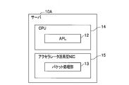
- FIG. 18 is a block diagram illustrating a configuration of a server 10 including a conventional NIC.
- the server 10 includes an NIC 11, an APL (application) 12 which is software for performing a target process, and a CPU 14 including a packet processing unit 13.
- the server 10 uses the core (arithmetic processing function) of the CPU 14 when the packet processing unit 13 processes the packet input from the NIC 11. At this time, since many cores are used only for the packet processing, the number of cores capable of performing the processing according to the activated APL 12 decreases.
- an accelerator utilizing NIC (also referred to as a utilization NIC) 15, which will be described later, is provided with a packet processing unit 13 in the utilization NIC 15 to perform an offload for load distribution.
- the accelerator utilization type NIC 15 is also called a smart NIC, and has an accelerator configured on the NIC by an FPGA (Field-Programmable Gate Array) as an integrated circuit capable of changing an electronic circuit.
- the utilization type NIC 15 performs the role of packet processing, thereby allocating many cores of the CPU 14 to the APL 12 and increasing the speed.
- the utilization type NIC 15 having the NIC port 15a is provided with a target function 16 such as a D plane (data transfer function), and is provided with the NIC 11 having the NIC port 11a separately from the utilization type NIC 15.
- a target function 16 such as a D plane (data transfer function)
- NW bandwidth network bandwidth
- the server 10B rewrites the data of the contents of the packet input from the NIC port 15a of the utilization type NIC 15 with the target function 16, and distributes the data to the target APLs 12a, 12b, and 12c according to the rewritten data. Processing is in progress.
- this kind of technique there is one described in Patent Document 1.
- the target function 16 can be accessed only by the NIC port 15a of the utilization type NIC 15.
- the target function 16 cannot be accessed from the NIC port 11a of another NIC 11, as indicated by the X mark on the arrow Y1.
- the NW band accessible to the target function 16 is limited to 40 Gbps.
- the NW band can be widened to 80 Gbps.
- the target functions 16a and 16b are divided, packets are input from a plurality of directions as indicated by arrows Y2 and Y3 when viewed from the APLs 12a to 12c. For this reason, the processing of the APLs 12a to 12c becomes complicated and the processing is restricted, so that there is a problem that the effect of widening the NW band becomes weak.
- the present invention has been made in view of such circumstances, and provides a server, a server system, and a method of increasing a network bandwidth of a server, which can increase an available network bandwidth without limiting application processing.
- the task is to
- the invention according to claim 1 is a smart NIC having an accelerator on a NIC (Network Interface Card) having an extended function for connecting to a communication network, and a process according to an application. And a target function having at least a data transfer function mounted on the smart NIC. The data in the packet input to the smart NIC from the communication network is processed by the target function and distributed to a target application.
- a server that transmits a packet related to processing of the application from the smart NIC to the communication network via the target function, and performs packet transfer between the NIC having the extended function and the NIC and the smart NIC.
- Software transfer function to mediate A virtual patch panel realized by the above, when transferring a packet input from the communication network to the NIC between the NIC and the smart NIC via the virtual patch panel, the target function of the smart NIC
- the server is characterized by transferring packets to and from an application.
- a smart NIC in which an accelerator is configured on an NIC having an extended function for connecting to a communication network, a CPU that performs processing according to an application, and at least data transfer mounted on the smart NIC. And a target function having a function, wherein the data in the packet input to the smart NIC from the communication network is processed by the target function and then distributed to a target application, and the packet related to the processing of the application is transferred to the target function.
- a network bandwidth increasing method for a server that transmits from a smart NIC to a communication network via a smart NIC, wherein a NIC having the extended function and a transfer function that mediates packet transfer between the NIC and the smart NIC are implemented by software.
- the target function of the smart NIC transfers the packet between the NIC and the application. Performing a network bandwidth increase of a server.
- the packet can be transferred between the NIC and the smart NIC via the virtual patch panel, so that the server can determine the network bandwidth when the NIC communicates with the communication network.
- the total bandwidth with the network bandwidth when the smart NIC communicates with the network can be used.
- the network bandwidth available to the server can be increased.
- packet transfer between the NIC or smart NIC and the application is always transferred to the application only via the smart NIC, there is no restriction on the processing of the application. That is, according to the server of the present invention, the available network bandwidth can be increased without any restriction on the processing of the application.
- the virtual patch panel includes a first input / output terminal and a second input / output terminal for a packet, and a second target which realizes the same function as the target function mounted on the smart NIC by software.
- Comprising a function connecting the application to the first input / output terminal of the virtual patch panel, connecting the second target function and the target function connected to the NIC to the second input / output terminal,
- the application and the first input / output terminal of the virtual patch panel are connected to each other.
- the virtual patch panel has a first input / output terminal and a second input / output terminal of a packet, and a second target which realizes the same function as a target function mounted on the smart NIC by software.
- Comprising a function connecting the application to the first input / output terminal of the virtual patch panel, connecting the second target function and the target function connected to the NIC to the second input / output terminal,
- the application and the first input / output terminal of the virtual patch panel are connected to each other.
- a step of transferring a packet between the two and the second input / output terminal is performed. It is a click-band increase method.
- the server can communicate with the communication network.
- the total bandwidth of the network bandwidth for communication and the network bandwidth for smart NIC communication with the network can be used.
- the network bandwidth available to the server can be increased.
- two packets input from both the NIC and the smart NIC can be transferred to the application from the first input / output terminal of the virtual patch panel. Therefore, when viewed from the application side, since packets are transferred from only one direction, complicated processing such as when packets are input to the application from multiple directions is eliminated. In other words, the processing of the application is not restricted. That is, according to the server of the present invention, the available network bandwidth can be increased without any restriction on the processing of the application.
- a smart NIC in which an accelerator is configured on an NIC having an extended function for connecting to a communication network, a CPU for performing a process according to an application, and at least data of data mounted on the smart NIC.
- a transfer function the data in the packet input to the smart NIC from the communication network is processed by the transfer function and then transferred to a target application, and the packet related to the processing of the application is transferred via the transfer function.
- a server for transmitting from a smart NIC to a communication network comprising: a NIC having the extended function; and a virtual patch panel which realizes, by software, a transfer function for mediating packet transfer between the NIC and the smart NIC.
- a forwarder for performing a process of transferring a packet from the original to one output destination is created and installed by software, and the smart NIC performs a process of distributing a packet from one input source to a plurality of output destinations and transferring the packet.
- a classifier as the transfer function and a merger as the transfer function for performing processing of merging packets from a plurality of input sources and transferring the merged packet to a single output destination are created and mounted in hardware, and input to the NIC.
- the packet is sorted by the classifier and transferred to the application, and the packet input to the smart NIC is sorted by the classifier and transferred to the application.
- the merger of the smart NIC After transfer, a server, characterized in that to transfer from the merger to the NIC via the forwarder.
- the packet transfer between the NIC or the smart NIC and the application can be performed through the forwarder of the virtual patch panel and the classifier and the merger of the smart NIC.
- the total bandwidth with the NIC network bandwidth can be used.
- the network bandwidth available to the server can be increased.
- packet transfer between the NIC or smart NIC and the application is always transferred to the application via only the smart NIC classifier or only the merger, so that there is no restriction on the processing of the application. That is, according to the server of the present invention, the available network bandwidth can be increased without any restriction on the processing of the application.
- a smart NIC in which an accelerator is configured on an NIC having an extended function for connecting to a communication network, a CPU for performing a process according to an application, and at least data of data mounted on the smart NIC.
- a transfer function the data in the packet input to the smart NIC from the communication network is processed by the transfer function and then transferred to a target application, and the packet related to the processing of the application is transferred via the transfer function.
- a server for transmitting from a smart NIC to a communication network comprising: a NIC having the extended function; and a virtual patch panel which realizes, by software, a transfer function for mediating packet transfer between the NIC and the smart NIC.
- the classifier as the transfer function for distributing the original packet to a plurality of output destinations and transferring the packet, and the transfer function for merging the packets from a plurality of input sources and transferring the packet to one output destination.
- a classifier as the transfer function for performing a process of distributing and transferring a packet from one input source to a plurality of output destinations on the smart NIC, and a plurality of mergers.
- a merger as a transfer function for performing processing of merging packets from an input source and transferring the merged packet to one output destination is created and installed in hardware, and a packet input to the NIC is transferred to the virtual patch panel by the virtual patch panel.
- the server is characterized in that it is sorted by each of a plurality of classifiers of the patch panel, one of the sorted is transferred to the NIC via the merger of the virtual patch panel, and the other is transferred to the merger of the smart NIC.
- the packet transfer between the NIC or the smart NIC and the application can be performed through the classifier and the merger of the virtual patch panel and the classifier and the merger of the smart NIC.
- the total bandwidth with the smart NIC network bandwidth can be used.
- the network bandwidth available to the server can be increased.
- the packet transfer between the NIC or the smart NIC and the application is always performed by the merger and the application of the one-to-one virtual patch panel, or is performed by the classifier of the one-to-one application and the virtual patch panel. Therefore, when viewed from the application side, since packets are transferred from only one direction, complicated processing such as when packets are input to the application from multiple directions is eliminated. In other words, the processing of the application is not restricted. That is, according to the server of the present invention, the available network bandwidth can be increased without any restriction on the processing of the application.
- a smart NIC in which an accelerator is configured on an NIC having an extended function for connecting to a communication network, a CPU for performing a process according to an application, and at least data of data mounted on the smart NIC.
- a transfer function the data in the packet input to the smart NIC from the communication network is processed by the transfer function and then transferred to a target application, and the packet related to the processing of the application is transferred via the transfer function.
- a server system comprising: a server that transmits data from a smart NIC to a communication network; and a control unit that controls the server. The server system transmits a NIC having the extended function and a packet transfer between the NIC and the smart NIC.
- a forwarder as the transfer function for transferring a packet from one input source to one output destination, and a plurality of packets from one input source.
- a classifier as the transfer function for performing a process of distributing and transferring to an output destination, and a merger as the transfer function for performing a process of merging packets from a plurality of input sources and transferring the packet to one output destination.
- a classifier as the transfer function for distributing a packet from one input source to a plurality of output destinations and transferring the packet from one input source to the smart NIC, and a packet from a plurality of input sources.
- a merger as the transfer function for performing a process of merging and transferring to one output destination is created and mounted by hardware
- the controller includes a forwarder mounted on the virtual patch panel of the server by software, a performance including a packet transfer capacity of a first transfer function including a classifier and a merger mounted on hardware, and a hardware And / or the performance including the packet transfer capacity of the second transfer function including the classifier and the merger mounted on the software is equal to or less than a predetermined performance threshold, the network bandwidth of the NIC to be added is And when the configuration of the first transfer function and / or the configuration of the second transfer function are adapted to a required network bandwidth, a request for adding the NIC to be added is made. It is a server system.
- the control unit can determine whether or not the NIC to be added can be added, and make a request for additional NICs.
- control unit is added to the configuration of the first transfer function or the second transfer function of the server when a NIC is added in response to the NIC addition request.
- control is performed to configure the first or second transfer function of the server in which the degree of adaptation of the network bandwidth is higher by the NIC in the server.
- a NIC can be added to the server so that the network bandwidth is optimized, and the performance and resource saving of the server can be improved.
- a server it is possible to provide a server, a server system, and a method of increasing a network bandwidth of a server, which can increase an available network bandwidth without any restriction on application processing.
- FIG. 2 is a block diagram illustrating a configuration of a server according to the first embodiment of the present invention. It is a block diagram showing the composition of the server concerning a 2nd embodiment of the present invention. It is a block diagram showing the composition of the server concerning a 3rd embodiment of the present invention.
- FIG. 3 is a block diagram illustrating a configuration including a distribution table of a virtual patch panel and a classifier, a merger, and a forwarder.
- FIG. 3 is a block diagram illustrating a configuration of a first transfer function of a server on an upstream packet side.
- FIG. 3 is a block diagram illustrating a configuration of a first transfer function of a server on a downstream packet side.
- FIG. 9 is a block diagram illustrating a configuration of a second transfer function of a server on an upstream packet side.
- FIG. 9 is a block diagram illustrating a configuration of a second transfer function of a server on a downstream packet side. It is a block diagram showing the composition of the server system concerning a 4th embodiment of the present invention. It is a block diagram which shows the structure of the server control part in a server system, the virtual patch panel control part in a server, and the accelerator control part.
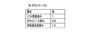
- FIG. 7 is a diagram illustrating the contents written in a policy table.
- FIG. 9 is a block diagram illustrating a configuration of a second transfer function of a server on an upstream packet side.
- FIG. 9 is a block diagram illustrating a configuration of a second transfer function of a server on a downstream packet side
- FIG. 11 is a sequence diagram for explaining an operation when a normal NIC addition request is made in the server system.
- FIG. 10 is a flowchart for explaining an operation when a normal NIC is added in response to a request from the normal NIC in the server system.
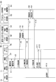
- FIG. 11 is a first sequence diagram for describing an operation when a normal NIC is added in response to a request from the normal NIC in the server system.
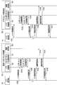
- FIG. 11 is a second sequence diagram for describing an operation performed when a normal NIC is added in response to a request from the normal NIC in the server system.
- FIG. 11 is a block diagram illustrating a configuration of a server including a conventional NIC. It is a block diagram which shows the structure of the server provided with the conventional accelerator utilization type NIC. It is a block diagram which shows the structure of the server provided with the conventional normal NIC and the accelerator utilization type NIC. It is a block diagram which shows the structure of the server provided with the normal NIC and the accelerator utilization type NIC to which the conventional
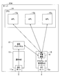
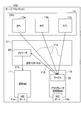
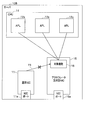
- FIG. 1 is a block diagram showing the configuration of the server according to the first embodiment of the present invention.
- the server 20A shown in FIG. 1 is different from the conventional server 10B (FIG. 20) in that the virtual patch panel 21 is connected between the normal NIC 11 and the target function 16 of the accelerator utilizing NIC (utilizing NIC) 15. That was provided.
- the normal NIC 11 is the above-described NIC 11 (see FIGS. 18 to 21), and is a name given to make it easy to discriminate from the utilization type NIC 15.
- the virtual patch panel 21 realizes a packet transfer function in the server 20A by software, and has a function of transferring a packet between the normal NIC 11 and the target function 16 of the utilization type NIC 15.
- the virtual patch panel 21 implements a virtual patch panel technology for transferring a packet input from the normal NIC 11 to the utilization type NIC 15 by software.
- a packet transfer destination (connection destination) can be changed, and a plurality of normal NICs 11 can be connected to the utilization type NIC 15.
- the packet transferred by the virtual patch panel 21 is processed by the accelerator of the utilization type NIC 15. This accelerator performs a part of the processing of the CPU 14, and enables the target function 16, which is a data transfer function, to execute the transfer processing.
- a packet input from the communication device (not shown) outside the server 20A to the normal NIC 11 via the NIC port 11a is transferred to the utilization type NIC 15 by the virtual patch panel 21, and the target function 16 Are further transferred to the APLs 12a to 12c.
- the packets that have been processed by the APLs 12a to 12c are transferred to the virtual patch panel 21 after being transferred to the target function 16, from which they are further transferred to the normal NIC 11, and transmitted from the NIC port 11a to the communication device.
- the packet input from the communication device to the utilization type NIC 15 via the NIC port 15a is transferred from the target function 16 to the APLs 12a to 12c.
- the packet for which the processing of the APLs 12a to 12c has been completed is transmitted to the communication device from the NIC port 15a after being transferred to the target function 16.
- the server 20A can use the two NIC ports 11a and 15a when communicating with an external communication device via the network.
- the server 20A includes an accelerator utilization type NIC 15 as a smart NIC in which an accelerator is configured on an NIC having an extended function for connecting to a communication network. Further, the server 20A includes a CPU 14 for performing processing according to the APLs 12a to 12c, and a target function 16 having at least a data transfer function mounted on the utilization type NIC 15; After the data is processed by the target function 16, the data is distributed to the target APLs 12 a to 12 c and transferred, and a packet related to the processing of the APLs 12 a to 12 c is transmitted from the utilization type NIC 15 to the communication network via the target function 16.
- This server 20A has the following characteristic configuration.
- the server 20A includes a normal NIC 11 as an NIC having an extended function, and a virtual patch panel 21 in which a transfer function for mediating a packet transfer between the normal NIC 11 and the utilization type NIC 15 is realized by software.
- the server 20A is configured such that the target function 16 transfers a packet between the APLs 12a to 12c when transferring a packet between the normal NIC 11 and the utilization type NIC 15 via the virtual patch panel 21.
- a packet can be transferred between the normal NIC 11 and the utilization type NIC 15 via the virtual patch panel 21.
- the server 20A can use the total bandwidth of the network bandwidth of the NIC port 11a when the normal NIC 11 communicates with the communication network and the network bandwidth of the NIC port 15a when the utilization type NIC 15 communicates with the communication network. . If the network bandwidth of the port 11a of the normal NIC 11 is 40 Gbps and the network bandwidth of the port 15a of the utilizable NIC 15 is 40 Gbps, the bandwidth of 80 Gbps can be used. As a result, the network bandwidth available to the server 20A can be increased.
- the processing of the APLs 12a to 12c is not restricted. That is, according to the server 20A of the present embodiment, the available network bandwidth can be increased without limiting the processing of the APLs 12a to 12c.
- the server 20A can be configured by using the normal NIC 11 and the utilization type NIC 15, which are general-purpose products, the manufacturing cost can be reduced.
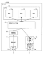
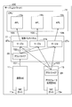
- FIG. 2 is a block diagram illustrating a configuration of a server according to the second embodiment of the present invention.
- the server 20B shown in FIG. 2 is different from the server 20A (FIG. 1) of the first embodiment in that a target function 23 is additionally provided and an input / output end (first input / output) of one packet of the virtual patch panel 21 is provided. End) are connected to the APLs 12a to 12c, and the other input / output end (second input / output end) is connected to the target function (second target function) 23 connected to the normal NIC 11 and the target function 16 in the utilization type NIC 15 To be connected.
- a target function 23 is additionally provided and an input / output end (first input / output) of one packet of the virtual patch panel 21 is provided. End) are connected to the APLs 12a to 12c, and the other input / output end (second input / output end) is connected to the target function (second target function) 23 connected to the normal NIC 11 and the target function 16 in the utilization type NIC 15
- the added target function 23 is realized by implementing the target function 16 of the hardware operating on the utilization type NIC 15 by software in the server 20B.
- a packet input from the communication device to the normal NIC 11 via the NIC port 11a is input to the virtual patch panel 21 via the target function 23. Further, a packet input from the communication device to the utilization type NIC 15 via the NIC port 15 a is input to the virtual patch panel 21 via the target function 16.
- the two packets input from both the normal NIC 11 and the utilization type NIC 15 can be transferred from one input / output terminal of the virtual patch panel 21 to the APLs 12a to 12c. Therefore, when viewed from the APLs 12a to 12c, packets are transferred from only one direction.
- the packet that has been processed by the APLs 12a to 12c is transmitted to the communication device from the NIC port 15a of the virtual patch panel 21 after being transferred to the target function 16, and is also transmitted to the communication device via the target function 23. Is transmitted to the communication equipment.
- the server 20B can use the two NIC ports 11a and 15a when communicating with an external communication device via the network.
- the server 20B includes an accelerator utilization type NIC 15 as a smart NIC in which an accelerator is configured on an NIC having an extended function for connecting to a communication network. Further, the server 20B includes a CPU 14 for performing processing according to the APLs 12a to 12c, and a target function 16 having at least a data transfer function mounted on the utilization type NIC 15, and the server 20B includes a target function 16 having a data transfer function.
- This server 20B has the following characteristic configuration.
- the server 20B is mounted on the normal NIC 11 as an NIC having an extended function, the virtual patch panel 21 in which a transfer function for mediating packet transfer between the normal NIC 11 and the smart NIC 15 as a smart NIC is implemented by software, and the smart NIC 15 And a target function (second target function) 23 in which the same function is realized by software.
- the server 20B connects the target function 23 to the normal NIC 11, connects the APLs 12a to 12c to the first input / output terminals of the packet of the virtual patch panel 21, and connects to the normal NIC 11 to the second input / output terminal of the packet.
- the target function 23 and the target function 16 are connected.
- the first input / output of the APLs 12a to 12c and the virtual patch panel 21 is performed.
- a packet is transferred between the two terminals and a packet is transferred between the two terminals and the second input / output terminal.
- packets can be transferred between both the normal NIC 11 and the utilization type NIC 15 and the APLs 12a to 12c via the virtual patch panel 21, so that the server 20B communicates with the communication network via the normal NIC 11.
- the total bandwidth of the network bandwidth at the time and the network bandwidth at the time when the utilization type NIC 15 communicates with the communication network can be used.
- the network bandwidth available to the server 20B can be increased.
- the server 20B can be configured using the normal NIC 11 and the utilizable NIC 15 which are general-purpose products, the manufacturing cost can be reduced.
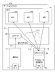
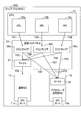
- FIG. 3 is a block diagram illustrating a configuration of a server according to the third embodiment of the present invention.
- the server 20C shown in FIG. 3 includes a normal NIC 11 having the same NIC port 11a as the server 20B (FIG. 2) of the second embodiment, a CPU 14 having APLs 12a to 12c, a utilization NIC 15 having an NIC port 15a, and a virtual NIC 15.
- the virtual NIC 15 includes a classifier 24 and a merger 25, and the virtual patch panel 21 includes a classifier 26, a merger 27, and a forwarder 28.
- the virtual patch panel 21 implements the virtual patch panel technology for transferring packets as described above by software.
- the functions of a classifier 26, a merger 27, and a forwarder 28 are respectively implemented as software. It operates on the core of the CPU 14 (CPU core), and high-speed performance is ensured by operating a plurality of CPU cores in parallel.
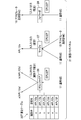
- the virtual patch panel 21 has a distribution table 30T shown in FIG.
- the distribution table 30T includes identifiers (eg, a to f) such as destination IP addresses, and transmission destinations (eg, APLs 12a to 12f) associated with the identifiers a to f.
- the classifier 26 performs a process of distributing and transferring a packet from one input source to a plurality (N) of output destinations. For example, when a packet is input from the normal NIC 11, the classifier 26 refers to the distribution table 30T and distributes the packet to the destination APL 12a, APL 12b associated with the identifier a, b such as the destination IP address. Forward.
- the merger 27 performs a process of merging packets from a plurality (N) of input sources and transferring them to one output destination. For example, when a packet from the normal NIC 11 and a packet from the utilization type NIC 15 are input, the merger 27 merges both packets and transfers them to one APL 12a.
- the forwarder 28 performs a process of transferring a packet from one input source to one output destination. For example, the forwarder 28 transfers a packet from the normal NIC 11 to the utilization type NIC 15.
- the classifier 24 and the merger 25 on the accelerator utilizing NIC 15 shown in FIG. 3 are configured by hardware on the accelerator, and perform the same processing as the classifier 26 and the merger 27 by the above-mentioned software.
- the distribution table 30T referred to by the classifier 24 is provided on the utilization type NIC 15.
- the server 20C having such a configuration has a first transfer function and a second transfer function, which are two types of packet transfer functions described below.
- the first transfer function performs the following packet transfer. That is, as shown in FIG. 5, an upstream packet input from the external communication device to the normal NIC 11 via the NIC port 11a is input to the forwarder 28 of the virtual patch panel 21 as shown by an arrow Y11, 28 is transferred to the classifier 24 of the utilization type NIC 15 as indicated by an arrow Y12. Next, the classifier 24 distributes and transfers the packet to the APLs 12a to 12c as indicated by the arrow Y13. In addition, the classifier 24 distributes the upstream packet input to the classifier 24 of the utilization type NIC 15 by distributing the packet to the APLs 12a to 12c as indicated by an arrow Y13.
- the downstream packet for which the processing of the APLs 12a to 12c has been completed is transferred to the merger 25 of the utilization type NIC 15, as indicated by an arrow Y14, and the merger 25 merges the packets to form an arrow.
- the data is transferred to the forwarder 28 of the virtual patch panel 21.
- the forwarder 28 transfers the packet to the normal NIC 11, and the transferred packet is transmitted from the NIC port 11a to the communication device.
- the downstream packet, which has been processed by the APLs 12a to 12c and transferred to the merger 25, is transmitted from the NIC port 15a of the NIC 15 to the communication device.
- the second transfer function performs the following packet transfer. That is, as shown in FIG. 7, an upstream packet input from the external communication device to the normal NIC 11 via the NIC port 11a is input to the classifier 26 of the virtual patch panel 21, as indicated by an arrow Y21. The classifier 26 outputs the packet to each of the mergers 27a, 27b, 27c as indicated by the arrow Y22. On the other hand, an upstream packet input from the external communication device to the utilization type NIC 15 via the NIC port 15a is transferred by the classifier 24 to each of the mergers 27a to 27c as indicated by an arrow Y23.
- the merger 27a merges the two packets transferred from the normal NIC 11 and the utilization type NIC 15 and transfers them to one APL 12a as indicated by an arrow Y24.
- the merger 27b merges the two packets forwarded in the same manner as described above and forwards them to one APL 12b as indicated by an arrow Y25, and the merger 27c similarly merges the two packets. , Is transferred to one APL 12c, as indicated by arrow Y26.
- the downstream packet for which the processing of the APL 12a has been completed is transferred to the classifier 26a of the virtual patch panel 21 as shown by an arrow Y31, and the classifier 26a separates the packet and As shown by Y32 and Y33, the image data is transferred to the normal NIC 11 via the merger 27, and is also transferred to the merger 25 of the utilization type NIC 15 as shown by an arrow Y34.
- the downstream packet for which the processing of the APL 12b has been completed is transferred to the classifier 26b as indicated by an arrow Y35, and the classifier 26b separates the packet and passes through the merger 27 as indicated by arrows Y36 and Y33.
- the transfer is made to the merger 25 of the utilization type NIC 15, as indicated by an arrow Y37.
- the downstream packet for which the processing of the APL 12c has been completed is transferred to the classifier 26c as shown by an arrow Y38, and the classifier 26c separates the packet and sends it to the normal NIC 11 via the merger 27 as shown by arrows Y39 and Y33.
- the transfer is made to the merger 25 of the utilization type NIC 15 as indicated by an arrow Y40.
- the server 20C includes an accelerator utilization type NIC 15 as a smart NIC in which an accelerator is configured on an NIC having an extended function for connecting to a communication network. Further, the server 20C includes a CPU 14 that performs processing according to the APLs 12a to 12c, and a function of transferring at least data mounted on the utilization type NIC 15, and a function of transmitting data in a packet input to the utilization type NIC 15 from a communication network.
- the server 20C After processing, the packet is distributed to the target APLs 12a to 12c and transferred, and the packet related to the processing of the APLs 12a to 12c is transmitted from the utilization type NIC 15 to the communication network via the transfer function.
- the server 20C has the following characteristic configuration.
- the first transfer function of the server 20C is configured as follows.
- the server 20C includes a normal NIC 11 which is an NIC having an extended function, and a virtual patch panel 21 which realizes a transfer function for mediating a packet transfer between the normal NIC 11 and the utilization type NIC 15 by software.
- a forwarder 28 for performing a process of transferring a packet from one input source to one output destination is created by software and mounted.
- a classifier 24 as a transfer function for distributing a packet from one input source to a plurality of output destinations and transferring the packet to a plurality of output destinations, and merging packets from a plurality of input sources to one output destination.
- the merger 25 as the transfer function for performing the transfer process is created and mounted by hardware.
- the server 20C transfers the packet input to the normal NIC 11 from the forwarder 28 to the classifier 24, then transfers the packet to the classifier 24 and transfers the packet to the APLs 12a to 12c. To 12c.
- the server 20C transfers the packets from the APLs 12a to 12c to the merger 25 of the utilization type NIC 15 and then transfers the packets from the merger 25 to the normal NIC 11 via the forwarder 28.
- the packet transfer between the normal NIC 11 or the utilization type NIC 15 and the APLs 12a to 12c can be performed via the forwarder 28 of the virtual patch panel 21 and the classifier 24 and the merger 25 of the utilization type NIC 15.
- the network bandwidth available to the server can be increased.
- the packet transfer between the normal NIC 11 or the utilization type NIC 15 and the APLs 12a to 12c is always transferred to the APLs 12a to 12c via only the classifier 24 or the merger 25 of the utilization type NIC 15, the processing is limited to the APLs 12a to 12c. Will not be applied. That is, according to the server of the present invention, the available network bandwidth can be increased without limiting the processing of the APLs 12a to 12c.
- the second transfer function of the server 20C is configured as follows.
- the server 20C combines the packets from one input source into the virtual patch panel 21 with the classifiers 26a to 26c performing processing of transferring the packets from one input source to a plurality of output destinations, and one output from the merger.
- a plurality of mergers 27a to 27c for performing a process of transferring data to a destination are prepared and mounted by software.
- the server 20C sorts the packet input to the normal NIC 11 by the classifier 26 and outputs the packet to the plurality of mergers 27a to 27c.
- the server 20C sorts the packet input to the utilization type NIC 15 by the classifier 24 and sorts the plurality of mergers 27a to 27c.
- the mergers 27a to 27c merge the packets from the normal NIC 11 and the utilization type NIC 15 and transfer them to the APLs 12a to 12c.
- the server 20C distributes the packets for each of the APLs 12a to 12c in each of the classifiers 26, transfers one of the distributed packets to the normal NIC 11 via the merger 27, and transfers the other to the utilization type NIC 15 via the merger 25. .
- packet transfer between the normal NIC 11 or the utilization type NIC 15 and the APLs 12a to 12c is performed via the classifiers 26a to 26c and the mergers 27a to 27c of the virtual patch panel 21, and the classifier 24 and the merger 25 of the utilization type NIC 15. Since this can be performed, the server 20C can use the total bandwidth of the network bandwidth of the normal NIC 11 and the network bandwidth of the utilization type NIC 15. As a result, the network bandwidth available to the server 20C can be increased.
- the packet transfer between the normal NIC 11 or the utilization type NIC 15 and the APLs 12a to 12c is always performed by the mergers 27a to 27c and the APLs 12a to 12c of the one-to-one virtual patch panel 21 or the one-to-one APLs 12a to 12c. This is performed by the classifiers 26a to 26c of the virtual patch panel 21.
- the processing of the APLs 12a to 12c is not restricted. That is, according to the server of the present invention, the available network bandwidth can be increased without limiting the processing of the APLs 12a to 12c.
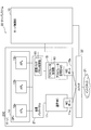
- FIG. 9 is a block diagram illustrating a configuration of a server system according to the fourth embodiment of the present invention.
- the server system 30 shown in FIG. 9 includes a server 20C (FIG. 3) and a server 20C via a switch 32 connected to an intranet (communication network) 31 which is a company network constructed using an IP (Internet Protocol) protocol or the like.
- the control unit 70 is connected and configured.
- the server control part 70 comprises the control part of Claim.
- the virtual patch panel 21 includes a virtual patch panel control unit 50, and the utilization type NIC 15 includes an accelerator control unit 60.
- the server control unit 70 determines the overall configuration of the server system 30 and performs control to issue a configuration change instruction to the virtual patch panel 21 and the accelerator utilizing NIC 15.
- the virtual patch panel control unit 50 controls to change the configuration of the virtual patch panel 21 according to the instruction of the server control unit 70.
- the accelerator control unit 60 controls to change the configuration of the accelerator utilization type NIC 15 according to the instruction of the server control unit 70.
- the server control unit 70 includes a configuration determination unit 71, an NIC detection unit 72, a software communication unit 73, a hardware communication unit 74, a switch control unit 75, a policy table 76, a threshold table 77.
- the virtual patch panel control unit 50 includes a component generation / deletion unit (also referred to as a generation / deletion unit) 51, a software control unit 52, a connection switching unit 53, and a performance monitoring unit 54.
- the generation / deletion unit 51 performs a process of generating or deleting the classifier 26, the merger 27, and the forwarder 28, which will be described later.
- the generation means that the classifier 26, the merger 27, and the forwarder 28 can be individually used.
- the deletion means that the classifier 26, the merger 27, and the forwarder 28 are individually stopped, thereby saving the amount of cores used by the CPU 14.
- the software control unit 52 controls transmission and reception of software performance requests and performance responses to and from the performance monitoring unit 54.
- the software control unit 52 performs control of transmitting and receiving a software performance request and a software performance response, which are software performance requests, to and from the configuration determination unit 71 via the software communication unit 73.
- the performance monitoring unit 54 monitors the transfer function of the virtual patch panel 21 and the like.
- connection switching unit 53 performs a process of switching the connection relationship between the classifier 26, the merger 27, and the forwarder 28, as described with reference to FIGS.
- the accelerator control unit 60 includes a component generation / deletion unit 61, a hardware control unit 62, a connection switching unit 63, and a performance monitoring unit 64.
- the generation / deletion unit 61 performs a process of generating or deleting the classifier 24 and the merger 25.
- the connection switching unit 63 performs a process of switching the connection relationship between the classifier 24 and the merger 25 as described with reference to FIGS.
- the hardware control unit 62 controls transmission and reception of hardware performance requests and performance responses to and from the performance monitoring unit 64. Further, the hardware control unit 62 performs control of transmitting and receiving a hardware performance request and a hardware performance response, which are hardware performance requirements, to and from the configuration determination unit 71 via the hardware communication unit 74.
- the performance monitoring unit 64 monitors the transfer function of the utilization type NIC 15 and the like.
- the value "1" is associated with the attribute “soft performance weight” (described later) as a policy.
- the value “0.8” is associated with the attribute “CPU resource weight”
- the value “1.2” is associated with the attribute “performance suitability weight” (described later).
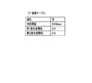
- the threshold table 77 has a value “50 Gbps” for the attribute “performance threshold” (described later) as a policy and a value “0.5 Gbps” for the attribute “first fitness threshold” (described later). , And the attribute “second fitness threshold” (described later) are associated with the value “0.5”.
- step S1 shown in FIG. 13 the configuration determining unit 71 of the server control unit 70 acquires a threshold.
- the configuration determining unit 71 makes a threshold request (K1) to the threshold table 77, and the threshold table 77 responds to the threshold according to the request (K1) (threshold response) (K2). It is done by doing.
- K1 threshold request
- K2 threshold response
- step S2 in FIG. 13 the configuration determining unit 71 inquires the virtual patch panel control unit 50 about the current software performance. As shown in FIG. 3, this inquires about the performance such as the transfer performance of the classifier 26, merger 27, and forwarder 28 created and mounted on the virtual patch panel 21 by software.
- a software performance request (K3) is sent from the configuration determining unit 71 to the software control unit 52 of the virtual patch panel control unit 50 via the software communication unit 73 (FIG. 10).
- the software control unit 52 requests the performance monitoring unit 54 for software performance (performance request) (K4).
- the performance monitoring unit 54 responds to the software performance (performance response) (K5).
- the software control unit 52 responds to the configuration determination unit 71 via the software communication unit 73 (FIG. 10) with the software performance (soft performance response) (K6).
- step S3 shown in FIG. 13 the configuration determining unit 71 inquires the utilization type NIC 15 about the current hardware performance. As shown in FIG. 3, this inquires about the performance such as the transfer performance of the classifier 24 and the merger 25 which are created and mounted on the utilization type NIC 15 by hardware.
- a hardware performance request (K7) is sent from the configuration determining unit 71 to the hardware control unit 62 of the accelerator control unit 60 via the hardware communication unit 74 (FIG. 10).
- the hardware control unit 62 requests hardware performance from the performance monitoring unit 64 (performance request) (K8).
- the performance monitoring unit 64 responds to the hardware performance (performance response) (K9).
- the hardware control unit 62 responds to the configuration determination unit 71 via the hardware communication unit 74 (FIG. 10) with the hardware performance (hard performance response) (K10).
- step S4 shown in FIG. 13 the configuration determining unit 71 determines whether the software performance and the hardware performance exceed the threshold. This determination is performed using the performance threshold “50 Gbps” acquired in step S1. If the result of this determination is that, for example, the sum of the transferable capacity, which is software performance, and the transferable capacity, which is hardware performance, exceeds the threshold value “50 Gbps”, the normal NIC is unnecessary, and the process returns to step S1.
- step S5 if it is determined that the sum of the software performance and the hardware performance is equal to or less than the threshold, the process proceeds to step S5 because a normal NIC is required.
- step S5 the configuration determining unit 71 sets the minimum bandwidth NIC.
- This setting is to set a normal NIC of the minimum specification NW band from the normal NICs existing as options in the server 20C. In this setting, the NW band is gradually increased from the minimum specification, and the normal NIC of the optimum NW band is set.
- step S6 the configuration determining unit 71 acquires a policy from the policy table 76 shown in FIG.
- each weight value as a policy described in the attribute column shown in the policy table 76 has been acquired.
- Which resource usage of the CPU and the accelerator is prioritized is represented by the CPU resource weight.
- the performance adaptation weight indicates, for example, which of the resource usage and the performance is prioritized when the configuration of the first transfer function described above is applied.
- the configuration determining unit 71 performs the first fitness calculation in step S7. This is to calculate the conformity of the NW band of the normal NIC set in step S5 when the configuration of the first transfer function described above is applied to the server 20C.
- Performance adaptability (soft prediction performance + hard prediction performance) ⁇ performance threshold (1)
- Resource conformity Min (CPU unused resource amount ⁇ CPU resource weight, accelerator unused resource amount) (2)
- Equation (1) is an equation for calculating a difference between a performance threshold and a performance threshold from the sum of the soft prediction performance and the hard prediction performance as a performance suitability.
- Equation (2) is an equation for calculating the smaller of the calculation result of “CPU unused resource amount ⁇ CPU resource weight” and the calculation result of “accelerator unused resource amount” as the resource matching degree.
- the configuration determining unit 71 determines the conformity (first conformity) of the NW band of the normal NIC set in step S5 by the above equation. It is calculated by (1) and (2).
- step S8 the configuration determining unit 71 performs a second fitness calculation. That is, when the above-described configuration of the second transfer function is applied to the server 20C, the conformity (second conformity) of the NW band of the normal NIC set in step S5 is calculated by using the above equations (1) and (2). ).
- step S9 the configuration determining unit 71 determines whether or not the calculated first fitness and the second fitness meet the criterion based on the policy. In other words, the configuration determining unit 71 determines that the first fitness exceeds the first fitness threshold “0.5” acquired in step S1 and the second fitness matches the second fitness threshold “0.5”. It is determined whether or not it has exceeded.
- step S10 the configuration determining unit 71 reselects a normal NIC having a larger NW band than the current one. Returning to S7, the calculation is performed.
- step S11 determines whether the normal NIC is added. Make a request.
- the configuration determining unit 71 makes a normal NIC addition request (NIC request) (K13) to the NIC detecting unit 72. This request reaches the operator, and the operator adds a normal NIC, and the NIC detector 72 detects this.
- NIC request normal NIC addition request
- step S21 shown in FIG. 15 a normal NIC is added.
- the NIC detecting unit 72 notifies the configuration determining unit 71 that the added normal NIC has been detected (NIC detection notification) (K21).
- step S22 the configuration determining unit 71 determines whether the added is a normal NIC. If the result of this determination is that it is not a normal NIC, this processing ends.
- the determination policy is acquired in step S23.
- the configuration determination unit 71 makes a policy request (K22) to the policy table 76, and the policy table 76 responds to the policy (policy response) (K23).
- the configuration determining unit 71 acquires and holds the policy.
- step S24 of FIG. 15 the configuration determining unit 71 performs the first fitness calculation similar to step S7 (FIG. 13). That is, when the software and hardware configuration of the first transfer function is applied, the adaptability of the NW band of the normal NIC is calculated.
- step S25 in FIG. 15 the configuration determining unit 71 performs the second fitness calculation similar to step S8 (FIG. 13). That is, when the software and hardware configuration of the second transfer function is applied, the adaptability of the NW band of the normal NIC is calculated.
- step S26 of FIG. 15 the configuration determining unit determines whether the first transfer function has higher fitness than the second transfer function.
- step S27 the software configuration is changed in step S27. That is, the configuration of the virtual patch panel 21 is changed as follows according to the addition of the normal NIC.
- the configuration determining unit 71 makes a software configuration request (software configuration request) (K24) for the first transfer function to the software communication unit 73.
- the software communication unit 73 issues a software control request (K25) to the software control unit 52 of the virtual patch panel control unit 50 to perform the software configuration of the first transfer function.
- the software control unit 52 sends a component generation request (K26) to the component generation and deletion unit 51.
- FIG. 17 describes a component generation deletion request (K26), which indicates that a component generation request (K26) or a component deletion request (K26) is made.
- Other descriptions such as “generate and delete” also have the meaning of “generate or delete”.
- the generation / deletion unit 51 performs a process of generating all or a part of the classifier 26, the merger 27, and the forwarder 28 (performing a software configuration) on the virtual patch panel 21 in response to the component generation request (K26). After this processing, the generation and deletion unit 51 notifies the software generation unit 52 of the component generation response (K27), and the software control unit 52 notifies the software communication unit 73 of the software control response (K28).
- the software communication unit 73 notifies the configuration determination unit 71 of a software configuration response (K29) indicating that the software configuration has been executed.
- step S28 the hardware configuration is changed. That is, according to the addition of the normal NIC, the configuration of the utilization type NIC 15 is changed as follows.
- the configuration determining unit 71 sends a hardware configuration request (hardware configuration request) (K30) for the first transfer function to the hardware communication unit 74.
- the hardware configuration request (method, hardware configuration) (K30) is described, but this is the hardware configuration request (K30) of the first transfer function (method) or the second transfer function (method). )) (K30).
- the hardware communication unit 74 sends a hardware control request (K31) to the hardware control unit 62 of the accelerator control unit 60 to perform the hardware configuration of the first transfer function.
- the hardware control unit 62 sends a component generation request (K32) to the component generation and deletion unit 61.
- the generation / deletion unit 61 performs a process of generating all or a part of the classifier 24 and the merger 25 (performing a hardware configuration) on the utilization type NIC 15 in response to the component generation request (K32). After this processing, the generation / deletion unit 61 notifies the hardware control unit 62 of the component generation response (K33), and the hardware control unit 62 notifies the hardware communication unit 74 of the hardware control response (K34).
- the hardware communication unit 74 notifies the configuration determination unit 71 of a hardware configuration response (K35) indicating that the hardware configuration has been executed, as shown in FIG.
- step S29 of FIG. 15 the software / hardware connection is changed.
- the configuration determining unit 71 makes a request for a software configuration change of the first transfer function (soft connection change request) (K41) to the software communication unit 73.
- the software communication unit 73 sends a software connection change request (K42) to the software control unit 52 of the virtual patch panel control unit 50 to change the software connection of the first transfer function.
- the software control unit 52 sends a connection switching request (K43) to the connection switching unit 53.
- connection switching unit 53 changes the connection of all or a part of the classifier 26, the merger 27, and the forwarder 28 of the virtual patch panel 21 in response to the connection switching request (K43). After this processing, the connection switching unit 53 notifies the software control unit 52 of the connection switching response (K44), and the software control unit 52 notifies the software communication unit 73 of the software connection change response (K45).
- the software communication unit 73 notifies the configuration determining unit 71 of a software connection change response (K46) indicating that the software connection configuration has been changed.
- the configuration determining unit 71 makes a request for a hardware configuration change of the first transfer function (hard connection change request) (K47) to the hardware communication unit 74.
- the hardware communication unit 74 issues a hardware connection change request (K48) to the hardware control unit 62 of the accelerator control unit 60 to change the hardware connection of the first transfer function.
- the hardware control unit 62 sends a connection switching request (K49) to the connection switching unit 63.
- connection switching unit 63 changes the connection of all or a part of the classifier 26 and the merger 27 of the utilization type NIC 15 in response to the connection switching request (K49). After this processing, the connection switching unit 63 notifies the hardware control unit 62 of a connection switching response (K50), and the hardware control unit 62 notifies the hardware communication unit 74 of a hardware connection change response (K51).
- the hardware communication unit 74 notifies the configuration determination unit 71 of a hardware connection change response (K52) indicating that the hardware connection configuration change has been performed.
- step S30 shown in FIG. 15 the external switch is switched.
- the switch control unit 75 shown in FIG. 10 controls the switch 32 shown in FIG. 9 to perform a switching operation so that a packet is input / output from the intranet 31 to the added normal NIC.
- the configuration determining unit 71 sends a switch switching request (K53) to the switch control unit 75.
- the switch control unit 75 Upon receiving this request (K53), the switch control unit 75 performs a switching operation on the added normal NIC so that packets are input / output from the intranet 31, and sends this switch switching response (K54) to the configuration determining unit 71.
- K53 switch switching request
- the switch control unit 75 performs a switching operation on the added normal NIC so that packets are input / output from the intranet 31, and sends this switch switching response (K54) to the configuration determining unit 71.
- step S31 the software configuration of the second transfer function is changed in step S31. This change is performed in the same procedure as the change in the software configuration related to the first transfer function described in step S27, and thus the description thereof is omitted.
- step S32 a hardware configuration change related to the second transfer function is performed. This change is performed in the same procedure as the change in the hardware configuration related to the first transfer function described in step S28, and thus the description thereof is omitted.
- step S33 the software / hardware connection related to the second transfer function is changed. This change is performed in the same procedure as the change of the software / hardware connection relating to the first transfer function described in step S29, and therefore the description thereof is omitted.
- step S30 the switch control unit 75 controls the switch 32 to perform a switching operation so that packets are input and output from the intranet 31 to the normal NIC added according to the second transfer function.
- This switching operation is performed by the processes of K53 and K54 shown in FIG. 16, as in the case of the above-described first transfer function.
- the server system 30C includes the server 20C described above and a server control unit 70 that controls the server 20C.
- This server system 30 has the following characteristic configuration.
- the server control unit 70 controls the performance including the packet transfer capacity of the first transfer function, which is the classifier 26, the merger 27, and the forwarder 28, mounted on the virtual patch panel 21 of the server 20C by software, and the utilization type normal NIC 15. If the sum of the performance including the packet transfer capacity of the second transfer function, which is the classifier 24 and the merger 25 mounted on hardware, is equal to or less than a predetermined performance threshold, the network bandwidth of the normal NIC to be added is changed When both or one of the configuration of the first transfer function and the configuration of the second transfer function conforms to the required network bandwidth, a request to add a normal NIC to be added is made.
- the server control unit 70 can determine whether or not a normal NIC to be added can be added, and make a request to add a normal NIC. .
- the server control unit 70 performs network bandwidth control using the added normal NIC.
- the server 20C is configured to control the transfer function of the server 20C having the higher degree of conformity.
- a normal NIC can be added to the server 20C so that the network bandwidth is optimized.
Landscapes
- Engineering & Computer Science (AREA)
- Theoretical Computer Science (AREA)
- Computer Networks & Wireless Communication (AREA)
- Signal Processing (AREA)
- Physics & Mathematics (AREA)
- General Engineering & Computer Science (AREA)
- General Physics & Mathematics (AREA)
- Software Systems (AREA)
- Data Exchanges In Wide-Area Networks (AREA)
- Computer And Data Communications (AREA)
Abstract
【課題】アプリケーションの処理に制限が掛かることなく、利用可能なネットワーク帯域を増やす。 【解決手段】サーバ20Aは、拡張機能を有するNICとしての通常NIC11と、通常NIC11とアクセラレータ活用型NIC15間でパケットを転送する転送機能をソフトウェアで実現した仮想パッチパネル21とを備える。このサーバ20Aを、仮想パッチパネル21を介して通常NIC11とアクセラレータ活用型NIC15間でパケットを転送する際に、対象機能16がAPL12a~12cとの間でパケットを転送するように構成した。
Description
本発明は、CPU(Central Processing Unit)の処理の一部を分担して行うアクセラレータが適用された汎用サーバにおいてネットワーク帯域を増加可能とするサーバ、サーバシステム及びサーバのネットワーク帯域増加方法に関する。
サーバは、他のサーバ等の通信装置とパケット送受信により通信を行うためにNIC(Network Interface Card)を備える。NICは、サーバを通信ネットワークに接続するための専用の拡張基板(拡張機能という)である。図18は従来のNICを備えるサーバ10の構成を示すブロック図である。サーバ10は、NIC11と、目的の処理を行うソフトウェアであるAPL(アプリケーション)12及びパケット処理部13を備えるCPU14とを備えて構成されている。
サーバ10は、NIC11から入力されたパケットをパケット処理部13で処理する際に、CPU14のコア(演算処理機能)を使用する。この際、パケット処理のみで多くのコアを使用するため、起動しているAPL12に応じた処理を可能なコアが減ってしまう。
そこで、図19に示すサーバ10Aように、後述のアクセラレータ活用型NIC(活用型NICともいう)15を用い、この活用型NIC15にパケット処理部13を備えて負荷分散するオフロードを行うタイプのものがある。アクセラレータ活用型NIC15は、スマートNICとも呼ばれ、電子回路を可変できる集積回路としてのFPGA(Field-Programmable Gate Array)等によりアクセラレータをNIC上に構成したものである。サーバ10Aでは、パケット処理の役割を活用型NIC15に行わせることにより、CPU14のコアをAPL12に多く割り当てて高速化を可能としている。
上記のようにオフロードするタイプのサーバとして、図20に示す構成のサーバ10Bがある。このサーバ10Bは、NICポート15aを有する活用型NIC15に、Dプレーン(データ転送機能)等の対象機能16を備え、また、活用型NIC15とは別に、NICポート11aを有するNIC11を備える。各々のNICポート11a,15aは、例えば40Gbpsのネットワーク帯域(NW帯域という)を有する。
このような構成において、サーバ10Bは、活用型NIC15のNICポート15aから入力されたパケットの中身のデータを対象機能16で書き換え、この書き換えられたデータに応じて目的のAPL12a,12b,12cに振り分ける処理を行っている。この種の技術として、特許文献1に記載のものがある。
しかし、上述した図20に示したサーバ10Bにおいて、対象機能16に対しては、活用型NIC15のNICポート15aのみでしかアクセス出来ない。他のNIC11のNICポート11aからは矢印Y1に×印を付して示すように、対象機能16にはアクセスできない。このため、対象機能16にアクセス可能なNW帯域が40Gbpsと制限されてしまう。
この対策として、図21に示すサーバ10Cのように、対象機能を分割し、活用型NIC15の対象機能16aとは別に、NIC11に接続された対象機能16bを備える構成がある。この構成では、40GbpsのNICポート11a,15aが2つ使えるので、NW帯域を80Gbpsと広帯域にできる。しかし、この構成の場合、対象機能16a,16bが分割されているので、APL12a~12cから見た場合、矢印Y2及びY3で示すように、複数の方向からパケットが入力される。このため、APL12a~12cの処理が複雑となってしまい当該処理が制限されるので、NW帯域を広帯域にした効果が薄れてしまう問題が生じる。
本発明は、このような事情に鑑みてなされたものであり、アプリケーションの処理に制限が掛かることなく、利用可能なネットワーク帯域を増やすことができるサーバ、サーバシステム及びサーバのネットワーク帯域増加方法を提供することを課題とする。
上記課題を解決するための手段として、請求項1に係る発明は、通信ネットワークに接続するための拡張機能を有するNIC(Network Interface Card)上にアクセラレータを構成したスマートNICと、アプリケーションに応じた処理を行うCPUと、当該スマートNICに搭載された少なくともデータ転送機能を有する対象機能とを備え、通信ネットワークから前記スマートNICに入力されたパケット中のデータを前記対象機能で処理後に目的のアプリケーションに振り分けて転送し、当該アプリケーションの処理に係るパケットを当該対象機能を介してスマートNICから通信ネットワークへ送信するサーバであって、前記拡張機能を有するNICと、前記NICと前記スマートNIC間のパケット転送を仲介する転送機能をソフトウェアで実現した仮想パッチパネルとを備え、前記仮想パッチパネルを介した前記NICと前記スマートNIC間で通信ネットワークから前記NICに入力されたパケットを転送する際に、当該スマートNICの前記対象機能が前記アプリケーションとの間でパケットを転送することを特徴とするサーバである。
請求項7に係る発明は、通信ネットワークに接続するための拡張機能を有するNIC上にアクセラレータを構成したスマートNICと、アプリケーションに応じた処理を行うCPUと、当該スマートNICに搭載された少なくともデータ転送機能を有する対象機能とを備え、通信ネットワークから前記スマートNICに入力されたパケット中のデータを前記対象機能で処理後に目的のアプリケーションに振り分けて転送し、当該アプリケーションの処理に係るパケットを当該対象機能を介してスマートNICから通信ネットワークへ送信するサーバのネットワーク帯域増加方法であって、前記拡張機能を有するNICと、前記NICと前記スマートNIC間のパケット転送を仲介する転送機能をソフトウェアで実現した仮想パッチパネルとを備え、前記仮想パッチパネルを介した前記NICと前記スマートNIC間で通信ネットワークから前記NICに入力されたパケットを転送する際に、当該スマートNICの前記対象機能が前記アプリケーションとの間でパケットを転送するステップを実行することを特徴とするサーバのネットワーク帯域増加方法である。
請求項1の構成及び請求項7の方法によれば、仮想パッチパネルを介してNICとスマートNIC間でパケットを転送可能としたので、サーバは、NICが通信ネットワークと通信する際のネットワーク帯域と、スマートNICがネットワークと通信する際のネットワーク帯域との合計の帯域を利用できる。これによって、サーバが利用可能なネットワーク帯域を増やすことができる。また、NIC又はスマートNICと、アプリケーションとのパケット転送は、必ずスマートNICのみを介してアプリケーションと転送されるので、アプリケーションの処理に制限が掛かることが無くなる。つまり、本発明のサーバによれば、アプリケーションの処理に制限が掛かることなく、利用可能なネットワーク帯域を増やすことができる。
請求項2に係る発明は、前記仮想パッチパネルに、パケットの第1入出力端と第2入出力端を備え、前記スマートNICに搭載された対象機能と同機能をソフトウェアで実現した第2対象機能を備え、前記仮想パッチパネルの前記第1入出力端に前記アプリケーションを接続し、前記第2入出力端に、前記NICに接続された前記第2対象機能と前記対象機能とを接続し、前記NICを介した前記第2対象機能及び前記スマートNIC上の対象機能の双方と、前記アプリケーションとの間でパケットを転送する際に、前記アプリケーションと前記仮想パッチパネルの第1入出力端との間でパケットを転送し、前記双方と前記第2入出力端との間でパケットを転送することを特徴とする請求項1に記載のサーバである。
請求項8に係る発明は、前記仮想パッチパネルに、パケットの第1入出力端と第2入出力端を備え、前記スマートNICに搭載された対象機能と同機能をソフトウェアで実現した第2対象機能を備え、前記仮想パッチパネルの前記第1入出力端に前記アプリケーションを接続し、前記第2入出力端に、前記NICに接続された前記第2対象機能と前記対象機能とを接続し、前記NICを介した前記第2対象機能及び前記スマートNIC上の対象機能の双方と、前記アプリケーションとの間でパケットを転送する際に、前記アプリケーションと前記仮想パッチパネルの第1入出力端との間でパケットを転送し、前記双方と前記第2入出力端との間でパケットを転送するステップを実行することを特徴とする請求項7に記載のサーバのネットワーク帯域増加方法である。
請求項2の構成及び請求項8の方法によれば、仮想パッチパネルを介してNIC及びスマートNICの双方と、アプリケーションとの間でパケットを転送可能としたので、サーバは、NICが通信ネットワークと通信する際のネットワーク帯域と、スマートNICがネットワークと通信する際のネットワーク帯域との合計の帯域を利用できる。これによって、サーバが利用可能なネットワーク帯域を増やすことができる。また、NICとスマートNICとの双方から入力された2つのパケットは、仮想パッチパネルの第1入出力端からアプリケーションへ転送できる。このため、アプリケーション側から見た場合、1方向のみからパケットが転送されてくるので、アプリケーションに複数方向からパケットが入力される時のような複雑な処理が無くなる。言い換えれば、アプリケーションの処理に制限が掛かることが無くなる。つまり、本発明のサーバによれば、アプリケーションの処理に制限が掛かることなく、利用可能なネットワーク帯域を増やすことができる。
請求項3に係る発明は、通信ネットワークに接続するための拡張機能を有するNIC上にアクセラレータを構成したスマートNICと、アプリケーションに応じた処理を行うCPUと、当該スマートNICに搭載された少なくともデータの転送機能とを備え、通信ネットワークから前記スマートNICに入力されたパケット中のデータを前記転送機能で処理後に目的のアプリケーションに振り分けて転送し、当該アプリケーションの処理に係るパケットを当該転送機能を介してスマートNICから通信ネットワークへ送信するサーバであって、前記拡張機能を有するNICと、前記NICと前記スマートNIC間のパケット転送を仲介する転送機能をソフトウェアで実現した仮想パッチパネルとを備え、前記仮想パッチパネルに、1つの入力元からのパケットを1つの出力先に転送する処理を行うフォワーダをソフトウェアで作成して搭載し、前記スマートNICに、1つの入力元からのパケットを複数の出力先に振り分けて転送する処理を行う前記転送機能としてのクラシファイアと、複数の入力元からのパケットを合併して1つの出力先へ転送する処理を行う前記転送機能としてのマージャとをハードウェアで作成して搭載し、前記NICに入力されたパケットを、前記フォワーダから前記クラシファイアへ転送後に、当該クラシファイアで振り分けて前記アプリケーションへ転送し、前記スマートNICに入力されたパケットを前記クラシファイアで振り分けて前記アプリケーションへ転送し、前記アプリケーションからのパケットを、前記スマートNICの前記マージャへ転送後に、当該マージャから前記フォワーダを介して前記NICへ転送することを特徴とするサーバである。
この構成によれば、NIC又はスマートNICとアプリケーション間のパケット転送を、仮想パッチパネルのフォワーダと、スマートNICのクラシファイア及びマージャを介して行うことができるので、サーバは、NICのネットワーク帯域と、スマートNICのネットワーク帯域との合計の帯域を利用できる。これによって、サーバが利用可能なネットワーク帯域を増やすことができる。また、NIC又はスマートNICと、アプリケーションとのパケット転送は、必ずスマートNICのクラシファイアのみ又はマージャのみを介してアプリケーションと転送されるので、アプリケーションの処理に制限が掛かることが無くなる。つまり、本発明のサーバによれば、アプリケーションの処理に制限が掛かることなく、利用可能なネットワーク帯域を増やすことができる。
請求項4に係る発明は、通信ネットワークに接続するための拡張機能を有するNIC上にアクセラレータを構成したスマートNICと、アプリケーションに応じた処理を行うCPUと、当該スマートNICに搭載された少なくともデータの転送機能とを備え、通信ネットワークから前記スマートNICに入力されたパケット中のデータを前記転送機能で処理後に目的のアプリケーションに振り分けて転送し、当該アプリケーションの処理に係るパケットを当該転送機能を介してスマートNICから通信ネットワークへ送信するサーバであって、前記拡張機能を有するNICと、前記NICと前記スマートNIC間のパケット転送を仲介する転送機能をソフトウェアで実現した仮想パッチパネルとを備え、前記仮想パッチパネルに、1つの入力元からのパケットを複数の出力先に振り分けて転送する処理を行う前記転送機能としてのクラシファイアと、複数の入力元からのパケットを合併して1つの出力先へ転送する処理を行う前記転送機能としてのマージャと、をソフトウェアで各々複数作成して搭載し、前記スマートNICに、1つの入力元からのパケットを複数の出力先に振り分けて転送する処理を行う前記転送機能としてのクラシファイアと、複数の入力元からのパケットを合併して1つの出力先へ転送する処理を行う前記転送機能としてのマージャとをハードウェアで作成して搭載し、前記NICに入力されたパケットを、前記仮想パッチパネルのクラシファイアで振り分けて当該仮想パッチパネルの複数のマージャへ出力し、前記スマートNICに入力されたパケットを、当該スマートNICのクラシファイアで振り分けて当該複数のマージャへ出力し、各々のマージャが前記NIC及び前記スマートNICからの各パケットを合併して前記アプリケーションへ転送し、前記アプリケーション毎からのパケットを前記仮想パッチパネルの複数のクラシファイアの各々で振り分け、振り分けられた一方を前記仮想パッチパネルのマージャを介して前記NICへ転送し、他方を前記スマートNICのマージャへ転送することを特徴とするサーバである。
この構成によれば、NIC又はスマートNICとアプリケーション間のパケット転送を、仮想パッチパネルのクラシファイア及びマージャと、スマートNICのクラシファイア及びマージャを介して行うことができるので、サーバは、NICのネットワーク帯域と、スマートNICのネットワーク帯域との合計の帯域を利用できる。これによって、サーバが利用可能なネットワーク帯域を増やすことができる。また、NIC又はスマートNICと、アプリケーションとのパケット転送は、必ず1対1の仮想パッチパネルのマージャとアプリケーションで行われるか、1対1のアプリケーションと仮想パッチパネルのクラシファイアで行われる。このため、アプリケーション側から見た場合、1方向のみからパケットが転送されてくるので、アプリケーションに複数方向からパケットが入力される時のような複雑な処理が無くなる。言い換えれば、アプリケーションの処理に制限が掛かることが無くなる。つまり、本発明のサーバによれば、アプリケーションの処理に制限が掛かることなく、利用可能なネットワーク帯域を増やすことができる。
請求項5に係る発明は、通信ネットワークに接続するための拡張機能を有するNIC上にアクセラレータを構成したスマートNICと、アプリケーションに応じた処理を行うCPUと、当該スマートNICに搭載された少なくともデータの転送機能とを備え、通信ネットワークから前記スマートNICに入力されたパケット中のデータを前記転送機能で処理後に目的のアプリケーションに振り分けて転送し、当該アプリケーションの処理に係るパケットを当該転送機能を介してスマートNICから通信ネットワークへ送信するサーバと、当該サーバを制御する制御部とを有するサーバシステムであって、前記サーバは、前記拡張機能を有するNICと、前記NICと前記スマートNIC間のパケット転送を仲介する転送機能をソフトウェアで実現した仮想パッチパネルとを備え、前記仮想パッチパネルに、1つの入力元からのパケットを1つの出力先に転送する処理を行う前記転送機能としてのフォワーダと、1つの入力元からのパケットを複数の出力先に振り分けて転送する処理を行う前記転送機能としてのクラシファイアと、複数の入力元からのパケットを合併して1つの出力先へ転送する処理を行う前記転送機能としてのマージャと、をソフトウェアで各々複数作成して搭載し、前記スマートNICに、1つの入力元からのパケットを複数の出力先に振り分けて転送する処理を行う前記転送機能としてのクラシファイアと、複数の入力元からのパケットを合併して1つの出力先へ転送する処理を行う前記転送機能としてのマージャとをハードウェアで作成して搭載し、前記制御部は、前記サーバの前記仮想パッチパネルにソフトウェアで搭載されたフォワーダと、ハードウェアで搭載されたクラシファイア及びマージャを含む第1転送機能のパケット転送容量を含む性能と、前記スマートNICにハードウェア及びソフトウェアで搭載されたクラシファイア及びマージャを含む第2転送機能のパケット転送容量を含む性能との双方又は何れか一方が、予め定められた性能の閾値以下の場合、追加対象のNICのネットワーク帯域が、前記第1転送機能の構成と、前記第2転送機能の構成との双方又は何れか一方で必要なネットワーク帯域に適合する際に、前記追加対象のNICの追加要求を行うことを特徴とするサーバシステムである。
この構成によれば、サーバに更にネットワーク帯域が必要な場合等に、制御部が、追加対象のNICが追加可能か否かを判定して、NICを追加要求することができる。
請求項6に係る発明は、前記制御部は、前記サーバの前記第1転送機能又は前記第2転送機能の構成に、前記NICの追加要求に応じてNICが追加される際に、追加されるNICによりネットワーク帯域の適合度が高くなる方の第1又は第2転送機能をサーバに構成する制御を行うことを特徴とする請求項5に記載のサーバシステム。
この構成によれば、サーバにネットワーク帯域が最適となるようにNICを追加でき、また、サーバの高性能化及び省リソース化を図ることができる。
本発明によれば、アプリケーションの処理に制限が掛かることなく、利用可能なネットワーク帯域を増やすことが可能なサーバ、サーバシステム及びサーバのネットワーク帯域増加方法を提供することができる。
以下、本発明の実施形態を、図面を参照して説明する。但し、本明細書の全図において機能が対応する構成部分には同一符号を付し、その説明を適宜省略する。
<第1実施形態の構成>
図1は、本発明の第1実施形態に係るサーバの構成を示すブロック図である。
図1に示すサーバ20Aが、従来のサーバ10B(図20)と異なる点は、仮想パッチパネル21を、通常NIC11と、アクセラレータ活用型NIC(活用型NIC)15の対象機能16との間に接続して設けたことにある。なお、通常NIC11は、前述したNIC11(図18~図21参照)であり、活用型NIC15と判別し易くするために付けた名称である。
<第1実施形態の構成>
図1は、本発明の第1実施形態に係るサーバの構成を示すブロック図である。
図1に示すサーバ20Aが、従来のサーバ10B(図20)と異なる点は、仮想パッチパネル21を、通常NIC11と、アクセラレータ活用型NIC(活用型NIC)15の対象機能16との間に接続して設けたことにある。なお、通常NIC11は、前述したNIC11(図18~図21参照)であり、活用型NIC15と判別し易くするために付けた名称である。
仮想パッチパネル21は、サーバ20Aにおけるパケットの転送機能をソフトウェアで実現したものであり、通常NIC11と、活用型NIC15の対象機能16との間でパケットを転送する機能を有する。
仮想パッチパネル21は、通常NIC11から入力されたパケットを、活用型NIC15へ転送する仮想パッチパネル技術をソフトウェアで実現したものである。仮想パッチパネル技術では、パケットの転送先(接続先)を変えることが可能となっており、活用型NIC15に複数の通常NIC11を接続できる。仮想パッチパネル21で転送されたパケットは、活用型NIC15のアクセラレータで処理される。このアクセラレータは、CPU14の処理の一部を担って行うものであり、データ転送機能である対象機能16が転送処理を実行可能となる。
このような構成のサーバ20Aにおいて、サーバ20Aの外部の図示せぬ通信装置からNICポート11aを介して通常NIC11へ入力されたパケットは、仮想パッチパネル21により活用型NIC15へ転送され、対象機能16でAPL12a~12cへ更に転送される。この逆に、APL12a~12cの処理が完了したパケットは、対象機能16へ転送後に仮想パッチパネル21へ転送され、ここから更に通常NIC11へ転送されて、NICポート11aから通信装置へ送信される。
また、通信装置からNICポート15aを介して活用型NIC15へ入力されたパケットは、対象機能16からAPL12a~12cへ転送される。この逆に、APL12a~12cの処理が完了したパケットは、対象機能16へ転送後にNICポート15aから通信装置へ送信される。このように、サーバ20Aは、外部の通信装置とネットワークを介した通信を行う際に、2つのNICポート11a,15aを使用可能となっている。
<第1実施形態の効果>
第1実施形態に係るサーバ20Aの効果について説明する。サーバ20Aは、通信ネットワークに接続するための拡張機能を有するNIC上にアクセラレータを構成したスマートNICとしてのアクセラレータ活用型NIC15を備える。更にサーバ20Aは、APL12a~12cに応じた処理を行うCPU14と、活用型NIC15に搭載された少なくともデータ転送機能を有する対象機能16とを備え、通信ネットワークから活用型NIC15に入力されたパケット中のデータを対象機能16で処理後に目的のAPL12a~12cに振り分けて転送し、また、APL12a~12cの処理に係るパケットを対象機能16を介して活用型NIC15から通信ネットワークへ送信する。このサーバ20Aを次の特徴構成とした。
第1実施形態に係るサーバ20Aの効果について説明する。サーバ20Aは、通信ネットワークに接続するための拡張機能を有するNIC上にアクセラレータを構成したスマートNICとしてのアクセラレータ活用型NIC15を備える。更にサーバ20Aは、APL12a~12cに応じた処理を行うCPU14と、活用型NIC15に搭載された少なくともデータ転送機能を有する対象機能16とを備え、通信ネットワークから活用型NIC15に入力されたパケット中のデータを対象機能16で処理後に目的のAPL12a~12cに振り分けて転送し、また、APL12a~12cの処理に係るパケットを対象機能16を介して活用型NIC15から通信ネットワークへ送信する。このサーバ20Aを次の特徴構成とした。
サーバ20Aは、拡張機能を有するNICとしての通常NIC11と、この通常NIC11と活用型NIC15間のパケット転送を仲介する転送機能をソフトウェアで実現した仮想パッチパネル21とを備える。このサーバ20Aを、仮想パッチパネル21を介した通常NIC11と活用型NIC15間でパケットを転送する際に、対象機能16がAPL12a~12cとの間でパケットを転送するように構成した。
この構成によれば、通常NIC11と活用型NIC15間で仮想パッチパネル21を介してパケットを転送可能とした。これによって、サーバ20Aは、通常NIC11が通信ネットワークと通信する際のNICポート11aのネットワーク帯域と、活用型NIC15が通信ネットワークと通信する際のNICポート15aのネットワーク帯域との合計の帯域を利用できる。通常NIC11のポート11aが40Gbpsのネットワーク帯域、活用型NIC15のポート15aのネットワーク帯域が40Gbpsであれば、80Gbpsの帯域を利用できる。これによって、サーバ20Aが利用可能なネットワーク帯域を増やすことができる。
また、通常NIC11又は活用型NIC15と、APL12a~12cとのパケット転送は、必ず活用型NIC15のみを介してAPL12a~12cと転送されるので、APL12a~12cの処理に制限が掛かることが無くなる。つまり、本実施形態のサーバ20Aによれば、APL12a~12cの処理に制限が掛かることなく、利用可能なネットワーク帯域を増やすことができる。
更に、汎用製品である通常NIC11及び活用型NIC15を用いてサーバ20Aを構成できるので、製造コストを低減することができる。
<第2実施形態の構成>
図2は、本発明の第2実施形態に係るサーバの構成を示すブロック図である。
図2に示すサーバ20Bが、第1実施形態のサーバ20A(図1)と異なる点は、対象機能23を追加して備え、仮想パッチパネル21の一方のパケットの入出力端(第1入出力端)をAPL12a~12cに接続し、他方の入出力端(第2入出力端)を、通常NIC11に接続された対象機能(第2対象機能)23と、活用型NIC15内の対象機能16とに接続して構成したことにある。
図2は、本発明の第2実施形態に係るサーバの構成を示すブロック図である。
図2に示すサーバ20Bが、第1実施形態のサーバ20A(図1)と異なる点は、対象機能23を追加して備え、仮想パッチパネル21の一方のパケットの入出力端(第1入出力端)をAPL12a~12cに接続し、他方の入出力端(第2入出力端)を、通常NIC11に接続された対象機能(第2対象機能)23と、活用型NIC15内の対象機能16とに接続して構成したことにある。
追加した対象機能23は、活用型NIC15上で作動しているハードウェアの対象機能16を、サーバ20B内にソフトウェアで実現したものである。
このような構成のサーバ20Bにおいて、通信装置からNICポート11aを介して通常NIC11へ入力されたパケットは、対象機能23を介して仮想パッチパネル21へ入力される。また、通信装置からNICポート15aを介して活用型NIC15に入力されたパケットは、対象機能16を介して仮想パッチパネル21へ入力される。この通常NIC11と活用型NIC15との双方から入力された2つのパケットは、仮想パッチパネル21の1つの入出力端からAPL12a~12cへ転送できる。このため、APL12a~12c側から見た場合、1方向のみからパケットが転送されてくる。
この逆に、APL12a~12cの処理が完了したパケットは、対象機能16へ転送後に仮想パッチパネル21のNICポート15aから通信装置へ送信されると共に、対象機能23を介して通常NIC11のNICポート11aから通信設備へ送信される。このように、サーバ20Bは、外部の通信装置とネットワークを介した通信を行う際に、2つのNICポート11a,15aを使用できる。
<第2実施形態の効果>
第2実施形態に係るサーバ20Bの効果について説明する。サーバ20Bは、通信ネットワークに接続するための拡張機能を有するNIC上にアクセラレータを構成したスマートNICとしてのアクセラレータ活用型NIC15を備える。更にサーバ20Bは、APL12a~12cに応じた処理を行うCPU14と、活用型NIC15に搭載された少なくともデータ転送機能を有する対象機能16とを備え、通信ネットワークから活用型NIC15に入力されたパケット中のデータを対象機能16で処理後に目的のAPL12a~12cに振り分けて転送し、また、APL12a~12cの処理に係るパケットを対象機能16を介して活用型NIC15から通信ネットワークへ送信する。このサーバ20Bを次の特徴構成とした。
第2実施形態に係るサーバ20Bの効果について説明する。サーバ20Bは、通信ネットワークに接続するための拡張機能を有するNIC上にアクセラレータを構成したスマートNICとしてのアクセラレータ活用型NIC15を備える。更にサーバ20Bは、APL12a~12cに応じた処理を行うCPU14と、活用型NIC15に搭載された少なくともデータ転送機能を有する対象機能16とを備え、通信ネットワークから活用型NIC15に入力されたパケット中のデータを対象機能16で処理後に目的のAPL12a~12cに振り分けて転送し、また、APL12a~12cの処理に係るパケットを対象機能16を介して活用型NIC15から通信ネットワークへ送信する。このサーバ20Bを次の特徴構成とした。
サーバ20Bは、拡張機能を有するNICとしての通常NIC11と、通常NIC11とスマートNICとしての活用型NIC15間のパケット転送を仲介する転送機能をソフトウェアで実現した仮想パッチパネル21と、活用型NIC15に搭載された対象機能16と同機能をソフトウェアで実現した対象機能(第2対象機能)23とを備える。
このサーバ20Bは、通常NIC11に対象機能23を接続し、仮想パッチパネル21のパケットの第1入出力端にAPL12a~12cを接続し、パケットの第2入出力端に、通常NIC11に接続された対象機能23と対象機能16とを接続する。そして、通常NIC11を介した対象機能23及び活用型NIC15上の対象機能16の双方と、APL12a~12cとの間でパケットを転送する際に、APL12a~12cと仮想パッチパネル21の第1入出力端との間でパケットを転送し、また、上記双方と第2入出力端との間でパケットを転送する構成とした。
この構成によれば、仮想パッチパネル21を介して通常NIC11及び活用型NIC15の双方と、APL12a~12cとの間でパケットを転送可能としたので、サーバ20Bは、通常NIC11が通信ネットワークと通信する際のネットワーク帯域と、活用型NIC15が通信ネットワークと通信する際のネットワーク帯域との合計の帯域を利用できる。これによって、サーバ20Bが利用可能なネットワーク帯域を増やすことができる。
また、通常NIC11と活用型NIC15との双方から入力された2つのパケットは、仮想パッチパネル21の第1入出力端からAPL12a~12cへ転送できる。このため、APL12a~12c側から見た場合、1方向のみからパケットが転送されてくるので、APL12a~12cに複数方向からパケットが入力される時のような複雑な処理が無くなる。言い換えれば、APL12a~12cの処理に制限が掛かることが無くなる。つまり、本実施形態のサーバ20Bによれば、APL12a~12cの処理に制限が掛かることなく、利用可能なネットワーク帯域を増やすことができる。
更に、汎用製品である通常NIC11及び活用型NIC15を用いてサーバ20Bを構成できるので、製造コストを低減することができる。
<第3実施形態の構成>
図3は、本発明の第3実施形態に係るサーバの構成を示すブロック図である。
図3に示すサーバ20Cは、第2実施形態のサーバ20B(図2)と同様のNICポート11aを有する通常NIC11と、APL12a~12cを有するCPU14と、NICポート15aを有する活用型NIC15と、仮想パッチパネル21とを備え、活用型NIC15にクラシファイア24及びマージャ25を備え、仮想パッチパネル21にクラシファイア26、マージャ27及びフォワーダ28を備えて構成されている。
図3は、本発明の第3実施形態に係るサーバの構成を示すブロック図である。
図3に示すサーバ20Cは、第2実施形態のサーバ20B(図2)と同様のNICポート11aを有する通常NIC11と、APL12a~12cを有するCPU14と、NICポート15aを有する活用型NIC15と、仮想パッチパネル21とを備え、活用型NIC15にクラシファイア24及びマージャ25を備え、仮想パッチパネル21にクラシファイア26、マージャ27及びフォワーダ28を備えて構成されている。
仮想パッチパネル21は、前述したようにパケットを転送する仮想パッチパネル技術をソフトウェアで実現したものであるが、図4に示すように、クラシファイア26、マージャ27及びフォワーダ28といった機能が、それぞれソフトウェアとしてCPU14のコア(CPUコア)上で動作しており、複数のCPUコアを並列動作させることで高速性を担保している。
仮想パッチパネル21は、図4に示す振分テーブル30Tを有する。振分テーブル30Tは、宛先IPアドレス等の識別子(例えばa~f)と、識別子a~fに対応付けられた送信先(例えばAPL12a~12f)とを備える。
クラシファイア26は、1つの入力元からのパケットを複数(N)の出力先に振り分けて転送する処理を行う。例えば、クラシファイア26は、通常NIC11からパケットが入力された際に、振分テーブル30Tを参照し、その宛先IPアドレス等の識別子a,bに対応付けられた送信先APL12a,APL12bへパケットを振り分けて転送する。
マージャ27は、複数(N)の入力元からのパケットを合併して1つの出力先へ転送する処理を行う。例えば、マージャ27は、通常NIC11からのパケットと、活用型NIC15からのパケットとが入力された際に、双方のパケットを合併して1つのAPL12aへ転送する。
フォワーダ28は、1つの入力元からのパケットを1つの出力先に転送する処理を行う。例えば、フォワーダ28は、通常NIC11からのパケットを、活用型NIC15へ転送する。
図3に示すアクセラレータ活用型NIC15上のクラシファイア24とマージャ25は、アクセラレータ上にハードウェアで構成されており、上述したソフトウェアによるクラシファイア26及びマージャ27と同等の処理を行う。但し、クラシファイア24が参照する振分テーブル30Tは活用型NIC15上に備えられている。
このような構成のサーバ20Cは、次に説明する2種類のパケット転送機能である第1転送機能と第2転送機能を有する。
第1転送機能は次のようなパケット転送を行う。即ち、図5に示すように、外部の通信装置からNICポート11aを介して通常NIC11へ入力された上りのパケットが、矢印Y11で示すように、仮想パッチパネル21のフォワーダ28に入力され、フォワーダ28が矢印Y12で示すように、活用型NIC15のクラシファイア24へ転送する。次に、クラシファイア24が、矢印Y13で示すように、パケットをAPL12a~12cへ振り分けて転送する。また、活用型NIC15のクラシファイア24へ入力された上りのパケットを、クラシファイア24が矢印Y13で示すように、パケットをAPL12a~12cへ振り分けて転送する。
この逆に、図6に示すように、APL12a~12cの処理が完了した下りのパケットは、矢印Y14で示すように、活用型NIC15のマージャ25へ転送され、マージャ25がパケットを合併して矢印Y15で示すように、仮想パッチパネル21のフォワーダ28へ転送する。次に、フォワーダ28が矢印Y16で示すように、通常NIC11へ転送し、この転送されたパケットがNICポート11aから通信装置へ送信される。また、マージャ25に転送されたAPL12a~12cの処理が完了した下りのパケットは、活用型NIC15のNICポート15aから通信装置へ送信される。
第2転送機能は次のようなパケット転送を行う。即ち、図7に示すように、外部の通信装置からNICポート11aを介して通常NIC11へ入力された上りのパケットが、矢印Y21で示すように、仮想パッチパネル21のクラシファイア26に入力される。クラシファイア26が矢印Y22で示すように、パケットを各マージャ27a,27b,27cへ出力する。一方、外部の通信装置からNICポート15aを介して活用型NIC15へ入力された上りのパケットが、クラシファイア24によって矢印Y23で示すように、各マージャ27a~27cへ転送される。
マージャ27aは、通常NIC11及び活用型NIC15から転送されて来た2つのパケットを合併して、矢印Y24で示すように、1つのAPL12aへ転送する。同様に、マージャ27bは、前記同様に転送されて来た2つのパケットを合併して、矢印Y25で示すように、1つのAPL12bへ転送し、マージャ27cは、同様に2つのパケットを合併して、矢印Y26で示すように、1つのAPL12cへ転送する。
この逆に、図8に示すように、APL12aの処理が完了した下りのパケットは、矢印Y31で示すように、仮想パッチパネル21のクラシファイア26aへ転送され、クラシファイア26aがパケットを分離して、矢印Y32,Y33で示すように、マージャ27を介して通常NIC11へ転送すると共に、矢印Y34で示すように、活用型NIC15のマージャ25へ転送する。
同様に、APL12bの処理が完了した下りのパケットは、矢印Y35で示すように、クラシファイア26bへ転送され、クラシファイア26bがパケットを分離して、矢印Y36,Y33で示すように、マージャ27を介して通常NIC11へ転送すると共に、矢印Y37で示すように、活用型NIC15のマージャ25へ転送する。APL12cの処理が完了した下りのパケットは、矢印Y38で示すように、クラシファイア26cへ転送され、クラシファイア26cがパケットを分離して、矢印Y39,Y33で示すように、マージャ27を介して通常NIC11へ転送すると共に、矢印Y40で示すように、活用型NIC15のマージャ25へ転送する。
<第3実施形態の効果>
第3実施形態に係るサーバ20Cの効果について説明する。サーバ20Cは、通信ネットワークに接続するための拡張機能を有するNIC上にアクセラレータを構成したスマートNICとしてのアクセラレータ活用型NIC15を備える。更にサーバ20Cは、APL12a~12cに応じた処理を行うCPU14と、活用型NIC15に搭載された少なくともデータの転送機能とを備え、通信ネットワークから活用型NIC15に入力されたパケット中のデータを転送機能で処理後に目的のAPL12a~12cに振り分けて転送し、また、APL12a~12cの処理に係るパケットを転送機能を介して活用型NIC15から通信ネットワークへ送信する。このサーバ20Cを次の特徴構成とした。
第3実施形態に係るサーバ20Cの効果について説明する。サーバ20Cは、通信ネットワークに接続するための拡張機能を有するNIC上にアクセラレータを構成したスマートNICとしてのアクセラレータ活用型NIC15を備える。更にサーバ20Cは、APL12a~12cに応じた処理を行うCPU14と、活用型NIC15に搭載された少なくともデータの転送機能とを備え、通信ネットワークから活用型NIC15に入力されたパケット中のデータを転送機能で処理後に目的のAPL12a~12cに振り分けて転送し、また、APL12a~12cの処理に係るパケットを転送機能を介して活用型NIC15から通信ネットワークへ送信する。このサーバ20Cを次の特徴構成とした。
(1)サーバ20Cの第1転送機能を次のように構成した。サーバ20Cは、拡張機能を有するNICである通常NIC11と、通常NIC11と活用型NIC15間のパケット転送を仲介する転送機能をソフトウェアで実現した仮想パッチパネル21とを備える。仮想パッチパネル21に、1つの入力元からのパケットを1つの出力先に転送する処理を行うフォワーダ28をソフトウェアで作成して搭載した。活用型NIC15に、1つの入力元からのパケットを複数の出力先に振り分けて転送する処理を行う前記転送機能としてのクラシファイア24と、複数の入力元からのパケットを合併して1つの出力先へ転送する処理を行う前記転送機能としてのマージャ25とをハードウェアで作成して搭載した。
サーバ20Cは、通常NIC11に入力されたパケットを、フォワーダ28からクラシファイア24へ転送後に、当該クラシファイア24で振り分けてAPL12a~12cへ転送し、活用型NIC15に入力されたパケットをクラシファイア24で振り分けてAPL12a~12cへ転送する。サーバ20Cは、APL12a~12cからのパケットを、活用型NIC15のマージャ25へ転送後に、当該マージャ25からフォワーダ28を介して通常NIC11へ転送するようにした。
この構成によれば、通常NIC11又は活用型NIC15とAPL12a~12c間のパケット転送を、仮想パッチパネル21のフォワーダ28と、活用型NIC15のクラシファイア24及びマージャ25を介して行うことができるので、サーバは、通常NIC11のネットワーク帯域と、活用型NIC15のネットワーク帯域との合計の帯域を利用できる。これによって、サーバが利用可能なネットワーク帯域を増やすことができる。
また、通常NIC11又は活用型NIC15と、APL12a~12cとのパケット転送は、必ず活用型NIC15のクラシファイア24のみ又はマージャ25のみを介してAPL12a~12cと転送されるので、APL12a~12cの処理に制限が掛かることが無くなる。つまり、本発明のサーバによれば、APL12a~12cの処理に制限が掛かることなく、利用可能なネットワーク帯域を増やすことができる。
(2)サーバ20Cの第2転送機能を次のように構成した。サーバ20Cは、仮想パッチパネル21に、1つの入力元からのパケットを複数の出力先に振り分けて転送する処理を行うクラシファイア26a~26cと、複数の入力元からのパケットを合併して1つの出力先へ転送する処理を行うマージャ27a~27cと、をソフトウェアで各々複数作成して搭載した。
サーバ20Cは、通常NIC11に入力されたパケットを、クラシファイア26で振り分けて複数のマージャ27a~27cへ出力し、活用型NIC15に入力されたパケットを、クラシファイア24で振り分けて当該複数のマージャ27a~27cへ出力し、各々のマージャ27a~27cが通常NIC11及び活用型NIC15からの各パケットを合併してAPL12a~12cへ転送する。サーバ20Cは、APL12a~12c毎のパケットをクラシファイア26の各々で振り分け、振り分けられた一方をマージャ27を介して通常NIC11へ転送し、他方をマージャ25を介して活用型NIC15へ転送するようにした。
この構成によれば、通常NIC11又は活用型NIC15とAPL12a~12c間のパケット転送を、仮想パッチパネル21のクラシファイア26a~26c及びマージャ27a~27cと、活用型NIC15のクラシファイア24及びマージャ25を介して行うことができるので、サーバ20Cは、通常NIC11のネットワーク帯域と、活用型NIC15のネットワーク帯域との合計の帯域を利用できる。これによって、サーバ20Cが利用可能なネットワーク帯域を増やすことができる。
また、通常NIC11又は活用型NIC15と、APL12a~12cとのパケット転送は、必ず1対1の仮想パッチパネル21のマージャ27a~27cとAPL12a~12cで行われるか、1対1のAPL12a~12cと仮想パッチパネル21のクラシファイア26a~26cで行われる。このため、APL12a~12c側から見た場合、1方向のみからパケットが転送されてくるので、APL12a~12cに複数方向からパケットが入力される時のような複雑な処理が無くなる。言い換えれば、APL12a~12cの処理に制限が掛かることが無くなる。つまり、本発明のサーバによれば、APL12a~12cの処理に制限が掛かることなく、利用可能なネットワーク帯域を増やすことができる。
<第4実施形態の構成>
図9は、本発明の第4実施形態に係るサーバシステムの構成を示すブロック図である。
図9に示すサーバシステム30は、IP(Internet Protocol)プロトコル等を利用して構築された企業内のネットワークであるイントラネット(通信ネットワーク)31に、スイッチ32を介してサーバ20C(図3)とサーバ制御部70が接続され構成されている。なお、サーバ制御部70は、請求項記載の制御部を構成する。
図9は、本発明の第4実施形態に係るサーバシステムの構成を示すブロック図である。
図9に示すサーバシステム30は、IP(Internet Protocol)プロトコル等を利用して構築された企業内のネットワークであるイントラネット(通信ネットワーク)31に、スイッチ32を介してサーバ20C(図3)とサーバ制御部70が接続され構成されている。なお、サーバ制御部70は、請求項記載の制御部を構成する。
サーバ20Cにおいて、仮想パッチパネル21は仮想パッチパネル制御部50を備え、活用型NIC15はアクセラレータ制御部60を備える。
サーバ制御部70は、サーバシステム30全体の構成を決定し、仮想パッチパネル21やアクセラレータ活用型NIC15に対して構成変更の指示を出す制御を行う。
仮想パッチパネル制御部50は、サーバ制御部70の指示に従い、仮想パッチパネル21の構成を変更する制御を行う。
アクセラレータ制御部60は、サーバ制御部70の指示に従い、アクセラレータ活用型NIC15の構成を変更する制御を行う。
図10に示すように、サーバ制御部70は、構成決定部71と、NIC検知部72と、ソフト通信部73と、ハード通信部74と、スイッチ制御部75と、ポリシテーブル76と、閾値テーブル77とを備えて構成されている。
仮想パッチパネル制御部50は、コンポーネント生成削除部(生成削除部ともいう)51と、ソフト制御部52と、接続切替部53と、性能監視部54とを備えて構成されている。
生成削除部51は、クラシファイア26、マージャ27、フォワーダ28の後述する生成又は削除する処理を行う。生成とは、クラシファイア26、マージャ27、フォワーダ28を個別に利用可能な状態とすることである。削除とは、クラシファイア26、マージャ27、フォワーダ28を個別に停止状態とすることであり、これによってCPU14のコアの使用量を節約している。
ソフト制御部52は、性能監視部54との間でソフトウェアの性能要求及び性能応答を送受信する制御を行う。また、ソフト制御部52は、構成決定部71との間でソフト通信部73を介してソフトウェアの性能要求であるソフト性能要求及びソフト性能応答を送受信する制御を行う。性能監視部54は、仮想パッチパネル21の転送機能等の監視を行う。
接続切替部53は、図5~図8に矢印で示してパケット入出力を説明したように、クラシファイア26、マージャ27、フォワーダ28の接続関係を切り替える処理を行う。
アクセラレータ制御部60は、コンポーネント生成削除部61と、ハード制御部62と、接続切替部63と、性能監視部64とを備えて構成されている。
生成削除部61は、クラシファイア24、マージャ25の生成又は削除する処理を行う。接続切替部63は、図5~図8に矢印で示してパケット入出力を説明したように、クラシファイア24、マージャ25の接続関係を切り替える処理を行う。
ハード制御部62は、性能監視部64との間でハードウェアの性能要求及び性能応答を送受信する制御を行う。また、ハード制御部62は、構成決定部71との間でハード通信部74を介してハードウェアの性能要求であるハード性能要求及びハード性能応答を送受信する制御を行う。性能監視部64は、活用型NIC15の転送機能等の監視を行う。
ポリシテーブル76は、図11に示すように、ポリシとしての属性の「ソフト性能重み」(後述)に値の「1」が対応付けられている。同様に、属性の「CPUリソース重み」に値の「0.8」、属性の「性能適合度重み」(後述)に値の「1.2」が対応付けられている。
閾値テーブル77は、図12に示すように、ポリシとしての属性の「性能閾値」(後述)に値の「50Gbps」、属性の「第1適合度閾値」(後述)に値の「0.5」、属性の「第2適合度閾値」(後述)に値の「0.5」が対応付けられている。
<第4実施形態の動作>
次に、サーバシステム30において、通常NICの追加要求を行う際の動作について、図13に示すフローチャート及び図14に示すシーケンス図を参照して説明する。但し、サーバ20Cが作動中にNW帯域が不足気味となった場合等に、通常NIC11の追加要求を行う際の動作について説明する。
次に、サーバシステム30において、通常NICの追加要求を行う際の動作について、図13に示すフローチャート及び図14に示すシーケンス図を参照して説明する。但し、サーバ20Cが作動中にNW帯域が不足気味となった場合等に、通常NIC11の追加要求を行う際の動作について説明する。
図13に示すステップS1において、サーバ制御部70の構成決定部71が閾値を取得する。この処理は、図14に示すように、構成決定部71が閾値テーブル77に閾値要求(K1)を行い、閾値テーブル77がその要求(K1)に応じて閾値を応答(閾値応答)(K2)することにより行われる。ここでは、図12の閾値テーブル77に示す全ての閾値の値が取得されたとする。
次に、図13のステップS2において、構成決定部71が仮想パッチパネル制御部50に現在のソフト性能の問い合わせを行う。これは、図3に示すように、仮想パッチパネル21にソフトウェアで作成されて搭載されたクラシファイア26、マージャ27、フォワーダ28の転送性能等の性能を問い合わせるものである。
この問合せ処理は、図14に示すように、構成決定部71からソフト性能要求(K3)が、ソフト通信部73(図10)を介して仮想パッチパネル制御部50のソフト制御部52に行われ、ソフト制御部52が、その要求(K3)に応じて性能監視部54にソフト性能を要求(性能要求)(K4)する。この要求(K4)に応じて、性能監視部54がソフト性能を応答(性能応答)(K5)する。この応答(K5)によりソフト制御部52が、ソフト通信部73(図10)を介して構成決定部71にソフト性能を応答(ソフト性能応答)(K6)する。
次に、図13に示すステップS3において、構成決定部71が活用型NIC15に現在のハード性能の問い合わせを行う。これは、図3に示すように、活用型NIC15にハードウェアで作成されて搭載されたクラシファイア24、マージャ25の転送性能等の性能を問い合わせるものである。
この問合せ処理は、図14に示すように、構成決定部71からハード性能要求(K7)が、ハード通信部74(図10)を介してアクセラレータ制御部60のハード制御部62に行われ、この要求(K7)に応じてハード制御部62が性能監視部64にハード性能を要求(性能要求)(K8)する。この要求(K8)に応じて、性能監視部64がハード性能を応答(性能応答)(K9)する。この応答(K9)によりハード制御部62がハード通信部74(図10)を介して構成決定部71にハード性能を応答(ハード性能応答)(K10)する。
次に、図13に示すステップS4において、構成決定部71がソフト性能とハード性能が閾値を超えるか否かを判定する。この判定は、上記ステップS1で取得した性能閾値「50Gbps」を用いて行う。この判定の結果、例えばソフト性能である転送可能容量とハード性能である転送可能容量の和が閾値「50Gbps」を超えている場合、通常NICは不要なので、上記ステップS1の処理に戻る。
一方、ソフト性能及びハード性能の和が閾値以下と判定された場合、通常NICが必要なのでステップS5へ進む。
ステップS5において、構成決定部71は、最小帯域NICの設定を行う。この設定は、サーバ20C内にオプションとして存在する通常NICの中から、最小スペックのNW帯域の通常NICを設定することである。この設定は、最小スペックから徐々にNW帯域を上げ、最適なNW帯域の通常NICを設定するようになっている。
次に、ステップS6において、構成決定部71は、図11に示すポリシテーブル76からポリシを取得する。ここでは、ポリシテーブル76に示す属性の欄に記載されたポリシとしての各重みの値が取得されたとする。CPUとアクセラレータのうちどちらのリソース使用量を優先するかをCPUリソース重みで表わしている。性能適合度重みは、例えば、前述した第1転送機能の構成を適用した際に、リソース使用量と性能のどちらを優先するかを重みで表わしたものである。
次に、構成決定部71は、ステップS7において第1適合度計算を行う。これは、サーバ20Cに前述した第1転送機能の構成を適用した際に、上記ステップS5で設定された通常NICのNW帯域の適合度を計算するものである。
第1適合度計算は、適合度=Min(性能適合度×性能適合度重み,リソース適合度)で行う。なお、リソースとは、CPUリソースのことである。上式は、カンマで区切られる「性能適合度×性能適合度重み」の計算結果と、「リソース適合度」の計算結果との小さい方を、適合度として求めるようになっている。
上記適合度の計算を、実際には、次の式(1)と式(2)で行う。
性能適合度=(ソフト予測性能+ハード予測性能)-性能閾値 …(1)
リソース適合度=Min(CPU未使用リソース量×CPUリソース重み,アクセラレータ未使用リソース量) …(2)
性能適合度=(ソフト予測性能+ハード予測性能)-性能閾値 …(1)
リソース適合度=Min(CPU未使用リソース量×CPUリソース重み,アクセラレータ未使用リソース量) …(2)
式(1)は、ソフト予測性能と、ハード予測性能の和から、性能閾値との差を性能適合度として求める式である。
式(2)は、「CPU未使用リソース量×CPUリソース重み」の計算結果と、「アクセラレータ未使用リソース量」の計算結果との小さい方をリソース適合度として求める式である。
つまり、構成決定部71は、サーバ20Cに前述した第1転送機能の構成を適用した際に、上記ステップS5で設定された通常NICのNW帯域の適合度(第1適合度)を、上式(1)及び(2)により計算する。
次に、ステップS8において、構成決定部71は、第2適合度計算を行う。即ち、サーバ20Cに前述した第2転送機能の構成を適用した際に、上記ステップS5で設定された通常NICのNW帯域の適合度(第2適合度)を、上式(1)及び(2)により計算する。
次に、ステップS9において、構成決定部71は、上記計算された第1適合度と第2適合度とが、ポリシによる判断基準をクリアしているか否かを判定する。即ち、構成決定部71は、第1適合度が、上記ステップS1で取得された第1適合度閾値「0.5」を超え、第2適合度が第2適合度閾値「0.5」を超えているか否かを判定する。
この結果、第1及び第2適合度の双方とも閾値「0.5」以下であれば、ステップS10において、構成決定部71は、現在よりもNW帯域の大きい通常NICを再選択し、上記ステップS7に戻って計算を行う。
一方、上記ステップS9の判定の結果、第1及び第2適合度の双方又は何れか一方が閾値「0.5」を超えていれば、ステップS11において、構成決定部71が通常NICの追加の要求を行う。これは、図14に示すように、構成決定部71が通常NICの追加の要求(NIC要求)(K13)をNIC検知部72に行う。この要求は、オペレータに届き、オペレータが通常NICを追加し、これをNIC検知部72が検知するといった動作となる。
次に、上述した通常NICの要求に応じて、通常NICを追加する際の動作について、図15に示すフローチャートを参照して説明する。
図15に示すステップS21において、通常NICの追加が行われる。図16に示すように、NIC検知部72が構成決定部71に、追加された通常NICを検知したことを通知(NIC検知通知)(K21)する。
ステップS22において、構成決定部71は、追加されたのが通常NICかを判定する。この判定結果、通常NICでない場合は本処理を終了する。
通常NICの場合はステップS23において、判断ポリシが取得される。これは、図16に示すように、構成決定部71がポリシ要求(K22)をポリシテーブル76に行い、ポリシテーブル76がポリシを応答(ポリシ応答)(K23)する。これによって、構成決定部71がポリシを取得して保持する。
この後、構成決定部71は、図15のステップS24において、上記ステップS7(図13)と同様な第1適合度計算を行う。つまり、第1転送機能のソフト及びハード構成を適用した際の、通常NICのNW帯域の適合度を計算する。
次に、構成決定部71は、図15のステップS25において、上記ステップS8(図13)と同様な第2適合度計算を行う。つまり、第2転送機能のソフト及びハード構成を適用した際の、通常NICのNW帯域の適合度を計算する。
次に、構成決定部は、図15のステップS26において、第1転送機能の方が第2転送機能よりも適合度が高いか否かを判定する。
この結果、第1転送機能の方が適合度が高い場合、ステップS27において、ソフト構成変更を行う。つまり、通常NICの追加に応じて、仮想パッチパネル21の構成を次のように変更する。
即ち、図16に示すように、構成決定部71は、第1転送機能のソフト構成の要求(ソフト構成要求)(K24)を、ソフト通信部73に行う。
なお、図16には、ソフト構成要求(方法、ソフト構成)(K24)と記載したが、これは、第1転送機能(方法)のソフト構成の要求(K24)又は、第2転送機能(方法)のソフト構成の要求(K24)であることを表わす。
ソフト通信部73は、図17に示すように、仮想パッチパネル制御部50のソフト制御部52に、第1転送機能のソフト構成を行うためのソフト制御要求(K25)を行う。ソフト制御部52は、コンポーネント生成要求(K26)を、コンポーネント生成削除部51に行う。
なお、図17にはコンポーネント生成削除要求(K26)と記載しているが、これは、コンポーネント生成要求(K26)又は、コンポーネント削除要求(K26)が行われることを表わす。他の「生成削除」との記載も、「生成又は削除」の意味合いを有する。
生成削除部51は、コンポーネント生成要求(K26)に応じて、仮想パッチパネル21に、クラシファイア26、マージャ27、フォワーダ28の全て又は一部を生成する(ソフト構成を行う)処理を行う。この処理後に、生成削除部51は、コンポーネント生成応答(K27)をソフト制御部52へ通知し、ソフト制御部52は、ソフト制御応答(K28)をソフト通信部73に通知する。
ソフト通信部73は、図16に示すように、ソフト構成が実行されたことを示すソフト構成応答(K29)を構成決定部71へ通知する。
次に、ステップS28において、ハード構成変更を行う。つまり、通常NICの追加に応じて、活用型NIC15の構成を次のように変更する。
即ち、図16に示すように、構成決定部71は、第1転送機能のハード構成の要求(ハード構成要求)(K30)を、ハード通信部74に行う。
なお、図16には、ハード構成要求(方法、ハード構成)(K30)と記載したが、これは、第1転送機能(方法)のハード構成の要求(K30)又は、第2転送機能(方法)のハード構成の要求(K30)であることを表わす。
ハード通信部74は、図17に示すように、アクセラレータ制御部60のハード制御部62に、第1転送機能のハード構成を行うためのハード制御要求(K31)を行う。ハード制御部62は、コンポーネント生成要求(K32)を、コンポーネント生成削除部61に行う。
生成削除部61は、コンポーネント生成要求(K32)に応じて、活用型NIC15に、クラシファイア24、マージャ25の全て又は一部を生成する(ハード構成を行う)処理を行う。この処理後に、生成削除部61は、コンポーネント生成応答(K33)をハード制御部62へ通知し、ハード制御部62は、ハード制御応答(K34)をハード通信部74に通知する。
ハード通信部74は、図16に示すように、ハード構成が実行されたことを示すハード構成応答(K35)を構成決定部71へ通知する。
次に、図15のステップS29において、ソフト・ハード接続変更を行う。
即ち、図16に示すように、構成決定部71は、第1転送機能のソフト構成の接続変更の要求(ソフト接続変更要求)(K41)を、ソフト通信部73に行う。
ソフト通信部73は、図17に示すように、仮想パッチパネル制御部50のソフト制御部52に、第1転送機能のソフト接続変更を行うためのソフト接続変更要求(K42)を行う。ソフト制御部52は、接続切替要求(K43)を、接続切替部53に行う。
接続切替部53は、接続切替要求(K43)に応じて、仮想パッチパネル21のクラシファイア26、マージャ27、フォワーダ28の全て又は一部の接続変更を行う。この処理後に、接続切替部53は、接続切替応答(K44)をソフト制御部52へ通知し、ソフト制御部52は、ソフト接続変更応答(K45)をソフト通信部73に通知する。
ソフト通信部73は、図16に示すように、ソフト接続構成変更が実行されたことを示すソフト接続変更応答(K46)を構成決定部71へ通知する。
次に、図16に示すように、構成決定部71は、第1転送機能のハード構成の接続変更の要求(ハード接続変更要求)(K47)を、ハード通信部74に行う。
ハード通信部74は、図17に示すように、アクセラレータ制御部60のハード制御部62に、第1転送機能のハード接続変更を行うためのハード接続変更要求(K48)を行う。ハード制御部62は、接続切替要求(K49)を、接続切替部63に行う。
接続切替部63は、接続切替要求(K49)に応じて、活用型NIC15のクラシファイア26、マージャ27の全て又は一部の接続変更を行う。この処理後に、接続切替部63は、接続切替応答(K50)をハード制御部62へ通知し、ハード制御部62は、ハード接続変更応答(K51)をハード通信部74に通知する。
ハード通信部74は、図16に示すように、ハード接続構成変更が実行されたことを示すハード接続変更応答(K52)を構成決定部71へ通知する。
次に、図15に示すステップS30において、外部スイッチ切替を行う。これは、図10に示すスイッチ制御部75が、図9に示すスイッチ32を制御して、追加された通常NICに、イントラネット31からパケットが入出力されるように切替動作を行うものである。
即ち、図16に示すように、構成決定部71は、スイッチ切替要求(K53)を、スイッチ制御部75に行う。この要求(K53)を受けたスイッチ制御部75が、追加された通常NICに、イントラネット31からパケットが入出力されるように切替動作を行い、このスイッチ切替応答(K54)を構成決定部71へ通知する。
一方、図15のステップS26において、第2転送機能の方が適合度が高いと判定された場合、ステップS31において、第2転送機能に係るソフト構成変更を行う。この変更は、上記ステップS27で説明した第1転送機能に係るソフト構成変更と同様な手順で行われるので、その説明を省略する。
次に、ステップS32において、第2転送機能に係るハード構成変更を行う。この変更は、上記ステップS28で説明した第1転送機能に係るハード構成変更と同様な手順で行われるので、その説明を省略する。
次に、ステップS33において、第2転送機能に係るソフト・ハード接続変更を行う。この変更は、上記ステップS29で説明した第1転送機能に係るソフト・ハード接続変更と同様な手順で行われるので、その説明を省略する。
この後、ステップS30において、スイッチ制御部75がスイッチ32を制御して、第2転送機能に係って追加された通常NICに、イントラネット31からパケットが入出力されるように切替動作を行う。この切替動作は、上述した第1転送機能に係る場合と同様に、図16に示すK53とK54の処理で行われる。
<第4実施形態の効果>
第4実施形態に係るサーバシステム30Cの効果について説明する。サーバシステム30Cは、前述したサーバ20Cと、当該サーバ20Cを制御するサーバ制御部70とを有する。このサーバシステム30を次の特徴構成とした。
第4実施形態に係るサーバシステム30Cの効果について説明する。サーバシステム30Cは、前述したサーバ20Cと、当該サーバ20Cを制御するサーバ制御部70とを有する。このサーバシステム30を次の特徴構成とした。
(1)サーバ制御部70は、サーバ20Cの仮想パッチパネル21にソフトウェアで搭載されたクラシファイア26、マージャ27、フォワーダ28である第1転送機能のパケット転送容量を含む性能と、活用型常NIC15にハードウェアで搭載されたクラシファイア24及びマージャ25である第2転送機能のパケット転送容量を含む性能との和が予め定められた性能の閾値以下の場合、追加対象の通常NICのネットワーク帯域が、第1転送機能の構成と、第2転送機能の構成との双方又は何れか一方で必要なネットワーク帯域に適合する際に、追加対象の通常NICの追加要求を行うようにした。
この構成によれば、サーバ20Cに更にネットワーク帯域が必要な場合等に、サーバ制御部70が、追加対象の通常NICが追加可能か否かを判定して、通常NICを追加要求することができる。
(2)サーバ制御部70は、サーバ20Cの第1転送機能又は第2転送機能の構成に、通常NICの追加要求に応じた通常NICが追加される際に、追加される通常NICによりネットワーク帯域の適合度が高くなる方の転送機能をサーバ20Cに構成する制御を行うようにした。
この構成によれば、サーバ20Cにネットワーク帯域が最適となるように通常NICを追加できる。
その他、具体的な構成について、本発明の主旨を逸脱しない範囲で適宜変更が可能である。
20A,20B,20C サーバ
11 通常NIC
11a,15a NICポート
12a~12c APL
14 CPU
15 アクセラレータ活用型NIC
16,23 対象機能
21 仮想パッチパネル
24,26 クラシファイア
25,27 マージャ
28 フォワーダ
30 サーバシステム
50 仮想パッチパネル制御部
51 コンポーネント生成削除部
52 ソフト制御部
53 接続切替部
54 性能監視部
60 アクセラレータ制御部
61 コンポーネント生成削除部
62 ハード制御部
63 接続切替部
64 性能監視部
70 サーバ制御部
71 構成決定部
72 NIC検知部
73 ソフト通信部
74 ハード通信部
75 スイッチ制御部
76 ポリシテーブル
77 閾値テーブル
11 通常NIC
11a,15a NICポート
12a~12c APL
14 CPU
15 アクセラレータ活用型NIC
16,23 対象機能
21 仮想パッチパネル
24,26 クラシファイア
25,27 マージャ
28 フォワーダ
30 サーバシステム
50 仮想パッチパネル制御部
51 コンポーネント生成削除部
52 ソフト制御部
53 接続切替部
54 性能監視部
60 アクセラレータ制御部
61 コンポーネント生成削除部
62 ハード制御部
63 接続切替部
64 性能監視部
70 サーバ制御部
71 構成決定部
72 NIC検知部
73 ソフト通信部
74 ハード通信部
75 スイッチ制御部
76 ポリシテーブル
77 閾値テーブル
Claims (8)
- 通信ネットワークに接続するための拡張機能を有するNIC(Network Interface Card)上にアクセラレータを構成したスマートNICと、アプリケーションに応じた処理を行うCPUと、当該スマートNICに搭載された少なくともデータ転送機能を有する対象機能とを備え、通信ネットワークから前記スマートNICに入力されたパケット中のデータを前記対象機能で処理後に目的のアプリケーションに振り分けて転送し、当該アプリケーションの処理に係るパケットを当該対象機能を介してスマートNICから通信ネットワークへ送信するサーバであって、
前記拡張機能を有するNICと、
前記NICと前記スマートNIC間のパケット転送を仲介する転送機能をソフトウェアで実現した仮想パッチパネルと
を備え、
前記仮想パッチパネルを介した前記NICと前記スマートNIC間で通信ネットワークから前記NICに入力されたパケットを転送する際に、当該スマートNICの前記対象機能が前記アプリケーションとの間でパケットを転送する
ことを特徴とするサーバ。 - 前記仮想パッチパネルに、パケットの第1入出力端と第2入出力端を備え、
前記スマートNICに搭載された対象機能と同機能をソフトウェアで実現した第2対象機能を備え、
前記仮想パッチパネルの前記第1入出力端に前記アプリケーションを接続し、前記第2入出力端に、前記NICに接続された前記第2対象機能と前記対象機能とを接続し、
前記NICを介した前記第2対象機能及び前記スマートNIC上の対象機能の双方と、前記アプリケーションとの間でパケットを転送する際に、前記アプリケーションと前記仮想パッチパネルの第1入出力端との間でパケットを転送し、前記双方と前記第2入出力端との間でパケットを転送する
ことを特徴とする請求項1に記載のサーバ。 - 通信ネットワークに接続するための拡張機能を有するNIC上にアクセラレータを構成したスマートNICと、アプリケーションに応じた処理を行うCPUと、当該スマートNICに搭載された少なくともデータの転送機能とを備え、通信ネットワークから前記スマートNICに入力されたパケット中のデータを前記転送機能で処理後に目的のアプリケーションに振り分けて転送し、当該アプリケーションの処理に係るパケットを当該転送機能を介してスマートNICから通信ネットワークへ送信するサーバであって、
前記拡張機能を有するNICと、
前記NICと前記スマートNIC間のパケット転送を仲介する転送機能をソフトウェアで実現した仮想パッチパネルと
を備え、
前記仮想パッチパネルに、1つの入力元からのパケットを1つの出力先に転送する処理を行うフォワーダをソフトウェアで作成して搭載し、
前記スマートNICに、1つの入力元からのパケットを複数の出力先に振り分けて転送する処理を行う前記転送機能としてのクラシファイアと、複数の入力元からのパケットを合併して1つの出力先へ転送する処理を行う前記転送機能としてのマージャとをハードウェアで作成して搭載し、
前記NICに入力されたパケットを、前記フォワーダから前記クラシファイアへ転送後に、当該クラシファイアで振り分けて前記アプリケーションへ転送し、前記スマートNICに入力されたパケットを前記クラシファイアで振り分けて前記アプリケーションへ転送し、
前記アプリケーションからのパケットを、前記スマートNICの前記マージャへ転送後に、当該マージャから前記フォワーダを介して前記NICへ転送する
ことを特徴とするサーバ。 - 通信ネットワークに接続するための拡張機能を有するNIC上にアクセラレータを構成したスマートNICと、アプリケーションに応じた処理を行うCPUと、当該スマートNICに搭載された少なくともデータの転送機能とを備え、通信ネットワークから前記スマートNICに入力されたパケット中のデータを前記転送機能で処理後に目的のアプリケーションに振り分けて転送し、当該アプリケーションの処理に係るパケットを当該転送機能を介してスマートNICから通信ネットワークへ送信するサーバであって、
前記拡張機能を有するNICと、
前記NICと前記スマートNIC間のパケット転送を仲介する転送機能をソフトウェアで実現した仮想パッチパネルと
を備え、
前記仮想パッチパネルに、1つの入力元からのパケットを複数の出力先に振り分けて転送する処理を行う前記転送機能としてのクラシファイアと、複数の入力元からのパケットを合併して1つの出力先へ転送する処理を行う前記転送機能としてのマージャと、をソフトウェアで各々複数作成して搭載し、
前記スマートNICに、1つの入力元からのパケットを複数の出力先に振り分けて転送する処理を行う前記転送機能としてのクラシファイアと、複数の入力元からのパケットを合併して1つの出力先へ転送する処理を行う前記転送機能としてのマージャとをハードウェアで作成して搭載し、
前記NICに入力されたパケットを、前記仮想パッチパネルのクラシファイアで振り分けて当該仮想パッチパネルの複数のマージャへ出力し、前記スマートNICに入力されたパケットを、当該スマートNICのクラシファイアで振り分けて当該複数のマージャへ出力し、各々のマージャが前記NIC及び前記スマートNICからの各パケットを合併して前記アプリケーションへ転送し、
前記アプリケーション毎からのパケットを前記仮想パッチパネルの複数のクラシファイアの各々で振り分け、振り分けられた一方を前記仮想パッチパネルのマージャを介して前記NICへ転送し、他方を前記スマートNICのマージャへ転送する
ことを特徴とするサーバ。 - 通信ネットワークに接続するための拡張機能を有するNIC上にアクセラレータを構成したスマートNICと、アプリケーションに応じた処理を行うCPUと、当該スマートNICに搭載された少なくともデータの転送機能とを備え、通信ネットワークから前記スマートNICに入力されたパケット中のデータを前記転送機能で処理後に目的のアプリケーションに振り分けて転送し、当該アプリケーションの処理に係るパケットを当該転送機能を介してスマートNICから通信ネットワークへ送信するサーバと、当該サーバを制御する制御部とを有するサーバシステムであって、
前記サーバは、
前記拡張機能を有するNICと、
前記NICと前記スマートNIC間のパケット転送を仲介する転送機能をソフトウェアで実現した仮想パッチパネルと
を備え、
前記仮想パッチパネルに、1つの入力元からのパケットを1つの出力先に転送する処理を行う前記転送機能としてのフォワーダと、1つの入力元からのパケットを複数の出力先に振り分けて転送する処理を行う前記転送機能としてのクラシファイアと、複数の入力元からのパケットを合併して1つの出力先へ転送する処理を行う前記転送機能としてのマージャと、をソフトウェアで各々複数作成して搭載し、
前記スマートNICに、1つの入力元からのパケットを複数の出力先に振り分けて転送する処理を行う前記転送機能としてのクラシファイアと、複数の入力元からのパケットを合併して1つの出力先へ転送する処理を行う前記転送機能としてのマージャとをハードウェアで作成して搭載し、
前記制御部は、
前記サーバの前記仮想パッチパネルにソフトウェアで搭載されたフォワーダと、ハードウェアで搭載されたクラシファイア及びマージャを含む第1転送機能のパケット転送容量を含む性能と、前記スマートNICにハードウェア及びソフトウェアで搭載されたクラシファイア及びマージャを含む第2転送機能のパケット転送容量を含む性能との双方又は何れか一方が、予め定められた性能の閾値以下の場合、追加対象のNICのネットワーク帯域が、前記第1転送機能の構成と、前記第2転送機能の構成との双方又は何れか一方で必要なネットワーク帯域に適合する際に、前記追加対象のNICの追加要求を行う
ことを特徴とするサーバシステム。 - 前記制御部は、
前記サーバの前記第1転送機能又は前記第2転送機能の構成に、前記NICの追加要求に応じてNICが追加される際に、追加されるNICによりネットワーク帯域の適合度が高くなる方の第1又は第2転送機能をサーバに構成する制御を行う
ことを特徴とする請求項5に記載のサーバシステム。 - 通信ネットワークに接続するための拡張機能を有するNIC上にアクセラレータを構成したスマートNICと、アプリケーションに応じた処理を行うCPUと、当該スマートNICに搭載された少なくともデータ転送機能を有する対象機能とを備え、通信ネットワークから前記スマートNICに入力されたパケット中のデータを前記対象機能で処理後に目的のアプリケーションに振り分けて転送し、当該アプリケーションの処理に係るパケットを当該対象機能を介してスマートNICから通信ネットワークへ送信するサーバのネットワーク帯域増加方法であって、
前記拡張機能を有するNICと、
前記NICと前記スマートNIC間のパケット転送を仲介する転送機能をソフトウェアで実現した仮想パッチパネルと
を備え、
前記仮想パッチパネルを介した前記NICと前記スマートNIC間で通信ネットワークから前記NICに入力されたパケットを転送する際に、当該スマートNICの前記対象機能が前記アプリケーションとの間でパケットを転送するステップ
を実行することを特徴とするサーバのネットワーク帯域増加方法。 - 前記仮想パッチパネルに、パケットの第1入出力端と第2入出力端を備え、
前記スマートNICに搭載された対象機能と同機能をソフトウェアで実現した第2対象機能を備え、
前記仮想パッチパネルの前記第1入出力端に前記アプリケーションを接続し、前記第2入出力端に、前記NICに接続された前記第2対象機能と前記対象機能とを接続し、
前記NICを介した前記第2対象機能及び前記スマートNIC上の対象機能の双方と、前記アプリケーションとの間でパケットを転送する際に、前記アプリケーションと前記仮想パッチパネルの第1入出力端との間でパケットを転送し、前記双方と前記第2入出力端との間でパケットを転送するステップ
を実行することを特徴とする請求項7に記載のサーバのネットワーク帯域増加方法。
Priority Applications (1)
| Application Number | Priority Date | Filing Date | Title |
|---|---|---|---|
| US17/266,797 US11528237B2 (en) | 2018-08-08 | 2019-07-25 | Server, server system, and method of increasing network bandwidth of server |
Applications Claiming Priority (2)
| Application Number | Priority Date | Filing Date | Title |
|---|---|---|---|
| JP2018-149469 | 2018-08-08 | ||
| JP2018149469A JP7087807B2 (ja) | 2018-08-08 | 2018-08-08 | サーバ、サーバシステム及びサーバのネットワーク帯域増加方法 |
Publications (1)
| Publication Number | Publication Date |
|---|---|
| WO2020031726A1 true WO2020031726A1 (ja) | 2020-02-13 |
Family
ID=69414116
Family Applications (1)
| Application Number | Title | Priority Date | Filing Date |
|---|---|---|---|
| PCT/JP2019/029258 Ceased WO2020031726A1 (ja) | 2018-08-08 | 2019-07-25 | サーバ、サーバシステム及びサーバのネットワーク帯域増加方法 |
Country Status (3)
| Country | Link |
|---|---|
| US (1) | US11528237B2 (ja) |
| JP (1) | JP7087807B2 (ja) |
| WO (1) | WO2020031726A1 (ja) |
Families Citing this family (3)
| Publication number | Priority date | Publication date | Assignee | Title |
|---|---|---|---|---|
| JP7700966B2 (ja) * | 2022-06-01 | 2025-07-01 | 日本電信電話株式会社 | 情報処理システム |
| CN115834369B (zh) * | 2022-11-11 | 2024-10-18 | 苏州浪潮智能科技有限公司 | 一种服务器网络配置方法及系统 |
| US20250358174A1 (en) * | 2024-05-16 | 2025-11-20 | Mellanox Technologies, Ltd. | Virtualizing hardware resilience for network connections |
Citations (2)
| Publication number | Priority date | Publication date | Assignee | Title |
|---|---|---|---|---|
| JP2013251883A (ja) * | 2012-05-02 | 2013-12-12 | Univ Of Tokyo | ネットワーク中継装置及びプログラム |
| JP2017174301A (ja) * | 2016-03-25 | 2017-09-28 | 日本電気株式会社 | 仮想マシン配置装置、仮想マシン配置方法および仮想マシン配置プログラム |
Family Cites Families (5)
| Publication number | Priority date | Publication date | Assignee | Title |
|---|---|---|---|---|
| JP6396934B2 (ja) | 2016-02-15 | 2018-09-26 | 日本電信電話株式会社 | パケット処理システム及びパケット処理方法 |
| US20180109471A1 (en) * | 2016-10-13 | 2018-04-19 | Alcatel-Lucent Usa Inc. | Generalized packet processing offload in a datacenter |
| US10382346B2 (en) * | 2017-10-24 | 2019-08-13 | Cisco Technology, Inc. | Method and device for offloading processing of data flows |
| PT3744066T (pt) * | 2018-01-28 | 2024-10-16 | Drivenets Ltd | Método e dispositivo para melhorar a utilização da largura de banda numa rede de comunicação |
| JP6977621B2 (ja) * | 2018-03-02 | 2021-12-08 | 日本電信電話株式会社 | 制御装置、及び制御方法 |
-
2018
- 2018-08-08 JP JP2018149469A patent/JP7087807B2/ja active Active
-
2019
- 2019-07-25 WO PCT/JP2019/029258 patent/WO2020031726A1/ja not_active Ceased
- 2019-07-25 US US17/266,797 patent/US11528237B2/en active Active
Patent Citations (2)
| Publication number | Priority date | Publication date | Assignee | Title |
|---|---|---|---|---|
| JP2013251883A (ja) * | 2012-05-02 | 2013-12-12 | Univ Of Tokyo | ネットワーク中継装置及びプログラム |
| JP2017174301A (ja) * | 2016-03-25 | 2017-09-28 | 日本電気株式会社 | 仮想マシン配置装置、仮想マシン配置方法および仮想マシン配置プログラム |
Non-Patent Citations (1)
| Title |
|---|
| OGAWA ET AL: "A Study of Soft Patch Panel for High Performance and Flexible inter-VM Cominication", IEICE TECHNICAL REPORT, vol. 116, no. 322, 17 November 2016 (2016-11-17), pages 85 - 90 * |
Also Published As
| Publication number | Publication date |
|---|---|
| JP7087807B2 (ja) | 2022-06-21 |
| US11528237B2 (en) | 2022-12-13 |
| US20210320885A1 (en) | 2021-10-14 |
| JP2020024622A (ja) | 2020-02-13 |
Similar Documents
| Publication | Publication Date | Title |
|---|---|---|
| US9942148B1 (en) | Tunneled packet aggregation for virtual networks | |
| CN110313163B (zh) | 分布式计算系统中的负载平衡 | |
| US8913613B2 (en) | Method and system for classification and management of inter-blade network traffic in a blade server | |
| US9058213B2 (en) | Cloud-based mainframe integration system and method | |
| US10484233B2 (en) | Implementing provider edge with hybrid packet processing appliance | |
| EP2940949B1 (en) | Method and device for packet handling | |
| US20160150043A1 (en) | Source ip address transparency systems and methods | |
| US7769025B2 (en) | Load balancing in data networks | |
| WO2023005773A1 (zh) | 基于远程直接数据存储的报文转发方法、装置、网卡及设备 | |
| CN116055426B (zh) | 用于多绑定模式下流量卸载转发的方法、设备及介质 | |
| CN110278161B (zh) | 基于用户态协议栈的报文分流方法、装置及系统 | |
| CN104394080A (zh) | 实现安全组功能的方法及装置 | |
| WO2020031726A1 (ja) | サーバ、サーバシステム及びサーバのネットワーク帯域増加方法 | |
| EP3800867A1 (en) | Load balancing method and device | |
| US20200076736A1 (en) | Method and apparatus for tunnel endpoint ip address selection in a network environment | |
| CN116366379B (zh) | 智能网卡组件、物理机、云服务系统以及数据中心装置 | |
| CN107094119A (zh) | 一种基于云计算和sdn网络的负载均衡控制方法及系统 | |
| CN114640682A (zh) | 一种基于改进无状态哈希的负载均衡方法和系统 | |
| CN110365759B (zh) | 一种数据转发方法、装置、系统、网关设备及存储介质 | |
| CN120321250A (zh) | 一种副本传输方法、装置、设备及计算机可读存储介质 | |
| CN112702362B (zh) | Tcp/ip协议栈的增强方法、装置、电子设备及存储介质 | |
| CN111371694A (zh) | 一种分流方法、装置和系统、处理设备和存储介质 | |
| EP1540473B1 (en) | System and method for network interfacing in a multiple network environment | |
| CN112333690B (zh) | 数据传输方法、装置、存储介质、终端及网络接入点设备 | |
| CN114531389A (zh) | 一种路由表优化方法、控制器以及路由器 |
Legal Events
| Date | Code | Title | Description |
|---|---|---|---|
| 121 | Ep: the epo has been informed by wipo that ep was designated in this application |
Ref document number: 19846398 Country of ref document: EP Kind code of ref document: A1 |
|
| NENP | Non-entry into the national phase |
Ref country code: DE |
|
| 122 | Ep: pct application non-entry in european phase |
Ref document number: 19846398 Country of ref document: EP Kind code of ref document: A1 |