WO2020031719A1 - 集音装置 - Google Patents
集音装置 Download PDFInfo
- Publication number
- WO2020031719A1 WO2020031719A1 PCT/JP2019/029191 JP2019029191W WO2020031719A1 WO 2020031719 A1 WO2020031719 A1 WO 2020031719A1 JP 2019029191 W JP2019029191 W JP 2019029191W WO 2020031719 A1 WO2020031719 A1 WO 2020031719A1
- Authority
- WO
- WIPO (PCT)
- Prior art keywords
- sound
- base
- microphone
- center
- sound collection
- Prior art date
- Legal status (The legal status is an assumption and is not a legal conclusion. Google has not performed a legal analysis and makes no representation as to the accuracy of the status listed.)
- Ceased
Links
Images


















Classifications
-
- H—ELECTRICITY
- H04—ELECTRIC COMMUNICATION TECHNIQUE
- H04R—LOUDSPEAKERS, MICROPHONES, GRAMOPHONE PICK-UPS OR LIKE ACOUSTIC ELECTROMECHANICAL TRANSDUCERS; ELECTRIC HEARING AIDS; PUBLIC ADDRESS SYSTEMS
- H04R5/00—Stereophonic arrangements
- H04R5/027—Spatial or constructional arrangements of microphones, e.g. in dummy heads
-
- H—ELECTRICITY
- H04—ELECTRIC COMMUNICATION TECHNIQUE
- H04R—LOUDSPEAKERS, MICROPHONES, GRAMOPHONE PICK-UPS OR LIKE ACOUSTIC ELECTROMECHANICAL TRANSDUCERS; ELECTRIC HEARING AIDS; PUBLIC ADDRESS SYSTEMS
- H04R1/00—Details of transducers, loudspeakers or microphones
- H04R1/20—Arrangements for obtaining desired frequency or directional characteristics
- H04R1/32—Arrangements for obtaining desired frequency or directional characteristics for obtaining desired directional characteristic only
- H04R1/34—Arrangements for obtaining desired frequency or directional characteristics for obtaining desired directional characteristic only by using a single transducer with sound reflecting, diffracting, directing or guiding means
- H04R1/342—Arrangements for obtaining desired frequency or directional characteristics for obtaining desired directional characteristic only by using a single transducer with sound reflecting, diffracting, directing or guiding means for microphones
-
- H—ELECTRICITY
- H04—ELECTRIC COMMUNICATION TECHNIQUE
- H04R—LOUDSPEAKERS, MICROPHONES, GRAMOPHONE PICK-UPS OR LIKE ACOUSTIC ELECTROMECHANICAL TRANSDUCERS; ELECTRIC HEARING AIDS; PUBLIC ADDRESS SYSTEMS
- H04R1/00—Details of transducers, loudspeakers or microphones
- H04R1/20—Arrangements for obtaining desired frequency or directional characteristics
- H04R1/32—Arrangements for obtaining desired frequency or directional characteristics for obtaining desired directional characteristic only
- H04R1/40—Arrangements for obtaining desired frequency or directional characteristics for obtaining desired directional characteristic only by combining a number of identical transducers
- H04R1/406—Arrangements for obtaining desired frequency or directional characteristics for obtaining desired directional characteristic only by combining a number of identical transducers microphones
-
- H—ELECTRICITY
- H04—ELECTRIC COMMUNICATION TECHNIQUE
- H04R—LOUDSPEAKERS, MICROPHONES, GRAMOPHONE PICK-UPS OR LIKE ACOUSTIC ELECTROMECHANICAL TRANSDUCERS; ELECTRIC HEARING AIDS; PUBLIC ADDRESS SYSTEMS
- H04R2201/00—Details of transducers, loudspeakers or microphones covered by H04R1/00 but not provided for in any of its subgroups
- H04R2201/40—Details of arrangements for obtaining desired directional characteristic by combining a number of identical transducers covered by H04R1/40 but not provided for in any of its subgroups
- H04R2201/401—2D or 3D arrays of transducers
-
- H—ELECTRICITY
- H04—ELECTRIC COMMUNICATION TECHNIQUE
- H04S—STEREOPHONIC SYSTEMS
- H04S2400/00—Details of stereophonic systems covered by H04S but not provided for in its groups
- H04S2400/15—Aspects of sound capture and related signal processing for recording or reproduction
Definitions
- Patent Literature 1 describes a technique for estimating and extracting information (target sound source signal and position) on an arbitrary target sound source by linear filtering using an acoustic array device (sound collecting device) including a plurality of microphones. I have.
- the present invention has been made in view of such a point, and an object of the present invention is to accurately collect omnidirectional sounds without increasing the size of the sound collecting device.
- a sound collecting apparatus having at least a base of a substantially spherical body having N concave portions on a surface thereof at predetermined intervals, and N microphones.
- N is an integer of 2 or more.
- Each of the microphones is provided one by one on the inner bottom surface side of each of the concave portions, and the intervals between the sound collecting portions of the microphones adjacent to each other are substantially the same.
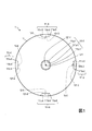
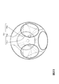
- FIG. 1 is a front view for illustrating the sound collecting device of the first embodiment.
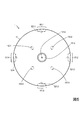
- FIG. 2 is a rear view illustrating the sound collecting device of the first embodiment.
- FIG. 3A is a plan view illustrating the concave portion of the first embodiment.
- FIG. 3B is a sectional view taken along line 3B-3B in FIG. 3A.
- FIG. 4A is a front view illustrating the arrangement of the microphones according to the first embodiment.
- FIG. 4B is a rear view illustrating the arrangement of the microphones of the first embodiment.
- FIG. 5 is a bottom view for illustrating the sound collecting device of the first embodiment.
- FIG. 6 is a bottom view illustrating the arrangement of the support areas according to the first embodiment.
- FIG. 1 is a front view for illustrating the sound collecting device of the first embodiment.
- FIG. 2 is a rear view illustrating the sound collecting device of the first embodiment.
- FIG. 3A is a plan view illustrating the concave portion of the first embodiment.
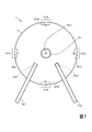
- FIG. 7 is a front view for illustrating a state where the support members are attached to the support areas in the first embodiment.
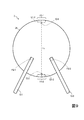
- FIG. 8 is a rear view illustrating a state where the support member is attached to the support area in the first embodiment.
- FIG. 9 is a front view for illustrating the sound collection device of the second embodiment.
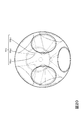
- FIG. 10 is a rear view illustrating the sound collection device of the second embodiment.
- FIG. 11 is a front view for illustrating the sound collection device of the third embodiment.
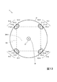
- FIG. 12 is a rear view illustrating the sound collecting device of the third embodiment.
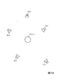
- FIG. 13 is a bottom view illustrating the sound collection device of the third embodiment.
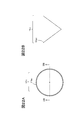
- FIG. 14 is a front view for illustrating the sound collection device of the fourth embodiment.
- FIG. 32 is a diagram illustrating an example of an impulse response when the depth of the concave portion is determined so that the sound collecting portion of the microphone is located at a position 20 mm from the center of the base.
- FIG. 33 is a diagram illustrating an example of an impulse response in a case where the depth of the concave portion is determined so that the sound collecting portion of the microphone is located at a position 30 mm from the center of the base.
- FIG. 34 is a diagram illustrating an example of an impulse response in a case where the shape of the concave portion is the shape of an exponential horn.
- FIG. 35 is a diagram illustrating an example of an impulse response when the shape of the concave portion is a bowl shape.
- FIG. 36 is a diagram illustrating an example of an impulse response when the shape of the concave portion is substantially a truncated cone.
- An example of a substantially spherical body is a three-dimensional body whose surface shape other than the concave portions 111-1,..., 111-N matches or almost matches the surface shape of the spherical body.
- the number of the recesses 111-1,..., 111-N is, for example, the same as the number of the microphones 12-1,.
- N is an integer of 2 or more.
- the base 11 is made of, for example, a material (for example, synthetic resin, metal, wood, or the like) that sufficiently reflects sound.
- D in is less than D out
- the inner wall surface between the edge portions 111a-i and 111c-i is formed in a slope shape
- the inner bottom surface 111b-i has a smooth surface. linked.
- the depth d of the concave portion 111-i is less than half the diameter (for example, the diameter) D out of the edge 111a-i of the open end of the concave portion 111-i.
- D out and D in are larger than the diameter (for example, the diameter) of the sound collection unit 121-i of the microphones 12-1,..., 12-N.
- An example of D out and D in is twice or near twice the diameter (eg, diameter) of the sound collection unit 121-i of the microphones 12-1,..., 12-N.
- the sound collection unit 121-i is a part including a mechanism (for example, a diaphragm or a metal foil) that converts air vibration of sound into an electric signal.
- the sound collection unit 121-i is provided, for example, on one end side of the microphone 12-i.
- One example of d is 2 mm.
- the shapes of the N concave portions 111-1,..., 111-N are substantially the same (the same or substantially the same). As a result, it is possible to reduce variations in sound pickup due to the direction of arrival of the sound.
- the recesses 111-1,..., 111-N are provided at predetermined intervals from each other, and the edges 111a-1,. Are away from each other. That is, the recesses 111-1,..., 111-N are provided at positions where they do not interfere with each other, and are independent of each other. As a result, the resolution can be improved, and variations in sound pickup due to the direction of arrival of the sound can be reduced.
- the intervals between each sound collecting unit 121-i and four other sound collecting units 121-i 'adjacent thereto are substantially the same.
- the intervals between the sound collecting units 121-1 and 121-6 are substantially the same (FIG. 1).
- ⁇ and ⁇ are substantially the same means that ⁇ and ⁇ are the same or that ⁇ and ⁇ are substantially the same.
- ⁇ 2 1, 3, 5, 10, 20, 30, 40, and 50.
- a sound collecting section 121-i provided on one end side of the microphone 12-i is arranged on the inner bottom surface 111b-i side of each concave section 111-i, and each sound collecting section 121-i is arranged.
- the front end of i or the vicinity of the front end is arranged on the same plane as the inner bottom surface 111b-i.
- the sound collection unit 121-i of each microphone 12-i is arranged near the center of the inner bottom surface 111b-i of the concave portion 111-i or near the center of the inner bottom surface 111b-i.
- the sound collection units 121-i of the microphones 12-i are arranged at substantially the same distance from the inner wall surface between the edge 111a-i and the edge 111c-i. Thereby, improvement in resolution can be expected.
- the sound collecting unit 121-i is arranged in the vicinity of ⁇ means that, for example, the deviation width of the sound collecting unit 121-i from ⁇ is ⁇ 3% of the diameter (for example, the diameter) of the sound collecting unit 121-i.
- ⁇ 3 1, 3, 5, 10, 20, 30, 40, and 50.
- each of the sound collection units 121-i of the microphones 12-i has a positive number having N vertexes. What is necessary is just to arrange
- the regular polyhedron has only regular tetrahedron, regular hexahedron, regular octahedron, regular dodecahedron, regular icosahedron. The relationship among the constituent faces, the number of faces, the number of sides, and the number of vertices of each regular polyhedron is shown below.
- FIG. 4A and FIG. 4B illustrate a front view and a rear view illustrating the positional relationship of the sound collection unit 121-i illustrated in FIG. 1 and FIG.
- the sound pickup of the microphone 12-i is provided at each vertex of the regular polyhedron (octahedron) 100 having six vertices or near the vertex.
- the sound collection units 121-i arranged at or near each vertex are arranged, for example, in a direction from the center of the regular polyhedron toward the vertex or its vicinity.
- Each support member 13-j supports a support area 112-j located below the base 11. For example, one end of each support member 13-j is attached to the support region 112-j, and supports the base 11 from below.
- the presence of the support member 13-j affects the spatial environment, and the sound is received by the microphone 12-i existing near the support member 13-j. The sound may be adversely affected.
- the support member 13-j supports the base 11 from the side where the target sound source does not exist, and reduces the adverse effect.
- the target sound source does not often exist below the base 11. Therefore, it can be expected that supporting the base 11 from below can reduce this adverse effect more than supporting the base 11 from above or horizontally.
- the distance between each support region 112-j and the sound collection unit 121-i of the microphone 12-i adjacent (surrounding) to the support region 112-j is substantially uniform.
- substantially uniform means uniform or substantially uniform.
- the influence of the support member 13-j on the observation at the sound collection unit 121-i disposed around the support region 112-j can be made uniform, and the above-described adverse effects can be further suppressed.
- the shape of the support member 13-j is not limited, and for example, a rod-shaped support member 13-j may be used. However, when M ⁇ 2, it is desirable that the shapes of the support members 13-j are substantially the same as each other. Thus, the influence of the support member 13-j on the sound observed by the sound collection unit 121-i can be made uniform, so that the above-mentioned adverse effects can be further suppressed.
- each of the sound collection units 121-i of the microphone 12-i is divided into N vertexes in order to make the intervals between the sound collection units 121-i of the microphones 12-i adjacent to each other substantially the same.
- An example has been shown in which one is arranged at each vertex of the regular polyhedron having or the vicinity of the vertex.
- N 2
- 9 and 10 illustrate a front view and a rear view of the sound collection device 2 having such a configuration, respectively.
- the recesses 111-1 and 111-2 are provided on a straight line Lv (on a vertical axis) passing through the center of the base 21 or near the center of the base 21.
- the recess 111-1 is provided above the base 21, and the recess 111-2 is provided below the base 21.
- the distance between the sound collecting units 121-1 and 121-2 thus arranged is substantially the same regardless of the direction in which the measurement is performed.
- the third embodiment is a modification of the first embodiment, and differs from the first embodiment in that a rod-shaped support member is fixed to a base while penetrating the base.
- FIGS. 11, 12, and 13 respectively illustrate a front view, a rear view, and a bottom view of the sound collecting device 3 of the third embodiment.
- the distance from one side portion 331 arranged outside the base portion 31 of the support member 33 to the sound collection portions 121-3, 121-4, 121-7, 121-8 of the microphones arranged in the vicinity thereof. are substantially the same as each other.
- the distance from the other side portion 332 disposed outside the base portion 31 of the support member 33 to the sound collection portions 121-1, 121-2, 121-5, 121-6 of the microphones disposed therearound. are substantially the same as each other.
- One support member 33 is disposed at each of the vertexes or near the vertices of the regular polyhedron 300, and the support member 33 is located at the center or the set of surfaces 301 of a pair of parallel surfaces 301-5 and 301-6 of the regular polyhedron 300. -5 and 301-6 are arranged on a straight line L3 (third straight line) passing near the center of each. Accordingly, the distance from the portion 331 to the sound collecting portion of the microphone arranged therearound is equal to each other, and the distance from the portion 332 to the sound collecting portion of the microphone arranged therearound is equal to each other. As a result, the adverse effect based on the support member 33 as described in the first embodiment can be reduced. Further, the camera can be attached to the portion 332 of the support member 33 while the portion 331 of the support member 33 is fixed to the ground or held by the user.
- the fourth embodiment is a modification of the second and third embodiments.
- N 2
- the rod-shaped support member is fixed to the base while penetrating the base.
- 14 and 15 illustrate a front view and a right side view of a sound collection device 4 of the fourth embodiment, respectively.
- the distances from the one side portion 331 arranged outside the base 41 of the support member 33 to the microphones 121-1 and 121-2 of the microphone are substantially the same.
- the distance from the other portion 332 disposed outside the base 41 of the support member 33 to the sound collecting units 121-1 and 121-2 of the microphones is also substantially the same.
- the microphones 121-1 and 121-2 of the microphone are arranged on a straight line Lh (first straight line) passing through the center of the base 41 or near the center of the base 41, and the support member 33 is connected to the base 41.
- Lh first straight line
- Lv second straight line
- ⁇ and ⁇ represent the angular frequency and the index of the frame time, respectively.
- W k, i represents the element of the linear filter.
- the sound collection unit 121-i of the microphone 12-i reflects not only the direct sound emitted from the sound source 110-k, but also the inner wall surface of the recess 121-i. A reflected sound arrives. As a result, more information on the sound emitted from the sound source 110-k can be collected without increasing the number of microphones 12-i per unit area. By suppressing the number of microphones 12-i per unit area, it becomes possible to sufficiently detect the phase difference between the sounds emitted from the same sound source 110-k observed by the adjacent microphones 12-i.
- each microphone 12-i can acquire a large amount of sound information by the function of the concave portion 121-i, the number of the microphones 12-i can be reduced, and the sound collection device can be downsized.
- FIG. 18 shows the sensitivity when the estimated value of Y k ( ⁇ , ⁇ ) of each sound source 110-k is obtained by performing the linear filtering using the linear filter calculated as described above using the sound pickup device 1. sensitivity).
- the horizontal axis represents frequency, and the vertical axis represents sensitivity.
- This sensitivity represents the level [dB] of the estimated value of Y k ( ⁇ , ⁇ ) based on the actual Y k ( ⁇ , ⁇ ).
- the thick solid line in FIG. 18 represents the sensitivity of the estimated value of Y I ( ⁇ , ⁇ ) of the target sound source, and the thin solid line represents another sound source whose direction viewed from the sound pickup device 1 is shifted by 30 degrees from the target sound source.
- the thick solid line represents the sensitivity of the target sound source component (sound component emitted from the target sound source) to be extracted
- the thin solid line represents the sensitivity of the sound source component (sound component emitted from the sound source) adjacent to the target sound source.
- the broken line represents the sensitivity of the estimated value of Y k ′′ ( ⁇ , ⁇ ) of the other sound sources, where k ′, k ′′ ⁇ 1,..., K ⁇ . That is, the broken line indicates the sensitivity of the sound source component to be suppressed.
- FIG. 18 it can be seen that the use of the sound pickup device 1 sufficiently suppresses components other than the target sound source component to be extracted from the low band (particularly around 100 Hz) to the high band.
- each sound source 110-k is subjected to linear filtering by using a linear filter calculated as described above using a sound collecting device in which a microphone is arranged on the surface of a sphere having no concave portion instead of the sound collecting device 1.
- the sensitivity when an estimated value of Y k ( ⁇ , ⁇ ) is obtained is shown below. As illustrated in FIG. 19, in this case, it can be seen that components other than the target sound source component to be extracted particularly on the low frequency side are not sufficiently suppressed.
- the use of the sound pickup device 1 improves the accuracy of estimating and extracting information on the target sound source as compared with the case where the sound pickup device in which the microphone is arranged on the surface of a sphere having no concave portion is used. .
- the sound collection devices 1 to 4 of the embodiments each include at least the substantially spherical bases 11 to 41 having N concave portions on the surface thereof at predetermined intervals and the N microphones 12-41. 1 to 12-N.
- N is an integer of 2 or more.
- Each of the microphones 12-1 to 12-N is provided one by one on the inner bottom surface side of each of the recesses 111-1 to 111-N, and a sound collecting unit of the microphones 12-1 to 12-N adjacent to each other.
- the intervals between 121-1 to 121-N are substantially the same.
- the resolution is reduced, but the sound collecting units 121-1 to 12-N of the microphones 12-1 to 12-N are reduced. If the interval between 121-N is increased, the information collected will decrease. It is not preferable that the resolution and the information to be collected vary depending on the direction viewed from the sound collectors 1 to 4. In each embodiment, since the intervals between the sound collecting units 121-1 to 121-N of the microphones 12-1 to 12-N adjacent to each other are substantially the same, such variation due to the azimuth can be reduced. As described above, it is possible to accurately collect sounds in all directions without increasing the size of the sound collecting devices 1 to 4.
- the recesses 111-i are not limited to those described above.
- the inner wall surface between the edge portions 111a-i and the edge portions 111c-i is formed in a slope shape and is smoothly connected to the inner bottom surface 111b-i.
- the inner wall surface between the edge portion 111c-i and the edge portion 111c-i may have a truncated cone side surface shape. That is, the cross-sectional shape (shape of the cross section 3B-3B) of the concave portion 111-i may be a trapezoid.
- the case where the inner wall surface between the edge portions 111a-i and the edge portions 111c-i has a side surface shape of a truncated cone will be described in more detail.
- N sound pickup units 121-i are required. Are arranged one by one at the vertices of the regular polyhedron having the vertices of. However, if the intervals between the sound collecting units 121-i are not exactly the same, the sound collecting units 121-i may be arranged at positions other than the vertices of the regular polyhedron. Further, the inner bottom surface 111b of the sound collection unit 121-i may be a curved surface instead of a flat surface.
- the fifth embodiment is an embodiment in which the shape of the concave portion 111-i is formed so that the microphone 12-i has directivity.
- the shape of the concave portion 111-i may be a substantially truncated cone.
- the edge of the concave portion 111-i is chamfered. In the fifth embodiment, this chamfered portion becomes the edge 111a-i.
- FIG. 20 is a perspective view of the sound collector 1 in the case where the number of the recesses 111-1,..., 111-8 is 8, and the shape of the recess 111-i is a substantially truncated cone.
- FIG. 21A is a plan view of an example of the concave portion 111-i having a substantially truncated conical shape.
- FIG. 21B is a sectional view taken along line 21B-21B of FIG. 21A.
- the shape of the recess 111-i may be substantially conical. That is, the recess 111-i may not have the edge 111c-i and the inner bottom surface 11b-i.
- concave portion 111-i having a substantially conical shape and the concave portion 111-i having a substantially frustoconical shape may coexist.
- the shape of the concave portion 111-i may be the shape of an exponential horn.
- the shape of the recess 111-i may be formed such that the rate of change in the diameter of the recess 111-i decreases from the open end to the bottom.
- the edge of the concave portion 111-i is chamfered. As in Example 1 of the shape of the concave portion 111-i, the chamfered portion becomes the edge portion 111a-i.
- FIG. 23 is a perspective view of the sound collecting device 1 in the case where the number of the recesses 111-1,..., 111-8 is 8, and the shape of the recess 111-i is an exponential horn.
- FIG. 24A is a plan view of an example of the concave portion 111-i having an exponential horn shape.
- FIG. 24B is a sectional view taken along line 24B-24B of FIG. 24A.
- the cross section from the edge portion 111a-i to the edge portion 111ci has a curved shape protruding inward.
- the shape of the recess 111-i may be a bowl shape.
- the shape of the concave portion 111-i may be formed such that the rate of change in the diameter of the concave portion 111-i increases from the open end side to the bottom surface side.
- the edge of the concave portion 111-i is chamfered. As in Example 1 of the shape of the concave portion 111-i, the chamfered portion becomes the edge portion 111a-i.
- FIG. 25 is a perspective view of the sound collector 1 in the case where the number of the recesses 111-1,..., 111-8 is 8, and the shape of the recess 111-i is a bowl shape.
- FIG. 26A is a plan view of an example of the recess 111-i having a bowl shape.
- FIG. 26B is a sectional view taken along line 26B-26B of FIG. 26A.
- the cross section from the edge portion 111a-i to the edge portion 111ci has a curved shape that protrudes outward.
- the sound collection unit 121-i of the microphone 12-i is located at the center of the base or in the vicinity of the center of the base, and at the center of the outer periphery or the bottom of the recess 111-i where the microphone 12-i is installed. Or it is installed on a straight line L passing substantially through the center.
- the sound collecting unit 121-i of the microphone 12-i is installed so that the distance between the sound collecting unit 121-i of the microphone 12-i and the center of the base is smaller than the radius of the base.
- the distance between the sound collection unit 121-i of the microphone 12-i and the center of the base becomes smaller, the directivity of the microphone 12-i becomes stronger, and the width of the directivity of the microphone 12-i becomes narrower. For this reason, the distance between the sound collection unit 121-i of the microphone 12-i and the center of the base is appropriately determined according to the directivity required for the microphone 12-i.
- the sound collecting unit 121-i of the microphone 12-i is configured such that the distance between the sound collecting unit 121-i of the microphone 12-i and the center of the base is smaller than 1/2 (half) of the radius of the base. Will be installed.
- the sound collecting unit 121-i of the microphone 12-i is installed such that the distance between the sound collecting unit 121-i of the microphone 12-i and the center of the base is larger than 1/2 of the radius of the base. Is also good.
- the directivity of the sound collecting device 1 can be set to a desired directivity.
- the microphone 12-i may be installed so as to be in contact with the inner bottom surface 11b-i of the recess 111-i, or may be installed so as not to be in contact with the inner bottom surface 11bi of the recess 111-i.
- the sound collecting unit 121-i is located at the center of the base or in the vicinity of the center of the base and the outer periphery of the concave part 111-i where the microphone 12-i is installed. What is necessary is just to install on the straight line L which passes through the center of a bottom part or substantially center.
- the diameter of the recess 111-i is determined so that the recess 111-i does not overlap with the adjacent recess 111-i.
- the diameter of the base is 80 mm and the number of the recesses 111-1,..., 111-8 is 8, as illustrated in FIGS. 20, 23 and 25, the diameter of the recess 111-i Is set to 40 mm or less.
- the diameter of the recess 111-i is the diameter of the outer periphery of the recess 111-i.
- a regular hexahedron having eight vertices inscribed in a sphere having the same size as the base is formed by connecting four parallel sides of the 12 sides of the regular hexahedron.
- the upper side of the regular hexahedron or the lower part of the regular hexahedron obtained by dividing each of the two sides by a dividing plane that is a plane that bisects each of the sides is rotated 45 degrees along the dividing plane while maintaining the state inscribed in the sphere .., 111-8 are provided at the positions of the eight vertices (see FIG. 27B).
- Three microphones 121-1, 121-2, and 121-3 were provided on the surface of a base having a diameter of 80 mm.
- the sound collecting units 121-1 and 121-2 of the microphone are provided at positions at 90 degrees to each other, and the sound collecting units 121-2 and 121-3 of the microphone are provided at positions at 90 degrees to each other.
- the sound collection units 121-1 and 121-3 of the microphone are provided at positions forming 180 degrees from each other.
- a certain sound collection part and another sound collection part different from this certain sound collection part are provided at positions forming x degrees with each other means that a straight line passing through the center of the certain sound collection part and the base part And a straight line passing through the center of the base and the other sound collecting units, and these lines form x degrees.
- the sound collection units 121-1, 121-2, 121-3 of the microphone are provided at the positions shown in FIG.
- FIG. 29A shows the impulse response of each microphone in this case.
- FIG. 29B the inner bottom surfaces 11b-1, 11b-2, and 11b-3 of the three concave portions 111-1, 111-2, and 111-3 each having a substantially frustoconical shape, not the surface of the base.
- the depths of the recesses 111-1, 111-2, 111-3 are determined so that the sound collecting sections 121-1, 121-2, 121-3 of the microphone are arranged at a position 20 mm from the center of the base. I have.
- the other experimental conditions in FIG. 29B are the same as those in FIG. 29A.
- the solid line represents the impulse response of the microphone 12-1
- the dotted line represents the impulse response of the microphone 12-2
- the dashed line represents the impulse response of the microphone 12-3. This is the same for other figures.
- the difference between the maximum sound pressure of the microphone 12-1 and the maximum sound pressure of the microphones 12-2, 12-3 is It is larger than in the case of FIG. 29A.
- FIGS. 30A and 30B show the impulse response of each microphone when the frequency of the sound wave generated from the point sound source P is 1500 Hz.
- the other experimental conditions in FIG. 30A are the same as those in FIG. 29A.
- the other experimental conditions in FIG. 30B are the same as those in FIG. 29B.
- FIG. 31 shows the depths of the recesses 111-1, 111-2, 111-3 such that the sound collecting units 121-1, 121-2, 121-3 of the microphone are arranged at a position 10 mm from the center of the base. Represents the impulse response of each microphone when is defined.
- FIG. 32 shows the depths of the recesses 111-1, 111-2, 111-3 such that the sound collecting sections 121-1, 121-2, 121-3 of the microphone are arranged at a position 20 mm from the center of the base. Represents the impulse response of each microphone when is defined.
- FIG. 33 shows the depths of the recesses 111-1, 111-2, 111-3 such that the sound collecting sections 121-1, 121-2, 121-3 of the microphone are arranged at a position 30 mm from the center of the base. Represents the impulse response of each microphone when is defined.
- FIGS. 31 to 33 are the same as those of FIG. 29B.
- the maximum sound pressure of the microphones 12-2 and 12-3 is suppressed to be lower than the maximum sound pressure of the microphone 12-1. This indicates that directivity is obtained regardless of the depth when the concave portions 111-1, 111-2, and 111-3 are provided.
- FIG. 34 shows the impulse response of each microphone when the shape of the concave portions 111-1, 111-2, and 111-3 is the shape of an exponential horn.
- FIG. 35 shows the impulse response of each microphone when the concave portions 111-1, 111-2, and 111-3 are bowl-shaped.
- FIG. 36 shows the impulse response of each microphone when the shapes of the recesses 111-1, 111-2, and 111-3 are substantially truncated cones.
- FIGS. 34 to 36 are the same as those of FIG. 29B.
- the maximum sound pressure of the microphones 12-2 and 12-3 is relatively smaller than the maximum sound pressure of the microphone 12-1. Accordingly, when the shapes of the recesses 111-1, 111-2, and 111-3 are substantially truncated cones, the shape of the recesses 111-1, 111-2, and 111-3 is the shape of the exponential horn or It can be said that higher directivity can be obtained than in the case of a bowl shape.
- the sound collecting device 1 according to the fourth embodiment of the first embodiment includes N microphones 12-1,..., 12-N, the same number as the number of the recesses 111-1,. .
- the sound collection device 1 of the fifth embodiment may further include at least one microphone.
- each of these at least one microphone is installed in any of the N recesses 111-1,..., 111-N.
- two or more microphone holons may be provided in at least one of the recesses 111-1,..., 111-N.
Landscapes
- Health & Medical Sciences (AREA)
- Otolaryngology (AREA)
- Physics & Mathematics (AREA)
- Engineering & Computer Science (AREA)
- Acoustics & Sound (AREA)
- Signal Processing (AREA)
- Obtaining Desirable Characteristics In Audible-Bandwidth Transducers (AREA)
- Details Of Audible-Bandwidth Transducers (AREA)
Abstract
少なくとも、互いに所定の間隔をおいたN個の凹部を表面に備えた略球体の基部と、N個のマイクロホンと、を有する集音装置が提供される。ただし、Nが2以上の整数であり、マイクロホンのそれぞれは、凹部のそれぞれの内底面側に1個ずつ設置されており、互いに隣接するマイクロホンの集音部間の間隔は略同一である。
Description
本発明は、集音技術に関し、特に複数の方向から到来する音を観測する技術に関する。
特許文献1には、複数のマイクロホンで構成された音響アレイ装置(収音装置)を用い、線形フィルタリングによって任意の目標音源に関する情報(目標音源信号や位置)を推定・抽出する技術が記載されている。
特許文献1の収音装置で全方位の音を集音するためには多くのマイクロホンが必要となる。一方、隣接するマイクロホンの間隔が狭いと、それらで観測された同じ音源から発せられた音の位相差が小さくなり、目標音源に関する情報の推定・抽出精度(すなわち分解能)が低下してしまう。この精度を向上させるために隣接するマイクロホンの間隔を広くすると収音装置も大型化してしまう。
本発明はこのような点に鑑みてなされたものであり、集音装置の大きさをさほど大きくすることなく、全方位の音を精度よく集音することを目的とする。
本発明では、少なくとも、互いに所定の間隔をおいたN個の凹部を表面に備えた略球体の基部と、N個のマイクロホンと、を有する集音装置が提供される。ただし、Nは2以上の整数である。マイクロホンのそれぞれは、凹部のそれぞれの内底面側に1個ずつ設置されており、互いに隣接するマイクロホンの集音部間の間隔は略同一である。
これにより、集音装置の大きさをさほど大きくすることなく、全方位の音を精度よく集音できる。
以下、図面を参照して本発明の実施形態を説明する。
[第1実施形態]
図1および図2に本実施形態の集音装置1の正面図および背面図をそれぞれ例示する。図1および図2に例示するように、本実施形態の集音装置1は、互いに所定の間隔をおいたN個の凹部111-1,…,111-Nを表面に備えた略球体の基部11と、N個のマイクロホン12-1,…,12-Nとを有する。略球体とは、厳密には球体ではないものの球体に近い形状を持つ立体(ほぼ球体)を意味する。略球体の例は、凹部111-1,…,111-N以外の部分の表面形状が球体の表面形状に一致またはほぼ一致する立体である。凹部111-1,…,111-Nの個数は、例えば、マイクロホン12-1,…,12-Nの個数と同じN個である。ただしNは2以上の整数である。第1実施形態ではN=6の例を図示するが、これは本発明を限定するものではない。また、基部11は、例えば、音を十分に反射する材質(例えば、合成樹脂、金属、木など)で構成されている。
図1および図2に本実施形態の集音装置1の正面図および背面図をそれぞれ例示する。図1および図2に例示するように、本実施形態の集音装置1は、互いに所定の間隔をおいたN個の凹部111-1,…,111-Nを表面に備えた略球体の基部11と、N個のマイクロホン12-1,…,12-Nとを有する。略球体とは、厳密には球体ではないものの球体に近い形状を持つ立体(ほぼ球体)を意味する。略球体の例は、凹部111-1,…,111-N以外の部分の表面形状が球体の表面形状に一致またはほぼ一致する立体である。凹部111-1,…,111-Nの個数は、例えば、マイクロホン12-1,…,12-Nの個数と同じN個である。ただしNは2以上の整数である。第1実施形態ではN=6の例を図示するが、これは本発明を限定するものではない。また、基部11は、例えば、音を十分に反射する材質(例えば、合成樹脂、金属、木など)で構成されている。
図3Aは、本実施形態の凹部111-i(ただし、i=1,…,N)を例示するための平面図であり、図3Bは、図3Aの3B-3B断面図である。図3Aおよび図3Bに例示するように、本実施形態で例示する凹部111-iは、皿状の内壁面形状を持ったくぼみである。すなわち、本実施形態で例示する凹部111-iの開放端側(表面側)の縁部111a-iの形状は略円形であり、凹部111-iの内底面111b-i(凹部111-iの内部の底面)は略円形の略平面(内底面111b-iの縁部111c-iが略円形の略平面)である。ただし、略円形とは、円形または円形に近い形状(ほぼ円形)を意味する。円形に近い形状の例は、短軸に対する長軸の比率が所定値γ1以下の楕円、線対称又は点対称となる多角形である。ただし、γ1は1より大きな実数である。γ1の例はγ1=1.1,1.2,1.3,1.4,1.5などである。略平面とは、平面または平面に近い面(ほぼ平面)を意味する。ほぼ平面は、例えば、多少の凹凸を持つ面であってもよいし、わずかに湾曲した面であってもよい。内底面111b-iの縁部111c-iの径(例えば、直径)Dinは、凹部111-iの開放端側の縁部111a-iの径(例えば、直径)Dout以下であり、例えば、DinはDout未満である。縁部111a-iと縁部111c-iとの間の領域は凹部111-iの内壁面である。図3Aおよび図3Bの例では、DinはDout未満であり、縁部111a-iと縁部111c-iとの間の内壁面はスロープ状に形成され、内底面111b-iに滑らかにつながっている。凹部111-iの深さdは、凹部111-iの開放端の縁部111a-iの径(例えば、直径)Doutの半分未満であることが望ましい。例えば、図3Bに例示するように、凹部111-iの深さdが、凹部111-iの開放端の縁部111a-iの直径Dout=2rの半分未満であることが望ましい(0<d<r)。これにより、分解能を向上させることができるからである(詳細は後述する)。DoutおよびDinは、マイクロホン12-1,…,12-Nの集音部121-iの径(例えば、直径)よりも大きい。DoutおよびDinの一例は、マイクロホン12-1,…,12-Nの集音部121-iの径(例えば、直径)の2倍または2倍の近傍である。なお、集音部121-iは、音の空気振動を電気信号に変換する機構(例えば、振動板や金属箔)を含む部位である。集音部121-iは、例えばマイクロホン12-iの一端側に設けられている。dの一例は2mmである。N個の凹部111-1,…,111-Nの形状は互いに略同一(同一またはほぼ同一)であることが望ましい。これにより、音の到来方向による収音ばらつきを低減できる。また図1および図2に例示するように、凹部111-1,…,111-Nは互いに所定の間隔をおいて設けられており、開放端側の縁部111a-1,…,111a-Nは互いに離れている。すなわち、凹部111-1,…,111-Nは互いに干渉しない位置に設けられており、互いに独立している。これにより、分解能を向上させることができるとともに、音の到来方向による収音ばらつきを低減させることができる。
図1、図2、図3Aおよび図3Bに例示するように、各マイクロホン12-i(ただし、i=1,…,N)は、各凹部111-i(ただし、i=1,…,N)の内底面111b-i側に1個ずつ設置(固定)されている。ただし、互いに隣接するマイクロホン12-iの集音部121-i間の間隔(距離)は略同一である。すなわち、互いに隣接するマイクロホン12-iの集音部121-i間の間隔は所定値またはその近傍である。図1および図2の例の場合、各集音部121-iとそれに隣り合っている4個の他の集音部121-i’との間隔は互に略同一である。例えば、集音部121-1と集音部121-2との間隔、集音部121-1と集音部121-4との間隔、集音部121-1と集音部121-5との間隔、集音部121-1と集音部121-6との間隔は、すべて略同一である(図1)。なお、αとβとが略同一とは、αとβとが同一であること、またはαとβとがほぼ同一であることを意味する。αとβとがほぼ同一とは、αとβとの差分δ=|α-β|がαに対して0%よりも大きくγ2%以下であることを意味する。γ2の例はγ2=1,3,5,10,20,30,40,50である。図1および図2の例の場合、マイクロホン12-iの一端側に設けられた集音部121-iが各凹部111-iの内底面111b-i側に配置され、各集音部121-iの先端または当該先端の近傍が内底面111b-iと同一の面上に配置されている。図3Aおよび図3Bに例示するように、各マイクロホン12-iの集音部121-iは、各凹部111-iの内底面111b-iの中央または内底面111b-iの中央の近傍に配置されることが望ましい。すなわち、各マイクロホン12-iの集音部121-iは、縁部111a-iと縁部111c-iとの間の内壁面から略同一距離の位置に配置されることが望ましい。これにより、分解能の向上を期待できる。なお、集音部121-iがαの近傍に配置されるとは、例えば、集音部121-iのαからのずれ幅が集音部121-iの径(例えば、直径)のγ3%以下となる位置に集音部121-iが配置されることを意味する。γ3の例はγ3=1,3,5,10,20,30,40,50である。
互いに隣接するマイクロホン12-iの集音部121-i間の間隔を略同一にするためには、例えば、マイクロホン12-iの集音部121-iのそれぞれを、N個の頂点を持つ正多面体の頂点または当該頂点の近傍のそれぞれに1個ずつ配置すればよい。正n面体のすべての頂点が外接する球で、その頂点部分にマイクロホン12-iを配置することで均一性を担保する。正多面体は、正四面体、正六面体、正八面体、正十二面体、正二十面体しか存在しない。以下に各正多面体の構成面、面数、辺数、頂点数の関係を示す。

このように、各集音部121-iを正多面体の頂点または当該頂点の近傍のそれぞれに1個ずつ配置する場合、Nは4,6,8,12,20の何れかとなる。図4Aおよび図4Bに、図1および図2に例示した集音部121-iの位置関係を表す正面図および背面図を例示する。図4Aおよび図4Bに例示するように、図1および図2の例の場合、6個の頂点を持つ正多面体(正八面体)100の各頂点または当該頂点の近傍にマイクロホン12-iの集音部121-i(i=1,…,6)を1個ずつ配置すればよい。各頂点またはその近傍に配置される集音部121-iは、例えば、正多面体の中央からその頂点またはその近傍に向かう方向に向けて配置される。
図5から8に例示するように、集音装置1が基部11を下方側(基部11が配置された際に下に配置される側)から支持する支持部材13-j(ただし、j=1,…,M)を有していてもよい。Mは1以上の整数である。図5から8ではM=4の場合を例示するが、これは本発明を限定するものではない。各支持部材13-jは、基部11の下方側に位置する支持領域112-jを支持する。例えば、各支持部材13-jの一端が支持領域112-jに取り付けられ、基部11を下方側から支持する。基部11が支持部材13-jに支持される場合、その支持部材13-jの存在が空間環境に影響を与え、その支持部材13-jの近くに存在するマイクロホン12-iで受音される音に悪影響を及ぼす場合がある。目標音源方向から到来した音の観測に悪影響があると、目標音源に関する情報の推定・抽出精度にも悪影響を与えてしまう。そのため、目標音源が存在しない側から支持部材13-jが基部11を支持し、この悪影響を低減させることが望ましい。通常、目標音源は基部11の下方に存在しないことが多い。そのため、上方側や水平方向から基部11を支持するよりも、下方側から基部11を支持した方がこの悪影響を低く抑えることができると期待できる。また、各支持領域112-jと当該支持領域112-jに隣接する(周囲に存在する)マイクロホン12-iの集音部121-iとの間隔は略均一であることが望ましい。なお、略均一とは、均一またはほぼ均一であることを意味する。すなわち、支持領域112-jは、それに隣接するマイクロホン12-iの集音部121-iから略同一の距離に設けられることが望ましい。例えば、図5および図6の例の場合、支持領域112-1は、集音部121-1,121-4,121-6から略同一の距離に配置され、支持領域112-2は、集音部121-1,121-2,121-6から略同一の距離に配置され、支持領域112-3は、集音部121-2,121-3,121-6から略同一の距離に配置され、支持領域112-4は、集音部121-3,121-4,121-6から略同一の距離に配置されることが望ましい。例えば、集音部121-iのそれぞれが正多面体100の頂点または当該頂点の近傍のそれぞれに1個ずつ配置される場合、この正多面体100の下方側(基部11が配置された際に下に配置される側)に存在する面101-j(ただし、j=1,…,M)に支持領域112-jが設けられ、面101-jのすべての頂点から当該支持領域112-jまでの距離が略同一となるように当該支持領域112-jが配置されることが望ましい(図6)。これにより、支持部材13-jが当該支持領域112-jの周囲に配置された集音部121-iでの観測に与える影響を均一化でき、上述した悪影響をより抑えることができる。なお、支持部材13-jの形状に限定はなく、例えば棒状の支持部材13-jを用いてもよい。ただし、M≧2の場合、支持部材13-jの形状は互いに略同一であることが望ましい。これにより、支持部材13-jが集音部121-iで観測される音に与える影響を均一化できるため、上述した悪影響をより一層抑えることができる。
[第2実施形態]
第1実施形態では、互いに隣接するマイクロホン12-iの集音部121-i間の間隔を略同一にするために、マイクロホン12-iの集音部121-iのそれぞれを、N個の頂点を持つ正多面体の頂点または当該頂点の近傍のそれぞれに1個ずつ配置する例を示した。ここで2個の頂点を持つ正多面体は存在しないが、N=2の場合には、マイクロホン12-i(ただし、i=1,2)の集音部121-iを基部の中央または当該基部の中央の近傍を通る直線上に配置すればよい。図9および図10に、このような構成の集音装置2の正面図および背面図をそれぞれ例示する。以降、これまでに説明した事項との相違点を中心に説明し、既に説明した事項については同じ参照番号を用いて説明を簡略化する。
第1実施形態では、互いに隣接するマイクロホン12-iの集音部121-i間の間隔を略同一にするために、マイクロホン12-iの集音部121-iのそれぞれを、N個の頂点を持つ正多面体の頂点または当該頂点の近傍のそれぞれに1個ずつ配置する例を示した。ここで2個の頂点を持つ正多面体は存在しないが、N=2の場合には、マイクロホン12-i(ただし、i=1,2)の集音部121-iを基部の中央または当該基部の中央の近傍を通る直線上に配置すればよい。図9および図10に、このような構成の集音装置2の正面図および背面図をそれぞれ例示する。以降、これまでに説明した事項との相違点を中心に説明し、既に説明した事項については同じ参照番号を用いて説明を簡略化する。
図9および図10に例示するように、第2実施形態の集音装置2は、互いに所定の間隔をおいた2個の凹部111-1,111-2を表面に備えた略球体の基部21と、2個のマイクロホン12-1,12-2と、基部21を支持する支持部材13-j(j=1,…,M)とを有する。図9および図10ではM=4の場合を例示するが、これは本発明を限定するものではない。例えば、M=3であってもよいし、M≧5であってもよい。凹部111-1,111-2は、基部21の中央または基部21の中央の近傍を通る直線Lv上(垂直軸上)に設けられている。凹部111-1は基部21の上方側に設けられ、凹部111-2は基部21の下方側に設けられている。各マイクロホン12-i(ただし、i=1,2)は、各凹部111-i(ただし、i=1,2)の内底面111b-i側に1個ずつ設置(固定)されている。この際、各集音部121-i(ただし、i=1,2)はこの直線Lv上に配置されている。このように配置された集音部121-1と集音部121-2との間の間隔は、どの方向に測定しても略同一である。各支持部材13-j(ただし、j=1,…,M)は基部21の下方側に位置する支持領域112-jを支持し、基部21を下方側から支持する。ここで、基部21の下方側に配置された集音部121-2から各支持領域112-jまでの距離は互いに略同一であることが望ましい。これにより、各方向から集音部121-2に到達する音が各支持領域112-jから受ける影響を均一化できる。
[第3実施形態]
第3実施形態は第1実施形態の変形例であり、棒状の支持部材が基部を貫通した状態で基部に固定される点が第1実施形態と相違する。図11,図12および図13に、第3実施形態の集音装置3の正面図、背面図、および底面図をそれぞれ例示する。図11から図13に例示するように、第3実施形態の集音装置3は、互いに所定の間隔をおいたN個の凹部111-i(ただし、i=1,…,N)を表面に備えた略球体の基部31と、N個のマイクロホン12-1,…,12-Nと、基部31を貫通した状態で基部31に固定されている棒状の支持部材33とを有する。なお、図11から図13ではN=8の場合を例示するが、これは本発明を限定するものではない。
第3実施形態は第1実施形態の変形例であり、棒状の支持部材が基部を貫通した状態で基部に固定される点が第1実施形態と相違する。図11,図12および図13に、第3実施形態の集音装置3の正面図、背面図、および底面図をそれぞれ例示する。図11から図13に例示するように、第3実施形態の集音装置3は、互いに所定の間隔をおいたN個の凹部111-i(ただし、i=1,…,N)を表面に備えた略球体の基部31と、N個のマイクロホン12-1,…,12-Nと、基部31を貫通した状態で基部31に固定されている棒状の支持部材33とを有する。なお、図11から図13ではN=8の場合を例示するが、これは本発明を限定するものではない。
ここで、支持部材33の基部31の外部に配置された一方側の部分331からその近隣に配置されるマイクロホンの集音部121-3,121-4,121-7,121-8までの距離は、互いに略同一とされる。同様に、支持部材33の基部31の外部に配置された他方側の部分332からその周囲に配置されるマイクロホンの集音部121-1,121-2,121-5,121-6までの距離は、互いに略同一とされる。例えば、Nが6,8,12,20の何れかであり、かつ、マイクロホンの集音部121-i(ただし、i=1,…,N)のそれぞれが、N個の頂点を持つ正多面体300の頂点または頂点の近傍のそれぞれに1個ずつ配置されており、支持部材33が当該正多面体300の互いに平行な一組の面301-5,301-6それぞれの中央または一組の面301-5,301-6それぞれの中央の近傍を通る直線L3(第3直線)上に配置される。これにより、部分331からその周囲に配置されるマイクロホンの集音部までの距離が互いに同一となり、かつ、部分332からその周囲に配置されるマイクロホンの集音部までの距離が互いに同一となる。その結果、第1実施形態で説明したような支持部材33に基づく悪影響を低減できる。さらに、支持部材33の部分331を地面に対して固定したり、利用者が把持したりするとともに、支持部材33の部分332にカメラを取り付けることもできる。
[第4実施形態]
第4実施形態は第2,3実施形態の変形例である。本実施形態では、N=2であり、かつ、棒状の支持部材が基部を貫通した状態で基部に固定される。図14および図15に、第4実施形態の集音装置4の正面図および右側面図をそれぞれ例示する。図14および図15に例示するように、第4実施形態の集音装置4は、互いに所定の間隔をおいた2個の凹部111-i(ただし、i=1,2)を表面に備えた略球体の基部41と、2個のマイクロホン12-1,12-2と、基部41を貫通した状態で基部41に固定されている棒状の支持部材33とを有する。ここで、支持部材33の基部41の外部に配置された一方側の部分331からマイクロホンの集音部121-1,121-2までの距離は、互いに略同一とされる。同様に、支持部材33の基部41の外部に配置された他方側の部分332からマイクロホンの集音部121-1,121-2までの距離も、互いに略同一とされる。例えば、マイクロホンの集音部121-1,121-2が基部41の中央または基部41の中央の近傍を通る直線Lh(第1直線)上に配置されており、かつ、支持部材33が基部41の中央または基部の中央の近傍を通り直線Lh(第1直線)と略直交する直線Lv(第2直線)上に配置されている。例えば、直線Lhは水平方向に沿った直線であり、直線Lvは鉛直方向に沿った直線である。なお略直交とは、直交またはほぼ直交することを意味する。これにより、部分331からマイクロホンの集音部121-1,121-2までの距離が互いに同一となり、かつ、部分332からマイクロホンの集音部121-1,121-2までの距離が互いに同一となる。その結果、第1実施形態で説明したような支持部材33に基づく悪影響を低減できる。
第4実施形態は第2,3実施形態の変形例である。本実施形態では、N=2であり、かつ、棒状の支持部材が基部を貫通した状態で基部に固定される。図14および図15に、第4実施形態の集音装置4の正面図および右側面図をそれぞれ例示する。図14および図15に例示するように、第4実施形態の集音装置4は、互いに所定の間隔をおいた2個の凹部111-i(ただし、i=1,2)を表面に備えた略球体の基部41と、2個のマイクロホン12-1,12-2と、基部41を貫通した状態で基部41に固定されている棒状の支持部材33とを有する。ここで、支持部材33の基部41の外部に配置された一方側の部分331からマイクロホンの集音部121-1,121-2までの距離は、互いに略同一とされる。同様に、支持部材33の基部41の外部に配置された他方側の部分332からマイクロホンの集音部121-1,121-2までの距離も、互いに略同一とされる。例えば、マイクロホンの集音部121-1,121-2が基部41の中央または基部41の中央の近傍を通る直線Lh(第1直線)上に配置されており、かつ、支持部材33が基部41の中央または基部の中央の近傍を通り直線Lh(第1直線)と略直交する直線Lv(第2直線)上に配置されている。例えば、直線Lhは水平方向に沿った直線であり、直線Lvは鉛直方向に沿った直線である。なお略直交とは、直交またはほぼ直交することを意味する。これにより、部分331からマイクロホンの集音部121-1,121-2までの距離が互いに同一となり、かつ、部分332からマイクロホンの集音部121-1,121-2までの距離が互いに同一となる。その結果、第1実施形態で説明したような支持部材33に基づく悪影響を低減できる。
[集音装置の使用例]
次に、上述した収音装置1~4を用い、線形フィルタリングによって目標音源に関する情報を推定・抽出する例を説明する(例えば、特許文献1等参照)。図16に例示するように、空間内にK個の音源110-1,…,110-K、および、収音装置1が配置されているとする。ここでは一例として収音装置1を用いるが、その他の収音装置2~4が用いられてもよい。この環境では以下のような関係を近似できる。
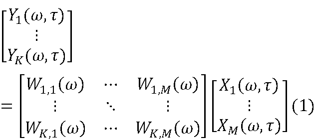
ただし、Xi(ω,τ)(ただし、i=1,…,M)はマイクロホン12-iで観測された時間領域の観測信号(混合信号)を時間周波数領域に変換(例えば、短時間フーリエ変換等)して得られる時間周波数領域の観測信号を表す。ここでω、τはそれぞれ角周波数、フレーム時間のインデックスを表す。Yk(ω,τ)は音源110-k(ただし、k=1,…,K)で発せられた時間領域の音源信号を時間周波数領域に変換して得られる時間周波数領域の音源信号を表す。Wk,iは線形フィルタの要素を表す。例えば、事前に特定の音源110-Iのみから特定の音(例えば、インパルス)が発せられた環境を収音装置1で観測(例えば、インパルス応答を観測)してXi(ω,τ)(ただし、i=1,…,M)を得、これらのXi(ω,τ)と、当該特定の音源110-Iのみから特定の音のみが発生られた状態に対応するYk(ω,τ)(ただし、k=1,…,K)とを式(1)に代入して連立方程式を解くことで、当該特定の音源110-I(目標音源)から発せられた音を抽出するためのWk,iを得ることができる。また、音源110-1,…,110-Kのそれぞれを音源110-Iとして同様な計算を行うことで、音源110-1,…,110-Kのそれぞれを目標音源とするWk,iを得ることができる。このように事前にWk,iを求めておけば、上記の式(1)に従い、マイクロホン12-iで観測された時間領域の観測信号(混合信号)に対応するXi(ω,τ)から特定の音源110-I(ただし、I∈{1,…,K})(目標音源)のYI(ω,τ)の推定値を計算できる。
次に、上述した収音装置1~4を用い、線形フィルタリングによって目標音源に関する情報を推定・抽出する例を説明する(例えば、特許文献1等参照)。図16に例示するように、空間内にK個の音源110-1,…,110-K、および、収音装置1が配置されているとする。ここでは一例として収音装置1を用いるが、その他の収音装置2~4が用いられてもよい。この環境では以下のような関係を近似できる。
ただし、Xi(ω,τ)(ただし、i=1,…,M)はマイクロホン12-iで観測された時間領域の観測信号(混合信号)を時間周波数領域に変換(例えば、短時間フーリエ変換等)して得られる時間周波数領域の観測信号を表す。ここでω、τはそれぞれ角周波数、フレーム時間のインデックスを表す。Yk(ω,τ)は音源110-k(ただし、k=1,…,K)で発せられた時間領域の音源信号を時間周波数領域に変換して得られる時間周波数領域の音源信号を表す。Wk,iは線形フィルタの要素を表す。例えば、事前に特定の音源110-Iのみから特定の音(例えば、インパルス)が発せられた環境を収音装置1で観測(例えば、インパルス応答を観測)してXi(ω,τ)(ただし、i=1,…,M)を得、これらのXi(ω,τ)と、当該特定の音源110-Iのみから特定の音のみが発生られた状態に対応するYk(ω,τ)(ただし、k=1,…,K)とを式(1)に代入して連立方程式を解くことで、当該特定の音源110-I(目標音源)から発せられた音を抽出するためのWk,iを得ることができる。また、音源110-1,…,110-Kのそれぞれを音源110-Iとして同様な計算を行うことで、音源110-1,…,110-Kのそれぞれを目標音源とするWk,iを得ることができる。このように事前にWk,iを求めておけば、上記の式(1)に従い、マイクロホン12-iで観測された時間領域の観測信号(混合信号)に対応するXi(ω,τ)から特定の音源110-I(ただし、I∈{1,…,K})(目標音源)のYI(ω,τ)の推定値を計算できる。
上述した収音装置1(2,3,4)を用いることで、従来よりも高い分解能で、任意の目標音源から発せられた音を抽出することができる。すなわち、図17Aおよび図17Bに例示するように、マイクロホン12-iの集音部121-iには、音源110-kから発せられた直接音だけではなく、凹部121-iの内壁面で反射した反射音も届く。これにより、単位面積当たりのマイクロホン12-iの数を増やすことなく、音源110-kから発せられた音の情報をより多く集めることができる。単位面積当たりのマイクロホン12-iの個数を抑えることにより、隣接するマイクロホン12-iでそれぞれ観測される同じ音源110-kから発せられた音の位相差を十分検出することも可能になる。結果として目標音源に関する情報の推定・抽出精度が向上すると期待できる。また、凹部121-iの働きによって各マイクロホン12-iが多くの音情報を取得できるため、マイクロホン12-iの個数を抑えることができ、収音装置を小型化できる。
図18に、収音装置1を用いて上述のように計算した線形フィルタを用い、線形フィルタリングを行って各音源110-kのYk(ω,τ)の推定値を得た場合の感度(sensitivity)を例示する。横軸が周波数を表し、縦軸が感度を表す。なお、この感度は実際のYk(ω,τ)を基準としたYk(ω,τ)の推定値のレベル[dB]を表す。図18における太い実線は目標音源のYI(ω,τ)の推定値の感度を表し、細い実線は収音装置1から見た方向が目標音源から30度ずれた位置に存在する他の音源の音源のYk’(ω,τ)の推定値の感度を表す。すなわち、太い実線は抽出しようとする目標音源成分(目標音源から発せられた音の成分)の感度を表し、細い実線は目標音源に隣接する音源成分(当該音源から発せられた音の成分)の感度を表す。破線はその他の音源のYk”(ω,τ)の推定値の感度を表す。ただし、k’,k”∈{1,…,K}である。すなわち、破線は抑制しようとする音源成分の感度を表す。図18に例示するように、収音装置1を用いることで、低域(特に100Hzあたり)から高域に至るまで、抽出しようとする目標音源成分以外が十分に抑圧されていることが分かる。
図19に、収音装置1に代え、凹部を有しない球体の表面にマイクロホンを配置した収音装置を用いて上述のように計算した線形フィルタを用い、線形フィルタリングを行って各音源110-kのYk(ω,τ)の推定値を得た場合の感度を例示する。図19に例示するように、この場合には、特に低域側で抽出しようとする目標音源成分以外が十分に抑圧されていないことが分かる。
以上のように、収音装置1を用いることにより、凹部を有しない球体の表面にマイクロホンを配置した収音装置を用いる場合に比べ、目標音源に関する情報の推定・抽出精度が向上することが分かる。
[まとめ]
以上のように、各実施形態の集音装置1~4は、少なくとも、互いに所定の間隔をおいたN個の凹部を表面に備えた略球体の基部11~41と、N個のマイクロホン12-1~12-Nと、を有する。ただし、Nは2以上の整数である。マイクロホン12-1~12-Nのそれぞれは、凹部111-1~111-Nのそれぞれの内底面側に1個ずつ設置されており、互いに隣接するマイクロホン12-1~12-Nの集音部121-1~121-N間の間隔は略同一である。前述のように、凹部121-iの働きにより、従来よりも高い分解能で、任意の目標音源から発せられた音を抽出することができる。また、マイクロホン12-1~12-Nの集音部121-1~121-N間の間隔が近すぎると分解能が低下するが、マイクロホン12-1~12-Nの集音部121-1~121-N間の間隔が離れると収音される情報が低下する。集音装置1~4から見た方位によって分解能や収音される情報にばらつきがあることは好ましくない。各実施形態では、互いに隣接するマイクロホン12-1~12-Nの集音部121-1~121-N間の間隔を略同一とするため、このような方位によるばらつきを低減できる。以上により、集音装置1~4の大きさをさほど大きくすることなく、全方位の音を精度よく集音できる。
以上のように、各実施形態の集音装置1~4は、少なくとも、互いに所定の間隔をおいたN個の凹部を表面に備えた略球体の基部11~41と、N個のマイクロホン12-1~12-Nと、を有する。ただし、Nは2以上の整数である。マイクロホン12-1~12-Nのそれぞれは、凹部111-1~111-Nのそれぞれの内底面側に1個ずつ設置されており、互いに隣接するマイクロホン12-1~12-Nの集音部121-1~121-N間の間隔は略同一である。前述のように、凹部121-iの働きにより、従来よりも高い分解能で、任意の目標音源から発せられた音を抽出することができる。また、マイクロホン12-1~12-Nの集音部121-1~121-N間の間隔が近すぎると分解能が低下するが、マイクロホン12-1~12-Nの集音部121-1~121-N間の間隔が離れると収音される情報が低下する。集音装置1~4から見た方位によって分解能や収音される情報にばらつきがあることは好ましくない。各実施形態では、互いに隣接するマイクロホン12-1~12-Nの集音部121-1~121-N間の間隔を略同一とするため、このような方位によるばらつきを低減できる。以上により、集音装置1~4の大きさをさほど大きくすることなく、全方位の音を精度よく集音できる。
[その他の変形例等]
凹部111-iは上述したものに限定されない。例えば、図3Bの例では、縁部111a-iと縁部111c-iとの間の内壁面はスロープ状に形成され、内底面111b-iに滑らかにつながっていたが、縁部111a-iと縁部111c-iとの間の内壁面形状が円錐台の側面形状であってもよい。すなわち、凹部111-iの断面形状(3B-3B断面の形状)が台形であってもよい。後述する第5実施形態において、縁部111a-iと縁部111c-iとの間の内壁面形状が円錐台の側面形状である場合について、より詳細に説明する。
凹部111-iは上述したものに限定されない。例えば、図3Bの例では、縁部111a-iと縁部111c-iとの間の内壁面はスロープ状に形成され、内底面111b-iに滑らかにつながっていたが、縁部111a-iと縁部111c-iとの間の内壁面形状が円錐台の側面形状であってもよい。すなわち、凹部111-iの断面形状(3B-3B断面の形状)が台形であってもよい。後述する第5実施形態において、縁部111a-iと縁部111c-iとの間の内壁面形状が円錐台の側面形状である場合について、より詳細に説明する。
また、隣接するマイクロホン12-i(ただし、i=1,…,N)の集音部121-i間の間隔をすべて厳密に同一にする場合には、各集音部121-iをN個の頂点を持つ正多面体の頂点に1個ずつ配置することになる。しかし、集音部121-i間の間隔をすべて厳密に同一にしない場合には、各集音部121-iが正多面体の頂点以外に配置されてもよい。また、集音部121-iの内底面111bが平面ではなく曲面であってもよい。
[第5実施形態]
第5実施形態は、マイクロホン12-iが指向性を持つように、凹部111-iの形状を形成した実施形態である。
第5実施形態は、マイクロホン12-iが指向性を持つように、凹部111-iの形状を形成した実施形態である。
以下、第1実施形態から第4実施形態と異なる部分を中心に説明する。第1実施形態から第4実施形態と同じ部分については重複説明を省略する。
<凹部111-iの形状の例1>
図20、図21A及び図21Bに例示するように、凹部111-iの形状は、略円錐台形であってもよい。
図20、図21A及び図21Bに例示するように、凹部111-iの形状は、略円錐台形であってもよい。
図20、図21A及び図21Bに示すように、凹部111-iの縁は面取りされている。第5実施形態では、この面取りされている部分が、縁部111a-iとなる。
図20は、凹部111-1,…,111-8の個数が8であり、凹部111-iの形状が略円錐台形である場合の集音装置1の斜視図である。
図21Aは、形状が略円錐台形である凹部111-iの例の平面図である。図21Bは、図21Aの21B-21B断面図である。
この例では、図21Bの凹部111-iの断面図において、縁部111a-iから縁部111c-iの断面が直線形になっている。
また、図22A及び図22Bに例示するように、凹部111-iの形状は、略円錐であってもよい。すなわち、凹部111-iは、縁部111c-i、内底面11b-iを有していなくてもよい。
なお、形状が略円錐である凹部111-iと、形状が略円錐台形である凹部111-iとが混在していてもよい。
<凹部111-iの形状の例2>
図23、図24A及び図24Bに例示するように、凹部111-iの形状は、エクスポーネンシャルホーンの形状であってもよい。言い換えれば、凹部111-iの形状は、開放端側から底面側に向かうに従って、凹部111-iの径の変化率が小さくなるように形成されていてもよい。
図23、図24A及び図24Bに例示するように、凹部111-iの形状は、エクスポーネンシャルホーンの形状であってもよい。言い換えれば、凹部111-iの形状は、開放端側から底面側に向かうに従って、凹部111-iの径の変化率が小さくなるように形成されていてもよい。
図23、図24A及び図24Bに示すように、凹部111-iの縁は面取りされている。凹部111-iの形状の例1と同様に、この面取りされている部分が、縁部111a-iとなる。
図23は、凹部111-1,…,111-8の個数が8であり、凹部111-iの形状がエクスポーネンシャルホーンの形状である場合の集音装置1の斜視図である。
図24Aは、形状がエクスポーネンシャルホーンの形状である凹部111-iの例の平面図である。図24Bは、図24Aの24B-24B断面図である。
この例では、図24Bの凹部111-iの断面図において、縁部111a-iから縁部111c-iの断面が内側に凸になる曲線形になっている。
<凹部111-iの形状の例3>
図25、図26A及び図26Bに例示するように、凹部111-iの形状は、椀形状であってもよい。言い換えれば、凹部111-iの形状は、開放端側から底面側に向かうに従って、凹部111-iの径の変化率が大きくなるように形成されていてもよい。
図25、図26A及び図26Bに例示するように、凹部111-iの形状は、椀形状であってもよい。言い換えれば、凹部111-iの形状は、開放端側から底面側に向かうに従って、凹部111-iの径の変化率が大きくなるように形成されていてもよい。
図25、図26A及び図26Bに示すように、凹部111-iの縁は面取りされている。凹部111-iの形状の例1と同様に、この面取りされている部分が、縁部111a-iとなる。
図25は、凹部111-1,…,111-8の個数が8であり、凹部111-iの形状が椀形状である場合の集音装置1の斜視図である。
図26Aは、形状が椀形状である凹部111-iの例の平面図である。図26Bは、図26Aの26B-26B断面図である。
この例では、図26Bの凹部111-iの断面図において、縁部111a-iから縁部111c-iの断面が外側に凸になる曲線形になっている。
以下、<凹部111-iの形状の例1から例3に共通する第5実施形態の構成について説明する。第5実施形態においては、マイクロホン12-iの集音部121-iは、基部の中央または当該基部の中央の近傍と、マイクロホン12-iが設置される凹部111-iの外周若しくは底部の中心ないし略中心を通る直線L上に設置される。
また、マイクロホン12-iの集音部121-iは、マイクロホン12-iの集音部121-iと基部の中央との距離が基部の半径よりも小さくなるように設置される。
マイクロホン12-iの集音部121-iと基部の中央との距離が小さくなるほど、マイクロホン12-iの指向性は強くなり、マイクロホン12-iの指向性の幅は狭くなる。このため、マイクロホン12-iの集音部121-iと基部の中央との距離は、マイクロホン12-iに求める指向性に応じて適宜定められる。
例えば、マイクロホン12-iの集音部121-iは、マイクロホン12-iの集音部121-iと基部の中央との距離が基部の半径の1/2(半分)よりも小さくなるように設置される。
もちろん、マイクロホン12-iの集音部121-iは、マイクロホン12-iの集音部121-iと基部の中央との距離が基部の半径の1/2よりも大きくなるように設置されてもよい。
このように、マイクロホン12-iの集音部121-iと基部の中央との距離を変えることで、集音装置1の指向性を所望の指向性にすることができる。
マイクロホン12-iは、凹部111-iの内底面11b-iに接するように設置されてもよいし、凹部111-iの内底面11b-iに接しないように設置されてもよい。接しないように設置される場合は、マイクロホン12-iの集音部121-iは、基部の中央または当該基部の中央の近傍と、マイクロホン12-iが設置される凹部111-iの外周若しくは底部の中心ないし略中心を通る直線L上に設置されればよい。
凹部111-iは隣接する凹部111-iに重ならないように、凹部111-iの直径は定められる。例えば、基部の直径が80mmであり、図20、図23及び図25に例示したように、凹部111-1,…,111-8の個数が8である場合には、凹部111-iの直径を40mm以下とする。なお、凹部111-iの直径とは、凹部111-iの外周の直径のことである。
図20、図23及び図25では、基部と同じ大きさの球に内接する8個の頂点を持つ正六面体(図27A参照。)を、正六面体の12個の辺の中の互いに平行な4個の辺のそれぞれを2等分する平面である分割面で2分割することにより得られる正六面体の上部または正六面体の下部を球に内接する状態を維持したまま分割面に沿って45度回転させたときの8個の頂点の位置(図27B参照。)に凹部111-1,…,111-8が設けられている。
<実験例>
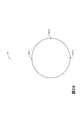
直径が80mmの球である基部の表面に3個のマイクロホンの集音部121-1,121-2,121-3を設けた。マイクロホンの集音部121-1,121-2は互いに90度を成す位置に設けられており、マイクロホンの集音部121-2,121-3は互いに90度を成す位置に設けられており、マイクロホンの集音部121-1,121-3は互いに180度を成す位置に設けられている。ここで、ある集音部と、このある集音部とは異なる他の集音部とが、互いにx度を成す位置に設けられているとは、ある集音部と基部の中心を通る直線と、他の集音部と基部の中心を通る直線との両方を含む平面上で、これらの直線がx度を成すことを意味する。
例えば、マイクロホンの集音部121-1,121-2,121-3は、図28の位置に設けられる。
直径が80mmの球である基部の表面に3個のマイクロホンの集音部121-1,121-2,121-3を設けた。マイクロホンの集音部121-1,121-2は互いに90度を成す位置に設けられており、マイクロホンの集音部121-2,121-3は互いに90度を成す位置に設けられており、マイクロホンの集音部121-1,121-3は互いに180度を成す位置に設けられている。ここで、ある集音部と、このある集音部とは異なる他の集音部とが、互いにx度を成す位置に設けられているとは、ある集音部と基部の中心を通る直線と、他の集音部と基部の中心を通る直線との両方を含む平面上で、これらの直線がx度を成すことを意味する。
例えば、マイクロホンの集音部121-1,121-2,121-3は、図28の位置に設けられる。
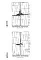
マイクロホン12-1から80cm離れた位置にある点音源Pで発生した450Hzの音波を各マイクロホンで集音する。図29Aは、この場合の各マイクロホンのインパルス応答を表す。
一方、図29Bに、基部の表面ではなく、基部に形状が略円錐台形である3個の凹部111-1,111-2,111-3の内底面11b-1,11b-2,11b-3にそれぞれマイクロホンの集音部121-1,121-2,121-3を設置した場合の各マイクロホンのインパルス応答を表す。マイクロホンの集音部121-1,121-2,121-3が基部の中央から20mmの位置に配置されるように、凹部111-1,111-2,111-3の深さが定められている。図29Bの他の実験条件は、図29Aと同様である。
図29A及び図29Bにおいて、実線はマイクロホン12-1のインパルス応答を表し、点線はマイクロホン12-2のインパルス応答を表し、破線はマイクロホン12-3のインパルス応答を表す。これは、他の図についても同様である。
凹部111-1,111-2,111-3を設けた場合(図29Bの場合)には、マイクロホン12-1の最大音圧とマイクロホン12-2,12-3の最大音圧との差が図29Aの場合よりも大きくなっている。
このため、凹部111-1,111-2,111-3を設けた場合(図29Bの場合)の方が指向性が高いことがわかる。なお、音源P以外の音源はない若しくは無視できる程度であるため、音圧の差は指向性の差と推定できる。
また、図30A及び図30Bに、点音源Pから発生する音波の周波数が1500Hzである場合の各マイクロホンのインパルス応答を表す。図30Aの他の実験条件は、図29Aと同様である。また、図30Bの他の実験条件は、図29Bと同様である。
周波数が1500Hzである場合も、周波数が450Hzである場合と同様に、凹部111-1,111-2,111-3を設けた場合(図30Bの場合)の方が指向性が高いことがわかる。
また、図29Bと図30Bを比較すると、図30Bの方が、マイクロホン12-1の最大音圧とマイクロホン12-2,12-3の最大音圧との差が大きい。このため、周波数が高い方が高い指向性が得られると言える。
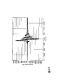
図31に、マイクロホンの集音部121-1,121-2,121-3が基部の中央から10mmの位置に配置されるように、凹部111-1,111-2,111-3の深さが定められている場合の各マイクロホンのインパルス応答を表す。
図32に、マイクロホンの集音部121-1,121-2,121-3が基部の中央から20mmの位置に配置されるように、凹部111-1,111-2,111-3の深さが定められている場合の各マイクロホンのインパルス応答を表す。
図33に、マイクロホンの集音部121-1,121-2,121-3が基部の中央から30mmの位置に配置されるように、凹部111-1,111-2,111-3の深さが定められている場合の各マイクロホンのインパルス応答を表す。
図31から図33の他の実験条件は、図29Bと同様である。
図31から図33では、マイクロホン12-2,12-3の最大音圧がマイクロホン12-1の最大音圧よりも小さく抑えられている。このことから、凹部111-1,111-2,111-3が設けられている場合には、その深さによらず指向性が得られていることがわかる。
図34に、凹部111-1,111-2,111-3の形状をエクスポーネンシャルホーンの形状とした場合の各マイクロホンのインパルス応答を表す。
図35に、凹部111-1,111-2,111-3の形状を椀形状とした場合の各マイクロホンのインパルス応答を表す。
図36に、凹部111-1,111-2,111-3の形状を略円錐台形とした場合の各マイクロホンのインパルス応答を表す。
図34から図36の他の実験条件は、図29Bと同様である。
図34及び図35の場合と比較すると図36の場合には、マイクロホン12-2,12-3の最大音圧がマイクロホン12-1の最大音圧よりも相対的に小さく抑えられている。このことから、凹部111-1,111-2,111-3の形状が略円錐台形である場合には、凹部111-1,111-2,111-3の形状がエクスポーネンシャルホーンの形状又は椀形状である場合よりも高い指向性が得られると言える。
<第5実施形態の変形例>
第1実施形態の第4実施形態の集音装置1は、凹部111-1,…,111-Nの個数と同じ個数であるN個のマイクロホン12-1,…,12-Nを備えていた。
第1実施形態の第4実施形態の集音装置1は、凹部111-1,…,111-Nの個数と同じ個数であるN個のマイクロホン12-1,…,12-Nを備えていた。
これに対して、第5実施形態の集音装置1は、更に少なくとも1つのマイクロホンを有していてもよい。この場合、これらの少なくとも1つのマイクロホンのそれぞれは、N個の凹部111-1,…,111-Nの中の何れかの凹部に設置される。言い換えれば、凹部111-1,…,111-Nの中の少なくとも1つの凹部に、2個以上のマイクホロンが設けられていてもよい。
1~4 収音装置
11~41 基部
111-i 凹部
12-i マイクロホン
121-i 集音部
11~41 基部
111-i 凹部
12-i マイクロホン
121-i 集音部
Claims (10)
- 少なくとも、互いに所定の間隔をおいたN個の凹部を表面に備えた略球体の基部と、
N個のマイクロホンと、を有し、
Nが2以上の整数であり、前記マイクロホンのそれぞれは、前記凹部のそれぞれの内底面側に1個ずつ設置されており、互いに隣接する前記マイクロホンの集音部間の間隔は略同一である、集音装置。 - 請求項1の集音装置であって、
前記凹部の開放端側の縁部の形状は略円形であり、前記凹部の内底面は略円形の略平面であり、
前記マイクロホンの集音部は、前記凹部の内底面の中央または前記内底面の中央の近傍に配置されている、集音装置。 - 請求項1または2の集音装置であって、
前記凹部の開放端側の縁部の形状は略円形であり、
前記凹部の深さは、前記凹部の開放端の縁部の直径の半分未満である、集音装置。 - 請求項1から3の何れかの集音装置であって、
N個の前記凹部の形状は互いに略同一である、集音装置。 - 請求項1から4の何れかの集音装置であって、
Nが2であり、かつ、前記マイクロホンの集音部が前記基部の中央または前記基部の中央の近傍を通る直線上に配置されている、または、
Nが4,6,8,12,20の何れかであり、かつ、前記マイクロホンの集音部のそれぞれが、N個の頂点を持つ正多面体の頂点または前記頂点の近傍のそれぞれに1個ずつ配置されている、集音装置。 - 請求項1から5の何れかの集音装置であって、
前記基部を下方側から支持する支持部材を有し、
前記支持部材は前記基部の下方側に位置する支持領域を支持し、
前記支持領域と前記支持領域に隣接する前記マイクロホンの集音部との間隔は略均一である、集音装置。 - 請求項1から5の何れかの集音装置であって、
前記基部を貫通した状態で前記基部に固定されている棒状の支持部材を有し、
Nが2であり、かつ、前記マイクロホンの集音部が前記基部の中央または前記基部の中央の近傍を通る第1直線上に配置されており、かつ、前記支持部材が前記基部の中央または前記基部の中央の近傍を通り前記第1直線と略直交する第2直線上に配置されている、または、
Nが6,8,12,20の何れかであり、かつ、前記マイクロホンの集音部のそれぞれが、N個の頂点を持つ正多面体の頂点または前記頂点の近傍のそれぞれに1個ずつ配置されており、前記支持部材が前記正多面体の互いに平行な一組の面それぞれの中央または前記一組の面それぞれの中央の近傍を通る第3直線上に配置されている、集音装置。 - 請求項1の集音装置であって、
前記凹部の形状は、略円錐又は略円錐台形である、集音装置。 - 請求項8の集音装置であって、
前記マイクロホンの集音部と前記基部の中央との距離が、前記基部の半径の半分よりも小さくなるように、前記マイクロホンは設置されている、集音装置。 - 請求項9の集音装置であって、
前記マイクロホンの集音部は、前記基部の中央または前記基部の中央の近傍と、前記マイクロホンの集音部が設置される凹部の外周若しくは底部の中心ないし略中心とを通る直線上に配置されている、集音装置。
Priority Applications (2)
| Application Number | Priority Date | Filing Date | Title |
|---|---|---|---|
| JP2020536454A JP7389036B2 (ja) | 2018-08-08 | 2019-07-25 | 集音装置 |
| US17/265,673 US11510000B2 (en) | 2018-08-08 | 2019-07-25 | Sound collection apparatus |
Applications Claiming Priority (2)
| Application Number | Priority Date | Filing Date | Title |
|---|---|---|---|
| JP2018149269 | 2018-08-08 | ||
| JP2018-149269 | 2018-08-08 |
Publications (1)
| Publication Number | Publication Date |
|---|---|
| WO2020031719A1 true WO2020031719A1 (ja) | 2020-02-13 |
Family
ID=69414125
Family Applications (1)
| Application Number | Title | Priority Date | Filing Date |
|---|---|---|---|
| PCT/JP2019/029191 Ceased WO2020031719A1 (ja) | 2018-08-08 | 2019-07-25 | 集音装置 |
Country Status (3)
| Country | Link |
|---|---|
| US (1) | US11510000B2 (ja) |
| JP (1) | JP7389036B2 (ja) |
| WO (1) | WO2020031719A1 (ja) |
Cited By (1)
| Publication number | Priority date | Publication date | Assignee | Title |
|---|---|---|---|---|
| WO2022172401A1 (ja) * | 2021-02-12 | 2022-08-18 | 日本電信電話株式会社 | 設計装置、設計方法、およびプログラム |
Families Citing this family (1)
| Publication number | Priority date | Publication date | Assignee | Title |
|---|---|---|---|---|
| US12368993B2 (en) * | 2022-06-03 | 2025-07-22 | Apple Inc. | Apple dual concentric spherical microphone array |
Citations (4)
| Publication number | Priority date | Publication date | Assignee | Title |
|---|---|---|---|---|
| EP2773131A1 (en) * | 2013-02-27 | 2014-09-03 | Harman Becker Automotive Systems GmbH | Spherical microphone array |
| EP3007461A1 (en) * | 2014-10-10 | 2016-04-13 | Harman Becker Automotive Systems GmbH | Microphone array |
| WO2017137921A1 (en) * | 2016-02-09 | 2017-08-17 | Zylia Spolka Z Ograniczona Odpowiedzialnoscia | Microphone probe, method, system and computer program product for audio signals processing |
| US20170347193A1 (en) * | 2016-05-24 | 2017-11-30 | Matthew Marrin | Multichannel Head-Trackable Microphone |
Family Cites Families (7)
| Publication number | Priority date | Publication date | Assignee | Title |
|---|---|---|---|---|
| EP1475996B1 (en) * | 2003-05-06 | 2009-04-08 | Harman Becker Automotive Systems GmbH | Stereo audio-signal processing system |
| US8295527B2 (en) * | 2010-01-08 | 2012-10-23 | Research In Motion Limited | Microphone boot for a portable electronic device |
| WO2013098871A1 (ja) * | 2011-12-26 | 2013-07-04 | 日本板硝子環境アメニティ株式会社 | 音響システム |
| JP2014017645A (ja) * | 2012-07-09 | 2014-01-30 | Sony Corp | 音声信号処理装置、音声信号処理方法、プログラム及び記録媒体 |
| JP5815489B2 (ja) | 2012-08-28 | 2015-11-17 | 日本電信電話株式会社 | 音源別音声強調装置、方法、プログラム |
| JP6294805B2 (ja) | 2014-10-17 | 2018-03-14 | 日本電信電話株式会社 | 収音装置 |
| EP3352473B1 (en) * | 2017-01-24 | 2019-07-24 | Panasonic Intellectual Property Management Co., Ltd. | Sound pickup device and imaging device using same |
-
2019
- 2019-07-25 JP JP2020536454A patent/JP7389036B2/ja active Active
- 2019-07-25 WO PCT/JP2019/029191 patent/WO2020031719A1/ja not_active Ceased
- 2019-07-25 US US17/265,673 patent/US11510000B2/en active Active
Patent Citations (4)
| Publication number | Priority date | Publication date | Assignee | Title |
|---|---|---|---|---|
| EP2773131A1 (en) * | 2013-02-27 | 2014-09-03 | Harman Becker Automotive Systems GmbH | Spherical microphone array |
| EP3007461A1 (en) * | 2014-10-10 | 2016-04-13 | Harman Becker Automotive Systems GmbH | Microphone array |
| WO2017137921A1 (en) * | 2016-02-09 | 2017-08-17 | Zylia Spolka Z Ograniczona Odpowiedzialnoscia | Microphone probe, method, system and computer program product for audio signals processing |
| US20170347193A1 (en) * | 2016-05-24 | 2017-11-30 | Matthew Marrin | Multichannel Head-Trackable Microphone |
Cited By (1)
| Publication number | Priority date | Publication date | Assignee | Title |
|---|---|---|---|---|
| WO2022172401A1 (ja) * | 2021-02-12 | 2022-08-18 | 日本電信電話株式会社 | 設計装置、設計方法、およびプログラム |
Also Published As
| Publication number | Publication date |
|---|---|
| JPWO2020031719A1 (ja) | 2021-08-02 |
| US20210321192A1 (en) | 2021-10-14 |
| US11510000B2 (en) | 2022-11-22 |
| JP7389036B2 (ja) | 2023-11-29 |
Similar Documents
| Publication | Publication Date | Title |
|---|---|---|
| US11765498B2 (en) | Microphone array system | |
| US11381906B2 (en) | Conference system with a microphone array system and a method of speech acquisition in a conference system | |
| US9591404B1 (en) | Beamformer design using constrained convex optimization in three-dimensional space | |
| EP2208359B1 (en) | Position determination of sound sources | |
| US9973848B2 (en) | Signal-enhancing beamforming in an augmented reality environment | |
| US20200145753A1 (en) | Conference System with a Microphone Array System and a Method of Speech Acquisition In a Conference System | |
| EP2773131B1 (en) | Spherical microphone array | |
| CN114467312A (zh) | 具有改进方向性的二维麦克风阵列 | |
| TW202005415A (zh) | 圖案形成麥克風陣列 | |
| WO2020031719A1 (ja) | 集音装置 | |
| US11595756B2 (en) | Sound collecting apparatus | |
| EP2208358B1 (en) | Microphone arrangement | |
| Clapp et al. | Three-dimensional spatial analysis of concert and recital halls with a spherical microphone array | |
| JP2018148340A (ja) | 収音装置、及び収音方法 | |
| WO2021064917A1 (ja) | 関係決定装置、方法及びプログラム | |
| Araujo | Comparison between the spherical harmonics beamforming and the delay-and-sum beamforming | |
| Lewis | Microphone array beamforming | |
| US9407983B2 (en) | Microphone device | |
| Szwajcowski et al. | An iterative approach to sound source localization based on spherical beamforming | |
| CN119724195A (zh) | 基于声纹识别的会议签到方法及系统 |
Legal Events
| Date | Code | Title | Description |
|---|---|---|---|
| 121 | Ep: the epo has been informed by wipo that ep was designated in this application |
Ref document number: 19848623 Country of ref document: EP Kind code of ref document: A1 |
|
| ENP | Entry into the national phase |
Ref document number: 2020536454 Country of ref document: JP Kind code of ref document: A |
|
| NENP | Non-entry into the national phase |
Ref country code: DE |
|
| 122 | Ep: pct application non-entry in european phase |
Ref document number: 19848623 Country of ref document: EP Kind code of ref document: A1 |