WO2020031501A1 - Manipulable device and manipulable part - Google Patents
Manipulable device and manipulable part Download PDFInfo
- Publication number
- WO2020031501A1 WO2020031501A1 PCT/JP2019/023538 JP2019023538W WO2020031501A1 WO 2020031501 A1 WO2020031501 A1 WO 2020031501A1 JP 2019023538 W JP2019023538 W JP 2019023538W WO 2020031501 A1 WO2020031501 A1 WO 2020031501A1
- Authority
- WO
- WIPO (PCT)
- Prior art keywords
- unit
- housing
- conductive
- operating
- supported
- Prior art date
Links
Images


Classifications
-
- H—ELECTRICITY
- H01—ELECTRIC ELEMENTS
- H01H—ELECTRIC SWITCHES; RELAYS; SELECTORS; EMERGENCY PROTECTIVE DEVICES
- H01H3/00—Mechanisms for operating contacts
- H01H3/02—Operating parts, i.e. for operating driving mechanism by a mechanical force external to the switch
-
- H—ELECTRICITY
- H01—ELECTRIC ELEMENTS
- H01H—ELECTRIC SWITCHES; RELAYS; SELECTORS; EMERGENCY PROTECTIVE DEVICES
- H01H3/00—Mechanisms for operating contacts
- H01H3/02—Operating parts, i.e. for operating driving mechanism by a mechanical force external to the switch
- H01H3/04—Levers
-
- G—PHYSICS
- G06—COMPUTING; CALCULATING OR COUNTING
- G06F—ELECTRIC DIGITAL DATA PROCESSING
- G06F3/00—Input arrangements for transferring data to be processed into a form capable of being handled by the computer; Output arrangements for transferring data from processing unit to output unit, e.g. interface arrangements
- G06F3/01—Input arrangements or combined input and output arrangements for interaction between user and computer
- G06F3/03—Arrangements for converting the position or the displacement of a member into a coded form
- G06F3/033—Pointing devices displaced or positioned by the user, e.g. mice, trackballs, pens or joysticks; Accessories therefor
-
- H—ELECTRICITY
- H01—ELECTRIC ELEMENTS
- H01H—ELECTRIC SWITCHES; RELAYS; SELECTORS; EMERGENCY PROTECTIVE DEVICES
- H01H3/00—Mechanisms for operating contacts
- H01H3/02—Operating parts, i.e. for operating driving mechanism by a mechanical force external to the switch
- H01H3/08—Turn knobs
-
- H—ELECTRICITY
- H01—ELECTRIC ELEMENTS
- H01H—ELECTRIC SWITCHES; RELAYS; SELECTORS; EMERGENCY PROTECTIVE DEVICES
- H01H3/00—Mechanisms for operating contacts
- H01H3/02—Operating parts, i.e. for operating driving mechanism by a mechanical force external to the switch
- H01H3/12—Push-buttons
-
- H—ELECTRICITY
- H01—ELECTRIC ELEMENTS
- H01H—ELECTRIC SWITCHES; RELAYS; SELECTORS; EMERGENCY PROTECTIVE DEVICES
- H01H3/00—Mechanisms for operating contacts
- H01H3/02—Operating parts, i.e. for operating driving mechanism by a mechanical force external to the switch
- H01H2003/0293—Operating parts, i.e. for operating driving mechanism by a mechanical force external to the switch with an integrated touch switch
-
- H—ELECTRICITY
- H01—ELECTRIC ELEMENTS
- H01H—ELECTRIC SWITCHES; RELAYS; SELECTORS; EMERGENCY PROTECTIVE DEVICES
- H01H2239/00—Miscellaneous
- H01H2239/006—Containing a capacitive switch or usable as such
-
- H—ELECTRICITY
- H01—ELECTRIC ELEMENTS
- H01H—ELECTRIC SWITCHES; RELAYS; SELECTORS; EMERGENCY PROTECTIVE DEVICES
- H01H33/00—High-tension or heavy-current switches with arc-extinguishing or arc-preventing means
- H01H33/60—Switches wherein the means for extinguishing or preventing the arc do not include separate means for obtaining or increasing flow of arc-extinguishing fluid
- H01H33/66—Vacuum switches
- H01H33/664—Contacts; Arc-extinguishing means, e.g. arcing rings
- H01H33/6642—Contacts; Arc-extinguishing means, e.g. arcing rings having cup-shaped contacts, the cylindrical wall of which being provided with inclined slits to form a coil
-
- H—ELECTRICITY
- H01—ELECTRIC ELEMENTS
- H01H—ELECTRIC SWITCHES; RELAYS; SELECTORS; EMERGENCY PROTECTIVE DEVICES
- H01H33/00—High-tension or heavy-current switches with arc-extinguishing or arc-preventing means
- H01H33/60—Switches wherein the means for extinguishing or preventing the arc do not include separate means for obtaining or increasing flow of arc-extinguishing fluid
- H01H33/66—Vacuum switches
- H01H33/666—Operating arrangements
Definitions
- the present invention relates to an operation device and an operation unit.
- Patent Document 1 Conventionally, for example, in a game machine or an automobile, an operation device capable of performing a tilting operation using an operation lever has been used (for example, see Patent Document 1 below).
- the operating device has a housing having a conductive portion on a surface thereof, and the operating device is movably supported by the housing based on an operation by the operating body, and the operating device and the conductive portion are respectively And an operation unit capable of capacitively coupling, and a detection unit that detects a proximity state of the operation tool to the operation unit based on a change in capacitance in the conductive unit.
- the finger proximity circuit is not arranged on a movable portion such as a stick, it is possible to improve the degree of freedom in arranging members and extend the life.
- FIG. 3 is a cross-sectional view (first example) of the operation device according to the embodiment along the YZ plane. It is sectional drawing by the YZ plane (2nd example) of the operating device which concerns on one Embodiment. It is a block diagram showing the electric connection composition of the operation device concerning one embodiment.
- FIG. 2 is a block diagram illustrating a functional configuration of a control circuit according to one embodiment. It is sectional drawing of the push switch which concerns on 2nd Embodiment. It is a top view of the slide switch concerning a 3rd embodiment. It is a top view of the slide switch concerning a 3rd embodiment. It is sectional drawing of the rotary switch which concerns on 4th Embodiment.
- the Z-axis direction in the drawing is referred to as the up-down direction
- the X-axis direction in the drawing is referred to as the front-back direction
- the Y-axis direction in the drawing is referred to as the left-right direction.
- FIG. 1 is an external perspective view of an operation device 100 according to an embodiment.
- the operating device 100 illustrated in FIG. 1 is a device that allows the operating body 10 to tilt the operating lever 120 (an example of an “operating unit”).
- the operation device 100 is mounted on an operation target device 20 such as a game machine or an in-vehicle device, and is used for performing various application operations on the operation target device 20.
- the operation device 100 includes an operation lever 120 provided on an upper portion of a housing 110.
- the operating lever 120 can be tilted by the operating body 10 in the front-back direction (X-axis direction) and the left-right direction (Y-axis direction).
- the operator's finger is shown as the operating body 10, but the present invention is not limited to this.
- FIG. 2 is an exploded perspective view of the operation device 100 according to the embodiment.
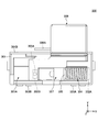
- FIGS. 3A and 3B are cross-sectional views (first and second examples) of the operating device 100 according to the embodiment along the YZ plane.
- the operating device 100 includes a housing 110, an operating lever 120, an encoder 132, an encoder 134, a substrate 135, and a control circuit 140.
- the housing 110 is a box-like member having a substantially rectangular parallelepiped shape.
- the housing 110 supports the operation lever 120 so that the operation lever 120 can be tilted.
- the surface (frame portion) of the housing 110 is formed of a conductive material (for example, a metal plate).
- a conductive material for example, a metal plate.
- the outer periphery of the housing 110 is surrounded by the operation knob 124 of the operation lever 120.
- the housing 110 can be capacitively coupled to the operation knob 124 on its surface.
- the operation lever 120 can be tilted in the front-rear direction (X-axis direction) and the left-right direction (Y-axis direction), and includes a shaft 122 and an operation knob 124.
- the shaft portion 122 is a bar-shaped member that stands upright in an opening 110 ⁇ / b> A formed on the upper surface of the housing 110.
- the shaft portion 122 is supported by the housing 110 so as to be tiltable in the front-rear direction (X-axis direction) and the left-right direction (Y-axis direction).
- a return means such as a spring.
- the operation knob 124 is attached to the tip of the shaft 122.
- the operation knob 124 is a member that can be attached to the shaft portion 122 to increase the contact area of the operation body 10 and enhance operability.
- the operation knob 124 is made of a relatively hard material (eg, resin, silicon, rubber, or the like).
- the operation knob 124 has an operation part 124A and an umbrella-shaped part 124B.
- the operation unit 124 ⁇ / b> A is a portion that is attached to the tip of the shaft unit 122, and on which a contact operation by the operation body 10 is performed.
- the operation section 124A has a substantially elliptical shape, but may have another shape (for example, a spherical shape or a flat shape).
- the umbrella-shaped portion 124B is a portion that extends outward and downward from the operation portion 124A in a curved manner along the outer periphery of the lower portion of the operation portion 124A.
- the umbrella-shaped portion 124 ⁇ / b> B has a shape close to the surface of the housing 110 and surrounding the outer periphery of the housing 110.
- a conductive layer 124C is formed on the surface of the operation knob 124.
- the conductive layer 124C can be formed by applying a conductive paint (for example, a paint containing carbon) on the surface of the operation knob 124.
- the operation knob 124 has an entire surface having conductivity, and can be capacitively coupled to each of the operation body 10 and the housing 110.
- the operation knob 124 can be capacitively coupled to the operation body 10 adjacent to the operation unit 124A at the operation unit 124A (“first capacitance coupling unit”).
- the operation knob 124 can be capacitively coupled to the surface of the housing 110 adjacent to the umbrella-shaped portion 124B at the umbrella-shaped portion 124B (“second capacitive coupling portion”).
- an insulating layer 124D (e.g., an elastomer) may be formed on the conductive layer 124C formed on the surface of the operation knob 124.
- the operation knob 124 itself may be a conductor, and the insulating layer 124 ⁇ / b> D may be formed on the surface of the operation knob 124.
- the operation knob 124 may not have the conductive layer 124C.
- the operation knob 124 can be capacitively coupled to each of the operation body 10 and the housing 110, and the insulating layer 124D formed on the surface of the operation knob 124 can stably detect capacitance coupling.
- the insulating layer 124D may cover the entire conductive layer 124C, or may cover only the region of the conductive layer 124C that is operated by the operating body.
- the encoder 132 and the encoder 134 are attached to the side surface of the housing 110.
- the encoder 132 detects an operation amount of the operation lever 120 in the X-axis direction (a rotation amount of the rotating shaft 112 that rotates in the X-axis direction) and outputs an operation signal (analog signal) corresponding to the operation amount in the X-axis direction. I do.
- the encoder 134 detects an operation amount of the operation lever 120 in the Y-axis direction (a rotation amount of the rotating shaft 114 rotating in the Y-axis direction) and outputs an operation signal (analog signal) corresponding to the operation amount in the Y-axis direction. I do.
- an optical rotary encoder is used as the encoder 132 and the encoder 134.
- the substrate 135 is a flat member on the upper surface of which the housing 110 and the control circuit 140 are mounted.
- a rigid substrate such as PWB (Printed Wired Board) or PCB (Printed Circuit Board) is used.
- the control circuit 140 is electrically connected to the surface of the housing 110 and each of the encoders 132 and 134 via wiring, metal terminals and the like (not shown).
- the control circuit 140 performs various controls of the operation device 100 (for example, driving of the surface of the housing 110, detection of capacitance on the surface of the housing 110, acquisition of operation signals from the encoders 132 and 134, and control of the operation target device 20). Output of operation signals, processing of operation signals, etc.).
- the control circuit 140 includes an IC (Integrated Circuit), a drive circuit, an AD (Analog Digital) converter, and the like in order to realize each function described later with reference to FIG.
- FIG. 4 is a block diagram illustrating an electrical connection configuration of the operating device 100 according to the embodiment.
- the operation knob 124 has a conductive layer 124 ⁇ / b> C on its surface, so that it can be capacitively coupled to the surface of the housing 110 and each of the operation bodies 10.
- the control circuit 140 is electrically connected to the surface of the housing 110 via wiring or the like. Thereby, the control circuit 140 can drive the surface of the housing 110 as a detection electrode by applying an AC voltage to the surface of the housing 110.
- control circuit 140 detects a current value corresponding to a change in the capacitance on the surface of the housing 110, and can determine the proximity state of the operating tool 10 based on the current value.
- control circuit 140 is electrically connected to the encoders 132 and 134 and the operation target device 20 via wiring and the like. Accordingly, the control circuit 140 receives the operation signals output from the encoders 132 and 134, performs various processes on the operation signals (for example, an analog-digital conversion process, a correction process of the operation position, and the like), and then performs the process. An operation signal can be output to the operation target device 20.
- FIG. 5 is a block diagram illustrating a functional configuration of the control circuit 140 according to the embodiment.
- the control circuit 140 includes a driving unit 142, an AD conversion unit 143, a detection unit 144, an acquisition unit 146, an AD conversion unit 147, and an output unit 154.
- the drive unit 142 drives the surface of the housing 110 as a detection electrode by applying an AC voltage to the surface of the housing 110.
- the AD conversion unit 143 converts an analog signal indicating a current value on the surface of the housing 110 driven by the driving unit 142 into a digital signal.
- the detecting unit 144 determines the proximity state of the operating tool 10 to the operating knob 124 based on a change in the current value (current value after AD conversion by the AD converting unit 143) on the surface of the housing 110 driven by the driving unit 142. To detect.
- the capacitance on the surface of the housing 110 changes when the proximity state of the operating tool 10 to the operation knob 124 changes, so that the capacitance on the surface of the housing 110 changes. I do.
- the detection unit 144 can detect the proximity state of the operation tool 10 to the operation knob 124 based on the current value on the surface of the housing 110.
- the detection unit 144 determines that the operating tool 10 is not close to the housing 110, and the current value on the surface of the housing 110 is equal to or more than the predetermined threshold th1. In the case of, it is determined that the operating tool 10 is close.
- the predetermined threshold value th1 for example, a suitable value capable of determining the proximity state of the operating tool 10 is stored in the memory in advance. The value of the predetermined threshold th1 may be changeable from an external information processing device.
- the acquisition unit 146 acquires operation signals (analog signals) corresponding to the operation of the operation lever 120 from the encoders 132 and 134. Specifically, the acquisition unit 146 acquires from the encoder 132 an operation signal corresponding to the operation amount of the operation lever 120 in the X-axis direction. Further, the acquisition unit 146 acquires an operation signal corresponding to the operation amount of the operation lever 120 in the Y-axis direction from the encoder 134.
- the AD conversion unit 147 converts the operation signal (analog signal) acquired by the acquisition unit 146 into a digital signal.
- the output unit 154 outputs an operation signal to the operation target device 20.
- the operation target device 20 can perform the operation of the operation target application with high accuracy based on the operation signal output from the output unit 154.
- the operating device 100 of the present embodiment is configured to make an electrical connection for capacitance detection to the surface of the housing 110 that is a fixed portion, instead of the operating lever 120 that is a movable portion. And thus, according to the operating device 100 of the present embodiment, the electrical connection in the manufacturing process can be performed relatively easily, and the durability of the electrical connection portion can be increased. Further, since the electrical connection member such as the wiring does not interfere with the movement of the operation lever 120, the operability of the operation lever 120 can be improved.
- the operating lever 120 can be capacitively coupled to the operating body 10 and the housing 110. Accordingly, the operating device 100 of the present embodiment can easily operate the operating lever 120 regardless of the shape or the material of the operating lever 120 and without changing the design of the shape and the material of the operating lever 120. And the housing 110 can be capacitively coupled.
- the operating device 100 of the present embodiment includes an operating portion 124A operated by the operating body 10 and an umbrella-shaped portion 124B extending downward from the operating portion 124A and surrounding the outer periphery of the housing 110. And thereby, the operation device 100 of the present embodiment can efficiently capacitively couple the operation knob 124 to both the operation body 10 and the housing 110 without increasing the number of components of the operation knob 124.
- the frame part forming the surface of the housing 110 is used as a conductive part for detecting capacitance.
- the operating device 100 of the present embodiment can detect a change in the capacitance of the housing 110 without increasing the number of components of the housing 110.
- the operation lever is not limited to the configuration described in the embodiment as long as it can be capacitively coupled to at least the operation body and the housing.
- the operation lever may be one in which the operation knob and the shaft are integrally formed.
- a conductive member for example, an electric wire
- the operation knob may be provided on the surface or inside instead of the conductive layer.
- the operation knob may be formed using a conductive material. In this case, since the operation knob has conductivity as a whole, it is not necessary to have a conductive layer on the surface.
- the conductivity is formed on the entire surface of the operation lever.
- the present invention is not limited to this.
- a conductive layer may be formed.
- the entire surface of the housing is defined as the “conductive portion” using a conductive material.
- the present invention is not limited to this, and a part of the surface of the housing may be formed of a conductive material. It may be used as a “conductive portion”.
- a metal plate may be attached to the surface of the housing, and this may be used as a “conductive portion”.
- the present invention is applied to the operation lever that can be tilted in both the X-axis direction and the Y-axis direction.
- the present invention is not limited to this, and the invention may be applied to either the X-axis direction or the Y-axis direction.
- the present invention is also applicable to an operation lever that can be tilted.
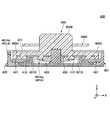
- FIG. 6 is a sectional view of a push switch 200 according to the second embodiment.
- the push switch 200 includes a housing 201, a pressing operation member 202, a rubber contact 203, fixed contacts 204A and 204B, and a movable contact 205.
- the housing 201 holds each component (the rubber contact 203 and the fixed contacts 204A and 204B).
- the surface of the housing 201 is covered with a conductive portion 201A formed using a conductive material (for example, a metal plate).
- Fixed contacts 204A and 204B are provided side by side at the center of the upper surface of the housing 201.
- the pressing operation member 202 is a member on which a pressing operation is performed by the operator.
- the pressing operation member 202 has an operation portion 202A, a flange portion 202B, and a side wall portion 202C.
- the operation unit 202A is a columnar part on which a pressing operation is performed by an operator.
- the operation unit 202A is fixed to the rubber contact 203 (the upper surface of the central part 203A) on the bottom surface.
- the flange portion 202B is a horizontal portion provided along the outer peripheral side surface of the operation portion 202A so as to expand outward from a lower end portion of the outer peripheral side surface.
- the side wall portion 202C is a wall-shaped portion provided along the outer peripheral edge of the flange portion 202B and hanging downward from the outer peripheral edge.
- the rubber contact 203 is provided on the upper surface of the housing 201.
- Rubber contact 203 has central portion 203A and leg portion 203B.
- the rubber contact 203 is formed using an elastic material such as rubber or silicon.
- the central portion 203A is a portion that moves up and down together with the pressing operation member 202 when the pressing operation member 202 is fixed to the upper surface thereof.
- a movable contact 205 is provided on the bottom surface of the central portion 203A.
- the central portion 203A is supported on its outer peripheral side surface by a leg portion 203B. When a pressing operation of the pressing operation member 202 is performed, the central portion 203A moves downward due to elastic deformation of the leg portion 203B.
- the central portion 203A can make the movable contact 205 conductive with each of the fixed contacts 204A and 204B.
- the pressing operation member 202 when no pressing operation is performed by the operator, the pressing operation member 202 is located at the initial position as shown in FIG. At this time, the movable contact 205 is separated from the fixed contacts 204A and 204B. Therefore, the push switch 200 is in an off state in which the fixed contact 204A and the fixed contact 204B are not electrically connected to each other.
- the push operation member 202 moves downward, and the leg portion 203B of the rubber contact 203 is elastically deformed. Move down. As a result, the movable contact 205 contacts the fixed contacts 204A and 204B. As a result, the push switch 200 is turned on, in which the fixed contact 204A and the fixed contact 204B are electrically connected to each other.
- the push switch 200 when the pressing operation by the operator is released, the push switch 200 returns the pressing operation member 202 to the initial position by the elastic return force of the leg portion 203B. Thus, the push switch 200 is turned off as shown in FIG. 6, in which the fixed contact 204A and the fixed contact 204B are not electrically connected to each other.
- the pressing operation member 202 has a side wall 202 ⁇ / b> C that is spaced apart from the side surface of the housing 201 by a certain distance and is provided in parallel with the side surface of the housing 301.
- the side wall portion 202C moves up and down on the side of the side surface of the housing 301 with the pressing operation of the pressing operation member 202.
- the pressing operation member 202 is formed using a conductive material (for example, a conductive resin) including the side wall portion 202C.
- the side surface of the housing 201 is covered with a conductive portion 201A formed using a material having conductivity.
- the push switch 200 can capacitively couple the pressing operation member 202 with each of the operating body (for example, the user's finger) and the side surface of the housing 201.
- the operation unit 202A corresponds to “a first capacitance coupling unit capable of capacitive coupling with the operation body”
- the side wall unit 202C has a “capacitive coupling with the conductive unit included in the housing”.
- Second capacitive coupling section ". Therefore, similarly to the first embodiment, the push switch 200 according to the second embodiment drives the side surface (the conductive portion 201A) of the housing 201 as a detection electrode to reduce the capacitance of the side surface of the housing 201.
- the proximity state of the operating tool can be determined based on the current value. Therefore, according to the push switch 200 according to the second embodiment, since the finger proximity circuit is not arranged on the pressing operation member 202 which is a movable portion, it is possible to improve the degree of freedom in the arrangement of members and extend the life.
- the push switch 200 the overlapping area of the side wall portion 202C and the conductive portion 201A changes according to the operation amount of the pressing operation member 202. Accordingly, the push switch 200 has a configuration in which the capacitance of the conductive portion 201A changes according to the operation amount of the pressing operation member 202.
- FIGS. 7A and 7B are plan views of the slide switch 300 according to the third embodiment.
- the slide switch 300 shown in FIGS. 7A and 7B is a so-called self-return type slide switch.
- the slide switch 300 includes a housing 301, fixed contacts 302A and 302B, connection terminals 303A and 303B, a coil spring 304, a movable contact 305, a holding member 307, and a slide operation member 308.
- the slide switch 300 includes a lid member (not shown) that covers an upper opening of the housing space 301A of the housing 301.
- FIGS. 7A and 7B the slide switch 300 with the lid member removed is illustrated. Is shown.
- the housing 301 houses and holds the components (fixed contacts 302A and 302B, connection terminals 303A and 303B, coil spring 304, movable contact 305, holding member 307, and slide operation member 308).
- the slide operation member 308 is provided to be slidable in the X-axis direction with respect to the housing 301 in accordance with a slide operation by an operator.
- the holding member 307 is provided in the housing space 301A of the housing 301 and holds the movable contact 305.
- the holding member 307 slides in the X-axis direction together with the slide operation member 308.
- the coil spring 304 is provided on the X-axis positive side of the holding member 307 so as to be elastically deformable in the X-axis direction.
- the coil spring 304 urges the holding member 307 and the slide operation member 308 toward the X axis negative side. Thereby, the coil spring 304 can return the slide operation member 308 to the initial position when the slide operation by the operator is released.
- the end on the X axis positive side of the coil spring 304 is in contact with the fixed contact 302A.
- An end on the X axis negative side of the coil spring 304 is in contact with the movable contact 305.
- the movable contact 305 is held by the holding member 307, and slides in the X-axis direction together with the holding member 307.
- the movable contact 305 is formed using a conductive material.
- the movable contact 305 is in contact with the end of the coil spring 304 on the negative side of the X axis, and is electrically connected to the fixed contact 302A via the coil spring 304.
- the movable contact 305 has a contact portion 305A below the holding member 307.
- the movable contact 305 is slid in the positive direction of the X-axis along with the sliding operation by the operator, so that the contact portion 305A is electrically connected to the fixed contact 302B (see FIG. 7B). As a result, the slide switch 300 is turned on.
- the movable contact 305 is slid in the negative direction of the X-axis with the release of the sliding operation by the operator, so that the conduction between the contact portion 305A and the fixed contact 302B is released (see FIG. 7A). As a result, the slide switch 300 is turned off.
- connection terminals 303A and 303B are provided on the side surface of the housing 301 and are connected to the outside (the target of the switch operation by the slide switch 300).
- the connection terminals 303A and 303B are formed using a conductive material.
- the connection terminal 303A is electrically connected to the fixed contact 302A.
- the connection terminal 303B is electrically connected to the fixed contact 302B.
- the fixed contact 302 ⁇ / b> A is provided in the housing space 301 ⁇ / b> A of the housing 301 in contact with the end of the coil spring 304 on the X axis positive side.
- the fixed contact 302B is provided below the holding member 307 in the housing space 301A of the housing 301.
- the fixed contacts 302A and 302B are formed using a conductive material.
- the slide operation member 308 when the operator does not perform the slide operation, the slide operation member 308 is located at the initial position by the urging force of the coil spring 304 as shown in FIG. 7A. At this time, the contact portion 305A of the movable contact 305 and the fixed contact 302B are not electrically connected to each other, so that the fixed contact 302A and the fixed contact 302B are not electrically connected to each other (ie, in an off state).
- the slide switch 300 slides the movable contact 305 along with the slide operation member 308 in the positive direction of the X axis.
- the contact portion 305A of the movable contact 305 and the fixed contact 302B conduct with each other, and thus the fixed contact 302A and the fixed contact 302B conduct with each other via the movable contact 305 and the coil spring 304 (ie, , ON state).
- the slide operation member 308 has a plate-shaped capacitive coupling portion 308A that is provided at a predetermined distance from the side surface of the housing 301 and is provided in parallel with the side surface of the housing 301. Further, the slide operation member 308 is formed using a conductive material (for example, a conductive resin) including the capacitive coupling portion 308A. Further, a conductive portion 301B having conductivity is provided on at least a side surface of the housing 301 facing the capacitive coupling portion 308A.
- the slide operation member 308 can be capacitively coupled to each of the operation body (for example, the user's finger) and the surface of the housing 301.
- the slide switch 300 drives the surface of the housing 301 (the conductive portion 301B) as a detection electrode, as in the first embodiment, to reduce the capacitance of the surface of the housing 301. By detecting a current value corresponding to the change, the proximity state of the operating tool can be determined based on the current value. Therefore, according to the slide switch 300 according to the third embodiment, since the finger proximity circuit is not disposed on the slide operation member 308 that is a movable portion, it is possible to improve the degree of freedom of member arrangement and extend the life.
- the slide switch 300 may have a configuration in which the overlapping area between the capacitive coupling unit 308A and the conductive unit 301B changes according to the operation amount of the slide operation member 308. Thereby, the slide switch 300 can be configured to change the capacitance of the conductive portion 301B according to the operation amount of the slide operation member 308.
- FIG. 8 is a sectional view of a rotary switch 400 according to the fourth embodiment.
- the rotary switch 400 includes a housing 401, a fixed contact 404, a connection terminal 405, a support shaft 406, a click plate 407, a movable contact 408, and a rotation operation member 409.
- the housing 401 houses and holds each component (fixed contact 404, connection terminal 405, support shaft 406, click plate 407, movable contact 408, and rotation operation member 409).
- An accommodation space 401A is formed inside the housing 401.
- the accommodation space 401A has an inner peripheral area 401Aa and an outer peripheral area 401Ab.
- An annular dustproof wall 401B is provided at the boundary between the inner peripheral area 401Aa and the outer peripheral area 401Ab in plan view.
- the upper opening of the accommodation space 401 is closed by a flat holding member 411.
- the holding member 411 is formed using a conductive material.
- the fixed contact 404 is provided at the bottom of the inner peripheral area 401Aa.
- the fixed contact 404 includes an annular common contact and a plurality of individual contacts arranged on the same circumference outside the common contact. Each of the common contact and the plurality of individual contacts is connected to a corresponding one of the plurality of connection terminals 405 exposed to the outside of the housing 401.
- the support shaft 406 is provided upright at the center of the bottom of the inner peripheral area 401Aa.
- the support shaft 406 rotatably supports the base 409A of the rotation operation member 409.
- the click plate 407 is an annular and flat member provided in the bottom of the outer peripheral area 401Ab in plan view.
- the click plate 407 is formed using a metal plate.
- the click plate 407 has a plurality of click generators formed side by side on the same circumference. Each of the plurality of click generators has an opening shape.
- the rotation operation member 409 has a base 409A arranged at the center of the accommodation space 401, and a cylindrical grip 409B provided to protrude upward from the center of the base 409A.
- the base 409A is rotatably supported by a support shaft 406.
- the grip portion 409B is a portion that protrudes from the upper surface of the housing 401 (the opening of the holding member 411) and that can be rotated by an operator.
- the rotation operation member 409 is formed using a resin material.
- the movable contact 408 is an annular member arranged in the inner peripheral area 401Aa and fixed to the bottom surface of the rotation operation member 409 (base 409A).
- the movable contact 408 includes a first slider that can slide while contacting the common contact of the fixed contact 404 and a second slider that can slide while sequentially contacting a plurality of individual contacts of the fixed contact 404. It is configured to have.
- the elastic member 410 is an annular member which is held by the rotation operating member 409 and is made of an elastic metal plate such as a stainless steel plate.
- the elastic member 410 has an engaging / disengaging portion projecting downward toward the click plate 407.
- the elastic member 410 rotates together with the rotation operation member 409.
- the engaging and disengaging portion of the elastic member 410 moves on the circumference of the click plate 407 to sequentially engage and disengage with a plurality of click generating portions formed side by side on the click plate 407.
- the elastic member 410 can give a click feeling to the rotation operation of the rotation operation member 409.
- the rotary switch 400 configured as described above, when the rotation operation of the rotation operation member 409 is performed by the operator, the movable contact 408 and the elastic member 410 rotate together with the rotation operation member 409. As a result, the common contact of the fixed contact 404 is sequentially connected to the plurality of individual contacts of the fixed contact 404 via the movable contact 408. At this time, the rotary switch 400 is configured to rotate and engage the elastic member 410 sequentially with a plurality of click generating portions arranged on the same circumference on the click plate 407 so that the rotating operation member 409 is rotated. Can be given a click feeling.
- the rotation operation member 409 has a capacitive coupling portion 409C.
- the capacitive coupling portion 409C is a horizontal and flat plate-shaped portion provided along the outer peripheral side surface of the grip portion 409B so as to expand outward from the outer peripheral side surface.
- the capacitive coupling portion 409C is separated from the holding member 411 forming the upper surface of the housing 401 by a certain distance, and is parallel to the holding member 411.
- the rotation operation member 409 is formed using a conductive material (for example, a conductive resin) including the capacitive coupling portion 409C.
- the holding member 411 configuring the upper surface of the housing 401 is formed using a conductive material (for example, a metal plate).
- the rotary operation member 409 can be capacitively coupled to each of the operating body (for example, a user's finger) and the holding member 411 configuring the upper surface of the housing 401.
- the grip portion 409B corresponds to “a first capacitive coupling portion capable of capacitive coupling with the operating body”
- the capacitive coupling portion 409C corresponds to “capacitive coupling with the conductive portion of the housing.
- the rotary switch 400 drives the upper surface of the housing 401 (the holding member 411) as a detection electrode, as in the first embodiment, to reduce the capacitance of the upper surface of the housing 401.
- the proximity state of the operating tool can be determined based on the current value. Therefore, according to the rotary switch 400 according to the fourth embodiment, since the finger proximity circuit is not arranged on the rotary operation member 409, which is a movable portion, it is possible to improve the degree of freedom of member arrangement and extend the life.
- the rotary switch 400 may have a configuration in which the overlapping area between the capacitive coupling portion 409C and the holding member 411 changes according to the operation amount of the rotary operation member 409.
- the rotary switch 400 can be configured to change the capacitance of the holding member 411 according to the operation amount of the rotation operation member 409.
Abstract
The manipulable device is provided with: a case having conductive parts on the surface thereof; a manipulable unit supported by the case so as to be able to move on the basis of manipulation by a manipulable body and capable of capacitive-coupling with the manipulable body and with each of the conductive parts; and a detection unit for detecting a state of the manipulable body being proximity to the manipulable unit on the basis of changes in the electrostatic capacitances at the conductive parts.
Description
本発明は、操作装置および操作部に関する。
The present invention relates to an operation device and an operation unit.
従来、例えば、ゲーム機や自動車等において、操作レバーによる傾倒操作を行うことが可能な操作装置が用いられている(例えば、下記特許文献1参照)。
Conventionally, for example, in a game machine or an automobile, an operation device capable of performing a tilting operation using an operation lever has been used (for example, see Patent Document 1 below).
しかしながら、上記特許文献1の技術は、操作レバー部にスティックと指などの操作体の近接を検出するセンサが配置されているが、可動部に近接回路が配置されているので部材配置の自由度や長寿命化が損なう恐れがあった。
However, in the technique disclosed in Patent Document 1, although a sensor that detects the proximity of an operating body such as a stick and a finger is arranged on the operating lever unit, the proximity circuit is arranged on the movable unit. And the life extension may be impaired.
一実施形態の操作装置は、操作装置は、表面に導電部を有する筐体と、操作体による操作に基づいて移動可能に前記筐体によって支持され、前記操作体および前記導電部の各々に対して容量結合可能な操作部と、前記導電部における静電容量の変化に基づいて、前記操作部に対する前記操作体の近接状態を検出する検出部とを備える。
In one embodiment, the operating device has a housing having a conductive portion on a surface thereof, and the operating device is movably supported by the housing based on an operation by the operating body, and the operating device and the conductive portion are respectively And an operation unit capable of capacitively coupling, and a detection unit that detects a proximity state of the operation tool to the operation unit based on a change in capacitance in the conductive unit.
一実施形態によれば、スティックなどの可動部に指近接回路を配置しないため、部材配置の自由度向上や長寿命化を図ることができる。
According to one embodiment, since the finger proximity circuit is not arranged on a movable portion such as a stick, it is possible to improve the degree of freedom in arranging members and extend the life.
以下、図面を参照して、一実施形態について説明する。なお、以降の説明では、便宜上、図中Z軸方向を、上下方向とし、図中X軸方向を、前後方向とし、図中Y軸方向を、左右方向とする。
Hereinafter, an embodiment will be described with reference to the drawings. In the following description, for convenience, the Z-axis direction in the drawing is referred to as the up-down direction, the X-axis direction in the drawing is referred to as the front-back direction, and the Y-axis direction in the drawing is referred to as the left-right direction.
(操作装置100の概要)
図1は、一実施形態に係る操作装置100の外観斜視図である。図1に示す操作装置100は、操作体10による操作レバー120(「操作部」の一例)の傾倒操作が可能な装置である。例えば、操作装置100は、ゲーム機、車載機等の操作対象装置20に搭載され、当該操作対象装置20に対する各種アプリケーション操作を行うために用いられる。図1に示すように、操作装置100は、筐体110の上部に操作レバー120が設けられている。操作レバー120は、操作体10により、前後方向(X軸方向)および左右方向(Y軸方向)に傾倒操作可能である。なお、図1では、操作体10として操作者の指を示しているが、これに限らない。 (Overview of the operating device 100)
FIG. 1 is an external perspective view of anoperation device 100 according to an embodiment. The operating device 100 illustrated in FIG. 1 is a device that allows the operating body 10 to tilt the operating lever 120 (an example of an “operating unit”). For example, the operation device 100 is mounted on an operation target device 20 such as a game machine or an in-vehicle device, and is used for performing various application operations on the operation target device 20. As shown in FIG. 1, the operation device 100 includes an operation lever 120 provided on an upper portion of a housing 110. The operating lever 120 can be tilted by the operating body 10 in the front-back direction (X-axis direction) and the left-right direction (Y-axis direction). In FIG. 1, the operator's finger is shown as the operating body 10, but the present invention is not limited to this.
図1は、一実施形態に係る操作装置100の外観斜視図である。図1に示す操作装置100は、操作体10による操作レバー120(「操作部」の一例)の傾倒操作が可能な装置である。例えば、操作装置100は、ゲーム機、車載機等の操作対象装置20に搭載され、当該操作対象装置20に対する各種アプリケーション操作を行うために用いられる。図1に示すように、操作装置100は、筐体110の上部に操作レバー120が設けられている。操作レバー120は、操作体10により、前後方向(X軸方向)および左右方向(Y軸方向)に傾倒操作可能である。なお、図1では、操作体10として操作者の指を示しているが、これに限らない。 (Overview of the operating device 100)
FIG. 1 is an external perspective view of an
(操作装置100の構成)
図2は、一実施形態に係る操作装置100の分解斜視図である。図3Aおよび図3Bは、一実施形態に係る操作装置100のYZ平面による断面図(第1例および第2例)である。図2および図3に示すように、操作装置100は、筐体110、操作レバー120、エンコーダ132、エンコーダ134、基板135、および制御回路140を備えている。 (Configuration of the operation device 100)
FIG. 2 is an exploded perspective view of theoperation device 100 according to the embodiment. FIGS. 3A and 3B are cross-sectional views (first and second examples) of the operating device 100 according to the embodiment along the YZ plane. As shown in FIGS. 2 and 3, the operating device 100 includes a housing 110, an operating lever 120, an encoder 132, an encoder 134, a substrate 135, and a control circuit 140.
図2は、一実施形態に係る操作装置100の分解斜視図である。図3Aおよび図3Bは、一実施形態に係る操作装置100のYZ平面による断面図(第1例および第2例)である。図2および図3に示すように、操作装置100は、筐体110、操作レバー120、エンコーダ132、エンコーダ134、基板135、および制御回路140を備えている。 (Configuration of the operation device 100)
FIG. 2 is an exploded perspective view of the
筐体110は、概ね直方体をなす箱状の部材である。筐体110は、操作レバー120を傾倒操作可能に支持する。筐体110は、その表面(フレーム部)が、導電性を有する素材(例えば、金属板)から形成される。これにより、筐体110は、その表面の全体が「導電部」として機能する。筐体110は、操作レバー120の操作ノブ124によって外周が取り囲まれる。これにより、筐体110は、その表面において、操作ノブ124と容量結合できるようになっている。
The housing 110 is a box-like member having a substantially rectangular parallelepiped shape. The housing 110 supports the operation lever 120 so that the operation lever 120 can be tilted. The surface (frame portion) of the housing 110 is formed of a conductive material (for example, a metal plate). Thus, the entire surface of the housing 110 functions as a “conductive portion”. The outer periphery of the housing 110 is surrounded by the operation knob 124 of the operation lever 120. Thus, the housing 110 can be capacitively coupled to the operation knob 124 on its surface.
操作レバー120は、前後方向(X軸方向)および左右方向(Y軸方向)に傾倒操作可能であり、軸部122および操作ノブ124を備えている。軸部122は、筐体110の上面に形成された開口110A内において上方に立設された棒状の部材である。軸部122は、筐体110によって、前後方向(X軸方向)および左右方向(Y軸方向)に傾倒操作可能に支持されている。なお、軸部122は、操作体10による操作から解放されると、バネ等の復帰手段により、自動的に中立位置に復帰するようになっている。操作ノブ124は、軸部122の先端に取り付けられる。
The operation lever 120 can be tilted in the front-rear direction (X-axis direction) and the left-right direction (Y-axis direction), and includes a shaft 122 and an operation knob 124. The shaft portion 122 is a bar-shaped member that stands upright in an opening 110 </ b> A formed on the upper surface of the housing 110. The shaft portion 122 is supported by the housing 110 so as to be tiltable in the front-rear direction (X-axis direction) and the left-right direction (Y-axis direction). When the shaft 122 is released from the operation by the operation body 10, the shaft 122 is automatically returned to the neutral position by a return means such as a spring. The operation knob 124 is attached to the tip of the shaft 122.
操作ノブ124は、軸部122に取り付けられることにより、操作体10による接触面積を拡大し、操作容易性を高めることができる部材である。操作ノブ124は、比較的硬質な素材(例えば、樹脂、シリコン、ゴム等)が用いられる。
The operation knob 124 is a member that can be attached to the shaft portion 122 to increase the contact area of the operation body 10 and enhance operability. The operation knob 124 is made of a relatively hard material (eg, resin, silicon, rubber, or the like).
操作ノブ124は、操作部124Aおよび傘状部124Bを有している。操作部124Aは、軸部122の先端に取り付けられて、操作体10による接触操作がなされる部分である。操作部124Aは、概ね楕円体をなしているが、その他の形状(例えば、球状、平板状等)であってもよい。傘状部124Bは、操作部124Aの下部の外周に沿って、操作部124Aから外側且つ下方に湾曲して延在する部分である。傘状部124Bは、筐体110の表面と近接して、筐体110の外周を取り囲む形状を有している。
The operation knob 124 has an operation part 124A and an umbrella-shaped part 124B. The operation unit 124 </ b> A is a portion that is attached to the tip of the shaft unit 122, and on which a contact operation by the operation body 10 is performed. The operation section 124A has a substantially elliptical shape, but may have another shape (for example, a spherical shape or a flat shape). The umbrella-shaped portion 124B is a portion that extends outward and downward from the operation portion 124A in a curved manner along the outer periphery of the lower portion of the operation portion 124A. The umbrella-shaped portion 124 </ b> B has a shape close to the surface of the housing 110 and surrounding the outer periphery of the housing 110.
図3Aに示すように、操作ノブ124の表面には、導電層124Cが形成されている。例えば、導電層124Cは、操作ノブ124の表面に導電性を有する塗料(例えば、カーボンを含有する塗料)を塗装することにより形成することができる。これにより、操作ノブ124は、表面の全体が導電性を有するものとなり、操作体10および筐体110の各々と容量結合できるようになる。具体的には、操作ノブ124は、操作部124A(「第1の容量結合部」)において、当該操作部124Aに近接した操作体10と容量結合することができる。また、操作ノブ124は、傘状部124B(「第2の容量結合部」)において、当該傘状部124Bと近接する筐体110の表面と容量結合することができる。
導電 As shown in FIG. 3A, a conductive layer 124C is formed on the surface of the operation knob 124. For example, the conductive layer 124C can be formed by applying a conductive paint (for example, a paint containing carbon) on the surface of the operation knob 124. As a result, the operation knob 124 has an entire surface having conductivity, and can be capacitively coupled to each of the operation body 10 and the housing 110. Specifically, the operation knob 124 can be capacitively coupled to the operation body 10 adjacent to the operation unit 124A at the operation unit 124A (“first capacitance coupling unit”). Further, the operation knob 124 can be capacitively coupled to the surface of the housing 110 adjacent to the umbrella-shaped portion 124B at the umbrella-shaped portion 124B (“second capacitive coupling portion”).
また、図3Bに示すように、操作ノブ124の表面に形成された導電層124Cの上に絶縁層124D(例えば、エラストマー等)が重ねて形成されていてもよい。または、操作ノブ124自体が導電体であり、操作ノブ124の表面に絶縁層124Dが形成されていてもよい。この場合、操作ノブ124は、導電層124Cを有しなくてもよい。これにより、操作ノブ124は、操作体10および筐体110の各々と容量結合できるようになるとともに、操作ノブ124の表面に形成された絶縁層124Dにより容量結合の検出安定性が図れる。なお、絶縁層124Dは導電層124Cを全て覆うものであってもよく、導電層124Cのうち操作体によって操作される領域のみを覆うものであってもよい。
3B, as shown in FIG. 3B, an insulating layer 124D (e.g., an elastomer) may be formed on the conductive layer 124C formed on the surface of the operation knob 124. Alternatively, the operation knob 124 itself may be a conductor, and the insulating layer 124 </ b> D may be formed on the surface of the operation knob 124. In this case, the operation knob 124 may not have the conductive layer 124C. Thereby, the operation knob 124 can be capacitively coupled to each of the operation body 10 and the housing 110, and the insulating layer 124D formed on the surface of the operation knob 124 can stably detect capacitance coupling. Note that the insulating layer 124D may cover the entire conductive layer 124C, or may cover only the region of the conductive layer 124C that is operated by the operating body.
エンコーダ132およびエンコーダ134は、筐体110の側面に取り付けられる。エンコーダ132は、操作レバー120のX軸方向の操作量(X軸方向に回転する回転軸112の回転量)を検出し、当該X軸方向の操作量に応じた操作信号(アナログ信号)を出力する。エンコーダ134は、操作レバー120のY軸方向の操作量(Y軸方向に回転する回転軸114の回転量)を検出し、当該Y軸方向の操作量に応じた操作信号(アナログ信号)を出力する。エンコーダ132,エンコーダ134としては、例えば、光学式のロータリエンコーダが用いられる。
The encoder 132 and the encoder 134 are attached to the side surface of the housing 110. The encoder 132 detects an operation amount of the operation lever 120 in the X-axis direction (a rotation amount of the rotating shaft 112 that rotates in the X-axis direction) and outputs an operation signal (analog signal) corresponding to the operation amount in the X-axis direction. I do. The encoder 134 detects an operation amount of the operation lever 120 in the Y-axis direction (a rotation amount of the rotating shaft 114 rotating in the Y-axis direction) and outputs an operation signal (analog signal) corresponding to the operation amount in the Y-axis direction. I do. As the encoder 132 and the encoder 134, for example, an optical rotary encoder is used.
基板135は、その上面において、筐体110および制御回路140が実装される平板状の部材である。基板135としては、例えば、PWB(Printed Wired Board)、PCB(Printed Circuit Board)等のリジッド基板が用いられる。
The substrate 135 is a flat member on the upper surface of which the housing 110 and the control circuit 140 are mounted. As the substrate 135, for example, a rigid substrate such as PWB (Printed Wired Board) or PCB (Printed Circuit Board) is used.
制御回路140は、配線、金属端子等(図示省略)を介して、筐体110の表面およびエンコーダ132,134の各々と電気的に接続される。制御回路140は、操作装置100の各種制御(例えば、筐体110の表面の駆動、筐体110の表面における静電容量検出、エンコーダ132,134からの操作信号の取得、操作対象装置20への操作信号の出力、操作信号の処理等)を行う。制御回路140は、図4で後述する各機能を実現するため、IC(Integrated Circuit)、駆動回路、AD(Analog Digital)コンバータ等を備えて構成される。
The control circuit 140 is electrically connected to the surface of the housing 110 and each of the encoders 132 and 134 via wiring, metal terminals and the like (not shown). The control circuit 140 performs various controls of the operation device 100 (for example, driving of the surface of the housing 110, detection of capacitance on the surface of the housing 110, acquisition of operation signals from the encoders 132 and 134, and control of the operation target device 20). Output of operation signals, processing of operation signals, etc.). The control circuit 140 includes an IC (Integrated Circuit), a drive circuit, an AD (Analog Digital) converter, and the like in order to realize each function described later with reference to FIG.
(操作装置100の電気的接続構成)
図4は、一実施形態に係る操作装置100の電気的接続構成を示すブロック図である。図4に示すように、操作ノブ124は、表面に導電層124Cを有することにより、筐体110の表面および操作体10の各々と容量結合することができる。これにより、筐体110の表面における静電容量は、操作ノブ124に対する操作体10の近接状態に応じて変化するようになっている。制御回路140は、筐体110の表面と配線等を介して電気的に接続されている。これにより、制御回路140は、筐体110の表面に交流電圧を印加することによって、筐体110の表面を検出電極として駆動することができる。そして、制御回路140は、筐体110の表面における静電容量の変化に応じた電流値を検出し、この電流値に基づいて操作体10の近接状態を判定することができる。また、制御回路140は、エンコーダ132,134および操作対象装置20と配線等を介して電気的に接続されている。これにより、制御回路140は、エンコーダ132,134から出力された操作信号を受信し、当該操作信号に対する各種処理(例えば、アナログ-デジタル変換処理、操作位置の補正処理等)を行った後、当該操作信号を操作対象装置20へ出力することができる。 (Electrical connection configuration of operation device 100)
FIG. 4 is a block diagram illustrating an electrical connection configuration of theoperating device 100 according to the embodiment. As shown in FIG. 4, the operation knob 124 has a conductive layer 124 </ b> C on its surface, so that it can be capacitively coupled to the surface of the housing 110 and each of the operation bodies 10. Thus, the capacitance on the surface of the housing 110 changes according to the state of the operation body 10 approaching the operation knob 124. The control circuit 140 is electrically connected to the surface of the housing 110 via wiring or the like. Thereby, the control circuit 140 can drive the surface of the housing 110 as a detection electrode by applying an AC voltage to the surface of the housing 110. Then, the control circuit 140 detects a current value corresponding to a change in the capacitance on the surface of the housing 110, and can determine the proximity state of the operating tool 10 based on the current value. In addition, the control circuit 140 is electrically connected to the encoders 132 and 134 and the operation target device 20 via wiring and the like. Accordingly, the control circuit 140 receives the operation signals output from the encoders 132 and 134, performs various processes on the operation signals (for example, an analog-digital conversion process, a correction process of the operation position, and the like), and then performs the process. An operation signal can be output to the operation target device 20.
図4は、一実施形態に係る操作装置100の電気的接続構成を示すブロック図である。図4に示すように、操作ノブ124は、表面に導電層124Cを有することにより、筐体110の表面および操作体10の各々と容量結合することができる。これにより、筐体110の表面における静電容量は、操作ノブ124に対する操作体10の近接状態に応じて変化するようになっている。制御回路140は、筐体110の表面と配線等を介して電気的に接続されている。これにより、制御回路140は、筐体110の表面に交流電圧を印加することによって、筐体110の表面を検出電極として駆動することができる。そして、制御回路140は、筐体110の表面における静電容量の変化に応じた電流値を検出し、この電流値に基づいて操作体10の近接状態を判定することができる。また、制御回路140は、エンコーダ132,134および操作対象装置20と配線等を介して電気的に接続されている。これにより、制御回路140は、エンコーダ132,134から出力された操作信号を受信し、当該操作信号に対する各種処理(例えば、アナログ-デジタル変換処理、操作位置の補正処理等)を行った後、当該操作信号を操作対象装置20へ出力することができる。 (Electrical connection configuration of operation device 100)
FIG. 4 is a block diagram illustrating an electrical connection configuration of the
(制御回路140の機能構成)
図5は、一実施形態に係る制御回路140の機能構成を示すブロック図である。図5に示すように、制御回路140は、駆動部142、AD変換部143、検出部144、取得部146、AD変換部147、および出力部154を備える。 (Functional Configuration of Control Circuit 140)
FIG. 5 is a block diagram illustrating a functional configuration of thecontrol circuit 140 according to the embodiment. As shown in FIG. 5, the control circuit 140 includes a driving unit 142, an AD conversion unit 143, a detection unit 144, an acquisition unit 146, an AD conversion unit 147, and an output unit 154.
図5は、一実施形態に係る制御回路140の機能構成を示すブロック図である。図5に示すように、制御回路140は、駆動部142、AD変換部143、検出部144、取得部146、AD変換部147、および出力部154を備える。 (Functional Configuration of Control Circuit 140)
FIG. 5 is a block diagram illustrating a functional configuration of the
駆動部142は、筐体110の表面に交流電圧を印加することにより、筐体110の表面を検出電極として駆動する。AD変換部143は、駆動部142によって駆動された筐体110の表面における電流値を示すアナログ信号を、デジタル信号へ変換する。
The drive unit 142 drives the surface of the housing 110 as a detection electrode by applying an AC voltage to the surface of the housing 110. The AD conversion unit 143 converts an analog signal indicating a current value on the surface of the housing 110 driven by the driving unit 142 into a digital signal.
検出部144は、駆動部142によって駆動された筐体110の表面における電流値(AD変換部143によるAD変換後の電流値)の変化に基づいて、操作ノブ124に対する操作体10の近接状態を検出する。筐体110の表面における静電容量は、操作ノブ124に対する操作体10の近接状態が変化すると、筐体110の表面における静電容量が変化し、よって、筐体110の表面における電流値が変化する。具体的には、操作体10が操作ノブ124に近づくにつれて、筐体110の表面における電流値が高まる。したがって、検出部144は、筐体110の表面における電流値に基づいて、操作ノブ124に対する操作体10の近接状態を検出することができる。例えば、検出部144は、筐体110の表面における電流値が所定の閾値th1未満の場合、操作体10が近接していないと判断し、筐体110の表面における電流値が所定の閾値th1以上の場合、操作体10が近接していると判断する。なお、所定の閾値th1としては、例えば、操作体10の近接状態を判別可能な好適な値が、メモリに予め格納されている。所定の閾値th1は、外部の情報処理装置から値の変更が可能であってもよい。
The detecting unit 144 determines the proximity state of the operating tool 10 to the operating knob 124 based on a change in the current value (current value after AD conversion by the AD converting unit 143) on the surface of the housing 110 driven by the driving unit 142. To detect. The capacitance on the surface of the housing 110 changes when the proximity state of the operating tool 10 to the operation knob 124 changes, so that the capacitance on the surface of the housing 110 changes. I do. Specifically, as the operation body 10 approaches the operation knob 124, the current value on the surface of the housing 110 increases. Therefore, the detection unit 144 can detect the proximity state of the operation tool 10 to the operation knob 124 based on the current value on the surface of the housing 110. For example, when the current value on the surface of the housing 110 is less than the predetermined threshold th1, the detection unit 144 determines that the operating tool 10 is not close to the housing 110, and the current value on the surface of the housing 110 is equal to or more than the predetermined threshold th1. In the case of, it is determined that the operating tool 10 is close. As the predetermined threshold value th1, for example, a suitable value capable of determining the proximity state of the operating tool 10 is stored in the memory in advance. The value of the predetermined threshold th1 may be changeable from an external information processing device.
取得部146は、操作レバー120の操作に応じた操作信号(アナログ信号)を、エンコーダ132,134から取得する。具体的には、取得部146は、操作レバー120のX軸方向の操作量に応じた操作信号を、エンコーダ132から取得する。また、取得部146は、操作レバー120のY軸方向の操作量に応じた操作信号を、エンコーダ134から取得する。AD変換部147は、取得部146によって取得された操作信号(アナログ信号)を、デジタル信号へ変換する。
The acquisition unit 146 acquires operation signals (analog signals) corresponding to the operation of the operation lever 120 from the encoders 132 and 134. Specifically, the acquisition unit 146 acquires from the encoder 132 an operation signal corresponding to the operation amount of the operation lever 120 in the X-axis direction. Further, the acquisition unit 146 acquires an operation signal corresponding to the operation amount of the operation lever 120 in the Y-axis direction from the encoder 134. The AD conversion unit 147 converts the operation signal (analog signal) acquired by the acquisition unit 146 into a digital signal.
出力部154は、操作信号を、操作対象装置20へ出力する。操作対象装置20は、出力部154から出力された操作信号により、操作対象のアプリケーションの操作を高精度に行うことができる。
The output unit 154 outputs an operation signal to the operation target device 20. The operation target device 20 can perform the operation of the operation target application with high accuracy based on the operation signal output from the output unit 154.
以上説明したように、本実施形態の操作装置100は、可動部分である操作レバー120ではなく、固定部分である筐体110の表面に対し、静電容量検出のための電気的接続を行う構成とした。これにより、本実施形態の操作装置100によれば、製造過程における電気的接続を比較的容易に行うことができるうえに、電気的接続部分の耐久性を高めることができる。また、配線等の電気的接続部材が操作レバー120の動きに干渉しないため、操作レバー120の操作性を向上することができる。
As described above, the operating device 100 of the present embodiment is configured to make an electrical connection for capacitance detection to the surface of the housing 110 that is a fixed portion, instead of the operating lever 120 that is a movable portion. And Thus, according to the operating device 100 of the present embodiment, the electrical connection in the manufacturing process can be performed relatively easily, and the durability of the electrical connection portion can be increased. Further, since the electrical connection member such as the wiring does not interfere with the movement of the operation lever 120, the operability of the operation lever 120 can be improved.
また、本実施形態の操作装置100は、操作レバー120の表面に導電層124Cを形成することにより、操作レバー120を操作体10および筐体110に容量結合できるようにした。これにより、本実施形態の操作装置100は、例えば、操作レバー120の形状や素材を問わず、また、操作レバー120の形状や素材を設計変更することなく、操作レバー120を容易に操作体10および筐体110に容量結合可能とすることができる。
In addition, in the operating device 100 of the present embodiment, by forming the conductive layer 124C on the surface of the operating lever 120, the operating lever 120 can be capacitively coupled to the operating body 10 and the housing 110. Accordingly, the operating device 100 of the present embodiment can easily operate the operating lever 120 regardless of the shape or the material of the operating lever 120 and without changing the design of the shape and the material of the operating lever 120. And the housing 110 can be capacitively coupled.
また、本実施形態の操作装置100は、操作ノブ124を、操作体10による操作がなされる操作部124Aと、操作部124Aから下方に延在し、筐体110の外周を取り囲む傘状部124Bとを有するものとした。これにより、本実施形態の操作装置100は、操作ノブ124の部品点数を増加させることなく、操作ノブ124を操作体10および筐体110の双方に効率的に容量結合させることができる。
Further, the operating device 100 of the present embodiment includes an operating portion 124A operated by the operating body 10 and an umbrella-shaped portion 124B extending downward from the operating portion 124A and surrounding the outer periphery of the housing 110. And Thereby, the operation device 100 of the present embodiment can efficiently capacitively couple the operation knob 124 to both the operation body 10 and the housing 110 without increasing the number of components of the operation knob 124.
また、本実施形態の操作装置100は、筐体110の表面を構成するフレーム部を、静電容量を検出するための導電部として用いるようにした。これにより、本実施形態の操作装置100は、筐体110の部品点数を増加させることなく、筐体110における静電容量の変化を検出することができる。
In addition, in the operating device 100 according to the present embodiment, the frame part forming the surface of the housing 110 is used as a conductive part for detecting capacitance. Thus, the operating device 100 of the present embodiment can detect a change in the capacitance of the housing 110 without increasing the number of components of the housing 110.
以上、本発明の一実施形態について詳述したが、本発明はこれらの実施形態に限定されるものではなく、特許請求の範囲に記載された本発明の要旨の範囲内において、種々の変形又は変更が可能である。
As described above, one embodiment of the present invention has been described in detail, but the present invention is not limited to these embodiments, and various modifications or changes may be made within the scope of the present invention described in the claims. Changes are possible.
例えば、操作レバーは、少なくとも操作体および筐体と容量結合可能であればよく、実施形態で説明した構成に限らない。
For example, the operation lever is not limited to the configuration described in the embodiment as long as it can be capacitively coupled to at least the operation body and the housing.
例えば、操作レバーは、操作ノブと軸部とが一体的に形成されたものであってもよい。また、操作ノブにおいて、導電層の代わりに、導電性を有する部材(例えば、電線等)を表面または内部に設けるようにしてもよい。
For example, the operation lever may be one in which the operation knob and the shaft are integrally formed. In the operation knob, a conductive member (for example, an electric wire) may be provided on the surface or inside instead of the conductive layer.
また、操作ノブを、導電性を有する素材を用いて形成するようにしてもよい。この場合、操作ノブは、全体的に導電性を有するものとなるため、表面に導電層を有しなくともよい。
操作 Also, the operation knob may be formed using a conductive material. In this case, since the operation knob has conductivity as a whole, it is not necessary to have a conductive layer on the surface.
また、実施形態では、操作レバーの表面の全部に導電性を形成するようにしているが、これに限らず、操作体および筐体と容量結合可能であれば、操作レバーの表面の一部に導電層を形成するようにしてもよい。
Further, in the embodiment, the conductivity is formed on the entire surface of the operation lever. However, the present invention is not limited to this. A conductive layer may be formed.
また、実施形態では、筐体の表面の全体を、導電性を有する素材を用いて「導電部」としているが、これに限らず、筐体の表面の一部を、導電性を有する素材を用いて「導電部」としてもよい。例えば、筐体の表面に金属板を取り付け、これを「導電部」としてもよい。
Further, in the embodiment, the entire surface of the housing is defined as the “conductive portion” using a conductive material. However, the present invention is not limited to this, and a part of the surface of the housing may be formed of a conductive material. It may be used as a “conductive portion”. For example, a metal plate may be attached to the surface of the housing, and this may be used as a “conductive portion”.
また、実施形態では、本発明をX軸方向およびY軸方向の双方に傾倒操作可能な操作レバーに適用したが、これに限らず、発明は、X軸方向またはY軸方向のいずれか一方に傾倒操作可能な操作レバーにも適用可能である。
In the embodiment, the present invention is applied to the operation lever that can be tilted in both the X-axis direction and the Y-axis direction. However, the present invention is not limited to this, and the invention may be applied to either the X-axis direction or the Y-axis direction. The present invention is also applicable to an operation lever that can be tilted.
〔第2実施形態〕
次に、図6を参照して、第2実施形態を説明する。第2実施形態では、本発明をプッシュスイッチに適用する例を説明する。図6は、第2実施形態に係るプッシュスイッチ200の断面図である。 [Second embodiment]
Next, a second embodiment will be described with reference to FIG. In the second embodiment, an example in which the present invention is applied to a push switch will be described. FIG. 6 is a sectional view of apush switch 200 according to the second embodiment.
次に、図6を参照して、第2実施形態を説明する。第2実施形態では、本発明をプッシュスイッチに適用する例を説明する。図6は、第2実施形態に係るプッシュスイッチ200の断面図である。 [Second embodiment]
Next, a second embodiment will be described with reference to FIG. In the second embodiment, an example in which the present invention is applied to a push switch will be described. FIG. 6 is a sectional view of a
図6に示すように、プッシュスイッチ200は、筐体201、押圧操作部材202、ラバーコンタクト203、固定接点204A,204B、および可動接点205を備える。
As shown in FIG. 6, the push switch 200 includes a housing 201, a pressing operation member 202, a rubber contact 203, fixed contacts 204A and 204B, and a movable contact 205.
筐体201は、各構成部品(ラバーコンタクト203および固定接点204A,204B)を保持する。筐体201の表面は、導電性素材(例えば、金属板)が用いられて形成される導電部201Aによって覆われている。筐体201の上面における中央部には、固定接点204A,204Bが並べて設けられている。
(4) The housing 201 holds each component (the rubber contact 203 and the fixed contacts 204A and 204B). The surface of the housing 201 is covered with a conductive portion 201A formed using a conductive material (for example, a metal plate). Fixed contacts 204A and 204B are provided side by side at the center of the upper surface of the housing 201.
押圧操作部材202は、操作者による押圧操作がなされる部材である。押圧操作部材202は、操作部202A、フランジ部202B、および側壁部202Cを有する。操作部202Aは、操作者による押圧操作がなされる円柱状の部分である。操作部202Aは、その底面において、ラバーコンタクト203(中央部203Aの上面)に固定される。フランジ部202Bは、操作部202Aの外周側面に沿って、当該外周側面の下端部から外側に拡大して設けられた水平部分である。側壁部202Cは、フランジ部202Bの外周縁部に沿って、当該外周縁部から下方に垂下して設けられた壁状の部分である。
The pressing operation member 202 is a member on which a pressing operation is performed by the operator. The pressing operation member 202 has an operation portion 202A, a flange portion 202B, and a side wall portion 202C. The operation unit 202A is a columnar part on which a pressing operation is performed by an operator. The operation unit 202A is fixed to the rubber contact 203 (the upper surface of the central part 203A) on the bottom surface. The flange portion 202B is a horizontal portion provided along the outer peripheral side surface of the operation portion 202A so as to expand outward from a lower end portion of the outer peripheral side surface. The side wall portion 202C is a wall-shaped portion provided along the outer peripheral edge of the flange portion 202B and hanging downward from the outer peripheral edge.
ラバーコンタクト203は、筐体201の上面に設けられている。ラバーコンタクト203は、中央部203Aおよび脚部203Bを有する。ラバーコンタクト203は、ゴム、シリコン等の弾性素材が用いられて形成される。中央部203Aは、その上面に押圧操作部材202が固定されることにより、押圧操作部材202とともに上下移動する部分である。中央部203Aの底面には、可動接点205が設けられている。中央部203Aは、その外周側面において、脚部203Bによって支持されている。中央部203Aは、押圧操作部材202の押圧操作がなされたとき、脚部203Bが弾性変形することによって下方へ移動する。これにより、中央部203Aは、可動接点205を固定接点204A,204Bの各々と導通させることができる。
The rubber contact 203 is provided on the upper surface of the housing 201. Rubber contact 203 has central portion 203A and leg portion 203B. The rubber contact 203 is formed using an elastic material such as rubber or silicon. The central portion 203A is a portion that moves up and down together with the pressing operation member 202 when the pressing operation member 202 is fixed to the upper surface thereof. A movable contact 205 is provided on the bottom surface of the central portion 203A. The central portion 203A is supported on its outer peripheral side surface by a leg portion 203B. When a pressing operation of the pressing operation member 202 is performed, the central portion 203A moves downward due to elastic deformation of the leg portion 203B. Thus, the central portion 203A can make the movable contact 205 conductive with each of the fixed contacts 204A and 204B.
このように構成されたプッシュスイッチ200は、操作者による押圧操作がなされていないとき、図6に示すように、押圧操作部材202が初期位置に位置している。このとき、可動接点205が、固定接点204A,204Bから離間している。このため、プッシュスイッチ200は、固定接点204Aと固定接点204Bとが互いに導通していないオフ状態となる。
In the push switch 200 configured as described above, when no pressing operation is performed by the operator, the pressing operation member 202 is located at the initial position as shown in FIG. At this time, the movable contact 205 is separated from the fixed contacts 204A and 204B. Therefore, the push switch 200 is in an off state in which the fixed contact 204A and the fixed contact 204B are not electrically connected to each other.
一方、プッシュスイッチ200は、操作者による押圧操作がなされたとき、押圧操作部材202が下方へ移動するとともに、ラバーコンタクト203の脚部203Bが弾性変形することにより、ラバーコンタクト203の中央部203Aが下方へ移動する。これにより、可動接点205が、固定接点204A,204Bと接触する。その結果、プッシュスイッチ200は、固定接点204Aと固定接点204Bとが互いに導通したオン状態となる。
On the other hand, when a push operation is performed by the operator, the push operation member 202 moves downward, and the leg portion 203B of the rubber contact 203 is elastically deformed. Move down. As a result, the movable contact 205 contacts the fixed contacts 204A and 204B. As a result, the push switch 200 is turned on, in which the fixed contact 204A and the fixed contact 204B are electrically connected to each other.
さらに、プッシュスイッチ200は、操作者による押圧操作が解除されたとき、脚部203Bの弾性復帰力により、押圧操作部材202が初期位置に復帰する。これにより、プッシュスイッチ200は、図6に示すように、固定接点204Aと固定接点204Bとが互いに導通していないオフ状態となる。
Furthermore, when the pressing operation by the operator is released, the push switch 200 returns the pressing operation member 202 to the initial position by the elastic return force of the leg portion 203B. Thus, the push switch 200 is turned off as shown in FIG. 6, in which the fixed contact 204A and the fixed contact 204B are not electrically connected to each other.
ここで、押圧操作部材202は、筐体201の側面から一定距離離間し、且つ、筐体301の側面と並行に設けられた、側壁部202Cを有する。側壁部202Cは、押圧操作部材202の押圧操作に伴って、筐体301の側面の側方で、上下移動する。また、押圧操作部材202は、側壁部202Cを含めて、導電性素材(例えば、導電性樹脂)が用いられて形成されている。そして、筐体201の側面は、導電性を有する素材が用いられて形成される導電部201Aによって覆われている。これにより、第2実施形態に係るプッシュスイッチ200は、押圧操作部材202を、操作体(例えば、ユーザの指)および筐体201の側面の各々と容量結合させることができる。ここで、押圧操作部材202では、操作部202Aが、「操作体と容量結合可能な第1の容量結合部」に相当し、側壁部202Cが、「筐体が有する導電部と容量結合可能な第2の容量結合部」に相当する。このため、第2実施形態に係るプッシュスイッチ200は、第1実施形態と同様に、筐体201の側面(導電部201A)を検出電極として駆動して、筐体201の側面における静電容量の変化に応じた電流値を検出することにより、この電流値に基づいて操作体の近接状態を判定することができる。したがって、第2実施形態に係るプッシュスイッチ200によれば、可動部である押圧操作部材202に指近接回路を配置しないため、部材配置の自由度向上や長寿命化を図ることができる。
Here, the pressing operation member 202 has a side wall 202 </ b> C that is spaced apart from the side surface of the housing 201 by a certain distance and is provided in parallel with the side surface of the housing 301. The side wall portion 202C moves up and down on the side of the side surface of the housing 301 with the pressing operation of the pressing operation member 202. The pressing operation member 202 is formed using a conductive material (for example, a conductive resin) including the side wall portion 202C. The side surface of the housing 201 is covered with a conductive portion 201A formed using a material having conductivity. Accordingly, the push switch 200 according to the second embodiment can capacitively couple the pressing operation member 202 with each of the operating body (for example, the user's finger) and the side surface of the housing 201. Here, in the pressing operation member 202, the operation unit 202A corresponds to “a first capacitance coupling unit capable of capacitive coupling with the operation body”, and the side wall unit 202C has a “capacitive coupling with the conductive unit included in the housing”. Second capacitive coupling section ". Therefore, similarly to the first embodiment, the push switch 200 according to the second embodiment drives the side surface (the conductive portion 201A) of the housing 201 as a detection electrode to reduce the capacitance of the side surface of the housing 201. By detecting a current value corresponding to the change, the proximity state of the operating tool can be determined based on the current value. Therefore, according to the push switch 200 according to the second embodiment, since the finger proximity circuit is not arranged on the pressing operation member 202 which is a movable portion, it is possible to improve the degree of freedom in the arrangement of members and extend the life.
なお、プッシュスイッチ200は、押圧操作部材202の操作量に応じて、側壁部202Cと、導電部201Aとの重なる面積が変化する。これにより、プッシュスイッチ200は、押圧操作部材202の操作量に応じて、導電部201Aにおける静電容量が変化する構成となっている。
In the push switch 200, the overlapping area of the side wall portion 202C and the conductive portion 201A changes according to the operation amount of the pressing operation member 202. Accordingly, the push switch 200 has a configuration in which the capacitance of the conductive portion 201A changes according to the operation amount of the pressing operation member 202.
〔第3実施形態〕
次に、図7Aおよび図7Bを参照して、第3実施形態を説明する。第3実施形態では、本発明をスライドスイッチに適用する例を説明する。図7Aおよび図7Bは、第3実施形態に係るスライドスイッチ300の平面図である。 [Third embodiment]
Next, a third embodiment will be described with reference to FIGS. 7A and 7B. In the third embodiment, an example in which the present invention is applied to a slide switch will be described. 7A and 7B are plan views of theslide switch 300 according to the third embodiment.
次に、図7Aおよび図7Bを参照して、第3実施形態を説明する。第3実施形態では、本発明をスライドスイッチに適用する例を説明する。図7Aおよび図7Bは、第3実施形態に係るスライドスイッチ300の平面図である。 [Third embodiment]
Next, a third embodiment will be described with reference to FIGS. 7A and 7B. In the third embodiment, an example in which the present invention is applied to a slide switch will be described. 7A and 7B are plan views of the
図7Aおよび図7Bに示すスライドスイッチ300は、いわゆるセルフリターン型スライドスイッチである。図7Aおよび図7Bに示すように、スライドスイッチ300は、筐体301、固定接点302A,302B、接続端子303A,303B、コイルばね304、可動接点305、保持部材307、およびスライド操作部材308を備える。なお、スライドスイッチ300は、筐体301の収容空間301Aの上部開口を覆う蓋部材(図示省略)を備えているが、図7Aおよび図7Bでは、蓋部材が取り外された状態のスライドスイッチ300を示している。
ス ラ イ ド The slide switch 300 shown in FIGS. 7A and 7B is a so-called self-return type slide switch. 7A and 7B, the slide switch 300 includes a housing 301, fixed contacts 302A and 302B, connection terminals 303A and 303B, a coil spring 304, a movable contact 305, a holding member 307, and a slide operation member 308. . Note that the slide switch 300 includes a lid member (not shown) that covers an upper opening of the housing space 301A of the housing 301. In FIGS. 7A and 7B, the slide switch 300 with the lid member removed is illustrated. Is shown.
筐体301は、各構成部品(固定接点302A,302B、接続端子303A,303B、コイルばね304、可動接点305、保持部材307、およびスライド操作部材308)を収容および保持する。
The housing 301 houses and holds the components (fixed contacts 302A and 302B, connection terminals 303A and 303B, coil spring 304, movable contact 305, holding member 307, and slide operation member 308).
スライド操作部材308は、筐体301に対し、操作者によるスライド操作に伴って、X軸方向にスライド移動可能に設けられている。
The slide operation member 308 is provided to be slidable in the X-axis direction with respect to the housing 301 in accordance with a slide operation by an operator.
保持部材307は、筐体301の収容空間301A内に設けられており、可動接点305を保持する。保持部材307は、スライド操作部材308とともに、X軸方向にスライド移動する。
The holding member 307 is provided in the housing space 301A of the housing 301 and holds the movable contact 305. The holding member 307 slides in the X-axis direction together with the slide operation member 308.
コイルばね304は、保持部材307のX軸正側において、X軸方向に弾性変形可能に設けられている。コイルばね304は、保持部材307およびスライド操作部材308をX軸負側に付勢する。これにより、コイルばね304は、操作者によるスライド操作が解除されたとき、スライド操作部材308を、初期位置に復帰させることができる。コイルばね304のX軸正側の端部は、固定接点302Aに当接している。コイルばね304のX軸負側の端部は、可動接点305に当接している。
The coil spring 304 is provided on the X-axis positive side of the holding member 307 so as to be elastically deformable in the X-axis direction. The coil spring 304 urges the holding member 307 and the slide operation member 308 toward the X axis negative side. Thereby, the coil spring 304 can return the slide operation member 308 to the initial position when the slide operation by the operator is released. The end on the X axis positive side of the coil spring 304 is in contact with the fixed contact 302A. An end on the X axis negative side of the coil spring 304 is in contact with the movable contact 305.
可動接点305は、保持部材307によって保持されており、保持部材307とともに、X軸方向にスライド移動する。可動接点305は、導電性を有する素材が用いられて形成される。可動接点305は、コイルばね304のX軸負側の端部に当接しており、コイルばね304を介して、固定接点302Aに導通している。可動接点305は、保持部材307の下側に接点部305Aを有する。可動接点305は、操作者によるスライド操作に伴って、X軸正方向にスライド移動することにより、その接点部305Aが、固定接点302Bと導通する(図7B参照)。これにより、スライドスイッチ300は、オン状態となる。一方、可動接点305は、操作者によるスライド操作の解除に伴って、X軸負方向にスライド移動することにより、その接点部305Aと固定接点302Bとの導通が解除される(図7A参照)。これにより、スライドスイッチ300は、オフ状態となる。
The movable contact 305 is held by the holding member 307, and slides in the X-axis direction together with the holding member 307. The movable contact 305 is formed using a conductive material. The movable contact 305 is in contact with the end of the coil spring 304 on the negative side of the X axis, and is electrically connected to the fixed contact 302A via the coil spring 304. The movable contact 305 has a contact portion 305A below the holding member 307. The movable contact 305 is slid in the positive direction of the X-axis along with the sliding operation by the operator, so that the contact portion 305A is electrically connected to the fixed contact 302B (see FIG. 7B). As a result, the slide switch 300 is turned on. On the other hand, the movable contact 305 is slid in the negative direction of the X-axis with the release of the sliding operation by the operator, so that the conduction between the contact portion 305A and the fixed contact 302B is released (see FIG. 7A). As a result, the slide switch 300 is turned off.
接続端子303A,303Bは、筐体301の側面に設けられており、外部(スライドスイッチ300によるスイッチ操作の対象)に接続される。接続端子303A,303Bは、導電性を有する素材が用いられて形成される。接続端子303Aは、固定接点302Aと導通している。接続端子303Bは、固定接点302Bと導通している。
(4) The connection terminals 303A and 303B are provided on the side surface of the housing 301 and are connected to the outside (the target of the switch operation by the slide switch 300). The connection terminals 303A and 303B are formed using a conductive material. The connection terminal 303A is electrically connected to the fixed contact 302A. The connection terminal 303B is electrically connected to the fixed contact 302B.
固定接点302Aは、筐体301の収容空間301A内において、コイルばね304のX軸正側の端部に当接して設けられている。固定接点302Bは、筐体301の収容空間301A内において、保持部材307の下側に設けられている。固定接点302A,302Bは、導電性を有する素材が用いられて形成される。
The fixed contact 302 </ b> A is provided in the housing space 301 </ b> A of the housing 301 in contact with the end of the coil spring 304 on the X axis positive side. The fixed contact 302B is provided below the holding member 307 in the housing space 301A of the housing 301. The fixed contacts 302A and 302B are formed using a conductive material.
このように構成されたスライドスイッチ300は、操作者によるスライド操作がなされていないとき、図7Aに示すように、コイルばね304の付勢力により、スライド操作部材308が初期位置に位置している。このとき、可動接点305の接点部305Aと、固定接点302Bとが互いに導通してなく、よって、固定接点302Aと固定接点302Bとが、互いに導通していない状態(すなわち、オフ状態)となる。
In the slide switch 300 configured as described above, when the operator does not perform the slide operation, the slide operation member 308 is located at the initial position by the urging force of the coil spring 304 as shown in FIG. 7A. At this time, the contact portion 305A of the movable contact 305 and the fixed contact 302B are not electrically connected to each other, so that the fixed contact 302A and the fixed contact 302B are not electrically connected to each other (ie, in an off state).
一方、スライドスイッチ300は、操作者によるスライド操作がなされたとき、図7Bに示すように、スライド操作部材308とともに、可動接点305がX軸正方向へスライド移動する。これにより、可動接点305の接点部305Aと、固定接点302Bとが互いに導通し、よって、固定接点302Aと固定接点302Bとが、可動接点305およびコイルばね304を介して、互いに導通した状態(すなわち、オン状態)となる。
On the other hand, as shown in FIG. 7B, when the operator performs a slide operation, the slide switch 300 slides the movable contact 305 along with the slide operation member 308 in the positive direction of the X axis. As a result, the contact portion 305A of the movable contact 305 and the fixed contact 302B conduct with each other, and thus the fixed contact 302A and the fixed contact 302B conduct with each other via the movable contact 305 and the coil spring 304 (ie, , ON state).
さらに、操作者によるスライド操作が解除されたとき、コイルばね304の付勢力により、スライド操作部材308が初期位置に復帰する。これにより、スライドスイッチ300は、図7Aに示すように、固定接点302Aと固定接点302Bとが、互いに導通していない状態(すなわち、オフ状態)となる。
(4) Further, when the slide operation by the operator is released, the slide operation member 308 returns to the initial position by the urging force of the coil spring 304. Thereby, as shown in FIG. 7A, the slide switch 300 is in a state where the fixed contact 302A and the fixed contact 302B are not electrically connected to each other (ie, in an off state).
ここで、スライド操作部材308は、筐体301の側面から一定距離離間し、且つ、筐体301の側面と並行に設けられた、平板状の容量結合部308Aを有する。また、スライド操作部材308は、容量結合部308Aを含めて、導電性素材(例えば、導電性樹脂)が用いられて形成されている。そして、筐体301の少なくとも容量結合部308Aと対向する側面には、導電性を有する導電部301Bを有する。これにより、第3実施形態に係るスライドスイッチ300は、スライド操作部材308を、操作体(例えば、ユーザの指)および筐体301の表面の各々と容量結合させることができる。ここで、スライド操作部材308では、筐体301の側面から突出している部分が、「操作体と容量結合可能な第1の容量結合部」に相当し、容量結合部308Aが、「筐体が有する導電部と容量結合可能な第2の容量結合部」に相当する。このため、第3実施形態に係るスライドスイッチ300は、第1実施形態と同様に、筐体301の表面(導電部301B)を検出電極として駆動して、筐体301の表面における静電容量の変化に応じた電流値を検出することにより、この電流値に基づいて操作体の近接状態を判定することができる。したがって、第3実施形態に係るスライドスイッチ300によれば、可動部であるスライド操作部材308に指近接回路を配置しないため、部材配置の自由度向上や長寿命化を図ることができる。
Here, the slide operation member 308 has a plate-shaped capacitive coupling portion 308A that is provided at a predetermined distance from the side surface of the housing 301 and is provided in parallel with the side surface of the housing 301. Further, the slide operation member 308 is formed using a conductive material (for example, a conductive resin) including the capacitive coupling portion 308A. Further, a conductive portion 301B having conductivity is provided on at least a side surface of the housing 301 facing the capacitive coupling portion 308A. Thus, in the slide switch 300 according to the third embodiment, the slide operation member 308 can be capacitively coupled to each of the operation body (for example, the user's finger) and the surface of the housing 301. Here, in the slide operation member 308, a portion protruding from the side surface of the housing 301 corresponds to a “first capacitive coupling portion capable of capacitively coupling with the operating body”, and the capacitance coupling portion 308A corresponds to “ The second capacitive coupling portion capable of capacitive coupling with the conductive portion of the second capacitive coupling portion. " For this reason, the slide switch 300 according to the third embodiment drives the surface of the housing 301 (the conductive portion 301B) as a detection electrode, as in the first embodiment, to reduce the capacitance of the surface of the housing 301. By detecting a current value corresponding to the change, the proximity state of the operating tool can be determined based on the current value. Therefore, according to the slide switch 300 according to the third embodiment, since the finger proximity circuit is not disposed on the slide operation member 308 that is a movable portion, it is possible to improve the degree of freedom of member arrangement and extend the life.
なお、スライドスイッチ300は、スライド操作部材308の操作量に応じて、容量結合部308Aと導電部301Bとの重なる面積が変化する構成とすることができる。これにより、スライドスイッチ300は、スライド操作部材308の操作量に応じて、導電部301Bにおける静電容量が変化する構成とすることができる。
The slide switch 300 may have a configuration in which the overlapping area between the capacitive coupling unit 308A and the conductive unit 301B changes according to the operation amount of the slide operation member 308. Thereby, the slide switch 300 can be configured to change the capacitance of the conductive portion 301B according to the operation amount of the slide operation member 308.
〔第4実施形態〕
次に、図8を参照して、第4実施形態を説明する。第4実施形態では、本発明をロータリースイッチに適用する例を説明する。図8は、第4実施形態に係るロータリースイッチ400の断面図である。 [Fourth embodiment]
Next, a fourth embodiment will be described with reference to FIG. In the fourth embodiment, an example in which the present invention is applied to a rotary switch will be described. FIG. 8 is a sectional view of arotary switch 400 according to the fourth embodiment.
次に、図8を参照して、第4実施形態を説明する。第4実施形態では、本発明をロータリースイッチに適用する例を説明する。図8は、第4実施形態に係るロータリースイッチ400の断面図である。 [Fourth embodiment]
Next, a fourth embodiment will be described with reference to FIG. In the fourth embodiment, an example in which the present invention is applied to a rotary switch will be described. FIG. 8 is a sectional view of a
図8に示すように、ロータリースイッチ400は、筐体401、固定接点404、接続端子405、支持軸406、クリック板407、可動接点408、および回転操作部材409を備える。
ロ ー タ リ ー As shown in FIG. 8, the rotary switch 400 includes a housing 401, a fixed contact 404, a connection terminal 405, a support shaft 406, a click plate 407, a movable contact 408, and a rotation operation member 409.
筐体401は、各構成部品(固定接点404、接続端子405、支持軸406、クリック板407、可動接点408、および回転操作部材409)を収容および保持する。筐体401の内部には、収容空間401Aが形成されている。収容空間401Aは、内周領域401Aaおよび外周領域401Abを有する。内周領域401Aaと外周領域401Abとの境界には、平面視において円環状の防塵壁401Bが設けられている。収容空間401の上部開口は、平板状の保持部材411によって閉塞されている。保持部材411は、導電性素材が用いられて形成される。
The housing 401 houses and holds each component (fixed contact 404, connection terminal 405, support shaft 406, click plate 407, movable contact 408, and rotation operation member 409). An accommodation space 401A is formed inside the housing 401. The accommodation space 401A has an inner peripheral area 401Aa and an outer peripheral area 401Ab. An annular dustproof wall 401B is provided at the boundary between the inner peripheral area 401Aa and the outer peripheral area 401Ab in plan view. The upper opening of the accommodation space 401 is closed by a flat holding member 411. The holding member 411 is formed using a conductive material.
固定接点404は、内周領域401Aaの底部に設けられている。固定接点404は、環状の共通接点と、共通接点の外側において同一円周上に並べて設けられた複数の個別接点とを有して構成されている。共通接点および複数の個別接点の各々は、筐体401の外部に露出して設けられた複数の接続端子405のうち、対応する一の接続端子405に接続されている。
The fixed contact 404 is provided at the bottom of the inner peripheral area 401Aa. The fixed contact 404 includes an annular common contact and a plurality of individual contacts arranged on the same circumference outside the common contact. Each of the common contact and the plurality of individual contacts is connected to a corresponding one of the plurality of connection terminals 405 exposed to the outside of the housing 401.
支持軸406は、内周領域401Aaの底部における中心部に立設されている。支持軸406は、回転操作部材409の基部409Aを回転可能に軸支する。
The support shaft 406 is provided upright at the center of the bottom of the inner peripheral area 401Aa. The support shaft 406 rotatably supports the base 409A of the rotation operation member 409.
クリック板407は、外周領域401Abの底部に設けられている、平面視において環状且つ平板状の部材である。例えば、クリック板407は、金属板が用いられて形成される。クリック板407は、同一円周上に並べて形成された、複数のクリック発生部を有する。複数のクリック発生部は、いずれも開口形状を有する。
The click plate 407 is an annular and flat member provided in the bottom of the outer peripheral area 401Ab in plan view. For example, the click plate 407 is formed using a metal plate. The click plate 407 has a plurality of click generators formed side by side on the same circumference. Each of the plurality of click generators has an opening shape.
回転操作部材409は、収容空間401の中心部に配置される基部409Aと、基部409Aの中心部から上方に突出して設けられた円柱状の把持部409Bとを有する。基部409Aは、支持軸406によって回転可能に軸支されている。把持部409Bは、筐体401の上面(保持部材411の開口部)から突出し、操作者による回転操作が可能な部分である。例えば、回転操作部材409は、樹脂素材が用いられて形成される。
The rotation operation member 409 has a base 409A arranged at the center of the accommodation space 401, and a cylindrical grip 409B provided to protrude upward from the center of the base 409A. The base 409A is rotatably supported by a support shaft 406. The grip portion 409B is a portion that protrudes from the upper surface of the housing 401 (the opening of the holding member 411) and that can be rotated by an operator. For example, the rotation operation member 409 is formed using a resin material.
可動接点408は、内周領域401Aaに配置され、回転操作部材409(基部409A)の底面に固定される環状の部材である。可動接点408は、固定接点404の共通接点に当接しつつ摺動可能な第1摺動子と、固定接点404の複数の個別接点に順次当接しつつ摺動可能な第2摺動子とを有して構成されている。
The movable contact 408 is an annular member arranged in the inner peripheral area 401Aa and fixed to the bottom surface of the rotation operation member 409 (base 409A). The movable contact 408 includes a first slider that can slide while contacting the common contact of the fixed contact 404 and a second slider that can slide while sequentially contacting a plurality of individual contacts of the fixed contact 404. It is configured to have.
弾性部材410は、回転操作部材409によって保持されており、ステンレス板等の弾性を有する金属板からなる環状の部材である。弾性部材410は、クリック板407に向って下方に突出した係脱部を有する。弾性部材410は、回転操作部材409とともに回転する。その際、弾性部材410の係脱部は、クリック板407の円周上を移動することにより、クリック板407に並べて形成された複数のクリック発生部に順次係脱する。これにより、弾性部材410は、回転操作部材409の回転操作に対して、クリック感を与えることができる。
The elastic member 410 is an annular member which is held by the rotation operating member 409 and is made of an elastic metal plate such as a stainless steel plate. The elastic member 410 has an engaging / disengaging portion projecting downward toward the click plate 407. The elastic member 410 rotates together with the rotation operation member 409. At this time, the engaging and disengaging portion of the elastic member 410 moves on the circumference of the click plate 407 to sequentially engage and disengage with a plurality of click generating portions formed side by side on the click plate 407. Thus, the elastic member 410 can give a click feeling to the rotation operation of the rotation operation member 409.
このように構成されたロータリースイッチ400は、操作者による回転操作部材409の回転操作がなされたとき、回転操作部材409とともに、可動接点408および弾性部材410が回転する。これにより、固定接点404が有する共通接点が、可動接点408を介して、固定接点404が有する複数の個別接点と順次導通する。その際、ロータリースイッチ400は、弾性部材410の係脱部が、クリック板407に同一円周上に並べて形成された複数のクリック発生部に順次係脱することにより、回転操作部材409の回転操作に対して、クリック感を与えることができる。
ロ ー タ リ ー In the rotary switch 400 configured as described above, when the rotation operation of the rotation operation member 409 is performed by the operator, the movable contact 408 and the elastic member 410 rotate together with the rotation operation member 409. As a result, the common contact of the fixed contact 404 is sequentially connected to the plurality of individual contacts of the fixed contact 404 via the movable contact 408. At this time, the rotary switch 400 is configured to rotate and engage the elastic member 410 sequentially with a plurality of click generating portions arranged on the same circumference on the click plate 407 so that the rotating operation member 409 is rotated. Can be given a click feeling.
ここで、回転操作部材409は、容量結合部409Cを有する。容量結合部409Cは、把持部409Bの外周側面に沿って、当該外周側面から外側に拡大して設けられた水平且つ平板状の部分である。容量結合部409Cは、筐体401の上面を構成する保持部材411から一定距離離間し、且つ、保持部材411と平行である。また、回転操作部材409は、容量結合部409Cを含めて、導電性素材(例えば、導電性樹脂)が用いられて形成される。そして、筐体401の上面を構成する保持部材411は、導電性を有する素材(例えば、金属板)が用いられて形成される。これにより、第4実施形態に係るロータリースイッチ400は、回転操作部材409を、操作体(例えば、ユーザの指)および筐体401の上面を構成する保持部材411の各々と容量結合させることができる。ここで、回転操作部材409では、把持部409Bが、「操作体と容量結合可能な第1の容量結合部」に相当し、容量結合部409Cが、「筐体が有する導電部と容量結合可能な第2の容量結合部」に相当する。このため、第4実施形態に係るロータリースイッチ400は、第1実施形態と同様に、筐体401の上面(保持部材411)を検出電極として駆動して、筐体401の上面における静電容量の変化に応じた電流値を検出することにより、この電流値に基づいて操作体の近接状態を判定することができる。したがって、第4実施形態に係るロータリースイッチ400によれば、可動部である回転操作部材409に指近接回路を配置しないため、部材配置の自由度向上や長寿命化を図ることができる。
Here, the rotation operation member 409 has a capacitive coupling portion 409C. The capacitive coupling portion 409C is a horizontal and flat plate-shaped portion provided along the outer peripheral side surface of the grip portion 409B so as to expand outward from the outer peripheral side surface. The capacitive coupling portion 409C is separated from the holding member 411 forming the upper surface of the housing 401 by a certain distance, and is parallel to the holding member 411. Further, the rotation operation member 409 is formed using a conductive material (for example, a conductive resin) including the capacitive coupling portion 409C. The holding member 411 configuring the upper surface of the housing 401 is formed using a conductive material (for example, a metal plate). Thus, in the rotary switch 400 according to the fourth embodiment, the rotary operation member 409 can be capacitively coupled to each of the operating body (for example, a user's finger) and the holding member 411 configuring the upper surface of the housing 401. . Here, in the rotary operation member 409, the grip portion 409B corresponds to “a first capacitive coupling portion capable of capacitive coupling with the operating body”, and the capacitive coupling portion 409C corresponds to “capacitive coupling with the conductive portion of the housing. A second capacitive coupling section ". For this reason, the rotary switch 400 according to the fourth embodiment drives the upper surface of the housing 401 (the holding member 411) as a detection electrode, as in the first embodiment, to reduce the capacitance of the upper surface of the housing 401. By detecting a current value corresponding to the change, the proximity state of the operating tool can be determined based on the current value. Therefore, according to the rotary switch 400 according to the fourth embodiment, since the finger proximity circuit is not arranged on the rotary operation member 409, which is a movable portion, it is possible to improve the degree of freedom of member arrangement and extend the life.
なお、ロータリースイッチ400は、回転操作部材409の操作量に応じて、容量結合部409Cと保持部材411との重なる面積が変化する構成とすることができる。これにより、ロータリースイッチ400は、回転操作部材409の操作量に応じて、保持部材411における静電容量が変化する構成とすることができる。
The rotary switch 400 may have a configuration in which the overlapping area between the capacitive coupling portion 409C and the holding member 411 changes according to the operation amount of the rotary operation member 409. Thus, the rotary switch 400 can be configured to change the capacitance of the holding member 411 according to the operation amount of the rotation operation member 409.
本国際出願は、2018年8月8日に出願した日本国特許出願第2018-149572号に基づく優先権を主張するものであり、当該出願の全内容を本国際出願に援用する。
This international application claims priority based on Japanese Patent Application No. 2018-149572 filed on August 8, 2018, the entire contents of which are incorporated herein by reference.
10 操作体
20 操作対象装置
100 操作装置
110 筐体
120 操作レバー
122 軸部
124 操作ノブ
124A 操作部(第1の容量結合部)
124B 傘状部(第2の容量結合部)
124C 導電層
124D 絶縁層
132,134 エンコーダ
135 基板
140 制御回路
142 駆動部
143 AD変換部
144 検出部
146 取得部
147 AD変換部
154 出力部
200 プッシュスイッチ
201 筐体
202 押圧操作部材
300 スライドスイッチ
301 筐体
308 スライド操作部材
400 ロータリースイッチ
401 筐体
409 回転操作部材Reference Signs List 10 operation body 20 operation target device 100 operation device 110 housing 120 operation lever 122 shaft section 124 operation knob 124A operation section (first capacitive coupling section)
124B Umbrella-shaped part (second capacitive coupling part)
124Cconductive layer 124D insulating layer 132, 134 encoder 135 substrate 140 control circuit 142 drive unit 143 AD conversion unit 144 detection unit 146 acquisition unit 147 AD conversion unit 154 output unit 200 push switch 201 housing 202 pressing operation member 300 slide switch 301 housing Body 308 Slide operation member 400 Rotary switch 401 Housing 409 Rotation operation member
20 操作対象装置
100 操作装置
110 筐体
120 操作レバー
122 軸部
124 操作ノブ
124A 操作部(第1の容量結合部)
124B 傘状部(第2の容量結合部)
124C 導電層
124D 絶縁層
132,134 エンコーダ
135 基板
140 制御回路
142 駆動部
143 AD変換部
144 検出部
146 取得部
147 AD変換部
154 出力部
200 プッシュスイッチ
201 筐体
202 押圧操作部材
300 スライドスイッチ
301 筐体
308 スライド操作部材
400 ロータリースイッチ
401 筐体
409 回転操作部材
124B Umbrella-shaped part (second capacitive coupling part)
124C
Claims (17)
- 表面に導電部を有する筐体と、
操作体による操作に基づいて移動可能に前記筐体によって支持され、前記操作体および前記導電部の各々に対して容量結合可能な操作部と、
前記導電部における静電容量の変化に基づいて、前記操作部に対する前記操作体の近接状態を検出する検出部と
を備えることを特徴とする操作装置。 A housing having a conductive portion on the surface,
An operation unit that is movably supported by the housing based on an operation by the operation body and that can be capacitively coupled to each of the operation body and the conductive unit;
A detection unit configured to detect a proximity state of the operation tool to the operation unit based on a change in capacitance of the conductive unit. - 前記操作部は、前記操作体による傾倒操作可能に前記筐体によって支持され、前記操作体および前記導電部の各々に対して容量結合可能な操作レバーである
請求項1に記載の操作装置。 The operating device according to claim 1, wherein the operating unit is an operating lever supported by the housing so as to be tiltable by the operating body and capable of capacitively coupling to each of the operating body and the conductive unit. - 前記操作部は、前記操作体による押圧操作可能に前記筐体によって支持され、前記操作体および前記導電部の各々に対して容量結合可能なプッシュスイッチ用の押圧操作部材である
請求項1に記載の操作装置。 The said operation part is a press operation member for the push switch which is supported by the said housing | casing so that a pressing operation by the said operation body can be carried out, and can capacitively couple with each of the said operation body and the said conductive part. Operating device. - 前記操作部は、前記操作体による平面移動操作可能に前記筐体によって支持され、前記操作体および前記導電部の各々に対して容量結合可能なスライドスイッチ用のスライド操作部材である
請求項1に記載の操作装置。 The operation unit is a slide operation member for a slide switch that is supported by the housing so as to be able to perform a planar movement operation by the operation body and that can be capacitively coupled to each of the operation body and the conductive unit. The operating device as described. - 前記操作部は、前記操作体による回転操作可能に前記筐体によって支持され、前記操作体および前記導電部の各々に対して容量結合可能なロータリースイッチ用の回転操作部材である
請求項1に記載の操作装置。 2. The rotary unit according to claim 1, wherein the operation unit is a rotary operation member for a rotary switch that is supported by the housing to be rotatable by the operation body and that can be capacitively coupled to each of the operation body and the conductive unit. Operating device. - 前記操作部の操作量に応じて、前記操作部と前記導電部との重なる面積が変化する
ことを特徴とする請求項3から5のいずれか一項に記載の操作装置。 The operation device according to any one of claims 3 to 5, wherein an overlapping area between the operation unit and the conductive unit changes according to an operation amount of the operation unit. - 前記操作部は、表面に導電層を有する
ことを特徴とする請求項2から6のいずれか一項に記載の操作装置。 The operation device according to any one of claims 2 to 6, wherein the operation unit has a conductive layer on a surface. - 前記操作部は導電体であり、表面に絶縁層を有する
ことを特徴とする請求項2から6のいずれか一項に記載の操作装置。 The operating device according to any one of claims 2 to 6, wherein the operating portion is a conductor and has an insulating layer on a surface. - 前記操作部は、
前記筐体から上方に立設された軸部と、
前記軸部に取り付けられた操作ノブと
を有し、
前記操作ノブは、
前記操作体による操作がなされる操作部と、
前記操作部から下方に延在し、前記筐体の外周を取り囲む傘状部と
を有することを特徴とする請求項1から8のいずれか一項に記載の操作装置。 The operation unit includes:
A shaft portion erected upward from the housing;
An operation knob attached to the shaft,
The operation knob is
An operation unit operated by the operation tool;
The operating device according to any one of claims 1 to 8, further comprising: an umbrella-shaped portion extending downward from the operating portion and surrounding an outer periphery of the housing. - 前記導電部は、前記筐体の表面を構成するフレーム部である
ことを特徴とする請求項1から9のいずれか一項に記載の操作装置。 The operating device according to claim 1, wherein the conductive unit is a frame unit that forms a surface of the housing. - 表面に導電部を有する筐体と、操作体による操作に基づいて移動可能に前記筐体によって支持される操作部とを備えた操作装置に用いられる前記操作部であって、
前記操作体と容量結合可能な第1の容量結合部と、
前記筐体が有する前記導電部と容量結合可能な第2の容量結合部と
を有することを特徴とする操作部。 A housing having a conductive portion on a surface thereof, and the operating portion used in an operating device including an operating portion supported by the housing so as to be movable based on an operation by an operating body,
A first capacitive coupling unit capable of capacitive coupling with the operation body;
An operation unit, comprising: a second capacitive coupling unit capable of capacitive coupling with the conductive unit included in the housing. - 前記操作部は、前記操作体による傾倒操作可能に前記筐体によって支持され、前記操作体および前記導電部の各々に対して容量結合可能な操作レバーである
請求項11に記載の操作部。 The operation unit according to claim 11, wherein the operation unit is an operation lever that is supported by the housing so as to be tiltable by the operation body and that can be capacitively coupled to each of the operation body and the conductive unit. - 前記操作部は、前記操作体による押圧操作可能に前記筐体によって支持され、前記操作体および前記導電部の各々に対して容量結合可能なプッシュスイッチ用の押圧操作部材である
請求項11に記載の操作部。 The operation unit is a pressing operation member for a push switch, which is supported by the housing so as to be able to be pressed by the operation body, and is capacitively coupled to each of the operation body and the conductive unit. Operation unit. - 前記操作部は、前記操作体による平面移動操作可能に前記筐体によって支持され、前記操作体および前記導電部の各々に対して容量結合可能なスライドスイッチ用のスライド操作部材である
請求項11に記載の操作部。 The operation unit is a slide operation member for a slide switch that is supported by the housing so as to be able to perform a plane movement operation by the operation body and that can be capacitively coupled to each of the operation body and the conductive unit. Operation unit described. - 前記操作部は、前記操作体による回転操作可能に前記筐体によって支持され、前記操作体および前記導電部の各々に対して容量結合可能なロータリースイッチ用の回転操作部材である
請求項11に記載の操作部。 The rotation unit for a rotary switch, wherein the operation unit is supported by the housing so as to be rotatable by the operation unit, and is capacitively coupled to each of the operation unit and the conductive unit. Operation unit. - 第1の容量結合部および第2の容量結合部の各々の表面に導電層を有する
ことを特徴とする請求項11から15のいずれか一項に記載の操作部。 The operation unit according to any one of claims 11 to 15, further comprising a conductive layer on a surface of each of the first capacitive coupling unit and the second capacitive coupling unit. - 前記操作部は導電体であり、前記第1の容量結合部の表面に絶縁層を有する
ことを特徴とする請求項11から15のいずれか一項に記載の操作部。 The operation unit according to any one of claims 11 to 15, wherein the operation unit is a conductor, and has an insulating layer on a surface of the first capacitive coupling unit.
Priority Applications (3)
| Application Number | Priority Date | Filing Date | Title |
|---|---|---|---|
| JP2020536356A JP7286655B2 (en) | 2018-08-08 | 2019-06-13 | Operating device |
| CN201980052774.XA CN112602161A (en) | 2018-08-08 | 2019-06-13 | Operation device and operation unit |
| US17/165,123 US11424086B2 (en) | 2018-08-08 | 2021-02-02 | Operation device and operation member |
Applications Claiming Priority (2)
| Application Number | Priority Date | Filing Date | Title |
|---|---|---|---|
| JP2018149572 | 2018-08-08 | ||
| JP2018-149572 | 2018-08-08 |
Related Child Applications (1)
| Application Number | Title | Priority Date | Filing Date |
|---|---|---|---|
| US17/165,123 Continuation US11424086B2 (en) | 2018-08-08 | 2021-02-02 | Operation device and operation member |
Publications (1)
| Publication Number | Publication Date |
|---|---|
| WO2020031501A1 true WO2020031501A1 (en) | 2020-02-13 |
Family
ID=69415465
Family Applications (1)
| Application Number | Title | Priority Date | Filing Date |
|---|---|---|---|
| PCT/JP2019/023538 WO2020031501A1 (en) | 2018-08-08 | 2019-06-13 | Manipulable device and manipulable part |
Country Status (4)
| Country | Link |
|---|---|
| US (1) | US11424086B2 (en) |
| JP (1) | JP7286655B2 (en) |
| CN (1) | CN112602161A (en) |
| WO (1) | WO2020031501A1 (en) |
Cited By (1)
| Publication number | Priority date | Publication date | Assignee | Title |
|---|---|---|---|---|
| WO2023084976A1 (en) * | 2021-11-15 | 2023-05-19 | アルプスアルパイン株式会社 | Multi-directional input device |
Families Citing this family (1)
| Publication number | Priority date | Publication date | Assignee | Title |
|---|---|---|---|---|
| TWI801056B (en) * | 2021-12-23 | 2023-05-01 | 宏碁股份有限公司 | Knob device |
Citations (3)
| Publication number | Priority date | Publication date | Assignee | Title |
|---|---|---|---|---|
| JP2009218785A (en) * | 2008-03-10 | 2009-09-24 | Toto Ltd | Electrostatic capacity type operation switch and cock device using the same |
| JP2011243399A (en) * | 2010-05-18 | 2011-12-01 | Shin Etsu Polymer Co Ltd | Switch |
| JP2018073731A (en) * | 2016-11-02 | 2018-05-10 | 池上通信機株式会社 | Electronic apparatus with toggle switch |
Family Cites Families (4)
| Publication number | Priority date | Publication date | Assignee | Title |
|---|---|---|---|---|
| US7105762B1 (en) * | 2005-06-07 | 2006-09-12 | Eaton Corporation | Rocker switch and actuator therefor |
| JP2007173098A (en) * | 2005-12-22 | 2007-07-05 | Alps Electric Co Ltd | Multidirectional switch device |
| JP6627085B2 (en) * | 2014-11-10 | 2020-01-08 | パナソニックIpマネジメント株式会社 | Input device |
| US9804693B2 (en) | 2015-12-18 | 2017-10-31 | Oculus Vr, Llc | Handheld controller with activation sensors |
-
2019
- 2019-06-13 JP JP2020536356A patent/JP7286655B2/en active Active
- 2019-06-13 WO PCT/JP2019/023538 patent/WO2020031501A1/en active Application Filing
- 2019-06-13 CN CN201980052774.XA patent/CN112602161A/en active Pending
-
2021
- 2021-02-02 US US17/165,123 patent/US11424086B2/en active Active
Patent Citations (3)
| Publication number | Priority date | Publication date | Assignee | Title |
|---|---|---|---|---|
| JP2009218785A (en) * | 2008-03-10 | 2009-09-24 | Toto Ltd | Electrostatic capacity type operation switch and cock device using the same |
| JP2011243399A (en) * | 2010-05-18 | 2011-12-01 | Shin Etsu Polymer Co Ltd | Switch |
| JP2018073731A (en) * | 2016-11-02 | 2018-05-10 | 池上通信機株式会社 | Electronic apparatus with toggle switch |
Cited By (1)
| Publication number | Priority date | Publication date | Assignee | Title |
|---|---|---|---|---|
| WO2023084976A1 (en) * | 2021-11-15 | 2023-05-19 | アルプスアルパイン株式会社 | Multi-directional input device |
Also Published As
| Publication number | Publication date |
|---|---|
| US11424086B2 (en) | 2022-08-23 |
| JPWO2020031501A1 (en) | 2021-08-10 |
| US20210159027A1 (en) | 2021-05-27 |
| JP7286655B2 (en) | 2023-06-05 |
| CN112602161A (en) | 2021-04-02 |
Similar Documents
| Publication | Publication Date | Title |
|---|---|---|
| US5613600A (en) | Rotatively-operated electronic component with push switch | |
| JP5415970B2 (en) | Switch mechanism and input device | |
| CN110506317B (en) | Button structure for touch panel, button for touch panel, and electronic device | |
| US5952628A (en) | Multiple-way electronic component with push switch | |
| US8283583B2 (en) | Switch | |
| JP4184821B2 (en) | Rotary push switch device | |
| JP2020514875A (en) | Operating device for automobile | |
| WO2020031501A1 (en) | Manipulable device and manipulable part | |
| US7781686B2 (en) | Operating element with a central pushbutton | |
| JP3960132B2 (en) | Multidirectional operation switch and multidirectional input device using the same | |
| JP4426209B2 (en) | Slide input key | |
| KR20110048880A (en) | Input device | |
| KR101514154B1 (en) | Vehicular multi-operating switching unit | |
| JP4557599B2 (en) | Pointing device and terminal device | |
| JP4063753B2 (en) | Joystick type input device | |
| JP2006073249A (en) | Portable apparatus | |
| JP3828795B2 (en) | Pointing device | |
| KR102016930B1 (en) | Switch apparatus for an automobile | |
| JP2001256863A (en) | Input device and detecting device | |
| TW202025195A (en) | Rotary push switch with touch screen which is provided with the functions of touch control and rotation at the same time | |
| JP3931532B2 (en) | Multi-directional electronic component and electronic equipment using the same | |
| JP4023279B2 (en) | Input device and electronic device | |
| CN211454560U (en) | Novel regulating switch | |
| JP2017123229A (en) | Push switch and input device | |
| JP2001265527A (en) | Track ball device and electronic equipment using the same |
Legal Events
| Date | Code | Title | Description |
|---|---|---|---|
| 121 | Ep: the epo has been informed by wipo that ep was designated in this application |
Ref document number: 19848337 Country of ref document: EP Kind code of ref document: A1 |
|
| ENP | Entry into the national phase |
Ref document number: 2020536356 Country of ref document: JP Kind code of ref document: A |
|
| NENP | Non-entry into the national phase |
Ref country code: DE |
|
| 122 | Ep: pct application non-entry in european phase |
Ref document number: 19848337 Country of ref document: EP Kind code of ref document: A1 |