WO2020031490A1 - 端末装置および端末装置の制御方法 - Google Patents
端末装置および端末装置の制御方法 Download PDFInfo
- Publication number
- WO2020031490A1 WO2020031490A1 PCT/JP2019/022884 JP2019022884W WO2020031490A1 WO 2020031490 A1 WO2020031490 A1 WO 2020031490A1 JP 2019022884 W JP2019022884 W JP 2019022884W WO 2020031490 A1 WO2020031490 A1 WO 2020031490A1
- Authority
- WO
- WIPO (PCT)
- Prior art keywords
- field frame
- specific object
- visual field
- terminal device
- dimensional
- Prior art date
- Legal status (The legal status is an assumption and is not a legal conclusion. Google has not performed a legal analysis and makes no representation as to the accuracy of the status listed.)
- Ceased
Links
Images




Classifications
-
- G—PHYSICS
- G06—COMPUTING OR CALCULATING; COUNTING
- G06F—ELECTRIC DIGITAL DATA PROCESSING
- G06F3/00—Input arrangements for transferring data to be processed into a form capable of being handled by the computer; Output arrangements for transferring data from processing unit to output unit, e.g. interface arrangements
- G06F3/01—Input arrangements or combined input and output arrangements for interaction between user and computer
- G06F3/011—Arrangements for interaction with the human body, e.g. for user immersion in virtual reality
-
- G—PHYSICS
- G02—OPTICS
- G02B—OPTICAL ELEMENTS, SYSTEMS OR APPARATUS
- G02B27/00—Optical systems or apparatus not provided for by any of the groups G02B1/00 - G02B26/00, G02B30/00
- G02B27/01—Head-up displays
- G02B27/0101—Head-up displays characterised by optical features
-
- G—PHYSICS
- G02—OPTICS
- G02B—OPTICAL ELEMENTS, SYSTEMS OR APPARATUS
- G02B27/00—Optical systems or apparatus not provided for by any of the groups G02B1/00 - G02B26/00, G02B30/00
- G02B27/01—Head-up displays
- G02B27/017—Head mounted
-
- G—PHYSICS
- G06—COMPUTING OR CALCULATING; COUNTING
- G06F—ELECTRIC DIGITAL DATA PROCESSING
- G06F3/00—Input arrangements for transferring data to be processed into a form capable of being handled by the computer; Output arrangements for transferring data from processing unit to output unit, e.g. interface arrangements
- G06F3/01—Input arrangements or combined input and output arrangements for interaction between user and computer
- G06F3/011—Arrangements for interaction with the human body, e.g. for user immersion in virtual reality
- G06F3/012—Head tracking input arrangements
-
- G—PHYSICS
- G06—COMPUTING OR CALCULATING; COUNTING
- G06F—ELECTRIC DIGITAL DATA PROCESSING
- G06F3/00—Input arrangements for transferring data to be processed into a form capable of being handled by the computer; Output arrangements for transferring data from processing unit to output unit, e.g. interface arrangements
- G06F3/01—Input arrangements or combined input and output arrangements for interaction between user and computer
- G06F3/048—Interaction techniques based on graphical user interfaces [GUI]
- G06F3/0481—Interaction techniques based on graphical user interfaces [GUI] based on specific properties of the displayed interaction object or a metaphor-based environment, e.g. interaction with desktop elements like windows or icons, or assisted by a cursor's changing behaviour or appearance
- G06F3/04815—Interaction with a metaphor-based environment or interaction object displayed as three-dimensional [3D], e.g. changing the user viewpoint with respect to the environment or object
-
- G—PHYSICS
- G06—COMPUTING OR CALCULATING; COUNTING
- G06F—ELECTRIC DIGITAL DATA PROCESSING
- G06F3/00—Input arrangements for transferring data to be processed into a form capable of being handled by the computer; Output arrangements for transferring data from processing unit to output unit, e.g. interface arrangements
- G06F3/01—Input arrangements or combined input and output arrangements for interaction between user and computer
- G06F3/048—Interaction techniques based on graphical user interfaces [GUI]
- G06F3/0481—Interaction techniques based on graphical user interfaces [GUI] based on specific properties of the displayed interaction object or a metaphor-based environment, e.g. interaction with desktop elements like windows or icons, or assisted by a cursor's changing behaviour or appearance
- G06F3/0482—Interaction with lists of selectable items, e.g. menus
-
- G—PHYSICS
- G06—COMPUTING OR CALCULATING; COUNTING
- G06T—IMAGE DATA PROCESSING OR GENERATION, IN GENERAL
- G06T19/00—Manipulating three-dimensional [3D] models or images for computer graphics
- G06T19/006—Mixed reality
-
- G—PHYSICS
- G02—OPTICS
- G02B—OPTICAL ELEMENTS, SYSTEMS OR APPARATUS
- G02B27/00—Optical systems or apparatus not provided for by any of the groups G02B1/00 - G02B26/00, G02B30/00
- G02B27/01—Head-up displays
- G02B27/0101—Head-up displays characterised by optical features
- G02B2027/0138—Head-up displays characterised by optical features comprising image capture systems, e.g. camera
-
- G—PHYSICS
- G02—OPTICS
- G02B—OPTICAL ELEMENTS, SYSTEMS OR APPARATUS
- G02B27/00—Optical systems or apparatus not provided for by any of the groups G02B1/00 - G02B26/00, G02B30/00
- G02B27/01—Head-up displays
- G02B27/017—Head mounted
- G02B2027/0178—Eyeglass type
Definitions
- the present invention relates to a terminal device and a control method of the terminal device.
- the head-mounted display is configured with, for example, a smartphone and goggles for the purpose of simplification
- an operation device in the above-described technology, an operation device must be separately prepared, which is a factor that hinders simplification.
- FIG. 3 is a block diagram illustrating a configuration of a terminal device.
- FIG. 3 is a block diagram illustrating an example of a configuration of a function configured in the terminal device.
- FIG. 2 is a diagram illustrating an example of a virtual space provided by a display device of a terminal device.
- 5 is a flowchart illustrating an example of an operation of the terminal device.
- FIG. 4 is a diagram illustrating an example in which a three-dimensional pointer is displayed in a virtual space.
- FIG. 8 is a diagram illustrating an example of an operation by a user.
- FIG. 4 is a diagram illustrating an example in which a three-dimensional pointer is displayed in a virtual space.
- FIG. 4 is a diagram illustrating an example in which a two-dimensional pointer is displayed in a virtual space.
- FIG. 1 is a diagram for explaining an outline of a head mounted display (hereinafter abbreviated as HMD) 1.
- the HMD 1 includes a terminal device 10 according to the embodiment and a goggle 20 to which the terminal device 10 is attached.
- the goggles 20 are worn on the head of the user 3 by the headband 22 at a position where the terminal device 10 is in front of the user 3 with both eyes.
- FIG. 2 is a diagram illustrating a hardware configuration of the terminal device 10.
- the terminal device 10 is realized by a computer system including a processing device 102, a storage device 104, a sensor 106, a display device 108, and a photographing device 110.
- Each element of the terminal device 10 is mutually connected by one or a plurality of buses.
- the term “apparatus” in the present description may be replaced with another term such as a circuit, a device, or a unit.
- each element of the terminal device 10 is configured by a single device or a plurality of devices. Some elements of the terminal device 10 may be omitted.
- the processing device 102 is a processor that controls the entire terminal device 10, and is configured by, for example, a single chip or a plurality of chips.
- the processing device 102 includes, for example, a central processing unit (CPU) including an interface with a peripheral device, an arithmetic device, a register, and the like. Some or all of the functions of the processing device 102 are realized by hardware such as a DSP (Digital Signal Processor), an ASIC (Application Specific Integrated Circuit), a PLD (Programmable Logic Device), and an FPGA (Field Programmable Gate Array). May be.
- the processing device 102 executes various kinds of processing in parallel or sequentially.
- the storage device 104 is a recording medium that can be used by the processing device 102, and stores a plurality of programs executed by the processing device 102 and various data used by the processing device 102.
- the plurality of programs executed by the processing device 102 include an OS (Operating System), an application program that provides a virtual space to the user 3, and the like, and various data include, as described later, Information indicating the location (position) of the operation object placed in the virtual space by the user is included.
- the storage device 104 includes one or more types of storage circuits such as a ROM (Read Only Memory), an EPROM (Erasable Programmable ROM), an EEPROM (Electrically Erasable Programmable ROM), and a RAM (Random Access Memory).
- the attitude detection unit 152 processes the signal output from the sensor 106, and outputs the processed result to the attitude information of the terminal device 10. Specifically, the posture detection unit 152 detects the detection result of the sensor 106, that is, the detection result of each acceleration in the horizontal X axis, the vertical Y axis, and the depth Z axis as shown in FIG. By processing, the attitude information of the terminal device 10 is output periodically, for example, every 0.02 seconds.
- the display control unit 154 generates and controls a screen displayed by the display device 108.
- the display control unit 154 generates an image for the left eye and an image for the right eye for stereoscopically viewing the virtual space, and corresponds to the opening of the left eye in the display area of the display device 108.
- the left-eye image is displayed in the area corresponding to the opening area
- the right-eye image is displayed in the area corresponding to the opening of the right eye.
- the virtual space is a space that simulates the reality generated in the terminal device 10.
- the virtual space is a concept that extends in all directions around the user 3.
- the omnidirectional space a space corresponding to the direction in which the face of the user 3 is detected based on the posture information of the terminal device 10 is partially cut out and displayed on the display device 108.
- posture information corresponding to the rotation is output from the posture detection unit 152.
- the display control unit 154 that has acquired the posture information moves the virtual space provided to the user 3 to the left by moving the viewing frame W to the position indicated by the broken line in FIG.
- the virtual space moves in accordance with the direction in which the face turns, so that the user 3 can obtain through the visual sense a sensation as if the user is in a space where a natural scenery exists.
- Reference symbol Cen indicates a reference point fixed to the field frame W.
- the reference point Cen is an example of a specific point.
- the reference point Cen is located at the diagonal center of the field frame W.
- the reference point Cen is fixed with respect to the field frame W. For this reason, even if the direction in which the face turns changes, and as a result, the virtual space cut out by the visual field frame W changes, the reference point Cen is immovable with respect to the visual field frame W. On the other hand, it moves relative to the virtual space.
- the reference point Cen is not limited to the diagonal center of the visual field frame W, and may be any point having a predetermined relationship with the visual field frame W.
- the intersection may be an intersection of a vertical line dividing the field of view W into left and right portions in the left-right direction and an upper line and lower two lines dividing the field frame W in the up-down direction.
- the reference point Cen is shown as an intersection of the crosshairs for convenience of description, but actually, in the present embodiment, the reference point Cen is not displayed including the crosshairs.
- various operation objects are arranged in the virtual space.
- the operation object is for the user 3 to perform various inputs and settings in the virtual space, and is a software button, a software keyboard, a radio button, a check box, or the like.
- these operation objects those that have an operation surface as viewed from the user 3 and are predetermined, specifically, those whose accuracy is required to specify the position of the operation surface, Is called a specific object.
- the operation surface is preferably parallel to the XY plane, but does not have to be parallel. Further, the operation surface may not be flat, but may be an undulating surface such as an electronic book.
- Some of these operation objects are arranged at arbitrary positions in the virtual space by the user, while others are arranged inside the visual field frame W by executing an application program.
- the information on the location (position) of the operation object placed in the virtual space by the user is stored in the storage device 104 by the operation control unit 150, for example.
- a software keyboard that requires accuracy in specifying a position on the operation surface is set as the specific object.
- the software does not require the same accuracy as the software keyboard to specify the position (that is, the accuracy required to specify the position is lower than the accuracy required to the software keyboard).
- Buttons are not specific objects.
- the software button may be a specific object as described later. It should be noted that whether or not a radio button or a check box used for setting an application program is a specific object is arbitrary.
- FIG. 4 shows an example in which the software keyboard K, which is a specific object, is arranged outside the visual field frame W in the virtual space. If the user 3 turns his / her head to the left as shown in FIG. 8 described later, the field frame W moves to the left with the rotation, and the software keyboard K is displayed inside the field frame W by the movement. Will be done.
- the first determination unit 156 determines whether or not the specific object has appeared inside the visual field frame W, and the second determination unit 158 determines that the first determination unit 156 has a positive result. In this case, it is determined whether or not the specific object appearing in the visual field frame W overlaps the reference point Cen as viewed from the user 3. It should be noted that the specific object has appeared in the visual field frame W when the display control unit 154 cuts out the virtual space using the visual field frame W corresponding to the attitude of the terminal device 10 and displays the virtual space on the display device 108. It means that some or all of the objects are displayed in the virtual space.
- FIG. 5 is a flowchart showing the operation of switching the pointer. This operation is executed when the virtual space is provided to the user by executing the application program in the terminal device 10. That is, in the pointer switching operation, the virtual space is cut out by the visual field frame W corresponding to the direction in which the face of the user 3 faces (strictly speaking, the direction based on the posture of the terminal device 10), and the virtual space is provided to the user 3. Will be executed if
- the display control unit 154 acquires the location (position) of the specific object from the storage device 104. Further, if there is a specific object to be arranged in the field of view W by executing the application program, the display control unit 154 acquires the location of the specific object from the application program. Then, when the face of the user 3 faces the direction in which the operation object located at the acquired location is located, the display control unit 154 displays the operation object in the virtual space.
- the first determination unit 156 determines whether a part or the entirety of the specific object is present inside the visual field frame W at the present time (step S11).
- step S11 When the specific object does not appear inside the visual field frame W (the determination result of step S11 is “No”), the processing procedure shifts to step S13. On the other hand, when the specific object has appeared inside the visual field frame W (the determination result in step S11 is “Yes”), the second determination unit 158 determines that the specific object that has appeared and the reference point Cen are different. It is determined from the user 3 whether or not they overlap (step S12).
- step S12 If the specific object does not overlap the reference point Cen (the determination result in step S12 is “No”), the processing procedure proceeds to step S13. On the other hand, if the specific object and the reference point Cen overlap (the determination result of step S12 is “Yes”), the process proceeds to step S14.
- step S13 the display control unit 154 controls the display device 108 to display a three-dimensional pointer inside the visual field frame W.
- the display control unit 154 displays the three-dimensional pointer inside the visual field frame W, and moves the three-dimensional pointer according to the movement of the user's hand (operating body) photographed by the photographing device 110, for example. Control the display device 108 as follows.
- the operation control unit 150 executes a command associated with the action.
- step S14 the display control unit 154 controls the display device 108 to display the two-dimensional pointer inside the visual field frame W.
- the display control unit 154 causes the two-dimensional pointer to be displayed inside the visual field frame W, and when the posture detection unit 152 detects a change in the posture of the terminal device 10, the two-dimensional pointer is identified according to the change.
- the display device 108 is controlled to move on the operation surface of the object.
- the operation control unit 150 executes a command associated with the action.
- the process returns to step S11. Thereafter, in the present embodiment, the same pointer is continuously displayed if there is no change in the presence or absence of the specific object in the visual field frame W and the positional relationship between the specific object and the reference point Cen. On the other hand, if there is a change, the pointer may be switched between the two-dimensional pointer and the three-dimensional pointer.
- the operation control unit 150 may control each unit of the posture detection unit 152, the display control unit 154, the first determination unit 156, and the second determination unit 158.
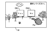
- FIG. 6 is a diagram showing a display example of a virtual space cut out by the visual field frame W when a specific object does not appear, and is software for causing the user 3 to select a positive answer as an operation object.
- a button Ob1 and a software button Ob2 for selecting a negative answer are displayed.
- the determination result of step S11 is “No” in the example of FIG. Therefore, a three-dimensional pointer Pa is displayed inside the visual field frame W.
- the three-dimensional pointer Pa is used, when a real space including an operating tool having a predetermined shape is shot by the image capturing apparatus 110, to cut out the image of the shot operating tool from a background image by image processing, and Is synthesized and displayed on the image in the virtual space.
- the operating tool having a predetermined shape is, for example, a fingertip of the user 3 from the fingertip to the wrist.
- the operating body having the predetermined shape is not limited to the hand, but may be any that can be photographed by the photographing device 110 and that can be moved by the user 3.
- the operating tool may be, for example, a pen tip operated by the user 3 or the like.
- FIG. 7 it is as if the user 3 wearing the goggles 20 to which the terminal device 10 is attached points to something with his / her right index finger in the shooting area of the shooting device 110.
- the gesture is performed, as shown in FIG. 6, the image of the three-dimensional pointer Pa having the shape of the right hand (right @ hand) separated from the background image of the shooting area is combined with the image of the virtual space and displayed.
- the three-dimensional pointer Pa When displayed in the virtual space, the three-dimensional pointer Pa may be an image simply cut out from the background by image processing, an image in which the inside of the outline of the cut out image is filled, and an image unrelated to the background image. It may be CG (Computer @ Graphics).
- the operation control unit 150 determines that the software button on which the three-dimensional pointer Op overlaps is touched. For example, if it is determined that the software button Ob1 has been touched, the operation control unit 150 notifies the application program or the OS that has displayed the software buttons Ob1 and Ob2 that the user has given a positive answer to any question. Notice. As a result, the command associated with the software button Ob1 is executed.
- the photographed right hand becomes smaller. Conversely, when the right hand is moved in a direction closer to the user, the photographed image is taken. The right hand is larger. Therefore, the size of the displayed three-dimensional pointer P changes according to the coordinates in the Z-axis direction. For this reason, the coordinates of the three-dimensional pointer in the Z-axis direction may be determined using the size of the displayed three-dimensional pointer P.
- FIG. 8 is a diagram showing a display example in a case where the software keyboard K as a specific object appears inside the view frame W, but the software keyboard K does not overlap the reference point Cen.
- FIG. 8 illustrates a state in which the software keyboard K is arranged on the left side outside the view frame W in FIG. This is an example of a case where the information is displayed inside.
- step S11 the determination result of step S11 is “Yes”. However, since the determination result in step S12 is “No”, the three-dimensional pointer Pa is displayed inside the visual field frame W. Note that when the operation tool having a predetermined shape is not photographed in the photographing area by the photographing measure 110, the three-dimensional pointer P is not displayed.
- FIG. 9 is a diagram illustrating a display example in a case where the software keyboard K as a specific object appears inside the visual field frame W and the software keyboard K overlaps the reference point Cen. Note that FIG. 9 is an example of a case where the user 3 further rotates the head to the left in a state where the software keyboard K is arranged as shown in FIG.
- the determination result in step S11 is “Yes” and the determination result in step S12 is “Yes”, so that the two-dimensional pointer Pb is displayed inside the visual field frame W.
- the two-dimensional pointer Pb has a pattern imitating the right hand.
- the two-dimensional pointer Pb and the three-dimensional pointer Pa are different in shape or color, or both.
- the tip of the index finger of the two-dimensional pointer Pb in FIG. 9 is a point designated by the pointer.
- the designated point is fixed to the reference point Cen.
- the head is rotated in the vertical and horizontal directions.
- the user 3 turns the head in a direction in which the tip of the index finger of the two-dimensional pointer Pb overlaps the operation area corresponding to the key, and fixes the head.
- the overlapping state is maintained for a predetermined time (for example, 2 seconds).
- the user 3 When inputting another key, the user 3 similarly turns the head in the direction in which the tip of the index finger of the two-dimensional pointer Pb overlaps the operation area of the another key, and fixes the head to Is maintained over a period of time.
- the user 3 moves the head to a position where the two-dimensional pointer Pb overlaps the operation area of another key once after inputting the first key, for example. . Then, after moving the head again to the position where the two-dimensional pointer Pb overlaps the operation area of the same key, the head may be fixed and the overlapping state may be maintained for a certain period of time.
- step S12 If the software keyboard K does not overlap the reference point Cen as a result of the user 3 moving in the direction in which the head is turned, the determination result in step S12 becomes “No”. Is changed to the three-dimensional pointer Pa as shown in FIG. Unlike the three-dimensional pointer Pa, the two-dimensional pointer Pb does not move in the depth direction but relatively moves along the operation surface of the software keyboard K.
- the two-dimensional pointer Pb uses the detection result of the sensor 106 of the terminal device 10, it is possible to specify the position with higher precision than the three-dimensional pointer Pa due to the movement of the fingertip or the like by the user. Becomes possible.
- the Z axis is added to the X axis and the Y axis.
- the three-dimensional pointer Pa that can be moved in the three axial directions is displayed. Therefore, it is possible to specify the position in consideration of the depth.
- switching from one of the three-dimensional pointer Pa or the two-dimensional pointer Pb to the other is performed according to the direction in which the head is turned, so that the user is not bothered and This can be realized with a simple configuration without separately preparing a special operation device.
- the operation area of the specific object is designated by the two-dimensional pointer Pb by fixing the two-dimensional pointer Pb to the reference point Cen and then moving the specific object in accordance with the direction of the head.
- the two-dimensional pointer may be moved along the operation surface of the specific object according to the operation of the user 3.
- only the software keyboard is used as the specific object among the operation objects.
- it may be configured such that the user can set whether or not to use the specific object for each type of operation object.
- the specific object is the above-described software keyboard K
- an operation area corresponding to each of the plurality of keys is provided in the area where the software keyboard K is displayed.
- the portion other than the key is the non-operation area, even if the area other than the key is designated by the two-dimensional pointer Pb, the operation is not significant.
- the software keyboard K is an example in which a plurality of operation areas are arranged in a part of a specific object.
- the operation control unit 150 executes the attached instruction.
- the operation control unit 150 executes a command associated with the designated operation area.
- the operation control unit 150 executes a command associated with the operation area.
- the reference point Cen may be displayed in such a manner that the user 3 can surely recognize the position of the reference point Cen instead of not displaying the reference point Cen.
- the operation area of the key of the software keyboard K is designated by the two-dimensional pointer Pb for a certain period of time
- the input of the key is performed.
- the present invention is not limited to this, and the key input area may be specified when the key operation area is designated by the two-dimensional pointer Pb and a specific action (for example, drawing a circle) is performed.
- the HMD 1 that provides a virtual space to the user 3 has been described as an example.
- an image of an operation object is combined with an image of a real space captured by the imaging device 110, and a real space is created.
- the present invention can also be applied to a case where an operation object is displayed on a screen.
- a program whether referred to as software, firmware, middleware, microcode or a hardware description language, or by another name, includes instructions, instruction sets, codes, code segments, program codes, subprograms, software modules, applications , Software applications, software packages, routines, subroutines, objects, executables, threads of execution, procedures or functions, and the like.
- software, instructions, and the like may be transmitted and received via a transmission medium.
- a transmission medium such as coaxial cable, fiber optic cable, twisted pair and digital subscriber line (DSL) and / or a wireless technology such as infrared, wireless and microwave, the website, server, or other When transmitted from a remote source, these wired and / or wireless technologies are included within the definition of transmission medium.
- the embodiments / aspects described in this specification include LTE (Long Term Evolution), LTE-A (LTE-Advanced), SUPER 3G, IMT-Advanced, 4G, 5G, FRA (Future Radio Access), W-CDMA.
- LTE Long Term Evolution
- LTE-A Long Term Evolution-Advanced
- SUPER 3G IMT-Advanced
- 4G 5G
- FRA Full Radio Access
- W-CDMA Wideband
- GSM registered trademark
- CDMA2000 Code Division Multiple Access 2000
- UMB User Mobile Broadband
- IEEE 802.11 Wi-Fi
- IEEE 802.16 WiMAX
- IEEE 802.20 UWB (Ultra-WideBand
- the present invention may be applied to a system using Bluetooth (registered trademark), another appropriate system, and / or a next-generation system extended based on the system.
- the input and output information may be stored in a specific place (for example, a memory) or may be managed by a management table. Information that is input and output can be overwritten, updated, or added. The output information or the like may be deleted. The input information or the like may be transmitted to another device.
- the determination may be made based on a value represented by 1 bit (0 or 1), a Boolean value (Boolean: true or false), or a comparison of numerical values (for example, a predetermined value). Value).
- the information described in this specification may be represented by an absolute value, a relative value from a predetermined value, or another corresponding information.
- a mobile station such as a smart phone is suitable as described above.
- a mobile station can be a subscriber station, mobile unit, subscriber unit, wireless unit, remote unit, mobile device, wireless device, wireless communication device, remote device, mobile subscriber station, access terminal, mobile terminal, wireless terminal, by one of ordinary skill in the art. It may also be called a terminal, a remote terminal, a handset, a user agent, a mobile client, a client, or some other suitable term.
- connection means any direct or indirect connection or coupling between two or more elements, and between two elements “connected” to each other. May include the presence of one or more intermediate elements.
- the coupling or connection between the elements may be physical, logical, or a combination thereof.
- two elements are defined by the use of one or more electrical wires, cables and / or printed electrical connections, and, as some non-limiting and non-exhaustive examples, radio frequency
- electromagnetic energy such as electromagnetic energy having wavelengths in the region, microwave region and light (both visible and invisible) region, it can be considered to be "connected” to each other.
- a recording circuit such as a ROM and a RAM is illustrated as the storage device 104.
- a flexible disk for example, a compact disk, a digital versatile disk, a Blu-ray (registered trademark) disk
- Cards for example, cards, sticks, key drives
- CD-ROMs Compact Discs
- registers removable disks, hard disks, floppy disks, magnetic strips, databases, servers and other suitable It is a storage medium.
- the program may be transmitted via a telecommunication line.
Landscapes
- Engineering & Computer Science (AREA)
- General Engineering & Computer Science (AREA)
- Theoretical Computer Science (AREA)
- Physics & Mathematics (AREA)
- General Physics & Mathematics (AREA)
- Human Computer Interaction (AREA)
- Optics & Photonics (AREA)
- Computer Graphics (AREA)
- Computer Hardware Design (AREA)
- Software Systems (AREA)
- User Interface Of Digital Computer (AREA)
- Position Input By Displaying (AREA)
Abstract
端末装置は、仮想空間に配置されるとともに、二次元の操作面を有する特定オブジェクトが、ユーザに提供される仮想空間の視野枠内に出現したか否かを判定する第1判定部と、特定オブジェクトが、視野枠内に出現したと判定された場合に、視野枠内の特定地点と重なっているか否かを判定する第2判定部と、特定オブジェクトが特定の地点に重なっていると判定された場合、表示装置を制御して、二次元操作面に沿って移動可能な二次元ポインタを視野枠内に表示させ、特定オブジェクトが、視野枠内に出現していないと判定された場合、表示装置を制御して、仮想空間を三次元で移動する三次元ポインタを前記視野枠内に表示させる表示制御部と、を有する。
Description
本発明は、端末装置および端末装置の制御方法に関する。
近年、ヘッドマウントディスプレイを装着したユーザに、仮想的または現実的な空間を種々のオブジェクトを合成して提供する技術が知られている。このような空間はコンピュータ等によって三次元的に提供される一方で、ユーザに対する指示や入力などのためのインターフェイスは、GUI(Graphical User Interface)で二次元的に提供される場合が多い。このような場合において、三次元的に表示された対象物への入力/操作を行うモードと、二次元的に表示された対象物への入力/操作を行うモードとを、並進及び回転の動きを検出する操作デバイスを用いて切り換える技術が提案されている(例えば特許文献1参照)。
しかしながら、簡易化を図るために、ヘッドマウントディプレイを、例えばスマートホンおよびゴーグルで構成する場合、上記技術では、操作デバイスを別途用意しなければならず、簡易化を阻害する要因となる。
上述した目的の一つを解決するために、本発明の一態様に係る端末装置は、二次元の操作面を有する特定オブジェクトが、ユーザに提供される仮想空間の視野枠内に出現したか否かを判定する第1判定部と、前記特定オブジェクトが、前記視野枠内に出現したと判定された場合に、前記視野枠内の特定地点と重なっているか否かを判定する第2判定部と、前記特定オブジェクトが前記特定地点に重なっていると判定された場合、表示装置を制御して、前記二次元操作面に対し相対移動が可能な二次元ポインタを前記視野枠内に表示させ、前記特定オブジェクトが、前記視野枠内に出現していないと判定された場合、前記表示装置を制御して、前記仮想空間を三次元で移動させる三次元ポインタを前記視野枠内に表示させる表示制御部とを有する。
上記一態様に係る端末装置によれば、ユーザに提供する現実の空間の視野枠内に、特定オブジェクトが出現していなければ三次元ポインタが表示され、特定オブジェクトが視野枠内の特定地点に重なっていれば、二次元ポインタが表示される。このため、プログラムを実行する処理装置を有する端末装置として、スマートホンなどを適用できるので、二次元操作と三次元操作とをユーザに煩わしさを与えることなく簡易な構成で切り換えることができる。
以下、本発明を実施するための形態について図面を参照して説明する。なお、以下に述べる実施の形態は、本発明の好適な具体例であるので、技術的に好ましい種々の限定が付されている。ただし、本発明の範囲は、以下の説明において特に本発明を限定する旨の記載がない限り、これらの形態に限られない。
<実施形態>
図1は、ヘッドマウントディスプレイ(以下、HMDと略称する)1の概略を説明するための図である。
この図に示されるようにHMD1は、実施形態に係る端末装置10と、該端末装置10が取り付けられたゴーグル20とを含む。ゴーグル20は、該端末装置10がユーザ3の両眼手前となる位置に、ヘッドバンド22によってユーザ3の頭部に装着される。
図1は、ヘッドマウントディスプレイ(以下、HMDと略称する)1の概略を説明するための図である。
この図に示されるようにHMD1は、実施形態に係る端末装置10と、該端末装置10が取り付けられたゴーグル20とを含む。ゴーグル20は、該端末装置10がユーザ3の両眼手前となる位置に、ヘッドバンド22によってユーザ3の頭部に装着される。
端末装置10は、例えばスマートホンであり、ユーザ3に対向する面が表(おもて)面である。該表面には、図では隠れているが、表示装置が配置されている。ゴーグル20において端末装置10の取り付け面には、特に図示しないが、左眼用画像だけをユーザ3の左眼に視認させる開孔部と、右眼用画像だけをユーザ3の右眼に視認させる開孔部とをそれぞれ有する。このため、端末装置10の表示装置が、仮想空間を提供するために、左眼の開孔部に相当するエリアに左眼用画像を、右眼の開孔部に相当するエリアに右眼用画像を、それぞれ視差を与えて表示させた場合、ユーザ3は該画像で示される仮想空間を立体的に視認することができる。
端末装置10の裏面、すなわち図1でいえば、手前側の面には、撮影装置110が位置する。
なお、端末装置10は、スマートホンに限られず、ゴーグルに取り付けられるHMD専用の表示装置であってもよい。また、ゴーグルを備える(すなわち、ゴーグルから着脱不能な)HMD装置であってもよい。
なお、端末装置10は、スマートホンに限られず、ゴーグルに取り付けられるHMD専用の表示装置であってもよい。また、ゴーグルを備える(すなわち、ゴーグルから着脱不能な)HMD装置であってもよい。
図2は、端末装置10におけるハードウェアの構成を示す図である。
この図に示されるように、端末装置10は、処理装置102と記憶装置104とセンサー106と表示装置108と撮影装置110とを具備するコンピュータシステムにより実現される。
端末装置10の各要素は、単体または複数のバスで相互に接続される。なお、本説明における「装置」という用語は、回路、デバイスまたはユニット等の他の用語に読替えても良い。また、端末装置10の各要素は、単数または複数の機器で構成される。端末装置10の一部の要素を省略しても良い。
この図に示されるように、端末装置10は、処理装置102と記憶装置104とセンサー106と表示装置108と撮影装置110とを具備するコンピュータシステムにより実現される。
端末装置10の各要素は、単体または複数のバスで相互に接続される。なお、本説明における「装置」という用語は、回路、デバイスまたはユニット等の他の用語に読替えても良い。また、端末装置10の各要素は、単数または複数の機器で構成される。端末装置10の一部の要素を省略しても良い。
処理装置102は、端末装置10の全体を制御するプロセッサであり、例えば単数または複数のチップで構成される。処理装置102は、例えば、周辺装置とのインターフェイス、演算装置およびレジスタ等を含む中央処理装置(CPU:Central Processing Unit)で構成される。
なお、処理装置102の機能の一部または全部を、DSP(Digital Signal Processor)、ASIC(Application Specific Integrated Circuit)、PLD(Programmable Logic Device)、FPGA(Field Programmable Gate Array)等のハードウェアで実現しても良い。処理装置102は、各種の処理を並列的または逐次的に実行する。
なお、処理装置102の機能の一部または全部を、DSP(Digital Signal Processor)、ASIC(Application Specific Integrated Circuit)、PLD(Programmable Logic Device)、FPGA(Field Programmable Gate Array)等のハードウェアで実現しても良い。処理装置102は、各種の処理を並列的または逐次的に実行する。
記憶装置104は、処理装置102が利用可能な記録媒体であり、処理装置102が実行する複数のプログラムと、処理装置102が使用する各種のデータと、を記憶する。ここで、処理装置102が実行する複数のプログラムには、OS(Operating System)や、ユーザ3に仮想空間を提供するアプリケーションプログラムなどが含まれ、また、各種のデータには、後述するように、ユーザによって仮想空間に配置された操作オブジェクトの場所(位置)を示す情報などが含まれる。
なお、記憶装置104は、例えば、ROM(Read Only Memory)、EPROM(Erasable Programmable ROM)、EEPROM(Electrically Erasable Programmable ROM)、RAM(Random Access Memory)等の記憶回路の1種類以上で構成される。
なお、記憶装置104は、例えば、ROM(Read Only Memory)、EPROM(Erasable Programmable ROM)、EEPROM(Electrically Erasable Programmable ROM)、RAM(Random Access Memory)等の記憶回路の1種類以上で構成される。
センサー106は、端末装置10の姿勢や動きを検出するための、例えば3軸角度センサーである。
表示装置108は、処理装置102による制御のもとで各種の画像(静止画および動画を含む)を表示する。特に、本実施形態においては、上述した仮想空間を示す左眼用画像と右眼用画像とが表示装置108によって表示される。
なお、例えば液晶表示パネルまたは有機EL表示パネル等の各種の表示パネルが表示装置108として好適に利用される。
撮影装置110は、端末装置10の裏面に配置されたリアカメラである。該端末装置10が取り付けられたゴーグル20をユーザ3が装着した場合、撮影装置110は、該ユーザ3の顔が向く方向を撮影する。
表示装置108は、処理装置102による制御のもとで各種の画像(静止画および動画を含む)を表示する。特に、本実施形態においては、上述した仮想空間を示す左眼用画像と右眼用画像とが表示装置108によって表示される。
なお、例えば液晶表示パネルまたは有機EL表示パネル等の各種の表示パネルが表示装置108として好適に利用される。
撮影装置110は、端末装置10の裏面に配置されたリアカメラである。該端末装置10が取り付けられたゴーグル20をユーザ3が装着した場合、撮影装置110は、該ユーザ3の顔が向く方向を撮影する。
図3は、仮想空間を提供するプログラムを端末装置10の処理装置102が実行することにより実現される機能構成を示すブロック図である。
この図に示されるように、端末装置10では、動作制御部150、姿勢検出部152、表示制御部154、第1判定部156および第2判定部158が構築される。
この図に示されるように、端末装置10では、動作制御部150、姿勢検出部152、表示制御部154、第1判定部156および第2判定部158が構築される。
姿勢検出部152は、センサー106から出力される信号を処理して、処理した結果を端末装置10の姿勢情報を出力する。具体的には、姿勢検出部152は、センサー106の検出結果、すなわち、図1に示されるように水平方向のX軸、垂直方向のY軸および奥行き方向のZ軸における各加速度の検出結果を処理して、端末装置10の姿勢情報を周期的に、例えば0.02秒毎に出力する。
表示制御部154は、表示装置108が表示する画面の生成および制御を実行する。詳細には、表示制御部154は、仮想空間を立体視させるための左眼用画像および右眼用画像をそれぞれ生成して、表示装置108の表示領域のうち、左眼の開孔部に相当するエリアに左眼用画像を、右眼の開孔部に相当するエリアに右眼用画像を、それぞれ表示させる。
なお、仮想空間とは、端末装置10において生成された現実を模擬した空間である。仮想空間は、ユーザ3を中心に全方位に拡がった概念である。そして、全方位の空間のうち、端末装置10の姿勢情報に基づいて検出されたユーザ3の顔が向く方向に対応する空間が部分的に切り出されて、表示装置108に表示される。
なお、仮想空間とは、端末装置10において生成された現実を模擬した空間である。仮想空間は、ユーザ3を中心に全方位に拡がった概念である。そして、全方位の空間のうち、端末装置10の姿勢情報に基づいて検出されたユーザ3の顔が向く方向に対応する空間が部分的に切り出されて、表示装置108に表示される。
図4は、端末装置10で提供される仮想空間を説明するための図である。この図において、符号Wは、端末装置10が取り付けられたゴーグル20を装着したユーザ3が、顔をある方向に向けている場合に、仮想空間の切り出し枠となる視野枠である。
なお、この図は、仮想空間として自然風景が提供された例である。仮想空間は左眼用画像および右眼用画像による立体視でユーザ3に提供されるので、視野枠Wは、表示装置108で表示される画面そのものを示しているわけではない。
なお、この図は、仮想空間として自然風景が提供された例である。仮想空間は左眼用画像および右眼用画像による立体視でユーザ3に提供されるので、視野枠Wは、表示装置108で表示される画面そのものを示しているわけではない。
ユーザ3が顔をある方向に向け、図4において実線の視野枠Wによって図に示されるような自然風景の仮想空間が提供されている場合に、ユーザ3が頭部を回転させて顔を左側(X軸方向)に向けると、該回転に対応した姿勢情報が姿勢検出部152から出力される。
該姿勢情報を取得した表示制御部154は、視野枠Wを図4の破線で示される位置まで移動させることにより、ユーザ3に提供する仮想空間を左側に移動させる。このように顔の向く方向に応じて仮想空間が移動するので、ユーザ3は、あたかも自然風景が存在する空間にいるかのような感覚を、視覚を通じて得ることができる。
該姿勢情報を取得した表示制御部154は、視野枠Wを図4の破線で示される位置まで移動させることにより、ユーザ3に提供する仮想空間を左側に移動させる。このように顔の向く方向に応じて仮想空間が移動するので、ユーザ3は、あたかも自然風景が存在する空間にいるかのような感覚を、視覚を通じて得ることができる。
符号Cenは、視野枠Wに固定された基準点を示す。基準点Cenは、特定地点の一例である。この例では、基準点Cenは、視野枠Wの対角中心に位置している。基準点Cenは、視野枠Wに対して固定されている。このため、顔の向く方向が変化し、その結果視野枠Wによって切り取られる仮想空間が変化しても、該視野枠Wに対して基準点Cenは不動の関係にある。一方、該仮想空間に対しては相対移動することになる。
なお、基準点Cenは、視野枠Wの対角中心に限られず、視野枠Wに対して予め定められた関係を有する地点であればよい。例えば、視野枠Wを左右方向に左2:右3に分割する上下線と、上下方向に上3:下2に分割する左右線との交点であってもよい。
また、基準点Cenは、図4では、説明の便宜のために十字線の交点として示されているが、実際には本実施形態では、十字線を含めて非表示としている。
なお、基準点Cenは、視野枠Wの対角中心に限られず、視野枠Wに対して予め定められた関係を有する地点であればよい。例えば、視野枠Wを左右方向に左2:右3に分割する上下線と、上下方向に上3:下2に分割する左右線との交点であってもよい。
また、基準点Cenは、図4では、説明の便宜のために十字線の交点として示されているが、実際には本実施形態では、十字線を含めて非表示としている。
本実施形態において仮想空間には、様々な操作オブジェクトが配置される。ここで、操作オブジェクトとは、仮想空間においてユーザ3が各種の入力や設定等を行うためのものであり、ソフトウェアボタン、ソフトウェアキーボート、ラジオボタン、または、チェックボックスなどである。
本実施形態では、これらの操作オブジェクトのうち、ユーザ3からみて操作面を有し、かつ、予め定められたもの、具体的には、当該操作面の位置の指定に精度が要求されるものを、特定オブジェクトと呼んでいる。換言すれば、上記操作面を有する操作オブジェクトであっても、予め定められていないものは、特定オブジェクトではない。なお、操作面は、XY平面と平行であることが好ましいが、平行でなくてもよい。また、操作面は、平坦ではなく、電子ブックのように起伏がある面でもよい。
これらの操作オブジェクトには、ユーザによって仮想空間における任意の位置に配置されるものもあれば、アプリケーションプログラムの実行により視野枠Wの内側に配置されるものもある。なお、ユーザによって仮想空間に配置された操作オブジェクトの場所(位置)についての情報は、例えば動作制御部150によって記憶装置104に記憶される。
本実施形態では、これらの操作オブジェクトのうち、ユーザ3からみて操作面を有し、かつ、予め定められたもの、具体的には、当該操作面の位置の指定に精度が要求されるものを、特定オブジェクトと呼んでいる。換言すれば、上記操作面を有する操作オブジェクトであっても、予め定められていないものは、特定オブジェクトではない。なお、操作面は、XY平面と平行であることが好ましいが、平行でなくてもよい。また、操作面は、平坦ではなく、電子ブックのように起伏がある面でもよい。
これらの操作オブジェクトには、ユーザによって仮想空間における任意の位置に配置されるものもあれば、アプリケーションプログラムの実行により視野枠Wの内側に配置されるものもある。なお、ユーザによって仮想空間に配置された操作オブジェクトの場所(位置)についての情報は、例えば動作制御部150によって記憶装置104に記憶される。
本実施形態では、上記操作オブジェクトのうち、多数のキーのいずれかを指定する際に、操作面における位置の指定に精度が要求されるソフトウェアキーボードを特定オブジェクトとしている。一方で、ボタンエリアのいずれかを指定するに際し、位置の指定にソフトウェアキーボードほどの精度が要求されない(すなわち、位置の指定に要求される精度が、ソフトウェアキーボードに要求される精度よりも低い)ソフトウェアボタンについては、特定オブジェクトとはしていない。ただし、ソフトウェアボタンについては、後述するように、特定オブジェクトとしてもよい場合がある。
なお、アプリケーションプログラムの設定などで用いられるラジオボタン、またはチェックボックス等については、特定オブジェクトとするか否かについては任意である。
なお、アプリケーションプログラムの設定などで用いられるラジオボタン、またはチェックボックス等については、特定オブジェクトとするか否かについては任意である。
図4は、特定オブジェクトであるソフトウェアキーボードKが仮想空間において視野枠Wの外側に配置された例である。後述する図8で示されるようにユーザ3が頭部を左側に回転させれば、視野枠Wが該回転に伴って左側に移動するので、移動によって視野枠Wの内側にソフトウェアキーボードKが表示されることになる。
説明を図3に戻すと、第1判定部156は、特定オブジェクトが視野枠Wの内側に出現しているか否かを判定し、第2判定部158は、第1判定部156による判定が肯定的な場合、視野枠Wに出現した特定オブジェクトが基準点Cenとユーザ3からみて重なっているか否かを判定する。
なお、特定オブジェクトが視野枠Wに出現した、とは、表示制御部154が、端末装置10の姿勢に応じた視野枠Wによって仮想空間を切り出して表示装置108に表示させている場合に、特定オブジェクトの一部または全部が仮想空間において表示されたことをいう。
なお、特定オブジェクトが視野枠Wに出現した、とは、表示制御部154が、端末装置10の姿勢に応じた視野枠Wによって仮想空間を切り出して表示装置108に表示させている場合に、特定オブジェクトの一部または全部が仮想空間において表示されたことをいう。
本実施形態では、視野枠Wに特定オブジェクトが出現しているか否か、出現していれば、該特定オブジェクトが基準点Cenと重なっているか否かによって、操作用のポインタを切り換える。
そこで次に、ポインタの切り換え動作について説明する。
そこで次に、ポインタの切り換え動作について説明する。
図5は、ポインタを切り換える動作を示すフローチャートである。
なお、この動作は、端末装置10においてアプリケーションプログラムの実行によりユーザに仮想空間が提供されている場合に実行される。すなわち、ポインタの切り換え動作は、ユーザ3の顔の向く方向(厳密にいえば端末装置10の姿勢に基づく方向)に応じた視野枠Wによって仮想空間が切り出されて、該ユーザ3に提供されている場合に実行される。
なお、この動作は、端末装置10においてアプリケーションプログラムの実行によりユーザに仮想空間が提供されている場合に実行される。すなわち、ポインタの切り換え動作は、ユーザ3の顔の向く方向(厳密にいえば端末装置10の姿勢に基づく方向)に応じた視野枠Wによって仮想空間が切り出されて、該ユーザ3に提供されている場合に実行される。
この場合において、表示制御部154は、操作オブジェクトのうち、ユーザによって仮想空間に配置された特定オブジェクトがあれば、該特定オブジェクトの場所(位置)を記憶装置104から取得する。また、表示制御部154は、アプリケーションプログラムの実行により視野枠Wに配置される特定オブジェクトがあれば、該特定オブジェクトの場所を該アプリケーションプログラムから取得する。そして、表示制御部154は、取得した場所に配置された操作オブジェクトがある方向にユーザ3の顔が向けば、該操作オブジェクトを仮想空間に表示させる。
まず、第1判定部156は、現時点において視野枠Wの内側に特定オブジェクトの一部または全部が出現しているか否かを判定する(ステップS11)。
視野枠Wの内側に特定オブジェクトが出現していない場合(ステップS11の判定結果が「No」である旨)、処理手順はステップS13に移行する。
一方、視野枠Wの内側に特定オブジェクトが出現している場合(ステップS11の判定結果が「Yes」である旨)、第2判定部158は、出現している特定オブジェクトと基準点Cenとが、ユーザ3からみて重なっているか否かを判定する(ステップS12)。
一方、視野枠Wの内側に特定オブジェクトが出現している場合(ステップS11の判定結果が「Yes」である旨)、第2判定部158は、出現している特定オブジェクトと基準点Cenとが、ユーザ3からみて重なっているか否かを判定する(ステップS12)。
特定オブジェクトと基準点Cenとが重なっていない場合(ステップS12の判定結果が「No」である旨)、処理手順はステップS13に進む。
一方、特定オブジェクトと基準点Cenとが重なっている場合(ステップS12の判定結果が「Yes」である旨)、処理はステップS14に進む。
一方、特定オブジェクトと基準点Cenとが重なっている場合(ステップS12の判定結果が「Yes」である旨)、処理はステップS14に進む。
ステップS13において、表示制御部154は、視野枠Wの内側に三次元ポインタを表示するよう表示装置108を制御する。表示制御部154は、視野枠Wの内側において、三次元ポインタを表示させるとともに、例えば撮影装置110で撮影されたユーザの手先(hand)(操作体)の動きに応じて三次元ポインタが移動するよう表示装置108を制御する。
動作制御部150は、三次元ポインタが、特定オブジェクト以外の操作オブジェクトとユーザ3からみて重なっており、かつ、ユーザ3による特定のアクションを伴う場合、該アクションに対応付けられた命令を実行する。
ステップS14において、表示制御部154は、視野枠Wの内側に二次元ポインタを表示するよう表示装置108を制御する。表示制御部154は、視野枠Wの内側において、二次元ポインタを表示させるとともに、姿勢検出部152が端末装置10の姿勢変化を検出したときに、その変化に応じて、該二次元ポインタが特定オブジェクトの操作面上を移動するよう表示装置108を制御する。
なお、動作制御部150は、二次元ポインタが特定オブジェクトの操作エリアにユーザ3からみて重なっており、かつ、ユーザ3による特定のアクションを伴う場合、該アクションに対応付けられた命令を実行する。
なお、動作制御部150は、二次元ポインタが特定オブジェクトの操作エリアにユーザ3からみて重なっており、かつ、ユーザ3による特定のアクションを伴う場合、該アクションに対応付けられた命令を実行する。
表示制御部154が三次元ポインタまたは二次元ポインタを表示装置108に表示させた後、処理手順はステップS11に戻る。
この後、本実施形態では、視野枠Wにおける特定オブジェクトの出現の有無、および、特定オブジェクトと基準点Cenとの位置関係に変化がなければ、引き続き同じポインタが表示される。一方、変化があれば、二次元ポインタと三次元ポインタとでポインタが切り換えられる場合がある。なお、動作制御部150が、姿勢検出部152、表示制御部154、第1判定部156および第2判定部158の各部を制御してもよい。
この後、本実施形態では、視野枠Wにおける特定オブジェクトの出現の有無、および、特定オブジェクトと基準点Cenとの位置関係に変化がなければ、引き続き同じポインタが表示される。一方、変化があれば、二次元ポインタと三次元ポインタとでポインタが切り換えられる場合がある。なお、動作制御部150が、姿勢検出部152、表示制御部154、第1判定部156および第2判定部158の各部を制御してもよい。
次に、ユーザに提供される仮想空間の例について説明する。
図6は、特定オブジェクトが出現していない場合において視野枠Wにより切り出された仮想空間の表示例を示す図であり、操作オブジェクトとして、ユーザ3に対し、肯定的な回答を選択させるためのソフトウェアボタンOb1と、否定的な回答を選択させるためのソフトウェアボタンOb2とが表示された例である。上述したように本実施形態では、ソフトウェアボタンについては特定オブジェクトとしていないので、図6の例では、ステップS11の判定結果が「No」となる。このため、視野枠Wの内側には、三次元ポインタPaが表示される。
図6は、特定オブジェクトが出現していない場合において視野枠Wにより切り出された仮想空間の表示例を示す図であり、操作オブジェクトとして、ユーザ3に対し、肯定的な回答を選択させるためのソフトウェアボタンOb1と、否定的な回答を選択させるためのソフトウェアボタンOb2とが表示された例である。上述したように本実施形態では、ソフトウェアボタンについては特定オブジェクトとしていないので、図6の例では、ステップS11の判定結果が「No」となる。このため、視野枠Wの内側には、三次元ポインタPaが表示される。
三次元ポインタPaは、撮影装置110によって予め定められた形状の操作体を含む現実空間が撮影された場合に、撮影された操作体の画像を画像処理によって背景画像から切り出し、該切り出した操作体の画像を仮想空間の画像に合成して表示したものである。ここで、予め定められた形状の操作体とは、例えばユーザ3の指先から手首までの手先である。予め定められた形状の操作体としては、手先に限られず、撮影装置110に撮影され得るものであって、ユーザ3の意思によって移動可能なものであればよい。操作体としては、例えばユーザ3によって操作されるペン先等などであってもよい。
詳細には、図7に示されるように、端末装置10が取り付けられたゴーグル20を装着したユーザ3が、撮影装置110の撮影エリアにて、自身の右手人差し指で何かを指し示すかのような仕草をした場合、図6に示されるように、撮影エリアの背景画像から切り離された右手先(right hand)の形状の三次元ポインタPaの画像が仮想空間の画像に合成されて表示される。
三次元ポインタPaは、仮想空間において表示される場合に、画像処理によって、背景から単に切り出した画像としてもよいし、切り出した画像の輪郭内側を塗り潰した画像、および、背景の画像とは無関係なCG(Computer Graphics)としてもよい。
なお、ユーザ3が自身の右手先を操作して、ソフトウェアボタンOb1またはOb2をタッチすると、具体的には、ソフトウェアボタンOb1またはOb2が表示された四角枠内に三次元ポインタOpの一部を重ねると、動作制御部150は、三次元ポインタOpが重なったソフトウェアボタンがタッチされたと判定する。例えばソフトウェアボタンOb1がタッチされたと判定したならば、動作制御部150は、ユーザが任意の質問に対して肯定的な回答をした旨を、ソフトウェアボタンOb1およびOb2を表示させたアプリケーションプログラムまたはOSに通知する。この結果、ソフトウェアボタンOb1に関連付けられた命令が実行されることになる。
また、ユーザ3が例えば右手先を奥行き方向(自身から遠くなる方向)に移動させると、撮影された右手先は小さくなり、逆に右手先を自身に近くなる方向に移動させると、撮影された右手先は大きくなる。したがって、表示された三次元ポインタPの大きさは、Z軸方向の座標に応じて変化することになる。
このため、三次元ポインタにおけるZ軸方向の座標については、表示された三次元ポインタPの大きさを用いて判定してもよい。
このため、三次元ポインタにおけるZ軸方向の座標については、表示された三次元ポインタPの大きさを用いて判定してもよい。
図8は、特定オブジェクトであるソフトウェアキーボードKが視野枠Wの内側に出現しているが、該ソフトウェアキーボードKが基準点Cenに重なっていない場合の表示例を示す図である。
図8は、例えば図4においてソフトウェアキーボードKが視野枠Wの外左側に配置されていた状態において、ユーザ3が頭部を、左側かつ上向きに回転させることによって、ソフトウェアキーボードKが視野枠Wの内側に表示された場合の例である。
図8は、例えば図4においてソフトウェアキーボードKが視野枠Wの外左側に配置されていた状態において、ユーザ3が頭部を、左側かつ上向きに回転させることによって、ソフトウェアキーボードKが視野枠Wの内側に表示された場合の例である。
図8の例では、ステップS11の判定結果が「Yes」となる。しかし、ステップS12の判定結果が「No」となるので、視野枠Wの内側には、三次元ポインタPaが表示される。なお、撮影措置110による撮影エリアに予め定められた形状の操作体が撮影されない場合、三次元ポインタPは表示されない。
図9は、特定オブジェクトであるソフトウェアキーボードKが視野枠Wの内側に出現し、かつ、該ソフトウェアキーボードKが基準点Cenに重なっている場合の表示例を示す図である。
なお、図9は、例えば視野枠Wの内側に図8に示されるようにソフトウェアキーボードKが配置されていた状態において、ユーザ3が頭部を、さらに左側に回転させた場合の例である。
なお、図9は、例えば視野枠Wの内側に図8に示されるようにソフトウェアキーボードKが配置されていた状態において、ユーザ3が頭部を、さらに左側に回転させた場合の例である。
図9の例では、ステップS11の判定結果が「Yes」となり、ステップS12の判定結果も「Yes」となるので、視野枠Wの内側には、二次元ポインタPbが表示される。
二次元ポインタPbは、右手先を模したパターンとなっている。しかし、二次元ポインタPbを三次元ポインタPaと一見して区別する目的で、二次元ポインタPbと三次元ポインタPaとは形状または色、もしくは双方を相互に異ならせている。
二次元ポインタPbは、右手先を模したパターンとなっている。しかし、二次元ポインタPbを三次元ポインタPaと一見して区別する目的で、二次元ポインタPbと三次元ポインタPaとは形状または色、もしくは双方を相互に異ならせている。
図9の二次元ポインタPbの人差し指先端が、ポインタで指定される地点であり、本実施形態では基準点Cenに当該指定された地点が固定される。このため、ユーザ3が、二次元ポインタPbの人差し指先端で指定される地点を移動させる場合、頭部を上下左右方向に回転させることになる。詳細には、ソフトキーボードKにおいて、あるキーを入力する場合、ユーザ3は、二次元ポインタPbにおける人差し指先端が該キーに相当する操作エリアに重なる方向に頭部を向けるとともに、頭部を固定して、重なった状態を一定時間(例えば2秒間)維持する。
また、別のキーを入力する場合、ユーザ3は、同様に、二次元ポインタPbにおける人差し指先端が該別のキーの操作エリアに重なる方向に頭部を向けるとともに、頭部を固定して、重なった状態を一定時間にわたって維持する。
なお、同じキーを2回連続して入力する場合、ユーザ3は、例えば1回目のキーを入力してから、一旦、二次元ポインタPbが別のキーの操作エリアに重なる位置に頭部を動かす。その後、再度同じキーの操作エリアに二次元ポインタPbが重なる位置に頭部を動かした後、頭部を固定して、重なった状態を一定時間にわたって維持すればよい。
なお、同じキーを2回連続して入力する場合、ユーザ3は、例えば1回目のキーを入力してから、一旦、二次元ポインタPbが別のキーの操作エリアに重なる位置に頭部を動かす。その後、再度同じキーの操作エリアに二次元ポインタPbが重なる位置に頭部を動かした後、頭部を固定して、重なった状態を一定時間にわたって維持すればよい。
なお、ユーザ3が頭部の向く方向を移動させた結果、ソフトウェアキーボードKが基準点Cenに重ならなくなれば、ステップS12の判定結果が「No」となるので、二次元ポインタPbが、図8に示されるように三次元ポインタPaに変更される。
二次元ポインタPbは、三次元ポインタPaとは異なり、奥行き方向には移動せず、ソフトウェアキーボードKの操作面に沿って相対移動することになる。
二次元ポインタPbは、三次元ポインタPaとは異なり、奥行き方向には移動せず、ソフトウェアキーボードKの操作面に沿って相対移動することになる。
本実施形態によれば、二次元ポインタPbは、端末装置10のセンサー106の検出結果を利用するので、ユーザによる指先等の移動による三次元ポインタPaと比較して高精度に位置を指定することが可能となる。
一方、本実施形態では、ソフトウェアキーボードKのような特定オブジェクトが基準点Cenに重ならない場合、すなわち、特定オブジェクトを用いて入力、設定等を行わない場合、X軸およびY軸にZ軸を加えた3軸方向に移動可能な三次元ポインタPaが表示される。したがって、奥行きを考慮した位置の指定が可能となる。
そして、本実施形態では、三次元ポインタPa、または、二次元ポインタPbの一方から他方への切り換えが、頭部の向く方向に応じて実行されるので、ユーザに煩わしさを与えることなく、また、特別な操作デバイスを別途用意することなく、簡易な構成で実現することが可能となる。
<応用/変形の各種態様>
実施形態では、二次元ポインタPbを基準点Cenに固定した後、特定オブジェクトを頭部の向く方向に応じて移動させることで、二次元ポインタPbにより特定オブジェクトの操作エリアを指定する構成としたが、特定オブジェクトが基準点Cenに重なっている状態において、二次元ポインタを、ユーザ3の操作に応じて特定オブジェクトの操作面に沿って移動させてもよい。
実施形態では、二次元ポインタPbを基準点Cenに固定した後、特定オブジェクトを頭部の向く方向に応じて移動させることで、二次元ポインタPbにより特定オブジェクトの操作エリアを指定する構成としたが、特定オブジェクトが基準点Cenに重なっている状態において、二次元ポインタを、ユーザ3の操作に応じて特定オブジェクトの操作面に沿って移動させてもよい。
上述した実施形態では、操作オブジェクトのうち、ソフトウェアキーボードのみを特定オブジェクトとしたが、操作オブジェクトの種類毎に、特定オブジェクトとするか否かを、ユーザ側で設定可能とする構成としてもよい。
特定オブジェクトが上述したソフトウェアキーボードKである場合に、ソフトウェアキーボードKが表示された領域に、複数のキーの各々に対応する操作エリアがそれぞれ設けられる。ここで、キー以外の部分は非操作エリアとなるので、キー以外のエリアが二次元ポインタPbで指定されても、有意の操作にはならない。換言すれば、ソフトウェアキーボードKは、特定オブジェクトの一部の領域に、複数の操作エリアが配置された例である。
これに限られず、例えば特定オブジェクトに1つのソフトウェアボタンを含ませた場合には、該ソフトウェアボタンの全領域を操作エリアとしてもよい。換言すれば、1つのソフトウェアボタンを特定オブジェクトとする例は、特定オブジェクトの全部の領域が操作エリアとなる例である。また例えば、特定オブジェクト内に複数のソフトウェアボタンを互いに離間させて配置した場合、該複数のソフトウェアボタンの各領域が操作エリアとなり、ボタン以外の部分は非操作エリアとなる。換言すれば、複数のソフトウェアボタンを特定オブジェクトに含ませる例は、特定オブジェクトの一部の領域に、複数の操作エリアが配置された例である。
すなわち、特定オブジェクトの一部または全部に、命令が対応付けられた操作エリアが配置された場合において、二次元ポインタPbによって操作エリアが指定された場合、動作制御部150は、該操作エリアに対応付けられた命令を実行する。換言すると、特定オブジェクトの一部に、命令が各々に対応付けられた複数の操作エリアが配置された場合において、二次元ポインタPbによって複数の操作エリアのいずれかが指定された場合、動作制御部150は、該指定された操作エリアに対応付けられた命令を実行する。また、特定オブジェクトの全部に、命令が対応付けられた1の操作エリアが配置された場合において、二次元ポインタPbによって前記操作エリアが指定された場合に、動作制御部150は、該指定された操作エリアに対応付けられた命令を実行する。
基準点Cenについては非表示ではなく、ユーザ3が確実に基準点Cenの位置が判る態様で表示してもよい。
上述した実施形態では、ソフトウェアキーボードKのキーの操作エリアが二次元ポインタPbで指定された状態が一定時間継続したときに、該キーの入力が行われることとした。これに限られず、キーの操作エリアが二次元ポインタPbで指定されるとともに、特定のアクション(例えば円を描く)があったときに、該キーの入力が行われる構成としてもよい。
また、実施形態では、ユーザ3に仮想的な空間を提供するHMD1を例にとって説明したが、例えば撮影装置110によって撮影された現実の空間の画像に、操作オブジェクトの画像を合成し、現実の空間に操作オブジェクトを表示する場合にも適用できる。
<その他>
例示したフローチャートにおいて、各ステップの順序を変更しても良い。すなわち、本発明の好適な態様における各処理の順序は、特定の順序に限定されない。
例示したフローチャートにおいて、各ステップの順序を変更しても良い。すなわち、本発明の好適な態様における各処理の順序は、特定の順序に限定されない。
図3に例示された各機能は、ハードウェアおよびソフトウェアの任意の組合せによって実現される。また、各機能は、単体の装置によって実現されても良いし、相互に別体で構成された2個以上の装置によって実現されても良い。
プログラムは、ソフトウェア、ファームウェア、ミドルウェア、マイクロコードまたはハードウェア記述言語と呼ばれるか、他の名称によって呼ばれるかを問わず、命令、命令セット、コード、コードセグメント、プログラムコード、サブプログラム、ソフトウェアモジュール、アプリケーション、ソフトウェアアプリケーション、ソフトウェアパッケージ、ルーチン、サブルーチン、オブジェクト、実行可能ファイル、実行スレッド、手順または機能等を意味するよう広く解釈されるべきである。
また、ソフトウェア、命令などは、伝送媒体を介して送受信されても良い。例えば、ソフトウェアが、同軸ケーブル、光ファイバケーブル、ツイストペアおよびデジタル加入者回線(DSL)などの有線技術および/または赤外線、無線およびマイクロ波などの無線技術を使用してウェブサイト、サーバ、または他のリモートソースから送信される場合、これらの有線技術および/または無線技術は、伝送媒体の定義内に含まれる。
本明細書で説明した実施形態/各態様は、LTE(Long Term Evolution)、LTE-A(LTE-Advanced)、SUPER 3G、IMT-Advanced、4G、5G、FRA(Future Radio Access)、W-CDMA(登録商標)、GSM(登録商標)、CDMA2000、UMB(Ultra Mobile Broadband)、IEEE 802.11(Wi-Fi)、IEEE 802.16(WiMAX)、IEEE 802.20、UWB(Ultra-WideBand)、Bluetooth(登録商標)、その他の適切なシステムを利用するシステムおよび/またはこれらに基づいて拡張された次世代システムに適用されても良い。
入出力された情報等は特定の場所(例えば、メモリ)に保存されても良いし、管理テーブルで管理しても良い。入出力される情報等は、上書き、更新、または追記され得る。出力された情報等は削除されても良い。入力された情報等は他の装置へ送信されても良い。
判定は、1ビットで表される値(0か1か)によって行われても良いし、真偽値(Boolean:trueまたはfalse)によって行われても良いし、数値の比較(例えば、所定の値との比較)によって行われても良い。
本明細書で説明した各態様/実施形態は単独で用いても良いし、組み合わせて用いても良いし、実行に伴って切り替えて用いても良い。
本明細書で説明した情報、信号などは、様々な異なる技術のいずれかを使用して表されても良い。例えば、上記の説明全体に渡って言及され得るデータ、命令、コマンド、情報、信号、ビット、シンボル、チップなどは、電圧、電流、電磁波、磁界若しくは磁性粒子、光場若しくは光子、またはこれらの任意の組み合わせによって表されても良い。
本明細書で説明した情報などは、絶対値で表されても良いし、所定の値からの相対値で表されても良いし、対応する別の情報で表されても良い。
端末装置10としては、上述したようにスマートホンのような移動局が好適である。移動局は、当業者によって、加入者局、モバイルユニット、加入者ユニット、ワイヤレスユニット、リモートユニット、モバイルデバイス、ワイヤレスデバイス、ワイヤレス通信デバイス、リモートデバイス、モバイル加入者局、アクセス端末、モバイル端末、ワイヤレス端末、リモート端末、ハンドセット、ユーザエージェント、モバイルクライアント、クライアント、またはいくつかの他の適切な用語で呼ばれる場合もある。
「接続された(connected)」という用語、または、このあらゆる変形は、2またはそれ以上の要素間の直接的または間接的なあらゆる接続または結合を意味し、互いに「接続」された2つの要素間に1またはそれ以上の中間要素が存在することを含むことができる。要素間の結合または接続は、物理的なものであっても、論理的なものであっても、或いはこれらの組み合わせであっても良い。本明細書で使用する場合、2つの要素は、1またはそれ以上の電線、ケーブルおよび/またはプリント電気接続を使用することにより、並びにいくつかの非限定的かつ非包括的な例として、無線周波数領域、マイクロ波領域および光(可視および不可視の両方)領域の波長を有する電磁エネルギーなどの電磁エネルギーを使用することにより、互いに「接続」されると考えることができる。
前述の実施形態では、記憶装置104としてROMおよびRAM等の記録回路を例示したが、フレキシブルディスク、光磁気ディスク(例えば、コンパクトディスク、デジタル多用途ディスク、Blu-ray(登録商標)ディスク)、スマートカード、フラッシュメモリデバイス(例えば、カード、スティック、キードライブ)、CD-ROM(Compact Disc-ROM)、レジスタ、リムーバブルディスク、ハードディスク、フロッピー(登録商標)ディスク、磁気ストリップ、データベース、サーバその他の適切な記憶媒体である。また、プログラムは、電気通信回線を介して送信されても良い。
本説明において、例えば、英語におけるa、anおよびtheのように、翻訳によって冠詞が追加された場合、これらの冠詞は、文脈から明らかにそうではないことが示されていなければ、複数を含む。
本発明が本明細書中に説明した実施形態に限定されないことは当業者にとって明白である。本発明は、特許請求の範囲の記載に基づいて定まる本発明の趣旨および範囲を逸脱することなく修正および変更態様として実施することができる。したがって、本明細書の記載は、例示的な説明を目的とし、本発明に対して何ら制限的な意味を有さない。また、本明細書に例示した態様から選択された複数の態様を組み合わせても良い。
1…HMD、10…端末装置、20…ゴーグル、102…処理装置、150…動作制御部、152…姿勢検出部、154…動作制御部、156…第1判定部、158…第2判定部、Pa…三次元ポインタ、Pb…二次元ポインタ、K…ソフトウェアキーボード(特定オブジェクト)、Cen…基準点、Ob1、Ob2…ソフトウェアボタン(操作オブジェクト)。
Claims (6)
- 二次元の操作面を有する特定オブジェクトが、ユーザに提供される仮想空間の視野枠内に出現したか否かを判定する第1判定部と、
前記特定オブジェクトが、前記視野枠内に出現したと判定された場合に、前記視野枠内の特定地点と重なっているか否かを判定する第2判定部と、
前記特定オブジェクトが前記特定地点に重なっていると判定された場合、
表示装置を制御して、前記二次元操作面に対し相対移動が可能な二次元ポインタを前記視野枠内に表示させ、
前記特定オブジェクトが前記視野枠内に出現していないと判定された場合、前記表示装置を制御して、前記仮想空間を三次元で移動する三次元ポインタを前記視野枠内に表示させる
表示制御部と、
を有する端末装置。 - 前記表示制御部は、
前記端末装置の姿勢情報に基づいて、前記二次元ポインタを前記二次元の操作面に沿って移動させる
請求項1に記載の端末装置。 - 前記端末装置は、前記ユーザによって操作される操作体を撮影する撮影装置を備え、
前記表示制御部は、
前記撮影装置によって撮影された前記操作体の動きに基づいて、前記三次元ポインタを前記視野枠内で三次元に移動させる
請求項1または2に記載の端末装置。 - 前記特定オブジェクトが前記視野枠内に出現したと判定された場合であって、前記特定オブジェクトが前記特定地点に重なっていないと判定された場合、
前記表示制御部は、前記三次元ポインタを表示させる
請求項2または3に記載の端末装置。 - 前記特定オブジェクトの一部または全部に、命令が対応付けられた操作エリアが配置される場合において、前記二次元ポインタによって前記操作エリアが指定された場合、該操作エリアに対応付けられた命令を実行する動作制御部をさらに有する
請求項1乃至4のいずれかに記載の端末装置。 - 二次元の操作面を有する特定オブジェクトが、ユーザに提供される仮想空間の視野枠内に出現したか否かを判定し、
前記特定オブジェクトが、前記視野枠内に出現したと判定した場合に、前記視野枠内の特定地点と重なっているか否かを判定し、
前記特定オブジェクトが前記特定地点に重なっていると判定した場合、前記二次元操作面に対し相対移動が可能な二次元ポインタを前記視野枠内に表示し、
前記特定オブジェクトが、前記視野枠内に出現していないと判定した場合、前記仮想空間を三次元で移動する三次元ポインタを前記視野枠内に表示する
端末装置の制御方法。
Priority Applications (2)
| Application Number | Priority Date | Filing Date | Title |
|---|---|---|---|
| JP2020536349A JP6999821B2 (ja) | 2018-08-08 | 2019-06-10 | 端末装置および端末装置の制御方法 |
| US17/265,869 US20220113791A1 (en) | 2018-08-08 | 2019-06-10 | Terminal apparatus and method for controlling terminal apparatus |
Applications Claiming Priority (2)
| Application Number | Priority Date | Filing Date | Title |
|---|---|---|---|
| JP2018-149268 | 2018-08-08 | ||
| JP2018149268 | 2018-08-08 |
Publications (1)
| Publication Number | Publication Date |
|---|---|
| WO2020031490A1 true WO2020031490A1 (ja) | 2020-02-13 |
Family
ID=69414750
Family Applications (1)
| Application Number | Title | Priority Date | Filing Date |
|---|---|---|---|
| PCT/JP2019/022884 Ceased WO2020031490A1 (ja) | 2018-08-08 | 2019-06-10 | 端末装置および端末装置の制御方法 |
Country Status (3)
| Country | Link |
|---|---|
| US (1) | US20220113791A1 (ja) |
| JP (1) | JP6999821B2 (ja) |
| WO (1) | WO2020031490A1 (ja) |
Cited By (1)
| Publication number | Priority date | Publication date | Assignee | Title |
|---|---|---|---|---|
| WO2023089728A1 (ja) * | 2021-11-18 | 2023-05-25 | 三菱電機株式会社 | 操作装置、操作方法及び操作プログラム |
Citations (3)
| Publication number | Priority date | Publication date | Assignee | Title |
|---|---|---|---|---|
| JP2014206990A (ja) * | 2014-06-09 | 2014-10-30 | 富士フイルム株式会社 | ヘッドマウント型拡張現実映像提示装置及び仮想表示物操作方法 |
| JP2018010702A (ja) * | 2017-10-25 | 2018-01-18 | 株式会社コナミデジタルエンタテインメント | 端末装置、及びプログラム |
| WO2018038136A1 (ja) * | 2016-08-24 | 2018-03-01 | ナーブ株式会社 | 画像表示装置、画像表示方法、及び画像表示プログラム |
Family Cites Families (2)
| Publication number | Priority date | Publication date | Assignee | Title |
|---|---|---|---|---|
| US8943569B1 (en) * | 2013-10-01 | 2015-01-27 | Myth Innovations, Inc. | Wireless server access control system and method |
| US10466858B2 (en) * | 2013-12-01 | 2019-11-05 | Upskill, Inc. | Systems and methods for interacting with a virtual menu |
-
2019
- 2019-06-10 JP JP2020536349A patent/JP6999821B2/ja active Active
- 2019-06-10 US US17/265,869 patent/US20220113791A1/en not_active Abandoned
- 2019-06-10 WO PCT/JP2019/022884 patent/WO2020031490A1/ja not_active Ceased
Patent Citations (3)
| Publication number | Priority date | Publication date | Assignee | Title |
|---|---|---|---|---|
| JP2014206990A (ja) * | 2014-06-09 | 2014-10-30 | 富士フイルム株式会社 | ヘッドマウント型拡張現実映像提示装置及び仮想表示物操作方法 |
| WO2018038136A1 (ja) * | 2016-08-24 | 2018-03-01 | ナーブ株式会社 | 画像表示装置、画像表示方法、及び画像表示プログラム |
| JP2018010702A (ja) * | 2017-10-25 | 2018-01-18 | 株式会社コナミデジタルエンタテインメント | 端末装置、及びプログラム |
Cited By (2)
| Publication number | Priority date | Publication date | Assignee | Title |
|---|---|---|---|---|
| WO2023089728A1 (ja) * | 2021-11-18 | 2023-05-25 | 三菱電機株式会社 | 操作装置、操作方法及び操作プログラム |
| JP7357832B1 (ja) * | 2021-11-18 | 2023-10-06 | 三菱電機株式会社 | 操作装置、操作方法及び操作プログラム |
Also Published As
| Publication number | Publication date |
|---|---|
| US20220113791A1 (en) | 2022-04-14 |
| JP6999821B2 (ja) | 2022-02-04 |
| JPWO2020031490A1 (ja) | 2021-08-02 |
Similar Documents
| Publication | Publication Date | Title |
|---|---|---|
| US12189861B2 (en) | Augmented reality experiences with object manipulation | |
| JP7674441B2 (ja) | 頭部装着型画像ディスプレイデバイスのための入力を提供するための方法および装置 | |
| CN107743604B (zh) | 增强和/或虚拟现实环境中的触摸屏悬停检测 | |
| US11195341B1 (en) | Augmented reality eyewear with 3D costumes | |
| US10635259B2 (en) | Location globe in virtual reality | |
| JP6510648B2 (ja) | ウェアラブル装置、制御方法及び制御プログラム | |
| JPWO2020121483A1 (ja) | 表示端末、表示制御システムおよび表示制御方法 | |
| JP5300825B2 (ja) | 指示受付装置、指示受付方法、コンピュータプログラム及び記録媒体 | |
| US11675198B2 (en) | Eyewear including virtual scene with 3D frames | |
| US20210406542A1 (en) | Augmented reality eyewear with mood sharing | |
| US20220365344A1 (en) | Augmented reality gaming using virtual eyewear beams | |
| JP6999822B2 (ja) | 端末装置および端末装置の制御方法 | |
| JP6999821B2 (ja) | 端末装置および端末装置の制御方法 | |
| US20250203061A1 (en) | Augmented reality eyewear with x-ray effect | |
| WO2022208612A1 (ja) | ウェアラブル端末装置、プログラムおよび表示方法 | |
| US12504940B2 (en) | Augmented reality display control device for controlling information commonly arranged in a common virtual space | |
| WO2024254066A1 (en) | Devices, methods, and graphical user interfaces for detecting inputs | |
| WO2016158080A1 (ja) | 情報処理装置、情報処理方法およびプログラム | |
| CN118897620A (zh) | 使用可穿戴设备来控制设备 |
Legal Events
| Date | Code | Title | Description |
|---|---|---|---|
| 121 | Ep: the epo has been informed by wipo that ep was designated in this application |
Ref document number: 19846752 Country of ref document: EP Kind code of ref document: A1 |
|
| ENP | Entry into the national phase |
Ref document number: 2020536349 Country of ref document: JP Kind code of ref document: A |
|
| NENP | Non-entry into the national phase |
Ref country code: DE |
|
| 122 | Ep: pct application non-entry in european phase |
Ref document number: 19846752 Country of ref document: EP Kind code of ref document: A1 |