WO2020031297A1 - 符号化装置、符号化方法、符号化プログラム、復号装置、復号方法及び復号プログラム - Google Patents
符号化装置、符号化方法、符号化プログラム、復号装置、復号方法及び復号プログラム Download PDFInfo
- Publication number
- WO2020031297A1 WO2020031297A1 PCT/JP2018/029794 JP2018029794W WO2020031297A1 WO 2020031297 A1 WO2020031297 A1 WO 2020031297A1 JP 2018029794 W JP2018029794 W JP 2018029794W WO 2020031297 A1 WO2020031297 A1 WO 2020031297A1
- Authority
- WO
- WIPO (PCT)
- Prior art keywords
- block
- reference direction
- prediction
- value
- intra prediction
- Prior art date
- Legal status (The legal status is an assumption and is not a legal conclusion. Google has not performed a legal analysis and makes no representation as to the accuracy of the status listed.)
- Ceased
Links
Images











Classifications
-
- H—ELECTRICITY
- H04—ELECTRIC COMMUNICATION TECHNIQUE
- H04N—PICTORIAL COMMUNICATION, e.g. TELEVISION
- H04N19/00—Methods or arrangements for coding, decoding, compressing or decompressing digital video signals
- H04N19/10—Methods or arrangements for coding, decoding, compressing or decompressing digital video signals using adaptive coding
- H04N19/102—Methods or arrangements for coding, decoding, compressing or decompressing digital video signals using adaptive coding characterised by the element, parameter or selection affected or controlled by the adaptive coding
- H04N19/103—Selection of coding mode or of prediction mode
- H04N19/105—Selection of the reference unit for prediction within a chosen coding or prediction mode, e.g. adaptive choice of position and number of pixels used for prediction
-
- H—ELECTRICITY
- H04—ELECTRIC COMMUNICATION TECHNIQUE
- H04N—PICTORIAL COMMUNICATION, e.g. TELEVISION
- H04N19/00—Methods or arrangements for coding, decoding, compressing or decompressing digital video signals
- H04N19/50—Methods or arrangements for coding, decoding, compressing or decompressing digital video signals using predictive coding
- H04N19/593—Methods or arrangements for coding, decoding, compressing or decompressing digital video signals using predictive coding involving spatial prediction techniques
-
- H—ELECTRICITY
- H04—ELECTRIC COMMUNICATION TECHNIQUE
- H04N—PICTORIAL COMMUNICATION, e.g. TELEVISION
- H04N19/00—Methods or arrangements for coding, decoding, compressing or decompressing digital video signals
- H04N19/10—Methods or arrangements for coding, decoding, compressing or decompressing digital video signals using adaptive coding
- H04N19/102—Methods or arrangements for coding, decoding, compressing or decompressing digital video signals using adaptive coding characterised by the element, parameter or selection affected or controlled by the adaptive coding
- H04N19/13—Adaptive entropy coding, e.g. adaptive variable length coding [AVLC] or context adaptive binary arithmetic coding [CABAC]
-
- H—ELECTRICITY
- H04—ELECTRIC COMMUNICATION TECHNIQUE
- H04N—PICTORIAL COMMUNICATION, e.g. TELEVISION
- H04N19/00—Methods or arrangements for coding, decoding, compressing or decompressing digital video signals
- H04N19/10—Methods or arrangements for coding, decoding, compressing or decompressing digital video signals using adaptive coding
- H04N19/134—Methods or arrangements for coding, decoding, compressing or decompressing digital video signals using adaptive coding characterised by the element, parameter or criterion affecting or controlling the adaptive coding
- H04N19/157—Assigned coding mode, i.e. the coding mode being predefined or preselected to be further used for selection of another element or parameter
-
- H—ELECTRICITY
- H04—ELECTRIC COMMUNICATION TECHNIQUE
- H04N—PICTORIAL COMMUNICATION, e.g. TELEVISION
- H04N19/00—Methods or arrangements for coding, decoding, compressing or decompressing digital video signals
- H04N19/10—Methods or arrangements for coding, decoding, compressing or decompressing digital video signals using adaptive coding
- H04N19/134—Methods or arrangements for coding, decoding, compressing or decompressing digital video signals using adaptive coding characterised by the element, parameter or criterion affecting or controlling the adaptive coding
- H04N19/157—Assigned coding mode, i.e. the coding mode being predefined or preselected to be further used for selection of another element or parameter
- H04N19/159—Prediction type, e.g. intra-frame, inter-frame or bidirectional frame prediction
-
- H—ELECTRICITY
- H04—ELECTRIC COMMUNICATION TECHNIQUE
- H04N—PICTORIAL COMMUNICATION, e.g. TELEVISION
- H04N19/00—Methods or arrangements for coding, decoding, compressing or decompressing digital video signals
- H04N19/10—Methods or arrangements for coding, decoding, compressing or decompressing digital video signals using adaptive coding
- H04N19/169—Methods or arrangements for coding, decoding, compressing or decompressing digital video signals using adaptive coding characterised by the coding unit, i.e. the structural portion or semantic portion of the video signal being the object or the subject of the adaptive coding
- H04N19/17—Methods or arrangements for coding, decoding, compressing or decompressing digital video signals using adaptive coding characterised by the coding unit, i.e. the structural portion or semantic portion of the video signal being the object or the subject of the adaptive coding the unit being an image region, e.g. an object
- H04N19/176—Methods or arrangements for coding, decoding, compressing or decompressing digital video signals using adaptive coding characterised by the coding unit, i.e. the structural portion or semantic portion of the video signal being the object or the subject of the adaptive coding the unit being an image region, e.g. an object the region being a block, e.g. a macroblock
Definitions
- the present invention relates to an encoding device, an encoding method, an encoding program, a decoding device, a decoding method, and a decoding program.
- H.265 / HEVC As an international standard for compression encoding of moving image data, H.265 / HEVC is known. H. In H.265 / HEVC, two prediction methods, intra prediction and inter prediction, are adopted. In intra prediction, three types of prediction modes (planar prediction, DC prediction, and angle prediction) are further defined.
- the selected reference direction is referred to, and the block to be processed is referred to.
- Predict pixel values are referred to.
- the encoding device arithmetically encodes a binary signal having a number of bits corresponding to the number of reference directions (N) using an occurrence probability model, thereby forming a coded stream. Generate.
- One aspect is to reduce the amount of code in intra prediction in the angle prediction mode.
- the encoding device comprises: Based on the value indicating the reference direction selected when intra prediction in the angle prediction mode is performed in an adjacent block adjacent to the block to be processed, intra prediction in the angle prediction mode is performed in the block to be processed.
- An estimating unit for estimating a predicted value of a reference direction selected when the In the block to be processed, a value indicating the reference direction selected when the intra prediction is performed in the angle prediction mode is binarized, and a comparison result between the value of the most significant bit of the binary signal and the predicted value is obtained.
- the code amount can be reduced.
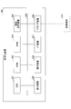
- FIG. 1 is a diagram illustrating an example of a functional configuration of the encoding device.
- FIG. 2 is a diagram illustrating an example of a hardware configuration of the encoding device.
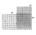
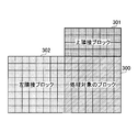
- FIG. 3 is a diagram illustrating an example of a processing target block that is processed in the intra prediction unit of the encoding device.
- FIG. 4A is a first diagram illustrating a reference direction of intra prediction in an angle prediction mode, which is performed in the intra prediction unit of the encoding device.
- FIG. 4B is a second diagram illustrating a reference direction of the intra prediction in the angle prediction mode, which is performed in the intra prediction unit of the encoding device.
- FIG. 5A is a first diagram illustrating details of a functional configuration of an intra prediction unit of the encoding device.
- FIG. 5A is a first diagram illustrating details of a functional configuration of an intra prediction unit of the encoding device.
- FIG. 5B is a second diagram illustrating the details of the functional configuration of the intra prediction unit of the encoding device.
- FIG. 6 is a diagram illustrating details of a functional configuration of the intra reference direction estimating unit of the encoding device according to the first embodiment.
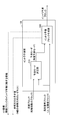
- FIG. 7 is a flowchart illustrating a flow of the MSB prediction value calculation process by the intra reference direction estimation unit of the encoding device according to the first embodiment.
- FIG. 8A is a first diagram illustrating a specific example of the MSB predicted value calculation process.
- FIG. 8B is a second diagram illustrating a specific example of the MSB predicted value calculation process.
- FIG. 8C is a third diagram illustrating a specific example of the MSB predicted value calculation process.
- FIG. 8A is a first diagram illustrating a specific example of the MSB predicted value calculation process.
- FIG. 8B is a second diagram illustrating a specific example of the MSB predicted value calculation process.
- FIG. 8C is a third diagram illustrating a
- FIG. 9 is a fourth diagram illustrating a specific example of the MSB predicted value calculation process.
- FIG. 10 is a fifth diagram illustrating a specific example of the MSB prediction value calculation process.
- FIG. 11A is a sixth diagram illustrating a specific example of the MSB prediction value calculation process.
- FIG. 11B is a seventh diagram illustrating a specific example of the MSB prediction value calculation process.
- FIG. 12A is a first diagram illustrating details of a functional configuration of a variable-length encoding unit of the encoding device.
- FIG. 12B is a second diagram illustrating the details of the functional configuration of the variable-length encoding unit of the encoding device.
- FIG. 13 is a diagram illustrating an example of a functional configuration of the decoding device.
- FIG. 12A is a first diagram illustrating details of a functional configuration of a variable-length encoding unit of the encoding device.
- FIG. 12B is a second diagram illustrating the details of the functional configuration of the variable-
- FIG. 14 is a diagram illustrating details of a functional configuration of the stream decoding unit of the decoding device.
- FIG. 15 is a diagram illustrating details of a functional configuration of an intra reference direction estimation unit of the decoding device.
- FIG. 16 is a diagram illustrating details of a functional configuration of an intra reference direction estimating unit of the encoding device according to the second embodiment.
- FIG. 17A is a first diagram illustrating a specific example of a table stored in the table storage unit.
- FIG. 17B is a second diagram illustrating a specific example of the table stored in the table storage unit.
- FIG. 17C is a third diagram illustrating a specific example of the table stored in the table storage unit.
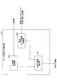
- FIG. 18 is a flowchart illustrating a flow of an MSB prediction value calculation process performed by the intra reference direction estimation unit of the encoding device according to the second embodiment.
- the encoding device and the decoding device in the intra prediction in the angle prediction mode, when encoding a value indicating the reference direction, Estimate a prediction value (binary signal) of the reference direction in the processing target block based on the value indicating the reference direction selected when intra prediction in the angle prediction mode is performed in the adjacent block.
- the difference (exclusive OR) between the binary signal of the value indicating the reference direction and the predicted value in the reference direction is arithmetically coded to reduce the code amount.
- the occurrence probability (the predicted value of the reference direction and the reference direction) (The rate of coincidence of the value indicating ⁇ with the binary signal).
- the amount of code at the time of generating a coded stream can be reduced.
- FIG. 1 is a diagram illustrating an example of a functional configuration of an encoding device.
- the coding apparatus 100 includes a block division unit 101, an orthogonal transformation unit 102, a quantization unit 103, an inverse quantization unit 104, an inverse orthogonal transformation unit 105, a loop filter unit 106, and a local decoded image memory 107.
- the encoding device 100 includes an intra reference direction estimation unit 110, a variable length encoding unit 111, and an encoding control unit 112.
- the block dividing unit 101 generates an original block by dividing each frame included in the input moving image data into a plurality of blocks.
- the orthogonal transformation unit 102 calculates a prediction error block, which is a difference between an original block generated by the block division unit 101 and a prediction block generated by a prediction unit (intra prediction unit 108 or inter prediction unit 109) described later. get. Further, the orthogonal transform unit 102 performs an orthogonal transform process on the obtained prediction error block, and calculates a transform coefficient.
- the quantization unit 103 quantizes the transform coefficient calculated by the orthogonal transform unit 102, and calculates a quantized transform coefficient.
- the inverse quantization unit 104 inversely quantizes the quantized transform coefficient calculated by the quantization unit 103, and calculates an inverse quantized transform coefficient.
- the inverse orthogonal transform unit 105 performs an inverse orthogonal transform on the inverse quantized transform coefficient calculated in the inverse quantization unit 104, and generates a prediction error decoding block.
- the prediction error decoded block generated by the inverse orthogonal transform unit 105 is added with a prediction block generated by a prediction unit (an intra prediction unit 108 or an inter prediction unit 109), which will be described later. Is generated.
- the ⁇ ⁇ ⁇ ⁇ loop filter unit 106 performs a filtering process on the generated locally decoded block using a deblocking filter or the like, and stores the locally decoded block after the filtering process in the locally decoded image memory 107.
- the intra prediction unit 108 performs intra prediction and generates an intra prediction block.
- the intra prediction unit 108 performs intra prediction in the angle prediction mode.
- the intra prediction unit 108 is a locally decoded block on which intra prediction has been performed, and is adjacent to the upper side or the left side of the processing target block. Refers to a block.
- the intra prediction unit 108 notifies the intra reference direction estimation unit 110 of “information on intra prediction” when performing intra prediction in a block adjacent to the upper side or the left side of the processing target block.
- the intra prediction unit 108 notifies the “reference information” (X coordinate, Y coordinate) of each region in the processing target block to the intra reference direction estimation unit 110.
- the intra prediction unit 108 notifies the variable-length encoding unit 111 of the “value indicating the reference direction” selected when performing intra prediction in the angle prediction mode in the block to be processed.
- the inter prediction unit 109 performs inter prediction on each processing target block of the original block using a locally decoded block in another frame, and generates an inter prediction block.
- either the intra prediction block generated by the intra prediction unit 108 or the inter prediction block generated by the inter prediction unit 109 is selected.
- the selected prediction block is used for calculating a difference between the original block and the processing target block, and is input to the orthogonal transformation unit 102 as a prediction error block.
- description will be made assuming that an intra prediction block is selected as a prediction block.
- the intra reference direction estimating unit 110 is an example of an estimating unit.
- the intra reference direction estimation unit 110 acquires information on the position notified from the intra prediction unit 108. Further, the intra reference direction estimating unit 110 acquires information related to intra prediction notified from the intra prediction unit 108.
- the intra reference direction estimating unit 110 estimates a predicted value of the reference direction in the processing target block based on the acquired information on the position or the acquired information on the intra prediction. Further, the intra reference direction estimating unit 110 notifies the variable length coding unit 111 of the estimated prediction value of the reference direction.
- variable-length encoding unit 111 is an example of an encoding unit, and encodes the quantized transform coefficient calculated by the quantization unit 103.
- variable-length coding unit 111 binarizes the value indicating the reference direction notified from the intra prediction unit 108, and compares the value of the most significant bit of the binary signal with the predicted value of the reference direction (exclusive). Logical OR). Further, the variable length coding unit 111 arithmetically codes the binary signal including the comparison result (exclusive OR).
- variable-length coding unit 111 generates a coded stream for intra prediction in the angle prediction mode, and outputs the coded stream to a decoding device (not illustrated).
- the encoding control unit 112 determines a quantization value so that the information amount (generated information amount) of the encoded stream generated by the variable-length encoding unit 111 becomes a predetermined information amount. Notice. As a result, the quantization unit 103 calculates a quantized transform coefficient using the notified quantization value.
- FIG. 2 is a diagram illustrating an example of a hardware configuration of the encoding device.
- the encoding device 100 includes a CPU (Central Processing Unit) 201, a ROM (Read Only Memory) 202, and a RAM (Random Access Memory) 203.
- the CPU 201, the ROM 202, and the RAM 203 form a so-called computer.
- the encoding device 100 includes an auxiliary storage device 204, a display device 205, an operation device 206, an I / F (Interface) device 207, and a drive device 208.
- the hardware of the encoding device 100 is mutually connected via a bus 209.
- the CPU 201 is an arithmetic device that executes various programs (for example, an encoding program) installed in the auxiliary storage device 204.
- the ROM 202 is a nonvolatile memory.
- the ROM 202 functions as a main storage device that stores various programs, data, and the like necessary for the CPU 201 to execute various programs installed in the auxiliary storage device 204.
- the ROM 202 functions as a main storage device that stores a boot program such as a BIOS (Basic Input / Output System) and an EFI (Extensible Firmware Interface).
- BIOS Basic Input / Output System
- EFI Extensible Firmware Interface
- the RAM 203 is a volatile memory such as a DRAM (Dynamic Random Access Memory) and an SRAM (Static Random Access Memory).
- the RAM 203 functions as a main storage device that provides a work area that is developed when the CPU 201 executes various programs installed in the auxiliary storage device 204.
- the auxiliary storage device 204 is an auxiliary storage device that stores various programs and data used when the various programs are executed.
- the display device 205 is a display device that displays the internal state of the encoding device 100.
- the operation device 206 is an input device for an administrator of the encoding device 100 to input various instructions to the encoding device 100.
- the I / F device 207 is a connection device for connecting to another device (for example, a decoding device) and transmitting and receiving a coded stream to and from the other device.
- another device for example, a decoding device
- the drive device 208 is a device for setting the recording medium 210.
- the recording medium 210 here includes a medium for optically, electrically, or magnetically recording information, such as a CD-ROM, a flexible disk, and a magneto-optical disk.
- the recording medium 210 may include a semiconductor memory such as a ROM or a flash memory for electrically recording information.
- the various programs to be installed in the auxiliary storage device 204 are installed, for example, by setting the distributed recording medium 210 to the drive device 208 and reading out the various programs recorded on the recording medium 210 by the drive device 208. Is done.
- various programs installed in the auxiliary storage device 204 may be installed by being downloaded from a network (not shown).
- FIG. 3 is a diagram illustrating an example of a processing target block that is processed in the intra prediction unit of the encoding device.
- the intra prediction unit 108 refers to a coded block (that is, a local decoding block) adjacent to the processing target block 300 in a frame including the processing target block 300, and in the processing target block 300, Predict the pixel value of a pixel.
- FIG. 3 shows an upper adjacent block 301 adjacent to the processing target block 300 on the upper side and a left adjacent block 302 adjacent to the left of the local decoding block.
- FIGS. 4A and 4B are first and second diagrams illustrating a reference direction of intra prediction in an angle prediction mode, which is performed in an intra prediction unit of the encoding device.
- H.265 / HEVC 33 reference directions are defined as reference directions that can be referred to when performing intra prediction in the angle prediction mode.
- next-generation video codec under consideration the next-generation codec following H.265 / HEVC
- the number of reference directions is expanded to 65.
- FIG. 4B shows 65 reference directions assumed in the next-generation codec using 65 arrows. The meaning of each arrow is the same as in FIG. 4A.
- 5A and 5B are first and second diagrams illustrating details of the functional configuration of the intra prediction unit of the encoding device.
- the intra prediction unit 108 includes a prediction mode determination unit 510 and an intra prediction block generation unit 520.
- the prediction mode determination unit 510 generates a prediction pixel value by intra prediction in each of three types of prediction modes (planar prediction, DC prediction, and angle prediction), and determines a prediction mode in which a prediction error is minimized. For example, for intra prediction in the angle prediction mode, a prediction pixel value is generated using a processing target block, an upper adjacent block and a left adjacent block, and a prediction error is calculated.
- the prediction mode determination unit 510 notifies the intra prediction block generation unit 520 of the determined prediction mode (here, the angle prediction mode).
- the intra prediction block generation unit 520 Upon receiving the notification from the prediction mode determination unit 510, the intra prediction block generation unit 520 generates an intra prediction block by referring to the selected reference direction for the processing target block, and outputs the generated intra prediction block. At this time, the intra-prediction block generation unit 520 notifies the variable-length coding unit 111 of a value indicating the selected reference direction (a value indicating any of the N reference directions).
- the intra prediction block generation unit 520 notifies the intra reference direction estimating unit 110 of information (X coordinate, Y coordinate) regarding the position of each region in the processing target block in the processing target block.
- the intra prediction block generation unit 520 notifies the intra reference direction estimation unit 110 of information on intra prediction when intra prediction is performed on the upper neighboring block or the left neighboring block of the processing target block.
- FIG. 5B is a diagram showing a state in which one reference direction is selected in the processing target block 300 in the intra prediction in the angle prediction mode. Specifically, a state in which the eleventh reference direction (arrow 501) is selected from the 16 reference directions is shown.
- the intra prediction block generation unit 520 notifies the variable length coding unit 111 of “11” as a value indicating the reference direction. In addition, the intra-prediction block generation unit 520 notifies the X- and Y-coordinates of the position of the starting point of the arrow 501 to the intra-reference-direction estimating unit 110 as information on the position.
- the intra prediction block generation unit 520 sends, to the intra reference direction estimation unit 110, a value indicating the reference direction selected when performing intra prediction in the angle prediction mode in the upper or left adjacent block of the processing target block 300. Notice.
- the intra prediction block generation unit 520 holds information related to intra prediction when intra prediction is performed in the block 300 to be processed. Then, when intra prediction in the angle prediction mode is performed on another processing target block, the intra prediction block generation unit 520 notifies the intra reference direction estimation unit 110 as information on intra prediction of an adjacent block.
- FIG. 6 is a diagram illustrating details of a functional configuration of the intra reference direction estimating unit of the encoding device according to the first embodiment.
- the intra reference direction estimation unit 110 includes an XY coordinate acquisition unit 610, an adjacent block information acquisition unit 620, and an MSB predicted value estimation unit 630.
- XY coordinate acquisition section 610 acquires information (X coordinate, Y coordinate) regarding the position of each area in the block to be processed from intra prediction section 108 and notifies MSB predicted value estimation section 630.
- the adjacent block information acquisition unit 620 acquires information related to intra prediction of an adjacent block adjacent to the processing target block.
- the information regarding the intra prediction of the adjacent block acquired by the adjacent block information acquisition unit 620 includes: That intra prediction in the angle prediction mode has been performed in the upper adjacent block, A value indicating the reference direction selected in each region of the upper adjacent block, The number of areas in the upper adjacent block, That intra prediction in the angle prediction mode has been performed in the left adjacent block, A value indicating the reference direction selected in each region of the left adjacent block, The number of regions in the left adjacent block, Etc. shall be included.
- the neighboring block information acquiring unit 620 notifies the MSB predicted value estimating unit 630 of information on the acquired intra prediction of the neighboring block.
- the MSB predicted value estimating unit 630 is based on the information on the position of each area to be processed notified from the XY coordinate obtaining unit 610 and the information on intra prediction of the adjacent block notified from the adjacent block information obtaining unit 620. To estimate the MSB prediction value.
- the MSB prediction value is a prediction value in the reference direction, and indicates a value corresponding to the most significant bit (MSB) estimated when the value indicating the reference direction is binarized, which is estimated in the processing target block.
- MSB most significant bit
- the MSB prediction value estimation unit 630 estimates whether the reference direction estimated in the processing target block at the time of intra prediction in the angle prediction mode belongs to at least the horizontal group or the vertical group. .
- the MSB predicted value estimating unit 630 estimates “0” as the MSB predicted value.
- the MSB predicted value estimating unit 630 estimates “1” as the MSB predicted value.
- the MSB predicted value estimating unit 630 estimates “0” as the MSB predicted value.
- the MSB predicted value estimating unit 630 estimates “1” as the MSB predicted value.
- the MSB prediction value estimation section 630 outputs the estimated MSB prediction value to the variable length coding section 111.
- FIG. 7 is a flowchart illustrating a flow of the MSB prediction value calculation process performed by the intra reference direction estimation unit of the encoding device according to the first embodiment.
- 8A to 11B are first to seventh diagrams showing specific examples of the MSB predicted value calculation processing.
- step S701 the MSB predicted value estimating unit 630 acquires information on intra prediction of an adjacent block notified from the adjacent block information acquiring unit 620. Further, the MSB prediction value estimating unit 630 determines whether or not intra prediction has been performed in the upper adjacent block of the processing target block based on the acquired information on the intra prediction of the adjacent block (the thick line frame in FIG. 8A). reference).
- step S701 If it is determined in step S701 that intra prediction has not been performed (NO in step S701), the process proceeds to step S707.
- step S701 determines whether intra prediction has been performed (YES in step S702) or not. If it is determined in step S701 that intra prediction has been performed (YES in step S702), the process advances to step S702.
- step S702 the MSB prediction value estimation unit 630 determines whether or not intra prediction has been performed on the left neighboring block of the processing target block based on the acquired information on the intra prediction of the neighboring block (see FIG. 8B). (See bold frame).
- step S702 If it is determined in step S702 that intra prediction has not been performed (NO in step S702), the process proceeds to step S708. On the other hand, if it is determined in step S702 that intra prediction has been performed (YES in step S702), the process advances to step S703.
- step S703 the MSB prediction value estimating unit 630 determines whether or not the intra prediction performed on the upper neighboring block or the left neighboring block is in the angle prediction mode based on the acquired information on the intra prediction of the neighboring block ( (See the thick frame in FIG. 8C).
- step S703 when it is determined that neither the intra prediction performed in the upper adjacent block nor the left adjacent block is in the angle prediction mode (NO in step S703), the process proceeds to step S704.
- step S ⁇ b> 704 the MSB predicted value estimating unit 630 acquires, from the XY coordinate acquiring unit 610, information on the position of each area in the processing target block. Further, the MSB predicted value estimating unit 630 determines whether the position of each region in the processing target block is on the upper right or lower left based on the information on the acquired position.
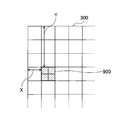
- step S704 it is determined whether or not the X coordinate of the processing target area 900 is larger than the Y coordinate (see FIG. 9). If it is determined in step S704 that the X coordinate is larger than the Y coordinate (YES in step S704), the process advances to step S708. If it is determined in step S704 that the X coordinate is equal to or smaller than the Y coordinate (NO in step S704), the process proceeds to step S707.
- step S703 determines whether the current mode is the angle prediction mode (YES in step S703). If it is determined in step S703 that the current mode is the angle prediction mode (YES in step S703), the process advances to step S705. In step S705, the MSB prediction value estimating unit 630 calculates the average angle Ang from the following equation based on the acquired information on the intra prediction of the adjacent block.
- Ang top is a value indicating the reference direction selected in each region of the upper adjacent block, and “0” is input when the mode is not the angle prediction mode.
- Ang left is a value indicating the reference direction selected in each area of the left adjacent block, and “0” is input when the mode is not the angle prediction mode.
- nbAng Modes is the number of blocks for which intra prediction has been performed in the angle prediction mode between the upper adjacent block and the left adjacent block, and "1" or "2" is input.
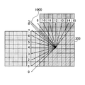
- the MSB predicted value estimating unit 630 determines whether or not the average angle Ang calculated in step S705 satisfies a predetermined condition. Specifically, the MSB prediction value estimating unit 630 determines that the average angle Ang calculated in step S705 is smaller than the angle up to the uppermost row of the left adjacent block of the processing target block when viewed from the position of the processing target area. It is determined whether it is larger (see arrow 1000 in FIG. 10). Accordingly, the MSB prediction value estimation unit 630 can determine whether the reference direction of each region in the processing target block is either the horizontal direction or the vertical direction.
- step S706 If it is determined in step S706 that the average angle Ang does not satisfy the predetermined condition (any of the horizontal directions) (NO in step S706), the process proceeds to step S707.
- the process proceeds to step S707.
- the reference direction specified by the average angle Ang is indicated by an arrow 1101 when viewed from the position of the processing target area, the angle is smaller than the arrow 1000 in FIG. 10.
- the MSB predicted value estimating unit 630 determines that the predetermined condition is not satisfied (the reference direction is the horizontal direction), and proceeds to step S707.
- step S706 when it is determined in step S706 that the average angle Ang satisfies the predetermined condition (in the case of YES in step S706), the process proceeds to step S708.
- the process proceeds to step S708.
- the reference direction specified by the average angle Ang is indicated by an arrow 1102 as viewed from the processing target area, the angle is larger than the arrow 1000 in FIG. 10.
- the MSB prediction value estimating unit 630 determines that a predetermined condition is satisfied (the reference direction is the vertical direction), and proceeds to step S708.
- MSB predicted value estimating section 630 inputs “1” to the MSB predicted value.
- the MSB predicted value estimating unit 630 inputs “0” as the MSB predicted value.
- 12A and 12B are first and second diagrams illustrating details of the functional configuration of the variable-length encoding unit of the encoding device.
- variable-length coding unit 111 includes a binarizing unit 1210, an exclusive-OR calculating unit 1220, and an arithmetic coding unit 1230.
- Binarization section 1210 acquires a value indicating the reference direction (a value indicating any of the N reference directions) output from intra prediction section 108.
- the binarizing unit 1210 binarizes the acquired value indicating the reference direction.
- the exclusive OR calculation unit 1220 obtains, from the binarization unit 1210, a binary signal indicating the reference direction. Further, exclusive OR calculation section 1220 obtains the MSB prediction value from intra reference direction estimation section 110.
- the exclusive OR calculating unit 1220 calculates the exclusive OR of the bit value of the most significant bit of the binary signal of the value indicating the reference direction and the MSB prediction value, and notifies the arithmetic coding unit 1230 of the result. . In addition, exclusive OR calculation section 1220 notifies arithmetic coding section 1230 of the value of the bit string other than the most significant bit in the binary signal indicating the reference direction.
- the arithmetic coding unit 1230 arithmetically codes the exclusive OR of the bit value of the most significant bit notified from the exclusive OR calculation unit 1220 and the MSB prediction value in the context mode. Arithmetic encoding section 1230 arithmetically encodes the values of bit strings other than the most significant bit in the bypass mode.
- binarization section 1210 instructs exclusive OR calculation section 1220 to refer to “1011” is reported as a binary signal indicating the direction (see arrow 1102).
- the exclusive OR calculation unit 1220 has obtained “1” as the MSB prediction value from the intra reference direction estimation unit 110.
- the exclusive OR calculation unit 1220 arithmetically calculates “0” as the exclusive OR of the bit value (“1”) of the most significant bit of “1011” and the MSB prediction value (“1”). Notify the encoding unit 1230.
- the exclusive OR calculation unit 1220 notifies the arithmetic coding unit 1230 of the value of the bit string other than the most significant bit (“011”) of the binary signal “1011” indicating the reference direction. I do.
- the arithmetic encoding unit 1230 arithmetically encodes “1” in the context mode and arithmetically encodes “011” in the bypass mode.
- a decoding program is installed in the decoding device, and by executing the program, the decoding device decodes the encoded stream received from the encoding device 100 via a network (not shown), and converts the moving image data. Output.
- FIG. 13 is a diagram illustrating an example of a functional configuration of the decoding device.
- the decoding device 1300 includes a stream decoding unit 1301, an inverse quantization unit 1302, an inverse orthogonal transform unit 1303, a loop filter unit 1304, and a local decoded image memory 1305.
- decoding apparatus 1300 includes intra prediction section 1306, inter prediction section 1307, and intra reference direction estimation section 1308.
- the stream decoding unit 1301 is an example of a decoding unit.
- the stream decoding unit 1301 decodes the encoded stream by the CABAC decoding method, and notifies the inverse quantization unit 1302 of the quantization coefficient of the processing target block. Also, the stream decoding unit 1301 obtains information on the position of each area in the processing target block by decoding the encoded stream, and notifies the intra reference direction estimation unit 1308 of the information.
- the stream decoding unit 1301 acquires the MSB prediction value notified from the intra reference direction estimation unit 1308, and outputs a value indicating the reference direction calculated using the acquired MSB prediction value to the intra prediction unit 1306.
- the inverse quantization unit 1302 performs inverse quantization on the quantization coefficient notified from the stream decoding unit 1301, and calculates an inverse quantization coefficient. In addition, the inverse quantization unit 1302 notifies the inverse orthogonal transform unit 1303 of the calculated inverse quantization coefficient.
- the inverse orthogonal transform unit 1303 performs an inverse orthogonal transform on the inverse quantization coefficient notified from the inverse quantization unit 1302, and generates a prediction error block.
- a local decoding block is generated by adding a prediction block generated by a prediction unit (an intra prediction unit 1306 or an inter prediction unit 1307) described later to the prediction error block generated by the inverse orthogonal transform unit 1303. You.
- the loop filter unit 1304 performs a filtering process on the generated local decoding block using a deblocking filter or the like, and outputs the local decoding block after the filtering process in units of frames, thereby outputting moving image data. I do.
- the loop filter unit 1304 stores the locally decoded block after the filtering process in the locally decoded image memory 1305.
- the intra prediction unit 1306 is an example of a prediction unit, performs intra prediction, and generates an intra prediction block. Specifically, the intra prediction unit 1306 acquires a value indicating the reference direction from the stream decoding unit 1301. In addition, based on the acquired value indicating the reference direction, the intra prediction unit 1306 uses the locally decoded image memory 1305 to generate a locally decoded block for which intra prediction has been performed and which is located above or to the left of the block to be processed. To perform intra prediction.
- the inter prediction unit 1307 performs inter prediction on the block to be processed using a locally decoded block in another frame, and generates an inter prediction block.
- one of the intra prediction unit 1306 and the inter prediction unit 1307 is executed based on information obtained by decoding the encoded stream.
- the intra reference direction estimating unit 1308 is an example of an estimating unit.
- the intra reference direction estimation unit 1308 acquires information on the position notified from the stream decoding unit 1301. Further, the intra reference direction estimating unit 1308 acquires information on intra prediction notified from the intra prediction unit 1306.
- the intra reference direction estimating unit 1308 estimates the MSB prediction value in the processing target block based on the acquired information on the position or the acquired information on the intra prediction. Further, intra reference direction estimation section 1308 outputs the estimated MSB prediction value to stream decoding section 1301.
- FIG. 14 is a diagram illustrating details of a functional configuration of the stream decoding unit of the decoding device.
- the stream decoding unit 1301 includes an arithmetic decoding unit 1401, a reference direction calculation unit 1402, and a multi-level conversion unit 1403.
- the arithmetic decoding unit 1401 decodes the encoded stream to obtain information on the position of each region of the processing target block, and notifies the intra reference direction estimating unit 1308 of the information.
- the arithmetic decoding unit 1401 decodes the coded stream to convert the value indicating the reference direction into a binary signal, and the bit value of the most significant bit is an exclusive logical value of the MSB prediction value. Obtain a binary signal that is the sum. Further, the arithmetic decoding unit 1401 notifies the reference direction calculation unit 1402 of the obtained binary signal.
- the reference direction calculation unit 1402 calculates a binary signal of a value indicating the reference direction using the binary signal notified from the arithmetic decoding unit 1401 and the MSB prediction value notified from the intra reference direction estimation unit 1308. . Further, reference direction calculation section 1402 notifies binary signal of value indicating the calculated reference direction to multilevel conversion section 1403.
- the multi-leveling section 1403 multi-values the binary signal of the value indicating the reference direction notified from the reference direction calculating section 1402 to calculate a value indicating the reference direction, and notifies the intra prediction section 1306 of the value.
- FIG. 15 is a diagram illustrating details of a functional configuration of an intra reference direction estimation unit of the decoding device.
- the intra reference direction estimation unit 1308 of the decoding device 1300 includes an XY coordinate acquisition unit 1510, an adjacent block information acquisition unit 1520, and an MSB prediction value estimation unit 1530.
- the function of the intra reference direction estimation unit 1308 of the decoding device 1300 is the same as the function (XY coordinate acquisition unit 610 to MSB prediction value estimation unit 630) of the intra reference direction estimation unit 110 of the encoding device 100.
- the description is omitted.
- the encoding device and the decoding device at the time of intra prediction in the angle prediction mode, based on information about intra prediction when intra prediction is performed in a neighboring block. To estimate the MSB prediction value.
- the value indicating the reference direction selected when the intra prediction is performed is binarized, and the top level of the binary signal is converted. Arithmetic coding is performed on the exclusive OR of the bit and the MSB prediction value.
- the encoding device and the decoding device it is possible to increase the occurrence probability of the most significant bit when arithmetically encoding a binary signal having a value indicating the reference direction. .
- the MSB predicted value is calculated according to the flowchart shown in FIG. 7 .
- the method of calculating the MSB predicted value is not limited to this.
- a table is prepared in which MSB prediction values corresponding to information regarding intra prediction of an adjacent block and information regarding the position of each region to be processed are defined in advance.
- the intra reference direction estimating unit may calculate the MSB prediction value based on the table.
- the second embodiment will be described focusing on differences from the first embodiment.
- FIG. 16 is a diagram illustrating details of a functional configuration of an intra reference direction estimating unit of the encoding device according to the second embodiment.
- the difference from the intra reference direction estimation unit 110 of the encoding device according to the first embodiment described using FIG. 6 is that the intra reference direction estimation unit 1600 includes an MSB prediction value acquisition unit 1630. .
- the MSB prediction value acquisition unit 1630 acquires the information on the position notified from the XY coordinate acquisition unit 610 and the information on the intra prediction of the adjacent block notified from the adjacent block information acquisition unit 620.
- the MSB prediction value acquisition unit 1630 acquires the MSB prediction value corresponding to the acquired information on the position and the acquired information on the intra prediction of the adjacent block from the table storage unit 1640 which is an example of the storage unit.
- 17A to 17C are first to third diagrams showing specific examples of tables stored in the table storage unit.
- 17A to 17C show a case where 16 reference directions (IdxT) are defined in the upper adjacent block and 16 reference directions (IdxL) are defined in the left adjacent block with respect to the processing target block. Is shown.
- the 16 reference directions defined in the upper adjacent block are divided into four ranges (0 ⁇ IdxT ⁇ 4, 5 ⁇ IdxT ⁇ 7, 8 ⁇ IdxT ⁇ 12, 13 ⁇ IdxT ⁇ 15).
- the 16 reference directions defined in the left adjacent block are divided into four ranges (0 ⁇ IdxL ⁇ 4, 5 ⁇ IdxL ⁇ 7, 8 ⁇ IdxL ⁇ 12, 13 ⁇ IdxL). ⁇ 15).
- Each table defines the MSB prediction value in association with each range.
- the table shown in FIG. 17A shows the MSB predicted value when the X coordinate and the Y coordinate of the processing target area are equal.
- the table shown in FIG. 17B shows the MSB predicted value when the X coordinate and the Y coordinate of the processing target area have a relationship of “X coordinate> Y coordinate”.
- the table shown in FIG. 17C shows the MSB predicted value when the X coordinate and the Y coordinate of the processing target area have a relationship of “X coordinate ⁇ Y coordinate”.
- the tables shown in FIGS. 17A to 17C are also stored in the table storage unit on the decoding device side, and the MSB prediction value obtaining unit on the decoding device obtains the MSB prediction value by the same processing. I do.
- FIG. 18 is a flowchart illustrating a flow of an MSB prediction value calculation process in the intra reference direction estimation unit of the encoding device according to the second embodiment.
- step S1801 the adjacent block information acquisition unit 620 acquires information on intra prediction of an upper adjacent block from information on intra prediction of an adjacent block.
- step S1802 the adjacent block information acquisition unit 620 acquires information on intra prediction of a left adjacent block from information on intra prediction of an adjacent block.
- step S1803 the XY coordinate acquisition unit 610 acquires information (X coordinate, Y coordinate) indicating the position of the processing target area.
- step S1804 the MSB predicted value obtaining unit 1630 obtains the MSB predicted value by referring to the tables (FIGS. 17A to 17C and the like) in the table storage unit 1640 based on the information obtained in steps S1801 to S1803.
- the MSB prediction value corresponding to the information regarding the intra prediction of the adjacent block and the information regarding the position of each region to be processed. Is prepared in advance. Then, at the time of intra prediction in the angle prediction mode, the MSB prediction value of each region of the processing target block is calculated based on the table.
- the encoding device and the decoding device as in the first embodiment, when the binary signal having the value indicating the reference direction is arithmetically encoded, The probability of occurrence can be increased. As a result, it is possible to increase the probability that the arithmetic coding in the context mode is realized for the most significant bit instead of the arithmetic coding in the bypass mode, thereby reducing the code amount when the coded stream is generated.
- the table storage unit is provided in each of the intra reference direction estimation unit of the encoding device and the intra reference direction estimation unit of the decoding device, and the same table is stored in advance.
- the table sharing method is not limited to this.
- a table may be dynamically determined on the encoding device side based on statistics or the like, and the determined table may be added to the header of the encoded stream and transmitted.
- the header used at this time is, for example, H.264.
- “slice_segmenty_header ()” or the like is used.
- the encoding device and the decoding device have been described as separate devices, but the encoding device and the decoding device may be an integrated device.
- the present invention is not limited to the configuration shown here, such as a combination of the configuration described in the above embodiment with other elements. These points can be changed without departing from the spirit of the present invention, and can be appropriately determined according to the application form.
- coding device 108 intra prediction unit 110: intra reference direction estimating unit 111: variable length coding unit 300: block 301 to be processed: upper adjacent block 302: left adjacent block 510: prediction mode determination unit 520: intra prediction Block generation unit 610: XY coordinate acquisition unit 620: Neighbor block information acquisition unit 630: MSB predicted value estimation unit 1210: Binarization unit 1220: Exclusive OR calculation unit 1230: Arithmetic encoding unit 1300: Decoding device 1301: Stream Decoding unit 1306: Intra prediction unit 1308: Intra reference direction estimating unit 1401: Arithmetic decoding unit 1402: Reference direction calculating unit 1403: Multi-value conversion unit 1510: XY coordinate acquisition unit 1520: Neighbor block information obtaining unit 1530: MSB prediction value estimation unit 1600: Intra reference direction estimation unit 1630: MSB prediction value obtaining unit
Landscapes
- Engineering & Computer Science (AREA)
- Multimedia (AREA)
- Signal Processing (AREA)
- Compression Or Coding Systems Of Tv Signals (AREA)
Abstract
角度予測モードによるイントラ予測において、符号量を削減する。符号化装置は、処理対象のブロックに隣接する隣接ブロックにおいて、角度予測モードによるイントラ予測が行われた際に選択された参照方向を示す値に基づいて、前記処理対象のブロックにおいて、角度予測モードによるイントラ予測が行われる際に選択される参照方向の予測値を推定する推定部と、前記処理対象のブロックにおいて、角度予測モードによるイントラ予測が行われた際に選択された参照方向を示す値を2値化し、2値信号の最上位ビットの値と前記予測値との対比結果について算術符号化を行う符号化部とを有する。
Description
本発明は、符号化装置、符号化方法、符号化プログラム、復号装置、復号方法及び復号プログラムに関する。
動画像データの圧縮符号化に関する国際標準として、H.265/HEVCが知られている。H.265/HEVCでは、イントラ予測とインタ予測の2つの予測方法が採用されており、イントラ予測には、更に、3種類の予測モード(プレーナ予測、直流予測、角度予測)が規定されている。
このうち、角度予測モードによるイントラ予測では、予め定義されたN個(例えば、N=33)の異なる角度(参照方向)のうち、選択された参照方向を参照することで、処理対象のブロックの画素値を予測する。
角度予測モードによるイントラ予測の場合、符号化装置では、参照方向の数(N個)に応じたビット数の2値信号を、生起確率モデルを用いて算術符号化することで、符号化ストリームを生成する。
ここで、従来の符号化装置では、生起確率の推定が困難な2値信号については、生起確率を0.5に固定するバイパスモードを用いて算術符号化を行っていた。このため、かかる2値信号については、符号化ストリーム生成時の符号量の削減が十分ではないといった問題があった。
一つの側面では、角度予測モードによるイントラ予測において、符号量を削減することを目的としている。
一態様によれば、符号化装置は、
処理対象のブロックに隣接する隣接ブロックにおいて、角度予測モードによるイントラ予測が行われた際に選択された参照方向を示す値に基づいて、前記処理対象のブロックにおいて、角度予測モードによるイントラ予測が行われる際に選択される参照方向の予測値を推定する推定部と、
前記処理対象のブロックにおいて、角度予測モードによるイントラ予測が行われた際に選択された参照方向を示す値を2値化し、2値信号の最上位ビットの値と前記予測値との対比結果について算術符号化を行う符号化部とを有する。
処理対象のブロックに隣接する隣接ブロックにおいて、角度予測モードによるイントラ予測が行われた際に選択された参照方向を示す値に基づいて、前記処理対象のブロックにおいて、角度予測モードによるイントラ予測が行われる際に選択される参照方向の予測値を推定する推定部と、
前記処理対象のブロックにおいて、角度予測モードによるイントラ予測が行われた際に選択された参照方向を示す値を2値化し、2値信号の最上位ビットの値と前記予測値との対比結果について算術符号化を行う符号化部とを有する。
角度予測モードによるイントラ予測において、符号量を削減することができる。
はじめに、以下の各実施形態に係る符号化装置及び復号装置の概要について説明する。以下の各実施形態に係る符号化装置及び復号装置は、角度予測モードによるイントラ予測において、参照方向を示す値を符号化する際、
・隣接ブロックにて角度予測モードによるイントラ予測が行われた際に選択された参照方向を示す値に基づいて、処理対象のブロックにおける参照方向の予測値(2値信号)を推定する。そして、参照方向を示す値の2値信号と、参照方向の予測値との差(排他的論理和)を算術符号化することで、符号量を削減する。
・参照方向の予測値として、参照方向を示す値の2値信号の最上位ビット(MSB(Most Significant Bit))に対応する値を推定することで、生起確率(参照方向の予測値と参照方向を示す値の2値信号との一致率)を上げる。そして、参照方向を示す値の2値信号を算術符号化するにあたり、最上位ビットについては、バイパスモードによる算術符号化に代えてコンテキストモードによる算術符号化を実現する確率を上げることで、符号量を削減する。
・隣接ブロックにて角度予測モードによるイントラ予測が行われた際に選択された参照方向を示す値に基づいて、処理対象のブロックにおける参照方向の予測値(2値信号)を推定する。そして、参照方向を示す値の2値信号と、参照方向の予測値との差(排他的論理和)を算術符号化することで、符号量を削減する。
・参照方向の予測値として、参照方向を示す値の2値信号の最上位ビット(MSB(Most Significant Bit))に対応する値を推定することで、生起確率(参照方向の予測値と参照方向を示す値の2値信号との一致率)を上げる。そして、参照方向を示す値の2値信号を算術符号化するにあたり、最上位ビットについては、バイパスモードによる算術符号化に代えてコンテキストモードによる算術符号化を実現する確率を上げることで、符号量を削減する。
この結果、以下の各実施形態に係る符号化装置及び復号装置によれば、角度予測モードによるイントラ予測において、符号化ストリーム生成時の符号量を削減することができる。
以下、各実施形態について添付の図面を参照しながら説明する。なお、本明細書及び図面において、実質的に同一の機能構成を有する構成要素については、同一の符号を付することにより重複した説明を省略する。
[第1の実施形態]
<符号化装置の機能構成>
はじめに、符号化装置の機能構成について説明する。符号化装置には符号化プログラムがインストールされており、当該プログラムが実行されることで、符号化装置は、原画像として入力された動画像データを符号化し、符号化ストリームを、不図示のネットワークを介して復号装置に送信する。
<符号化装置の機能構成>
はじめに、符号化装置の機能構成について説明する。符号化装置には符号化プログラムがインストールされており、当該プログラムが実行されることで、符号化装置は、原画像として入力された動画像データを符号化し、符号化ストリームを、不図示のネットワークを介して復号装置に送信する。
図1は、符号化装置の機能構成の一例を示す図である。図1に示すように、符号化装置100は、ブロック分割部101、直交変換部102、量子化部103、逆量子化部104、逆直交変換部105、ループフィルタ部106、局所復号画像メモリ107、イントラ予測部108、インタ予測部109を有する。また、符号化装置100は、イントラ参照方向推定部110、可変長符号化部111、符号化制御部112を有する。
ブロック分割部101は、入力された動画像データに含まれる各フレームを、複数のブロックに分割することで、原画ブロックを生成する。
直交変換部102は、ブロック分割部101において生成された原画ブロックと、後述する予測部(イントラ予測部108またはインタ予測部109)にて生成された予測ブロックとの差分である、予測誤差ブロックを取得する。また、直交変換部102は、取得した予測誤差ブロックに対して直交変換処理を行い、変換係数を算出する。
量子化部103は、直交変換部102において算出された変換係数を量子化し、量子化変換係数を算出する。
逆量子化部104は、量子化部103において算出された量子化変換係数を逆量子化し、逆量子化変換係数を算出する。
逆直交変換部105は、逆量子化部104において算出された逆量子化変換係数に対して逆直交変換を行い、予測誤差復号ブロックを生成する。逆直交変換部105において生成された予測誤差復号ブロックに対しては、後述する予測部(イントラ予測部108またはインタ予測部109)にて生成された予測ブロックが加算されることで、局所復号ブロックが生成される。
ループフィルタ部106は、生成された局所復号ブロックに対して、デブロッキングフィルタ等を用いてフィルタ処理を行い、フィルタ処理後の局所復号ブロックを局所復号画像メモリ107に格納する。
イントラ予測部108は、イントラ予測を行い、イントラ予測ブロックを生成する。なお、以下では、イントラ予測部108にて、角度予測モードによるイントラ予測が行われるものとして説明する。具体的には、イントラ予測部108は、原画ブロックの各処理対象のブロックにおいてイントラ予測を行う際、イントラ予測が行われた局所復号ブロックであって、処理対象のブロックの上側または左側に隣接するブロックを参照する。
また、イントラ予測部108は、処理対象のブロックの上側または左側に隣接するブロックにおいてイントラ予測を行った際の"イントラ予測に関する情報"を、イントラ参照方向推定部110に通知する。
また、イントラ予測部108は、処理対象のブロック内の各領域の"位置に関する情報"(X座標、Y座標)をイントラ参照方向推定部110に通知する。
更に、イントラ予測部108は、処理対象のブロックにおいて、角度予測モードによるイントラ予測を行った際に選択した"参照方向を示す値"を可変長符号化部111に通知する。
インタ予測部109は、原画ブロックの各処理対象のブロックについて、他のフレーム内の局所復号ブロックを用いてインタ予測を行い、インタ予測ブロックを生成する。
符号化装置100では、イントラ予測部108において生成されたイントラ予測ブロック、または、インタ予測部109において生成されたインタ予測ブロックのいずれか一方が選択される。選択された予測ブロックは、原画ブロックのうち処理対象のブロックとの差分の算出に用いられ、予測誤差ブロックとして、直交変換部102に入力される。なお、以下では、予測ブロックとしてイントラ予測ブロックが選択されるものとして説明する。
イントラ参照方向推定部110は推定部の一例である。イントラ参照方向推定部110は、予測ブロックとしてイントラ予測ブロックが選択された場合に、イントラ予測部108より通知された位置に関する情報を取得する。更に、イントラ参照方向推定部110は、イントラ予測部108より通知されたイントラ予測に関する情報を取得する。
また、イントラ参照方向推定部110は、取得した位置に関する情報または取得したイントラ予測に関する情報に基づいて、処理対象のブロックにおいて、参照方向の予測値を推定する。更に、イントラ参照方向推定部110は、推定した参照方向の予測値を、可変長符号化部111に通知する。
可変長符号化部111は符号化部の一例であり、量子化部103において算出された量子化変換係数を符号化する。
また、可変長符号化部111は、イントラ予測部108より通知された参照方向を示す値を2値化し、2値信号の最上位ビットの値と、参照方向の予測値とを対比する(排他的論理和を算出する)。更に、可変長符号化部111は、対比結果(排他的論理和)を含む2値信号を算術符号化する。
これにより、可変長符号化部111は、角度予測モードによるイントラ予測について符号化ストリームを生成し、不図示の復号装置に出力する。
符号化制御部112は、可変長符号化部111により生成される符号化ストリームの情報量(発生情報量)が所定の情報量になるように、量子化値を決定し、量子化部103に通知する。これにより、量子化部103では、通知された量子化値を用いて量子化変換係数を算出する。
<符号化装置のハードウェア構成>
次に、符号化装置100のハードウェア構成について説明する。図2は、符号化装置のハードウェア構成の一例を示す図である。図2に示すように、符号化装置100は、CPU(Central Processing Unit)201、ROM(Read Only Memory)202、RAM(Random Access Memory)203を有する。CPU201、ROM202、RAM203は、いわゆるコンピュータを形成する。
次に、符号化装置100のハードウェア構成について説明する。図2は、符号化装置のハードウェア構成の一例を示す図である。図2に示すように、符号化装置100は、CPU(Central Processing Unit)201、ROM(Read Only Memory)202、RAM(Random Access Memory)203を有する。CPU201、ROM202、RAM203は、いわゆるコンピュータを形成する。
また、符号化装置100は、補助記憶装置204、表示装置205、操作装置206、I/F(Interface)装置207、ドライブ装置208を有する。なお、符号化装置100の各ハードウェアは、バス209を介して相互に接続されている。
CPU201は、補助記憶装置204にインストールされている各種プログラム(例えば、符号化プログラム等)を実行する演算デバイスである。
ROM202は、不揮発性メモリである。ROM202は、補助記憶装置204にインストールされている各種プログラムをCPU201が実行するために必要な各種プログラム、データ等を格納する、主記憶デバイスとして機能する。具体的には、ROM202はBIOS(Basic Input/Output System)やEFI(Extensible Firmware Interface)等のブートプログラム等を格納する、主記憶デバイスとして機能する。
RAM203は、DRAM(Dynamic Random Access Memory)やSRAM(Static Random Access Memory)等の揮発性メモリである。RAM203は、補助記憶装置204にインストールされている各種プログラムがCPU201によって実行される際に展開される作業領域を提供する、主記憶デバイスとして機能する。
補助記憶装置204は、各種プログラムや、各種プログラムが実行される際に用いられるデータを格納する補助記憶デバイスである。
表示装置205は、符号化装置100の内部状態を表示する表示デバイスである。操作装置206は、符号化装置100の管理者が符号化装置100に対して各種指示を入力する入力デバイスである。
I/F装置207は、他の装置(例えば、復号装置)と接続し、他の装置との間で符号化ストリームの送受信を行うための接続デバイスである。
ドライブ装置208は記録媒体210をセットするためのデバイスである。ここでいう記録媒体210には、CD-ROM、フレキシブルディスク、光磁気ディスク等のように情報を光学的、電気的あるいは磁気的に記録する媒体が含まれる。また、記録媒体210には、ROM、フラッシュメモリ等のように情報を電気的に記録する半導体メモリ等が含まれていてもよい。
なお、補助記憶装置204にインストールされる各種プログラムは、例えば、配布された記録媒体210がドライブ装置208にセットされ、該記録媒体210に記録された各種プログラムがドライブ装置208により読み出されることでインストールされる。あるいは、補助記憶装置204にインストールされる各種プログラムは、不図示のネットワークよりダウンロードされることでインストールされてもよい。
<処理対象のブロックの説明>
次に、符号化装置100のイントラ予測部108において処理される、処理対象のブロックについて説明する。図3は、符号化装置のイントラ予測部において処理される、処理対象のブロックの一例を示す図である。
次に、符号化装置100のイントラ予測部108において処理される、処理対象のブロックについて説明する。図3は、符号化装置のイントラ予測部において処理される、処理対象のブロックの一例を示す図である。
イントラ予測部108では、処理対象のブロック300が含まれるフレーム内において、処理対象のブロック300に隣接する符号化済みのブロック(つまり、局所復号ブロック)を参照し、処理対象のブロック300において、各画素の画素値を予測する。
図3の例は、局所復号ブロックのうち、処理対象のブロック300に対して上側に隣接する上隣接ブロック301と、左側に隣接する左隣接ブロック302とを示したものである。
<角度予測モードによるイントラ予測における参照方向>
次に、符号化装置100のイントラ予測部108において実行される、角度予測モードによるイントラ予測の参照方向について説明する。図4A、Bは、符号化装置のイントラ予測部において実行される、角度予測モードによるイントラ予測の参照方向を説明するための第1及び第2の図である。
次に、符号化装置100のイントラ予測部108において実行される、角度予測モードによるイントラ予測の参照方向について説明する。図4A、Bは、符号化装置のイントラ予測部において実行される、角度予測モードによるイントラ予測の参照方向を説明するための第1及び第2の図である。
H.265/HEVCでは、角度予測モードによるイントラ予測を実行する際に参照可能な参照方向として、33個の参照方向が規定されている。また、現在検討中である次世代ビデオコーデック(H.265/HEVCに続く次世代コーデック)では、参照方向の数が65個に拡張されることが想定される。
図4Aは、H.265/HEVCで規定されている33個の参照方向のうち、16個の参照方向を、16本の矢印を用いて示したものである。各矢印は、始点位置が処理対象の領域を表しており、終点位置が参照する方向を示している。
一方、図4Bは、次世代コーデックにおいて想定される65個の参照方向を、65本の矢印を用いて示したものである。各矢印の意味は、図4Aと同様である。
<イントラ予測部の機能構成>
次に、角度予測モードによるイントラ予測を実行するイントラ予測部108の機能構成について説明する。図5A、Bは、符号化装置のイントラ予測部の機能構成の詳細を示す第1及び第2の図である。
次に、角度予測モードによるイントラ予測を実行するイントラ予測部108の機能構成について説明する。図5A、Bは、符号化装置のイントラ予測部の機能構成の詳細を示す第1及び第2の図である。
図5Aに示すように、イントラ予測部108は、予測モード決定部510と、イントラ予測ブロック生成部520とを有する。
予測モード決定部510は、3種類の予測モード(プレーナ予測、直流予測、角度予測)それぞれによるイントラ予測により、予測画素値を生成し、予測誤差が最小となる予測モードを決定する。例えば、角度予測モードによるイントラ予測については、処理対象のブロックと、上隣接ブロック及び左隣接ブロックとを用いて、予測画素値が生成され、予測誤差が算出される。
また、予測モード決定部510は、決定した予測モード(ここでは、角度予測モード)をイントラ予測ブロック生成部520に通知する。
イントラ予測ブロック生成部520は、予測モード決定部510より通知を受けると、処理対象のブロックについて、選択された参照方向を参照することでイントラ予測ブロックを生成し、出力する。このとき、イントラ予測ブロック生成部520では、選択された参照方向を示す値(N個の参照方向のいずれかを示す値)を、可変長符号化部111に通知する。
また、イントラ予測ブロック生成部520は、処理対象のブロック内の各領域の処理対象のブロック内における位置に関する情報(X座標、Y座標)を、イントラ参照方向推定部110に通知する。
更に、イントラ予測ブロック生成部520は、処理対象のブロックの上隣接ブロックまたは左隣接ブロックにおいてイントラ予測が行われた際のイントラ予測に関する情報を、イントラ参照方向推定部110に通知する。
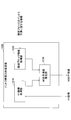
図5Bは、角度予測モードによるイントラ予測において、処理対象のブロック300において、1の参照方向が選択された様子を示した図である。具体的には、16個の参照方向のうち、11番目の参照方向(矢印501)が選択された様子を示している。
この場合、イントラ予測ブロック生成部520では、参照方向を示す値として"11"を、可変長符号化部111に通知する。また、イントラ予測ブロック生成部520では、位置に関する情報として、矢印501の始点の位置のX座標、Y座標を、イントラ参照方向推定部110に通知する。
更に、イントラ予測ブロック生成部520では、処理対象のブロック300の上または左隣接ブロックにおいて角度予測モードによるイントラ予測を行った際に選択した参照方向を示す値等を、イントラ参照方向推定部110に通知する。
なお、処理対象のブロック300についての符号化が完了すると、処理対象のブロック300については、他の処理対象のブロックの上隣接ブロックまたは左隣接ブロックとなる。この場合、イントラ予測ブロック生成部520では、処理対象のブロック300においてイントラ予測を行った際のイントラ予測に関する情報を保持しておく。そして、イントラ予測ブロック生成部520では、他の処理対象のブロックにおいて角度予測モードによるイントラ予測を行った際に、隣接ブロックのイントラ予測に関する情報として、イントラ参照方向推定部110に通知する。
<イントラ参照方向推定部の機能構成>
次に、イントラ参照方向推定部110の機能構成の詳細について説明する。図6は、第1の実施形態に係る符号化装置のイントラ参照方向推定部の機能構成の詳細を示す図である。
次に、イントラ参照方向推定部110の機能構成の詳細について説明する。図6は、第1の実施形態に係る符号化装置のイントラ参照方向推定部の機能構成の詳細を示す図である。
図6に示すように、イントラ参照方向推定部110は、XY座標取得部610と、隣接ブロック情報取得部620と、MSB予測値推定部630とを有する。
XY座標取得部610は、イントラ予測部108より、処理対象のブロックにおける各領域の位置に関する情報(X座標、Y座標)を取得し、MSB予測値推定部630に通知する。
隣接ブロック情報取得部620は、処理対象のブロックに隣接する隣接ブロックのイントラ予測に関する情報を取得する。
隣接ブロック情報取得部620が取得する、隣接ブロックのイントラ予測に関する情報には、
・上隣接ブロックにおいて角度予測モードによるイントラ予測が行われたこと、
・上隣接ブロックの各領域において選択された、参照方向を示す値、
・上隣接ブロックの領域の数、
・左隣接ブロックにおいて角度予測モードによるイントラ予測が行われたこと、
・左隣接ブロックの各領域において選択された、参照方向を示す値、
・左隣接ブロックの領域の数、
等が含まれるものとする。
・上隣接ブロックにおいて角度予測モードによるイントラ予測が行われたこと、
・上隣接ブロックの各領域において選択された、参照方向を示す値、
・上隣接ブロックの領域の数、
・左隣接ブロックにおいて角度予測モードによるイントラ予測が行われたこと、
・左隣接ブロックの各領域において選択された、参照方向を示す値、
・左隣接ブロックの領域の数、
等が含まれるものとする。
また、隣接ブロック情報取得部620は、取得した隣接ブロックのイントラ予測に関する情報を、MSB予測値推定部630に通知する。
MSB予測値推定部630は、XY座標取得部610より通知された、処理対象の各領域の位置に関する情報と、隣接ブロック情報取得部620より通知された、隣接ブロックのイントラ予測に関する情報とに基づいて、MSB予測値を推定する。
MSB予測値とは、参照方向の予測値であり、処理対象のブロックにおいて推定される、参照方向を示す値を2値化した場合の最上位ビット(MSB)に対応する値を指す。なお、図5Bの例のように、16個の参照方向を、4ビットの2値信号で表した場合、最上位ビットのビット値が"0"とは、参照方向が水平方向のいずれかであることを表すことになる。また、最上位ビットのビット値が"1"とは、参照方向が垂直方向のいずれかであることを表すことになる。
つまり、MSB予測値推定部630では、角度予測モードによるイントラ予測の際に処理対象のブロックにおいて推定される参照方向が、少なくとも水平方向のグループに属するのか、垂直方向のグループに属するのかを推定する。
例えば、処理対象のブロック内において処理対象の領域が左下に位置している場合(つまり、該領域のX座標がY座標以下の場合)には、水平方向のいずれかを参照方向としている可能性が高い。このような場合、MSB予測値推定部630では、MSB予測値として"0"を推定する。
一方、処理対象のブロック内において処理対象の領域が右上に位置している場合(つまり、該領域のX座標がY座標よりも大きい場合)には、垂直方向のいずれかを参照方向としている可能性が高い。このような場合、MSB予測値推定部630では、MSB予測値として"1"を推定する。
また、処理対象のブロックの上隣接ブロック及び左隣接ブロックにおいて、角度予測モードによるイントラ予測の際、水平方向のいずれかが参照方向として数多く選択されていたとする。この場合、処理対象のブロックにおいても、水平方向のいずれかが参照方向として選択される可能性が高い。このような場合、MSB予測値推定部630では、MSB予測値として"0"を推定する。
一方、処理対象のブロックの上隣接ブロック及び左隣接ブロックにおいて、角度予測モードによるイントラ予測の際、垂直方向のいずれかが参照方向として数多く選択されていたとする。この場合、処理対象のブロックにおいても、垂直方向のいずれかを参照方向として選択される可能性が高い。このような場合、MSB予測値推定部630では、MSB予測値として"1"を推定する。
なお、MSB予測値推定部630では、推定したMSB予測値を、可変長符号化部111に出力する。
<イントラ参照方向推定部によるMSB予測値算出処理の流れ>
次に、イントラ参照方向推定部110によるMSB予測値算出処理について、図8A乃至図11Bを参照しながら、図7に沿って説明する。なお、図7は、第1の実施形態に係る符号化装置のイントラ参照方向推定部によるMSB予測値算出処理の流れを示すフローチャートである。また、図8A乃至図11Bは、MSB予測値算出処理の具体例を示す第1乃至第7の図である。
次に、イントラ参照方向推定部110によるMSB予測値算出処理について、図8A乃至図11Bを参照しながら、図7に沿って説明する。なお、図7は、第1の実施形態に係る符号化装置のイントラ参照方向推定部によるMSB予測値算出処理の流れを示すフローチャートである。また、図8A乃至図11Bは、MSB予測値算出処理の具体例を示す第1乃至第7の図である。
図7に示すように、ステップS701において、MSB予測値推定部630は、隣接ブロック情報取得部620より通知された、隣接ブロックのイントラ予測に関する情報を取得する。また、MSB予測値推定部630は、取得した隣接ブロックのイントラ予測に関する情報に基づいて、処理対象のブロックの上隣接ブロックにおいて、イントラ予測が行われたか否かを判定する(図8Aの太線枠参照)。
ステップS701において、イントラ予測が行われていないと判定された場合には(ステップS701においてNOの場合には)、ステップS707に進む。
一方、ステップS701において、イントラ予測が行われたと判定された場合には(ステップS702においてYESの場合には)、ステップS702に進む。
ステップS702において、MSB予測値推定部630は、取得した隣接ブロックのイントラ予測に関する情報に基づいて、処理対象のブロックの左隣接ブロックにおいて、イントラ予測が行われたか否かを判定する(図8Bの太線枠参照)。
ステップS702において、イントラ予測が行われていないと判定された場合には(ステップS702においてNOの場合には)、ステップS708に進む。一方、ステップS702において、イントラ予測が行われたと判定された場合には(ステップS702においてYESの場合には)、ステップS703に進む。
ステップS703において、MSB予測値推定部630は、取得した隣接ブロックのイントラ予測に関する情報に基づいて、上隣接または左隣接ブロックにおいて行われたイントラ予測が、角度予測モードであったか否かを判定する(図8Cの太線枠参照)。
ステップS703において、上隣接ブロック及び左隣接ブロックにおいて行われたイントラ予測が、いずれも角度予測モードでなかったと判定された場合には(ステップS703においてNOの場合には)、ステップS704に進む。
ステップS704において、MSB予測値推定部630は、XY座標取得部610より、処理対象のブロックにおける各領域の位置に関する情報を取得する。また、MSB予測値推定部630は、取得した位置に関する情報に基づいて、各領域の処理対象のブロック内における位置が、右上にあるか、左下にあるかを判定する。
具体的には、処理対象の領域900のX座標が、Y座標よりも大きいか否かを判定する(図9参照)。ステップS704において、X座標がY座標よりも大きいと判定された場合には(ステップS704においてYESの場合には)、ステップS708に進む。また、ステップS704において、X座標がY座標以下であると判定された場合には(ステップS704においてNOの場合には)、ステップS707に進む。
一方、ステップS703において角度予測モードであると判定された場合には(ステップS703においてYESの場合には)、ステップS705に進む。ステップS705において、MSB予測値推定部630は、取得した隣接ブロックのイントラ予測に関する情報に基づいて、下式から平均角度Angを算出する。

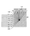
ステップS706において、MSB予測値推定部630は、ステップS705において算出された平均角度Angが所定の条件を満たすか否かを判定する。具体的には、MSB予測値推定部630は、ステップS705において算出された平均角度Angが、処理対象の領域の位置から見て、処理対象のブロックの左隣接ブロックの最上段までの角度よりも大きいか否かを判定する(図10の矢印1000参照)。これにより、MSB予測値推定部630では、処理対象のブロック内の各領域の参照方向が水平方向のいずれかであるのか、垂直方向のいずれかであるのかを判定することができる。
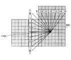
ステップS706において、平均角度Angが所定の条件を満たさない(水平方向のいずれかである)と判定された場合には(ステップS706においてNOの場合には)、ステップS707に進む。例えば、図11Aに示すように、平均角度Angにより特定される参照方向が、処理対象の領域の位置から見て矢印1101で示される場合、図10の矢印1000よりも角度が小さい。このような場合、MSB予測値推定部630では、所定の条件を満たさない(参照方向が水平方向である)と判定し、ステップS707に進む。
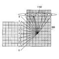
一方、ステップS706において、平均角度Angが所定の条件を満たすと判定された場合には(ステップS706においてYESの場合には)、ステップS708に進む。例えば、図11Bに示すように、平均角度Angにより特定される参照方向が、処理対象の領域から見て矢印1102で示される場合、図10の矢印1000よりも角度が大きい。このような場合、MSB予測値推定部630では、所定の条件を満たす(参照方向が垂直方向である)と判定し、ステップS708に進む。
ステップS708において、MSB予測値推定部630は、MSB予測値に"1"を入力する。また、ステップS707において、MSB予測値推定部630は、MSB予測値に"0"を入力する。
<可変長符号化部の機能構成>
次に、可変長符号化部111の機能構成の詳細について説明する。図12A、Bは、符号化装置の可変長符号化部の機能構成の詳細を示す第1及び第2の図である。
次に、可変長符号化部111の機能構成の詳細について説明する。図12A、Bは、符号化装置の可変長符号化部の機能構成の詳細を示す第1及び第2の図である。
図12Aに示すように、可変長符号化部111は、2値化部1210と、排他的論理和算出部1220と、算術符号化部1230とを有する。
2値化部1210は、イントラ予測部108より出力された参照方向を示す値(N個の参照方向のいずれかを示す値)を取得する。2値化部1210は、取得した参照方向を示す値を2値化する。
排他的論理和算出部1220は、2値化部1210より、参照方向を示す値の2値信号を取得する。また、排他的論理和算出部1220は、イントラ参照方向推定部110より、MSB予測値を取得する。
更に、排他的論理和算出部1220は、参照方向を示す値の2値信号の最上位ビットのビット値と、MSB予測値との排他的論理和を算出し、算術符号化部1230に通知する。また、排他的論理和算出部1220は、参照方向を示す値の2値信号のうち、最上位ビット以外のビット列の値を、算術符号化部1230に通知する。
算術符号化部1230は、排他的論理和算出部1220より通知された最上位ビットのビット値とMSB予測値との排他的論理和をコンテキストモードにより算術符号化する。また、算術符号化部1230は、最上位ビット以外のビット列の値を、バイパスモードにより算術符号化する。
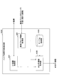
図12Bは、参照方向を示す値の2値信号の一例を示す図である。図12Bに示すように、N個(N=16)の参照方向が定義されている場合、参照方向を示す値の2値信号は、"0000"~"1111"のいずれかとなる。
ここで、2値化部1210が、イントラ予測部108より参照方向を示す値として"11"を取得していたとすると、2値化部1210は、排他的論理和算出部1220に対して、参照方向を示す値の2値信号として"1011"を通知する(矢印1102参照)。
また、排他的論理和算出部1220が、イントラ参照方向推定部110より、MSB予測値として、"1"を取得していたとする。この場合、排他的論理和算出部1220は、"1011"の最上位ビットのビット値("1")と、MSB予測値("1")との排他的論理和として、"0"を算術符号化部1230に通知する。
また、排他的論理和算出部1220は、参照方向を示す値の2値信号である"1011"のうち、最上位ビット以外のビット列の値("011")を、算術符号化部1230に通知する。
これにより、算術符号化部1230では、"1"をコンテキストモードにより算術符号化し、"011"をバイパスモードにより算術符号化する。
<復号装置の機能構成>
次に、復号装置の機能構成について説明する。復号装置には復号プログラムがインストールされており、当該プログラムが実行されることで、復号装置は、不図示のネットワークを介して符号化装置100より受信した符号化ストリームを復号し、動画像データを出力する。
次に、復号装置の機能構成について説明する。復号装置には復号プログラムがインストールされており、当該プログラムが実行されることで、復号装置は、不図示のネットワークを介して符号化装置100より受信した符号化ストリームを復号し、動画像データを出力する。
図13は、復号装置の機能構成の一例を示す図である。図13に示すように、復号装置1300は、ストリーム復号部1301、逆量子化部1302、逆直交変換部1303、ループフィルタ部1304、局所復号画像メモリ1305を有する。また、復号装置1300は、イントラ予測部1306、インタ予測部1307、イントラ参照方向推定部1308を有する。
ストリーム復号部1301は復号部の一例である。ストリーム復号部1301は、CABACの復号方式により符号化ストリームを復号し、処理対象のブロックの量子化係数を逆量子化部1302に通知する。また、ストリーム復号部1301は、符号化ストリームを復号することで処理対象のブロック内の各領域の位置に関する情報を取得し、イントラ参照方向推定部1308に通知する。
更に、ストリーム復号部1301は、イントラ参照方向推定部1308より通知されたMSB予測値を取得し、取得したMSB予測値を用いて算出した参照方向を示す値をイントラ予測部1306に出力する。
逆量子化部1302は、ストリーム復号部1301より通知された量子化係数に対して逆量子化を行い、逆量子化係数を算出する。また、逆量子化部1302は、算出した逆量子化係数を逆直交変換部1303に通知する。
逆直交変換部1303は、逆量子化部1302より通知された逆量子化係数に対して逆直交変換を行い、予測誤差ブロックを生成する。逆直交変換部1303において生成された予測誤差ブロックには、後述する予測部(イントラ予測部1306またはインタ予測部1307)にて生成された予測ブロックが加算されることで、局所復号ブロックが生成される。
ループフィルタ部1304は、生成された局所復号ブロックに対して、デブロッキングフィルタ等を用いてフィルタ処理を行い、フィルタ処理後の局所復号ブロックを、フレーム単位で出力することで、動画像データを出力する。
また、ループフィルタ部1304は、フィルタ処理後の局所復号ブロックを、局所復号画像メモリ1305に格納する。
イントラ予測部1306は予測部の一例であり、イントラ予測を行い、イントラ予測ブロックを生成する。具体的には、イントラ予測部1306は、ストリーム復号部1301より、参照方向を示す値を取得する。また、イントラ予測部1306は、取得した参照方向を示す値に基づいて、局所復号画像メモリ1305より、イントラ予測が行われた局所復号ブロックであって処理対象のブロックの上側または左側に隣接するブロックを参照して、イントラ予測を行う。
インタ予測部1307は、処理対象のブロックについて、他のフレーム内の局所復号ブロックを用いてインタ予測を行い、インタ予測ブロックを生成する。
復号装置1300では、符号化ストリームを復号することで得られる情報に基づいて、イントラ予測部1306またはインタ予測部1307のいずれか一方が実行される。
イントラ参照方向推定部1308は推定部の一例である。イントラ参照方向推定部1308は、イントラ予測部1306が実行された場合に、ストリーム復号部1301より通知された位置に関する情報を取得する。更に、イントラ参照方向推定部1308は、イントラ予測部1306より通知されたイントラ予測に関する情報を取得する。
また、イントラ参照方向推定部1308は、取得した位置に関する情報または取得したイントラ予測に関する情報に基づいて、処理対象のブロックにおいて、MSB予測値を推定する。更に、イントラ参照方向推定部1308は、推定したMSB予測値を、ストリーム復号部1301に出力する。
<ストリーム復号部の機能構成>
次に、ストリーム復号部1301の機能構成の詳細について説明する。図14は、復号装置のストリーム復号部の機能構成の詳細を示す図である。
次に、ストリーム復号部1301の機能構成の詳細について説明する。図14は、復号装置のストリーム復号部の機能構成の詳細を示す図である。
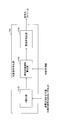
図14に示すように、ストリーム復号部1301は、算術復号部1401と、参照方向算出部1402と、多値化部1403とを有する。
算術復号部1401は、符号化ストリームを復号することで、処理対象のブロックの各領域の位置に関する情報を取得し、イントラ参照方向推定部1308に通知する。また、算術復号部1401は、符号化ストリームを復号することで、参照方向を示す値を2値化した2値信号であって、最上位ビットのビット値が、MSB予測値との排他的論理和である2値信号を取得する。更に、算術復号部1401は、取得した2値信号を参照方向算出部1402に通知する。
参照方向算出部1402は、算術復号部1401より通知された2値信号と、イントラ参照方向推定部1308より通知されたMSB予測値とを用いて、参照方向を示す値の2値信号を算出する。また、参照方向算出部1402は、算出した参照方向を示す値の2値信号を多値化部1403に通知する。
多値化部1403は、参照方向算出部1402より通知された参照方向を示す値の2値信号を多値化することで、参照方向を示す値を算出し、イントラ予測部1306に通知する。
<イントラ参照方向推定部の機能構成>
次に、復号装置1300のイントラ参照方向推定部1308の機能構成の詳細について説明する。図15は、復号装置のイントラ参照方向推定部の機能構成の詳細を示す図である。図15に示すように、復号装置1300のイントラ参照方向推定部1308は、XY座標取得部1510、隣接ブロック情報取得部1520、MSB予測値推定部1530を有する。なお、復号装置1300のイントラ参照方向推定部1308が有する機能は、符号化装置100のイントラ参照方向推定部110が有する機能(XY座標取得部610~MSB予測値推定部630)と同じであるため、ここでは説明を省略する。
次に、復号装置1300のイントラ参照方向推定部1308の機能構成の詳細について説明する。図15は、復号装置のイントラ参照方向推定部の機能構成の詳細を示す図である。図15に示すように、復号装置1300のイントラ参照方向推定部1308は、XY座標取得部1510、隣接ブロック情報取得部1520、MSB予測値推定部1530を有する。なお、復号装置1300のイントラ参照方向推定部1308が有する機能は、符号化装置100のイントラ参照方向推定部110が有する機能(XY座標取得部610~MSB予測値推定部630)と同じであるため、ここでは説明を省略する。
以上の説明から明らかなように、第1の実施形態に係る符号化装置及び復号装置では、角度予測モードによるイントラ予測の際、隣接ブロックにおいてイントラ予測が行われた際のイントラ予測に関する情報に基づいて、MSB予測値を推定する。
また、第1の実施形態に係る符号化装置及び復号装置では、処理対象のブロックにおいて、イントラ予測が行われた際に選択された参照方向を示す値を2値化し、2値信号の最上位ビットとMSB予測値との排他的論理和について、算術符号化を行う。
これにより、第1の実施形態に係る符号化装置及び復号装置によれば、参照方向を示す値の2値信号を算術符号化する際の、最上位ビットの生起確率を上げることが可能となる。この結果、最上位ビットについてはバイパスモードによる算術符号化に代えて、コンテキストモードによる算術符号化を実現する確率を上げることが可能となり、符号化ストリーム生成時の符号量を削減することができる。
[第2の実施形態]
上記第1の実施形態では、MSB予測値を、図7に示すフローチャートに従って算出する場合について説明した。しかしながら、MSB予測値の算出方法はこれに限定されない。例えば、隣接ブロックのイントラ予測に関する情報と、処理対象の各領域の位置に関する情報と、に対応するMSB予測値を予め定義したテーブルを用意する。そして、イントラ参照方向推定部では、当該テーブルに基づいてMSB予測値を算出してもよい。以下、第2の実施形態について、上記第1の実施形態との相違点を中心に説明する。
上記第1の実施形態では、MSB予測値を、図7に示すフローチャートに従って算出する場合について説明した。しかしながら、MSB予測値の算出方法はこれに限定されない。例えば、隣接ブロックのイントラ予測に関する情報と、処理対象の各領域の位置に関する情報と、に対応するMSB予測値を予め定義したテーブルを用意する。そして、イントラ参照方向推定部では、当該テーブルに基づいてMSB予測値を算出してもよい。以下、第2の実施形態について、上記第1の実施形態との相違点を中心に説明する。
<イントラ参照方向推定部の機能構成>
はじめに、第2の実施形態に係る符号化装置のイントラ参照方向推定部の機能構成について説明する。図16は、第2の実施形態に係る符号化装置のイントラ参照方向推定部の機能構成の詳細を示す図である。図6を用いて説明した第1の実施形態に係る符号化装置のイントラ参照方向推定部110との相違点は、イントラ参照方向推定部1600の場合、MSB予測値取得部1630を有する点である。
はじめに、第2の実施形態に係る符号化装置のイントラ参照方向推定部の機能構成について説明する。図16は、第2の実施形態に係る符号化装置のイントラ参照方向推定部の機能構成の詳細を示す図である。図6を用いて説明した第1の実施形態に係る符号化装置のイントラ参照方向推定部110との相違点は、イントラ参照方向推定部1600の場合、MSB予測値取得部1630を有する点である。
MSB予測値取得部1630は、XY座標取得部610より通知された、位置に関する情報と、隣接ブロック情報取得部620より通知された、隣接ブロックのイントラ予測に関する情報とを取得する。
また、MSB予測値取得部1630は、取得した位置に関する情報と、取得した隣接ブロックのイントラ予測に関する情報とに対応したMSB予測値を、格納部の一例であるテーブル格納部1640より取得する。
<テーブル格納部に格納されたテーブルの具体例>
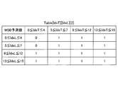
次に、テーブル格納部1640に格納されたテーブルの具体例について説明する。図17A~図17Cは、テーブル格納部に格納されたテーブルの具体例を示す第1乃至第3の図である。図17A~図17Cの例は、処理対象のブロックに対して、上隣接ブロックにおいて16個の参照方向(IdxT)が規定され、左隣接ブロックにおいて16個の参照方向(IdxL)が規定される場合を示している。
次に、テーブル格納部1640に格納されたテーブルの具体例について説明する。図17A~図17Cは、テーブル格納部に格納されたテーブルの具体例を示す第1乃至第3の図である。図17A~図17Cの例は、処理対象のブロックに対して、上隣接ブロックにおいて16個の参照方向(IdxT)が規定され、左隣接ブロックにおいて16個の参照方向(IdxL)が規定される場合を示している。
なお、図17A~図17Cの例では、上隣接ブロックにおいて規定した16個の参照方向を、4つの範囲(0≦IdxT≦4、5≦IdxT≦7、8≦IdxT≦12、13≦IdxT≦15)に分けている。同様に、図17A~図17Cの例では、左隣接ブロックにおいて規定した16個の参照方向を、4つの範囲(0≦IdxL≦4、5≦IdxL≦7、8≦IdxL≦12、13≦IdxL≦15)に分けている。そして、各テーブルには、それぞれの範囲に対応付けて、MSB予測値が規定されている。
このうち、図17Aに示すテーブルは、処理対象の領域のX座標とY座標とが等しい場合のMSB予測値を示したものである。また、図17Bに示すテーブルは、処理対象の領域のX座標とY座標とが、"X座標>Y座標"の関係にある場合のMSB予測値を示したものである。更に、図17Cに示すテーブルは、処理対象の領域のX座標とY座標とが、"X座標<Y座標"の関係にある場合のMSB予測値を示したものである。
なお、図17A~図17Cに示すテーブルは、復号装置側のテーブル格納部にも格納されており、復号装置側のMSB予測値取得部では、同様の処理により、MSB予測値を取得するものとする。
<イントラ参照方向推定部によるMSB予測値算出処理の流れ>
次に、第2の実施形態に係る符号化装置のイントラ参照方向推定部によるMSB予測値算出処理の流れについて説明する。図18は、第2の実施形態に係る符号化装置のイントラ参照方向推定部におけるMSB予測値算出処理の流れを示すフローチャートである。
次に、第2の実施形態に係る符号化装置のイントラ参照方向推定部によるMSB予測値算出処理の流れについて説明する。図18は、第2の実施形態に係る符号化装置のイントラ参照方向推定部におけるMSB予測値算出処理の流れを示すフローチャートである。
ステップS1801において、隣接ブロック情報取得部620は、隣接ブロックのイントラ予測に関する情報のうち、上隣接ブロックのイントラ予測に関する情報を取得する。
ステップS1802において、隣接ブロック情報取得部620は、隣接ブロックのイントラ予測に関する情報のうち、左隣接ブロックのイントラ予測に関する情報を取得する。
ステップS1803において、XY座標取得部610は、処理対象の領域の位置を示す情報(X座標、Y座標)を取得する。
ステップS1804において、MSB予測値取得部1630は、ステップS1801~S1803において取得した情報に基づいて、テーブル格納部1640内のテーブル(図17A~図17C等)を参照し、MSB予測値を取得する。
以上の説明から明らかなように、第2の実施形態に係る符号化装置及び復号装置では、隣接ブロックのイントラ予測に関する情報と、処理対象の各領域の位置に関する情報と、に対応するMSB予測値を予め定義したテーブルを用意する。そして、角度予測モードによるイントラ予測の際、当該テーブルに基づいて、処理対象のブロックの各領域のMSB予測値を算出する。
これにより、第2の実施形態に係る符号化装置及び復号装置によれば、上記第1の実施形態と同様、参照方向を示す値の2値信号を算術符号化する際の、最上位ビットの生起確率を上げることが可能となる。この結果、最上位ビットについてはバイパスモードによる算術符号化に代えて、コンテキストモードによる算術符号化を実現する確率を上げることが可能となり、符号化ストリーム生成時の符号量を削減することができる。
[その他の実施形態]
上記第2の実施形態では、符号化装置のイントラ参照方向推定部及び復号装置のイントラ参照方向推定部それぞれに、テーブル格納部を設け、予め同じテーブルを格納しておくものとして説明した。しかしながら、テーブルの共有方法は、これに限定されない。
上記第2の実施形態では、符号化装置のイントラ参照方向推定部及び復号装置のイントラ参照方向推定部それぞれに、テーブル格納部を設け、予め同じテーブルを格納しておくものとして説明した。しかしながら、テーブルの共有方法は、これに限定されない。
例えば、符号化装置側で統計量等に基づいて動的にテーブルを決定し、決定したテーブルを符号化ストリームのヘッダに付加して送信してもよい。このとき利用するヘッダとしては、例えば、H.265/HEVCの場合、"slice_segmeny_header()"等が挙げられる。
また、上記第1及び第2の実施形態では、符号化装置と復号装置とを別体の装置として説明したが、符号化装置と復号装置とは一体の装置であってもよい。
なお、上記実施形態に挙げた構成等に、その他の要素との組み合わせ等、ここで示した構成に本発明が限定されるものではない。これらの点に関しては、本発明の趣旨を逸脱しない範囲で変更することが可能であり、その応用形態に応じて適切に定めることができる。
100 :符号化装置
108 :イントラ予測部
110 :イントラ参照方向推定部
111 :可変長符号化部
300 :処理対象のブロック
301 :上隣接ブロック
302 :左隣接ブロック
510 :予測モード決定部
520 :イントラ予測ブロック生成部
610 :XY座標取得部
620 :隣接ブロック情報取得部
630 :MSB予測値推定部
1210 :2値化部
1220 :排他的論理和算出部
1230 :算術符号化部
1300 :復号装置
1301 :ストリーム復号部
1306 :イントラ予測部
1308 :イントラ参照方向推定部
1401 :算術復号部
1402 :参照方向算出部
1403 :多値化部
1510 :XY座標取得部
1520 :隣接ブロック情報取得部
1530 :MSB予測値推定部
1600 :イントラ参照方向推定部
1630 :MSB予測値取得部
108 :イントラ予測部
110 :イントラ参照方向推定部
111 :可変長符号化部
300 :処理対象のブロック
301 :上隣接ブロック
302 :左隣接ブロック
510 :予測モード決定部
520 :イントラ予測ブロック生成部
610 :XY座標取得部
620 :隣接ブロック情報取得部
630 :MSB予測値推定部
1210 :2値化部
1220 :排他的論理和算出部
1230 :算術符号化部
1300 :復号装置
1301 :ストリーム復号部
1306 :イントラ予測部
1308 :イントラ参照方向推定部
1401 :算術復号部
1402 :参照方向算出部
1403 :多値化部
1510 :XY座標取得部
1520 :隣接ブロック情報取得部
1530 :MSB予測値推定部
1600 :イントラ参照方向推定部
1630 :MSB予測値取得部
Claims (16)
- 処理対象のブロックに隣接する隣接ブロックにおいて、角度予測モードによるイントラ予測が行われた際に選択された参照方向を示す値に基づいて、前記処理対象のブロックにおいて、角度予測モードによるイントラ予測が行われる際に選択される参照方向の予測値を推定する推定部と、
前記処理対象のブロックにおいて、角度予測モードによるイントラ予測が行われた際に選択された参照方向を示す値を2値化し、2値信号の最上位ビットの値と前記予測値との対比結果について算術符号化を行う符号化部と
を有することを特徴とする符号化装置。 - 前記推定部は、
前記処理対象のブロックの上側に隣接する上隣接ブロックと左側に隣接する左隣接ブロックとにおいて、角度予測モードによるイントラ予測が行われた際に選択された参照方向を示す値に基づいて、前記処理対象のブロック内の位置ごとに前記予測値を推定することを特徴とする請求項1に記載の符号化装置。 - 前記推定部は、
前記上隣接ブロックと左隣接ブロックのいずれにおいても、角度予測モードによるイントラ予測が行われなかった場合、前記処理対象のブロック内の位置に応じた前記予測値を推定することを特徴とする請求項2に記載の符号化装置。 - 前記推定部は、
前記処理対象のブロックにおいて、角度予測モードによるイントラ予測が行われる際に選択される参照方向が、水平方向のグループに属するか、垂直方向のグループに属するかを判定することで、前記予測値を推定することを特徴とする請求項1に記載の符号化装置。 - 前記符号化部は、
前記2値信号の最上位ビットの値と前記予測値との排他的論理和について、コンテキストモードによる算術符号化を行うことを特徴とする請求項1に記載の符号化装置。 - 前記符号化部は、
前記2値信号の最上位ビットを除く各ビットの値について、バイパスモードによる算術符号化を行うことを特徴とする請求項5に記載の符号化装置。 - 前記上隣接ブロックと前記左隣接ブロックとにおいて、角度予測モードによるイントラ予測が行われた際に選択された参照方向を示す値に応じた予測値を、前記処理対象のブロック内の位置ごとに予めテーブルに格納する格納部を更に有し、
前記推定部は、前記テーブルを参照することで、前記予測値を推定することを特徴とする請求項2に記載の符号化装置。 - 処理対象のブロックに隣接する隣接ブロックにおいて、角度予測モードによるイントラ予測が行われた際に選択された参照方向を示す値に基づいて、前記処理対象のブロックにおいて、角度予測モードによるイントラ予測が行われる際に選択される参照方向の予測値を推定し、
前記処理対象のブロックにおいて、角度予測モードによるイントラ予測が行われた際に選択された参照方向を示す値を2値化し、2値信号の最上位ビットの値と前記予測値との対比結果について算術符号化を行う、
処理をコンピュータが実行する符号化方法。 - 処理対象のブロックに隣接する隣接ブロックにおいて、角度予測モードによるイントラ予測が行われた際に選択された参照方向を示す値に基づいて、前記処理対象のブロックにおいて、角度予測モードによるイントラ予測が行われる際に選択される参照方向の予測値を推定し、
前記処理対象のブロックにおいて、角度予測モードによるイントラ予測が行われた際に選択された参照方向を示す値を2値化し、2値信号の最上位ビットの値と前記予測値との対比結果について算術符号化を行う、
処理をコンピュータに実行させるための符号化プログラム。 - 処理対象のブロックに隣接する隣接ブロックにおいて、角度予測モードによるイントラ予測を行った際に選択した参照方向を示す値に基づいて、前記処理対象のブロックにおいて、角度予測モードによるイントラ予測が行われる際に選択する参照方向の予測値を推定する推定部と、
符号化ストリームを復号することで、前記処理対象のブロックにおいて角度予測モードによるイントラ予測が行われた際に選択された参照方向を示す値の2値信号を取得し、最上位ビットの値と前記予測値との対比結果について多値化する復号部と、
前記復号部が多値化することで得た前記参照方向を示す値を用いて、前記処理対象のブロックにおいて、角度予測モードによるイントラ予測を行う予測部と
を有することを特徴とする復号装置。 - 前記推定部は、
前記処理対象のブロックの上側に隣接する上隣接ブロックと左側に隣接する左隣接ブロックとにおいて、角度予測モードによるイントラ予測が行われた際に選択された参照方向を示す値に基づいて、前記処理対象のブロック内の位置ごとに前記予測値を推定することを特徴とする請求項10に記載の復号装置。 - 前記推定部は、
前記上隣接ブロックと左隣接ブロックのいずれにおいても、角度予測モードによるイントラ予測が行われなかった場合、前記処理対象のブロック内の位置に応じた前記予測値を推定することを特徴とする請求項11に記載の復号装置。 - 前記推定部は、
前記処理対象のブロックにおいて、角度予測モードによるイントラ予測が行われる際に選択される参照方向が、水平方向のグループに属するか、垂直方向のグループに属するかを判定することで、前記予測値を推定することを特徴とする請求項10に記載の復号装置。 - 前記上隣接ブロックと前記左隣接ブロックとにおいて、角度予測モードによるイントラ予測が行われた際に選択された参照方向を示す値に応じた予測値を、前記処理対象のブロック内の位置ごとに予めテーブルに格納する格納部を更に有し、
前記推定部は、前記テーブルを参照することで、前記予測値を推定することを特徴とする請求項11に記載の復号装置。 - 処理対象のブロックに隣接する隣接ブロックにおいて、角度予測モードによるイントラ予測が行われた際に選択した参照方向を示す値に基づいて、前記処理対象のブロックにおいて、角度予測モードによるイントラ予測が行われる際に選択する参照方向の予測値を推定し、
符号化ストリームを復号することで、前記処理対象のブロックにおいて角度予測モードによるイントラ予測が行われた際に選択された参照方向を示す値の2値信号を取得し、最上位ビットの値と前記予測値との対比結果について多値化し、
多値化することで得た前記参照方向を示す値を用いて、前記処理対象のブロックにおいて、角度予測モードによるイントラ予測を行う、
処理をコンピュータが実行する復号方法。 - 処理対象のブロックに隣接する隣接ブロックにおいて、角度予測モードによるイントラ予測が行われた際に選択した参照方向を示す値に基づいて、前記処理対象のブロックにおいて、角度予測モードによるイントラ予測が行われる際に選択する参照方向の予測値を推定し、
符号化ストリームを復号することで、前記処理対象のブロックにおいて角度予測モードによるイントラ予測が行われた際に選択された参照方向を示す値の2値信号を取得し、最上位ビットの値と前記予測値との対比結果について多値化し、
多値化することで得た前記参照方向を示す値を用いて、前記処理対象のブロックにおいて、角度予測モードによるイントラ予測を行う、
処理をコンピュータに実行させるための復号プログラム。
Priority Applications (4)
| Application Number | Priority Date | Filing Date | Title |
|---|---|---|---|
| CN201880096352.8A CN112514388B (zh) | 2018-08-08 | 2018-08-08 | 编码装置、编码方法、解码装置 |
| JP2020535397A JP6940006B2 (ja) | 2018-08-08 | 2018-08-08 | 符号化装置、符号化方法、符号化プログラム、復号装置、復号方法及び復号プログラム |
| PCT/JP2018/029794 WO2020031297A1 (ja) | 2018-08-08 | 2018-08-08 | 符号化装置、符号化方法、符号化プログラム、復号装置、復号方法及び復号プログラム |
| US17/148,620 US11330256B2 (en) | 2018-08-08 | 2021-01-14 | Encoding device, encoding method, and decoding device |
Applications Claiming Priority (1)
| Application Number | Priority Date | Filing Date | Title |
|---|---|---|---|
| PCT/JP2018/029794 WO2020031297A1 (ja) | 2018-08-08 | 2018-08-08 | 符号化装置、符号化方法、符号化プログラム、復号装置、復号方法及び復号プログラム |
Related Child Applications (1)
| Application Number | Title | Priority Date | Filing Date |
|---|---|---|---|
| US17/148,620 Continuation US11330256B2 (en) | 2018-08-08 | 2021-01-14 | Encoding device, encoding method, and decoding device |
Publications (1)
| Publication Number | Publication Date |
|---|---|
| WO2020031297A1 true WO2020031297A1 (ja) | 2020-02-13 |
Family
ID=69414060
Family Applications (1)
| Application Number | Title | Priority Date | Filing Date |
|---|---|---|---|
| PCT/JP2018/029794 Ceased WO2020031297A1 (ja) | 2018-08-08 | 2018-08-08 | 符号化装置、符号化方法、符号化プログラム、復号装置、復号方法及び復号プログラム |
Country Status (4)
| Country | Link |
|---|---|
| US (1) | US11330256B2 (ja) |
| JP (1) | JP6940006B2 (ja) |
| CN (1) | CN112514388B (ja) |
| WO (1) | WO2020031297A1 (ja) |
Citations (3)
| Publication number | Priority date | Publication date | Assignee | Title |
|---|---|---|---|---|
| WO2008149840A1 (ja) * | 2007-06-04 | 2008-12-11 | Ntt Docomo, Inc. | 画像予測符号化装置、画像予測復号装置、画像予測符号化方法、画像予測復号方法、画像予測符号化プログラム、及び画像予測復号プログラム |
| WO2012096229A1 (ja) * | 2011-01-13 | 2012-07-19 | ソニー株式会社 | 符号化装置および符号化方法、並びに復号装置および復号方法 |
| WO2018037949A1 (ja) * | 2016-08-25 | 2018-03-01 | ソニー株式会社 | 画像処理装置および方法 |
Family Cites Families (9)
| Publication number | Priority date | Publication date | Assignee | Title |
|---|---|---|---|---|
| KR20090004658A (ko) * | 2007-07-02 | 2009-01-12 | 엘지전자 주식회사 | 디지털 방송 시스템 및 데이터 처리 방법 |
| JP2009111691A (ja) * | 2007-10-30 | 2009-05-21 | Hitachi Ltd | 画像符号化装置及び符号化方法、画像復号化装置及び復号化方法 |
| CN102595121A (zh) * | 2011-01-15 | 2012-07-18 | 华为技术有限公司 | 帧内预测模式二进制化的方法、解码方法、装置和系统 |
| BR112013003521B1 (pt) * | 2011-07-18 | 2022-03-03 | Sun Patent Trust | Método de codificação de imagem, método de decodificação de imagem, aparelho de codificação de imagem, aparelho de decodificação de imagem e aparelho de codificação e decodificação de imagem |
| CN106101727B (zh) * | 2011-08-04 | 2019-10-08 | 寰发股份有限公司 | 基于上下文自适应二进制算术编码的方法及装置 |
| US20180213222A1 (en) * | 2015-05-27 | 2018-07-26 | Kt Corporation | Method and device for processing video signal |
| CN108293136B (zh) * | 2015-09-23 | 2022-12-30 | 诺基亚技术有限公司 | 编码360度全景视频的方法、装置和计算机可读存储介质 |
| JP6796405B2 (ja) | 2016-06-20 | 2020-12-09 | 日本放送協会 | イントラ予測器、画像符号化装置、画像復号装置およびプログラム |
| US11039130B2 (en) * | 2016-10-28 | 2021-06-15 | Electronics And Telecommunications Research Institute | Video encoding/decoding method and apparatus, and recording medium in which bit stream is stored |
-
2018
- 2018-08-08 JP JP2020535397A patent/JP6940006B2/ja not_active Expired - Fee Related
- 2018-08-08 WO PCT/JP2018/029794 patent/WO2020031297A1/ja not_active Ceased
- 2018-08-08 CN CN201880096352.8A patent/CN112514388B/zh not_active Expired - Fee Related
-
2021
- 2021-01-14 US US17/148,620 patent/US11330256B2/en active Active
Patent Citations (3)
| Publication number | Priority date | Publication date | Assignee | Title |
|---|---|---|---|---|
| WO2008149840A1 (ja) * | 2007-06-04 | 2008-12-11 | Ntt Docomo, Inc. | 画像予測符号化装置、画像予測復号装置、画像予測符号化方法、画像予測復号方法、画像予測符号化プログラム、及び画像予測復号プログラム |
| WO2012096229A1 (ja) * | 2011-01-13 | 2012-07-19 | ソニー株式会社 | 符号化装置および符号化方法、並びに復号装置および復号方法 |
| WO2018037949A1 (ja) * | 2016-08-25 | 2018-03-01 | ソニー株式会社 | 画像処理装置および方法 |
Non-Patent Citations (2)
| Title |
|---|
| "Done Bugdayci and Kemal Ugur, TE5: Results of test 5.1.3 on inter-layer intra mode prediction", JOINT COLLABORATIVE TEAM ON VIDEO CODING (JCT-VC) OF ITU-T SG 16 WP 3 AND ISO/IEC JTC 1/SC 29/WG 11, JCTUC-L0031, 12TH MEETING, January 2013 (2013-01-01), Geneva, CH, pages 1 - 4 * |
| YU HAN ET AL.: "Improvements for Intra Prediction Mode Coding", JOINT VIDEO EXPLORATION TEAM (JVET) OF ITU-T SG 16 WP 3 AND ISO/IEC JTC 1/SC 29/WG 11, JVET-G0060, 7TH MEETING, July 2017 (2017-07-01), Torino, IT, pages 1 - 4 * |
Also Published As
| Publication number | Publication date |
|---|---|
| JP6940006B2 (ja) | 2021-09-22 |
| CN112514388A (zh) | 2021-03-16 |
| JPWO2020031297A1 (ja) | 2021-05-13 |
| US11330256B2 (en) | 2022-05-10 |
| US20210136361A1 (en) | 2021-05-06 |
| CN112514388B (zh) | 2022-10-25 |
Similar Documents
| Publication | Publication Date | Title |
|---|---|---|
| US20090110070A1 (en) | Image encoding device and encoding method, and image decoding device and decoding method | |
| JP5071416B2 (ja) | 動画像符号化装置、及び動画像復号装置、並びに動画像伝送システム | |
| CN109429071B (zh) | 图像编码装置、图像解码装置及图像处理方法 | |
| JP5367097B2 (ja) | 動きベクトル予測符号化方法、動きベクトル予測復号方法、動画像符号化装置、動画像復号装置およびそれらのプログラム | |
| JP5306485B2 (ja) | 動きベクトル予測符号化方法、動きベクトル予測復号方法、動画像符号化装置、動画像復号装置およびそれらのプログラム | |
| CN104982035A (zh) | 用于对数字图像的序列进行编码的方法 | |
| WO2018014301A1 (zh) | 视频编码方法及装置 | |
| CN109510987A (zh) | 编码树节点划分方式的确定方法、装置及编码设备 | |
| US9848204B2 (en) | Spatial prediction method and device, coding and decoding methods and devices | |
| CN113347417A (zh) | 提高率失真优化计算效率的方法、装置、设备及存储介质 | |
| JP2014212374A (ja) | 画像符号化装置、画像符号化方法、画像符号化プログラムおよび記録媒体 | |
| WO2020031297A1 (ja) | 符号化装置、符号化方法、符号化プログラム、復号装置、復号方法及び復号プログラム | |
| JP7185467B2 (ja) | 画像復号装置、画像符号化装置、画像処理システム及びプログラム | |
| WO2021117091A1 (ja) | 符号化方法、符号化装置、及びプログラム | |
| WO2018205781A1 (zh) | 一种实现运动估计的方法及电子设备 | |
| KR101574391B1 (ko) | 영상 부호화 방법 및 그 장치 | |
| JP6992825B2 (ja) | 映像符号化装置、映像符号化方法、映像復号装置、映像復号方法、及び映像符号化システム | |
| US11381810B2 (en) | Encoding apparatus, encoding method, and decoding apparatus | |
| JP4034317B2 (ja) | 画像符号化装置 | |
| TW201501511A (zh) | 框內預測方法及系統 | |
| JP5739714B2 (ja) | 符号化装置、復号装置及びプログラム | |
| JP5244479B2 (ja) | 画像符号化装置及び画像符号化方法 | |
| JP2009033266A (ja) | 動きベクトル探索方法、動きベクトル探索装置、符号化装置及びコンピュータプログラム | |
| JP4085301B2 (ja) | 情報処理装置および方法、記録媒体、並びにプログラム | |
| CN121128172A (zh) | 用于图像再压缩的方法和设备 |
Legal Events
| Date | Code | Title | Description |
|---|---|---|---|
| 121 | Ep: the epo has been informed by wipo that ep was designated in this application |
Ref document number: 18929509 Country of ref document: EP Kind code of ref document: A1 |
|
| ENP | Entry into the national phase |
Ref document number: 2020535397 Country of ref document: JP Kind code of ref document: A |
|
| NENP | Non-entry into the national phase |
Ref country code: DE |
|
| 122 | Ep: pct application non-entry in european phase |
Ref document number: 18929509 Country of ref document: EP Kind code of ref document: A1 |