WO2020031270A1 - 端末装置、無線通信システム及びリソース選択方法 - Google Patents
端末装置、無線通信システム及びリソース選択方法 Download PDFInfo
- Publication number
- WO2020031270A1 WO2020031270A1 PCT/JP2018/029668 JP2018029668W WO2020031270A1 WO 2020031270 A1 WO2020031270 A1 WO 2020031270A1 JP 2018029668 W JP2018029668 W JP 2018029668W WO 2020031270 A1 WO2020031270 A1 WO 2020031270A1
- Authority
- WO
- WIPO (PCT)
- Prior art keywords
- unit
- terminal device
- idle
- resources
- resource
- Prior art date
- Legal status (The legal status is an assumption and is not a legal conclusion. Google has not performed a legal analysis and makes no representation as to the accuracy of the status listed.)
- Ceased
Links
Images




Classifications
-
- H—ELECTRICITY
- H04—ELECTRIC COMMUNICATION TECHNIQUE
- H04W—WIRELESS COMMUNICATION NETWORKS
- H04W72/00—Local resource management
- H04W72/02—Selection of wireless resources by user or terminal
Definitions
- the present invention relates to a terminal device, a wireless communication system, and a resource selection method.
- the traffic of mobile terminals occupies most of the network resources.
- the traffic used by mobile terminals tends to increase in the future.
- eMBB Enhanced Mobile Broadband
- Massive MTC Machine Type Communications
- URLLC Ultra-Reliable and Low Latency Communication
- V2X Vehicle to Everything
- V2X is a vehicle-to-vehicle (V2V) indicating inter-vehicle communication
- V2P Vehicle-to-Pedestrian
- a road infrastructure such as a car and a sign
- V2I Vehicle-to-Infrastructure
- the regulations regarding V2X are described in Non-Patent Document 1, for example.
- FIG. 1 is a diagram illustrating an example of a resource arrangement in which a control channel PSCCH (Physical Sidelink Control CHannel) and a data channel PSSCH (Physical Sidelink Shared CHannel) indicated by oblique lines are adjacent in the frequency axis direction. is there.
- PSCCH and PSSCH resources actually used for transmission are indicated by thick oblique lines and horizontal lines, respectively.
- subframes SF1 to SF8 are shown in the time axis direction.
- SCI Segmentlink Control Information
- FIG. 2 is a diagram showing an example of resource allocation in which the PSCCH and the PSSCH indicated by oblique lines in the drawing are not adjacent to each other in the frequency axis direction. Also in FIG. 2, the PSCCH and PSSCH resources actually used for transmission are shown by thick oblique lines and horizontal lines, respectively, and subframes SF1 to SF8 are shown in the time axis direction. In FIG. 2, the corresponding PSCCH and PSSCH are not adjacent to each other, but the SCI related to the corresponding PSSCH is mapped to the PSCCH resource indicated by the thick hatching in the figure.
- a method of allocating these resources there are, for example, a method in which the mobile communication system performs centralized control, and a method in which each terminal device implementing V2X performs autonomous control.
- a system in which the mobile communication system performs centralized control is applicable when a terminal device implementing V2X is located in coverage of the mobile communication system, and is also referred to as mode 3.
- a method in which each terminal device controls autonomously is applicable even if the terminal device does not exist in coverage of the mobile communication system, and is also referred to as mode 4.
- mode 4 since communication between the terminal device and the mobile communication system for resource allocation is not performed, transmission delay when transmission data occurs in the terminal device is reduced, and a strict delay requirement is satisfied. Is possible.
- each terminal device senses the frequency band used for V2X, and when transmission data is generated, excludes resources that are likely to be used by other terminal devices based on the sensing result.
- a resource used for data transmission is selected. Specifically, for example, as shown in FIG. 3, when transmission data of a certain terminal device occurs at time T, this terminal device sets a selection window having a time width according to a delay time allowed for the transmission data. . Then, the terminal device excludes resources in the selection window that are likely to be used by other terminal devices based on the result of sensing up to time T. In FIG. 3, for example, resources indicated by thick oblique lines and horizontal lines are excluded. Then, the terminal device selects any of the resources remaining without being excluded in the selection window, maps transmission data to the selected resource, and transmits the transmission data.
- a terminal device transmitting relatively large-sized data occupies many resources in mode 4. Specifically, for example, a resource continuous over a plurality of subframes may be occupied by one terminal device.
- this terminal device determines whether another terminal device in the selection window is present based on the sensing result up to the time T1. Exclude resources that are likely to be used. In FIG. 4, for example, resources indicated by thick oblique lines and horizontal lines are excluded. Then, the terminal device selects any of the resources remaining without being excluded in the selection window, maps transmission data to the selected resource, and transmits the transmission data.
- the terminal device since the resources of the four subframes after the time T1 are excluded, the terminal device selects the resources after the time T2 at the earliest. Therefore, data transmission may be delayed, and it may be difficult to satisfy the data delay requirement. As described above, when resources continuous in the frequency axis direction and the time axis direction are occupied by some terminal devices, data transmission by other terminal devices is delayed.
- the disclosed technology has been made in view of the above points, and has as its object to provide a terminal device, a wireless communication system, and a resource selection method capable of suppressing a delay in data transmission.
- a terminal device disclosed by the present application calculates a parameter indicating a degree of expectation that an idle resource capable of transmitting predetermined data exists in a predetermined range of resources, and a parameter calculated by the calculation unit.
- a control unit controls resources used for data transmission according to the parameters, and a transmission unit transmits data according to control by the control unit.
- the terminal device According to one aspect of the terminal device, the wireless communication system, and the resource selection method disclosed in the present application, there is an effect that a delay in data transmission can be suppressed.
- FIG. 1 is a diagram illustrating an example of a V2X resource arrangement.
- FIG. 2 is a diagram illustrating another example of the V2X resource arrangement.
- FIG. 3 is a diagram illustrating selection of a resource.
- FIG. 4 is a diagram illustrating an example of a resource selection window.
- FIG. 5 is a block diagram showing a configuration of the terminal device according to one embodiment.
- FIG. 6 is a flowchart illustrating a packet transmission method according to one embodiment.
- FIG. 7 is a diagram illustrating a specific example of the resource use status.
- FIG. 8 is a diagram illustrating a specific example of the idle rate for each subframe.
- FIG. 9 is a diagram illustrating a specific example of the continuous idle rate for each subframe.
- FIG. 10 is a diagram illustrating an example of a resource selection window.
- FIG. 11 is a diagram illustrating a specific example of the number of sets of consecutive idle subchannels for each subframe.
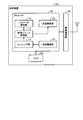
- FIG. 5 is a block diagram showing a configuration of the terminal device 100 according to one embodiment.
- the terminal device 100 illustrated in FIG. 5 includes a processor 110, a memory 120, and a wireless communication unit 130.
- the processor 110 includes, for example, a CPU (Central Processing Unit), an FPGA (Field Programmable Gate Array) or a DSP (Digital Signal Processor), and controls the entire terminal device 100.
- the processor 110 includes a reception control unit 111, a sensing unit 112, a used resource control unit 113, a parameter calculation unit 114, and a transmission control unit 115.
- the reception control unit 111 demodulates and decodes reception data received from another terminal device. Specifically, the reception control unit 111 performs demodulation and decoding of the control channel (PSCCH), and obtains an SCI (Sidelink Control Information) related to data addressed to the terminal device 100. Then, the reception control unit 111 performs demodulation and decoding of the data channel (PSSCH) based on the SCI.
- PSCCH control channel
- SCI Servicelink Control Information
- the sensing unit 112 performs sensing for detecting whether resources are being used for communication by another terminal device. Specifically, the sensing unit 112 receives the SCI of the entire frequency band used for the V2X communication in a predetermined sensing period, measures the received power of each sub-channel in each sub-frame, and It is determined whether or not another terminal device is transmitting a signal in the channel.
- resources used by other terminal devices for signal transmission are referred to as "busy" resources
- resources not used by other terminal devices for signal transmission are referred to as "idle” resources.
- the used resource control unit 113 determines a resource that the terminal device 100 uses for signal transmission based on a result of sensing by the sensing unit 112. Specifically, when a packet to be transmitted occurs, the used resource control unit 113 sets a selection window according to the allowable delay of the packet. Then, the used resource control unit 113 specifies an idle resource in the selection window based on a result of the sensing, and selects a resource to be used for packet transmission from the idle resource. At this time, the used resource control unit 113 outputs the sensing result to the parameter calculation unit 114, and instructs the parameter calculation unit 114 to calculate the channel idle rate indicating the degree of expectation that an idle resource capable of transmitting an emergency packet exists. Ask. Then, the used resource control unit 113 selects a resource to be used for packet transmission so that the channel idle rate in the selection window is maximized.
- the data transmitted by the terminal device 100 includes a regular packet that occurs periodically and an emergency packet that occurs suddenly. Normal packets are transmitted using pre-allocated periodic resources, whereas urgent packets are transmitted using idle resources selected from the selection window each time they occur.
- the used resource control unit 113 always selects a resource to be used based on the channel idle rate when an emergency packet occurs, but when a normal packet occurs, the channel idle when a predetermined condition is satisfied. Change resources used based on rates.
- k is the index of the sub-frame
- i k denotes the number of idle sub-channel in the k th subframe
- N is the number of all sub-channels in one subframe.
- the parameter calculation unit 114 calculates a channel idle ratio (Channel Idle Ratio) ⁇ CIR of a predetermined time width using the idle ratio ⁇ ISNRS by the following equation (2).
- M indicates the number of subframes included in a predetermined time width, and for example, a sensing window (subframe used in the past) and a selection window (subframe used in the future) in a sensing period. Indicates the number of subframes included in the subframes.
- Floor (x) is a floor function indicating the largest integer less than or equal to x.
- H ISNRS is a reference value indicating a criterion for determining that a packet can be transmitted in a subframe.
- H ISNRS is a value in which the average value of the number of subchannels corresponding to the resource size (for example, the size of the urgent packet) required for packet transmission is equal to or more than the ratio of the number of all subchannels in one subframe.
- the following values In idle ratio gamma ISNRS reference value H ISNRS more subframes while there is enough idle subchannels to transmit a packet, idle ratio gamma ISNRS is a subframe below threshold H ISNRS transmits the packet There will not be enough idle subchannels.
- the floor function of the difference between the idle rate ⁇ ISNRS and the reference value H ISNRS is obtained for each subframe, and the average value for the subframe within a predetermined time width is calculated.
- the idle rate ⁇ CIR indicates the degree of expectation indicating the possibility of transmitting a packet within a predetermined time width. Since the selection window is included in the predetermined time width, it can be said that the channel idle rate ⁇ CIR indicates the degree of expectation indicating the possibility of transmitting a normal packet or an urgent packet within the selection window.
- the parameter calculation unit 114 calculates the channel idle rate ⁇ CIR calculated by the above equation (2) for each resource allocation in the selection window for the packet. That is, it is assumed that the used resource control unit 113 selects the resources in the selection window and allocates them to the packet, and the channel idle rate ⁇ CIR when each resource is allocated is calculated. As a result, the used resource control unit 113 selects a resource allocation that maximizes the channel idle rate ⁇ CIR and determines a resource to be used for packet transmission.
- the above-mentioned channel idle rate ⁇ CIR is calculated based on the idle rate ⁇ ISNRS indicating the ratio of idle sub-channels for each sub-frame, but based on the ratio of busy sub-channels for each sub-frame. It is also possible to calculate the channel idle rate ⁇ CIR .
- the parameter calculation unit 114 calculates a busy rate (Channel occupancy Ratio in Subframe) ⁇ CRS indicating the ratio of busy subchannels for each subframe by the following equation (3).
- ⁇ CRS (k) n k / N (3)
- nk indicates the number of busy subchannels in the k-th subframe. Then, the parameter calculation unit 114 calculates the channel idle rate ⁇ CIR of a predetermined time width using the busy rate ⁇ CRS by the following equation (4).
- ceil (x) is a ceiling function indicating a minimum integer equal to or larger than x.
- H CRS is a reference value indicating a criterion for determining that a packet can be transmitted in a subframe. Therefore, the H CRS is a value in which the average value of the number of subchannels corresponding to the resource size (for example, the size of the urgent packet) required for packet transmission is equal to or more than the ratio of the number of all subchannels in one subframe. The following values.
- i max, k indicates the maximum number of consecutive idle sub-channels in the k-th sub-frame. Then, the parameter calculation unit 114 calculates a channel idle rate ⁇ CIR of a predetermined time width using ⁇ CSNRS by the following equation (6).
- H CSNRS is a reference value indicating a criterion for determining that a packet can be transmitted in a subframe.
- H CSNRS is a value in which the average value of the number of sub-channels corresponding to the resource size (for example, the size of the urgent packet) required for packet transmission is equal to or greater than the ratio of the number of all sub-channels in one sub-frame.
- the following values In subframes in which the continuous idle rate ⁇ CSNRS is equal to or greater than the reference value H CSNRS , there are enough continuous idle subchannels to transmit packets, whereas in subframes in which the continuous idle rate ⁇ CSNRS is less than the reference value H CSNRS. There will not be enough consecutive idle subchannels to transmit a packet.
- the parameter calculation unit 114 allocates resources similarly to the case of calculating the channel idle rate ⁇ CIR by the above equation (2).
- the channel idle rate ⁇ CIR is calculated every time.
- the transmission control unit 115 controls to transmit a packet using the resource selected by the used resource control unit 113. That is, the transmission control unit 115 performs data encoding, modulation, and the like, and maps the packet to the resource selected by the used resource control unit 113. Then, transmission control section 115 transmits the transmission data obtained by the mapping via wireless communication section 130. As described above, the packet includes the normal packet and the urgent packet, and the transmission control unit 115 controls the transmission of any packet.
- the memory 120 includes, for example, a random access memory (RAM) or a read only memory (ROM), and stores information used by the processor 110 to execute processing.
- RAM random access memory
- ROM read only memory
- the wireless communication unit 130 performs wireless transmission processing such as D / A (Digital / Analog) conversion and up-conversion on transmission data generated by the processor 110, and wirelessly transmits the data via an antenna.
- the wireless communication unit 130 performs wireless reception processing such as down-conversion and A / D (Analog / Digital) conversion on received data wirelessly received via the antenna, and outputs the data to the processor 110.
- Normal packets are transmitted from each terminal device using pre-allocated periodic resources. Therefore, when a normal packet occurs, the resource is not always selected, and when the channel idle rate decreases and it becomes difficult to transmit an urgent packet, or when a reselection timer described later expires. Then, the resources normally used for transmitting the packet are changed.
- the threshold value H CIR for determining whether or not the channel idle rate has decreased is set by the used resource control unit 113 (step S101).
- the threshold H CIR is a value equal to or greater than the ratio of the subframe time length to the maximum delay time allowed for the packet, and is a value equal to or less than 1. If the channel idle rate ⁇ CIR is equal to or greater than the threshold value H CIR , the resource allocation has room for transmitting packets. On the other hand, if the channel idle rate ⁇ CIR is less than the threshold value H CIR , it is difficult to transmit packets. It will be an arrangement.
- the reference value H ISNRS used for calculating the channel idle rate is set by the parameter calculation unit 114 (step S102).
- the sensing result up to the generation timing of the normal packet acquired by the sensing unit 112 is output from the used resource control unit 113 to the parameter calculation unit 114. Since the sensing result indicates whether each sub-channel in each sub-frame in the sensing period is idle or busy, the parameter calculation unit 114 calculates the channel idle rate ⁇ CIR in the sensing period (step S104). ).
- the used resource control unit 113 compares the channel idle rate ⁇ CIR with the threshold H CIR (step S105). If the channel idle rate ⁇ CIR is less than the threshold H CIR (No in step S105), the emergency packet is transmitted. Therefore, the resources normally allocated to packet transmission are changed.
- step S105 Yes whether or not the reselection timer that counts a random time after changing the resource allocation and expires is used. The determination is made by the resource control unit 113 (step S109). If the reselection timer has not expired (No in step S109), the normal packet is transmitted using a pre-allocated periodic resource because there is no need to change the resources used for transmitting the normal packet. (Step S108). On the other hand, when the reselection timer expires (Step S109 Yes), the resources allocated to the transmission of the normal packet are changed even if the channel idle rate ⁇ CIR is equal to or larger than the threshold H CIR .
- the change of the resources allocated to the transmission of normal packets is performed as follows. That is, the used resource control unit 113 sets the range of resources in which the normal packet may be transmitted in the selection window. This selection window may be a range of resources according to the allowable delay of the emergency packet. Then, the parameter calculation unit 114 estimates whether each resource in the selection window is busy or idle from the sensing result. At this time, the periodic resource previously allocated to the terminal device 100 for transmitting the normal packet is an idle resource.
- a channel idle rate ⁇ ′ CIR of a predetermined time width including the selection window is calculated for each resource allocation to normal packets. Is performed (step S106). That is, the channel idle rate ⁇ ′ CIR is calculated for each of the cases where idle resources are allocated to transmission of normal packets and become busy resources. Each channel idle rate ⁇ ′ CIR when different idle resources are allocated to normal packet transmission is reported to the used resource control unit 113 each time. Then, when the channel idle rate ⁇ ′ CIR is calculated for all the resource allocations within the predetermined time width, the used resource control unit 113 determines the resource allocation that maximizes the channel idle rate ⁇ ′ CIR (step S107).
- the packet can be transmitted within the selection window. Sex can be maximized. That is, if the selection window is set according to, for example, the allowable delay of the emergency packet, the possibility of transmitting the emergency packet within the allowable delay can be maximized. In other words, a delay in data transmission can be suppressed.
- the resource allocation determined by the used resource control unit 113 is notified to the transmission control unit 115, and the transmission control unit 115 controls to transmit a normal packet using the determined resource. Then, the normal packet is transmitted from the wireless communication unit 130 via the antenna (Step S108).
- the resource used for transmitting the emergency packet is determined by the calculation of ⁇ ′ CIR . That is, when an urgent packet occurs, the processing of steps S104, S105, and S109 in FIG. 6 is omitted, and the resources used for transmitting the urgent packet are determined by the processing of steps S106 and S107.
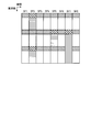
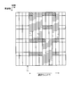
- FIG. 7 is a diagram illustrating an example of a resource use situation.
- the resources indicated by diagonal lines indicate resources used as control channels, and the resources indicated by thick diagonal lines are busy resources.
- the resources indicated by solid or horizontal lines indicate resources used as data channels, and the resources indicated by horizontal lines are busy resources.
- the resource shown in FIG. 7 may be a resource for the sensing period or a resource for the selection window, and has subframes SF1 to SF16 in the time axis direction, and each subframe has four subframes.
- the channel idle rate ⁇ CIR of equation (2) can be calculated. Assuming that the reference value H ISNRS is, for example, 0.3, the channel idle rate ⁇ CIR calculated from the idle rate in FIG. 8 is 0.5.
- the used resource control unit 113 and the parameter calculation unit 114 determine the channel idle rate ⁇ CIR for allocating idle resources to the packet for each resource allocation, and use the resource to maximize the channel idle rate ⁇ CIR Determine the assignment.
- the channel idle rate ⁇ CIR is calculated using the idle rate ⁇ ISNRS.
- the channel idle rate ⁇ CIR calculated by the above equation (4) is 0.5 as described above.
- the continuous idle rate ⁇ CSNRS shown in the above equation (5) is used, the following is performed.
- the continuous idle rate ⁇ CSNRS shown in the above equation (5) is calculated for each subframe.
- FIG. 9 shows the continuous idle rate of each subframe.
- the channel idle rate ⁇ CIR of the above equation (6) can be calculated. Assuming that the reference value H CSNRS is, for example, 0.3, the channel idle rate ⁇ CIR calculated from the continuous idle rate in FIG. 9 is 0.375.
- the used resource control unit 113 and the parameter calculation unit 114 determine a channel idle rate ⁇ CIR for each resource allocation when allocating idle resources to the packet, and determine a resource for maximizing the channel idle rate ⁇ CIR. Determine the assignment.
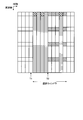
- the terminal device 100 transmits a packet by resource allocation that maximizes the channel idle rate ⁇ CIR , it is possible to increase the possibility that another terminal device satisfies an allowable delay and transmits a packet. That is, as shown in FIG. 10, for example, many resources that can be allocated to a packet can be left in the selection window, and delay in data transmission can be suppressed. In the example shown in FIG. 10, two consecutive sub-channels are idle in all sub-frames in the selection window. Subchannel resources can be allocated.
- the terminal device calculates the channel idle rate indicating the degree of expectation that an idle resource capable of transmitting a packet exists in the selection window corresponding to the packet size and the allowable delay. Then, resources are allocated so that the channel idle rate is maximized, and the packet is transmitted. For this reason, a large amount of resources that can be allocated to the packet can be left in the selection window, and the possibility that another terminal device transmits the packet while satisfying the allowable delay can be increased. In other words, a delay in data transmission can be suppressed.
- the information of the resources allocated to the packet in the above embodiment may be broadcast by the SCI mapped to the control channel.
- the SCI may use a two-dimensional bitmap in the frequency axis direction and the time axis direction to indicate the resources allocated to the packet and other resources in two values, for example. good.
- the SCI may indicate the number of consecutive resources in the frequency axis direction and the time axis direction, for example.
- the channel idle rate ⁇ CIR when transmitting packets using continuous sub-channels, is calculated using the continuous idle rate ⁇ CSNRS for each sub-frame. It is also possible to use parameters. That is, the continuous channel idle rate ⁇ CCIR indicating the degree of expectation of the presence of continuous idle sub-channels in a predetermined time width may be calculated.
- the continuous channel idle rate ⁇ CCIR is calculated using the number mk, l of sets of continuous idle subchannels for each subframe. Here, k is the index of the subframe, and l is the number of consecutive idle subchannels. Therefore, for example, when two sets of single idle subchannels and one set of two consecutive idle subchannels exist in the first subframe, m 1,1 is 2 and m 1,2 Is 1.
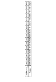
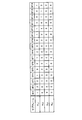
- FIG. 11 shows a list of mk, l in each subframe in the resource use situation shown in FIG.
- m k, l is obtained in this way, the continuous channel idle rate ⁇ CCIR can be calculated by the following equation (7).
- H NCISC indicates continuous subframes capable of transmitting a packet. Indicates the number of channels (Number of Contiguous Idle SubChannels). Therefore, H NCISC is an integer of 1 or more and N or less.
- the continuous channel idle rate ⁇ CCIR is calculated for the resource use status shown in FIG. 7, when H NCISC is 1, the continuous channel idle rate ⁇ CCIR is 0.391. When H NCISC is 2, the continuous channel idle rate ⁇ CCIR is 0.219 , and when H NCISC is 3, the continuous channel idle rate ⁇ CCIR is 0.094.
- the parameter calculation unit 114 calculates the continuous channel idle rate ⁇ CCIR instead of the channel idle rate ⁇ CIR , and the used resource control unit 113 uses it for packet transmission so that the continuous channel idle rate ⁇ CCIR is maximized. Resources may be determined.
- a subframe is used as an example of a unit in the time axis direction.
- the time unit is not necessarily a subframe, and may be a slot or a minislot. That is, if the channel idle rate or the continuous channel idle rate is calculated from the ratio of the idle or busy subchannel for each predetermined time unit, the same effect as described above can be obtained.
Landscapes
- Engineering & Computer Science (AREA)
- Computer Networks & Wireless Communication (AREA)
- Signal Processing (AREA)
- Mobile Radio Communication Systems (AREA)
Abstract
端末装置(100)は、所定範囲のリソースに所定のデータを送信可能なアイドルのリソースが存在する期待度を示すパラメータを算出するパラメータ算出部(114)と、前記パラメータ算出部(114)によって算出されたパラメータに応じてデータの送信に使用されるリソースを制御する使用リソース制御部(113)と、前記使用リソース制御部(113)による制御に従ってデータを送信する送信部(115、130)とを有する。
Description
本発明は、端末装置、無線通信システム及びリソース選択方法に関する。
現在のネットワークは、モバイル端末(スマートフォンやフィーチャーホン)のトラフィックがネットワークのリソースの大半を占めている。また、モバイル端末が使うトラフィックは、今後も拡大していく傾向にある。
一方で、IoT(Internet of a things)サービス(例えば、交通システム、スマートメータ、装置等の監視システム)の展開に合わせて、多様な要求条件を持つサービスに対応することが求められている。そのため、第5世代移動体通信(5G又はNR(New Radio))の通信規格では、4G(第4世代移動体通信)の標準技術(例えば、非特許文献1~11)に加えて、さらなる高データレート化、大容量化、低遅延化を実現する技術が求められている。なお、第5世代通信規格については、3GPPの作業部会(例えば、TSG-RAN WG1、TSG-RAN WG2等)で技術検討が進められている。
上述したように、多種多様なサービスに対応するために、5Gでは、eMBB(Enhanced Mobile BroadBand)、Massive MTC(Machine Type Communications)及びURLLC(Ultra-Reliable and Low Latency Communication)に分類される多くのユースケースのサポートが想定されている。
また、3GPPの作業部会では、V2X(Vehicle to Everything)通信についても議論されている。V2Xは、それぞれサイドリンクチャネルを用いる、自動車間通信を示すV2V(Vehicle to Vehicle)、自動車と歩行者(Pedestrian)との通信を示すV2P(Vehicle to Pedestrian)、及び自動車と標識等の道路インフラとの通信を示すV2I(Vehicle to Infrastructure)等の総称である。V2Xに関する規定は、例えば非特許文献1に記載されている。
V2Xにおけるリソース配置に関しては、制御チャネル及びデータチャネルを隣接させる配置方法と制御チャネル及びデータチャネルを隣接させない配置方法とが検討されている。具体的に、図1は、図中斜線で示す制御チャネルのPSCCH(Physical Sidelink Control CHannel)とデータチャネルのPSSCH(Physical Sidelink Shared CHannel)とを周波数軸方向で隣接させるリソース配置の例を示す図である。図1においては、実際に送信に用いられるPSCCH及びPSSCHのリソースをそれぞれ太い斜線及び横線で示す。また、図1において、時間軸方向にはサブフレームSF1~SF8が示されている。図中太い斜線で示すPSCCHのリソースには、対応するPSSCHのデータの変調方式及び符号化率に関する情報などを含むSCI(Sidelink Control Information)がマッピングされる。
一方、図2は、図中斜線で示すPSCCHとPSSCHとを周波数軸方向で隣接させないリソース配置の例を示す図である。図2においても、実際に送信に用いられるPSCCH及びPSSCHのリソースをそれぞれ太い斜線及び横線で示し、時間軸方向にサブフレームSF1~SF8を示す。図2においては、互いに対応するPSCCHとPSSCHが隣接していないが、図中太い斜線で示すPSCCHのリソースには、対応するPSSCHに関するSCIがマッピングされる。
これらのリソースを割り当てる方式には、例えば移動体通信システムが集中的に制御する方式と、V2Xを実施する各端末装置が自律的に制御する方式とがある。移動体通信システムが集中的に制御する方式は、V2Xを実施する端末装置が移動体通信システムのカバレージに在圏する際に適用可能であり、モード3とも呼ばれる。一方、各端末装置が自律的に制御する方式は、端末装置が移動体通信システムのカバレージに在圏しなくても適用可能であり、モード4とも呼ばれる。モード4では、リソースの割り当てのための端末装置と移動体通信システムとの間の通信が行われないため、端末装置において送信データが発生した場合の送信遅延が短縮され、厳しい遅延要求を満たすことが可能である。
モード4においては、各端末装置は、V2Xに用いられる周波数帯域をセンシングし、送信データが発生した場合には、センシングの結果に基づいて他の端末装置が使用する可能性が高いリソースを除外し、データの送信に用いるリソースを選択する。具体的には、例えば図3に示すように、ある端末装置の送信データが時刻Tにおいて発生すると、この端末装置は、送信データに許容される遅延時間に応じた時間幅の選択ウインドウを設定する。そして、端末装置は、時刻Tまでのセンシングの結果に基づいて、選択ウインドウ内の他の端末装置が使用する可能性が高いリソースを除外する。図3においては、例えば太い斜線及び横線で示すリソースが除外される。そして、端末装置は、選択ウインドウ内で除外されずに残ったリソースのいずれかを選択し、選択したリソースに送信データをマッピングして送信する。
3GPP TS 22.186 V15.2.0(2017-09)
3GPP TS 36.211 V15.1.0(2018-03)
3GPP TS 36.212 V15.1.0(2018-03)
3GPP TS 36.213 V15.1.0(2018-03)
3GPP TS 36.300 V15.1.0(2018-03)
3GPP TS 36.321 V15.1.0(2018-03)
3GPP TS 36.322 V15.0.1(2018-04)
3GPP TS 36.323 V14.5.0(2017-12)
3GPP TS 36.331 V15.1.0(2018-03)
3GPP TS 36.413 V15.1.0(2018-03)
3GPP TS 36.423 V15.1.0(2018-03)
3GPP TS 36.425 V14.1.0(2018-03)
3GPP TS 37.340 V15.1.0(2018-03)
3GPP TS 38.201 V15.0.0(2017-12)
3GPP TS 38.202 V15.1.0(2018-03)
3GPP TS 38.211 V15.1.0(2018-03)
3GPP TS 38.212 V15.1.1(2018-04)
3GPP TS 38.213 V15.1.0(2018-03)
3GPP TS 38.214 V15.1.0(2018-03)
3GPP TS 38.215 V15.1.0(2018-03)
3GPP TS 38.300 V15.1.0(2018-03)
3GPP TS 38.321 V15.1.0(2018-03)
3GPP TS 38.322 V15.1.0(2018-03)
3GPP TS 38.323 V15.1.0(2018-03)
3GPP TS 38.331 V15.1.0(2018-03)
3GPP TS 38.401 V15.1.0(2018-03)
3GPP TS 38.410 V0.9.0(2018-04)
3GPP TS 38.413 V0.8.0(2018-04)
3GPP TS 38.420 V0.8.0(2018-04)
3GPP TS 38.423 V0.8.0(2018-04)
3GPP TS 38.470 V15.1.0(2018-03)
3GPP TS 38.473 V15.1.1(2018-04)
3GPP TR 38.801 V14.0.0(2017-04)
3GPP TR 38.802 V14.2.0(2017-09)
3GPP TR 38.803 V14.2.0(2017-09)
3GPP TR 38.804 V14.0.0(2017-03)
3GPP TR 38.900 V14.3.1(2017-07)
3GPP TR 38.912 V14.1.0(2017-06)
3GPP TR 38.913 V14.3.0(2017-06)
Rafael Molina-Masegosa et al., "LTE-V for Sidelink 5G V2X Vehicular Communications: A New 5G Technology for Short-Range Vehicle-to-Everything Communications", IEEE Vehicular Technology Magazine Volume 12 Issue 4, December 2017
ところで、NR(New Radio)-V2Xでは様々なデータが送受信されるため、比較的大きいサイズのデータを送信する端末装置は、モード4において多くのリソースを占有する。具体的には、例えば複数のサブフレームにわたって連続するリソースが1つの端末装置によって占有されることがある。
しかしながら、多くのリソースが占有されると、他の端末装置による送信機会が減少し、他の端末装置によるデータの送信が遅延するという問題がある。すなわち、例えば図4に示すように、ある端末装置において時刻T1に送信すべきデータが発生した場合、この端末装置は、時刻T1までのセンシングの結果に基づいて、選択ウインドウ内の他の端末装置が使用する可能性が高いリソースを除外する。図4においては、例えば太い斜線及び横線で示すリソースが除外される。そして、端末装置は、選択ウインドウ内で除外されずに残ったリソースのいずれかを選択し、選択したリソースに送信データをマッピングして送信する。
図4においては、時刻T1の後の4サブフレームのリソースが除外されるため、端末装置は、早くても時刻T2以降のリソースを選択することになる。したがって、データの送信が遅延し、データの遅延要求を満たすことが困難になる場合がある。このように、周波数軸方向及び時間軸方向に連続したリソースが一部の端末装置によって占有されると、他の端末装置によるデータの送信が遅延してしまう。
開示の技術は、かかる点に鑑みてなされたものであって、データ送信の遅延を抑制することができる端末装置、無線通信システム及びリソース選択方法を提供することを目的とする。
本願が開示する端末装置は、1つの態様において、所定範囲のリソースに所定のデータを送信可能なアイドルのリソースが存在する期待度を示すパラメータを算出する算出部と、前記算出部によって算出されたパラメータに応じてデータの送信に使用されるリソースを制御する制御部と、前記制御部による制御に従ってデータを送信する送信部とを有する。
本願が開示する端末装置、無線通信システム及びリソース選択方法の1つの態様によれば、データ送信の遅延を抑制することができるという効果を奏する。
以下、本願が開示する端末装置、無線通信システム及びリソース選択方法の一実施の形態について、図面を参照して詳細に説明する。なお、この実施の形態により本発明が限定されるものではない。
図5は、一実施の形態に係る端末装置100の構成を示すブロック図である。図5に示す端末装置100は、プロセッサ110、メモリ120及び無線通信部130を有する。
プロセッサ110は、例えばCPU(Central Processing Unit)、FPGA(Field Programmable Gate Array)又はDSP(Digital Signal Processor)などを備え、端末装置100の全体を統括制御する。具体的には、プロセッサ110は、受信制御部111、センシング部112、使用リソース制御部113、パラメータ算出部114及び送信制御部115を有する。
受信制御部111は、他の端末装置から受信された受信データを復調及び復号する。具体的には、受信制御部111は、制御チャネル(PSCCH)の復調及び復号を実行し、端末装置100宛てのデータに関するSCI(Sidelink Control Information)を取得する。そして、受信制御部111は、SCIに基づいてデータチャネル(PSSCH)の復調及び復号を実行する。
センシング部112は、他の端末装置によってリソースが通信に使用されているか否かを検知するセンシングを実行する。具体的には、センシング部112は、所定のセンシング期間において、V2X通信に用いられる周波数帯域全体のSCIを受信し、各サブフレームにおける各サブチャネルの受信電力を測定し、それぞれのサブフレーム及びサブチャネルにおいて他の端末装置が信号を送信しているか否かを判定する。以下においては、他の端末装置が信号の送信に使用しているリソースを「ビジー」のリソースといい、他の端末装置が信号の送信に使用していないリソースを「アイドル」のリソースという。
使用リソース制御部113は、センシング部112によるセンシングの結果に基づいて、端末装置100が信号の送信に使用するリソースを決定する。具体的には、使用リソース制御部113は、送信すべきパケットが発生した場合に、パケットの許容遅延に応じた選択ウインドウを設定する。そして、使用リソース制御部113は、センシングの結果に基づいて選択ウインドウ内のアイドルのリソースを特定し、アイドルのリソースからパケットの送信に使用するリソースを選択する。このとき、使用リソース制御部113は、センシング結果をパラメータ算出部114へ出力し、緊急パケットを送信可能なアイドルのリソースが存在する期待度を示すチャネルアイドル率を算出するようにパラメータ算出部114に依頼する。そして、使用リソース制御部113は、選択ウインドウ内のチャネルアイドル率が最大となるようにパケットの送信に使用するリソースを選択する。
なお、端末装置100が送信するデータには、定期的に発生する通常パケットと、突発的に発生する緊急パケットとがある。通常パケットは、あらかじめ割り当てられた周期的なリソースを使用して送信されるのに対し、緊急パケットは、発生する度に選択ウインドウから選択されたアイドルのリソースを使用して送信される。使用リソース制御部113は、緊急パケットが発生した場合には、常にチャネルアイドル率に基づいて使用するリソースを選択するが、通常パケットが発生した場合には、所定の条件が満たされる場合にチャネルアイドル率に基づいて使用するリソースを変更する。
パラメータ算出部114は、使用リソース制御部113から出力されるセンシング結果に基づいて、チャネルアイドル率を算出する。具体的には、パラメータ算出部114は、センシング結果から、選択ウインドウ内の各リソースがビジーであるかアイドルであるかを推定する。すなわち、選択ウインドウ内のリソース全体は、時間軸方向には複数のサブフレームを含み、周波数軸方向には複数のサブチャネルを含むため、選択ウインドウ内の各サブフレームにおいてそれぞれのサブチャネルがビジーであるかアイドルであるかが推定される。そして、パラメータ算出部114は、サブフレームごとのアイドルのサブチャネルの割合(Idle Subchannel Number Ratio in Subframe)を示すアイドル率γISNRSを以下の式(1)によって算出する。
γISNRS(k)=ik/N …(1)
γISNRS(k)=ik/N …(1)
ただし、式(1)において、kはサブフレームのインデックスであり、ikはk番目のサブフレームにおけるアイドルのサブチャネルの数を示し、Nは1サブフレームにおける全サブチャネルの数を示す。
そして、パラメータ算出部114は、アイドル率γISNRSを用いて所定の時間幅のチャネルアイドル率(Channel Idle Ratio)γCIRを以下の式(2)によって算出する。

ただし、式(2)において、Mは所定の時間幅に含まれるサブフレームの数を示し、例えばセンシング期間におけるセンシングウインドウ(過去に使用されたサブフレーム)と選択ウインドウ(将来使用されるサブフレーム)とに含まれるサブフレームの数を示す。また、floor(x)はx以下の最大の整数を示す床関数である。HISNRSは、サブフレームでパケットを送信可能と判断できる基準を示す基準値である。したがって、HISNRSは、パケットの送信に必要なリソースサイズ(例えば緊急パケットのサイズ)に対応するサブチャネル数の平均値が1サブフレームにおける全サブチャネルの数に占める割合以上の値であり、1以下の値である。アイドル率γISNRSが基準値HISNRS以上のサブフレームではパケットを送信するのに十分なアイドルのサブチャネルがあるのに対し、アイドル率γISNRSが基準値HISNRS未満のサブフレームではパケットを送信するのに十分なアイドルのサブチャネルがないことになる。
そして、上式(2)では、アイドル率γISNRSと基準値HISNRSとの差の床関数をサブフレームごとに求め、所定の時間幅内のサブフレームに関する平均値を算出しているため、チャネルアイドル率γCIRは、所定の時間幅内でのパケットの送信可能性を示す期待度を表している。そして、所定の時間幅には選択ウインドウが含まれるため、チャネルアイドル率γCIRは、選択ウインドウ内での通常パケット又は緊急パケットの送信可能性を示す期待度を表しているといえる。
パラメータ算出部114は、上式(2)によって算出されるチャネルアイドル率γCIRを、パケットに対する選択ウインドウ内のリソースの割り当てごとに算出する。つまり、使用リソース制御部113が選択ウインドウ内のリソースを選択してパケットに割り当てることを仮定し、それぞれのリソース割り当てをした場合のチャネルアイドル率γCIRが算出される。この結果、使用リソース制御部113は、チャネルアイドル率γCIRが最大となるリソース割り当てを選択し、パケットの送信に使用するリソースを決定する。
ところで、上述したチャネルアイドル率γCIRは、サブフレームごとのアイドルのサブチャネルの割合を示すアイドル率γISNRSに基づいて算出するものとしたが、サブフレームごとのビジーのサブチャネルの割合に基づいてチャネルアイドル率γCIRを算出することも可能である。この場合、パラメータ算出部114は、サブフレームごとのビジーのサブチャネルの割合を示すビジー率(Channel occupancy Ratio in Subframe)γCRSを以下の式(3)によって算出する。
γCRS(k)=nk/N …(3)
γCRS(k)=nk/N …(3)
ただし、式(3)において、nkはk番目のサブフレームにおけるビジーのサブチャネルの数を示す。そして、パラメータ算出部114は、ビジー率γCRSを用いて所定の時間幅のチャネルアイドル率γCIRを以下の式(4)によって算出する。

ただし、式(4)において、ceil(x)はx以上の最小の整数を示す天井関数である。また、HCRSは、サブフレームでパケットを送信可能と判断できる基準を示す基準値である。したがって、HCRSは、パケットの送信に必要なリソースサイズ(例えば緊急パケットのサイズ)に対応するサブチャネル数の平均値が1サブフレームにおける全サブチャネルの数に占める割合以上の値であり、1以下の値である。ビジー率γCRSが基準値HCRS以上のサブフレームでは、ビジーのサブチャネルが多くパケットを送信するのに十分なアイドルのサブチャネルがないのに対し、ビジー率γCRSが基準値HCRS未満のサブフレームでは、ビジーのサブチャネルが少なくパケットを送信するのに十分なアイドルのサブチャネルがあることになる。
上式(2)、(4)で示したチャネルアイドル率γCIRは、単にアイドルのサブチャネルの総量がパケットのサイズ以上であれば、該当するサブフレームでパケットを送信可能であるものとして算出されている。しかしながら、サブフレーム内で連続したアイドルのサブチャネルのサイズがパケットのサイズ以上である場合に、該当するサブフレームでパケットを送信可能であるものとしてチャネルアイドル率γCIRを算出することも可能である。この場合、パラメータ算出部114は、サブフレームごとの連続する最大のアイドルのサブチャネルの割合を示す連続アイドル率(maximum Contiguous Subchannel Number Ratio in Subframe)γCSNRSを以下の式(5)によって算出する。
γCSNRS(k)=imax,k/N …(5)
γCSNRS(k)=imax,k/N …(5)
ただし、式(5)において、imax,kはk番目のサブフレームにおいて連続するアイドルのサブチャネルの最大数を示す。そして、パラメータ算出部114は、γCSNRSを用いて所定の時間幅のチャネルアイドル率γCIRを以下の式(6)によって算出する。

ただし、式(6)において、HCSNRSは、サブフレームでパケットを送信可能と判断できる基準を示す基準値である。したがって、HCSNRSは、パケットの送信に必要なリソースサイズ(例えば緊急パケットのサイズ)に対応するサブチャネル数の平均値が1サブフレームにおける全サブチャネルの数に占める割合以上の値であり、1以下の値である。連続アイドル率γCSNRSが基準値HCSNRS以上のサブフレームではパケットを送信するのに十分な連続するアイドルのサブチャネルがあるのに対し、連続アイドル率γCSNRSが基準値HCSNRS未満のサブフレームではパケットを送信するのに十分な連続するアイドルのサブチャネルがないことになる。
パラメータ算出部114は、上式(4)又は式(6)によってチャネルアイドル率γCIRを算出する場合も、上式(2)によってチャネルアイドル率γCIRを算出する場合と同様に、リソースの割り当てごとにチャネルアイドル率γCIRを算出する。上式(6)のチャネルアイドル率γCIRを用いてパケットの送信に使用するリソースを決定する場合には、連続するサブチャネルがアイドルである期待度を大きくすることができ、大きいサイズの緊急パケットを少ない遅延で送信する可能性を向上することができる。
送信制御部115は、使用リソース制御部113によって選択されたリソースを用いてパケットを送信するように制御する。すなわち、送信制御部115は、データの符号化及び変調などを実行し、使用リソース制御部113によって選択されたリソースにパケットをマッピングする。そして、送信制御部115は、マッピングにより得られた送信データを無線通信部130を介して送信する。上述したように、パケットには通常パケットと緊急パケットとがあるが、送信制御部115は、いずれのパケットについても送信制御を行う。
メモリ120は、例えばRAM(Random Access Memory)又はROM(Read Only Memory)などを備え、プロセッサ110が処理を実行するために使用する情報を記憶する。
無線通信部130は、プロセッサ110によって生成される送信データに対して、例えばD/A(Digital/Analog)変換及びアップコンバートなどの無線送信処理を施し、アンテナを介して無線送信する。また、無線通信部130は、アンテナを介して無線受信した受信データに対して、例えばダウンコンバート及びA/D(Analog/Digital)変換などの無線受信処理を施し、プロセッサ110へ出力する。
次いで、上記のように構成された端末装置100によるパケット送信方法について、図6に示すフロー図を参照しながら説明する。以下においては、定期的に送信される通常パケットが発生した場合のパケット送信方法について説明する。
通常パケットは、あらかじめ割り当てられた周期的なリソースを用いて各端末装置から送信される。このため、通常パケットが発生した場合は、常にリソースが選択されるわけではなく、チャネルアイドル率が低下して緊急パケットの送信が困難になっている場合や、後述する再選択タイマが満了した場合に、通常パケットの送信に使用されるリソースが変更される。
そこで、使用リソース制御部113によって、チャネルアイドル率が低下したか否かを判定するための閾値HCIRが設定される(ステップS101)。閾値HCIRは、パケットに許容される最大の遅延時間に対するサブフレームの時間長の比率以上の値であり、1以下の値である。チャネルアイドル率γCIRが閾値HCIR以上であればパケットを送信する余裕があるリソース配置であるのに対し、チャネルアイドル率γCIRが閾値HCIR未満であればパケットを送信するのが困難なリソース配置であることになる。
また、パラメータ算出部114によって、チャネルアイドル率の算出に用いられる基準値HISNRSが設定される(ステップS102)。そして、通常パケットが発生すると(ステップS103)、センシング部112によって取得された通常パケットの発生タイミングまでのセンシング結果が、使用リソース制御部113からパラメータ算出部114へ出力される。センシング結果は、センシング期間の各サブフレームにおける各サブチャネルがアイドルであるかビジーであるかを示しているため、パラメータ算出部114によって、センシング期間のチャネルアイドル率γCIRが算出される(ステップS104)。
そして、使用リソース制御部113によって、チャネルアイドル率γCIRと閾値HCIRとが比較され(ステップS105)、チャネルアイドル率γCIRが閾値HCIR未満である場合は(ステップS105No)、緊急パケットの送信が困難となっているため、通常パケットの送信に割り当てられるリソースが変更される。
一方、チャネルアイドル率γCIRが閾値HCIR以上である場合は(ステップS105Yes)、リソースの割り当てを変更してからランダムな時間をカウントして満了する再選択タイマが満了したか否かが、使用リソース制御部113によって判定される(ステップS109)。再選択タイマが満了していない場合には(ステップS109No)、通常パケットの送信に使用されるリソースの変更が不要なため、あらかじめ割り当てられた周期的なリソースを使用して通常パケットが送信される(ステップS108)。これに対して、再選択タイマが満了した場合には(ステップS109Yes)、チャネルアイドル率γCIRが閾値HCIR以上であっても、通常パケットの送信に割り当てられるリソースが変更される。
通常パケットの送信に割り当てられるリソースの変更は、以下のようにして実行される。すなわち、使用リソース制御部113によって、通常パケットの送信可能性があるリソースの範囲が選択ウインドウに設定される。この選択ウインドウは、緊急パケットの許容遅延に応じたリソースの範囲であっても良い。そして、パラメータ算出部114によって、センシング結果から、選択ウインドウ内の各リソースがビジーであるかアイドルであるかが推定される。このとき、通常パケットの送信のために端末装置100にあらかじめ割り当てられた周期的なリソースはアイドルのリソースとされる。
選択ウインドウ内の各サブフレームにおけるサブチャネルがアイドルであるかビジーであるかが推定されると、通常パケットに対するリソース割り当てごとに、選択ウインドウを含む所定の時間幅のチャネルアイドル率γ’CIRが算出される(ステップS106)。すなわち、アイドルのリソースを通常パケットの送信に割り当ててビジーのリソースとする場合それぞれについて、チャネルアイドル率γ’CIRが算出される。異なるアイドルのリソースを通常パケットの送信に割り当てる場合のそれぞれのチャネルアイドル率γ’CIRは、その都度使用リソース制御部113へ報告される。そして、所定の時間幅内のすべてのリソース割り当てについてチャネルアイドル率γ’CIRが算出されると、使用リソース制御部113によって、チャネルアイドル率γ’CIRを最大にするリソース割り当てが決定される(ステップS107)。
このようにして決定されたリソース割り当ては、チャネルアイドル率γ’CIRを最大にするものであるため、決定されたリソースを使用して通常パケットを送信すれば、選択ウインドウ内でのパケットの送信可能性を最大にすることができる。つまり、選択ウインドウが例えば緊急パケットの許容遅延に応じて設定されていれば、緊急パケットを許容遅延以内で送信する可能性を最大にすることができる。換言すれば、データ送信の遅延を抑制することができる。
使用リソース制御部113によって決定されたリソース割り当ては、送信制御部115へ通知され、送信制御部115によって、決定されたリソースを使用して通常パケットを送信するように制御される。そして、通常パケットは、無線通信部130からアンテナを介して送信される(ステップS108)。
なお、ここでは通常パケットの送信について説明したが、緊急パケットが発生した場合には、センシング期間のチャネルアイドル率γCIRや再選択タイマに関わらず、選択ウインドウを含む所定の時間幅のチャネルアイドル率γ’CIRの算出によって緊急パケットの送信に使用するリソースが決定される。すなわち、緊急パケットが発生した場合は、図6のステップS104、S105、S109の処理は省略され、ステップS106、S107の処理によって緊急パケットの送信に使用するリソースが決定される。
次に、チャネルアイドル率の算出の具体例について図7~9を参照しながら説明する。図7は、リソースの使用状況の一例を示す図である。図7において、斜線で示すリソースは制御チャネルとして使用されるリソースを示し、太い斜線で示すリソースがビジーのリソースである。また、無地又は横線で示すリソースはデータチャネルとして使用されるリソースを示し、横線で示すリソースがビジーのリソースである。図7に示すリソースは、センシング期間のリソースであっても良いし、選択ウインドウのリソースであっても良く、時間軸方向にはサブフレームSF1からSF16を有し、各サブフレームには4つのサブチャネルを有する。すなわち、周波数軸方向では、制御チャネル及びデータチャネルそれぞれ1つ分に相当するリソースが1つのサブチャネルを構成する。
図7に示すリソースの使用状況が得られた場合、上式(1)に示したアイドル率γISNRSがそれぞれのサブフレームについて算出される。例えばサブフレームSF1では、4つのサブチャネルのうち1つのサブチャネルのみがアイドルであるため、アイドル率γISNRSは0.25(=1/4)である。同様に、例えばサブフレームSF2では、4つのサブチャネルのうち2つのサブチャネルがアイドルであるため、アイドル率γISNRSは0.5(=2/4)である。各サブフレームのアイドル率を図8に示す。
各サブフレームのアイドル率が算出されると、上式(2)のチャネルアイドル率γCIRを算出することができる。基準値HISNRSを例えば0.3とすると、図8のアイドル率から算出されるチャネルアイドル率γCIRは0.5となる。使用リソース制御部113及びパラメータ算出部114は、パケットを送信する際、パケットにアイドルのリソースを割り当てる場合のチャネルアイドル率γCIRをそれぞれのリソース割り当てについて求め、チャネルアイドル率γCIRを最大にするリソース割り当てを決定する。
なお、ここではアイドル率γISNRSを用いてチャネルアイドル率γCIRを算出する例を示したが、上式(3)に示したビジー率γCRSを用いる場合には、基準値HCRSを例えば0.7(=1-0.3)とすれば、上式(4)によって算出されるチャネルアイドル率γCIRは上記と同様に0.5となる。また、上式(5)に示した連続アイドル率γCSNRSを用いる場合には、以下のようになる。
すなわち、図7に示すリソースの使用状況が得られた場合、上式(5)に示した連続アイドル率γCSNRSがそれぞれのサブフレームについて算出される。例えばサブフレームSF1では、連続するアイドルのサブチャネルの数の最大値は1であるため、連続アイドル率γCSNRSは0.25(=1/4)である。同様に、例えばサブフレームSF2でも、連続するアイドルのサブチャネルの数の最大値は1であるため、連続アイドル率γISNRSは0.25(=1/4)である。つまり、サブフレームSF2では、アイドルのサブチャネルが2つあっても、連続するアイドルのサブチャネルの最大数は1であるため、サブフレームSF2の連続アイドル率はサブフレームSF1の連続アイドル率と等しくなる。各サブフレームの連続アイドル率を図9に示す。
各サブフレームの連続アイドル率が算出されると、上式(6)のチャネルアイドル率γCIRを算出することができる。基準値HCSNRSを例えば0.3とすると、図9の連続アイドル率から算出されるチャネルアイドル率γCIRは0.375となる。使用リソース制御部113及びパラメータ算出部114は、パケットを送信する際、パケットにアイドルのリソースを割り当てる場合のチャネルアイドル率γCIRをそれぞれのリソース割り当てについて求め、チャネルアイドル率γCIRを最大にするリソース割り当てを決定する。
このようなチャネルアイドル率γCIRを最大にするリソース割り当てによって端末装置100がパケットを送信することにより、他の端末装置が、許容遅延を満たしてパケットを送信する可能性を高めることができる。すなわち、例えば図10に示すように、パケットに割り当て可能なリソースを選択ウインドウ内に多く残すことができ、データ送信の遅延を抑制することができる。図10に示した例では、選択ウインドウ内のすべてのサブフレームにおいて、連続する2つのサブチャネルがアイドルであるため、時刻T1において発生したパケットに対して、いずれかのサブフレームの連続する2つのサブチャネルのリソースを割り当てることができる。
以上のように、本実施の形態によれば、端末装置は、パケットのサイズと許容遅延に対応する選択ウインドウ内にパケットを送信可能なアイドルのリソースが存在する期待度を示すチャネルアイドル率を算出し、チャネルアイドル率が最大になるようにリソース割り当てを行ってパケットを送信する。このため、パケットに割り当て可能なリソースを選択ウインドウ内に多く残すことができ、他の端末装置が許容遅延を満たしてパケットを送信する可能性を高めることができる。換言すれば、データ送信の遅延を抑制することができる。
なお、上記一実施の形態においてパケットに割り当てられたリソースの情報は、制御チャネルにマッピングされるSCIによって報知されても良い。パケットに非連続のリソースが割り当てられる場合には、SCIは、例えば周波数軸方向及び時間軸方向の2次元のビットマップに、パケットに割り当てられるリソースとそれ以外のリソースとを2値で示しても良い。また、パケットに連続するリソースが割り当てられる場合には、SCIは、例えば周波数軸方向及び時間軸方向それぞれの連続するリソースの数を示しても良い。
上記一実施の形態においては、連続したサブチャネルを使用してパケットを送信する場合にはサブフレームごとの連続アイドル率γCSNRSを用いてチャネルアイドル率γCIRを算出するものとしたが、他のパラメータを用いることも可能である。すなわち、所定の時間幅において連続するアイドルのサブチャネルが存在する期待度を示す連続チャネルアイドル率γCCIRが算出されても良い。連続チャネルアイドル率γCCIRは、サブフレームごとの連続するアイドルのサブチャネルの組の数mk,lを用いて算出される。ただし、kはサブフレームのインデックスであり、lは連続するアイドルのサブチャネルの数である。したがって、例えば1番目のサブフレームに、単独のアイドルのサブチャネルが2組存在し連続する2つのアイドルのサブチャネルが1組存在する場合には、m1,1が2でありm1,2が1であることになる。
図11に、図7に示したリソース使用状況での各サブフレームにおけるmk,lの一覧を示す。このようにしてmk,lが得られると、以下の式(7)によって連続チャネルアイドル率γCCIRを算出することができる。
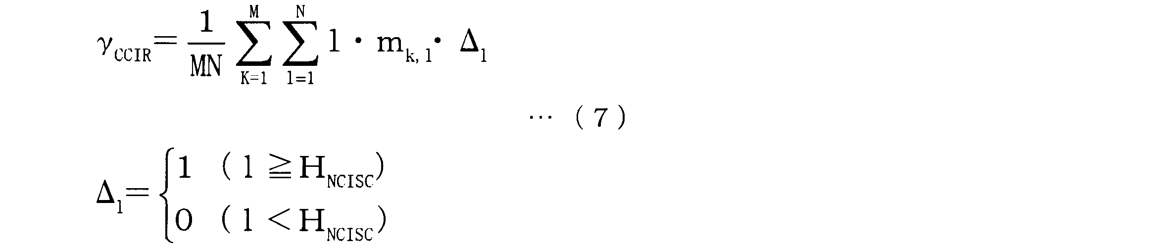
ただし、上式(7)において、Mは所定の時間幅に含まれるサブフレームの数を示し、Nは1サブフレームにおける全サブチャネルの数を示し、HNCISCはパケットを送信可能な連続するサブチャネル数(Number of Contiguous Idle SubChannels)を示す。したがって、HNCISCは、1以上N以下の整数である。
図7に示したリソースの使用状況について、連続チャネルアイドル率γCCIRを算出すると、HNCISCが1の場合には、連続チャネルアイドル率γCCIRは0.391となる。また、HNCISCが2の場合には、連続チャネルアイドル率γCCIRは0.219となり、HNCISCが3の場合には、連続チャネルアイドル率γCCIRは0.094となる。パラメータ算出部114は、チャネルアイドル率γCIRの代わりに連続チャネルアイドル率γCCIRを算出し、使用リソース制御部113は、連続チャネルアイドル率γCCIRを最大とするように、パケットの送信に使用するリソースを決定しても良い。
なお、以上の説明においては、時間軸方向の単位の例としてサブフレームを用いたが、時間単位は必ずしもサブフレームでなくても良く、スロット又はミニスロットなどでも良い。つまり、所定の時間単位ごとのアイドル又はビジーのサブチャネルの割合からチャネルアイドル率又は連続チャネルアイドル率が算出されれば、上記と同様の効果が得られる。
110 プロセッサ
111 受信制御部
112 センシング部
113 使用リソース制御部
114 パラメータ算出部
115 送信制御部
120 メモリ
130 無線通信部
111 受信制御部
112 センシング部
113 使用リソース制御部
114 パラメータ算出部
115 送信制御部
120 メモリ
130 無線通信部
Claims (8)
- 所定範囲のリソースに所定のデータを送信可能なアイドルのリソースが存在する期待度を示すパラメータを算出する算出部と、
前記算出部によって算出されたパラメータに応じてデータの送信に使用されるリソースを制御する制御部と、
前記制御部による制御に従ってデータを送信する送信部と
を有することを特徴とする端末装置。 - 前記算出部は、
周波数軸方向に複数のサブチャネルを有し時間軸方向に複数の時間単位を有する前記所定範囲のリソースにおける、前記所定のデータを送信可能なアイドルのサブチャネルを有する時間単位の割合に対応するチャネルアイドル率を算出し、
前記制御部は、
前記チャネルアイドル率を最大にするようにデータの送信に使用されるリソースを決定する
ことを特徴とする請求項1記載の端末装置。 - 前記算出部は、
1つの時間単位における全サブチャネル数Nと、前記所定範囲のリソースのk番目の時間単位におけるアイドルのサブチャネル数ikとを用いて、下記の式によって算出される時間単位ごとのアイドル率γISNRS(k)からチャネルアイドル率を算出する
γISNRS(k)=ik/N
ことを特徴とする請求項2記載の端末装置。 - 前記算出部は、
1つの時間単位における全サブチャネル数Nと、前記所定範囲のリソースのk番目の時間単位におけるビジーのサブチャネル数nkとを用いて、下記の式によって算出される時間単位ごとのビジー率γCRS(k)からチャネルアイドル率を算出する
γCRS(k)=nk/N
ことを特徴とする請求項2記載の端末装置。 - 前記算出部は、
1つの時間単位における全サブチャネル数Nと、前記所定範囲のリソースのk番目の時間単位における連続する最大のアイドルのサブチャネル数imax,kとを用いて、下記の式によって算出される時間単位ごとの連続アイドル率γCSNRS(k)からチャネルアイドル率を算出する
γCSNRS(k)=imax,k/N
ことを特徴とする請求項2記載の端末装置。 - 他の端末装置が使用するビジーのリソースを検知するセンシングを実行するセンシング部をさらに有し、
前記算出部は、
前記センシング部によるセンシング結果に基づいてパラメータを算出する
ことを特徴とする請求項1記載の端末装置。 - 第1の端末装置と第2の端末装置とを有する無線通信システムであって、
前記第1の端末装置は、
所定範囲のリソースに所定のデータを送信可能なアイドルのリソースが存在する期待度を示すパラメータを算出する算出部と、
前記算出部によって算出されたパラメータに応じてデータの送信に使用されるリソースを制御する制御部と、
前記制御部による制御に従ってデータを送信する送信部とを有し、
前記第2の端末装置は、
前記第1の端末装置を含む他の端末装置から送信されたデータを受信する受信部と、
前記受信部によって受信されるデータに基づいて、前記他の端末装置が使用するビジーのリソースを検知するセンシングを実行するセンシング部とを有する
ことを特徴とする無線通信システム。 - 所定範囲のリソースに所定のデータを送信可能なアイドルのリソースが存在する期待度を示すパラメータを算出し、
算出されたパラメータに応じてデータの送信に使用されるリソースを制御し、
リソースの制御に従ってデータを送信する
処理を有することを特徴とするリソース選択方法。
Priority Applications (1)
| Application Number | Priority Date | Filing Date | Title |
|---|---|---|---|
| PCT/JP2018/029668 WO2020031270A1 (ja) | 2018-08-07 | 2018-08-07 | 端末装置、無線通信システム及びリソース選択方法 |
Applications Claiming Priority (1)
| Application Number | Priority Date | Filing Date | Title |
|---|---|---|---|
| PCT/JP2018/029668 WO2020031270A1 (ja) | 2018-08-07 | 2018-08-07 | 端末装置、無線通信システム及びリソース選択方法 |
Publications (1)
| Publication Number | Publication Date |
|---|---|
| WO2020031270A1 true WO2020031270A1 (ja) | 2020-02-13 |
Family
ID=69415238
Family Applications (1)
| Application Number | Title | Priority Date | Filing Date |
|---|---|---|---|
| PCT/JP2018/029668 Ceased WO2020031270A1 (ja) | 2018-08-07 | 2018-08-07 | 端末装置、無線通信システム及びリソース選択方法 |
Country Status (1)
| Country | Link |
|---|---|
| WO (1) | WO2020031270A1 (ja) |
Citations (1)
| Publication number | Priority date | Publication date | Assignee | Title |
|---|---|---|---|---|
| JP2012191432A (ja) * | 2011-03-10 | 2012-10-04 | Yamaha Corp | 無線オーディオ伝送方法 |
-
2018
- 2018-08-07 WO PCT/JP2018/029668 patent/WO2020031270A1/ja not_active Ceased
Patent Citations (1)
| Publication number | Priority date | Publication date | Assignee | Title |
|---|---|---|---|---|
| JP2012191432A (ja) * | 2011-03-10 | 2012-10-04 | Yamaha Corp | 無線オーディオ伝送方法 |
Non-Patent Citations (1)
| Title |
|---|
| ITRI: "Remaining Issues on Latency Reduction for V2X", 3GPP TSG RAN WG1 MEETING #93 R1-1806819, 11 May 2018 (2018-05-11), XP051461972 * |
Similar Documents
| Publication | Publication Date | Title |
|---|---|---|
| He et al. | Design and analysis of a short-term sensing-based resource selection scheme for C-V2X networks | |
| US20250267706A1 (en) | Network routing system, method, and computer program product | |
| US11678299B2 (en) | Method and user equipment for multi-carrier data transmission | |
| EP4093132A1 (en) | Method and apparatus for allocating resources through cooperation between terminals in v2x system | |
| JP6789302B2 (ja) | 通信方法、ネットワーク側装置、及び端末 | |
| US10743336B2 (en) | Scheduling and transmitting control information and data for direct communication | |
| CN113785612A (zh) | 用于在侧链路通信中测量和报告信道状态的方法和装置 | |
| EP3354048B1 (en) | Speed dependent transmission format for vehicular or d2d transmission | |
| KR20210141408A (ko) | 무선 통신 네트워크를 위한 장치, 방법 및 그 사용 | |
| JP2019533364A (ja) | データ送信方法及びその端末デバイス | |
| JP7837364B2 (ja) | サイドリンク構成のためのシステムおよび方法 | |
| Rolich et al. | Impact of Persistence on the Age of Information in 5G NR-V2X Sidelink Communications. | |
| EP4583601A1 (en) | Communication method, apparatus and system | |
| Ha et al. | C-V2X adaptive short-term sensing scheme for enhanced DENM and CAM communication | |
| EP3886514A1 (en) | Communication device and wireless communication system | |
| CN115529572B (zh) | 资源选择方法及装置 | |
| CN107431901A (zh) | 蜂窝网络中的调度 | |
| JP7423121B2 (ja) | 無線通信システムにおけるリソース割り当て方法及び装置 | |
| WO2020031270A1 (ja) | 端末装置、無線通信システム及びリソース選択方法 | |
| WO2021161473A1 (ja) | 無線通信装置、無線通信システム及び無線リソース選択方法 | |
| CN108781442B (zh) | 在无线网络中的移动设备之间控制直接数据传输 | |
| CN116326009A (zh) | 边链路资源选择方法以及装置 | |
| US11968695B2 (en) | Communication device, wireless communication system, and resource selecting method | |
| JP7329660B2 (ja) | データ送信方法及びその端末デバイス | |
| WO2022029943A1 (ja) | 端末装置、無線通信システム及び無線通信方法 |
Legal Events
| Date | Code | Title | Description |
|---|---|---|---|
| 121 | Ep: the epo has been informed by wipo that ep was designated in this application |
Ref document number: 18929330 Country of ref document: EP Kind code of ref document: A1 |
|
| NENP | Non-entry into the national phase |
Ref country code: DE |
|
| 122 | Ep: pct application non-entry in european phase |
Ref document number: 18929330 Country of ref document: EP Kind code of ref document: A1 |
|
| NENP | Non-entry into the national phase |
Ref country code: JP |