WO2020031228A1 - 生産スケジューリング装置、および生産スケジューリング方法 - Google Patents
生産スケジューリング装置、および生産スケジューリング方法 Download PDFInfo
- Publication number
- WO2020031228A1 WO2020031228A1 PCT/JP2018/029393 JP2018029393W WO2020031228A1 WO 2020031228 A1 WO2020031228 A1 WO 2020031228A1 JP 2018029393 W JP2018029393 W JP 2018029393W WO 2020031228 A1 WO2020031228 A1 WO 2020031228A1
- Authority
- WO
- WIPO (PCT)
- Prior art keywords
- production
- information
- operation state
- supply
- facility
- Prior art date
- Legal status (The legal status is an assumption and is not a legal conclusion. Google has not performed a legal analysis and makes no representation as to the accuracy of the status listed.)
- Ceased
Links
Images



















Classifications
-
- G—PHYSICS
- G05—CONTROLLING; REGULATING
- G05B—CONTROL OR REGULATING SYSTEMS IN GENERAL; FUNCTIONAL ELEMENTS OF SUCH SYSTEMS; MONITORING OR TESTING ARRANGEMENTS FOR SUCH SYSTEMS OR ELEMENTS
- G05B19/00—Program-control systems
- G05B19/02—Program-control systems electric
- G05B19/418—Total factory control, i.e. centrally controlling a plurality of machines, e.g. direct or distributed numerical control [DNC], flexible manufacturing systems [FMS], integrated manufacturing systems [IMS] or computer integrated manufacturing [CIM]
- G05B19/41865—Total factory control, i.e. centrally controlling a plurality of machines, e.g. direct or distributed numerical control [DNC], flexible manufacturing systems [FMS], integrated manufacturing systems [IMS] or computer integrated manufacturing [CIM] characterised by job scheduling, process planning, material flow
-
- G—PHYSICS
- G06—COMPUTING OR CALCULATING; COUNTING
- G06Q—INFORMATION AND COMMUNICATION TECHNOLOGY [ICT] SPECIALLY ADAPTED FOR ADMINISTRATIVE, COMMERCIAL, FINANCIAL, MANAGERIAL OR SUPERVISORY PURPOSES; SYSTEMS OR METHODS SPECIALLY ADAPTED FOR ADMINISTRATIVE, COMMERCIAL, FINANCIAL, MANAGERIAL OR SUPERVISORY PURPOSES, NOT OTHERWISE PROVIDED FOR
- G06Q10/00—Administration; Management
- G06Q10/06—Resources, workflows, human or project management; Enterprise or organisation planning; Enterprise or organisation modelling
- G06Q10/063—Operations research, analysis or management
- G06Q10/0631—Resource planning, allocation, distributing or scheduling for enterprises or organisations
-
- G—PHYSICS
- G06—COMPUTING OR CALCULATING; COUNTING
- G06Q—INFORMATION AND COMMUNICATION TECHNOLOGY [ICT] SPECIALLY ADAPTED FOR ADMINISTRATIVE, COMMERCIAL, FINANCIAL, MANAGERIAL OR SUPERVISORY PURPOSES; SYSTEMS OR METHODS SPECIALLY ADAPTED FOR ADMINISTRATIVE, COMMERCIAL, FINANCIAL, MANAGERIAL OR SUPERVISORY PURPOSES, NOT OTHERWISE PROVIDED FOR
- G06Q10/00—Administration; Management
- G06Q10/06—Resources, workflows, human or project management; Enterprise or organisation planning; Enterprise or organisation modelling
- G06Q10/063—Operations research, analysis or management
- G06Q10/0637—Strategic management or analysis, e.g. setting a goal or target of an organisation; Planning actions based on goals; Analysis or evaluation of effectiveness of goals
- G06Q10/06375—Prediction of business process outcome or impact based on a proposed change
-
- G—PHYSICS
- G06—COMPUTING OR CALCULATING; COUNTING
- G06Q—INFORMATION AND COMMUNICATION TECHNOLOGY [ICT] SPECIALLY ADAPTED FOR ADMINISTRATIVE, COMMERCIAL, FINANCIAL, MANAGERIAL OR SUPERVISORY PURPOSES; SYSTEMS OR METHODS SPECIALLY ADAPTED FOR ADMINISTRATIVE, COMMERCIAL, FINANCIAL, MANAGERIAL OR SUPERVISORY PURPOSES, NOT OTHERWISE PROVIDED FOR
- G06Q50/00—Information and communication technology [ICT] specially adapted for implementation of business processes of specific business sectors, e.g. utilities or tourism
- G06Q50/04—Manufacturing
-
- G—PHYSICS
- G05—CONTROLLING; REGULATING
- G05B—CONTROL OR REGULATING SYSTEMS IN GENERAL; FUNCTIONAL ELEMENTS OF SUCH SYSTEMS; MONITORING OR TESTING ARRANGEMENTS FOR SUCH SYSTEMS OR ELEMENTS
- G05B2219/00—Program-control systems
- G05B2219/30—Nc systems
- G05B2219/32—Operator till task planning
- G05B2219/32252—Scheduling production, machining, job shop
-
- G—PHYSICS
- G05—CONTROLLING; REGULATING
- G05B—CONTROL OR REGULATING SYSTEMS IN GENERAL; FUNCTIONAL ELEMENTS OF SUCH SYSTEMS; MONITORING OR TESTING ARRANGEMENTS FOR SUCH SYSTEMS OR ELEMENTS
- G05B2219/00—Program-control systems
- G05B2219/30—Nc systems
- G05B2219/32—Operator till task planning
- G05B2219/32297—Adaptive scheduling, feedback of actual proces progress to adapt schedule
-
- Y—GENERAL TAGGING OF NEW TECHNOLOGICAL DEVELOPMENTS; GENERAL TAGGING OF CROSS-SECTIONAL TECHNOLOGIES SPANNING OVER SEVERAL SECTIONS OF THE IPC; TECHNICAL SUBJECTS COVERED BY FORMER USPC CROSS-REFERENCE ART COLLECTIONS [XRACs] AND DIGESTS
- Y02—TECHNOLOGIES OR APPLICATIONS FOR MITIGATION OR ADAPTATION AGAINST CLIMATE CHANGE
- Y02P—CLIMATE CHANGE MITIGATION TECHNOLOGIES IN THE PRODUCTION OR PROCESSING OF GOODS
- Y02P90/00—Enabling technologies with a potential contribution to greenhouse gas [GHG] emissions mitigation
- Y02P90/02—Total factory control, e.g. smart factories, flexible manufacturing systems [FMS] or integrated manufacturing systems [IMS]
-
- Y—GENERAL TAGGING OF NEW TECHNOLOGICAL DEVELOPMENTS; GENERAL TAGGING OF CROSS-SECTIONAL TECHNOLOGIES SPANNING OVER SEVERAL SECTIONS OF THE IPC; TECHNICAL SUBJECTS COVERED BY FORMER USPC CROSS-REFERENCE ART COLLECTIONS [XRACs] AND DIGESTS
- Y02—TECHNOLOGIES OR APPLICATIONS FOR MITIGATION OR ADAPTATION AGAINST CLIMATE CHANGE
- Y02P—CLIMATE CHANGE MITIGATION TECHNOLOGIES IN THE PRODUCTION OR PROCESSING OF GOODS
- Y02P90/00—Enabling technologies with a potential contribution to greenhouse gas [GHG] emissions mitigation
- Y02P90/30—Computing systems specially adapted for manufacturing
Definitions
- the present invention relates to a production scheduling device that creates a production plan for a product in a factory.
- Patent Literature 1 has a power consumption list or a power consumption characteristic table indicating a relation between an energy consumption amount and an operation state of each production facility, and uses the power consumption list or the power consumption characteristic table to control the entire production facility. By adjusting the power consumption and changing the production plan so as to realize the amount of power suppression requested by the demand response from the power provider, a production plan that realizes energy saving can be created.
- Patent Literature 1 the information on the supplied power is only the demand response transmitted from the power provider when the power situation is tight. There is a problem that a production plan that realizes energy saving cannot be created because it is not considered properly.
- Patent Literature 1 only power is considered as a resource supplied to a production facility, and other resources, for example, water resources are not taken into consideration. There is a problem that it is not possible to create a production plan that takes into account the environment.
- the present invention has been made in order to solve the above-described problems, and a production scheduling apparatus capable of creating a production plan in consideration of the environment by considering the operation states of facilities related to a production plan other than the production facilities.
- the purpose is to realize.
- a production scheduling device of the present invention calculates a production facility operation state, which is an operation state of a production facility, according to a production plan, and creates production facility operation state information.
- Calculates the supply equipment operation state which is the operation state of the supply equipment that supplies resources to the production equipment whose operation state has been changed based on the equipment operation state calculation unit and the production equipment operation state information, and creates supply equipment operation state information
- a control unit having a determining unit for determining whether it is necessary to change the production plan by using the control unit, and a production plan changing unit for changing the production plan based on the determination result of the determining unit;
- a memory for storing, in which comprises a.
- a production plan that takes the environment into consideration can be created by taking into account the operation states of facilities related to the production plan other than the production facilities.
- FIG. 1 is a configuration diagram illustrating an example of a production scheduling system according to Embodiment 1 of the present invention.
- FIG. 1 is a structural diagram illustrating an example of a production scheduling device according to Embodiment 1 of the present invention.
- FIG. 2 is a configuration diagram illustrating an example of a functional configuration of a control unit of the production scheduling device according to the first embodiment of the present invention.
- FIG. 4 is a data configuration diagram illustrating an example of process information according to Embodiment 1 of the present invention.
- FIG. 3 is an explanatory diagram illustrating an order of a production process according to the first embodiment of the present invention.
- FIG. 3 is a data configuration diagram illustrating an example of production capacity information according to Embodiment 1 of the present invention.
- FIG. 1 is a configuration diagram illustrating an example of a production scheduling system according to Embodiment 1 of the present invention.
- FIG. 1 is a structural diagram illustrating an example of a production scheduling device according to Embodiment 1 of the present
- FIG. 4 is a data configuration diagram illustrating an example of process operation information according to Embodiment 1 of the present invention.
- FIG. 4 is a data configuration diagram illustrating an example of facility operation information according to Embodiment 1 of the present invention.
- FIG. 4 is a data configuration diagram illustrating an example of production plan information according to Embodiment 1 of the present invention.
- FIG. 4 is a data configuration diagram illustrating an example of calculation time information according to Embodiment 1 of the present invention.
- FIG. 4 is a data configuration diagram illustrating an example of calculation unit time information according to Embodiment 1 of the present invention.
- FIG. 4 is a data configuration diagram illustrating an example of production resource information in an assembly process according to Embodiment 1 of the present invention.
- FIG. 3 is a data configuration diagram illustrating an example of production resource information in a painting process according to Embodiment 1 of the present invention.
- FIG. 4 is a data configuration diagram illustrating an example of production resource information in an inspection process according to Embodiment 1 of the present invention.
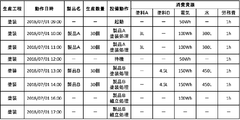
- FIG. 4 is a data configuration diagram illustrating an example of production facility operation state information in an assembly process according to Embodiment 1 of the present invention.
- FIG. 3 is a data configuration diagram illustrating an example of production facility operation state information in a painting process according to Embodiment 1 of the present invention.
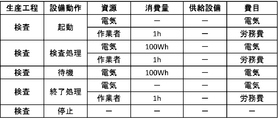
- FIG. 4 is a data configuration diagram illustrating an example of production facility operation state information in an inspection process according to Embodiment 1 of the present invention.
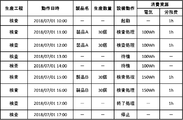
- FIG. 4 is a data configuration diagram illustrating an example of production facility operation state information in an inspection process according to Embodiment 1 of the present invention.
- FIG. 4 is a data configuration diagram illustrating an example of supply facility operation plan information of a compressed air supply facility according to Embodiment 1 of the present invention.
- FIG. 4 is a data configuration diagram illustrating an example of supply facility operation plan information of the water reuse facility according to Embodiment 1 of the present invention.
- FIG. 4 is a data configuration diagram illustrating an example of supply resource information of a compressed air supply facility according to Embodiment 1 of the present invention.
- FIG. 4 is a data configuration diagram illustrating an example of supply resource information of a water reuse facility according to Embodiment 1 of the present invention.
- FIG. 4 is a data configuration diagram illustrating an example of supply facility operation state information of a compressed air supply facility according to Embodiment 1 of the present invention.
- FIG. 4 is a data configuration diagram illustrating an example of supply facility operation state information of a water reuse facility according to Embodiment 1 of the present invention.
- FIG. 4 is a data configuration diagram illustrating an example of resource consumption information according to Embodiment 1 of the present invention.
- FIG. 4 is a data configuration diagram illustrating an example of expense item information according to Embodiment 1 of the present invention.
- FIG. 4 is a data configuration diagram illustrating an example of cost information according to Embodiment 1 of the present invention.
- FIG. 4 is a data configuration diagram illustrating an example of production plan change information according to Embodiment 1 of the present invention.
- FIG. 4 is a data configuration diagram illustrating an example of converted production plan information according to Embodiment 1 of the present invention.
- 5 is a data configuration diagram illustrating an example of converted cost information according to Embodiment 1 of the present invention.
- 5 is a flowchart illustrating an example of a flow of a production plan change process according to the first embodiment of the present invention.
- It is a data block diagram which shows an example of the supply equipment operation plan information in the compressed air supply equipment in Embodiment 2 of this invention.
- FIG. 13 is a data configuration diagram illustrating an example of pre-supply facility operation plan information in a compressed air supply facility according to Embodiment 2 of the present invention.
- It is a data structure figure showing an example of comparative supply equipment operation plan information in a compressed air supply equipment in Embodiment 2 of the present invention.
- FIG. 13 is a flowchart illustrating an example of a flow of a production plan change process according to the second embodiment of the present invention.
- FIG. 13 is a configuration diagram illustrating an example of a functional configuration of a control unit of a production scheduling device according to Embodiment 3 of the present invention.
- It is a data structure figure showing an example of supply plan change information in Embodiment 3 of the present invention.
- It is a data block diagram which shows an example of the supply equipment operation plan information after supply plan change in the water reuse equipment in Embodiment 3 of this invention.
- FIG. 15 is a flowchart illustrating an example of the flow of a production plan change process according to Embodiment 3 of the present invention.
- FIG. 14 is a configuration diagram illustrating an example of a functional configuration of a control unit of a production scheduling device according to a fourth embodiment of the present invention.
- FIG. 14 is a data configuration diagram illustrating an example of operating state change information according to Embodiment 4 of the present invention.
- FIG. 16 is a data configuration diagram illustrating an example of production facility operation state information of an assembly process after a change according to Embodiment 4 of the present invention.
- FIG. 13 is a data configuration diagram illustrating an example of production facility operation state information of a coating process after a change according to Embodiment 4 of the present invention.
- FIG. 16 is a data configuration diagram illustrating an example of production facility operation state information of a post-change inspection process in Embodiment 4 of the present invention.
- 15 is a flowchart illustrating an example of the flow of a production plan change process according to Embodiment 4 of the present invention.
- FIG. 19 is a configuration diagram illustrating an example of a functional configuration of a control unit of a production scheduling device according to Embodiment 5 of the present invention.
- FIG. 21 is a configuration diagram illustrating an example of a production scheduling system according to Embodiment 6 of the present invention.
- FIG. 19 is a configuration diagram illustrating an example of a functional configuration of a control unit of a production scheduling device according to a sixth embodiment of the present invention.
- It is a lineblock diagram showing an example of disposal equipment operation plan information of sewage treatment equipment in Embodiment 6 of the present invention.
- It is a block diagram which shows an example of the waste information of the sewage treatment equipment in Embodiment 6 of this invention.
- FIG. 1 is a configuration diagram illustrating an example of a production scheduling system according to Embodiment 1 of the present invention.
- the production scheduling system 100 includes five production facilities 1, a production control device 2, a supply facility 3, a production scheduling device 4, a display device 5, and a network 6.
- the production scheduling system 100 includes five production facilities 1 is described, the production scheduling system 100 is not limited to the case where the production scheduling system 100 includes five production facilities 1, and four or less or six or more arbitrary production facilities are provided. Equipment 1 may be provided.
- the case where the production scheduling system 100 includes only one supply facility 3 is described, but the number of supply facilities 3 is not limited to one, and two or more supply facilities 3 are provided. May be.
- the production equipment 1 is equipment used for the production of a product.
- processing equipment such as an injection molding machine, an extrusion molding machine, a lathe and a grinding machine for processing raw materials of the product, and parts such as screws and nuts for the product.
- the equipment is provided with an assembling apparatus for assembling a product by tightening, or an inspection apparatus such as a magnetic particle inspection apparatus, a radiation inspection apparatus, and a penetrant inspection apparatus.
- the production control device 2 is a device that controls the production equipment 1 in accordance with production plan information, which is information on a product production plan, and manages product production.
- the production control device 2 is, for example, a programmable logic controller (PLC).
- PLC programmable logic controller
- the production plan information is information acquired from the production scheduling device 4, and will be described later in detail.
- Supply equipment 3 is equipment for supplying resources to production equipment 1.
- the resources that the supply facility 3 supplies to the production facility 1 are, for example, cold cold water, warm hot water, compressed air, or electric power.
- the supply facility 3 creates supply facility information relating to the facility and outputs the information to the production scheduling device 4. The details of the supply facility information will be described later.
- the production facility 1 and the supply facility 3 are connected by a supply path for supplying resources such as a water supply pipe, an air pipe, or an electric wire.
- the supply facility 3 is a facility that cannot be controlled by the production control device 2, and the manager who manages the production facility 1 and the supply facility 3 may be different.
- the supply facility 3 is a facility that supplies resources only to the production facility 1 controlled by the production control device 2, and does not supply resources to the production facility 1 that is not controlled by the production control device 2.
- the production scheduling device 4 has various types of information related to the production plan, acquires supply facility information on the supply facility 3 from the supply facility 3, and converts the acquired supply facility information and production facility information relating to the production facility 1 into information. Based on this, the production plan information of the product in the production facility information is changed to appropriate production plan information considering the supply facility 3.
- the production scheduling device 4 outputs the changed production plan information to the production control device 2 and the display device 5. The details of the supply facility information, the production facility information, the production plan changing method in the production scheduling device 4, and the production plan information will be described later.
- the display device 5 is a device that creates and displays a display screen based on the production plan information acquired from the production scheduling device 4.
- the display device 5 is a device including a monitor such as a liquid crystal display (liquid crystal display) or an organic EL display (organic electro-luminescence display), and displays the created display screen on the monitor.
- a monitor such as a liquid crystal display (liquid crystal display) or an organic EL display (organic electro-luminescence display)
- the display device 5 is not limited to the case where the display device 5 is separate from the production scheduling device 4. , That is, the production scheduling device 4 may have a display function.
- the network 6 is a network that connects the production facility 1 with the production control device 2, the production control device 2 with the production scheduling device 4, the supply facility 3 with the production scheduling device 4, and the production scheduling device 4 with the display device 5.
- This is a field network such as CC-Link (Control @ & Communication @ Link, registered trademark), a general network such as Ethernet (registered trademark), or a dedicated input / output line.
- the production facility 1 and the production control device 2, the production control device 2 and the production scheduling device 4, the supply facility 3 and the production scheduling device 4, and the production scheduling device 4 and the display device 5 are all connected by the same network 6. Although the case has been described, the connections are not limited to being all made on the same network 6, but may be made on different networks.
- FIG. 2 is a structural diagram showing an example of the production scheduling device according to the first embodiment of the present invention.
- the production scheduling device 4 includes a control unit 41, a storage 42, a memory 43, a communication unit 44, and an input unit 45.
- the production scheduling device 4 also includes a power source (not shown) serving as a power source for each unit.
- the control unit 41 is a device that controls the production scheduling device 4, controls the storage 42, the memory 43, the communication unit 44, and the input unit 45, and supplies supply equipment information acquired from the supply equipment 3 and production equipment of the production equipment 1. Based on the information, the production plan information of the product in the production facility information is changed to appropriate production plan information in consideration of the supply facility 3.
- the controller 41 may be a processor such as a CPU (Central Processing Unit), a single integrated circuit such as an FPGA (Field Programmable Gate Array), an LSI (Large Scale Integration), or a combination thereof. Good.
- the control unit 41 converts the product production plan information of the production facility information into appropriate production plan information considering the supply facility 3 based on the supply facility information of the supply facility 3 and the production facility information of the production facility 1. Details of the production plan changing method to be changed will be described later. In the following description, it is assumed that the control unit 41 is a CPU that implements the control processing by software.
- the storage 42 stores various programs executed by the control unit 41, data referred to when the control unit 41 executes various programs, data created as a result of the control unit 41 executing each program, and the like. Device.
- a production plan change program 421 in which the control unit 41 changes product production plan information based on the production facility information of the production facility 1 and the supply facility information of the supply facility 3 is stored as a program.
- the storage 42 is a nonvolatile memory such as a flash memory, a ROM (Read Only Memory), a hard disk (hard disk drive, HDD), a solid state drive (solid state drive, SSD), or a memory card reader / writer (memory card reader / writer). Memory.
- the memory 43 is a storage device to which the control unit 41 directly accesses when executing the program processing, in which various programs and data stored in the storage 42 are copied and temporarily stored.
- the memory 43 is a volatile memory such as a RAM (Random Access Memory).
- the control unit 41 executes the various programs by temporarily storing the various programs stored in the normal storage 42 in the memory 43 and sequentially reading the programs from the memory 43.
- the communication unit 44 includes a receiver for receiving data and a transmitter for transmitting data, and is a device that communicates with the outside.
- the control unit 41 acquires supply facility information from the supply facility 3 via the communication unit 44, The product production plan information is output to the production control device 2 and the display device 5.
- the input unit 45 is a device that receives an input from a user, and is, for example, a keyboard, a mouse, a touch pad, or a touch panel having a display function.
- control unit 41 changes production plan information of a product based on the production facility information of the production facility 1 and the supply facility information of the supply facility 3
- the control unit 41 performs a production plan change process of changing the product production plan based on the production facility information of the production facility 1 and the supply facility information of the supply facility 3. I do.
- the production plan change process is performed by the control unit 41 executing the production plan change program 421 stored in the storage 42.
- FIG. 3 is a configuration diagram illustrating an example of a functional configuration of a control unit of the production scheduling device according to the first embodiment of the present invention.
- the control unit 41 includes a production facility operation state calculation unit 411 that calculates a production facility operation state, a communication control unit 412 that controls communication, a supply facility operation state calculation unit 413 that calculates a supply facility operation state, A resource consumption calculator 414 for calculating the total amount of resources consumed in the production facility 1 and the supply facility 3, a cost calculator 415 for computing the cost of resources consumed in the production facility 1 and the supply facility 3, and changing the production plan. It has a determination unit 416 for determining whether or not it is necessary, and a production plan change unit 417 for changing the production plan.
- FIG. 4 has a determination unit 416 for determining whether or not it is necessary, and a production plan change unit 417 for changing the production plan.
- the memory 43 includes a supply calculation database 432, which is a database generated in the process of the control unit 41 executing the production plan change program 421, a production calculation database 431 obtained by temporarily copying a database stored in the storage 42, It has an expense item database 433, a consumption target database 434, and a production plan change database 435.
- the processing flow of each functional block is indicated by a solid arrow, and the data flow is indicated by a broken arrow.
- the production calculation database 431 and the supply calculation database 432 are periodically copied and stored in the storage 42.
- the production equipment operation state calculation unit 411 calculates the production equipment operation state indicating the operation state of the production equipment 1 based on the production equipment information related to the production equipment 1 acquired from the production calculation database 431 stored in the memory 43. , Create production equipment operation state information.
- the production equipment information includes process information indicating a production process for producing a product, production capacity information indicating a production capacity per unit time of each production process, process operation information indicating an equipment operation of each production process, and each production process.
- Equipment operation information indicating the time required for the equipment operation of the production equipment 1 relating to the process, production planning information indicating the start time of starting product production and the production quantity to be produced, and calculation indicating the operable time of the production equipment 1 used for calculation It comprises time information, calculation unit time information indicating a unit time for calculating the operation state, and production resource information indicating resources consumed in each production process.
- the supply equipment 3 supplies compressed air, which is a resource, to the production equipment 1 and supplies water, which is a resource, to the production equipment 1 and purifies water used once. It is assumed that the facility is a water reuse facility that can be reused.
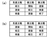
- FIG. 4 is a data configuration diagram showing an example of the process information according to the first embodiment of the present invention.
- FIG. 4A shows the process information on the product A
- FIG. 4B shows the process information on the product A
- the product A and the product B are different products.
- the process information includes a production process indicating a production process to which the process is to be performed, a pre-process in which the process is performed immediately before the production process, and a post-process in which the process is performed immediately after the production process. It consists of three pieces of information.
- assembly refers to the assembly process of assembling each part as a product
- painting refers to the coating process of forming a coating with paint on the surface of each part for decoration or protection
- inspection refers to the quality of the product produced.
- 3 shows an inspection process for inspecting whether or not the condition is satisfied.
- the production process in which the previous process is started is the first process
- the production process in which the post process is completed is the last process.
- the production process information on the product A includes three processes of assembling, painting, and inspection, and the process sequence is assembling, painting, and inspection.
- the production process information on the product B also has three processes of assembling, painting and inspection, and the order of the processes is painting, assembly and inspection.
- FIG. 5 is an explanatory diagram showing the order of the production process in the first embodiment of the present invention.
- FIG. 5 is an explanatory diagram showing the production process information of the products A and B shown in FIG. 4 in a flow
- FIG. 5A is an explanatory diagram showing the product A shown in FIG.
- FIG. 5B is an explanatory diagram showing the product B shown in FIG. 4B.
- the production process of the product A is completed through the steps of assembling process, painting process, and inspection process in order from the start of the process.
- FIG. 5B in the production process of the product B, the process is completed in the order of the painting process, the assembling process, and the inspection process from the start of the process.
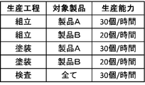
- FIG. 6 is a data configuration diagram showing an example of the production capacity information according to the first embodiment of the present invention.
- the production capacity information includes a production process indicating a production process to be processed, a target product indicating a product to be processed, and the number of products that can be processed in one hour by the production process. It consists of three pieces of information of the production capacity shown. As shown in FIG. 6, when the target product is the product A, the assembling process and the coating process have a production capacity of 30 pieces / hour, and when the target product is the product B, the assembly process and the coating process are 20 pieces. / Hour production capacity. In the inspection process, the target product has a production capacity of 30 pieces / hour regardless of the product A or the product B.
- FIG. 6 is a data configuration diagram showing an example of the production capacity information according to the first embodiment of the present invention.
- the production capacity information includes a production process indicating a production process to be processed, a target product indicating a product to be processed, and the number of products that can be
- the production capacity indicates the number of products that can be processed in one hour by the production process
- the production capacity is not limited to the number of products that can be processed in one hour
- the number of products that can be processed in a predetermined time such as two hours or more, or less than one hour, or the time required to produce one product may be used.
- FIG. 7 is a data configuration diagram showing an example of the process operation information according to the first embodiment of the present invention.
- the process operation information is composed of two pieces of information of a production process indicating a production process to be processed and a facility operation indicating an operation of the production equipment 1 related to the production process.
- activation is an operation of activating the production equipment 1 related to the production process
- assembly processing is an operation of assembling the product by the production equipment 1 related to the production process
- painting processing is an operation of the production equipment 1 related to the production process.
- the inspection process is an operation in which the production equipment 1 relating to the production process inspects a product
- the standby is a process in which the production equipment 1 is in a standby state without any product to be processed in the production process and without performing the process.
- the terminating process is an operation performed by the production facility 1 relating to the production process to terminate the process of each production process
- the terminating operation is an operation of stopping the production facility 1 relating to each production process.
- the assembling process and the painting process are different operations for each type of product. As shown in FIG. 7, for example, the assembling process has six facility operations of start, product A assembling process, product B assembling process, standby, end process, and stop.
- FIG. 8 is a data configuration diagram showing an example of the equipment operation information according to the first embodiment of the present invention.
- the equipment operation information includes a production process indicating a production process for which processing is to be performed, an equipment operation indicating an operation of the production equipment 1 related to each production process, and an operation time indicating a time required for each equipment operation. It consists of three pieces of information.
- assembling processing, painting processing, inspection processing, and standby do not have a predetermined operation time, and vary according to the type and quantity of products to be produced. Not included. As shown in FIG.
- the operation time of the start is one hour
- the operation time of the termination process is one hour
- the operation time of the stop is zero hour. That is, in the production equipment 1 related to the assembling process, the stop operation does not take much time.
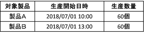
- FIG. 9 is a data configuration diagram showing an example of the production plan information according to the first embodiment of the present invention.
- the production plan information includes a target product indicating a product to be processed, a production start date and time indicating the date and time when the production of the target product is started in the production facility 1, and a target product to be produced in the production facility 1. It is composed of three pieces of information of the production quantity indicating the quantity.
- the production start date and time indicates that the production of the target product starts after the designated date and time.
- the product A has a production start date and time of 2018/07/01 @ 09: 00 and a production quantity of 60 pieces. That is, the production plan information indicates that the production facility 1 starts producing the product A after 2018/07/01 @ 9: 00, and the production quantity is 60 pieces.
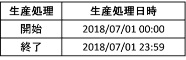
- FIG. 10 is a data configuration diagram showing an example of calculation time information according to Embodiment 1 of the present invention.
- the calculation time information is composed of two pieces of information: a production process indicating the start or end of the process of the production process, and a production process date and time indicating the date and time at which the production process can be performed.
- the production process date and time indicates the date and time when the production process can be started when the production process is started, and the date and time when the production process must be terminated when the production process is completed.
- the processing of each production process in the production facility 1 can be started from 2018/07/01 00:00, and the processing of each production process in the production facility 1 is 2018/07/01 @ 23: It must be completed by 59.
- FIG. 11 is a data configuration diagram illustrating an example of calculation unit time information according to Embodiment 1 of the present invention.
- the calculation unit time information includes a calculation unit time indicating a unit time for the production equipment operation state calculation unit 411 to calculate the processing state of the production process in the production equipment 1.
- the production equipment operation state calculation unit 411 calculates the production equipment operation state of the production process in the production equipment 1 every 3,600 seconds.
- the calculation unit time is not limited to 3,600 seconds, but may be any time, such as 7,200 seconds, 10,800 seconds, or the like. It may be.
- FIGS. 12 to 14 show the data structure of the production resource information of each production process.
- FIG. 12 is a data configuration diagram illustrating an example of the production resource information in the assembly process according to Embodiment 1 of the present invention.
- FIG. 13 is a data configuration diagram illustrating an example of the production resource information in the painting process according to Embodiment 1 of the present invention.
- FIG. 14 is a data configuration diagram illustrating an example of the production resource information in the inspection process according to Embodiment 1 of the present invention.
- the production resource information includes a production process indicating a production process to be processed, a facility operation indicating an operation of the production facility 1 related to the production process, and a resource indicating a resource consumed in the facility operation.
- the assembly process consumes electricity, workers, screws, and compressed air as resources
- the painting process consumes electricity, workers, paint A, paint B, and water as resources.
- the inspection process consumes electricity and workers as resources.
- the worker is a person who performs work in the production facility 1 in each facility operation, and 1h indicates that one worker works per hour (h).
- the product A assembling process in the assembling process consumes four resources as electricity, screws, compressed air, and a worker.
- the production facility operation state calculation unit 411 calculates the operation state of the production facility 1, that is, the processing state of the production process performed by the production facility 1, will be described with reference to FIGS.
- the time required for transporting the products between the production processes is included in the time for the production processing in each production process, and the transportation of the products between the production processes is performed collectively every hour. It is assumed that the product produced in the production process is transported to the next production process.
- the production equipment operation state calculation unit 411 performs production equipment information, that is, process information, production capacity information, process operation information, equipment operation information, production plan information, calculation time information, and calculation shown in FIG. 4 and FIGS. 6 to 14. Based on the unit time information and the production resource information, the operation state of the production equipment is calculated for each production process. For example, a case will be described below where the production equipment operation state calculation unit 411 calculates the production equipment operation state for the assembly process.
- the production equipment operation state calculation unit 411 obtains production equipment information from the production calculation database 431 of the memory 43, that is, the process information, production capacity information, process operation information, and equipment operation information shown in FIGS. 4 and 6 to 14. , Production plan information, calculation time information, calculation unit time information, and production resource information.
- the production facility operation state calculation unit 411 acquires the production process of each product and the process order of the production process from the process information shown in FIG. For example, the production equipment operation state calculation unit 411 acquires that the production process of the product A is three, that is, assembly, painting, and inspection, and that the process sequence is assembling, painting, and inspection, and that the production of the product B is performed. It is acquired that there are three processes of assembling, painting, and inspection, and the process order is painting, assembling, and inspection.
- the production equipment operation state calculation unit 411 can execute the processing in which the production capacity of the assembly process of the product A is 30 pieces per hour from the production capacity information shown in FIG. That 20 processes can be performed. Further, the production facility operation state calculation unit 411 determines that the facility operations of the assembly process of the product A are five, starting, product A assembly processing, standby, termination processing, and stop, based on the process operation information shown in FIG. It is acquired that the equipment operations in the assembly process of B are start, product B assembly processing, standby, end processing, and stop. Here, the production facility operation state calculation unit 411 assumes that the product A assembling process in the assembly process of the product A is 30 processes per hour based on the acquired information on the production capacity and the facility operation.
- the production equipment operation state calculation unit 411 determines that it takes 1 hour for the equipment operation for starting the assembly process, 1 hour for the equipment operation for the end processing, and 0 hour for the equipment operation for the stop. To get. Further, the production facility operation state calculation unit 411 determines that the production start date and time of the product A is 2018/07/01 @ 09: 00, the production quantity is 60 pieces, and the production start of the production B from the production plan information shown in FIG. It is acquired that the date and time is 2018/07/01 @ 13: 00 and the production quantity is 60 pieces.
- the production facility operation state calculation unit 411 can start the production process in the production facility 1 from 2018/07/01 @ 00: 00 based on the calculation time information shown in FIG. It is acquired that the processing must be completed by 2018/07/01 @ 23: 59. Further, the production equipment operation state calculation unit 411 acquires that the production equipment operation state calculation unit 411 calculates the production equipment operation state of the production equipment 1 every 3,600 seconds from the calculation unit time information shown in FIG. . Finally, the production equipment operation state calculation unit 411 uses the production resource information shown in FIGS. 12 to 14 to correspond to the name of the resource to be consumed in each production process, the consumption of the resource, the supply equipment for supplying the resource, and the resource. Get the cost item to do.
- the production equipment operation state calculation unit 411 calculates the production equipment operation state of the production equipment 1 based on the obtained various information.
- the production facility operation state calculation unit 411 determines the assembly process of the product A from 2018/07/01 @ 9: 00, and the assembly process of the product B from 2018 based on the acquired production start date and time and the process sequence of the production process. / 07/01 Calculated to start at 14:00.
- the reason why the production of the product B starts at 14:00 is that the painting process of the product B starts at 13:00, and the product in the painting process is transported to the assembly process at 14:00.
- the production facility operation state calculation unit 411 determines that the product A assembly process of the product A assembly process is 30 processes per hour based on the acquired production capacity and facility operation information. It is calculated that the product B assembling process is 20 processes per hour. As a result, the product A assembling process starts at 2018/07/01 @ 09:00 and ends at 2018/07/01 @ 11:00, and the product B assembling process starts at 2018/07/01 @ 14:00. It is calculated to end at 2018/07/01 @ 17: 00.
- the production equipment operation state calculation unit 411 starts the production of the product A at 2018/07/01 @ 09: 00 based on the acquired information on the equipment operation in the assembly process of each product and the operation time of each equipment operation. For this purpose, the start-up facility operation is performed on 2018/07/01 @ 08: 00, the stand-by facility operation is performed from 2018/07/01 @ 11: 00 to 14:00, and the end-operation facility operation is performed. It is derived that starting at 17:00 and ending at 18:00, and performing the facility operation of stopping at 18:00.
- the production equipment operation state calculation unit 411 determines the name of the resource to be consumed in each of the production processes, the resource consumption, the supply facility for supplying the resource, and the cost item corresponding to the resource.
- the name of the resource to be consumed, the amount of the resource consumed, the supply equipment for supplying the resource, and the cost item corresponding to the resource are associated with each equipment operation in each production process.
- FIG. 15 shows the result of summarizing the production equipment operation states in the assembling process of the production equipment 1 calculated by the production equipment operation state calculation unit 411.
- FIG. 15 is a data configuration diagram illustrating an example of production facility operation state information in an assembly process according to Embodiment 1 of the present invention.
- the production facility operation state information of the assembly process includes a production process indicating a production process to be processed, and an operation date and time indicating the operation date and time at which the production facility 1 related to the production process operates for each calculation unit time.
- the name of the consumed resource is the name of the cost item of the consumed resource.
- the production equipment operation state calculation unit 411 calculates the production equipment operation state in the painting process of the production equipment 1 in the same manner as the method in which the production equipment operation state calculation unit 411 calculates the production equipment operation state in the assembly process of the production equipment 1.
- the production equipment operation state in the inspection process of the production equipment 1 is calculated.
- FIG. 16 is a data configuration diagram illustrating an example of production facility operation state information in the painting process according to Embodiment 1 of the present invention.
- FIG. 17 is a data configuration diagram illustrating an example of production facility operation state information in an inspection process according to Embodiment 1 of the present invention.
- the production equipment operation state calculation unit 411 obtains the production equipment information from the production calculation database 431 of the memory 43 so that there is an acquisition order, and based on the acquired production equipment information, the production equipment operation state Have been described so that there is a calculation order when calculating the production equipment.
- these orders are examples for explanation, and the production equipment operation state calculation unit 411 acquires the production equipment information and the acquired production equipment.
- the calculation order for calculating the operation state of the production equipment based on the information is not limited to the order described above, and may be performed in any order or simultaneously.
- the production equipment operation state calculation unit 411 stores the created production equipment operation state information in the production calculation database 431 of the memory 43.
- the communication control unit 412 controls communication related to transmission and reception of information with the production control device 2, the supply facility 3, and the display device 5 via the communication unit 44.
- the communication control unit 412 acquires the production facility operation state information shown in FIGS. 15 to 17 from the production calculation database 431 of the memory 43, and, based on the acquired production facility operation state information, the consumption resource associated with the supply facility. And the operation date and time of the facility operation that consumes the consumed resources, and supplies the extracted consumption resources to the supply facility 3 that supplies the consumed resources at the operation date and time. Output instructions requesting relevant supply equipment information.
- the instruction output from the communication control unit 412 to the supply facility 3 is based on the production facility operation state information shown in FIG.
- This is a request for supply facility information relating to the compressed air supply facility, which is the supply facility 3 when supplying 150 L of compressed air at 2018/07/01 @ 09: 00 and 2018/07/01 @ 10: 00.
- the details of the supply facility information related to the supply facility 3 will be described later.
- the communication control unit 412 acquires supply facility information from the supply facility 3 and stores the acquired supply facility information in the memory 43 as the supply calculation database 432.
- the supply equipment information includes two pieces of information: supply equipment operation plan information indicating a plan of equipment operation of the supply equipment 3 and supply resource information indicating resources consumed by each supply equipment 3.
- the supply resource information is not included in the supply facility information acquired from the supply facility 3 by the communication control unit 412, and may be originally stored in the supply calculation database 432 of the memory 43.
- FIGS. 18 and 19 show the data structure of the supply facility operation plan information of each supply facility 3, and FIGS. 20 and 21 show the data structure of the supply resource information of each supply facility 3.
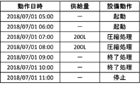
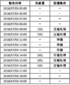
- FIG. 18 is a data configuration diagram illustrating an example of supply facility operation plan information of the compressed air supply facility according to Embodiment 1 of the present invention.
- FIG. 19 is a data configuration diagram illustrating an example of supply facility operation plan information of the water reuse facility according to Embodiment 1 of the present invention.
- FIG. 20 is a data configuration diagram illustrating an example of supply resource information of the compressed air supply facility according to Embodiment 1 of the present invention.
- FIG. 21 is a data configuration diagram illustrating an example of supply resource information of the water reuse facility according to Embodiment 1 of the present invention.
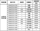
- the supply facility operation plan information in the compressed air supply facility that is the supply facility 3 includes an operation date and time indicating the operation date and time when the compressed air supply facility operates for each calculation unit time, and a supply amount indicating the supply amount of the compressed air.
- the compression process of the equipment operation is a process showing an operation of compressing air and supplying the compressed air to the production equipment 1.
- the supply facility operation plan information in the water reuse facility that is the supply facility 3 includes an operation date and time indicating the operation date and time at which the water reuse facility operates for each calculation unit time, and a supply amount indicating the water supply amount.
- Recycled water that indicates the amount of reused water that has undergone a reuse process in the water reuse facility, water supply that indicates the amount of water supplied from a tap, etc. It is composed of five pieces of equipment operation information indicating the operation of the utilization equipment.
- the compressed air supply facility is 2018/07/01 according to the production facility operation state information in the assembly process of the production facility 1 shown in FIG. At 09:00, a compression process of supplying 150 L of compressed air is performed as a facility operation.
- supply resource information includes supply facilities indicating supply facilities 3 that supply resources, facility operations indicating operations of the supply facilities 3, resources indicating resources consumed in each facility operation, It is composed of five pieces of information of the consumption amount indicating the resource consumption amount and the cost item indicating the cost name corresponding to the resource.
- the reason why the compressed air and the reused water are not described as the resources is that the compressed air and the reused water are inexpensive, that is, because they are inexpensive resources, there is no need to consider consumption.
- the water supply of the cost item is a cost item set for expensive water.
- the communication control unit 412 outputs the production plan information on the production plan acquired from the production plan change unit 417 to the production control device 2 and the display device 5 via the communication unit 44.
- the details of the production plan information acquired from the production plan change unit 417 will be described later.
- the supply facility operation state calculation unit 413 acquires supply facility information from the supply calculation database 432 in the memory 43, and calculates the supply facility operation state of the supply facility 3 based on the acquired supply facility information. For example, a case in which the supply facility operation state calculation unit 413 calculates the supply facility operation state of the compressed air supply facility that is the supply facility 3 will be described below.
- the supply equipment operation state calculation unit 413 obtains supply equipment operation plan information shown in FIG. 18 and supply equipment information shown in FIG. 21 which is supply equipment information of the compressed air supply equipment which is the supply equipment 3 from the supply calculation database 432 of the memory 43. Get resource information.
- the supply equipment operation state calculation unit 413 calculates the supply equipment operation state of the compressed air supply equipment based on the acquired supply equipment operation plan information and supply resource information, and creates supply equipment operation state information.
- FIG. 22 is a data configuration diagram illustrating an example of supply facility operation state information of the compressed air supply facility according to Embodiment 1 of the present invention.
- the supply equipment operation state information of the compressed air supply equipment includes supply equipment, operation date and time, supply amount, equipment operation, and the name of the resource consumed in each equipment operation and the consumption resource consumption amount indicating the consumed amount. It consists of five pieces of information.
- the name of the consumed resource is the name of the cost item of the consumed resource, which is electricity.
- the compressed air supply equipment has a compressed air supply amount of 150 L
- the equipment operation is compression processing
- the resource consumption is 500 Wh. It is electricity.
- FIG. 23 is a data configuration diagram illustrating an example of supply facility operation state information of the water utilization facility according to Embodiment 1 of the present invention. As shown in FIG. 23, the consumption resources of the water use equipment are electricity and water supply.
- the supply facility operation state calculation unit 413 stores the supply facility operation state information of the supply facility 3 in the supply computation database 432 of the memory 43.
- the resource consumption calculation unit 414 acquires the production facility operation state information of the production facility 1 from the production computation database 431 of the memory 43 and the supply facility operation state information of the supply facility 3 from the supply computation database 432. Based on the obtained production equipment operation state information and supply equipment operation state information, the total of resources consumed by the production equipment 1 and the supply equipment 3 is calculated, and resource consumption information is created.
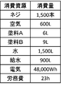
- FIG. 24 is a data configuration diagram showing an example of the resource consumption information according to Embodiment 1 of the present invention.
- the resource consumption information indicates a consumed resource indicating a resource consumed in accordance with the production facility operation state information of the production facility 1 and the supply facility operation state information of the supply facility 3, and a consumption amount of the consumed resource. Consisting of two pieces of information on consumption.
- the name of the consumed resource is the name of the cost item to be consumed.
- the resource consumption information shown in FIG. 24 is based on the resource consumption in the case of following the production facility operation state information of the production facility 1 shown in FIGS. 15 to 17 and the supply facility operation information of the supply facility 3 shown in FIGS. Information. As shown in FIG. 24, for example, 1,500 screws are consumed, electricity is 48,000 Wh, and labor is consumed for 23h.
- the cost calculation unit 415 acquires the resource consumption information from the resource consumption calculation unit 414 and the cost item information from the cost item database 433 of the memory 43, and based on the acquired resource consumption information and the cost item information, 1 and the total cost required for the supply equipment 3 is calculated, and cost information is created.
- FIG. 25 is a data configuration diagram showing an example of expense item information according to Embodiment 1 of the present invention.
- the cost item information is composed of two pieces of information: a cost item indicating the name of the cost corresponding to the resource, and a cost indicating the cost unit price of each cost item.
- a cost item indicating the name of the cost corresponding to the resource
- a cost indicating the cost unit price of each cost item As shown in FIG. 25, for example, one screw costs 10 yen, electricity costs 1 Wh 0.02 yen, and labor costs 1000 yen per hour.
- each cost item is not limited to the case where it has only one cost. You may have more than one cost.
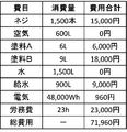
- FIG. 26 is a data configuration diagram illustrating an example of cost information according to Embodiment 1 of the present invention.
- the cost information is composed of three pieces of information: a cost item indicating the name of the cost corresponding to the resource, a consumption amount indicating the consumption amount of the resource, and a total cost indicating the total cost of the cost item.
- the total cost is calculated by the cost calculation unit 415 based on the resource consumption information shown in FIG. 24 and the cost information shown in FIG. 25, and is a value obtained by multiplying the cost unit of the cost by the consumption amount.
- the total cost of the cost items is the sum of the total costs of all the cost items, and is the total cost required for the production facility 1 and the supply facility 3. As shown in FIG. 26, the total cost is 71,960 yen.
- the determination unit 416 acquires the cost information from the cost calculation unit 415 and the consumption target information from the consumption target database 434 of the memory 43, and based on the acquired cost information and the consumption target information, produces the production plan. It is determined whether the information needs to be changed.
- the consumption target information is a value obtained by converting the resource consumption target value into the cost, which is compared with the total cost of the cost information, and the determination unit 416 determines that the total cost of the cost information is equal to or less than the consumption target information. It is determined that there is no need to change the information, and when the total cost of the cost information is larger than the consumption target information, it is determined that the production plan information needs to be changed.
- the value of the consumption target information is a value arbitrarily set according to a value that realizes appropriate resource saving requested by the user.
- the determination unit 416 determines that there is no need to change the production plan information in comparison with the total cost of the cost information shown in FIG. If the price is 71,960 yen or less, the determination unit 416 determines that the production plan information needs to be changed.
- the production plan change unit 417 does not particularly perform the process when the result of the determination obtained from the determination unit 416 determines that the production plan information does not need to be changed.
- the communication control unit 412 outputs the production plan information to the production control device 2 and the display device 5.
- the production plan change unit 417 acquires the production plan change information from the production plan change database 435 of the memory 43 when the result of the determination obtained from the determination unit 416 determines that the production plan information needs to be changed. Then, the production plan information is changed based on the obtained production plan change information. Further, the production plan change unit 417 stores the changed production plan information in the production calculation database 431 of the memory 43. In this case, the production equipment operation state calculation unit 411 calculates the production equipment operation state of the production equipment 1 again.
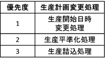
- FIG. 27 is a data configuration diagram showing an example of the production plan change information according to the first embodiment of the present invention.
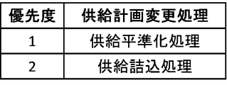
- the production plan change information is composed of two pieces of information: a priority indicating a priority for executing the process, and a production plan change process indicating a production plan change process to be executed.
- the production plan change unit 417 performs the production plan change process in accordance with the priority order of the production plan change information shown in FIG. 27, and stores the changed production plan information in the production calculation database 431 of the memory 43. After that, each functional component of the control unit 41 executes the processing again. As a result, the production plan change unit 417 performs the production plan change process on a brute force basis, until the determination unit 416 determines that it is not necessary to change the production plan information.
- the production start date / time changing process is a process of changing the production start date / time of the production plan information shown in FIG. 9 to the calculation unit time of the calculation unit time information shown in FIG. If the production start date and time for which production is prohibited is set for each target product, or if another product is already planned at the time after the change, the production start date and time excludes that time. Will be changed only at the specified time.
- the production plan change unit 417 performs a process of changing the production start date and time of the product A to 2018/07/01 @ 10: 00 in the production plan information shown in FIG.
- the production leveling process is a process for distributing the production plan of each target product in the production plan information shown in FIG. If the production start date and time for which production is prohibited is set for each target product, or if another product is already planned at the time after distribution, the production start date and time excludes that time. Will be changed only at the specified time.
- the production plan change unit 417 produces a plan with a production quantity of 60 pieces at the production start date and time 2018/07/01 @ 09:00, which is the production plan of the product A, in the production plan information shown in FIG.
- a process of distributing the production quantity to 30 pieces at the start date and time 2018/07/01 @ 09:00 and the production quantity to 30 pieces at the production start date and time 2018/07/01 @ 16:00 is executed.
- the production packing process is a process for aggregating a plurality of production plans dispersed in each target product in the production plan information shown in FIG. If the production start date and time for which production is prohibited is set for each target product, or if other products are already planned at the time after aggregation, the production start date and time excludes that time. Will be changed only at the specified time. For example, when each target product is planned in a distributed manner in the production plan information illustrated in FIG. 9, the production plan changing unit 417 performs a process of integrating the distributed production plans.
- FIG. 28 shows the production plan information after the production plan changing unit 417 has changed the production plan information shown in FIG. 9 in accordance with the production start date / time changing process shown in FIG.
- FIG. 28 is a data configuration diagram showing an example of production plan information after conversion according to Embodiment 1 of the present invention.
- the production plan change unit 417 changes the production plan of the product A in the production plan information shown in FIG. 9, and changes the production start date to 2018/07/01 @ 10: 00 one hour later. I have.
- the production plan change unit 417 stores the converted production plan information shown in FIG. 28 in the production calculation database 431 of the memory 43, and causes the production equipment operation state calculation unit 411 to recalculate the production equipment operation state of the production equipment 1. Is output. Thereafter, based on the converted production plan information shown in FIG. 28, the production equipment operation state calculation unit 411, the communication control unit 412, the supply equipment operation state calculation unit 413, the resource consumption calculation unit 414, the cost calculation unit 415, and the determination unit 416 and the processing of the production plan change unit 417 are executed.
- the processing in the production equipment operation state calculation unit 411, the communication control unit 412, the supply equipment operation state calculation unit 413, the resource consumption calculation unit 414, the cost calculation unit 415, the determination unit 416, and the production plan change unit 417 is performed by the determination unit 416. Until it is determined that there is no need to change the production plan information.
- FIG. 29 shows converted cost information as a result of performing the calculation again based on the converted production plan information shown in FIG.
- FIG. 29 is a data configuration diagram illustrating an example of converted cost information according to Embodiment 1 of the present invention.
- electricity is reduced by 1,700 Wh and labor cost is reduced by 1 hour, and the total cost is reduced by 1,034 yen to 70,926 yen.
- the determination unit 416 determines that it is not necessary to change the production plan information, and ends the processing.
- the production equipment operation state calculation unit 411, the communication control unit 412, the supply equipment operation state calculation unit 413, the resource consumption calculation unit 414, the cost calculation unit 415, the determination unit 416, and the production plan change unit of the control unit 41 By performing the processing in step 417, the production plan information can be changed to the production plan information that realizes appropriate resource saving requested by the user, and a production plan in consideration of the environment can be created.
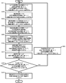
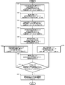
- FIG. 30 is a flowchart illustrating an example of the flow of the production plan change process according to the first embodiment of the present invention.
- the control unit 41 receives a request for a production plan change process from a user, or automatically starts the production plan change process.
- a method for the user to request the start of the production plan change process any method such as a method of providing a start button of the production plan change process as the input unit 45 and pressing the corresponding button by the user may be used.
- a method for the control unit 41 to automatically start the production plan change processing an arbitrary method such as a method for starting the production plan change processing when the production plan information shown in FIG. May be.
- the production equipment operation state calculation unit 411 creates production equipment operation state information based on the production equipment information, and stores it in the production calculation database 431.
- the production equipment information is information stored in the production calculation database 431 of the memory 43, and includes process information, production capacity information, process operation information, equipment operation information, production plan information, and the like shown in FIGS. This information is composed of eight pieces of information: calculation time information, calculation unit time information, and production resource information.
- the production equipment operation state information is the information shown in FIGS.
- step S102 the communication control unit 412 generates and outputs an instruction to the supply facility 3 based on the production facility operation state information created in step S101.
- the instruction generated by the communication control unit 412 is an instruction for instructing the supply facility 3 to request supply facility information based on the production facility operation state information.
- step S103 the communication control unit 412 acquires supply facility information from the supply facility 3 via the communication unit 44, and stores it in the supply calculation database 432.
- the supply facility information is composed of two pieces of information of supply facility operation plan information and supply resource information shown in FIGS.
- step S104 the supply equipment operation state calculation unit 413 creates supply equipment operation state information based on the supply equipment information, and stores it in the supply calculation database 432.
- the supply facility operation state information is the information shown in FIGS. 22 and 23.
- step S105 the resource consumption calculation unit 414 creates resource consumption information based on the production facility operation state information and the supply facility operation state information.
- the resource consumption information is the information shown in FIG.
- the cost calculator 415 creates cost information based on the resource consumption information and the cost item information.
- the expense information is information stored in the expense database 433 of the memory 43, and is the information shown in FIG.
- the cost information is the information shown in FIG.
- step S107 the determination unit 416 determines whether it is necessary to change the production plan information based on the cost information and the consumption target information, and when it is not necessary to change the production plan information (No). Shifts to step S109, and when it is necessary to change the production plan information (Yes), shifts to step S108.
- the consumption target information is information stored in the consumption target database 434 of the memory 43, and is obtained by converting a resource consumption target value arbitrarily set in accordance with a value required by a user to realize appropriate resource saving into a cost. Value.
- the determining unit 416 compares the cost information with the consumption target information, and determines that it is not necessary to change the production plan information when the total cost of the cost information is equal to or less than the consumption target information. If it is larger than the target information, it is determined that the production plan information needs to be changed.
- step S108 the production plan change unit 417 changes the production plan information based on the production plan change information, stores it in the production calculation database 431, and proceeds to step S101.
- the production plan change information is the information shown in FIG. 27, and the production plan change unit 417 performs the production plan change processing in accordance with the order of priority. As a result, the production plan change unit 417 performs a round robin production plan change process until the determination unit 416 determines in step S107 that the production plan information need not be changed.
- step S109 the communication control unit 412 outputs the production plan information to the production control device 2 and the display device 5.
- a production plan that considers the environment can be created by considering the operation state of the supply facility 3 that supplies resources to the production facility 1. .
- the production equipment operation state calculation unit 411 calculates the production equipment operation state
- a method of calculating based on information including time required for transporting a product between production processes in a production process of each production process will be described.
- the method is not limited to the method of calculating based on information including the time required for transporting the product between the production processes in the production process of each production process, and the time required for transporting the product between the respective production processes is defined as The calculation may be performed based on information defined separately from the production process in the production process.
- the production equipment operation state calculation unit 411 calculates the production equipment operation state
- the calculation is performed on the assumption that the products generated in each production process are collectively transported hourly to the next production process.
- the method is not limited to the method of calculating on the assumption that products produced in each production process are transported to the next production process collectively every hour. It may be calculated that the products produced by the above are transported one by one to the next production process.
- the method of calculating that the products produced in each production process are individually transported to the next production process is not a method of calculating based on the information in the form of a table as described in the first embodiment. There is a method of managing a product input to a production process as a work and calculating a time required for processing each work.
- each of the production processes has an input list for managing the work to be inputted and a processed list for managing the work after being processed in the production process.
- the individual work is processed assuming that the next production process will take the work into its own input list.
- the method of calculating the products produced in each production process as individually transporting to the next production process has an effect that the operation state of the production equipment close to the actual situation can be calculated. it can.
- the determination unit 416 determines whether it is necessary to change the production plan information by comparing the cost information with consumption target information that is a target value arbitrarily set by the user.
- the determination method is not limited to the method of comparing the cost information and the consumption target information, and a plurality of changed production plan information in which the production plan information is changed in advance by the production plan changing unit 417 is generated, and the production plan information is generated.
- One piece of production plan information can be specified, such as a method of determining the lowest cost production plan information among the pieces of cost information based on the cost information based on a plurality of changed production plan information as the appropriate production plan information. Any determination method may be used.
- the production equipment information is composed of eight pieces of information of process information, production capacity information, process operation information, equipment operation information, production plan information, calculation time information, calculation unit time information, and production resource information.
- the production equipment information is not limited to being composed of eight pieces of information, but includes process information, production capacity information, process operation information, equipment operation information, production plan information, calculation time information, calculation unit time information,
- the production resource information may be further divided into a plurality of pieces of information, or may be integrated into seven or less pieces of information.
- the supply facility information is composed of two pieces of information, namely, supply facility operation plan information and supply resource information, but the supply facility information is not limited to being composed of two pieces of information.
- the supply facility operation plan information and the supply resource information may be further divided into a plurality of pieces of information or may be integrated into one piece of information.
- Embodiment 2 FIG.
- the configuration of the production scheduling system 100, the configuration of the production scheduling device 4, the functional configuration of the control unit 41, the production equipment operation state calculation unit 411, the resource consumption calculation unit 414, the cost calculation unit 415, the determination unit 416, and the production plan The processing in the changing unit 417 is the same as in the first embodiment, and a description thereof will not be repeated. Unless otherwise described below, it is assumed that various information stored in various databases is the same information as in the first embodiment.
- the communication control unit 412 shown in FIG. 3 outputs an instruction to the supply equipment 3 based on the production equipment operation state information stored in the production calculation database 431 of the memory 43.
- the communication control unit 412 The supply facility information is acquired, and the acquired supply facility information is stored in the supply calculation database 432.
- the supply equipment information is different from the first embodiment, the supply equipment operation plan information indicating the equipment operation plan of the supply equipment 3, and the equipment operation plan of the supply equipment 3 before receiving an instruction from the communication control unit 412. , And supply resource information indicating resources consumed by each supply facility 3.
- the supply resource information is not included in the supply facility information acquired from the supply facility 3 by the communication control unit 412, and may be originally stored in the supply calculation database 432 of the memory 43.
- the supply resource information is the same as in the first embodiment, and is the information shown in FIGS. 20 and 21.
- FIG. 31 is a data configuration diagram showing an example of supply facility operation plan information in the compressed air supply facility according to Embodiment 2 of the present invention.
- FIG. 32 is a data configuration diagram showing an example of pre-supply equipment operation plan information in the compressed air supply equipment according to Embodiment 2 of the present invention.
- the supply facility operation plan information indicates the operation date and time indicating the operation date and time when the compressed air supply facility operates for each calculation unit time, the supply amount indicating the supply amount of compressed air, and the operation of the compressed air supply facility. It consists of three pieces of equipment operation information.
- the pre-supply facility operation plan information includes an operation date and time indicating the operation date and time at which the compressed air supply facility operates for each calculation unit time, a supply quantity indicating the supply quantity of compressed air, and a supply quantity of the compressed air supply facility. It is composed of three pieces of information on the equipment operation indicating the operation.
- the supply equipment operation state calculation unit 413 acquires supply equipment information from the supply calculation database 432 of the memory 43 and converts the supply equipment operation plan information and the previous supply installation operation plan information into the acquired supply equipment information. Based on the instruction, the communication control unit 412 creates comparative supply facility operation plan information by extracting operation processing of the compressed air supply facility added.
- FIG. 33 is a data configuration diagram illustrating an example of comparative supply facility operation plan information in the compressed air supply facility according to Embodiment 2 of the present invention.
- the supply facility operation plan information indicates an operation date and time indicating the operation date and time at which the compressed air supply facility operates for each calculation unit time, a supply amount indicating the supply amount of compressed air, and an operation of the compressed air supply facility. It consists of three pieces of equipment operation information.
- the comparative supply facility operation plan information has facility operations from 2018/07/01 @ 09: 00 to 2018/07/01 @ 16: 00, and these facility operations are instructed by the communication control unit 412.
- the equipment operation is added to the compressed air supply equipment.
- the equipment operation of start, end processing, and stop since the operation date and time are different, since both the supply equipment operation plan information shown in FIG. 31 and the previous supply equipment operation plan information shown in FIG. 32 have, It is excluded from the comparative supply facility operation plan information shown in FIG.
- FIG. 34 is a data configuration diagram illustrating an example of supply facility operation state information in the compressed air supply facility according to Embodiment 2 of the present invention.
- the supply equipment operation state information of the compressed air supply equipment is composed of five pieces of information of supply equipment, operation date and time, supply amount, equipment operation, and consumed resources.
- the supply equipment operation state information of the compressed air supply equipment shown in FIG. 34 is different from the supply equipment operation state information of the compressed air supply equipment in the first embodiment shown in FIG. This is the information from which the operation has been removed.
- the processing after the resource consumption calculation unit 414 is the same as in the first embodiment.
- the equipment operation of the supply equipment 3 before and after the instruction from the communication control unit 412 based on the production equipment operation information created by the production equipment operation state calculation unit 411 is compared, and added by the instruction from the communication control unit 412.
- the supply equipment 3 may be a facility that supplies resources to production equipment other than the production equipment 1 controlled by the production control device 2. Therefore, the operation state of the supply equipment 3 can be appropriately considered, and a production plan in consideration of the environment can be created.
- FIG. 35 is a flowchart illustrating an example of the flow of a production plan change process according to the second embodiment of the present invention.
- Step S201, Step S202, Step S203, Step S206, Step S207, Step S208, Step S209, and Step S210 correspond to Step S101, Step S102, Step S103, Step S105, Step S101 in FIG. Steps S106, S107, S108, and S109 are the same as those described above, and a description thereof will be omitted.
- the supply equipment information that the communication control unit 412 acquires from the supply equipment 3 in step S203 is different from that of the first embodiment, and includes three pieces of supply equipment operation plan information, previous supply equipment operation plan information, and supply resource information. It consists of information.
- step S204 the supply facility operation state calculation unit 413 creates comparative supply facility operation plan information based on the supply facility operation plan information and the previous supply facility operation plan information included in the supply facility information.
- the comparative supply facility operation plan information is the information shown in FIG.
- step S205 the supply equipment operation state calculation unit 413 creates supply equipment operation state information based on the comparative supply equipment operation plan information and supply resource information, and stores the information in the supply calculation database 432.
- the supply facility operation state information is the information shown in FIG.
- the production scheduling device 4 of the second embodiment even when the supply facility 3 is a facility that supplies resources to production facilities other than the production facility 1 controlled by the production control device 2, In addition, the operation state of the supply equipment 3 can be considered, and a production plan can be created in consideration of the environment.
- Embodiment 3 In the first embodiment, the embodiment in which the production plan changing unit 417 changes the production plan information based on the determination result of the determining unit 416 has been described.
- the control unit 41 further has a supply plan change unit that changes the supply plan of the supply equipment 3, and the production plan change unit 417 changes the production plan information based on the determination result of the determination unit 416.
- the supply plan changing unit changes the supply plan will be described.
- the configuration of the production scheduling system 100, the structure of the production scheduling device 4, and the processes in the production equipment operation state calculation unit 411, the supply equipment operation state calculation unit 413, the resource consumption calculation unit 414, and the cost calculation unit 415 are described in the embodiment. Description is omitted because it is the same as 1. Unless described below, it is assumed that various information stored in various databases is the same information as in the first embodiment.
- FIG. 36 is a configuration diagram showing an example of a functional configuration of a control unit of the production scheduling device according to Embodiment 3 of the present invention.
- the control unit 41 includes a production equipment operation state calculation unit 411, a communication control unit 412, a supply equipment operation state calculation unit 413, a resource consumption calculation unit 414, a cost calculation unit 415, a determination unit 416, and a production plan change.
- a supply plan changing unit 418 that changes the supply plan of the supply facility 3.
- FIG. 36 illustrates the memory 43, the production control device 2, the supply equipment 3, and the display device 5 for explanation.
- the memory 43 includes a supply calculation database 432, which is a database generated in the process of the control unit 41 executing the production plan change program 421, a production calculation database 431 obtained by temporarily copying a database stored in the storage 42, It has an expense item database 433, a consumption target database 434, a production plan change database 435, and a supply plan change database 436.
- a supply calculation database 432 which is a database generated in the process of the control unit 41 executing the production plan change program 421, a production calculation database 431 obtained by temporarily copying a database stored in the storage 42, It has an expense item database 433, a consumption target database 434, a production plan change database 435, and a supply plan change database 436.
- the processing flow of each functional block is indicated by a solid arrow, and the data flow is indicated by a broken arrow.
- the supply plan change database 436 is a database in which supply plan change information necessary for the processing of the supply plan change unit 418 is stored. The details of the supply plan change information will be described later. Further, the production calculation database 431 and the supply calculation database 432 are periodically copied and stored in the storage 42. Further, the production calculation database 431, the supply calculation database 432, the cost item database 433, the consumption target database 434, and the production plan change database 435 are the same as those in the first embodiment, and thus description thereof will be omitted.
- the communication control unit 412 controls communication related to transmission and reception of information with the production control device 2, the supply equipment 3, and the display device 5 via the communication unit 44.
- the communication control unit 412 acquires the production equipment operation state information shown in FIGS. 15 to 17 from the supply calculation database 432 of the memory 43, and the supply equipment is associated with the acquired production equipment operation state information.
- a supply facility in the case of extracting the consumption amount of the consumption resource and the operation date and time of the facility operation that consumes the consumption resource, and supplying the consumption resource of the consumption quantity at the operation date and time to the supply facility 3 that supplies the extracted consumption resource. 3.
- the communication control unit 412 acquires the supply facility information from the supply facility 3 and stores the acquired supply facility information in the memory 43 as the supply calculation database 432. This processing is the same as the processing in the first embodiment, and thus the description is omitted.
- the communication control unit 412 outputs an instruction to instruct the supply facility 3 to change the supply plan via the communication unit 44 based on the supply plan change information regarding the supply plan change acquired from the supply plan change unit 418. I do. After that, the communication control unit 412 acquires the supply facility information changed according to the instruction from the supply facility 3 and stores the acquired supply facility information after the change in the supply calculation database 432 of the memory 43. The details of the supply plan change information obtained from the supply plan change unit 418 and the supply equipment information after change obtained from the supply equipment 3 will be described later.
- the communication control unit 412 outputs the production plan information on the production plan acquired from the production plan change unit 417 to the production control device 2 and the display device 5 via the communication unit 44.
- This processing is the same as the processing in the first embodiment, and thus the description is omitted.
- the determination unit 416 acquires the cost information from the cost calculation unit 415 and the consumption target information from the consumption target database 434 of the memory 43, and changes the production plan information or the supply plan based on the acquired cost information and consumption target information. Determine if it is necessary to do so. Specifically, the determination unit 416 determines whether it is necessary to change the production plan information, the supply plan of the supply facility 3, or both the production plan information and the supply plan of the supply facility 3. judge.
- the consumption target information is a value obtained by converting a resource consumption target value to be compared with the total cost of the cost information into a cost, and is a production plan consumption target value that serves as a basis for changing the production plan information and a basis for changing the supply plan.
- the determination unit 416 determines that it is not necessary to change both the production plan information and the supply plan of the supply equipment 3, and determines the total cost information. If the cost is greater than the supply plan consumption target value of the consumption target information and is equal to or less than the production plan consumption target value, it is determined that the supply plan of the supply equipment 3 needs to be changed, and the total cost of the cost information is the production of the consumption target information. If it is larger than the planned consumption target value, it is determined that the production plan information needs to be changed. Note that the value of the consumption target information is a value arbitrarily set according to a value that realizes appropriate resource saving requested by the user.
- the determination unit 416 determines whether the cost information shown in FIG. It is determined that the supply plan needs to be changed in comparison with the total cost.
- the production plan change unit 417 does not particularly perform the process when the result of the determination acquired from the determination unit 416 indicates that it is not necessary to change both the production plan information and the supply plan.
- the communication control unit 412 outputs the production plan information to the production control device 2 and the display device 5.
- the production plan change unit 417 acquires the production plan change information from the production plan change database 435 of the memory 43 when the result of the determination obtained from the determination unit 416 determines that the production plan information needs to be changed. Then, the production plan information is changed based on the obtained production plan change information. Further, the production plan change unit 417 stores the changed production plan information in the production calculation database 431 of the memory 43. In this case, the production equipment operation state calculation unit 411 calculates the production equipment operation state of the production equipment 1 again. This processing is the same as that of the first embodiment, and thus a detailed description is omitted.
- the supply plan change unit 418 acquires the supply plan change information from the supply plan change database 436 of the memory 43 when the result of the determination obtained from the determination unit 416 determines that the supply plan needs to be changed. An instruction to change the supply plan of the supply equipment 3 based on the supplied supply plan change information is generated.
- FIG. 37 is a data configuration diagram showing an example of supply plan change information according to the third embodiment of the present invention.
- the supply plan change information is composed of two pieces of information: a priority indicating the priority of executing the processing, and a supply plan change processing indicating the supply plan changing processing to be executed.
- the supply plan change unit 418 selects a supply plan change process according to the priority order of the supply plan change information shown in FIG. 37, and changes the supply plan of the supply equipment 3 based on the selected supply plan change process. Generate instructions to command.
- the supply leveling process is a process of distributing the supply plan into a plurality.
- the supply packing process is a process for aggregating a plurality of supply plans.
- the communication control unit 412 acquires the instruction generated by the supply plan change unit 418, and outputs the acquired instruction to the supply facility 3 via the communication unit 44.
- the communication control unit 412 acquires the supply facility information after the supply plan is changed from the supply facility 3 via the communication unit 44, and stores the acquired supply facility information in the supply calculation database 432 of the memory 43. Thereafter, the supply equipment operation state calculation unit 413 calculates the supply equipment operation state of the supply equipment 3 again.
- the supply equipment information after the supply plan is changed is obtained from supply equipment operation plan information indicating the equipment operation plan of the supply equipment 3 after the supply plan is changed and supply resource information indicating the resources consumed by each supply equipment 3. It is configured.
- the supply resource information is not included in the supply facility information acquired from the supply facility 3 by the communication control unit 412, and may be originally stored in the supply calculation database 432 of the memory 43.
- FIG. 38 is a data configuration diagram showing an example of the supply facility operation plan information after the supply plan is changed in the water reuse facility according to Embodiment 3 of the present invention.
- the supply facility operation plan information includes the operation date and time indicating the operation date and time at which the water reuse facility operates, for each calculation unit time, the supply quantity indicating the amount of water supply, and the water supply facility Water indicating the amount of reused water that has been subjected to recycle processing, water supply indicating the amount of water supplied from a tap, etc. of the supplied water, and equipment operation indicating the operation of the water reuse facility. It is composed of
- the supply facility operation plan information after the supply plan change in the water reuse facility is different from the supply facility operation plan information before the supply plan change shown in FIG. Is the supply facility operation plan information reduced by 600 L.
- the resources consumed by the water reuse facility increase electricity by 20,000 Wh, decrease water supply by 600 L, and reduce the total cost of the cost information by 5,600 yen.
- the supply facility operation state calculation unit 413 calculates the supply facility operation state based on the supply facility information after the supply plan change. Thereafter, the functional components of the control unit 41 repeat the processing until the determination unit 416 determines that it is not necessary to change both the production plan information and the supply plan of the supply equipment 3.
- FIG. 39 is a flowchart illustrating an example of the flow of a production plan change process according to Embodiment 3 of the present invention.
- Step S301, Step S302, Step S303, Step S304, Step S305, Step S306, Step S308, and Step S312 are performed in Step S101, Step S102, Step S103, Step S104, and Step S104 in FIG.
- Steps S105, S106, S108, and S109 are the same as those described above, and thus description thereof is omitted.
- step S307 the determination unit 416 determines whether it is necessary to change the production plan information or the supply plan of the supply equipment 3 based on the cost information and the consumption target information, and it is necessary to change the production plan information. If it is determined (1) that it is determined that there is, then it is determined that the supply plan of the supply facility 3 needs to be changed. If (2), it is determined that the production plan information and the supply plan of the supply facility 3 need to be changed. If it is determined that there is no need to change (3), the process moves to step S312.
- the consumption target information is information stored in the consumption target database 434 of the memory 43, and includes a production plan consumption target value serving as a reference for changing the production plan information and a supply plan consumption target serving as a reference for changing the supply plan.
- target values are values obtained by converting a resource consumption target value arbitrarily set in accordance with a value that realizes appropriate resource saving requested by a user into a cost.
- Changing the production plan information requires recalculation of both the production facility operation state information and the supply facility operation state information, so the production plan consumption target value is set to a value larger than the supply calculation consumption target value. Is done.
- the determination unit 416 determines that it is not necessary to change both the production plan information and the supply plan of the supply equipment 3, and determines the total cost information. If the cost is greater than the supply plan consumption target value of the consumption target information and is equal to or less than the production plan consumption target value, it is determined that the supply plan of the supply equipment 3 needs to be changed, and the total cost of the cost information is the production of the consumption target information. If it is larger than the planned consumption target value, it is determined that the production plan information needs to be changed.
- the supply plan change unit 418 generates an instruction to instruct to change the supply plan of the supply equipment 3 based on the supply plan change information. More specifically, the supply plan change unit 418 selects a supply plan change process in accordance with the priority order of the supply plan change information shown in FIG. 37, and determines a supply plan of the supply equipment 3 based on the selected supply plan change process. Generate an instruction that instructs to change. As a result, the supply plan change unit 418 performs a round robin supply plan change process until the determination unit 416 determines that it is not necessary to change the production plan information and the supply plan of the supply equipment 3 in step S307.
- step S310 the communication control unit 412 outputs the instruction generated by the supply plan change unit 418 to the supply equipment 3 via the communication unit 44.
- the supply facility operation state information is the information shown in FIGS. 22 and 23.
- step S311 the communication control unit 412 acquires the supply facility information after the supply plan is changed from the supply facility 3 via the communication unit 44, and stores it in the supply calculation database 432 of the memory 43.
- the supply equipment information after the supply plan is changed is composed of supply equipment operation plan information indicating a plan of equipment operation of the supply equipment 3 after the supply plan is changed, and supply resource information.
- the supply facility operation plan information after the supply plan change is the information shown in FIG.
- the production scheduling device 4 of the third embodiment not only the production plan information of the production facility 1 but also the supply plan of the supply facility 3 is appropriately changed, so that the operation state of the supply facility 3 is appropriately performed. Can be taken into account, and a production plan that takes the environment into account can be created.
- the determination unit 416 needs to change the production plan information, it is necessary to change the supply plan of the supply facility 3, and it is not necessary to change both the production plan information and the supply plan of the supply facility 3.
- the method of determining three cases is described, but the determination method of the determination unit 416 is not limited to the case of determining three cases, and in the case of three, both the production plan information and the supply plan of the supply equipment 3 are both determined. May be determined in addition to the case where it is necessary to change. In this case, the supply plan of the supply equipment 3 of the supply equipment 3 changed by changing the production plan information can be further changed, and a resource-saving production plan can be created in the entire production scheduling system 100. The effect described above can be obtained.
- Embodiment 4 FIG.
- the control unit 41 further includes a production equipment operation state change unit that changes the operation state of the production equipment 1, and the production plan change unit 417 outputs the production plan information based on the determination result of the determination unit 416.
- An embodiment in which the operation state of the production equipment 1 is changed or the production equipment operation state change unit changes the operation state of the production equipment 1 will be described.
- the configuration of the production scheduling system 100, the structure of the production scheduling device 4, and the production equipment operation state calculation unit 411, the communication control unit 412, the supply equipment operation state calculation unit 413, the resource consumption calculation unit 414, and the cost calculation unit 415 The processing is the same as in the first embodiment, and a description thereof will not be repeated. Unless otherwise described below, it is assumed that various information stored in various databases is the same information as in the first embodiment.
- FIG. 40 is a configuration diagram showing an example of a functional configuration of a control unit of the production scheduling device according to Embodiment 4 of the present invention.
- the control unit 41 includes a production equipment operation state calculation unit 411, a communication control unit 412, a supply equipment operation state calculation unit 413, a resource consumption calculation unit 414, a cost calculation unit 415, a determination unit 416, and a production plan change.
- a production facility operation state change unit 419 that changes the operation state of the production facility 1.
- FIG. 40 illustrates the memory 43, the production control device 2, the supply equipment 3, and the display device 5 for explanation.
- the memory 43 includes a supply calculation database 432, which is a database generated in the process of the control unit 41 executing the production plan change program 421, a production calculation database 431 obtained by temporarily copying a database stored in the storage 42, It has an expense item database 433, a consumption target database 434, a production plan change database 435, and an operation state change database 437.
- a supply calculation database 432 which is a database generated in the process of the control unit 41 executing the production plan change program 421, a production calculation database 431 obtained by temporarily copying a database stored in the storage 42, It has an expense item database 433, a consumption target database 434, a production plan change database 435, and an operation state change database 437.
- the processing flow of each functional block is indicated by a solid arrow, and the data flow is indicated by a broken arrow.
- the operating state change database 437 is a database in which operating state change information necessary for the processing of the production equipment operating state changing unit 419 is stored. The details of the operating state change information will be described later. Further, the production calculation database 431 and the supply calculation database 432 are periodically copied and stored in the storage 42. Further, the production calculation database 431, the supply calculation database 432, the cost item database 433, the consumption target database 434, and the production plan change database 435 are the same as those in the first embodiment, and thus description thereof will be omitted.
- the determination unit 416 acquires the cost information from the cost calculation unit 415 and the consumption target information from the consumption target database 434 of the memory 43, and based on the acquired cost information and the consumption target information, determines the production plan information or the production facility 1 It is determined whether the operating state needs to be changed. Specifically, the determination unit 416 determines whether it is necessary to change the production plan information, change the operation state of the production facility 1, or change both the production plan information and the operation state of the production facility 1. judge. The determination unit 416 outputs the result of the determination to the production plan change unit 417 and the production equipment operation state change unit 419.
- the consumption target information is a value obtained by converting a resource consumption target value to be compared with the total cost of the cost information into a cost, and a production plan consumption target value serving as a reference for changing the production plan information and an operation state of the production equipment 1.
- This is information in which two target values of the operating state consumption target value serving as a reference for changing are set. Since changing the production plan information changes the entire production plan of the production equipment 1, the production plan consumption target value is set to a value larger than the operating state consumption target value.
- the determination unit 416 determines that it is not necessary to change both the production plan information and the operation state of the production equipment 1, and determines the total cost information. If the cost is greater than the operation state consumption target value of the consumption target information and is equal to or less than the production plan consumption target value, it is determined that the operation state of the production equipment 1 needs to be changed, and the total cost of the cost information is equal to the production of the consumption target information. If it is larger than the planned consumption target value, it is determined that the production plan information needs to be changed. Note that the value of the consumption target information is a value arbitrarily set according to a value that realizes appropriate resource saving requested by the user.
- the determination unit 416 determines whether the cost information shown in FIG. It is determined that the operation state of the production facility 1 needs to be changed as compared with the total cost.
- the production plan change unit 417 does not particularly perform the process when the result of the determination acquired from the determination unit 416 indicates that it is not necessary to change both the production plan information and the operation state of the production equipment 1.
- the communication control unit 412 outputs the production plan information to the production control device 2 and the display device 5.
- the production plan change unit 417 acquires the production plan change information from the production plan change database 435 of the memory 43 when the result of the determination obtained from the determination unit 416 determines that the production plan information needs to be changed. Then, the production plan information is changed based on the obtained production plan change information. Further, the production plan change unit 417 stores the changed production plan information in the production calculation database 431 of the memory 43. In this case, the production equipment operation state calculation unit 411 calculates the production equipment operation state of the production equipment 1 again. This processing is the same as that of the first embodiment, and thus a detailed description is omitted.
- the production equipment operation state change unit 419 changes the operation state from the operation state change database 437 of the memory 43.
- the information is obtained, and the production equipment information is changed based on the obtained operation state change information.
- the production equipment operation state change unit 419 stores the changed production equipment information in the production calculation database 431 of the memory 43. In this case, the production equipment operation state calculation unit 411 calculates the production equipment operation state of the production equipment 1 again.
- FIG. 41 is a data configuration diagram showing an example of operating state change information according to Embodiment 4 of the present invention.
- the operating state change information is composed of two pieces of information: a priority indicating a priority for executing the processing, and an operating state changing processing indicating the operating state changing processing to be executed.
- the production equipment operation state change unit 419 performs the operation state change processing in accordance with the priority order of the operation state change information shown in FIG. 41, and stores the changed production equipment information in the production calculation database 431 of the memory 43. After that, each functional component of the control unit 41 executes the processing again.
- the production plan change unit 417 or the production equipment operation state change unit 419 performs the round robin until the determination unit 416 determines that both the production plan information and the operation state of the production equipment 1 do not need to be changed. A change process or an operation state change process is performed.
- the production capacity change processing is processing for changing the number of products that can be produced per unit time of the production capacity of the production capacity information shown in FIG.
- the production capacity change processing is, for example, processing for changing the production capacity when the target product is the product B in the assembly process and the production capacity when the target product is the product B in the painting process to 30 pieces / hour.
- the production time change process is a process of changing the production time of the production process, for example, by setting a time during which production is prohibited for each production process.
- the production time change process is a process of setting a time during which production is prohibited during the daytime when the power price is high.
- by setting the time during which production is prohibited during the daytime when the power price is high it is possible to increase nighttime production when the power price is low and to achieve the effect of realizing resource saving.
- the determination unit 416 determines that the operation state of the production equipment 1 needs to be changed, and the production equipment operation state change unit 419 composes the production capacity information shown in FIG. 6 according to the production capacity change process of the operation state change information.
- the production capacity when the target product is the product B in the process and the production capacity when the target product is the product B in the painting process is changed to 30 pieces / hour will be described.
- FIGS. 42 to 44 show the production facility operation state information of the assembling step, the painting step, and the inspection step after the production facility operation state changing unit 419 changes the production capacity information based on the operation state change information.
- FIG. 42 is a data configuration diagram showing an example of production facility operation state information of an assembling process after a change according to Embodiment 4 of the present invention.
- FIG. 43 is a data configuration diagram showing an example of production facility operation state information of a coating process after a change according to Embodiment 4 of the present invention.
- FIG. 44 is a data configuration diagram illustrating an example of the production facility operation state information of the inspection process after the change according to Embodiment 4 of the present invention.
- the production facility operation state information includes a production process indicating a production process to be processed, and an operation date and time indicating the operation date and time at which the production facility 1 related to the production process operates for each calculation unit time.
- the name of the consumed resource is the name of the cost item of the consumed resource.
- the production facility operation state information after the production capacity information is changed is 400 Wh less than the production facility operation state information before the change shown in FIGS.
- This is production facility operation state information in which the cost has decreased by 3 hours.
- the electricity is reduced by 400 Wh
- the labor cost is reduced by 3 h
- the total cost of the cost information is reduced by 3,008 yen.
- the determination unit 416 determines the functional components of the control unit 41. The process is repeated until it is determined that it is not necessary to change both the production plan information and the operation state of the production facility 1.
- FIG. 45 is a flowchart illustrating an example of the flow of a production plan change process according to Embodiment 4 of the present invention.
- Step S401, Step S402, Step S403, Step S404, Step S405, Step S406, Step S408, and Step S410 are performed in Step S101, Step S102, Step S103, Step S104, and Step S104 in FIG.
- Steps S105, S106, S108, and S109 are the same as those described above, and thus description thereof is omitted.
- step S407 the determination unit 416 determines whether it is necessary to change the production plan information or the operation state of the production equipment 1 based on the cost information and the consumption target information, and it is necessary to change the production plan information. If it is determined (1) that it is determined that there is, the operation state of the production equipment 1 needs to be changed. If it is determined that the operation state of the production equipment 1 needs to be changed (2), both the production plan information and the operation state of the production equipment 1 are determined. If it is determined that there is no need to change, the process moves to step S410.
- the consumption target information is information stored in the consumption target database 434 of the memory 43, and serves as a reference for changing the production plan consumption target value and the operation state of the production equipment 1 as a reference for changing the production plan information.
- the operating state consumption target value There are two target values of the operating state consumption target value, which are values obtained by converting a resource consumption target value arbitrarily set in accordance with a value required by the user to realize appropriate resource saving into a cost. Since changing the production plan information changes the entire production plan of the production equipment 1, the production plan consumption target value is set to a value larger than the operating state consumption target value.
- the determination unit 416 determines that it is not necessary to change both the production plan information and the operation state of the production equipment 1, and determines the total cost information. If the cost is greater than the operation state consumption target value of the consumption target information and is equal to or less than the production plan consumption target value, it is determined that the operation state of the production equipment 1 needs to be changed, and the total cost of the cost information is equal to the production of the consumption target information. If it is larger than the planned consumption target value, it is determined that the production plan information needs to be changed.
- step S409 the production equipment operation state change unit 419 changes the production equipment information based on the operation state change information, stores it in the production calculation database 431 of the memory 43, and proceeds to step S401.
- the operation state change information is the information shown in FIG. 41
- the production equipment operation state change unit 419 performs the operation state change processing according to the order of the priority, and stores the changed production equipment information in the production calculation database of the memory 43. 431.
- the determination unit 416 determines that it is necessary to change the operation state of the production facility 1 until the determination unit 416 determines in step S407 that the production plan information and the operation state of the production facility 1 do not need to be changed.
- the production equipment operation state change unit 419 performs an operation state change process on a round robin basis.
- the production scheduling device 4 of the fourth embodiment not only the production plan information of the production equipment 1 but also the operation state of the production equipment 1 is appropriately changed, so that the operation state of the production equipment 1 is appropriately changed.
- the operation state of the supply facility 3 can be considered, and a production plan can be created in consideration of the environment.
- the determination unit 416 needs to change the production plan information, needs to change the operation state of the production facility 1, and does not need to change both the production plan information and the operation state of the production facility 1.
- the determination method of the determination unit 416 is not limited to the case of determining three cases, and in the case of three, both the production plan information and the operation state of the production facility 1 are further determined. May be determined in addition to the case where it is necessary to change. In this case, the operation state of the production equipment 1 changed by changing the production plan information can be further changed, and an effect that a resource-saving production plan can be created in the entire production scheduling system 100 is obtained. be able to.
- Embodiment 5 FIG.
- the production plan change unit 417 performs a round robin production plan change process according to the production plan change information based on the determination result of the determination unit 416, thereby changing the production plan information.
- the control unit 41 further learns the production plan change process executed by the production plan change unit 417 and the result thereof, and estimates the appropriate production plan change process selected by the production plan change unit 417.
- An embodiment will be described in which an estimation unit is provided, and the production plan change estimation unit estimates an appropriate production plan change process performed by the production plan change unit 417.
- the configuration of the production scheduling system 100, the structure of the production scheduling device 4, and the production equipment operation state calculation unit 411, the communication control unit 412, the supply equipment operation state calculation unit 413, the resource consumption calculation unit 414, the cost calculation unit 415, and The processing in determination section 416 is the same as that in the first embodiment, and a description thereof will not be repeated. Unless described below, it is assumed that various information stored in various databases is the same information as in the first embodiment.
- FIG. 46 is a configuration diagram showing an example of a functional configuration of a control unit of the production scheduling device according to the fifth embodiment of the present invention.
- the control unit 41 includes a production equipment operation state calculation unit 411, a communication control unit 412, a supply equipment operation state calculation unit 413, a resource consumption calculation unit 414, a cost calculation unit 415, a determination unit 416, and a production plan change.
- a production plan change estimating unit 420 that learns the production plan change process performed by the production plan change unit 417 and the result thereof and estimates an appropriate production plan change process performed by the production plan change unit 417.
- FIG. 46 illustrates the memory 43, the production control device 2, the supply facility 3, and the display device 5 for explanation.
- the memory 43 includes a supply calculation database 432, which is a database generated in the process of the control unit 41 executing the production plan change program 421, a production calculation database 431 obtained by temporarily copying a database stored in the storage 42, It has an expense database 433, a consumption target database 434, a production plan change database 435, and a production plan estimation database 438.
- a supply calculation database 432 which is a database generated in the process of the control unit 41 executing the production plan change program 421, a production calculation database 431 obtained by temporarily copying a database stored in the storage 42, It has an expense database 433, a consumption target database 434, a production plan change database 435, and a production plan estimation database 438.
- FIG. 46 the flow of processing of each functional block is indicated by a solid arrow, and the flow of data is indicated by a broken arrow.
- the production plan estimation database 438 stores the production plan change log information that stores the production plan change processing performed by the production plan change unit 417 and the production plan generated by the production plan change estimation unit 420 based on the production plan change log information.
- 4 is a database in which a change estimation model is stored.
- the production plan change estimating model is based on the production plan change estimating unit 420, based on the production plan change log information, a machine such as a K-means method which is a non-hierarchical clustering method or a kernel K-means method combining the kernel method. It is an estimation model generated by a learning method.
- the production calculation database 431 and the supply calculation database 432 are periodically copied and stored in the storage 42.
- the production calculation database 431, the supply calculation database 432, the cost item database 433, the consumption target database 434, and the production plan change database 435 are the same as those in the first embodiment, and thus description thereof will be omitted.
- the production plan change unit 417 does not particularly perform the process when the result of the determination obtained from the determination unit 416 determines that the production plan information does not need to be changed.
- the communication control unit 412 outputs the production plan information to the production control device 2 and the display device 5.
- the production plan change unit 417 determines whether or not the production plan change estimation unit 420 generates a production plan estimation model. Acquires the production plan change information from the production plan change database 435 of the memory 43, and changes the production plan information based on the acquired production plan change information. In this case, the production equipment operation state calculation unit 411 calculates the production equipment operation state of the production equipment 1 again. This processing is the same as that of the first embodiment, and thus a detailed description is omitted.
- the production plan change unit 417 executes the executed production plan change process on the production plan estimation database in the memory 43. 438 is stored as production plan change log information in association with the acquisition date and time.
- the production plan changing section 417 After the production plan change estimating section 420 generates the production plan estimating model, the production plan changing section 417 outputs the production plan change result obtained from the production plan estimating section 420 based on the production plan estimating model. The process is acquired, and the production plan information is changed based on the acquired production plan change process. Further, the production plan change unit 417 stores the changed production plan information in the production calculation database 431 of the memory 43. Thereafter, the production equipment operation state calculation unit 411 calculates the production equipment operation state of the production equipment 1 again.
- the production plan change estimating unit 420 acquires production plan change log information from the production plan estimation database 438 in the memory 43, and performs an appropriate production plan change process performed by the production plan change unit 417 based on the acquired production plan change log information. Is generated and stored in the production plan estimation database 438 of the memory 43. After generating the production plan estimation model, the production plan change estimation unit 420 estimates an appropriate production plan change process based on the production estimation model. Note that the production plan estimation model may be updated periodically.
- the production plan estimation database 438 is periodically copied to the storage 42 and stored.
- the production plan change estimating unit 420 estimates an appropriate production change process, it is possible to generate appropriate production plan information with a small processing amount. It is possible to generate a product production plan in consideration of the environment.
- the present invention is not limited to the case where the production plan change estimation unit 420 generates the production plan estimation model. Without generating a production plan estimation model, using a genetic algorithm or a full solution search method based on Lagrangian relaxation, a suitable production plan change process that minimizes the total cost in a predetermined finite time is estimated, and the production plan change unit 417 may be output. Further, even when the production plan change estimating unit 420 generates a production estimation model, the production plan change estimating unit 420 uses a genetic algorithm or a full solution search method by the Lagrangian relaxation method until the production plan estimation model is generated. Then, an appropriate production plan change process that minimizes the total cost in a predetermined finite time may be estimated and output to the production plan change unit 417.
- Embodiment 6 FIG.
- the embodiment has been described in which the production plan information is created in consideration of the operation state of the supply facility 3 that supplies resources to the production facility 1.
- the sixth embodiment an embodiment will be described in which production plan information is created in consideration of the operation state of a waste facility that processes waste from the production facility 1.
- FIG. 47 is a configuration diagram showing an example of the production scheduling system according to Embodiment 6 of the present invention.
- the production scheduling system 200 includes five production facilities 1, a production control device 2, a production scheduling device 4, a display device 5, a network 6, and a disposal facility 7.
- the production scheduling system 200 differs from the production scheduling system 100 shown in FIG.
- the production scheduling system 200 is not limited to the case where the production scheduling system 200 includes five production facilities 1 and four or less or six or more arbitrary production facilities 1 are provided.
- Equipment 1 may be provided.
- the production scheduling system 200 includes only one disposal facility 7 is described, the number of disposal facilities 7 is not limited to one, and two or more disposal facilities 7 are provided. May be. Note that the structures of the production equipment 1, the production control device 2, the display device 5, and the production scheduling device 4 are the same as those in the first embodiment, and therefore, description thereof will be omitted.
- the disposal facility 7 is a facility for treating waste from the production facility 1.
- the waste to be treated by the disposal facility 7 is, for example, carbon dioxide gas, sewage, or metal waste discarded from the production facility 1.
- the disposal facility 7 generates disposal facility information relating to the facility and outputs the information to the production scheduling device 4.
- the production facility 1 and the disposal facility 7 are connected by a disposal path for disposing of waste such as an air pipe or a drain pipe.
- the disposal facility 7 is a facility that cannot be controlled by the production control device 2, and the manager who manages the production facility 1 and the disposal facility 7 may be different.
- FIG. 48 is a configuration diagram showing an example of a functional configuration of the control unit of the production scheduling device according to the sixth embodiment of the present invention.
- the control unit 41 includes a production facility operation state calculation unit 411, a communication control unit 412, a resource consumption calculation unit 414, a cost calculation unit 415, a determination unit 416, a production plan change unit 417, and a disposal facility 7. It has a disposal facility operation state calculation unit 421 that calculates the disposal facility operation state based on the disposal facility information and creates the disposal facility operation state information.
- FIG. 48 illustrates the memory 43, the production control device 2, the supply facility 3, and the display device 5 for explanation.
- the memory 43 includes a discard calculation database 439 which is a database generated in the process of the control unit 41 executing the production plan change program 421, a production calculation database 431 obtained by temporarily copying a database stored in the storage 42, An expense database 433, a consumption target database 434, and a production plan change database 435 are provided.
- a discard calculation database 439 which is a database generated in the process of the control unit 41 executing the production plan change program 421, a production calculation database 431 obtained by temporarily copying a database stored in the storage 42, An expense database 433, a consumption target database 434, and a production plan change database 435 are provided.
- FIG. 48 the processing flow of each functional block is indicated by a solid arrow, and the data flow is indicated by a broken arrow.
- the difference from the control unit 41 in the first embodiment shown in FIG. 3 is that instead of the supply facility operation state information based on the supply facility information, the disposal facility operation state information based on the disposal facility information is replaced by each functional component. This is the point that is
- the waste facility information is composed of waste facility operation plan information indicating a plan of the facility operation of the waste facility 7 and waste information indicating the waste to be processed in each waste facility 7.
- the disposal facility 7 is a sewage treatment facility for treating sewage
- FIG. 49 is a configuration diagram illustrating an example of disposal facility operation plan information of the sewage treatment facility according to Embodiment 6 of the present invention.
- FIG. 50 is a configuration diagram illustrating an example of waste information of the sewage treatment facility according to Embodiment 6 of the present invention.
- the disposal facility operation plan information of the wastewater treatment facility that is the waste facility 7 includes the operation date and time indicating the operation date and time at which the wastewater treatment facility operates for each calculation unit time, the processing amount indicating the amount of wastewater treatment, and the wastewater It consists of three pieces of equipment operation information indicating the operation of the processing equipment.
- the water purification process of the facility operation is a process of purifying wastewater discarded from the production facility 1 into safe water.
- the disposal facility 7 when the disposal facility 7 is a sewage treatment facility, the sewage treatment facility performs a water purification treatment for purifying 100 L of sewage as a facility operation at 2018/07/01 @ 9: 00. .
- the waste information includes waste equipment indicating the waste equipment 7 for processing waste, equipment operation indicating the operation of the waste equipment 7, resources indicating the resources consumed in each equipment operation, and resources of the resources. It is composed of five pieces of information of the consumption amount indicating the consumption amount and the cost item indicating the name on the cost corresponding to the resource.
- the disposal facility operation plan information and the waste information are different from the supply facility operation plan information and the supply resource information of the first embodiment shown in FIGS. It has a similar configuration. Therefore, the calculation process in the disposal facility operation state calculation unit 421 for calculating the disposal facility operation state based on the disposal facility information composed of the disposal facility operation plan information and the waste information is the supply facility operation state in the first embodiment. This is the same as the calculation process of calculating the supply facility operation state in the calculation unit 413. Note that details of the calculation processing are the same as in the first embodiment, and a description thereof will be omitted.
- the disposal facility operation state calculation unit 421 creates disposal facility operation state information based on the calculation result and stores the information in the disposal computation database 439 of the memory 43.
- the disposal calculation database 439 is a database corresponding to the supply calculation database 432 of the first embodiment.
- the disposal facility operation state calculation unit 421 and the disposal computation database 439 are different from each other in whether the original information is the information of the supply facility 3 or the information of the disposal facility 7, but the first embodiment.
- the processing of each functional component of the control unit 41 is the same as in the first embodiment, and a description thereof will not be repeated.
- the production plan that takes the environment into consideration is created by considering the operation state of the disposal facility 7 that processes waste discarded from the production facility 1. can do.
- the disposal facility operation state computation unit 421 is provided instead of the supply facility operation state computation unit 413.
- the present invention is not limited to the case, and the production scheduling device 4 may include the disposal facility operation state calculation unit 421 in addition to the supply facility operation state computation unit 413. In this case, it is possible to create a production plan that considers both the supply facility 3 that supplies resources to the production facility 1 and the waste facility 7 that treats waste from the production facility 1, and a production plan that considers the environment more. The effect that it can be created can be obtained.
Landscapes
- Business, Economics & Management (AREA)
- Human Resources & Organizations (AREA)
- Engineering & Computer Science (AREA)
- Strategic Management (AREA)
- Economics (AREA)
- General Physics & Mathematics (AREA)
- Physics & Mathematics (AREA)
- Entrepreneurship & Innovation (AREA)
- Tourism & Hospitality (AREA)
- General Business, Economics & Management (AREA)
- Marketing (AREA)
- Quality & Reliability (AREA)
- Theoretical Computer Science (AREA)
- Educational Administration (AREA)
- Manufacturing & Machinery (AREA)
- Development Economics (AREA)
- Game Theory and Decision Science (AREA)
- Operations Research (AREA)
- Health & Medical Sciences (AREA)
- General Health & Medical Sciences (AREA)
- Primary Health Care (AREA)
- General Engineering & Computer Science (AREA)
- Automation & Control Theory (AREA)
- General Factory Administration (AREA)
- Management, Administration, Business Operations System, And Electronic Commerce (AREA)
Abstract
生産計画に従って、生産設備(1)の運転状態である生産設備運転状態を計算し、生産設備運転状態情報を作成する生産設備運転状態計算部と、生産設備運転状態情報に基づいて運転状態が変更された生産設備(1)に資源を供給する供給設備(3)の運転状態である供給設備運転状態を計算し、供給設備運転状態情報を作成する供給設備運転状態計算部と、生産設備運転状態情報と供給設備運転状態情報に基づいて、生産設備(1)と供給設備(3)にて消費される資源の総費用を計算する費用計算部と、総費用に基づいて生産計画を変更する必要があるか否かを判定する判定部と、判定部の判定結果に基づいて、生産計画を変更する生産計画変更部と、を有する制御部(41)と、生産計画を記憶するメモリ(43)と、を備えることで、環境を考慮した生産計画を作成することができる生産スケジューリング装置(4)を提供する。
Description
本発明は、工場における製品の生産計画を作成する生産スケジューリング装置に関するものである。
近年、環境意識の高まりおよびコスト削減の観点から工場における省エネルギーあるいは省資源などの環境対策に対する需要が高まっている。このような環境対策の一環として、環境を考慮した生産計画を立案することが求められており、生産計画を自動で作成する生産スケジューリング装置にも同様の機能が求められている。
このような環境を考慮した生産計画を実現する方法として、特許文献1では、製品の生産するための作業の流れを示す生産工程および生産設備の生産能力等をモデル化し、製品の生産をシミュレーションすることによって、生産の品質あるいは製品の納期を考慮した生産計画を作成する生産スケジューリング装置において、生産計画を作成する際に発電会社等の電力プロバイダから送信される、供給される電力に関する情報であるデマンドレスポンスを考慮して生産計画を変更し、省エネルギーを実現する生産計画の作成方法が提案されている。
特許文献1では、生産設備ごとの稼働状態に対するエネルギー消費量の関係を示す電力消費一覧表あるいは電力消費特性表を有しており、電力消費一覧表あるいは電力消費特性表を用いて生産設備全体の消費電力を調整し、電力プロバイダからのデマンドレスポンスにて要求された電力抑制量を実現するように生産計画を変更することで、省エネルギーを実現する生産計画を作成することができる。
しかし、特許文献1では、供給される電力に関する情報は電力事情が逼迫した際に電力プロバイダから送信されるデマンドレスポンスのみであり、電力事情が逼迫していない通常時においては生産計画に消費電力が適切に考慮されているとはいえず、省エネルギーを実現する生産計画が作成できないという問題がある。
また、特許文献1では、生産設備に供給される資源として考慮しているのは電力のみであり、その他の資源、例えば、水資源などが考慮されておらず、適切な省資源を実現するような環境を考慮した生産計画が作成できないという問題がある。
本発明は上述のような問題点を解決するためになされたもので、生産設備以外の生産計画に関連する設備の運転状態も考慮することで、環境を考慮した生産計画を作成できる生産スケジューリング装置を実現することを目的とする。
上述した課題を解決し、目的を達成するために、本発明の生産スケジューリング装置は、生産計画に従って、生産設備の運転状態である生産設備運転状態を計算し、生産設備運転状態情報を作成する生産設備運転状態計算部と、生産設備運転状態情報に基づいて運転状態が変更された生産設備に資源を供給する供給設備の運転状態である供給設備運転状態を計算し、供給設備運転状態情報を作成する供給設備運転状態計算部と、生産設備運転状態情報と供給設備運転状態情報に基づいて、生産設備と供給設備にて消費される資源の総費用を計算する費用計算部と、総費用に基づいて生産計画を変更する必要があるか否かを判定する判定部と、判定部の判定結果に基づいて、生産計画を変更する生産計画変更部と、を有する制御部と、生産計画を記憶するメモリと、を備えるものである。
本発明にかかる生産スケジューリング装置によれば、上述の構成を備えるため、生産設備以外の生産計画に関連する設備の運転状態も考慮することで、環境を考慮した生産計画を作成することができる。
以下に、本発明にかかる生産スケジューリング装置の実施の形態を図面に基づいて詳細に説明する。以下で参照する図面においては、同一もしくは相当する部分に同一の符号を付している。なお、この実施の形態によりこの発明が限定されるものではない。
実施の形態1.
図1は、本発明の実施の形態1における生産スケジューリングシステムの一例を示す構成図である。図1に示すように、生産スケジューリングシステム100は、5つの生産設備1、生産制御装置2、供給設備3、生産スケジューリング装置4、表示装置5、およびネットワーク6を備えている。なお、生産スケジューリングシステム100が5つの生産設備1を備えている場合について説明しているが、5つの生産設備1を備えている場合に限定されず、4つ以下あるいは6つ以上の任意の生産設備1を備えていてもよい。また、生産スケジューリングシステム100が供給設備3を1つのみ備えている場合について説明しているが、供給設備3は1つである場合に限定されず、2つ以上の複数の供給設備3を備えていてもよい。
図1は、本発明の実施の形態1における生産スケジューリングシステムの一例を示す構成図である。図1に示すように、生産スケジューリングシステム100は、5つの生産設備1、生産制御装置2、供給設備3、生産スケジューリング装置4、表示装置5、およびネットワーク6を備えている。なお、生産スケジューリングシステム100が5つの生産設備1を備えている場合について説明しているが、5つの生産設備1を備えている場合に限定されず、4つ以下あるいは6つ以上の任意の生産設備1を備えていてもよい。また、生産スケジューリングシステム100が供給設備3を1つのみ備えている場合について説明しているが、供給設備3は1つである場合に限定されず、2つ以上の複数の供給設備3を備えていてもよい。
生産設備1は、製品の生産のために用いられる設備であり、例えば製品の原材料を加工する、射出成形機、押出成型機、旋盤および研削盤などの加工装置、製品にネジ、ナットなどの部品を締めるなどして、製品を組み立てる組立装置、あるいは磁粉探傷検査装置、放射線検査装置、および浸透探傷検査装置などの検査装置などを備えた設備である。
生産制御装置2は、製品の生産計画に関する情報である生産計画情報に従って生産設備1を制御し、製品の生産を管理する装置である。生産制御装置2は、例えばプログラマブルロジックコントローラ(programmable logic controller、PLC)などである。なお生産計画情報は、生産スケジューリング装置4から取得する情報であり、詳細は後述する。
供給設備3は、生産設備1に資源を供給する設備である。供給設備3が生産設備1に供給する資源は、例えば、冷たい冷水、温かい温水、圧縮空気、あるいは電力などである。供給設備3は、設備に関する供給設備情報を作成し、生産スケジューリング装置4に出力する。なお、供給設備情報の詳細は後述する。また、図示していないが、生産設備1と供給設備3は、給水管、空気管、あるいは電線路などの資源を供給するための供給路によって接続されている。なお、供給設備3は、生産制御装置2によって制御のできない設備であって、生産設備1と供給設備3を管理する管理者は異なっていることもある。また、供給設備3は、生産制御装置2が制御する生産設備1にのみ資源を供給する設備であり、生産制御装置2が制御しない生産設備1には資源を供給しない。
生産スケジューリング装置4は、生産計画に関連する各種情報を有しており、供給設備3から供給設備3に関する供給設備情報を取得し、取得した供給設備情報および生産設備1に関連する生産設備情報に基づいて、生産設備情報のうちの製品の生産計画情報を、供給設備3を考慮した適切な生産計画情報に変更する。また、生産スケジューリング装置4は、変更後の生産計画情報を生産制御装置2および表示装置5に出力する。なお、供給設備情報、生産設備情報、生産スケジューリング装置4における生産計画変更方法、および生産計画情報の詳細は後述する。
表示装置5は、生産スケジューリング装置4から取得した生産計画情報に基づいて表示画面を作成し、表示する装置である。表示装置5は、液晶ディスプレイ(liquid crystal display)あるいは有機ELディスプレイ(organic electro-luminescence display)等のモニタを備えた装置であり、作成した表示画面をモニタに表示する。なお、表示装置5が生産スケジューリング装置4と別体である場合について説明しているが、表示装置5は生産スケジューリング装置4と別体である場合に限定されず、表示装置5が生産スケジューリング装置4と一体となっていても、つまり、生産スケジューリング装置4が表示機能を有していてもよい。
ネットワーク6は、生産設備1と生産制御装置2、生産制御装置2と生産スケジューリング装置4、供給設備3と生産スケジューリング装置4、および生産スケジューリング装置4と表示装置5とを接続するネットワークであり、例えばCC-Link(Control & Communication Link、登録商標)などのフィールドネットワーク、Ethernet(登録商標)などの一般的なネットワーク、あるいは専用の入出力線である。なお、生産設備1と生産制御装置2、生産制御装置2と生産スケジューリング装置4、供給設備3と生産スケジューリング装置4、および生産スケジューリング装置4と表示装置5が全て同じネットワーク6にて接続されている場合について説明しているが、全て同じネットワーク6にて接続されることに限定されず、それぞれが別のネットワークにて接続されてもよい。
次に生産スケジューリング装置4の詳細について説明する。
図2は、本発明の実施の形態1における生産スケジューリング装置の一例を示す構造図である。図2に示すように生産スケジューリング装置4は、制御部41、ストレージ42、メモリ43、通信部44、および入力部45を備えている。なお、生産スケジューリング装置4は、各部の動力源となる図示しない電源も備える。
図2は、本発明の実施の形態1における生産スケジューリング装置の一例を示す構造図である。図2に示すように生産スケジューリング装置4は、制御部41、ストレージ42、メモリ43、通信部44、および入力部45を備えている。なお、生産スケジューリング装置4は、各部の動力源となる図示しない電源も備える。
制御部41は、生産スケジューリング装置4を制御する装置であり、ストレージ42、メモリ43、通信部44、および入力部45を制御し、供給設備3から取得した供給設備情報および生産設備1の生産設備情報に基づいて、生産設備情報のうちの製品の生産計画情報を、供給設備3を考慮した適切な生産計画情報に変更する。制御部41は、CPU(Central Processing Unit)などプロセッサであっても、FPGA(Field Programmable Gate Array)、LSI(Large Scale Integration)などの1つの集積回路であっても、あるいはその組み合わせであってもよい。なお、制御部41が供給設備3の供給設備情報および生産設備1の生産設備情報に基づいて、生産設備情報のうちの製品の生産計画情報を、供給設備3を考慮した適切な生産計画情報に変更する生産計画変更方法の詳細は後述する。また、以下の説明において制御部41は、制御処理をソフトウェアにて実現するCPUであるとする。
ストレージ42は、制御部41が実行する各種プログラム、制御部41が各種プログラムを実行する際に参照するデータ、および制御部41が各プログラムを実行する結果として作成されるデータなどが記憶される記憶装置である。本発明の実施の形態1では、プログラムとして制御部41が生産設備1の生産設備情報および供給設備3の供給設備情報に基づいて製品の生産計画情報を変更する生産計画変更プログラム421が記憶されている。ストレージ42は、例えばフラッシュメモリ、ROM(Read Only Memory)、ハードディスク(hard disk drive、HDD)、ソリッドステートドライブ(solid state drive、SSD)あるいはメモリカードリーダライタ(memory card reader/ writer)などの不揮発性メモリである。
メモリ43は、制御部41がプログラムの処理を実行する際に直接アクセスする記憶装置であり、ストレージ42に記憶された各種プログラムとデータがコピーされ一時的に記憶される。メモリ43は、例えばRAM(Random Access Memory)などの揮発性メモリである。なお、制御部41は、通常ストレージ42に記憶された各種プログラムをメモリ43に一時的に記憶し、順次メモリ43から読み込むことで、各種プログラムを実行する。
通信部44は、データを受信する受信機とデータを送信する送信機を備え、外部と通信する装置であり、制御部41は通信部44を介して供給設備3から供給設備情報を取得し、生産制御装置2および表示装置5へ製品の生産計画情報を出力する。
入力部45は、ユーザからの入力を受け付ける装置であり、例えばキーボード、マウス、タッチパッド、あるいは表示機能を有しているタッチパネルである。
次に、制御部41が生産設備1の生産設備情報および供給設備3の供給設備情報に基づいて、製品の生産計画情報を変更する生産計画変更方法について説明する。ここで、製品の生産計画情報を変更するために、制御部41は、生産設備1の生産設備情報および供給設備3の供給設備情報に基づいて製品の生産計画を変更する生産計画変更処理を実施する。なお、生産計画変更処理は、ストレージ42に記憶されている生産計画変更プログラム421を制御部41が実行することによって実施される。
図3は、本発明の実施の形態1における生産スケジューリング装置の制御部の機能構成の一例を示す構成図である。図3に示すように、制御部41は生産設備運転状態を計算する生産設備運転状態計算部411、通信を制御する通信制御部412、供給設備運転状態を計算する供給設備運転状態計算部413、生産設備1および供給設備3にて消費する資源の総計を計算する資源消費計算部414、生産設備1および供給設備3にて消費する資源の費用を計算する費用計算部415、生産計画を変更する必要があるか否かを判定する判定部416、および生産計画を変更する生産計画変更部417を有している。また、図3には説明のため、メモリ43、生産制御装置2、供給設備3、および表示装置5を図示している。ここで、メモリ43は制御部41が生産計画変更プログラム421を実行する過程で生成されるデータベースである供給計算データベース432、およびストレージ42に記憶されたデータベースを一時的にコピーした生産計算データベース431、費目データベース433、消費目標データベース434、および生産計画変更データベース435を有している。図3において、各機能ブロックの処理の流れが実線矢印で、そしてデータの流れが破線矢印で示されている。なお、生産計算データベース431および供給計算データベース432は、定期的にストレージ42にコピーされ、記憶される。
生産設備運転状態計算部411は、メモリ43に記憶された生産計算データベース431から取得した生産設備1に関連する生産設備情報に基づいて、生産設備1の運転状態を示す生産設備運転状態を計算し、生産設備運転状態情報を作成する。ここで、生産設備情報は、製品を生産する生産工程を示す工程情報、各生産工程の単位時間当たりの生産能力を示す生産能力情報、各生産工程が有する設備動作を示す工程動作情報、各生産工程に係る生産設備1の設備動作にかかる時間を示す設備動作情報、製品の生産を開始する開始時間および生産する生産数量を示す生産計画情報、計算に用いる生産設備1の運転可能時間を示す計算時間情報、運転状態を計算する単位時間を示す計算単位時間情報、および各生産工程にて消費する資源を示す生産資源情報から構成される。
まず、図4から図14を用いて生産設備情報である工程情報、生産能力情報、工程動作情報、設備動作情報、生産計画情報、計算時間情報、計算単位時間情報、および生産資源情報について説明する。なお、以下において、供給設備3は、資源である圧縮空気を生産設備1に供給する圧縮空気供給設備、および資源である水を生産設備1に供給し、かつ一度使用した水を浄水して、再度使用できるようにする水再利用設備であるとする。
図4は、本発明の実施の形態1における工程情報の一例を示すデータ構成図である。図4(a)は製品Aに関する工程情報であり、図4(b)は製品Bに関する工程情報である。ここで、製品Aと製品Bは異なる製品である。図4において、工程情報は、処理を実施する対象である生産工程を示す生産工程、生産工程より一つ前に処理を実施する前工程、および生産工程より一つ後に処理を実施する後工程の3つの情報より構成されている。ここで、組立は各部品を製品として組み立てる組立工程を示し、塗装は各部品の表面に装飾あるいは保護の目的で塗料による被膜を形成する塗装工程を示し、検査は生産された製品の品質が基準を満たしているかを検査する検査工程を示している。また、図において、前工程が開始である生産工程が最初の工程であることを示し、後工程が終了である生産工程が最後の工程であることを示している。
図4(a)に示すように、製品Aに関する生産工程情報は、組立、塗装、および検査の3つの工程を有しており、工程順序が組立、塗装、検査の順である。一方、図4(b)に示すように、製品Bに関する生産工程情報も組立、塗装、および検査の3つの工程を有しており、工程順序が塗装、組立、検査の順である。
図5は、本発明の実施の形態1における生産工程の順序を示す説明図である。図5は、図4に示す製品Aおよび製品Bの生産工程情報をフローで示した説明図であり、図5(a)は図4(a)に示す製品Aを示す説明図であり、図5(b)は図4(b)に示す製品Bを示す説明図である。図5(a)に示すように、製品Aの生産工程は、工程の開始から組立工程、塗装工程、検査工程の順に工程を経て、工程を終了する。一方、図5(b)に示すように、製品Bの生産工程は、工程の開始から塗装工程、組立工程、検査工程の順に工程を経て、工程を終了する。
図6は、本発明の実施の形態1における生産能力情報の一例を示すデータ構成図である。図6において、生産能力情報は、処理を実施する対象である生産工程を示す生産工程、処理を実施する対象である製品を示す対象製品、および生産工程により1時間に処理可能な製品の数量を示す生産能力の3つの情報から構成されている。図6に示すように、対象製品が製品Aである場合、組立工程および塗装工程は30個/時間の生産能力を有し、対象製品が製品Bである場合、組立工程および塗装工程は20個/時間の生産能力を有している。また、検査工程は、対象製品が製品Aおよび製品Bのいずれにおいても、30個/時間の生産能力を有している。なお、図6において、生産能力が生産工程により1時間に処理可能な製品の数量を示す場合について説明しているが、生産能力は1時間に処理可能な製品の数量に限定されず、1日、2時間以上、あるいは1時間未満などの所定の時間に処理可能な製品の数量であっても、1つの製品を生産するのにかかる時間であってもよい。
図7は、本発明の実施の形態1における工程動作情報の一例を示すデータ構成図である。図7において、工程動作情報は、処理を実施する対象である生産工程を示す生産工程および生産工程に係る生産設備1の動作を示す設備動作の2つの情報から構成されている。設備動作において、起動は生産工程に係る生産設備1を起動する動作であり、組立処理は生産工程に係る生産設備1が製品を組み立てる動作であり、塗装処理は生産工程に係る生産設備1が製品を塗装する動作であり、検査処理は生産工程に係る生産設備1が製品を検査する動作であり、待機とは生産工程において処理する製品が無く処理を実施せずに生産設備1を待機状態とする動作であり、終了処理は生産工程に係る生産設備1が各生産工程の処理を終了するために実施する動作であり、停止は各生産工程に係る生産設備1を停止する動作である。なお、組立処理および塗装処理は製品の種類ごとに異なる動作である。図7に示すように、例えば組立工程は起動、製品A組立処理、製品B組立処理、待機、終了処理、および停止の6つの設備動作を有している。
図8は、本発明の実施の形態1における設備動作情報の一例を示すデータ構成図である。図8において、設備動作情報は、処理を実施する対象である生産工程を示す生産工程、各生産工程に係る生産設備1の動作を示す設備動作、および各設備動作にかかる時間を示す動作時間の3つの情報から構成されている。ここで、図7に示す設備動作のうち、組立処理、塗装処理、検査処理、および待機については、所定の動作時間はなく、生産する製品の種類および数量によって変化するため、設備動作情報には含まれない。図8に示すように、例えば組立工程において、起動の動作時間は1時間であり、終了処理の動作時間は1時間であり、停止の動作時間は0時間である。つまり、組立工程に係る生産設備1において、停止の動作には時間がかからないことを示している。
図9は、本発明の実施の形態1における生産計画情報の一例を示すデータ構成図である。図9において、生産計画情報は、処理を実施する対象である製品を示す対象製品、生産設備1において対象製品の生産を開始する日時を示す生産開始日時、および生産設備1において生産する対象製品の数量を示す生産数量の3つの情報から構成されている。ここで、生産開始日時は、指定された日時以降に対象製品の生産を開始することを示している。図9に示すように、例えば製品Aは、生産開始日時が2018/07/01 09:00であり、生産数量は60個である。つまり、生産計画情報は、生産設備1は製品Aを2018/07/01 09:00以降に生産を開始し、生産数量は60個であることを示している。
図10は、本発明の実施の形態1における計算時間情報の一例を示すデータ構成図である。図10において、計算時間情報は、生産工程の処理の開始あるいは処理の終了を示す生産処理、および生産処理の処理可能日時を示す生産処理日時の2つの情報から構成される。ここで、生産処理日時は、生産処理が開始の場合に生産工程の処理を開始することのできる日時を、生産処理が終了の場合に生産工程の処理を終了しなければならない日時を示している。図10に示すように、生産設備1における各生産工程の処理は2018/07/01 00:00時より開始することができ、生産設備1における各生産工程の処理は2018/07/01 23:59までに終了しなければならない。
図11は、本発明の実施の形態1における計算単位時間情報の一例を示すデータ構成図である。図11において、計算単位時間情報は、生産設備運転状態計算部411が生産設備1における生産工程の処理状態を計算する単位時間を示す計算単位時間から構成されている。図11に示すように、生産設備運転状態計算部411は生産設備1における生産工程の生産設備運転状態を3,600秒ごとに計算する。なお、計算単位時間が3,600秒である場合について説明しているが、計算単位時間は3,600秒であることに限定されず、例えば7,200秒、10,800秒など任意の時間であってもよい。
図12から図14は、各生産工程の生産資源情報のデータ構成を示している。図12は、本発明の実施の形態1における組立工程における生産資源情報の一例を示すデータ構成図である。図13は、本発明の実施の形態1における塗装工程における生産資源情報の一例を示すデータ構成図である。図14は、本発明の実施の形態1における検査工程における生産資源情報の一例を示すデータ構成図である。
図12から図14において、生産資源情報は、処理を実施する対象である生産工程を示す生産工程、生産工程に係る生産設備1の動作を示す設備動作、設備動作にて消費する資源を示す資源、資源の消費量を示す消費量、資源を供給する供給設備3を示す供給設備、および資源に対応した費用上の名称を示す費目の6つの情報から構成されている。
図12から図14に示すように、組立工程では、資源として電気、作業者、ネジ、および圧縮空気を消費し、塗装工程では資源として電気、作業者、塗料A、塗料B、および水を消費し、検査工程では、資源として電気および作業者を消費する。なお、作業者は各設備動作において生産設備1にて作業を実施する人であり、1hは1時間(h)に1人の作業者が作業することを示している。また、図12に示すように、例えば組立工程の製品A組立処理は、資源として電気、ネジ、圧縮空気、および作業者の4つの資源を消費する。
次に図15から図17を用いて、生産設備運転状態計算部411が生産設備1の運転状態、つまり、生産設備1が実施する生産工程の処理状態を計算する方法について説明する。なお、以下において、生産工程間の生産物の輸送にかかる時間は各生産工程の生産処理の時間に含まれており、生産工程間の生産物の輸送は1時間ごとにまとめて実施され、各生産工程にて生産された生産物は次の生産工程に輸送されるとする。
生産設備運転状態計算部411は、生産設備情報、つまり、図4、および図6から図14に示す工程情報、生産能力情報、工程動作情報、設備動作情報、生産計画情報、計算時間情報、計算単位時間情報、および生産資源情報に基づいて、生産工程ごとに生産設備運転状態を計算する。例えば以下において、生産設備運転状態計算部411が組立工程について生産設備運転状態を計算する場合について説明する。
まず、生産設備運転状態計算部411は、メモリ43の生産計算データベース431から生産設備情報、つまり、図4、および図6から図14に示す工程情報、生産能力情報、工程動作情報、設備動作情報、生産計画情報、計算時間情報、計算単位時間情報、および生産資源情報を取得する。
生産設備運転状態計算部411は、図4に示す工程情報より各製品の生産工程と生産工程の工程順序を取得する。例えば、生産設備運転状態計算部411は、製品Aの生産工程が組立、塗装、および検査の3つであり、工程順序が組立、塗装、検査の順であることを取得し、製品Bの生産工程が組立、塗装、および検査の3つであり、工程順序が塗装、組立、検査の順であることを取得する。
そして、生産設備運転状態計算部411は、図6に示す生産能力情報より製品Aの組立工程の生産能力が1時間に30個の処理を実施でき、製品Bの組立工程の生産能力が1時間に20個の処理を実施できることを取得する。また、生産設備運転状態計算部411は、図7に示す工程動作情報より製品Aの組立工程の設備動作が、起動、製品A組立処理、待機、終了処理、および停止の5つであり、製品Bの組立工程の設備動作が、起動、製品B組立処理、待機、終了処理、および停止の5つであることを取得する。ここで、生産設備運転状態計算部411は取得した生産能力と設備動作の情報に基づいて、製品Aの組立工程の製品A組立処理が1時間に30個の処理であるとする。
さらに、生産設備運転状態計算部411は、図8に示す設備動作情報より、組立工程の起動の設備動作に1時間、終了処理の設備動作に1時間、および停止の設備動作に0時間かかることを取得する。また、生産設備運転状態計算部411は、図9に示す生産計画情報より製品Aの生産開始日時が2018/07/01 09:00で生産数量が60個であること、および生産Bの生産開始日時が2018/07/01 13:00で生産数量が60個であることを取得する。
さらに、生産設備運転状態計算部411は、図10に示す計算時間情報より、生産設備1における生産工程を2018/07/01 00:00から開始することができること、および生産設備1における生産工程を2018/07/01 23:59までに終了しないといけないことを取得する。また、生産設備運転状態計算部411は、図11に示す計算単位時間情報より、生産設備運転状態計算部411が3,600秒ごとに生産設備1の生産設備運転状態を計算することを取得する。最後に、生産設備運転状態計算部411は、図12から図14に示す生産資源情報より、各生産工程において消費する資源の名称、資源の消費量、資源を供給する供給設備、および資源に対応する費目を取得する。
次に、生産設備運転状態計算部411は、取得した各種情報に基づいて生産設備1の生産設備運転状態を計算する。生産設備運転状態計算部411は、取得した各製品の生産開始日時および生産工程の工程順序に基づいて、製品Aの組立工程を2018/07/01 09:00より、製品Bの組立工程を2018/07/01 14:00より開始することを算出する。ここで、製品Bの生産が14:00より開始するのは、製品Bの塗装工程が13時より開始し、塗装工程における生産物が14:00に組立工程に輸送されるためである。
また、生産設備運転状態計算部411は、取得した生産能力と設備動作の情報に基づいて、製品Aの組立工程の製品A組立処理が1時間に30個の処理であり、製品Bの組立工程の製品B組立処理が1時間に20個の処理であることを算出する。これにより、製品A組立処理が2018/07/01 09:00に開始し、2018/07/01 11:00に終了すること、製品B組立処理が2018/07/01 14:00に開始し、2018/07/01 17:00に終了することが算出される。
さらに、生産設備運転状態計算部411は、取得した各製品の組立工程の設備動作の情報および各設備動作の動作時間に基づいて、製品Aの生産を2018/07/01 09:00に開始するために、2018/07/01 08:00に起動の設備動作を実施すること、2018/07/01 11:00から14:00まで待機の設備動作を実施すること、および終了処理の設備動作を17:00に開始し、18:00に終了すること、停止の設備動作を18:00に実施することを導出する。
最後に、生産設備運転状態計算部411は、取得した各生産工程において消費する資源の名称、資源の消費量、資源を供給する供給設備、および資源に対応する費目に基づいて、各生産工程において消費する資源の名称、資源の消費量、資源を供給する供給設備、および資源に対応する費目を、各生産工程の各設備動作に対応付ける。
生産設備運転状態計算部411が計算した生産設備1の組立工程の生産設備運転状態をまとめた結果を図15に示す。図15は、本発明の実施の形態1における組立工程の生産設備運転状態情報の一例を示すデータ構成図である。図15において、組立工程の生産設備運転状態情報は、処理を実施する対象である生産工程を示す生産工程、生産工程に係る生産設備1が動作する動作日時を計算単位時間ごとに示した動作日時、生産する製品を示す製品名、生産する製品の数量を示す生産数量、生産工程に係る生産設備1の動作を示す設備動作、および各設備動作にて消費する資源と消費数量を示す消費資源の6つの情報から構成されている。ここで、消費資源の名称は消費する資源の費目の名称となっている。
生産設備運転状態計算部411が生産設備1の組立工程の生産設備運転状態を計算した方法と同様の方法にて、生産設備運転状態計算部411は生産設備1の塗装工程の生産設備運転状態および生産設備1の検査工程の生産設備運転状態を計算する。図16は、本発明の実施の形態1における塗装工程の生産設備運転状態情報の一例を示すデータ構成図である。図17は、本発明の実施の形態1における検査工程の生産設備運転状態情報の一例を示すデータ構成図である。
なお、上記において、生産設備運転状態計算部411がメモリ43の生産計算データベース431から生産設備情報を取得する際に取得順序があるように、また取得した生産設備情報に基づいて、生産設備運転状態を計算する際に計算順序があるように説明しているが、これらの順序は説明のための一例であり、生産設備運転状態計算部411が生産設備情報を取得する取得順序および取得した生産設備情報に基づいて生産設備運転状態を計算する計算順序は上記に説明の順序に限定されず、任意の順序あるいは同時に実施してもよい。
次に、生産設備運転状態計算部411は、作成した生産設備運転状態情報をメモリ43の生産計算データベース431に記憶する。
図3に戻って、通信制御部412は、通信部44を介して生産制御装置2、供給設備3、および表示装置5との情報の送受信に係る通信を制御する。まず、通信制御部412は、メモリ43の生産計算データベース431から図15から図17に示す生産設備運転状態情報を取得し、取得した生産設備運転状態情報から、供給設備が対応付けられた消費資源の消費数量とその消費資源を消費する設備動作の動作日時を抽出し、抽出した消費資源を供給する供給設備3に対して、動作日時に消費数量の消費資源を供給する場合の供給設備3に関連する供給設備情報を要求する指示を出力する。例えば、組立工程において製品Aを生産する場合に通信制御部412が供給設備3に出力する指示は、図15に示す生産設備運転状態情報に基づいて、供給設備3である圧縮空気供給設備から、2018/07/01 09:00および2018/07/01 10:00に150Lの圧縮空気を供給する場合の供給設備3である圧縮空気供給設備に関連する供給設備情報を要求するものである。なお、供給設備3に関連する供給設備情報の詳細は後述する。
その後、通信制御部412は、供給設備3から供給設備情報を取得し、取得した供給設備情報をメモリ43に供給計算データベース432として記憶する。ここで、供給設備情報は、供給設備3の設備動作の計画を示す供給設備動作計画情報、および各供給設備3にて消費する資源を示す供給資源情報の2つの情報から構成されている。なお、供給資源情報は通信制御部412が供給設備3から取得する供給設備情報に含まれておらず、元々メモリ43の供給計算データベース432に記憶されていてもよい。
図18および図19は各供給設備3の供給設備動作計画情報のデータ構成を示しており、図20および図21は各供給設備3の供給資源情報のデータ構成を示している。図18は、本発明の実施の形態1における圧縮空気供給設備の供給設備動作計画情報の一例を示すデータ構成図である。図19は、本発明の実施の形態1における水再利用設備の供給設備動作計画情報の一例を示すデータ構成図である。図20は、本発明の実施の形態1における圧縮空気供給設備の供給資源情報の一例を示すデータ構成図である。図21は、本発明の実施の形態1における水再利用設備の供給資源情報の一例を示すデータ構成図である。
図18において、供給設備3である圧縮空気供給設備における供給設備動作計画情報は、圧縮空気供給設備が動作する動作日時を計算単位時間ごとに示した動作日時、圧縮空気の供給量を示す供給量、および圧縮空気供給設備の動作を示す設備動作の3つの情報から構成されている。ここで、設備動作の圧縮処理は、空気を圧縮して生産設備1へ供給する動作を示す処理である。また、図19において、供給設備3である水再利用設備における供給設備動作計画情報は、水再利用設備が動作する動作日時を計算単位時間ごとに示した動作日時、水の供給量を示す供給量、供給する水のうち水再利用設備にて再利用処理を実施した再利用水の水量を示す再利用水、供給する水のうち水道などからの給水された水量を示す給水、および水再利用設備の動作を示す設備動作の5つの情報から構成されている。
例えば、図18に示すように、供給設備3が圧縮空気供給設備である場合、図15に示す生産設備1の組立工程における生産設備運転状態情報に従うと、圧縮空気供給設備は2018/07/01 09:00に設備動作として150Lの圧縮空気を供給する圧縮処理を実施することになる。
次に、図20および図21において、供給資源情報は、資源を供給する供給設備3を示す供給設備、供給設備3の動作を示す設備動作、各設備動作にて消費される資源を示す資源、資源の消費量を示す消費量、および資源に対応した費用上の名称を示す費目の5つの情報から構成される。ここで、圧縮空気および再利用水が資源として記載されていないのは、圧縮空気および再利用水は費用のかからない、つまり費目の無い資源であるため、消費量を考慮する必要が無いためである。また、費目の給水は、費用のかかる水に設定される費目である。
図3に戻って、通信制御部412は、生産計画変更部417から取得した生産計画に関する生産計画情報を、通信部44を介して生産制御装置2および表示装置5に出力する。なお、生産計画変更部417から取得する生産計画情報の詳細は後述する。
供給設備運転状態計算部413は、メモリ43の供給計算データベース432から供給設備情報を取得し、取得した供給設備情報に基づいて供給設備3の供給設備運転状態を計算する。例えば以下において、供給設備運転状態計算部413が供給設備3である圧縮空気供給設備について供給設備運転状態を計算する場合について説明する。
まず、供給設備運転状態計算部413は、メモリ43の供給計算データベース432から供給設備3である圧縮空気供給設備の供給設備情報である、図18に示す供給設備動作計画情報と図21に示す供給資源情報を取得する。次に供給設備運転状態計算部413は、取得した供給設備動作計画情報と供給資源情報とに基づいて、圧縮空気供給設備の供給設備運転状態を計算し、供給設備運転状態情報を作成する。
図22は、本発明の実施の形態1における圧縮空気供給設備の供給設備運転状態情報の一例を示すデータ構成図である。図22において、圧縮空気供給設備の供給設備運転状態情報は、供給設備、動作日時、供給量、設備動作、および各設備動作にて消費される資源の名称および消費する消費量を示す消費資源の5つの情報から構成される。ここで、消費資源の名称は消費する資源の費目の名称であり、電気となっている。図22に示すように、例えば2018/07/01 09:00の動作日時において、圧縮空気供給設備は、圧縮空気の供給量が150Lであり、設備動作が圧縮処理であり、消費資源が500Whの電気である。
供給設備運転状態計算部413は、圧縮空気供給設備の場合と同様に、水再利用設備についても供給設備運転状態を計算する。図23は、本発明の実施の形態1における水利用設備の供給設備運転状態情報の一例を示すデータ構成図である。図23に示すように、水利用設備の消費資源は電気と給水である。
供給設備運転状態計算部413は、作成した供給設備3の供給設備運転状態情報をメモリ43の供給計算データベース432に記憶する。
図3に戻って、資源消費計算部414は、メモリ43の生産計算データベース431から生産設備1の生産設備運転状態情報を、供給計算データベース432から供給設備3の供給設備運転状態情報を取得し、取得した生産設備運転状態情報と供給設備運転状態情報とに基づいて、生産設備1および供給設備3にて消費する資源の総計を計算し、資源消費情報を作成する。
図24は、本発明の実施の形態1における資源消費情報の一例を示すデータ構成図である。図24において、資源消費情報は、生産設備1の生産設備運転状態情報および供給設備3の供給設備運転状態情報に従った場合に消費される資源を示す消費資源、および消費資源の消費数量を示す消費量の2つの情報から構成される。ここで、消費資源の名称は消費する費目の名称である。また、図24に示す資源消費情報は、図15から図17に示す生産設備1の生産設備運転状態情報および図22と図23に示す供給設備3の供給設備運転情報に従った場合の資源消費情報である。図24に示すように、例えばネジは1,500本消費され、電気は48,000Wh、労務費は23h消費される。
図3に戻って、費用計算部415は、資源消費計算部414から資源消費情報を、メモリ43の費目データベース433から費目情報を取得し、取得した資源消費情報と費目情報に基づいて、生産設備1および供給設備3にて必要となる費用の合計を計算し、費用情報を作成する。
図25は、本発明の実施の形態1における費目情報の一例を示すデータ構成図である。図25において、費目情報は資源に対応した費用上の名称を示す費目、および各費目の費用単価を示す費用の2つの情報から構成される。図25に示すように、例えばネジは1本10円であり、電気は1Wh0.02円であり、労務費は1時間1000円である。なお、図25において、各費目は1つの費用のみを有している場合について説明しているが、各費目は1つの費用のみを有している場合に限定されず、各費目は選択条件のある2つ以上の費用を有していてもよい。2つ以上の費用を有している例としては、例えば労務費において、08:00から17:00は1,000円/hであり、17:00から08:00は1,500円/hであるなど、労働時間を条件として2つの費用を有する場合などである。
図26は、本発明の実施の形態1における費用情報の一例を示すデータ構成図である。
図26において、費用情報は資源に対応した費用上の名称を示す費目、資源の消費量を示す消費量、および費目の費用の合計を示す費用合計の3つの情報から構成される。ここで、費用合計は、費用計算部415が図24に示す資源消費情報と図25に示す費目情報に基づいて計算したもので、費目の費用単価に消費量を掛け合わせた値である。また、費目の総費用は、全ての費目の費用合計を総計したものであり、生産設備1および供給設備3にて必要となる費用の総計である。図26に示すように、総費用は71,960円である。
図26において、費用情報は資源に対応した費用上の名称を示す費目、資源の消費量を示す消費量、および費目の費用の合計を示す費用合計の3つの情報から構成される。ここで、費用合計は、費用計算部415が図24に示す資源消費情報と図25に示す費目情報に基づいて計算したもので、費目の費用単価に消費量を掛け合わせた値である。また、費目の総費用は、全ての費目の費用合計を総計したものであり、生産設備1および供給設備3にて必要となる費用の総計である。図26に示すように、総費用は71,960円である。
図3に戻って、判定部416は、費用計算部415から費用情報を、メモリ43の消費目標データベース434から消費目標情報を取得し、取得した費用情報と消費目標情報とに基づいて、生産計画情報を変更する必要があるか否かを判定する。ここで、消費目標情報は費用情報の総費用と比較する、資源の消費目標値を費用に換算した値であり、判定部416は、費用情報の総費用が消費目標情報以下の場合は生産計画情報を変更する必要がないと判定し、費用情報の総費用が消費目標情報より大きい場合は生産計画情報を変更する必要があると判定する。なお、消費目標情報の値は、ユーザが要求する適切な省資源を実現する値に従って任意に設定した値である。
例えば、消費目標情報が71,960円よりも大きい場合、判定部416は図26に示す費用情報の総費用と比較して、生産計画情報を変更する必要がないと判定し、消費目標情報が71,960円以下の場合、判定部416は生産計画情報を変更する必要があると判定する。
生産計画変更部417は、判定部416から取得した判定の結果が生産計画情報を変更する必要がないとの判定の場合は、特に処理を実施しない。この場合、通信制御部412が、生産計画情報を生産制御装置2および表示装置5に出力する。
一方、生産計画変更部417は、判定部416から取得した判定の結果が生産計画情報を変更する必要があるとの判定の場合は、メモリ43の生産計画変更データベース435から生産計画変更情報を取得し、取得した生産計画変更情報に基づいて生産計画情報を変更する。また、生産計画変更部417は、変更した生産計画情報をメモリ43の生産計算データベース431に記憶する。この場合、生産設備運転状態計算部411は、生産設備1の生産設備運転状態を再度計算する。
図27は、本発明の実施の形態1における生産計画変更情報の一例を示すデータ構成図である。図27において、生産計画変更情報は、処理を実施する優先順位を示す優先度、および実施する生産計画変更処理を示す生産計画変更処理の2つの情報から構成される。生産計画変更部417は、図27に示す生産計画変更情報の優先度の順番に従って、生産計画変更処理を実施し、変更した生産計画情報をメモリ43の生産計算データベース431に記憶する。その後、制御部41の各機能構成部は、処理を再度実施する。その結果、判定部416が生産計画情報を変更する必要がないと判定するまで、生産計画変更部417は総当たりにて生産計画変更処理を実施する。
ここで、生産開始日時変更処理は、図9に示す生産計画情報の生産開始日時を図11に示す計算単位時間情報の計算単位時間、前後の時間に変更する処理である。なお、各対象製品に対して生産が禁止されている生産開始日時が設定されている場合、あるいは変更後の時間に他の製品が既に計画されている場合は、生産開始日時はその時間を除いた時間にのみ変更されることになる。例えば生産計画変更部417は、生産開始日時変更処理により、図9に示す生産計画情報において製品Aの生産開始日時を2018/07/01 10:00に変更する処理を実施する。
また、生産平準化処理は、図9に示す生産計画情報における各対象製品の生産計画を複数に分散させる処理である。なお、各対象製品に対して生産が禁止されている生産開始日時が設定されている場合、あるいは分散後の時間に他の製品が既に計画されている場合は、生産開始日時はその時間を除いた時間にのみ変更されることになる。例えば生産計画変更部417は、生産平準化処理により、図9に示す生産計画情報において製品Aの生産計画である生産開始日時2018/07/01 09:00に生産数量60個の計画を、生産開始日時2018/07/01 09:00に生産数量30個と生産開始日時2018/07/01 16:00に生産数量30個に分散させる処理を実施する。
また、生産詰込処理は、図9に示す生産計画情報における各対象製品において複数に分散された生産計画を集約する処理である。なお、各対象製品に対して生産が禁止されている生産開始日時が設定されている場合、あるいは集約後の時間に他の製品が既に計画されている場合は、生産開始日時はその時間を除いた時間にのみ変更されることになる。例えば図9に示す生産計画情報において各対象製品が分散して計画されていた場合、生産計画変更部417は、分散された生産計画を集約する処理を実施する。
生産計画変更部417が図9に示す生産計画情報を図27に示す生産開始日時変更処理に従って、変更した後の生産計画情報を図28に示す。図28は、本発明の実施の形態1における変換後の生産計画情報の一例を示すデータ構成図である。図28に示すように、生産計画変更部417は図9に示す生産計画情報における製品Aの生産計画を変更し、生産開始日時を1時間後の2018/07/01 10:00に変更している。
生産計画変更部417は、図28に示す変換後の生産計画情報をメモリ43の生産計算データベース431に記憶し、生産設備運転状態計算部411に生産設備1の生産設備運転状態を再度計算することを命令する指示を出力する。その後、図28に示す変換後の生産計画情報に基づいて、生産設備運転状態計算部411、通信制御部412、供給設備運転状態計算部413、資源消費計算部414、費用計算部415、判定部416、および生産計画変更部417の処理を実施する。なお、生産設備運転状態計算部411、通信制御部412、供給設備運転状態計算部413、資源消費計算部414、費用計算部415、判定部416、および生産計画変更部417における処理は判定部416が生産計画情報を変更する必要がないと判定するまで継続されることになる。
図28に示す変換後の生産計画情報に基づいて再度計算を実施した結果である変換後の費用情報を図29に示す。図29は、本発明の実施の形態1における変換後の費用情報の一例を示すデータ構成図である。図29に示すように、図26に示す費用情報と比較し、電気が1,700Wh、労務費が1h減っており、総費用が1,034円安い70,926円となる。この結果、消費目標情報が71,960円以下、例えば71,000円の場合においても、判定部416は生産計画情報を変更する必要がないと判定し、処理を終了することになる。
以上のように、制御部41の生産設備運転状態計算部411、通信制御部412、供給設備運転状態計算部413、資源消費計算部414、費用計算部415、判定部416、および生産計画変更部417によって処理を実施することによって、生産計画情報をユーザが要求する適切な省資源を実現する生産計画情報に変更することができ、環境を考慮した生産計画を作成することができる。
次に制御部41の生産計画変更処理の流れについて説明する。図30は、本発明の実施の形態1における生産計画変更処理の流れの一例を示すフローチャートである。
まず、制御部41はユーザからの生産計画変更処理の要求を受信する、あるいは自動にて生産計画変更処理を開始する。ユーザが生産計画変更処理の開始を要求する方法としては、例えば入力部45として生産計画変更処理の開始ボタンを備え、ユーザが該当のボタンを押下する方法など任意の方法であってよい。制御部41が自動にて生産計画変更処理を開始する方法としては、例えば図9に示す生産計画情報がストレージ42に記憶されたことを契機に生産計画変更処理を開始する方法など任意の方法であってよい。
ステップS101では、生産設備運転状態計算部411が生産設備情報に基づいて生産設備運転状態情報を作成し、生産計算データベース431に記憶する。ここで、生産設備情報は、メモリ43の生産計算データベース431に記憶された情報であり、図4から図14に示す、工程情報、生産能力情報、工程動作情報、設備動作情報、生産計画情報、計算時間情報、計算単位時間情報、および生産資源情報の8つの情報から構成される情報である。また、生産設備運転状態情報は、図15から図17に示す情報である。
次に、ステップS102では、通信制御部412がステップS101にて作成された生産設備運転状態情報に基づいて供給設備3に対する指示を生成し、出力する。ここで、通信制御部412が生成する指示は、生産設備運転状態情報に基づいて、供給設備3に対して供給設備情報を要求することを命令する指示である。
次に、ステップS103では、通信制御部412が通信部44を介して供給設備3から供給設備情報を取得し、供給計算データベース432に記憶する。ここで、供給設備情報は、図18から図21に示す、供給設備動作計画情報、および供給資源情報の2つの情報から構成されている。
次に、ステップS104では、供給設備運転状態計算部413が供給設備情報に基づいて供給設備運転状態情報を作成し、供給計算データベース432に記憶する。ここで、供給設備運転状態情報は、図22と図23に示す情報である。
次に、ステップS105では、資源消費計算部414が生産設備運転状態情報と供給設備運転状態情報に基づいて、資源消費情報を作成する。ここで、資源消費情報は、図24に示す情報である。
次に、ステップS106では、費用計算部415が資源消費情報と費目情報に基づいて、費用情報を作成する。ここで、費目情報はメモリ43の費目データベース433に記憶された情報であり、図25に示す情報である。また、費用情報は、図26に示す情報である。
次に、ステップS107では、判定部416が費用情報と消費目標情報に基づいて、生産計画情報を変更する必要があるか否かを判定し、生産計画情報を変更する必要がない場合(No)はステップS109に移行し、生産計画情報を変更する必要がある場合(Yes)はステップS108に移行する。ここで、消費目標情報は、メモリ43の消費目標データベース434に記憶された情報であり、ユーザが要求する適切な省資源を実現する値に従って任意に設定した資源の消費目標値を費用に換算した値である。また、判定部416は、費用情報と消費目標情報を比較し、費用情報の総費用が消費目標情報以下の場合は生産計画情報を変更する必要がないと判定し、費用情報の総費用が消費目標情報よりも大きい場合は生産計画情報を変更する必要があると判定する。
ステップS108では、生産計画変更部417が生産計画変更情報に基づいて生産計画情報を変更し、生産計算データベース431に記憶し、ステップS101に移行する。ここで、生産計画変更情報は図27に示す情報であり、生産計画変更部417は優先度の順番に従って、生産計画変更処理を実施する。その結果、ステップS107にて判定部416が生産計画情報を変更する必要がないと判定するまで、生産計画変更部417は総当たりにて生産計画変更処理を実施する。
ステップS109では、通信制御部412が生産計画情報を生産制御装置2および表示装置5に出力する。
以上のように、実施の形態1の生産スケジューリング装置4によれば、生産設備1に資源を供給する供給設備3の運転状態を考慮することで、環境を考慮した生産計画を作成することができる。
なお、生産設備運転状態計算部411が生産設備運転状態を計算する方法として、各生産工程の生産処理に生産工程間の生産物の輸送にかかる時間を含む情報に基づいて計算する方法について説明しているが、各生成工程の生産処理に生産工程間の生産物の輸送にかかる時間を含む情報に基づいて計算する方法に限定されず、各生産工程間の生産物の輸送にかかる時間を各生産工程の生産処理とは別に定義する情報に基づいて計算してもよい。
また、生産設備運転状態計算部411が生産設備運転状態を計算する方法として、各生産工程にて生成される生産物が1時間ごとにまとめて次の生産工程に輸送されると仮定して計算する方法について説明しているが、各生産工程にて生成される生産物が1時間ごとにまとめて次の生産工程に輸送されると仮定して計算する方法に限定されず、各生産工程にて生産された生産物を1つずつ次の生産工程に輸送するとして計算してもよい。各生産工程にて生産された生産物を個々に次の生産工程に輸送するとして計算する方法は、実施の形態1において説明したような表形式の情報に基づいて計算する方法ではなく、例えば各生産工程に投入される生産物をワークとして管理し、個々のワークの処理にかかる時間を計算する方法などがある。個々のワークの処理かかる時間を計算する方法では、各生産工程が投入されるワークを管理する投入リストと生産工程にて処理された後のワークを管理する処理済みリストをそれぞれ有し、処理済みリストにワークが追加されると、該当のワークを次の生産工程が自身の投入リストに引き取り処理を実施するとして個々のワークを処理していく。このように各生産工程にて生産された生産物を個々に次の生産工程に輸送するとして計算する方法は、現実の状況に近い生産設備運転状態を計算することができるという効果を得ることができる。
なお、判定部416が、費用情報とユーザが任意に設定した目標値である消費目標情報を比較することで生産計画情報を変更する必要があるか否かを判定する方法について説明しているが、判定する方法は費用情報と消費目標情報を比較する方法に限定されず、予め生産計画変更部417にて生産計画情報を変更した複数の変更後の生産計画情報を生成し、生産計画情報に基づいた費用情報と複数の変更後の生産計画情報に基づいた費用情報のうち最も費用の安い生産計画情報を適切な生産計画情報と判定する方法など、1つの生産計画情報を特定することのできる判定方法であればよい。
なお、生産設備情報が工程情報、生産能力情報、工程動作情報、設備動作情報、生産計画情報、計算時間情報、計算単位時間情報、および生産資源情報の8つの情報から構成されている場合について説明しているが、生産設備情報が8つの情報から構成されることに限定されず、工程情報、生産能力情報、工程動作情報、設備動作情報、生産計画情報、計算時間情報、計算単位時間情報、および生産資源情報がさらに複数の情報に分割されていても、7つ以下の情報に統合されていてもよい。
また、供給設備情報が供給設備動作計画情報、および供給資源情報の2つの情報から構成されている場合について説明しているが、供給設備情報が2つの情報から構成されることに限定されず、供給設備動作計画情報、および供給資源情報がさらに複数の情報に分割されていても、1つの情報に統合されていてもよい。
実施の形態2.
実施の形態1では、供給設備3が、生産制御装置2が制御する生産設備1にのみ資源を供給する設備である実施の形態について説明した。実施の形態2では、供給設備3が、生産制御装置2が制御する生産設備1以外の生産設備にも資源を供給する設備である実施の形態について説明する。なお、生産スケジューリングシステム100の構成、生産スケジューリング装置4の構成、制御部41の機能構成、および生産設備運転状態計算部411、資源消費計算部414、費用計算部415、判定部416、および生産計画変更部417における処理は実施の形態1と同様のため説明を省略する。また、以下において説明のない限り各種データベースに記憶された各種情報は実施の形態1と同じ情報であるとする。
実施の形態1では、供給設備3が、生産制御装置2が制御する生産設備1にのみ資源を供給する設備である実施の形態について説明した。実施の形態2では、供給設備3が、生産制御装置2が制御する生産設備1以外の生産設備にも資源を供給する設備である実施の形態について説明する。なお、生産スケジューリングシステム100の構成、生産スケジューリング装置4の構成、制御部41の機能構成、および生産設備運転状態計算部411、資源消費計算部414、費用計算部415、判定部416、および生産計画変更部417における処理は実施の形態1と同様のため説明を省略する。また、以下において説明のない限り各種データベースに記憶された各種情報は実施の形態1と同じ情報であるとする。
図3に示す通信制御部412は、メモリ43の生産計算データベース431に記憶された生産設備運転状態情報に基づいて供給設備3に指示を出力し、その結果、通信制御部412は供給設備3から供給設備情報を取得し、取得した供給設備情報を供給計算データベース432に記憶する。ここで、供給設備情報は、実施の形態1と異なり、供給設備3の設備動作の計画を示す供給設備動作計画情報、通信制御部412からの指示がある前の供給設備3の設備動作の計画を示す前供給設備動作計画情報、および各供給設備3にて消費する資源を示す供給資源情報の3つの情報から構成されている。なお、供給資源情報は通信制御部412が供給設備3から取得する供給設備情報に含まれておらず、元々メモリ43の供給計算データベース432に記憶されていてもよい。また、供給資源情報は実施の形態1と同様であり、図20および図21に示す情報である。
また、以下において説明する内容は供給設備3が圧縮空気供給設備である場合と水再利用設備である場合において共通のため、供給設備3が圧縮空気供給設備である例についてのみ説明する。
図31は、本発明の実施の形態2における圧縮空気供給設備における供給設備動作計画情報の一例を示すデータ構成図である。また、図32は、本発明の実施の形態2における圧縮空気供給設備における前供給設備動作計画情報の一例を示すデータ構成図である。
図31において、供給設備動作計画情報は、圧縮空気供給設備が動作する動作日時を計算単位時間ごとに示した動作日時、圧縮空気の供給量を示す供給量、および圧縮空気供給設備の動作を示す設備動作の3つの情報から構成されている。また、図32において、前供給設備動作計画情報は、圧縮空気供給設備が動作する動作日時を計算単位時間ごとに示した動作日時、圧縮空気の供給量を示す供給量、および圧縮空気供給設備の動作を示す設備動作の3つの情報から構成されている。
図3に戻って、供給設備運転状態計算部413は、メモリ43の供給計算データベース432から供給設備情報を取得し、取得した供給設備情報のうち供給設備動作計画情報と前供給設動作計画情報に基づいて、通信制御部412の指示により追加された圧縮空気供給設備の動作処理を抽出した比較供給設備動作計画情報を作成する。
図33は、本発明の実施の形態2における圧縮空気供給設備における比較供給設備動作計画情報の一例を示すデータ構成図である。図33において、供給設備動作計画情報は、圧縮空気供給設備が動作する動作日時を計算単位時間ごとに示した動作日時、圧縮空気の供給量を示す供給量、および圧縮空気供給設備の動作を示す設備動作の3つの情報から構成されている。
図33に示すように、比較供給設備動作計画情報は2018/07/01 09:00から2018/07/01 16:00に設備動作が有し、これらの設備動作が、通信制御部412の指示により圧縮空気供給設備に追加された設備動作であることが分かる。ここで、起動、終了処理、および停止の設備動作については、動作日時は異なるが図31に示す供給設備動作計画情報および図32に示す前供給設備動作計画情報の両方が有しているため、図33に示す比較供給設備動作計画情報では除かれている。
また、供給設備運転状態計算部413は、比較供給設備動作計画情報と供給資源情報に基づいて、供給設備運転状態情報を作成し、メモリ43の供給計算データベース432に記憶する。図34は、本発明の実施の形態2における圧縮空気供給設備における供給設備運転状態情報の一例を示すデータ構成図である。図34において、圧縮空気供給設備の供給設備運転状態情報は、供給設備、動作日時、供給量、設備動作、および消費資源の5つの情報から構成される。ここで、図34に示す圧縮空気供給設備の供給設備運転状態情報は、図22に示す実施の形態1における圧縮空気供給設備の供給設備運転状態情報と異なり、起動、終了処理、および停止の設備動作が除かれた情報となっている。なお、資源消費計算部414以降の処理は実施の形態1と同様である。
以上のように、生産設備運転状態計算部411が作成した生産設備運転情報に基づいた通信制御部412からの指示前後の供給設備3の設備動作を比較し、通信制御部412からの指示により追加された供給設備3の設備動作だけを抽出し、費用を計算することで、供給設備3が、生産制御装置2が制御する生産設備1以外の生産設備にも資源を供給する設備である場合も、適切に供給設備3の運転状態を考慮することができ、環境を考慮した生産計画を作成することができる。
次に制御部41の生産計画変更処理の流れについて説明する。図35は、本発明の実施の形態2における生産計画変更処理の流れの一例を示すフローチャートである。ここで、ステップS201、ステップS202、ステップS203、ステップS206、ステップS207、ステップS208、ステップS209、およびステップS210は、実施の形態1の図30におけるステップS101、ステップS102、ステップS103、ステップS105、ステップS106、ステップS107、ステップS108、およびステップS109とそれぞれ同様のため、説明を省略する。但し、ステップS203において通信制御部412が供給設備3から取得する供給設備情報は、実施の形態1と異なっており、供給設備動作計画情報、前供給設備動作計画情報、および供給資源情報の3つの情報から構成されている。
ステップS204では、供給設備運転状態計算部413が、供給設備情報に含まれる供給設備動作計画情報と前供給設備動作計画情報に基づいて、比較供給設備動作計画情報を作成する。ここで、比較供給設備動作計画情報は、図33に示す情報である。
次に、ステップS205では、供給設備運転状態計算部413が比較供給設備動作計画情報と供給資源情報に基づいて供給設備運転状態情報を作成し、供給計算データベース432に記憶する。ここで、供給設備運転状態情報は、図34に示す情報である。
以上のように、実施の形態2の生産スケジューリング装置4によれば、供給設備3が、生産制御装置2が制御する生産設備1以外の生産設備にも資源を供給する設備である場合も、適切に供給設備3の運転状態を考慮することができ、環境を考慮した生産計画を作成することができる。
実施の形態3.
実施の形態1では、判定部416の判定結果に基づいて生産計画変更部417が生産計画情報を変更する実施の形態について説明した。実施の形態3では、制御部41がさらに供給設備3の供給計画を変更する供給計画変更部を有し、判定部416の判定結果に基づいて、生産計画変更部417が生産計画情報を変更するか、あるいは供給計画変更部が供給計画を変更する実施の形態について説明する。なお、生産スケジューリングシステム100の構成、生産スケジューリング装置4の構造、および生産設備運転状態計算部411、供給設備運転状態計算部413、資源消費計算部414、および費用計算部415における処理は実施の形態1と同様のため説明を省略する。また、以下において説明のない限り各種データベースに記憶された各種情報は実施の形態1と同じ情報であるとする。
実施の形態1では、判定部416の判定結果に基づいて生産計画変更部417が生産計画情報を変更する実施の形態について説明した。実施の形態3では、制御部41がさらに供給設備3の供給計画を変更する供給計画変更部を有し、判定部416の判定結果に基づいて、生産計画変更部417が生産計画情報を変更するか、あるいは供給計画変更部が供給計画を変更する実施の形態について説明する。なお、生産スケジューリングシステム100の構成、生産スケジューリング装置4の構造、および生産設備運転状態計算部411、供給設備運転状態計算部413、資源消費計算部414、および費用計算部415における処理は実施の形態1と同様のため説明を省略する。また、以下において説明のない限り各種データベースに記憶された各種情報は実施の形態1と同じ情報であるとする。
図36は、本発明の実施の形態3における生産スケジューリング装置の制御部の機能構成の一例を示す構成図である。図36に示すように、制御部41は生産設備運転状態計算部411、通信制御部412、供給設備運転状態計算部413、資源消費計算部414、費用計算部415、判定部416、生産計画変更部417、および供給設備3の供給計画を変更する供給計画変更部418を有している。また、図36には説明のため、メモリ43、生産制御装置2、供給設備3、および表示装置5を図示している。ここで、メモリ43は制御部41が生産計画変更プログラム421を実行する過程で生成されるデータベースである供給計算データベース432、およびストレージ42に記憶されたデータベースを一時的にコピーした生産計算データベース431、費目データベース433、消費目標データベース434、生産計画変更データベース435、および供給計画変更データベース436を有している。図36において、各機能ブロックの処理の流れが実線矢印で、そしてデータの流れが破線矢印で示されている。
ここで、供給計画変更データベース436は、供給計画変更部418の処理に必要となる供給計画変更情報が記憶されたデータベースである。なお、供給計画変更情報の詳細は後述する。また、生産計算データベース431および供給計算データベース432は、定期的にストレージ42にコピーされ、記憶される。また、生産計算データベース431、供給計算データベース432、費目データベース433、消費目標データベース434、および生産計画変更データベース435は実施の形態1と同様のため説明を省略する。
通信制御部412は、通信部44を介して生産制御装置2、供給設備3、および表示装置5との情報の送受信に係る通信を制御する。まず、通信制御装部412は、メモリ43の供給計算データベース432から、図15から図17に示す生産設備運転状態情報を取得し、取得した生産設備運転状態情報から、供給設備が対応付けられた消費資源の消費数量とその消費資源を消費する設備動作の動作日時を抽出し、抽出した消費資源を供給する供給設備3に対して、動作日時に消費数量の消費資源を供給する場合の供給設備3に関連する供給設備情報を要求する指示を出力する。その後、通信制御部412は、供給設備3から供給設備情報を取得し、取得した供給設備情報をメモリ43に供給計算データベース432として記憶する。この処理は、実施の形態1における処理と同様のため説明を省略する。
また、通信制御部412は、供給計画変更部418から取得した供給計画変更に関する供給計画変更情報に基づいて、通信部44を介して供給設備3に供給計画を変更することを命令する指示を出力する。その後、通信制御部412は、供給設備3から指示に従って変更された供給設備情報を取得し、取得した変更後の供給設備情報をメモリ43の供給計算データベース432に記憶する。なお、供給計画変更部418から取得する供給計画変更情報および供給設備3から取得した変更後の供給設備情報の詳細は後述する。
また、通信制御部412は、生産計画変更部417から取得した生産計画に関する生産計画情報を、通信部44を介して生産制御装置2および表示装置5に出力する。この処理は、実施の形態1における処理と同様のため説明を省略する。
判定部416は、費用計算部415から費用情報を、メモリ43の消費目標データベース434から消費目標情報を取得し、取得した費用情報と消費目標情報とに基づいて、生産計画情報あるいは供給計画を変更する必要があるか否かを判定する。具体的には、判定部416は、生産計画情報を変更するか、供給設備3の供給計画を変更するか、あるいは生産計画情報および供給設備3の供給計画の両方を変更する必要がないかを判定する。ここで、消費目標情報は費用情報の総費用と比較する資源の消費目標値を費用に換算した値であり、生産計画情報を変更する基準となる生産計画消費目標値と供給計画を変更する基準となる供給計画消費目標値の2つの目標値が設定された情報である。なお、生産計画情報を変更することは、生産設備運転状態情報および供給設備運転状態情報の両方の再計算が必要となるため、生産計画消費目標値は供給計算消費目標値よりも大きな値が設定される。
判定部416は、費用情報の総費用が消費目標情報の供給計画消費目標値以下の場合は生産計画情報および供給設備3の供給計画の両方を変更する必要がないと判定し、費用情報の総費用が消費目標情報の供給計画消費目標値より大きく生産計画消費目標値以下である場合は供給設備3の供給計画を変更する必要があると判定し、費用情報の総費用が消費目標情報の生産計画消費目標値よりも大きい場合は生産計画情報を変更する必要があると判定する。なお、消費目標情報の値は、ユーザが要求する適切な省資源を実現する値に従って任意に設定した値である。
例えば、消費目標情報の供給計画消費目標値が71,960円よりも小さく、消費目標情報の生産計画消費目標値が71,960円よりも大きい場合、判定部416は図26に示す費用情報の総費用と比較して、供給計画を変更する必要があると判定する。
生産計画変更部417は、判定部416から取得した判定の結果が生産計画情報および供給計画の両方を変更する必要がないとの判定の場合は、特に処理を実施しない。この場合、通信制御部412が、生産計画情報を生産制御装置2および表示装置5に出力する。
一方、生産計画変更部417は、判定部416から取得した判定の結果が生産計画情報を変更する必要があるとの判定の場合は、メモリ43の生産計画変更データベース435から生産計画変更情報を取得し、取得した生産計画変更情報に基づいて生産計画情報を変更する。また、生産計画変更部417は、変更した生産計画情報をメモリ43の生産計算データベース431に記憶する。この場合、生産設備運転状態計算部411は、生産設備1の生産設備運転状態を再度計算する。この処理については、実施の形態1と同様のため詳細な説明は省略する。
供給計画変更部418は、判定部416から取得した判定の結果が供給計画を変更する必要があるとの判定の場合は、メモリ43の供給計画変更データベース436から供給計画変更情報を取得し、取得した供給計画変更情報に基づいて供給設備3の供給計画を変更することを命令する指示を生成する。
図37は、本発明の実施の形態3における供給計画変更情報の一例を示すデータ構成図である。図37において、供給計画変更情報は、処理を実施する優先順位を示す優先度、および実施する供給計画変更処理を示す供給計画変更処理の2つの情報から構成される。供給計画変更部418は、図37に示す供給計画変更情報の優先度の順番に従って、供給計画変更処理を選択し、選択した供給計画変更処理に基づいて供給設備3の供給計画を変更することを命令する指示を生成する。ここで、供給平準化処理は、供給計画を複数に分散させる処理である。また、供給詰込処理は、複数に分散された供給計画を集約する処理である。
図36に戻って、通信制御部412は、供給計画変更部418が生成した指示を取得し、取得した指示を、通信部44を介して供給設備3に出力する。
また、通信制御部412は、通信部44を介して供給設備3から供給計画変更後の供給設備情報を取得し、取得した供給設備情報をメモリ43の供給計算データベース432に記憶する。その後、供給設備運転状態計算部413は、供給設備3の供給設備運転状態を再度計算する。ここで、供給計画変更後の供給設備情報は、供給計画変更後の供給設備3の設備動作の計画を示す供給設備動作計画情報、および各供給設備3にて消費する資源を示す供給資源情報から構成されている。なお、供給資源情報は通信制御部412が供給設備3から取得する供給設備情報に含まれておらず、元々メモリ43の供給計算データベース432に記憶されていてもよい。
以下において説明する内容は供給設備3が圧縮空気供給設備である場合と水再利用設備である場合において共通のため、供給設備3が水再利用設備である例についてのみ説明する。
図38は、本発明の実施の形態3における水再利用設備における供給計画変更後の供給設備動作計画情報の一例を示すデータ構成図である。図38において、供給設備動作計画情報は、水再利用設備が動作する動作日時を計算単位時間ごとに示した動作日時、水の供給量を示す供給量、供給する水のうち水再利用設備にて再利用処理を実施した再利用水の水量を示す再利用水、供給する水のうち水道などからの給水された水量を示す給水、および水再利用設備の動作を示す設備動作の5つの情報から構成されている。
図38に示すように、水再利用設備における供給計画変更後の供給設備動作計画情報は、図19に示す供給計画変更前の供給設備動作計画情報に比べ、再利用水が600L増加し、給水が600L減少した供給設備動作計画情報となっている。その結果、水再利用設備が消費する資源は、電気が20,000Wh増加し、給水が600L減少することになり、費用情報の総費用が5,600円安くなることになる。
なお、供給計画変更後に供給設備運転状態計算部413は、供給計画変更後の供給設備情報に基づいて、供給設備運転状態を計算する。その後、制御部41の機能構成部は判定部416が生産計画情報および供給設備3の供給計画の両方を変更する必要がないと判定するまで、処理を繰り返す。
次に制御部41の生産計画変更処理の流れについて説明する。図39は、本発明の実施の形態3における生産計画変更処理の流れの一例を示すフローチャートである。ここで、ステップS301、ステップS302、ステップS303、ステップS304、ステップS305、ステップS306、ステップS308、およびステップS312は、実施の形態1の図30におけるステップS101、ステップS102、ステップS103、ステップS104、ステップS105、ステップS106、ステップS108およびステップS109とそれぞれ同様のため、説明を省略する。
ステップS307では、判定部416が費用情報と消費目標情報とに基づいて、生産計画情報あるいは供給設備3の供給計画を変更する必要があるか否かを判定し、生産計画情報を変更する必要があると判定した場合(1)はステップS308に、供給設備3の供給計画を変更する必要があると判定した場合(2)はステップS309に、生産計画情報および供給設備3の供給計画の両方を変更する必要がないと判定した場合(3)はステップS312に移行する。ここで、消費目標情報は、メモリ43の消費目標データベース434に記憶された情報であり、生産計画情報を変更する基準となる生産計画消費目標値と供給計画を変更する基準となる供給計画消費目標値の2つの目標値があり、ユーザが要求する適切な省資源を実現する値に従って任意に設定した資源の消費目標値を費用に換算した値である。なお、生産計画情報を変更することは、生産設備運転状態情報および供給設備運転状態情報の両方の再計算が必要となるため、生産計画消費目標値は供給計算消費目標値よりも大きな値が設定される。
判定部416は、費用情報の総費用が消費目標情報の供給計画消費目標値以下の場合は生産計画情報および供給設備3の供給計画の両方を変更する必要がないと判定し、費用情報の総費用が消費目標情報の供給計画消費目標値より大きく生産計画消費目標値以下である場合は供給設備3の供給計画を変更する必要があると判定し、費用情報の総費用が消費目標情報の生産計画消費目標値よりも大きい場合は生産計画情報を変更する必要があると判定する。
ステップS309では、供給計画変更部418が供給計画変更情報に基づいて供給設備3の供給計画を変更することを命令する指示を生成する。具体的には、供給計画変更部418は図37に示す供給計画変更情報の優先度の順番に従って、供給計画変更処理を選択し、選択した供給計画変更処理に基づいて供給設備3の供給計画を変更することを命令する指示を生成する。その結果、ステップS307にて判定部416が生産計画情報および供給設備3の供給計画を変更する必要がないと判定するまで、供給計画変更部418は総当たりにて供給計画変更処理を実施する。
次に、ステップS310では、通信制御部412が、供給計画変更部418が生成した指示を、通信部44を介して供給設備3に出力する。ここで、供給設備運転状態情報は、図22および図23に示す情報である。
次に、ステップS311では、通信制御部412が通信部44を介して供給設備3から供給計画変更後の供給設備情報を取得し、メモリ43の供給計算データベース432に記憶する。ここで、供給計画変更後の供給設備情報は、供給計画変更後の供給設備3の設備動作の計画を示す供給設備動作計画情報、および供給資源情報から構成されている。また、供給計画変更後の供給設備動作計画情報は、図38に示す情報である。
以上のように、実施の形態3の生産スケジューリング装置4によれば、生産設備1の生産計画情報だけでなく供給設備3の供給計画を適切に変更することで、適切に供給設備3の運転状態を考慮することができ、環境を考慮した生産計画を作成することができる。
なお、判定部416が生産計画情報を変更する必要がある、供給設備3の供給計画を変更する必要がある、および生産計画情報および供給設備3の供給計画の両方を変更する必要がない、の3つの場合について判定する方法について説明しているが、判定部416の判定方法は3つの場合を判定する場合に限定されず、3つの場合にさらに生産計画情報および供給設備3の供給計画の両方を変更する必要がある場合を加えた4つの場合を判定してもよい。この場合、生産計画情報を変更したことにより変更される供給設備3の供給設備3の供給計画をさらに変更することができ、より生産スケジューリングシステム100全体において省資源な生産計画を作成することができるという効果を得ることができる。
実施の形態4.
実施の形態1では、判定部416の判定結果に基づいて生産計画変更部417が生産計画情報を変更する実施の形態について説明した。実施の形態4では、制御部41がさらに生産設備1の運転状態を変更する生産設備運転状態変更部を有し、判定部416の判定結果に基づいて、生産計画変更部417が生産計画情報を変更するか、あるいは生産設備運転状態変更部が生産設備1の運転状態を変更する実施の形態について説明する。なお、生産スケジューリングシステム100の構成、生産スケジューリング装置4の構造、および生産設備運転状態計算部411、通信制御部412、供給設備運転状態計算部413、資源消費計算部414、および費用計算部415における処理は実施の形態1と同様のため説明を省略する。また、以下において説明のない限り各種データベースに記憶された各種情報は実施の形態1と同じ情報であるとする。
実施の形態1では、判定部416の判定結果に基づいて生産計画変更部417が生産計画情報を変更する実施の形態について説明した。実施の形態4では、制御部41がさらに生産設備1の運転状態を変更する生産設備運転状態変更部を有し、判定部416の判定結果に基づいて、生産計画変更部417が生産計画情報を変更するか、あるいは生産設備運転状態変更部が生産設備1の運転状態を変更する実施の形態について説明する。なお、生産スケジューリングシステム100の構成、生産スケジューリング装置4の構造、および生産設備運転状態計算部411、通信制御部412、供給設備運転状態計算部413、資源消費計算部414、および費用計算部415における処理は実施の形態1と同様のため説明を省略する。また、以下において説明のない限り各種データベースに記憶された各種情報は実施の形態1と同じ情報であるとする。
図40は、本発明の実施の形態4における生産スケジューリング装置の制御部の機能構成の一例を示す構成図である。図40に示すように、制御部41は生産設備運転状態計算部411、通信制御部412、供給設備運転状態計算部413、資源消費計算部414、費用計算部415、判定部416、生産計画変更部417、および生産設備1の運転状態を変更する生産設備運転状態変更部419を有している。また、図40には説明のため、メモリ43、生産制御装置2、供給設備3、および表示装置5を図示している。ここで、メモリ43は制御部41が生産計画変更プログラム421を実行する過程で生成されるデータベースである供給計算データベース432、およびストレージ42に記憶されたデータベースを一時的にコピーした生産計算データベース431、費目データベース433、消費目標データベース434、生産計画変更データベース435、および運転状態変更データベース437を有している。図40において、各機能ブロックの処理の流れが実線矢印で、そしてデータの流れが破線矢印で示されている。
ここで、運転状態変更データベース437は、生産設備運転状態変更部419の処理に必要となる運転状態変更情報が記憶されたデータベースである。なお、運転状態変更情報の詳細は後述する。また、生産計算データベース431および供給計算データベース432は、定期的にストレージ42にコピーされ、記憶される。また、生産計算データベース431、供給計算データベース432、費目データベース433、消費目標データベース434、および生産計画変更データベース435は実施の形態1と同様のため説明を省略する。
判定部416は、費用計算部415から費用情報を、メモリ43の消費目標データベース434から消費目標情報を取得し、取得した費用情報と消費目標情報とに基づいて、生産計画情報あるいは生産設備1の運転状態を変更する必要があるか否かを判定する。具体的には、判定部416は、生産計画情報を変更するか、生産設備1の運転状態を変更するか、あるいは生産計画情報および生産設備1の運転状態の両方を変更する必要がないかを判定する。また、判定部416は、判定した結果を生産計画変更部417および生産設備運転状態変更部419に出力する。ここで、消費目標情報は費用情報の総費用と比較する資源の消費目標値を費用に換算した値であり、生産計画情報を変更する基準となる生産計画消費目標値と生産設備1の運転状態を変更する基準となる運転状態消費目標値の2つの目標値が設定された情報である。なお、生産計画情報を変更することは、生産設備1の生産計画全体を変更することになるため、生産計画消費目標値は運転状態消費目標値よりも大きな値が設定される。
判定部416は、費用情報の総費用が消費目標情報の運転状態消費目標値以下の場合は生産計画情報および生産設備1の運転状態の両方を変更する必要がないと判定し、費用情報の総費用が消費目標情報の運転状態消費目標値より大きく生産計画消費目標値以下である場合は生産設備1の運転状態を変更する必要があると判定し、費用情報の総費用が消費目標情報の生産計画消費目標値よりも大きい場合は生産計画情報を変更する必要があると判定する。なお、消費目標情報の値は、ユーザが要求する適切な省資源を実現する値に従って任意に設定した値である。
例えば、消費目標情報の運転状態消費目標値が71,960円よりも小さく、消費目標情報の生産計画消費目標値が71,960円よりも大きい場合、判定部416は図26に示す費用情報の総費用と比較して、生産設備1の運転状態を変更する必要があると判定する。
生産計画変更部417は、判定部416から取得した判定の結果が生産計画情報および生産設備1の運転状態の両方を変更する必要がないとの判定の場合は、特に処理を実施しない。この場合、通信制御部412が、生産計画情報を生産制御装置2および表示装置5に出力する。
一方、生産計画変更部417は、判定部416から取得した判定の結果が生産計画情報を変更する必要があるとの判定の場合は、メモリ43の生産計画変更データベース435から生産計画変更情報を取得し、取得した生産計画変更情報に基づいて生産計画情報を変更する。また、生産計画変更部417は、変更した生産計画情報をメモリ43の生産計算データベース431に記憶する。この場合、生産設備運転状態計算部411は、生産設備1の生産設備運転状態を再度計算する。この処理については、実施の形態1と同様のため詳細な説明は省略する。
生産設備運転状態変更部419は、判定部416から取得した判定の結果が生産設備1の運転状態を変更する必要があるとの判定の場合は、メモリ43の運転状態変更データベース437から運転状態変更情報を取得し、取得した運転状態変更情報に基づいて生産設備情報を変更する。また、生産設備運転状態変更部419は、変更した生産設備情報をメモリ43の生産計算データベース431に記憶する。この場合、生産設備運転状態計算部411は、生産設備1の生産設備運転状態を再度計算する。
図41は、本発明の実施の形態4における運転状態変更情報の一例を示すデータ構成図である。図41において、運転状態変更情報は、処理を実施する優先順位を示す優先度、および実施する運転状態変更処理を示す運転状態変更処理の2つの情報から構成される。生産設備運転状態変更部419は、図41に示す運転状態変更情報の優先度の順番に従って、運転状態変更処理を実施し、変更した生産設備情報をメモリ43の生産計算データベース431に記憶する。その後、制御部41の各機能構成部は、処理を再度実施する。その結果、判定部416が生産計画情報および生産設備1の運転状態の両方を変更する必要がないと判定するまで、生産計画変更部417あるいは生産設備運転状態変更部419は総当たりにて生産計画変更処理あるいは運転状態変更処理を実施する。
ここで、生産能力変更処理は、図6に示す生産能力情報の生産能力の単位時間当たりに生産できる製品の数量を変更する処理である。生産能力変更処理は、例えば、組立工程において対象製品が製品Bである場合の生産能力および塗装工程において対象製品が製品Bである場合の生産能力を30個/時間に変更する処理である。
また、生産時間変更処理は、各生産工程に対して生産を禁止する時間を設定するなど、生産工程の生産時間を変更する処理である。生産時間変更処理は、例えば、電力価格の高い昼間に生産を禁止する時間を設定する処理である。なお、電力価格の高い昼間に生産を禁止する時間を設定することで、電力価格の安い夜間の生産を増加させることができ、省資源を実現することができるという効果を得ることができる。
以下において判定部416が生産設備1の運転状態を変更する必要があると判定し、生産設備運転状態変更部419が運転状態変更情報の生産能力変更処理に従って、図6に示す生産能力情報の組立工程において対象製品が製品Bである場合の生産能力および塗装工程において対象製品が製品Bである場合の生産能力を30個/時間に変更した場合について説明する。
図42から図44に生産設備運転状態変更部419が運転状態変更情報に基づいて生産能力情報を変更した後の組立工程、塗装工程、および検査工程の生産設備運転状態情報を示す。図42は、本発明の実施の形態4における変更後の組立工程の生産設備運転状態情報の一例を示すデータ構成図である。図43は、本発明の実施の形態4における変更後の塗装工程の生産設備運転状態情報の一例を示すデータ構成図である。図44は、本発明の実施の形態4における変更後の検査工程の生産設備運転状態情報の一例を示すデータ構成図である。
図42から図44において、生産設備運転状態情報は、処理を実施する対象である生産工程を示す生産工程、生産工程に係る生産設備1が動作する動作日時を計算単位時間ごとに示した動作日時、生産する製品を示す製品名、生産する製品の数量を示す生産数量、生産工程に係る生産設備1の動作を示す設備動作、および各設備動作にて消費する資源と消費数量を示す消費資源の6つの情報から構成されている。ここで、消費資源の名称は消費する資源の費目の名称となっている。
図42から図44に示すように、生産能力情報を変更した後の生産設備運転状態情報は、図15から図17に示す変更前の生産設備運転状態情報に比べ、電気が400Wh減少し、労務費が3h減少した生産設備運転状態情報となっている。その結果、生産設備1が消費する資源は、電気が400Wh減少し、労務費が3h減少することになり、費用情報の総費用が3,008円安くなることになる。
なお、生産設備運転状態変更部419が、運転状態変更処理を実施し、変更した生産設備情報をメモリ43の生産計算データベース431に記憶した後、制御部41の各機能構成部は判定部416が生産計画情報および生産設備1の運転状態の両方を変更する必要がないと判定するまで、処理を繰り返す。
次に制御部41の生産計画変更処理の流れについて説明する。図45は、本発明の実施の形態4における生産計画変更処理の流れの一例を示すフローチャートである。ここで、ステップS401、ステップS402、ステップS403、ステップS404、ステップS405、ステップS406、ステップS408、およびステップS410は、実施の形態1の図30におけるステップS101、ステップS102、ステップS103、ステップS104、ステップS105、ステップS106、ステップS108およびステップS109とそれぞれ同様のため、説明を省略する。
ステップS407では、判定部416が費用情報と消費目標情報とに基づいて、生産計画情報あるいは生産設備1の運転状態を変更する必要があるか否かを判定し、生産計画情報を変更する必要があると判定した場合(1)はステップS408に、生産設備1の運転状態を変更する必要があると判定した場合(2)はステップS409に、生産計画情報および生産設備1の運転状態の両方を変更する必要がないと判定した場合(3)はステップS410に移行する。ここで、消費目標情報は、メモリ43の消費目標データベース434に記憶された情報であり、生産計画情報を変更する基準となる生産計画消費目標値と生産設備1の運転状態を変更する基準となる運転状態消費目標値の2つの目標値があり、ユーザが要求する適切な省資源を実現する値に従って任意に設定した資源の消費目標値を費用に換算した値である。なお、生産計画情報を変更することは、生産設備1の生産計画全体を変更することになるため、生産計画消費目標値は運転状態消費目標値よりも大きな値が設定される。
判定部416は、費用情報の総費用が消費目標情報の運転状態消費目標値以下の場合は生産計画情報および生産設備1の運転状態の両方を変更する必要がないと判定し、費用情報の総費用が消費目標情報の運転状態消費目標値より大きく生産計画消費目標値以下である場合は生産設備1の運転状態を変更する必要があると判定し、費用情報の総費用が消費目標情報の生産計画消費目標値よりも大きい場合は生産計画情報を変更する必要があると判定する。
ステップS409では、生産設備運転状態変更部419が運転状態変更情報に基づいて生産設備情報を変更し、メモリ43の生産計算データベース431に記憶し、ステップS401に移行する。ここで、運転状態変更情報は図41に示す情報であり、生産設備運転状態変更部419は優先度の順番に従って、運転状態変更処理を実施し、変更した生産設備情報をメモリ43の生産計算データベース431に記憶する。その結果、ステップS407にて判定部416が生産計画情報および生産設備1の運転状態を変更する必要がないと判定するまで、判定部416が生産設備1の運転状態を変更する必要があると判定した場合、生産設備運転状態変更部419は総当たりにて運転状態変更処理を実施する。
以上のように、実施の形態4の生産スケジューリング装置4によれば、生産設備1の生産計画情報だけでなく生産設備1の運転状態を適切に変更することで、適切に生産設備1の運転状態および供給設備3の運転状態を考慮することができ、環境を考慮した生産計画を作成することができる。
なお、判定部416が生産計画情報を変更する必要がある、生産設備1の運転状態を変更する必要がある、および生産計画情報および生産設備1の運転状態の両方を変更する必要がない、の3つの場合について判定する方法について説明しているが、判定部416の判定方法は3つの場合を判定する場合に限定されず、3つの場合にさらに生産計画情報および生産設備1の運転状態の両方を変更する必要がある場合を加えた4つの場合を判定してもよい。この場合、生産計画情報を変更したことにより変更される生産設備1の運転状態をさらに変更することができ、より生産スケジューリングシステム100全体において省資源な生産計画を作成することができるという効果を得ることができる。
実施の形態5.
実施の形態1では、判定部416の判定結果に基づいて生産計画変更部417が生産計画変更情報に従って総当たりで生産計画変更処理を実施することで、生産計画情報を変更する実施の形態について説明した。実施の形態5では、制御部41がさらに生産計画変更部417が実施した生産計画変更処理とその結果を学習し、生産計画変更部417が選択する適切な生産計画変更処理を推定する生産計画変更推定部を有し、生産計画変更推定部が、生産計画変更部417が実施する適切な生産計画変更処理を推定する実施の形態について説明する。なお、生産スケジューリングシステム100の構成、生産スケジューリング装置4の構造、および生産設備運転状態計算部411、通信制御部412、供給設備運転状態計算部413、資源消費計算部414、費用計算部415、および判定部416における処理は実施の形態1と同様のため説明を省略する。また、以下において説明のない限り各種データベースに記憶された各種情報は実施の形態1と同じ情報であるとする。
実施の形態1では、判定部416の判定結果に基づいて生産計画変更部417が生産計画変更情報に従って総当たりで生産計画変更処理を実施することで、生産計画情報を変更する実施の形態について説明した。実施の形態5では、制御部41がさらに生産計画変更部417が実施した生産計画変更処理とその結果を学習し、生産計画変更部417が選択する適切な生産計画変更処理を推定する生産計画変更推定部を有し、生産計画変更推定部が、生産計画変更部417が実施する適切な生産計画変更処理を推定する実施の形態について説明する。なお、生産スケジューリングシステム100の構成、生産スケジューリング装置4の構造、および生産設備運転状態計算部411、通信制御部412、供給設備運転状態計算部413、資源消費計算部414、費用計算部415、および判定部416における処理は実施の形態1と同様のため説明を省略する。また、以下において説明のない限り各種データベースに記憶された各種情報は実施の形態1と同じ情報であるとする。
図46は、本発明の実施の形態5における生産スケジューリング装置の制御部の機能構成の一例を示す構成図である。図46に示すように、制御部41は生産設備運転状態計算部411、通信制御部412、供給設備運転状態計算部413、資源消費計算部414、費用計算部415、判定部416、生産計画変更部417、および生産計画変更部417が実施した生産計画変更処理とその結果を学習し、生産計画変更部417がする適切な生産計画変更処理を推定する生産計画変更推定部420を有している。また、図46には説明のため、メモリ43、生産制御装置2、供給設備3、および表示装置5を図示している。ここで、メモリ43は制御部41が生産計画変更プログラム421を実行する過程で生成されるデータベースである供給計算データベース432、およびストレージ42に記憶されたデータベースを一時的にコピーした生産計算データベース431、費目データベース433、消費目標データベース434、生産計画変更データベース435、および生産計画推定データベース438を有している。図46において、各機能ブロックの処理の流れが実線矢印で、そしてデータの流れが破線矢印で示されている。
ここで、生産計画推定データベース438は、生産計画変更部417が実施した生産計画変更処理を記憶した生産計画変更ログ情報および生産計画変更ログ情報に基づいて生産計画変更推定部420が生成した生産計画変更推定モデルが記憶されたデータベースである。ここで、生産計画変更推定モデルは、生産計画変更推定部420が生産計画変更ログ情報に基づいて、非階層型クラスタリング手法であるK平均法、あるいはカーネル法を組み合わせたカーネルK平均法などの機械学習手法にて生成された推定モデルである。また、生産計算データベース431および供給計算データベース432は、定期的にストレージ42にコピーされ、記憶される。また、生産計算データベース431、供給計算データベース432、費目データベース433、消費目標データベース434、および生産計画変更データベース435は実施の形態1と同様のため説明を省略する。
生産計画変更部417は、判定部416から取得した判定の結果が生産計画情報を変更する必要がないとの判定の場合は、特に処理を実施しない。この場合、通信制御部412が、生産計画情報を生産制御装置2および表示装置5に出力する。
一方、生産計画変更部417は、判定部416から取得した判定の結果が生産計画情報を変更する必要があるとの判定の場合は、生産計画変更推定部420が生産計画推定モデルを生成する前は、メモリ43の生産計画変更データベース435から生産計画変更情報を取得し、取得した生産計画変更情報に基づいて生産計画情報を変更する。この場合、生産設備運転状態計算部411は、生産設備1の生産設備運転状態を再度計算する。この処理については、実施の形態1と同様のため詳細な説明は省略する。
その後、生産計画変更部417は、判定部416から取得した判定の結果が生産計画情報を変更する必要があるとの判定の場合に、実施した生産計画変更処理を、メモリ43の生産計画推定データベース438に取得日時と関連付けて生産計画変更ログ情報として記憶する。
また、生産計画変更部417は、生産計画変更推定部420が生産計画推定モデルを生成した後は、生産計画変更推定部420から生産計画推定モデルに基づいた生産計画の推定結果である生産計画変更処理を取得し、取得した生産計画変更処理に基づいて生産計画情報を変更する。また、生産計画変更部417は、変更した生産計画情報をメモリ43の生産計算データベース431に記憶する。その後、生産設備運転状態計算部411は、生産設備1の生産設備運転状態を再度計算する。
生産計画変更推定部420は、メモリ43の生産計画推定データベース438から生産計画変更ログ情報を取得し、取得した生産計画変更ログ情報に基づいて生産計画変更部417が実施する適切な生産計画変更処理を推定する生産計画変更推定モデルを生成し、メモリ43の生産計画推定データベース438に記憶する。また、生産計画変更推定部420は、生産計画推定モデルを生成した後は、生産推定モデルに基づいて適切な生産計画変更処理を推定する。なお、生産計画推定モデルは、定期的に更新されるとしてもよい。また、生産計画推定データベース438は、定期的にストレージ42にコピーされ、記憶される。
以上のように、実施の形態5の生産スケジューリング装置4によれば、生産計画変更推定部420によって適切な生産変更処理を推定するため、少ない処理量にて適切な生産計画情報を生成することができ、環境を考慮した製品の生産計画を生成することができる。
なお、生産計画変更推定部420が生産計画推定モデルを生成する場合について説明しているが、生産計画変更推定部420が生産計画推定モデルを生成する場合に限定されず、生産計画推定部420が生産計画推定モデルを生成せず、遺伝的アルゴリズムあるいはラグランジュ緩和法による全解探索手法を用いて、所定の有限時間で総費用が最少となる適切な生産計画変更処理を推定し、生産計画変更部417に出力するとしてもよい。また、生産計画変更推定部420が生産推定モデルを生成する場合においても、生産計画変更推定部420は、生産計画推定モデルを生成するまで、遺伝的アルゴリズムあるいはラグランジュ緩和法による全解探索手法を用いて、所定の有限時間で総費用が最少となる適切な生産計画変更処理を推定し、生産計画変更部417に出力するとしてもよい。
実施の形態6.
実施の形態1では、生産設備1に資源を供給する供給設備3の運転状態を考慮した生産計画情報を作成する実施の形態について説明した。実施の形態6では、生産設備1からの廃棄物を処理する廃棄設備の運転状態を考慮した生産計画情報を作成する実施の形態について説明する。
実施の形態1では、生産設備1に資源を供給する供給設備3の運転状態を考慮した生産計画情報を作成する実施の形態について説明した。実施の形態6では、生産設備1からの廃棄物を処理する廃棄設備の運転状態を考慮した生産計画情報を作成する実施の形態について説明する。
図47は、本発明の実施の形態6における生産スケジューリングシステムの一例を示す構成図である。図47に示すように、生産スケジューリングシステム200は、5つの生産設備1、生産制御装置2、生産スケジューリング装置4、表示装置5、ネットワーク6、および廃棄設備7を備えている。ここで、生産スケジューリングシステム200は、図1に示す生産スケジューリングシステム100と異なり、供給設備3の代わりに廃棄設備7を有している。なお、生産スケジューリングシステム200が5つの生産設備1を備えている場合について説明しているが、5つの生産設備1を備えている場合に限定されず、4つ以下あるいは6つ以上の任意の生産設備1を備えていてもよい。また、生産スケジューリングシステム200が廃棄設備7を1つのみ備えている場合について説明しているが、廃棄設備7は1つである場合に限定されず、2つ以上の複数の廃棄設備7を備えていてもよい。なお、生産設備1、生産制御装置2、表示装置5、および生産スケジューリング装置4の構造は実施の形態1と同様のため説明を省略する。
廃棄設備7は、生産設備1からの廃棄物を処理する設備である。廃棄設備7が処理する廃棄物は、例えば、生産設備1から廃棄された二酸化炭素ガス、汚水、あるいは金属くずなどである。廃棄設備7は、設備に関する廃棄設備情報を生成し、生産スケジューリング装置4に出力する。ここで、廃棄設備情報の詳細は後述する。また、図示していないが、生産設備1と廃棄設備7は、空気管あるいは排水管などの廃棄物を廃棄するための廃棄路によって接続されている。なお、廃棄設備7は、生産制御装置2によって制御のできない設備であって、生産設備1と廃棄設備7を管理する管理者は異なっていることもある。
図48は、本発明の実施の形態6における生産スケジューリング装置の制御部の機能構成の一例を示す構成図である。図48に示すように、制御部41は生産設備運転状態計算部411、通信制御部412、資源消費計算部414、費用計算部415、判定部416、生産計画変更部417、および廃棄設備7の廃棄設備情報に基づいて、廃棄設備運転状態を計算し、廃棄設備運転状態情報を作成する廃棄設備運転状態計算部421を有している。また、図48には説明のため、メモリ43、生産制御装置2、供給設備3、および表示装置5を図示している。ここで、メモリ43は制御部41が生産計画変更プログラム421を実行する過程で生成されるデータベースである廃棄計算データベース439、およびストレージ42に記憶されたデータベースを一時的にコピーした生産計算データベース431、費目データベース433、消費目標データベース434、および生産計画変更データベース435を有している。図48において、各機能ブロックの処理の流れが実線矢印で、そしてデータの流れが破線矢印で示されている。ここで、図3に示す実施の形態1における制御部41と異なるのは、供給設備情報に基づいた供給設備運転状態情報の代わりに廃棄設備情報に基づいた廃棄設備運転状態情報が各機能構成部にて処理される点である。
廃棄設備情報は、廃棄設備7の設備動作の計画を示す廃棄設備動作計画情報、および各廃棄設備7にて処理する廃棄物を示す廃棄物情報から構成されている。以下において、廃棄設備7が汚水を処理する汚水処理設備である場合について説明する。図49は、本発明の実施の形態6における汚水処理設備の廃棄設備動作計画情報の一例を示す構成図である。また、図50は、本発明の実施の形態6における汚水処理設備の廃棄物情報の一例を示す構成図である。
図49において、廃棄設備7である汚水処理設備における廃棄設備動作計画情報は、汚水処理設備が動作する動作日時を計算単位時間ごとに示した動作日時、汚水の処理量を示す処理量、および汚水処理設備の動作を示す設備動作の3つの情報から構成されている。ここで、設備動作の浄水処理は、生産設備1から廃棄された汚水を安全な水に浄化する処理である。
例えば、図48に示すように、廃棄設備7が汚水処理設備である場合、汚水処理設備は2018/07/01 09:00に設備動作として100Lの汚水を浄化する浄水処理を実施することになる。
次に、図50において、廃棄物情報は、廃棄物を処理する廃棄設備7を示す廃棄設備、廃棄設備7の動作を示す設備動作、各設備動作にて消費される資源を示す資源、資源の消費量を示す消費量、および資源に対応した費用上の名称を示す費目の5つの情報から構成される。
図49および図50に示すように、廃棄設備動作計画情報および廃棄物情報は、図18から図21に示す実施の形態1の供給設備動作計画情報および供給資源情報と、項目の名称は異なるものの同様の構成である。したがって、廃棄設備動作計画情報および廃棄物情報から構成される廃棄設備情報に基づいて、廃棄設備運転状態を計算する廃棄設備運転状態計算部421における計算処理は、実施の形態1における供給設備運転状態計算部413における供給設備運転状態を計算する計算処理と同様となる。なお、計算処理の詳細は実施の形態1と同様のため、説明を省略する。
また、廃棄設備運転状態計算部421は、計算した結果を基に廃棄設備運転状態情報を作成し、メモリ43の廃棄計算データベース439に記憶する。ここで、廃棄計算データベース439は、実施の形態1の供給計算データベース432に対応するデータベースである。このように、廃棄設備運転状態計算部421および廃棄計算データベース439は、元になる情報が供給設備3の情報であるか、廃棄設備7の情報であるかの違いはあるが、実施の形態1における供給設備運転状態計算部413および供給計算データベース432と同様の機能構成部およびデータベースである。したがって、廃棄設備運転状態計算部421が作成した廃棄設備運転状態計算情報に基づいて各処理を実施する制御部41の各機能構成部の処理も、実施の形態1と同様となる。なお、制御部41の各機能構成部の処理は、実施の形態1と同様のため、説明を省略する。
以上のように、実施の形態6の生産スケジューリング装置4によれば、生産設備1から廃棄される廃棄物を処理する廃棄設備7の運転状態を考慮することで、環境を考慮した生産計画を作成することができる。
なお、供給設備運転状態計算部413の代わりに廃棄設備運転状態計算部421を有する生産スケジューリング装置4ついて説明しているが、供給設備運転状態計算部413の代わりに廃棄設備運転状態計算部421を有する場合に限定されず、供給設備運転状態計算部413に加え廃棄設備運転状態計算部421を有する生産スケジューリング装置4であってもよい。この場合、生産設備1に資源を供給する供給設備3と生産設備1からの廃棄物を処理する廃棄設備7の両方を考慮した生産計画を作成することができ、より環境を考慮した生産計画を作成することができるという効果を得ることができる。
1 生産設備、2 生産制御装置、3 供給設備、4 生産スケジューリング装置、5 表示装置、6 ネットワーク、7 廃棄設備、41 制御部、42 ストレージ、43 メモリ、44 通信部、45 入力部、100,200 生産スケジューリングシステム。
Claims (8)
- 生産計画に従って、生産設備の運転状態である生産設備運転状態を計算し、生産設備運転状態情報を作成する生産設備運転状態計算部と、
前記生産設備運転状態情報に基づいて運転状態が変更された前記生産設備に資源を供給する供給設備の運転状態である供給設備運転状態を計算し、供給設備運転状態情報を作成する供給設備運転状態計算部と、
前記生産設備運転状態情報と前記供給設備運転状態情報に基づいて、前記生産設備と前記供給設備にて消費される資源の総費用を計算する費用計算部と、
前記総費用に基づいて前記生産計画を変更する必要があるか否かを判定する判定部と、
前記判定部の判定結果に基づいて、生産計画を変更する生産計画変更部と、
を有する制御部と、
前記生産計画を記憶するメモリと、
を備える生産スケジューリング装置。 - 前記供給設備運転状態計算部は、前記生産設備運転状態情報に基づいて運転状態が変更される前の前記供給設備の動作処理と、前記生産設備運転状態情報に基づいて運転状態が変更された後の前記供給設備の動作処理に基づいて、前記生産設備運転状態情報により追加された前記供給設備の動作処理を抽出した前記供給設備運転状態情報を作成する請求項1に記載の生産スケジューリング装置。
- 前記制御部が、前記判定部の判定結果に基づいて前記供給設備の供給計画を変更する供給計画変更部を備え、
前記判定部が前記総費用に基づいて前記生産計画あるいは前記供給計画を変更する必要があるか否かを判定する請求項1あるいは2に記載の生産スケジューリング装置。 - 前記制御部が、前記判定部の判定結果に基づいて前記生産設備の運転状態を変更する生産設備運転状態変更部を備え、
前記判定部が前記総費用に基づいて前記生産計画あるいは前記生産設備運転状態を変更する必要があるか否かを判定する請求項1から3のいずれか1項に記載の生産スケジューリング装置。 - 前記制御部が、前記生産計画変更部が実施した生産計画変更処理を記憶した生産計画変更ログ情報に基づいて生産計画を変更するための適切な生産計画変更処理を推定する生産計画変更推定部を備える請求項1から4のいずれか1項に記載の生産スケジューリング装置。
- 前記制御部が、前記生産設備運転状態情報に基づいて運転状態が変更された前記生産設備からの廃棄物を処理する廃棄設備の運転状態である廃棄設備運転状態を計算し、廃棄設備運転状態情報を作成する廃棄設備運転状態計算部を備え、
前記費用計算部が前記生産設備運転状態情報、前記供給設備運転状態情報、および前記廃棄設備運転状態情報に基づいて、生産設備、供給設備、および廃棄設備にて消費される資源の総費用を計算する請求項1から5のいずれか1項に記載の生産スケジューリング装置。 - 生産計画に従って、生産設備の運転状態である生産設備運転状態を計算し、生産設備運転状態情報を作成する生産設備運転状態計算ステップと、
前記生産設備運転状態情報に基づいて運転状態が変更された前記生産設備に資源を供給する供給設備の運転状態である供給設備運転状態を計算し、供給設備運転状態情報を作成する供給設備運転状態計算ステップと、
前記生産設備運転状態情報と前記供給設備運転状態情報に基づいて、生産設備と供給設備にて消費される資源の総費用を計算する費用計算ステップと、
前記総費用に基づいて前記生産計画を変更する必要があるか否かを判定する判定ステップと、
前記判定ステップの判定結果に基づいて、生産計画を変更する生産計画変更ステップと、
を備える生産スケジューリング方法。 - 生産計画に従って、生産設備の運転状態である生産設備運転状態を計算し、生産設備運転状態情報を作成する生産設備運転状態計算部と、
前記生産設備運転状態情報に基づいて運転状態が変更された前記生産設備からの廃棄物を処理する廃棄設備の運転状態である廃棄設備運転状態を計算し、廃棄設備運転状態情報を作成する廃棄設備運転状態計算部と、
前記生産設備運転状態情報と前記廃棄設備運転状態情報に基づいて、生産設備と廃棄設備にて消費される資源の総費用を計算する費用計算部と、
前記総費用に基づいて前記生産計画を変更する必要があるか否かを判定する判定部と、
前記判定部の判定結果に基づいて、生産計画を変更する生産計画変更部と、
を有する制御部と、
前記生産計画を記憶するメモリと、
を備える生産スケジューリング装置。
Priority Applications (5)
| Application Number | Priority Date | Filing Date | Title |
|---|---|---|---|
| CN201880096159.4A CN112513753B (zh) | 2018-08-06 | 2018-08-06 | 生产调度装置以及生产调度方法 |
| DE112018007893.0T DE112018007893T5 (de) | 2018-08-06 | 2018-08-06 | Produktionsplanungsvorrichtung und produktionsplanungs- verfahren |
| PCT/JP2018/029393 WO2020031228A1 (ja) | 2018-08-06 | 2018-08-06 | 生産スケジューリング装置、および生産スケジューリング方法 |
| JP2020535344A JP6903239B2 (ja) | 2018-08-06 | 2018-08-06 | 生産スケジューリング装置、および生産スケジューリング方法 |
| TW107137948A TWI735812B (zh) | 2018-08-06 | 2018-10-26 | 生產排程裝置及生產排程方法 |
Applications Claiming Priority (1)
| Application Number | Priority Date | Filing Date | Title |
|---|---|---|---|
| PCT/JP2018/029393 WO2020031228A1 (ja) | 2018-08-06 | 2018-08-06 | 生産スケジューリング装置、および生産スケジューリング方法 |
Publications (1)
| Publication Number | Publication Date |
|---|---|
| WO2020031228A1 true WO2020031228A1 (ja) | 2020-02-13 |
Family
ID=69414240
Family Applications (1)
| Application Number | Title | Priority Date | Filing Date |
|---|---|---|---|
| PCT/JP2018/029393 Ceased WO2020031228A1 (ja) | 2018-08-06 | 2018-08-06 | 生産スケジューリング装置、および生産スケジューリング方法 |
Country Status (5)
| Country | Link |
|---|---|
| JP (1) | JP6903239B2 (ja) |
| CN (1) | CN112513753B (ja) |
| DE (1) | DE112018007893T5 (ja) |
| TW (1) | TWI735812B (ja) |
| WO (1) | WO2020031228A1 (ja) |
Cited By (3)
| Publication number | Priority date | Publication date | Assignee | Title |
|---|---|---|---|---|
| CN116629578A (zh) * | 2023-07-11 | 2023-08-22 | 工业富联(佛山)创新中心有限公司 | 一种制造工厂排程计算的方法及系统 |
| JP2023554176A (ja) * | 2020-12-11 | 2023-12-26 | 三菱電機(中国)有限公司 | 環境保護設備の制御装置、生産計画最適化システム、生産計画最適化方法およびコンピュータ読み取り可能な媒体 |
| JP7781356B1 (ja) * | 2024-12-19 | 2025-12-05 | 三菱電機株式会社 | 生産管理装置、生産管理システム、生産管理方法、およびプログラム |
Families Citing this family (4)
| Publication number | Priority date | Publication date | Assignee | Title |
|---|---|---|---|---|
| DE102021212412A1 (de) * | 2021-11-04 | 2023-05-04 | Dürr Systems Ag | Verfahren zur Bewertung des Ressourcenverbrauchs einer Prozessanlage und Prozessanlage |
| JP7689088B2 (ja) * | 2022-01-24 | 2025-06-05 | エヌ・ティ・ティ・コミュニケーションズ株式会社 | 生産支援装置、方法およびプログラム |
| JP2023182219A (ja) * | 2022-06-14 | 2023-12-26 | 株式会社ジェイテクト | 生産システム |
| DE102023113708B3 (de) | 2023-05-25 | 2024-11-21 | Multivac Sepp Haggenmüller Se & Co. Kg | Produktionslinie mit Produktmengenvorgabefunktion sowie Verfahren |
Citations (3)
| Publication number | Priority date | Publication date | Assignee | Title |
|---|---|---|---|---|
| JP2001184114A (ja) * | 1999-12-24 | 2001-07-06 | Nkk Corp | 生産計画作成方法 |
| JP2014160359A (ja) * | 2013-02-19 | 2014-09-04 | Fuji Electric Co Ltd | 生産計画支援装置、生産計画支援プログラム及びその方法 |
| JP2016081074A (ja) * | 2014-10-09 | 2016-05-16 | 横河電機株式会社 | 産業用デマンドレスポンス実現システム、産業用デマンドレスポンス実現方法、およびプログラム |
Family Cites Families (6)
| Publication number | Priority date | Publication date | Assignee | Title |
|---|---|---|---|---|
| CN101441468A (zh) * | 2008-12-05 | 2009-05-27 | 同济大学 | 基于Virtual-Hub的网络协作生产调度系统及其自适应调度方法 |
| TWI502523B (zh) * | 2013-09-11 | 2015-10-01 | Nat Univ Tsing Hua | 半導體產品多目標產能規劃系統及其方法 |
| TWI571820B (zh) * | 2014-11-06 | 2017-02-21 | 財團法人資訊工業策進會 | 工具機耗電量預測系統與方法 |
| JP6446308B2 (ja) * | 2015-03-26 | 2018-12-26 | 株式会社日立製作所 | 生産計画装置および生産計画方法 |
| CN106125702A (zh) * | 2016-08-26 | 2016-11-16 | 本钢板材股份有限公司 | 一种企业能效管理系统及其管控方法 |
| CN107831750B (zh) * | 2017-12-04 | 2024-03-22 | 青岛鹏海软件有限公司 | Imes智能制造执行系统 |
-
2018
- 2018-08-06 CN CN201880096159.4A patent/CN112513753B/zh active Active
- 2018-08-06 WO PCT/JP2018/029393 patent/WO2020031228A1/ja not_active Ceased
- 2018-08-06 JP JP2020535344A patent/JP6903239B2/ja active Active
- 2018-08-06 DE DE112018007893.0T patent/DE112018007893T5/de active Pending
- 2018-10-26 TW TW107137948A patent/TWI735812B/zh active
Patent Citations (3)
| Publication number | Priority date | Publication date | Assignee | Title |
|---|---|---|---|---|
| JP2001184114A (ja) * | 1999-12-24 | 2001-07-06 | Nkk Corp | 生産計画作成方法 |
| JP2014160359A (ja) * | 2013-02-19 | 2014-09-04 | Fuji Electric Co Ltd | 生産計画支援装置、生産計画支援プログラム及びその方法 |
| JP2016081074A (ja) * | 2014-10-09 | 2016-05-16 | 横河電機株式会社 | 産業用デマンドレスポンス実現システム、産業用デマンドレスポンス実現方法、およびプログラム |
Cited By (5)
| Publication number | Priority date | Publication date | Assignee | Title |
|---|---|---|---|---|
| JP2023554176A (ja) * | 2020-12-11 | 2023-12-26 | 三菱電機(中国)有限公司 | 環境保護設備の制御装置、生産計画最適化システム、生産計画最適化方法およびコンピュータ読み取り可能な媒体 |
| JP7705474B2 (ja) | 2020-12-11 | 2025-07-09 | 三菱電機(中国)有限公司 | 環境保護設備の制御装置、生産計画最適化システム、生産計画最適化方法およびコンピュータ読み取り可能な媒体 |
| CN116629578A (zh) * | 2023-07-11 | 2023-08-22 | 工业富联(佛山)创新中心有限公司 | 一种制造工厂排程计算的方法及系统 |
| CN116629578B (zh) * | 2023-07-11 | 2024-03-22 | 工业富联(佛山)创新中心有限公司 | 一种制造工厂排程计算的方法及系统 |
| JP7781356B1 (ja) * | 2024-12-19 | 2025-12-05 | 三菱電機株式会社 | 生産管理装置、生産管理システム、生産管理方法、およびプログラム |
Also Published As
| Publication number | Publication date |
|---|---|
| JPWO2020031228A1 (ja) | 2020-12-17 |
| JP6903239B2 (ja) | 2021-07-14 |
| TWI735812B (zh) | 2021-08-11 |
| TW202008090A (zh) | 2020-02-16 |
| CN112513753A (zh) | 2021-03-16 |
| CN112513753B (zh) | 2023-10-03 |
| DE112018007893T5 (de) | 2021-04-22 |
Similar Documents
| Publication | Publication Date | Title |
|---|---|---|
| WO2020031228A1 (ja) | 生産スケジューリング装置、および生産スケジューリング方法 | |
| Parisio et al. | Use of model predictive control for experimental microgrid optimization | |
| Zhang et al. | Energy clearing price prediction and confidence interval estimation with cascaded neural networks | |
| Ramezanian et al. | MIP formulation and heuristics for multi-stage capacitated lot-sizing and scheduling problem with availability constraints | |
| Zhai et al. | Dynamic scheduling of a flow shop with on-site wind generation for energy cost reduction under real time electricity pricing | |
| JP7026867B2 (ja) | 情報処理装置、情報処理方法及び情報処理プログラム | |
| US10613492B2 (en) | Method and system for providing flexible reserve power for power grid | |
| US11315077B2 (en) | Manufacturing materiel supply chain disruption management system | |
| Velez et al. | Mixed-integer programming model and tightening methods for scheduling in general chemical production environments | |
| CN115689222A (zh) | 物料调度方法及基于物联网的工地物料管理系统 | |
| Chen | Integrated optimization model for production planning and scheduling with logistics constraints | |
| Li et al. | Energy-aware dynamic rescheduling of flexible manufacturing system using edge-cloud collaborative decision-making method | |
| Yan et al. | Enhanced resilience and efficiency in multi-energy systems via stochastic gradient-driven robust optimization | |
| Mouzon | Operational methods and models for minimization of energy consumption in a manufacturing environment | |
| Xu et al. | Energy-efficient scheduling for flexible flow shops by using MIP | |
| Zhang et al. | Dynamic model and fuzzy robust control of uncertain closed-loop supply chain with time-varying delay in remanufacturing | |
| Sun et al. | Comparing dynamic risk-based scheduling methods with MRP via simulation | |
| CN115660261A (zh) | 生产订单信息处理方法、计算机装置和存储介质 | |
| Eklin et al. | Model for cost estimation in a finite-capacity stochastic environment based on shop floor optimization combined with simulation | |
| CN119990651A (zh) | 火电厂燃料采购计划计算方法、装置以及存储介质 | |
| Jabeur et al. | A reinforcement learning approach for a lot sizing and production scheduling problem with energy consideration | |
| Boroojeni et al. | Reliability in smart grids | |
| Wan et al. | Simulation research on multi-echelon inventory system in supply chain based on arena | |
| KR20130134589A (ko) | 실적호선 물량정보 구축 시스템 및 방법 | |
| Guo et al. | Two mixed integer programming formulations on single machine to reschedule repaired jobs for minimizing the total waiting-time |
Legal Events
| Date | Code | Title | Description |
|---|---|---|---|
| 121 | Ep: the epo has been informed by wipo that ep was designated in this application |
Ref document number: 18929096 Country of ref document: EP Kind code of ref document: A1 |
|
| ENP | Entry into the national phase |
Ref document number: 2020535344 Country of ref document: JP Kind code of ref document: A |
|
| 122 | Ep: pct application non-entry in european phase |
Ref document number: 18929096 Country of ref document: EP Kind code of ref document: A1 |