WO2020027129A1 - 瞳孔推定装置および瞳孔推定方法 - Google Patents
瞳孔推定装置および瞳孔推定方法 Download PDFInfo
- Publication number
- WO2020027129A1 WO2020027129A1 PCT/JP2019/029828 JP2019029828W WO2020027129A1 WO 2020027129 A1 WO2020027129 A1 WO 2020027129A1 JP 2019029828 W JP2019029828 W JP 2019029828W WO 2020027129 A1 WO2020027129 A1 WO 2020027129A1
- Authority
- WO
- WIPO (PCT)
- Prior art keywords
- pupil
- vector
- estimating device
- captured image
- center position
- Prior art date
- Legal status (The legal status is an assumption and is not a legal conclusion. Google has not performed a legal analysis and makes no representation as to the accuracy of the status listed.)
- Ceased
Links
Images

Classifications
-
- A—HUMAN NECESSITIES
- A61—MEDICAL OR VETERINARY SCIENCE; HYGIENE
- A61B—DIAGNOSIS; SURGERY; IDENTIFICATION
- A61B3/00—Apparatus for testing the eyes; Instruments for examining the eyes
- A61B3/10—Objective types, i.e. instruments for examining the eyes independent of the patients' perceptions or reactions
- A61B3/113—Objective types, i.e. instruments for examining the eyes independent of the patients' perceptions or reactions for determining or recording eye movement
-
- G—PHYSICS
- G06—COMPUTING OR CALCULATING; COUNTING
- G06F—ELECTRIC DIGITAL DATA PROCESSING
- G06F18/00—Pattern recognition
- G06F18/20—Analysing
- G06F18/21—Design or setup of recognition systems or techniques; Extraction of features in feature space; Blind source separation
- G06F18/214—Generating training patterns; Bootstrap methods, e.g. bagging or boosting
- G06F18/2148—Generating training patterns; Bootstrap methods, e.g. bagging or boosting characterised by the process organisation or structure, e.g. boosting cascade
-
- G—PHYSICS
- G06—COMPUTING OR CALCULATING; COUNTING
- G06F—ELECTRIC DIGITAL DATA PROCESSING
- G06F18/00—Pattern recognition
- G06F18/20—Analysing
- G06F18/22—Matching criteria, e.g. proximity measures
-
- G—PHYSICS
- G06—COMPUTING OR CALCULATING; COUNTING
- G06F—ELECTRIC DIGITAL DATA PROCESSING
- G06F18/00—Pattern recognition
- G06F18/20—Analysing
- G06F18/23—Clustering techniques
- G06F18/232—Non-hierarchical techniques
- G06F18/2323—Non-hierarchical techniques based on graph theory, e.g. minimum spanning trees [MST] or graph cuts
-
- G—PHYSICS
- G06—COMPUTING OR CALCULATING; COUNTING
- G06V—IMAGE OR VIDEO RECOGNITION OR UNDERSTANDING
- G06V10/00—Arrangements for image or video recognition or understanding
- G06V10/40—Extraction of image or video features
- G06V10/44—Local feature extraction by analysis of parts of the pattern, e.g. by detecting edges, contours, loops, corners, strokes or intersections; Connectivity analysis, e.g. of connected components
-
- G—PHYSICS
- G06—COMPUTING OR CALCULATING; COUNTING
- G06V—IMAGE OR VIDEO RECOGNITION OR UNDERSTANDING
- G06V10/00—Arrangements for image or video recognition or understanding
- G06V10/70—Arrangements for image or video recognition or understanding using pattern recognition or machine learning
- G06V10/762—Arrangements for image or video recognition or understanding using pattern recognition or machine learning using clustering, e.g. of similar faces in social networks
- G06V10/7635—Arrangements for image or video recognition or understanding using pattern recognition or machine learning using clustering, e.g. of similar faces in social networks based on graphs, e.g. graph cuts or spectral clustering
-
- G—PHYSICS
- G06—COMPUTING OR CALCULATING; COUNTING
- G06V—IMAGE OR VIDEO RECOGNITION OR UNDERSTANDING
- G06V10/00—Arrangements for image or video recognition or understanding
- G06V10/70—Arrangements for image or video recognition or understanding using pattern recognition or machine learning
- G06V10/766—Arrangements for image or video recognition or understanding using pattern recognition or machine learning using regression, e.g. by projecting features on hyperplanes
-
- G—PHYSICS
- G06—COMPUTING OR CALCULATING; COUNTING
- G06V—IMAGE OR VIDEO RECOGNITION OR UNDERSTANDING
- G06V40/00—Recognition of biometric, human-related or animal-related patterns in image or video data
- G06V40/10—Human or animal bodies, e.g. vehicle occupants or pedestrians; Body parts, e.g. hands
- G06V40/18—Eye characteristics, e.g. of the iris
- G06V40/193—Preprocessing; Feature extraction
Definitions
- the present disclosure relates to a technique for estimating the position of the center of a pupil from a captured image.
- Non-Patent Literature 1 discloses a method for realizing using machine learning.
- Non-Patent Document 2 discloses a method using a random forest or a boosted tree structure.
- One aspect of the present disclosure provides a technique capable of efficiently estimating a pupil center position.
- a pupil estimating device that estimates a pupil center position from a captured image, and includes a surrounding point detection unit, a position calculation unit, a first calculation unit, and a second calculation unit.
- the peripheral point detection unit is configured to detect a plurality of peripheral points indicating the outer edge of the eye from the captured image.
- the position calculation unit is configured to calculate the reference position using the plurality of surrounding points detected by the surrounding point detection unit.
- the first calculation unit calculates a difference vector representing a difference between the pupil center position and the reference position using the reference position calculated by the position calculation unit and the luminance of a predetermined region of the captured image using a regression function. It is configured to calculate.
- the second calculator is configured to calculate the pupil center position by adding the difference vector calculated by the first calculator to the reference position.
- One embodiment of the present disclosure is a pupil estimation method for estimating a pupil center position from a captured image including an eye, and detects a plurality of peripheral points indicating an outer edge of the eye from the captured image.
- a reference position is calculated using a plurality of surrounding points.
- a difference vector representing the difference between the pupil center position and the reference position is calculated using a regression function.
- the pupil center position is calculated by adding the calculated difference vector to the reference position.
- FIG. 2 is a block diagram illustrating a configuration of a pupil position estimation system. It is a figure explaining the estimation method of a pupil center.
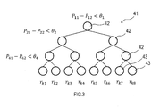
- FIG. 4 is a diagram illustrating a regression tree according to the embodiment.
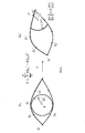
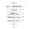
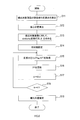
- FIG. 4 is a diagram illustrating a method for setting the position of a pixel pair using a similarity matrix. It is a flowchart of a learning process. It is a flowchart of a detection process.
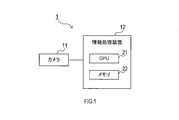
- the pupil position estimation system 1 shown in FIG. 1 is a system including a camera 11 and a pupil estimation device 12.
- the camera 11 can use, for example, a known CCD image sensor or CMOS image sensor.
- the camera 11 outputs the captured image data to the pupil estimating device 12.
- the pupil estimating apparatus 12 includes a microcomputer having a CPU 21 and a semiconductor memory such as a RAM or a ROM (hereinafter, a memory 22). Each function of the pupil estimating apparatus 12 is realized by the CPU 21 executing a program stored in a non-transitional substantial recording medium.
- the memory 22 corresponds to a non-transitional substantial recording medium storing a program. When this program is executed, a method corresponding to the program is executed.
- the pupil estimating device 12 may include one microcomputer or a plurality of microcomputers.
- the pupil center position is the center position of the pupil of the eye. More specifically, it is the center of the circular region forming the pupil.
- the pupil estimating device 12 estimates a pupil center position by a method described below.
- the estimated position of the pupil center can be obtained using the following equation (1).
- the position of the center of gravity is the position of the center of gravity of the eye region 31 that is the region where the eyeball is displayed in the captured image.
- the center-of-gravity position vector g is obtained based on a plurality of eye peripheral points Q which are feature points indicating the outer edge of the eye region 31.
- the method of obtaining the surrounding point Q is not particularly limited, and can be obtained by various methods capable of obtaining the center-of-gravity position vector g.
- f K (S (K) ) in the equation (2) can be represented by a function shown in the following equation (3).
- Equation (3) g k is a regression function.
- K is the number of additions of the regression function, that is, the number of iterations.
- the function f K is applied to the current difference vector S (K) (in other words, the regression function g k is ) To obtain an updated difference vector S (K + 1) .
- the function f K is applied to the current difference vector S (K) (in other words, the regression function g k is )
- an updated difference vector S (K + 1) By repeating this, a difference vector S with improved accuracy is obtained.
- f K is a function including a regression function g k , and is described in the above-mentioned Reference 1, and Greedy Function Approximation: A gradient boosting machine (Jerome H. Friedman, The Annals of Statistics Volume 29, Number 5 (2001) ), 1189-1232, hereafter referred to as reference document 2), which is a function to which an additive model of a regression function using Gradient Boosting is applied.
- reference document 2 A gradient boosting machine (Jerome H. Friedman, The Annals of Statistics Volume 29, Number 5 (2001) ), 1189-1232, hereafter referred to as reference document 2), which is a function to which an additive model of a regression function using Gradient Boosting is applied.
- each element of the equation (3) will be described.
- N Number of training sample images
- ⁇ a parameter for controlling the effectiveness of regression learning, where 0 ⁇ ⁇ 1 S (0) : average pupil position of a plurality of learning samples
- f 0 (S (0) ) is a value when ⁇ is input such that the right side in equation (4) is the smallest.
- the regression function g k (S (k) ) in the above equation (3) is a regression function that takes the current predicted pupil position S (k) as a parameter.
- the regression function g k (S (k) ) is obtained based on a regression tree 41 as shown in FIG.
- the regression function g k (S (k) ) is a relative displacement vector indicating the moving direction and the moving amount in the captured image plane. This regression function g k (S (k) ) corresponds to a correction vector used for correcting the difference vector S.
- Regression amount r k is defined for each lobe 43 of the regression tree 41.
- the regression amount r k is a value of the regression function g k (S (k)) for the current pupil predicted position (g + S (k)) .
- the position obtained by adding the current predicted pupil position (g + S (k) ) to the center of gravity position corresponds to the temporary pupil center position.
- Regression tree 41 i.e., the pixel pair and threshold of each node, and an end portion (i.e., the leaves 43 of the regression tree 41) Regression amount r k is set to, is acquired by learning. Note that a corrected value is used for the position of the pixel pair as described later.
- Each node 42 of the regression tree 41 determines whether one of the two pixels forms a pupil portion and the other forms a portion other than the pupil. In the captured image, the pupil portion is relatively dark in color, and portions other than the pupil are relatively light in color. Therefore, by using the luminance difference between the pixel pairs as the input information, the above-described determination can be easily performed.
- the difference vector S (k) can be updated by the following equation (6).
- f k (S (k) ) in equation (6) is a difference vector that has been updated up to the (k ⁇ 1) -th update
- vg k (S (k) ) is a correction amount in the k-th update.
- the position of the pixel pair is determined for each node 42 in the regression tree 41 for obtaining the regression function g k (S (k) ).
- the pixel position in the captured image of each pixel pair referred to in the regression tree 41 is a coordinate position determined by relative coordinates from the temporary pupil center position (g + S (k) ) at that time.
- the vector that defines the relative coordinates is a standard vector that is predetermined for a standard image that is a standard image, and a similarity that reduces the amount of deviation between the eye in the standard image and the eye in the captured image.
- This is a correction vector to which a correction by a matrix (hereinafter, conversion matrix R) is added.
- the standard image is an average image obtained from a large number of learning samples.
- FIG. 4 The diagram on the left side of FIG. 4 is a standard image, and the diagram on the left side is a photographed image.
- the standard vector defined for the standard image is (dx, dy).
- peripheral points Q of M eyes for a plurality of learning samples are acquired, and M Qm are learned as an average position of each point. Then, similarly, M Qm's of surrounding points are calculated from the captured image. Then, a transformation matrix R that minimizes the following equation (7) is obtained between Qm and Qm ′. Using the transformation matrix R, the position of a pixel relatively determined at a certain temporary pupil center position (g + S (k) ) is set by the following equation (8).
- the transformation matrix R is a matrix that indicates what kind of rotation, enlargement, or reduction is applied to the average value Qm based on a plurality of learning samples to most approximate the Qm ′ of the target learning sample.
- the position of the pixel pair can be set using a correction vector in which the difference between the standard image and the captured image has been offset compared to the standard vector.
- the accuracy of detecting the center of the pupil can be improved by using the transformation matrix R.
- the regression function estimation for obtaining the difference vector S is performed using the luminance difference between two different pixel pairs set at each node 42 of the regression tree 41.
- Gradient boosting was performed to determine the regression tree 22 (regression function g k ), and the relationship between the luminance difference and the pupil position was obtained.
- the information input to the regression tree 22 does not have to be the luminance difference between the pixel pairs.
- the absolute value of the luminance of the pixel pair may be used, or the average value of the luminance in a certain range may be obtained. That is, various types of information regarding the luminance around the temporary pupil center position can be used as input information.
- the use of the luminance difference between the pixel pairs is convenient because the feature amount is likely to be large, and can suppress an increase in the processing load.
- the pupil estimating device 12 performs learning in advance to obtain the regression tree 41, the selection of the pixel pair based on the average image, and the threshold ⁇ . Further, the pupil estimating device 12 efficiently estimates the pupil position from the detection target image, which is a captured image acquired by the camera 11, by using the regression tree 41, the pixel pair, and the threshold ⁇ acquired by learning.
- the pupil estimating device 12 does not necessarily need to perform the prior learning, and the pupil estimating device 12 can use information such as a regression tree acquired by learning by another device.
- the CPU 21 detects a peripheral point Q of the eye region of each learning sample for a plurality of learning samples.
- the CPU 21 calculates the average position Qm of each of the surrounding points Q of all the learning samples.
- this transformation matrix R is a transformation matrix that minimizes the expression (7).
- the CPU 21 obtains the initial value f 0 (S (0) ) of the regression function using the above-described equation (4).
- the CPU 21 configures a regression tree used for pupil center estimation, that is, a position and a threshold of a pixel pair for each node by learning using so-called gradient boosting.
- a regression function g k realized as a regression tree is obtained .
- a method of dividing each binary tree for example, a method described in the section 2.3.2 of the above-mentioned reference document 1 “One Millisecond Face Alignment with an Ensemble of Regression Trees” may be used.
- the regression tree is applied to each learning sample, and the current pupil position is updated using the above equation (3).
- the above (a) is performed again to obtain a regression function g k , and then the above (b) is performed. This is repeated K times to construct a regression tree by learning.
- the CPU 21 detects the peripheral point Q of the eye area 31 of the detection target image.
- This S11 corresponds to the processing of the surrounding point detection unit.
- the CPU 21 calculates the center-of-gravity position vector g from the surrounding point Q acquired in S11. This S12 corresponds to the processing of the position calculation unit.
- the CPU 21 obtains a Similarity transformation matrix R for the detection target image.
- the pixel position of the pixel pair used at each node 42 of the regression tree 41 is determined by prior learning, but is a relative position based on the above-described standard image. Therefore, by correcting the target pixel position in the detection target image using the transformation matrix R that approximates the standard image to the detection target image, the pixel position becomes more suitable for a regression tree or the like generated by learning. The detection accuracy of the center of the pupil is improved.
- Qm used in equation (7) may use a value obtained by learning in S2 of FIG. This S13 corresponds to the processing of the matrix acquisition unit.
- the CPU 21 obtains g k (S (k) ) by following the learned regression tree. This S15 corresponds to the processing of the correction amount calculation unit.
- the CPU 21 uses g k (S (k) ) acquired in S15 and adds g k (S (k) ) to S (k) based on the above equation (6), The difference vector S (k) for specifying the current pupil position is updated.
- This S16 corresponds to the processing of the updating unit.
- k k + 1.
- This S18 corresponds to the processing of the arithmetic control unit. Further, the processing of S13-S18 corresponds to the processing of the first arithmetic unit.
- the CPU 21 determines the pupil position on the detection target image according to Equation (1) using S (K) obtained in the last S17 and the barycentric position vector g obtained in S12. . That is, in S19, the final estimated value of the pupil center position is calculated. Thereafter, this detection processing ends.
- This S19 corresponds to the processing of the second calculation unit.
- the position of the center of the pupil is estimated by predicting the difference vector between the position of the center of gravity and the position of the pupil by using a regression function technique. Therefore, for example, the position of the pupil center can be estimated more efficiently as compared with a method of specifying a pupil position by repeatedly executing a sliding window.
- the reference position calculated using the surrounding points Q is not limited to the center-of-gravity position.
- the reference position of the eye is not limited to the position of the center of gravity, and various positions can be used as the reference.
- the midpoint between the outer corner and the inner corner of the eye may be used as the reference position.
- the configuration in which the difference vector S (k) is updated a plurality of times to obtain the center of the pupil is exemplified.
- the present invention is not limited to this. You may ask.
- the number of times the difference vector is updated in other words, the condition for ending the update is not limited to the above-described embodiment, and may be configured to be repeated until some predetermined condition is satisfied.
- a plurality of functions of one component in the above embodiment may be realized by a plurality of components, or one function of one component may be realized by a plurality of components. . Also, a plurality of functions of a plurality of components may be realized by one component, or one function realized by a plurality of components may be realized by one component. Further, a part of the configuration of the above embodiment may be omitted. Further, at least a part of the configuration of the above-described embodiment may be added to or replaced with the configuration of another above-described embodiment. Note that all aspects included in the technical idea specified by the terms described in the claims are embodiments of the present disclosure.
- the present disclosure can also be realized in various forms such as an actual recording medium and a pupil estimation method.
Landscapes
- Engineering & Computer Science (AREA)
- Theoretical Computer Science (AREA)
- Physics & Mathematics (AREA)
- Health & Medical Sciences (AREA)
- General Physics & Mathematics (AREA)
- Computer Vision & Pattern Recognition (AREA)
- Life Sciences & Earth Sciences (AREA)
- General Health & Medical Sciences (AREA)
- Multimedia (AREA)
- Evolutionary Computation (AREA)
- Data Mining & Analysis (AREA)
- Artificial Intelligence (AREA)
- Medical Informatics (AREA)
- Human Computer Interaction (AREA)
- Ophthalmology & Optometry (AREA)
- Software Systems (AREA)
- Databases & Information Systems (AREA)
- Computing Systems (AREA)
- General Engineering & Computer Science (AREA)
- Bioinformatics & Cheminformatics (AREA)
- Bioinformatics & Computational Biology (AREA)
- Evolutionary Biology (AREA)
- Biophysics (AREA)
- Biomedical Technology (AREA)
- Heart & Thoracic Surgery (AREA)
- Molecular Biology (AREA)
- Surgery (AREA)
- Animal Behavior & Ethology (AREA)
- Public Health (AREA)
- Veterinary Medicine (AREA)
- Spectroscopy & Molecular Physics (AREA)
- Discrete Mathematics (AREA)
- Eye Examination Apparatus (AREA)
- Image Analysis (AREA)
Priority Applications (1)
| Application Number | Priority Date | Filing Date | Title |
|---|---|---|---|
| US17/161,043 US20210145275A1 (en) | 2018-07-31 | 2021-01-28 | Pupil estimation device and pupil estimation method |
Applications Claiming Priority (2)
| Application Number | Priority Date | Filing Date | Title |
|---|---|---|---|
| JP2018-143754 | 2018-07-31 | ||
| JP2018143754A JP2020018474A (ja) | 2018-07-31 | 2018-07-31 | 瞳孔推定装置および瞳孔推定方法 |
Related Child Applications (1)
| Application Number | Title | Priority Date | Filing Date |
|---|---|---|---|
| US17/161,043 Continuation US20210145275A1 (en) | 2018-07-31 | 2021-01-28 | Pupil estimation device and pupil estimation method |
Publications (1)
| Publication Number | Publication Date |
|---|---|
| WO2020027129A1 true WO2020027129A1 (ja) | 2020-02-06 |
Family
ID=69231887
Family Applications (1)
| Application Number | Title | Priority Date | Filing Date |
|---|---|---|---|
| PCT/JP2019/029828 Ceased WO2020027129A1 (ja) | 2018-07-31 | 2019-07-30 | 瞳孔推定装置および瞳孔推定方法 |
Country Status (3)
| Country | Link |
|---|---|
| US (1) | US20210145275A1 (cg-RX-API-DMAC7.html) |
| JP (1) | JP2020018474A (cg-RX-API-DMAC7.html) |
| WO (1) | WO2020027129A1 (cg-RX-API-DMAC7.html) |
Families Citing this family (1)
| Publication number | Priority date | Publication date | Assignee | Title |
|---|---|---|---|---|
| CN117788361B (zh) * | 2022-09-22 | 2026-04-14 | 南京博视医疗科技有限公司 | 一种瞳孔定位方法及装置 |
Citations (3)
| Publication number | Priority date | Publication date | Assignee | Title |
|---|---|---|---|---|
| JP2001175869A (ja) * | 1999-12-07 | 2001-06-29 | Samsung Electronics Co Ltd | 話し手位置検出装置及びその方法 |
| JP2018520444A (ja) * | 2015-09-21 | 2018-07-26 | 三菱電機株式会社 | 顔の位置合わせのための方法 |
| WO2019045750A1 (en) * | 2017-09-01 | 2019-03-07 | Magic Leap, Inc. | DETAILED EYE SHAPE MODEL FOR ROBUST BIOMETRIC APPLICATIONS |
Family Cites Families (3)
| Publication number | Priority date | Publication date | Assignee | Title |
|---|---|---|---|---|
| US10016130B2 (en) * | 2015-09-04 | 2018-07-10 | University Of Massachusetts | Eye tracker system and methods for detecting eye parameters |
| US10872272B2 (en) * | 2017-04-13 | 2020-12-22 | L'oreal | System and method using machine learning for iris tracking, measurement, and simulation |
| US11839495B2 (en) * | 2018-03-26 | 2023-12-12 | Samsung Electronics Co., Ltd | Electronic device for monitoring health of eyes of user and method for operating the same |
-
2018
- 2018-07-31 JP JP2018143754A patent/JP2020018474A/ja active Pending
-
2019
- 2019-07-30 WO PCT/JP2019/029828 patent/WO2020027129A1/ja not_active Ceased
-
2021
- 2021-01-28 US US17/161,043 patent/US20210145275A1/en not_active Abandoned
Patent Citations (3)
| Publication number | Priority date | Publication date | Assignee | Title |
|---|---|---|---|---|
| JP2001175869A (ja) * | 1999-12-07 | 2001-06-29 | Samsung Electronics Co Ltd | 話し手位置検出装置及びその方法 |
| JP2018520444A (ja) * | 2015-09-21 | 2018-07-26 | 三菱電機株式会社 | 顔の位置合わせのための方法 |
| WO2019045750A1 (en) * | 2017-09-01 | 2019-03-07 | Magic Leap, Inc. | DETAILED EYE SHAPE MODEL FOR ROBUST BIOMETRIC APPLICATIONS |
Non-Patent Citations (3)
| Title |
|---|
| JEONG, MI-RA ET AL.: "Eye pupil detection system using an ensemble of regression forest and fast radial symmetry transform with a near infrared camera", INFRARED PHYSICS & TECHNOLOGY, vol. 85, 30 May 2017 (2017-05-30), pages 44 - 51, XP085175912, DOI: 10.1016/j.infrared.2017.05.019 * |
| KAZEMI, VAHID ET AL.: "One Millisecond Face Alignment with an Ensemble of Regression Trees", 2014 IEEE CONFERENCE ON COMPUTER VISION AND PATTERN RECOGNITION, 25 September 2014 (2014-09-25), pages 1867 - 1874 * |
| MARKUS, NENAD ET AL.: "Eye pupil localization with an ensemble of randomized trees", PATTERN RECOGNITION, vol. 47, 16 August 2013 (2013-08-16), pages 578 - 587, XP028759989, DOI: 10.1016/j.patcog.2013.08.008 * |
Also Published As
| Publication number | Publication date |
|---|---|
| US20210145275A1 (en) | 2021-05-20 |
| JP2020018474A (ja) | 2020-02-06 |
Similar Documents
| Publication | Publication Date | Title |
|---|---|---|
| KR102574141B1 (ko) | 이미지 디스플레이 방법 및 디바이스 | |
| US11126888B2 (en) | Target recognition method and apparatus for a deformed image | |
| EP3755204B1 (en) | Eye tracking method and system | |
| JP6961797B2 (ja) | プレビュー写真をぼかすための方法および装置ならびにストレージ媒体 | |
| US11087169B2 (en) | Image processing apparatus that identifies object and method therefor | |
| CN107529650B (zh) | 闭环检测方法、装置及计算机设备 | |
| CN110493488B (zh) | 视频稳像方法、视频稳像装置和计算机可读存储介质 | |
| JP6688277B2 (ja) | プログラム、学習処理方法、学習モデル、データ構造、学習装置、および物体認識装置 | |
| CN109919971B (zh) | 图像处理方法、装置、电子设备及计算机可读存储介质 | |
| US9967516B2 (en) | Stereo matching method and device for performing the method | |
| JP2023545190A (ja) | 画像の視線補正方法、装置、電子機器、及びコンピュータプログラム | |
| US20160358341A1 (en) | Fast Template-Based Tracking | |
| JP2010512581A (ja) | 多次元ブースト回帰を経た外観及び動作を使用する高速人間姿勢推定 | |
| CN108345821B (zh) | 面部追踪方法及设备 | |
| CN109190617B (zh) | 一种图像的矩形检测方法、装置及存储介质 | |
| CN111368731A (zh) | 静默活体检测方法、装置、设备及存储介质 | |
| JP7403995B2 (ja) | 情報処理装置、制御方法およびプログラム | |
| WO2018082308A1 (zh) | 一种图像处理方法及终端 | |
| EP4231253A1 (en) | A method and system for dynamic cropping of full body pose images | |
| CN110837781A (zh) | 一种人脸识别方法、人脸识别装置及电子设备 | |
| JP2021009493A (ja) | 画像処理装置、画像処理装置の制御方法及びプログラム | |
| CN103514435A (zh) | 手检测方法和装置 | |
| KR20190131366A (ko) | 영상 처리에서의 데이터 확장 방법 및 그 장치 | |
| KR102861404B1 (ko) | 인공지능 기반 얼굴 인식 장치 및 방법 | |
| JP2020018474A (ja) | 瞳孔推定装置および瞳孔推定方法 |
Legal Events
| Date | Code | Title | Description |
|---|---|---|---|
| 121 | Ep: the epo has been informed by wipo that ep was designated in this application |
Ref document number: 19844372 Country of ref document: EP Kind code of ref document: A1 |
|
| NENP | Non-entry into the national phase |
Ref country code: DE |
|
| 122 | Ep: pct application non-entry in european phase |
Ref document number: 19844372 Country of ref document: EP Kind code of ref document: A1 |