WO2020022455A1 - 情報処理装置、その設定方法及びプログラム - Google Patents
情報処理装置、その設定方法及びプログラム Download PDFInfo
- Publication number
- WO2020022455A1 WO2020022455A1 PCT/JP2019/029284 JP2019029284W WO2020022455A1 WO 2020022455 A1 WO2020022455 A1 WO 2020022455A1 JP 2019029284 W JP2019029284 W JP 2019029284W WO 2020022455 A1 WO2020022455 A1 WO 2020022455A1
- Authority
- WO
- WIPO (PCT)
- Prior art keywords
- information
- information processing
- terminal
- unit
- processing
- Prior art date
- Legal status (The legal status is an assumption and is not a legal conclusion. Google has not performed a legal analysis and makes no representation as to the accuracy of the status listed.)
- Ceased
Links
Images












Classifications
-
- H—ELECTRICITY
- H04—ELECTRIC COMMUNICATION TECHNIQUE
- H04N—PICTORIAL COMMUNICATION, e.g. TELEVISION
- H04N23/00—Cameras or camera modules comprising electronic image sensors; Control thereof
- H04N23/60—Control of cameras or camera modules
- H04N23/66—Remote control of cameras or camera parts, e.g. by remote control devices
- H04N23/661—Transmitting camera control signals through networks, e.g. control via the Internet
-
- H—ELECTRICITY
- H04—ELECTRIC COMMUNICATION TECHNIQUE
- H04L—TRANSMISSION OF DIGITAL INFORMATION, e.g. TELEGRAPHIC COMMUNICATION
- H04L47/00—Traffic control in data switching networks
- H04L47/10—Flow control; Congestion control
- H04L47/32—Flow control; Congestion control by discarding or delaying data units, e.g. packets or frames
-
- H—ELECTRICITY
- H04—ELECTRIC COMMUNICATION TECHNIQUE
- H04L—TRANSMISSION OF DIGITAL INFORMATION, e.g. TELEGRAPHIC COMMUNICATION
- H04L65/00—Network arrangements, protocols or services for supporting real-time applications in data packet communication
- H04L65/60—Network streaming of media packets
- H04L65/75—Media network packet handling
- H04L65/752—Media network packet handling adapting media to network capabilities
-
- H—ELECTRICITY
- H04—ELECTRIC COMMUNICATION TECHNIQUE
- H04L—TRANSMISSION OF DIGITAL INFORMATION, e.g. TELEGRAPHIC COMMUNICATION
- H04L65/00—Network arrangements, protocols or services for supporting real-time applications in data packet communication
- H04L65/60—Network streaming of media packets
- H04L65/75—Media network packet handling
- H04L65/756—Media network packet handling adapting media to device capabilities
-
- H—ELECTRICITY
- H04—ELECTRIC COMMUNICATION TECHNIQUE
- H04L—TRANSMISSION OF DIGITAL INFORMATION, e.g. TELEGRAPHIC COMMUNICATION
- H04L65/00—Network arrangements, protocols or services for supporting real-time applications in data packet communication
- H04L65/60—Network streaming of media packets
- H04L65/75—Media network packet handling
- H04L65/765—Media network packet handling intermediate
-
- H—ELECTRICITY
- H04—ELECTRIC COMMUNICATION TECHNIQUE
- H04N—PICTORIAL COMMUNICATION, e.g. TELEVISION
- H04N21/00—Selective content distribution, e.g. interactive television or video on demand [VOD]
- H04N21/60—Network structure or processes for video distribution between server and client or between remote clients; Control signalling between clients, server and network components; Transmission of management data between server and client, e.g. sending from server to client commands for recording incoming content stream; Communication details between server and client
- H04N21/63—Control signaling related to video distribution between client, server and network components; Network processes for video distribution between server and clients or between remote clients, e.g. transmitting basic layer and enhancement layers over different transmission paths, setting up a peer-to-peer communication via Internet between remote STB's; Communication protocols; Addressing
- H04N21/633—Control signals issued by server directed to the network components or client
Definitions
- the present invention is based on another information transmitted by a terminal when processing information transmitted by a terminal between a computing device and a terminal in a system in which the computing device is connected to a plurality of terminals via a network.
- the present invention relates to a system and a method for setting a rule for performing information processing of a system for performing processing.
- IoT Internet of Things
- NW Network
- technologies and services that utilize a large amount of information acquired by the terminals are being studied.
- a large number of sensors connected to the NW for example, a microphone for acquiring audio information, a camera for acquiring image information, a measuring device for acquiring environmental information such as temperature, humidity, and brightness, and the speed, direction, and position of a machine
- the effective use of a measurement device that acquires the operation information of the NW is taken up as an issue, and the information that can be acquired by individual terminals connected to the NW, in the above example, not only the sensor information alone but also the Utilization methods such as combining and using information or analyzing by statistical processing are being studied.
- a terminal becomes capable of transmitting and receiving information to and from the outside via the NW
- the control function of the terminal itself or a terminal that has been conventionally deployed in an NW closed to the site where the terminal is installed is provided by a cloud.
- decentralized terminal functions utilizing external resources such as deployment at the edge of an NW close to the terminal, can also be realized. If some terminal functions are aggregated and deployed on the cloud or at the edge of the NW close to the terminals, it is necessary to implement advanced functions on individual terminals to provide intelligent terminal control and high value-added services As a result, the service utilizing advanced functions can be developed while reducing the cost of the terminal itself and the maintenance and operation cost for maintenance.
- An existing mechanism for processing information, for example, packets, based on predetermined rules includes a firewall.
- rules for packet processing are set based on a network or application operation method determined in advance by a user, Packets are monitored / processed by the firewall.
- applications and general-purpose services that are widely used in order to easily and correctly set up the firewall
- Dynamic firewalls that use a predefined profile, such as "allow corresponding control traffic," and methods for automatically setting packet processing rules are widely used.
- terminal 1 When information to be transmitted in real time by a certain terminal (terminal 1) is to be processed based on information transmitted by another terminal (terminal 2) in real time, the information based on the information of terminal 2 which processes the information of terminal 1 is used. Rules must be decided. When manually creating a rule for processing the information of the terminal 1 based on the characteristics of the terminal 1 or the terminal 2 and the method of using the information of the terminal 1 by a preliminary preliminary experiment or the like, for each terminal to be used and for each method of using the information, It is necessary to perform trial and error to set an appropriate information processing rule, and it takes a lot of time to create an information processing rule. When the terminal and the method of using the information transmitted by the terminal are updated or changed, it is necessary to create a new information processing rule each time.
- the present invention has been made in view of the above circumstances, and an object of the present invention is to provide an information processing apparatus capable of automatically setting an appropriate information processing rule according to an environment of a terminal or a computing apparatus. .
- the present invention provides an actual processing status of terminal information processed based on an information processing rule, utilizing information of a terminal processed based on an information processing rule, and a processing side of the information. Collects the actual processing status, uses the information of the terminal and automatically creates and sets the information processing rule that satisfies the processing status requested by the information processing side based on the relationship with the set information processing rule ,Update.
- the present invention provides information arranged on a communication path between a first terminal and a second terminal that transmit different types of information in real time, and a computing device that processes information transmitted from the first terminal.
- An information receiving unit that receives information from a first terminal and a second terminal, and an information processing unit that processes information received from the first terminal based on information received from the second terminal in accordance with an information processing rule Unit, an information transmitting unit that transmits information from the first terminal processed by the information processing unit to the computing device, and an information transmitting unit in the information processing unit based on at least one of an information processing situation in the computing device or a device status of the computing device.
- an information processing method determining unit that determines a processing method of information received from the two terminals, creates an information processing rule, and sets the information processing rule in the information processing unit.
- the terminal according to the present invention when information to be transmitted from one terminal (terminal 1) in real time is to be processed based on information to be transmitted from another terminal (terminal 2) in real time, the terminal according to the present invention processes the information of terminal 1 Although a rule based on the second information must be determined, it is not necessary to create the information processing rule while manually adjusting the information processing rule. By keeping this solution functioning at all times even when processing terminal information, the terminal information can be placed in an unexpected environment or the environment around the terminal may change rapidly, for example. Even if there is an unexpected change from the beginning of the process, depending on the actual processing status of the terminal information processed based on the information processing rules, the actual processing status of the side using or processing the terminal information Thus, the rule for processing the terminal information can be changed in real time.
- the rules for processing the terminal information can be changed as necessary so as to satisfy the processing situation required by the side that uses or processes the terminal information. Further, it is possible to dynamically cope with an increase, a change, and a change in a required condition of a method of using or processing terminal information.
- FIG. 1 is a schematic configuration diagram of a system that is a premise of the present invention
- FIG. 2 is a schematic configuration diagram of an information processing rule setting system according to the present invention.
- a plurality of similar devices / configurations are denoted by a common main reference number, and a branch number is added after the main reference number to individually refer to each device / configuration.
- a branch number is added after the main reference number to individually refer to each device / configuration.
- a main reference numeral is used.
- each terminal 10 includes an information acquisition unit 11 for acquiring information, an information generation unit 12 for generating information, and information acquired by the information acquisition unit 11 and information generated by the information generation unit 12.
- An information transmitting unit 13 connected to the NW 90 and transmitting to the outside in real time is provided.
- Each terminal 10 transmits different types of information in real time.
- the terminal 10 may be configured to include only one of the information acquisition unit 11 and the information generation unit 12.
- the calculation device 20 includes an information receiving unit 21 that receives information transmitted from each terminal 10 connected to the NW 90, and an information processing unit 22 that performs information processing including information retransmission.
- the information processing device 100 is arranged on an information communication path from each terminal 10 to the computing device 20.
- each terminal 10 is connected to the NW 90-1
- the computing device 20 is connected to the NW 90-2
- the information processing device 100 is connected to each of the NWs 90-1 and 90-2. .
- the information processing apparatus 100 uses the information receiving unit 110 that receives information transmitted by each terminal 10 in real time and the received information alone or in combination with a plurality of pieces of information based on a set information processing rule. It has an information processing unit 120 that processes information transmitted from another terminal 10 in real time, and an information transmitting unit 130 that transmits processed information to the outside, here the computing device 20, connected to the NW 90-2.
- the information processing control device 200 includes an information processing control unit 210 that is a functional unit that sets an information processing rule used by the information processing unit 120 of the information processing device 100, and an information processing state in the calculation device 20 transmitted from the calculation device 20. And a status receiving unit 220 for receiving the device status.
- the information processing control unit 210 includes (a) a set information processing rule, (b) a processing status of information acquired from the information processing unit 120, and (c) an information processing status / An information processing rule is set based on the device status and (d) the information processing status / device status requested by the computing device 20.
- the information processing control unit 210 and the status receiving unit 220 exist independently of the information processing device 100 as the information processing control device 200, but may be included in the information processing device 100. I do not care.
- the information processing device 100 and the information processing control device 200 are mainly composed of semiconductor devices, and are volatile storage devices such as a CPU (Central Processing Unit) and a RAM (Random Access Memory), and nonvolatile storage devices such as a hard disk and a flash memory. , And a communication interface for performing a connection for communication with the outside. Further, the information processing apparatus 100 and the information processing control apparatus 200 are not limited to network devices such as physical switches and routers, but include a physical computer on which the program of the present invention operates and a virtualized computer.
- the computing device 20 includes an information receiving unit 21 that receives information transmitted by the information processing device 100 illustrated in FIG. 1 and an information processing unit 22 that processes information transmitted by the terminal 10. It includes a device monitoring unit 23 for monitoring, and a status transmitting unit 24 for transmitting the information processing status / device status in the computing device 20 acquired from the information processing unit 22 and the device monitoring unit 23 to an external unit, here, the status receiving unit 220.
- FIG. 3 is a functional block diagram of the information processing rule setting system.
- the information processing unit 120 in the information processing apparatus 100 in FIG. 2 information transmitted from the terminal 10 (here, the first terminal 10-1) in real time is transmitted to another terminal 10 (here, the second terminal 10-2). ), The processed information is transmitted to the computing device 20 via the information transmitting unit 130 after the processing according to the information processing rule based on the information transmitted in real time from the second NW 90- 2 to "change" the flow of information transmitted.
- the first terminal 10-1 and the second terminal 10-2 transmit different types of information in real time.
- the “change” means that the information processing device 100 discards information that is not required to be transmitted to the computing device 20 due to, for example, a problem of the quality of the information. This means a change that has an advantage on the side of using the terminal 10, the computing device 20, and the NW 90 to which they are connected, such as reducing the load or improving the information processing accuracy of the computing device 20.
- the information processing rule for causing the “change” is created by the information processing control unit 210, here, the information processing method determination unit 211, and the rule is set in the information processing unit 120 of the information processing apparatus 100.
- FIG. 3 shows that the information transmitted from the first terminal 10-1 to the first computing device 20-1 in real time is transmitted from the second terminal 10-2 in real time so that the information processing device 100 processes the information.
- the functional blocks necessary for creating, setting, and updating the information processing rule of the first terminal 10-1 based on the information are described.
- the actual information processing status / device status in the first computing device 20-1 that uses or processes the information of the first terminal 10-1 processed based on the information is determined by the information processing method determination unit 211 of the information processing control unit 210.
- the second terminal information processing method determination unit 211a collects the information and, based on the relationship between the collected information and the set information processing rule, the information processing requested by the first computer 20-1 stored in the storage unit 212 in advance.
- the information processing method of the second terminal 10-2 is determined and set in the information processing unit 120, in this case, the second terminal information processing unit 120b A constant.
- the created and set information processing rule, the processing status of the information of the first terminal 10-1, and the information processing status / device status in the first computing device 20-1 are stored in the storage unit 212 as needed.
- the information processing method determination unit 211 is notified of the actual processing status of the side that uses or processes the information of the terminal 10 that has been processed based on the information, or the information processing method determination unit 211 obtains the information using a request response method. Either may be used.
- the method of acquiring information may be either acquisition from inside the device or acquisition from outside via a network.
- the information processing unit 22 and the device monitoring unit 23 in the calculation device 20 transmit the information processing status / device status to the status transmission unit 24 (steps S1 and S2).
- the status transmitting unit 24 transmits the information processing status / device status in the computing device 20 to the status receiving unit 220 (Step S3).
- the situation receiving unit 220 and the information processing unit 120 in the information processing apparatus 100 here, the first terminal information processing unit 120a, correspond to the information processing method determination unit 211 of the information processing control unit 210, and the second terminal information
- the processing method determination unit 211a corresponds thereto, and transmits the information processing status / device status in the computing device 20 and the processing status of the first terminal information in the information processing device 100 thereto (steps S4 and S5).
- the second terminal information processing method determination unit 211a stores the received information in the storage unit 212, and stores the information stored in the storage unit 212 (the information processing status / device status requested by the computing device 20, the information processing device 100 After determining the processing method of the second terminal information based on the processing method of the second terminal information, the processing status of the first terminal information, and the relationship between the information processing status / device status in the computing device 20, the determination result is stored in the storage unit. It is stored in the second terminal 212 and transmitted to the second terminal information processing unit 120b (steps S6 to S9). As described above, the information processing method of the first terminal 10-1, that is, the information processing rule is created and set, and the information processing is performed based on the set rule.
- the information processing method determining unit 211 receives the processing status of the terminal information in the information processing device 100 from the information processing unit 120 (step S11), and receives the information processing status / device status in the computing device 20 from the status receiving unit 220 ( Step S12).
- the received information is stored in the storage unit 212 (Step S13), and the information processing status / device status requested by the computing device 20 stored in the storage unit 212 is referred to and compared with the received information (Steps S14 and S15). ).
- step S16 an information processing method that satisfies the information processing status / device status requested by the computing device 20 is determined based on (step S16).
- the determination result is stored in the storage unit 212 and transmitted to the information processing unit 120 (Steps S17 and S18).
- a rule for processing information of the terminal 10 is automatically created so as to satisfy a processing situation requested by a side that uses or processes the information of the terminal 10. , And can be changed and updated as needed.
- a first embodiment is an example in which the information processing rule setting system of the present invention is applied to a system for transmitting a video from a camera to a video processing device.
- a system according to the first embodiment will be described with reference to FIG.
- FIG. 6 is a configuration diagram of the system according to the first embodiment.
- information transmitted from the camera 31 is a processing target.
- the information processing apparatus 100 performs a process of discarding or transmitting video information.
- the rule for processing the video information is a terminal different from the camera 31, and is created and set based on sensor information transmitted from a sensor 32 such as a speed sensor attached to the camera 31. This sensor information is information indicating a state that affects the imaging state of the video information.
- the video processing device 40 corresponds to the above-described computing device 20, and includes an information receiving unit 41, an information processing unit 42, a device monitoring unit 43, and a status transmitting unit 44.
- the sensor information processing method determination unit 211b of the information processing control unit 210 determines the processing method of the sensor information, that is, creates an information processing rule, transmits the determination result to the sensor information processing unit 120d of the information processing unit 120, and Set.
- the camera information processing unit 120c of the information processing unit 120 processes the camera information based on a processing method of the camera information presented by the sensor information processing unit 120d, that is, an information processing rule.
- the processing method of the sensor information determined in the present embodiment is the setting of the speed threshold V sh as shown in the flowchart of FIG. 7, and the speed V t and V sh at the time t received by the sensor information processing unit 120d.
- An information rule for transmitting or discarding the camera information is created and set according to the magnitude relationship (steps S21 to S24).
- the sensor information processing method determination unit 211b receives the video processing status (eg, image recognition rate A 1 %) of the video processing device 40 (Step S101), and stores the video requested by the video processing device 40 stored in the storage unit 212. A comparison is made with reference to the processing status (eg, the image recognition rate A sh % or more) (steps S102 to S103). If the received video processing status satisfies the video processing status requested by the video processing device 40, the process ends. If the video processing status does not satisfy the video processing status, the processing method for the sensor information is determined, that is, the flow shifts to a flow for setting Vsh. (Steps S104 to S120).
- the video processing status eg, image recognition rate A 1 %) of the video processing device 40
- the decrease in the image recognition rate (A%) is caused by excess video when the camera 31 is moving at high speed, and the direction in which the video is reduced when the camera 31 is moving at high speed.
- Fixed information processing rules that is,
- / 2
- notifies the sensor information processing section 120d to use the (step S105).
- a 2 is compared with A sh (steps S106 to S107). If A 2 also does not satisfy A sh ,
- a 2 is when you meet the A sh,
- A is used at the time of no longer meets the A sh
- the video acquired when the camera 31 moves at high speed has poor quality and cannot be appropriately processed by the video processing device 40 even when transmitted to the video processing device 40. It is possible to automatically create, set, and update information processing rules that can selectively discard only video information that cannot be properly processed, that is, video information that deteriorates the video processing status of the video processing device 40. As a result, even when a change such as a change in the installation environment of the camera 31 occurs, it is possible to maintain a state that satisfies the video processing situation required by the video processing device 40.
- the video processing status requested by the video processing device 40 is not the image recognition rate A sh % but the image processing frequency. This is an example in the case of B sh fps (frame per second).
- B sh fps frame per second
- the sensor information processing method determination unit 211b receives the video processing status (eg, image processing frequency B 1 fps) of the video processing device 40 (Step S201), and stores the video requested by the video processing device 40 stored in the storage unit 212. A comparison is made with reference to a processing status (eg, image processing frequency B sh fps or more) (steps S202 to S203). If the received video processing status satisfies the video processing status requested by the video processing device 40, the process ends. If the video processing status does not satisfy the video processing status, the processing method for the sensor information is determined, that is, the flow shifts to a flow for setting Vsh. (Steps S204 to S220).
- the video processing status eg, image processing frequency B 1 fps
- the decrease in the image processing frequency (Bfps) is caused by excessive discarding of the video information, and the information processing rule is corrected in a direction to reduce the discarding of the video information when the camera 31 is moving, that is,
- the information processing unit 120 in the information processing apparatus 100 performs information processing based on the newly determined
- the video processing apparatus 40 when the video processing situation of the video processing apparatus 40 is deteriorated due to excessive discard of the obtained video when the camera 31 moves, the video processing apparatus 40 It is possible to automatically create, set, and update information processing rules that satisfy the required video processing status. As a result, even when a change such as a change in the installation environment of the camera 31 occurs, it is possible to maintain a state that satisfies the video processing situation required by the video processing device 40.
- the third embodiment is an example in which the information processing rule setting system of the present invention is applied to the same system as the first embodiment, and the device status requested by the video processing device 40 is the CPU usage rate C sh %. .
- the flow of setting the information processing rule according to the present embodiment will be described with reference to the flowchart of the sensor information processing method determination unit 211b shown in FIGS.
- the sensor information processing method determination unit 211b receives the device status of the video processing device 40 (eg, CPU usage rate C 1 %) (step S301), and requests the video processing device 40 stored in the storage unit 212 to request the device status. (Example: CPU usage rate C sh % or less) and make a comparison (steps S302 to S303). If the received device status satisfies the device status requested by the video processing device 40, the process ends. If the device status does not satisfy the device status, the processing method of the sensor information is determined, that is, the flow shifts to the flow of setting Vsh (step S304 to S320).
- the device status of the video processing device 40 eg, CPU usage rate C 1 %)
- the increase in the CPU usage rate (C%) is caused by excessive video when the camera 31 is moving at high speed, and the direction in which the video is reduced when the camera 31 is moving at high speed.
- the information processing rule is corrected, that is,
- is determined as, for example,
- / 2
- notifies the sensor information processing section 120d to use the (step S305).
- the information processing unit 120 in the information processing apparatus 100 performs information processing based on the newly determined
- C 2 also again does not meet the C sh
- the video obtained when the camera 31 moves at high speed has poor quality and does not need to be transmitted to the video processing device 40, it is necessary to transmit the video to the video processing device 40. It is possible to automatically create, set, and update a packet processing rule that can selectively discard video information that does not exist, that is, only video information that deteriorates the status of the video processing device 40. As a result, even when a change such as a change in the installation environment of the camera 31 occurs, a state that satisfies the device status required by the video processing device 40 can be maintained.
- the fourth embodiment is an example in which the information processing rule setting system of the present invention is applied to the same system as the first embodiment, and the set information processing rule, the video processing status of the video processing device 40, This is an example of a case where an information processing rule is created not only from the video processing status to be created but also from the processing status of camera information in the information processing apparatus 100.
- that is, a process of converging
- the system according to the first embodiment has a feature of processing video information transmitted by the camera 31 using information of a terminal different from the camera 31 such as the sensor 32, but processing terminal information different from the camera 31.
- a processing method of terminal information characteristic of the present system that is, an information processing rule to be used by the information processing apparatus 100 in the present system to satisfy the video processing situation required by the video processing apparatus 40,
- the sensor information processing method determination unit 211b receives the processing status of camera information (eg, the number of video frame transmissions per unit time N n fps) (Step S401), and further processes the video processing status of the video processing device 40 (eg, image (Recognition rate A 1 %) is received (step S402).
- a sensor information processing method eg,
- a processing state of camera information eg, N n fps
- and a video processing state (example) : relationship a n%) (example:
- and N for n and A n any at a certain time
- step S406 to S407 referring to the received video processing status A n % of the video processing device 40 and the video processing status (for example, the image recognition rate A sh % or more) requested by the video processing device 40 stored in the storage unit 212.
- the comparison is performed (steps S406 to S407). If the received video processing status satisfies the video processing status requested by the video processing device 40, the process ends. If the video processing status does not satisfy the video processing status, the processing method for the sensor information is determined, that is, the flow shifts to a flow for setting Vsh. (S408 to S417).
- V sh is estimated using a neural network in which information stored in the storage unit 212 is grown as learning data. From the relationship between
- V sh (n + 1) the receiving after setting as a new information processing rule N n + 1 and A n + 1, more
- a The following calculated with reference to N and A (
- ⁇ Vn + 1
- a n + 1 is the process ends if they meet the A sh, satisfies the re A n + 1 ⁇ A sh unless
- Information processing rules that satisfy the required video processing status can be automatically created, set, and updated.
- the grown neural network can be applied to the application of the present invention to other similar systems, in which case the information processing rules can be quickly and accurately created from an early stage.
- problems will occur in the initial stage of the speed and accuracy of information processing rules, but since learning is performed continuously, a neural network suitable for the system to which the information is applied will be created. You.
- the fifth embodiment is an example in which the information processing rule setting system of the present invention is applied to a system for transmitting an image from the camera 31 to the image processing device 40, as in the first embodiment.
- This embodiment is different from the above-described first embodiment in that, as shown in the functional block diagram of this embodiment in FIG. 16, two types of sensors are used for creating a rule for processing video information. . That is, in the present embodiment, the rule for processing the video information is a terminal different from the camera 31, and the speed information transmitted from the speed sensor 32 attached to the camera 31 and the luminance information transmitted from the luminance sensor 33 are different. Created and set based on the combination.
- the speed information and the luminance information are information indicating a state that affects the imaging state of the video information.
- Method of processing speed / intensity information determined in this embodiment is a setting threshold value L sh1, L sh2 threshold V sh and brightness speed as shown in the flowchart of FIG. 17, the speed / intensity information processing section 120e magnitude relationship between the magnitude of the velocity V t and V sh, the luminance L t and L sh1, processing rules camera information transmitting processing or disposal by the magnitude relation of L sh2 is created and set at time t but received (Steps S31 to S35).
- the speed / brightness information processing method determination unit 211c receives the video processing status (eg, the image recognition rate A 1 %) of the video processing device 40 (Step S501), and the video processing device 40 stored in the storage unit 212 sends the request.
- a comparison is made with reference to the video processing status (eg, image recognition rate A sh % or more) to be performed (steps S502 to S503).
- a priority here, luminance> speed
- the process is terminated; otherwise, the speed / luminance information processing method is determined, that is, V sh , L sh1 , L
- the flow transits to the flow for setting sh2 (steps S504 to S529).
- the decrease in the image recognition rate (A%) is caused by excessive video when the camera 31 is moving at a high speed or excessive video when the camera 31 is installed in a dark place or a dazzling place. It is estimated.
- the processing priority is luminance> speed
- the information processing rule is corrected in a direction to reduce the image when the camera is installed in a dark place or a dazzling place, that is, L sh2 > L sh2 ′> L L sh1 ′ and L sh2 ′ are determined so that sh1 ′> L sh1 (step S505), and L sh1 ′ and L sh2 ′ are used as L sh1 and L sh2 used in the speed / luminance information processing unit 120e.
- step S506 To the speed / brightness information processing unit 120e (step S506).
- a 2 may also does not meet the A sh similarly changing the V sh in Example 1 (steps S507 ⁇ S509).
- a 3-B and A sh received after the new information processing rule is set are compared with each other. If A 3-B satisfies A sh , V sh is converged by the same method as in the first embodiment (steps S510 to S510). S511, and after step S109 in FIG. 8). If A3 -B also does not satisfy Ash , the processing method of the luminance information is changed again (steps 512 to S518). If A 2 is met A sh, to converge L sh1 and L sh2 in the same manner as in Example 1 (steps S518 ⁇ S529).
- the quality of the image acquired when the camera 31 moves at high speed and the quality of the image acquired when the camera 31 is installed in a dark place or a dazzling place are poor.
- An information processing rule that can selectively discard only video information that cannot be appropriately processed because it cannot be properly processed by the video processing device 40 even when transmitted to the device 40, that is, video information that deteriorates the video processing status of the video processing device 40. Can be automatically created, set, and updated. As a result, even when a change such as a change in the installation environment of the camera 31 occurs, it is possible to maintain a state that satisfies the video processing situation required by the video processing device 40.
- Example 6 In the sixth embodiment, as in the fifth embodiment, in the example in which the information processing rule setting system of the present invention is applied to a system for transmitting a video from the camera 31 to the video processing device 40, the video processing status requested by the video processing device 40 is described.
- the image processing frequency is B sh fps instead of the image recognition rate A sh %.
- the flow of setting the information processing rule according to the present embodiment will be described with reference to the flowchart of the speed / luminance information processing method determination unit 211c shown in FIGS.
- the speed / brightness information processing method determination unit 211c receives the video processing status (eg, image processing frequency B 1 fps) of the video processing device 40 (step S601), and the video processing device 40 stored in the storage unit 212 sends the request. A comparison is made with reference to the video processing status (eg, image processing frequency B sh fps or more) to be performed (steps S602 to S603). At this time, a priority (here, luminance> speed) as to which of the luminance and the speed is preferentially executed for processing is also referred to.
- a priority here, luminance> speed
- the process is terminated; otherwise, the speed / luminance information processing method is determined, that is, V sh , L sh1 , L
- the flow transits to the flow for setting sh2 (steps S604 to S624).
- the decrease in the image processing frequency (Bfps) is caused by excessive discard of camera information.
- the processing priority is luminance> speed
- the information processing rule is corrected so that video discarding does not occur when the camera 31 is moving, that is,
- the speed / luminance information processing unit 120e is notified to use ⁇ as sh
- L sh2 '> L sh2> L sh1> L sh1' become so 'and L sh2' L sh1 determines the installation camera 31 in the dark or bright place
- the information processing rule is corrected in a direction to reduce discard of the video when the image processing is performed (steps S607 and S608). Thereafter, L sh1 and L sh2 are converged by the same method as in the second embodiment (steps S609 to S624).
- the video processing apparatus is excessively discarded when the camera 31 is moved and when the camera 31 is installed in a dark place or a dazzling place.
- an information processing rule that satisfies the video processing status required by the video processing device 40 can be automatically created, set, and updated. As a result, even when a change such as a change in the installation environment of the camera 31 occurs, it is possible to maintain a state that satisfies the video processing situation required by the video processing device 40.
- the seventh embodiment is an example in which the information processing rule setting system of the present invention is applied to the same system as the fifth embodiment, and the apparatus status requested by the video processing apparatus 40 is the CPU usage rate C sh %. .
- the flow of setting the information processing rule according to the present embodiment will be described with reference to the flowchart of the speed / luminance information processing method determination unit 211c shown in FIGS.
- the speed / brightness information processing method determination unit 211c receives the device status of the video processing device 40 (eg, CPU usage rate C 1 %) (step S701), and requests the video processing device 40 stored in the storage unit 212. A comparison is made with reference to the device status (eg, CPU usage rate C sh % or less) (steps S702 and S703). At this time, a priority (here, luminance> speed) as to which of the luminance and the speed is preferentially executed for processing is also referred to.
- a priority here, luminance> speed
- the process is terminated; otherwise, the speed / luminance information processing method is determined, that is, V sh , L sh1 , L
- the flow transits to the flow for setting sh2 (steps S704 to S729).
- the increase in the CPU usage rate (C%) is caused by excessive video when the camera 31 is moving at high speed or excessive video when the camera is installed in a dark place or a dazzling place.
- the processing priority is luminance> speed
- the information processing rule is corrected in a direction to reduce the image when the camera 31 is installed in a dark place or a dazzling place, that is, L sh2 > L sh2 ′> L sh1 '> L sh1 become as L sh1' and 'determines, as L sh1 and L sh2 used at a speed / luminance processing section 120e, L sh1' L sh2 speed so used as L sh2 '/
- the brightness information processing unit 120e is notified (steps S704 and S705).
- step S706, S707 Comparing C 2 and C sh received since the new packet processing rule setting (step S706, S707), C 2 also is does not meet the C sh similarly changing the V sh in Example 1 (step S708, S709). Compares the C 3-B and C sh received since new information processing rule setting (step S710, S711), the V sh in the same manner as in Example 1, when the C 3-B filled with C sh The convergence is performed (from step 309 in FIG. 12). If C 3-B also does not satisfy C sh , the processing method of the luminance information is changed again (steps S712 and S713). If the C 2 satisfies the C sh, to converge L sh1 and L sh2 in the same manner as in Example 1 (steps S718 ⁇ S729).
- the quality of the image acquired when the camera 31 moves at high speed and the quality of the image acquired when the camera 31 is installed in a dark place or a dazzling place are poor. Since there is no need to transmit to the device 40, an information processing rule that can selectively discard only video information that does not need to be transmitted to the video processing device 40, that is, only video information that deteriorates the status of the video processing device 40 is automatically set. Can be created, configured, and updated. As a result, even when a change such as a change in the installation environment of the camera 31 occurs, a state that satisfies the device status required by the video processing device 40 can be maintained.
- Example 8 in the eighth embodiment, in the example in which the information processing rule setting system of the present invention is applied to the same system as the fifth embodiment, the set information processing rule, the video processing status of the video processing device 40, and the video processing device 40 This is an example of a case similar to the fourth embodiment in which the information processing rule is created not only from the video processing status to be created but also from the processing status of the camera information in the information processing apparatus 100.
- , L sh1 , L sh2 optimal from
- , L sh1 , L sh2 the processing status of camera information in the information processing device 100, the time series data of the video processing status in the video processing device 40,
- , L sh1 , L sh2 can estimate the mechanism, for example, a neural network Create and use a tool.
- the system of the fifth embodiment has a feature of processing video information transmitted by the camera 31 using information of a terminal different from the camera 31 such as the speed sensor 32 and the luminance sensor 33. Not only knowledge of how the processing method of different terminal information affected the video processing status in the video processing device 40, but also knowledge of how the processing status of camera information itself was affected as learning data.
- a processing method of terminal information characteristic of the present system that is, information to be used by the information processing apparatus 100 in the present system to satisfy a video processing situation required by the video processing apparatus 40
- , L sh1 , and L sh2 can be created quickly and accurately as compared with the fifth embodiment.
- the speed / brightness information processing method determination unit 211c receives the processing status of the camera information (eg, the number of video frame transmissions per unit time N n fps) (Step S801), and furthermore, the video processing status of the video processing device 40 (Example). : Image recognition rate A 1 %) is received (step S802).
- the processing status of the camera information eg, the number of video frame transmissions per unit time N n fps
- a speed / brightness information processing method eg,
- a camera Relationship between information processing status (example: N n fps) and video processing status (example: A n %)) (example:
- , L sh1 (n), L sh2 for (n) and N n and A n any at a certain time
- , L sh1 (n) may be used L sh2 (n) and the n n and a n.
- step S806 and S807 If the received video processing status satisfies the video processing status requested by the video processing device 40, the process ends; otherwise, the processing method of the speed / luminance information is determined, that is, V sh and L sh1 (n ) And Lsh2 (n) are set (steps S808 to S817).
- V sh , L sh1 (n) and L sh2 (n) are estimated using a neural network in which information stored in the storage unit 212 is grown as learning data.
- , L sh1 , and L sh2 are estimated, and the speed / luminance information processing unit 120e is notified to use them (steps S808, S809).
- N n + 1 and A n + 1 received after setting new packet processing rules (
- ⁇ Vn + 1
- ⁇ L 1 (n + 1) L sh1 (n + 1)
- An An + 1 is compared with A sh (steps S814 and S815). If An + 1 satisfies A sh , the processing is terminated. If An +1 does not satisfy A sh , A n + 1 ⁇ A sh is satisfied again.
- L sh1 (n + 1) and L sh2 (n + 1) are estimated, and the speed / luminance information processing unit 120e is notified to use
- Information processing rules that satisfy the required video processing status can be automatically created, set, and updated.
- the grown neural network can be applied to the application of the present invention to other similar systems, in which case the information processing rules can be quickly and accurately created from an early stage.
- problems will occur in the initial stage of the speed and accuracy of information processing rules, but since learning is performed continuously, a neural network suitable for the system to which the information is applied will be created. You.
- the present invention is not limited to these.
- the first terminal 10-1 is the camera 31 that transmits the video information
- the second terminal 10-2 is the speed information or the information indicating the information that affects the imaging state of the video information.
- the sensors 32 and 33 transmit the orbit information, the present invention can be used in various applications without being limited thereto.
Landscapes
- Engineering & Computer Science (AREA)
- Multimedia (AREA)
- Signal Processing (AREA)
- Computer Networks & Wireless Communication (AREA)
- Data Exchanges In Wide-Area Networks (AREA)
- Computer And Data Communications (AREA)
Abstract
端末や計算装置の環境に応じた適切な情報処理ルールを自動で設定可能な情報処理装置を提供する。情報処理装置100は、第1端末10-1及び第2端末10-2からの情報を受信する情報受信部110と、第2端末10-2から受信した情報に基づき情報処理ルールに則って第1端末10-1から受信した情報を処理する情報処理部120と、情報処理部120で処理された第1端末10-1からの情報を計算装置20-1に送信する情報送信部130と、計算装置20-1における情報処理状況又は計算装置20-1の装置状況の少なくとも一方に基づき前記情報処理部120における第2端末10-2から受信する情報の処理方法を判定するとともに情報処理ルールを作成して前記情報処理部120に設定する情報処理方法判定部211とを備えた。
Description
本発明は、計算装置がネットワークを介して複数の端末と接続している構成のシステムにおいて、計算装置と端末間において端末が送信する情報を処理する際に端末が送信する別の情報に基づいた処理を実施するシステムの情報処理を実施するルールを設定するシステムおよびその方法に関する。
IoT(Internet of Things)の発展に伴い、ネットワーク(NW:Network)に接続された様々な種類の端末およびそれらが取得する大量の情報を活用する技術やサービスが検討されている。IoTではNWに接続された大量のセンサ(例えば、音声情報を取得するマイク、画像情報を取得するカメラ、温度や湿度、輝度などの環境情報を取得する計測装置、機械の速さや向き、位置などの動作情報を取得する計測装置)の有効活用が課題として取り上げられ、NWに接続された個々の端末で取得できる情報、上記の例ではセンサ情報をそれ単独で利用するだけではなく、複数端末の情報を組み合わせて利用する、あるいは統計処理して分析するなどの利用方法が検討されている。
さらに、端末がNWを介して外部と情報を送受信することが可能になれば、従来は端末自身、あるいは端末が設置されている現場に閉じたNW内に配備されていた端末の制御機能をクラウド、あるいは端末に近接したNWのエッジへ配備するなど、外部リソースを活用した端末機能の分散化も実現できる。一部の端末機能をクラウド上や端末に近接したNWのエッジに集約して配備すれば、インテリジェントな端末制御や付加価値の高いサービスを提供するための高度な機能を個々の端末に実装する必要がなくなるため、端末自身のコストやメンテナンスにかかる保守運用コストを軽減しつつ、高度な機能を活用したサービスを展開できる。
端末で取得した複数の別々の情報の組み合わせをクラウド上、あるいはNWのエッジで利用することを考えた場合、複数の情報をどのように組み合わせて利用又は処理するかのルールを決めておく必要がある。例えば、ある端末(端末1)がリアルタイムに送信する情報を、別の端末(端末2)がリアルタイムに送信する情報に基づいて処理しようとする場合、端末1の情報を処理する端末2の情報に基づいたルール、およびそのルールを設定する方法を決めておかなければならない。
決められたルールに基づいて情報、例えばパケットを処理する既存の仕組みとしてはファイアウォールが挙げられるが、ファイアウォールではあらかじめ利用者が定めたネットワークやアプリケーションの運用方法に基づいてパケット処理のルールが設定され、ファイアウォールによりパケットが監視/処理される。ファイアウォールの設定を簡易かつ誤りなく実施するため、遍く利用されているアプリケーションや汎用的なサービスを利用する際に、「アプリケーションAの動作を感知するとポートAを開放する」、「サービスBの利用時には対応する制御トラフィックを許可する」といったあらかじめ規定されたプロファイルを利用するような動的ファイアウォール、パケット処理ルールの自動設定の方法は広く普及している。また、手動で作成したプロファイルやパケット処理ルールを複数のファイアウォールに自動で反映する方式も既存技術として存在する(非特許文献1参照)。
下條敏男, 他2名, 「ポリシによる複数ファイアウォールの一括設定方式の提案と実装」, 電子情報通信学会論文誌B, Vol.J87-B, No.10, pp.1616-1625, 2004年10月01日
ある端末(端末1)がリアルタイムに送信する情報を、別の端末(端末2)がリアルタイムに送信する情報に基づいて処理しようとする場合、端末1の情報を処理する端末2の情報に基づいたルールを決めておかなければならない。端末1や端末2の特性、端末1の情報の利用方法に基づき、事前の予備実験等により端末1の情報を処理するルールを手動で作成する場合、使用する端末毎、情報の利用方法毎に適切な情報処理ルールを設定するために試行錯誤する必要があり、情報処理ルールの作成に多大な手間がかかる。また端末や端末が送信する情報の利用方法が更新、変更された場合、その都度改めて情報処理ルールを作成する必要がある。またその情報処理ルールに基づいて処理された情報を受け取る側、端末の情報を利用する側が要求する条件を常時満足させる状態とするために、端末の設置環境や利用状況といった数多くの場合を想定して、情報処理ルールを作成するための事前の予備実験等を実施しなければならない。
本発明は上記事情に鑑みてなされたものであり、その目的とするところは、端末や計算装置の環境に応じた適切な情報処理ルールを自動で設定可能な情報処理装置を提供することにある。
上記の課題を解決する手段として本発明では、情報処理ルールに基づいて処理される端末情報の実際の処理状況、情報処理ルールに基づいて処理された端末の情報を利用、情報を処理する側の実際の処理状況を収集し、それらと設定されている情報処理ルールとの関係性から、端末の情報を利用、情報を処理する側が要求する処理状況を満たす情報処理ルールを自動的に作成、設定、更新する。
すなわち、本発明は、互いに異なる種類の情報をリアルタイムに送信する第1端末及び第2端末と、第1端末から送信された情報を処理する計算装置との間の通信経路上に配置された情報処理装置であって、第1端末及び第2端末から情報を受信する情報受信部と、第2端末から受信した情報に基づき情報処理ルールに則って第1端末から受信した情報を処理する情報処理部と、情報処理部で処理された第1端末からの情報を計算装置に送信する情報送信部と、計算装置における情報処理状況又は計算装置の装置状況の少なくとも一方に基づき前記情報処理部における第2端末から受信する情報の処理方法を判定するとともに情報処理ルールを作成して前記情報処理部に設定する情報処理方法判定部とを備えたことを特徴とする。
ある端末(端末1)がリアルタイムに送信する情報を、別の端末(端末2)がリアルタイムに送信する情報に基づいて処理しようとする場合、本発明によれば、端末1の情報を処理する端末2の情報に基づいたルールを決めておかなければならないが、その情報処理ルールを手動で調整しながら作成する必要がなくなる。この解決手段を端末情報の処理を実施している状況でも常時機能させておくことで、端末が想定外の環境に置かれる、もしくは端末周辺の環境が急激に変化するといったような、端末情報の処理開始時から当初予期していなかった変化が生じた場合でも、情報処理ルールに基づいて処理される端末情報の実際の処理状況、端末の情報を利用又は処理する側の実際の処理状況に応じて、端末情報を処理するルールをリアルタイムに変更できるようになる。つまり、端末の情報を利用又は処理する側が要求する処理状況を満たすように、端末の情報を処理するルールを必要に応じて変更できる。また、端末の情報を利用又は処理する方法の増加、変更、要求条件の変化にも動的に対応可能になる。
本願に係る情報処理ルール設定システムおよび設定方法の実施形態を図面に基づいて詳細に説明する。図1は本発明の前提となるシステムの構成概略図、図2は本発明に係る情報処理ルール設定システムの構成概略図である。なお本願では、複数の同種の装置・構成については共通の主参照符号を付すとともに、各装置・構成を個別に参照するために前記主参照符号の後に枝番を付した。また、複数の同種の装置・構成を総称する際には主参照符号のみを用いる。
図1に示すように、各端末10は、情報を取得する情報取得部11と、情報を生成する情報生成部12と、情報取得部11が取得した情報や情報生成部12が生成した情報をNW90に接続された外部にリアルタイムに送信する情報送信部13とを備える。各端末10は、互いに異なる種類の情報をリアルタイムに送信する。端末10は、前記情報取得部11および情報生成部12について何れか一方のみを備えるように構成してもよい。
計算装置20は、NW90に接続された各端末10から送信された情報を受信する情報受信部21と、情報の再送信を含む情報の処理を行う情報処理部22とを備える。
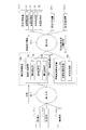
図2に示すように、本発明に係る情報処理ルール設定システムでは、各端末10から計算装置20への情報通信経路上に情報処理装置100が配置されている。図2の例では、各端末10はNW90-1に接続しており、計算装置20はNW90-2に接続しており、情報処理装置100は各NW90-1,90-2に接続している。
情報処理装置100は、各端末10がリアルタイムに送信する情報を受信する情報受信部110と、受信した情報を単独で、あるいは複数の情報の組み合わせを利用し、設定された情報処理ルールに基づいて別の端末10からリアルタイムに送信されてくる情報を処理する情報処理部120と、NW90-2に接続された外部、ここでは計算装置20に処理済みの情報を送信する情報送信部130を有する。
情報処理制御装置200は、情報処理装置100の情報処理部120で用いられる情報処理ルールを設定する機能部である情報処理制御部210と、計算装置20から送信される計算装置20における情報処理状況/装置状況を受信する状況受信部220とを備える。情報処理制御部210は、(a)設定した情報処理ルール、(b)情報処理部120から取得される情報の処理状況、(c)状況受信部220から受信する計算装置20における情報処理状況/装置状況、(d)計算装置20が要求する情報処理状況/装置状況、に基づいて情報処理ルールを設定する。
なお、図2では、情報処理制御部210及び状況受信部220は、情報処理制御装置200として情報処理装置100とは独立して存在しているが、情報処理装置100に包含されている形態でも構わない。
情報処理装置100及び情報処理制御装置200は、主に半導体装置で構成され、CPU(Central Processing Unit)、RAM(Random Access Memory)等の揮発性記憶装置、ハードディスクやフラッシュメモリ等の不揮発性記憶装置、及び外部との通信のための接続を行う通信インタフェースを有する、いわゆる情報処理機器として構成することができる。また、情報処理装置100及び情報処理制御装置200は、物理的なスイッチ、ルータ等のネットワーク機器に限らず、本発明のプログラムが動作する物理コンピュータや仮想化されたコンピュータを含む。
計算装置20は、図1に示した情報処理装置100が送信する情報を受信する情報受信部21と端末10が送信した情報を処理する情報処理部22に加えて、計算装置20の装置状況を監視する装置監視部23と、情報処理部22および装置監視部23から取得する計算装置20における情報処理状況/装置状況を外部、ここでは状況受信部220に送信する状況送信部24とを備える。
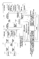
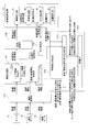
次に情報処理ルール設定システムの詳細について図3を参照して説明する。図3は情報処理ルール設定システムの機能ブロック図である。図2の情報処理装置100における情報処理部120では、端末10(ここでは第1端末10-1)からリアルタイムに送信される情報に対して、別の端末10(ここでは第2端末10-2)からリアルタイムに送信される情報に基づいた情報処理ルールに従った処理を実施した後に、情報送信部130を介して処理済みの情報を計算装置20へ送信することで、図2の第2NW90-2に送信される情報の流れを「変化」させる。第1端末10-1と第2端末10-2は、互いに異なる種類の情報をリアルタイムに送信する。
ここで、前記の「変化」とは、例えば情報の品質等の問題により、計算装置20に送信不要な情報を情報処理装置100が廃棄することで、不要なNW帯域利用や計算装置20の処理負荷を削減する、あるいは計算装置20の情報処理精度を向上させることなど、各端末10や計算装置20、それらが接続されたNW90を利用する側にとっての利点がある変化を意味する。この「変化」を発生させるための情報処理ルールについては、情報処理制御部210、ここでは情報処理方法判定部211によって作成され、情報処理装置100における情報処理部120に当該ルールが設定される。
図3は、第1端末10-1から第1計算装置20-1に対してリアルタイムに送信される情報を情報処理装置100で処理するために、第2端末10-2からリアルタイムに送信される情報に基づいた第1端末10-1の情報処理ルールを作成、設定、更新するために必要な機能ブロックを記載している。
情報処理装置100における情報処理部120に設定されている第1端末10-1の情報を処理するルールに基づいて処理される第1端末10-1の情報の実際の処理状況、情報処理ルールに基づいて処理された第1端末10-1の情報を利用又は処理する第1計算装置20-1における実際の情報処理状況/装置状況を、情報処理制御部210の情報処理方法判定部211、ここでは第2端末情報処理方法判定部211aが収集し、それらと設定されている情報処理ルールとの関係性から、記憶部212に予め格納されている第1計算装置20-1が要求する情報処理状況/装置状況を満たす情報処理ルール作成、ここでは第2端末10-2の情報の処理方法を判定し、情報処理部120に設定、ここでは第2端末情報処理部120bに設定する。作成、設定した情報処理ルールと第1端末10-1の情報の処理状況、第1計算装置20-1における情報処理状況/装置状況に関しては記憶部212に随時格納される。
情報処理装置100における情報処理部120と状況受信部220を介して情報処理方法判定部211が取得する、情報処理ルールに基づいて処理される端末10の情報の実際の処理状況、情報処理ルールに基づいて処理された端末10の情報を利用又は処理する側の実際の処理状況については、情報処理方法判定部211に通知される、もしくは情報処理方法判定部211がリクエストレスポンス方式で取得するといった方法のどちらを用いても構わない。また、情報取得の方法についても、装置内部からの取得もしくはネットワークを介した外部からの取得のどちらでも構わない。
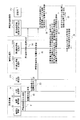
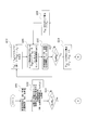
次に、情報処理装置100における情報処理部120で用いられる情報処理ルールが設定される流れについて、図4のシーケンスチャートを参照して説明する。
計算装置20における情報処理部22と装置監視部23は、状況送信部24に対して情報処理状況/装置状況をそれぞれ送信する(ステップS1,2)。状況送信部24は、状況受信部220に対して計算装置20における情報処理状況/装置状況を送信する(ステップS3)。状況受信部220と情報処理装置100における情報処理部120、ここでは第1端末情報処理部120aが該当するが、それらは情報処理制御部210の情報処理方法判定部211、ここでは第2端末情報処理方法判定部211aが該当するが、それに対して、計算装置20における情報処理状況/装置状況、情報処理装置100における第1端末情報の処理状況を送信する(ステップS4,5)。
第2端末情報処理方法判定部211aは、受信した情報を記憶部212に格納し、記憶部212に格納されている情報(計算装置20が要求する情報処理状況/装置状況、情報処理装置100における第2端末情報の処理方法、第1端末情報の処理状況、計算装置20における情報処理状況/装置状況の関係)に基づいて第2端末情報の処理方法を判定した上で、判定結果を記憶部212に格納すると共に第2端末情報処理部120bに送信する(ステップS6~S9)。以上により、第1端末10-1の情報処理方法、すなわち情報処理ルールが作成、設定され、設定されたルールに基づいて情報処理が実施されるようになる。
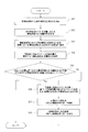
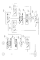
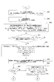
情報処理方法判定部211における流れを図5のフローチャートを参照して説明する。情報処理方法判定部211は、情報処理部120から情報処理装置100における端末情報の処理状況を受信し(ステップS11)、状況受信部220から計算装置20における情報処理状況/装置状況を受信する(ステップS12)。受信した情報を記憶部212に格納し(ステップS13)、記憶部212に格納されている計算装置20が要求する情報処理状況/装置状況を参照して受信した情報と比較する(ステップS14,S15)。受信した計算装置20における情報処理状況/装置状況が計算装置20の要求する情報処理状況/装置状況を満たしていれば処理を終了し、満たしていない場合は、記憶部212に格納されている情報に基づいて計算装置20が要求する情報処理状況/装置状況を満たす情報処理方法を判定する(ステップS16)。判定結果は記憶部212に格納されると共に、情報処理部120に送信される(ステップS17,S18)。
以上のように、本実施形態に係る情報処理ルール設定システムによれば、端末10の情報を利用又は処理する側が要求する処理状況を満たすように、端末10の情報を処理するルールを自動で作成、設定でき、必要に応じて変更、更新できるようになる。
以下に本発明に係る情報処理ルール設定システムの実施例について説明する。
[実施例1]
実施例1は、本発明の情報処理ルール設定システムを、カメラから映像処理装置に映像を送信するシステムに適用した例である。実施例1に係るシステムについて図6を参照して説明する。図6は実施例1に係るシステムの構成図である。
実施例1は、本発明の情報処理ルール設定システムを、カメラから映像処理装置に映像を送信するシステムに適用した例である。実施例1に係るシステムについて図6を参照して説明する。図6は実施例1に係るシステムの構成図である。
本システムでは、カメラ31から送信される情報が処理の対象である。本実施例1に係る情報処理装置100は、映像情報の廃棄あるいは透過の処理を実施する。映像情報を処理するルールは、カメラ31とは別端末であり、カメラ31に付属する速度センサのようなセンサ32から送信されるセンサ情報に基づいて作成、設定される。このセンサ情報は、映像情報の撮像状態に影響を与える状態を示す情報である。また、映像処理装置40は上記の計算装置20に相当するものであり、情報受信部41と、情報処理部42と、装置監視部43と、状況送信部44とを備えている。
情報処理制御部210のセンサ情報処理方法判定部211bがセンサ情報の処理方法を判定、すなわち情報処理ルールを作成し、判定結果を情報処理部120のセンサ情報処理部120dに送信、情報処理ルールを設定する。情報処理部120のカメラ情報処理部120cでは、センサ情報処理部120dが提示するカメラ情報の処理方法、すなわち情報処理ルールに基づいてカメラ情報を処理する。
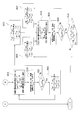
本実施例で判定されるセンサ情報の処理方法は、図7のフローチャートに示すように速度の閾値Vshの設定であり、センサ情報処理部120dが受信した時刻tにおける速度VtとVshの大きさの大小関係によってカメラ情報を透過処理あるいは廃棄処理する情報ルールが作成、設定されることになる(ステップS21~S24)。
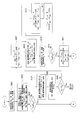
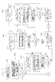
本実施例に係る情報処理ルールの設定の流れについて、図8及び図9に示すセンサ情報処理方法判定部211bのフローチャートを参照して説明する。
センサ情報処理方法判定部211bは映像処理装置40の映像処理状況(例:画像認識率A1%)を受信し(ステップS101)、記憶部212に格納されている映像処理装置40が要求する映像処理状況(例:画像認識率Ash%以上)を参照して比較する(ステップS102~S103)。受信した映像処理状況が映像処理装置40の要求する映像処理状況を満たしていれば処理を終了し、満たしていない場合はセンサ情報の処理方法を判定する、すなわちVshを設定するフローに遷移する(ステップS104~S120)。
本実施例では、画像認識率(A%)の低下をカメラ31が高速に移動している際の映像の過剰によると推定し、カメラ31が高速に移動している際の映像を減少させる方向に情報処理ルールを修正、すなわち|Vsh’|<|Vsh|となるように、例えば|Vsh|/2=|Vsh’|として|Vsh’|を決定し(ステップS104)、センサ情報処理部120dで用いる|Vsh|として|Vsh’|を用いるようにセンサ情報処理部120dに通知する(ステップS105)。
情報処理装置100の情報処理部120では新たに決定した|Vsh|に基づいた情報処理が実施されることになるが、情報処理に変化が生じるため、次に受信する映像処理状況(例:画像認識率A2%)は前に受信した映像処理状況(例:画像認識率A1%)と異なっていることが予想される。
したがってA2とAshを比較し(ステップS106~S107)、A2もまたAshを満たしていない場合は再度|Vsh’|/2として|Vsh’|を決定し(ステップS108)、センサ情報処理部120dで用いる|Vsh|として|Vsh’|を用いるようにセンサ情報処理部に通知する(ステップS105)。
一方、A2がAshを満たしている場合は、|Vsh’|が映像処理装置40の要求するAshを満たすための|Vsh|としては小さすぎる場合が想定されるため、再度AがAshを満たさなくなるまで|Vsh|を増加させる。再度AがAshを満たさなくなった時点で用いられている|Vsh|は映像処理装置40の要求するAshを満たすための|Vsh|として最適な値、ここでの最適な値とは、|Vsh|を極端に小さく設定することで生じる映像の極端な減少を回避しつつ、AがAshを満たす状態となる|Vsh|とするが、その最適な値に近付いていると考えられるため、再度|Vsh|を減少させ、AがAshを満たしつつAの変化が既定の幅(ここではΔAshとしている)以下となった時点で用いられている|Vsh|をもって、最終的なセンサ情報処理部120dで用いる|Vsh|として採用し、処理を終了する(ステップS109~S120)。
以上のように、本実施例1では、カメラ31が高速に移動する場合に取得された映像は品質が悪く、映像処理装置40に送信しても映像処理装置40で適切に処理できないことから、適切に処理できない映像情報、すなわち映像処理装置40の映像処理状況を悪化させる映像情報のみを選択的に廃棄できる情報処理ルールを自動で作成、設定、更新することができる。またその結果、カメラ31の設置環境が変わるなどの変化が生じた際にも、映像処理装置40が要求する映像処理状況を満たす状態を維持することができる。
[実施例2]
実施例2は、実施例1と同様のシステムに本発明の情報処理ルール設定システムを適用した例において、映像処理装置40が要求する映像処理状況を画像認識率Ash%ではなく、画像処理頻度Bshfps(frame per second)とした場合の例である。本実施例に係る情報処理ルールの設定の流れについて、図10及び図11に示すセンサ情報処理方法判定部211bのフローチャートを参照して説明する。
実施例2は、実施例1と同様のシステムに本発明の情報処理ルール設定システムを適用した例において、映像処理装置40が要求する映像処理状況を画像認識率Ash%ではなく、画像処理頻度Bshfps(frame per second)とした場合の例である。本実施例に係る情報処理ルールの設定の流れについて、図10及び図11に示すセンサ情報処理方法判定部211bのフローチャートを参照して説明する。
センサ情報処理方法判定部211bは映像処理装置40の映像処理状況(例:画像処理頻度B1fps)を受信し(ステップS201)、記憶部212に格納されている映像処理装置40が要求する映像処理状況(例:画像処理頻度Bshfps以上)を参照して比較する(ステップS202~S203)。受信した映像処理状況が映像処理装置40の要求する映像処理状況を満たしていれば処理を終了し、満たしていない場合はセンサ情報の処理方法を判定する、すなわちVshを設定するフローに遷移する(ステップS204~S220)。
本実施例では、画像処理頻度(Bfps)の低下を映像情報の廃棄の過剰によると推定し、カメラ31が移動している際の映像情報の廃棄を減少させる方向に情報処理ルールを修正、すなわち|Vsh’|>|Vsh|となるように、例えば2×|Vsh|=|Vsh’|として|Vsh’|を決定し(ステップS204)、センサ情報処理部120dで用いる|Vsh|として|Vsh’|を用いるようにセンサ情報処理部120dに通知する(ステップS205)。
情報処理装置100における情報処理部120では新たに決定した|Vsh|に基づいた情報処理が実施されることになるが、情報処理に変化が生じるため、次に受信する映像処理状況(例:画像処理頻度B2fps)は前に受信した映像処理状況(例:画像処理頻度B1fps)と異なっていることが予想される。
したがってB2とBshを比較し(ステップS206~S207)、B2もまたBshを満たしていない場合は再度2×|Vsh’|として|Vsh’|を決定し(ステップS208)、センサ情報処理部120dで用いる|Vsh|として|Vsh’|を用いるようにセンサ情報処理部120dに通知する(ステップS205)。
一方、B2がBshを満たしている場合は、|Vsh’|が映像処理装置40の要求するBshを満たすための|Vsh|としては大き過ぎる場合が想定されるため、再度BがBshを満たさなくなるまで|Vsh|を減少させる。再度BがBshを満たさなくなった時点で用いられている|Vsh|は映像処理装置40の要求するBshを満たすための|Vsh|として最適な値、ここでの最適な値とは、|Vsh|に大きすぎる値を設定することで生じる、カメラが高速で移動している際の映像処理装置40で適切に処理できない映像の過剰を回避しつつ、BがBshを満たす状態となる|Vsh|とするが、その最適な値に近付いていると考えられるため、再度|Vsh|を減少させ、BがBshを満たしつつBの変化が既定の幅(ここではΔBshとしている)以下となった時点で用いられている|Vsh|をもって、最終的なセンサ情報処理部120dで用いる|Vsh|として採用し、処理を終了する(ステップS209~S220)。
以上のように、本実施例2では、カメラ31が移動する場合に取得された映像の廃棄が過剰に発生することで映像処理装置40の映像処理状況を悪化させる場合に、映像処理装置40が要求する映像処理状況を満たす情報処理ルールを自動で作成、設定、更新することができる。またその結果、カメラ31の設置環境が変わるなどの変化が生じた際にも、映像処理装置40が要求する映像処理状況を満たす状態を維持することができる。
[実施例3]
実施例3は、実施例1と同様のシステムに本発明の情報処理ルール設定システムを適用した例において、映像処理装置40が要求する装置状況をCPU使用率Csh%とした場合の例である。本実施例に係る情報処理ルールの設定の流れについて、図12及び図13に示すセンサ情報処理方法判定部211bのフローチャートを参照して説明する。
実施例3は、実施例1と同様のシステムに本発明の情報処理ルール設定システムを適用した例において、映像処理装置40が要求する装置状況をCPU使用率Csh%とした場合の例である。本実施例に係る情報処理ルールの設定の流れについて、図12及び図13に示すセンサ情報処理方法判定部211bのフローチャートを参照して説明する。
センサ情報処理方法判定部211bは映像処理装置40の装置状況(例:CPU使用率C1%)を受信し(ステップS301)、記憶部212に格納されている映像処理装置40が要求する装置状況(例:CPU使用率Csh%以下)を参照して比較する(ステップS302~S303)。受信した装置状況が映像処理装置40の要求する装置状況を満たしていれば処理を終了し、満たしていない場合はセンサ情報の処理方法を判定する、すなわちVshを設定するフローに遷移する(ステップS304~S320)。
本実施例では、CPU使用率(C%)の増加をカメラ31が高速に移動している際の映像の過剰によると推定し、カメラ31が高速に移動している際の映像を減少させる方向に情報処理ルールを修正、すなわち|Vsh’|<|Vsh|となるように、例えば|Vsh|/2 =|Vsh’|として|Vsh’|を決定し(ステップS304)、センサ情報処理部120dで用いる|Vsh|として|Vsh’|を用いるようにセンサ情報処理部120dに通知する(ステップS305)。
情報処理装置100における情報処理部120では新たに決定した|Vsh|に基づいた情報処理が実施されることになるが、情報処理に変化が生じるため、次に受信する装置状況(例:CPU使用率C2%)は前に受信した映像処理状況(例:CPU使用率C1%)と異なっていることが予想される。
したがってC2とCshを比較し(ステップS306~S307)、C2もまたCshを満たしていない場合は再度|Vsh’|/2として|Vsh’|を決定し(ステップS308)、センサ情報処理部120dで用いる|Vsh|として|Vsh’|を用いるようにセンサ情報処理部120dに通知する(ステップS305)。
一方、C2がCshを満たしている場合は、|Vsh’|が映像処理装置40の要求するCshを満たすための|Vsh|としては小さすぎる場合が想定されるため、再度CがCshを満たさなくなるまで|Vsh|を増加させる。再度CがCshを満たさなくなった時点で用いられている|Vsh|は映像処理装置40の要求するCshを満たすための|Vsh|として最適な値、ここでの最適な値とは、|Vsh|を極端に小さく設定することで生じる映像の極端な減少を回避しつつ、CがCshを満たす状態となる|Vsh|とするが、その最適な値に近付いていると考えられるため、再度|Vsh|を減少させ、CがCshを満たしつつCの変化が既定の幅(ここではΔCshとしている)以下となった時点で用いられている|Vsh|をもって、最終的なセンサ情報処理部120dで用いる|Vsh|として採用し、処理を終了する(ステップS309~S320)。
以上のように、本実施例3では、カメラ31が高速に移動する場合に取得された映像は品質が悪く、映像処理装置40に送信する必要がないことから、映像処理装置40に送信する必要にない映像情報、すなわち映像処理装置40の装置状況を悪化させる映像情報のみを選択的に廃棄できるパケット処理ルールを自動で作成、設定、更新することができる。またその結果、カメラ31の設置環境が変わるなどの変化が生じた際にも、映像処理装置40が要求する装置状況を満たす状態を維持することができる。
[実施例4]
実施例4は、実施例1と同様のシステムに本発明の情報処理ルール設定システムを適用した例において、設定されている情報処理ルールと映像処理装置40の映像処理状況、映像処理装置40が要求する映像処理状況のみから情報処理ルールを作成するのではなく、情報処理装置100におけるカメラ情報の処理状況も利用して情報処理ルールを作成する場合の例である。
実施例4は、実施例1と同様のシステムに本発明の情報処理ルール設定システムを適用した例において、設定されている情報処理ルールと映像処理装置40の映像処理状況、映像処理装置40が要求する映像処理状況のみから情報処理ルールを作成するのではなく、情報処理装置100におけるカメラ情報の処理状況も利用して情報処理ルールを作成する場合の例である。
さらに本実施例では、実施例1のように最初に任意に設定した|Vsh|から最適な|Vsh|を求める過程、すなわち|Vsh|を収束させる過程を踏むのではなく、設定されている|Vsh|、情報処理装置100におけるカメラ情報の処理状況、映像処理装置40における映像処理状況の時系列データ、|Vsh|を変化させた際の情報処理装置100におけるカメラ情報の処理状況と映像処理装置40における映像処理状況の変化の関係を示す情報を機械学習の学習データとして蓄積し、映像処理装置40が要求する映像処理状況を満たす|Vsh|を推定できる機構、例えばニューラルネットワークを作成して利用する。
実施例1のシステムはセンサ32のようなカメラ31とは異なる端末の情報を利用してカメラ31が送信する映像情報を処理する特徴を有しているが、カメラ31とは異なる端末情報の処理方法が映像処理装置40での映像処理状況にどのような影響を与えたかの知見のみならず、カメラ情報の処理状況自体にどのような影響を与えたかの知見も合わせて学習データとして利用し、例えばニューラルネットワークを成長させることで、本システムに特徴的な端末情報の処理方法、すなわち映像処理装置40が要求する映像処理状況を満たすために本システムにおける情報処理装置100で用いるべき情報処理ルール、|Vsh|を実施例1と比較して迅速かつ正確に作成できる。
このニューラルネットワークに利用される学習データは情報処理ルール設定システムを利用する限り蓄積され続けるので、情報処理装置100で用いる情報処理ルール、|Vsh|の作成における正確性、迅速性はニューラルネットワークの成長に応じて向上する。本実施例に係る情報処理ルールの設定の流れについて、図14及び図15に示すセンサ情報処理方法判定部のフローチャートを参照して説明する。
センサ情報処理方法判定部211bは、カメラ情報の処理状況(例:単位時間当たりの映像フレーム送信数Nnfps)を受信し(ステップS401)、さらに映像処理装置40の映像処理状況(例:画像認識率A1%)を受信する(ステップS402)。次に、センサ情報処理方法(例:現在センサ情報処理部で用いられている|Vsh(n)|、最初はなし)、カメラ情報の処理状況(例:Nnfps)、映像処理状況(例:An%)の関係(例:|Vsh(n)|とNnとAnの関係)を記憶部212に格納する(ステップS403)。 ここでの|Vsh(n)|とNnとAnについては、ある時刻における任意の|Vsh(n)|とNnとAnをピックアップしても、ある単位時間当たりの|Vsh(n)|とNnとAnをそれぞれ平均したものを|Vsh(n)|とNnとAnとして用いても構わない。
|Vsh(n)|とNnとAnの関係を記憶部212に格納する時点で、既に|Vsh|とNとAの関係(例:|Vsh(n-1)|とNn-1とAn-1の関係)が格納されている場合、下記を算出し、
ΔVn= |Vsh(n)|-|Vsh(n-1)|
ΔNn= Nn-Nn-1
ΔAn=An-An-1
上記と|Vsh(n) |とNnとAnとの関係を記憶部に格納する(ステップS404~S405)。記憶部212に格納された情報は、情報処理ルール、|Vsh|を推定するためのニューラルネットワークの学習に使用される。
ΔVn= |Vsh(n)|-|Vsh(n-1)|
ΔNn= Nn-Nn-1
ΔAn=An-An-1
上記と|Vsh(n) |とNnとAnとの関係を記憶部に格納する(ステップS404~S405)。記憶部212に格納された情報は、情報処理ルール、|Vsh|を推定するためのニューラルネットワークの学習に使用される。
次に、受信した映像処理装置40の映像処理状況An%と記憶部212に格納されている映像処理装置40が要求する映像処理状況(例:画像認識率Ash%以上)を参照して比較する(ステップS406~S407)。受信した映像処理状況が映像処理装置40の要求する映像処理状況を満たしていれば処理を終了し、満たしていない場合はセンサ情報の処理方法を判定する、すなわちVshを設定するフローに遷移する(S408~S417)。
本実施例では、記憶部212に格納されている情報を学習データとして成長させたニューラルネットワークを用いてVshを推定する。記憶部212に格納されている|Vsh(n)|とNn、An、ΔVn、ΔNn、ΔAnの関係から、An+1≧Ashとなる|Vsh(n+1)|を推定し(ステップS408)、センサ情報処理部120dに|Vsh(n+1)|を用いるように通知する(ステップS409)。|Vsh(n+1)|を新たな情報処理ルールとして設定した後に受信するNn+1とAn+1、さらには|Vsh(n+1)|と記憶部212に格納されている最新の|Vsh|とNとA(|Vsh(n)|とNnとAn)を参照した上で算出される下記も合わせて記憶部212に格納する(ステップS410~S413)。
ΔVn+1= |Vsh(n+1)|-|Vsh(n)|
ΔNn+1= Nn+1-Nn
ΔAn+1=An+1-An
ΔVn+1= |Vsh(n+1)|-|Vsh(n)|
ΔNn+1= Nn+1-Nn
ΔAn+1=An+1-An
An+1とAshを比較し(ステップS414~S415)、An+1がAshを満たしていれば処理を終了し、満たしていなければ再度An+1≧Ashとなる|Vsh(n+1)|を推定し(ステップS416~S417)、センサ情報処理部に|Vsh(n+1)|を用いるように通知する(ステップS409)。
以上のように、設定した情報処理ルールと実際のカメラ情報の処理状況、映像処理装置40における映像処理状況の関係性と映像処理装置40の要求する映像処理状況に基づいて、映像処理装置40の要求する映像処理状況を満たす情報処理ルールを自動で作成、設定、更新できる。
さらに、情報処理ルールの更新が起きない際にも情報処理ルールを作成するニューラルネットワークの学習は継続的に実施されるため、適切な情報処理ルールの作成速度、精度は向上し続ける。成長したニューラルネットワークは他の類似のシステムに本発明を適用する際にも転用でき、その際は初期段階から情報処理ルールを迅速かつ正確に作成できる。もちろん、完全に同じシステムへの適用でない限り情報処理ルールの作成速度、精度に初期段階では課題が生じるが、学習が継続的に実施されるため、適用先のシステムに合ったニューラルネットワークが作成される。
[実施例5]
実施例5は実施例1と同様に、本発明の情報処理ルール設定システムをカメラ31から映像処理装置40に映像を送信するシステムに適用した例である。本実施例が前述の実施例1と異なる点は、図16の本実施例の機能ブロック図に示すように、映像情報を処理するルールの作成に用いられるセンサを2種類備えている点である。すなわち本実施例では、映像情報を処理するルールが、カメラ31とは別端末であり、カメラ31に付属する速度センサ32から送信される速度情報と、輝度センサ33から送信される輝度情報との組み合わせに基づいて作成、設定される。この速度情報及び輝度情報は、映像情報の撮像状態に影響を与える状態を示す情報である。
実施例5は実施例1と同様に、本発明の情報処理ルール設定システムをカメラ31から映像処理装置40に映像を送信するシステムに適用した例である。本実施例が前述の実施例1と異なる点は、図16の本実施例の機能ブロック図に示すように、映像情報を処理するルールの作成に用いられるセンサを2種類備えている点である。すなわち本実施例では、映像情報を処理するルールが、カメラ31とは別端末であり、カメラ31に付属する速度センサ32から送信される速度情報と、輝度センサ33から送信される輝度情報との組み合わせに基づいて作成、設定される。この速度情報及び輝度情報は、映像情報の撮像状態に影響を与える状態を示す情報である。
本実施例で判定される速度/輝度情報の処理方法は、図17のフローチャートに示すように速度の閾値Vshと輝度の閾値Lsh1、Lsh2の設定であり、速度/輝度情報処理部120eが受信した時刻tにおける速度VtとVshの大きさの大小関係、輝度LtとLsh1、Lsh2の大小関係によってカメラ情報を透過処理あるいは廃棄処理する情報処理ルールが作成、設定されることになる(ステップS31~S35)。
本実施例に係る情報処理ルールの設定の流れについて、図18及び図19に示す速度/輝度情報処理方法判定部211cのフローチャートを参照して説明する。
速度/輝度情報処理方法判定部211cは映像処理装置40の映像処理状況(例:画像認識率A1%)を受信し(ステップS501)、記憶部212に格納されている映像処理装置40が要求する映像処理状況(例:画像認識率Ash%以上)を参照して比較する(ステップS502~S503)。またこの際、輝度と速度のどちらを優先して処理を実施するかの優先度(ここでは輝度>速度とする)も合わせて参照する。受信した映像処理状況が映像処理装置40の要求する映像処理状況を満たしていれば処理を終了し、満たしていない場合は速度/輝度情報の処理方法を判定する、すなわちVsh、Lsh1、Lsh2を設定するフローに遷移する(ステップS504~S529)。
本実施例では、画像認識率(A%)の低下をカメラ31が高速に移動している際の映像の過剰、あるいはカメラ31が暗い場所か眩しい場所に設置されている際の映像の過剰によると推定する。ここでは処理の優先度として輝度>速度であるため、まずはカメラが暗い場所か眩しい場所に設置されている際の映像を減少させる方向に情報処理ルールを修正、すなわちLsh2>Lsh2’>Lsh1’>Lsh1となるようにLsh1’とLsh2’を決定し(ステップS505)、速度/輝度情報処理部120eで用いるLsh1とLsh2として、Lsh1’とLsh2‘を用いるように速度/輝度情報処理部120eに通知する(ステップS506)。
新たな情報処理ルール設定以降に受信したA2とAshを比較し、A2もまたAshを満たしていない場合は実施例1と同様にVshを変更する(ステップS507~S509)。新たな情報処理ルール設定以降に受信したA3-BとAshを比較し、A3-BがAshを満たした場合は実施例1と同様の方法でVshを収束させる(ステップS510~S511、図8のステップS109以降)。A3-BもAshを満たさない場合は、再度輝度情報の処理方法を変更する(ステップ512~S518)。A2がAshを満たした場合は、実施例1と同様の方法でLsh1とLsh2を収束させる(ステップS518~S529)。
以上のように、本実施例では、カメラ31が高速に移動する場合に取得された映像およびカメラ31が暗い場所か眩しい場所に設置されている場合に取得された映像は品質が悪く、映像処理装置40に送信しても映像処理装置40で適切に処理できないことから、適切に処理できない映像情報、すなわち映像処理装置40の映像処理状況を悪化させる映像情報のみを選択的に廃棄できる情報処理ルールを自動で作成、設定、更新することができる。またその結果、カメラ31の設置環境が変わるなどの変化が生じた際にも、映像処理装置40が要求する映像処理状況を満たす状態を維持することができる。
[実施例6]
実施例6は実施例5と同様に、本発明の情報処理ルール設定システムをカメラ31から映像処理装置40に映像を送信するシステムに適用した例において、映像処理装置40が要求する映像処理状況を画像認識率Ash%ではなく、画像処理頻度Bshfpsとした場合の例である。本実施例に係る情報処理ルールの設定の流れについて、図20及び図21に示す速度/輝度情報処理方法判定部211cのフローチャートを参照して説明する。
実施例6は実施例5と同様に、本発明の情報処理ルール設定システムをカメラ31から映像処理装置40に映像を送信するシステムに適用した例において、映像処理装置40が要求する映像処理状況を画像認識率Ash%ではなく、画像処理頻度Bshfpsとした場合の例である。本実施例に係る情報処理ルールの設定の流れについて、図20及び図21に示す速度/輝度情報処理方法判定部211cのフローチャートを参照して説明する。
速度/輝度情報処理方法判定部211cは映像処理装置40の映像処理状況(例:画像処理頻度B1fps)を受信し(ステップS601)、記憶部212に格納されている映像処理装置40が要求する映像処理状況(例:画像処理頻度Bshfps以上)を参照して比較する(ステップS602~S603)。またこの際、輝度と速度のどちらを優先して処理を実施するかの優先度(ここでは輝度>速度とする)も合わせて参照する。受信し映像処理状況が映像処理装置40の要求する映像処理状況を満たしていれば処理を終了し、満たしていない場合は速度/輝度情報の処理方法を判定する、すなわちVsh、Lsh1、Lsh2を設定するフローに遷移する(ステップS604~S624)。
本実施例では、画像処理頻度(Bfps)の低下をカメラ情報の廃棄の過剰によると推定する。ここでは処理の優先度として輝度>速度であるため、まずはカメラ31が移動している際の映像廃棄が起こらないように情報処理ルールを修正、すなわち速度/輝度情報処理部120eで用いられる|Vsh|として∞を用いるように速度/輝度情報処理部120eに通知する(ステップS604)。新たな情報処理ルール設定以降に受信したB2とBshを比較し、B2がBshを満たした場合は、実施例2と同様の方法でVshを収束させる(ステップS605,S606,図10のステップS204以降)。B2がBshを満たさなかった場合は、Lsh2’>Lsh2>Lsh1>Lsh1’となるようにLsh1’とLsh2’を決定し、カメラ31が暗い場所か眩しい場所に設置されている際の映像の廃棄を減少させる方向に情報処理ルールを修正する(ステップS607,S608)。以降、実施例2と同様の方法でLsh1とLsh2を収束させる(ステップS609~S624)。
以上のように、本実施例では、カメラ31が移動する場合に取得された映像およびカメラ31が暗い場所か眩しい場所に設置されている際の映像の廃棄が過剰に発生することで映像処理装置40の映像処理状況を悪化させる場合に、映像処理装置40が要求する映像処理状況を満たす情報処理ルールを自動で作成、設定、更新することができる。またその結果、カメラ31の設置環境が変わるなどの変化が生じた際にも、映像処理装置40が要求する映像処理状況を満たす状態を維持することができる。
[実施例7]
実施例7は、実施例5と同様のシステムに本発明の情報処理ルール設定システムを適用した例において、映像処理装置40が要求する装置状況をCPU使用率Csh%とした場合の例である。本実施例に係る情報処理ルールの設定の流れについて、図22及び図23に示す速度/輝度情報処理方法判定部211cのフローチャートを参照して説明する。
実施例7は、実施例5と同様のシステムに本発明の情報処理ルール設定システムを適用した例において、映像処理装置40が要求する装置状況をCPU使用率Csh%とした場合の例である。本実施例に係る情報処理ルールの設定の流れについて、図22及び図23に示す速度/輝度情報処理方法判定部211cのフローチャートを参照して説明する。
速度/輝度情報処理方法判定部211cは映像処理装置40の装置状況(例:CPU使用率C1%)を受信し(ステップS701)、記憶部212に格納されている映像処理装置40が要求する装置状況(例:CPU使用率Csh%以下)を参照して比較する(ステップS702,S703)。またこの際、輝度と速度のどちらを優先して処理を実施するかの優先度(ここでは輝度>速度とする)も合わせて参照する。受信した映像処理状況が映像処理装置40の要求する映像処理状況を満たしていれば処理を終了し、満たしていない場合は速度/輝度情報の処理方法を判定する、すなわちVsh、Lsh1、Lsh2を設定するフローに遷移する(ステップS704~S729)。
本実施例では、CPU使用率(C%)の増加をカメラ31が高速に移動している際の映像の過剰、あるいはカメラが暗い場所か眩しい場所に設置されている際の映像の過剰によると推定する。ここでは処理の優先度として輝度>速度であるため、まずはカメラ31が暗い場所か眩しい場所に設置されている際の映像を減少させる方向に情報処理ルールを修正、すなわちLsh2>Lsh2’>Lsh1’>Lsh1となるようにLsh1’とLsh2’を決定し、速度/輝度情報処理部120eで用いるLsh1とLsh2として、Lsh1’とLsh2‘を用いるように速度/輝度情報処理部120eに通知する(ステップS704,S705)。
新たなパケット処理ルール設定以降に受信したC2とCshを比較し(ステップS706,S707)、C2もまたCshを満たしていない場合は実施例1と同様にVshを変更する(ステップS708,S709)。新たな情報処理ルール設定以降に受信したC3-BとCshを比較し(ステップS710,S711)、C3-BがCshを満たした場合は実施例1と同様の方法でVshを収束させる(図12のステップ309以降)。C3-BもCshを満たさない場合は、再度輝度情報の処理方法を変更する(ステップS712,S713)。C2がCshを満たした場合は、実施例1と同様の方法でLsh1とLsh2を収束させる(ステップS718~S729)。
以上のように、本実施例では、カメラ31が高速に移動する場合に取得された映像およびカメラ31が暗い場所か眩しい場所に設置されている場合に取得された映像は品質が悪く、映像処理装置40に送信する必要がないことから、映像処理装置40に送信する必要にない映像情報、すなわち映像処理装置40の装置状況を悪化させる映像情報のみを選択的に廃棄できる情報処理ルールを自動で作成、設定、更新することができる。またその結果、カメラ31の設置環境が変わるなどの変化が生じた際にも、映像処理装置40が要求する装置状況を満たす状態を維持することができる。
[実施例8]
実施例8は、実施例5と同様のシステムに本発明の情報処理ルール設定システムを適用した例において、設定されている情報処理ルールと映像処理装置40の映像処理状況、映像処理装置40が要求する映像処理状況のみから情報処理ルールを作成するのではなく、情報処理装置100におけるカメラ情報の処理状況も利用して情報処理ルールを作成する実施例4と同様の場合の例である。
実施例8は、実施例5と同様のシステムに本発明の情報処理ルール設定システムを適用した例において、設定されている情報処理ルールと映像処理装置40の映像処理状況、映像処理装置40が要求する映像処理状況のみから情報処理ルールを作成するのではなく、情報処理装置100におけるカメラ情報の処理状況も利用して情報処理ルールを作成する実施例4と同様の場合の例である。
本実施例では、実施例5のように最初に任意に設定した|Vsh|、Lsh1、Lsh2から最適な|Vsh|、Lsh1、Lsh2を求める過程、すなわち|Vsh|、Lsh1、Lsh2を収束させる過程を踏むのではなく、|Vsh|、Lsh1、Lsh2、情報処理装置100におけるカメラ情報の処理状況、映像処理装置40における映像処理状況の時系列データ、|Vsh|、Lsh1、Lsh2を変化させた際の情報処理装置100におけるカメラ情報の処理状況と映像処理装置40における映像処理状況の変化の関係を示す情報を機械学習の学習データとして蓄積し、映像処理装置40が要求する映像処理状況を満たす|Vsh|、Lsh1、Lsh2を推定できる機構、例えばニューラルネットワークを作成して利用する。
実施例5のシステムは速度センサ32や輝度センサ33のようなカメラ31とは異なる端末の情報を利用してカメラ31が送信する映像情報を処理する特徴を有しているが、カメラ31とは異なる端末情報の処理方法が映像処理装置40での映像処理状況にどのような影響を与えたかの知見のみならず、カメラ情報の処理状況自体にどのような影響を与えたかの知見も合わせて学習データとして利用し、例えばニューラルネットワークを成長させることで、本システムに特徴的な端末情報の処理方法、すなわち映像処理装置40が要求する映像処理状況を満たすために本システムにおける情報処理装置100で用いるべき情報処理ルール、|Vsh|、Lsh1、Lsh2を実施例5と比較して迅速かつ正確に作成できる。
このニューラルネットワークに利用される学習データは情報処理ルール設定システムを利用する限り蓄積され続けるので、情報処理装置100で用いる情報処理ルール、|Vsh|、Lsh1、Lsh2の作成における正確性、迅速性はニューラルネットワークの成長に応じて向上する。
本実施例に係る情報処理ルールの設定の流れについて、図24及び図25に示す速度/輝度情報処理方法判定部211cのフローチャートを参照して説明する。
速度/輝度情報処理方法判定部211cは、カメラ情報の処理状況(例:単位時間当たりの映像フレーム送信数Nnfps)を受信し(ステップS801)、さらに映像処理装置40の映像処理状況(例:画像認識率A1%)を受信する(ステップS802)。次に、速度/輝度情報処理方法(例:現在速度/輝度情報処理部120eで用いられている|Vsh(n)|、Lsh1(n)、Lsh2(n)、最初はなし)、カメラ情報の処理状況(例:Nn fps)、映像処理状況(例:An %) )の関係(例:|Vsh(n)|とLsh1(n)とLsh2(n)とNnとAnの関係)を記憶部212に格納する(ステップS803)。
ここでの|Vsh(n)|、Lsh1(n)、Lsh2(n)とNnとAnについては、ある時刻における任意の|Vsh(n)|、Lsh1(n)、Lsh2(n)とNnとAnをピックアップしても、ある単位時間当たりの|Vsh(n)|、Lsh1(n)、Lsh2(n)とNnとAnをそれぞれ平均したものを|Vsh(n)|、Lsh1(n)、Lsh2(n)とNnとAnとして用いても構わない。|Vsh(n)|とLsh1(n)とLsh2(n)とNnとAnの関係を記憶部212に格納する時点で、既に|Vsh|とLsh1とLsh2とNとAの関係(例:|Vsh(n-1)|とLsh1(n-1)とLsh2(n-1)とNn-1とAn-1の関係)が格納されている場合、下記を算出し、
ΔVn= |Vsh(n)|-|Vsh(n-1)|
ΔL1(n)= Lsh1(n)-Lsh1(n-1)
ΔL2(n)= Lsh2(n)-Lsh2(n-1)
ΔNn= Nn-Nn-1
ΔAn=An-An-1
上記と|Vsh(n)|とLsh1(n)とLsh2(n)とNnとAnの関係を記憶部212に格納する(ステップS804,S805)。記憶部212に格納された情報は、情報処理ルール、|Vsh|とLsh1とLsh2を推定するためのニューラルネットワークの学習に使用される。
ΔVn= |Vsh(n)|-|Vsh(n-1)|
ΔL1(n)= Lsh1(n)-Lsh1(n-1)
ΔL2(n)= Lsh2(n)-Lsh2(n-1)
ΔNn= Nn-Nn-1
ΔAn=An-An-1
上記と|Vsh(n)|とLsh1(n)とLsh2(n)とNnとAnの関係を記憶部212に格納する(ステップS804,S805)。記憶部212に格納された情報は、情報処理ルール、|Vsh|とLsh1とLsh2を推定するためのニューラルネットワークの学習に使用される。
次に、受信した映像処理装置40の映像処理状況An%と記憶部212に格納されている映像処理装置40が要求する映像処理状況(例:画像認識率Ash%以上)を参照して比較する(ステップS806,S807)。受信した映像処理状況が映像処理装置40の要求する映像処理状況を満たしていれば処理を終了し、満たしていない場合は速度/輝度情報の処理方法を判定する、すなわちVsh とLsh1(n)とLsh2(n)を設定するフローに遷移する(ステップS808~S817)。
本実施例では、記憶部212に格納されている情報を学習データとして成長させたニューラルネットワークを用いてVshとLsh1(n)とLsh2(n)を推定する。記憶部212に格納されている最新の|Vsh|、Lsh1、Lsh2とN、A、ΔV、ΔL1、ΔL2、ΔN、ΔAの関係から、A≧Ashとなる|Vsh|、Lsh1、Lsh2を推定し、速度/輝度情報処理部120eにそれらを用いるように通知する(ステップS808,S809)。
新たなパケット処理ルール(|Vsh(n+1)|、Lsh1(n+1)、Lsh2(n+1))を設定した後に受信するNn+1とAn+1、さらには|Vsh(n+1)|、Lsh1(n+1)、Lsh2(n+1)と記憶部に格納されている最新の|Vsh|、Lsh1、Lsh2とNとA(|Vsh(n)|とLsh1(n)とLsh2(n)とNnとAn)を参照した上で算出される下記も合わせて記憶部212に格納する(ステップS810~S813)。
ΔVn+1= |Vsh(n+1)|-|Vsh(n)|
ΔL1(n+1)= Lsh1(n+1)-Lsh1(n)
ΔL2(n+1)= Lsh2(n+1)-Lsh2(n)
ΔNn+1= Nn+1-Nn
ΔAn+1=An+1-An
ΔVn+1= |Vsh(n+1)|-|Vsh(n)|
ΔL1(n+1)= Lsh1(n+1)-Lsh1(n)
ΔL2(n+1)= Lsh2(n+1)-Lsh2(n)
ΔNn+1= Nn+1-Nn
ΔAn+1=An+1-An
An+1とAshを比較し(ステップS814,S815)、An+1がAshを満たしていれば処理を終了し、満たしていなければ再度An+1≧Ashとなる|Vsh(n+1)|、Lsh1(n+1)、Lsh2(n+1)を推定し、速度/輝度情報処理部120eに|Vsh(n+1)|、Lsh1(n+1)、Lsh2(n+1)を用いるように通知する(ステップS816,S817,S809)。
以上のように、設定した情報処理ルールと実際のカメラ情報の処理状況、映像処理装置40における映像処理状況の関係性と映像処理装置40の要求する映像処理状況に基づいて、映像処理装置40の要求する映像処理状況を満たす情報処理ルールを自動で作成、設定、更新できる。
さらに、情報処理ルールの更新が起きない際にも情報処理ルールを作成するニューラルネットワークの学習は継続的に実施されるため、適切な情報処理ルールの作成速度、精度は向上し続ける。成長したニューラルネットワークは他の類似のシステムに本発明を適用する際にも転用でき、その際は初期段階から情報処理ルールを迅速かつ正確に作成できる。もちろん、完全に同じシステムへの適用でない限り情報処理ルールの作成速度、精度に初期段階では課題が生じるが、学習が継続的に実施されるため、適用先のシステムに合ったニューラルネットワークが作成される。
以上、本発明の実施の形態及び実施例について詳述したが、本発明はこれに限定されるものではない。例えば、上記各実施例では、第1端末10-1は映像情報を送信するカメラ31であり、第2端末10-2は映像情報の撮像状態に影響を与える情報を示す情報である速度情報や軌道情報を送信するセンサ32,33であったが、本発明はこれに限定さえることなく種々の用途で用いることができる。
10…端末
11…情報取得部
12…情報生成部
13…情報送信部
20…計算装置
21…情報受信部
22…情報処理部
23…装置監視部
24…状況送信部
31…カメラ
32…速度センサ
33…輝度センサ
40…映像処理装置
90…ネットワーク
100…情報処理装置
110…情報受信部
120…情報処理部
120a…第1端末情報処理部
120b…第2端末情報処理部
120c…カメラ情報処理部
120d…センサ情報処理部
120e…速度/輝度情報処理部
130…情報送信部
200…情報制御装置
210…情報処理制御部
211…情報処理方法判定部
211a…第2端末情報処理方法判定部
211b…センサ情報処理方法判定部
211c…速度/輝度情報処理方法判定部
212…記憶部
220…状況受信部
11…情報取得部
12…情報生成部
13…情報送信部
20…計算装置
21…情報受信部
22…情報処理部
23…装置監視部
24…状況送信部
31…カメラ
32…速度センサ
33…輝度センサ
40…映像処理装置
90…ネットワーク
100…情報処理装置
110…情報受信部
120…情報処理部
120a…第1端末情報処理部
120b…第2端末情報処理部
120c…カメラ情報処理部
120d…センサ情報処理部
120e…速度/輝度情報処理部
130…情報送信部
200…情報制御装置
210…情報処理制御部
211…情報処理方法判定部
211a…第2端末情報処理方法判定部
211b…センサ情報処理方法判定部
211c…速度/輝度情報処理方法判定部
212…記憶部
220…状況受信部
Claims (7)
- 互いに異なる種類の情報をリアルタイムに送信する第1端末及び第2端末と、第1端末から送信された情報を処理する計算装置との間の通信経路上に配置された情報処理装置であって、
第1端末及び第2端末からの情報を受信する情報受信部と、
第2端末から受信した情報に基づき情報処理ルールに則って第1端末から受信した情報を処理する情報処理部と、
情報処理部で処理された第1端末からの情報を計算装置に送信する情報送信部と、
計算装置における情報処理状況又は計算装置の装置状況の少なくとも一方に基づき前記情報処理部における第2端末から受信する情報の処理方法を判定するとともに情報処理ルールを作成して前記情報処理部に設定する情報処理方法判定部とを備えた
ことを特徴とする情報処理装置。 - 前記情報処理方法判定部は、計算装置が要求する情報処理状況又は装置状況に関する条件を満たすように、前記情報処理部における第2端末から受信する情報の処理方法を判定するとともに情報処理ルールを作成して前記情報処理部に設定する
ことを特徴とする請求項1記載の情報処理装置。 - 前記情報処理方法判定部は、前記処理方法の判定結果の変化と計算装置における情報処理状況又は計算装置の装置状況の少なくとも一方の変化の関係性を学習し、学習結果に基づき、前記情報処理部における第2端末から受信する情報の処理方法を判定するとともに情報処理ルールを作成して前記情報処理部に設定する
ことを特徴とする請求項1又は2記載の情報処理装置。 - 前記情報処理方法判定部は、計算装置における情報処理状況又は計算装置の装置状況の少なくとも一方に加えて、前記情報処理部における第1端末から受信した情報の処理状況に基づき、前記情報処理部における第2端末から受信する情報の処理方法を判定するとともに情報処理ルールを作成して前記情報処理部に設定する
ことを特徴とする請求項1乃至3何れか1項記載の情報処理装置。 - 前記第1端末から受信する情報は映像情報であり、
前記第2端末から受信する情報は前記映像情報第1端末が送信する映像情報の撮像状態に影響を与える状態を示す情報である
ことを特徴とする請求項1乃至4何れか1項記載の情報処理装置。 - 互いに異なる種類の情報をリアルタイムに送信する第1端末及び第2端末と、第1端末から送信された情報を処理する計算装置との間の通信経路上に配置された情報処理装置における設定方法であって、
前記情報処理装置は、第1端末及び第2端末から情報を受信する情報受信部と、第2端末から受信した情報に基づき情報処理ルールに則って第1端末から受信した情報を処理する情報処理部と、情報処理部で処理された第1端末からの情報を計算装置に送信する情報送信部とを備え、
前記設定方法は、
情報処理方法判定部が、計算装置における情報処理状況又は計算装置の装置状況の少なくとも一方に基づき前記情報処理部における第2端末から受信する情報の処理方法を判定するとともに情報処理ルールを作成して前記情報処理部に設定するステップを備えた
ことを特徴とする情報処理装置における設定方法。 - コンピュータを、請求項1乃至5何れか1項記載の情報処理装置の各部として機能させるプログラム。
Priority Applications (1)
| Application Number | Priority Date | Filing Date | Title |
|---|---|---|---|
| US17/261,815 US20210344836A1 (en) | 2018-07-27 | 2019-07-25 | Information processing device, setting method therefor, and program |
Applications Claiming Priority (2)
| Application Number | Priority Date | Filing Date | Title |
|---|---|---|---|
| JP2018-141103 | 2018-07-27 | ||
| JP2018141103A JP6974737B2 (ja) | 2018-07-27 | 2018-07-27 | 情報処理装置、その設定方法及びプログラム |
Publications (1)
| Publication Number | Publication Date |
|---|---|
| WO2020022455A1 true WO2020022455A1 (ja) | 2020-01-30 |
Family
ID=69182042
Family Applications (1)
| Application Number | Title | Priority Date | Filing Date |
|---|---|---|---|
| PCT/JP2019/029284 Ceased WO2020022455A1 (ja) | 2018-07-27 | 2019-07-25 | 情報処理装置、その設定方法及びプログラム |
Country Status (3)
| Country | Link |
|---|---|
| US (1) | US20210344836A1 (ja) |
| JP (1) | JP6974737B2 (ja) |
| WO (1) | WO2020022455A1 (ja) |
Family Cites Families (3)
| Publication number | Priority date | Publication date | Assignee | Title |
|---|---|---|---|---|
| US8564661B2 (en) * | 2000-10-24 | 2013-10-22 | Objectvideo, Inc. | Video analytic rule detection system and method |
| EP2680506A4 (en) * | 2011-02-21 | 2015-08-12 | Nec Corp | COMMUNICATION SYSTEM, DATABASE, CONTROL DEVICE, COMMUNICATION PROCESS AND PROGRAM |
| US10521020B2 (en) * | 2017-07-12 | 2019-12-31 | Unity IPR ApS | Methods and systems for displaying UI elements in mixed reality environments |
-
2018
- 2018-07-27 JP JP2018141103A patent/JP6974737B2/ja active Active
-
2019
- 2019-07-25 US US17/261,815 patent/US20210344836A1/en not_active Abandoned
- 2019-07-25 WO PCT/JP2019/029284 patent/WO2020022455A1/ja not_active Ceased
Non-Patent Citations (3)
| Title |
|---|
| 06 March 2018, p. 42, non-officialtranslation (ONO Kotaro, ISHIBASHI, Ryota, KUWABARA, Takashi "A study on image packet processing method for movable cameras based on external sensor information", Lecture proceedings of the 2018 general conference of IEICE: Communication 2) * |
| 19 May 2016, pp. 1-7,non-official translation (NAKAMURA, Yugo, et al.,"Proposal of a distributed processing system for achieving effective video analysis in the local environment", IPSJ SIG technical reports: Mobile Computing and Pervasive System(MBL) [online]) * |
| 25 February2016, vol. 115, no. 483, pp. 393-398, (SUZUKI,Takaaki, IWAI, Takanori, "An Estimation Sending Method Which Select Sending Picture Area Depending on the Size of Communication Bandwidth", IEICE technical report) * |
Also Published As
| Publication number | Publication date |
|---|---|
| JP2020017905A (ja) | 2020-01-30 |
| US20210344836A1 (en) | 2021-11-04 |
| JP6974737B2 (ja) | 2021-12-01 |
Similar Documents
| Publication | Publication Date | Title |
|---|---|---|
| EP3869752A1 (en) | Device for handling routing paths for streams in a time-sensitive networking network | |
| CN101138209B (zh) | 控制分组流量的方法 | |
| US10594568B2 (en) | Method and apparatus for measuring a data transmission speed, device and computer readable medium | |
| Karmeshu et al. | Adaptive mean queue size and its rate of change: queue management with random dropping | |
| US10405314B2 (en) | Channel plans for wireless local area networks | |
| EP3479530B1 (en) | Message schema control | |
| US10505859B2 (en) | Packet deadlines in a queue to control the age of information | |
| KR20210028722A (ko) | 혼잡 제어 방법 및 네트워크 디바이스 | |
| JP6390167B2 (ja) | 通信スループット予測装置、通信スループット予測方法、及び、プログラム | |
| JP5884812B2 (ja) | 通信装置及び無線通信システム | |
| JPWO2022138232A5 (ja) | ||
| US12463914B2 (en) | Accommodation of latency variations of a communication network | |
| US20150350085A1 (en) | Route determination apparatus and transfer route determination method | |
| CN112866146A (zh) | 端到端带宽调整方法、系统、电子设备及存储介质 | |
| EP3162113B1 (en) | Methods, nodes and system for enabling redistribution of cell load | |
| US20190132269A1 (en) | Message schema control | |
| CN113159332B (zh) | 实现模型更新的方法及其设备 | |
| JP6974737B2 (ja) | 情報処理装置、その設定方法及びプログラム | |
| JP6885463B2 (ja) | 送信装置、可用帯域推定装置、可用帯域推定システム、方法 | |
| US11604445B2 (en) | Control system and control method | |
| CN118827546B (zh) | 显示拥塞通知门限配置方法、装置、设备、介质和产品 | |
| US11133995B2 (en) | Detection method, device, and system | |
| US20170250929A1 (en) | Method and apparatus for active queue management for wireless networks using shared wireless channel | |
| CN115865806B (zh) | 一种拥塞控制方法、装置、电子设备及存储介质 | |
| WO2019244828A1 (ja) | パケット転送装置、方法および記録媒体 |
Legal Events
| Date | Code | Title | Description |
|---|---|---|---|
| 121 | Ep: the epo has been informed by wipo that ep was designated in this application |
Ref document number: 19840724 Country of ref document: EP Kind code of ref document: A1 |
|
| NENP | Non-entry into the national phase |
Ref country code: DE |
|
| 122 | Ep: pct application non-entry in european phase |
Ref document number: 19840724 Country of ref document: EP Kind code of ref document: A1 |