WO2020022067A1 - Heat exchanger - Google Patents
Heat exchanger Download PDFInfo
- Publication number
- WO2020022067A1 WO2020022067A1 PCT/JP2019/027364 JP2019027364W WO2020022067A1 WO 2020022067 A1 WO2020022067 A1 WO 2020022067A1 JP 2019027364 W JP2019027364 W JP 2019027364W WO 2020022067 A1 WO2020022067 A1 WO 2020022067A1
- Authority
- WO
- WIPO (PCT)
- Prior art keywords
- heat
- heat exchange
- section
- flow rate
- heat exchanger
- Prior art date
Links
Images


Classifications
-
- B—PERFORMING OPERATIONS; TRANSPORTING
- B60—VEHICLES IN GENERAL
- B60K—ARRANGEMENT OR MOUNTING OF PROPULSION UNITS OR OF TRANSMISSIONS IN VEHICLES; ARRANGEMENT OR MOUNTING OF PLURAL DIVERSE PRIME-MOVERS IN VEHICLES; AUXILIARY DRIVES FOR VEHICLES; INSTRUMENTATION OR DASHBOARDS FOR VEHICLES; ARRANGEMENTS IN CONNECTION WITH COOLING, AIR INTAKE, GAS EXHAUST OR FUEL SUPPLY OF PROPULSION UNITS IN VEHICLES
- B60K11/00—Arrangement in connection with cooling of propulsion units
- B60K11/02—Arrangement in connection with cooling of propulsion units with liquid cooling
- B60K11/04—Arrangement or mounting of radiators, radiator shutters, or radiator blinds
-
- F—MECHANICAL ENGINEERING; LIGHTING; HEATING; WEAPONS; BLASTING
- F28—HEAT EXCHANGE IN GENERAL
- F28D—HEAT-EXCHANGE APPARATUS, NOT PROVIDED FOR IN ANOTHER SUBCLASS, IN WHICH THE HEAT-EXCHANGE MEDIA DO NOT COME INTO DIRECT CONTACT
- F28D9/00—Heat-exchange apparatus having stationary plate-like or laminated conduit assemblies for both heat-exchange media, the media being in contact with different sides of a conduit wall
-
- F—MECHANICAL ENGINEERING; LIGHTING; HEATING; WEAPONS; BLASTING
- F28—HEAT EXCHANGE IN GENERAL
- F28F—DETAILS OF HEAT-EXCHANGE AND HEAT-TRANSFER APPARATUS, OF GENERAL APPLICATION
- F28F9/00—Casings; Header boxes; Auxiliary supports for elements; Auxiliary members within casings
Definitions
- the case 360 is fixed to the valve body 301 and the sensor body 302.
- the case 360 houses the actuator 340, the sensor 350, and the circuit board 330.
- Case 360 is formed of a resin material.
Landscapes
- Engineering & Computer Science (AREA)
- Mechanical Engineering (AREA)
- Physics & Mathematics (AREA)
- Thermal Sciences (AREA)
- General Engineering & Computer Science (AREA)
- Chemical & Material Sciences (AREA)
- Combustion & Propulsion (AREA)
- Transportation (AREA)
- Heat-Exchange Devices With Radiators And Conduit Assemblies (AREA)
- Air-Conditioning For Vehicles (AREA)
Abstract
This heat exchanger (1) comprises a flow rate adjustment section (300), a heat exchange section (400), an inflow section (100), and an outflow section (200). The flow rate adjustment section adjusts the flow rate of a first heat medium. The heat exchange section causes heat exchange between a second heat medium and the first heat medium flowing out from the flow rate adjustment section. The inflow section causes the first heat medium to flow into the flow rate adjustment section. The outflow section causes the first heat medium to flow out from the heat exchange section. In addition, the inflow section and the outflow section are formed from separate members that make it possible to inhibit the transfer of heat therebetween.
Description
本出願は、2018年7月25日に出願された日本特許出願2018-139341号に基づくもので、ここにその記載内容を援用する。
This application is based on Japanese Patent Application No. 2018-139341 filed on July 25, 2018, the contents of which are incorporated herein by reference.
本開示は、熱交換器に関する。
The present disclosure relates to a heat exchanger.
従来より、第1熱媒体と第2熱媒体との熱交換を行う熱交換器が、例えば特許文献1で提案されている。熱交換器には、第1熱媒体の流入量を制御するための流量調整部が一体化されている。
Conventionally, a heat exchanger for exchanging heat between a first heat medium and a second heat medium has been proposed in, for example, Patent Document 1. The heat exchanger is integrated with a flow rate adjustment unit for controlling the inflow amount of the first heat medium.
流量調整部は、第1熱媒体が流通する通路面積を変化させる弁体部と、弁体部を収容するバルブボディと、を含む。バルブボディは、第1の入口、第1の出口、第2の入口、第2の出口を含む。バルブボディは、第1の入口と第1の出口との間で第1流路を構成し、第2の入口と第2の出口との間で第2流路を構成する。
The flow rate adjusting unit includes a valve body that changes a passage area through which the first heat medium flows, and a valve body that houses the valve body. The valve body includes a first inlet, a first outlet, a second inlet, and a second outlet. The valve body forms a first flow path between the first inlet and the first outlet, and forms a second flow path between the second inlet and the second outlet.
特許文献1の熱交換器では、第1熱媒体はバルブボディの第1の入口と第1の出口との間の第1流路を流通する。また、流量調整部にて減圧して温度低下させた第1熱媒体と第2熱媒体とを熱交換させて第2熱媒体を冷却する。したがって、熱交換部から流出する第1熱媒体は、流量調整部から熱交換部へ流入する第1熱媒体よりも温度が高くなりやすい。
で は In the heat exchanger of Patent Document 1, the first heat medium flows through the first flow path between the first inlet and the first outlet of the valve body. Further, the second heat medium is cooled by exchanging heat between the first heat medium and the second heat medium whose temperature has been reduced by reducing the pressure in the flow rate adjusting unit. Therefore, the temperature of the first heat medium flowing out of the heat exchange unit tends to be higher than that of the first heat medium flowing into the heat exchange unit from the flow rate adjustment unit.
このため、流量調整部から熱交換部へ流入する第1熱媒体が、熱交換部から流出する第1熱媒体に加熱されてしまうと、熱交換部における熱交換効率が低下してしまう。つまり、熱媒体の冷却効率が低下してしまう。
Therefore, if the first heat medium flowing into the heat exchange unit from the flow rate adjustment unit is heated by the first heat medium flowing out of the heat exchange unit, the heat exchange efficiency in the heat exchange unit is reduced. That is, the cooling efficiency of the heat medium is reduced.
本開示は、熱交換部における熱交換効率が低下してしまうことを抑制可能な流量調整部一体型の熱交換器を提供することを目的とする。
The present disclosure has an object to provide a heat exchanger integrated with a flow control unit that can suppress a decrease in heat exchange efficiency in a heat exchange unit.
本開示の一態様による熱交換器は、流量調整部、熱交換部、流入部、及び流出部を含む。流量調整部は、第1熱媒体の流量を調整する。熱交換部は、流量調整部から流出する第1熱媒体と第2熱媒体とを熱交換させる。流入部は、流量調整部へ第1熱媒体を流入させる。流出部は、熱交換部から第1熱媒体を流出させる。流入部と流出部とは互いに熱伝達が抑制可能な別部材で形成されている。
熱 A heat exchanger according to an aspect of the present disclosure includes a flow control unit, a heat exchange unit, an inflow unit, and an outflow unit. The flow rate adjuster adjusts the flow rate of the first heat medium. The heat exchange unit exchanges heat between the first heat medium and the second heat medium flowing out of the flow rate adjustment unit. The inflow section causes the first heat medium to flow into the flow rate adjustment section. The outflow section causes the first heat medium to flow out of the heat exchange section. The inflow portion and the outflow portion are formed of different members capable of suppressing heat transfer to each other.
これによると、流入部と流出部が、互いに別部材で形成されているので、熱交換部から流出する第1熱媒体の有する熱が流量調整部へ流入する第1熱媒体へ伝達されてしまうことを抑制できる。また、熱交換部から流出する第1熱媒体の有する熱が熱交換部へ流入する第1熱媒体へ伝達されてしまうことも抑制できる。したがって、熱交換部における熱交換効率の低下を抑制することができる。
According to this, since the inflow portion and the outflow portion are formed of different members, heat of the first heat medium flowing out of the heat exchange portion is transmitted to the first heat medium flowing into the flow rate adjustment portion. Can be suppressed. Further, it is also possible to prevent the heat of the first heat medium flowing out of the heat exchange unit from being transferred to the first heat medium flowing into the heat exchange unit. Therefore, a decrease in heat exchange efficiency in the heat exchange section can be suppressed.
本開示についての上記及び他の目的、特徴や利点は、添付図面を参照した下記詳細な説明から、より明確になる。添付図面において、
図1は、第1実施形態に係る熱交換器の斜視図であり、
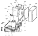
図2は、図1に示された熱交換器の一部分解斜視図であり、
図3は、図1に示された熱交換器の上面図であり、
図4は、図1に示された熱交換器の変形例を示した側面図であり、
図5は、第2実施形態に係る熱交換器の上面図であり、
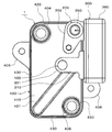
図6は、図5に示された熱交換器の作用効果を示した斜視図である。
The above and other objects, features and advantages of the present disclosure will become more apparent from the following detailed description with reference to the accompanying drawings. In the attached drawings,
FIG. 1 is a perspective view of the heat exchanger according to the first embodiment, FIG. 2 is a partially exploded perspective view of the heat exchanger shown in FIG. FIG. 3 is a top view of the heat exchanger shown in FIG. FIG. 4 is a side view showing a modification of the heat exchanger shown in FIG. FIG. 5 is a top view of the heat exchanger according to the second embodiment, FIG. 6 is a perspective view showing the operation and effect of the heat exchanger shown in FIG.
以下に、図面を参照しながら本開示を実施するための複数の形態を説明する。各実施形態において先行する実施形態で説明した事項に対応する部分には同一の参照符号を付して重複する説明を省略する場合がある。各実施形態において構成の一部のみを説明している場合は、構成の他の部分については先行して説明した他の実施形態を適用することができる。各実施形態で具体的に組合せが可能であることを明示している部分同士の組合せばかりではなく、特に組合せに支障が生じなければ、明示してなくとも実施形態同士を部分的に組み合せることも可能である。
Hereinafter, a plurality of embodiments for carrying out the present disclosure will be described with reference to the drawings. In each embodiment, portions corresponding to the items described in the preceding embodiment are denoted by the same reference numerals, and redundant description may be omitted. When only a part of the configuration is described in each embodiment, the other embodiments described earlier can be applied to other parts of the configuration. Not only the combination of the parts that clearly indicate that a combination is possible in each embodiment, but also the embodiments may be partially combined without being specified unless there is any particular problem with the combination. Is also possible.
(第1実施形態)
以下、本開示の第1実施形態について図を参照して説明する。図1に示された流量調整部一体型の熱交換器1は、例えば、車両に搭載された2次電池を適切な温度に調整する電池温調装置に用いられる。なお、電池温調装置は、車室内空間を適切な温度に調整する空調装置としても機能する。 (1st Embodiment)
Hereinafter, a first embodiment of the present disclosure will be described with reference to the drawings. 1 is used, for example, in a battery temperature controller that adjusts a secondary battery mounted on a vehicle to an appropriate temperature. Note that the battery temperature control device also functions as an air conditioner that adjusts the interior space of the vehicle to an appropriate temperature.
電池温調装置は、走行用電動モータから車両走行用の駆動力を得る電気自動車に搭載される。電気自動車は、車両停車時に外部電源から供給された電力を、車両に搭載された2次電池に充電可能となっている。外部電源は例えば商用電源である。2次電池に蓄えられた電力は、走行用電動モータのみならず、電池温調装置を構成する電動式構成機器をはじめとする各種車載機器に供給される。
The battery temperature control device is mounted on an electric vehicle that obtains a driving force for running the vehicle from the running electric motor. In an electric vehicle, electric power supplied from an external power supply when the vehicle is stopped can be charged into a secondary battery mounted on the vehicle. The external power supply is, for example, a commercial power supply. The electric power stored in the secondary battery is supplied not only to the electric motor for traveling but also to various in-vehicle devices such as electric components constituting the battery temperature controller.
電池温調装置は、第1熱媒体として冷媒が循環する冷凍サイクル装置と、第2熱媒体としての低温冷却水が循環する低温冷却水回路と、高温冷却水が循環する高温冷却水回路と、を含む。低温冷却水回路は、2次電池の熱を低温冷却水で受け取る熱媒体回路である。冷凍サイクル装置が構成する冷媒回路は、熱交換器1を介して低温冷却水回路の低温冷却水の熱を冷媒で受け取る熱媒体回路である。高温冷却水回路は、高温側水-冷媒熱交換器を介して冷凍サイクル装置の冷媒の熱を高温冷却水で受け取る熱媒体回路である。
The battery temperature control device includes a refrigeration cycle device in which a refrigerant circulates as a first heat medium, a low-temperature coolant circuit in which low-temperature coolant as a second heat medium circulates, a high-temperature coolant circuit in which high-temperature coolant circulates, including. The low-temperature cooling water circuit is a heat medium circuit that receives the heat of the secondary battery with the low-temperature cooling water. The refrigerant circuit configured by the refrigeration cycle device is a heat medium circuit that receives the heat of the low-temperature cooling water of the low-temperature cooling water circuit via the heat exchanger 1 with the refrigerant. The high-temperature cooling water circuit is a heat medium circuit that receives the heat of the refrigerant of the refrigeration cycle apparatus with the high-temperature cooling water via the high-temperature side water-refrigerant heat exchanger.
なお、本実施形態の冷媒が第1熱媒体に対応し、低温冷却水が第2熱媒体に対応する。
冷媒 Note that the refrigerant of the present embodiment corresponds to the first heat medium, and the low-temperature cooling water corresponds to the second heat medium.
続いて、熱交換器1の具体的な構成について説明する。図1~図3に示されるように、流量調整部一体型の熱交換器1は、流入部100、流出部200、流量調整部300、及び熱交換部400を含んでいる。
Next, a specific configuration of the heat exchanger 1 will be described. As shown in FIGS. 1 to 3, the heat exchanger 1 integrated with the flow control unit includes an inflow unit 100, an outflow unit 200, a flow control unit 300, and a heat exchange unit 400.
流入部100は、流量調整部300へ冷媒を流入させる入口部分である。流出部200は、熱交換部400から冷媒を流出させる出口部分である。
The inflow section 100 is an inlet section through which the refrigerant flows into the flow rate adjustment section 300. Outflow portion 200 is an outlet portion through which the refrigerant flows out of heat exchange portion 400.
流入部100と流出部200とは互いに熱伝達が抑制可能な別部材で形成されている。ここで、別部材とは、流入部100と流出部200とは物体が分離した状態である。よって、流入部100と流出部200とが接触した状態であっても、流入部100と流出部200とは物体が互いに分離している。
The inflow portion 100 and the outflow portion 200 are formed of different members capable of suppressing heat transfer to each other. Here, the separate member is a state where the object is separated from the inflow portion 100 and the outflow portion 200. Therefore, even when the inflow portion 100 and the outflow portion 200 are in contact with each other, the inflow portion 100 and the outflow portion 200 are separated from each other.
本実施形態では、流量調整部300は、バルブボディ301とセンサボディ302とを含む。流入部100及び弁体部310はバルブボディ301に形成されている。流出部200はセンサボディ302に形成されている。すなわち、バルブボディ301に設けられた流入部100と、センサボディ302に設けられた流出部200と、は分割されている。バルブボディ301及びセンサボディ302はケース360に固定されている。バルブボディ301及びセンサボディ302は、Al、Alを主体とする合金、Cu、Cuを主体とする合金等の金属材料によって形成されている。すなわち、流入部100及び流出部200は、例えば、Al、Alを主体とする合金、Cu、Cuを主体とする合金等の金属材料で構成されている。
で は In the present embodiment, the flow adjusting unit 300 includes the valve body 301 and the sensor body 302. The inflow portion 100 and the valve body 310 are formed on the valve body 301. Outflow portion 200 is formed in sensor body 302. That is, the inflow portion 100 provided in the valve body 301 and the outflow portion 200 provided in the sensor body 302 are divided. The valve body 301 and the sensor body 302 are fixed to the case 360. The valve body 301 and the sensor body 302 are formed of a metal material such as Al, an alloy mainly containing Al, Cu, an alloy mainly containing Cu, or the like. That is, the inflow portion 100 and the outflow portion 200 are made of a metal material such as Al, an alloy mainly containing Al, Cu, an alloy mainly containing Cu, or the like.
流量調整部300は、冷媒を減圧させる減圧部であると共に、熱交換部400へ流入する冷媒の流量を調整する。また、流量調整部300は、弁体部310及び駆動部320を含む。弁体部310は、バルブボディ301に内蔵されている。弁体部310は、弁体の絞り開度を変更可能に構成された可変絞り機構である。弁体部310は、流入部100からバルブボディ301へ流入する冷媒が流通する通路面積を変化させる。
The flow rate adjusting unit 300 is a pressure reducing unit that reduces the pressure of the refrigerant, and also adjusts the flow rate of the refrigerant flowing into the heat exchange unit 400. Further, the flow rate adjusting section 300 includes a valve body section 310 and a driving section 320. The valve body 310 is built in the valve body 301. The valve element 310 is a variable throttle mechanism configured to change the throttle opening of the valve element. The valve portion 310 changes the passage area through which the refrigerant flowing from the inflow portion 100 to the valve body 301 flows.
駆動部320は、弁体部310を駆動変位させる。駆動部320は、回路基板330、アクチュエータ340、センサ350、及びケース360を含む。
The drive section 320 drives and displaces the valve body section 310. The driving unit 320 includes a circuit board 330, an actuator 340, a sensor 350, and a case 360.
回路基板330は、四角形状の平坦面を持つ平板である。回路基板330は、センサ350の検出信号やアクチュエータ340を制御する電気信号を処理する電気回路が構成されている。回路基板330は、トランジスタ、コンデンサ、抵抗素子等の発熱素子331を含む。
The circuit board 330 is a flat plate having a square flat surface. The circuit board 330 has an electric circuit configured to process a detection signal of the sensor 350 and an electric signal for controlling the actuator 340. The circuit board 330 includes a heating element 331 such as a transistor, a capacitor, or a resistance element.
アクチュエータ340は、弁体部310の弁体の開度を変化させる駆動部品である。アクチュエータ340は、例えば、ステッピングモータである。アクチュエータ340は、ケース360の一部を構成するバルブボディ301に固定されている。センサ350は、流量調整部300を通過する冷媒の物理量として温度及び圧力を検出する。アクチュエータ340及びセンサ350は、回路基板330の電気回路に電気的に接続されている。センサ350のセンシング部はバルブボディ301に配置されている。
The actuator 340 is a driving component that changes the opening of the valve body of the valve body 310. The actuator 340 is, for example, a stepping motor. The actuator 340 is fixed to the valve body 301 forming a part of the case 360. The sensor 350 detects the temperature and the pressure as physical quantities of the refrigerant passing through the flow rate adjusting unit 300. The actuator 340 and the sensor 350 are electrically connected to an electric circuit of the circuit board 330. The sensing unit of the sensor 350 is disposed on the valve body 301.
ケース360は、バルブボディ301及びセンサボディ302に固定される。ケース360は、アクチュエータ340、センサ350、及び回路基板330を収容する。ケース360は、樹脂材料によって形成されている。
The case 360 is fixed to the valve body 301 and the sensor body 302. The case 360 houses the actuator 340, the sensor 350, and the circuit board 330. Case 360 is formed of a resin material.
熱交換部400は、流量調整部300から流出する冷媒と、低温冷却水回路を循環する低温冷却水と、を熱交換させる。熱交換部400は、いわゆるチラーである。
(4) The heat exchange unit 400 exchanges heat between the refrigerant flowing out of the flow control unit 300 and the low-temperature cooling water circulating in the low-temperature cooling water circuit. Heat exchange section 400 is a so-called chiller.
図1及び図2に示されるように、熱交換部400は、複数の板状部材401が所定間隔を設けて積層配置されたことにより直方体状に構成されている。すなわち、熱交換部400は、複数の板状部材401の最上層に対応する上面410、複数の板状部材401の最下層に対応する下面420、及び、複数の板状部材401の積層方向に平行な側面430を有する。
As shown in FIGS. 1 and 2, the heat exchange unit 400 is configured in a rectangular parallelepiped shape by arranging a plurality of plate-shaped members 401 at predetermined intervals. That is, the heat exchange unit 400 includes an upper surface 410 corresponding to the uppermost layer of the plurality of plate members 401, a lower surface 420 corresponding to the lowermost layer of the plurality of plate members 401, and a stacking direction of the plurality of plate members 401. It has parallel sides 430.
積層された複数の板状部材401は、冷媒と低温冷却水とを熱交換するコア部を構成する。各板状部材401は細長の略矩形状の部材である。各板状部材401は、例えばアルミニウム芯材の両面にろう材をクラッドした両面クラッド材である。
The plurality of laminated plate-like members 401 constitute a core for exchanging heat between the refrigerant and the low-temperature cooling water. Each plate-shaped member 401 is a slender, substantially rectangular member. Each plate member 401 is, for example, a double-sided clad material in which a brazing material is clad on both surfaces of an aluminum core material.
隣接する板状部材401の間には空間が形成されている。この空間が冷媒流路及び冷却水流路を構成する。冷媒流路及び冷却水流路は、板状部材401の積層方向に交互に形成されている。
空間 A space is formed between the adjacent plate members 401. This space forms a coolant channel and a cooling water channel. The coolant flow path and the cooling water flow path are alternately formed in the laminating direction of the plate members 401.
板状部材401は、冷媒流路と冷却水流路とを仕切る隔壁である。また、板状部材401は、冷媒流路を流れる冷媒と冷却水流路を流れる低温冷却水とを熱交換させる伝熱プレートとしての機能を有する。例えば、熱交換部400では、冷媒流路の冷媒流れ方向と、冷却水流路の冷却水流れ方向は反対方向である。つまり、冷媒と低温冷却水とは対向流となる。
The plate-shaped member 401 is a partition that separates the refrigerant flow path and the cooling water flow path. Further, the plate-shaped member 401 has a function as a heat transfer plate that exchanges heat between the refrigerant flowing through the refrigerant flow path and the low-temperature cooling water flowing through the cooling water flow path. For example, in the heat exchange section 400, the flow direction of the refrigerant in the refrigerant flow path and the flow direction of the cooling water in the cooling water flow path are opposite directions. That is, the refrigerant and the low-temperature cooling water flow in opposite directions.
本実施形態では、熱交換部400は、上面410に対応する板状部材401に、冷媒の流入口402及び流出口403と、低温冷却水の流入口404及び流出口405と、を有する。また、熱交換部400は、下面420に対応する板状部材401に、熱交換器1を取付対象に固定するためのフランジ406を有する。
In the present embodiment, the heat exchange unit 400 has a coolant inlet 402 and a coolant outlet 403 and a coolant inlet 404 and a coolant outlet 405 on the plate-shaped member 401 corresponding to the upper surface 410. Further, the heat exchange section 400 has a flange 406 for fixing the heat exchanger 1 to an attachment target on the plate-shaped member 401 corresponding to the lower surface 420.
上記の構成において、流量調整部300と熱交換部400とは一体的に構成されている。流量調整部300の弁体部310は、熱交換部400の流入口402に固定される。流出部200は、熱交換部400の流出口403に固定される。すなわち、バルブボディ301は、熱交換部400の冷媒の流入口402に固定される。センサボディ302は、熱交換部400の冷媒の流出口403に固定される。つまり、流入部100及び流出部200は、熱交換部400の上面410に配置される。
に お い て In the above configuration, the flow rate adjustment unit 300 and the heat exchange unit 400 are integrally formed. The valve body section 310 of the flow rate adjustment section 300 is fixed to the inflow port 402 of the heat exchange section 400. Outflow section 200 is fixed to outlet 403 of heat exchange section 400. That is, the valve body 301 is fixed to the refrigerant inlet 402 of the heat exchange unit 400. The sensor body 302 is fixed to the refrigerant outlet 403 of the heat exchange unit 400. That is, the inflow section 100 and the outflow section 200 are arranged on the upper surface 410 of the heat exchange section 400.
以上の構成によると、流入部100と流出部200が、互いに別部材で形成されているので、熱交換部400から流出する冷媒の有する熱が流量調整部300へ流入する冷媒へ伝達されてしまうことを抑制できる。また、熱交換部400から流出する冷媒の有する熱が熱交換部400へ流入する冷媒へ伝達されてしまうことも抑制できる。したがって、熱交換部400における熱交換効率の低下を抑制することができる。
According to the above configuration, since the inflow section 100 and the outflow section 200 are formed of different members, heat of the refrigerant flowing out of the heat exchange section 400 is transmitted to the refrigerant flowing into the flow rate adjustment section 300. Can be suppressed. In addition, it is possible to prevent the heat of the refrigerant flowing out of the heat exchange unit 400 from being transmitted to the refrigerant flowing into the heat exchange unit 400. Therefore, a decrease in heat exchange efficiency in the heat exchange section 400 can be suppressed.
また、流入部100と流出部200とが分割されているので、バルブボディ301とセンサボディ302とが一つの物体として構成される場合よりも2物体に分割されたことにより表面積が増える。よって、バルブボディ301及びセンサボディ302を介した放熱性を向上させることができる。また、熱交換部400に対するバルブボディ301及びセンサボディ302のロウ付け性を向上させることができる。
{Circle around (2)} Since the inflow portion 100 and the outflow portion 200 are divided, the surface area is increased by dividing the valve body 301 and the sensor body 302 into two objects as compared with the case where they are configured as one object. Therefore, heat radiation through the valve body 301 and the sensor body 302 can be improved. Further, the brazing property of the valve body 301 and the sensor body 302 to the heat exchange section 400 can be improved.
さらに、流入部100と流出部200とが分割されているので、冷媒が熱交換部400に流入する影響と、冷媒が熱交換部400から流出する影響と、を分けることができる。冷媒が熱交換部400に流入する影響には弁体部310の動作の影響も含まれる。このため、センサ350がセンサボディ302を通過する冷媒の温度及び圧力を検出する場合、バルブボディ301の影響を外乱として受けずに済む。よって、センサ350への外乱を抑制することができる。
Furthermore, since the inflow portion 100 and the outflow portion 200 are divided, the effect of the refrigerant flowing into the heat exchange unit 400 and the effect of the refrigerant flowing out of the heat exchange unit 400 can be separated. The influence of the refrigerant flowing into the heat exchange section 400 includes the influence of the operation of the valve body section 310. Therefore, when the sensor 350 detects the temperature and the pressure of the refrigerant passing through the sensor body 302, the sensor 350 does not need to be affected by the valve body 301 as a disturbance. Therefore, disturbance to the sensor 350 can be suppressed.
変形例として、熱交換器1は、電池温調装置以外の装置に適用しても良い。例えば、熱交換器1の熱交換部400は、動作時に発熱を伴う車載機器の温度調整のために用いられても良い。車載機器は、例えば、発電機、インバータ、モータジェネレータ、充放電器等である。
As a modification, the heat exchanger 1 may be applied to devices other than the battery temperature control device. For example, the heat exchange unit 400 of the heat exchanger 1 may be used for adjusting the temperature of a vehicle-mounted device that generates heat during operation. The on-vehicle device is, for example, a generator, an inverter, a motor generator, a charger / discharger, and the like.
変形例として、冷媒の流入口402及び流出口403と、低温冷却水の流入口404及び流出口405と、は熱交換部400の上面410に限られず、側面430や下面420に設けられていても良い。また、冷媒の流入口402及び流出口403と、低温冷却水の流入口404及び流出口405と、は熱交換部400のうち異なる面に設けられていても良い。
As a modification, the inflow port 402 and the outflow port 403 of the refrigerant, and the inflow port 404 and the outflow port 405 of the low-temperature cooling water are not limited to the upper surface 410 of the heat exchange unit 400 but are provided on the side surface 430 and the lower surface 420. Is also good. Further, the inlet 402 and the outlet 403 of the refrigerant and the inlet 404 and the outlet 405 of the low-temperature cooling water may be provided on different surfaces of the heat exchange unit 400.
変形例として、流入部100及び流出部200は、熱交換部400の上面410に限られず、側面430や下面420に設けられていても良い。また、図4に示されるように、流入部100及び流出部200は、熱交換部400のうち異なる面に設けられていても良い。
As a modified example, the inflow portion 100 and the outflow portion 200 are not limited to the upper surface 410 of the heat exchange portion 400, and may be provided on the side surface 430 or the lower surface 420. Further, as shown in FIG. 4, the inflow section 100 and the outflow section 200 may be provided on different surfaces of the heat exchange section 400.
(第2実施形態)
本実施形態では、第1実施形態と異なる部分について説明する。図5に示されるように、流入部100及び流出部200は、熱交換部400を構成する面のうちの同じ面に配置されている。また、ケース360は、流入部100と流出部200との間に配置されている。すなわち、ケース360は、バルブボディ301とセンサボディ302との間に配置されている。また、ケース360の全体が熱交換部400の上面410に配置される。 (2nd Embodiment)
In the present embodiment, portions different from the first embodiment will be described. As shown in FIG. 5, theinflow portion 100 and the outflow portion 200 are arranged on the same surface among the surfaces constituting the heat exchange portion 400. The case 360 is arranged between the inflow section 100 and the outflow section 200. That is, case 360 is arranged between valve body 301 and sensor body 302. Further, the entire case 360 is disposed on the upper surface 410 of the heat exchange unit 400.
本実施形態では、第1実施形態と異なる部分について説明する。図5に示されるように、流入部100及び流出部200は、熱交換部400を構成する面のうちの同じ面に配置されている。また、ケース360は、流入部100と流出部200との間に配置されている。すなわち、ケース360は、バルブボディ301とセンサボディ302との間に配置されている。また、ケース360の全体が熱交換部400の上面410に配置される。 (2nd Embodiment)
In the present embodiment, portions different from the first embodiment will be described. As shown in FIG. 5, the
そして、回路基板330の法線方向において、回路基板330と熱交換部400とが重合配置される領域が回路基板330の全体になる。また、ケース360の全体が熱交換部400の上面410に沿っている。したがって、図6に示されるように、破線部で示された領域において、ケース360の内部の熱や通電時に回路基板330で発生する熱を熱交換部400へ移動させやすくすることができる。
{Circle around (4)} In the normal direction of the circuit board 330, the area where the circuit board 330 and the heat exchange section 400 are overlapped and arranged is the entire circuit board 330. Further, the entire case 360 is along the upper surface 410 of the heat exchange unit 400. Therefore, as shown in FIG. 6, in the region indicated by the broken line, heat inside the case 360 and heat generated in the circuit board 330 when energized can be easily moved to the heat exchange unit 400.
また、流入部100と流出部200とがケース360によって引き離されている。このため、流入部100と流出部200とが互いに影響しにくくなるようにすることができる。
(5) The inflow portion 100 and the outflow portion 200 are separated from each other by the case 360. For this reason, the inflow part 100 and the outflow part 200 can be made hard to influence each other.
変形例として、回路基板330は、実装面が熱交換部400の上面410に対して垂直になるように立てられた状態でケース360に収容されても良い。
As a modified example, the circuit board 330 may be housed in the case 360 in a state where the mounting surface stands upright with respect to the upper surface 410 of the heat exchange unit 400.
本開示は上述の実施形態に限定されることなく、本開示の趣旨を逸脱しない範囲内で、以下のように種々変形可能である。
The present disclosure is not limited to the above-described embodiments, and can be variously modified as follows without departing from the spirit of the present disclosure.
例えば、熱交換器1が適用される電池温調装置は電気自動車に搭載されているが、電池温調装置は、内燃機関及び走行用電動モータから車両走行用の駆動力を得るハイブリッド自動車に搭載されていても良い。また、電池温調装置は、車両用に限られず、車両用以外の2次電池に適用しても良い。熱交換器1は電池温調装置以外の装置に適用されても良い。
For example, the battery temperature control device to which the heat exchanger 1 is applied is mounted on an electric vehicle, but the battery temperature control device is mounted on a hybrid vehicle that obtains driving force for vehicle travel from an internal combustion engine and a traveling electric motor. It may be. Further, the battery temperature control device is not limited to a vehicle, and may be applied to a secondary battery other than a vehicle. The heat exchanger 1 may be applied to a device other than the battery temperature control device.
また、上記実施形態では、熱媒体として冷却水や冷媒を用いているが、油等の各種媒体を熱媒体として用いても良い。熱交換部400は空気と冷媒とを熱交換させるものでも良い。
Further, in the above embodiment, cooling water or refrigerant is used as a heat medium, but various media such as oil may be used as a heat medium. The heat exchange section 400 may exchange heat between the air and the refrigerant.
上記実施形態では、流入部100はバルブボディ301に一体化され、流出部200はセンサボディ302に一体化されていたが、これは構成の一例である。流入部100はバルブボディ301から分離されていても良いし、流出部200はセンサボディ302から分離されていても良い。流入部100及び流出部200は、バルブボディ301及びセンサボディ302と同じ材料で構成されていても良いし、異なる材料で構成されていても良い。流入部100及び流出部200は、例えばステンレス等の他の金属材料で構成されていても良い。流入部100及び流出部200は、互いに異なる金属材料で構成されていても良い。流入部100及び流出部200は互いに熱伝導が困難な材料で構成されていても良い。
In the above embodiment, the inflow portion 100 is integrated with the valve body 301 and the outflow portion 200 is integrated with the sensor body 302, but this is an example of the configuration. The inflow portion 100 may be separated from the valve body 301, and the outflow portion 200 may be separated from the sensor body 302. The inflow portion 100 and the outflow portion 200 may be made of the same material as the valve body 301 and the sensor body 302, or may be made of different materials. The inflow portion 100 and the outflow portion 200 may be made of another metal material such as stainless steel. The inflow portion 100 and the outflow portion 200 may be made of different metal materials. The inflow portion 100 and the outflow portion 200 may be made of materials that are difficult to conduct heat to each other.
本開示は、実施例に準拠して記述されたが、本開示は当該実施例や構造に限定されるものではないと理解される。本開示は、様々な変形例や均等範囲内の変形をも包含する。加えて、様々な組み合わせや形態、さらには、それらに一要素のみ、それ以上、あるいはそれ以下、を含む他の組み合わせや形態をも、本開示の範疇や思想範囲に入るものである。
Although the present disclosure has been described based on the embodiments, it is understood that the present disclosure is not limited to the embodiments and the structure. The present disclosure also encompasses various modifications and variations within an equivalent range. In addition, various combinations and forms, and other combinations and forms including only one element, more or less, are also included in the scope and concept of the present disclosure.
Claims (8)
- 第1熱媒体の流量を調整する流量調整部(300)と、
前記流量調整部から流出する前記第1熱媒体と第2熱媒体とを熱交換させる熱交換部(400)と、
前記流量調整部へ前記第1熱媒体を流入させる流入部(100)と、
前記熱交換部から前記第1熱媒体を流出させる流出部(200)と、
を含み、
前記流入部と前記流出部とは互いに熱伝達が抑制可能な別部材で形成されている熱交換器。 A flow rate adjusting unit (300) for adjusting the flow rate of the first heat medium,
A heat exchange unit (400) for exchanging heat between the first heat medium and the second heat medium flowing out of the flow rate adjustment unit;
An inflow section (100) for flowing the first heat medium into the flow rate adjusting section;
An outlet section (200) for allowing the first heat medium to flow out of the heat exchange section;
Including
The heat exchanger wherein the inflow portion and the outflow portion are formed of different members capable of suppressing heat transfer to each other. - 前記流量調整部は、バルブボディ(301)とセンサボディ(302)とを含み、
前記バルブボディに設けられた前記流入部と、前記センサボディに設けられた前記流出部と、は分割されている請求項1に記載の熱交換器。 The flow rate adjusting unit includes a valve body (301) and a sensor body (302),
The heat exchanger according to claim 1, wherein the inflow portion provided in the valve body and the outflow portion provided in the sensor body are divided. - 前記流入部及び前記流出部は、前記熱交換部を構成するいずれかの面に配置されている請求項1または2に記載の熱交換器。 (3) The heat exchanger according to (1) or (2), wherein the inflow portion and the outflow portion are arranged on any one of surfaces constituting the heat exchange portion.
- 前記流入部及び前記流出部は、前記熱交換部を構成するいずれかの面のうち異なる面に配置されている請求項1または2に記載の熱交換器。 The heat exchanger according to claim 1 or 2, wherein the inflow portion and the outflow portion are arranged on different surfaces among any surfaces constituting the heat exchange unit.
- 前記流入部及び前記流出部は、前記熱交換部を構成する面のうちの同じ面に配置されており、
前記流量調整部は、前記熱交換部へ流入する前記第1熱媒体の流量を調整する弁体部(310)の動作を制御する回路基板(330)を収容したケース(360)を含み、
前記ケースは、前記流入部と前記流出部との間に配置されている請求項1または2に記載の熱交換器。 The inflow portion and the outflow portion are arranged on the same surface among the surfaces constituting the heat exchange unit,
The flow rate adjustment unit includes a case (360) containing a circuit board (330) that controls an operation of a valve body (310) that adjusts a flow rate of the first heat medium flowing into the heat exchange unit,
The heat exchanger according to claim 1, wherein the case is disposed between the inflow portion and the outflow portion. - 前記熱交換部は、直方体状に構成されている請求項3ないし5のいずれか1つに記載の熱交換器。 The heat exchanger according to any one of claims 3 to 5, wherein the heat exchange unit is formed in a rectangular parallelepiped shape.
- 前記流量調整部は、前記第1熱媒体の物理量を検出するセンサ(350)を含む請求項1ないし6のいずれか1つに記載の熱交換器。 The heat exchanger according to any one of claims 1 to 6, wherein the flow rate adjusting unit includes a sensor (350) for detecting a physical quantity of the first heat medium.
- 前記熱交換部は、動作時に発熱を伴う車載機器の温度調整のために用いられる請求項1ないし7のいずれか1つに記載の熱交換器。 The heat exchanger according to any one of claims 1 to 7, wherein the heat exchange unit is used for adjusting the temperature of the vehicle-mounted device that generates heat during operation.
Applications Claiming Priority (2)
| Application Number | Priority Date | Filing Date | Title |
|---|---|---|---|
| JP2018-139341 | 2018-07-25 | ||
| JP2018139341A JP7115101B2 (en) | 2018-07-25 | 2018-07-25 | Heat exchanger |
Publications (1)
| Publication Number | Publication Date |
|---|---|
| WO2020022067A1 true WO2020022067A1 (en) | 2020-01-30 |
Family
ID=69181635
Family Applications (1)
| Application Number | Title | Priority Date | Filing Date |
|---|---|---|---|
| PCT/JP2019/027364 WO2020022067A1 (en) | 2018-07-25 | 2019-07-10 | Heat exchanger |
Country Status (2)
| Country | Link |
|---|---|
| JP (1) | JP7115101B2 (en) |
| WO (1) | WO2020022067A1 (en) |
Families Citing this family (1)
| Publication number | Priority date | Publication date | Assignee | Title |
|---|---|---|---|---|
| JP7206670B2 (en) * | 2018-07-25 | 2023-01-18 | 株式会社デンソー | Heat exchanger |
Citations (3)
| Publication number | Priority date | Publication date | Assignee | Title |
|---|---|---|---|---|
| JP2010249499A (en) * | 2009-03-26 | 2010-11-04 | Modine Mfg Co | Suction line heat exchanger module and method of operating the same |
| JP2015212604A (en) * | 2014-04-18 | 2015-11-26 | 株式会社ティラド | Thermo valve incorporated oil cooler |
| JP2016526145A (en) * | 2013-06-07 | 2016-09-01 | バレオ システム テルミクValeo Systemes Thermiques | Connection module, heat exchanger, and corresponding heat exchange assembly |
-
2018
- 2018-07-25 JP JP2018139341A patent/JP7115101B2/en active Active
-
2019
- 2019-07-10 WO PCT/JP2019/027364 patent/WO2020022067A1/en active Application Filing
Patent Citations (3)
| Publication number | Priority date | Publication date | Assignee | Title |
|---|---|---|---|---|
| JP2010249499A (en) * | 2009-03-26 | 2010-11-04 | Modine Mfg Co | Suction line heat exchanger module and method of operating the same |
| JP2016526145A (en) * | 2013-06-07 | 2016-09-01 | バレオ システム テルミクValeo Systemes Thermiques | Connection module, heat exchanger, and corresponding heat exchange assembly |
| JP2015212604A (en) * | 2014-04-18 | 2015-11-26 | 株式会社ティラド | Thermo valve incorporated oil cooler |
Also Published As
| Publication number | Publication date |
|---|---|
| JP7115101B2 (en) | 2022-08-09 |
| JP2020016384A (en) | 2020-01-30 |
Similar Documents
| Publication | Publication Date | Title |
|---|---|---|
| US9121643B2 (en) | Heat exchanger | |
| JP3972501B2 (en) | Heat exchange device for heat storage and air conditioner for vehicle | |
| US7823671B2 (en) | Cooling structure of heat generating member | |
| US20140290296A1 (en) | Heat exchange system | |
| CN102574472A (en) | Cooling system for electric vehicle | |
| KR101316268B1 (en) | Variable Capacity Core type Heat Exchanger Unit | |
| US20120168125A1 (en) | Multi-Function Automotive Radiator and Condenser Airflow System | |
| JP2013254725A (en) | Heating/cooling system for battery of motor vehicle, and operating method for the same | |
| JP2006082805A (en) | Heat exchanger for automobile | |
| JP2012229906A (en) | Heat exchanger for vehicle | |
| US20110100021A1 (en) | Air conditioner | |
| WO2012137639A1 (en) | Heat medium heating device and vehicle air-conditioning device provided with same | |
| US20190020078A1 (en) | Systems and methods for controlling the temperature of a battery and of other electric components of a vehicle | |
| JP2012196985A (en) | Heater for heat medium and air conditioner for vehicle with the same | |
| WO2014027514A1 (en) | Heat exchanger | |
| JPH11313406A (en) | Cooler for hybrid vehicle | |
| JP5951205B2 (en) | Heat medium heating device and vehicle air conditioner equipped with the same | |
| US9175886B2 (en) | Heat exchanger having thermoelectric element | |
| WO2020022067A1 (en) | Heat exchanger | |
| WO2012124469A1 (en) | Battery temperature adjustment device | |
| WO2020022066A1 (en) | Heat exchanger | |
| JP7327613B2 (en) | Heat exchanger | |
| US20090249810A1 (en) | Evaporator | |
| US20160273854A1 (en) | Device for regulating the circulation of a coolant liquid for a heat exchanger, particularly for a motor vehicle engine charge air cooler | |
| JP2012145311A (en) | Vehicle air conditioning device |
Legal Events
| Date | Code | Title | Description |
|---|---|---|---|
| 121 | Ep: the epo has been informed by wipo that ep was designated in this application |
Ref document number: 19839833 Country of ref document: EP Kind code of ref document: A1 |
|
| NENP | Non-entry into the national phase |
Ref country code: DE |
|
| 122 | Ep: pct application non-entry in european phase |
Ref document number: 19839833 Country of ref document: EP Kind code of ref document: A1 |