WO2020021904A1 - 生育情報表示システム - Google Patents
生育情報表示システム Download PDFInfo
- Publication number
- WO2020021904A1 WO2020021904A1 PCT/JP2019/023745 JP2019023745W WO2020021904A1 WO 2020021904 A1 WO2020021904 A1 WO 2020021904A1 JP 2019023745 W JP2019023745 W JP 2019023745W WO 2020021904 A1 WO2020021904 A1 WO 2020021904A1
- Authority
- WO
- WIPO (PCT)
- Prior art keywords
- information
- field
- mesh
- terminal device
- growth
- Prior art date
- Legal status (The legal status is an assumption and is not a legal conclusion. Google has not performed a legal analysis and makes no representation as to the accuracy of the status listed.)
- Ceased
Links
Images




Classifications
-
- G—PHYSICS
- G06—COMPUTING OR CALCULATING; COUNTING
- G06Q—INFORMATION AND COMMUNICATION TECHNOLOGY [ICT] SPECIALLY ADAPTED FOR ADMINISTRATIVE, COMMERCIAL, FINANCIAL, MANAGERIAL OR SUPERVISORY PURPOSES; SYSTEMS OR METHODS SPECIALLY ADAPTED FOR ADMINISTRATIVE, COMMERCIAL, FINANCIAL, MANAGERIAL OR SUPERVISORY PURPOSES, NOT OTHERWISE PROVIDED FOR
- G06Q50/00—Information and communication technology [ICT] specially adapted for implementation of business processes of specific business sectors, e.g. utilities or tourism
- G06Q50/02—Agriculture; Fishing; Forestry; Mining
-
- G—PHYSICS
- G06—COMPUTING OR CALCULATING; COUNTING
- G06T—IMAGE DATA PROCESSING OR GENERATION, IN GENERAL
- G06T7/00—Image analysis
- G06T7/70—Determining position or orientation of objects or cameras
Definitions
- This invention relates to a growth information display system.
- Patent Literature 1 discloses a technique for creating a fertilization map representing the fertilization amount for each of a plurality of meshes (small areas) set by dividing a field. Specifically, while flying a helicopter equipped with various sensors such as a camera and a satellite positioning system over the field, the camera shoots each part of the field, and the obtained captured images are located. Store with information. Then, each photographed image is analyzed, and based on the analysis result and the positioning information of each photographed image, growth status information indicating the growth status of the crop is calculated for each mesh in the field. A fertilization map is created based on the obtained growth status information for each mesh.
- the fertilization map created for a certain field is printed on a recording sheet, for example, and given to a farmer who is cultivating crops in the field. The farmer performs fertilization while adjusting the fertilization amount for each mesh in the field with reference to the fertilization map printed on the recording paper.
- An object of the present invention is to provide a growth information display system that makes it easy to compare the actual growth state of a crop for each mesh in a field with growth information.
- a growth information display system includes a terminal device capable of capturing an image of a field and a server capable of communicating with the terminal device, wherein the terminal device calculates a position information of the terminal device;
- a posture / azimuth detecting unit for detecting posture information and azimuth information of the terminal device, an imaging unit for imaging the field, a display unit for displaying an image captured by the imaging unit, and a position of the terminal device Information, field identification information including at least position information of the orientation information and the orientation information, a field identification information transmission processing unit that transmits to the server, the server is set by dividing the field
- a storage unit storing mesh information including position information and growth information for each of the plurality of meshes, and the terminal information based on field identification information received from the terminal device.
- a mesh information transmission processing unit that specifies a field imaged by the device and transmits mesh information for the specified field to the terminal device, wherein the terminal device receives mesh information for the field from the server. Based on the received mesh information, the position information of the terminal device, the posture information and the azimuth information, to identify the mesh in the field included in the captured image, for each identified mesh, the corresponding growth information, It further includes a growth information display control unit that is displayed in a superimposed manner.
- the terminal device transmits the field identification information including at least the position information among the position information, the posture information, and the azimuth information of the terminal device to the server while imaging the field.
- the server specifies a field imaged by the terminal device based on the field specifying information received from the terminal device, and transmits mesh information for the specified field to the terminal device.
- the mesh information includes position information and growth information for each mesh.
- the terminal device receives mesh information for the field from the server, identifies the mesh in the field included in the captured image based on the received mesh information, the position information of the terminal device, the posture information, and the azimuth information. The corresponding growth information is superimposed and displayed on each mesh.
- the mesh information transmission processing unit when it is determined that there are two or more fields imaged by the terminal device, the mesh information transmission processing unit is closest to the terminal device among the plurality of fields. It is configured to identify a field present at a position as a field imaged by the terminal device.
- the mesh information for the field is created by analyzing an image of the field taken by an imaging device mounted on a flying object flying over the field.
- the growth information is information indicating a crop growth status or information indicating a fertilization amount calculated from information indicating a crop growth status.
- FIG. 1 is a schematic diagram showing a configuration of a growth information display system according to an embodiment of the present invention.
- FIG. 2 is a block diagram illustrating an electrical configuration of the management server.
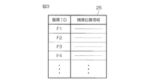
- FIG. 3 is a schematic diagram illustrating an example of the field management table.
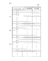
- FIG. 4 is a schematic diagram illustrating an example of the mesh information management table.
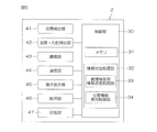
- FIG. 5 is a block diagram illustrating an electrical configuration of the mobile terminal.
- FIG. 6 is a flowchart illustrating an example of a procedure of an information addition process performed by the information addition processing unit.
- FIG. 7 is a flowchart illustrating an example of a procedure of a mesh information transmission process performed by the mesh information transmission processing unit.
- FIG. 8 is a schematic diagram illustrating an example in which the corresponding growth information is displayed in different colors for each mesh in the information addition target field included in the captured image.
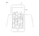
- FIG. 9 is a schematic diagram illustrating an example in which the corresponding growth information is displayed as a three-dimensional bar graph for each mesh in the information addition target field included in the captured image.
- FIG. 1 is a schematic diagram showing a configuration of a growth information display system according to one embodiment of the present invention.
- the growth information display system 1 includes a portable terminal device (hereinafter, “portable terminal 2”) and a management server 3.
- the mobile terminal 2 is a mobile terminal such as a smartphone or a tablet personal computer (tablet PC).
- the mobile terminal 2 is a smartphone.
- the mobile terminal 2 includes an imaging unit 43 (see FIG. 5) such as a CMOS sensor.
- the mobile terminal 2 has a function of measuring its own position using the positioning satellite 4.
- the mobile terminal 2 can communicate with the management server 3 via the communication network 5.
- the portable information terminal 2 is equipped with a growth information addition program developed for implementing the present embodiment.
- the growth information addition program receives the growth information for each mesh of the field from the management server 3 by transmitting the field identification information for specifying the field imaged by the mobile terminal 2 to the management server 3, An application program for adding the received growth information to the captured image. Details of the field identification information will be described later.
- a mesh refers to a plurality of small areas set by dividing a field.
- the mesh is rectangular (more specifically, square).
- the growth information refers to information on the growth of the crop, and includes information indicating the growth state of the crop, and information such as the amount of fertilization calculated from the growth state of the crop.
- the growth information is a normalized difference vegetation index (NDVI: ⁇ Normalized ⁇ Difference @ Vegetation @ Index) for each mesh in the field.
- NDVI normalized difference vegetation index
- Green leaves of plants absorb visible light such as red, and strongly reflect light having a wavelength in the near infrared region.
- NDVI is an index that utilizes such properties of green leaves, and is an index that indicates the presence or absence and activity of vegetation. NDVI is defined by the following equation (1).
- NDVI (IR-R) / (IR + R) (1)
- IR Observed value of near-infrared light
- R Observed value of visible light NDVI is normalized to take a value of, for example, 0.01 to 1.00.
- the NDVI for each mesh in a certain field is created as follows, for example. That is, while flying a flying object on which a multispectral camera is mounted over a field, the field is photographed with the multispectral camera.
- the multispectral camera is, for example, a camera that can capture images of visible red light and near infrared light.
- the flying object is, for example, a drone (unmanned aerial vehicle). Then, NDVI for each mesh in the field is calculated based on the obtained captured image.
- the management server 3 stores the location information of the field, the location information for each mesh of the field, and the growth information.
- the management server 3 can communicate with the mobile terminal 2 via the communication network 5.
- FIG. 2 is a block diagram showing an electrical configuration of the management server 3.
- the management server 3 includes a control unit 10.
- the communication unit 21, the operation display unit 22, the operation unit 23, the storage unit 24, and the like are connected to the control unit 10.
- the communication unit 21 is a communication interface for the control unit 10 to communicate with the mobile terminal 2 via the communication network 5.
- the operation display unit 22 includes, for example, a touch panel display.
- the operation unit 23 includes, for example, a keyboard, a mouse, and the like.
- the storage unit 24 is configured by a storage device such as a hard disk and a nonvolatile memory.
- the storage unit 24 includes a field management table 25, a mesh information management table 26, and the like.
- the field management table 25 stores, for each field ID, position information for specifying the position of the field (hereinafter, may be referred to as “field position information”).
- the field position information includes, for example, position information of a plurality of points on the contour line of the field.
- the field position information for example, if the field is substantially rectangular, is composed of a pair of vertex position information among the four vertices of the four vertex position information of the field.
- the field position information may include position information of the center of the field.
- the mesh information management table 26 stores, for each field ID, mesh information for the field.
- the mesh information for a certain field includes mesh information for each mesh in the field, and is stored for each corresponding mesh ID.
- the mesh information for a certain mesh includes position information for specifying the position of the mesh (hereinafter, may be referred to as “mesh position information”) and growth information for the mesh.
- the mesh position information includes, for example, position information of a pair of vertexes of the four vertices of the position information of the four vertices of the mesh.
- the mesh position information may include position information of the center of the mesh.
- the control unit 10 includes a microcomputer having a CPU and a memory (ROM, RAM, etc.) 11.
- the control unit 10 includes a mesh information transmission processing unit 12.
- the mesh information transmission processing unit 12 includes a field identification unit 13 and an information transmission unit 14.
- the field specifying unit 13 specifies the field imaged by the mobile terminal 2 based on the field specifying information received from the mobile terminal 2.
- the information transmitting unit 14 transmits, to the portable terminal 2, mesh information for each mesh of the field specified by the field specifying unit 13.
- FIG. 5 is a block diagram showing an electrical configuration of the portable terminal 2. As shown in FIG.
- the mobile terminal 2 includes the control unit 30.
- the control unit 30 is connected with a position detection unit 41, a posture / azimuth detection unit 42, an imaging unit 43, a communication unit 44, an operation display unit 45, an operation unit 46, a storage unit 47, and the like.
- the position detector 41 calculates position information of the mobile terminal 2 based on the satellite positioning system.
- the satellite positioning system is a GNSS (Global Navigation Satellite System).
- the position detection unit 41 receives satellite signals from a plurality of positioning satellites 4 (see FIG. 1) and calculates position information of the mobile terminal 2.
- the position information includes, for example, latitude, longitude, and altitude information.
- the attitude / azimuth detection unit 42 detects the attitude and orientation of the mobile terminal 2.
- the attitude of the mobile terminal 2 indicates a three-dimensional tilt angle of the mobile terminal 2, and the azimuth of the mobile terminal 2 indicates an imaging direction of the imaging unit 43.
- the posture / azimuth detection unit 42 detects the posture and orientation of the mobile terminal 2 using, for example, a gyro sensor, an acceleration sensor, a geomagnetic sensor, and the like.
- the field identification information includes all the information of the position, posture, and orientation.
- the imaging unit 43 captures an image of a field using an imaging device such as a CCD (Charge Coupled Device) or a CMOS (Complementary Metal Oxide Semiconductor).
- an imaging device such as a CCD (Charge Coupled Device) or a CMOS (Complementary Metal Oxide Semiconductor).
- the communication unit 44 is a communication interface for the control unit 30 to communicate with the management server 3 via the communication network 5.
- the operation display unit 45 includes, for example, a touch panel display.
- the operation unit 46 includes, for example, one or a plurality of operation buttons.
- the storage unit 47 includes a storage device such as a nonvolatile memory.
- the control unit 30 includes a microcomputer including a CPU and a memory (ROM, RAM, nonvolatile memory, etc.) 31.
- the memory (specifically, a non-volatile memory) 31 stores the above-described growth information addition program and the like.
- the control unit 30 includes an information addition processing unit 32 that executes information addition processing according to the growth information addition program when the growth information addition program is started.
- the information addition processing section 32 includes a field identification information transmission processing section 33 and a growth information display control section 34.
- the field specifying information transmission processing unit 33 transmits the field specifying information to the management server 3.
- the growth information display control unit 34 receives the mesh information for the field transmitted from the management server 3, and outputs the field information included in the captured image based on the received mesh information, the position information, the posture information, the direction information, and the like of the mobile terminal 2. Are specified, and the corresponding growth information is superimposed and displayed on each of the specified meshes.
- FIG. 6 is a flowchart illustrating an example of a procedure of an information addition process performed by the information addition processing unit 32.
- FIG. 7 is a flowchart illustrating an example of a procedure of the mesh information transmission process performed by the mesh information transmission processing unit 12.
- the user when the user wants to check the growth information of the crop in the field where the fertilization work is to be performed, the user operates the portable terminal 2 to activate the growth information addition program.
- the growth information addition program When the growth information addition program is started, the information addition process is started.
- the information addition processing unit 32 puts the imaging unit 43 into an operating state (step S1).
- an image is captured by the imaging unit 53.
- the image captured by the imaging unit 53 is displayed on the operation display unit 45 via the control unit 30.
- the user turns the mobile terminal 2 to the field so that the field whose growth information is to be confirmed is imaged.
- the field specifying information transmission processing unit 33 in the information addition processing unit 32 transmits the field specifying information to the management server 3 (step S2).
- the field identification information includes the position information, the posture information, and the direction information of the mobile terminal 2.
- the field specifying information may include angle-of-view information of the imaging unit 43 of the mobile terminal 2.
- step S11 when field specifying unit 13 (see FIG. 2) in mesh information transmission processing unit 12 of management server 3 receives field specifying information from mobile terminal 2 (step S11: YES), reception is performed.
- the field identification processing is performed based on the field identification information thus obtained.
- the field identification process is a process of identifying a field (hereinafter, referred to as an “information addition target field”) that is included in a captured image captured by the mobile terminal 2 and to which growth information is to be added.
- the field specifying unit 13 specifies a shooting area of the imaging unit 53 of the mobile terminal 2 based on the field specifying information (Step S12).
- the field specifying unit 13 determines that only one field exists in the imaging region specified in step 12. It is determined whether it exists, there are two or more, and there is no field (step S13). This determination may be made based only on the mesh position information for the field.
- the information transmission unit 14 (see FIG. 2) in the mesh information transmission processing unit 12 has not been able to identify the field imaged by the mobile terminal 2. Is transmitted to the portable terminal 2 including the specific failure command indicating the error (step S14).
- step S13 If it is determined in step S13 that there is only one field in the shooting area of the imaging unit 53, the field specifying unit 13 specifies the field as an information addition target field (step S15). Then, the field specifying unit 13 proceeds to Step S17.
- step S13 when it is determined that two or more fields exist in the imaging area of the imaging unit 53, the field identification unit 13 exists at a position closest to the mobile terminal 2 among the plurality of fields.
- the field is specified as an information addition target field (step S16). Then, the field specifying unit 13 proceeds to Step S17.
- step S17 the information transmitting unit 14 first obtains mesh information for the field specified as the information addition target field based on at least the mesh information management table 26 of the field management table 25 and the mesh information management table 26. Then, the information transmitting unit 14 transmits the specified result information including the acquired mesh information and the specified success command to the mobile terminal 2.
- step S4 when the growth information display control unit 34 (see FIG. 5) in the information addition processing unit 32 of the mobile terminal 2 receives the specific result information from the management server 3 (step S3: YES), it is included in the information. It is determined whether or not the present command is a successful identification command (step S4). If the command included in the identification result information is a specific failure command (step S4: NO), the growth information display control unit 34 returns to step S2.
- step S4 If the command included in the specification result information is a specification success command (step S4: YES), the growth information display control unit 34 performs growth information display processing (step S5).
- the growth information display control unit 34 specifies the mesh in the information addition target field based on the mesh information, the position information, the posture information, and the azimuth information included in the specification result information. At this time, the growth information display control unit 34 may specify a mesh in the information addition target field in consideration of the view angle information of the imaging unit 43. Then, the information addition processing unit 32 superimposes and displays the corresponding growth information on each of the specified meshes.
- the information addition target field F in the captured image is divided into meshes, and the growth information corresponding to the divided meshes is displayed in different colors, as shown in FIG. You may make it.
- the field to which information is added in the captured image may be divided for each mesh, and the corresponding growth information may be numerically displayed in the divided mesh.
- a mesh in the field to which information is added in the captured image may be specified, and the growth information corresponding to the specified mesh may be displayed in a two-dimensional or three-dimensional bar graph.
- FIG. 9 shows an example of displaying corresponding growth information in a three-dimensional bar graph for each mesh in the information addition target field F.
- the information addition processing section 32 determines whether or not the user has performed an operation for restarting the information addition processing (step S6).
- the information addition processing unit 32 may display a redo button on the display screen, and when the redo button is operated by the user, may determine that an operation for redoing the information addition processing has been performed. .
- step S6 determines whether or not the user has performed an operation for ending the growth information addition program. It is determined (step S7). If the operation for terminating the growth information addition program has not been performed (step S7: NO), the information addition processing unit 32 returns to step S6.
- step S6 If it is determined in step S6 that an operation for redoing the information addition process has been performed (step S6: YES), the information addition processing unit 32 returns to step S2. Thereby, the processing after step S2 is executed again.
- step S7 If it is determined in step S7 that an operation for terminating the growth information addition program has been performed (step S7: YES), the information addition processing unit 32 ends the information addition processing.
- the field is imaged by the imaging unit 43 of the mobile terminal 2. Then, the field identification information including at least the position information of the mobile terminal 2 is transmitted from the mobile terminal 2 to the management server 3.
- the field (field to which information is to be added) that is imaged by the imaging unit 43 is specified based on the field specifying information from the mobile terminal 2.
- the mesh information for the specified field is transmitted from the management server 3 to the mobile terminal 2.
- meshes in the information addition target field included in the captured image are specified based on the mesh information and the like from the management server 3, and the growth information is superimposed and displayed on each specified mesh. .
- the growth information for a certain field is obtained, for example, by shooting a field with a multispectral camera while flying a flying object equipped with a multispectral camera over the field, and analyzing the obtained captured image.
- the photographed image and the position information of the photographed area may be transmitted to the management server 3 in real time.
- the management server 3 creates mesh information including position information and growth information for each mesh in the field based on the received captured image and stores the mesh information in the mesh information management table 26. You may.
- the user can check the growth information for each mesh in the field by using the portable terminal 2. It is possible to compare the growth status of the crop with the growth information. Accordingly, when the user determines that the growth information created by the management server 3 is not suitable for the actual growth situation of the crop, the user can perform the re-imaging of the field by the flying object, the operator of the flying object, or the like. It is possible to instruct the management server 3.
- the growth information is NDVI, but the growth information may be information indicating the growth status of a crop other than NDVI. Further, the growth information may be a fertilization amount created based on information indicating a growth state of a crop such as NDVI.
- the portable terminal 2 transmits the field identification information including the position information, the posture information, and the direction information to the management server 3.
- the field identification information only needs to include at least the position information among the position information, the posture information, and the azimuth information.
- the GNSS single positioning system is used as the positioning system used for the mobile terminal 2.
- positioning other than the single positioning system such as the RTK-GNSS (real-time kinematic GNSS) is used.
- a system may be used.
Landscapes
- Engineering & Computer Science (AREA)
- Business, Economics & Management (AREA)
- Theoretical Computer Science (AREA)
- Physics & Mathematics (AREA)
- General Physics & Mathematics (AREA)
- Strategic Management (AREA)
- Marketing (AREA)
- Health & Medical Sciences (AREA)
- Economics (AREA)
- General Health & Medical Sciences (AREA)
- Human Resources & Organizations (AREA)
- Tourism & Hospitality (AREA)
- Animal Husbandry (AREA)
- Primary Health Care (AREA)
- Agronomy & Crop Science (AREA)
- Mining & Mineral Resources (AREA)
- General Business, Economics & Management (AREA)
- Marine Sciences & Fisheries (AREA)
- Life Sciences & Earth Sciences (AREA)
- Computer Vision & Pattern Recognition (AREA)
- Image Processing (AREA)
- Management, Administration, Business Operations System, And Electronic Commerce (AREA)
- Processing Or Creating Images (AREA)
- Studio Devices (AREA)
Abstract
端末装置は、端末装置の位置情報を少なくとも含む圃場特定用情報をサーバに送信する。サーバは、端末装置から受信した圃場特定用情報に基づいて、端末装置によって撮像されている圃場を特定し、特定された圃場に対するメッシュ情報を端末装置に送信する。端末装置は、サーバから圃場に対するメッシュ情報を受信し、受信したメッシュ情報、端末装置の位置情報、姿勢情報および方位情報に基づいて撮像画像に含まれている圃場内のメッシュを特定し、特定された各メッシュに対して、対応する生育情報を重ねて表示する。
Description
この発明は、生育情報表示システムに関する。
特許文献1には、圃場を分割することによって設定される複数のメッシュ(小領域)毎の施肥量を表す施肥マップを作成する技術が開示されている。具体的には、カメラ等の各種センサと衛星測位システムとが搭載されたヘリコプタを、圃場の上空に飛行させながら、カメラで圃場内の各部を撮影していき、得られた各撮影画像を測位情報とともに記憶する。そして、各撮影画像を解析し、解析結果と各撮影画像の測位情報とに基づいて、圃場内のメッシュ毎に作物の生育状況を表す生育状況情報を算出する。得られたメッシュ毎の生育状況情報に基づいて、施肥マップを作成する。
ある圃場に対して作成された施肥マップは、例えば、記録紙に印刷されて、当該圃場に作物を栽培している農家に与えられる。農家は、記録紙に印刷された施肥マップを参照して、圃場のメッシュ毎の施肥量を調整しながら施肥を行う。
圃場に施肥を行う場合には圃場内のメッシュ毎の実際の作物の生育状況と、それに対応する施肥マップ上の施肥量とを比較しながら、施肥量を調整することが好ましい。しかしながら、記録紙に印刷された施肥マップでは、圃場内のメッシュ毎の実際の作物の生育状況と施肥マップ上の施肥量との比較を行いにくいという問題があった。
この発明の目的は、圃場内のメッシュ毎の実際の作物の生育状況と、生育情報との比較が容易となる生育情報表示システムを提供することである。
この発明による生育情報表示システムは、圃場を撮像可能な端末装置と、前記端末装置と通信可能なサーバとを含み、前記端末装置は、当該端末装置の位置情報を算出する位置検出部と、当該端末装置の姿勢情報および方位情報を検出する姿勢・方位検出部と、前記圃場を撮像するための撮像部と、前記撮像部によって撮像された撮像画像を表示する表示部と、前記端末装置の位置情報、姿勢情報および方位情報のうちの少なくとも位置情報を含む圃場特定用情報を、前記サーバに送信する圃場特定用情報送信処理部とを含み、前記サーバは、前記圃場を分割することによって設定された複数のメッシュ毎の位置情報および生育情報を含むメッシュ情報が記憶された記憶部と、前記端末装置から受信した圃場特定用情報に基づいて、前記端末装置によって撮像されている圃場を特定し、特定された圃場に対するメッシュ情報を前記端末装置に送信するメッシュ情報送信処理部とを含み、前記端末装置は、前記サーバから前記圃場に対するメッシュ情報を受信し、受信したメッシュ情報、前記端末装置の位置情報、姿勢情報および方位情報に基づいて撮像画像に含まれている圃場内のメッシュを特定し、特定された各メッシュに対して、対応する生育情報を重ねて表示する生育情報表示制御部をさらに含む。
端末装置は、圃場を撮像している状態で、端末装置の位置情報、姿勢情報および方位情報のうちの少なくとも位置情報を含む圃場特定用情報をサーバに送信する。サーバは、端末装置から受信した圃場特定用情報に基づいて、端末装置によって撮像されている圃場を特定し、特定された圃場に対するメッシュ情報を端末装置に送信する。メッシュ情報は、メッシュ毎の位置情報および生育情報を含む。端末装置は、サーバから圃場に対するメッシュ情報を受信し、受信したメッシュ情報、端末装置の位置情報、姿勢情報および方位情報に基づいて撮像画像に含まれている圃場内のメッシュを特定し、特定された各メッシュに対して、対応する生育情報を重ねて表示する。
これにより、携帯端末のユーザは、撮像画像上でメッシュ毎の生育情報を容易に認識できるようになる。これにより、携帯端末のユーザは、圃場内のメッシュ毎の実際の作物の生育状況と、生育情報との比較が容易となる。
この発明の一実施形態では、前記メッシュ情報送信処理部は、前記端末装置によって撮像されている圃場が2以上存在すると判別された場合には、これらの複数の圃場のうち前記端末装置に最も近い位置に存在する圃場を、前記端末装置によって撮像されている圃場として特定するように構成されている。
この発明の一実施形態では、前記圃場に対するメッシュ情報は、前記圃場上空を飛行する飛行体に搭載された撮像装置によって撮影された前記圃場の画像を解析することによって作成される。
この発明の一実施形態では、前記生育情報は、作物の生育状況を表す情報または作物の生育状況を表す情報から算出された施肥量を表す情報である。
本発明における上述の、またはさらに他の目的、特徴および効果は、添付図面を参照して次に述べる実施形態の説明により明らかにされる。
図1は、この発明の一実施形態に係る生育情報表示システムの構成を示す模式図である。
生育情報表示システム1は、携帯型の端末装置(以下、「携帯端末2」という)と管理サーバ3とを含む。
携帯端末2は、スマートフォン、タブレット型パーソナルコンピュータ(タブレット型PC)等の携帯端末からなる。この実施形態では、携帯端末2は、スマートフォンである。携帯端末2は、CMOSセンサ等の撮像部43(図5参照)を備えている。また、携帯端末2は、測位衛星4を利用して自己位置を測位する機能を備えている。携帯端末2は、通信網5を介して管理サーバ3と通信可能である。
携帯端末2には、本実施形態を実施するために開発された生育情報付加プログラムが搭載されている。生育情報付加プログラムは、携帯端末2によって撮像されている圃場を特定するための圃場特定用情報を管理サーバ3に送信することによって、管理サーバ3から当該圃場のメッシュ毎の生育情報を受信し、受信した生育情報を撮像画像に付加するためのアプリケーションプログラムである。圃場特定用情報の詳細については後述する。
メッシュとは、圃場を分割することによって設定された複数の小領域をいう。この実施形態では、メッシュは、矩形状(より具体的には正方形)である。生育情報とは、作物の生育に関する情報をいい、作物の生育状況を表す情報、作物の生育状況から算出される施肥量等の情報を含む。
この実施形態では、生育情報は、圃場の各メッシュに対する正規化差植生指数(NDVI : Normalized Difference Vegetation Index)である。以下において、正規化差植生指数をNDVIという場合がある。NDVIについて説明する。植物の緑葉は赤色等の可視光を吸収し、近赤外領域の波長の光を強く反射する。NDVIは、このような緑葉の性質を利用した指数であって、植生の有無や活性度を表す指数である。NDVIは、次式(1)で定義される。
NDVI=(IR-R)/(IR+R) …(1)
IR:近赤外光の観測値
R:可視光の観測値
NDVIは、例えば、0.01~1.00の値をとるように正規化されている。
IR:近赤外光の観測値
R:可視光の観測値
NDVIは、例えば、0.01~1.00の値をとるように正規化されている。
ある圃場の各メッシュに対するNDVIは、例えば、次のようにして作成される。すなわち、マルチスペクトルカメラが搭載された飛行体を、圃場の上空に飛行させながら、マルチスペクトルカメラで圃場を撮影する。マルチスペクトルカメラは、例えば、可視赤色光と近赤外光の画像を撮影できるカメラである。飛行体は、例えば、ドローン(無人航空機)である。そして、得られた撮影画像に基づいて、圃場内のメッシュ毎のNDVIを演算する。
管理サーバ3には、圃場の位置情報と、圃場のメッシュ毎の位置情報および生育情報とが記憶されている。管理サーバ3は、通信網5を介して、携帯端末2と通信可能である。
図2は、管理サーバ3の電気的構成を示すブロック図である。
管理サーバ3は、制御部10を備えている。制御部10には、通信部21、操作表示部22、操作部23、記憶部24等が接続されている。通信部21は、制御部10が通信網5を介して携帯端末2と通信するための通信インタフェースである。操作表示部22は、例えば、タッチパネル式ディスプレイからなる。操作部23は、例えば、キーボード、マウス等を含む。記憶部24は、ハードディスク、不揮発性メモリ等の記憶デバイスから構成されている。
記憶部24には、圃場管理テーブル25、メッシュ情報管理テーブル26等が設けられている。
圃場管理テーブル25には、図3に示すように、圃場ID毎に、当該圃場の位置を特定するための位置情報(以下、「圃場位置情報」という場合がある)が記憶されている。圃場位置情報は、例えば、当該圃場の輪郭線上の複数の点の位置情報からなる。圃場位置情報は、例えば、圃場が略四角形状であれば、当該圃場の4頂点の位置情報の当該4頂点のうちの一組の対頂点の位置情報からなる。圃場位置情報は、当該圃場の中心の位置情報を含んでいてもよい。
メッシュ情報管理テーブル26には、図4に示すように、圃場ID毎に、当該圃場に対するメッシュ情報が記憶されている。ある圃場に対するメッシュ情報は、その圃場内のメッシュ毎のメッシュ情報からなり、対応するメッシュID毎に記憶されている。あるメッシュに対するメッシュ情報は、当該メッシュの位置を特定するための位置情報(以下、「メッシュ位置情報」という場合がある)および当該メッシュに対する生育情報からなる。メッシュ位置情報は、例えば、当該メッシュの4頂点の位置情報の当該4頂点のうちの一組の対頂点の位置情報からなる。メッシュ位置情報は、当該メッシュの中心の位置情報を含んでいてもよい。
制御部10は、CPUおよびメモリ(ROM、RAM等)11を備えたマイクロコンピュータを含む。制御部10は、メッシュ情報送信処理部12を含む。メッシュ情報送信処理部12は、圃場特定部13と情報送信部14とを含む。
圃場特定部13は、携帯端末2から受信した圃場特定用情報に基づいて携帯端末2によって撮像されている圃場を特定する。情報送信部14は、圃場特定部13によって特定された圃場のメッシュ毎のメッシュ情報を携帯端末2に送信する。
図5は、携帯端末2の電気的構成を示すブロック図である。
携帯端末2は、制御部30を備えている。制御部30には、位置検出部41、姿勢・方位検出部42、撮像部43、通信部44、操作表示部45、操作部46、記憶部47等が接続されている。位置検出部41は、衛星測位システムに基づいて携帯端末2の位置情報を算出する。この実施形態では、衛星測位システムは、GNSS(Global Navigation Satellite System)である。具体的には、位置検出部41は、複数の測位衛星4(図1参照)からの衛星信号を受信して、携帯端末2の位置情報を算出する。位置情報は、例えば、緯度、経度および高度情報からなる。
姿勢・方位検出部42は、携帯端末2の姿勢および方位を検出する。携帯端末2の姿勢とは、携帯端末2の三次元方向の傾き角を示し、携帯端末2の方位とは、撮像部43による撮像方向を示す。姿勢・方位検出部42は、例えば、ジャイロセンサ、加速度センサ、地磁気センサ等を用いて、携帯端末2の姿勢および方位を検出する。
以下において、位置検出部41によって検出された位置ならびに姿勢・方位検出部42によって検出された姿勢および方位のうち、少なくとも位置を含む情報を圃場特定用情報ということにする。ただし、この実施形態では、圃場特定用情報は、位置、姿勢および方位の全ての情報を含んでいる。
撮像部43は、例えば、CCD(Charge Coupled Device)、CMOS(Complementary Metal Oxide Semiconductor)等の撮像デバイスを用いて、圃場を撮像する。
通信部44は、制御部30が通信網5を介して管理サーバ3と通信を行うための通信インタフェースである。操作表示部45は、例えば、タッチパネル式ディスプレイからなる。操作部46は、例えば、1または複数の操作ボタンを含む。記憶部47は、不揮発性メモリ等の記憶デバイスから構成される。
制御部30は、CPUおよびメモリ(ROM、RAM、不揮発性メモリ等)31を備えたマイクロコンピュータを含む。メモリ(詳しくは不揮発性メモリ)31には、前述した生育情報付加プログラム等が記憶されている。制御部30は、生育情報付加プログラムが起動されたときに、生育情報付加プログラムに従って情報付加処理を実行する情報付加処理部32を含む。情報付加処理部32は、圃場特定用情報送信処理部33と生育情報表示制御部34とを含む。
圃場特定用情報送信処理部33は、圃場特定用情報を管理サーバ3に送信する。
生育情報表示制御部34は、管理サーバ3から送信される圃場に対するメッシュ情報を受信し、受信したメッシュ情報、携帯端末2の位置情報、姿勢情報および方位情報等に基づいて撮像画像に含まれる圃場内のメッシュを特定し、特定された各メッシュに対して、対応する生育情報を重ねて表示する。
図6は、情報付加処理部32によって実行される情報付加処理の手順の一例を示すフローチャートである。図7は、メッシュ情報送信処理部12によって実行されるメッシュ情報送信処理の手順の一例を示すフローチャートである。
ユーザは、例えば、施肥作業を行うとしている圃場に対する作物の生育情報を確認したい場合には、携帯端末2を操作して、生育情報付加プログラムが起動させる。生育情報付加プログラムが起動されると、情報付加処理が開始される。
情報付加処理が開始されると、情報付加処理部32(図5参照)は、撮像部43を作動状態にする(ステップS1)。これにより、撮像部53によって画像が撮像される。撮像部53による撮像画像は、制御部30を介して操作表示部45に表示される。ユーザは、生育情報を確認したい圃場が撮像されるように、携帯端末2を当該圃場に向ける。
情報付加処理部32内の圃場特定用情報送信処理部33は、圃場特定用情報を管理サーバ3に送信する(ステップS2)。前述したように、この実施形態では、圃場特定用情報は、携帯端末2の位置情報、姿勢情報および方位情報からなる。なお、圃場特定用情報は、携帯端末2の撮像部43の画角情報を含んでいてもよい。
図7を参照して、管理サーバ3のメッシュ情報送信処理部12内の圃場特定部13(図2参照)は、携帯端末2からの圃場特定用情報を受信すると(ステップS11:YES)、受信した圃場特定用情報に基づいて圃場特定処理を行う。圃場特定処理は、携帯端末2によって撮像されている撮像画像に含まれておりかつ生育情報を付加しようとする圃場(以下、「情報付加対象圃場」という)を特定する処理である。
具体的には、圃場特定部13は、圃場特定用情報に基づいて、携帯端末2の撮像部53の撮影領域を特定する(ステップS12)。
次に、圃場特定部13は、圃場管理テーブル25内の圃場位置情報およびメッシュ情報管理テーブル26内の圃場に対するメッシュ位置情報に基づいて、ステップ12で特定された撮影領域内に圃場が1つのみ存在するか、2以上存在するか、圃場が存在しないかを判別する(ステップS13)。なお、この判別は、圃場に対するメッシュ位置情報のみに基づいて行ってもよい。
撮影領域内に圃場が存在しないと判別された場合には、メッシュ情報送信処理部12内の情報送信部14(図2参照)は、携帯端末2で撮像されている圃場を特定できなかったことを表す特定失敗コマンドを含む特定結果情報を、携帯端末2に送信する(ステップS14)。
前記ステップS13において、撮像部53の撮影領域内に圃場が1つのみ存在すると判別された場合には、圃場特定部13は、当該圃場を、情報付加対象圃場として特定する(ステップS15)。そして、圃場特定部13は、ステップS17に移行する。
前記ステップS13において、撮像部53の撮影領域内に圃場が2以上存在すると判別された場合には、圃場特定部13は、これらの複数の圃場のうち、携帯端末2に最も近い位置に存在する圃場を、情報付加対象圃場として特定する(ステップS16)。そして、圃場特定部13は、ステップS17に移行する。
ステップS17では、情報送信部14は、まず、圃場管理テーブル25およびメッシュ情報管理テーブル26のうち少なくともメッシュ情報管理テーブル26に基づいて、情報付加対象圃場として特定された圃場に対するメッシュ情報を取得する。そして、情報送信部14は、取得したメッシュ情報と特定成功コマンドとを含む特定結果情報を、携帯端末2に送信する。
図6に戻り、携帯端末2の情報付加処理部32内の生育情報表示制御部34(図5参照)は、管理サーバ3からの特定結果情報を受信すると(ステップS3:YES)、それに含まれているコマンドが識別成功コマンドあるか否かを判別する(ステップS4)。識別結果情報に含まれているコマンドが特定失敗コマンドである場合には(ステップS4:NO)、生育情報表示制御部34は、ステップS2に戻る。
特定結果情報に含まれているコマンドが特定成功コマンドである場合には(ステップS4:YES)、生育情報表示制御部34は生育情報表示処理を行う(ステップS5)。
具体的には、生育情報表示制御部34は、特定結果情報に含まれているメッシュ情報、携帯端末2の位置情報、姿勢情報および方位情報に基づいて情報付加対象圃場内のメッシュを特定する。この際、生育情報表示制御部34は、撮像部43の画角情報をも考慮して情報付加対象圃場内のメッシュを特定してもよい。そして、情報付加処理部32は、特定された各メッシュに対して、対応する生育情報を重ねて表示する。
メッシュに生育情報を重ねて表示する態様としては、例えば、図8に示すように、撮像画像内の情報付加対象圃場Fをメッシュ毎に分割し、分割されたメッシュに対応する生育情報を色分け表示するようにしてもよい。
また、撮像画像内の情報付加対象圃場をメッシュ毎に分割し、分割されたメッシュ内に対応する生育情報を数値で表示するようにしてもよい。また、撮像画像内の情報付加対象圃場内のメッシュを特定し、特定されたメッシュに、対応する生育情報を二次元または三次元の棒グラフで表示してもよい。図9に、情報付加対象圃場F内のメッシュ毎に、対応する生育情報を三次元の棒グラフで表示する例を示す。
この後、情報付加処理部32は、ユーザによって情報付加処理をやり直すための操作が行われたか否かを判別する(ステップS6)。情報付加処理部32は、例えば、表示画面上にやり直しボタンを表示し、このやり直しボタンがユーザによって操作されたときに、情報付加処理をやり直すための操作が行われたと判別するようにしてもよい。
情報付加処理をやり直すための操作が行われていない場合には(ステップS6:NO)、情報付加処理部32は、ユーザによって、生育情報付加プログラムを終了させるための操作が行われたか否かを判別する(ステップS7)。生育情報付加プログラムを終了させるための操作が行われていない場合には(ステップS7:NO)、情報付加処理部32は、ステップS6に戻る。
前記ステップS6において、情報付加処理をやり直すための操作が行われたと判別された場合には(ステップS6:YES)、情報付加処理部32は、ステップS2に戻る。これにより、ステップS2以降の処理が再度実行される。
前記ステップS7において、生育情報付加プログラムを終了させるための操作が行われたと判別された場合には(ステップS7:YES)、情報付加処理部32は、情報付加処理を終了する。
前記実施形態では、携帯端末2の撮像部43によって圃場が撮像される。そして、携帯端末2の少なくとも位置情報を含む圃場特定用情報が、携帯端末2から管理サーバ3に送信される。管理サーバ3側では、携帯端末2からの圃場特定用情報に基づいて撮像部43によって撮像されている圃場(情報付加対象圃場)が特定される。そして、特定された圃場に対するメッシュ情報が管理サーバ3から携帯端末2に送信される。携帯端末2側では、管理サーバ3からのメッシュ情報等に基づいて、撮像画像に含まれている情報付加対象圃場内のメッシュが特定され、特定された各メッシュに生育情報が重ねて表示される。
これにより、携帯端末2のユーザは、撮像画像上でメッシュ毎の生育情報を容易に認識できるようになる。これにより、携帯端末2のユーザは、圃場内のメッシュ毎の実際の作物の生育状況と、生育情報との比較が容易となる。
前述したように、ある圃場に対する生育情報は、例えば、マルチスペクトルカメラが搭載された飛行体を、圃場の上空に飛行させながら、マルチスペクトルカメラで圃場を撮影し、得られた撮影画像を解析することによって作成される。飛行体からマルチスペクトルカメラで圃場を撮影しているときに、その撮像画像および撮像領域の位置情報をリアルタイムで管理サーバ3に送信するようにしてもよい。この場合、管理サーバ3は撮像画像を受信すると、受信した撮像画像に基づいて、当該圃場のメッシュ毎の位置情報および生育情報を含むメッシュ情報を作成してメッシュ情報管理テーブル26に記憶するようにしてもよい。
このようにすると、飛行体からマルチスペクトルカメラで圃場を撮影しているときに、ユーザは携帯端末2によって当該圃場のメッシュ毎の生育情報を確認することができるので、圃場内のメッシュ毎の実際の作物の生育状況と生育情報とを比較することができる。これにより、管理サーバ3によって作成された生育情報が実際の作物の生育状況に適合していないとユーザが判断したときには、ユーザは飛行体による当該圃場の撮像のやり直し等を飛行体の操作者や管理サーバ3に指示することが可能となる。
以上、この発明の実施形態について説明したが、この発明はさらに他の形態で実施することもできる。例えば、前記実施形態では、生育情報はNDVIであったが、生育情報はNDVI以外の作物の生育状況を表す情報であってもよい。また、生育情報は、NDVI等の作物の生育状況を表す情報に基づいて作成された施肥量であってもよい。
前述の実施形態では、携帯端末2は、位置情報、姿勢情報および方位情報からなる圃場特定用情報を管理サーバ3に送信している。しかし、圃場特定用情報は、位置情報、姿勢情報および方位情報のうち、少なくとも位置情報を含んでいればよい。
前述の本実施形態では、携帯端末2に用いられている測位システムとして、GNSSの単独測位システムが用いられているが、RTK-GNSS(リアルタイム・キネマティクGNSS)等のような単独測位システム以外の測位システムを用いてもよい。
本発明の実施形態について詳細に説明してきたが、これらは本発明の技術的内容を明らかにするために用いられた具体例に過ぎず、本発明はこれらの具体例に限定して解釈されるべきではなく、本発明の範囲は添付の請求の範囲によってのみ限定される。
この出願は、2018年7月24日に日本国特許庁に提出された特願2018-138665号に対応しており、その出願の全開示はここに引用により組み込まれるものとする。
1 生育情報表示システム
2 携帯端末
3 管理サーバ
4 測位衛星
5 通信網
10 制御部
11 メモリ
12 メッシュ情報送信処理部
13 圃場特定部
14 情報送信部
21 通信部
22 操作表示部
23 操作部
24 記憶部
25 圃場管理テーブル
26 メッシュ情報管理テーブル
30 制御部
31 メモリ
32 情報付加処理部
33 圃場特定用情報送信処理部
34 生育情報表示制御部
41 位置検出部
42 姿勢・方位検出部
43 撮像部
44 通信部
45 操作表示部
46 操作部
47 記憶部
2 携帯端末
3 管理サーバ
4 測位衛星
5 通信網
10 制御部
11 メモリ
12 メッシュ情報送信処理部
13 圃場特定部
14 情報送信部
21 通信部
22 操作表示部
23 操作部
24 記憶部
25 圃場管理テーブル
26 メッシュ情報管理テーブル
30 制御部
31 メモリ
32 情報付加処理部
33 圃場特定用情報送信処理部
34 生育情報表示制御部
41 位置検出部
42 姿勢・方位検出部
43 撮像部
44 通信部
45 操作表示部
46 操作部
47 記憶部
Claims (4)
- 圃場を撮像可能な端末装置と、
前記端末装置と通信可能なサーバとを含み、
前記端末装置は、当該端末装置の位置情報を算出する位置検出部と、当該端末装置の姿勢情報および方位情報を検出する姿勢・方位検出部と、前記圃場を撮像するための撮像部と、前記撮像部によって撮像された撮像画像を表示する表示部と、前記端末装置の位置情報、姿勢情報および方位情報のうちの少なくとも位置情報を含む圃場特定用情報を、前記サーバに送信する圃場特定用情報送信処理部とを含み、
前記サーバは、前記圃場を分割することによって設定された複数のメッシュ毎の位置情報および生育情報であるメッシュ情報が記憶された記憶部と、前記端末装置から受信した圃場特定用情報に基づいて、前記端末装置によって撮像されている圃場を特定し、特定された圃場に対するメッシュ情報を前記端末装置に送信するメッシュ情報送信処理部とを含み、
前記端末装置は、前記サーバから前記圃場に対するメッシュ情報を受信し、受信したメッシュ情報、前記端末装置の位置情報、姿勢情報および方位情報に基づいて撮像画像に含まれている圃場内のメッシュを特定し、特定された各メッシュに対して、対応する生育情報を重ねて表示する生育情報表示制御部をさらに含む、生育情報表示システム。 - 前記メッシュ情報送信処理部は、前記端末装置によって撮像されている圃場が2以上存在すると判別された場合には、これらの複数の圃場のうち前記端末装置に最も近い位置に存在する圃場を、前記端末装置によって撮像されている圃場として特定するように構成されている、請求項1に記載の生育情報表示システム。
- 前記圃場に対するメッシュ情報は、前記圃場上空を飛行する飛行体に搭載された撮像装置によって撮影された前記圃場の画像を解析することによって作成される、請求項1または2に記載の生育情報表示システム。
- 前記生育情報は、作物の生育状況を表す情報または作物の生育状況を表す情報から算出された施肥量を表す情報である、請求項1~3のいずれか一項に記載の生育情報表示システム。
Priority Applications (2)
| Application Number | Priority Date | Filing Date | Title |
|---|---|---|---|
| CN201980047110.4A CN112424816A (zh) | 2018-07-24 | 2019-06-14 | 生长发育信息显示系统 |
| KR1020207033752A KR102765484B1 (ko) | 2018-07-24 | 2019-06-14 | 생육 정보 표시 시스템 |
Applications Claiming Priority (2)
| Application Number | Priority Date | Filing Date | Title |
|---|---|---|---|
| JP2018-138665 | 2018-07-24 | ||
| JP2018138665A JP7152212B2 (ja) | 2018-07-24 | 2018-07-24 | 生育情報表示システム |
Publications (1)
| Publication Number | Publication Date |
|---|---|
| WO2020021904A1 true WO2020021904A1 (ja) | 2020-01-30 |
Family
ID=69181978
Family Applications (1)
| Application Number | Title | Priority Date | Filing Date |
|---|---|---|---|
| PCT/JP2019/023745 Ceased WO2020021904A1 (ja) | 2018-07-24 | 2019-06-14 | 生育情報表示システム |
Country Status (4)
| Country | Link |
|---|---|
| JP (1) | JP7152212B2 (ja) |
| KR (1) | KR102765484B1 (ja) |
| CN (1) | CN112424816A (ja) |
| WO (1) | WO2020021904A1 (ja) |
Families Citing this family (2)
| Publication number | Priority date | Publication date | Assignee | Title |
|---|---|---|---|---|
| JP2022119267A (ja) * | 2021-02-04 | 2022-08-17 | 日立チャネルソリューションズ株式会社 | 農業支援システム、移動体、及び農業支援方法 |
| JP2023148487A (ja) * | 2022-03-30 | 2023-10-13 | 株式会社トプコン | 圃場情報管理装置、圃場情報管理システム、圃場情報管理方法、及び圃場情報管理プログラム |
Citations (5)
| Publication number | Priority date | Publication date | Assignee | Title |
|---|---|---|---|---|
| JP2011254711A (ja) * | 2010-06-05 | 2011-12-22 | Zukosha:Kk | 施肥マップ生成システム,その方法,産業用ヘリコプタ,サーバ,可変施肥機 |
| WO2013030965A1 (ja) * | 2011-08-30 | 2013-03-07 | 富士通株式会社 | 撮影装置、撮影支援プログラム、情報提供方法、および情報提供プログラム |
| WO2016039176A1 (ja) * | 2014-09-11 | 2016-03-17 | ソニー株式会社 | 情報処理装置、情報処理方法、及び、プログラム |
| JP2017068869A (ja) * | 2016-12-27 | 2017-04-06 | 三菱電機株式会社 | 農業用管理システム及び農業用管理システム用管理センタ |
| WO2017164009A1 (ja) * | 2016-03-24 | 2017-09-28 | 日本電気株式会社 | 営農支援システム、営農支援方法、制御装置、通信端末、制御方法、及び、制御プログラムが記録された記録媒体 |
Family Cites Families (5)
| Publication number | Priority date | Publication date | Assignee | Title |
|---|---|---|---|---|
| CN103430170B (zh) | 2011-03-15 | 2017-08-01 | 富士通株式会社 | 操作辅助程序以及操作辅助装置 |
| JP6025390B2 (ja) * | 2012-05-09 | 2016-11-16 | 株式会社クボタ | 農作業支援システム |
| KR101754599B1 (ko) * | 2015-12-08 | 2017-07-07 | 가톨릭대학교 산학협력단 | 드론 촬영 이미지를 기반으로 3d 오브젝트를 자동으로 추출하는 시스템 및 방법 |
| JP2018066616A (ja) * | 2016-10-18 | 2018-04-26 | ヤンマー株式会社 | 土壌診断方法、及び土壌状況改善方法 |
| JP6755209B2 (ja) * | 2017-03-10 | 2020-09-16 | ヤンマーパワーテクノロジー株式会社 | 収量情報表示システム |
-
2018
- 2018-07-24 JP JP2018138665A patent/JP7152212B2/ja active Active
-
2019
- 2019-06-14 WO PCT/JP2019/023745 patent/WO2020021904A1/ja not_active Ceased
- 2019-06-14 CN CN201980047110.4A patent/CN112424816A/zh active Pending
- 2019-06-14 KR KR1020207033752A patent/KR102765484B1/ko active Active
Patent Citations (5)
| Publication number | Priority date | Publication date | Assignee | Title |
|---|---|---|---|---|
| JP2011254711A (ja) * | 2010-06-05 | 2011-12-22 | Zukosha:Kk | 施肥マップ生成システム,その方法,産業用ヘリコプタ,サーバ,可変施肥機 |
| WO2013030965A1 (ja) * | 2011-08-30 | 2013-03-07 | 富士通株式会社 | 撮影装置、撮影支援プログラム、情報提供方法、および情報提供プログラム |
| WO2016039176A1 (ja) * | 2014-09-11 | 2016-03-17 | ソニー株式会社 | 情報処理装置、情報処理方法、及び、プログラム |
| WO2017164009A1 (ja) * | 2016-03-24 | 2017-09-28 | 日本電気株式会社 | 営農支援システム、営農支援方法、制御装置、通信端末、制御方法、及び、制御プログラムが記録された記録媒体 |
| JP2017068869A (ja) * | 2016-12-27 | 2017-04-06 | 三菱電機株式会社 | 農業用管理システム及び農業用管理システム用管理センタ |
Also Published As
| Publication number | Publication date |
|---|---|
| KR102765484B1 (ko) | 2025-02-12 |
| JP7152212B2 (ja) | 2022-10-12 |
| JP2020017008A (ja) | 2020-01-30 |
| KR20210035078A (ko) | 2021-03-31 |
| CN112424816A (zh) | 2021-02-26 |
Similar Documents
| Publication | Publication Date | Title |
|---|---|---|
| US11377211B2 (en) | Flight path generation method, flight path generation system, flight vehicle, program, and storage medium | |
| US11531340B2 (en) | Flying body, living body detection system, living body detection method, program and recording medium | |
| CN106647804B (zh) | 一种自动巡检方法及系统 | |
| CN109923488A (zh) | 使用可移动物体生成实时地图的系统和方法 | |
| CN105956081B (zh) | 地面站地图更新方法及装置 | |
| US11082639B2 (en) | Image display method, image display system, flying object, program, and recording medium | |
| JPWO2018198634A1 (ja) | 情報処理装置、情報処理方法、情報処理プログラム、画像処理装置および画像処理システム | |
| KR20210104684A (ko) | 측량 및 매핑 시스템, 측량 및 매핑 방법, 장치 및 기기 | |
| US11122209B2 (en) | Three-dimensional shape estimation method, three-dimensional shape estimation system, flying object, program and recording medium | |
| CN112955711A (zh) | 位置信息确定方法、设备及存储介质 | |
| JP6930840B2 (ja) | 測量システム | |
| WO2018214401A1 (zh) | 移动平台、飞行体、支持装置、便携式终端、摄像辅助方法、程序以及记录介质 | |
| WO2020021904A1 (ja) | 生育情報表示システム | |
| JP5543870B2 (ja) | カメラ、カメラの制御方法、及びプログラム | |
| JP7081198B2 (ja) | 撮影システム及び撮影制御装置 | |
| JP5514062B2 (ja) | 電子機器、情報付き撮像画面表示方法及びプログラム | |
| JP6329219B2 (ja) | 操作端末、及び移動体 | |
| CN110574365B (zh) | 图像生成装置以及图像生成方法 | |
| WO2021255941A1 (ja) | 作物の生育管理装置及び生育管理方法 | |
| US11272090B2 (en) | Event data and location-linked spherical imaging system | |
| JP6689492B2 (ja) | 端末装置、データ処理システム及びプログラム | |
| JP6495559B2 (ja) | 点群処理システム | |
| JP7838337B2 (ja) | 情報処理装置、3次元計測装置、および情報処理システム | |
| JP5670092B2 (ja) | 地形表示システム、携帯端末、地形表示方法およびプログラム | |
| JP2018103823A (ja) | 情報処理装置、システム、及びその制御方法、プログラム |
Legal Events
| Date | Code | Title | Description |
|---|---|---|---|
| 121 | Ep: the epo has been informed by wipo that ep was designated in this application |
Ref document number: 19840969 Country of ref document: EP Kind code of ref document: A1 |
|
| ENP | Entry into the national phase |
Ref document number: 20207033752 Country of ref document: KR Kind code of ref document: A |
|
| NENP | Non-entry into the national phase |
Ref country code: DE |
|
| 122 | Ep: pct application non-entry in european phase |
Ref document number: 19840969 Country of ref document: EP Kind code of ref document: A1 |