WO2020021829A1 - Automatic analysis device and automatic analysis system - Google Patents
Automatic analysis device and automatic analysis system Download PDFInfo
- Publication number
- WO2020021829A1 WO2020021829A1 PCT/JP2019/020011 JP2019020011W WO2020021829A1 WO 2020021829 A1 WO2020021829 A1 WO 2020021829A1 JP 2019020011 W JP2019020011 W JP 2019020011W WO 2020021829 A1 WO2020021829 A1 WO 2020021829A1
- Authority
- WO
- WIPO (PCT)
- Prior art keywords
- reagent
- automatic analyzer
- container
- solution
- sample
- Prior art date
Links
Images


Classifications
-
- G—PHYSICS
- G01—MEASURING; TESTING
- G01N—INVESTIGATING OR ANALYSING MATERIALS BY DETERMINING THEIR CHEMICAL OR PHYSICAL PROPERTIES
- G01N35/00—Automatic analysis not limited to methods or materials provided for in any single one of groups G01N1/00 - G01N33/00; Handling materials therefor
- G01N35/00584—Control arrangements for automatic analysers
- G01N35/00722—Communications; Identification
- G01N35/00732—Identification of carriers, materials or components in automatic analysers
-
- G—PHYSICS
- G01—MEASURING; TESTING
- G01N—INVESTIGATING OR ANALYSING MATERIALS BY DETERMINING THEIR CHEMICAL OR PHYSICAL PROPERTIES
- G01N35/00—Automatic analysis not limited to methods or materials provided for in any single one of groups G01N1/00 - G01N33/00; Handling materials therefor
- G01N35/02—Automatic analysis not limited to methods or materials provided for in any single one of groups G01N1/00 - G01N33/00; Handling materials therefor using a plurality of sample containers moved by a conveyor system past one or more treatment or analysis stations
- G01N35/025—Automatic analysis not limited to methods or materials provided for in any single one of groups G01N1/00 - G01N33/00; Handling materials therefor using a plurality of sample containers moved by a conveyor system past one or more treatment or analysis stations having a carousel or turntable for reaction cells or cuvettes
-
- G—PHYSICS
- G01—MEASURING; TESTING
- G01N—INVESTIGATING OR ANALYSING MATERIALS BY DETERMINING THEIR CHEMICAL OR PHYSICAL PROPERTIES
- G01N35/00—Automatic analysis not limited to methods or materials provided for in any single one of groups G01N1/00 - G01N33/00; Handling materials therefor
- G01N35/10—Devices for transferring samples or any liquids to, in, or from, the analysis apparatus, e.g. suction devices, injection devices
- G01N35/1002—Reagent dispensers
-
- G—PHYSICS
- G01—MEASURING; TESTING
- G01N—INVESTIGATING OR ANALYSING MATERIALS BY DETERMINING THEIR CHEMICAL OR PHYSICAL PROPERTIES
- G01N35/00—Automatic analysis not limited to methods or materials provided for in any single one of groups G01N1/00 - G01N33/00; Handling materials therefor
- G01N35/10—Devices for transferring samples or any liquids to, in, or from, the analysis apparatus, e.g. suction devices, injection devices
- G01N35/1009—Characterised by arrangements for controlling the aspiration or dispense of liquids
-
- G—PHYSICS
- G01—MEASURING; TESTING
- G01N—INVESTIGATING OR ANALYSING MATERIALS BY DETERMINING THEIR CHEMICAL OR PHYSICAL PROPERTIES
- G01N35/00—Automatic analysis not limited to methods or materials provided for in any single one of groups G01N1/00 - G01N33/00; Handling materials therefor
- G01N2035/00346—Heating or cooling arrangements
- G01N2035/00435—Refrigerated reagent storage
-
- G—PHYSICS
- G01—MEASURING; TESTING
- G01N—INVESTIGATING OR ANALYSING MATERIALS BY DETERMINING THEIR CHEMICAL OR PHYSICAL PROPERTIES
- G01N35/00—Automatic analysis not limited to methods or materials provided for in any single one of groups G01N1/00 - G01N33/00; Handling materials therefor
- G01N35/00584—Control arrangements for automatic analysers
- G01N35/00722—Communications; Identification
- G01N35/00732—Identification of carriers, materials or components in automatic analysers
- G01N2035/00742—Type of codes
- G01N2035/00772—Type of codes mechanical or optical code other than bar code
-
- G—PHYSICS
- G01—MEASURING; TESTING
- G01N—INVESTIGATING OR ANALYSING MATERIALS BY DETERMINING THEIR CHEMICAL OR PHYSICAL PROPERTIES
- G01N35/00—Automatic analysis not limited to methods or materials provided for in any single one of groups G01N1/00 - G01N33/00; Handling materials therefor
- G01N35/02—Automatic analysis not limited to methods or materials provided for in any single one of groups G01N1/00 - G01N33/00; Handling materials therefor using a plurality of sample containers moved by a conveyor system past one or more treatment or analysis stations
- G01N35/04—Details of the conveyor system
- G01N2035/0401—Sample carriers, cuvettes or reaction vessels
- G01N2035/0437—Cleaning cuvettes or reaction vessels
Definitions
- the present invention relates to an automatic analyzer and an automatic analysis system for analyzing a sample by aspirating a reagent from a reagent container.
- Patent Document 1 contains a staining solution, and from the side of an analyzer that is a blood cell counter or a urine particulate analyzer, A reagent container set in the analyzer by being inserted toward the inside of the analyzer, provided near the tip in the direction of insertion into the analyzer, and having a suction pipe through which the suction pipe of the analyzer can enter from above. It has a pipe entry part and an inclined surface that is inclined on the outer bottom surface of the reagent container on the outer bottom surface of the reagent container.
- the color of the reagent container is black or brown, and the reagent is deteriorated by external light. It is stated to prevent.
- an automatic analyzer such as a biochemical analyzer or an immune analyzer
- reagents provided in small containers and reagents provided in large containers.
- a reagent used for sample analysis in a biochemical analyzer is known. These reagents are provided for each analysis item and are set on a reagent disk.
- the reagent container is filled with approximately 100 mL of the reagent, and is sucked by the reagent probe from the reagent container by analysis and dispensed into the reaction container. Then, it is mixed with a sample such as a patient sample and analyzed.
- examples of a reagent having a large capacity include an alkaline detergent or an acidic detergent used in a biochemical analyzer, and an internal agent used for measuring an electrolyte item (hereinafter, referred to as an ISE (Ion Selective Electrode) item).
- an ISE Ion Selective Electrode
- These reagents are commonly used in a plurality of analysis items, and have a reagent volume of about 500 mL to 2000 mL.
- reagent containers are not dispensed with reagent probes.
- a tube or a metal tube connected to the reagent container is used by being fluidly connected from the reagent bottle to a predetermined portion of the analyzer.
- the reagent provided in these large-volume containers is set by the user at a predetermined installation location without being installed on the reagent disk.
- RFAn example of a method for managing reagent information is an RFID tag.
- Reagent information of each reagent is recognized by the analyzer by reading an RFID tag attached to the reagent container with an RFID reader provided in the device.
- Patent Document 1 is known about simplification of reagent information management and replacement of a reagent container using an RFID tag.
- a reagent container can be inserted into a reagent setting place of an analyzer so that a user can exchange a reagent without accessing a tube of the apparatus. Further, the reagent information is read from the RFID tag attached to the reagent container by the RFID reader provided at each reagent installation location.
- Patent Document 1 it is necessary to provide an RFID reader at each reagent installation location. In other words, it is necessary to secure a space in the apparatus for providing a plurality of RFID readers, and there is a problem that the apparatus cannot be applied to a small automatic analyzer.
- the first viewpoint is about the tube insertion work.
- the user when replacing a reagent having a large capacity (about 500 mL to 2000 mL), the user removes the lid of the reagent container and inserts a tube connected to the device into the reagent container. . Further, there is a case where an operation of attaching the lid attached to the tube to the reagent container again occurs. For this reason, it is necessary to secure a sufficient workable space near the tube.
- this tube is often installed toward the front of the apparatus at a position that is one reagent container deep from the front of the apparatus. Therefore, it is necessary for the user to replace the reagent container by putting his / her hand in the back of the apparatus.
- the user must replace the reagent while taking care not to touch the tube in a narrow space.
- a sufficient work space cannot be secured at the place where the reagent container is installed, and thus the replacement of the reagent places a heavy burden on the user.
- the second viewpoint is about RFID tag reading work.
- the configuration of Patent Document 1 requires an RFID reader at each reagent installation location.
- a small automatic analyzer cannot provide sufficient space, it is not possible to provide an RFID reader at each reagent installation location. Instead, one RFID reader may be used in a plurality of reagent containers.
- the user replaces the reagent container as follows. First, the reagent container to be replaced is supported and fixed by the user with the hand in front of the RFID reader, and the RFID tag of the reagent container is read. Thereafter, the reagent container from which the reading of the RFID tag has been completed is moved to a predetermined reagent installation location, and is replaced with an empty reagent container.
- the above-described replacement requires a burden that the user needs to fix a heavy reagent container of up to about 2 kg without a guide in front of the RFID reader. Further, if the fixed position is shifted or the reagent container is separated from the RFID reader at a timing shorter than the reading time, the RFID tag reading will fail, and the reagent replacement operation must be performed again from the beginning. Further, there is also a problem that the subsequent movement to the reagent setting place places a burden on the user because the reagent container is heavy.
- the object of the present invention is to provide an automatic analyzer and an automatic analysis system which can reduce the burden on the user when replacing a large-volume reagent while realizing space saving.
- the present invention includes a plurality of means for solving the above-mentioned problems, an example of which is an automatic analyzer for measuring a liquid obtained by mixing a sample and a solution, and a side surface of the automatic analyzer.
- a solution mounting mechanism having a solution mounting portion serving as an installation location of the container holding the solution is provided so as to be able to be pulled out, and the RFID reader for reading an RFID tag attached to the container is provided with the solution mounting mechanism pulled out.
- the RFID tag is arranged so that the position matches the position of the RFID tag.
- FIG. 1 is a diagram schematically illustrating an entire configuration of an automatic analysis system according to a first embodiment of the present invention.
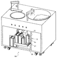
- FIG. 2 is a perspective view illustrating a schematic configuration of an analysis unit in the automatic analysis system according to the first embodiment.
- FIG. 3 is a diagram schematically illustrating an ISE analysis unit and a reagent drawer in the analysis unit according to the first embodiment.
- FIG. 5 is a diagram illustrating a state in which a reagent container is installed in front of an RFID reader in a reagent drawer using the analysis unit according to the first embodiment.
- FIG. 3 is a perspective view illustrating a configuration of a reagent drawer using the analysis unit according to the first embodiment.
- FIG. 5 is a diagram illustrating a state where the reagent drawer by the analysis unit according to the first embodiment is closed to a reagent installation location.
- FIG. 5 is a diagram illustrating a state in which the reagent drawer is pulled out to a reagent replacement position in the analysis unit according to the first embodiment.
- FIG. 5 is a diagram illustrating a procedure of replacing a reagent container by a reagent drawer in the analysis unit of the first embodiment.
- FIG. 9 is a diagram illustrating a procedure for replacing a reagent container by a reagent drawer in the analysis unit according to the first embodiment, and is a continuation of FIG. 8.
- FIG. 8 is a diagram illustrating a state where the reagent drawer by the analysis unit according to the first embodiment is closed to a reagent installation location.
- FIG. 5 is a diagram illustrating a state in which the reagent drawer is pulled out to a reagent replacement position in the analysis unit according to the first embodiment.
- FIG. 5 is
- FIG. 11 is a diagram illustrating a procedure for replacing a reagent container by a reagent drawer in the analysis unit of the automatic analysis system according to the second embodiment of the present invention.
- FIG. 11 is a diagram illustrating a procedure for replacing a reagent container by a reagent drawer in the analysis unit according to the second embodiment, and is a continuation of FIG. 10. It is a perspective view showing composition of a reagent drawer by an analysis unit of an automatic analysis system of Example 3 of the present invention.
- FIG. 13 is a diagram illustrating a reagent container installed in front of an RFID reader in a reagent drawer in the analysis unit of Example 3.
- FIG. 14 is a diagram illustrating a state in which a reagent drawer is pulled out to a reagent replacement position in the analysis unit of the automatic analysis system according to the fourth embodiment.
- an automatic analysis system to which the first embodiment of the present invention is applied and an automatic analyzer provided in the automatic analysis system will be described with reference to FIGS.
- the automatic analyzer a device including an analysis unit for measuring a biochemical item and an analysis unit for measuring an immune item will be described.
- FIG. 1 is a view schematically showing the overall configuration of the automatic analysis system of the present embodiment
- FIG. 2 is a perspective view showing the schematic configuration of an analysis unit in the automatic analysis system
- FIG. It is a figure showing the outline of a reagent drawer.
- the automatic analysis system 1000 in FIG. 1 is a device for performing qualitative / quantitative analysis of a biological sample such as blood or urine, and includes a transport unit 200, an analysis unit 100 for measuring a biochemical item, and an analysis for measuring an immune item. It mainly includes a unit 400 and a control unit 300.
- the transport unit 200 loads and recovers the sample rack 206 loaded with one or more sample containers containing biological samples such as blood and urine to be analyzed into the automatic analysis system 1000, and collects the sample in the analysis unit 100 or This is a unit for carrying to the analysis unit 400.
- the transport unit 200 includes a rack buffer 204, a rack supply tray 202, a rack storage tray 208, a transport line 207, and a transport controller 210.
- the sample rack 206 installed on the rack supply tray 202 is transported to the rack buffer 204 by the transport line 207.
- a sample presence / absence determination sensor (not shown) is provided in the middle of the transport line 207, and recognizes the presence / absence of a sample container on the sample rack 206. If it is determined that the sample container is present, the sample barcode reader (not shown) reads the sample barcode (not shown) attached to the sample container to recognize the sample identification information. In an actual system, a patient is specified by this identification information.
- the rack buffer 204 has a rotor structure that performs a circular motion, and has slots that radially hold a plurality of sample racks 206 on which a plurality of sample containers are placed on the outer circumference on a concentric circle. By rotating this slot by a motor, an arbitrary sample rack 206 is loaded and unloaded to a request destination. With such a structure, it is not always necessary to sequentially process the sample racks 206 placed first. That is, if there is a high priority, it can be processed first.
- a transport line 207 is connected to a point on the radial circumference of the rack buffer 204, and loading and unloading of the sample rack 206 are performed. Assuming that this one point is a position of 0 degree on the circumference, a sample dispensing line 3A for drawing the sample rack 206 into the analysis unit 100 described later from the position where the transport line 207 is connected to a position of 90 degrees on the circumference. Are connected, and loading and unloading of the sample rack 206 are performed. Further, a sample dispensing line 409 for drawing the sample rack 206 into an analysis unit 400 described later is connected to a position on the opposite side of the sample dispensing line 3A by 180 degrees, so that the sample rack 206 is loaded and unloaded.
- the sample rack 206 which has been dispensed by the analysis unit 100, can wait for the output of the measurement result in the rack buffer 204 and perform processing such as automatic retesting if necessary. When the processing is completed, the sheet is conveyed to the rack storage tray 208 via the transfer line 207.
- the transport control unit 210 is a part that controls an operation of transporting an appropriate sample rack 206 from the rack buffer 204 to the sample dispensing line 3A and an operation of returning the sample rack 206 from the sample dispensing line 3A to the rack buffer 204. is there.
- the control unit 300 includes a user interface such as an operation screen for displaying an operation screen for ordering a measurement item to be measured for a sample to be measured, an operation screen for confirming a measurement result, and an input device for inputting various instructions. It is a part that has a role of controlling information of units of the entire automatic analysis system 1000.
- the control unit 300 is connected to the analysis unit 100, the transport unit 200, and the analysis unit 400 by a wired or wireless network line.
- the analysis unit 100 is a unit that performs a measurement operation of a measurement item requested for a sample and outputs a measurement result, and is connected to the transport unit 200. As shown in FIGS. 1 and 2, the analysis unit 100 includes a reaction disk 1, a reagent disk 2, a sample suction position 3, a reagent probe 4, a sample dispensing line 3A, a sample probe 5, a cleaning mechanism 6, a light source and a spectroscopic device.
- Biochemical measurement section 30 composed of a photometer, stirring mechanism, installation location 7 of detergent containers 7a and 7b, ISE analysis section 8, reagent drawer 9, RFID reader 10, reagent button switches 11a, 11b, 11c, 11d, 11e. , A washing tank, and a controller 102.
- the ISE reagent that is, the internal standard solution, the diluent, and the reference electrode solution are installed in the reagent drawer 9.
- FIG. 2 is a diagram specifically illustrating the external shape of the analysis unit 100.
- a cleaning mechanism, a light source, a spectrophotometer, a stirring mechanism, a cleaning tank, a controller 102, a sample dispensing line 3A, and the like are not illustrated. Omitted.
- Reaction vessels 12 are arranged on the reaction disk 1 on the circumference.
- a sample dispensing line 3 ⁇ / b> A is provided near the reaction disk 1 for moving a sample rack 206 on which sample containers (for convenience of illustration) are placed.
- the sample suction position 3 is arranged on the trajectory of the sample dispensing line 3A.
- the sample dispensing line 3A is a line that transports the sample rack 206 transported from the rack buffer 204 to the dispensing position and returns the sample rack 206 after dispensing to the rack buffer 204.
- a sample probe 5 that can rotate and move up and down is provided between the reaction disk 1 and the sample suction position 3.
- the sample probe 5 is connected to a sample syringe (omitted for convenience of illustration).
- the sample probe 5 moves while drawing an arc around the rotation axis to dispense the sample from the sample container on the sample rack 206 to the reaction container 12.
- the reagent disk 2 is a storage in which a plurality of reagent bottles each containing a reagent therein can be placed on the circumference.
- the reagent disk 2 can be kept cool, and is covered by a cover provided with a suction port 2a. Installed inside are small reagents used for each analysis item.
- a reagent probe 4 that can rotate and move up and down is installed between the reaction disk 1 and the reagent disk 2.
- a reagent syringe (illustration omitted for convenience) is connected to the reagent probe 4.
- the reagent probe 4 moves while drawing an arc about the rotation axis, accesses the inside of the reagent disk 2 from the suction port 2a, and dispenses the reagent from the reagent container (not shown for convenience) to the reaction container 12.
- a cleaning mechanism 6 is arranged around the reaction disk 1.
- a washing pump (not shown) is connected to the washing mechanism 6 and dispenses the detergent from the detergent container 7a of the detergent installed at the installation location 7 of the detergent containers 7a and 7b to the reaction container 12.
- an alkaline detergent or an acidic detergent provided in a large-capacity reagent container is installed.
- the ISE analyzer 8 is arranged on the trajectory of the sample probe 5 around the reaction disk 1.
- the ISE analysis unit 8 is an analysis unit that measures the electrolyte concentration in a sample using an ion selective electrode, and is covered by a cover provided with a dispensing port 8a. As shown in FIG. 3, an ISE dilution tank 8b, an ISE electrode 8c, a comparative electrode 8d, and a flow path 8e are arranged below the cover.
- the sample probe 5 accesses the ISE diluting tank 8b from the sample container through the dispensing port 8a, and dispenses the sample.
- the ISE dilution tank 8b is provided with two nozzles 8f and 8g, and is connected to the ISE reagent syringe 8h.
- the ISE is supplied from the internal standard solution container 9a containing the internal standard solution and the diluent container 9b containing the diluent via the ISE reagent syringe 8h and the nozzles 8f and 8g. It is dispensed to the dilution tank 8b.
- the internal standard solution dispensed into the ISE diluting tank 8b and the sample diluted with the diluting solution are sent to the ISE electrode 8c through the flow path 8e.
- the internal standard solution, the diluting solution, and the reference electrode solution provided in the reagent drawer 9 are reagents provided in containers 9a, 9b, and 9c having large capacities, respectively.
- the reagents are different types of reagents from the reagents held by the reagent disks 2 and 405 disposed on the upper surface of the analysis unit 100 and the diluent used for diluting the sample.
- RFID tags 13 are affixed to detergent containers 7a and 7b installed at the installation location 7 and containers 9a, 9b and 9c storing ISE reagents installed in the reagent drawer 9, respectively.
- the RFID tag 13 includes information such as a reagent lot, an expiration date, and an opened or unopened.
- the detergent containers 7a, 7b and the containers 9a, 9b, 9c for the ISE reagent have the same shape as long as the capacities are the same, and the RFID tags 13 of the respective containers are all attached to the same position.
- a biochemical measurement unit 30 and a stirring mechanism are arranged around the reaction disk 1.
- the biochemical measurement unit 30 analyzes the biochemical components in the sample by measuring the absorbance, the amount of transmitted light, and the amount of scattered light of the reaction solution generated by mixing and reacting in the reaction vessel 12 on the reaction disk 1. And a light source and a spectrophotometer.
- a dedicated washing tank is provided on each of the operating ranges of the reagent probe 4, the sample probe 5, and the stirring mechanism.
- the sample containers mounted on the sample rack 206 include patient samples such as blood and urine, standard solutions for preparing a calibration curve, and samples such as controls for quality control.
- the controller 102 disposed in the analysis unit 100 includes a CPU, a memory, and the like, is connected to each mechanism in the analysis unit 100 described above, and controls the operation thereof.
- the analysis unit 400 is a unit that performs a measurement operation of a measurement item requested for a sample and outputs a measurement result, similarly to the analysis unit 100, and includes an incubator 404, a reagent disk 405, a reagent probe 406, a sample dispensing line 409, A sample probe 403, an immunoassay unit 407, and a controller 408 are provided.
- the incubator 404 is a disk for performing a reaction between a sample and a reagent at a constant temperature.
- the immunoassay unit 407 mixes and reacts the reagent and the sample in a reaction vessel (not shown) provided on the incubator 404, and performs an analysis for highly sensitive analysis of trace components in blood such as hormones in the sample. Department.
- the controller 408 is connected to each mechanism in the analysis unit 400 described above, and controls its operation.
- reagent disk 405, sample dispensing line 409, reagent probe 406, and sample probe 403 are substantially the same as those of the reagent disk 2, sample dispensing line 3A, reagent probe 4, and sample probe 5 of the analysis unit 100, respectively. Therefore, the details are omitted.
- a configuration corresponding to the reagent drawer 9 is provided on the analysis unit 400 side similarly to the analysis unit 100, but is omitted for convenience of illustration.
- a reaction auxiliary solution for assisting the reaction between the sample and the reagent in the analysis unit 400 and a diluent used for diluting the sample correspond to a solution provided in a container having a large capacity.
- the above is the general configuration of the automatic analysis system 1000, the analysis unit 100, and the analysis unit 400.
- the analysis process of the colorimetric item and the ISE item of the sample by the analysis unit 100 is generally executed according to the following procedure.
- the transport unit 200 sends out the sample racks 206 installed on the rack supply tray 202 of the automatic analysis system 1000 one by one onto the transport line 207 and carries them into the rack buffer 204.
- the sample rack 206 transported to the rack buffer 204 is transported to the sample dispensing line 3A of the analysis unit 100 or the sample dispensing line 409 of the analysis unit 400 according to the measurement item requested by the control unit 300.
- the sample probe 5 discharges the aspirated sample to the reaction container 12 on the reaction disk 1 and aspirates the reaction container 12 from the reagent disk 2 by the reagent probe 4.
- the added reagent is further added and stirred. Thereafter, the absorbance is measured by the biochemical measurement unit 30 and the measurement result is transmitted to the control unit 300.
- the reaction vessel 12 used for the analysis is washed with water, an alkaline detergent, and an acidic detergent dispensed from the washing mechanism 6 and used for the next analysis.
- the sample probe 5 dispenses the sucked sample into the ISE dilution tank 8b.
- the sample is diluted with a diluent at a certain magnification.
- the diluted sample is sucked into the channel 8e passing through the ISE electrode 8c.
- the ISE dilution tank 8b used for the analysis is washed with the internal standard solution and used for the next analysis.
- the reagent aspirated from the reagent disk 405 by the reagent probe 406 is discharged to a reaction container on the incubator 404, and a sample is further added to the reaction container by the sample probe 403. And stir. Thereafter, the measurement is performed by the immune measurement unit 407, and the measurement result is transmitted to the control unit 300.
- the control unit 300 calculates the concentration of the specific component in the sample from the transmitted measurement result by arithmetic processing, and performs processing such as displaying the result on the display device 310 or the like or storing the result in the storage unit.
- FIG. 4 is a view for explaining a state in which a reagent container is installed in front of the RFID reader in the reagent drawer
- FIG. 5 is a perspective view showing a configuration of the reagent drawer
- FIG. 7 is a diagram showing a state in which the reagent drawer is pulled out to the reagent replacement position.
- the reagent drawer 9 in which the containers 9a, 9b, 9c, 19 for holding the solution are installed can be pulled out to the front side of the side surface of the analysis unit 100 as shown in FIGS. , And has a configuration as shown in FIG.
- front side in this embodiment is the lower side on the paper surface of FIGS. 1 and 2.
- the reagent drawer 9 includes a reagent loading mechanism 14, a reagent loading section 15, a tube 16, and a lid 17, as shown in FIG.
- the reagent mounting mechanism 14 is configured to be movable between a reagent setting position 14a shown in FIG. 6 and a reagent replacement position 14b shown in FIG. That is, the reagent loading mechanism 14 moves in the front-back direction when viewed from the front of the system 1000.
- an RFID reader 10 is arranged in the side plate 10a constituting the front surface of the analysis unit 100, close to the reagent drawer 9.
- the arrangement position of the RFID reader 10 in the side plate 10a coincides with the RFID tag 13 attached to the reagent container 19 as shown in FIG. Position.
- the width 14c of the reagent mounting mechanism 14 is the same as the length of the reagent mounting section 15 on which the containers 9a, 9b, 9c are mounted, and the table 14f on which the newly installed reagent container 19 is temporarily placed. That is, the length is almost the same as that of four reagent containers.
- the reagent drawer 9 is provided with three reagent containers for measuring ISE items. Therefore, the width 14c of the reagent loading mechanism 14 is set to four reagent containers. 9 depends on the number of reagent containers.
- FIG. 4 shows a state where the reagent container 19 is installed in front of the RFID reader 10.
- the information of the RFID tag 13 attached to the reagent container 19 can be read by the RFID reader 10 only by placing a new one on the table 14f when replacing the containers 9a, 9b, 9c. Therefore, when newly disposing the containers 9a, 9b, 9c having a large capacity in the system 1000, it is possible to greatly reduce the labor required for the user to read the RFID tag 13.
- the front surface 14d of the reagent mounting mechanism 14 extends downward, and has a handle structure that allows a user to easily pull out the reagent mounting mechanism 14 to the front side of the system 1000 by hand.
- the reagent mounting section 15 is a section for installing the containers 9a, 9b, 9c on the reagent mounting mechanism 14.
- the reagent mounting section 15 has a structure in which a plurality of containers 9a, 9b, 9c can be installed in a horizontal line when viewed from the front of the system 1000.
- the front surface 15a of the reagent mounting portion 15 and the side surface 15b on the side where the containers 9a, 9b and 9c are installed extend upward, and the installed containers 9a, 9b and 9c are It does not fall.
- the reagent mounting section 15 is provided with a partition 15c which is partitioned for each of the containers 9a, 9b, 9c, so that the positions where the containers 9a, 9b, 9c are installed are clear.
- the partition 15c may or may not be provided.
- the installation space 15d of the reagent mounting portion 15 in which the container 9c containing the comparative electrode solution is installed has a small container space. This is because the container 9c containing the comparative electrode solution is smaller than the other containers 9a and 9b.
- the installation space 15d of the container 9c is disposed adjacent to the RFID reader 10, that is, the table 14f. Further, the depth 14e of the reagent mounting mechanism is slightly longer than the long sides of the containers 9a, 9b, 9c. As a result, the RFID reader 10 and the RFID tag 13 of the reference electrode solution are disposed to be shifted back and forth as viewed from the front of the system 1000. Therefore, it is possible to more reliably prevent the RFID reader 13 from erroneously recognizing the RFID tag 13 of the reagent container in use.
- the apparatus-side back surface 14g of the reagent mounting mechanism 14 has a structure higher than the height of the containers 9a, 9b, 9c, and 19, and is installed so that the tube 16 hangs from above.
- An attached lid 17 is connected to the tube 16.
- the attached lid 17 is not required.
- the tube 16 and the lid 17 can move between the reagent installation position 14a and the reagent replacement position 14b together with the reagent loading mechanism 14.
- the tube 16 and the upper portion of the lid 17 are opened because there are no components of the apparatus or the like.
- the lid 17 may have any shape as long as it can be connected to the mouth of the reagent container 19.
- a shape such as a screw shape or a rubber stopper that is inserted into the mouth of the reagent container, and a shape such as a cap that fits in the mouth of the reagent container.
- FIG. 5 shows a screw shape.
- One reagent button switch 11a, 11b, 11c, 11d, 11e corresponding to each container 9a, 9b, 9c and detergent container 7a, 7b on the reagent drawer 9 is provided above the reagent drawer 9 and in front of the analysis unit 100. Are arranged one by one.
- the reagent button switch 11 there is a button provided with an LED lamp (hereinafter, an LED button). Although a square LED button is shown in FIG. 2 and the like, the shape is not particularly specified.
- the reagent button switch 11a corresponds to the detergent container 7a
- the reagent button switch 11b corresponds to the detergent container 7b
- the reagent button switch 11c corresponds to the internal standard solution container 9a
- the reagent button switch 11d corresponds to the diluent container 9b
- the reagent button switch 11e corresponds to the comparative electrode liquid container 9c.
- the reagent drawer 9, the RFID reader 10, and the reagent button switch 11 are arranged on the front of the apparatus, but they may be arranged on the side or the back of the analysis unit 100. These locations are determined by the location of the reagent.
- the above is the configuration of the reagent drawer 9, the RFID reader 10, and the reagent button switch 11.
- FIGS. FIG. 8 and FIG. 9 are diagrams showing a procedure for replacing a reagent container by a reagent drawer.
- step S101 when the controller 102 recognizes that the containers 9a, 9b, 9c have been used (step S101), there are containers 9a, 9b, 9c that need to be replaced by the user via the display device 310. Is notified (step S102). At the same time, the reagent button switches 11 corresponding to the used containers 9a, 9b, 9c are blinked (step S102), and the user is visually shown which container 9a, 9b, 9c should be replaced.
- step S103 when recognizing that the user has pressed the blinking reagent button switch 11 for the first time (step S103), the controller 102 recognizes that the container replacement operation has been started.
- step S104 the user draws out the reagent drawer 9 (step S104), and a new reagent container 19 is set on the platform 14f in front of the RFID reader 10 (step S105).
- the controller 102 reads the information of the RFID tag 13 of the new reagent container 19 with the RFID reader 10 and obtains the information of the reagent in the reagent container 19 (Step S106A). Thereafter, it is determined whether the reagent information has been obtained (step S106B). If it is determined that the information has been obtained, the process proceeds to step S107. On the other hand, when it is determined that it cannot be obtained, the process proceeds to Step E106A.
- the controller 102 issues an alarm to notify the user (step E106A). Further, the controller 102 ends the reagent replacement operation step without updating the information of the reagent container (step E106B).
- the reagent container 19 has been moved by the user before the information of the RFID tag 13 is read, and the new reagent container 19 is set in the wrong direction by the user. , The RFID tag 13 of the reagent container 19 is not arranged at a position where the RFID tag 13 can be read.
- step S107 the controller 102 determines whether or not the new reagent container 19 can be used. If it is determined that the reagent container 19 from which the reagent information has been read can be used, the process proceeds to step S108.
- step E107A the process proceeds to step E107A, and the controller 102 issues an alarm to notify the user (step E107A). Further, the controller 102 ends the reagent replacement operation step without updating the information of the reagent container (step E107B).
- a reagent container already used (empty) is erroneously installed by the user, and a reagent container already used once by another device by the user is erroneously set. Installed cases. Further, there is a case where a reagent of a type different from the reagent that is erroneously replaced by the user is installed.
- the reagent button switch 11 stops blinking and remains lit (step S108). Thus, the user can visually confirm that the new reagent container 19 may be replaced with the used reagent container.
- the user lifts the new reagent container 19 from the platform 14f in front of the RFID reader and opens the lid of the reagent container 19.
- the lid 17 attached to the tube 16 is connected to the mouth of the reagent container 19 (step S110).
- step S111 the controller 102 recognizes that the reagent button switch 11 has been pressed (step S111), the controller 102 performs the second pressing of the reagent button switch 11 by the user, and the replacement operation of the reagent container 19 is completed. Recognize that.
- the controller 102 turns off the light of the reagent button switch 11 (step S112), and displays to the user so that the user can visually confirm that the replacement operation of the reagent container is completed.
- step S112A determines whether the reagent should be replaced continuously. If the subsequent reagent replacement is not performed, the process proceeds to step S114; otherwise, the process proceeds to step S113.
- step S111 If the second press of the reagent button switch 11 is not recognized within a certain period of time after reading the reagent information in step S111, the controller 102 issues an alarm to notify the user (step E111A). Further, the controller 102 ends the step of the reagent replacement operation without updating the information of the reagent container (step E111B).
- the user does not perform the replacement operation of the reagent container. For example, there is a case where the second press is forgotten.
- step S113 When replacing a plurality of reagent containers at the same time, it is recognized that the reagent button switch 11 of the reagent container to be replaced has been pressed while the reagent drawer 9 has been pulled out to the reagent replacement position 14b (step S113). Thereafter, the processes of steps S105 to S112 shown in FIG. 8 are repeated by the number of containers for which reagent replacement is to be performed.
- step S114 when the user recognizes that the reagent drawer 9 has been closed (step S114), the reagent replacement operation ends (step S115).
- the controller 102 recognizes that the replacement operation of the reagent container has been completed, the controller 102 enables measurement and other maintenance operations.
- step S114 the processing of step S114 is not essential.
- the controller 102 may complete the processing assuming that the reagent replacement operation has been completed by the determination of No in step S112A for turning off all the reagent button switches 11, and enable measurement and other maintenance operations.
- the above is the operation of replacing a used reagent container and a new reagent container using the reagent drawer 9, the RFID reader 10, and the reagent button switch 11.
- the reagent button switch 11 is used has been described.
- any other method may be used as long as the method specifies the reagent container to be replaced and indicates whether the reading of the RFID tag 13 is successful or not and the start and end of the procedure.
- the position of the reagent container to be replaced may be explained by voice, or the success or failure of reading the RFID tag 13 may be reported.
- the analysis unit 100 and the analysis unit 400 according to the first embodiment of the present invention are the reagents on the side surfaces of the analysis unit 100 and the analysis unit 400, where the containers 9a, 9b, 9c, and 19 for holding the solution such as the reagent are installed.
- a reagent mounting mechanism 14 having a mounting portion 15 is installed so as to be able to be pulled out, and the RFID reader 10 that reads the RFID tag 13 attached to the containers 9a, 9b, 9c, 19 mounts the reagent mounted on the extracted reagent mounting mechanism 14.
- the container 19 is placed on the part 15, it is arranged so that the position matches the position of the RFID tag 13.
- the present invention can be suitably applied to the analysis units 100 and 400 as shown in FIG. 1 which are small-sized automatic analyzers in which it is difficult to secure a sufficient working space at the installation location of the reagent container.
- the reagent mounting portion 15 has a structure (partition 15c) partitioned for each of the containers 9a, 9b, 9c, the user can stably install the containers 9a, 9b, 9c, and The burden can be further reduced.
- the reagent mounting mechanism 14 has a table 14f for installing one reagent container 19, in addition to the reagent mounting section 15, and the RFID reader 10 is arranged at the position of the table 14f.
- the RFID reader 10 can perform the drawing operation without interfering with the containers 9a, 9b, and 9c.
- the RFID tag 13 can be read by the RFID reader 10, and the registration of the reagent information to the system 1000 can be performed more easily. Therefore, the burden on the user can be further reduced.
- the width 14c of the reagent mounting mechanism 14 is the same as the width of all the containers 9a, 9b, 9c installed in the reagent mounting section 15 and the length of the table 14f. Can be minimized, and the size of the system 1000 can be reduced more easily.
- the containers 9a, 9b and 9c have two or more capacities, and of the containers 9a, 9b and 9c, a place where the container 9c having a small capacity is installed and a table 14f for installing one reagent container 19 are provided. Since the RFID reader 13 and the RFID tag 13 of the container 9c are arranged adjacent to each other when viewed from the front of the system 1000 by being disposed adjacent to each other, the RFID tag 13 of the reagent container being used is replaced with the RFID reader 10 Can prevent erroneous recognition.
- the apparatus further includes a reagent mounting portion 15 provided in the reagent mounting mechanism 14, a drawer rail 18, a tube 16 for obtaining a solution from the containers 9a, 9b, 9c, and a lid 17 of the containers 9a, 9b, 9c, 19.
- the tube 16 and the lid 17 have a structure in which the upper part is opened when the reagent mounting mechanism 14 is pulled out to the solution exchange position, so that the operation of connecting the tube 16 to the container at the time of container exchange is made easier. And the burden on the user can be further reduced.
- the reagent button switch 11 corresponding to each of the containers 9a, 9b, and 9c is provided above the reagent mounting portion 15 of the reagent mounting mechanism 14 on the side surfaces of the analysis unit 100 and the analysis unit 400. The user can easily know which container is to be replaced during the work around the reagent drawer 9, and the replacement work can be performed more smoothly.
- the reagent button switch 11 is a button provided with an LED lamp, it is possible to inform the user of the reagent replacement status by turning on the LED, thereby improving usability in reagent replacement.
- the front surface 14d of the reagent mounting portion 15 has a handle structure extending downward, so that the reagent mounting mechanism 14 can be further easily pulled out to the front side of the system 1000.
- the reagent loading mechanism 14 is pulled out on the front side of the side surfaces, the replacement operation of the reagent containers can be performed smoothly.
- the positions of the containers 9a, 9b, 9c to be replaced are notified by the reagent button switch 11
- the positions of the containers 9a, 9b, 9c to be replaced can be notified by the display device 310.
- FIGS. 10 and 11 are diagrams showing the procedure for replacing the reagent containers by the reagent drawer of the present embodiment.
- the automatic analysis system according to the second embodiment is different from the analysis unit 100 of the automatic analysis system 1000 according to the first embodiment in that the reagent mounting mechanism 14 is provided with an interlock function for preventing the drawing operation and the reading of the RFID reader 10.
- the movement of the reagent drawer 9 is controlled by an interlock function.
- the reagent drawer 9 can be pulled out only when the user starts reagent replacement, and locked when the reagent drawer 9 is pulled out to the reagent replacement position 14b. Thereafter, when the user recognizes that the reagent replacement operation has been completed, the lock is released, and the reagent drawer 9 can be closed in the apparatus 14a.
- the RFID reader 10 is set to a state in which the RFID tag 13 can be read (hereinafter, read mode) only while the reagent drawer 9 is locked.
- interlock functions can be realized by various methods such as a lock member and a limit switch for preventing the reagent mounting mechanism 14 from being pulled out, and the details thereof are not particularly limited.
- step S201 when the controller 102 recognizes that the containers 9a, 9b, and 9c have been used (step S201), the container 9a that needs to be replaced by the user via the display device 310 as in the first embodiment. , 9b and 9c are notified (step S202). At the same time, the reagent button switches 11 corresponding to the used containers 9a, 9b, 9c are blinked (step S202), and the user is visually indicated which container 9a, 9b, 9c should be replaced.
- step S203 when recognizing that the user has pressed the blinking reagent button switch 11 for the first time (step S203), the controller 102 recognizes that the container replacement operation has been started. At the same time, the interlock of the reagent drawer 9 is released (step S204), and the reagent drawer 9 can be pulled out.
- This control may be a form in which the reagent button switch 11 is locked so as not to be actually pressed, or a form in which the apparatus does not recognize the start of the reagent replacement operation even if the reagent button switch 11 is pressed.
- step S205 when it is recognized that the user has pulled out the reagent drawer 9 (step S205), the reagent drawer 9 is locked at the reagent replacement position 14b, and the controller 102 puts the RFID reader 10 into the reading mode (step S206). ).
- Step S207 The user installs a new reagent container 19 on the platform 14f in front of the RFID reader 10 (Step S207).
- the controller 102 reads the information of the RFID tag 13 of the new reagent container 19 with the RFID reader 10 and obtains information of the reagent in the reagent container (step S208A). Thereafter, it is determined whether the reagent information has been obtained (step S208B). If it is determined that the information has been obtained, the process proceeds to step S209. On the other hand, when it is determined that it cannot be obtained, the process proceeds to Step E208.
- step E208 the controller 102 issues an alarm to notify the user (step E208). Thereafter, the process proceeds to step E219, and the user repeatedly installs the reagent container 19 on the table 14f in front of the RFID reader 10 and reads the RFID tag until the reagent information is available (steps S207, S208A, S208B). .
- step S209 the controller 102 determines whether or not the new reagent container 19 can be used. If it is determined that the reagent container 19 from which the reagent information has been read can be used, the process proceeds to step S210.
- step E209 the controller 102 issues an alarm to notify the user (step E209). Thereafter, the process proceeds to step E219 as in step E208, and a new reagent container 19 is placed on the platform 14f in front of the RFID reader 10 (steps S207 to S209).
- the reagent button switch 11 stops blinking and remains lit (step S210). Thus, the user can visually confirm that the new reagent container 19 may be replaced with the used reagent container.
- the user lifts the new reagent container 19 from the front of the table 14f of the RFID reader 10 and opens the lid of the reagent container 19.
- the lid 17 attached to the tube 16 is connected to the mouth of the reagent container 19 (step S212).
- step S223 the controller 102 recognizes that the reagent button switch 11 has been pressed (step S213), the controller 102 performs the second pressing of the reagent button switch 11 by the user, and the replacement operation of the reagent container 19 is completed. Recognize that.
- the controller 102 unlocks the reagent drawer 9 and unlocks the reading mode of the RFID reader 10 (step S214).
- the lighting of the reagent button switch 11 is turned off (step S215), and a message is displayed so that the user can visually confirm that the replacement of the reagent container is completed.
- step S215A determines whether the reagent should be replaced continuously. If the subsequent reagent replacement is not to be performed, the process proceeds to step S217; otherwise, the process proceeds to step S216.
- step S213 If the second press of the reagent button switch 11 cannot be recognized within a certain period of time after reading the reagent information in step S213, the controller 102 issues an alarm to notify the user (step E213A). When recognizing that the user has pressed the reagent button switch 11, the controller 102 stops the alarm (step E213B). Thereafter, the process proceeds to step S214.
- step S216 the reagent button switch 11 of the reagent container to be replaced is pressed down while the reagent drawer 9 is pulled out to the reagent replacement position 14b (step S216), and the process proceeds to step S206 in FIG. Then, the reagent drawer 9 is locked again, and the RFID reader 10 is again set to the reading mode (step S206). Thereafter, steps S206 to S215 are repeated by the number of times of reagent replacement.
- step S21-7 when the user recognizes that the reagent drawer 9 has been closed (step S217), the reagent drawer 9 cannot be pulled out due to the interlock (S218), and the reagent replacement operation is completed (step S219).
- the controller 102 recognizes that the replacement operation of the reagent container has been completed, and enables measurement and other maintenance operations.
- steps E208 and E209 if the system 1000 issues an alarm, the user can end the reagent registration work step.
- step E219 when the controller 102 recognizes that the reagent button switch 11 has been long-pressed (for example, 2 seconds or more) (step E219), the controller 102 recognizes that the user has instructed the interruption of the reagent registration work.
- step E220 This releases the lock of the reagent drawer 9 and the reading mode of the RFID reader 10 (step E220). Thereafter, the process proceeds to step S217 in FIG. 11, and when the reagent drawer 9 is closed (step S217), the reagent drawer 9 is prevented from being drawn out again by the interlock (step S218). As a result, the controller 102 ends the step of the reagent replacement operation without updating the information of the reagent container (step S219).
- the method of stopping the reagent registration operation may take another form as long as it can be distinguished from the normal depression of the reagent button switch 11. For example, the number of seconds for determining the long press (step E219) may be different, or the reagent button switch 11 may be pressed twice.
- the automatic analyzer and the automatic analysis system according to the second embodiment of the present invention can provide substantially the same effects as those of the automatic analysis system 1000 according to the first embodiment.
- the reagent loading mechanism 14 has an interlock function for preventing the drawing operation and the reading of the RFID reader 10, there is no danger that the reagent drawer 9 is drawn out carelessly outside the reagent replacement operation. As a result, it is possible to reduce the risk that the system 1000 may be damaged by hitting the reagent drawer 9 drawn out due to an unexpected situation such as an earthquake, or the user may be injured.
- the possibility that the reagent drawer 9 is accidentally closed without replacing the reagent container even if the user reads the RFID tag 13 of the new reagent container is further reduced. Can be.
- FIG. 12 is a perspective view showing a configuration of a reagent drawer by the analysis unit of the automatic analysis system of the present embodiment
- FIG. 13 is a view showing a reagent container installed in front of an RFID reader.
- the spring 20 is disposed below the platform 14 f of the reagent mounting mechanism 14 in front of the RFID reader.
- a single RFID reader 10 can easily read the RFID tags 13 attached to the containers 9a, 9b, and 9c having different shapes, particularly, different heights.
- the positional relationship between the RFID reader 10 and the RFID tag 13 is fixed, and the reading cannot be performed by merely placing the reagent container on which the RFID tag 13 is disposed at a position lower than the RFID reader 10 on the table 14f.
- a reagent container having a low height, for example, the container 9c for accommodating the comparative electrode solution in the first embodiment needs to be manually lifted by the user and fixed at the position of the RFID reader 10.
- the position of the table 14f in front of the RFID reader changes due to the degree of contraction of the spring 20 depending on the weight of the reagent container 19 placed thereon. For example, if the light container 9c is placed, the spring 20 does not shrink and the base 14f is fixed at a high position. Conversely, if a heavy reagent container is placed, the spring 20 contracts and the table 14f is fixed at a low position.
- the RFID reader 10 can read a reagent container having a low height only by placing it on the table 14f. If the bottom area of the reagent container is the same, the capacity of the reagent container having a small height is small. That is, since the reagent container is light, the spring 20 does not shrink when placed on the table 14f, and is fixed at a high position 21. Since the position of the RFID tag 13 attached to the container 9c is also high, the RFID reader 10 can read the information simply by placing the container 9c on the table 14f.
- the RFID reader 10 does not read the RFID tag 13 of a used (empty) reagent container that has been erroneously installed by a user or a reagent container that has already been used once by another device. It can be.
- a reagent container other than a new reagent container is lighter than a new reagent container because the reagent volume is reduced. Therefore, when placed on the table 14f, the table 14f is fixed at a higher position than when a new reagent container is placed on the table. That is, since the position of the RFID tag 13 attached to the reagent container also becomes higher, the RFID reader 10 cannot read the RFID tag 13 and an error occurs. As a result, the user can more easily recognize that the reagent container is not a new reagent container, and the burden can be further reduced.
- the table 14f is provided with a spring 20, and the shrinkage of the spring 20 changes according to the weight of the containers 9a, 9b, 9c, and 19, and the RFID tags 13 attached to the containers 9a, 9b, 9c, and 19 are automatically RFID-tagged. Since the position matches with that of the reader 10 and reading becomes possible, the burden on the user when introducing a new container 19 into the system 1000 can be further reduced.
- the interlock function described in the second embodiment can also be applied.
- FIG. 14 is a diagram illustrating a state in which the reagent drawer is pulled out to the reagent replacement position in the analysis unit of the automatic analysis system according to the present embodiment.
- the reagent drawer 9B of the fourth embodiment is configured such that the reagent mounting portions 15e, 15f, 15g and the table 14f of the reagent mounting mechanism 14 can be individually pulled out to the front of the analysis unit 100 by the rails 18A. Have been. As a result, only the reagent mounting portion corresponding to the container 9a, 9b, 9c to be replaced among the containers 9a, 9b, 9c can be pulled out to the front surface, and the container to be replaced can be more easily specified. Can be
- the platform 14f may be configured to be pulled out to the front side in conjunction with any one of the reagent mounting portions 15e, 15f, and 15g pulled out to the front side, or may be configured to be independently pulled out to the front side. Not limited.
- the automatic analyzer and the automatic analysis system according to the fourth embodiment of the present invention can provide substantially the same effects as those of the automatic analyzer and the automatic analysis system according to the first embodiment.
- the interlock function can be mounted as in the second embodiment, or the spring 20 can be applied to the base 14f as in the third embodiment.
- a part of the configuration of one embodiment can be replaced with the configuration of another embodiment, and the configuration of another embodiment can be added to the configuration of one embodiment. Further, for a part of the configuration of each embodiment, it is also possible to add, delete, or replace another configuration.
- diluent container (solution container) 9c Reference electrode liquid container (solution container) 10 RFID reader 10a Side plates 11, 11a, 11b, 11c, 11d, 11e Reagent button switch (solution button switch) 12 reaction container 13 RFID tag 14 reagent loading mechanism (solution loading mechanism) 14a Reagent installation position 14b Reagent replacement position 14c Width 14d Front surface 14e Depth 14f Stand in front of RFID reader (temporary installation location) 14g ... device side back 15, 15e, 15f, 15g ... reagent mounting part (solution mounting part) 15a Front surface 15b Side surface 15c Partition 15d Installation space 16 Tube 17 Lid 18, 18A Rail 19 Reagent container 20 Spring 21 Position of table 30 when reference electrode solution is placed in front of RFID reader ... Biochemical measuring units 100 and 400 ... Analysis unit (automatic analyzer) 102: controller 200: transport unit (transport device) 300 control unit 310 display device 407 immunoassay unit 408 controller 1000 automatic analysis system
Abstract
A reagent loading mechanism (14) having a reagent loading part (15) as the installation location of containers (9a, 9b, 9c, 19) for retaining a reagent or other solution is installed on a side surface of an analysis unit (100) so as to be able to be drawn out, and an RFID reader (10) for reading RFID tags (13) attached to the containers (9a, 9b, 9c, 19) is disposed so that the position thereof coincides with the RFID tags (13) when the containers (9a, 9b, 9c, 19) are placed in the reagent loading part (15) of the drawn-out reagent loading mechanism (14). User burden that accompanies replacement of large-capacity reagents can thereby be alleviated while also saving space.
Description
本発明は、試薬容器から試薬を吸引して検体を分析する自動分析装置および自動分析システムに関する。
The present invention relates to an automatic analyzer and an automatic analysis system for analyzing a sample by aspirating a reagent from a reagent container.
試薬容器の設置作業を簡素化することが可能な試薬容器の一例として、特許文献1には、染色液を収容し、血球計数装置あるいは尿中有形成分分析装置である分析装置の側面から、分析装置の内部に向かって挿入されることにより分析装置にセットされる試薬容器であって、分析装置に挿入される方向における先端近傍に設けられ、分析装置の吸引管が上方から進入可能な吸引管進入部と、試薬容器の外部底面に、試薬容器の外部上面に対して傾斜する傾斜面と、を備え、試薬容器の色は黒又は茶色であり、試薬が外部からの光により劣化することを防ぐことが記載されている。
As an example of a reagent container capable of simplifying the installation operation of the reagent container, Patent Document 1 contains a staining solution, and from the side of an analyzer that is a blood cell counter or a urine particulate analyzer, A reagent container set in the analyzer by being inserted toward the inside of the analyzer, provided near the tip in the direction of insertion into the analyzer, and having a suction pipe through which the suction pipe of the analyzer can enter from above. It has a pipe entry part and an inclined surface that is inclined on the outer bottom surface of the reagent container on the outer bottom surface of the reagent container. The color of the reagent container is black or brown, and the reagent is deteriorated by external light. It is stated to prevent.
血液や尿などの患者から採取される検体を分析する装置として、生化学分析装置や免疫分析装置などの自動分析装置(以下、装置)が知られている。これらの装置で使用する試薬には、容量の小さい容器で提供される試薬と大きい容器で提供される試薬の2種類がある。
2. Description of the Related Art As an apparatus for analyzing a sample collected from a patient such as blood or urine, an automatic analyzer (hereinafter, referred to as an apparatus) such as a biochemical analyzer or an immune analyzer is known. There are two types of reagents used in these devices: reagents provided in small containers and reagents provided in large containers.
容量の小さい試薬の一例としては、生化学分析装置で検体分析に使用される試薬が知られている。これらの試薬は分析項目ごとに提供されており、試薬ディスクに設置される。試薬容器にはおおよそ100mLの試薬が充填されており、分析によって試薬容器から試薬プローブで吸引され、反応容器に分注される。その後、患者検体などの試料と混合されて分析される。
試 薬 As an example of a small-volume reagent, a reagent used for sample analysis in a biochemical analyzer is known. These reagents are provided for each analysis item and are set on a reagent disk. The reagent container is filled with approximately 100 mL of the reagent, and is sucked by the reagent probe from the reagent container by analysis and dispensed into the reaction container. Then, it is mixed with a sample such as a patient sample and analyzed.
一方、容量の大きい試薬の例としては、生化学分析装置で使用されているアルカリ性の洗剤や酸性の洗剤、電解質項目(以下、ISE(Ion Selective Electrode)項目と記載)の測定に使用される内部標準液や希釈液、比較電極液などがある。これらの試薬は複数の分析項目で共通に使用される試薬であり、試薬容量は約500mL~2000mLである。
On the other hand, examples of a reagent having a large capacity include an alkaline detergent or an acidic detergent used in a biochemical analyzer, and an internal agent used for measuring an electrolyte item (hereinafter, referred to as an ISE (Ion Selective Electrode) item). There are standard solutions, diluents, and reference electrode solutions. These reagents are commonly used in a plurality of analysis items, and have a reagent volume of about 500 mL to 2000 mL.
これら容量の大きい試薬は、試薬プローブでの分注は行われない。試薬容器に接続されたチューブや金属製の筒などによって、試薬ボトルから分析装置の所定の箇所と流体的に接続されて用いられるのが一般的である。
These large reagents are not dispensed with reagent probes. In general, a tube or a metal tube connected to the reagent container is used by being fluidly connected from the reagent bottle to a predetermined portion of the analyzer.
そのため、これら容量の大きな容器で提供される試薬は、試薬ディスクへは設置せずに、予め決められた設置場所へユーザによってセットされる。
Therefore, the reagent provided in these large-volume containers is set by the user at a predetermined installation location without being installed on the reagent disk.
このような容量の大きな試薬を装置へセットするには、試薬容器の蓋をユーザ自身がはずし、装置に接続されたチューブを試薬容器の内部へ挿入する、という作業が発生する。さらに、空気中の雑菌の混入や試薬の蒸発を防ぎたい場合、チューブに付属の蓋を試薬容器に取り付けるという作業が追加される。
(4) In order to set such a large-capacity reagent in the apparatus, the user has to remove the lid of the reagent container and insert a tube connected to the apparatus into the reagent container. Further, when it is desired to prevent contamination of bacteria and evaporation of the reagent in the air, an operation of attaching a lid attached to the tube to the reagent container is added.
以上が、容量の大きい試薬の試薬交換作業の現状である。
The above is the current situation of the replacement work of large reagents.
近年、検査結果のトレーサビリティや測定結果の信頼性向上への要求が高まっている。このことから、ロット番号や使用開始日、有効期限などの試薬の情報を装置で管理する機能が求められている。
In recent years, there has been an increasing demand for improved traceability of test results and reliability of measurement results. For this reason, there is a demand for a function of managing reagent information such as a lot number, a use start date, and an expiration date by the apparatus.
試薬の情報を管理する方法の一例としてRFIDタグがある。各試薬の試薬情報は、試薬容器に付けられたRFIDタグを装置に備えられたRFIDリーダで読み取ることで分析装置に認識させている。
RFAn example of a method for managing reagent information is an RFID tag. Reagent information of each reagent is recognized by the analyzer by reading an RFID tag attached to the reagent container with an RFID reader provided in the device.
RFIDタグによる試薬情報管理と試薬容器の交換作業の簡略化について、上述した特許文献1が知られている。特許文献1では、試薬容器を分析装置の試薬設置場所に差し込むことによって、ユーザによって装置のチューブにアクセスせずに試薬交換を可能としている。さらに、各試薬設置場所に備えられているRFIDリーダで試薬容器に付けられたRFIDタグから試薬情報を読み取っている。
The above-mentioned Patent Document 1 is known about simplification of reagent information management and replacement of a reagent container using an RFID tag. In Patent Literature 1, a reagent container can be inserted into a reagent setting place of an analyzer so that a user can exchange a reagent without accessing a tube of the apparatus. Further, the reagent information is read from the RFID tag attached to the reagent container by the RFID reader provided at each reagent installation location.
しかし、特許文献1の手法では各試薬設置場所にRFIDリーダを備える必要がある。つまり複数のRFIDリーダを備えるだけのスペースを装置内に確保する必要があり、小型の自動分析装置には応用できない、という問題がある。
However, in the method of Patent Document 1, it is necessary to provide an RFID reader at each reagent installation location. In other words, it is necessary to secure a space in the apparatus for providing a plurality of RFID readers, and there is a problem that the apparatus cannot be applied to a small automatic analyzer.
更に、一般的な自動分析装置では、以下のような2つの視点から解決すべき課題が存在する。
Furthermore, in a general automatic analyzer, there are problems to be solved from the following two viewpoints.
1つ目の視点は、チューブの差込作業についてである。前述したように、容量の大きい(約500mL~2000mL)試薬の交換作業は、試薬容器の蓋をユーザ自身がはずし、装置に接続されたチューブを試薬容器の内部へ挿入する、という作業が発生する。さらに、チューブに付属した蓋を再び試薬容器に取り付ける作業が発生する場合もある。そのため、チューブの付近に作業可能な十分なスペースを確保する必要が生じる。
The first viewpoint is about the tube insertion work. As described above, when replacing a reagent having a large capacity (about 500 mL to 2000 mL), the user removes the lid of the reagent container and inserts a tube connected to the device into the reagent container. . Further, there is a case where an operation of attaching the lid attached to the tube to the reagent container again occurs. For this reason, it is necessary to secure a sufficient workable space near the tube.
このチューブは、一般的に、装置の前面から試薬容器ひとつ分奥に入った箇所に、装置前面に向かって設置されていることが多い。そのため、ユーザは装置の奥へ手を入れて試薬容器の交換作業を行う必要がある。
チ ュ ー ブ Generally, this tube is often installed toward the front of the apparatus at a position that is one reagent container deep from the front of the apparatus. Therefore, it is necessary for the user to replace the reagent container by putting his / her hand in the back of the apparatus.
しかし、ユーザは狭いスペースでチューブに指が触れないように注意しながら試薬の交換作業を行わなければならない。特に、小型の自動分析装置では試薬容器の設置場所に十分な作業スペースを確保できないため、試薬の交換作業はユーザにとって大きな負担となる。
However, the user must replace the reagent while taking care not to touch the tube in a narrow space. In particular, with a small-sized automatic analyzer, a sufficient work space cannot be secured at the place where the reagent container is installed, and thus the replacement of the reagent places a heavy burden on the user.
2つ目の視点は、RFIDタグ読取作業についてである。先に述べたように、特許文献1の形態では各試薬設置場所にRFIDリーダが必要となる。ところが、小型の自動分析装置ではスペースを十分に確保できないため、各試薬設置場所にRFIDリーダを備えることができない。代わりに、1つのRFIDリーダを複数の試薬容器で使用する形態が考えられる。
The second viewpoint is about RFID tag reading work. As described above, the configuration of Patent Document 1 requires an RFID reader at each reagent installation location. However, since a small automatic analyzer cannot provide sufficient space, it is not possible to provide an RFID reader at each reagent installation location. Instead, one RFID reader may be used in a plurality of reagent containers.
この場合、ユーザによる試薬容器の交換作業は次のようになる。まず交換したい試薬容器をユーザによってRFIDリーダの前にて手で支えて固定し、試薬容器のRFIDタグを読み込ませる。その後RFIDタグの読取を終えた試薬容器を所定の試薬設置場所に移動させ、空の試薬容器と交換する。
In this case, the user replaces the reagent container as follows. First, the reagent container to be replaced is supported and fixed by the user with the hand in front of the RFID reader, and the RFID tag of the reagent container is read. Thereafter, the reagent container from which the reading of the RFID tag has been completed is moved to a predetermined reagent installation location, and is replaced with an empty reagent container.
上述の交換作業では、ユーザは最大約2kgの重い試薬容器をRFIDリーダの前でガイドなしで固定する必要がある、という負担がかかる。また、固定位置がずれたり読取時間より短いタイミングで試薬容器をRFIDリーダから離したりすると、RFIDタグ読取に失敗して、再度最初から試薬交換作業を行わなくてはならない。更に、その後の試薬設置場所までの移動も、試薬容器が重いのでユーザに負担がかかる、という課題がある。
(4) The above-described replacement requires a burden that the user needs to fix a heavy reagent container of up to about 2 kg without a guide in front of the RFID reader. Further, if the fixed position is shifted or the reagent container is separated from the RFID reader at a timing shorter than the reading time, the RFID tag reading will fail, and the reagent replacement operation must be performed again from the beginning. Further, there is also a problem that the subsequent movement to the reagent setting place places a burden on the user because the reagent container is heavy.
本発明は、省スペース化を実現しながら、容量の大きい試薬の交換作業に伴うユーザの負担を軽減することができる自動分析装置および自動分析システムを提供することを目的とする。
The object of the present invention is to provide an automatic analyzer and an automatic analysis system which can reduce the burden on the user when replacing a large-volume reagent while realizing space saving.
本発明は、上記課題を解決する手段を複数含んでいるが、その一例を挙げるならば、試料と溶液とを混合させた液体を測定する自動分析装置であって、前記自動分析装置の側面に、前記溶液を保持する容器の設置場所となる溶液搭載部を有する溶液搭載機構が引き出し可能に設置されており、前記容器に取り付けられたRFIDタグを読み取るRFIDリーダが、引き出された前記溶液搭載機構の前記溶液搭載部に前記容器を置いた際に、前記RFIDタグと位置が一致するように配置されていることを特徴とする。
The present invention includes a plurality of means for solving the above-mentioned problems, an example of which is an automatic analyzer for measuring a liquid obtained by mixing a sample and a solution, and a side surface of the automatic analyzer. A solution mounting mechanism having a solution mounting portion serving as an installation location of the container holding the solution is provided so as to be able to be pulled out, and the RFID reader for reading an RFID tag attached to the container is provided with the solution mounting mechanism pulled out. When the container is placed on the solution mounting section, the RFID tag is arranged so that the position matches the position of the RFID tag.
本発明によれば、省スペース化を実現しながら、容量の大きい試薬の交換作業に伴うユーザの負担を軽減できる。上記した以外の課題、構成および効果は、以下の実施例の説明により明らかにされる。
According to the present invention, it is possible to reduce the burden on the user when replacing a large-volume reagent while realizing space saving. Problems, configurations, and effects other than those described above will be apparent from the following description of the embodiments.
以下に本発明の自動分析装置および自動分析システムの実施例を、図面を用いて説明する。
Hereinafter, embodiments of the automatic analyzer and the automatic analysis system according to the present invention will be described with reference to the drawings.
<実施例1>
本発明の自動分析装置および自動分析システムの実施例1について図1乃至図9を用いて説明する。 <Example 1>
First Embodiment An automatic analyzer and an automatic analysis system according to a first embodiment of the present invention will be described with reference to FIGS.
本発明の自動分析装置および自動分析システムの実施例1について図1乃至図9を用いて説明する。 <Example 1>
First Embodiment An automatic analyzer and an automatic analysis system according to a first embodiment of the present invention will be described with reference to FIGS.
まず、図1乃至図3を用いて、本発明の実施例1が適用される自動分析システムとそれが備える自動分析装置について説明する。なお、自動分析装置の一例として、生化学項目を測定する分析ユニットと免疫項目を測定する分析ユニットとを備える装置を例に説明する。
First, an automatic analysis system to which the first embodiment of the present invention is applied and an automatic analyzer provided in the automatic analysis system will be described with reference to FIGS. As an example of the automatic analyzer, a device including an analysis unit for measuring a biochemical item and an analysis unit for measuring an immune item will be described.
図1は本実施例の自動分析システムの全体構成の概略を示す図、図2は自動分析システムのうち、分析ユニットの概略構成を示す斜視図、図3は分析ユニットのうち、ISE分析部および試薬ドロワの概略を示す図である。
FIG. 1 is a view schematically showing the overall configuration of the automatic analysis system of the present embodiment, FIG. 2 is a perspective view showing the schematic configuration of an analysis unit in the automatic analysis system, and FIG. It is a figure showing the outline of a reagent drawer.
図1における自動分析システム1000は、血液や尿などの生体試料の定性・定量分析を行うための装置であり、搬送ユニット200と、生化学項目測定用の分析ユニット100、免疫項目測定用の分析ユニット400と、制御部300とから主に構成されている。
The automatic analysis system 1000 in FIG. 1 is a device for performing qualitative / quantitative analysis of a biological sample such as blood or urine, and includes a transport unit 200, an analysis unit 100 for measuring a biochemical item, and an analysis for measuring an immune item. It mainly includes a unit 400 and a control unit 300.
搬送ユニット200は、分析対象である血液や尿などの生体試料を収容した一つ以上の試料容器が搭載された検体ラック206を自動分析システム1000内へ投入、回収を行うとともに、分析ユニット100あるいは分析ユニット400への搬送を行うためのユニットである。
The transport unit 200 loads and recovers the sample rack 206 loaded with one or more sample containers containing biological samples such as blood and urine to be analyzed into the automatic analysis system 1000, and collects the sample in the analysis unit 100 or This is a unit for carrying to the analysis unit 400.
搬送ユニット200は、ラックバッファ204、ラック供給トレイ202、ラック収納トレイ208、搬送ライン207、搬送制御部210を備えている。
The transport unit 200 includes a rack buffer 204, a rack supply tray 202, a rack storage tray 208, a transport line 207, and a transport controller 210.
搬送ユニット200では、ラック供給トレイ202に設置された検体ラック206は、搬送ライン207によってラックバッファ204に搬送される。搬送ライン207の途中に、試料有無判定用センサ(図示省略)があり、検体ラック206上の試料容器の有無が認識される。ここで試料容器が存在すると判断されれば、試料バーコードリーダー(図示省略)によって試料容器上に貼り付けられた試料バーコード(図示省略)を読み取り、試料の識別情報を認識する。実際のシステムでは、この識別情報によって、患者を特定する。
In the transport unit 200, the sample rack 206 installed on the rack supply tray 202 is transported to the rack buffer 204 by the transport line 207. A sample presence / absence determination sensor (not shown) is provided in the middle of the transport line 207, and recognizes the presence / absence of a sample container on the sample rack 206. If it is determined that the sample container is present, the sample barcode reader (not shown) reads the sample barcode (not shown) attached to the sample container to recognize the sample identification information. In an actual system, a patient is specified by this identification information.
ラックバッファ204は、円運動を行うローター構造であり、外円周上に試料容器を複数載置する検体ラック206を同心円上に放射的に複数保持するスロットを有している。このスロットをモータによって回転させることで、任意の検体ラック206を要求先に搬入・搬出するように構成されている。このような構造により、必ずしも先に入れられた検体ラック206を順に処理しなくてもよくなっている。つまり、優先度の高いものがあれば、それを先に処理することが出来るようになっている。
The rack buffer 204 has a rotor structure that performs a circular motion, and has slots that radially hold a plurality of sample racks 206 on which a plurality of sample containers are placed on the outer circumference on a concentric circle. By rotating this slot by a motor, an arbitrary sample rack 206 is loaded and unloaded to a request destination. With such a structure, it is not always necessary to sequentially process the sample racks 206 placed first. That is, if there is a high priority, it can be processed first.
このラックバッファ204の放射状の円周上のある一点に対し、搬送ライン207が接続されており、検体ラック206の搬入,搬出が行われる。この一点を円周上の0度の位置とすると、搬送ライン207が接続された位置から円周上の90度の位置に後述する分析ユニット100へ検体ラック206を引き込むための試料分注ライン3Aが接続されており、検体ラック206の搬入,搬出が行われる。また、試料分注ライン3Aの180度反対側の位置に後述する分析ユニット400へ検体ラック206を引き込むための試料分注ライン409が接続されており、検体ラック206の搬入,搬出が行われる。
(4) A transport line 207 is connected to a point on the radial circumference of the rack buffer 204, and loading and unloading of the sample rack 206 are performed. Assuming that this one point is a position of 0 degree on the circumference, a sample dispensing line 3A for drawing the sample rack 206 into the analysis unit 100 described later from the position where the transport line 207 is connected to a position of 90 degrees on the circumference. Are connected, and loading and unloading of the sample rack 206 are performed. Further, a sample dispensing line 409 for drawing the sample rack 206 into an analysis unit 400 described later is connected to a position on the opposite side of the sample dispensing line 3A by 180 degrees, so that the sample rack 206 is loaded and unloaded.
分析ユニット100で分注の終えた検体ラック206は、このラックバッファ204内で測定結果の出力を待機し、必要に応じて自動再検等の処理をすることもできる。また、処理の終えた場合は、搬送ライン207を介してラック収納トレイ208に搬送される。
(4) The sample rack 206, which has been dispensed by the analysis unit 100, can wait for the output of the measurement result in the rack buffer 204 and perform processing such as automatic retesting if necessary. When the processing is completed, the sheet is conveyed to the rack storage tray 208 via the transfer line 207.
搬送制御部210は、ラックバッファ204から試料分注ライン3Aへ適切な検体ラック206を搬送する動作や、試料分注ライン3Aからラックバッファ204へ検体ラック206を戻す動作の制御を実行する部分である。
The transport control unit 210 is a part that controls an operation of transporting an appropriate sample rack 206 from the rack buffer 204 to the sample dispensing line 3A and an operation of returning the sample rack 206 from the sample dispensing line 3A to the rack buffer 204. is there.
制御部300は、測定する試料に対して測定する測定項目をオーダーする操作画面、および測定した結果を確認する操作画面を表示する表示装置310や、各種指示を入力する入力装置等のユーザインターフェースを有しており、自動分析システム1000全体のユニットの情報を統括する役割を担う部分である。
The control unit 300 includes a user interface such as an operation screen for displaying an operation screen for ordering a measurement item to be measured for a sample to be measured, an operation screen for confirming a measurement result, and an input device for inputting various instructions. It is a part that has a role of controlling information of units of the entire automatic analysis system 1000.
制御部300は、分析ユニット100や搬送ユニット200、分析ユニット400に対して有線或いは無線のネットワーク回線によって接続されている。
The control unit 300 is connected to the analysis unit 100, the transport unit 200, and the analysis unit 400 by a wired or wireless network line.
分析ユニット100は、試料に依頼された測定項目の測定動作を行い、測定結果を出力するユニットであり、搬送ユニット200に接続されている。この分析ユニット100は、図1や図2に示すように、反応ディスク1、試薬ディスク2、試料吸引位置3、試薬プローブ4、試料分注ライン3A、サンプルプローブ5、洗浄機構6、光源や分光光度計から構成される生化学測定部30、撹拌機構、洗剤容器7a,7bの設置場所7、ISE分析部8、試薬ドロワ9、RFIDリーダ10、試薬ボタンスイッチ11a,11b,11c,11d,11e、洗浄槽、コントローラ102を備えている。
The analysis unit 100 is a unit that performs a measurement operation of a measurement item requested for a sample and outputs a measurement result, and is connected to the transport unit 200. As shown in FIGS. 1 and 2, the analysis unit 100 includes a reaction disk 1, a reagent disk 2, a sample suction position 3, a reagent probe 4, a sample dispensing line 3A, a sample probe 5, a cleaning mechanism 6, a light source and a spectroscopic device. Biochemical measurement section 30 composed of a photometer, stirring mechanism, installation location 7 of detergent containers 7a and 7b, ISE analysis section 8, reagent drawer 9, RFID reader 10, reagent button switches 11a, 11b, 11c, 11d, 11e. , A washing tank, and a controller 102.
本実施例の分析ユニット100では、試薬ドロワ9にISE試薬、つまり内部標準液、希釈液、および比較電極液を設置する。
In the analysis unit 100 of the present embodiment, the ISE reagent, that is, the internal standard solution, the diluent, and the reference electrode solution are installed in the reagent drawer 9.
なお、図2は分析ユニット100の外観形状に特化して図示している図であり、洗浄機構や光源、分光光度計、撹拌機構、洗浄槽、コントローラ102、試料分注ライン3A等は図示を省略している。
FIG. 2 is a diagram specifically illustrating the external shape of the analysis unit 100. A cleaning mechanism, a light source, a spectrophotometer, a stirring mechanism, a cleaning tank, a controller 102, a sample dispensing line 3A, and the like are not illustrated. Omitted.
反応ディスク1には反応容器12が円周上に並んでいる。反応ディスク1の近くには試料容器(図示の都合省略)を載せた検体ラック206を移動させる搬入される試料分注ライン3Aが設置されている。試料吸引位置3は、試料分注ライン3Aの軌道上に配置されている。
Reaction vessels 12 are arranged on the reaction disk 1 on the circumference. A sample dispensing line 3 </ b> A is provided near the reaction disk 1 for moving a sample rack 206 on which sample containers (for convenience of illustration) are placed. The sample suction position 3 is arranged on the trajectory of the sample dispensing line 3A.
試料分注ライン3Aは、ラックバッファ204から搬送された検体ラック206を分注位置まで搬送するとともに、分注後の検体ラック206をラックバッファ204に戻すラインである。
The sample dispensing line 3A is a line that transports the sample rack 206 transported from the rack buffer 204 to the dispensing position and returns the sample rack 206 after dispensing to the rack buffer 204.
反応ディスク1と試料吸引位置3の間には、回転および上下動可能なサンプルプローブ5が設置されている。サンプルプローブ5には試料用シリンジ(図示の都合省略)が接続されている。サンプルプローブ5は回転軸を中心に円弧を描きながら移動して検体ラック206上の試料容器から反応容器12への試料の分注を行う。
サ ン プ ル A sample probe 5 that can rotate and move up and down is provided between the reaction disk 1 and the sample suction position 3. The sample probe 5 is connected to a sample syringe (omitted for convenience of illustration). The sample probe 5 moves while drawing an arc around the rotation axis to dispense the sample from the sample container on the sample rack 206 to the reaction container 12.
試薬ディスク2は、その中に試薬を収容した試薬ボトルを円周上に複数載置可能な保管庫である。試薬ディスク2は保冷可能であり、吸引口2aが設けられたカバーによって覆われている。中に設置するのは、容量の小さな、分析項目ごとに使用される試薬である。
The reagent disk 2 is a storage in which a plurality of reagent bottles each containing a reagent therein can be placed on the circumference. The reagent disk 2 can be kept cool, and is covered by a cover provided with a suction port 2a. Installed inside are small reagents used for each analysis item.
反応ディスク1と試薬ディスク2の間には回転および上下動可能な試薬プローブ4が設置されている。試薬プローブ4には試薬用シリンジ(図示の都合省略)が接続している。試薬プローブ4は回転軸を中心に円弧を描きながら移動して、吸引口2aから試薬ディスク2内にアクセスし、試薬容器(図示の都合省略)から反応容器12へ試薬の分注を行う。
試 薬 A reagent probe 4 that can rotate and move up and down is installed between the reaction disk 1 and the reagent disk 2. A reagent syringe (illustration omitted for convenience) is connected to the reagent probe 4. The reagent probe 4 moves while drawing an arc about the rotation axis, accesses the inside of the reagent disk 2 from the suction port 2a, and dispenses the reagent from the reagent container (not shown for convenience) to the reaction container 12.
反応ディスク1の周囲には洗浄機構6が配置されている。洗浄機構6には洗浄用ポンプ(図示の都合省略)が接続されており、洗剤容器7a,7bの設置場所7に設置された洗剤の洗剤容器7aから反応容器12へ洗剤を分注する。洗剤容器7a,7bの設置場所7には、容量の大きな試薬容器で提供されるアルカリ性洗剤や酸性洗剤が設置される。
洗浄 A cleaning mechanism 6 is arranged around the reaction disk 1. A washing pump (not shown) is connected to the washing mechanism 6 and dispenses the detergent from the detergent container 7a of the detergent installed at the installation location 7 of the detergent containers 7a and 7b to the reaction container 12. At the installation location 7 of the detergent containers 7a and 7b, an alkaline detergent or an acidic detergent provided in a large-capacity reagent container is installed.
また、反応ディスク1の周囲のサンプルプローブ5の軌道上には、ISE分析部8が配置されている。
{Circle around (1)} The ISE analyzer 8 is arranged on the trajectory of the sample probe 5 around the reaction disk 1.
ISE分析部8は、イオン選択電極を用いて試料中の電解質濃度を測定する分析部であり、分注口8aが設けられたカバーによって覆われている。カバーの下側には、図3に示すように、ISE希釈槽8b、ISE電極8c、比較電極8d、流路8eが配置されている。ISE項目を測定する際、サンプルプローブ5は試料容器から分注口8aを通ってISE希釈槽8bへアクセスし、試料分注を行う。ISE希釈槽8bには2本のノズル8f,8gが配置されており、ISE試薬用シリンジ8hが接続されている。
The ISE analysis unit 8 is an analysis unit that measures the electrolyte concentration in a sample using an ion selective electrode, and is covered by a cover provided with a dispensing port 8a. As shown in FIG. 3, an ISE dilution tank 8b, an ISE electrode 8c, a comparative electrode 8d, and a flow path 8e are arranged below the cover. When measuring the ISE item, the sample probe 5 accesses the ISE diluting tank 8b from the sample container through the dispensing port 8a, and dispenses the sample. The ISE dilution tank 8b is provided with two nozzles 8f and 8g, and is connected to the ISE reagent syringe 8h.
図3に示すように、試薬ドロワ9に設置された内部標準液を収容する内部標準液容器9aや希釈液を収容する希釈液容器9bからISE試薬用シリンジ8hおよびノズル8f,8gを介してISE希釈槽8bへ分注される。ISE希釈槽8bへ分注された内部標準液や、希釈液で希釈された試料は流路8eを通ってISE電極8cへ送られる。
As shown in FIG. 3, the ISE is supplied from the internal standard solution container 9a containing the internal standard solution and the diluent container 9b containing the diluent via the ISE reagent syringe 8h and the nozzles 8f and 8g. It is dispensed to the dilution tank 8b. The internal standard solution dispensed into the ISE diluting tank 8b and the sample diluted with the diluting solution are sent to the ISE electrode 8c through the flow path 8e.
本実施例における分析ユニット100側では、試薬ドロワ9に設置される内部標準液、希釈液、および比較電極液が、それぞれ容量の大きな容器9a,9b,9cで提供される試薬であり、分析ユニット100や分析ユニット400の上面に配置される試薬ディスク2,405で保持される試薬とは異なる種類の試薬や、試料の希釈に用いる希釈液である。
On the analysis unit 100 side in the present embodiment, the internal standard solution, the diluting solution, and the reference electrode solution provided in the reagent drawer 9 are reagents provided in containers 9a, 9b, and 9c having large capacities, respectively. The reagents are different types of reagents from the reagents held by the reagent disks 2 and 405 disposed on the upper surface of the analysis unit 100 and the diluent used for diluting the sample.
設置場所7に設置する洗剤容器7a,7bや、試薬ドロワ9に設置するISE試薬を収容する容器9a,9b,9cには各々RFIDタグ13が貼り付けられている。RFIDタグ13には、試薬ロットや有効期限、開封または未開封などの情報が含まれている。洗剤容器7a,7bやISE試薬の容器9a,9b,9cは、容量が同じであれば形状が統一されており、それぞれの容器のRFIDタグ13はすべて同じ位置に貼り付けられている。
RFID tags 13 are affixed to detergent containers 7a and 7b installed at the installation location 7 and containers 9a, 9b and 9c storing ISE reagents installed in the reagent drawer 9, respectively. The RFID tag 13 includes information such as a reagent lot, an expiration date, and an opened or unopened. The detergent containers 7a, 7b and the containers 9a, 9b, 9c for the ISE reagent have the same shape as long as the capacities are the same, and the RFID tags 13 of the respective containers are all attached to the same position.
なお、図2では比較電極液の容器9cのみ容量が異なり、RFIDタグ13の貼り付け位置も異なっている。
In FIG. 2, only the capacity of the comparative electrode solution container 9c is different, and the position where the RFID tag 13 is attached is also different.
図1に戻り、反応ディスク1の周囲には生化学測定部30や撹拌機構が配置されている。
に Returning to FIG. 1, a biochemical measurement unit 30 and a stirring mechanism are arranged around the reaction disk 1.
生化学測定部30は、反応ディスク1上の反応容器12内で混合・反応させて生成された反応液の吸光度や透過光量、散乱光量を測定して試料中の生化学成分の分析を行う分析部であり、光源や分光光度計等からなる。
The biochemical measurement unit 30 analyzes the biochemical components in the sample by measuring the absorbance, the amount of transmitted light, and the amount of scattered light of the reaction solution generated by mixing and reacting in the reaction vessel 12 on the reaction disk 1. And a light source and a spectrophotometer.
更に、試薬プローブ4、サンプルプローブ5、撹拌機構の動作範囲上にはそれぞれ専用の洗浄槽が設置されている。
Further, a dedicated washing tank is provided on each of the operating ranges of the reagent probe 4, the sample probe 5, and the stirring mechanism.
検体ラック206に搭載される試料容器には血液や尿などの患者検体や検量線作成のための標準液、精度管理のためのコントロールなどの試料が含まれる。
試 料 The sample containers mounted on the sample rack 206 include patient samples such as blood and urine, standard solutions for preparing a calibration curve, and samples such as controls for quality control.
分析ユニット100内に配置されたコントローラ102は、CPUやメモリ等から構成され、上述された分析ユニット100内の各機構に接続されており、その動作を制御する。
(4) The controller 102 disposed in the analysis unit 100 includes a CPU, a memory, and the like, is connected to each mechanism in the analysis unit 100 described above, and controls the operation thereof.
分析ユニット400は、分析ユニット100と同様に試料に依頼された測定項目の測定動作を行い、測定結果を出力するユニットであり、インキュベータ404、試薬ディスク405、試薬プローブ406、試料分注ライン409、サンプルプローブ403、免疫測定ユニット407、コントローラ408を備えている。
The analysis unit 400 is a unit that performs a measurement operation of a measurement item requested for a sample and outputs a measurement result, similarly to the analysis unit 100, and includes an incubator 404, a reagent disk 405, a reagent probe 406, a sample dispensing line 409, A sample probe 403, an immunoassay unit 407, and a controller 408 are provided.
インキュベータ404は、試料と試薬の反応を恒温で行うためのディスクである。
The incubator 404 is a disk for performing a reaction between a sample and a reagent at a constant temperature.
免疫測定ユニット407は、試薬と試料とをインキュベータ404上に架設された反応容器(図示省略)内で混合・反応させ、試料中のホルモン等の血液中の微量成分を高感度分析するための分析部である。
The immunoassay unit 407 mixes and reacts the reagent and the sample in a reaction vessel (not shown) provided on the incubator 404, and performs an analysis for highly sensitive analysis of trace components in blood such as hormones in the sample. Department.
コントローラ408は、上述された分析ユニット400内の各機構に接続されており、その動作を制御する。
The controller 408 is connected to each mechanism in the analysis unit 400 described above, and controls its operation.
また、試薬ディスク405、試料分注ライン409、試薬プローブ406、サンプルプローブ403は、それぞれ分析ユニット100の試薬ディスク2、試料分注ライン3A、試薬プローブ4、サンプルプローブ5と構造や動作は略同じであるため、詳細は省略する。
The structure and operation of the reagent disk 405, sample dispensing line 409, reagent probe 406, and sample probe 403 are substantially the same as those of the reagent disk 2, sample dispensing line 3A, reagent probe 4, and sample probe 5 of the analysis unit 100, respectively. Therefore, the details are omitted.
なお、分析ユニット400側にも、分析ユニット100と同様に試薬ドロワ9に相当する構成が設けられているが、図示の都合上省略している。本実施例の分析ユニット400側では、分析ユニット400において試料と試薬との反応を補助する反応補助液や試料の希釈に用いる希釈液が容量の大きな容器で提供される溶液に相当する。
構成 Also, a configuration corresponding to the reagent drawer 9 is provided on the analysis unit 400 side similarly to the analysis unit 100, but is omitted for convenience of illustration. On the side of the analysis unit 400 of the present embodiment, a reaction auxiliary solution for assisting the reaction between the sample and the reagent in the analysis unit 400 and a diluent used for diluting the sample correspond to a solution provided in a container having a large capacity.
以上が、自動分析システム1000や分析ユニット100、分析ユニット400の一般的な構成である。
The above is the general configuration of the automatic analysis system 1000, the analysis unit 100, and the analysis unit 400.
次に、図2に示す自動分析システム1000の機構動作の概略を説明する。
Next, an outline of the mechanism operation of the automatic analysis system 1000 shown in FIG. 2 will be described.
上述のような自動分析システム1000のうち、分析ユニット100による試料の比色項目およびISE項目の分析処理は、一般的に以下の手順に従い実行される。
の う ち In the automatic analysis system 1000 as described above, the analysis process of the colorimetric item and the ISE item of the sample by the analysis unit 100 is generally executed according to the following procedure.
搬送ユニット200は、自動分析システム1000のラック供給トレイ202に設置した検体ラック206を1ラックずつ搬送ライン207上に送り出し、ラックバッファ204に搬入する。
The transport unit 200 sends out the sample racks 206 installed on the rack supply tray 202 of the automatic analysis system 1000 one by one onto the transport line 207 and carries them into the rack buffer 204.
ラックバッファ204に搬送された検体ラック206は、制御部300により依頼された測定項目に応じて、分析ユニット100の試料分注ライン3A、あるいは分析ユニット400の試料分注ライン409に搬送される。
The sample rack 206 transported to the rack buffer 204 is transported to the sample dispensing line 3A of the analysis unit 100 or the sample dispensing line 409 of the analysis unit 400 according to the measurement item requested by the control unit 300.
試料分注ライン3Aあるいは試料分注ライン409に検体ラック206が到着すると、検体ラック206に搭載された各試料に対して、サンプルプローブ5あるいはサンプルプローブ403により分注動作が実施される。
(4) When the sample rack 206 arrives at the sample dispensing line 3A or the sample dispensing line 409, a dispensing operation is performed by the sample probe 5 or the sample probe 403 on each sample mounted on the sample rack 206.
測定項目が生化学項目の場合には、サンプルプローブ5は、吸引した試料を反応ディスク1上にある反応容器12に吐出し、その反応容器12に対して試薬プローブ4により試薬ディスク2上から吸引した試薬をさらに添加し、攪拌する。その後、生化学測定部30により吸光度が測定され、測定結果が制御部300に送信される。
When the measurement item is a biochemical item, the sample probe 5 discharges the aspirated sample to the reaction container 12 on the reaction disk 1 and aspirates the reaction container 12 from the reagent disk 2 by the reagent probe 4. The added reagent is further added and stirred. Thereafter, the absorbance is measured by the biochemical measurement unit 30 and the measurement result is transmitted to the control unit 300.
分析に使用された反応容器12は、洗浄機構6から分注される水やアルカリ性洗剤、および酸性洗剤で洗浄され、次の分析へ使用される。
The reaction vessel 12 used for the analysis is washed with water, an alkaline detergent, and an acidic detergent dispensed from the washing mechanism 6 and used for the next analysis.
また、測定項目が電解質項目の場合には、サンプルプローブ5は、吸引した試料をISE希釈槽8bへと分注する。試料は希釈液によって一定の倍率で希釈される。希釈された試料はISE電極8c内部を通る流路8e内へ吸引される。
If the measurement item is an electrolyte item, the sample probe 5 dispenses the sucked sample into the ISE dilution tank 8b. The sample is diluted with a diluent at a certain magnification. The diluted sample is sucked into the channel 8e passing through the ISE electrode 8c.
その後、比較電極液容器9cから比較電極液を吸引した比較電極8dとの電位差を測定する。電位差の情報はコントローラ102を介して制御部300に送信される。
(4) Thereafter, the potential difference between the reference electrode 8d and the reference electrode 8d sucked from the reference electrode solution container 9c is measured. The information on the potential difference is transmitted to the control unit 300 via the controller 102.
分析に使用されたISE希釈槽8bは、内部標準液で洗浄され、次の分析へ使用される。
I The ISE dilution tank 8b used for the analysis is washed with the internal standard solution and used for the next analysis.
また、測定項目が免疫項目の場合には、試薬プローブ406により試薬ディスク405上から吸引した試薬をインキュベータ404上にある反応容器に吐出し、その反応容器に対してサンプルプローブ403により試料をさらに添加し、攪拌する。その後、免疫測定ユニット407により測定され、測定結果が制御部300に送信される。
When the measurement item is an immune item, the reagent aspirated from the reagent disk 405 by the reagent probe 406 is discharged to a reaction container on the incubator 404, and a sample is further added to the reaction container by the sample probe 403. And stir. Thereafter, the measurement is performed by the immune measurement unit 407, and the measurement result is transmitted to the control unit 300.
制御部300は、送信された測定結果から演算処理によって試料内の特定成分の濃度を求め、結果を表示装置310等に表示させる、あるいは記憶部に記憶させるなどの処理を行う。
The control unit 300 calculates the concentration of the specific component in the sample from the transmitted measurement result by arithmetic processing, and performs processing such as displaying the result on the display device 310 or the like or storing the result in the storage unit.
次に、分析ユニット100側を用いて、試薬ドロワ9とRFIDリーダ10、試薬ボタンスイッチ11の構成について、図4乃至図7を用いて説明する。
Next, the configuration of the reagent drawer 9, the RFID reader 10, and the reagent button switch 11 using the analysis unit 100 will be described with reference to FIGS.
図4は試薬ドロワのうち、RFIDリーダの前に試薬容器を設置した状態を説明する図、図5は試薬ドロワの構成を示す斜視図、図6は試薬ドロワが試薬設置場所まで仕舞われている状態を示す図、図7は試薬ドロワが試薬交換位置まで引き出されている状態を示す図である。
FIG. 4 is a view for explaining a state in which a reagent container is installed in front of the RFID reader in the reagent drawer, FIG. 5 is a perspective view showing a configuration of the reagent drawer, and FIG. FIG. 7 is a diagram showing a state in which the reagent drawer is pulled out to the reagent replacement position.
溶液を保持する容器9a,9b,9c,19が設置される試薬ドロワ9は、図2や図4等に示すように、分析ユニット100の側面のうち前面側に引き出し可能に、かつRFIDリーダ10に隣接して設置されており、図5に示すような構成となっている。
The reagent drawer 9 in which the containers 9a, 9b, 9c, 19 for holding the solution are installed can be pulled out to the front side of the side surface of the analysis unit 100 as shown in FIGS. , And has a configuration as shown in FIG.
なお、本実施例における「前面」側とは、図1や図2の紙面上、下側とする。
Note that the “front” side in this embodiment is the lower side on the paper surface of FIGS. 1 and 2.
試薬ドロワ9は、図5等に示すように、試薬搭載機構14、試薬搭載部15、チューブ16、蓋17を備えている。
(5) The reagent drawer 9 includes a reagent loading mechanism 14, a reagent loading section 15, a tube 16, and a lid 17, as shown in FIG.
試薬搭載機構14は、図6に示す試薬設置位置14aと図7に示す試薬交換位置14bとの間を、引き出し用のレール18によって移動することができるよう構成されている。つまり、試薬搭載機構14はシステム1000の前面から見て前後方向に移動する。
The reagent mounting mechanism 14 is configured to be movable between a reagent setting position 14a shown in FIG. 6 and a reagent replacement position 14b shown in FIG. That is, the reagent loading mechanism 14 moves in the front-back direction when viewed from the front of the system 1000.
また、図5に示すように、試薬ドロワ9に近接して、分析ユニット100の前面を構成する側板10a内にはRFIDリーダ10が配置されている。
(5) As shown in FIG. 5, an RFID reader 10 is arranged in the side plate 10a constituting the front surface of the analysis unit 100, close to the reagent drawer 9.
側板10a内のRFIDリーダ10の配置位置は、RFIDリーダ10の前となる台14fに新たな試薬容器19を置いた際に、図4に示したとおり試薬容器19についたRFIDタグ13と一致する位置とする。
When the new reagent container 19 is placed on the table 14f in front of the RFID reader 10, the arrangement position of the RFID reader 10 in the side plate 10a coincides with the RFID tag 13 attached to the reagent container 19 as shown in FIG. Position.
図5に示すように、試薬搭載機構14の横幅14cは、容器9a,9b,9cを搭載する試薬搭載部15と、新たに設置する試薬容器19を仮置きするための台14fと、の長さ、すなわち4個分の試薬容器とほぼ同じ長さである。
As shown in FIG. 5, the width 14c of the reagent mounting mechanism 14 is the same as the length of the reagent mounting section 15 on which the containers 9a, 9b, 9c are mounted, and the table 14f on which the newly installed reagent container 19 is temporarily placed. That is, the length is almost the same as that of four reagent containers.
なお、本実施例では試薬ドロワ9にISE項目を測定するための3個の試薬容器を設置するため、試薬搭載機構14の横幅14cを4個分の試薬容器としたが、横幅14cは試薬ドロワ9に設置する試薬容器の数によって変わる。
In this embodiment, the reagent drawer 9 is provided with three reagent containers for measuring ISE items. Therefore, the width 14c of the reagent loading mechanism 14 is set to four reagent containers. 9 depends on the number of reagent containers.
これらのような構造により、試薬搭載機構14を引き出すと、ISE項目を測定するための3個分の容器9a,9b,9cのスペースのほかに、図6および図7に示すように、側板10a内のRFIDリーダ10の前に1個分の試薬容器19のスペースの台14fが現れる。なお、図4はRFIDリーダ10の前に試薬容器19を設置した状態である。
With such a structure, when the reagent mounting mechanism 14 is pulled out, in addition to the space of three containers 9a, 9b, and 9c for measuring ISE items, the side plate 10a as shown in FIGS. A table 14f in the space of one reagent container 19 appears in front of the RFID reader 10 inside. FIG. 4 shows a state where the reagent container 19 is installed in front of the RFID reader 10.
また、容器9a,9b,9cの交換時にこの台14fに新しいを置くのみで、試薬容器19に取り付けられているRFIDタグ13の情報をRFIDリーダ10が読み取ることができる。従って、重い容量の大きい容器9a,9b,9cを新たにシステム1000内に配置するときにユーザにかかるRFIDタグ13を読み取らせる労力を大幅に減らすことが可能となっている。
(4) The information of the RFID tag 13 attached to the reagent container 19 can be read by the RFID reader 10 only by placing a new one on the table 14f when replacing the containers 9a, 9b, 9c. Therefore, when newly disposing the containers 9a, 9b, 9c having a large capacity in the system 1000, it is possible to greatly reduce the labor required for the user to read the RFID tag 13.
図5に示すように、試薬搭載機構14の前面14dは下方向に伸びており、ユーザによって手をかけて試薬搭載機構14をシステム1000の前面側に引き出しやすい取っ手の構造になっている。
As shown in FIG. 5, the front surface 14d of the reagent mounting mechanism 14 extends downward, and has a handle structure that allows a user to easily pull out the reagent mounting mechanism 14 to the front side of the system 1000 by hand.
試薬搭載部15は、試薬搭載機構14上の容器9a,9b,9cを設置するための部分である。試薬搭載部15は、複数の容器9a,9b,9cをシステム1000の前面から見て横一列に設置可能な構造となっている。
The reagent mounting section 15 is a section for installing the containers 9a, 9b, 9c on the reagent mounting mechanism 14. The reagent mounting section 15 has a structure in which a plurality of containers 9a, 9b, 9c can be installed in a horizontal line when viewed from the front of the system 1000.
試薬搭載部15の前面15aおよび容器9a,9b,9cを設置する側の側面15b(図5では装置前面から見て左側)は、上方向に伸びており、設置した容器9a,9b,9cが落下しないようになっている。
The front surface 15a of the reagent mounting portion 15 and the side surface 15b on the side where the containers 9a, 9b and 9c are installed (the left side in FIG. 5 when viewed from the front of the apparatus) extend upward, and the installed containers 9a, 9b and 9c are It does not fall.
更に、図5に示すように、試薬搭載部15には容器9a,9b,9cごとに仕切られた仕切り15cが設けられており、容器9a,9b,9cを設置する位置が明確になっている。なお、仕切り15cはあっても無くてもよい。
Further, as shown in FIG. 5, the reagent mounting section 15 is provided with a partition 15c which is partitioned for each of the containers 9a, 9b, 9c, so that the positions where the containers 9a, 9b, 9c are installed are clear. . The partition 15c may or may not be provided.
また、図5に示すように、試薬搭載部15のうち、比較電極液を収容する容器9cが設置される設置スペース15dは、容器スペースが小さくなっている。これは、比較電極液を収容する容器9cが他の容器9a,9bと比較して小さいためである。
(5) As shown in FIG. 5, the installation space 15d of the reagent mounting portion 15 in which the container 9c containing the comparative electrode solution is installed has a small container space. This is because the container 9c containing the comparative electrode solution is smaller than the other containers 9a and 9b.
また、容器9cの設置スペース15dは、RFIDリーダ10、すなわち台14fに隣接して配置されている。更に、試薬搭載機構の奥行き14eは容器9a,9b,9cの長辺よりやや長くしている。これにより、RFIDリーダ10と比較電極液のRFIDタグ13がシステム1000の前面から見て前後にずれて配置される。このため、使用中の試薬容器のRFIDタグ13をRFIDリーダ10で誤って認識することをより確実に防ぐことができる。
The installation space 15d of the container 9c is disposed adjacent to the RFID reader 10, that is, the table 14f. Further, the depth 14e of the reagent mounting mechanism is slightly longer than the long sides of the containers 9a, 9b, 9c. As a result, the RFID reader 10 and the RFID tag 13 of the reference electrode solution are disposed to be shifted back and forth as viewed from the front of the system 1000. Therefore, it is possible to more reliably prevent the RFID reader 13 from erroneously recognizing the RFID tag 13 of the reagent container in use.
試薬搭載機構14の装置側背面14gは容器9a,9b,9c,19の高さより高い構造となっており、上からチューブ16が垂れ下がるように設置されている。チューブ16には付属の蓋17が接続されている。
(4) The apparatus-side back surface 14g of the reagent mounting mechanism 14 has a structure higher than the height of the containers 9a, 9b, 9c, and 19, and is installed so that the tube 16 hangs from above. An attached lid 17 is connected to the tube 16.
なお、試薬ドロワ9に設置する試薬が空気中の雑菌の混入や試薬の蒸発の影響を受けにくい場合、付属の蓋17は必要ない。チューブ16と蓋17は、試薬搭載機構14と一緒に試薬設置位置14aと試薬交換位置14bの間を移動することができる。試薬搭載機構14が試薬交換位置14bまで引き出されると、チューブ16と蓋17の上部は装置の構成部品などが存在せず、開放される。
If the reagent placed in the reagent drawer 9 is not easily affected by contamination of bacteria in the air or evaporation of the reagent, the attached lid 17 is not required. The tube 16 and the lid 17 can move between the reagent installation position 14a and the reagent replacement position 14b together with the reagent loading mechanism 14. When the reagent loading mechanism 14 is pulled out to the reagent replacement position 14b, the tube 16 and the upper portion of the lid 17 are opened because there are no components of the apparatus or the like.
蓋17は、試薬容器19の口と接続可能であればどのような形状でも良い。例えば、スクリュー形状やゴム栓のように試薬容器の口内に入れ込む形状、キャップのように試薬容器の口にはまる形状などがある。図5ではスクリュー形状を示している。
The lid 17 may have any shape as long as it can be connected to the mouth of the reagent container 19. For example, there is a shape such as a screw shape or a rubber stopper that is inserted into the mouth of the reagent container, and a shape such as a cap that fits in the mouth of the reagent container. FIG. 5 shows a screw shape.
試薬ドロワ9の上部、分析ユニット100の前面には、試薬ドロワ9上の各容器9a,9b,9cや洗剤容器7a,7bに対応した試薬ボタンスイッチ11a,11b,11c,11d,11eが1つずつ配置されている。試薬ボタンスイッチ11の例としては、LEDランプを備えたボタン(以下、LEDボタン)がある。なお図2等では四角のLEDボタンを示したが、形状は特に指定しない。
One reagent button switch 11a, 11b, 11c, 11d, 11e corresponding to each container 9a, 9b, 9c and detergent container 7a, 7b on the reagent drawer 9 is provided above the reagent drawer 9 and in front of the analysis unit 100. Are arranged one by one. As an example of the reagent button switch 11, there is a button provided with an LED lamp (hereinafter, an LED button). Although a square LED button is shown in FIG. 2 and the like, the shape is not particularly specified.
試薬ボタンスイッチ11aは洗剤容器7aに対応し、試薬ボタンスイッチ11bは洗剤容器7bに対応し、試薬ボタンスイッチ11cは内部標準液容器9aに対応し、試薬ボタンスイッチ11dは希釈液容器9bに対応し、試薬ボタンスイッチ11eは比較電極液容器9cに対応する。
The reagent button switch 11a corresponds to the detergent container 7a, the reagent button switch 11b corresponds to the detergent container 7b, the reagent button switch 11c corresponds to the internal standard solution container 9a, and the reagent button switch 11d corresponds to the diluent container 9b. And the reagent button switch 11e corresponds to the comparative electrode liquid container 9c.
なお、図2等では装置の前面に試薬ドロワ9とRFIDリーダ10、および試薬ボタンスイッチ11を配置する例を示したが、これらは分析ユニット100の側面や背面に配置しても良い。これらの位置は試薬の設置場所によって決定される。
2 shows an example in which the reagent drawer 9, the RFID reader 10, and the reagent button switch 11 are arranged on the front of the apparatus, but they may be arranged on the side or the back of the analysis unit 100. These locations are determined by the location of the reagent.
以上が試薬ドロワ9とRFIDリーダ10、試薬ボタンスイッチ11の構成である。
The above is the configuration of the reagent drawer 9, the RFID reader 10, and the reagent button switch 11.
次に、試薬ドロワ9とRFIDリーダ10を用いた使用済み試薬容器と新規の試薬容器の交換作業を、図8および図9を用いて説明する。図8および図9は、試薬ドロワによる試薬容器の交換作業手順を示した図である。
Next, a replacement operation of a used reagent container and a new reagent container using the reagent drawer 9 and the RFID reader 10 will be described with reference to FIGS. FIG. 8 and FIG. 9 are diagrams showing a procedure for replacing a reagent container by a reagent drawer.
以下のフローは、主にコントローラ102によって実行される。
フ ロ ー The following flow is mainly executed by the controller 102.
まず、コントローラ102は、容器9a,9b,9cが使用済みの状態になったことを認識する(ステップS101)と、表示装置310を介してユーザに交換の必要な容器9a,9b,9cがあることを知らせる(ステップS102)。同時に、使用済みの容器9a,9b,9cに対応する試薬ボタンスイッチ11を点滅させ(ステップS102)、ユーザにどの容器9a,9b,9cを交換すべきか、目視で確認できるよう表示する。
First, when the controller 102 recognizes that the containers 9a, 9b, 9c have been used (step S101), there are containers 9a, 9b, 9c that need to be replaced by the user via the display device 310. Is notified (step S102). At the same time, the reagent button switches 11 corresponding to the used containers 9a, 9b, 9c are blinked (step S102), and the user is visually shown which container 9a, 9b, 9c should be replaced.
なお、容器9a,9b,9cが使用済であるか否かについては、容量センサによって認識する方法や、溶液を使用した回数×使用量から認識する方法等、様々な方法を用いることができる。
Note that various methods such as a method of recognizing whether or not the containers 9a, 9b, and 9c have been used by a capacity sensor and a method of recognizing the number of times the solution has been used times the amount used can be used.
次に、ユーザによって点滅している試薬ボタンスイッチ11の第1回目の押下が行われたことを認識する(ステップS103)と、コントローラ102は容器の交換作業が開始されたと認識する。
Next, when recognizing that the user has pressed the blinking reagent button switch 11 for the first time (step S103), the controller 102 recognizes that the container replacement operation has been started.
その後、ユーザにより試薬ドロワ9が引き出され(ステップS104)、RFIDリーダ10の前の台14fに新規の試薬容器19が設置される(ステップS105)。
Thereafter, the user draws out the reagent drawer 9 (step S104), and a new reagent container 19 is set on the platform 14f in front of the RFID reader 10 (step S105).
コントローラ102は、RFIDリーダ10で新規の試薬容器19のRFIDタグ13の情報を読み取り、試薬容器19内の試薬の情報を入手する(ステップS106A)。その後、試薬情報が入手できたか否かを判定する(ステップS106B)。入手できたと判定されたときは処理をステップS107に進める。これに対し、入手できなかったと判定されたときは処理をステップE106Aに進める。
The controller 102 reads the information of the RFID tag 13 of the new reagent container 19 with the RFID reader 10 and obtains the information of the reagent in the reagent container 19 (Step S106A). Thereafter, it is determined whether the reagent information has been obtained (step S106B). If it is determined that the information has been obtained, the process proceeds to step S107. On the other hand, when it is determined that it cannot be obtained, the process proceeds to Step E106A.
試薬情報を入手できなければ、コントローラ102はアラームを出してユーザに知らせる(ステップE106A)。さらに、コントローラ102は試薬容器の情報を更新せずに試薬交換作業のステップを終了する(ステップE106B)。
If the reagent information cannot be obtained, the controller 102 issues an alarm to notify the user (step E106A). Further, the controller 102 ends the reagent replacement operation step without updating the information of the reagent container (step E106B).
試薬情報を入手できない例としては、RFIDタグ13の情報を読み取る前に、ユーザによって試薬容器19が移動されてしまった、ユーザによって新規の試薬容器19を誤った向きに設置されて、RFIDリーダ10の読取可能な位置に試薬容器19のRFIDタグ13が配置されなかった、等のケースが挙げられる。
As an example in which the reagent information cannot be obtained, the reagent container 19 has been moved by the user before the information of the RFID tag 13 is read, and the new reagent container 19 is set in the wrong direction by the user. , The RFID tag 13 of the reagent container 19 is not arranged at a position where the RFID tag 13 can be read.
次いで、コントローラ102は新規の試薬容器19の使用可否判断を行う(ステップS107)。試薬情報を読み込んだ試薬容器19が使用できると判定されたときは処理をステップS108に進める。
Next, the controller 102 determines whether or not the new reagent container 19 can be used (step S107). If it is determined that the reagent container 19 from which the reagent information has been read can be used, the process proceeds to step S108.
これに対し、使用できないと判定されたときは処理をステップE107Aに進め、コントローラ102はアラームを出してユーザに知らせる(ステップE107A)。さらに、コントローラ102は試薬容器の情報を更新せずに試薬交換作業のステップを終了する(ステップE107B)。
On the other hand, if it is determined that the device cannot be used, the process proceeds to step E107A, and the controller 102 issues an alarm to notify the user (step E107A). Further, the controller 102 ends the reagent replacement operation step without updating the information of the reagent container (step E107B).
試薬容器19が使用できないと判定される例としては、ユーザによって既に使用済み(空)の試薬容器が誤って設置された、ユーザによって既に他の装置で一度使用したことのある試薬容器が誤って設置された、等のケースが挙げられる。さらに、ユーザによって誤って交換しようとしている試薬と別の種類の試薬が設置されるケースも挙げられる。
As an example in which it is determined that the reagent container 19 cannot be used, a reagent container already used (empty) is erroneously installed by the user, and a reagent container already used once by another device by the user is erroneously set. Installed cases. Further, there is a case where a reagent of a type different from the reagent that is erroneously replaced by the user is installed.
ユーザによってRFIDリーダ10の前に設置した新規の試薬容器19が使用可能であると判定されると、試薬ボタンスイッチ11が点滅を止めて点灯したままになる(ステップS108)。これにより、ユーザは新規の試薬容器19を使用済み試薬容器と交換しても良いと、目視で確認できる。
If the user determines that the new reagent container 19 installed in front of the RFID reader 10 is usable, the reagent button switch 11 stops blinking and remains lit (step S108). Thus, the user can visually confirm that the new reagent container 19 may be replaced with the used reagent container.
ユーザは試薬ボタンスイッチ11が点灯している試薬搭載部15の使用済み試薬容器から、チューブ16と一体になった蓋17を取りはずす。また、ユーザは試薬容器の口からチューブ16をはずし、使用済み試薬容器を試薬搭載部15から取り出す(ステップS109)。
(4) The user removes the lid 17 integrated with the tube 16 from the used reagent container of the reagent mounting section 15 where the reagent button switch 11 is lit. Further, the user removes the tube 16 from the mouth of the reagent container, and takes out the used reagent container from the reagent mounting unit 15 (Step S109).
その後、ユーザはRFIDリーダの前の台14fから新規の試薬容器19を持ち上げ、試薬容器19の蓋を開ける。試薬容器19の口からチューブ16を入れ、試薬容器19を試薬搭載部15に置いたあと、チューブ16に付属の蓋17を試薬容器19の口に接続する(ステップS110)。
(4) Thereafter, the user lifts the new reagent container 19 from the platform 14f in front of the RFID reader and opens the lid of the reagent container 19. After inserting the tube 16 through the mouth of the reagent container 19 and placing the reagent container 19 on the reagent mounting portion 15, the lid 17 attached to the tube 16 is connected to the mouth of the reagent container 19 (step S110).
使用済みの試薬容器と新規の試薬容器19を交換した後、ユーザは試薬ボタンスイッチ11の第2回目の押下を行う。コントローラ102は試薬ボタンスイッチ11が押下されたことを認識する(ステップS111)と、コントローラ102は、ユーザによって試薬ボタンスイッチ11の第2回目の押下が行われ、試薬容器19の交換作業が終了したことを認識する。
(4) After replacing the used reagent container with the new reagent container 19, the user presses the reagent button switch 11 for the second time. When the controller 102 recognizes that the reagent button switch 11 has been pressed (step S111), the controller 102 performs the second pressing of the reagent button switch 11 by the user, and the replacement operation of the reagent container 19 is completed. Recognize that.
次いで、コントローラ102は、試薬ボタンスイッチ11の点灯を消し(ステップS112)、ユーザに試薬容器の交換作業が完了したことを目視で確認できるよう表示する。
Next, the controller 102 turns off the light of the reagent button switch 11 (step S112), and displays to the user so that the user can visually confirm that the replacement operation of the reagent container is completed.
また、コントローラ102は、続けて試薬交換するか否かを判定する(ステップS112A)。続けての試薬交換が行われないときはステップS114に処理を進め、行われるときは処理をステップS113に進める。
{Circle around (4)} The controller 102 determines whether the reagent should be replaced continuously (step S112A). If the subsequent reagent replacement is not performed, the process proceeds to step S114; otherwise, the process proceeds to step S113.
なお、ステップS111において試薬情報を読み込んでからある一定時間経過しても試薬ボタンスイッチ11の第2回目の押下を認識できなければ、コントローラ102はアラームを出してユーザに知らせる(ステップE111A)。さらに、コントローラ102は試薬容器の情報を更新せずに試薬交換作業のステップを終了する(ステップE111B)。
If the second press of the reagent button switch 11 is not recognized within a certain period of time after reading the reagent information in step S111, the controller 102 issues an alarm to notify the user (step E111A). Further, the controller 102 ends the step of the reagent replacement operation without updating the information of the reagent container (step E111B).
試薬ボタンスイッチ11の第2回目の押下を認識できない例としては、ユーザによって試薬容器の交換作業が行われなかった、試薬容器の交換作業を行ったにも関わらず、ユーザが試薬ボタンスイッチ11の第2回目の押下を忘れた、等のケースが挙げられる。
As an example in which the second press of the reagent button switch 11 cannot be recognized, the user does not perform the replacement operation of the reagent container. For example, there is a case where the second press is forgotten.
同時に複数の試薬容器を交換する場合、試薬ドロワ9を試薬交換位置14bに引き出したまま、交換すべき試薬容器の試薬ボタンスイッチ11が押下されたことを認識する(ステップS113)。この後、図8に示すステップS105乃至ステップS112の処理を、試薬交換を行う容器の数だけ繰り返して行う。
When replacing a plurality of reagent containers at the same time, it is recognized that the reagent button switch 11 of the reagent container to be replaced has been pressed while the reagent drawer 9 has been pulled out to the reagent replacement position 14b (step S113). Thereafter, the processes of steps S105 to S112 shown in FIG. 8 are repeated by the number of containers for which reagent replacement is to be performed.
最後に、ユーザにより試薬ドロワ9が仕舞われたことを認識する(ステップS114)と、試薬交換作業が終了する(ステップS115)。コントローラ102は試薬容器の交換作業が終了したことを認識すると、測定やその他のメンテナンス動作を可能とする。
(4) Finally, when the user recognizes that the reagent drawer 9 has been closed (step S114), the reagent replacement operation ends (step S115). When the controller 102 recognizes that the replacement operation of the reagent container has been completed, the controller 102 enables measurement and other maintenance operations.
なお、図8および図9では、コントローラ102が、ユーザにより試薬ドロワ9が仕舞われたことを認識するステップ114を実施する場合について説明したが、ステップS114の処理は必須ではない。
8 and 9, the case where the controller 102 performs step 114 for recognizing that the user has finished the reagent drawer 9 has been described, but the processing of step S114 is not essential.
例えば、ユーザは試薬ボタンスイッチ11の第2回目の押下を行って試薬ボタンスイッチ11の点灯を確認した後にそのまま試薬ドロワ9を仕舞うことが想定される。そのため、コントローラ102は、全ての試薬ボタンスイッチ11の点灯を消すステップS112AのNoの判定により試薬交換作業が終了したとして処理を完了させて、測定やその他のメンテナンス動作を可能としてもよい。
For example, it is assumed that the user presses the reagent button switch 11 for the second time to confirm that the reagent button switch 11 is lit, and then closes the reagent drawer 9 as it is. Therefore, the controller 102 may complete the processing assuming that the reagent replacement operation has been completed by the determination of No in step S112A for turning off all the reagent button switches 11, and enable measurement and other maintenance operations.
以上が、試薬ドロワ9とRFIDリーダ10、および試薬ボタンスイッチ11を用いた使用済み試薬容器と新規の試薬容器の交換作業である。
The above is the operation of replacing a used reagent container and a new reagent container using the reagent drawer 9, the RFID reader 10, and the reagent button switch 11.
上述の方法では、試薬ボタンスイッチ11を使用した例を示したが、これ以外でも交換すべき試薬容器を指定し、RFIDタグ13の読取成否や手順の開始と終了を示す方法なら手段を問わない。例えば、音声で交換すべき試薬容器の位置を説明したり、RFIDタグ13の読取成否を報告したりしても良い。
In the above-described method, an example in which the reagent button switch 11 is used has been described. However, any other method may be used as long as the method specifies the reagent container to be replaced and indicates whether the reading of the RFID tag 13 is successful or not and the start and end of the procedure. . For example, the position of the reagent container to be replaced may be explained by voice, or the success or failure of reading the RFID tag 13 may be reported.
次に、本実施例の効果について説明する。
Next, effects of the present embodiment will be described.
上述した本発明の実施例1の分析ユニット100,分析ユニット400は、分析ユニット100,分析ユニット400の側面に、試薬等の溶液を保持する容器9a,9b,9c,19の設置場所となる試薬搭載部15を有する試薬搭載機構14が引き出し可能に設置されており、容器9a,9b,9c,19に取り付けられたRFIDタグ13を読み取るRFIDリーダ10が、引き出された試薬搭載機構14の試薬搭載部15に容器19を置いた際に、RFIDタグ13と位置が一致するように配置されている。
The analysis unit 100 and the analysis unit 400 according to the first embodiment of the present invention are the reagents on the side surfaces of the analysis unit 100 and the analysis unit 400, where the containers 9a, 9b, 9c, and 19 for holding the solution such as the reagent are installed. A reagent mounting mechanism 14 having a mounting portion 15 is installed so as to be able to be pulled out, and the RFID reader 10 that reads the RFID tag 13 attached to the containers 9a, 9b, 9c, 19 mounts the reagent mounted on the extracted reagent mounting mechanism 14. When the container 19 is placed on the part 15, it is arranged so that the position matches the position of the RFID tag 13.
これによって、試薬交換に関連する機構の設置スペースの最小化や構成部品の削減を図ることで装置の小型化を達成すると同時に、容量の大きい試薬交換作業に伴うユーザの負担を従来に比べて軽減することができる。とくに、試薬容器の設置場所に十分な作業スペースを確保することが困難な、小型の自動分析装置である図1に示すような分析ユニット100,400に対して好適に適用することができる。
By minimizing the installation space for the mechanisms related to reagent replacement and reducing the number of components, it is possible to reduce the size of the device, and at the same time reduce the burden on the user when replacing large reagents. can do. In particular, the present invention can be suitably applied to the analysis units 100 and 400 as shown in FIG. 1 which are small-sized automatic analyzers in which it is difficult to secure a sufficient working space at the installation location of the reagent container.
また、試薬搭載部15は容器9a,9b,9cごとに仕切られた構造(仕切り15c)を有しているため、ユーザは容器9a,9b,9cを安定して設置することができ、ユーザの負担をより軽減することができる。
Further, since the reagent mounting portion 15 has a structure (partition 15c) partitioned for each of the containers 9a, 9b, 9c, the user can stably install the containers 9a, 9b, 9c, and The burden can be further reduced.
更に、試薬搭載機構14は、試薬搭載部15に加えて、試薬容器19を1個設置するための台14fを有しており、RFIDリーダ10は台14fの位置に配置されていることで、試薬搭載機構14に容器9a,9b,9cを搭載している際にRFIDリーダ10が容器9a,9b,9cに干渉することなく引き出し動作を行うことができる。また、この台14fに容器19を仮置きすることでRFIDリーダ10によってRFIDタグ13を読み取ることができ、システム1000に対する試薬情報の登録作業を更に容易に行うことができる。従って、ユーザの負担をさらに軽減することができる。
Further, the reagent mounting mechanism 14 has a table 14f for installing one reagent container 19, in addition to the reagent mounting section 15, and the RFID reader 10 is arranged at the position of the table 14f. When the containers 9a, 9b, and 9c are mounted on the reagent mounting mechanism 14, the RFID reader 10 can perform the drawing operation without interfering with the containers 9a, 9b, and 9c. Further, by temporarily placing the container 19 on the table 14f, the RFID tag 13 can be read by the RFID reader 10, and the registration of the reagent information to the system 1000 can be performed more easily. Therefore, the burden on the user can be further reduced.
また、試薬搭載機構14の横幅14cは、試薬搭載部15に設置するすべての容器9a,9b,9cの横幅に加えて、台14fの長さで構成されることにより、試薬搭載機構14のサイズを最小限にすることができ、システム1000の小型化をより容易に図ることができる。
The width 14c of the reagent mounting mechanism 14 is the same as the width of all the containers 9a, 9b, 9c installed in the reagent mounting section 15 and the length of the table 14f. Can be minimized, and the size of the system 1000 can be reduced more easily.
更に、容器9a,9b,9cは容量が2種類以上あり、容器9a,9b,9cのうち、容量が小さい容器9cが設置される箇所と試薬容器19を1個設置するための台14fとが隣接して配置されていることで、RFIDリーダ10と容器9cのRFIDタグ13がシステム1000の前面から見て前後にずれて配置されるため、使用中の試薬容器のRFIDタグ13をRFIDリーダ10で誤って認識することを防ぐことができる。
Further, the containers 9a, 9b and 9c have two or more capacities, and of the containers 9a, 9b and 9c, a place where the container 9c having a small capacity is installed and a table 14f for installing one reagent container 19 are provided. Since the RFID reader 13 and the RFID tag 13 of the container 9c are arranged adjacent to each other when viewed from the front of the system 1000 by being disposed adjacent to each other, the RFID tag 13 of the reagent container being used is replaced with the RFID reader 10 Can prevent erroneous recognition.
また、試薬搭載機構14に設けられた試薬搭載部15、引き出し用のレール18、容器9a,9b,9cから溶液を取得するチューブ16、容器9a,9b,9c,19の蓋17、を更に備え、チューブ16および蓋17は、試薬搭載機構14を溶液交換位置まで引き出すと上部が開放される構造となっていることで、容器交換の際に、容器にチューブ16を接続する作業をより容易に行うことができ、ユーザの負担をさらに軽減することができる。
Further, the apparatus further includes a reagent mounting portion 15 provided in the reagent mounting mechanism 14, a drawer rail 18, a tube 16 for obtaining a solution from the containers 9a, 9b, 9c, and a lid 17 of the containers 9a, 9b, 9c, 19. , The tube 16 and the lid 17 have a structure in which the upper part is opened when the reagent mounting mechanism 14 is pulled out to the solution exchange position, so that the operation of connecting the tube 16 to the container at the time of container exchange is made easier. And the burden on the user can be further reduced.
また、分析ユニット100,分析ユニット400の側面のうち、試薬搭載機構14の試薬搭載部15の上側には、各容器9a,9b,9cに対応した試薬ボタンスイッチ11を有していることにより、ユーザは交換対象の容器がどれであるかを試薬ドロワ9の周囲での作業中に容易に把握することができ、交換作業をよりスムーズに行うことが可能となる。
In addition, the reagent button switch 11 corresponding to each of the containers 9a, 9b, and 9c is provided above the reagent mounting portion 15 of the reagent mounting mechanism 14 on the side surfaces of the analysis unit 100 and the analysis unit 400. The user can easily know which container is to be replaced during the work around the reagent drawer 9, and the replacement work can be performed more smoothly.
更に、試薬ボタンスイッチ11は、LEDランプを備えたボタンであることで、LEDの点灯によりユーザに対して試薬交換の状況を伝えることができ、試薬交換におけるユーザビリティの向上を図ることができる。
Further, since the reagent button switch 11 is a button provided with an LED lamp, it is possible to inform the user of the reagent replacement status by turning on the LED, thereby improving usability in reagent replacement.
また、試薬搭載部15の前面14dは下方向に伸びた取っ手の構造を有していることにより、試薬搭載機構14を更にシステム1000の前面側に引き出しやすい構造とすることができる。
The front surface 14d of the reagent mounting portion 15 has a handle structure extending downward, so that the reagent mounting mechanism 14 can be further easily pulled out to the front side of the system 1000.
更に、試薬搭載機構14が引き出されるのは側面のうち、前面側であることで、試薬容器の交換作業をスムーズに行うことができる。
Furthermore, since the reagent loading mechanism 14 is pulled out on the front side of the side surfaces, the replacement operation of the reagent containers can be performed smoothly.
なお、交換する容器9a,9b,9cの位置を試薬ボタンスイッチ11で通知する場合について説明したが、交換する容器9a,9b,9cの位置は表示装置310で通知することができる。
Although the case where the positions of the containers 9a, 9b, 9c to be replaced are notified by the reagent button switch 11 has been described, the positions of the containers 9a, 9b, 9c to be replaced can be notified by the display device 310.
<実施例2>
本発明の実施例2の自動分析装置および自動分析システムについて図10および図11を用いて説明する。図10および図11は、本実施例の試薬ドロワによる試薬容器の交換作業手順を示した図である。 <Example 2>
Second Embodiment An automatic analyzer and an automatic analysis system according to a second embodiment of the present invention will be described with reference to FIGS. FIGS. 10 and 11 are diagrams showing the procedure for replacing the reagent containers by the reagent drawer of the present embodiment.
なお、本実施例において実施例1と同じ構成には同一の符号を示し、説明は省略する。以下の実施例においても同様とする。
In this embodiment, the same components as those in the first embodiment are denoted by the same reference numerals, and the description thereof will be omitted. The same applies to the following embodiments.
本実施例2の自動分析システムは、実施例1の自動分析システム1000の分析ユニット100に対して、試薬搭載機構14に、引き出し動作、およびRFIDリーダ10の読取を阻止するインターロック機能が設けられており、試薬ドロワ9がインターロック機能によりその動きが制御されているものである。
The automatic analysis system according to the second embodiment is different from the analysis unit 100 of the automatic analysis system 1000 according to the first embodiment in that the reagent mounting mechanism 14 is provided with an interlock function for preventing the drawing operation and the reading of the RFID reader 10. The movement of the reagent drawer 9 is controlled by an interlock function.
本実施例の自動分析システムでは、ユーザによって試薬交換を開始したときのみ試薬ドロワ9が引き出せ、試薬交換位置14bまで引き出されるとロックされる。その後、ユーザによって試薬交換作業が終了したことを認識するとロックが解除され、試薬ドロワ9を装置内14aに仕舞うことができるようになる。
In the automatic analysis system according to the present embodiment, the reagent drawer 9 can be pulled out only when the user starts reagent replacement, and locked when the reagent drawer 9 is pulled out to the reagent replacement position 14b. Thereafter, when the user recognizes that the reagent replacement operation has been completed, the lock is released, and the reagent drawer 9 can be closed in the apparatus 14a.
さらに、試薬ドロワ9がロックされている間だけRFIDリーダ10がRFIDタグ13を読取可能な状態(以下、読取りモード)にする。
Furthermore, the RFID reader 10 is set to a state in which the RFID tag 13 can be read (hereinafter, read mode) only while the reagent drawer 9 is locked.
これらのインターロック機能については、試薬搭載機構14が引き出せないようにするロック部材とリミットスイッチ等、様々な方法で実現することができ、その詳細は特に限定されない。
These interlock functions can be realized by various methods such as a lock member and a limit switch for preventing the reagent mounting mechanism 14 from being pulled out, and the details thereof are not particularly limited.
次いで、本実施例2における、試薬ドロワ9とRFIDリーダ10、試薬ボタンスイッチ11およびインターロック機能を用いた、試薬容器の交換作業の手順を図10および図11を用いて説明する。
Next, a procedure for replacing a reagent container using the reagent drawer 9, the RFID reader 10, the reagent button switch 11, and the interlock function in the second embodiment will be described with reference to FIGS.
まず、コントローラ102は、容器9a,9b,9cが使用済みの状態になったことを認識する(ステップS201)と、実施例1と同様に表示装置310を介してユーザに交換の必要な容器9a,9b,9cがあることを知らせる(ステップS202)。同時に、使用済みの容器9a,9b,9cに対応する試薬ボタンスイッチ11を点滅させ(ステップS202)、ユーザにどの容器9a,9b,9cを交換すべきか、目視で確認できるよう表示する。
First, when the controller 102 recognizes that the containers 9a, 9b, and 9c have been used (step S201), the container 9a that needs to be replaced by the user via the display device 310 as in the first embodiment. , 9b and 9c are notified (step S202). At the same time, the reagent button switches 11 corresponding to the used containers 9a, 9b, 9c are blinked (step S202), and the user is visually indicated which container 9a, 9b, 9c should be replaced.
次に、ユーザによって点滅している試薬ボタンスイッチ11の第1回目の押下が行われたことを認識する(ステップS203)と、コントローラ102は容器の交換作業が開始されたと認識する。同時に、試薬ドロワ9のインターロックを解除(ステップS204)し、試薬ドロワ9が引き出せるようになる。
Next, when recognizing that the user has pressed the blinking reagent button switch 11 for the first time (step S203), the controller 102 recognizes that the container replacement operation has been started. At the same time, the interlock of the reagent drawer 9 is released (step S204), and the reagent drawer 9 can be pulled out.
ここで、ユーザは試薬ドロワ9が仕舞われている、つまり試薬ドロワ9のインターロックがかかっている状態でないと、試薬ボタンスイッチ11の押下を行えない。この制御は、実際に試薬ボタンスイッチ11が押せないようロックされる形態でも良いし、試薬ボタンスイッチ11を押下しても、装置に試薬交換作業の開始を認識させない形態でも良い。
Here, the user cannot press the reagent button switch 11 unless the reagent drawer 9 is closed, that is, the reagent drawer 9 is not interlocked. This control may be a form in which the reagent button switch 11 is locked so as not to be actually pressed, or a form in which the apparatus does not recognize the start of the reagent replacement operation even if the reagent button switch 11 is pressed.
その後、ユーザにより試薬ドロワ9が引き出されたことを認識する(ステップS205)と、試薬ドロワ9は試薬交換位置14bにてロックされるとともに、コントローラ102はRFIDリーダ10を読取りモードにする(ステップS206)。
Thereafter, when it is recognized that the user has pulled out the reagent drawer 9 (step S205), the reagent drawer 9 is locked at the reagent replacement position 14b, and the controller 102 puts the RFID reader 10 into the reading mode (step S206). ).
ユーザは、RFIDリーダ10の前の台14fに新規の試薬容器19を設置する(ステップS207)。コントローラ102はRFIDリーダ10で新規の試薬容器19のRFIDタグ13の情報を読み取り、試薬容器内の試薬の情報を入手する(ステップS208A)。その後、試薬情報入手できたか否かを判定する(ステップS208B)。入手できたと判定されたときは処理をステップS209に進める。これに対し、入手できなかったと判定されたときは処理をステップE208に進める。
(4) The user installs a new reagent container 19 on the platform 14f in front of the RFID reader 10 (Step S207). The controller 102 reads the information of the RFID tag 13 of the new reagent container 19 with the RFID reader 10 and obtains information of the reagent in the reagent container (step S208A). Thereafter, it is determined whether the reagent information has been obtained (step S208B). If it is determined that the information has been obtained, the process proceeds to step S209. On the other hand, when it is determined that it cannot be obtained, the process proceeds to Step E208.
試薬情報を入手できなければ、コントローラ102はアラームを出してユーザに知らせる(ステップE208)。その後、処理をステップE219に進めるとともに、ユーザは、試薬情報を入手できるまで繰り返し試薬容器19をRFIDリーダ10の前の台14fに設置し、RFIDタグの読込みをする(ステップS207,S208A,S208B)。
If the reagent information cannot be obtained, the controller 102 issues an alarm to notify the user (step E208). Thereafter, the process proceeds to step E219, and the user repeatedly installs the reagent container 19 on the table 14f in front of the RFID reader 10 and reads the RFID tag until the reagent information is available (steps S207, S208A, S208B). .
次いで、コントローラ102は新規の試薬容器19の使用可否判断を行う(ステップS209)。試薬情報を読み込んだ試薬容器19が使用できると判定されたときは処理をステップS210に進める。
Next, the controller 102 determines whether or not the new reagent container 19 can be used (step S209). If it is determined that the reagent container 19 from which the reagent information has been read can be used, the process proceeds to step S210.
これに対し、使用できないと判定されたときは処理をステップE209に進め、コントローラ102はアラームを出してユーザに知らせる(ステップE209)。その後は、ステップE208と同様に処理をステップE219に進めるとともに、新しい試薬容器19をRFIDリーダ10の前の台14fに設置する(ステップS207乃至ステップS209)。
On the other hand, if it is determined that the device cannot be used, the process proceeds to step E209, and the controller 102 issues an alarm to notify the user (step E209). Thereafter, the process proceeds to step E219 as in step E208, and a new reagent container 19 is placed on the platform 14f in front of the RFID reader 10 (steps S207 to S209).
ユーザによってRFIDリーダ10の前に設置した新規の試薬容器19が使用可能であると判定されると、試薬ボタンスイッチ11が点滅を止め点灯したままになる(ステップS210)。これにより、ユーザは新規の試薬容器19を使用済み試薬容器と交換しても良いと、目視で確認できる。
(4) If the user determines that the new reagent container 19 installed in front of the RFID reader 10 is usable, the reagent button switch 11 stops blinking and remains lit (step S210). Thus, the user can visually confirm that the new reagent container 19 may be replaced with the used reagent container.
ユーザは試薬ボタンスイッチ11が点灯している試薬搭載部15の使用済み試薬容器から、チューブ16と一体になった蓋17を取りはずす。また、ユーザは試薬容器の口からチューブ16をはずし、使用済み試薬容器を試薬搭載部15から取り出す(ステップS211)。
(4) The user removes the lid 17 integrated with the tube 16 from the used reagent container of the reagent mounting section 15 where the reagent button switch 11 is lit. In addition, the user removes the tube 16 from the mouth of the reagent container, and takes out the used reagent container from the reagent mounting unit 15 (Step S211).
その後、ユーザはRFIDリーダ10の台14fの前から新規の試薬容器19を持ち上げ、試薬容器19の蓋を開ける。試薬容器19の口からチューブ16を入れ、試薬容器19を試薬搭載部15に置いたあと、チューブ16に付属の蓋17を試薬容器19の口に接続する(ステップS212)。
Thereafter, the user lifts the new reagent container 19 from the front of the table 14f of the RFID reader 10 and opens the lid of the reagent container 19. After inserting the tube 16 through the mouth of the reagent container 19 and placing the reagent container 19 on the reagent mounting portion 15, the lid 17 attached to the tube 16 is connected to the mouth of the reagent container 19 (step S212).
使用済みの試薬容器と新規の試薬容器19を交換した後、ユーザは試薬ボタンスイッチ11の第2回目の押下を行う。コントローラ102は試薬ボタンスイッチ11が押下されたことを認識する(ステップS213)と、コントローラ102は、ユーザによって試薬ボタンスイッチ11の第2回目の押下が行われ、試薬容器19の交換作業が終了したことを認識する。
(4) After replacing the used reagent container with the new reagent container 19, the user presses the reagent button switch 11 for the second time. When the controller 102 recognizes that the reagent button switch 11 has been pressed (step S213), the controller 102 performs the second pressing of the reagent button switch 11 by the user, and the replacement operation of the reagent container 19 is completed. Recognize that.
次いで、コントローラ102は、試薬ドロワ9のロックを解除するとともに、RFIDリーダ10の読取りモードを解除する(ステップS214)。また、試薬ボタンスイッチ11の点灯を消し(ステップS215)、ユーザに試薬容器の交換作業が完了したことを目視で確認できるよう表示する。
Next, the controller 102 unlocks the reagent drawer 9 and unlocks the reading mode of the RFID reader 10 (step S214). In addition, the lighting of the reagent button switch 11 is turned off (step S215), and a message is displayed so that the user can visually confirm that the replacement of the reagent container is completed.
また、コントローラ102は、続けて試薬交換するか否かを判定する(ステップS215A)。続けての試薬交換行われないときはステップS217に処理を進め、行われるときは処理をステップS216に進める。
{Circle around (5)} The controller 102 determines whether the reagent should be replaced continuously (step S215A). If the subsequent reagent replacement is not to be performed, the process proceeds to step S217; otherwise, the process proceeds to step S216.
なお、ステップS213において試薬情報を読み込んでからある一定時間経過しても、試薬ボタンスイッチ11の第2回目の押下を認識できなければ、コントローラ102はアラームを出してユーザに知らせる(ステップE213A)。ユーザにより試薬ボタンスイッチ11が押下されたことを認識したときは、コントローラ102はアラームを停止させる(ステップE213B)。その後は処理をステップS214に進める。
If the second press of the reagent button switch 11 cannot be recognized within a certain period of time after reading the reagent information in step S213, the controller 102 issues an alarm to notify the user (step E213A). When recognizing that the user has pressed the reagent button switch 11, the controller 102 stops the alarm (step E213B). Thereafter, the process proceeds to step S214.
同時に複数の試薬容器を交換する場合、試薬ドロワ9を試薬交換位置14bに引き出したまま、交換すべき試薬容器の試薬ボタンスイッチ11の押下をする(ステップS216)と、処理が図10のステップS206へ進み、試薬ドロワ9は再びロックされ、RFIDリーダ10も再度読取りモードとなる(ステップS206)。この後、ステップS206乃至ステップS215を試薬交換の数だけ繰り返して行う。
When a plurality of reagent containers are to be replaced at the same time, the reagent button switch 11 of the reagent container to be replaced is pressed down while the reagent drawer 9 is pulled out to the reagent replacement position 14b (step S216), and the process proceeds to step S206 in FIG. Then, the reagent drawer 9 is locked again, and the RFID reader 10 is again set to the reading mode (step S206). Thereafter, steps S206 to S215 are repeated by the number of times of reagent replacement.
最後に、ユーザにより試薬ドロワ9が仕舞われたことを認識する(ステップS217)と、試薬ドロワ9はインターロックによって、引き出し不可能となり(S218)、試薬交換作業が終了して(ステップS219)、コントローラ102は試薬容器の交換作業が終了したことを認識し、測定やその他のメンテナンス動作を可能とする。
Finally, when the user recognizes that the reagent drawer 9 has been closed (step S217), the reagent drawer 9 cannot be pulled out due to the interlock (S218), and the reagent replacement operation is completed (step S219). The controller 102 recognizes that the replacement operation of the reagent container has been completed, and enables measurement and other maintenance operations.
また、ステップE208,E209において、システム1000がアラームを出した場合は、ユーザは試薬登録作業のステップを終了することもできる。
{Circle around (4)} In steps E208 and E209, if the system 1000 issues an alarm, the user can end the reagent registration work step.
例えば、試薬ボタンスイッチ11が長押し(例えば2秒以上)されたことを認識した(ステップE219)ときは、コントローラ102は、ユーザによって試薬登録作業の中断を指示されたことを認識する。
For example, when the controller 102 recognizes that the reagent button switch 11 has been long-pressed (for example, 2 seconds or more) (step E219), the controller 102 recognizes that the user has instructed the interruption of the reagent registration work.
これにより、試薬ドロワ9のロックとRFIDリーダ10の読取りモードを解除する(ステップE220)。その後処理を図11のステップS217に進めて、試薬ドロワ9が仕舞われる(ステップS217)と、インターロックにより再び試薬ドロワ9を引き出せないようにする(ステップS218)。これによって、コントローラ102は試薬容器の情報を更新せずに試薬交換作業のステップを終了する(ステップS219)。
This releases the lock of the reagent drawer 9 and the reading mode of the RFID reader 10 (step E220). Thereafter, the process proceeds to step S217 in FIG. 11, and when the reagent drawer 9 is closed (step S217), the reagent drawer 9 is prevented from being drawn out again by the interlock (step S218). As a result, the controller 102 ends the step of the reagent replacement operation without updating the information of the reagent container (step S219).
試薬登録作業の中止方法は、試薬ボタンスイッチ11の通常の押下と区別できる方法であれば、他の形態をとっても構わない。例えば、長押し(ステップE219)を判断する秒数が違っても良いし、試薬ボタンスイッチ11の二度押しでも良い。
(4) The method of stopping the reagent registration operation may take another form as long as it can be distinguished from the normal depression of the reagent button switch 11. For example, the number of seconds for determining the long press (step E219) may be different, or the reagent button switch 11 may be pressed twice.
以上が、実施例2での、試薬ドロワ9とRFIDリーダ10、試薬ボタンスイッチ11およびインターロック制御を用いた、試薬容器の交換作業の手順である。
The above is the procedure for replacing the reagent container using the reagent drawer 9, the RFID reader 10, the reagent button switch 11, and the interlock control in the second embodiment.
その他の構成・動作は前述した実施例1と略同じ構成・動作であり、詳細は省略する。
Other configurations and operations are substantially the same as those of the first embodiment, and the details are omitted.
本発明の実施例2の自動分析装置および自動分析システムにおいても、前述した実施例1の自動分析システム1000とほぼ同様な効果が得られる。
に お い て The automatic analyzer and the automatic analysis system according to the second embodiment of the present invention can provide substantially the same effects as those of the automatic analysis system 1000 according to the first embodiment.
また、試薬搭載機構14は、引き出し動作、およびRFIDリーダ10の読取を阻止するインターロック機能を有していることにより、試薬交換作業外で不用意に試薬ドロワ9が引き出される危険がなくなる。これにより、地震などの不測の事態によって引き出された試薬ドロワ9にぶつかるなどしてシステム1000が破損したり、ユーザが怪我をしたりするリスクを軽減することができる。
(4) Since the reagent loading mechanism 14 has an interlock function for preventing the drawing operation and the reading of the RFID reader 10, there is no danger that the reagent drawer 9 is drawn out carelessly outside the reagent replacement operation. As a result, it is possible to reduce the risk that the system 1000 may be damaged by hitting the reagent drawer 9 drawn out due to an unexpected situation such as an earthquake, or the user may be injured.
また、試薬交換作業が不意に中断して、ユーザによって新規の試薬容器のRFIDタグ13を読み取ったにもかかわらず、試薬容器を交換しないまま誤って試薬ドロワ9が仕舞われる可能性をより減らすことができる。
Further, even if the reagent replacement operation is abruptly interrupted and the user reads the RFID tag 13 of the new reagent container, the possibility that the reagent drawer 9 is accidentally closed without replacing the reagent container even if the user reads the RFID tag 13 of the new reagent container is further reduced. Can be.
さらに、試薬容器交換作業外でのRFIDタグ13の誤認識を無くす効果がある。ユーザによって誤ってRFIDリーダ10の前に試薬容器を近づけた際に、RFIDリーダ10がRFIDタグ13を読み取って読取不良などのアラームを発生させる恐れをより低減することができる。
Furthermore, there is an effect of eliminating erroneous recognition of the RFID tag 13 outside the reagent container replacement operation. When the user brings the reagent container close to the RFID reader 10 by mistake, the possibility that the RFID reader 10 reads the RFID tag 13 and generates an alarm such as a reading error can be further reduced.
<実施例3>
本発明の実施例3の自動分析装置および自動分析システムについて図12および図13を用いて説明する。図12は本実施例の自動分析システムの分析ユニットによる試薬ドロワの構成を示す斜視図、図13はRFIDリーダの前に試薬容器を設置した図である。 <Example 3>
Third Embodiment An automatic analyzer and an automatic analysis system according to a third embodiment of the present invention will be described with reference to FIGS. FIG. 12 is a perspective view showing a configuration of a reagent drawer by the analysis unit of the automatic analysis system of the present embodiment, and FIG. 13 is a view showing a reagent container installed in front of an RFID reader.
図12および図13に示すように、本実施例3の試薬ドロワ9Aでは、試薬搭載機構14のうちRFIDリーダの前の台14fの下にバネ20が配置されている。
As shown in FIGS. 12 and 13, in the reagent drawer 9 </ b> A of the third embodiment, the spring 20 is disposed below the platform 14 f of the reagent mounting mechanism 14 in front of the RFID reader.
実施例3では、複数の種類の形状、特に高さが異なる容器9a,9b,9cに付いたRFIDタグ13を1つのRFIDリーダ10で容易に読み取ることが可能になる。
In the third embodiment, a single RFID reader 10 can easily read the RFID tags 13 attached to the containers 9a, 9b, and 9c having different shapes, particularly, different heights.
例えば、実施例1ではRFIDリーダ10とRFIDタグ13の位置関係は固定であり、RFIDリーダ10より低い位置にRFIDタグ13が配置される試薬容器を台14fに置くだけでは読み取ることができない。高さが低い試薬容器、例えば実施例1では比較電極液を収容する容器9cはユーザによって手で持ち上げてRFIDリーダ10の位置で固定する必要がある。
For example, in the first embodiment, the positional relationship between the RFID reader 10 and the RFID tag 13 is fixed, and the reading cannot be performed by merely placing the reagent container on which the RFID tag 13 is disposed at a position lower than the RFID reader 10 on the table 14f. A reagent container having a low height, for example, the container 9c for accommodating the comparative electrode solution in the first embodiment needs to be manually lifted by the user and fixed at the position of the RFID reader 10.
一方、実施例3では、RFIDリーダの前の台14fは、そこに置かれた試薬容器19の重さによってバネ20の収縮度が変わって、位置が変わる。例えば軽い容器9cが置かれれば、バネ20は縮まず台14fが高い位置で固定される。逆に重い試薬容器が置かれれば、バネ20が縮み台14fは低い位置で固定される。
On the other hand, in the third embodiment, the position of the table 14f in front of the RFID reader changes due to the degree of contraction of the spring 20 depending on the weight of the reagent container 19 placed thereon. For example, if the light container 9c is placed, the spring 20 does not shrink and the base 14f is fixed at a high position. Conversely, if a heavy reagent container is placed, the spring 20 contracts and the table 14f is fixed at a low position.
そのため、高さが低い試薬容器も台14fに置くだけでRFIDリーダ10での読取りが可能になる。試薬容器の底面積が同じであれば、高さが低い試薬容器は容量が小さくなる。つまり試薬容器は軽くなるので、台14fに置いた際にバネ20が縮まず、高い位置21で固定される。容器9cにつけられたRFIDタグ13の位置も高くなるので、容器9cを台14fに置くだけでRFIDリーダ10での読取りが可能になる。
(5) Therefore, the RFID reader 10 can read a reagent container having a low height only by placing it on the table 14f. If the bottom area of the reagent container is the same, the capacity of the reagent container having a small height is small. That is, since the reagent container is light, the spring 20 does not shrink when placed on the table 14f, and is fixed at a high position 21. Since the position of the RFID tag 13 attached to the container 9c is also high, the RFID reader 10 can read the information simply by placing the container 9c on the table 14f.
さらに、本実施例3では、ユーザによって誤って設置した、既に使用済み(空)の試薬容器や既に他の装置で一度使用したことのある試薬容器のRFIDタグ13をRFIDリーダ10で読み取らない構成とすることができる。
Furthermore, in the third embodiment, the RFID reader 10 does not read the RFID tag 13 of a used (empty) reagent container that has been erroneously installed by a user or a reagent container that has already been used once by another device. It can be.
具体的には、新品以外の試薬容器は、試薬容量が減っているため新品の試薬容器よりも軽くなる。そのため、台14fに置くと新品の試薬容器を台に置く場合よりも高い位置で台14fが固定される。つまり、試薬容器に付いたRFIDタグ13の位置も高くなるため、RFIDリーダ10で読み取れず、エラーとなる。これにより、新品以外の試薬容器であることをユーザはより容易に把握することができ、負担をより軽減することが可能となる。
Specifically, a reagent container other than a new reagent container is lighter than a new reagent container because the reagent volume is reduced. Therefore, when placed on the table 14f, the table 14f is fixed at a higher position than when a new reagent container is placed on the table. That is, since the position of the RFID tag 13 attached to the reagent container also becomes higher, the RFID reader 10 cannot read the RFID tag 13 and an error occurs. As a result, the user can more easily recognize that the reagent container is not a new reagent container, and the burden can be further reduced.
その他の構成・動作は前述した実施例1の自動分析装置および自動分析システムと略同じ構成・動作であり、詳細は省略する。
構成 Other configurations and operations are substantially the same as those of the automatic analyzer and the automatic analysis system of the first embodiment described above, and the details are omitted.
本発明の実施例3の自動分析装置および自動分析システムにおいても、前述した実施例1の自動分析装置および自動分析システムとほぼ同様な効果が得られる。
に お い て In the automatic analyzer and the automatic analysis system according to the third embodiment of the present invention, substantially the same effects as those of the automatic analyzer and the automatic analysis system according to the first embodiment can be obtained.
また、台14fはバネ20を供えており、容器9a,9b,9c,19の重さによってバネ20の収縮度が変わって容器9a,9b,9c,19に付いたRFIDタグ13が自動でRFIDリーダ10と位置が一致し、読み取り可能となることにより、新たな容器19をシステム1000内に導入する際のユーザの負担をより軽減することができる。
The table 14f is provided with a spring 20, and the shrinkage of the spring 20 changes according to the weight of the containers 9a, 9b, 9c, and 19, and the RFID tags 13 attached to the containers 9a, 9b, 9c, and 19 are automatically RFID-tagged. Since the position matches with that of the reader 10 and reading becomes possible, the burden on the user when introducing a new container 19 into the system 1000 can be further reduced.
なお、本実施例においても、実施例2で説明したインターロック機能を適用することができる。
In this embodiment, the interlock function described in the second embodiment can also be applied.
<実施例4>
本発明の実施例4の自動分析装置および自動分析システムについて図14を用いて説明する。図14は本実施例の自動分析システムの分析ユニットにおいて、試薬ドロワが試薬交換位置まで引き出されている状態を示す図である。 <Example 4>
Fourth Embodiment An automatic analyzer and an automatic analysis system according to a fourth embodiment of the present invention will be described with reference to FIG. FIG. 14 is a diagram illustrating a state in which the reagent drawer is pulled out to the reagent replacement position in the analysis unit of the automatic analysis system according to the present embodiment.
図14に示すように、本実施例4の試薬ドロワ9Bは、試薬搭載機構14の試薬搭載部15e,15f,15gや台14fがそれぞれレール18Aにより個別に分析ユニット100の前面に引き出し可能に構成されている。これにより、容器9a,9b,9cのうち交換する対象の容器9a,9b,9cに対応する試薬搭載部のみ前面に引き出すことができ、交換すべき容器をより特定しやすい、との効果が得られる。
As shown in FIG. 14, the reagent drawer 9B of the fourth embodiment is configured such that the reagent mounting portions 15e, 15f, 15g and the table 14f of the reagent mounting mechanism 14 can be individually pulled out to the front of the analysis unit 100 by the rails 18A. Have been. As a result, only the reagent mounting portion corresponding to the container 9a, 9b, 9c to be replaced among the containers 9a, 9b, 9c can be pulled out to the front surface, and the container to be replaced can be more easily specified. Can be
台14fは、試薬搭載部15e,15f,15gのうち何れかが前面に引き出されると連動して前面側に引き出されるようにしても、単独で前面側に引き出せる等に構成してもよく、特に限定されない。
The platform 14f may be configured to be pulled out to the front side in conjunction with any one of the reagent mounting portions 15e, 15f, and 15g pulled out to the front side, or may be configured to be independently pulled out to the front side. Not limited.
その他の構成・動作は前述した実施例1の自動分析装置および自動分析システムと略同じ構成・動作であり、詳細は省略する。
構成 Other configurations and operations are substantially the same as those of the automatic analyzer and the automatic analysis system of the first embodiment described above, and the details are omitted.
本発明の実施例4の自動分析装置および自動分析システムにおいても、前述した実施例1の自動分析装置および自動分析システムとほぼ同様な効果が得られる。
に お い て The automatic analyzer and the automatic analysis system according to the fourth embodiment of the present invention can provide substantially the same effects as those of the automatic analyzer and the automatic analysis system according to the first embodiment.
なお、本実施例においても、実施例2のようにインターロック機能を搭載したり、実施例3のように台14fにバネ20を適用したりすることができる。
In this embodiment, the interlock function can be mounted as in the second embodiment, or the spring 20 can be applied to the base 14f as in the third embodiment.
<その他>
なお、本発明は、上記の実施例に限定されるものではなく、様々な変形例が含まれる。上記の実施例は本発明を分かりやすく説明するために詳細に説明したものであり、必ずしも説明した全ての構成を備えるものに限定されるものではない。 <Others>
Note that the present invention is not limited to the above-described embodiment, and includes various modifications. The above embodiments have been described in detail for easy understanding of the present invention, and are not necessarily limited to those having all the configurations described above.
また、ある実施例の構成の一部を他の実施例の構成に置き換えることも可能であり、また、ある実施例の構成に他の実施例の構成を加えることも可能である。また、各実施例の構成の一部について、他の構成の追加・削除・置換をすることも可能である。
In addition, a part of the configuration of one embodiment can be replaced with the configuration of another embodiment, and the configuration of another embodiment can be added to the configuration of one embodiment. Further, for a part of the configuration of each embodiment, it is also possible to add, delete, or replace another configuration.
1…反応ディスク
2…試薬ディスク
2a…吸引口
3…試料吸引位置
3A,409…試料分注ライン
4…試薬プローブ
5…サンプルプローブ
6…洗浄機構
7…設置場所
7a,7b…洗剤容器
8…ISE分析部
8a…分注口
8b…ISE希釈槽
8c…ISE電極
8d…比較電極
8e…流路
8f,8g…ノズル
8h…ISE試薬用シリンジ
9,A,9B…試薬ドロワ
9a…内部標準液容器(溶液容器)
9b…希釈液容器(溶液容器)
9c…比較電極液容器(溶液容器)
10…RFIDリーダ
10a…側板
11,11a,11b,11c,11d,11e…試薬ボタンスイッチ(溶液ボタンスイッチ)
12…反応容器
13…RFIDタグ
14…試薬搭載機構(溶液搭載機構)
14a…試薬設置位置
14b…試薬交換位置
14c…横幅
14d…前面
14e…奥行き
14f…RFIDリーダの前の台(仮設置箇所)
14g…装置側背面
15,15e,15f,15g…試薬搭載部(溶液搭載部)
15a…前面
15b…側面
15c…仕切り
15d…設置スペース
16…チューブ
17…蓋
18,18A…レール
19…試薬容器
20…バネ
21…比較電極液をRFIDリーダの前に置いたときの台の位置
30…生化学測定部
100,400…分析ユニット(自動分析装置)
102…コントローラ
200…搬送ユニット(搬送装置)
300…制御部
310…表示装置
407…免疫測定ユニット
408…コントローラ
1000…自動分析システム DESCRIPTION OF SYMBOLS 1 ...Reaction disk 2 ... Reagent disk 2a ... Suction port 3 ... Sample suction position 3A, 409 ... Sample dispensing line 4 ... Reagent probe 5 ... Sample probe 6 ... Cleaning mechanism 7 ... Installation locations 7a and 7b ... Detergent container 8 ... ISE Analyzing unit 8a Dispensing port 8b ISE dilution tank 8c ISE electrode 8d Reference electrode 8e Flow paths 8f and 8g Nozzle 8h ISE reagent syringes 9, A and 9B Reagent drawer 9a Internal standard liquid container ( Solution container)
9b ... diluent container (solution container)
9c: Reference electrode liquid container (solution container)
10RFID reader 10a Side plates 11, 11a, 11b, 11c, 11d, 11e Reagent button switch (solution button switch)
12reaction container 13 RFID tag 14 reagent loading mechanism (solution loading mechanism)
14aReagent installation position 14b Reagent replacement position 14c Width 14d Front surface 14e Depth 14f Stand in front of RFID reader (temporary installation location)
14g ... device side back 15, 15e, 15f, 15g ... reagent mounting part (solution mounting part)
15a Front surface 15b Side surface 15c Partition 15d Installation space 16 Tube 17 Lid 18, 18A Rail 19 Reagent container 20 Spring 21 Position of table 30 when reference electrode solution is placed in front of RFID reader ... Biochemical measuring units 100 and 400 ... Analysis unit (automatic analyzer)
102: controller 200: transport unit (transport device)
300control unit 310 display device 407 immunoassay unit 408 controller 1000 automatic analysis system
2…試薬ディスク
2a…吸引口
3…試料吸引位置
3A,409…試料分注ライン
4…試薬プローブ
5…サンプルプローブ
6…洗浄機構
7…設置場所
7a,7b…洗剤容器
8…ISE分析部
8a…分注口
8b…ISE希釈槽
8c…ISE電極
8d…比較電極
8e…流路
8f,8g…ノズル
8h…ISE試薬用シリンジ
9,A,9B…試薬ドロワ
9a…内部標準液容器(溶液容器)
9b…希釈液容器(溶液容器)
9c…比較電極液容器(溶液容器)
10…RFIDリーダ
10a…側板
11,11a,11b,11c,11d,11e…試薬ボタンスイッチ(溶液ボタンスイッチ)
12…反応容器
13…RFIDタグ
14…試薬搭載機構(溶液搭載機構)
14a…試薬設置位置
14b…試薬交換位置
14c…横幅
14d…前面
14e…奥行き
14f…RFIDリーダの前の台(仮設置箇所)
14g…装置側背面
15,15e,15f,15g…試薬搭載部(溶液搭載部)
15a…前面
15b…側面
15c…仕切り
15d…設置スペース
16…チューブ
17…蓋
18,18A…レール
19…試薬容器
20…バネ
21…比較電極液をRFIDリーダの前に置いたときの台の位置
30…生化学測定部
100,400…分析ユニット(自動分析装置)
102…コントローラ
200…搬送ユニット(搬送装置)
300…制御部
310…表示装置
407…免疫測定ユニット
408…コントローラ
1000…自動分析システム DESCRIPTION OF SYMBOLS 1 ...
9b ... diluent container (solution container)
9c: Reference electrode liquid container (solution container)
10
12
14a
14g ... device side back 15, 15e, 15f, 15g ... reagent mounting part (solution mounting part)
102: controller 200: transport unit (transport device)
300
Claims (15)
- 試料と溶液とを混合させた液体を測定する自動分析装置であって、
前記自動分析装置の側面に、前記溶液を保持する容器の設置場所となる溶液搭載部を有する溶液搭載機構が引き出し可能に設置されており、
前記容器に取り付けられたRFIDタグを読み取るRFIDリーダが、引き出された前記溶液搭載機構の前記溶液搭載部に前記容器を置いた際に、前記RFIDタグと位置が一致するように配置されている
ことを特徴とする自動分析装置。 An automatic analyzer for measuring a liquid obtained by mixing a sample and a solution,
On the side surface of the automatic analyzer, a solution mounting mechanism having a solution mounting portion serving as an installation location of a container holding the solution is installed so as to be able to be pulled out,
An RFID reader for reading an RFID tag attached to the container is arranged so that the position of the RFID reader coincides with the position of the RFID tag when the container is placed on the solution mounting portion of the solution mounting mechanism pulled out. An automatic analyzer characterized by the following. - 請求項1に記載の自動分析装置において、
前記溶液搭載部は前記容器ごとに仕切られた構造を有している
ことを特徴とする自動分析装置。 The automatic analyzer according to claim 1,
The automatic analyzer, wherein the solution mounting section has a structure partitioned for each of the containers. - 請求項1に記載の自動分析装置において、
前記溶液搭載機構は、引き出し動作、および前記RFIDリーダの読取を阻止するインターロック機能を有している
ことを特徴とする自動分析装置。 The automatic analyzer according to claim 1,
The automatic analyzer according to claim 1, wherein the solution mounting mechanism has an interlock function of preventing a pull-out operation and reading of the RFID reader. - 請求項1に記載の自動分析装置において、
前記溶液搭載機構は、前記溶液搭載部に加えて、前記容器を1個設置するための仮設置箇所を有しており、前記RFIDリーダは前記仮設置箇所の位置に配置されている
ことを特徴とする自動分析装置。 The automatic analyzer according to claim 1,
The solution mounting mechanism has a temporary installation location for installing one container in addition to the solution loading section, and the RFID reader is arranged at the temporary installation location. Automatic analyzer. - 請求項4に記載の自動分析装置において、
前記仮設置箇所はばねを供えており、前記容器の重さによって前記ばねの収縮度が変わって前記容器に付いた前記RFIDタグが自動で前記RFIDリーダと位置が一致し、読み取り可能となる
ことを特徴とする自動分析装置。 The automatic analyzer according to claim 4,
The temporary installation location is provided with a spring, and the degree of contraction of the spring changes according to the weight of the container, so that the RFID tag attached to the container automatically matches the position of the RFID reader and becomes readable. An automatic analyzer characterized by the following. - 請求項4に記載の自動分析装置において、
前記溶液搭載機構の横幅は、前記溶液搭載部に設置するすべての前記容器の横幅に加えて、前記仮設置箇所の長さで構成される
ことを特徴とする自動分析装置。 The automatic analyzer according to claim 4,
The automatic analyzer according to claim 1, wherein a width of the solution mounting mechanism is configured by a length of the temporary installation location in addition to a width of all the containers installed in the solution mounting unit. - 請求項1に記載の自動分析装置において、
前記容器は容量が2種類以上あり、前記容器のうち、容量が小さい容器が設置される箇所と前記容器を1個設置するための仮設置箇所とが隣接して配置されている
ことを特徴とする自動分析装置。 The automatic analyzer according to claim 1,
The container has two or more capacities, and among the containers, a place where a container having a small capacity is placed and a temporary placement place for placing one container are arranged adjacent to each other. Automatic analyzer. - 請求項1に記載の自動分析装置において、
前記溶液搭載機構に設けられた前記溶液搭載部、引き出し用レール、前記容器から前記溶液を取得するチューブ、前記容器の蓋、を更に備える
ことを特徴とする自動分析装置。 The automatic analyzer according to claim 1,
An automatic analyzer, further comprising: the solution mounting part provided on the solution mounting mechanism, a drawer rail, a tube for obtaining the solution from the container, and a lid of the container. - 請求項8に記載の自動分析装置において、
前記チューブおよび前記蓋は、前記溶液搭載機構を溶液交換位置まで引き出すと上部が開放される構造となっている
ことを特徴とする自動分析装置。 The automatic analyzer according to claim 8,
The automatic analyzer according to claim 1, wherein the tube and the lid are opened at the top when the solution mounting mechanism is pulled out to the solution exchange position. - 請求項1に記載の自動分析装置において、
前記自動分析装置の側面のうち、前記溶液搭載機構の前記溶液搭載部の上側には、各前記容器に対応した溶液ボタンスイッチを有している
ことを特徴とする自動分析装置。 The automatic analyzer according to claim 1,
The automatic analyzer according to claim 1, further comprising a solution button switch corresponding to each of the containers above the solution mounting portion of the solution mounting mechanism on a side surface of the automatic analyzer. - 請求項10に記載の自動分析装置において、
前記溶液ボタンスイッチは、LEDランプを備えたボタンである
ことを特徴とする自動分析装置。 The automatic analyzer according to claim 10,
The said solution button switch is a button provided with the LED lamp. The automatic analyzer characterized by the above-mentioned. - 請求項1に記載の自動分析装置において、
前記溶液搭載部の前面は下方向に伸びた取っ手を有している
ことを特徴とする自動分析装置。 The automatic analyzer according to claim 1,
The automatic analyzer according to claim 1, wherein a front surface of the solution mounting portion has a handle extending downward. - 請求項1に記載の自動分析装置において、
前記溶液搭載機構が引き出されるのは前記側面のうち、前面側である
ことを特徴とする自動分析装置。 The automatic analyzer according to claim 1,
An automatic analyzer wherein the solution mounting mechanism is drawn out on the front side of the side surfaces. - 請求項1に記載の自動分析装置において、
前記溶液は、前記試料の分析に用いる試薬であって前記自動分析装置の上面に配置される試薬ディスクで保持される試薬とは異なる種類の試薬、前記試料の希釈に用いる希釈液、前記試料と前記試薬との反応を補助する反応補助液、のうち少なくとも何れかである
ことを特徴とする自動分析装置。 The automatic analyzer according to claim 1,
The solution is a reagent used for analysis of the sample, a reagent of a different type from a reagent held by a reagent disk arranged on the upper surface of the automatic analyzer, a diluent used for diluting the sample, the sample and An automatic analyzer, which is at least one of a reaction auxiliary liquid for assisting a reaction with the reagent. - 請求項1に記載の自動分析装置と、
前記自動分析装置に前記試料を供給する搬送装置と、を備えた
ことを特徴とする自動分析システム。 An automatic analyzer according to claim 1,
A transfer device for supplying the sample to the automatic analyzer.
Priority Applications (4)
| Application Number | Priority Date | Filing Date | Title |
|---|---|---|---|
| JP2020532178A JP7068462B2 (en) | 2018-07-27 | 2019-05-21 | Automated analyzer and automated analyzer |
| US15/734,312 US20210223275A1 (en) | 2018-07-27 | 2019-05-21 | Automatic analysis device and automatic analysis system |
| EP19841304.9A EP3832312B1 (en) | 2018-07-27 | 2019-05-21 | Automatic analysis device and automatic analysis system |
| CN201980042508.9A CN112352162A (en) | 2018-07-27 | 2019-05-21 | Automatic analysis device and automatic analysis system |
Applications Claiming Priority (2)
| Application Number | Priority Date | Filing Date | Title |
|---|---|---|---|
| JP2018-140874 | 2018-07-27 | ||
| JP2018140874 | 2018-07-27 |
Publications (1)
| Publication Number | Publication Date |
|---|---|
| WO2020021829A1 true WO2020021829A1 (en) | 2020-01-30 |
Family
ID=69182199
Family Applications (1)
| Application Number | Title | Priority Date | Filing Date |
|---|---|---|---|
| PCT/JP2019/020011 WO2020021829A1 (en) | 2018-07-27 | 2019-05-21 | Automatic analysis device and automatic analysis system |
Country Status (5)
| Country | Link |
|---|---|
| US (1) | US20210223275A1 (en) |
| EP (1) | EP3832312B1 (en) |
| JP (1) | JP7068462B2 (en) |
| CN (1) | CN112352162A (en) |
| WO (1) | WO2020021829A1 (en) |
Citations (3)
| Publication number | Priority date | Publication date | Assignee | Title |
|---|---|---|---|---|
| JPH07151766A (en) * | 1993-08-05 | 1995-06-16 | Boehringer Mannheim Gmbh | Analysis method of sample liquid |
| JP2014119328A (en) * | 2012-12-17 | 2014-06-30 | Hitachi High-Technologies Corp | Reagent storage box and automatic analyzer including reagent storage box |
| JP2015111146A (en) | 2010-02-26 | 2015-06-18 | シスメックス株式会社 | Reagent container |
Family Cites Families (10)
| Publication number | Priority date | Publication date | Assignee | Title |
|---|---|---|---|---|
| EP1225450A1 (en) * | 2001-01-02 | 2002-07-24 | Randox Laboratories Ltd. | Reagent dispensing or filling apparatus and holder |
| JP2008519285A (en) * | 2004-11-05 | 2008-06-05 | インヴィトロジェン コーポレーション | Compositions and methods for using radio frequency identifiers in biological sciences |
| US20120028298A1 (en) * | 2010-07-28 | 2012-02-02 | Glenn Takayama | System and method for automated tissue slide processing and data management |
| JP5508236B2 (en) * | 2010-11-24 | 2014-05-28 | シスメックス株式会社 | Sample analyzer and computer program |
| JP5926990B2 (en) * | 2012-03-16 | 2016-05-25 | シスメックス株式会社 | Sample processing equipment |
| EP2746775B1 (en) * | 2012-12-19 | 2019-09-04 | F.Hoffmann-La Roche Ag | Device and process for transferring reaction vessels |
| EP2746736B1 (en) * | 2012-12-20 | 2019-02-06 | F. Hoffmann-La Roche AG | System for managing of bulk liquids and/or solids |
| US9764073B2 (en) * | 2014-02-26 | 2017-09-19 | Medtronic, Inc. | Authentication and tracking system |
| US11175301B2 (en) * | 2015-08-28 | 2021-11-16 | Hitachi High-Tech Corporation | Automatic analyzer and reagent bottle loading method |
| EP3239718B1 (en) * | 2016-04-27 | 2020-10-14 | Roche Diagniostics GmbH | Analyzer and method for loading a rack into a rack slot of an analyzer |
-
2019
- 2019-05-21 EP EP19841304.9A patent/EP3832312B1/en active Active
- 2019-05-21 CN CN201980042508.9A patent/CN112352162A/en active Pending
- 2019-05-21 WO PCT/JP2019/020011 patent/WO2020021829A1/en unknown
- 2019-05-21 JP JP2020532178A patent/JP7068462B2/en active Active
- 2019-05-21 US US15/734,312 patent/US20210223275A1/en active Pending
Patent Citations (3)
| Publication number | Priority date | Publication date | Assignee | Title |
|---|---|---|---|---|
| JPH07151766A (en) * | 1993-08-05 | 1995-06-16 | Boehringer Mannheim Gmbh | Analysis method of sample liquid |
| JP2015111146A (en) | 2010-02-26 | 2015-06-18 | シスメックス株式会社 | Reagent container |
| JP2014119328A (en) * | 2012-12-17 | 2014-06-30 | Hitachi High-Technologies Corp | Reagent storage box and automatic analyzer including reagent storage box |
Non-Patent Citations (1)
| Title |
|---|
| See also references of EP3832312A4 |
Also Published As
| Publication number | Publication date |
|---|---|
| CN112352162A (en) | 2021-02-09 |
| EP3832312A1 (en) | 2021-06-09 |
| EP3832312B1 (en) | 2023-12-13 |
| EP3832312A4 (en) | 2022-04-20 |
| JP7068462B2 (en) | 2022-05-16 |
| US20210223275A1 (en) | 2021-07-22 |
| JPWO2020021829A1 (en) | 2021-05-13 |
Similar Documents
| Publication | Publication Date | Title |
|---|---|---|
| JP5178830B2 (en) | Automatic analyzer | |
| US6319718B1 (en) | Handling method of body fluid sample and analysis apparatus using the same | |
| US7776264B2 (en) | Automatic analyzer | |
| EP1873531B1 (en) | Sample analyzer | |
| JP4128449B2 (en) | Automatic analyzer | |
| JP6434407B2 (en) | Automatic analyzer | |
| US11860177B2 (en) | Analysis method of automatic analyzer | |
| JP6886837B2 (en) | Automatic analyzer | |
| WO2020021829A1 (en) | Automatic analysis device and automatic analysis system | |
| JP2011007719A (en) | Automatic analyzer | |
| US20230228777A1 (en) | Automatic analyzer | |
| EP3578994A1 (en) | Automatic analyzer | |
| WO2023008069A1 (en) | Automatic analysis device, and guidance method used in automatic analysis device | |
| JP2004286469A (en) | Automatic analyzer | |
| JP2023068295A (en) | Detergent bottle and automatic analyzer |
Legal Events
| Date | Code | Title | Description |
|---|---|---|---|
| 121 | Ep: the epo has been informed by wipo that ep was designated in this application |
Ref document number: 19841304 Country of ref document: EP Kind code of ref document: A1 |
|
| ENP | Entry into the national phase |
Ref document number: 2020532178 Country of ref document: JP Kind code of ref document: A |
|
| NENP | Non-entry into the national phase |
Ref country code: DE |
|
| ENP | Entry into the national phase |
Ref document number: 2019841304 Country of ref document: EP Effective date: 20210301 |