WO2020021691A1 - Screw joint for pipe and method for manufacturing screw joint for pipe - Google Patents
Screw joint for pipe and method for manufacturing screw joint for pipe Download PDFInfo
- Publication number
- WO2020021691A1 WO2020021691A1 PCT/JP2018/028165 JP2018028165W WO2020021691A1 WO 2020021691 A1 WO2020021691 A1 WO 2020021691A1 JP 2018028165 W JP2018028165 W JP 2018028165W WO 2020021691 A1 WO2020021691 A1 WO 2020021691A1
- Authority
- WO
- WIPO (PCT)
- Prior art keywords
- box
- pin
- contact surface
- plating layer
- side contact
- Prior art date
Links
Images

Classifications
-
- F—MECHANICAL ENGINEERING; LIGHTING; HEATING; WEAPONS; BLASTING
- F16—ENGINEERING ELEMENTS AND UNITS; GENERAL MEASURES FOR PRODUCING AND MAINTAINING EFFECTIVE FUNCTIONING OF MACHINES OR INSTALLATIONS; THERMAL INSULATION IN GENERAL
- F16L—PIPES; JOINTS OR FITTINGS FOR PIPES; SUPPORTS FOR PIPES, CABLES OR PROTECTIVE TUBING; MEANS FOR THERMAL INSULATION IN GENERAL
- F16L15/00—Screw-threaded joints; Forms of screw-threads for such joints
- F16L15/04—Screw-threaded joints; Forms of screw-threads for such joints with additional sealings
-
- F—MECHANICAL ENGINEERING; LIGHTING; HEATING; WEAPONS; BLASTING
- F16—ENGINEERING ELEMENTS AND UNITS; GENERAL MEASURES FOR PRODUCING AND MAINTAINING EFFECTIVE FUNCTIONING OF MACHINES OR INSTALLATIONS; THERMAL INSULATION IN GENERAL
- F16L—PIPES; JOINTS OR FITTINGS FOR PIPES; SUPPORTS FOR PIPES, CABLES OR PROTECTIVE TUBING; MEANS FOR THERMAL INSULATION IN GENERAL
- F16L15/00—Screw-threaded joints; Forms of screw-threads for such joints
- F16L15/08—Screw-threaded joints; Forms of screw-threads for such joints with supplementary elements
Definitions
- the present invention relates to a threaded joint for pipes and a method for manufacturing a threaded joint for pipes, and more particularly, to a threaded joint for oil country tubular goods and a method for manufacturing a threaded joint for oil country tubular goods.
- Oil well pipes are used for mining oil fields and natural gas fields.
- An oil country tubular good is formed by connecting a plurality of steel pipes according to the depth of the well.
- the connection of the steel pipes is performed by screwing together pipe threaded joints formed at the ends of the steel pipes.
- the steel pipe is pulled up for inspection or the like, unscrewed, inspected, screwed again, and used again.
- Pipe threaded joints include pins and boxes.
- the pin includes a male screw portion formed on the outer peripheral surface of the tip of the steel pipe.
- the box includes a female screw portion formed on the inner peripheral surface of the distal end portion of the steel pipe.
- Pins and boxes may also have unthreaded metal contacts. The threaded portion of the pin and the box and the threadless metal contact portion repeatedly receive strong friction when screwing and unscrewing the steel pipe. If these parts do not have sufficient durability against friction, galling (irreparable seizure) occurs when the screwing and unscrewing are repeated. Therefore, threaded joints for pipes are required to have sufficient durability against friction, that is, excellent seizure resistance.
- compound grease containing a heavy metal called a dope has been used to improve seizure resistance.
- heavy metals (Pb, Zn, Cu, etc.) contained in the compound grease may affect the environment. For this reason, development of a threaded joint for pipes in which use of compound grease is suppressed is desired.
- Patent Document 1 proposes a threaded pipe joint having excellent seizure resistance even without compound grease.
- the pipe threaded joint described in Patent Document 1 includes a pin and a box each having a contact surface having a threaded portion and a threadless metal contact portion.
- the contact surface of the box has as its top layer a solid lubricating coating having a plastic or viscoplastic rheological behavior.
- the contact surface of the pin has, as the uppermost layer, a solid anticorrosive coating mainly composed of an ultraviolet curable resin.
- the pipe threaded joint described in Patent Document 2 includes a pin portion and a coupling.
- the coupling is a steel pipe containing 9% by mass or more of Cr.
- a box portion having a female screw and a metal-metal seal portion is provided at both ends of the coupling.
- a Cu—Sn alloy layer is disposed on the surface of the female screw and the metal-metal seal portion of the coupling.
- Patent Document 2 describes that the use of this threaded joint for pipes has a better sealing property and can significantly suppress galling even if a green dope (lubricant containing no Pb) is used. I have.
- Patent Document 3 includes a pin and a box. At least one contact surface of the pin and the box has a first plating layer made of a Cu—Zn alloy.
- Patent Literature 3 describes that the threaded joint for pipe shows sufficient leakage resistance and seizure resistance even when a green dope is applied or even when it is not doped.
- An object of the present invention is to provide a threaded pipe joint having excellent seizure resistance and a method for manufacturing the same.
- the threaded joint for pipes of this embodiment includes a pin, a box, a Ni—W alloy plating layer, and a solid lubricating film.
- the pin has a pin-side contact surface that includes a pin-side thread.
- the box has a box side contact surface that includes a box side thread.
- the Ni—W alloy plating layer is disposed on at least one of the pin-side contact surface and the box-side contact surface.
- the Ni—W alloy plating layer is composed of 35.0 to 45.0 mass% of W, and the remainder is composed of Ni and impurities, and has a thickness of 1.0 to 20.0 ⁇ m.
- the solid lubricating coating is disposed on the Ni—W alloy plating layer on at least one of the pin-side contact surface and the box-side contact surface.
- the method of manufacturing a pipe threaded joint of the present embodiment is a method of forming a Ni—W alloy plating layer on a pipe threaded joint including a pin and a box.
- the pin has a pin-side contact surface that includes a pin-side thread.
- the box has a box side contact surface that includes a box side thread.
- the manufacturing method includes a Ni-W alloy plating layer forming step and a solid lubricating film forming step. In the Ni—W alloy plating layer forming step, at least one of the pin-side contact surface and the box-side contact surface is immersed in a plating solution.
- the plating solution contains nickel ions and tungsten ions.
- a Ni—W alloy plating layer is formed on at least one of the pin-side contact surface and the box-side contact surface.
- the Ni—W alloy plating layer is composed of 35.0 to 45.0 mass% of W, and the remainder is composed of Ni and impurities, and has a thickness of 1.0 to 20.0 ⁇ m.
- a solid lubricant film is formed on the Ni—W alloy plating layer on at least one of the pin-side contact surface and the box-side contact surface.
- the threaded joint for pipes of the present embodiment has excellent seizure resistance.
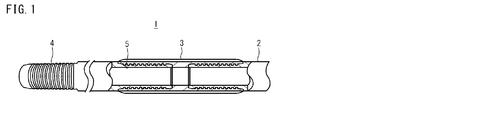
- FIG. 1 is a view showing a configuration of a coupling type pipe threaded joint according to the present embodiment.
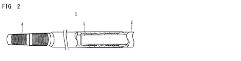
- FIG. 2 is a diagram showing a configuration of an integral type pipe threaded joint according to the present embodiment.
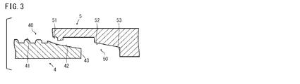
- FIG. 3 is a cross-sectional view of an example of a pipe threaded joint.
- FIG. 4 is a diagram showing a configuration of the pipe threaded joint according to the present embodiment in the case where the pipe has no metal seal portion and no shoulder portion.
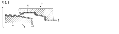
- FIG. 5 is a sectional view of an example of the threaded pipe joint according to the present embodiment.
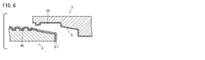
- FIG. 6 is a sectional view of an example of a pipe threaded joint according to another embodiment different from FIG. FIG.
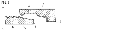
- FIG. 7 is a cross-sectional view of an example of a pipe threaded joint according to another embodiment different from FIGS. 5 and 6.
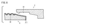
- FIG. 8 is a sectional view of an example of a pipe threaded joint according to another embodiment different from FIGS. 5 to 7.
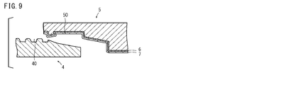
- FIG. 9 is a sectional view of an example of a pipe threaded joint according to another embodiment different from FIGS. 5 to 8.
- the present inventors have further studied a plating layer suitable for a threaded joint for pipes. As a result, the present inventors formed a Ni—W alloy plating layer containing 35.0 to 45.0 mass% of W and the balance of Ni and impurities on the contact surface of the pipe threaded joint, It has been found that the seizure resistance of the threaded joint for pipes during screwing and unscrewing can be improved. Hereinafter, this point will be described.
- the hardness and melting point of a Ni—W alloy containing 35.0 to 45.0% by mass of W and the balance being Ni and impurities are determined by the hardness of a Cu plating layer conventionally used as a plating layer for threaded joints for pipes. And higher than the melting point. Therefore, the Ni—W alloy plating layer containing 35.0 to 45.0% by mass of W and the balance of Ni and impurities has high hardness (Hv 600 or more) and high melting point (1455 ° C. or more). As a result, the use of a Ni-W alloy plating layer containing 35.0 to 45.0% by mass of W and the balance of Ni and impurities increases the seizure resistance of the threaded joint for pipes.
- the present inventors have further studied the thickness of the Ni—W alloy plating layer in detail.
- the pin and box slide frictionally while receiving significantly higher pressure.
- seizure resistance is enhanced even under a high-pressure environment such as when screwing and unscrewing a threaded joint for pipes.
- the threaded joint for pipes of the present embodiment completed based on the above findings includes a pin, a box, a Ni-W alloy plating layer, and a solid lubricating film.
- the pin has a pin-side contact surface that includes a pin-side thread.
- the box has a box side contact surface that includes a box side thread.
- the Ni—W alloy plating layer is disposed on at least one of the pin-side contact surface and the box-side contact surface.
- the Ni—W alloy plating layer is composed of 35.0 to 45.0 mass% of W, and the remainder is composed of Ni and impurities, and has a thickness of 1.0 to 20.0 ⁇ m.
- the solid lubricating coating is disposed on the Ni—W alloy plating layer on at least one of the pin-side contact surface and the box-side contact surface.
- the threaded joint for pipes of the present embodiment contains a Ni-W alloy containing 35.0 to 45.0% by mass of W on at least one of the pin-side contact surface and the box-side contact surface, with the balance being Ni and impurities. It has a plating layer.
- the pipe threaded joint of the present embodiment further has a solid lubricating coating on the Ni—W alloy plating layer on at least one of the pin-side contact surface and the box-side contact surface. Therefore, it has excellent seizure resistance.
- the pin-side contact surface of the pipe threaded joint may further include a pin-side metal seal portion and a pin-side shoulder portion.
- the box side contact surface may further include a box side metal seal and a box side shoulder.
- the method of manufacturing a pipe threaded joint of the present embodiment is a method of forming a Ni—W alloy plating layer on a pipe threaded joint including a pin and a box.
- the pin has a pin-side contact surface that includes a pin-side thread.
- the box has a box side contact surface that includes a box side thread.
- the manufacturing method includes a Ni-W alloy plating layer forming step and a solid lubricating film forming step. In the Ni—W alloy plating layer forming step, at least one of the pin-side contact surface and the box-side contact surface is immersed in a plating solution.
- the plating solution contains nickel ions and tungsten ions.
- a Ni—W alloy plating layer is formed on at least one of the pin-side contact surface and the box-side contact surface.
- the Ni—W alloy plating layer is composed of 35.0 to 45.0 mass% of W, and the remainder is composed of Ni and impurities, and has a thickness of 1.0 to 20.0 ⁇ m.
- a solid lubricant film is formed on the Ni—W alloy plating layer on at least one of the pin-side contact surface and the box-side contact surface.
- the Ni-W alloy plating layer is provided on at least one of the pin-side contact surface and the box-side contact surface, and the Ni-W alloy plating layer is provided on at least one of the pin-side contact surface and the box-side contact surface.
- a threaded joint for pipes having a solid lubricating coating on a W alloy plating layer can be manufactured. Therefore, the threaded pipe joint has excellent seizure resistance.
- the pin-side contact surface may further include a pin-side metal seal portion and a pin-side shoulder portion.
- the box side contact surface may further include a box side metal seal and a box side shoulder.
- FIG. 1 is a diagram showing a configuration of a pipe threaded joint 1 according to the present embodiment.
- a pipe threaded joint 1 includes a steel pipe 2 and a coupling 3.
- Pins 4 each having an external thread portion on the outer surface are formed at both ends of the steel pipe 2.
- Boxes 5 each having a female screw portion on the inner surface are formed at both ends of the coupling 3.
- the coupling 3 is attached to the end of the steel pipe 2 by screwing the pin 4 and the box 5 together.
- a protector may be attached to the pin 4 of the steel pipe 2 and the box 5 of the coupling 3 to which the mating member is not attached in order to protect the respective screw portions.
- FIG. 2 is a diagram showing the configuration of the integral type pipe threaded joint 1 according to the present embodiment.
- the threaded pipe joint 1 includes a steel pipe 2. At one end of the steel pipe 2, a pin 4 having an external thread portion on the outer surface is formed. At the other end of the steel pipe 2, a box 5 having a female screw portion on the inner surface is formed.
- the steel pipes 2 can be connected to each other by screwing the pins 4 and the box 5 together.
- the pipe threaded joint 1 of the present embodiment can be used for both coupling type and integral type pipe threaded joints 1.
- FIG. 3 is a sectional view of an example of the threaded pipe joint 1.
- the pin 4 includes a pin-side screw part 41, a pin-side metal seal part 42, and a pin-side shoulder part 43.
- the box 5 includes a box-side screw portion 51, a box-side metal seal portion 52, and a box-side shoulder portion 53. The portions that come into contact when the pin 4 and the box 5 are screwed together are referred to as contact surfaces 40 and 50.
- the screw portions (the pin-side screw portion 41 and the box-side screw portion 51) and the metal seal portions (the pin-side metal seal portion 42 and the box-side metal seal portion) 52) and the shoulder portions (the pin-side shoulder portion 43 and the box-side shoulder portion 53) come into contact with each other.
- the pin-side contact surface 40 includes a pin-side screw portion 41, a pin-side metal seal portion 42, and a pin-side shoulder portion 43.
- the box-side contact surface 50 includes a box-side screw portion 51, a box-side metal seal portion 52, and a box-side shoulder portion 53.
- the pins 4 are arranged in the order of the pin-side shoulder 43, the pin-side metal seal 42, and the pin-side screw 41 from the end of the steel pipe 2.
- the box-side screw portion 51, the box-side metal seal portion 52, and the box-side shoulder portion 53 are arranged in this order.
- the arrangement of the pin side screw portion 41 and the box side screw portion 51, the pin side metal seal portion 42 and the box side metal seal portion 52, and the arrangement of the pin side shoulder portion 43 and the box side shoulder portion 53 are limited to the arrangement of FIG. However, it can be changed as appropriate. For example, as shown in FIG.
- 43, the pin-side metal seal part 42 and the pin-side screw part 41 may be arranged in this order.
- the seal portion 52 and the box-side shoulder portion 53 may be arranged in this order.
- FIGS. 1 and 2 illustrate a so-called premium joint including a metal seal portion (the pin-side metal seal portion 42 and the box-side metal seal portion 52) and a shoulder portion (the pin-side shoulder portion 43 and the box-side shoulder portion 53).
- the metal seal portion (the pin-side metal seal portion 42 and the box-side metal seal portion 52) and the shoulder portion (the pin-side shoulder portion 43 and the box-side shoulder portion 53) may not be provided.
- FIG. 4 illustrates the pipe threaded joint 1 without the metal seal portions 42 and 52 and the shoulder portions 43 and 53.
- the pipe threaded joint 1 of the present embodiment can be suitably applied to the pipe threaded joint 1 without the metal seal portions 42 and 52 and the shoulder portions 43 and 53.
- the pin-side contact surface 40 includes a pin-side thread 41 and the box-side contact surface 50 includes a box-side thread 51.
- the threaded pipe joint 1 includes a Ni—W alloy plating layer 6 on at least one of the pin-side contact surface 40 and the box-side contact surface 50.
- the threaded pipe joint 1 includes a Ni—W alloy plating layer 6 on both the pin-side contact surface 40 and the box-side contact surface 50.
- the threaded pipe joint 1 further includes a solid lubricating coating 7 on the Ni—W alloy plating layer 6 on at least one of the pin-side contact surface 40 and the box-side contact surface 50.
- the threaded pipe joint 1 includes a solid lubricating coating 7 on both the Ni—W alloy plating layer 6 on the pin-side contact surface 40 and the Ni—W alloy plating layer 6 on the box-side contact surface 50. . If the solid lubricating film 7 is provided on the Ni—W alloy plating layer 6, the lubricating property is enhanced, and the seizure resistance of the threaded pipe joint 1 is further enhanced.
- the arrangement of the alloy plating layers of the present embodiment is not limited to FIG.
- the Ni-W alloy plating layer 6 is provided on both the pin-side contact surface 40 and the box-side contact surface 50, and the Ni-W alloy plating layer 6 on the pin-side contact surface 40 is provided.
- the solid lubricant film 7 may be provided, and the solid lubricant film 7 may not be provided on the Ni—W alloy plating layer 6 on the box-side contact surface 50.
- the Ni-W alloy plating layer 6 is provided on both the pin-side contact surface 40 and the box-side contact surface 50, and the Ni-W alloy plating layer 6 on the box-side contact surface 50 is provided.
- the solid lubricant film 7 may be provided, and the solid lubricant film 7 may not be provided on the Ni—W alloy plating layer 6 on the pin-side contact surface 40. As shown in FIG. 8, the Ni-W alloy plating layer 6 and the solid lubricant film 7 may be provided only on the pin-side contact surface 40. As shown in FIG. 9, the Ni—W alloy plating layer 6 and the solid lubricant film 7 may be provided only on the box-side contact surface 50. Although not shown, the Ni-W alloy plating layer 6 and the solid lubricant film 7 may be provided only on the pin-side contact surface 40, and only the solid lubricant film 7 may be provided on the box-side contact surface 50.
- the Ni-W alloy plating layer 6 and the solid lubricating film 7 may be provided only on the box-side contact surface 50, and only the solid lubricating film 7 may be provided on the pin-side contact surface 40. That is, nothing may be formed on the contact surface where the Ni—W alloy plating layer 6 is not formed, or the solid lubricating film 7 may be formed.
- Another coating for example, a solid anticorrosion coating
- Ni—W alloy plating layer 6 The Ni—W alloy plating layer 6 is disposed on at least one of the pin-side contact surface 40 and the box-side contact surface 50.
- the Ni—W alloy plating layer 6 is made of a Ni—W alloy.
- the Ni—W alloy contains Ni and W, with the balance being impurities.
- the impurities are substances other than Ni and W, and are contained in the Ni—W alloy plating layer 6 during the production of the pipe threaded joint 1 and are contained in a content that does not affect the effects of the present invention. including.
- the impurities are, for example, Fe, S, O, C and the like.
- the hardness and melting point of the Ni—W alloy plating layer 6 are high. Therefore, the seizure resistance of the pipe threaded joint 1 is enhanced.
- the chemical composition of the Ni—W alloy plating layer 6 is 100% by mass, the Ni—W alloy plating layer 6 contains 35.0 to 45.0% by mass of W. In this case, the Ni—W alloy plating layer 6 has high seizure resistance. As a result, the threaded pipe joint 1 exhibits excellent seizure resistance.
- the W content in the Ni—W alloy plating layer 6 is 35.0 to 45.0% by mass.
- a preferable lower limit of the W content in the Ni—W alloy plating layer 6 is 38.0% by mass.
- the preferable upper limit of the W content in the Ni—W alloy plating layer 6 is 42.0% by mass.
- the W content of the Ni—W alloy plating layer 6 is measured by the following method.
- the W content is measured using a handheld X-ray fluorescence spectrometer (DP2000 manufactured by Olympus (trade name: DELTA @ Premium)).
- the composition analysis is performed at any four locations (any 0 °, 90 °, 180 °, or 270 ° location in the circumferential direction of the tube) on the surface of the metal seal portion on which Ni—W has been applied.
- the measured contents of Ni and W are determined by the measurement mode of the alloy.
- the W content (% by mass) is obtained by dividing the measured W content by the total measured Ni and W content.
- the thickness of the Ni—W alloy plating layer 6 is 1.0 to 20.0 ⁇ m. If the thickness of the Ni—W alloy plating layer 6 is less than 1.0 ⁇ m, the seizure resistance decreases. If the thickness of the Ni—W alloy plating layer 6 exceeds 20.0 ⁇ m, the adhesion of the plating decreases.
- the lower limit of the thickness of the Ni—W alloy plating layer 6 is preferably 5.0 ⁇ m, and more preferably 8.0 ⁇ m.
- the upper limit of the thickness of the Ni—W alloy plating layer 6 is preferably 15.0 ⁇ m, and more preferably 12.0 ⁇ m.
- the thickness of the Ni—W alloy plating layer 6 is measured by the following method.
- the contact surface 40 or 50 on which the Ni—W alloy plating layer 6 is formed is brought into contact with a probe of an overcurrent phase type film thickness measuring device conforming to ISO (International Organization for Standardization) 21968 (2005).
- ISO International Organization for Standardization
- the phase difference between the high frequency magnetic field on the input side of the probe and the overcurrent on the Ni—W alloy plating layer 6 excited by the high frequency magnetic field is measured. This phase difference is converted into a thickness of the Ni—W alloy plating layer 6.
- four arbitrary points any 0 °, 90 °, 180 °, 270 ° point in the circumferential direction of the tube) of the contact surface 40 or 50 are measured.
- the pipe threaded joint 1 further includes a solid lubricating coating 7 on the Ni—W alloy plating layer 6 on at least one of the pin-side contact surface 40 and the box-side contact surface 50.
- the lubricity of the pipe threaded joint 1 is further enhanced.
- the solid lubricating film 7 a known material can be used.
- the solid lubricating coating 7 contains, for example, lubricating particles and a binder.
- the solid lubricating coating 7 may contain a solvent and other components as needed.
- the lubricating particles reduce the coefficient of friction of the surface of the solid lubricating coating 7.
- the lubricating particles are not particularly limited as long as they have lubricating properties.
- the lubricating particles are, for example, graphite, MoS 2 (molybdenum disulfide), WS 2 (tungsten disulfide), BN (boron nitride), PTFE (polytetrafluoroethylene), CF x (fluorinated graphite) and CaCO 3 (carbonate Calcium) or one or more selected from the group consisting of:
- graphite, fluorinated graphite, MoS 2 and PTFE are used.
- the preferable content of the lubricating particles is 5 to 40% by mass.
- the binder binds the lubricating particles into the solid lubricating coating 7.
- the binder is, for example, one or two selected from the group consisting of an organic resin and an inorganic resin.
- an organic resin one selected from the group consisting of a thermosetting resin and a thermoplastic resin can be used.
- the thermosetting resin is, for example, one or two selected from the group consisting of an epoxy resin, a polyimide resin, a polycarbodiimide resin, a polyethersulfone, a polyetheretherketone resin, a phenol resin, a furan resin, a urea resin, and an acrylic resin. More than a species.
- the thermoplastic resin is, for example, one or more selected from the group consisting of a polyamideimide resin, a polyethylene resin, a polypropylene resin, a polystyrene resin, and an ethylene vinyl acetate resin. Assuming that the solid lubricating coating 7 is 100% by mass, the preferable content of the binder is 60 to 95% by mass.
- polymetalloxane refers to a polymer compound in which a repeating metal-oxygen bond is a main chain skeleton.
- polytitanoxane (Ti—O) and polysiloxane (Si—O) are used.
- These inorganic resins are obtained by hydrolyzing and condensing a metal alkoxide.
- the alkoxy group of the metal alkoxide is, for example, a lower alkoxy group such as a methoxy group, an ethoxy group, a propoxy group, an isopropoxy group, an isobutoxy group, a butoxy group and a tert-butoxy group.
- the solvent is not particularly limited as long as the components contained in the solid lubricating coating 7 can be dispersed or dissolved.
- the solvent one or two kinds selected from the group consisting of an organic solvent and water can be used.
- the organic solvent is, for example, one or two selected from the group consisting of toluene and isopropyl alcohol.
- the solid lubricating coating 7 can contain other components as needed.
- Other components are, for example, rust inhibitors, corrosion inhibitors, surfactants, waxes, friction modifiers and pigments.
- the content of each of the lubricating particles, the binder, the solvent, and other components is appropriately set.
- a preferable content of other components is, for example, 1 to 50% by mass, and preferably 5 to 30% by mass.
- the chemical composition of the base material of the threaded pipe joint 1 is not particularly limited.
- the base material is, for example, carbon steel, stainless steel, alloy steel, or the like.
- the alloy steel is, for example, a Ni alloy and a duplex stainless steel containing alloy elements such as Cr, Ni and Mo.
- the base material of the pipe threaded joint 1 is, for example, 13% Cr steel (C: 0.18%, Si: 0.23%, Mn: 0.8%, P: 0.02%), which is a kind of high alloy steel. , S: 0.01%, Cu: 0.04%, Ni: 0.1%, Cr: 13%, Mo: 0.04%, balance: Fe and impurities).
- the method for manufacturing the threaded pipe joint 1 of the present embodiment is the method for manufacturing the above-described threaded pipe joint 1.
- the manufacturing method includes a Ni-W alloy plating layer forming step and a solid lubricating film forming step.
- Ni—W alloy plating layer forming step the Ni—W alloy plating layer 6 made of a Ni—W alloy is deposited on at least one of the pin-side contact surface 40 and the box-side contact surface 50 of the prepared pipe threaded joint 1.
- the Ni—W alloy plating layer 6 is formed by electroplating. The electroplating is performed by immersing the pin-side contact surface 40 of the pin 4 or the box-side contact surface 50 of the box 5 as a material to be plated in a plating bath containing Ni ions and W ions, and supplying electricity.
- the plating bath preferably contains Ni ions: 0.13 to 0.3 mol / L and W ions: 0.3 to 0.42 mol / L.
- Electroplating conditions can be set as appropriate.
- the electroplating conditions are, for example, plating bath pH: 1 to 10, plating bath temperature: 10 to 60 ° C., current density: 1 to 100 A / dm 2 , and treatment time: 0.1 to 30 minutes.
- Solid lubrication film forming process The solid lubricating coating 7 is formed on the Ni—W alloy plating layer 6 on at least one of the pin-side contact surface 40 and the box-side contact surface 50.
- a composition for a solid lubricating film (hereinafter, also referred to as a composition) is prepared.
- the composition is formed by mixing the lubricating particles and the binder described above.
- the composition may further contain the above-mentioned solvents and other components.
- the obtained composition is applied on the Ni—W alloy plating layer 6.
- the method of application is not particularly limited.
- the composition is sprayed on the Ni—W alloy plating layer 6 using a spray gun.
- the pin 4 or the box 5 to which the composition has been applied is dried by heating.
- the composition is cured, and a solid lubricating film 7 is formed on the Ni—W alloy plating layer 6.
- the conditions for the heating and drying can be appropriately set in consideration of the boiling point and melting point of each component contained in the composition.
- a hot melt method can be used. In the hot melt method, the composition is heated to a fluid state.
- the composition in a fluidized state is sprayed using, for example, a spray gun having a temperature maintaining function.
- the pin 4 or the box 5 to which the composition has been applied is cooled by air cooling or the like.
- the composition is cured, and a solid lubricating film 7 is formed on the Ni—W alloy plating layer 6.
- a base treatment step may be performed before the Ni—W alloy plating layer forming step, if necessary.
- the undercoating process is, for example, pickling and alkali degreasing.
- oil and the like attached to the contact surface forming the Ni—W alloy plating layer 6 are removed.
- the base treatment step may further include a grinding process such as sandblasting and mechanical grinding. Only one kind of these base treatments may be performed, or a plurality of base treatments may be performed in combination.
- the contact surface of the pin is called the pin surface
- the contact surface of the box is called the box surface.
- % in the examples means mass%.
- the base material is a 13% Cr steel (C: 0.18%, Si: 0.23%, Mn: 0.8%, P: 0.02%, S: 0. 01%, Cu: 0.04%, Ni: 0.1%, Cr: 13%, Mo: 0.04%, balance: Fe and impurities).
- a seamless steel pipe and a coupling were manufactured.
- the size of the seamless steel pipe was 168.28 mm in outer diameter, 12.1 mm in wall thickness, and 1200 mm in length.
- Pins having a male thread portion and a threadless metal contact portion were formed on the outer surfaces of both ends of the seamless steel pipe by cutting.
- a box having a female thread portion and a threadless metal contact portion was formed on the inner surfaces of both ends of the coupling by cutting.
- Ni—W alloy plating layer forming step A Ni—W alloy plating layer was formed on the box surfaces of Test Nos. 1 to 7.
- the Ni—W alloy plating layer was formed by electroplating. Specifically, the coupling was immersed in the plating bath of each test number and energized to form a Ni—W alloy plating layer.
- the plating conditions were as follows: plating bath pH: 5, plating bath temperature: 60 ° C, current density: 20 A / dm 2 (constant current electrolytic method).
- the composition of the plating bath for each test number was as shown in Table 1.
- the plating bath was prepared by dissolving commercially available special grade nickel sulfate heptahydrate, disodium tungstate, and triammonium citrate: 0.6 mol / L in pure water.
- the total metal salt concentration was constant at 0.6 mol / L.
- Several types of plating baths were constructed by changing the ratio of the concentration of disodium tungstate to the concentration of all metal salts.
- CuA Cu—Sn—Zn alloy plating layer was formed on the box surface of Test No. 8. Specifically, a Cu—Sn—Zn alloy plating layer was formed on the box surface by electroplating using a cyan bath containing copper ions, tin ions, and zinc ions. The Cu—Sn—Zn alloy plating layer contained about 7% of Zn, about 40% of Sn, and about 53% of Cu.
- Solid lubrication film forming process A solid lubricating film was further formed on the box surfaces of Test Nos. 1 to 8.
- the composition for forming a solid lubricating film contained polyamideimide resin: 12% by mass, dimethyl sulfoxide: 45% by mass, PTFE particles: 5% by mass, and pure water: balance. After spray-coating this composition on the alloy plating layer, preliminary drying (85 ° C., 10 minutes) and main heating (280 ° C., 30 minutes) were performed to form a solid lubricating film having an average film thickness of 30 ⁇ m.
- the pin surface was subjected to a mechanical grinding finish (surface roughness 3 ⁇ m), and then a solid anticorrosion film was formed.
- the composition for forming a solid anticorrosive film contained an acrylic resin-based UV-curable resin paint, aluminum phosphite, and polyethylene wax. The contents of aluminum phosphite and polyethylene wax were 0.05 and 0.01 with respect to the acrylic resin-based ultraviolet-curable resin 1, respectively.
- the composition was cured by irradiating the composition with ultraviolet rays using a UV lamp (air-cooled mercury lamp, output 4 kW, ultraviolet wavelength: 260 nm).
- the thickness of the solid anticorrosion coating was 25 ⁇ m.
- the pipe threaded joint of Test No. 8 was provided with a conventional Cu-Sn-Zn alloy plating layer. Therefore, seizure occurred in the pipe threaded joint of Test No. 8 when the screw tightening and unscrewing were repeated seven times.
Abstract
The present invention provides a screw joint (1) which is for a pipe and has excellent seizure resistance. The screw joint (1) for a pipe according to the present embodiment includes a pin (4), a box (5), a Ni-W alloy plating layer (6), and a solid lubricating film (7). The pin (4) has a pin-side contact surface (40) that includes a pin-side screw portion (41). The box (5) has a box-side contact surface (50) that includes a box-side screw portion (51). The Ni-W alloy plating layer (6) is disposed on at least one among the pin-side contact surface (40) and the box-side contact surface (50). The Ni-W alloy plating layer (6) is composed of 35.0-45.0 mass% of W, and the remainder comprising Ni and impurities, and has a thickness of 1.0-20.0 μm. The solid lubricating film (7) is disposed on the Ni-W alloy plating layer (6) on at least one among the pin-side contact surface (40) and the box-side contact surface (50).
Description
本発明は、管用ねじ継手及び管用ねじ継手の製造方法に関し、さらに詳しくは、油井管用ねじ継手及び油井管用ねじ継手の製造方法に関する。
The present invention relates to a threaded joint for pipes and a method for manufacturing a threaded joint for pipes, and more particularly, to a threaded joint for oil country tubular goods and a method for manufacturing a threaded joint for oil country tubular goods.
油田や天然ガス田の採掘のために、油井管が使用される。油井管は、井戸の深さに応じて、複数の鋼管を連結して形成される。鋼管の連結は、鋼管の端部に形成された管用ねじ継手同士をねじ締めすることによって行われる。鋼管は、検査等のために引き上げられ、ねじ戻しされ、検査された後、再びねじ締めされて、再度使用される。
油 Oil well pipes are used for mining oil fields and natural gas fields. An oil country tubular good is formed by connecting a plurality of steel pipes according to the depth of the well. The connection of the steel pipes is performed by screwing together pipe threaded joints formed at the ends of the steel pipes. The steel pipe is pulled up for inspection or the like, unscrewed, inspected, screwed again, and used again.
管用ねじ継手は、ピン及びボックスを備える。ピンは、鋼管の先端部の外周面に形成された雄ねじ部を含む。ボックスは、鋼管の先端部の内周面に形成された雌ねじ部を含む。ピン及びボックスはさらに、ねじ無し金属接触部を有する場合がある。ピン及びボックスのねじ部及びねじ無し金属接触部は、鋼管のねじ締め及びねじ戻し時に強い摩擦を繰り返し受ける。これらの部位に摩擦に対する十分な耐久性がなければ、ねじ締め及びねじ戻しを繰り返した時にゴーリング(修復不可能な焼付き)が発生する。したがって、管用ねじ継手には、摩擦に対する十分な耐久性、すなわち、優れた耐焼付き性が要求される。
ね じ Pipe threaded joints include pins and boxes. The pin includes a male screw portion formed on the outer peripheral surface of the tip of the steel pipe. The box includes a female screw portion formed on the inner peripheral surface of the distal end portion of the steel pipe. Pins and boxes may also have unthreaded metal contacts. The threaded portion of the pin and the box and the threadless metal contact portion repeatedly receive strong friction when screwing and unscrewing the steel pipe. If these parts do not have sufficient durability against friction, galling (irreparable seizure) occurs when the screwing and unscrewing are repeated. Therefore, threaded joints for pipes are required to have sufficient durability against friction, that is, excellent seizure resistance.
ピン及びボックスのねじ部及びねじ無し金属接触部は、鋼管のねじ締め及びねじ戻し時に強い摩擦を繰り返し受ける。これらの部位に、摩擦に対する十分な耐久性がなければ、ねじ締め及びねじ戻しを繰り返した時にゴーリング(修復不可能な焼付き)が発生する。したがって、管用ねじ継手には、摩擦に対する十分な耐久性、すなわち、優れた耐焼付き性が要求される。
ね じ The threaded portion of the pin and the box and the metal contact portion without the screw repeatedly receive strong friction when screwing and unscrewing the steel pipe. If these parts do not have sufficient durability against friction, galling (irreparable seizure) occurs when repeated tightening and unscrewing. Therefore, threaded joints for pipes are required to have sufficient durability against friction, that is, excellent seizure resistance.
従来、耐焼付き性を向上するために、ドープと呼ばれる重金属を含有するコンパウンドグリースが使用されてきた。しかしながら、コンパウンドグリースに含まれる重金属(Pb、Zn及びCu等)は環境に影響を与える可能性がある。このため、コンパウンドグリースの使用を抑えた管用ねじ継手の開発が望まれている。
Conventionally, compound grease containing a heavy metal called a dope has been used to improve seizure resistance. However, heavy metals (Pb, Zn, Cu, etc.) contained in the compound grease may affect the environment. For this reason, development of a threaded joint for pipes in which use of compound grease is suppressed is desired.
国際公開第2009/072486号(特許文献1)は、コンパウンドグリース無しでも耐焼付き性に優れる管用ねじ継手を提案する。
WO2009 / 072486 (Patent Document 1) proposes a threaded pipe joint having excellent seizure resistance even without compound grease.
特許文献1に記載されている管用ねじ継手は、ねじ部とねじ無し金属接触部とを有する接触表面をそれぞれ備えたピンとボックスとを備える。ボックスの接触表面は、最上層として、塑性もしくは粘塑性型レオロジー挙動を有する固体潤滑被膜を有する。ピンの接触表面は、最上層として、紫外線硬化樹脂を主成分とする固体防食被膜を有する。これにより、コンパウンドグリースを使用せずに、錆の発生を抑制し、優れた耐焼付き性と気密性とを示し、かつ表面にべたつきがなく、外観や検査性に優れた管用ねじ継手が得られる、と特許文献1には記載されている。
The pipe threaded joint described in Patent Document 1 includes a pin and a box each having a contact surface having a threaded portion and a threadless metal contact portion. The contact surface of the box has as its top layer a solid lubricating coating having a plastic or viscoplastic rheological behavior. The contact surface of the pin has, as the uppermost layer, a solid anticorrosive coating mainly composed of an ultraviolet curable resin. Thereby, without using compound grease, it is possible to obtain a threaded joint for pipes which suppresses rust generation, exhibits excellent seizure resistance and airtightness, has no sticky surface, and has excellent appearance and inspection properties. And Patent Document 1.
管用ねじ継手の焼付きを抑制するには、硬度及び融点が高い金属を含むめっき層を形成することが有効である。そのため、従来、銅(Cu)めっき又はCu合金めっきが用いられてきた。Cuの硬度及び融点は高い。そのため、Cuがめっき層に含まれることによって、めっき層全体の硬度及び融点が高まる。したがって、管用ねじ継手の耐焼付き性が高まる。
In order to suppress seizure of the threaded joint for pipes, it is effective to form a plating layer containing a metal having a high hardness and a high melting point. Therefore, conventionally, copper (Cu) plating or Cu alloy plating has been used. The hardness and melting point of Cu are high. Therefore, by including Cu in the plating layer, the hardness and the melting point of the entire plating layer increase. Therefore, the seizure resistance of the pipe threaded joint is enhanced.
Cu合金めっきによって管用ねじ継手の耐焼付き性を改善する技術が、特開2003-074763号公報(特許文献2)及び特開2008-215473号公報(特許文献3)に記載されている。
Techniques for improving the seizure resistance of threaded joints for tubes by Cu alloy plating are described in JP-A-2003-074763 (Patent Document 2) and JP-A-2008-215473 (Patent Document 3).
特許文献2に記載されている管用ねじ継手は、ピン部とカップリングとを含む。カップリングはCrを9質量%以上含有する鋼管である。カップリングの両端には、雌ネジ及びメタル-メタルシール部を有するボックス部が設けられている。カップリングの雌ネジ及びメタル-メタルシール部の表面には、Cu-Sn合金層が一層配置されている。この管用ねじ継手を用いれば、グリーンドープ(Pbを含有しない潤滑剤)を使用しても従来よりシール性が良好で、且つゴーリングを格段に抑制することができる、と特許文献2に記載されている。
管 The pipe threaded joint described in Patent Document 2 includes a pin portion and a coupling. The coupling is a steel pipe containing 9% by mass or more of Cr. At both ends of the coupling, a box portion having a female screw and a metal-metal seal portion is provided. A Cu—Sn alloy layer is disposed on the surface of the female screw and the metal-metal seal portion of the coupling. Patent Document 2 describes that the use of this threaded joint for pipes has a better sealing property and can significantly suppress galling even if a green dope (lubricant containing no Pb) is used. I have.
特許文献3に記載されている管用ねじ継手は、ピン及びボックスを含む。ピン及びボックスの少なくとも一方の接触表面は、Cu-Zn合金からなる第1のめっき層を有する。これにより、管用ねじ継手は、グリーンドープを塗布する場合、さらには無ドープの場合でも、十分な耐漏れ性と耐焼付き性とを示す、と特許文献3には記載されている。
ね じ The pipe threaded joint described in Patent Document 3 includes a pin and a box. At least one contact surface of the pin and the box has a first plating layer made of a Cu—Zn alloy. Patent Literature 3 describes that the threaded joint for pipe shows sufficient leakage resistance and seizure resistance even when a green dope is applied or even when it is not doped.
しかしながら、上述の特許文献1~3に開示された技術を用いても、管用ねじ継手の耐焼付き性が十分でない場合がある。
However, even when the techniques disclosed in Patent Documents 1 to 3 described above are used, the seizure resistance of the threaded pipe joint may not be sufficient.
本発明の目的は、優れた耐焼付き性を有する管用ねじ継手及びその製造方法を提供することである。
目的 An object of the present invention is to provide a threaded pipe joint having excellent seizure resistance and a method for manufacturing the same.
本実施形態の管用ねじ継手は、ピンと、ボックスと、Ni-W合金めっき層と、固体潤滑被膜とを備える。ピンは、ピン側ねじ部を含むピン側接触表面を有する。ボックスは、ボックス側ねじ部を含むボックス側接触表面を有する。Ni-W合金めっき層は、ピン側接触表面及びボックス側接触表面の少なくとも一方の上に配置される。Ni-W合金めっき層は、35.0~45.0質量%のW、及び、残部はNi及び不純物からなり、厚さが1.0~20.0μmである。固体潤滑被膜は、ピン側接触表面及びボックス側接触表面の少なくとも一方の上のNi-W合金めっき層上に配置される。
ね じ The threaded joint for pipes of this embodiment includes a pin, a box, a Ni—W alloy plating layer, and a solid lubricating film. The pin has a pin-side contact surface that includes a pin-side thread. The box has a box side contact surface that includes a box side thread. The Ni—W alloy plating layer is disposed on at least one of the pin-side contact surface and the box-side contact surface. The Ni—W alloy plating layer is composed of 35.0 to 45.0 mass% of W, and the remainder is composed of Ni and impurities, and has a thickness of 1.0 to 20.0 μm. The solid lubricating coating is disposed on the Ni—W alloy plating layer on at least one of the pin-side contact surface and the box-side contact surface.
本実施形態の管用ねじ継手の製造方法は、ピン及びボックスを備える管用ねじ継手にNi-W合金めっき層を形成する製造方法である。ピンは、ピン側ねじ部を含むピン側接触表面を有する。ボックスは、ボックス側ねじ部を含むボックス側接触表面を有する。製造方法は、Ni-W合金めっき層形成工程と、固体潤滑被膜形成工程とを備える。Ni-W合金めっき層形成工程では、ピン側接触表面及びボックス側接触表面の少なくとも一方をめっき液に浸漬する。めっき液はニッケルイオン及びタングステンイオンを含有する。次に、めっき液に浸漬させたピン側接触表面及びボックス側接触表面の少なくとも一方に通電する。これにより、ピン側接触表面及びボックス側接触表面の少なくとも一方の上にNi-W合金めっき層を形成する。Ni-W合金めっき層は、35.0~45.0質量%のW、及び、残部はNi及び不純物からなり、厚さが1.0~20.0μmである。固体潤滑被膜形成工程では、ピン側接触表面及びボックス側接触表面の少なくとも一方の上のNi-W合金めっき層上に、固体潤滑被膜を形成する。
製造 The method of manufacturing a pipe threaded joint of the present embodiment is a method of forming a Ni—W alloy plating layer on a pipe threaded joint including a pin and a box. The pin has a pin-side contact surface that includes a pin-side thread. The box has a box side contact surface that includes a box side thread. The manufacturing method includes a Ni-W alloy plating layer forming step and a solid lubricating film forming step. In the Ni—W alloy plating layer forming step, at least one of the pin-side contact surface and the box-side contact surface is immersed in a plating solution. The plating solution contains nickel ions and tungsten ions. Next, at least one of the pin-side contact surface and the box-side contact surface immersed in the plating solution is energized. Thus, a Ni—W alloy plating layer is formed on at least one of the pin-side contact surface and the box-side contact surface. The Ni—W alloy plating layer is composed of 35.0 to 45.0 mass% of W, and the remainder is composed of Ni and impurities, and has a thickness of 1.0 to 20.0 μm. In the solid lubricant film forming step, a solid lubricant film is formed on the Ni—W alloy plating layer on at least one of the pin-side contact surface and the box-side contact surface.
本実施形態の管用ねじ継手は、優れた耐焼付き性を有する。
ね じ The threaded joint for pipes of the present embodiment has excellent seizure resistance.
以下、図面を参照して、本実施形態を詳しく説明する。図中同一又は相当部分には同一符号を付してその説明は繰り返さない。
Hereinafter, the present embodiment will be described in detail with reference to the drawings. In the drawings, the same or corresponding parts have the same reference characters allotted, and description thereof will not be repeated.
本発明者らは、管用ねじ継手の耐焼付き性について種々検討を行った。その結果、以下の知見を得た。
者 The present inventors have conducted various studies on seizure resistance of threaded joints for pipes. As a result, the following findings were obtained.
ねじ締め及びねじ戻し時の管用ねじ継手の耐焼付き性を高めるには、高硬度及び高融点を有するめっき層を、ねじ部、金属シール部及びショルダー部を有する接触表面に形成することが有効である。めっき層の硬度が高ければ、管用ねじ継手のねじ締め及びねじ戻しの際にめっき層が損傷を受けにくい。さらに、めっき層の融点が高ければ、管用ねじ継手のねじ締め及びねじ戻しの際、局所的にめっき層が高温になった場合でも、めっき層の硬度の低下を抑制できる。その結果、管用ねじ継手の耐焼付き性が高まる。
In order to enhance the seizure resistance of the threaded pipe joint during screw tightening and unscrewing, it is effective to form a plating layer having high hardness and a high melting point on the contact surface having the screw portion, the metal seal portion, and the shoulder portion. is there. If the hardness of the plating layer is high, the plating layer is less likely to be damaged during screwing and unscrewing of the pipe threaded joint. Furthermore, if the melting point of the plating layer is high, a decrease in the hardness of the plating layer can be suppressed even when the plating layer is locally heated to a high temperature when screwing and unscrewing the threaded joint for pipes. As a result, seizure resistance of the pipe threaded joint is enhanced.
本発明者らは、管用ねじ継手に適するめっき層について、さらなる検討を行った。その結果、本発明者らは、35.0~45.0質量%のWを含有し、残部はNi及び不純物からなるNi-W合金めっき層を管用ねじ継手の接触表面上に形成すれば、ねじ締め及びねじ戻し時の管用ねじ継手の耐焼付き性を高められることを見出した。以下、この点について説明する。
者 The present inventors have further studied a plating layer suitable for a threaded joint for pipes. As a result, the present inventors formed a Ni—W alloy plating layer containing 35.0 to 45.0 mass% of W and the balance of Ni and impurities on the contact surface of the pipe threaded joint, It has been found that the seizure resistance of the threaded joint for pipes during screwing and unscrewing can be improved. Hereinafter, this point will be described.
35.0~45.0質量%のWを含有し、残部はNi及び不純物からなるNi-W合金の硬度及び融点は、従来、管用ねじ継手のめっき層として使用されてきたCuめっき層の硬度及び融点よりも高い。そのため、35.0~45.0質量%のWを含有し、残部はNi及び不純物からなるNi-W合金めっき層は、高硬度(Hv600以上)及び高融点(1455℃以上)を有する。その結果、35.0~45.0質量%のWを含有し、残部はNi及び不純物からなるNi-W合金めっき層を用いれば、管用ねじ継手の耐焼付き性が高まる。
The hardness and melting point of a Ni—W alloy containing 35.0 to 45.0% by mass of W and the balance being Ni and impurities are determined by the hardness of a Cu plating layer conventionally used as a plating layer for threaded joints for pipes. And higher than the melting point. Therefore, the Ni—W alloy plating layer containing 35.0 to 45.0% by mass of W and the balance of Ni and impurities has high hardness (Hv 600 or more) and high melting point (1455 ° C. or more). As a result, the use of a Ni-W alloy plating layer containing 35.0 to 45.0% by mass of W and the balance of Ni and impurities increases the seizure resistance of the threaded joint for pipes.
さらに本発明者らは、Ni-W合金めっき層の厚さを詳細に検討した。管用ねじ継手のねじ締め及びねじ戻し時においては、ピン及びボックスは顕著に高い圧力を受けながら摩擦摺動する。しかしながら、Ni-W合金めっき層の厚さが1.0μm以上であれば、管用ねじ継手のねじ締め及びねじ戻し時のような高圧力環境下でも、耐焼付き性が高まることを見出した。
The present inventors have further studied the thickness of the Ni—W alloy plating layer in detail. When screwing and unscrewing a pipe threaded joint, the pin and box slide frictionally while receiving significantly higher pressure. However, it has been found that when the thickness of the Ni—W alloy plating layer is 1.0 μm or more, seizure resistance is enhanced even under a high-pressure environment such as when screwing and unscrewing a threaded joint for pipes.
以上の知見に基づいて完成した本実施形態の管用ねじ継手は、ピンと、ボックスと、Ni-W合金めっき層と、固体潤滑被膜とを備える。ピンは、ピン側ねじ部を含むピン側接触表面を有する。ボックスは、ボックス側ねじ部を含むボックス側接触表面を有する。Ni-W合金めっき層は、ピン側接触表面及びボックス側接触表面の少なくとも一方の上に配置される。Ni-W合金めっき層は、35.0~45.0質量%のW、及び、残部はNi及び不純物からなり、厚さが1.0~20.0μmである。固体潤滑被膜は、ピン側接触表面及びボックス側接触表面の少なくとも一方の上のNi-W合金めっき層上に配置される。
管 The threaded joint for pipes of the present embodiment completed based on the above findings includes a pin, a box, a Ni-W alloy plating layer, and a solid lubricating film. The pin has a pin-side contact surface that includes a pin-side thread. The box has a box side contact surface that includes a box side thread. The Ni—W alloy plating layer is disposed on at least one of the pin-side contact surface and the box-side contact surface. The Ni—W alloy plating layer is composed of 35.0 to 45.0 mass% of W, and the remainder is composed of Ni and impurities, and has a thickness of 1.0 to 20.0 μm. The solid lubricating coating is disposed on the Ni—W alloy plating layer on at least one of the pin-side contact surface and the box-side contact surface.
本実施形態の管用ねじ継手は、ピン側接触表面及びボックス側接触表面の少なくとも一方の上に35.0~45.0質量%のWを含有し、残部はNi及び不純物からなるNi-W合金めっき層を有する。本実施形態の管用ねじ継手はさらに、ピン側接触表面及びボックス側接触表面の少なくとも一方の上のNi-W合金めっき層上に固体潤滑被膜を有する。そのため、優れた耐焼付き性を有する。
The threaded joint for pipes of the present embodiment contains a Ni-W alloy containing 35.0 to 45.0% by mass of W on at least one of the pin-side contact surface and the box-side contact surface, with the balance being Ni and impurities. It has a plating layer. The pipe threaded joint of the present embodiment further has a solid lubricating coating on the Ni—W alloy plating layer on at least one of the pin-side contact surface and the box-side contact surface. Therefore, it has excellent seizure resistance.
上記管用ねじ継手のピン側接触表面はさらに、ピン側金属シール部及びピン側ショルダー部を含んでもよい。ボックス側接触表面はさらに、ボックス側金属シール部及びボックス側ショルダー部を含んでもよい。
ピ ン The pin-side contact surface of the pipe threaded joint may further include a pin-side metal seal portion and a pin-side shoulder portion. The box side contact surface may further include a box side metal seal and a box side shoulder.
本実施形態の管用ねじ継手の製造方法は、ピン及びボックスを備える管用ねじ継手にNi-W合金めっき層を形成する製造方法である。ピンは、ピン側ねじ部を含むピン側接触表面を有する。ボックスは、ボックス側ねじ部を含むボックス側接触表面を有する。製造方法は、Ni-W合金めっき層形成工程と、固体潤滑被膜形成工程とを備える。Ni-W合金めっき層形成工程では、ピン側接触表面及びボックス側接触表面の少なくとも一方をめっき液に浸漬する。めっき液はニッケルイオン及びタングステンイオンを含有する。次に、めっき液に浸漬させたピン側接触表面及びボックス側接触表面の少なくとも一方に通電する。これにより、ピン側接触表面及びボックス側接触表面の少なくとも一方の上にNi-W合金めっき層を形成する。Ni-W合金めっき層は、35.0~45.0質量%のW、及び、残部はNi及び不純物からなり、厚さが1.0~20.0μmである。固体潤滑被膜形成工程では、ピン側接触表面及びボックス側接触表面の少なくとも一方の上のNi-W合金めっき層上に、固体潤滑被膜を形成する。
製造 The method of manufacturing a pipe threaded joint of the present embodiment is a method of forming a Ni—W alloy plating layer on a pipe threaded joint including a pin and a box. The pin has a pin-side contact surface that includes a pin-side thread. The box has a box side contact surface that includes a box side thread. The manufacturing method includes a Ni-W alloy plating layer forming step and a solid lubricating film forming step. In the Ni—W alloy plating layer forming step, at least one of the pin-side contact surface and the box-side contact surface is immersed in a plating solution. The plating solution contains nickel ions and tungsten ions. Next, at least one of the pin-side contact surface and the box-side contact surface immersed in the plating solution is energized. Thus, a Ni—W alloy plating layer is formed on at least one of the pin-side contact surface and the box-side contact surface. The Ni—W alloy plating layer is composed of 35.0 to 45.0 mass% of W, and the remainder is composed of Ni and impurities, and has a thickness of 1.0 to 20.0 μm. In the solid lubricant film forming step, a solid lubricant film is formed on the Ni—W alloy plating layer on at least one of the pin-side contact surface and the box-side contact surface.
本実施形態の製造方法により、ピン側接触表面及びボックス側接触表面の少なくとも一方の上にNi-W合金めっき層を有し、ピン側接触表面及びボックス側接触表面の少なくとも一方の上のNi-W合金めっき層上に固体潤滑被膜を有する管用ねじ継手を製造できる。そのため、管用ねじ継手は、優れた耐焼付き性を有する。
According to the manufacturing method of this embodiment, the Ni-W alloy plating layer is provided on at least one of the pin-side contact surface and the box-side contact surface, and the Ni-W alloy plating layer is provided on at least one of the pin-side contact surface and the box-side contact surface. A threaded joint for pipes having a solid lubricating coating on a W alloy plating layer can be manufactured. Therefore, the threaded pipe joint has excellent seizure resistance.
上記管用ねじ継手の製造方法においては、ピン側接触表面はさらに、ピン側金属シール部及びピン側ショルダー部を含んでもよい。ボックス側接触表面はさらに、ボックス側金属シール部及びボックス側ショルダー部を含んでもよい。
In the method for manufacturing a pipe threaded joint, the pin-side contact surface may further include a pin-side metal seal portion and a pin-side shoulder portion. The box side contact surface may further include a box side metal seal and a box side shoulder.
以下、本実施形態による管用ねじ継手及びその製造方法について詳述する。
Hereinafter, the pipe threaded joint according to the present embodiment and the method for manufacturing the same will be described in detail.
[管用ねじ継手1]
管用ねじ継手は、ピン及びボックスを備える。図1は、本実施形態による管用ねじ継手1の構成を示す図である。図1を参照して、管用ねじ継手1は、鋼管2とカップリング3とを備える。鋼管2の両端には、外面に雄ねじ部を有するピン4が形成される。カップリング3の両端には、内面に雌ねじ部を有するボックス5が形成される。ピン4とボックス5とをねじ締めすることによって、鋼管2の端に、カップリング3が取り付けられる。図示していないが、相手部材が装着されていない鋼管2のピン4及びカップリング3のボックス5には、それぞれのねじ部を保護するため、プロテクターが装着される場合がある。 [Pipe threaded joint 1]
The threaded pipe joint includes a pin and a box. FIG. 1 is a diagram showing a configuration of a pipe threaded joint 1 according to the present embodiment. Referring to FIG. 1, a pipe threaded joint 1 includes asteel pipe 2 and a coupling 3. Pins 4 each having an external thread portion on the outer surface are formed at both ends of the steel pipe 2. Boxes 5 each having a female screw portion on the inner surface are formed at both ends of the coupling 3. The coupling 3 is attached to the end of the steel pipe 2 by screwing the pin 4 and the box 5 together. Although not shown, a protector may be attached to the pin 4 of the steel pipe 2 and the box 5 of the coupling 3 to which the mating member is not attached in order to protect the respective screw portions.
管用ねじ継手は、ピン及びボックスを備える。図1は、本実施形態による管用ねじ継手1の構成を示す図である。図1を参照して、管用ねじ継手1は、鋼管2とカップリング3とを備える。鋼管2の両端には、外面に雄ねじ部を有するピン4が形成される。カップリング3の両端には、内面に雌ねじ部を有するボックス5が形成される。ピン4とボックス5とをねじ締めすることによって、鋼管2の端に、カップリング3が取り付けられる。図示していないが、相手部材が装着されていない鋼管2のピン4及びカップリング3のボックス5には、それぞれのねじ部を保護するため、プロテクターが装着される場合がある。 [Pipe threaded joint 1]
The threaded pipe joint includes a pin and a box. FIG. 1 is a diagram showing a configuration of a pipe threaded joint 1 according to the present embodiment. Referring to FIG. 1, a pipe threaded joint 1 includes a
一方で、カップリング3を使用せず、鋼管2の一方の端をピン4とし、他方の端をボックス5とした、インテグラル形式の管用ねじ継手1を用いてもよい。図2は、本実施形態によるインテグラル型の管用ねじ継手1の構成を示す図である。図2を参照して、管用ねじ継手1は、鋼管2を備える。鋼管2の一方の端には、外面に雄ねじ部を有するピン4が形成される。鋼管2の他方の端には、内面に雌ねじ部を有するボックス5が形成される。ピン4とボックス5とをねじ締めすることによって、鋼管2同士を連結できる。本実施形態の管用ねじ継手1は、カップリング方式及びインテグラル形式の両方の管用ねじ継手1に使用できる。
On the other hand, an integral type pipe threaded joint 1 in which one end of the steel pipe 2 is a pin 4 and the other end is a box 5 without using the coupling 3 may be used. FIG. 2 is a diagram showing the configuration of the integral type pipe threaded joint 1 according to the present embodiment. With reference to FIG. 2, the threaded pipe joint 1 includes a steel pipe 2. At one end of the steel pipe 2, a pin 4 having an external thread portion on the outer surface is formed. At the other end of the steel pipe 2, a box 5 having a female screw portion on the inner surface is formed. The steel pipes 2 can be connected to each other by screwing the pins 4 and the box 5 together. The pipe threaded joint 1 of the present embodiment can be used for both coupling type and integral type pipe threaded joints 1.
図3は、管用ねじ継手1の一例の断面図である。図3では、ピン4は、ピン側ねじ部41、ピン側金属シール部42及びピン側ショルダー部43を備える。図3では、ボックス5は、ボックス側ねじ部51、ボックス側金属シール部52及びボックス側ショルダー部53を備える。ピン4とボックス5とをねじ締めした時に接触する部分を、接触表面40,50という。具体的には、ピン4とボックス5とをねじ締めすると、ねじ部同士(ピン側ねじ部41及びボックス側ねじ部51)、金属シール部同士(ピン側金属シール部42及びボックス側金属シール部52)、及び、ショルダー部同士(ピン側ショルダー部43及びボックス側ショルダー部53)が互いに接触する。図3では、ピン側接触表面40は、ピン側ねじ部41、ピン側金属シール部42及びピン側ショルダー部43を含む。図3では、ボックス側接触表面50は、ボックス側ねじ部51、ボックス側金属シール部52及びボックス側ショルダー部53を含む。
FIG. 3 is a sectional view of an example of the threaded pipe joint 1. In FIG. 3, the pin 4 includes a pin-side screw part 41, a pin-side metal seal part 42, and a pin-side shoulder part 43. In FIG. 3, the box 5 includes a box-side screw portion 51, a box-side metal seal portion 52, and a box-side shoulder portion 53. The portions that come into contact when the pin 4 and the box 5 are screwed together are referred to as contact surfaces 40 and 50. Specifically, when the pin 4 and the box 5 are screwed together, the screw portions (the pin-side screw portion 41 and the box-side screw portion 51) and the metal seal portions (the pin-side metal seal portion 42 and the box-side metal seal portion) 52) and the shoulder portions (the pin-side shoulder portion 43 and the box-side shoulder portion 53) come into contact with each other. In FIG. 3, the pin-side contact surface 40 includes a pin-side screw portion 41, a pin-side metal seal portion 42, and a pin-side shoulder portion 43. In FIG. 3, the box-side contact surface 50 includes a box-side screw portion 51, a box-side metal seal portion 52, and a box-side shoulder portion 53.
図3では、ピン4においては、鋼管2の端から、ピン側ショルダー部43、ピン側金属シール部42及びピン側ねじ部41の順で配置される。また、ボックス5においては、鋼管2又はカップリング3の端から、ボックス側ねじ部51、ボックス側金属シール部52及びボックス側ショルダー部53の順で配置される。しかしながら、ピン側ねじ部41及びボックス側ねじ部51、ピン側金属シール部42及びボックス側金属シール部52、及び、ピン側ショルダー部43及びボックス側ショルダー部53の配置は図3の配置に限定されず、適宜変更できる。たとえば、図2において示す様に、ピン4においては、鋼管2の端から、ピン側ショルダー部43、ピン側金属シール部42、ピン側ねじ部41、ピン側金属シール部42、ピン側ショルダー部43、ピン側金属シール部42及びピン側ねじ部41の順で配置されてもよい。ボックス5においては、鋼管2又はカップリング3の端から、ボックス側ねじ部51、ボックス側金属シール部52、ボックス側ショルダー部53、ボックス側金属シール部52、ボックス側ねじ部51、ボックス側金属シール部52及びボックス側ショルダー部53の順に配置されてもよい。
In FIG. 3, the pins 4 are arranged in the order of the pin-side shoulder 43, the pin-side metal seal 42, and the pin-side screw 41 from the end of the steel pipe 2. In the box 5, from the end of the steel pipe 2 or the coupling 3, the box-side screw portion 51, the box-side metal seal portion 52, and the box-side shoulder portion 53 are arranged in this order. However, the arrangement of the pin side screw portion 41 and the box side screw portion 51, the pin side metal seal portion 42 and the box side metal seal portion 52, and the arrangement of the pin side shoulder portion 43 and the box side shoulder portion 53 are limited to the arrangement of FIG. However, it can be changed as appropriate. For example, as shown in FIG. 2, in the pin 4, a pin-side shoulder 43, a pin-side metal seal 42, a pin-side screw 41, a pin-side metal seal 42, and a pin-side shoulder from the end of the steel pipe 2. 43, the pin-side metal seal part 42 and the pin-side screw part 41 may be arranged in this order. In the box 5, from the end of the steel pipe 2 or the coupling 3, the box side screw portion 51, the box side metal seal portion 52, the box side shoulder portion 53, the box side metal seal portion 52, the box side screw portion 51, the box side metal portion The seal portion 52 and the box-side shoulder portion 53 may be arranged in this order.
図1及び図2では、金属シール部(ピン側金属シール部42及びボックス側金属シール部52)及びショルダー部(ピン側ショルダー部43及びボックス側ショルダー部53)を備える、いわゆるプレミアムジョイントを図示した。しかしながら、金属シール部(ピン側金属シール部42及びボックス側金属シール部52)及びショルダー部(ピン側ショルダー部43及びボックス側ショルダー部53)は無くてもよい。金属シール部42,52及びショルダー部43,53を有さない管用ねじ継手1を図4に例示する。本実施形態の管用ねじ継手1は、金属シール部42,52及びショルダー部43,53が無い管用ねじ継手1にも好適に適用可能である。金属シール部42,52及びショルダー部43,53無しの場合、ピン側接触表面40は、ピン側ねじ部41を含み、ボックス側接触表面50は、ボックス側ねじ部51を含む。
FIGS. 1 and 2 illustrate a so-called premium joint including a metal seal portion (the pin-side metal seal portion 42 and the box-side metal seal portion 52) and a shoulder portion (the pin-side shoulder portion 43 and the box-side shoulder portion 53). . However, the metal seal portion (the pin-side metal seal portion 42 and the box-side metal seal portion 52) and the shoulder portion (the pin-side shoulder portion 43 and the box-side shoulder portion 53) may not be provided. FIG. 4 illustrates the pipe threaded joint 1 without the metal seal portions 42 and 52 and the shoulder portions 43 and 53. The pipe threaded joint 1 of the present embodiment can be suitably applied to the pipe threaded joint 1 without the metal seal portions 42 and 52 and the shoulder portions 43 and 53. Without the metal seals 42, 52 and the shoulders 43, 53, the pin-side contact surface 40 includes a pin-side thread 41 and the box-side contact surface 50 includes a box-side thread 51.
図5は、本実施形態による管用ねじ継手1の一例の断面図である。管用ねじ継手1は、ピン側接触表面40及びボックス側接触表面50の少なくとも一方の上にNi-W合金めっき層6を備える。図5では、管用ねじ継手1は、ピン側接触表面40及びボックス側接触表面50の両方の上にNi-W合金めっき層6を備える。管用ねじ継手1はさらに、ピン側接触表面40及びボックス側接触表面50の少なくとも一方の上のNi-W合金めっき層6上に固体潤滑被膜7を備える。図5では、管用ねじ継手1は、ピン側接触表面40上のNi-W合金めっき層6及びボックス側接触表面50上のNi-W合金めっき層6の両方の上に固体潤滑被膜7を備える。Ni-W合金めっき層6上に固体潤滑被膜7を備えれば、潤滑性が高まり、管用ねじ継手1の耐焼付き性がさらに高まる。
5 is a sectional view of an example of the pipe threaded joint 1 according to the present embodiment. The threaded pipe joint 1 includes a Ni—W alloy plating layer 6 on at least one of the pin-side contact surface 40 and the box-side contact surface 50. In FIG. 5, the threaded pipe joint 1 includes a Ni—W alloy plating layer 6 on both the pin-side contact surface 40 and the box-side contact surface 50. The threaded pipe joint 1 further includes a solid lubricating coating 7 on the Ni—W alloy plating layer 6 on at least one of the pin-side contact surface 40 and the box-side contact surface 50. In FIG. 5, the threaded pipe joint 1 includes a solid lubricating coating 7 on both the Ni—W alloy plating layer 6 on the pin-side contact surface 40 and the Ni—W alloy plating layer 6 on the box-side contact surface 50. . If the solid lubricating film 7 is provided on the Ni—W alloy plating layer 6, the lubricating property is enhanced, and the seizure resistance of the threaded pipe joint 1 is further enhanced.
本実施形態の合金めっき層の配置は図5に限定されない。図6に示すように、ピン側接触表面40及びボックス側接触表面50の双方の上に、Ni-W合金めっき層6を備え、ピン側接触表面40上のNi-W合金めっき層6上に固体潤滑被膜7を備え、ボックス側接触表面50上のNi-W合金めっき層6上には固体潤滑被膜7を備えなくてもよい。図7に示すように、ピン側接触表面40及びボックス側接触表面50の双方の上に、Ni-W合金めっき層6を備え、ボックス側接触表面50上のNi-W合金めっき層6上に固体潤滑被膜7を備え、ピン側接触表面40上のNi-W合金めっき層6上には固体潤滑被膜7を備えなくてもよい。図8に示すように、ピン側接触表面40上のみに、Ni-W合金めっき層6及び固体潤滑被膜7を備えてもよい。図9に示すようにボックス側接触表面50上のみに、Ni-W合金めっき層6及び固体潤滑被膜7を備えてもよい。また、図示しないが、ピン側接触表面40上のみに、Ni-W合金めっき層6及び固体潤滑被膜7を備え、ボックス側接触表面50上に固体潤滑被膜7のみを備えてもよい。ボックス側接触表面50上のみに、Ni-W合金めっき層6及び固体潤滑被膜7を備え、ピン側接触表面40上に固体潤滑被膜7のみを備えてもよい。つまり、Ni-W合金めっき層6が形成されない接触表面上には、何も形成されなくてもよいし、固体潤滑被膜7が形成されてもよい。Ni-W合金めっき層6が形成されない接触表面上には、他の被膜(たとえば固体防食被膜)が形成されてもよい。
配置 The arrangement of the alloy plating layers of the present embodiment is not limited to FIG. As shown in FIG. 6, the Ni-W alloy plating layer 6 is provided on both the pin-side contact surface 40 and the box-side contact surface 50, and the Ni-W alloy plating layer 6 on the pin-side contact surface 40 is provided. The solid lubricant film 7 may be provided, and the solid lubricant film 7 may not be provided on the Ni—W alloy plating layer 6 on the box-side contact surface 50. As shown in FIG. 7, the Ni-W alloy plating layer 6 is provided on both the pin-side contact surface 40 and the box-side contact surface 50, and the Ni-W alloy plating layer 6 on the box-side contact surface 50 is provided. The solid lubricant film 7 may be provided, and the solid lubricant film 7 may not be provided on the Ni—W alloy plating layer 6 on the pin-side contact surface 40. As shown in FIG. 8, the Ni-W alloy plating layer 6 and the solid lubricant film 7 may be provided only on the pin-side contact surface 40. As shown in FIG. 9, the Ni—W alloy plating layer 6 and the solid lubricant film 7 may be provided only on the box-side contact surface 50. Although not shown, the Ni-W alloy plating layer 6 and the solid lubricant film 7 may be provided only on the pin-side contact surface 40, and only the solid lubricant film 7 may be provided on the box-side contact surface 50. The Ni-W alloy plating layer 6 and the solid lubricating film 7 may be provided only on the box-side contact surface 50, and only the solid lubricating film 7 may be provided on the pin-side contact surface 40. That is, nothing may be formed on the contact surface where the Ni—W alloy plating layer 6 is not formed, or the solid lubricating film 7 may be formed. Another coating (for example, a solid anticorrosion coating) may be formed on the contact surface where the Ni—W alloy plating layer 6 is not formed.
[Ni-W合金めっき層6]
Ni-W合金めっき層6は、ピン側接触表面40及びボックス側接触表面50の少なくとも一方の上に配置される。Ni-W合金めっき層6は、Ni-W合金からなる。Ni-W合金は、Ni及びWを含有し、残部は不純物からなる。ここで、不純物とはNi及びW以外の物質で、管用ねじ継手1の製造中にNi-W合金めっき層6に含有され、本発明の効果に影響を与えない範囲の含有量で含まれる物質を含む。不純物はたとえば、Fe、S、O、C等である。Ni-W合金めっき層6の硬度及び融点は高い。そのため、管用ねじ継手1の耐焼付き性が高まる。 [Ni-W alloy plating layer 6]
The Ni—Walloy plating layer 6 is disposed on at least one of the pin-side contact surface 40 and the box-side contact surface 50. The Ni—W alloy plating layer 6 is made of a Ni—W alloy. The Ni—W alloy contains Ni and W, with the balance being impurities. Here, the impurities are substances other than Ni and W, and are contained in the Ni—W alloy plating layer 6 during the production of the pipe threaded joint 1 and are contained in a content that does not affect the effects of the present invention. including. The impurities are, for example, Fe, S, O, C and the like. The hardness and melting point of the Ni—W alloy plating layer 6 are high. Therefore, the seizure resistance of the pipe threaded joint 1 is enhanced.
Ni-W合金めっき層6は、ピン側接触表面40及びボックス側接触表面50の少なくとも一方の上に配置される。Ni-W合金めっき層6は、Ni-W合金からなる。Ni-W合金は、Ni及びWを含有し、残部は不純物からなる。ここで、不純物とはNi及びW以外の物質で、管用ねじ継手1の製造中にNi-W合金めっき層6に含有され、本発明の効果に影響を与えない範囲の含有量で含まれる物質を含む。不純物はたとえば、Fe、S、O、C等である。Ni-W合金めっき層6の硬度及び融点は高い。そのため、管用ねじ継手1の耐焼付き性が高まる。 [Ni-W alloy plating layer 6]
The Ni—W
Ni-W合金めっき層6の化学組成を100質量%とした場合、Ni-W合金めっき層6は、35.0~45.0質量%のWを含有する。この場合、Ni-W合金めっき層6は高い耐焼付き性を示す。その結果、管用ねじ継手1は優れた耐焼付き性を示す。
When the chemical composition of the Ni—W alloy plating layer 6 is 100% by mass, the Ni—W alloy plating layer 6 contains 35.0 to 45.0% by mass of W. In this case, the Ni—W alloy plating layer 6 has high seizure resistance. As a result, the threaded pipe joint 1 exhibits excellent seizure resistance.
W含有量が35.0質量%未満であれば、Ni-W合金めっき層6の硬度が低下して、耐焼付き性が低下する。一方、W含有量が45.0質量%を超えれば、Ni-W合金めっき層6の硬度が高くなりすぎ、耐焼付き性がかえって低下する。したがって、Ni-W合金めっき層6中のW含有量は35.0~45.0質量%である。Ni-W合金めっき層6中のW含有量の好ましい下限は38.0質量%である。Ni-W合金めっき層6中のW含有量の好ましい上限は42.0質量%である。
If the W content is less than 35.0% by mass, the hardness of the Ni—W alloy plating layer 6 decreases, and the seizure resistance decreases. On the other hand, if the W content exceeds 45.0% by mass, the hardness of the Ni—W alloy plating layer 6 becomes too high, and the seizure resistance is rather lowered. Therefore, the W content in the Ni—W alloy plating layer 6 is 35.0 to 45.0% by mass. A preferable lower limit of the W content in the Ni—W alloy plating layer 6 is 38.0% by mass. The preferable upper limit of the W content in the Ni—W alloy plating layer 6 is 42.0% by mass.
Ni-W合金めっき層6のW含有量は次の方法で測定する。W含有量の測定は、ハンドヘルド蛍光X線分析装置(オリンパス製DP2000(商品名DELTA Premium))を用いて行う。Ni-Wを施した金属シール部表面の任意の4箇所(管周方向の任意の0°、90°、180°、270°箇所)を組成分析する。合金の測定モードによりNi及びWの測定含有量を求める。求めたNi及びWの測定含有量の総量でWの測定含有量を除したものをW含有量(質量%)とする。
WThe W content of the Ni—W alloy plating layer 6 is measured by the following method. The W content is measured using a handheld X-ray fluorescence spectrometer (DP2000 manufactured by Olympus (trade name: DELTA @ Premium)). The composition analysis is performed at any four locations (any 0 °, 90 °, 180 °, or 270 ° location in the circumferential direction of the tube) on the surface of the metal seal portion on which Ni—W has been applied. The measured contents of Ni and W are determined by the measurement mode of the alloy. The W content (% by mass) is obtained by dividing the measured W content by the total measured Ni and W content.
Ni-W合金めっき層6の厚さは、1.0~20.0μmである。Ni-W合金めっき層6の厚さが1.0μm未満であれば、耐焼付き性が低下する。Ni-W合金めっき層6の厚さが20.0μmを超えれば、めっきの密着性が低下する。Ni-W合金めっき層6の厚さの下限は、好ましくは5.0μmであり、さらに好ましくは8.0μmである。Ni-W合金めっき層6の厚さの上限は、好ましくは15.0μmであり、さらに好ましくは12.0μmである。
The thickness of the Ni—W alloy plating layer 6 is 1.0 to 20.0 μm. If the thickness of the Ni—W alloy plating layer 6 is less than 1.0 μm, the seizure resistance decreases. If the thickness of the Ni—W alloy plating layer 6 exceeds 20.0 μm, the adhesion of the plating decreases. The lower limit of the thickness of the Ni—W alloy plating layer 6 is preferably 5.0 μm, and more preferably 8.0 μm. The upper limit of the thickness of the Ni—W alloy plating layer 6 is preferably 15.0 μm, and more preferably 12.0 μm.
Ni-W合金めっき層6の厚さは、次の方法で測定する。Ni-W合金めっき層6を形成した接触表面40又は50に、ISO(International Organization for Standardization)21968(2005)に準拠する過電流位相式の膜厚測定器のプローブを接触させる。プローブの入力側の高周波磁界と、それにより励起されたNi-W合金めっき層6上の過電流との位相差を測定する。この位相差をNi-W合金めっき層6の厚さに変換する。ねじ継手での膜厚測定では、接触表面40又は50の任意の4箇所(管周方向の任意の0°、90°、180°、270°箇所)を測定する。
The thickness of the Ni—W alloy plating layer 6 is measured by the following method. The contact surface 40 or 50 on which the Ni—W alloy plating layer 6 is formed is brought into contact with a probe of an overcurrent phase type film thickness measuring device conforming to ISO (International Organization for Standardization) 21968 (2005). The phase difference between the high frequency magnetic field on the input side of the probe and the overcurrent on the Ni—W alloy plating layer 6 excited by the high frequency magnetic field is measured. This phase difference is converted into a thickness of the Ni—W alloy plating layer 6. In the film thickness measurement at the threaded joint, four arbitrary points (any 0 °, 90 °, 180 °, 270 ° point in the circumferential direction of the tube) of the contact surface 40 or 50 are measured.
[固体潤滑被膜7]
図5~図9を参照して、管用ねじ継手1はさらに、ピン側接触表面40及びボックス側接触表面50の少なくとも一方の上のNi-W合金めっき層6上に固体潤滑被膜7を備える。この場合、管用ねじ継手1の潤滑性がさらに高まる。固体潤滑被膜7は周知のものを使用できる。固体潤滑被膜7はたとえば、潤滑性粒子及び結合剤を含有する。固体潤滑被膜7は、必要に応じて、溶媒及び他の成分を含有してもよい。 [Solid lubricating coating 7]
5 to 9, the pipe threaded joint 1 further includes asolid lubricating coating 7 on the Ni—W alloy plating layer 6 on at least one of the pin-side contact surface 40 and the box-side contact surface 50. In this case, the lubricity of the pipe threaded joint 1 is further enhanced. As the solid lubricating film 7, a known material can be used. The solid lubricating coating 7 contains, for example, lubricating particles and a binder. The solid lubricating coating 7 may contain a solvent and other components as needed.
図5~図9を参照して、管用ねじ継手1はさらに、ピン側接触表面40及びボックス側接触表面50の少なくとも一方の上のNi-W合金めっき層6上に固体潤滑被膜7を備える。この場合、管用ねじ継手1の潤滑性がさらに高まる。固体潤滑被膜7は周知のものを使用できる。固体潤滑被膜7はたとえば、潤滑性粒子及び結合剤を含有する。固体潤滑被膜7は、必要に応じて、溶媒及び他の成分を含有してもよい。 [Solid lubricating coating 7]
5 to 9, the pipe threaded joint 1 further includes a
潤滑性粒子は、固体潤滑被膜7の表面の摩擦係数を低下させる。潤滑性粒子は、潤滑性を有する粒子であれば特に限定されない。潤滑性粒子はたとえば、黒鉛、MoS2(二硫化モリブデン)、WS2(二硫化タングステン)、BN(窒化ホウ素)、PTFE(ポリテトラフルオロエチレン)、CFx(フッ化黒鉛)及びCaCO3(炭酸カルシウム)からなる群から選択される1種又は2種以上である。好ましくは、黒鉛、フッ化黒鉛、MoS2及びPTFEが用いられる。固体潤滑被膜7を100質量%とした場合、潤滑性粒子の好ましい含有量は5~40質量%である。
The lubricating particles reduce the coefficient of friction of the surface of the solid lubricating coating 7. The lubricating particles are not particularly limited as long as they have lubricating properties. The lubricating particles are, for example, graphite, MoS 2 (molybdenum disulfide), WS 2 (tungsten disulfide), BN (boron nitride), PTFE (polytetrafluoroethylene), CF x (fluorinated graphite) and CaCO 3 (carbonate Calcium) or one or more selected from the group consisting of: Preferably, graphite, fluorinated graphite, MoS 2 and PTFE are used. Assuming that the solid lubricating coating 7 is 100% by mass, the preferable content of the lubricating particles is 5 to 40% by mass.
結合剤は、潤滑性粒子を固体潤滑被膜7中に結合させる。結合剤はたとえば、有機系樹脂及び無機系樹脂からなる群から選択される1種又は2種である。有機系樹脂を用いる場合は、熱硬化性樹脂及び熱可塑性樹脂からなる群から選択される1種を用いることができる。熱硬化性樹脂はたとえば、エポキシ樹脂、ポリイミド樹脂、ポリカルボジイミド樹脂、ポリエーテルサルホン、ポリエーテルエーテルケトン樹脂、フェノール樹脂、フラン樹脂、ウレア樹脂及びアクリル樹脂からなる群から選択される1種又は2種以上である。熱可塑性樹脂はたとえば、ポリアミドイミド樹脂、ポリエチレン樹脂、ポリプロピレン樹脂、ポリスチレン樹脂及びエチレン酢酸ビニル樹脂からなる群から選択される1種又は2種以上である。固体潤滑被膜7を100質量%とした場合、結合材の好ましい含有量は60~95質量%である。
The binder binds the lubricating particles into the solid lubricating coating 7. The binder is, for example, one or two selected from the group consisting of an organic resin and an inorganic resin. When an organic resin is used, one selected from the group consisting of a thermosetting resin and a thermoplastic resin can be used. The thermosetting resin is, for example, one or two selected from the group consisting of an epoxy resin, a polyimide resin, a polycarbodiimide resin, a polyethersulfone, a polyetheretherketone resin, a phenol resin, a furan resin, a urea resin, and an acrylic resin. More than a species. The thermoplastic resin is, for example, one or more selected from the group consisting of a polyamideimide resin, a polyethylene resin, a polypropylene resin, a polystyrene resin, and an ethylene vinyl acetate resin. Assuming that the solid lubricating coating 7 is 100% by mass, the preferable content of the binder is 60 to 95% by mass.
無機系樹脂を用いる場合は、ポリメタロキサンを用いることができる。ポリメタロキサンとは、金属-酸素結合の繰り返しが主鎖骨格である高分子化合物のことをいう。好ましくは、ポリチタノキサン(Ti-O)及びポリシロキサン(Si-O)が用いられる。これらの無機系樹脂は、金属アルコキシドを加水分解及び縮合させることで得られる。金属アルコキシドのアルコキシ基はたとえば、メトキシ基、エトキシ基、プロポキシ基、イソプロポキシ基、イソブトキシ基、ブトキシ基及びtert-ブトキシ基等の低級アルコキシ基である。
ポ リ When using an inorganic resin, polymetalloxane can be used. Polymetalloxane refers to a polymer compound in which a repeating metal-oxygen bond is a main chain skeleton. Preferably, polytitanoxane (Ti—O) and polysiloxane (Si—O) are used. These inorganic resins are obtained by hydrolyzing and condensing a metal alkoxide. The alkoxy group of the metal alkoxide is, for example, a lower alkoxy group such as a methoxy group, an ethoxy group, a propoxy group, an isopropoxy group, an isobutoxy group, a butoxy group and a tert-butoxy group.
潤滑性粒子及び結合剤を溶解又は分散させる必要がある場合は、溶媒を用いる。溶媒は、固体潤滑被膜7に含まれる成分を分散又は溶解できるものであれば、特に限定されない。溶媒は、有機溶媒及び水からなる群から選択される1種又は2種を用いることができる。有機溶媒はたとえば、トルエン及びイソプロピルアルコールからなる群から選択される1種又は2種である。
溶媒 If it is necessary to dissolve or disperse the lubricating particles and the binder, use a solvent. The solvent is not particularly limited as long as the components contained in the solid lubricating coating 7 can be dispersed or dissolved. As the solvent, one or two kinds selected from the group consisting of an organic solvent and water can be used. The organic solvent is, for example, one or two selected from the group consisting of toluene and isopropyl alcohol.
固体潤滑被膜7は、必要に応じて、他の成分を含有できる。他の成分はたとえば、防錆剤、腐食抑制剤、界面活性剤、ワックス、摩擦調整剤及び顔料等である。潤滑性粒子、結合剤、溶媒及びその他の成分のそれぞれの含有量は、適宜設定される。固体潤滑被膜7を100質量%とした場合、その他の成分の好ましい含有量はたとえば1~50質量%であり、好ましくは5~30質量%である。
The solid lubricating coating 7 can contain other components as needed. Other components are, for example, rust inhibitors, corrosion inhibitors, surfactants, waxes, friction modifiers and pigments. The content of each of the lubricating particles, the binder, the solvent, and other components is appropriately set. When the amount of the solid lubricating coating 7 is 100% by mass, a preferable content of other components is, for example, 1 to 50% by mass, and preferably 5 to 30% by mass.
[管用ねじ継手1の母材]
管用ねじ継手1の母材の化学組成は、特に限定されない。母材はたとえば、炭素鋼、ステンレス鋼及び合金鋼等である。合金鋼はたとえば、Ni合金、及び、Cr、Ni及びMo等の合金元素を含んだ二相ステンレス鋼である。管用ねじ継手1の母材はたとえば、高合金鋼の1種である13%Cr鋼(C:0.18%、Si:0.23%、Mn:0.8%、P:0.02%、S:0.01%、Cu:0.04%、Ni:0.1%、Cr:13%、Mo:0.04%、残部:Fe及び不純物)である。 [Base material of pipe threaded joint 1]
The chemical composition of the base material of the threaded pipe joint 1 is not particularly limited. The base material is, for example, carbon steel, stainless steel, alloy steel, or the like. The alloy steel is, for example, a Ni alloy and a duplex stainless steel containing alloy elements such as Cr, Ni and Mo. The base material of the pipe threaded joint 1 is, for example, 13% Cr steel (C: 0.18%, Si: 0.23%, Mn: 0.8%, P: 0.02%), which is a kind of high alloy steel. , S: 0.01%, Cu: 0.04%, Ni: 0.1%, Cr: 13%, Mo: 0.04%, balance: Fe and impurities).
[製造方法]
本実施形態の管用ねじ継手1の製造方法は、上述の管用ねじ継手1の製造方法である。製造方法は、Ni-W合金めっき層形成工程と固体潤滑被膜形成工程とを備える。 [Production method]
The method for manufacturing the threadedpipe joint 1 of the present embodiment is the method for manufacturing the above-described threaded pipe joint 1. The manufacturing method includes a Ni-W alloy plating layer forming step and a solid lubricating film forming step.
本実施形態の管用ねじ継手1の製造方法は、上述の管用ねじ継手1の製造方法である。製造方法は、Ni-W合金めっき層形成工程と固体潤滑被膜形成工程とを備える。 [Production method]
The method for manufacturing the threaded
[Ni-W合金めっき層形成工程]
Ni-W合金めっき層形成工程では、準備された管用ねじ継手1のピン側接触表面40及びボックス側接触表面50の少なくとも一方の上に、Ni-W合金からなるNi-W合金めっき層6を形成する。Ni-W合金めっき層6は、電気めっきにより形成される。電気めっきは、Niイオン及びWイオンを含有するめっき浴に、被めっき材であるピン4のピン側接触表面40又はボックス5のボックス側接触表面50を浸漬し、通電することによって行う。めっき浴には、好ましくは、Niイオン:0.13~0.3mol/L及びWイオン:0.3~0.42mol/Lが含有される。電気めっきの条件は適宜設定できる。電気めっきの条件はたとえば、めっき浴pH:1~10、めっき浴温度:10~60℃、電流密度:1~100A/dm2、及び、処理時間:0.1~30分である。 [Ni-W alloy plating layer forming step]
In the Ni—W alloy plating layer forming step, the Ni—Walloy plating layer 6 made of a Ni—W alloy is deposited on at least one of the pin-side contact surface 40 and the box-side contact surface 50 of the prepared pipe threaded joint 1. Form. The Ni—W alloy plating layer 6 is formed by electroplating. The electroplating is performed by immersing the pin-side contact surface 40 of the pin 4 or the box-side contact surface 50 of the box 5 as a material to be plated in a plating bath containing Ni ions and W ions, and supplying electricity. The plating bath preferably contains Ni ions: 0.13 to 0.3 mol / L and W ions: 0.3 to 0.42 mol / L. Electroplating conditions can be set as appropriate. The electroplating conditions are, for example, plating bath pH: 1 to 10, plating bath temperature: 10 to 60 ° C., current density: 1 to 100 A / dm 2 , and treatment time: 0.1 to 30 minutes.
Ni-W合金めっき層形成工程では、準備された管用ねじ継手1のピン側接触表面40及びボックス側接触表面50の少なくとも一方の上に、Ni-W合金からなるNi-W合金めっき層6を形成する。Ni-W合金めっき層6は、電気めっきにより形成される。電気めっきは、Niイオン及びWイオンを含有するめっき浴に、被めっき材であるピン4のピン側接触表面40又はボックス5のボックス側接触表面50を浸漬し、通電することによって行う。めっき浴には、好ましくは、Niイオン:0.13~0.3mol/L及びWイオン:0.3~0.42mol/Lが含有される。電気めっきの条件は適宜設定できる。電気めっきの条件はたとえば、めっき浴pH:1~10、めっき浴温度:10~60℃、電流密度:1~100A/dm2、及び、処理時間:0.1~30分である。 [Ni-W alloy plating layer forming step]
In the Ni—W alloy plating layer forming step, the Ni—W
[固体潤滑被膜形成工程]
ピン側接触表面40及びボックス側接触表面50の少なくとも一方の上のNi-W合金めっき層6上に固体潤滑被膜7を形成する。固体潤滑被膜形成工程では、はじめに、固体潤滑被膜用組成物(以下、組成物ともいう)を準備する。組成物は、上述の潤滑性粒子及び結合剤を混合することで形成される。組成物はさらに、上述の溶媒及び他の成分を含有してもよい。 [Solid lubrication film forming process]
Thesolid lubricating coating 7 is formed on the Ni—W alloy plating layer 6 on at least one of the pin-side contact surface 40 and the box-side contact surface 50. In the solid lubricating film forming step, first, a composition for a solid lubricating film (hereinafter, also referred to as a composition) is prepared. The composition is formed by mixing the lubricating particles and the binder described above. The composition may further contain the above-mentioned solvents and other components.
ピン側接触表面40及びボックス側接触表面50の少なくとも一方の上のNi-W合金めっき層6上に固体潤滑被膜7を形成する。固体潤滑被膜形成工程では、はじめに、固体潤滑被膜用組成物(以下、組成物ともいう)を準備する。組成物は、上述の潤滑性粒子及び結合剤を混合することで形成される。組成物はさらに、上述の溶媒及び他の成分を含有してもよい。 [Solid lubrication film forming process]
The
得られた組成物をNi-W合金めっき層6上に塗布する。塗布の方法は特に限定されない。たとえば、スプレーガンを用いて、Ni-W合金めっき層6上に組成物を噴霧する。組成物が塗布されたピン4又はボックス5を、加熱乾燥させる。これにより、組成物が硬化し、Ni-W合金めっき層6上に固体潤滑被膜7が形成される。加熱乾燥の条件は、組成物に含まれる各成分の沸点及び融点等を考慮して、適宜設定できる。溶媒を用いない組成物に対しては、ホットメルト法を用いることができる。ホットメルト法では、組成物を加熱して流動状態にする。流動状態になった組成物をたとえば、温度保持機能を有するスプレーガンを用いて噴霧する。組成物を塗布したピン4又はボックス5を、空冷等により冷却する。これにより、組成物が硬化し、Ni-W合金めっき層6上に固体潤滑被膜7が形成される。
(4) The obtained composition is applied on the Ni—W alloy plating layer 6. The method of application is not particularly limited. For example, the composition is sprayed on the Ni—W alloy plating layer 6 using a spray gun. The pin 4 or the box 5 to which the composition has been applied is dried by heating. As a result, the composition is cured, and a solid lubricating film 7 is formed on the Ni—W alloy plating layer 6. The conditions for the heating and drying can be appropriately set in consideration of the boiling point and melting point of each component contained in the composition. For a composition that does not use a solvent, a hot melt method can be used. In the hot melt method, the composition is heated to a fluid state. The composition in a fluidized state is sprayed using, for example, a spray gun having a temperature maintaining function. The pin 4 or the box 5 to which the composition has been applied is cooled by air cooling or the like. As a result, the composition is cured, and a solid lubricating film 7 is formed on the Ni—W alloy plating layer 6.
[下地処理工程]
本製造方法は、必要に応じて、Ni-W合金めっき層形成工程の前に下地処理工程を実施してもよい。下地処理工程はたとえば、酸洗及びアルカリ脱脂である。下地処理工程では、Ni-W合金めっき層6を形成する接触表面上に付着した油分等を除去する。下地処理工程はさらに、サンドブラスト及び機械研削仕上げ等の研削加工を備えてもよい。これらの下地処理は、1種のみ実施してもよく、複数の下地処理を組み合わせて実施してもよい。 [Substrate treatment step]
In the present manufacturing method, a base treatment step may be performed before the Ni—W alloy plating layer forming step, if necessary. The undercoating process is, for example, pickling and alkali degreasing. In the base treatment step, oil and the like attached to the contact surface forming the Ni—Walloy plating layer 6 are removed. The base treatment step may further include a grinding process such as sandblasting and mechanical grinding. Only one kind of these base treatments may be performed, or a plurality of base treatments may be performed in combination.
本製造方法は、必要に応じて、Ni-W合金めっき層形成工程の前に下地処理工程を実施してもよい。下地処理工程はたとえば、酸洗及びアルカリ脱脂である。下地処理工程では、Ni-W合金めっき層6を形成する接触表面上に付着した油分等を除去する。下地処理工程はさらに、サンドブラスト及び機械研削仕上げ等の研削加工を備えてもよい。これらの下地処理は、1種のみ実施してもよく、複数の下地処理を組み合わせて実施してもよい。 [Substrate treatment step]
In the present manufacturing method, a base treatment step may be performed before the Ni—W alloy plating layer forming step, if necessary. The undercoating process is, for example, pickling and alkali degreasing. In the base treatment step, oil and the like attached to the contact surface forming the Ni—W
以下、実施例を説明する。実施例において、ピンの接触表面をピン表面、ボックスの接触表面をボックス表面という。また、実施例中の%は、質量%を意味する。
Hereinafter, examples will be described. In the embodiment, the contact surface of the pin is called the pin surface, and the contact surface of the box is called the box surface. Further,% in the examples means mass%.
基材には、高合金鋼の1種である13%Cr鋼(C:0.18%、Si:0.23%、Mn:0.8%、P:0.02%、S:0.01%、Cu:0.04%、Ni:0.1%、Cr:13%、Mo:0.04%、残部:Fe及び不純物)を用いた。この13%Cr鋼を用いて、継目無鋼管及びカップリングを製造した。継目無鋼管のサイズは外径168.28mm、肉厚12.1mm、長さ1200mmであった。継目無鋼管の両端の外面には、切削加工によって雄ねじ部及びねじ無し金属接触部を有するピンを形成した。カップリングの両端の内面には、切削加工によって雌ねじ部及びねじ無し金属接触部を有するボックスを形成した。
The base material is a 13% Cr steel (C: 0.18%, Si: 0.23%, Mn: 0.8%, P: 0.02%, S: 0. 01%, Cu: 0.04%, Ni: 0.1%, Cr: 13%, Mo: 0.04%, balance: Fe and impurities). Using this 13% Cr steel, a seamless steel pipe and a coupling were manufactured. The size of the seamless steel pipe was 168.28 mm in outer diameter, 12.1 mm in wall thickness, and 1200 mm in length. Pins having a male thread portion and a threadless metal contact portion were formed on the outer surfaces of both ends of the seamless steel pipe by cutting. A box having a female thread portion and a threadless metal contact portion was formed on the inner surfaces of both ends of the coupling by cutting.
[Ni-W合金めっき層形成工程]
試験番号1~試験番号7のボックス表面にNi-W合金めっき層を形成した。Ni-W合金めっき層の形成は、電気めっきにより実施した。具体的には、各試験番号のめっき浴にカップリングを浸漬し、通電することでNi-W合金めっき層を形成した。めっき条件は、めっき浴pH:5、めっき浴温度:60℃、電流密度:20A/dm2(定電流電解法)であった。各試験番号のめっき浴の組成は、表1に示すとおりであった。 [Ni-W alloy plating layer forming step]
A Ni—W alloy plating layer was formed on the box surfaces of Test Nos. 1 to 7. The Ni—W alloy plating layer was formed by electroplating. Specifically, the coupling was immersed in the plating bath of each test number and energized to form a Ni—W alloy plating layer. The plating conditions were as follows: plating bath pH: 5, plating bath temperature: 60 ° C, current density: 20 A / dm 2 (constant current electrolytic method). The composition of the plating bath for each test number was as shown in Table 1.

なお、めっき浴は、市販特級の硫酸ニッケル七水和物、タングステン酸二ナトリウム、クエン酸三アンモニウム:0.6mol/Lを純水に溶かして作製した。全金属塩濃度は0.6mol/Lで一定とした。全金属塩濃度に対するタングステン酸二ナトリウム濃度の比を変化させて数種類のめっき浴を建浴した。
The plating bath was prepared by dissolving commercially available special grade nickel sulfate heptahydrate, disodium tungstate, and triammonium citrate: 0.6 mol / L in pure water. The total metal salt concentration was constant at 0.6 mol / L. Several types of plating baths were constructed by changing the ratio of the concentration of disodium tungstate to the concentration of all metal salts.
試験番号8のボックス表面には、Cu-Sn-Zn合金めっき層を形成した。具体的には、銅イオン、錫イオン及び亜鉛イオンを含有するシアン浴を用いて、電気めっきによりボックス表面にCu-Sn-Zn合金めっき層を形成した。Cu-Sn-Zn合金めっき層は、Zn:約7%、Sn:約40%、Cu:約53%を含有した。
CuA Cu—Sn—Zn alloy plating layer was formed on the box surface of Test No. 8. Specifically, a Cu—Sn—Zn alloy plating layer was formed on the box surface by electroplating using a cyan bath containing copper ions, tin ions, and zinc ions. The Cu—Sn—Zn alloy plating layer contained about 7% of Zn, about 40% of Sn, and about 53% of Cu.
[固体潤滑被膜形成工程]
試験番号1~試験番号8のボックス表面にさらに固体潤滑被膜を形成した。固体潤滑被膜形成用の組成物は、ポリアミドイミド樹脂:12質量%、ジメチルスルホキシド:45質量%、PTFE粒子:5質量%、純水:残部を含有した。この組成物を合金めっき層上にスプレー塗布した後、予備乾燥(85℃、10分)及び本加熱(280℃、30分)し、平均膜厚30μmの固体潤滑被膜を形成した。 [Solid lubrication film forming process]
A solid lubricating film was further formed on the box surfaces of Test Nos. 1 to 8. The composition for forming a solid lubricating film contained polyamideimide resin: 12% by mass, dimethyl sulfoxide: 45% by mass, PTFE particles: 5% by mass, and pure water: balance. After spray-coating this composition on the alloy plating layer, preliminary drying (85 ° C., 10 minutes) and main heating (280 ° C., 30 minutes) were performed to form a solid lubricating film having an average film thickness of 30 μm.
ピン表面は、機械研削仕上げ(表面粗さ3μm)を施した後、固体防食被膜を形成した。固体防食被膜形成用の組成物は、アクリル樹脂系紫外線硬化型樹脂塗料、亜燐酸アルミニウム及びポリエチレンワックスを含有した。亜燐酸アルミニウム及びポリエチレンワックスの含有量は、アクリル樹脂系紫外線硬化型樹脂1に対して、それぞれ0.05及び0.01であった。この組成物をピン表面に塗布した後、組成物にUVランプ(空冷水銀ランプ、出力4kW、紫外線波長:260nm)で紫外線を照射して硬化させた。固体防食被膜の厚さは25μmであった。
The pin surface was subjected to a mechanical grinding finish (surface roughness 3 μm), and then a solid anticorrosion film was formed. The composition for forming a solid anticorrosive film contained an acrylic resin-based UV-curable resin paint, aluminum phosphite, and polyethylene wax. The contents of aluminum phosphite and polyethylene wax were 0.05 and 0.01 with respect to the acrylic resin-based ultraviolet-curable resin 1, respectively. After applying this composition to the surface of a pin, the composition was cured by irradiating the composition with ultraviolet rays using a UV lamp (air-cooled mercury lamp, output 4 kW, ultraviolet wavelength: 260 nm). The thickness of the solid anticorrosion coating was 25 μm.
[Ni-W合金めっき層中のW含有量測定試験]
各試験番号のNi-W合金めっき層中のW含有量を上述の方法により測定した。結果を表1に示す。 [Test for measuring W content in Ni-W alloy plating layer]
The W content in the Ni—W alloy plating layer of each test number was measured by the method described above. Table 1 shows the results.
各試験番号のNi-W合金めっき層中のW含有量を上述の方法により測定した。結果を表1に示す。 [Test for measuring W content in Ni-W alloy plating layer]
The W content in the Ni—W alloy plating layer of each test number was measured by the method described above. Table 1 shows the results.
[Ni-W合金めっき層の厚さ測定試験]
各試験番号のNi-W合金めっき層の厚さを上述の方法により測定した。結果を表1に示す。 [Thickness measurement test of Ni-W alloy plating layer]
The thickness of the Ni—W alloy plating layer of each test number was measured by the method described above. Table 1 shows the results.
各試験番号のNi-W合金めっき層の厚さを上述の方法により測定した。結果を表1に示す。 [Thickness measurement test of Ni-W alloy plating layer]
The thickness of the Ni—W alloy plating layer of each test number was measured by the method described above. Table 1 shows the results.
[耐焼付き性評価試験]
各試験番号のピン及びボックスに対して耐焼付き性を評価した。具体的には、各試験番号のピン及びボックスを有する継目無鋼管及びカップリングを用いて、常温でねじ締め及びねじ戻しを繰り返した。ねじ締め及びねじ戻しは最大10回繰り返された。ねじ締めの締付けトルクは49351.8N・m(36400ft・lbs)であった。ねじ締め及びねじ戻しを1回行うごとに、ピン表面を目視観察した。目視観察により、焼付きの発生状況を確認した。焼付きを生ずることなく、ねじ締め及びねじ戻しができた回数を測定した。結果を表1に示す。表1中、「>10」とあるのは、ねじ締め及びねじ戻しを10回繰り返しても焼付きが発生しなかったことを示す。 [Seizure resistance evaluation test]
Seizure resistance was evaluated for the pins and boxes of each test number. Specifically, using a seamless steel pipe having a pin and a box of each test number and a coupling, screwing and unscrewing were repeated at room temperature. Screw tightening and unscrewing were repeated up to 10 times. The tightening torque of the screw tightening was 49351.8 N · m (36400 ft · lbs). Each time the screw was tightened and unscrewed once, the pin surface was visually observed. The occurrence of seizure was confirmed by visual observation. The number of times the screw was tightened and unscrewed without seizure was measured. Table 1 shows the results. In Table 1, ">10" indicates that seizure did not occur even when screwing and unscrewing were repeated 10 times.
[評価結果]
表1を参照して、試験番号3~試験番号5の管用ねじ継手は、ボックス側接触表面の上にNi-W合金めっき層を備えた。さらに、Ni-W合金めっき層中のW含有量は35.0~45.0質量%であった。また、Ni-W合金めっき層の厚さは1.0~20.0μmであった。そのため、優れた耐焼付き性を示した。具体的には、試験番号3~試験番号5の管用ねじ継手は、ねじ締め及びねじ戻しを9回繰り返しても焼付きが発生しなかった。 [Evaluation results]
Referring to Table 1, the threaded joints for pipes of Test Nos. 3 to 5 were provided with a Ni—W alloy plating layer on the box-side contact surface. Further, the W content in the Ni—W alloy plating layer was 35.0 to 45.0% by mass. The thickness of the Ni—W alloy plating layer was 1.0 to 20.0 μm. Therefore, it exhibited excellent seizure resistance. Specifically, in the pipe threaded joints of Test No. 3 to Test No. 5, seizure did not occur even if screwing and unscrewing were repeated nine times.
一方、試験番号1の管用ねじ継手は、Ni-W合金めっき層のW含有量が35.0質量%未満であった。そのため、試験番号1の管用ねじ継手はねじ締め及びねじ戻しを4回繰り返すと焼付きが発生した。
On the other hand, in the pipe threaded joint of Test No. 1, the W content of the Ni—W alloy plating layer was less than 35.0% by mass. Therefore, seizure occurred in the pipe threaded joint of Test No. 1 when screwing and unscrewing were repeated four times.
試験番号2の管用ねじ継手は、Ni-W合金めっき層のW含有量が35.0質量%未満であった。そのため、試験番号2の管用ねじ継手はねじ締め及びねじ戻しを3回繰り返すと焼付きが発生した。
ね じ In the pipe threaded joint of Test No. 2, the W content of the Ni—W alloy plating layer was less than 35.0% by mass. Therefore, in the pipe threaded joint of Test No. 2, seizure occurred when the screw tightening and unscrewing were repeated three times.
試験番号6の管用ねじ継手は、Ni-W合金めっき層のW含有量が45.0質量%を超えた。そのため、試験番号6の管用ねじ継手はねじ締め及びねじ戻しを5回繰り返すと焼付きが発生した。
ね じ In the pipe threaded joint of Test No. 6, the W content of the Ni—W alloy plating layer exceeded 45.0% by mass. Therefore, in the pipe threaded joint of Test No. 6, seizure occurred when the screw tightening and unscrewing were repeated five times.
試験番号7の管用ねじ継手は、Ni-W合金めっき層の厚さが0.5μmと薄すぎた。そのため、試験番号7の管用ねじ継手はねじ締め及びねじ戻しを2回繰り返すと焼付きが発生した。
ね じ In the pipe threaded joint of Test No. 7, the thickness of the Ni—W alloy plating layer was too thin, 0.5 μm. Therefore, in the pipe threaded joint of Test No. 7, seizure occurred when screwing and unscrewing were repeated twice.
試験番号8の管用ねじ継手は、従来のCu-Sn-Zn合金めっき層を備えた。そのため、試験番号8の管用ねじ継手はねじ締め及びねじ戻しを7回繰り返すと焼付きが発生した。
管 The pipe threaded joint of Test No. 8 was provided with a conventional Cu-Sn-Zn alloy plating layer. Therefore, seizure occurred in the pipe threaded joint of Test No. 8 when the screw tightening and unscrewing were repeated seven times.
以上、本発明の実施の形態を説明した。しかしながら、上述した実施の形態は本発明を実施するための例示に過ぎない。したがって、本発明は上述した実施の形態に限定されることなく、その趣旨を逸脱しない範囲内で上述した実施の形態を適宜変更して実施することができる。
The embodiments of the present invention have been described above. However, the above-described embodiment is merely an example for embodying the present invention. Therefore, the present invention is not limited to the above-described embodiments, and can be implemented by appropriately modifying the above-described embodiments without departing from the spirit thereof.
1 管用ねじ継手
2 鋼管
3 カップリング
4 ピン
5 ボックス
6 Ni-W合金めっき層
7 固体潤滑被膜
40 ピン側接触表面
41 ピン側ねじ部
42 ピン側金属シール部
43 ピン側ショルダー部
50 ボックス側接触表面
51 ボックス側ねじ部
52 ボックス側金属シール部
53 ボックス側ショルダー部 DESCRIPTION OFSYMBOLS 1 Screw joint for pipes 2 Steel pipe 3 Coupling 4 Pin 5 Box 6 Ni-W alloy plating layer 7 Solid lubricating film 40 Pin side contact surface 41 Pin side screw part 42 Pin side metal seal part 43 Pin side shoulder part 50 Box side contact surface 51 Box side screw part 52 Box side metal seal part 53 Box side shoulder part
2 鋼管
3 カップリング
4 ピン
5 ボックス
6 Ni-W合金めっき層
7 固体潤滑被膜
40 ピン側接触表面
41 ピン側ねじ部
42 ピン側金属シール部
43 ピン側ショルダー部
50 ボックス側接触表面
51 ボックス側ねじ部
52 ボックス側金属シール部
53 ボックス側ショルダー部 DESCRIPTION OF
Claims (4)
- 管用ねじ継手であって、
ピン側ねじ部を含むピン側接触表面を有するピンと、
ボックス側ねじ部を含むボックス側接触表面を有するボックスと、
前記ピン側接触表面及び前記ボックス側接触表面の少なくとも一方の上に、35.0~45.0質量%のW、及び、残部はNi及び不純物からなり、厚さが1.0~20.0μmである、Ni-W合金めっき層と、
前記ピン側接触表面及び前記ボックス側接触表面の少なくとも一方の上の前記Ni-W合金めっき層上に固体潤滑被膜とを備える、管用ねじ継手。 A pipe threaded joint,
A pin having a pin-side contact surface including a pin-side thread;
A box having a box side contact surface including a box side thread;
On at least one of the pin-side contact surface and the box-side contact surface, 35.0 to 45.0% by mass of W, and the balance is made of Ni and impurities, and has a thickness of 1.0 to 20.0 μm. A Ni—W alloy plating layer,
A threaded joint for pipes, comprising: a solid lubricating coating on the Ni-W alloy plating layer on at least one of the pin-side contact surface and the box-side contact surface. - 請求項1に記載の管用ねじ継手であって、
前記ピン側接触表面はさらに、ピン側金属シール部及びピン側ショルダー部を含み、
前記ボックス側接触表面はさらに、ボックス側金属シール部及びボックス側ショルダー部を含む、管用ねじ継手。 The pipe threaded joint according to claim 1,
The pin-side contact surface further includes a pin-side metal seal portion and a pin-side shoulder portion,
The threaded joint for pipe, wherein the box-side contact surface further includes a box-side metal seal portion and a box-side shoulder portion. - 管用ねじ継手の製造方法であって、
ピン側ねじ部を含むピン側接触表面及びボックス側ねじ部を含むボックス側接触表面の少なくとも一方を、ニッケルイオン及びタングステンイオンを含有するめっき液に浸漬し、前記めっき液に浸漬した前記ピン側接触表面及び前記ボックス側接触表面の少なくとも一方に通電することにより、前記ピン側接触表面及び前記ボックス側接触表面の少なくとも一方の上に35.0~45.0質量%のW、及び、残部はNi及び不純物からなり、厚さが1.0~20.0μmである、Ni-W合金めっき層を形成する工程と、
前記ピン側接触表面及び前記ボックス側接触表面の少なくとも一方の上の前記Ni-W合金めっき層上に、固体潤滑被膜を形成する工程とを備える、管用ねじ継手の製造方法。 A method of manufacturing a threaded pipe joint,
At least one of the pin-side contact surface including the pin-side thread and the box-side contact surface including the box-side thread is immersed in a plating solution containing nickel ions and tungsten ions, and the pin-side contact immersed in the plating solution is immersed in the plating solution. By energizing at least one of the surface and the box-side contact surface, 35.0-45.0 mass% of W is placed on at least one of the pin-side contact surface and the box-side contact surface, and the balance is Ni. Forming a Ni—W alloy plating layer having a thickness of 1.0 to 20.0 μm, comprising:
Forming a solid lubricating coating on the Ni-W alloy plating layer on at least one of the pin-side contact surface and the box-side contact surface. - 請求項3に記載の管用ねじ継手の製造方法であって、
前記ピン側接触表面はさらに、ピン側金属シール部及びピン側ショルダー部を含み、
前記ボックス側接触表面はさらに、ボックス側金属シール部及びボックス側ショルダー部を含む、管用ねじ継手の製造方法。 It is a manufacturing method of the pipe threaded joint of Claim 3, Comprising:
The pin-side contact surface further includes a pin-side metal seal portion and a pin-side shoulder portion,
The method for manufacturing a threaded pipe joint, wherein the box-side contact surface further includes a box-side metal seal portion and a box-side shoulder portion.
Priority Applications (1)
| Application Number | Priority Date | Filing Date | Title |
|---|---|---|---|
| PCT/JP2018/028165 WO2020021691A1 (en) | 2018-07-27 | 2018-07-27 | Screw joint for pipe and method for manufacturing screw joint for pipe |
Applications Claiming Priority (1)
| Application Number | Priority Date | Filing Date | Title |
|---|---|---|---|
| PCT/JP2018/028165 WO2020021691A1 (en) | 2018-07-27 | 2018-07-27 | Screw joint for pipe and method for manufacturing screw joint for pipe |
Publications (1)
| Publication Number | Publication Date |
|---|---|
| WO2020021691A1 true WO2020021691A1 (en) | 2020-01-30 |
Family
ID=69181483
Family Applications (1)
| Application Number | Title | Priority Date | Filing Date |
|---|---|---|---|
| PCT/JP2018/028165 WO2020021691A1 (en) | 2018-07-27 | 2018-07-27 | Screw joint for pipe and method for manufacturing screw joint for pipe |
Country Status (1)
| Country | Link |
|---|---|
| WO (1) | WO2020021691A1 (en) |
Cited By (1)
| Publication number | Priority date | Publication date | Assignee | Title |
|---|---|---|---|---|
| CN114633487A (en) * | 2022-02-08 | 2022-06-17 | 厦门建霖健康家居股份有限公司 | Plastic composite structure and connection mode thereof |
Citations (4)
| Publication number | Priority date | Publication date | Assignee | Title |
|---|---|---|---|---|
| JPS6026695A (en) * | 1983-07-26 | 1985-02-09 | Sumitomo Metal Ind Ltd | Joint for oil well pipe |
| JP2016540884A (en) * | 2013-10-02 | 2016-12-28 | ヴァルレック オイル アンド ガス フランス | Contact structure of tubular component covered with metal composite deposit and manufacturing method thereof |
| WO2017110686A1 (en) * | 2015-12-25 | 2017-06-29 | 新日鐵住金株式会社 | Threaded joint for pipe and manufacturing method of threaded joint for pipe |
| JP2018123349A (en) * | 2017-01-30 | 2018-08-09 | 新日鐵住金株式会社 | Screw joint for tube and manufacturing method of screw joint for tube |
-
2018
- 2018-07-27 WO PCT/JP2018/028165 patent/WO2020021691A1/en active Application Filing
Patent Citations (4)
| Publication number | Priority date | Publication date | Assignee | Title |
|---|---|---|---|---|
| JPS6026695A (en) * | 1983-07-26 | 1985-02-09 | Sumitomo Metal Ind Ltd | Joint for oil well pipe |
| JP2016540884A (en) * | 2013-10-02 | 2016-12-28 | ヴァルレック オイル アンド ガス フランス | Contact structure of tubular component covered with metal composite deposit and manufacturing method thereof |
| WO2017110686A1 (en) * | 2015-12-25 | 2017-06-29 | 新日鐵住金株式会社 | Threaded joint for pipe and manufacturing method of threaded joint for pipe |
| JP2018123349A (en) * | 2017-01-30 | 2018-08-09 | 新日鐵住金株式会社 | Screw joint for tube and manufacturing method of screw joint for tube |
Cited By (1)
| Publication number | Priority date | Publication date | Assignee | Title |
|---|---|---|---|---|
| CN114633487A (en) * | 2022-02-08 | 2022-06-17 | 厦门建霖健康家居股份有限公司 | Plastic composite structure and connection mode thereof |
Similar Documents
| Publication | Publication Date | Title |
|---|---|---|
| JP6368868B2 (en) | Threaded joint for pipe and method for manufacturing threaded joint for pipe | |
| JP6815498B2 (en) | Manufacturing method of threaded joints for pipes and threaded joints for pipes | |
| CN115789358A (en) | Threaded joint for pipe and method for manufacturing threaded joint for pipe | |
| JPWO2018216416A1 (en) | Pipe threaded joint and method of manufacturing pipe threaded joint | |
| WO2018003455A1 (en) | Screw joint for pipe and manufacturing method for screw joint for pipe | |
| JP6964678B2 (en) | Manufacturing method of threaded joints for pipes and threaded joints for pipes | |
| JP6949968B2 (en) | Manufacturing method of threaded joints for pipes and threaded joints for pipes | |
| WO2020021691A1 (en) | Screw joint for pipe and method for manufacturing screw joint for pipe | |
| WO2020149310A1 (en) | Threaded joint for pipes and method for manufacturing threaded joint for pipes | |
| JP2018123831A (en) | Screw joint for pipe and manufacturing method of screw joint for pipe | |
| JP6918103B2 (en) | Manufacturing method of threaded joints for oil country tubular goods and threaded joints for oil country tubular goods | |
| JP2018123346A (en) | Screw joint for tube and manufacturing method therefor | |
| JP2018123349A (en) | Screw joint for tube and manufacturing method of screw joint for tube | |
| WO2020021710A1 (en) | Screw joint for pipe and method for manufacturing screw joint for pipe | |
| WO2020021704A1 (en) | Screw joint for pipe and method for manufacturing same | |
| WO2023063384A1 (en) | Metal pipe for oil wells | |
| EA045795B1 (en) | METAL PIPE FOR OIL WELL AND METHOD OF ITS MANUFACTURE | |
| OA18803A (en) | Threaded joint for pipe, and manufacturing method of threaded joint for pipe. | |
| OA20120A (en) | Threaded joint for pipes and method for producing threaded joint for pipes. | |
| OA20066A (en) | Pipe threaded joint, and method for producing pipe threaded joint. |
Legal Events
| Date | Code | Title | Description |
|---|---|---|---|
| 121 | Ep: the epo has been informed by wipo that ep was designated in this application |
Ref document number: 18927712 Country of ref document: EP Kind code of ref document: A1 |
|
| NENP | Non-entry into the national phase |
Ref country code: DE |
|
| 122 | Ep: pct application non-entry in european phase |
Ref document number: 18927712 Country of ref document: EP Kind code of ref document: A1 |
|
| NENP | Non-entry into the national phase |
Ref country code: JP |