WO2020012975A1 - Conversion device, learning device, conversion method, learning method, and program - Google Patents
Conversion device, learning device, conversion method, learning method, and program Download PDFInfo
- Publication number
- WO2020012975A1 WO2020012975A1 PCT/JP2019/025636 JP2019025636W WO2020012975A1 WO 2020012975 A1 WO2020012975 A1 WO 2020012975A1 JP 2019025636 W JP2019025636 W JP 2019025636W WO 2020012975 A1 WO2020012975 A1 WO 2020012975A1
- Authority
- WO
- WIPO (PCT)
- Prior art keywords
- data
- function
- max
- neural network
- conversion
- Prior art date
Links
- 238000006243 chemical reaction Methods 0.000 title claims abstract description 90
- 238000000034 method Methods 0.000 title claims description 56
- 238000013528 artificial neural network Methods 0.000 claims abstract description 52
- 238000007781 pre-processing Methods 0.000 claims abstract description 42
- 238000004364 calculation method Methods 0.000 claims abstract description 20
- 230000006870 function Effects 0.000 claims description 83
- 238000012545 processing Methods 0.000 claims description 35
- 230000008569 process Effects 0.000 claims description 7
- 239000011159 matrix material Substances 0.000 description 30
- 238000010586 diagram Methods 0.000 description 8
- 239000013598 vector Substances 0.000 description 8
- 230000007704 transition Effects 0.000 description 6
- 238000004891 communication Methods 0.000 description 5
- 230000000694 effects Effects 0.000 description 4
- 230000002457 bidirectional effect Effects 0.000 description 3
- 230000007774 longterm Effects 0.000 description 3
- 238000013519 translation Methods 0.000 description 3
- 239000004065 semiconductor Substances 0.000 description 2
- 238000006467 substitution reaction Methods 0.000 description 2
- 238000012549 training Methods 0.000 description 2
- 238000007476 Maximum Likelihood Methods 0.000 description 1
- 238000002372 labelling Methods 0.000 description 1
- 238000013178 mathematical model Methods 0.000 description 1
- 230000007246 mechanism Effects 0.000 description 1
- 230000015654 memory Effects 0.000 description 1
- 238000012986 modification Methods 0.000 description 1
- 230000004048 modification Effects 0.000 description 1
- 230000001537 neural effect Effects 0.000 description 1
- 230000006403 short-term memory Effects 0.000 description 1
- 239000007787 solid Substances 0.000 description 1
- 239000000126 substance Substances 0.000 description 1
Images


Classifications
-
- G—PHYSICS
- G06—COMPUTING; CALCULATING OR COUNTING
- G06F—ELECTRIC DIGITAL DATA PROCESSING
- G06F17/00—Digital computing or data processing equipment or methods, specially adapted for specific functions
- G06F17/10—Complex mathematical operations
-
- G—PHYSICS
- G06—COMPUTING; CALCULATING OR COUNTING
- G06F—ELECTRIC DIGITAL DATA PROCESSING
- G06F18/00—Pattern recognition
- G06F18/20—Analysing
- G06F18/29—Graphical models, e.g. Bayesian networks
-
- G—PHYSICS
- G06—COMPUTING; CALCULATING OR COUNTING
- G06F—ELECTRIC DIGITAL DATA PROCESSING
- G06F40/00—Handling natural language data
- G06F40/20—Natural language analysis
- G06F40/205—Parsing
- G06F40/211—Syntactic parsing, e.g. based on context-free grammar [CFG] or unification grammars
-
- G—PHYSICS
- G06—COMPUTING; CALCULATING OR COUNTING
- G06N—COMPUTING ARRANGEMENTS BASED ON SPECIFIC COMPUTATIONAL MODELS
- G06N3/00—Computing arrangements based on biological models
- G06N3/02—Neural networks
- G06N3/04—Architecture, e.g. interconnection topology
- G06N3/044—Recurrent networks, e.g. Hopfield networks
-
- G—PHYSICS
- G06—COMPUTING; CALCULATING OR COUNTING
- G06N—COMPUTING ARRANGEMENTS BASED ON SPECIFIC COMPUTATIONAL MODELS
- G06N3/00—Computing arrangements based on biological models
- G06N3/02—Neural networks
- G06N3/04—Architecture, e.g. interconnection topology
- G06N3/045—Combinations of networks
-
- G—PHYSICS
- G06—COMPUTING; CALCULATING OR COUNTING
- G06N—COMPUTING ARRANGEMENTS BASED ON SPECIFIC COMPUTATIONAL MODELS
- G06N3/00—Computing arrangements based on biological models
- G06N3/02—Neural networks
- G06N3/08—Learning methods
-
- G—PHYSICS
- G06—COMPUTING; CALCULATING OR COUNTING
- G06N—COMPUTING ARRANGEMENTS BASED ON SPECIFIC COMPUTATIONAL MODELS
- G06N3/00—Computing arrangements based on biological models
- G06N3/02—Neural networks
- G06N3/08—Learning methods
- G06N3/084—Backpropagation, e.g. using gradient descent
-
- G—PHYSICS
- G06—COMPUTING; CALCULATING OR COUNTING
- G06N—COMPUTING ARRANGEMENTS BASED ON SPECIFIC COMPUTATIONAL MODELS
- G06N3/00—Computing arrangements based on biological models
- G06N3/02—Neural networks
- G06N3/08—Learning methods
- G06N3/082—Learning methods modifying the architecture, e.g. adding, deleting or silencing nodes or connections
-
- G—PHYSICS
- G06—COMPUTING; CALCULATING OR COUNTING
- G06N—COMPUTING ARRANGEMENTS BASED ON SPECIFIC COMPUTATIONAL MODELS
- G06N7/00—Computing arrangements based on specific mathematical models
- G06N7/01—Probabilistic graphical models, e.g. probabilistic networks
Abstract
This conversion device using a neural network to convert inputted first data X into second data Y is characterized by having: a calculation means that calculates DPΩ(θ), which is an approximation of a dynamic programming solution to a problem represented by a weighted directed acyclic graph G, by using third data θ that is acquired by executing a prescribed preprocessing of the first data X and by using a DPΩ function recursively defined using a maxΩ function, which is a max function into which a strongly convex regularization function Ω has been introduced; and an outputting means that outputs, as the second data Y, at least one of the DPΩ(θ) that was calculated by the calculation means or a gradient ∇DPΩ(θ) of said DPΩ(θ).
Description
本発明は、変換装置、学習装置、変換方法、学習方法及びプログラムに関する。
The present invention relates to a conversion device, a learning device, a conversion method, a learning method, and a program.
ニューラルネットワークと呼ばれる数学モデルが従来から知られている。古典的なニューラルネットワークは、ベクトルで表現される入力データを、ベクトルやスカラー等で表現される出力データに変換する計算を行う。このようなニューラルネットワークにおける計算は、各層をそれぞれ表す関数を入れ子にした形式で記述することができる。
数学 A mathematical model called a neural network has been conventionally known. A classical neural network performs a calculation for converting input data represented by a vector into output data represented by a vector, a scalar, or the like. The calculation in such a neural network can be described in a form in which functions representing the respective layers are nested.
ところで、近年では、ニューラルネットワークが様々な分野に応用されるようになってきており、複雑な問題をニューラルネットワークで扱うことも多くなってきている。このような複雑な問題をニューラルネットワークで扱う場合には、入力データや出力データが構造化されたデータ(以降、「構造化データ」とも表す。)であることが多い。ここで、構造化データとは、単なるベクトル等のデータではなく、何等かの構造を有するデータのことであり、例えば、データに含まれる要素間に構造的な関係性があるデータや、他のデータとの間に構造的な関係性があるデータ等のことである。構造化データの具体例としては、例えば、テキスト文書を構成する単語系列や、複数の時系列データ間の対応関係を表すベクトル又は行列等が挙げられる。
By the way, in recent years, neural networks have been applied to various fields, and complicated problems are often handled by neural networks. When such a complex problem is handled by a neural network, input data and output data are often structured data (hereinafter also referred to as “structured data”). Here, the structured data is not simply data such as vectors and the like, but data having some structure, for example, data having a structural relationship between elements included in the data, and other data. Data that has a structural relationship with the data. Specific examples of the structured data include, for example, a word sequence constituting a text document, a vector or a matrix representing a correspondence between a plurality of time-series data, and the like.
このような構造化データをニューラルネットワークで扱うために、動的計画法(Dynamic Programming)の演算をニューラルネットワークの層として用いる方法が知られている。動的計画法の演算は、対象となる問題を再帰的に複数の部分問題に分割し、分割問題を順次解いていくことで解を求める手法である。ただし、動的計画法の演算は、その多様な表現力ゆえに、微分不可能な演算となることが多い。
扱 う In order to handle such structured data by a neural network, a method of using an operation of dynamic programming (Dynamic Programming) as a layer of the neural network is known. The operation of the dynamic programming is a method of recursively dividing a target problem into a plurality of partial problems and sequentially solving the divided problems to obtain a solution. However, the operation of the dynamic programming is often an undifferentiable operation due to its various expressive powers.
ここで、ニューラルネットワークのパラメータを誤差逆伝播法等により学習する場合、ニューラルネットワークの予測出力と正解データとに基づいて、所定の損失関数の微分値が計算される。このため、ニューラルネットワークの各層で行われる演算は微分可能である必要がある。
Here, when learning the parameters of the neural network by the back propagation method or the like, the differential value of a predetermined loss function is calculated based on the predicted output of the neural network and the correct data. For this reason, the operation performed in each layer of the neural network needs to be differentiable.
しかしながら、動的計画法の演算は微分不可能な演算となる場合が多いため、動的計画法を行う層を有するニューラルネットワークでは、パラメータの学習が困難になることがある。これに対して、条件付き確率場(CRF:Conditional Random Field)を用いて、動的計画法の演算を微分可能な演算に変換する方法が提案されている(例えば、非特許文献1及び2)。
However, in many cases, the dynamic programming operation is a non-differentiable operation, so that in a neural network having a layer for performing dynamic programming, it may be difficult to learn parameters. On the other hand, there has been proposed a method of converting a dynamic programming operation into a differentiable operation using a conditional random field (CRF: Conditional Random Field) (for example, Non-Patent Documents 1 and 2). .
しかしながら、非特許文献1及び2で提案されている方法では、動的計画法の演算を行う層の出力データのスパース性が失われてしまうため、出力データの解釈性が低下する場合があった。
However, in the methods proposed in Non-Patent Documents 1 and 2, the sparseness of the output data of the layer performing the operation of the dynamic programming is lost, so that the interpretability of the output data may be reduced. .
動的計画法が対象とする問題では、入力された構造化データ(以降、「構造化入力データ」とも表す。)と、出力された構造化データ(以降、「構造化出力データ」とも表す。)との解釈性が重要になる場合が多い。例えば、テキスト文書を構成する単語系列を構造化入力データ、当該単語系列に含まれる各単語へのタグ(例えば、単語の品詞やカテゴリ等を表すタグ)付けを表す行列を構造化出力データとした場合、1つの単語に対して1つのタグが対応付けられた構造化出力データが得られることが好ましいことが多い。しかしながら、非特許文献1及び2で提案されている方法では、動的計画法の演算を行う層の出力データのスパース性が失われてしまうため、例えば、1つの単語に対して複数のタグが対応付けられた構造化出力データが得られる場合がある。このため、例えば、1つの単語に対して1つの品詞を特定するといった解釈が困難になることがある。
In the problem addressed by the dynamic programming, the input structured data (hereinafter also referred to as “structured input data”) and the output structured data (hereinafter also referred to as “structured output data”). ) Is often important. For example, a word sequence forming a text document is structured input data, and a matrix representing a tag attached to each word included in the word sequence (for example, a tag indicating a part of speech or a category of a word) is defined as structured output data. In this case, it is often preferable to obtain structured output data in which one tag is associated with one word. However, the methods proposed in Non-Patent Documents 1 and 2 lose the sparseness of the output data of the layer performing the operation of the dynamic programming, so that, for example, a plurality of tags can be assigned to one word. In some cases, associated structured output data may be obtained. For this reason, it may be difficult to interpret, for example, specifying one part of speech for one word.
本発明の実施の形態は、上記の点に鑑みてなされたもので、微分可能で、かつ、解釈性が高い動的計画法の演算を実現することを目的とする。
The embodiments of the present invention have been made in view of the above points, and have an object to realize a dynamic programming operation that is differentiable and highly interpretable.
上記目的を達成するため、本発明の実施の形態は、入力された第1のデータXをニューラルネットワークにより第2のデータYに変換する変換装置であって、前記第1のデータXに対して所定の前処理を行うことで得られた第3のデータθと、max関数に対して強凸正則化関数Ωを導入したmaxΩ関数を用いて再帰的に定義されるDPΩ関数とを用いて、重み付き有向非巡回グラフGで表される問題を対象とした動的計画法の解の近似DPΩ(θ)を計算する計算手段と、前記計算手段により計算された前記DPΩ(θ)と、該DPΩ(θ)の勾配∇DPΩ(θ)との少なくとも一方を前記第2のデータYとして出力する出力手段と、を有することを特徴とする。
In order to achieve the above object, an embodiment of the present invention is a conversion device for converting input first data X into second data Y by a neural network, wherein the first data X Using third data θ obtained by performing predetermined preprocessing and a DP Ω function recursively defined using a max Ω function in which a strongly convex regularization function Ω is introduced to the max function Te, a calculating means for calculating an approximate DP Omega (theta) of the solution of dynamic programming that targets the problem represented by the weighted directed acyclic graph G, the DP Omega calculated by said calculation means ( and theta), and having and an output means for outputting as said second data Y at least one of the said DP Omega gradient ∇DP Omega in (θ) (θ).
本発明の実施の形態によれば、微分可能で、かつ、解釈性が高い動的計画法の演算を実現することができる。
According to the embodiment of the present invention, it is possible to realize a dynamic programming operation that is differentiable and highly interpretable.
以下、本発明の実施の形態について説明する。本発明の実施の形態では、構造化入力データを構造化出力データに変換する変換装置100について説明する。このとき、本発明の実施の形態における変換装置100は、微分可能な動的計画法の演算により、構造化入力データを、解釈性が高い構造化出力データに変換する。本発明の実施の形態における変換装置100が実行する動的計画法の演算は、ニューラルネットワークの層として実現される。
Hereinafter, embodiments of the present invention will be described. In the embodiment of the present invention, a conversion device 100 that converts structured input data into structured output data will be described. At this time, the conversion device 100 according to the embodiment of the present invention converts the structured input data into highly interpretable structured output data by a differentiable dynamic programming operation. The operation of the dynamic programming executed by the conversion device 100 according to the embodiment of the present invention is realized as a layer of a neural network.
また、本発明の実施の形態では、上記の動的計画法の演算が層として実現されているニューラルネットワークの学習を行う学習装置200についても説明する。
In addition, in the embodiment of the present invention, a learning device 200 that learns a neural network in which the above-described operation of the dynamic programming is realized as a layer will be described.
ここで、構造化入力データを構造化出力データに変換するタスクとしては、例えば、品詞タグ付け(Part-of-Speech Tagging)が挙げられる。品詞タグ付けでは、例えば、テキスト文書を構成する単語系列が構造化入力データ、当該単語系列に含まれる各単語へのタグ(例えば、単語の品詞を表すタグ)付けを表す行列が構造化出力データとなる。この場合、本発明の実施の形態における変換装置100は、テキスト解析装置として機能することになる。
Here, the task of converting the structured input data into the structured output data includes, for example, part-of-speech tagging. In the part-of-speech tagging, for example, a word sequence constituting a text document is structured input data, and a matrix representing a tag (for example, a tag indicating the part of speech of a word) attached to each word included in the word sequence is structured output data. It becomes. In this case, the conversion device 100 according to the embodiment of the present invention functions as a text analysis device.
構造化入力データを構造化出力データに変換する別のタスクとしては、例えば、翻訳が挙げられる。翻訳では、例えば、原言語のテキスト文書を構成する単語系列が構造化入力データ、当該単語系列を目的言語に翻訳した単語系列が構造化出力データとなる。この場合、本発明の実施の形態における変換装置100は、翻訳装置として機能することになる。
Another task of converting structured input data into structured output data is, for example, translation. In translation, for example, a word sequence constituting a text document in the source language is structured input data, and a word sequence obtained by translating the word sequence into a target language is structured output data. In this case, the conversion device 100 according to the embodiment of the present invention functions as a translation device.
構造化入力データを構造化出力データに変換する別のタスクとしては、例えば、複数の時系列データ間のアラインメントが挙げられる。アラインメントでは、例えば、複数の時系列データを表すデータが構造化入力データ、これら複数の時系列データ間の対応関係(例えば、複数の時系列データにそれぞれ含まれる各要素間の類似度等)を表すベクトル又は行列等が構造化出力データとなる。この場合、本発明の実施の形態における変換装置100は、時系列データのアラインメント装置として機能することになる。
Another task of converting structured input data into structured output data is, for example, alignment between a plurality of time-series data. In the alignment, for example, data representing a plurality of time-series data is structured input data, and a correspondence relationship between the plurality of time-series data (for example, a similarity between elements included in each of the plurality of time-series data). The vector or matrix to be represented becomes the structured output data. In this case, the conversion device 100 according to the embodiment of the present invention functions as an alignment device for time-series data.
なお、構造化入力データとしては、上述した単語系列や複数の時系列データ等に限られない。構造化入力データとしては、系列や配列等で表される任意のデータを用いることができる。例えば、画像データ、映像データ、音響信号を表すデータ、生体信号を表すデータ等も構造化入力データとして用いることができる。
Note that the structured input data is not limited to the above-described word series or a plurality of time-series data. Arbitrary data represented by a series, an array, or the like can be used as the structured input data. For example, image data, video data, data representing an acoustic signal, data representing a biological signal, and the like can also be used as structured input data.
<理論的背景>
以降では、本発明の実施の形態における変換装置100及び学習装置200が実行する動的計画法を用いた変換や学習等の理論的背景について説明する。本発明の実施の形態では、構造化入力データをX、構造化出力データをYで表す。また、構造化出力データXの集合を <Theoretical background>
Hereinafter, the theoretical background of conversion, learning, and the like using the dynamic programming executed by theconversion device 100 and the learning device 200 according to the embodiment of the present invention will be described. In the embodiment of the present invention, structured input data is represented by X, and structured output data is represented by Y. Also, the set of structured output data X is
以降では、本発明の実施の形態における変換装置100及び学習装置200が実行する動的計画法を用いた変換や学習等の理論的背景について説明する。本発明の実施の形態では、構造化入力データをX、構造化出力データをYで表す。また、構造化出力データXの集合を <Theoretical background>
Hereinafter, the theoretical background of conversion, learning, and the like using the dynamic programming executed by the

、構造化出力データYの集合を
, The set of structured output data Y

構造化入力データXを構造化出力データYに変換する何等かのタスクを行う際には、例えば、以下の式(1)や式(2)に示す手順が行われる。
When performing any task of converting the structured input data X into the structured output data Y, for example, the procedure shown in the following Expression (1) or Expression (2) is performed.


前処理(preprocessing)は、動的計画法が対象とする問題に応じて、構造化入力データXをθに変換(射影)するものであり、例えばニューラルネットワークにより実現される。具体的には、例えば、上述した品詞タグ付け(Part-of-Speech Tagging)を行う問題であれば、この前処理は双方向長短期記憶(BLSTM:bi-directional long short-term memory)により実現される。
The preprocessing (preprocessing) converts (projects) the structured input data X into θ in accordance with a problem to be addressed by the dynamic programming, and is realized by, for example, a neural network. Specifically, for example, in the case of the problem of performing the part-of-speech tagging described above, this preprocessing is realized by bidirectional long-term short-term memory (BLSTM). Is done.
上記の式(1)は動的計画法が対象とする問題の目的関数の最適解(value)を求めるものであり、上記の式(2)は当該最適解を与える目的関数の引数(Y*)を求めるものである。上記の式(1)では、動的計画法が対象とする問題の目的関数を解くことにより最適解(value)が得られる。一方で、上記の式(2)では、当該最適解(Value)を得た後に、バックトラッキングを行うことで目的関数の引数(Y*)が得られる。
The above equation (1) is for finding the optimal solution (value) of the objective function of the problem to be addressed by the dynamic programming, and the above equation (2) is for the argument (Y * ) of the objective function that gives the optimal solution . ). In the above equation (1), an optimal solution is obtained by solving the objective function of the problem targeted by the dynamic programming. On the other hand, in the above equation (2), the argument (Y * ) of the objective function is obtained by performing backtracking after obtaining the optimal solution (Value).
目的関数の最適解(value)又は最適解を与える目的関数の引数(Y*)の何れが必要となるかは、動的計画法が対象とする問題によって異なる。例えば、上述した品詞タグ付け(Part-of-Speech Tagging)を行う問題や複数の時系列データ間のアラインメントを行う問題であれば、最適解を与える目的関数の引数(Y*)が必要となる。なお、目的関数の最適解(value)と最適解を与える目的関数の引数(Y*)との両方が必要になる場合もある。
Whether the optimal solution (value) of the objective function or the argument (Y * ) of the objective function that gives the optimal solution is required depends on the problem to be addressed by the dynamic programming. For example, in the case of the above-described problem of performing part-of-speech tagging or the problem of performing alignment between a plurality of time-series data, an argument (Y * ) of an objective function that provides an optimal solution is required. . In some cases, both the optimal solution (value) of the objective function and the argument (Y * ) of the objective function that provides the optimal solution may be necessary.
一般に、構造化入力データXから構造化出力データYを得たい場合には上記の式(2)の手順により、最適解を与える目的関数の引数(Y*)を得ることが行われる。このとき、構造化出力データY=Y*である。一方で、構造化入力データXから構造化出力データY=Y*が得られた場合における何等かの値(例えば、Y*が得られた場合における品詞タグ付けの精度等)を得たい場合には上記の式(1)の手順により、目的関数の解(value)を得ることが行われる。
Generally, when it is desired to obtain the structured output data Y from the structured input data X, an argument (Y * ) of the objective function that gives the optimum solution is obtained by the procedure of the above equation (2). At this time, the structured output data Y = Y * . On the other hand, when it is desired to obtain some value when structured output data Y = Y * is obtained from structured input data X (for example, accuracy of part of speech tagging when Y * is obtained). Is to obtain a solution of the objective function by the procedure of the above equation (1).
また、一般に、動的計画法が対象とする問題の目的関数の最適解(value)を「動的計画法の解」と呼ぶ場合が多いが、最適解を与える目的関数の引数(Y*)を「動的計画法の解」と呼ぶ場合もある。本発明の実施の形態では、動的計画法が対象とする問題の目的関数の最適解(value)を「動的計画法の解」と呼ぶこととする。
In general, the optimal solution (value) of an objective function of a problem to be addressed by dynamic programming is often referred to as a “dynamic programming solution”, but the argument (Y * ) of the objective function that gives the optimal solution is often used. Is sometimes referred to as a "dynamic programming solution." In the embodiment of the present invention, an optimal solution (value) of an objective function of a problem to be addressed by dynamic programming is referred to as a “dynamic programming solution”.
ここで、上述した前処理によってθが得られたと仮定すると、動的計画法が対象とする問題の目的関数の最適解(value)を求める処理は、重み付き有向非巡回グラフ(DAG:Directed Acyclic Graph)上の開始ノードから終了ノードまでの経路のうち、所定のスコアが最大となる経路を見つける問題に定式化することができる。
Here, assuming that θ is obtained by the above-described preprocessing, the process of obtaining the optimal solution (value) of the objective function of the problem to be addressed by the dynamic programming is performed by a weighted directed acyclic graph (DAG: Directed graph). It can be formulated as a problem of finding a path having a maximum predetermined score among paths from a start node to an end node on Acyclic Graph).
そこで、G=(ν,ε)をノード集合νとエッジ集合εとで構成される重み付き有向非巡回グラフとする。また、ノード数Nは、N=|ν|≧2であるものとする。エッジ集合εに含まれる各エッジは有向エッジであり、或るノードから別の或るノードへの有向エッジが存在する場合、当該或るノードが「親ノード」、当該別の或るノードが「子ノード」となる。
Therefore, let G = (ν, ε) be a weighted directed acyclic graph composed of a node set ν and an edge set ε. The number of nodes N is assumed to be N = | ν | ≧ 2. Each edge included in the edge set ε is a directed edge, and when there is a directed edge from a certain node to another certain node, the certain node is a “parent node” and the another certain node is Becomes a “child node”.
一般性を欠くことなく、何れのノードも子ノードよりも小さい番号となるように、各ノードに対して順番に番号(ID)を付与し、各ノードを順序付けることができる。IDが1のノードを開始ノード、IDがNのノードを終了ノードとする。これにより、
番号 Each node can be sequentially numbered (ID) such that each node has a smaller number than the child node without loss of generality, and the nodes can be ordered. The node with ID 1 is the start node, and the node with ID N is the end node. This allows

と表すことができる。以降では、IDがnのノードを「ノードn」と表す。なお、「=の上に△が付与された記号」は、この記号の左辺を右辺で定義することを意味する。
It can be expressed as. Hereinafter, the node whose ID is n is referred to as “node n”. Note that “symbol in which“ の 上 ”is added above“ = ”means that the left side of this symbol is defined by the right side.
重み付き有向非巡回グラフGにおいて、ノード1は親ノードを持たない唯一のノードであり、ノードNは子ノードを持たない唯一のノードである。また、重み付き有向非巡回グラフGにおいて、親ノードjから子ノードiへの有向エッジ(i,j)は、重みθi,j∈Rを持つものとする。
In the weighted directed acyclic graph G, node 1 is the only node having no parent node, and node N is the only node having no child nodes. In the weighted directed acyclic graph G, a directed edge (i, j) from a parent node j to a child node i has a weight θ i, j ∈R.
重み付き有向非巡回グラフGの各重みθi,jを要素とする行列をθ∈Θ⊆RN×Nとする。ただし、エッジ集合εに含まれない有向エッジ(i,j)に関する重みθi,jは、θi,j=-∞とする。
A matrix having elements of each weight θ i, j of the weighted directed acyclic graph G as θ∈Θ⊆RN × N. However, the weight θ i, j regarding the directed edge (i, j) not included in the edge set ε is θ i, j = −∞.
重み付き有向非巡回グラフGにおいてノード1からノードNに至る全ての経路(パス)の集合を
集合 A set of all the paths from the node 1 to the node N in the weighted directed acyclic graph G is


このとき、Yとθとのフロベニウス内積を<Y,θ>と表した場合、<Y,θ>は経路Yに沿って各エッジ(i,j)の重みθi,jを足し合わせた総和に相当する。したがって、フロベニウス内積<Y,θ>をスコアとして、全ての経路Yの中からスコアが最大となる経路Y=Y*を求めるには、以下の組み合わせ問題LP(θ)を計算することになる。
At this time, if the Frobenius inner product of Y and θ is expressed as <Y, θ>, <Y, θ> is the total sum of the weights θ i, j of the edges (i, j) along the path Y. Is equivalent to Therefore, in order to determine the route Y = Y * with the maximum score from all the routes Y with the Frobenius inner product <Y, θ> as the score, the following combination problem LP (θ) is calculated.


の大きさはNに対して指数関数的に増大するが、LP(θ)は、動的計画法を用いて、重み付き有向非巡回グラフG上の1つの順序付けられた経路Yについて計算することができる。そこで、重み付き有向非巡回グラフGにおけるノードiの親ノードの集合を
Grow exponentially with respect to N, but LP (θ) is calculated for one ordered path Y on the weighted directed acyclic graph G using dynamic programming. be able to. Thus, the set of parent nodes of node i in the weighted directed acyclic graph G is


動的計画法により計算される解が最適であることは証明することができるため、任意のθ∈Θに対して、DP(θ)=LP(θ)が成り立つ。すなわち、再帰的に定義された上記の式(3)を計算することで、動的計画法の解(上記の式(1)におけるvalue)を求めることができる。
Since it is possible to prove that the solution calculated by the dynamic programming is optimal, DP (θ) = LP (θ) holds for any θ∈Θ. That is, the solution of dynamic programming (value in the above formula (1)) can be obtained by calculating the above formula (3) recursively defined.
ここで、上記の式(2)のように、動的計画法の解(目的関数の最適解)が得られた場合に、この最適解を与える目的関数の引数(Y*)を求める問題は、最大スコアを与える経路Yに対して、
Here, when the solution of the dynamic programming (optimum solution of the objective function) is obtained as in the above equation (2), the problem of finding the argument (Y * ) of the objective function that gives the optimal solution is as follows. , For the path Y that gives the maximum score,

を求める問題であると言える。上記の式(4)に示す引数(Y*)は、まず、上記の式(3)の再帰的な計算を行った後、バックトラッキングを行うことで求めることができる。
It can be said that this is a problem that requires. The argument (Y * ) shown in the above equation (4) can be obtained by first performing a recursive calculation of the above equation (3) and then performing back tracking.
しかしながら、DP(θ)は微分不可能であり、Y*(θ)は不連続関数である。このため、ニューラルネットワークの層として動的計画法の演算を実現する場合、誤差逆伝播法等による微分値(所定の損失関数の微分値)の計算を行うことができないため、例えば勾配降下法(gradient descent)等を用いたニューラルネットワークの学習を行うことができない。
However, DP (θ) is not differentiable and Y * (θ) is a discontinuous function. For this reason, when implementing the operation of the dynamic programming method as a layer of the neural network, the differential value (the differential value of the predetermined loss function) cannot be calculated by the error back propagation method or the like. Neural network learning using gradient descent or the like cannot be performed.
そこで、本発明の実施の形態では、上記の式(1)及び式(2)に示す手順の代わりに、以下の式(1´)及び式(2´)に示す手順を用いる。
Therefore, in the embodiment of the present invention, instead of the procedures shown in the above equations (1) and (2), the procedures shown in the following equations (1 ′) and (2 ′) are used.


で定義される。また、ΔDはD次元の単体(simplex)であり、
Is defined by Also, delta D is the D-dimensional unitary (simplex),

ここで、DPΩ及び∇DPΩは、DP及びY*と異なり、微分可能である。また、任意の精度をγ(言い換えれば、DPΩとDPとの誤差をγ)とすれば、DPΩ及びDPの関係と、∇DPΩ及びY*の関係とは、それぞれ以下のように表される。
Here, DP Ω and ΔDP Ω are differentiable, unlike DP and Y * . If the arbitrary precision is γ (in other words, the error between DP Ω and DP is γ), the relationship between DP Ω and DP and the relationship between ∇DP Ω and Y * are expressed as follows, respectively. Is done.


また、
Also,

に関するmaxΩ関数として、便宜的に以下の表記を導入する。
For convenience, the following notation will be introduced as a max Ω function.


上記の式(5)により最終的に計算されるvN(θ)がDPΩ(θ)となる。すなわち、
V N (θ) finally calculated by the above equation (5) is DP Ω (θ). That is,

である。
It is.
以上により、動的計画法の演算を行う層は、以下の2つの層(Value layer及びGradient layer)で表現することができる。
As described above, the layer for performing the dynamic programming operation can be represented by the following two layers (Value layer and Gradient layer).

Value layerであるDPΩ(θ)は、DP(θ)の微分可能な近似として利用することができる。例えば、DPΩ(θ)は、ニューラルネットワークの学習時に、正解出力Ytrueと、当該ニューラルネットワークの予測出力∇DPΩ(θ)とがどの程度近付いたかを表す損失関数(この損失関数をL1と表す。)を定義する際に用いることができる。損失関数L1は、例えば、以下の式(6)により定義される。
The value of DP Ω (θ), which is a value layer, can be used as a differentiable approximation of DP (θ). For example, DP Omega (theta) is the time of the neural network training, the correct answer output Y true and predicted output ∇DP of the neural network Omega (theta) and the loss function representing whether approaching degree (the loss function L 1 .) Can be used when defining Loss function L 1 is, for example, is defined by the following equation (6).

ニューラルネットワークの或る層としてValue layer(すなわち、DPΩ(θ)の演算を行う層)を用いた場合、このニューラルネットワークのパラメータを学習するためにDPΩ(θ)の勾配∇DPΩ(θ)を計算する必要がある。この勾配∇DPΩ(θ)は、上記の式(5)を用いて誤差逆伝播法により計算することができる。より具体的には、E=(eij)∈RN×N,Q=(qij)∈RN×N,h=(h1,・・・,hN)∈RNとして、以下のStep1-1~Step1-3の手順によりE=∇DPΩ(θ)∈RN×Nを得ることができる。なお、θ∈RN×Nは所与であるものとする。
When a Value layer (that is, a layer for calculating DP Ω (θ)) is used as a certain layer of the neural network, the gradient ∇DP Ω (θ) of DP Ω (θ) is used to learn the parameters of the neural network. ) Needs to be calculated. This gradient ∇DP Ω (θ) can be calculated by the error back propagation method using the above equation (5). More specifically, E = (e ij) ∈R N × N, Q = (q ij) ∈R N × N, h = (h 1, ···, h N) as ∈R N, the following by the procedure of Step 1-1 ~ Step 1-3 can be obtained E = ∇DP Ω (θ) ∈R N × N. It is assumed that θ∈RN × N is given.
Step1-1:初期化手順として、v1←0∈R,hN←1∈R,Q←0∈RN×N,E←0∈RN×Nとする。なお、「←」は、左辺に右辺を代入することを意味する。
Step 1-1: As an initialization procedure, it is assumed that v 1 ← 0hR, h N ∈1∈R, Q ← 0∈R N × N , and E ← 0∈R N × N. Note that “←” means that the right side is substituted for the left side.
Step1-2:順方向手順として、i=2,・・・,Nに対して、順に、以下の計算及び代入をそれぞれ行う。
-2Step1-2: As a forward procedure, the following calculations and substitutions are sequentially performed on i = 2,..., N, respectively.


以上の手順により最終的に得られたEが∇DPΩ(θ)である。
Finally obtained E is ∇DP Ω (θ) by the above procedure.
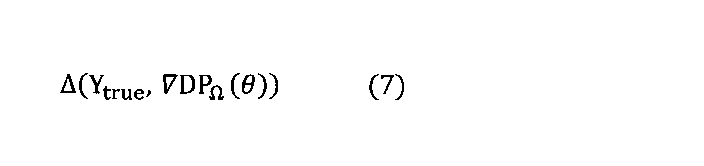
一方で、Gradient layerである∇DPΩ(θ)は、上記の式(4)により定義されるY*(θ)の微分可能な近似として利用することができる。例えば、∇DPΩ(θ)は、ニューラルネットワークの学習時に、正解出力Ytrueと、当該ニューラルネットの予測出力∇DPΩ(θ)とがどの程度近付いたかを表す損失関数(この損失関数をL2と表す。)を定義する際に用いることができる。損失関数L2は、例えば、以下の式(7)により定義される。
On the other hand, a Gradient layer ∇DP Ω (θ) can be used as a differentiable approximation Y * (theta) which is defined by the above equation (4). For example, ∇DP Ω (θ), at the time of the neural network training, the correct output Y true, the loss function (this loss function indicating whether approaching predicted output ∇DP Ω (θ) and how much is the neural network L 2 ). Loss function L 2 is, for example, is defined by the following equation (7).
ニューラルネットワークの或る層としてGradient layer(すなわち、∇DPΩ(θ)の演算を行う層)を用いた場合、このニューラルネットワークのパラメータを学習するために、∇DPΩ(θ)のヤコビアン∇∇DPΩ(θ)(すなわち、ヘッセ行列(Hessian)∇2DPΩ(θ))と、与えられた行列Z∈RN×Nとの積を計算する必要がある。これは、以下の参考文献1に開示されているPearlmutter's methodにより計算することができる。
Gradient layer (i.e., ∇DP Ω (θ layer for performing operations)) as a certain layer of the neural network when using, to learn the parameters of the neural network, ∇DP Omega Jacobian ∇∇ of (theta) It is necessary to calculate the product of DP Ω (θ) (that is, Hessian matrix ∇ 2 DP Ω (θ)) and the given matrix ZNR N × N. This can be calculated by Pearlmutter's method disclosed in Reference 1 below.
[参考文献1]
Pearlmutter, Barak A. Fast exact multiplication by the Hessian. Neural computation, 6(1):147-160, 1994.
なお、Gradient layerである∇DPΩ(θ)を、ニューラルネットワークの注意機構(attention mechanism)として用いることもできる。 [Reference 1]
Pearlmutter, Barak A. Fast exact multiplication by the Hessian.Neural computation, 6 (1): 147-160, 1994.
The gradient layer ∇DP Ω (θ) can be used as an attention mechanism of the neural network.
ここで、DPΩ(θ)及び∇DPΩ(θ)に用いられるmaxΩ関数は、動的計画法が対象とする問題に応じて適宜に設定されれば良いが、以下にmaxΩ関数の具体例を2つ示す。
Here, DP Omega (theta) and ∇DP Omega is max Omega functions used (theta), may be set appropriately in accordance with issues dynamic programming is targeted, but the max Omega function below Two specific examples are shown.
・maxΩ関数の具体例1
maxΩ関数の具体例1は、強凸正則化関数Ωとしてnegative entropyを用いたものである。 ・ Specific example 1 of max Ω function
Specific example 1 of the max Ω function uses a negative entropy as the strongly convex regularization function Ω.
maxΩ関数の具体例1は、強凸正則化関数Ωとしてnegative entropyを用いたものである。 ・ Specific example 1 of max Ω function
Specific example 1 of the max Ω function uses a negative entropy as the strongly convex regularization function Ω.
γ>0として、
と し て Assuming γ> 0,


ここで、
here,

・maxΩ関数の具体例2
maxΩ関数の具体例2は、強凸正則化関数Ωとしてsquared 2-normを用いたものである。 ・ Specific example 2 of max Ω function
The specific example 2 of the max Ω function uses squared 2-norm as the strongly convex regularization function Ω.
maxΩ関数の具体例2は、強凸正則化関数Ωとしてsquared 2-normを用いたものである。 ・ Specific example 2 of max Ω function
The specific example 2 of the max Ω function uses squared 2-norm as the strongly convex regularization function Ω.
γ>0として、
と し て Assuming γ> 0,


ここで、
here,

具体例2における∇maxΩは、以下の参考文献2に記載されている「sparsemax」と一致する。このため、具体例2におけるmaxΩ関数を用いた場合、スパース性の高い構造化出力データYを得られることが期待できる。
Δmax Ω in the specific example 2 matches “sparsemax” described in the following reference 2. Therefore, when the max Ω function in the specific example 2 is used, it can be expected that structured output data Y having high sparseness can be obtained.
[参考文献2]
Martins, Andre F.T. and Astudillo, Ramoon Fernandez. From softmax to sparsemax: A sparse model of attention and multi-label classification. In Proc. of ICML, pp. 1614-1623, 2016.
<機能構成>
以降では、本発明の実施の形態における変換装置100及び学習装置200の機能構成について説明する。 [Reference 2]
Martins, Andre FT and Astudillo, Ramoon Fernandez. From softmax to sparsemax: A sparse model of attention and multi-label classification.In Proc. Of ICML, pp. 1614-1623, 2016.
<Functional configuration>
Hereinafter, the functional configurations of theconversion device 100 and the learning device 200 according to the embodiment of the present invention will be described.
Martins, Andre F.T. and Astudillo, Ramoon Fernandez. From softmax to sparsemax: A sparse model of attention and multi-label classification. In Proc. of ICML, pp. 1614-1623, 2016.
<機能構成>
以降では、本発明の実施の形態における変換装置100及び学習装置200の機能構成について説明する。 [Reference 2]
Martins, Andre FT and Astudillo, Ramoon Fernandez. From softmax to sparsemax: A sparse model of attention and multi-label classification.In Proc. Of ICML, pp. 1614-1623, 2016.
<Functional configuration>
Hereinafter, the functional configurations of the
(変換装置100)
まず、本発明の実施の形態における変換装置100の機能構成について、図1を参照しながら説明する。図1は、本発明の実施の形態における変換装置100の機能構成の一例を示す図である。 (Conversion device 100)
First, a functional configuration of aconversion device 100 according to an embodiment of the present invention will be described with reference to FIG. FIG. 1 is a diagram illustrating an example of a functional configuration of a conversion device 100 according to an embodiment of the present invention.
まず、本発明の実施の形態における変換装置100の機能構成について、図1を参照しながら説明する。図1は、本発明の実施の形態における変換装置100の機能構成の一例を示す図である。 (Conversion device 100)
First, a functional configuration of a
図1に示すように、本発明の実施の形態における変換装置100は、前処理部101と、変換処理部102とを有する。これら各機能部は、例えば、変換装置100にインストールされた1以上のプログラムが、CPU(Central Processing Unit)等の演算装置に実行させる処理により実現される。
As shown in FIG. 1, the conversion device 100 according to the embodiment of the present invention includes a pre-processing unit 101 and a conversion processing unit 102. Each of these functional units is realized by, for example, a process in which one or more programs installed in the conversion device 100 are executed by an arithmetic device such as a CPU (Central Processing Unit).
前処理部101及び変換処理部102は、構造化入力データXを構造化出力データY(=∇DPΩ(θ))に変換する。又は、前処理部101及び変換処理部102は、構造化入力データXを、動的計画法の解(=DPΩ(θ))に変換する。なお、上述したように、DPΩ(θ)は、正確には動的計画法の解DP(θ)の近似である。
Pre-processing unit 101 and the conversion unit 102 converts the structured input data X structured output data Y (= ∇DP Ω (θ) ). Or, pre-processing unit 101 and the conversion unit 102 converts the structured input data X, the solution of dynamic programming (= DP Ω (θ)) on. Note that, as described above, DP Ω (θ) is exactly an approximation of the solution DP (θ) of the dynamic programming.
前処理部101及び変換処理部102は、1以上のニューラルネットワークにより実現される。例えば、上述したように、前処理部101は、双方向長短期記憶(BLSTM)等のニューラルネットワークで実現され、変換処理部102は、動的計画法の演算を行う層を有するニューラルネットワークにより実現される。
The pre-processing unit 101 and the conversion processing unit 102 are realized by one or more neural networks. For example, as described above, the pre-processing unit 101 is realized by a neural network such as bidirectional long-term short-term storage (BLSTM), and the conversion processing unit 102 is realized by a neural network having a layer for performing a dynamic programming operation. Is done.
なお、前処理部101及び変換処理部102は、前処理部101を実現するニューラルネットワークと、変換処理部102を実現するニューラルネットワークとを組み合わせたニューラルネットワークにより実現されていても良い。この場合、前処理部101及び変換処理部102を実現するニューラルネットワークは、構造化入力データXをθに変換する層(前処理部101の演算を行う層)と、θを構造化出力データY(=∇DPΩ(θ))又は動的計画法の解(=DPΩ(θ))に変換する層(変換処理部102の演算を行う層)とを有することになる。
The pre-processing unit 101 and the conversion processing unit 102 may be realized by a neural network that combines a neural network that realizes the pre-processing unit 101 and a neural network that realizes the conversion processing unit 102. In this case, the neural network that realizes the preprocessing unit 101 and the conversion processing unit 102 includes a layer that converts the structured input data X into θ (a layer that performs an operation of the preprocessing unit 101) and a layer that converts θ into the structured output data Y (= ∇DP Ω (θ)) or will have a (a layer for performing an operation of the conversion processing unit 102) solution (= DP Omega (theta)) layer into a dynamic programming.
前処理部101は、学習済のニューラルネットワークにより、上記の式(1´)又は式(2´)における前処理(preprocessing)を行う。すなわち、前処理部101は、構造化入力データXをθに変換する。この前処理は、動的計画法が対象とする問題に応じて決定される所定の前処理である。例えば、上述したように、動的計画法が対象とする問題が品詞タグ付け(Part-of-Speech Tagging)である場合、この前処理は、双方向長短期記憶(BLSTM)により実現される。
The preprocessing unit 101 performs preprocessing in the above equation (1 ′) or equation (2 ′) using the learned neural network. That is, the preprocessing unit 101 converts the structured input data X into θ. This pre-processing is a predetermined pre-processing determined according to a problem to be addressed by the dynamic programming. For example, as described above, when the problem targeted by the dynamic programming is part-of-speech tagging (Part-of-Speech @ Tagging), this preprocessing is realized by bidirectional long-term short-term storage (BLSTM).
なお、変換装置100が前処理部101を有する代わりに、変換装置100とは異なる別の装置が前処理部101を有しても良い。この場合、当該別の装置の前処理部101で構造化入力データXをθに変換した後、このθを変換装置100に入力するようにしても良い。
Note that instead of the conversion device 100 having the pre-processing unit 101, another device different from the conversion device 100 may have the pre-processing unit 101. In this case, the preprocessing unit 101 of the other device may convert the structured input data X into θ, and then input this θ to the conversion device 100.
変換処理部102は、学習済のニューラルネットワークにより、上記の式(1´)又は式(2´)におけるDPΩ又は∇DPΩに相当する演算を行う。すなわち、変換処理部102は、前処理部101による前処理で得られたθを、構造化出力データY(=∇DPΩ(θ))又は動的計画法の解(=DPΩ(θ))に変換する。この変換結果(DPΩ(θ)又は∇DPΩ(θ))は、所定の出力先に出力される。所定の出力先としては、例えば、ディスプレイ等の表示装置、補助記憶装置等の記憶装置、他のプログラム、他の装置、ニューラルネットワークにおける次の層等が挙げられる。
Conversion processing unit 102, a trained neural network, performs a calculation corresponding to DP Omega or ∇DP Omega in the above formula (1 ') or formula (2'). That is, the conversion processing unit 102, a theta obtained by pretreatment with the pretreatment unit 101, the solution of the structured output data Y (= ∇DP Ω (θ) ) or dynamic programming (= DP Ω (θ) ). The conversion result (DP Ω (θ) or ∇DP Ω (θ)) is output to a predetermined output destination. Examples of the predetermined output destination include a display device such as a display, a storage device such as an auxiliary storage device, another program, another device, and the next layer in a neural network.
DPΩに相当する演算を行う場合、変換処理部102は、上記の式(5)で再帰的に定義された演算を行えば良い。これにより、DPΩ(θ)=vN(θ)が得られる。
When performing an operation corresponding to DP Omega, conversion processing unit 102 may be performed recursively defined operations by formula (5). Thus, DP Ω (θ) = v N (θ) is obtained.
一方で、∇DPΩに相当する演算を行う場合、変換処理部102は、上記のStep1-1~Step1-3の手順で示される演算を行えば良い。これにより、∇DPΩ(θ)が得られる。
On the other hand, when performing an operation corresponding to ∇DP Ω , the conversion processing unit 102 may perform the operation shown in the above-described procedures of Step 1-1 to Step 1-3. As a result, ∇DP Ω (θ) is obtained.
なお、上述したように、変換処理部102による変換結果として、DPΩ(θ)又は∇DPΩ(θ)の何れを求めたいかは、動的計画法の対象とする問題に応じて決定される。なお、変換処理部102による変換結果として、DPΩ(θ)と∇DPΩ(θ)との両方を求めても良い。
As described above, whether DP Ω (θ) or ∇DP Ω (θ) is desired to be obtained as a conversion result by the conversion processing unit 102 is determined according to a problem to be subjected to the dynamic programming. You. Note that both DP Ω (θ) and ∇DP Ω (θ) may be obtained as conversion results by the conversion processing unit 102.
(学習装置200)
次に、本発明の実施の形態における学習装置200の機能構成について、図2を参照しながら説明する。図2は、本発明の実施の形態における学習装置200の機能構成の一例を示す図である。 (Learning device 200)
Next, a functional configuration of thelearning device 200 according to the embodiment of the present invention will be described with reference to FIG. FIG. 2 is a diagram illustrating an example of a functional configuration of the learning device 200 according to the embodiment of the present invention.
次に、本発明の実施の形態における学習装置200の機能構成について、図2を参照しながら説明する。図2は、本発明の実施の形態における学習装置200の機能構成の一例を示す図である。 (Learning device 200)
Next, a functional configuration of the
図2に示すように、本発明の実施の形態における学習装置200は、学習用データ入力部201と、前処理部101と、変換処理部102と、パラメータ更新部202とを有する。これら各機能部は、学習装置200にインストールされた1以上のプログラムが、CPU等の演算装置に実行させる処理により実現される。
As shown in FIG. 2, the learning device 200 according to the embodiment of the present invention includes a learning data input unit 201, a preprocessing unit 101, a conversion processing unit 102, and a parameter updating unit 202. Each of these functional units is realized by a process in which an arithmetic device such as a CPU executes one or more programs installed in the learning device 200.
なお、学習装置200の前処理部101及び変換処理部102は、上述した変換装置100の前処理部101及び変換処理部102と同様である。ただし、学習装置200の前処理部101及び変換処理部102を実現するニューラルネットワークのパラメータには、例えば、予め決められた初期値が設定されている。これらのパラメータが学習によって更新される。
The preprocessing unit 101 and the conversion processing unit 102 of the learning device 200 are the same as the preprocessing unit 101 and the conversion processing unit 102 of the conversion device 100 described above. However, the parameters of the neural network that implement the pre-processing unit 101 and the conversion processing unit 102 of the learning device 200 are set to, for example, predetermined initial values. These parameters are updated by learning.
学習用データ入力部201は、学習用データセットを入力する。学習用データセットとは、学習に用いられる構造化入力データXtrainと、この構造化入力データXtrainに対応する正解出力Ytrueとの組で構成される学習用データの集合である。
The learning data input unit 201 inputs a learning data set. The learning data set is a set of learning data composed of a set of structured input data X train used for learning and a correct output Y true corresponding to the structured input data X train .
前処理部101及び変換処理部102は、学習用データ入力部201が入力した学習用データに含まれる各構造化入力データXtrainに対して前処理(preprocessing)及び変換処理(DPΩに相当する演算又は∇DPΩに相当する演算)をそれぞれ行って、変換結果として、DPΩ(θ)又は∇DPΩ(θ)を計算する。
Pre-processing unit 101 and the conversion processing unit 102 corresponds to the pre-processing (preprocessing) and conversion processing (DP Omega for each structured input data X train the learning data input unit 201 is included in the learning data input Operation or an operation corresponding to ∇DP Ω ), respectively, to calculate DP Ω (θ) or ∇DP Ω (θ) as the conversion result.
パラメータ更新部202は、変換処理部102による変換結果DPΩ(θ)又は∇DPΩ(θ)と、前処理及び変換処理を行った構造化入力データXtrainに対応する正解出力Ytrueとに基づいて、所定の損失関数の微分値を計算し、この計算結果を用いてニューラルネットワークのパラメータを更新する。損失関数の微分値は、例えば、誤差逆伝播法等を用いて計算される。また、損失関数は、変換処理部102による変換結果がDPΩ(θ)である場合には上記の式(6)が、変換処理部102による変換結果が∇DPΩ(θ)である場合には上記の式(7)が用いられる。
The parameter updating unit 202 converts the conversion result DP Ω (θ) or ∇DP Ω (θ) by the conversion processing unit 102 and the correct output Y true corresponding to the structured input data X train that has been subjected to the preprocessing and the conversion processing. Then, the differential value of the predetermined loss function is calculated, and the parameters of the neural network are updated using the calculation result. The differential value of the loss function is calculated using, for example, an error back propagation method. The above equation (6) is used when the conversion result by the conversion processing unit 102 is DP Ω (θ), and when the conversion result by the conversion processing unit 102 is ∇DP Ω (θ). Uses the above equation (7).
このとき、パラメータ更新部202は、所定の条件を満たすまで、ニューラルネットワークのパラメータを繰り返し更新する。この所定の条件は、ニューラルネットワークの学習が収束したか否かを判定するものであり、例えば、損失関数の値が所定の閾値以下となったか否か、所定の繰り返し回数に達したか否か等である。
At this time, the parameter updating unit 202 repeatedly updates the parameters of the neural network until a predetermined condition is satisfied. The predetermined condition is to determine whether learning of the neural network has converged.For example, whether the value of the loss function has become equal to or less than a predetermined threshold, whether or not a predetermined number of repetitions has been reached. And so on.
パラメータ更新部202は、所定の条件を満たした場合、例えば、ニューラルネットワークのパラメータの値を出力して処理を終了する。
When the predetermined condition is satisfied, for example, the parameter updating unit 202 outputs the value of the parameter of the neural network, and ends the process.
<変換装置100の動作の具体例1>
以降では、変換装置100の動作の具体例1として、変換処理部102がビタビアルゴリズム(Viterbi Algorithm)に相当する演算を行う場合について説明する。ビタビアルゴリズムは、動的計画法に用いられるアルゴリズムの中で最も有名な例の1つであり、各時刻において或る状態から別の状態に所定の確率で遷移するような状態遷移モデルの下で、入力系列に対する状態系列のうち、尤もらしい状態系列を出力系列として求めるアルゴリズムである。各状態をノード、状態から状態への遷移を有向エッジ、状態から状態に遷移する確率を重みとすれば、上記の状態遷移モデルは、重み付き有向非巡回グラフ(DAG)で表すことができる。この場合、状態系列は、重み付き有向非巡回グラフ上の開始ノードから終了ノードまでの経路として表すことができる。 <Specific example 1 of operation ofconversion device 100>
Hereinafter, as a specific example 1 of the operation of theconversion device 100, a case where the conversion processing unit 102 performs an operation corresponding to a Viterbi algorithm will be described. The Viterbi algorithm is one of the most famous examples of the algorithm used in the dynamic programming, and is based on a state transition model in which a state transitions from one state to another state with a predetermined probability at each time. , Among the state sequences for the input sequence, an algorithm that determines a likely state sequence as an output sequence. If each state is a node, the transition from state to state is a directed edge, and the probability of transition from state to state is weight, the above state transition model can be represented by a weighted directed acyclic graph (DAG). it can. In this case, the state sequence can be represented as a path from the start node to the end node on the weighted directed acyclic graph.
以降では、変換装置100の動作の具体例1として、変換処理部102がビタビアルゴリズム(Viterbi Algorithm)に相当する演算を行う場合について説明する。ビタビアルゴリズムは、動的計画法に用いられるアルゴリズムの中で最も有名な例の1つであり、各時刻において或る状態から別の状態に所定の確率で遷移するような状態遷移モデルの下で、入力系列に対する状態系列のうち、尤もらしい状態系列を出力系列として求めるアルゴリズムである。各状態をノード、状態から状態への遷移を有向エッジ、状態から状態に遷移する確率を重みとすれば、上記の状態遷移モデルは、重み付き有向非巡回グラフ(DAG)で表すことができる。この場合、状態系列は、重み付き有向非巡回グラフ上の開始ノードから終了ノードまでの経路として表すことができる。 <Specific example 1 of operation of
Hereinafter, as a specific example 1 of the operation of the
したがって、構造化入力データXを入力系列X=(x1,x2,・・・,xT)とした場合、ビタビアルゴリズムでは、例えば、この入力系列Xに対する状態系列y=(y1,y2,・・・,yT)のうち、尤もらしい状態系列y(すなわち、有向非巡回グラフ上の尤もらしい経路y)を解(出力系列)として求めることになる。ここで、各xt(t=1,2,・・・,T)はD次元の実ベクトル、各yt(t=1,2,・・・,T)は[S]の元であるとする。なお、[S]は、集合{1,・・・,S}を表す。
Therefore, when structured input data X is input sequence X = (x 1 , x 2 ,..., X T ), the Viterbi algorithm, for example, uses state sequence y = (y 1 , y) for input sequence X 2 ,..., Y T ), a likely state sequence y (that is, a likely path y on the directed acyclic graph) is determined as a solution (output sequence). Here, each x t (t = 1, 2,..., T) is a D-dimensional real vector, and each y t (t = 1, 2,..., T) is an element of [S]. And [S] represents the set {1,..., S}.
具体的には、例えば、入力系列Xとして各xtの各々が単語である単語系列Xを、出力系列yとして各xtに対応するタグytの系列を考えることができる。この場合、ビタビアルゴリズムは、入力系列Xに対して品詞タグ付け(Part-of-Speech Tagging)を行う処理と考えることができる。
Specifically, for example, can be considered a word sequence X each of the x t is a word as an input sequence X, the sequence of tag y t for each x t as the output sequence y. In this case, the Viterbi algorithm can be considered as a process of performing part-of-speech tagging on the input sequence X.
ここで、時刻tにおいてノードjからノードiへ遷移する場合をyt,i,j=1、それ以外の場合をyt,i,j=0とすれば、状態系列yは、(t,i,j)成分の要素がyt,i,jであるT×S×SのバイナリテンソルYで表すことができる。
Here, assuming that y t, i, j = 1 when transitioning from node j to node i at time t, and y t, i, j = 0 in other cases, the state sequence y becomes (t, i, j) . The element of the (i, j) component can be represented by a T × S × S binary tensor Y in which the elements are y t, i, j .
また、時刻tにおいてノードjからノードiに遷移する確率をθt,i,jとして、(t,i,j)成分の要素がθt,i,jであるT×S×Sの実テンソルをθとする。このθは、例えばBLSTM等を用いて前処理部101により求められる。すなわち、この場合、変換装置100の前処理部101は、例えばBLSTMによりT×S×Sの実テンソルθを求めることになる。
Also, the probability of transition from the node j to node i at time t theta t, i, as j, (t, i, j) real tensor elements components theta t, i, a j T × S × S Is θ. Is obtained by the pre-processing unit 101 using, for example, BLSTM. That is, in this case, the preprocessing unit 101 of the conversion apparatus 100 obtains the actual tensor θ of T × S × S by, for example, BLSTM.
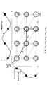
すると、フロベニウス内積<Y,θ>は、状態系列yが表す経路に沿って各エッジの重みθt,i,jを足し合わせた総和に相当する。この様子を図3に示す。図3に示す例では、入力系列をX=(x1,x2,x3)=(the,boat,sank)、状態系列をy=(y1,y2,y3)、yt∈{NOUN,VERB,DET}とした場合に、この入力系列Xに対する状態系列yのうち、時刻t=1でノード1からノード3、時刻t=2でノード3からノード1、時刻t=3でノード3からノード2に遷移したときの状態系列yを表している。このとき、図3に示すように、フロベニウス内積<Y,θ>は、<Y,θ>=θ1,3,1+θ2,1,3+θ3,2,1と表される。
Then, the Frobenius inner product <Y, θ> corresponds to the sum of the weights θ t, i, j of the respective edges along the path represented by the state sequence y. This is shown in FIG. In the example shown in FIG. 3, the input sequence X = (x 1, x 2 , x 3) = (the, boat, sank), the state sequence y = (y 1, y 2 , y 3), y t ∈ If {NOUN, VERB, DET}, the state sequence y for this input sequence X is from node 1 to node 3 at time t = 1, from node 3 to node 1 at time t = 2, and at time t = 3. The state sequence y when transitioning from node 3 to node 2 is shown. At this time, as shown in FIG. 3, the Frobenius inner product <Y, theta> is represented <Y, θ> = a θ 1,3,1 + θ 2,1,3 + θ 3,2,1 .
ここで、このフロベニウス内積<Y,θ>=θ1,3,1+θ2,1,3+θ3,2,1が最大スコアであれば、図3に示す経路yが最尤経路(すなわち、ビタビアルゴリズムの解となる出力系列)であり、このときの経路yは、単語x1=「the」に対して品詞y1=「DET」(限定詞)、単語x2=「boat」に対して品詞y2=「NOUN」(名詞)、単語x3=「sank」に対して品詞y3=「VERB」(動詞)が対応付けられることを表している。
Here, the Frobenius inner product <Y, θ> = if θ 1,3,1 + θ 2,1,3 + θ 3,2,1 is the maximum score, the path y is the maximum likelihood path shown in FIG. 3 (i.e., An output sequence which is a solution of the Viterbi algorithm). At this time, the path y is a part of speech y 1 = “DET” (qualifier) for the word x 1 = “the” and a word x 2 = “boat” for the word x 2 = “boat”. This indicates that the part of speech y 3 = “VERB” (verb) is associated with the part of speech y 2 = “NOUN” (noun) and the word x 3 = “sank”.
なお、Ω=-H(negative entropy)とすれば、以下の参考文献3に開示されているlinear-chain CRFs(conditional random fields)を復元することができる。
If Ω = −H (negative @ entropy), linear-chain @ CRFs (conditional @ random @ fields) disclosed in Reference 3 below can be restored.
[参考文献3]
Lafferty, John, McCallum, Andrew, and Pereira, Fernando CN. Conditional random fields: Probabilistic models for segmenting and labeling sequence data. In Proc. of ICML, pp. 282-289, 2001.
ビタビアルゴリズムの解を求めるためには、変換装置100の変換処理部102は、前処理部101で求めたT×S×Sの実テンソルθに基づき、以下に定義されるVitΩ(θ)と、このVitΩ(θ)から計算される∇VitΩ(θ)とを計算すれば良い。 [Reference 3]
Lafferty, John, McCallum, Andrew, and Pereira, Fernando CN.Conditional random fields: Probabilistic models for segmenting and labeling sequence data.In Proc. Of ICML, pp. 282-289, 2001.
In order to obtain a solution of the Viterbi algorithm, theconversion processing unit 102 of the conversion apparatus 100 calculates Vit Ω (θ) defined below based on the T × S × S real tensor θ obtained by the preprocessing unit 101. ∇Vit Ω (θ) calculated from this Vit Ω (θ) may be calculated.
Lafferty, John, McCallum, Andrew, and Pereira, Fernando CN. Conditional random fields: Probabilistic models for segmenting and labeling sequence data. In Proc. of ICML, pp. 282-289, 2001.
ビタビアルゴリズムの解を求めるためには、変換装置100の変換処理部102は、前処理部101で求めたT×S×Sの実テンソルθに基づき、以下に定義されるVitΩ(θ)と、このVitΩ(θ)から計算される∇VitΩ(θ)とを計算すれば良い。 [Reference 3]
Lafferty, John, McCallum, Andrew, and Pereira, Fernando CN.Conditional random fields: Probabilistic models for segmenting and labeling sequence data.In Proc. Of ICML, pp. 282-289, 2001.
In order to obtain a solution of the Viterbi algorithm, the


ここで、VitΩ(θ)は、以下のStep2-1~Step2-3の手順(順方向の手順)により計算することができる。また、∇VitΩ(θ)は、以下のStep2-1~Step2-3の手順が行われた後に、以下のStep3-1~Step3-2の手順(逆方向の手順)により計算することができる。なお、以下のStep2-1~Step2-3及びStep3-1~Step3-2では、Qを(T+1)×T×Sのテンソル、Uを(T+1)×Sの行列、すなわち、
Here, Vit Ω (θ) can be calculated by the following procedure of Step 2-1 to Step 2-3 (forward procedure). Further, ∇Vit Ω (θ) can be calculated by the following procedure of Step 3-1 to Step 3-2 (the procedure in the reverse direction) after the following procedure of Step 2-1 to Step 2-3 is performed. . In the following Step 2-1 to Step 2-3 and Step 3-1 to Step 3-2, Q is a tensor of (T + 1) × T × S, and U is a matrix of (T + 1) × S, that is,

とする。また、θ∈RT×N×Nは所与であるものとする。
And Further, it is assumed that θ∈RT × N × N is given.
Step2-1:v0=0∈RSとする。
Step2-1: v and 0 = 0∈R S.
Step2-2:t=1,・・・,Tに対して、順に、各i∈[S]に対する以下の計算を行う。
{Step 2-2: For t = 1,..., T, the following calculation is performed for each iS [S] in order.


Step3-1:uT+1=(1,0,・・・,0)∈RSとする。
Step3-1: u T + 1 = ( 1,0, ···, 0) and ∈R S.
Step3-2:t=T,・・・,0に対して、順に、各j∈[S]に対する以下の計算を行う。
{Step 3-2: For t = T,..., 0, the following calculation is performed for each j∈ [S] in order.

以上の手順により
に よ り By the above procedure

が得られる。
Is obtained.
また、上記のStep3-1~Step3-3の手順を行った後、以下のStep4-1~Step4-5の手順により、与えられたZ∈RT×S×Sに対して、<∇VitΩ(θ),Z>及び∇2VitΩ(θ)Zを計算することができる。なお、Step4-1~Step4-3が順方向の手順、Step4-4~Step4-5が逆方向の手順である。
Also, after performing the above-described steps 3-1 to 3-3, the following steps 4-1 to 4-5 give <∇Vit Ω to the given Z∈RT × S × S. (Θ), Z> and ∇ 2 Vit Ω (θ) Z can be calculated. Step 4-1 to Step 4-3 are forward procedures, and Step 4-4 to Step 4-5 are reverse procedures.
Step4-1:まず、
Step4-1: First,

Step4-2:t=1,・・・,Tに対して、順に、各i∈[S]に対する以下の計算を行う。
{Step 4-2: For t = 1,..., T, the following calculation is performed for each iS [S] in order.


とする。
And
Step4-5:t=T,・・・,0に対して、順に、各i∈[S]に対する以下の計算を行う。
{Step 4-5: For t = T,..., 0, the following calculation is sequentially performed for each i∈ [S].


<変換装置100の動作の具体例2>
以降では、変換装置100の動作の具体例2として、変換処理部102が動的時間伸縮法(DTW:Dynamic Time Wrapping)に相当する演算を行う場合について説明する。動的時間伸縮法は、2つの時系列データの相関(類似度)を分析する場合等に用いられる。 <Specific example 2 of operation ofconversion device 100>
Hereinafter, as a specific example 2 of the operation of theconversion apparatus 100, a case will be described in which the conversion processing unit 102 performs an operation corresponding to the dynamic time wrapping method (DTW: Dynamic Time Wrapping). The dynamic time warping method is used when analyzing the correlation (similarity) between two time-series data.
以降では、変換装置100の動作の具体例2として、変換処理部102が動的時間伸縮法(DTW:Dynamic Time Wrapping)に相当する演算を行う場合について説明する。動的時間伸縮法は、2つの時系列データの相関(類似度)を分析する場合等に用いられる。 <Specific example 2 of operation of
Hereinafter, as a specific example 2 of the operation of the
NAを時系列データAの系列長、NBを時系列データBの系列長とする。また、時系列データAのi番目の観測値をai、時系列データBのj番目の観測値をbjとする。
Sequence length of the time series data A to N A, the sequence length of the time series data B to N B. Also, i th observation value a i of the time series data A, when the j th observation value series data B and b j.
そして、aiとbjとが類似する場合はyij=1、そうでない場合はyij=0として、yijを要素とするNA×NBのバイナリ行列Yを考えた場合、このバイナリ行列Yは、時系列データAと時系列データBとの対応関係(類似関係)を表すアラインメントYである。
Then, as y ij = 0 if y ij = 1, otherwise if similar and the a i and b j, when considering binary matrix Y of N A × N B to the y ij element, the binary The matrix Y is an alignment Y representing the correspondence (similarity) between the time-series data A and the time-series data B.
また、θをNA×NBの行列として、θの各要素をθi,jとする。古典的な例としては、或る微分可能な距離尺度dを用いて、θi,j=d(ai,bj)である。このθは、変換装置100の前処理部101により求められる。なお、θは、距離行列とも呼ばれる。
Also, the theta as matrix N A × N B, each element of theta and theta i, j. As a classic example, using some differentiable distance measure d, θ i, j = d (a i , b j ). Is obtained by the preprocessing unit 101 of the conversion device 100. Note that θ is also called a distance matrix.
すると、観測値の組(ai,bj)をノードとして、アラインメントYは、重み付き有向非巡回グラフ(DAG)上の経路(パス)を表す。
Then, using the set of observation values (a i , b j ) as a node, the alignment Y represents a path on a weighted directed acyclic graph (DAG).
ここで、全ての単調アラインメント行列の集合を
を Here, the set of all monotone alignment matrices is

上記の単調アラインメント行列Yを用いることで、フロベニウス内積<Y,θ>は、単調アラインメント行列Yが表す経路に沿って各エッジの重みθi,jを足し合わせた総和に相当する。すなわち、このフロベニウス内積<Y,θ>をアラインメントのコストに用いることができる。図4に示す経路では、フロベニウス内積<Y,θ>は、<Y,θ>=θ1,1+θ2,2+θ2,3+θ3,3+θ3,4と表される。
By using the above-described monotone alignment matrix Y, the Frobenius inner product <Y, θ> corresponds to the sum of the weights θ i, j of the respective edges along the path represented by the monotone alignment matrix Y. That is, the Frobenius inner product <Y, θ> can be used for the cost of the alignment. In the path shown in FIG. 4, the Frobenius inner product <Y, θ> is expressed as <Y, θ> = θ 1,1 + θ 2,2 + θ 2,3 + θ 3,3 + θ 3,4 .
ここで、vi,j(θ)をアラインメントの(i,j)成分(セル)のコストであるとすれば、vi,j(θ)は、
Here, if vi , j (θ) is the cost of the (i, j) component (cell) of the alignment, then vi , j (θ) is

と表すことができる。
It can be expressed as.
また、minΩ関数、勾配∇minΩ及びヘッセ行列∇2minΩをそれぞれ以下で定義及び導入する。
In addition, a min Ω function, a gradient ∇min Ω, and a Hessian matrix ∇ 2 min Ω are defined and introduced below, respectively.


は所与であるものとする。
Is given.
Step5-1:v0,0=0とする。また、i=1,・・・,NA、j=1,・・・,NBに対して、vi,0=v0,j=∞とする。
Step 5-1: It is assumed that v 0,0 = 0. Further, i = 1, ···, N A, j = 1, ···, against the N B, and v i, 0 = v 0, j = ∞.
Step5-2:i=1,・・・,NA,j=1,・・・,NBに対して、順に、以下の計算を行う。
Step5-2: i = 1, ···, N A, j = 1, ···, against the N B, in turn, performs the following calculation.


Step6-2:j=NB,・・・,1,i=NA,・・・,1対して、順に、以下の計算を行う。
Step 6-2: The following calculation is sequentially performed on j = N B ,..., 1, i = N A ,.


が得られる。
Is obtained.
また、上記のStep5-1~Step5-2の手順を行った後、以下のStep7-1~Step7-4の手順により、与えられた
Also, after performing the above-mentioned procedures of Step 5-1 to Step 5-2, the following steps 7-1 to 7-4 are provided.

Step7-1:まず、i=0,・・・,NA、j=1,・・・,NBに対して、
Step7-1: First, i = 0, ···, N A, j = 1, ···, against the N B,

Step7-2:i=1,・・・,NB,j=1,・・・,NAに対して、順に、以下の計算を行う。
Step7-2: i = 1, ···, N B, j = 1, ···, against N A, in turn, performs the following calculation.


とする。
And
Step7-4:j=NB,・・・,1,i=NA,・・・,1に対して、順に、以下の計算を行う。
Step7-4: The following calculation is sequentially performed on j = N B ,..., 1 and i = N A ,.


<本発明の効果>
ここで、本発明の一例として上記の具体例2を用いた場合における効果について、図5を参照しながら説明する。図5は、本発明の効果の一例を示す図である。 <Effect of the present invention>
Here, the effect when the above specific example 2 is used as an example of the present invention will be described with reference to FIG. FIG. 5 is a diagram illustrating an example of the effect of the present invention.
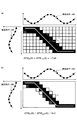
図5(a)は、Ωとしてnegative entropyを用いた場合におけるDTWΩ(θ)=-7.49と、∇DTWΩ(θ)のヒートマップとを示している。一方で、図5(b)は、Ωとしてsquared 2-normを用いた場合におけるDTWΩ(θ)=9.61と、∇DTWΩ(θ)のヒートマップとを示している。ヒートマップは、セルの色が濃い程その値が大きいことを表し、セルが存在しない場所は値が0であることを表している。また、図5(a)及び図5(b)におけるラインLは、maxΩ関数ではなく、max関数を用いた場合におけるDTW(θ)に対応するアラインメントを表している。
5 (a) is, DTW Omega in the case of using the negatives entropy as Ω (θ) = - 7.49 and shows a heat map of ∇DTW Ω (θ). On the other hand, FIG. 5B shows a heat map of DTW Ω (θ) = 9.61 and ΔDTW Ω (θ) when squared 2-norm is used as Ω . The heat map indicates that the darker the cell is, the larger the value is, and the place where no cell is present indicates that the value is 0. The line L in FIGS. 5A and 5B represents an alignment corresponding to DTW (θ) when a max function is used instead of the max Ω function.
図5(a)及び図5(b)に示すように、いずれの∇DTWΩ(θ)も、DTW(θ)に対応するアラインメントを高い精度で近似できており、高い解釈性が得られていることがわかる。また、図5(b)では、図5(a)と比べて、より高いスパース性も得られている。したがって、本発明の実施の形態では、微分可能で、かつ、解釈性が高い動的計画法の演算が実現できていることがわかる。
Figure 5 (a) and as shown in FIG. 5 (b), any ∇DTW Ω (θ) even, and can be approximated with high accuracy alignment corresponding to DTW (theta), and high construed property is obtained You can see that there is. Also, in FIG. 5B, higher sparsity is obtained than in FIG. 5A. Therefore, in the embodiment of the present invention, it can be seen that a dynamic programming operation that is differentiable and highly interpretable can be realized.
なお、図5(a)及び図5(b)でヒートマップとして示されている∇DTWΩ(θ)は、上述したように、誤差逆伝播法によって得られる。これにより、距離行列θの学習が可能となる。
Note that ∇DTW Ω (θ) shown as a heat map in FIGS. 5A and 5B is obtained by the error back propagation method as described above. This makes it possible to learn the distance matrix θ.
<ハードウェア構成>
最後に、本発明の実施の形態における変換装置100及び学習装置200のハードウェア構成について、図6を参照しながら説明する。図6は、本発明の実施の形態における変換装置100及び学習装置200のハードウェア構成の一例を示す図である。なお、変換装置100及び学習装置200は同様のハードウェア構成で実現可能であるため、以降では、主に、変換装置100のハードウェア構成について説明する。 <Hardware configuration>
Finally, the hardware configuration of theconversion device 100 and the learning device 200 according to the embodiment of the present invention will be described with reference to FIG. FIG. 6 is a diagram illustrating an example of a hardware configuration of the conversion device 100 and the learning device 200 according to the embodiment of the present invention. Since the conversion device 100 and the learning device 200 can be realized with the same hardware configuration, the hardware configuration of the conversion device 100 will be mainly described below.
最後に、本発明の実施の形態における変換装置100及び学習装置200のハードウェア構成について、図6を参照しながら説明する。図6は、本発明の実施の形態における変換装置100及び学習装置200のハードウェア構成の一例を示す図である。なお、変換装置100及び学習装置200は同様のハードウェア構成で実現可能であるため、以降では、主に、変換装置100のハードウェア構成について説明する。 <Hardware configuration>
Finally, the hardware configuration of the
図6に示すように、本発明の実施の形態における変換装置100は、入力装置301と、表示装置302と、外部I/F303と、RAM(Random Access Memory)304と、ROM(Read Only Memory)305と、演算装置306と、通信I/F307と、補助記憶装置308とを有する。これら各ハードウェアは、それぞれがバスBを介して通信可能に接続されている。
As shown in FIG. 6, a conversion device 100 according to an embodiment of the present invention includes an input device 301, a display device 302, an external I / F 303, a RAM (Random Access Memory) 304, and a ROM (Read Only Memory). 305, an arithmetic unit 306, a communication I / F 307, and an auxiliary storage device 308. These pieces of hardware are communicably connected via a bus B.
入力装置301は、例えば、キーボードやマウス、タッチパネル等であり、ユーザが各種操作を入力するのに用いられる。表示装置302は、例えば、ディスプレイ等であり、変換装置100の処理結果を表示する。なお、変換装置100及び学習装置200は、入力装置301及び表示装置302の少なくとも一方を有していなくても良い。
The input device 301 is, for example, a keyboard, a mouse, a touch panel, or the like, and is used by a user to input various operations. The display device 302 is, for example, a display, and displays a processing result of the conversion device 100. Note that the conversion device 100 and the learning device 200 need not include at least one of the input device 301 and the display device 302.
外部I/F303は、外部装置とのインタフェースである。外部装置には、記録媒体303a等がある。変換装置100は、外部I/F303を介して、記録媒体303a等の読み取りや書き込みを行うことができる。記録媒体303aには、変換装置100が有する各機能部や学習装置200が有する各機能部を実現する1以上のプログラム等が記録されていても良い。
The external I / F 303 is an interface with an external device. The external device includes a recording medium 303a and the like. The conversion device 100 can read and write the recording medium 303a and the like via the external I / F 303. The recording medium 303a may store one or more programs or the like that realize each functional unit of the conversion device 100 and each functional unit of the learning device 200.
記録媒体303aとして、例えば、フレキシブルディスク、CD(Compact Disc)、DVD(Digital Versatile Disk)、SDメモリカード(Secure Digital memory card)、USB(Universal Serial Bus)メモリカード等が挙げられる。
Examples of the recording medium 303a include a flexible disk, a CD (Compact Disc), a DVD (Digital Versatile Disk), an SD memory card (Secure Digital Memory card), and a USB (Universal Serial Bus) memory card.
RAM304は、プログラムやデータを一時保持する揮発性の半導体メモリである。ROM305は、電源を切ってもプログラムやデータを保持することができる不揮発性の半導体メモリである。ROM305には、例えば、OS(Operating System)に関する設定や通信ネットワークに関する設定等が格納されている。
The RAM 304 is a volatile semiconductor memory that temporarily stores programs and data. The ROM 305 is a nonvolatile semiconductor memory that can retain programs and data even when the power is turned off. The ROM 305 stores, for example, settings related to an OS (Operating System), settings related to a communication network, and the like.
演算装置306は、例えば、CPUやGPU(Graphics Processing Unit)等であり、ROM305や補助記憶装置308等からプログラムやデータをRAM304上に読み出して処理を実行する演算装置である。
The arithmetic unit 306 is, for example, a CPU, a GPU (Graphics Processing Unit), or the like, and is an arithmetic unit that reads a program or data from the ROM 305 or the auxiliary storage device 308 onto the RAM 304 and executes processing.
通信I/F307は、変換装置100を通信ネットワークに接続するためのインタフェースである。変換装置100が有する各機能部や学習装置200が有する各機能部を実現する1以上のプログラムは、通信I/F307を介して、所定のサーバ装置等が取得(ダウンロード)されても良い。
The communication I / F 307 is an interface for connecting the conversion device 100 to a communication network. A predetermined server device or the like may be obtained (downloaded) via the communication I / F 307 for one or more programs realizing each functional unit included in the conversion device 100 and each functional unit included in the learning device 200.
補助記憶装置308は、例えば、HDD(Hard Disk Drive)やSSD(Solid State Drive)等であり、プログラムやデータを格納している不揮発性の記憶装置である。補助記憶装置308に格納されているプログラムやデータには、例えば、OS、変換装置100が有する各機能部や学習装置200が有する各機能部を実現する1以上のプログラム等がある。
The auxiliary storage device 308 is, for example, a hard disk drive (HDD) or a solid state drive (SSD), and is a nonvolatile storage device that stores programs and data. The programs and data stored in the auxiliary storage device 308 include, for example, an OS, one or more programs for realizing each functional unit of the conversion device 100 and each functional unit of the learning device 200, and the like.
本発明の実施の形態における変換装置100及び学習装置200は、図6に示すハードウェア構成を有することにより、上述した各種処理を実現することができる。
The conversion device 100 and the learning device 200 according to the embodiment of the present invention can realize the above-described various processes by having the hardware configuration illustrated in FIG.
本発明は、具体的に開示された上記の実施の形態に限定されるものではなく、特許請求の範囲から逸脱することなく、種々の変形や変更が可能である。
The present invention is not limited to the above-described embodiments specifically disclosed, and various modifications and changes can be made without departing from the scope of the claims.
100 変換装置
101 前処理部
102 変換処理部
200 学習装置
201 学習用データ入力部
202 パラメータ更新部 REFERENCE SIGNSLIST 100 conversion device 101 preprocessing unit 102 conversion processing unit 200 learning device 201 learning data input unit 202 parameter update unit
101 前処理部
102 変換処理部
200 学習装置
201 学習用データ入力部
202 パラメータ更新部 REFERENCE SIGNS
Claims (8)
- 入力された第1のデータXをニューラルネットワークにより第2のデータYに変換する変換装置であって、
前記第1のデータXに対して所定の前処理を行うことで得られた第3のデータθと、max関数に対して強凸正則化関数Ωを導入したmaxΩ関数を用いて再帰的に定義されるDPΩ関数とを用いて、重み付き有向非巡回グラフGで表される問題を対象とした動的計画法の解の近似DPΩ(θ)を計算する計算手段と、
前記計算手段により計算された前記DPΩ(θ)と、該DPΩ(θ)の勾配∇DPΩ(θ)との少なくとも一方を前記第2のデータYとして出力する出力手段と、
を有することを特徴とする変換装置。 A conversion device for converting the input first data X into second data Y by a neural network,
Recursively using the third data θ obtained by performing predetermined preprocessing on the first data X and a max Ω function in which a strongly convex regularization function Ω is introduced for the max function. Calculating means for calculating an approximate DP Ω (θ) of a dynamic programming solution for a problem represented by a weighted directed acyclic graph G using the defined DP Ω function and
Output means for outputting at least one of the DP Ω (θ) calculated by the calculation means and a gradient ΔDP Ω (θ) of the DP Ω (θ) as the second data Y;
A conversion device comprising: - 前記DPΩ関数は、


で再帰的に定義されるvi(θ)によって、DPΩ(θ)=vN(θ)と定義される、ことを特徴とする請求項1に記載の変換装置。 The DP Ω function is
In the v i (theta) is recursively defined, DP Ω (θ) = v N (θ) to be defined, that conversion apparatus according to claim 1, wherein the. - 前記強凸正則化関数Ωは、
γ>0として、


As γ> 0,
- 入力された第1のデータXを第2のデータYに変換するニューラルネットワークの学習を行う学習装置であって、
前記第1のデータXに対して所定の前処理を行うことで得られた第3のデータθと、max関数に対して強凸正則化関数Ωを導入したmaxΩ関数を用いて再帰的に定義されるDPΩ関数とを用いて、重み付き有向非巡回グラフGで表される問題を対象とした動的計画法の解の近似DPΩ(θ)を計算する計算手段と、
前記計算手段により計算された前記DPΩ(θ)と、該DPΩ(θ)の勾配∇DPΩ(θ)との少なくとも一方を前記第2のデータYとして出力する出力手段と、
前記出力手段により出力された前記DPΩ(θ)又は前記∇DPΩ(θ)と、前記第1のデータXに対する正解データYtrueとを用いた損失関数の微分値に基づいて、前記ニューラルネットワークのパラメータである前記θを更新する更新手段と、
を有することを特徴とする学習装置。 A learning device for learning a neural network that converts input first data X into second data Y,
Recursively using the third data θ obtained by performing predetermined preprocessing on the first data X and a max Ω function in which a strongly convex regularization function Ω is introduced for the max function. Calculating means for calculating an approximate DP Ω (θ) of a dynamic programming solution for a problem represented by a weighted directed acyclic graph G using the defined DP Ω function and
Output means for outputting at least one of the DP Ω (θ) calculated by the calculation means and a gradient ΔDP Ω (θ) of the DP Ω (θ) as the second data Y;
The neural network is based on a differential value of a loss function using the DP Ω (θ) or the ∇DP Ω (θ) output from the output unit and the correct data Y true for the first data X. Updating means for updating the parameter θ,
A learning device comprising: - 前記損失関数は、
前記出力手段により前記DPΩ(θ)が出力された場合は、DPΩ(θ)-<Ytrue,θ>であり、
前記出力手段により前記∇DPΩ(θ)が出力された場合は、ダイバーバージェンスΔ(Ytrue,∇DPΩ(θ))である、ことを特徴とする請求項4に記載の学習装置。 The loss function is
When the output means outputs the DP Ω (θ), DP Ω (θ) − <Y true , θ>,
The learning device according to claim 4, wherein when the output unit outputs the ∇DP Ω (θ), the divergence is Δ (Y true , ∇DP Ω (θ)). - 入力された第1のデータXをニューラルネットワークにより第2のデータYに変換するコンピュータが、
前記第1のデータXに対して所定の前処理を行うことで得られた第3のデータθと、max関数に対して強凸正則化関数Ωを導入したmaxΩ関数を用いて再帰的に定義されるDPΩ関数とを用いて、重み付き有向非巡回グラフGで表される問題を対象とした動的計画法の解の近似DPΩ(θ)を計算し、
計算された前記DPΩ(θ)と、該DPΩ(θ)の勾配∇DPΩ(θ)との少なくとも一方を前記第2のデータYとして出力する、
処理を実行することを特徴とする変換方法。 A computer for converting the input first data X into second data Y by a neural network,
Recursively using third data θ obtained by performing predetermined preprocessing on the first data X and a max Ω function in which a strongly convex regularization function Ω is introduced for the max function. Using the defined DP Ω function, an approximate DP Ω (θ) of the solution of the dynamic programming for the problem represented by the weighted directed acyclic graph G is calculated,
The calculated the DP Ω (θ), and outputs at least one of the said DP Omega gradient ∇DP Omega in (θ) (θ) as the second data Y,
A conversion method characterized by performing a process. - 入力された第1のデータXを第2のデータYに変換するニューラルネットワークの学習を行うコンピュータが、
前記第1のデータXに対して所定の前処理を行うことで得られた第3のデータθと、max関数に対して強凸正則化関数Ωを導入したmaxΩ関数を用いて再帰的に定義されるDPΩ関数とを用いて、重み付き有向非巡回グラフGで表される問題を対象とした動的計画法の解の近似DPΩ(θ)を計算し、
計算された前記DPΩ(θ)と、該DPΩ(θ)の勾配∇DPΩ(θ)との少なくとも一方を前記第2のデータYとして出力し、
出力された前記DPΩ(θ)又は前記∇DPΩ(θ)と、前記第1のデータXに対する正解データYtrueとを用いた損失関数の微分値に基づいて、前記ニューラルネットワークのパラメータである前記θを更新する、
処理を実行することを特徴とする学習方法。 A computer that learns a neural network that converts the input first data X into second data Y
Recursively using third data θ obtained by performing predetermined preprocessing on the first data X and a max Ω function in which a strongly convex regularization function Ω is introduced for the max function. Using the defined DP Ω function, an approximate DP Ω (θ) of the solution of the dynamic programming for the problem represented by the weighted directed acyclic graph G is calculated,
Outputting at least one of the calculated DP Ω (θ) and a gradient ΔDP Ω (θ) of the DP Ω (θ) as the second data Y;
Based on the differential value of the loss function using the output DP Ω (θ) or ∇DP Ω (θ) and the correct data Y true for the first data X, the parameter of the neural network is obtained. Updating the θ,
A learning method characterized by performing processing. - コンピュータを、請求項1乃至3の何れか一項に記載の変換装置における各手段、又は、請求項4又は5に記載の学習装置における各手段として機能させるためのプログラム。 A program for causing a computer to function as each unit in the conversion device according to any one of claims 1 to 3, or as each unit in the learning device according to claim 4 or 5.
Priority Applications (1)
| Application Number | Priority Date | Filing Date | Title |
|---|---|---|---|
| US17/258,236 US20210279579A1 (en) | 2018-07-09 | 2019-06-27 | Conversion apparatus, learning apparatus, conversion method, learning method and program |
Applications Claiming Priority (2)
| Application Number | Priority Date | Filing Date | Title |
|---|---|---|---|
| JP2018-129998 | 2018-07-09 | ||
| JP2018129998A JP2020009178A (en) | 2018-07-09 | 2018-07-09 | Conversion apparatus, learning apparatus, conversion method, learning method and program |
Publications (1)
| Publication Number | Publication Date |
|---|---|
| WO2020012975A1 true WO2020012975A1 (en) | 2020-01-16 |
Family
ID=69141896
Family Applications (1)
| Application Number | Title | Priority Date | Filing Date |
|---|---|---|---|
| PCT/JP2019/025636 WO2020012975A1 (en) | 2018-07-09 | 2019-06-27 | Conversion device, learning device, conversion method, learning method, and program |
Country Status (3)
| Country | Link |
|---|---|
| US (1) | US20210279579A1 (en) |
| JP (1) | JP2020009178A (en) |
| WO (1) | WO2020012975A1 (en) |
Families Citing this family (2)
| Publication number | Priority date | Publication date | Assignee | Title |
|---|---|---|---|---|
| US11399037B2 (en) * | 2019-09-06 | 2022-07-26 | Paypal, Inc. | Anomaly behavior detection in interactive networks |
| JP7341387B2 (en) * | 2020-07-30 | 2023-09-11 | オムロン株式会社 | Model generation method, search program and model generation device |
-
2018
- 2018-07-09 JP JP2018129998A patent/JP2020009178A/en active Pending
-
2019
- 2019-06-27 WO PCT/JP2019/025636 patent/WO2020012975A1/en active Application Filing
- 2019-06-27 US US17/258,236 patent/US20210279579A1/en active Pending
Non-Patent Citations (1)
| Title |
|---|
| SHINOHARA, SHOTA ET AL.: "Word segmentation method by sequence labeling using neural network", THE 9TH FORUM OF DATA ENGINEERING AND INFORMATION MANAGEMENT, THE DATABASE SOCIETY OF JAPAN, 8 March 2017 (2017-03-08) * |
Also Published As
| Publication number | Publication date |
|---|---|
| US20210279579A1 (en) | 2021-09-09 |
| JP2020009178A (en) | 2020-01-16 |
Similar Documents
| Publication | Publication Date | Title |
|---|---|---|
| CN108960277B (en) | Cold fusion of sequence-to-sequence models using language models | |
| Garg et al. | What can transformers learn in-context? a case study of simple function classes | |
| US11132512B2 (en) | Multi-perspective, multi-task neural network model for matching text to program code | |
| US20190266246A1 (en) | Sequence modeling via segmentations | |
| Yao et al. | Bi-directional LSTM recurrent neural network for Chinese word segmentation | |
| JP7443401B2 (en) | Systems and methods for training machine learning algorithms to process biologically related data, microscopy and trained machine learning algorithms | |
| US11113479B2 (en) | Utilizing a gated self-attention memory network model for predicting a candidate answer match to a query | |
| White et al. | Neural architecture search: Insights from 1000 papers | |
| US20170308790A1 (en) | Text classification by ranking with convolutional neural networks | |
| EP3156949A2 (en) | Systems and methods for human inspired simple question answering (hisqa) | |
| US10445654B2 (en) | Learning parameters in a feed forward probabilistic graphical model | |
| CN114641779A (en) | Countermeasure training of machine learning models | |
| US20210216887A1 (en) | Knowledge graph alignment with entity expansion policy network | |
| US10909451B2 (en) | Apparatus and method for learning a model corresponding to time-series input data | |
| CN114610900A (en) | Knowledge graph complementing method and system | |
| US11182665B2 (en) | Recurrent neural network processing pooling operation | |
| He et al. | Quantum Architecture Search with Meta‐Learning | |
| Felsberger et al. | Physics-constrained, data-driven discovery of coarse-grained dynamics | |
| Su et al. | Investigation of improving the pre-training and fine-tuning of BERT model for biomedical relation extraction | |
| WO2020012975A1 (en) | Conversion device, learning device, conversion method, learning method, and program | |
| KR102405578B1 (en) | Context-Aware Cross-Sentence Relation Extraction Apparatus with Knowledge Graph, and Method Thereof | |
| JP7331937B2 (en) | ROBUST LEARNING DEVICE, ROBUST LEARNING METHOD, PROGRAM AND STORAGE DEVICE | |
| Chakravarthy et al. | HYBRID ARCHITECTURE FOR SENTIMENT ANALYSIS USING DEEP LEARNING. | |
| JP6705506B2 (en) | Learning program, information processing apparatus, and learning method | |
| D’Souza et al. | Training recurrent neural networks as generative neural networks for molecular structures: how does it impact drug discovery? |
Legal Events
| Date | Code | Title | Description |
|---|---|---|---|
| 121 | Ep: the epo has been informed by wipo that ep was designated in this application |
Ref document number: 19835108 Country of ref document: EP Kind code of ref document: A1 |
|
| NENP | Non-entry into the national phase |
Ref country code: DE |
|
| 122 | Ep: pct application non-entry in european phase |
Ref document number: 19835108 Country of ref document: EP Kind code of ref document: A1 |