WO2020009126A1 - Authentication device and authentication method - Google Patents
Authentication device and authentication method Download PDFInfo
- Publication number
- WO2020009126A1 WO2020009126A1 PCT/JP2019/026367 JP2019026367W WO2020009126A1 WO 2020009126 A1 WO2020009126 A1 WO 2020009126A1 JP 2019026367 W JP2019026367 W JP 2019026367W WO 2020009126 A1 WO2020009126 A1 WO 2020009126A1
- Authority
- WO
- WIPO (PCT)
- Prior art keywords
- image
- iris
- authentication
- unit
- reflected light
- Prior art date
Links
Images


Classifications
-
- G—PHYSICS
- G06—COMPUTING; CALCULATING OR COUNTING
- G06T—IMAGE DATA PROCESSING OR GENERATION, IN GENERAL
- G06T1/00—General purpose image data processing
-
- G—PHYSICS
- G06—COMPUTING; CALCULATING OR COUNTING
- G06T—IMAGE DATA PROCESSING OR GENERATION, IN GENERAL
- G06T7/00—Image analysis
Definitions
- the following disclosure relates to an authentication device and the like.
- Patent Documents 1 and 2 disclose techniques for generating an image from which the reflection of ambient light has been removed.
- JP-A-10-22228 International Publication 2012/073381
- the reflection of the illumination light is contained in the pupil region as described above, the reflection of the illumination light also occurs at the boundary between the eyelid and the iris region in the iris region. For this reason, in the related art, the reflection in the iris area lowers the accuracy of iris authentication.
- Patent Documents 1 and 2 do not disclose techniques for suppressing a decrease in the accuracy of iris authentication due to reflection of illumination light.
- One embodiment of the present disclosure has an object to realize an authentication device capable of improving the accuracy of iris authentication by a realistic method.
- an authentication device includes an illumination unit that emits illumination light that irradiates a subject, and an imaging unit that captures an image including a pupil region and an iris region of the subject.
- an illumination unit that emits illumination light that irradiates a subject
- an imaging unit that captures an image including a pupil region and an iris region of the subject.
- An iris region acquiring unit that acquires, as an authentication iris region used for iris authentication, an area obtained by excluding at least a part of the image of the second reflected light from the iris area in the image, using an image of the authentication iris area.
- An iris code acquisition unit that acquires an iris code for performing iris authentication, the iris code acquired by the iris code acquisition unit, and a registered iris code registered in a storage unit are compared with each other to obtain the object.
- An authentication unit that performs iris authentication of a person.
- an authentication method captures an image including an illumination unit that emits illumination light for irradiating a subject, and a pupil region and an iris region of the subject.
- the first reflected light where the illumination light is directly reflected on the corneal surface of the subject, and after being reflected at the edge of the subject's eyelid,
- the second reflected light including at least the light reflected on the corneal surface in the vicinity of the boundary is reflected as an image of reflected light in a pupil region and an iris region in an image captured by the imaging unit, the iris is included in the image.
- the authentication device and the authentication method according to an aspect of the present disclosure it is possible to improve the accuracy of iris authentication by a realistic method.
- FIG. 2 is a block diagram illustrating a configuration example of a main part of the authentication device according to the first embodiment.
- (A) is a figure showing an example of an image which an imaging part acquires
- (b) is a figure for explaining an example of processing of an iris field acquisition part.
- FIG. 9 is a diagram for describing an example of a process for specifying a position and a size of a second reflected light.
- (A) And (b) is a graph which shows an example of the change of the luminance value in the arbitrary pixel row which passes through a pupil area. It is a flowchart which shows an example of the process in the said authentication apparatus.
- FIG. 9 is a block diagram illustrating a configuration example of a main part of an authentication device according to a second embodiment.
- FIG. 11 is a graph illustrating an example of a temporal change in a luminance value of a pixel corresponding to a position where the second reflected light is reflected when illumination on and illumination off are continuously repeated temporally.
- FIG. 4 is a diagram illustrating an example of a relationship between a switching timing of lighting on and lighting off and a shutter opening / closing timing of an imaging unit. It is a flowchart which shows an example of the process in the said authentication apparatus.
- FIG. 13 is a block diagram illustrating a configuration example of a main part of an authentication device according to a third embodiment.
- (A) is a figure showing an example of an image acquired when an eyelid is open, and
- (b) is a figure showing an example of an image acquired when an eyelid is almost closed.
- FIG. 14 is a block diagram illustrating a configuration example of a main part of an authentication device according to a fourth embodiment.
- A is a figure which shows an example of the 1st image and 2nd image acquired when an imaging target is a living body's eyes
- (b) and (c) are cases where an imaging target is a printed matter.
- (d) is 1st image and 2nd image acquired when an imaging target is a printed matter with which the lens which imitated the cornea was mounted.
- It is a figure showing an example of two images.
- FIG. 1 is a block diagram illustrating a configuration example of a main part of an authentication device 1 according to the present embodiment.
- the authentication device 1 authenticates the subject H using the iris authentication technology.
- the subject H to be authenticated (collated) by the authentication device 1 is a living body including the eyeball HE.
- the subject H living body
- the authentication by the authentication device 1 is performed based on the result of the image analysis on at least one of the two eyes HE of the subject H (at least one of the left eye and the right eye).
- the authentication device 1 performs iris authentication using an image captured by the imaging unit 2 and including the iris region HIR (see FIG. 2) of the eyeball HE.
- the authentication device 1 includes an imaging unit 2 (imaging device), an illumination unit 3 (illumination device), a storage unit 4, a display unit 5, and a control unit 6.
- the authentication device 1 does not need to integrally include all of these members.
- the authentication device 1 only needs to have at least the function of the control unit 6. That is, at least one of the imaging unit 2, the illumination unit 3, the storage unit 4, and the display unit 5 may be realized as an external device of the authentication device 1.
- the imaging unit 2 functions as an image acquisition unit that acquires an image including the eyes of the subject H by imaging the subject H. Specifically, the imaging unit 2 acquires an image including the pupil region HPP and the iris region HIR of the eyeball HE of the subject H so that the control unit 6 performs iris authentication.
- the imaging unit 2 includes an imaging element such as a CCD (Charge Coupled Device) or a CMOS (Complementary Metal Oxide Semiconductor).
- the imaging unit 2 has wavelength sensitivity to light having a wavelength of 700 nm or more and 1000 nm or less. In this case, a luminance value (shading information) in the iris region HIR can be acquired with high accuracy.
- the wavelength is not limited to the above range unless this point is considered.
- the illumination unit 3 emits illumination light for irradiating the subject H. Specifically, the illumination unit 3 controls emission of illumination light emitted to the eyes of the subject H. More specifically, the illumination unit 3 emits illumination light to the eyes of the subject H at the timing when the imaging unit 2 captures an image. That is, the illumination unit 3 irradiates the eyeball HE with illumination light when imaging the eyeball HE.
- the authentication device 1 can also perform imaging in a dark place by using the illumination unit 3. Further, when an image is taken in an environment where the intensity of the ambient light is relatively high (for example, outdoors), the image can be acquired with the influence of the ambient light reduced.
- the illumination unit 3 emits illumination light corresponding to the wavelength sensitivity of the imaging unit 2, for example.
- the illumination section 3 emits illumination light having a wavelength of, for example, 700 nm or more and 1000 nm or less.
- the illuminating unit 3 provides the intensity of illumination light (the illumination at the eyes of the subject H) at the eyeball HE (the position of the subject H).
- the intensity of the illumination light may be adjusted so that the light intensity is 10 W / m 2 or more.
- the authentication device 1 can acquire a clear image to the extent that iris authentication can be performed accurately even outdoors.
- the upper limit of the intensity of the illumination light is determined in consideration of, for example, the power consumption of the illumination unit 3, the safety of the eyes of the subject H, and the ease of realization of the illumination unit 3.
- the authentication device 1 determines that the illumination unit 3 has entered a range of a predetermined distance from the eyes of the subject H (the illumination unit 3 has approached the eyes of the subject H).
- a proximity sensor (not shown) for detecting may be provided. When the proximity sensor detects that the illumination unit 3 has approached the eyes of the subject H, the illumination unit 3 stops emitting illumination light.
- the state in which the illumination light is emitted is also referred to as “illumination on”, and the state in which the illumination light is not emitted (including the stop of emission) is also referred to as “illumination off”.
- the storage unit 4 stores various programs executed by the control unit 6 and data used by the programs.
- the data includes a registered iris code to be collated with the acquired iris code.
- the display unit 5 displays an authentication result obtained by the control unit 6.
- the authentication device 1 may include a speaker that notifies the authentication result as sound data instead of or in addition to the display unit 5.
- the control unit 6 controls each unit of the authentication device 1 as a whole. Details of the control unit 6 will be described later.
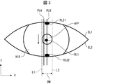
- FIG. 2A is a diagram illustrating an example of an image acquired by the imaging unit 2. As shown in FIG. 2A, an image of the first reflected light RL1 and the second reflected light RL2 is reflected in an image acquired by the imaging unit 2. Note that the images of the first reflected light RL1 and the second reflected light RL2 in the image are also simply referred to as the first reflected light RL1 and the second reflected light RL2.
- reflected light obtained as a result of reflecting the illumination light from the eyeball HE there are two types of reflected light obtained as a result of reflecting the illumination light from the eyeball HE, that is, a first reflected light RL1 and a second reflected light RL2.
- the first reflected light RL1 changes its reflection position depending on the angle at which the illumination light is incident on the eyeball HE, and is obtained by directly reflecting the illumination light on the corneal surface of the eyeball HE.
- the second reflected light RL2 is reflected immediately below the upper eyelid EL1 and immediately above the lower eyelid EL2, and the illumination light mainly reflected at the respective edges of the upper eyelid EL1 and the lower eyelid EL2 further reflects the corneal surface. It is obtained by reflection at.
- the second reflected light RL2 may include light obtained by further illuminating the illumination light reflected at the edge.
- the second reflected light RL2 includes at least light reflected on the edges of the upper eyelid EL1 and the lower eyelid EL2 and then reflected on the corneal surface near the boundary between the upper eyelid EL1 and the lower eyelid EL2.
- the corneal surface near the boundary with the upper eyelid EL1 means the corneal surface near the boundary between the upper eyelid EL1 and the eyeball HE when the eyeball HE is viewed from the front. The same applies to the corneal surface near the boundary with the lower eyelid EL2.
- the second reflected light RL2 is obtained by further reflecting the illumination light reflected at the edge on the corneal surface or the iris, because the structure of the edge of the eyelid is in front of the corneal surface near the boundary with the eyelid. This is caused by having a shape protruding from the surface.
- the edge of the upper eyelid EL1 has an eaves shape.
- the second reflected light RL2 includes the second reflected light RL21 reflected on the corneal surface near the boundary with the upper eyelid EL1, and the second reflected light RL22 reflected on the corneal surface near the boundary with the lower eyelid EL2.
- the second reflected light RL2 reflected on the boundary between the iris region HIR and the upper eyelid EL1 in the iris region HIR is the second reflected light RL21
- the second reflected light RL2 reflected on the boundary between the iris region HIR and the lower eyelid EL2 in the region HIR is the second reflected light RL22.
- the first reflection light RL1 is reflected inside the pupil region HPP by adjusting the positional relationship between the imaging unit 2 and the illumination unit 3. That is, the positional relationship between the imaging unit 2 and the illumination unit 3 is set such that the illumination light includes the first reflected light RL1 in the pupil region HPP.
- the first reflected light RL1 is not reflected in the iris region HIR. Therefore, the accuracy of iris authentication can be improved.
- the second reflected lights RL21 and RL22 are respectively provided at the boundary portions. Is reflected.
- the iris region HIR is on a substantially straight line that is a boundary portion between the iris region HIR and the upper eyelid EL1 and that passes through the pupil region HPP and is parallel to the eyelid opening / closing direction ( ⁇ Y-axis direction).
- the second reflected light RL21 is reflected.
- the second reflected light RL22 is reflected on the boundary between the iris region HIR and the lower eyelid EL2 in the iris region HIR and on the substantially straight line.
- the first reflected light RL1 and the second reflected light RL2 are reflected as reflected light images on the pupil region HPP and the iris region HIR in the image captured by the imaging unit 2. .
- the intensity of the illuminating light that can be realized from the viewpoint of the power consumption of the lighting unit and the size (module size) of the lighting unit that can be incorporated in the authentication device.
- the upper limit of the intensity of illumination light that can be realized has been raised.
- the intensity of illumination light increases, the influence of environmental light can be reduced in outdoor imaging. From this viewpoint, it is preferable to use an illumination unit having relatively high intensity of illumination light as the illumination unit 3.
- the intensity of the illumination light is relatively high, even if the positional relationship is adjusted so that the first reflected light RL1 is contained within the pupil region HPP, the size and the size cannot be ignored when performing iris authentication.
- the second reflected light RL2 having an intensity is reflected inside the iris region HIR.
- the authentication device 1 performs a process of removing the influence of the reflection of the second reflected light RL2, which occurs when the illumination unit 3 that can reduce the influence of environmental light is used. Therefore, the authentication device 1 includes the control unit 6 (particularly, the iris region acquisition unit 61).
- control unit 6 includes an iris area acquisition unit 61, an iris code acquisition unit 62, and an authentication unit 63.
- the iris region acquisition unit 61 acquires an authentication iris region CHIR in the image acquired by the imaging unit 2 excluding the image of the second reflected light RL2 reflected on the boundary portion of the iris region HIR.
- ((B) of FIG. 2 is a diagram for explaining an example of the processing of the iris area acquisition unit 61.
- the iris region acquiring unit 61 determines the width D1 of the second reflected light RL21 in the eyelid opening / closing direction and the second reflected light RL22. Of the eyelid in the opening and closing direction is calculated.
- the iris region acquisition unit 61 shifts the curve (boundary line BL1) along the upper eyelid EL1 and the edge of the eyeball HE toward the pupil region HPP ( ⁇ Y-axis direction) by the width D1.
- the iris region acquisition unit 61 shifts the curve (boundary line BL2) along the lower eyelid EL2 and the edge of the eyeball HE toward the pupil region HPP (+ Y axis direction) by the width D2.
- the iris region acquisition unit 61 specifies the regions included in the shifted boundary lines BL11 and BL12 in the iris region HIR as the authentication iris region CHIR (the hatched portion in FIG. 2B) used for iris authentication. I do. That is, the iris region acquisition unit 61 excludes the region outside the boundary line BL11 including the second reflected light RL21 and the region outside the boundary line BL12 including the second reflected light RL22 from the iris region HIR. , The authentication iris region CHIR is specified.
- the authentication iris area CHIR may be an area obtained by excluding the second reflected lights RL21 and RL22 from the iris area HIR. Therefore, the iris region acquisition unit 61 specifies, for example, the size and position of the second reflected lights RL21 and RL22, and specifies the region excluding only the second reflected lights RL21 and RL22 as the authentication iris region CHIR. It does not matter.
- the iris region acquisition unit 61 acquires the authentication iris region CHIR by excluding all of the second reflected lights RL21 and RL22 from the iris region HIR, but is not limited thereto.
- the iris region acquisition unit 61 may acquire the authentication iris region CHIR excluding only one of the second reflected lights RL21 and RL22. In this case, the width of the eyelid in the opening and closing direction may be calculated only for the excluded second reflected light RL2.
- the iris region acquisition unit 61 may acquire the authentication iris region CHIR excluding a part of the second reflected light RL21 and / or a part of the second reflected light RL22.
- the iris region acquisition unit 61 may acquire the authentication iris region CHIR in the image acquired by the imaging unit 2 excluding at least a part of the second reflected light RL2 from the iris region HIR. Even when a part of the second reflected light RL2 is excluded, the accuracy of the iris authentication can be improved as compared with the case where the iris authentication is performed without excluding the second reflected light RL2 at all. However, when all of the second reflected light RL2 is excluded, the accuracy of iris authentication can be further improved.
- the detection of the width D1 and the width D2 and the detection of the boundary lines BL1 and BL2 based on the image acquired by the imaging unit 2 may use a known image processing technique. Further, the detection of the size and the position of the pupil region HPP and the detection of the size and the position of the second reflected light RL2 based on the image acquired by the imaging unit 2 may use a known image processing technique. . The same applies to other image processing by the control unit 6.
- the iris code acquisition unit 62 acquires (creates) an iris code used for performing iris authentication based on the authentication iris region CHIR acquired by the iris region acquisition unit 61.
- the iris code obtaining unit 62 obtains an iris code for performing iris authentication using the image of the authentication iris region CHIR.
- a known method may be used for creating an iris code by the iris code acquisition unit 62.
- the authentication unit 63 performs iris authentication using the authentication iris region CHIR. Specifically, the authentication unit 63 collates the iris code created based on the authentication iris region CHIR (the iris code acquired by the iris code acquisition unit 62) with the registered iris code registered in advance in the storage unit 4. Then, the iris of the subject H is authenticated.
- a known method may be used for the authentication determination by the authentication unit 63. For example, the authentication unit 63 may calculate a Hamming distance HD between the registered iris code and the iris code, and may perform the collation based on the Hamming distance HD.
- the authentication unit 63 determines that the degree of coincidence between the registered iris code and the iris code is within a predetermined range when the hamming distance HD is equal to or less than a predetermined hamming distance threshold HDth. In this case, the authentication unit 63 determines that the iris authentication for the subject H has been successful. On the other hand, when the matching degree is out of the predetermined range (when the hamming distance HD is larger than the hamming distance threshold HDth), the authentication unit 63 determines that the iris authentication has failed.
- the iris region acquisition unit 61 may specify the position and the size of the second reflected light RL2 based on the respective luminance values of a plurality of pixels constituting the iris region HIR included in the image. In other words, the iris region acquisition unit 61 may specify the region of the image of the second reflected light RL2 based on the brightness of each of the pixels included in the iris region HIR in the image. In this case, the area (size) of the image of the second reflected light RL2 can be easily specified. Specifically, the iris area acquisition unit 61 specifies, for example, the widths D1 and D2 by specifying the position and the size of the second reflected light RL2 based on the luminance value.
- the iris area acquisition unit 61 configures the pixels having a luminance value equal to or more than a predetermined value (eg, “TH1” shown in FIG. 4A) among the plurality of pixels as the second reflected light RL2. It is determined that the pixel to be used.
- the iris area acquisition unit 61 extracts, for example, the luminance values of a plurality of pixel columns (see FIG. 3) formed in the eyelid opening / closing direction from the image, and for each of the pixel columns, a pixel having a luminance value equal to or more than a predetermined value May be specified.
- the iris region acquisition unit 61 determines a set of pixels in the iris region HIR among the pixels having the luminance value determined to be equal to or greater than the predetermined value, in the region of the image of the second reflected light RL2 (specifically, the size thereof). And position).
- the iris area acquisition unit 61 can also specify the position and size of the first reflected light RL1.
- the iris region acquisition unit 61 determines the position and the size of the first reflected light RL1 based on the luminance values of a plurality of pixels constituting the pupil region HPP included in the image. To identify.
- the iris region acquisition unit 61 may specify the region of the image of the first reflected light RL1 based on the luminance of each of the plurality of pixels included in the pupil region HPP in the image.
- the iris region acquiring unit 61 for example, among the pixels having the luminance value determined to be equal to or larger than the predetermined value, sets a set of pixels included in the pupil region HPP to an image region of the first reflected light RL1 (specifically, Is specified as its size and position).
- the predetermined value for specifying the first reflected light RL1 and the predetermined value for specifying the second reflected light RL2 need not be the same value, and may be different from each other.
- the predetermined value may be set to a size that can specify each of the first reflected light RL1 and the second reflected light RL2 by an experiment or the like.
- the iris region acquisition unit 61 can specify the width D1 or D2 from the captured image without using the boundary lines BL1 and BL2 that can be acquired by a known technique.
- the iris region acquisition unit 61 calculates, for example, a distance between pixels at the farthest position in the eyelid opening / closing direction as the width D1 or D2 among a plurality of pixels specified as the second reflected light RL2.
- the iris area acquisition unit 61 specifies a pixel closest to the pupil area HPP in the + Y-axis direction as a lower end of the second reflected light RL21 among the pixels having a luminance value equal to or greater than the predetermined value.
- the iris region acquiring unit 61 specifies a pixel farthest from the pupil region HPP in the + Y-axis direction (a pixel closest to the upper eyelid EL1) in a pixel row including the pixel as the upper end of the second reflected light RL21. Then, the iris area acquisition unit 61 calculates the distance between the upper end and the lower end as the width D1.
- the iris region acquiring unit 61 specifies, as a top end of the second reflected light RL22, a pixel closest to the pupil region HPP in the ⁇ Y-axis direction among pixels having a luminance value equal to or greater than the predetermined value.
- the iris area acquisition unit 61 specifies, as a lower end of the second reflected light RL22, a pixel farthest from the pupil area HPP in the pixel row including the pixel (a pixel closest to the lower eyelid EL2) in the -Y-axis direction. Then, the iris region acquisition unit 61 calculates the distance between the upper end and the lower end as the width D2.
- the iris area acquisition unit 61 can also specify the width D1 or D2 from the captured image using the boundary lines BL1 and BL2 acquired by a known technique, for example.
- the iris area acquisition unit 61 sets, as a lower end of the second reflected light RL21, a pixel farthest from the upper eyelid EL1 side boundary line BL1 acquired by a known technique among pixels having a luminance value equal to or greater than the predetermined value. Identify. Then, the iris area acquisition unit 61 calculates the distance between the lower end and the boundary line BL1 as the width D1.
- the iris area acquisition unit 61 determines, from among the pixels having the luminance value equal to or greater than the predetermined value, the pixel farthest from the lower eyelid EL2 side boundary line BL2 acquired by a known technique, the upper end of the second reflected light RL22. To be specified. Then, the iris area acquisition unit 61 calculates the distance between the upper end and the boundary line BL2 as the width D2.
- FIG. 3 is a diagram for explaining an example of a process for specifying the size of the second reflected light RL2.
- FIGS. 4A and 4B are graphs (characteristics of luminance values) showing an example of a change in luminance value in an arbitrary pixel row passing through the pupil region HPP.
- FIGS. 4A and 4B the vertical axis represents the luminance value
- the horizontal axis represents the pixel position.
- the direction in which the horizontal axis extends corresponds to the direction of the arrow shown in FIG. That is, 0 on the horizontal axis indicates the uppermost pixel in the image shown in FIG. 3, and as the value on the horizontal axis increases, the image shown in FIG. The position of the pixel changes.
- FIGS. 4A and 4B show the results when the illumination unit 3 having two light sources is used. For this reason, in FIGS. 4A and 4B, there are two positions where the luminance value sharply increases at the positions of the pixels corresponding to the pupil region HPP. It should be noted that both of the second reflected lights RL21 and RL22 are generated even if the illumination unit 3 has one light source.
- FIG. 3 shows the pixel columns PLA and PLB as an example of the pixel column formed in the opening and closing direction of the eyelids.
- the pixel row PLA is a pixel row that passes through the pupil region HPP and the iris region HIR and does not pass through the first reflected light RL1, the second reflected light RL21, and the RL22.
- the pixel row PLB is a pixel row that passes through the pupil region HPP and the iris region HIR, and passes through the first reflected light RL1, the second reflected light RL21, and the RL22.
- the luminance value of the pixel column PLA increases as the value of the horizontal axis increases (in the image of FIG. 3, the pixel position is changed to the eyelid (skin) region and the iris region HIR in the arrow direction). (As it changes), and the luminance value becomes minimum near the approximate center of the pupil region HPP.
- the position of the pixel changes to the iris region HIR and the eyelid region. Therefore, as the value on the horizontal axis increases from approximately near the center of pupil region HPP, the luminance value of pixel column PLA increases.
- a predetermined value TH1 (a threshold value of an appropriate luminance value for determining the first reflected light RL1 and the second reflected light RL2) is set, as shown in FIG. 4A, the iris region HIR and the pupil region HPP There is no pixel having a luminance value equal to or more than the predetermined value TH1. Therefore, by setting the predetermined value TH1, the iris region acquiring unit 61 can specify that the pixels forming the first reflected light RL1 and the second reflected light RL2 do not exist in the pixel row PLA.
- the pixel row PLB there are pixels whose luminance values sharply increase at the positions of the pixels corresponding to the iris region HIR and the positions of the pixels corresponding to the pupil region HPP.
- the luminance value increases at that position.
- the predetermined value TH1 is set, as shown in FIG. 4A, there are pixels having a luminance value equal to or higher than the predetermined value TH1 in the pupil region HPP and the iris region HIR.
- the iris region obtaining unit 61 can specify that the pixels forming the first reflected light RL1 and the second reflected light RL2 exist in the pixel row PLB.
- the iris region acquisition unit 61 can specify the positions of the pixels forming the first reflected light RL1 and the second reflected light RL2.
- the iris area acquisition unit 61 can easily specify the first reflected light RL1 and the second reflected light RL2 in the image by determining whether the luminance value of each pixel is equal to or more than the predetermined value TH1.
- the region where the iris region acquiring unit 61 acquires the luminance value and determines whether the pixels included in the image are the pixels constituting the second reflected light RL2 are the boundary lines BL1 and BL2 in the image. And a region surrounded by two straight lines L1 and L2 defining the maximum width of the pupil region HPP in a direction perpendicular to the opening and closing direction of the eyelids.
- the region where the iris region acquiring unit 61 acquires the luminance value and determines whether the pixels included in the image are the pixels constituting the first reflected light RL1 or not. It is.
- the iris area acquisition unit 61 acquires the luminance value of the pixel in the above-described area in the image, and determines whether the pixel is a pixel forming the image of the first reflected light RL1 or the second reflected light RL2. It may be determined whether or not. In this case, the range for performing the above determination is limited. Therefore, the process of specifying the first reflected light RL1 and the second reflected light RL2 in the image can be performed more easily.
- the direction perpendicular to the opening and closing direction of the eyelids indicates the X-axis direction.
- the maximum width is, for example, the pupil diameter DM.
- the iris area acquisition unit 61 may specify the first reflected light RL1 and the second reflected light RL2 as follows.
- the iris area acquisition unit 61 determines, for each of a plurality of pixel rows formed along the direction (X-axis direction) perpendicular to the eyelid opening and closing direction in the area sandwiched between the two straight lines L1 and L2, The average value of the luminance values of the pixels constituting the row is calculated.
- An example of a graph showing the average value of the luminance values of each pixel row is shown as “average value of pixel columns” in FIG.
- the iris region acquisition unit 61 calculates a luminance value of an arbitrary pixel forming an arbitrary pixel column formed along the opening / closing direction and a luminance value corresponding to a pixel row including the arbitrary pixel. The difference value from the average value is calculated. When the difference value is equal to or greater than the predetermined value TH2 (see FIG. 4B), the iris region acquiring unit 61 determines, for any pixel included in the iris region HIR, a pixel constituting the second reflected light RL2. Is determined. On the other hand, the iris region acquisition unit 61 determines that any pixel included in the pupil region HPP is a pixel constituting the first reflected light RL1.
- FIG. 4B shows a graph of the above difference value when an arbitrary pixel column is a pixel column PLA and a pixel column PLB and the position of the pixel is changed in the direction of the arrow in FIG.
- a predetermined value TH2 for determining whether or not the pixel constitutes the first reflected light RL1 and the second reflected light RL2 (an appropriate luminance value for determining the first reflected light RL1 and the second reflected light RL2) Is set, there is no pixel having the predetermined value TH2 or more.
- the iris region acquisition unit 61 can specify that the pixels forming the first reflected light RL1 and the second reflected light RL2 exist in the pixel row PLB.
- the iris region acquisition unit 61 can specify the positions of the pixels forming the first reflected light RL1 and the second reflected light RL2.
- the predetermined values TH1 and TH2 need not be a common threshold for specifying the first reflected light RL1 and the second reflected light RL2.
- predetermined values for specifying the first reflected light RL1 and the second reflected light RL2 may be respectively set.
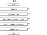
- FIG. 5 is a flowchart illustrating an example of a process in the authentication device 1.
- the imaging unit 2 acquires an image including the iris region HIR of the eyeball HE of the subject H (S1; image acquisition step).
- the illumination unit 3 emits illumination light to the eyes of the subject H at a timing when the imaging unit 2 captures an image.
- the first reflected light RL1 is reflected in the pupil region HPP
- the second reflected light RL2 is reflected in the iris region HIR.
- the imaging unit 2 outputs the obtained image to the iris area obtaining unit 61.
- the iris region acquiring unit 61 analyzes the received image to acquire an authentication iris region CHIR excluding at least a part of the image of the second reflected light RL2 (S2: iris region acquiring step).
- the iris region acquiring unit 61 outputs the acquired information on the authenticated iris region CHIR (eg, shading information of each pixel constituting the authentic iris region CHIR) to the iris code acquiring unit 62.
- the iris code acquisition unit 62 creates an iris code based on the acquired information (S3; iris code acquisition step).
- the iris code acquisition unit 62 outputs the created iris code to the authentication unit 63.
- the authentication unit 63 reads the registered iris code registered in the storage unit 4 and performs iris authentication on the subject H by comparing the received iris code with the registered iris code (S4; authentication step). That is, the authentication unit 63 performs iris authentication using the authentication iris region CHIR.
- the authentication unit 63 outputs the result of the iris authentication via the display unit 5 (S5; output step).
- a case where one image (still image) is captured and iris authentication is performed on the image is illustrated.
- a moving image may be captured, and iris authentication (moving image authentication) may be performed on a frame constituting the moving image.
- a plurality of images may be acquired in a short time by capturing a moving image. Therefore, the iris authentication is performed in order from the captured image while continuing the image acquisition step (imaging step). May be advanced at the same timing as the image acquisition step. In this case, when the iris authentication succeeds, the image acquisition (moving image capturing) may be stopped, and the authentication unit 63 may output the authentication result.
- an authentication result indicating that the iris authentication has failed is output to the authentication unit 63. You may let me.
- Example> The result of performing iris authentication based on the authentication iris region CHIR acquired by the authentication device 1 of the present embodiment is compared with the result of performing iris authentication based on the iris region HIR acquired by the authentication device of the comparative example.
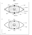
- FIG. 6A is a diagram illustrating an example of the authentication iris region CHIR acquired by the authentication device 1
- FIG. 6B is a diagram illustrating an example of the iris region HIR acquired by the authentication device of the comparative example. It is.
- the positional relationship between the imaging unit and the illumination unit is determined by the first reflected light RL1 as described above. Is set to be reflected in the pupil region HPP. That is, in both the image acquired by the authentication device 1 and the image acquired by the authentication device of the comparative example, the first reflected light RL1 is reflected in the pupil region HPP, but is reflected in the iris region HIR. Not in. On the other hand, the second reflected lights RL21 and RL22 are reflected on the above-described boundary portion of the iris region HIR.
- the authentication device 1 causes the iris region acquisition unit 61 to acquire the authentication iris region CHIR shown as a hatched portion in FIG. 6A from the image captured by the imaging unit 2. That is, the authentication iris area CHIR acquired by the iris area acquisition unit 61 does not include the second reflected lights RL21 and RL22.
- the authentication device of the comparative example includes an iris region acquisition unit, an iris code acquisition unit, and an authentication unit, like the authentication device 1.
- the iris region acquisition unit of the comparative example acquires the iris region HIR shown as a hatched portion in FIG. 6B from the image captured by the imaging unit. That is, the second reflected lights RL21 and RL22 are included in the iris region HIR acquired by the iris region acquisition unit of the comparative example.
- FIG. 7 shows a cumulative probability plot of the hamming distance HD obtained by the authentication device 1 performing iris authentication (verification) based on the authentication iris region CHIR, and an iris authentication (verification) based on the iris region HIR performed by the authentication device of the comparative example. And a cumulative probability plot of the hamming distance HD obtained by performing the above. 7, the vertical axis indicates the cumulative probability distribution of the Hamming distance HD, and the horizontal axis indicates the Hamming distance HD.
- each part of the authentication device 1 is denoted by a reference numeral
- each part of the authentication device of the comparative example is not denoted by a reference numeral.
- the imaging unit 2 and the imaging unit have wavelength sensitivity to light having a wavelength of 800 nm or more and 850 nm or less.
- the linear distance between the eyes of the subject H and the authentication device 1 and the linear distance between the eyes of the subject H and the authentication device of the comparative example are both 30 cm.
- the intensity of illumination light at the eyes of the subject H is 15 W / m 2 .
- the iris region obtaining unit 61 obtains the authentication iris region CHIR from the image captured under the above conditions (see FIG. 6A).
- the iris code acquisition unit 62 has created an iris code based on the authenticated iris region CHIR.
- the authentication unit 63 calculates the hamming distance HD between the created iris code and the registered iris code of the subject H registered in advance.
- the iris region acquisition unit acquired the iris region HIR from the image captured under the above conditions (see FIG. 6B).
- the iris code acquisition unit created an iris code from the iris region HIR.
- the authentication unit calculated a hamming distance HD between the created iris code and the registered iris code (same as the registered iris code used in the authentication device 1).
- 60 registered iris codes to be compared with the iris code are prepared in advance.
- the authentication device 1 and the authentication device of the comparative example respectively obtained six iris codes as iris codes to be compared with the registered iris codes.
- the authentication device 1 and the authentication device of the comparative example each calculate the hamming distance HD of each of the 60 registered iris codes for one of the six iris codes.
- the authentication device 1 and the authentication device of the comparative example each similarly calculate the hamming distance HD for the remaining five devices. That is, the authentication device 1 and the authentication device of the comparative example each calculated 360 hamming distance HD as the calculation result of the hamming distance HD.
- FIG. 7 The results of FIG. 7 are plotted while accumulating the Hamming distance HD calculated by each of the authentication device 1 and the authentication device of the comparative example.
- “Embodiment 1" in the figure shows a plotting result of the hamming distance HD calculated by the authentication device 1
- “Comparative Example” in the diagram shows a plotting result of the hamming distance HD calculated by the authentication device of the comparative example. .
- the iris code and the registered iris code are composed of a plurality of parts (for example, 8 ⁇ 128 parts), and in each part, any one of information 0 and 1 is stored based on the density information of the iris area HIR. It has been created by.
- the authentication unit 63 and the authentication unit compare the corresponding parts of the iris code and the registered iris code to determine whether the stored information matches. This determination is made for all parts, and the ratio of the number of parts whose information does not match the total number of parts is calculated as the hamming distance HD.
- the Hamming distance HD 0 is an ideal value where the iris code and the registered iris code completely match. Also, between the iris code acquired from the person and the iris code acquired from another person, the information of 0 and 1 is about 50% identical. Therefore, in this case, the hamming distance HD is about 0.5. In other words, it can be said that the smaller the value of the hamming distance HD, the higher the authentication accuracy.
- the hamming distance HD calculated by the authentication device 1 is smaller than the hamming distance HD calculated by the authentication device of the comparative example.
- the value of the hamming distance HD having the cumulative existence probability of 50% is 0.294 in the authentication device of the comparative example, and is 0.255 in the authentication device 1. Therefore, it can be seen that the iris authentication by the authentication device 1 has higher authentication accuracy than the comparative example.
- the authentication device of the comparative example has an authentication ratio of 20%, whereas the authentication device 1 has an authentication ratio of 90% or more. It turns out that it has an authentication rate.
- the authentication device 1 detects the second reflected light RL2.
- the iris authentication is performed based on the authentication iris region CHIR excluding at least a part of the image. Thereby, the authentication device 1 can perform the iris authentication in a state where the influence of the reflection of the illumination light on the iris region HIR is reduced. Therefore, the accuracy of iris authentication can be improved.
- the authentication device 1 When acquiring the authentication iris region CHIR excluding all of the second reflected light RL2, the authentication device 1 acquires an iris authentication iris region in which the first reflected light RL1 and the second reflected light RL2 are not reflected. it can. Therefore, the authentication device 1 can further improve the accuracy of iris authentication.
- FIG. 8 is a block diagram illustrating a configuration example of a main part of the authentication device 1A of the present embodiment. As shown in FIG. 8, the authentication device 1A is different from the authentication device 1 in that the authentication device 1A includes a control unit 6A having an image generation unit 64.
- the image generation unit 64 generates an ambient light-removed image by removing at least a part of the reflection of the ambient light from the image acquired by the imaging unit 2.
- the iris region obtaining unit 61 obtains an authentication iris region CHIR in the environment light removed image excluding at least a part of the image of the second reflected light RL2.
- the image generation unit 64 may calculate, based on the luminance value of the first image obtained when the eyeball HE is irradiated with the illumination light, a second image obtained when the eyeball HE is not irradiated with the illumination light. A difference image from which the luminance value has been subtracted is generated as an ambient light removed image. In this case, the image generation unit 64 can generate the ambient light removed image by a simple method.
- the lighting unit 3 switches lighting on and off continuously in time.
- the image capturing unit 2 captures an image of the eyeball HE in accordance with the switching timing of the illumination ON and the illumination OFF.
- the image generating unit 64 calculates the respective luminance values of the plurality of pixels constituting the first image acquired when the illumination is turned on, and the respective luminance values of the plurality of pixels constituting the second image acquired when the illumination is turned off. get.
- the image generator 64 subtracts the luminance value of the second image from the luminance value of the first image for each corresponding pixel in the first image and the second image.
- the image generation unit 64 acquires an image having a luminance value as a result of subtraction for each pixel as a difference image.
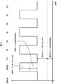
- FIG. 9 is a graph showing an example of a temporal change of the luminance value of the pixel corresponding to the position where the second reflected light RL2 is reflected when the lighting-on and the lighting-off are repeated continuously in time. Note that FIG. 9 illustrates a case where the time during which the light is on and the time during which the light is off are substantially the same, but these times need not be substantially the same.
- the luminance value of the pixel is composed of the following four components.
- -Reflection component due to lighting The illumination light is mainly obtained by specular reflection on the corneal surface.
- -An iris information component due to lighting It is obtained by diffusely reflecting illumination light at the iris.
- -Reflected components due to ambient light It is mainly obtained by specular reflection of environmental light on the corneal surface.
- Environmental light is obtained by diffuse reflection of the iris.
- the luminance value of the pixel is composed of two components, a reflection component due to ambient light and an iris information component due to ambient light. Therefore, by calculating the difference between the luminance values of the first image and the second image as described above, it is possible to obtain an ambient light-removed image from which the glare component due to ambient light and the iris information component due to ambient light have been removed. Note that the second reflected light RL2 having a reflection component due to illumination is excluded by the iris region acquisition unit 61.
- the iris information component due to the ambient light may be removed.
- the intensity of the ambient light changes depending on the situation at the time of iris authentication (whether an image is acquired outdoors or indoors, etc.). Further, the intensity of the ambient light also changes at the position of the iris region HIR in the acquired image (that is, the position of the pixel constituting the iris region HIR).
- the intensity of the illumination light is controlled to a predetermined intensity. Therefore, accurate iris authentication is performed by removing the iris information component due to environmental light whose intensity changes due to the situation and using an image that leaves only the iris information component due to the illumination light whose intensity does not easily change due to the situation. Can be.
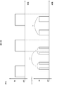
- FIG. 10 is a diagram illustrating an example of the relationship between the timing of switching the illumination on and the illumination off and the timing of opening and closing the shutter of the imaging unit 2.
- the imaging unit 2 acquires the first image when the illumination is on, and acquires the second image after the illumination is off.
- the second image is acquired when the illumination is turned off before the illumination is turned on, and the first image is acquired after the illumination is turned on.
- the image generation unit 64 when the image generation unit 64 acquires the first image and the second image while switching the illumination on and the illumination off a plurality of times, the first image acquired when the illumination is on and the next illumination off A difference image is generated based on the second image acquired at that time (see (i) of FIG. 10).
- the image generation unit 64 may generate a difference image based on the second image acquired when the illumination is turned off and the first image acquired when the next illumination is turned on ((ii) in FIG. 10). reference). That is, the image generation unit 64 generates a difference image based on the first image and the second image acquired continuously. In this case, the change of the ambient light between the lighting ON and the lighting OFF can be reduced. Further, it is possible to prevent the displacement of the corresponding pixel due to the influence of body movement. Therefore, the image generation unit 64 can generate a difference image having a luminance value that hardly includes components due to environmental light.
- the image generating unit 64 may generate a plurality of difference images based on a set of the plurality of first images and the second images, and use an image obtained by integrating luminance values of these difference images as an ambient light removed image.
- the image generation unit 64 generates an image obtained by integrating the luminance values of the difference image generated in (i) and the difference image acquired in (ii). I do.
- the image generation unit 64 generates an image in which the luminance value of this image and the luminance value of the difference image generated based on the first image and the second image acquired at the next timing of (ii) are integrated. .
- An image generated as a result of repeating this integration is defined as an ambient light removed image.
- the shutter open / close time can be set arbitrarily. If this condition is satisfied, the shutter opening time shown in (i) and (ii) may be set, or the shutter opening time shown in (iv) may be set.
- the image generation unit 64 generates the difference image based on the first image and the second image acquired continuously. You don't have to. Further, the switching of the illumination on and the illumination off may be performed once (the set of the first image and the second image to be acquired is one set). Further, as a technique for generating the difference image as the ambient light-removed image, various known techniques can be adopted (for example, a technique disclosed in Patent Document 1 or 2).
- FIG. 11 is a flowchart illustrating an example of processing in the authentication device 1A.
- the imaging unit 2 acquires a first image when the illumination is on and acquires a second image when the illumination is off as an image including the iris region HIR (S11; image acquisition step).
- the imaging unit 2 outputs the obtained image to the image generation unit 64.
- the image generation unit 64 generates an ambient light removal image based on the received first image and second image (S12; image generation step). For example, the image generation unit 64 generates a difference image obtained by subtracting the luminance value of the second image from the luminance value of the first image as an ambient light removed image. The image generation unit 64 outputs the generated environment light removed image to the iris region acquisition unit 61.
- the iris region acquiring unit 61 acquires the authentication iris region CHIR excluding at least a part of the image of the second reflected light RL2 by analyzing the received environment light removed image (S13; iris region acquiring step). Thereafter, the processing of S3 to S5 described in the first embodiment is performed.
- the accuracy of the iris authentication is reduced because the iris information includes the ambient light reflected on the corneal surface. That is, when the environment light is reflected in the iris area, the accuracy of the iris authentication is reduced similarly to the reflection of the illumination light.
- the authentication device 1A acquires the authentication iris region CHIR from the ambient light removed image from which at least a part of the reflection of the ambient light has been removed, thereby performing the iris authentication in a state where the influence of the reflection of the ambient light is reduced. it can. Therefore, the accuracy of iris authentication can be improved. In addition, when the authentication device 1A generates an environment light-removed image from which all of the reflection of the environment light has been removed, the accuracy of the iris authentication can be further improved.
- FIG. 12 is a block diagram illustrating a configuration example of a main part of the authentication device 1B of the present embodiment. As shown in FIG. 12, the authentication device 1B is different from the authentication device 1 in that the authentication device 1B includes a control unit 6B having an image determination unit 65.
- the image determination unit 65 determines whether the image is appropriate as an image for performing iris authentication, based on the size of the iris region HIR included in the image captured by the imaging unit 2. Even if an image is acquired, if the image hardly includes the iris region HIR, the result of the iris authentication is “failure (NG)”. In other words, when the eyelid opening (opening degree) is relatively low, it can be said that the image is not suitable as an image for performing iris authentication. Therefore, in order to obtain an image that is appropriate as an image for performing iris authentication, the image determining unit 65 determines whether or not the image is appropriate.
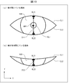
- FIG. 13A is a diagram illustrating an example of an image acquired when the eyelid is open
- FIG. 13B is a diagram when the eyelid is almost closed (not completely closed).
- FIG. 5 is a diagram showing an example of an image acquired in FIG. If the eyelids are slightly open (ie, unless the eyelids are completely closed), the cornea is exposed. For this reason, if the eyelid is not completely closed, as shown in FIGS. 13A and 13B, the eyelid is located in the vertical direction ( ⁇ Y-axis direction) when viewed from the pupil region HPP and the upper eyelid The second reflected lights RL21 and RL22 are reflected immediately below EL1 and directly above the lower eyelid EL2, respectively.
- the distance between the image of the second reflected light RL21 near the upper eyelid EL1 and the image of the second reflected light RL22 near the lower eyelid EL2 included in the image it is possible to use the distance between the image of the second reflected light RL21 near the upper eyelid EL1 and the image of the second reflected light RL22 near the lower eyelid EL2 included in the image. it can.
- the image determination unit 65 determines whether the image is appropriate as an image for performing iris authentication by determining whether the distance is equal to or greater than a predetermined distance (reference opening). Specifically, if the distance is equal to or longer than a predetermined distance, the image is determined to be appropriate as an image for performing iris authentication, and if shorter than the predetermined distance, it is determined to be inappropriate as the image.
- a predetermined distance may be set, for example, by an experiment or the like to a distance at which iris authentication can be performed.
- the image determination unit 65 determines that the calculated distance D11 is equal to or longer than a predetermined distance.
- the image determination unit 65 determines that the calculated distance D12 is less than the predetermined distance.
- the image determination unit 65 can perform iris authentication using the acquired image, and thus causes the iris region acquisition unit 61 to acquire the authentication iris region CHIR in the image.
- the result is “failure (NG)” even if the iris authentication is performed using the acquired image.
- the acquisition is urged to the subject H.
- the image determination unit 65 causes the display unit 5 to perform a display requesting reacquisition of an image.
- the subject H operates the imaging unit 2 based on this display to cause the imaging unit 2 to reacquire an image including the iris region HIR.
- the authentication time can be reduced as compared with a case where an iris code is created using an inappropriate image as an image to be subjected to iris authentication, the iris authentication is performed using the iris code, and the image is reacquired.
- the image determination unit 65 cannot specify the reflection of the second reflected lights RL21 and RL22 in the image. Therefore, when the reflection of the second reflected lights RL21 and RL22 cannot be specified in the image, the image determination unit 65 estimates that the image is obtained with the eyes closed, and the image is subjected to iris authentication. It is determined that the image to be performed is inappropriate.
- the calculation of the distance may be performed together with the calculation of the magnitudes of the second reflected lights RL21 and RL22 by the iris area acquisition unit 61.
- the iris area acquisition unit 61 may have the function of the image determination unit 65.
- the predetermined distance may be defined by an index whose distance does not change depending on the imaging environment. That is, the predetermined distance may be set in association with the size of the index. Examples of the index include the distance between the outer corner of the eye and the inner corner of the eye, or the diameter of the iris region HIR (iris diameter). Since the diameter of the pupil region HPP (pupil diameter DM) changes depending on the illuminance of visible light included in the ambient light, it is not suitable for the above index.
- FIG. 14 is a flowchart illustrating an example of processing in the authentication device 1B.
- the imaging unit 2 acquires an image including the iris region HIR (S1; image acquisition step).
- the imaging unit 2 outputs the obtained image to the image determination unit 65.
- the image determining unit 65 calculates the distance between the second reflected lights RL21 and RL22 by specifying the positions of the second reflected lights RL21 and RL22 reflected in the received image (S21; distance calculating step). The image determining unit 65 determines whether the calculated distance is equal to or longer than a predetermined distance (S22; distance determining step).
- the image determination unit 65 determines that the obtained image is appropriate as an image for performing iris authentication. In this case, the image determination unit 65 instructs the iris region acquisition unit 61 to acquire the authentication iris region CHIR. Thus, the processing of S2 to S5 described in the first embodiment is performed.
- the image determination unit 65 determines that the obtained image is inappropriate as an image for performing iris authentication. In this case, the image determination unit 65 determines whether or not the number of times of obtaining the image is equal to or more than the predetermined number (S23; number determination step).
- the image determination unit 65 displays via the display unit 5 a message prompting reacquisition of an image.
- the imaging unit 2 receives the operation of the subject H and reacquires an image including the iris region HIR (S24; image reacquisition step). Thereafter, the process proceeds to S21.
- the image determination unit 65 notifies the authentication unit 63 of that. Upon receiving this notification in S5, the authentication unit 63 determines that iris authentication cannot be performed (iris authentication has failed), and outputs the determination result via the display unit 5.
- the authentication device 1B can accurately determine whether or not the acquired image is an image for performing iris authentication by a simple method. Therefore, the authentication device 1B can prevent performing iris authentication using an image in which the eyelids are not sufficiently opened. Further, it is possible to prevent an iris code created using the image from being registered as a registered iris code. The authentication device 1B does not perform authentication using an inappropriate image as an image for performing iris authentication. Therefore, the time required for iris authentication can be reduced.
- the opening degree of the eyelid can be calculated by detecting the boundary lines BL1 and BL2 using a known technique.
- detection of the boundary lines BL1 and BL2 may be unstable due to the influence of the eyelashes.
- the boundaries BL1 and BL2 tend to be erroneously detected as being outside the boundaries of the actual eyelids.
- the eyelid opening degree is set to an opening degree suitable for performing iris authentication even though the eyelids are actually closing. It is erroneously determined that there is.
- the authentication device 1B uses the distance between the second reflected lights RL21 and RL22 to determine whether or not the opening of the eyelid is an opening suitable for performing iris authentication. Therefore, the determination can be accurately performed without being affected by the eyelashes. That is, the authentication device 1B can accurately determine whether or not the image is for performing iris authentication. Further, the authentication device 1B does not perform iris authentication using an image affected by eyelashes. That is, since unnecessary iris authentication is not performed, the time required for iris authentication can be reduced.
- FIG. 15 is a block diagram illustrating a configuration example of a main part of the authentication device 1C of the present embodiment. As shown in FIG. 15, the authentication device 1C differs from the authentication device 1 in that the authentication device 1C includes a control unit 6C having a forgery determination unit 66.
- the forgery determination unit 66 determines whether or not the imaging target is a forgery for the purpose of preventing impersonation using a printed matter such as a photograph of an eyeball to impersonate another person and bypass the iris authentication. Specifically, the forgery determination unit 66 determines whether the imaging target is a forgery by comparing the first image obtained when the illumination is on and the second image obtained when the illumination is off. I do.
- the forgery determination unit 66 determines that the second image does not include the first reflected light RL1 even though the first image includes the first reflected light RL1, the forgery determination unit 66 determines that the imaging target is not included. You may decide that it is not a fake. This determination method is referred to as a determination method MA.
- the forgery determination unit 66 determines that the first image includes the first reflected light RL1 and the second reflected light RL2, although the first image includes the first reflected light RL1 and the second reflected light RL2. If it is determined that the object has not been copied, it may be determined that the imaging target is not a forgery.
- This determination method is referred to as a determination method MB. In the case of the determination method MB, the accuracy of the forgery determination can be improved.
- the forgery determination unit 66 generates, for example, a difference image between the first image and the second image, so that the first reflected light RL1 and / or the second reflected light RL2 are included in each of the first image and the second image. It is determined whether or not it is included.
- the difference image is generated, the influence of the ambient light can be eliminated as described in the second embodiment, so that erroneous determination of iris authentication due to the reflection of the ambient light can be avoided.
- the method described in the first embodiment can be used as a method for specifying the first reflected light RL1 and / or the second reflected light RL2 in the image.
- the forgery determination unit 66 determines that the imaging target is not a forgery, the forgery determination unit 66 causes the iris region acquisition unit 61 to acquire the authentication iris region CHIR in the acquired image. On the other hand, when determining that the imaging target is a counterfeit, the forgery determination unit 66 may prompt the subject H to reacquire the image via the display unit 5. When the imaging target is a forgery, the authentication unit 63 may output via the display unit 5 that the iris authentication has failed without prompting the user to reacquire the image.
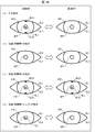
- FIG. 16 is a diagram illustrating an example of a first image and a second image acquired when an imaging target is an eye of a living body.
- FIGS. 16B and 16C are diagrams illustrating an example of the first image and the second image acquired when the imaging target is a printed matter.
- FIG. 16D is a diagram illustrating an example of the first image and the second image acquired when the imaging target is a printed matter on which a lens (eg, a contact lens) imitating a cornea is placed. .
- a lens eg, a contact lens
- the first image obtained when the illumination is turned on includes the first reflected light RL1 and the second reflected light RL2.
- the first image RL1 and the second image RL2 are not included in the second image acquired when the camera is turned off.
- the imaging target is a printed matter such as a photograph of an eyeball
- no change occurs between the first image and the second image.
- FIG. 16B in the case of a forgery printed with an eyeball image on which the first reflected light RL1 and the second reflected light RL2 are not reflected, both the first image and the second image are used. , The first reflected light RL1 and the second reflected light RL2 do not exist. Further, as shown in FIG.
- both the first image and the second image include There are a first reflected light RL1 and a second reflected light RL2.
- the forgery determination unit 66 may use the above-described determination method MA. Further, the forgery determination unit 66 may determine that the imaging target is a forgery at the point in time when the first image does not include the first reflected light RL1 and the second reflected light RL2. Further, the forgery determination unit 66 determines that the imaging target is not a forgery if a change occurs between the first image and the second image, and determines that the imaging target is a forgery if there is no change. You may decide.
- the illumination light is specularly reflected on the lens surface, so that the first reflected light RL1 is generated.
- the second reflected light RL2 which is obtained by the illumination light mainly reflected on the edge of the eyelid being further reflected on the corneal surface, does not occur. Therefore, as shown in FIG. 16D, the first image includes the first reflected light RL1, but does not include the second reflected light RL2.
- neither the first reflected light RL1 nor the second reflected light RL2 exists in the second image.
- the forgery determination unit 66 may use the determination method MB. In this case, since the presence or absence of the second reflected light RL2 is also used as the determination material, it is possible to determine that the printed matter on which the lens is placed is also a counterfeit. Further, the forgery determination unit 66 may determine that the imaging target is a forgery when specifying that the first image does not include the second reflected light RL2.
- both the image of the first reflected light RL1 and the image of the second reflected light RL2 are included in the first image.
- the second image does not include both the image of the first reflected light RL1 and the image of the second reflected light RL2. Therefore, the difference image in the case of FIG. 16A includes both the image of the first reflected light RL1 and the image of the second reflected light RL2.
- no change occurs in the first image and the second image.
- Both the image of the light RL1 and the image of the second reflected light RL2 are not included.
- the first image includes only the image of the first reflected light RL1.
- the two images do not include both the image of the first reflected light RL1 and the image of the second reflected light RL2. Therefore, only the image of the first reflected light RL1 is included in the difference image.
- the forgery determination unit 66 may determine that the imaging target is a forgery when at least one of the image of the first reflected light RL1 and the image of the second reflected light RL2 is not included in the difference image. I do not care. That is, in this case, when the difference image includes both the image of the first reflected light RL1 and the image of the second reflected light RL2, the forgery determination unit 66 determines that the imaging target is not a forgery.
- the difference image does not include both (1) the image of the first reflected light RL1 and the image of the second reflected light RL2, or (2) the first image
- FIG. 17 is a flowchart illustrating an example of a process in the authentication device 1C.
- the imaging unit 2 acquires a first image when the illumination is on and acquires a second image when the illumination is off as an image including the iris region HIR (S11; image acquisition step).
- the imaging unit 2 outputs the acquired first image and second image to the forgery determination unit 66.
- the forgery determination unit 66 compares the received first image and second image (S31; comparison step). Thereby, it is determined whether or not the imaging target is a counterfeit (S32; counterfeit determination step). The forgery determination unit 66 determines whether or not the imaging target is a forgery, for example, by determining the presence or absence of the first reflected light RL1 and the second reflected light RL2 in the first image and the second image or the difference image. Is determined.
- the forgery determination unit 66 determines that the imaging target is not a forgery (NO in S32), it instructs the iris region acquisition unit 61 to acquire the authentication iris region CHIR.
- the processing of S2 to S5 described in the first embodiment is performed.
- the forgery determination unit 66 determines that the imaging target is a forgery (YES in S32), the processing of S23 and S24 is performed. However, when the forgery determination unit 66 determines that the iris is forged, the forgery determination unit 66 may immediately determine that the iris cannot be authenticated. Specifically, in the case of YES in S32, the process proceeds to S5 without performing S23 and S24. In this case, the forgery determination unit 66 notifies the authentication unit 63 that the imaging target is a forgery. Upon receiving this notification in S5, the authentication unit 63 determines that iris authentication cannot be performed (iris authentication has failed), and outputs the determination result via the display unit 5. The authentication unit 63 may output that the imaging target is a forgery.
- the authentication device 1C determines whether or not the imaging target is a counterfeit, so that when another person impersonating the person performs the iris authentication using the counterfeit, the authentication device 1C is not the user. Can be determined. Further, the authentication device 1C can perform the above determination by a simple method such as comparing the first image and the second image.
- control blocks of the authentication devices 1, 1A, 1B, and 1C may be realized by a logic circuit (hardware) formed on an integrated circuit (IC chip) or the like. It may be realized by software.
- the authentication device 1 includes a computer that executes instructions of a program that is software for realizing each function.
- the computer includes, for example, at least one processor (control device) and at least one computer-readable recording medium storing the program. Then, in the computer, the object of the present disclosure is achieved by the processor reading the program from the recording medium and executing the program.
- the processor for example, a CPU (Central Processing Unit) can be used.
- the recording medium a "temporary tangible medium” such as a ROM (Read Only Memory), a tape, a disk, a card, a semiconductor memory, and a programmable logic circuit can be used. Further, a RAM (Random Access Memory) for expanding the program may be further provided.
- An authentication device is an authentication device that performs iris authentication using an image including an iris region of an eyeball captured by an imaging unit, and (1) capturing the eyeball on the image. And (2) the illumination light is reflected from the pupil region of the eyeball at the boundary between the iris region and the eyelid of the iris region.
- an iris region acquisition unit that acquires an authentication iris region excluding at least a part of the image of the second reflected light;
- An authentication unit that performs iris authentication using the authentication unit may be provided.
- an authentication method according to an aspect of the present disclosure is an authentication method for performing iris authentication using an image including an iris region of an eyeball captured by an imaging unit, wherein (1) the eyeball is added to the image. (1) the illumination light applied to the eyeball at the time of imaging the eyeball is reflected in a pupil region of the eyeball; and (2) the illumination light is applied to a boundary between the iris region and the eyelid of the iris region.
Abstract
The precision of iris authentication is improved using a practical method. An authentication device (1) comprises: an iris region acquisition unit (61) that adjusts the positional relationship of a lighting unit (3) and an imaging unit (2), whereby when a first reflection light and a second reflection light are projected, respectively, in the pupil region and the iris region of an image as reflected-light images, an authentication iris region is acquired with at least a part of the image of the second reflection light removed from the iris region in the image; an iris code acquisition unit (62) that acquires an iris code using the image of the authentication iris region; and an authentication unit (63) that compares the iris code with a registration iris code registered in a storage unit (4), thereby performing iris authentication of a subject.
Description
以下の開示は、認証装置等に関する。
The following disclosure relates to an authentication device and the like.
虹彩認証を行う場合、一般に、照明光の映り込みを瞳孔領域内に収めるように眼球を撮像することで、虹彩認証の精度を向上させている。なお、特許文献1及び2には、環境光の映り込みを除去した画像を生成する技術が開示されている。
(4) When performing iris authentication, generally, the accuracy of iris authentication is improved by imaging the eyeball so that the reflection of illumination light falls within the pupil region. Note that Patent Documents 1 and 2 disclose techniques for generating an image from which the reflection of ambient light has been removed.
上記のように照明光の映り込みを瞳孔領域内に収めた場合、虹彩領域の、瞼と虹彩領域との境界部分にも、照明光の映り込みが生じる。そのため、従来技術では、この虹彩領域への映り込みにより、虹彩認証の精度が低下してしまう。
場合 When the reflection of the illumination light is contained in the pupil region as described above, the reflection of the illumination light also occurs at the boundary between the eyelid and the iris region in the iris region. For this reason, in the related art, the reflection in the iris area lowers the accuracy of iris authentication.
なお、照明光の映り込みを虹彩領域の外側領域に収めるように眼球を撮像した場合、虹彩領域への映り込みは生じない。しかしながら、照明光の映り込みを虹彩領域の外側領域に収めるためには、照明装置と撮像装置との距離を十分に離す必要がある。従って、照明光の映り込みを虹彩領域の外側領域に収めることは現実的な手法ではない。
(4) When the eyeball is imaged so that the reflection of the illumination light falls within the region outside the iris region, the reflection does not occur in the iris region. However, in order for the reflection of the illumination light to be contained in the region outside the iris region, the distance between the illumination device and the imaging device needs to be sufficiently large. Therefore, it is not a practical method to contain the reflection of the illumination light in the area outside the iris area.
また、特許文献1及び2は、照明光の映り込みによる虹彩認証の精度の低下を抑制する技術を開示するものでは無い。
特許 Moreover, Patent Documents 1 and 2 do not disclose techniques for suppressing a decrease in the accuracy of iris authentication due to reflection of illumination light.
本開示の一態様は、現実的な手法で、虹彩認証の精度を向上させることが可能な認証装置を実現することを目的とする。
の 一 One embodiment of the present disclosure has an object to realize an authentication device capable of improving the accuracy of iris authentication by a realistic method.
上記の課題を解決するために、本開示の一態様に係る認証装置は、対象者を照射する照明光を出射する照明部と、前記対象者の瞳孔領域及び虹彩領域を含む画像を撮像する撮像部と、前記照明部と前記撮像部との位置関係を調整することにより、前記照明光が前記対象者の角膜表面で直接反射した第1反射光と、前記対象者の瞼の縁部で反射した後、当該瞼との境界近傍における角膜表面で反射した光を少なくとも含む第2反射光とが、前記撮像部により撮像された画像における瞳孔領域及び虹彩領域にそれぞれ反射光の像として映り込むとき、前記画像において、前記虹彩領域から前記第2反射光の像の少なくとも一部を除外した領域を、虹彩認証に用いる認証虹彩領域として取得する虹彩領域取得部と、前記認証虹彩領域の画像を用いて虹彩認証を行うための虹彩コードを取得する虹彩コード取得部と、前記虹彩コード取得部により取得された前記虹彩コードと、記憶部に登録されている登録虹彩コードとを照合することにより、前記対象者の虹彩認証を行う認証部と、を備える。
In order to solve the above-described problem, an authentication device according to an embodiment of the present disclosure includes an illumination unit that emits illumination light that irradiates a subject, and an imaging unit that captures an image including a pupil region and an iris region of the subject. By adjusting the positional relationship between the unit and the illumination unit and the imaging unit, the first reflected light where the illumination light is directly reflected on the corneal surface of the subject, and the reflected light is reflected on the edge of the eyelid of the subject Then, when the second reflected light including at least the light reflected on the corneal surface in the vicinity of the boundary with the eyelid is reflected as an image of the reflected light on the pupil region and the iris region in the image captured by the imaging unit, respectively. An iris region acquiring unit that acquires, as an authentication iris region used for iris authentication, an area obtained by excluding at least a part of the image of the second reflected light from the iris area in the image, using an image of the authentication iris area. An iris code acquisition unit that acquires an iris code for performing iris authentication, the iris code acquired by the iris code acquisition unit, and a registered iris code registered in a storage unit are compared with each other to obtain the object. An authentication unit that performs iris authentication of a person.
また、上記の課題を解決するために、本開示の一態様に係る認証方法は、対象者を照射する照明光を出射する照明部と、前記対象者の瞳孔領域及び虹彩領域を含む画像を撮像する撮像部との位置関係を調整することにより、前記照明光が前記対象者の角膜表面で直接反射した第1反射光と、前記対象者の瞼の縁部で反射した後、当該瞼との境界近傍における角膜表面で反射した光を少なくとも含む第2反射光とが、前記撮像部により撮像された画像における瞳孔領域及び虹彩領域にそれぞれ反射光の像として映り込むとき、前記画像において、前記虹彩領域から前記第2反射光の像の少なくとも一部を除外した領域を、虹彩認証に用いる認証虹彩領域として取得する虹彩領域取得ステップと、前記認証虹彩領域の画像を用いて虹彩認証を行うための虹彩コードを取得する虹彩コード取得ステップと、前記虹彩コード取得ステップにより取得された前記虹彩コードと、記憶部に登録されている登録虹彩コードとを照合することにより、前記対象者の虹彩認証を行う認証ステップと、を含む。
To solve the above problem, an authentication method according to an aspect of the present disclosure captures an image including an illumination unit that emits illumination light for irradiating a subject, and a pupil region and an iris region of the subject. By adjusting the positional relationship with the imaging unit to perform, the first reflected light where the illumination light is directly reflected on the corneal surface of the subject, and after being reflected at the edge of the subject's eyelid, When the second reflected light including at least the light reflected on the corneal surface in the vicinity of the boundary is reflected as an image of reflected light in a pupil region and an iris region in an image captured by the imaging unit, the iris is included in the image. An iris region obtaining step of obtaining an area obtained by excluding at least a part of the image of the second reflected light from the area as an authentication iris area used for iris authentication; and performing iris authentication using the image of the authentication iris area. An iris code obtaining step for obtaining an iris code for the subject, and comparing the iris code obtained in the iris code obtaining step with a registered iris code registered in a storage unit to thereby authenticate the iris of the subject. Performing an authentication step.
本開示の一態様に係る認証装置及び認証方法によれば、現実的な手法で、虹彩認証の精度を向上させることができる。
According to the authentication device and the authentication method according to an aspect of the present disclosure, it is possible to improve the accuracy of iris authentication by a realistic method.
〔実施形態1〕
以下、本開示の一実施形態について、詳細に説明する。図1は、本実施形態の認証装置1の要部の構成例を示すブロック図である。以下に述べるように、認証装置1は、虹彩認証技術を用いて被写体Hを認証する。 [Embodiment 1]
Hereinafter, an embodiment of the present disclosure will be described in detail. FIG. 1 is a block diagram illustrating a configuration example of a main part of anauthentication device 1 according to the present embodiment. As described below, the authentication device 1 authenticates the subject H using the iris authentication technology.
以下、本開示の一実施形態について、詳細に説明する。図1は、本実施形態の認証装置1の要部の構成例を示すブロック図である。以下に述べるように、認証装置1は、虹彩認証技術を用いて被写体Hを認証する。 [Embodiment 1]
Hereinafter, an embodiment of the present disclosure will be described in detail. FIG. 1 is a block diagram illustrating a configuration example of a main part of an
このため、認証装置1による認証(照合)の対象となる被写体Hは、眼球HEを含む生体であるものとする。本実施形態では、被写体H(生体)が人(対象者)である場合を例示する。認証装置1による認証は、被写体Hの2つの眼球HEのうちの少なくとも一方(左目および右目の少なくともいずれか)に対する画像解析の結果に基づいて行われる。
Therefore, it is assumed that the subject H to be authenticated (collated) by the authentication device 1 is a living body including the eyeball HE. In the present embodiment, a case where the subject H (living body) is a person (subject) will be exemplified. The authentication by the authentication device 1 is performed based on the result of the image analysis on at least one of the two eyes HE of the subject H (at least one of the left eye and the right eye).
<認証装置>
認証装置1は、撮像部2により撮像された、眼球HEの虹彩領域HIR(図2参照)を含む画像を用いて、虹彩認証を行うものである。認証装置1は、撮像部2(撮像装置)、照明部3(照明装置)、記憶部4、表示部5、及び制御部6を備える。 <Authentication device>
Theauthentication device 1 performs iris authentication using an image captured by the imaging unit 2 and including the iris region HIR (see FIG. 2) of the eyeball HE. The authentication device 1 includes an imaging unit 2 (imaging device), an illumination unit 3 (illumination device), a storage unit 4, a display unit 5, and a control unit 6.
認証装置1は、撮像部2により撮像された、眼球HEの虹彩領域HIR(図2参照)を含む画像を用いて、虹彩認証を行うものである。認証装置1は、撮像部2(撮像装置)、照明部3(照明装置)、記憶部4、表示部5、及び制御部6を備える。 <Authentication device>
The
なお、認証装置1は、これらの部材の全てを一体的に備えている必要は無い。認証装置1は、少なくとも制御部6の機能を有していればよい。つまり、撮像部2、照明部3、記憶部4及び表示部5の少なくともいずれかは、認証装置1の外部装置として実現されていても構わない。
Note that the authentication device 1 does not need to integrally include all of these members. The authentication device 1 only needs to have at least the function of the control unit 6. That is, at least one of the imaging unit 2, the illumination unit 3, the storage unit 4, and the display unit 5 may be realized as an external device of the authentication device 1.
撮像部2は、被写体Hを撮像することで、被写体Hの目を含む画像を取得する画像取得部として機能する。具体的には、撮像部2は、制御部6で虹彩認証を行うために、被写体Hの眼球HEの瞳孔領域HPP及び虹彩領域HIRを含む画像を取得する。撮像部2は、CCD(Charge Coupled Device)又はCMOS(Complementary Metal Oxide Semiconductor)等の撮像素子を含む。撮像部2は、波長700nm以上1000nm以下の光に波長感度を有する。この場合、虹彩領域HIRにおける輝度値(濃淡情報)を精度良く取得できる。但し、この点を考慮しなければ、波長は上記範囲に限定されない。
(4) The imaging unit 2 functions as an image acquisition unit that acquires an image including the eyes of the subject H by imaging the subject H. Specifically, the imaging unit 2 acquires an image including the pupil region HPP and the iris region HIR of the eyeball HE of the subject H so that the control unit 6 performs iris authentication. The imaging unit 2 includes an imaging element such as a CCD (Charge Coupled Device) or a CMOS (Complementary Metal Oxide Semiconductor). The imaging unit 2 has wavelength sensitivity to light having a wavelength of 700 nm or more and 1000 nm or less. In this case, a luminance value (shading information) in the iris region HIR can be acquired with high accuracy. However, the wavelength is not limited to the above range unless this point is considered.
照明部3は、被写体Hを照射する照明光を出射する。具体的には、照明部3は、被写体Hの目に照射される照明光の出射を制御する。より具体的には、照明部3は、撮像部2が撮像するタイミングにあわせて、被写体Hの目に照明光を出射する。つまり、照明部3は、眼球HEを撮像するときに眼球HEに照明光を照射するものである。認証装置1は、照明部3を用いることで、暗所での撮像も可能となる。また、環境光の強度が比較的高い環境(例:屋外)で撮像する場合に、環境光の影響を低減した状態で画像を取得できる。
The illumination unit 3 emits illumination light for irradiating the subject H. Specifically, the illumination unit 3 controls emission of illumination light emitted to the eyes of the subject H. More specifically, the illumination unit 3 emits illumination light to the eyes of the subject H at the timing when the imaging unit 2 captures an image. That is, the illumination unit 3 irradiates the eyeball HE with illumination light when imaging the eyeball HE. The authentication device 1 can also perform imaging in a dark place by using the illumination unit 3. Further, when an image is taken in an environment where the intensity of the ambient light is relatively high (for example, outdoors), the image can be acquired with the influence of the ambient light reduced.
照明部3は、例えば、撮像部2の波長感度に対応した照明光を出射する。照明部3は、例えば700nm以上1000nm以下の波長を有する照明光を出射する。また、照明部3は、眼球HE(被写体Hの目)と照明部3との距離が30cmであるとき、眼球HE(被写体Hの位置)での照明光の強度(被写体Hの目元での照明光の強度)が10W/m2以上となるように、照明光の強度を調整しても構わない。この場合、認証装置1は、屋外においても、虹彩認証を精度良く行うことが可能な程度に鮮明な画像を取得できる。
The illumination unit 3 emits illumination light corresponding to the wavelength sensitivity of the imaging unit 2, for example. The illumination section 3 emits illumination light having a wavelength of, for example, 700 nm or more and 1000 nm or less. Further, when the distance between the eyeball HE (the eyes of the subject H) and the lighting unit 3 is 30 cm, the illuminating unit 3 provides the intensity of illumination light (the illumination at the eyes of the subject H) at the eyeball HE (the position of the subject H). The intensity of the illumination light may be adjusted so that the light intensity is 10 W / m 2 or more. In this case, the authentication device 1 can acquire a clear image to the extent that iris authentication can be performed accurately even outdoors.
なお、上記照明光の強度の上限値は、例えば、照明部3の消費電力、被写体Hの目の安全性、及び照明部3の実現容易性を考慮して決定される。
The upper limit of the intensity of the illumination light is determined in consideration of, for example, the power consumption of the illumination unit 3, the safety of the eyes of the subject H, and the ease of realization of the illumination unit 3.
認証装置1は、被写体Hの目の安全性を確保するために、照明部3が被写体Hの目から所定距離の範囲内に入り込んだ(照明部3が被写体Hの目に近接した)ことを検知する近接センサ(不図示)を備えていても構わない。照明部3が被写体Hの目に近接したことを近接センサが検知した場合、照明部3は、照明光の出射を停止する。なお、照明光が出射されている状態(出射の開始を含む)を「照明オン」、照明光が出射されていない状態(出射の停止を含む)を「照明オフ」とも称する。
In order to ensure the safety of the eyes of the subject H, the authentication device 1 determines that the illumination unit 3 has entered a range of a predetermined distance from the eyes of the subject H (the illumination unit 3 has approached the eyes of the subject H). A proximity sensor (not shown) for detecting may be provided. When the proximity sensor detects that the illumination unit 3 has approached the eyes of the subject H, the illumination unit 3 stops emitting illumination light. The state in which the illumination light is emitted (including the start of emission) is also referred to as “illumination on”, and the state in which the illumination light is not emitted (including the stop of emission) is also referred to as “illumination off”.
記憶部4は、制御部6が実行する各種のプログラム、及び当該プログラムによって使用されるデータを格納する。当該データとしては、取得した虹彩コードの照合対象となる登録虹彩コードが挙げられる。表示部5は、制御部6による認証結果を表示する。認証装置1は、表示部5に代えて、又は表示部5に加えて、認証結果を音データとして通知するスピーカを備えていても構わない。制御部6は、認証装置1の各部を統括的に制御する。制御部6の詳細は後述する。
The storage unit 4 stores various programs executed by the control unit 6 and data used by the programs. The data includes a registered iris code to be collated with the acquired iris code. The display unit 5 displays an authentication result obtained by the control unit 6. The authentication device 1 may include a speaker that notifies the authentication result as sound data instead of or in addition to the display unit 5. The control unit 6 controls each unit of the authentication device 1 as a whole. Details of the control unit 6 will be described later.
<撮像部と照明部との位置関係>
図2の(a)は、撮像部2が取得する画像の一例を示す図である。図2の(a)に示すように、撮像部2が取得する画像には、第1反射光RL1及び第2反射光RL2の像が映り込んでいる。なお、画像における第1反射光RL1及び第2反射光RL2の像を、単に第1反射光RL1及び第2反射光RL2とも称する。 <Position relationship between imaging unit and illumination unit>
FIG. 2A is a diagram illustrating an example of an image acquired by theimaging unit 2. As shown in FIG. 2A, an image of the first reflected light RL1 and the second reflected light RL2 is reflected in an image acquired by the imaging unit 2. Note that the images of the first reflected light RL1 and the second reflected light RL2 in the image are also simply referred to as the first reflected light RL1 and the second reflected light RL2.
図2の(a)は、撮像部2が取得する画像の一例を示す図である。図2の(a)に示すように、撮像部2が取得する画像には、第1反射光RL1及び第2反射光RL2の像が映り込んでいる。なお、画像における第1反射光RL1及び第2反射光RL2の像を、単に第1反射光RL1及び第2反射光RL2とも称する。 <Position relationship between imaging unit and illumination unit>
FIG. 2A is a diagram illustrating an example of an image acquired by the
一般に、眼球HEにおいて照明光を反射した結果得られる反射光としては、第1反射光RL1及び第2反射光RL2の2種類が存在する。第1反射光RL1は、照明光が眼球HEに入射する角度によってその映り込む位置が変化するものであり、照明光が眼球HEの角膜表面で直接反射することにより得られる。第2反射光RL2は、上瞼EL1の直下及び下瞼EL2の直上のそれぞれに映り込むものであり、主に上瞼EL1及び下瞼EL2のそれぞれの縁部で反射した照明光が更に角膜表面で反射することにより得られる。また、第2反射光RL2は、上記縁部で反射した照明光が更に虹彩で反射することにより得られる光を含み得る。換言すれば、第2反射光RL2は、上瞼EL1及び下瞼EL2の縁部で反射した後、上瞼EL1及び下瞼EL2との境界近傍における角膜表面で反射した光を少なくとも含んでいる。上瞼EL1との境界近傍における角膜表面とは、眼球HEを正面視したときの、上瞼EL1と眼球HEとの境界の近傍における角膜表面を意味する。下瞼EL2との境界近傍における角膜表面についても同様である。第2反射光RL2が、上記縁部で反射した照明光を更に角膜表面又は虹彩で反射することにより得られるのは、瞼の縁部の構造が、瞼との境界近傍における角膜表面よりも前面に突出した形状となっているために生じるものである。例えば、上瞼EL1の縁部は、庇形状となっている。
Generally, there are two types of reflected light obtained as a result of reflecting the illumination light from the eyeball HE, that is, a first reflected light RL1 and a second reflected light RL2. The first reflected light RL1 changes its reflection position depending on the angle at which the illumination light is incident on the eyeball HE, and is obtained by directly reflecting the illumination light on the corneal surface of the eyeball HE. The second reflected light RL2 is reflected immediately below the upper eyelid EL1 and immediately above the lower eyelid EL2, and the illumination light mainly reflected at the respective edges of the upper eyelid EL1 and the lower eyelid EL2 further reflects the corneal surface. It is obtained by reflection at. Further, the second reflected light RL2 may include light obtained by further illuminating the illumination light reflected at the edge. In other words, the second reflected light RL2 includes at least light reflected on the edges of the upper eyelid EL1 and the lower eyelid EL2 and then reflected on the corneal surface near the boundary between the upper eyelid EL1 and the lower eyelid EL2. The corneal surface near the boundary with the upper eyelid EL1 means the corneal surface near the boundary between the upper eyelid EL1 and the eyeball HE when the eyeball HE is viewed from the front. The same applies to the corneal surface near the boundary with the lower eyelid EL2. The second reflected light RL2 is obtained by further reflecting the illumination light reflected at the edge on the corneal surface or the iris, because the structure of the edge of the eyelid is in front of the corneal surface near the boundary with the eyelid. This is caused by having a shape protruding from the surface. For example, the edge of the upper eyelid EL1 has an eaves shape.
第2反射光RL2は、上瞼EL1との境界近傍における角膜表面で反射した第2反射光RL21と、下瞼EL2との境界近傍における角膜表面で反射した第2反射光RL22と、を含む。図2の(a)に示すように、画像においては、虹彩領域HIRの、虹彩領域HIRと上瞼EL1との境界部分に映り込んだ第2反射光RL2が第2反射光RL21であり、虹彩領域HIRの、虹彩領域HIRと下瞼EL2との境界部分に映り込んだ第2反射光RL2が第2反射光RL22である。
The second reflected light RL2 includes the second reflected light RL21 reflected on the corneal surface near the boundary with the upper eyelid EL1, and the second reflected light RL22 reflected on the corneal surface near the boundary with the lower eyelid EL2. As shown in FIG. 2A, in the image, the second reflected light RL2 reflected on the boundary between the iris region HIR and the upper eyelid EL1 in the iris region HIR is the second reflected light RL21, and the iris The second reflected light RL2 reflected on the boundary between the iris region HIR and the lower eyelid EL2 in the region HIR is the second reflected light RL22.
本実施形態では、撮像部2と照明部3との位置関係を調整することで、第1反射光RL1を瞳孔領域HPPの内部に映り込ませている。つまり、撮像部2と照明部3との位置関係は、照明光が瞳孔領域HPPに第1反射光RL1が含まれるように設定されている。第1反射光RL1を瞳孔領域HPPの内部に収めることで、虹彩領域HIRには第1反射光RL1が映り込まない。そのため、虹彩認証の精度を向上させることができる。
In the present embodiment, the first reflection light RL1 is reflected inside the pupil region HPP by adjusting the positional relationship between the imaging unit 2 and the illumination unit 3. That is, the positional relationship between the imaging unit 2 and the illumination unit 3 is set such that the illumination light includes the first reflected light RL1 in the pupil region HPP. By storing the first reflected light RL1 inside the pupil region HPP, the first reflected light RL1 is not reflected in the iris region HIR. Therefore, the accuracy of iris authentication can be improved.
しかしながら、第1反射光RL1を瞳孔領域HPPの内部に収めるように撮像部2と照明部3との位置関係を調整した場合、実際には、上記境界部分のそれぞれに第2反射光RL21及びRL22が映り込んでしまう。具体的には、虹彩領域HIRの、虹彩領域HIRと上瞼EL1との境界部分であって、かつ、瞳孔領域HPPを通る、瞼の開閉方向(±Y軸方向)と平行な略直線上に、第2反射光RL21が映り込む。同様に、虹彩領域HIRの、虹彩領域HIRと下瞼EL2との境界部分であって、かつ、上記略直線上に、第2反射光RL22が映り込む。
However, when the positional relationship between the imaging unit 2 and the illumination unit 3 is adjusted so that the first reflected light RL1 is contained within the pupil region HPP, actually, the second reflected lights RL21 and RL22 are respectively provided at the boundary portions. Is reflected. Specifically, the iris region HIR is on a substantially straight line that is a boundary portion between the iris region HIR and the upper eyelid EL1 and that passes through the pupil region HPP and is parallel to the eyelid opening / closing direction (± Y-axis direction). , The second reflected light RL21 is reflected. Similarly, the second reflected light RL22 is reflected on the boundary between the iris region HIR and the lower eyelid EL2 in the iris region HIR and on the substantially straight line.
つまり、上記位置関係を調整することで、第1反射光RL1と第2反射光RL2とが、撮像部2により撮像された画像における瞳孔領域HPP及び虹彩領域HIRにそれぞれ反射光の像として映り込む。
That is, by adjusting the positional relationship, the first reflected light RL1 and the second reflected light RL2 are reflected as reflected light images on the pupil region HPP and the iris region HIR in the image captured by the imaging unit 2. .
ここで、照明部の消費電力、及び認証装置に組み込める照明部のサイズ(モジュールサイズ)の観点から、実現できる照明光の強度には限界がある。但し、近年の照明部の開発により、実現できる照明光の強度の上限は引き上げられている。一般に、照明光の強度が高くなるほど、屋外での撮像において環境光の影響を低減できる。この観点からは、照明部3として、照明光の強度が比較的高い照明部を用いることが好ましい。しかしながら、照明光の強度を比較的高くした場合、第1反射光RL1を瞳孔領域HPPの内部に収めるように上記位置関係を調整したとしても、虹彩認証を行うときに無視できないほどの大きさ及び強度を有する第2反射光RL2が虹彩領域HIRの内部に映り込んでしまう。
Here, there is a limit to the intensity of the illuminating light that can be realized from the viewpoint of the power consumption of the lighting unit and the size (module size) of the lighting unit that can be incorporated in the authentication device. However, with the development of the illumination unit in recent years, the upper limit of the intensity of illumination light that can be realized has been raised. In general, as the intensity of illumination light increases, the influence of environmental light can be reduced in outdoor imaging. From this viewpoint, it is preferable to use an illumination unit having relatively high intensity of illumination light as the illumination unit 3. However, when the intensity of the illumination light is relatively high, even if the positional relationship is adjusted so that the first reflected light RL1 is contained within the pupil region HPP, the size and the size cannot be ignored when performing iris authentication. The second reflected light RL2 having an intensity is reflected inside the iris region HIR.
そのため、認証装置1は、環境光の影響を低減可能な照明部3を用いた場合に生じる、第2反射光RL2の映り込みの影響を除去する処理を行う。そのため、認証装置1は、制御部6(特に、虹彩領域取得部61)を備える。
Therefore, the authentication device 1 performs a process of removing the influence of the reflection of the second reflected light RL2, which occurs when the illumination unit 3 that can reduce the influence of environmental light is used. Therefore, the authentication device 1 includes the control unit 6 (particularly, the iris region acquisition unit 61).
<制御部>
図1に示すように、制御部6は、虹彩領域取得部61、虹彩コード取得部62、及び認証部63を備える。 <Control unit>
As shown in FIG. 1, thecontrol unit 6 includes an iris area acquisition unit 61, an iris code acquisition unit 62, and an authentication unit 63.
図1に示すように、制御部6は、虹彩領域取得部61、虹彩コード取得部62、及び認証部63を備える。 <Control unit>
As shown in FIG. 1, the
虹彩領域取得部61は、撮像部2が取得した画像において、虹彩領域HIRの上記境界部分に映り込んだ第2反射光RL2の像を除外した認証虹彩領域CHIRを取得する。
The iris region acquisition unit 61 acquires an authentication iris region CHIR in the image acquired by the imaging unit 2 excluding the image of the second reflected light RL2 reflected on the boundary portion of the iris region HIR.
図2の(b)は、虹彩領域取得部61の処理の一例を説明するための図である。図2の(b)に示すように、例えば、虹彩領域取得部61は、撮像部2が取得した画像において、第2反射光RL21の、瞼の開閉方向の幅D1と、第2反射光RL22の、瞼の開閉方向の幅D2とを算出する。虹彩領域取得部61は、上瞼EL1と眼球HEの縁部とに沿う曲線(境界線BL1)を、幅D1の分、瞳孔領域HPP側(-Y軸方向)にシフトさせる。同様に、虹彩領域取得部61は、下瞼EL2と眼球HEの縁部とに沿う曲線(境界線BL2)を、幅D2の分、瞳孔領域HPP側(+Y軸方向)にシフトさせる。
((B) of FIG. 2 is a diagram for explaining an example of the processing of the iris area acquisition unit 61. As shown in (b) of FIG. 2, for example, in the image acquired by the imaging unit 2, the iris region acquiring unit 61 determines the width D1 of the second reflected light RL21 in the eyelid opening / closing direction and the second reflected light RL22. Of the eyelid in the opening and closing direction is calculated. The iris region acquisition unit 61 shifts the curve (boundary line BL1) along the upper eyelid EL1 and the edge of the eyeball HE toward the pupil region HPP (−Y-axis direction) by the width D1. Similarly, the iris region acquisition unit 61 shifts the curve (boundary line BL2) along the lower eyelid EL2 and the edge of the eyeball HE toward the pupil region HPP (+ Y axis direction) by the width D2.
虹彩領域取得部61は、虹彩領域HIRのうち、シフト後の境界線BL11及びBL12の内部に含まれる領域を、虹彩認証に用いる認証虹彩領域CHIR(図2の(b)の斜線部)として特定する。つまり、虹彩領域取得部61は、虹彩領域HIRから、第2反射光RL21を含む、境界線BL11の外部領域と、第2反射光RL22を含む、境界線BL12の外部領域とを除外することで、認証虹彩領域CHIRを特定する。
The iris region acquisition unit 61 specifies the regions included in the shifted boundary lines BL11 and BL12 in the iris region HIR as the authentication iris region CHIR (the hatched portion in FIG. 2B) used for iris authentication. I do. That is, the iris region acquisition unit 61 excludes the region outside the boundary line BL11 including the second reflected light RL21 and the region outside the boundary line BL12 including the second reflected light RL22 from the iris region HIR. , The authentication iris region CHIR is specified.
なお、認証虹彩領域CHIRは、虹彩領域HIRから第2反射光RL21及びRL22を除外した領域であればよい。そのため、虹彩領域取得部61は、例えば、第2反射光RL21及びRL22の大きさ及び位置を特定することで、第2反射光RL21及びRL22のみを除外した領域を、認証虹彩領域CHIRとして特定しても構わない。
Note that the authentication iris area CHIR may be an area obtained by excluding the second reflected lights RL21 and RL22 from the iris area HIR. Therefore, the iris region acquisition unit 61 specifies, for example, the size and position of the second reflected lights RL21 and RL22, and specifies the region excluding only the second reflected lights RL21 and RL22 as the authentication iris region CHIR. It does not matter.
また、本実施形態では、虹彩領域取得部61は、虹彩領域HIRから第2反射光RL21及びRL22の全てを除外することで、認証虹彩領域CHIRを取得しているが、これに限られない。例えば、虹彩領域取得部61は、第2反射光RL21及びRL22の何れか一方のみを除外した認証虹彩領域CHIRを取得しても構わない。この場合、除外する方の第2反射光RL2についてのみ、瞼の開閉方向の幅を算出すればよい。また、虹彩領域取得部61は、第2反射光RL21の一部及び/又は第2反射光RL22の一部を除外した認証虹彩領域CHIRを取得しても構わない。
Also, in the present embodiment, the iris region acquisition unit 61 acquires the authentication iris region CHIR by excluding all of the second reflected lights RL21 and RL22 from the iris region HIR, but is not limited thereto. For example, the iris region acquisition unit 61 may acquire the authentication iris region CHIR excluding only one of the second reflected lights RL21 and RL22. In this case, the width of the eyelid in the opening and closing direction may be calculated only for the excluded second reflected light RL2. Further, the iris region acquisition unit 61 may acquire the authentication iris region CHIR excluding a part of the second reflected light RL21 and / or a part of the second reflected light RL22.
つまり、虹彩領域取得部61は、撮像部2が取得した画像において、虹彩領域HIRから第2反射光RL2の少なくとも一部を除外した認証虹彩領域CHIRを取得すればよい。第2反射光RL2の一部を除外した場合であっても、第2反射光RL2を全く除外せずに虹彩認証を行う場合と比べ、虹彩認証の精度を向上させることができる。但し、第2反射光RL2の全てを除外した場合には、虹彩認証の精度を更に向上させることができる。
In other words, the iris region acquisition unit 61 may acquire the authentication iris region CHIR in the image acquired by the imaging unit 2 excluding at least a part of the second reflected light RL2 from the iris region HIR. Even when a part of the second reflected light RL2 is excluded, the accuracy of the iris authentication can be improved as compared with the case where the iris authentication is performed without excluding the second reflected light RL2 at all. However, when all of the second reflected light RL2 is excluded, the accuracy of iris authentication can be further improved.
なお、撮像部2が取得した画像に基づく、幅D1及び幅D2の検出、並びに、境界線BL1及びBL2の検出は、公知の画像処理技術が用いられてよい。また、撮像部2が取得した画像に基づく、瞳孔領域HPPの大きさ及び位置の検出、並びに、第2反射光RL2の大きさ及び位置の検出についても、公知の画像処理技術が用いられてよい。制御部6によるその他の画像処理についても同様である。
Note that the detection of the width D1 and the width D2 and the detection of the boundary lines BL1 and BL2 based on the image acquired by the imaging unit 2 may use a known image processing technique. Further, the detection of the size and the position of the pupil region HPP and the detection of the size and the position of the second reflected light RL2 based on the image acquired by the imaging unit 2 may use a known image processing technique. . The same applies to other image processing by the control unit 6.
虹彩コード取得部62は、虹彩領域取得部61が取得した認証虹彩領域CHIRに基づき、虹彩認証を行うために用いられる虹彩コードを取得(作成)する。換言すれば、虹彩コード取得部62は、認証虹彩領域CHIRの画像を用いて虹彩認証を行うための虹彩コードを取得する。虹彩コード取得部62による虹彩コードの作成には、公知の手法が用いられてよい。
The iris code acquisition unit 62 acquires (creates) an iris code used for performing iris authentication based on the authentication iris region CHIR acquired by the iris region acquisition unit 61. In other words, the iris code obtaining unit 62 obtains an iris code for performing iris authentication using the image of the authentication iris region CHIR. A known method may be used for creating an iris code by the iris code acquisition unit 62.
認証部63は、認証虹彩領域CHIRを用いて虹彩認証を行う。具体的には、認証部63は、認証虹彩領域CHIRに基づき作成された虹彩コード(虹彩コード取得部62により取得された虹彩コード)を、記憶部4に予め登録されている登録虹彩コードと照合することで、被写体Hの虹彩認証を行う。認証部63による認証判定は、公知の手法が用いられてよい。例えば、認証部63は、登録虹彩コードと虹彩コードとのハミングディスタンス(Hamming distance)HDを算出し、当該ハミングディスタンスHDに基づいて照合を行ってよい。具体的には、認証部63は、ハミングディスタンスHDが所定のハミングディスタンス閾値HDth以下である場合に、登録虹彩コードと虹彩コードとの一致度が所定範囲内であると判定する。この場合、認証部63は、被写体Hに対する虹彩認証に成功したと判定する。一方、認証部63は、上記一致度が所定範囲外である場合(ハミングディスタンスHDがハミングディスタンス閾値HDthよりも大きい場合)には、虹彩認証に失敗したと判定する。
The authentication unit 63 performs iris authentication using the authentication iris region CHIR. Specifically, the authentication unit 63 collates the iris code created based on the authentication iris region CHIR (the iris code acquired by the iris code acquisition unit 62) with the registered iris code registered in advance in the storage unit 4. Then, the iris of the subject H is authenticated. A known method may be used for the authentication determination by the authentication unit 63. For example, the authentication unit 63 may calculate a Hamming distance HD between the registered iris code and the iris code, and may perform the collation based on the Hamming distance HD. Specifically, the authentication unit 63 determines that the degree of coincidence between the registered iris code and the iris code is within a predetermined range when the hamming distance HD is equal to or less than a predetermined hamming distance threshold HDth. In this case, the authentication unit 63 determines that the iris authentication for the subject H has been successful. On the other hand, when the matching degree is out of the predetermined range (when the hamming distance HD is larger than the hamming distance threshold HDth), the authentication unit 63 determines that the iris authentication has failed.
(第1反射光及び第2反射光の位置及び大きさの特定)
虹彩領域取得部61は、画像に含まれる虹彩領域HIRを構成する複数の画素のそれぞれの輝度値に基づき、第2反射光RL2の位置及び大きさを特定しても構わない。換言すれば、虹彩領域取得部61は、画像における虹彩領域HIRに含まれる複数の画素のそれぞれの輝度に基づき、第2反射光RL2の像の領域を特定しても構わない。この場合、第2反射光RL2の像の領域(大きさ)を簡易に特定できる。具体的には、虹彩領域取得部61は、輝度値に基づき、第2反射光RL2の位置及び大きさを特定することで、例えば幅D1及びD2を特定する。 (Specification of position and size of first reflected light and second reflected light)
The irisregion acquisition unit 61 may specify the position and the size of the second reflected light RL2 based on the respective luminance values of a plurality of pixels constituting the iris region HIR included in the image. In other words, the iris region acquisition unit 61 may specify the region of the image of the second reflected light RL2 based on the brightness of each of the pixels included in the iris region HIR in the image. In this case, the area (size) of the image of the second reflected light RL2 can be easily specified. Specifically, the iris area acquisition unit 61 specifies, for example, the widths D1 and D2 by specifying the position and the size of the second reflected light RL2 based on the luminance value.
虹彩領域取得部61は、画像に含まれる虹彩領域HIRを構成する複数の画素のそれぞれの輝度値に基づき、第2反射光RL2の位置及び大きさを特定しても構わない。換言すれば、虹彩領域取得部61は、画像における虹彩領域HIRに含まれる複数の画素のそれぞれの輝度に基づき、第2反射光RL2の像の領域を特定しても構わない。この場合、第2反射光RL2の像の領域(大きさ)を簡易に特定できる。具体的には、虹彩領域取得部61は、輝度値に基づき、第2反射光RL2の位置及び大きさを特定することで、例えば幅D1及びD2を特定する。 (Specification of position and size of first reflected light and second reflected light)
The iris
一例として、虹彩領域取得部61は、上記複数の画素のうち、輝度値が所定値(例:図4の(a)に示す「TH1」)以上である画素を、第2反射光RL2を構成する画素であると判定する。虹彩領域取得部61は、例えば、画像から、瞼の開閉方向に形成される複数の画素列(図3参照)の輝度値を抽出し、当該画素列毎に所定値以上の輝度値を有する画素が存在するか否かを特定しても構わない。
As an example, the iris area acquisition unit 61 configures the pixels having a luminance value equal to or more than a predetermined value (eg, “TH1” shown in FIG. 4A) among the plurality of pixels as the second reflected light RL2. It is determined that the pixel to be used. The iris area acquisition unit 61 extracts, for example, the luminance values of a plurality of pixel columns (see FIG. 3) formed in the eyelid opening / closing direction from the image, and for each of the pixel columns, a pixel having a luminance value equal to or more than a predetermined value May be specified.
虹彩領域取得部61は、所定値以上であると判定した輝度値を有する画素のうち、虹彩領域HIRにおける画素の集合を、第2反射光RL2の像の領域(具体的には、その大きさ及び位置)として特定する。
The iris region acquisition unit 61 determines a set of pixels in the iris region HIR among the pixels having the luminance value determined to be equal to or greater than the predetermined value, in the region of the image of the second reflected light RL2 (specifically, the size thereof). And position).
また、虹彩領域取得部61は、第1反射光RL1の位置及び大きさを特定することも可能である。虹彩領域取得部61は、例えば、第2反射光RL2の場合と同様、画像に含まれる瞳孔領域HPPを構成する複数の画素のそれぞれの輝度値に基づき、第1反射光RL1の位置及び大きさを特定する。換言すれば、虹彩領域取得部61は、画像における瞳孔領域HPPに含まれる複数の画素のそれぞれの輝度に基づき、第1反射光RL1の像の領域を特定しても構わない。虹彩領域取得部61は、例えば、上記所定値以上であると判定した輝度値を有する画素のうち、瞳孔領域HPPに含まれる画素の集合を、第1反射光RL1の像の領域(具体的には、その大きさ及び位置)として特定する。
{Circle around (1)} The iris area acquisition unit 61 can also specify the position and size of the first reflected light RL1. The iris region acquisition unit 61, for example, similarly to the case of the second reflected light RL2, determines the position and the size of the first reflected light RL1 based on the luminance values of a plurality of pixels constituting the pupil region HPP included in the image. To identify. In other words, the iris region acquisition unit 61 may specify the region of the image of the first reflected light RL1 based on the luminance of each of the plurality of pixels included in the pupil region HPP in the image. The iris region acquiring unit 61, for example, among the pixels having the luminance value determined to be equal to or larger than the predetermined value, sets a set of pixels included in the pupil region HPP to an image region of the first reflected light RL1 (specifically, Is specified as its size and position).
但し、第1反射光RL1を特定するための所定値と、第2反射光RL2を特定するための所定値とが同じ値で有る必要は無く、互いに異なる値であっても構わない。所定値は、実験等により、第1反射光RL1及び第2反射光RL2のそれぞれを特定できる程度の大きさに設定されていればよい。
{However, the predetermined value for specifying the first reflected light RL1 and the predetermined value for specifying the second reflected light RL2 need not be the same value, and may be different from each other. The predetermined value may be set to a size that can specify each of the first reflected light RL1 and the second reflected light RL2 by an experiment or the like.
(幅D1及びD2の検出方法M1)
虹彩領域取得部61は、例えば、撮像した画像から、公知の技術で取得可能な境界線BL1及びBL2を利用せずに、幅D1又はD2を特定することができる。虹彩領域取得部61は、例えば第2反射光RL2として特定した複数の画素のうち、瞼の開閉方向において、最も離れた位置にある画素間の距離を、幅D1又はD2として算出する。 (Detection method M1 for widths D1 and D2)
For example, the irisregion acquisition unit 61 can specify the width D1 or D2 from the captured image without using the boundary lines BL1 and BL2 that can be acquired by a known technique. The iris region acquisition unit 61 calculates, for example, a distance between pixels at the farthest position in the eyelid opening / closing direction as the width D1 or D2 among a plurality of pixels specified as the second reflected light RL2.
虹彩領域取得部61は、例えば、撮像した画像から、公知の技術で取得可能な境界線BL1及びBL2を利用せずに、幅D1又はD2を特定することができる。虹彩領域取得部61は、例えば第2反射光RL2として特定した複数の画素のうち、瞼の開閉方向において、最も離れた位置にある画素間の距離を、幅D1又はD2として算出する。 (Detection method M1 for widths D1 and D2)
For example, the iris
例えば、虹彩領域取得部61は、上記所定値以上の輝度値を有する画素のうち、+Y軸方向において瞳孔領域HPPから最も近い画素を、第2反射光RL21の下端として特定する。虹彩領域取得部61は、当該画素を含む画素列において、+Y軸方向において瞳孔領域HPPから最も遠い画素(上瞼EL1に最も近い画素)を、第2反射光RL21の上端として特定する。そして、虹彩領域取得部61は、この上端と下端との距離を幅D1として算出する。
{For example, the iris area acquisition unit 61 specifies a pixel closest to the pupil area HPP in the + Y-axis direction as a lower end of the second reflected light RL21 among the pixels having a luminance value equal to or greater than the predetermined value. The iris region acquiring unit 61 specifies a pixel farthest from the pupil region HPP in the + Y-axis direction (a pixel closest to the upper eyelid EL1) in a pixel row including the pixel as the upper end of the second reflected light RL21. Then, the iris area acquisition unit 61 calculates the distance between the upper end and the lower end as the width D1.
同様に、虹彩領域取得部61は、上記所定値以上の輝度値を有する画素のうち、-Y軸方向において瞳孔領域HPPから最も近い画素を、第2反射光RL22の上端として特定する。虹彩領域取得部61は、当該画素を含む画素列において、-Y軸方向において瞳孔領域HPPから最も遠い画素(下瞼EL2に最も近い画素)を、第2反射光RL22の下端として特定する。そして、虹彩領域取得部61は、この上端と下端との距離を幅D2として算出する。
Similarly, the iris region acquiring unit 61 specifies, as a top end of the second reflected light RL22, a pixel closest to the pupil region HPP in the −Y-axis direction among pixels having a luminance value equal to or greater than the predetermined value. The iris area acquisition unit 61 specifies, as a lower end of the second reflected light RL22, a pixel farthest from the pupil area HPP in the pixel row including the pixel (a pixel closest to the lower eyelid EL2) in the -Y-axis direction. Then, the iris region acquisition unit 61 calculates the distance between the upper end and the lower end as the width D2.
(幅D1及びD2の検出方法M2)
また、虹彩領域取得部61は、例えば、撮像した画像から、公知の技術で取得した境界線BL1及びBL2を利用して、幅D1又はD2を特定することも可能である。 (Detection method M2 for widths D1 and D2)
Further, the irisarea acquisition unit 61 can also specify the width D1 or D2 from the captured image using the boundary lines BL1 and BL2 acquired by a known technique, for example.
また、虹彩領域取得部61は、例えば、撮像した画像から、公知の技術で取得した境界線BL1及びBL2を利用して、幅D1又はD2を特定することも可能である。 (Detection method M2 for widths D1 and D2)
Further, the iris
例えば、虹彩領域取得部61は、上記所定値以上の輝度値を有する画素のうち、公知の技術で取得した上瞼EL1側の境界線BL1から最も遠い画素を、第2反射光RL21の下端として特定する。そして、虹彩領域取得部61は、この下端と境界線BL1との距離を幅D1として算出する。
For example, the iris area acquisition unit 61 sets, as a lower end of the second reflected light RL21, a pixel farthest from the upper eyelid EL1 side boundary line BL1 acquired by a known technique among pixels having a luminance value equal to or greater than the predetermined value. Identify. Then, the iris area acquisition unit 61 calculates the distance between the lower end and the boundary line BL1 as the width D1.
同様に、虹彩領域取得部61は、上記所定値以上の輝度値を有する画素のうち、公知の技術で取得した下瞼EL2側の境界線BL2から最も遠い画素を、第2反射光RL22の上端として特定する。そして、虹彩領域取得部61は、この上端と境界線BL2との距離を幅D2として算出する。
Similarly, the iris area acquisition unit 61 determines, from among the pixels having the luminance value equal to or greater than the predetermined value, the pixel farthest from the lower eyelid EL2 side boundary line BL2 acquired by a known technique, the upper end of the second reflected light RL22. To be specified. Then, the iris area acquisition unit 61 calculates the distance between the upper end and the boundary line BL2 as the width D2.
(第1反射光及び第2反射光による輝度値の変化)
図3は、第2反射光RL2の大きさを特定する処理の一例を説明するための図である。図4の(a)及び(b)は、瞳孔領域HPPを通る任意の画素列における輝度値の変化の一例を示すグラフ(輝度値の特性)である。 (Change in luminance value due to first reflected light and second reflected light)
FIG. 3 is a diagram for explaining an example of a process for specifying the size of the second reflected light RL2. FIGS. 4A and 4B are graphs (characteristics of luminance values) showing an example of a change in luminance value in an arbitrary pixel row passing through the pupil region HPP.
なお、図4の(a)及び(b)の縦軸は輝度値であり、横軸は画素の位置である。横軸が延伸する方向は、図3に示す矢印方向と一致している。つまり、横軸の0は、図3に示す画像における最も上側の画素を示し、横軸の値が増加するほど、図3に示す画像において、上側から下側へ(-Y軸方向へ)と画素の位置が変化する。また、図4の(a)及び(b)では、光源を2つ有する照明部3を用いたときの結果を示している。そのため、図4の(a)及び(b)では、瞳孔領域HPPに対応する画素の位置で、輝度値が急激に上昇している位置が2つある。なお、第2反射光RL21及びRL22については、光源を1つ有する照明部3であっても、その両方が生じることに留意されたい。
In FIGS. 4A and 4B, the vertical axis represents the luminance value, and the horizontal axis represents the pixel position. The direction in which the horizontal axis extends corresponds to the direction of the arrow shown in FIG. That is, 0 on the horizontal axis indicates the uppermost pixel in the image shown in FIG. 3, and as the value on the horizontal axis increases, the image shown in FIG. The position of the pixel changes. FIGS. 4A and 4B show the results when the illumination unit 3 having two light sources is used. For this reason, in FIGS. 4A and 4B, there are two positions where the luminance value sharply increases at the positions of the pixels corresponding to the pupil region HPP. It should be noted that both of the second reflected lights RL21 and RL22 are generated even if the illumination unit 3 has one light source.
図3では、瞼の開閉方向に形成される画素列の一例として、画素列PLA及びPLBを示している。図3に示すように、画素列PLAは、瞳孔領域HPP及び虹彩領域HIRを通り、かつ、第1反射光RL1、第2反射光RL21及びRL22を通らない画素列である。画素列PLBは、瞳孔領域HPP及び虹彩領域HIRを通り、かつ、第1反射光RL1、第2反射光RL21及びRL22を通る画素列である。
FIG. 3 shows the pixel columns PLA and PLB as an example of the pixel column formed in the opening and closing direction of the eyelids. As shown in FIG. 3, the pixel row PLA is a pixel row that passes through the pupil region HPP and the iris region HIR and does not pass through the first reflected light RL1, the second reflected light RL21, and the RL22. The pixel row PLB is a pixel row that passes through the pupil region HPP and the iris region HIR, and passes through the first reflected light RL1, the second reflected light RL21, and the RL22.
図4の(a)に示すように、画素列PLAの輝度値は、横軸の値が増加するにつれて(図3の画像において矢印方向に画素の位置が瞼(肌)領域、虹彩領域HIRと変化するにつれて)低下し、瞳孔領域HPPにおける略中央付近において輝度値が最小となる。横軸の値が更に増加すると、上記画素の位置が虹彩領域HIR、瞼領域と変化する。そのため、瞳孔領域HPPにおける略中央付近から横軸の値が増加するにつれて、画素列PLAの輝度値は増加する。所定値TH1(第1反射光RL1及び第2反射光RL2と判定するための適切な輝度値の閾値)を設定した場合、図4の(a)に示すように、虹彩領域HIR及び瞳孔領域HPPにおいて所定値TH1以上となる輝度値を有する画素が無い。そのため、所定値TH1を設定しておくことで、虹彩領域取得部61は、画素列PLAには、第1反射光RL1及び第2反射光RL2を構成する画素が存在しないと特定できる。
As shown in FIG. 4A, the luminance value of the pixel column PLA increases as the value of the horizontal axis increases (in the image of FIG. 3, the pixel position is changed to the eyelid (skin) region and the iris region HIR in the arrow direction). (As it changes), and the luminance value becomes minimum near the approximate center of the pupil region HPP. When the value on the horizontal axis further increases, the position of the pixel changes to the iris region HIR and the eyelid region. Therefore, as the value on the horizontal axis increases from approximately near the center of pupil region HPP, the luminance value of pixel column PLA increases. When a predetermined value TH1 (a threshold value of an appropriate luminance value for determining the first reflected light RL1 and the second reflected light RL2) is set, as shown in FIG. 4A, the iris region HIR and the pupil region HPP There is no pixel having a luminance value equal to or more than the predetermined value TH1. Therefore, by setting the predetermined value TH1, the iris region acquiring unit 61 can specify that the pixels forming the first reflected light RL1 and the second reflected light RL2 do not exist in the pixel row PLA.
一方、画素列PLBは、虹彩領域HIRに対応する画素の位置、及び、瞳孔領域HPPに対応する画素の位置において、輝度値が急減に上昇している画素が存在する。第1反射光RL1及び第2反射光RL2を構成する画素が存在する場合、その位置において輝度値は上昇する。所定値TH1を設定した場合、図4の(a)に示すように、瞳孔領域HPP及び虹彩領域HIRにおいて所定値TH1以上となる輝度値を有する画素が存在する。そのため、所定値TH1を設定しておくことで、虹彩領域取得部61は、画素列PLBに、第1反射光RL1及び第2反射光RL2を構成する画素が存在することを特定できる。また、虹彩領域取得部61は、第1反射光RL1及び第2反射光RL2を構成する画素の位置を特定できる。
On the other hand, in the pixel row PLB, there are pixels whose luminance values sharply increase at the positions of the pixels corresponding to the iris region HIR and the positions of the pixels corresponding to the pupil region HPP. When there is a pixel constituting the first reflected light RL1 and the second reflected light RL2, the luminance value increases at that position. When the predetermined value TH1 is set, as shown in FIG. 4A, there are pixels having a luminance value equal to or higher than the predetermined value TH1 in the pupil region HPP and the iris region HIR. Therefore, by setting the predetermined value TH1, the iris region obtaining unit 61 can specify that the pixels forming the first reflected light RL1 and the second reflected light RL2 exist in the pixel row PLB. In addition, the iris region acquisition unit 61 can specify the positions of the pixels forming the first reflected light RL1 and the second reflected light RL2.
このように、瞼の開閉方向に形成される画素列の位置によって、第1反射光RL1及び第2反射光RL2が映り込んだ画素を有する場合と、映り込んだ画素を有さない場合とで、輝度値の特性は明らかに異なる。そのため、虹彩領域取得部61は、各画素の輝度値が所定値TH1以上であるか否かを判定することで、画像における第1反射光RL1及び第2反射光RL2を容易に特定できる。
As described above, depending on the position of the pixel row formed in the opening / closing direction of the eyelid, the case where the first reflected light RL1 and the second reflected light RL2 have a pixel reflected and the case where the first reflected light RL1 does not have the reflected pixel are determined. The characteristics of the brightness values are clearly different. Therefore, the iris area acquisition unit 61 can easily specify the first reflected light RL1 and the second reflected light RL2 in the image by determining whether the luminance value of each pixel is equal to or more than the predetermined value TH1.
また、虹彩領域取得部61が輝度値を取得して、画像に含まれる画素が第2反射光RL2を構成する画素であるか否かの判定を行う領域は、画像において、境界線BL1及びBL2、並びに、瞼の開閉方向と垂直な方向における瞳孔領域HPPの最大幅を規定する2直線L1及びL2、で囲まれた領域であっても構わない。虹彩領域取得部61が輝度値を取得して、画像に含まれる画素が第1反射光RL1を構成する画素であるか否かの判定を行う領域についても、第2反射光RL2の場合と同様である。換言すれば、虹彩領域取得部61は、画像における上記領域において画素の輝度値を取得することにより、当該画素が第1反射光RL1又は第2反射光RL2の像を構成する画素であるか否かの判定を行っても構わない。この場合、上記判定を行う範囲が限定される。そのため、画像における第1反射光RL1及び第2反射光RL2の特定処理を更に簡易に行うことができる。上記瞼の開閉方向と垂直な方向はX軸方向を指す。また、上記最大幅は、例えば瞳孔径DMである。
The region where the iris region acquiring unit 61 acquires the luminance value and determines whether the pixels included in the image are the pixels constituting the second reflected light RL2 are the boundary lines BL1 and BL2 in the image. And a region surrounded by two straight lines L1 and L2 defining the maximum width of the pupil region HPP in a direction perpendicular to the opening and closing direction of the eyelids. Similarly to the case of the second reflected light RL2, the region where the iris region acquiring unit 61 acquires the luminance value and determines whether the pixels included in the image are the pixels constituting the first reflected light RL1 or not. It is. In other words, the iris area acquisition unit 61 acquires the luminance value of the pixel in the above-described area in the image, and determines whether the pixel is a pixel forming the image of the first reflected light RL1 or the second reflected light RL2. It may be determined whether or not. In this case, the range for performing the above determination is limited. Therefore, the process of specifying the first reflected light RL1 and the second reflected light RL2 in the image can be performed more easily. The direction perpendicular to the opening and closing direction of the eyelids indicates the X-axis direction. The maximum width is, for example, the pupil diameter DM.
また、虹彩領域取得部61は、第1反射光RL1及び第2反射光RL2の特定を、以下のように行っても構わない。
The iris area acquisition unit 61 may specify the first reflected light RL1 and the second reflected light RL2 as follows.
例えば、虹彩領域取得部61は、2直線L1及びL2で挟まれた上記領域において瞼の開閉方向と垂直な方向(X軸方向)に沿って形成される複数の画素行のそれぞれについて、当該画素行を構成する画素の輝度値の平均値を算出する。各画素行の輝度値の平均値を示すグラフの一例が、図4の(a)に「画素列の平均値」として示されている。
For example, the iris area acquisition unit 61 determines, for each of a plurality of pixel rows formed along the direction (X-axis direction) perpendicular to the eyelid opening and closing direction in the area sandwiched between the two straight lines L1 and L2, The average value of the luminance values of the pixels constituting the row is calculated. An example of a graph showing the average value of the luminance values of each pixel row is shown as “average value of pixel columns” in FIG.
虹彩領域取得部61は、画像の虹彩領域HIRにおいて、開閉方向に沿って形成される任意の画素列を構成する任意の画素の輝度値と、当該任意の画素を含む画素行に対応する輝度値の平均値との差分値を算出する。虹彩領域取得部61は、この差分値が所定値TH2(図4の(b)参照)以上である場合に、虹彩領域HIRに含まれる任意の画素については、第2反射光RL2を構成する画素であると判定する。一方、虹彩領域取得部61は、瞳孔領域HPPに含まれる任意の画素については、第1反射光RL1を構成する画素であると判定する。
In the iris region HIR of the image, the iris region acquisition unit 61 calculates a luminance value of an arbitrary pixel forming an arbitrary pixel column formed along the opening / closing direction and a luminance value corresponding to a pixel row including the arbitrary pixel. The difference value from the average value is calculated. When the difference value is equal to or greater than the predetermined value TH2 (see FIG. 4B), the iris region acquiring unit 61 determines, for any pixel included in the iris region HIR, a pixel constituting the second reflected light RL2. Is determined. On the other hand, the iris region acquisition unit 61 determines that any pixel included in the pupil region HPP is a pixel constituting the first reflected light RL1.
図4の(b)は、任意の画素列を画素列PLA及び画素列PLBとした場合に、図3の矢印方向に画素の位置を変化させた場合の、上記差分値のグラフを示す。
FIG. 4B shows a graph of the above difference value when an arbitrary pixel column is a pixel column PLA and a pixel column PLB and the position of the pixel is changed in the direction of the arrow in FIG.
画素列PLAの場合、差分値においても輝度値が大きく上昇する画素は無い。第1反射光RL1及び第2反射光RL2を構成する画素であるか否かの判定を行うための所定値TH2(第1反射光RL1及び第2反射光RL2と判定するための適切な輝度値の閾値)を設定した場合、所定値TH2以上となる画素は存在しない。
In the case of the pixel column PLA, there is no pixel whose luminance value increases significantly even in the difference value. A predetermined value TH2 for determining whether or not the pixel constitutes the first reflected light RL1 and the second reflected light RL2 (an appropriate luminance value for determining the first reflected light RL1 and the second reflected light RL2) Is set, there is no pixel having the predetermined value TH2 or more.
一方、画素列PLBの場合、差分値においても、虹彩領域HIRに対応する画素の位置、及び瞳孔領域HPPに対応する画素の位置において、輝度値が大きく上昇する画素が存在する。つまり、所定値TH2を設定した場合、瞳孔領域HPP及び虹彩領域HIRにおいて所定値TH2以上となる輝度値を有する画素が存在する。そのため、所定値TH2を設定しておくことで、虹彩領域取得部61は、画素列PLBに、第1反射光RL1及び第2反射光RL2を構成する画素が存在することを特定できる。また、虹彩領域取得部61は、第1反射光RL1及び第2反射光RL2を構成する画素の位置を特定できる。
On the other hand, in the case of the pixel row PLB, even in the difference values, there are pixels whose luminance values greatly increase at the positions of the pixels corresponding to the iris region HIR and the positions of the pixels corresponding to the pupil region HPP. That is, when the predetermined value TH2 is set, there are pixels having a luminance value equal to or larger than the predetermined value TH2 in the pupil region HPP and the iris region HIR. Therefore, by setting the predetermined value TH2, the iris region acquisition unit 61 can specify that the pixels forming the first reflected light RL1 and the second reflected light RL2 exist in the pixel row PLB. In addition, the iris region acquisition unit 61 can specify the positions of the pixels forming the first reflected light RL1 and the second reflected light RL2.
なお、上述の通り、所定値TH1及びTH2は、第1反射光RL1及び第2反射光RL2を特定するための共通の閾値である必要は無い。図4の(a)及び(b)において、第1反射光RL1及び第2反射光RL2を特定するための所定値がそれぞれ設定されてよい。
As described above, the predetermined values TH1 and TH2 need not be a common threshold for specifying the first reflected light RL1 and the second reflected light RL2. 4A and 4B, predetermined values for specifying the first reflected light RL1 and the second reflected light RL2 may be respectively set.
<認証装置における処理>
次に、認証装置1における処理(認証方法)の一例について説明する。図5は、認証装置1における処理の一例を示すフローチャートである。 <Processing in authentication device>
Next, an example of processing (authentication method) in theauthentication device 1 will be described. FIG. 5 is a flowchart illustrating an example of a process in the authentication device 1.
次に、認証装置1における処理(認証方法)の一例について説明する。図5は、認証装置1における処理の一例を示すフローチャートである。 <Processing in authentication device>
Next, an example of processing (authentication method) in the
まず、撮像部2は、被写体Hの眼球HEの虹彩領域HIRを含む画像を取得する(S1;画像取得ステップ)。このとき、照明部3は、撮像部2が撮像するタイミングで、被写体Hの目に照明光を照射する。上述したように、取得した画像においては、瞳孔領域HPPに第1反射光RL1が映り込み、虹彩領域HIRに第2反射光RL2が映り込んでいる。撮像部2は、取得した画像を、虹彩領域取得部61に出力する。
First, the imaging unit 2 acquires an image including the iris region HIR of the eyeball HE of the subject H (S1; image acquisition step). At this time, the illumination unit 3 emits illumination light to the eyes of the subject H at a timing when the imaging unit 2 captures an image. As described above, in the acquired image, the first reflected light RL1 is reflected in the pupil region HPP, and the second reflected light RL2 is reflected in the iris region HIR. The imaging unit 2 outputs the obtained image to the iris area obtaining unit 61.
虹彩領域取得部61は、受け取った画像を解析することで、第2反射光RL2の像の少なくとも一部を除外した認証虹彩領域CHIRを取得する(S2;虹彩領域取得ステップ)。虹彩領域取得部61は、取得した認証虹彩領域CHIRに関する情報(例:認証虹彩領域CHIRを構成する各画素の濃淡情報)を、虹彩コード取得部62に出力する。虹彩コード取得部62は、取得した情報に基づき虹彩コードを作成する(S3;虹彩コード取得ステップ)。虹彩コード取得部62は、作成した虹彩コードを認証部63に出力する。
(4) The iris region acquiring unit 61 analyzes the received image to acquire an authentication iris region CHIR excluding at least a part of the image of the second reflected light RL2 (S2: iris region acquiring step). The iris region acquiring unit 61 outputs the acquired information on the authenticated iris region CHIR (eg, shading information of each pixel constituting the authentic iris region CHIR) to the iris code acquiring unit 62. The iris code acquisition unit 62 creates an iris code based on the acquired information (S3; iris code acquisition step). The iris code acquisition unit 62 outputs the created iris code to the authentication unit 63.
認証部63は、記憶部4に登録されている登録虹彩コードを読み出し、受け取った虹彩コードと登録虹彩コードとの照合を行うことで、被写体Hに対する虹彩認証を行う(S4;認証ステップ)。つまり、認証部63は、認証虹彩領域CHIRを用いた虹彩認証を行う。認証部63は、虹彩認証の結果を、表示部5を介して出力する(S5;出力ステップ)。
The authentication unit 63 reads the registered iris code registered in the storage unit 4 and performs iris authentication on the subject H by comparing the received iris code with the registered iris code (S4; authentication step). That is, the authentication unit 63 performs iris authentication using the authentication iris region CHIR. The authentication unit 63 outputs the result of the iris authentication via the display unit 5 (S5; output step).
なお、上述の例では、1枚の画像(静止画)を撮像し、当該画像に対して虹彩認証を行う場合を例示した。但し、動画像を撮像し、当該動画像を構成するフレームに対して虹彩認証(動画認証)を行っても構わない。
In the above example, a case where one image (still image) is captured and iris authentication is performed on the image is illustrated. However, a moving image may be captured, and iris authentication (moving image authentication) may be performed on a frame constituting the moving image.
動画認証の場合、動画像の撮像によって短時間に複数枚の画像(フレーム)が取得される場合もあるため、画像取得ステップ(撮像ステップ)を継続しつつ、撮像された画像から順に、虹彩認証を画像取得ステップと同タイミングで進行させてよい。この場合、虹彩認証に成功した時点で、画像取得(動画撮像)を停止させ、認証部63に認証結果を出力させてよい。
In the case of moving image authentication, a plurality of images (frames) may be acquired in a short time by capturing a moving image. Therefore, the iris authentication is performed in order from the captured image while continuing the image acquisition step (imaging step). May be advanced at the same timing as the image acquisition step. In this case, when the iris authentication succeeds, the image acquisition (moving image capturing) may be stopped, and the authentication unit 63 may output the authentication result.
なお、所定の撮像時間において取得された複数枚の画像(フレーム)のいずれに対しても、虹彩認証が成功しなかった場合は、虹彩認証が失敗した旨の認証結果を、認証部63に出力させてよい。
If the iris authentication has not been successful for any of the plurality of images (frames) acquired during the predetermined imaging time, an authentication result indicating that the iris authentication has failed is output to the authentication unit 63. You may let me.
<実施例>
本実施形態の認証装置1において取得した認証虹彩領域CHIRに基づき虹彩認証を行った結果と、比較例の認証装置において取得した虹彩領域HIRに基づき虹彩認証を行った結果とを比較する。 <Example>
The result of performing iris authentication based on the authentication iris region CHIR acquired by theauthentication device 1 of the present embodiment is compared with the result of performing iris authentication based on the iris region HIR acquired by the authentication device of the comparative example.
本実施形態の認証装置1において取得した認証虹彩領域CHIRに基づき虹彩認証を行った結果と、比較例の認証装置において取得した虹彩領域HIRに基づき虹彩認証を行った結果とを比較する。 <Example>
The result of performing iris authentication based on the authentication iris region CHIR acquired by the
図6の(a)は、認証装置1において取得した認証虹彩領域CHIRの一例を示す図であり、図6の(b)は、比較例の認証装置において取得した虹彩領域HIRの一例を示す図である。
FIG. 6A is a diagram illustrating an example of the authentication iris region CHIR acquired by the authentication device 1, and FIG. 6B is a diagram illustrating an example of the iris region HIR acquired by the authentication device of the comparative example. It is.
図6の(a)及び(b)に示すように、認証装置1においても、比較例の認証装置においても、撮像部と照明部との位置関係は、上述のように、第1反射光RL1が瞳孔領域HPPの内部に映り込むように設定されている。つまり、認証装置1が取得する画像においても、比較例の認証装置が取得する画像においても、第1反射光RL1は、瞳孔領域HPPには映り込んでいるが、虹彩領域HIRには映り込んでいない。一方で、虹彩領域HIRの上記境界部分には、第2反射光RL21及びRL22が映り込んでいる。
As shown in FIGS. 6A and 6B, in both the authentication device 1 and the authentication device of the comparative example, the positional relationship between the imaging unit and the illumination unit is determined by the first reflected light RL1 as described above. Is set to be reflected in the pupil region HPP. That is, in both the image acquired by the authentication device 1 and the image acquired by the authentication device of the comparative example, the first reflected light RL1 is reflected in the pupil region HPP, but is reflected in the iris region HIR. Not in. On the other hand, the second reflected lights RL21 and RL22 are reflected on the above-described boundary portion of the iris region HIR.
認証装置1は、上述の通り、虹彩領域取得部61により、撮像部2が撮像した画像から、図6の(a)において斜線部として示す認証虹彩領域CHIRを取得する。つまり、虹彩領域取得部61が取得した認証虹彩領域CHIRには、第2反射光RL21及びRL22が含まれていない。
As described above, the authentication device 1 causes the iris region acquisition unit 61 to acquire the authentication iris region CHIR shown as a hatched portion in FIG. 6A from the image captured by the imaging unit 2. That is, the authentication iris area CHIR acquired by the iris area acquisition unit 61 does not include the second reflected lights RL21 and RL22.
一方、比較例の認証装置は、認証装置1と同様、虹彩領域取得部、虹彩コード取得部、及び認証部を備える。しかしながら、比較例の虹彩領域取得部は、撮像部が撮像した画像から、図6の(b)において斜線部として示す虹彩領域HIRを取得する。つまり、比較例の虹彩領域取得部が取得した虹彩領域HIRには、第2反射光RL21及びRL22が含まれている。
On the other hand, the authentication device of the comparative example includes an iris region acquisition unit, an iris code acquisition unit, and an authentication unit, like the authentication device 1. However, the iris region acquisition unit of the comparative example acquires the iris region HIR shown as a hatched portion in FIG. 6B from the image captured by the imaging unit. That is, the second reflected lights RL21 and RL22 are included in the iris region HIR acquired by the iris region acquisition unit of the comparative example.
図7は、認証装置1が認証虹彩領域CHIRに基づき虹彩認証(照合)を行うことで取得したハミングディスタンスHDの累積確率プロットと、比較例の認証装置が虹彩領域HIRに基づき虹彩認証(照合)を行うことで取得したハミングディスタンスHDの累積確率プロットとを示すグラフである。図7において、縦軸は、ハミングディスタンスHDの累積確率分布を示し、横軸はハミングディスタンスHDを示す。
FIG. 7 shows a cumulative probability plot of the hamming distance HD obtained by the authentication device 1 performing iris authentication (verification) based on the authentication iris region CHIR, and an iris authentication (verification) based on the iris region HIR performed by the authentication device of the comparative example. And a cumulative probability plot of the hamming distance HD obtained by performing the above. 7, the vertical axis indicates the cumulative probability distribution of the Hamming distance HD, and the horizontal axis indicates the Hamming distance HD.
ここで、図7の結果は、以下の条件下で得られた。以下、認証装置1の各部には符号を付しているが、比較例の認証装置の各部には符号を付していない。
・撮像部2及び撮像部は、共に波長800nm以上850nm以下の光に波長感度を有する。
・画像取得時、被写体Hの目と認証装置1との間の直線距離、及び、被写体Hの目と比較例の認証装置との間の直線距離は、共に30cm。
・画像取得時、被写体Hの目元における照明光の強度は、共に15W/m2。
・被写体Hの片目を用いた虹彩認証。 Here, the result of FIG. 7 was obtained under the following conditions. Hereinafter, although each part of theauthentication device 1 is denoted by a reference numeral, each part of the authentication device of the comparative example is not denoted by a reference numeral.
-Both theimaging unit 2 and the imaging unit have wavelength sensitivity to light having a wavelength of 800 nm or more and 850 nm or less.
At the time of image acquisition, the linear distance between the eyes of the subject H and theauthentication device 1 and the linear distance between the eyes of the subject H and the authentication device of the comparative example are both 30 cm.
At the time of image acquisition, the intensity of illumination light at the eyes of the subject H is 15 W / m 2 .
-Iris authentication using one eye of the subject H.
・撮像部2及び撮像部は、共に波長800nm以上850nm以下の光に波長感度を有する。
・画像取得時、被写体Hの目と認証装置1との間の直線距離、及び、被写体Hの目と比較例の認証装置との間の直線距離は、共に30cm。
・画像取得時、被写体Hの目元における照明光の強度は、共に15W/m2。
・被写体Hの片目を用いた虹彩認証。 Here, the result of FIG. 7 was obtained under the following conditions. Hereinafter, although each part of the
-Both the
At the time of image acquisition, the linear distance between the eyes of the subject H and the
At the time of image acquisition, the intensity of illumination light at the eyes of the subject H is 15 W / m 2 .
-Iris authentication using one eye of the subject H.
認証装置1では、上記の条件下において撮像された画像から、虹彩領域取得部61が認証虹彩領域CHIRを取得した(図6の(a)参照)。虹彩コード取得部62は、認証虹彩領域CHIRに基づき虹彩コードを作成した。認証部63は、作成された虹彩コードと、予め登録されている被写体H自身の登録虹彩コードとのハミングディスタンスHDを算出した。
In the authentication device 1, the iris region obtaining unit 61 obtains the authentication iris region CHIR from the image captured under the above conditions (see FIG. 6A). The iris code acquisition unit 62 has created an iris code based on the authenticated iris region CHIR. The authentication unit 63 calculates the hamming distance HD between the created iris code and the registered iris code of the subject H registered in advance.
比較例としての認証装置では、上記の条件下において撮像された画像から、虹彩領域取得部が虹彩領域HIRを取得した(図6の(b)参照)。虹彩コード取得部は、虹彩領域HIRから虹彩コードを作成した。認証部は、作成された虹彩コードと、上記登録虹彩コード(認証装置1で用いられる登録虹彩コードと同一)とのハミングディスタンスHDを算出した。
認証 In the authentication device as the comparative example, the iris region acquisition unit acquired the iris region HIR from the image captured under the above conditions (see FIG. 6B). The iris code acquisition unit created an iris code from the iris region HIR. The authentication unit calculated a hamming distance HD between the created iris code and the registered iris code (same as the registered iris code used in the authentication device 1).
本実施例では、虹彩コードと照合する登録虹彩コードを、予め60個準備した。また、認証装置1及び比較例の認証装置は、登録虹彩コードと比較する虹彩コードとして、それぞれ6個の虹彩コードを取得した。認証装置1及び比較例の認証装置は、それぞれ6個の虹彩コードのうちの1個の虹彩コードについて、60個の登録虹彩コードのそれぞれとのハミングディスタンスHDを算出した。認証装置1及び比較例の認証装置は、それぞれ残りの5個についても同様にハミングディスタンスHDを算出した。つまり、認証装置1及び比較例の認証装置は、ハミングディスタンスHDの算出結果として、それぞれ360個のハミングディスタンスHDを算出した。
In this embodiment, 60 registered iris codes to be compared with the iris code are prepared in advance. In addition, the authentication device 1 and the authentication device of the comparative example respectively obtained six iris codes as iris codes to be compared with the registered iris codes. The authentication device 1 and the authentication device of the comparative example each calculate the hamming distance HD of each of the 60 registered iris codes for one of the six iris codes. The authentication device 1 and the authentication device of the comparative example each similarly calculate the hamming distance HD for the remaining five devices. That is, the authentication device 1 and the authentication device of the comparative example each calculated 360 hamming distance HD as the calculation result of the hamming distance HD.
図7の結果は、認証装置1及び比較例の認証装置のそれぞれで算出されたハミングディスタンスHDを累積しながらプロットしていったものである。図中の「実施形態1」が認証装置1で算出されたハミングディスタンスHDのプロット結果を示し、図中の「比較例」が比較例の認証装置で算出されたハミングディスタンスHDのプロット結果を示す。
7 The results of FIG. 7 are plotted while accumulating the Hamming distance HD calculated by each of the authentication device 1 and the authentication device of the comparative example. "Embodiment 1" in the figure shows a plotting result of the hamming distance HD calculated by the authentication device 1, and "Comparative Example" in the diagram shows a plotting result of the hamming distance HD calculated by the authentication device of the comparative example. .
ここで、虹彩コード及び登録虹彩コードは、複数のパート(例:8×128パート)からなり、各パートに、虹彩領域HIRの濃淡情報を元に0,1のいずれかの情報が格納されることで作成されている。認証部63及び認証部は、虹彩コード及び登録虹彩コードの、対応するパート同士を比較することで、格納されている情報が一致しているか否かを判定する。この判定を全パートについて行い、全パート数に対する、情報が一致していないパート数の割合を、ハミングディスタンスHDとして算出する。
Here, the iris code and the registered iris code are composed of a plurality of parts (for example, 8 × 128 parts), and in each part, any one of information 0 and 1 is stored based on the density information of the iris area HIR. It has been created by. The authentication unit 63 and the authentication unit compare the corresponding parts of the iris code and the registered iris code to determine whether the stored information matches. This determination is made for all parts, and the ratio of the number of parts whose information does not match the total number of parts is calculated as the hamming distance HD.
従って、ハミングディスタンスHD=0が、虹彩コードと登録虹彩コードとが完全一致する理想的な値となる。また、本人から取得した虹彩コードと他人から取得した虹彩コードとの間でも、上記0,1の情報は50%程度一致する。そのためこの場合、ハミングディスタンスHDは0.5程度となる。つまり、ハミングディスタンスHDの値が小さいほど、認証精度が高いといえる。
Accordingly, the Hamming distance HD = 0 is an ideal value where the iris code and the registered iris code completely match. Also, between the iris code acquired from the person and the iris code acquired from another person, the information of 0 and 1 is about 50% identical. Therefore, in this case, the hamming distance HD is about 0.5. In other words, it can be said that the smaller the value of the hamming distance HD, the higher the authentication accuracy.
図7に示すように、認証装置1で算出されたハミングディスタンスHDの方が、比較例の認証装置で算出されたハミングディスタンスHDよりも小さい。例えば、累積存在確率50%のハミングディスタンスHDの値は、比較例の認証装置では0.294であるのに対し、認証装置1では0.255である。そのため、認証装置1による虹彩認証の方が、比較例の場合に比べ、その認証精度が高いことが分かる。
ハ As shown in FIG. 7, the hamming distance HD calculated by the authentication device 1 is smaller than the hamming distance HD calculated by the authentication device of the comparative example. For example, the value of the hamming distance HD having the cumulative existence probability of 50% is 0.294 in the authentication device of the comparative example, and is 0.255 in the authentication device 1. Therefore, it can be seen that the iris authentication by the authentication device 1 has higher authentication accuracy than the comparative example.
また、図7から、ハミングディスタンス閾値HDth(認証閾値)を仮に0.28とした場合、比較例の認証装置では本人認証率が20%であるのに対し、認証装置1では90%以上の本人認証率を有することがわかる。
Also, from FIG. 7, when the hamming distance threshold HDth (authentication threshold) is tentatively set to 0.28, the authentication device of the comparative example has an authentication ratio of 20%, whereas the authentication device 1 has an authentication ratio of 90% or more. It turns out that it has an authentication rate.
なお、上記の本人認証と同様に、他人認証についても同様の検討を行った。つまり、登録された虹彩コードの持ち主とは全く異なる他人の虹彩コードを、認証装置1及び比較例の認証装置で認証(照合)した。そして、認証装置1及び比較例の認証装置において、本人認証の検証と同様に、ハミングディスタンスHDの累積確率プロットを作成した。その結果、認証装置1、及び比較例の認証装置のいずれにおいても、累積存在確率50%のハミングディスタンスHDの値が0.45となり、ハミングディスタンスHDの累積確率プロットが略一致した。これは、認証閾値に対して他人を誤って認証してしまう確率、すなわち他人受入率が同一であることを示している。
In the same way as the above-mentioned personal authentication, the same examination was carried out for other-person authentication. That is, another person's iris code completely different from the registered iris code owner was authenticated (collated) by the authentication device 1 and the authentication device of the comparative example. Then, in the authentication device 1 and the authentication device of the comparative example, a cumulative probability plot of the hamming distance HD was created in the same manner as in the verification of the personal authentication. As a result, in each of the authentication device 1 and the authentication device of the comparative example, the value of the hamming distance HD having the cumulative existence probability of 50% was 0.45, and the cumulative probability plots of the humming distance HD substantially matched. This indicates that the probability of erroneously authenticating another person with respect to the authentication threshold, that is, the other person acceptance rate is the same.
<効果>
以上のように、認証装置1は、瞳孔領域HPPに第1反射光RL1が映り込み、虹彩領域HIRの上記境界部分に第2反射光RL2が映り込んでいる場合に、第2反射光RL2の像の少なくとも一部を除外した認証虹彩領域CHIRに基づき虹彩認証を行う。これにより、認証装置1は、虹彩領域HIRへの照明光の映り込みの影響を低減した状態で虹彩認証を行うことができる。そのため、虹彩認証の精度を向上させることができる。 <Effect>
As described above, when the first reflected light RL1 is reflected on the pupil region HPP and the second reflected light RL2 is reflected on the boundary portion of the iris region HIR, theauthentication device 1 detects the second reflected light RL2. The iris authentication is performed based on the authentication iris region CHIR excluding at least a part of the image. Thereby, the authentication device 1 can perform the iris authentication in a state where the influence of the reflection of the illumination light on the iris region HIR is reduced. Therefore, the accuracy of iris authentication can be improved.
以上のように、認証装置1は、瞳孔領域HPPに第1反射光RL1が映り込み、虹彩領域HIRの上記境界部分に第2反射光RL2が映り込んでいる場合に、第2反射光RL2の像の少なくとも一部を除外した認証虹彩領域CHIRに基づき虹彩認証を行う。これにより、認証装置1は、虹彩領域HIRへの照明光の映り込みの影響を低減した状態で虹彩認証を行うことができる。そのため、虹彩認証の精度を向上させることができる。 <Effect>
As described above, when the first reflected light RL1 is reflected on the pupil region HPP and the second reflected light RL2 is reflected on the boundary portion of the iris region HIR, the
また、認証装置1は、第2反射光RL2の全てを除外した認証虹彩領域CHIRを取得した場合、第1反射光RL1及び第2反射光RL2が映り込んでいない虹彩認証用の虹彩領域を取得できる。そのため、認証装置1は、虹彩認証の精度を更に向上させることができる。
When acquiring the authentication iris region CHIR excluding all of the second reflected light RL2, the authentication device 1 acquires an iris authentication iris region in which the first reflected light RL1 and the second reflected light RL2 are not reflected. it can. Therefore, the authentication device 1 can further improve the accuracy of iris authentication.
〔実施形態2〕
本開示の他の実施形態について、以下に説明する。なお、説明の便宜上、上記実施形態にて説明した部材と同じ機能を有する部材については、同じ符号を付記し、その説明を繰り返さない。実施形態2以降の実施形態についても同様である。 [Embodiment 2]
Another embodiment of the present disclosure will be described below. For convenience of description, members having the same functions as those described in the above embodiment are denoted by the same reference numerals, and description thereof will not be repeated. The same applies to the second and subsequent embodiments.
<認証装置>
図8は、本実施形態の認証装置1Aの要部の構成例を示すブロック図である。図8に示すように、認証装置1Aは、画像生成部64を有する制御部6Aを備えている点で、認証装置1と異なる。 <Authentication device>
FIG. 8 is a block diagram illustrating a configuration example of a main part of theauthentication device 1A of the present embodiment. As shown in FIG. 8, the authentication device 1A is different from the authentication device 1 in that the authentication device 1A includes a control unit 6A having an image generation unit 64.
図8は、本実施形態の認証装置1Aの要部の構成例を示すブロック図である。図8に示すように、認証装置1Aは、画像生成部64を有する制御部6Aを備えている点で、認証装置1と異なる。 <Authentication device>
FIG. 8 is a block diagram illustrating a configuration example of a main part of the
画像生成部64は、撮像部2が取得した画像から環境光の映り込みの少なくとも一部を除去した環境光除去画像を生成する。虹彩領域取得部61は、環境光除去画像において、第2反射光RL2の像の少なくとも一部を除外した認証虹彩領域CHIRを取得する。
The image generation unit 64 generates an ambient light-removed image by removing at least a part of the reflection of the ambient light from the image acquired by the imaging unit 2. The iris region obtaining unit 61 obtains an authentication iris region CHIR in the environment light removed image excluding at least a part of the image of the second reflected light RL2.
画像生成部64は、例えば、照明光が眼球HEに照射されているときに取得された第1画像の輝度値から、照明光が眼球HEに照射されていないときに取得された第2画像の輝度値を減算した差分画像を、環境光除去画像として生成する。この場合、画像生成部64は、簡易な手法で環境光除去画像を生成できる。
For example, the image generation unit 64 may calculate, based on the luminance value of the first image obtained when the eyeball HE is irradiated with the illumination light, a second image obtained when the eyeball HE is not irradiated with the illumination light. A difference image from which the luminance value has been subtracted is generated as an ambient light removed image. In this case, the image generation unit 64 can generate the ambient light removed image by a simple method.
第1画像及び第2画像を取得するために、照明部3は、時間的に連続して照明オン及び照明オフを切替える。撮像部2は、この照明オン及び照明オフの切替えタイミングにあわせて眼球HEを撮像する。
(4) In order to acquire the first image and the second image, the lighting unit 3 switches lighting on and off continuously in time. The image capturing unit 2 captures an image of the eyeball HE in accordance with the switching timing of the illumination ON and the illumination OFF.
画像生成部64は、照明オン時に取得された第1画像を構成する複数の画素のそれぞれの輝度値、及び、照明オフ時に取得された第2画像を構成する複数の画素のそれぞれの輝度値を取得する。画像生成部64は、第1画像及び第2画像において対応する画素毎に、第1画像の輝度値から第2画像の輝度値を減算する。画像生成部64は、各画素について減算した結果としての輝度値を有する画像を、差分画像として取得する。
The image generating unit 64 calculates the respective luminance values of the plurality of pixels constituting the first image acquired when the illumination is turned on, and the respective luminance values of the plurality of pixels constituting the second image acquired when the illumination is turned off. get. The image generator 64 subtracts the luminance value of the second image from the luminance value of the first image for each corresponding pixel in the first image and the second image. The image generation unit 64 acquires an image having a luminance value as a result of subtraction for each pixel as a difference image.
図9は、照明オン及び照明オフを時間的に連続して繰り返した場合の、第2反射光RL2が映り込んだ位置に対応する画素の輝度値の時間変化の一例を示すグラフである。なお、図9では、照明オンである時間と照明オフである時間が略同一である場合を例示しているが、これらの時間が略同一である必要は無い。
FIG. 9 is a graph showing an example of a temporal change of the luminance value of the pixel corresponding to the position where the second reflected light RL2 is reflected when the lighting-on and the lighting-off are repeated continuously in time. Note that FIG. 9 illustrates a case where the time during which the light is on and the time during which the light is off are substantially the same, but these times need not be substantially the same.
図9に示すように、照明オンの場合、上記画素の輝度値は、以下の4つの成分から構成される。
・照明による映り込み成分。主に照明光が角膜表面で鏡面反射することで得られる。
・照明による虹彩情報成分。照明光が虹彩で拡散反射することで得られる。
・環境光による映り込み成分。主に環境光が角膜表面で鏡面反射することで得られる。
・環境光による虹彩情報成分。環境光が虹彩で拡散反射することで得られる。 As shown in FIG. 9, when the illumination is on, the luminance value of the pixel is composed of the following four components.
-Reflection component due to lighting. The illumination light is mainly obtained by specular reflection on the corneal surface.
-An iris information component due to lighting. It is obtained by diffusely reflecting illumination light at the iris.
-Reflected components due to ambient light. It is mainly obtained by specular reflection of environmental light on the corneal surface.
-An iris information component due to ambient light. Environmental light is obtained by diffuse reflection of the iris.
一方、照明オフの場合、上記画素の輝度値は、環境光による映り込み成分、及び環境光による虹彩情報成分の2つの成分から構成される。そのため、上記のように第1画像と第2画像との輝度値の差分を算出することで、環境光による映り込み成分、及び環境光による虹彩情報成分を除去した環境光除去画像を取得できる。なお、照明による映り込み成分を有する第2反射光RL2については、虹彩領域取得部61にて除外される。
On the other hand, when the illumination is off, the luminance value of the pixel is composed of two components, a reflection component due to ambient light and an iris information component due to ambient light. Therefore, by calculating the difference between the luminance values of the first image and the second image as described above, it is possible to obtain an ambient light-removed image from which the glare component due to ambient light and the iris information component due to ambient light have been removed. Note that the second reflected light RL2 having a reflection component due to illumination is excluded by the iris region acquisition unit 61.
ここで、環境光による虹彩情報成分は除去されて構わない。虹彩認証時のシチュエーション(画像を屋外で取得するのか屋内で取得するのか等)によって、環境光の強度は変化する。また、環境光の強度は、取得した画像における虹彩領域HIRの位置(つまり、虹彩領域HIRを構成する画素の位置)においても変化する。一方、照明光の強度は、所定の強度に制御されている。そのため、シチュエーションによりその強度が変化する環境光による虹彩情報成分を除去し、シチュエーションによりその強度が変化しにくい照明光による虹彩情報成分のみを残した画像を用いることで、虹彩認証を精度良く行うことができる。
Here, the iris information component due to the ambient light may be removed. The intensity of the ambient light changes depending on the situation at the time of iris authentication (whether an image is acquired outdoors or indoors, etc.). Further, the intensity of the ambient light also changes at the position of the iris region HIR in the acquired image (that is, the position of the pixel constituting the iris region HIR). On the other hand, the intensity of the illumination light is controlled to a predetermined intensity. Therefore, accurate iris authentication is performed by removing the iris information component due to environmental light whose intensity changes due to the situation and using an image that leaves only the iris information component due to the illumination light whose intensity does not easily change due to the situation. Can be.
図10は、照明オン及び照明オフの切替えタイミングと、撮像部2のシャッター開閉タイミングとの関係の一例を示す図である。(i)に示すように、撮像部2は、照明オン時に第1画像を取得し、照明オフとなった後に第2画像を取得する。(i)の次の照明オン時においては、(ii)に示すように、照明オンとなる前の照明オフ時に第2画像を取得し、照明オンとなった後に第1画像を取得する。
FIG. 10 is a diagram illustrating an example of the relationship between the timing of switching the illumination on and the illumination off and the timing of opening and closing the shutter of the imaging unit 2. As shown in (i), the imaging unit 2 acquires the first image when the illumination is on, and acquires the second image after the illumination is off. As shown in (ii), when the illumination is turned on next to (i), the second image is acquired when the illumination is turned off before the illumination is turned on, and the first image is acquired after the illumination is turned on.
このように、画像生成部64は、照明オン及び照明オフを複数回切替えながら第1画像及び第2画像を取得していく場合、照明オン時に取得された第1画像と、その次の照明オフ時に取得された第2画像とに基づき差分画像を生成する(図10の(i)参照)。また、画像生成部64は、照明オフ時に取得された第2画像と、その次の照明オン時に取得された第1画像とに基づき差分画像を生成しても構わない(図10の(ii)参照)。つまり、画像生成部64は、連続して取得された第1画像及び第2画像に基づき差分画像を生成する。この場合、照明オン及び照明オフ間での環境光の変化を小さくできる。また、体動の影響による対応画素の位置ずれを防止できる。そのため、画像生成部64は、環境光による成分をほとんど含まない輝度値を有する差分画像を生成できる。
As described above, when the image generation unit 64 acquires the first image and the second image while switching the illumination on and the illumination off a plurality of times, the first image acquired when the illumination is on and the next illumination off A difference image is generated based on the second image acquired at that time (see (i) of FIG. 10). The image generation unit 64 may generate a difference image based on the second image acquired when the illumination is turned off and the first image acquired when the next illumination is turned on ((ii) in FIG. 10). reference). That is, the image generation unit 64 generates a difference image based on the first image and the second image acquired continuously. In this case, the change of the ambient light between the lighting ON and the lighting OFF can be reduced. Further, it is possible to prevent the displacement of the corresponding pixel due to the influence of body movement. Therefore, the image generation unit 64 can generate a difference image having a luminance value that hardly includes components due to environmental light.
また、画像生成部64は、複数の第1画像及び第2画像の組に基づき複数の差分画像を生成し、これらの差分画像の輝度値を積算した画像を環境光除去画像としても構わない。この場合、例えば、画像生成部64は、図10の(iii)に示すように、(i)で生成した差分画像と、(ii)で取得した差分画像との輝度値を積算した画像を生成する。次に、画像生成部64は、この画像の輝度値と、(ii)の次のタイミングで取得した第1画像及び第2画像に基づき生成した差分画像の輝度値とを積算した画像を生成する。この積算を繰り返した結果生成された画像を、環境光除去画像とする。
The image generating unit 64 may generate a plurality of difference images based on a set of the plurality of first images and the second images, and use an image obtained by integrating luminance values of these difference images as an ambient light removed image. In this case, for example, as illustrated in (iii) of FIG. 10, the image generation unit 64 generates an image obtained by integrating the luminance values of the difference image generated in (i) and the difference image acquired in (ii). I do. Next, the image generation unit 64 generates an image in which the luminance value of this image and the luminance value of the difference image generated based on the first image and the second image acquired at the next timing of (ii) are integrated. . An image generated as a result of repeating this integration is defined as an ambient light removed image.
また、撮像部2の絞りが固定であって、かつ、照明オン時のシャッター開時間と、照明オフ時のシャッター開時間とが同一であれば、シャッター開閉時間は任意に設定可能である。この条件を満たしていれば、(i)及び(ii)に示すシャッター開時間に設定されていても構わないし、(iv)に示すシャッター開時間に設定されていても構わない。
If the aperture of the imaging unit 2 is fixed and the shutter open time when the illumination is on and the shutter open time when the illumination is off are the same, the shutter open / close time can be set arbitrarily. If this condition is satisfied, the shutter opening time shown in (i) and (ii) may be set, or the shutter opening time shown in (iv) may be set.
なお、環境光の映り込みの少なくとも一部を除去した環境光除去画像を生成できるのであれば、画像生成部64は、連続して取得された第1画像及び第2画像に基づき差分画像を生成しなくても構わない。また、照明オン及び照明オフの切替えが1度(取得する第1画像及び第2画像の組が1組)であっても構わない。また、差分画像を環境光除去画像として生成する技術としては、公知の様々な手法を採用できる(例:特許文献1又は2に開示の技術)。
In addition, if the environment light removal image in which at least a part of the reflection of the environment light is removed can be generated, the image generation unit 64 generates the difference image based on the first image and the second image acquired continuously. You don't have to. Further, the switching of the illumination on and the illumination off may be performed once (the set of the first image and the second image to be acquired is one set). Further, as a technique for generating the difference image as the ambient light-removed image, various known techniques can be adopted (for example, a technique disclosed in Patent Document 1 or 2).
<認証装置における処理>
次に、認証装置1Aにおける処理の一例について説明する。図11は、認証装置1Aにおける処理の一例を示すフローチャートである。 <Processing in authentication device>
Next, an example of processing in theauthentication device 1A will be described. FIG. 11 is a flowchart illustrating an example of processing in the authentication device 1A.
次に、認証装置1Aにおける処理の一例について説明する。図11は、認証装置1Aにおける処理の一例を示すフローチャートである。 <Processing in authentication device>
Next, an example of processing in the
まず、撮像部2は、虹彩領域HIRを含む画像として、照明オン時に第1画像を取得すると共に、照明オフ時に第2画像を取得する(S11;画像取得ステップ)。撮像部2は、取得した画像を、画像生成部64に出力する。
First, the imaging unit 2 acquires a first image when the illumination is on and acquires a second image when the illumination is off as an image including the iris region HIR (S11; image acquisition step). The imaging unit 2 outputs the obtained image to the image generation unit 64.
画像生成部64は、受け取った第1画像及び第2画像に基づき、環境光除去画像を生成する(S12;画像生成ステップ)。例えば、画像生成部64は、第1画像の輝度値から第2画像の輝度値を減算した差分画像を、環境光除去画像として生成する。画像生成部64は、生成した環境光除去画像を虹彩領域取得部61に出力する。
The image generation unit 64 generates an ambient light removal image based on the received first image and second image (S12; image generation step). For example, the image generation unit 64 generates a difference image obtained by subtracting the luminance value of the second image from the luminance value of the first image as an ambient light removed image. The image generation unit 64 outputs the generated environment light removed image to the iris region acquisition unit 61.
虹彩領域取得部61は、受け取った環境光除去画像を解析することで、第2反射光RL2の像の少なくとも一部を除外した認証虹彩領域CHIRを取得する(S13;虹彩領域取得ステップ)。以降、実施形態1で説明したS3~S5の処理が行われる。
(4) The iris region acquiring unit 61 acquires the authentication iris region CHIR excluding at least a part of the image of the second reflected light RL2 by analyzing the received environment light removed image (S13; iris region acquiring step). Thereafter, the processing of S3 to S5 described in the first embodiment is performed.
<効果>
環境光の強度が比較的高い環境(例:屋外)において認証装置を用いる場合、角膜表面で反射した環境光が虹彩情報に含まれることで、虹彩認証の精度が低下してしまう。つまり、虹彩領域に環境光の映り込みが生じている場合、照明光の映り込みと同様、虹彩認証の精度が低下してしまう。 <Effect>
When the authentication device is used in an environment where the intensity of the ambient light is relatively high (for example, outdoors), the accuracy of the iris authentication is reduced because the iris information includes the ambient light reflected on the corneal surface. That is, when the environment light is reflected in the iris area, the accuracy of the iris authentication is reduced similarly to the reflection of the illumination light.
認証装置1Aは、環境光の映り込みの少なくとも一部を除去した環境光除去画像から認証虹彩領域CHIRを取得することで、環境光の映り込みの影響を低減した状態で虹彩認証を行うことができる。そのため、虹彩認証の精度を向上させることができる。また、認証装置1Aは、環境光の映り込みの全てを除去した環境光除去画像を生成した場合には、虹彩認証の精度を更に向上させることができる。
The authentication device 1A acquires the authentication iris region CHIR from the ambient light removed image from which at least a part of the reflection of the ambient light has been removed, thereby performing the iris authentication in a state where the influence of the reflection of the ambient light is reduced. it can. Therefore, the accuracy of iris authentication can be improved. In addition, when the authentication device 1A generates an environment light-removed image from which all of the reflection of the environment light has been removed, the accuracy of the iris authentication can be further improved.
〔実施形態3〕
本実施形態では、認証装置1Bの構成及び処理について説明する。 [Embodiment 3]
In the present embodiment, the configuration and processing of theauthentication device 1B will be described.
本実施形態では、認証装置1Bの構成及び処理について説明する。 [Embodiment 3]
In the present embodiment, the configuration and processing of the
<認証装置>
図12は、本実施形態の認証装置1Bの要部の構成例を示すブロック図である。図12に示すように、認証装置1Bは、画像判定部65を有する制御部6Bを備えている点で、認証装置1と異なる。 <Authentication device>
FIG. 12 is a block diagram illustrating a configuration example of a main part of theauthentication device 1B of the present embodiment. As shown in FIG. 12, the authentication device 1B is different from the authentication device 1 in that the authentication device 1B includes a control unit 6B having an image determination unit 65.
図12は、本実施形態の認証装置1Bの要部の構成例を示すブロック図である。図12に示すように、認証装置1Bは、画像判定部65を有する制御部6Bを備えている点で、認証装置1と異なる。 <Authentication device>
FIG. 12 is a block diagram illustrating a configuration example of a main part of the
画像判定部65は、撮像部2が撮像した画像に含まれる虹彩領域HIRの大きさに基づき、画像が虹彩認証を行うための画像として適切であるか否かを判定する。画像を取得したとしても、画像に虹彩領域HIRがほとんど含まれていないような場合には、虹彩認証の結果は「失敗(NG)」となる。つまり、瞼の開度(開き具合)が比較的低い場合には、虹彩認証を行うための画像としては不適であるといえる。そこで、虹彩認証を行うための画像として適切である画像を取得すべく、画像判定部65により当該画像としての適否を判定する。
The image determination unit 65 determines whether the image is appropriate as an image for performing iris authentication, based on the size of the iris region HIR included in the image captured by the imaging unit 2. Even if an image is acquired, if the image hardly includes the iris region HIR, the result of the iris authentication is “failure (NG)”. In other words, when the eyelid opening (opening degree) is relatively low, it can be said that the image is not suitable as an image for performing iris authentication. Therefore, in order to obtain an image that is appropriate as an image for performing iris authentication, the image determining unit 65 determines whether or not the image is appropriate.
図13の(a)は、瞼が開いている場合に取得される画像の一例を示す図であり、図13の(b)は、瞼がほぼ閉じている(完全には閉じていない)場合に取得される画像の一例を示す図である。瞼が少しでも開いている場合(つまり、瞼が完全に閉じている場合を除き)、角膜が露出した状態となる。そのため、瞼が完全に閉じていなければ、図13の(a)及び(b)に示すように、瞳孔領域HPPから見て上下方向(±Y軸方向)の位置であって、かつ、上瞼EL1の直下及び下瞼EL2の直上のそれぞれには、第2反射光RL21及びRL22が映り込む。つまり、瞼の開度を特定するために、画像に含まれる上瞼EL1近傍の第2反射光RL21の像と下瞼EL2近傍の第2反射光RL22の像との間の距離を用いることができる。
FIG. 13A is a diagram illustrating an example of an image acquired when the eyelid is open, and FIG. 13B is a diagram when the eyelid is almost closed (not completely closed). FIG. 5 is a diagram showing an example of an image acquired in FIG. If the eyelids are slightly open (ie, unless the eyelids are completely closed), the cornea is exposed. For this reason, if the eyelid is not completely closed, as shown in FIGS. 13A and 13B, the eyelid is located in the vertical direction (± Y-axis direction) when viewed from the pupil region HPP and the upper eyelid The second reflected lights RL21 and RL22 are reflected immediately below EL1 and directly above the lower eyelid EL2, respectively. That is, in order to specify the opening degree of the eyelid, it is possible to use the distance between the image of the second reflected light RL21 near the upper eyelid EL1 and the image of the second reflected light RL22 near the lower eyelid EL2 included in the image. it can.
この場合、画像判定部65は、上記距離が所定距離(基準開度)以上であるか否かを判定することで、虹彩認証を行うための画像として適切であるか否かを判定する。具体的には、上記距離が所定距離以上であれば、虹彩認証を行うための画像として適切であり、所定距離未満であれば、当該画像として不適切であると判定する。なお、所定距離は、例えば実験等により、虹彩認証を行うことができる程度の距離に設定されていればよい。
In this case, the image determination unit 65 determines whether the image is appropriate as an image for performing iris authentication by determining whether the distance is equal to or greater than a predetermined distance (reference opening). Specifically, if the distance is equal to or longer than a predetermined distance, the image is determined to be appropriate as an image for performing iris authentication, and if shorter than the predetermined distance, it is determined to be inappropriate as the image. Note that the predetermined distance may be set, for example, by an experiment or the like to a distance at which iris authentication can be performed.
例えば、図13の(a)では、画像判定部65は、算出した距離D11が所定距離以上であると判定する。一方、図13の(b)では、画像判定部65は、算出した距離D12が所定距離未満であると判定する。
For example, in FIG. 13A, the image determination unit 65 determines that the calculated distance D11 is equal to or longer than a predetermined distance. On the other hand, in FIG. 13B, the image determination unit 65 determines that the calculated distance D12 is less than the predetermined distance.
画像判定部65は、上記距離が所定距離以上である場合、取得した画像を用いて虹彩認証を行うことができるため、虹彩領域取得部61に、当該画像において認証虹彩領域CHIRを取得させる。一方、画像判定部65は、上記距離が所定距離未満であると判定した場合、取得した画像を用いて虹彩認証を行ったとしてもその結果は「失敗(NG)」となるため、画像の再取得を被写体Hに促す。例えば、画像判定部65は、画像の再取得を要求する表示を表示部5に行わせる。被写体Hは、この表示により、撮像部2を操作することで、撮像部2に虹彩領域HIRを含む画像を再取得させる。この場合、虹彩認証を行う画像として不適切な画像を用いて虹彩コードを作成し、当該虹彩コードを用いて虹彩認証を行った後に画像を再取得する場合に比べ、認証時間を短縮できる。
When the distance is equal to or longer than the predetermined distance, the image determination unit 65 can perform iris authentication using the acquired image, and thus causes the iris region acquisition unit 61 to acquire the authentication iris region CHIR in the image. On the other hand, if the image determination unit 65 determines that the distance is less than the predetermined distance, the result is “failure (NG)” even if the iris authentication is performed using the acquired image. The acquisition is urged to the subject H. For example, the image determination unit 65 causes the display unit 5 to perform a display requesting reacquisition of an image. The subject H operates the imaging unit 2 based on this display to cause the imaging unit 2 to reacquire an image including the iris region HIR. In this case, the authentication time can be reduced as compared with a case where an iris code is created using an inappropriate image as an image to be subjected to iris authentication, the iris authentication is performed using the iris code, and the image is reacquired.
なお、完全に瞼が閉じている場合には角膜が露出していない。そのため、画像判定部65は、画像において、第2反射光RL21及びRL22の映り込みを特定できない。従って、画像判定部65は、画像において第2反射光RL21及びRL22の映り込みを特定できなかった場合には、目を閉じた状態で取得した画像であると推定し、当該画像が虹彩認証を行うための画像として不適切であると判定する。
If the eyelids are completely closed, the cornea is not exposed. Therefore, the image determination unit 65 cannot specify the reflection of the second reflected lights RL21 and RL22 in the image. Therefore, when the reflection of the second reflected lights RL21 and RL22 cannot be specified in the image, the image determination unit 65 estimates that the image is obtained with the eyes closed, and the image is subjected to iris authentication. It is determined that the image to be performed is inappropriate.
また、上記距離の算出は、虹彩領域取得部61で第2反射光RL21及びRL22の大きさの算出と共に行われても構わない。この場合、虹彩領域取得部61が画像判定部65の機能を有していても構わない。
The calculation of the distance may be performed together with the calculation of the magnitudes of the second reflected lights RL21 and RL22 by the iris area acquisition unit 61. In this case, the iris area acquisition unit 61 may have the function of the image determination unit 65.
また、撮像環境によって距離が変化しない指標によって、上記所定距離を規定しても構わない。つまり、上記指標の大きさに対応付けて上記所定距離が設定されていても構わない。上記指標としては、例えば、目尻と目頭との距離、又は、虹彩領域HIRの直径(虹彩径)が挙げられる。瞳孔領域HPPの直径(瞳孔径DM)は、環境光に含まれる可視光の照度に依存して変化するため、上記指標には適さない。
The predetermined distance may be defined by an index whose distance does not change depending on the imaging environment. That is, the predetermined distance may be set in association with the size of the index. Examples of the index include the distance between the outer corner of the eye and the inner corner of the eye, or the diameter of the iris region HIR (iris diameter). Since the diameter of the pupil region HPP (pupil diameter DM) changes depending on the illuminance of visible light included in the ambient light, it is not suitable for the above index.
<認証装置における処理>
次に、認証装置1Bにおける処理の一例について説明する。図14は、認証装置1Bにおける処理の一例を示すフローチャートである。 <Processing in authentication device>
Next, an example of processing in theauthentication device 1B will be described. FIG. 14 is a flowchart illustrating an example of processing in the authentication device 1B.
次に、認証装置1Bにおける処理の一例について説明する。図14は、認証装置1Bにおける処理の一例を示すフローチャートである。 <Processing in authentication device>
Next, an example of processing in the
まず、撮像部2は、虹彩領域HIRを含む画像を取得する(S1;画像取得ステップ)。撮像部2は、取得した画像を、画像判定部65に出力する。
First, the imaging unit 2 acquires an image including the iris region HIR (S1; image acquisition step). The imaging unit 2 outputs the obtained image to the image determination unit 65.
画像判定部65は、受け取った画像に映り込んだ第2反射光RL21及びRL22の位置を特定することで、第2反射光RL21及びRL22の間の距離を算出する(S21;距離算出ステップ)。画像判定部65は、算出した距離が所定距離以上であるか否かを判定する(S22;距離判定ステップ)。
The image determining unit 65 calculates the distance between the second reflected lights RL21 and RL22 by specifying the positions of the second reflected lights RL21 and RL22 reflected in the received image (S21; distance calculating step). The image determining unit 65 determines whether the calculated distance is equal to or longer than a predetermined distance (S22; distance determining step).
画像判定部65は、算出した距離が所定距離以上であると判定した場合(S22でYES)、取得された画像が虹彩認証を行うための画像として適切であると判定する。この場合、画像判定部65は、虹彩領域取得部61に、認証虹彩領域CHIRを取得するよう指示する。これにより、実施形態1で説明したS2~S5の処理が行われる。
When determining that the calculated distance is equal to or longer than the predetermined distance (YES in S22), the image determination unit 65 determines that the obtained image is appropriate as an image for performing iris authentication. In this case, the image determination unit 65 instructs the iris region acquisition unit 61 to acquire the authentication iris region CHIR. Thus, the processing of S2 to S5 described in the first embodiment is performed.
一方、算出した距離が所定距離未満であると判定した場合(S22でNO)、画像判定部65は、取得された画像が虹彩認証を行うための画像として不適切であると判定する。この場合、画像判定部65は、画像の取得回数が所定回数以上であるか否かを判定する(S23;回数判定ステップ)。
On the other hand, when it is determined that the calculated distance is less than the predetermined distance (NO in S22), the image determination unit 65 determines that the obtained image is inappropriate as an image for performing iris authentication. In this case, the image determination unit 65 determines whether or not the number of times of obtaining the image is equal to or more than the predetermined number (S23; number determination step).
取得回数が所定回数未満であると判定した場合(S23でNO)、画像判定部65は、画像の再取得を促す表示を、表示部5を介して行う。これにより、撮像部2は、被写体Hの操作を受けて、虹彩領域HIRを含む画像を再取得する(S24;画像再取得ステップ)。その後、S21へと移行する。一方、取得回数が所定回数以上であると判定した場合(S23でYES)、画像判定部65は、認証部63にその旨を通知する。認証部63は、S5において、この通知を受けると、虹彩認証を行うことができない(虹彩認証が失敗した)と判定し、当該判定結果を、表示部5を介して出力する。
(4) When it is determined that the number of acquisitions is less than the predetermined number (NO in S23), the image determination unit 65 displays via the display unit 5 a message prompting reacquisition of an image. Thus, the imaging unit 2 receives the operation of the subject H and reacquires an image including the iris region HIR (S24; image reacquisition step). Thereafter, the process proceeds to S21. On the other hand, when it is determined that the number of acquisitions is equal to or more than the predetermined number (YES in S23), the image determination unit 65 notifies the authentication unit 63 of that. Upon receiving this notification in S5, the authentication unit 63 determines that iris authentication cannot be performed (iris authentication has failed), and outputs the determination result via the display unit 5.
なお、動画像の場合、S22でNOとなった場合には、次のフレームに対してS22の処理が行われる。所定のフレーム数の分、S22の処理を行ってもなおS22でNOとなった場合には、虹彩認証が失敗した旨の認証結果を、認証部63に出力させる。一方、S22でYESの場合には、静止画と同様、S2~S5の処理が行われる。また、動画像の場合、虹彩認証に成功したタイミング、又は、予め設定された認証時間(例:10秒間)を経過したタイミングで、画像取得(動画撮像)を停止しても構わない。
In the case of a moving image, if S22 is NO, the process of S22 is performed for the next frame. If the result of S22 is NO even after performing the processing of S22 for the predetermined number of frames, the authentication unit 63 is caused to output an authentication result indicating that the iris authentication has failed. On the other hand, if YES in S22, the processes in S2 to S5 are performed, as in the case of the still image. In the case of a moving image, image acquisition (moving image capturing) may be stopped at a timing when iris authentication is successful or at a timing when a preset authentication time (eg, 10 seconds) has elapsed.
<効果>
以上のように、認証装置1Bは、取得した画像が、虹彩認証を行うための画像であるか否かを、簡易な手法で正確に判定できる。そのため、認証装置1Bは、瞼が十分に開いていない画像を用いて虹彩認証を行うことを防止できる。また、当該画像を用いて作成した虹彩コードを、登録虹彩コードとして登録することを防止できる。また、認証装置1Bは、虹彩認証を行うための画像として不適切な画像を用いて認証を行うことが無い。そのため、虹彩認証に要する時間を短縮できる。 <Effect>
As described above, theauthentication device 1B can accurately determine whether or not the acquired image is an image for performing iris authentication by a simple method. Therefore, the authentication device 1B can prevent performing iris authentication using an image in which the eyelids are not sufficiently opened. Further, it is possible to prevent an iris code created using the image from being registered as a registered iris code. The authentication device 1B does not perform authentication using an inappropriate image as an image for performing iris authentication. Therefore, the time required for iris authentication can be reduced.
以上のように、認証装置1Bは、取得した画像が、虹彩認証を行うための画像であるか否かを、簡易な手法で正確に判定できる。そのため、認証装置1Bは、瞼が十分に開いていない画像を用いて虹彩認証を行うことを防止できる。また、当該画像を用いて作成した虹彩コードを、登録虹彩コードとして登録することを防止できる。また、認証装置1Bは、虹彩認証を行うための画像として不適切な画像を用いて認証を行うことが無い。そのため、虹彩認証に要する時間を短縮できる。 <Effect>
As described above, the
なお、公知の技術を用いて境界線BL1及びBL2を検出することで、瞼の開度を算出することもできる。しかし、瞼には睫毛が存在するため、睫毛の影響を受けて境界線BL1及びBL2の検出が不安定となり得る。具体的には、境界線BL1及びBL2が、実際の瞼の境界よりも外側にあるものとして誤検出してしまう傾向がある。この場合、瞼の開度が実際よりも大きいと誤判定してしまう結果、実際には瞼が閉じ気味であるにもかかわらず、瞼の開度が虹彩認証を行う上で適した開度であると誤判定してしまうことになる。
In addition, the opening degree of the eyelid can be calculated by detecting the boundary lines BL1 and BL2 using a known technique. However, since eyelashes are present in the eyelids, detection of the boundary lines BL1 and BL2 may be unstable due to the influence of the eyelashes. Specifically, the boundaries BL1 and BL2 tend to be erroneously detected as being outside the boundaries of the actual eyelids. In this case, as a result of erroneously determining that the eyelid opening degree is larger than the actual one, the eyelid opening degree is set to an opening degree suitable for performing iris authentication even though the eyelids are actually closing. It is erroneously determined that there is.
一方、認証装置1Bは、第2反射光RL21及びRL22の間の距離を用いて、瞼の開度が虹彩認証を行うのに適した開度であるか否かの判定を行う。そのため、睫毛の影響を受けることなく、当該判定を正確に行うことができる。つまり、認証装置1Bは、虹彩認証を行うための画像であるか否かを、正確に判定できる。また、認証装置1Bは、睫毛の影響を受けた画像を用いて虹彩認証を行うことが無い。つまり、無駄な虹彩認証を行うことがないので、虹彩認証に要する時間を短縮できる。
On the other hand, the authentication device 1B uses the distance between the second reflected lights RL21 and RL22 to determine whether or not the opening of the eyelid is an opening suitable for performing iris authentication. Therefore, the determination can be accurately performed without being affected by the eyelashes. That is, the authentication device 1B can accurately determine whether or not the image is for performing iris authentication. Further, the authentication device 1B does not perform iris authentication using an image affected by eyelashes. That is, since unnecessary iris authentication is not performed, the time required for iris authentication can be reduced.
〔実施形態4〕
本実施形態では、認証装置1Cの構成及び処理について説明する。 [Embodiment 4]
In the present embodiment, the configuration and processing of theauthentication device 1C will be described.
本実施形態では、認証装置1Cの構成及び処理について説明する。 [Embodiment 4]
In the present embodiment, the configuration and processing of the
<認証装置>
図15は、本実施形態の認証装置1Cの要部の構成例を示すブロック図である。図15に示すように、認証装置1Cは、偽造判定部66を有する制御部6Cを備えている点で、認証装置1と異なる。 <Authentication device>
FIG. 15 is a block diagram illustrating a configuration example of a main part of theauthentication device 1C of the present embodiment. As shown in FIG. 15, the authentication device 1C differs from the authentication device 1 in that the authentication device 1C includes a control unit 6C having a forgery determination unit 66.
図15は、本実施形態の認証装置1Cの要部の構成例を示すブロック図である。図15に示すように、認証装置1Cは、偽造判定部66を有する制御部6Cを備えている点で、認証装置1と異なる。 <Authentication device>
FIG. 15 is a block diagram illustrating a configuration example of a main part of the
偽造判定部66は、眼球の写真等の印刷物を用いて他人になりすまし、虹彩認証をすり抜ける不正行為を抑止する目的として、撮像対象が偽造物であるか否かを判定する。具体的には、偽造判定部66は、照明オン時に取得された第1画像と、照明オフ時に取得された第2画像とを比較することで、撮像対象が偽造物であるか否かを判定する。
The forgery determination unit 66 determines whether or not the imaging target is a forgery for the purpose of preventing impersonation using a printed matter such as a photograph of an eyeball to impersonate another person and bypass the iris authentication. Specifically, the forgery determination unit 66 determines whether the imaging target is a forgery by comparing the first image obtained when the illumination is on and the second image obtained when the illumination is off. I do.
生体の眼球HEを撮像した場合、第1画像には第1反射光RL1が含まれるが、第2画像には第1反射光RL1は含まれない。そのため、偽造判定部66は、第1画像に第1反射光RL1が含まれているにも関わらず、第2画像に第1反射光RL1が含まれていないと判定した場合に、撮像対象が偽造物ではないと判定しても構わない。この判定手法を、判定手法MAと称する。
When the living body's eyeball HE is imaged, the first image includes the first reflected light RL1, but the second image does not include the first reflected light RL1. Therefore, when the forgery determination unit 66 determines that the second image does not include the first reflected light RL1 even though the first image includes the first reflected light RL1, the forgery determination unit 66 determines that the imaging target is not included. You may decide that it is not a fake. This determination method is referred to as a determination method MA.
また、生体の眼球HEを撮像した場合、第1画像には、第1反射光RL1だけでなく第2反射光RL2も含まれる。そのため、偽造判定部66は、第1画像に第1反射光RL1及び第2反射光RL2が含まれているにも関わらず、第2画像に第1反射光RL1及び第2反射光RL2が含まれていないと判定した場合に、撮像対象が偽造物ではないと判定しても構わない。この判定手法を、判定手法MBと称する。判定手法MBの場合、偽造の判定精度を向上させることができる。
In addition, when the eyeball HE of the living body is imaged, the first image includes not only the first reflected light RL1 but also the second reflected light RL2. For this reason, the forgery determination unit 66 determines that the first image includes the first reflected light RL1 and the second reflected light RL2, although the first image includes the first reflected light RL1 and the second reflected light RL2. If it is determined that the object has not been copied, it may be determined that the imaging target is not a forgery. This determination method is referred to as a determination method MB. In the case of the determination method MB, the accuracy of the forgery determination can be improved.
偽造判定部66は、例えば、第1画像と第2画像との差分画像を生成することで、第1画像及び第2画像のそれぞれに、第1反射光RL1及び/又は第2反射光RL2が含まれているか否かを判定する。差分画像を生成した場合、実施形態2で述べたように環境光の影響を排除できるため、環境光の映り込みによる虹彩認証の誤判定を回避できる。なお、画像における第1反射光RL1及び/又は第2反射光RL2の特定手法は、実施形態1で述べた手法を用いることができる。
The forgery determination unit 66 generates, for example, a difference image between the first image and the second image, so that the first reflected light RL1 and / or the second reflected light RL2 are included in each of the first image and the second image. It is determined whether or not it is included. When the difference image is generated, the influence of the ambient light can be eliminated as described in the second embodiment, so that erroneous determination of iris authentication due to the reflection of the ambient light can be avoided. Note that the method described in the first embodiment can be used as a method for specifying the first reflected light RL1 and / or the second reflected light RL2 in the image.
偽造判定部66は、撮像対象が偽造物ではないと判定した場合には、虹彩領域取得部61に、取得した画像において認証虹彩領域CHIRを取得させる。一方、偽造判定部66は、撮像対象が偽造物であると判定した場合には、表示部5を介して、画像を再取得するよう被写体Hに促しても構わない。また、撮像対象が偽造物である場合、画像の再取得を促すことなく、認証部63は、虹彩認証に失敗したことを、表示部5を介して出力しても構わない。
When the forgery determination unit 66 determines that the imaging target is not a forgery, the forgery determination unit 66 causes the iris region acquisition unit 61 to acquire the authentication iris region CHIR in the acquired image. On the other hand, when determining that the imaging target is a counterfeit, the forgery determination unit 66 may prompt the subject H to reacquire the image via the display unit 5. When the imaging target is a forgery, the authentication unit 63 may output via the display unit 5 that the iris authentication has failed without prompting the user to reacquire the image.
図16の(a)は、撮像対象が生体の目である場合に取得される第1画像及び第2画像の一例を示す図である。図16の(b)及び(c)は、撮像対象が印刷物である場合に取得される第1画像及び第2画像の一例を示す図である。図16の(d)は、撮像対象が、角膜を模したレンズ(例:コンタクトレンズ)が載置された印刷物である場合に取得される第1画像及び第2画像の一例を示す図である。
((A) of FIG. 16 is a diagram illustrating an example of a first image and a second image acquired when an imaging target is an eye of a living body. FIGS. 16B and 16C are diagrams illustrating an example of the first image and the second image acquired when the imaging target is a printed matter. FIG. 16D is a diagram illustrating an example of the first image and the second image acquired when the imaging target is a printed matter on which a lens (eg, a contact lens) imitating a cornea is placed. .
図16の(a)に示すように、撮像対象が生体の目である場合、照明オン時に取得される第1画像には、第1反射光RL1及び第2反射光RL2が含まれるが、照明オフ時に取得される第2画像には、第1反射光RL1及び第2反射光RL2が両方とも含まれない。
As shown in FIG. 16A, when the imaging target is the eye of a living body, the first image obtained when the illumination is turned on includes the first reflected light RL1 and the second reflected light RL2. The first image RL1 and the second image RL2 are not included in the second image acquired when the camera is turned off.
一方、撮像対象が眼球の写真等の印刷物である場合、第1画像と第2画像との間で変化が生じない。例えば、図16の(b)に示すように、第1反射光RL1及び第2反射光RL2が映り込んでいない眼球画像を印刷した偽造物の場合、第1画像及び第2画像のいずれにも、第1反射光RL1及び第2反射光RL2は存在しない。また、図16の(c)に示すように、第1反射光RL1及び第2反射光RL2が映り込んだ眼球画像を印刷した偽造物の場合、第1画像及び第2画像のいずれにも、第1反射光RL1及び第2反射光RL2が存在する。
On the other hand, when the imaging target is a printed matter such as a photograph of an eyeball, no change occurs between the first image and the second image. For example, as shown in FIG. 16B, in the case of a forgery printed with an eyeball image on which the first reflected light RL1 and the second reflected light RL2 are not reflected, both the first image and the second image are used. , The first reflected light RL1 and the second reflected light RL2 do not exist. Further, as shown in FIG. 16C, in the case of a forgery printed with an eyeball image in which the first reflected light RL1 and the second reflected light RL2 are reflected, both the first image and the second image include There are a first reflected light RL1 and a second reflected light RL2.
図16の(a)~(c)を参照すれば、撮像対象が偽造物であるか否かを判定する場合、偽造判定部66は上記判定手法MAを用いれば良い。また、偽造判定部66は、第1画像に第1反射光RL1及び第2反射光RL2が無いことを特定した時点で、撮像対象が偽造物であると判定しても構わない。また、偽造判定部66は、第1画像と第2画像との間で変化が生じていれば撮像対象が偽造物ではないと判定し、変化が生じていなければ撮像対象が偽造物であると判定しても構わない。
れ ば Referring to (a) to (c) of FIG. 16, when determining whether or not the imaging target is a forgery, the forgery determination unit 66 may use the above-described determination method MA. Further, the forgery determination unit 66 may determine that the imaging target is a forgery at the point in time when the first image does not include the first reflected light RL1 and the second reflected light RL2. Further, the forgery determination unit 66 determines that the imaging target is not a forgery if a change occurs between the first image and the second image, and determines that the imaging target is a forgery if there is no change. You may decide.
一方、印刷物上にレンズを載置した偽造物の場合、照明オン時には、レンズ表面で照明光が鏡面反射するため、第1反射光RL1は生じる。しかしながら、印刷物上には生体の瞼に相当する物が存在しない。そのため、主に瞼の縁部で反射した照明光が更に角膜表面で反射することにより得られる第2反射光RL2が生じることはない。従って、図16の(d)に示すように、第1画像には、第1反射光RL1が存在するが、第2反射光RL2は存在しない。一方、第2画像には、第1反射光RL1及び第2反射光RL2のいずれも存在しない。
On the other hand, in the case of a counterfeit product in which a lens is placed on a printed matter, when the illumination is on, the illumination light is specularly reflected on the lens surface, so that the first reflected light RL1 is generated. However, there is no thing corresponding to the eyelid of the living body on the printed matter. Therefore, the second reflected light RL2, which is obtained by the illumination light mainly reflected on the edge of the eyelid being further reflected on the corneal surface, does not occur. Therefore, as shown in FIG. 16D, the first image includes the first reflected light RL1, but does not include the second reflected light RL2. On the other hand, neither the first reflected light RL1 nor the second reflected light RL2 exists in the second image.
そのため、図16の(a)及び(d)を参照すれば、レンズが載置された印刷物の場合、図16の(b)及び(c)の場合に用いた判定手法MA等を用いても、撮像対象が偽造物であるか否かを判定することはできない。レンズが載置された印刷物も偽造物であると判定するためには、偽造判定部66は、判定手法MBを用いればよい。この場合、第2反射光RL2の有無も判定材料とするため、レンズが載置された印刷物も偽造物であると判定できる。また、偽造判定部66は、第1画像に第2反射光RL2が無いことを特定した時点で、撮像対象が偽造物であると判定しても構わない。
Therefore, referring to FIGS. 16A and 16D, in the case of a printed matter on which a lens is placed, even if the determination method MA or the like used in the cases of FIGS. 16B and 16C is used. However, it is not possible to determine whether the imaging target is a forgery. In order to determine that the printed matter on which the lens is mounted is also a counterfeit, the forgery determination unit 66 may use the determination method MB. In this case, since the presence or absence of the second reflected light RL2 is also used as the determination material, it is possible to determine that the printed matter on which the lens is placed is also a counterfeit. Further, the forgery determination unit 66 may determine that the imaging target is a forgery when specifying that the first image does not include the second reflected light RL2.
ここで、図16の(a)の場合(撮像対象が偽造物でない(生体の目である)場合)、第1画像には第1反射光RL1の像及び第2反射光RL2の像が両方とも含まれ、第2画像には第1反射光RL1の像及び第2反射光RL2の像が両方とも含まれない。そのため、図16の(a)の場合の差分画像には、第1反射光RL1の像及び第2反射光RL2の像が両方とも含まれることとなる。一方、図16の(b)及び(c)の場合(撮像対象が偽造物(印刷物)である場合)、第1画像及び第2画像において変化が生じないため、差分画像には、第1反射光RL1の像及び第2反射光RL2の像が両方とも含まれない。また、図16の(d)の場合には(撮像対象が、印刷物上にレンズを載置した偽造物である場合)、第1画像に第1反射光RL1の像のみが含まれるが、第2画像には第1反射光RL1の像及び第2反射光RL2の像が両方とも含まれない。そのため、差分画像には第1反射光RL1の像のみが含まれる。
Here, in the case of FIG. 16A (when the imaging target is not a counterfeit (the eyes of a living body)), both the image of the first reflected light RL1 and the image of the second reflected light RL2 are included in the first image. The second image does not include both the image of the first reflected light RL1 and the image of the second reflected light RL2. Therefore, the difference image in the case of FIG. 16A includes both the image of the first reflected light RL1 and the image of the second reflected light RL2. On the other hand, in the case of (b) and (c) of FIG. 16 (when the imaging target is a forgery (printed matter)), no change occurs in the first image and the second image. Both the image of the light RL1 and the image of the second reflected light RL2 are not included. In the case of FIG. 16D (when the imaging target is a counterfeit in which a lens is placed on a printed matter), the first image includes only the image of the first reflected light RL1. The two images do not include both the image of the first reflected light RL1 and the image of the second reflected light RL2. Therefore, only the image of the first reflected light RL1 is included in the difference image.
そのため、偽造判定部66は、差分画像において、第1反射光RL1の像及び第2反射光RL2の像の少なくとも一方が含まれていない場合に、撮像対象が偽造物であると判定しても構わない。つまりこの場合、偽造判定部66は、差分画像に第1反射光RL1の像及び第2反射光RL2の像の両方が含まれている場合に、撮像対象が偽造物では無いと判定する。一方で、偽造判定部66は、それ以外の場合(差分画像に、(1)第1反射光RL1の像及び第2反射光RL2の像が両方とも含まれていない、又は(2)第1反射光RL1の像及び第2反射光RL2の像の何れかが含まれていない場合)に、撮像対象が偽造物であると判定する。
Therefore, the forgery determination unit 66 may determine that the imaging target is a forgery when at least one of the image of the first reflected light RL1 and the image of the second reflected light RL2 is not included in the difference image. I do not care. That is, in this case, when the difference image includes both the image of the first reflected light RL1 and the image of the second reflected light RL2, the forgery determination unit 66 determines that the imaging target is not a forgery. On the other hand, in other cases (the difference image does not include both (1) the image of the first reflected light RL1 and the image of the second reflected light RL2, or (2) the first image When either the image of the reflected light RL1 or the image of the second reflected light RL2 is not included), it is determined that the imaging target is a forgery.
<認証装置における処理>
次に、認証装置1Cにおける処理の一例について説明する。図17は、認証装置1Cにおける処理の一例を示すフローチャートである。 <Processing in authentication device>
Next, an example of processing in theauthentication device 1C will be described. FIG. 17 is a flowchart illustrating an example of a process in the authentication device 1C.
次に、認証装置1Cにおける処理の一例について説明する。図17は、認証装置1Cにおける処理の一例を示すフローチャートである。 <Processing in authentication device>
Next, an example of processing in the
まず、撮像部2は、虹彩領域HIRを含む画像として、照明オン時に第1画像を取得すると共に、照明オフ時に第2画像を取得する(S11;画像取得ステップ)。撮像部2は、取得した第1画像及び第2画像を、偽造判定部66に出力する。
First, the imaging unit 2 acquires a first image when the illumination is on and acquires a second image when the illumination is off as an image including the iris region HIR (S11; image acquisition step). The imaging unit 2 outputs the acquired first image and second image to the forgery determination unit 66.
偽造判定部66は、受け取った第1画像と第2画像とを比較する(S31;比較ステップ)。これにより、撮像対象が偽造物であるか否かを判定する(S32;偽造判定ステップ)。偽造判定部66は、例えば、第1画像及び第2画像、又は差分画像における、第1反射光RL1及び第2反射光RL2の有無を判定することで、撮像対象が偽造物であるか否かを判定する。
The forgery determination unit 66 compares the received first image and second image (S31; comparison step). Thereby, it is determined whether or not the imaging target is a counterfeit (S32; counterfeit determination step). The forgery determination unit 66 determines whether or not the imaging target is a forgery, for example, by determining the presence or absence of the first reflected light RL1 and the second reflected light RL2 in the first image and the second image or the difference image. Is determined.
偽造判定部66は、撮像対象が偽造物ではないと判定した場合(S32でNO)、虹彩領域取得部61に、認証虹彩領域CHIRを取得するよう指示する。これにより、実施形態1で説明したS2~S5の処理が行われる。
When the forgery determination unit 66 determines that the imaging target is not a forgery (NO in S32), it instructs the iris region acquisition unit 61 to acquire the authentication iris region CHIR. Thus, the processing of S2 to S5 described in the first embodiment is performed.
一方、偽造判定部66が、撮像対象が偽造物であると判定した場合(S32でYES)、S23及びS24の処理が行われる。但し、偽造判定部66は、偽造物であると判定した場合には、即座に虹彩認証できないと判定しても構わない。具体的には、S32でYESの場合、S23及びS24を行わずS5に移行する。この場合、偽造判定部66は、撮像対象が偽造物である旨の通知を認証部63に行う。認証部63は、S5において、この通知を受けると、虹彩認証を行うことができない(虹彩認証が失敗した)と判定し、当該判定結果を、表示部5を介して出力する。認証部63は、撮像対象が偽造物である旨の出力を行っても構わない。
On the other hand, when the forgery determination unit 66 determines that the imaging target is a forgery (YES in S32), the processing of S23 and S24 is performed. However, when the forgery determination unit 66 determines that the iris is forged, the forgery determination unit 66 may immediately determine that the iris cannot be authenticated. Specifically, in the case of YES in S32, the process proceeds to S5 without performing S23 and S24. In this case, the forgery determination unit 66 notifies the authentication unit 63 that the imaging target is a forgery. Upon receiving this notification in S5, the authentication unit 63 determines that iris authentication cannot be performed (iris authentication has failed), and outputs the determination result via the display unit 5. The authentication unit 63 may output that the imaging target is a forgery.
なお、動画像の場合、S32でYESとなった場合には、次のフレームに対してS32の処理が行われる。所定のフレーム数の分、S32の処理を行ってもなおS32でYESとなった場合には、虹彩認証が失敗した旨の認証結果を、認証部63に出力させる。一方、S32でNOの場合には、静止画と同様、S2~S5の処理が行われる。また、動画像の場合、虹彩認証に成功したタイミング、又は、予め設定された認証時間(例:10秒間)を経過したタイミングで、画像取得(動画撮像)を停止しても構わない。また、偽造物であると判定されたタイミングで、画像取得(動画撮像)を停止しても構わない。この場合、1回目の偽造物であるとの判定タイミングで停止しても構わないし、偽造物であると複数回判定された後のタイミングで停止しても構わない。
In the case of a moving image, if “YES” in S32, the process of S32 is performed on the next frame. If the result of S32 is YES even after performing the processing of S32 for the predetermined number of frames, the authentication unit 63 is caused to output an authentication result indicating that the iris authentication has failed. On the other hand, in the case of NO in S32, the processes of S2 to S5 are performed as in the case of the still image. In the case of a moving image, image acquisition (moving image capturing) may be stopped at a timing when iris authentication is successful or at a timing when a preset authentication time (eg, 10 seconds) has elapsed. The image acquisition (moving image capturing) may be stopped at the timing determined to be a counterfeit. In this case, the operation may be stopped at the timing of the first determination of the counterfeit, or may be stopped at the timing after the counterfeit is determined a plurality of times.
<効果>
以上のように、認証装置1Cは、撮像対象が偽造物であるか否かの判定を行うことで、本人になりすました他人が偽造物を用いて虹彩認証を行った場合に、本人ではないと判定できる。また、認証装置1Cは、第1画像と第2画像との比較といった簡易な手法で、上記判定を行うことができる。 <Effect>
As described above, theauthentication device 1C determines whether or not the imaging target is a counterfeit, so that when another person impersonating the person performs the iris authentication using the counterfeit, the authentication device 1C is not the user. Can be determined. Further, the authentication device 1C can perform the above determination by a simple method such as comparing the first image and the second image.
以上のように、認証装置1Cは、撮像対象が偽造物であるか否かの判定を行うことで、本人になりすました他人が偽造物を用いて虹彩認証を行った場合に、本人ではないと判定できる。また、認証装置1Cは、第1画像と第2画像との比較といった簡易な手法で、上記判定を行うことができる。 <Effect>
As described above, the
〔ソフトウェアによる実現例〕
認証装置1、1A、1B及び1Cの制御ブロック(特に制御部6、6A、6B及び6Cの各部)は、集積回路(ICチップ)等に形成された論理回路(ハードウェア)によって実現してもよいし、ソフトウェアによって実現してもよい。 [Example of software implementation]
The control blocks of the authentication devices 1, 1A, 1B, and 1C (particularly, the control units 6, 6A, 6B, and 6C) may be realized by a logic circuit (hardware) formed on an integrated circuit (IC chip) or the like. It may be realized by software.
認証装置1、1A、1B及び1Cの制御ブロック(特に制御部6、6A、6B及び6Cの各部)は、集積回路(ICチップ)等に形成された論理回路(ハードウェア)によって実現してもよいし、ソフトウェアによって実現してもよい。 [Example of software implementation]
The control blocks of the
後者の場合、認証装置1は、各機能を実現するソフトウェアであるプログラムの命令を実行するコンピュータを備えている。このコンピュータは、例えば少なくとも1つのプロセッサ(制御装置)を備えていると共に、上記プログラムを記憶したコンピュータ読み取り可能な少なくとも1つの記録媒体を備えている。そして、上記コンピュータにおいて、上記プロセッサが上記プログラムを上記記録媒体から読み取って実行することにより、本開示の目的が達成される。上記プロセッサとしては、例えばCPU(Central Processing Unit)を用いることができる。上記記録媒体としては、「一時的でない有形の媒体」、例えば、ROM(Read Only Memory)等の他、テープ、ディスク、カード、半導体メモリ、プログラマブルな論理回路などを用いることができる。また、上記プログラムを展開するRAM(Random Access Memory)などをさらに備えていてもよい。また、上記プログラムは、該プログラムを伝送可能な任意の伝送媒体(通信ネットワークや放送波等)を介して上記コンピュータに供給されてもよい。なお、本開示の一態様は、上記プログラムが電子的な伝送によって具現化された、搬送波に埋め込まれたデータ信号の形態でも実現され得る。
〔本発明の別表現〕
本開示の一態様に係る認証装置は、撮像部により撮像された、眼球の虹彩領域を含む画像を用いて、虹彩認証を行う認証装置であって、前記画像に、(1)前記眼球を撮像するときに前記眼球に照射された照明光を、前記眼球の瞳孔領域において反射した第1反射光と、(2)前記照明光を、前記虹彩領域の、前記虹彩領域と瞼との境界部分において反射した第2反射光と、が映り込んでいるとき、前記画像において、前記第2反射光の像の少なくとも一部を除外した認証虹彩領域を取得する虹彩領域取得部と、前記認証虹彩領域を用いて虹彩認証を行う認証部と、を備えても構わない。
また、本開示の一態様に係る認証方法は、撮像部により撮像された、眼球の虹彩領域を含む画像を用いて、虹彩認証を行う認証方法であって、前記画像に、(1)前記眼球を撮像するときに前記眼球に照射された照明光を、前記眼球の瞳孔領域において反射した第1反射光と、(2)前記照明光を、前記虹彩領域の、前記虹彩領域と瞼との境界部分において反射した第2反射光と、が映り込んでいるとき、前記画像において、前記第2反射光の像の少なくとも一部を除外した認証虹彩領域を取得する虹彩領域取得ステップと、前記認証虹彩領域を用いて虹彩認証を行う認証ステップと、を含んでも構わない。
〔関連出願の相互参照〕
本出願は、2018年7月3日に出願された日本国特許出願:特願2018-126950に対して優先権の利益を主張するものであり、それを参照することにより、その内容の全てが本書に含まれる。 In the latter case, theauthentication device 1 includes a computer that executes instructions of a program that is software for realizing each function. The computer includes, for example, at least one processor (control device) and at least one computer-readable recording medium storing the program. Then, in the computer, the object of the present disclosure is achieved by the processor reading the program from the recording medium and executing the program. As the processor, for example, a CPU (Central Processing Unit) can be used. As the recording medium, a "temporary tangible medium" such as a ROM (Read Only Memory), a tape, a disk, a card, a semiconductor memory, and a programmable logic circuit can be used. Further, a RAM (Random Access Memory) for expanding the program may be further provided. Further, the program may be supplied to the computer via an arbitrary transmission medium (a communication network, a broadcast wave, or the like) capable of transmitting the program. Note that one embodiment of the present disclosure can also be realized in the form of a data signal embedded in a carrier wave, in which the program is embodied by electronic transmission.
(Another expression of the present invention)
An authentication device according to an embodiment of the present disclosure is an authentication device that performs iris authentication using an image including an iris region of an eyeball captured by an imaging unit, and (1) capturing the eyeball on the image. And (2) the illumination light is reflected from the pupil region of the eyeball at the boundary between the iris region and the eyelid of the iris region. When the reflected second reflected light is reflected, in the image, an iris region acquisition unit that acquires an authentication iris region excluding at least a part of the image of the second reflected light; An authentication unit that performs iris authentication using the authentication unit may be provided.
Further, an authentication method according to an aspect of the present disclosure is an authentication method for performing iris authentication using an image including an iris region of an eyeball captured by an imaging unit, wherein (1) the eyeball is added to the image. (1) the illumination light applied to the eyeball at the time of imaging the eyeball is reflected in a pupil region of the eyeball; and (2) the illumination light is applied to a boundary between the iris region and the eyelid of the iris region. An iris region acquiring step of acquiring, in the image, an authentication iris region excluding at least a part of the image of the second reflected light, when the second reflected light reflected on the portion is reflected; An authentication step of performing iris authentication using the area.
(Cross-reference of related applications)
This application claims the benefit of priority to Japanese patent application filed on July 3, 2018: Japanese Patent Application No. 2018-126950, and by referencing it, the entire contents thereof are Included in this book.
〔本発明の別表現〕
本開示の一態様に係る認証装置は、撮像部により撮像された、眼球の虹彩領域を含む画像を用いて、虹彩認証を行う認証装置であって、前記画像に、(1)前記眼球を撮像するときに前記眼球に照射された照明光を、前記眼球の瞳孔領域において反射した第1反射光と、(2)前記照明光を、前記虹彩領域の、前記虹彩領域と瞼との境界部分において反射した第2反射光と、が映り込んでいるとき、前記画像において、前記第2反射光の像の少なくとも一部を除外した認証虹彩領域を取得する虹彩領域取得部と、前記認証虹彩領域を用いて虹彩認証を行う認証部と、を備えても構わない。
また、本開示の一態様に係る認証方法は、撮像部により撮像された、眼球の虹彩領域を含む画像を用いて、虹彩認証を行う認証方法であって、前記画像に、(1)前記眼球を撮像するときに前記眼球に照射された照明光を、前記眼球の瞳孔領域において反射した第1反射光と、(2)前記照明光を、前記虹彩領域の、前記虹彩領域と瞼との境界部分において反射した第2反射光と、が映り込んでいるとき、前記画像において、前記第2反射光の像の少なくとも一部を除外した認証虹彩領域を取得する虹彩領域取得ステップと、前記認証虹彩領域を用いて虹彩認証を行う認証ステップと、を含んでも構わない。
〔関連出願の相互参照〕
本出願は、2018年7月3日に出願された日本国特許出願:特願2018-126950に対して優先権の利益を主張するものであり、それを参照することにより、その内容の全てが本書に含まれる。 In the latter case, the
(Another expression of the present invention)
An authentication device according to an embodiment of the present disclosure is an authentication device that performs iris authentication using an image including an iris region of an eyeball captured by an imaging unit, and (1) capturing the eyeball on the image. And (2) the illumination light is reflected from the pupil region of the eyeball at the boundary between the iris region and the eyelid of the iris region. When the reflected second reflected light is reflected, in the image, an iris region acquisition unit that acquires an authentication iris region excluding at least a part of the image of the second reflected light; An authentication unit that performs iris authentication using the authentication unit may be provided.
Further, an authentication method according to an aspect of the present disclosure is an authentication method for performing iris authentication using an image including an iris region of an eyeball captured by an imaging unit, wherein (1) the eyeball is added to the image. (1) the illumination light applied to the eyeball at the time of imaging the eyeball is reflected in a pupil region of the eyeball; and (2) the illumination light is applied to a boundary between the iris region and the eyelid of the iris region. An iris region acquiring step of acquiring, in the image, an authentication iris region excluding at least a part of the image of the second reflected light, when the second reflected light reflected on the portion is reflected; An authentication step of performing iris authentication using the area.
(Cross-reference of related applications)
This application claims the benefit of priority to Japanese patent application filed on July 3, 2018: Japanese Patent Application No. 2018-126950, and by referencing it, the entire contents thereof are Included in this book.
〔付記事項〕
本開示は上述した各実施形態に限定されるものではなく、請求項に示した範囲で種々の変更が可能であり、異なる実施形態にそれぞれ開示された技術的手段を適宜組み合わせて得られる実施形態についても本開示の技術的範囲に含まれる。さらに、各実施形態にそれぞれ開示された技術的手段を組み合わせることにより、新しい技術的特徴を形成することができる。 [Appendix]
The present disclosure is not limited to the embodiments described above, and various modifications are possible within the scope of the claims, and embodiments obtained by appropriately combining technical means disclosed in different embodiments. Is also included in the technical scope of the present disclosure. Furthermore, new technical features can be formed by combining the technical means disclosed in each embodiment.
1、1A、1B、1C 認証装置
2 撮像部
3 照明部
4 記憶部
61 虹彩領域取得部
62 虹彩コード取得部
63 認証部
64 画像生成部
65 画像判定部
66 偽造判定部
BL1、BL2 境界線
CHIR 認証虹彩領域
DM 瞳孔径(最大幅)
EL1 上瞼(瞼)
EL2 下瞼(瞼)
HIR 虹彩領域
HPP 瞳孔領域
L1、L2 直線
RL1 第1反射光
RL2 第2反射光
H 被写体(対象者)
1, 1A, 1B,1C authentication device 2 imaging unit 3 illumination unit 4 storage unit 61 iris region acquisition unit 62 iris code acquisition unit 63 authentication unit 64 image generation unit 65 image determination unit 66 forgery determination unit BL1, BL2 borderline CHIR authentication Iris area DM Pupil diameter (maximum width)
EL1 Upper eyelid (eyelid)
EL2 Lower eyelid (eyelid)
HIR Iris area HPP Pupil area L1, L2 Straight line RL1 First reflected light RL2 Second reflected light H Subject (subject)
2 撮像部
3 照明部
4 記憶部
61 虹彩領域取得部
62 虹彩コード取得部
63 認証部
64 画像生成部
65 画像判定部
66 偽造判定部
BL1、BL2 境界線
CHIR 認証虹彩領域
DM 瞳孔径(最大幅)
EL1 上瞼(瞼)
EL2 下瞼(瞼)
HIR 虹彩領域
HPP 瞳孔領域
L1、L2 直線
RL1 第1反射光
RL2 第2反射光
H 被写体(対象者)
1, 1A, 1B,
EL1 Upper eyelid (eyelid)
EL2 Lower eyelid (eyelid)
HIR Iris area HPP Pupil area L1, L2 Straight line RL1 First reflected light RL2 Second reflected light H Subject (subject)
Claims (9)
- 対象者を照射する照明光を出射する照明部と、
前記対象者の瞳孔領域及び虹彩領域を含む画像を撮像する撮像部と、
前記照明部と前記撮像部との位置関係を調整することにより、前記照明光が前記対象者の角膜表面で直接反射した第1反射光と、前記対象者の瞼の縁部で反射した後、当該瞼との境界近傍における角膜表面で反射した光を少なくとも含む第2反射光とが、前記撮像部により撮像された画像における瞳孔領域及び虹彩領域にそれぞれ反射光の像として映り込むとき、
前記画像において、前記虹彩領域から前記第2反射光の像の少なくとも一部を除外した領域を、虹彩認証に用いる認証虹彩領域として取得する虹彩領域取得部と、
前記認証虹彩領域の画像を用いて虹彩認証を行うための虹彩コードを取得する虹彩コード取得部と、
前記虹彩コード取得部により取得された前記虹彩コードと、記憶部に登録されている登録虹彩コードとを照合することにより、前記対象者の虹彩認証を行う認証部と、を備える、認証装置。 An illumination unit that emits illumination light for irradiating the subject;
An imaging unit configured to capture an image including the pupil region and the iris region of the subject;
By adjusting the positional relationship between the illumination unit and the imaging unit, after the illumination light is directly reflected on the corneal surface of the subject and reflected at the edge of the eyelid of the subject, When the second reflected light including at least the light reflected on the corneal surface in the vicinity of the boundary with the eyelid is reflected as an image of reflected light on the pupil region and the iris region in the image captured by the imaging unit,
In the image, an iris area acquisition unit that acquires an area obtained by excluding at least a part of the image of the second reflected light from the iris area as an authentication iris area used for iris authentication,
An iris code acquisition unit that acquires an iris code for performing iris authentication using the image of the authentication iris region,
An authentication device, comprising: an authentication unit that performs iris authentication of the subject by comparing the iris code acquired by the iris code acquisition unit with a registered iris code registered in a storage unit. - 前記虹彩領域取得部は、前記画像における虹彩領域に含まれる複数の画素のそれぞれの輝度値に基づき、前記第2反射光の像の領域を特定する、請求項1に記載の認証装置。 2. The authentication device according to claim 1, wherein the iris area acquiring unit specifies an area of the image of the second reflected light based on a luminance value of each of a plurality of pixels included in the iris area in the image.
- 前記虹彩領域取得部は、前記画像における前記虹彩領域と前記瞼との境界線、及び、前記瞼の開閉方向と垂直な方向における前記瞳孔領域の最大幅を規定する2直線、で囲まれた領域において、前記画素の輝度値を取得することにより、当該画素が前記第2反射光の像を構成する画素であるか否かの判定を行う、請求項2に記載の認証装置。 The iris region acquisition unit is a region surrounded by a boundary line between the iris region and the eyelid in the image, and two straight lines that define a maximum width of the pupil region in a direction perpendicular to the opening and closing direction of the eyelid. 3. The authentication device according to claim 2, wherein, by acquiring a luminance value of the pixel, it is determined whether the pixel is a pixel constituting the image of the second reflected light.
- 前記画像から環境光の映り込みの少なくとも一部を除去した環境光除去画像を生成する画像生成部を備え、
前記虹彩領域取得部は、前記環境光除去画像において前記第2反射光の像の少なくとも一部を除外した前記認証虹彩領域を取得する、請求項1から3の何れか1項に記載の認証装置。 An image generation unit that generates an ambient light removal image in which at least a part of reflection of ambient light is removed from the image,
The authentication device according to any one of claims 1 to 3, wherein the iris region obtaining unit obtains the authentication iris region excluding at least a part of the image of the second reflected light in the environment light removed image. . - 前記画像生成部は、前記照明光が前記対象者に照射されているときに撮像された第1画像の輝度値から、前記照明光が前記対象者に照射されていないときに撮像された第2画像の輝度値を減算した差分画像を、前記環境光除去画像として生成する、請求項4に記載の認証装置。 The image generation unit may determine, from the luminance value of the first image captured when the illumination light is radiated to the subject, a second image captured when the illumination light is not radiated to the subject. The authentication device according to claim 4, wherein a difference image obtained by subtracting a luminance value of the image is generated as the environment light removed image.
- 前記画像に映り込んでいる、上瞼近傍の前記第2反射光の像と下瞼近傍の前記第2反射光の像との距離に基づき、前記画像が虹彩認証を行うための画像として適切であるか否かを判定する画像判定部を備える、請求項1から5の何れか1項に記載の認証装置。 Based on the distance between the image of the second reflected light near the upper eyelid and the image of the second reflected light near the lower eyelid reflected in the image, the image is appropriate as an image for performing iris authentication. The authentication device according to any one of claims 1 to 5, further comprising an image determination unit that determines whether or not there is an authentication device.
- 前記照明光が照射されているときに撮像された第1画像と、前記照明光が照射されていないときに撮像された第2画像との差分画像において、前記第1反射光の像及び前記第2反射光の像の少なくとも一方が含まれていない場合に、前記撮像部の撮像対象が偽造物であると判定する偽造判定部を備える、請求項1から6の何れか1項に記載の認証装置。 In a difference image between a first image captured when the illumination light is radiated and a second image captured when the illumination light is not radiated, the image of the first reflected light and the second The authentication according to any one of claims 1 to 6, further comprising a forgery determination unit that determines that an imaging target of the imaging unit is a forgery when at least one of the two reflected light images is not included. apparatus.
- 前記対象者の位置での前記照明光の強度は、前記対象者と前記照明部との距離が30cmであるとき、10W/m2以上である、請求項1から7の何れか1項に記載の認証装置。 The intensity of the illumination light at the position of the subject is 10 W / m 2 or more when the distance between the subject and the lighting unit is 30 cm, according to any one of claims 1 to 7. Authentication device.
- 対象者を照射する照明光を出射する照明部と、前記対象者の瞳孔領域及び虹彩領域を含む画像を撮像する撮像部との位置関係を調整することにより、前記照明光が前記対象者の角膜表面で直接反射した第1反射光と、前記対象者の瞼の縁部で反射した後、当該瞼との境界近傍における角膜表面で反射した光を少なくとも含む第2反射光とが、前記撮像部により撮像された画像における瞳孔領域及び虹彩領域にそれぞれ反射光の像として映り込むとき、
前記画像において、前記虹彩領域から前記第2反射光の像の少なくとも一部を除外した領域を、虹彩認証に用いる認証虹彩領域として取得する虹彩領域取得ステップと、
前記認証虹彩領域の画像を用いて虹彩認証を行うための虹彩コードを取得する虹彩コード取得ステップと、
前記虹彩コード取得ステップにより取得された前記虹彩コードと、記憶部に登録されている登録虹彩コードとを照合することにより、前記対象者の虹彩認証を行う認証ステップと、を含む、認証方法。
By adjusting the positional relationship between an illumination unit that emits illumination light for irradiating the subject and an imaging unit that captures an image including the pupil region and the iris region of the subject, the illumination light emits the cornea of the subject. The first reflected light directly reflected on the surface and the second reflected light including at least the light reflected on the corneal surface near the boundary with the eyelid after being reflected on the edge of the eyelid of the subject, When reflected in the pupil region and the iris region in the image captured by
An iris area obtaining step of obtaining, in the image, an area obtained by excluding at least a part of the image of the second reflected light from the iris area as an authentication iris area used for iris authentication;
An iris code obtaining step of obtaining an iris code for performing iris authentication using the image of the authentication iris region;
An authentication method including an authentication step of performing iris authentication of the subject by comparing the iris code acquired in the iris code acquisition step with a registered iris code registered in a storage unit.
Applications Claiming Priority (2)
| Application Number | Priority Date | Filing Date | Title |
|---|---|---|---|
| JP2018126950 | 2018-07-03 | ||
| JP2018-126950 | 2018-07-03 |
Publications (1)
| Publication Number | Publication Date |
|---|---|
| WO2020009126A1 true WO2020009126A1 (en) | 2020-01-09 |
Family
ID=69060979
Family Applications (1)
| Application Number | Title | Priority Date | Filing Date |
|---|---|---|---|
| PCT/JP2019/026367 WO2020009126A1 (en) | 2018-07-03 | 2019-07-02 | Authentication device and authentication method |
Country Status (1)
| Country | Link |
|---|---|
| WO (1) | WO2020009126A1 (en) |
Cited By (2)
| Publication number | Priority date | Publication date | Assignee | Title |
|---|---|---|---|---|
| CN111582145A (en) * | 2020-05-06 | 2020-08-25 | 英华达(上海)科技有限公司 | Biometric identification method, electronic device, and computer-readable storage medium |
| WO2023032051A1 (en) | 2021-08-31 | 2023-03-09 | 日本電気株式会社 | Illumination control device, illumination control method, recording medium, and imaging system |
Citations (5)
| Publication number | Priority date | Publication date | Assignee | Title |
|---|---|---|---|---|
| JPH09305765A (en) * | 1996-05-15 | 1997-11-28 | Oki Electric Ind Co Ltd | Method and device for identifying iris |
| JP2004110621A (en) * | 2002-09-20 | 2004-04-08 | Matsushita Electric Ind Co Ltd | Eye determination device and method |
| JP2004206444A (en) * | 2002-12-25 | 2004-07-22 | Matsushita Electric Ind Co Ltd | Individual authentication method and iris authentication device |
| JP2006512126A (en) * | 2002-12-24 | 2006-04-13 | ニューキャッスル−アプオン−タイン ホスピタルズ エヌエイチエス トラスト | Pupillometer |
| JP2017530476A (en) * | 2014-09-24 | 2017-10-12 | プリンストン・アイデンティティー・インコーポレーテッド | Control of wireless communication device functions in mobile devices using biometric keys |
-
2019
- 2019-07-02 WO PCT/JP2019/026367 patent/WO2020009126A1/en active Application Filing
Patent Citations (5)
| Publication number | Priority date | Publication date | Assignee | Title |
|---|---|---|---|---|
| JPH09305765A (en) * | 1996-05-15 | 1997-11-28 | Oki Electric Ind Co Ltd | Method and device for identifying iris |
| JP2004110621A (en) * | 2002-09-20 | 2004-04-08 | Matsushita Electric Ind Co Ltd | Eye determination device and method |
| JP2006512126A (en) * | 2002-12-24 | 2006-04-13 | ニューキャッスル−アプオン−タイン ホスピタルズ エヌエイチエス トラスト | Pupillometer |
| JP2004206444A (en) * | 2002-12-25 | 2004-07-22 | Matsushita Electric Ind Co Ltd | Individual authentication method and iris authentication device |
| JP2017530476A (en) * | 2014-09-24 | 2017-10-12 | プリンストン・アイデンティティー・インコーポレーテッド | Control of wireless communication device functions in mobile devices using biometric keys |
Cited By (2)
| Publication number | Priority date | Publication date | Assignee | Title |
|---|---|---|---|---|
| CN111582145A (en) * | 2020-05-06 | 2020-08-25 | 英华达(上海)科技有限公司 | Biometric identification method, electronic device, and computer-readable storage medium |
| WO2023032051A1 (en) | 2021-08-31 | 2023-03-09 | 日本電気株式会社 | Illumination control device, illumination control method, recording medium, and imaging system |
Similar Documents
| Publication | Publication Date | Title |
|---|---|---|
| US10657401B2 (en) | Biometric object spoof detection based on image intensity variations | |
| CN107408298B (en) | Living body detection device, living body detection method, and recording medium | |
| EP2680192B1 (en) | Facial recognition | |
| EP2680191B1 (en) | Facial recognition | |
| KR101286454B1 (en) | Fake face identification apparatus and method using characteristic of eye image | |
| US9672341B2 (en) | Systems and methods for spoof detection in iris based biometric systems | |
| JP5212927B2 (en) | Face shooting system | |
| JP2019506694A (en) | Biometric analysis system and method | |
| JPWO2006088042A1 (en) | Biometric device, authentication device, and biometric method | |
| US20080152198A1 (en) | Biometric Identification Device, Authentication Device Using Same, and Biometric Identification Method | |
| WO2007004498A1 (en) | Iris authentication device, iris authentication method, and iris authentication program | |
| US11080516B1 (en) | Spoof detection based on red-eye effects | |
| JP6984724B2 (en) | Spoofing detection device, spoofing detection method, and program | |
| JP3879719B2 (en) | Image input device and authentication device using the same | |
| WO2020009126A1 (en) | Authentication device and authentication method | |
| JP2009187130A (en) | Face authentication device | |
| US10163009B2 (en) | Apparatus and method for recognizing iris | |
| JP2007319175A (en) | Photographing device and authentication device using the same | |
| JP2008139973A (en) | Face image authentication system and imaging device | |
| WO2008023509A1 (en) | Iris imaging device, iris authentication device, iris imaging method, and iris authentication method | |
| US20210192205A1 (en) | Binding of selfie face image to iris images for biometric identity enrollment | |
| JP2004086614A (en) | Eye image pickup device and eye image verifying device | |
| JP2010267121A (en) | Iris imaging device | |
| JP2005040591A (en) | Organism eye determining method and organism eye determining device | |
| EP3724815B1 (en) | Anti-spoofing face id sensing based on retro-reflection |
Legal Events
| Date | Code | Title | Description |
|---|---|---|---|
| 121 | Ep: the epo has been informed by wipo that ep was designated in this application |
Ref document number: 19831270 Country of ref document: EP Kind code of ref document: A1 |
|
| NENP | Non-entry into the national phase |
Ref country code: DE |
|
| 122 | Ep: pct application non-entry in european phase |
Ref document number: 19831270 Country of ref document: EP Kind code of ref document: A1 |
|
| NENP | Non-entry into the national phase |
Ref country code: JP |