WO2020009022A1 - Sensor cover, sensor device provided with same, liquid property measuring method and method for producing metabolite in aeration culture - Google Patents
Sensor cover, sensor device provided with same, liquid property measuring method and method for producing metabolite in aeration culture Download PDFInfo
- Publication number
- WO2020009022A1 WO2020009022A1 PCT/JP2019/025828 JP2019025828W WO2020009022A1 WO 2020009022 A1 WO2020009022 A1 WO 2020009022A1 JP 2019025828 W JP2019025828 W JP 2019025828W WO 2020009022 A1 WO2020009022 A1 WO 2020009022A1
- Authority
- WO
- WIPO (PCT)
- Prior art keywords
- sensor
- cover
- liquid
- main body
- transmission portion
- Prior art date
Links
- 239000007788 liquid Substances 0.000 title claims abstract description 75
- 238000005273 aeration Methods 0.000 title claims description 11
- 238000004519 manufacturing process Methods 0.000 title claims description 7
- 239000002207 metabolite Substances 0.000 title claims description 6
- 238000000034 method Methods 0.000 title claims description 4
- 230000005540 biological transmission Effects 0.000 claims description 84
- 238000005259 measurement Methods 0.000 claims description 31
- 239000002184 metal Substances 0.000 claims description 8
- 239000002994 raw material Substances 0.000 claims description 2
- 235000001014 amino acid Nutrition 0.000 description 33
- 150000001413 amino acids Chemical class 0.000 description 33
- 239000000523 sample Substances 0.000 description 11
- 238000010586 diagram Methods 0.000 description 9
- 230000000694 effects Effects 0.000 description 8
- OKTJSMMVPCPJKN-UHFFFAOYSA-N Carbon Chemical compound [C] OKTJSMMVPCPJKN-UHFFFAOYSA-N 0.000 description 7
- 230000002411 adverse Effects 0.000 description 7
- 229910052799 carbon Inorganic materials 0.000 description 7
- CURLTUGMZLYLDI-UHFFFAOYSA-N Carbon dioxide Chemical compound O=C=O CURLTUGMZLYLDI-UHFFFAOYSA-N 0.000 description 6
- 229910001220 stainless steel Inorganic materials 0.000 description 5
- 239000010935 stainless steel Substances 0.000 description 5
- QVGXLLKOCUKJST-UHFFFAOYSA-N atomic oxygen Chemical compound [O] QVGXLLKOCUKJST-UHFFFAOYSA-N 0.000 description 4
- 229910052760 oxygen Inorganic materials 0.000 description 4
- 239000001301 oxygen Substances 0.000 description 4
- 229910002092 carbon dioxide Inorganic materials 0.000 description 3
- 239000001569 carbon dioxide Substances 0.000 description 3
- 239000007789 gas Substances 0.000 description 3
- 238000009940 knitting Methods 0.000 description 3
- 238000003756 stirring Methods 0.000 description 3
- KDXKERNSBIXSRK-YFKPBYRVSA-N L-lysine Chemical compound NCCCC[C@H](N)C(O)=O KDXKERNSBIXSRK-YFKPBYRVSA-N 0.000 description 2
- 238000009825 accumulation Methods 0.000 description 2
- 230000000052 comparative effect Effects 0.000 description 2
- 238000001514 detection method Methods 0.000 description 2
- 230000003760 hair shine Effects 0.000 description 2
- 238000012423 maintenance Methods 0.000 description 2
- 239000000463 material Substances 0.000 description 2
- 244000005700 microbiome Species 0.000 description 2
- 238000012856 packing Methods 0.000 description 2
- 239000012466 permeate Substances 0.000 description 2
- 238000001228 spectrum Methods 0.000 description 2
- 238000012360 testing method Methods 0.000 description 2
- 241000894006 Bacteria Species 0.000 description 1
- 235000019766 L-Lysine Nutrition 0.000 description 1
- 239000004472 Lysine Substances 0.000 description 1
- 238000004458 analytical method Methods 0.000 description 1
- 238000013459 approach Methods 0.000 description 1
- 230000007812 deficiency Effects 0.000 description 1
- 238000005530 etching Methods 0.000 description 1
- 238000009776 industrial production Methods 0.000 description 1
- 230000003287 optical effect Effects 0.000 description 1
- 239000013307 optical fiber Substances 0.000 description 1
- -1 polytetrafluoroethylene Polymers 0.000 description 1
- 229920001343 polytetrafluoroethylene Polymers 0.000 description 1
- 239000004810 polytetrafluoroethylene Substances 0.000 description 1
- 239000000047 product Substances 0.000 description 1
- 239000011347 resin Substances 0.000 description 1
- 229920005989 resin Polymers 0.000 description 1
- 230000000630 rising effect Effects 0.000 description 1
- 238000005070 sampling Methods 0.000 description 1
- 238000004611 spectroscopical analysis Methods 0.000 description 1
- 230000001629 suppression Effects 0.000 description 1
- 230000036962 time dependent Effects 0.000 description 1
- 238000009941 weaving Methods 0.000 description 1
- 238000003466 welding Methods 0.000 description 1
Images


Classifications
-
- G—PHYSICS
- G01—MEASURING; TESTING
- G01N—INVESTIGATING OR ANALYSING MATERIALS BY DETERMINING THEIR CHEMICAL OR PHYSICAL PROPERTIES
- G01N21/00—Investigating or analysing materials by the use of optical means, i.e. using sub-millimetre waves, infrared, visible or ultraviolet light
- G01N21/84—Systems specially adapted for particular applications
- G01N21/85—Investigating moving fluids or granular solids
- G01N21/8507—Probe photometers, i.e. with optical measuring part dipped into fluid sample
-
- G—PHYSICS
- G01—MEASURING; TESTING
- G01N—INVESTIGATING OR ANALYSING MATERIALS BY DETERMINING THEIR CHEMICAL OR PHYSICAL PROPERTIES
- G01N21/00—Investigating or analysing materials by the use of optical means, i.e. using sub-millimetre waves, infrared, visible or ultraviolet light
- G01N21/17—Systems in which incident light is modified in accordance with the properties of the material investigated
- G01N21/25—Colour; Spectral properties, i.e. comparison of effect of material on the light at two or more different wavelengths or wavelength bands
- G01N21/255—Details, e.g. use of specially adapted sources, lighting or optical systems
-
- C—CHEMISTRY; METALLURGY
- C12—BIOCHEMISTRY; BEER; SPIRITS; WINE; VINEGAR; MICROBIOLOGY; ENZYMOLOGY; MUTATION OR GENETIC ENGINEERING
- C12M—APPARATUS FOR ENZYMOLOGY OR MICROBIOLOGY; APPARATUS FOR CULTURING MICROORGANISMS FOR PRODUCING BIOMASS, FOR GROWING CELLS OR FOR OBTAINING FERMENTATION OR METABOLIC PRODUCTS, i.e. BIOREACTORS OR FERMENTERS
- C12M23/00—Constructional details, e.g. recesses, hinges
- C12M23/38—Caps; Covers; Plugs; Pouring means
-
- C—CHEMISTRY; METALLURGY
- C12—BIOCHEMISTRY; BEER; SPIRITS; WINE; VINEGAR; MICROBIOLOGY; ENZYMOLOGY; MUTATION OR GENETIC ENGINEERING
- C12M—APPARATUS FOR ENZYMOLOGY OR MICROBIOLOGY; APPARATUS FOR CULTURING MICROORGANISMS FOR PRODUCING BIOMASS, FOR GROWING CELLS OR FOR OBTAINING FERMENTATION OR METABOLIC PRODUCTS, i.e. BIOREACTORS OR FERMENTERS
- C12M27/00—Means for mixing, agitating or circulating fluids in the vessel
- C12M27/02—Stirrer or mobile mixing elements
- C12M27/04—Stirrer or mobile mixing elements with introduction of gas through the stirrer or mixing element
-
- C—CHEMISTRY; METALLURGY
- C12—BIOCHEMISTRY; BEER; SPIRITS; WINE; VINEGAR; MICROBIOLOGY; ENZYMOLOGY; MUTATION OR GENETIC ENGINEERING
- C12M—APPARATUS FOR ENZYMOLOGY OR MICROBIOLOGY; APPARATUS FOR CULTURING MICROORGANISMS FOR PRODUCING BIOMASS, FOR GROWING CELLS OR FOR OBTAINING FERMENTATION OR METABOLIC PRODUCTS, i.e. BIOREACTORS OR FERMENTERS
- C12M41/00—Means for regulation, monitoring, measurement or control, e.g. flow regulation
- C12M41/30—Means for regulation, monitoring, measurement or control, e.g. flow regulation of concentration
- C12M41/32—Means for regulation, monitoring, measurement or control, e.g. flow regulation of concentration of substances in solution
-
- C—CHEMISTRY; METALLURGY
- C12—BIOCHEMISTRY; BEER; SPIRITS; WINE; VINEGAR; MICROBIOLOGY; ENZYMOLOGY; MUTATION OR GENETIC ENGINEERING
- C12M—APPARATUS FOR ENZYMOLOGY OR MICROBIOLOGY; APPARATUS FOR CULTURING MICROORGANISMS FOR PRODUCING BIOMASS, FOR GROWING CELLS OR FOR OBTAINING FERMENTATION OR METABOLIC PRODUCTS, i.e. BIOREACTORS OR FERMENTERS
- C12M41/00—Means for regulation, monitoring, measurement or control, e.g. flow regulation
- C12M41/30—Means for regulation, monitoring, measurement or control, e.g. flow regulation of concentration
- C12M41/36—Means for regulation, monitoring, measurement or control, e.g. flow regulation of concentration of biomass, e.g. colony counters or by turbidity measurements
-
- G—PHYSICS
- G01—MEASURING; TESTING
- G01N—INVESTIGATING OR ANALYSING MATERIALS BY DETERMINING THEIR CHEMICAL OR PHYSICAL PROPERTIES
- G01N21/00—Investigating or analysing materials by the use of optical means, i.e. using sub-millimetre waves, infrared, visible or ultraviolet light
- G01N21/17—Systems in which incident light is modified in accordance with the properties of the material investigated
- G01N21/25—Colour; Spectral properties, i.e. comparison of effect of material on the light at two or more different wavelengths or wavelength bands
- G01N21/31—Investigating relative effect of material at wavelengths characteristic of specific elements or molecules, e.g. atomic absorption spectrometry
- G01N21/35—Investigating relative effect of material at wavelengths characteristic of specific elements or molecules, e.g. atomic absorption spectrometry using infrared light
- G01N21/3577—Investigating relative effect of material at wavelengths characteristic of specific elements or molecules, e.g. atomic absorption spectrometry using infrared light for analysing liquids, e.g. polluted water
-
- G—PHYSICS
- G01—MEASURING; TESTING
- G01N—INVESTIGATING OR ANALYSING MATERIALS BY DETERMINING THEIR CHEMICAL OR PHYSICAL PROPERTIES
- G01N21/00—Investigating or analysing materials by the use of optical means, i.e. using sub-millimetre waves, infrared, visible or ultraviolet light
- G01N21/17—Systems in which incident light is modified in accordance with the properties of the material investigated
- G01N21/25—Colour; Spectral properties, i.e. comparison of effect of material on the light at two or more different wavelengths or wavelength bands
- G01N21/31—Investigating relative effect of material at wavelengths characteristic of specific elements or molecules, e.g. atomic absorption spectrometry
- G01N21/35—Investigating relative effect of material at wavelengths characteristic of specific elements or molecules, e.g. atomic absorption spectrometry using infrared light
- G01N21/359—Investigating relative effect of material at wavelengths characteristic of specific elements or molecules, e.g. atomic absorption spectrometry using infrared light using near infrared light
Definitions
- the present invention relates to a cover for a sensor, and more particularly to a cover for a sensor for measuring characteristics of a liquid mixed with air bubbles and a sensor device including the same.
- Patent Document 1 describes a method for producing L-lysine.
- the carbon source is added so as to maintain the concentration of the carbon source in the culture solution at 5 g / L or less.
- this method measures the carbon source concentration by sampling the culture solution at appropriate times and directly analyzing the carbon source concentration, measuring the pH and dissolved oxygen concentration, and sensing the carbon source deficiency from the changes. And control the media feed.
- Patent Document 2 describes a turbidity sensor.
- This turbidity sensor has a stainless steel hollow semi-cylindrical member, a swing valve that automatically opens and closes with a sample liquid intake port is provided at the lower part, and a bubble removing hole is provided at the upper part. ing. Further, a liquid contacting photometric part of the laser turbidity meter is arranged at a tip position inside the hollow half cylinder. At the time of measurement by this turbidity sensor, first, the swing valve is opened to replace the test liquid inside the hollow semi-cylinder.
- the present invention provides a cover for a sensor for measuring the characteristics of a liquid mixed with air bubbles, the cover having a cover body arranged so as to surround the sensor, and a cover under the cover body. At least a portion of the side surface is provided with a lower transmission portion through which liquid passes, and at least a portion of the upper surface of the cover body is provided with an upper transmission portion through which liquid passes, and the lower transmission portion and the upper portion.
- a large number of fine holes for passing liquid are formed in the transmitting portion, and the fine holes provided in the lower transmitting portion are formed smaller than the fine holes provided in the upper transmitting portion. It is characterized by.
- the cover main body arranged to surround the sensor is provided with the lower transmission portion and the upper transmission portion through which the liquid passes, so that the liquid to be measured is provided on the cover main body.
- the liquid in the cover main body is constantly replaced, and the sensor arranged in the cover main body can continuously measure the characteristics of the liquid in real time.
- the fine holes provided in the lower transmitting portion are formed smaller than the fine holes provided in the upper transmitting portion, the air bubbles rising from below the cover main body are small holes in the lower transmitting portion. And it is possible to effectively prevent air bubbles from entering the cover body.
- the cover main body is formed in a substantially cylindrical shape, and the sensor extends in an axial direction inside the cover main body.
- the cover main body is formed in a substantially cylindrical shape, air bubbles floating from the lower side of the cover main body easily flow upward along the lower surface of the cover main body, Intrusion of bubbles into the cover body can be further suppressed.
- the cover main body is formed in a substantially cylindrical shape, air bubbles that have entered the cover main body and floated are collected at the highest portion in the cover main body, and are less likely to contact the sensor. Thus, even when air bubbles enter the cover body, adverse effects on the measurement can be suppressed to a minimum.
- the lower transmitting portion is provided on the entire lower semicircular portion of the substantially cylindrical cover main body
- the upper transmitting portion is provided on the entire upper semicircular portion of the cover main body.
- the cover main body is formed of a thin metal plate, and the fine holes provided in the lower transmission portion and the upper transmission portion are substantially circular holes provided in the thin metal plate.
- the lower part is formed by a net formed by knitting element wires. The liquid is less likely to adhere to the lower transmission part and the upper transmission part as compared with the case where the side transmission part and the upper transmission part are formed, and the maintenance of the sensor cover can be improved.
- the fine holes in the lower transmission part and the upper transmission part by the holes provided in the metal thin plate, it is possible to form a cover body that is less susceptible to damage than a net-like material and has high durability.
- the diameter of the fine holes provided in the upper transmission portion is 1.5 to 5 times the diameter of the fine holes provided in the lower transmission portion.
- the present invention configured as described above, by setting the diameter of the fine holes in the upper transmission portion to 1.5 to 5 times the diameter of the fine holes in the lower transmission portion, air bubbles can enter the cover body. And the discharge of the air bubbles that have entered the cover body are properly balanced, and the effect of the air bubbles on the sensor can be effectively suppressed.
- the diameter of the fine holes provided in the lower transmission portion is 100 ⁇ m to 400 ⁇ m, and preferably 150 ⁇ m to 400 ⁇ m.
- the diameter of the fine hole provided in the lower transmission portion is formed in the range of 100 ⁇ m to 400 ⁇ m, the measurement of the sensor while allowing the liquid to flow into the cover body is performed. Intrusion of bubbles having a size that easily affects the value can be effectively suppressed.
- the cover main body is provided so as to project obliquely downward from the side wall surface of the container storing the liquid, and the measurement unit of the sensor is disposed near the tip of the cover main body.
- the cover main body projects obliquely downward from the side wall surface of the container containing the liquid, air bubbles that float from below and reach the cover main body are formed on the lower surface of the cover main body. It is easy to flow upward along the direction, and intrusion into the cover main body can be effectively suppressed.
- air bubbles that have entered the cover body collect at the base end of the cover body located above, the bubbles move away from the measurement unit of the sensor disposed near the front end of the cover body, thereby reducing adverse effects on the measurement. it can.
- the sensor device of the present invention includes a sensor for measuring a property of a liquid, and the sensor cover of the present invention disposed so as to surround the sensor.
- the method for measuring the properties of a liquid according to the present invention includes the steps of preparing the sensor device of the present invention and obtaining a measurement signal from the sensor device inserted into the liquid.
- the method for producing a metabolite in aeration culture according to the present invention includes the steps of preparing a sensor device of the present invention, obtaining a measurement signal from the sensor device inserted into the culture solution, and performing aeration culture of the culture solution. And a step of tracking a change in the concentration of a metabolite in the aeration culture and / or a change in the concentration of the raw material for the culture based on the measurement signal.
- the sensor cover of the present invention and the sensor device provided with the same, it is possible to reduce the influence of air bubbles mixed in the liquid with a simple structure.
- FIG. 4 is an enlarged view showing an example of a fine hole provided on a surface of a cover body in the sensor cover according to the embodiment of the present invention. It is a figure which shows the effect
- FIG. 4 is an enlarged view showing an example of a fine hole provided on a surface of a cover body in the sensor cover according to the embodiment of the present invention. It is a figure which shows the effect
- FIG. 5 is a diagram illustrating an example of a comparative example in which the amino acid concentration is measured without using the sensor cover according to the embodiment of the present invention.
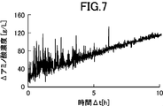
- FIG. 7 is a diagram showing an example of a case where the amino acid concentration is measured using a conventional sensor cover as a comparative example. It is a figure showing the example of measurement of the amino acid concentration by the sensor device using the cover for sensors by an embodiment of the present invention.
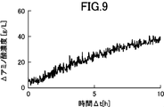
- FIG. 9 is a diagram illustrating an example in which an amino acid concentration in a culture solution different from those in FIGS. 6 to 8 is measured using the sensor cover according to the embodiment of the present invention.
- FIG. 9 is a diagram illustrating an example in which an amino acid concentration in a culture solution different from those in FIGS. 6 to 8 is measured using the sensor cover according to the embodiment of the present invention.
- FIG. 1 is a cross-sectional view showing an example in which a sensor device provided with a sensor cover according to an embodiment of the present invention is applied to a culture tank for amino acids.
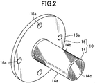
- FIG. 2 is a perspective view showing the appearance of the sensor cover according to the embodiment of the present invention.
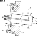
- FIG. 3 is an enlarged sectional view showing a state in which the sensor device according to the embodiment of the present invention is attached to a side wall surface of a culture tank.
- a sensor device 1 having a sensor cover is provided on a side wall surface 2 a of a culture tank 2, which is a container containing a liquid, and is stored in the culture tank 2. It is configured to measure the concentration of amino acids in the culture solution L in-line. Further, a sensor is disposed inside the sensor device 1, and a signal acquired by the sensor is transmitted to the measuring device main body 4. Further, in the present embodiment, the culture tank 2 has a substantially cylindrical shape, and is provided with a stirrer 6 for stirring the culture solution along the central axis thereof. The stirrer 6 is provided with a plurality of blades 6a for stirring the culture solution L.
- the culture solution L in the culture tank 2 is stirred to be homogeneous.
- oxygen or air is introduced into the culture tank 2 from a supply device (not shown). Therefore, the culture solution L contains microbubbles of supplied oxygen and air and microbubbles of carbon dioxide gas generated by the microorganism being cultured.
- the sensor device 1 includes a sensor cover 10 according to the embodiment of the present invention, and a sensor 12 disposed inside the sensor cover 10.
- the sensor cover 10 includes a substantially cylindrical cover body 14 and a flange portion 16 provided at a base end of the cover body 14 and fixed to the side wall surface 2 a of the culture tank 2.
- the cover body 14 is formed of a stainless steel thin plate, has a substantially cylindrical shape with a closed end, and is arranged so as to surround the sensor 12. Further, as will be described later, the cover main body 14 is provided with a large number of fine holes on the entire surface, and the liquid in the culture tank 2 can flow into the cover main body 14 through these fine holes.
- the cover body can be formed in any shape other than a cylindrical shape such as a rectangular parallelepiped. Further, the cover body can be formed of a metal other than stainless steel or a resin such as polytetrafluoroethylene, and is preferably formed of a material that is not easily damaged by the flow of the liquid caused by stirring.
- the flange portion 16 is a stainless steel disk, and the cover body 14 is fixed to the center by welding and integrated. Further, the cover body 14 is attached perpendicular to the plate surface of the flange portion 16.
- the flange portion 16 is provided with a bolt hole 16a, and the flange portion 16 is fixed to the outside of the side wall surface 2a by a fixing bolt 18a.
- a packing 18b is arranged between the flange portion 16 and the side wall surface 2a to ensure watertightness between the flange portion 16 and the side wall surface 2a. Further, as shown in FIG. 3, the portion for fixing the flange portion 16 outside the side wall surface 2a is formed so as to be inclined with respect to the vertical.
- the cover body 14 projects obliquely downward from the side wall surface of the container toward the inside.
- the mounting angle of the cover main body 14 can be set to an angle that suppresses the inflow of bubbles into the cover main body 14 and suppresses the accumulation of liquid near the cover main body 14 and the propagation of various bacteria.
- the angle can be set close to horizontal depending on the properties of the liquid.
- the center axis of the cover body 14 is inclined by about 16 degrees with respect to the horizontal axis.
- a transmission / reflection type near-infrared spectroscopic sensor (NIR sensor) is employed as the sensor 12, and the concentration of the amino acid in the culture solution L is measured by near-infrared analysis.
- NIR sensor near-infrared spectroscopic sensor
- the sensor cover 10 of the present embodiment is not limited to an NIR sensor, but may be a spectroscopic sensor using ultraviolet light or visible light, another optical sensor, an electromagnetic sensor for measuring dielectric constant or conductivity, or the like. And a sensor device can be configured in combination with these sensors.
- the sensor 12 includes a rod-shaped sensor probe 12a having a circular cross section, and a measuring unit 12b is provided at the tip thereof.
- the sensor probe 12a extends inside the cover main body 14 through an opening provided at the center of the flange portion 16 of the sensor cover 10.
- the sensor probe 12a extends along the center axis of the cover main body 14, and the measuring section 12b provided at the front end thereof is located near the front end of the cover main body 14.
- the outer diameter of the sensor probe 12a is about 20 mm, and the surrounding area is surrounded by a cover body 14 having an outer diameter of about 60 mm.
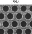
- FIG. 4 is an enlarged view showing an example of the fine holes provided on the surface of the cover main body 14.
- FIG. 5 is a diagram schematically showing a comparison between the operation of the conventional sensor cover and the operation of the sensor cover of the present embodiment.
- the cover body 14 of the sensor cover 10 has a large number of fine holes formed on the entire surface thereof, so that the surrounding liquid can flow into the inside of the cover body 14. ing.
- the size of each fine hole provided on the lower surface of the cover main body 14 is different from the size of each fine hole provided on the upper surface.
- the lower surface of the cover body 14 is provided with a lower transmission part 14a through which liquid passes
- the upper surface is provided with an upper transmission part 14b through which liquid passes, and is provided in the lower transmission part 14a.
- the formed fine holes are formed smaller than the fine holes provided in the upper transmission portion 14b.
- the lower transmission part 14 a is formed on the entire lower semicircle part corresponding to the lower semicircle of the cover body 14 having a circular cross section
- the upper transmission part 14 b is formed on the cover body 14. It is formed on the entire upper semicircle portion corresponding to the upper semicircle. Also, a large number of the same fine holes as the lower transmission portion 14a are formed on the entire front surface 14c of the cover body 14.
- the "lower surface” of the cover main body 14 means the surface on which the light shines when the light is projected from below vertically onto the sensor cover 10 installed in use.
- the “surface” means a surface to which light shines when light is projected from vertically above.
- a large number of fine holes are formed on the entire “lower surface” and “upper surface” of the cover main body 14, but the fine holes are not necessarily formed on the entire surface. What is necessary is just to be formed in a part.
- the fine holes are also provided on the distal end surface 14c of the cover main body 14, the fine holes need not be provided on the distal end surface 14c.
- the lower transmission portion 14a and the upper transmission portion 14b are arranged with substantially circular fine holes in a staggered manner. That is, the respective fine holes are arranged such that a line connecting the centers of three adjacent fine holes forms an equilateral triangle.
- the lower transmission portion 14a and the upper transmission portion 14b are formed by etching a thin stainless steel plate to form a large number of fine holes.
- a circular hole having a diameter D of about 180 ⁇ m is arranged at a pitch P of about 320 ⁇ m (the length of a side of an equilateral triangle connecting the center of the circle) so that the lower transmitting portion is formed. 14a are formed.
- the upper transmission portion 14b is formed by arranging circular holes having a diameter D of about 850 ⁇ m at a pitch P of about 1270 ⁇ m, or forming circular holes having a diameter D of about 350 ⁇ m at a pitch P of about 630 ⁇ m. It consists of an array.
- the lower transmission portion 14a in which circular holes having a diameter D of about 180 ⁇ m are arranged at a pitch P of about 320 ⁇ m has an aperture ratio of about 28.7%, and has a mesh of approximately 80 ° (80 mesh: 1 inch). (A net formed by arranging 80 element wires vertically and horizontally between them). Further, the upper transmission portion 14b in which circular holes having a diameter D of about 850 ⁇ m are arranged at a pitch P of about 1270 ⁇ m has an aperture ratio of about 40.6%, which corresponds to a net of about 20 °.
- the upper transmission portion 14b in which circular holes having a diameter D of about 350 ⁇ m are arranged at a pitch P of about 630 ⁇ m has an aperture ratio of about 28%, which is equivalent to a net of about 40 °.
- the aperture ratio becomes about 20.5%, which corresponds to a net of approximately 150 °, and a circle having a diameter D of about 150 ⁇ m.
- the aperture ratio is about 32.5%, which is equivalent to a net of about 100 °.
- the lower transmission portion 14a and the upper transmission portion 14b are formed by forming a large number of fine holes in a thin plate, but are formed by weaving, knitting, or the like a thin element wire.
- the lower transmission part 14a and the upper transmission part 14b can also be constituted by a mesh.
- the "micropore” is formed as a space between the wires constituting the mesh, and the "diameter of the micropore” means the distance between adjacent wires.
- the diameter of the fine holes provided in the lower transmission part 14a is set to be about 100 ⁇ m to about 400 ⁇ m. More preferably, the diameter of the fine holes provided in the lower transmission part 14a is set to be about 150 ⁇ m to about 400 ⁇ m.
- the fine holes provided in the upper transmission portion 14b be formed to be larger than the diameter of the fine holes in the lower transmission portion.
- the diameter of the fine holes of the upper transmission part 14b is preferably set to a diameter that can sufficiently suppress the flow of bubbles through the upper transmission part 14b due to the downward flow of the liquid.
- the diameter of the fine holes provided in the upper transmission part 14b is set to about 1.5 to about 5 times the diameter of the fine holes provided in the lower transmission part 14a.
- the cover main body 14 since the lower transmission portion 14a of the cover main body 14 has a small hole with a small diameter, it rises from below. Large air bubbles are prevented from entering the cover body 14.
- the cover main body 14 since the cover main body 14 is provided so as to protrude obliquely downward from the side wall surface 2a of the culture tank 2, the air bubbles prevented from entering by the cover main body 14 are covered by the cover main body 14. It is easy to move diagonally upward along the lower surface of the main body 14, and many air bubbles move upward while easily bypassing the sensor cover 10.
- the ratio of the bubbles approaching the sensor cover 10 from below is low. In many cases, these intrusions are largely suppressed by the lower transmission portion 14a. Further, the upper transmission part 14b also prevents the intrusion of some bubbles approaching the sensor cover 10 from the side or the like.
- the cover main body 14 is provided so as to protrude obliquely downward, air bubbles that have entered the cover main body 14 move upward toward the base end of the cover main body 14.
- the measuring portion 12b of the sensor probe 12a disposed in the cover main body 14 is disposed near the tip of the cover main body 14, the air bubbles in the cover main body 14 move away from the measuring portion 12b of the sensor 12. Moved to For this reason, the influence of the bubbles that have entered the cover body 14 on the measurement is further reduced.
- the influence of bubbles on measurement is effectively reduced.
- FIG. 6 is a diagram illustrating an example of the case where the amino acid concentration is measured without using the sensor cover 10
- FIG. 7 is a diagram illustrating the case where the amino acid concentration is measured using the conventional sensor cover (strainer). It is a figure showing an example.
- FIG. 8 is a diagram showing an example of measuring the amino acid concentration by the sensor device 1 using the sensor cover 10 according to the embodiment of the present invention.
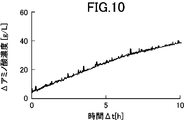
- 9 and 10 are diagrams showing examples in which the amino acid concentration in a culture solution different from those in FIGS. 6 to 8 is measured using two types of sensor covers according to the embodiment of the present invention. .
- the senor 12 is an NIR sensor, and light received by the sensor probe 12a is guided to the measuring instrument main body 4 (FIG. 1) via an optical fiber.
- the measuring device main body 4 an NIR spectrum of the guided light is acquired.
- the concentration of amino acids contained in the culture solution L can be estimated.
- 6 to 8 are graphs showing the time-dependent changes in the amino acid concentration estimated in this manner.
- FIG. 6 is an example in which the amino acid concentration in the culture solution L in the culture tank 2 is measured (estimated) using the sensor 12 without attaching the sensor cover 10.
- the estimated value fluctuates greatly every measurement. This is considered that bubbles mixed in the culture solution L affect the light received by the sensor probe 12a, and the estimated value varies.
- FIG. 7 shows an example in which the amino acid concentration of the culture solution L measured in the example shown in FIG. 6 is measured using the sensor 12 covered with a strainer (conventional sensor cover) of 20 °.
- a strainer conventional sensor cover
- FIG. 8 shows an example of the case where the amino acid concentration of the culture solution L measured in the examples shown in FIGS. 6 and 7 is measured using the sensor cover 10 according to the embodiment of the present invention.
- a mesh in which circular holes of about 180 ⁇ m are arranged at a pitch of about 320 ⁇ m is provided as the lower transmission section 14a, and circular holes of about 850 ⁇ m are arranged at a pitch of about 1270 ⁇ m as the upper transmission section 14b.
- the cover body 14 provided with the mesh is used.
- the variation in the estimated value of the amino acid concentration is extremely small as compared with the examples shown in FIGS. 6 and 7. A sufficiently reliable estimate has been obtained.
- FIGS. 9 and 10 an example of estimating the amino acid concentration in the culture tank 2 in which amino acids different from those in FIGS. 6 to 8 are cultured will be described.
- aeration culture is performed in the culture tank 2 in which an example of estimating the amino acid concentration is shown in FIGS. 6 to 8, and fine bubbles having a diameter of about 150 ⁇ m are generated by a supply device (not shown).
- L a supply device
- no air bubbles were introduced in the culture tank 2 shown in the measurement examples in FIGS. 9 and 10, and the mixed air bubbles had a diameter of about 350 ⁇ m due to carbon dioxide gas generated in the culture solution L. Fine bubbles are the center.
- FIG. 9 shows an example of the case where the amino acid concentration of the culture solution L is measured using the sensor cover 10 according to the embodiment of the present invention.
- a mesh in which circular holes of about 180 ⁇ m are arranged at a pitch of about 320 ⁇ m is provided as the lower transmitting part 14 a, and a mesh is formed as the upper transmitting part 14 b.
- a cover body 14 provided with a mesh in which 850 ⁇ m circular holes are arranged at a pitch of about 1270 ⁇ m is used.
- FIG. 9 by covering the sensor 12 with the sensor cover 10 of the present embodiment, variation in the estimated value of the amino acid concentration is suppressed to a small value, and a highly reliable estimated value is obtained.
- FIG. 10 shows an example in which the same amino acid concentration in the culture solution L as in the example shown in FIG. 9 is measured using the sensor cover 10 according to the embodiment of the present invention.
- a mesh in which circular holes of about 180 ⁇ m are arranged at a pitch of about 320 ⁇ m is provided as the lower transmitting section 14a, and circular holes of about 350 ⁇ m are arranged at a pitch of about 630 ⁇ m as the upper transmitting section 14b.
- the cover body 14 provided with the mesh is used.
- the variation in the estimated value of the amino acid concentration is extremely small, and a sufficiently reliable estimated value is obtained.
- the variation in the estimated value is further smaller than in the example shown in FIG.
- the size of the micropores provided in the lower transmission part 14a and the upper transmission part 14b is appropriately set according to the properties of the bubbles mixed in the liquid to be measured and the properties of the liquid such as viscosity. As a result, the effect of the inclusion of bubbles can be sufficiently suppressed.
- the cover main body 14 arranged so as to surround the sensor 12 is provided with the lower transmission part 14a and the upper transmission part 14b through which the liquid passes (FIG. 2). Therefore, the liquid to be measured can flow into and out of the cover body 14 constantly. As a result, the liquid in the cover main body 14 is constantly replaced, and the sensor 12 disposed in the cover main body 14 can continuously measure the characteristics of the liquid in real time (FIGS. 8 to 10). Further, since the fine holes provided in the lower transmitting portion 14a are formed smaller than the fine holes provided in the upper transmitting portion 14b (FIG. 5C), they have risen from below the cover main body 14.
- Bubbles are less likely to pass through the fine holes of the lower transmission portion 14a, and the intrusion of bubbles into the cover main body 14 can be effectively suppressed.
- the fine holes of the upper transmitting portion 14b are formed larger than the fine holes of the lower transmitting portion 14a, the air bubbles that have entered the cover main body 14 rise in the cover main body and are discharged through the upper transmitting portion 14b. Easy to be. As a result, it is possible to suppress the air bubbles that have entered the cover main body 14 from remaining in the cover main body 14 and adversely affect the measurement value of the sensor 12.
- the cover body 14 is formed in a substantially cylindrical shape (FIG. 2), air bubbles that float from the lower side of the cover body 14 are formed on the lower side of the cover body 14. It is easy to flow upward along the surface, and the intrusion of bubbles into the cover main body 14 can be further suppressed. Further, since the cover main body 14 is formed in a substantially cylindrical shape, air bubbles that have entered the cover main body 14 and floated are collected at the highest portion in the cover main body 14 and are less likely to contact the sensor 12. Accordingly, even when air bubbles enter the cover main body 14, adverse effects on the measurement can be suppressed to a minimum.
- the lower transmitting portion 14a and the upper transmitting portion 14b are provided on the entire surface of the lower semicircular portion and the upper semicircular portion, respectively (FIG. 2),
- the portion of the cover body 14 through which the liquid permeates can be made extremely large.
- the liquid in the cover body 14 is easily replaced with an external liquid, and the characteristics of the liquid can be accurately measured in real time.
- the fine holes of the lower transmission portion 14a and the upper transmission portion 14b are formed by the holes provided in the thin metal plate (FIG. 4).
- the liquid is less likely to adhere to the lower transmission part 14a and the upper transmission part 14b as compared with the case where the lower transmission part and the upper transmission part are formed by a net formed by knitting, thereby improving the maintainability of the sensor cover 10. Can be.
- the cover body 14 projects obliquely downward from the side wall surface 2a of the culture tank 2 which is a container containing the liquid (FIG. 3), so that it rises from below.
- the air bubbles that have reached the cover main body 14 can easily flow upward along the lower surface of the cover main body 14, and can effectively prevent entry into the cover main body 14.
- air bubbles that have entered the cover main body 14 collect at the base end of the cover main body 14 located above, and thus move away from the measurement unit 12b of the sensor 12 disposed near the distal end of the cover main body 14, and adversely affect the measurement. Can be reduced.
- the amino acid concentration in the culture solution in which bubbles are mixed is estimated by spectroscopic analysis. It can be applied to measure properties.
- the present invention is applied to the measurement of the concentration of a specific component in a liquid.
- the sensor of any sensor that measures characteristics of the liquid itself, such as the dielectric constant or conductivity of the liquid is used.
- the present invention can be applied to a cover for use.
- the present invention is applied to the measurement of the amino acid concentration in a culture solution.
- the present invention is applied to the measurement of various component concentrations in a liquid, not limited to the amino acid concentration. This makes it possible to accurately manage the aeration culture, and to increase the accumulation and yield of products in the culture solution.
- the carbon source concentration can be measured in-line.
Abstract
Provided are: a sensor cover that is capable of reducing, with a simple structure, the influence of air bubbles mixed in a liquid; and a sensor device provided with the same. The present invention is a cover (10) of a sensor that measures a property of a liquid in which air bubbles are mixed, characterized by: having a cover body (14) that is disposed so as to surround a sensor (12); being provided with, at least in a section of a lower-side surface of the cover body (14), a lower-side passage section (14a) that allows the liquid to pass therethrough; being provided with, at least in a section of an upper-side surface of the cover body (14), an upper-side passage section (14b) that allows the liquid to pass therethrough; having numerous fine holes for allowing the liquid to pass therethrough formed in each of the lower-side passage section (14a) and the upper-side passage section (14b); and having the fine holes provided in the lower-side passage section (14a) that are formed in smaller sizes than the fine holes provided in the upper-side passage section (14b).
Description
本発明はセンサー用カバーに関し、特に、気泡が混入した液体の特性を測定するセンサー用のカバー及びそれを備えたセンサー装置に関する。
{Circle over (1)} The present invention relates to a cover for a sensor, and more particularly to a cover for a sensor for measuring characteristics of a liquid mixed with air bubbles and a sensor device including the same.
種々の工業的生産工程において、液体の導電率や、濁度、液体中に含まれる特定成分の濃度等、種々の液体の特性を測定する必要がある。特許第3074781号(特許文献1)には、L-リジンの製造方法が記載されている。この製造方法においては、培養液中の炭素源の濃度を5g/L以下に保持するように炭素源を添加している。即ち、この方法では、適時培養液をサンプリングして炭素源濃度を直接分析したり、pHや溶存酸素濃度を測定し、その変化から炭素源の欠乏状態を感知したりして炭素源濃度を測定し、培地のフィードを制御している。
に お い て In various industrial production processes, it is necessary to measure the characteristics of various liquids, such as the conductivity and turbidity of the liquid, and the concentration of specific components contained in the liquid. Patent No. 3074781 (Patent Document 1) describes a method for producing L-lysine. In this production method, the carbon source is added so as to maintain the concentration of the carbon source in the culture solution at 5 g / L or less. In other words, this method measures the carbon source concentration by sampling the culture solution at appropriate times and directly analyzing the carbon source concentration, measuring the pH and dissolved oxygen concentration, and sensing the carbon source deficiency from the changes. And control the media feed.
特許文献1記載の発明のように、液体の特性は、製造工程から測定すべき液体の一部を取り出して測定することは比較的容易であるが、製造工程から取り出すことなくインラインで測定することが、製造効率の観点からは好ましい。しかしながら、測定すべき液体中に気泡が混入している場合には、特にインラインで液体の特性を測定することが困難になることがある。例えば、通気培養を行っている培養液中には、供給された酸素や空気の気泡や、培養中の微生物自体の代謝産物である炭酸ガスの気泡が混入しており、これらの気泡が測定値にノイズを混入させたり、測定誤差を増大させたりする場合がある。
As in the invention described in Patent Document 1, it is relatively easy to take out a part of the liquid to be measured from the manufacturing process and measure the characteristics of the liquid. However, it is preferable from the viewpoint of production efficiency. However, when bubbles are mixed in the liquid to be measured, it may be difficult to measure the characteristics of the liquid, particularly in-line. For example, in the culture solution in which aeration culture is performed, bubbles of supplied oxygen and air and bubbles of carbon dioxide gas, which is a metabolite of the microorganism itself during culture, are mixed, and these bubbles are measured values. In some cases, noise may be mixed into the data, or the measurement error may be increased.
特許第4420168号公報(特許文献2)には、濁度センサが記載されている。この濁度センサは、ステンレス製の中空半円筒の部材を有し、その下部に被検液の取り込み口と自動的に開閉するスイングバルブが設けられ、上部には泡抜き用の孔が設けられている。さらに、中空半円筒の内部の先端位置には、レーザ濁度計の接液測光部が配置されている。この濁度センサによる測定時においては、まず、スイングバルブを開弁して中空半円筒内部の被検液を置換する。次いで、スイングバルブを閉弁し、中空半円筒内の気泡が泡抜き用の孔から排出されて、検出される濁度が安定するのを待ってから濁度の測定を実行する。特許文献2記載の発明では、このようにして被検液中の気泡の影響を低減している。
No. 4,420,168 (Patent Document 2) describes a turbidity sensor. This turbidity sensor has a stainless steel hollow semi-cylindrical member, a swing valve that automatically opens and closes with a sample liquid intake port is provided at the lower part, and a bubble removing hole is provided at the upper part. ing. Further, a liquid contacting photometric part of the laser turbidity meter is arranged at a tip position inside the hollow half cylinder. At the time of measurement by this turbidity sensor, first, the swing valve is opened to replace the test liquid inside the hollow semi-cylinder. Next, the swing valve is closed, and the turbidity measurement is performed after the bubbles in the hollow semi-cylinder are discharged from the bubble removing hole and the detected turbidity is stabilized. In the invention described in Patent Document 2, the influence of bubbles in the test liquid is reduced in this way.
しかしながら、特許文献2記載の濁度センサにおいては、スイングバルブを閉弁した後、検出値が安定するのを待つ必要があり、リアルタイムで検出を行うのが困難である。また、特許文献2記載の濁度センサでは、遠隔操作により開閉されるスイングバルブ等が必要であるため構造が複雑になると共に、長期間に亘って安定動作させるためのメンテナンスにも手間がかかるという問題がある。
However, in the turbidity sensor described in Patent Literature 2, it is necessary to wait until the detection value is stabilized after closing the swing valve, and it is difficult to perform detection in real time. In addition, the turbidity sensor described in Patent Document 2 requires a swing valve or the like that can be opened and closed by remote control, so that the structure is complicated, and maintenance for stable operation for a long period of time is troublesome. There's a problem.
従って、本発明は、シンプルな構造で、液体に混入している気泡の影響を軽減することができるセンサー用のカバー及びそれを備えたセンサー装置を提供することを目的としている。
Accordingly, it is an object of the present invention to provide a cover for a sensor having a simple structure and capable of reducing the influence of air bubbles mixed in a liquid, and a sensor device having the same.
上述した課題を解決するために、本発明は、気泡が混入した液体の特性を測定するセンサー用のカバーであって、センサーを取り囲むように配置されるカバー本体を有し、このカバー本体の下側の面の少なくとも一部には、液体を通す下側透過部が設けられ、カバー本体の上側の面の少なくとも一部には、液体を通す上側透過部が設けられ、下側透過部及び上側透過部には、液体を通すための多数の微細孔が夫々形成されており、下側透過部に設けられた微細孔は、上側透過部に設けられた微細孔よりも小さく形成されていることを特徴としている。
In order to solve the above-described problems, the present invention provides a cover for a sensor for measuring the characteristics of a liquid mixed with air bubbles, the cover having a cover body arranged so as to surround the sensor, and a cover under the cover body. At least a portion of the side surface is provided with a lower transmission portion through which liquid passes, and at least a portion of the upper surface of the cover body is provided with an upper transmission portion through which liquid passes, and the lower transmission portion and the upper portion. A large number of fine holes for passing liquid are formed in the transmitting portion, and the fine holes provided in the lower transmitting portion are formed smaller than the fine holes provided in the upper transmitting portion. It is characterized by.
このように構成された本発明によれば、センサーを取り囲むように配置されるカバー本体に、液体を通す下側透過部及び上側透過部が設けられているので、測定すべき液体はカバー本体に絶えず流入、流出することができる。この結果、カバー本体内の液体は常に置換され、カバー本体内に配置されたセンサーは、リアルタイムで連続的に液体の特性を測定することができる。また、下側透過部に設けられた微細孔は、上側透過部に設けられた微細孔よりも小さく形成されているので、カバー本体の下方から浮き上がってきた気泡は、下側透過部の微細孔を通過しにくく、カバー本体内への気泡の侵入を効果的に抑制することができる。一方、上側透過部の微細孔は下側透過部の微細孔よりも大きく形成されているので、カバー本体内に侵入した気泡はカバー本体内で浮き上がり、上側透過部を通って排出されやすい。この結果、カバー本体内に侵入した気泡がカバー本体内に滞留し、センサーの測定値に悪影響を及ぼすのを抑制することができる。
According to the present invention configured as described above, the cover main body arranged to surround the sensor is provided with the lower transmission portion and the upper transmission portion through which the liquid passes, so that the liquid to be measured is provided on the cover main body. Can constantly flow in and out. As a result, the liquid in the cover main body is constantly replaced, and the sensor arranged in the cover main body can continuously measure the characteristics of the liquid in real time. Further, since the fine holes provided in the lower transmitting portion are formed smaller than the fine holes provided in the upper transmitting portion, the air bubbles rising from below the cover main body are small holes in the lower transmitting portion. And it is possible to effectively prevent air bubbles from entering the cover body. On the other hand, since the fine holes in the upper transmitting portion are formed larger than the fine holes in the lower transmitting portion, air bubbles that have entered the cover main body float up in the cover main body and are easily discharged through the upper transmitting portion. As a result, it is possible to suppress the air bubbles that have entered the cover main body from remaining in the cover main body and adversely affecting the measurement value of the sensor.
本発明において、好ましくは、カバー本体は略円筒形に形成され、その内部の軸線方向にセンサーが延びている。
このように構成された本発明によれば、カバー本体が略円筒形に形成されているので、カバー本体の下側から浮き上がった気泡が、カバー本体の下側表面に沿って上方に流れやすく、気泡のカバー本体内への侵入を更に抑制することができる。また、カバー本体が略円筒形に形成されているので、カバー本体内に侵入して浮き上がった気泡がカバー本体内の最も高い部分に集められ、センサーに接触しにくくなる。これにより、カバー本体内に気泡が侵入した場合でも、測定への悪影響を最低限に抑制することができる。 In the present invention, preferably, the cover main body is formed in a substantially cylindrical shape, and the sensor extends in an axial direction inside the cover main body.
According to the present invention configured as described above, since the cover main body is formed in a substantially cylindrical shape, air bubbles floating from the lower side of the cover main body easily flow upward along the lower surface of the cover main body, Intrusion of bubbles into the cover body can be further suppressed. In addition, since the cover main body is formed in a substantially cylindrical shape, air bubbles that have entered the cover main body and floated are collected at the highest portion in the cover main body, and are less likely to contact the sensor. Thus, even when air bubbles enter the cover body, adverse effects on the measurement can be suppressed to a minimum.
本発明において、好ましくは、下側透過部は略円筒形のカバー本体の下側半円部全面に設けられ、上側透過部はカバー本体の上側半円部全面に設けられている。
このように構成された本発明によれば、下側半円部及び上側半円部の全面に、下側透過部及び上側透過部が夫々設けられているので、カバー本体の液体が透過する部分を極めて大きくすることができる。この結果、カバー本体内の液体が外部の液体と置換されやすくなり、液体の特性をリアルタイムで正確に測定することが可能となる。 In the present invention, preferably, the lower transmitting portion is provided on the entire lower semicircular portion of the substantially cylindrical cover main body, and the upper transmitting portion is provided on the entire upper semicircular portion of the cover main body.
According to the present invention configured as described above, since the lower transmission portion and the upper transmission portion are provided on the entire surface of the lower semicircular portion and the upper semicircular portion, respectively, the portion of the cover main body through which the liquid permeates is provided. Can be made extremely large. As a result, the liquid in the cover body is easily replaced by the external liquid, and the characteristics of the liquid can be accurately measured in real time.
本発明において、好ましくは、カバー本体は金属製の薄板から形成され、下側透過部及び上側透過部に設けられた微細孔は、金属製の薄板に設けた略円形の穴である。
このように構成された本発明によれば、金属製の薄板に設けた穴により下側透過部及び上側透過部の微細孔が形成されているので、素線を編んで形成した網状物で下側透過部や上側透過部を形成した場合に比べ、液体が下側透過部、上側透過部に付着しにくく、センサー用カバーのメンテナンス性を向上させることができる。また、金属製の薄板に設けた穴により下側透過部及び上側透過部の微細孔を形成することにより、網状物よりも破損しにくく、耐久性の高いカバー本体を構成することができる。 In the present invention, preferably, the cover main body is formed of a thin metal plate, and the fine holes provided in the lower transmission portion and the upper transmission portion are substantially circular holes provided in the thin metal plate.
According to the present invention configured as described above, since the fine holes of the lower transmission part and the upper transmission part are formed by the holes provided in the metal thin plate, the lower part is formed by a net formed by knitting element wires. The liquid is less likely to adhere to the lower transmission part and the upper transmission part as compared with the case where the side transmission part and the upper transmission part are formed, and the maintenance of the sensor cover can be improved. In addition, by forming the fine holes in the lower transmission part and the upper transmission part by the holes provided in the metal thin plate, it is possible to form a cover body that is less susceptible to damage than a net-like material and has high durability.
本発明において、好ましくは、上側透過部に設けられている微細孔の径は、下側透過部に設けられている微細孔の径の1.5倍乃至5倍である。
このように構成された本発明においては、上側透過部の微細孔の径を下側透過部の微細孔の径の1.5倍乃至5倍に設定することにより、カバー本体内への気泡侵入の抑制と、カバー本体内に侵入してしまった気泡の排出が適正にバランスし、センサーへの気泡の影響を効果的に抑制することができる。 In the present invention, preferably, the diameter of the fine holes provided in the upper transmission portion is 1.5 to 5 times the diameter of the fine holes provided in the lower transmission portion.
In the present invention configured as described above, by setting the diameter of the fine holes in the upper transmission portion to 1.5 to 5 times the diameter of the fine holes in the lower transmission portion, air bubbles can enter the cover body. And the discharge of the air bubbles that have entered the cover body are properly balanced, and the effect of the air bubbles on the sensor can be effectively suppressed.
本発明において、下側透過部に設けられている微細孔の径は、100μm乃至400μm、好ましくは、150μm乃至400μmである。
このように構成された本発明においては、下側透過部に設けられている微細孔の径が100μm乃至400μmに形成されているので、カバー本体内への液体の流入を許容しながらセンサーの測定値に悪影響を与えやすい大きさの気泡の侵入を、効果的に抑制することができる。 In the present invention, the diameter of the fine holes provided in the lower transmission portion is 100 μm to 400 μm, and preferably 150 μm to 400 μm.
In the present invention configured as described above, since the diameter of the fine hole provided in the lower transmission portion is formed in the range of 100 μm to 400 μm, the measurement of the sensor while allowing the liquid to flow into the cover body is performed. Intrusion of bubbles having a size that easily affects the value can be effectively suppressed.
本発明において、好ましくは、カバー本体は、液体を収容した容器の側壁面から斜め下方に向けて突出するように設けられ、センサーの計測部は、カバー本体の先端近傍に配置される。
このように構成された本発明においては、カバー本体が、液体を収容した容器の側壁面から斜め下方に向けて突出するので、下方から浮き上がってカバー本体に到達した気泡が、カバー本体の下側面に沿って上方に流れやすく、カバー本体内への侵入を効果的に抑制することができる。また、カバー本体内に侵入した気泡は、上方に位置するカバー本体の基端部に集まるので、カバー本体の先端近傍に配置されたセンサーの計測部から遠ざかり、測定に与える悪影響を軽減することができる。 In the present invention, preferably, the cover main body is provided so as to project obliquely downward from the side wall surface of the container storing the liquid, and the measurement unit of the sensor is disposed near the tip of the cover main body.
In the present invention thus configured, since the cover main body projects obliquely downward from the side wall surface of the container containing the liquid, air bubbles that float from below and reach the cover main body are formed on the lower surface of the cover main body. It is easy to flow upward along the direction, and intrusion into the cover main body can be effectively suppressed. In addition, since air bubbles that have entered the cover body collect at the base end of the cover body located above, the bubbles move away from the measurement unit of the sensor disposed near the front end of the cover body, thereby reducing adverse effects on the measurement. it can.
また、本発明のセンサー装置は、液体の特性を測定するためのセンサーと、このセンサーを取り囲むように配置された本発明のセンサー用カバーと、を有することを特徴としている。
The sensor device of the present invention includes a sensor for measuring a property of a liquid, and the sensor cover of the present invention disposed so as to surround the sensor.
さらに、本発明の液体の特性の測定方法は、本発明のセンサー装置を準備する段階と、液体内に挿入されたセンサー装置から測定信号を取得する段階と、を有することを特徴としている。
また、本発明の通気培養における代謝生産物の製造方法は、本発明のセンサー装置を準備する段階と、培養液中に挿入したセンサー装置から測定信号を取得する段階と、培養液を通気培養する段階と、測定信号に基づいて、通気培養における代謝生産物の濃度変化、及び/又は培養の原料の濃度変化を追跡する段階と、を有することを特徴としている。 Further, the method for measuring the properties of a liquid according to the present invention includes the steps of preparing the sensor device of the present invention and obtaining a measurement signal from the sensor device inserted into the liquid.
The method for producing a metabolite in aeration culture according to the present invention includes the steps of preparing a sensor device of the present invention, obtaining a measurement signal from the sensor device inserted into the culture solution, and performing aeration culture of the culture solution. And a step of tracking a change in the concentration of a metabolite in the aeration culture and / or a change in the concentration of the raw material for the culture based on the measurement signal.
本発明のセンサー用カバー及びそれを備えたセンサー装置によれば、シンプルな構造で、液体に混入している気泡の影響を軽減することができる。
According to the sensor cover of the present invention and the sensor device provided with the same, it is possible to reduce the influence of air bubbles mixed in the liquid with a simple structure.
次に、添付図面を参照して、本発明の好ましい実施形態を説明する。
図1は、本発明の実施形態によるセンサー用カバーを備えたセンサー装置を、アミノ酸の培養槽に適用した例を示す断面図である。図2は、本発明の実施形態によるセンサー用カバーの外観を示す斜視図である。図3は、本発明の実施形態によるセンサー装置を培養槽の側壁面に取り付けた状態を拡大して示す断面図である。 Next, a preferred embodiment of the present invention will be described with reference to the accompanying drawings.
FIG. 1 is a cross-sectional view showing an example in which a sensor device provided with a sensor cover according to an embodiment of the present invention is applied to a culture tank for amino acids. FIG. 2 is a perspective view showing the appearance of the sensor cover according to the embodiment of the present invention. FIG. 3 is an enlarged sectional view showing a state in which the sensor device according to the embodiment of the present invention is attached to a side wall surface of a culture tank.
図1に示すように、本発明の実施形態によるセンサー用カバーを備えたセンサー装置1は、液体を収容した容器である培養槽2の側壁面2aに設けられ、培養槽2の中に収容されている培養液L中のアミノ酸の濃度をインラインで測定するように構成されている。さらに、センサー装置1の内部には、センサーが配置されており、このセンサーによって取得された信号が測定器本体4に送信される。また、本実施形態においては、培養槽2は概ね円筒形であり、その中心軸線に沿って培養液を攪拌するための攪拌機6が設けられている。攪拌機6には培養液Lを攪拌するための複数の羽根6aが備えられており、これらの羽根6aを回転させることにより、培養槽2の培養液Lは均質になるように攪拌される。また、培養槽2内で通気培養を行う場合には、供給装置(図示せず)から培養槽2内に酸素又は空気が導入される。従って、培養液L中には、供給された酸素や空気の微細な気泡や、培養している微生物が生成した炭酸ガスの微細な気泡が混入している。
As shown in FIG. 1, a sensor device 1 having a sensor cover according to an embodiment of the present invention is provided on a side wall surface 2 a of a culture tank 2, which is a container containing a liquid, and is stored in the culture tank 2. It is configured to measure the concentration of amino acids in the culture solution L in-line. Further, a sensor is disposed inside the sensor device 1, and a signal acquired by the sensor is transmitted to the measuring device main body 4. Further, in the present embodiment, the culture tank 2 has a substantially cylindrical shape, and is provided with a stirrer 6 for stirring the culture solution along the central axis thereof. The stirrer 6 is provided with a plurality of blades 6a for stirring the culture solution L. By rotating these blades 6a, the culture solution L in the culture tank 2 is stirred to be homogeneous. When performing aeration culture in the culture tank 2, oxygen or air is introduced into the culture tank 2 from a supply device (not shown). Therefore, the culture solution L contains microbubbles of supplied oxygen and air and microbubbles of carbon dioxide gas generated by the microorganism being cultured.
次に、図2及び図3を参照して、本発明の実施形態によるセンサー装置1の構成を説明する。
図3に示すように、センサー装置1は、本発明の実施形態によるセンサー用カバー10と、このセンサー用カバー10の内部に配置されたセンサー12と、を有する。 Next, a configuration of thesensor device 1 according to the embodiment of the present invention will be described with reference to FIGS.
As shown in FIG. 3, thesensor device 1 includes a sensor cover 10 according to the embodiment of the present invention, and a sensor 12 disposed inside the sensor cover 10.
図3に示すように、センサー装置1は、本発明の実施形態によるセンサー用カバー10と、このセンサー用カバー10の内部に配置されたセンサー12と、を有する。 Next, a configuration of the
As shown in FIG. 3, the
センサー用カバー10は、略円筒形のカバー本体14と、このカバー本体14の基端に設けられ、培養槽2の側壁面2aに固定されるフランジ部16と、を有する。
カバー本体14は、ステンレス製の薄板で形成されると共に、先端が閉塞された略円筒形に構成されており、センサー12を取り囲むように配置されている。また、後述するように、カバー本体14は、その全面に多数の微細孔が設けられており、培養槽2内の液体は、これらの微細孔を通ってカバー本体14内に流入することができる。なお、カバー本体は、直方体等、円筒形以外の任意の形状に構成することができる。また、カバー本体は、ステンレス以外の金属や、ポリテトラフルオロエチレン等の樹脂でも形成することができ、攪拌による液体の流れにより破損しにくい材質で形成するのが良い。 Thesensor cover 10 includes a substantially cylindrical cover body 14 and a flange portion 16 provided at a base end of the cover body 14 and fixed to the side wall surface 2 a of the culture tank 2.
Thecover body 14 is formed of a stainless steel thin plate, has a substantially cylindrical shape with a closed end, and is arranged so as to surround the sensor 12. Further, as will be described later, the cover main body 14 is provided with a large number of fine holes on the entire surface, and the liquid in the culture tank 2 can flow into the cover main body 14 through these fine holes. . The cover body can be formed in any shape other than a cylindrical shape such as a rectangular parallelepiped. Further, the cover body can be formed of a metal other than stainless steel or a resin such as polytetrafluoroethylene, and is preferably formed of a material that is not easily damaged by the flow of the liquid caused by stirring.
カバー本体14は、ステンレス製の薄板で形成されると共に、先端が閉塞された略円筒形に構成されており、センサー12を取り囲むように配置されている。また、後述するように、カバー本体14は、その全面に多数の微細孔が設けられており、培養槽2内の液体は、これらの微細孔を通ってカバー本体14内に流入することができる。なお、カバー本体は、直方体等、円筒形以外の任意の形状に構成することができる。また、カバー本体は、ステンレス以外の金属や、ポリテトラフルオロエチレン等の樹脂でも形成することができ、攪拌による液体の流れにより破損しにくい材質で形成するのが良い。 The
The
フランジ部16は、ステンレス製の円板であり、その中央にカバー本体14が溶接により固定され、一体化されている。また、カバー本体14は、フランジ部16の板面に対し垂直に取り付けられている。フランジ部16にはボルト穴16aが設けられており、固定用ボルト18aによりフランジ部16が側壁面2aの外側に固定される。また、フランジ部16と側壁面2aの間にはパッキン18bが配置されており、フランジ部16と側壁面2aの間の水密性が確保されている。さらに、図3に示すように、側壁面2a外側の、フランジ部16を固定する部分は鉛直に対して傾斜するように形成されている。これにより、センサー装置1が培養槽2の側壁面2aに取り付けられたとき、カバー本体14は容器の側壁面から内側に向けて斜め下方に突出する。カバー本体14の取り付け角度は、カバー本体14内への気泡の流入を抑制すると共に、カバー本体14の近傍に液溜まりができて雑菌が繁殖するのを抑制することができる角度に設定することが好ましく、液体の性質によっては水平に近い角度に設定することもできる。本実施形態においては、カバー本体14の中心軸線は、水平な軸線に対して約16度傾斜している。
The flange portion 16 is a stainless steel disk, and the cover body 14 is fixed to the center by welding and integrated. Further, the cover body 14 is attached perpendicular to the plate surface of the flange portion 16. The flange portion 16 is provided with a bolt hole 16a, and the flange portion 16 is fixed to the outside of the side wall surface 2a by a fixing bolt 18a. A packing 18b is arranged between the flange portion 16 and the side wall surface 2a to ensure watertightness between the flange portion 16 and the side wall surface 2a. Further, as shown in FIG. 3, the portion for fixing the flange portion 16 outside the side wall surface 2a is formed so as to be inclined with respect to the vertical. Thus, when the sensor device 1 is attached to the side wall surface 2a of the culture tank 2, the cover body 14 projects obliquely downward from the side wall surface of the container toward the inside. The mounting angle of the cover main body 14 can be set to an angle that suppresses the inflow of bubbles into the cover main body 14 and suppresses the accumulation of liquid near the cover main body 14 and the propagation of various bacteria. Preferably, the angle can be set close to horizontal depending on the properties of the liquid. In the present embodiment, the center axis of the cover body 14 is inclined by about 16 degrees with respect to the horizontal axis.
また、本実施形態においては、センサー12として透過反射型近赤外分光センサ(NIRセンサー)が採用されており、近赤外分析により培養液L中のアミノ酸の濃度を測定している。しかしながら、本実施形態のセンサー用カバー10は、NIRセンサーの他、紫外線や可視光を使用した分光センサー、その他の光学的センサー、誘電率や、導電率を測定するための電磁気的センサー等、種々のセンサーに適用することができ、これらのセンサーと組み合わせてセンサー装置を構成することができる。
In the present embodiment, a transmission / reflection type near-infrared spectroscopic sensor (NIR sensor) is employed as the sensor 12, and the concentration of the amino acid in the culture solution L is measured by near-infrared analysis. However, the sensor cover 10 of the present embodiment is not limited to an NIR sensor, but may be a spectroscopic sensor using ultraviolet light or visible light, another optical sensor, an electromagnetic sensor for measuring dielectric constant or conductivity, or the like. And a sensor device can be configured in combination with these sensors.
図3に示すように、センサー12は、円形断面の棒状のセンサープローブ12aを備えており、その先端部に計測部12bが設けられている。センサープローブ12aは、センサー用カバー10のフランジ部16中央に設けられた開口を通ってカバー本体14の内部に延びている。また、センサープローブ12aはカバー本体14の中心軸線に沿って延びており、その先端部に設けられた計測部12bは、カバー本体14の先端部近傍に位置している。なお、本実施形態においては、センサープローブ12aの外径は約20mmであり、その周囲を外径約60mmのカバー本体14が取り囲むように構成されている。このように、センサープローブ12aとカバー本体14の内壁面との間には、約10mm乃至約30mm程度のクリアランスを設けることが好ましい。
As shown in FIG. 3, the sensor 12 includes a rod-shaped sensor probe 12a having a circular cross section, and a measuring unit 12b is provided at the tip thereof. The sensor probe 12a extends inside the cover main body 14 through an opening provided at the center of the flange portion 16 of the sensor cover 10. The sensor probe 12a extends along the center axis of the cover main body 14, and the measuring section 12b provided at the front end thereof is located near the front end of the cover main body 14. In the present embodiment, the outer diameter of the sensor probe 12a is about 20 mm, and the surrounding area is surrounded by a cover body 14 having an outer diameter of about 60 mm. Thus, it is preferable to provide a clearance of about 10 mm to about 30 mm between the sensor probe 12a and the inner wall surface of the cover body 14.
次に、図4及び図5を新たに参照して、本発明の実施形態のセンサー用カバー10に備えられているカバー本体14の構成を詳細に説明する。
図4は、カバー本体14表面に設けられている微細孔の一例を拡大して示す図である。図5は、従来のセンサー用カバーの作用と、本実施形態のセンサー用カバーの作用を比較して、模式的に示す図である。 Next, the configuration of the covermain body 14 provided in the sensor cover 10 according to the embodiment of the present invention will be described in detail with reference to FIGS. 4 and 5.
FIG. 4 is an enlarged view showing an example of the fine holes provided on the surface of the covermain body 14. FIG. 5 is a diagram schematically showing a comparison between the operation of the conventional sensor cover and the operation of the sensor cover of the present embodiment.
図4は、カバー本体14表面に設けられている微細孔の一例を拡大して示す図である。図5は、従来のセンサー用カバーの作用と、本実施形態のセンサー用カバーの作用を比較して、模式的に示す図である。 Next, the configuration of the cover
FIG. 4 is an enlarged view showing an example of the fine holes provided on the surface of the cover
上述したように、本発明の実施形態によるセンサー用カバー10のカバー本体14には、その全面に多数の微細孔が形成されており、周囲の液体がカバー本体14の内側に流入できるようになっている。ここで、本実施形態のセンサー用カバー10においては、カバー本体14の下側の面に設けられた各微細孔の大きさと、上側の面に設けられた各微細孔の大きさが異なるものとなっている。即ち、カバー本体14の下側の面には液体を通す下側透過部14aが設けられ、上側の面には液体を通す上側透過部14bが設けられており、下側透過部14aに設けられた微細孔は、上側透過部14bに設けられた微細孔よりも小さく形成されている。
As described above, the cover body 14 of the sensor cover 10 according to the embodiment of the present invention has a large number of fine holes formed on the entire surface thereof, so that the surrounding liquid can flow into the inside of the cover body 14. ing. Here, in the sensor cover 10 of the present embodiment, the size of each fine hole provided on the lower surface of the cover main body 14 is different from the size of each fine hole provided on the upper surface. Has become. That is, the lower surface of the cover body 14 is provided with a lower transmission part 14a through which liquid passes, and the upper surface is provided with an upper transmission part 14b through which liquid passes, and is provided in the lower transmission part 14a. The formed fine holes are formed smaller than the fine holes provided in the upper transmission portion 14b.
図2に示すように、下側透過部14aは、円形断面を有するカバー本体14の下側の半円に対応する下側半円部全面に形成され、上側透過部14bは、カバー本体14の上側の半円に対応する上側半円部全面に形成されている。また、カバー本体14の先端面14cにも、全面に下側透過部14aと同一の微細孔が多数形成されている。
As shown in FIG. 2, the lower transmission part 14 a is formed on the entire lower semicircle part corresponding to the lower semicircle of the cover body 14 having a circular cross section, and the upper transmission part 14 b is formed on the cover body 14. It is formed on the entire upper semicircle portion corresponding to the upper semicircle. Also, a large number of the same fine holes as the lower transmission portion 14a are formed on the entire front surface 14c of the cover body 14.
なお、本明細書において、カバー本体14の「下側の面」とは、使用状態に設置したセンサー用カバー10に鉛直下方から光を投射したときに光が当たる面を意味し、「上側の面」とは、鉛直上方から光を投射したときに光が当たる面を意味している。また、本実施形態においては、カバー本体14の「下側の面」及び「上側の面」全体に多数の微細孔が形成されているが、微細孔は必ずしも全面に形成される必要はなく、一部に形成されていれば良い。さらに、本実施形態においては、カバー本体14の先端面14cにも微細孔が設けられているが、先端面14cには微細孔を設けなくても良い。
In addition, in this specification, the "lower surface" of the cover main body 14 means the surface on which the light shines when the light is projected from below vertically onto the sensor cover 10 installed in use. The “surface” means a surface to which light shines when light is projected from vertically above. Further, in the present embodiment, a large number of fine holes are formed on the entire “lower surface” and “upper surface” of the cover main body 14, but the fine holes are not necessarily formed on the entire surface. What is necessary is just to be formed in a part. Further, in the present embodiment, although the fine holes are also provided on the distal end surface 14c of the cover main body 14, the fine holes need not be provided on the distal end surface 14c.
次に、図4に示すように、下側透過部14a及び上側透過部14bには、千鳥状に略円形の微細孔が配列されている。即ち、各微細孔は、隣接する3つの微細孔の中心を結ぶ線が正三角形を形成するように配列されている。本実施形態においては、下側透過部14a及び上側透過部14bは、ステンレス製の薄板にエッチング加工を施して多数の微細孔を形成することにより構成されている。また、一例として、本実施形態においては、直径D=約180μmの円形の穴を、ピッチP=約320μm(円の中心を結ぶ正三角形の辺の長さ)で配列することにより下側透過部14aが形成されている。さらに、上側透過部14bは、一例として、直径D=約850μmの円形の穴を、ピッチP=約1270μmで配列したもの、又は直径D=約350μmの円形の穴を、ピッチP=約630μmで配列したものから構成されている。
Next, as shown in FIG. 4, the lower transmission portion 14a and the upper transmission portion 14b are arranged with substantially circular fine holes in a staggered manner. That is, the respective fine holes are arranged such that a line connecting the centers of three adjacent fine holes forms an equilateral triangle. In the present embodiment, the lower transmission portion 14a and the upper transmission portion 14b are formed by etching a thin stainless steel plate to form a large number of fine holes. Also, as an example, in the present embodiment, a circular hole having a diameter D of about 180 μm is arranged at a pitch P of about 320 μm (the length of a side of an equilateral triangle connecting the center of the circle) so that the lower transmitting portion is formed. 14a are formed. Further, as an example, the upper transmission portion 14b is formed by arranging circular holes having a diameter D of about 850 μm at a pitch P of about 1270 μm, or forming circular holes having a diameter D of about 350 μm at a pitch P of about 630 μm. It consists of an array.
ここで、直径D=約180μmの円形の穴を、ピッチP=約320μmで配列した下側透過部14aは、開口率約28.7%となり、概ね80♯の網(80メッシュ:1インチの間に80本の素線を縦横に配置して形成した網)に相当する。さらに、直径D=約850μmの円形の穴を、ピッチP=約1270μmで配列した上側透過部14bは開口率約40.6%となり、概ね20♯の網に相当する。また、直径D=約350μmの円形の穴を、ピッチP=約630μmで配列した上側透過部14bは開口率約28%となり、概ね40♯の網に相当する。
なお、直径D=約100μmの円形の穴を、ピッチP=約210μmで配列した場合には、開口率約20.5%となり、概ね150♯の網に相当し、直径D=約150μmの円形の穴を、ピッチP=約250μmで配列した場合には、開口率約32.5%となり、概ね100♯の網に相当する。 Here, thelower transmission portion 14a in which circular holes having a diameter D of about 180 μm are arranged at a pitch P of about 320 μm has an aperture ratio of about 28.7%, and has a mesh of approximately 80 ° (80 mesh: 1 inch). (A net formed by arranging 80 element wires vertically and horizontally between them). Further, the upper transmission portion 14b in which circular holes having a diameter D of about 850 μm are arranged at a pitch P of about 1270 μm has an aperture ratio of about 40.6%, which corresponds to a net of about 20 °. The upper transmission portion 14b in which circular holes having a diameter D of about 350 μm are arranged at a pitch P of about 630 μm has an aperture ratio of about 28%, which is equivalent to a net of about 40 °.
When circular holes having a diameter D of about 100 μm are arranged at a pitch P of about 210 μm, the aperture ratio becomes about 20.5%, which corresponds to a net of approximately 150 °, and a circle having a diameter D of about 150 μm. Are arranged at a pitch P of about 250 μm, the aperture ratio is about 32.5%, which is equivalent to a net of about 100 °.
なお、直径D=約100μmの円形の穴を、ピッチP=約210μmで配列した場合には、開口率約20.5%となり、概ね150♯の網に相当し、直径D=約150μmの円形の穴を、ピッチP=約250μmで配列した場合には、開口率約32.5%となり、概ね100♯の網に相当する。 Here, the
When circular holes having a diameter D of about 100 μm are arranged at a pitch P of about 210 μm, the aperture ratio becomes about 20.5%, which corresponds to a net of approximately 150 °, and a circle having a diameter D of about 150 μm. Are arranged at a pitch P of about 250 μm, the aperture ratio is about 32.5%, which is equivalent to a net of about 100 °.
なお、本実施形態においては、薄板に多数の微細孔を形成したもので下側透過部14a及び上側透過部14bを構成しているが、細い素線を織る、編む等して組み合わせて形成した網状物で下側透過部14aや上側透過部14bを構成することもできる。この場合には「微細孔」は、網状物を構成する素線間の空間として形成され、「微細孔の径」は隣接する素線間の距離を意味するものとする。好ましくは、下側透過部14aに設ける微細孔の径は約100μm乃至約400μmに設定する。より好ましくは、下側透過部14aに設ける微細孔の径は約150μm乃至約400μmに設定する。また、カバー本体内に入った気泡を排出しやすくするため、上側透過部14bに設ける微細孔は下側透過部の微細孔の径よりも大きくする形成することが好ましい。しかしながら、上側透過部14bの微細孔の径は、下方へ向かう液体の流れにより気泡が上側透過部14bを通って流入するのを十分に抑制できる径に設定するのが良い。好ましくは、上側透過部14bに設ける微細孔の径は、下側透過部14aに設ける微細孔の径の約1.5倍乃至約5倍に設定する。これにより、カバー本体14内への気泡侵入の抑制と、カバー本体14内に侵入してしまった気泡の排出を適正にバランスさせることができる。
In the present embodiment, the lower transmission portion 14a and the upper transmission portion 14b are formed by forming a large number of fine holes in a thin plate, but are formed by weaving, knitting, or the like a thin element wire. The lower transmission part 14a and the upper transmission part 14b can also be constituted by a mesh. In this case, the "micropore" is formed as a space between the wires constituting the mesh, and the "diameter of the micropore" means the distance between adjacent wires. Preferably, the diameter of the fine holes provided in the lower transmission part 14a is set to be about 100 μm to about 400 μm. More preferably, the diameter of the fine holes provided in the lower transmission part 14a is set to be about 150 μm to about 400 μm. In addition, in order to easily discharge air bubbles that have entered the cover main body, it is preferable that the fine holes provided in the upper transmission portion 14b be formed to be larger than the diameter of the fine holes in the lower transmission portion. However, the diameter of the fine holes of the upper transmission part 14b is preferably set to a diameter that can sufficiently suppress the flow of bubbles through the upper transmission part 14b due to the downward flow of the liquid. Preferably, the diameter of the fine holes provided in the upper transmission part 14b is set to about 1.5 to about 5 times the diameter of the fine holes provided in the lower transmission part 14a. Thereby, it is possible to appropriately balance the suppression of the intrusion of bubbles into the cover main body 14 and the discharge of the bubbles that have entered the cover main body 14.
次に、図5を参照して、センサー用カバーの作用を模式的に説明する。
まず、気泡が混入した液体の特性を測定する場合において、センサーを網状のストレーナでカバーして気泡の影響を低減することは従来から知られている。しかしながら、このような従来のカバーでは、図5(a)に示すように、センサーを覆うストレーナの網目を粗く設定しておくと、液体中の大きな気泡も、小さな気泡もカバーの内部に容易に侵入してしまうため、気泡の影響を十分に低減することはできない。 Next, the operation of the sensor cover will be described schematically with reference to FIG.
First, it is conventionally known that, when measuring the characteristics of a liquid mixed with air bubbles, the sensor is covered with a mesh-shaped strainer to reduce the influence of the air bubbles. However, in such a conventional cover, as shown in FIG. 5 (a), if the mesh of the strainer covering the sensor is set to be coarse, large and small bubbles in the liquid can easily enter the inside of the cover. Because of the intrusion, the effects of bubbles cannot be reduced sufficiently.
一方、図5(b)に示すように、センサーを覆うストレーナの網目を細かく設定しておくと、大きな気泡の侵入を防止することができる。しかしながら、小さな気泡の一部はカバーの内部に侵入してしまう。ここで、ストレーナの網目が細かく設定されていると、カバーの内部に侵入した気泡はカバーの内部から排出されにくく、長時間カバー内に滞留することとなる。カバー内に滞留している気泡は浮き上がり、カバーの上部に溜まるため、ここで気泡同士が合体して大きな気泡となり、更にカバー内から排出されにくくなる。このため、従来のセンサー用のカバーでは、ストレーナの網目を細かく設定した場合でも、時間の経過と共に多くの気泡がカバー内に滞留することとなり、これらの気泡がセンサーの測定に悪影響を与えていた。
On the other hand, as shown in FIG. 5B, if the mesh of the strainer that covers the sensor is set finely, it is possible to prevent large bubbles from entering. However, some of the small air bubbles enter the inside of the cover. Here, if the mesh of the strainer is finely set, air bubbles that have entered the inside of the cover are difficult to be discharged from the inside of the cover, and stay in the cover for a long time. The air bubbles staying in the cover float up and accumulate in the upper portion of the cover, so that the air bubbles are united to form large air bubbles, and it is hard to be discharged from the inside of the cover. For this reason, in the conventional cover for the sensor, even when the mesh of the strainer is finely set, many air bubbles stay in the cover with the passage of time, and these air bubbles adversely affect the measurement of the sensor. .
これに対し、図5(c)に示す本発明の実施形態によるセンサー用カバー10では、カバー本体14の下側透過部14aには直径の小さな微細孔が形成されているので、下方から浮き上がってきた大きな気泡のカバー本体14内への侵入が阻止される。加えて、本実施形態においては、カバー本体14が、培養槽2の側壁面2aから斜め下方に向けて突出するように設けられているので、カバー本体14により侵入を阻止された気泡が、カバー本体14の下面に沿って斜め上方に移動しやすく、多くの気泡はセンサー用カバー10を容易に迂回しながら上方に移動する。
On the other hand, in the sensor cover 10 according to the embodiment of the present invention shown in FIG. 5C, since the lower transmission portion 14a of the cover main body 14 has a small hole with a small diameter, it rises from below. Large air bubbles are prevented from entering the cover body 14. In addition, in this embodiment, since the cover main body 14 is provided so as to protrude obliquely downward from the side wall surface 2a of the culture tank 2, the air bubbles prevented from entering by the cover main body 14 are covered by the cover main body 14. It is easy to move diagonally upward along the lower surface of the main body 14, and many air bubbles move upward while easily bypassing the sensor cover 10.
一方、下方から近づいた気泡であっても小さなものは、下側透過部14aを通ってカバー本体14内へ侵入する。しかしながら、上側透過部14bには直径の大きな微細孔が形成されているので、下側透過部14aを通って侵入した小さな気泡はカバー本体14内で浮き上がり、上側透過部14bを通って容易にカバー本体14の外へ排出される。このため、侵入した気泡がカバー本体14内に長時間滞留し、そこで大きな気泡に成長するのを防止することができる。
On the other hand, even small bubbles approaching from below enter the cover main body 14 through the lower transmission part 14a. However, since fine holes having a large diameter are formed in the upper transmission portion 14b, small air bubbles that have entered through the lower transmission portion 14a are lifted up in the cover main body 14 and easily cover through the upper transmission portion 14b. It is discharged out of the main body 14. Therefore, it is possible to prevent the invading air bubbles from staying in the cover main body 14 for a long time and growing into large air bubbles there.
また、センサー用カバー10に接近する気泡は、全てが下側から接近するものではないが、気泡には常に液体による浮力が作用するため、下側からセンサー用カバー10に接近する気泡の割合が多く、これらの侵入が下側透過部14aによって大幅に抑制される。さらに、上側透過部14bによっても、側方等からセンサー用カバー10に接近する一部の気泡の侵入が阻止される。
Also, not all of the bubbles approaching the sensor cover 10 approach from below, but since the buoyancy of the liquid always acts on the bubbles, the ratio of the bubbles approaching the sensor cover 10 from below is low. In many cases, these intrusions are largely suppressed by the lower transmission portion 14a. Further, the upper transmission part 14b also prevents the intrusion of some bubbles approaching the sensor cover 10 from the side or the like.
また、カバー本体14は、斜め下方に向けて突出するように設けられているため、カバー本体14内に侵入した気泡はカバー本体14の基端部の方へ、上方に移動する。一方、カバー本体14内に配置されているセンサープローブ12aの計測部12bは、カバー本体14の先端部近傍に配置されているため、カバー本体14内の気泡はセンサー12の計測部12bから遠ざかるように移動される。このため、カバー本体14内に侵入した気泡の測定への影響が更に軽減される。
これらの作用により、本実施形態のセンサー用カバー10によれば、測定に対する気泡の影響が効果的に低減される。 Further, since the covermain body 14 is provided so as to protrude obliquely downward, air bubbles that have entered the cover main body 14 move upward toward the base end of the cover main body 14. On the other hand, since the measuring portion 12b of the sensor probe 12a disposed in the cover main body 14 is disposed near the tip of the cover main body 14, the air bubbles in the cover main body 14 move away from the measuring portion 12b of the sensor 12. Moved to For this reason, the influence of the bubbles that have entered the cover body 14 on the measurement is further reduced.
By these actions, according to thesensor cover 10 of the present embodiment, the influence of bubbles on measurement is effectively reduced.
これらの作用により、本実施形態のセンサー用カバー10によれば、測定に対する気泡の影響が効果的に低減される。 Further, since the cover
By these actions, according to the
次に、図6乃至図10を参照して、本発明の実施形態によるセンサー用カバー10を備えたセンサー装置1を使用したアミノ酸濃度の測定例を説明する。
図6は、センサー用カバー10を使用せずにアミノ酸濃度を測定した場合の一例を示す図であり、図7は、従来のセンサー用カバー(ストレーナ)を使用してアミノ酸濃度を測定した場合の一例を示す図である。図8は、本発明の実施形態によるセンサー用カバー10を使用したセンサー装置1によるアミノ酸濃度の測定例を示す図である。さらに、図9及び図10は、図6乃至図8とは異なる培養液中のアミノ酸濃度を、本発明の実施形態による2種類のセンサー用カバーを使用して夫々測定した例を示す図である。 Next, an example of measuring the amino acid concentration using thesensor device 1 including the sensor cover 10 according to the embodiment of the present invention will be described with reference to FIGS.
FIG. 6 is a diagram illustrating an example of the case where the amino acid concentration is measured without using thesensor cover 10, and FIG. 7 is a diagram illustrating the case where the amino acid concentration is measured using the conventional sensor cover (strainer). It is a figure showing an example. FIG. 8 is a diagram showing an example of measuring the amino acid concentration by the sensor device 1 using the sensor cover 10 according to the embodiment of the present invention. 9 and 10 are diagrams showing examples in which the amino acid concentration in a culture solution different from those in FIGS. 6 to 8 is measured using two types of sensor covers according to the embodiment of the present invention. .
図6は、センサー用カバー10を使用せずにアミノ酸濃度を測定した場合の一例を示す図であり、図7は、従来のセンサー用カバー(ストレーナ)を使用してアミノ酸濃度を測定した場合の一例を示す図である。図8は、本発明の実施形態によるセンサー用カバー10を使用したセンサー装置1によるアミノ酸濃度の測定例を示す図である。さらに、図9及び図10は、図6乃至図8とは異なる培養液中のアミノ酸濃度を、本発明の実施形態による2種類のセンサー用カバーを使用して夫々測定した例を示す図である。 Next, an example of measuring the amino acid concentration using the
FIG. 6 is a diagram illustrating an example of the case where the amino acid concentration is measured without using the
まず、上述したように、本実施形態においては、センサー12はNIRセンサーであり、センサープローブ12aにおいて受光された光が光ファイバを介して測定器本体4(図1)に導かれる。測定器本体4においては、導かれた光のNIRスペクトルが取得される。このセンサープローブ12aからの光に対して求められたNIRスペクトルに、予め作成しておいた検量モデルを当てはめることにより、培養液L中に含まれるアミノ酸の濃度を推定することができる。図6乃至図8は、このようにして推定されたアミノ酸濃度の時間的変化を示すグラフである。
First, as described above, in the present embodiment, the sensor 12 is an NIR sensor, and light received by the sensor probe 12a is guided to the measuring instrument main body 4 (FIG. 1) via an optical fiber. In the measuring device main body 4, an NIR spectrum of the guided light is acquired. By applying a calibration model created in advance to the NIR spectrum obtained for the light from the sensor probe 12a, the concentration of amino acids contained in the culture solution L can be estimated. 6 to 8 are graphs showing the time-dependent changes in the amino acid concentration estimated in this manner.
図6は、培養槽2内の培養液L内のアミノ酸濃度を、センサー用カバー10を取り付けることなく、センサー12を使用して測定(推定)した例である。図6に示すように、センサー用カバー10を用いない測定では、時間の経過と共に培養槽2内のアミノ酸濃度が上昇するという傾向はみられるものの、測定ごとに極めて大きく推定値がばらついている。これは、培養液L中に混入している気泡がセンサープローブ12aにおいて受光される光に影響を与え、推定値がばらついているものと考えられる。
FIG. 6 is an example in which the amino acid concentration in the culture solution L in the culture tank 2 is measured (estimated) using the sensor 12 without attaching the sensor cover 10. As shown in FIG. 6, in the measurement without using the sensor cover 10, although there is a tendency that the amino acid concentration in the culture tank 2 increases with the passage of time, the estimated value fluctuates greatly every measurement. This is considered that bubbles mixed in the culture solution L affect the light received by the sensor probe 12a, and the estimated value varies.
図7は、図6に示す例で測定した培養液Lのアミノ酸濃度を、20♯のストレーナ(従来のセンサー用カバー)で覆ったセンサー12を使用して測定した場合の一例である。図7に示すように、センサー12をストレーナで覆うことにより、図6に示す例と比較して、アミノ酸濃度の推定値のばらつきが小さくなっている。しかしながら、ストレーナを使用した場合でも推定値が大きくばらつく時間帯があり、従来のセンサー用カバーでは、アミノ酸濃度を十分な信頼度で推定することはできない。
FIG. 7 shows an example in which the amino acid concentration of the culture solution L measured in the example shown in FIG. 6 is measured using the sensor 12 covered with a strainer (conventional sensor cover) of 20 °. As shown in FIG. 7, by covering the sensor 12 with the strainer, the variation in the estimated value of the amino acid concentration is reduced as compared with the example shown in FIG. However, even when a strainer is used, there is a time zone in which the estimated value greatly varies, and the amino acid concentration cannot be estimated with sufficient reliability with a conventional sensor cover.
図8は、図6及び図7に示す例で測定した培養液Lのアミノ酸濃度を、本発明の実施形態によるセンサー用カバー10を使用して測定した場合の一例である。なお、図8に示す例では、下側透過部14aとして、約180μmの円形穴をピッチ約320μmで配列したメッシュが設けられ、上側透過部14bとして、約850μmの円形穴をピッチ約1270μmで配列したメッシュが設けられたカバー本体14が使用されている。図8に示すように、センサー12を本実施形態のセンサー用カバー10で覆うことにより、図6及び図7に示す例と比較して、アミノ酸濃度の推定値のばらつきは極めて小さくなっており、十分に信頼性の高い推定値が得られている。
FIG. 8 shows an example of the case where the amino acid concentration of the culture solution L measured in the examples shown in FIGS. 6 and 7 is measured using the sensor cover 10 according to the embodiment of the present invention. In the example shown in FIG. 8, a mesh in which circular holes of about 180 μm are arranged at a pitch of about 320 μm is provided as the lower transmission section 14a, and circular holes of about 850 μm are arranged at a pitch of about 1270 μm as the upper transmission section 14b. The cover body 14 provided with the mesh is used. As shown in FIG. 8, by covering the sensor 12 with the sensor cover 10 of the present embodiment, the variation in the estimated value of the amino acid concentration is extremely small as compared with the examples shown in FIGS. 6 and 7. A sufficiently reliable estimate has been obtained.
次に、図9及び図10を参照して、図6乃至図8の例とは異なるアミノ酸を培養している培養槽2内のアミノ酸濃度の推定例を説明する。
ここで、図6乃至図8にアミノ酸濃度の推定例を示した培養槽2においては、通気培養が行われており、供給装置(図示せず)により直径約150μm程度の微細な気泡が培養液L内に導入されている。これに対し、図9及び図10に測定例を示す培養槽2では気泡の導入は行われておらず、混入している気泡は培養液L内で生成される炭酸ガスによる直径約350μm程度の微細な気泡が中心となる。 Next, with reference to FIGS. 9 and 10, an example of estimating the amino acid concentration in theculture tank 2 in which amino acids different from those in FIGS. 6 to 8 are cultured will be described.
Here, aeration culture is performed in theculture tank 2 in which an example of estimating the amino acid concentration is shown in FIGS. 6 to 8, and fine bubbles having a diameter of about 150 μm are generated by a supply device (not shown). L. On the other hand, no air bubbles were introduced in the culture tank 2 shown in the measurement examples in FIGS. 9 and 10, and the mixed air bubbles had a diameter of about 350 μm due to carbon dioxide gas generated in the culture solution L. Fine bubbles are the center.
ここで、図6乃至図8にアミノ酸濃度の推定例を示した培養槽2においては、通気培養が行われており、供給装置(図示せず)により直径約150μm程度の微細な気泡が培養液L内に導入されている。これに対し、図9及び図10に測定例を示す培養槽2では気泡の導入は行われておらず、混入している気泡は培養液L内で生成される炭酸ガスによる直径約350μm程度の微細な気泡が中心となる。 Next, with reference to FIGS. 9 and 10, an example of estimating the amino acid concentration in the
Here, aeration culture is performed in the
図9は培養液Lのアミノ酸濃度を、本発明の実施形態によるセンサー用カバー10を使用して測定した場合の一例である。なお、図9に示す例では、図8に示した例と同様に、下側透過部14aとして、約180μmの円形穴をピッチ約320μmで配列したメッシュが設けられ、上側透過部14bとして、約850μmの円形穴をピッチ約1270μmで配列したメッシュが設けられたカバー本体14が使用されている。図9に示すように、センサー12を本実施形態のセンサー用カバー10で覆うことにより、アミノ酸濃度の推定値のばらつきは小さく抑えられており、信頼性の高い推定値が得られている。
FIG. 9 shows an example of the case where the amino acid concentration of the culture solution L is measured using the sensor cover 10 according to the embodiment of the present invention. In the example shown in FIG. 9, similarly to the example shown in FIG. 8, a mesh in which circular holes of about 180 μm are arranged at a pitch of about 320 μm is provided as the lower transmitting part 14 a, and a mesh is formed as the upper transmitting part 14 b. A cover body 14 provided with a mesh in which 850 μm circular holes are arranged at a pitch of about 1270 μm is used. As shown in FIG. 9, by covering the sensor 12 with the sensor cover 10 of the present embodiment, variation in the estimated value of the amino acid concentration is suppressed to a small value, and a highly reliable estimated value is obtained.
図10は、図9に示す例と同一の培養液Lのアミノ酸濃度を、本発明の実施形態によるセンサー用カバー10を使用して測定した場合の一例である。なお、図10に示す例では、下側透過部14aとして、約180μmの円形穴をピッチ約320μmで配列したメッシュが設けられ、上側透過部14bとして、約350μmの円形穴をピッチ約630μmで配列したメッシュが設けられたカバー本体14が使用されている。図10に示す例においても、アミノ酸濃度の推定値のばらつきは極めて小さく抑えられており、十分に信頼性の高い推定値が得られている。
FIG. 10 shows an example in which the same amino acid concentration in the culture solution L as in the example shown in FIG. 9 is measured using the sensor cover 10 according to the embodiment of the present invention. In the example shown in FIG. 10, a mesh in which circular holes of about 180 μm are arranged at a pitch of about 320 μm is provided as the lower transmitting section 14a, and circular holes of about 350 μm are arranged at a pitch of about 630 μm as the upper transmitting section 14b. The cover body 14 provided with the mesh is used. In the example shown in FIG. 10 as well, the variation in the estimated value of the amino acid concentration is extremely small, and a sufficiently reliable estimated value is obtained.
また、図10に示す例では、図9に示す例と比較して、推定値のばらつきは更に小さくなっている。このように、下側透過部14a及び上側透過部14bに設ける微細孔の大きさを、測定する液体に混入している気泡の性状や、液体の粘性等の性質に応じて夫々適切に設定することにより、気泡の混入による影響を十分に抑制することができる。
In addition, in the example shown in FIG. 10, the variation in the estimated value is further smaller than in the example shown in FIG. As described above, the size of the micropores provided in the lower transmission part 14a and the upper transmission part 14b is appropriately set according to the properties of the bubbles mixed in the liquid to be measured and the properties of the liquid such as viscosity. As a result, the effect of the inclusion of bubbles can be sufficiently suppressed.
本発明の実施形態のセンサー用カバー10によれば、センサー12を取り囲むように配置されるカバー本体14に、液体を通す下側透過部14a及び上側透過部14bが設けられている(図2)ので、測定すべき液体はカバー本体14に絶えず流入、流出することができる。この結果、カバー本体14内の液体は常に置換され、カバー本体14内に配置されたセンサー12は、リアルタイムで連続的に液体の特性を測定することができる(図8乃至図10)。また、下側透過部14aに設けられた微細孔は、上側透過部14bに設けられた微細孔よりも小さく形成されているので(図5(c))、カバー本体14の下方から浮き上がってきた気泡は、下側透過部14aの微細孔を通過しにくく、カバー本体14内への気泡の侵入を効果的に抑制することができる。一方、上側透過部14bの微細孔は下側透過部14aの微細孔よりも大きく形成されているので、カバー本体14内に侵入した気泡はカバー本体内で浮き上がり、上側透過部14bを通って排出されやすい。この結果、カバー本体14内に侵入した気泡がカバー本体14内に滞留し、センサー12の測定値に悪影響を及ぼすのを抑制することができる。
According to the sensor cover 10 of the embodiment of the present invention, the cover main body 14 arranged so as to surround the sensor 12 is provided with the lower transmission part 14a and the upper transmission part 14b through which the liquid passes (FIG. 2). Therefore, the liquid to be measured can flow into and out of the cover body 14 constantly. As a result, the liquid in the cover main body 14 is constantly replaced, and the sensor 12 disposed in the cover main body 14 can continuously measure the characteristics of the liquid in real time (FIGS. 8 to 10). Further, since the fine holes provided in the lower transmitting portion 14a are formed smaller than the fine holes provided in the upper transmitting portion 14b (FIG. 5C), they have risen from below the cover main body 14. Bubbles are less likely to pass through the fine holes of the lower transmission portion 14a, and the intrusion of bubbles into the cover main body 14 can be effectively suppressed. On the other hand, since the fine holes of the upper transmitting portion 14b are formed larger than the fine holes of the lower transmitting portion 14a, the air bubbles that have entered the cover main body 14 rise in the cover main body and are discharged through the upper transmitting portion 14b. Easy to be. As a result, it is possible to suppress the air bubbles that have entered the cover main body 14 from remaining in the cover main body 14 and adversely affect the measurement value of the sensor 12.
また、本実施形態のセンサー用カバー10によれば、カバー本体14が略円筒形に形成されているので(図2)、カバー本体14の下側から浮き上がった気泡が、カバー本体14の下側表面に沿って上方に流れやすく、気泡のカバー本体14内への侵入を更に抑制することができる。また、カバー本体14が略円筒形に形成されているので、カバー本体14内に侵入して浮き上がった気泡がカバー本体14内の最も高い部分に集められ、センサー12に接触しにくくなる。これにより、カバー本体14内に気泡が侵入した場合でも、測定への悪影響を最低限に抑制することができる。
Further, according to the sensor cover 10 of the present embodiment, since the cover body 14 is formed in a substantially cylindrical shape (FIG. 2), air bubbles that float from the lower side of the cover body 14 are formed on the lower side of the cover body 14. It is easy to flow upward along the surface, and the intrusion of bubbles into the cover main body 14 can be further suppressed. Further, since the cover main body 14 is formed in a substantially cylindrical shape, air bubbles that have entered the cover main body 14 and floated are collected at the highest portion in the cover main body 14 and are less likely to contact the sensor 12. Accordingly, even when air bubbles enter the cover main body 14, adverse effects on the measurement can be suppressed to a minimum.
さらに、本実施形態のセンサー用カバー10によれば、下側半円部及び上側半円部の全面に、下側透過部14a及び上側透過部14bが夫々設けられているので(図2)、カバー本体14の液体が透過する部分を極めて大きくすることができる。この結果、カバー本体14内の液体が外部の液体と置換されやすくなり、液体の特性をリアルタイムで正確に測定することが可能となる。
Further, according to the sensor cover 10 of the present embodiment, since the lower transmitting portion 14a and the upper transmitting portion 14b are provided on the entire surface of the lower semicircular portion and the upper semicircular portion, respectively (FIG. 2), The portion of the cover body 14 through which the liquid permeates can be made extremely large. As a result, the liquid in the cover body 14 is easily replaced with an external liquid, and the characteristics of the liquid can be accurately measured in real time.
また、本実施形態のセンサー用カバー10によれば、金属製の薄板に設けた穴により下側透過部14a及び上側透過部14bの微細孔が形成されているので(図4)、素線を編んで形成した網状物で下側透過部や上側透過部を形成した場合に比べ、液体が下側透過部14a、上側透過部14bに付着しにくく、センサー用カバー10のメンテナンス性を向上させることができる。
Further, according to the sensor cover 10 of the present embodiment, since the fine holes of the lower transmission portion 14a and the upper transmission portion 14b are formed by the holes provided in the thin metal plate (FIG. 4), The liquid is less likely to adhere to the lower transmission part 14a and the upper transmission part 14b as compared with the case where the lower transmission part and the upper transmission part are formed by a net formed by knitting, thereby improving the maintainability of the sensor cover 10. Can be.
さらに、本実施形態のセンサー用カバー10によれば、カバー本体14が、液体を収容した容器である培養槽2の側壁面2aから斜め下方に向けて突出するので(図3)、下方から浮き上がってカバー本体14に到達した気泡が、カバー本体14の下側面に沿って上方に流れやすく、カバー本体14内への侵入を効果的に抑制することができる。また、カバー本体14内に侵入した気泡は、上方に位置するカバー本体14の基端部に集まるので、カバー本体14の先端近傍に配置されたセンサー12の計測部12bから遠ざかり、測定に与える悪影響を軽減することができる。
Further, according to the sensor cover 10 of the present embodiment, the cover body 14 projects obliquely downward from the side wall surface 2a of the culture tank 2 which is a container containing the liquid (FIG. 3), so that it rises from below. Thus, the air bubbles that have reached the cover main body 14 can easily flow upward along the lower surface of the cover main body 14, and can effectively prevent entry into the cover main body 14. In addition, air bubbles that have entered the cover main body 14 collect at the base end of the cover main body 14 located above, and thus move away from the measurement unit 12b of the sensor 12 disposed near the distal end of the cover main body 14, and adversely affect the measurement. Can be reduced.
以上、本発明の好ましい実施形態を説明したが、上述した実施形態に種々の変更を加えることができる。特に、上述した本発明の実施形態においては、気泡が混入している培養液中のアミノ酸濃度を分光分析により推定しているが、本発明は、気泡が混入している他の任意の液体の特性を測定するために適用することができる。また、上述した実施形態においては、液体中の特定の成分濃度の測定に本発明を適用しているが、液体の誘電率や、導電率等、液体自体の特性を測定する任意のセンサーのセンサー用カバーに本発明を適用することができる。
Although the preferred embodiment of the present invention has been described above, various changes can be made to the above-described embodiment. In particular, in the embodiment of the present invention described above, the amino acid concentration in the culture solution in which bubbles are mixed is estimated by spectroscopic analysis. It can be applied to measure properties. Further, in the above-described embodiment, the present invention is applied to the measurement of the concentration of a specific component in a liquid. However, the sensor of any sensor that measures characteristics of the liquid itself, such as the dielectric constant or conductivity of the liquid, is used. The present invention can be applied to a cover for use.
また、上述した本発明の実施形態においては、培養液中のアミノ酸濃度の測定に本発明を適用していたが、アミノ酸濃度に限らず液体中の種々の成分濃度の測定に本発明を適用することで、通気培養を精度よく管理することが可能となり、培養液中の生産物の蓄積や収率を高めることができる。例えば、上述した特許文献1に記載されている、炭素源濃度の測定に本発明を適用することにより、炭素源濃度をインラインで測定することもできる。
In the above-described embodiment of the present invention, the present invention is applied to the measurement of the amino acid concentration in a culture solution. However, the present invention is applied to the measurement of various component concentrations in a liquid, not limited to the amino acid concentration. This makes it possible to accurately manage the aeration culture, and to increase the accumulation and yield of products in the culture solution. For example, by applying the present invention to the measurement of the carbon source concentration described in Patent Document 1 described above, the carbon source concentration can be measured in-line.
1 センサー装置
2 培養槽
2a 側壁面
4 測定器本体
6 攪拌機
6a 羽根
10 センサー用カバー
12 センサー
12a センサープローブ
12b 計測部
14 カバー本体
14a 下側透過部
14b 上側透過部
14c 先端面
16 フランジ部
18a 固定用ボルト
18b パッキン DESCRIPTION OFSYMBOLS 1 Sensor apparatus 2 Culture tank 2a Side wall surface 4 Measuring device main body 6 Stirrer 6a Blade 10 Sensor cover 12 Sensor 12a Sensor probe 12b Measuring unit 14 Cover main body 14a Lower transmitting part 14b Upper transmitting part 14c Tip surface 16 Flange part 18a For fixing Bolt 18b Packing
2 培養槽
2a 側壁面
4 測定器本体
6 攪拌機
6a 羽根
10 センサー用カバー
12 センサー
12a センサープローブ
12b 計測部
14 カバー本体
14a 下側透過部
14b 上側透過部
14c 先端面
16 フランジ部
18a 固定用ボルト
18b パッキン DESCRIPTION OF
Claims (10)
- 気泡が混入した液体の特性を測定するセンサー用のカバーであって、
センサーを取り囲むように配置されるカバー本体を有し、
このカバー本体の下側の面の少なくとも一部には、液体を通す下側透過部が設けられ、上記カバー本体の上側の面の少なくとも一部には、液体を通す上側透過部が設けられ、
上記下側透過部及び上記上側透過部には、液体を通すための多数の微細孔が夫々形成されており、上記下側透過部に設けられた微細孔は、上記上側透過部に設けられた微細孔よりも小さく形成されていることを特徴とするセンサー用カバー。 A cover for a sensor that measures the characteristics of the liquid mixed with air bubbles,
Having a cover body arranged to surround the sensor,
At least a portion of the lower surface of the cover main body is provided with a lower transmission portion through which liquid passes, and at least a portion of the upper surface of the cover main body is provided with an upper transmission portion through which liquid passes,
The lower transmission portion and the upper transmission portion are each formed with a number of fine holes for passing a liquid, and the fine holes provided in the lower transmission portion are provided in the upper transmission portion. A cover for a sensor, wherein the cover is formed smaller than the fine holes. - 上記カバー本体は略円筒形に形成され、その内部の軸線方向に上記センサーが延びている請求項1記載のセンサー用カバー。 The sensor cover according to claim 1, wherein the cover body is formed in a substantially cylindrical shape, and the sensor extends in an axial direction inside the cover body.
- 上記下側透過部は略円筒形の上記カバー本体の下側半円部全面に設けられ、上記上側透過部は上記カバー本体の上側半円部全面に設けられている請求項2記載のセンサー用カバー。 3. The sensor according to claim 2, wherein the lower transmission portion is provided on the entire lower semicircle portion of the substantially cylindrical cover body, and the upper transmission portion is provided on the entire upper semicircle portion of the cover body. cover.
- 上記カバー本体は金属製の薄板から形成され、上記下側透過部及び上記上側透過部に設けられた微細孔は、金属製の薄板に設けた略円形の穴である請求項1乃至3の何れか1項に記載のセンサー用カバー。 4. The cover body according to claim 1, wherein the cover main body is formed of a metal thin plate, and the fine holes provided in the lower transmission portion and the upper transmission portion are substantially circular holes provided in the metal thin plate. 4. The sensor cover according to claim 1.
- 上記上側透過部に設けられている微細孔の径は、上記下側透過部に設けられている微細孔の径の1.5倍乃至5倍である請求項1乃至4の何れか1項に記載のセンサー用カバー。 The diameter of the micropores provided in the upper transmission part is 1.5 to 5 times the diameter of the micropores provided in the lower transmission part according to any one of claims 1 to 4. Sensor cover as described.
- 上記下側透過部に設けられている微細孔の径は、100μm乃至400μmである請求項1乃至5の何れか1項に記載のセンサー用カバー。 The sensor cover according to any one of claims 1 to 5, wherein the diameter of the fine hole provided in the lower transmission portion is 100 µm to 400 µm.
- 上記カバー本体は、液体を収容した容器の側壁面から斜め下方に向けて突出するように設けられ、上記センサーの計測部は、上記カバー本体の先端近傍に配置される請求項1乃至6の何れか1項に記載のセンサー用カバー。 7. The cover body according to claim 1, wherein the cover body is provided so as to project obliquely downward from a side wall surface of the container containing the liquid, and the measurement unit of the sensor is arranged near a tip of the cover body. 4. The sensor cover according to claim 1.
- 液体の特性を測定するためのセンサーと、
このセンサーを取り囲むように配置された請求項1乃至7の何れか1項に記載のセンサー用カバーと、
を有することを特徴とするセンサー装置。 A sensor for measuring the properties of the liquid,
The sensor cover according to any one of claims 1 to 7, which is arranged to surround the sensor.
A sensor device comprising: - 請求項8記載のセンサー装置を準備する段階と、
液体内に挿入された上記センサー装置から測定信号を取得する段階と、
を有することを特徴とする液体の特性の測定方法。 Preparing a sensor device according to claim 8;
Obtaining a measurement signal from the sensor device inserted into the liquid,
A method for measuring characteristics of a liquid, comprising: - 請求項8記載のセンサー装置を準備する段階と、
培養液中に挿入した上記センサー装置から測定信号を取得する段階と、
上記培養液で通気培養する段階と、
上記測定信号に基づいて、通気培養における代謝生産物の濃度変化、及び/又は培養の原料の濃度変化を追跡する段階と、
を有することを特徴とする通気培養における代謝生産物の製造方法。 Preparing a sensor device according to claim 8;
Obtaining a measurement signal from the sensor device inserted into the culture solution,
Aeration culture with the above culture solution,
Tracking the change in the concentration of the metabolite in the aeration culture and / or the change in the concentration of the raw material for the culture based on the measurement signal;
A method for producing a metabolite in aeration culture, comprising the steps of:
Priority Applications (4)
| Application Number | Priority Date | Filing Date | Title |
|---|---|---|---|
| JP2020528836A JP7397410B2 (en) | 2018-07-06 | 2019-06-28 | Sensor cover, sensor device equipped with the same, method for measuring liquid properties, and method for producing metabolic products in aerated culture |
| EP19831001.3A EP3819629A4 (en) | 2018-07-06 | 2019-06-28 | Sensor cover, sensor device provided with same, liquid property measuring method and method for producing metabolite in aeration culture |
| US17/136,132 US20210190677A1 (en) | 2018-07-06 | 2020-12-29 | Sensor cover and sensor apparatus including same, method for measuring properties of a solution, and method for manufacturing metabolic products in an aerobic culture |
| JP2023175958A JP2023184548A (en) | 2018-07-06 | 2023-10-11 | Cover for sensor and sensor device including the same, method for measuring characteristics of liquid, and method for manufacturing metabolic product in aerobic culture |
Applications Claiming Priority (2)
| Application Number | Priority Date | Filing Date | Title |
|---|---|---|---|
| JP2018128836 | 2018-07-06 | ||
| JP2018-128836 | 2018-07-06 |
Related Child Applications (1)
| Application Number | Title | Priority Date | Filing Date |
|---|---|---|---|
| US17/136,132 Continuation US20210190677A1 (en) | 2018-07-06 | 2020-12-29 | Sensor cover and sensor apparatus including same, method for measuring properties of a solution, and method for manufacturing metabolic products in an aerobic culture |
Publications (1)
| Publication Number | Publication Date |
|---|---|
| WO2020009022A1 true WO2020009022A1 (en) | 2020-01-09 |
Family
ID=69059517
Family Applications (1)
| Application Number | Title | Priority Date | Filing Date |
|---|---|---|---|
| PCT/JP2019/025828 WO2020009022A1 (en) | 2018-07-06 | 2019-06-28 | Sensor cover, sensor device provided with same, liquid property measuring method and method for producing metabolite in aeration culture |
Country Status (4)
| Country | Link |
|---|---|
| US (1) | US20210190677A1 (en) |
| EP (1) | EP3819629A4 (en) |
| JP (2) | JP7397410B2 (en) |
| WO (1) | WO2020009022A1 (en) |
Citations (5)
| Publication number | Priority date | Publication date | Assignee | Title |
|---|---|---|---|---|
| JPS551574A (en) * | 1978-06-20 | 1980-01-08 | Matsushita Electric Ind Co Ltd | Fine particle detector |
| JPS62192242U (en) * | 1986-05-27 | 1987-12-07 | ||
| JPH04212044A (en) * | 1991-01-28 | 1992-08-03 | Komatsugawa Kakoki Kk | Turbidity meter |
| JP3074781B2 (en) | 1991-03-12 | 2000-08-07 | 味の素株式会社 | Production method of L-lysine by fermentation method |
| JP2003075344A (en) * | 2001-08-30 | 2003-03-12 | Ajinomoto Co Inc | Turbidity sensor |
Family Cites Families (10)
| Publication number | Priority date | Publication date | Assignee | Title |
|---|---|---|---|---|
| JPS62114353U (en) * | 1986-01-08 | 1987-07-21 | ||
| JP3049297B2 (en) * | 1990-11-08 | 2000-06-05 | 東京理化器械株式会社 | Method for measuring bacterial mass |
| JPH11248696A (en) * | 1998-02-28 | 1999-09-17 | Horiba Ltd | Water quality measuring device |
| JP2000002685A (en) * | 1998-05-11 | 2000-01-07 | Heraeus Electro Nite Internatl Nv | Housing for gas sensor |
| JP2000097930A (en) * | 1998-09-21 | 2000-04-07 | Horiba Ltd | Water quality measuring apparatus |
| DE19942740A1 (en) * | 1999-09-07 | 2001-03-22 | Heraeus Electro Nite Int | Housing for a sensor |
| DE10138298A1 (en) | 2001-08-10 | 2003-02-27 | Basf Ag | Thermoplastic polyurethanes |
| JP5072777B2 (en) * | 2008-09-02 | 2012-11-14 | 株式会社堀場製作所 | Sample measuring device |
| KR101248567B1 (en) * | 2012-04-25 | 2013-04-12 | 주식회사 인바이온 | Apparatus for controlling algae bloom and killing pathogens in fish tank |
| EP3217163B8 (en) * | 2015-09-02 | 2023-08-02 | Fuji Electric Co., Ltd. | Analysis device and exhaust gas treatment device |
-
2019
- 2019-06-28 EP EP19831001.3A patent/EP3819629A4/en active Pending
- 2019-06-28 WO PCT/JP2019/025828 patent/WO2020009022A1/en unknown
- 2019-06-28 JP JP2020528836A patent/JP7397410B2/en active Active
-
2020
- 2020-12-29 US US17/136,132 patent/US20210190677A1/en active Pending
-
2023
- 2023-10-11 JP JP2023175958A patent/JP2023184548A/en active Pending
Patent Citations (6)
| Publication number | Priority date | Publication date | Assignee | Title |
|---|---|---|---|---|
| JPS551574A (en) * | 1978-06-20 | 1980-01-08 | Matsushita Electric Ind Co Ltd | Fine particle detector |
| JPS62192242U (en) * | 1986-05-27 | 1987-12-07 | ||
| JPH04212044A (en) * | 1991-01-28 | 1992-08-03 | Komatsugawa Kakoki Kk | Turbidity meter |
| JP3074781B2 (en) | 1991-03-12 | 2000-08-07 | 味の素株式会社 | Production method of L-lysine by fermentation method |
| JP2003075344A (en) * | 2001-08-30 | 2003-03-12 | Ajinomoto Co Inc | Turbidity sensor |
| JP4420168B2 (en) | 2001-08-30 | 2010-02-24 | 味の素株式会社 | Turbidity sensor |
Non-Patent Citations (1)
| Title |
|---|
| See also references of EP3819629A4 |
Also Published As
| Publication number | Publication date |
|---|---|
| JP7397410B2 (en) | 2023-12-13 |
| EP3819629A1 (en) | 2021-05-12 |
| JP2023184548A (en) | 2023-12-28 |
| JPWO2020009022A1 (en) | 2021-08-02 |
| EP3819629A4 (en) | 2022-04-13 |
| US20210190677A1 (en) | 2021-06-24 |
Similar Documents
| Publication | Publication Date | Title |
|---|---|---|
| Krantz-Rülcker et al. | Electronic tongues for environmental monitoring based on sensor arrays and pattern recognition: a review | |
| CN105143857B (en) | Fluorimeter with multiple sense channels | |
| EP0576501B1 (en) | Organic pollutant monitor | |
| EP0786082A1 (en) | A method of determining the organic content in pulp and paper mill effluents | |
| JP2013061341A (en) | Liquid level detection device for detecting liquid level of bubbles and air-blown slurry in wet flue gas desulfurization absorption column | |
| CA2978145A1 (en) | Wastewater analyser assembly | |
| WO2020009022A1 (en) | Sensor cover, sensor device provided with same, liquid property measuring method and method for producing metabolite in aeration culture | |
| US3020795A (en) | Fluid inspection apparatus | |
| US4006988A (en) | Photo-electric depth or turbidity meter for fluid suspensions | |
| US9423367B2 (en) | Permeable measuring cell for receiving measuring means | |
| US10190980B2 (en) | System and method for simultaneous measurement of turbidity, color and chlorine content of a sample of a liquid | |
| CN206399831U (en) | A kind of online turbidity transducer of ultralow range of high accuracy | |
| CN105651739B (en) | Contents of many kinds of heavy metal ion nanocomposite optical detection device and method based on Stripping Voltammetry | |
| KR101466384B1 (en) | Turbidity measuring apparatus | |
| US7662342B2 (en) | Measuring cell | |
| WO2021131555A1 (en) | Method for producing fermentation product and sensor device to be used therein | |
| US20240052288A1 (en) | Image analysis and non-invasive data collection from cell culture devices | |
| DE202004013614U1 (en) | Sensor for spectrometric determination of e.g. carbon dioxide in drinks industry has housing containing radiation source and two detectors, front of housing consisting of inert inner insert and outer polymer matrix | |
| KR102083327B1 (en) | Fluid pathways for measuring water quality with high precision | |
| US10132749B1 (en) | System and method for simultaneous measurement of turbidity and chlorine content of a sample of a liquid | |
| JPH053971Y2 (en) | ||
| US20230032774A1 (en) | Omni-stream nozzle | |
| CN219810799U (en) | Solution concentration on-line measuring device | |
| CN207263616U (en) | A kind of glass-reflected formula for fiber laser arrays is popped one's head in | |
| JP2009527244A (en) | Apparatus and method for observing cultures |
Legal Events
| Date | Code | Title | Description |
|---|---|---|---|
| 121 | Ep: the epo has been informed by wipo that ep was designated in this application |
Ref document number: 19831001 Country of ref document: EP Kind code of ref document: A1 |
|
| ENP | Entry into the national phase |
Ref document number: 2020528836 Country of ref document: JP Kind code of ref document: A |
|
| NENP | Non-entry into the national phase |
Ref country code: DE |