WO2020008724A1 - 画像処理装置、画像処理方法及びプログラム - Google Patents
画像処理装置、画像処理方法及びプログラム Download PDFInfo
- Publication number
- WO2020008724A1 WO2020008724A1 PCT/JP2019/018616 JP2019018616W WO2020008724A1 WO 2020008724 A1 WO2020008724 A1 WO 2020008724A1 JP 2019018616 W JP2019018616 W JP 2019018616W WO 2020008724 A1 WO2020008724 A1 WO 2020008724A1
- Authority
- WO
- WIPO (PCT)
- Prior art keywords
- motion
- motion compensation
- mode
- image
- unit
- Prior art date
Links
Images


Classifications
-
- H—ELECTRICITY
- H04—ELECTRIC COMMUNICATION TECHNIQUE
- H04N—PICTORIAL COMMUNICATION, e.g. TELEVISION
- H04N19/00—Methods or arrangements for coding, decoding, compressing or decompressing digital video signals
- H04N19/10—Methods or arrangements for coding, decoding, compressing or decompressing digital video signals using adaptive coding
- H04N19/134—Methods or arrangements for coding, decoding, compressing or decompressing digital video signals using adaptive coding characterised by the element, parameter or criterion affecting or controlling the adaptive coding
- H04N19/136—Incoming video signal characteristics or properties
- H04N19/137—Motion inside a coding unit, e.g. average field, frame or block difference
- H04N19/139—Analysis of motion vectors, e.g. their magnitude, direction, variance or reliability
-
- H—ELECTRICITY
- H04—ELECTRIC COMMUNICATION TECHNIQUE
- H04N—PICTORIAL COMMUNICATION, e.g. TELEVISION
- H04N19/00—Methods or arrangements for coding, decoding, compressing or decompressing digital video signals
- H04N19/10—Methods or arrangements for coding, decoding, compressing or decompressing digital video signals using adaptive coding
- H04N19/102—Methods or arrangements for coding, decoding, compressing or decompressing digital video signals using adaptive coding characterised by the element, parameter or selection affected or controlled by the adaptive coding
- H04N19/103—Selection of coding mode or of prediction mode
- H04N19/109—Selection of coding mode or of prediction mode among a plurality of temporal predictive coding modes
-
- H—ELECTRICITY
- H04—ELECTRIC COMMUNICATION TECHNIQUE
- H04N—PICTORIAL COMMUNICATION, e.g. TELEVISION
- H04N19/00—Methods or arrangements for coding, decoding, compressing or decompressing digital video signals
- H04N19/10—Methods or arrangements for coding, decoding, compressing or decompressing digital video signals using adaptive coding
- H04N19/102—Methods or arrangements for coding, decoding, compressing or decompressing digital video signals using adaptive coding characterised by the element, parameter or selection affected or controlled by the adaptive coding
- H04N19/124—Quantisation
-
- H—ELECTRICITY
- H04—ELECTRIC COMMUNICATION TECHNIQUE
- H04N—PICTORIAL COMMUNICATION, e.g. TELEVISION
- H04N19/00—Methods or arrangements for coding, decoding, compressing or decompressing digital video signals
- H04N19/10—Methods or arrangements for coding, decoding, compressing or decompressing digital video signals using adaptive coding
- H04N19/169—Methods or arrangements for coding, decoding, compressing or decompressing digital video signals using adaptive coding characterised by the coding unit, i.e. the structural portion or semantic portion of the video signal being the object or the subject of the adaptive coding
- H04N19/17—Methods or arrangements for coding, decoding, compressing or decompressing digital video signals using adaptive coding characterised by the coding unit, i.e. the structural portion or semantic portion of the video signal being the object or the subject of the adaptive coding the unit being an image region, e.g. an object
- H04N19/176—Methods or arrangements for coding, decoding, compressing or decompressing digital video signals using adaptive coding characterised by the coding unit, i.e. the structural portion or semantic portion of the video signal being the object or the subject of the adaptive coding the unit being an image region, e.g. an object the region being a block, e.g. a macroblock
-
- H—ELECTRICITY
- H04—ELECTRIC COMMUNICATION TECHNIQUE
- H04N—PICTORIAL COMMUNICATION, e.g. TELEVISION
- H04N19/00—Methods or arrangements for coding, decoding, compressing or decompressing digital video signals
- H04N19/50—Methods or arrangements for coding, decoding, compressing or decompressing digital video signals using predictive coding
- H04N19/503—Methods or arrangements for coding, decoding, compressing or decompressing digital video signals using predictive coding involving temporal prediction
- H04N19/51—Motion estimation or motion compensation
- H04N19/537—Motion estimation other than block-based
- H04N19/54—Motion estimation other than block-based using feature points or meshes
Definitions
- the present disclosure relates to an image processing device, an image processing method, and a program, and particularly to an image processing device, an image processing method, and a program that can perform motion compensation at high speed and improve image coding efficiency.
- JVET Joint Video Exploration Team
- ITU-T International Telecommunication Union Telecommunication Standardization Sector
- An affine transformation of a reference image is performed based on motion vectors of two vertices in the reference image.
- An inter prediction process (Affine ⁇ motion ⁇ compensation (MC) ⁇ prediction) that performs motion compensation according to the following has been proposed (for example, see Non-Patent Documents 1 and 2).
- MC Motion ⁇ compensation
- a high-precision predicted image is generated by compensating for not only translational movement (parallel movement) between screens, but also rotational movement and linear movement (generally called affine transformation) such as enlargement or reduction. can do.
- JVET-C1001 Joint Exploration Test Model 4
- JVET-C0062 JVET of ITU-T SG16 WP3 and ISO / IEC JTC1 / SC29 / WG11, 26 May-1 June 2016
- JVET-C0062 JVET of ITU-T SG16 WP3 and ISO / IEC JTC1 / SC29 / WG11,26 May-1 June 2016
- the present disclosure proposes an image processing device, an image processing method, and a program that can perform motion compensation at high speed and improve image coding efficiency.
- the image processing device includes a plurality of motion compensation modes for compensating a state of a motion occurring with time in a partial region indicating a partial region of an image, and detects a state of a motion occurring in the partial region. And a motion compensation unit that compensates for the detected motion state to generate a predicted image, and a motion state detected by the motion compensation unit, or a condition that the motion compensation unit generates the predicted image is a predetermined
- An image processing apparatus comprising: an execution control unit configured to cause the motion compensation unit to skip a motion compensation mode according to the predetermined condition when a condition is satisfied.
- An image processing method includes a plurality of motion compensation modes for compensating for a state of a motion occurring over time in a partial region indicating a partial region of an image, and detecting a state of a motion occurring in the partial region. And, when generating a predicted image by compensating the detected state of motion, when the state of the motion detected in the partial region, or conditions for generating the predicted image, satisfy a predetermined condition, An image processing method for skipping a motion compensation mode according to the predetermined condition for the partial region.
- a program provides a computer included in an image processing apparatus, including a plurality of motion compensation modes for compensating for a state of motion occurring over time in a partial region indicating a partial region of an image, and A motion compensator that detects the state of the detected motion and generates a predicted image by compensating the detected state of the motion, and a state of the motion detected by the motion compensator, or the motion compensator generates the predicted image.
- the program causes the motion compensation unit to function as an execution control unit that skips the motion compensation mode according to the predetermined condition.
- the present disclosure it is possible to improve image coding efficiency. That is, according to the present disclosure, for example, when a predicted image is generated based on a motion vector, it is possible to reduce overhead and improve coding efficiency.
- FIG. 9 is a first diagram illustrating an inter prediction process for performing motion compensation based on two motion vectors.
- FIG. 11 is a second diagram illustrating an inter prediction process that performs motion compensation based on two motion vectors. It is a figure explaining the inter prediction processing which performs motion compensation based on three motion vectors.
- FIG. 7 is a diagram illustrating the number of parameters detected from a reference image, types of detectable motion, and a motion compensation mode. It is a figure explaining block division in HEVC.
- FIG. 9 is a diagram illustrating a first example of a state of occurrence of a motion occurring in each PU in an image.
- FIG. 9 is a diagram illustrating a first example of a state of occurrence of a motion occurring in each PU in an image.
- FIG. 11 is a diagram illustrating a second example of the state of occurrence of motion occurring in each PU in an image.
- FIG. 14 is a diagram illustrating a third example of the state of occurrence of motion occurring in each PU in an image.
- FIG. 15 is a diagram illustrating a fourth example of the state of occurrence of motion occurring in each PU in an image.
- 1 is a functional block diagram illustrating a configuration example of an embodiment of an image encoding device as an image processing device to which the present disclosure is applied.
- FIG. 3 is a functional block diagram illustrating an example of a detailed functional configuration of a motion prediction unit of the image encoding device.
- FIG. 4 is a diagram illustrating a merge mode.
- 15 is a flowchart illustrating an example of a flow of a process performed by the image encoding device. It is a flowchart which shows an example of the flow of a process in which the image encoding device estimates the RD cost in the inter prediction mode. It is a flowchart which shows an example of the flow of the motion prediction process of AMVP mode which an image coding apparatus performs.
- 9 is a flowchart illustrating an example of a flow of an encoding process performed by the image encoding device. It is a figure showing an example of the neighborhood area set when performing motion prediction processing in a merge mode.
- 21 is a flowchart illustrating an example of a flow of a motion prediction process in a merge mode performed by the image encoding device.
- FIG. 20 is a flowchart illustrating an example of a flow of a process in which an image encoding device sets a motion compensation mode according to a CU size and performs motion compensation and encoding. It is a flowchart which shows an example of the flow of the process which an image encoding apparatus sets a motion compensation mode according to a QP value, and performs motion compensation and encoding.
- FIG. 21 is a functional block diagram illustrating a configuration example of an embodiment of a decoding device as an image processing device to which the present disclosure is applied.
- 15 is a flowchart illustrating an example of the flow of a decoding process performed by the image decoding device.
- FIG. 3 is a block diagram illustrating an example of a hardware configuration of a computer.
- FIG. 46 is a block diagram illustrating an example of a schematic configuration of a television device.
- FIG. 3 is a block diagram illustrating an example of a schematic configuration of a mobile phone. It is a block diagram which shows an example of a schematic structure of a recording / reproducing apparatus.
- FIG. 3 is a block diagram illustrating an example of a schematic configuration of an imaging device.
- FIG. 3 is a block diagram illustrating an example of a schematic configuration of a video set.
- FIG. 2 is a block diagram illustrating an example of a schematic configuration of a video processor.
- FIG. 35 is a block diagram illustrating another example of a schematic configuration of the video processor.
- FIG. 1 is a block diagram illustrating an example of a schematic configuration of a network system.
- FIG. 1 is a diagram illustrating an inter prediction process for performing motion compensation based on one motion vector.
- the horizontal direction (horizontal direction) of the image is defined as the x direction and the vertical direction (vertical direction) is defined as the y direction unless otherwise specified.
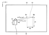
- two decoded images at different times are selected as reference images from among the encoded images (decoded images), and one of the first reference images 10 is selected as shown in FIG. It is determined at which position in the second reference image 12 the partial area, which is the area of the part, has moved. Movement direction and movement amount of the partial region is represented by motion vectors (Motion Vector) v 0. Then, based on the determined motion vector v 0, predicts an image to be encoded.
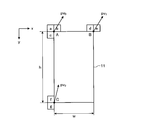
- a PU (Prediction Unit) 11 indicating a partial region in FIG. 1 is an example of a partial region in the present disclosure. It is assumed that the PU 11 is a rectangular area having a width w and a height h.
- the motion vector v 0 is a vector connecting the point A1 inside the PU 11 and the corresponding point of the point A1 inside the second reference image 12.
- the point corresponding to the point A1 in the second reference image 12 is, for example, a region having a high grayscale distribution that is highly correlated with the grayscale distribution around the point A1 in the first reference image 10 from the second reference image 12. Detect by searching.
- FIG. 1 is an example in which a point B1 is detected from the second reference image 12 as a corresponding point to the point A1 at the upper left of the PU 11.
- the point set inside the PU 11 to detect the corresponding point is not limited to the upper left point of the PU 11.
- the first reference image 10 and the second reference image 12 are searched for corresponding points in a state where the vertices of the respective images are matched, but FIG. 1 shows the first reference image 10 for explanation. And the second reference image 12 are slightly shifted.
- Such a search for a corresponding point is a method that is often used in image processing, for example, in a corresponding point search process for a left and right image of a stereo camera, and a detailed description thereof will be omitted.
- the first reference image 10 and the second reference image 12 are examples of images according to the present disclosure.
- one motion vector v 0 (v 0x , v 0y ) connecting both corresponding points is determined.
- one motion vector v 0 (v 0x , v 0y ) connecting the point A1 and the point B1 is determined.
- This state is referred to as a state in which two parameters are detected. That is, in order to determine the single motion vector v 0 may detect two parameters (one set of corresponding points).
- FIG. 1 it is interpreted that the PU 11 translates and moves to the corresponding block 13. That is, by detecting one set of corresponding points (two points) with respect to the PU 11, translational movement occurring in the partial area (PU11) can be detected.
- FIG. 2 is a first diagram illustrating an inter prediction process for performing motion compensation based on two motion vectors.
- FIG. 2 is a diagram illustrating a case where the partial area (PU11) formed in the first reference image 10 performs translation and rotation.
- FIG. 2 is an example in which the motion vectors v 0 (v 0x , v 0y ) and v 1 (v 1x , v 1y ) are determined.
- This state is referred to as a state in which four parameters are detected. That is, in order to determine two motion vectors v 01 and v 02 , four parameters (two sets of corresponding points) may be detected.
- FIG. 2 it is interpreted that the PU 11 translates and then rotates and moves by the rotation angle ⁇ and moves to the corresponding block 13.
- FIG. 3 is a second diagram illustrating an inter prediction process for performing motion compensation based on two motion vectors.
- FIG. 3 is a diagram illustrating a case where the partial area (PU11) formed in the first reference image 10 performs translation and scaling.
- FIG. 3 is an example in which the motion vectors v 0 (v 0x , v 0y ) and v 1 (v 1x , v 1y ) are determined.
- This state is also a state in which four parameters are detected.
- the PU 11 translates and then scales up and down by the magnification s (s> 1 indicates enlargement and s ⁇ 1 indicates reduction) and moves to the corresponding block 13. Will be interpreted.
- FIG. 4 is a third diagram illustrating an inter prediction process for performing motion compensation based on three motion vectors.
- FIG. 4 is a diagram illustrating a case where the partial area (PU11) formed in the first reference image 10 performs translation and skew deformation.
- FIG. 4 is an example in which the motion vectors v 0 (v 0x , v 0y ), v 1 (v 1x , v 1y ), and v 2 (v 2x , v 2y ) are determined.
- This state will be referred to as a state where six parameters are detected. That is, in order to determine three motion vectors v 0 , v 1 , and v 2 , six parameters (three sets of corresponding points) may be detected.
- FIG. 4 it is interpreted that the PU 11 translates and then skews at the shear angle ⁇ and moves to the corresponding block 13. That is, by detecting three sets of corresponding points with respect to the PU 11, it is possible to detect a movement including translation, rotation, enlargement / reduction, and skew deformation occurring in the partial area (PU11).
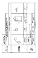
- FIG. 5 is a diagram showing the number of parameters detected from the reference image, the types of motion that can be detected, and the motion compensation mode. As shown in FIG. 5, as the number of detected parameters increases to 2, 4 (3), and 6, the types of motion that can be detected are expanded. That is, as the number of detected parameters increases, the accuracy of the predicted image improves. However, with an increase in the number of parameters to be detected, the calculation cost of the corresponding point search increases and the amount of codes to be transmitted increases, so that the overhead increases and the coding efficiency decreases.
- the translation mode is a mode for compensating for the movement that occurs with the translation (parallel movement).
- the translation rotation mode is a mode for compensating for the movement occurring due to the combination of the translation movement and the rotation movement.
- the translation scaling mode is a mode for compensating for a motion that occurs with a combination of translation and scaling.
- the affine transformation mode is a mode for compensating for a motion generated by a combination of translation, rotation, scaling, and skew.
- FIG. 6 is a diagram illustrating block division in HEVC (High Efficiency Video Coding).
- coding processing is executed in processing units called macroblocks.
- the macro block is a block having a uniform size of, for example, 16 ⁇ 16 pixels.
- HEVC Joint Photographic Experts Group 2
- coding processing is executed in a processing unit called a coding unit (CU: Coding @ Unit).
- CU Coding unit
- PU prediction unit
- a transform process for performing an orthogonal transform described later is executed in a process unit called a transform unit (TU: Transform @ Unit).
- TU Transform @ Unit
- LCU Large Coding Unit
- PU Physical Unit
- TU Physical Unit
- the PU and the TU are each divided on the basis of a quadtree.
- AMP Asymmetric Motion Partition
- Tolerate By allowing such asymmetric block division, the degree of freedom in dividing an image into regions is improved. Therefore, it is possible to generate a prediction block that matches the moving object in the image, and it is possible to improve the motion prediction performance.
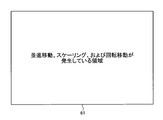
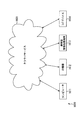
- FIG. 7 to FIG. 10 are diagrams for explaining a specific state of occurrence of a motion that occurs in each PU in an image.
- the image 64 includes an area 64A where the translation and the scaling have occurred between the two reference images, an area 64B where the translation and the rotation have occurred, the translation and the scaling, And an area 64C in which movement in the rotation direction has occurred, and an area 64D in which only translation has occurred.
- the inter prediction processing of the PU in the region 64C it is desirable to perform motion compensation in the translation rotation mode or the translation scaling mode.
- motion compensation may be performed in the rotation scaling mode.
- motion compensation may be performed in the translation mode.
- the state of the motion to be predicted is translation
- the present disclosure applies such a concept to reduce overhead and improve coding efficiency.
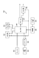
- FIG. 11 is a functional block diagram illustrating a configuration example of an embodiment of an image encoding device 100a as an example of an image processing device to which the present disclosure is applied.
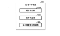
- FIG. 12 is a functional block diagram illustrating an example of a detailed functional configuration of the motion prediction unit 123 of the image encoding device 100a.
- Each function described in FIG. 11 includes, for example, a CPU 801 and a storage device such as a ROM 802 and a RAM 803 as illustrated in FIG. 28 described below, and executes a program stored in the ROM 802 or the RAM 803. It is also possible to realize the functions of each unit described later of the image encoding device 100a. In addition, some or all of the functions of each unit illustrated in FIG. 11 can be realized by dedicated hardware.
- the image encoding device 100a is a so-called video encoder that encodes a prediction residual between an image and a prediction image of the image, such as AVC or HEVC.
- the image encoding device 100a implements, for example, a technology proposed by HEVC or a technology proposed by JVET.
- FIG. 11 shows only main components such as the processing unit and the flow of data, and the components shown in FIG. 11 are not necessarily all components. That is, in the image encoding device 100a illustrated in FIG. 11, a processing unit that is not illustrated as a block may exist, or a process or a data flow that does not illustrated as an arrow or the like may exist.
- the image encoding device 100a encodes an image (video) by an inter prediction process or an intra prediction process as necessary.
- the intra prediction process is a so-called intra-frame prediction in which a prediction is performed using only information included in one reference image.
- the encoded moving image has a GOP (Group @ Of @ Pictures) structure, and includes, for example, prediction from an I picture coded by intra prediction, a P picture coded by inter prediction, and an I picture and a B picture. And a B picture.
- the image coding apparatus 100a sets the motion compensation mode of the motion compensation performed in the inter prediction process to a motion state (translation, rotation, enlargement / reduction, skew, and a motion obtained by combining them) occurring in the reference image. Accordingly, appropriate motion compensation for compensating the detected motion is performed.
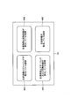
- the image coding apparatus 100a includes a control unit 101, an AD conversion unit 102, a calculation unit 110, an orthogonal transformation unit 111, a quantization unit 112, a coding unit 113, an inverse quantization unit 114, and an inverse orthogonal transformation unit 115. , An operation unit 116, and a frame memory 117. Further, the image encoding device 100 includes a selection unit 120, an intra prediction unit 121, and an inter prediction unit 122.
- the image encoding device 100a encodes an input video signal (moving image) in frame units for each of a plurality of CUs (or PUs) formed inside the image.
- the control unit 101 sets various coding parameters (header information Hinfo, prediction information Pinfo, conversion information Tinfo, and the like) based on an external input, an RD (Rate @ Distortion) cost, and the like. Then, the control unit 101 supplies parameters necessary for each block in FIG. 11 to the corresponding block among these coding parameters.
- the header information Hinfo is information for defining various initial values necessary for encoding a video signal.
- the header information Hinfo includes, for example, information such as a video parameter set, a sequence parameter set, a picture parameter set, and a slice header. Further, the header information Hinfo includes information defining the image size, the bit depth, the maximum value and the minimum value of the CU size, and the like. Note that the content of the header information Hinfo is arbitrary, and information other than the above example may be included in the header information Hinfo.
- the prediction information Pinfo includes, for example, a split flag indicating whether or not there is horizontal or vertical division in each division hierarchy when a PU (CU) is formed. Further, the prediction information Pinfo includes, for each PU, mode information pred_mode_flag indicating whether the prediction process in the PU is the intra prediction process or the inter prediction process.
- the prediction information Pinfo includes a merge flag, motion compensation mode information, parameter information, reference image specifying information for specifying a reference image, and the like.
- the $ merge flag is information indicating whether the mode of the inter prediction process is a merge mode or an AMVP (Adaptive Motion Vector Prediction) mode.
- the merge flag is, for example, 1 when indicating the merge mode, and is 0 when indicating the AMVP mode.
- the image encoding device 100a operates in one of the merge mode and the AMVP mode.
- the merge mode is a process based on parameters (motion vector, rotation angle information, scaling information, etc .; hereinafter referred to as adjacent parameters) used for motion compensation in an encoded PU adjacent to the processing target PU.
- This is a mode in which inter prediction processing of the target PU is performed.
- the AMVP mode is a mode in which inter prediction processing of a PU to be processed is performed based on parameters used for motion compensation of the PU.
- the motion compensation mode is information indicating whether the state of motion in the partial area to be predicted (PU or CU to be processed) is any of the above-described translation mode, translation rotation mode, translation scaling mode, or affine transformation mode. is there.
- the parameter information is information that specifies, when the merge flag is 1, parameters used for inter prediction processing from among candidates including adjacent parameters as prediction parameters (prediction vector, prediction rotation angle information, prediction scaling information). is there.
- the merge flag is information indicating a prediction parameter and information indicating a difference between the prediction parameter and a parameter of a processing target PU.
- the conversion information Tinfo includes information such as the size of the TU.
- the content of the conversion information Tinfo is arbitrary, and any information other than the size of the TU may be included in the conversion information Tinfo.
- the RD cost is a parameter that is calculated after encoding and that indicates the degree of encoding.
- the RD cost is calculated from, for example, an encoding distortion calculated based on a square error between an actually observed image and a predicted image and an encoding cost. The lower the RD cost is, the smaller the difference between the actually observed image and the predicted image is, that is, it indicates that efficient coding is being performed.
- the image coding apparatus 100a evaluates the degree of coding based on the RD cost, changes the coding parameter according to the evaluation result, and adopts a coding parameter with a lower RD cost.
- the AD conversion unit 102 performs AD conversion on a frame-by-frame video signal input as an input signal for each frame.
- a predetermined value is used as information necessary for performing AD conversion such as the number of quantization bits and the sampling frequency.
- the operation unit 110 functions as a difference operation unit, and calculates the difference between the predicted image P supplied from the selection unit 120 and the image to be encoded that has been AD-converted by the AD conversion unit 102.
- the operation unit 110 supplies the image obtained as a result of the subtraction to the orthogonal transformation unit 111 as a prediction residual image D.
- the orthogonal transform unit 111 performs an orthogonal transform such as a discrete cosine transform or a Karhunen-Loeve transform on the prediction residual image D supplied from the arithmetic unit 110 based on the transform information Tinfo supplied from the control unit 101. . Then, the orthogonal transform unit 111 supplies the transform coefficient Coeff obtained as a result of the orthogonal transform to the quantization unit 112.
- an orthogonal transform such as a discrete cosine transform or a Karhunen-Loeve transform
- the quantization unit 112 scales (quantizes) the transform coefficient Coeff supplied from the orthogonal transform unit 111 based on the transform information Tinfo supplied from the control unit 101, and calculates a quantized transform coefficient level level. Then, the quantization unit 112 supplies the quantized transform coefficient level level to the encoding unit 113 and the inverse quantization unit 114. The quantization unit 112 quantizes the transform coefficient Coeff obtained by the orthogonal transform using the number of quantization levels according to the quantization parameter (QP: Quantization Parameter). In general, the larger the value of QP (QP value), the higher the compression ratio.
- QP Quantization Parameter
- the encoding unit 113 encodes the quantized transform coefficient level supplied from the quantization unit 112 by a predetermined method. For example, the encoding unit 113 supplies the encoding parameters (header information Hinfo, prediction information Pinfo, conversion information Tinfo, and the like) supplied from the control unit 101 and the quantization unit 112 according to the definition of the syntax table. Is converted into a syntax value of each syntax element. Then, the encoding unit 113 encodes each syntax value. As a specific encoding method, for example, CABAC (Context-based Adaptive Binary Arithmetic Coding) or the like is used.
- CABAC Context-based Adaptive Binary Arithmetic Coding
- the coding unit 113 switches the context of the CABAC probability model based on the motion compensation mode information of the adjacent PU, and sets the CABAC probability model so that the probability of the motion compensation mode information of the adjacent PU becomes higher. Then, the motion compensation mode information of the PU is encoded.
- encoding section 113 sets a CABAC probability model to encode the motion compensation mode information of the PU so that the probability of the motion compensation mode information of the PU adjacent to the PU encoding the motion compensation mode information is increased. You may. As a result, overhead can be reduced and coding efficiency can be improved.
- the coding unit 113 may set a CABAC probability model based on the appearance frequency of each adjacent PU for each motion compensation mode information. Also, the encoding unit 113 may switch the code (bit string) to be assigned to the motion compensation mode information, instead of switching the context of the CABAC probability model based on the motion compensation mode information.
- the encoding unit 113 multiplexes, for example, encoded data that is a bit string of each syntax element obtained as a result of encoding, and outputs a bit stream as an encoded video signal.
- the inverse quantization unit 114 scales (inversely quantizes) the value of the quantized transform coefficient level supplied from the quantization unit 112 based on the transform information Tinfo supplied from the control unit 101, and performs inverse quantization. Is calculated.
- the inverse quantization unit 114 supplies the transform coefficient Coeff_IQ to the inverse orthogonal transform unit 115. Note that the inverse quantization performed by the inverse quantization unit 114 is an inverse process of the quantization performed by the quantization unit 112.
- the inverse orthogonal transform unit 115 performs an inverse orthogonal transform or the like on the transform coefficient Coeff_IQ supplied from the inverse quantization unit 114 based on the transform information Tinfo supplied from the control unit 101, and generates a prediction residual image D ′. calculate.
- the inverse orthogonal transform unit 115 supplies the prediction residual image D ′ to the calculation unit 116. Note that the inverse orthogonal transform performed by the inverse orthogonal transform unit 115 is an inverse process of the orthogonal transform performed by the orthogonal transform unit 111.
- the arithmetic unit 116 adds the prediction residual image D ′ supplied from the inverse orthogonal transform unit 115 and the prediction image P corresponding to the prediction residual image D ′ supplied from the inter prediction unit 122, and Calculate the decoded image Rec. Then, the arithmetic unit 116 supplies the local decoded image Rec to the frame memory 117.
- the frame memory 117 reconstructs a decoded image in units of pictures using the locally decoded image Rec supplied from the arithmetic unit 116 and stores the reconstructed image in the frame memory 117.
- the frame memory 117 reads the decoded image specified by the inter prediction unit 122 from the frame memory 117 as a reference image, and supplies the reference image to the inter prediction unit 122 and the motion prediction unit 123. Further, the frame memory 117 may store header information Hinfo, prediction information Pinfo, conversion information Tinfo, and the like related to generation of a decoded image in a buffer in the frame memory 117.
- the intra prediction unit 121 acquires a decoded image at the same time as the encoding target CU stored in the frame memory 117 as a reference image. Then, the intra prediction unit 121 performs an intra prediction process on the encoding target PU using the reference image.
- the inter prediction unit 122 acquires a decoded image at a time different from the encoding target CU stored in the frame memory 117 as a reference image based on the reference image specifying information. I do. Further, the inter prediction unit 122 detects a motion vector in the CU to be encoded, predicts a motion state of the CU, and generates motion compensation mode information in the CU. Then, the inter prediction unit 122 performs inter prediction processing on the encoding target PU by performing motion compensation on the reference image based on the merge flag, the motion compensation mode information, the parameter information, and the like.
- the inter prediction unit 122 includes a plurality of motion compensation modes for compensating for a state of motion occurring with time in a CU (partial area) indicating a partial area of an image, and In addition to the detection, the predicted image P is generated by compensating the state of the detected motion.
- the image encoding device 100a has the above-described translation mode, translation rotation mode, translation scaling mode, and affine transformation mode as the plurality of motion compensation modes.
- the selection unit 120 supplies the predicted image P generated as a result of the intra prediction process or the inter prediction process to the calculation unit 110 and the calculation unit 116.
- the inter prediction unit 122 includes a motion detection unit 122a, a condition determination unit 122b, and a motion compensation execution control unit 122c.
- the motion detection unit 122a is an example of a motion compensation unit according to the present disclosure.
- the motion detection unit 122a includes a plurality of motion compensation modes for compensating for a state of a motion occurring with time in a partial region (for example, a PU) indicating a partial region of an image.
- a predicted image P is generated by detecting the state and compensating the detected state of the motion.
- the condition determination unit 122b determines the position and the direction of the motion vector at a maximum of three vertices of the rectangular partial area detected by the motion detection unit 122a (motion compensation unit), and the width and the height of the partial area. Whether the state of movement of the region satisfies a predetermined condition, that is, the state of movement of the partial region involves translation and rotation, involves translation and scaling, or translation and rotation, It is determined whether enlargement / reduction and skew deformation are involved.
- the motion compensation execution control unit 122c is an example of an execution control unit according to the present disclosure.
- the motion compensation execution control unit 122c gives the motion detecting unit 122a a motion compensation mode corresponding to the predetermined condition. To skip.
- the motion compensation execution control unit 122c determines that the predetermined condition is that the motion state of the partial area detected by the motion detection unit 122a involves translation and rotation, and that the predetermined condition is satisfied.
- the predetermined condition is that the motion state of the partial area detected by the motion detection unit 122a involves translation and rotation, and that the predetermined condition is satisfied.
- a translation scaling mode that compensates for motion involving translation and scaling
- an affine transformation mode that compensates for motion that involves translation, rotation, scaling, and skew deformation
- the motion compensation execution control unit 122c determines that the predetermined condition is that the state of the motion of the partial area detected by the motion detection unit 122a involves translation and enlargement / reduction.
- the condition is satisfied, a translation rotation mode for compensating for a motion involving translation and rotation, and an affine transformation mode for compensating for a motion involving translation, rotation, scaling and skew deformation for the motion detection unit 122a. And skip.
- the motion compensation execution control unit 122c sets the condition determination unit 122b such that the predetermined condition is that the motion state of the partial area detected by the motion detection unit 122a involves translation, rotation, scaling, and skew deformation. And a translation scaling mode for compensating a motion involving translation and scaling, and a translation for compensating for motion involving translation and rotation, when the predetermined condition is satisfied. Rotate mode and skip.
- FIG. 13 is a diagram illustrating the merge mode.
- the motion detection unit 122a converts the prediction vector pv 0 at the upper left vertex A of the prediction target PU 11 in FIG. It is determined based on the motion vector in the neighboring area. That is, in FIG. 13, a prediction vector predicted at the vertex A based on motion vectors in the upper left neighboring area a of the vertex A, the upper right neighboring area b of the vertex A, and the lower left neighboring area c of the vertex A, respectively. Determine pv 0 .
- the motion detecting unit 122a the prediction vector pv 1 in the upper right apex B of PU11, is already already coded is determined based on the motion vector in the region near the vertex B. That is, in FIG. 13, the region near the upper left vertex B d, based on the motion vector in each of the upper right of the neighboring region e of the vertex B, and determines a prediction vector pv 1 at vertex B. Then, for the predicted vector pv 2 at the vertex C of the lower left PU11, likewise, the area near f of the vertex C, is determined based on the motion vector in the neighboring region g. It is assumed that the motion vectors detected in the neighboring areas a to g are held in the motion detecting unit 122a.
- the motion prediction unit 123 determines, as a motion vector at the vertices A, B, and C, among the twelve combinations of candidates, the combination that minimizes the cost DV obtained by the following equation (1).
- v 0x ′ and v 0y ′ are the x-direction component and the y-direction component of the motion vector in any of the neighboring regions a to c used for determining the prediction vector pv 0 .
- v 1x in the formula (1) ', v 1y' is a x-direction component and the y-direction component of the motion vector in one of the neighboring region d and the adjacent region e is used for determining the prediction vector pv 1.
- v 2x in the formula (1) ', v 2y' is a x-direction component and the y-direction component of the motion vector in one of the neighboring region f and the adjacent region g is used for determining the prediction vector pv 2.
- the motion detection unit 122a uses the result of motion compensation in a plurality of motion-compensated neighboring regions located in the vicinity of the partial region to calculate the motion of the partial region. To generate the predicted image.
- the motion compensation execution control unit 122c applies the occurrence frequency of the motion compensation mode used for motion compensation of the plurality of neighboring regions and the motion compensation mode used for motion compensation of the plurality of neighboring regions to the partial region.
- the motion state in the partial area is detected based on the cost (RD cost) indicating the degree of prediction of the predicted image P generated by performing the motion compensation.
- the motion detection unit 122a calculates the RD cost in the order of the occurrence frequency of the motion compensation mode in a plurality of neighboring regions.
- the predetermined condition is that the motion state of the partial region involves translation and rotation, and the motion compensation execution control unit 122c Is satisfied, a translation scaling mode for compensating for a motion involving translation and scaling, and an affine for compensating for a motion involving translation, rotation, scaling and skew deformation for the motion detection unit 122a. Conversion mode and skip.
- the motion compensation execution control unit 122c determines that the predetermined condition is that the motion state of the partial region is accompanied by translation and scaling.
- a translation rotation mode for compensating for a motion involving translation and rotation
- an affine for compensating for a motion involving translation, rotation, scaling, and skew deformation for the motion detection unit 122a. Conversion mode and skip.
- the motion compensation execution control unit 122c determines that the predetermined condition is that the motion state of the partial area is translation, rotation, scaling, and skew deformation.
- the motion detecting unit 122a compensates for the translational scaling mode and the translational scaling mode. And the translation rotation mode.
- the motion compensation mode information includes, for example, affine_flag, affine3parameter_flag, and rotate_scale_idx.
- affine_flag (affine transformation information) is information indicating whether the motion compensation mode is an affine transformation mode other than the translation mode, a translation scaling mode, or a translation rotation mode.
- the affine_flag is set to 1, for example, when the motion compensation mode is the affine transformation mode, the translation rotation mode, or the translation scaling mode.
- affine_flag is set to 0 when the motion compensation mode is not the affine transformation mode, the translation rotation mode, and the translation scaling mode, that is, when the motion compensation mode is the translation mode.
- Affine3parameter_flag (translation extended information) is information indicating whether the motion compensation mode is the translation scaling mode or the translation rotation mode, and is set when affine_flag is 1.
- affine3parameter_flag is set to 1 when the motion compensation mode is the translation scaling mode or the translation rotation mode.
- affine3parameter_flag is set to 0 when the motion compensation mode is not the translation rotation mode or the translation scaling mode, that is, when the motion compensation mode is the affine transformation mode.
- Rotate_scale_idx (translation rotation information) is information indicating whether the motion compensation mode is the translation rotation mode, and is set when affine3parameter_flag is 1.
- rotate_scale_idx is set to 1 when the motion compensation mode is the translation rotation mode.
- the motion compensation mode is not the translation rotation mode, that is, when the motion compensation mode is the translation scaling mode, 0 is set.
- the motion compensation mode information is constituted by affine_flag, and affine_flag is 0.
- the motion compensation mode information is composed of affine_flag and affine3parameter_flag, affine_flag is 1, and affine3parameter_flag is 0.
- the motion compensation mode information is composed of affine_flag, affine3parameter_flag, and rotate_scale_idx.
- affine_flag and affine3parameter_flag are 1 and rotate_scale_idx is 0.
- rotate_scale_idx is 0.
- the prediction information Pinfo includes intra prediction mode information indicating the intra prediction mode.
- the content of the prediction information Pinfo is arbitrary, and any information other than the example described above may be included in the prediction information Pinfo.
- one motion vector v 0 of the processing target PU that is, a prediction vector corresponding to the motion vector v 0 of the vertex A of the PU.
- Information specifying pv 0 is set as parameter information refidx0, and a difference between one of the motion vectors v 0 and prediction vector pv 0 is set as parameter information mvd0.
- the parameter information refidx0 and mvd0 are set as in the case of the translation mode. Further, information specifying predicted angle information corresponding to the angle information of the processing target PU 11 is set as refidx1 of the parameter information, and a difference between the angle information and the predicted angle information is set as dr of the parameter information.
- dr is the difference d ⁇ between the rotation angle ⁇ of the processing target PU 11 and the rotation angle ⁇ ′ as the predicted angle information.
- dr is the difference mvd1.y between the difference dvy of the processing target PU 11 and the difference dvy as the predicted angle information.
- refidx0 and mvd0 of the parameter information are set as in the case of the translation mode.
- information that specifies predicted scaling information corresponding to the scaling information of the processing target PU 11 is set as refidx1 of the parameter information, and the difference between the scaling information and the predicted scaling information is set as ds of the parameter information.
- ds is a difference ds between the scaling factor s of the processing target PU 11 and the scaling factor s as the prediction scaling information.
- ds is the difference mvd1.x between the difference dvx of the processing target PU 11 and the difference dvx as the prediction scaling information.
- refidx0 and mvd0 of the parameter information are set as in the case of the translation mode. Further, information specifying another motion vector v 1 of the processing target PU 11, that is, a prediction vector pv 1 corresponding to the motion vector v 1 of the vertex B of the PU 11 is set as refidx1 of the parameter information. 1 and the difference between the prediction vector pv 1 is set as mvd1 parameter information.
- refidx0 and mvd0 and refidx1 and mvd1 of the parameter information are set as in the case of the translation rotation mode or the translation scaling mode. Further, information for specifying still another motion vector v 2 of the processing target PU 11, that is, information for specifying the prediction vector pv 2 corresponding to the motion vector v 2 of the vertex C of the PU 11 is set as refidx2 of the parameter information. v 2 the difference between the predicted vector pv 2 is set as mvd2 parameter information.
- the mode of the inter prediction process is the merge mode
- the above-described mvd0, mvd1, mvd2, ds, dr, refidx0, refidx1, and refidx2 are not set.
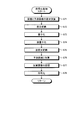
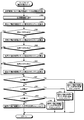
- FIG. 14 is a flowchart illustrating an example of the flow of a process performed by the image encoding device 100a.
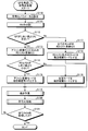
- FIGS. 15 to 17 and 19 are flowcharts showing the detailed flow of the main processing shown in FIG. Specifically, FIG. 15 is a flowchart illustrating an example of a flow of a process in which the image encoding device 100a estimates the RD cost in the inter prediction mode.
- FIG. 16 is a flowchart illustrating an example of the flow of the motion prediction process in the AMVP mode performed by the image encoding device 100a.
- FIG. 17 is a flowchart illustrating an example of the flow of an encoding process performed by the image encoding device 100a.
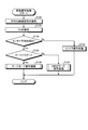
- FIG. 19 is a flowchart illustrating an example of the flow of the motion prediction process in the merge mode performed by the image encoding device 100a.
- step S10 of FIG. 14 the control unit 101 sets encoding parameters (header information Hinfo, prediction information Pinfo, conversion information Tinfo, and the like).
- step S11 the condition determination unit 122b determines whether the merge flag is 0. If it is determined in step S11 that the merge flag is 1 (step S11: Yes), the process proceeds to step S12. On the other hand, if it is not determined in step S11 that the merge is 1 (step S11: No), the process proceeds to step S19.
- step S12 the motion detection unit 122a reads the reference image stored in the frame memory 117 and divides the CU in order to perform motion prediction. Specifically, the motion detection unit 122a divides the reference image into regions that are likely to be motion generation units. At this time, the CU is divided according to the method described with reference to FIG. The area division as a unit of occurrence of motion is performed using a known image processing method, such as merging pixels having similar pixel values into one area.
- step S13 the intra prediction unit 121 estimates the RD cost of the intra prediction mode.
- step S14 the motion compensation execution control unit 123c estimates the RD cost of the inter prediction mode.
- the detailed processing flow in step S14 will be described later (FIG. 15).
- step S15 the condition determination unit 122b determines the mode having the minimum RD cost among the calculated RD costs to be the motion compensation mode.
- the process performed in step S15 is performed when the estimation of the RD cost is not completed early in step S14.
- step S14 when the estimation of the RD cost ends early, the condition determining unit 122b applies a motion compensation mode corresponding to the state ended early to the motion compensation according to the determination. Details will be described in the description of FIG. 15 described later.
- step S16 the inter prediction unit 122 performs motion prediction in the motion compensation mode determined in step S15 (or the motion compensation mode determined in step S14).
- the detailed flow of the process in step S16 will be described later (FIG. 16).
- the intra prediction process is executed instead of step S16.
- step S17 the orthogonal transformation unit 111, the quantization unit 112, the encoding unit 113, and the like perform the encoding process in cooperation.
- the detailed processing flow in step S17 will be described later (FIG. 17).
- step S18 the condition determination unit 122b determines whether the encoding process has been performed on all the CUs in the image to be encoded.
- step S18 when it is determined that the encoding process has been performed on all CUs in the image (step S18: Yes), the image encoding device 100a ends the process in FIG. On the other hand, if it is not determined in step S18 that the encoding process has been performed on all the CUs in the image (step S18: No), the process returns to step S13, and steps S13 to S18 are performed for the next PU. repeat.
- step S19 the motion detection unit 122a reads the reference image and performs CU division. Note that the processing performed here is the same as the processing described in step S12.
- step S20 the motion detection unit 122a performs motion prediction in the merge mode.
- the detailed flow of the process in step S20 will be described later (FIG. 19).
- step S21 the orthogonal transformation unit 111, the quantization unit 112, the encoding unit 113, and the like perform the encoding process in cooperation.
- the detailed flow of the process in step S21 will be described later (FIG. 17).
- step S22 the condition determination unit 122b determines whether the encoding process has been performed on all the CUs in the image to be encoded.
- step S22 when it is determined that the encoding process has been performed on all the CUs in the image (step S22: Yes), the image encoding device 100a ends the process in FIG. On the other hand, if it is not determined in step S22 that the encoding process has been performed on all the CUs in the image (step S22: No), the process returns to step S20, and steps S20 to S22 are performed for the next PU. repeat.
- step S31 in FIG. 15 the motion compensation execution control unit 122c assumes that a translation has occurred in the target CU, and calculates the RD cost J RD2 when encoding based on normal inter prediction, that is, The RD cost when the motion compensation estimated by two parameters is performed is calculated.
- step S32 the motion compensation execution control unit 122c calculates the RD cost J RD6A when the target CU is encoded on the assumption that the motion described in the affine transformation mode has occurred, that is, 6
- the RD cost when the motion compensation estimated by the parameter is performed is calculated.
- the motion compensation execution control unit 122c calculates an evaluation cost JA4 when performing motion compensation on the target CU in the affine transformation mode.
- the evaluation cost JA4 is calculated by, for example, the following equation (2).
- Estimation cost J A4 represents the degree to which the CU as an object undergoing skew deformation. That indicates that there is a high possibility that the larger the evaluation cost J A4, CU as an object is subjected to skew deformation.
- step S34 condition determination unit 122b, estimation cost J A4 calculated in step S33 it is determined greater than the predetermined threshold value J THA4.
- step S34 if J A4 > J THA4 (step S34: Yes), the process returns to the main routine (the flowchart of FIG. 14). If it is determined in step S34 that J A4 > J THA4, it is determined that there is a high possibility that the target CU has undergone skew deformation. Then, the motion compensation execution control unit 122c determines that motion compensation in the affine transformation mode (6 parameter motion compensation) is applied to the target CU. Then, the processing in FIG. 15 is terminated early and the process returns to the main routine in FIG. 14, thereby speeding up the processing. That is, in this case, the motion compensation in the translation mode, the translation rotation mode, and the translation scaling mode is set to be skipped.
- step S34 when it is determined as Yes in step S34, a flag indicating that the RD cost estimation process has been terminated early is set, and the motion compensation in the affine transformation mode is applied. After adding the indicated information, the process returns to the main routine of FIG. In step S15 of FIG. 14, when a flag indicating that the RD cost estimation process has been terminated early is set, and when information indicating that motion compensation in the affine transformation mode is to be applied is added, The motion compensation performed in step S16 is performed in the affine transformation mode.
- step S34 No
- the process proceeds to step S35.
- the motion compensation execution control unit 122c calculates the RD cost J RD4A when the target CU is coded assuming that the motion described in the translation rotation mode or the translation scaling mode has occurred. That is, the RD cost when the motion compensation estimated using the 4 (3) parameters is performed is calculated.
- step S36 the motion compensation execution control unit 122c evaluates the evaluation cost J R3 when performing motion compensation in the translation rotation mode on the target CU and performs motion compensation in the translation scaling mode. Is calculated respectively.
- the evaluation cost JR3 is calculated by, for example, the following equation (3).
- the evaluation cost JR3 represents the degree to which the target CU is performing translational rotation. That is, the higher the evaluation cost JR3, the higher the possibility that the target CU is performing translational rotation.
- the evaluation cost JS3 is calculated by, for example, the following equation (4).
- Estimation cost J S3 represents the degree to CU as an object is moving translation scaling. That is, the larger the evaluation cost J S3, indicates an increased likelihood that CU as an object is moving translation scaling.
- step S37 the condition determining unit 122b, an evaluation cost J S3 calculated in step S36 it is determined greater than the predetermined threshold value J THS3. If it is determined in step S37 that J S3 > J THS3 (step S37: Yes), the process proceeds to step S39. If it is determined in step S37 that J S3 > J THS3, it is determined that there is a high possibility that the target CU has undergone translational scaling movement.
- step S37 if J S3 > J THS3 is not satisfied (step S37: No), the process proceeds to step S38.
- the motion compensation execution control unit 122c calculates the RD cost J RDS3 when the target CU is coded assuming that the motion described in the translation scaling mode has occurred, that is, 4 (3 )
- the RD cost when the motion compensation estimated by the parameter is performed is calculated.
- step S39 the condition determining unit 122b, an evaluation cost J R3 calculated in step S36 it is determined greater than the predetermined threshold value J THR3.
- step S39 if it is J R3> J THR3 (step S39: Yes), the flow returns to the main routine (FIG. 14).
- step S39 if it is determined that J R3> J THR3, CU of interest is determined that there is a high possibility that the translation and rotation movement.
- the motion compensation execution control unit 122c determines that the motion compensation (4 (3) parameter motion compensation) in the translation rotation mode is applied to the target CU.
- the processing in FIG. 15 is terminated early, and the process returns to the main routine in FIG. 14, thereby speeding up the processing. That is, in this case, the motion compensation in the translation mode, the translation scaling mode, and the affine transformation mode is set to be skipped.
- step S39 if it is determined to be Yes in step S39, a flag indicating that the RD cost estimation process has been terminated early is set, and motion compensation in the translational rotation mode is applied. And returns to the main routine of FIG. In step S15 of FIG. 14, a flag indicating that the RD cost estimation process has been terminated early is set, and information indicating that motion compensation in the translational rotation mode is to be applied is added. Performs the motion compensation performed in step S16 in the translational rotation mode.
- step S37 If it is determined in step S37 that J S3 > J THS3 , there is a high possibility that the target CU has undergone translational scaling as described above. Therefore, the process may return to the main routine at the time of determining “Yes” in step S37, but there is a possibility that the target CU is performing translational rotation. Therefore, in the flowchart of FIG. 15, step S37 is determined to be “Yes”. Even if this is the case, step S39 is subsequently executed. However, in this case, the processing is speeded up by skipping step S38.
- step S39 if not J R3> J THR3 (step S39: No), the process proceeds to step S40.
- step S40 the condition determining unit 123b is again evaluated cost J S3 calculated in step S36 it is determined greater than the predetermined threshold value J THS3.
- This process is the same as the determination process performed in step S37, in the case of J S3> J THS3 and J R3 ⁇ J THR3, in order to terminate the determination of the motion compensation mode early, try again.
- step S40 if J S3 > J THS3 (step S40: Yes), the process returns to the main routine (FIG. 14). If it is determined in step S40 that J S3 > J THS3, it is determined that there is a high possibility that the target CU has undergone translational scaling movement. Then, the motion compensation execution control unit 123c determines that the motion compensation (4 (3) parameter motion compensation) in the translation scaling mode is applied to the target CU. Then, the processing in FIG. 15 is terminated early, and the process returns to the main routine in FIG. 14, thereby speeding up the processing. That is, in this case, the motion compensation in the translation mode, the translation rotation mode, and the affine transformation mode is set to be skipped.
- step S40 when it is determined to be Yes in step S40, a flag indicating that the RD cost estimation process has been terminated early is set, and the motion compensation by the translation scaling mode is applied. After adding the indicated information, the process returns to the main routine of FIG. If the flag indicating that the RD cost estimation process has been terminated early is set in step S15 of FIG. 14 and information indicating that motion compensation in the translational scaling mode is to be applied is added, The motion compensation performed in S16 is performed in the translation scaling mode.
- step S40 if J S3 > J THS3 is not satisfied (step S40: No), the process proceeds to step S41, and the motion compensation execution control unit 122c determines whether the motion described in the translation rotation mode is the target CU.
- FIG. 16 shows the flow of the process performed in step S16 of FIG. 14 in detail.
- the set motion compensation mode is specified.
- the motion compensation mode may be determined by referring to the above-described motion compensation mode information (affine_flag, affine3parameter_flag, rotate_scale_idx). In the following description, for the sake of simplicity, it is simply described as determining whether or not a specific motion compensation mode is set. The actual determination is made by referring to the status of each flag and index.
- step S51 the condition determination unit 122b determines whether the motion compensation mode is the translation mode. If it is determined that the motion compensation mode is the translation mode (step S51: Yes), the process proceeds to step S52. On the other hand, if it is not determined that the motion compensation mode is the translation mode (step S51: No), the process proceeds to step S55.
- step S52 the motion detection unit 122a, on the basis of the parameter information to determine the predicted vector pv 0. Specifically, when the parameter information is information for specifying an adjacent vector as a prediction vector, the motion detection unit 122a calculates a cost based on the stored motion vectors of the neighboring regions a to g (FIG. 13). DV is adjacent vectors generated from one of the motion vectors of the smallest neighboring region a to the region near c, determining the prediction vector pv 0.
- step S53 the motion detection unit 122a, a difference of one and the predicted vector pv 0 of which is determined in step S52, the motion vector v 0 of the prediction vector pv 0 and the processed PU of the parameter information dv 0 and the motion vector v 0 of the processing target PU are calculated.
- step S54 the inter prediction unit 122 uses the motion vectors v 0 calculated in step S53, in a translational mode for the reference image specified by the reference image identification information stored in the frame memory 117 Perform motion compensation.
- the motion detecting unit 122a supplies the motion-compensated reference image as the predicted image P to the arithmetic unit 110 and the arithmetic unit 116. Then, the process returns to the main routine (FIG. 14).
- step S55 the condition determination unit 122b determines whether the motion compensation mode is the affine transformation mode. If it is determined that the motion compensation mode is the affine transformation mode (step S55: Yes), the process proceeds to step S56. On the other hand, if it is not determined that the motion compensation mode is the affine transformation mode (step S55: No), the process proceeds to step S60.
- step S56 the motion detection unit 122a determines three prediction vectors pv 0 , pv 1 , and pv 2 based on the parameter information.
- step S57 the motion detection unit 122a corresponds to each of the three prediction vectors pv 0 , pv 1 , and pv 2 determined in step S46 and the prediction vectors pv 0 , pv 1 , and pv 2
- the three motion vectors v 0 , v 1 , and v 2 in the processing target PU 11 are obtained by adding the differences among the parameter information to be processed.
- Equation (5) w, h, x, and y represent the width and height of the PU 11, the position of the PU 11 in the x direction, and the position of the PU 11 in the y direction, respectively.
- the motion vector v in the PU 11 is obtained by proportionally distributing the motion vectors v 0 to v 2 according to the position (x, y) of the PU 11.
- step S59 the motion detection unit 122a performs affine transformation on the block of the reference image specified by the reference image specifying information based on the motion vector v for each unit block, thereby affine-converting the reference image. Perform motion compensation in conversion mode.
- the motion detection unit 122a supplies the reference image on which the motion compensation has been performed as the prediction image P to the calculation unit 110 or the calculation unit 116. Then, the process returns to the main routine (FIG. 14).
- step S60 the condition determination unit 122b determines whether the motion compensation mode is the translation rotation mode. If it is determined that the motion compensation mode is the translation rotation mode (step S60: Yes), the process proceeds to step S61. On the other hand, if it is not determined that the motion compensation mode is the translation rotation mode (step S60: No), the process proceeds to step S64.
- step S61 the motion detection unit 122a determines a prediction vector pv 0 of one on the basis of the parameter information. Further, the motion detection unit 123a determines predicted angle information based on the parameter information.
- step S62 the motion detection unit 122a calculates a single motion vector v 0 in the same way as the process of step S53.
- the motion detection unit 122a adds the prediction angle information determined in step S61 and the difference between the prediction angle information of the parameter information and the angle information of the processing target PU, thereby obtaining the processing target PU. Calculate angle information.
- step S63 the motion detection unit 122a, using a single motion vector v 0 and the angle information calculated in step S62, performs motion compensation in translation and rotation mode for the reference image.
- the motion detection unit 122a supplies the reference image on which the motion compensation has been performed as the prediction image P to the calculation unit 110 or the calculation unit 116. Then, the process returns to the main routine (FIG. 14).
- step S64 the motion detection unit 122a performs one process on the basis of the parameter information as in the process in step S52. Determine the prediction vector pv 0 . Further, the motion detection unit 122a determines the prediction magnification information based on the parameter information.
- step S65 the motion detection unit 123a calculates a single motion vector v 0 in the same way as the process of step S53. Further, the motion detection unit 123a adds the prediction magnification information determined in step S64 and the difference between the prediction magnification information of the parameter information and the magnification information of the processing target PU, thereby obtaining the processing target PU. Calculate magnification information.
- step S66 the motion detection unit 122a, using a single motion vector v 0 and magnification information calculated in step S65, performs motion compensation in translation scaling mode for the reference image.
- the motion detection unit 122a supplies the reference image on which the motion compensation has been performed as the prediction image P to the calculation unit 110 or the calculation unit 116. Then, the process returns to the main routine (FIG. 14).
- step S71 the calculation unit 110 calculates a difference between the encoding target image that has been AD-converted by the AD conversion unit 102 and the predicted image P.
- the calculation result is supplied to the orthogonal transformation unit 111 as a prediction residual image D.
- the data amount of the prediction residual image D thus obtained is reduced as compared with the image to be encoded. Therefore, the data amount can be reduced as compared with the case where the image to be encoded is encoded as it is.
- the orthogonal transform unit 111 performs orthogonal transform on the prediction residual image D supplied from the arithmetic unit 110 based on the transform information Tinfo supplied from the control unit 101, and calculates a transform coefficient Coeff. .
- the orthogonal transform unit 111 supplies the transform coefficient Coeff to the quantization unit 112. Note that the orthogonal transform unit 111 specifically performs an orthogonal transform represented by a discrete cosine transform (DCT) or the like.
- DCT discrete cosine transform
- step S73 the quantization unit 112 scales (quantizes) the transform coefficient Coeff supplied from the orthogonal transform unit 111 based on the transform information Tinfo supplied from the control unit 101, and sets the quantized transform coefficient level level. calculate.
- the quantization unit 112 supplies the quantized transform coefficient level “level” to the encoding unit 113 and the inverse quantization unit 114.
- step S74 the inverse quantization unit 114 sets the quantized transform coefficient level supplied from the quantization unit 112 based on the transform information Tinfo supplied from the control unit 101 to the quantization characteristic in step S73. Inverse quantization with the characteristic The inverse quantization unit 114 supplies the resulting transform coefficient Coeff_IQ to the inverse orthogonal transform unit 115.
- step S75 the inverse orthogonal transform unit 115 converts the transform coefficient Coeff_IQ supplied from the inverse quantization unit 114 into a method corresponding to the orthogonal transform in step S72 based on the transform information Tinfo supplied from the control unit 101. Perform an inverse orthogonal transform or the like to calculate a prediction residual image D ′.
- step S76 the calculation unit 116 generates the local decoded image Rec by adding the prediction residual image D ′ calculated in the processing in step S75 to the prediction image P supplied from the inter prediction unit 122. I do.
- step S77 the frame memory 117 reconstructs a decoded image for each picture using the locally decoded image Rec obtained by the processing in step S76, and stores the reconstructed image in a buffer in the frame memory 117.
- step S78 the encoding unit 113 encodes the encoding parameter set by the process of step S10 in FIG. 14 and the quantized transform coefficient level obtained by the process of step S73 by a predetermined method. .
- the encoding unit 113 multiplexes the encoded data obtained as a result and outputs the multiplexed data to the outside of the image encoding device 100a as an encoded stream. This encoded stream is transmitted to the decoding side via a transmission path or a recording medium, for example.
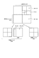
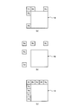
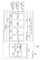
- FIG. 18 is a diagram illustrating an example of the neighborhood area set when performing the motion prediction process in the merge mode.
- FIG. 18A shows an example in which five motion-compensated (encoded) neighboring areas are set near a CU 14 (a CU 14 may be a PU) as a motion prediction target. That is, the CU 14 is an example of a partial region in the present disclosure.
- the neighboring regions Ra, Rb, and Re are regions that are adjacent to the CU 14 by eight at the upper left.
- the neighborhood area Ra is adjacent to the upper left vertex of the CU 14 at the lower left.
- the neighboring region Rb is adjacent to the upper right corner of the CU 14 at the upper right corner.
- the neighboring area Re is adjacent to the upper left vertex of the CU 14 at the upper left.
- the neighboring region Rc is adjacent to the upper left corner of the CU 14 at the upper left
- the neighboring region Rd is adjacent to the lower left vertex of the CU 14 at the upper left.
- the neighboring area may be set to four neighbors instead of eight neighbors. That is, in FIG. 18A, only four neighboring regions Ra, Rb, Rc, and Rd may be set.
- the condition determination unit 122b of the image encoding device 100a determines the state of the motion detected in the neighboring areas Ra to Re (translation mode, translation rotation (The mode, the translation scaling mode, and the affine transformation mode), the motion state of the CU 14 is determined in descending order of the frequency of the detected motion state. Then, the motion compensation execution control unit 122c (execution control unit) of the image encoding device 100a sets the condition that the condition determination unit 122b satisfies the predetermined condition, that is, determines that the condition of the predetermined motion has been detected. And skip the motion compensation mode according to the predetermined condition.
- the motion state in the CU 14 is predicted to be equal to the high-frequency motion state. In this way, by determining the state of movement in the order of appearance frequency, the state of movement can be determined early and the determination can be terminated.
- the number of neighboring areas set near the CU 14 is not limited to five as shown in FIG. That is, as shown in FIG. 18C, more neighboring regions may be set, such as the neighboring regions Ra to Ri. As the number of neighboring areas to be set is larger, the number of motion states that can be referred to is increased. Therefore, the frequency of occurrence of highly reliable motion is further increased, so that the accuracy of motion prediction in the CU 14 can be improved. .
- the vicinity area set near the CU 14 does not necessarily need to be adjacent to the CU 14. That is, as shown in FIG. 18B, the vicinity area may be set at a position not adjacent to the CU. As described above, by setting the vicinity area at a position that is not adjacent to the CU 14, the state of movement in the CU 14 can be predicted based on the state of movement in a wider range near the CU 14.
- step S81 the motion detection unit 122a counts the number of appearances of the motion compensation mode in a region near (or adjacent to) the CU 14 to be predicted. That is, it counts how many neighboring areas (or adjacent areas) each of the motion compensation modes of the translation mode, the translation rotation mode, the translation scaling mode, and the affine transformation mode have occurred.
- the counting result is supplied to the condition determining unit 122b.
- step S82 the condition determination unit 122b arranges the results counted in step S81 in the order of the appearance frequency of the motion compensation mode.
- step S83 the motion compensation execution control unit 122c applies the motion compensation mode having the highest appearance frequency (hereinafter, referred to as order 1) to encode the CU 14 to be subjected to motion prediction. It calculates the RD cost J 1.
- step S84 the condition determination unit 122b determines whether or not to terminate the determination of the motion compensation mode to be applied to the CU 14 that is a target of motion prediction based on the result of order 1. If it is determined that the processing should be terminated based on the result of the order 1 (step S84: Yes), the process proceeds to step S90. On the other hand, if it is not determined that the operation is to be terminated based on the result of the order 1 (step S84: No), the process proceeds to step S85.
- truncating the result of order 1 for example, may be determined by RD cost J 1 falls below a predetermined threshold value J TH.
- step S85 the motion compensation execution control unit 122c applies a motion compensation mode in which the appearance frequency of the motion compensation mode is the second highest (hereinafter, referred to as order 2). It calculates the RD cost J 2 in the case of performing encoding of CU14 to be motion prediction.
- step S86 the condition determination unit 122b determines whether to terminate the determination of the motion compensation mode to be applied to the CU 14 that is a target of motion prediction, based on the result of the order 2. If it is determined that the processing should be terminated based on the result of the order 2 (step S86: Yes), the process proceeds to step S90. On the other hand, if it is not determined that the processing should be terminated based on the result of the order 2 (step S86: No), the process proceeds to step S87.
- truncating the result of order 2 for example, may be determined by RD cost J 2 falls below a predetermined threshold value J TH.
- step S87 the motion compensation execution control unit 122c applies a motion compensation mode in which the appearance frequency of the motion compensation mode is the third highest (hereinafter, referred to as order 3). It calculates the RD cost J 3 in the case of performing encoding of CU14 to be motion prediction.
- step S88 the condition determination unit 122b determines whether or not to terminate the determination of the motion compensation mode to be applied to the CU 14 to be subjected to motion prediction based on the result of the order 3. If it is determined that the processing should be terminated based on the result of the order 3 (step S88: Yes), the process proceeds to step S90. On the other hand, if it is not determined that the processing is to be terminated based on the result of the order 3 (step S88: No), the process proceeds to step S89.
- truncating the result of order 3 for example, may be determined by RD cost J 3 falls below a predetermined threshold value J TH.
- step S89 the motion compensation execution control unit 122c applies the motion compensation mode having the fourth highest appearance frequency (hereinafter, referred to as order 4) to perform motion prediction. It calculates the RD cost J 4 in the case of performing encoding of CU14 to be. Thereafter, the process proceeds to step S90.
- Step S90 is subsequently performed. You.
- step S89 is executed, step S90 is subsequently executed.
- step S90 the condition determining unit 122b determines whether the RD cost J 1 is the smallest. RD cost J 1 is determined to be minimum: (step S90 Yes), the process proceeds to step S94. On the other hand, it is not determined that RD cost J 1 is a minimum: (step S90 No), and the process proceeds to step S91.
- step S90 in step S84 the although the RD cost J 1 contains the values, since the RD cost J 2 to J 4 does not contain a value, the determination in step S90 Is unconditionally set to Yes, and the process shifts to step S84.
- the process proceeds is determined Yes at step S86 or step S88 to step S90, and if the procedure advances to step S90 after performing step S89, RD cost J 1, and RD cost J 2 to J 4 because among the at least one has entered a value, in step S90, by comparing the values, it determines RD cost J 1 is the smallest.
- step S90 it determines if it is determined that No, in step S91, the whether condition determining unit 122b is a RD cost J 2 is minimized.
- RD cost J 2 is determined to be the minimum: (step S91 Yes), the process proceeds to step S95. On the other hand, is not determined that RD cost J 2 is minimum: (step S91 No), the process proceeds to step S92.
- step S91 the determining if it is determined that No, in step S92, whether the condition determining unit 122b is a RD cost J 3 is minimized.
- RD cost J 3 is determined to be the minimum: (step S92 Yes), the process proceeds to step S96. On the other hand, it is not determined that RD cost J 3 is the smallest: (step S92 No), the process proceeds to step S93.
- step S94 the motion compensation execution control unit 122c instructs the motion detection unit 122a to perform motion compensation on the CU 14 to be subjected to motion prediction in the motion compensation mode corresponding to order 1. Is performed.
- step S95 the motion compensation execution control unit 122c instructs the motion detection unit 122a to perform motion compensation on the CU 14 to be motion predicted in the motion compensation mode corresponding to order 2. Is performed.
- step S96 the motion compensation execution control unit 122c instructs the motion detection unit 122a to perform motion compensation on the CU 14 to be motion predicted in the motion compensation mode corresponding to order 3. Is performed.
- step S93 the motion compensation execution control unit 122c instructs the motion detection unit 122a to perform motion compensation on the CU 14 to be motion predicted in the motion compensation mode corresponding to order 4. Is performed.
- motion prediction A motion compensation mode that is likely to be assigned to the target CU 14 can be found at an early stage. Then, when a motion compensation mode that is likely to be assigned to the CU 14 is found, the subsequent determination can be terminated (skipping of a motion compensation mode other than the motion compensation mode that is likely to be assigned to the CU 14) can be performed. Therefore, it is possible to efficiently determine the motion compensation mode.
- a shorter code (signal inter_mode) is assigned to the motion compensation mode that is more likely to be assigned to the CU 14 to be subjected to motion prediction. Contribute to improvement.
- the process illustrated in FIG. 19 is an example in which the condition determination unit 122b determines whether the state of the motion detected by the motion detection unit 122a matches a predetermined motion compensation mode as a predetermined condition.
- a motion detection unit 122a motion compensation unit having a plurality of motion compensation modes for compensating for a state of motion occurring with time is provided in a partial region indicating a partial region of an image.
- the motion compensation execution control unit 122c execution control unit determines that the motion state detected by the motion detection unit 122a satisfies a predetermined condition. In this case, the motion detection unit 122a skips the motion compensation mode according to a predetermined condition. Therefore, since it is not necessary to determine the motion compensation mode other than the predetermined condition, the motion compensation in the partial region can be executed at high speed (efficiently).
- the image coding apparatus 100a determines the state of motion in a partial area based on a motion vector in a partial area (eg, PU11 or CU14) to be subjected to motion prediction.
- the condition determination unit 122b terminates the determination of the motion state early based on the RD cost and the evaluation cost.
- the motion compensation execution control unit 123c generates a predicted image P by performing motion compensation on the partial area in a motion compensation mode according to the state of the motion determined to have occurred in the partial area. That is, the motion compensation mode that is not determined is skipped. Therefore, motion compensation in a partial area can be performed at high speed, and the coding efficiency of an image can be improved.
- the condition determination unit 122b sets Are determined in the order of the appearance frequencies of the motion vectors in the partial area to be subjected to motion prediction.
- the motion compensation execution control unit 123c generates a predicted image P by performing motion compensation on the partial area in the motion compensation mode corresponding to the state of the motion determined to have occurred in the partial area. Therefore, motion compensation in a partial area can be performed at high speed, and the coding efficiency of an image can be improved.
- condition determination unit 122b determines the direction and length of the motion vector at up to three vertices of the rectangular partial region detected by the motion detection unit 122a (motion compensation unit), the width w and height h of the partial region, It is determined whether the state of movement of the partial area satisfies a predetermined condition based on Therefore, the determination of the motion state of the partial area can be easily and reliably performed.
- a motion compensation mode to be applied is determined according to a set CU size when the image encoding device 100a performs motion compensation. That is, when the size of the set partial area (CU), which is the condition for the motion detection unit 122a (motion compensation unit) of the image encoding device 100a to generate the predicted image P, satisfies the predetermined condition, the motion compensation is performed.
- the execution control unit 122c causes the motion detection unit 122a to skip the motion compensation mode according to a predetermined condition.
- the motion compensation execution control unit 122c Is skipped in the motion compensation mode according to the condition (1).
- the motion compensation execution control unit 122c sends a predetermined condition to the motion detection unit 122a when the predetermined condition is that the size of the partial region is smaller than a predetermined value and the predetermined condition is satisfied. Skip motion compensation.
- the motion compensation execution control unit 122c determines that the predetermined condition is that the size of the partial area is smaller than a predetermined value, and that the predetermined condition is satisfied.
- a translation mode that compensates for motion involving translation a translation rotation mode that compensates for motion involving translation and rotation
- the motion compensation execution control unit 122c determines whether the size of the partial area is equal to or larger than a predetermined value, and when the predetermined condition is satisfied, the motion detection unit 122a Motion other than the motion compensation mode in which the RD cost indicating the degree of prediction of the predicted image P generated when performing motion compensation by applying a plurality of motion compensation modes provided in the motion detection unit 122a to the region is minimized. Skip the compensation mode.
- FIG. 20 illustrates an example of a flow of a process in which the image encoding device 100a sets a motion compensation mode according to the size of the CU (the product hw of the width w and the height h) and performs motion compensation and encoding. It is a flowchart.
- FIG. 20 shows a flow of processing in the case of performing inter prediction in the AMVP mode for simplicity.
- Steps S100 and S101 are the same as steps S10 and S12 in FIG. 14, respectively, and thus description thereof is omitted.
- step S102 the condition determination unit 123b determines whether the size of the CU set in step S101 is smaller than the threshold. If it is determined that the size of the CU is smaller than the threshold (step S102: Yes), the process proceeds to step S103. On the other hand, if it is not determined that the size of the CU is smaller than the threshold (step S102: No), the process proceeds to step S105.
- step S103 the motion compensation execution control unit 123c applies the translation mode, the translation rotation mode, and the translation scaling mode to encode the CU to be subjected to motion prediction.
- the RD cost in the case of performing is calculated. That is, the motion compensation execution control unit 123c does not only estimate the RD cost when the affine transformation mode having the largest number of parameters is applied.
- step S104 the motion compensation execution control unit 123c sets the motion compensation mode having the minimum RD cost among the RD costs calculated in step S103 as the motion compensation mode of the CU to be subjected to motion prediction. . Then, the motion compensation execution control unit 123c supplies a signal indicating the determined motion compensation mode to the inter prediction unit 122. Thereafter, the process proceeds to step S107. That is, in this case, settings are made such that the motion compensation modes other than the motion compensation mode in which the RD cost is minimized are skipped.
- step S105 the motion compensation execution control unit 123c applies all prepared motion compensation modes (translation mode, translation rotation mode, translation scaling mode, and affine transformation mode). Then, the RD cost when the CU to be subjected to motion prediction is encoded is calculated.
- step S106 the motion compensation execution control unit 123c sets the motion compensation mode having the smallest RD cost among the RD costs calculated in step S105 as the motion compensation mode of the CU to be subjected to motion prediction. . Then, the motion compensation execution control unit 123c supplies a signal indicating the determined motion compensation mode to the inter prediction unit 122. Thereafter, the process proceeds to step S107. That is, in this case, settings are made such that the motion compensation modes other than the motion compensation mode in which the RD cost is minimized are skipped.
- step S107 motion prediction is performed in step S107, and encoding processing is performed in step S108.
- the processing performed here is the same as the processing performed in steps S16 and S17 in FIG. 14 described above.
- step S109 the inter prediction unit 122 determines whether encoding processing has been performed on all CUs in the image.
- step S109 when it is determined that the encoding process has been performed on all CUs in the image (step S109: Yes), the image encoding device 100a ends the process in FIG. On the other hand, if it is not determined in step S109 that encoding processing has been performed on all CUs in the image (step S109: No), the process returns to step S102, and the same processing as described above is performed on the next PU. repeat.
- the amount of motion information is small (in consideration of an increase in the overhead of motion information per pixel) (the number of parameters is small).
- (Less) Use only motion compensation mode. In this way, by limiting the motion compensation mode to be used, the amount of codes specifying the motion compensation mode can be reduced. Therefore, the coding efficiency is improved.
- the flow of the process illustrated in FIG. 20 can be applied to the case where the inter prediction is performed in the merge mode. That is, when the size of the CU to be encoded is smaller than the threshold value, the translation mode, the translation rotation mode, and the translation scaling mode among the plurality of motion compensation modes determined in the neighboring area (or the adjacent area).
- the order of appearance frequency may be calculated by limiting only to the motion compensation mode indicating the mode.
- the image encoding device 100a determines a motion compensation mode to be applied to a partial area according to the size of a CU (partial area) to be subjected to motion prediction. Specifically, when the size of the partial region is smaller than the threshold, the motion compensation in the affine transformation mode with the largest calculation amount is skipped for the partial region. Therefore, the motion compensation can be performed at high speed, and the coding efficiency of the image can be improved.
- ⁇ Third embodiment> (Explanation of the flow of the motion prediction process according to the QP value)
- the present disclosure is an example in which, when the image encoding device 100a performs motion compensation, a motion compensation mode to be applied is determined according to the QP value set in the quantization unit 112. That is, the image encoding device 100a determines the QP value, which is the condition under which the motion detection unit 122a (motion compensation unit) generates the predicted image P, and executes the motion compensation execution control when the QP value satisfies the predetermined condition.
- the unit 122c causes the motion detection unit 122a to skip the motion compensation mode according to a predetermined condition.
- the motion compensation execution control unit 122c determines that the predetermined condition is that a quantization parameter (QP value) when quantizing the result of motion compensation is smaller than a predetermined value, When the condition is satisfied, the motion detection unit 122a skips a translation scaling mode for compensating for a motion involving translation and scaling, and a translation / rotation mode for compensating for a motion involving translation and rotation. .
- QP value quantization parameter
- the motion compensation execution control unit 122c determines that the predetermined condition is that the quantization parameter (QP value) when quantizing the result of motion compensation is smaller than the predetermined value, and that the partial region to be predicted is The RD cost indicating the degree of prediction of the predicted image P generated by the motion compensation applying the affine transformation mode for compensating the motion accompanied by translation, rotation, scaling, and skew deformation is smaller than a predetermined threshold. Then, when the predetermined condition is satisfied, the motion detection unit 122a is caused to skip a motion compensation mode other than the affine transformation mode for compensating for a motion involving translation, rotation, scaling, and skew deformation.
- the motion compensation execution control unit 122c determines that the predetermined condition is that the quantization parameter (QP value) when quantizing the result of the motion compensation is smaller than the predetermined value, and that the partial region to be predicted is The RD cost indicating the degree of prediction of the predicted image P generated by the motion compensation applying the affine transformation mode for compensating the motion accompanied by translation, rotation, scaling, and skew deformation is equal to or more than a predetermined threshold. Then, when the predetermined condition is satisfied, the motion detection unit 122a is caused to skip a motion compensation mode other than the translation mode for compensating the motion accompanied by the translation.
- the motion compensation execution control unit 122c determines that the predetermined condition is that a quantization parameter (QP value) when quantizing the result of the motion compensation is equal to or more than a predetermined value, and the predetermined condition is satisfied.
- the RD cost indicating the degree of prediction of the predicted image P generated when the motion compensation is performed by applying each of the plurality of motion compensation modes to the partial region to be predicted, to the motion detection unit 122a.
- the motion compensation modes other than the motion compensation mode in which is minimized are skipped.
- FIG. 21 is a flowchart illustrating an example of a flow of processing in which the image encoding device 100a sets a motion compensation mode according to a QP value and performs motion compensation and encoding.
- FIG. 21 shows a flow of processing when performing inter prediction in the AMVP mode for simplicity.
- Steps S110 and S111 are the same as steps S10 and S12 in FIG. 14, respectively, and a description thereof will be omitted.
- step S112 the condition determination unit 123b determines whether the QP value set in the quantization unit 112 is smaller than a threshold. If it is determined that the QP value is smaller than the threshold value (step S112: Yes), the process proceeds to step S113. On the other hand, if it is not determined that the QP value is smaller than the threshold value (step S112: No), the process proceeds to step S117.
- step S113 the motion compensation execution control unit 123c calculates the RD cost when the CU to be subjected to motion prediction is encoded by applying the affine transformation mode. I do.
- step S114 the motion compensation execution control unit 123c determines whether the RD cost calculated in step S113 is smaller than a predetermined threshold. If it is determined that the RD cost is smaller than the predetermined threshold (step S114: Yes), the process proceeds to step S115. On the other hand, if it is not determined that the RD cost is smaller than the predetermined threshold (step S114: No), the process proceeds to step S116.
- step S115 the motion compensation execution control unit 123c performs the motion compensation of the CU to be motion predicted.
- An affine transformation mode is assigned as a mode. Thereafter, the process proceeds to step S119. That is, in this case, the motion compensation mode other than the affine transformation mode is set to be skipped.
- step S116 the motion compensation execution control unit 123c determines whether or not the CU to be motion predicted A translation mode is assigned as the motion compensation mode. Thereafter, the process proceeds to step S119. That is, in this case, the motion compensation mode other than the translation mode is set to be skipped.
- step S117 the motion compensation execution control unit 123c applies all the motion compensation modes, The RD cost when the CU to be subjected to motion prediction is encoded is calculated.
- step S118 the motion compensation execution control unit 123c searches for a motion compensation mode that gives the minimum RD cost from all the RD costs calculated in step S117. Then, the motion compensation execution control unit 123c assigns the searched motion compensation mode as the motion compensation mode of the CU to be subjected to motion prediction. Thereafter, the process proceeds to step S119. That is, in this case, the motion compensation modes other than the motion compensation mode that gives the minimum RD cost are set to be skipped.
- step S119 motion prediction is performed in step S119
- coding processing is performed in step S120.
- the processing performed here is the same as the processing performed in steps S16 and S17 in FIG. 14 described above.
- step S121 the inter prediction unit 122 determines whether encoding processing has been performed on all CUs in the image.
- step S121 when it is determined that the encoding process has been performed on all the CUs in the image (step S121: Yes), the image encoding device 100a ends the process in FIG. On the other hand, if it is not determined in step S121 that encoding processing has been performed on all CUs in the image (step S121: No), the process returns to step S119, and the same processing as described above is performed on the next PU. repeat.
- the image encoding device 100a performs motion prediction based on a QP value that is a quantization parameter when generating (encoding) a predicted image. Determine the motion compensation mode to apply to the region. That is, when the QP value is smaller than the threshold value, the RD cost when the affine transformation mode is applied is estimated, and the motion compensation in the affine transformation mode or the translation mode is performed. Therefore, especially when the QP value is smaller than the threshold value, motion compensation can be performed at high speed, and image coding efficiency can be improved.
- the flow of the motion prediction process and the encoding process performed by the image encoding device 100a has been described above.
- the motion prediction process according to the RD cost and the evaluation cost, the motion prediction process according to the CU size, and the QP value The corresponding motion prediction processing may be performed independently, or may be performed using two or all three types in combination. For example, when the size of the CU to be predicted is smaller than the threshold, the prediction process described in the second embodiment is applied. On the other hand, when the size of the CU is larger than the threshold, The prediction processing described in the first embodiment may be applied.
- the RD cost in the case where the motion compensation is performed in the affine transformation mode is evaluated, and the motion compensation is performed in the affine transformation mode or the translation mode according to the RD cost.
- the QP value is equal to or larger than the threshold value, a motion prediction process according to the CU size, the RD cost, and the evaluation cost may be performed.
- FIG. 22 is a functional block diagram illustrating a configuration example of an embodiment of an image decoding device 100b as an example of an image processing device to which the present disclosure is applied.
- Each function described in FIG. 22 includes, for example, a CPU 801 and a storage device such as a ROM 802 and a RAM 803 as illustrated in FIG. 28 described below, and executes a program stored in the ROM 802 or the RAM 803. It is also possible to realize the functions of each unit described later of the image encoding device 100a. In addition, some or all of the functions of each unit illustrated in FIG. 11 can be realized by dedicated hardware.
- the image decoding device 100b illustrated in FIG. 22 decodes the coded stream generated by the image coding device 100a in FIG. 11 using a decoding method corresponding to the coding method in the image coding device 100a.
- the image decoding device 100b implements, for example, the technology proposed by HEVC and the technology proposed by JVET.
- FIG. 22 shows only main components such as a processing unit and a flow of data, and not all components shown in FIG. That is, in the image decoding device 100b shown in FIG. 22, there may be a processing unit not shown as a block, or there may be processing or data flow not shown as an arrow or the like.
- the image decoding device 100b includes a decoding unit 132, an inverse quantization unit 133, an inverse orthogonal transformation unit 134, an operation unit 135, a DA conversion unit 136, a selection unit 137, a frame memory 138, an intra prediction unit 139, and an inter prediction unit 140. Have.
- the image decoding device 100b decodes the coded stream generated by the image coding device 100a for each CU.
- the decoding unit 132 of the image decoding device 100b decodes the encoded stream generated by the image encoding device 100a using a predetermined decoding method corresponding to the encoding method in the encoding unit 113. For example, the decoding unit 132 decodes a coding parameter (header information Hinfo, prediction information Pinfo, conversion information Tinfo, and the like) and a quantized transform coefficient level from the bit stream of the coded stream according to the definition of the syntax table. .
- the decoding unit 132 divides the LCU based on split flag included in the encoding parameter, and sequentially sets the CU corresponding to each quantized transform coefficient level as a CU (PU, TU) to be decoded.
- the decoding unit 132 supplies the coding parameters to each block. For example, the decoding unit 132 supplies the prediction information Pinfo to the intra prediction unit 139 and the inter prediction unit 140, supplies the transformation information Tinfo to the inverse quantization unit 133 and the inverse orthogonal transformation unit 134, and supplies the header information Hinfo to each block. Supply. In addition, the decoding unit 132 supplies the quantized transform coefficient level level to the inverse quantization unit 133.
- the inverse quantization unit 133 scales (inversely quantizes) the value of the quantized transform coefficient level supplied from the decoding unit 132 based on the transform information Tinfo supplied from the decoding unit 132, and derives a transform coefficient Coeff_IQ. I do.
- This inverse quantization is an inverse process of the quantization performed by the quantization unit 112 (FIG. 11) of the image encoding device 100a.
- the inverse quantization unit 114 (FIG. 11) performs the same inverse quantization as the inverse quantization unit 133.
- the inverse quantization unit 133 supplies the obtained transform coefficient Coeff_IQ to the inverse orthogonal transform unit 134.
- the inverse orthogonal transform unit 134 performs an inverse orthogonal transform or the like on the transform coefficient Coeff_IQ supplied from the inverse quantization unit 133 based on the transform information Tinfo or the like supplied from the decoding unit 132, and performs a prediction residual image D ′. Is calculated.
- This inverse orthogonal transform is an inverse process of the orthogonal transform performed by the orthogonal transform unit 111 (FIG. 11) of the image encoding device 100a. That is, the inverse orthogonal transform unit 134 performs the same inverse orthogonal transform as the inverse orthogonal transform unit 115 (FIG. 11).
- the inverse orthogonal transform unit 134 supplies the obtained prediction residual image D ′ to the calculation unit 135.
- the operation unit 135 adds the prediction residual image D 'supplied from the inverse orthogonal transform unit 134 and the prediction image P corresponding to the prediction residual image D' to calculate a local decoded image Rec.
- the operation unit 135 reconstructs a decoded image for each picture using the obtained local decoded image Rec, and outputs the obtained decoded image to the outside of the image decoding device 100b.
- the arithmetic unit 135 also supplies the local decoded image Rec to the frame memory 138. Note that the decoded image output by the arithmetic unit 135 may be output as a digital video signal as it is, or may be converted into an analog video signal by the DA converter 136 and output.
- the frame memory 138 reconstructs a decoded image for each picture using the local decoded image Rec supplied from the arithmetic unit 135 and stores the reconstructed image in a buffer in the frame memory 138.
- the frame memory 138 reads the decoded image specified by the intra prediction unit 139 or the inter prediction unit 140 from the buffer as a reference image, and supplies the reference image to the intra prediction unit 139 or the inter prediction unit 140 that specifies the reading. Further, the frame memory 138 may store header information Hinfo, prediction information Pinfo, conversion information Tinfo, and the like related to the generation of the decoded image in a buffer in the frame memory 138.
- the intra prediction unit 139 acquires a decoded image at the same time as the encoding target CU stored in the frame memory 138 as a reference image. Then, the intra prediction unit 139 performs the intra prediction process of the intra prediction mode indicated by the intra prediction mode information on the encoding target PU using the reference image. Then, the intra prediction unit 139 supplies the prediction image P generated as a result of the intra prediction process to the selection unit 137.
- the inter prediction unit 140 acquires a decoded image at a time different from the encoding target CU stored in the frame memory 138 as a reference image based on the reference image specifying information. .
- the inter prediction unit 140 performs the inter prediction process on the encoding target PU using the reference image based on the Merge flag, the motion compensation mode information, and the parameter information, similarly to the inter prediction unit 122 in FIG. Then, the inter prediction unit 140 supplies the prediction image P generated as a result of the inter prediction process to the selection unit 137.
- the inter prediction unit 140 has the same configuration as the inter prediction unit 122 of the image encoding device 100a described above. That is, the inter prediction unit 140 includes the motion detection unit 122a, the condition determination unit 122b, and the motion compensation execution control unit 122c.
- the selection unit 137 supplies the prediction image P output from the intra prediction unit 139 or the inter prediction unit 140 to the calculation unit 135.
- FIG. 23 is a flowchart illustrating an example of the flow of a decoding process performed by the image decoding device 100b.
- step S122 the decoding unit 132 decodes the coded video signal supplied to the image decoding device 100b, and obtains a coding parameter and a quantized transform coefficient level level. Then, the decoding unit 132 supplies the encoding parameter to each block of the image decoding device 100b. In addition, the decoding unit 132 supplies the quantized transform coefficient level level to the inverse quantization unit 133.
- step S123 the decoding unit 132 divides the CU based on the split @ flag included in the encoding parameter, and sets the CU corresponding to each quantized transform coefficient level as the CU to be decoded. Steps S124 to S128 described below are performed for each CU to be decoded.
- step S124 the inter prediction unit 140 determines whether the mode information pred_mode of the prediction information P info indicates inter prediction information. If it is determined to indicate the inter prediction information (step S124: Yes), the process proceeds to step S125. On the other hand, if it is not determined to indicate the inter prediction information (step S124: No), the process proceeds to step S128.
- step S125 the inter prediction unit 140 determines whether the merge flag of the prediction information Pinfo is 1. When it is determined that the merge flag is 1 (step S125: Yes), the process proceeds to step S126. On the other hand, if it is not determined that the merge flag is 1 (step S125: No), the process proceeds to step S127.
- step S126 the inter prediction unit 140 uses the prediction image P generated by the inter prediction process in the merge mode to perform A merge mode decoding process for decoding an image to be decoded is performed.
- the detailed flow of the merge mode decoding process will be described with reference to FIG. Then, when the merge mode decoding process ends, the image decoding device 100b ends the image decoding process.
- step S125 if No is determined in step S125, that is, if the merge flag is not determined to be 1, in step S127, the inter prediction unit 140 uses the prediction image P generated by the inter prediction process in the AMVP mode. Then, an AMVP mode decoding process for decoding the image to be decoded is performed.
- the detailed flow of the AMVP mode decoding process will be described with reference to FIG.
- the image decoding device 100b ends the image decoding process.
- step S124 when it is determined as No, that is, when it does not indicate the inter prediction process, in step S128, the intra prediction unit 139 uses the prediction image P generated by the intra prediction process, An intra decoding process for decoding the image to be decoded is performed. Then, when the intra decoding process ends, the image decoding device 100b ends the image decoding process.
- FIG. 24 is a flowchart illustrating an example of the flow of a process in which the image decoding device 100b decodes a video signal encoded in the merge mode.
- FIG. 24 shows a detailed processing flow in step S126 of the flowchart in FIG.
- step S129 the inverse quantization unit 133 inversely quantizes the quantized transform coefficient level obtained in step S122 in FIG. 23 to calculate a transform coefficient Coeff_IQ.
- This inverse quantization process is an inverse process of the quantization performed in step S73 (FIG. 17) of the image encoding process, and is similar to the inverse quantization performed in step S74 (FIG. 17) of the image encoding process. Processing.
- the inverse orthogonal transform unit 134 performs an inverse orthogonal transform on the transform coefficient Coeff_IQ obtained in the process in step S129 to generate a prediction residual image D ′.
- This inverse orthogonal transform is an inverse process of the orthogonal transform performed in step S72 (FIG. 17) of the image encoding process described above, and is similar to the inverse orthogonal transform performed in step S75 (FIG. 17) of the image encoding process. Processing.
- the inter prediction unit 140 counts the number of appearances of the motion compensation mode in a region near (or adjacent to) the CU 14 to be subjected to motion prediction. That is, it counts how many neighboring areas (or adjacent areas) each of the motion compensation modes of the translation mode, the translation rotation mode, the translation scaling mode, and the affine transformation mode have occurred. The counting result is supplied to the condition determination unit 123b.
- step S132 the condition determination unit 123b arranges the results counted in step S131 in the order of the appearance frequency of the motion compensation mode.
- step S133 the condition determination unit 123b receives the signal inter_oder from the motion compensation execution control unit 123c.
- step S134 the condition determination unit 123b determines whether the signal inter_oder is 0. When it is determined that the signal inter_oder is 0 (step S134: Yes), the process proceeds to step S138. On the other hand, if it is not determined that the signal inter_oder is 0 (step S134: No), the process proceeds to step S135.
- step S138 the motion compensation execution control unit 123c sets the motion compensation mode of order 1, that is, the motion compensation mode to be applied to the CU to be subjected to motion prediction, to the vicinity of the CU. Of the motion compensation modes that have appeared in the region (or the adjacent region), the mode with the highest appearance frequency is set. Then, the motion compensation execution control unit 123c causes the motion detection unit 122a to perform motion compensation on the CU 14 in the motion compensation mode set in step S138, and generates the predicted image P. Thereafter, the process proceeds to step S141.
- the motion compensation execution control unit 123c sets the motion compensation mode of order 1, that is, the motion compensation mode to be applied to the CU to be subjected to motion prediction, to the vicinity of the CU. Of the motion compensation modes that have appeared in the region (or the adjacent region), the mode with the highest appearance frequency is set. Then, the motion compensation execution control unit 123c causes the motion detection unit 122a to perform motion compensation on the CU 14 in the motion compensation mode set in step S138,
- step S135 the condition determination unit 123b determines whether the signal inter_oder is 1. If it is determined that the signal inter_oder is 1 (step S135: Yes), the process proceeds to step S139. On the other hand, if it is not determined that the signal inter_oder is 1 (step S135: No), the process proceeds to step S136.
- step S139 the motion compensation execution control unit 123c sets the motion compensation mode of order 2, that is, the motion compensation mode to be applied to the CU to be subjected to motion prediction, to the vicinity of the CU. Among the motion compensation modes that have appeared in the area (or the adjacent area), the mode with the second highest appearance frequency is set. Then, the motion compensation execution control unit 123c causes the motion detection unit 122a to perform motion compensation on the CU 14 in the motion compensation mode set in step S139, and generates the predicted image P. Thereafter, the process proceeds to step S141.
- step S135 the condition determination unit 123b determines whether the signal inter_oder is 2 in step S136. When it is determined that the signal inter_oder is 2 (step S136: Yes), the process proceeds to step S140. On the other hand, if the signal inter_oder is not determined to be 2 (step S136: No), the process proceeds to step S137.
- step S140 the motion compensation execution control unit 123c sets the motion compensation mode of order 3, that is, the motion compensation mode to be applied to the CU to be subjected to motion prediction, to the vicinity of the CU. Among the motion compensation modes that have appeared in the area (or the adjacent area), the mode with the third highest appearance frequency is set. Then, the motion compensation execution control unit 123c causes the motion detection unit 122a to perform motion compensation on the CU 14 in the motion compensation mode set in step S140, and generates the predicted image P. Thereafter, the process proceeds to step S141.
- step S137 the motion compensation execution control unit 123c sets the motion compensation mode of order 4, that is, the motion compensation mode to be applied to the CU 14 to be subjected to motion prediction, to the CU 14 Among the motion compensation modes that have appeared in the vicinity area (or the adjacent area), the mode having the fourth highest appearance frequency is set. Then, the motion compensation execution control unit 123c causes the motion detection unit 122a to perform motion compensation on the CU 14 in the motion compensation mode set in step S137, and generates the predicted image P. Thereafter, the process proceeds to step S141.
- the motion compensation execution control unit 123c sets the motion compensation mode of order 4, that is, the motion compensation mode to be applied to the CU 14 to be subjected to motion prediction, to the CU 14 Among the motion compensation modes that have appeared in the vicinity area (or the adjacent area), the mode having the fourth highest appearance frequency is set. Then, the motion compensation execution control unit 123c causes the motion detection unit 122a to perform motion compensation on the CU 14 in the motion compensation mode set in step S
- step S141 the calculation unit 135 adds the prediction residual image D ′ generated in step S130 to the prediction image P supplied from the inter prediction unit 140 via the selection unit 137, and performs local decoding. Generate an image Rec.
- the arithmetic unit 135 reconstructs a decoded image for each picture using the obtained local decoded image Rec, and outputs the obtained decoded image to the outside of the image decoding device 100b as a video signal. Further, the arithmetic unit 135 supplies the locally decoded image Rec to the frame memory 138.
- step S142 the frame memory 138 reconstructs a decoded image for each picture using the locally decoded image Rec supplied from the arithmetic unit 135, and stores the reconstructed image in a buffer in the frame memory 138. Then, returning to the flowchart of FIG. 23, the image decoding device 100b ends the decoding process.
- FIG. 25 is a flowchart illustrating an example of a flow of a process in which the image decoding device 100b decodes a video signal encoded in the AMVP mode.
- FIG. 25 shows the detailed processing flow in step S127 of the flowchart in FIG.
- a prediction vector is determined in each CU based on the motion compensation mode determined by the condition determination unit 122b. Further, a prediction vector, a motion vector, angle information, and magnification information required for motion compensation are calculated according to the motion compensation mode. Then, the motion compensation execution control unit 123c causes the motion detection unit 122a to perform motion compensation in each CU based on the calculated motion vector, angle information, and magnification information.
- a series of these processes is the same as the prediction process (FIG. 16) performed by the image encoding device 100a.
- step S153 the condition determination unit 122b determines whether the motion compensation mode is the translation mode (corresponding to step S51).
- step S157 the condition determination unit 122b determines whether the motion compensation mode is the affine transformation mode (corresponding to step S55). Further, in step S162, the condition determination unit 122b determines whether the motion compensation mode is the translation rotation mode (corresponding to step S60).
- step S153 If it is determined that the motion compensation mode is the translation mode (step S153: Yes), one prediction vector is determined in step S154 (corresponding to step S52), and one motion vector is calculated in step S155. (Corresponding to step S53). Further, in step S156, motion compensation is performed in the translation mode to generate a predicted image P (corresponding to step S54).
- step S157 If it is determined that the motion compensation mode is the affine transformation mode (step S157: Yes), one prediction vector is determined in step S158 (corresponding to step S56), and three motion vectors are calculated in step S159. (Corresponding to step S57). Further, in step S160, a motion vector of the unit block is calculated (corresponding to step S58), and in step S161, motion compensation is performed in the affine transformation mode to generate a predicted image P (corresponding to step S59).
- step S162 When it is determined that the motion compensation mode is the translation rotation mode (step S162: Yes), one prediction vector is determined in step S163 (corresponding to step S61), and in step S164, one motion vector and the angle are determined. Information is calculated (corresponding to step S62). Further, in step S165, motion compensation is performed in the translation rotation mode, and a predicted image P is generated (corresponding to step S63).
- step S162 If it is determined that the motion compensation mode is the translation scaling mode (step S162: No), one prediction vector is determined in step S166 (corresponding to step S64), and one motion vector and the magnification are determined in step S167. Information is calculated (corresponding to step S65). Further, in step S168, motion compensation is performed in the translation scaling mode to generate a predicted image P (corresponding to step S66).
- step S169 the prediction image P and the prediction residual image D 'generated in step S152 are added. This is the same process as the process performed in step S141 (FIG. 24) of the decryption process.
- step S170 the frame memory 138 reconstructs a decoded image for each picture using the local decoded image Rec supplied from the arithmetic unit 135, and stores the reconstructed image in a buffer in the frame memory 138. This is the same processing as the notation performed in step S142 (FIG. 24) of the decoding processing. Then, after execution of step S142, the process returns to the flowchart of FIG. 23, and the image decoding device 100b ends the decoding process.
- the image decoding device 100b indicates the motion compensation mode received from the image encoding device 100a when decoding the encoded video signal encoded in the merge mode.
- the motion compensation mode is determined based on the signal inter_order. Therefore, the motion compensation mode can be quickly determined.
- the present disclosure is an example in which the image decoding device 100b performs the inter prediction process in the motion compensation mode and the decoding process of the coded video signal that has been coded by the image coding device 100a according to the CU size. That is, the condition determination unit 122b determines the size of the CU set at the time of encoding, and based on the determination result of the condition determination unit 122b, the motion compensation execution control unit 122c This is an example in which a predetermined motion compensation mode is skipped.
- FIG. 26 is a flowchart illustrating an example of a flow of a process in which the image decoding device 100b sets a motion compensation mode according to a CU size and performs a decoding process.
- step S171 the condition determination unit 122b determines whether the size of the CU to be decoded is smaller than a threshold. If it is determined in step S171 that the size of the CU is smaller than the threshold value (step S171: Yes), the process proceeds to step S172. On the other hand, if it is not determined that the size of the CU is smaller than the threshold value (step S171: No), the process proceeds to step S173.
- step S172 the motion detection unit 122a sends the translation mode and the translation mode from the motion compensation execution control unit 122c.
- a signal inter_mode for specifying a rotation mode or a translation scaling mode is received.
- the signal inter_mode received in step S172 is the signal inter_mode that specifies the motion compensation mode set in step S104 when the image encoding device 100a executes the encoding process in FIG. After receiving the signal inter_mode, the process proceeds to step S174.
- step S173 the motion detection unit 122a sends all motion compensation modes from the motion compensation execution control unit 122c, namely, the translation mode, the translation rotation mode, the translation scaling mode, And a signal inter_mode for designating a motion compensation mode from the affine transformation mode.
- the signal inter_mode received in step S173 is the signal inter_mode that specifies the motion compensation mode set in step S106 when the image encoding device 100a executes the encoding process in FIG. After receiving the signal inter_mode, the process proceeds to step S174.
- step S174 the motion compensation execution control unit 122c sets the motion compensation mode specified by the signal inter_mode received in step S172 or S173 as the motion compensation mode.
- step S175 the motion compensation execution control unit 122c causes the motion detection unit 122a to perform motion prediction in the motion compensation mode specified in step S174.
- the motion prediction process is a process similar to steps S51 to S66 in FIG.
- step S176 the image decoding device 100b performs a decoding process.
- the decryption processing is the same processing as steps S122 to S128 in FIG.
- step S177 the condition determination unit 122b determines whether the decoding process has been performed on all the CUs in the image to be decoded. When it is determined in step S177 that the decoding process has been performed on all CUs in the image (step S177: Yes), the image decoding device 100b ends the decoding process. On the other hand, if it is not determined in step S177 that decoding processing has been performed on all the CUs in the image (step S177: No), the process returns to step S171, and the processing in steps S171 to S177 is next performed on the CU. repeat.
- the image encoding device 100a decodes the encoded video signal that has been motion-compensated in the motion compensation mode according to the CU size
- the image decoding device 100b Motion compensation is performed by the corresponding motion compensation mode. Therefore, the motion compensation mode can be quickly determined.
- the present disclosure is an example in which the image decoding device 100b performs the inter prediction process in the motion compensation mode according to the QP value and the decoding process of the coded video signal that has been coded by the image coding device 100a. That is, the condition determination unit 122b determines the QP value set at the time of encoding, and based on the determination result of the condition determination unit 122b, the motion compensation execution control unit 122c This is an example in which a predetermined motion compensation mode is skipped.
- FIG. 27 is a flowchart illustrating an example of a flow of a process in which the image decoding device 100b sets a motion compensation mode according to a QP value and performs a decoding process.
- condition determination unit 122b determines whether the QP value at the time of performing the encoding process is smaller than a threshold value. If it is determined in step S181 that the QP value is smaller than the threshold value (step S181: Yes), the process proceeds to step S182. On the other hand, if it is not determined that the QP value is smaller than the threshold value (step S111: No), the process proceeds to step S183.
- step S182 the motion detection unit 122a receives a signal inter_mode specifying the affine transformation mode or the translation mode from the motion compensation execution control unit 122c.
- the signal inter_mode received in step S182 is the signal inter_mode that specifies the motion compensation mode set in step S115 or step S116 when the image encoding device 100a executes the encoding processing in FIG. After receiving the signal inter_mode, the process proceeds to step S184.
- step S183 the motion detection unit 122a sends all motion compensation modes from the motion compensation execution control unit 122c, namely, the translation mode, the translation rotation mode, the translation scaling mode, And a signal inter_mode for designating a motion compensation mode from the affine transformation mode.
- the signal inter_mode received in step S183 is the signal inter_mode that specifies the motion compensation mode set in step S118 when the image encoding device 100a executes the encoding process in FIG. After receiving the signal inter_mode, the process proceeds to step S184.
- step S184 the motion compensation execution control unit 122c sets the motion compensation mode specified by the signal inter_mode received in step S182 or S183 as the motion compensation mode.
- step S185 the motion compensation execution control unit 122c causes the motion detection unit 122a to perform motion prediction in the motion compensation mode specified in step S184.
- the motion prediction process is a process similar to steps S51 to S66 in FIG.
- step S186 the image decoding device 100b performs a decoding process.
- the decryption processing is the same processing as steps S122 to S128 in FIG.
- step S187 the condition determination unit 122b determines whether the decoding process has been performed on all the CUs in the image to be decoded. When it is determined in step S187 that the decoding process has been performed on all the CUs in the image (step S187: Yes), the image decoding device 100b ends the decoding process. On the other hand, if it is not determined in step S187 that decoding processing has been performed on all CUs in the image (step S187: No), the process returns to step S185, and the processing in steps S185 to S187 is performed on the next CU. repeat.
- the image decoding device 100b when the image decoding device 100b decodes the coded video signal motion-compensated in the motion compensation mode according to the QP value, the image decoding device 100b outputs Motion compensation is performed by the corresponding motion compensation mode. Therefore, the motion compensation mode can be quickly determined.
- the series of processes described above can be executed by hardware or can be executed by software.
- a program constituting the software is installed in a computer.
- the computer includes a computer incorporated in dedicated hardware, a general-purpose personal computer that can execute various functions by installing various programs, and the like.
- FIG. 28 is a block diagram illustrating an example of a hardware configuration of a computer that executes the series of processes described above by a program.
- a CPU Central Processing Unit
- ROM Read Only Memory
- RAM Random Access Memory
- the input / output interface 810 is further connected to the bus 804.
- An input unit 811, an output unit 812, a storage unit 813, a communication unit 814, and a drive 815 are connected to the input / output interface 810.
- the input unit 811 includes a keyboard, a mouse, a microphone, and the like.
- the output unit 812 includes a display, a speaker, and the like.
- the storage unit 813 includes a hard disk, a non-volatile memory, and the like.
- the communication unit 814 includes a network interface and the like.
- the drive 815 drives a removable medium 821 such as a magnetic disk, an optical disk, a magneto-optical disk, or a semiconductor memory.
- the CPU 801 loads the program stored in the storage unit 813 into the RAM 803 via the input / output interface 810 and the bus 804 and executes the program, for example. A series of processing is performed.
- the program executed by the computer 800 can be provided, for example, by recording it on a removable medium 821 as a package medium or the like.
- the program can be provided via a wired or wireless transmission medium such as a local area network, the Internet, or digital satellite broadcasting.
- the program can be installed in the storage unit 813 via the input / output interface 810 by attaching the removable medium 821 to the drive 815. Further, the program can be received by the communication unit 814 via a wired or wireless transmission medium and installed in the storage unit 813. In addition, the program can be installed in the ROM 802 or the storage unit 813 in advance.
- the program executed by the computer 800 may be a program in which processing is performed in chronological order according to the order described in this specification, or may be performed at a necessary timing such as in parallel or when a call is made. May be a program that performs the processing.
- FIG. 29 is a block diagram illustrating an example of a schematic configuration of a television device to which the above-described embodiment is applied.
- the television device 900 includes an antenna 901, a tuner 902, a demultiplexer 903, a decoder 904, a video signal processing unit 905, a display unit 906, an audio signal processing unit 907, a speaker 908, an external interface (I / F) unit 909, and a control unit. 910, a user interface (I / F) unit 911, and a bus 912.
- the tuner 902 extracts a signal of a desired channel from a broadcast signal received via the antenna 901 and demodulates the extracted signal. Then, the tuner 902 outputs the encoded bit stream obtained by the demodulation to the demultiplexer 903. That is, the tuner 902 has a role as a transmission unit in the television device 900 that receives an encoded stream in which an image is encoded.
- the ⁇ ⁇ ⁇ ⁇ ⁇ ⁇ ⁇ ⁇ ⁇ ⁇ demultiplexer 903 separates the video stream and the audio stream of the program to be viewed from the coded bit stream, and outputs the separated streams to the decoder 904. Further, the demultiplexer 903 extracts auxiliary data such as EPG (Electronic Program Guide) from the encoded bit stream, and supplies the extracted data to the control unit 910. Note that the demultiplexer 903 may perform descrambling when the encoded bit stream is scrambled.
- EPG Electronic Program Guide
- the decoder 904 decodes the video stream and the audio stream input from the demultiplexer 903. Then, the decoder 904 outputs the video data generated by the decoding process to the video signal processing unit 905. Also, the decoder 904 outputs the audio data generated by the decoding process to the audio signal processing unit 907.
- the video signal processing unit 905 reproduces the video data input from the decoder 904 and causes the display unit 906 to display a video. Further, the video signal processing unit 905 may cause the display unit 906 to display an application screen supplied via a network. In addition, the video signal processing unit 905 may perform additional processing such as noise removal on the video data according to the setting. Furthermore, the video signal processing unit 905 may generate a GUI (Graphical User Interface) image such as a menu, a button, or a cursor, and superimpose the generated image on the output image.
- GUI Graphic User Interface
- the display unit 906 is driven by a drive signal supplied from the video signal processing unit 905, and is displayed on a video surface of a display device (for example, a liquid crystal display, a plasma display, or an OELD (Organic Electro Luminescence Display)). Display video or image.
- a display device for example, a liquid crystal display, a plasma display, or an OELD (Organic Electro Luminescence Display)
- Display video or image for example, a liquid crystal display, a plasma display, or an OELD (Organic Electro Luminescence Display)
- the audio signal processing unit 907 performs reproduction processing such as DA conversion and amplification on the audio data input from the decoder 904, and outputs audio from the speaker 908. Further, the audio signal processing unit 907 may perform additional processing such as noise removal on the audio data.
- the external interface unit 909 is an interface for connecting the television device 900 to an external device or a network.
- a video stream or an audio stream received via the external interface unit 909 may be decoded by the decoder 904. That is, the external interface unit 909 also has a role as a transmission unit in the television device 900 that receives an encoded stream in which an image is encoded.
- the control unit 910 has a processor such as a CPU and a memory such as a RAM and a ROM.
- the memory stores programs executed by the CPU, program data, EPG data, data acquired via a network, and the like.
- the program stored in the memory is read and executed by the CPU when the television device 900 is started, for example.
- the CPU controls the operation of the television device 900 according to, for example, an operation signal input from the user interface unit 911.
- the user interface unit 911 is connected to the control unit 910.
- the user interface unit 911 includes, for example, buttons and switches for the user to operate the television device 900, a remote control signal receiving unit, and the like.
- the user interface unit 911 detects an operation performed by the user via these components, generates an operation signal, and outputs the generated operation signal to the control unit 910.
- the bus 912 connects the tuner 902, the demultiplexer 903, the decoder 904, the video signal processing unit 905, the audio signal processing unit 907, the external interface unit 909, and the control unit 910 to each other.
- the decoder 904 may have the function of the image decoding device 100b described above. That is, the decoder 904 may decode the encoded data by the method described in each of the above embodiments. By doing so, the television device 900 can obtain the same effects as those of the above-described embodiments.
- the video signal processing unit 905 encodes, for example, image data supplied from the decoder 904, and outputs the obtained encoded data via the external interface unit 909. You may make it output outside the television apparatus 900. Then, the video signal processing unit 905 may have the function of the image encoding device 100a described above. That is, the video signal processing unit 905 may encode the image data supplied from the decoder 904 by the method described in each of the above embodiments. By doing so, the television device 900 can obtain the same effects as those of the above-described embodiments.
- FIG. 30 is a block diagram illustrating an example of a schematic configuration of a mobile phone to which the above-described embodiment is applied.
- the mobile phone 920 includes an antenna 921, a communication unit 922, an audio codec 923, a speaker 924, a microphone 925, a camera unit 926, an image processing unit 927, a demultiplexing unit 928, a recording / reproducing unit 929, a display unit 930, a control unit 931, and an operation unit.
- a section 932 and a bus 933 are provided.
- the antenna 921 is connected to the communication unit 922.
- the speaker 924 and the microphone 925 are connected to the audio codec 923.
- the operation unit 932 is connected to the control unit 931.
- the bus 933 connects the communication unit 922, the audio codec 923, the camera unit 926, the image processing unit 927, the demultiplexing unit 928, the recording / reproducing unit 929, the display unit 930, and the control unit 931 to each other.
- the mobile phone 920 operates in various operation modes including a voice call mode, a data communication mode, a shooting mode, a videophone mode, and the like, and transmits and receives voice signals, transmits and receives e-mail or image data, captures images, records data, and the like. Perform the operation.
- an analog voice signal generated by the microphone 925 is supplied to the voice codec 923.
- the audio codec 923 converts an analog audio signal into audio data, AD-converts the converted audio data, and compresses the data. Then, the audio codec 923 outputs the compressed audio data to the communication unit 922.
- the communication unit 922 encodes and modulates the audio data, and generates a transmission signal. Then, communication section 922 transmits the generated transmission signal to a base station (not shown) via antenna 921. In addition, the communication unit 922 amplifies and frequency-converts a wireless signal received via the antenna 921 to obtain a received signal.
- the communication unit 922 generates audio data by demodulating and decoding the received signal, and outputs the generated audio data to the audio codec 923.
- the audio codec 923 expands and DA converts the audio data to generate an analog audio signal. Then, the audio codec 923 supplies the generated audio signal to the speaker 924 to output audio.
- the control unit 931 In the data communication mode, for example, the control unit 931 generates character data constituting an e-mail in accordance with an operation by a user via the operation unit 932.
- the control unit 931 causes the display unit 930 to display characters.
- the control unit 931 generates e-mail data in response to a transmission instruction from the user via the operation unit 932, and outputs the generated e-mail data to the communication unit 922.
- the communication unit 922 encodes and modulates the e-mail data to generate a transmission signal. Then, communication section 922 transmits the generated transmission signal to a base station (not shown) via antenna 921.
- the communication unit 922 amplifies and frequency-converts a radio signal received via the antenna 921 to obtain a received signal.
- the communication unit 922 demodulates and decodes the received signal to restore the e-mail data, and outputs the restored e-mail data to the control unit 931.
- the control unit 931 causes the display unit 930 to display the contents of the e-mail, and supplies the e-mail data to the recording / reproducing unit 929 to write the data on the storage medium.
- the recording / reproducing unit 929 has an arbitrary readable / writable storage medium.
- the storage medium may be a built-in storage medium such as a RAM or a flash memory, or an external storage such as a hard disk, a magnetic disk, a magneto-optical disk, an optical disk, a USB (Universal Serial Bus) memory, or a memory card. It may be a type storage medium.
- the camera unit 926 captures an image of a subject to generate image data, and outputs the generated image data to the image processing unit 927.
- the image processing unit 927 encodes image data input from the camera unit 926, supplies the encoded stream to the recording / reproducing unit 929, and causes the recording / reproducing unit 929 to write the encoded stream in the storage medium.
- the recording / reproducing unit 929 reads the encoded stream recorded on the storage medium and outputs the encoded stream to the image processing unit 927.
- the image processing unit 927 decodes the encoded stream input from the recording / reproducing unit 929, supplies image data to the display unit 930, and displays the image.
- the multiplexing / demultiplexing unit 928 multiplexes the video stream encoded by the image processing unit 927 and the audio stream compressed by the audio codec 923, and transmits the multiplexed stream to the communication unit 922.
- Output to The communication unit 922 encodes and modulates the stream, and generates a transmission signal.
- communication section 922 transmits the generated transmission signal to a base station (not shown) via antenna 921.
- the communication unit 922 amplifies and frequency-converts a radio signal received via the antenna 921 to obtain a received signal.
- These transmission and reception signals may include an encoded bit stream.
- communication section 922 demodulates and decodes the received signal to restore the stream, and outputs the restored stream to demultiplexing section 928.
- the demultiplexing unit 928 separates the video stream and the audio stream from the input stream, outputs the video stream to the image processing unit 927, and outputs the audio stream to the audio codec 923.
- the image processing unit 927 decodes the video stream and generates video data.
- the video data is supplied to the display unit 930, and the display unit 930 displays a series of images.
- the audio codec 923 expands the audio stream and performs DA conversion to generate an analog audio signal. Then, the audio codec 923 supplies the generated audio signal to the speaker 924 to output audio.
- the image processing unit 927 may have the function of the above-described image encoding device 100a. That is, the image processing unit 927 may encode the image data by the method described in each of the above embodiments. By doing so, the mobile phone 920 can obtain the same effects as those of the above-described embodiments.
- the image processing unit 927 may have the function of the image decoding device 100b described above. That is, the image processing unit 927 may decode the encoded data by the method described in each of the above embodiments. By doing so, the mobile phone 920 can obtain the same effects as those of the above-described embodiments.
- FIG. 31 is a block diagram illustrating an example of a schematic configuration of a recording / reproducing apparatus to which the above-described embodiment is applied.
- the recording / reproducing device 940 encodes, for example, audio data and video data of the received broadcast program and records the encoded data on a recording medium. Further, the recording / reproducing device 940 may, for example, encode audio data and video data obtained from another device and record the encoded audio data and video data on a recording medium. Further, the recording / reproducing device 940 reproduces data recorded on the recording medium with a monitor and a speaker, for example, in accordance with a user's instruction. At this time, the recording / reproducing device 940 decodes the audio data and the video data.
- the recording / reproducing device 940 includes a tuner 941, an external interface (I / F) unit 942, an encoder 943, an HDD (Hard Disk Drive) unit 944, a disk drive 945, a selector 946, a decoder 947, and an OSD (On-Screen Display) unit 948. , A control unit 949, and a user interface (I / F) unit 950.
- the tuner 941 extracts a signal of a desired channel from a broadcast signal received via an antenna (not shown), and demodulates the extracted signal. Then, the tuner 941 outputs the encoded bit stream obtained by the demodulation to the selector 946. That is, the tuner 941 has a role as a transmission unit in the recording / reproducing device 940.
- the external interface unit 942 is an interface for connecting the recording / reproducing device 940 to an external device or a network.
- the external interface unit 942 may be, for example, an IEEE (Institute of Electrical and Electronic) Engineers (1394) interface, a network interface, a USB interface, or a flash memory interface.
- IEEE Institute of Electrical and Electronic
- video data and audio data received via the external interface unit 942 are input to the encoder 943. That is, the external interface unit 942 has a role as a transmission unit in the recording / reproducing device 940.
- the encoder 943 encodes the video data and the audio data when the video data and the audio data input from the external interface unit 942 are not encoded. Then, the encoder 943 outputs the encoded bit stream to the selector 946.
- the HDD unit 944 records an encoded bit stream in which content data such as video and audio data is compressed, various programs, and other data on an internal hard disk. In addition, the HDD unit 944 reads these data from the hard disk at the time of reproducing video and audio.
- the disk drive 945 records and reads data to and from a mounted recording medium.
- the recording medium mounted on the disc drive 945 is, for example, a DVD (Digital Versatile Disc) disc (DVD-Video, DVD-RAM (DVD-Random Access Memory), DVD-R (DVD-Recordable), DVD-RW (DVD-RW). Rewritable), DVD + R (DVD + Recordable), DVD + RW (DVD + Rewritable), or a Blu-ray (registered trademark) disc.
- DVD Digital Versatile Disc
- DVD-Video DVD-Video
- DVD-RAM DVD-Random Access Memory
- DVD-R DVD-Recordable
- DVD-RW DVD-RW
- Rewritable DVD + R (DVD + Recordable)
- DVD + RW DVD + Rewritable
- a Blu-ray registered trademark
- the selector 946 selects an encoded bit stream input from the tuner 941 or the encoder 943 when recording video and audio, and outputs the selected encoded bit stream to the HDD unit 944 or the disk drive 945. Further, the selector 946 outputs an encoded bit stream input from the HDD unit 944 or the disk drive 945 to the decoder 947 at the time of reproducing video and audio.
- the decoder 947 decodes the encoded bit stream to generate video data and audio data. Then, the decoder 947 outputs the generated video data to the OSD unit 948. The decoder 947 outputs the generated audio data to an external speaker.
- the OSD unit 948 reproduces the video data input from the decoder 947 and displays the video.
- the OSD unit 948 may superimpose a GUI image such as a menu, a button, or a cursor on the video to be displayed.
- the control unit 949 includes a processor such as a CPU and memories such as a RAM and a ROM.
- the memory stores a program executed by the CPU, program data, and the like.
- the program stored in the memory is read and executed by the CPU when the recording / reproducing device 940 is activated, for example.
- the CPU controls the operation of the recording / reproducing device 940 in accordance with, for example, an operation signal input from the user interface unit 950.
- the user interface unit 950 is connected to the control unit 949.
- the user interface unit 950 includes, for example, buttons and switches for a user to operate the recording / reproducing device 940, a remote control signal receiving unit, and the like.
- the user interface unit 950 detects a user operation via these components. Then, the user interface unit 950 generates an operation signal according to the operation of the user, and outputs the generated operation signal to the control unit 949.
- the encoder 943 may have the function of the image encoding device 100a described above. That is, the encoder 943 may encode the image data by the method described in each of the above embodiments. Thus, the recording / reproducing device 940 can obtain the same effects as those of the above-described embodiments.
- the decoder 947 may have the function of the above-described image decoding device 100b. That is, the decoder 947 may decode the encoded data by the method described in each of the above embodiments. Thus, the recording / reproducing device 940 can obtain the same effects as those of the above-described embodiments.
- FIG. 32 is a block diagram illustrating an example of a schematic configuration of an imaging device to which the above-described embodiment is applied.
- the imaging device 960 captures a subject to generate an image, encodes the image data, and records the image data on a recording medium.
- the imaging device 960 includes an optical block 961, an imaging unit 962, a signal processing unit 963, an image processing unit 964, a display unit 965, an external interface (I / F) unit 966, a memory unit 967, a media drive 968, an OSD unit 969, and a control unit.
- the optical block 961 is connected to the imaging unit 962.
- the imaging unit 962 is connected to the signal processing unit 963.
- the display unit 965 is connected to the image processing unit 964.
- the user interface unit 971 is connected to the control unit 970.
- the bus 972 interconnects the image processing unit 964, the external interface unit 966, the memory unit 967, the media drive 968, the OSD unit 969, and the control unit 970.
- the optical block 961 has a focus lens, a diaphragm mechanism, and the like.
- the optical block 961 forms an optical image of a subject on an imaging surface of the imaging unit 962.
- the imaging unit 962 includes an image sensor such as a CCD (Charge Coupled Device) or a CMOS (Complementary Metal Oxide Semiconductor), and converts an optical image formed on an imaging surface into an image signal as an electric signal by photoelectric conversion. Then, the imaging unit 962 outputs the image signal to the signal processing unit 963.
- CCD Charge Coupled Device
- CMOS Complementary Metal Oxide Semiconductor
- the signal processing unit 963 performs various camera signal processing such as knee correction, gamma correction, and color correction on the image signal input from the imaging unit 962.
- the signal processing unit 963 outputs the image data after the camera signal processing to the image processing unit 964.
- the image processing unit 964 encodes the image data input from the signal processing unit 963 and generates encoded data. Then, the image processing unit 964 outputs the generated encoded data to the external interface unit 966 or the media drive 968. Further, the image processing unit 964 decodes encoded data input from the external interface unit 966 or the media drive 968 to generate image data. Then, the image processing unit 964 outputs the generated image data to the display unit 965. Further, the image processing unit 964 may output image data input from the signal processing unit 963 to the display unit 965 to display an image. Further, the image processing unit 964 may superimpose the display data acquired from the OSD unit 969 on the image output to the display unit 965.
- the OSD unit 969 generates a GUI image such as a menu, a button, or a cursor, for example, and outputs the generated image to the image processing unit 964.
- the external interface unit 966 is configured as, for example, a USB input / output terminal.
- the external interface unit 966 connects the imaging device 960 and a printer when printing an image, for example.
- a drive is connected to the external interface unit 966 as necessary.
- a removable medium such as a magnetic disk or an optical disk is mounted on the drive, and a program read from the removable medium can be installed in the imaging device 960.
- the external interface unit 966 may be configured as a network interface connected to a network such as a LAN or the Internet. That is, the external interface unit 966 has a role as a transmission unit in the imaging device 960.
- the recording medium attached to the media drive 968 may be any readable / writable removable medium such as a magnetic disk, a magneto-optical disk, an optical disk, or a semiconductor memory.
- a recording medium may be fixedly mounted on the media drive 968, and a non-portable storage unit such as a built-in hard disk drive or an SSD (Solid State Drive) may be configured.
- the control unit 970 has a processor such as a CPU and a memory such as a RAM and a ROM.
- the memory stores a program executed by the CPU, program data, and the like.
- the program stored in the memory is read and executed by the CPU when the imaging device 960 is activated, for example.
- the CPU controls the operation of the imaging device 960 according to, for example, an operation signal input from the user interface unit 971.
- the user interface unit 971 is connected to the control unit 970.
- the user interface unit 971 has, for example, buttons and switches for the user to operate the imaging device 960.
- the user interface unit 971 detects an operation by a user via these components. Then, the user interface unit 971 generates an operation signal according to the user's operation, and outputs the generated operation signal to the control unit 970.
- the image processing unit 964 may have the function of the above-described image encoding device 100a. That is, the image processing unit 964 may encode the image data by the method described in each of the above embodiments. By doing so, the imaging device 960 can obtain the same effects as those of the above-described embodiments.
- the image processing unit 964 may have the function of the image decoding device 100b described above. That is, the image processing unit 964 may decode the encoded data by the method described in each of the above embodiments. By doing so, the imaging device 960 can obtain the same effects as those of the above-described embodiments.
- FIG. 33 is a block diagram illustrating an example of a schematic configuration of a video set.
- the video set 1300 illustrated in FIG. 33 has such a multifunctional configuration, and a device having a function related to image encoding and decoding (either one or both may be used) may be used as a device. It is a combination of devices having other related functions.
- a video set 1300 includes a module group such as a video module 1311, an external memory 1312, a power management module 1313, and a front end module 1314, and related functions such as a connectivity 1321, a camera 1322, and a sensor 1323. And a device having
- a module is a component that has a coherent function by assembling several part-related functions.
- the specific physical configuration is arbitrary, for example, a plurality of processors each having a function, electronic circuit elements such as resistors and capacitors, and other devices are arranged on a wiring board or the like and integrated. . It is also conceivable to combine the module with another module, a processor or the like to form a new module. In the example of FIG. 33, the above-described module group forms the video unit 1361.
- the video module 1311 is a combination of components having functions related to image processing, and includes an application processor 1331, a video processor 1332, a broadband modem 1333, and an RF module 1334.
- the processor has a configuration having a predetermined function integrated on a semiconductor chip by a SoC (System On ⁇ a ⁇ ⁇ ⁇ Chip).
- SoC System On ⁇ a ⁇ ⁇ ⁇ Chip
- the configuration having the predetermined function may be a logic circuit (hardware configuration), a CPU, a ROM, a RAM, and the like, and a program (software configuration) executed using them. , Or a combination of both.
- a processor has a logic circuit and a CPU, a ROM, a RAM, and the like, and a part of the functions is implemented by a logic circuit (hardware configuration), and other functions are executed by the CPU (software configuration). May be realized.
- the application processor 1331 in FIG. 33 is a processor that executes an application related to image processing.
- the application executed by the application processor 1331 not only performs arithmetic processing to realize a predetermined function, but also controls, for example, a configuration inside and outside the video module 1311 such as a video processor 1332 as necessary. it can.
- the video processor 1332 is a processor having a function relating to image encoding / decoding (one or both).
- the broadband modem 1333 performs digital modulation of data (digital signal) transmitted by wired or wireless (or both) broadband communication performed through a broadband line such as the Internet or a public telephone line network, and performs analog modulation. Convert to Further, the broadband modem 1333 demodulates an analog signal received by the broadband communication and converts it into data (digital signal).
- the broadband modem 1333 processes arbitrary information such as image data processed by the video processor 1332, a stream in which the image data is encoded, an application program, and setting data.
- the RF module 1334 is a module that performs frequency conversion, modulation / demodulation, amplification, filter processing, and the like on an RF (Radio Frequency) signal transmitted and received via an antenna. For example, the RF module 1334 performs frequency conversion or the like on the baseband signal generated by the broadband modem 1333 to generate an RF signal. Further, the RF module 1334 performs frequency conversion or the like on the RF signal received via the front-end module 1314 to generate a baseband signal.
- RF Radio Frequency
- the application processor 1331 and the video processor 1332 may be integrated into one processor.
- the external memory 1312 is a module provided outside the video module 1311 and having a storage device used by the video module 1311.
- the storage device of the external memory 1312 may be realized by any physical configuration. However, since the storage device is generally used for storing a large amount of data such as image data in a frame unit, For example, it is desirable to realize this using a relatively inexpensive and large-capacity semiconductor memory such as a DRAM (Dynamic Random Access Memory).
- DRAM Dynamic Random Access Memory
- the power management module 1313 manages and controls power supply to the video module 1311 (each component in the video module 1311).
- the front-end module 1314 is a module that provides the RF module 1334 with a front-end function (a circuit at the transmitting / receiving end on the antenna side). As shown in FIG. 33, the front end module 1314 includes, for example, an antenna unit 1351, a filter 1352, and an amplification unit 1353.
- the antenna unit 1351 has an antenna for transmitting / receiving a radio signal and a peripheral configuration thereof.
- the antenna unit 1351 transmits a signal supplied from the amplification unit 1353 as a wireless signal, and supplies the received wireless signal to the filter 1352 as an electric signal (RF signal).
- the filter 1352 performs a filtering process or the like on the RF signal received via the antenna unit 1351, and supplies the processed RF signal to the RF module 1334.
- the amplification unit 1353 amplifies the RF signal supplied from the RF module 1334 and supplies the RF signal to the antenna unit 1351.
- the connectivity 1321 is a module having a function regarding connection with the outside.
- the physical configuration of the connectivity 1321 is arbitrary.
- the connectivity 1321 has a configuration having a communication function other than the communication standard supported by the broadband modem 1333, an external input / output terminal, and the like.
- the connectivity 1321 conforms to wireless communication standards such as Bluetooth (registered trademark), IEEE 802.11 (for example, Wi-Fi (Wireless Fidelity, registered trademark)), NFC (Near Field Communication), and IrDA (Infrared Data Association).
- a module having a communication function to perform communication, an antenna for transmitting and receiving a signal conforming to the standard, or the like may be provided.
- the connectivity 1321 includes a module having a communication function conforming to a wired communication standard such as USB (Universal Serial Bus) and HDMI (registered trademark) (High-Definition Multimedia Interface), and a terminal conforming to the standard. You may do so.
- the connectivity 1321 may have another data (signal) transmission function such as an analog input / output terminal.
- the connectivity 1321 may include a device to which data (signal) is transmitted.
- the connectivity 1321 is a drive that reads and writes data on a recording medium such as a magnetic disk, an optical disk, a magneto-optical disk, or a semiconductor memory (not only a removable medium drive, but also a hard disk, SSD (Solid State Drive)).
- NAS including Network Attached Storage
- the connectivity 1321 may include an image and audio output device (a monitor, a speaker, and the like).
- the camera 1322 is a module having a function of capturing an image of a subject and obtaining image data of the subject.
- Image data obtained by imaging with the camera 1322 is supplied to, for example, a video processor 1332 and encoded.
- the sensor 1323 includes, for example, a voice sensor, an ultrasonic sensor, an optical sensor, an illuminance sensor, an infrared sensor, an image sensor, a rotation sensor, an angle sensor, an angular velocity sensor, a speed sensor, an acceleration sensor, a tilt sensor, a magnetic sensor, an impact sensor, and a temperature.
- This is a module having an arbitrary sensor function such as a sensor.
- the data detected by the sensor 1323 is supplied to, for example, an application processor 1331 and used by an application or the like.
- the configuration described above as a module may be realized as a processor, or the configuration described as a processor may be realized as a module.
- the present disclosure can be applied to the video processor 1332 (FIG. 34). Therefore, the video set 1300 can be implemented as a set to which the present disclosure is applied.
- FIG. 34 is a block diagram illustrating an example of a schematic configuration of a video processor 1332 (FIG. 33) to which the present disclosure is applied.
- the video processor 1332 receives a video signal and an audio signal and encodes them by a predetermined method, decodes the encoded video data and audio data, and outputs the video signal and the audio signal. And a function of reproducing and outputting an audio signal.
- the video processor 1332 includes a video input processing unit 1401, a first image scaling unit 1402, a second image scaling unit 1403, a video output processing unit 1404, a frame memory 1405, and a memory control unit 1406. Having.
- the video processor 1332 has an encode / decode engine 1407, video ES (Elementary @ Stream) buffers 1408A and 1408B, and audio ES buffers 1409A and 1409B.
- the video processor 1332 includes an audio encoder 1410, an audio decoder 1411, a multiplexing unit (MUX (Multiplexer)) 1412, a demultiplexing unit (DMUX (Demultiplexer)) 1413, and a stream buffer 1414.
- MUX Multiplexing unit
- DMUX demultiplexing unit
- the video input processing unit 1401 acquires a video signal input from, for example, the connectivity 1321 (FIG. 33) and converts the video signal into digital image data.
- the first image scaling unit 1402 performs format conversion, image scaling processing, and the like on image data.
- the second image scaling unit 1403 performs image scaling processing on the image data according to the format at the output destination of the video output processing unit 1404. Also, the second image scaling unit 1403 performs the same format conversion and image scaling processing as the first image scaling unit 1402 on the image data.
- the video output processing unit 1404 performs format conversion, conversion to an analog signal, and the like on the image data, and outputs the reproduced video signal to, for example, the connectivity 1321 or the like.
- the frame memory 1405 is a memory for image data shared by the video input processing unit 1401, the first image scaling unit 1402, the second image scaling unit 1403, the video output processing unit 1404, and the encoding / decoding engine 1407. .
- the frame memory 1405 is realized as a semiconductor memory such as a DRAM.
- the memory control unit 1406 receives a synchronization signal from the encode / decode engine 1407, and controls write / read access to the frame memory 1405 according to the access schedule to the frame memory 1405 written in the access management table 1406A.
- the access management table 1406A is updated by the memory control unit 1406 in accordance with processing executed by the encode / decode engine 1407, the first image scaling unit 1402, the second image scaling unit 1403, and the like.
- the encoding / decoding engine 1407 performs an encoding process on image data and a decoding process on a video stream that is data obtained by encoding image data. For example, the encoding / decoding engine 1407 encodes the image data read from the frame memory 1405 and sequentially writes the encoded image data as a video stream in the video ES buffer 1408A. In addition, for example, the video stream is sequentially read from the video ES buffer 1408B, decoded, and sequentially written to the frame memory 1405 as image data. The encoding / decoding engine 1407 uses the frame memory 1405 as a work area in these encoding and decoding. Further, the encoding / decoding engine 1407 outputs a synchronization signal to the memory control unit 1406, for example, at a timing when processing for each macroblock is started.
- the video ES buffer 1408A buffers the video stream generated by the encode / decode engine 1407 and supplies the video stream to the multiplexing unit (MUX) 1412.
- the video ES buffer 1408B buffers the video stream supplied from the demultiplexer (DMUX) 1413 and supplies the buffered video stream to the encode / decode engine 1407.
- the audio ES buffer 1409A buffers the audio stream generated by the audio encoder 1410 and supplies the audio stream to the multiplexing unit (MUX) 1412.
- the audio ES buffer 1409B buffers the audio stream supplied from the demultiplexer (DMUX) 1413 and supplies the audio stream to the audio decoder 1411.
- the audio encoder 1410 converts, for example, an audio signal input from the connectivity 1321 or the like into a digital signal, and encodes the audio signal using a predetermined method such as an MPEG audio method or an AC3 (Audio Code number 3) method.
- the audio encoder 1410 sequentially writes an audio stream, which is data obtained by encoding an audio signal, into the audio ES buffer 1409A.
- the audio decoder 1411 decodes the audio stream supplied from the audio ES buffer 1409B, converts the audio stream to an analog signal, and supplies the reproduced audio signal to the connectivity 1321 and the like.
- the multiplexing unit (MUX) 1412 multiplexes the video stream and the audio stream.
- the multiplexing method (that is, the format of the bit stream generated by the multiplexing) is arbitrary. Further, the multiplexing unit (MUX) 1412 can add predetermined header information or the like to the bit stream at the time of multiplexing. That is, the multiplexing unit (MUX) 1412 can convert the format of the stream by multiplexing. For example, the multiplexing unit (MUX) 1412 converts the video stream and the audio stream into a transport stream that is a bit stream in a transfer format by multiplexing the video stream and the audio stream. Also, for example, the multiplexing unit (MUX) 1412 multiplexes the video stream and the audio stream to convert the stream into data (file data) in a recording file format.
- the demultiplexer (DMUX) 1413 demultiplexes the bit stream in which the video stream and the audio stream are multiplexed in a method corresponding to the multiplexing by the multiplexor (MUX) 1412. That is, the demultiplexer (DMUX) 1413 extracts a video stream and an audio stream from the bit stream read from the stream buffer 1414 (separates the video stream and the audio stream). That is, the demultiplexing unit (DMUX) 1413 can convert the format of the stream by demultiplexing (reverse conversion of the conversion performed by the multiplexing unit (MUX) 1412).
- the demultiplexing unit (DMUX) 1413 obtains the transport stream supplied from the connectivity 1321, the broadband modem 1333, or the like via the stream buffer 1414 and demultiplexes the transport stream, thereby forming a video stream and an audio stream.
- the demultiplexer (DMUX) 1413 obtains, for example, file data read from various recording media by the connectivity 1321 via the stream buffer 1414, and demultiplexes the file data, thereby forming a video stream and an audio stream.
- the stream buffer 1414 buffers the bit stream.
- the stream buffer 1414 buffers the transport stream supplied from the multiplexing unit (MUX) 1412, and supplies the transport stream to the connectivity 1321, the broadband modem 1333, or the like based on a predetermined timing or a request from the outside. .
- MUX multiplexing unit
- the stream buffer 1414 buffers the file data supplied from the multiplexing unit (MUX) 1412 and supplies the file data to the connectivity 1321 or the like at a predetermined timing or based on a request from the outside, etc. To record.
- MUX multiplexing unit
- the stream buffer 1414 buffers the transport stream obtained via the connectivity 1321, the broadband modem 1333, or the like, and demultiplexes (DMUX) 1413 at a predetermined timing or based on an external request or the like. To supply.
- DMUX demultiplexes
- the stream buffer 1414 buffers file data read from various recording media in the connectivity 1321 or the like, and demultiplexes (DMUX) 1413 at a predetermined timing or based on an external request or the like. To supply.
- DMUX demultiplexes
- a video signal input to the video processor 1332 from the connectivity 1321 or the like is converted into digital image data of a predetermined format such as 4: 2: 2Y / Cb / Cr by the video input processing unit 1401, and the frame memory 1405 Are sequentially written.
- the digital image data is read by the first image enlargement / reduction unit 1402 or the second image enlargement / reduction unit 1403, and is subjected to format conversion and enlargement / reduction processing to a predetermined method such as 4: 2: 0 Y / Cb / Cr method. Is performed, and the data is written into the frame memory 1405 again.
- This image data is encoded by the encode / decode engine 1407 and written to the video ES buffer 1408A as a video stream.
- the audio signal input to the video processor 1332 from the connectivity 1321 or the like is encoded by the audio encoder 1410 and written as an audio stream to the audio ES buffer 1409A.
- the video stream of the video ES buffer 1408A and the audio stream of the audio ES buffer 1409A are read by the multiplexing unit (MUX) 1412, multiplexed, and converted into a transport stream or file data.
- the transport stream generated by the multiplexing unit (MUX) 1412 is buffered in the stream buffer 1414, and then output to an external network via, for example, the connectivity 1321 or the broadband modem 1333.
- the file data generated by the multiplexing unit (MUX) 1412 is buffered in the stream buffer 1414 and then output to, for example, the connectivity 1321 and recorded on various recording media.
- a transport stream input to the video processor 1332 from the external network via the connectivity 1321, the broadband modem 1333, or the like is buffered in a stream buffer 1414, and then demultiplexed by a demultiplexing unit (DMUX) 1413.
- DMUX demultiplexing unit
- Be transformed into File data read from various recording media in the connectivity 1321 and the like and input to the video processor 1332 is buffered in the stream buffer 1414 and then demultiplexed by the demultiplexer (DMUX) 1413. That is, the transport stream or the file data input to the video processor 1332 is separated by the demultiplexer (DMUX) 1413 into a video stream and an audio stream.
- the audio stream is supplied to the audio decoder 1411 via the audio ES buffer 1409B, where it is decoded and an audio signal is reproduced.
- the video stream is sequentially read and decoded by the encode / decode engine 1407, and written to the frame memory 1405.
- the decoded image data is scaled by the second image scaling unit 1403 and written to the frame memory 1405.
- the decoded image data is read out by the video output processing unit 1404, is converted into a format such as 4: 2: 2Y / Cb / Cr format, is further converted into an analog signal, and is converted into a video signal. Is reproduced and output.
- the present disclosure may be applied to the encode / decode engine 1407. That is, for example, the encoding / decoding engine 1407 may have the function of the image encoding device 100a or the function of the image decoding device 100b. Further, the encode / decode engine 1407 may have both the function of the image encoding device 100a and the function of the image decoding device 100b. Thereby, the video processor 1332 can obtain the same effects as those of the above-described embodiments.
- the present disclosure (that is, the function of the image encoding device 100a and / or the function of the image decoding device 100b) may be realized by hardware such as a logic circuit, or may be implemented by an embedded program. And the like, or both.
- FIG. 35 is a block diagram illustrating another example of a schematic configuration of the video processor 1332 to which the present disclosure is applied.
- the video processor 1332 has a function of encoding / decoding video data by a predetermined method.
- the video processor 1332 has a control unit 1511, a display interface 1512, a display engine 1513, an image processing engine 1514, and an internal memory 1515.
- the video processor 1332 has a codec engine 1516, a memory interface 1517, a multiplexing / demultiplexing unit (MUX / DMUX) 1518, a network interface 1519, and a video interface 1520.
- MUX / DMUX multiplexing / demultiplexing unit
- the control unit 1511 controls the operation of each processing unit in the video processor 1332, such as the display interface 1512, the display engine 1513, the image processing engine 1514, and the codec engine 1516.
- the control unit 1511 has, for example, a main CPU 1531, a sub CPU 1532, and a system controller 1533.
- the main CPU 1531 executes a program or the like for controlling the operation of each processing unit in the video processor 1332.
- the main CPU 1531 controls the operation of each processing unit by generating a control signal according to the program and supplying the control signal to each processing unit.
- the sub CPU 1532 plays an auxiliary role of the main CPU 1531.
- the sub CPU 1532 executes a child process such as a program executed by the main CPU 1531, a subroutine, and the like.
- the system controller 1533 controls operations of the main CPU 1531 and the sub CPU 1532, such as designating a program to be executed by the main CPU 1531 and the sub CPU 1532.
- the display interface 1512 outputs image data to, for example, the connectivity 1321 (FIG. 33) under the control of the control unit 1511. More specifically, the display interface 1512 converts the digital image data into an analog signal, and outputs the analog signal to a monitor device of the connectivity 1321 as a reproduced video signal or as digital image data.
- the display engine 1513 performs various conversion processes such as format conversion, size conversion, and color gamut conversion on the image data under the control of the control unit 1511 so as to match hardware specifications of a monitor device or the like for displaying the image. I do.
- the image processing engine 1514 performs predetermined image processing on image data, for example, a filter process for improving image quality, under the control of the control unit 1511.
- the internal memory 1515 is a memory provided inside the video processor 1332 and shared by the display engine 1513, the image processing engine 1514, and the codec engine 1516.
- the internal memory 1515 is used for exchanging data between the display engine 1513, the image processing engine 1514, and the codec engine 1516, for example.
- the internal memory 1515 stores data supplied from the display engine 1513, the image processing engine 1514, or the codec engine 1516, and stores the data as needed (for example, upon request). It is supplied to the image processing engine 1514 or the codec engine 1516.
- the internal memory 1515 may be realized by any storage device.
- the internal memory 1515 is generally used for storing small-capacity data such as image data and parameters in block units, for example, an SRAM (Static) It is desirable to realize this by a semiconductor memory such as Random @ Access @ Memory which has a relatively small capacity (compared to the external memory 1312, for example) but has a high response speed.
- SRAM Static
- the codec engine 1516 performs processing related to encoding and decoding of image data.
- the encoding / decoding method supported by the codec engine 1516 is arbitrary, and the number thereof may be one or plural.
- the codec engine 1516 may have a codec function of a plurality of encoding / decoding schemes, and perform encoding of image data or decoding of encoded data using a selected one of them.
- the codec engine 1516 includes, for example, MPEG-2 ⁇ Video 1541, AVC / H. 264 (1542), HEVC / H. 265 (1543), HEVC / H. 265 (Scalable) 1544, HEVC / H. 265 (Multi-view) 1545 and MPEG-DASH1551.
- Video 1541 is a functional block that encodes and decodes image data according to the MPEG-2 method.
- AVC / H. H.264 (1542) is a functional block that encodes and decodes image data according to the AVC method.
- HEVC / H. H.265 (1543) is a functional block that encodes and decodes image data by the HEVC method.
- An H.265 (Scalable) 1544 is a functional block that performs scalable encoding and scalable decoding of image data using the HEVC method.
- a reference numeral 265 (Multi-view) 1545 is a functional block for multi-view encoding and multi-view decoding of image data by the HEVC method.
- the MPEG-DASH 1551 is a functional block for transmitting and receiving image data by the MPEG-DASH (MPEG-Dynamic Adaptive Streaming over HTTP) method.
- MPEG-DASH1551 is a technology for streaming video using HTTP (HyperText Transfer Protocol), and selects and transmits an appropriate one of a plurality of coded data prepared in advance having different resolutions or the like in units of segments. Is one of the features.
- the MPEG-DASH 1551 performs generation of a stream conforming to the standard, transmission control of the stream, and the like.
- the above-described MPEG-2 @ Video1541 or HEVC / H. 265 (Multi-view) 1545 is used.
- the memory interface 1517 is an interface for the external memory 1312. Data supplied from the image processing engine 1514 or the codec engine 1516 is supplied to the external memory 1312 via the memory interface 1517. The data read from the external memory 1312 is supplied to the video processor 1332 (the image processing engine 1514 or the codec engine 1516) via the memory interface 1517.
- the multiplexing / demultiplexing unit (MUX / DMUX) 1518 performs multiplexing and demultiplexing of various data relating to images, such as a bit stream of coded data, image data, and a video signal.
- the multiplexing / demultiplexing method is optional.
- the multiplexing / demultiplexing unit (MUX / DMUX) 1518 can not only combine a plurality of data into one, but also add predetermined header information or the like to the data.
- the multiplexing / demultiplexing unit (MUX / DMUX) 1518 not only divides one data into a plurality of data, but also adds predetermined header information or the like to each divided data. You can also. That is, the multiplexing / demultiplexing unit (MUX / DMUX) 1518 can convert the data format by multiplexing / demultiplexing. For example, the multiplexing / demultiplexing unit (MUX / DMUX) 1518 multiplexes the bit stream to form a transport stream that is a bit stream in a transfer format or data (file data) in a recording file format. ). Of course, the inverse conversion is also possible by demultiplexing.
- the network interface 1519 is an interface for connecting to, for example, the broadband modem 1333 and the connectivity 1321 shown in FIG.
- the video interface 1520 is an interface for connecting to, for example, the connectivity 1321, the camera 1322, and the like.
- the transport stream is sent to a multiplexing / demultiplexing unit (MUX / DMUX) 1518 via a network interface 1519.
- MUX / DMUX multiplexing / demultiplexing unit
- codec engine 1516 Provided, demultiplexed, and decoded by codec engine 1516.
- the image data obtained by the decoding by the codec engine 1516 is subjected to, for example, predetermined image processing by an image processing engine 1514 and predetermined conversion by a display engine 1513, and is connected via a display interface 1512 to, for example, the connectivity 1321. And the image is displayed on the monitor.
- image data obtained by decoding by the codec engine 1516 is re-encoded by the codec engine 1516, multiplexed by the multiplexing / demultiplexing unit (MUX / DMUX) 1518, and converted into file data.
- MUX / DMUX multiplexing / demultiplexing unit
- the file data of the coded data obtained by coding the image data read from the recording medium (not shown) by the connectivity 1321 or the like is transmitted to the multiplexing / demultiplexing unit (MUX / DMUX) via the video interface 1520. ) 1518 to be demultiplexed and decoded by the codec engine 1516.
- Image data obtained by decoding by the codec engine 1516 is subjected to predetermined image processing by an image processing engine 1514, is subjected to predetermined conversion by a display engine 1513, and is supplied to, for example, a connectivity 1321 or the like via a display interface 1512. And the image is displayed on the monitor.
- image data obtained by decoding by the codec engine 1516 is re-encoded by the codec engine 1516, multiplexed by the multiplexing / demultiplexing unit (MUX / DMUX) 1518, and converted into a transport stream.
- MUX / DMUX multiplexing / demultiplexing unit
- the transfer of image data and other data between the processing units in the video processor 1332 is performed using, for example, the internal memory 1515 and the external memory 1312.
- the power management module 1313 controls, for example, power supply to the control unit 1511.
- the present disclosure is applied to the video processor 1332 configured as described above
- the present disclosure according to each embodiment described above may be applied to the codec engine 1516. That is, for example, the codec engine 1516 may have the function of the above-described image encoding device 100a, the function of the image decoding device 100b, or both functions. By doing so, the video processor 1332 can obtain the same effects as those of the above embodiments.
- the present disclosure (that is, the function of the image encoding device 100a) may be realized by hardware such as a logic circuit, or may be realized by software such as an embedded program. Or both of them.
- the configuration of the video processor 1332 is arbitrary and may be other than the two examples described above.
- the video processor 1332 may be configured as one semiconductor chip, or may be configured as a plurality of semiconductor chips.
- a three-dimensional stacked LSI in which a plurality of semiconductors are stacked may be used. Further, it may be realized by a plurality of LSIs.
- the video set 1300 can be incorporated in various devices that process image data.
- the video set 1300 can be incorporated in a television device 900 (FIG. 29), a mobile phone 920 (FIG. 30), a recording / reproducing device 940 (FIG. 31), an imaging device 960 (FIG. 32), and the like.
- the device can obtain the same effects as those of the above embodiments.
- each configuration of the video set 1300 described above can be implemented as a configuration to which the present disclosure is applied as long as it includes the video processor 1332.
- the video processor 1332 can be implemented as a video processor to which the present disclosure is applied.
- the processor, the video module 1311, and the like surrounded by a dotted line 1341 in FIG. 33 can be implemented as a processor, a module, or the like to which the present disclosure is applied.
- the video module 1311, the external memory 1312, the power management module 1313, and the front-end module 1314 can be combined to be implemented as a video unit 1361 (FIG. 33) to which the present disclosure is applied. In any case, the same effects as those of the above embodiments can be obtained.
- any configuration including the video processor 1332 can be incorporated in various devices that process image data, as in the case of the video set 1300.
- a video processor 1332, a processor indicated by a dotted line 1341, a video module 1311 or a video unit 1361 may be connected to a television device 900 (FIG. 29), a mobile phone 920 (FIG. 29), a recording / reproducing device 940 (FIG. 31), It can be incorporated in the imaging device 960 (FIG. 32) or the like.
- the device can obtain the same effects as those of the above-described embodiments, similarly to the case of the video set 1300.
- FIG. 36 is a block diagram illustrating an example of a schematic configuration of a network system to which the present disclosure is applied.
- the network system 1600 shown in FIG. 36 is a system in which devices exchange information about images (moving images) via a network.
- the cloud service 1601 of the network system 1600 is connected to terminals such as a computer 1611, an AV (Audio Visual) device 1612, a portable information processing terminal 1613, and an IoT (Internet of Things) device 1614, which are communicably connected to the cloud service 1601.
- the cloud service 1601 provides a terminal with an image (moving image) content supply service such as so-called video distribution (on-demand or live distribution).
- the cloud service 1601 provides a backup service for receiving and storing image (moving image) content from a terminal.
- the cloud service 1601 provides a service for mediating the transfer of image (moving image) content between terminals.
- the physical configuration of the cloud service 1601 is optional.
- the cloud service 1601 includes various servers such as a server that stores and manages moving images, a server that distributes moving images to terminals, a server that obtains moving images from terminals, and a server that manages users (terminals) and billing.
- An arbitrary network such as the Internet or a LAN.
- the computer 1611 is configured by an information processing device such as a personal computer, a server, and a workstation.
- the AV device 1612 is configured by an image processing device such as a television receiver, a hard disk recorder, a game device, and a camera.
- the portable information processing terminal 1613 includes, for example, a portable information processing device such as a notebook personal computer, a tablet terminal, a mobile phone, a smartphone, or the like.
- the IoT device 1614 is configured by an arbitrary object that performs image-related processing, such as a machine, a home appliance, furniture, other objects, an IC tag, a card-type device, and the like.
- Each of these terminals has a communication function, and can connect to the cloud service 1601 (establish a session) and exchange information with the cloud service 1601 (that is, perform communication). Also, each terminal can communicate with other terminals. Communication between terminals may be performed via the cloud service 1601 or may be performed without the cloud service 1601.
- the present disclosure is applied to the network system 1600 as described above, and when image (moving image) data is exchanged between terminals or between the terminal and the cloud service 1601, the image data is used in each embodiment.
- Encoding and decoding may be performed as described above. That is, the terminal (computer 1611 to IoT device 1614) and cloud service 1601 may have the functions of the above-described image encoding device 100a and image decoding device 100b, respectively. By doing so, the terminal (computer 1611 to IoT device 1614) that exchanges image data and the cloud service 1601 can obtain the same effects as those of the above-described embodiments.
- encoded data may be multiplexed with the encoded data and transmitted or recorded, or may be encoded without being multiplexed with the encoded data. It may be transmitted or recorded as associated separate data.
- the term "associate" means, for example, that one data can be used (linked) when one data is processed. That is, data associated with each other may be collected as one data or may be individual data. For example, information associated with encoded data (image) may be transmitted on a transmission path different from that of the encoded data (image). Further, for example, information associated with encoded data (image) may be recorded on a recording medium different from the encoded data (image) (or another recording area of the same recording medium). Good. Note that this “association” may be a part of the data instead of the entire data. For example, an image and information corresponding to the image may be associated with each other in an arbitrary unit such as a plurality of frames, one frame, or a part of the frame.
- the present disclosure may have the following configurations.
- a partial region indicating a partial region of an image is provided with a plurality of motion compensation modes for compensating a state of a motion occurring with time, and a state of a motion occurring in the partial region is detected, and a state of the detected motion is detected.
- a motion compensation unit that compensates for When the state of the motion detected by the motion compensator, or the condition under which the motion compensator generates the predicted image, satisfies a predetermined condition, the motion compensator performs a motion according to the predetermined condition.
- An execution control unit for skipping the compensation mode An image processing apparatus comprising: (2) The direction and length of a motion vector at a maximum of three vertices of the rectangular partial area detected by the motion compensation unit; Width and height of the partial area, Based on the, further comprising a condition determination unit that determines whether the state of the motion of the partial region satisfies the predetermined condition, The image processing device according to (1).
- (3) The predetermined condition is that the state of movement of the partial region involves translation and rotation
- the execution control unit includes: When the predetermined condition is satisfied, a translation scaling mode for compensating a motion involving translation and scaling, and an affine for compensating for a motion involving translation, rotation, scaling and skew deformation are provided to the motion compensation unit.
- the image processing device according to (1) or (2).
- the predetermined condition is that the state of movement of the partial region involves translation and scaling.
- the execution control unit includes: When the predetermined condition is satisfied, a translation rotation mode for compensating for a motion involving translation and rotation, and an affine transformation for compensating for a motion involving translation, rotation, scaling, and skew deformation, for the motion compensation unit.
- Mode and skip The image processing device according to any one of (1) to (3).
- the predetermined condition is that the state of movement of the partial region involves translation, rotation, scaling, and skew deformation
- the execution control unit includes: When the predetermined condition is satisfied, the motion compensator skips a translation scaling mode that compensates for motion involving translation and scaling, and a translation rotation mode that compensates for motion involving translation and rotation. Let The image processing device according to any one of (1) to (4). (6)
- the execution control unit includes: When the motion compensation unit uses the result of motion compensation in a plurality of motion-compensated neighboring areas located in the vicinity of the partial area to compensate for the motion state of the partial area to generate the predicted image.
- the motion compensation unit performs the motion compensation by applying the occurrence frequency of the motion compensation mode used for motion compensation of the plurality of neighboring regions and the motion compensation mode used for motion compensation of the plurality of neighboring regions to the partial region. Based on the cost indicating the degree of prediction of the predicted image to be generated, based on, to detect the state of motion in the partial area, The image processing device according to any one of (1) to (5). (7) The motion compensation unit calculates the cost in the order of occurrence frequency of the motion compensation mode in the plurality of neighboring areas, The image processing device according to (6).
- the predetermined condition is that the state of movement of the partial region involves translation and rotation
- the execution control unit includes: When the predetermined condition is satisfied, a translation scaling mode for compensating a motion involving translation and scaling, and an affine for compensating for a motion involving translation, rotation, scaling and skew deformation are provided to the motion compensation unit. Conversion mode and skip, The image processing device according to (6) or (7).
- the predetermined condition is that the state of movement of the partial region involves translation and scaling.
- the execution control unit includes: When the predetermined condition is satisfied, a translation rotation mode for compensating for a motion involving translation and rotation, and an affine transformation for compensating for a motion involving translation, rotation, scaling, and skew deformation, for the motion compensation unit.
- the predetermined condition is that the state of movement of the partial region involves translation, rotation, scaling, and skew deformation
- the execution control unit includes: When the predetermined condition is satisfied, the motion compensator skips a translation scaling mode that compensates for motion involving translation and scaling, and a translation rotation mode that compensates for motion involving translation and rotation. Let The image processing device according to any one of (6) to (9).
- the predetermined condition is that the size of the partial region is smaller than a predetermined size
- the execution control unit includes: When the predetermined condition is satisfied, the motion compensation unit skips the predetermined motion compensation, The image processing device according to any one of (1) to (10).
- the predetermined condition is that the size of the partial region is smaller than a predetermined value
- the execution control unit includes: When the predetermined condition is satisfied, the motion compensating unit performs a translation mode for compensating for a motion involving translation, a translation rotation mode for compensating for a motion involving translation and rotation, and a translation and scaling. Skip motion compensation modes other than the translation scaling mode that compensates for accompanying motion, The image processing device according to any one of (1) to (11).
- the predetermined condition is that the size of the partial area is equal to or larger than a predetermined value
- the execution control unit includes: When the predetermined condition is satisfied, a prediction generated when the motion compensation unit performs motion compensation on the partial region by applying a plurality of motion compensation modes included in the motion compensation unit.
- the image processing device according to any one of (1) to (12).
- the predetermined condition is that a quantization parameter used when quantizing a result of the motion compensation is smaller than a predetermined value
- the execution control unit includes: When the predetermined condition is satisfied, the motion compensator skips a translation scaling mode that compensates for motion involving translation and scaling, and a translation rotation mode that compensates for motion involving translation and rotation. Let The image processing device according to any one of (1) to (13).
- the predetermined condition is that the quantization parameter used when quantizing the result of the motion compensation is smaller than a predetermined value, and the motion involving translation, rotation, scaling, and skew deformation is compensated for the partial region.
- the cost indicating the degree of prediction of the predicted image generated by the motion compensation applying the affine transformation mode is smaller than a predetermined threshold.
- the execution control unit includes: When the predetermined condition is satisfied, the motion compensation unit is caused to skip a motion compensation mode other than the affine transformation mode for compensating for a motion involving translation, rotation, scaling, and skew deformation.
- the predetermined condition is that the quantization parameter used when quantizing the result of the motion compensation is smaller than a predetermined value, and the motion involving translation, rotation, scaling, and skew deformation is compensated for the partial region.
- the cost indicating the degree of prediction of the predicted image generated by the motion compensation applying the affine transformation mode is equal to or more than a predetermined threshold,
- the execution control unit includes: When the predetermined condition is satisfied, the motion compensating unit skips a motion compensation mode other than the translation mode for compensating the motion accompanied by the translation.
- the predetermined condition is that a quantization parameter when quantizing a result of the motion compensation is equal to or more than a predetermined value
- the execution control unit includes: When the predetermined condition is satisfied, the motion compensation unit indicates a degree of prediction of a prediction image generated when motion compensation is performed by applying a plurality of motion compensation modes to the partial region. Skip motion compensation modes other than the motion compensation mode that minimizes cost, The image processing apparatus according to any one of (1) to (16). (18) A partial region indicating a partial region of an image is provided with a plurality of motion compensation modes for compensating a state of a motion occurring with time, and a state of a motion occurring in the partial region is detected, and a state of the detected motion is detected.
- a motion compensation unit that compensates for When the state of the motion detected by the motion compensator, or the condition under which the motion compensator generates the predicted image, satisfies a predetermined condition, the motion compensator performs a motion according to the predetermined condition.
Landscapes
- Engineering & Computer Science (AREA)
- Multimedia (AREA)
- Signal Processing (AREA)
- Compression Or Coding Systems Of Tv Signals (AREA)
Priority Applications (4)
| Application Number | Priority Date | Filing Date | Title |
|---|---|---|---|
| US17/255,159 US20210281849A1 (en) | 2018-07-06 | 2019-05-09 | Image processing device, image processing method, and program |
| EP19830632.6A EP3820149A4 (de) | 2018-07-06 | 2019-05-09 | Bildverarbeitungsvorrichtung, bildverarbeitungsverfahren und programm |
| JP2020528700A JPWO2020008724A1 (ja) | 2018-07-06 | 2019-05-09 | 画像処理装置、画像処理方法及びプログラム |
| CN201980044164.5A CN112369024A (zh) | 2018-07-06 | 2019-05-09 | 图像处理装置、图像处理方法和程序 |
Applications Claiming Priority (2)
| Application Number | Priority Date | Filing Date | Title |
|---|---|---|---|
| JP2018-129536 | 2018-07-06 | ||
| JP2018129536 | 2018-07-06 |
Publications (1)
| Publication Number | Publication Date |
|---|---|
| WO2020008724A1 true WO2020008724A1 (ja) | 2020-01-09 |
Family
ID=69059448
Family Applications (1)
| Application Number | Title | Priority Date | Filing Date |
|---|---|---|---|
| PCT/JP2019/018616 WO2020008724A1 (ja) | 2018-07-06 | 2019-05-09 | 画像処理装置、画像処理方法及びプログラム |
Country Status (5)
| Country | Link |
|---|---|
| US (1) | US20210281849A1 (de) |
| EP (1) | EP3820149A4 (de) |
| JP (1) | JPWO2020008724A1 (de) |
| CN (1) | CN112369024A (de) |
| WO (1) | WO2020008724A1 (de) |
Cited By (2)
| Publication number | Priority date | Publication date | Assignee | Title |
|---|---|---|---|---|
| CN112449197A (zh) * | 2021-01-28 | 2021-03-05 | 浙江智慧视频安防创新中心有限公司 | 视频编解码的方法、装置、电子设备及存储介质 |
| WO2022160636A1 (zh) * | 2021-01-28 | 2022-08-04 | 浙江智慧视频安防创新中心有限公司 | 视频编解码的方法、装置、电子设备及存储介质 |
Families Citing this family (1)
| Publication number | Priority date | Publication date | Assignee | Title |
|---|---|---|---|---|
| KR20210143325A (ko) * | 2019-06-23 | 2021-11-26 | 엘지전자 주식회사 | 비디오/영상 코딩 시스템에서 머지 데이터 신택스의 시그널링 방법 및 장치 |
Citations (2)
| Publication number | Priority date | Publication date | Assignee | Title |
|---|---|---|---|---|
| JP2015092650A (ja) * | 2013-09-30 | 2015-05-14 | パナソニック インテレクチュアル プロパティ コーポレーション オブアメリカPanasonic Intellectual Property Corporation of America | 画像符号化方法、画像復号方法、画像符号化装置及び画像復号装置 |
| WO2018061563A1 (ja) * | 2016-09-27 | 2018-04-05 | シャープ株式会社 | アフィン動きベクトル導出装置、予測画像生成装置、動画像復号装置、および動画像符号化装置 |
-
2019
- 2019-05-09 EP EP19830632.6A patent/EP3820149A4/de not_active Withdrawn
- 2019-05-09 US US17/255,159 patent/US20210281849A1/en not_active Abandoned
- 2019-05-09 WO PCT/JP2019/018616 patent/WO2020008724A1/ja unknown
- 2019-05-09 JP JP2020528700A patent/JPWO2020008724A1/ja not_active Abandoned
- 2019-05-09 CN CN201980044164.5A patent/CN112369024A/zh not_active Withdrawn
Patent Citations (2)
| Publication number | Priority date | Publication date | Assignee | Title |
|---|---|---|---|---|
| JP2015092650A (ja) * | 2013-09-30 | 2015-05-14 | パナソニック インテレクチュアル プロパティ コーポレーション オブアメリカPanasonic Intellectual Property Corporation of America | 画像符号化方法、画像復号方法、画像符号化装置及び画像復号装置 |
| WO2018061563A1 (ja) * | 2016-09-27 | 2018-04-05 | シャープ株式会社 | アフィン動きベクトル導出装置、予測画像生成装置、動画像復号装置、および動画像符号化装置 |
Non-Patent Citations (4)
| Title |
|---|
| FENG ZOU: "Improved affine motion prediction (JVET-C0062", JVET OF ITU-T SG16 WP3 AND ISO/IEC JTC1/SC29/WG11, 26 May 2016 (2016-05-26) |
| JIANLE CHEN ET AL.: "Algorithm Description of Joint Exploration Test Model 4 (JVET-C1001", JVET OF ITU-T SG16 WP3 AND ISO/IEC JTC1/SC29/WG11, 26 May 2016 (2016-05-26) |
| See also references of EP3820149A4 |
| SUZUKI, TERUHIKO ET AL.: "Description of SDR and HDR video coding technology proposal by Sony", JOINT VIDEO EXPLORATION TEAM (JVET) OF ITU-T SG 16 WP 3 AND ISO/IEC JTC 1/SC 29/WG 11 10TH MEETING, 10 April 2018 (2018-04-10), San Diego, US, pages 7 - 9, XP030151196 * |
Cited By (2)
| Publication number | Priority date | Publication date | Assignee | Title |
|---|---|---|---|---|
| CN112449197A (zh) * | 2021-01-28 | 2021-03-05 | 浙江智慧视频安防创新中心有限公司 | 视频编解码的方法、装置、电子设备及存储介质 |
| WO2022160636A1 (zh) * | 2021-01-28 | 2022-08-04 | 浙江智慧视频安防创新中心有限公司 | 视频编解码的方法、装置、电子设备及存储介质 |
Also Published As
| Publication number | Publication date |
|---|---|
| JPWO2020008724A1 (ja) | 2021-07-15 |
| EP3820149A1 (de) | 2021-05-12 |
| EP3820149A4 (de) | 2021-05-12 |
| US20210281849A1 (en) | 2021-09-09 |
| CN112369024A (zh) | 2021-02-12 |
Similar Documents
| Publication | Publication Date | Title |
|---|---|---|
| WO2018047668A1 (ja) | 画像処理装置および画像処理方法 | |
| US11272180B2 (en) | Image processing apparatus and method | |
| RU2669685C2 (ru) | Устройство и способ декодирования изображения | |
| US20190238839A1 (en) | Image processing apparatus and image processing method | |
| WO2018037737A1 (ja) | 画像処理装置、画像処理方法、及びプログラム | |
| US20210243475A1 (en) | Image processing apparatus and method | |
| WO2018131515A1 (ja) | 画像処理装置及び画像処理方法 | |
| WO2018131523A1 (ja) | 画像処理装置および画像処理方法 | |
| US20200213610A1 (en) | Image processor and image processing method | |
| JP6891895B2 (ja) | 画像処理装置および画像処理方法 | |
| WO2020008724A1 (ja) | 画像処理装置、画像処理方法及びプログラム | |
| US10893269B2 (en) | Image processing device and method | |
| WO2019065261A1 (ja) | 符号化装置、符号化方法、復号装置、及び、復号方法 | |
| JP2015128205A (ja) | 復号装置および復号方法、並びに、符号化装置および符号化方法 | |
| WO2020008769A1 (ja) | 画像処理装置、画像処理方法、及び画像処理プログラム | |
| WO2018037949A1 (ja) | 画像処理装置および方法 | |
| US11997316B2 (en) | Image processing apparatus and method for curbing deterioration in coding efficiency |
Legal Events
| Date | Code | Title | Description |
|---|---|---|---|
| 121 | Ep: the epo has been informed by wipo that ep was designated in this application |
Ref document number: 19830632 Country of ref document: EP Kind code of ref document: A1 |
|
| ENP | Entry into the national phase |
Ref document number: 2020528700 Country of ref document: JP Kind code of ref document: A |
|
| NENP | Non-entry into the national phase |
Ref country code: DE |