WO2020008666A1 - Power tool, method for controlling same, and control program - Google Patents
Power tool, method for controlling same, and control program Download PDFInfo
- Publication number
- WO2020008666A1 WO2020008666A1 PCT/JP2019/001789 JP2019001789W WO2020008666A1 WO 2020008666 A1 WO2020008666 A1 WO 2020008666A1 JP 2019001789 W JP2019001789 W JP 2019001789W WO 2020008666 A1 WO2020008666 A1 WO 2020008666A1
- Authority
- WO
- WIPO (PCT)
- Prior art keywords
- mode
- motor
- work
- current value
- power tool
- Prior art date
Links
Images


Classifications
-
- B—PERFORMING OPERATIONS; TRANSPORTING
- B25—HAND TOOLS; PORTABLE POWER-DRIVEN TOOLS; MANIPULATORS
- B25B—TOOLS OR BENCH DEVICES NOT OTHERWISE PROVIDED FOR, FOR FASTENING, CONNECTING, DISENGAGING OR HOLDING
- B25B23/00—Details of, or accessories for, spanners, wrenches, screwdrivers
- B25B23/14—Arrangement of torque limiters or torque indicators in wrenches or screwdrivers
-
- B—PERFORMING OPERATIONS; TRANSPORTING
- B25—HAND TOOLS; PORTABLE POWER-DRIVEN TOOLS; MANIPULATORS
- B25F—COMBINATION OR MULTI-PURPOSE TOOLS NOT OTHERWISE PROVIDED FOR; DETAILS OR COMPONENTS OF PORTABLE POWER-DRIVEN TOOLS NOT PARTICULARLY RELATED TO THE OPERATIONS PERFORMED AND NOT OTHERWISE PROVIDED FOR
- B25F5/00—Details or components of portable power-driven tools not particularly related to the operations performed and not otherwise provided for
-
- H—ELECTRICITY
- H02—GENERATION; CONVERSION OR DISTRIBUTION OF ELECTRIC POWER
- H02P—CONTROL OR REGULATION OF ELECTRIC MOTORS, ELECTRIC GENERATORS OR DYNAMO-ELECTRIC CONVERTERS; CONTROLLING TRANSFORMERS, REACTORS OR CHOKE COILS
- H02P29/00—Arrangements for regulating or controlling electric motors, appropriate for both AC and DC motors
- H02P29/40—Regulating or controlling the amount of current drawn or delivered by the motor for controlling the mechanical load
-
- H—ELECTRICITY
- H02—GENERATION; CONVERSION OR DISTRIBUTION OF ELECTRIC POWER
- H02P—CONTROL OR REGULATION OF ELECTRIC MOTORS, ELECTRIC GENERATORS OR DYNAMO-ELECTRIC CONVERTERS; CONTROLLING TRANSFORMERS, REACTORS OR CHOKE COILS
- H02P6/00—Arrangements for controlling synchronous motors or other dynamo-electric motors using electronic commutation dependent on the rotor position; Electronic commutators therefor
- H02P6/14—Electronic commutators
- H02P6/16—Circuit arrangements for detecting position
- H02P6/17—Circuit arrangements for detecting position and for generating speed information
Definitions
- the present invention relates to a power tool, a control method thereof, and a control program.
- Electric tools usually perform various operations such as screw tightening and drilling using the motor control parameters set at the time of factory shipment as they are. For this reason, in drilling and text screw tightening, various processing members (hard materials such as metal and keyaki, soft materials such as gypsum and cedar, heterogeneous materials such as natural solid wood, gypsum board and laminated wood, etc.) However, there was a problem that only moderate workability could be obtained with respect to homogeneous materials.
- Patent Document 1 a learning operation is performed in a predetermined sample mode to learn a use condition of a motor and store it as control information (for example, a tightening time by a motor, a current limit value, a rotation speed, and the like).
- control information for example, a tightening time by a motor, a current limit value, a rotation speed, and the like.
- the above-described conventional power tool has the following problems. That is, in the power tool disclosed in the above-mentioned publication, a user can select a desired operation mode (for example, four types of “wood mode”, “bolt mode”, “text thick plate mode”, and “text thin plate mode”). Is selected, the user has to operate a switch for selecting an optimum mode for each operation. Further, since the user needs to select one work mode determined to be optimum from the work modes prepared in advance, there is a problem that the number of selectable modes is limited to several kinds prepared in advance. .
- a desired operation mode for example, four types of “wood mode”, “bolt mode”, “text thick plate mode”, and “text thin plate mode”.
- An object of the present invention is to provide a power tool capable of automatically selecting an optimum mode for each work and performing the work without the user himself selecting a mode suitable for various works, and a control method therefor. To provide a control program.
- the power tool according to the first invention includes a DC motor, a speed setting unit, a switching circuit, and a control unit.
- the speed setting unit sets the rotation speed of the DC motor according to the operation amount.
- the switching circuit has a plurality of switching elements and supplies power to the DC motor.
- the control unit controls the switching circuit so as to rotate the DC motor based on the rotation speed set in the speed setting unit, and has a trial mode for estimating a work mode. The work mode is estimated based on the obtained DC motor characteristic values.
- the power tool when starting various operations using a power tool such as text screw tightening, drilling, bolt tightening, and bolt loosening, in a predetermined trial mode, the power tool is applied to a work material to be processed in the predetermined trial mode.
- the work used is performed, and based on the acquired characteristic values of the DC motor, a work mode optimal for the work is estimated.
- the work mode to be estimated for example, a text mode in which a work using a text screw is performed, a bolt tightening mode in which a bolt is tightened, a bolt loosening mode in which a bolt is loosened, a strong mode in which a long screw is tightened, a cosmetic material, or the like
- a medium mode for tightening screws, a weak mode for tightening screws to a gypsum board or the like, an iron drill mode using an iron drill, a wood drill mode using a wood drill, and the like are included.
- the characteristic value of the DC motor obtained by performing the work on the processing material to be processed in the state where the trial mode is set includes a current value flowing through the DC motor, a rotation pulse, and the like. It is.
- the user before performing the work, it is possible to estimate the optimum work mode for the work by using the characteristic values acquired by performing the work in the trial mode. Therefore, the user can automatically select an optimal mode for each operation and perform the operation without selecting the mode suitable for various operations.
- a power tool according to a second invention is the power tool according to the first invention, wherein the control unit controls the DC motor according to the operation amount of the speed setting unit based on the estimated operation mode.
- the DC motor is controlled in accordance with the operation amount of the speed setting unit while the estimated work mode is automatically selected.
- the work can be started in a state where the optimum work mode is automatically selected. Therefore, the work can be performed under the control condition optimized for each work, so that the work efficiency can be improved.
- a power tool according to a third invention is the power tool according to the first or second invention, wherein the characteristic value includes at least one of a current value of the DC motor and a rotation pulse acquired in the trial mode.
- the characteristic value includes at least one of a current value of the DC motor and a rotation pulse acquired in the trial mode.
- at least one of a current value flowing through the DC motor and a rotation pulse is used as the characteristic value of the DC motor used for estimating the work mode.
- the power tool according to a fourth aspect is the power tool according to the third aspect, wherein the control unit is configured to control the first current value and the load state from a first current value after a predetermined time when the DC motor enters the load state.
- the work mode is estimated using at least one characteristic value of the ratio of the current value and the fourth current value at the time when T all 2/3 has elapsed, and the total number of rotations in the loaded state.
- the first current value, the second current value, the ratio of the third and fourth current values are obtained from the current value of the DC motor described above, and the total number of rotations in a loaded state is obtained from the above-described rotation pulse,
- the work mode is estimated using these four feature amounts.
- these four feature amounts are set as feature amounts in which features are likely to appear in each work mode.
- estimating the work mode by combining one or more of these four feature amounts it is possible to improve the accuracy of the work mode estimation.
- the power tool according to a fifth aspect is the power tool according to any one of the first to fourth aspects, further comprising a trial switch operated by a user when the trial mode is performed.
- the trial mode when the trial mode is performed before the work is started, for example, the trial switch provided on the outer surface of the power tool is operated by the user. Accordingly, when the trial mode is performed to estimate the optimal work mode, the trial mode is easily implemented by providing the trial switch at a position where the user can easily operate. it can.
- a power tool is the power tool according to any one of the first to fifth aspects, wherein the work mode estimated by the control unit includes a text mode, a bolt tightening mode, and a bolt loosening mode. At least one of a mode, a strong mode, a medium mode, a weak mode, an ironwork mode, and a woodwork mode is included.
- the text mode, the bolt tightening mode, the bolt loosening mode, the strong mode, the medium mode, the weak mode, the ironwork mode, and the woodwork mode are given as examples of the estimated work mode.
- the text mode, the bolt tightening mode, the bolt loosening mode, the strong mode, the medium mode, the weak mode, the ironwork mode, and the woodwork mode are given as examples of the estimated work mode.
- a power tool is the power tool according to any one of the first to sixth aspects, further comprising a storage unit that stores the work mode estimated by the control unit.
- the estimated work mode is stored in the storage unit.
- An electric power tool is the electric power tool according to any one of the first to seventh aspects, wherein the control unit, when the estimated operation mode is a predetermined operation mode, A change in the current value of the DC motor is detected, and when the rate of change exceeds a predetermined threshold, the rotation of the DC motor is stopped.
- stop control is performed to stop the rotation of the DC motor when the change in the current value of the DC motor exceeds a predetermined threshold.
- the specific work mode includes, for example, a text mode in which text screws are tightened, a bolt loosening mode in which bolts are loosened, and the like.
- a text mode in which text screws are tightened
- a bolt loosening mode in which bolts are loosened
- the rotation of the DC motor is prevented in order to prevent the head of the text screw from jumping or breaking. Can be stopped.
- the rotational resistance of the bolt becomes light and the current value shows a change rate exceeding a predetermined threshold value, in order to prevent the detached bolt from dropping, The rotation of the motor can be stopped.
- a power tool according to a ninth aspect is the power tool according to any one of the first to eighth aspects, wherein the control unit sets a work mode based on a characteristic value acquired in the trial mode. Estimate using fuzzy inference.
- the above-described estimation of the optimal work mode is performed using fuzzy inference.
- the optimal work mode is estimated using fuzzy inference, so that the optimal work mode is automatically selected for the work. Can be implemented.
- a control method for a power tool according to a tenth aspect is the control method for the power tool according to any one of the first to ninth aspects, wherein the DC motor is controlled in a trial mode under a preset control condition. , Rotating in a trial mode, acquiring a characteristic value of the DC motor in the trial mode, and estimating a work mode based on the characteristic value acquired in the trial mode.
- the power tool when starting various operations using a power tool such as text screw tightening, drilling, bolt tightening, and bolt loosening, in a predetermined trial mode, the power tool is applied to a work material to be processed in the predetermined trial mode.
- the work used is performed, and based on the acquired characteristic values of the DC motor, a work mode optimal for the work is estimated.
- the estimated work mode for example, a text mode in which work using a text screw is performed, a bolt tightening mode in which bolts are tightened, a bolt loosening mode in which bolts are loosened, a strong mode in which long screws are tightened, a cosmetic material, or the like
- a medium mode for tightening screws, a weak mode for tightening screws to a gypsum board or the like, an iron drill mode using an iron drill, a wood drill mode using a wood drill, and the like are included.
- the characteristic value of the DC motor obtained by performing the work on the processing material to be processed in the state where the trial mode is set includes a current value flowing through the DC motor, a rotation pulse, and the like. It is.
- the user before performing the work, it is possible to estimate the optimum work mode for the work by using the characteristic values acquired by performing the work in the trial mode. Therefore, the user can automatically select an optimal mode for each operation and perform the operation without selecting the mode suitable for various operations.
- An electric tool control method is the electric tool control method according to the tenth aspect, wherein the direct current motor is controlled in accordance with the operation amount of the speed setting unit based on the estimated working mode. Further comprising the step of:
- the DC motor is controlled in accordance with the operation amount of the speed setting unit while the estimated work mode is automatically selected.
- the work can be started in a state where the optimum work mode is automatically selected. Therefore, the work can be performed under the control condition optimized for each work, so that the work efficiency can be improved.
- a control method for a power tool according to a twelfth invention is the control method for a power tool according to the tenth or eleventh invention, wherein the characteristic value includes a current value and a rotation pulse of the DC motor acquired in the trial mode. At least one is included.
- at least one of a current value flowing through the DC motor and a rotation pulse is used as the characteristic value of the DC motor used for estimating the work mode.
- a control method for a power tool according to a thirteenth invention is the control method for a power tool according to the twelfth invention, wherein the step of estimating the work mode includes a step after a predetermined time when the DC motor enters a loaded state.
- the first current value, the second current value a predetermined time before the time when the state changes from the loaded state to the no-load state, and the total time when the loaded state is set to Tall , from the time when the loaded state is reached.
- the first current value, the second current value, the ratio of the third and fourth current values are obtained from the current value of the DC motor described above, and the total number of rotations in a loaded state is obtained from the above-described rotation pulse.
- the work mode is estimated using the four feature amounts.
- these four feature amounts are set as feature amounts in which features are likely to appear in each work mode.
- estimating the work mode by combining one or more of these four feature amounts it is possible to improve the accuracy of the work mode estimation.
- a control method for a power tool according to a fourteenth invention is the control method for a power tool according to any one of the tenth to thirteenth inventions, wherein the work mode estimated includes a text mode and a bolt fastening mode. , Bolt loosening mode, strong mode, medium mode, weak mode, ironwork mode, and woodwork mode.
- the text mode, the bolt tightening mode, the bolt loosening mode, the strong mode, the medium mode, the weak mode, the ironwork mode, and the woodwork mode are given as examples of the estimated work mode.
- the text mode, the bolt tightening mode, the bolt loosening mode, the strong mode, the medium mode, the weak mode, the ironwork mode, and the woodwork mode are given as examples of the estimated work mode.
- a power tool control method is the power tool control method according to any one of the tenth to fourteenth inventions, wherein the estimated work mode is a predetermined work mode. Further comprises a step of detecting a change in the current value of the DC motor and stopping the rotation of the DC motor when a rate of the change exceeds a predetermined threshold.
- stop control is performed to stop the rotation of the DC motor when the change in the current value of the DC motor exceeds a predetermined threshold.
- the specific work mode includes, for example, a text mode in which text screws are tightened, a bolt loosening mode in which bolts are loosened, and the like.
- a text mode in which text screws are tightened
- a bolt loosening mode in which bolts are loosened
- the rotation of the DC motor is prevented in order to prevent the head of the text screw from jumping or breaking. Can be stopped.
- the rotational resistance of the bolt becomes light and the current value shows a change rate exceeding a predetermined threshold value, in order to prevent the detached bolt from dropping, The rotation of the motor can be stopped.
- a control method for a power tool according to a sixteenth invention is the control method for a power tool according to any one of the tenth to fifteenth inventions, wherein fuzzy inference is used for estimating a work mode.
- fuzzy inference is used for estimating a work mode.
- the above-described estimation of the optimal work mode is performed using fuzzy inference.
- the optimal work mode is estimated using fuzzy inference, so that the optimal work mode is automatically selected for the work. Can be implemented.
- a control program for a power tool according to a seventeenth invention is a control program for a power tool according to any one of the first to ninth inventions, wherein the DC motor is controlled in a trial mode in a preset control condition.
- a power tool control method comprising: a step of rotating and driving; a step of acquiring a characteristic value related to a DC motor in a trial mode; and a step of estimating a work mode based on the characteristic value acquired in the trial mode. On a computer.
- the power tool when starting various operations using a power tool such as text screw tightening, drilling, bolt tightening, and bolt loosening, in a predetermined trial mode, the power tool is applied to a work material to be processed in the predetermined trial mode.
- the work used is performed, and based on the acquired characteristic values of the DC motor, a work mode optimal for the work is estimated.
- the estimated work mode for example, a text mode in which work using a text screw is performed, a bolt tightening mode in which bolts are tightened, a bolt loosening mode in which bolts are loosened, a strong mode in which long screws are tightened, a cosmetic material, or the like
- a medium mode for tightening screws, a weak mode for tightening screws to a gypsum board or the like, an iron drill mode using an iron drill, a wood drill mode using a wood drill, and the like are included.
- the characteristic value of the DC motor obtained by performing the work on the processing material to be processed in the state where the trial mode is set includes a current value flowing through the DC motor, a rotation pulse, and the like. It is.
- the user before performing the work, it is possible to estimate the optimum work mode for the work by using the characteristic values acquired by performing the work in the trial mode. Therefore, the user can automatically select an optimal mode for each operation and perform the operation without selecting the mode suitable for various operations.
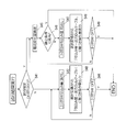
- FIG. 1 is a control block diagram illustrating a configuration of a power tool according to an embodiment of the present invention.
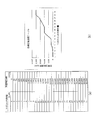
- 3A is a table showing a relationship between an operation amount of a trigger switch and a target rotation speed stored in a storage unit of the power tool in FIG. 1;
- (B) is a graph of the table.
- 2 is a flowchart illustrating a flow of a control method of the power tool in FIG. 1.
- 4 is a flowchart showing a flow of initial setting in FIG. 3.
- 3A and 3B are tables and graphs showing a relationship between an operation amount of a trigger switch of the power tool of FIG. 1 and an output duty in a default state. 4 is a flowchart showing the flow of processing in the trial mode in FIG. FIG.
- FIG. 4 is a flowchart showing the flow of processing for estimating a work mode in FIG. 3;
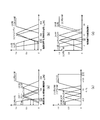
- FIG. (A)-(d) is a graph showing a membership function indicating a relationship between each parameter using a current value and a rotation pulse and each operation mode.
- 9 is a table showing a relationship between each parameter using a current value and a rotation pulse and each operation mode as a numerical value of a membership function.
- (A)-(d) is a graph showing a method of calculating a fitness using a membership function indicating a relationship between each parameter using a current value and a rotation pulse and each work mode.
- 4 is a graph showing a relationship between an operation amount of a trigger switch of the power tool and an output duty in each operation mode.
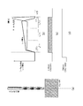
- (A) is a figure showing a text screw mode.
- (B) is a figure which shows step-by-step work in the text screw mode.
- (C) is a graph showing the relationship between the motor current and the motor speed in the text screw mode.
- (D) is a graph showing ON / OFF of the trigger switch in the text screw mode.
- (E) is a graph showing the normal rotation / reversal of the direction switch in the text screw mode.
- (A) is a figure which shows a mode of a bolting operation
- (B) is a graph which shows the relationship between motor current and motor speed in bolt work.
- (C) is a graph showing ON / OFF of a trigger switch in a bolt tightening operation.
- (D) is a graph which shows the normal rotation / reversal of the direction switch in bolting work.
- (A) is a figure showing a situation of bolt loosening work.
- (B) is a graph showing the relationship between the motor current and the motor speed in the bolt loosening work.
- (C) is a graph which shows ON / OFF of a trigger switch in bolt loosening work.
- (D) is a graph showing the forward / reverse rotation of the direction switch in the bolt loosening operation.
- (A) is a figure which shows the mode of a tapping screw fastening (there is a prepared hole) operation
- (B) is a graph showing the relationship between the motor current and the motor speed in the tapping screw fastening operation.
- (C) is a graph showing ON / OFF of a trigger switch in a tapping screw tightening operation.
- (D) is a graph which shows the normal rotation / reversal of the direction switch in the tapping screw fastening operation.
- (A) is a figure which shows the mode of operation
- (B) is a graph showing a relationship between a motor current and a motor speed in an operation using an iron drill.
- (C) is a graph which shows ON / OFF of the trigger switch in the work using the drill for ironsmiths.
- (D) is a graph showing the forward / reverse rotation of the direction switch in the work using the drill for ironsmith.
- (A) is a figure showing a situation of work using a drill for woodworking.
- (B) is a graph showing a relationship between a motor current and a motor speed in an operation using a woodworking drill.
- (C) is a graph showing ON / OFF of a trigger switch in work using a woodworking drill.
- (D) is a graph showing the forward / reverse rotation of the direction switch in the work using the woodworking drill.
- 4 is a flowchart showing the flow of processing in a trial result execution mode in FIG. 3.
- the power tool 10 rotates a tip tool such as a driver or a drill mounted on the tip portion thereof by a brushless motor (motor 16) supplied with power from the battery 11.
- the power tool 10 includes a battery (power supply unit) 11, a trigger switch (speed setting unit) 12, a switching circuit (gate circuit 13, an FET (Field Effect Transistor) array 14), a current detection resistor. 15, a motor 16, a magnetic pole position detection circuit 17, a trial switch 18, and a control unit 20.
- the battery (power supply unit) 11 is, for example, a replaceable rechargeable battery that is mounted on a grip portion of the power tool 10, and is used as a power source of the power tool 10. Further, as shown in FIG. 1, the battery 11 is connected to the FET array 14 and the control unit 20, and supplies power to each.
- a constant-voltage power supply for generating a constant-voltage power supply in which the voltage of the battery 11 is reduced to a predetermined constant voltage Vcc (for example, 5 V) is provided in the driving device of the electric tool 10.
- Vcc constant voltage power supply
- the constant voltage power supply (Vcc) is used as a power supply for operating a predetermined circuit in the driving device including the control unit 20.
- the trigger switch (speed setting unit) 12 is an operation part for rotating the motor 16 of the electric tool 10 at a rotation speed according to the operation amount (retraction amount), and as shown in FIG. Including vessel.
- the variable resistor has one end connected to the constant voltage Vcc and the other end connected to the ground line.
- the trigger switch 12 is configured as a so-called potentiometer, and inputs a voltage (trigger operation amount signal) corresponding to the operation amount of the trigger switch 12 to the trigger operation amount signal input port of the control unit 20 using the constant voltage Vcc as a power supply. I do.
- the gate circuit 13 constitutes a switching circuit together with the FET array 14, and is provided for individually turning on / off each switching element 14a in the FET array 14, as shown in FIG.
- the six gate drivers 13a included in the gate circuit 13 are controlled by the control unit 20.
- the FET array 14 connects a terminal of each phase of the motor 16 to the positive terminal of the battery 11 and a terminal of each phase of the motor 16 and the negative terminal of the battery 11. It is configured as a half-bridge circuit including six switching elements 14a including a low-side switch to be connected.
- the switching element 14a configuring the FET array 14 is configured by an n-channel FET. Each switching element 14a is connected to a gate circuit 13 that turns on each switching element 14a by applying a drive voltage equal to or greater than a threshold value between the gate and the source.
- the current detection resistor 15 is provided for detecting a current flowing through the motor 16, and is connected to a current calculation unit 25 described later, as shown in FIG.
- the motor 16 is configured by a three-phase (U-phase, V-phase, W-phase) brushless motor, and a terminal of each phase is connected to a battery 11 as a DC power supply via an FET array 14. It is connected to the.
- the motor 16 has three coils 16a, three Hall ICs (or Hall elements) 16b, and a rotor 16c.
- the coil 16a is provided for each of three phases (U-phase, V-phase, and W-phase), and is located at a position close to the rotor 16c on the rotor side and on the stator side.
- the Hall IC (or Hall element) 16b outputs a pulse signal to the control unit 20 via the magnetic pole position detection circuit 17 according to the rotational position of the motor 16 (ie, every time the motor 16 rotates a predetermined amount). .
- the rotor 16c is equipped with a tip tool such as a drill, and as shown in FIG. 1, is configured by embedding a permanent magnet including a pair of N poles and a pair of S poles. And are arranged facing each other.
- the magnetic pole position detection circuit 17 detects the positional relationship between the three-phase (U-phase, V-phase, and W-phase) coils 16a and the rotor 16c based on the output signals of the three Hall ICs 16b. I do. Then, the magnetic pole position detection circuit 17 transmits the detection result to the control unit 20 (the rotation counter 23).
- the trial switch 18 is, for example, a button-type switch provided on the outer surface of the power tool 10.
- the trial switch 18 is connected to the work mode estimating unit 24 as shown in FIG. 1, and when operated by the user, the trial switch 18 performs a trial for estimating the work mode. Send the signal to execute the mode.
- the control unit 20 controls the rotational driving of the motor 16 according to the control conditions when the motor 16 of the electric tool 10 is rotationally driven.
- the control unit 20 calculates the rotation position and the current speed of the motor 16 based on a pulse signal from the magnetic pole position detection circuit 17 that detects the rotation position of the motor 16. Then, the control unit 20 performs PWM (Pulse Width Modulation) control on the motor 16 so that the current rotation speed matches a target rotation speed determined by the operation amount of the trigger switch 12.
- PWM Pulse Width Modulation
- the control unit 20 controls each switching element 14a in the FET array 14 via the gate circuit 13 based on the detection signal from the Hall IC 16b included in the motor 16. Is turned ON / OFF.
- the control unit 20 controls the current supplied to the coil 16a of each phase of the motor 16 to rotate the motor 16 in a predetermined direction at a predetermined rotation speed. Then, the control unit 20 inputs a control signal for driving each switching element 14a to the gate circuit 13.
- the trigger operation amount signal taken into the control unit 20 is input to the table reference unit 21 and is converted into an output duty by referring to a table of each work mode stored in the storage unit 26.
- FIG. 2A shows an example of a target rotation speed table indicating the relationship between the operation amount of the trigger switch 12 and the target rotation speed. As shown in the graph of FIG. 2B, the target rotation speed of the motor 16 with respect to the operation amount of the trigger switch 12 is set to increase (partially unchanged) as the operation amount increases.
- the output Duty is set according to the trigger operation amount signal from the variable resistor, and the motor 16 is driven.
- PWM control is started. That is, the drive duty ratio of the FET array 14 is adjusted such that the larger the operation amount of the trigger switch 12 is, the higher the speed of the motor 16 is rotated, that is, the higher the drive duty ratio is.
- control unit 20 controls the commutation of the motor 16 based on the pulse signal from the Hall IC 16b and counts the number of pulses. Further, the control unit 20 performs PWM control of the motor 16 based on the operation amount of the trigger switch 12, the “trigger switch operation amount-output duty table”, and various operation modes stored in the storage unit 26 in advance.
- control unit 20 includes a table reference unit 21, an operation amount calculation unit 22, a rotation counter 23, a work mode estimation unit 24, a current calculation unit 25, a storage unit 26, and a PWM.
- the signal generator 27 is provided.
- the table reference unit 21 corresponds to the current operation amount of the trigger switch 12 with reference to the target rotation speed table (graph) stored in the storage unit 26 (see FIGS. 2A and 2B). Find the target rotation speed. Then, the table reference unit 21 transmits the target rotation speed to the operation amount calculation unit 22.
- the table reference unit 21 receives a table designation signal from a work mode estimating unit 24, which will be described later, and sets a target rotation speed table (for example, a gradient of a graph or the like) corresponding to the work mode estimated by the work mode estimating unit 24. Is specified.
- the work mode estimation performed by the work mode estimating unit 24 will be described later in detail.
- the operation amount calculation unit 22 receives the target rotation speed of the motor 16 corresponding to the operation amount of the trigger switch 12 received from the table reference unit 21, and causes the PWM signal generation unit to rotate the motor 16 at the target rotation speed.
- the duty ratio is transmitted to 27.
- the operation mode estimated by the operation mode estimating unit 24 is a specific operation mode and satisfies a predetermined stop condition
- the operation amount estimating unit 24 controls the rotation of the motor 16 from the operation mode estimating unit 24. Receiving a stop control signal for stopping the operation. The stop control will be described later in detail.
- the rotation counter 23 is connected to the magnetic pole position detection circuit 17 and calculates the current actual rotation speed of the motor 16 based on the detection result received from the magnetic pole position detection circuit 17. Then, the rotation counter 23 transmits the calculated actual rotation speed to the storage unit 26.
- the work mode estimating unit 24 When receiving the signal for executing the trial mode received from the trial switch 18, the work mode estimating unit 24 reads the current value and the rotation pulse of the motor 16 acquired in the trial mode from the storage unit 26, and estimates the work mode. I do.
- the work mode estimated by the work mode estimating unit 24 includes, for example, a tex mode, a bolt tightening mode, a bolt loosening mode, a strong mode, a medium mode, a weak mode, an iron work mode, and a woodwork mode. included.
- the text mode is a mode for performing an operation using the text screw (see FIG. 12A), and is controlled so as to reduce a load on the screw head of the text screw due to excessive tightening.
- the bolt tightening mode is a mode for performing a bolt tightening operation (see FIG. 13A), and it is assumed that the load torque is small from the beginning of the work, and the load torque increases when the tightening is completed. Control is performed.
- the bolt loosening mode is a mode for performing the work of loosening the fastened bolt (see FIG. 14A), and the load torque is large at the beginning of the work, and the load torque decreases at a stretch when the bolt is loosened.
- the control is performed on the assumption that this is the case.
- the strong mode is, for example, a mode for performing an operation using a long screw or the like, and is controlled so as to rotate faster than a default setting from the start of the operation.
- the medium mode is, for example, a mode for performing an operation such as attaching a gypsum board or fastening a screw to a decorative material (see FIG. 15A), and rotates at a lower speed than the default setting. Controlled.
- the weak mode is, for example, a mode for performing an operation such as fastening a screw to finish the gypsum board, and is controlled so as to rotate at a lower speed than the setting of the middle mode.
- the ironsmith mode is a mode for performing an operation using an ironsmith drill (see FIG. 16A), and is controlled so as to start tightening slowly at the beginning of the operation and gradually increase the rotation speed. You.
- the woodworking mode is a mode for performing work using a woodworking drill (see FIG. 17 (a)), and starts tightening slowly at the beginning of the work, and gradually rotates at a lower rotation speed than the ironworking mode. It is controlled to increase the speed.
- the work mode estimation is performed using the characteristic values (current value and rotation pulse) of the motor 16 acquired.
- the unit 24 estimates an optimal operation mode for the operation. The work mode estimation process will be described later in detail.
- the current calculator 25 is connected between the FET array 14 and the current detection resistor 15 and calculates the current flowing through the motor 16 as shown in FIG. Then, the current calculation unit 25 transmits the calculation result (current value) to the storage unit 26.
- the storage unit 26 stores the table indicating the relationship between the operation amount of the trigger switch 12 and the target rotation speed of the motor 16 shown in FIG. 2A, and the operation amount and the output Duty of the trigger switch 12 shown in FIG. Save a table showing the relationship. Further, in the present embodiment, the storage unit 26 stores the rotation pulse of the motor 16 received from the rotation counter 23, the current value of the motor 16 received from the current calculation unit 25, and a control method of the power tool 10 described later. Save the control program.
- the PWM signal generation unit 27 refers to the table of each work mode stored in the storage unit 26 based on the trigger operation amount signal of the trigger switch 12 received from the table reference unit 21 and converts the table into the output duty. . Further, after the work mode is estimated by the work mode estimation unit 24, the PWM signal generation unit 27 outputs an output Duty according to the estimated work mode.
- the work mode optimal for the work is estimated by using the current value and the rotation pulse acquired during the work performed in the trial mode, according to the flowchart shown in FIG. I do. Then, the work is performed in the work mode automatically set based on the estimation result.
- step S1 the initialization is performed when the charged battery 11 is connected to the power tool 10.
- the initial setting is performed according to the flowchart shown in FIG.
- step S11 the trial result data is reset.
- step S12 a process of clearing the rotation counter 23 is performed. Thereby, various initialization processes necessary for the operation of the control unit 20 are performed.
- step S2 the control unit 20 waits until the trigger switch 12 is operated by the user and turned on.
- the process proceeds to step S3.
- step S3 it is determined whether or not the trial switch 18 has been operated to be in the ON state.
- the process proceeds to step S9, and the trial mode is executed.
- the process proceeds to step S4.
- step S4 since the trial switch 18 is in the OFF state, it is confirmed whether trial result data is held.
- the process proceeds to step S10, and the trial result execution mode is executed. On the other hand, if the trial result data is not held, the process proceeds to step S5.
- step S5 the operation amount of the trigger switch 12 is read. Specifically, the potential divided by the resistance of the trigger switch 12 is taken into the control unit 20 via the A / D converter.
- step S6 an output duty proportional to the read operation amount of the trigger switch 12 is output (see FIGS. 5A and 5B).
- step S7 the processing from step S5 to step S7 is repeated until the trigger switch 12 is no longer operated.
- step S8 after the rotation of the motor 16 is stopped, the process returns to step S2, and the processing after step S2 is repeated.
- step S21 the control unit 20 resets the output pulse counter of the magnetic pole position detection circuit 17.
- step S22 the control unit 20 reads the operation amount of the trigger switch 12. That is, the control unit 20 takes in the potential divided by the resistance by the trigger switch 12 via an A / D converter (not shown).
- step S23 the control unit 20 outputs an output Duty proportional to the read operation amount of the trigger switch 12.
- step S24 the control unit 20 causes the storage unit 26 to store the current value of the motor 16 calculated by the current calculation unit 25 and the number of rotations obtained by the rotation counter 23 as time-series data.
- step S25 when the state in which the trigger switch 12 is operated (ON state) is continued, the process returns to step S22, and the subsequent operations are repeated.
- step S10 when the trial switch 18 is operated in step S3 to be turned on and trial result data is present in step S4, the process of executing the trial result execution mode in step S10 will be described with reference to the flowchart shown in FIG. Will be explained.
- step S9 after the trial mode is executed, time series data of the current value of the motor 16 acquired in the trial mode and the rotation pulse acquired from the rotation counter 23 is used. , And the following five values are extracted.
- Current value i on 0.5 second after the load state (first current value) The presence or absence of a load is determined by setting a threshold value for the current value (for example, 1.0 A).
- step S31 The current value 0.5 seconds before the point when the load state changes to the no-load state is i off (second current value) (3) Assuming that the total load time is T all , the current value at the time when T all 1/3 has elapsed from the point of the load state is i 1 (third current value) (4) Assuming that the total load time is T all , the current value at the time when T all 2/3 has elapsed from the time when the load state is reached is i 2 (fourth current value) (5) Total number of rotations N under load (rotation pulse is counted) Specifically, in step S31, the control unit 20, the motor 16 is to extract a current value i on the 0.5 second after a loaded conditions.
- step S32 the control unit 20 extracts the current value i off 0.5 seconds before the time when the motor 16 changes from the loaded state to the unloaded state.
- step S33 the control unit 20, when the organic load total time of the motor 16 and the T all, from the time when a loaded conditions to extract the current i 1 of the T all 1/3 elapsed time.
- step S34 the control unit 20, when the organic load total time of the motor 16 and the T all, from the time when a loaded conditions to extract the current value i 2 of the T all 2/3 elapsed time.
- step S35 the control unit 20 counts the number of rotation pulses of the motor 16 in the loaded state, and extracts the total number of rotations N.
- step S36 the control unit 20 executes a fuzzy inference, obtained is extracted from the characteristic values of the motor 16 was the above five values in trial mode (i on, i off, i 1, i 2, N) a To estimate the optimal work mode for the work.
- step S37 the control unit 20 stores the result (estimated work mode) of executing the trial mode in the storage unit 26, and ends the process.
- the power tool 10 of the present embodiment uses fuzzy inference when estimating the work mode.
- the membership functions shown in FIGS. 8A to 8D indicate the degree of conformity of each work mode by a degree (0 to 1.0).
- the fitness of each work mode can be linked to the characteristic values (current value, rotation pulse) acquired during the actual work.
- fuzzy inference four feature values are applied to a membership function to find a matching point for each work mode. Next, the four matching points are summed for each work mode. Then, the work mode in which the sum of the matching points becomes the maximum is stored as the trial result.
- the current value ion and the eight working modes are represented in the membership function as shown in FIG. That is, in FIG. 8A, when the current value ion is as small as 5 A or less, the matching point of (b) the bolt tightening mode or (f) the weak mode is added. Then, when the current value i on is in the range of 2 ⁇ 10A is, (a) tex mode, (d) strong mode, (e) Medium mode, (h) Woodworking mode, (g) fit points Tekko mode Is added. Then, when the current value i on is as large as more than 18A is subject to adaptation point (c) bolt loosening mode.
- the current value i off and the eight working modes are expressed in the membership function as shown in FIG. 8B. That is, in FIG. 8B, when the current value i off is as small as 10 A or less, the matching points of (c) the bolt loosening mode and (h) the woodworking mode are added. When the current value i off is equal to or less than 20 A, the matching points of (f) weak mode and (g) iron work mode are added. Further, when the current value i off is in the range of 10 to 30 A, the (e) medium mode matching point is added. If the current value i off is in the range of 10 to 40 A, the (a) text mode matching point is added. Further, when the current value i off is equal to or more than 20 A, the matching points of (b) the bolt tightening mode and (d) the strong mode are added.
- the current value ratio (i 1 / i 2 ) and the eight working modes are expressed in the membership function as shown in FIG. 8C. That is, in FIG. 8C, when i 1 / i 2 is smaller than 0.8, the matching points of (d) strong mode and (g) ironwork mode are added. When i 1 / i 2 is in the range of 0.7 to 0.9, the matching points of (e) medium mode and (h) woodworking mode are added. Further, when i 1 / i 2 is in the range of 0.85 to 1.0, the (f) weak mode adaptation point is added.
- the total number of revolutions N and the eight working modes are expressed in the membership function as shown in FIG. That is, in FIG. 8D, when the total number of revolutions N is smaller than 6, the adaptation point of (c) the bolt loosening mode is added. If the total number of revolutions N is smaller than 9, the (f) weak mode matching point is added. Further, when the total number of revolutions N is in the range of 4 to 11, (a) the text mode matching point is added. When the total number of revolutions N is in the range of 7 to 15, the matching points of (e) medium mode and (h) woodworking mode are added. Further, when the total number of revolutions N is larger than 11, the matching points of (d) strong mode and (g) ironing mode are added. Further, when the total number of rotations N is larger than 12, an adaptation point in the (b) bolt tightening mode is added.
- the work mode with the largest numerical value has the highest possibility and is used as the estimation result. Therefore, in the above example, the (a) tex mode having the highest fitness of 2.3 is estimated.
- step S10 a graph showing the relationship between the operation amount of the trigger switch 12 and the output duty corresponding to the (a) tex mode estimated in the trial mode of FIG. Is selected, and the motor 16 can be controlled according to the optimum control conditions.
- the output Duty is adjusted so that the rotation speed becomes low immediately after the start of the work as compared with the default graph, and the operation amount of the trigger switch 12 is reduced.
- the duty is increased, the output Duty is gradually increased after a period in which the output Duty is constant.
- the output Duty reaches 70%, the output is controlled so as not to exceed it.
- the work mode is estimated according to the following fuzzy rules using the current value and the rotation pulse acquired in the trial mode.
- the work mode is estimated based on the fuzzy rules (1) to (6) using the following characteristic values (current value, rotation speed, etc. of the motor 16) acquired during each work. Done.
- characteristic values current value, rotation speed, etc. of the motor 16
- the text mode is a mode in which a driver is mounted as a tip tool and a work (see) using a text screw is performed as shown in FIG.
- the load is controlled so as to reduce the load on the screw head of the tex screw due to the overshoot.
- the operation using the texture screw is performed in four stages of contact with the surface of the work material, drilling a pilot hole, tapping, and tightening.
- the current value of the motor 16 rises after the tex screw comes into contact with the surface of the work material, and when the process proceeds to the preparation of the pilot hole, the rate of rise becomes gentle.
- the current value of the motor 16 shifts to tapping the current value sharply decreases and then gradually increases, and then, in the tightening operation, the current value rapidly increases and then becomes constant.
- the rotation speed of the motor 16 starts to increase from the state where the tex screw is in contact with the surface of the work material, and then gradually decreases when the process proceeds to the preparation of the pilot hole.
- the current value suddenly drops, then gradually rises, and then rapidly rises again in the tightening operation.
- the trigger switch 12 during the operation shifts to the ON state at the same time as the start of the operation, and when the tightening operation is completed, in order to prevent the screw head of the tex screw from jumping. Automatically transition to the OFF state by the stop control.
- the direction switch for switching the rotation direction of the motor 16 during the operation is on the normal rotation side as shown in FIG.
- the current value and the rotation speed of the motor 16 change as shown in FIG. Therefore, in the trial mode, the current value i on (first current value) 0.5 seconds after the above-described loaded state, and 0.5 seconds before the change from the loaded state to the no-load state. Is the current value of i off (the second current value), and the total load time is T all, and the current value at the time when T all 1/3 elapses from the load state is i 1 (the third current value).
- the bolt tightening mode is a mode for mounting a socket as a tool bit and tightening a bolt and a nut as shown in FIG.
- the control is performed on the assumption that the load torque is small and the load torque increases when the tightening is completed.
- the current value of the motor 16 during the bolting operation changes at a low current value from the start of the operation, and rises sharply when the operation shifts to the tightening operation. Is shown.
- the trigger switch 12 during the operation shifts to the ON state simultaneously with the start of the operation, and shifts to the OFF state when the tightening operation is completed.
- the direction switch for switching the rotation direction of the motor 16 during the operation is on the normal rotation side as shown in FIG.
- the current value and the rotation speed of the motor 16 change as shown in FIG. Therefore, in the trial mode, the current value i on (first current value) 0.5 seconds after the above-described loaded state, and 0.5 seconds before the change from the loaded state to the no-load state. Is the current value of i off (the second current value), and the total load time is T all, and the current value at the time when T all 1/3 elapses from the load state is i 1 (the third current value).
- the work is performed in a state in which the “graph indicating the relationship between the operation amount of the trigger switch 12 and the output duty” corresponding to the bolt tightening mode shown in FIG. 11 is selected. By doing so, it is possible to perform optimal motor control for bolting work.
- the bolt loosening mode is a mode for mounting a socket as a tip tool and performing a work of loosening the fastened bolts and nuts as shown in FIG. Initially, control is performed on the assumption that the load torque is large, and that the load torque drops at once if the bolt is loosened.
- the current value of the motor 16 during the bolt loosening operation changes at a high current value from the start of the operation to loosen the bolt in the fastened state, and the bolt is loosened. It shows a characteristic that when it shifts to the state where it has been moved, it drops sharply.
- the rotation speed of the motor 16 gradually increases from 0 at the beginning of the work, and when the bolt shifts to a loosened state, the rotation load suddenly decreases. Shows the characteristic of rising.
- the trigger switch 12 during the operation shifts to the ON state simultaneously with the start of the operation, and when the bolt shifts to the loosened state, the loosened bolt (or nut) is dropped. In order to prevent this, the state automatically shifts to the OFF state by the stop control described later.
- the direction switch for switching the rotation direction of the motor 16 during the operation is on the reverse rotation side as shown in FIG.
- the current value and the rotation speed of the motor 16 change as shown in FIG. Therefore, in the trial mode, the current value i on (first current value) 0.5 seconds after the above-described loaded state, and 0.5 seconds before the change from the loaded state to the no-load state. Is the current value of i off (the second current value), and the total load time is T all, and the current value at the time when T all 1/3 elapses from the load state is i 1 (the third current value).
- the work is performed in a state in which the “graph indicating the relationship between the operation amount of the trigger switch 12 and the output duty” corresponding to the bolt loosening mode shown in FIG. 11 is selected. By doing so, it is possible to carry out optimal motor control for bolt loosening work.
- (E) Medium mode
- a driver is mounted as a tip tool, and as shown in FIG. 15 (a), for example, using a tapping screw or the like to paste a plaster board or a decorative material on which a pilot hole has been formed.
- This is a mode for performing work such as screw tightening, and is controlled to rotate at a slightly lower speed than the default setting.
- the current value of the motor 16 during the screw tightening operation changes at a low current value due to a small rotation load at the start of the operation, and the screw moves into the prepared hole. It shows the characteristic that the current value gradually rises as it enters, and rises sharply when it shifts to the tightening operation.
- the rotation speed of the motor 16 rapidly increases at the beginning of the work due to a small rotation load, and gradually decreases as the screw enters the pilot hole.
- the operation shifts to the tightening operation it shows a characteristic of rapidly increasing.
- the trigger switch 12 during the operation shifts to the ON state at the same time as the start of the operation, and shifts to the OFF state when the screw tightening operation is completed.
- the direction switch for switching the rotation direction of the motor 16 during the operation is on the normal rotation side as shown in FIG.
- the current value and the rotation speed of the motor 16 change as shown in FIG. Therefore, in the trial mode, the current value i on (first current value) 0.5 seconds after the above-described loaded state, and 0.5 seconds before the change from the loaded state to the no-load state. Is the current value of i off (the second current value), and the total load time is T all, and the current value at the time when T all 1/3 elapses from the load state is i 1 (the third current value).
- the iron work mode is a mode for performing a work of processing iron or the like using a drill for iron work as a tip tool as shown in FIG. At first, the rotation speed is controlled to be gradually increased.
- the current value of the motor 16 during the work using the iron drill is gradually increased from the start of the work as shown in FIG. As the current progresses, the current value gradually increases, and when it penetrates through the work material, the rotating load sharply decreases, so that the current value sharply decreases.
- the rotation speed of the motor 16 rises to a constant rotation speed from the beginning of the work and then remains almost constant. It shows the characteristic that it suddenly rises because of the decrease.
- the trigger switch 12 during the operation shifts to the ON state at the same time as the start of the operation, and shifts to the OFF state when the iron drill passes through the work material.
- the direction switch for switching the rotation direction of the motor 16 during the operation is on the normal rotation side as shown in FIG.
- the current value and the rotation speed of the motor 16 change as shown in FIG. Therefore, in the trial mode, the current value i on (first current value) 0.5 seconds after the above-described loaded state, and 0.5 seconds before the change from the loaded state to the no-load state. Is the current value of i off (the second current value), and the total load time is T all, and the current value at the time when T all 1/3 elapses from the load state is i 1 (the third current value).
- the woodworking mode is a mode for performing woodworking work using a woodworking drill as a tool bit as shown in FIG. 17 (a). Control is performed so that the rotation speed is gradually increased at a rotation speed lower than the ironwork mode.
- the current value of the motor 16 during the work using the woodworking drill gradually increases from the start of the work, as shown in FIG. Even if it advances, it keeps almost constant, and when it penetrates the work material, it shows the characteristic that the rotational load drops sharply and drops sharply.
- the rotation speed of the motor 16 rises to a constant rotation speed from the beginning of the operation and then remains almost constant. It shows the characteristic that it goes up because it goes down.
- the trigger switch 12 during the operation shifts to the ON state at the same time as the start of the operation as shown in FIG. 17C, and shifts to the OFF state when the woodworking drill penetrates the work material.
- the direction switch for switching the rotation direction of the motor 16 during the operation is on the normal rotation side as shown in FIG.
- the current value and the rotation speed of the motor 16 change as shown in FIG. Therefore, in the trial mode, the current value i on (first current value) 0.5 seconds after the above-described loaded state, and 0.5 seconds before the change from the loaded state to the no-load state. Is the current value of i off (the second current value), and the total load time is T all, and the current value at the time when T all 1/3 elapses from the load state is i 1 (the third current value).
- step S41 the control unit 20 determines whether or not the work mode estimated in the trial mode is one of the (a) text mode and (c) the bolt loosening mode.
- the process proceeds to step S45.
- the process proceeds to step S42.
- step S42 since it is determined that the work mode estimated in step S41 is not (a) or (c), the determination of the condition for stopping the motor 16 is not performed.
- Read the manipulated variable Specifically, the potential divided by the resistance of the trigger switch 12 is taken into the control unit 20 via the A / D converter.
- step S43 the control unit 20 refers to the “operation amount of trigger switch 12—output duty table” (see FIG. 11) corresponding to each work mode stored in the storage unit 26, and outputs the operation amount.
- the user can always set the optimum work mode without any special operation such as setting the optimum work mode by himself / herself when repeating the same work. It is possible to work comfortably under the motor control setting.
- step S41 determines whether the work mode estimated is not (a) or (c). If it is determined in step S41 that the work mode estimated is not (a) or (c), the process proceeds to step S45 in order to determine whether a condition for stopping the motor 16 is satisfied. The amount of change in current of the motor 16 per unit time (current change rate) is calculated.
- step S46 it is determined whether or not the amount of change in the current calculated in step S45 satisfies the condition for stopping the rotation of the motor 16 for each estimated working mode. For example, if (a) the text mode is estimated in step S41, the condition that the current change per unit time (current change rate) becomes 5 A / sec or more is determined as a condition for stopping the rotation of the motor 16. I do.
- the rotation of the motor 16 is automatically stopped when the current change rate satisfies the stop condition of 5 A / sec or more.
- the control unit 20 determines that a sudden load is applied to the motor 16 (the condition that the current change rate is 5 A / sec or more is satisfied). In this case, the rotation of the motor 16 is stopped regardless of the operation amount of the trigger switch 12. As a result, it is possible to prevent excessive tightening of the tex screw at the time of completion of the operation using the tex screw, and to effectively prevent problems such as screw head jump and breakage.
- step S41 if (c) the bolt loosening mode is estimated in step S41, the rotation of the motor 16 is stopped until the amount of change in current per unit time (current change rate) becomes -1 A / sec or more. Condition.
- the control unit 20 causes the load on the motor 16 to drop sharply (satisfies the condition that the current change rate is -1 A / sec or more).
- the rotation of the motor 16 is stopped regardless of the operation amount of the trigger switch 12. As a result, it is possible to effectively prevent the bolt (or nut) from dropping off when the bolt loosening operation is completed.
- step S47 since it is determined that the predetermined stop condition is not satisfied in step S46, the condition for stopping the motor 16 is not determined, and the control unit 20 reads the operation amount of the trigger switch 12. Specifically, the potential divided by the resistance of the trigger switch 12 is taken into the control unit 20 via the A / D converter.
- step S48 the control unit 20 refers to the “operation amount of the trigger switch 12—output duty table” (see FIG. 11) corresponding to each work mode stored in the storage unit 26, and outputs the operation amount.
- the user can always set the optimum work mode without any special operation such as setting the optimum work mode by himself when repeating the same work. It is possible to work comfortably under the motor control setting.
- the control unit 20 sets the trial mode to the trial mode in order to automatically set the optimal work mode for the work.
- the work mode is estimated based on the characteristic values (current value, rotation pulse, and the like) of the motor 16 acquired in the state where the operation is performed.
- a single power tool has a plurality of functions (for example, in the case of a drill driver, screw tightening, nut tightening, hole drilling, etc.).
- a user it has been necessary for a user to select an optimal work mode by himself assuming work contents and to manually switch the work mode.
- the user himself / herself can perform various works.
- An operation can be performed by automatically selecting an optimal mode for each operation without selecting an appropriate mode.
- the power consumption of the battery 11 can be reduced by improving the usability of the user and the work efficiency. Further, by performing the work by selecting the work mode most suitable for the work, work mistakes (failures) are reduced, so that the work yield can be improved and the loss of the work material can be reduced.
- the estimation of the work mode is performed after the trigger switch 12 is turned on in the trial mode, after the trigger switch 12 is turned off, and before the next work is started (the trigger switch 12 is turned on). Is done. For this reason, the load related to the work mode estimation processing of the control unit 20 is small, and it can be realized at low cost.
- the optimum work mode may be estimated by combining two, three, four, or six or more of the above five values. That is, in the present invention, the values acquired in the trial mode are not limited to the above five values, and may be smaller values or larger values. The values acquired in the trial mode are not limited to the above five types, and other types of values may be used.
- 0.1 second after become loaded conditions or current value after 1.0 seconds may be i on.
- a current value 0.1 seconds before or 0.8 seconds after the point of time when the state changes from the loaded state to the unloaded state may be set as i off .
- the feature amounts i on and i off need only be set so that the current value at the time when a change is easily detected for each work mode is used.
- the work modes to be estimated include the tex mode, the bolt tightening mode, the bolt loosening mode, the strong mode, the medium mode, the weak mode, the ironwork mode, and the woodwork mode.
- the present invention is not limited to this.
- the estimated operation mode is not limited to the above operation mode, and may be an operation mode other than the above operation modes.
- the present invention is implemented as the power tool 10 and the control method of the power tool 10.
- the present invention is not limited to this.
- the present invention may be realized as a control program that causes a computer to execute the control method of the power tool 10 described in the above embodiment.
- This control program only needs to be stored in the storage unit 26 shown in FIG. 1, and can be read by the CPU so that the computer can execute the control method described above.
- the power tool according to the present invention has an effect that the user can automatically select an optimal mode for each work and perform the work without the user himself selecting a mode suitable for various works. It is widely applicable to electric tools used in various operations.
- Power tool 11 Battery (power supply) 12 Trigger switch (speed setting section) 13 Gate circuit (switching circuit) 13a Gate driver 14 FET array (switching circuit) 14a Switching element 15 Current detection resistor 16 Motor (DC motor) 16a Coil 16b Hall IC 16c Rotor 17 Magnetic pole position detection circuit 18 Trial switch 20 Control unit 21 Table reference unit 22 Operation amount calculation unit 23 Rotation counter 24 Work mode estimation unit 25 Current calculation unit 26 Storage unit 27 PWM signal generation unit
Abstract
A power tool (10) comprises a motor (16), a trigger switch (12), a switching circuit (gate circuit (13) and FET array (14)), and a control unit (20). The trigger switch (12) sets the speed of the motor (16) in accordance with a manipulation amount. The switching circuit has a plurality of switching elements (14a) and supplies electric power to the motor (16). The control unit (20) controls the switching circuit so that the motor is rotationally driven on the basis of the speed set by the trigger switch (12), and has a trial run mode for estimating an operation mode. The operation mode is estimated on the basis of a characteristic value of the motor (16) as acquired in the trial run mode.
Description
本発明は、電動工具およびその制御方法、制御プログラムに関する。
The present invention relates to a power tool, a control method thereof, and a control program.
電動工具は、通常、工場出荷時に設定されたモータ制御パラメータをそのまま使用して、ネジ締め、ドリル加工等の各種作業が実施される。このため、ドリル加工やテクスネジ締め加工等において、様々な加工部材(金属や欅などの硬い材料、石膏や杉などの柔らかい材料、天然無垢木材のような不均質材、石膏ボードや集成材などの均質材)に対して、いずれも中庸の作業性しか得られないという問題があった。
Electric tools usually perform various operations such as screw tightening and drilling using the motor control parameters set at the time of factory shipment as they are. For this reason, in drilling and text screw tightening, various processing members (hard materials such as metal and keyaki, soft materials such as gypsum and cedar, heterogeneous materials such as natural solid wood, gypsum board and laminated wood, etc.) However, there was a problem that only moderate workability could be obtained with respect to homogeneous materials.
例えば、特許文献1には、所定のサンプルモードにおいて学習動作を実施し、モータの使用状況を学習して制御情報(例えば、モータによる締め付け時間、電流制限値、回転数等)として記憶することで、ユーザごとに最適な駆動モードを実現できる電動工具について開示されている。
For example, in Patent Document 1, a learning operation is performed in a predetermined sample mode to learn a use condition of a motor and store it as control information (for example, a tightening time by a motor, a current limit value, a rotation speed, and the like). A power tool that can realize an optimal drive mode for each user is disclosed.
しかしながら、上記従来の電動工具では、以下に示すような問題点を有している。
すなわち、上記公報に開示された電動工具では、使用者が所望の作業モード(例えば、「木材モード」、「ボルトモード」、「テクス用厚板モード」、「テクス用薄板モード」の4種)を選択する場合には、その都度、作業ごとに最適なモードを選択するスイッチを操作しなくてはならないという煩わしさがあった。さらに、使用者は、予め用意された作業モードの中から最適と判断した1つの作業モードを選択する必要があるため、選択できるモード数が予め用意された数種類に限定されるという問題があった。 However, the above-described conventional power tool has the following problems.
That is, in the power tool disclosed in the above-mentioned publication, a user can select a desired operation mode (for example, four types of “wood mode”, “bolt mode”, “text thick plate mode”, and “text thin plate mode”). Is selected, the user has to operate a switch for selecting an optimum mode for each operation. Further, since the user needs to select one work mode determined to be optimum from the work modes prepared in advance, there is a problem that the number of selectable modes is limited to several kinds prepared in advance. .
本発明の課題は、使用者が自ら各種作業に適したモードを選択することなく、その作業ごとに最適なモードを自動的に選択して作業を実施することが可能な電動工具およびその制御方法、制御プログラムを提供することにある。
An object of the present invention is to provide a power tool capable of automatically selecting an optimum mode for each work and performing the work without the user himself selecting a mode suitable for various works, and a control method therefor. To provide a control program.
第1の発明に係る電動工具は、直流モータと、速度設定部と、スイッチング回路と、制御部と、を備えている。速度設定部は、操作量に応じて直流モータの回転速度を設定する。スイッチング回路は、複数のスイッチング素子を有し、直流モータに対して電力を供給する。制御部は、速度設定部において設定された回転速度に基づいて直流モータを回転駆動させるようにスイッチング回路を制御するとともに、作業モードを推定するための試行モードを有しており、試行モードにおいて取得された直流モータの特性値に基づいて、作業モードを推定する。
The power tool according to the first invention includes a DC motor, a speed setting unit, a switching circuit, and a control unit. The speed setting unit sets the rotation speed of the DC motor according to the operation amount. The switching circuit has a plurality of switching elements and supplies power to the DC motor. The control unit controls the switching circuit so as to rotate the DC motor based on the rotation speed set in the speed setting unit, and has a trial mode for estimating a work mode. The work mode is estimated based on the obtained DC motor characteristic values.
ここでは、例えば、テクスネジ締め、ドリル加工、ボルト締め、ボルト緩め等の電動工具を用いた各種作業を開始する際に、所定の試行モードにおいて、当該作業対象となる加工材料に対して電動工具を用いた作業を行い、取得された直流モータの特性値に基づいて、当該作業に最適な作業モードを推定する。
Here, for example, when starting various operations using a power tool such as text screw tightening, drilling, bolt tightening, and bolt loosening, in a predetermined trial mode, the power tool is applied to a work material to be processed in the predetermined trial mode. The work used is performed, and based on the acquired characteristic values of the DC motor, a work mode optimal for the work is estimated.
ここで、推定される作業モードとしては、例えば、テクスネジを用いた作業を行うテクスモード、ボルトを締め付けるボルト締めモード、ボルトを緩めるボルト緩めモード、長いネジ締め等を行う強モード、化粧材等のネジ締めを行う中モード、石膏ボード等へのネジ締めを行う弱モード、鉄工用ドリルを用いた鉄工ドリルモード、木工用ドリルを用いた木工ドリルモード等が含まれる。
Here, as the work mode to be estimated, for example, a text mode in which a work using a text screw is performed, a bolt tightening mode in which a bolt is tightened, a bolt loosening mode in which a bolt is loosened, a strong mode in which a long screw is tightened, a cosmetic material, or the like A medium mode for tightening screws, a weak mode for tightening screws to a gypsum board or the like, an iron drill mode using an iron drill, a wood drill mode using a wood drill, and the like are included.
また、試行モードに設定された状態で、当該作業の対象となる加工材料に対して作業を実施して取得される直流モータの特性値には、直流モータを流れる電流値、回転パルス等が含まれる。
Further, the characteristic value of the DC motor obtained by performing the work on the processing material to be processed in the state where the trial mode is set includes a current value flowing through the DC motor, a rotation pulse, and the like. It is.
これにより、作業を実施する前に、試行モードに設定された状態で当該作業を実施することで取得された特性値を用いて、当該作業に最適な作業モードを推測することができる。
よって、使用者が自ら各種作業に適したモードを選択することなく、その作業ごとに最適なモードを自動的に選択して作業を実施することができる。 Thus, before performing the work, it is possible to estimate the optimum work mode for the work by using the characteristic values acquired by performing the work in the trial mode.
Therefore, the user can automatically select an optimal mode for each operation and perform the operation without selecting the mode suitable for various operations.
第2の発明に係る電動工具は、第1の発明に係る電動工具であって、制御部は、推定された作業モードに基づいて、速度設定部の操作量に応じて直流モータを制御する。
ここでは、作業モードの推定後、作業を実施する際には、推定された作業モードが自動的に選択された状態で、速度設定部の操作量に応じて直流モータを制御する。
これにより、自動的に最適な作業モードが選択された状態で作業を開始することができる。
よって、各作業ごとに最適化された制御条件で作業を実施することができるため、作業効率を向上させることができる。 A power tool according to a second invention is the power tool according to the first invention, wherein the control unit controls the DC motor according to the operation amount of the speed setting unit based on the estimated operation mode.
Here, when performing the work after the estimation of the work mode, the DC motor is controlled in accordance with the operation amount of the speed setting unit while the estimated work mode is automatically selected.
Thus, the work can be started in a state where the optimum work mode is automatically selected.
Therefore, the work can be performed under the control condition optimized for each work, so that the work efficiency can be improved.
第3の発明に係る電動工具は、第1または第2の発明に係る電動工具であって、特性値には、試行モードにおいて取得された直流モータの電流値および回転パルスの少なくとも一方が含まれる。
ここでは、作業モードの推定に用いられる直流モータの特性値として、直流モータを流れる電流値および回転パルスの少なくとも一方を用いる。
これにより、試行モードにおいて取得された直流モータの電流値および/または回転パルスを用いて、最適な作業モードを推定することができる。 A power tool according to a third invention is the power tool according to the first or second invention, wherein the characteristic value includes at least one of a current value of the DC motor and a rotation pulse acquired in the trial mode. .
Here, at least one of a current value flowing through the DC motor and a rotation pulse is used as the characteristic value of the DC motor used for estimating the work mode.
Thus, it is possible to estimate an optimal work mode using the current value and / or the rotation pulse of the DC motor acquired in the trial mode.
第4の発明に係る電動工具は、第3の発明に係る電動工具であって、制御部は、直流モータが有負荷状態になった時点の所定時間後の第1電流値、有負荷状態から無負荷状態へ変化した時点から所定時間前の第2電流値、有負荷状態となった総時間をTallとした時、有負荷状態となった時点からTall1/3経過時点の第3電流値およびTall2/3経過時点の第4電流値の比、有負荷状態での総回転数の少なくとも1つの特徴量を用いて、作業モードを推定する。
The power tool according to a fourth aspect is the power tool according to the third aspect, wherein the control unit is configured to control the first current value and the load state from a first current value after a predetermined time when the DC motor enters the load state. second current value before the predetermined time from the time of change to the no-load condition, when the total time a loaded conditions was T all, from the third time point when loaded conditions of T all 1/3 elapse The work mode is estimated using at least one characteristic value of the ratio of the current value and the fourth current value at the time when T all 2/3 has elapsed, and the total number of rotations in the loaded state.
ここでは、上述した直流モータの電流値から第1電流値、第2電流値、第3および第4電流値の比を求め、上述した回転パルスから有負荷状態での総回転数を求めて、これら4つの特徴量を用いて、作業モードを推定する。
Here, the first current value, the second current value, the ratio of the third and fourth current values are obtained from the current value of the DC motor described above, and the total number of rotations in a loaded state is obtained from the above-described rotation pulse, The work mode is estimated using these four feature amounts.
ここで、これら4つの特徴量は、それぞれの作業モードにおいて特徴が現れやすい特徴量として設定される。
これにより、これら4つの特徴量の1つあるいは複数を組み合わせて作業モードの推定を行うことで、作業モードの推定の精度を向上させることができる。 Here, these four feature amounts are set as feature amounts in which features are likely to appear in each work mode.
Thus, by estimating the work mode by combining one or more of these four feature amounts, it is possible to improve the accuracy of the work mode estimation.
第5の発明に係る電動工具は、第1から第4の発明のいずれか1つに係る電動工具であって、試行モードの実施時に使用者によって操作される試行スイッチを、さらに備えている。
The power tool according to a fifth aspect is the power tool according to any one of the first to fourth aspects, further comprising a trial switch operated by a user when the trial mode is performed.
ここでは、作業開始前に試行モードを実施する際に、使用者によって、例えば、電動工具の外表面に設けられた試行スイッチが操作される。
これにより、最適な作業モードを推定するために実施される試行モードを実施する際に、使用者が操作しやすい位置に試行スイッチが設けられていることで、容易に試行モードを実施することができる。 Here, when the trial mode is performed before the work is started, for example, the trial switch provided on the outer surface of the power tool is operated by the user.
Accordingly, when the trial mode is performed to estimate the optimal work mode, the trial mode is easily implemented by providing the trial switch at a position where the user can easily operate. it can.
第6の発明に係る電動工具は、第1から第5の発明のいずれか1つに係る電動工具であって、制御部によって推定される作業モードには、テクスモード、ボルト締めモード、ボルト緩めモード、強モード、中モード、弱モード、鉄工モード、木工モードのうちの少なくとも1つが含まれる。
A power tool according to a sixth aspect is the power tool according to any one of the first to fifth aspects, wherein the work mode estimated by the control unit includes a text mode, a bolt tightening mode, and a bolt loosening mode. At least one of a mode, a strong mode, a medium mode, a weak mode, an ironwork mode, and a woodwork mode is included.
ここでは、推定される作業モードの一例として、テクスモード、ボルト締めモード、ボルト緩めモード、強モード、中モード、弱モード、鉄工モード、木工モードを挙げている。
これにより、各種作業モードにおいて特徴的な特性値を検出することで、各種作業に対して最適な作業モードを推定することができる。 Here, the text mode, the bolt tightening mode, the bolt loosening mode, the strong mode, the medium mode, the weak mode, the ironwork mode, and the woodwork mode are given as examples of the estimated work mode.
Thus, by detecting characteristic characteristic values in various operation modes, it is possible to estimate an optimal operation mode for various operations.
第7の発明に係る電動工具は、第1から第6の発明のいずれか1つに係る電動工具であって、制御部によって推定された作業モードを保存する記憶部を、さらに備えている。
ここでは、推定された作業モードを記憶部に保存する。
これにより、制御部によって推定され、記憶部に保存された作業モードを用いて、作業を開始することで、当該作業に最適な作業モードに自動的に設定された状態で作業を行うことができる。 A power tool according to a seventh aspect is the power tool according to any one of the first to sixth aspects, further comprising a storage unit that stores the work mode estimated by the control unit.
Here, the estimated work mode is stored in the storage unit.
Thus, by starting the work using the work mode estimated by the control unit and stored in the storage unit, the work can be performed in a state automatically set to the work mode optimal for the work. .
第8の発明に係る電動工具は、第1から第7の発明のいずれか1つに係る電動工具であって、制御部は、推定された作業モードが所定の作業モードである場合には、直流モータの電流値の変化を検出し、変化の割合が所定の閾値を超えると、直流モータの回転を停止させる。
An electric power tool according to an eighth aspect is the electric power tool according to any one of the first to seventh aspects, wherein the control unit, when the estimated operation mode is a predetermined operation mode, A change in the current value of the DC motor is detected, and when the rate of change exceeds a predetermined threshold, the rotation of the DC motor is stopped.
ここでは、推定された作業モードが特定の作業モードである場合において、直流モータの電流値の変化が所定の閾値を越えると、直流モータの回転を停止させる停止制御を実施する。
Here, in the case where the estimated work mode is a specific work mode, stop control is performed to stop the rotation of the DC motor when the change in the current value of the DC motor exceeds a predetermined threshold.
ここで、特定の作業モードには、例えば、テクスネジ締めを行うテクスモード、ボルトを緩めるボルト緩めモード等が含まれる。
これにより、例えば、テクスモードにおいて、テクスネジを所望の締め付け状態まで達し、電流値が閾値を超える変化率を示した場合には、テクスネジの頭飛びや破断等を防止するために、直流モータの回転を停止させることができる。 Here, the specific work mode includes, for example, a text mode in which text screws are tightened, a bolt loosening mode in which bolts are loosened, and the like.
Thus, for example, in the text mode, when the text screw reaches a desired tightening state and the current value shows a change rate exceeding the threshold value, the rotation of the DC motor is prevented in order to prevent the head of the text screw from jumping or breaking. Can be stopped.
また、例えば、ボルト緩めモードにおいて、ボルトの回転抵抗が軽くなり、電流値が所定の閾値を超える変化率を示した場合には、外れたボルトが落下してしまうことを防止するために、直流モータの回転を停止させることができる。
Further, for example, in the bolt loosening mode, when the rotational resistance of the bolt becomes light and the current value shows a change rate exceeding a predetermined threshold value, in order to prevent the detached bolt from dropping, The rotation of the motor can be stopped.
この結果、特定の作業モードにおいて、それ以上回転させる必要がないことを電流値の変化率によって検出することで、各作業モードにおいて最適なモータ制御を実施することができる。
結果 As a result, by detecting from the change rate of the current value that there is no need for further rotation in a specific work mode, it is possible to perform optimal motor control in each work mode.
第9の発明に係る電動工具は、第1から第8の発明のいずれか1つに係る電動工具であって、制御部は、試行モードにおいて取得される特性値に基づいて、作業モードを、ファジィ推論を用いて推定する。
A power tool according to a ninth aspect is the power tool according to any one of the first to eighth aspects, wherein the control unit sets a work mode based on a characteristic value acquired in the trial mode. Estimate using fuzzy inference.
ここでは、上述した最適な作業モードの推定を、ファジィ推論を用いて実施する。
これにより、上述した試行モードにおいて取得された特性値に基づいて、ファジィ推論を用いて、最適な作業モードの推定を実施することで、当該作業に最適な作業モードを自動的に選択して作業を実施することができる。 Here, the above-described estimation of the optimal work mode is performed using fuzzy inference.
Thereby, based on the characteristic values acquired in the above-described trial mode, the optimal work mode is estimated using fuzzy inference, so that the optimal work mode is automatically selected for the work. Can be implemented.
第10の発明に係る電動工具の制御方法は、第1から第9の発明のいずれか1つに係る電動工具の制御方法であって、試行モードにおいて、予め設定された制御条件にて直流モータを回転駆動させるステップと、試行モードにおいて、直流モータに関する特性値を取得するステップと、試行モードにおいて取得された特性値に基づいて、作業モードを推定するステップと、を備えている。
A control method for a power tool according to a tenth aspect is the control method for the power tool according to any one of the first to ninth aspects, wherein the DC motor is controlled in a trial mode under a preset control condition. , Rotating in a trial mode, acquiring a characteristic value of the DC motor in the trial mode, and estimating a work mode based on the characteristic value acquired in the trial mode.
ここでは、例えば、テクスネジ締め、ドリル加工、ボルト締め、ボルト緩め等の電動工具を用いた各種作業を開始する際に、所定の試行モードにおいて、当該作業対象となる加工材料に対して電動工具を用いた作業を行い、取得された直流モータの特性値に基づいて、当該作業に最適な作業モードを推定する。
Here, for example, when starting various operations using a power tool such as text screw tightening, drilling, bolt tightening, and bolt loosening, in a predetermined trial mode, the power tool is applied to a work material to be processed in the predetermined trial mode. The work used is performed, and based on the acquired characteristic values of the DC motor, a work mode optimal for the work is estimated.
ここで、推定される作業モードとしては、例えば、テクスネジを用いた作業を行うテクスモード、ボルトを締め付けるボルト締めモード、ボルトを緩めるボルト緩めモード、長いネジ締め等を行う強モード、化粧材等のネジ締めを行う中モード、石膏ボード等へのネジ締めを行う弱モード、鉄工用ドリルを用いた鉄工ドリルモード、木工用ドリルを用いた木工ドリルモード等が含まれる。
Here, as the estimated work mode, for example, a text mode in which work using a text screw is performed, a bolt tightening mode in which bolts are tightened, a bolt loosening mode in which bolts are loosened, a strong mode in which long screws are tightened, a cosmetic material, or the like A medium mode for tightening screws, a weak mode for tightening screws to a gypsum board or the like, an iron drill mode using an iron drill, a wood drill mode using a wood drill, and the like are included.
また、試行モードに設定された状態で、当該作業の対象となる加工材料に対して作業を実施して取得される直流モータの特性値には、直流モータを流れる電流値、回転パルス等が含まれる。
Further, the characteristic value of the DC motor obtained by performing the work on the processing material to be processed in the state where the trial mode is set includes a current value flowing through the DC motor, a rotation pulse, and the like. It is.
これにより、作業を実施する前に、試行モードに設定された状態で当該作業を実施することで取得された特性値を用いて、当該作業に最適な作業モードを推測することができる。
よって、使用者が自ら各種作業に適したモードを選択することなく、その作業ごとに最適なモードを自動的に選択して作業を実施することができる。 Thus, before performing the work, it is possible to estimate the optimum work mode for the work by using the characteristic values acquired by performing the work in the trial mode.
Therefore, the user can automatically select an optimal mode for each operation and perform the operation without selecting the mode suitable for various operations.
よって、使用者が自ら各種作業に適したモードを選択することなく、その作業ごとに最適なモードを自動的に選択して作業を実施することができる。 Thus, before performing the work, it is possible to estimate the optimum work mode for the work by using the characteristic values acquired by performing the work in the trial mode.
Therefore, the user can automatically select an optimal mode for each operation and perform the operation without selecting the mode suitable for various operations.
第11の発明に係る電動工具の制御方法は、第10の発明に係る電動工具の制御方法であって、推定された作業モードに基づいて、速度設定部の操作量に応じて直流モータを制御するステップを、さらに備えている。
An electric tool control method according to an eleventh aspect of the present invention is the electric tool control method according to the tenth aspect, wherein the direct current motor is controlled in accordance with the operation amount of the speed setting unit based on the estimated working mode. Further comprising the step of:
ここでは、作業モードの推定後、作業を実施する際には、推定された作業モードが自動的に選択された状態で、速度設定部の操作量に応じて直流モータを制御する。
これにより、自動的に最適な作業モードが選択された状態で作業を開始することができる。
よって、各作業ごとに最適化された制御条件で作業を実施することができるため、作業効率を向上させることができる。 Here, when performing the work after the estimation of the work mode, the DC motor is controlled in accordance with the operation amount of the speed setting unit while the estimated work mode is automatically selected.
Thus, the work can be started in a state where the optimum work mode is automatically selected.
Therefore, the work can be performed under the control condition optimized for each work, so that the work efficiency can be improved.
第12の発明に係る電動工具の制御方法は、第10または第11の発明に係る電動工具の制御方法であって、特性値には、試行モードにおいて取得された直流モータの電流値および回転パルスの少なくとも一方が含まれる。
ここでは、作業モードの推定に用いられる直流モータの特性値として、直流モータを流れる電流値および回転パルスの少なくとも一方を用いる。
これにより、試行モードにおいて取得された直流モータの電流値および/または回転パルスを用いて、最適な作業モードを推定することができる。 A control method for a power tool according to a twelfth invention is the control method for a power tool according to the tenth or eleventh invention, wherein the characteristic value includes a current value and a rotation pulse of the DC motor acquired in the trial mode. At least one is included.
Here, at least one of a current value flowing through the DC motor and a rotation pulse is used as the characteristic value of the DC motor used for estimating the work mode.
Thus, it is possible to estimate an optimal work mode using the current value and / or the rotation pulse of the DC motor acquired in the trial mode.
第13の発明に係る電動工具の制御方法は、第12の発明に係る電動工具の制御方法であって、作業モードを推定するステップでは、直流モータが有負荷状態になった時点の所定時間後の第1電流値、有負荷状態から無負荷状態へ変化した時点から所定時間前の第2電流値、有負荷状態となった総時間をTallとした時、有負荷状態となった時点からTall1/3経過時点の第3電流値およびTall2/3経過時点の第4電流値の比、有負荷状態での総回転数の少なくとも1つの特徴量を用いて、作業モードを推定する。
A control method for a power tool according to a thirteenth invention is the control method for a power tool according to the twelfth invention, wherein the step of estimating the work mode includes a step after a predetermined time when the DC motor enters a loaded state. The first current value, the second current value a predetermined time before the time when the state changes from the loaded state to the no-load state, and the total time when the loaded state is set to Tall , from the time when the loaded state is reached. T all 1/3 ratios of the fourth current value of the third current value and T all 2/3 elapse elapsed time, using at least one characteristic quantity of the total number of revolutions in loaded conditions, estimating the working mode I do.
ここでは、上述した直流モータの電流値から第1電流値、第2電流値、第3および第4電流値の比を求め、上述した回転パルスから有負荷状態での総回転数を求め、これら4つの特徴量を用いて、作業モードを推定する。
Here, the first current value, the second current value, the ratio of the third and fourth current values are obtained from the current value of the DC motor described above, and the total number of rotations in a loaded state is obtained from the above-described rotation pulse. The work mode is estimated using the four feature amounts.
ここで、これら4つの特徴量は、それぞれの作業モードにおいて特徴が現れやすい特徴量として設定される。
これにより、これら4つの特徴量の1つあるいは複数を組み合わせて作業モードの推定を行うことで、作業モードの推定の精度を向上させることができる。 Here, these four feature amounts are set as feature amounts in which features are likely to appear in each work mode.
Thus, by estimating the work mode by combining one or more of these four feature amounts, it is possible to improve the accuracy of the work mode estimation.
これにより、これら4つの特徴量の1つあるいは複数を組み合わせて作業モードの推定を行うことで、作業モードの推定の精度を向上させることができる。 Here, these four feature amounts are set as feature amounts in which features are likely to appear in each work mode.
Thus, by estimating the work mode by combining one or more of these four feature amounts, it is possible to improve the accuracy of the work mode estimation.
第14の発明に係る電動工具の制御方法は、第10から第13の発明のいずれか1つに係る電動工具の制御方法であって、推定される作業モードには、テクスモード、ボルト締めモード、ボルト緩めモード、強モード、中モード、弱モード、鉄工モード、木工モードのうちの少なくとも1つが含まれる。
A control method for a power tool according to a fourteenth invention is the control method for a power tool according to any one of the tenth to thirteenth inventions, wherein the work mode estimated includes a text mode and a bolt fastening mode. , Bolt loosening mode, strong mode, medium mode, weak mode, ironwork mode, and woodwork mode.
ここでは、推定される作業モードの一例として、テクスモード、ボルト締めモード、ボルト緩めモード、強モード、中モード、弱モード、鉄工モード、木工モードを挙げている。
これにより、各種作業モードにおいて特徴的な特性値を検出することで、各種作業に対して最適な作業モードを推定することができる。 Here, the text mode, the bolt tightening mode, the bolt loosening mode, the strong mode, the medium mode, the weak mode, the ironwork mode, and the woodwork mode are given as examples of the estimated work mode.
Thus, by detecting characteristic characteristic values in various operation modes, it is possible to estimate an optimal operation mode for various operations.
これにより、各種作業モードにおいて特徴的な特性値を検出することで、各種作業に対して最適な作業モードを推定することができる。 Here, the text mode, the bolt tightening mode, the bolt loosening mode, the strong mode, the medium mode, the weak mode, the ironwork mode, and the woodwork mode are given as examples of the estimated work mode.
Thus, by detecting characteristic characteristic values in various operation modes, it is possible to estimate an optimal operation mode for various operations.
第15の発明に係る電動工具の制御方法は、第10から第14の発明のいずれか1つに係る電動工具の制御方法であって、推定された作業モードが所定の作業モードである場合には、直流モータの電流値の変化を検出し、変化の割合が所定の閾値を超えると、直流モータの回転を停止させるステップを、さらに備えている。
A power tool control method according to a fifteenth invention is the power tool control method according to any one of the tenth to fourteenth inventions, wherein the estimated work mode is a predetermined work mode. Further comprises a step of detecting a change in the current value of the DC motor and stopping the rotation of the DC motor when a rate of the change exceeds a predetermined threshold.
ここでは、推定された作業モードが特定の作業モードである場合において、直流モータの電流値の変化が所定の閾値を越えると、直流モータの回転を停止させる停止制御を実施する。
Here, in the case where the estimated work mode is a specific work mode, stop control is performed to stop the rotation of the DC motor when the change in the current value of the DC motor exceeds a predetermined threshold.
ここで、特定の作業モードには、例えば、テクスネジ締めを行うテクスモード、ボルトを緩めるボルト緩めモード等が含まれる。
これにより、例えば、テクスモードにおいて、テクスネジを所望の締め付け状態まで達し、電流値が閾値を超える変化率を示した場合には、テクスネジの頭飛びや破断等を防止するために、直流モータの回転を停止させることができる。 Here, the specific work mode includes, for example, a text mode in which text screws are tightened, a bolt loosening mode in which bolts are loosened, and the like.
Thus, for example, in the text mode, when the text screw reaches a desired tightening state and the current value shows a change rate exceeding the threshold value, the rotation of the DC motor is prevented in order to prevent the head of the text screw from jumping or breaking. Can be stopped.
これにより、例えば、テクスモードにおいて、テクスネジを所望の締め付け状態まで達し、電流値が閾値を超える変化率を示した場合には、テクスネジの頭飛びや破断等を防止するために、直流モータの回転を停止させることができる。 Here, the specific work mode includes, for example, a text mode in which text screws are tightened, a bolt loosening mode in which bolts are loosened, and the like.
Thus, for example, in the text mode, when the text screw reaches a desired tightening state and the current value shows a change rate exceeding the threshold value, the rotation of the DC motor is prevented in order to prevent the head of the text screw from jumping or breaking. Can be stopped.
また、例えば、ボルト緩めモードにおいて、ボルトの回転抵抗が軽くなり、電流値が所定の閾値を超える変化率を示した場合には、外れたボルトが落下してしまうことを防止するために、直流モータの回転を停止させることができる。
Further, for example, in the bolt loosening mode, when the rotational resistance of the bolt becomes light and the current value shows a change rate exceeding a predetermined threshold value, in order to prevent the detached bolt from dropping, The rotation of the motor can be stopped.
この結果、特定の作業モードにおいて、それ以上回転させる必要がないことを電流値の変化率によって検出することで、各作業モードにおいて最適なモータ制御を実施することができる。
結果 As a result, by detecting from the change rate of the current value that there is no need for further rotation in a specific work mode, it is possible to perform optimal motor control in each work mode.
第16の発明に係る電動工具の制御方法は、第10から第15の発明のいずれか1つに係る電動工具の制御方法であって、作業モードの推定には、ファジィ推論が用いられる。
ここでは、上述した最適な作業モードの推定を、ファジィ推論を用いて実施する。 A control method for a power tool according to a sixteenth invention is the control method for a power tool according to any one of the tenth to fifteenth inventions, wherein fuzzy inference is used for estimating a work mode.
Here, the above-described estimation of the optimal work mode is performed using fuzzy inference.
これにより、上述した試行モードにおいて取得された特性値に基づいて、ファジィ推論を用いて、最適な作業モードの推定を実施することで、当該作業に最適な作業モードを自動的に選択して作業を実施することができる。
Thereby, based on the characteristic values acquired in the above-described trial mode, the optimal work mode is estimated using fuzzy inference, so that the optimal work mode is automatically selected for the work. Can be implemented.
第17の発明に係る電動工具の制御プログラムは、第1から第9の発明のいずれか1つに係る電動工具の制御プログラムであって、試行モードにおいて、予め設定された制御条件にて直流モータを回転駆動させるステップと、試行モードにおいて、直流モータに関する特性値を取得するステップと、試行モードにおいて取得された特性値に基づいて、作業モードを推定するステップと、を備えた電動工具の制御方法を、コンピュータに実行させる。
A control program for a power tool according to a seventeenth invention is a control program for a power tool according to any one of the first to ninth inventions, wherein the DC motor is controlled in a trial mode in a preset control condition. A power tool control method, comprising: a step of rotating and driving; a step of acquiring a characteristic value related to a DC motor in a trial mode; and a step of estimating a work mode based on the characteristic value acquired in the trial mode. On a computer.
ここでは、例えば、テクスネジ締め、ドリル加工、ボルト締め、ボルト緩め等の電動工具を用いた各種作業を開始する際に、所定の試行モードにおいて、当該作業対象となる加工材料に対して電動工具を用いた作業を行い、取得された直流モータの特性値に基づいて、当該作業に最適な作業モードを推定する。
Here, for example, when starting various operations using a power tool such as text screw tightening, drilling, bolt tightening, and bolt loosening, in a predetermined trial mode, the power tool is applied to a work material to be processed in the predetermined trial mode. The work used is performed, and based on the acquired characteristic values of the DC motor, a work mode optimal for the work is estimated.
ここで、推定される作業モードとしては、例えば、テクスネジを用いた作業を行うテクスモード、ボルトを締め付けるボルト締めモード、ボルトを緩めるボルト緩めモード、長いネジ締め等を行う強モード、化粧材等のネジ締めを行う中モード、石膏ボード等へのネジ締めを行う弱モード、鉄工用ドリルを用いた鉄工ドリルモード、木工用ドリルを用いた木工ドリルモード等が含まれる。
Here, as the estimated work mode, for example, a text mode in which work using a text screw is performed, a bolt tightening mode in which bolts are tightened, a bolt loosening mode in which bolts are loosened, a strong mode in which long screws are tightened, a cosmetic material, or the like A medium mode for tightening screws, a weak mode for tightening screws to a gypsum board or the like, an iron drill mode using an iron drill, a wood drill mode using a wood drill, and the like are included.
また、試行モードに設定された状態で、当該作業の対象となる加工材料に対して作業を実施して取得される直流モータの特性値には、直流モータを流れる電流値、回転パルス等が含まれる。
Further, the characteristic value of the DC motor obtained by performing the work on the processing material to be processed in the state where the trial mode is set includes a current value flowing through the DC motor, a rotation pulse, and the like. It is.
これにより、作業を実施する前に、試行モードに設定された状態で当該作業を実施することで取得された特性値を用いて、当該作業に最適な作業モードを推測することができる。
よって、使用者が自ら各種作業に適したモードを選択することなく、その作業ごとに最適なモードを自動的に選択して作業を実施することができる。 Thus, before performing the work, it is possible to estimate the optimum work mode for the work by using the characteristic values acquired by performing the work in the trial mode.
Therefore, the user can automatically select an optimal mode for each operation and perform the operation without selecting the mode suitable for various operations.
よって、使用者が自ら各種作業に適したモードを選択することなく、その作業ごとに最適なモードを自動的に選択して作業を実施することができる。 Thus, before performing the work, it is possible to estimate the optimum work mode for the work by using the characteristic values acquired by performing the work in the trial mode.
Therefore, the user can automatically select an optimal mode for each operation and perform the operation without selecting the mode suitable for various operations.
(発明の効果)
本発明に係る電動工具によれば、使用者が自ら所望のモードを選択することなく、最適なモードで作業を実施することができる。 (The invention's effect)
ADVANTAGE OF THE INVENTION According to the electric power tool which concerns on this invention, a user can implement work in an optimal mode, without selecting a desired mode by himself.
本発明に係る電動工具によれば、使用者が自ら所望のモードを選択することなく、最適なモードで作業を実施することができる。 (The invention's effect)
ADVANTAGE OF THE INVENTION According to the electric power tool which concerns on this invention, a user can implement work in an optimal mode, without selecting a desired mode by himself.
本発明の一実施形態に係る電動工具について、図1~図18を用いて説明すれば以下の通りである。
本実施形態に係る電動工具10は、バッテリ11から電力を供給されるブラシレスモータ(モータ16)によって、先端部分に装着されたドライバ、ドリル等の先端工具を回転駆動させる。そして、電動工具10は、図1に示すように、バッテリ(電源部)11、トリガスイッチ(速度設定部)12、スイッチング回路(ゲート回路13、FET(Field Effect Transistor)アレイ14)、電流検出抵抗15、モータ16、磁極位置検出回路17、試行スイッチ18、および制御部20を備えている。 A power tool according to an embodiment of the present invention will be described below with reference to FIGS.
Thepower tool 10 according to the present embodiment rotates a tip tool such as a driver or a drill mounted on the tip portion thereof by a brushless motor (motor 16) supplied with power from the battery 11. As shown in FIG. 1, the power tool 10 includes a battery (power supply unit) 11, a trigger switch (speed setting unit) 12, a switching circuit (gate circuit 13, an FET (Field Effect Transistor) array 14), a current detection resistor. 15, a motor 16, a magnetic pole position detection circuit 17, a trial switch 18, and a control unit 20.
本実施形態に係る電動工具10は、バッテリ11から電力を供給されるブラシレスモータ(モータ16)によって、先端部分に装着されたドライバ、ドリル等の先端工具を回転駆動させる。そして、電動工具10は、図1に示すように、バッテリ(電源部)11、トリガスイッチ(速度設定部)12、スイッチング回路(ゲート回路13、FET(Field Effect Transistor)アレイ14)、電流検出抵抗15、モータ16、磁極位置検出回路17、試行スイッチ18、および制御部20を備えている。 A power tool according to an embodiment of the present invention will be described below with reference to FIGS.
The
バッテリ(電源部)11は、例えば、電動工具10の把持部分に装着される交換可能な充電池であって、電動工具10の電源として使用される。また、バッテリ11は、図1に示すように、FETアレイ14と制御部20とに接続されており、それぞれに電力を供給する。
The battery (power supply unit) 11 is, for example, a replaceable rechargeable battery that is mounted on a grip portion of the power tool 10, and is used as a power source of the power tool 10. Further, as shown in FIG. 1, the battery 11 is connected to the FET array 14 and the control unit 20, and supplies power to each.
なお、図示は省略したが、電動工具10の駆動装置内には、バッテリ11の電圧を所定の定電圧Vcc(例えば、5V)に降圧した定電圧電源を生成する定電圧電源装置が設けられている。定電圧電源(Vcc)は、制御部20を含む当該駆動装置内の所定の回路を動作させるための電源として用いられる。
Although not shown, a constant-voltage power supply for generating a constant-voltage power supply in which the voltage of the battery 11 is reduced to a predetermined constant voltage Vcc (for example, 5 V) is provided in the driving device of the electric tool 10. I have. The constant voltage power supply (Vcc) is used as a power supply for operating a predetermined circuit in the driving device including the control unit 20.
トリガスイッチ(速度設定部)12は、電動工具10のモータ16を、操作量(引込み量)に応じた回転速度で回転駆動させるための操作部分であって、図1に示すように、可変抵抗器を含む。可変抵抗器は、その一端が定電圧Vccに、他端がグランドラインに接続されている。トリガスイッチ12は、いわゆるポテンショメータとして構成されており、定電圧Vccを電源として、トリガスイッチ12の操作量に応じた電圧(トリガ操作量信号)を、制御部20のトリガ操作量信号入力ポートに入力する。
The trigger switch (speed setting unit) 12 is an operation part for rotating the motor 16 of the electric tool 10 at a rotation speed according to the operation amount (retraction amount), and as shown in FIG. Including vessel. The variable resistor has one end connected to the constant voltage Vcc and the other end connected to the ground line. The trigger switch 12 is configured as a so-called potentiometer, and inputs a voltage (trigger operation amount signal) corresponding to the operation amount of the trigger switch 12 to the trigger operation amount signal input port of the control unit 20 using the constant voltage Vcc as a power supply. I do.
ゲート回路13は、FETアレイ14とともにスイッチング回路を構成し、図1に示すように、FETアレイ14内の各スイッチング素子14aを個々にオン/オフさせるために設けられている。そして、ゲート回路13に含まれる6つのゲートドライバ13aは、制御部20によって制御される。
The gate circuit 13 constitutes a switching circuit together with the FET array 14, and is provided for individually turning on / off each switching element 14a in the FET array 14, as shown in FIG. The six gate drivers 13a included in the gate circuit 13 are controlled by the control unit 20.
FETアレイ14は、図1に示すように、モータ16の各相の端子とバッテリ11の正極側とを接続するハイサイドスイッチと、同じくモータ16の各相の端子とバッテリ11の負極側とを接続するローサイドスイッチと、を含む6つのスイッチング素子14aからなるハーフブリッジ回路として構成されている。
As shown in FIG. 1, the FET array 14 connects a terminal of each phase of the motor 16 to the positive terminal of the battery 11 and a terminal of each phase of the motor 16 and the negative terminal of the battery 11. It is configured as a half-bridge circuit including six switching elements 14a including a low-side switch to be connected.
また、FETアレイ14を構成するスイッチング素子14aは、nチャネルのFETによって構成されている。各スイッチング素子14aには、ゲート-ソース間に閾値以上の駆動電圧を印加することで、各スイッチング素子14aをオンさせるゲート回路13が接続されている。
{Circle around (1)} The switching element 14a configuring the FET array 14 is configured by an n-channel FET. Each switching element 14a is connected to a gate circuit 13 that turns on each switching element 14a by applying a drive voltage equal to or greater than a threshold value between the gate and the source.
電流検出抵抗15は、モータ16に流れる電流を検出するために設けられており、図1に示すように、後述する電流演算部25と接続されている。
モータ16は、図1に示すように、3相(U相、V相、W相)ブラシレスモータによって構成されており、各相の端子は、FETアレイ14を介して、直流電源としてのバッテリ11に接続されている。そして、モータ16は、3つのコイル16aと3つのホールIC(またはホール素子)16bと回転子16cとを有している。 Thecurrent detection resistor 15 is provided for detecting a current flowing through the motor 16, and is connected to a current calculation unit 25 described later, as shown in FIG.
As shown in FIG. 1, themotor 16 is configured by a three-phase (U-phase, V-phase, W-phase) brushless motor, and a terminal of each phase is connected to a battery 11 as a DC power supply via an FET array 14. It is connected to the. The motor 16 has three coils 16a, three Hall ICs (or Hall elements) 16b, and a rotor 16c.
モータ16は、図1に示すように、3相(U相、V相、W相)ブラシレスモータによって構成されており、各相の端子は、FETアレイ14を介して、直流電源としてのバッテリ11に接続されている。そして、モータ16は、3つのコイル16aと3つのホールIC(またはホール素子)16bと回転子16cとを有している。 The
As shown in FIG. 1, the
コイル16aは、3相(U相、V相、W相)の各相ごとに設けられており、ロータ側の回転子16cに近接する位置であって、ステータ側に配置されている。
The
ホールIC(またはホール素子)16bは、モータ16の回転位置に応じて(すなわち、モータ16が所定量回転する毎に)、磁極位置検出回路17を介して、制御部20へパルス信号を出力する。
The Hall IC (or Hall element) 16b outputs a pulse signal to the control unit 20 via the magnetic pole position detection circuit 17 according to the rotational position of the motor 16 (ie, every time the motor 16 rotates a predetermined amount). .
回転子16cは、ドリル等の先端工具が装着され、図1に示すように、一対のN極と一対のS極とを含む永久磁石が埋め込まれて構成されており、3つのコイル16aに対して対向配置されている。
The rotor 16c is equipped with a tip tool such as a drill, and as shown in FIG. 1, is configured by embedding a permanent magnet including a pair of N poles and a pair of S poles. And are arranged facing each other.
磁極位置検出回路17は、図1に示すように、3つのホールIC16bの出力信号に基づいて、3相(U相、V相、W相)のコイル16aと回転子16cとの位置関係を検出する。そして、磁極位置検出回路17は、検出した結果を、制御部20(回転カウンタ23)へ送信する。
As shown in FIG. 1, the magnetic pole position detection circuit 17 detects the positional relationship between the three-phase (U-phase, V-phase, and W-phase) coils 16a and the rotor 16c based on the output signals of the three Hall ICs 16b. I do. Then, the magnetic pole position detection circuit 17 transmits the detection result to the control unit 20 (the rotation counter 23).
試行スイッチ18は、例えば、電動工具10の外表面に設けられたボタン式のスイッチである。そして、試行スイッチ18は、図1に示すように、作業モード推定部24に接続されており、使用者によって操作されると、作業モード推定部24に対して、作業モードを推定するための試行モードを実行する信号を送信する。
The trial switch 18 is, for example, a button-type switch provided on the outer surface of the power tool 10. The trial switch 18 is connected to the work mode estimating unit 24 as shown in FIG. 1, and when operated by the user, the trial switch 18 performs a trial for estimating the work mode. Send the signal to execute the mode.
制御部20は、電動工具10のモータ16を回転駆動する際の制御条件に従って、モータ16の回転駆動を制御する。
本実施形態の電動工具10では、制御部20が、モータ16の回転位置を検出する磁極位置検出回路17からのパルス信号に基づいてモータ16の回転位置、現在速度を演算する。そして、制御部20は、現在の回転速度がトリガスイッチ12の操作量よって定まる目標回転速度と一致するように、モータ16をPWM(Pulse Width Modulation)制御する。 Thecontrol unit 20 controls the rotational driving of the motor 16 according to the control conditions when the motor 16 of the electric tool 10 is rotationally driven.
In thepower tool 10 of the present embodiment, the control unit 20 calculates the rotation position and the current speed of the motor 16 based on a pulse signal from the magnetic pole position detection circuit 17 that detects the rotation position of the motor 16. Then, the control unit 20 performs PWM (Pulse Width Modulation) control on the motor 16 so that the current rotation speed matches a target rotation speed determined by the operation amount of the trigger switch 12.
本実施形態の電動工具10では、制御部20が、モータ16の回転位置を検出する磁極位置検出回路17からのパルス信号に基づいてモータ16の回転位置、現在速度を演算する。そして、制御部20は、現在の回転速度がトリガスイッチ12の操作量よって定まる目標回転速度と一致するように、モータ16をPWM(Pulse Width Modulation)制御する。 The
In the
ここで、制御部20は、トリガスイッチ12が操作されてON状態になると、モータ16に含まれるホールIC16bからの検出信号に基づいて、ゲート回路13を介してFETアレイ14内の各スイッチング素子14aをON/OFFさせる。これにより、制御部20は、モータ16の各相のコイル16aへの通電電流を制御して、モータ16を所定の方向へ所定の回転速度になるように回転駆動させる。そして、制御部20は、ゲート回路13に対して、各スイッチング素子14aを駆動するための制御信号を入力する。
Here, when the trigger switch 12 is turned on by operating the trigger switch 12, the control unit 20 controls each switching element 14a in the FET array 14 via the gate circuit 13 based on the detection signal from the Hall IC 16b included in the motor 16. Is turned ON / OFF. Thus, the control unit 20 controls the current supplied to the coil 16a of each phase of the motor 16 to rotate the motor 16 in a predetermined direction at a predetermined rotation speed. Then, the control unit 20 inputs a control signal for driving each switching element 14a to the gate circuit 13.
制御部20に取り込まれたトリガ操作量信号は、テーブル参照部21に入力され、記憶部26に保存されている各作業モードのテーブルが参照されて、出力Dutyに変換される。
The trigger operation amount signal taken into the control unit 20 is input to the table reference unit 21 and is converted into an output duty by referring to a table of each work mode stored in the storage unit 26.
図2(a)は、トリガスイッチ12の操作量に対する目標回転速度の関係を示す目標回転速度テーブルの一例を示す。トリガスイッチ12の操作量に対するモータ16の目標回転速度は、図2(b)のグラフに示すように、操作量が増加するに従って、増加(一部不変)するように設定される。
FIG. 2A shows an example of a target rotation speed table indicating the relationship between the operation amount of the trigger switch 12 and the target rotation speed. As shown in the graph of FIG. 2B, the target rotation speed of the motor 16 with respect to the operation amount of the trigger switch 12 is set to increase (partially unchanged) as the operation amount increases.
本実施形態の電動工具10では、このような構成により、使用者がトリガスイッチ12を操作すると(例えば、少量引くと)、可変抵抗器からのトリガ操作量信号に従って出力Dutyが設定され、モータ16のPWM制御が開始される。すなわち、トリガスイッチ12の操作量が大きいほど、モータ16が高速で回転するように、つまり駆動デューティ比が高くなるように、FETアレイ14の駆動デューティ比が調整される。
In the power tool 10 of the present embodiment, when the user operates the trigger switch 12 (for example, when the user pulls a small amount), the output Duty is set according to the trigger operation amount signal from the variable resistor, and the motor 16 is driven. PWM control is started. That is, the drive duty ratio of the FET array 14 is adjusted such that the larger the operation amount of the trigger switch 12 is, the higher the speed of the motor 16 is rotated, that is, the higher the drive duty ratio is.
また、本実施形態の電動工具10では、制御部20が、ホールIC16bからのパルス信号に基づいて、モータ16の転流制御を行うとともに、同パルス数をカウントする。また、制御部20は、トリガスイッチ12の操作量、「トリガスイッチ操作量-出力Dutyテーブル」、記憶部26に予め記憶された各種作業モード等に基づいて、モータ16をPWM制御する。
In addition, in the power tool 10 of the present embodiment, the control unit 20 controls the commutation of the motor 16 based on the pulse signal from the Hall IC 16b and counts the number of pulses. Further, the control unit 20 performs PWM control of the motor 16 based on the operation amount of the trigger switch 12, the “trigger switch operation amount-output duty table”, and various operation modes stored in the storage unit 26 in advance.
より具体的には、制御部20は、図1に示すように、テーブル参照部21、操作量演算部22、回転カウンタ23、作業モード推定部24、電流演算部25、記憶部26、およびPWM信号生成部27を備えている。
More specifically, as illustrated in FIG. 1, the control unit 20 includes a table reference unit 21, an operation amount calculation unit 22, a rotation counter 23, a work mode estimation unit 24, a current calculation unit 25, a storage unit 26, and a PWM. The signal generator 27 is provided.
テーブル参照部21は、記憶部26に保存された目標回転速度テーブル(グラフ)(図2(a)および図2(b)参照)を参照して、現在のトリガスイッチ12の操作量に対応する目標回転速度を求める。そして、テーブル参照部21は、操作量演算部22へ目標回転速度を送信する。
The table reference unit 21 corresponds to the current operation amount of the trigger switch 12 with reference to the target rotation speed table (graph) stored in the storage unit 26 (see FIGS. 2A and 2B). Find the target rotation speed. Then, the table reference unit 21 transmits the target rotation speed to the operation amount calculation unit 22.
また、テーブル参照部21は、後述する作業モード推定部24からテーブル指定信号を受信して、作業モード推定部24において推定された作業モードに対応する目標回転速度テーブル(例えば、グラフの傾き等)を指定する。なお、作業モード推定部24における作業モードの推定については、後段にて詳述する。
Further, the table reference unit 21 receives a table designation signal from a work mode estimating unit 24, which will be described later, and sets a target rotation speed table (for example, a gradient of a graph or the like) corresponding to the work mode estimated by the work mode estimating unit 24. Is specified. The work mode estimation performed by the work mode estimating unit 24 will be described later in detail.
操作量演算部22は、テーブル参照部21から受信したトリガスイッチ12の操作量に対応するモータ16の目標回転速度を受信して、目標回転速度でモータ16を回転させるように、PWM信号生成部27へデューティ比を送信する。また、操作量演算部22は、作業モード推定部24において推定された作業モードが特定の作業モードであって、かつ所定の停止条件を満たす場合には、作業モード推定部24からモータ16の回転を停止させる停止制御信号を受信する。なお、停止制御についても、後段にて詳述する。
The operation amount calculation unit 22 receives the target rotation speed of the motor 16 corresponding to the operation amount of the trigger switch 12 received from the table reference unit 21, and causes the PWM signal generation unit to rotate the motor 16 at the target rotation speed. The duty ratio is transmitted to 27. When the operation mode estimated by the operation mode estimating unit 24 is a specific operation mode and satisfies a predetermined stop condition, the operation amount estimating unit 24 controls the rotation of the motor 16 from the operation mode estimating unit 24. Receiving a stop control signal for stopping the operation. The stop control will be described later in detail.
回転カウンタ23は、磁極位置検出回路17と接続されており、磁極位置検出回路17から受信した検出結果に基づいて、現在のモータ16の実際の回転速度を演算する。そして、回転カウンタ23は、演算した実際の回転速度を、記憶部26へ送信する。
The rotation counter 23 is connected to the magnetic pole position detection circuit 17 and calculates the current actual rotation speed of the motor 16 based on the detection result received from the magnetic pole position detection circuit 17. Then, the rotation counter 23 transmits the calculated actual rotation speed to the storage unit 26.
作業モード推定部24は、試行スイッチ18から受信した試行モードを実行する信号を受信すると、試行モードにおいて取得されたモータ16の電流値および回転パルスを、記憶部26から読み出して、作業モードの推定を行う。
When receiving the signal for executing the trial mode received from the trial switch 18, the work mode estimating unit 24 reads the current value and the rotation pulse of the motor 16 acquired in the trial mode from the storage unit 26, and estimates the work mode. I do.
ここで、本実施形態において、作業モード推定部24によって推定される作業モードには、例えば、テクスモード、ボルト締めモード、ボルト緩めモード、強モード、中モード、弱モード、鉄工モード、木工モードが含まれる。
Here, in the present embodiment, the work mode estimated by the work mode estimating unit 24 includes, for example, a tex mode, a bolt tightening mode, a bolt loosening mode, a strong mode, a medium mode, a weak mode, an iron work mode, and a woodwork mode. included.
テクスモードとは、テクスネジを用いた作業(図12(a)参照)を実施するためのモードであって、締め付け過ぎによるテクスネジのネジ頭への負荷を低減するように制御される。
The text mode is a mode for performing an operation using the text screw (see FIG. 12A), and is controlled so as to reduce a load on the screw head of the text screw due to excessive tightening.
ボルト締めモードとは、ボルトを締め付ける作業(図13(a)参照)を実施するためのモードであって、作業開始当初から負荷トルクが小さく、締め付けが完了すると負荷トルクが上昇することを想定した制御が行われる。
The bolt tightening mode is a mode for performing a bolt tightening operation (see FIG. 13A), and it is assumed that the load torque is small from the beginning of the work, and the load torque increases when the tightening is completed. Control is performed.
ボルト緩めモードとは、締結されたボルトを緩める作業(図14(a)参照)を実施するためのモードであって、作業開始当初は負荷トルクが大きく、ボルトが緩むと負荷トルクが一気に低下することを想定した制御が行われる。
The bolt loosening mode is a mode for performing the work of loosening the fastened bolt (see FIG. 14A), and the load torque is large at the beginning of the work, and the load torque decreases at a stretch when the bolt is loosened. The control is performed on the assumption that this is the case.
強モードとは、例えば、長いネジを用いた作業等を実施するためのモードであって、作業開始からデフォルトの設定よりも高速回転するように制御される。
中モードとは、例えば、石膏ボード貼りや化粧材へのネジ締め等の作業(図15(a)参照)を実施するためのモードであって、デフォルトの設定よりもやや低速で回転するように制御される。 The strong mode is, for example, a mode for performing an operation using a long screw or the like, and is controlled so as to rotate faster than a default setting from the start of the operation.
The medium mode is, for example, a mode for performing an operation such as attaching a gypsum board or fastening a screw to a decorative material (see FIG. 15A), and rotates at a lower speed than the default setting. Controlled.
弱モードとは、例えば、石膏ボードへの仕上げのネジ締め等の作業を実施するためのモードであって、中モードの設定よりもさらに低速で回転するように制御される。
鉄工モードとは、鉄工用ドリルを用いた作業(図16(a)参照)を実施するためのモードであって、作業開始当初はゆっくり締め始め、徐々に回転速度を上げていくように制御される。 The weak mode is, for example, a mode for performing an operation such as fastening a screw to finish the gypsum board, and is controlled so as to rotate at a lower speed than the setting of the middle mode.
The ironsmith mode is a mode for performing an operation using an ironsmith drill (see FIG. 16A), and is controlled so as to start tightening slowly at the beginning of the operation and gradually increase the rotation speed. You.
木工モードとは、木工用ドリルを用いた作業(図17(a)参照)を実施するためのモードであって、作業開始当初はゆっくり締め始め、鉄工モードよりも低い回転速度で、徐々に回転速度を上げていくように制御される。
The woodworking mode is a mode for performing work using a woodworking drill (see FIG. 17 (a)), and starts tightening slowly at the beginning of the work, and gradually rotates at a lower rotation speed than the ironworking mode. It is controlled to increase the speed.
本実施形態の電動工具10では、試行スイッチ18を操作して設定された試行モードにおいて作業を実施した結果、取得されたモータ16の特性値(電流値および回転パルス)を用いて、作業モード推定部24が、当該作業に最適な作業モードを推定する。なお、作業モードの推定処理については、後段にて詳述する。
In the power tool 10 of the present embodiment, as a result of performing the work in the trial mode set by operating the trial switch 18, the work mode estimation is performed using the characteristic values (current value and rotation pulse) of the motor 16 acquired. The unit 24 estimates an optimal operation mode for the operation. The work mode estimation process will be described later in detail.
電流演算部25は、図1に示すように、FETアレイ14と電流検出抵抗15との間に接続されており、モータ16を流れる電流を演算する。そして、電流演算部25は、演算結果(電流値)を、記憶部26へ送信する。
The current calculator 25 is connected between the FET array 14 and the current detection resistor 15 and calculates the current flowing through the motor 16 as shown in FIG. Then, the current calculation unit 25 transmits the calculation result (current value) to the storage unit 26.
記憶部26は、図2(a)に示すトリガスイッチ12の操作量とモータ16の目標回転数との関係を示すテーブル、および図5(a)に示すトリガスイッチ12の操作量と出力Dutyとの関係を示すテーブルを保存する。さらに、本実施形態では、記憶部26は、回転カウンタ23から受信したモータ16の回転パルス、電流演算部25から受信したモータ16の電流値、および後述する電動工具10の制御方法を実施するための制御プログラムを保存する。
The storage unit 26 stores the table indicating the relationship between the operation amount of the trigger switch 12 and the target rotation speed of the motor 16 shown in FIG. 2A, and the operation amount and the output Duty of the trigger switch 12 shown in FIG. Save a table showing the relationship. Further, in the present embodiment, the storage unit 26 stores the rotation pulse of the motor 16 received from the rotation counter 23, the current value of the motor 16 received from the current calculation unit 25, and a control method of the power tool 10 described later. Save the control program.
PWM信号生成部27は、テーブル参照部21から受信したトリガスイッチ12のトリガ操作量信号に基づいて、記憶部26に保存されている各作業モードのテーブルが参照されて、出力Dutyに変換される。
また、PWM信号生成部27は、作業モード推定部24において作業モードが推定された後には、推定された作業モードに応じて、出力Dutyが出力される。 The PWMsignal generation unit 27 refers to the table of each work mode stored in the storage unit 26 based on the trigger operation amount signal of the trigger switch 12 received from the table reference unit 21 and converts the table into the output duty. .
Further, after the work mode is estimated by the workmode estimation unit 24, the PWM signal generation unit 27 outputs an output Duty according to the estimated work mode.
また、PWM信号生成部27は、作業モード推定部24において作業モードが推定された後には、推定された作業モードに応じて、出力Dutyが出力される。 The PWM
Further, after the work mode is estimated by the work
<作業モードの推定>
本実施形態の電動工具10では、図3に示すフローチャートに従って、試行モードに設定された状態で実施された作業時に取得された電流値および回転パルスを用いて、当該作業に最適な作業モードを推定する。そして、推定結果に基づいて、自動的に設定された作業モードによって、当該作業を行う。 <Estimation of work mode>
In thepower tool 10 according to the present embodiment, the work mode optimal for the work is estimated by using the current value and the rotation pulse acquired during the work performed in the trial mode, according to the flowchart shown in FIG. I do. Then, the work is performed in the work mode automatically set based on the estimation result.
本実施形態の電動工具10では、図3に示すフローチャートに従って、試行モードに設定された状態で実施された作業時に取得された電流値および回転パルスを用いて、当該作業に最適な作業モードを推定する。そして、推定結果に基づいて、自動的に設定された作業モードによって、当該作業を行う。 <Estimation of work mode>
In the
すなわち、ステップS1では、電動工具10に充電済みのバッテリ11が接続されると初期設定が行われる。
初期設定は、図4に示すフローチャートに従って実施される。 That is, in step S1, the initialization is performed when the chargedbattery 11 is connected to the power tool 10.
The initial setting is performed according to the flowchart shown in FIG.
初期設定は、図4に示すフローチャートに従って実施される。 That is, in step S1, the initialization is performed when the charged
The initial setting is performed according to the flowchart shown in FIG.
具体的には、ステップS11において、試行結果データがリセットされる。
ステップS12では、回転カウンタ23をクリアする処理が実施される。これにより、制御部20の動作に必要な各種の初期化処理が行われる。 Specifically, in step S11, the trial result data is reset.
In step S12, a process of clearing therotation counter 23 is performed. Thereby, various initialization processes necessary for the operation of the control unit 20 are performed.
ステップS12では、回転カウンタ23をクリアする処理が実施される。これにより、制御部20の動作に必要な各種の初期化処理が行われる。 Specifically, in step S11, the trial result data is reset.
In step S12, a process of clearing the
初期設定が完了すると、再び、図3に示すフローチャートに戻る。
ステップS2では、制御部20が、使用者によってトリガスイッチ12が操作され、ON状態となるまで待機する。ここで、使用者によってトリガスイッチ12が操作されると、ステップS3へ進む。 When the initial setting is completed, the process returns to the flowchart shown in FIG.
In step S2, thecontrol unit 20 waits until the trigger switch 12 is operated by the user and turned on. Here, when the trigger switch 12 is operated by the user, the process proceeds to step S3.
ステップS2では、制御部20が、使用者によってトリガスイッチ12が操作され、ON状態となるまで待機する。ここで、使用者によってトリガスイッチ12が操作されると、ステップS3へ進む。 When the initial setting is completed, the process returns to the flowchart shown in FIG.
In step S2, the
ステップS3では、試行スイッチ18が操作されて、ON状態になっているか否かを判定する。ここで、試行スイッチ18がON状態である場合には、ステップS9へ進み、試行モードを実行する。一方、試行スイッチ18がON状態でなければ、ステップS4へ進む。
In step S3, it is determined whether or not the trial switch 18 has been operated to be in the ON state. Here, when the trial switch 18 is ON, the process proceeds to step S9, and the trial mode is executed. On the other hand, if the trial switch 18 is not ON, the process proceeds to step S4.
ステップS4では、試行スイッチ18がOFF状態であるため、試行結果データが保持されているか確認する。ここで、試行結果データが保持されている場合には、ステップS10へ進み、試行結果実行モードを実行する。一方、試行結果データが保持されていない場合には、ステップS5へ進む。
In step S4, since the trial switch 18 is in the OFF state, it is confirmed whether trial result data is held. Here, when the trial result data is held, the process proceeds to step S10, and the trial result execution mode is executed. On the other hand, if the trial result data is not held, the process proceeds to step S5.
ステップS5では、トリガスイッチ12の操作量が読み出される。具体的には、トリガスイッチ12で抵抗分圧された電位が、A/Dコンバータを介して制御部20へ取り込まれる。
In step S5, the operation amount of the trigger switch 12 is read. Specifically, the potential divided by the resistance of the trigger switch 12 is taken into the control unit 20 via the A / D converter.
ステップS6では、読み出されたトリガスイッチ12の操作量に比例した出力Dutyが出力される(図5(a)および図5(b)参照)。
ステップS7では、トリガスイッチ12が操作されなくなるまで、ステップS5からステップS7の処理を繰り返し行う。 In step S6, an output duty proportional to the read operation amount of thetrigger switch 12 is output (see FIGS. 5A and 5B).
In step S7, the processing from step S5 to step S7 is repeated until thetrigger switch 12 is no longer operated.
ステップS7では、トリガスイッチ12が操作されなくなるまで、ステップS5からステップS7の処理を繰り返し行う。 In step S6, an output duty proportional to the read operation amount of the
In step S7, the processing from step S5 to step S7 is repeated until the
そして、ステップS7において、トリガスイッチ12が開放された状態(OFF状態)になると、出力Duty=0を出力する。
ステップS8では、モータ16の回転を停止させた後、ステップS2に戻って、ステップS2以降の処理を繰り返す。 Then, in step S7, when thetrigger switch 12 is opened (OFF state), an output Duty = 0 is output.
In step S8, after the rotation of themotor 16 is stopped, the process returns to step S2, and the processing after step S2 is repeated.
ステップS8では、モータ16の回転を停止させた後、ステップS2に戻って、ステップS2以降の処理を繰り返す。 Then, in step S7, when the
In step S8, after the rotation of the
次に、ステップS3において試行スイッチ18が操作されてON状態であり、ステップS9の試行モードを実行する場合の処理について、図6に示すフローチャートを用いて説明する。
Next, the process in the case where the trial switch 18 is operated in the step S3 to be in the ON state and the trial mode of the step S9 is executed will be described with reference to the flowchart shown in FIG.
ステップS21では、制御部20は、磁極位置検出回路17の出力パルスカウンタをリセットする。
ステップS22では、制御部20は、トリガスイッチ12の操作量を読み出す。すなわち、制御部20は、トリガスイッチ12で抵抗分圧された電位を、A/Dコンバータ(図示せず)を介して取り込む。 In step S21, thecontrol unit 20 resets the output pulse counter of the magnetic pole position detection circuit 17.
In step S22, thecontrol unit 20 reads the operation amount of the trigger switch 12. That is, the control unit 20 takes in the potential divided by the resistance by the trigger switch 12 via an A / D converter (not shown).
ステップS22では、制御部20は、トリガスイッチ12の操作量を読み出す。すなわち、制御部20は、トリガスイッチ12で抵抗分圧された電位を、A/Dコンバータ(図示せず)を介して取り込む。 In step S21, the
In step S22, the
ステップS23では、制御部20は、読み出されたトリガスイッチ12の操作量に比例した出力Dutyを出力する。
ステップS24では、制御部20は、電流演算部25において算出されたモータ16の電流値および回転カウンタ23において得られた回転数を、時系列データとして記憶部26に保存させる。 In step S23, thecontrol unit 20 outputs an output Duty proportional to the read operation amount of the trigger switch 12.
In step S24, thecontrol unit 20 causes the storage unit 26 to store the current value of the motor 16 calculated by the current calculation unit 25 and the number of rotations obtained by the rotation counter 23 as time-series data.
ステップS24では、制御部20は、電流演算部25において算出されたモータ16の電流値および回転カウンタ23において得られた回転数を、時系列データとして記憶部26に保存させる。 In step S23, the
In step S24, the
ステップS25では、トリガスイッチ12が操作された状態(ON状態)が継続している場合には、ステップS22へ戻り、それ以降の動作を繰り返し行う。一方、トリガスイッチ12が開放された状態(OFF状態)である場合には、制御部20は、出力Duty=0を出力して、モータ16の回転を停止させる。
In step S25, when the state in which the trigger switch 12 is operated (ON state) is continued, the process returns to step S22, and the subsequent operations are repeated. On the other hand, when the trigger switch 12 is open (OFF state), the control unit 20 outputs the output Duty = 0 and stops the rotation of the motor 16.
続いて、ステップS3において試行スイッチ18が操作されてON状態、かつステップS4において試行結果データがある場合に、ステップS10の試行結果実行モードを実行する場合の処理について、図7に示すフローチャートを用いて説明する。
Subsequently, when the trial switch 18 is operated in step S3 to be turned on and trial result data is present in step S4, the process of executing the trial result execution mode in step S10 will be described with reference to the flowchart shown in FIG. Will be explained.
まず、試行結果実行モードでは、ステップS9において、試行モードが実行された後、試行モードにおいて取得されたモータ16の電流値と回転カウンタ23から取得された回転パルスとの時系列のデータを用いて、下記5つの値を抽出する。
(1)有負荷状態となった時点から0.5秒後の電流値ion(第1電流値)
なお、負荷の有無は、電流値に閾値を設け(例えば1.0A)、それ以上ならば、有負荷、それ未満なら無負荷と判断する。
(2)有負荷状態から無負荷状態へ変化する時点の0.5秒前の電流値をioff(第2電流値)
(3)有負荷総時間をTallとした時、有負荷状態となった時点から、Tall1/3経過時点の電流値をi1(第3電流値)
(4)有負荷総時間をTallとした時、有負荷状態となった時点から、Tall2/3経過時点の電流値をi2(第4電流値)
(5)有負荷下の総回転数N(回転パルスを積算カウント)
具体的には、ステップS31では、制御部20は、モータ16が有負荷状態となった時点から0.5秒後の電流値ionを抽出する。 First, in the trial result execution mode, in step S9, after the trial mode is executed, time series data of the current value of themotor 16 acquired in the trial mode and the rotation pulse acquired from the rotation counter 23 is used. , And the following five values are extracted.
(1) Current value i on 0.5 second after the load state (first current value)
The presence or absence of a load is determined by setting a threshold value for the current value (for example, 1.0 A).
(2) The current value 0.5 seconds before the point when the load state changes to the no-load state is i off (second current value)
(3) Assuming that the total load time is T all , the current value at the time whenT all 1/3 has elapsed from the point of the load state is i 1 (third current value)
(4) Assuming that the total load time is T all , the current value at the time whenT all 2/3 has elapsed from the time when the load state is reached is i 2 (fourth current value)
(5) Total number of rotations N under load (rotation pulse is counted)
Specifically, in step S31, thecontrol unit 20, the motor 16 is to extract a current value i on the 0.5 second after a loaded conditions.
(1)有負荷状態となった時点から0.5秒後の電流値ion(第1電流値)
なお、負荷の有無は、電流値に閾値を設け(例えば1.0A)、それ以上ならば、有負荷、それ未満なら無負荷と判断する。
(2)有負荷状態から無負荷状態へ変化する時点の0.5秒前の電流値をioff(第2電流値)
(3)有負荷総時間をTallとした時、有負荷状態となった時点から、Tall1/3経過時点の電流値をi1(第3電流値)
(4)有負荷総時間をTallとした時、有負荷状態となった時点から、Tall2/3経過時点の電流値をi2(第4電流値)
(5)有負荷下の総回転数N(回転パルスを積算カウント)
具体的には、ステップS31では、制御部20は、モータ16が有負荷状態となった時点から0.5秒後の電流値ionを抽出する。 First, in the trial result execution mode, in step S9, after the trial mode is executed, time series data of the current value of the
(1) Current value i on 0.5 second after the load state (first current value)
The presence or absence of a load is determined by setting a threshold value for the current value (for example, 1.0 A).
(2) The current value 0.5 seconds before the point when the load state changes to the no-load state is i off (second current value)
(3) Assuming that the total load time is T all , the current value at the time when
(4) Assuming that the total load time is T all , the current value at the time when
(5) Total number of rotations N under load (rotation pulse is counted)
Specifically, in step S31, the
ステップS32では、制御部20は、モータ16が有負荷状態から無負荷状態へ変化した時点から0.5秒前の電流値ioffを抽出する。
ステップS33では、制御部20は、モータ16の有負荷総時間をTallとした時、有負荷状態となった時点から、Tall1/3経過時点の電流値i1を抽出する。 In step S32, thecontrol unit 20 extracts the current value i off 0.5 seconds before the time when the motor 16 changes from the loaded state to the unloaded state.
In step S33, thecontrol unit 20, when the organic load total time of the motor 16 and the T all, from the time when a loaded conditions to extract the current i 1 of the T all 1/3 elapsed time.
ステップS33では、制御部20は、モータ16の有負荷総時間をTallとした時、有負荷状態となった時点から、Tall1/3経過時点の電流値i1を抽出する。 In step S32, the
In step S33, the
ステップS34では、制御部20は、モータ16の有負荷総時間をTallとした時、有負荷状態となった時点から、Tall2/3経過時点の電流値i2を抽出する。
ステップS35では、制御部20は、モータ16の有負荷状態における回転パルスを積算カウントして、総回転数Nを抽出する。 In step S34, thecontrol unit 20, when the organic load total time of the motor 16 and the T all, from the time when a loaded conditions to extract the current value i 2 of the T all 2/3 elapsed time.
In step S35, thecontrol unit 20 counts the number of rotation pulses of the motor 16 in the loaded state, and extracts the total number of rotations N.
ステップS35では、制御部20は、モータ16の有負荷状態における回転パルスを積算カウントして、総回転数Nを抽出する。 In step S34, the
In step S35, the
ステップS36では、制御部20は、ファジィ推論を実行し、試行モードにおいて取得されたモータ16の特性値から抽出された上記5つの値(ion,ioff,i1,i2,N)を用いて、当該作業に最適な作業モードを推定する。
ステップS37では、制御部20は、試行モードを実行した結果(推定された作業モード)を、記憶部26に保存させて、処理を終了する。 At step S36, thecontrol unit 20 executes a fuzzy inference, obtained is extracted from the characteristic values of the motor 16 was the above five values in trial mode (i on, i off, i 1, i 2, N) a To estimate the optimal work mode for the work.
In step S37, thecontrol unit 20 stores the result (estimated work mode) of executing the trial mode in the storage unit 26, and ends the process.
ステップS37では、制御部20は、試行モードを実行した結果(推定された作業モード)を、記憶部26に保存させて、処理を終了する。 At step S36, the
In step S37, the
<ファジィ推論>
本実施形態の電動工具10では、上述したように、作業モードの推定を行う際に、ファジィ推論を用いる。 <Fuzzy reasoning>
As described above, thepower tool 10 of the present embodiment uses fuzzy inference when estimating the work mode.
本実施形態の電動工具10では、上述したように、作業モードの推定を行う際に、ファジィ推論を用いる。 <Fuzzy reasoning>
As described above, the
ファジィ推論を用いた作業モードの推定では、まず初めに、先に求められた5つの値から算出された以下の4つの特徴量ion,ioff,i1/i2,Nを、図8(a)~図8(d)に示す各作業モードに対応するメンバシップ関数として定めておく。
In estimating the work mode using fuzzy inference, first, the following four feature amounts i on , i off , i 1 / i 2 , N calculated from the five values obtained earlier are shown in FIG. It is defined as a membership function corresponding to each of the operation modes shown in FIGS.
なお、図8(a)~図8(d)に示すメンバシップ関数は、各作業モードの適合度を、度合い(0~1.0)で示したものである。
このようにファジィ推論のメンバシップ関数を用いることで、各作業モードの適合度を、実際の作業中に取得された特性値(電流値、回転パルス)と結びつけることができる。 Note that the membership functions shown in FIGS. 8A to 8D indicate the degree of conformity of each work mode by a degree (0 to 1.0).
By using the membership function of fuzzy inference as described above, the fitness of each work mode can be linked to the characteristic values (current value, rotation pulse) acquired during the actual work.
本実施形態において推定される作業モードしては、上述したように、以下の8つの作業モードが想定されている。
(a)テクスモード(スクリューネジ)
(b)ボルト締めモード
(c)ボルト緩めモード
(d)強モード(長ネジ、コーチネジ)
(e)中モード(石膏ボード、化粧材貼り)
(f)弱モード(小径の機械ネジ)
(g)鉄工モード(鉄工用ドリル)
(h)木工モード(木工用ドリル)
なお、図8(a)~図8(d)に示すメンバシップ関数において、各作業モードを上下に併記している箇所については、これらの作業モードを示すラインが重なっていることを意味する。 As described above, the following eight work modes are assumed as the work modes estimated in the present embodiment.
(A) Text mode (screw screw)
(B) Bolt tightening mode (c) Bolt loosening mode (d) Strong mode (long screw, coach screw)
(E) Medium mode (plaster board, decorative material applied)
(F) Weak mode (small diameter machine screw)
(G) Iron work mode (drill for iron work)
(H) Woodworking mode (woodworking drill)
In the membership functions shown in FIGS. 8 (a) to 8 (d), a portion where each work mode is described above and below means that lines indicating these work modes are overlapped.
ファジィ推論では、4つの特徴量をメンバシップ関数にあてはめて、各作業モードの適合ポイントを求める。次に、作業モード毎に4つの適合ポイントが合計される。そして、合計された適合ポイントが最大となった作業モードが、試行結果として記憶される。
で は In fuzzy inference, four feature values are applied to a membership function to find a matching point for each work mode. Next, the four matching points are summed for each work mode. Then, the work mode in which the sum of the matching points becomes the maximum is stored as the trial result.
なお、電流値ionと上記8つの作業モードとは、メンバシップ関数において、図8(a)に示すように表される。
つまり、図8(a)では、電流値ionが5A以下と小さい場合には、(b)ボルト締めモード、あるいは(f)弱モードの適合ポイントが加算される。そして、電流値ionが2~10Aの範囲にある場合には、(a)テクスモード、(d)強モード、(e)中モード、(h)木工モード、(g)鉄工モードの適合ポイントが加算される。そして、電流値ionが18A以上と大きい場合には、(c)ボルト緩めモードの適合ポイントが加算される。 Note that the current value ion and the eight working modes are represented in the membership function as shown in FIG.
That is, in FIG. 8A, when the current value ion is as small as 5 A or less, the matching point of (b) the bolt tightening mode or (f) the weak mode is added. Then, when the current value i on is in the range of 2 ~ 10A is, (a) tex mode, (d) strong mode, (e) Medium mode, (h) Woodworking mode, (g) fit points Tekko mode Is added. Then, when the current value i on is as large as more than 18A is subject to adaptation point (c) bolt loosening mode.
電流値ioffと上記8つの作業モードとは、メンバシップ関数において、図8(b)に示すように表される。
つまり、図8(b)では、電流値ioffが10A以下と小さい場合には、(c)ボルト緩めモード、(h)木工モードの適合ポイントが加算される。電流値ioffが20A以下である場合には、(f)弱モード、(g)鉄工モードの適合ポイントが加算される。さらに、電流値ioffが10~30Aの範囲にある場合には、(e)中モードの適合ポイントが加算される。また、電流値ioffが10~40Aの範囲にある場合には、(a)テクスモードの適合ポイントが加算される。さらに、電流値ioffが20A以上である場合には、(b)ボルト締めモード、(d)強モードの適合ポイントが加算される。 The current value i off and the eight working modes are expressed in the membership function as shown in FIG. 8B.
That is, in FIG. 8B, when the current value i off is as small as 10 A or less, the matching points of (c) the bolt loosening mode and (h) the woodworking mode are added. When the current value i off is equal to or less than 20 A, the matching points of (f) weak mode and (g) iron work mode are added. Further, when the current value i off is in the range of 10 to 30 A, the (e) medium mode matching point is added. If the current value i off is in the range of 10 to 40 A, the (a) text mode matching point is added. Further, when the current value i off is equal to or more than 20 A, the matching points of (b) the bolt tightening mode and (d) the strong mode are added.
電流値の比(i1/i2)と上記8つの作業モードとは、メンバシップ関数において、図8(c)に示すように表される。
つまり、図8(c)では、i1/i2が0.8より小さい場合には、(d)強モード、(g)鉄工モードの適合ポイントが加算される。そして、i1/i2が0.7から0.9の範囲にある場合には、(e)中モード、(h)木工モードの適合ポイントが加算される。さらに、i1/i2が0.85から1.0の範囲にある場合には、(f)弱モードの適合ポイントが加算される。さらに、i1/i2が0.9から1.1の範囲にある場合には、(b)ボルト締めモード、(c)ボルト緩めモードの適合ポイントが加算される。そして、i1/i2が1.0以上である場合には、(a)テクスモードの適合ポイントが加算される。 The current value ratio (i 1 / i 2 ) and the eight working modes are expressed in the membership function as shown in FIG. 8C.
That is, in FIG. 8C, when i 1 / i 2 is smaller than 0.8, the matching points of (d) strong mode and (g) ironwork mode are added. When i 1 / i 2 is in the range of 0.7 to 0.9, the matching points of (e) medium mode and (h) woodworking mode are added. Further, when i 1 / i 2 is in the range of 0.85 to 1.0, the (f) weak mode adaptation point is added. Further, when i 1 / i 2 is in the range of 0.9 to 1.1, the matching points of (b) bolt tightening mode and (c) bolt loosening mode are added. If i 1 / i 2 is equal to or greater than 1.0, the (a) text mode matching point is added.
総回転数Nと上記8つの作業モードとは、メンバシップ関数において、図8(d)に示すように表される。
つまり、図8(d)では、総回転数Nが6より小さい場合には、(c)ボルト緩めモードの適合ポイントが加算される。また、総回転数Nが9より小さい場合には、(f)弱モードの適合ポイントが加算される。さらに、総回転数Nが4から11の範囲である場合には、(a)テクスモードの適合ポイントが加算される。総回転数Nが7から15の範囲である場合には、(e)中モード、(h)木工モードの適合ポイントが加算される。さらに、総回転数Nが11より大きい場合には、(d)強モード、(g)鉄工モードの適合ポイントが加算される。さらに、総回転数Nが12よりも大きい場合には、(b)ボルト締めモードの適合ポイントが加算される。 The total number of revolutions N and the eight working modes are expressed in the membership function as shown in FIG.
That is, in FIG. 8D, when the total number of revolutions N is smaller than 6, the adaptation point of (c) the bolt loosening mode is added. If the total number of revolutions N is smaller than 9, the (f) weak mode matching point is added. Further, when the total number of revolutions N is in the range of 4 to 11, (a) the text mode matching point is added. When the total number of revolutions N is in the range of 7 to 15, the matching points of (e) medium mode and (h) woodworking mode are added. Further, when the total number of revolutions N is larger than 11, the matching points of (d) strong mode and (g) ironing mode are added. Further, when the total number of rotations N is larger than 12, an adaptation point in the (b) bolt tightening mode is added.
ここで、ファジィ推論において、各作業モードの適合度の算出について、具体的に説明すれば以下の通りである。
ここでは、図9に示すように、4つの特徴量(ion,ioff,i1/i2,N)について、それぞれ、3A、12A、9/4=2.3、8の場合について説明する。 Here, in the fuzzy inference, the calculation of the fitness of each work mode will be specifically described as follows.
Here, as shown in FIG. 9, four feature amounts (i on, i off, i 1 /i 2, N) for each, 3A, 12A, 9/4 = 2.3,8 If the description I do.
ここでは、図9に示すように、4つの特徴量(ion,ioff,i1/i2,N)について、それぞれ、3A、12A、9/4=2.3、8の場合について説明する。 Here, in the fuzzy inference, the calculation of the fitness of each work mode will be specifically described as follows.
Here, as shown in FIG. 9, four feature amounts (i on, i off, i 1 /
4つの特徴量から、各作業モードの適合度を算出した結果、図9に示すように、ionについては、(a)テクスモードの適合度は0.2、(b)ボルト締めモード、(e)中モード、(h)木工モードの適合度は0.3、(f)弱モードの適合度は0.6、その他の作業モードの適合度は0であった。
Four feature values, the result of calculating the fitness of each work mode, as shown in FIG. 9, for i on, (a) fit the vertex mode 0.2, (b) bolted mode, ( e) Medium mode, (h) Woodworking mode had a suitability of 0.3, (f) Low mode had a suitability of 0.6, and other work modes had a suitability of 0.
これらの適合度は、図10(a)~図10(d)に示すメンバシップ関数から得ることができる。
4つの特徴量のうち、電流値ionについては、図10(a)に示すように、(a)テクスモードの適合度は0.2、(b)ボルト締めモード、(e)中モード、(h)木工モードの適合度は0.3、(f)弱モードの適合度は0.6、その他の作業モードの適合度は0であった。 These fitness levels can be obtained from the membership functions shown in FIGS. 10 (a) to 10 (d).
Of the four feature amounts, for the current value i on, as shown in FIG. 10 (a), (a) the vertex mode fitness is 0.2, (b) bolted mode, (e) Medium mode, (H) The fitness of the woodworking mode was 0.3, the fitness of the weak mode was 0.6, and the fitness of the other work modes was 0.
次に、電流値ioffについては、図10(b)に示すように、(e)中モードの適合度は0.1、(a)テクスモードの適合度は0.2、(f)弱モードおよび(g)鉄工モードの適合度は0.6、その他の作業モードの適合度は0であった。
Next, as for the current value i off , as shown in FIG. 10B, (e) the fitness of the medium mode is 0.1, (a) the fitness of the tex mode is 0.2, and (f) is weak. The suitability of the mode and (g) iron work mode was 0.6, and the suitability of the other work modes was 0.
次に、i1/i2については、図10(c)に示すように、(a)テクスモードの適合度は1.0、その他の作業モードの適合度は0であった。
次に、総回転数Nについては、図10(d)に示すように、(e)中モード、(f)弱モード、(h)木工モードの適合度は0.3、(a)テクスモードの適合度は0.9、その他の作業モードの適合度は0であった。 Next, as for i 1 / i 2 , as shown in FIG. 10C, (a) the suitability of the tex mode was 1.0, and the suitability of the other work modes was 0.
Next, regarding the total number of revolutions N, as shown in FIG. 10 (d), the conformity of (e) medium mode, (f) weak mode, (h) woodworking mode is 0.3, and (a) text mode. Of the other work modes was 0.
以上の4つの特徴量を用いて算出された各作業モードの適合度は、図9に示すように、
(a)テクスモード=2.3
(b)ボルト締めモード=0.3
(c)ボルト緩めモード=0
(d)強モード=0
(e)中モード=0.7
(f)弱モード=1.5
(g)鉄工モード=0.6
(h)木工モード=0.6
であった。 The fitness of each work mode calculated using the above four feature amounts is as shown in FIG.
(A) Tex mode = 2.3
(B) Bolt tightening mode = 0.3
(C) Bolt loosening mode = 0
(D) Strong mode = 0
(E) Medium mode = 0.7
(F) Weak mode = 1.5
(G) Iron work mode = 0.6
(H) Woodworking mode = 0.6
Met.
本実施形態の電動工具10では、以上のように、各作業モードの適合度を数値として求めることで、最も大きい数値の作業モードを最も可能性が高いものとし、これを推定結果として採用する。よって、上記の例では、最も大きい数値2.3の適合度になった(a)テクスモードが推定される。
In the power tool 10 of the present embodiment, as described above, by determining the fitness of each work mode as a numerical value, the work mode with the largest numerical value has the highest possibility and is used as the estimation result. Therefore, in the above example, the (a) tex mode having the highest fitness of 2.3 is estimated.
よって、図3に示すステップS10の試行結果実行モードでは、図9の試行モードにおいて推定された(a)テクスモードに対応するトリガスイッチ12の操作量と出力Dutyとの関係を示すグラフ(図11参照)が選択されて、モータ16を最適な制御条件によって制御することができる。
Therefore, in the trial result execution mode of step S10 shown in FIG. 3, a graph showing the relationship between the operation amount of the trigger switch 12 and the output duty corresponding to the (a) tex mode estimated in the trial mode of FIG. Is selected, and the motor 16 can be controlled according to the optimum control conditions.
すなわち、図11に示すように、推定された(a)テクスモードでは、デフォルトのグラフと比較して、作業開始直後から低速回転となるように出力Dutyが調整され、トリガスイッチ12の操作量が大きくなると、出力Dutyが一定となる期間を経て、徐々に出力Dutyを上昇させていき、出力Duty=70%に達すると、それ以上の出力にならないように制御される。
That is, as shown in FIG. 11, in the estimated (a) tex mode, the output Duty is adjusted so that the rotation speed becomes low immediately after the start of the work as compared with the default graph, and the operation amount of the trigger switch 12 is reduced. When the duty is increased, the output Duty is gradually increased after a period in which the output Duty is constant. When the output Duty reaches 70%, the output is controlled so as not to exceed it.
これにより、テクスネジを用いた作業を実施する際に、テクスネジを締めすぎてネジ頭を飛ばしてしまう等の作業上の課題を解消して、適切な作業を実施することができる。また、試行モード中に取得された電流値および回転パルスを用いて推定された作業モードに対応するテーブルまたはグラフ(図11参照)に従ってモータ16の制御を行うことで、各作業の作業性を向上させることができる。
(4) With this, when performing the work using the text screw, it is possible to solve an operation problem such as skipping the screw head by overtightening the text screw and performing an appropriate work. In addition, by controlling the motor 16 according to a table or a graph (see FIG. 11) corresponding to the work mode estimated using the current value and the rotation pulse acquired during the trial mode, the workability of each work is improved. Can be done.
なお、図11に示すグラフでは、デフォルト用のグラフに加えて、(a)テクスモード、(b)ボルト締めモード、(c)ボルト緩めモード、(d)強モード、(e)中モード、(f)弱モード、(g)鉄工モード、(h)木工モード用のグラフを示している。
そして、図11では、(b)ボルト締めモード用のグラフと(c)ボルト緩めモード用のグラフとが重ねて表示されているものとする。 In addition, in the graph shown in FIG. 11, in addition to the graph for default, (a) tex mode, (b) bolt tightening mode, (c) bolt loosening mode, (d) strong mode, (e) medium mode, (e) The graphs for f) weak mode, (g) ironwork mode, and (h) woodwork mode are shown.
In FIG. 11, it is assumed that the graph for the bolt tightening mode (b) and the graph for the bolt loosening mode (c) are displayed in an overlapping manner.
<各作業の特性>
本実施形態の電動工具10では、試行モードにおいて取得された電流値および回転パルスを用いて、以下のファジィルールに従って、作業モードの推定を行う。 <Characteristics of each work>
In thepower tool 10 of the present embodiment, the work mode is estimated according to the following fuzzy rules using the current value and the rotation pulse acquired in the trial mode.
本実施形態の電動工具10では、試行モードにおいて取得された電流値および回転パルスを用いて、以下のファジィルールに従って、作業モードの推定を行う。 <Characteristics of each work>
In the
ルール(1)モータ16の回転速度が速く、電流値が小さく、最後に電流値が急上昇する場合、「ボルト締め」作業と推定する。
ルール(2)作業開始当初からモータ16の回転負荷が極めて大きく、その後、一挙に低下するとともに、トリガスイッチ12がOFFになるまで電流ピークがない場合、「ボルト緩め」作業と推定する。 Rule (1) When the rotation speed of themotor 16 is high, the current value is small, and the current value suddenly rises at the end, it is estimated that the work is “bolting”.
Rule (2) If the rotational load of themotor 16 is extremely large from the beginning of the work and then drops at once, and there is no current peak until the trigger switch 12 is turned off, it is estimated that the work is "bolt loosening".
ルール(2)作業開始当初からモータ16の回転負荷が極めて大きく、その後、一挙に低下するとともに、トリガスイッチ12がOFFになるまで電流ピークがない場合、「ボルト緩め」作業と推定する。 Rule (1) When the rotation speed of the
Rule (2) If the rotational load of the
ルール(3)作業開始当初は、モータ16の回転負荷が小さく、そのあと漸増し、最後に急増する(突当り)場合、「ネジ締め」作業と推定する。
ルール(4)作業開始当初は、モータ16の回転負荷が大きく、そのあと漸減し、最後に急減する(抜け)場合、「ネジ緩め(ネジ外し)」作業と推定する。 When the rotation load of themotor 16 is small at the beginning of the operation of the rule (3), gradually increases after that, and then suddenly increases (short end), it is estimated that the operation is “screw tightening”.
When the rotation load of themotor 16 is large at the beginning of the operation of the rule (4), and then gradually decreased, and then suddenly decreased (exit), it is assumed that the operation is "loosening (unscrewing)".
ルール(4)作業開始当初は、モータ16の回転負荷が大きく、そのあと漸減し、最後に急減する(抜け)場合、「ネジ緩め(ネジ外し)」作業と推定する。 When the rotation load of the
When the rotation load of the
ルール(5)作業開始当初は、モータ16の回転負荷が小さく、そのあと漸増する場合、「厚板へのドリル穴あけ」作業と推定する。
ルール(6)作業開始当初は、モータ16の回転負荷が小さく、そのあと漸増し、最後に急減する(抜け)場合、「薄板へのドリル穴あけ」作業と推定する。 When the rotation load of themotor 16 is small at the beginning of the operation of the rule (5) and then gradually increases, it is assumed that the operation is “drilling a hole in a thick plate”.
If the rotation load of themotor 16 is small at the beginning of the operation of the rule (6), then gradually increases, and finally decreases suddenly (exit), it is assumed that the operation is “drilling a thin plate”.
ルール(6)作業開始当初は、モータ16の回転負荷が小さく、そのあと漸増し、最後に急減する(抜け)場合、「薄板へのドリル穴あけ」作業と推定する。 When the rotation load of the
If the rotation load of the
本実施形態では、各作業中に取得される以下の特性値(モータ16の電流値、回転速度等)を用いて、上記ファジィルール(1)~(6)に基づいて、作業モードの推定が行われる。
なお、以下の説明では、(d)強モードおよび(f)弱モードが推定される場合については、(e)中モードとほぼ同様であることから、その説明を省略する。 In the present embodiment, the work mode is estimated based on the fuzzy rules (1) to (6) using the following characteristic values (current value, rotation speed, etc. of the motor 16) acquired during each work. Done.
In the following description, the case where the (d) strong mode and the (f) weak mode are estimated is almost the same as that of the (e) medium mode, and thus the description thereof is omitted.
(a)テクスモード
テクスモードは、先端工具としてドライバを装着し、図12(a)に示すように、テクスネジを用いた作業(参照)を実施するためのモードであって、作業完了時における締め付け過ぎによるテクスネジのネジ頭への負荷を低減するように制御される。 (A) Text mode The text mode is a mode in which a driver is mounted as a tip tool and a work (see) using a text screw is performed as shown in FIG. The load is controlled so as to reduce the load on the screw head of the tex screw due to the overshoot.
テクスモードは、先端工具としてドライバを装着し、図12(a)に示すように、テクスネジを用いた作業(参照)を実施するためのモードであって、作業完了時における締め付け過ぎによるテクスネジのネジ頭への負荷を低減するように制御される。 (A) Text mode The text mode is a mode in which a driver is mounted as a tip tool and a work (see) using a text screw is performed as shown in FIG. The load is controlled so as to reduce the load on the screw head of the tex screw due to the overshoot.
テクスネジを用いた作業は、図12(b)に示すように、加工材料の表面への接触、下穴開け、タップ立て、締め付けという4段階で行われる。
このとき、モータ16の電流値は、図12(c)に示すように、テクスネジが作業材料の表面に接触してから上昇し、下穴開けに移行すると、上昇率が緩やかになる。そして、モータ16の電流値は、タップ立てに移行すると、電流値は急激に低下した後で徐々に上昇した後、締め付け作業において、急激に上昇した後、一定になるという特性を示す。 As shown in FIG. 12 (b), the operation using the texture screw is performed in four stages of contact with the surface of the work material, drilling a pilot hole, tapping, and tightening.
At this time, as shown in FIG. 12 (c), the current value of themotor 16 rises after the tex screw comes into contact with the surface of the work material, and when the process proceeds to the preparation of the pilot hole, the rate of rise becomes gentle. Then, when the current value of the motor 16 shifts to tapping, the current value sharply decreases and then gradually increases, and then, in the tightening operation, the current value rapidly increases and then becomes constant.
このとき、モータ16の電流値は、図12(c)に示すように、テクスネジが作業材料の表面に接触してから上昇し、下穴開けに移行すると、上昇率が緩やかになる。そして、モータ16の電流値は、タップ立てに移行すると、電流値は急激に低下した後で徐々に上昇した後、締め付け作業において、急激に上昇した後、一定になるという特性を示す。 As shown in FIG. 12 (b), the operation using the texture screw is performed in four stages of contact with the surface of the work material, drilling a pilot hole, tapping, and tightening.
At this time, as shown in FIG. 12 (c), the current value of the
また、モータ16の回転速度は、図12(c)に示すように、テクスネジが作業材料の表面に接触した状態から作業が開始されて上昇し、下穴開けに移行すると、緩やかに下降した後、タップ立てに移行すると、電流値は一旦急激に低下した後で徐々に上昇した後、締め付け作業において、再度、急激に上昇するという特性を示す。
Also, as shown in FIG. 12 (c), the rotation speed of the motor 16 starts to increase from the state where the tex screw is in contact with the surface of the work material, and then gradually decreases when the process proceeds to the preparation of the pilot hole. When the operation shifts to tapping, the current value suddenly drops, then gradually rises, and then rapidly rises again in the tightening operation.
また、作業中のトリガスイッチ12は、図12(d)に示すように、作業開始と同時にON状態へ移行し、締め付け作業が完了すると、テクスネジのネジ頭が飛ぶことを防止するために、後述する停止制御によって自動的にOFF状態へ移行する。
Further, as shown in FIG. 12 (d), the trigger switch 12 during the operation shifts to the ON state at the same time as the start of the operation, and when the tightening operation is completed, in order to prevent the screw head of the tex screw from jumping. Automatically transition to the OFF state by the stop control.
さらに、作業中のモータ16の回転方向を切り換える方向スイッチは、図12(e)に示すように、正転側となっている。
以上のように、テクスモードでは、モータ16の電流値および回転数が図12(c)に示すような変化を示す。よって、試行モードにおいて、上述した有負荷状態となった時点から0.5秒後の電流値ion(第1電流値)、有負荷状態から無負荷状態へ変化する時点の0.5秒前の電流値をioff(第2電流値)、有負荷総時間をTallとした時、有負荷状態となった時点から、Tall1/3経過時点の電流値をi1(第3電流値)、有負荷総時間をTallとした時、有負荷状態となった時点から、Tall2/3経過時点の電流値をi2(第4電流値)、(5)有負荷下の総回転数N(回転パルスを積算カウント)という5つの値から4つの特徴量ion,ioff,i1/i2,Nを算出することで、これらの4つの特徴量が、テクス作業の特性に合致した場合には、この作業をテクスネジを用いた作業と判定し、当該作業にはテクスモードが最適と推定することができる。 Further, the direction switch for switching the rotation direction of themotor 16 during the operation is on the normal rotation side as shown in FIG.
As described above, in the text mode, the current value and the rotation speed of themotor 16 change as shown in FIG. Therefore, in the trial mode, the current value i on (first current value) 0.5 seconds after the above-described loaded state, and 0.5 seconds before the change from the loaded state to the no-load state. Is the current value of i off (the second current value), and the total load time is T all, and the current value at the time when T all 1/3 elapses from the load state is i 1 (the third current value). Value), when the total load time is T all , the current value at the elapse of T all 2/3 from the point of the load state is i 2 (the fourth current value), and By calculating four characteristic amounts i on , i off , i 1 / i 2 , and N from five values of the total number of rotations N (integrated count of rotation pulses), these four characteristic amounts are used for text work. If the characteristics are met, this work is determined to be work using a text screw, and The tex mode can be estimated to be optimal for the industry.
以上のように、テクスモードでは、モータ16の電流値および回転数が図12(c)に示すような変化を示す。よって、試行モードにおいて、上述した有負荷状態となった時点から0.5秒後の電流値ion(第1電流値)、有負荷状態から無負荷状態へ変化する時点の0.5秒前の電流値をioff(第2電流値)、有負荷総時間をTallとした時、有負荷状態となった時点から、Tall1/3経過時点の電流値をi1(第3電流値)、有負荷総時間をTallとした時、有負荷状態となった時点から、Tall2/3経過時点の電流値をi2(第4電流値)、(5)有負荷下の総回転数N(回転パルスを積算カウント)という5つの値から4つの特徴量ion,ioff,i1/i2,Nを算出することで、これらの4つの特徴量が、テクス作業の特性に合致した場合には、この作業をテクスネジを用いた作業と判定し、当該作業にはテクスモードが最適と推定することができる。 Further, the direction switch for switching the rotation direction of the
As described above, in the text mode, the current value and the rotation speed of the
そして、実際の作業を実施する際には、図11に示す、テクスモードに対応する「トリガスイッチ12の操作量と出力Dutyとの関係を示すグラフ」が選択された状態で、作業を実施することで、テクスネジを用いた作業に最適なモータ制御を実施することができる。
Then, when the actual work is performed, the work is performed in a state where the “graph indicating the relationship between the operation amount of the trigger switch 12 and the output duty” corresponding to the text mode shown in FIG. 11 is selected. Thus, it is possible to perform the motor control optimal for the operation using the text screw.
(b)ボルト締めモード
ボルト締めモードは、先端工具としてソケットを装着し、図13(a)に示すように、ボルトとナットとを締め付ける作業を実施するためのモードであって、作業開始当初から負荷トルクが小さく、締め付けが完了すると負荷トルクが上昇することを想定した制御が行われる。 (B) Bolt tightening mode The bolt tightening mode is a mode for mounting a socket as a tool bit and tightening a bolt and a nut as shown in FIG. The control is performed on the assumption that the load torque is small and the load torque increases when the tightening is completed.
ボルト締めモードは、先端工具としてソケットを装着し、図13(a)に示すように、ボルトとナットとを締め付ける作業を実施するためのモードであって、作業開始当初から負荷トルクが小さく、締め付けが完了すると負荷トルクが上昇することを想定した制御が行われる。 (B) Bolt tightening mode The bolt tightening mode is a mode for mounting a socket as a tool bit and tightening a bolt and a nut as shown in FIG. The control is performed on the assumption that the load torque is small and the load torque increases when the tightening is completed.
具体的には、ボルト締め作業を実施中のモータ16の電流値は、図13(b)に示すように、作業開始から低い電流値で推移し、締め付けに移行すると、急激に上昇するという特性を示す。
Specifically, as shown in FIG. 13B, the current value of the motor 16 during the bolting operation changes at a low current value from the start of the operation, and rises sharply when the operation shifts to the tightening operation. Is shown.
また、モータ16の回転速度は、図13(b)に示すように、作業開始当初から急上昇して、締め付け作業までは高い値のままほぼ一定で推移し、締め付け作業に移行すると、急激に低下するという特性を示す。
Further, as shown in FIG. 13 (b), the rotation speed of the motor 16 rises rapidly from the beginning of the work, remains almost constant at a high value until the tightening work, and rapidly decreases when the work shifts to the tightening work. It shows the characteristic of doing.
また、作業中のトリガスイッチ12は、図13(c)に示すように、作業開始と同時にON状態へ移行し、締め付け作業が完了すると、OFF状態へ移行する。
さらに、作業中のモータ16の回転方向を切り換える方向スイッチは、図13(d)に示すように、正転側となっている。 Further, as shown in FIG. 13C, thetrigger switch 12 during the operation shifts to the ON state simultaneously with the start of the operation, and shifts to the OFF state when the tightening operation is completed.
Further, the direction switch for switching the rotation direction of themotor 16 during the operation is on the normal rotation side as shown in FIG.
さらに、作業中のモータ16の回転方向を切り換える方向スイッチは、図13(d)に示すように、正転側となっている。 Further, as shown in FIG. 13C, the
Further, the direction switch for switching the rotation direction of the
以上のように、ボルト締め作業では、モータ16の電流値および回転数が図13(b)に示すような変化を示す。よって、試行モードにおいて、上述した有負荷状態となった時点から0.5秒後の電流値ion(第1電流値)、有負荷状態から無負荷状態へ変化する時点の0.5秒前の電流値をioff(第2電流値)、有負荷総時間をTallとした時、有負荷状態となった時点から、Tall1/3経過時点の電流値をi1(第3電流値)、有負荷総時間をTallとした時、有負荷状態となった時点から、Tall2/3経過時点の電流値をi2(第4電流値)、(5)有負荷下の総回転数N(回転パルスを積算カウント)という5つの値から4つの特徴量ion,ioff,i1/i2,Nを算出することで、これらの4つの特徴量が、ボルト締め作業の特性に合致した場合には、この作業をボルト締め作業と判定し、当該作業にはボルト締めモードが最適と推定することができる。
As described above, in the bolting operation, the current value and the rotation speed of the motor 16 change as shown in FIG. Therefore, in the trial mode, the current value i on (first current value) 0.5 seconds after the above-described loaded state, and 0.5 seconds before the change from the loaded state to the no-load state. Is the current value of i off (the second current value), and the total load time is T all, and the current value at the time when T all 1/3 elapses from the load state is i 1 (the third current value). Value), when the total load time is T all , the current value at the elapse of T all 2/3 from the point of the load state is i 2 (the fourth current value), and By calculating four characteristic amounts i on , i off , i 1 / i 2 , and N from five values of the total number of rotations N (counting the number of rotation pulses), these four characteristic amounts are bolted. If these characteristics are met, this work is determined to be bolting work, and It can be estimated that the bolting mode is optimal.
そして、実際の作業を実施する際には、図11に示す、ボルト締めモードに対応する「トリガスイッチ12の操作量と出力Dutyとの関係を示すグラフ」が選択された状態で、作業を実施することで、ボルト締め作業に最適なモータ制御を実施することができる。
When the actual work is performed, the work is performed in a state in which the “graph indicating the relationship between the operation amount of the trigger switch 12 and the output duty” corresponding to the bolt tightening mode shown in FIG. 11 is selected. By doing so, it is possible to perform optimal motor control for bolting work.
(c)ボルト緩めモード
ボルト緩めモードは、先端工具としてソケットを装着し、図14(a)に示すように、締結されたボルトとナットを緩める作業を実施するためのモードであって、作業開始当初は負荷トルクが大きく、ボルトが緩むと負荷トルクが一気に低下することを想定した制御が行われる。 (C) Bolt loosening mode The bolt loosening mode is a mode for mounting a socket as a tip tool and performing a work of loosening the fastened bolts and nuts as shown in FIG. Initially, control is performed on the assumption that the load torque is large, and that the load torque drops at once if the bolt is loosened.
ボルト緩めモードは、先端工具としてソケットを装着し、図14(a)に示すように、締結されたボルトとナットを緩める作業を実施するためのモードであって、作業開始当初は負荷トルクが大きく、ボルトが緩むと負荷トルクが一気に低下することを想定した制御が行われる。 (C) Bolt loosening mode The bolt loosening mode is a mode for mounting a socket as a tip tool and performing a work of loosening the fastened bolts and nuts as shown in FIG. Initially, control is performed on the assumption that the load torque is large, and that the load torque drops at once if the bolt is loosened.
具体的には、ボルト緩め作業を実施中のモータ16の電流値は、図14(b)に示すように、作業開始から締結状態のボルトを緩めるために高い電流値で推移し、ボルトを緩めた状態へ移行すると、急激に下降するという特性を示す。
Specifically, as shown in FIG. 14B, the current value of the motor 16 during the bolt loosening operation changes at a high current value from the start of the operation to loosen the bolt in the fastened state, and the bolt is loosened. It shows a characteristic that when it shifts to the state where it has been moved, it drops sharply.
また、モータ16の回転速度は、図14(b)に示すように、作業開始当初は0から徐々に上昇し、ボルトが緩めた状態へ移行すると、回転負荷が急激に低下するため、急激に上昇するという特性を示す。
Also, as shown in FIG. 14B, the rotation speed of the motor 16 gradually increases from 0 at the beginning of the work, and when the bolt shifts to a loosened state, the rotation load suddenly decreases. Shows the characteristic of rising.
また、作業中のトリガスイッチ12は、図14(c)に示すように、作業開始と同時にON状態へ移行し、ボルトが緩められた状態へ移行すると、緩んだボルト(あるいはナット)の落下を防止するために、後述する停止制御によって自動的にOFF状態へ移行する。
Further, as shown in FIG. 14 (c), the trigger switch 12 during the operation shifts to the ON state simultaneously with the start of the operation, and when the bolt shifts to the loosened state, the loosened bolt (or nut) is dropped. In order to prevent this, the state automatically shifts to the OFF state by the stop control described later.
さらに、作業中のモータ16の回転方向を切り換える方向スイッチは、図14(d)に示すように、逆転側となっている。
以上のように、ボルト緩め作業では、モータ16の電流値および回転数が図14(b)に示すような変化を示す。よって、試行モードにおいて、上述した有負荷状態となった時点から0.5秒後の電流値ion(第1電流値)、有負荷状態から無負荷状態へ変化する時点の0.5秒前の電流値をioff(第2電流値)、有負荷総時間をTallとした時、有負荷状態となった時点から、Tall1/3経過時点の電流値をi1(第3電流値)、有負荷総時間をTallとした時、有負荷状態となった時点から、Tall2/3経過時点の電流値をi2(第4電流値)、(5)有負荷下の総回転数N(回転パルスを積算カウント)という5つの値から4つの特徴量ion,ioff,i1/i2,Nを算出することで、これらの4つの特徴量が、ボルト緩め作業の特性に合致した場合には、この作業をボルト緩め作業と判定し、当該作業にはボルト緩めモードが最適と推定することができる。 Further, the direction switch for switching the rotation direction of themotor 16 during the operation is on the reverse rotation side as shown in FIG.
As described above, in the bolt loosening operation, the current value and the rotation speed of themotor 16 change as shown in FIG. Therefore, in the trial mode, the current value i on (first current value) 0.5 seconds after the above-described loaded state, and 0.5 seconds before the change from the loaded state to the no-load state. Is the current value of i off (the second current value), and the total load time is T all, and the current value at the time when T all 1/3 elapses from the load state is i 1 (the third current value). Value), when the total load time is T all , the current value at the elapse of T all 2/3 from the point of the load state is i 2 (the fourth current value), and By calculating four characteristic amounts i on , i off , i 1 / i 2 , and N from five values of the total number of rotations N (integrated count of rotation pulses), these four characteristic amounts can be used to loosen bolts. If the above characteristics are met, this work is determined to be bolt loosening work, and It can be estimated that the bolt loosening mode is optimal.
以上のように、ボルト緩め作業では、モータ16の電流値および回転数が図14(b)に示すような変化を示す。よって、試行モードにおいて、上述した有負荷状態となった時点から0.5秒後の電流値ion(第1電流値)、有負荷状態から無負荷状態へ変化する時点の0.5秒前の電流値をioff(第2電流値)、有負荷総時間をTallとした時、有負荷状態となった時点から、Tall1/3経過時点の電流値をi1(第3電流値)、有負荷総時間をTallとした時、有負荷状態となった時点から、Tall2/3経過時点の電流値をi2(第4電流値)、(5)有負荷下の総回転数N(回転パルスを積算カウント)という5つの値から4つの特徴量ion,ioff,i1/i2,Nを算出することで、これらの4つの特徴量が、ボルト緩め作業の特性に合致した場合には、この作業をボルト緩め作業と判定し、当該作業にはボルト緩めモードが最適と推定することができる。 Further, the direction switch for switching the rotation direction of the
As described above, in the bolt loosening operation, the current value and the rotation speed of the
そして、実際の作業を実施する際には、図11に示す、ボルト緩めモードに対応する「トリガスイッチ12の操作量と出力Dutyとの関係を示すグラフ」が選択された状態で、作業を実施することで、ボルト緩め作業に最適なモータ制御を実施することができる。
When the actual work is performed, the work is performed in a state in which the “graph indicating the relationship between the operation amount of the trigger switch 12 and the output duty” corresponding to the bolt loosening mode shown in FIG. 11 is selected. By doing so, it is possible to carry out optimal motor control for bolt loosening work.
(e)中モード
中モードは、先端工具としてドライバを装着し、図15(a)に示すように、例えば、タッピングネジ等を用いて、下穴加工が施された石膏ボード貼りや化粧材へのネジ締め等の作業を実施するためのモードであって、デフォルトの設定よりもやや低速で回転するように制御される。 (E) Medium mode In the medium mode, a driver is mounted as a tip tool, and as shown in FIG. 15 (a), for example, using a tapping screw or the like to paste a plaster board or a decorative material on which a pilot hole has been formed. This is a mode for performing work such as screw tightening, and is controlled to rotate at a slightly lower speed than the default setting.
中モードは、先端工具としてドライバを装着し、図15(a)に示すように、例えば、タッピングネジ等を用いて、下穴加工が施された石膏ボード貼りや化粧材へのネジ締め等の作業を実施するためのモードであって、デフォルトの設定よりもやや低速で回転するように制御される。 (E) Medium mode In the medium mode, a driver is mounted as a tip tool, and as shown in FIG. 15 (a), for example, using a tapping screw or the like to paste a plaster board or a decorative material on which a pilot hole has been formed. This is a mode for performing work such as screw tightening, and is controlled to rotate at a slightly lower speed than the default setting.
具体的には、ネジ締め作業を実施中のモータ16の電流値は、図15(b)に示すように、作業開始は回転負荷が小さいために低い電流値で推移し、ネジが下穴内へ入っていくに従って徐々に電流値が上昇し、締め付け作業に移行すると、急激に上昇するという特性を示す。
Specifically, as shown in FIG. 15B, the current value of the motor 16 during the screw tightening operation changes at a low current value due to a small rotation load at the start of the operation, and the screw moves into the prepared hole. It shows the characteristic that the current value gradually rises as it enters, and rises sharply when it shifts to the tightening operation.
また、モータ16の回転速度は、図15(b)に示すように、作業開始当初は回転負荷が小さいために急激に上昇し、ネジが下穴内へ入っていくに従って徐々に低下していき、締め付け作業に移行すると、急激に上昇するという特性を示す。
Further, as shown in FIG. 15B, the rotation speed of the motor 16 rapidly increases at the beginning of the work due to a small rotation load, and gradually decreases as the screw enters the pilot hole. When the operation shifts to the tightening operation, it shows a characteristic of rapidly increasing.
また、作業中のトリガスイッチ12は、図15(c)に示すように、作業開始と同時にON状態へ移行し、ネジの締め付け作業が完了するとOFF状態へ移行する。
さらに、作業中のモータ16の回転方向を切り換える方向スイッチは、図15(d)に示すように、正転側となっている。 Further, as shown in FIG. 15C, thetrigger switch 12 during the operation shifts to the ON state at the same time as the start of the operation, and shifts to the OFF state when the screw tightening operation is completed.
Further, the direction switch for switching the rotation direction of themotor 16 during the operation is on the normal rotation side as shown in FIG.
さらに、作業中のモータ16の回転方向を切り換える方向スイッチは、図15(d)に示すように、正転側となっている。 Further, as shown in FIG. 15C, the
Further, the direction switch for switching the rotation direction of the
以上のように、ネジ締め作業では、モータ16の電流値および回転数が図15(b)に示すような変化を示す。よって、試行モードにおいて、上述した有負荷状態となった時点から0.5秒後の電流値ion(第1電流値)、有負荷状態から無負荷状態へ変化する時点の0.5秒前の電流値をioff(第2電流値)、有負荷総時間をTallとした時、有負荷状態となった時点から、Tall1/3経過時点の電流値をi1(第3電流値)、有負荷総時間をTallとした時、有負荷状態となった時点から、Tall2/3経過時点の電流値をi2(第4電流値)、(5)有負荷下の総回転数N(回転パルスを積算カウント)という5つの値から4つの特徴量ion,ioff,i1/i2,Nを算出することで、これらの4つの特徴量が、ネジ締め作業の特性に合致した場合には、この作業をネジ締め作業と判定し、当該作業には中モードが最適と推定することができる。
As described above, in the screw tightening operation, the current value and the rotation speed of the motor 16 change as shown in FIG. Therefore, in the trial mode, the current value i on (first current value) 0.5 seconds after the above-described loaded state, and 0.5 seconds before the change from the loaded state to the no-load state. Is the current value of i off (the second current value), and the total load time is T all, and the current value at the time when T all 1/3 elapses from the load state is i 1 (the third current value). Value), when the total load time is T all , the current value at the elapse of T all 2/3 from the point of the load state is i 2 (the fourth current value), and By calculating four characteristic amounts i on , i off , i 1 / i 2 , and N from five values of the total number of rotations N (counting the number of rotation pulses), these four characteristic amounts can be screwed down. If these characteristics are met, this work is determined to be screw tightening work, and The mode can be estimated to be optimal.
そして、実際の作業を実施する際には、図11に示す、中モードに対応する「トリガスイッチ12の操作量と出力Dutyとの関係を示すグラフ」が選択された状態で、作業を実施することで、ネジ締め作業に最適なモータ制御を実施することができる。
Then, when the actual work is performed, the work is performed in a state where the “graph indicating the relationship between the operation amount of the trigger switch 12 and the output duty” corresponding to the middle mode shown in FIG. 11 is selected. Thus, it is possible to perform the optimal motor control for the screw tightening operation.
(g)鉄工モード
鉄工モードは、図16(a)に示すように、先端工具として鉄工用ドリルを用いて、鉄等の加工作業を実施するためのモードであって、作業開始当初はゆっくり締め始め、徐々に回転速度を上げていくように制御される。 (G) Iron work mode The iron work mode is a mode for performing a work of processing iron or the like using a drill for iron work as a tip tool as shown in FIG. At first, the rotation speed is controlled to be gradually increased.
鉄工モードは、図16(a)に示すように、先端工具として鉄工用ドリルを用いて、鉄等の加工作業を実施するためのモードであって、作業開始当初はゆっくり締め始め、徐々に回転速度を上げていくように制御される。 (G) Iron work mode The iron work mode is a mode for performing a work of processing iron or the like using a drill for iron work as a tip tool as shown in FIG. At first, the rotation speed is controlled to be gradually increased.
具体的には、鉄工用ドリルを用いた作業を実施中のモータ16の電流値は、図16(b)に示すように、作業開始から徐々に上昇し、鉄工用ドリルが加工穴の奥へ進むに従って徐々に電流値が上昇し、加工材料を貫通すると、回転負荷が急激に低下するため急激に下降するという特性を示す。
Specifically, the current value of the motor 16 during the work using the iron drill is gradually increased from the start of the work as shown in FIG. As the current progresses, the current value gradually increases, and when it penetrates through the work material, the rotating load sharply decreases, so that the current value sharply decreases.
また、モータ16の回転速度は、図16(b)に示すように、作業開始当初から一定の回転速度まで上昇した後、ほぼ一定のまま推移し、加工材料を貫通すると、回転負荷が急激に低下するため急激に上昇するという特性を示す。
Further, as shown in FIG. 16 (b), the rotation speed of the motor 16 rises to a constant rotation speed from the beginning of the work and then remains almost constant. It shows the characteristic that it suddenly rises because of the decrease.
また、作業中のトリガスイッチ12は、図16(c)に示すように、作業開始と同時にON状態へ移行し、鉄工用ドリルが加工材料を貫通するとOFF状態へ移行する。
さらに、作業中のモータ16の回転方向を切り換える方向スイッチは、図16(d)に示すように、正転側となっている。 Further, as shown in FIG. 16C, thetrigger switch 12 during the operation shifts to the ON state at the same time as the start of the operation, and shifts to the OFF state when the iron drill passes through the work material.
Further, the direction switch for switching the rotation direction of themotor 16 during the operation is on the normal rotation side as shown in FIG.
さらに、作業中のモータ16の回転方向を切り換える方向スイッチは、図16(d)に示すように、正転側となっている。 Further, as shown in FIG. 16C, the
Further, the direction switch for switching the rotation direction of the
以上のように、鉄工用ドリルを用いた作業では、モータ16の電流値および回転数が図16(b)に示すような変化を示す。よって、試行モードにおいて、上述した有負荷状態となった時点から0.5秒後の電流値ion(第1電流値)、有負荷状態から無負荷状態へ変化する時点の0.5秒前の電流値をioff(第2電流値)、有負荷総時間をTallとした時、有負荷状態となった時点から、Tall1/3経過時点の電流値をi1(第3電流値)、有負荷総時間をTallとした時、有負荷状態となった時点から、Tall2/3経過時点の電流値をi2(第4電流値)、(5)有負荷下の総回転数N(回転パルスを積算カウント)という5つの値から4つの特徴量ion,ioff,i1/i2,Nを算出することで、これらの4つの特徴量が、鉄工用ドリルを用いた作業の特性に合致した場合には、この作業を鉄工用ドリルを用いた作業と判定し、当該作業には鉄工モードが最適と推定することができる。
As described above, in the operation using the iron drill, the current value and the rotation speed of the motor 16 change as shown in FIG. Therefore, in the trial mode, the current value i on (first current value) 0.5 seconds after the above-described loaded state, and 0.5 seconds before the change from the loaded state to the no-load state. Is the current value of i off (the second current value), and the total load time is T all, and the current value at the time when T all 1/3 elapses from the load state is i 1 (the third current value). Value), when the total load time is T all , the current value at the elapse of T all 2/3 from the point of the load state is i 2 (the fourth current value), and By calculating four characteristic amounts i on , i off , i 1 / i 2 , and N from five values of the total number of rotations N (counting the number of rotation pulses), these four characteristic amounts are converted into iron drills. If the characteristics of the work using the drill are met, this work is performed using the drill for ironsmith. It can be determined that the iron work mode is optimal for the work.
そして、実際の作業を実施する際には、図11に示す、鉄工モードに対応する「トリガスイッチ12の操作量と出力Dutyとの関係を示すグラフ」が選択された状態で、作業を実施することで、鉄工用ドリルを用いた作業に最適なモータ制御を実施することができる。
Then, when the actual work is performed, the work is performed in a state in which the “graph indicating the relationship between the operation amount of the trigger switch 12 and the output duty” corresponding to the ironwork mode shown in FIG. 11 is selected. Thus, it is possible to perform the motor control optimal for the operation using the iron drill.
(h)木工モード
木工モードは、図17(a)に示すように、先端工具として木工用ドリルを用いて木材の加工作業を実施するためのモードであって、作業開始当初はゆっくり締め始め、鉄工モードよりも低い回転速度で、徐々に回転速度を上げていくように制御される。 (H) Woodworking mode The woodworking mode is a mode for performing woodworking work using a woodworking drill as a tool bit as shown in FIG. 17 (a). Control is performed so that the rotation speed is gradually increased at a rotation speed lower than the ironwork mode.
木工モードは、図17(a)に示すように、先端工具として木工用ドリルを用いて木材の加工作業を実施するためのモードであって、作業開始当初はゆっくり締め始め、鉄工モードよりも低い回転速度で、徐々に回転速度を上げていくように制御される。 (H) Woodworking mode The woodworking mode is a mode for performing woodworking work using a woodworking drill as a tool bit as shown in FIG. 17 (a). Control is performed so that the rotation speed is gradually increased at a rotation speed lower than the ironwork mode.
具体的には、木工用ドリルを用いた作業を実施中のモータ16の電流値は、図17(b)に示すように、作業開始から徐々に上昇し、木工用ドリルが加工穴の奥へ進んでもほぼ一定のまま推移し、加工材料を貫通すると、回転負荷が急激に低下するため急激に下降するという特性を示す。
Specifically, the current value of the motor 16 during the work using the woodworking drill gradually increases from the start of the work, as shown in FIG. Even if it advances, it keeps almost constant, and when it penetrates the work material, it shows the characteristic that the rotational load drops sharply and drops sharply.
また、モータ16の回転速度は、図17(b)に示すように、作業開始当初から一定の回転速度まで上昇した後、ほぼ一定のまま推移し、加工材料を貫通すると、回転負荷が急激に低下するためさらに上昇するという特性を示す。
Also, as shown in FIG. 17 (b), the rotation speed of the motor 16 rises to a constant rotation speed from the beginning of the operation and then remains almost constant. It shows the characteristic that it goes up because it goes down.
また、作業中のトリガスイッチ12は、図17(c)に示すように、作業開始と同時にON状態へ移行し、木工用ドリルが加工材料を貫通するとOFF状態へ移行する。
さらに、作業中のモータ16の回転方向を切り換える方向スイッチは、図17(d)に示すように、正転側となっている。 Also, thetrigger switch 12 during the operation shifts to the ON state at the same time as the start of the operation as shown in FIG. 17C, and shifts to the OFF state when the woodworking drill penetrates the work material.
Further, the direction switch for switching the rotation direction of themotor 16 during the operation is on the normal rotation side as shown in FIG.
さらに、作業中のモータ16の回転方向を切り換える方向スイッチは、図17(d)に示すように、正転側となっている。 Also, the
Further, the direction switch for switching the rotation direction of the
ここで、上記(g)鉄工モードと(h)木工モードとを比較すると、図16(b)および図17(b)に示すように、加工材料(鉄と木)の硬さが異なるため、鉄工用ドリルを用いた作業の方が木工用ドリルを用いた作業よりも、加工中のモータ16の電流が大きく、回転速度は小さくなる。
Here, when comparing the (g) iron work mode with the (h) wood work mode, as shown in FIG. 16 (b) and FIG. 17 (b), the hardness of the processed materials (iron and wood) is different. The current using the motor 16 during processing is larger and the rotation speed is lower in the operation using the drill for ironsmithing than in the operation using the drill for woodworking.
以上のように、木工用ドリルを用いた作業では、モータ16の電流値および回転数が図17(b)に示すような変化を示す。よって、試行モードにおいて、上述した有負荷状態となった時点から0.5秒後の電流値ion(第1電流値)、有負荷状態から無負荷状態へ変化する時点の0.5秒前の電流値をioff(第2電流値)、有負荷総時間をTallとした時、有負荷状態となった時点から、Tall1/3経過時点の電流値をi1(第3電流値)、有負荷総時間をTallとした時、有負荷状態となった時点から、Tall2/3経過時点の電流値をi2(第4電流値)、(5)有負荷下の総回転数N(回転パルスを積算カウント)という5つの値から4つの特徴量ion,ioff,i1/i2,Nを算出することで、これらの4つの特徴量が、木工用ドリルを用いた作業の特性に合致した場合には、この作業を木工用ドリルを用いた作業と判定し、当該作業には木工モードが最適と推定することができる。
As described above, in the operation using the woodworking drill, the current value and the rotation speed of the motor 16 change as shown in FIG. Therefore, in the trial mode, the current value i on (first current value) 0.5 seconds after the above-described loaded state, and 0.5 seconds before the change from the loaded state to the no-load state. Is the current value of i off (the second current value), and the total load time is T all, and the current value at the time when T all 1/3 elapses from the load state is i 1 (the third current value). Value), when the total load time is T all , the current value at the elapse of T all 2/3 from the point of the load state is i 2 (the fourth current value), and By calculating four characteristic amounts i on , i off , i 1 / i 2 , and N from five values of the total number of rotations N (integrated count of rotation pulses), these four characteristic amounts are converted into a woodworking drill. If the characteristics match the characteristics of the work using It can be estimated that the woodworking mode is optimal for the work.
そして、実際の作業を実施する際には、図11に示す、木工モードに対応する「トリガスイッチ12の操作量と出力Dutyとの関係を示すグラフ」が選択された状態で、作業を実施することで、木工用ドリルを用いた作業に最適なモータ制御を実施することができる。
Then, when the actual work is performed, the work is performed in a state where the “graph indicating the relationship between the operation amount of the trigger switch 12 and the output duty” corresponding to the woodworking mode shown in FIG. 11 is selected. Thereby, it is possible to perform the motor control optimal for the operation using the woodworking drill.
<推定された作業モードの実行およびモータ16の停止制御>
本実施形態の電動工具10によって実施される制御方法のうち、図3のステップS10の試行結果実行モードにおける処理について、図18に示すフローチャートを用いて説明する。 <Execution of estimated work mode and stop control ofmotor 16>
The processing in the trial result execution mode of step S10 in FIG. 3 among the control methods performed by thepower tool 10 of the present embodiment will be described with reference to the flowchart shown in FIG.
本実施形態の電動工具10によって実施される制御方法のうち、図3のステップS10の試行結果実行モードにおける処理について、図18に示すフローチャートを用いて説明する。 <Execution of estimated work mode and stop control of
The processing in the trial result execution mode of step S10 in FIG. 3 among the control methods performed by the
すなわち、ステップS41では、制御部20が、試行モードにおいて推定された作業モードが、(a)テクスモード、(c)ボルト緩めモードのいずれかであるか否かを判定する。ここで、推定された作業モードが、(a)または(c)である場合には、ステップS45へ進む。一方、推定された作業モードが、(a)または(c)ではない場合には、ステップS42へ進む。
That is, in step S41, the control unit 20 determines whether or not the work mode estimated in the trial mode is one of the (a) text mode and (c) the bolt loosening mode. Here, if the estimated work mode is (a) or (c), the process proceeds to step S45. On the other hand, when the estimated work mode is not (a) or (c), the process proceeds to step S42.
ステップS42では、ステップS41において推定された作業モードが(a)または(c)ではないと判定されているため、モータ16を停止させる条件の判定は行わず、制御部20は、トリガスイッチ12の操作量を読み出す。具体的には、トリガスイッチ12で抵抗分圧された電位をA/Dコンバータを介して制御部20へ取り込む。
In step S42, since it is determined that the work mode estimated in step S41 is not (a) or (c), the determination of the condition for stopping the motor 16 is not performed. Read the manipulated variable. Specifically, the potential divided by the resistance of the trigger switch 12 is taken into the control unit 20 via the A / D converter.
ステップS43では、制御部20が、記憶部26に保存された各作業モードに対応する「トリガスイッチ12の操作量-出力Dutyテーブル」(図11参照)を参照し、その操作量を出力する。
In step S43, the control unit 20 refers to the “operation amount of trigger switch 12—output duty table” (see FIG. 11) corresponding to each work mode stored in the storage unit 26, and outputs the operation amount.
これにより、推定された作業モードごとに最適なモータ制御を実施することで、使用者は、同じ作業を繰り返す場合において、自ら最適な作業モードを設定する等の特別な操作なしで、常に最適なモータ制御設定の下で、快適に作業することができる。
Thus, by performing the optimal motor control for each of the estimated work modes, the user can always set the optimum work mode without any special operation such as setting the optimum work mode by himself / herself when repeating the same work. It is possible to work comfortably under the motor control setting.
ステップS44では、制御部20が、トリガスイッチ12が開放された状態(OFF状態)である場合には、出力Duty=0を出力してモータ16の回転を停止させる。一方、トリガスイッチ12が操作された状態(ON状態)が継続している場合には、制御部20は、ステップS42へ戻り、ステップS42からステップS44の処理を繰り返し行う。
In step S44, when the trigger switch 12 is open (OFF state), the control unit 20 outputs an output Duty = 0 to stop the rotation of the motor 16. On the other hand, when the state in which the trigger switch 12 is operated (ON state) continues, the control unit 20 returns to step S42 and repeats the processing from step S42 to step S44.
一方、ステップS41において推定された作業モードが(a)または(c)ではないと判定された場合には、モータ16を停止させる条件を満たすか否かを判定するために、ステップS45において、単位時間当たりのモータ16の電流の変化量(電流の変化率)を算出する。
On the other hand, if it is determined in step S41 that the work mode estimated is not (a) or (c), the process proceeds to step S45 in order to determine whether a condition for stopping the motor 16 is satisfied. The amount of change in current of the motor 16 per unit time (current change rate) is calculated.
ステップS46では、ステップS45において算出された電流の変化量が、推定された作業モードごとに、モータ16の回転を停止させる条件を満たすか否かを判定する。
例えば、ステップS41において(a)テクスモードが推定されている場合には、単位時間当たりの電流変化量(電流変化率)が5A/sec以上になることを、モータ16の回転を停止させる条件とする。 In step S46, it is determined whether or not the amount of change in the current calculated in step S45 satisfies the condition for stopping the rotation of themotor 16 for each estimated working mode.
For example, if (a) the text mode is estimated in step S41, the condition that the current change per unit time (current change rate) becomes 5 A / sec or more is determined as a condition for stopping the rotation of themotor 16. I do.
例えば、ステップS41において(a)テクスモードが推定されている場合には、単位時間当たりの電流変化量(電流変化率)が5A/sec以上になることを、モータ16の回転を停止させる条件とする。 In step S46, it is determined whether or not the amount of change in the current calculated in step S45 satisfies the condition for stopping the rotation of the
For example, if (a) the text mode is estimated in step S41, the condition that the current change per unit time (current change rate) becomes 5 A / sec or more is determined as a condition for stopping the rotation of the
よって、推定された(a)テクスモードにおいて電流の変化率が5A/sec以上という停止条件を満たす場合には、制御部20は、出力Duty=0を出力して、モータ16の回転を停止させる。
Therefore, in the estimated (a) text mode, when the stop condition that the current change rate is 5 A / sec or more is satisfied, the control unit 20 outputs the output Duty = 0, and stops the rotation of the motor 16. .
すなわち、推定された(a)テクスモードで作業を行う場合には、電流の変化率が5A/sec以上という停止条件を満たすと、自動的にモータ16の回転を停止させる。
これにより、推定された作業モードが(a)テクスモードである場合には、制御部20が、モータ16に急激な負荷が掛かった(電流変化率が5A/sec以上という条件を満たす)と判定した場合に、トリガスイッチ12の操作量に関わらず、モータ16の回転を停止させる。この結果、テクスネジを用いた作業完了時におけるテクスネジの締め過ぎを防止して、ネジ頭飛びや破断等の不具合を効果的に防止することができる。 That is, when the work is performed in the estimated (a) text mode, the rotation of themotor 16 is automatically stopped when the current change rate satisfies the stop condition of 5 A / sec or more.
Thereby, when the estimated work mode is the (a) text mode, thecontrol unit 20 determines that a sudden load is applied to the motor 16 (the condition that the current change rate is 5 A / sec or more is satisfied). In this case, the rotation of the motor 16 is stopped regardless of the operation amount of the trigger switch 12. As a result, it is possible to prevent excessive tightening of the tex screw at the time of completion of the operation using the tex screw, and to effectively prevent problems such as screw head jump and breakage.
これにより、推定された作業モードが(a)テクスモードである場合には、制御部20が、モータ16に急激な負荷が掛かった(電流変化率が5A/sec以上という条件を満たす)と判定した場合に、トリガスイッチ12の操作量に関わらず、モータ16の回転を停止させる。この結果、テクスネジを用いた作業完了時におけるテクスネジの締め過ぎを防止して、ネジ頭飛びや破断等の不具合を効果的に防止することができる。 That is, when the work is performed in the estimated (a) text mode, the rotation of the
Thereby, when the estimated work mode is the (a) text mode, the
一方、ステップS41において(c)ボルト緩めモードが推定されている場合には、単位時間当たりの電流の変化量(電流変化率)が-1A/sec以上になることを、モータ16の回転を停止させる条件とする。
On the other hand, if (c) the bolt loosening mode is estimated in step S41, the rotation of the motor 16 is stopped until the amount of change in current per unit time (current change rate) becomes -1 A / sec or more. Condition.
よって、推定された(c)ボルト緩めモードにおいて電流の変化率が-1A/sec以上という停止条件を満たす場合には、制御部20は、出力Duty=0を出力して、モータ16の回転を停止させる。
Therefore, in the estimated (c) volt loosening mode, if the stop condition that the current change rate is −1 A / sec or more satisfies the condition, the control unit 20 outputs the output Duty = 0 to stop the rotation of the motor 16. Stop.
すなわち、推定された(c)ボルト緩めモードで作業を行う場合には、電流の変化率が-1A/sec以上という停止条件を満たすと、自動的にモータ16の回転を停止させる。
In other words, when the operation is performed in the estimated (c) bolt loosening mode, the rotation of the motor 16 is automatically stopped when the current change rate satisfies the stop condition of -1 A / sec or more.
これにより、推定された作業モードが(c)ボルト緩めモードである場合には、制御部20が、モータ16の負荷が急激に低下した(電流変化率が-1A/sec以上という条件を満たす)と判定した場合に、トリガスイッチ12の操作量に関わらず、モータ16の回転を停止させる。この結果、ボルト緩め作業完了時におけるボルト(またはナット)の脱落を効果的に防止することができる。
As a result, when the estimated work mode is (c) the bolt loosening mode, the control unit 20 causes the load on the motor 16 to drop sharply (satisfies the condition that the current change rate is -1 A / sec or more). When the determination is made, the rotation of the motor 16 is stopped regardless of the operation amount of the trigger switch 12. As a result, it is possible to effectively prevent the bolt (or nut) from dropping off when the bolt loosening operation is completed.
一方、ステップS47では、ステップS46において所定の停止条件を満たしていないと判定されているため、モータ16を停止させる条件の判定は行わず、制御部20は、トリガスイッチ12の操作量を読み出す。具体的には、トリガスイッチ12で抵抗分圧された電位をA/Dコンバータを介して制御部20へ取り込む。
On the other hand, in step S47, since it is determined that the predetermined stop condition is not satisfied in step S46, the condition for stopping the motor 16 is not determined, and the control unit 20 reads the operation amount of the trigger switch 12. Specifically, the potential divided by the resistance of the trigger switch 12 is taken into the control unit 20 via the A / D converter.
ステップS48では、制御部20が、記憶部26に保存された各作業モードに対応する「トリガスイッチ12の操作量-出力Dutyテーブル」(図11参照)を参照し、その操作量を出力する。
In step S48, the control unit 20 refers to the “operation amount of the trigger switch 12—output duty table” (see FIG. 11) corresponding to each work mode stored in the storage unit 26, and outputs the operation amount.
これにより、推定された作業モードごとに最適なモータ制御を実施することで、使用者は、同じ作業を繰り返す場合において、自ら最適な作業モードを設定する等の特別な操作なしで、常に最適なモータ制御設定の下で、快適に作業することができる。
Thereby, by performing the optimal motor control for each of the estimated work modes, the user can always set the optimum work mode without any special operation such as setting the optimum work mode by himself when repeating the same work. It is possible to work comfortably under the motor control setting.
ステップS49では、制御部20が、トリガスイッチ12が開放された状態(OFF状態)である場合には、出力Duty=0を出力してモータ16の回転を停止させる。一方、トリガスイッチ12が操作された状態(ON状態)が継続している場合には、制御部20は、ステップS45へ戻り、ステップS45からステップS49の処理を繰り返し行う。
In step S49, when the trigger switch 12 is open (OFF state), the control unit 20 outputs the output Duty = 0 to stop the rotation of the motor 16. On the other hand, when the state in which the trigger switch 12 is operated (ON state) is continued, the control unit 20 returns to step S45 and repeats the processing from step S45 to step S49.
本実施形態の電動工具10では、以上のように、同種の作業が繰り返し実施される場合において、当該作業に最適な作業モードを自動的に設定するために、制御部20が、試行モードに設定された状態において取得されたモータ16の特性値(電流値および回転パルス等)に基づいて、作業モードを推定する。
In the power tool 10 according to the present embodiment, as described above, when the same type of work is repeatedly performed, the control unit 20 sets the trial mode to the trial mode in order to automatically set the optimal work mode for the work. The work mode is estimated based on the characteristic values (current value, rotation pulse, and the like) of the motor 16 acquired in the state where the operation is performed.
通常、電動工具は、一台で複数の機能(例えば、ドリルドライバの場合には、ネジ締め、ナット締め、穴あけドリル等)を有している。従来は、使用者が作業内容を想定して自ら最適な作業モードを選択して、手動で切り換える必要があった。
Normally, a single power tool has a plurality of functions (for example, in the case of a drill driver, screw tightening, nut tightening, hole drilling, etc.). Conventionally, it has been necessary for a user to select an optimal work mode by himself assuming work contents and to manually switch the work mode.
本実施形態の電動工具10によれば、試行モードにおいて実際の作業を実施して取得された特性値を用いて、当該作業に最適な作業モードを推定することで、使用者が自ら各種作業に適したモードを選択することなく、その作業ごとに最適なモードを自動的に選択して作業を実施することができる。
According to the power tool 10 of the present embodiment, by estimating the optimal work mode for the work by using the characteristic values obtained by performing the actual work in the trial mode, the user himself / herself can perform various works. An operation can be performed by automatically selecting an optimal mode for each operation without selecting an appropriate mode.
よって、使用者の使い勝手を向上させるとともに、作業効率が向上することで、バッテリ11の消費電力を低減することができる。
さらに、当該作業に最適な作業モードが選択されて作業を実施することで、作業ミス(失敗)が減るため、作業歩留りを向上させて、加工材料のロスを減少させることができる。 Therefore, the power consumption of thebattery 11 can be reduced by improving the usability of the user and the work efficiency.
Further, by performing the work by selecting the work mode most suitable for the work, work mistakes (failures) are reduced, so that the work yield can be improved and the loss of the work material can be reduced.
さらに、当該作業に最適な作業モードが選択されて作業を実施することで、作業ミス(失敗)が減るため、作業歩留りを向上させて、加工材料のロスを減少させることができる。 Therefore, the power consumption of the
Further, by performing the work by selecting the work mode most suitable for the work, work mistakes (failures) are reduced, so that the work yield can be improved and the loss of the work material can be reduced.
また、作業モードの推定は、試行モードにおいてトリガスイッチ12がON状態になった後、OFF状態へ移行した後、次の作業の開始(トリガスイッチ12がON状態へ移行)するまでの間に実行される。このため、制御部20の作業モードの推定処理に係る負荷は小さく、低コストで実現が可能となる。
In addition, the estimation of the work mode is performed after the trigger switch 12 is turned on in the trial mode, after the trigger switch 12 is turned off, and before the next work is started (the trigger switch 12 is turned on). Is done. For this reason, the load related to the work mode estimation processing of the control unit 20 is small, and it can be realized at low cost.
なお、作業が切り替わる際には、リセットボタン(図示せず)を操作することで、これまでの学習内容を消去して初期状態へ戻すことができる。
[他の実施形態]
以上、本発明の一実施形態について説明したが、本発明は上記実施形態に限定されるものではなく、発明の要旨を逸脱しない範囲で種々の変更が可能である。 When the work is switched, by operating a reset button (not shown), the learning contents so far can be erased and returned to the initial state.
[Other embodiments]
As mentioned above, although one Embodiment of this invention was described, this invention is not limited to the said Embodiment, A various change is possible within the range which does not deviate from the summary of this invention.
(A)
上記実施形態では、試行モードにおいて取得された5つの値ion,ioff,i1,i2,Nから、4つの特徴量ion,ioff,i1/i2,Nを算出して、最適な作業モードを推定する例を挙げて説明した。しかし、本発明はこれに限定されるものではない。 (A)
In the above embodiment, four feature values i on , i off , i 1 / i 2 , and N are calculated from the five values i on , i off , i 1 , i 2 , and N obtained in the trial mode. In the above, the example of estimating the optimal operation mode has been described. However, the present invention is not limited to this.
例えば、上記5つの値のうち、2つ、3つ、4つあるいは6つ以上を組み合わせて、最適な作業モードの推定を実施してもよい。
すなわち、本発明において、試行モードにおいて取得される値は、上記5つの値に限らず、より少ない値であってもよいし、より多い値であってもよい。
また、試行モードにおいて取得される値は、上記5つの種類に限らず、他の種類の値を用いてもよい。 For example, the optimum work mode may be estimated by combining two, three, four, or six or more of the above five values.
That is, in the present invention, the values acquired in the trial mode are not limited to the above five values, and may be smaller values or larger values.
The values acquired in the trial mode are not limited to the above five types, and other types of values may be used.
(B)
上記実施形態では、作業モードの推定に用いられる4つの特徴量のうち、ion,ioffについて、有負荷状態となった時点から0.5秒後の電流値をion、有負荷状態から無負荷状態へ変化する時点の0.5秒前の電流値をioffとした例を挙げて説明した。しかし、本発明はこれに限定されるものではない。 (B)
In the above-described embodiment, of the four feature amounts used for estimating the work mode, the current value 0.5 seconds after the load state is reached for i on and i off , and the current value for the on state and the off state from the load state The description has been given by taking an example in which the current value 0.5 seconds before the time point when the state changes to the no-load state is set to i off . However, the present invention is not limited to this.
例えば、有負荷状態となって時点から0.1秒後、あるいは1.0秒後の電流値をionとしてもよい。また、有負荷状態から無負荷状態へ変化する時点の0.1秒前、あるいは0.8秒後の電流値をioffとしてもよい。
つまり、特徴量ion,ioffは、作業モードごとに変化が検出されやすい時点での電流値が用いられるように設定されていればよい。 For example, 0.1 second after become loaded conditions or current value after 1.0 seconds may be i on. Further, a current value 0.1 seconds before or 0.8 seconds after the point of time when the state changes from the loaded state to the unloaded state may be set as i off .
In other words, the feature amounts i on and i off need only be set so that the current value at the time when a change is easily detected for each work mode is used.
(C)
上記実施形態では、推定される作業モードとして、テクスモード、ボルト締めモード、ボルト緩めモード、強モード、中モード、弱モード、鉄工モード、木工モードを挙げた例を挙げて説明した。しかし、本発明はこれに限定されるものではない。
例えば、推定される作業モードは、上記作業モードに限らず、上記各作業モード以外の作業モードであってもよい。 (C)
In the above-described embodiment, examples have been described in which the work modes to be estimated include the tex mode, the bolt tightening mode, the bolt loosening mode, the strong mode, the medium mode, the weak mode, the ironwork mode, and the woodwork mode. However, the present invention is not limited to this.
For example, the estimated operation mode is not limited to the above operation mode, and may be an operation mode other than the above operation modes.
(D)
上記実施形態では、作業モードの推定に用いられるモータ16の特性値として、電流値と回転パルスとが用いられた例を挙げて説明した。しかし、本発明はこれに限定されるものではない。
例えば、本発明において作業モードの推定に用いられる特性値としては、電流値および回転パルス以外の特性値を用いてもよい。 (D)
In the above embodiment, an example has been described in which a current value and a rotation pulse are used as the characteristic values of themotor 16 used for estimating the work mode. However, the present invention is not limited to this.
For example, as the characteristic value used for estimating the work mode in the present invention, a characteristic value other than the current value and the rotation pulse may be used.
上記実施形態では、作業モードの推定に用いられるモータ16の特性値として、電流値と回転パルスとが用いられた例を挙げて説明した。しかし、本発明はこれに限定されるものではない。
例えば、本発明において作業モードの推定に用いられる特性値としては、電流値および回転パルス以外の特性値を用いてもよい。 (D)
In the above embodiment, an example has been described in which a current value and a rotation pulse are used as the characteristic values of the
For example, as the characteristic value used for estimating the work mode in the present invention, a characteristic value other than the current value and the rotation pulse may be used.
(E)
上記実施形態では、作業モードを推定する際に、ファジィ推論を用いた例を挙げて説明した。しかし、本発明はこれに限定されるものではない。
本発明の電動工具のモータの制御方法では、ファジィ推論の使用は必須ではなく、これ以外の方法によって実施されてもよい。 (E)
In the above embodiment, an example using fuzzy inference when estimating the work mode has been described. However, the present invention is not limited to this.
In the method of controlling a motor of a power tool according to the present invention, the use of fuzzy inference is not essential, and may be implemented by other methods.
(F)
上記実施形態では、モータ16として、ブラシレスモータを用いた例を挙げて説明した。しかし、本発明はこれに限定されるものではない。
例えば、トリガスイッチの操作量に応じて回転駆動されるブラシレスモータ以外の直流モータを用いてもよい。 (F)
In the above embodiment, an example in which a brushless motor is used as themotor 16 has been described. However, the present invention is not limited to this.
For example, a DC motor other than the brushless motor that is driven to rotate in accordance with the operation amount of the trigger switch may be used.
上記実施形態では、モータ16として、ブラシレスモータを用いた例を挙げて説明した。しかし、本発明はこれに限定されるものではない。
例えば、トリガスイッチの操作量に応じて回転駆動されるブラシレスモータ以外の直流モータを用いてもよい。 (F)
In the above embodiment, an example in which a brushless motor is used as the
For example, a DC motor other than the brushless motor that is driven to rotate in accordance with the operation amount of the trigger switch may be used.
(G)
上記実施形態では、本発明を、電動工具10および電動工具10の制御方法として実現した例を挙げて説明した。しかし、本発明はこれに限定されるものではない。
例えば、上記実施形態において説明した電動工具10の制御方法をコンピュータに実行させる制御プログラムとして、本発明を実現してもよい。
この制御プログラムは、図1に示す記憶部26に保存されていればよく、CPUによって読み出されることで、上述した制御方法をコンピュータに実行させることができる。 (G)
In the above-described embodiment, an example has been described in which the present invention is implemented as thepower tool 10 and the control method of the power tool 10. However, the present invention is not limited to this.
For example, the present invention may be realized as a control program that causes a computer to execute the control method of thepower tool 10 described in the above embodiment.
This control program only needs to be stored in thestorage unit 26 shown in FIG. 1, and can be read by the CPU so that the computer can execute the control method described above.
上記実施形態では、本発明を、電動工具10および電動工具10の制御方法として実現した例を挙げて説明した。しかし、本発明はこれに限定されるものではない。
例えば、上記実施形態において説明した電動工具10の制御方法をコンピュータに実行させる制御プログラムとして、本発明を実現してもよい。
この制御プログラムは、図1に示す記憶部26に保存されていればよく、CPUによって読み出されることで、上述した制御方法をコンピュータに実行させることができる。 (G)
In the above-described embodiment, an example has been described in which the present invention is implemented as the
For example, the present invention may be realized as a control program that causes a computer to execute the control method of the
This control program only needs to be stored in the
本発明の電動工具は、使用者が自ら各種作業に適したモードを選択することなく、その作業ごとに最適なモードを自動的に選択して作業を実施することができるという効果を奏することから、各種作業において使用される電動工具に対して広く適用可能である。
The power tool according to the present invention has an effect that the user can automatically select an optimal mode for each work and perform the work without the user himself selecting a mode suitable for various works. It is widely applicable to electric tools used in various operations.
10 電動工具
11 バッテリ(電源部)
12 トリガスイッチ(速度設定部)
13 ゲート回路(スイッチング回路)
13a ゲートドライバ
14 FETアレイ(スイッチング回路)
14a スイッチング素子
15 電流検出抵抗
16 モータ(直流モータ)
16a コイル
16b ホールIC
16c 回転子
17 磁極位置検出回路
18 試行スイッチ
20 制御部
21 テーブル参照部
22 操作量演算部
23 回転カウンタ
24 作業モード推定部
25 電流演算部
26 記憶部
27 PWM信号生成部
10Power tool 11 Battery (power supply)
12 Trigger switch (speed setting section)
13 Gate circuit (switching circuit)
13a Gate driver 14 FET array (switching circuit)
14a Switching element 15 Current detection resistor 16 Motor (DC motor)
16a Coil 16b Hall IC
16c Rotor 17 Magnetic pole position detection circuit 18 Trial switch 20 Control unit 21 Table reference unit 22 Operation amount calculation unit 23 Rotation counter 24 Work mode estimation unit 25 Current calculation unit 26 Storage unit 27 PWM signal generation unit
11 バッテリ(電源部)
12 トリガスイッチ(速度設定部)
13 ゲート回路(スイッチング回路)
13a ゲートドライバ
14 FETアレイ(スイッチング回路)
14a スイッチング素子
15 電流検出抵抗
16 モータ(直流モータ)
16a コイル
16b ホールIC
16c 回転子
17 磁極位置検出回路
18 試行スイッチ
20 制御部
21 テーブル参照部
22 操作量演算部
23 回転カウンタ
24 作業モード推定部
25 電流演算部
26 記憶部
27 PWM信号生成部
10
12 Trigger switch (speed setting section)
13 Gate circuit (switching circuit)
Claims (17)
- 直流モータと、
操作量に応じて前記直流モータの回転速度を設定する速度設定部と、
複数のスイッチング素子を有し、前記直流モータに対して電力を供給するスイッチング回路と、
前記速度設定部において設定された回転速度に基づいて前記直流モータを回転駆動させるように前記スイッチング回路を制御するとともに、作業モードを推定するための試行モードを有しており、前記試行モードにおいて取得された前記直流モータの特性値に基づいて、前記作業モードを推定する制御部と、
を備えている電動工具。 A DC motor,
A speed setting unit that sets the rotation speed of the DC motor according to an operation amount;
A switching circuit having a plurality of switching elements and supplying power to the DC motor,
The switching circuit is controlled so as to rotate the DC motor based on the rotation speed set in the speed setting unit, and a trial mode for estimating a work mode is provided. A control unit that estimates the work mode based on the characteristic value of the DC motor,
A power tool equipped with. - 前記制御部は、前記推定された前記作業モードに基づいて、前記速度設定部の操作量に応じて前記直流モータを制御する、
請求項1に記載の電動工具。 The control unit controls the DC motor according to the operation amount of the speed setting unit based on the estimated work mode,
The power tool according to claim 1. - 前記特性値には、前記試行モードにおいて取得された前記直流モータの電流値および回転パルスの少なくとも一方が含まれる、
請求項1または2に記載の電動工具。 The characteristic value includes at least one of a current value and a rotation pulse of the DC motor obtained in the trial mode,
The power tool according to claim 1. - 前記制御部は、前記直流モータが有負荷状態になった時点の所定時間後の第1電流値、前記有負荷状態から無負荷状態へ変化した時点から所定時間前の第2電流値、前記有負荷状態となった総時間をTallとした時、前記有負荷状態となった時点からTall1/3経過時点の第3電流値およびTall2/3経過時点の第4電流値の比、前記有負荷状態での総回転数の少なくとも1つの特徴量を用いて、前記作業モードを推定する、
請求項3に記載の電動工具。 The control unit includes: a first current value after a predetermined time after the DC motor enters the loaded state; a second current value a predetermined time before the change from the loaded state to the no-load state; when the total time a load state was T all, the ratio of the third current value and T all 2/3 fourth current value of the elapsed time of T all 1/3 elapsed time from the time when the became loaded conditions Estimating the work mode using at least one characteristic amount of the total number of rotations in the loaded state;
The power tool according to claim 3. - 前記試行モードの実施時に使用者によって操作される試行スイッチを、さらに備えている、
請求項1から4のいずれか1項に記載の電動工具。 A trial switch operated by a user when the trial mode is performed, further comprising:
The power tool according to any one of claims 1 to 4. - 前記制御部によって推定される前記作業モードには、テクスモード、ボルト締めモード、ボルト緩めモード、強モード、中モード、弱モード、鉄工モード、木工モードのうちの少なくとも1つが含まれる、
請求項1から5のいずれか1項に記載の電動工具。 The work mode estimated by the control unit includes at least one of a text mode, a bolt tightening mode, a bolt loosening mode, a strong mode, a medium mode, a weak mode, an ironwork mode, and a woodwork mode.
The power tool according to any one of claims 1 to 5. - 前記制御部によって推定された前記作業モードを保存する記憶部を、さらに備えている、
請求項1から6のいずれか1項に記載の電動工具。 A storage unit that stores the work mode estimated by the control unit,
The power tool according to any one of claims 1 to 6. - 前記制御部は、推定された前記作業モードが所定の作業モードである場合には、前記直流モータの電流値の変化を検出し、前記変化の割合が所定の閾値を超えると、前記直流モータの回転を停止させる、
請求項1から7のいずれか1項に記載の電動工具。 The control unit detects a change in the current value of the DC motor when the estimated work mode is the predetermined work mode, and detects a change in the current value of the DC motor when the rate of the change exceeds a predetermined threshold. Stop rotation,
The power tool according to any one of claims 1 to 7. - 前記制御部は、前記試行モードにおいて取得される前記特性値に基づいて、前記作業モードを、ファジィ推論を用いて推定する、
請求項1から8のいずれか1項に記載の電動工具。 The control unit estimates the work mode using fuzzy inference based on the characteristic value acquired in the trial mode.
The power tool according to any one of claims 1 to 8. - 請求項1から9のいずれか1項に記載の電動工具の制御方法であって、
前記試行モードにおいて、予め設定された前記制御条件にて前記直流モータを回転駆動させるステップと、
前記試行モードにおいて、前記直流モータに関する前記特性値を取得するステップと、
前記試行モードにおいて取得された前記特性値に基づいて、前記作業モードを推定するステップと、
を備えた電動工具の制御方法。 It is a control method of the electric tool as described in any one of Claim 1 to 9, Comprising:
In the trial mode, rotating the DC motor under the previously set control conditions,
In the trial mode, obtaining the characteristic value of the DC motor;
Estimating the work mode based on the characteristic value obtained in the trial mode,
The control method of the electric tool provided with. - 前記推定された前記作業モードに基づいて、前記速度設定部の操作量に応じて前記直流モータを制御するステップを、さらに備えた、
請求項10に記載の電動工具の制御方法。 Controlling the DC motor in accordance with the operation amount of the speed setting unit based on the estimated working mode, further comprising:
A control method for a power tool according to claim 10. - 前記特性値には、前記試行モードにおいて取得された前記直流モータの電流値および回転パルスの少なくとも一方が含まれる、
請求項10または11に記載の電動工具の制御方法。 The characteristic value includes at least one of a current value and a rotation pulse of the DC motor obtained in the trial mode,
A method for controlling a power tool according to claim 10. - 前記作業モードを推定するステップでは、前記直流モータが有負荷状態になった時点の所定時間後の第1電流値、前記有負荷状態から無負荷状態へ変化した時点から所定時間前の第2電流値、前記有負荷状態となった総時間をTallとした時、前記有負荷状態となった時点からTall1/3経過時点の第3電流値およびTall2/3経過時点の第4電流値の比、前記有負荷状態での総回転数の少なくとも1つの特徴量を用いて、前記作業モードを推定する、
請求項12に記載の電動工具の制御方法。 In the step of estimating the work mode, the first current value after a predetermined time after the DC motor enters the loaded state, and the second current value a predetermined time before the time when the load state changes from the loaded state to the no-load state. value, wherein when the total time a loaded conditions was T all, fourth third current value and T all 2/3 elapse of T all 1/3 elapsed time from the time when the became loaded conditions Estimating the work mode using at least one characteristic amount of a ratio of current values and a total rotation speed in the loaded state;
A method for controlling a power tool according to claim 12. - 推定される前記作業モードには、テクスモード、ボルト締めモード、ボルト緩めモード、強モード、中モード、弱モード、鉄工モード、木工モードのうちの少なくとも1つが含まれる、
請求項10から13のいずれか1項に記載の電動工具の制御方法。 The estimated work mode includes at least one of a text mode, a bolt tightening mode, a bolt loosening mode, a strong mode, a medium mode, a weak mode, an ironwork mode, and a woodwork mode.
The method for controlling a power tool according to claim 10. - 推定された前記作業モードが所定の作業モードである場合には、前記直流モータの電流値の変化を検出し、前記変化の割合が所定の閾値を超えると、前記直流モータの回転を停止させるステップを、さらに備えた、
請求項10から14のいずれか1項に記載の電動工具の制御方法。 Detecting the change in the current value of the DC motor when the estimated work mode is the predetermined work mode, and stopping the rotation of the DC motor when the rate of the change exceeds a predetermined threshold value; , Further equipped,
The method for controlling a power tool according to claim 10. - 前記作業モードの推定には、ファジィ推論が用いられる、
請求項10から15のいずれか1項に記載の電動工具の制御方法。 The work mode is estimated using fuzzy inference.
A control method for a power tool according to any one of claims 10 to 15. - 請求項1から9のいずれか1項に記載の電動工具の制御プログラムであって、
前記試行モードにおいて、予め設定された前記制御条件にて前記直流モータを回転駆動させるステップと、
前記試行モードにおいて、前記直流モータに関する前記特性値を取得するステップと、
前記試行モードにおいて取得された前記特性値に基づいて、前記作業モードを推定するステップと、
を備えた電動工具の制御方法を、コンピュータに実行させる制御プログラム。 It is a control program of the electric tool according to any one of claims 1 to 9,
In the trial mode, rotating the DC motor under the previously set control conditions,
In the trial mode, obtaining the characteristic value of the DC motor;
Estimating the work mode based on the characteristic value obtained in the trial mode,
A control program for causing a computer to execute a control method of a power tool having a program.
Applications Claiming Priority (2)
| Application Number | Priority Date | Filing Date | Title |
|---|---|---|---|
| JP2018125902A JP2020001147A (en) | 2018-07-02 | 2018-07-02 | Electric power tool and control method for the same, and control program |
| JP2018-125902 | 2018-07-02 |
Publications (1)
| Publication Number | Publication Date |
|---|---|
| WO2020008666A1 true WO2020008666A1 (en) | 2020-01-09 |
Family
ID=69059422
Family Applications (1)
| Application Number | Title | Priority Date | Filing Date |
|---|---|---|---|
| PCT/JP2019/001789 WO2020008666A1 (en) | 2018-07-02 | 2019-01-22 | Power tool, method for controlling same, and control program |
Country Status (2)
| Country | Link |
|---|---|
| JP (1) | JP2020001147A (en) |
| WO (1) | WO2020008666A1 (en) |
Cited By (1)
| Publication number | Priority date | Publication date | Assignee | Title |
|---|---|---|---|---|
| CN113814943A (en) * | 2020-06-18 | 2021-12-21 | 南京德朔实业有限公司 | Electric tool and electric tool control method |
Families Citing this family (1)
| Publication number | Priority date | Publication date | Assignee | Title |
|---|---|---|---|---|
| KR102446333B1 (en) * | 2021-05-18 | 2022-09-26 | 주식회사 아임삭 | Control device of electric power tool output and control method thereof |
Citations (9)
| Publication number | Priority date | Publication date | Assignee | Title |
|---|---|---|---|---|
| JPH0319778A (en) * | 1989-06-12 | 1991-01-28 | Omron Corp | Screw tightening control device |
| JP2004287821A (en) * | 2003-03-20 | 2004-10-14 | Matsushita Electric Works Ltd | Use support method and device for power tool |
| JP2009113121A (en) * | 2007-11-01 | 2009-05-28 | Max Co Ltd | Impact driver |
| JP2010247326A (en) * | 2009-04-20 | 2010-11-04 | Hilti Ag | Impact driver and method for controlling impact driver |
| JP2013022681A (en) * | 2011-07-21 | 2013-02-04 | Hitachi Koki Co Ltd | Electric tool |
| JP2013516335A (en) * | 2010-01-07 | 2013-05-13 | ブラック アンド デッカー インク | Power screw driver with rotation input control function |
| JP2013233637A (en) * | 2012-05-10 | 2013-11-21 | Panasonic Corp | Power tool |
| JP2015150671A (en) * | 2014-02-18 | 2015-08-24 | 株式会社マキタ | Rotary impact tool |
| JP2016005866A (en) * | 2015-10-09 | 2016-01-14 | 日立工機株式会社 | Electric tool and power tool |
-
2018
- 2018-07-02 JP JP2018125902A patent/JP2020001147A/en active Pending
-
2019
- 2019-01-22 WO PCT/JP2019/001789 patent/WO2020008666A1/en active Application Filing
Patent Citations (9)
| Publication number | Priority date | Publication date | Assignee | Title |
|---|---|---|---|---|
| JPH0319778A (en) * | 1989-06-12 | 1991-01-28 | Omron Corp | Screw tightening control device |
| JP2004287821A (en) * | 2003-03-20 | 2004-10-14 | Matsushita Electric Works Ltd | Use support method and device for power tool |
| JP2009113121A (en) * | 2007-11-01 | 2009-05-28 | Max Co Ltd | Impact driver |
| JP2010247326A (en) * | 2009-04-20 | 2010-11-04 | Hilti Ag | Impact driver and method for controlling impact driver |
| JP2013516335A (en) * | 2010-01-07 | 2013-05-13 | ブラック アンド デッカー インク | Power screw driver with rotation input control function |
| JP2013022681A (en) * | 2011-07-21 | 2013-02-04 | Hitachi Koki Co Ltd | Electric tool |
| JP2013233637A (en) * | 2012-05-10 | 2013-11-21 | Panasonic Corp | Power tool |
| JP2015150671A (en) * | 2014-02-18 | 2015-08-24 | 株式会社マキタ | Rotary impact tool |
| JP2016005866A (en) * | 2015-10-09 | 2016-01-14 | 日立工機株式会社 | Electric tool and power tool |
Cited By (2)
| Publication number | Priority date | Publication date | Assignee | Title |
|---|---|---|---|---|
| CN113814943A (en) * | 2020-06-18 | 2021-12-21 | 南京德朔实业有限公司 | Electric tool and electric tool control method |
| CN113814943B (en) * | 2020-06-18 | 2023-12-01 | 南京泉峰科技有限公司 | Electric tool and electric tool control method |
Also Published As
| Publication number | Publication date |
|---|---|
| JP2020001147A (en) | 2020-01-09 |
Similar Documents
| Publication | Publication Date | Title |
|---|---|---|
| US7007762B2 (en) | Power tool | |
| US10322498B2 (en) | Electric power tool | |
| US20210094158A1 (en) | Electric power tool | |
| US20150158157A1 (en) | Electric power tool | |
| US11533841B2 (en) | Electric working machine and method for controlling motor of electric working machine | |
| WO2020008666A1 (en) | Power tool, method for controlling same, and control program | |
| US20230107745A1 (en) | Technique for controlling motor in electric power tool | |
| US11607789B2 (en) | Technique for detecting twisted motion of electric working machine | |
| US20210234492A1 (en) | Overload control in a power tool | |
| WO2021002120A1 (en) | Impact tool | |
| US10833612B2 (en) | Electric working machine | |
| TWI807578B (en) | Method for controlling commutation of brushless dc motor, power tool and controller for controlling switching array | |
| WO2021100368A1 (en) | Impact tool, impact tool control method and program | |
| JP2023031617A (en) | electric work machine | |
| CN113710425B (en) | Electric tool | |
| WO2021095427A1 (en) | Impact tool, and method and program for controlling impact tool | |
| WO2020003569A1 (en) | Electrical power tool, method for controlling same, and control program | |
| WO2020217625A1 (en) | Electric tool | |
| US20230106949A1 (en) | Technique for controlling motor in electric power tool | |
| CN116032162A (en) | Electric tool and control method thereof | |
| JP2021030358A (en) | Power tool | |
| JPS63181692A (en) | Dc motor control circuit |
Legal Events
| Date | Code | Title | Description |
|---|---|---|---|
| 121 | Ep: the epo has been informed by wipo that ep was designated in this application |
Ref document number: 19831218 Country of ref document: EP Kind code of ref document: A1 |
|
| NENP | Non-entry into the national phase |
Ref country code: DE |
|
| 122 | Ep: pct application non-entry in european phase |
Ref document number: 19831218 Country of ref document: EP Kind code of ref document: A1 |