WO2020008655A1 - Device for generating head-related transfer function, method for generating head-related transfer function, and program - Google Patents
Device for generating head-related transfer function, method for generating head-related transfer function, and program Download PDFInfo
- Publication number
- WO2020008655A1 WO2020008655A1 PCT/JP2018/029903 JP2018029903W WO2020008655A1 WO 2020008655 A1 WO2020008655 A1 WO 2020008655A1 JP 2018029903 W JP2018029903 W JP 2018029903W WO 2020008655 A1 WO2020008655 A1 WO 2020008655A1
- Authority
- WO
- WIPO (PCT)
- Prior art keywords
- head
- transfer function
- related transfer
- amplitude value
- listener
- Prior art date
Links
Images


Classifications
-
- G—PHYSICS
- G10—MUSICAL INSTRUMENTS; ACOUSTICS
- G10K—SOUND-PRODUCING DEVICES; METHODS OR DEVICES FOR PROTECTING AGAINST, OR FOR DAMPING, NOISE OR OTHER ACOUSTIC WAVES IN GENERAL; ACOUSTICS NOT OTHERWISE PROVIDED FOR
- G10K15/00—Acoustics not otherwise provided for
Definitions
- the present invention relates to a head-related transfer function generation device, a head-related transfer function generation method, and a program.
- a head-related transfer function generation device a head-related transfer function generation method, and a program.
- a head-related transfer function selection device that selects a head-related transfer function that is similar to its own head-related transfer function is known (for example, see Patent Document 1).
- a measurement unit is configured to perform measurement based on a sound signal picked up by a microphone mounted on a listener's ear. Obtain the listener's head impulse response.
- the feature value extraction unit extracts a feature value of a frequency characteristic corresponding to the head impulse response.
- the characteristic selection unit selects one of the heads from a database in which the head-related transfer functions of the plurality of persons are associated with the feature amounts of the head-related transfer functions. Select the partial transfer function.
- An object of the present invention is to provide a head-related transfer function generation device, a head-related transfer function generation method, and a program that can easily obtain a function.
- the present inventors obtained by performing multiple regression analysis using the pinna shape as an explanatory variable and the amplitude value of the head-related transfer function or initial head-related transfer function as the objective variable at each frequency in each direction.
- the amplitude value of the head-related transfer function of each frequency in each direction is calculated, and the head-related transfer function of the listener itself is calculated. It has been found that it is possible to generate a head-related transfer function that is as accurate as the actually-measured head-related transfer function of the listener without actually performing the measurement.
- One aspect of the present invention is an auricle shape acquisition unit that acquires an auricle shape of a listener, the auricle shape acquired by the auricle shape acquisition unit, and the auricle shape at each frequency in each direction.
- Multiple regression coefficient data that is obtained by converting multiple regression coefficients obtained by performing multiple regression analysis using the head-related transfer function or the amplitude value of the initial head-related transfer function as the objective variable, or
- a head that calculates the amplitude value of the head-related transfer function of each frequency in each direction based on the correspondence between the pinna shape after learning using the teacher data and the amplitude value of the head-related transfer function
- a head-related transfer function generation device including a transfer function amplitude value generation unit.
- the head-related transfer function generation device further includes a multiple regression coefficient data acquisition unit that acquires the stored multiple regression coefficient data, wherein the head-related transfer function amplitude value generation unit includes the pinna Based on the pinna shape acquired by the shape acquisition unit and the multiple regression coefficient data acquired by the multiple regression coefficient data acquisition unit, calculate the amplitude value of the head-related transfer function of each frequency in each direction. You may.
- the head-related transfer function generation device includes a head-related impulse by performing an inverse Fourier transform on the amplitude value of the head-related transfer function of each frequency in each direction generated by the head-related transfer function amplitude value generation unit.
- a head impulse response generator for calculating a response may be further provided.
- the apparatus for generating a head related transfer function may further include a multiple regression coefficient database storing the multiple regression coefficient data.
- the head-related transfer function generation device may further include a multiple regression coefficient data generation unit that generates the multiple regression coefficient data.
- the head-related transfer function generation device may further include a binaural time difference adding unit that adds the impulse response.
- a head-related transfer function generation apparatus includes a teacher data acquisition unit that acquires the teacher data, and the teacher data acquired by the teacher data acquisition unit.
- a learning unit that learns a correspondence relationship between the amplitude value of the function and the teacher data, wherein the teacher data includes an auricle shape of a predetermined listener and an amplitude value of a head-related transfer function of the predetermined listener.
- the head-related transfer function amplitude value generation unit based on the pinna shape acquired by the pinna shape acquisition unit and the correspondence after learning by the learning unit, in each direction The amplitude value of the head-related transfer function at each frequency may be calculated.
- One aspect of the present invention is an auricle shape acquisition step of acquiring an auricle shape of a listener, the auricle shape acquired in the auricle shape acquisition step, and the auricle shape at each frequency in each direction.
- Multiple regression coefficient data that is obtained by converting multiple regression coefficients obtained by performing multiple regression analysis using the head-related transfer function or the amplitude value of the initial head-related transfer function as the objective variable, or
- a head that calculates the amplitude value of the head-related transfer function of each frequency in each direction based on the correspondence between the pinna shape after learning using the teacher data and the amplitude value of the head-related transfer function
- a head-related transfer function generation method comprising a transfer function amplitude value generation step.
- One embodiment of the present invention provides a computer with an auricle shape acquisition step of acquiring an auricle shape of a listener, the auricle shape acquired in the auricle shape acquisition step, and at each frequency in each direction, Multiple regression coefficient data obtained by performing multiple regression analysis using the pinna shape as an explanatory variable and performing multiple regression analysis using the head-related transfer function or the initial head-related transfer function amplitude as the target variable Or, based on the correspondence between the pinna shape and the amplitude value of the head-related transfer function after learning using the teacher data is performed, the amplitude value of the head-related transfer function of each frequency in each direction is calculated. And a head-related transfer function amplitude value generating step.
- a head-related transfer function generating apparatus, a head-related transfer function generating method, and a program can be provided.
- FIG. 1 It is a figure for explaining an ear axis coordinate system. It is a figure which shows the amplitude characteristic of the head-related transfer function measured from the front to the back in the median plane of the upper hemisphere at intervals of 30 [deg.]. It is a figure which shows the amplitude characteristic of the head-related transfer function in the right ear (solid line), the amplitude characteristic of the head-related transfer function in the left ear (dotted line), etc. with respect to the sound source whose rising angle ⁇ in the median plane is 0 [°]. . It is a figure for explaining individual difference of a head-related transfer function. It is a figure showing an example of the outline of the head transfer function generating device of a 1st embodiment. FIG.
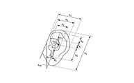
- FIG. 3 is a front view of the left ear for explaining the pinna shapes x 1 to x 8 and x 10 to x 13 of the listener. It is a sectional view seen from the lower side of Fig. 5A the left ear in order to explain the pinna shape x 9 of the listener.
- FIG. 9 is a diagram showing names of measurement sites corresponding to the pinna shapes x 1 to x 13 of the listener. It is a figure for explaining other examples of a pinna shape of a listener acquired by a pinna shape acquisition part of a head-related transfer function generation device of a 1st embodiment.
- FIG. 7A It is a front view of the left ear for demonstrating a listener's pinna shape (each part of a listener's pinna). It is a sectional view seen from the lower side in FIG. 7A to the left ear in order to explain the pinna shape (the measurement site) x 14 of the listener.
- Listener auricle shape definition of (measurement portion) x 1 ⁇ x 14 is a diagram for explaining the like. It is a figure which shows the amplitude value of the head-related transfer function which the head-related transfer function amplitude value generation part produced
- FIG. 5 is a flowchart illustrating an example of a process performed when the head-related transfer function generation device of the first embodiment generates an amplitude value of a head-related transfer function.
- the head generated using multiple regression coefficient data obtained by performing multiple regression analysis using the pinna shapes x 1 to x 13 as explanatory variables and the amplitude value of the (all sections) head-related transfer function as an objective variable. It is a figure showing the amplitude value of a partial transfer function. Head transfer function generated using multiple regression coefficient data obtained by performing multiple regression analysis using the pinna shapes x 1 to x 13 as explanatory variables and the amplitude value of the initial head transfer function as the objective variable
- FIG. 6 is a diagram showing amplitude values of the.
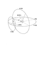
- FIG. 1 is a diagram for explaining the ear axis coordinate system.
- the ear axis coordinate system shown in FIG. 1 is defined as follows.
- the origin is the midpoint of a line connecting the left and right ear canal entrances of the listener.
- the horizontal plane is a plane connecting the right orbital point and the left and right tragus.
- the cross section (not shown) is a plane passing through the left and right ear canal entrances and orthogonal to the horizontal plane.
- the median plane is a plane orthogonal to both the horizontal plane and the transverse section (a plane that bisects the listener to the left and right).
- the sound source direction is represented by a lateral angle ⁇ and a rising angle ⁇ .
- the lateral angle ⁇ is the complementary angle of an angle formed by a straight line connecting the sound source (the portion indicated by a black circle “ ⁇ ” in FIG. 1) and the origin with the ear axis (a straight line passing through the left and right external auditory canal entrances).
- the rising angle ⁇ is an elevation angle in a sagittal plane passing through the sound source.
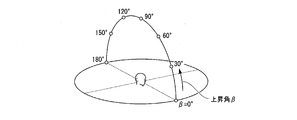
- FIG. 2A is a diagram showing the amplitude characteristics of the head-related transfer functions measured from the front to the rear in the median plane of the upper hemisphere at intervals of 30 °.
- FIG. 2A shows a sound source whose rise angle ⁇ in the median plane is 0 [°], a sound source whose rise angle ⁇ in the median plane is 30 [°], and a rise angle ⁇ in the median plane of 60 [°].
- ° a sound source with a rise angle ⁇ in the median plane of 90 °
- a sound source with a rise angle ⁇ in the median plane of 120 ° and a rise angle ⁇ in the median plane of 150 °.
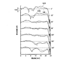
- FIG. 2B shows the amplitude characteristic of the head-related transfer function at the right ear (solid line) and the amplitude characteristic of the head-related transfer function at the left ear (dotted line) for a sound source having an elevation angle ⁇ of 0 [°] in the median plane.
- FIG. 2B shows the amplitude characteristics of the head-related transfer function at the right ear (solid line) and the amplitude characteristics of the head-related transfer function at the left ear (solid line) for a sound source whose elevation angle ⁇ in the median plane is 0 [°].
- the amplitude characteristic of the head-related transfer function at the right ear (solid line) and the amplitude characteristic of the head-related transfer function at the left ear (dotted line) for a sound source with a rising angle ⁇ of 30 [°] in the median plane The amplitude characteristic of the head-related transfer function at the right ear (solid line) and the amplitude characteristic of the head-related transfer function at the left ear (dotted line) for a sound source having a rising angle ⁇ of 60 [°] in the median plane
- the amplitude characteristic of the head-related transfer function at the right ear (solid line) and the amplitude characteristic of the head-related transfer function at the left ear (dotted line) for a sound source with a rising angle ⁇ of 90 [°] and the rising angle ⁇ in the median plane are The amplitude characteristic of the head-related transfer function at the right ear (solid line) and the amplitude characteristic of the head-related transfer function at the left ear (dotted line) for a sound source of
- the vertical axis in FIG. 2B indicates the relative amplitude [dB], and the horizontal axis in FIG. 2B indicates the frequency [kHz].
- the head-related transfer function differs depending on the incident direction of the sound wave. This is because the head shape and the pinna shape of the listener are asymmetrical in any of the front, rear, left, right, up, and down directions. The listener perceives the direction of the sound using the incident direction dependency as a clue.
- the listener perceives a sound image in that direction. That is, for example, when reproducing the amplitude characteristic (solid line) of the head-related transfer function at the right ear for the sound source whose rising angle ⁇ in the median plane shown in FIG. 2B is 0 [°], it has the amplitude characteristic of the head-related transfer function.
- the listener perceives the sound image in the direction in which the elevation angle ⁇ in the median plane is 0 [°].
- the sound waves emitted from the sound source reach the eardrum of the listener, the listener has various perceptions. The whole of what the listener perceives with sound waves is called a sound image.
- a sound source is a physical entity, while a sound image is a psychological entity caused by a perceptual phenomenon.
- a sound image has a temporal property (such as a feeling of reverberation, a sense of rhythm, and a sense of persistence), a spatial property (such as a sense of direction, a sense of distance, and a sense of spaciousness) and a qualitative property (such as a size, a height, and a tone).
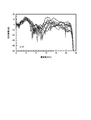
- FIG. 3 is a diagram for explaining individual differences in head-related transfer functions. More specifically, FIG. 3 shows the amplitude characteristics of the head-related transfer function for a sound source in the direction of 0 [°] in the median plane of 10 Japanese people. The vertical axis in FIG. 3 indicates the relative amplitude [dB], and the horizontal axis in FIG.
- the inventor's earnest research has confirmed that when a head-related transfer function of another person is reproduced, an erroneous determination in the front-back and up-down directions (an erroneous determination in the median plane) by the listener occurs.
- the front / back misjudgment is a phenomenon in which the front and rear of the target sound source direction and the perceived sound image direction are reversed.
- the inventor's earnest research has confirmed that when a head-related transfer function of another person is reproduced, a localization in the listener (a phenomenon in which the listener perceives a sound image in the head) occurs. I have.
- Convention three-dimensional sound systems and sound VR systems are effective only for specific listeners, and The biggest reason for the lack of widespread use is that individual differences in head related transfer functions have not been overcome.
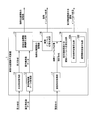
- FIG. 4 is a diagram illustrating an example of an outline of the head-related transfer function generation device 1 according to the first embodiment.
- the head-related transfer function generation device 1 includes an auricle shape acquisition unit 11, a multiple regression coefficient data acquisition unit 12, and a head-related transfer function amplitude value generation unit 13.
- the pinna shape acquisition unit 11 acquires the pinna shapes x 1 to x 13 (see FIGS. 5A to 5C) of the listener.
- FIGS. 5A to 5C show the shape of the pinna of the listener (measured value of each measurement site of the pinna of the listener) obtained by the pinna shape obtaining unit 11 of the head-related transfer function generation device 1 of the first embodiment. It is a figure for explaining an example.
- FIG. 5A is a front view of the left ear for describing the pinna shapes x 1 to x 8 and x 10 to x 13 of the listener.
- 5B is a sectional view viewed left ear from the lower side of FIG. 5A to explain the pinna shape x 9 of listener.
- FIG. 5C is a diagram showing names of measurement sites corresponding to the pinna shapes x 1 to x 13 of the listener.
- pinna shapes x 1 of the listener is a measure of the maximum ear width of the listener.
- Pinna shape x 2 of the listener is the measurement of the maximum width of the cavity of the concha of the listener.
- Pinna shape x 3 of the listener is the measurement of the maximum width of the listener's tragus and chopped marks.
- Pinna shape x 4 of the listener is the measurement of the maximum width of the helix of the listener.
- Pinna shape x 5 of the listener is the measured value of the maximum ear length of the listener.
- Pinna shape x 6 of the listener is the measurement of the length of the cavity of the concha of the listener.
- Pinna shape x 7 of the listener is the measurement of the length of a cavum Kaifune of the listener.
- Pinna shape x 8 of the listener is the height of the measurement values of the navicular fossa of the listener.
- the listener's pinna shape x 9 (see FIG. 5B) is a measurement of the depth of the concha of the listener.
- Pinna shape x 10 of the listener is the measured value of the slope of the via ear of the listener.
- Pinna shape x 11 of the listener is the length of the measurement values from the ear canal entrance of the listener to the triangular fossa.
- Pinna shape x 12 of the listener is the length of the measurement values from the ear canal entrance of the listener to the cavum Kaifune.
- Pinna shape x 13 of the listener is the length of the measurement values from the ear canal entrance of the listener to the cavum conchae.
- the pinna shapes x 1 to x 13 (see FIGS. 5A to 5C) of the listener acquired by the pinna shape acquisition unit 11 are measured from the pinna of the listener using calipers or the like. It was done.
- the ear type of the listener is first collected, and then the pinna shapes x 1 to x 13 of the listener are measured from the ear type of the listener using calipers or the like.
- the pinna shapes x 1 to x 13 of the listener are acquired by the pinna shape acquisition unit 11.
- an image of the listener's pinna is first captured, and then the listener's pinna shapes x 1 to x 13 are measured using the image. Next, the pinna shapes x 1 to x 13 of the listener are acquired by the pinna shape acquisition unit 11.
- FIG. 6 is another example of the auricle shape of the listener (measured value of each measurement site of the auricle of the listener) acquired by the auricle shape acquisition unit 11 of the head-related transfer function generation device 1 of the first embodiment.
- FIG. Listener pinna shape x 1 ⁇ x 8, x 10 in in FIG. 6 is similar to the pinna shape x 1 ⁇ x 8, x 10 of the listener in FIGS. 5A ⁇ FIG 5C.
- the pinna shape obtaining section 11, ear shape x 1 ⁇ x 13 of a listener as shown in FIGS. 5A ⁇ FIG. 5C is obtained.
- the pinna shape acquisition unit 11 uses the pinna shapes x 1 to x 8 and x 10 of the listener shown in FIG. 6 and the pinna shape x of the listener shown in FIG. 5B. 9 is obtained.
- the head-related transfer function generating apparatus 1 is configured to acquire the listener's pinna shape x 1 to x 8 and x 10 shown in FIG. 6 and the listener's pinna shape x 9 shown in FIG. 5B.
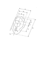
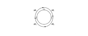
- FIGS. 7A to 7C show the shape of the listener's pinna (measured values of each measurement site of the listener's pinna) acquired by the pinna shape acquisition unit 11 of the head-related transfer function generation device 1 of the first embodiment. It is a figure for explaining another example. Specifically, FIG. 7A is a front view of the left ear for explaining the shape of the pinna of the listener (each part of the pinna of the listener). Figure 7B is a cross-sectional view of the left ear from the lower side of FIG. 7A to explain the pinna shape (the measurement site) x 14 of the listener. FIG. 7C is a diagram for explaining the definitions of the auricle shapes (measurement sites) x 1 to x 14 of the listener.
- portions C 1 is the inner boundary of the helix.
- Site C 2 are paired wheels.
- Site C 3 is outside the boundary line of the concha.
- Site p 0 is the origin (the ear canal entrance).
- Site p 1 is a straight line and the intersection of site C 1 rising angle 120 °.
- Site p 2 is a straight line and the intersection of site C 1 rising angle 150 °.
- Site p 3 is linear and the intersection portion C 1 of the rising angle 180 °.
- Sites p 4 is the intersection of the straight line and part C 2 rising angle 120 °.
- Site p 5 is the intersection of the straight line and part C 2 rising angle 150 °.
- Site p 6 is the intersection of the straight line and part C 2 rising angle 180 °.
- Site p 7 is the intersection of the straight line and part C 3 of the rising angle 120 °.
- Site p 8 is the intersection of the straight line and part C 3 of the rising angle 150 °.
- Site p 9 is the intersection of the straight line and part C 3 of the rising angle 180 °.
- Site p 10 is the intersection of the straight line and part C 3 of the rising angle 210 °.
- Site p 11 is the intersection of the straight line and part C 3 of the rising angle 240 °.
- Site p 12 is the intersection of the straight line and part C 3 of the rising angle 270 °.
- Listener pinna shape (measurement portion) x 1 is the length of the portion p 1 from the site p 0.
- Listener pinna shape (measurement portion) x 2 is the length of the portion p 2 from the site p 0.
- Listener pinna shape (the measurement site) x 3 is the length of the portion p 3 from the site p 0.
- Listener pinna shape (the measurement site) x 4 is the length of the portion p 4 from the site p 0.
- Listener pinna shape (the measurement site) x 5 is the length of the portion p 5 from the site p 0.
- Listener pinna shape (measurement portion) x 6 is the length of the portion p 6 from the site p 0.
- Pinna shape (the measurement site) x 7 of the listener is the length of the portion p 7 from the site p 0.
- Pinna shape (the measurement site) x 8 of the listener is the length of the portion p 8 from the site p 0.
- Listener pinna shape (the measurement site) x 9 is the length of the portion p 9 from the site p 0.
- Pinna shape (the measurement site) x 10 of the listener is the length of the portion p 10 from site p 0.
- Pinna shape (the measurement site) x 11 of the listener is the length of the portion p 11 from site p 0.
- Listener pinna shape (the measurement site) x 12 is the length of the portion p 12 from site p 0.
- Pinna shape x 13 of the listener is the measured value of the slope of the via ear of the listener.
- the listener's pinna shape x 14 is a measurement of the depth of the concha of the listener.
- the pinna shape acquiring unit 11 acquires the pinna shapes x 1 to x 14 of the listener shown in FIGS. 7A to 7C.
- the head-related transfer function generating apparatus 1 from which the auricle shapes x 1 to x 14 of the listener shown in FIGS. 7A to 7C are acquired can also be used for the listener shown in FIGS. 5A to 5C. It has been confirmed that a highly accurate head-related transfer function can be generated as in the head-related transfer function generating device 1 from which the pinna shapes x 1 to x 13 are acquired.
- the multiple regression coefficient data acquisition unit 12 acquires multiple regression coefficient data stored in, for example, a multiple regression coefficient database (not shown).
- the multiple regression coefficient data indicates that each frequency (for example, the direction in which the elevation angle ⁇ in the median plane shown in FIG. 2A is 0 [°], the direction of 30 [°], etc.) is 0 [kHz shown in FIG. ] To 24 [kHz] at 93.75 [Hz] intervals, the pinna shapes x 1 to x 13 (see FIGS. 5A to 5C) are used as explanatory variables, and the HRTF or the head-related transfer function is used.
- the data is a multiple regression coefficient obtained by performing multiple regression analysis using the amplitude value of the initial head-related transfer function as a target variable.
- the human perceives the left-right direction and the front-back and up-down directions using the interaural difference and the first notch N1 and the second notch N2 included in the head-related transfer function as clues. Therefore, if these cues are extracted or calculated from the head-related transfer functions and processed appropriately, three-dimensional sound image control becomes possible.
- the first notch N1 and the second notch N2 may not be clear depending on the listener and the sound source direction, and a method for easily and surely detecting the first notch N1 and the second notch N2 is required. .
- the head-related transfer function is generally affected by the pinna, the head, and the torso, but it is known that the first notch N1 and the second notch N2 are strongly affected by the pinna. ing.
- the present inventors filled each part of the pinna with clay, measured the head-related transfer function in the median plane and performed a sound image localization experiment, and filled the concha with the first notch N1 and the first notch N1. It has been found that the two notches N2 have disappeared and the sound image localization accuracy has significantly deteriorated.
- the present inventors have conducted intensive research to extract a part of the head impulse response by changing the cut-out time window length, and observed the appearance process of the first notch N1 and the second notch N2. As a result, the present inventors have found that the first notch N1 and the second notch N2 can be clearly detected by cutting out and analyzing about the initial 1 ms of the head impulse response. This is presumably because the response from the head or torso arrived, that is, only the response of the pinna was observed. About 1 ms of the initial head impulse response is the initial head impulse response, and the initial head impulse response obtained by Fourier transforming the initial head impulse response is the initial head related transfer function in the present invention.
- the head-related transfer function amplitude value generation unit 13 compares the pinna shapes x 1 to x 13 (see FIGS. 5A to 5C) of the listener with the pinna shape acquired by the pinna shape acquisition unit 11. Based on the multiple regression coefficient data acquired by the regression coefficient data acquisition unit 12, the amplitude value of the head-related transfer function at each frequency in each direction is calculated. More specifically, the head-related transfer function amplitude value generation unit 13 calculates each pinna shape x i (s) of the listener s and a multiple regression coefficient a i ( ⁇ , f) ( ⁇ is a rising angle, f is a frequency). Then, the amplitude value L (s, ⁇ , f) of the head-related transfer function of each frequency in each direction is calculated based on the following Expression 1.
- L (s, ⁇ , f) the amplitude value of the head-related transfer function of each frequency in each direction using the pinna shapes x 1 to x 13 shown in FIGS. 5A to 5C.
- n the value of n is “13”.
- ". b ( ⁇ , f) is a constant term.
- FIG. 8 is a diagram illustrating the amplitude value of the head-related transfer function generated by the head-related transfer function amplitude value generation unit 13.
- the vertical axis of FIG. 8 indicates the relative amplitude [dB], and the horizontal axis of FIG. 8 indicates the frequency [Hz].
- the solid line indicates the pinna shapes x 1 to x 13 of the listener s (see FIGS. 5A to 5C) and the pinna shapes x 1 to x 13 at each frequency in each direction.
- the amplitude value L (s, ⁇ , f) of the head-related transfer function generated (calculated) by the transfer function amplitude value generation unit 13 is shown.
- the dotted lines indicate the pinna shapes x 1 to x 13 (see FIGS. 5A to 5C) of the listener s and the pinna shapes x 1 to x 13 as explanatory variables at each frequency in each direction.
- the head-related transfer function amplitude value generation unit 13 Shows the amplitude value L (s, ⁇ , f) of the head-related transfer function generated (calculated).
- the “initial head-related transfer function” in which the amplitude value is set as the target variable is obtained by cutting out about 1 ms of the initial head impulse response as the initial head impulse response, This is a Fourier transform of the impulse response.
- the “head-related transfer function” in which the amplitude value is used as the target variable is obtained by cutting out the entire head impulse response (5.3 ms) as a head impulse response and performing a Fourier transform on the head impulse response.
- FIG. 9 is a flowchart for explaining an example of processing executed when the head-related transfer function generation device 1 of the first embodiment generates an amplitude value L (s, ⁇ , f) of a head-related transfer function. .
- step S1 the pinna shape x 1 to x 13 of the listener s (see FIGS. 5A to 5C) or the pinna shape of the listener s by any of the methods described above.
- x 1 to x 8 and x 10 see FIG. 6
- the pinna shape x 9 of the listener s see FIG. 5B
- the pinna shape x 1 to x 14 of the listener s see FIGS.
- step S2 the pinna shape acquisition unit 11 sets the pinna shapes x 1 to x 13 of the listener s measured in step S1, or the pinna shapes x 1 to x 10 of the listener s, or The pinna shapes x 1 to x 14 of the listener s are obtained. Also, in step S3, for example, the auricle shapes x 1 to x 13 , or the auricle shapes x 1 to x 10 , or the auricle shape at each frequency in each direction by a multiple regression coefficient data generation unit (not shown).
- a multiple regression coefficient a obtained by performing a multiple regression analysis using the intermediary shapes x 1 to x 14 as explanatory variables and the amplitude value of the head-related transfer function or the initial head-related transfer function as the objective variable is converted into data.
- Certain multiple regression coefficient data is generated.
- step S4 the multiple regression coefficient data generated in step S3 is stored in, for example, a multiple regression coefficient database (not shown).
- step S5 the multiple regression coefficient data acquisition unit 12 acquires multiple regression coefficient data stored in the multiple regression coefficient database.
- step S6 the pinna shapes x 1 to x 13 of the listener s obtained in step S2, the pinna shapes x 1 to x 10 of the listener s, or the pinna shape x of the listener s and 1 ⁇ x 14, and multiple regression coefficient data obtained in step S5, on the basis of the equation 1 described above, the HRTF amplitude value generator 13, the amplitude of the head-related transfer function of the frequency in each direction
- the value L (s, ⁇ , f) is calculated (generated).
- the head-related transfer function generation device 1 of the first embodiment the head-related transfer function of the listener is not actually measured, but the pinna shape of the listener and the multiple regression coefficient data prepared in advance Then, the head-related transfer function amplitude value generation unit 13 calculates the amplitude value L (s, ⁇ , f) of the head-related transfer function at each frequency in each direction.
- the inventor of the present invention has earnestly studied that it is possible to calculate the amplitude value L (s, ⁇ , f) of the head-related transfer function with high accuracy equivalent to the amplitude value of the head-related transfer function of the listener actually measured. I found it.
- FIG. 10A and 10B are diagrams showing a comparison between the actually measured amplitude value of the head-related transfer function of the listener and the amplitude value of the head-related transfer function generated by the head-related transfer function generation device 1. is there.
- FIG. 10A is generated using multiple regression coefficient data obtained by performing multiple regression analysis using the pinna shapes x 1 to x 13 as explanatory variables and (all sections) the amplitude value of the head-related transfer function as an objective variable.
- FIG. 9 is a diagram showing the amplitude value of the head-related transfer function obtained. In detail, FIG.
- FIG. 10A shows the amplitude value (solid line) of the head-related transfer function actually measured for the sound source whose rising angle ⁇ in the median plane is 0 [°] and generated by the head-related transfer function generator 1.
- the head-related transfer function dotted line
- FIG. 10B shows a head generated using multiple regression coefficient data obtained by performing multiple regression analysis using the pinna shapes x 1 to x 13 as explanatory variables and using the amplitude value of the initial head-related transfer function as an objective variable. It is a figure showing the amplitude value of a partial transfer function.
- FIG. 10B shows the amplitude value (solid line) of the head-related transfer function actually measured for a sound source having a rising angle ⁇ in the median plane of 0 [°] and the head-related transfer function generator 1 generates the amplitude value.
- the amplitude value (dotted line) of the head-related transfer function generated by the head-related transfer function generation device 1 An amplitude value (solid line) of the head-related transfer function actually measured for a sound source whose elevation angle ⁇ is 120 [°] and an amplitude value (dotted line) of the head-related transfer
- the head-related transfer function generation device 1 of the first embodiment it is not necessary to actually measure the head-related transfer function of the listener himself, and the listener actually measured A head transfer function (dotted line in FIGS. 10A and 10B) that is as accurate as the person's head transfer function (solid line in FIGS. 10A and 10B) can be easily obtained.
- the head-related transfer function generation device 1 of the first embodiment does not need to actually measure the head-related transfer function of the listener himself, does not need to listen to the listener himself, and generates the head-related transfer function.
- the head-related transfer function suitable for the listener can be generated without the device 1 having to have a multiple regression coefficient database.
- the head-related transfer function generator is used. By using the head-related transfer function obtained by (1), three-dimensional sound reproduction and sound VR can be realized with high accuracy.
- the head-related transfer function generator 1 of the second embodiment has the same configuration as the head-related transfer function generator 1 of the first embodiment described above, except for the points described below. Therefore, according to the head-related transfer function generation device 1 of the second embodiment, the same effects as those of the head-related transfer function generation device 1 of the above-described first embodiment can be obtained except for the points described below.
- FIG. 11 is a diagram illustrating an example of an outline of the head-related transfer function generation device 1 according to the second embodiment.
- the head-related transfer function generation device 1 similarly to the example illustrated in FIG. 4, the head-related transfer function generation device 1 includes an auricle shape acquisition unit 11, a multiple regression coefficient data acquisition unit 12, and a head-related transfer function amplitude value generation unit. 13 is provided.
- the head-related transfer function generation device 1 further includes a head impulse response generation unit 14.
- the head impulse response generator 14 performs an inverse Fourier transform on the amplitude value of the head-related transfer function of each frequency in each direction generated by the head-related transfer function amplitude value generator 13, thereby obtaining a head impulse response in each direction.
- the phase of each frequency is assumed to be, for example, a minimum phase system. Since the head-related transfer function generator 1 of the second embodiment includes the head impulse response generator 14, the head-related transfer function is as accurate as the actually measured head-related transfer function of the listener. Not only can the function be easily obtained, but it is not necessary to actually measure both the listener's own head impulse response and the listener's head-related transfer function. , A head impulse response with high accuracy equivalent to that of the head impulse response can be easily obtained.
- the head-related transfer function generator 1 of the third embodiment has the same configuration as the head-related transfer function generator 1 of the above-described second embodiment, except for the points described below. Therefore, according to the head-related transfer function generation device 1 of the third embodiment, the same effects as those of the head-related transfer function generation device 1 of the above-described second embodiment can be obtained, except for the following points.
- FIG. 12 is a diagram illustrating an example of an outline of the head-related transfer function generation device 1 according to the third embodiment.
- the head-related transfer function generation device 1 similarly to the example illustrated in FIG. 11, the head-related transfer function generation device 1 includes an auricle shape acquisition unit 11, a multiple regression coefficient data acquisition unit 12, and a head-related transfer function amplitude value generation unit. 13 and a head impulse response generator 14.
- the head-related transfer function generation device 1 further includes a multiple regression coefficient database 15.
- the multiple regression coefficient database 15 stores multiple regression coefficient data generated by, for example, a multiple regression coefficient data generation unit (not shown) provided outside the head-related transfer function generation device 1.
- the head-related transfer function generator 1 of the third embodiment is provided with the multiple regression coefficient database 15, it accesses a multiple regression coefficient database (not shown) provided outside the head-related transfer function generator 1. Without having to perform the measurement of the head-related transfer function of the listener itself, and easily obtain a head-related transfer function that is as accurate as the actually measured head-related transfer function of the listener. be able to.
- the head-related transfer function generator 1 of the fourth embodiment has the same configuration as the head-related transfer function generator 1 of the third embodiment described above, except for the points described below. Therefore, according to the head-related transfer function generation device 1 of the fourth embodiment, the same effects as those of the head-related transfer function generation device 1 of the above-described third embodiment can be obtained, except for the following points.
- FIG. 13 is a diagram illustrating an example of an outline of the head-related transfer function generation device 1 according to the fourth embodiment.
- the head-related transfer function generation device 1 includes an auricle shape acquisition unit 11, a multiple regression coefficient data acquisition unit 12, and a head-related transfer function amplitude value generation unit. 13, a head impulse response generator 14, and a multiple regression coefficient database 15.
- the head-related transfer function generation device 1 further includes a multiple regression coefficient data generation unit 16.
- the multiple regression coefficient data generation unit 16 uses the pinna shapes x 1 to x 13 , the pinna shapes x 1 to x 10 , or the pinna shapes x 1 to x 14 as explanatory variables at each frequency in each direction. Then, multiple regression coefficient data, which is obtained by converting a multiple regression coefficient a obtained by performing multiple regression analysis using the amplitude value of the head-related transfer function or the initial head-related transfer function as a target variable, is generated.
- the multiple regression coefficient data generated by the multiple regression coefficient data generator 16 is stored in the multiple regression coefficient database 15.
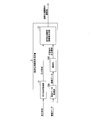
- the head-related transfer function generation device 1 of the fifth embodiment has substantially the same configuration as the head-related transfer function generation device 1 of the first embodiment described above, except for the points described below. Therefore, according to the head-related transfer function generation device 1 of the fifth embodiment, the same effects as those of the head-related transfer function generation device 1 of the above-described first embodiment can be obtained, except for the following points.
- FIG. 14 is a diagram illustrating an example of an outline of the head-related transfer function generation device 1 according to the fifth embodiment.
- the head-related transfer function generating device 1 includes an auricle shape obtaining unit 11, a multiple regression coefficient data obtaining unit 12, a head-related transfer function amplitude value generating unit 13, and a head impulse response generating unit 14, a head shape acquisition unit 17, and a head impulse response generation unit 18 with a binaural time difference.
- the pinna shape acquisition unit 11 is configured in the same manner as the pinna shape acquisition unit 11 shown in FIG. 4, and the pinna shapes x 1 to x 13 (see FIGS.
- the multiple regression coefficient data acquisition unit 12 is configured similarly to the multiple regression coefficient data acquisition unit 12 illustrated in FIG. 4 and acquires multiple regression coefficient data stored in, for example, a multiple regression coefficient database (not shown). I do.
- the multiple regression coefficient data indicates that each frequency (for example, the direction in which the elevation angle ⁇ in the median plane shown in FIG. 2A is 0 [°], the direction of 30 [°], etc.) is 0 [kHz shown in FIG.
- the pinna shapes x 1 to x 13 (see FIGS. 5A to 5C) or the pinna shapes x 1 to x 13 10 ) or multiple regression obtained by performing multiple regression analysis using the pinna shapes x 1 to x 14 (see FIGS. 7A to 7C) as explanatory variables and the amplitude value of the head-related transfer function as the objective variable. It is a data of coefficients.
- the head-related transfer function amplitude value generation unit 13 is configured similarly to the head-related transfer function amplitude value generation unit 13 illustrated in FIG. 4, and includes a pinna shape x i (s) of the listener s and a multiple regression coefficient.
- the amplitude value L (s, ⁇ , f) of the head-related transfer function at each frequency in each direction is calculated. calculate.
- the head impulse response generator 14 is configured in the same manner as the head impulse response generator 14 shown in FIG. 11, and transmits the head transfer of each frequency in each direction generated by the head transfer function amplitude value generator 13.
- the head impulse response in each direction is calculated by performing an inverse Fourier transform on the amplitude value of the function.
- the phase of each frequency is assumed to be, for example, a minimum phase system.
- the head shape acquisition unit 17 acquires the listener's head shapes p1 to p7 (see FIGS. 15A to 15C).
- FIGS. 15A to 15C show the listener's head shape (measurement of the listener's head and each measurement site around it) acquired by the head shape acquisition unit 17 of the head-related transfer function generation device 1 of the fifth embodiment.
- FIG. 9 is a diagram for explaining an example of a value.
- FIG. 15A is a front view of the listener for explaining the listener's head shape p1, p6 l, p6 r, p7.
- FIG. 15B is a diagram showing the listener's left side head for explaining the listener's head shapes p2 and p3.
- 15C is a diagram illustrating the top of the listener's head for describing the listener's head shapes p4 l , p4 r , p5 l , and p5 r .
- 15A to 15C the suffix “l” indicates the left ear, and the suffix “r” indicates the left ear.
- the head shapes p1 to p7 (see FIGS. 15A to 15C) of the listener acquired by the head shape acquiring unit 17 are transmitted from the listener's head and its surroundings to a tactile meter, a tape measure, or the like. It was measured using.
- an image of the listener's head and its surroundings is taken, and then the listener's head shapes p1 to p7 are measured using the image.
- the head shapes p1 to p7 of the listener are acquired by the head shape acquiring unit 17.
- the head impulse response generation unit 18 with the interaural time difference includes an interaural time difference calculation unit 18A and an interaural time difference addition unit 18B.
- the interaural time difference calculation unit 18A calculates an interaural time difference ITD (interaural time difference).
- the interaural time difference calculating unit 18A calculates the head shape p i (s) (p1 to p7) of the listener s acquired by the head shape acquiring unit 17 (see FIGS. 15A to 15C),
- the interaural time difference ITD (s, ⁇ ) of the listener s is calculated based on the multiple regression coefficient a i ( ⁇ ) and the following equation 2.
- Equation 2 ⁇ [°] is a lateral angle (see FIG. 1).
- ITD interaural time difference
- the interaural time difference calculation unit 18A calculates the head shape p1 (interaural distance D) of the listener s acquired by the head shape acquisition unit 17, the sound velocity c, and the following equation (3). , The binaural time difference ITD (s, ⁇ ) is calculated.
- the interaural time difference adding unit 18B adds the listener s calculated by the interaural time difference calculating unit 18A to the head impulse response in each direction generated by the head impulse response generating unit 14. Is added to the interaural time difference ITD (s, ⁇ ).
- the head-related transfer function generation device 1 of the fifth embodiment it is not necessary to actually measure the head-related transfer function of the listener, and the accuracy is as high as that of the actually measured head-related transfer function of the listener.
- the head related transfer function can be easily obtained, and the head impulse response of the listener himself added with the interaural time difference ITD (s, ⁇ ) of the listener himself can be obtained with high precision and ease.
- FIG. 16 is a diagram illustrating an example of an outline of the head-related transfer function generation device 1 according to the sixth embodiment.
- the head-related transfer function generation device 1 includes an auricle shape acquisition unit 11, a teacher data acquisition unit 19A, a learning unit 19B, and a head-related transfer function amplitude value generation unit 13. .
- the pinna shape acquisition unit 11 outputs the pinna shapes x 1 to x 13 (see FIGS. 5A to 5C) or the pinna shapes x 1 to x 10 of the listener or the pinna shapes x 1 to x 14. (See FIGS. 7A to 7C).
- the teacher data acquisition unit 19A acquires teacher data including the pinna shape of a predetermined listener and the amplitude value of the head-related transfer function of the predetermined listener.
- the learning unit 19B learns the correspondence between the pinna shape and the amplitude value of the head-related transfer function by using the teacher data acquired by the teacher data acquiring unit 19A.
- the learning unit 19B includes, for example, an NN (Neural Network) having an input layer, a hidden layer (hidden layer), and an output layer, and a DNN (Deep Neural Network) having an input layer, a plurality of hidden layers (hidden layers), and an output layer. And so on.
- the learning unit 19B outputs the correspondence between the pinna shape after learning and the amplitude value of the head-related transfer function to the head-related transfer function amplitude value generation unit 13.
- the head-related transfer function amplitude value generation unit 13 associates the pinna shape acquired by the pinna shape acquisition unit 11 with the pinna shape after learning output from the learning unit 19B and the amplitude value of the head-related transfer function. Based on the relationship, the amplitude value of the head-related transfer function of each frequency in each direction (see FIGS. 10A and 10B) is calculated.
- the head-related transfer function generation device 1 of the sixth embodiment similarly to the head-related transfer function generation device 1 of the first embodiment, it is not necessary to actually measure the head-related transfer function of the listener, and the measurement is actually performed. It is possible to easily obtain a highly accurate head-related transfer function equivalent to the measured head-related transfer function of the listener.
- an output signal y (t) at a certain time t is a product x ( ⁇ ) h (t) of an input signal x ( ⁇ ) at a time ⁇ and an impulse response at a time (t ⁇ ) calculated from ⁇ . ⁇ ) for all ⁇ .
- the output signal y (t) when the signal x (t) is input to the system of the impulse response h (t) is the sum of all the x ( ⁇ ) h (t ⁇ ) that reach the time t. It is represented by
- the convolution on the time axis is a multiplication of the sound source signal and the complex spectrum of the impulse response on the frequency axis. Compared to the amount of calculation on the time axis, the number is significantly reduced.
- the three-dimensional space characteristic of the original sound field can be reproduced in another space beyond time and space, or an arbitrary three-dimensional space characteristic can be obtained. Can be generated.
- the whole or a part of the function of each unit included in the head-related transfer function generation device 1 in the above-described embodiment is obtained by recording a program for realizing these functions on a computer-readable recording medium. May be realized by causing a computer system to read and execute the program recorded in the computer.
- the “computer system” includes an OS and hardware such as peripheral devices.
- the “computer-readable recording medium” refers to a portable medium such as a flexible disk, a magneto-optical disk, a ROM, and a CD-ROM, and a storage unit such as a hard disk built in a computer system.
- a “computer-readable recording medium” refers to a communication line for transmitting a program via a network such as the Internet or a communication line such as a telephone line, which dynamically holds the program for a short time.
- a program may include a program that holds a program for a certain period of time, such as a volatile memory in a computer system serving as a server or a client in that case.
- the above-mentioned program may be for realizing a part of the above-mentioned functions, or may be for realizing the above-mentioned functions in combination with a program already recorded in a computer system.
- SYMBOLS 1 Head-related transfer function generator, 11 ... Pinna shape acquisition part, 12 ... Multiple regression coefficient data acquisition part, 13 ... Head-related transfer function amplitude value generation part, 14 ... Head impulse response generation part, 15 ... Multiple regression Coefficient database, 16: multiple regression coefficient data generation unit, 17: head shape acquisition unit, 18: head impulse response generation unit with interaural time difference, 18A: interaural time difference calculation unit, 18B: interaural time difference addition Section, 19A: teacher data acquisition section, 19B: learning section
Abstract
This device for generating a head-related transfer function is provided with: an auricle shape acquisition unit for acquiring the shape of an auricle of a listener; and a head-related transfer function amplitude value generating unit for calculating the amplitude value of a head-related transfer function of each frequency in each direction on the basis of the auricle shape acquired by the auricle shape acquisition unit and multiple regression coefficient data obtained by digitizing a multiple regression coefficient obtained by multiple regression analysis using the auricle shape as an explanatory variable and the amplitude value of the head-related transfer function or an initial head-related transfer function as an objective variable, or a correlation between the amplitude value of the head-related transfer function and the auricle shape after learning using training data is performed.
Description
本発明は、頭部伝達関数生成装置、頭部伝達関数生成方法およびプログラムに関する。
本願は、2018年7月3日に、日本に出願された特願2018-127146号に基づき優先権を主張し、その内容をここに援用する。 The present invention relates to a head-related transfer function generation device, a head-related transfer function generation method, and a program.
Priority is claimed on Japanese Patent Application No. 2018-127146, filed on July 3, 2018, the content of which is incorporated herein by reference.
従来、自分自身の頭部伝達関数に近似する頭部伝達関数を選択する頭部伝達関数選択装置が知られている(例えば特許文献1参照)。特許文献1に記載された頭部伝達関数選択装置では、スピーカが所定の音声を発生している状態で、受聴者の耳に装着されたマイクロホンが収音した音声信号に基づいて、測定部が受聴者の頭部インパルス応答を取得する。次いで、特徴量抽出部が頭部インパルス応答に対応する周波数特性の特徴量を抽出する。次いで、特性選択部が、特徴量抽出部によって抽出された特徴量に基づいて、複数の人のそれぞれの頭部伝達関数と頭部伝達関数の特徴量とを対応付けたデータベースからいずれかの頭部伝達関数を選択する。
Conventionally, a head-related transfer function selection device that selects a head-related transfer function that is similar to its own head-related transfer function is known (for example, see Patent Document 1). In the head-related transfer function selection device described in Patent Literature 1, in a state where a speaker is generating a predetermined sound, a measurement unit is configured to perform measurement based on a sound signal picked up by a microphone mounted on a listener's ear. Obtain the listener's head impulse response. Next, the feature value extraction unit extracts a feature value of a frequency characteristic corresponding to the head impulse response. Next, based on the feature amount extracted by the feature amount extraction unit, the characteristic selection unit selects one of the heads from a database in which the head-related transfer functions of the plurality of persons are associated with the feature amounts of the head-related transfer functions. Select the partial transfer function.
上述したように、特許文献1に記載された技術では、データベースに記憶されている複数の頭部伝達関数のうちのいずれかが選択されるにすぎない。そのため、受聴者本人の頭部伝達関数に適合する(目標の方向に聴こえる)頭部伝達関数がデータベースに記憶されていない場合には、当然のことながら、受聴者本人の頭部伝達関数に適合する頭部伝達関数を得ることができない。
受聴者本人の頭部伝達関数の測定を実際に行うことによって受聴者本人の頭部伝達関数を得る場合であっても、例えば住宅、オフィスなどで頭部伝達関数の測定が行われる場合には、不要な反射や騒音が混入するため、受聴者本人の頭部伝達関数に適合する頭部伝達関数(高精度な受聴者本人の頭部伝達関数)を得ることができない。高精度な受聴者本人の頭部伝達関数を得るためには、反射のない無響室において受聴者本人の頭部伝達関数の測定を行う必要がある。
無響室において頭部伝達関数の測定が行われる場合であっても、音響の専門知識の無い一般ユーザが測定を行う場合には、当然のことながら、高精度な受聴者本人の頭部伝達関数を得ることはできない。 As described above, in the technique described inPatent Document 1, only one of the plurality of head-related transfer functions stored in the database is selected. Therefore, if the head-related transfer function that matches the listener's own head-related transfer function (sounds in the direction of the target) is not stored in the database, it naturally matches the listener's own head-related transfer function. Head transfer function cannot be obtained.
Even when the head-related transfer function of the listener is actually obtained by actually measuring the head-related transfer function of the listener, for example, when the head-related transfer function is measured in a house or office, etc. Since unnecessary reflection and noise are mixed, a head-related transfer function (a highly accurate head-related transfer function of the listener) that matches the head-related transfer function of the listener cannot be obtained. In order to obtain a highly accurate head-related transfer function of the listener, it is necessary to measure the head-related transfer function of the listener in an anechoic room without reflection.
Even when the head-related transfer function is measured in an anechoic room, if a general user who does not have expertise in acoustics performs the measurement, naturally, the listener's head transfer can be performed with high accuracy. You cannot get a function.
受聴者本人の頭部伝達関数の測定を実際に行うことによって受聴者本人の頭部伝達関数を得る場合であっても、例えば住宅、オフィスなどで頭部伝達関数の測定が行われる場合には、不要な反射や騒音が混入するため、受聴者本人の頭部伝達関数に適合する頭部伝達関数(高精度な受聴者本人の頭部伝達関数)を得ることができない。高精度な受聴者本人の頭部伝達関数を得るためには、反射のない無響室において受聴者本人の頭部伝達関数の測定を行う必要がある。
無響室において頭部伝達関数の測定が行われる場合であっても、音響の専門知識の無い一般ユーザが測定を行う場合には、当然のことながら、高精度な受聴者本人の頭部伝達関数を得ることはできない。 As described above, in the technique described in
Even when the head-related transfer function of the listener is actually obtained by actually measuring the head-related transfer function of the listener, for example, when the head-related transfer function is measured in a house or office, etc. Since unnecessary reflection and noise are mixed, a head-related transfer function (a highly accurate head-related transfer function of the listener) that matches the head-related transfer function of the listener cannot be obtained. In order to obtain a highly accurate head-related transfer function of the listener, it is necessary to measure the head-related transfer function of the listener in an anechoic room without reflection.
Even when the head-related transfer function is measured in an anechoic room, if a general user who does not have expertise in acoustics performs the measurement, naturally, the listener's head transfer can be performed with high accuracy. You cannot get a function.
上述した問題点に鑑み、本発明は、受聴者本人の頭部伝達関数の測定を実際に行う必要なく、実際に測定された受聴者本人の頭部伝達関数と同等に高精度な頭部伝達関数を容易に得ることができる頭部伝達関数生成装置、頭部伝達関数生成方法およびプログラムを提供することを目的とする。
In view of the above-mentioned problems, the present invention does not need to actually measure the head-related transfer function of the listener himself, and the head transfer function is as accurate as the actually measured head-related transfer function of the listener himself. An object of the present invention is to provide a head-related transfer function generation device, a head-related transfer function generation method, and a program that can easily obtain a function.
鋭意研究において、本発明者は、各方向の各周波数において、耳介形状を説明変数とし、頭部伝達関数もしくは初期頭部伝達関数の振幅値を目的変数とした重回帰分析を行うことによって得られた重回帰係数をデータ化したものと、受聴者の耳介形状とを用いて、各方向の各周波数の頭部伝達関数の振幅値を算出することによって、受聴者本人の頭部伝達関数の測定を実際に行う必要なく、実際に測定された受聴者本人の頭部伝達関数と同等に高精度な頭部伝達関数を生成できることを見い出したのである。
In earnest research, the present inventors obtained by performing multiple regression analysis using the pinna shape as an explanatory variable and the amplitude value of the head-related transfer function or initial head-related transfer function as the objective variable at each frequency in each direction. By using the data of the obtained multiple regression coefficients and the auricle shape of the listener, the amplitude value of the head-related transfer function of each frequency in each direction is calculated, and the head-related transfer function of the listener itself is calculated. It has been found that it is possible to generate a head-related transfer function that is as accurate as the actually-measured head-related transfer function of the listener without actually performing the measurement.
本発明の一態様は、受聴者の耳介形状を取得する耳介形状取得部と、前記耳介形状取得部によって取得された前記耳介形状と、各方向の各周波数において、前記耳介形状を説明変数とし、頭部伝達関数もしくは初期頭部伝達関数の振幅値を目的変数とした重回帰分析を行うことによって得られた重回帰係数をデータ化したものである重回帰係数データ、または、教師データを用いた学習が行われた後の耳介形状と頭部伝達関数の振幅値との対応関係とに基づいて、各方向の各周波数の頭部伝達関数の振幅値を算出する頭部伝達関数振幅値生成部とを備える、頭部伝達関数生成装置である。
One aspect of the present invention is an auricle shape acquisition unit that acquires an auricle shape of a listener, the auricle shape acquired by the auricle shape acquisition unit, and the auricle shape at each frequency in each direction. Multiple regression coefficient data that is obtained by converting multiple regression coefficients obtained by performing multiple regression analysis using the head-related transfer function or the amplitude value of the initial head-related transfer function as the objective variable, or A head that calculates the amplitude value of the head-related transfer function of each frequency in each direction based on the correspondence between the pinna shape after learning using the teacher data and the amplitude value of the head-related transfer function A head-related transfer function generation device including a transfer function amplitude value generation unit.
本発明の一態様の頭部伝達関数生成装置は、記憶されている前記重回帰係数データを取得する重回帰係数データ取得部を更に備え、前記頭部伝達関数振幅値生成部は、前記耳介形状取得部によって取得された前記耳介形状と、前記重回帰係数データ取得部によって取得された前記重回帰係数データとに基づいて、各方向の各周波数の頭部伝達関数の振幅値を算出してもよい。
The head-related transfer function generation device according to one aspect of the present invention further includes a multiple regression coefficient data acquisition unit that acquires the stored multiple regression coefficient data, wherein the head-related transfer function amplitude value generation unit includes the pinna Based on the pinna shape acquired by the shape acquisition unit and the multiple regression coefficient data acquired by the multiple regression coefficient data acquisition unit, calculate the amplitude value of the head-related transfer function of each frequency in each direction. You may.
本発明の一態様の頭部伝達関数生成装置は、前記頭部伝達関数振幅値生成部によって生成された各方向の各周波数の頭部伝達関数の振幅値を逆フーリエ変換することによって頭部インパルス応答を算出する頭部インパルス応答生成部を更に備えてもよい。
The head-related transfer function generation device according to one aspect of the present invention includes a head-related impulse by performing an inverse Fourier transform on the amplitude value of the head-related transfer function of each frequency in each direction generated by the head-related transfer function amplitude value generation unit. A head impulse response generator for calculating a response may be further provided.
本発明の一態様の頭部伝達関数生成装置は、前記重回帰係数データを記憶する重回帰係数データベースを更に備えてもよい。
The apparatus for generating a head related transfer function according to one aspect of the present invention may further include a multiple regression coefficient database storing the multiple regression coefficient data.
本発明の一態様の頭部伝達関数生成装置は、前記重回帰係数データを生成する重回帰係数データ生成部を更に備えてもよい。
The head-related transfer function generation device according to one aspect of the present invention may further include a multiple regression coefficient data generation unit that generates the multiple regression coefficient data.
本発明の一態様の頭部伝達関数生成装置は、前記受聴者の頭部形状を取得する頭部形状取得部と、前記頭部形状取得部によって取得された前記頭部形状に基づいて、前記受聴者の両耳間時間差を算出する両耳間時間差算出部と、前記両耳間時間差算出部によって算出された前記両耳間時間差を、前記頭部インパルス応答生成部によって算出された前記頭部インパルス応答に付加する両耳間時間差付加部とを更に備えてもよい。
The head-related transfer function generation device according to one aspect of the present invention, a head shape acquisition unit that acquires the head shape of the listener, based on the head shape acquired by the head shape acquisition unit, The interaural time difference calculation unit that calculates the interaural time difference of the listener, and the interaural time difference calculated by the interaural time difference calculation unit, the head calculated by the head impulse response generation unit The apparatus may further include a binaural time difference adding unit that adds the impulse response.
本発明の一態様の頭部伝達関数生成装置は、前記教師データを取得する教師データ取得部と、前記教師データ取得部によって取得された前記教師データを用いることによって、耳介形状と頭部伝達関数の振幅値との対応関係を学習する学習部とを更に備え、前記教師データは、所定の受聴者の耳介形状と前記所定の受聴者の頭部伝達関数の振幅値と含むものであり、前記頭部伝達関数振幅値生成部は、前記耳介形状取得部によって取得された前記耳介形状と、前記学習部による学習が行われた後の前記対応関係とに基づいて、各方向の各周波数の頭部伝達関数の振幅値を算出してもよい。
A head-related transfer function generation apparatus according to one aspect of the present invention includes a teacher data acquisition unit that acquires the teacher data, and the teacher data acquired by the teacher data acquisition unit. A learning unit that learns a correspondence relationship between the amplitude value of the function and the teacher data, wherein the teacher data includes an auricle shape of a predetermined listener and an amplitude value of a head-related transfer function of the predetermined listener. The head-related transfer function amplitude value generation unit, based on the pinna shape acquired by the pinna shape acquisition unit and the correspondence after learning by the learning unit, in each direction The amplitude value of the head-related transfer function at each frequency may be calculated.
本発明の一態様は、受聴者の耳介形状を取得する耳介形状取得ステップと、前記耳介形状取得ステップにおいて取得された前記耳介形状と、各方向の各周波数において、前記耳介形状を説明変数とし、頭部伝達関数もしくは初期頭部伝達関数の振幅値を目的変数とした重回帰分析を行うことによって得られた重回帰係数をデータ化したものである重回帰係数データ、または、教師データを用いた学習が行われた後の耳介形状と頭部伝達関数の振幅値との対応関係とに基づいて、各方向の各周波数の頭部伝達関数の振幅値を算出する頭部伝達関数振幅値生成ステップとを備える、頭部伝達関数生成方法である。
One aspect of the present invention is an auricle shape acquisition step of acquiring an auricle shape of a listener, the auricle shape acquired in the auricle shape acquisition step, and the auricle shape at each frequency in each direction. Multiple regression coefficient data that is obtained by converting multiple regression coefficients obtained by performing multiple regression analysis using the head-related transfer function or the amplitude value of the initial head-related transfer function as the objective variable, or A head that calculates the amplitude value of the head-related transfer function of each frequency in each direction based on the correspondence between the pinna shape after learning using the teacher data and the amplitude value of the head-related transfer function A head-related transfer function generation method, comprising a transfer function amplitude value generation step.
本発明の一態様は、コンピュータに、受聴者の耳介形状を取得する耳介形状取得ステップと、前記耳介形状取得ステップにおいて取得された前記耳介形状と、各方向の各周波数において、前記耳介形状を説明変数とし、頭部伝達関数もしくは初期頭部伝達関数の振幅値を目的変数とした重回帰分析を行うことによって得られた重回帰係数をデータ化したものである重回帰係数データ、または、教師データを用いた学習が行われた後の耳介形状と頭部伝達関数の振幅値との対応関係とに基づいて、各方向の各周波数の頭部伝達関数の振幅値を算出する頭部伝達関数振幅値生成ステップとを実行させるためのプログラムである。
One embodiment of the present invention provides a computer with an auricle shape acquisition step of acquiring an auricle shape of a listener, the auricle shape acquired in the auricle shape acquisition step, and at each frequency in each direction, Multiple regression coefficient data obtained by performing multiple regression analysis using the pinna shape as an explanatory variable and performing multiple regression analysis using the head-related transfer function or the initial head-related transfer function amplitude as the target variable Or, based on the correspondence between the pinna shape and the amplitude value of the head-related transfer function after learning using the teacher data is performed, the amplitude value of the head-related transfer function of each frequency in each direction is calculated. And a head-related transfer function amplitude value generating step.
本発明によれば、受聴者本人の頭部伝達関数の測定を実際に行う必要なく、実際に測定された受聴者本人の頭部伝達関数と同等に高精度な頭部伝達関数を容易に得ることができる頭部伝達関数生成装置、頭部伝達関数生成方法およびプログラムを提供することができる。
According to the present invention, it is not necessary to actually measure the head related transfer function of the listener itself, and a head transfer function with high accuracy equivalent to the actually measured head related transfer function of the listener itself can be easily obtained. A head-related transfer function generating apparatus, a head-related transfer function generating method, and a program can be provided.
本発明の頭部伝達関数生成装置、頭部伝達関数生成方法およびプログラムの実施形態の説明の前に、本発明の理解に必要な基礎的な項目について説明する。
音波は鼓膜に届く直前に頭や耳介あるいは胴体の影響を受ける。このような頭部周辺による入射音波の物理特性の変化を周波数領域で表現したものを頭部伝達関数(HRTF:head-related transfer function)という。頭部伝達関数を考える場合には、耳軸座標系が主に用いられる。 Before describing embodiments of the head-related transfer function generation device, the head-related transfer function generation method, and the program of the present invention, basic items necessary for understanding the present invention will be described.
Sound waves are affected by the head, pinna, or trunk just before reaching the eardrum. Such a change in the physical characteristics of the incident sound wave around the head in the frequency domain is called a head-related transfer function (HRTF). When considering the HRTF, the ear axis coordinate system is mainly used.
図1は耳軸座標系を説明するための図である。
図1に示す耳軸座標系は次のように定義される。原点は、受聴者の左右の外耳道入口を結ぶ線分の中点である。水平面は、右眼窩点と左右の耳珠を結ぶ平面である。横断面(図示せず)は左右の外耳道入口を通り、水平面に直交する面である。正中面は、水平面と横断面の両方に直交する面(受聴者を左右に2等分する面)である。
耳軸座標系では、音源方向を、側方角αと上昇角βとにより表す。側方角αは、音源(図1中の黒丸「●」で示す部分)と原点とを結ぶ直線が耳軸(左右の外耳道入口を通る直線)となす角の余角である。上昇角βは、音源を通る矢状面内における仰角である。 FIG. 1 is a diagram for explaining the ear axis coordinate system.
The ear axis coordinate system shown in FIG. 1 is defined as follows. The origin is the midpoint of a line connecting the left and right ear canal entrances of the listener. The horizontal plane is a plane connecting the right orbital point and the left and right tragus. The cross section (not shown) is a plane passing through the left and right ear canal entrances and orthogonal to the horizontal plane. The median plane is a plane orthogonal to both the horizontal plane and the transverse section (a plane that bisects the listener to the left and right).
In the ear axis coordinate system, the sound source direction is represented by a lateral angle α and a rising angle β. The lateral angle α is the complementary angle of an angle formed by a straight line connecting the sound source (the portion indicated by a black circle “●” in FIG. 1) and the origin with the ear axis (a straight line passing through the left and right external auditory canal entrances). The rising angle β is an elevation angle in a sagittal plane passing through the sound source.
図2Aは上半球正中面内の正面から後ろまでを30[°]間隔で測定した頭部伝達関数の振幅特性を示す図である。詳細には、図2Aは、正中面内の上昇角βが0[°]の音源と、正中面内の上昇角βが30[°]の音源と、正中面内の上昇角βが60[°]の音源と、正中面内の上昇角βが90[°]の音源と、正中面内の上昇角βが120[°]の音源と、正中面内の上昇角βが150[°]の音源と、正中面内の上昇角βが180[°]の音源とを黒丸「●」で示している。
図2Bは正中面内の上昇角βが0[°]の音源に対する右耳での頭部伝達関数の振幅特性(実線)および左耳での頭部伝達関数の振幅特性(点線)などを示す図である。詳細には、図2Bは、正中面内の上昇角βが0[°]の音源に対する右耳での頭部伝達関数の振幅特性(実線)および左耳での頭部伝達関数の振幅特性(点線)と、正中面内の上昇角βが30[°]の音源に対する右耳での頭部伝達関数の振幅特性(実線)および左耳での頭部伝達関数の振幅特性(点線)と、正中面内の上昇角βが60[°]の音源に対する右耳での頭部伝達関数の振幅特性(実線)および左耳での頭部伝達関数の振幅特性(点線)と、正中面内の上昇角βが90[°]の音源に対する右耳での頭部伝達関数の振幅特性(実線)および左耳での頭部伝達関数の振幅特性(点線)と、正中面内の上昇角βが120[°]の音源に対する右耳での頭部伝達関数の振幅特性(実線)および左耳での頭部伝達関数の振幅特性(点線)と、正中面内の上昇角βが150[°]の音源に対する右耳での頭部伝達関数の振幅特性(実線)および左耳での頭部伝達関数の振幅特性(点線)と、正中面内の上昇角βが180[°]の音源に対する右耳での頭部伝達関数の振幅特性(実線)および左耳での頭部伝達関数の振幅特性(点線)とを示している。図2Bの縦軸は相対振幅[dB]を示しており、図2Bの横軸は周波数[kHz]を示している。
図2Bに示すように、頭部伝達関数は、音波の入射方向により異なる。それは、受聴者の頭部形状や耳介形状が前後左右上下のいずれについても非対称であるからである。受聴者は、この入射方向依存性を手掛かりとして音の方向を知覚している。 FIG. 2A is a diagram showing the amplitude characteristics of the head-related transfer functions measured from the front to the rear in the median plane of the upper hemisphere at intervals of 30 °. In detail, FIG. 2A shows a sound source whose rise angle β in the median plane is 0 [°], a sound source whose rise angle β in the median plane is 30 [°], and a rise angle β in the median plane of 60 [°]. °), a sound source with a rise angle β in the median plane of 90 °, a sound source with a rise angle β in the median plane of 120 °, and a rise angle β in the median plane of 150 °. Are indicated by black circles and the sound source having an elevation angle β of 180 [°] in the median plane.
FIG. 2B shows the amplitude characteristic of the head-related transfer function at the right ear (solid line) and the amplitude characteristic of the head-related transfer function at the left ear (dotted line) for a sound source having an elevation angle β of 0 [°] in the median plane. FIG. Specifically, FIG. 2B shows the amplitude characteristics of the head-related transfer function at the right ear (solid line) and the amplitude characteristics of the head-related transfer function at the left ear (solid line) for a sound source whose elevation angle β in the median plane is 0 [°]. (Dotted line), the amplitude characteristic of the head-related transfer function at the right ear (solid line) and the amplitude characteristic of the head-related transfer function at the left ear (dotted line) for a sound source with a rising angle β of 30 [°] in the median plane, The amplitude characteristic of the head-related transfer function at the right ear (solid line) and the amplitude characteristic of the head-related transfer function at the left ear (dotted line) for a sound source having a rising angle β of 60 [°] in the median plane The amplitude characteristic of the head-related transfer function at the right ear (solid line) and the amplitude characteristic of the head-related transfer function at the left ear (dotted line) for a sound source with a rising angle β of 90 [°] and the rising angle β in the median plane are The amplitude characteristic of the head-related transfer function at the right ear (solid line) and the amplitude characteristic of the head-related transfer function at the left ear (dotted line) for a sound source of 120 [°] Amplitude characteristics of head-related transfer functions at the right ear (solid line) and head-related transfer functions at the left ear (dotted line) for a sound source with an in-plane rising angle β of 150 [°], and a rise in the median plane The amplitude characteristic of the head-related transfer function at the right ear (solid line) and the amplitude characteristic of the head-related transfer function at the left ear (dotted line) for a sound source with an angle β of 180 [°] are shown. The vertical axis in FIG. 2B indicates the relative amplitude [dB], and the horizontal axis in FIG. 2B indicates the frequency [kHz].
As shown in FIG. 2B, the head-related transfer function differs depending on the incident direction of the sound wave. This is because the head shape and the pinna shape of the listener are asymmetrical in any of the front, rear, left, right, up, and down directions. The listener perceives the direction of the sound using the incident direction dependency as a clue.
ある方向の受聴者本人の頭部伝達関数を再現すると、受聴者は、その方向に音像を知覚する。つまり、例えば図2Bに示す正中面内の上昇角βが0[°]の音源に対する右耳での頭部伝達関数の振幅特性(実線)を再現すると、その頭部伝達関数の振幅特性を有する受聴者は、正中面内の上昇角βが0[°]の方向に音像を知覚する。
音源から発せられた音波が受聴者の鼓膜に到達すると、受聴者には様々な知覚が生まれる。音波により受聴者が知覚したものの総体を音像という。音源は物理的な存在であるが、音像は知覚現象により生じる心理的な存在である。音像には、時間的性質(残響感、リズム感、持続感など)、空間的性質(方向感、距離感、広がり感など)、質的性質(大きさ、高さ、音色など)がある。 When the head-related transfer function of the listener in a certain direction is reproduced, the listener perceives a sound image in that direction. That is, for example, when reproducing the amplitude characteristic (solid line) of the head-related transfer function at the right ear for the sound source whose rising angle β in the median plane shown in FIG. 2B is 0 [°], it has the amplitude characteristic of the head-related transfer function. The listener perceives the sound image in the direction in which the elevation angle β in the median plane is 0 [°].
When the sound waves emitted from the sound source reach the eardrum of the listener, the listener has various perceptions. The whole of what the listener perceives with sound waves is called a sound image. A sound source is a physical entity, while a sound image is a psychological entity caused by a perceptual phenomenon. A sound image has a temporal property (such as a feeling of reverberation, a sense of rhythm, and a sense of persistence), a spatial property (such as a sense of direction, a sense of distance, and a sense of spaciousness) and a qualitative property (such as a size, a height, and a tone).
上述したように、ある方向の受聴者本人の頭部伝達関数を再現すると受聴者はその方向に音像を知覚するため、原理的には、様々な方向の頭部伝達関数を用いることにより、効果的な3次元音響システムや音のバーチャルリアリティ(VR)システムを実現できると考えられる。しかし、頭部伝達関数には、個人差が存在する。
図3は頭部伝達関数の個人差を説明するための図である。詳細には、図3は日本人10名の正中面内の上昇角βが0[°]の方向の音源に対する頭部伝達関数の振幅特性を示している。図3の縦軸は相対振幅[dB]を示しており、図3の横軸は周波数[kHz]を示している。
図3に示すように、4kHz程度までの周波数では頭部伝達関数の個人差が少ないものの、それ以上の周波数ではノッチやピークの周波数もレベル(振幅値)も受聴者によって大きく異なる。つまり、正中面内の上昇角βが0[°]の方向の音源に対する頭部伝達関数には、個人差が存在する。
図示しないが、正中面内の上昇角βが30[°]、60[°]、90[°]、120[°]、150[°]、180[°]の各方向の音源に対する頭部伝達関数にも個人差が存在することが、本発明者の鋭意研究において確認されている。
本発明者の鋭意研究において、他人の頭部伝達関数を再現した場合に、受聴者による前後・上下方向の誤判定(正中面内の方向の誤判定)が発生することが確認されている。前後誤判定とは、目標とする音源方向と、知覚する音像方向の前後が逆転する現象である。
また、本発明者の鋭意研究において、他人の頭部伝達関数を再現した場合に、受聴者に頭内定位(受聴者が音像を頭の中に知覚する現象)が発生することが確認されている。
頭部伝達関数を利用した音像制御や音場再生が長い研究の歴史をもつにもかかわらず、従来の3次元音響システムや音のVRシステムは特定の受聴者にしか効果がなく、一般のユーザに広く浸透しない最大の理由は、頭部伝達関数の個人差を克服できていないことにある。 As described above, when the head-related transfer function of the listener in a certain direction is reproduced, the listener perceives a sound image in that direction. Therefore, in principle, the effect is obtained by using the head-related transfer functions in various directions. It is considered that a realistic three-dimensional sound system and a sound virtual reality (VR) system can be realized. However, there are individual differences in the head related transfer functions.
FIG. 3 is a diagram for explaining individual differences in head-related transfer functions. More specifically, FIG. 3 shows the amplitude characteristics of the head-related transfer function for a sound source in the direction of 0 [°] in the median plane of 10 Japanese people. The vertical axis in FIG. 3 indicates the relative amplitude [dB], and the horizontal axis in FIG. 3 indicates the frequency [kHz].
As shown in FIG. 3, although there is little individual difference in the head-related transfer function at frequencies up to about 4 kHz, at frequencies higher than that, notch and peak frequencies and levels (amplitude values) greatly differ depending on listeners. That is, there is an individual difference in the head-related transfer function for the sound source in the direction in which the elevation angle β in the median plane is 0 [°].
Although not shown, the head transmission to the sound source in each direction where the elevation angle β in the median plane is 30 [°], 60 [°], 90 [°], 120 [°], 150 [°], 180 [°] It has been confirmed by the inventor's earnest research that the function has individual differences.
The inventor's earnest research has confirmed that when a head-related transfer function of another person is reproduced, an erroneous determination in the front-back and up-down directions (an erroneous determination in the median plane) by the listener occurs. The front / back misjudgment is a phenomenon in which the front and rear of the target sound source direction and the perceived sound image direction are reversed.
In addition, the inventor's earnest research has confirmed that when a head-related transfer function of another person is reproduced, a localization in the listener (a phenomenon in which the listener perceives a sound image in the head) occurs. I have.
Despite the long research history of sound image control and sound field reproduction using head related transfer functions, conventional three-dimensional sound systems and sound VR systems are effective only for specific listeners, and The biggest reason for the lack of widespread use is that individual differences in head related transfer functions have not been overcome.
<第1実施形態>
以下、本発明の頭部伝達関数生成装置、頭部伝達関数生成方法およびプログラムの第1実施形態について説明する。 <First embodiment>
Hereinafter, a first embodiment of a head-related transfer function generation device, a head-related transfer function generation method, and a program according to the present invention will be described.
以下、本発明の頭部伝達関数生成装置、頭部伝達関数生成方法およびプログラムの第1実施形態について説明する。 <First embodiment>
Hereinafter, a first embodiment of a head-related transfer function generation device, a head-related transfer function generation method, and a program according to the present invention will be described.
図4は第1実施形態の頭部伝達関数生成装置1の概要の一例を示す図である。
図4に示す例では、頭部伝達関数生成装置1が、耳介形状取得部11と、重回帰係数データ取得部12と、頭部伝達関数振幅値生成部13とを備えている。耳介形状取得部11は、受聴者の耳介形状x1~x13(図5A~図5C参照)を取得する。 FIG. 4 is a diagram illustrating an example of an outline of the head-related transferfunction generation device 1 according to the first embodiment.
In the example illustrated in FIG. 4, the head-related transferfunction generation device 1 includes an auricle shape acquisition unit 11, a multiple regression coefficient data acquisition unit 12, and a head-related transfer function amplitude value generation unit 13. The pinna shape acquisition unit 11 acquires the pinna shapes x 1 to x 13 (see FIGS. 5A to 5C) of the listener.
図4に示す例では、頭部伝達関数生成装置1が、耳介形状取得部11と、重回帰係数データ取得部12と、頭部伝達関数振幅値生成部13とを備えている。耳介形状取得部11は、受聴者の耳介形状x1~x13(図5A~図5C参照)を取得する。 FIG. 4 is a diagram illustrating an example of an outline of the head-related transfer
In the example illustrated in FIG. 4, the head-related transfer
図5A~図5Cは第1実施形態の頭部伝達関数生成装置1の耳介形状取得部11によって取得される受聴者の耳介形状(受聴者の耳介の各計測部位の計測値)の一例を説明するための図である。
詳細には、図5Aは受聴者の耳介形状x1~x8、x10~x13を説明するための左耳の正面図である。図5Bは受聴者の耳介形状x9を説明するために左耳を図5Aの下側から見た断面図である。図5Cは受聴者の耳介形状x1~x13に対応する計測部位の名称を示す図である。
図5A~図5Cに示す例では、受聴者の耳介形状x1が受聴者の最大耳幅の計測値である。受聴者の耳介形状x2は受聴者の耳甲介腔の最大幅の計測値である。受聴者の耳介形状x3は受聴者の珠間切痕の最大幅の計測値である。受聴者の耳介形状x4は受聴者の耳輪の最大幅の計測値である。受聴者の耳介形状x5は受聴者の最大耳長の計測値である。
受聴者の耳介形状x6は受聴者の耳甲介腔の長さの計測値である。受聴者の耳介形状x7は受聴者の耳甲介舟の長さの計測値である。受聴者の耳介形状x8は受聴者の舟状窩の高さの計測値である。受聴者の耳介形状x9(図5B参照)は受聴者の耳甲介腔の深さの計測値である。受聴者の耳介形状x10は受聴者の耳介の傾きの計測値である。
受聴者の耳介形状x11は受聴者の外耳道入口から三角窩までの長さの計測値である。受聴者の耳介形状x12は受聴者の外耳道入口から耳甲介舟までの長さの計測値である。受聴者の耳介形状x13は受聴者の外耳道入口から耳甲介腔までの長さの計測値である。 FIGS. 5A to 5C show the shape of the pinna of the listener (measured value of each measurement site of the pinna of the listener) obtained by the pinnashape obtaining unit 11 of the head-related transfer function generation device 1 of the first embodiment. It is a figure for explaining an example.
Specifically, FIG. 5A is a front view of the left ear for describing the pinna shapes x 1 to x 8 and x 10 to x 13 of the listener. 5B is a sectional view viewed left ear from the lower side of FIG. 5A to explain the pinna shape x 9 of listener. FIG. 5C is a diagram showing names of measurement sites corresponding to the pinna shapes x 1 to x 13 of the listener.
In the example shown in FIGS. 5A ~ FIG 5C, pinna shapes x 1 of the listener is a measure of the maximum ear width of the listener. Pinna shape x 2 of the listener is the measurement of the maximum width of the cavity of the concha of the listener. Pinna shape x 3 of the listener is the measurement of the maximum width of the listener's tragus and chopped marks. Pinna shape x 4 of the listener is the measurement of the maximum width of the helix of the listener. Pinna shape x 5 of the listener is the measured value of the maximum ear length of the listener.
Pinna shape x 6 of the listener is the measurement of the length of the cavity of the concha of the listener. Pinna shape x 7 of the listener is the measurement of the length of a cavum Kaifune of the listener. Pinna shape x 8 of the listener is the height of the measurement values of the navicular fossa of the listener. The listener's pinna shape x 9 (see FIG. 5B) is a measurement of the depth of the concha of the listener. Pinna shape x 10 of the listener is the measured value of the slope of the via ear of the listener.
Pinna shape x 11 of the listener is the length of the measurement values from the ear canal entrance of the listener to the triangular fossa. Pinna shape x 12 of the listener is the length of the measurement values from the ear canal entrance of the listener to the cavum Kaifune. Pinna shape x 13 of the listener is the length of the measurement values from the ear canal entrance of the listener to the cavum conchae.
詳細には、図5Aは受聴者の耳介形状x1~x8、x10~x13を説明するための左耳の正面図である。図5Bは受聴者の耳介形状x9を説明するために左耳を図5Aの下側から見た断面図である。図5Cは受聴者の耳介形状x1~x13に対応する計測部位の名称を示す図である。
図5A~図5Cに示す例では、受聴者の耳介形状x1が受聴者の最大耳幅の計測値である。受聴者の耳介形状x2は受聴者の耳甲介腔の最大幅の計測値である。受聴者の耳介形状x3は受聴者の珠間切痕の最大幅の計測値である。受聴者の耳介形状x4は受聴者の耳輪の最大幅の計測値である。受聴者の耳介形状x5は受聴者の最大耳長の計測値である。
受聴者の耳介形状x6は受聴者の耳甲介腔の長さの計測値である。受聴者の耳介形状x7は受聴者の耳甲介舟の長さの計測値である。受聴者の耳介形状x8は受聴者の舟状窩の高さの計測値である。受聴者の耳介形状x9(図5B参照)は受聴者の耳甲介腔の深さの計測値である。受聴者の耳介形状x10は受聴者の耳介の傾きの計測値である。
受聴者の耳介形状x11は受聴者の外耳道入口から三角窩までの長さの計測値である。受聴者の耳介形状x12は受聴者の外耳道入口から耳甲介舟までの長さの計測値である。受聴者の耳介形状x13は受聴者の外耳道入口から耳甲介腔までの長さの計測値である。 FIGS. 5A to 5C show the shape of the pinna of the listener (measured value of each measurement site of the pinna of the listener) obtained by the pinna
Specifically, FIG. 5A is a front view of the left ear for describing the pinna shapes x 1 to x 8 and x 10 to x 13 of the listener. 5B is a sectional view viewed left ear from the lower side of FIG. 5A to explain the pinna shape x 9 of listener. FIG. 5C is a diagram showing names of measurement sites corresponding to the pinna shapes x 1 to x 13 of the listener.
In the example shown in FIGS. 5A ~ FIG 5C, pinna shapes x 1 of the listener is a measure of the maximum ear width of the listener. Pinna shape x 2 of the listener is the measurement of the maximum width of the cavity of the concha of the listener. Pinna shape x 3 of the listener is the measurement of the maximum width of the listener's tragus and chopped marks. Pinna shape x 4 of the listener is the measurement of the maximum width of the helix of the listener. Pinna shape x 5 of the listener is the measured value of the maximum ear length of the listener.
Pinna shape x 6 of the listener is the measurement of the length of the cavity of the concha of the listener. Pinna shape x 7 of the listener is the measurement of the length of a cavum Kaifune of the listener. Pinna shape x 8 of the listener is the height of the measurement values of the navicular fossa of the listener. The listener's pinna shape x 9 (see FIG. 5B) is a measurement of the depth of the concha of the listener. Pinna shape x 10 of the listener is the measured value of the slope of the via ear of the listener.
Pinna shape x 11 of the listener is the length of the measurement values from the ear canal entrance of the listener to the triangular fossa. Pinna shape x 12 of the listener is the length of the measurement values from the ear canal entrance of the listener to the cavum Kaifune. Pinna shape x 13 of the listener is the length of the measurement values from the ear canal entrance of the listener to the cavum conchae.
図4に示す例では、耳介形状取得部11によって取得される受聴者の耳介形状x1~x13(図5A~図5C参照)が、受聴者の耳介からノギスなどを用いて計測されたものである。
他の例では、まず、受聴者の耳型が採取され、次いで、その受聴者の耳型からノギスなどを用いて受聴者の耳介形状x1~x13が計測される。次いで、その受聴者の耳介形状x1~x13が、耳介形状取得部11によって取得される。
更に他の例では、まず、受聴者の耳介の画像が撮影され、次いで、その画像を用いて受聴者の耳介形状x1~x13が計測される。次いで、その受聴者の耳介形状x1~x13が、耳介形状取得部11によって取得される。 In the example illustrated in FIG. 4, the pinna shapes x 1 to x 13 (see FIGS. 5A to 5C) of the listener acquired by the pinnashape acquisition unit 11 are measured from the pinna of the listener using calipers or the like. It was done.
In another example, the ear type of the listener is first collected, and then the pinna shapes x 1 to x 13 of the listener are measured from the ear type of the listener using calipers or the like. Next, the pinna shapes x 1 to x 13 of the listener are acquired by the pinnashape acquisition unit 11.
In still another example, an image of the listener's pinna is first captured, and then the listener's pinna shapes x 1 to x 13 are measured using the image. Next, the pinna shapes x 1 to x 13 of the listener are acquired by the pinnashape acquisition unit 11.
他の例では、まず、受聴者の耳型が採取され、次いで、その受聴者の耳型からノギスなどを用いて受聴者の耳介形状x1~x13が計測される。次いで、その受聴者の耳介形状x1~x13が、耳介形状取得部11によって取得される。
更に他の例では、まず、受聴者の耳介の画像が撮影され、次いで、その画像を用いて受聴者の耳介形状x1~x13が計測される。次いで、その受聴者の耳介形状x1~x13が、耳介形状取得部11によって取得される。 In the example illustrated in FIG. 4, the pinna shapes x 1 to x 13 (see FIGS. 5A to 5C) of the listener acquired by the pinna
In another example, the ear type of the listener is first collected, and then the pinna shapes x 1 to x 13 of the listener are measured from the ear type of the listener using calipers or the like. Next, the pinna shapes x 1 to x 13 of the listener are acquired by the pinna
In still another example, an image of the listener's pinna is first captured, and then the listener's pinna shapes x 1 to x 13 are measured using the image. Next, the pinna shapes x 1 to x 13 of the listener are acquired by the pinna
図6は第1実施形態の頭部伝達関数生成装置1の耳介形状取得部11によって取得される受聴者の耳介形状(受聴者の耳介の各計測部位の計測値)の他の例を説明するための図である。図6における受聴者の耳介形状x1~x8、x10は、図5A~図5Cにおける受聴者の耳介形状x1~x8、x10と同様である。
図4および図5A~図5Cに示す例では、耳介形状取得部11によって、図5A~図5Cに示す受聴者の耳介形状x1~x13が取得される。
一方、図4および図6に示す例では、耳介形状取得部11によって、図6に示す受聴者の耳介形状x1~x8、x10および図5Bに示す受聴者の耳介形状x9が取得される。
本発明者の鋭意研究において、図6に示す受聴者の耳介形状x1~x8、x10および図5Bに示す受聴者の耳介形状x9が取得される頭部伝達関数生成装置1によっても、図5A~図5Cに示す受聴者の耳介形状x1~x13が取得される頭部伝達関数生成装置1と同等に高精度な頭部伝達関数を生成できることが確認されている。 FIG. 6 is another example of the auricle shape of the listener (measured value of each measurement site of the auricle of the listener) acquired by the auricleshape acquisition unit 11 of the head-related transfer function generation device 1 of the first embodiment. FIG. Listener pinna shape x 1 ~ x 8, x 10 in in FIG. 6 is similar to the pinna shape x 1 ~ x 8, x 10 of the listener in FIGS. 5A ~ FIG 5C.
In the example shown in FIGS. 4 and 5A ~ FIG. 5C, the pinnashape obtaining section 11, ear shape x 1 ~ x 13 of a listener as shown in FIGS. 5A ~ FIG. 5C is obtained.
On the other hand, in the examples shown in FIGS. 4 and 6, the pinnashape acquisition unit 11 uses the pinna shapes x 1 to x 8 and x 10 of the listener shown in FIG. 6 and the pinna shape x of the listener shown in FIG. 5B. 9 is obtained.
In the earnest study of the present inventor, the head-related transferfunction generating apparatus 1 is configured to acquire the listener's pinna shape x 1 to x 8 and x 10 shown in FIG. 6 and the listener's pinna shape x 9 shown in FIG. 5B. 5A to 5C, it has been confirmed that a highly accurate head-related transfer function can be generated in the same manner as the head-related transfer function generating device 1 in which the pinna shapes x 1 to x 13 of the listener shown in FIGS. 5A to 5C are obtained. .
図4および図5A~図5Cに示す例では、耳介形状取得部11によって、図5A~図5Cに示す受聴者の耳介形状x1~x13が取得される。
一方、図4および図6に示す例では、耳介形状取得部11によって、図6に示す受聴者の耳介形状x1~x8、x10および図5Bに示す受聴者の耳介形状x9が取得される。
本発明者の鋭意研究において、図6に示す受聴者の耳介形状x1~x8、x10および図5Bに示す受聴者の耳介形状x9が取得される頭部伝達関数生成装置1によっても、図5A~図5Cに示す受聴者の耳介形状x1~x13が取得される頭部伝達関数生成装置1と同等に高精度な頭部伝達関数を生成できることが確認されている。 FIG. 6 is another example of the auricle shape of the listener (measured value of each measurement site of the auricle of the listener) acquired by the auricle
In the example shown in FIGS. 4 and 5A ~ FIG. 5C, the pinna
On the other hand, in the examples shown in FIGS. 4 and 6, the pinna
In the earnest study of the present inventor, the head-related transfer
図7A~図7Cは第1実施形態の頭部伝達関数生成装置1の耳介形状取得部11によって取得される受聴者の耳介形状(受聴者の耳介の各計測部位の計測値)の更に他の例を説明するための図である。
詳細には、図7Aは受聴者の耳介形状(受聴者の耳介の各部位)などを説明するための左耳の正面図である。図7Bは受聴者の耳介形状(計測部位)x14を説明するために左耳を図7Aの下側から見た断面図である。図7Cは受聴者の耳介形状(計測部位)x1~x14の定義などを説明するための図である。 FIGS. 7A to 7C show the shape of the listener's pinna (measured values of each measurement site of the listener's pinna) acquired by the pinnashape acquisition unit 11 of the head-related transfer function generation device 1 of the first embodiment. It is a figure for explaining another example.
Specifically, FIG. 7A is a front view of the left ear for explaining the shape of the pinna of the listener (each part of the pinna of the listener). Figure 7B is a cross-sectional view of the left ear from the lower side of FIG. 7A to explain the pinna shape (the measurement site) x 14 of the listener. FIG. 7C is a diagram for explaining the definitions of the auricle shapes (measurement sites) x 1 to x 14 of the listener.
詳細には、図7Aは受聴者の耳介形状(受聴者の耳介の各部位)などを説明するための左耳の正面図である。図7Bは受聴者の耳介形状(計測部位)x14を説明するために左耳を図7Aの下側から見た断面図である。図7Cは受聴者の耳介形状(計測部位)x1~x14の定義などを説明するための図である。 FIGS. 7A to 7C show the shape of the listener's pinna (measured values of each measurement site of the listener's pinna) acquired by the pinna
Specifically, FIG. 7A is a front view of the left ear for explaining the shape of the pinna of the listener (each part of the pinna of the listener). Figure 7B is a cross-sectional view of the left ear from the lower side of FIG. 7A to explain the pinna shape (the measurement site) x 14 of the listener. FIG. 7C is a diagram for explaining the definitions of the auricle shapes (measurement sites) x 1 to x 14 of the listener.
図7A~図7Cに示す例では、部位C1が耳輪の内側境界線である。部位C2が対輪である。部位C3が耳甲介の外側境界線である。
部位p0が原点(外耳道入口)である。部位p1が上昇角120°の直線と部位C1の交点である。部位p2が上昇角150°の直線と部位C1の交点である。部位p3が上昇角180°の直線と部位C1の交点である。部位p4が上昇角120°の直線と部位C2の交点である。部位p5が上昇角150°の直線と部位C2の交点である。部位p6が上昇角180°の直線と部位C2の交点である。部位p7が上昇角120°の直線と部位C3の交点である。部位p8が上昇角150°の直線と部位C3の交点である。部位p9が上昇角180°の直線と部位C3の交点である。部位p10が上昇角210°の直線と部位C3の交点である。部位p11が上昇角240°の直線と部位C3の交点である。部位p12が上昇角270°の直線と部位C3の交点である。
受聴者の耳介形状(計測部位)x1が部位p0から部位p1の長さである。受聴者の耳介形状(計測部位)x2が部位p0から部位p2の長さである。受聴者の耳介形状(計測部位)x3が部位p0から部位p3の長さである。受聴者の耳介形状(計測部位)x4が部位p0から部位p4の長さである。受聴者の耳介形状(計測部位)x5が部位p0から部位p5の長さである。受聴者の耳介形状(計測部位)x6が部位p0から部位p6の長さである。受聴者の耳介形状(計測部位)x7が部位p0から部位p7の長さである。受聴者の耳介形状(計測部位)x8が部位p0から部位p8の長さである。受聴者の耳介形状(計測部位)x9が部位p0から部位p9の長さである。受聴者の耳介形状(計測部位)x10が部位p0から部位p10の長さである。受聴者の耳介形状(計測部位)x11が部位p0から部位p11の長さである。受聴者の耳介形状(計測部位)x12が部位p0から部位p12の長さである。受聴者の耳介形状x13は受聴者の耳介の傾きの計測値である。受聴者の耳介形状x14(図7B参照)は受聴者の耳甲介腔の深さの計測値である。 In the example shown in FIG. 7A ~ Figure 7C, portions C 1 is the inner boundary of the helix. Site C 2 are paired wheels. Site C 3 is outside the boundary line of the concha.
Site p 0 is the origin (the ear canal entrance). Site p 1 is a straight line and the intersection of site C 1 rising angle 120 °. Site p 2 is a straight line and the intersection of site C 1 rising angle 150 °. Site p 3 is linear and the intersection portion C 1 of the rising angle 180 °. Sites p 4 is the intersection of the straight line and part C 2 rising angle 120 °. Site p 5 is the intersection of the straight line and part C 2 rising angle 150 °. Site p 6 is the intersection of the straight line and part C 2 rising angle 180 °. Site p 7 is the intersection of the straight line and part C 3 of the rising angle 120 °. Site p 8 is the intersection of the straight line and part C 3 of the rising angle 150 °. Site p 9 is the intersection of the straight line and part C 3 of the rising angle 180 °. Site p 10 is the intersection of the straight line and part C 3 of the rising angle 210 °. Site p 11 is the intersection of the straight line and part C 3 of the rising angle 240 °. Site p 12 is the intersection of the straight line and part C 3 of the rising angle 270 °.
Listener pinna shape (measurement portion) x 1 is the length of the portion p 1 from the site p 0. Listener pinna shape (measurement portion) x 2 is the length of the portion p 2 from the site p 0. Listener pinna shape (the measurement site) x 3 is the length of the portion p 3 from the site p 0. Listener pinna shape (the measurement site) x 4 is the length of the portion p 4 from the site p 0. Listener pinna shape (the measurement site) x 5 is the length of the portion p 5 from the site p 0. Listener pinna shape (measurement portion) x 6 is the length of the portion p 6 from the site p 0. Pinna shape (the measurement site) x 7 of the listener is the length of the portion p 7 from the site p 0. Pinna shape (the measurement site) x 8 of the listener is the length of the portion p 8 from the site p 0. Listener pinna shape (the measurement site) x 9 is the length of the portion p 9 from the site p 0. Pinna shape (the measurement site) x 10 of the listener is the length of the portion p 10 from site p 0. Pinna shape (the measurement site) x 11 of the listener is the length of the portion p 11 from site p 0. Listener pinna shape (the measurement site) x 12 is the length of the portion p 12 from site p 0. Pinna shape x 13 of the listener is the measured value of the slope of the via ear of the listener. The listener's pinna shape x 14 (see FIG. 7B) is a measurement of the depth of the concha of the listener.
図4および図7A~図7Cに示す例では、耳介形状取得部11によって、図7A~図7Cに示す受聴者の耳介形状x1~x14が取得される。
本発明者の鋭意研究において、図7A~図7Cに示す受聴者の耳介形状x1~x14が取得される頭部伝達関数生成装置1によっても、図5A~図5Cに示す受聴者の耳介形状x1~x13が取得される頭部伝達関数生成装置1と同等に高精度な頭部伝達関数を生成できることが確認されている。 In the example shown in FIG. 4 and FIGS. 7A to 7C, the pinnashape acquiring unit 11 acquires the pinna shapes x 1 to x 14 of the listener shown in FIGS. 7A to 7C.
In the earnest study of the inventor, the head-related transferfunction generating apparatus 1 from which the auricle shapes x 1 to x 14 of the listener shown in FIGS. 7A to 7C are acquired can also be used for the listener shown in FIGS. 5A to 5C. It has been confirmed that a highly accurate head-related transfer function can be generated as in the head-related transfer function generating device 1 from which the pinna shapes x 1 to x 13 are acquired.
本発明者の鋭意研究において、図7A~図7Cに示す受聴者の耳介形状x1~x14が取得される頭部伝達関数生成装置1によっても、図5A~図5Cに示す受聴者の耳介形状x1~x13が取得される頭部伝達関数生成装置1と同等に高精度な頭部伝達関数を生成できることが確認されている。 In the example shown in FIG. 4 and FIGS. 7A to 7C, the pinna
In the earnest study of the inventor, the head-related transfer
図4に示す例では、重回帰係数データ取得部12が、例えば重回帰係数データベース(図示せず)などに記憶されている重回帰係数データを取得する。重回帰係数データは、各方向(例えば図2Aに示す正中面内の上昇角βが、0[°]の方向、30[°]の方向など)の各周波数(例えば図2Bに示す0[kHz]から24[kHz]の周波数のうちの93.75[Hz]間隔の各周波数)において、耳介形状x1~x13(図5A~図5C参照)を説明変数とし、頭部伝達関数もしくは初期頭部伝達関数の振幅値を目的変数とした重回帰分析を行うことによって得られた重回帰係数をデータ化したものである。
In the example illustrated in FIG. 4, the multiple regression coefficient data acquisition unit 12 acquires multiple regression coefficient data stored in, for example, a multiple regression coefficient database (not shown). The multiple regression coefficient data indicates that each frequency (for example, the direction in which the elevation angle β in the median plane shown in FIG. 2A is 0 [°], the direction of 30 [°], etc.) is 0 [kHz shown in FIG. ] To 24 [kHz] at 93.75 [Hz] intervals, the pinna shapes x 1 to x 13 (see FIGS. 5A to 5C) are used as explanatory variables, and the HRTF or the head-related transfer function is used. The data is a multiple regression coefficient obtained by performing multiple regression analysis using the amplitude value of the initial head-related transfer function as a target variable.
重回帰係数データを生成するために用いられる初期頭部伝達関数について説明する。
ヒトは、頭部伝達関数に含まれる両耳間差および第1ノッチN1、第2ノッチN2を手がかりとして左右方向および前後・上下方向を知覚している。したがって、頭部伝達関数から、これらの手がかりを抽出あるいは算出し、それを適切に処理すれば、3次元方向の音像制御が可能となる。しかし、受聴者や音源方向によっては、第1ノッチN1、第2ノッチN2が明確ではない場合もあり、容易かつ確実に第1ノッチN1、第2ノッチN2を検出する方法が必要となっていた。
上述したように、頭部伝達関数は、一般に耳介、頭部、胴体の影響を受けるが、第1ノッチN1、第2ノッチN2は耳介の影響を強く受けて形成されることが知られている。本発明者等は、鋭意研究において、耳介の各部位を粘土で埋めて、正中面内での頭部伝達関数の測定および音像定位実験を行い、conchaを埋めることで第1ノッチN1、第2ノッチN2が消失し、また音像定位精度も有意に劣化することを見い出した。
第1ノッチN1、第2ノッチN2は、耳介の影響を強く受けて形成されることから、外耳道入口で測定した頭部インパルス応答(HRIR:head-related impulse response)の初期部分に含まれていると考えられる。
そこで、本発明者等は、鋭意研究において、切り出し時間窓長を変化させて頭部インパルス応答の一部を抽出し、第1ノッチN1、第2ノッチN2の出現過程を観察した。その結果、本発明者等は、頭部インパルス応答の初期1ms程度を切り出して分析することにより、第1ノッチN1、第2ノッチN2を明確に検出できることを見い出した。頭部や胴体からの応答が届く前、すなわち、耳介の応答だけを観察しているためであると考えられる。
頭部インパルス応答の初期1ms程度が初期頭部インパルス応答であり、その初期頭部インパルス応答をフーリエ変換したものが、本発明における初期頭部伝達関数である。 An initial head related transfer function used to generate multiple regression coefficient data will be described.
The human perceives the left-right direction and the front-back and up-down directions using the interaural difference and the first notch N1 and the second notch N2 included in the head-related transfer function as clues. Therefore, if these cues are extracted or calculated from the head-related transfer functions and processed appropriately, three-dimensional sound image control becomes possible. However, the first notch N1 and the second notch N2 may not be clear depending on the listener and the sound source direction, and a method for easily and surely detecting the first notch N1 and the second notch N2 is required. .
As described above, the head-related transfer function is generally affected by the pinna, the head, and the torso, but it is known that the first notch N1 and the second notch N2 are strongly affected by the pinna. ing. In the earnest study, the present inventors filled each part of the pinna with clay, measured the head-related transfer function in the median plane and performed a sound image localization experiment, and filled the concha with the first notch N1 and the first notch N1. It has been found that the two notches N2 have disappeared and the sound image localization accuracy has significantly deteriorated.
Since the first notch N1 and the second notch N2 are formed under the strong influence of the pinna, they are included in the initial part of the head-related impulse response (HRIR) measured at the entrance of the ear canal. It is thought that there is.
In view of this, the present inventors have conducted intensive research to extract a part of the head impulse response by changing the cut-out time window length, and observed the appearance process of the first notch N1 and the second notch N2. As a result, the present inventors have found that the first notch N1 and the second notch N2 can be clearly detected by cutting out and analyzing about the initial 1 ms of the head impulse response. This is presumably because the response from the head or torso arrived, that is, only the response of the pinna was observed.
About 1 ms of the initial head impulse response is the initial head impulse response, and the initial head impulse response obtained by Fourier transforming the initial head impulse response is the initial head related transfer function in the present invention.
図4に示す例では、頭部伝達関数振幅値生成部13が、耳介形状取得部11によって取得された受聴者の耳介形状x1~x13(図5A~図5C参照)と、重回帰係数データ取得部12によって取得された重回帰係数データとに基づいて、各方向の各周波数の頭部伝達関数の振幅値を算出する。詳細には、頭部伝達関数振幅値生成部13は、受聴者sの各耳介形状xi(s)と、重回帰係数ai(β,f)(βは上昇角、fは周波数)と、下記の式1とに基づいて、各方向の各周波数の頭部伝達関数の振幅値L(s,β,f)を算出する。
In the example illustrated in FIG. 4, the head-related transfer function amplitude value generation unit 13 compares the pinna shapes x 1 to x 13 (see FIGS. 5A to 5C) of the listener with the pinna shape acquired by the pinna shape acquisition unit 11. Based on the multiple regression coefficient data acquired by the regression coefficient data acquisition unit 12, the amplitude value of the head-related transfer function at each frequency in each direction is calculated. More specifically, the head-related transfer function amplitude value generation unit 13 calculates each pinna shape x i (s) of the listener s and a multiple regression coefficient a i (β, f) (β is a rising angle, f is a frequency). Then, the amplitude value L (s, β, f) of the head-related transfer function of each frequency in each direction is calculated based on the following Expression 1.
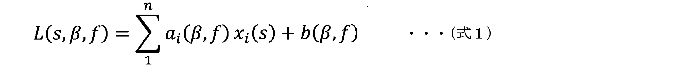
式1において、i(=1~n)は図5A~図5Cに示す耳介形状x1~x13の添え字(「1」~「13」)に対応している。図5A~図5Cに示す耳介形状x1~x13を用いて各方向の各周波数の頭部伝達関数の振幅値L(s,β,f)を算出する場合、nの値は「13」である。b(β,f)は定数項である。
In Equation 1, i (= 1 to n) corresponds to the suffixes (“1” to “13”) of the pinna shapes x 1 to x 13 shown in FIGS. 5A to 5C. When calculating the amplitude value L (s, β, f) of the head-related transfer function of each frequency in each direction using the pinna shapes x 1 to x 13 shown in FIGS. 5A to 5C, the value of n is “13”. ". b (β, f) is a constant term.
図8は頭部伝達関数振幅値生成部13が生成した頭部伝達関数の振幅値を示す図である。図8の縦軸は相対振幅[dB]を示しており、図8の横軸は周波数[Hz]を示している。
詳細には、図8において、実線は、受聴者sの耳介形状x1~x13(図5A~図5C参照)と、各方向の各周波数において、耳介形状x1~x13を説明変数とし、『頭部伝達関数』の振幅値を目的変数とした重回帰分析を行うことによって得られた重回帰係数ai(β,f)と、上記の式1とに基づいて、頭部伝達関数振幅値生成部13が生成(算出)した頭部伝達関数の振幅値L(s,β,f)を示している。
点線は、受聴者sの耳介形状x1~x13(図5A~図5C参照)と、各方向の各周波数において、耳介形状x1~x13を説明変数とし、『初期頭部伝達関数』の振幅値を目的変数とした重回帰分析を行うことによって得られた重回帰係数ai(β,f)と、上記の式1とに基づいて、頭部伝達関数振幅値生成部13が生成(算出)した頭部伝達関数の振幅値L(s,β,f)を示している。
図8に示す例では、上述したように、振幅値が目的変数とされる『初期頭部伝達関数』は、頭部インパルス応答の初期1ms程度を初期頭部インパルス応答として切り出し、その初期頭部インパルス応答をフーリエ変換したものである。一方、振幅値が目的変数とされる『頭部伝達関数』は、頭部インパルス応答の全体(5.3ms)を頭部インパルス応答として切り出し、その頭部インパルス応答をフーリエ変換したものである。 FIG. 8 is a diagram illustrating the amplitude value of the head-related transfer function generated by the head-related transfer function amplitudevalue generation unit 13. The vertical axis of FIG. 8 indicates the relative amplitude [dB], and the horizontal axis of FIG. 8 indicates the frequency [Hz].
In detail, in FIG. 8, the solid line indicates the pinna shapes x 1 to x 13 of the listener s (see FIGS. 5A to 5C) and the pinna shapes x 1 to x 13 at each frequency in each direction. Based on the multiple regression coefficient a i (β, f) obtained by performing multiple regression analysis using the amplitude value of “head-related transfer function” as the target variable and theabove equation 1, The amplitude value L (s, β, f) of the head-related transfer function generated (calculated) by the transfer function amplitude value generation unit 13 is shown.
The dotted lines indicate the pinna shapes x 1 to x 13 (see FIGS. 5A to 5C) of the listener s and the pinna shapes x 1 to x 13 as explanatory variables at each frequency in each direction. Based on the multiple regression coefficient a i (β, f) obtained by performing the multiple regression analysis using the amplitude value of the function as the target variable and the above-describedequation 1, the head-related transfer function amplitude value generation unit 13 Shows the amplitude value L (s, β, f) of the head-related transfer function generated (calculated).
In the example illustrated in FIG. 8, as described above, the “initial head-related transfer function” in which the amplitude value is set as the target variable is obtained by cutting out about 1 ms of the initial head impulse response as the initial head impulse response, This is a Fourier transform of the impulse response. On the other hand, the “head-related transfer function” in which the amplitude value is used as the target variable is obtained by cutting out the entire head impulse response (5.3 ms) as a head impulse response and performing a Fourier transform on the head impulse response.
詳細には、図8において、実線は、受聴者sの耳介形状x1~x13(図5A~図5C参照)と、各方向の各周波数において、耳介形状x1~x13を説明変数とし、『頭部伝達関数』の振幅値を目的変数とした重回帰分析を行うことによって得られた重回帰係数ai(β,f)と、上記の式1とに基づいて、頭部伝達関数振幅値生成部13が生成(算出)した頭部伝達関数の振幅値L(s,β,f)を示している。
点線は、受聴者sの耳介形状x1~x13(図5A~図5C参照)と、各方向の各周波数において、耳介形状x1~x13を説明変数とし、『初期頭部伝達関数』の振幅値を目的変数とした重回帰分析を行うことによって得られた重回帰係数ai(β,f)と、上記の式1とに基づいて、頭部伝達関数振幅値生成部13が生成(算出)した頭部伝達関数の振幅値L(s,β,f)を示している。
図8に示す例では、上述したように、振幅値が目的変数とされる『初期頭部伝達関数』は、頭部インパルス応答の初期1ms程度を初期頭部インパルス応答として切り出し、その初期頭部インパルス応答をフーリエ変換したものである。一方、振幅値が目的変数とされる『頭部伝達関数』は、頭部インパルス応答の全体(5.3ms)を頭部インパルス応答として切り出し、その頭部インパルス応答をフーリエ変換したものである。 FIG. 8 is a diagram illustrating the amplitude value of the head-related transfer function generated by the head-related transfer function amplitude
In detail, in FIG. 8, the solid line indicates the pinna shapes x 1 to x 13 of the listener s (see FIGS. 5A to 5C) and the pinna shapes x 1 to x 13 at each frequency in each direction. Based on the multiple regression coefficient a i (β, f) obtained by performing multiple regression analysis using the amplitude value of “head-related transfer function” as the target variable and the
The dotted lines indicate the pinna shapes x 1 to x 13 (see FIGS. 5A to 5C) of the listener s and the pinna shapes x 1 to x 13 as explanatory variables at each frequency in each direction. Based on the multiple regression coefficient a i (β, f) obtained by performing the multiple regression analysis using the amplitude value of the function as the target variable and the above-described
In the example illustrated in FIG. 8, as described above, the “initial head-related transfer function” in which the amplitude value is set as the target variable is obtained by cutting out about 1 ms of the initial head impulse response as the initial head impulse response, This is a Fourier transform of the impulse response. On the other hand, the “head-related transfer function” in which the amplitude value is used as the target variable is obtained by cutting out the entire head impulse response (5.3 ms) as a head impulse response and performing a Fourier transform on the head impulse response.
図9は第1実施形態の頭部伝達関数生成装置1が頭部伝達関数の振幅値L(s,β,f)を生成する場合に実行される処理の一例を説明するためのフローチャートである。
図9に示す例では、ステップS1において、例えば上述したいずれかの手法により、受聴者sの耳介形状x1~x13(図5A~図5C参照)、または、受聴者sの耳介形状x1~x8、x10(図6参照)および受聴者sの耳介形状x9(図5B参照)、または、受聴者sの耳介形状x1~x14(図7A~図7C参照)が計測される。
次いで、ステップS2では、耳介形状取得部11が、ステップS1において計測された受聴者sの耳介形状x1~x13、または、受聴者sの耳介形状x1~x10、または、受聴者sの耳介形状x1~x14を取得する。
また、ステップS3において、例えば重回帰係数データ生成部(図示せず)によって、各方向の各周波数において、耳介形状x1~x13、または、耳介形状x1~x10、または、耳介形状x1~x14を説明変数とし、頭部伝達関数もしくは初期頭部伝達関数の振幅値を目的変数とした重回帰分析を行うことによって得られた重回帰係数aをデータ化したものである重回帰係数データが生成される。
次いで、ステップS4では、ステップS3において生成された重回帰係数データが、例えば重回帰係数データベース(図示せず)に記憶される。
次いで、ステップS5において、重回帰係数データ取得部12は、重回帰係数データベースに記憶されている重回帰係数データを取得する。
次いで、ステップS6では、ステップS2において取得された受聴者sの耳介形状x1~x13、または、受聴者sの耳介形状x1~x10、または、受聴者sの耳介形状x1~x14と、ステップS5において取得された重回帰係数データと、上述した式1とに基づいて、頭部伝達関数振幅値生成部13が、各方向の各周波数の頭部伝達関数の振幅値L(s,β,f)を算出(生成)する。 FIG. 9 is a flowchart for explaining an example of processing executed when the head-related transferfunction generation device 1 of the first embodiment generates an amplitude value L (s, β, f) of a head-related transfer function. .
In the example shown in FIG. 9, in step S1, the pinna shape x 1 to x 13 of the listener s (see FIGS. 5A to 5C) or the pinna shape of the listener s by any of the methods described above. x 1 to x 8 and x 10 (see FIG. 6) and the pinna shape x 9 of the listener s (see FIG. 5B) or the pinna shape x 1 to x 14 of the listener s (see FIGS. 7A to 7C) ) Is measured.
Next, in step S2, the pinnashape acquisition unit 11 sets the pinna shapes x 1 to x 13 of the listener s measured in step S1, or the pinna shapes x 1 to x 10 of the listener s, or The pinna shapes x 1 to x 14 of the listener s are obtained.
Also, in step S3, for example, the auricle shapes x 1 to x 13 , or the auricle shapes x 1 to x 10 , or the auricle shape at each frequency in each direction by a multiple regression coefficient data generation unit (not shown). A multiple regression coefficient a obtained by performing a multiple regression analysis using the intermediary shapes x 1 to x 14 as explanatory variables and the amplitude value of the head-related transfer function or the initial head-related transfer function as the objective variable is converted into data. Certain multiple regression coefficient data is generated.
Next, in step S4, the multiple regression coefficient data generated in step S3 is stored in, for example, a multiple regression coefficient database (not shown).
Next, in step S5, the multiple regression coefficientdata acquisition unit 12 acquires multiple regression coefficient data stored in the multiple regression coefficient database.
Next, in step S6, the pinna shapes x 1 to x 13 of the listener s obtained in step S2, the pinna shapes x 1 to x 10 of the listener s, or the pinna shape x of the listener s and 1 ~ x 14, and multiple regression coefficient data obtained in step S5, on the basis of theequation 1 described above, the HRTF amplitude value generator 13, the amplitude of the head-related transfer function of the frequency in each direction The value L (s, β, f) is calculated (generated).
図9に示す例では、ステップS1において、例えば上述したいずれかの手法により、受聴者sの耳介形状x1~x13(図5A~図5C参照)、または、受聴者sの耳介形状x1~x8、x10(図6参照)および受聴者sの耳介形状x9(図5B参照)、または、受聴者sの耳介形状x1~x14(図7A~図7C参照)が計測される。
次いで、ステップS2では、耳介形状取得部11が、ステップS1において計測された受聴者sの耳介形状x1~x13、または、受聴者sの耳介形状x1~x10、または、受聴者sの耳介形状x1~x14を取得する。
また、ステップS3において、例えば重回帰係数データ生成部(図示せず)によって、各方向の各周波数において、耳介形状x1~x13、または、耳介形状x1~x10、または、耳介形状x1~x14を説明変数とし、頭部伝達関数もしくは初期頭部伝達関数の振幅値を目的変数とした重回帰分析を行うことによって得られた重回帰係数aをデータ化したものである重回帰係数データが生成される。
次いで、ステップS4では、ステップS3において生成された重回帰係数データが、例えば重回帰係数データベース(図示せず)に記憶される。
次いで、ステップS5において、重回帰係数データ取得部12は、重回帰係数データベースに記憶されている重回帰係数データを取得する。
次いで、ステップS6では、ステップS2において取得された受聴者sの耳介形状x1~x13、または、受聴者sの耳介形状x1~x10、または、受聴者sの耳介形状x1~x14と、ステップS5において取得された重回帰係数データと、上述した式1とに基づいて、頭部伝達関数振幅値生成部13が、各方向の各周波数の頭部伝達関数の振幅値L(s,β,f)を算出(生成)する。 FIG. 9 is a flowchart for explaining an example of processing executed when the head-related transfer
In the example shown in FIG. 9, in step S1, the pinna shape x 1 to x 13 of the listener s (see FIGS. 5A to 5C) or the pinna shape of the listener s by any of the methods described above. x 1 to x 8 and x 10 (see FIG. 6) and the pinna shape x 9 of the listener s (see FIG. 5B) or the pinna shape x 1 to x 14 of the listener s (see FIGS. 7A to 7C) ) Is measured.
Next, in step S2, the pinna
Also, in step S3, for example, the auricle shapes x 1 to x 13 , or the auricle shapes x 1 to x 10 , or the auricle shape at each frequency in each direction by a multiple regression coefficient data generation unit (not shown). A multiple regression coefficient a obtained by performing a multiple regression analysis using the intermediary shapes x 1 to x 14 as explanatory variables and the amplitude value of the head-related transfer function or the initial head-related transfer function as the objective variable is converted into data. Certain multiple regression coefficient data is generated.
Next, in step S4, the multiple regression coefficient data generated in step S3 is stored in, for example, a multiple regression coefficient database (not shown).
Next, in step S5, the multiple regression coefficient
Next, in step S6, the pinna shapes x 1 to x 13 of the listener s obtained in step S2, the pinna shapes x 1 to x 10 of the listener s, or the pinna shape x of the listener s and 1 ~ x 14, and multiple regression coefficient data obtained in step S5, on the basis of the
第1実施形態の頭部伝達関数生成装置1では、受聴者本人の頭部伝達関数の測定が実際に行われるのではなく、受聴者本人の耳介形状と、予め準備された重回帰係数データとに基づいて、頭部伝達関数振幅値生成部13が、各方向の各周波数の頭部伝達関数の振幅値L(s,β,f)を算出する。本発明者は、鋭意研究において、実際に測定された受聴者本人の頭部伝達関数の振幅値と同等に高精度な頭部伝達関数の振幅値L(s,β,f)を算出できることを見い出した。
In the head-related transfer function generation device 1 of the first embodiment, the head-related transfer function of the listener is not actually measured, but the pinna shape of the listener and the multiple regression coefficient data prepared in advance Then, the head-related transfer function amplitude value generation unit 13 calculates the amplitude value L (s, β, f) of the head-related transfer function at each frequency in each direction. The inventor of the present invention has earnestly studied that it is possible to calculate the amplitude value L (s, β, f) of the head-related transfer function with high accuracy equivalent to the amplitude value of the head-related transfer function of the listener actually measured. I found it.
図10Aおよび図10Bは実際に測定された受聴者本人の頭部伝達関数の振幅値と、頭部伝達関数生成装置1によって生成された頭部伝達関数の振幅値とを比較して示す図である。
図10Aは耳介形状x1~x13を説明変数とし、(全区間)頭部伝達関数の振幅値を目的変数とした重回帰分析を行うことによって得られた重回帰係数データを用いて生成された頭部伝達関数の振幅値を示す図である。
詳細には、図10Aは、正中面内の上昇角βが0[°]の音源に対して実測された頭部伝達関数の振幅値(実線)および頭部伝達関数生成装置1によって生成された頭部伝達関数の振幅値(点線)と、正中面内の上昇角βが30[°]の音源に対して実測された頭部伝達関数の振幅値(実線)および頭部伝達関数生成装置1によって生成された頭部伝達関数の振幅値(点線)と、正中面内の上昇角βが60[°]の音源に対して実測された頭部伝達関数の振幅値(実線)および頭部伝達関数生成装置1によって生成された頭部伝達関数の振幅値(点線)と、正中面内の上昇角βが90[°]の音源に対して実測された頭部伝達関数の振幅値(実線)および頭部伝達関数生成装置1によって生成された頭部伝達関数の振幅値(点線)と、正中面内の上昇角βが120[°]の音源に対して実測された頭部伝達関数の振幅値(実線)および頭部伝達関数生成装置1によって生成された頭部伝達関数の振幅値(点線)と、正中面内の上昇角βが150[°]の音源に対して実測された頭部伝達関数の振幅値(実線)および頭部伝達関数生成装置1によって生成された頭部伝達関数の振幅値(点線)と、正中面内の上昇角βが180[°]の音源に対して実測された頭部伝達関数の振幅値(実線)および頭部伝達関数生成装置1によって生成された頭部伝達関数の振幅値(点線)とを示している。図10Aの縦軸は相対振幅[dB]を示しており、図10Aの横軸は周波数[Hz]を示している。 10A and 10B are diagrams showing a comparison between the actually measured amplitude value of the head-related transfer function of the listener and the amplitude value of the head-related transfer function generated by the head-related transferfunction generation device 1. is there.
FIG. 10A is generated using multiple regression coefficient data obtained by performing multiple regression analysis using the pinna shapes x 1 to x 13 as explanatory variables and (all sections) the amplitude value of the head-related transfer function as an objective variable. FIG. 9 is a diagram showing the amplitude value of the head-related transfer function obtained.
In detail, FIG. 10A shows the amplitude value (solid line) of the head-related transfer function actually measured for the sound source whose rising angle β in the median plane is 0 [°] and generated by the head-relatedtransfer function generator 1. The head-related transfer function amplitude value (dotted line), the head-related transfer function amplitude value (solid line) actually measured for a sound source whose rise angle β in the median plane is 30 [°], and the head-related transfer function generator 1 Of the head-related transfer function (dotted line), the amplitude of the head-related transfer function (solid line), and the head-related transfer measured for a sound source with a rising angle β in the median plane of 60 [°] The amplitude value (dotted line) of the head-related transfer function generated by the function generation device 1 and the amplitude value (solid line) of the head-related transfer function actually measured for a sound source whose elevation angle β in the median plane is 90 [°] And the amplitude value (dotted line) of the head-related transfer function generated by the head-related transfer function generation device 1 An amplitude value (solid line) of the head-related transfer function actually measured for a sound source whose elevation angle β is 120 [°] and an amplitude value (dotted line) of the head-related transfer function generated by the head-related transfer function generator 1; The amplitude value (solid line) of the head-related transfer function actually measured for a sound source whose rising angle β in the median plane is 150 [°] and the amplitude value of the head-related transfer function generated by the head-related transfer function generator 1 ( Dotted line), the amplitude value (solid line) of the head-related transfer function actually measured for the sound source whose elevation angle β in the median plane is 180 [°], and the head-related transfer function generated by the head-related transfer function generator 1 (Dotted line). The vertical axis of FIG. 10A indicates the relative amplitude [dB], and the horizontal axis of FIG. 10A indicates the frequency [Hz].
図10Aは耳介形状x1~x13を説明変数とし、(全区間)頭部伝達関数の振幅値を目的変数とした重回帰分析を行うことによって得られた重回帰係数データを用いて生成された頭部伝達関数の振幅値を示す図である。
詳細には、図10Aは、正中面内の上昇角βが0[°]の音源に対して実測された頭部伝達関数の振幅値(実線)および頭部伝達関数生成装置1によって生成された頭部伝達関数の振幅値(点線)と、正中面内の上昇角βが30[°]の音源に対して実測された頭部伝達関数の振幅値(実線)および頭部伝達関数生成装置1によって生成された頭部伝達関数の振幅値(点線)と、正中面内の上昇角βが60[°]の音源に対して実測された頭部伝達関数の振幅値(実線)および頭部伝達関数生成装置1によって生成された頭部伝達関数の振幅値(点線)と、正中面内の上昇角βが90[°]の音源に対して実測された頭部伝達関数の振幅値(実線)および頭部伝達関数生成装置1によって生成された頭部伝達関数の振幅値(点線)と、正中面内の上昇角βが120[°]の音源に対して実測された頭部伝達関数の振幅値(実線)および頭部伝達関数生成装置1によって生成された頭部伝達関数の振幅値(点線)と、正中面内の上昇角βが150[°]の音源に対して実測された頭部伝達関数の振幅値(実線)および頭部伝達関数生成装置1によって生成された頭部伝達関数の振幅値(点線)と、正中面内の上昇角βが180[°]の音源に対して実測された頭部伝達関数の振幅値(実線)および頭部伝達関数生成装置1によって生成された頭部伝達関数の振幅値(点線)とを示している。図10Aの縦軸は相対振幅[dB]を示しており、図10Aの横軸は周波数[Hz]を示している。 10A and 10B are diagrams showing a comparison between the actually measured amplitude value of the head-related transfer function of the listener and the amplitude value of the head-related transfer function generated by the head-related transfer
FIG. 10A is generated using multiple regression coefficient data obtained by performing multiple regression analysis using the pinna shapes x 1 to x 13 as explanatory variables and (all sections) the amplitude value of the head-related transfer function as an objective variable. FIG. 9 is a diagram showing the amplitude value of the head-related transfer function obtained.
In detail, FIG. 10A shows the amplitude value (solid line) of the head-related transfer function actually measured for the sound source whose rising angle β in the median plane is 0 [°] and generated by the head-related
図10Bは耳介形状x1~x13を説明変数とし、初期頭部伝達関数の振幅値を目的変数とした重回帰分析を行うことによって得られた重回帰係数データを用いて生成された頭部伝達関数の振幅値を示す図である。
詳細には、図10Bは、正中面内の上昇角βが0[°]の音源に対して実測された頭部伝達関数の振幅値(実線)および頭部伝達関数生成装置1によって生成された頭部伝達関数の振幅値(点線)と、正中面内の上昇角βが30[°]の音源に対して実測された頭部伝達関数の振幅値(実線)および頭部伝達関数生成装置1によって生成された頭部伝達関数の振幅値(点線)と、正中面内の上昇角βが60[°]の音源に対して実測された頭部伝達関数の振幅値(実線)および頭部伝達関数生成装置1によって生成された頭部伝達関数の振幅値(点線)と、正中面内の上昇角βが90[°]の音源に対して実測された頭部伝達関数の振幅値(実線)および頭部伝達関数生成装置1によって生成された頭部伝達関数の振幅値(点線)と、正中面内の上昇角βが120[°]の音源に対して実測された頭部伝達関数の振幅値(実線)および頭部伝達関数生成装置1によって生成された頭部伝達関数の振幅値(点線)と、正中面内の上昇角βが150[°]の音源に対して実測された頭部伝達関数の振幅値(実線)および頭部伝達関数生成装置1によって生成された頭部伝達関数の振幅値(点線)と、正中面内の上昇角βが180[°]の音源に対して実測された頭部伝達関数の振幅値(実線)および頭部伝達関数生成装置1によって生成された頭部伝達関数の振幅値(点線)とを示している。図10Bの縦軸は相対振幅[dB]を示しており、図10Bの横軸は周波数[Hz]を示している。 FIG. 10B shows a head generated using multiple regression coefficient data obtained by performing multiple regression analysis using the pinna shapes x 1 to x 13 as explanatory variables and using the amplitude value of the initial head-related transfer function as an objective variable. It is a figure showing the amplitude value of a partial transfer function.
In detail, FIG. 10B shows the amplitude value (solid line) of the head-related transfer function actually measured for a sound source having a rising angle β in the median plane of 0 [°] and the head-relatedtransfer function generator 1 generates the amplitude value. The head-related transfer function amplitude value (dotted line), the head-related transfer function amplitude value (solid line) actually measured for a sound source whose rise angle β in the median plane is 30 [°], and the head-related transfer function generator 1 Of the head-related transfer function (dotted line), the amplitude of the head-related transfer function (solid line), and the head-related transfer measured for a sound source with a rising angle β in the median plane of 60 [°] The amplitude value (dotted line) of the head-related transfer function generated by the function generation device 1 and the amplitude value (solid line) of the head-related transfer function actually measured for a sound source whose elevation angle β in the median plane is 90 [°] And the amplitude value (dotted line) of the head-related transfer function generated by the head-related transfer function generation device 1 An amplitude value (solid line) of the head-related transfer function actually measured for a sound source whose elevation angle β is 120 [°] and an amplitude value (dotted line) of the head-related transfer function generated by the head-related transfer function generator 1; The amplitude value (solid line) of the head-related transfer function actually measured for a sound source whose rising angle β in the median plane is 150 [°] and the amplitude value of the head-related transfer function generated by the head-related transfer function generator 1 ( Dotted line), the amplitude value (solid line) of the head-related transfer function actually measured for the sound source whose elevation angle β in the median plane is 180 [°], and the head-related transfer function generated by the head-related transfer function generator 1 (Dotted line). The vertical axis of FIG. 10B indicates the relative amplitude [dB], and the horizontal axis of FIG. 10B indicates the frequency [Hz].
詳細には、図10Bは、正中面内の上昇角βが0[°]の音源に対して実測された頭部伝達関数の振幅値(実線)および頭部伝達関数生成装置1によって生成された頭部伝達関数の振幅値(点線)と、正中面内の上昇角βが30[°]の音源に対して実測された頭部伝達関数の振幅値(実線)および頭部伝達関数生成装置1によって生成された頭部伝達関数の振幅値(点線)と、正中面内の上昇角βが60[°]の音源に対して実測された頭部伝達関数の振幅値(実線)および頭部伝達関数生成装置1によって生成された頭部伝達関数の振幅値(点線)と、正中面内の上昇角βが90[°]の音源に対して実測された頭部伝達関数の振幅値(実線)および頭部伝達関数生成装置1によって生成された頭部伝達関数の振幅値(点線)と、正中面内の上昇角βが120[°]の音源に対して実測された頭部伝達関数の振幅値(実線)および頭部伝達関数生成装置1によって生成された頭部伝達関数の振幅値(点線)と、正中面内の上昇角βが150[°]の音源に対して実測された頭部伝達関数の振幅値(実線)および頭部伝達関数生成装置1によって生成された頭部伝達関数の振幅値(点線)と、正中面内の上昇角βが180[°]の音源に対して実測された頭部伝達関数の振幅値(実線)および頭部伝達関数生成装置1によって生成された頭部伝達関数の振幅値(点線)とを示している。図10Bの縦軸は相対振幅[dB]を示しており、図10Bの横軸は周波数[Hz]を示している。 FIG. 10B shows a head generated using multiple regression coefficient data obtained by performing multiple regression analysis using the pinna shapes x 1 to x 13 as explanatory variables and using the amplitude value of the initial head-related transfer function as an objective variable. It is a figure showing the amplitude value of a partial transfer function.
In detail, FIG. 10B shows the amplitude value (solid line) of the head-related transfer function actually measured for a sound source having a rising angle β in the median plane of 0 [°] and the head-related
図10Aおよび図10Bに示すように、第1実施形態の頭部伝達関数生成装置1によれば、受聴者本人の頭部伝達関数の測定を実際に行う必要なく、実際に測定された受聴者本人の頭部伝達関数(図10Aおよび図10Bの実線)と同等に高精度な頭部伝達関数(図10Aおよび図10Bの点線)を容易に得ることができる。
As shown in FIG. 10A and FIG. 10B, according to the head-related transfer function generation device 1 of the first embodiment, it is not necessary to actually measure the head-related transfer function of the listener himself, and the listener actually measured A head transfer function (dotted line in FIGS. 10A and 10B) that is as accurate as the person's head transfer function (solid line in FIGS. 10A and 10B) can be easily obtained.
換言すれば、第1実施形態の頭部伝達関数生成装置1では、受聴者本人の頭部伝達関数の測定が実際に行われる必要なく、受聴者本人による試聴の必要なく、頭部伝達関数生成装置1が重回帰係数データベースを有する必要なく、受聴者に適合する頭部伝達関数を生成することができる。
また、第1実施形態の頭部伝達関数生成装置1によって得られる頭部伝達関数と、実際に測定された受聴者本人の頭部伝達関数との類似度が高いため、頭部伝達関数生成装置1によって得られる頭部伝達関数を用いることによって、3次元音響再生や音のVRを高い精度で実現することができる。
つまり、騒音下で測定された頭部伝達関数が用いられる場合や、データベースに記憶されている複数の頭部伝達関数のうちのいずれかが試聴によって選択される場合には、高精度の3次元音響再生や音のVRを期待できないのに対し、第1実施形態の頭部伝達関数生成装置1によって得られる頭部伝達関数を用いることによって、3次元音響再生や音のVRを高い精度で実現することができる。 In other words, the head-related transferfunction generation device 1 of the first embodiment does not need to actually measure the head-related transfer function of the listener himself, does not need to listen to the listener himself, and generates the head-related transfer function. The head-related transfer function suitable for the listener can be generated without the device 1 having to have a multiple regression coefficient database.
In addition, since the similarity between the head-related transfer function obtained by the head-relatedtransfer function generator 1 of the first embodiment and the actually measured head-related transfer function of the listener is high, the head-related transfer function generator is used. By using the head-related transfer function obtained by (1), three-dimensional sound reproduction and sound VR can be realized with high accuracy.
In other words, when a head-related transfer function measured under noise is used, or when one of a plurality of head-related transfer functions stored in a database is selected by listening, a high-precision three-dimensional While sound reproduction and VR of sound cannot be expected, three-dimensional sound reproduction and VR of sound can be realized with high accuracy by using the head-related transfer function obtained by the head-relatedtransfer function generator 1 of the first embodiment. can do.
また、第1実施形態の頭部伝達関数生成装置1によって得られる頭部伝達関数と、実際に測定された受聴者本人の頭部伝達関数との類似度が高いため、頭部伝達関数生成装置1によって得られる頭部伝達関数を用いることによって、3次元音響再生や音のVRを高い精度で実現することができる。
つまり、騒音下で測定された頭部伝達関数が用いられる場合や、データベースに記憶されている複数の頭部伝達関数のうちのいずれかが試聴によって選択される場合には、高精度の3次元音響再生や音のVRを期待できないのに対し、第1実施形態の頭部伝達関数生成装置1によって得られる頭部伝達関数を用いることによって、3次元音響再生や音のVRを高い精度で実現することができる。 In other words, the head-related transfer
In addition, since the similarity between the head-related transfer function obtained by the head-related
In other words, when a head-related transfer function measured under noise is used, or when one of a plurality of head-related transfer functions stored in a database is selected by listening, a high-precision three-dimensional While sound reproduction and VR of sound cannot be expected, three-dimensional sound reproduction and VR of sound can be realized with high accuracy by using the head-related transfer function obtained by the head-related
<第2実施形態>
以下、本発明の頭部伝達関数生成装置、頭部伝達関数生成方法およびプログラムの第2実施形態について説明する。
第2実施形態の頭部伝達関数生成装置1は、後述する点を除き、上述した第1実施形態の頭部伝達関数生成装置1と同様に構成されている。従って、第2実施形態の頭部伝達関数生成装置1によれば、後述する点を除き、上述した第1実施形態の頭部伝達関数生成装置1と同様の効果を奏することができる。 <Second embodiment>
Hereinafter, a second embodiment of the head-related transfer function generation device, the head-related transfer function generation method, and the program according to the present invention will be described.
The head-relatedtransfer function generator 1 of the second embodiment has the same configuration as the head-related transfer function generator 1 of the first embodiment described above, except for the points described below. Therefore, according to the head-related transfer function generation device 1 of the second embodiment, the same effects as those of the head-related transfer function generation device 1 of the above-described first embodiment can be obtained except for the points described below.
以下、本発明の頭部伝達関数生成装置、頭部伝達関数生成方法およびプログラムの第2実施形態について説明する。
第2実施形態の頭部伝達関数生成装置1は、後述する点を除き、上述した第1実施形態の頭部伝達関数生成装置1と同様に構成されている。従って、第2実施形態の頭部伝達関数生成装置1によれば、後述する点を除き、上述した第1実施形態の頭部伝達関数生成装置1と同様の効果を奏することができる。 <Second embodiment>
Hereinafter, a second embodiment of the head-related transfer function generation device, the head-related transfer function generation method, and the program according to the present invention will be described.
The head-related
図11は第2実施形態の頭部伝達関数生成装置1の概要の一例を示す図である。
図11に示す例では、図4に示す例と同様に、頭部伝達関数生成装置1が、耳介形状取得部11と、重回帰係数データ取得部12と、頭部伝達関数振幅値生成部13とを備えている。
図11に示す例では、図4に示す例とは異なり、頭部伝達関数生成装置1が、頭部インパルス応答生成部14を更に備えている。頭部インパルス応答生成部14は、頭部伝達関数振幅値生成部13によって生成された各方向の各周波数の頭部伝達関数の振幅値を逆フーリエ変換することによって、各方向の頭部インパルス応答を算出する。頭部インパルス応答生成部14では、各周波数の位相は、例えば最小位相系を仮定する。
第2実施形態の頭部伝達関数生成装置1では、頭部インパルス応答生成部14が備えられているため、実際に測定された受聴者本人の頭部伝達関数と同等に高精度な頭部伝達関数を容易に得ることができるのみならず、受聴者本人の頭部インパルス応答の測定および受聴者本人の頭部伝達関数の測定のいずれも実際に行う必要なく、実際に測定された受聴者本人の頭部インパルス応答と同等に高精度な頭部インパルス応答を容易に得ることができる。 FIG. 11 is a diagram illustrating an example of an outline of the head-related transferfunction generation device 1 according to the second embodiment.
In the example illustrated in FIG. 11, similarly to the example illustrated in FIG. 4, the head-related transferfunction generation device 1 includes an auricle shape acquisition unit 11, a multiple regression coefficient data acquisition unit 12, and a head-related transfer function amplitude value generation unit. 13 is provided.
In the example illustrated in FIG. 11, unlike the example illustrated in FIG. 4, the head-related transferfunction generation device 1 further includes a head impulse response generation unit 14. The head impulse response generator 14 performs an inverse Fourier transform on the amplitude value of the head-related transfer function of each frequency in each direction generated by the head-related transfer function amplitude value generator 13, thereby obtaining a head impulse response in each direction. Is calculated. In the head impulse response generation unit 14, the phase of each frequency is assumed to be, for example, a minimum phase system.
Since the head-relatedtransfer function generator 1 of the second embodiment includes the head impulse response generator 14, the head-related transfer function is as accurate as the actually measured head-related transfer function of the listener. Not only can the function be easily obtained, but it is not necessary to actually measure both the listener's own head impulse response and the listener's head-related transfer function. , A head impulse response with high accuracy equivalent to that of the head impulse response can be easily obtained.
図11に示す例では、図4に示す例と同様に、頭部伝達関数生成装置1が、耳介形状取得部11と、重回帰係数データ取得部12と、頭部伝達関数振幅値生成部13とを備えている。
図11に示す例では、図4に示す例とは異なり、頭部伝達関数生成装置1が、頭部インパルス応答生成部14を更に備えている。頭部インパルス応答生成部14は、頭部伝達関数振幅値生成部13によって生成された各方向の各周波数の頭部伝達関数の振幅値を逆フーリエ変換することによって、各方向の頭部インパルス応答を算出する。頭部インパルス応答生成部14では、各周波数の位相は、例えば最小位相系を仮定する。
第2実施形態の頭部伝達関数生成装置1では、頭部インパルス応答生成部14が備えられているため、実際に測定された受聴者本人の頭部伝達関数と同等に高精度な頭部伝達関数を容易に得ることができるのみならず、受聴者本人の頭部インパルス応答の測定および受聴者本人の頭部伝達関数の測定のいずれも実際に行う必要なく、実際に測定された受聴者本人の頭部インパルス応答と同等に高精度な頭部インパルス応答を容易に得ることができる。 FIG. 11 is a diagram illustrating an example of an outline of the head-related transfer
In the example illustrated in FIG. 11, similarly to the example illustrated in FIG. 4, the head-related transfer
In the example illustrated in FIG. 11, unlike the example illustrated in FIG. 4, the head-related transfer
Since the head-related
<第3実施形態>
以下、本発明の頭部伝達関数生成装置、頭部伝達関数生成方法およびプログラムの第3実施形態について説明する。
第3実施形態の頭部伝達関数生成装置1は、後述する点を除き、上述した第2実施形態の頭部伝達関数生成装置1と同様に構成されている。従って、第3実施形態の頭部伝達関数生成装置1によれば、後述する点を除き、上述した第2実施形態の頭部伝達関数生成装置1と同様の効果を奏することができる。 <Third embodiment>
Hereinafter, a third embodiment of the head-related transfer function generation device, the head-related transfer function generation method, and the program of the present invention will be described.
The head-relatedtransfer function generator 1 of the third embodiment has the same configuration as the head-related transfer function generator 1 of the above-described second embodiment, except for the points described below. Therefore, according to the head-related transfer function generation device 1 of the third embodiment, the same effects as those of the head-related transfer function generation device 1 of the above-described second embodiment can be obtained, except for the following points.
以下、本発明の頭部伝達関数生成装置、頭部伝達関数生成方法およびプログラムの第3実施形態について説明する。
第3実施形態の頭部伝達関数生成装置1は、後述する点を除き、上述した第2実施形態の頭部伝達関数生成装置1と同様に構成されている。従って、第3実施形態の頭部伝達関数生成装置1によれば、後述する点を除き、上述した第2実施形態の頭部伝達関数生成装置1と同様の効果を奏することができる。 <Third embodiment>
Hereinafter, a third embodiment of the head-related transfer function generation device, the head-related transfer function generation method, and the program of the present invention will be described.
The head-related
図12は第3実施形態の頭部伝達関数生成装置1の概要の一例を示す図である。
図12に示す例では、図11に示す例と同様に、頭部伝達関数生成装置1が、耳介形状取得部11と、重回帰係数データ取得部12と、頭部伝達関数振幅値生成部13と、頭部インパルス応答生成部14とを備えている。
図12に示す例では、図11に示す例とは異なり、頭部伝達関数生成装置1が、重回帰係数データベース15を更に備えている。重回帰係数データベース15は、例えば頭部伝達関数生成装置1の外部に設けられた重回帰係数データ生成部(図示せず)によって生成された重回帰係数データを記憶する。
第3実施形態の頭部伝達関数生成装置1では、重回帰係数データベース15が備えられているため、頭部伝達関数生成装置1の外部に設けられた重回帰係数データベース(図示せず)にアクセスする必要なく、かつ、受聴者本人の頭部伝達関数の測定を実際に行う必要なく、実際に測定された受聴者本人の頭部伝達関数と同等に高精度な頭部伝達関数を容易に得ることができる。 FIG. 12 is a diagram illustrating an example of an outline of the head-related transferfunction generation device 1 according to the third embodiment.
In the example illustrated in FIG. 12, similarly to the example illustrated in FIG. 11, the head-related transferfunction generation device 1 includes an auricle shape acquisition unit 11, a multiple regression coefficient data acquisition unit 12, and a head-related transfer function amplitude value generation unit. 13 and a head impulse response generator 14.
In the example illustrated in FIG. 12, unlike the example illustrated in FIG. 11, the head-related transferfunction generation device 1 further includes a multiple regression coefficient database 15. The multiple regression coefficient database 15 stores multiple regression coefficient data generated by, for example, a multiple regression coefficient data generation unit (not shown) provided outside the head-related transfer function generation device 1.
Since the head-relatedtransfer function generator 1 of the third embodiment is provided with the multiple regression coefficient database 15, it accesses a multiple regression coefficient database (not shown) provided outside the head-related transfer function generator 1. Without having to perform the measurement of the head-related transfer function of the listener itself, and easily obtain a head-related transfer function that is as accurate as the actually measured head-related transfer function of the listener. be able to.
図12に示す例では、図11に示す例と同様に、頭部伝達関数生成装置1が、耳介形状取得部11と、重回帰係数データ取得部12と、頭部伝達関数振幅値生成部13と、頭部インパルス応答生成部14とを備えている。
図12に示す例では、図11に示す例とは異なり、頭部伝達関数生成装置1が、重回帰係数データベース15を更に備えている。重回帰係数データベース15は、例えば頭部伝達関数生成装置1の外部に設けられた重回帰係数データ生成部(図示せず)によって生成された重回帰係数データを記憶する。
第3実施形態の頭部伝達関数生成装置1では、重回帰係数データベース15が備えられているため、頭部伝達関数生成装置1の外部に設けられた重回帰係数データベース(図示せず)にアクセスする必要なく、かつ、受聴者本人の頭部伝達関数の測定を実際に行う必要なく、実際に測定された受聴者本人の頭部伝達関数と同等に高精度な頭部伝達関数を容易に得ることができる。 FIG. 12 is a diagram illustrating an example of an outline of the head-related transfer
In the example illustrated in FIG. 12, similarly to the example illustrated in FIG. 11, the head-related transfer
In the example illustrated in FIG. 12, unlike the example illustrated in FIG. 11, the head-related transfer
Since the head-related
<第4実施形態>
以下、本発明の頭部伝達関数生成装置、頭部伝達関数生成方法およびプログラムの第4実施形態について説明する。
第4実施形態の頭部伝達関数生成装置1は、後述する点を除き、上述した第3実施形態の頭部伝達関数生成装置1と同様に構成されている。従って、第4実施形態の頭部伝達関数生成装置1によれば、後述する点を除き、上述した第3実施形態の頭部伝達関数生成装置1と同様の効果を奏することができる。 <Fourth embodiment>
Hereinafter, a fourth embodiment of the head-related transfer function generation device, the head-related transfer function generation method, and the program according to the present invention will be described.
The head-relatedtransfer function generator 1 of the fourth embodiment has the same configuration as the head-related transfer function generator 1 of the third embodiment described above, except for the points described below. Therefore, according to the head-related transfer function generation device 1 of the fourth embodiment, the same effects as those of the head-related transfer function generation device 1 of the above-described third embodiment can be obtained, except for the following points.
以下、本発明の頭部伝達関数生成装置、頭部伝達関数生成方法およびプログラムの第4実施形態について説明する。
第4実施形態の頭部伝達関数生成装置1は、後述する点を除き、上述した第3実施形態の頭部伝達関数生成装置1と同様に構成されている。従って、第4実施形態の頭部伝達関数生成装置1によれば、後述する点を除き、上述した第3実施形態の頭部伝達関数生成装置1と同様の効果を奏することができる。 <Fourth embodiment>
Hereinafter, a fourth embodiment of the head-related transfer function generation device, the head-related transfer function generation method, and the program according to the present invention will be described.
The head-related
図13は第4実施形態の頭部伝達関数生成装置1の概要の一例を示す図である。
図13に示す例では、図12に示す例と同様に、頭部伝達関数生成装置1が、耳介形状取得部11と、重回帰係数データ取得部12と、頭部伝達関数振幅値生成部13と、頭部インパルス応答生成部14と、重回帰係数データベース15とを備えている。
図13に示す例では、図12に示す例とは異なり、頭部伝達関数生成装置1が、重回帰係数データ生成部16を更に備えている。重回帰係数データ生成部16は、各方向の各周波数において、耳介形状x1~x13、または、耳介形状x1~x10、または、耳介形状x1~x14を説明変数とし、頭部伝達関数もしくは初期頭部伝達関数の振幅値を目的変数とした重回帰分析を行うことによって得られた重回帰係数aをデータ化したものである重回帰係数データを生成する。重回帰係数データ生成部16が生成した重回帰係数データは、重回帰係数データベース15に記憶される。 FIG. 13 is a diagram illustrating an example of an outline of the head-related transferfunction generation device 1 according to the fourth embodiment.
In the example illustrated in FIG. 13, similarly to the example illustrated in FIG. 12, the head-related transferfunction generation device 1 includes an auricle shape acquisition unit 11, a multiple regression coefficient data acquisition unit 12, and a head-related transfer function amplitude value generation unit. 13, a head impulse response generator 14, and a multiple regression coefficient database 15.
In the example illustrated in FIG. 13, unlike the example illustrated in FIG. 12, the head-related transferfunction generation device 1 further includes a multiple regression coefficient data generation unit 16. The multiple regression coefficient data generation unit 16 uses the pinna shapes x 1 to x 13 , the pinna shapes x 1 to x 10 , or the pinna shapes x 1 to x 14 as explanatory variables at each frequency in each direction. Then, multiple regression coefficient data, which is obtained by converting a multiple regression coefficient a obtained by performing multiple regression analysis using the amplitude value of the head-related transfer function or the initial head-related transfer function as a target variable, is generated. The multiple regression coefficient data generated by the multiple regression coefficient data generator 16 is stored in the multiple regression coefficient database 15.
図13に示す例では、図12に示す例と同様に、頭部伝達関数生成装置1が、耳介形状取得部11と、重回帰係数データ取得部12と、頭部伝達関数振幅値生成部13と、頭部インパルス応答生成部14と、重回帰係数データベース15とを備えている。
図13に示す例では、図12に示す例とは異なり、頭部伝達関数生成装置1が、重回帰係数データ生成部16を更に備えている。重回帰係数データ生成部16は、各方向の各周波数において、耳介形状x1~x13、または、耳介形状x1~x10、または、耳介形状x1~x14を説明変数とし、頭部伝達関数もしくは初期頭部伝達関数の振幅値を目的変数とした重回帰分析を行うことによって得られた重回帰係数aをデータ化したものである重回帰係数データを生成する。重回帰係数データ生成部16が生成した重回帰係数データは、重回帰係数データベース15に記憶される。 FIG. 13 is a diagram illustrating an example of an outline of the head-related transfer
In the example illustrated in FIG. 13, similarly to the example illustrated in FIG. 12, the head-related transfer
In the example illustrated in FIG. 13, unlike the example illustrated in FIG. 12, the head-related transfer
<第5実施形態>
以下、本発明の頭部伝達関数生成装置、頭部伝達関数生成方法およびプログラムの第5実施形態について説明する。
第5実施形態の頭部伝達関数生成装置1は、後述する点を除き、上述した第1実施形態の頭部伝達関数生成装置1とほぼ同様に構成されている。従って、第5実施形態の頭部伝達関数生成装置1によれば、後述する点を除き、上述した第1実施形態の頭部伝達関数生成装置1と同様の効果を奏することができる。 <Fifth embodiment>
Hereinafter, a fifth embodiment of the head-related transfer function generation device, the head-related transfer function generation method, and the program according to the present invention will be described.
The head-related transferfunction generation device 1 of the fifth embodiment has substantially the same configuration as the head-related transfer function generation device 1 of the first embodiment described above, except for the points described below. Therefore, according to the head-related transfer function generation device 1 of the fifth embodiment, the same effects as those of the head-related transfer function generation device 1 of the above-described first embodiment can be obtained, except for the following points.
以下、本発明の頭部伝達関数生成装置、頭部伝達関数生成方法およびプログラムの第5実施形態について説明する。
第5実施形態の頭部伝達関数生成装置1は、後述する点を除き、上述した第1実施形態の頭部伝達関数生成装置1とほぼ同様に構成されている。従って、第5実施形態の頭部伝達関数生成装置1によれば、後述する点を除き、上述した第1実施形態の頭部伝達関数生成装置1と同様の効果を奏することができる。 <Fifth embodiment>
Hereinafter, a fifth embodiment of the head-related transfer function generation device, the head-related transfer function generation method, and the program according to the present invention will be described.
The head-related transfer
図14は第5実施形態の頭部伝達関数生成装置1の概要の一例を示す図である。
図14に示す例では、頭部伝達関数生成装置1が、耳介形状取得部11と、重回帰係数データ取得部12と、頭部伝達関数振幅値生成部13と、頭部インパルス応答生成部14と、頭部形状取得部17と、両耳間時間差付き頭部インパルス応答生成部18とを備えている。
耳介形状取得部11は、図4に示す耳介形状取得部11と同様に構成されており、受聴者の耳介形状x1~x13(図5A~図5C参照)、または、耳介形状x1~x10、または、耳介形状x1~x14(図7A~図7C参照)を取得する。
重回帰係数データ取得部12は、図4に示す重回帰係数データ取得部12と同様に構成されており、例えば重回帰係数データベース(図示せず)などに記憶されている重回帰係数データを取得する。重回帰係数データは、各方向(例えば図2Aに示す正中面内の上昇角βが、0[°]の方向、30[°]の方向など)の各周波数(例えば図2Bに示す0[kHz]から24[kHz]の周波数のうちの93.75[Hz]間隔の各周波数)において、耳介形状x1~x13(図5A~図5C参照)、または、耳介形状x1~x10)、または、耳介形状x1~x14(図7A~図7C参照)を説明変数とし、頭部伝達関数の振幅値を目的変数とした重回帰分析を行うことによって得られた重回帰係数をデータ化したものである。
頭部伝達関数振幅値生成部13は、図4に示す頭部伝達関数振幅値生成部13と同様に構成されており、受聴者sの各耳介形状xi(s)と、重回帰係数ai(β,f)(βは上昇角、fは周波数)と、上述した式1とに基づいて、各方向の各周波数の頭部伝達関数の振幅値L(s,β,f)を算出する。
頭部インパルス応答生成部14は、図11に示す頭部インパルス応答生成部14と同様に構成されており、頭部伝達関数振幅値生成部13によって生成された各方向の各周波数の頭部伝達関数の振幅値を逆フーリエ変換することによって、各方向の頭部インパルス応答を算出する。頭部インパルス応答生成部14では、各周波数の位相は、例えば最小位相系を仮定する。
頭部形状取得部17は、受聴者の頭部形状p1~p7(図15A~図15C参照)を取得する。 FIG. 14 is a diagram illustrating an example of an outline of the head-related transferfunction generation device 1 according to the fifth embodiment.
In the example illustrated in FIG. 14, the head-related transferfunction generating device 1 includes an auricle shape obtaining unit 11, a multiple regression coefficient data obtaining unit 12, a head-related transfer function amplitude value generating unit 13, and a head impulse response generating unit 14, a head shape acquisition unit 17, and a head impulse response generation unit 18 with a binaural time difference.
The pinnashape acquisition unit 11 is configured in the same manner as the pinna shape acquisition unit 11 shown in FIG. 4, and the pinna shapes x 1 to x 13 (see FIGS. 5A to 5C) of the listener or the pinna The shapes x 1 to x 10 or the pinna shapes x 1 to x 14 (see FIGS. 7A to 7C) are acquired.
The multiple regression coefficientdata acquisition unit 12 is configured similarly to the multiple regression coefficient data acquisition unit 12 illustrated in FIG. 4 and acquires multiple regression coefficient data stored in, for example, a multiple regression coefficient database (not shown). I do. The multiple regression coefficient data indicates that each frequency (for example, the direction in which the elevation angle β in the median plane shown in FIG. 2A is 0 [°], the direction of 30 [°], etc.) is 0 [kHz shown in FIG. ] To 24 [kHz] at 93.75 [Hz] intervals, the pinna shapes x 1 to x 13 (see FIGS. 5A to 5C) or the pinna shapes x 1 to x 13 10 ) or multiple regression obtained by performing multiple regression analysis using the pinna shapes x 1 to x 14 (see FIGS. 7A to 7C) as explanatory variables and the amplitude value of the head-related transfer function as the objective variable. It is a data of coefficients.
The head-related transfer function amplitudevalue generation unit 13 is configured similarly to the head-related transfer function amplitude value generation unit 13 illustrated in FIG. 4, and includes a pinna shape x i (s) of the listener s and a multiple regression coefficient. Based on a i (β, f) (β is a rising angle, f is a frequency) and Equation 1 described above, the amplitude value L (s, β, f) of the head-related transfer function at each frequency in each direction is calculated. calculate.
The headimpulse response generator 14 is configured in the same manner as the head impulse response generator 14 shown in FIG. 11, and transmits the head transfer of each frequency in each direction generated by the head transfer function amplitude value generator 13. The head impulse response in each direction is calculated by performing an inverse Fourier transform on the amplitude value of the function. In the head impulse response generation unit 14, the phase of each frequency is assumed to be, for example, a minimum phase system.
The headshape acquisition unit 17 acquires the listener's head shapes p1 to p7 (see FIGS. 15A to 15C).
図14に示す例では、頭部伝達関数生成装置1が、耳介形状取得部11と、重回帰係数データ取得部12と、頭部伝達関数振幅値生成部13と、頭部インパルス応答生成部14と、頭部形状取得部17と、両耳間時間差付き頭部インパルス応答生成部18とを備えている。
耳介形状取得部11は、図4に示す耳介形状取得部11と同様に構成されており、受聴者の耳介形状x1~x13(図5A~図5C参照)、または、耳介形状x1~x10、または、耳介形状x1~x14(図7A~図7C参照)を取得する。
重回帰係数データ取得部12は、図4に示す重回帰係数データ取得部12と同様に構成されており、例えば重回帰係数データベース(図示せず)などに記憶されている重回帰係数データを取得する。重回帰係数データは、各方向(例えば図2Aに示す正中面内の上昇角βが、0[°]の方向、30[°]の方向など)の各周波数(例えば図2Bに示す0[kHz]から24[kHz]の周波数のうちの93.75[Hz]間隔の各周波数)において、耳介形状x1~x13(図5A~図5C参照)、または、耳介形状x1~x10)、または、耳介形状x1~x14(図7A~図7C参照)を説明変数とし、頭部伝達関数の振幅値を目的変数とした重回帰分析を行うことによって得られた重回帰係数をデータ化したものである。
頭部伝達関数振幅値生成部13は、図4に示す頭部伝達関数振幅値生成部13と同様に構成されており、受聴者sの各耳介形状xi(s)と、重回帰係数ai(β,f)(βは上昇角、fは周波数)と、上述した式1とに基づいて、各方向の各周波数の頭部伝達関数の振幅値L(s,β,f)を算出する。
頭部インパルス応答生成部14は、図11に示す頭部インパルス応答生成部14と同様に構成されており、頭部伝達関数振幅値生成部13によって生成された各方向の各周波数の頭部伝達関数の振幅値を逆フーリエ変換することによって、各方向の頭部インパルス応答を算出する。頭部インパルス応答生成部14では、各周波数の位相は、例えば最小位相系を仮定する。
頭部形状取得部17は、受聴者の頭部形状p1~p7(図15A~図15C参照)を取得する。 FIG. 14 is a diagram illustrating an example of an outline of the head-related transfer
In the example illustrated in FIG. 14, the head-related transfer
The pinna
The multiple regression coefficient
The head-related transfer function amplitude
The head
The head
図15A~図15Cは第5実施形態の頭部伝達関数生成装置1の頭部形状取得部17によって取得される受聴者の頭部形状(受聴者の頭部およびその周辺の各計測部位の計測値)の一例を説明するための図である。詳細には、図15Aは受聴者の頭部形状p1、p6l、p6r、p7を説明するための受聴者の正面図である。図15Bは受聴者の頭部形状p2、p3を説明するための受聴者の左側頭部を示す図である。図15Cは受聴者の頭部形状p4l、p4r、p5l、p5rを説明するための受聴者の頭頂部を示す図である。
図15A~図15Cにおいて、添え字「l」は左耳を表し、添え字「r」は左耳を表す。 FIGS. 15A to 15C show the listener's head shape (measurement of the listener's head and each measurement site around it) acquired by the headshape acquisition unit 17 of the head-related transfer function generation device 1 of the fifth embodiment. FIG. 9 is a diagram for explaining an example of a value. Specifically, FIG. 15A is a front view of the listener for explaining the listener's head shape p1, p6 l, p6 r, p7. FIG. 15B is a diagram showing the listener's left side head for explaining the listener's head shapes p2 and p3. FIG. 15C is a diagram illustrating the top of the listener's head for describing the listener's head shapes p4 l , p4 r , p5 l , and p5 r .
15A to 15C, the suffix “l” indicates the left ear, and the suffix “r” indicates the left ear.
図15A~図15Cにおいて、添え字「l」は左耳を表し、添え字「r」は左耳を表す。 FIGS. 15A to 15C show the listener's head shape (measurement of the listener's head and each measurement site around it) acquired by the head
15A to 15C, the suffix “l” indicates the left ear, and the suffix “r” indicates the left ear.
図14に示す例では、頭部形状取得部17によって取得される受聴者の頭部形状p1~p7(図15A~図15C参照)が、受聴者の頭部およびその周辺から触覚計や巻尺などを用いて計測されたものである。
他の例では、まず、受聴者の頭部およびその周辺の画像が撮影され、次いで、その画像を用いて受聴者の頭部形状p1~p7が計測される。次いで、その受聴者の頭部形状p1~p7が、頭部形状取得部17によって取得される。 In the example illustrated in FIG. 14, the head shapes p1 to p7 (see FIGS. 15A to 15C) of the listener acquired by the headshape acquiring unit 17 are transmitted from the listener's head and its surroundings to a tactile meter, a tape measure, or the like. It was measured using.
In another example, first, an image of the listener's head and its surroundings is taken, and then the listener's head shapes p1 to p7 are measured using the image. Next, the head shapes p1 to p7 of the listener are acquired by the headshape acquiring unit 17.
他の例では、まず、受聴者の頭部およびその周辺の画像が撮影され、次いで、その画像を用いて受聴者の頭部形状p1~p7が計測される。次いで、その受聴者の頭部形状p1~p7が、頭部形状取得部17によって取得される。 In the example illustrated in FIG. 14, the head shapes p1 to p7 (see FIGS. 15A to 15C) of the listener acquired by the head
In another example, first, an image of the listener's head and its surroundings is taken, and then the listener's head shapes p1 to p7 are measured using the image. Next, the head shapes p1 to p7 of the listener are acquired by the head
図14に示す例では、両耳間時間差付き頭部インパルス応答生成部18が、両耳間時間差算出部18Aと、両耳間時間差付加部18Bとを備えている。両耳間時間差算出部18Aは両耳間時間差ITD(interaural time difference)を算出する。詳細には、両耳間時間差算出部18Aが、頭部形状取得部17によって取得された受聴者sの頭部形状pi(s)(p1~p7)(図15A~図15C参照)と、重回帰係数ai(α)と、下記の式2とに基づいて、受聴者sの両耳間時間差ITD(s,α)を算出する。
In the example illustrated in FIG. 14, the head impulse response generation unit 18 with the interaural time difference includes an interaural time difference calculation unit 18A and an interaural time difference addition unit 18B. The interaural time difference calculation unit 18A calculates an interaural time difference ITD (interaural time difference). In detail, the interaural time difference calculating unit 18A calculates the head shape p i (s) (p1 to p7) of the listener s acquired by the head shape acquiring unit 17 (see FIGS. 15A to 15C), The interaural time difference ITD (s, α) of the listener s is calculated based on the multiple regression coefficient a i (α) and the following equation 2.

式2において、α[°]は側方角(図1参照)である。i(=1~n)は図15A~図15Cに示す頭部形状p1~p7の添え字(「1」、「2」、「3」、「4l」、「4r」、「5l」、「5r」、「6l」、「6r」、「7」)に対応している。図15A~図15Cに示す頭部形状p1~p7を用いて両耳間時間差ITD(s,α)を算出する場合、nの値は「7」である。
b(β,f)は定数項である。 In Equation 2, α [°] is a lateral angle (see FIG. 1). i (= 1 to n) are suffixes (“1”, “2”, “3”, “4 l ”, “4 r ”, “5 l ”) of the head shapesp 1 to p 7 shown in FIGS. 15A to 15C. , " 5r ", " 6l ", " 6r ", "7"). When calculating the interaural time difference ITD (s, α) using the head shapes p1 to p7 shown in FIGS. 15A to 15C, the value of n is “7”.
b (β, f) is a constant term.
b(β,f)は定数項である。 In Equation 2, α [°] is a lateral angle (see FIG. 1). i (= 1 to n) are suffixes (“1”, “2”, “3”, “4 l ”, “4 r ”, “5 l ”) of the head shapes
b (β, f) is a constant term.
他の例では、両耳間時間差算出部18Aが、頭部形状取得部17によって取得された受聴者sの頭部形状p1(両耳間距離D)と、音速cと、下記の式3とに基づいて、両耳間時間差ITD(s,α)を算出する。
In another example, the interaural time difference calculation unit 18A calculates the head shape p1 (interaural distance D) of the listener s acquired by the head shape acquisition unit 17, the sound velocity c, and the following equation (3). , The binaural time difference ITD (s, α) is calculated.

図14に示す例では、両耳間時間差付加部18Bが、頭部インパルス応答生成部14によって生成された各方向の頭部インパルス応答に、両耳間時間差算出部18Aによって算出された受聴者sの両耳間時間差ITD(s,α)を付加する。
In the example illustrated in FIG. 14, the interaural time difference adding unit 18B adds the listener s calculated by the interaural time difference calculating unit 18A to the head impulse response in each direction generated by the head impulse response generating unit 14. Is added to the interaural time difference ITD (s, α).
第5実施形態の頭部伝達関数生成装置1では、受聴者本人の頭部伝達関数の測定を実際に行う必要なく、実際に測定された受聴者本人の頭部伝達関数と同等に高精度な頭部伝達関数を容易に得ることができると共に、受聴者本人の両耳間時間差ITD(s,α)が付加された受聴者本人の頭部インパルス応答を高精度かつ容易に得ることができる。
In the head-related transfer function generation device 1 of the fifth embodiment, it is not necessary to actually measure the head-related transfer function of the listener, and the accuracy is as high as that of the actually measured head-related transfer function of the listener. The head related transfer function can be easily obtained, and the head impulse response of the listener himself added with the interaural time difference ITD (s, α) of the listener himself can be obtained with high precision and ease.
<第6実施形態>
以下、本発明の頭部伝達関数生成装置、頭部伝達関数生成方法およびプログラムの第6実施形態について説明する。 <Sixth embodiment>
Hereinafter, a sixth embodiment of the head-related transfer function generation device, the head-related transfer function generation method, and the program according to the present invention will be described.
以下、本発明の頭部伝達関数生成装置、頭部伝達関数生成方法およびプログラムの第6実施形態について説明する。 <Sixth embodiment>
Hereinafter, a sixth embodiment of the head-related transfer function generation device, the head-related transfer function generation method, and the program according to the present invention will be described.
図16は第6実施形態の頭部伝達関数生成装置1の概要の一例を示す図である。
図16に示す例では、頭部伝達関数生成装置1が、耳介形状取得部11と、教師データ取得部19Aと、学習部19Bと、頭部伝達関数振幅値生成部13とを備えている。耳介形状取得部11は、受聴者の耳介形状x1~x13(図5A~図5C参照)、または、耳介形状x1~x10)、または、耳介形状x1~x14(図7A~図7C参照)を取得する。
教師データ取得部19Aは、所定の受聴者の耳介形状とそれらの所定の受聴者の頭部伝達関数の振幅値と含むものである教師データを取得する。
学習部19Bは、教師データ取得部19Aによって取得された教師データを用いることによって、耳介形状と頭部伝達関数の振幅値との対応関係を学習する。学習部19Bは、例えば入力層と中間層(隠れ層)と出力層とを有するNN(Neural Network)、入力層と複数の中間層(隠れ層)と出力層とを有するDNN(Deep Neural Network)などである。学習部19Bは、学習後の耳介形状と頭部伝達関数の振幅値との対応関係を頭部伝達関数振幅値生成部13に出力する。
頭部伝達関数振幅値生成部13は、耳介形状取得部11によって取得された耳介形状と、学習部19Bから出力された学習後の耳介形状と頭部伝達関数の振幅値との対応関係とに基づいて、各方向の各周波数の頭部伝達関数の振幅値(図10Aおよび図10B参照)を算出する。
第6実施形態の頭部伝達関数生成装置1によっても、第1実施形態の頭部伝達関数生成装置1と同様に、受聴者本人の頭部伝達関数の測定を実際に行う必要なく、実際に測定された受聴者本人の頭部伝達関数と同等に高精度な頭部伝達関数を容易に得ることができる。 FIG. 16 is a diagram illustrating an example of an outline of the head-related transferfunction generation device 1 according to the sixth embodiment.
In the example illustrated in FIG. 16, the head-related transferfunction generation device 1 includes an auricle shape acquisition unit 11, a teacher data acquisition unit 19A, a learning unit 19B, and a head-related transfer function amplitude value generation unit 13. . The pinna shape acquisition unit 11 outputs the pinna shapes x 1 to x 13 (see FIGS. 5A to 5C) or the pinna shapes x 1 to x 10 of the listener or the pinna shapes x 1 to x 14. (See FIGS. 7A to 7C).
The teacherdata acquisition unit 19A acquires teacher data including the pinna shape of a predetermined listener and the amplitude value of the head-related transfer function of the predetermined listener.
Thelearning unit 19B learns the correspondence between the pinna shape and the amplitude value of the head-related transfer function by using the teacher data acquired by the teacher data acquiring unit 19A. The learning unit 19B includes, for example, an NN (Neural Network) having an input layer, a hidden layer (hidden layer), and an output layer, and a DNN (Deep Neural Network) having an input layer, a plurality of hidden layers (hidden layers), and an output layer. And so on. The learning unit 19B outputs the correspondence between the pinna shape after learning and the amplitude value of the head-related transfer function to the head-related transfer function amplitude value generation unit 13.
The head-related transfer function amplitudevalue generation unit 13 associates the pinna shape acquired by the pinna shape acquisition unit 11 with the pinna shape after learning output from the learning unit 19B and the amplitude value of the head-related transfer function. Based on the relationship, the amplitude value of the head-related transfer function of each frequency in each direction (see FIGS. 10A and 10B) is calculated.
According to the head-related transferfunction generation device 1 of the sixth embodiment, similarly to the head-related transfer function generation device 1 of the first embodiment, it is not necessary to actually measure the head-related transfer function of the listener, and the measurement is actually performed. It is possible to easily obtain a highly accurate head-related transfer function equivalent to the measured head-related transfer function of the listener.
図16に示す例では、頭部伝達関数生成装置1が、耳介形状取得部11と、教師データ取得部19Aと、学習部19Bと、頭部伝達関数振幅値生成部13とを備えている。耳介形状取得部11は、受聴者の耳介形状x1~x13(図5A~図5C参照)、または、耳介形状x1~x10)、または、耳介形状x1~x14(図7A~図7C参照)を取得する。
教師データ取得部19Aは、所定の受聴者の耳介形状とそれらの所定の受聴者の頭部伝達関数の振幅値と含むものである教師データを取得する。
学習部19Bは、教師データ取得部19Aによって取得された教師データを用いることによって、耳介形状と頭部伝達関数の振幅値との対応関係を学習する。学習部19Bは、例えば入力層と中間層(隠れ層)と出力層とを有するNN(Neural Network)、入力層と複数の中間層(隠れ層)と出力層とを有するDNN(Deep Neural Network)などである。学習部19Bは、学習後の耳介形状と頭部伝達関数の振幅値との対応関係を頭部伝達関数振幅値生成部13に出力する。
頭部伝達関数振幅値生成部13は、耳介形状取得部11によって取得された耳介形状と、学習部19Bから出力された学習後の耳介形状と頭部伝達関数の振幅値との対応関係とに基づいて、各方向の各周波数の頭部伝達関数の振幅値(図10Aおよび図10B参照)を算出する。
第6実施形態の頭部伝達関数生成装置1によっても、第1実施形態の頭部伝達関数生成装置1と同様に、受聴者本人の頭部伝達関数の測定を実際に行う必要なく、実際に測定された受聴者本人の頭部伝達関数と同等に高精度な頭部伝達関数を容易に得ることができる。 FIG. 16 is a diagram illustrating an example of an outline of the head-related transfer
In the example illustrated in FIG. 16, the head-related transfer
The teacher
The
The head-related transfer function amplitude
According to the head-related transfer
<適用例>
[時間領域での処理]
3次元音響システムにより、任意の音源信号に対してその空間特性を制御する場合、音源信号と、上述した頭部伝達関数生成装置1によって得られる頭部インパルス応答の畳込み演算が行われる。多くのアプリケーションでは、これが実時間で処理される。
ある系のインパルス応答をh(t)とすると、この系に任意の信号x(t)を入力したときの出力信号y(t)は、下記の式4のように畳込み積分で表される。 <Application example>
[Processing in the time domain]
When the spatial characteristics of an arbitrary sound source signal are controlled by the three-dimensional sound system, a convolution operation of the sound source signal and the head impulse response obtained by the above-described head-related transferfunction generating device 1 is performed. In many applications, this is handled in real time.
Assuming that an impulse response of a certain system is h (t), an output signal y (t) when an arbitrary signal x (t) is input to this system is expressed by convolution integral as in the followingExpression 4. .
[時間領域での処理]
3次元音響システムにより、任意の音源信号に対してその空間特性を制御する場合、音源信号と、上述した頭部伝達関数生成装置1によって得られる頭部インパルス応答の畳込み演算が行われる。多くのアプリケーションでは、これが実時間で処理される。
ある系のインパルス応答をh(t)とすると、この系に任意の信号x(t)を入力したときの出力信号y(t)は、下記の式4のように畳込み積分で表される。 <Application example>
[Processing in the time domain]
When the spatial characteristics of an arbitrary sound source signal are controlled by the three-dimensional sound system, a convolution operation of the sound source signal and the head impulse response obtained by the above-described head-related transfer
Assuming that an impulse response of a certain system is h (t), an output signal y (t) when an arbitrary signal x (t) is input to this system is expressed by convolution integral as in the following

この式は、ある時間tにおける出力信号y(t)は、時間τにおける入力信号x(τ)と、τから起算した時間(t-τ)におけるインパルス応答との積x(τ)h(t-τ)をすべてのτについて加算したものであることを意味している。
このように、インパルス応答h(t)の系に信号x(t)を入力したときの出力信号y(t)は、時間tに到達するすべてのx(τ)h(t-τ)の和で表される。 This equation shows that an output signal y (t) at a certain time t is a product x (τ) h (t) of an input signal x (τ) at a time τ and an impulse response at a time (t−τ) calculated from τ. −τ) for all τ.
Thus, the output signal y (t) when the signal x (t) is input to the system of the impulse response h (t) is the sum of all the x (τ) h (t−τ) that reach the time t. It is represented by
[周波数領域での処理]
時間軸上での畳込み積分は、周波数軸上では音源信号とインパルス応答の複素スペクトルの乗算となる。時間軸上での演算量と比較すると、顕著に少なくなる。 [Process in frequency domain]
The convolution on the time axis is a multiplication of the sound source signal and the complex spectrum of the impulse response on the frequency axis. Compared to the amount of calculation on the time axis, the number is significantly reduced.
[3次元音響システム]
上述した頭部伝達関数生成装置1によって得られる頭部伝達関数を適用すれば、時間と空間を超えて、原音場の3次元空間特性を別の空間に再現したり、任意の3次元空間特性を生成したりすることが可能になる。 [3D sound system]
By applying the head-related transfer function obtained by the head-related transferfunction generation device 1 described above, the three-dimensional space characteristic of the original sound field can be reproduced in another space beyond time and space, or an arbitrary three-dimensional space characteristic can be obtained. Can be generated.
上述した頭部伝達関数生成装置1によって得られる頭部伝達関数を適用すれば、時間と空間を超えて、原音場の3次元空間特性を別の空間に再現したり、任意の3次元空間特性を生成したりすることが可能になる。 [3D sound system]
By applying the head-related transfer function obtained by the head-related transfer
[VR(仮想現実)]
上述した頭部伝達関数生成装置1によって得られる頭部伝達関数を適用すれば、高精度な音のVRの実現が期待できる。つまり、上述した頭部伝達関数生成装置1によって得られる頭部伝達関数を適用すれば、エンターテイメントのみならず、専門性の高い教育・訓練、ヒトの知覚や認識の研究、ロボットや機器の高精度な制御、建築や都市の設計、臨場感の高いコミュニケーション、新しい芸術表現など、幅広い分野で社会や生活を向上発展させることが期待できる。 [VR (Virtual Reality)]
By applying the head-related transfer function obtained by the head-related transferfunction generation device 1 described above, realization of highly accurate sound VR can be expected. In other words, if the head related transfer function obtained by the head related transfer function generation device 1 described above is applied, not only entertainment but also highly specialized education and training, research on human perception and recognition, high precision of robots and devices, etc. It can be expected to improve and develop society and life in a wide range of fields, including sophisticated control, architectural and urban design, highly realistic communication, and new artistic expressions.
上述した頭部伝達関数生成装置1によって得られる頭部伝達関数を適用すれば、高精度な音のVRの実現が期待できる。つまり、上述した頭部伝達関数生成装置1によって得られる頭部伝達関数を適用すれば、エンターテイメントのみならず、専門性の高い教育・訓練、ヒトの知覚や認識の研究、ロボットや機器の高精度な制御、建築や都市の設計、臨場感の高いコミュニケーション、新しい芸術表現など、幅広い分野で社会や生活を向上発展させることが期待できる。 [VR (Virtual Reality)]
By applying the head-related transfer function obtained by the head-related transfer
以上、本発明を実施するための形態について実施形態を用いて説明したが、本発明はこうした実施形態に何等限定されるものではなく、本発明の要旨を逸脱しない範囲内において種々の変形及び置換を加えることができる。上述した各実施形態および各例に記載の構成を組み合わせてもよい。
As described above, the embodiments for carrying out the present invention have been described using the embodiments. However, the present invention is not limited to such embodiments at all, and various modifications and substitutions may be made without departing from the gist of the present invention. Can be added. The configurations described in the above embodiments and examples may be combined.
なお、上述した実施形態における頭部伝達関数生成装置1が備える各部の機能全体あるいはその一部は、これらの機能を実現するためのプログラムをコンピュータ読み取り可能な記録媒体に記録して、この記録媒体に記録されたプログラムをコンピュータシステムに読み込ませ、実行することによって実現しても良い。なお、ここでいう「コンピュータシステム」とは、OSや周辺機器等のハードウェアを含むものとする。
また、「コンピュータ読み取り可能な記録媒体」とは、フレキシブルディスク、光磁気ディスク、ROM、CD-ROM等の可搬媒体、コンピュータシステムに内蔵されるハードディスク等の記憶部のことをいう。さらに「コンピュータ読み取り可能な記録媒体」とは、インターネット等のネットワークや電話回線等の通信回線を介してプログラムを送信する場合の通信線のように、短時間の間、動的にプログラムを保持するもの、その場合のサーバやクライアントとなるコンピュータシステム内部の揮発性メモリのように、一定時間プログラムを保持しているものも含んでも良い。また上記プログラムは、前述した機能の一部を実現するためのものであっても良く、さらに前述した機能をコンピュータシステムにすでに記録されているプログラムとの組み合わせで実現できるものであっても良い。 In addition, the whole or a part of the function of each unit included in the head-related transferfunction generation device 1 in the above-described embodiment is obtained by recording a program for realizing these functions on a computer-readable recording medium. May be realized by causing a computer system to read and execute the program recorded in the computer. Here, the “computer system” includes an OS and hardware such as peripheral devices.
The “computer-readable recording medium” refers to a portable medium such as a flexible disk, a magneto-optical disk, a ROM, and a CD-ROM, and a storage unit such as a hard disk built in a computer system. Further, a “computer-readable recording medium” refers to a communication line for transmitting a program via a network such as the Internet or a communication line such as a telephone line, which dynamically holds the program for a short time. Such a program may include a program that holds a program for a certain period of time, such as a volatile memory in a computer system serving as a server or a client in that case. Further, the above-mentioned program may be for realizing a part of the above-mentioned functions, or may be for realizing the above-mentioned functions in combination with a program already recorded in a computer system.
また、「コンピュータ読み取り可能な記録媒体」とは、フレキシブルディスク、光磁気ディスク、ROM、CD-ROM等の可搬媒体、コンピュータシステムに内蔵されるハードディスク等の記憶部のことをいう。さらに「コンピュータ読み取り可能な記録媒体」とは、インターネット等のネットワークや電話回線等の通信回線を介してプログラムを送信する場合の通信線のように、短時間の間、動的にプログラムを保持するもの、その場合のサーバやクライアントとなるコンピュータシステム内部の揮発性メモリのように、一定時間プログラムを保持しているものも含んでも良い。また上記プログラムは、前述した機能の一部を実現するためのものであっても良く、さらに前述した機能をコンピュータシステムにすでに記録されているプログラムとの組み合わせで実現できるものであっても良い。 In addition, the whole or a part of the function of each unit included in the head-related transfer
The “computer-readable recording medium” refers to a portable medium such as a flexible disk, a magneto-optical disk, a ROM, and a CD-ROM, and a storage unit such as a hard disk built in a computer system. Further, a “computer-readable recording medium” refers to a communication line for transmitting a program via a network such as the Internet or a communication line such as a telephone line, which dynamically holds the program for a short time. Such a program may include a program that holds a program for a certain period of time, such as a volatile memory in a computer system serving as a server or a client in that case. Further, the above-mentioned program may be for realizing a part of the above-mentioned functions, or may be for realizing the above-mentioned functions in combination with a program already recorded in a computer system.
1…頭部伝達関数生成装置、11…耳介形状取得部、12…重回帰係数データ取得部、13…頭部伝達関数振幅値生成部、14…頭部インパルス応答生成部、15…重回帰係数データベース、16…重回帰係数データ生成部、17…頭部形状取得部、18…両耳間時間差付き頭部インパルス応答生成部、18A…両耳間時間差算出部、18B…両耳間時間差付加部、19A…教師データ取得部、19B…学習部
DESCRIPTION OF SYMBOLS 1 ... Head-related transfer function generator, 11 ... Pinna shape acquisition part, 12 ... Multiple regression coefficient data acquisition part, 13 ... Head-related transfer function amplitude value generation part, 14 ... Head impulse response generation part, 15 ... Multiple regression Coefficient database, 16: multiple regression coefficient data generation unit, 17: head shape acquisition unit, 18: head impulse response generation unit with interaural time difference, 18A: interaural time difference calculation unit, 18B: interaural time difference addition Section, 19A: teacher data acquisition section, 19B: learning section
Claims (9)
- 受聴者の耳介形状を取得する耳介形状取得部と、
前記耳介形状取得部によって取得された前記耳介形状と、各方向の各周波数において、前記耳介形状を説明変数とし、頭部伝達関数もしくは初期頭部伝達関数の振幅値を目的変数とした重回帰分析を行うことによって得られた重回帰係数をデータ化したものである重回帰係数データ、または、教師データを用いた学習が行われた後の耳介形状と頭部伝達関数の振幅値との対応関係とに基づいて、各方向の各周波数の頭部伝達関数の振幅値を算出する頭部伝達関数振幅値生成部とを備える、
頭部伝達関数生成装置。 An auricle shape acquisition unit that acquires the auricle shape of the listener,
The auricle shape acquired by the auricle shape acquisition unit and, at each frequency in each direction, the auricle shape as an explanatory variable, and the amplitude value of a head-related transfer function or an initial head-related transfer function as a target variable. Multiple regression coefficient data, which is the data of multiple regression coefficients obtained by performing multiple regression analysis, or the auricle shape and the amplitude value of the HRTF after learning using teacher data And a head related transfer function amplitude value generation unit that calculates an amplitude value of the head related transfer function of each frequency in each direction based on the correspondence relationship with
Head related transfer function generator. - 記憶されている前記重回帰係数データを取得する重回帰係数データ取得部を更に備え、
前記頭部伝達関数振幅値生成部は、前記耳介形状取得部によって取得された前記耳介形状と、前記重回帰係数データ取得部によって取得された前記重回帰係数データとに基づいて、各方向の各周波数の頭部伝達関数の振幅値を算出する、
請求項1に記載の頭部伝達関数生成装置。 Further comprising a multiple regression coefficient data acquisition unit for acquiring the stored multiple regression coefficient data,
The head-related transfer function amplitude value generation unit, based on the pinna shape acquired by the pinna shape acquisition unit and the multiple regression coefficient data acquired by the multiple regression coefficient data acquisition unit, Calculating the amplitude value of the head related transfer function at each frequency of
The head-related transfer function generator according to claim 1. - 前記頭部伝達関数振幅値生成部によって生成された各方向の各周波数の頭部伝達関数の振幅値を逆フーリエ変換することによって頭部インパルス応答を算出する頭部インパルス応答生成部を更に備える、
請求項1に記載の頭部伝達関数生成装置。 The apparatus further includes a head impulse response generation unit that calculates a head impulse response by performing an inverse Fourier transform on the amplitude value of the head transfer function of each frequency in each direction generated by the head transfer function amplitude value generation unit,
The head-related transfer function generator according to claim 1. - 前記重回帰係数データを記憶する重回帰係数データベースを更に備える、
請求項2に記載の頭部伝達関数生成装置。 Further comprising a multiple regression coefficient database storing the multiple regression coefficient data,
The head-related transfer function generator according to claim 2. - 前記重回帰係数データを生成する重回帰係数データ生成部を更に備える、
請求項4に記載の頭部伝達関数生成装置。 The apparatus further includes a multiple regression coefficient data generation unit that generates the multiple regression coefficient data,
The head-related transfer function generator according to claim 4. - 前記受聴者の頭部形状を取得する頭部形状取得部と、
前記頭部形状取得部によって取得された前記頭部形状に基づいて、前記受聴者の両耳間時間差を算出する両耳間時間差算出部と、
前記両耳間時間差算出部によって算出された前記両耳間時間差を、前記頭部インパルス応答生成部によって算出された前記頭部インパルス応答に付加する両耳間時間差付加部とを更に備える、
請求項3に記載の頭部伝達関数生成装置。 A head shape acquisition unit that acquires the head shape of the listener,
Based on the head shape acquired by the head shape acquisition unit, the interaural time difference calculation unit that calculates the interaural time difference of the listener,
The interaural time difference calculated by the interaural time difference calculation unit, further comprising a binaural time difference addition unit to add to the head impulse response calculated by the head impulse response generation unit,
The head-related transfer function generator according to claim 3. - 前記教師データを取得する教師データ取得部と、
前記教師データ取得部によって取得された前記教師データを用いることによって、耳介形状と頭部伝達関数の振幅値との対応関係を学習する学習部とを更に備え、
前記教師データは、所定の受聴者の耳介形状と前記所定の受聴者の頭部伝達関数の振幅値と含むものであり、
前記頭部伝達関数振幅値生成部は、前記耳介形状取得部によって取得された前記耳介形状と、前記学習部による学習が行われた後の前記対応関係とに基づいて、各方向の各周波数の頭部伝達関数の振幅値を算出する、
請求項1に記載の頭部伝達関数生成装置。 A teacher data acquisition unit for acquiring the teacher data,
A learning unit that learns the correspondence between the pinna shape and the amplitude value of the head-related transfer function by using the teacher data acquired by the teacher data acquisition unit;
The teacher data includes a predetermined listener's pinna shape and an amplitude value of a head related transfer function of the predetermined listener,
The head-related transfer function amplitude value generation unit, based on the pinna shape acquired by the pinna shape acquisition unit and the correspondence after learning by the learning unit, each of each direction Calculating the amplitude value of the head related transfer function of the frequency,
The head-related transfer function generator according to claim 1. - 受聴者の耳介形状を取得する耳介形状取得ステップと、
前記耳介形状取得ステップにおいて取得された前記耳介形状と、各方向の各周波数において、前記耳介形状を説明変数とし、頭部伝達関数もしくは初期頭部伝達関数の振幅値を目的変数とした重回帰分析を行うことによって得られた重回帰係数をデータ化したものである重回帰係数データ、または、教師データを用いた学習が行われた後の耳介形状と頭部伝達関数の振幅値との対応関係とに基づいて、各方向の各周波数の頭部伝達関数の振幅値を算出する頭部伝達関数振幅値生成ステップとを備える、
頭部伝達関数生成方法。 Pinna shape acquisition step of acquiring the pinna shape of the listener,
The pinna shape obtained in the pinna shape obtaining step and, at each frequency in each direction, the pinna shape as an explanatory variable, and the amplitude value of a head-related transfer function or an initial head-related transfer function as a target variable. Multiple regression coefficient data, which is the data of multiple regression coefficients obtained by performing multiple regression analysis, or the auricle shape and the amplitude value of the HRTF after learning using teacher data And a head-related transfer function amplitude value generation step of calculating an amplitude value of the head-related transfer function of each frequency in each direction based on the correspondence relationship with
Head related transfer function generation method. - コンピュータに、
受聴者の耳介形状を取得する耳介形状取得ステップと、
前記耳介形状取得ステップにおいて取得された前記耳介形状と、各方向の各周波数において、前記耳介形状を説明変数とし、頭部伝達関数もしくは初期頭部伝達関数の振幅値を目的変数とした重回帰分析を行うことによって得られた重回帰係数をデータ化したものである重回帰係数データ、または、教師データを用いた学習が行われた後の耳介形状と頭部伝達関数の振幅値との対応関係とに基づいて、各方向の各周波数の頭部伝達関数の振幅値を算出する頭部伝達関数振幅値生成ステップと
を実行させるためのプログラム。 On the computer,
Pinna shape acquisition step of acquiring the pinna shape of the listener,
The pinna shape obtained in the pinna shape obtaining step and, at each frequency in each direction, the pinna shape as an explanatory variable, and the amplitude value of a head-related transfer function or an initial head-related transfer function as a target variable. Multiple regression coefficient data, which is the data of multiple regression coefficients obtained by performing multiple regression analysis, or the auricle shape and the amplitude value of the HRTF after learning using teacher data A head-related transfer function amplitude value generating step of calculating an amplitude value of the head-related transfer function for each frequency in each direction based on the correspondence relationship with and.
Applications Claiming Priority (2)
| Application Number | Priority Date | Filing Date | Title |
|---|---|---|---|
| JP2018127146 | 2018-07-03 | ||
| JP2018-127146 | 2018-07-03 |
Publications (1)
| Publication Number | Publication Date |
|---|---|
| WO2020008655A1 true WO2020008655A1 (en) | 2020-01-09 |
Family
ID=69059566
Family Applications (1)
| Application Number | Title | Priority Date | Filing Date |
|---|---|---|---|
| PCT/JP2018/029903 WO2020008655A1 (en) | 2018-07-03 | 2018-08-09 | Device for generating head-related transfer function, method for generating head-related transfer function, and program |
Country Status (1)
| Country | Link |
|---|---|
| WO (1) | WO2020008655A1 (en) |
Citations (1)
| Publication number | Priority date | Publication date | Assignee | Title |
|---|---|---|---|---|
| JP2008527821A (en) * | 2005-01-10 | 2008-07-24 | フランス テレコム | Method and apparatus for individualizing HRTFs by modeling |
-
2018
- 2018-08-09 WO PCT/JP2018/029903 patent/WO2020008655A1/en active Application Filing
Patent Citations (1)
| Publication number | Priority date | Publication date | Assignee | Title |
|---|---|---|---|---|
| JP2008527821A (en) * | 2005-01-10 | 2008-07-24 | フランス テレコム | Method and apparatus for individualizing HRTFs by modeling |
Non-Patent Citations (3)
| Title |
|---|
| ISHII, YOHJI: "Personalization of interaural difference cues based on the anthropometry of the listener's head", TRANSACTIONS OF THE VIRTUAL REALITY SOCIETY OF JAPAN, vol. 22, no. 3, 2017, pages 405 - 412, XP055669183 * |
| NISHINO, TAKANORI: "Estimating head related transfer function using multiple regression analysis", THE TRANSACTIONS OF THE INSTITUTE OF ELECTRONICS, INFORMATION AND COMMUNICATION ENGINEERS, vol. J84-A, no. 3, March 2001 (2001-03-01), pages 260 - 268 * |
| YANO, AKIHIRO: "Prediction of HRTF using neural network", PROCEEDINGS OF THE 2014 SPRING MEETING OF THE ACOUSTICAL SOCIETY OF JAPAN, March 2014 (2014-03-01), pages 885 - 886 * |
Similar Documents
| Publication | Publication Date | Title |
|---|---|---|
| US10939225B2 (en) | Calibrating listening devices | |
| Keyrouz | Advanced binaural sound localization in 3-D for humanoid robots | |
| Jot et al. | Augmented reality headphone environment rendering | |
| Mehra et al. | Source and listener directivity for interactive wave-based sound propagation | |
| Spagnol et al. | Current use and future perspectives of spatial audio technologies in electronic travel aids | |
| Hwang et al. | Sound direction estimation using an artificial ear for robots | |
| CN113889125B (en) | Audio generation method and device, computer equipment and storage medium | |
| Zhong et al. | Head-related transfer functions and virtual auditory display | |
| Udesen et al. | The effect of vision on psychoacoustic testing with headphone-based virtual sound | |
| Bujacz et al. | Sound of Vision-Spatial audio output and sonification approaches | |
| Yang et al. | Personalizing head related transfer functions for earables | |
| Zhang et al. | Platform for dynamic virtual auditory environment real-time rendering system | |
| Gamper | Enabling technologies for audio augmented reality systems | |
| Bolaños et al. | HRIR database with measured actual source direction data | |
| Yuan et al. | Sound image externalization for headphone based real-time 3D audio | |
| WO2020008655A1 (en) | Device for generating head-related transfer function, method for generating head-related transfer function, and program | |
| US11337021B2 (en) | Head-related transfer function generator, head-related transfer function generation program, and head-related transfer function generation method | |
| Yu et al. | Effect of individualized head-related transfer functions on distance perception in virtual reproduction for a nearby sound source | |
| JP2018152834A (en) | Method and apparatus for controlling audio signal output in virtual auditory environment | |
| Bujacz et al. | Sonification of 3d scenes in an electronic travel aid for the blind | |
| JP6587047B2 (en) | Realistic transmission system and realistic reproduction device | |
| KR20090090693A (en) | Embodiment method of generating virtual sound using distance measurement devices and computer-readable medium thereof | |
| Steffens et al. | Auditory orientation and distance estimation of sighted humans using virtual echolocation with artificial and self-generated sounds | |
| Sunder et al. | Individualization of head-related transfer functions in the median plane using frontal projection headphones | |
| Xu et al. | Binaural sound source distance reproduction based on distance variation function and artificial reverberation |
Legal Events
| Date | Code | Title | Description |
|---|---|---|---|
| 121 | Ep: the epo has been informed by wipo that ep was designated in this application |
Ref document number: 18925453 Country of ref document: EP Kind code of ref document: A1 |
|
| NENP | Non-entry into the national phase |
Ref country code: DE |
|
| 122 | Ep: pct application non-entry in european phase |
Ref document number: 18925453 Country of ref document: EP Kind code of ref document: A1 |
|
| NENP | Non-entry into the national phase |
Ref country code: JP |