WO2020008652A1 - Support device and surgery assistive system - Google Patents
Support device and surgery assistive system Download PDFInfo
- Publication number
- WO2020008652A1 WO2020008652A1 PCT/JP2018/025795 JP2018025795W WO2020008652A1 WO 2020008652 A1 WO2020008652 A1 WO 2020008652A1 JP 2018025795 W JP2018025795 W JP 2018025795W WO 2020008652 A1 WO2020008652 A1 WO 2020008652A1
- Authority
- WO
- WIPO (PCT)
- Prior art keywords
- arm
- microscope
- support
- support device
- user
- Prior art date
Links
Images


Classifications
-
- A—HUMAN NECESSITIES
- A61—MEDICAL OR VETERINARY SCIENCE; HYGIENE
- A61B—DIAGNOSIS; SURGERY; IDENTIFICATION
- A61B90/00—Instruments, implements or accessories specially adapted for surgery or diagnosis and not covered by any of the groups A61B1/00 - A61B50/00, e.g. for luxation treatment or for protecting wound edges
- A61B90/20—Surgical microscopes characterised by non-optical aspects
- A61B90/25—Supports therefor
Definitions
- the technology of the present disclosure relates to a support device and a surgery support system.
- Japanese Patent Application Laid-Open No. 2004-329762 discloses a microscope provided with a microscope supported via a lens body support, and moving means for moving the microscope in the vertical direction, so that the operator can freely move the lens body to an arbitrary position.
- An operating microscope capable of being operated is disclosed.
- an operation microscope including a camera for imaging an affected part and a display unit for displaying the captured image has been used.
- a support device is a support device that can support a microscope including an imaging unit, and an installation unit on which the microscope is installed, and an arm that holds the installation unit, An arm that is arranged at a position outside a field of view for the observation image while a user is viewing the observation image obtained from the microscope from the front side of the microscope.
- a support device is a support device capable of supporting a microscope including an imaging unit, and a mounting unit in which the microscope is movably mounted, and a direction intersecting a vertical direction.
- An arm having a first arm portion extending from the installation portion, and a second arm portion extending from the first arm portion in a direction crossing upward with respect to a direction in which the first arm portion extends.
- a support device is a support device that can support a microscope including an imaging unit, and includes an installation unit on which the microscope is installed, a top plate that holds the installation unit, and It has one or more legs that support the top plate from below, and deviates from the field of view for the observation image while the user is viewing the observation image obtained from the microscope from the front side of the microscope. And a table arranged at a different position.
- a support device is a support unit that can support a microscope including an imaging unit, and in which a user is viewing an observation image obtained from the microscope from the front side of the microscope. And a support portion entirely disposed at a position outside the visual field region for the observation image.
- a surgery support system includes a support device according to any one of the first aspect to the fourth aspect, the microscope, and an image based on an operation field light incident on the microscope. And a display control unit that causes the display unit to display.
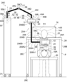
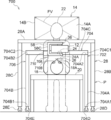
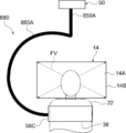
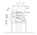
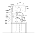
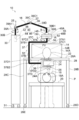
- FIG. 1 is a front view configuration diagram illustrating an example of an overall configuration of a surgery support system according to a first embodiment.
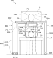
- FIG. 1 is a plan view showing an example of an overall configuration of a surgery support system according to a first embodiment.
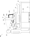
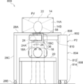
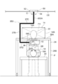
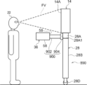
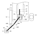
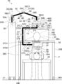
- FIG. 1 is a side view configuration diagram illustrating an example of an overall configuration of a surgery support system according to a first embodiment.
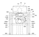
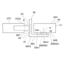
- It is a front view block diagram which shows an example of a structure of the installation part contained in the support apparatus of the surgery assistance system which concerns on 1st Embodiment.
- FIG. 2 is a plan view configuration diagram illustrating an example of a configuration of an installation unit included in a support device of the surgery support system according to the first embodiment.
- FIG. 25 is a schematic front view showing a first modification of the configuration for supporting the display included in the surgery support system shown in FIG. 24.
- FIG. 25 is a schematic front view showing a first modification of the configuration for supporting the display included in the surgery support system shown in FIG. 24.
- FIG. 25 is a schematic front view showing a second modification of the configuration for supporting the display included in the surgery support system shown in FIG. 24.
- FIG. 26 is a schematic front view showing a first modification of the configuration for supporting the display included in the surgery support system shown in FIG. 25.
- FIG. 26 is a schematic front view showing a second modification of the configuration for supporting the display included in the surgery support system shown in FIG. 25.
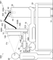
- It is a front view schematic configuration diagram showing an example of a case where the user is located on the temporal side of the patient in the surgery support system shown in the first embodiment.
- FIG. 3 is a schematic plan view showing an example of a case where the user is located on the temporal side of the patient in the surgery support system shown in the first embodiment.
- FIG. 1 It is a front view block diagram which shows the 1st modification of the structure of the installation part contained in the support apparatus of the surgery assistance system which concerns on embodiment. It is a front view configuration diagram showing a second modification of the configuration of the installation section included in the support device of the surgery support system according to the first to eighth embodiments.
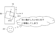
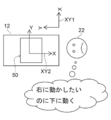
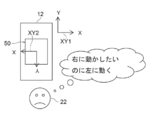
- a plan view showing a first arrangement example which is an example of a positional relationship between the surgical microscope and the arm body moving mechanism when the orientation of the surgical microscope in the horizontal plane and the direction of the arm body moving mechanism in the horizontal plane deviate from each other.
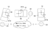
- FIG. 40 is a plan view showing an example of the positional relationship between the surgical microscope and the arm body moving mechanism when the misalignment shown in each of FIGS. 37 to 39 is eliminated.
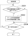
- FIG. 6 is a flowchart illustrating an example of a flow of a control process according to the embodiment.
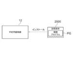
- FIG. 4 is a conceptual diagram showing an example of a mode in which a control program stored in a storage medium is installed on an operating microscope. It is a front view schematic structure figure showing the modification of the support device concerning a 1st embodiment. It is a front view schematic configuration diagram showing a modified example of a display and a caster base provided with a swivel mechanism used in the surgery support system according to the embodiment. It is a front view schematic structure figure showing the 2nd modification of the support device concerning a 1st embodiment.
- CPU indicates an abbreviation of “Central Processing Unit”.
- RAM refers to an abbreviation of “Random @ Access @ Memory”.
- ROM refers to an abbreviation of “Read @ Only @ Memory”.
- I / F indicates an abbreviation of “Interface”.
- EL indicates an abbreviation of “Electro-Luminescence”.
- the ASIC is an abbreviation of “Application ⁇ Specific ⁇ Integrated ⁇ Circuit”.
- FPGA indicates an abbreviation of “Field-Programmable Gate Array”.
- SSD indicates an abbreviation of “Solid ⁇ State ⁇ Drive”.
- DVD-ROM is an abbreviation of “Digital ⁇ Versatile ⁇ Disc ⁇ Read ⁇ Only ⁇ Memory”.
- USB indicates an abbreviation of “Universal ⁇ Serial ⁇ Bus”.
- right angle refers to an angle obtained by intersecting a horizontal line and a vertical line.
- the angle described as “right angle” is not necessarily a right angle, and may be shifted as long as it is within an allowable error.
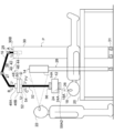
- the surgery support system 10 includes a surgical microscope 12, a display 14, and a support device 16.
- the surgery support system 10 is an example of the “surgery support system” or the “image display system” according to the technology of the present disclosure.
- the display 14 is an example of the “display unit” according to the technology of the present disclosure.
- the support device 16 is an example of a “support device” according to the technology of the present disclosure.
- the surgical microscope 12 is an example of a “microscope” according to the technology of the present disclosure.
- the surgery support system 10 includes an ophthalmic surgery support system applied to the surgery or observation of the eye 18A of the patient 18 or a surgical support system applied to the surgery or observation of the affected area of the patient 18. Including.
- a patient 18 who is a subject of a surgery by the surgery support system 10 is placed on an operating table 20 in a operable posture.
- the operable posture refers to, for example, a state of lying on the back.
- the user 22 faces the patient 18 and the surgical microscope 12 placed on the operating table 20 in an operable posture in a posture in which the patient 18 and the surgical microscope 12 are looked down from the top of the patient 18.
- the user 22 indicates, for example, a surgeon, but the technology of the present disclosure is not limited to this.
- the user 22 may be an assistant who assists the surgeon from the side or behind the surgeon.
- the operating microscope 12 has an objective lens 24.
- the objective lens 24 has an objective surface 24A directed outside the operating microscope 12.
- the objective surface 24A includes the lens surface closest to the operation field 26 side among the lens surfaces of the objective lens 24.
- the objective surface 24A includes an incident surface on which observation light reflected on a predetermined portion of the patient 18 is incident, or includes a lens surface on which reflected light from the operation field 26 is incident.
- the operating microscope 12 is arranged so that the object plane 24A is located in front of the operating field 26 and below the line of sight of the user 22 located at the top of the patient 18. That is, the line of sight of the user 22 is in a region vertically above the operating microscope 12 supported by the support device 16.
- the operating microscope 12 arranged in this way captures the surgical field light, which is the reflected light with respect to the surgical field 26, from the objective lens 24, and generates a surgical field image based on the captured surgical field light.
- the eye 18A as a surgical target is illustrated as the surgical field 26.
- the surgical field 26 is, for example, an area including the eye 18A and the periphery of the eye 18A. Alternatively, only the region that has been recognized by the user 22 as a lesion in the eye 18A may be used.
- the operative field 26 may be an area determined by the user 22 as an observation target.
- the operation field image is an example of the “observation image” according to the technology of the present disclosure.
- the display 14 displays various information.
- the display 14 includes a liquid crystal display or an organic EL display.
- the display 14 is installed on the upper surface of a caster table 28 having a gate shape as viewed from the user 22 side.
- the caster table 28 includes a top plate 28A and legs 28B and 28C.
- a caster 28D is provided on the bottom surface of the leg 28B, and a caster 28E is provided on the bottom surface of the leg 28C.
- the top plate 28A is formed along a horizontal plane.
- the top plate 28A is supported by a leg 28B from one end and supported by a leg 28C from the other end. Therefore, the outline shape of the caster table 28 is a gate shape in a front view due to the top plate 28A and the legs 28B and 28C.
- the caster table 28 is arranged at the user front position P.
- the user front position P refers to a position that is located in front of the user 22 and straddles the operating table 20 and the patient 18 placed on the operating table 20 in an operable posture.
- the abdomen of the patient 18 is located directly below the top plate 28A
- the leg 28B is located on one side of the abdomen of the patient 18
- the leg 28C is located on the other side of the abdomen of the patient 18. It is arranged to be located.
- An operation field image of the patient 18 obtained from the operation microscope 12 is displayed on the horizontally long rectangular screen 14A of the display 14.
- the operative field image refers to an image indicating the operative field 26.
- the surgical field image is generated based on the surgical field light captured by the surgical microscope 12 via the objective lens 24.
- the display 14 has a screen frame 14B.
- the screen frame 14B is an outer frame of the screen 14A and holds the screen 14A.
- the operative field image is displayed as a live view image on the entire screen 14A of the display 14, but this is merely an example.
- a screen on which an operation field image is displayed as a live view image and a screen on which information other than the operation field image is displayed may be arranged.
- Information other than the operative field image includes, for example, patient information and a past image.
- the patient information refers to text information that can specify the patient, such as the name, age, and gender of the patient 18.
- the past image refers to, for example, an image obtained by imaging a lesion of the patient 18 before the operation.
- the support device 16 is a device that can support the surgical microscope 12.
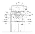
- the support device 16 includes a base 30, a support arm 32, an installation part 36, and a moving part 38.
- the outer surface of the support device 16 that is, the surface exposed to the outside of the support device 16 is a surface that suppresses noise light such as reflected light. In this case, the reflected light is reduced on the surface exposed to the outside of the support device 16.
- the outer surface of the support device 16 is given a color that suppresses reflection of light that hinders the user 22 from visually recognizing the operative field image, as compared to a case where the support device 16 is formed of, for example, a glossy surface or white.
- the outer surface of the support device 16 is colored black.
- the technology of the present disclosure is not limited to this, and at least the surface that enters the field of view of the user 22 is colored black. Just fine.
- the color adopted as the color of the outer surface of the support device 16 may be a color other than black, and is a color derived from a test result such as a sensory test as a color that suppresses reflected light that hinders visual recognition of an operation field image. I just need. Further, the outer surface of the support device 16 may be formed of a material that absorbs not only coloring but also light.
- the support arm 32 is an arm that can support the operation microscope 12.
- the support arm 32 can support the operating microscope 12 by holding the installation section 36.
- the entire support arm 32 is obtained from the surgical microscope 12, and the surgical field image displayed on the screen 14 ⁇ / b> A is viewed by the user 22 from the front side of the surgical microscope 12. Is located at a position deviating from the visual field region FV (see FIGS. 1 to 3) for.
- the user 22 visually recognizes the operation field image through a space vertically above the operation microscope 12.
- the visual field region FV refers to a space region for the screen 14A in the visual field of the user 22 when the user 22 is viewing the screen 14A from the front side of the surgical microscope 12.
- the visual field region FV is determined based on the positional relationship between the pupil of the user 22 and the screen 14A.
- the support arm 32 is an example of the “arm” according to the technology of the present disclosure. Further, the support arm 32 is an example of a “support section” according to the technology of the present disclosure.
- the support arm 32 is a multi-joint arm having a support arm body 37 and an extension arm 39.
- the shape of the support arm body 37 is a half-rectangular frame when viewed from the front side of the surgical microscope 12 during an operation or in an observation state.
- the shape of the support arm main body 37 is a half rectangular frame shape. It is.
- the support arm main body 37 is formed by bending a first vertical arm portion 37A, a second vertical arm portion 37B, a first horizontal arm portion 37C, and a second horizontal arm portion 37D.
- the support arm main body 37 is formed in a shape bent at a right angle or a predetermined angle, and includes a first vertical arm portion 37A, a second vertical arm portion 37B, a first horizontal arm portion 37C, and a plurality of bent nodes. And the second horizontal arm portion 37D.
- Each of the first vertical arm portion 37A, the second vertical arm portion 37B, the first horizontal arm portion 37C, and the second horizontal arm portion 37D is formed in a cylindrical shape.
- the support arm main body 37 is integrally formed from one end to the other end in the order of a first vertical arm portion 37A, a first horizontal arm portion 37C, a second vertical arm portion 37B, and a second horizontal arm portion 37D. .
- the term “formed integrally” as used herein refers to, for example, being formed by integral molding or being integrated by welding, and means that the bent portion is fixed. I do.
- the first vertical arm portion 37A is one end portion of the support arm main body 37 and extends in the vertical direction.
- the second vertical arm portion 37B is the other end portion of the support arm main body 37 and extends in the vertical direction.
- One end 37A1 of the first vertical arm 37A is connected to one end 37B1 of the second vertical arm 37B via the first horizontal arm 37C. That is, one end 37A1 of the first vertical arm 37A is connected to one end 37C1 of the first horizontal arm 37C, and the other end 37C2 of the first horizontal arm 37C is connected to one end 37B1 of the second vertical arm 37B. Are linked.
- the other end 37B2 of the second vertical arm 37B is connected to one end 37D1 of the second horizontal arm 37D.
- the second horizontal arm portion 37D extends horizontally from the installation portion 36, and the second vertical arm portion 37B extends vertically from one end 37D1 of the second horizontal arm portion 37D.
- the tip of the support arm main body 37 that is, the other end 37D2 of the second horizontal arm portion 37D is connected to the installation portion.
- the operating microscope 12 is movably installed on the installation section 36.
- the first vertical arm 37A, the second vertical arm 37B, the first horizontal arm 37C, and the second horizontal arm 37D include a microscope-side moving mechanism 46 and a setting unit 36 (or the operating microscope 12) described later. And is located between.
- the length of the second horizontal arm portion 37D is formed to be longer than the length of the first vertical arm portion 37A.
- the first vertical arm 37A, the second vertical arm 37B, the first horizontal arm 37C, and the second horizontal arm 37D are examples of the “plurality of arms” according to the technology of the present disclosure.
- the second horizontal arm portion 37D is an example of a “first arm portion” according to the technology of the present disclosure.
- the second vertical arm 37B is an example of a “second arm” according to the technology of the present disclosure.
- the first horizontal arm portion 37C is an example of a “third arm portion” according to the technology of the present disclosure.
- the other end 37D2 is an example of “one end of the first arm unit” according to the technology of the present disclosure.
- the one end 37D1 is an example of “the other end of the first arm unit” according to the technology of the present disclosure.
- the other end 37B2 is an example of “one end of the second arm” according to the technology of the present disclosure.
- the one end 37B1 is an example of “the other end of the second arm unit” according to the technology of the present disclosure.
- the other end 37C2 is an example of “one end of the third arm unit” according to the technology of the present disclosure.
- one end 37A1 of the first vertical arm portion 37A is connected to one end 37C1 of the first horizontal arm portion 37C.
- the technology of the present disclosure is not limited to this, and the first vertical arm portion 37A is not limited thereto. May be connected to one end 37C1 of the first horizontal arm portion 37C. That is, a portion on the one end 37A1 side of the first vertical arm portion 37A may be connected to a portion on the one end 37C1 side of the first horizontal arm portion 37C.
- the other end 37C2 of the first horizontal arm portion 37C is connected to one end 37B1 of the second vertical arm portion 37B, but the technology of the present disclosure is not limited to this, and The other end 37C2 of the horizontal arm 37C may be connected to the one end 37B1 of the second vertical arm 37B. That is, the portion on the other end 37C2 side of the first horizontal arm portion 37C may be connected to the portion on the one end 37B1 side of the second vertical arm portion 37B.
- the other end 37B2 of the second vertical arm portion 37B is connected to one end 37D1 of the second horizontal arm portion 37D.
- the other end 37B2 of the vertical arm 37B may be connected to the one end 37D1 of the second horizontal arm 37D. That is, the portion on the other end 37B2 side of the second vertical arm portion 37B may be connected to the portion on the one end 37D1 side of the second horizontal arm portion 37D. Further, in the example illustrated in FIG.
- the other end 37D2 of the second horizontal arm portion 37D is connected to the installation portion 36, but the technology of the present disclosure is not limited thereto, and the other end of the second horizontal arm portion 37D.
- the 37D2 side may be connected to the installation section 36. That is, a portion on the other end 37D2 side of the second horizontal arm portion 37D may be connected to the installation portion 36.
- the second horizontal arm portion 37D extends from the setting portion 36 in an intersecting direction (for example, an orthogonal direction) that intersects the ground in a vertical direction.
- the direction in which the second horizontal arm 37D extends is such that the other end 37B2 is connected to the second horizontal arm 37D and the one end 37B1 is directed upward from the other end 37B2 in the vertical direction.
- the second horizontal arm portion 37D Extends from the second horizontal arm portion 37D in a direction crossing upward.
- the second horizontal arm portion 37D extends in a direction different from the front surface of the surgical microscope 12 from the installation portion 36 in a direction perpendicular to the installation portion 36, and the second vertical arm portion 37B is connected to the surgical microscope 12 Are formed to extend in a direction away from the later-described objective surface 24A.
- the extension arm section 39 supports the support arm main body 37 by being connected to the support arm main body 37 via a microscope-side moving mechanism 46 described below from a position further upward from the screen 14A than the support arm main body 37.
- the general appearance of the extension arm 39 is a bent shape, and is divided into a third vertical arm 39A, a fourth vertical arm 39B, a first inclined arm 39C, and a second inclined arm 39D.
- Each of the third vertical arm portion 39A, the fourth vertical arm portion 39B, the first inclined arm portion 39C, and the second inclined arm portion 39D is formed in a cylindrical shape.
- the extension arm section 39 is an articulated arm, and includes a first arm displacement mechanism 25 and a second arm displacement mechanism 27.
- the third vertical arm 39A and the first inclined arm 39C are connected via the first arm displacement mechanism 25.
- the first inclined arm 39C and the second inclined arm 39D are connected via the second arm displacement mechanism 27.
- the third vertical arm 39A is one end of the extension arm 39 and extends in the vertical direction.
- the fourth vertical arm 39B is the other end of the extension arm 39 and extends in the vertical direction.
- One end 39A1 of the third vertical arm 39A is connected to one end of the fourth vertical arm 39B via the first arm displacement mechanism 25, the first inclined arm 39C, the second arm displacement mechanism 27, and the second inclined arm 39D.
- the first inclined arm portion 39C is inclined upward from one end 39A1 to the first arm displacement mechanism 25.
- the second inclined arm portion 39D is inclined downward from the second arm displacement mechanism 27 to one end 39B1 of the fourth vertical arm portion 39B.
- the first inclined arm 39C is provided in the first arm displacement mechanism 25 so as to be able to swing vertically along one end 39A1 of the third vertical arm 39A. That is, the first arm displacement mechanism 25 causes the first inclined arm 39C to pitch with respect to the third vertical arm 39A.
- the pitching of the first inclined arm portion 39C by the first arm displacement mechanism 25 is realized manually, but is not limited thereto, and may be realized electrically.
- the second inclined arm portion 39D is provided in the second arm displacement mechanism 27 so as to be capable of swinging in the vertical and horizontal directions with one end 39C1 of the first inclined arm portion 39C as a base point. That is, the second arm displacement mechanism 27 causes the second inclined arm portion 39D to pitch and yaw with respect to the first inclined arm portion 39C.
- the pitching and yawing of the second inclined arm portion 39D by the second arm displacement mechanism 27 are realized by a manual method, but are not limited thereto, and may be realized by an electric method.
- an articulated arm is given as an example of the extension arm 39, but the technology of the present disclosure is not limited to this.
- the third vertical arm 39A, the first inclined arm 39C, the second inclined arm 39D, and the fourth vertical arm 39B are integrally formed in this order. May be.
- first arm displacement mechanism 25 and the second arm displacement mechanism 27 illustrate the technique of the present disclosure is not limited to this, and Only one of the first arm displacement mechanism 25 and the second arm displacement mechanism 27 may be applied.
- the moving unit 38 moves the support arm 32.
- the moving unit 38 includes a horizontal plane moving mechanism 40 and a height adjusting mechanism 42, and moves the support arm 32 by operating at least one of the horizontal plane moving mechanism 40 and the height adjusting mechanism 42.
- the horizontal plane moving mechanism 40 is an example of the “cross plane moving mechanism” according to the technology of the present disclosure.
- the height adjustment mechanism 42 is an example of a “height adjustment mechanism” according to the technology of the present disclosure.
- the horizontal plane moving mechanism 40 moves the support arm 32 along the horizontal plane.
- the horizontal plane moving mechanism 40 includes a base side rotating mechanism 44 and a microscope side moving mechanism 46.
- the movement of the support arm 32 along the horizontal plane is realized by operating at least one of the base rotation mechanism 44 and the microscope movement mechanism 46.
- the microscope-side moving mechanism 46 includes a rotating mechanism 48 for turning and an arm body moving mechanism 50.
- the turning rotation mechanism 48 and the base side rotation mechanism 44 cause the extension arm 39 to yaw.
- the operations of the turning rotation mechanism 48 and the base rotation mechanism 44 are manually realized.
- the operation of the arm body moving mechanism 50 is realized by receiving power supplied from a power supply source 114 (see FIG. 6) described later.
- the turning rotation mechanism 48 and the base-side rotation mechanism 44 are examples of the “yaw mechanism” and the “overall yaw mechanism” according to the technology of the present disclosure.
- the operations of the turning rotation mechanism 48 and the base-side rotation mechanism 44 may be realized by electric power.
- the operation of the arm body moving mechanism 50 may be realized manually.
- the arm body moving mechanism 50 moves the support arm body 37 along a horizontal plane.
- the arm body moving mechanism 50 includes an arm body sliding mechanism 52 and an arm body rotating mechanism 54.
- the movement of the support arm body 37 along the horizontal plane is realized by operating at least one of the arm body slide mechanism 52 and the arm body rotation mechanism 54.
- the arm body slide mechanism 52 is an example of the “cross-plane slide mechanism” according to the technology of the present disclosure.
- the arm body moving mechanism 50 is disposed above the surgical microscope 12 in the vertical direction (eg, in a direction away from the ground upward). Thus, the operating microscope 12 is supported in a state of being suspended by the support arm 32.
- the base 30 is formed in a column shape. At the lower end of the base 30, a plurality of casters 31 are provided.
- the base-side rotation mechanism 44 is formed in a bottomed cylindrical shape with an upper opening, and is provided at the upper end 30 ⁇ / b> B of the base 30.
- a third vertical arm portion 39A is inserted into the base rotation mechanism 44 from above vertically.
- the base-side rotation mechanism 44 holds the third vertical arm portion 39A rotatably in the direction of the arc arrow A, thereby holding the entire extension arm portion 39 as yawable with the third vertical arm portion 39A as a rotation axis. ing.
- the height adjustment mechanism 42 is formed in a bottomed cylindrical shape with an open top, and is provided at the upper end 30 ⁇ / b> B of the base 30.
- a base rotation mechanism 44 is fitted into the height adjustment mechanism 42 from above vertically.
- the height adjustment mechanism 42 holds the base-side rotation mechanism 44 so as to be movable by sliding in multiple stages along the vertical direction. Therefore, the base-side rotation mechanism 44 fitted in the height adjustment mechanism 42 slides in multiple stages along the vertical direction by receiving an external force from vertically above.
- the “external force from vertically above” here refers to, for example, an external force by the user 22. That is, the operation of the height adjustment mechanism 42 is realized manually.
- the case where the operation of the height adjustment mechanism 42 is manually realized is illustrated, but the technology of the present disclosure is not limited to this, and the operation of the height adjustment mechanism 42 is realized electrically. You may do so.
- the multi-step sliding in the height adjustment mechanism 42 is realized, for example, by the height adjustment mechanism 42 having a plurality of stoppers (not shown).
- the plurality of stoppers are provided on the inner peripheral surface of the height adjusting mechanism 42 along the vertical direction.
- Each of the plurality of stoppers expands and contracts in the horizontal direction according to a pressing force generated from the outer peripheral surface of the base rotation mechanism 44 to the inner peripheral surface of the height adjustment mechanism 42 by receiving an external force from vertically above.
- the base-side rotation mechanism 44 slides in multiple stages along the vertical direction.
- a multi-step slide is illustrated, but the present invention is not limited to this, and a stepless continuous slide may be used.
- Sliding the base-side rotating mechanism 44 steplessly in the vertical direction requires a vertical movement against the frictional force generated by the contact between the inner peripheral surface of the height adjusting mechanism 42 and the outer peripheral surface of the base-side rotating mechanism 44. This is realized by pushing or pulling the base side rotation mechanism 44 in the direction.
- the turning mechanism 48 includes a bearing 48A and a base 48B.
- the base 48B is a rectangular plate in plan view.
- a bearing 48A is provided on the upper surface of the base 48B.
- the bearing 48A is formed in a bottomed cylindrical shape whose upper part is opened.
- a fourth vertical arm portion 39B is inserted into the bearing 48A from above vertically.
- the bearing 48A holds the fourth vertical arm 39B rotatably in the direction of the arc B to hold the entire extension arm 39 together with the base 30 in a yawable manner with the fourth vertical arm 39B as a rotation axis. ing.
- the arm main body slide mechanism 52 is provided on the lower surface of the base 48B so as to be slidable and movable along each of four directions orthogonal to each other in a horizontal plane.
- the “four directions” referred to here are an upward direction U (see FIG. 3), a downward direction D (see FIG. 3), and a leftward direction L when viewed from the patient 18 placed on the operating table 20 in a operable posture. (See FIG. 1) and rightward direction R (see FIG. 1).
- the arm body rotation mechanism 54 is provided in the arm body slide mechanism 52, and is formed in a bottomed cylindrical shape with an open bottom.
- the base end of the support arm main body 37 that is, the other end of the first vertical arm portion 37A is inserted into the arm main body rotation mechanism 54 from below vertically.
- the arm main body rotation mechanism 54 holds the first vertical arm portion 37A so as to be rotatable in the direction of the arc C, thereby holding the whole of the support arm main body 37 in a yawable manner with the first vertical arm portion 37A as a rotation axis. ing.
- the arm body rotation mechanism 54 causes the entire support arm body 37 to yaw with respect to the extension arm 39.
- the arm body rotation mechanism 54 is an example of a “yaw mechanism” and a “partial yaw mechanism” according to the technology of the present disclosure.
- the arm body rotation mechanism 54 is disposed between the arm body slide mechanism 52 and the support arm body 37.
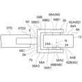
- the installation section 36 includes an installation section main body 58.
- the installation portion main body 58 is formed in a semi-rectangular frame shape when viewed from the front.
- the “front view” mode refers to a mode viewed from the user 22 side.
- the installation portion main body 58 is divided into a first horizontal plate 58A, a second horizontal plate 58B, and a vertical plate 58C.
- Each of the first horizontal plate 58A, the second horizontal plate 58B, and the vertical plate 58C is a rectangular parallelepiped thin plate.
- the installation section main body 58 is integrally formed from one end to the other end in the order of the first horizontal plate 58A, the vertical plate 58C, and the second horizontal plate 58B.
- Each of the upper surface 58A1 and the lower surface 58A2 of the first horizontal plate 58A is a horizontal plane.
- Each of the upper surface 58B1 and the lower surface 58B2 of the second horizontal plate 58B is also a horizontal plane.
- the first horizontal plate 58A and the second horizontal plate 58B are arranged at a position where the upper surface 58A1 of the first horizontal plate 58A and the lower surface 58B2 of the second horizontal plate 58B face each other in the vertical direction.
- the vertical plate 58C is formed along the vertical direction, and connects the base end 58A3 of the first horizontal plate 58A and the base end 58B3 of the second horizontal plate 58B.
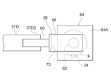
- the installation unit 36 holds the operating microscope 12 at at least a portion of the housing 64 thereof, and holds the operating microscope 12 in a vertically rotatable manner.
- the “vertical rotation” here means so-called pitching.
- the installation section 36 holds the surgical microscope 12 so as to be able to rotate laterally.
- the “lateral rotation” here means so-called yawing. In the embodiment according to the technology of the present disclosure, yawing, pitching, and rolling of the surgical microscope 12 refer to operations when the surgical microscope 12 is viewed from the front.
- the installation unit 36 holds the operating microscope 12 slidably in the direction of the normal line N of the objective surface 24A of the operating microscope 12.
- the installation section 36 holds the operating microscope 12 slidably along the XY plane.
- the “XY plane” refers to a plane perpendicular to the normal line N of the objective plane 24A of the operating microscope 12.
- the term “vertical” as used herein refers to not only a perfect vertical but also a vertical in a sense including an allowable error.
- the installation section 36 includes a vertical rotation shaft 60, a horizontal rotation mechanism 62, an intersecting plane slide mechanism 68, and a normal direction slide mechanism 70 as a moving mechanism of the installation section 36 for moving the operating microscope 12.
- the operations of the vertical rotation shaft 60, the horizontal rotation mechanism 62, the cross-plane slide mechanism 68, and the normal direction slide mechanism 70 are realized by receiving power supplied from a power supply source 114 described later.
- the housing 64 of the surgical microscope 12 is formed in a rectangular parallelepiped shape in which the aspect ratio in the front view is larger than the height in the horizontal direction.
- the upper surface 64A of the housing 64 is disposed at a position facing the lower surface 58B2 of the second horizontal plate 58B and in parallel with the lower surface 58B2.
- the lower surface 64B of the housing 64 is arranged at a position facing the upper surface 58A1 of the first horizontal plate 58A and parallel to the upper surface 58A1.
- the housing 64 is held by the installation part main body 58 so as to be able to rotate laterally in the direction of the arc arrow F while protruding from the installation part main body 58.
- the objective lens 24 is disposed at a position protruding from the installation section main body 58, and as an example, the objective surface 24A is exposed from the lower surface 64B as shown in FIG.
- One end of the vertical rotation shaft 60 is supported by the other end 37D2 of the second horizontal arm portion 37D so as to be vertically rotatable.
- the other end of the vertical rotation shaft 60 is supported by the vertical plate 58C so as to be vertically rotatable.
- the normal direction slide mechanism 70 holds the operating microscope 12 so as to be slidable in the direction of the normal line N of the objective surface 24A.
- the other end of the vertical rotation shaft 60 is held so as to be slidable in the normal direction N with respect to the normal direction slide mechanism 70.
- the cross plane slide mechanism 68 includes a first cross plane slide mechanism 68A and a second cross plane slide mechanism 68B.
- the horizontal rotation mechanism 62 includes a first rotation shaft 62A and a second rotation shaft 62B, and holds the operation microscope 12 so as to be able to rotate in the horizontal direction.
- One end of a first rotating shaft 62A is fixed to the center of the upper surface 64A of the housing 64.
- the “central portion of the upper surface 64A of the housing 64” here includes, for example, a portion of the upper surface 64A corresponding to the center of gravity of the operating microscope 12.
- the “center of gravity” means a center of gravity including an allowable error in addition to a perfect center of gravity.
- the first rotation shaft 62A is arranged at a position where the axis of the first rotation shaft 62A is along the normal line N and coincides with the center of gravity of the operating microscope 12.
- the other end of the second rotating shaft 62B is fixed to the center of the lower surface 64B of the housing 64.
- the “central portion of the lower surface 64B of the housing 64” referred to here includes a portion of the lower surface 64B corresponding to the center of gravity of the operating microscope 12.
- the second rotation shaft 62B is disposed at a position where the axis of the second rotation shaft 62B is along the normal line N and coincides with the center of gravity of the operating microscope 12. Further, the second rotation shaft 62B is arranged at a position where the axis of the second rotation shaft 62B and the axis of the first rotation shaft 62A coincide.
- first rotation shaft 62A is rotatably held by a first cross-plane slide mechanism 68A.
- the other end of the second rotation shaft 62B is held by a second intersecting plane slide mechanism 68B.
- the first cross-plane slide mechanism 68A holds the first rotation shaft 62A so as to be slidable along the XY plane.
- the second intersecting plane slide mechanism 68B holds the second rotation shaft 62B slidably along XY.
- the first cross-plane slide mechanism 68A and the second cross-plane slide mechanism 68B allow the operating microscope 12 to move within the movable range by sliding the first rotation shaft 62A and the second rotation shaft 62B in the same direction along the XY plane. Slide along the XY plane.
- the “movable range” refers to a slidable range in the XY plane.
- the operating microscope 12 includes an imaging unit that acquires an image of an observation target.
- the imaging unit includes a compound-eye imaging device 78.
- Observation light which is light reflected by the observation target, enters the operating microscope 12.
- the operating microscope 12 captures, from the objective lens 24, the surgical field light, which is the light reflected at a site 80 corresponding to the tissue forming the surgical field 26, of the body tissue of the patient 18, and converts the captured surgical field light into a compound eye.
- the part 80 is imaged by being imaged by the image sensor 78.
- the operating microscope 12 captures an image of the part 80 to acquire an image indicating the part 80 as an operation field image.
- operation field light is described as an example of “observation light” according to the technology of the present disclosure, the technology of the present disclosure is not limited thereto, and is used for an observation target other than the site 80. Observation light, which is reflected light, may be incident on the surgical microscope 12.
- the compound-eye imaging device 78 generates and outputs images corresponding to each of a plurality of directions by imaging the part 80 from a plurality of directions.
- the plurality of directions refers to two directions.
- the two directions refer to, for example, the gaze directions of the right and left eyes of a human.
- the compound-eye imaging device 78 includes a first imaging device 78A and a second imaging device 78B, and each of the first imaging device 78A and the second imaging device 78B has a portion 80 from two directions. Is imaged.
- an operation field image obtained by imaging the region 80 by the first imaging device 78A is referred to as a first image
- a surgical image obtained by imaging the region 80 by the second imaging device 78B is referred to as a second image.
- the field image is called a second image.
- image sensors when it is not necessary to distinguish and describe the first image sensor 78A and the second image sensor 78B, they are simply referred to as “image sensors” without reference numerals.
- a CCD image sensor is applied as an example of an imaging device.
- the technology of the present disclosure is not limited thereto, and another image sensor such as a CMOS image sensor is applied. May be.
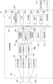
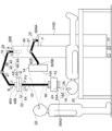
- the operating microscope 12 includes a first illumination device 81, a second illumination device 82, a first imaging optical system 84, a second imaging optical system 86, a first image signal processing circuit 88, a second image signal processing circuit 90, And an image sensor driver 92.
- the surgical microscope 12 includes a bus line 94, a CPU 96, a ROM 98, a RAM 100, a receiving device 102, a communication I / F 104, a drive driver 106, a display control unit 108, an image memory 110, and an image processing unit 112.
- the first image signal processing circuit 88 is connected to the first image sensor 78A and the bus line 94.
- the second image signal processing circuit 90 is connected to the second image sensor 78B and the bus line 94.
- the image sensor driver 92 is connected to the first image sensor 78A, the second image sensor 78B, and the bus line 94.
- the CPU 96, the ROM 98, the RAM 100, the receiving device 102, the communication I / F 104, the drive driver 106, and the display control unit 108 are connected to the bus line 94.
- a first imaging optical system 84 is provided between the first imaging element 78A and the objective lens 24.
- the first illumination device 81 emits the first illumination light to the portion 80 via the objective lens 24.
- the first illumination light emitted from the first illuminating device 81 is reflected at the portion 80, and the first operative field light, which is the light reflected at the portion 80, enters the first imaging optical system 84 via the objective lens 24. I do.
- the first imaging optical system 84 forms an image of the incident first operation field light on a light receiving surface of the first image sensor 78A.
- the first image sensor 78A generates and outputs a first image signal based on the first operation field light.
- a second imaging optical system 86 is provided between the second imaging element 78B and the objective lens 24.
- the second illumination device 82 emits the second illumination light to the part 80 via the objective lens 24.
- the second illumination light emitted from the second illumination device 82 is reflected at the site 80, and the second operating field light, which is the light reflected at the site 80, enters the second imaging optical system 86 via the objective lens 24. I do.
- the second imaging optical system 86 forms an image of the incident second operation field light on a light receiving surface of the second image sensor 78B.
- the second image sensor 78B generates and outputs a second image signal based on the second operation field light.
- the CPU 96 is a control unit that controls the entire operation support system 10.
- the ROM 98 is a memory in which various programs and various parameters are stored in advance.
- the RAM 100 is a memory used as a work area when executing various programs.
- the image sensor driver 92 is connected to the first image sensor 78A and the second image sensor 78B, and supplies a drive pulse to each of the first image sensor 78A and the second image sensor 78B under the control of the CPU 96. Each pixel of the first image sensor 78A and the second image sensor 78B is driven according to a drive pulse supplied by the image sensor driver 92.
- the first image signal processing circuit 88 reads out one frame of the first image signal from the first image sensor 78A for each pixel under the control of the CPU 96.
- the first image signal processing circuit 88 performs various processes such as correlated double sampling, gain adjustment, and A / D conversion on the read first image signal.
- the first image signal processing circuit 88 converts the first image signal digitized by performing various processes on the first image signal to a specific frame rate (for example, a number) specified by a clock signal supplied from the CPU 96. (10 frames / sec) to the image memory 110 for each frame.
- the second image signal processing circuit 90 reads the second image signal for one frame from the second image sensor 78B for each pixel under the control of the CPU 96.
- the second image signal processing circuit 90 performs various processes such as correlated double sampling, gain adjustment, and A / D conversion on the read second image signal.
- the second image signal processing circuit 90 converts the digitized second image signal by performing various processes on the second image signal for each frame at a specific frame rate specified by a clock signal supplied from the CPU 96. To the image memory 110.
- the image memory 110 temporarily holds the first image signal input from the first image signal processing circuit 88 and the second image signal input from the second image signal processing circuit 90.
- the image processing unit 112 acquires the first image signal and the second image signal for each frame at a specific frame rate from the image memory 110, and performs gamma correction on the acquired first image signal and second image signal. Various processing such as luminance / color difference conversion and compression processing are performed. Further, the image processing unit 112 outputs the first image signal and the second image signal subjected to various processes to the display control unit 108 at a specific frame rate for each frame. Further, the image processing unit 112 outputs the first image signal and the second image signal subjected to various processes to the CPU 96 in response to a request from the CPU 96. The CPU 96 performs a predetermined process on the input first image signal and second image signal, and outputs the processed first image signal and second image signal to a predetermined output destination.
- the display control unit 108 is connected to the display 14 and controls the display 14 under the control of the CPU 96.
- the display control unit 108 outputs the first image signal and the second image signal input from the image processing unit 112 to the display 14 at a specific frame rate for each frame.
- the display 14 is configured to display a first image signal indicated by the first image signal and a second image signal indicated by the second image signal based on the first image signal and the second image signal input at a specific frame rate from the display control unit 108. Is displayed as a live view image. In a state where the first image and the second image are displayed on the display 14 as a live view image, the user 22 observes the live view image through polarized glasses to view the operative field 26 in a stereoscopic live view. It can be recognized as an image.
- the receiving device 102 has a plurality of foot switches, a touch panel, various hard keys, and the like, and receives a plurality of instructions from the user 22.
- the plurality of instructions include a plurality of mechanism operation instructions for operating the moving unit 38.
- the plurality of mechanism operation instructions are received by, for example, a plurality of foot switches.
- the plurality of foot switches are operated by the user 22 or an assistant.
- a manual input device and / or a voice input device may be used together with at least one of the plurality of foot switches. Instead of a plurality of foot switches, a manual input type input device and / or a voice input type input device may be applied.
- Examples of the input device of the manual input method include a touch panel, a handle, a dial, a cross key, and / or a mouse.
- the input device of the voice input method refers to, for example, a microphone.
- the CPU 96 analyzes the sound collected by the microphone, and controls the power supply source 114 via the drive driver 106 according to the analysis result.
- the plurality of mechanism operation instructions include, for example, an arm body slide instruction, an arm body rotation instruction, a pitching instruction, a yawing instruction, a cross plane slide instruction, and a normal direction slide instruction.
- the arm body slide instruction includes, for example, an instruction to start the operation of the arm body slide mechanism 52, an instruction to stop the operation of the arm body slide mechanism 52, and an instruction to slide the support arm body 37.
- the arm body rotation instruction includes, for example, an instruction to start the operation of the arm body rotation mechanism 54, an instruction to stop the operation of the arm body rotation mechanism 54, and an instruction of a direction to yaw the entire support arm body 37.
- the pitching instruction includes, for example, an instruction to start the rotation of the vertical rotation shaft 60, an instruction to stop the rotation of the vertical rotation shaft 60, and an instruction of a direction in which the surgical microscope 12 is pitched.
- the direction in which the operating microscope 12 is pitched refers to, in other words, the rotation direction of the vertical rotation shaft 60.
- the yawing instruction includes, for example, an instruction to start the operation of the horizontal rotation mechanism 62, an instruction to stop the operation of the horizontal rotation mechanism 62, and an instruction to yaw the operating microscope 12.
- the direction in which the operating microscope 12 is yawed refers to the rotation direction of the first rotation shaft 62A and the second rotation shaft 62B.
- the cross plane slide instruction includes, for example, an instruction to start the operation of the cross plane slide mechanism 68, an instruction to stop the operation of the cross plane slide mechanism 68, and an instruction of a direction in which the surgical microscope 12 is slid.
- the normal direction slide instruction is, for example, an instruction to start the operation of the normal direction slide mechanism 70, an instruction to stop the operation of the normal direction slide mechanism 70, or any one of the directions in which the operating microscope 12 is moved along the normal line N. Instructions for moving in the direction.
- the drive driver 106 is connected to the power supply 114 and controls the power supply 114 under the control of the CPU 96.
- the power supply source 114 includes a plurality of motors, and supplies power to the arm body moving mechanism 50, the vertical rotation shaft 60, the horizontal rotation mechanism 62, the cross plane slide mechanism 68, and the normal direction slide mechanism 70.
- Each of the plurality of motors included in the power supply source 114 is connected to the arm body slide mechanism 52, the arm body rotation mechanism 54, the vertical rotation shaft 60, the horizontal rotation mechanism 62, the cross plane slide mechanism 68, and the normal direction slide mechanism 70. Assigned individually.
- Each of the arm body slide mechanism 52, the arm body rotation mechanism 54, the vertical rotation shaft 60, the horizontal rotation mechanism 62, the cross plane slide mechanism 68, and the normal direction slide mechanism 70 includes a plurality of motors included in the power supply source 114. It operates by receiving power from the corresponding motor.
- the operations of the arm body slide mechanism 52, the arm body rotation mechanism 54, the vertical rotation shaft 60, the horizontal rotation mechanism 62, the cross plane slide mechanism 68, and the normal direction slide mechanism 70 are controlled by the power supply source 114 by the drive driver 106. Is controlled by
- the CPU 96 controls the plurality of motors included in the power supply source 114 by controlling the drive driver 106 in accordance with the mechanism operation instruction received by the receiving device 102.
- the communication I / F 104 performs transmission and reception of various kinds of information by communicating with an external communication device (not shown) installed outside under the control of the CPU 96. That is, the communication I / F 104 receives the information transmitted from the external communication device, and outputs the received information to the CPU 96 via the bus line 94. In addition, the communication I / F 104 transmits information input from the CPU 96 via the bus line 94 to the external communication device.
- the external communication device there is at least one of a personal computer (not shown), a server (not shown), and a smart device (not shown).
- the following description is based on the premise that the caster table 28 is already arranged at the user front position P as shown in FIGS. 1 to 3 as an example. Also, in the following, for convenience of explanation, as shown in FIGS. 1 to 3 as an example, the screen 14A is displayed in a posture in which the user 22 stands on the top of the patient 18 placed on the operating table 20 in an operable posture. The following description is based on the premise that the user is facing directly.
- a live view image showing the operation field 26 is displayed on the screen 14A.
- the user 22 visually recognizes the screen 14A in the visual field region FV. It is assumed that this is the case.
- description will be made on the assumption that the operative field 26 is stereoscopically viewed by the user 22 through the live view image. The following description is based on the premise that one assistant is located in the left direction L (see FIG. 1) or the right direction R (see FIG. 1) of the patient 18 in addition to the user 22.
- the description will be made on the assumption that the base 30 of the support device 16 is already arranged on one side of the operating table 20.
- step 150 the user 22 or the assistant operates the arm body rotation mechanism 54 to support the assistant at the position where the assistant stands during surgery and on the opposite side of the patient 18.
- the arm body 37 is moved.
- the operation of the arm body rotation mechanism 54 is realized by receiving an arm body rotation instruction from the user 22 or an assistant by the reception device 102 and driving the power supply source 114 in accordance with the arm body rotation instruction received by the reception device 102. Is done.
- the user 22 or the assistant When the assistant's standing position at the time of surgery is the right direction R side of the patient 18, the user 22 or the assistant operates the arm body rotation mechanism 54 to position the entire support arm body 37 on the outer periphery of the screen frame 14B. Further, the support arm main body 37 is positioned on the left direction L side of the patient 18. In the example shown in FIG. 1, a state is shown in which the support arm main body 37 is positioned on the left direction L side of the patient 18 when the assistant stands during the operation on the right direction R side of the patient 18. Conversely, when the assistant's standing position during the operation is on the left side L of the patient 18, the user 22 or the assistant operates the arm body rotation mechanism 54 to move the entire support arm body 37 to the outer periphery of the screen frame 14B. And the support arm main body 37 is positioned on the right direction R side of the patient 18.
- the user 22 activates the moving unit 38 so that the lower surface 58A2 (see FIGS. 3 and 4) is positioned in front of the patient 18's face, and the setting unit 36 is positioned in front of the user 22.
- the position of the support arm main body 37 is adjusted so as to be positioned below the eyes of the user 22 on the side.
- the user 22 When adjusting the position of the support arm main body 37 in the height direction, for example, the user 22 manually operates the height adjustment mechanism 42.
- the user 22 controls the base-side rotation mechanism 44, the turning rotation mechanism 48, the arm body slide mechanism 52, and the arm body rotation mechanism 54. Activate.
- the operations of the base-side rotation mechanism 44 and the turning rotation mechanism 48 are manually implemented by the user 22.
- the operation of the arm body slide mechanism 52 is realized by receiving an arm body slide instruction from the user 22 by the reception device 102 and driving the power supply source 114 in accordance with the arm body slide instruction received by the reception device 102.
- the operation of the arm body rotation mechanism 54 is realized by receiving an arm body rotation instruction from the user 22 by the reception device 102 and driving the power supply source 114 in accordance with the arm body rotation instruction received by the reception device 102. .
- the user visually recognizes the operation field image displayed on the screen 14 ⁇ / b> A from the front side of the surgical microscope 12.
- the entire support arm 32 is disposed at a position outside the visual field region FV.
- the entire installation section 36 is arranged at a position deviating from the visual field region FV.
- the entire surgical microscope 12 is also arranged at a position deviating from the visual field region FV.
- the operation field image is displayed through the operation microscope 12 from the side of the user 22 facing the operation microscope 12.
- the user 22 moves the object plane 24A to a position directly facing the operation field 26 by operating the vertical rotation shaft 60, the horizontal rotation mechanism 62, and the cross plane slide mechanism 68.
- the user 22 when the user 22 moves the surgical microscope 12 in the pitching direction, the user 22 operates the vertical rotation shaft 60.
- the operation of the vertical rotation shaft 60 is realized by receiving a pitching instruction from the user 22 by the receiving device 102 and driving the power supply source 114 according to the pitching instruction received by the receiving device 102.
- the user 22 When the user 22 causes the surgical microscope 12 to yaw, the user 22 operates the lateral rotation mechanism 62.
- the operation of the horizontal rotation mechanism 62 is realized by receiving a yawing instruction from the user 22 by the receiving device 102 and driving the power supply source 114 in accordance with the yawing instruction received by the receiving device 102.
- the user 22 When the user 22 slides the surgical microscope 12 along the XY plane, the user 22 operates the cross-plane slide mechanism 68.
- the operation of the cross plane slide mechanism 68 is realized by receiving a cross plane slide instruction from the user 22 by the reception apparatus 102 and driving the power supply source 114 in accordance with the cross plane slide instruction received by the reception apparatus 102. .
- the normal direction sliding mechanism 70 operates by receiving a normal direction sliding instruction from the user 22 by the receiving device 102 and driving the power supply source 114 according to the normal direction sliding instruction received by the receiving device 102. It is realized by doing.
- step 152 a case has been described in which the work proceeds in the order of step 152 ⁇ step 154 ⁇ step 156.
- steps 152, step 154, and step 156 may be interchanged. good.
- the support device 16 includes the support arm 32 and the installation unit 36.
- the operating microscope 12 is installed on the installation section 36.
- the support arm 32 holds the installation section 36, and the entire support arm 32 is disposed at a position outside the visual field FV of the user 22. Therefore, in a state where the operation field 26 is observed by the operation microscope 12, the support device 16 moves the operation field 26 while the user 22 visually recognizes the operation field image displayed on the screen 14 ⁇ / b> A from the front side of the operation microscope 12.
- the operating microscope 12 can be held so as not to block the visual field region FV for the image.
- the entire support arm 32 is disposed at a position outside the visual field region FV of the user 22, the user 22 ensures better visibility compared to a case where some obstacle enters the visual field region FV. be able to.
- the user in a state where the surgical field image is visually recognized from the front side of the surgical microscope 12 using the surgical microscope 12 supported by the support device 16, the user is supported by the support device 16.
- a large visual recognition space can be secured between the image 22 and the operation field image.
- the entire support arm 32 is located on the outer periphery of the screen frame 14B. Therefore, the visibility of the user 22 on the screen 14 ⁇ / b> A is better than when the member supporting the surgical microscope 12 and the screen frame 14 ⁇ / b> B overlap when viewed from the user 22 side.
- the support arm main body 37 is formed along the outer periphery of the screen frame 14B as shown in FIG. 1 as an example. Thereby, the visual discomfort caused by the difference in shape between the screen frame 14B and the support arm body 37 is reduced as compared with the case where the support arm body 37 is formed independently of the outer periphery of the screen frame 14B. You.
- the support arm main body 37 includes a second horizontal arm portion 37D and a second vertical arm portion 37B extending from the second horizontal arm portion 37D in the vertical direction.
- the operating microscope 12 is supported by the second horizontal arm portion 37D and the second vertical arm portion 37B in a state where the visual field region FV is secured.
- the support arm 32 is arranged at a position outside the visual field region FV of the user 22, so that the user 22 ensures better visibility compared to a case where some obstacle enters the visual field region FV. be able to.
- the other end 37D2 of the second horizontal arm portion 37D is connected to the installation portion 36, and the other end 37B2 of the second vertical arm portion 37B is connected to one end 37D1 of the second horizontal arm portion 37D.
- the installation section 36 is supported by the second horizontal arm section 37D and the second vertical arm section 37B in a state where the viewing area FV is secured.
- the other end 37D2 of the second horizontal arm portion 37D is connected to the installation portion 36, and the other end 37B2 of the second vertical arm portion 37B is connected to one end 37D1 of the second horizontal arm portion 37D.
- the other end 37C2 of the first horizontal arm portion 37C is connected to one end 37B1 of the second vertical arm portion 37B.
- the shape of the support arm main body 37 from the front side of the surgical microscope 12 is a half-rectangular frame. Therefore, the operating microscope 12 is supported by the support arm main body 37 in a state where the visual field region FV is secured.
- the moving unit 38 is provided in the support device 16. Therefore, the user 22 can arrange the support arm 32 at a position convenient for the user 22 by operating the moving unit 38.
- the moving unit 38 includes the horizontal plane moving mechanism 40.
- the user 22 operates the horizontal plane moving mechanism 40 to move the support arm 32 along the horizontal plane. Thereby, the user 22 can arrange the support arm 32 at a position convenient for the user.
- the horizontal plane moving mechanism 40 includes the turning rotation mechanism 48 and the base side rotation mechanism 44.
- the user 22 causes the support arm 32 to yaw by operating the turning rotation mechanism 48 and the base-side rotation mechanism 44. Thereby, the user 22 can arrange the support arm 32 at a position convenient for the user.
- the support device 16 includes an articulated arm having a support arm main body 37 and an extension arm 39.
- the support device 16 includes an arm body rotation mechanism 54.
- the user 22 operates the turning rotation mechanism 48 and the base rotation mechanism 44 to yaw the support arm main body 37 together with the extension arm 39, and operates the arm main body rotation mechanism 54 to cause the support arm main body 37 to operate.
- the extension arm 39 is yawed. Thereby, the user 22 can arrange the support arm 32 at a position convenient for the user.
- the support device 16 includes the arm body moving mechanism 50.
- the arm body moving mechanism 50 includes an arm body sliding mechanism 52.
- the user 22 operates the arm body slide mechanism 52 to move the support arm body 37 upward U (see FIG. 3), downward D (see FIG. 3), leftward L (see FIG. 1), and rightward. Slide to R (see FIG. 2). Thereby, the user 22 can arrange the support arm 32 at a position convenient for the user.
- the moving unit 38 includes the height adjusting mechanism 42.
- the user 22 changes the position of the extension arm 39 in the height direction by operating the height adjustment mechanism 42.
- the position of the support arm 37 in the height direction also changes.
- the user 22 can arrange the support arm 32 at a position convenient for the user.
- the installation unit 36 holds the operation microscope 12 in a vertically rotatable manner.
- the installation section 36 has a vertical rotation shaft 60.
- the user 22 pitches the installation unit main body 58 by operating the vertical rotation shaft 60. With the pitching of the installation section main body 58, the surgical microscope 12 is also pitched. Thereby, the user 22 can arrange the surgical microscope 12 at a position convenient for the user.
- the installation unit 36 holds the operation microscope 12 so as to be able to rotate laterally.
- the installation section 36 includes a horizontal rotation mechanism 62.
- the user 22 laterally rotates the operating microscope 12 by operating the lateral rotation mechanism 62. Thereby, the user 22 can arrange the surgical microscope 12 at a position convenient for the user.
- the installation section 36 includes the normal direction slide mechanism 70.
- the user 22 slides the installation section main body 58 in the direction of the normal line N by operating the normal direction slide mechanism 70. Thereby, the user 22 can arrange the surgical microscope 12 at a position convenient for the user.
- the installation section 36 includes the cross-plane slide mechanism 68.
- the user 22 slides the operating microscope 12 along the XY plane by operating the cross-plane slide mechanism 68. Thereby, the user 22 can arrange the surgical microscope 12 at a position convenient for the user.
- the outer surface of the support device 16 is formed on a surface that suppresses reflected light. Therefore, the user 22 can suppress the visibility of the operative field image from being deteriorated due to the reflected light on the outer surface of the support device 16 as compared with the case where the outer surface of the support device 16 is formed with a glossy surface or white. can do.
- the surgery support system 200 differs from the surgery support system 10 in that a support device 202 is provided instead of the support device 16.
- the support device 202 is different from the support device 16 in that a support arm 204 is provided instead of the support arm 32.
- the support arm 204 differs from the support arm 32 in that a support arm body 206 is provided instead of the support arm body 37.
- the support arm 204 is an example of the “arm” and the “support portion” according to the technology of the present disclosure.
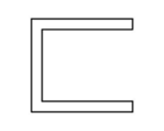
- the shape of the support arm main body 206 from the front side of the surgical microscope 12 is L-shaped, and is formed along the outer periphery of the screen frame 14B.
- the support arm main body 206 includes a horizontal arm portion 206A and a vertical arm portion 206B.
- the horizontal arm 206A extends from the installation section 36 in the horizontal direction.
- the vertical arm 206B extends in the vertical direction.
- One end 206A1 of the horizontal arm 206A is connected to the vertical plate 58C of the installation section main body 58 via the vertical rotation shaft 60 shown in FIG.
- One end 206B1 of the vertical arm 206B is connected to the other end 206A2 of the horizontal arm 206A.
- the base end of the vertical arm 206B is inserted into the arm body rotation mechanism 54 from below vertically.
- the other end 206B2 of the vertical arm portion 206B is held by the arm body rotation mechanism 54 so as to be rotatable in the direction of the arc C. That is, the arm main body rotation mechanism 54 holds the whole of the support arm main body 206 in a yawable manner with the vertical arm portion 206B as a rotation axis.
- the entire support arm 204 is arranged at a position outside the visual field region FV.
- the support arm main body 206 is viewed from the user 22 side, the support arm main body 206 is arranged along the outer periphery of the screen frame 14B.
- the vertical arm portion 206B is arranged along one side surface of the screen frame 14B, and the horizontal arm portion 206A is arranged along the bottom surface of the screen frame 14B.
- the entire installation section 36 is arranged at a position outside the viewing area FV.
- the setting unit 36 and the operating microscope 12 are located below the eyes of the user 22, and the user 22 is viewing the screen 14 ⁇ / b> A through the setting unit 36 and the operating microscope 12.
- the user 22 or the assistant operates the arm main body rotation mechanism 54 so that the assistant's standing position during surgery and the patient's position What is necessary is just to move the support arm main body 206 to a position on the opposite side with respect to.
- the shape of the support arm main body 206 from the front view side of the operation microscope 12 is L-shaped. Therefore, the operating microscope 12 is supported by the support arm main body 206 in a state where the visual field region FV is secured.
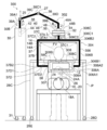
- the surgery support system 300 differs from the surgery support system 10 in that a support device 302 is provided instead of the support device 16.
- the support device 302 is different from the support device 16 in that the support device 304 includes a support arm 304 instead of the support arm 32 and that the support device 302 includes an installation portion 307 instead of the installation portion 36.
- the support arm 304 is different from the support arm 32 in that a support arm body 306 is provided instead of the support arm body 37.
- the support arm 304 is an example of the “arm” and the “support portion” according to the technology of the present disclosure.
- the installation unit 307 is different from the installation unit 36 in that an installation unit main body 308 is provided instead of the installation unit main body 58.
- the installation part main body 308 is different from the installation part main body 58 in that it has a first horizontal plate 308A instead of the first horizontal plate 58A and that it has a second horizontal plate 308B instead of the second horizontal plate 58B.
- the installation part main body 308 is different from the installation part main body 58 in that an installation vertical body 308C is further provided.
- Each of the first horizontal plate 308A, the second horizontal plate 308B, and the opposed vertical plate 308C is a rectangular parallelepiped thin plate.
- the first horizontal plate 308A and the second horizontal plate 308B are arranged at positions facing each other along the direction of the normal line N.
- One end of a first horizontal plate 308A is connected to one end of the vertical plate 58C, and one end of a second horizontal plate 308B is connected to the other end of the vertical plate 58C.
- the opposed vertical plate 308C is disposed at a position facing the vertical plate 58C with the operating microscope 12 interposed therebetween.
- the other end of the first horizontal plate 308A is connected to one end of the opposed vertical plate 308C, and the other end of the second horizontal plate 308B is connected to the other end of the opposed vertical plate 308C.
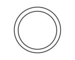
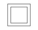
- the shape of the support arm main body 306 from the front side of the surgical microscope 12 is a rectangular frame, and is formed along the outer periphery of the screen frame 14B.
- the rectangular frame shape can be said to be a frame shape.
- a rectangular frame shape is illustrated, but the present invention is not limited to this, and may be a circular frame shape or a polygonal frame shape other than a rectangle.
- the support arm main body 306 further includes a third horizontal arm 306A, a third vertical arm 306B, and a fourth horizontal arm 306C, as compared to the support arm main body 37.
- Each of the third horizontal arm section 306A, the third vertical arm section 306B, and the fourth horizontal arm section 306C is also a first vertical arm section 37A, a second vertical arm section 37B, a first horizontal arm section 37C, and a second horizontal arm section.
- the arm part 37D it is formed in a cylindrical shape.
- the third horizontal arm section 306A, the third vertical arm section 306B, and the fourth horizontal arm section 306C are connected to the second horizontal arm section 37D, the second vertical arm section 37B, via the axis of the first vertical arm section 37A. And the first horizontal arm portion 37C. That is, the third horizontal arm 306A is in a line-symmetrical positional relationship with the second horizontal arm 37D, the third vertical arm 306B is in a line-symmetrical positional relationship with the second vertical arm 37B, and the fourth The horizontal arm 306C is in a line-symmetrical positional relationship with the first horizontal arm 37C.
- One end 306A1 of the third horizontal arm 306A is connected to the opposed vertical plate 308C of the installation section main body 308.
- One end 306B1 of the third vertical arm 306B is connected to the other end 306A2 of the third horizontal arm 306A.
- One end 306C1 of the fourth horizontal arm 306C is connected to the other end 306B2 of the third vertical arm 306B.
- the other end 306C2 of the fourth horizontal arm 306C is connected to one end 37A1 of the first vertical arm 37A.
- the entire support arm 304 is arranged at a position deviating from the visual field region FV. Further, the entire installation section 307 is arranged at a position deviating from the visual field region FV.
- the setting unit 307 and the surgical microscope 12 are located below the eyes of the user 22, and the user 22 is viewing the screen 14 ⁇ / b> A through the setting unit 307 and the surgical microscope 12.
- the support arm main body 306 when viewing the support arm main body 306 from the user 22 side, the support arm main body 306 is disposed along the outer periphery of the screen frame 14B.
- the second vertical arm portion 37B is arranged along one side surface of the screen frame 14B
- the third vertical arm portion 306B is arranged along the other side surface of the screen frame 14B.
- the second horizontal arm portion 37D and the third horizontal arm portion 306A are arranged along the bottom surface of the screen frame 14B.
- the first horizontal arm section 37C and the fourth horizontal arm section 306C are arranged along the upper surface of the screen frame 14B. That is, when the support arm main body 306 is viewed from the user 22 side, the support arm main body 306 is disposed so as to surround the screen frame 14B together with the installation section 307.
- the shape of the support arm main body 306 from the front view side of the operation microscope 12 is a rectangular frame shape. Therefore, the operating microscope 12 is supported by the support arm main body 306 in a state where the visual field region FV is secured.
- the surgery support system 400 includes a support device 402 instead of the support device 16 as compared with the surgery support system 10, and And the caster base 28 is not provided.
- the support device 402 differs from the support device 16 in that it has a base 404 in place of the base 30 and in that it has a support arm 406 in place of the support arm 32.
- the support arm 406 is an example of an “arm” and a “support” according to the technology of the present disclosure.
- a caster 401 is provided on the lower surface 404A of the base 404.
- the casters 401 rotate, and the base 404 moves on the floor surface FL.
- the support arm 406 is supported by the base 402.
- the support arm 406 is formed in a cylindrical shape.
- the support arm 406 extends from the base 402 toward the user 22 in the horizontal direction.
- the installation part 36 is attached to the tip of the support arm 406.
- An arm moving mechanism 408 is provided on the upper part 410 of the base 404.
- the arm moving mechanism 408 has a function corresponding to the function of the arm body moving mechanism 50 described in the first embodiment.
- the arm moving mechanism 408 holds the support arm 406 so as to be slidable and yawable.
- the arm moving mechanism 408 includes an arm slide mechanism 412 and an arm turning mechanism 414.
- the arm slide mechanism 412 holds the arm turning mechanism 414, and receives the power supplied from the power supply source 114 to move the arm turning mechanism 414 to the left direction L, the right direction R, the upward direction U, and the downward direction. Selectively slide with respect to D.
- the arm turning mechanism 414 holds the one end 406A of the support arm 406 so as to be able to rotate laterally, and yaw the support arm 406 by receiving the power supplied from the power supply source 114.
- the base end of the support arm 406 is attached to the arm turning mechanism 414 via the first arm displacement mechanism 25 described in the first embodiment. That is, the support arm 406 is pitched by operating the first arm displacement mechanism 25 with respect to the arm turning mechanism 414, similarly to the first inclined arm section 39C described in the first embodiment.
- the support arm 406 is attached to the first arm displacement mechanism 25 has been described, but the technology of the present disclosure is not limited to this, and the first arm displacement mechanism 25 may not be provided.
- a horizontal rotation mechanism 413 is provided on the upper part 410 of the base 404 so as to be capable of horizontal rotation.
- the horizontal rotation mechanism 413 is provided with a display support frame 415.
- the display support frame 415 is a bent rod-shaped member.
- the bent portion of the display support frame 415 operates similarly to the first arm displacement mechanism 25 or the second arm displacement mechanism 27 described in the first embodiment.
- a displacement mechanism may be applied.
- a displacement mechanism that operates in the same manner as the first arm displacement mechanism 25 is referred to as a first displacement mechanism
- a displacement mechanism that operates in the same manner as the second arm displacement mechanism 25 is referred to as a second displacement mechanism.
- the first displacement mechanism displacement mechanism When the first displacement mechanism displacement mechanism is applied to the bent portion of the display support frame 415, the portion of the display support frame 415 on the display 14 side from the bent portion is operated by operating the first displacement mechanism. Be pitched.
- the second displacement mechanism When the second displacement mechanism is applied to the bent portion of the display support frame 415, the portion of the display support frame 415 on the display 14 side from the bent portion is pitched by operating the second displacement mechanism. And yawed.
- the display support frame 415 may be formed integrally without applying the first displacement mechanism or the second displacement mechanism to the bent portion of the display support frame 415.
- One end of the display support frame 415 is held by the horizontal rotation mechanism 413.
- the other end of the display support frame 415 is fixed to the back of the display 14.
- the horizontal rotation mechanism 413 yaw the display support frame 415 by receiving the power supplied from the power supply source 114.
- the entire support arm 406 is disposed at a position outside the visual field region FV.
- the support arm 406 extends from one side of the operation field 26 toward the user 22.
- the support arm main body 406 is arranged along the outer periphery of the screen frame 14B. Further, the support arm main body 406 is arranged along the bottom surface of the screen frame 14B.
- the user 22 or the assistant moves the support arm main body 406 along the horizontal plane by operating the arm moving mechanism 408 to position the surgical microscope 12. Then, the user 22 performs the final positioning with respect to the surgical microscope 12 by operating the vertical rotation shaft 60, the horizontal rotation mechanism 62, the intersecting plane slide mechanism 68, and the normal direction slide mechanism 70.
- the support arm 406 extends toward the user 22 from the side of the operation field 26 or the operation field image. Therefore, the operating microscope 12 is supported by the support arm main body 406 in a state where the field of view FV is secured.
- the surgery support system 500 includes a support device 501 instead of the support device 16 as compared to the surgery support system 10, and a caster table. 28 is different.
- the support device 501 is different from the support device 16 in that a support portion 504 is provided instead of the support arm 32.
- the support 504 is an example of the “support” according to the technology of the present disclosure.
- the support section 504 includes a display support arm 505, a display board 506, a protruding arm 508, and a vertical slide mechanism 510.
- the display board 506 is a rectangular parallelepiped plate member extending in the vertical direction, and the display 14 is fixed to the front surface 506A.
- the schematic appearance of the display support arm 505 is a bent shape.
- the display support arm 505 is an articulated arm, and includes the first arm displacement mechanism 25 and the second arm displacement mechanism 27 described in the first embodiment.
- the base end 505A of the display support arm 505 extends in the vertical direction.
- the base end 505A is inserted into the base side rotation mechanism 44 from above vertically.
- the base-side rotation mechanism 44 holds the base end 505A rotatably in the direction of the arc arrow A, thereby holding the entire support 504 as yawable with the base end 505A as a rotation axis.
- the tip 505B of the display support arm 505 is fixed to the back 506B of the display board 506.
- the display support arm 505 supports the screen 14A on the front side of the user 22 in a posture facing the operating microscope 12.
- the posture directly facing the operating microscope 12 is, for example, as shown in FIG. 12, a state in which the patient stands on the top of the patient 18 placed on the operating table 20 in an operable posture. Refers to a posture including a posture directly facing the microscope for use 12.
- the display support arm 505 is provided with a first arm displacement mechanism 25 and a second arm displacement mechanism 27 between a base end 505A and a tip end 505B.
- the entire display support arm 505 is formed to be bent via the first arm displacement mechanism 25 and the second arm displacement mechanism 27.
- a part of the display support arm 505 from the first arm displacement mechanism 25 to the second arm displacement mechanism 27 is inclined upward with respect to the ground, and a part from the second arm displacement mechanism 27 to the tip part 505B is on the ground. It is inclined downward.
- the portion of the display support arm 505 from the first arm displacement mechanism 25 to the second arm displacement mechanism 27 is similar to the first inclined arm section 39C described in the first embodiment, in that the first arm displacement mechanism 25 is used. Actuation causes pitching.
- the portion of the display support arm 505 from the second arm displacement mechanism 27 to the distal end portion 505B operates the second arm displacement mechanism 27 similarly to the second inclined arm section 39D described in the first embodiment. And pitching and yawing.
- a tilt mechanism that can tilt the display 14 in the up, down, left, and right directions may be provided on the back surface 506B of the display board 506 to which the distal end portion 505B of the display support arm 505 is fixed.
- a vertical slide mechanism 510 is provided below the front surface 506A of the display board 506.
- the protruding arm 508 extends horizontally from the vertical slide mechanism 510 toward the user 22, and the distal end of the protruding arm 508 is connected to the vertical plate 58 ⁇ / b> C of the installation unit 36 (see FIG. 4). .
- the installation section 36 is arranged by the protruding arm 508 on the near side of the user 22 and below the viewing area FV, which is a position deviated from the viewing area FV.
- the base end 508A of the protruding arm 508 is fitted into the vertical slide mechanism 510.
- the vertical sliding mechanism 510 slides the protruding arm 508 in the predetermined first movable range in the vertical direction by receiving the power supplied from the power supply source 114.
- the predetermined first movable range refers to a movable range in which the installation section 36 is not allowed to enter the visual field region FV when the protruding arm 508 is slid in the vertical direction.
- the entire support portion 504 is arranged at a position outside the visual field region FV.
- the display support arm 505 supports the screen 14 ⁇ / b> A on the front side of the user 22 facing the operating microscope 12, and the protruding arm 508 supports the installation section 36.
- the protruding arm 508 protrudes toward the user 22 from a vertically lower region of the display 14, that is, a lower portion of the front surface of the display board 506.
- the user 22 requires more time to adjust the position of the setting unit 36 with respect to the display 14, as compared to the case where the member supporting the display 14 and the member supporting the setting unit 36 are separated. Can be reduced.
- the surgery support system 600 differs from the surgery support system 10 in having a support device 602 instead of the support device 16.
- the support device 602 is different from the support device 16 in that a support arm 603 is provided instead of the support arm 32.
- the support arm 603 differs from the support arm 32 in that a support arm body 604 is provided instead of the support arm body 37.
- the support arm 603 is an example of the “arm” and the “support portion” according to the technology of the present disclosure.
- the support arm body 604 extends from the back of the operative field image to the lower side under the operative field image, and protrudes from the lower side of the operative field image toward the user 22.
- the support arm main body 604 extends below the screen 14A where the operation field image is displayed as a live view image, and projects from the lower side of the screen 14A to the user 22 side.
- the support arm 604 extends below the screen frame 14B and protrudes from the lower side of the screen frame 14B toward the user 22 by slipping through the caster table 28.
- the operation field image is displayed on the display 14, but the technique of the present disclosure is not limited to this.
- the operation field image is displayed on a space using a mapping technique. Is projected and formed, the support arm main body 604 is extended from the back of the operative field image formed in the space to the lower side under the operative field image and from the lower side of the operative field image to the user 22 side. What is necessary is just to make it protrude.
- the support arm body 604 includes a vertical arm 604A and a horizontal arm 604B.
- the vertical arm 604A is a cylindrical member extending in the vertical direction.
- the horizontal arm portion 604B is a cylindrical member extending in the horizontal direction, and protrudes toward the user 22 through the caster table 28.
- One end 604A1 of the vertical arm 604A is connected to the other end 604B2 of the horizontal arm 604B.
- the other end 604A2 of the vertical arm 604A is inserted into the arm body rotation mechanism 54 from below vertically.
- the arm body rotation mechanism 54 holds the vertical arm 604A so as to be rotatable around the axis of the vertical arm 604A.
- One end 604B1 of the horizontal arm portion 604B is connected to the center of the vertical width of the vertical plate 58C of the installation portion main body 58 via the vertical rotation shaft 60 shown in FIG.
- the installation section 36 is arranged such that the vertical plate 58C is located closer to the caster table 28 than the horizontal rotation mechanism 62 is.
- the vertical plate 58 ⁇ / b> C is located on the back side of the horizontal rotation mechanism 62. In this case, when the vertical rotation shaft 60 is operated, the operation microscope 12 is rolled while viewing the operation microscope 12 from the user 22 side.
- the vertical plate 58 ⁇ / b> C is positioned closer to the caster table 28 from the user 22 than the horizontal rotation mechanism 62, but the technology of the present disclosure is not limited to this.
- the installation section 36 may be arranged in a state where the horizontal rotation mechanism 62 and the vertical plate 58C are arranged side by side as viewed from the user 22.
- the horizontal arm 604B may be connected to the vertical plate 58C in the same manner as the protruding arm 508 is connected to the vertical plate 58C as shown in FIG. In this way, the operating microscope 12 can be pitched by the vertical rotation shaft 60. Also, as shown in FIG.
- the surgical microscope 12 can be pitched. is there. That is, in this case, by connecting the horizontal arm 604B to the side surface of the vertical plate 58C via the vertical rotation shaft 60 shown in FIG. 5, the surgical microscope 12 can be pitched by the rotation of the vertical rotation shaft 60. .
- the entire support arm 603 is arranged at a position deviated from the visual field region FV. Therefore, the support device 602 can hold the operating microscope 12 so as not to block the visual field region FV. Further, since the support arm 603 does not block the visual field region FV, the visibility of the user 22 on the screen 14A is better than when the member supporting the surgical microscope 12 enters the visual field region FV.
- the support arm body 604 protrudes toward the user 22 from below the screen 14A under the screen 14A. Therefore, since the support arm main body 604 does not block the viewing area FV, the visibility of the user 22 on the screen 14A is better than when the member supporting the installation unit 36 enters the viewing area FV.
- the installation section 36 and the surgical microscope 12 are also located vertically below the field of view FV. Therefore, since the setting part 36 and the surgical microscope 12 do not block the visual field FV, the visibility of the user 22 on the screen 14A is better than when the setting part 36 and the surgical microscope 12 enter the visual field FV. become.
- the surgery support system 700 differs from the surgery support system 10 in having a support device 702 instead of the support device 16.
- the support device 702 is different from the support device 16 in that the support device 702 includes a table 704 with a moving mechanism instead of the base 30, the support arm 32, and the moving unit 38.
- the table 704 with a moving mechanism is an example of a “table” according to the technology of the present disclosure.
- the shape of the front side of the table 704 with the moving mechanism is a gate shape.
- the table with movement mechanism 704 includes a table body 706, a movement mechanism 708, and a protruding arm 710.
- the table body 706 includes a plate-shaped upper portion and legs 704A and 704B.
- the plate-shaped upper portion is supported from below vertically by leg portions 704A and 704B.
- FIGS. 15 and 16 show a top plate 704C as an example of the plate-like upper portion.
- a caster 704D is attached to a lower end 704A1 of the leg 704A, and a caster 704E is attached to a lower end 704B1 of the leg 704B.
- the contour of the top plate 708 in a plan view is rectangular, and the shape of the top plate 708 is a thin plate formed along a horizontal plane.
- the upper end 704A2 of the leg 704A is connected to one end 704C1 of the top plate 708, and the upper end 704B2 of the leg 704B is connected to the other end 704C2 of the top plate 708. That is, both ends of the top plate 708 in the longitudinal direction in plan view are supported from below by the legs 704A and 704B.
- the top plate 704C is an example of the “top plate” according to the technology of the present disclosure.
- the legs 704A and 704B are an example of “one or more legs” according to the technology of the present disclosure. Here, the legs 704A and 704B are illustrated, but the technology of the present disclosure is not limited thereto, and three or more legs may be used.
- the table 704 with the moving mechanism is arranged so that the top plate 704C is located below the display 14 via the top plate 28A of the caster stand 28. Further, the table body 706 is arranged so as to straddle the operating table 20 and the patient 18 placed on the operating table 20 in a operable posture.
- a projecting arm 710 is provided on a front surface 704C3 of a top plate 704C of the table main body 706 via a moving mechanism 708.
- the front surface 704C3 refers to a surface facing the user 22 among the outer surfaces of the top plate 704C.
- a moving mechanism 708 is provided on the front surface 704C3 (see FIG. 16) of the top plate 704C of the table body 706.
- the base end 710A of the protruding arm 710 is fitted into the moving mechanism 708.
- the protruding arm 710 extends in the horizontal direction from the moving mechanism 708 toward the user 22, and a distal end 710 ⁇ / b> B of the protruding arm 710 is connected to the vertical plate 58 ⁇ / b> C of the installation section main body 58.
- the installation section 36 is disposed by the protruding arm 710 on the near side of the user 22 and below the viewing area FV, which is a position deviated from the viewing area FV.
- the moving mechanism 708 receives the power supplied from the power supply source 114 to slide the projecting arm 710 in the vertical direction within the predetermined second movable range.
- the predetermined second movable range refers to a movable range in which the installation section 36 is not allowed to enter the visual field region FV when the protruding arm 710 is slid in the vertical direction.
- the entire table with a moving mechanism 704 is arranged at a position outside the visual field region FV.
- the position deviating from the visual field region FV indicates the lower side of the visual field region FV.
- the operating microscope 12 can be held so as not to block the visual field region FV.
- the entire table 704 with the moving mechanism is arranged at a position outside the visual field region FV, so that the visibility of the user 22 on the screen 14A is smaller than when any obstacle enters the visual field region FV. Become good.
- the protruding arm 710 is arranged at a position offset from the top plate 704C to the near side of the user 22, the user 22 and the assistant can operate the surgical microscope 12 more easily than when the surgical microscope 12 is installed in the top plate 704C. The approach to the field 26 becomes easier.
- the table 704 with a moving mechanism in a front view is illustrated.
- a table 804 with a cantilever in a front view is described.
- the same components as those described in the first and seventh embodiments are denoted by the same reference numerals, and description thereof will be omitted. Components that are different from the components described in the embodiment will be described.
- the surgery support system 800 differs from the surgery support system 700 in having a support device 802 instead of the support device 702.
- the support device 802 is different in that it has a table 804 with a moving mechanism instead of the table 704 with a moving mechanism.
- the table 804 with a moving mechanism is an example of a “table” according to the technology of the present disclosure.
- the shape of the front side of the table with a movement mechanism 804 is cantilevered.
- the cantilever shape can be said to be a semi-portion shape.
- the table with a moving mechanism 804 includes a base 806, a moving mechanism 808, and a plate-like upper part.
- a protruding arm 810 is cited as an example of a plate-like upper portion.
- the “cantilever shape” here is realized by the upper part of the base 806 supporting the base end 810A of the protruding arm 810 via the moving mechanism 808.
- the base 806 is an example of a “leg” according to the technology of the present disclosure.
- the protruding arm 810 is an example of a “top plate” according to the technology of the present disclosure.
- the base 806 includes a base main body 812 and casters 814.
- the base body 812 is formed in a column shape.
- a caster 814 is attached to the lower surface 812A of the base body 812.
- a moving mechanism 808 is provided above the base body 812.
- the base end 810A of the protruding arm 810 is fitted into the moving mechanism 808.
- the protruding arm 810 extends horizontally from the moving mechanism 808 toward the user 22, and the distal end 810 ⁇ / b> B of the protruding arm 810 is connected to the vertical plate 58 ⁇ / b> C of the installation section main body 58.
- the installation section 36 is arranged on the near side of the user 22 by the protruding arm 810 and below the viewing area FV, which is a position deviated from the viewing area FV.
- the base end 810A of the protruding arm 810 is fitted into the moving mechanism 808.
- the moving mechanism 808 slides the protruding arm 810 in the vertical direction within the predetermined third movable range by receiving the power supplied from the power supply source 114.
- the predetermined third movable range refers to a movable range in which the installation section 36 is not allowed to enter the viewing area FV when the protruding arm 810 is slid in the vertical direction.
- the thus configured support device 802 is disposed between the user 22 and the caster table 28. Thereby, the user 22 in a posture directly facing the surgical microscope 12 can visually recognize the screen 14A through the surgical microscope 12.
- the support device 802 is arranged so that the objective surface 24A of the surgical microscope 12 faces the operation field 26.
- the support device 802 positions the base 806 on the other side of the patient 18.
- the base 806 Since the base 806 has the casters 814, it is selectively changed to, for example, a position P1 shown in FIG. 17 and a position P2 shown in FIG. 18 according to the standing position of the assistant.
- the position P1 indicates the position where the base 806 is arranged when the assistant is located on one side of the patient 18, and the position P2 indicates the base 806 when the assistant is located on the other side of the patient 18. Indicates the position where is placed. In other words, the position P2 indicates a position indicating one side of the patient 18, and the position P1 indicates a position indicating the other side of the patient 18.
- the table 804 with a moving mechanism is formed in a cantilevered shape. Therefore, according to the table 804 with the moving mechanism, the assistant is located on the opposite side to the base 806 via the operating table 20, so that the assistant can use the member that supports the surgical microscope 12 from both sides. , The approach to the operative field 26 becomes easier.
- the operation field image may be displayed on a partial screen that is a screen of a partial area in the screen 14A.
- all of the support arms 32, 204, 304, 406, 603, the support portion 504, and the tables with movement mechanisms 704, 804 may be arranged at positions outside the visual field region FV.
- each of the support arms 32, 204, 304, 406, 603, the support section 504, and the tables 704, 804 with a moving mechanism is operated by the operator. It is arranged on the outer periphery of the field image, that is, on the outer periphery of the partial screen.
- each of the support arms 32, 204, 304, 406, and 603, the support unit 504, and the tables with movement mechanisms 704 and 804 is operated. It is formed along the outer periphery of the field image, that is, along the outer periphery of the partial screen.
- a black or white non-display area is formed along the inner periphery of the partial screen and the operative field image is displayed surrounded by the non-display area, the support arms 32, 204, 304, 406, 603, the support section
- Each of the table 504 and the tables with movement mechanisms 704 and 804 may be arranged so as to be superimposed on the non-display area of the partial screen.
- a region or a space in which an operation field image is displayed may be applied instead of the screen 14A, or an area or a space in which an operation field image is displayed in addition to the screen 14A. Is also good.
- The“ viewing area FV ” here includes a spatial area for the partial screen in the user's 22 view in a state where the user 22 is viewing the partial screen from the front side of the surgical microscope 12. Further, the visual field region FV here is determined according to the positional relationship between the pupil of the user 22 and the partial screen. In the following, when it is not necessary to distinguish the support arms 32, 204, 304, 406, 603, the support portion 504, and the tables with movement mechanisms 704, 804, the reference numeral is used as a "support portion" without a reference numeral. Name.
- the surgical microscope 12 is movably installed with respect to the installation section 36, but the technology of the present disclosure is not limited to this.
- the operating microscope 12 may be fixed to the installation section 36.
- the arm main body moving mechanism 50 may be installed on the ceiling CE in the room, and the support arm 850 may be suspended from the arm main body moving mechanism 50.
- the support arm 850 is different from the support arm body 37 in that a vertical arm 850A is provided instead of the first vertical arm 37A.
- the vertical arm portion 850A differs from the first vertical arm portion 37A only in that it is longer in the vertical direction.
- the shape of the contour formed along the outer periphery of the screen frame 14B by the second vertical arm portion 37B, the first horizontal arm portion 37C, and the second horizontal arm portion 37D matches the shape of the surgical microscope 12.
- it has a semi-rectangular frame shape when viewed from the front side
- the technology of the present disclosure is not limited to this.
- it may be L-shaped as shown in FIG. 8 or rectangular frame as shown in FIG.
- a rail portion movable in one direction or a plurality of directions may be provided on the ceiling CE, and the arm body moving mechanism 50 may be provided on the rail portion.
- examples of the support arm that replaces the support arm 850 include the support arm 860 illustrated in FIG. 20, the support arm 870 illustrated in FIG. 21, and the support arm 880 illustrated in FIG.
- the support arms 860 and 870 are arms formed by bending a plurality of times, and the support arm 880 is an arm having a curved portion.
- all of the support arms 860, 870, and 880 are out of the visual field region FV in the front view of the surgical microscope 12 or in the observation state of the operation field 26. Placed at the right position.
- the support arm 860 includes linear arm portions 860A and 860B in addition to the vertical arm portion 850A.
- Each of the linear arms 860A and 860B extends linearly and is formed in a cylindrical shape.
- the support arm 860 has a plurality of bent portions by connecting the vertical arm portion 850A and the linear arm portions 860A and 860B. In the example shown in FIG. 20, there are bent portions between the vertical arm portion 850A and the linear arm portion 860B and between the linear arm portion 860A and the linear arm portion 860B.
- One end of the linear arm 860A is connected to the vertical plate 58C of the installation part 36 via the vertical rotation shaft 60 shown in FIG.
- the linear arm portion 860A is inclined upward in a direction away from the vertical plate 58C.
- One end of the linear arm 860B is connected to the other end of the linear arm 860A.
- the linear arm portion 860B is inclined upward from the other end of the linear arm portion 860A toward one end of the vertical arm 850 at an angle different from the upward inclination angle of the linear arm portion 860A.
- One end of the vertical arm 850A is connected to the other end of the linear arm 860B.
- the linear arm 860A is an example of the “first arm” according to the technology of the present disclosure
- the linear arm 860B is “second arm” according to the technology of the present disclosure
- the vertical arm 850A is an example of the “third arm” according to the technology of the present disclosure.
- the support arm 870 includes linear arm portions 870A, 870B, 870C, and 870D in addition to the vertical arm portion 850A.
- Each of the linear arms 870A, 870B, 870C, 870D extends linearly and is formed in a cylindrical shape.
- the support arm 870 has a plurality of bent portions by connecting the vertical arm portion 850A and the linear arm portions 870A, 870B, 870C, 870D.
- first to fourth bent portions are shown.
- the first bent portion is between the vertical arm 850A and the linear arm 870D.
- the second bending point is between the linear arm 870C and the linear arm 870D.
- the third bent portion is between the linear arm 870B and the linear arm 870C.
- the fourth bent portion is between the linear arm 870A and the linear arm 870B.
- One end of the linear arm portion 870A is connected to the vertical plate 58C of the installation portion 36 via the vertical rotation shaft 60 shown in FIG.
- the linear arm portion 870A is inclined upward in a direction away from the vertical plate 58C.
- One end of the linear arm 870B is connected to the other end of the linear arm 870A.
- the linear arm portion 870B is inclined upward from the other end of the linear arm portion 870A toward one end of the linear arm portion 870C at an angle different from the upward inclination angle of the linear arm portion 870A.
- One end of the linear arm 870C is connected to the other end of the linear arm 870B.
- the linear arm portion 870C is inclined upward from the other end of the linear arm portion 870B toward one end of the linear arm portion 870D at an angle different from the upward inclination angle of each of the linear arm portions 870A and 870B.
- One end of the linear arm 870D is connected to the other end of the linear arm 870C.
- the linear arm 870D extends horizontally from the other end of the linear arm 870C toward one end of the vertical arm 850A.
- One end of the vertical arm 850A is connected to the other end of the linear arm 870D.
- the support arm 880 includes a curved arm 880A in addition to the vertical arm 850A.
- the curved arm portion 880A is curved, and the shape of the curved arm portion 880A from the front side of the operating microscope 12 is a C-shape.
- One end of the curved arm section 880A is connected to the vertical plate 58C of the installation section 36 via the vertical rotation shaft 60 shown in FIG.
- One end of the vertical arm 850A is connected to the other end of the curved arm 880A.
- the shapes of the support arms 860, 870, and 880 described above are merely examples, and any shape may be used as long as the support arms are entirely disposed at positions outside the visual field region FV.
- the support arm 850 is suspended from the ceiling CE, but the technology of the present disclosure is not limited to this.
- the support arm 850 may be suspended from a beam, and the entire support arm 850 may be disposed at a position outside the viewing region FV.
- the support arm may be protruded from the side wall in the room, and the entire support arm may be disposed at a position outside the viewing area FV.
- the supporting device 702 having the table 704 with the moving mechanism is illustrated, but the technology of the present disclosure is not limited to this.
- the supporting device 890 illustrated in FIG. Technology is established.
- the support device 890 includes the caster table 28 and the arm 900.
- the arm 900 may be provided on the front surface 28A1 of the top plate 28A of the caster stand 28.
- the arm 900 is an arm that holds the installation section 36.
- the arm 900 includes a protruding arm section 902 and a moving mechanism 904.
- the moving mechanism 904 is attached to the front surface 28A1.
- the protruding arm 902 is formed in a cylindrical shape. One end of the protruding arm 902 is fitted into the moving mechanism 904.
- the moving mechanism 904 receives the power supplied from the power supply source 114 to selectively move the protruding arm 902 in the vertical and horizontal directions. Note that the moving mechanism 904 may be operated manually.
- the other end of the protruding arm portion 902 is connected to the installation section via the vertical rotation shaft 60 shown in FIG. 4 so that the operating microscope 12 installed on the installation section 36 is pitched or rolled with respect to the installation section main body 58. It is connected to the main body 58.
- the caster base 28 since the caster base 28 also functions as a base supporting the arm 900, it is possible to contribute to the reduction in the number of components required for holding the installation unit 36.
- the support device 702 is an example of the “support device” according to the technology of the present disclosure.
- the arm 900 is an example of an “arm” and a “support” according to the technology of the present disclosure.
- the supporting device 702 having the table 704 with the moving mechanism has been exemplified.
- the technology of the present disclosure is not limited to this.
- the supporting device 920 illustrated in FIG. Holds.
- the supporting device 920 is different from the supporting device 702 in that the supporting device 920 includes a table 922 with a moving mechanism instead of the table 704 with a moving mechanism.
- the table with a moving mechanism 922 is different from the table with a moving mechanism 704 in that it does not have the casters 704D and 704E and that it has legs 924A and 924B instead of the legs 704A and 704B.
- the table 922 with the moving mechanism is arranged between the caster table 28 and the user 22 on the operating table 20.
- the leg 924A is different from the leg 704A in that the length in the vertical direction is shorter.
- the leg 924B is different from the leg 804B in that the length is shorter.
- the leg 924A and the leg 924B are arranged on the operating table 20 at a position where the table body 706 straddles the patient 18 placed on the operating table 20 in an operable posture.
- the bottom surface 924A1 of the leg portion 924A and the bottom surface 924B1 of the leg portion 924B are positioned opposite to each other across the patient 18 in a direction crossing the patient 18 placed on the operating table 20 in an operable posture. It is arranged on the upper surface 20A.
- the length of the legs 924A and 924B is a length that positions the entire table 704 with the moving mechanism and the entire installation section 36 vertically below the viewing area FV.
- a slide mechanism 926 is provided on the upper surface 20A of the operating table 20.
- the slide mechanism 926 supports the legs 924A and 924B, and slides the table 922 with the moving mechanism in a direction in which the patient 18 placed on the operating table 20 is traversed in an operable posture.
- the slide movement by the slide mechanism 926 is realized by receiving the power supplied from the power supply source 114, but is not limited thereto, and may be realized manually.
- the display 14 is supported by the caster base 28, but the technology of the present disclosure is not limited to this.
- the display 14 may be installed on a table of the table 922 with a moving mechanism.
- a pedestal 1000 is installed on a table of a table 922 with a moving mechanism, and the display 14 is fixedly installed on the pedestal 1000.
- the display 14 may be supported by an arm 1002 provided at one end of the table of the table 922 with a moving mechanism.
- the arm 1002 includes a vertical arm 1002A and a horizontal arm 1002B.
- the vertical arm 1002A extends in the vertical direction
- the horizontal arm 1002B extends in the horizontal direction.
- One end of the vertical arm 1002A is connected to one end of the table of the table 922 with a moving mechanism
- one end of the horizontal arm 1002B is connected to the other end of the vertical arm 1002A.
- the other end of the horizontal arm unit 1002B is fixed to the side surface or the back surface of the display 14, so that the display 14 is supported by the arm 1002 vertically above the table of the table 922 with the moving mechanism.
- one end of the vertical arm 1002A may be attached to the upper end of the table of the table 922 with the moving mechanism so as to be yawable and adjustable in the height direction.
- the vertical arm 1002A and the horizontal arm 1002B may be connected via the second displacement mechanism described in the fourth embodiment.
- the display 14 can be yawed or pitched by operating the second displacement mechanism.
- the supporting device 802 having the table 804 with the moving mechanism has been exemplified.
- the technology of the present disclosure is not limited thereto.
- the supporting device 930 illustrated in FIG. Holds.
- the support device 930 is different from the support device 802 in that a table 932 with a moving mechanism is provided instead of the table 804 with a moving mechanism.
- the table with moving mechanism 932 is different from the table with moving mechanism 804 in that a table 934 is provided instead of the base 806.
- the base 934 is different from the base 806 in that it does not include the casters 814 and is smaller in height and thinner than the base 806.
- the table with moving mechanism 932 is disposed between the caster table 28 and the user 22 on the operating table 20.
- the base 934 is disposed on the operating table 20 to one side of the patient 18 placed on the operating table 20 in an operable posture.
- the height of the base 934 is a height at which the entire table 932 with the moving mechanism and the entire installation section 36 are positioned vertically below the viewing area FV.
- a slide mechanism 936 is provided on the upper surface 20A of the operating table 20.
- the slide mechanism 936 supports the base 934, and slides the table with moving mechanism 932 in a direction in which the patient 18 placed on the operating table 20 is traversed in an operable posture.
- the slide motion by the slide mechanism 936 is realized by receiving the power supplied from the power supply source 114, but is not limited thereto, and may be manually performed.
- the display 14 is supported by the caster base 28, but the technology of the present disclosure is not limited to this.
- the display 14 may be provided on a table of the table 932 with a moving mechanism.
- the pedestal 1004 is installed on the table of the table 932 with the moving mechanism, and the display 14 is fixedly installed on the pedestal 1004.
- the display 14 may be supported by an arm 1006 provided at one end of the table of the table 922 with a moving mechanism.
- the arm 1006 includes a vertical arm 1006A and a horizontal arm 1006B.
- the vertical arm 1006A extends in the vertical direction
- the horizontal arm 1006B extends in the horizontal direction.
- One end of the vertical arm 1006A is connected to one end of a table of the table 932 with a moving mechanism
- one end of the horizontal arm 1006B is connected to the other end of the vertical arm 1006A.
- the other end of the horizontal arm unit 1006B is fixed to the side surface or the back surface of the display 14, so that the display 14 is supported by the arm 1006 vertically above the table of the table 932 with the moving mechanism.
- one end of the vertical arm 1006A may be attached to the upper end of the table of the table 932 with the moving mechanism so as to be yawable and adjustable in the height direction. Further, the vertical arm portion 1006A and the horizontal arm portion 1006B may be connected via the second displacement mechanism described in the fourth embodiment. Thus, the display 14 can be yawed or pitched by operating the second displacement mechanism.
- the operation field image may be visually recognized by the user 22 on the operation microscope 12.
- a tablet terminal capable of communicating with the operation microscope 12 by wire or wirelessly is exemplified.
- an operation field image may be stereoscopically displayed on a wall surface in a room or a space on the upper surface side of the surgical microscope 12 by projection mapping.
- the user 22 recognizes the live view image indicating the operation field 26 in a stereoscopic manner through polarized glasses, but the technology is not limited to this.
- the user 22 observes the screen 14A in which the first image and the second image are alternately displayed as the live view images through glasses with a liquid crystal shutter, and stereoscopically displays the live view image showing the operation field 26. You may make it recognize visually.
- the glasses with a liquid crystal shutter have liquid crystal shutters in each of the left-eye lens and the right-eye lens, and the left-eye lens is synchronized with the switching of the display between the first image and the second image. What is necessary is just to operate the liquid crystal shutter and the liquid crystal shutter of the lens for the right eye.
- a lenticular sheet having right and left eye cylindrical lenses formed in a strip shape is attached to the screen 14A, and a live view image is provided to the user 22 via the lenticular sheet.
- each of the first image and the second image is cut into strips according to the right-eye and left-eye cylindrical lenses.
- An image obtained by dividing the first image is displayed on a screen corresponding to each position of the right-eye cylindrical lens in the screen 14A, and a screen corresponding to each position of the left-eye cylindrical lens in the screen 14A is displayed. Then, an image obtained by dividing the second image is displayed.
- the live view image may be stereoscopically viewed by the user 22 using a means called a binocular viewer.
- the binocular viewer the first image and the second image are arranged side by side in the screen 14A, and the first image is displayed by the optical system in the left and right optical paths arranged between the screen 14A and the eyes of the user 22.
- the operation field image is stereoscopically viewed by the user 22
- the operation field image may be visually recognized as a two-dimensional image by the user 22.
- various members extending in the vertical direction are illustrated, but the technology of the present disclosure is not limited to this, and various members illustrated as members extending in the vertical direction are allowed in the vertical direction. It may extend in a direction deviated within a given error.
- the error allowed in the vertical direction may be an error allowed in design.
- the “horizontal direction” is exemplified, but the technology of the present disclosure is not limited to this, and may be a direction intersecting the vertical direction.
- the “horizontal plane” is exemplified, but the technology of the present disclosure is not limited thereto, and may be a plane that intersects the vertical direction.
- the angle intersecting with the vertical direction may be any angle within an allowable error in design.
- an ophthalmologic operation targeting the eye portion 18A has been described as an example.
- the technology of the present disclosure is not limited thereto, and involves the use of a surgical microscope such as an otolaryngology or a neurosurgery operation. Applicable for surgery.
- the entire support portion is arranged on the outer periphery of the screen frame 14B, but the technology of the present disclosure is not limited to this.
- a part or the whole of the arm holding the setting unit 36 may be positioned so as to be superimposed on the screen frame 14B within a range that does not overlap the operation field image.
- the arm is arranged at a position outside the visual field region FV and protrudes from the lower end of the screen frame 14B toward the user 22.
- the caster table 28 is illustrated, but the technology of the present disclosure is not limited to this, and the display is performed without using the caster table 28.
- 14 may be supported by an arm.
- the support 3100 may be fixed to the base 30, and the display support arm 505 illustrated in FIG. 12 may be provided at the upper end of the support 3100.
- the first arm displacement mechanism 25 and the second arm displacement mechanism 27 are applied to the display support arm 505, but the technology of the present disclosure is not limited to this.
- the display support arm 505 may be integrally formed without applying the first arm displacement mechanism 25 and the second arm displacement mechanism 27 to the display support arm 505.
- a caster stand 28 may be applied instead of the display support frame 415. That is, for example, similarly to the first embodiment, the display 14 may be installed on the caster table 28.
- the technology of the present disclosure is not limited to this.
- at least a part of the arms described in each of the above embodiments may be formed in a solid columnar shape in cross section, as shown in FIG. 28B as an example.
- at least some of the arms described in each of the above embodiments may be formed in a solid quadrangular prism shape in cross section, as shown in FIG. 28C as an example.
- At least a part of the arms described in each of the above embodiments may be formed in a hollow quadrangular prism shape in cross section, as shown in FIG. 28D as an example. Further, at least a part of the arms described in each of the above embodiments may have a shape in which one side wall is cut off in a hollow rectangular column in a cross-sectional view as shown in FIG. 28E as an example. As an example, as shown in FIGS. 28A, 28D, and 28E, it is possible to reduce the weight of the arm by making the cross-sectional shape of the arm hollow.
- the cross-sectional shapes shown in FIGS. 28A to 28E are merely examples, and at least some of the arms described in the above embodiments may have other cross-sectional shapes.
- a case has been described in which the user 22 faces the screen 14A in a posture in which the user 22 stands upright on the parietal side of the patient 18 placed on the operating table 20 in a operable posture. It is not limited to this.
- the user 22 may be located on the temporal side of the patient 18.
- An example of a case where the user 22 is located on the temporal side of the patient 18 is a case where an ear incision is performed.
- the installation portion main body 58 is formed by the first horizontal plate 58A, the second horizontal plate 58B, and the vertical plate 58C has been described, but the technology of the present disclosure is not limited thereto. Not done.
- the second horizontal plate 58B may be omitted.
- the operating microscope 12 is supported by the second rotation shaft 62B so as to be able to rotate laterally.
- the first horizontal plate 58A may be omitted. In this case, the operating microscope 12 is supported by the first rotation shaft 62A so as to be able to rotate laterally.
- the layout of various devices included in the surgery support system 10 is changed according to the surgical technique applied to the patient 18 placed on the operating table 20 in an operable posture and / or the standing position of the assistant. Further, when the position of the surgical microscope 12 is adjusted in order for the user 22 to visually recognize the operation field 26 or for the user 22 to place the head lens in the optical path for the observation of the eye, when viewed from the front of the user 22
- the orientation of the arm body moving mechanism 50 in the horizontal plane does not match the orientation of the surgical microscope 12 in the horizontal plane.
- the surgical microscope 12 is arranged so as to match the front of the user 22 and the front of the surgical microscope 12, but the arm of the support device 16 needs to be rotated according to the layout of various devices.
- the arm main body moving mechanism 50 has a direction XY1 in the horizontal plane of the operating microscope 12 when the front of the operating microscope 12 is viewed from the front side of the user 22.
- the direction XY2 in the horizontal plane is shifted.
- the user 22 wants to move the surgical microscope 12 rightward when viewed from the user 22 side, but the positional displacement between the arm body moving mechanism 50 and the surgical microscope 12 in the horizontal plane.
- the operating microscope 12 moves to the lower right in front view with respect to the paper surface of FIG.
- the “positional displacement between the arm body moving mechanism 50 and the operating microscope 12 in the horizontal plane” means that the directions XY1 and XY2 do not match.
- the user 22 wants to move the surgical microscope 12 rightward when viewed from the user 22 side, but the arm body moving mechanism 50 and the surgical microscope 12 in a horizontal plane. Due to the displacement, the surgical microscope 12 moves downward in the front view with respect to the plane of FIG. Further, in the example shown in FIG. 39, the user 22 wants to move the surgical microscope 12 rightward when viewed from the user 22 side, but the arm body moving mechanism 50 and the surgical microscope 12 in the horizontal plane. Due to the displacement, the surgical microscope 12 moves to the left in a front view with respect to the paper surface of FIG. 39.
- the arm body moving mechanism 50 is supported by the base 48B so as to be able to rotate laterally. That is, as shown in FIG. 43 as an example, a direction adjusting mechanism 55 is provided on the base 48B, and the direction adjusting mechanism 55 receives the power supplied from the power supply source 114, and thereby the arm body moving mechanism. Rotate the entire 50 sideways.
- the direction adjusting mechanism 55 may be configured as a part of the arm body moving mechanism 50.
- the arm body rotating mechanism 54 of the arm body moving mechanism 50 may be configured to be used as the direction adjusting mechanism 55.
- the support device 16 is installed in the operating room (step 1).
- the operating microscope 12 is set at a working position on the eye of the patient 18 (step 2).
- the surgical microscope 12 is arranged at a position where the front of the surgical microscope 12 faces the user 22 in a state where the directions XY1 and XY2 match (step 3).
- the direction adjusting mechanism 55 By operating the direction adjusting mechanism 55, the entire arm main body moving mechanism 50 is rotated sideways, and the layout of the support arm main body 37 is changed (step 4).
- a control program PG is stored in the ROM 98 in advance.
- the CPU 96 expands the control program PG from the ROM 98 to the RAM 100 and executes the expanded control program PG.
- the CPU 96 determines whether or not the position of the surgical microscope 12 has changed.
- the change in the position of the surgical microscope 12 means that the direction XY1 of the surgical microscope 12 has been changed by at least the horizontal rotation mechanism 62 of the horizontal rotation mechanism 62 and the cross-plane slide mechanism 68, for example.
- the direction of the surgical microscope 12 includes a moving position after movement such as rotation, or an angle of rotation during lateral rotation.
- the rotation angle of the operating microscope 12 can be detected by an angle detector provided in the horizontal rotation mechanism 62.
- the angle detector is a rotary encoder.
- the position of the housing of the surgical microscope 12 may be changed.
- the CPU 96 obtains the angle at which the direction XY1 has been changed based on the detection result by the angle detector. Note that the technology of the present disclosure is not limited to this. For example, even if the CPU 96 acquires the angle at which the direction XY1 has been changed based on the number of drive pulses to the motor used for changing the direction of the surgical microscope 12 Good.
- step 2001 If it is determined in step 2001 that the position of the surgical microscope 12 has not changed, the determination is negative and the control process proceeds to step 2004. If the position of the surgical microscope 12 has changed in step 2001, the determination is affirmative, and the processing by the CPU 96 proceeds to step 2002.
- step 2002 the CPU 96 causes the arm body moving mechanism 50 to follow the movement of the surgical microscope 12 based on the angle at which the direction of the surgical microscope 12 has been changed, and then the processing by the CPU 96 proceeds to step 2004. That is, the direction XY1 and the direction XY2 are matched by laterally rotating the entire arm body moving mechanism 50 at the angle required for changing the direction XY1.
- the term “match” here refers to a match in a sense including an allowable error in addition to a perfect match.
- the movement of the arm body moving mechanism 50 to the movement of the surgical microscope 12 is realized by operating the direction adjusting mechanism 55 under the control of the CPU 96. That is, the CPU 96 controls the power supply source 114 via the power driver 106 to operate the direction adjusting mechanism 55, and by operating the direction adjusting mechanism 55, causes the arm main body moving mechanism 50 to operate the operating microscope 12.
- the CPU 96 controls the power supply source 114 via the power driver 106 to operate the direction adjusting mechanism 55, and by operating the direction adjusting mechanism 55, causes the arm main body moving mechanism 50 to operate the operating microscope 12.
- step 2004, the CPU 96 determines whether or not an end condition, which is a condition for ending the control processing, is satisfied.
- an end condition there is a condition that an instruction to end the control process has been received by the receiving device 102.
- step 2004 If it is determined in step 2004 that the termination condition is not satisfied, the determination is negative and the process proceeds to step 2001. If the termination condition is satisfied in step 2004, the determination is affirmative, and the CPU 96 terminates the control processing.
- the arm main body moving mechanism 50 moves in the direction intended by the user 22, so that the surgical microscope is moved in a direction not intended by the user 22. It is possible to avoid occurrence of a situation in which 12 moves.
- the control unit 96 controls the arm body moving mechanism 50 (eg, the direction adjustment mechanism 55, the arm body slide mechanism 52, or the arm body rotation mechanism 54) and the installation unit 36 based on the orientation of the surgical microscope 12. It can be controlled so that the moving mechanism (for example, the vertical rotation shaft 60, the horizontal rotation mechanism 62, the cross plane slide mechanism 68, or the normal direction slide mechanism 70) is driven in conjunction with the movement mechanism.
- the technology of the present disclosure is not limited thereto.
- the CPU 96 may control the horizontal rotation mechanism 62 so that the direction XY1 matches the direction XY2.
- the control of the horizontal rotation mechanism 62 is realized by the CPU 96 controlling the power supply source 114 via the drive driver 106.
- the CPU 96 determines the direction of the arm body moving mechanism 50 based on the number of drive pulses to the motor used for changing the direction of the arm body moving mechanism 50 and / or the detection result obtained by an angle detector (for example, a rotary encoder). To get the changed angle.
- an angle detector for example, a rotary encoder
- the direction of the arm main body moving mechanism 50 is changed by the direction adjusting mechanism 55
- the technology of the present disclosure is not limited thereto.
- the operation microscope 12 is moved by the movement of the support arm body 37 so that the direction of the support arm body 37 and the direction XY1 continue to match. You only have to follow.
- the CPU 96 controls the horizontal rotation mechanism 62 so that the direction of the support arm main body 37 and the direction XY1 match, thereby causing the operation microscope 12 to follow the movement of the support arm main body 37.
- control program PG may be first stored in an arbitrary portable storage medium 2500 such as an SSD, a USB memory, or a DVD-ROM.
- control program PG in the storage medium 2500 is installed on the surgical microscope 12, and the installed control program PG is executed by the CPU 96.
- control program PG is stored in a storage unit such as another computer or a server device connected to the surgical microscope 12 via a communication network (not shown), and the control program PG responds to a request for the surgical microscope 12. It may be installed after being downloaded accordingly. In this case, the installed control program PG is executed by the CPU 96.
- control process is realized by a software configuration using a computer
- the technology of the present disclosure is not limited thereto.
- the control process may be executed only by a hardware configuration such as an FPGA or an ASIC, instead of the software configuration using a computer.
- the control process may be executed by a combination of a software configuration and a hardware configuration.
- the method of adjusting the direction using the direction adjusting mechanism 55 has been exemplified as a modification of the first embodiment.
- the technology of the present disclosure is not limited to this. Applicable to the embodiment having the mechanism 50.
- the 106, the display control unit 108, the image memory 110, and the image processing unit 112 are incorporated in the surgical microscope 12
- the technology of the present disclosure is not limited thereto.
- the display 14 is supported by the caster table 28 by mounting the display 14 on the caster table 28 and an example in which the display 14 is supported by the arm are described. It is not limited to.
- the display 14 may be supported by a swivel stand.
- the display 14 makes a horizontal swing motion by operating a swivel mechanism 57 (see FIG. 44) which is an example of the screen horizontal rotation mechanism according to the technology of the present disclosure.
- the swing motion of the display 14 in the horizontal direction is generally called a swivel.
- the swivel mechanism 57 is provided at the center of the top plate 28A of the caster table 28, and rotatably supports the center of the lower end surface of the screen frame 14B.
- the swivel mechanism 57 is effective when used in, for example, the process of step 2002 of the control process shown in FIG. That is, the display 14 is swiveled by operating the swivel mechanism 57 in the same manner as the arm body moving mechanism 50 is made to follow the movement of the operating microscope 12 by executing the processing of step 2002 shown in FIG. . Thereby, even when the direction of the surgical microscope 12 is changed, the screen 14A can be positioned in front of the user 22.
- the method using the swivel mechanism 57 has been illustrated as a modified example of the first embodiment, but the technology of the present disclosure is not limited to this, and the direction adjustment mechanism 55 can be applied in each of the embodiments. It can be applied to the embodiment.
- the direction adjusting mechanism 55 is illustrated, but the technique of the present disclosure can be realized without the direction adjusting mechanism 55.
- the arm body rotating mechanism 54 may be linked to the movement of the surgical microscope 12.
- the operation microscope 12 may be linked to the movement of the arm body rotation mechanism 54.
- the CPU 96 may move the surgical microscope 12 by driving the horizontal rotation mechanism 62.
- the support arm main body 37 is exemplified as a rigid member formed integrally, but the technology of the present disclosure is not limited to this, and the support arm main body 37 may be moved in one direction or in a plurality of directions. It may be formed to be stretchable.
- the support arm main body 37 includes the joints 11, 13, 15, and 17, which are examples of the “displacement mechanism (displacement unit, expansion and contraction unit)” according to the technology of the present disclosure.
- Each of the joints 11, 13, 15, and 17 connects the adjacent cylindrical members so as to be able to expand and contract.
- each of the first vertical arm portion 37A, the second vertical arm portion 37B, the first horizontal arm portion 37C, and the second horizontal arm portion 37D is a “microscope according to the technology of the present disclosure. Supporting member ".
- the joint 11 is provided on the first vertical arm portion 37A, and the first vertical arm portion 37A expands and contracts in the vertical direction via the joint 11.
- the extended state and the contracted state of the first vertical arm portion 37A are held by a stopper or a brake (not shown) provided on the joint 11.
- the joint 13 is provided on the first horizontal arm portion 37C, and the first horizontal arm portion 37C expands and contracts in the horizontal direction via the joint 13.
- the extended state and the contracted state of the first horizontal arm portion 37C are held by a stopper or a brake (not shown) provided on the joint 13.
- the joint 15 is provided on the second vertical arm portion 37B, and the second vertical arm portion 37B expands and contracts in the vertical direction via the joint 15.
- the extended state and the contracted state of the second vertical arm portion 37B are held by a stopper or a brake (not shown) provided on the joint 15.
- the joint 17 is provided on the second horizontal arm 37D, and the second horizontal arm 37D expands and contracts in the horizontal direction via the joint 17.
- the extended state and the contracted state of the second horizontal arm portion 37D are held by a stopper or a brake (not shown) provided on the joint 15.
- the first vertical arm portion 37A, the second vertical arm portion 37B, and the first horizontal arm so that the support arm main body 37 does not enter the visual field region FV.
- One or more of the portion 37C and the second horizontal arm portion 37D may be expanded and contracted.
- the first vertical arm portion 37A and the second vertical arm 37A so that the support arm main body 37, the installation portion 36, and the operating microscope 12 do not enter the field of view FV.
- One or more of the arm 37B, the first horizontal arm 37C, and the second horizontal arm 37D may be expanded and contracted.
- the outline of the display 14 when viewed from the front corresponds to the size of the outline of the screen frame 14B when viewed from the front.
- the first vertical arm 37A, the second vertical arm 37B, and the first horizontal arm are arranged so that the support arm main body 37 does not enter the visual field region FV.
- 37C and one or more of the second horizontal arm portions 37D may be expanded and contracted.
- the first vertical arm portion 37A and the second vertical arm portion 37A prevent the support arm main body 37, the installation portion 36, and the operation microscope 12 from entering the visual field region FV.
- One or more of the arm 37B, the first horizontal arm 37C, and the second horizontal arm 37D may be expanded and contracted.
- the outline of the screen 14A in a front view corresponds to the size of the outline of the screen frame 14B in a front view.
- the size of the front-view outline of the screen 14A is illustrated, but the present invention is not limited thereto, and the case where the size of the front-view outline of the operative field image displayed by the mapping technique changes may be used. However, it is only necessary to respond similarly.
- the displacement mechanism is incorporated in the support arm main body 37, but the technology of the present disclosure is not limited to this.
- a displacement mechanism (for example, a joint) is incorporated into each of the support arm bodies 206, 306, 604, the support arms 406, 860, 870, 880, the protruding arms 508, 710, 810, and the protruding arm unit 902 described above. It may be.
- a displacement mechanism may be incorporated in the extension arm 39. In this case, for example, the displacement mechanism may be incorporated in at least one of the third vertical arm portion 39A, the fourth vertical arm portion 39B, the first inclined arm portion 39C, and the second inclined arm portion 39D.
- the user 22 may activate the displacement mechanism when the size of the screen 14A, the screen frame 14B, or the contour of the surgical field image changes.
- FIG. 37 an example in which the support arm main body 37 is manually expanded and contracted has been described.
- the support arm receives power supplied from the power supply source 114 under the control of the CPU 96.
- the main body 37 may be expanded and contracted.
- a control unit (96) that controls the direction adjusting mechanism (55) so that the direction of the arm body moving mechanism (50) matches the direction of the operating microscope (12).
- the arm (32, 37) allows the user (22) to visually recognize the operative field image obtained from the operating microscope (12) from the front side of the operating microscope (12). In the state in which it is located, it is arranged at a position out of the visual field region for the operation field image. Further, the control section (96) controls the direction of the arm body moving mechanism (50) by moving the directions of the arms (32, 37) based on the direction of the surgical microscope (12).
- An arm (32, 37) holding the installation section (32), and a user (22) visually recognizes an operation field image obtained from the operation microscope (12) from the front side of the operation microscope (12).
- An arm body moving mechanism (50) for moving the body of the arm;
- a lateral rotation mechanism (68) for laterally rotating the surgical microscope;
- a direction adjusting mechanism (55) capable of adjusting the direction of the arm body moving mechanism (50)
- the control unit () controls the horizontal rotation mechanism (68) so that the direction of the surgical microscope (12) is adjusted to the direction of the arm body moving mechanism (50).
- a support device including.
- An arm (32) arranged at a position deviating from the visual field region for the operative field image;
- An arm body rotation mechanism (54) for horizontally rotating the body of the arm;
- a control unit (96) for controlling the arm body rotation mechanism (54) so that when the direction of the operation microscope (12) is changed, the direction of the arm (32) is adjusted to the direction of the operation microscope (12);
- a support device including.
- An arm (32) arranged at a position deviating from the visual field region for the operative field image;
- a lateral rotation mechanism (68) for laterally rotating the surgical microscope;
- the control section (68) controls the horizontal rotation mechanism (68) so that the direction of the operating microscope (12) is adjusted to the direction of the main body of the arm.
- a support device including.
- a user (22) visually recognizes an operation field image obtained from the operating microscope (12) from the front side of the operating microscope (12), which is a support part (37) that can support the operating microscope (12).
- a support portion (37) which is entirely disposed at a position deviating from a visual field region (FV) for an operation field image in a state where A displacement mechanism (11, 13, 15, 17) for expanding and contracting the support portion (37);
- a support device (16) comprising:
- a support device (16) according to attachment 7 A screen (14A) on which a surgical field image obtained from the operating microscope (12) is displayed, comprising: In accordance with a change in the size of the contour of the screen (14A), the displacement mechanism (11, 13, 15, 17) is operated so that the entire support portion is arranged at a position deviating from the field of view (FV). How to use the system.
Abstract
This support device is capable of supporting a microscope equipped with an imaging unit. This support device comprises an installation section whereon the microscope is installed, and an arm holding the installation section, wherein the arm is disposed at a position that is outside the field-of-view region of an observation image when the observation image obtained from the microscope is being viewed by a user from the front side of the microscope.
Description
本開示の技術は、支持装置及び手術支援システムに関する。
技術 The technology of the present disclosure relates to a support device and a surgery support system.
特開2004-329762号公報には、鏡体支持部を介して支持された顕微鏡と、該顕微鏡を上下方向に移動させる移動手段とを備え、術者が鏡体を任意の位置に自由に移動させることが可能な手術用顕微鏡が開示されている。また、最近では、患部を撮像するカメラと撮像した画像を表示する表示部とを備える手術用顕微鏡が使われている。
Japanese Patent Application Laid-Open No. 2004-329762 discloses a microscope provided with a microscope supported via a lens body support, and moving means for moving the microscope in the vertical direction, so that the operator can freely move the lens body to an arbitrary position. An operating microscope capable of being operated is disclosed. In recent years, an operation microscope including a camera for imaging an affected part and a display unit for displaying the captured image has been used.
本開示の技術の第1態様に係る支持装置は、撮像部を備える顕微鏡を支持可能な支持装置であって、前記顕微鏡が設置される設置部と、前記設置部を保持するアームであって、前記顕微鏡から得られる観察画像をユーザが前記顕微鏡の正面側から視認している状態で前記観察画像を対象とした視野領域から外れた位置に配置されるアームと、を含む。
A support device according to a first aspect of the technology of the present disclosure is a support device that can support a microscope including an imaging unit, and an installation unit on which the microscope is installed, and an arm that holds the installation unit, An arm that is arranged at a position outside a field of view for the observation image while a user is viewing the observation image obtained from the microscope from the front side of the microscope.
本開示の技術の第2態様に係る支持装置は、撮像部を備える顕微鏡を支持可能な支持装置であって、前記顕微鏡が移動可能に設置される設置部と、鉛直方向に対して交差する方向に前記設置部から延びる第1アーム部と、前記第1アーム部の延びる方向に対して上方に交差する方向に前記第1アーム部から延びる第2アーム部と、を有するアームと、を含む。
A support device according to a second aspect of the technology of the present disclosure is a support device capable of supporting a microscope including an imaging unit, and a mounting unit in which the microscope is movably mounted, and a direction intersecting a vertical direction. An arm having a first arm portion extending from the installation portion, and a second arm portion extending from the first arm portion in a direction crossing upward with respect to a direction in which the first arm portion extends.
本開示の技術の第3態様に係る支持装置は、撮像部を備える顕微鏡を支持可能な支持装置であって、前記顕微鏡が設置される設置部と、前記設置部を保持する天板、及び前記天板を下方から支持する1つ以上の脚部を有し、前記顕微鏡から得られる観察画像をユーザが前記顕微鏡の正面側から視認している状態で前記観察画像を対象とした視野領域から外れた位置に配置されるテーブルと、を含む。
A support device according to a third aspect of the technology of the present disclosure is a support device that can support a microscope including an imaging unit, and includes an installation unit on which the microscope is installed, a top plate that holds the installation unit, and It has one or more legs that support the top plate from below, and deviates from the field of view for the observation image while the user is viewing the observation image obtained from the microscope from the front side of the microscope. And a table arranged at a different position.
本開示の技術の第4態様に係る支持装置は、撮像部を備える顕微鏡を支持可能な支持部であって、前記顕微鏡から得られる観察画像をユーザが前記顕微鏡の正面側から視認している状態で前記観察画像を対象とした視野領域から外れた位置に全体が配置される支持部を含む。
A support device according to a fourth aspect of the technology of the present disclosure is a support unit that can support a microscope including an imaging unit, and in which a user is viewing an observation image obtained from the microscope from the front side of the microscope. And a support portion entirely disposed at a position outside the visual field region for the observation image.
本開示の技術の第5態様に係る手術支援システムは、第1態様から第4態様の何れか1つの態様に係る支持装置と、前記顕微鏡と、前記顕微鏡に入射された術野光に基づく画像を表示部に対して表示させる表示制御部と、を含む。
A surgery support system according to a fifth aspect of the technology of the present disclosure includes a support device according to any one of the first aspect to the fourth aspect, the microscope, and an image based on an operation field light incident on the microscope. And a display control unit that causes the display unit to display.
以下、添付図面に従って本開示の技術に係る実施形態の一例について説明する。
Hereinafter, an example of an embodiment according to the technology of the present disclosure will be described with reference to the accompanying drawings.
先ず、本実施形態において以下の説明で使用される用語の意味について説明する。
First, the meanings of terms used in the following description in the present embodiment will be described.
また、以下の説明において、CPUとは、“Central Processing Unit”の略称を指す。また、以下の説明において、RAMとは、“Random Access Memory”の略称を指す。また、以下の説明において、ROMとは、“Read Only Memory”の略称を指す。また、以下の説明において、I/Fとは、“InterFace”の略称を指す。また、以下の説明において、ELとは、“Electro-Luminescence”の略称を指す。
In the following description, “CPU” indicates an abbreviation of “Central Processing Unit”. Further, in the following description, the RAM refers to an abbreviation of “Random @ Access @ Memory”. Further, in the following description, ROM refers to an abbreviation of “Read @ Only @ Memory”. In the following description, the I / F indicates an abbreviation of “Interface”. In the following description, EL indicates an abbreviation of “Electro-Luminescence”.
また、以下の説明において、ASICとは、“Application Specific Integrated Circuit”の略称を指す。また、以下の説明において、FPGAとは、“Field-Programmable Gate Array”の略称を指す。また、以下の説明において、SSDとは、“Solid State Drive”の略称を指す。また、以下の説明において、DVD-ROMとは、“Digital Versatile Disc Read Only Memory”の略称を指す。また、以下の説明において、USBとは、“Universal Serial Bus”の略称を指す。
In the following description, the ASIC is an abbreviation of “Application \ Specific \ Integrated \ Circuit”. In the following description, FPGA indicates an abbreviation of “Field-Programmable Gate Array”. In the following description, SSD indicates an abbreviation of “Solid \ State \ Drive”. In the following description, DVD-ROM is an abbreviation of “Digital \ Versatile \ Disc \ Read \ Only \ Memory". In the following description, USB indicates an abbreviation of “Universal \ Serial \ Bus”.
また、以下の説明において、「直角」とは、水平線と鉛直線とが交差して得られる角を指す。なお、以下の説明において、「直角」と記載されている角は、必ずしも直角でなくてもよく、許容される誤差内であれば、ずれていてもよい。
直 In the following description, “right angle” refers to an angle obtained by intersecting a horizontal line and a vertical line. In the following description, the angle described as “right angle” is not necessarily a right angle, and may be shifted as long as it is within an allowable error.
[第1実施形態]
一例として図1~図3に示すように、手術支援システム10は、手術用顕微鏡12、ディスプレイ14、及び支持装置16を備えている。なお、手術支援システム10は、本開示の技術に係る「手術支援システム」又は「画像表示システム」の一例である。また、ディスプレイ14は、本開示の技術に係る「表示部」の一例である。更に、支持装置16は、本開示の技術に係る「支持装置」の一例である。手術用顕微鏡12は、本開示の技術に係る「顕微鏡」の一例である。 [First Embodiment]
As an example, as shown in FIGS. 1 to 3, thesurgery support system 10 includes a surgical microscope 12, a display 14, and a support device 16. The surgery support system 10 is an example of the “surgery support system” or the “image display system” according to the technology of the present disclosure. The display 14 is an example of the “display unit” according to the technology of the present disclosure. Furthermore, the support device 16 is an example of a “support device” according to the technology of the present disclosure. The surgical microscope 12 is an example of a “microscope” according to the technology of the present disclosure.
一例として図1~図3に示すように、手術支援システム10は、手術用顕微鏡12、ディスプレイ14、及び支持装置16を備えている。なお、手術支援システム10は、本開示の技術に係る「手術支援システム」又は「画像表示システム」の一例である。また、ディスプレイ14は、本開示の技術に係る「表示部」の一例である。更に、支持装置16は、本開示の技術に係る「支持装置」の一例である。手術用顕微鏡12は、本開示の技術に係る「顕微鏡」の一例である。 [First Embodiment]
As an example, as shown in FIGS. 1 to 3, the
手術支援システム10は、患者18の眼部18Aの手術或いは観察に対して適用される眼科用の手術支援システム、又は患者18の患部の手術或いは観察に対して適用される外科用の支援システムを含む。手術支援システム10による手術の対象者である患者18は、手術可能な姿勢で手術台20に載せられている。手術可能な姿勢とは、例えば仰向けの状態で横たわった状態を指す。ユーザ22は、手術可能な姿勢で手術台20に載せられている患者18及び手術用顕微鏡12に対して、患者18の頭頂部側から患者18及び手術用顕微鏡12を見下ろす姿勢で向かい合っている。
The surgery support system 10 includes an ophthalmic surgery support system applied to the surgery or observation of the eye 18A of the patient 18 or a surgical support system applied to the surgery or observation of the affected area of the patient 18. Including. A patient 18 who is a subject of a surgery by the surgery support system 10 is placed on an operating table 20 in a operable posture. The operable posture refers to, for example, a state of lying on the back. The user 22 faces the patient 18 and the surgical microscope 12 placed on the operating table 20 in an operable posture in a posture in which the patient 18 and the surgical microscope 12 are looked down from the top of the patient 18.
ここで、ユーザ22とは、例えば、執刀医を指すが、本開示の技術はこれに限らない。例えば、ユーザ22は、執刀医の側方又は後方から執刀医の作業を補助する助手であってもよい。
Here, the user 22 indicates, for example, a surgeon, but the technology of the present disclosure is not limited to this. For example, the user 22 may be an assistant who assists the surgeon from the side or behind the surgeon.
手術用顕微鏡12は、対物レンズ24を備えている。対物レンズ24は、手術用顕微鏡12の外側に向けられた対物面24Aを有する。対物面24Aとは、対物レンズ24のレンズ面のうち、術野26側に1番近いレンズ面を含む。また、対物面24Aは、患者18の所定部位で反射される観察光が入射する入射面を含むし、或いは術野26からの反射光が入射されるレンズ面を含む。
The operating microscope 12 has an objective lens 24. The objective lens 24 has an objective surface 24A directed outside the operating microscope 12. The objective surface 24A includes the lens surface closest to the operation field 26 side among the lens surfaces of the objective lens 24. The objective surface 24A includes an incident surface on which observation light reflected on a predetermined portion of the patient 18 is incident, or includes a lens surface on which reflected light from the operation field 26 is incident.
手術用顕微鏡12は、対物面24Aが術野26の正面に位置するように、かつ、患者18の頭頂部側に位置するユーザ22の目線よりも下側に位置するように配置される。すなわち、ユーザ22の視線は、支持装置16に支持される手術用顕微鏡12よりも鉛直上方の領域にある。
The operating microscope 12 is arranged so that the object plane 24A is located in front of the operating field 26 and below the line of sight of the user 22 located at the top of the patient 18. That is, the line of sight of the user 22 is in a region vertically above the operating microscope 12 supported by the support device 16.
このように配置された手術用顕微鏡12は、術野26に対する反射光である術野光を対物レンズ24から取り込み、取り込んだ術野光に基づく術野画像を生成する。ここでは術野26として、手術対象とされた眼部18Aを例示しているが、これに限らず、術野26は、例えば、眼部18Aと眼部18Aの周辺部とを含む領域であってもよいし、眼部18A内の病変部としてユーザ22によって認定された領域のみであってもよい。例えば、術野26は、ユーザ22が観察対象として定めた領域であればよい。なお、術野画像は、本開示の技術に係る「観察画像」の一例である。
The operating microscope 12 arranged in this way captures the surgical field light, which is the reflected light with respect to the surgical field 26, from the objective lens 24, and generates a surgical field image based on the captured surgical field light. Here, the eye 18A as a surgical target is illustrated as the surgical field 26. However, the present invention is not limited to this. The surgical field 26 is, for example, an area including the eye 18A and the periphery of the eye 18A. Alternatively, only the region that has been recognized by the user 22 as a lesion in the eye 18A may be used. For example, the operative field 26 may be an area determined by the user 22 as an observation target. The operation field image is an example of the “observation image” according to the technology of the present disclosure.
ディスプレイ14は、各種情報が表示される。ディスプレイ14としては、液晶ディスプレイ又は有機ELディスプレイが挙げられる。ディスプレイ14は、ユーザ22側から見て正面視門状のキャスタ台28の上面に設置されている。キャスタ台28は、天板28A及び脚部28B,28Cを備えている。脚部28Bの底面にはキャスタ28Dが設けられており、脚部28Cの底面にはキャスタ28Eが設けられている。天板28Aは、水平面に沿って形成されている。天板28Aは、一端側から脚部28Bによって支持されており、他端側から脚部28Cによって支持されている。よって、キャスタ台28の概略輪郭の形状は、天板28A及び脚部28B,28Cによって正面視門状である。
(4) The display 14 displays various information. The display 14 includes a liquid crystal display or an organic EL display. The display 14 is installed on the upper surface of a caster table 28 having a gate shape as viewed from the user 22 side. The caster table 28 includes a top plate 28A and legs 28B and 28C. A caster 28D is provided on the bottom surface of the leg 28B, and a caster 28E is provided on the bottom surface of the leg 28C. The top plate 28A is formed along a horizontal plane. The top plate 28A is supported by a leg 28B from one end and supported by a leg 28C from the other end. Therefore, the outline shape of the caster table 28 is a gate shape in a front view due to the top plate 28A and the legs 28B and 28C.
キャスタ台28は、ユーザ正面位置Pに配置されている。ここで、ユーザ正面位置Pとは、ユーザ22の前面に位置し、かつ、手術台20と、手術可能な姿勢で手術台20に載せられた患者18とを跨ぐ位置を指す。例えば、キャスタ台28は、天板28Aの真下に患者18の腹部が位置し、患者18の腹部の一側方に脚部28Bが位置し、患者18の腹部の他側方に脚部28Cが位置するように配置されている。
The caster table 28 is arranged at the user front position P. Here, the user front position P refers to a position that is located in front of the user 22 and straddles the operating table 20 and the patient 18 placed on the operating table 20 in an operable posture. For example, in the caster table 28, the abdomen of the patient 18 is located directly below the top plate 28A, the leg 28B is located on one side of the abdomen of the patient 18, and the leg 28C is located on the other side of the abdomen of the patient 18. It is arranged to be located.
ディスプレイ14の横長矩形状の画面14Aには、手術用顕微鏡12から得られた患者18の術野画像が表示される。術野画像とは、術野26を示す画像を指す。術野画像は、手術用顕微鏡12に対物レンズ24を介して取り込まれた術野光に基づいて生成される。ディスプレイ14は、画面枠14Bを備えている。画面枠14Bは、画面14Aの外枠であり、画面14Aを保持する。
術 An operation field image of the patient 18 obtained from the operation microscope 12 is displayed on the horizontally long rectangular screen 14A of the display 14. The operative field image refers to an image indicating the operative field 26. The surgical field image is generated based on the surgical field light captured by the surgical microscope 12 via the objective lens 24. The display 14 has a screen frame 14B. The screen frame 14B is an outer frame of the screen 14A and holds the screen 14A.
本開示の技術に係る第1実施形態では、ディスプレイ14の画面14Aの全体に術野画像がライブビュー画像として表示されるが、これはあくまでも一例にすぎない。例えば、画面14Aには、術野画像がライブビュー画像として表示される画面と、術野画像以外の情報が表示される画面とが並べられていてもよい。術野画像以外の情報としては、例えば、患者情報及び過去画像が挙げられる。患者情報とは、患者18の氏名、年齢、及び性別などの患者を特定可能なテキスト情報を指す。過去画像とは、例えば、手術前に患者18の病変部が撮影されて得られた画像などを指す。
で は In the first embodiment according to the technology of the present disclosure, the operative field image is displayed as a live view image on the entire screen 14A of the display 14, but this is merely an example. For example, on the screen 14A, a screen on which an operation field image is displayed as a live view image and a screen on which information other than the operation field image is displayed may be arranged. Information other than the operative field image includes, for example, patient information and a past image. The patient information refers to text information that can specify the patient, such as the name, age, and gender of the patient 18. The past image refers to, for example, an image obtained by imaging a lesion of the patient 18 before the operation.
支持装置16は、手術用顕微鏡12を支持可能な装置である。支持装置16は、基部30、支持アーム32、設置部36、及び移動部38を備えている。
The support device 16 is a device that can support the surgical microscope 12. The support device 16 includes a base 30, a support arm 32, an installation part 36, and a moving part 38.
支持装置16の外面、すなわち、支持装置16の外部へ露出している面は、反射光などのノイズ光を抑制する面である。この場合、支持装置16の外部へ露出している面では、反射光が低減される。支持装置16の外面には、例えば、光沢面又は白色で形成されている場合に比べ、ユーザ22の術野画像に対する視認を妨げる光の反射が抑制される色が付されている。本開示の技術に係る支持装置16では、支持装置16の外面が黒に着色されているが、本開示の技術はこれに限らず、少なくともユーザ22の視野に入る面が黒に着色されていればよい。支持装置16の外面の色として採用される色は、黒以外の色であってもよく、術野画像に対する視認を妨げる反射光を抑制する色として官能試験等の試験結果から導き出された色であればよい。また、着色だけでなく、光を吸収する素材で支持装置16の外面が形成されるようにしてもよい。
The outer surface of the support device 16, that is, the surface exposed to the outside of the support device 16 is a surface that suppresses noise light such as reflected light. In this case, the reflected light is reduced on the surface exposed to the outside of the support device 16. The outer surface of the support device 16 is given a color that suppresses reflection of light that hinders the user 22 from visually recognizing the operative field image, as compared to a case where the support device 16 is formed of, for example, a glossy surface or white. In the support device 16 according to the technology of the present disclosure, the outer surface of the support device 16 is colored black. However, the technology of the present disclosure is not limited to this, and at least the surface that enters the field of view of the user 22 is colored black. Just fine. The color adopted as the color of the outer surface of the support device 16 may be a color other than black, and is a color derived from a test result such as a sensory test as a color that suppresses reflected light that hinders visual recognition of an operation field image. I just need. Further, the outer surface of the support device 16 may be formed of a material that absorbs not only coloring but also light.
支持アーム32は、手術用顕微鏡12を支持可能なアームである。本開示の技術に係る第1実施形態では、支持アーム32は、設置部36を保持することで手術用顕微鏡12を支持可能にしている。また、支持アーム32の全体は、手術用顕微鏡12から得られ、かつ、画面14Aに表示されている術野画像をユーザ22が手術用顕微鏡12の正面側から視認している状態で術野画像を対象とした視野領域FV(図1~図3参照)から外れた位置に配置される。ユーザ22は、術野画像を手術用顕微鏡12の鉛直上方の空間を通して視認している。なお、ここで、視野領域FVとは、ユーザ22が手術用顕微鏡12の正面側から画面14Aを見ている状態でのユーザ22の視野のうち、画面14Aを対象とした空間領域を指す。視野領域FVは、ユーザ22の瞳孔と画面14Aとの位置関係に基づいて定まる。
The support arm 32 is an arm that can support the operation microscope 12. In the first embodiment according to the technology of the present disclosure, the support arm 32 can support the operating microscope 12 by holding the installation section 36. The entire support arm 32 is obtained from the surgical microscope 12, and the surgical field image displayed on the screen 14 </ b> A is viewed by the user 22 from the front side of the surgical microscope 12. Is located at a position deviating from the visual field region FV (see FIGS. 1 to 3) for. The user 22 visually recognizes the operation field image through a space vertically above the operation microscope 12. Here, the visual field region FV refers to a space region for the screen 14A in the visual field of the user 22 when the user 22 is viewing the screen 14A from the front side of the surgical microscope 12. The visual field region FV is determined based on the positional relationship between the pupil of the user 22 and the screen 14A.
なお、支持アーム32は、本開示の技術に係る「アーム」の一例である。また、支持アーム32は、本開示の技術に係る「支持部」の一例である。
The support arm 32 is an example of the “arm” according to the technology of the present disclosure. Further, the support arm 32 is an example of a “support section” according to the technology of the present disclosure.
支持アーム32は、支持アーム本体37と延長アーム部39とを有する多関節アームである。支持アーム本体37の形状は、手術中或いは観察状態において手術用顕微鏡12の正面側から見ると、半矩形枠状である。例えば、支持アーム本体37の形状は、手術用顕微鏡12の正面視上側で画面14Aに対してユーザ22が正対している状態でのユーザ22側から支持アーム本体37を見ると、半矩形枠状である。
The support arm 32 is a multi-joint arm having a support arm body 37 and an extension arm 39. The shape of the support arm body 37 is a half-rectangular frame when viewed from the front side of the surgical microscope 12 during an operation or in an observation state. For example, when the support arm main body 37 is viewed from the user 22 side in a state where the user 22 directly faces the screen 14A on the upper side of the surgical microscope 12 in a front view, the shape of the support arm main body 37 is a half rectangular frame shape. It is.
支持アーム本体37は、第1鉛直アーム部37A、第2鉛直アーム部37B、第1水平アーム部37C、及び第2水平アーム部37Dによって屈曲して形成されている。例えば、支持アーム本体37は、直角或いは所定の角度に屈曲した形状に形成されており、複数の屈曲節によって、第1鉛直アーム部37A、第2鉛直アーム部37B、第1水平アーム部37C、及び第2水平アーム部37Dに区分けされる。第1鉛直アーム部37A、第2鉛直アーム部37B、第1水平アーム部37C、及び第2水平アーム部37Dの各々は、円筒状に形成されている。
The support arm main body 37 is formed by bending a first vertical arm portion 37A, a second vertical arm portion 37B, a first horizontal arm portion 37C, and a second horizontal arm portion 37D. For example, the support arm main body 37 is formed in a shape bent at a right angle or a predetermined angle, and includes a first vertical arm portion 37A, a second vertical arm portion 37B, a first horizontal arm portion 37C, and a plurality of bent nodes. And the second horizontal arm portion 37D. Each of the first vertical arm portion 37A, the second vertical arm portion 37B, the first horizontal arm portion 37C, and the second horizontal arm portion 37D is formed in a cylindrical shape.
支持アーム本体37は、一端から他端にかけて、第1鉛直アーム部37A、第1水平アーム部37C、第2鉛直アーム部37B、及び第2水平アーム部37Dの順に一体化されて形成されている。ここで言う「一体化されて形成されている」とは、例えば、一体成形により形成されている、又は、溶接によって一体化されていることを指し、屈曲部が固定化されていることを意味する。第1鉛直アーム部37Aは、支持アーム本体37の一端部位であり、鉛直方向に延びている。第2鉛直アーム部37Bは、支持アーム本体37の他端部位であり、鉛直方向に延びている。
The support arm main body 37 is integrally formed from one end to the other end in the order of a first vertical arm portion 37A, a first horizontal arm portion 37C, a second vertical arm portion 37B, and a second horizontal arm portion 37D. . The term “formed integrally” as used herein refers to, for example, being formed by integral molding or being integrated by welding, and means that the bent portion is fixed. I do. The first vertical arm portion 37A is one end portion of the support arm main body 37 and extends in the vertical direction. The second vertical arm portion 37B is the other end portion of the support arm main body 37 and extends in the vertical direction.
第1鉛直アーム部37Aの一端37A1は、第1水平アーム部37Cを介して第2鉛直アーム部37Bの一端37B1に連結されている。つまり、第1鉛直アーム部37Aの一端37A1は、第1水平アーム部37Cの一端37C1に連結されており、第1水平アーム部37Cの他端37C2は、第2鉛直アーム部37Bの一端37B1に連結されている。第2鉛直アーム部37Bの他端37B2は、第2水平アーム部37Dの一端37D1に連結されている。第2水平アーム部37Dは、設置部36から水平方向に延びており、第2鉛直アーム部37Bは、第2水平アーム部37Dの一端37D1から鉛直方向に延びている。支持アーム本体37の先端、すなわち、第2水平アーム部37Dの他端37D2は設置部36に連結されている。設置部36には手術用顕微鏡12が移動可能に設置される。また、第1鉛直アーム部37A、第2鉛直アーム部37B、第1水平アーム部37C、及び第2水平アーム部37Dは、後述の顕微鏡側移動機構46と設置部36(又は手術用顕微鏡12)との間に配置されている。なお、例えば、第2水平アーム部37Dの長さは、第1鉛直アーム部37Aの長さより長くなるように形成されている。
一端 One end 37A1 of the first vertical arm 37A is connected to one end 37B1 of the second vertical arm 37B via the first horizontal arm 37C. That is, one end 37A1 of the first vertical arm 37A is connected to one end 37C1 of the first horizontal arm 37C, and the other end 37C2 of the first horizontal arm 37C is connected to one end 37B1 of the second vertical arm 37B. Are linked. The other end 37B2 of the second vertical arm 37B is connected to one end 37D1 of the second horizontal arm 37D. The second horizontal arm portion 37D extends horizontally from the installation portion 36, and the second vertical arm portion 37B extends vertically from one end 37D1 of the second horizontal arm portion 37D. The tip of the support arm main body 37, that is, the other end 37D2 of the second horizontal arm portion 37D is connected to the installation portion. The operating microscope 12 is movably installed on the installation section 36. The first vertical arm 37A, the second vertical arm 37B, the first horizontal arm 37C, and the second horizontal arm 37D include a microscope-side moving mechanism 46 and a setting unit 36 (or the operating microscope 12) described later. And is located between. In addition, for example, the length of the second horizontal arm portion 37D is formed to be longer than the length of the first vertical arm portion 37A.
なお、第1鉛直アーム部37A、第2鉛直アーム部37B、第1水平アーム部37C、及び第2水平アーム部37Dは、本開示の技術に係る「複数のアーム部」の一例である。第2水平アーム部37Dは、本開示の技術に係る「第1アーム部」の一例である。第2鉛直アーム部37Bは、本開示の技術に係る「第2アーム部」の一例である。第1水平アーム部37Cは、本開示の技術に係る「第3アーム部」の一例である。他端37D2は、本開示の技術に係る「第1アーム部の一端」の一例である。一端37D1は、本開示の技術に係る「第1アーム部の他端」の一例である。他端37B2は、本開示の技術に係る「第2アーム部の一端」の一例である。一端37B1は、本開示の技術に係る「第2アーム部の他端」の一例である。他端37C2は、本開示の技術に係る「第3アーム部の一端」の一例である。
The first vertical arm 37A, the second vertical arm 37B, the first horizontal arm 37C, and the second horizontal arm 37D are examples of the “plurality of arms” according to the technology of the present disclosure. The second horizontal arm portion 37D is an example of a “first arm portion” according to the technology of the present disclosure. The second vertical arm 37B is an example of a “second arm” according to the technology of the present disclosure. The first horizontal arm portion 37C is an example of a “third arm portion” according to the technology of the present disclosure. The other end 37D2 is an example of “one end of the first arm unit” according to the technology of the present disclosure. The one end 37D1 is an example of “the other end of the first arm unit” according to the technology of the present disclosure. The other end 37B2 is an example of “one end of the second arm” according to the technology of the present disclosure. The one end 37B1 is an example of “the other end of the second arm unit” according to the technology of the present disclosure. The other end 37C2 is an example of “one end of the third arm unit” according to the technology of the present disclosure.
図1に示す例では、第1鉛直アーム部37Aの一端37A1が第1水平アーム部37Cの一端37C1に連結されているが、本開示の技術はこれに限定されず、第1鉛直アーム部37Aの一端37A1側が第1水平アーム部37Cの一端37C1側に連結されていてもよい。つまり、第1鉛直アーム部37Aのうちの一端37A1側の部位が第1水平アーム部37Cのうちの一端37C1側の部位に連結されていてもよい。
In the example shown in FIG. 1, one end 37A1 of the first vertical arm portion 37A is connected to one end 37C1 of the first horizontal arm portion 37C. However, the technology of the present disclosure is not limited to this, and the first vertical arm portion 37A is not limited thereto. May be connected to one end 37C1 of the first horizontal arm portion 37C. That is, a portion on the one end 37A1 side of the first vertical arm portion 37A may be connected to a portion on the one end 37C1 side of the first horizontal arm portion 37C.
また、図1に示す例では、第1水平アーム部37Cの他端37C2は、第2鉛直アーム部37Bの一端37B1に連結されているが、本開示の技術はこれに限定されず、第1水平アーム部37Cの他端37C2側が第2鉛直アーム部37Bの一端37B1側に連結されていてもよい。つまり、第1水平アーム部37Cのうちの他端37C2側の部位が第2鉛直アーム部37Bのうちの一端37B1側の部位に連結されていてもよい。
Further, in the example shown in FIG. 1, the other end 37C2 of the first horizontal arm portion 37C is connected to one end 37B1 of the second vertical arm portion 37B, but the technology of the present disclosure is not limited to this, and The other end 37C2 of the horizontal arm 37C may be connected to the one end 37B1 of the second vertical arm 37B. That is, the portion on the other end 37C2 side of the first horizontal arm portion 37C may be connected to the portion on the one end 37B1 side of the second vertical arm portion 37B.
また、図1に示す例では、第2鉛直アーム部37Bの他端37B2は、第2水平アーム部37Dの一端37D1に連結されているが、本開示の技術はこれに限定されず、第2鉛直アーム部37Bの他端37B2側が第2水平アーム部37Dの一端37D1側に連結されていてもよい。つまり、第2鉛直アーム部37Bのうちの他端37B2側の部位が第2水平アーム部37Dのうちの一端37D1側の部位に連結されていてもよい。また、図1に示す例では、第2水平アーム部37Dの他端37D2は設置部36に連結されているが、本開示の技術はこれに限定されず、第2水平アーム部37Dの他端37D2側が設置部36に連結されていてもよい。つまり、第2水平アーム部37Dのうちの他端37D2側の部位が設置部36に連結されていてもよい。また、第2水平アーム部37Dは、地面に対する鉛直方向に交差する交差方向(例えば、直交方向など)に設定部36から延びている。そして、第2鉛直アーム部37Bは、他端37B2が第2水平アーム部37Dに連結し、一端37B1が他端37B2より鉛直方向の上方側へ向かうように、第2水平アーム部37Dの延びる方向に対して上方に交差する方向に第2水平アーム部37Dから延びている。また、第2水平アーム部37Dは、手術用顕微鏡12の正面とは異なる面側において設置部36から鉛直方向に交差する交差方向に延びており、第2鉛直アーム部37Bは、手術用顕微鏡12における後述の対物面24Aよりも上方側へ離れる方向に延びて形成されている。
Further, in the example illustrated in FIG. 1, the other end 37B2 of the second vertical arm portion 37B is connected to one end 37D1 of the second horizontal arm portion 37D. However, the technology of the present disclosure is not limited to this, and the second disclosure is not limited thereto. The other end 37B2 of the vertical arm 37B may be connected to the one end 37D1 of the second horizontal arm 37D. That is, the portion on the other end 37B2 side of the second vertical arm portion 37B may be connected to the portion on the one end 37D1 side of the second horizontal arm portion 37D. Further, in the example illustrated in FIG. 1, the other end 37D2 of the second horizontal arm portion 37D is connected to the installation portion 36, but the technology of the present disclosure is not limited thereto, and the other end of the second horizontal arm portion 37D. The 37D2 side may be connected to the installation section 36. That is, a portion on the other end 37D2 side of the second horizontal arm portion 37D may be connected to the installation portion 36. The second horizontal arm portion 37D extends from the setting portion 36 in an intersecting direction (for example, an orthogonal direction) that intersects the ground in a vertical direction. The direction in which the second horizontal arm 37D extends is such that the other end 37B2 is connected to the second horizontal arm 37D and the one end 37B1 is directed upward from the other end 37B2 in the vertical direction. Extends from the second horizontal arm portion 37D in a direction crossing upward. The second horizontal arm portion 37D extends in a direction different from the front surface of the surgical microscope 12 from the installation portion 36 in a direction perpendicular to the installation portion 36, and the second vertical arm portion 37B is connected to the surgical microscope 12 Are formed to extend in a direction away from the later-described objective surface 24A.
延長アーム部39は、支持アーム本体37よりも画面14Aから上方へ離れた位置から後述の顕微鏡側移動機構46を介して支持アーム本体37に連結されることで支持アーム本体37を支持する。延長アーム部39の概略的な外観は、屈曲した形状であり、第3鉛直アーム部39A、第4鉛直アーム部39B、第1傾斜アーム部39C、及び第2傾斜アーム部39Dに区分けされる。第3鉛直アーム部39A、第4鉛直アーム部39B、第1傾斜アーム部39C、及び第2傾斜アーム部39Dの各々は、円筒状に形成されている。
The extension arm section 39 supports the support arm main body 37 by being connected to the support arm main body 37 via a microscope-side moving mechanism 46 described below from a position further upward from the screen 14A than the support arm main body 37. The general appearance of the extension arm 39 is a bent shape, and is divided into a third vertical arm 39A, a fourth vertical arm 39B, a first inclined arm 39C, and a second inclined arm 39D. Each of the third vertical arm portion 39A, the fourth vertical arm portion 39B, the first inclined arm portion 39C, and the second inclined arm portion 39D is formed in a cylindrical shape.
延長アーム部39は、多関節型アームであり、第1アーム変位機構25及び第2アーム変位機構27を備えている。第3鉛直アーム部39Aと第1傾斜アーム部39Cとが第1アーム変位機構25を介して接続されている。第1傾斜アーム部39Cと第2傾斜アーム部39Dとが第2アーム変位機構27を介して接続されている。
The extension arm section 39 is an articulated arm, and includes a first arm displacement mechanism 25 and a second arm displacement mechanism 27. The third vertical arm 39A and the first inclined arm 39C are connected via the first arm displacement mechanism 25. The first inclined arm 39C and the second inclined arm 39D are connected via the second arm displacement mechanism 27.
第3鉛直アーム部39Aは、延長アーム部39の一端部位であり、鉛直方向に延びている。第4鉛直アーム部39Bは、延長アーム部39の他端部位であり、鉛直方向に延びている。第3鉛直アーム部39Aの一端39A1は、第1アーム変位機構25、第1傾斜アーム部39C、第2アーム変位機構27、及び第2傾斜アーム部39Dを介して第4鉛直アーム部39Bの一端39B1に連結されている。第1傾斜アーム部39Cは、一端39A1から第1アーム変位機構25にかけて上り傾斜している。第2傾斜アーム部39Dは、第2アーム変位機構27から第4鉛直アーム部39Bの一端39B1にかけて下り傾斜している。
The third vertical arm 39A is one end of the extension arm 39 and extends in the vertical direction. The fourth vertical arm 39B is the other end of the extension arm 39 and extends in the vertical direction. One end 39A1 of the third vertical arm 39A is connected to one end of the fourth vertical arm 39B via the first arm displacement mechanism 25, the first inclined arm 39C, the second arm displacement mechanism 27, and the second inclined arm 39D. 39B1. The first inclined arm portion 39C is inclined upward from one end 39A1 to the first arm displacement mechanism 25. The second inclined arm portion 39D is inclined downward from the second arm displacement mechanism 27 to one end 39B1 of the fourth vertical arm portion 39B.
第1傾斜アーム部39Cは、第3鉛直アーム部39Aの一端39A1を基点として、鉛直方向に沿って首振り運動可能に第1アーム変位機構25に設けられている。つまり、第1アーム変位機構25は、第3鉛直アーム部39Aに対して、第1傾斜アーム部39Cをピッチングさせる。第1アーム変位機構25による第1傾斜アーム部39Cのピッチングは、手動で実現されるが、これに限らず、電動で実現されるようにしてもよい。
The first inclined arm 39C is provided in the first arm displacement mechanism 25 so as to be able to swing vertically along one end 39A1 of the third vertical arm 39A. That is, the first arm displacement mechanism 25 causes the first inclined arm 39C to pitch with respect to the third vertical arm 39A. The pitching of the first inclined arm portion 39C by the first arm displacement mechanism 25 is realized manually, but is not limited thereto, and may be realized electrically.
第2傾斜アーム部39Dは、第1傾斜アーム部39Cの一端39C1を基点として、鉛直方向及び水平方向の各々に沿って首振り運動可能に第2アーム変位機構27に設けられている。つまり、第2アーム変位機構27は、第1傾斜アーム部39Cに対して、第2傾斜アーム部39Dをピッチングさせ、かつ、ヨーイングさせる。第2アーム変位機構27による第2傾斜アーム部39Dのピッチング及びヨーイングは手動式で実現されるが、これに限らず、電動式で実現されるようにしてもよい。
The second inclined arm portion 39D is provided in the second arm displacement mechanism 27 so as to be capable of swinging in the vertical and horizontal directions with one end 39C1 of the first inclined arm portion 39C as a base point. That is, the second arm displacement mechanism 27 causes the second inclined arm portion 39D to pitch and yaw with respect to the first inclined arm portion 39C. The pitching and yawing of the second inclined arm portion 39D by the second arm displacement mechanism 27 are realized by a manual method, but are not limited thereto, and may be realized by an electric method.
なお、図1~図3に示す例では、延長アーム部39の一例として、多関節型アームを挙げているが、本開示の技術はこれに限定されない。例えば、延長アーム部39の一端から他端にかけて、第3鉛直アーム部39A、第1傾斜アーム部39C、第2傾斜アーム部39D、及び第4鉛直アーム部39Bの順に一体化されて形成されていてもよい。
In the examples shown in FIGS. 1 to 3, an articulated arm is given as an example of the extension arm 39, but the technology of the present disclosure is not limited to this. For example, from one end to the other end of the extension arm 39, the third vertical arm 39A, the first inclined arm 39C, the second inclined arm 39D, and the fourth vertical arm 39B are integrally formed in this order. May be.
また、図1~図3に示す例では、第1アーム変位機構25及び第2アーム変位機構27を挙げているが、本開示の技術はこれに限定されず、延長アーム部39に対して、第1アーム変位機構25及び第2アーム変位機構27のうちの一方のみを適用してもよい。
1 to 3 illustrate the first arm displacement mechanism 25 and the second arm displacement mechanism 27, the technique of the present disclosure is not limited to this, and Only one of the first arm displacement mechanism 25 and the second arm displacement mechanism 27 may be applied.
移動部38は、支持アーム32を移動させる。移動部38は、水平面移動機構40及び高さ調整機構42を備えており、水平面移動機構40及び高さ調整機構42のうちの少なくとも一方を作動させることで、支持アーム32を移動させる。水平面移動機構40は、本開示の技術に係る「交差面移動機構」の一例である。高さ調整機構42は、本開示の技術に係る「高さ調整機構」の一例である。
The moving unit 38 moves the support arm 32. The moving unit 38 includes a horizontal plane moving mechanism 40 and a height adjusting mechanism 42, and moves the support arm 32 by operating at least one of the horizontal plane moving mechanism 40 and the height adjusting mechanism 42. The horizontal plane moving mechanism 40 is an example of the “cross plane moving mechanism” according to the technology of the present disclosure. The height adjustment mechanism 42 is an example of a “height adjustment mechanism” according to the technology of the present disclosure.
水平面移動機構40は、支持アーム32を水平面に沿って移動させる。水平面移動機構40は、基部側回転機構44及び顕微鏡側移動機構46を備えている。支持アーム32を水平面に沿って移動させることは、基部側回転機構44及び顕微鏡側移動機構46のうちの少なくとも一方を作動させることによって実現される。
The horizontal plane moving mechanism 40 moves the support arm 32 along the horizontal plane. The horizontal plane moving mechanism 40 includes a base side rotating mechanism 44 and a microscope side moving mechanism 46. The movement of the support arm 32 along the horizontal plane is realized by operating at least one of the base rotation mechanism 44 and the microscope movement mechanism 46.
顕微鏡側移動機構46は、旋回用回転機構48及びアーム本体移動機構50を備えている。旋回用回転機構48及び基部側回転機構44は、延長アーム部39をヨーイングさせる。旋回用回転機構48及び基部側回転機構44の作動は、手動で実現される。アーム本体移動機構50の作動は、後述の動力供給源114(図6参照)から供給される動力を受けることで実現される。なお、旋回用回転機構48及び基部側回転機構44は、本開示の技術に係る「ヨーイング機構」及び「全体ヨーイング機構」の一例である。また、旋回用回転機構48及び基部側回転機構44の作動は、電動で実現されてもよい。また、アーム本体移動機構50の作動は、手動で実現されてもよい。
The microscope-side moving mechanism 46 includes a rotating mechanism 48 for turning and an arm body moving mechanism 50. The turning rotation mechanism 48 and the base side rotation mechanism 44 cause the extension arm 39 to yaw. The operations of the turning rotation mechanism 48 and the base rotation mechanism 44 are manually realized. The operation of the arm body moving mechanism 50 is realized by receiving power supplied from a power supply source 114 (see FIG. 6) described later. Note that the turning rotation mechanism 48 and the base-side rotation mechanism 44 are examples of the “yaw mechanism” and the “overall yaw mechanism” according to the technology of the present disclosure. Further, the operations of the turning rotation mechanism 48 and the base-side rotation mechanism 44 may be realized by electric power. Further, the operation of the arm body moving mechanism 50 may be realized manually.
アーム本体移動機構50は、支持アーム本体37を水平面に沿って移動させる。アーム本体移動機構50は、アーム本体スライド機構52及びアーム本体回転機構54を備えている。支持アーム本体37を水平面に沿って移動させることは、アーム本体スライド機構52及びアーム本体回転機構54のうちの少なくとも一方を作動させることによって実現される。アーム本体スライド機構52は、本開示の技術に係る「交差面スライド機構」の一例である。アーム本体移動機構50は、手術用顕微鏡12よりも鉛直方向の上方側(例、地面から上方へ離れる方向)に配置されている。これにより、手術用顕微鏡12は、支持アーム32によって吊り下げられた状態で支持されている。
The arm body moving mechanism 50 moves the support arm body 37 along a horizontal plane. The arm body moving mechanism 50 includes an arm body sliding mechanism 52 and an arm body rotating mechanism 54. The movement of the support arm body 37 along the horizontal plane is realized by operating at least one of the arm body slide mechanism 52 and the arm body rotation mechanism 54. The arm body slide mechanism 52 is an example of the “cross-plane slide mechanism” according to the technology of the present disclosure. The arm body moving mechanism 50 is disposed above the surgical microscope 12 in the vertical direction (eg, in a direction away from the ground upward). Thus, the operating microscope 12 is supported in a state of being suspended by the support arm 32.
基部30は、柱状に形成されている。基部30の下端部には、複数のキャスタ31が設けられている。基部側回転機構44は、上方が開口された有底筒状に形成されており、基部30の上端部30Bに設けられている。基部側回転機構44には、鉛直上方から第3鉛直アーム部39Aが挿入されている。基部側回転機構44は、第3鉛直アーム部39Aを円弧矢印A方向に回転可能に保持することで、第3鉛直アーム部39Aを回転軸として、延長アーム部39の全体をヨーイング可能に保持している。
The base 30 is formed in a column shape. At the lower end of the base 30, a plurality of casters 31 are provided. The base-side rotation mechanism 44 is formed in a bottomed cylindrical shape with an upper opening, and is provided at the upper end 30 </ b> B of the base 30. A third vertical arm portion 39A is inserted into the base rotation mechanism 44 from above vertically. The base-side rotation mechanism 44 holds the third vertical arm portion 39A rotatably in the direction of the arc arrow A, thereby holding the entire extension arm portion 39 as yawable with the third vertical arm portion 39A as a rotation axis. ing.
高さ調整機構42は、上方が開口された有底筒状に形成されており、基部30の上端部30Bに設けられている。高さ調整機構42には、鉛直上方から基部側回転機構44が嵌め込まれている。高さ調整機構42は、基部側回転機構44を鉛直方向に沿って多段階的にスライドさせて移動可能に保持している。従って、高さ調整機構42に嵌め込まれた状態の基部側回転機構44は、鉛直上方からの外力を受けることで鉛直方向に沿って多段階的にスライドする。ここで言う「鉛直上方からの外力」とは、例えば、ユーザ22による外力を指す。すなわち、高さ調整機構42の作動は、手動で実現される。なお、ここでは、高さ調整機構42の作動が手動で実現される場合を例示しているが、本開示の技術はこれに限定されず、高さ調整機構42の作動が電動で実現されるようにしてもよい。
The height adjustment mechanism 42 is formed in a bottomed cylindrical shape with an open top, and is provided at the upper end 30 </ b> B of the base 30. A base rotation mechanism 44 is fitted into the height adjustment mechanism 42 from above vertically. The height adjustment mechanism 42 holds the base-side rotation mechanism 44 so as to be movable by sliding in multiple stages along the vertical direction. Therefore, the base-side rotation mechanism 44 fitted in the height adjustment mechanism 42 slides in multiple stages along the vertical direction by receiving an external force from vertically above. The “external force from vertically above” here refers to, for example, an external force by the user 22. That is, the operation of the height adjustment mechanism 42 is realized manually. Here, the case where the operation of the height adjustment mechanism 42 is manually realized is illustrated, but the technology of the present disclosure is not limited to this, and the operation of the height adjustment mechanism 42 is realized electrically. You may do so.
高さ調整機構42での多段階的なスライドは、例えば、高さ調整機構42が複数のストッパ(図示省略)を有することで実現される。この場合、複数のストッパは、高さ調整機構42の内周面に、鉛直方向に沿って設けられている。複数のストッパは、鉛直上方から外力を受けることで基部側回転機構44の外周面から高さ調整機構42の内周面側に対して生じる押圧力に応じて各々水平方向に伸縮し、これによって、基部側回転機構44は、鉛直方向に沿って多段階的にスライドする。
多 The multi-step sliding in the height adjustment mechanism 42 is realized, for example, by the height adjustment mechanism 42 having a plurality of stoppers (not shown). In this case, the plurality of stoppers are provided on the inner peripheral surface of the height adjusting mechanism 42 along the vertical direction. Each of the plurality of stoppers expands and contracts in the horizontal direction according to a pressing force generated from the outer peripheral surface of the base rotation mechanism 44 to the inner peripheral surface of the height adjustment mechanism 42 by receiving an external force from vertically above. The base-side rotation mechanism 44 slides in multiple stages along the vertical direction.
なお、ここでは、多段階的なスライドを例示しているが、これに限らず、無段階式の連続的なスライドであってもよい。基部側回転機構44を鉛直方向に沿って無段階的にスライドさせることは、高さ調整機構42の内周面と基部側回転機構44の外周面との接触により生じる摩擦力に抗して鉛直方向に基部側回転機構44を押し込んだり、引き上げたりすることによって実現される。
Note that, here, a multi-step slide is illustrated, but the present invention is not limited to this, and a stepless continuous slide may be used. Sliding the base-side rotating mechanism 44 steplessly in the vertical direction requires a vertical movement against the frictional force generated by the contact between the inner peripheral surface of the height adjusting mechanism 42 and the outer peripheral surface of the base-side rotating mechanism 44. This is realized by pushing or pulling the base side rotation mechanism 44 in the direction.
旋回用回転機構48は、軸受48A及び基体48Bを備えている。基体48Bは、平面視矩形状のプレートである。基体48Bの上面には軸受48Aが設けられている。軸受48Aは、上方が開口された有底筒状に形成されている。軸受48Aには、鉛直上方から第4鉛直アーム部39Bが挿入されている。軸受48Aは、第4鉛直アーム部39Bを円弧矢印B方向に回転可能に保持することで、第4鉛直アーム部39Bを回転軸として、基部30と共に延長アーム部39の全体をヨーイング可能に保持している。
The turning mechanism 48 includes a bearing 48A and a base 48B. The base 48B is a rectangular plate in plan view. A bearing 48A is provided on the upper surface of the base 48B. The bearing 48A is formed in a bottomed cylindrical shape whose upper part is opened. A fourth vertical arm portion 39B is inserted into the bearing 48A from above vertically. The bearing 48A holds the fourth vertical arm 39B rotatably in the direction of the arc B to hold the entire extension arm 39 together with the base 30 in a yawable manner with the fourth vertical arm 39B as a rotation axis. ing.
アーム本体スライド機構52は、水平面内で互いに直交する4方向の各々に沿ってスライドして移動可能に基体48Bの下面に設けられている。なお、ここで言う「4方向」とは、手術可能な姿勢で手術台20に載せられた患者18から見て上方向U(図3参照)、下方向D(図3参照)、左方向L(図1参照)、及び右方向R(図1参照)を指す。
The arm main body slide mechanism 52 is provided on the lower surface of the base 48B so as to be slidable and movable along each of four directions orthogonal to each other in a horizontal plane. Note that the “four directions” referred to here are an upward direction U (see FIG. 3), a downward direction D (see FIG. 3), and a leftward direction L when viewed from the patient 18 placed on the operating table 20 in a operable posture. (See FIG. 1) and rightward direction R (see FIG. 1).
アーム本体回転機構54は、アーム本体スライド機構52に設けられており、下方が開口された有底筒状に形成されている。アーム本体回転機構54には、鉛直下方から、支持アーム本体37の基端部、すなわち、第1鉛直アーム部37Aの他端部が挿入されている。アーム本体回転機構54は、第1鉛直アーム部37Aを円弧矢印C方向に回転可能に保持することで、第1鉛直アーム部37Aを回転軸として、支持アーム本体37の全体をヨーイング可能に保持している。アーム本体回転機構54は、支持アーム本体37の全体を延長アーム部39に対してヨーイングさせる。なお、アーム本体回転機構54は、本開示の技術に係る「ヨーイング機構」及び「部分ヨーイング機構」の一例である。アーム本体回転機構54は、アーム本体スライド機構52と支持アーム本体37との間に配置されている。
The arm body rotation mechanism 54 is provided in the arm body slide mechanism 52, and is formed in a bottomed cylindrical shape with an open bottom. The base end of the support arm main body 37, that is, the other end of the first vertical arm portion 37A is inserted into the arm main body rotation mechanism 54 from below vertically. The arm main body rotation mechanism 54 holds the first vertical arm portion 37A so as to be rotatable in the direction of the arc C, thereby holding the whole of the support arm main body 37 in a yawable manner with the first vertical arm portion 37A as a rotation axis. ing. The arm body rotation mechanism 54 causes the entire support arm body 37 to yaw with respect to the extension arm 39. Note that the arm body rotation mechanism 54 is an example of a “yaw mechanism” and a “partial yaw mechanism” according to the technology of the present disclosure. The arm body rotation mechanism 54 is disposed between the arm body slide mechanism 52 and the support arm body 37.
一例として図4に示すように、設置部36は、設置部本体58を備えている。設置部本体58は、正面視で半矩形枠状に形成されている。ここで言う「正面視」の態様とは、ユーザ22側から見た態様を指す。設置部本体58は、第1水平プレート58A、第2水平プレート58B、及び鉛直プレート58Cに区分けされる。第1水平プレート58A、第2水平プレート58B、及び鉛直プレート58Cの各々は直方体状の薄板である。
設置 As an example, as shown in FIG. 4, the installation section 36 includes an installation section main body 58. The installation portion main body 58 is formed in a semi-rectangular frame shape when viewed from the front. Here, the “front view” mode refers to a mode viewed from the user 22 side. The installation portion main body 58 is divided into a first horizontal plate 58A, a second horizontal plate 58B, and a vertical plate 58C. Each of the first horizontal plate 58A, the second horizontal plate 58B, and the vertical plate 58C is a rectangular parallelepiped thin plate.
設置部本体58は、一端から他端にかけて、第1水平プレート58A、鉛直プレート58C、及び第2水平プレート58Bの順に一体化されて形成されている。第1水平プレート58Aの上面58A1及び下面58A2の各々は水平面である。第2水平プレート58Bの上面58B1及び下面58B2の各々も水平面である。第1水平プレート58A及び第2水平プレート58Bは、第1水平プレート58Aの上面58A1と第2水平プレート58Bの下面58B2とが鉛直方向で対向する位置に配置されている。
The installation section main body 58 is integrally formed from one end to the other end in the order of the first horizontal plate 58A, the vertical plate 58C, and the second horizontal plate 58B. Each of the upper surface 58A1 and the lower surface 58A2 of the first horizontal plate 58A is a horizontal plane. Each of the upper surface 58B1 and the lower surface 58B2 of the second horizontal plate 58B is also a horizontal plane. The first horizontal plate 58A and the second horizontal plate 58B are arranged at a position where the upper surface 58A1 of the first horizontal plate 58A and the lower surface 58B2 of the second horizontal plate 58B face each other in the vertical direction.
鉛直プレート58Cは、鉛直方向に沿って形成されており、第1水平プレート58Aの基端58A3と第2水平プレート58Bの基端58B3とを連結している。
The vertical plate 58C is formed along the vertical direction, and connects the base end 58A3 of the first horizontal plate 58A and the base end 58B3 of the second horizontal plate 58B.
設置部36は、手術用顕微鏡12の筐体64の少なくとも一部の位置で保持し、手術用顕微鏡12を縦回転可能に保持する。ここで言う「縦回転」とは、いわゆるピッチングを意味する。設置部36は、手術用顕微鏡12を横回転可能に保持する。ここで言う「横回転」とは、いわゆるヨーイングを意味する。なお、本開示の技術に係る実施形態において、手術用顕微鏡12のヨーイング、ピッチング、及びローリングとは、手術用顕微鏡12を正面から見た場合の動作を指す。
The installation unit 36 holds the operating microscope 12 at at least a portion of the housing 64 thereof, and holds the operating microscope 12 in a vertically rotatable manner. The “vertical rotation” here means so-called pitching. The installation section 36 holds the surgical microscope 12 so as to be able to rotate laterally. The “lateral rotation” here means so-called yawing. In the embodiment according to the technology of the present disclosure, yawing, pitching, and rolling of the surgical microscope 12 refer to operations when the surgical microscope 12 is viewed from the front.
設置部36は、手術用顕微鏡12の対物面24Aの法線N方向に手術用顕微鏡12をスライド可能に保持する。設置部36は、XY平面に沿って手術用顕微鏡12をスライド可能に保持する。ここで言う「XY平面」とは、手術用顕微鏡12の対物面24Aの法線Nに対して垂直な面を指す。ここでの「垂直」とは、完全な垂直のみならず、許容される誤差も含む意味合いでの垂直を指す。
The installation unit 36 holds the operating microscope 12 slidably in the direction of the normal line N of the objective surface 24A of the operating microscope 12. The installation section 36 holds the operating microscope 12 slidably along the XY plane. Here, the “XY plane” refers to a plane perpendicular to the normal line N of the objective plane 24A of the operating microscope 12. The term “vertical” as used herein refers to not only a perfect vertical but also a vertical in a sense including an allowable error.
設置部36は、手術用顕微鏡12を移動させる設置部36の移動機構として、縦回転軸60、横回転機構62、交差面スライド機構68、及び法線方向スライド機構70を備えている。縦回転軸60、横回転機構62、交差面スライド機構68、及び法線方向スライド機構70の作動は、後述の動力供給源114から供給される動力を受けることで実現される。
The installation section 36 includes a vertical rotation shaft 60, a horizontal rotation mechanism 62, an intersecting plane slide mechanism 68, and a normal direction slide mechanism 70 as a moving mechanism of the installation section 36 for moving the operating microscope 12. The operations of the vertical rotation shaft 60, the horizontal rotation mechanism 62, the cross-plane slide mechanism 68, and the normal direction slide mechanism 70 are realized by receiving power supplied from a power supply source 114 described later.
なお、ここでは、縦回転軸60、横回転機構62、交差面スライド機構68、及び法線方向スライド機構70の作動が電動で実現される形態例を挙げているが、本開示の技術はこれに限定されない。縦回転軸60、横回転機構62、交差面スライド機構68、及び法線方向スライド機構70のうちの一部又は全部の作動が手動で実現されるようにしてもよい。
Here, an example in which the operations of the vertical rotation shaft 60, the horizontal rotation mechanism 62, the intersecting plane slide mechanism 68, and the normal direction slide mechanism 70 are realized by electric motors is described. It is not limited to. Some or all of the operations of the vertical rotation shaft 60, the horizontal rotation mechanism 62, the cross-plane slide mechanism 68, and the normal direction slide mechanism 70 may be manually performed.
手術用顕微鏡12の筐体64は、正面視の縦横比に関して縦よりも横の比率が大きい直方体状に形成されている。筐体64の上面64Aは、第2水平プレート58Bの下面58B2に対向し、かつ、下面58B2と平行となる位置に配置されている。筐体64の下面64Bは、第1水平プレート58Aの上面58A1に対向し、かつ、上面58A1と平行となる位置に配置されている。一例として図5に示すように、筐体64は、設置部本体58から食み出した状態で設置部本体58によって、円弧矢印F方向に横回転可能に保持されている。筐体64の下面64Bのうち、設置部本体58から食み出す箇所には、対物レンズ24が配置されており、一例として図4に示すように対物面24Aが下面64Bから露出している。
(4) The housing 64 of the surgical microscope 12 is formed in a rectangular parallelepiped shape in which the aspect ratio in the front view is larger than the height in the horizontal direction. The upper surface 64A of the housing 64 is disposed at a position facing the lower surface 58B2 of the second horizontal plate 58B and in parallel with the lower surface 58B2. The lower surface 64B of the housing 64 is arranged at a position facing the upper surface 58A1 of the first horizontal plate 58A and parallel to the upper surface 58A1. As an example, as shown in FIG. 5, the housing 64 is held by the installation part main body 58 so as to be able to rotate laterally in the direction of the arc arrow F while protruding from the installation part main body 58. In the lower surface 64B of the housing 64, the objective lens 24 is disposed at a position protruding from the installation section main body 58, and as an example, the objective surface 24A is exposed from the lower surface 64B as shown in FIG.
縦回転軸60の一端部は、第2水平アーム部37Dの他端37D2に縦回転可能に支持されている。縦回転軸60の他端部は鉛直プレート58Cに縦回転可能に支持されている。
一端 One end of the vertical rotation shaft 60 is supported by the other end 37D2 of the second horizontal arm portion 37D so as to be vertically rotatable. The other end of the vertical rotation shaft 60 is supported by the vertical plate 58C so as to be vertically rotatable.
法線方向スライド機構70は、対物面24Aの法線N方向に手術用顕微鏡12をスライド可能に保持する。図4に示す例では、縦回転軸60の他端部が法線方向スライド機構70に対して法線N方向にスライド可能に保持されている。
The normal direction slide mechanism 70 holds the operating microscope 12 so as to be slidable in the direction of the normal line N of the objective surface 24A. In the example shown in FIG. 4, the other end of the vertical rotation shaft 60 is held so as to be slidable in the normal direction N with respect to the normal direction slide mechanism 70.
交差面スライド機構68は、第1交差面スライド機構68A及び第2交差面スライド機構68Bを備えている。
The cross plane slide mechanism 68 includes a first cross plane slide mechanism 68A and a second cross plane slide mechanism 68B.
横回転機構62は、第1回転軸62A及び第2回転軸62Bを備えており、手術用顕微鏡12を横回転可能に保持する。筐体64の上面64Aの中央部には、第1回転軸62Aの一端が固定されている。ここで言う「筐体64の上面64Aの中央部」は、例えば、上面64Aのうち、手術用顕微鏡12の重心に対応する部分を含む。ここで、「重心」とは、完全な重心の他に、許容される誤差も含む重心も意味する。第1回転軸62Aは、第1回転軸62Aの軸心が法線Nに沿い、かつ、手術用顕微鏡12の重心と一致する位置に配置されている。
The horizontal rotation mechanism 62 includes a first rotation shaft 62A and a second rotation shaft 62B, and holds the operation microscope 12 so as to be able to rotate in the horizontal direction. One end of a first rotating shaft 62A is fixed to the center of the upper surface 64A of the housing 64. The “central portion of the upper surface 64A of the housing 64” here includes, for example, a portion of the upper surface 64A corresponding to the center of gravity of the operating microscope 12. Here, the “center of gravity” means a center of gravity including an allowable error in addition to a perfect center of gravity. The first rotation shaft 62A is arranged at a position where the axis of the first rotation shaft 62A is along the normal line N and coincides with the center of gravity of the operating microscope 12.
筐体64の下面64Bの中央部には、第2回転軸62Bの他端が固定されている。ここで言う「筐体64の下面64Bの中央部」は、下面64Bのうち、手術用顕微鏡12の重心に対応する部分を含む。第2回転軸62Bは、第2回転軸62Bの軸心が法線Nに沿い、かつ、手術用顕微鏡12の重心と一致する位置に配置されている。また、第2回転軸62Bは、第2回転軸62Bの軸心と第1回転軸62Aの軸心とが一致する位置に配置されている。
他 端 The other end of the second rotating shaft 62B is fixed to the center of the lower surface 64B of the housing 64. The “central portion of the lower surface 64B of the housing 64” referred to here includes a portion of the lower surface 64B corresponding to the center of gravity of the operating microscope 12. The second rotation shaft 62B is disposed at a position where the axis of the second rotation shaft 62B is along the normal line N and coincides with the center of gravity of the operating microscope 12. Further, the second rotation shaft 62B is arranged at a position where the axis of the second rotation shaft 62B and the axis of the first rotation shaft 62A coincide.
第1回転軸62Aの他端は、第1交差面スライド機構68Aによって回転可能に保持されている。第2回転軸62Bの他端は、第2交差面スライド機構68Bによって保持されている。
他 端 The other end of the first rotation shaft 62A is rotatably held by a first cross-plane slide mechanism 68A. The other end of the second rotation shaft 62B is held by a second intersecting plane slide mechanism 68B.
第1交差面スライド機構68Aは、第1回転軸62AをXY平面に沿ってスライド可能に保持する。第2交差面スライド機構68Bは、第2回転軸62BをXYに沿ってスライド可能に保持する。第1交差面スライド機構68A及び第2交差面スライド機構68Bは、第1回転軸62A及び第2回転軸62BをXY平面に沿って同方向にスライドさせることで、可動域内で手術用顕微鏡12がXY平面に沿ってスライドする。ここで言う「可動域」とは、XY平面内でのスライド可能な範囲を指す。
The first cross-plane slide mechanism 68A holds the first rotation shaft 62A so as to be slidable along the XY plane. The second intersecting plane slide mechanism 68B holds the second rotation shaft 62B slidably along XY. The first cross-plane slide mechanism 68A and the second cross-plane slide mechanism 68B allow the operating microscope 12 to move within the movable range by sliding the first rotation shaft 62A and the second rotation shaft 62B in the same direction along the XY plane. Slide along the XY plane. Here, the “movable range” refers to a slidable range in the XY plane.
一例として図6に示すように、手術用顕微鏡12は、観察対象の画像を取得する撮像部を備えている。また、本実施形態における撮像部は、複眼撮像素子78を備えている。手術用顕微鏡12には、観察対象で反射された光である観察光が入射される。手術用顕微鏡12は、患者18の身体の組織のうち、術野26を形成する組織に相当する部位80で反射した光である術野光を対物レンズ24から取り込み、取り込んだ術野光を複眼撮像素子78で結像されることで、部位80を撮像する。手術用顕微鏡12は、部位80を撮像することで、部位80を示す画像を術野画像として取得する。なお、ここでは、本開示の技術に係る「観察光」の一例として「術野光」を挙げて説明しているが、本開示の技術はこれに限定されず、部位80以外の観察対象で反射された光である観察光が手術用顕微鏡12に入射されればよい。
と し て As an example, as shown in FIG. 6, the operating microscope 12 includes an imaging unit that acquires an image of an observation target. The imaging unit according to the present embodiment includes a compound-eye imaging device 78. Observation light, which is light reflected by the observation target, enters the operating microscope 12. The operating microscope 12 captures, from the objective lens 24, the surgical field light, which is the light reflected at a site 80 corresponding to the tissue forming the surgical field 26, of the body tissue of the patient 18, and converts the captured surgical field light into a compound eye. The part 80 is imaged by being imaged by the image sensor 78. The operating microscope 12 captures an image of the part 80 to acquire an image indicating the part 80 as an operation field image. In addition, here, although "operation field light" is described as an example of "observation light" according to the technology of the present disclosure, the technology of the present disclosure is not limited thereto, and is used for an observation target other than the site 80. Observation light, which is reflected light, may be incident on the surgical microscope 12.
複眼撮像素子78は、複数の方向から部位80を撮像することで、複数の方向の各々に対応する画像を生成して出力する。本開示の技術に係る第1実施形態において、複数の方向とは、2つの方向を指す。2つの方向とは、例えば、人間の右眼及び左眼の各々の視線方向を指す。図6に示す例では、複眼撮像素子78が、第1撮像素子78A及び第2撮像素子78Bを備えており、第1撮像素子78A及び第2撮像素子78Bの各々により、2つの方向から部位80が撮像される。
The compound-eye imaging device 78 generates and outputs images corresponding to each of a plurality of directions by imaging the part 80 from a plurality of directions. In the first embodiment according to the technology of the present disclosure, the plurality of directions refers to two directions. The two directions refer to, for example, the gaze directions of the right and left eyes of a human. In the example shown in FIG. 6, the compound-eye imaging device 78 includes a first imaging device 78A and a second imaging device 78B, and each of the first imaging device 78A and the second imaging device 78B has a portion 80 from two directions. Is imaged.
なお、以下では、説明の便宜上、第1撮像素子78Aにより部位80が撮像されて得られた術野画像を第1画像と称し、第2撮像素子78Bにより部位80が撮像されて得られた術野画像を第2画像と称する。また、以下では、説明の便宜上、第1撮像素子78A及び第2撮像素子78Bを区別して説明する必要がない場合、符号を付さずに単に「撮像素子」と称する。
In the following, for convenience of explanation, an operation field image obtained by imaging the region 80 by the first imaging device 78A is referred to as a first image, and a surgical image obtained by imaging the region 80 by the second imaging device 78B. The field image is called a second image. In the following, for convenience of description, when it is not necessary to distinguish and describe the first image sensor 78A and the second image sensor 78B, they are simply referred to as “image sensors” without reference numerals.
本開示の技術に係る第1実施形態では、撮像素子の一例として、CCDイメージセンサが適用されているが、本開示の技術はこれに限らず、CMOSイメージセンサ等の他のイメージセンサが適用されてもよい。
In the first embodiment according to the technology of the present disclosure, a CCD image sensor is applied as an example of an imaging device. However, the technology of the present disclosure is not limited thereto, and another image sensor such as a CMOS image sensor is applied. May be.
手術用顕微鏡12は、第1照明装置81、第2照明装置82、第1結像光学系84、第2結像光学系86、第1画像信号処理回路88、第2画像信号処理回路90、及び撮像素子ドライバ92を備えている。また、手術用顕微鏡12は、バスライン94、CPU96、ROM98、RAM100、受付装置102、通信I/F104、駆動ドライバ106、表示制御部108、画像メモリ110、及び画像処理部112を備えている。
The operating microscope 12 includes a first illumination device 81, a second illumination device 82, a first imaging optical system 84, a second imaging optical system 86, a first image signal processing circuit 88, a second image signal processing circuit 90, And an image sensor driver 92. The surgical microscope 12 includes a bus line 94, a CPU 96, a ROM 98, a RAM 100, a receiving device 102, a communication I / F 104, a drive driver 106, a display control unit 108, an image memory 110, and an image processing unit 112.
第1画像信号処理回路88は、第1撮像素子78A及びバスライン94に接続されている。第2画像信号処理回路90は、第2撮像素子78B及びバスライン94に接続されている。撮像素子ドライバ92は、第1撮像素子78A、第2撮像素子78B、及びバスライン94に接続されている。
The first image signal processing circuit 88 is connected to the first image sensor 78A and the bus line 94. The second image signal processing circuit 90 is connected to the second image sensor 78B and the bus line 94. The image sensor driver 92 is connected to the first image sensor 78A, the second image sensor 78B, and the bus line 94.
バスライン94には、CPU96、ROM98、RAM100、受付装置102、通信I/F104、駆動ドライバ106、及び表示制御部108が接続されている。
The CPU 96, the ROM 98, the RAM 100, the receiving device 102, the communication I / F 104, the drive driver 106, and the display control unit 108 are connected to the bus line 94.
第1撮像素子78Aと対物レンズ24との間には第1結像光学系84が設けられている。第1照明装置81は、対物レンズ24を介して第1照明光を部位80に射出する。第1照明装置81から射出された第1照明光は部位80で反射し、部位80で反射した光である第1術野光は、対物レンズ24を介して第1結像光学系84に入射する。第1結像光学系84は、入射された第1術野光を第1撮像素子78Aの受光面に結像させる。第1撮像素子78Aは、第1術野光に基づいて第1画像信号を生成して出力する。
第 A first imaging optical system 84 is provided between the first imaging element 78A and the objective lens 24. The first illumination device 81 emits the first illumination light to the portion 80 via the objective lens 24. The first illumination light emitted from the first illuminating device 81 is reflected at the portion 80, and the first operative field light, which is the light reflected at the portion 80, enters the first imaging optical system 84 via the objective lens 24. I do. The first imaging optical system 84 forms an image of the incident first operation field light on a light receiving surface of the first image sensor 78A. The first image sensor 78A generates and outputs a first image signal based on the first operation field light.
第2撮像素子78Bと対物レンズ24との間には第2結像光学系86が設けられている。第2照明装置82は、対物レンズ24を介して第2照明光を部位80に射出する。第2照明装置82から射出された第2照明光は部位80で反射し、部位80で反射した光である第2術野光は、対物レンズ24を介して第2結像光学系86に入射する。第2結像光学系86は、入射された第2術野光を第2撮像素子78Bの受光面に結像させる。第2撮像素子78Bは、第2術野光に基づいて第2画像信号を生成して出力する。
第 A second imaging optical system 86 is provided between the second imaging element 78B and the objective lens 24. The second illumination device 82 emits the second illumination light to the part 80 via the objective lens 24. The second illumination light emitted from the second illumination device 82 is reflected at the site 80, and the second operating field light, which is the light reflected at the site 80, enters the second imaging optical system 86 via the objective lens 24. I do. The second imaging optical system 86 forms an image of the incident second operation field light on a light receiving surface of the second image sensor 78B. The second image sensor 78B generates and outputs a second image signal based on the second operation field light.
CPU96は、手術支援システム10の全体を制御する制御部である。ROM98は、各種プログラム及び各種パラメータ等を予め記憶したメモリである。RAM100は、各種プログラムの実行時のワークエリア等として用いられるメモリである。
The CPU 96 is a control unit that controls the entire operation support system 10. The ROM 98 is a memory in which various programs and various parameters are stored in advance. The RAM 100 is a memory used as a work area when executing various programs.
撮像素子ドライバ92は、第1撮像素子78A及び第2撮像素子78Bに接続されており、CPU96の制御下で、第1撮像素子78A及び第2撮像素子78Bの各々に駆動パルスを供給する。第1撮像素子78A及び第2撮像素子78Bの各画素は、撮像素子ドライバ92によって供給された駆動パルスに従って駆動する。
The image sensor driver 92 is connected to the first image sensor 78A and the second image sensor 78B, and supplies a drive pulse to each of the first image sensor 78A and the second image sensor 78B under the control of the CPU 96. Each pixel of the first image sensor 78A and the second image sensor 78B is driven according to a drive pulse supplied by the image sensor driver 92.
第1画像信号処理回路88は、CPU96の制御下で、第1撮像素子78Aから1フレーム分の第1画像信号を画素毎に読み出す。第1画像信号処理回路88は、読み出した第1画像信号に対して、相関二重サンプリング処理、ゲイン調整、A/D変換等の各種処理を行う。第1画像信号処理回路88は、第1画像信号に対して各種処理を行うことでデジタル化した第1画像信号を、CPU96から供給されるクロック信号で規定される特定のフレームレート(例えば、数十フレーム/秒)で1フレーム毎に画像メモリ110に出力する。
The first image signal processing circuit 88 reads out one frame of the first image signal from the first image sensor 78A for each pixel under the control of the CPU 96. The first image signal processing circuit 88 performs various processes such as correlated double sampling, gain adjustment, and A / D conversion on the read first image signal. The first image signal processing circuit 88 converts the first image signal digitized by performing various processes on the first image signal to a specific frame rate (for example, a number) specified by a clock signal supplied from the CPU 96. (10 frames / sec) to the image memory 110 for each frame.
第2画像信号処理回路90は、CPU96の制御下で、第2撮像素子78Bから1フレーム分の第2画像信号を画素毎に読み出す。第2画像信号処理回路90は、読み出した第2画像信号に対して、相関二重サンプリング処理、ゲイン調整、A/D変換等の各種処理を行う。第2画像信号処理回路90は、第2画像信号に対して各種処理を行うことでデジタル化した第2画像信号を、CPU96から供給されるクロック信号で規定される特定のフレームレートで1フレーム毎に画像メモリ110に出力する。
The second image signal processing circuit 90 reads the second image signal for one frame from the second image sensor 78B for each pixel under the control of the CPU 96. The second image signal processing circuit 90 performs various processes such as correlated double sampling, gain adjustment, and A / D conversion on the read second image signal. The second image signal processing circuit 90 converts the digitized second image signal by performing various processes on the second image signal for each frame at a specific frame rate specified by a clock signal supplied from the CPU 96. To the image memory 110.
画像メモリ110は、第1画像信号処理回路88から入力された第1画像信号、及び第2画像信号処理回路90から入力された第2画像信号を一時的に保持する。
The image memory 110 temporarily holds the first image signal input from the first image signal processing circuit 88 and the second image signal input from the second image signal processing circuit 90.
画像処理部112は、画像メモリ110から特定のフレームレートで1フレーム毎に第1画像信号及び第2画像信号を取得し、取得した第1画像信号及び第2画像信号に対して、ガンマ補正、輝度・色差変換、及び圧縮処理等の各種処理を行う。また、画像処理部112は、各種処理を施した第1画像信号及び第2画像信号を特定のフレームレートで1フレーム毎に表示制御部108に出力する。更に、画像処理部112は、各種処理を施した第1画像信号及び第2画像信号を、CPU96の要求に応じて、CPU96に出力する。CPU96は、入力された第1画像信号及び第2画像信号に対して既定の処理を実行し、処理済みの第1画像信号及び第2画像信号を既定の出力先に出力する。
The image processing unit 112 acquires the first image signal and the second image signal for each frame at a specific frame rate from the image memory 110, and performs gamma correction on the acquired first image signal and second image signal. Various processing such as luminance / color difference conversion and compression processing are performed. Further, the image processing unit 112 outputs the first image signal and the second image signal subjected to various processes to the display control unit 108 at a specific frame rate for each frame. Further, the image processing unit 112 outputs the first image signal and the second image signal subjected to various processes to the CPU 96 in response to a request from the CPU 96. The CPU 96 performs a predetermined process on the input first image signal and second image signal, and outputs the processed first image signal and second image signal to a predetermined output destination.
表示制御部108は、ディスプレイ14に接続されており、CPU96の制御下で、ディスプレイ14を制御する。また、表示制御部108は、画像処理部112から入力された第1画像信号及び第2画像信号を1フレーム毎に特定のフレームレートでディスプレイ14に出力する。
The display control unit 108 is connected to the display 14 and controls the display 14 under the control of the CPU 96. The display control unit 108 outputs the first image signal and the second image signal input from the image processing unit 112 to the display 14 at a specific frame rate for each frame.
ディスプレイ14は、表示制御部108から特定のフレームレートで入力された第1画像信号及び第2画像信号に基づいて、第1画像信号により示される第1画像と第2画像信号により示される第2画像とをライブビュー画像として表示する。ディスプレイ14に第1画像と第2画像とがライブビュー画像として表示されている状態において、ユーザ22は、偏光眼鏡を介してライブビュー画像を観察することで、術野26を立体視のライブビュー画像として認識することが可能となる。
The display 14 is configured to display a first image signal indicated by the first image signal and a second image signal indicated by the second image signal based on the first image signal and the second image signal input at a specific frame rate from the display control unit 108. Is displayed as a live view image. In a state where the first image and the second image are displayed on the display 14 as a live view image, the user 22 observes the live view image through polarized glasses to view the operative field 26 in a stereoscopic live view. It can be recognized as an image.
受付装置102は、複数のフットスイッチ、タッチパネル、及び各種ハードキー等を有しており、ユーザ22による複数の指示を受け付ける。複数の指示には、移動部38を作動せる複数の機構作動指示が含まれる。複数の機構作動指示は、例えば、複数のフットスイッチによって受け付けられる。複数のフットスイッチは、ユーザ22又は助手等によって操作される。
The receiving device 102 has a plurality of foot switches, a touch panel, various hard keys, and the like, and receives a plurality of instructions from the user 22. The plurality of instructions include a plurality of mechanism operation instructions for operating the moving unit 38. The plurality of mechanism operation instructions are received by, for example, a plurality of foot switches. The plurality of foot switches are operated by the user 22 or an assistant.
なお、複数のフットスイッチのうちの少なくとも1つと共に、手入力方式の入力デバイス及び/又は音声入力方式の入力デバイスが併用されてもよい。複数のフットスイッチに代えて、手入力方式の入力デバイス及び/又は音声入力方式の入力デバイスを適用してもよい。手入力方式の入力デバイスとしては、例えば、タッチパネル、ハンドル、ダイヤル、十字キー、及び/又はマウスが挙げられる。音声入力方式の入力デバイスとは、例えば、マイクを指す。この場合、CPU96は、マイクによって集音された音声を解析し、解析結果に応じて、駆動ドライバ106を介して動力供給源114を制御する。
Note that a manual input device and / or a voice input device may be used together with at least one of the plurality of foot switches. Instead of a plurality of foot switches, a manual input type input device and / or a voice input type input device may be applied. Examples of the input device of the manual input method include a touch panel, a handle, a dial, a cross key, and / or a mouse. The input device of the voice input method refers to, for example, a microphone. In this case, the CPU 96 analyzes the sound collected by the microphone, and controls the power supply source 114 via the drive driver 106 according to the analysis result.
複数の機構作動指示としては、例えば、アーム本体スライド指示、アーム本体回転指示、ピッチング指示、ヨーイング指示、交差面スライド指示、及び法線方向スライド指示等が挙げられる。
The plurality of mechanism operation instructions include, for example, an arm body slide instruction, an arm body rotation instruction, a pitching instruction, a yawing instruction, a cross plane slide instruction, and a normal direction slide instruction.
アーム本体スライド指示は、例えば、アーム本体スライド機構52の作動を開始させる指示と、アーム本体スライド機構52の作動を停止する指示と、支持アーム本体37をスライドさせる方向の指示とを含む。
The arm body slide instruction includes, for example, an instruction to start the operation of the arm body slide mechanism 52, an instruction to stop the operation of the arm body slide mechanism 52, and an instruction to slide the support arm body 37.
アーム本体回転指示は、例えば、アーム本体回転機構54の作動を開始させる指示と、アーム本体回転機構54の作動を停止する指示と、支持アーム本体37の全体をヨーイングさせる方向の指示とを含む。
The arm body rotation instruction includes, for example, an instruction to start the operation of the arm body rotation mechanism 54, an instruction to stop the operation of the arm body rotation mechanism 54, and an instruction of a direction to yaw the entire support arm body 37.
ピッチング指示は、例えば、縦回転軸60の回転を開始させる指示と、縦回転軸60の回転を停止する指示と、手術用顕微鏡12をピッチングさせる方向の指示とを含む。手術用顕微鏡12をピッチングさせる方向とは、換言すると、縦回転軸60の回転方向を指す。
The pitching instruction includes, for example, an instruction to start the rotation of the vertical rotation shaft 60, an instruction to stop the rotation of the vertical rotation shaft 60, and an instruction of a direction in which the surgical microscope 12 is pitched. The direction in which the operating microscope 12 is pitched refers to, in other words, the rotation direction of the vertical rotation shaft 60.
ヨーイング指示は、例えば、横回転機構62の作動を開始させる指示と、横回転機構62の作動を停止する指示と、手術用顕微鏡12をヨーイングさせる方向の指示とを含む。手術用顕微鏡12をヨーイングさせる方向とは、換言すると、第1回転軸62A及び第2回転軸62Bの回転方向を指す。
The yawing instruction includes, for example, an instruction to start the operation of the horizontal rotation mechanism 62, an instruction to stop the operation of the horizontal rotation mechanism 62, and an instruction to yaw the operating microscope 12. In other words, the direction in which the operating microscope 12 is yawed refers to the rotation direction of the first rotation shaft 62A and the second rotation shaft 62B.
交差面スライド指示は、例えば、交差面スライド機構68の作動を開始させる指示と、交差面スライド機構68の作動を停止する指示と、手術用顕微鏡12をスライドさせる方向の指示とを含む。
The cross plane slide instruction includes, for example, an instruction to start the operation of the cross plane slide mechanism 68, an instruction to stop the operation of the cross plane slide mechanism 68, and an instruction of a direction in which the surgical microscope 12 is slid.
法線方向スライド指示は、例えば、法線方向スライド機構70の作動を開始させる指示と、法線方向スライド機構70の作動を停止する指示と、手術用顕微鏡12を法線Nに沿った何れの方向に移動させるかの指示とを含む。
The normal direction slide instruction is, for example, an instruction to start the operation of the normal direction slide mechanism 70, an instruction to stop the operation of the normal direction slide mechanism 70, or any one of the directions in which the operating microscope 12 is moved along the normal line N. Instructions for moving in the direction.
駆動ドライバ106は、動力供給源114に接続されており、CPU96の制御下で、動力供給源114を制御する。動力供給源114は、複数のモータを含み、アーム本体移動機構50、縦回転軸60、横回転機構62、交差面スライド機構68、及び法線方向スライド機構70に対して動力を供給する。動力供給源114に含まれる複数のモータの各々は、アーム本体スライド機構52、アーム本体回転機構54、縦回転軸60、横回転機構62、交差面スライド機構68、及び法線方向スライド機構70に対して個別に割り当てられている。アーム本体スライド機構52、アーム本体回転機構54、縦回転軸60、横回転機構62、交差面スライド機構68、及び法線方向スライド機構70の各々は、動力供給源114に含まれる複数のモータのうち、対応するモータから動力を受けて作動する。
The drive driver 106 is connected to the power supply 114 and controls the power supply 114 under the control of the CPU 96. The power supply source 114 includes a plurality of motors, and supplies power to the arm body moving mechanism 50, the vertical rotation shaft 60, the horizontal rotation mechanism 62, the cross plane slide mechanism 68, and the normal direction slide mechanism 70. Each of the plurality of motors included in the power supply source 114 is connected to the arm body slide mechanism 52, the arm body rotation mechanism 54, the vertical rotation shaft 60, the horizontal rotation mechanism 62, the cross plane slide mechanism 68, and the normal direction slide mechanism 70. Assigned individually. Each of the arm body slide mechanism 52, the arm body rotation mechanism 54, the vertical rotation shaft 60, the horizontal rotation mechanism 62, the cross plane slide mechanism 68, and the normal direction slide mechanism 70 includes a plurality of motors included in the power supply source 114. It operates by receiving power from the corresponding motor.
アーム本体スライド機構52、アーム本体回転機構54、縦回転軸60、横回転機構62、交差面スライド機構68、及び法線方向スライド機構70の動作は、動力供給源114が駆動ドライバ106によって制御されることで、制御される。
The operations of the arm body slide mechanism 52, the arm body rotation mechanism 54, the vertical rotation shaft 60, the horizontal rotation mechanism 62, the cross plane slide mechanism 68, and the normal direction slide mechanism 70 are controlled by the power supply source 114 by the drive driver 106. Is controlled by
CPU96は、受付装置102によって受け付けられた機構作動指示に応じて駆動ドライバ106を制御することで、動力供給源114に含まれる複数のモータを制御する。
The CPU 96 controls the plurality of motors included in the power supply source 114 by controlling the drive driver 106 in accordance with the mechanism operation instruction received by the receiving device 102.
通信I/F104は、外部に設置されている外部通信装置(図示省略)との間で、CPU96の制御下で通信を行うことにより各種情報の送受信を行う。すなわち、通信I/F104は、外部通信装置から送信された情報を受信し、受信した情報をバスライン94を介してCPU96に出力する。また、通信I/F104は、CPU96からバスライン94を介して入力された情報を外部通信装置に送信する。なお、外部通信装置の一例としては、パーソナル・コンピュータ(図示省略)、サーバ(図示省略)、及びスマートデバイス(図示省略)のうちの少なくとも1つが挙げられる。
The communication I / F 104 performs transmission and reception of various kinds of information by communicating with an external communication device (not shown) installed outside under the control of the CPU 96. That is, the communication I / F 104 receives the information transmitted from the external communication device, and outputs the received information to the CPU 96 via the bus line 94. In addition, the communication I / F 104 transmits information input from the CPU 96 via the bus line 94 to the external communication device. As an example of the external communication device, there is at least one of a personal computer (not shown), a server (not shown), and a smart device (not shown).
次に、手術支援システム10の本開示の技術に関する部分の作用について図7のフローチャートを参照しながら説明する。
Next, the operation of the portion of the surgery support system 10 relating to the technology of the present disclosure will be described with reference to the flowchart in FIG.
なお、以下では、説明の便宜上、一例として図1~図3に示すように、キャスタ台28は、既にユーザ正面位置Pに配置されていることを前提として説明する。また、以下では、説明の便宜上、一例として図1~図3に示すように、手術可能な姿勢で手術台20に載せられた患者18の頭頂部側にユーザ22が起立した姿勢で画面14Aに正対していることを前提として説明する。
Note that, for convenience of description, the following description is based on the premise that the caster table 28 is already arranged at the user front position P as shown in FIGS. 1 to 3 as an example. Also, in the following, for convenience of explanation, as shown in FIGS. 1 to 3 as an example, the screen 14A is displayed in a posture in which the user 22 stands on the top of the patient 18 placed on the operating table 20 in an operable posture. The following description is based on the premise that the user is facing directly.
また、以下では、説明の便宜上、術野26を示すライブビュー画像が画面14Aに表示されており、一例として図1~図3に示すように、ユーザ22が視野領域FVで画面14Aを視認していることを前提として説明する。また、以下では、説明の便宜上、術野26がライブビュー画像を通してユーザ22によって立体視されていることを前提として説明する。また、以下では、ユーザ22の他に、1名の助手が患者18の左方向L(図1参照)又は右方向R(図1参照)に位置することを前提として説明する。また、以下では、説明の便宜上、支持装置16の基部30が手術台20の一側方に既に配置されていることを前提として説明する。
In the following, for convenience of explanation, a live view image showing the operation field 26 is displayed on the screen 14A. As an example, as shown in FIGS. 1 to 3, the user 22 visually recognizes the screen 14A in the visual field region FV. It is assumed that this is the case. In the following, for convenience of explanation, description will be made on the assumption that the operative field 26 is stereoscopically viewed by the user 22 through the live view image. The following description is based on the premise that one assistant is located in the left direction L (see FIG. 1) or the right direction R (see FIG. 1) of the patient 18 in addition to the user 22. In the following, for convenience of explanation, the description will be made on the assumption that the base 30 of the support device 16 is already arranged on one side of the operating table 20.
図7に示す作業手順では、先ず、ステップ150で、ユーザ22又は助手は、アーム本体回転機構54を作動させることで、手術時の助手の立ち位置と患者18を挟んで反対側の位置に支持アーム本体37を移動させる。アーム本体回転機構54の作動は、ユーザ22又は助手から受付装置102によってアーム本体回転指示が受け付けられ、受付装置102によって受け付けられたアーム本体回転指示に応じて動力供給源114を駆動させることで実現される。
In the work procedure shown in FIG. 7, first, in step 150, the user 22 or the assistant operates the arm body rotation mechanism 54 to support the assistant at the position where the assistant stands during surgery and on the opposite side of the patient 18. The arm body 37 is moved. The operation of the arm body rotation mechanism 54 is realized by receiving an arm body rotation instruction from the user 22 or an assistant by the reception device 102 and driving the power supply source 114 in accordance with the arm body rotation instruction received by the reception device 102. Is done.
手術時の助手の立ち位置が患者18の右方向R側の場合、ユーザ22又は助手は、アーム本体回転機構54を作動させることで、支持アーム本体37の全体を画面枠14Bの外周に位置させ、かつ、支持アーム本体37を患者18の左方向L側に位置させる。図1に示す例では、手術中の助手の立ち位置が患者18の右方向R側の場合に支持アーム本体37を患者18の左方向L側に位置させた状態が示されている。逆に、手術時の助手の立ち位置が患者18の左方向L側の場合、ユーザ22又は助手は、アーム本体回転機構54を作動させることで、支持アーム本体37の全体を画面枠14Bの外周に位置させ、かつ、支持アーム本体37を患者18の右方向R側に位置させる。
When the assistant's standing position at the time of surgery is the right direction R side of the patient 18, the user 22 or the assistant operates the arm body rotation mechanism 54 to position the entire support arm body 37 on the outer periphery of the screen frame 14B. Further, the support arm main body 37 is positioned on the left direction L side of the patient 18. In the example shown in FIG. 1, a state is shown in which the support arm main body 37 is positioned on the left direction L side of the patient 18 when the assistant stands during the operation on the right direction R side of the patient 18. Conversely, when the assistant's standing position during the operation is on the left side L of the patient 18, the user 22 or the assistant operates the arm body rotation mechanism 54 to move the entire support arm body 37 to the outer periphery of the screen frame 14B. And the support arm main body 37 is positioned on the right direction R side of the patient 18.
次のステップ152で、ユーザ22は、移動部38を作動させることで、下面58A2(図3及び図4参照)が患者18の顔の正面に位置し、かつ、設置部36がユーザ22の手前側でユーザ22の眼下に位置するように、支持アーム本体37の位置を調整する。
In the next step 152, the user 22 activates the moving unit 38 so that the lower surface 58A2 (see FIGS. 3 and 4) is positioned in front of the patient 18's face, and the setting unit 36 is positioned in front of the user 22. The position of the support arm main body 37 is adjusted so as to be positioned below the eyes of the user 22 on the side.
支持アーム本体37の高さ方向の位置を調整する場合、例えば、ユーザ22は、手動で高さ調整機構42を作動させる。ユーザ22は、支持アーム本体37の水平面に沿った位置を調整する場合、例えば、ユーザ22は、基部側回転機構44、旋回用回転機構48、アーム本体スライド機構52、及びアーム本体回転機構54を作動させる。
When adjusting the position of the support arm main body 37 in the height direction, for example, the user 22 manually operates the height adjustment mechanism 42. When the user 22 adjusts the position of the support arm body 37 along the horizontal plane, for example, the user 22 controls the base-side rotation mechanism 44, the turning rotation mechanism 48, the arm body slide mechanism 52, and the arm body rotation mechanism 54. Activate.
基部側回転機構44及び旋回用回転機構48の作動は、ユーザ22による手動で実現される。アーム本体スライド機構52の作動は、ユーザ22から受付装置102によってアーム本体スライド指示が受け付けられ、受付装置102によって受け付けられたアーム本体スライド指示に応じて動力供給源114を駆動させることで実現される。アーム本体回転機構54の作動は、ユーザ22から受付装置102によってアーム本体回転指示が受け付けられ、受付装置102によって受け付けられたアーム本体回転指示に応じて動力供給源114を駆動させることで実現される。
The operations of the base-side rotation mechanism 44 and the turning rotation mechanism 48 are manually implemented by the user 22. The operation of the arm body slide mechanism 52 is realized by receiving an arm body slide instruction from the user 22 by the reception device 102 and driving the power supply source 114 in accordance with the arm body slide instruction received by the reception device 102. . The operation of the arm body rotation mechanism 54 is realized by receiving an arm body rotation instruction from the user 22 by the reception device 102 and driving the power supply source 114 in accordance with the arm body rotation instruction received by the reception device 102. .
このようにして移動部38を作動させることで、一例として図1及び図3に示すように、画面14Aに表示されている術野画像をユーザが手術用顕微鏡12の正面側から視認している状態で視野領域FVから外れた位置に支持アーム32の全体が配置される。また、設置部36の全体は、視野領域FVから外れた位置に配置され、この結果、手術用顕微鏡12の全体も、視野領域FVから外れた位置に配置される。更に、術野画像は、手術用顕微鏡12に正対した姿勢のユーザ22側から手術用顕微鏡12越しに表示される。
By operating the moving unit 38 in this manner, as shown in FIGS. 1 and 3 as an example, the user visually recognizes the operation field image displayed on the screen 14 </ b> A from the front side of the surgical microscope 12. In this state, the entire support arm 32 is disposed at a position outside the visual field region FV. Further, the entire installation section 36 is arranged at a position deviating from the visual field region FV. As a result, the entire surgical microscope 12 is also arranged at a position deviating from the visual field region FV. Further, the operation field image is displayed through the operation microscope 12 from the side of the user 22 facing the operation microscope 12.
次のステップ154で、ユーザ22は、縦回転軸60、横回転機構62、及び交差面スライド機構68を作動させることで、術野26と正対する位置に対物面24Aを移動させる。
In the next step 154, the user 22 moves the object plane 24A to a position directly facing the operation field 26 by operating the vertical rotation shaft 60, the horizontal rotation mechanism 62, and the cross plane slide mechanism 68.
ここで、ユーザ22は、手術用顕微鏡12をピッチング方向に移動させる場合、ユーザ22は、縦回転軸60を作動させる。縦回転軸60の作動は、ユーザ22から受付装置102によってピッチング指示が受け付けられ、受付装置102によって受け付けられたピッチング指示に応じて動力供給源114を駆動させることで実現される。
Here, when the user 22 moves the surgical microscope 12 in the pitching direction, the user 22 operates the vertical rotation shaft 60. The operation of the vertical rotation shaft 60 is realized by receiving a pitching instruction from the user 22 by the receiving device 102 and driving the power supply source 114 according to the pitching instruction received by the receiving device 102.
また、ユーザ22は、手術用顕微鏡12をヨーイングさせる場合、ユーザ22は、横回転機構62を作動させる。横回転機構62の作動は、ユーザ22から受付装置102によってヨーイング指示が受け付けられ、受付装置102によって受け付けられたヨーイング指示に応じて動力供給源114を駆動させることで実現される。
When the user 22 causes the surgical microscope 12 to yaw, the user 22 operates the lateral rotation mechanism 62. The operation of the horizontal rotation mechanism 62 is realized by receiving a yawing instruction from the user 22 by the receiving device 102 and driving the power supply source 114 in accordance with the yawing instruction received by the receiving device 102.
また、ユーザ22は、手術用顕微鏡12をXY平面に沿ってスライドさせる場合、ユーザ22は、交差面スライド機構68を作動させる。交差面スライド機構68の作動は、ユーザ22から受付装置102によって交差面スライド指示が受け付けられ、受付装置102によって受け付けられた交差面スライド指示に応じて動力供給源114を駆動させることで実現される。
When the user 22 slides the surgical microscope 12 along the XY plane, the user 22 operates the cross-plane slide mechanism 68. The operation of the cross plane slide mechanism 68 is realized by receiving a cross plane slide instruction from the user 22 by the reception apparatus 102 and driving the power supply source 114 in accordance with the cross plane slide instruction received by the reception apparatus 102. .
次のステップ156で、ユーザ22は、法線方向スライド機構70を作動させることで、手術用顕微鏡12の高さ方向の位置を調整する。ここで、法線方向スライド機構70の作動は、ユーザ22から受付装置102によって法線方向スライド指示が受け付けられ、受付装置102によって受け付けられた法線方向スライド指示に応じて動力供給源114を駆動させることで実現される。
In the next step 156, the user 22 adjusts the position of the operating microscope 12 in the height direction by operating the normal direction slide mechanism 70. Here, the normal direction sliding mechanism 70 operates by receiving a normal direction sliding instruction from the user 22 by the receiving device 102 and driving the power supply source 114 according to the normal direction sliding instruction received by the receiving device 102. It is realized by doing.
ここでは、ステップ152⇒ステップ154⇒ステップ156の順に作業を進める場合について説明したが、図7に示す作業手順のうち、ステップ152、ステップ154、及びステップ156の手順については、順序を入れ替えても良い。
Here, a case has been described in which the work proceeds in the order of step 152 ⇒ step 154 ⇒ step 156. However, of the work procedures shown in FIG. 7, the procedures of step 152, step 154, and step 156 may be interchanged. good.
以上説明したように、手術支援システム10では、支持装置16が、支持アーム32及び設置部36を備えている。手術用顕微鏡12は設置部36に設置される。そして、支持アーム32は、設置部36を保持し、支持アーム32の全体は、ユーザ22の視野領域FVから外れた位置に配置される。従って、手術用顕微鏡12による術野26の観察状態において、支持装置16は、画面14Aに表示されている術野画像をユーザ22が手術用顕微鏡12の正面側から視認している状態で術野画像を対象とした視野領域FVを遮らないように手術用顕微鏡12を保持することができる。また、支持アーム32の全体がユーザ22の視野領域FVから外れた位置に配置されるので、ユーザ22は、視野領域FVに何らかの障害物が入り込んでいる場合に比べ、良好な視認性を確保することができる。このように、本実施形態によれば、支持装置16に支持される手術用顕微鏡12を使用して手術用顕微鏡12の正面側から術野画像を視認している状態において、支持装置16によってユーザ22と術野画像との間に大きな視認空間を確保することができる。
As described above, in the surgery support system 10, the support device 16 includes the support arm 32 and the installation unit 36. The operating microscope 12 is installed on the installation section 36. The support arm 32 holds the installation section 36, and the entire support arm 32 is disposed at a position outside the visual field FV of the user 22. Therefore, in a state where the operation field 26 is observed by the operation microscope 12, the support device 16 moves the operation field 26 while the user 22 visually recognizes the operation field image displayed on the screen 14 </ b> A from the front side of the operation microscope 12. The operating microscope 12 can be held so as not to block the visual field region FV for the image. Further, since the entire support arm 32 is disposed at a position outside the visual field region FV of the user 22, the user 22 ensures better visibility compared to a case where some obstacle enters the visual field region FV. be able to. As described above, according to the present embodiment, in a state where the surgical field image is visually recognized from the front side of the surgical microscope 12 using the surgical microscope 12 supported by the support device 16, the user is supported by the support device 16. A large visual recognition space can be secured between the image 22 and the operation field image.
また、手術支援システム10では、支持アーム32の全体が画面枠14Bの外周に位置している。そのため、ユーザ22の画面14Aに対する視認性は、手術用顕微鏡12を支持する部材と画面枠14Bとがユーザ22側から見て重なっている場合に比べ、良好になる。
In addition, in the surgery support system 10, the entire support arm 32 is located on the outer periphery of the screen frame 14B. Therefore, the visibility of the user 22 on the screen 14 </ b> A is better than when the member supporting the surgical microscope 12 and the screen frame 14 </ b> B overlap when viewed from the user 22 side.
また、手術支援システム10では、一例として図1に示すように、支持アーム本体37が画面枠14Bの外周に沿って形成されている。これにより、支持アーム本体37が画面枠14Bの外周とは無関係に形成されている場合に比べ、画面枠14Bと支持アーム本体37との形状の違いに起因して生じる視覚的な違和感が軽減される。
In the surgery support system 10, the support arm main body 37 is formed along the outer periphery of the screen frame 14B as shown in FIG. 1 as an example. Thereby, the visual discomfort caused by the difference in shape between the screen frame 14B and the support arm body 37 is reduced as compared with the case where the support arm body 37 is formed independently of the outer periphery of the screen frame 14B. You.
また、手術支援システム10では、一例として図1に示すように、支持アーム本体37が、第2水平アーム部37Dと、鉛直方向に第2水平アーム部37Dから延びる第2鉛直アーム部37Bとを有する。すなわち、手術用顕微鏡12は、第2水平アーム部37D及び第2鉛直アーム部37Bによって、視野領域FVが確保された状態で、支持される。換言すると、支持アーム32がユーザ22の視野領域FVから外れた位置に配置されることで、ユーザ22は、視野領域FVに何らかの障害物が入り込んでいる場合に比べ、良好な視認性を確保することができる。
Further, in the surgery support system 10, as shown in FIG. 1 as an example, the support arm main body 37 includes a second horizontal arm portion 37D and a second vertical arm portion 37B extending from the second horizontal arm portion 37D in the vertical direction. Have. That is, the operating microscope 12 is supported by the second horizontal arm portion 37D and the second vertical arm portion 37B in a state where the visual field region FV is secured. In other words, the support arm 32 is arranged at a position outside the visual field region FV of the user 22, so that the user 22 ensures better visibility compared to a case where some obstacle enters the visual field region FV. be able to.
また、手術支援システム10では、第2水平アーム部37Dの他端37D2が設置部36に連結されており、第2鉛直アーム部37Bの他端37B2が第2水平アーム部37Dの一端37D1に連結されている。これにより、設置部36は、第2水平アーム部37D及び第2鉛直アーム部37Bによって、視野領域FVが確保された状態で、支持される。
In the surgery support system 10, the other end 37D2 of the second horizontal arm portion 37D is connected to the installation portion 36, and the other end 37B2 of the second vertical arm portion 37B is connected to one end 37D1 of the second horizontal arm portion 37D. Have been. Thus, the installation section 36 is supported by the second horizontal arm section 37D and the second vertical arm section 37B in a state where the viewing area FV is secured.
また、手術支援システム10では、第2水平アーム部37Dの他端37D2が設置部36に連結されており、第2鉛直アーム部37Bの他端37B2が第2水平アーム部37Dの一端37D1に連結されている。また、第1水平アーム部37Cの他端37C2は、第2鉛直アーム部37Bの一端37B1に連結されている。これにより、設置部36は、第2水平アーム部37D、第2鉛直アーム部37B、及び第1水平アーム部37Cによって、視野領域FVが確保された状態で、支持される。
In the surgery support system 10, the other end 37D2 of the second horizontal arm portion 37D is connected to the installation portion 36, and the other end 37B2 of the second vertical arm portion 37B is connected to one end 37D1 of the second horizontal arm portion 37D. Have been. Further, the other end 37C2 of the first horizontal arm portion 37C is connected to one end 37B1 of the second vertical arm portion 37B. Thus, the installation section 36 is supported by the second horizontal arm section 37D, the second vertical arm section 37B, and the first horizontal arm section 37C in a state where the viewing area FV is secured.
また、手術支援システム10では、手術用顕微鏡12の正面側からの支持アーム本体37の形状が半矩形枠状である。従って、手術用顕微鏡12は、支持アーム本体37によって、視野領域FVが確保された状態で、支持される。
手術 In the surgery support system 10, the shape of the support arm main body 37 from the front side of the surgical microscope 12 is a half-rectangular frame. Therefore, the operating microscope 12 is supported by the support arm main body 37 in a state where the visual field region FV is secured.
また、手術支援システム10では、支持装置16に移動部38が設けられている。従って、ユーザ22は、移動部38を作動させることで、ユーザ22にとって都合の良い位置に支持アーム32を配置することができる。
手術 In the surgery support system 10, the moving unit 38 is provided in the support device 16. Therefore, the user 22 can arrange the support arm 32 at a position convenient for the user 22 by operating the moving unit 38.
また、手術支援システム10では、移動部38が水平面移動機構40を備えている。ユーザ22は、水平面移動機構40を作動させることで、支持アーム32が水平面に沿って移動させる。これにより、ユーザ22は、自身にとって都合の良い位置に支持アーム32を配置することができる。
移動 In the surgery support system 10, the moving unit 38 includes the horizontal plane moving mechanism 40. The user 22 operates the horizontal plane moving mechanism 40 to move the support arm 32 along the horizontal plane. Thereby, the user 22 can arrange the support arm 32 at a position convenient for the user.
また、手術支援システム10では、水平面移動機構40が旋回用回転機構48及び基部側回転機構44を備えている。ユーザ22は、旋回用回転機構48及び基部側回転機構44を作動させることで、支持アーム32をヨーイングさせる。これにより、ユーザ22は、自身にとって都合の良い位置に支持アーム32を配置することができる。
In addition, in the surgery support system 10, the horizontal plane moving mechanism 40 includes the turning rotation mechanism 48 and the base side rotation mechanism 44. The user 22 causes the support arm 32 to yaw by operating the turning rotation mechanism 48 and the base-side rotation mechanism 44. Thereby, the user 22 can arrange the support arm 32 at a position convenient for the user.
また、手術支援システム10では、支持装置16が支持アーム本体37と延長アーム部39とを有する多関節型アームを備えている。また、支持装置16はアーム本体回転機構54を備えている。ユーザ22は、旋回用回転機構48及び基部側回転機構44を作動させることで、支持アーム本体37を延長アーム部39と共にヨーイングさせ、アーム本体回転機構54を作動させることで、支持アーム本体37を延長アーム部39に対してヨーイングさせる。これにより、ユーザ22は、自身にとって都合の良い位置に支持アーム32を配置することができる。
In addition, in the surgery support system 10, the support device 16 includes an articulated arm having a support arm main body 37 and an extension arm 39. The support device 16 includes an arm body rotation mechanism 54. The user 22 operates the turning rotation mechanism 48 and the base rotation mechanism 44 to yaw the support arm main body 37 together with the extension arm 39, and operates the arm main body rotation mechanism 54 to cause the support arm main body 37 to operate. The extension arm 39 is yawed. Thereby, the user 22 can arrange the support arm 32 at a position convenient for the user.
また、手術支援システム10では、支持装置16がアーム本体移動機構50を備えている。また、アーム本体移動機構50は、アーム本体スライド機構52を備えている。ユーザ22は、アーム本体スライド機構52を作動させることで、支持アーム本体37を上方向U(図3参照)、下方向D(図3参照)、左方向L(図1参照)、及び右方向R(図2参照)にスライド移動させる。これにより、ユーザ22は、自身にとって都合の良い位置に支持アーム32を配置することができる。
In addition, in the surgery support system 10, the support device 16 includes the arm body moving mechanism 50. The arm body moving mechanism 50 includes an arm body sliding mechanism 52. The user 22 operates the arm body slide mechanism 52 to move the support arm body 37 upward U (see FIG. 3), downward D (see FIG. 3), leftward L (see FIG. 1), and rightward. Slide to R (see FIG. 2). Thereby, the user 22 can arrange the support arm 32 at a position convenient for the user.
また、手術支援システム10では、移動部38が高さ調整機構42を備えている。ユーザ22は、高さ調整機構42を作動させることで、延長アーム部39の高さ方向の位置を変える。この結果、支持アーム37の高さ方向の位置も変わる。これにより、ユーザ22は、自身にとって都合の良い位置に支持アーム32を配置することができる。
移動 In the surgery support system 10, the moving unit 38 includes the height adjusting mechanism 42. The user 22 changes the position of the extension arm 39 in the height direction by operating the height adjustment mechanism 42. As a result, the position of the support arm 37 in the height direction also changes. Thereby, the user 22 can arrange the support arm 32 at a position convenient for the user.
また、手術支援システム10では、設置部36が手術用顕微鏡12を縦回転可能に保持している。設置部36は、縦回転軸60を有している。ユーザ22は、縦回転軸60を作動させることで、設置部本体58をピッチングさせる。設置部本体58のピッチングに伴って、手術用顕微鏡12もピッチングする。これにより、ユーザ22は、自身にとって都合の良い位置に手術用顕微鏡12を配置することができる。
In addition, in the operation support system 10, the installation unit 36 holds the operation microscope 12 in a vertically rotatable manner. The installation section 36 has a vertical rotation shaft 60. The user 22 pitches the installation unit main body 58 by operating the vertical rotation shaft 60. With the pitching of the installation section main body 58, the surgical microscope 12 is also pitched. Thereby, the user 22 can arrange the surgical microscope 12 at a position convenient for the user.
また、手術支援システム10では、設置部36が手術用顕微鏡12を横回転可能に保持している。設置部36は横回転機構62を備えている。ユーザ22は、横回転機構62を作動させることで、手術用顕微鏡12を横回転させる。これにより、ユーザ22は、自身にとって都合の良い位置に手術用顕微鏡12を配置することができる。
In the operation support system 10, the installation unit 36 holds the operation microscope 12 so as to be able to rotate laterally. The installation section 36 includes a horizontal rotation mechanism 62. The user 22 laterally rotates the operating microscope 12 by operating the lateral rotation mechanism 62. Thereby, the user 22 can arrange the surgical microscope 12 at a position convenient for the user.
また、手術支援システム10では、設置部36が法線方向スライド機構70を備えている。ユーザ22は、法線方向スライド機構70を作動させることで法線N方向に設置部本体58をスライドさせる。これにより、ユーザ22は、自身にとって都合の良い位置に手術用顕微鏡12を配置することができる。
In addition, in the surgery support system 10, the installation section 36 includes the normal direction slide mechanism 70. The user 22 slides the installation section main body 58 in the direction of the normal line N by operating the normal direction slide mechanism 70. Thereby, the user 22 can arrange the surgical microscope 12 at a position convenient for the user.
また、手術支援システム10では、設置部36が交差面スライド機構68を備えている。ユーザ22は、交差面スライド機構68を作動させることで手術用顕微鏡12をXY平面に沿ってスライドさせる。これにより、ユーザ22は、自身にとって都合の良い位置に手術用顕微鏡12を配置することができる。
In addition, in the surgery support system 10, the installation section 36 includes the cross-plane slide mechanism 68. The user 22 slides the operating microscope 12 along the XY plane by operating the cross-plane slide mechanism 68. Thereby, the user 22 can arrange the surgical microscope 12 at a position convenient for the user.
更に、手術支援システム10では、支持装置16の外面が反射光を抑制する面に形成されている。従って、ユーザ22は、支持装置16の外面が光沢面又は白色で形成されている場合に比べ、支持装置16の外面での反射光に起因して術野画像に対する視認性が悪化することを抑制することができる。
Furthermore, in the surgery support system 10, the outer surface of the support device 16 is formed on a surface that suppresses reflected light. Therefore, the user 22 can suppress the visibility of the operative field image from being deteriorated due to the reflected light on the outer surface of the support device 16 as compared with the case where the outer surface of the support device 16 is formed with a glossy surface or white. can do.
[第2実施形態]
上記第1実施形態では、支持アーム本体37が半矩形枠状に形成されている形態例を挙げて説明したが、本開示の技術に係る第2実施形態では、支持アーム本体37とは異なる形状の支持アーム本体206を備えた支持装置202について説明する。なお、本開示の技術に係る第2実施形態では、上記第1実施形態で説明した構成要素と同一の構成要素については同一の符号を付し、その説明を省略し、上記第1実施形態で説明した構成要素と異なる構成要素について説明する。 [Second embodiment]
In the above-described first embodiment, an example in which thesupport arm body 37 is formed in a semi-rectangular frame shape has been described. However, in the second embodiment according to the technology of the present disclosure, a shape different from the support arm body 37 is used. The support device 202 provided with the support arm main body 206 will be described. In the second embodiment according to the technology of the present disclosure, the same components as those described in the first embodiment are denoted by the same reference numerals, and description thereof will be omitted. Components that are different from the described components will be described.
上記第1実施形態では、支持アーム本体37が半矩形枠状に形成されている形態例を挙げて説明したが、本開示の技術に係る第2実施形態では、支持アーム本体37とは異なる形状の支持アーム本体206を備えた支持装置202について説明する。なお、本開示の技術に係る第2実施形態では、上記第1実施形態で説明した構成要素と同一の構成要素については同一の符号を付し、その説明を省略し、上記第1実施形態で説明した構成要素と異なる構成要素について説明する。 [Second embodiment]
In the above-described first embodiment, an example in which the
一例として図8に示すように、本開示の技術に係る第2実施形態の手術支援システム200は、手術支援システム10に比べ、支持装置16に代えて支持装置202を有する点が異なる。支持装置202は、支持装置16に比べ、支持アーム32に代えて支持アーム204を有する点が異なる。支持アーム204は、支持アーム32に比べ、支持アーム本体37に代えて支持アーム本体206を有する点が異なる。なお、支持アーム204は、本開示の技術に係る「アーム」及び「支持部」の一例である。
と し て As an example, as shown in FIG. 8, the surgery support system 200 according to the second embodiment of the present disclosure differs from the surgery support system 10 in that a support device 202 is provided instead of the support device 16. The support device 202 is different from the support device 16 in that a support arm 204 is provided instead of the support arm 32. The support arm 204 differs from the support arm 32 in that a support arm body 206 is provided instead of the support arm body 37. Note that the support arm 204 is an example of the “arm” and the “support portion” according to the technology of the present disclosure.
手術用顕微鏡12の正面側からの支持アーム本体206の形状はL字状であり、画面枠14Bの外周に沿って形成されている。支持アーム本体206は、水平アーム部206A及び鉛直アーム部206Bを備えている。水平アーム部206Aは、設置部36から水平方向に延びている。鉛直アーム部206Bは、鉛直方向に延びている。
支持 The shape of the support arm main body 206 from the front side of the surgical microscope 12 is L-shaped, and is formed along the outer periphery of the screen frame 14B. The support arm main body 206 includes a horizontal arm portion 206A and a vertical arm portion 206B. The horizontal arm 206A extends from the installation section 36 in the horizontal direction. The vertical arm 206B extends in the vertical direction.
水平アーム部206Aの一端206A1は、図4に示す縦回転軸60を介して設置部本体58の鉛直プレート58Cに連結されている。鉛直アーム部206Bの一端206B1は、水平アーム部206Aの他端206A2に連結されている。
一端 One end 206A1 of the horizontal arm 206A is connected to the vertical plate 58C of the installation section main body 58 via the vertical rotation shaft 60 shown in FIG. One end 206B1 of the vertical arm 206B is connected to the other end 206A2 of the horizontal arm 206A.
鉛直アーム部206Bの基端部は、鉛直下方から、アーム本体回転機構54に挿入されている。鉛直アーム部206Bの他端206B2は、アーム本体回転機構54によって円弧矢印C方向に回転可能に保持されている。つまり、アーム本体回転機構54は、鉛直アーム部206Bを回転軸として、支持アーム本体206の全体をヨーイング可能に保持している。
基 The base end of the vertical arm 206B is inserted into the arm body rotation mechanism 54 from below vertically. The other end 206B2 of the vertical arm portion 206B is held by the arm body rotation mechanism 54 so as to be rotatable in the direction of the arc C. That is, the arm main body rotation mechanism 54 holds the whole of the support arm main body 206 in a yawable manner with the vertical arm portion 206B as a rotation axis.
支持装置202では、視野領域FVから外れた位置に支持アーム204の全体が配置される。また、ユーザ22側から支持アーム本体206を見ると、支持アーム本体206が画面枠14Bの外周に沿って配置される。そして、鉛直アーム部206Bが画面枠14Bの一側面に沿って配置され、水平アーム部206Aが画面枠14Bの底面に沿って配置される。更に、設置部36の全体が視野領域FVから外れた位置に配置される。図8に示す例では、ユーザ22の眼下に設置部36及び手術用顕微鏡12が位置しており、ユーザ22は、設置部36及び手術用顕微鏡12越しに画面14Aを視認している。
In the support device 202, the entire support arm 204 is arranged at a position outside the visual field region FV. When the support arm main body 206 is viewed from the user 22 side, the support arm main body 206 is arranged along the outer periphery of the screen frame 14B. Then, the vertical arm portion 206B is arranged along one side surface of the screen frame 14B, and the horizontal arm portion 206A is arranged along the bottom surface of the screen frame 14B. Further, the entire installation section 36 is arranged at a position outside the viewing area FV. In the example illustrated in FIG. 8, the setting unit 36 and the operating microscope 12 are located below the eyes of the user 22, and the user 22 is viewing the screen 14 </ b> A through the setting unit 36 and the operating microscope 12.
なお、本開示の技術に係る第2実施形態においても、上記第1実施形態と同様に、ユーザ22又は助手は、アーム本体回転機構54を作動させることで、手術時の助手の立ち位置と患者18を挟んで反対側の位置に支持アーム本体206を移動させればよい。
In the second embodiment according to the technology of the present disclosure, similarly to the first embodiment, the user 22 or the assistant operates the arm main body rotation mechanism 54 so that the assistant's standing position during surgery and the patient's position What is necessary is just to move the support arm main body 206 to a position on the opposite side with respect to.
以上説明したように、手術支援システム200では、術野26の観察状態において、手術用顕微鏡12の正面視側からの支持アーム本体206の形状がL字状である。従って、手術用顕微鏡12は、支持アーム本体206によって、視野領域FVが確保された状態で、支持される。
As described above, in the surgery support system 200, in the observation state of the operation field 26, the shape of the support arm main body 206 from the front view side of the operation microscope 12 is L-shaped. Therefore, the operating microscope 12 is supported by the support arm main body 206 in a state where the visual field region FV is secured.
[第3実施形態]
上記第1実施形態では、支持アーム本体37が半矩形枠状に形成されている形態例を挙げて説明したが、本開示の技術に係る第3実施形態では、支持アーム本体37とは異なる形状の支持アーム本体306を備えた支持装置302について説明する。なお、本開示の技術に係る第3実施形態では、上記第1実施形態で説明した構成要素と同一の構成要素については同一の符号を付し、その説明を省略し、上記第1実施形態で説明した構成要素と異なる構成要素について説明する。 [Third embodiment]
In the above-described first embodiment, an example in which thesupport arm body 37 is formed in a semi-rectangular frame shape has been described. However, in the third embodiment according to the technology of the present disclosure, a shape different from the support arm body 37 is used. The support device 302 including the support arm main body 306 will be described. In the third embodiment according to the technology of the present disclosure, the same components as those described in the first embodiment are denoted by the same reference numerals, and description thereof will be omitted. Components that are different from the described components will be described.
上記第1実施形態では、支持アーム本体37が半矩形枠状に形成されている形態例を挙げて説明したが、本開示の技術に係る第3実施形態では、支持アーム本体37とは異なる形状の支持アーム本体306を備えた支持装置302について説明する。なお、本開示の技術に係る第3実施形態では、上記第1実施形態で説明した構成要素と同一の構成要素については同一の符号を付し、その説明を省略し、上記第1実施形態で説明した構成要素と異なる構成要素について説明する。 [Third embodiment]
In the above-described first embodiment, an example in which the
一例として図9に示すように、本開示の技術に係る第3実施形態の手術支援システム300は、手術支援システム10に比べ、支持装置16に代えて支持装置302を有する点が異なる。支持装置302は、支持装置16に比べ、支持アーム32に代えて支持アーム304を有する点、及び、設置部36に代えて設置部307を有する点が異なる。
As an example, as illustrated in FIG. 9, the surgery support system 300 according to the third embodiment of the present disclosure differs from the surgery support system 10 in that a support device 302 is provided instead of the support device 16. The support device 302 is different from the support device 16 in that the support device 304 includes a support arm 304 instead of the support arm 32 and that the support device 302 includes an installation portion 307 instead of the installation portion 36.
支持アーム304は、支持アーム32に比べ、支持アーム本体37に代えて支持アーム本体306を有する点が異なる。なお、支持アーム304は、本開示の技術に係る「アーム」及び「支持部」の一例である。
The support arm 304 is different from the support arm 32 in that a support arm body 306 is provided instead of the support arm body 37. Note that the support arm 304 is an example of the “arm” and the “support portion” according to the technology of the present disclosure.
設置部307は、設置部36に比べ、設置部本体58に代えて設置部本体308を有する点が異なる。設置部本体308は、設置部本体58に比べ、第1水平プレート58Aに代えて第1水平プレート308Aを有する点、及び、第2水平プレート58Bに代えて第2水平プレート308Bを有する点が異なる。また、設置部本体308は、設置部本体58に比べ、対向鉛直プレート308Cを更に備えている点が異なる。
The installation unit 307 is different from the installation unit 36 in that an installation unit main body 308 is provided instead of the installation unit main body 58. The installation part main body 308 is different from the installation part main body 58 in that it has a first horizontal plate 308A instead of the first horizontal plate 58A and that it has a second horizontal plate 308B instead of the second horizontal plate 58B. . Further, the installation part main body 308 is different from the installation part main body 58 in that an installation vertical body 308C is further provided.
第1水平プレート308A、第2水平プレート308B、及び対向鉛直プレート308Cの各々は直方体状の薄板である。第1水平プレート308A及び第2水平プレート308Bは、法線N方向に沿って互いに対向する位置に配置されている。鉛直プレート58Cの一端には、第1水平プレート308Aの一端が連結されており、鉛直プレート58Cの他端には、第2水平プレート308Bの一端が連結されている。
Each of the first horizontal plate 308A, the second horizontal plate 308B, and the opposed vertical plate 308C is a rectangular parallelepiped thin plate. The first horizontal plate 308A and the second horizontal plate 308B are arranged at positions facing each other along the direction of the normal line N. One end of a first horizontal plate 308A is connected to one end of the vertical plate 58C, and one end of a second horizontal plate 308B is connected to the other end of the vertical plate 58C.
対向鉛直プレート308Cは、鉛直プレート58Cに対して、手術用顕微鏡12を挟んで対向する位置に配置されている。対向鉛直プレート308Cの一端には、第1水平プレート308Aの他端が連結されており、対向鉛直プレート308Cの他端には、第2水平プレート308Bの他端が連結されている。
The opposed vertical plate 308C is disposed at a position facing the vertical plate 58C with the operating microscope 12 interposed therebetween. The other end of the first horizontal plate 308A is connected to one end of the opposed vertical plate 308C, and the other end of the second horizontal plate 308B is connected to the other end of the opposed vertical plate 308C.
手術用顕微鏡12の正面側からの支持アーム本体306の形状は矩形枠状であり、画面枠14Bの外周に沿って形成されている。矩形枠状とは、換言すると、額縁状とも言える。ここでは、矩形枠状を例示しているが、これに限らず、円枠状であってもよいし、矩形以外の多角形枠状であってもよい。
(4) The shape of the support arm main body 306 from the front side of the surgical microscope 12 is a rectangular frame, and is formed along the outer periphery of the screen frame 14B. In other words, the rectangular frame shape can be said to be a frame shape. Here, a rectangular frame shape is illustrated, but the present invention is not limited to this, and may be a circular frame shape or a polygonal frame shape other than a rectangle.
支持アーム本体306は、支持アーム本体37に比べ、第3水平アーム部306A、第3鉛直アーム部306B、及び第4水平アーム部306Cを更に備えている。第3水平アーム部306A、第3鉛直アーム部306B、及び第4水平アーム部306Cの各々も、第1鉛直アーム部37A、第2鉛直アーム部37B、第1水平アーム部37C、及び第2水平アーム部37Dと同様に、円筒状に形成されている。
The support arm main body 306 further includes a third horizontal arm 306A, a third vertical arm 306B, and a fourth horizontal arm 306C, as compared to the support arm main body 37. Each of the third horizontal arm section 306A, the third vertical arm section 306B, and the fourth horizontal arm section 306C is also a first vertical arm section 37A, a second vertical arm section 37B, a first horizontal arm section 37C, and a second horizontal arm section. Like the arm part 37D, it is formed in a cylindrical shape.
第3水平アーム部306A、第3鉛直アーム部306B、及び第4水平アーム部306Cは、第1鉛直アーム部37Aの軸心を介して、第2水平アーム部37D、第2鉛直アーム部37B、及び第1水平アーム部37Cと線対称に配置されている。すなわち、第3水平アーム部306Aは、第2水平アーム部37Dと線対称の位置関係にあり、第3鉛直アーム部306Bは、第2鉛直アーム部37Bと線対称の位置関係にあり、第4水平アーム部306Cは、第1水平アーム部37Cと線対称の位置関係にある。
The third horizontal arm section 306A, the third vertical arm section 306B, and the fourth horizontal arm section 306C are connected to the second horizontal arm section 37D, the second vertical arm section 37B, via the axis of the first vertical arm section 37A. And the first horizontal arm portion 37C. That is, the third horizontal arm 306A is in a line-symmetrical positional relationship with the second horizontal arm 37D, the third vertical arm 306B is in a line-symmetrical positional relationship with the second vertical arm 37B, and the fourth The horizontal arm 306C is in a line-symmetrical positional relationship with the first horizontal arm 37C.
第3水平アーム部306Aの一端306A1は、設置部本体308の対向鉛直プレート308Cに連結されている。第3鉛直アーム部306Bの一端306B1は、第3水平アーム部306Aの他端306A2に連結されている。第4水平アーム部306Cの一端306C1は、第3鉛直アーム部306Bの他端306B2に連結されている。第4水平アーム部306Cの他端306C2は、第1鉛直アーム部37Aの一端37A1に連結されている。
一端 One end 306A1 of the third horizontal arm 306A is connected to the opposed vertical plate 308C of the installation section main body 308. One end 306B1 of the third vertical arm 306B is connected to the other end 306A2 of the third horizontal arm 306A. One end 306C1 of the fourth horizontal arm 306C is connected to the other end 306B2 of the third vertical arm 306B. The other end 306C2 of the fourth horizontal arm 306C is connected to one end 37A1 of the first vertical arm 37A.
支持装置302では、視野領域FVから外れた位置に支持アーム304の全体が配置される。また、設置部307の全体が視野領域FVから外れた位置に配置される。図9に示す例では、ユーザ22の眼下に設置部307及び手術用顕微鏡12が位置しており、ユーザ22は、設置部307及び手術用顕微鏡12越しに画面14Aを視認している。
In the support device 302, the entire support arm 304 is arranged at a position deviating from the visual field region FV. Further, the entire installation section 307 is arranged at a position deviating from the visual field region FV. In the example illustrated in FIG. 9, the setting unit 307 and the surgical microscope 12 are located below the eyes of the user 22, and the user 22 is viewing the screen 14 </ b> A through the setting unit 307 and the surgical microscope 12.
また、ユーザ22側から支持アーム本体306を見ると、支持アーム本体306が画面枠14Bの外周に沿って配置される。第2鉛直アーム部37Bは、画面枠14Bの一側面に沿って配置され、第3鉛直アーム部306Bは、画面枠14Bの他側面に沿って配置される。第2水平アーム部37D及び第3水平アーム部306Aは、画面枠14Bの底面に沿って配置される。第1水平アーム部37C及び第4水平アーム部306Cは、画面枠14Bの上面に沿って配置される。つまり、ユーザ22側から支持アーム本体306を見ると、支持アーム本体306は、設置部307と共に画面枠14Bを取り囲むように配置される。
Also, when viewing the support arm main body 306 from the user 22 side, the support arm main body 306 is disposed along the outer periphery of the screen frame 14B. The second vertical arm portion 37B is arranged along one side surface of the screen frame 14B, and the third vertical arm portion 306B is arranged along the other side surface of the screen frame 14B. The second horizontal arm portion 37D and the third horizontal arm portion 306A are arranged along the bottom surface of the screen frame 14B. The first horizontal arm section 37C and the fourth horizontal arm section 306C are arranged along the upper surface of the screen frame 14B. That is, when the support arm main body 306 is viewed from the user 22 side, the support arm main body 306 is disposed so as to surround the screen frame 14B together with the installation section 307.
以上説明したように、手術支援システム300では、術野26の観察状態において、手術用顕微鏡12の正面視側からの支持アーム本体306の形状が矩形枠状である。従って、手術用顕微鏡12は、支持アーム本体306によって、視野領域FVが確保された状態で、支持される。
As described above, in the operation support system 300, in the observation state of the operation field 26, the shape of the support arm main body 306 from the front view side of the operation microscope 12 is a rectangular frame shape. Therefore, the operating microscope 12 is supported by the support arm main body 306 in a state where the visual field region FV is secured.
[第4実施形態]
上記第1実施形態では、設置部36が支持アーム32によって上方から吊り下げられた状態を例に挙げて説明したが、本開示の技術に係る第4実施形態では、設置部36を側方から支持する場合について説明する。なお、本開示の技術に係る第4実施形態では、上記第1実施形態で説明した構成要素と同一の構成要素については同一の符号を付し、その説明を省略し、上記第1実施形態で説明した構成要素と異なる構成要素について説明する。 [Fourth embodiment]
In the above-described first embodiment, the state in which theinstallation unit 36 is suspended from above by the support arm 32 has been described as an example. However, in the fourth embodiment according to the technology of the present disclosure, the installation unit 36 is moved from the side. The case of supporting will be described. In the fourth embodiment according to the technology of the present disclosure, the same components as those described in the first embodiment are denoted by the same reference numerals, and description thereof will be omitted. Components that are different from the described components will be described.
上記第1実施形態では、設置部36が支持アーム32によって上方から吊り下げられた状態を例に挙げて説明したが、本開示の技術に係る第4実施形態では、設置部36を側方から支持する場合について説明する。なお、本開示の技術に係る第4実施形態では、上記第1実施形態で説明した構成要素と同一の構成要素については同一の符号を付し、その説明を省略し、上記第1実施形態で説明した構成要素と異なる構成要素について説明する。 [Fourth embodiment]
In the above-described first embodiment, the state in which the
一例として図10及び図11に示すように、本開示の技術に係る第4実施形態の手術支援システム400は、手術支援システム10に比べ、支持装置16に代えて支持装置402を有する点、及び、キャスタ台28を有しない点が異なる。支持装置402は、支持装置16に比べ、基部30に代えて基部404を有する点、支持アーム32に代えて支持アーム406を有する点が異なる。支持アーム406は、本開示の技術に係る「アーム」及び「支持部」の一例である。
As an example, as illustrated in FIGS. 10 and 11, the surgery support system 400 according to the fourth embodiment of the present disclosure includes a support device 402 instead of the support device 16 as compared with the surgery support system 10, and And the caster base 28 is not provided. The support device 402 differs from the support device 16 in that it has a base 404 in place of the base 30 and in that it has a support arm 406 in place of the support arm 32. The support arm 406 is an example of an “arm” and a “support” according to the technology of the present disclosure.
基部404の下面404Aにはキャスタ401が設けられている。ユーザ22又は助手等が基部404に対して、例えば水平方向の外力を加えることで、キャスタ401が回転し、基部404は床面FL上を移動する。
キ ャ A caster 401 is provided on the lower surface 404A of the base 404. When the user 22 or the assistant applies an external force, for example, in the horizontal direction to the base 404, the casters 401 rotate, and the base 404 moves on the floor surface FL.
支持アーム406は、基部402によって支持されている。支持アーム406は、円筒状に形成されている。基部402が手術台20の一側方に配置されている状態において、支持アーム406は、水平方向に沿って基部402からユーザ22の手前側に向かって延びている。支持アーム406の先端には設置部36が取り付けられている。
The support arm 406 is supported by the base 402. The support arm 406 is formed in a cylindrical shape. When the base 402 is disposed on one side of the operating table 20, the support arm 406 extends from the base 402 toward the user 22 in the horizontal direction. The installation part 36 is attached to the tip of the support arm 406.
基部404の上部410には、アーム移動機構408が設けられている。アーム移動機構408は、上記第1実施形態で説明したアーム本体移動機構50の機能に相当する機能を有する。アーム移動機構408は、支持アーム406をスライド移動可能かつヨーイング可能に保持する。アーム移動機構408は、アームスライド機構412及びアーム旋回機構414を備えている。アームスライド機構412は、アーム旋回機構414を保持しており、動力供給源114から供給される動力を受けることで、アーム旋回機構414を左方向L、右方向R、上方向U、及び下方向Dに対して選択的にスライド移動させる。
An arm moving mechanism 408 is provided on the upper part 410 of the base 404. The arm moving mechanism 408 has a function corresponding to the function of the arm body moving mechanism 50 described in the first embodiment. The arm moving mechanism 408 holds the support arm 406 so as to be slidable and yawable. The arm moving mechanism 408 includes an arm slide mechanism 412 and an arm turning mechanism 414. The arm slide mechanism 412 holds the arm turning mechanism 414, and receives the power supplied from the power supply source 114 to move the arm turning mechanism 414 to the left direction L, the right direction R, the upward direction U, and the downward direction. Selectively slide with respect to D.
アーム旋回機構414は、支持アーム406の一端部406Aを横回転可能に保持しており、動力供給源114から供給される動力を受けることで、支持アーム406をヨーイングさせる。なお、ここでは、図示を省略しているが、支持アーム406の基端部は、上記第1実施形態で説明した第1アーム変位機構25を介してアーム旋回機構414に取り付けられている。すなわち、支持アーム406は、上記第1実施形態で説明した第1傾斜アーム部39Cと同様に、アーム旋回機構414に対して、第1アーム変位機構25を作動させることにより、ピッチングされる。ここでは、第1アーム変位機構25に対して支持アーム406を取り付ける形態例を挙げたが、本開示の技術はこれに限定されず、第1アーム変位機構25を設けなくてもよい。
The arm turning mechanism 414 holds the one end 406A of the support arm 406 so as to be able to rotate laterally, and yaw the support arm 406 by receiving the power supplied from the power supply source 114. Although not shown here, the base end of the support arm 406 is attached to the arm turning mechanism 414 via the first arm displacement mechanism 25 described in the first embodiment. That is, the support arm 406 is pitched by operating the first arm displacement mechanism 25 with respect to the arm turning mechanism 414, similarly to the first inclined arm section 39C described in the first embodiment. Here, an example in which the support arm 406 is attached to the first arm displacement mechanism 25 has been described, but the technology of the present disclosure is not limited to this, and the first arm displacement mechanism 25 may not be provided.
基部404の上部410には、横回転機構413が横回転可能に設けられている。横回転機構413には、ディスプレイ用支持フレーム415が設けられている。ディスプレイ用支持フレーム415は、屈曲した棒状の部材である。
横 A horizontal rotation mechanism 413 is provided on the upper part 410 of the base 404 so as to be capable of horizontal rotation. The horizontal rotation mechanism 413 is provided with a display support frame 415. The display support frame 415 is a bent rod-shaped member.
なお、ここでは、図示を省略しているが、ディスプレイ用支持フレーム415の屈曲部には、上記第1実施形態で説明した第1アーム変位機構25又は第2アーム変位機構27と同様に動作する変位機構を適用しても良い。以下、説明の便宜上、第1アーム変位機構25と同様に動作する変位機構を第1変位機構と称し、第2アーム変位機構25と同様に動作する変位機構を第2変位機構と称する。
Although not shown here, the bent portion of the display support frame 415 operates similarly to the first arm displacement mechanism 25 or the second arm displacement mechanism 27 described in the first embodiment. A displacement mechanism may be applied. Hereinafter, for convenience of description, a displacement mechanism that operates in the same manner as the first arm displacement mechanism 25 is referred to as a first displacement mechanism, and a displacement mechanism that operates in the same manner as the second arm displacement mechanism 25 is referred to as a second displacement mechanism.
ディスプレイ用支持フレーム415の屈曲部に対して第1変位機構変位機構が適用された場合、ディスプレイ用支持フレーム415のうち、屈曲部からディスプレイ14側の部位は、第1変位機構を作動させることにより、ピッチングされる。ディスプレイ用支持フレーム415の屈曲部に対して第2変位機構が適用された場合、ディスプレイ用支持フレーム415のうち、屈曲部からディスプレイ14側の部位は、第2変位機構を作動させることにより、ピッチングされ、かつ、ヨーイングされる。
When the first displacement mechanism displacement mechanism is applied to the bent portion of the display support frame 415, the portion of the display support frame 415 on the display 14 side from the bent portion is operated by operating the first displacement mechanism. Be pitched. When the second displacement mechanism is applied to the bent portion of the display support frame 415, the portion of the display support frame 415 on the display 14 side from the bent portion is pitched by operating the second displacement mechanism. And yawed.
なお、ディスプレイ用支持フレーム415の屈曲部に対して第1変位機構又は第2変位機構を適用せずに、ディスプレイ用支持フレーム415が一体化されて形成されていてもよい。
The display support frame 415 may be formed integrally without applying the first displacement mechanism or the second displacement mechanism to the bent portion of the display support frame 415.
ディスプレイ用支持フレーム415の一端は横回転機構413に保持されている。ディスプレイ用支持フレーム415の他端はディスプレイ14の背面に固定されている。横回転機構413は、動力供給源114から供給される動力を受けることで、ディスプレイ用支持フレーム415をヨーイングさせる。
一端 One end of the display support frame 415 is held by the horizontal rotation mechanism 413. The other end of the display support frame 415 is fixed to the back of the display 14. The horizontal rotation mechanism 413 yaw the display support frame 415 by receiving the power supplied from the power supply source 114.
支持装置402では、視野領域FVから外れた位置に支持アーム406の全体が配置される。また、支持アーム406は、術野26の一側方からユーザ22側に延びている。また、ユーザ22側から支持アーム本体406を見ると、支持アーム本体406が画面枠14Bの外周に沿って配置される。また、支持アーム本体406は、画面枠14Bの底面に沿って配置される。
In the support device 402, the entire support arm 406 is disposed at a position outside the visual field region FV. The support arm 406 extends from one side of the operation field 26 toward the user 22. When the support arm main body 406 is viewed from the user 22 side, the support arm main body 406 is arranged along the outer periphery of the screen frame 14B. Further, the support arm main body 406 is arranged along the bottom surface of the screen frame 14B.
このように構成された手術支援システム400では、ユーザ22又は助手は、アーム移動機構408を作動させることで、支持アーム本体406を水平面に沿って移動させ、手術用顕微鏡12の位置決めを行う。そして、ユーザ22は、縦回転軸60、横回転機構62、交差面スライド機構68、及び法線方向スライド機構70を作動させることで、手術用顕微鏡12に対する最終的な位置決めを行う。
In the surgery support system 400 configured as described above, the user 22 or the assistant moves the support arm main body 406 along the horizontal plane by operating the arm moving mechanism 408 to position the surgical microscope 12. Then, the user 22 performs the final positioning with respect to the surgical microscope 12 by operating the vertical rotation shaft 60, the horizontal rotation mechanism 62, the intersecting plane slide mechanism 68, and the normal direction slide mechanism 70.
以上説明したように、手術支援システム300では、支持アーム406が術野26或いは術野画像の側方からユーザ22側に延びている。従って、手術用顕微鏡12は、支持アーム本体406によって、視野領域FVが確保された状態で、支持される。
As described above, in the surgery support system 300, the support arm 406 extends toward the user 22 from the side of the operation field 26 or the operation field image. Therefore, the operating microscope 12 is supported by the support arm main body 406 in a state where the field of view FV is secured.
[第5実施形態]
上記第1実施形態では、手術用顕微鏡12を支持する部材とディスプレイ14を支持する部材とが別体である形態例を挙げて説明したが、本開示の技術に係る第5実施形態では、手術用顕微鏡12及びディスプレイ14を一体的に支持する場合について説明する。なお、本開示の技術に係る第5実施形態では、上記第1実施形態で説明した構成要素と同一の構成要素については同一の符号を付し、その説明を省略し、上記第1実施形態で説明した構成要素と異なる構成要素について説明する。 [Fifth Embodiment]
In the above-described first embodiment, an example has been described in which the member that supports thesurgical microscope 12 and the member that supports the display 14 are separate bodies. However, in the fifth embodiment according to the technology of the present disclosure, a surgical operation is performed. A case where the microscope for use 12 and the display 14 are integrally supported will be described. In the fifth embodiment according to the technology of the present disclosure, the same components as those described in the first embodiment are denoted by the same reference numerals, and description thereof will be omitted. Components that are different from the described components will be described.
上記第1実施形態では、手術用顕微鏡12を支持する部材とディスプレイ14を支持する部材とが別体である形態例を挙げて説明したが、本開示の技術に係る第5実施形態では、手術用顕微鏡12及びディスプレイ14を一体的に支持する場合について説明する。なお、本開示の技術に係る第5実施形態では、上記第1実施形態で説明した構成要素と同一の構成要素については同一の符号を付し、その説明を省略し、上記第1実施形態で説明した構成要素と異なる構成要素について説明する。 [Fifth Embodiment]
In the above-described first embodiment, an example has been described in which the member that supports the
一例として図12に示すように、本開示の技術に係る第5実施形態の手術支援システム500は、手術支援システム10に比べ、支持装置16に代えて支持装置501を有する点、及び、キャスタ台28を有しない点が異なる。支持装置501は、支持装置16に比べ、支持アーム32に代えて支持部504を有する点が異なる。支持部504は、本開示の技術に係る「支持部」の一例である。
As an example, as shown in FIG. 12, the surgery support system 500 according to the fifth embodiment of the present disclosure includes a support device 501 instead of the support device 16 as compared to the surgery support system 10, and a caster table. 28 is different. The support device 501 is different from the support device 16 in that a support portion 504 is provided instead of the support arm 32. The support 504 is an example of the “support” according to the technology of the present disclosure.
支持部504は、ディスプレイ支持アーム505、ディスプレイボード506、突出アーム508、及び鉛直方向スライド機構510を備えている。
The support section 504 includes a display support arm 505, a display board 506, a protruding arm 508, and a vertical slide mechanism 510.
ディスプレイボード506は、鉛直方向に延びた直方体状の板部材であり、前面506Aにディスプレイ14が固定されている。ディスプレイ支持アーム505の概略的な外観は、屈曲した形状である。ディスプレイ支持アーム505は、多関節型アームであり、上記第1実施形態で説明した第1アーム変位機構25及び第2アーム変位機構27を備えている。ディスプレイ支持アーム505の基端部505Aは鉛直方向に延びている。基端部505Aは鉛直上方から基部側回転機構44に挿入されている。基部側回転機構44は、基端部505Aを円弧矢印A方向に回転可能に保持することで、基端部505Aを回転軸として、支持部504の全体をヨーイング可能に保持している。
The display board 506 is a rectangular parallelepiped plate member extending in the vertical direction, and the display 14 is fixed to the front surface 506A. The schematic appearance of the display support arm 505 is a bent shape. The display support arm 505 is an articulated arm, and includes the first arm displacement mechanism 25 and the second arm displacement mechanism 27 described in the first embodiment. The base end 505A of the display support arm 505 extends in the vertical direction. The base end 505A is inserted into the base side rotation mechanism 44 from above vertically. The base-side rotation mechanism 44 holds the base end 505A rotatably in the direction of the arc arrow A, thereby holding the entire support 504 as yawable with the base end 505A as a rotation axis.
ディスプレイ支持アーム505の先端部505Bは、ディスプレイボード506の背面506Bに固定されている。ディスプレイ支持アーム505は、手術用顕微鏡12に正対した姿勢のユーザ22の正面側で画面14Aを支持する。なお、ここで、手術用顕微鏡12に正対した姿勢とは、一例として図12に示すように、手術可能な姿勢で手術台20に載せられた患者18の頭頂部側に起立した状態で手術用顕微鏡12に正対した姿勢を含む姿勢を指す。
先端 The tip 505B of the display support arm 505 is fixed to the back 506B of the display board 506. The display support arm 505 supports the screen 14A on the front side of the user 22 in a posture facing the operating microscope 12. Here, the posture directly facing the operating microscope 12 is, for example, as shown in FIG. 12, a state in which the patient stands on the top of the patient 18 placed on the operating table 20 in an operable posture. Refers to a posture including a posture directly facing the microscope for use 12.
ディスプレイ支持アーム505は、基端部505Aと先端部505Bとの間に第1アーム変位機構25及び第2アーム変位機構27が設けられている。ディスプレイ支持アーム505の全体は、第1アーム変位機構25及び第2アーム変位機構27を介して屈曲して形成されている。ディスプレイ支持アーム505のうちの第1アーム変位機構25から第2アーム変位機構27にかけての部位は地面に対して上り傾斜しており、第2アーム変位機構27から先端部505Bにかけての部位は地面に向かって下り傾斜している。
The display support arm 505 is provided with a first arm displacement mechanism 25 and a second arm displacement mechanism 27 between a base end 505A and a tip end 505B. The entire display support arm 505 is formed to be bent via the first arm displacement mechanism 25 and the second arm displacement mechanism 27. A part of the display support arm 505 from the first arm displacement mechanism 25 to the second arm displacement mechanism 27 is inclined upward with respect to the ground, and a part from the second arm displacement mechanism 27 to the tip part 505B is on the ground. It is inclined downward.
ディスプレイ支持アーム505のうちの第1アーム変位機構25から第2アーム変位機構27にかけての部位は、上記第1実施形態で説明した第1傾斜アーム部39Cと同様に、第1アーム変位機構25を作動させることにより、ピッチングされる。ディスプレイ支持アーム505のうちの第2アーム変位機構27から先端部505Bにかけての部位は、上記第1実施形態で説明した第2傾斜アーム部39Dと同様に、第2アーム変位機構27を作動させることにより、ピッチング及びヨーイングされる。
The portion of the display support arm 505 from the first arm displacement mechanism 25 to the second arm displacement mechanism 27 is similar to the first inclined arm section 39C described in the first embodiment, in that the first arm displacement mechanism 25 is used. Actuation causes pitching. The portion of the display support arm 505 from the second arm displacement mechanism 27 to the distal end portion 505B operates the second arm displacement mechanism 27 similarly to the second inclined arm section 39D described in the first embodiment. And pitching and yawing.
なお、ディスプレイ支持アーム505の先端部505Bが固定されるディスプレイボード506の背面506Bには、ディスプレイ14を上下左右方向に傾斜させることが可能な傾斜機構が設けられてもよい。
Note that a tilt mechanism that can tilt the display 14 in the up, down, left, and right directions may be provided on the back surface 506B of the display board 506 to which the distal end portion 505B of the display support arm 505 is fixed.
ディスプレイボード506の前面506Aの下部には、鉛直方向スライド機構510が設けられている。突出アーム508は、鉛直方向スライド機構510からユーザ22の手前に向かって水平方向に延びており、突出アーム508の先端部は、設置部36の鉛直プレート58C(図4参照)に連結されている。設置部36は、ユーザ22の手前側で、突出アーム508によって、視野領域FVから外れた位置である視野領域FVの下側に配置される。
A vertical slide mechanism 510 is provided below the front surface 506A of the display board 506. The protruding arm 508 extends horizontally from the vertical slide mechanism 510 toward the user 22, and the distal end of the protruding arm 508 is connected to the vertical plate 58 </ b> C of the installation unit 36 (see FIG. 4). . The installation section 36 is arranged by the protruding arm 508 on the near side of the user 22 and below the viewing area FV, which is a position deviated from the viewing area FV.
突出アーム508の基端部508Aは、鉛直方向スライド機構510に嵌め込まれている。鉛直方向スライド機構510は、動力供給源114から供給された動力を受けることで、鉛直方向に突出アーム508を既定の第1可動域内でスライドさせる。ここで、既定の第1可動域とは、突出アーム508を鉛直方向にスライドさせた場合に設置部36を視野領域FVに入り込ませない可動域を指す。
基 The base end 508A of the protruding arm 508 is fitted into the vertical slide mechanism 510. The vertical sliding mechanism 510 slides the protruding arm 508 in the predetermined first movable range in the vertical direction by receiving the power supplied from the power supply source 114. Here, the predetermined first movable range refers to a movable range in which the installation section 36 is not allowed to enter the visual field region FV when the protruding arm 508 is slid in the vertical direction.
支持装置501では、視野領域FVから外れた位置に支持部504の全体が配置される。また、支持部504では、ディスプレイ支持アーム505が手術用顕微鏡12に正対した姿勢のユーザ22の正面側で画面14Aを支持し、かつ、突出アーム508が設置部36を支持している。しかも、突出アーム508は、ディスプレイ14の鉛直下方側の領域、すなわち、ディスプレイボード506の前面の下部からユーザ22の手前に向けて突出している。
In the support device 501, the entire support portion 504 is arranged at a position outside the visual field region FV. In the support section 504, the display support arm 505 supports the screen 14 </ b> A on the front side of the user 22 facing the operating microscope 12, and the protruding arm 508 supports the installation section 36. In addition, the protruding arm 508 protrudes toward the user 22 from a vertically lower region of the display 14, that is, a lower portion of the front surface of the display board 506.
従って、手術支援システム500によれば、ディスプレイ14を支持する部材と設置部36を支持する部材とが切り離されている場合に比べ、ユーザ22は、ディスプレイ14に対する設置部36の位置合わせにかかる手間を軽減することができる。
Therefore, according to the surgery support system 500, the user 22 requires more time to adjust the position of the setting unit 36 with respect to the display 14, as compared to the case where the member supporting the display 14 and the member supporting the setting unit 36 are separated. Can be reduced.
[第6実施形態]
上記第1実施形態では、支持アーム本体37が画面14Aの一側方から患者18の眼前に延びている形態例を説明したが、本開示の技術に係る第6実施形態では、画面14Aの下側を潜り抜けるアームによって手術用顕微鏡12が保持される場合について説明する。なお、本開示の技術に係る第6実施形態では、上記第1実施形態で説明した構成要素と同一の構成要素については同一の符号を付し、その説明を省略し、上記第1実施形態で説明した構成要素と異なる構成要素について説明する。 [Sixth embodiment]
In the above-described first embodiment, an example in which the support armmain body 37 extends from one side of the screen 14A to the front of the patient 18 is described. However, in the sixth embodiment according to the technology of the present disclosure, the support arm main body 37 is below the screen 14A. A case where the operating microscope 12 is held by the arm that passes through the side will be described. In the sixth embodiment according to the technology of the present disclosure, the same components as those described in the first embodiment are denoted by the same reference numerals, and description thereof will be omitted. Components that are different from the described components will be described.
上記第1実施形態では、支持アーム本体37が画面14Aの一側方から患者18の眼前に延びている形態例を説明したが、本開示の技術に係る第6実施形態では、画面14Aの下側を潜り抜けるアームによって手術用顕微鏡12が保持される場合について説明する。なお、本開示の技術に係る第6実施形態では、上記第1実施形態で説明した構成要素と同一の構成要素については同一の符号を付し、その説明を省略し、上記第1実施形態で説明した構成要素と異なる構成要素について説明する。 [Sixth embodiment]
In the above-described first embodiment, an example in which the support arm
一例として図13及び図14に示すように、本開示の技術に係る第6実施形態の手術支援システム600は、手術支援システム10に比べ、支持装置16に代えて支持装置602を有する点が異なる。支持装置602は、支持装置16に比べ、支持アーム32に代えて支持アーム603を有する点が異なる。支持アーム603は、支持アーム32に比べ、支持アーム本体37に代えて支持アーム本体604を有する点が異なる。なお、支持アーム603は、本開示の技術に係る「アーム」及び「支持部」の一例である。
As an example, as illustrated in FIGS. 13 and 14, the surgery support system 600 according to the sixth embodiment of the present disclosure differs from the surgery support system 10 in having a support device 602 instead of the support device 16. . The support device 602 is different from the support device 16 in that a support arm 603 is provided instead of the support arm 32. The support arm 603 differs from the support arm 32 in that a support arm body 604 is provided instead of the support arm body 37. Note that the support arm 603 is an example of the “arm” and the “support portion” according to the technology of the present disclosure.
支持アーム本体604は、術野画像の後方から術野画像下の下側へ延びて術野画像の下側からユーザ22側に突出している。図13及び図14に示す例では、支持アーム本体604は、術野画像がライブビュー画像として表示される画面14A下の下側へ延びて画面14Aの下側からユーザ22側に突出している。例えば、支持アーム604は、キャスタ台28を潜り抜けることで、画面枠14B下の下側へ延びて画面枠14Bの下側からユーザ22側に突出している。
The support arm body 604 extends from the back of the operative field image to the lower side under the operative field image, and protrudes from the lower side of the operative field image toward the user 22. In the example shown in FIGS. 13 and 14, the support arm main body 604 extends below the screen 14A where the operation field image is displayed as a live view image, and projects from the lower side of the screen 14A to the user 22 side. For example, the support arm 604 extends below the screen frame 14B and protrudes from the lower side of the screen frame 14B toward the user 22 by slipping through the caster table 28.
なお、図13及び図14に示す例では、ディスプレイ14に術野画像が表示されているが、本開示の技術はこれに限定されず、例えば、マッピング技術を利用して空間上に術野画像が投影されて形成される場合には、支持アーム本体604を、空間上に形成された術野画像の後方から術野画像下の下側へ延ばして術野画像の下側からユーザ22側に突出させればよい。
13 and 14, the operation field image is displayed on the display 14, but the technique of the present disclosure is not limited to this. For example, the operation field image is displayed on a space using a mapping technique. Is projected and formed, the support arm main body 604 is extended from the back of the operative field image formed in the space to the lower side under the operative field image and from the lower side of the operative field image to the user 22 side. What is necessary is just to make it protrude.
支持アーム本体604は、鉛直アーム部604A及び水平アーム部604Bを備えている。鉛直アーム部604Aは、鉛直方向に延びた円筒状の部材である。水平アーム部604Bは、水平方向に延びた円筒状の部材であり、キャスタ台28を潜り抜けてユーザ22側に突出している。鉛直アーム部604Aの一端604A1は、水平アーム部604Bの他端604B2に連結されている。鉛直アーム部604Aの他端604A2は、アーム本体回転機構54に鉛直下方から挿入されている。アーム本体回転機構54は、鉛直アーム部604Aの軸心周りに回転可能に鉛直アーム部604Aを保持している。
The support arm body 604 includes a vertical arm 604A and a horizontal arm 604B. The vertical arm 604A is a cylindrical member extending in the vertical direction. The horizontal arm portion 604B is a cylindrical member extending in the horizontal direction, and protrudes toward the user 22 through the caster table 28. One end 604A1 of the vertical arm 604A is connected to the other end 604B2 of the horizontal arm 604B. The other end 604A2 of the vertical arm 604A is inserted into the arm body rotation mechanism 54 from below vertically. The arm body rotation mechanism 54 holds the vertical arm 604A so as to be rotatable around the axis of the vertical arm 604A.
水平アーム部604Bの一端604B1は、設置部本体58の鉛直プレート58Cの板幅中央部に、図5に示す縦回転軸60を介して連結されている。図13に示す例では、鉛直プレート58Cが横回転機構62よりもキャスタ台28側に位置するように設置部36が配置されている。換言すると、ユーザ22から見て、鉛直プレート58Cが横回転機構62よりも奥側に位置している。この場合、縦回転軸60を作動させると、ユーザ22側から手術用顕微鏡12を見て、手術用顕微鏡12がローリングする。
一端 One end 604B1 of the horizontal arm portion 604B is connected to the center of the vertical width of the vertical plate 58C of the installation portion main body 58 via the vertical rotation shaft 60 shown in FIG. In the example shown in FIG. 13, the installation section 36 is arranged such that the vertical plate 58C is located closer to the caster table 28 than the horizontal rotation mechanism 62 is. In other words, when viewed from the user 22, the vertical plate 58 </ b> C is located on the back side of the horizontal rotation mechanism 62. In this case, when the vertical rotation shaft 60 is operated, the operation microscope 12 is rolled while viewing the operation microscope 12 from the user 22 side.
なお、図13に示す例では、鉛直プレート58Cが横回転機構62よりもユーザ22からキャスタ台28側に位置しているが、本開示の技術はこれに限定されない。例えば、図12に示すように、ユーザ22から見て横回転機構62と鉛直プレート58Cとが横並びの状態で設置部36が配置されるようにしてもよい。この場合、図12に示すように突出アーム508が鉛直プレート58Cと連結されるのと同様に、水平アーム604Bが鉛直プレート58Cと連結されるようにすればよい。このようにすれば、縦回転軸60により手術用顕微鏡12をピッチングさせることが可能となる。また、図13に示すように、鉛直プレート58Cが横回転機構62よりもキャスタ台28側に位置するように設置部36が配置されていたとしても、手術用顕微鏡12をピッチングさせることは可能である。すなわち、この場合、鉛直プレート58Cの側面に、水平アーム604Bを、図5に示す縦回転軸60を介して連結することで、縦回転軸60の回転により手術用顕微鏡12をピッチングさせることができる。
In the example illustrated in FIG. 13, the vertical plate 58 </ b> C is positioned closer to the caster table 28 from the user 22 than the horizontal rotation mechanism 62, but the technology of the present disclosure is not limited to this. For example, as shown in FIG. 12, the installation section 36 may be arranged in a state where the horizontal rotation mechanism 62 and the vertical plate 58C are arranged side by side as viewed from the user 22. In this case, the horizontal arm 604B may be connected to the vertical plate 58C in the same manner as the protruding arm 508 is connected to the vertical plate 58C as shown in FIG. In this way, the operating microscope 12 can be pitched by the vertical rotation shaft 60. Also, as shown in FIG. 13, even if the installation section 36 is arranged so that the vertical plate 58C is located closer to the caster table 28 than the horizontal rotation mechanism 62, the surgical microscope 12 can be pitched. is there. That is, in this case, by connecting the horizontal arm 604B to the side surface of the vertical plate 58C via the vertical rotation shaft 60 shown in FIG. 5, the surgical microscope 12 can be pitched by the rotation of the vertical rotation shaft 60. .
支持装置602では、視野領域FVから外れた位置に支持アーム603の全体が配置される。従って、支持装置602は、視野領域FVを遮らないように手術用顕微鏡12を保持することができる。また、支持アーム603が視野領域FVを遮ることはないので、ユーザ22の画面14Aに対する視認性は、手術用顕微鏡12を支持する部材が視野領域FVに入り込む場合に比べ、良好になる。
In the support device 602, the entire support arm 603 is arranged at a position deviated from the visual field region FV. Therefore, the support device 602 can hold the operating microscope 12 so as not to block the visual field region FV. Further, since the support arm 603 does not block the visual field region FV, the visibility of the user 22 on the screen 14A is better than when the member supporting the surgical microscope 12 enters the visual field region FV.
また、支持アーム本体604が画面14Aの後方から画面14A下を潜ってユーザ22側に突出している。従って、支持アーム本体604が視野領域FVを遮ることはないので、ユーザ22の画面14Aに対する視認性は、設置部36を支持する部材が視野領域FVに入り込む場合に比べ、良好になる。
{Circle around (4)} The support arm body 604 protrudes toward the user 22 from below the screen 14A under the screen 14A. Therefore, since the support arm main body 604 does not block the viewing area FV, the visibility of the user 22 on the screen 14A is better than when the member supporting the installation unit 36 enters the viewing area FV.
なお、一例として図13に示すように、設置部36及び手術用顕微鏡12も、視野領域FVよりも鉛直下方に位置している。よって、設置部36及び手術用顕微鏡12が視野領域FVを遮ることはないので、ユーザ22の画面14Aに対する視認性は、設置部36及び手術用顕微鏡12が視野領域FVに入り込む場合に比べ、良好になる。
As an example, as shown in FIG. 13, the installation section 36 and the surgical microscope 12 are also located vertically below the field of view FV. Therefore, since the setting part 36 and the surgical microscope 12 do not block the visual field FV, the visibility of the user 22 on the screen 14A is better than when the setting part 36 and the surgical microscope 12 enter the visual field FV. become.
[第7実施形態]
上記第1実施形態では、柱状部材である基部30から支持アーム32が患者18の眼前にかけて延びている形態例を挙げて説明したが、本開示の技術に係る第7実施形態では、門状のテーブルを用いて手術用顕微鏡12を保持する場合について説明する。なお、本開示の技術に係る第7実施形態では、上記第1実施形態で説明した構成要素と同一の構成要素については同一の符号を付し、その説明を省略し、上記第1実施形態で説明した構成要素と異なる構成要素について説明する。 [Seventh embodiment]
In the above-described first embodiment, an example in which thesupport arm 32 extends from the base 30 that is the columnar member to the front of the patient 18 is described. However, in the seventh embodiment according to the technology of the present disclosure, a gate-shaped member is provided. A case where the operating microscope 12 is held using a table will be described. In the seventh embodiment according to the technology of the present disclosure, the same components as those described in the first embodiment are denoted by the same reference numerals, and description thereof will be omitted. Components that are different from the described components will be described.
上記第1実施形態では、柱状部材である基部30から支持アーム32が患者18の眼前にかけて延びている形態例を挙げて説明したが、本開示の技術に係る第7実施形態では、門状のテーブルを用いて手術用顕微鏡12を保持する場合について説明する。なお、本開示の技術に係る第7実施形態では、上記第1実施形態で説明した構成要素と同一の構成要素については同一の符号を付し、その説明を省略し、上記第1実施形態で説明した構成要素と異なる構成要素について説明する。 [Seventh embodiment]
In the above-described first embodiment, an example in which the
一例として図15及び図16に示すように、本開示の技術に係る第7実施形態の手術支援システム700は、手術支援システム10に比べ、支持装置16に代えて支持装置702を有する点が異なる。支持装置702は、支持装置16に比べ、基部30、支持アーム32、及び移動部38に代えて移動機構付きテーブル704を有する点が異なる。移動機構付きテーブル704は、本開示の技術に係る「テーブル」の一例である。
As an example, as illustrated in FIGS. 15 and 16, the surgery support system 700 according to the seventh embodiment of the present disclosure differs from the surgery support system 10 in having a support device 702 instead of the support device 16. . The support device 702 is different from the support device 16 in that the support device 702 includes a table 704 with a moving mechanism instead of the base 30, the support arm 32, and the moving unit 38. The table 704 with a moving mechanism is an example of a “table” according to the technology of the present disclosure.
移動機構付きテーブル704の正面側の形状は門状である。移動機構付きテーブル704は、テーブル本体706、移動機構708、及び突出アーム710を備えている。
テ ー ブ ル The shape of the front side of the table 704 with the moving mechanism is a gate shape. The table with movement mechanism 704 includes a table body 706, a movement mechanism 708, and a protruding arm 710.
テーブル本体706は、板状の上方部及び脚部704A,704Bを備えている。板状の上方部は、脚部704A,704Bによって鉛直下方から支持されている。図15及び図16では、板状の上方部の一例として、天板704Cが挙げられている。脚部704Aの下端704A1にはキャスタ704Dが取り付けられており、脚部704Bの下端704B1にはキャスタ704Eが取り付けられている。天板708の平面視輪郭の形状は長方形状であり、天板708の形状は、水平面に沿って形成された薄板状である。天板708の一端704C1には脚部704Aの上端704A2が連結されており、天板708の他端704C2には脚部704Bの上端704B2が連結されている。すなわち、天板708の平面視長手方向の両端は脚部704A,704Bによって下方から支持されている。
The table body 706 includes a plate-shaped upper portion and legs 704A and 704B. The plate-shaped upper portion is supported from below vertically by leg portions 704A and 704B. FIGS. 15 and 16 show a top plate 704C as an example of the plate-like upper portion. A caster 704D is attached to a lower end 704A1 of the leg 704A, and a caster 704E is attached to a lower end 704B1 of the leg 704B. The contour of the top plate 708 in a plan view is rectangular, and the shape of the top plate 708 is a thin plate formed along a horizontal plane. The upper end 704A2 of the leg 704A is connected to one end 704C1 of the top plate 708, and the upper end 704B2 of the leg 704B is connected to the other end 704C2 of the top plate 708. That is, both ends of the top plate 708 in the longitudinal direction in plan view are supported from below by the legs 704A and 704B.
なお、天板704Cは、本開示の技術に係る「天板」の一例である。脚部704A,704Bは、本開示の技術に係る「1つ以上の脚部」の一例である。ここでは、脚部704A,704Bを例示しているが、本開示の技術はこれに限定されず、3つ以上の脚部であってもよい。
天 The top plate 704C is an example of the “top plate” according to the technology of the present disclosure. The legs 704A and 704B are an example of “one or more legs” according to the technology of the present disclosure. Here, the legs 704A and 704B are illustrated, but the technology of the present disclosure is not limited thereto, and three or more legs may be used.
移動機構付きテーブル704は、キャスタ台28の天板28Aを介してディスプレイ14の下側に天板704Cが位置するように配置される。また、テーブル本体706は、手術台20と、手術可能な姿勢で手術台20に載せられた患者18とを跨いで配置される。
The table 704 with the moving mechanism is arranged so that the top plate 704C is located below the display 14 via the top plate 28A of the caster stand 28. Further, the table body 706 is arranged so as to straddle the operating table 20 and the patient 18 placed on the operating table 20 in a operable posture.
テーブル本体706の天板704Cの前面704C3には、移動機構708を介して突出アーム710が設けられている。なお、前面704C3とは、天板704Cの外面のうち、ユーザ22に対峙する面を指す。
突出 A projecting arm 710 is provided on a front surface 704C3 of a top plate 704C of the table main body 706 via a moving mechanism 708. Note that the front surface 704C3 refers to a surface facing the user 22 among the outer surfaces of the top plate 704C.
テーブル本体706の天板704Cの前面704C3(図16参照)には、移動機構708が設けられている。突出アーム710の基端部710Aは、移動機構708に嵌め込まれている。突出アーム710は、移動機構708からユーザ22の手前に向かって水平方向に延びており、突出アーム710の先端部710Bは、設置部本体58の鉛直プレート58Cに連結されている。設置部36は、ユーザ22の手前側で、突出アーム710によって、視野領域FVから外れた位置である視野領域FVの下側に配置される。
移動 A moving mechanism 708 is provided on the front surface 704C3 (see FIG. 16) of the top plate 704C of the table body 706. The base end 710A of the protruding arm 710 is fitted into the moving mechanism 708. The protruding arm 710 extends in the horizontal direction from the moving mechanism 708 toward the user 22, and a distal end 710 </ b> B of the protruding arm 710 is connected to the vertical plate 58 </ b> C of the installation section main body 58. The installation section 36 is disposed by the protruding arm 710 on the near side of the user 22 and below the viewing area FV, which is a position deviated from the viewing area FV.
移動機構708は、動力供給源114から供給された動力を受けることで、鉛直方向に突出アーム710を既定の第2可動域内でスライドさせる。ここで、既定の第2可動域とは、突出アーム710を鉛直方向にスライドさせた場合に設置部36を視野領域FVに入り込ませない可動域を指す。
The moving mechanism 708 receives the power supplied from the power supply source 114 to slide the projecting arm 710 in the vertical direction within the predetermined second movable range. Here, the predetermined second movable range refers to a movable range in which the installation section 36 is not allowed to enter the visual field region FV when the protruding arm 710 is slid in the vertical direction.
支持装置702では、視野領域FVから外れた位置に移動機構付きテーブル704の全体が配置される。ここで、視野領域FVから外れた位置とは、視野領域FVの下側を指す。このように構成された支持装置702によれば、支持装置16と同様に、視野領域FVを遮らないように手術用顕微鏡12を保持することができる。換言すると、移動機構付きテーブル704の全体が視野領域FVから外れた位置に配置されることで、ユーザ22の画面14Aに対する視認性は、視野領域FVに何らかの障害物が入り込んでいる場合に比べ、良好になる。
In the support device 702, the entire table with a moving mechanism 704 is arranged at a position outside the visual field region FV. Here, the position deviating from the visual field region FV indicates the lower side of the visual field region FV. According to the supporting device 702 configured as described above, similarly to the supporting device 16, the operating microscope 12 can be held so as not to block the visual field region FV. In other words, the entire table 704 with the moving mechanism is arranged at a position outside the visual field region FV, so that the visibility of the user 22 on the screen 14A is smaller than when any obstacle enters the visual field region FV. Become good.
また、天板704Cからユーザ22の手前側にオフセットされた位置に突出アーム710が配置されるので、ユーザ22及び助手は、天板704C内に手術用顕微鏡12が設置される場合に比べ、術野26に対するアプローチがし易くなる。
Further, since the protruding arm 710 is arranged at a position offset from the top plate 704C to the near side of the user 22, the user 22 and the assistant can operate the surgical microscope 12 more easily than when the surgical microscope 12 is installed in the top plate 704C. The approach to the field 26 becomes easier.
[第8実施形態]
上記第7実施形態では、正面視門状の移動機構付きテーブル704を例示したが、本開示の技術に係る第8実施形態では、正面視片持ち台状の移動機構付きテーブル804について説明する。なお、本開示の技術に係る第8実施形態では、上記第1及び第7実施形態で説明した構成要素と同一の構成要素については同一の符号を付し、その説明を省略し、上記第1実施形態で説明した構成要素と異なる構成要素について説明する。 [Eighth Embodiment]
In the seventh embodiment, the table 704 with a moving mechanism in a front view is illustrated. However, in the eighth embodiment according to the technology of the present disclosure, a table 804 with a cantilever in a front view is described. In the eighth embodiment according to the technology of the present disclosure, the same components as those described in the first and seventh embodiments are denoted by the same reference numerals, and description thereof will be omitted. Components that are different from the components described in the embodiment will be described.
一例として図17に示すように、本開示の技術に係る第8実施形態の手術支援システム800は、手術支援システム700に比べ、支持装置702に代えて支持装置802を有する点が異なる。支持装置802は、移動機構付きテーブル704に代えて移動機構付きテーブル804を有する点が異なる。移動機構付きテーブル804は、本開示の技術に係る「テーブル」の一例である。
と し て As an example, as illustrated in FIG. 17, the surgery support system 800 according to the eighth embodiment of the present disclosure differs from the surgery support system 700 in having a support device 802 instead of the support device 702. The support device 802 is different in that it has a table 804 with a moving mechanism instead of the table 704 with a moving mechanism. The table 804 with a moving mechanism is an example of a “table” according to the technology of the present disclosure.
移動機構付きテーブル804の正面側の形状は片持ち台状である。片持ち台状は、換言すると、半門状とも言える。移動機構付きテーブル804は、基部806、移動機構808、及び板状の上方部を備えている。図17に示す例では、板状の上方部の一例として突出アーム810が挙げられている。ここで言う「片持ち台状」は、基部806の上部が、移動機構808を介して突出アーム810の基端部810Aを支持することによって実現される。基部806は、本開示の技術に係る「脚部」の一例である。突出アーム810は、本開示の技術に係る「天板」の一例である。
テ ー ブ ル The shape of the front side of the table with a movement mechanism 804 is cantilevered. In other words, the cantilever shape can be said to be a semi-portion shape. The table with a moving mechanism 804 includes a base 806, a moving mechanism 808, and a plate-like upper part. In the example shown in FIG. 17, a protruding arm 810 is cited as an example of a plate-like upper portion. The “cantilever shape” here is realized by the upper part of the base 806 supporting the base end 810A of the protruding arm 810 via the moving mechanism 808. The base 806 is an example of a “leg” according to the technology of the present disclosure. The protruding arm 810 is an example of a “top plate” according to the technology of the present disclosure.
基部806は、基部本体812及びキャスタ814を備えている。基部本体812は柱状に形成されている。基部本体812の下面812Aにはキャスタ814が取り付けられている。基部本体812の上部には、移動機構808が設けられている。
The base 806 includes a base main body 812 and casters 814. The base body 812 is formed in a column shape. A caster 814 is attached to the lower surface 812A of the base body 812. A moving mechanism 808 is provided above the base body 812.
突出アーム810の基端部810Aは、移動機構808に嵌め込まれている。突出アーム810は、移動機構808からユーザ22の手前に向かって水平方向に延びており、突出アーム810の先端部810Bは、設置部本体58の鉛直プレート58Cに連結されている。設置部36は、ユーザ22の手前側で、突出アーム810によって、視野領域FVから外れた位置である視野領域FVの下側に配置される。
基 The base end 810A of the protruding arm 810 is fitted into the moving mechanism 808. The protruding arm 810 extends horizontally from the moving mechanism 808 toward the user 22, and the distal end 810 </ b> B of the protruding arm 810 is connected to the vertical plate 58 </ b> C of the installation section main body 58. The installation section 36 is arranged on the near side of the user 22 by the protruding arm 810 and below the viewing area FV, which is a position deviated from the viewing area FV.
突出アーム810の基端部810Aは、移動機構808に嵌め込まれている。移動機構808は、動力供給源114から供給された動力を受けることで、鉛直方向に突出アーム810を既定の第3可動域内でスライドさせる。ここで、既定の第3可動域とは、突出アーム810を鉛直方向にスライドさせた場合に設置部36を視野領域FVに入り込ませない可動域を指す。
基 The base end 810A of the protruding arm 810 is fitted into the moving mechanism 808. The moving mechanism 808 slides the protruding arm 810 in the vertical direction within the predetermined third movable range by receiving the power supplied from the power supply source 114. Here, the predetermined third movable range refers to a movable range in which the installation section 36 is not allowed to enter the viewing area FV when the protruding arm 810 is slid in the vertical direction.
このように構成された支持装置802は、ユーザ22とキャスタ台28との間に配置される。これにより、手術用顕微鏡12に正対した姿勢のユーザ22は、手術用顕微鏡12越しに画面14Aを視認することが可能となる。
支持 The thus configured support device 802 is disposed between the user 22 and the caster table 28. Thereby, the user 22 in a posture directly facing the surgical microscope 12 can visually recognize the screen 14A through the surgical microscope 12.
また、支持装置802は、手術用顕微鏡12の対物面24Aが術野26に正対するように配置される。また、支持装置802は、助手が患者18の一側方に位置する場合、基部806を患者18の他側方に位置させる。
支持 The support device 802 is arranged so that the objective surface 24A of the surgical microscope 12 faces the operation field 26. When the assistant is located on one side of the patient 18, the support device 802 positions the base 806 on the other side of the patient 18.
基部806は、キャスタ814を有しているので、助手の立ち位置に応じて、例えば、図17に示す位置P1と図18に示す位置P2とに選択的に変更される。なお、位置P1とは、助手が患者18の一側方に位置する場合に基部806が配置される位置を指し、位置P2とは、助手が患者18の他側方に位置する場合に基部806が配置される位置を指す。換言すると、位置P2とは、患者18の一側方を示す位置を指し、位置P1とは、患者18の他側方を示す位置を指す。
Since the base 806 has the casters 814, it is selectively changed to, for example, a position P1 shown in FIG. 17 and a position P2 shown in FIG. 18 according to the standing position of the assistant. The position P1 indicates the position where the base 806 is arranged when the assistant is located on one side of the patient 18, and the position P2 indicates the base 806 when the assistant is located on the other side of the patient 18. Indicates the position where is placed. In other words, the position P2 indicates a position indicating one side of the patient 18, and the position P1 indicates a position indicating the other side of the patient 18.
以上説明したように、移動機構付きテーブル804は片持ち台状に形成されている。従って、移動機構付きテーブル804によれば、手術台20を介して基部806と反対側に助手が位置することで、助手は、手術用顕微鏡12を両側方から支持する部材が用いられる場合に比べ、術野26に対するアプローチがし易くなる。
As described above, the table 804 with a moving mechanism is formed in a cantilevered shape. Therefore, according to the table 804 with the moving mechanism, the assistant is located on the opposite side to the base 806 via the operating table 20, so that the assistant can use the member that supports the surgical microscope 12 from both sides. , The approach to the operative field 26 becomes easier.
なお、上記各実施形態では、画面14Aの全領域に術野画像を表示させる場合について説明したが、本開示の技術はこれに限定されない。例えば、画面14A内のうちの一部領域の画面である部分画面に対して術野画像を表示させるようにしてもよい。
In each of the above embodiments, the case where the operative field image is displayed in the entire area of the screen 14A has been described, but the technology of the present disclosure is not limited to this. For example, the operation field image may be displayed on a partial screen that is a screen of a partial area in the screen 14A.
この場合、支持アーム32,204,304,406,603、支持部504、及び移動機構付きテーブル704,804の各々の全体が視野領域FVから外れた位置に配置されるようにすればよい。また、部分画面の全領域に術野画像が満たされて表示されている場合、支持アーム32,204,304,406,603、支持部504、及び移動機構付きテーブル704,804の各々が、術野画像の外周、すなわち、部分画面の外周に配置される。また、部分画面の全領域に術野画像が満たされて表示されている場合、支持アーム32,204,304,406,603、支持部504、及び移動機構付きテーブル704,804の各々は、術野画像の外周、すなわち、部分画面の外周に沿って形成される。部分画面の内周に沿ってブラック又はホワイトの非表示領域が形成され、術野画像が非表示領域に囲まれて表示されている場合、支持アーム32,204,304,406,603、支持部504、及び移動機構付きテーブル704,804の各々は、部分画面の非表示領域に重ねられた状態で配置されるようにしてもよい。また、上記各実施形態では、画面14Aに代えて、術野画像が表示される領域或いは空間が適用されてもよいし、画面14Aに加えて術野画像が表示される領域或いは空間があってもよい。
In this case, all of the support arms 32, 204, 304, 406, 603, the support portion 504, and the tables with movement mechanisms 704, 804 may be arranged at positions outside the visual field region FV. When the operation field image is filled and displayed in the entire area of the partial screen, each of the support arms 32, 204, 304, 406, 603, the support section 504, and the tables 704, 804 with a moving mechanism is operated by the operator. It is arranged on the outer periphery of the field image, that is, on the outer periphery of the partial screen. When the operation field image is filled and displayed in the entire region of the partial screen, each of the support arms 32, 204, 304, 406, and 603, the support unit 504, and the tables with movement mechanisms 704 and 804 is operated. It is formed along the outer periphery of the field image, that is, along the outer periphery of the partial screen. When a black or white non-display area is formed along the inner periphery of the partial screen and the operative field image is displayed surrounded by the non-display area, the support arms 32, 204, 304, 406, 603, the support section Each of the table 504 and the tables with movement mechanisms 704 and 804 may be arranged so as to be superimposed on the non-display area of the partial screen. Further, in each of the above-described embodiments, a region or a space in which an operation field image is displayed may be applied instead of the screen 14A, or an area or a space in which an operation field image is displayed in addition to the screen 14A. Is also good.
ここで言う「視野領域FV」とは、ユーザ22が手術用顕微鏡12の正面側から部分画面を見ている状態でのユーザ22の視野のうち、部分画面を対象とした空間領域を含む。また、ここでの視野領域FVは、ユーザ22の瞳孔と部分画面との位置関係に応じて定まる。なお、以下では、支持アーム32,204,304,406,603、支持部504、及び移動機構付きテーブル704,804を区別して説明する必要がない場合、符号を付さずに「支持部」と称する。
「The“ viewing area FV ”here includes a spatial area for the partial screen in the user's 22 view in a state where the user 22 is viewing the partial screen from the front side of the surgical microscope 12. Further, the visual field region FV here is determined according to the positional relationship between the pupil of the user 22 and the partial screen. In the following, when it is not necessary to distinguish the support arms 32, 204, 304, 406, 603, the support portion 504, and the tables with movement mechanisms 704, 804, the reference numeral is used as a "support portion" without a reference numeral. Name.
上記各実施形態では、手術用顕微鏡12が設置部36に対して移動可能に設置されているが、本開示の技術はこれに限定されない。手術用顕微鏡12は設置部36に対して固定されていてもよい。
In each of the above embodiments, the surgical microscope 12 is movably installed with respect to the installation section 36, but the technology of the present disclosure is not limited to this. The operating microscope 12 may be fixed to the installation section 36.
上記第1及び第2実施形態では、基部30及び延長アーム部39を介して支持アーム本体37,206を吊り下げる形態例を挙げて説明したが、本開示の技術はこれに限定されない。例えば、図19に示すように、室内の天井CEにアーム本体移動機構50が設置され、アーム本体移動機構50から支持アーム850を吊り下げるようにすればよい。支持アーム850は、支持アーム本体37に比べ、第1鉛直アーム部37Aに代えて鉛直アーム部850Aを有する点が異なる。鉛直アーム部850Aは、第1鉛直アーム部37Aに比べ、鉛直方向に長いという点のみが異なる。
で は In the first and second embodiments, an example in which the support arm bodies 37 and 206 are suspended via the base 30 and the extension arm 39 has been described, but the technology of the present disclosure is not limited to this. For example, as shown in FIG. 19, the arm main body moving mechanism 50 may be installed on the ceiling CE in the room, and the support arm 850 may be suspended from the arm main body moving mechanism 50. The support arm 850 is different from the support arm body 37 in that a vertical arm 850A is provided instead of the first vertical arm 37A. The vertical arm portion 850A differs from the first vertical arm portion 37A only in that it is longer in the vertical direction.
図19に示す例では、第2鉛直アーム部37B、第1水平アーム部37C、及び第2水平アーム部37Dによって画面枠14Bの外周に沿って形成される輪郭の形状が、手術用顕微鏡12の正面側から見て半矩形枠状であるが、本開示の技術はこれに限定されない。例えば、図8に示すようにL字状であってもよいし、図9に示すように矩形枠状であってもよい。また、例えば、天井CEに1方向又は複数の方向に移動可能なレール部を設け、アーム本体移動機構50が該レール部に設置されるように構成してもよい。
In the example shown in FIG. 19, the shape of the contour formed along the outer periphery of the screen frame 14B by the second vertical arm portion 37B, the first horizontal arm portion 37C, and the second horizontal arm portion 37D matches the shape of the surgical microscope 12. Although it has a semi-rectangular frame shape when viewed from the front side, the technology of the present disclosure is not limited to this. For example, it may be L-shaped as shown in FIG. 8 or rectangular frame as shown in FIG. Further, for example, a rail portion movable in one direction or a plurality of directions may be provided on the ceiling CE, and the arm body moving mechanism 50 may be provided on the rail portion.
また、支持アーム850に代替する支持アームとしては、例えば、図20に示す支持アーム860、図21に示す支持アーム870、又は図22に示す支持アーム880が挙げられる。支持アーム860,870は、複数回屈曲して形成されたアームであり、支持アーム880は、湾曲した部位を有するアームである。
Further, examples of the support arm that replaces the support arm 850 include the support arm 860 illustrated in FIG. 20, the support arm 870 illustrated in FIG. 21, and the support arm 880 illustrated in FIG. The support arms 860 and 870 are arms formed by bending a plurality of times, and the support arm 880 is an arm having a curved portion.
一例として図20~図22に示すように、支持アーム860,870,880の各々の全体は、何れも、手術用顕微鏡12の正面視において又は術野26の観察状態において、視野領域FVから外れた位置に配置される。
As an example, as shown in FIGS. 20 to 22, all of the support arms 860, 870, and 880 are out of the visual field region FV in the front view of the surgical microscope 12 or in the observation state of the operation field 26. Placed at the right position.
一例として図20に示すように、支持アーム860は、鉛直アーム部850Aの他に、直線状アーム部860A,860Bを備えている。直線状アーム部860A,860Bの各々は直線状に延びており、かつ、円筒状に形成されている。支持アーム860は、鉛直アーム部850A及び直線状アーム部860A,860Bが連結されることによって複数の屈曲部を有している。図20に示す例では、鉛直アーム部850Aと直線状アーム部860Bとの間、及び、直線状アーム部860Aと直線状アーム部860Bとの間の各々に屈曲部がある。
と し て As an example, as shown in FIG. 20, the support arm 860 includes linear arm portions 860A and 860B in addition to the vertical arm portion 850A. Each of the linear arms 860A and 860B extends linearly and is formed in a cylindrical shape. The support arm 860 has a plurality of bent portions by connecting the vertical arm portion 850A and the linear arm portions 860A and 860B. In the example shown in FIG. 20, there are bent portions between the vertical arm portion 850A and the linear arm portion 860B and between the linear arm portion 860A and the linear arm portion 860B.
直線状アーム部860Aの一端は、設置部36の鉛直プレート58Cに図4に示す縦回転軸60を介して連結されている。直線状アーム部860Aは、鉛直プレート58Cから離れる方向に上り傾斜している。直線状アーム部860Bの一端は、直線状アーム部860Aの他端に連結されている。直線状アーム部860Bは、直線状アーム部860Aの他端から鉛直アーム850の一端に向かって、直線状アーム部860Aの上り傾斜角度とは異なる角度で上り傾斜している。鉛直アーム部850Aの一端は、直線状アーム部860Bの他端に連結されている。
一端 One end of the linear arm 860A is connected to the vertical plate 58C of the installation part 36 via the vertical rotation shaft 60 shown in FIG. The linear arm portion 860A is inclined upward in a direction away from the vertical plate 58C. One end of the linear arm 860B is connected to the other end of the linear arm 860A. The linear arm portion 860B is inclined upward from the other end of the linear arm portion 860A toward one end of the vertical arm 850 at an angle different from the upward inclination angle of the linear arm portion 860A. One end of the vertical arm 850A is connected to the other end of the linear arm 860B.
なお、図20に示す例では、直線状アーム部860Aが本開示の技術に係る「第1アーム部」の一例であり、直線状アーム部860Bが本開示の技術に係る「第2アーム部」の一例であり、鉛直アーム部850Aが本開示の技術に係る「第3アーム部」の一例である。
In the example illustrated in FIG. 20, the linear arm 860A is an example of the “first arm” according to the technology of the present disclosure, and the linear arm 860B is “second arm” according to the technology of the present disclosure. And the vertical arm 850A is an example of the “third arm” according to the technology of the present disclosure.
一例として図21に示すように、支持アーム870は、鉛直アーム部850Aの他に、直線状アーム部870A,870B,870C,870Dを備えている。直線状アーム部870A,870B,870C,870Dの各々は直線状に延びており、かつ、円筒状に形成されている。
As an example, as shown in FIG. 21, the support arm 870 includes linear arm portions 870A, 870B, 870C, and 870D in addition to the vertical arm portion 850A. Each of the linear arms 870A, 870B, 870C, 870D extends linearly and is formed in a cylindrical shape.
支持アーム870は、鉛直アーム部850A及び直線状アーム部870A,870B,870C,870Dが連結されることによって複数の屈曲部を有している。図21に示す例では、第1~第4の屈曲部が示されている。第1の屈曲部は、鉛直アーム部850Aと直線状アーム部870Dとの間にある。第2の屈曲点は、直線状アーム部870Cと直線状アーム部870Dとの間にある。第3の屈曲部は、直線状アーム部870Bと直線状アーム部870Cとの間にある。第4の屈曲部は、直線状アーム部870Aと直線状アーム部870Bの間にある。
The support arm 870 has a plurality of bent portions by connecting the vertical arm portion 850A and the linear arm portions 870A, 870B, 870C, 870D. In the example shown in FIG. 21, first to fourth bent portions are shown. The first bent portion is between the vertical arm 850A and the linear arm 870D. The second bending point is between the linear arm 870C and the linear arm 870D. The third bent portion is between the linear arm 870B and the linear arm 870C. The fourth bent portion is between the linear arm 870A and the linear arm 870B.
直線状アーム部870Aの一端は、設置部36の鉛直プレート58Cに図4に示す縦回転軸60を介して連結されている。直線状アーム部870Aは、鉛直プレート58Cから離れる方向に上り傾斜している。直線状アーム部870Bの一端は、直線状アーム部870Aの他端に連結されている。直線状アーム部870Bは、直線状アーム部870Aの他端から直線状アーム部870Cの一端に向かって直線状アーム部870Aの上り傾斜角度とは異なる角度で上り傾斜している。直線状アーム部870Cの一端は、直線状アーム部870Bの他端に連結されている。直線状アーム部870Cは、直線状アーム部870Bの他端から直線状アーム部870Dの一端に向かって直線状アーム部870A,870Bの各々の上り傾斜角度とは異なる角度で上り傾斜している。直線状アーム部870Dの一端は、直線状アーム部870Cの他端に連結されている。直線状アーム部870Dは直線状アーム部870Cの他端から水平方向に鉛直アーム部850Aの一端に向かって延びている。鉛直アーム部850Aの一端は、直線状アーム部870Dの他端に連結されている。
一端 One end of the linear arm portion 870A is connected to the vertical plate 58C of the installation portion 36 via the vertical rotation shaft 60 shown in FIG. The linear arm portion 870A is inclined upward in a direction away from the vertical plate 58C. One end of the linear arm 870B is connected to the other end of the linear arm 870A. The linear arm portion 870B is inclined upward from the other end of the linear arm portion 870A toward one end of the linear arm portion 870C at an angle different from the upward inclination angle of the linear arm portion 870A. One end of the linear arm 870C is connected to the other end of the linear arm 870B. The linear arm portion 870C is inclined upward from the other end of the linear arm portion 870B toward one end of the linear arm portion 870D at an angle different from the upward inclination angle of each of the linear arm portions 870A and 870B. One end of the linear arm 870D is connected to the other end of the linear arm 870C. The linear arm 870D extends horizontally from the other end of the linear arm 870C toward one end of the vertical arm 850A. One end of the vertical arm 850A is connected to the other end of the linear arm 870D.
一例として図22に示すように、支持アーム880は、鉛直アーム部850Aの他に、湾曲アーム部880Aを備えている。湾曲アーム部880Aは、湾曲しており、湾曲アーム部880Aの手術用顕微鏡12の正面側からの形状はC字形状である。湾曲アーム部880Aの一端は、設置部36の鉛直プレート58Cに図4に示す縦回転軸60を介して連結されている。鉛直アーム部850Aの一端は、湾曲アーム部880Aの他端に連結されている。
と し て As an example, as shown in FIG. 22, the support arm 880 includes a curved arm 880A in addition to the vertical arm 850A. The curved arm portion 880A is curved, and the shape of the curved arm portion 880A from the front side of the operating microscope 12 is a C-shape. One end of the curved arm section 880A is connected to the vertical plate 58C of the installation section 36 via the vertical rotation shaft 60 shown in FIG. One end of the vertical arm 850A is connected to the other end of the curved arm 880A.
上述した支持アーム860,870,880の形状はあくまでも一例に過ぎず、視野領域FVから外れた位置に全体が配置される支持アームであれば、如何なる形状であってもよい。
The shapes of the support arms 860, 870, and 880 described above are merely examples, and any shape may be used as long as the support arms are entirely disposed at positions outside the visual field region FV.
図19に示す例では、天井CEから支持アーム850が吊り下げられているが、本開示の技術はこれに限定されない。例えば、支持アーム850が梁から吊り下げられ、支持アーム850の全体が視野領域FVから外れた位置に配置されてもよい。また、支持アームが室内の側壁から張り出され、支持アームの全体が視野領域FVから外れた位置に配置されてもよい。
例 In the example shown in FIG. 19, the support arm 850 is suspended from the ceiling CE, but the technology of the present disclosure is not limited to this. For example, the support arm 850 may be suspended from a beam, and the entire support arm 850 may be disposed at a position outside the viewing region FV. Further, the support arm may be protruded from the side wall in the room, and the entire support arm may be disposed at a position outside the viewing area FV.
また、上記第7実施形態では、移動機構付きテーブル704を有する支持装置702を例示したが、本開示の技術はこれに限定されず、例えば、図23に示す支持装置890であっても本開示の技術は成立する。
Further, in the seventh embodiment, the supporting device 702 having the table 704 with the moving mechanism is illustrated, but the technology of the present disclosure is not limited to this. For example, the supporting device 890 illustrated in FIG. Technology is established.
一例として図23に示すように、支持装置890は、キャスタ台28及びアーム900を備えている。キャスタ台28の天板28Aの前面28A1にアーム900が設けられていてもよい。アーム900は、設置部36を保持するアームである。アーム900は、突出アーム部902及び移動機構904を備えている。移動機構904は、前面28A1に取り付けられている。突出アーム部902は円筒状に形成されている。移動機構904には、突出アーム部902の一端部が嵌め込まれている。移動機構904は、動力供給源114から供給された動力を受けることで、突出アーム部902部を鉛直方向及び水平方向に選択的に移動させる。なお、移動機構904は、手動式で作動させてもよい。
As an example, as shown in FIG. 23, the support device 890 includes the caster table 28 and the arm 900. The arm 900 may be provided on the front surface 28A1 of the top plate 28A of the caster stand 28. The arm 900 is an arm that holds the installation section 36. The arm 900 includes a protruding arm section 902 and a moving mechanism 904. The moving mechanism 904 is attached to the front surface 28A1. The protruding arm 902 is formed in a cylindrical shape. One end of the protruding arm 902 is fitted into the moving mechanism 904. The moving mechanism 904 receives the power supplied from the power supply source 114 to selectively move the protruding arm 902 in the vertical and horizontal directions. Note that the moving mechanism 904 may be operated manually.
突出アーム部902の他端部は、設置部36に設置された手術用顕微鏡12が設置部本体58に対してピッチング又はローリングされるように、図4に示す縦回転軸60を介して設置部本体58に連結されている。
The other end of the protruding arm portion 902 is connected to the installation section via the vertical rotation shaft 60 shown in FIG. 4 so that the operating microscope 12 installed on the installation section 36 is pitched or rolled with respect to the installation section main body 58. It is connected to the main body 58.
図23に示す支持装置890によれば、キャスタ台28がアーム900を支える基部としても機能するので、設置部36の保持に要する部品の点数を削減に寄与することができる。
According to the support device 890 shown in FIG. 23, since the caster base 28 also functions as a base supporting the arm 900, it is possible to contribute to the reduction in the number of components required for holding the installation unit 36.
なお、図23に示す例において、支持装置702は、本開示の技術に係る「支持装置」の一例である。アーム900は、本開示の技術に係る「アーム」及び「支持部」の一例である。
In the example illustrated in FIG. 23, the support device 702 is an example of the “support device” according to the technology of the present disclosure. The arm 900 is an example of an “arm” and a “support” according to the technology of the present disclosure.
上記第7実施形態では、移動機構付きテーブル704を有する支持装置702を例示したが、本開示の技術はこれに限定されず、例えば、図24に示す支持装置920であっても本開示の技術は成立する。
In the above-described seventh embodiment, the supporting device 702 having the table 704 with the moving mechanism has been exemplified. However, the technology of the present disclosure is not limited to this. For example, the supporting device 920 illustrated in FIG. Holds.
一例として図24に示すように、支持装置920は、支持装置702に比べ、移動機構付きテーブル704に代えて移動機構付きテーブル922を有する点が異なる。移動機構付きテーブル922は、移動機構付きテーブル704に比べ、キャスタ704D、704Eを有しない点、及び、脚部704A,704Bに代えて脚部924A,924Bを有する点が異なる。
と し て As an example, as shown in FIG. 24, the supporting device 920 is different from the supporting device 702 in that the supporting device 920 includes a table 922 with a moving mechanism instead of the table 704 with a moving mechanism. The table with a moving mechanism 922 is different from the table with a moving mechanism 704 in that it does not have the casters 704D and 704E and that it has legs 924A and 924B instead of the legs 704A and 704B.
移動機構付きテーブル922は、手術台20上で、キャスタ台28とユーザ22との間に配置される。脚部924Aは、脚部704Aに比べ、鉛直方向の長さが短い点が異なる。脚部924Bは、脚部804Bに比べ、長さが短い点が異なる。脚部924A及び脚部924Bは、手術台20上において、手術可能な姿勢で手術台20に載せられた患者18をテーブル本体706が跨ぐ位置に配置される。脚部924Aの底面924A1及び脚部924Bの底面924B1は、手術可能な姿勢で手術台20に載せられた患者18を横断する方向に患者18を挟んで互いに反対側の位置で、手術台20の上面20Aに配置される。脚部924A,924Bの長さは、移動機構付きテーブル704の全体及び設置部36の全体を視野領域FVよりも鉛直下方に位置させる長さである。
The table 922 with the moving mechanism is arranged between the caster table 28 and the user 22 on the operating table 20. The leg 924A is different from the leg 704A in that the length in the vertical direction is shorter. The leg 924B is different from the leg 804B in that the length is shorter. The leg 924A and the leg 924B are arranged on the operating table 20 at a position where the table body 706 straddles the patient 18 placed on the operating table 20 in an operable posture. The bottom surface 924A1 of the leg portion 924A and the bottom surface 924B1 of the leg portion 924B are positioned opposite to each other across the patient 18 in a direction crossing the patient 18 placed on the operating table 20 in an operable posture. It is arranged on the upper surface 20A. The length of the legs 924A and 924B is a length that positions the entire table 704 with the moving mechanism and the entire installation section 36 vertically below the viewing area FV.
手術台20の上面20Aには、スライド機構926が設けられている。スライド機構926は、脚部924A,924Bを支持しており、手術可能な姿勢で手術台20に載せられた患者18を縦断する方向に移動機構付きテーブル922をスライドさせる。スライド機構926によるスライド運動は、動力供給源114から供給された動力を受けることで実現するが、これに限らず、手動で実現されてもよい。
ス ラ イ ド A slide mechanism 926 is provided on the upper surface 20A of the operating table 20. The slide mechanism 926 supports the legs 924A and 924B, and slides the table 922 with the moving mechanism in a direction in which the patient 18 placed on the operating table 20 is traversed in an operable posture. The slide movement by the slide mechanism 926 is realized by receiving the power supplied from the power supply source 114, but is not limited thereto, and may be realized manually.
図24に示す例では、キャスタ台28によってディスプレイ14が支持されているが、本開示の技術はこれに限定されない。移動機構付きテーブル922の台上にディスプレイ14が設置されていてもよい。図29に示す例では、移動機構付きテーブル922の台上に台座1000が設置されており、台座1000上にディスプレイ14が固定されて設置されている。
デ ィ ス プ レ イ In the example shown in FIG. 24, the display 14 is supported by the caster base 28, but the technology of the present disclosure is not limited to this. The display 14 may be installed on a table of the table 922 with a moving mechanism. In the example shown in FIG. 29, a pedestal 1000 is installed on a table of a table 922 with a moving mechanism, and the display 14 is fixedly installed on the pedestal 1000.
また、一例として図30に示すように、移動機構付きテーブル922の台の一端部に設けられたアーム1002によってディスプレイ14が支持されるようにしてもよい。図30に示す例では、アーム1002は、鉛直アーム部1002Aと水平アーム部1002Bとを備えている。鉛直アーム部1002Aは、鉛直方向に延びており、水平アーム部1002Bは、水平方向に延びている。鉛直アーム部1002Aの一端部は、移動機構付きテーブル922の台の一端部に連結されており、水平アーム部1002Bの一端部は、鉛直アーム部1002Aの他端部に連結されている。水平アーム部1002Bの他端部はディスプレイ14の側面又は背面に固定されることで、移動機構付きテーブル922の台の鉛直上方で、アーム1002によってディスプレイ14が支持される。
As an example, as shown in FIG. 30, the display 14 may be supported by an arm 1002 provided at one end of the table of the table 922 with a moving mechanism. In the example shown in FIG. 30, the arm 1002 includes a vertical arm 1002A and a horizontal arm 1002B. The vertical arm 1002A extends in the vertical direction, and the horizontal arm 1002B extends in the horizontal direction. One end of the vertical arm 1002A is connected to one end of the table of the table 922 with a moving mechanism, and one end of the horizontal arm 1002B is connected to the other end of the vertical arm 1002A. The other end of the horizontal arm unit 1002B is fixed to the side surface or the back surface of the display 14, so that the display 14 is supported by the arm 1002 vertically above the table of the table 922 with the moving mechanism.
なお、鉛直アーム部1002Aの一端部は、移動機構付きテーブル922の台の上端部に対して、ヨーイング可能、かつ、高さ方向の調整可能に取り付けられていてもよい。また、鉛直アーム部1002Aと水平アーム部1002Bとが、上記第4実施形態で説明した第2変位機構を介して連結されていてもよい。これにより、第2変位機構を作動させることにより、ディスプレイ14をヨーイングさせたり、ピッチングさせたりすることが可能となる。
Note that one end of the vertical arm 1002A may be attached to the upper end of the table of the table 922 with the moving mechanism so as to be yawable and adjustable in the height direction. Further, the vertical arm 1002A and the horizontal arm 1002B may be connected via the second displacement mechanism described in the fourth embodiment. Thus, the display 14 can be yawed or pitched by operating the second displacement mechanism.
上記第8実施形態では、移動機構付きテーブル804を有する支持装置802を例示したが、本開示の技術はこれに限定されず、例えば、図25に示す支持装置930であっても本開示の技術は成立する。
In the above-described eighth embodiment, the supporting device 802 having the table 804 with the moving mechanism has been exemplified. However, the technology of the present disclosure is not limited thereto. For example, the supporting device 930 illustrated in FIG. Holds.
一例として図25に示すように、支持装置930は、支持装置802に比べ、移動機構付きテーブル804に代えて移動機構付きテーブル932を有する点が異なる。移動機構付きテーブル932は、移動機構付きテーブル804に比べ、基部806に代えて基部934を有する点が異なる。
と し て As an example, as shown in FIG. 25, the support device 930 is different from the support device 802 in that a table 932 with a moving mechanism is provided instead of the table 804 with a moving mechanism. The table with moving mechanism 932 is different from the table with moving mechanism 804 in that a table 934 is provided instead of the base 806.
基部934は、基部806に比べ、キャスタ814を有しない点、及び、基部806よりも高さが低く、かつ、太さが細い点が異なる。移動機構付きテーブル932は、手術台20上で、キャスタ台28とユーザ22との間に配置される。基部934は、手術台20上で、手術可能な姿勢で手術台20に載せられた患者18の一側方に配置される。基部934の高さは、移動機構付きテーブル932の全体及び設置部36の全体を視野領域FVよりも鉛直下方に位置させる高さである。
The base 934 is different from the base 806 in that it does not include the casters 814 and is smaller in height and thinner than the base 806. The table with moving mechanism 932 is disposed between the caster table 28 and the user 22 on the operating table 20. The base 934 is disposed on the operating table 20 to one side of the patient 18 placed on the operating table 20 in an operable posture. The height of the base 934 is a height at which the entire table 932 with the moving mechanism and the entire installation section 36 are positioned vertically below the viewing area FV.
手術台20の上面20Aには、スライド機構936が設けられている。スライド機構936は、基部934を支持しており、手術可能な姿勢で手術台20に載せられた患者18を縦断する方向に移動機構付きテーブル932をスライドさせる。スライド機構936によるスライド運動は、動力供給源114から供給された動力を受けることで実現するが、これに限らず、手動で実現されてもよい。
ス ラ イ ド A slide mechanism 936 is provided on the upper surface 20A of the operating table 20. The slide mechanism 936 supports the base 934, and slides the table with moving mechanism 932 in a direction in which the patient 18 placed on the operating table 20 is traversed in an operable posture. The slide motion by the slide mechanism 936 is realized by receiving the power supplied from the power supply source 114, but is not limited thereto, and may be manually performed.
図25に示す例では、キャスタ台28によってディスプレイ14が支持されているが、本開示の技術はこれに限定されない。移動機構付きテーブル932の台上にディスプレイ14が設置されていてもよい。図31に示す例では、移動機構付きテーブル932の台上に台座1004が設置されており、台座1004上にディスプレイ14が固定されて設置されている。
In the example shown in FIG. 25, the display 14 is supported by the caster base 28, but the technology of the present disclosure is not limited to this. The display 14 may be provided on a table of the table 932 with a moving mechanism. In the example shown in FIG. 31, the pedestal 1004 is installed on the table of the table 932 with the moving mechanism, and the display 14 is fixedly installed on the pedestal 1004.
また、一例として図32に示すように、移動機構付きテーブル922の台の一端部に設けられたアーム1006によってディスプレイ14が支持されるようにしてもよい。図32に示す例では、アーム1006は、鉛直アーム部1006Aと水平アーム部1006Bとを備えている。鉛直アーム部1006Aは、鉛直方向に延びており、水平アーム部1006Bは、水平方向に延びている。鉛直アーム部1006Aの一端部は、移動機構付きテーブル932の台の一端部に連結されており、水平アーム部1006Bの一端部は、鉛直アーム部1006Aの他端部に連結されている。水平アーム部1006Bの他端部はディスプレイ14の側面又は背面に固定されることで、移動機構付きテーブル932の台の鉛直上方で、アーム1006によってディスプレイ14が支持される。
As an example, as shown in FIG. 32, the display 14 may be supported by an arm 1006 provided at one end of the table of the table 922 with a moving mechanism. In the example shown in FIG. 32, the arm 1006 includes a vertical arm 1006A and a horizontal arm 1006B. The vertical arm 1006A extends in the vertical direction, and the horizontal arm 1006B extends in the horizontal direction. One end of the vertical arm 1006A is connected to one end of a table of the table 932 with a moving mechanism, and one end of the horizontal arm 1006B is connected to the other end of the vertical arm 1006A. The other end of the horizontal arm unit 1006B is fixed to the side surface or the back surface of the display 14, so that the display 14 is supported by the arm 1006 vertically above the table of the table 932 with the moving mechanism.
なお、鉛直アーム部1006Aの一端部は、移動機構付きテーブル932の台の上端部に対して、ヨーイング可能、かつ、高さ方向の調整可能に取り付けられていてもよい。また、鉛直アーム部1006Aと水平アーム部1006Bとが、上記第4実施形態で説明した第2変位機構を介して連結されていてもよい。これにより、第2変位機構を作動させることにより、ディスプレイ14をヨーイングさせたり、ピッチングさせたりすることが可能となる。
Note that one end of the vertical arm 1006A may be attached to the upper end of the table of the table 932 with the moving mechanism so as to be yawable and adjustable in the height direction. Further, the vertical arm portion 1006A and the horizontal arm portion 1006B may be connected via the second displacement mechanism described in the fourth embodiment. Thus, the display 14 can be yawed or pitched by operating the second displacement mechanism.
上記各実施形態では、ユーザ22が手術用顕微鏡12越しに画面14Aを視認する場合について説明したが、本開示の技術はこれに限定されない。例えば、手術用顕微鏡12上で術野画像がユーザ22によって視認されるようにしてもよい。手術用顕微鏡12上(例えば、手術用顕微鏡12の上方の空間を含む)の術野画像の表示を実現する手段としては、手術用顕微鏡12と有線又は無線で通信可能なタブレット端末が挙げられる。
In the above embodiments, the case where the user 22 visually recognizes the screen 14A through the surgical microscope 12 has been described, but the technology of the present disclosure is not limited to this. For example, the operation field image may be visually recognized by the user 22 on the operation microscope 12. As a means for displaying an operation field image on the operation microscope 12 (for example, including a space above the operation microscope 12), a tablet terminal capable of communicating with the operation microscope 12 by wire or wirelessly is exemplified.
上記各実施形態では、ディスプレイ14に術野画像が表示される場合について説明したが、本開示の技術はこれに限定されない。例えば、プロジェクションマッピングにより室内の壁面、又は、手術用顕微鏡12の上面側の空間に術野画像が立体視可能に表示されるようにしてもよい。
In each of the above embodiments, the case where the operative field image is displayed on the display 14 has been described, but the technology of the present disclosure is not limited to this. For example, an operation field image may be stereoscopically displayed on a wall surface in a room or a space on the upper surface side of the surgical microscope 12 by projection mapping.
上記各実施形態では、ユーザ22が、偏光眼鏡を介して、術野26を示すライブビュー画像を立体視で認識する場合について説明したが、本開示に技術はこれに限定されない。例えば、ユーザ22は、ライブビュー画像として第1画像と第2画像とが交互に表示される画面14Aを、液晶シャッタ付き眼鏡を介して観察することで、術野26を示すライブビュー画像を立体視で認識するようにしてもよい。この場合、液晶シャッタ付き眼鏡は、左眼用レンズ及び右眼用レンズの各々に液晶シャッタを有しており、第1画像と第2画像との表示の切り替えに同期させて左眼用レンズの液晶シャッタと右眼用レンズの液晶シャッタとを作動させればよい。
In each of the above embodiments, a case has been described where the user 22 recognizes the live view image indicating the operation field 26 in a stereoscopic manner through polarized glasses, but the technology is not limited to this. For example, the user 22 observes the screen 14A in which the first image and the second image are alternately displayed as the live view images through glasses with a liquid crystal shutter, and stereoscopically displays the live view image showing the operation field 26. You may make it recognize visually. In this case, the glasses with a liquid crystal shutter have liquid crystal shutters in each of the left-eye lens and the right-eye lens, and the left-eye lens is synchronized with the switching of the display between the first image and the second image. What is necessary is just to operate the liquid crystal shutter and the liquid crystal shutter of the lens for the right eye.
また、これ以外の手段としては、短冊状に形成された右眼用及び左眼用のシリンドリカルレンズを有するレンチキュラーシートを画面14Aに対して貼り付け、レンチキュラーシートを介してユーザ22にライブビュー画像を観察させる手段が挙げられる。この場合、右眼用及び左眼用のシリンドリカルレンズに合わせて、第1画像及び第2画像の各々を短冊状に切り分ける。画面14Aのうち、右眼用のシリンドリカルレンズの各々の位置に対する画面に、第1画像を切り分けて得られた画像を表示させ、画面14Aのうち、左眼用のシリンドリカルレンズの各々の位置に対する画面に、第2画像を切り分けて得られた画像を表示させる。
As another means, a lenticular sheet having right and left eye cylindrical lenses formed in a strip shape is attached to the screen 14A, and a live view image is provided to the user 22 via the lenticular sheet. There is a means for observation. In this case, each of the first image and the second image is cut into strips according to the right-eye and left-eye cylindrical lenses. An image obtained by dividing the first image is displayed on a screen corresponding to each position of the right-eye cylindrical lens in the screen 14A, and a screen corresponding to each position of the left-eye cylindrical lens in the screen 14A is displayed. Then, an image obtained by dividing the second image is displayed.
また、双眼ビューワと呼ばれる手段を用いてユーザ22に対してライブビュー画像を立体視させてもよい。双眼ビューワでは、画面14A内で第1画像と第2画像とを左右に並べて配置し、画面14Aとユーザ22の眼との間に配置された左右光路中の光学系により、第1画像をユーザ22の左眼に入れ、第2画像をユーザ22の右眼に入れることで、ライブビュー画像をユーザ22に対して立体的に認識させることができる。
(4) The live view image may be stereoscopically viewed by the user 22 using a means called a binocular viewer. In the binocular viewer, the first image and the second image are arranged side by side in the screen 14A, and the first image is displayed by the optical system in the left and right optical paths arranged between the screen 14A and the eyes of the user 22. By putting the second image in the left eye of the user 22 and the right image of the user 22, it is possible to make the user 22 stereoscopically recognize the live view image.
上記各実施形態では、ユーザ22に対して術野画像を立体視させる場合について説明したが、ユーザ22に対して術野画像を2次元画像として視認させるようにしてもよい。
In the above embodiments, the case where the operation field image is stereoscopically viewed by the user 22 has been described, but the operation field image may be visually recognized as a two-dimensional image by the user 22.
上記各実施形態では、鉛直方向に延びている各種部材を例示したが、本開示の技術はこれに限定されず、鉛直方向に延びている部材として例示した各種部材は、鉛直方向に対して許容される誤差内でずれた方向に延びていてもよい。鉛直方向に対して許容される誤差は、設計上、許容される誤差であればよい。
In each of the above embodiments, various members extending in the vertical direction are illustrated, but the technology of the present disclosure is not limited to this, and various members illustrated as members extending in the vertical direction are allowed in the vertical direction. It may extend in a direction deviated within a given error. The error allowed in the vertical direction may be an error allowed in design.
上記各実施形態では、「水平方向」を例示したが、本開示の技術はこれに限定されず、鉛直方向に対して交差する方向であってもよい。また、上記各実施形態では、「水平面」を例示したが、本開示の技術はこれに限定されず、鉛直方向に対して交差する面であってもよい。鉛直方向に対して交差する角度は、設計上、許容される誤差内の角度であればよい。
In the above embodiments, the “horizontal direction” is exemplified, but the technology of the present disclosure is not limited to this, and may be a direction intersecting the vertical direction. Further, in each of the above embodiments, the “horizontal plane” is exemplified, but the technology of the present disclosure is not limited thereto, and may be a plane that intersects the vertical direction. The angle intersecting with the vertical direction may be any angle within an allowable error in design.
上記各実施形態では、眼部18Aを対象とした眼科手術を例に挙げて説明したが、本開示の技術はこれに限定されず、耳鼻科又は脳神経外科手術などの手術用顕微鏡の使用を伴う手術に対して適用可能である。
In each of the above embodiments, an ophthalmologic operation targeting the eye portion 18A has been described as an example. However, the technology of the present disclosure is not limited thereto, and involves the use of a surgical microscope such as an otolaryngology or a neurosurgery operation. Applicable for surgery.
上記各実施形態では、画面枠14Bの外周に支持部の全体が配置される形態例を挙げて説明したが、本開示の技術はこれに限定されない。例えば、設置部36を保持するアームの一部又は全体を、術野画像に重ならない範囲内で画面枠14Bに重ねた状態で位置させるようにしてもよい。この場合、アームを、視野領域FVから外れた位置に配置し、かつ、画面枠14Bの下端部からユーザ22側に突出させる形態例が挙げられる。
In each of the above embodiments, an example has been described in which the entire support portion is arranged on the outer periphery of the screen frame 14B, but the technology of the present disclosure is not limited to this. For example, a part or the whole of the arm holding the setting unit 36 may be positioned so as to be superimposed on the screen frame 14B within a range that does not overlap the operation field image. In this case, there is an example in which the arm is arranged at a position outside the visual field region FV and protrudes from the lower end of the screen frame 14B toward the user 22.
上記第1、第2、第3、第6、第7、及び第8実施形態では、キャスタ台28を例示したが、本開示の技術はこれに限定されず、キャスタ台28を用いずにディスプレイ14をアームで支持するようにしてもよい。一例として図26示すように、基部30に対して支柱3100が固定されており、支柱3100の上端部に図12に示すディスプレイ支持アーム505が設けられるようにしてもよい。この場合も、図12に示す例と同様に、ディスプレイ支持アーム505に対して第1アーム変位機構25及び第2アーム変位機構27が適用されるが、本開示の技術はこれに限定されない。例えば、ディスプレイ支持アーム505に対して第1アーム変位機構25及び第2アーム変位機構27を適用せずに、ディスプレイ支持アーム505が一体化されて形成されていてもよい。
In the first, second, third, sixth, seventh, and eighth embodiments, the caster table 28 is illustrated, but the technology of the present disclosure is not limited to this, and the display is performed without using the caster table 28. 14 may be supported by an arm. As an example, as shown in FIG. 26, the support 3100 may be fixed to the base 30, and the display support arm 505 illustrated in FIG. 12 may be provided at the upper end of the support 3100. Also in this case, as in the example shown in FIG. 12, the first arm displacement mechanism 25 and the second arm displacement mechanism 27 are applied to the display support arm 505, but the technology of the present disclosure is not limited to this. For example, the display support arm 505 may be integrally formed without applying the first arm displacement mechanism 25 and the second arm displacement mechanism 27 to the display support arm 505.
また、上記第4実施形態では、ディスプレイ用支持フレーム415によってディスプレイ14を支持する形態例を挙げて説明したが、本開示の技術はこれに限定されない。例えば、図27に示すように、ディスプレイ用支持フレーム415に代えてキャスタ台28を適用してもよい。つまり、例えば、上記第1実施形態と同様に、ディスプレイ14がキャスタ台28に設置されるようにしてもよい。
In the fourth embodiment, an example in which the display 14 is supported by the display support frame 415 has been described, but the technology of the present disclosure is not limited to this. For example, as shown in FIG. 27, a caster stand 28 may be applied instead of the display support frame 415. That is, for example, similarly to the first embodiment, the display 14 may be installed on the caster table 28.
上記各実施形態では、支持アーム37及び延長アーム部39等の一部のアームが、一例として図28Aに示すように、断面視で中空の円筒状に形成されている形態例を挙げて説明したが、本開示の技術はこれに限定されない。例えば、上記各実施形態で挙げた少なくとも一部のアームは、一例として図28Bに示すように、断面視で中実円柱状に形成されていてもよい。また、上記各実施形態で挙げた少なくとも一部のアームは、一例として図28Cに示すように、断面視で中実四角柱状に形成されていてもよい。また、上記各実施形態で挙げた少なくとも一部のアームは、一例として図28Dに示すように、断面視で中空の四角柱状に形成されていてもよい。また、上記各実施形態で挙げた少なくとも一部のアームは、一例として図28Eに示すように、断面視で中空の四角柱において一側壁が欠けた形状であってもよい。一例として図28A、図28D、及び図28Eに示すように、アームの断面視形状を中空状にすることでアームの軽量化を図ることが可能となる。なお、図28A~図28Eに示す断面視形状は、あくまでも一例であり、上記各実施形態で挙げた少なくとも一部のアームは、他の断面視形状であってもよい。
In each of the embodiments described above, an example in which some of the arms such as the support arm 37 and the extension arm portion 39 are formed in a hollow cylindrical shape in a cross-sectional view as illustrated in FIG. 28A has been described. However, the technology of the present disclosure is not limited to this. For example, at least a part of the arms described in each of the above embodiments may be formed in a solid columnar shape in cross section, as shown in FIG. 28B as an example. In addition, at least some of the arms described in each of the above embodiments may be formed in a solid quadrangular prism shape in cross section, as shown in FIG. 28C as an example. In addition, at least a part of the arms described in each of the above embodiments may be formed in a hollow quadrangular prism shape in cross section, as shown in FIG. 28D as an example. Further, at least a part of the arms described in each of the above embodiments may have a shape in which one side wall is cut off in a hollow rectangular column in a cross-sectional view as shown in FIG. 28E as an example. As an example, as shown in FIGS. 28A, 28D, and 28E, it is possible to reduce the weight of the arm by making the cross-sectional shape of the arm hollow. The cross-sectional shapes shown in FIGS. 28A to 28E are merely examples, and at least some of the arms described in the above embodiments may have other cross-sectional shapes.
上記各実施形態では、手術可能な姿勢で手術台20に載せられた患者18の頭頂部側にユーザ22が起立した姿勢で画面14Aに正対している場合について説明したが、本開示の技術はこれに限定されない。例えば、図33及び図34に示すように、患者18の側頭部側にユーザ22が位置する場合も考えられる。患者18の側頭部側にユーザ22が位置する場合の一例としては、耳側切開術を行う場合が挙げられる。
In each of the above embodiments, a case has been described in which the user 22 faces the screen 14A in a posture in which the user 22 stands upright on the parietal side of the patient 18 placed on the operating table 20 in a operable posture. It is not limited to this. For example, as shown in FIGS. 33 and 34, the user 22 may be located on the temporal side of the patient 18. An example of a case where the user 22 is located on the temporal side of the patient 18 is a case where an ear incision is performed.
上記各実施形態では、設置部本体58が、第1水平プレート58A、第2水平プレート58B、及び鉛直プレート58Cによって形成されている形態例を挙げて説明したが、本開示の技術はこれに限定されない。一例として図35に示すように、第2水平プレート58Bを除いてもよい。この場合、第2回転軸62Bによって手術用顕微鏡12が横回転可能に支持される。また、一例として図36に示すように、第1水平プレート58Aを除いてもよい。この場合、第1回転軸62Aによって手術用顕微鏡12が横回転可能に支持される。
In each of the above embodiments, the example in which the installation portion main body 58 is formed by the first horizontal plate 58A, the second horizontal plate 58B, and the vertical plate 58C has been described, but the technology of the present disclosure is not limited thereto. Not done. As an example, as shown in FIG. 35, the second horizontal plate 58B may be omitted. In this case, the operating microscope 12 is supported by the second rotation shaft 62B so as to be able to rotate laterally. Further, as an example, as shown in FIG. 36, the first horizontal plate 58A may be omitted. In this case, the operating microscope 12 is supported by the first rotation shaft 62A so as to be able to rotate laterally.
ところで、手術可能な姿勢で手術台20に載せられた患者18に対して適用する術式及び/又は助手の立ち位置に応じて手術支援システム10に含まれる各種装置のレイアウトが変更される。また、ユーザ22が術野26を視認するために又はユーザ22が眼の観察に前置レンズを光路に配置するために、手術用顕微鏡12の位置を調整すると、ユーザ22の正面から見た場合のアーム本体移動機構50の水平面内での向きが手術用顕微鏡12の水平面内の向きと合わなくなってしまう。
By the way, the layout of various devices included in the surgery support system 10 is changed according to the surgical technique applied to the patient 18 placed on the operating table 20 in an operable posture and / or the standing position of the assistant. Further, when the position of the surgical microscope 12 is adjusted in order for the user 22 to visually recognize the operation field 26 or for the user 22 to place the head lens in the optical path for the observation of the eye, when viewed from the front of the user 22 The orientation of the arm body moving mechanism 50 in the horizontal plane does not match the orientation of the surgical microscope 12 in the horizontal plane.
この場合、手術用顕微鏡12は、ユーザ22の正面と手術用顕微鏡12の正面に合わせて配置されるが、支持装置16のアームは、各種装置のレイアウトに応じて回転させる必要がある。
In this case, the surgical microscope 12 is arranged so as to match the front of the user 22 and the front of the surgical microscope 12, but the arm of the support device 16 needs to be rotated according to the layout of various devices.
例えば、図37~図39に示すように、ユーザ22の正面側から手術用顕微鏡12の正面を見た場合の手術用顕微鏡12の水平面内での向きXY1に対して、アーム本体移動機構50の水平面内での向きXY2が、ずれてしまう。図37に示す例では、ユーザ22は、手術用顕微鏡12をユーザ22側から見て右方向に動かしたいにも拘わらず、アーム本体移動機構50と手術用顕微鏡12との水平面内での位置ずれに起因して、手術用顕微鏡12が図37の紙面に対する正面視右下に移動してしまうことになる。なお、ここで、「アーム本体移動機構50と手術用顕微鏡12との水平面内での位置ずれ」とは、向きXY1と向きXY2とが不一致であることを意味する。
For example, as shown in FIGS. 37 to 39, the arm main body moving mechanism 50 has a direction XY1 in the horizontal plane of the operating microscope 12 when the front of the operating microscope 12 is viewed from the front side of the user 22. The direction XY2 in the horizontal plane is shifted. In the example shown in FIG. 37, the user 22 wants to move the surgical microscope 12 rightward when viewed from the user 22 side, but the positional displacement between the arm body moving mechanism 50 and the surgical microscope 12 in the horizontal plane. As a result, the operating microscope 12 moves to the lower right in front view with respect to the paper surface of FIG. Here, the “positional displacement between the arm body moving mechanism 50 and the operating microscope 12 in the horizontal plane” means that the directions XY1 and XY2 do not match.
また、図38に示す例では、ユーザ22は、手術用顕微鏡12をユーザ22側から見て右方向に動かしたいにも拘わらず、アーム本体移動機構50と手術用顕微鏡12との水平面内での位置ずれに起因して、手術用顕微鏡12が図38の紙面に対する正面視下側に移動してしまうことになる。更に、図39に示す例では、ユーザ22は、手術用顕微鏡12をユーザ22側から見て右方向に動かしたいにも拘わらず、アーム本体移動機構50と手術用顕微鏡12との水平面内での位置ずれに起因して、手術用顕微鏡12が図39の紙面に対する正面視左側に移動してしまうことになる。
In the example shown in FIG. 38, the user 22 wants to move the surgical microscope 12 rightward when viewed from the user 22 side, but the arm body moving mechanism 50 and the surgical microscope 12 in a horizontal plane. Due to the displacement, the surgical microscope 12 moves downward in the front view with respect to the plane of FIG. Further, in the example shown in FIG. 39, the user 22 wants to move the surgical microscope 12 rightward when viewed from the user 22 side, but the arm body moving mechanism 50 and the surgical microscope 12 in the horizontal plane. Due to the displacement, the surgical microscope 12 moves to the left in a front view with respect to the paper surface of FIG. 39.
そこで、手術支援システム10では、基体48Bによって、アーム本体移動機構50が横回転可能に支持されている。つまり、一例として図43に示すように、基体48Bには、向き調整機構55が設けられており、向き調整機構55は、動力供給源114から供給された動力を受けることで、アーム本体移動機構50全体を横回転させる。なお、向き調整機構55は、アーム本体移動機構50の一部として構成されてもよい。例えば、アーム本体移動機構50のアーム本体回転機構54は、向き調整機構55として用いるように構成されてもよい。
Therefore, in the surgery support system 10, the arm body moving mechanism 50 is supported by the base 48B so as to be able to rotate laterally. That is, as shown in FIG. 43 as an example, a direction adjusting mechanism 55 is provided on the base 48B, and the direction adjusting mechanism 55 receives the power supplied from the power supply source 114, and thereby the arm body moving mechanism. Rotate the entire 50 sideways. The direction adjusting mechanism 55 may be configured as a part of the arm body moving mechanism 50. For example, the arm body rotating mechanism 54 of the arm body moving mechanism 50 may be configured to be used as the direction adjusting mechanism 55.
アーム本体移動機構50の向きを変えることで支持アーム本体37のレイアウトを変更する場合の作業手順は、例えば、先ず、支持装置16を手術室内に設置する(ステップ1)。次に、手術用顕微鏡12を患者18の眼上の作業位置に設置する(ステップ2)。次に、向きXY1と向きXY2とを一致させた状態で、手術用顕微鏡12の正面がユーザ22と対峙する位置に手術用顕微鏡12を配置する(ステップ3)。向き調整機構55を作動させることでアーム本体移動機構50全体を横回転させ、支持アーム本体37のレイアウトを変更する(ステップ4)。
(4) As a work procedure for changing the layout of the support arm body 37 by changing the direction of the arm body moving mechanism 50, for example, first, the support device 16 is installed in the operating room (step 1). Next, the operating microscope 12 is set at a working position on the eye of the patient 18 (step 2). Next, the surgical microscope 12 is arranged at a position where the front of the surgical microscope 12 faces the user 22 in a state where the directions XY1 and XY2 match (step 3). By operating the direction adjusting mechanism 55, the entire arm main body moving mechanism 50 is rotated sideways, and the layout of the support arm main body 37 is changed (step 4).
上記のステップ4をコンピュータによる制御で実現するために、手術支援システム10では、一例として図6に示すように、制御プログラムPGがROM98に予め記憶されている。CPU96は、ROM98から制御プログラムPGをRAM100に展開し、展開した制御プログラムPGを実行する。
In order to realize the above step 4 by control by a computer, in the surgery support system 10, as shown in FIG. 6, for example, a control program PG is stored in the ROM 98 in advance. The CPU 96 expands the control program PG from the ROM 98 to the RAM 100 and executes the expanded control program PG.
CPU96によって制御プログラムPGが実行されることで、一例として図41に示すように、CPU96によって制御処理が実行される。
(4) When the control program PG is executed by the CPU 96, the control process is executed by the CPU 96 as shown in FIG. 41 as an example.
図41に示す制御処理では、先ず、ステップ2001で、CPU96は、手術用顕微鏡12の位置が変わったか否かを判定する。手術用顕微鏡12の位置が変わったとは、例えば、横回転機構62及び交差面スライド機構68のうちの少なくとも横回転機構62によって手術用顕微鏡12の向きXY1が変わったことを意味する。また、手術用顕微鏡12の向きは、回転などの移動した後の移動位置、又は横回転時の回転の角度を含む。手術用顕微鏡12の回転の角度は、横回転機構62に設けられる角度検出器によって検出可能である。例えば、角度検出器はロータリー型のエンコーダである。なお、手術用顕微鏡12の筐体の位置が変わったこととしてもよい。
In the control process shown in FIG. 41, first, in step 2001, the CPU 96 determines whether or not the position of the surgical microscope 12 has changed. The change in the position of the surgical microscope 12 means that the direction XY1 of the surgical microscope 12 has been changed by at least the horizontal rotation mechanism 62 of the horizontal rotation mechanism 62 and the cross-plane slide mechanism 68, for example. Further, the direction of the surgical microscope 12 includes a moving position after movement such as rotation, or an angle of rotation during lateral rotation. The rotation angle of the operating microscope 12 can be detected by an angle detector provided in the horizontal rotation mechanism 62. For example, the angle detector is a rotary encoder. The position of the housing of the surgical microscope 12 may be changed.
この場合、CPU96は、角度検出器による検出結果に基づいて、向きXY1が変更された角度を取得する。なお、本開示の技術はこれに限定されず、例えば、CPU96は、手術用顕微鏡12の向きの変更に供したモータに対する駆動パルス数に基づいて、向きXY1が変更された角度を取得してもよい。
In this case, the CPU 96 obtains the angle at which the direction XY1 has been changed based on the detection result by the angle detector. Note that the technology of the present disclosure is not limited to this. For example, even if the CPU 96 acquires the angle at which the direction XY1 has been changed based on the number of drive pulses to the motor used for changing the direction of the surgical microscope 12 Good.
ステップ2001において、手術用顕微鏡12の位置が変わっていない場合は、判定が否定されて、制御処理はステップ2004へ移行する。ステップ2001において、手術用顕微鏡12の位置が変わった場合は、判定が肯定されて、CPU96による処理はステップ2002へ移行する。
If it is determined in step 2001 that the position of the surgical microscope 12 has not changed, the determination is negative and the control process proceeds to step 2004. If the position of the surgical microscope 12 has changed in step 2001, the determination is affirmative, and the processing by the CPU 96 proceeds to step 2002.
ステップ2002で、CPU96は、手術用顕微鏡12の向きが変更された角度に基づいて、アーム本体移動機構50を手術用顕微鏡12の動きに追従させ、その後、CPU96による処理はステップ2004へ移行する。すなわち、向きXY1の変更に要した角度でアーム本体移動機構50の全体を横回転させることで、向きXY1と向きXY2とを一致させる。ここで言う「一致」とは、完全な一致の他、許容される誤差を含む意味合いでの一致を指す。
In step 2002, the CPU 96 causes the arm body moving mechanism 50 to follow the movement of the surgical microscope 12 based on the angle at which the direction of the surgical microscope 12 has been changed, and then the processing by the CPU 96 proceeds to step 2004. That is, the direction XY1 and the direction XY2 are matched by laterally rotating the entire arm body moving mechanism 50 at the angle required for changing the direction XY1. The term “match” here refers to a match in a sense including an allowable error in addition to a perfect match.
アーム本体移動機構50の手術用顕微鏡12の動きに対する追従は、CPU96の制御下で、向き調整機構55を作動させることで実現する。つまり、CPU96は、動力ドライバ106を介して動力供給源114を制御することで、向き調整機構55を作動させ、向き調整機構55が作動されることによってアーム本体移動機構50を手術用顕微鏡12の動きに追従させる。
The movement of the arm body moving mechanism 50 to the movement of the surgical microscope 12 is realized by operating the direction adjusting mechanism 55 under the control of the CPU 96. That is, the CPU 96 controls the power supply source 114 via the power driver 106 to operate the direction adjusting mechanism 55, and by operating the direction adjusting mechanism 55, causes the arm main body moving mechanism 50 to operate the operating microscope 12. Follow the movement.
ステップ2004で、CPU96は、制御処理を終了する条件である終了条件を満たしたか否かを判定する。終了条件の一例としては、制御処理を終了する指示が受付装置102によって受け付けられたとの条件が挙げられる。
In step 2004, the CPU 96 determines whether or not an end condition, which is a condition for ending the control processing, is satisfied. As an example of the end condition, there is a condition that an instruction to end the control process has been received by the receiving device 102.
ステップ2004において、終了条件を満たしていない場合は、判定が否定されて、ステップ2001へ移行する。ステップ2004において、終了条件を満たした場合は、判定が肯定されて、CPU96は制御処理を終了する。
If it is determined in step 2004 that the termination condition is not satisfied, the determination is negative and the process proceeds to step 2001. If the termination condition is satisfied in step 2004, the determination is affirmative, and the CPU 96 terminates the control processing.
このように制御処理がCPU96によって実行されることで、一例として図40に示すように、ユーザ22が意図する方向にアーム本体移動機構50が移動するので、ユーザ22が意図しない方向に手術用顕微鏡12が移動してしまうという事態の発生を回避することができる。上記の通り、制御部96は、手術用顕微鏡12の向きに基づいて、アーム本体移動機構50(例、向き調整機構55、アーム本体スライド機構52、又はアーム本体回転機構54)と設置部36の移動機構(例、縦回転軸60、横回転機構62、交差面スライド機構68、又は法線方向スライド機構70)とを連動させて駆動するように制御することができる。
When the control process is executed by the CPU 96 in this manner, as shown in FIG. 40 as an example, the arm main body moving mechanism 50 moves in the direction intended by the user 22, so that the surgical microscope is moved in a direction not intended by the user 22. It is possible to avoid occurrence of a situation in which 12 moves. As described above, the control unit 96 controls the arm body moving mechanism 50 (eg, the direction adjustment mechanism 55, the arm body slide mechanism 52, or the arm body rotation mechanism 54) and the installation unit 36 based on the orientation of the surgical microscope 12. It can be controlled so that the moving mechanism (for example, the vertical rotation shaft 60, the horizontal rotation mechanism 62, the cross plane slide mechanism 68, or the normal direction slide mechanism 70) is driven in conjunction with the movement mechanism.
また、図37~図41に示す例では、アーム本体移動機構50を手術用顕微鏡12の動きに追従させる形態例を挙げたが、本開示の技術はこれに限定されない。例えば、手術用顕微鏡12に先立ってアーム本体移動機構50の向きが変更された場合、手術用顕微鏡12をアーム本体移動機構50の動きに追従させるようにしてもよい。つまり、CPU96は、向きXY1を向きXY2に一致させるように、横回転機構62を制御すればよい。横回転機構62の制御は、CPU96により駆動ドライバ106を介して動力供給源114が制御されることにより実現される。なお、CPU96は、アーム本体移動機構50の向きの変更に供したモータに対する駆動パルス数及び/又は角度検出器(例えば、ロータリー型のエンコーダ)による検出結果に基づいて、アーム本体移動機構50の向きが変更された角度を取得する。
In addition, in the examples shown in FIGS. 37 to 41, an example in which the arm body moving mechanism 50 follows the movement of the surgical microscope 12 has been described, but the technology of the present disclosure is not limited thereto. For example, when the direction of the arm main body moving mechanism 50 is changed prior to the operation microscope 12, the operating microscope 12 may be made to follow the movement of the arm main body moving mechanism 50. That is, the CPU 96 may control the horizontal rotation mechanism 62 so that the direction XY1 matches the direction XY2. The control of the horizontal rotation mechanism 62 is realized by the CPU 96 controlling the power supply source 114 via the drive driver 106. The CPU 96 determines the direction of the arm body moving mechanism 50 based on the number of drive pulses to the motor used for changing the direction of the arm body moving mechanism 50 and / or the detection result obtained by an angle detector (for example, a rotary encoder). To get the changed angle.
また、ここでは、向き調整機構55によりアーム本体移動機構50の向きが変更される場合について例示したが、本開示の技術はこれに限定されない。例えば、アーム本体回転機構54により支持アーム本体37の向きが変更された場合に、支持アーム本体37の向きと向きXY1とが一致し続けるように、支持アーム本体37の動きに手術用顕微鏡12を追従させればよい。この場合、CPU96は、支持アーム本体37の向きと向きXY1とが一致するように、横回転機構62を制御することで、支持アーム本体37の動きに手術用顕微鏡12を追従させる。
In addition, here, the case where the direction of the arm main body moving mechanism 50 is changed by the direction adjusting mechanism 55 has been illustrated, but the technology of the present disclosure is not limited thereto. For example, when the direction of the support arm body 37 is changed by the arm body rotation mechanism 54, the operation microscope 12 is moved by the movement of the support arm body 37 so that the direction of the support arm body 37 and the direction XY1 continue to match. You only have to follow. In this case, the CPU 96 controls the horizontal rotation mechanism 62 so that the direction of the support arm main body 37 and the direction XY1 match, thereby causing the operation microscope 12 to follow the movement of the support arm main body 37.
また、図3に示す例では、制御プログラムPGをROM98から読み出す場合を例示したが、必ずしも最初からROM98に記憶させておく必要はない。例えば、図42に示すように、SSD、USBメモリ、又はDVD-ROM等の任意の可搬型の記憶媒体2500に先ずは制御プログラムPGを記憶させておいてもよい。この場合、記憶媒体2500の制御プログラムPGが手術用顕微鏡12にインストールされ、インストールされた制御プログラムPGがCPU96によって実行される。
In addition, in the example shown in FIG. 3, the case where the control program PG is read from the ROM 98 is illustrated, but it is not always necessary to store the control program PG in the ROM 98 from the beginning. For example, as shown in FIG. 42, the control program PG may be first stored in an arbitrary portable storage medium 2500 such as an SSD, a USB memory, or a DVD-ROM. In this case, the control program PG in the storage medium 2500 is installed on the surgical microscope 12, and the installed control program PG is executed by the CPU 96.
また、通信網(図示省略)を介して手術用顕微鏡12に接続される他のコンピュータ又はサーバ装置等の記憶部に制御プログラムPGを記憶させておき、制御プログラムPGが手術用顕微鏡12の要求に応じてダウンロードされた後にインストールされるようにしてもよい。この場合、インストールされた制御プログラムPGはCPU96によって実行される。
In addition, the control program PG is stored in a storage unit such as another computer or a server device connected to the surgical microscope 12 via a communication network (not shown), and the control program PG responds to a request for the surgical microscope 12. It may be installed after being downloaded accordingly. In this case, the installed control program PG is executed by the CPU 96.
また、図41に示す例では、コンピュータを利用したソフトウェア構成により制御処理が実現される形態例を示したが、本開示の技術はこれに限定されるものではない。例えば、コンピュータを利用したソフトウェア構成に代えて、FPGA又はASIC等のハードウェア構成のみによって、制御処理が実行されるようにしてもよい。制御処理がソフトウェア構成とハードウェア構成との組み合わせた構成によって実行されるようにしてもよい。
In the example illustrated in FIG. 41, an example in which the control process is realized by a software configuration using a computer has been described, but the technology of the present disclosure is not limited thereto. For example, the control process may be executed only by a hardware configuration such as an FPGA or an ASIC, instead of the software configuration using a computer. The control process may be executed by a combination of a software configuration and a hardware configuration.
なお、向き調整機構55を用いた向きの調整手法については、上記第1実施形態の変形例として例示したが、本開示の技術はこれに限定されず、上記各実施形態のうち、アーム本体移動機構50を有する実施形態に対して適用可能である。
The method of adjusting the direction using the direction adjusting mechanism 55 has been exemplified as a modification of the first embodiment. However, the technology of the present disclosure is not limited to this. Applicable to the embodiment having the mechanism 50.
また、上記各実施形態では、第1画像信号処理回路88、第2画像信号処理回路90、撮像素子ドライバ92、バスライン94、CPU96、ROM98、RAM100、受付装置102、通信I/F104、駆動ドライバ106、表示制御部108、画像メモリ110、及び画像処理部112が手術用顕微鏡12に内蔵されている形態例を挙げて説明したが、本開示の技術はこれに限定されない。第1画像信号処理回路88、第2画像信号処理回路90、撮像素子ドライバ92、バスライン94、CPU96、ROM98、RAM100、受付装置102、通信I/F104、駆動ドライバ106、表示制御部108、画像メモリ110、及び画像処理部112のうちの全部又は少なくとも一部が手術用顕微鏡12の外側に設置されていてもよい。
In each of the above embodiments, the first image signal processing circuit 88, the second image signal processing circuit 90, the image sensor driver 92, the bus line 94, the CPU 96, the ROM 98, the RAM 100, the receiving device 102, the communication I / F 104, the driving driver Although the embodiment in which the 106, the display control unit 108, the image memory 110, and the image processing unit 112 are incorporated in the surgical microscope 12 has been described, the technology of the present disclosure is not limited thereto. First image signal processing circuit 88, second image signal processing circuit 90, image sensor driver 92, bus line 94, CPU 96, ROM 98, RAM 100, receiving device 102, communication I / F 104, drive driver 106, display control unit 108, image All or at least a part of the memory 110 and the image processing unit 112 may be provided outside the surgical microscope 12.
上記各実施形態では、ディスプレイ14をキャスタ台28に載せることでキャスタ台28によってディスプレイ14を支持する形態例と、ディスプレイ14をアームで支持する形態例とを示したが、本開示の技術はこれに限定されない。例えば、ディスプレイ14は、スイーベルスタンドによって支持されていてもよい。この場合、ディスプレイ14は、本開示の技術に係る画面横回転機構の一例であるスイーベル機構57(図44参照)を作動させることで、水平方向に首振り運動をする。ディスプレイ14の水平方向への首振り運動は、一般的にスイーベルとも称されている。一例として図44に示すように、スイーベル機構57は、キャスタ台28の天板28Aの中央部に設けられており、画面枠14Bの下端面の中央部を回転可能に支持している。
In each of the above embodiments, an example in which the display 14 is supported by the caster table 28 by mounting the display 14 on the caster table 28 and an example in which the display 14 is supported by the arm are described. It is not limited to. For example, the display 14 may be supported by a swivel stand. In this case, the display 14 makes a horizontal swing motion by operating a swivel mechanism 57 (see FIG. 44) which is an example of the screen horizontal rotation mechanism according to the technology of the present disclosure. The swing motion of the display 14 in the horizontal direction is generally called a swivel. As an example, as shown in FIG. 44, the swivel mechanism 57 is provided at the center of the top plate 28A of the caster table 28, and rotatably supports the center of the lower end surface of the screen frame 14B.
スイーベル機構57は、例えば、図41に示す制御処理のステップ2002の処理で使用すると効果的である。すなわち、図41に示すステップ2002の処理が実行されることでアーム本体移動機構50を手術用顕微鏡12の動きに追従させたのと同様に、スイーベル機構57も作動させることでディスプレイ14をスイーベルさせる。これにより、手術用顕微鏡12の向きを変えた場合であっても、ユーザ22の正面に画面14Aを位置させることが可能となる。
The swivel mechanism 57 is effective when used in, for example, the process of step 2002 of the control process shown in FIG. That is, the display 14 is swiveled by operating the swivel mechanism 57 in the same manner as the arm body moving mechanism 50 is made to follow the movement of the operating microscope 12 by executing the processing of step 2002 shown in FIG. . Thereby, even when the direction of the surgical microscope 12 is changed, the screen 14A can be positioned in front of the user 22.
なお、スイーベル機構57を用いる手法については、上記第1実施形態の変形例として例示したが、本開示の技術はこれに限定されず、上記各実施形態のうち、向き調整機構55を適用可能な実施形態に対して適用することができる。
In addition, the method using the swivel mechanism 57 has been illustrated as a modified example of the first embodiment, but the technology of the present disclosure is not limited to this, and the direction adjustment mechanism 55 can be applied in each of the embodiments. It can be applied to the embodiment.
図43に示す例では、向き調整機構55を例示したが、向き調整機構55がなくても本開示の技術は成立する。例えば、向き調整機構55に代えてアーム本体回転機構54を手術用顕微鏡12の動きに対して連動させるようにしてもよい。また、逆に、アーム本体回転機構54の動きに対して手術用顕微鏡12を連動させるようにしてもよい。この場合、CPU96は、横回転機構62を駆動させることで手術用顕微鏡12を動かせばよい。
例 In the example shown in FIG. 43, the direction adjusting mechanism 55 is illustrated, but the technique of the present disclosure can be realized without the direction adjusting mechanism 55. For example, instead of the direction adjusting mechanism 55, the arm body rotating mechanism 54 may be linked to the movement of the surgical microscope 12. Conversely, the operation microscope 12 may be linked to the movement of the arm body rotation mechanism 54. In this case, the CPU 96 may move the surgical microscope 12 by driving the horizontal rotation mechanism 62.
上記第1実施形態では、支持アーム本体37は一体化されて形成されたリジットな部材として例示したが、本開示の技術はこれに限定されず、支持アーム本体37は1方向又は複数の方向に伸縮可能に形成されていてもよい。
In the first embodiment, the support arm main body 37 is exemplified as a rigid member formed integrally, but the technology of the present disclosure is not limited to this, and the support arm main body 37 may be moved in one direction or in a plurality of directions. It may be formed to be stretchable.
図45に示す例では、支持アーム本体37は、本開示の技術に係る「変位機構(変位部、伸縮部)」の一例であるジョイント11,13,15,17を備えている。ジョイント11,13,15,17の各々は、隣接する円筒状部材を伸縮可能に連結する。なお、図45に示す例において、第1鉛直アーム部37A、第2鉛直アーム部37B、第1水平アーム部37C、及び第2水平アーム部37Dの各々は、本開示の技術に係る「顕微鏡を支持する部材」の一例である。
で は In the example shown in FIG. 45, the support arm main body 37 includes the joints 11, 13, 15, and 17, which are examples of the “displacement mechanism (displacement unit, expansion and contraction unit)” according to the technology of the present disclosure. Each of the joints 11, 13, 15, and 17 connects the adjacent cylindrical members so as to be able to expand and contract. In the example illustrated in FIG. 45, each of the first vertical arm portion 37A, the second vertical arm portion 37B, the first horizontal arm portion 37C, and the second horizontal arm portion 37D is a “microscope according to the technology of the present disclosure. Supporting member ".
ジョイント11は、第1鉛直アーム部37Aに設けられており、第1鉛直アーム部37Aは、ジョイント11を介して鉛直方向に伸縮する。第1鉛直アーム部37Aの伸ばした状態、及び縮めた状態は、ジョイント11に設けられているストッパ又はブレーキ(図示省略)により保持される。
The joint 11 is provided on the first vertical arm portion 37A, and the first vertical arm portion 37A expands and contracts in the vertical direction via the joint 11. The extended state and the contracted state of the first vertical arm portion 37A are held by a stopper or a brake (not shown) provided on the joint 11.
ジョイント13は、第1水平アーム部37Cに設けられており、第1水平アーム部37Cは、ジョイント13を介して水平方向に伸縮する。第1水平アーム部37Cの伸ばした状態、及び縮めた状態は、ジョイント13に設けられているストッパ又はブレーキ(図示省略)により保持される。
The joint 13 is provided on the first horizontal arm portion 37C, and the first horizontal arm portion 37C expands and contracts in the horizontal direction via the joint 13. The extended state and the contracted state of the first horizontal arm portion 37C are held by a stopper or a brake (not shown) provided on the joint 13.
ジョイント15は、第2鉛直アーム部37Bに設けられており、第2鉛直アーム部37Bは、ジョイント15を介して鉛直方向に伸縮する。第2鉛直アーム部37Bの伸ばした状態、及び縮めた状態は、ジョイント15に設けられているストッパ又はブレーキ(図示省略)により保持される。
The joint 15 is provided on the second vertical arm portion 37B, and the second vertical arm portion 37B expands and contracts in the vertical direction via the joint 15. The extended state and the contracted state of the second vertical arm portion 37B are held by a stopper or a brake (not shown) provided on the joint 15.
ジョイント17は、第2水平アーム部37Dに設けられており、第2水平アーム部37Dは、ジョイント17を介して水平方向に伸縮する。第2水平アーム部37Dの伸ばした状態、及び縮めた状態は、ジョイント15に設けられているストッパ又はブレーキ(図示省略)により保持される。
The joint 17 is provided on the second horizontal arm 37D, and the second horizontal arm 37D expands and contracts in the horizontal direction via the joint 17. The extended state and the contracted state of the second horizontal arm portion 37D are held by a stopper or a brake (not shown) provided on the joint 15.
従って、例えば、ディスプレイ14の正面視の輪郭の大きさの変化した場合、支持アーム本体37が視野領域FVに入り込まないように第1鉛直アーム部37A、第2鉛直アーム部37B、第1水平アーム部37C、及び第2水平アーム部37Dの1つ以上を伸縮させればよい。
Therefore, for example, when the size of the contour of the display 14 in front view changes, the first vertical arm portion 37A, the second vertical arm portion 37B, and the first horizontal arm so that the support arm main body 37 does not enter the visual field region FV. One or more of the portion 37C and the second horizontal arm portion 37D may be expanded and contracted.
また、ディスプレイ14の正面視の輪郭の大きさの変化した場合、支持アーム本体37、設置部36、及び手術用顕微鏡12が視野領域FVに入り込まないように第1鉛直アーム部37A、第2鉛直アーム部37B、第1水平アーム部37C、及び第2水平アーム部37Dの1つ以上を伸縮させるようにしてもよい。
Further, when the size of the contour of the display 14 when viewed from the front changes, the first vertical arm portion 37A and the second vertical arm 37A so that the support arm main body 37, the installation portion 36, and the operating microscope 12 do not enter the field of view FV. One or more of the arm 37B, the first horizontal arm 37C, and the second horizontal arm 37D may be expanded and contracted.
これにより、ディスプレイ14の正面視の輪郭の大きさが変わった場合であっても、ユーザ22は、視野領域FVに何らかの障害物が入り込んでいる場合に比べ、良好な視認性を確保することができる。なお、ディスプレイ14の正面視の輪郭は、換言すると、画面枠14Bの正面視の輪郭の大きさに相当する。
As a result, even when the size of the outline of the display 14 when viewed from the front changes, the user 22 can ensure better visibility as compared with the case where some obstacle enters the visual field region FV. it can. In addition, the outline of the display 14 when viewed from the front corresponds to the size of the outline of the screen frame 14B when viewed from the front.
例えば、画面14Aの正面視の輪郭の大きさの変化した場合も、支持アーム本体37が視野領域FVに入り込まないように第1鉛直アーム部37A、第2鉛直アーム部37B、第1水平アーム部37C、及び第2水平アーム部37Dの1つ以上を伸縮させればよい。
For example, even when the size of the outline of the screen 14A in a front view changes, the first vertical arm 37A, the second vertical arm 37B, and the first horizontal arm are arranged so that the support arm main body 37 does not enter the visual field region FV. 37C and one or more of the second horizontal arm portions 37D may be expanded and contracted.
また、画面14Aの正面視の輪郭の大きさの変化した場合、支持アーム本体37、設置部36、及び手術用顕微鏡12が視野領域FVに入り込まないように第1鉛直アーム部37A、第2鉛直アーム部37B、第1水平アーム部37C、及び第2水平アーム部37Dの1つ以上を伸縮させるようにしてもよい。
When the size of the outline of the screen 14A in a front view changes, the first vertical arm portion 37A and the second vertical arm portion 37A prevent the support arm main body 37, the installation portion 36, and the operation microscope 12 from entering the visual field region FV. One or more of the arm 37B, the first horizontal arm 37C, and the second horizontal arm 37D may be expanded and contracted.
これにより、画面14Aの正面視の輪郭の大きさが変わった場合であっても、ユーザ22は、視野領域FVに何らかの障害物が入り込んでいる場合に比べ、良好な視認性を確保することができる。なお、画面14Aの正面視の輪郭は、換言すると、画面枠14Bの正面視の輪郭の大きさに相当する。なお、ここでは、画面14Aの正面視の輪郭の大きさを例示しているが、これに限らず、マッピング技術により表示される術野画像の正面視の輪郭の大きさが変化した場合であっても、同様に対応すればよい。
Thus, even when the size of the outline of the screen 14A in the front view changes, the user 22 can secure better visibility compared to the case where some obstacle enters the visual field region FV. it can. In addition, the outline of the screen 14A in a front view corresponds to the size of the outline of the screen frame 14B in a front view. Here, the size of the front-view outline of the screen 14A is illustrated, but the present invention is not limited thereto, and the case where the size of the front-view outline of the operative field image displayed by the mapping technique changes may be used. However, it is only necessary to respond similarly.
図37に示す例では、支持アーム本体37に対して変位機構が組み込まれているが、本開示の技術はこれに限定されない。例えば、上述した支持アーム本体206,306,604、支持アーム406,860,870,880、突出アーム508,710,810、及び突出アーム部902の各々に対して変位機構(例えば、ジョイント)が組み込まれていてもよい。なお、延長アーム部39に対して変位機構が組み込まれていてもよい。この場合、例えば、第3鉛直アーム部39A、第4鉛直アーム部39B、第1傾斜アーム部39C、及び第2傾斜アーム部39Dのうちの少なくとも1つに変位機構が組み込まれていればよい。ユーザ22は、画面14A、画面枠14B、又は術野画像の輪郭の大きさが変化した場合に、変位機構を作動させればよい。
また、図37に示す例では、手動で支持アーム本体37を伸縮させる形態例を挙げて説明したが、例えば、CPU96の制御下で、動力供給源114から供給された動力を受けることで支持アーム本体37を伸縮させるようにしてもよい。 In the example illustrated in FIG. 37, the displacement mechanism is incorporated in the support armmain body 37, but the technology of the present disclosure is not limited to this. For example, a displacement mechanism (for example, a joint) is incorporated into each of the support arm bodies 206, 306, 604, the support arms 406, 860, 870, 880, the protruding arms 508, 710, 810, and the protruding arm unit 902 described above. It may be. Note that a displacement mechanism may be incorporated in the extension arm 39. In this case, for example, the displacement mechanism may be incorporated in at least one of the third vertical arm portion 39A, the fourth vertical arm portion 39B, the first inclined arm portion 39C, and the second inclined arm portion 39D. The user 22 may activate the displacement mechanism when the size of the screen 14A, the screen frame 14B, or the contour of the surgical field image changes.
In the example shown in FIG. 37, an example in which the support armmain body 37 is manually expanded and contracted has been described. However, for example, the support arm receives power supplied from the power supply source 114 under the control of the CPU 96. The main body 37 may be expanded and contracted.
また、図37に示す例では、手動で支持アーム本体37を伸縮させる形態例を挙げて説明したが、例えば、CPU96の制御下で、動力供給源114から供給された動力を受けることで支持アーム本体37を伸縮させるようにしてもよい。 In the example illustrated in FIG. 37, the displacement mechanism is incorporated in the support arm
In the example shown in FIG. 37, an example in which the support arm
本明細書に記載された全ての文献、特許出願及び技術規格は、個々の文献、特許出願及び技術規格が参照により取り込まれることが具体的かつ個々に記された場合と同程度に、本明細書中に参照により取り込まれる。
All publications, patent applications, and technical standards referred to in this specification are to the same extent as if each individual publication, patent application, or technical standard was specifically and individually stated to be incorporated by reference. Incorporated by reference in the book.
以上の実施形態に関し、更に以下の付記を開示する。
に 関 し Regarding the above embodiments, the following supplementary notes are further disclosed.
(付記1)
手術用顕微鏡(12)を支持可能な支持装置(16)であって、
手術用顕微鏡(12)が設置される設置部(36)であって、手術用顕微鏡(12)の対物面(24A)の法線(N)に対する交差面に沿って手術用顕微鏡(12)の向きを変更可能に保持する設置部(36)と、
設置部(36)を保持するアーム(32、37)と、
アームの本体を移動させるアーム本体移動機構(50)と、アーム本体移動機構(50)の向きを調整可能な向き調整機構(55)と、
手術用顕微鏡(12)の向きが変更された場合に、アーム本体移動機構(50)の向きを手術用顕微鏡(12)の向きに合わせるように向き調整機構(55)を制御する制御部(96)と、
を含む支持装置。
また、上記の支持装置(16)において、アーム(32、37)は、手術用顕微鏡(12)から得られる術野画像をユーザ(22)が手術用顕微鏡(12)の正面側から視認している状態で術野画像を対象とした視野領域から外れた位置に配置される。
さらに、上記の制御部(96)は、手術用顕微鏡(12)の向きに基づいて、アーム(32、37)の向きを移動させてアーム本体移動機構(50)の向きを制御する。 (Appendix 1)
A support device (16) capable of supporting an operating microscope (12),
An installation part (36) on which the operating microscope (12) is installed, wherein the operating microscope (12) is mounted along a plane intersecting the normal (N) of the object plane (24A) of the operating microscope (12). An installation part (36) for holding the orientation so as to be changeable,
Arms (32, 37) for holding an installation portion (36);
An arm body moving mechanism (50) for moving the arm body, a direction adjusting mechanism (55) capable of adjusting the direction of the arm body moving mechanism (50),
When the direction of the operating microscope (12) is changed, a control unit (96) that controls the direction adjusting mechanism (55) so that the direction of the arm body moving mechanism (50) matches the direction of the operating microscope (12). )When,
A support device including.
In the above support device (16), the arm (32, 37) allows the user (22) to visually recognize the operative field image obtained from the operating microscope (12) from the front side of the operating microscope (12). In the state in which it is located, it is arranged at a position out of the visual field region for the operation field image.
Further, the control section (96) controls the direction of the arm body moving mechanism (50) by moving the directions of the arms (32, 37) based on the direction of the surgical microscope (12).
(付記2)
手術用顕微鏡(12)を支持可能な支持装置(16)であって、
手術用顕微鏡(12)が設置される設置部(36)であって、手術用顕微鏡(12)の対物面(24A)の法線(N)に対する交差面に沿って手術用顕微鏡(12)の向きを変更可能に保持する設置部(36)と、
設置部(32)を保持するアーム(32、37)であって、手術用顕微鏡(12)から得られる術野画像をユーザ(22)が手術用顕微鏡(12)の正面側から視認している状態で術野画像を対象とした視野領域から外れた位置に配置されるアーム(32、37)と、
アームの本体を移動させるアーム本体移動機構(50)と、
手術用顕微鏡を横回転させる横回転機構(68)と、
アーム本体移動機構(50)の向きを調整可能な向き調整機構(55)と、
アーム本体移動機構(50)の向きが変更された場合に、手術用顕微鏡(12)の向きをアーム本体移動機構(50)の向きに合わせるように横回転機構(68)を制御する制御部(96)と、
を含む支持装置。 (Appendix 2)
A support device (16) capable of supporting an operating microscope (12),
An installation part (36) on which the operating microscope (12) is installed, wherein the operating microscope (12) is mounted along a plane intersecting the normal (N) of the object plane (24A) of the operating microscope (12). An installation part (36) for holding the orientation so as to be changeable,
An arm (32, 37) holding the installation section (32), and a user (22) visually recognizes an operation field image obtained from the operation microscope (12) from the front side of the operation microscope (12). An arm (32, 37) arranged at a position deviating from the visual field region for the operation field image in the state;
An arm body moving mechanism (50) for moving the body of the arm;
A lateral rotation mechanism (68) for laterally rotating the surgical microscope;
A direction adjusting mechanism (55) capable of adjusting the direction of the arm body moving mechanism (50),
When the direction of the arm body moving mechanism (50) is changed, the control unit () controls the horizontal rotation mechanism (68) so that the direction of the surgical microscope (12) is adjusted to the direction of the arm body moving mechanism (50). 96),
A support device including.
(付記3)
手術用顕微鏡(12)を支持可能な支持装置(16)であって、
手術用顕微鏡(12)が設置される設置部(32)であって、手術用顕微鏡(12)の対物面(24A)の法線(N)に対する交差面に沿って手術用顕微鏡(12)の向きを変更可能に保持する設置部(32)と、
設置部(32)を保持するアーム(32)であって、手術用顕微鏡(12)から得られる術野画像をユーザ(22)が手術用顕微鏡(12)の正面側から視認している状態で術野画像を対象とした視野領域から外れた位置に配置されるアーム(32)と、
アームの本体を横回転させるアーム本体回転機構(54)と、
手術用顕微鏡(12)の向きが変更された場合に、アーム(32)の向きを手術用顕微鏡(12)の向きに合わせるようにアーム本体回転機構(54)を制御する制御部(96)と、
を含む支持装置。 (Appendix 3)
A support device (16) capable of supporting an operating microscope (12),
An installation part (32) on which the operating microscope (12) is installed, wherein the operating microscope (12) is placed along a plane intersecting the normal line (N) of the object plane (24A) of the operating microscope (12); An installation part (32) for holding the orientation so as to be changeable,
An arm (32) holding an installation part (32), in a state where a user (22) visually recognizes an operation field image obtained from an operation microscope (12) from the front side of the operation microscope (12). An arm (32) arranged at a position deviating from the visual field region for the operative field image;
An arm body rotation mechanism (54) for horizontally rotating the body of the arm;
A control unit (96) for controlling the arm body rotation mechanism (54) so that when the direction of the operation microscope (12) is changed, the direction of the arm (32) is adjusted to the direction of the operation microscope (12); ,
A support device including.
(付記4)
手術用顕微鏡(12)を支持可能な支持装置(16)であって、
手術用顕微鏡(12)が設置される設置部(32)であって、手術用顕微鏡(12)の対物面(24A)の法線(N)に対する交差面に沿って手術用顕微鏡(12)の向きを変更可能に保持する設置部(32)と、
設置部(32)を保持するアーム(32)であって、手術用顕微鏡(12)から得られる術野画像をユーザ(22)が手術用顕微鏡(12)の正面側から視認している状態で術野画像を対象とした視野領域から外れた位置に配置されるアーム(32)と、
アームの本体を横回転させるアーム本体回転機構(54)と、
手術用顕微鏡を横回転させる横回転機構(68)と、
アーム本体回転機構(54)によりアームの本体の向きが変更された場合に、手術用顕微鏡(12)の向きをアームの本体の向きに合わせるように横回転機構(68)を制御する制御部(96)と、
を含む支持装置。 (Appendix 4)
A support device (16) capable of supporting an operating microscope (12),
An installation part (32) on which the operating microscope (12) is installed, wherein the operating microscope (12) is placed along a plane intersecting the normal line (N) of the object plane (24A) of the operating microscope (12); An installation part (32) for holding the orientation so as to be changeable,
An arm (32) holding an installation part (32), in a state where a user (22) visually recognizes an operation field image obtained from an operation microscope (12) from the front side of the operation microscope (12). An arm (32) arranged at a position deviating from the visual field region for the operative field image;
An arm body rotation mechanism (54) for horizontally rotating the body of the arm;
A lateral rotation mechanism (68) for laterally rotating the surgical microscope;
When the direction of the main body of the arm is changed by the arm main body rotation mechanism (54), the control section (68) controls the horizontal rotation mechanism (68) so that the direction of the operating microscope (12) is adjusted to the direction of the main body of the arm. 96),
A support device including.
(付記5)
制御部(96)はプロセッサである、付記1から付記4の何れか1つに記載の支持装置。 (Appendix 5)
The support device according to any one of supplementary notes 1 to 4, wherein the control unit (96) is a processor.
制御部(96)はプロセッサである、付記1から付記4の何れか1つに記載の支持装置。 (Appendix 5)
The support device according to any one of supplementary notes 1 to 4, wherein the control unit (96) is a processor.
(付記6)
付記1から付記5の何れか1つに記載の支持装置と、
手術用顕微鏡(12)から得られる術野画像が表示される画面(14A)と、
画面(14A)を横回転させる画面横回転機構(57)と、を含み、
制御部(96)は、手術用顕微鏡(12)の向きが変更された場合に、画面(14A)の向きを手術用顕微鏡(12)の向きに合わせるように画面横回転機構(57)を制御する
手術支援システム又は画像表示システム。 (Appendix 6)
Supplementary device according to any one of supplementary notes 1 to 5,
A screen (14A) on which a surgical field image obtained from the operating microscope (12) is displayed,
A screen horizontal rotation mechanism (57) for horizontally rotating the screen (14A),
The control unit (96) controls the screen horizontal rotation mechanism (57) so that the orientation of the screen (14A) matches the orientation of the surgical microscope (12) when the orientation of the surgical microscope (12) is changed. Surgery support system or image display system.
(付記7)
手術用顕微鏡(12)を支持可能な支持部(37)であって、手術用顕微鏡(12)から得られる術野画像をユーザ(22)が手術用顕微鏡(12)の正面側から視認している状態で術野画像を対象とした視野領域(FV)から外れた位置に全体が配置される支持部(37)と、
支持部(37)を伸縮させる変位機構(11,13,15,17)と、
を含む支持装置(16)。 (Appendix 7)
A user (22) visually recognizes an operation field image obtained from the operating microscope (12) from the front side of the operating microscope (12), which is a support part (37) that can support the operating microscope (12). A support portion (37) which is entirely disposed at a position deviating from a visual field region (FV) for an operation field image in a state where
A displacement mechanism (11, 13, 15, 17) for expanding and contracting the support portion (37);
A support device (16) comprising:
(付記8)
付記7に記載の支持装置(16)と、
手術用顕微鏡(12)から得られる術野画像が表示される画面(14A)と、を含む手術支持システムの使用方法であって、
画面(14A)の輪郭の大きさの変化に応じて、視野領域(FV)から外れた位置に支持部の全体を配置させるように変位機構(11,13,15,17)を作動させる
手術支持システムの使用方法。 (Appendix 8)
A support device (16) according to attachment 7,
A screen (14A) on which a surgical field image obtained from the operating microscope (12) is displayed, comprising:
In accordance with a change in the size of the contour of the screen (14A), the displacement mechanism (11, 13, 15, 17) is operated so that the entire support portion is arranged at a position deviating from the field of view (FV). How to use the system.
Claims (35)
- 撮像部を備える顕微鏡を支持可能な支持装置であって、
前記顕微鏡が設置される設置部と、
前記設置部を保持するアームであって、前記顕微鏡から得られる観察画像をユーザが前記顕微鏡の正面側から視認している状態で前記観察画像を対象とした視野領域から外れた位置に配置されるアームと、
を含む支持装置。 A support device capable of supporting a microscope including an imaging unit,
An installation unit where the microscope is installed,
An arm that holds the installation portion, and is disposed at a position outside a field of view for the observation image in a state where a user is viewing an observation image obtained from the microscope from the front side of the microscope. Arm and
A support device including. - 前記アームの全体は、前記観察画像の外周、前記観察画像が表示される画面を保持する画面枠、又は前記画面枠の外周に位置する請求項1に記載の支持装置。 2. The support device according to claim 1, wherein the entire arm is located at an outer periphery of the observation image, at a screen frame holding a screen on which the observation image is displayed, or at an outer periphery of the screen frame.
- 前記アームの本体は、前記観察画像の外周、前記画面枠、又は前記画面枠の外周に沿って形成されている請求項2に記載の支持装置。 The support device according to claim 2, wherein the main body of the arm is formed along an outer periphery of the observation image, the screen frame, or an outer periphery of the screen frame.
- 前記アームは、前記観察画像の側方から前記ユーザ側に延びている請求項1から請求項3の何れか1項に記載の支持装置。 4. The support device according to claim 1, wherein the arm extends from a side of the observation image toward the user. 5.
- 前記アームは、前記観察画像の後方から前記観察画像下の下側へ延びて前記観察画像の下側から前記ユーザ側に突出している請求項1から請求項4の何れか1項に記載の支持装置。 The support according to any one of claims 1 to 4, wherein the arm extends from a rear side of the observation image to a lower side below the observation image and projects from a lower side of the observation image to the user side. apparatus.
- 撮像部を備える顕微鏡を支持可能な支持装置であって、
前記顕微鏡が移動可能に設置される設置部と、
鉛直方向に対して交差する方向に前記設置部から延びる第1アーム部と、前記第1アーム部の延びる方向に対して上方に交差する方向に前記第1アーム部から延びる第2アーム部と、を有するアームと、
を含む支持装置。 A support device capable of supporting a microscope including an imaging unit,
An installation unit in which the microscope is movably installed,
A first arm portion extending from the installation portion in a direction intersecting with the vertical direction; a second arm portion extending from the first arm portion in a direction intersecting upward with respect to a direction in which the first arm portion extends; An arm having
A support device including. - 前記アームは、前記第1アーム部及び前記第2アーム部を含む複数のアーム部によって屈曲して形成されている請求項6に記載の支持装置。 The support device according to claim 6, wherein the arm is formed by bending a plurality of arms including the first arm and the second arm.
- 前記第1アーム部の一端側は、前記設置部に連結されており、
前記第2アーム部の一端側は、前記第1アーム部の他端側に連結されている請求項6又は請求項7に記載の支持装置。 One end of the first arm portion is connected to the installation portion,
8. The support device according to claim 6, wherein one end of the second arm is connected to the other end of the first arm. 9. - 前記アームは、前記第2アーム部の延びる方向に対して交差する方向に前記第2アーム部から延びる第3アーム部を更に有する請求項8に記載の支持装置。 The support device according to claim 8, wherein the arm further includes a third arm portion extending from the second arm portion in a direction intersecting a direction in which the second arm portion extends.
- 前記アームは、前記第1アーム部、前記第2アーム部、及び前記第3アーム部を含む複数のアーム部によって屈曲して形成されている請求項9に記載の支持装置。 The support device according to claim 9, wherein the arm is formed by bending a plurality of arms including the first arm, the second arm, and the third arm.
- 前記第1アーム部の一端側は、前記設置部に連結されており、
前記第2アーム部の一端側は、前記第1アーム部の他端側に連結されており、
前記第3アーム部の一端側は、前記第2アーム部の他端側に連結されている請求項10に記載の支持装置。 One end of the first arm portion is connected to the installation portion,
One end of the second arm is connected to the other end of the first arm,
The support device according to claim 10, wherein one end of the third arm is connected to the other end of the second arm. - 前記顕微鏡の正面側からの前記アームの本体の形状は、半枠状、枠状、又はL字状である請求項1から請求項11の何れか1項に記載の支持装置。 The support device according to any one of claims 1 to 11, wherein a shape of a main body of the arm from a front side of the microscope is a half-frame shape, a frame shape, or an L-shape.
- 前記アームを移動させる移動部を更に含む請求項1から請求項12の何れか1項に記載の支持装置。 The support device according to any one of claims 1 to 12, further comprising a moving unit configured to move the arm.
- 前記移動部は、鉛直方向に対する交差面に沿って前記アームを移動させる交差面移動機構を有する請求項13に記載の支持装置。 The support device according to claim 13, wherein the moving unit has a cross plane moving mechanism that moves the arm along a cross plane with respect to a vertical direction.
- 前記交差面移動機構は、前記アームをヨーイングさせるヨーイング機構を有する請求項14に記載の支持装置。 The support device according to claim 14, wherein the cross-plane moving mechanism includes a yawing mechanism that yaws the arm.
- 前記アームは、前記顕微鏡を支持する支持アーム本体と、前記支持アーム本体よりも前記顕微鏡から離れた位置から前記支持アーム本体に延び、前記支持アーム本体に連結されることで前記支持アーム本体を支持する延長アーム部と、を少なくとも有する多関節型アームであり、
前記ヨーイング機構は、前記支持アーム本体を前記延長アーム部に対してヨーイングさせる部分ヨーイング機構と、前記支持アーム本体を前記延長アーム部と共にヨーイングさせる全体ヨーイング機構とのうちの少なくとも一方を有する請求項15に記載の支持装置。 The arm extends to the support arm main body from a position further away from the microscope than the support arm main body that supports the microscope, and supports the support arm main body by being connected to the support arm main body. An extended arm portion, and an articulated arm having at least
16. The yawing mechanism has at least one of a partial yawing mechanism for yawing the support arm main body with respect to the extension arm portion and a total yawing mechanism for yawing the support arm main body with the extension arm portion. The support device according to claim 1. - 前記交差面移動機構は、前記アームを前記交差面に沿ってスライド移動させる交差面スライド機構を有する請求項14から請求項16の何れか1項に記載の支持装置。 The support device according to any one of claims 14 to 16, wherein the cross plane moving mechanism includes a cross plane slide mechanism that slides the arm along the cross plane.
- 前記移動部は、前記アームの高さ方向の位置を調整する高さ調整機構を有する請求項13から請求項17の何れか1項に記載の支持装置。 The support device according to any one of claims 13 to 17, wherein the moving unit includes a height adjustment mechanism that adjusts a position of the arm in a height direction.
- 撮像部を備える顕微鏡を支持可能な支持装置であって、
前記顕微鏡が設置される設置部と、
前記設置部を保持する天板、及び前記天板を下方から支持する1つ以上の脚部を有し、前記顕微鏡から得られる観察画像をユーザが前記顕微鏡の正面側から視認している状態で前記観察画像を対象とした視野領域から外れた位置に配置されるテーブルと、
を含む支持装置。 A support device capable of supporting a microscope including an imaging unit,
An installation unit where the microscope is installed,
A top plate that holds the installation portion, and one or more legs that support the top plate from below, in a state where a user is viewing an observation image obtained from the microscope from the front side of the microscope; A table arranged at a position outside the visual field for the observation image,
A support device including. - 前記脚部は複数であり、
前記テーブルの正面側の形状は門状である請求項19に記載の支持装置。 The legs are plural,
20. The support device according to claim 19, wherein the front side of the table has a gate shape. - 前記テーブルの正面側の形状は片持ち台状である請求項19に記載の支持装置。 20. The support device according to claim 19, wherein the front side of the table has a cantilever shape.
- 前記設置部は、前記天板から前記ユーザ側に突出している請求項19から請求項21の何れか1項に記載の支持装置。 22. The support device according to claim 19, wherein the installation portion protrudes from the top plate toward the user.
- 前記設置部の全体は、前記視野領域から外れた位置に配置される請求項1から請求項5及び請求項19から請求項22の何れか1項に記載の支持装置。 The support device according to any one of claims 1 to 5, wherein the entire installation portion is disposed at a position outside the visual field region.
- 前記設置部は、前記顕微鏡を縦回転可能に保持する請求項1から請求項23の何れか1項に記載の支持装置。 The support device according to any one of claims 1 to 23, wherein the installation unit holds the microscope in a vertically rotatable manner.
- 前記設置部は、前記顕微鏡を横回転可能に保持する請求項1から請求項24の何れか1項に記載の支持装置。 The support device according to any one of claims 1 to 24, wherein the installation unit holds the microscope so that the microscope can be rotated horizontally.
- 前記設置部は、前記顕微鏡の対物面の法線方向に前記顕微鏡をスライド可能に保持する請求項1から請求項25の何れか1項に記載の支持装置。 26. The supporting device according to claim 1, wherein the installation unit slidably holds the microscope in a direction normal to an objective surface of the microscope.
- 前記設置部は、前記顕微鏡の対物面の法線に対する交差面に沿って前記顕微鏡をスライド可能に保持する請求項1から請求項26の何れか1項に記載の支持装置。 27. The support device according to claim 1, wherein the installation unit slidably holds the microscope along a plane intersecting a normal to an objective surface of the microscope.
- 撮像部を備える顕微鏡を支持可能な支持部であって、前記顕微鏡から得られる観察画像をユーザが前記顕微鏡の正面側から視認している状態で前記観察画像を対象とした視野領域から外れた位置に全体が配置される支持部
を含む支持装置。 A support part capable of supporting a microscope having an imaging part, wherein the observation image obtained from the microscope is located out of a visual field for the observation image in a state where the user is visually recognizing the observation image from the front side of the microscope. A support device including a support portion which is entirely disposed on the support device. - 前記支持部は、前記顕微鏡に正対した姿勢の前記ユーザの正面側で前記観察画像が表示される画面を更に支持する請求項28に記載の支持装置。 29. The support device according to claim 28, wherein the support unit further supports a screen on which the observation image is displayed on a front side of the user facing the microscope.
- 前記顕微鏡の全体は、前記視野領域から外れた位置に配置される請求項1から請求項5、請求項19から請求項23、請求項28、及び請求項29の何れか1項に記載の支持装置。 30. The support according to any one of claims 1 to 5, 29 to 23, 28, and 29, wherein the entirety of the microscope is arranged at a position outside the field of view. apparatus.
- 前記観察画像は、前記顕微鏡に正対した姿勢の前記ユーザ側から前記顕微鏡越しに表示されている請求項1から請求項5、請求項19から請求項23、請求項28、請求項29、及び請求項30の何れか1項に記載の支持装置。 The observation image is displayed from the user side facing the microscope through the microscope from the user side, and the observation image is displayed through the microscope. The support device according to claim 30.
- 反射光を抑制する外面が形成されている請求項1から請求項31の何れか1項に記載の支持装置。 The support device according to any one of claims 1 to 31, wherein an outer surface that suppresses reflected light is formed.
- 前記顕微鏡を支持する部材を伸縮させる変位機構を更に含む請求項1から請求項32の何れか1項に記載の支持装置。 The support device according to any one of claims 1 to 32, further comprising a displacement mechanism that expands and contracts a member that supports the microscope.
- 前記顕微鏡の向きが変更された場合に、前記顕微鏡の向きに合わせるように前記アームの向きを制御する制御部を含む請求項1から請求項18の何れか1項に記載の支持装置。 The support device according to any one of claims 1 to 18, further comprising: a control unit that controls the direction of the arm so as to match the direction of the microscope when the direction of the microscope is changed.
- 請求項1から請求項34の何れか1項に記載の支持装置と、
前記顕微鏡と、
前記顕微鏡に入射された観察光に基づく画像を表示させる表示制御部と、
を含む手術支援システム。 A support device according to any one of claims 1 to 34,
Said microscope;
A display control unit configured to display an image based on observation light incident on the microscope,
Surgery support system including:
Priority Applications (1)
| Application Number | Priority Date | Filing Date | Title |
|---|---|---|---|
| PCT/JP2018/025795 WO2020008652A1 (en) | 2018-07-06 | 2018-07-06 | Support device and surgery assistive system |
Applications Claiming Priority (1)
| Application Number | Priority Date | Filing Date | Title |
|---|---|---|---|
| PCT/JP2018/025795 WO2020008652A1 (en) | 2018-07-06 | 2018-07-06 | Support device and surgery assistive system |
Publications (1)
| Publication Number | Publication Date |
|---|---|
| WO2020008652A1 true WO2020008652A1 (en) | 2020-01-09 |
Family
ID=69060028
Family Applications (1)
| Application Number | Title | Priority Date | Filing Date |
|---|---|---|---|
| PCT/JP2018/025795 WO2020008652A1 (en) | 2018-07-06 | 2018-07-06 | Support device and surgery assistive system |
Country Status (1)
| Country | Link |
|---|---|
| WO (1) | WO2020008652A1 (en) |
Cited By (1)
| Publication number | Priority date | Publication date | Assignee | Title |
|---|---|---|---|---|
| US20210251570A1 (en) * | 2018-12-26 | 2021-08-19 | 3D Medivision Inc. | Surgical video creation system |
Citations (11)
| Publication number | Priority date | Publication date | Assignee | Title |
|---|---|---|---|---|
| JPH0663061A (en) * | 1992-08-20 | 1994-03-08 | Olympus Optical Co Ltd | Operation assisting device |
| JP2001087212A (en) * | 1999-09-21 | 2001-04-03 | Olympus Optical Co Ltd | Hard mirror |
| JP2002522134A (en) * | 1998-07-31 | 2002-07-23 | ライカ ミクロズュステムス アーゲー | Surgical microscope stand for XY movement |
| JP2003233143A (en) * | 2002-02-12 | 2003-08-22 | Olympus Optical Co Ltd | Viewing apparatus |
| JP2005087249A (en) * | 2003-09-12 | 2005-04-07 | Olympus Corp | Retainer and observation device |
| JP2011104275A (en) * | 2009-11-20 | 2011-06-02 | Olympus Medical Systems Corp | Medical instrument holder |
| US20120019511A1 (en) * | 2010-07-21 | 2012-01-26 | Chandrasekhar Bala S | System and method for real-time surgery visualization |
| WO2012117922A1 (en) * | 2011-03-03 | 2012-09-07 | オリンパスメディカルシステムズ株式会社 | Medical holding device |
| WO2016208485A1 (en) * | 2015-06-26 | 2016-12-29 | ソニー・オリンパスメディカルソリューションズ株式会社 | Microscope device for surgical use, and microscope system for surgical use |
| WO2017169135A1 (en) * | 2016-03-30 | 2017-10-05 | ソニー株式会社 | Control device, control method, and operating microscope device |
| WO2018100828A1 (en) * | 2016-11-29 | 2018-06-07 | ソニー・オリンパスメディカルソリューションズ株式会社 | Microscope device and control method |
-
2018
- 2018-07-06 WO PCT/JP2018/025795 patent/WO2020008652A1/en active Application Filing
Patent Citations (11)
| Publication number | Priority date | Publication date | Assignee | Title |
|---|---|---|---|---|
| JPH0663061A (en) * | 1992-08-20 | 1994-03-08 | Olympus Optical Co Ltd | Operation assisting device |
| JP2002522134A (en) * | 1998-07-31 | 2002-07-23 | ライカ ミクロズュステムス アーゲー | Surgical microscope stand for XY movement |
| JP2001087212A (en) * | 1999-09-21 | 2001-04-03 | Olympus Optical Co Ltd | Hard mirror |
| JP2003233143A (en) * | 2002-02-12 | 2003-08-22 | Olympus Optical Co Ltd | Viewing apparatus |
| JP2005087249A (en) * | 2003-09-12 | 2005-04-07 | Olympus Corp | Retainer and observation device |
| JP2011104275A (en) * | 2009-11-20 | 2011-06-02 | Olympus Medical Systems Corp | Medical instrument holder |
| US20120019511A1 (en) * | 2010-07-21 | 2012-01-26 | Chandrasekhar Bala S | System and method for real-time surgery visualization |
| WO2012117922A1 (en) * | 2011-03-03 | 2012-09-07 | オリンパスメディカルシステムズ株式会社 | Medical holding device |
| WO2016208485A1 (en) * | 2015-06-26 | 2016-12-29 | ソニー・オリンパスメディカルソリューションズ株式会社 | Microscope device for surgical use, and microscope system for surgical use |
| WO2017169135A1 (en) * | 2016-03-30 | 2017-10-05 | ソニー株式会社 | Control device, control method, and operating microscope device |
| WO2018100828A1 (en) * | 2016-11-29 | 2018-06-07 | ソニー・オリンパスメディカルソリューションズ株式会社 | Microscope device and control method |
Cited By (1)
| Publication number | Priority date | Publication date | Assignee | Title |
|---|---|---|---|---|
| US20210251570A1 (en) * | 2018-12-26 | 2021-08-19 | 3D Medivision Inc. | Surgical video creation system |
Similar Documents
| Publication | Publication Date | Title |
|---|---|---|
| JP7225300B2 (en) | Stereoscopic visualization camera and platform | |
| US10895742B2 (en) | Microsurgery system for displaying in real time magnified digital image sequences of an operated area | |
| US11336804B2 (en) | Stereoscopic visualization camera and integrated robotics platform | |
| JP7379373B2 (en) | 3D visualization camera and integrated robot platform | |
| US20240036350A1 (en) | Systems and methods for three-dimensional visualization during robotic surgery | |
| US9772495B2 (en) | Digital loupe device | |
| WO2018096987A1 (en) | Information processing apparatus and method, and program | |
| JP2022048245A (en) | Imaging system and observation method | |
| TW201249397A (en) | An operating assembly including observation apparatus, the use of such an operating assembly, and an operating facility | |
| JP4455419B2 (en) | Stereoscopic image observation device for surgery | |
| WO2020008652A1 (en) | Support device and surgery assistive system | |
| JP2014175965A (en) | Camera for surgical operation | |
| JP2007117291A (en) | Stereoscopic observation apparatus | |
| JP2010511902A (en) | Support system and method for viewer-dependent positioning and alignment of display unit | |
| JP4262454B2 (en) | Surgical observation device | |
| WO2020045014A1 (en) | Medical system, information processing device and information processing method | |
| US20200306003A1 (en) | Medical control apparatus and medical observation system | |
| JP4217650B2 (en) | Surgical microscope | |
| WO2022091211A1 (en) | Surgery assistance device | |
| GB2552257A (en) | Digital loupe device and its image stabilizing method | |
| KR20220000833U (en) | Image display device for dental clinic | |
| JP2008015381A (en) | Video display apparatus, distortion correction processing method for video signal | |
| JP2016131787A (en) | Abdominoscope and abdominoscope surgery system |
Legal Events
| Date | Code | Title | Description |
|---|---|---|---|
| 121 | Ep: the epo has been informed by wipo that ep was designated in this application |
Ref document number: 18925629 Country of ref document: EP Kind code of ref document: A1 |
|
| NENP | Non-entry into the national phase |
Ref country code: DE |
|
| 122 | Ep: pct application non-entry in european phase |
Ref document number: 18925629 Country of ref document: EP Kind code of ref document: A1 |
|
| NENP | Non-entry into the national phase |
Ref country code: JP |