WO2020008629A1 - Image processing system, image processing method, and program - Google Patents
Image processing system, image processing method, and program Download PDFInfo
- Publication number
- WO2020008629A1 WO2020008629A1 PCT/JP2018/025720 JP2018025720W WO2020008629A1 WO 2020008629 A1 WO2020008629 A1 WO 2020008629A1 JP 2018025720 W JP2018025720 W JP 2018025720W WO 2020008629 A1 WO2020008629 A1 WO 2020008629A1
- Authority
- WO
- WIPO (PCT)
- Prior art keywords
- image
- feature
- detected
- alternative
- characteristic
- Prior art date
Links
Images


Classifications
-
- G—PHYSICS
- G06—COMPUTING; CALCULATING OR COUNTING
- G06V—IMAGE OR VIDEO RECOGNITION OR UNDERSTANDING
- G06V30/00—Character recognition; Recognising digital ink; Document-oriented image-based pattern recognition
- G06V30/40—Document-oriented image-based pattern recognition
- G06V30/41—Analysis of document content
- G06V30/414—Extracting the geometrical structure, e.g. layout tree; Block segmentation, e.g. bounding boxes for graphics or text
-
- G—PHYSICS
- G06—COMPUTING; CALCULATING OR COUNTING
- G06V—IMAGE OR VIDEO RECOGNITION OR UNDERSTANDING
- G06V10/00—Arrangements for image or video recognition or understanding
- G06V10/40—Extraction of image or video features
- G06V10/44—Local feature extraction by analysis of parts of the pattern, e.g. by detecting edges, contours, loops, corners, strokes or intersections; Connectivity analysis, e.g. of connected components
-
- G—PHYSICS
- G06—COMPUTING; CALCULATING OR COUNTING
- G06V—IMAGE OR VIDEO RECOGNITION OR UNDERSTANDING
- G06V10/00—Arrangements for image or video recognition or understanding
- G06V10/40—Extraction of image or video features
- G06V10/50—Extraction of image or video features by performing operations within image blocks; by using histograms, e.g. histogram of oriented gradients [HoG]; by summing image-intensity values; Projection analysis
-
- G—PHYSICS
- G06—COMPUTING; CALCULATING OR COUNTING
- G06V—IMAGE OR VIDEO RECOGNITION OR UNDERSTANDING
- G06V10/00—Arrangements for image or video recognition or understanding
- G06V10/70—Arrangements for image or video recognition or understanding using pattern recognition or machine learning
- G06V10/74—Image or video pattern matching; Proximity measures in feature spaces
- G06V10/75—Organisation of the matching processes, e.g. simultaneous or sequential comparisons of image or video features; Coarse-fine approaches, e.g. multi-scale approaches; using context analysis; Selection of dictionaries
- G06V10/751—Comparing pixel values or logical combinations thereof, or feature values having positional relevance, e.g. template matching
-
- G—PHYSICS
- G06—COMPUTING; CALCULATING OR COUNTING
- G06V—IMAGE OR VIDEO RECOGNITION OR UNDERSTANDING
- G06V20/00—Scenes; Scene-specific elements
- G06V20/60—Type of objects
- G06V20/62—Text, e.g. of license plates, overlay texts or captions on TV images
-
- G—PHYSICS
- G06—COMPUTING; CALCULATING OR COUNTING
- G06V—IMAGE OR VIDEO RECOGNITION OR UNDERSTANDING
- G06V30/00—Character recognition; Recognising digital ink; Document-oriented image-based pattern recognition
- G06V30/40—Document-oriented image-based pattern recognition
- G06V30/41—Analysis of document content
- G06V30/413—Classification of content, e.g. text, photographs or tables
Definitions
- the present invention relates to an image processing system, an image processing method, and a program.
- Patent Literature 1 describes an apparatus in which a reference mark is printed as a characteristic portion at a predetermined position in a document, and the reference mark is searched obliquely with respect to a captured image.
- the optical character recognition is performed after shaping the document in the captured image so as to correct the bending.
- an image processing system includes an acquisition unit configured to acquire a captured image of a document including a fixed portion and a non-fixed portion captured by an image reading device or an imaging device; Detecting means for detecting a characteristic portion of the fixed portion based on the captured image; and detecting the captured image so that, when the characteristic portion is detected, the position of the characteristic portion matches a predetermined first position.
- a shaping means for acquiring a shaped image of the image forming apparatus; and a search means for searching for an alternative feature part of the fixed part based on the captured image when the characteristic part is not detected, Is characterized in that, if the characteristic portion is not detected, the shaped image is acquired such that the position of the alternative characteristic portion matches a predetermined second position.
- the image processing method is an image reading apparatus, an acquisition step of acquiring a captured image of a document including a fixed part and an irregular part, which is captured by an image reading device or an imaging device, and based on the captured image, A detecting step of detecting a characteristic portion of the fixed portion; and a shaping step of acquiring a shaped image of the captured image so that, when the characteristic portion is detected, the position of the characteristic portion matches a predetermined first position. And a search step of searching for an alternative feature portion of the fixed portion based on the captured image when the feature portion is not detected, wherein the shaping step includes detecting the feature portion. If no, the shaped image is acquired such that the position of the alternative characteristic portion matches a predetermined second position.
- the program according to the present invention is an acquisition unit that acquires a captured image of a document including a fixed portion and an irregular portion, which is captured by an image reading device or an image capturing device, based on the captured image, Detecting means for detecting a characteristic part; shaping means for acquiring a shaped image of the captured image so that the position of the characteristic part matches a predetermined first position when the characteristic part is detected; Is not detected, a program for causing a computer to function as search means for searching for an alternative feature part of the fixed part based on the captured image, wherein the shaping means comprises: Is not detected, the shaped image is acquired such that the position of the alternative feature portion matches the predetermined second position.
- the image processing system further includes a unit configured to detect the alternative characteristic portion from the sample image, and the shaping unit includes, when the characteristic portion is not detected, Acquiring a position of an alternative feature portion as the second position and acquiring the shaped image.
- the search means searches for the alternative feature portion using a histogram based on the captured image.
- the search means searches the alternative feature portion from an area determined based on the first position.
- the detecting means detects a plurality of characteristic portions, and the shaping means adjusts a position of each of the plurality of characteristic portions to a first position corresponding to the characteristic portion.
- the search means searches for the alternative feature part when at least one of the feature parts is not detected, and the shaping means does not detect the at least one feature part. In this case, the shaped image is acquired based on the alternative characteristic part.
- the search unit determines, for each characteristic part that has not been detected, the position of the detected characteristic part with respect to the detected part. Searching for the alternative feature part based on the relationship.
- the number of the plurality of characteristic parts is three or more, and the search unit searches for a candidate for the alternative characteristic part for each of the non-detected characteristic parts, and The alternative feature portion is determined based on a size of a region surrounded by the detected some feature portions.
- the search unit may determine, based on a positional relationship with another alternative characteristic portion, each of the undetected characteristic portions. Is searched for.
- the number of the plurality of characteristic parts is three or more, and the search unit searches for a candidate for the alternative characteristic part for each of the non-detected characteristic parts, and The alternative feature portion is determined based on the size of an area surrounded by each of the plurality of feature portion candidates.
- the search means searches for the predetermined alternative characteristic portion.
- the characteristic portion is a character or a symbol in the fixed portion.
- the image processing system further includes an execution unit that executes optical character recognition on the shaped image.
- FIG. 1 is a diagram illustrating an overall configuration of an image processing system. It is a figure showing signs that a driver's license is taken in. It is a figure showing an example of a capture image.
- FIG. 2 is a functional block diagram illustrating an example of a function realized in the image processing system. It is a figure showing an example of a sample picture. It is a figure showing the example of data storage of a sample picture database.
- FIG. 4 is a diagram illustrating an example of a template image stored in a sample image database. It is a figure showing signs that a captured image is shaped. It is a figure showing signs that a captured image is shaped.
- FIG. 9 is a diagram illustrating an example of template matching.
- FIG. 5 is a flowchart illustrating an example of a process performed in the image processing system. It is a figure showing an example of a capture image.
- FIG. 2 is a functional block diagram illustrating an example of a function realized in the image processing system. It is a figure showing signs that an alternative feature part is searched. It is a figure showing signs that an alternative feature part is detected from a sample picture.
- FIG. 13 is a diagram illustrating a state in which a shaped image is obtained in a second embodiment.
- FIG. 13 is a diagram illustrating a state in which a shaped image is obtained in a second embodiment. It is a figure showing an example of the character extracted by optical character recognition.
- FIG. 5 is a flowchart illustrating an example of a process performed in the image processing system.
- FIG. 5 is a flowchart illustrating an example of a process performed in the image processing system.
- FIG. 19 is an explanatory diagram of a process in a modification (1) of the second embodiment.
- FIG. 19 is an explanatory diagram of a process in a modification (2) of the second embodiment.
- Embodiment 1 Hereinafter, an example of an embodiment of an image processing system according to the present invention will be described.
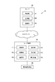
- FIG. 1 is a diagram showing the overall configuration of the image processing system.
- the image processing system S includes a user terminal 10, an image reading device 20, and a server 30.
- the user terminal 10 and the server 30 can each be connected to a network such as the Internet.
- a network such as the Internet.
- one user terminal 10, one image reading device 20, and one server 30 are shown, but a plurality of these terminals may be provided. Further, the image reading device 20 may be connectable to a network.
- the user terminal 10 is a computer operated by the user, and is, for example, a mobile phone (including a smartphone), a portable information terminal (including a tablet computer), or a personal computer. As illustrated in FIG. 1, the user terminal 10 includes a control unit 11, a storage unit 12, a communication unit 13, an operation unit 14, a display unit 15, and an imaging device 16.
- the control unit 11 includes, for example, at least one microprocessor.
- the control unit 11 performs processing according to programs and data stored in the storage unit 12.
- Storage unit 12 includes a main storage unit and an auxiliary storage unit.
- the main storage unit is a volatile memory such as a RAM
- the auxiliary storage unit is a nonvolatile memory such as a hard disk or a flash memory.
- the communication unit 13 is a communication interface for wired communication or wireless communication, and performs data communication via a network.
- the operation unit 14 is an input device, and includes, for example, a pointing device such as a touch panel and a mouse, a keyboard, and the like.
- the operation unit 14 transmits operation contents to the control unit 11.
- the display unit 15 is, for example, a liquid crystal display unit or an organic EL display unit.
- the photographing device 16 includes at least one camera, for example, a CMOS image sensor or a CCD image sensor.
- the image capturing device 16 captures a still image or a moving image and generates image data. In the present embodiment, a case will be described in which the imaging device 16 is included in the user terminal 10, but the imaging device 16 may be provided outside the user terminal 10.
- the image reading device 20 is a device that reads an image, and is, for example, a scanner.
- the image reading device 20 includes, for example, a CMOS image sensor or a CCD image sensor.
- the image reading device 20 reads a medium on which an image is formed (for example, paper, film, plastic, or the like) and generates image data. In the present embodiment, the case where the image reading device 20 is included outside the user terminal 10 will be described, but the image reading device 20 may be inside the user terminal 10.
- the server 30 is a server computer.
- the server 30 includes a control unit 31, a storage unit 32, and a communication unit 33.
- the hardware configurations of the control unit 31, the storage unit 32, and the communication unit 33 may be the same as those of the control unit 11, the storage unit 12, and the communication unit 13, respectively, and description thereof will not be repeated.
- the programs and data described as being stored in the storage units 12 and 32 may be supplied from another computer via a network.
- the hardware configurations of the user terminal 10, the image reading device 20, and the server 30 are not limited to the above examples, and various hardware can be applied.
- a reading unit for example, an optical disk drive or a memory card slot
- an input / output unit for example, a USB port
- a program or data stored in an information storage medium may be supplied via a reading unit or an input / output unit.
- the user captures an identity verification document with the imaging device 16 or the image reading device 20 and uploads the captured image to the server 30 in order to open a bank account, make an insurance contract, or the like on the Internet.
- the server 30 performs optical character recognition on the captured image and extracts characters such as the name, address, and date of birth printed on the personal identification document.
- the identity verification document may be any document that can identify the user, such as a driver's license, insurance card, resident's card, or passport.
- a driver's license will be described as an example of an identification document.
- a driver's license in a fictitious format is used as an example for convenience of explanation.
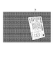
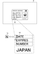
- FIG. 2 is a diagram showing a state in which a driver's license is taken in.
- the user uses the photographing device 16 of the user terminal 10 to photograph a driver's license placed on a desk. Since the position and orientation of the imaging device 16 can be freely changed, the driver's license is not always imaged from the front (directly above). For this reason, the driver's license in the captured image is often distorted or bent. In the present embodiment, it is assumed that the resolution of the captured image is secured to the extent that optical character recognition is possible, and that the focus of the photographing device 16 matches the driver's license.
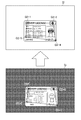
- FIG. 3 is a diagram showing an example of a captured image.
- the driver's license in the captured image I1 is distorted or bent, it is difficult to extract characters even if optical character recognition is performed.
- the driver's license does not have a dedicated mark for correcting distortion and bending of the document, it is not possible to correct distortion and bending using such a mark.
- the image processing system S after roughly correcting the distortion or the bending of the driver's license in the captured image I1, a fixed portion in the driver's license is detected to finely correct the distortion or the bending.
- a fixed portion in the driver's license is detected to finely correct the distortion or the bending.
- an image in a state where optical character recognition is easy to generate is generated.
- FIG. 4 is a functional block diagram illustrating an example of functions realized in the image processing system S. As illustrated in FIG. 4, a case will be described in which the image processing system S implements a data storage unit 100, an acquisition unit 101, a first shaping unit 102, a detection unit 103, a second shaping unit 104, and an execution unit 105. .
- the data storage unit 100 is realized mainly by the storage unit 32.
- the data storage unit 100 stores data necessary for executing image processing.
- the image processing here may be any processing based on an image, and includes various processes such as image processing and optical character recognition.
- a sample image database related to sample images of a document will be described as an example of data stored in the data storage unit 100.
- a document is a medium on which an image is formed, and is sometimes called a document. In other words, it is an object that is captured in an image by the imaging device 16 or the image reading device 20.
- the document has a predetermined format and a layout is predetermined. That is, it is assumed that the document knows in advance where and what is drawn.
- the type of the document may be arbitrary, and may be, for example, an identification document, an identification card, an application to a public organization, an application for goods or services, or a test answer sheet.
- a driver's license will be described as an example of a document. Therefore, the portion described as a driver's license in the present embodiment can be read as a document.
- the document includes a fixed part and an irregular part.
- the fixed form part is a part whose contents are fixed, and is a part whose contents are common to other documents.
- the fixed part is a part whose contents do not change regardless of the document, and a part whose contents do not change regardless of the user.
- the standard part is a format part in a document, and is a part where a specific character, symbol, figure, frame, illustration, or image is drawn.
- the fixed form part can be said to be a part containing information unique to the document.
- the title “DRIVER @ LICENSE” is an example of a standard part.
- item names such as “NAME”, “BIRTH @ DAY”, “ADDRESS”, “DATE”, “EXPIRES”, and “NUMBER” are examples of a standard part.
- the country name "JAPAN” is an example of a standard part.
- the name of the institution “Tokyo ⁇ Metropolitan ⁇ Public ⁇ Safety ⁇ Commission” is an example of a standard part.
- the fixed portion is not limited to the characters described above, and the image showing the Japanese flag on the driver's license in FIG. 3 is also an example of the fixed portion.
- the frame surrounding the above item names and the like is also an example of the fixed portion.
- Atypical parts are parts whose contents are not fixed and whose contents are not common to other documents.
- the atypical part is a part whose contents change for each document and a part whose contents change for each user.
- the atypical portion is a portion other than the format portion in the document, and is a portion on which information such as personal information, user identification information, application contents, application contents, or a test answer is printed.
- the atypical portion can also be referred to as a portion containing user-specific information.
- Bend is the rotation (orientation) of a document in an image. Stated another way, the degree to which the bend is deviated from the state of facing directly.
- the absence of any bend means a state of facing directly, and the absence of bend means that it can be considered that there is no bend.
- the long side direction is shifted from the horizontal direction (for example, the X axis direction of the image coordinate system), and the short side direction is the vertical direction (for example, the Y axis direction of the image coordinate system).
- Deviation corresponds to the occurrence of bending.
- the fact that the long side direction deviates from the vertical direction and the short side direction deviates from the horizontal direction corresponds to the occurrence of bending.
- an angle between these directions being substantially 0 ° (for example, an angle of less than 5 °) corresponds to substantially no bending.
- the obtaining unit 101 may obtain the captured image I1 from the user terminal 10 or the captured image I1 from the image reading device 20 via a network. Further, for example, the captured image I1 may be stored in the data storage unit 100. In this case, the acquisition unit 101 acquires the captured image I1 from the data storage unit 100. Further, for example, the captured image I1 may be stored in a database server outside the server 30, and in this case, the acquiring unit 101 acquires the captured image I1 from the database server.
- the first shaping unit 102 is realized mainly by the control unit 31.
- the first shaping unit 102 shapes the captured image I1 based on the characteristics of the document in the sample image I2 and the characteristics of the document in the captured image I1 to obtain a first formatted image.
- the first shaping unit 102 does not consider the local features (only partial features) of the image, but rather the overall features of the document in the sample image I2 and the overall features of the document in the captured image I1. Based on the characteristics, the captured image I1 is shaped. For example, the first shaping unit 102 shapes the captured image I1 so as to approach the characteristics of the document in the sample image I2. In other words, for example, the first shaping unit 102 shapes the captured image I1 so as to approach the shape and orientation of the document in the sample image I2.
- the first shaping unit 102 acquires feature point group information of the sample image I2 from the sample image database. Further, for example, the first shaping unit 102 extracts the feature point group P1 from the captured image I1, and acquires feature point group information. The extraction of the feature point group P1 and the acquisition of the feature point group information may be performed using the above-described algorithm. For example, the first shaping unit 102 performs matching of the feature point groups P1 and P2 based on the feature point group information of the sample image I2 and the feature point group information of the captured image I1.
- the feature point group may be extracted from the entire image, or may be extracted from only a part of the image.
- the first shaping unit 102 generates the first shaped image I3 based on the characteristics of the document in the predetermined area in the sample image I2 and the characteristics of the document in the area corresponding to the predetermined area in the captured image I1. May be acquired.
- the first shaping unit 102 may shape the captured image I1 based on the outline extracted from the sample image I2 and the outline extracted from the captured image I1.
- the outline may be obtained by edge detection processing such as a Sobel filter.
- the first shaping unit 102 may shape the captured image I1 so as to approach the contour extracted from the sample image I2.
- the first shaping unit 102 may shape the captured image I1 such that the shape of a frame surrounding “NAME” or “BIRTH @ DAY” in the driver's license of the present embodiment roughly matches. At this time, even if the entire frame cannot be detected and only a part of the frame is detected, the shape of the detected part of the frame may be roughly adjusted.
- the detection unit 103 detects a characteristic portion from the first shaped image I3 using an object detection algorithm.
- Various algorithms can be applied as the object detection algorithm. For example, template matching may be used, or an arrangement pattern of feature points or a direction of a contour line may be used.
- the detection unit 103 since the template image T of the characteristic portion in the sample image I2 is prepared, the detection unit 103 detects a portion similar to the template image T.
- FIG. 10 is a diagram showing an example of template matching.
- the detection unit 103 detects a characteristic part from the first shaped image I3 based on template matching using the characteristic part in the sample image I2 as the template image T.
- the detection unit 103 scans the window W having the same size as the template image T4 in the first shaped image I3, and determines the pixel value of each pixel in the frame and the pixel value of each pixel in the template image T4. Based on the value, the characteristic portion is detected. For example, the detection unit 103 calculates the similarity based on the difference between these pixel values, and determines that the characteristic portion exists in a frame whose similarity is equal to or larger than the threshold.
- the characteristic portion may be searched from the entire first shaped image I3, but in the present embodiment, the detecting unit 103 selects the characteristic portion from the region including the predetermined position in the first shaped image I3. May be detected.
- This area may have any shape and size, and in the example of FIG. 10, is an area A1 including a position in the sample image I2 where the character “on” indicated by the template image T4 appears. Since the template image T4 shows a characteristic portion near the lower right of the driver's license, the region A1 is also a region near the lower right.
- the second shaping unit 104 is realized mainly by the control unit 31.
- the second shaping unit 104 shapes the first shaped image I3 so that the position of the characteristic portion detected by the detection unit 103 matches a predetermined position, and acquires a second shaped image.
- the second shaping unit 104 shapes the first shaped image I3 based on the position of the feature in the sample image I2 and the position of the feature in the first shaped image I3.
- FIGS. 11 and 12 are diagrams showing the processing contents of the second shaping unit 104.
- FIG. 11 for example, the second shaping unit 104 shapes the first shaped image I3 so that the position Q3 of the feature in the first shaped image I3 approaches the position Q2 of the feature in the sample image I2. I do.
- the symbol Q2 is used to describe the position of the entire characteristic part of the sample image I2, and the code Q2-k (k is a natural number) is used to describe the position of each characteristic part.
- a reference numeral of Q3 is given, and when describing the position of each characteristic portion, a reference numeral of Q3-1 (l is a natural number) is given. Further, when it is not necessary to particularly refer to the drawings, the reference numerals of the respective positions may be omitted.
- the execution unit 105 performs optical character recognition on the second shaped image I4, thereby extracting information appearing in the atypical part of the driver's license and recording the information in the data storage unit 100.
- the execution unit 105 extracts information such as the user's name, date of birth, address, issuance date, effective date, and license number shown in the driver's license, and records the information in the data storage unit 100. .
- the control unit 11 acquires type information indicating the type of the personal identification document based on the detection signal of the operation unit 14 (S2).
- the user since the user does not know which identity verification document to upload, the user is caused to select the type of the identity verification document.
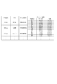
- S2 for example, a list indicating the type of the identification document is displayed on the display unit 15, and the user selects the identification document to be uploaded from the list.
- types such as a driver's license, a resident card, or a passport can be selected.
- the control unit 11 transmits the captured image I1 acquired in S1 and the type information acquired in S2 to the server 30 (S3).
- the control unit 31 acquires the feature point group information of the sample image I2 from the sample image database (S5).
- the control unit 31 refers to the record corresponding to the type indicated by the type information received in S4 in the sample image database, and acquires the feature point group information stored in the record.
- the control unit 31 shapes the captured image I1 based on the matching result in S6 to obtain a first shaped image I3 (S7).
- the control unit 31 calculates the above-described transformation matrix, and shapes the captured image I1 based on the transformation matrix.
- the shaped image is the first shaped image I3.
- the control unit 31 acquires the template image T from the sample image database (S8).
- the control unit 31 refers to the record corresponding to the type indicated by the type information received in S4 in the sample image database, and acquires the template image T stored in the record.
- the control unit 31 shapes the first shaped image I3 based on the matching result in S9 to obtain a second shaped image I4 (S10).
- the control unit 31 calculates the transformation matrix as described above, and shapes the first shaped image I3 based on the transformation matrix.
- the shaped image is the second shaped image I4.
- the control unit 31 performs optical character recognition on the second shaped image I4 acquired in S10 (S11). In S11, the control unit 31 extracts a character from the second shaped image I4.
- the control unit 31 records the character extracted in S11 in the storage unit 32 (S12), and the process ends.
- information such as the user's name, address, and date of birth is extracted from the personal identification document uploaded by the user, and recorded in the storage unit 32.
- the captured image is shaped so as to remove the rough distortion and the bending of the document, and then the document is shaped based on the characteristic portion so as to remove the fine distortion and the bending of the document.
- the first shaped image I3 is obtained, and various extraction algorithms exist.
- image processing can be further speeded up.
- a feature point group that shows the characteristics of a document in an image in detail the accuracy of image processing can be improved, and distortion and curving of the document can be effectively removed.
- a first formatted image I3 is acquired based on the characteristics of the document in the region where the fixed part appears in the sample image and the characteristics of the document in the region where the fixed part appears in the captured image.
- image processing can be further speeded up.
- areas having low reliability in shaping can be removed from the extraction target of the features, so that the accuracy of image processing can be improved.
- bending can be effectively removed.
- by combining a plurality of shaping units having different characteristics, that is, the first shaping unit 102 and the second shaping unit 104 it is possible to effectively remove the distortion and the bending of the document. For example, even if the second-stage shaping by the second shaping unit 104 can correct only linear distortion, the first-stage shaping by the first shaping unit 102 can correct nonlinear distortion. Thus, the second-stage correction can be supplemented.
- the characteristic portion is searched from the region including the known position, and the area for searching the characteristic portion is narrowed, so that the image processing can be performed at higher speed.
- the characteristic portion arranged near the end of the document the accuracy of the image processing can be improved, and the distortion and the bending of the document can be effectively removed.
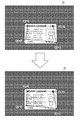
- FIG. 15 is a diagram illustrating an example of the captured image I1.
- a part of the characters "JAPAN” printed at the lower left of the driver's license is reflected by light, and the characters "J" and “A” are not reflected at all. Is not clearly shown.
- "J" and "A” are characteristic portions indicated by the template image T3, so that one of the four characteristic portions cannot be detected, and the accuracy of image processing is reduced.
- FIG. 16 is a functional block diagram illustrating an example of functions realized in the image processing system S.
- a data storage unit 200 an acquisition unit 201, a first detection unit 202, a search unit 203, a second detection unit 204, a shaping unit 205, and an execution unit 206 are realized. The case will be described.
- the data storage unit 200 is the same as the data storage unit 100 described in the first embodiment.
- the acquisition unit 201 is the same as the acquisition unit 101 described in the first embodiment.
- the first detection unit 202 is realized mainly by the control unit 31.
- the first detection unit 202 may be the same as the detection unit 103 of the first embodiment, and detects the characteristic portion of the fixed portion based on the captured image I1.
- the meaning of the characteristic portion is as described in the first embodiment.
- a predetermined position where a characteristic portion exists is referred to as a first position. That is, the first position is not the position where the specific portion appears in the captured image I1, but the position of the specific portion in the document.
- the first position is a position where a characteristic portion should be, for example, a position where a specific portion appears in the sample image I2.
- the portion described as the predetermined position in the first embodiment can be read as the first position in the second embodiment.
- the detection unit 103 detects a plurality of characteristic portions. Each of the plurality of features will be at the first location corresponding to itself. Also, as in the first embodiment, a case will be described in which the first detection unit 202 detects a characteristic portion from the first shaped image I3. However, in the second embodiment, the processing of the first shaping unit 102 in the first embodiment is omitted. The first detection unit 202 may detect a characteristic portion from the captured image I1.
- the captured image I1 may be manually shaped by an operator's operation to obtain a first shaped image I3, and the first detection unit 202 may output the first shaped image I3.
- the characteristic portion may be detected from one shaped image I3.
- the search unit 203 is realized mainly by the control unit 31. If no characteristic part is detected, the search unit 203 searches for a characteristic part alternative to the fixed part based on the captured image I1.
- the alternative feature is a feature used in place of a feature not detected.
- the meaning of the characteristic portion is as described in the first embodiment.
- the alternative features may have similar features to the undetected features, and in particular, these features may not be similar.
- a character having a similar shape or size may be used as an alternative characteristic portion, or a character having a shape or size not particularly similar may be used as an alternative characteristic portion. Is also good.
- An alternative feature is a feature that exists at the second position in the document.
- the second position may be a position different from the first position, and may be a position determined based on the first position, or may be a position that is not particularly related to the first position.
- the second position is a position near the first position, and is a position within a predetermined distance (for example, within 5 cm) from the first position.
- the second position is a position in an area including the first position.
- the second position is not the position where the alternative specific part appears in the captured image I1, but the position of the alternative specific part in the document.
- the second position is a position where the alternative characteristic portion should be, for example, a position where the alternative specific portion appears in the sample image I2.
- FIG. 17 is a diagram showing a state in which an alternative feature portion is searched.
- the search unit 203 searches for an alternative feature using the histogram H based on the captured image I1.
- the histogram H is statistical information indicating the frequency for each pixel value, and is represented by, for example, a graph in which the vertical axis indicates the frequency and the horizontal axis indicates the pixel value. For example, for each pixel value, the search unit 203 counts the number of pixels in which the pixel value appears in a predetermined area, and generates a histogram H.
- the search unit 203 determines whether or not the distribution of the histogram H indicates a specific distribution, and when indicating the specific distribution, determines the region in which the histogram H has been generated as a characteristic portion.
- the specific distribution is a distribution indicating that the image is characteristic, and may be determined based on, for example, a histogram of a fixed portion. Also, for example, a region having only a background color (for example, white) does not become a characteristic portion.
- the frequency of pixel values for example, black
- indicating a color (foreground color) that is not a background color appears above a threshold. It may be.
- the alternative feature part may be searched for from the entire image, but the search unit 203 may search for the alternative feature part from the area A2 determined based on the first position.
- the region determined based on the first position is a region including the first position, and is a region A2 within a predetermined distance (for example, within 5 cm) from the first position.
- a predetermined distance for example, within 5 cm
- an alternative characteristic portion was selected from the region A2 including the first position of the characteristic portion (ie, the position near the lower left of the driver's license). Searched.
- the search unit 203 searches for an alternative characteristic part when at least one characteristic part is not detected.
- the search unit 203 searches for an alternative feature part when the number of undetected feature parts is equal to or more than a predetermined number (for example, two), and the number of undetected feature parts is less than the predetermined number. If so, the alternative feature portion need not be searched.
- the search unit 203 searches for an alternative feature portion if there is at least one undetected feature portion, and does not search for an alternative feature portion if there is no number of undetected feature portions. Is also good.
- the second detection unit 204 is realized mainly by the control unit 31.
- the second detection unit 204 detects an alternative feature from the sample image I2.
- the method of detecting the characteristic portion itself may be the same as the method described in the first embodiment, and various object detection algorithms can be applied.
- the second detection unit 204 detects, from the sample image I2, a region similar to the alternative feature part searched by the search unit 203.
- FIG. 18 is a diagram illustrating a state where an alternative feature is detected from the sample image I2.
- the second detection unit 204 detects an alternative feature from the sample image I2 based on template matching using the alternative feature searched by the search unit 203 as the template image T5. .
- the second detection unit 204 determines the area similar to the alternative feature part. Will be detected.
- the details of the template matching process are as described in the first embodiment.
- the second detection unit 204 scans a window W having the same size as the template image T5 in the sample image I2, and An alternative feature is detected based on the pixel value of the pixel and the pixel value of each pixel of the template image T5. For example, the second detection unit 204 calculates the similarity based on the difference between these pixel values, and determines that the characteristic portion exists in a frame where the similarity is equal to or larger than the threshold.
- a feature portion may be searched for from the entire sample image I2, but in the present embodiment, the second detection unit 204 searches for a replacement feature portion in the first shaped image I3 of the sample image I2.
- the alternative characteristic portion may be detected from the area A3 including the shifted position.
- the area A3 may have any shape and size.
- the area A3 includes “N” indicated by the template image T5 and a position where a line near the “N” appears. Since the template image T5 shows an alternative characteristic portion searched near the lower left of the driver's license, the area A3 is also an area near the lower left.
- the shaping unit 205 is realized mainly by the control unit 31. When a characteristic portion is detected, the shaping section 205 acquires a shaped image of the captured image I1 such that the position of the characteristic portion matches a predetermined first position.
- the shaping unit 205 may execute the same processing as the first shaping unit 102 and the second shaping unit 104 of the first embodiment.
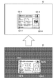
- FIGS. 19 and 20 are diagrams showing how a shaped image is obtained in the second embodiment.
- the shaping unit 205 shapes the first shaped image I3 such that the position Q3 of the feature portion in the first shaped image I3 approaches the position Q2 of the feature portion in the sample image I2.
- the shaping section 205 sets the position Q3 of each of the plurality of characteristic portions to the first position Q2 corresponding to the characteristic portion. Then, the second shaped image I4 is obtained. For example, the shaping unit 205 calculates the transformation matrix based on the first position Q2 of the characteristic part in the sample image I2 and the position Q3 of the characteristic part in the first shaped image I3.
- the transformation matrix is calculated such that the position Q3 of the characteristic part in the first shaped image I3 approaches the position Q2 of the characteristic part in the sample image I2.
- the method of acquiring the transformation matrix itself is as described in the first embodiment. As shown in FIG. 19, the shape of a rectangle (a rectangle surrounded by Q3-1, Q3-2, Q3-4, and Q3-5) connecting each characteristic portion and the alternative characteristic portion in the first shaped image I3. Is calculated so as to approach a square (a square surrounded by Q2-1, Q2-2, Q2-4, Q2-5) connecting each characteristic part and the alternative characteristic part in the sample image I2. Is done.
- the shaping unit 205 converts the first shaped image I3 based on the conversion matrix to obtain a second shaped image I4.
- the second shaped image I4 has a driver's license in which fine distortion and bending have been corrected, and has substantially the same shape and orientation as the driver's license of the sample image I2. That is, the shape of the square (the square surrounded by Q4-1, Q4-2, Q4-4, and Q4-5) connecting the respective characteristic portions of the second shaped image I4 connects the respective characteristic portions of the sample image I2. It is the same as or substantially the same as a rectangular shape (a square surrounded by Q2-1, Q2-2, Q2-4, and Q2-5).
- the second shaped image I4 is an image in a state where optical character recognition is easy.
- the shaping unit 205 shapes the first shaped image I3 and obtains the second shaped image I4 has been described.
- the first shaping unit 102 according to the first embodiment has been described. May be omitted, and the shaping unit 205 may obtain the shaped image by shaping the captured image I1.
- the captured image I1 may be manually shaped by an operator's operation to obtain the first shaped image I3, and the shaping unit 205 may perform the first shaping manually shaped.
- the image I3 may be shaped to obtain the second shaped image I4.
- the shaping section 205 may acquire a shaped image such that the position of the alternative characteristic portion matches the predetermined second position.
- the only difference is that an alternative feature is used in place of an undetected feature, and the shaping method is as described in the first embodiment.
- the shaping unit 205 may obtain the position of the alternative characteristic portion in the sample image I2 as the second position, and may obtain the shaped image.
- the only difference is that an alternative feature is used, and the shaping method itself is as described in the first embodiment.
- the shaping unit 205 may acquire a shaped image based on an alternative feature portion.
- the execution unit 206 is realized mainly by the control unit 31.
- the execution unit 206 performs optical character recognition on the shaped image.
- the details of the processing of the execution unit 206 are the same as those of the execution unit 105 described in the first embodiment, and the algorithm for optical character recognition may use the algorithm described in the first embodiment.
- FIG. 21 is a diagram showing an example of characters extracted by optical character recognition.
- the execution unit 206 performs the optical character recognition on the second shaped image I4 to extract the information appearing in the atypical portion of the driver's license, and records the information in the data storage unit 200. I do.
- the execution unit 206 extracts information such as the user's name, date of birth, address, issuance date, effective date, and license number shown in the driver's license, and records the information in the data storage unit 200.
- the execution unit 105 only needs to be information corresponding to a document, as in the first embodiment.
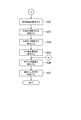
- FIG. 22 and FIG. 23 are flowcharts illustrating an example of processing executed in the image processing system S.
- the processes shown in FIGS. 22 and 23 are executed by the control unit 11 operating according to the program stored in the storage unit 12 and the control unit 31 operating according to the program stored in the storage unit 32.
- the processing described below is an example of processing executed by the functional blocks illustrated in FIG.
- the processing of S21 to S29 is the same as S1 to S9 of the first embodiment. Note that, as described above, the processing of S24 to S27 may be omitted, and the characteristic portion may be detected from the captured image I1 instead of the first shaped image I3.
- the control unit 31 determines whether or not there is a feature part that has not been detected (S30). In S30, the control unit 31 determines whether or not an area having a similarity greater than or equal to the threshold has been found for all the template images T acquired in S28.
- S30 If there is no undetected characteristic part (S30; N), the process proceeds to S31.
- the process of S31 is the same as S10 of the first embodiment. In this case, since all the characteristic portions have been detected and it is not necessary to search for an alternative characteristic portion, the processing of S32 to S35 is not executed.
- the process proceeds to FIG. 23, where the control unit 11 searches for an alternative feature part based on the first position of the feature part that has not been detected. Is set (S32). In S32, the control unit 11 sets an area A3 including the coordinates of the undetected characteristic portion as a search area. It is assumed that the size and shape of the search area are predetermined.
- the control unit 11 generates a histogram H for each small area in the search area set in S32, and searches for an alternative feature (S33). In S33, the control unit 11 determines whether or not the histogram H generated for each small area shows a specific feature. Note that the size and shape of the small region are determined in advance.
- the control unit 11 detects the alternative characteristic portion searched in S33 from the sample image I2 (S34). In S34, the control unit 11 performs template matching using the alternative feature portion as the template image T.
- the control unit 11 acquires the second shaped image I4 based on the characteristic part specified in S29, the alternative characteristic part searched in S33, and the alternative characteristic part detected in S34 (S35).
- the control unit 31 calculates the above-described conversion matrix, and shapes the first shaped image I3 based on the conversion matrix.
- the shaped image is the second shaped image I4.
- Subsequent processes in S36 to S37 are the same as S11 to S12 in the first embodiment.
- the image processing system S of the second embodiment when a feature portion is not detected, a search is made for an alternative feature portion, and the alternative feature portion is used instead of the undetected feature portion. Even if not performed, the accuracy of image processing can be improved.
- an alternative feature portion is detected from the sample image I2, and is shaped so as to match the position of the alternative feature portion in the sample image I2, thereby improving the accuracy of image processing and effectively removing distortion and bending. Can be.
- a more characteristic portion can be used as an alternative characteristic portion, and the accuracy of image processing can be improved.
- the search unit 203 uses, for each undetected feature part, based on the positional relationship with the detected part of the feature part.
- an alternative feature may be searched.
- the positional relationship is a relative position with respect to some detected characteristic portions.
- the search unit 203 searches for an alternative feature part candidate for each of the detected feature parts, and An alternative feature may be determined based on the size of the area surrounded by the detected some feature.
- the method of searching for the alternative feature portion may be the same as the search method of the alternative feature portion described in the second embodiment, and is performed using, for example, the histogram H.
- FIG. 24 is an explanatory diagram of the processing in the modification (1) of the second embodiment.
- the characteristic portions upper left, upper right, and lower right characteristic portions indicated by the template images T1, T2, and T4 are detected, and the characteristic portions indicated by the template image T3, as in the example described in the second embodiment. (Lower left characteristic part) is not detected.
- an alternative feature portion is searched for based on a positional relationship with a part of the detected feature portion, and an alternative feature portion suitable for image processing is used to perform image processing. And the distortion and bending can be effectively removed.
- the search unit 203 searches for an alternative feature part candidate for each of the not-detected feature parts, and searches for each of the plurality of undetected feature parts.
- An alternative feature is determined based on the size of the region enclosed by the candidate.
- the candidate search method is as described in the modification (1).
- the second detector 204 may be omitted in the present modification. Similar to the sample image database described in the embodiment 1-2, the position (second position) of the alternative feature portion may be stored in the data storage unit 200 in advance.
- the shaping unit 205 shapes the first shaped image I3 based on the positions of the characteristic portion and the alternative feature portion in the sample image I1 and the positions of the characteristic portion and the alternative feature portion in the first shaped image I3. Good. The details of this processing are as described in the second embodiment.
Landscapes
- Engineering & Computer Science (AREA)
- Theoretical Computer Science (AREA)
- Physics & Mathematics (AREA)
- Computer Vision & Pattern Recognition (AREA)
- Multimedia (AREA)
- General Physics & Mathematics (AREA)
- Artificial Intelligence (AREA)
- Computing Systems (AREA)
- Geometry (AREA)
- Health & Medical Sciences (AREA)
- Computer Graphics (AREA)
- Databases & Information Systems (AREA)
- Evolutionary Computation (AREA)
- General Health & Medical Sciences (AREA)
- Medical Informatics (AREA)
- Software Systems (AREA)
- Character Input (AREA)
- Image Processing (AREA)
Abstract
Description
以下、本発明に関わる画像処理システムの実施形態の例を説明する。 [1. Embodiment 1]
Hereinafter, an example of an embodiment of an image processing system according to the present invention will be described.
図1は、画像処理システムの全体構成を示す図である。図1に示すように、画像処理システムSは、ユーザ端末10、画像読取装置20、及びサーバ30を含む。ユーザ端末10とサーバ30は、それぞれインターネットなどのネットワークに接続可能である。なお、図1では、ユーザ端末10、画像読取装置20、及びサーバ30をそれぞれ1台ずつ示しているが、これらは複数台ずつあってもよい。また、画像読取装置20がネットワークに接続可能であってもよい。 [1-1. Overall configuration of image processing system]
FIG. 1 is a diagram showing the overall configuration of the image processing system. As shown in FIG. 1, the image processing system S includes a
本実施形態では、ユーザは、インターネットで銀行口座の開設や保険の契約等をするために、撮影装置16又は画像読取装置20で本人確認書類を取り込み、サーバ30に取込画像をアップロードする。サーバ30は、取込画像に対して光学文字認識を実行し、本人確認書類に印刷された氏名、住所、及び生年月日といった文字を抽出する。 [1-2. Overview of Image Processing System]
In the present embodiment, the user captures an identity verification document with the
図4は、画像処理システムSにおいて実現される機能の一例を示す機能ブロック図である。図4に示すように、画像処理システムSでは、データ記憶部100、取得部101、第1整形部102、検出部103、第2整形部104、及び実行部105が実現される場合を説明する。 [1-3. Function realized in image processing system]
FIG. 4 is a functional block diagram illustrating an example of functions realized in the image processing system S. As illustrated in FIG. 4, a case will be described in which the image processing system S implements a
データ記憶部100は、記憶部32を主として実現される。データ記憶部100は、画像処理を実行するために必要なデータを記憶する。ここでの画像処理とは、画像に基づいた処理であればよく、例えば、画像の加工や光学文字認識といった種々の処理を含む意味である。本実施形態では、データ記憶部100が記憶するデータの一例として、文書の見本画像に関する見本画像データベースを説明する。 [1-3-1. Data storage unit]
The
取得部101は、制御部31を主として実現される。取得部101は、画像読取装置20又は撮影装置16によって取り込まれた、定型部分と非定型部分とを含む文書の取込画像I1を取得する。なお、「画像を取得する」とは、画像のデータを取得することである。この点は、本実施形態で「画像を取得する」と記載した他の箇所も同様である。画像のデータとしては、種々のファイル形式を適用可能であり、例えば、JPEG、GIF、BMP、又はPNGといった形式であってもよい。 [1-3-2. Acquisition unit]
The
第1整形部102は、制御部31を主として実現される。第1整形部102は、見本画像I2における文書の特徴と、取込画像I1における文書の特徴と、に基づいて、取込画像I1を整形して第1整形画像を取得する。 [1-3-3. First shaping unit]
The
検出部103は、制御部31を主として実現される。検出部103は、第1整形画像I3から、定型部分の特徴部分を検出する。 [1-3-4. Detection unit]
The
第2整形部104は、制御部31を主として実現される。第2整形部104は、検出部103により検出された特徴部分の位置が所定位置に合うように、第1整形画像I3を整形して第2整形画像を取得する。例えば、第2整形部104は、見本画像I2における特徴部分の位置と、第1整形画像I3における特徴部分の位置と、に基づいて、第1整形画像I3を整形する。 [1-3-5. Second shaping unit]
The
実行部105は、制御部31を主として実現される。実行部105は、第2整形画像I4に対して光学文字認識を実行する。光学文字認識のアルゴリズム自体は、種々のアルゴリズムを適用可能であり、例えば、パターンマッチングを利用したアルゴリズムであってもよいし、構造解析を利用したアルゴリズムであってもよい。 [1-3-6. Execution section]
The
図14は、画像処理システムSにおいて実行される処理の一例を示すフロー図である。図14に示す処理は、制御部11が記憶部12に記憶されたプログラムに従って動作し、制御部31が記憶部32に記憶されたプログラムに従って動作することによって実行される。下記に説明する処理は、図4に示す機能ブロックにより実行される処理の一例である。 [1-4. Processing executed in the present embodiment]
FIG. 14 is a flowchart illustrating an example of processing executed in the image processing system S. The process illustrated in FIG. 14 is executed by the
次に、画像処理システムSの別実施形態を説明する。実施形態1のように特徴部分を利用して整形しようとしても、文書の取り込み方によっては、光が反射したり別の物体又は影で隠れたりして、特徴部分が取込画像I1にはっきりと写っておらず、うまく整形できないことがある。 [2. Embodiment 2]
Next, another embodiment of the image processing system S will be described. Even if an attempt is made to form using a characteristic portion as in the first embodiment, depending on how the document is captured, light is reflected or hidden by another object or shadow, and the characteristic portion is clearly displayed in the captured image I1. There is a case that it is not reflected and cannot be properly shaped.
図16は、画像処理システムSにおいて実現される機能の一例を示す機能ブロック図である。図16に示すように、画像処理システムSでは、データ記憶部200、取得部201、第1検出部202、探索部203、第2検出部204、整形部205、及び実行部206が実現される場合を説明する。 [2-1. Function realized in image processing system]
FIG. 16 is a functional block diagram illustrating an example of functions realized in the image processing system S. As shown in FIG. 16, in the image processing system S, a
データ記憶部200は、実施形態1で説明したデータ記憶部100と同様である。 [2-1-1. Data storage unit]
The
取得部201は、実施形態1で説明した取得部101と同様である。 [2-1-2. Acquisition unit]
The
第1検出部202は、制御部31を主として実現される。第1検出部202は、実施形態1の検出部103と同様であってよく、取込画像I1に基づいて、定型部分の特徴部分を検出する。特徴部分の意味は、実施形態1で説明した通りである。実施形態2では、特徴部分が存在する所定位置のことを第1位置と記載する。即ち、第1位置は、撮影画像I1において特定部分が表れた位置ではなく、文書における特定部分の位置を意味する。第1位置は、特徴部分があるべき位置であり、例えば、見本画像I2において特定部分が表れた位置である。実施形態1で所定位置と記載した箇所は、実施形態2の第1位置と読み替えることができる。 [2-1-3. First detection unit]
The
探索部203は、制御部31を主として実現される。探索部203は、特徴部分が検出されなかった場合は、取込画像I1に基づいて、定型部分の代替の特徴部分を探索する。 [2-1-4. Search section]
The
第2検出部204は、制御部31を主として実現される。第2検出部204は、見本画像I2から代替の特徴部分を検出する。特徴部分の検出方法自体は、実施形態1で説明した方法と同様であってよく、種々の物体検出アルゴリズムを適用可能である。第2検出部204は、探索部203により探索された代替の特徴部分と似た領域を、見本画像I2の中から検出する。 [2-1-5. Second detection unit]
The
整形部205は、制御部31を主として実現される。整形部205は、特徴部分が検出された場合に、当該特徴部分の位置が所定の第1位置に合うように、取込画像I1の整形画像を取得する。整形部205は、実施形態1の第1整形部102及び第2整形部104と同様の処理を実行してもよい。 [2-1-6. Shaping section]
The
実行部206は、制御部31を主として実現される。実行部206は、整形画像に対して光学文字認識を実行する。実行部206の処理の詳細は、実施形態1で説明した実行部105と同様であり、光学文字認識のアルゴリズは、実施形態1で説明したようなアルゴリズムを利用すればよい。 [2-1-7. Execution section]
The
図22及び図23は、画像処理システムSにおいて実行される処理の一例を示すフロー図である。図22及び図23に示す処理は、制御部11が記憶部12に記憶されたプログラムに従って動作し、制御部31が記憶部32に記憶されたプログラムに従って動作することによって実行される。下記に説明する処理は、図16に示す機能ブロックにより実行される処理の一例である。 [2-2. Process Executed in Second Embodiment]
FIG. 22 and FIG. 23 are flowcharts illustrating an example of processing executed in the image processing system S. The processes shown in FIGS. 22 and 23 are executed by the
(1)例えば、実施形態2のように、第1整形画像I3の特徴部分及び代替の特徴部分の位置Q3で囲われた四角形と、見本画像I2の特徴部分及び代替の特徴部分の位置Q4で囲われた四角形と、に基づいて第1整形画像I3が整形される場合、これら四角形の面積が広い方が、整形の精度が高くなる。このため、代替の特徴部分として利用できそうな部分が複数存在する場合には、四角形が広くなるような代替の特徴部分を利用してもよい。 [2-3. Modification of Second Embodiment]
(1) For example, as in the second embodiment, a square surrounded by the positions Q3 of the characteristic portion and the alternative characteristic portion of the first shaped image I3 and the position Q4 of the characteristic portion and the alternative characteristic portion of the sample image I2. When the first shaped image I3 is shaped based on the enclosed rectangle, the greater the area of these squares, the higher the shaping accuracy. For this reason, when there are a plurality of parts that can be used as alternative characteristic parts, an alternative characteristic part having a wider rectangle may be used.
なお、本発明は、以上に説明した実施の形態に限定されるものではない。本発明の趣旨を逸脱しない範囲で、適宜変更可能である。 [3. Other modifications]
Note that the present invention is not limited to the embodiment described above. Changes can be made as appropriate without departing from the spirit of the present invention.
Claims (14)
- 画像読取装置又は撮影装置によって取り込まれた、定型部分と非定型部分とを含む文書の取込画像を取得する取得手段と、
前記取込画像に基づいて、前記定型部分の特徴部分を検出する検出手段と、
前記特徴部分が検出された場合に、当該特徴部分の位置が所定の第1位置に合うように、前記取込画像の整形画像を取得する整形手段と、
前記特徴部分が検出されなかった場合は、前記取込画像に基づいて、前記定型部分の代替の特徴部分を探索する探索手段と、
を含み、
前記整形手段は、前記特徴部分が検出されなかった場合は、前記代替の特徴部分の位置が所定の第2位置に合うように、前記整形画像を取得する、
ことを特徴とする画像処理システム。 Acquisition means for acquiring a captured image of a document including a fixed part and a non-fixed part captured by an image reading device or an imaging device,
Based on the captured image, detecting means for detecting a characteristic portion of the fixed portion,
A shaping unit configured to acquire a shaped image of the captured image so that a position of the feature portion matches a predetermined first position when the feature portion is detected;
When the characteristic portion is not detected, a search unit that searches for an alternative characteristic portion of the fixed portion based on the captured image,
Including
The shaping means acquires the shaped image such that the position of the alternative feature part matches a predetermined second position when the feature part is not detected;
An image processing system, characterized in that: - 前記画像処理システムは、見本画像から前記代替の特徴部分を検出する手段を更に含み、
前記整形手段は、前記特徴部分が検出されなかった場合は、前記見本画像における前記代替の特徴部分の位置を前記第2位置として取得し、前記整形画像を取得する、
ことを特徴とする請求項1に記載の画像処理システム。 The image processing system further includes means for detecting the alternative feature from the sample image,
The shaping means, when the feature portion is not detected, acquires a position of the alternative feature portion in the sample image as the second position, and acquires the shaped image;
The image processing system according to claim 1, wherein: - 前記探索手段は、前記取込画像に基づくヒストグラムを利用して、前記代替の特徴部分を探索する、
ことを特徴とする請求項2に記載の画像処理システム。 The search means searches for the alternative feature using a histogram based on the captured image,
The image processing system according to claim 2, wherein: - 前記探索手段は、前記第1位置に基づいて定まる領域内から、前記代替の特徴部分を探索する、
ことを特徴とする請求項1~3の何れかに記載の画像処理システム。 The search means searches for the alternative feature portion from within an area determined based on the first position;
The image processing system according to any one of claims 1 to 3, wherein: - 前記検出手段は、複数の特徴部分を検出し、
前記整形手段は、前記複数の特徴部分の各々の位置が、当該特徴部分に対応する第1位置に合うように、前記整形画像を取得し、
前記探索手段は、少なくとも1つの前記特徴部分が検出されなかった場合に、前記代替の特徴部分を探索し、
前記整形手段は、前記少なくとも1つの特徴部分が検出されなかった場合に、前記代替の特徴部分に基づいて、前記整形画像を取得する、
ことを特徴とする請求項1~4の何れかに記載の画像処理システム。 The detecting means detects a plurality of characteristic portions,
The shaping means obtains the shaped image such that each position of the plurality of feature portions matches a first position corresponding to the feature portion,
The search means searches for the alternative feature part when at least one of the feature parts is not detected,
The shaping means acquires the shaped image based on the alternative feature when the at least one feature is not detected;
The image processing system according to any one of claims 1 to 4, wherein: - 前記探索手段は、前記複数の特徴部分のうちの一部だけが検出された場合に、検出されなかった特徴部分ごとに、検出された一部の特徴部分との位置関係に基づいて、前記代替の特徴部分を探索する、
ことを特徴とする請求項5に記載の画像処理システム。 When only a part of the plurality of feature parts is detected, the search unit performs, for each undetected feature part, the replacement based on a positional relationship with the detected part of the feature part. Search for the characteristic part of,
The image processing system according to claim 5, wherein: - 前記複数の特徴部分は、3つ以上であり、
前記探索手段は、前記検出されなかった特徴部分ごとに、前記代替の特徴部分の候補を探索し、当該候補と前記検出された一部の特徴部分とによって囲われる領域のサイズに基づいて、前記代替の特徴部分を決定する、
ことを特徴とする請求項6に記載の画像処理システム。 The plurality of feature parts is three or more,
The search means, for each of the non-detected feature portions, searches for a candidate for the alternative feature portion, based on the size of the region surrounded by the candidate and the detected part of the feature portion, Determine alternative features,
The image processing system according to claim 6, wherein: - 前記探索手段は、複数の前記特徴部分が検出されなかった場合に、検出されなかった特徴部分ごとに、他の代替の特徴部分との位置関係に基づいて、前記代替の特徴部分を探索する、
ことを特徴とする請求項5~7の何れかに記載の画像処理システム。 The search means, when a plurality of the feature portions are not detected, for each of the detected feature portions, based on a positional relationship with another alternative feature portion, to search for the alternative feature portion,
The image processing system according to any one of claims 5 to 7, wherein: - 前記複数の特徴部分は、3つ以上であり、
前記探索手段は、前記検出されなかった特徴部分ごとに、前記代替の特徴部分の候補を探索し、前記検出されなかった複数の特徴部分の各々の候補によって囲われる領域のサイズに基づいて、前記代替の特徴部分を決定する、
ことを特徴とする請求項8に記載の画像処理システム。 The plurality of feature parts is three or more,
The search means searches, for each of the undetected feature portions, a candidate for the alternative feature portion, and based on a size of an area surrounded by each of the plurality of undetected feature portions, Determine alternative features,
The image processing system according to claim 8, wherein: - 前記探索手段は、予め定められた前記代替の特徴部分を探索する、
ことを特徴とする請求項1~9の何れかに記載の画像処理システム。 The search means searches for the predetermined alternative feature portion;
The image processing system according to any one of claims 1 to 9, wherein: - 前記特徴部分は、前記定型部分における文字又は記号である、
ことを特徴とする請求項1~10の何れかに記載の画像処理システム。 The characteristic portion is a character or a symbol in the fixed portion,
The image processing system according to any one of claims 1 to 10, wherein: - 前記画像処理システムは、前記整形画像に対して光学文字認識を実行する実行手段、
を更に含むことを特徴とする請求項1~11の何れかに記載の画像処理システム。 The image processing system is an execution unit that performs optical character recognition on the shaped image,
The image processing system according to any one of claims 1 to 11, further comprising: - 画像読取装置又は撮影装置によって取り込まれた、定型部分と非定型部分とを含む文書の取込画像を取得する取得ステップと、
前記取込画像に基づいて、前記定型部分の特徴部分を検出する検出ステップと、
前記特徴部分が検出された場合に、当該特徴部分の位置が所定の第1位置に合うように、前記取込画像の整形画像を取得する整形ステップと、
前記特徴部分が検出されなかった場合は、前記取込画像に基づいて、前記定型部分の代替の特徴部分を探索する探索ステップと、
を含み、
前記整形ステップは、前記特徴部分が検出されなかった場合は、前記代替の特徴部分の位置が所定の第2位置に合うように、前記整形画像を取得する、
ことを特徴とする画像処理方法。 Acquisition step of acquiring a captured image of a document including a fixed part and a non-fixed part captured by an image reading device or an imaging device,
Based on the captured image, a detection step of detecting a characteristic portion of the fixed portion,
When the characteristic portion is detected, a shaping step of acquiring a shaped image of the captured image so that the position of the characteristic portion matches a predetermined first position;
When the characteristic portion is not detected, a search step of searching for an alternative characteristic portion of the fixed portion based on the captured image,
Including
The shaping step, if the feature portion is not detected, obtains the shaped image so that the position of the alternative feature portion matches a predetermined second position;
An image processing method comprising: - 画像読取装置又は撮影装置によって取り込まれた、定型部分と非定型部分とを含む文書の取込画像を取得する取得手段、
前記取込画像に基づいて、前記定型部分の特徴部分を検出する検出手段、
前記特徴部分が検出された場合に、当該特徴部分の位置が所定の第1位置に合うように、前記取込画像の整形画像を取得する整形手段、
前記特徴部分が検出されなかった場合は、前記取込画像に基づいて、前記定型部分の代替の特徴部分を探索する探索手段、
としてコンピュータを機能させるためのプログラムであって、
前記整形手段は、前記特徴部分が検出されなかった場合は、前記代替の特徴部分の位置が所定の第2位置に合うように、前記整形画像を取得する、
プログラム。 Acquisition means for acquiring a captured image of a document including a fixed part and a non-fixed part captured by an image reading device or a photographing device,
Detecting means for detecting a characteristic portion of the fixed portion based on the captured image;
A shaping unit configured to acquire a shaped image of the captured image so that a position of the feature portion matches a predetermined first position when the feature portion is detected;
When the characteristic portion is not detected, a search unit that searches for an alternative characteristic portion of the fixed portion based on the captured image,
A program for causing a computer to function as
The shaping means acquires the shaped image such that the position of the alternative feature part matches a predetermined second position when the feature part is not detected;
program.
Priority Applications (5)
| Application Number | Priority Date | Filing Date | Title |
|---|---|---|---|
| EP18925095.4A EP3796218A4 (en) | 2018-07-06 | 2018-07-06 | Image processing system, image processing method, and program |
| PCT/JP2018/025720 WO2020008629A1 (en) | 2018-07-06 | 2018-07-06 | Image processing system, image processing method, and program |
| JP2019523117A JP6574921B1 (en) | 2018-07-06 | 2018-07-06 | Image processing system, image processing method, and program |
| US17/057,104 US11881043B2 (en) | 2018-07-06 | 2018-07-06 | Image processing system, image processing method, and program |
| TW108123413A TWI751426B (en) | 2018-07-06 | 2019-07-03 | Image processing system, image processing method and program product |
Applications Claiming Priority (1)
| Application Number | Priority Date | Filing Date | Title |
|---|---|---|---|
| PCT/JP2018/025720 WO2020008629A1 (en) | 2018-07-06 | 2018-07-06 | Image processing system, image processing method, and program |
Publications (1)
| Publication Number | Publication Date |
|---|---|
| WO2020008629A1 true WO2020008629A1 (en) | 2020-01-09 |
Family
ID=67909565
Family Applications (1)
| Application Number | Title | Priority Date | Filing Date |
|---|---|---|---|
| PCT/JP2018/025720 WO2020008629A1 (en) | 2018-07-06 | 2018-07-06 | Image processing system, image processing method, and program |
Country Status (5)
| Country | Link |
|---|---|
| US (1) | US11881043B2 (en) |
| EP (1) | EP3796218A4 (en) |
| JP (1) | JP6574921B1 (en) |
| TW (1) | TWI751426B (en) |
| WO (1) | WO2020008629A1 (en) |
Cited By (2)
| Publication number | Priority date | Publication date | Assignee | Title |
|---|---|---|---|---|
| EP3975044A1 (en) | 2020-09-28 | 2022-03-30 | Rakuten Group, Inc. | System, program and method for verifying a target region in front and oblique document images |
| US11468655B2 (en) | 2020-04-17 | 2022-10-11 | Beijing Baidu Netcom Science And Technology Co., Ltd. | Method and apparatus for extracting information, device and storage medium |
Families Citing this family (2)
| Publication number | Priority date | Publication date | Assignee | Title |
|---|---|---|---|---|
| WO2020008628A1 (en) * | 2018-07-06 | 2020-01-09 | 楽天株式会社 | Image processing system, image processing method, and program |
| JP7287210B2 (en) * | 2019-09-19 | 2023-06-06 | コニカミノルタ株式会社 | Image processing device and program |
Citations (3)
| Publication number | Priority date | Publication date | Assignee | Title |
|---|---|---|---|---|
| JP2001014427A (en) | 1999-04-26 | 2001-01-19 | Oki Electric Ind Co Ltd | Method and device for detecting reference mark and optical character reader |
| JP2012098984A (en) * | 2010-11-04 | 2012-05-24 | Nomura Research Institute Ltd | Business form data correction method and business form data correction program |
| JP2016076093A (en) * | 2014-10-07 | 2016-05-12 | 富士通株式会社 | Character recognition support device, character recognition support program, and character recognition support method |
Family Cites Families (17)
| Publication number | Priority date | Publication date | Assignee | Title |
|---|---|---|---|---|
| JPH118814A (en) * | 1997-06-17 | 1999-01-12 | Futaba Corp | Digital photograph processing system |
| JP2001229341A (en) | 2000-02-14 | 2001-08-24 | Mitsubishi Electric Corp | Device and method for recognizing character |
| US9171202B2 (en) * | 2005-08-23 | 2015-10-27 | Ricoh Co., Ltd. | Data organization and access for mixed media document system |
| JP4919028B2 (en) * | 2006-03-03 | 2012-04-18 | 富士ゼロックス株式会社 | Image processing apparatus and image processing program |
| US9292737B2 (en) * | 2008-01-18 | 2016-03-22 | Mitek Systems, Inc. | Systems and methods for classifying payment documents during mobile image processing |
| US9672510B2 (en) * | 2008-01-18 | 2017-06-06 | Mitek Systems, Inc. | Systems and methods for automatic image capture and processing of documents on a mobile device |
| JP4926116B2 (en) | 2008-04-16 | 2012-05-09 | 株式会社日立ハイテクノロジーズ | Image inspection device |
| US9092667B2 (en) * | 2012-08-27 | 2015-07-28 | Symbol Technologies, Llc | Arrangement for and method of reading forms in correct orientation by image capture |
| US10127636B2 (en) | 2013-09-27 | 2018-11-13 | Kofax, Inc. | Content-based detection and three dimensional geometric reconstruction of objects in image and video data |
| CN103679638A (en) | 2013-12-25 | 2014-03-26 | 广州广电运通金融电子股份有限公司 | Correction method for incomplete or deformed quadrangular image |
| JP6187323B2 (en) * | 2014-03-05 | 2017-08-30 | 富士ゼロックス株式会社 | Image processing apparatus and image processing program |
| RU2651144C2 (en) | 2014-03-31 | 2018-04-18 | Общество с ограниченной ответственностью "Аби Девелопмент" | Data input from images of the documents with fixed structure |
| TWI543110B (en) * | 2015-04-27 | 2016-07-21 | 虹光精密工業股份有限公司 | Method for reproducing images and image-processing apparatus |
| CN105550633B (en) * | 2015-10-30 | 2018-12-11 | 小米科技有限责任公司 | Area recognizing method and device |
| US20170155792A1 (en) * | 2015-12-01 | 2017-06-01 | Sharp Kabushiki Kaisha | Image reading apparatus |
| CN106295638B (en) | 2016-07-29 | 2019-10-15 | 北京小米移动软件有限公司 | Certificate image sloped correcting method and device |
| US11144752B1 (en) * | 2020-05-12 | 2021-10-12 | Cyxtera Cybersecurity, Inc. | Physical document verification in uncontrolled environments |
-
2018
- 2018-07-06 EP EP18925095.4A patent/EP3796218A4/en active Pending
- 2018-07-06 US US17/057,104 patent/US11881043B2/en active Active
- 2018-07-06 JP JP2019523117A patent/JP6574921B1/en active Active
- 2018-07-06 WO PCT/JP2018/025720 patent/WO2020008629A1/en active Application Filing
-
2019
- 2019-07-03 TW TW108123413A patent/TWI751426B/en active
Patent Citations (3)
| Publication number | Priority date | Publication date | Assignee | Title |
|---|---|---|---|---|
| JP2001014427A (en) | 1999-04-26 | 2001-01-19 | Oki Electric Ind Co Ltd | Method and device for detecting reference mark and optical character reader |
| JP2012098984A (en) * | 2010-11-04 | 2012-05-24 | Nomura Research Institute Ltd | Business form data correction method and business form data correction program |
| JP2016076093A (en) * | 2014-10-07 | 2016-05-12 | 富士通株式会社 | Character recognition support device, character recognition support program, and character recognition support method |
Non-Patent Citations (1)
| Title |
|---|
| See also references of EP3796218A4 |
Cited By (4)
| Publication number | Priority date | Publication date | Assignee | Title |
|---|---|---|---|---|
| US11468655B2 (en) | 2020-04-17 | 2022-10-11 | Beijing Baidu Netcom Science And Technology Co., Ltd. | Method and apparatus for extracting information, device and storage medium |
| EP3975044A1 (en) | 2020-09-28 | 2022-03-30 | Rakuten Group, Inc. | System, program and method for verifying a target region in front and oblique document images |
| US20220100993A1 (en) * | 2020-09-28 | 2022-03-31 | Rakuten Group, Inc. | Verification system, verification method, and information storage medium |
| US11482028B2 (en) | 2020-09-28 | 2022-10-25 | Rakuten Group, Inc. | Verification system, verification method, and information storage medium |
Also Published As
| Publication number | Publication date |
|---|---|
| TW202006597A (en) | 2020-02-01 |
| US20210201069A1 (en) | 2021-07-01 |
| EP3796218A1 (en) | 2021-03-24 |
| JPWO2020008629A1 (en) | 2020-07-16 |
| JP6574921B1 (en) | 2019-09-11 |
| TWI751426B (en) | 2022-01-01 |
| EP3796218A4 (en) | 2021-06-23 |
| US11881043B2 (en) | 2024-01-23 |
Similar Documents
| Publication | Publication Date | Title |
|---|---|---|
| JP6574921B1 (en) | Image processing system, image processing method, and program | |
| JP6574920B1 (en) | Image processing system, image processing method, and program | |
| JP6856091B2 (en) | 10-finger fingerprint card input device, 10-finger fingerprint card input method, and storage medium | |
| CN111353492B (en) | Image recognition and information extraction method and device for standardized document | |
| US11574492B2 (en) | Efficient location and identification of documents in images | |
| CN110909740A (en) | Information processing apparatus and storage medium | |
| CN113903024A (en) | Handwritten bill numerical value information identification method, system, medium and device | |
| US9396389B2 (en) | Techniques for detecting user-entered check marks | |
| CN112308046A (en) | Method, device, server and readable storage medium for positioning text region of image | |
| EP3975044B1 (en) | System, program and method for verifying a target region in front and oblique document images | |
| JP2006330872A (en) | Fingerprint collation device, method and program | |
| JP5998090B2 (en) | Image collation device, image collation method, and image collation program | |
| CN116563876A (en) | Invoice identification method | |
| CN114998347A (en) | Semiconductor panel corner positioning method and device | |
| JP2011034548A (en) | System and method for acquiring handwritten pattern | |
| JP2005322061A (en) | Two-dimensional code reader | |
| CN112990096B (en) | Identity card information recording method based on integration of OCR and face detection | |
| JP2006330873A (en) | Fingerprint collation device, method and program | |
| Mai et al. | A SIFT-based approach of recognition of remotely mobile phone captured text images | |
| JPH11184965A (en) | Slip identification register device | |
| JP4431335B2 (en) | String reader | |
| JP2004280530A (en) | System and method for processing form | |
| JP2021022285A (en) | Medium identification device, medium identification system, and medium identification method | |
| JP2017122974A (en) | Information processing apparatus, information processing method, and program | |
| JP2016081133A (en) | Image processing apparatus, image processing system, image processing method, and program |
Legal Events
| Date | Code | Title | Description |
|---|---|---|---|
| ENP | Entry into the national phase |
Ref document number: 2019523117 Country of ref document: JP Kind code of ref document: A |
|
| 121 | Ep: the epo has been informed by wipo that ep was designated in this application |
Ref document number: 18925095 Country of ref document: EP Kind code of ref document: A1 |
|
| WWE | Wipo information: entry into national phase |
Ref document number: 18925095.4 Country of ref document: EP |
|
| ENP | Entry into the national phase |
Ref document number: 2018925095 Country of ref document: EP Effective date: 20201217 |
|
| NENP | Non-entry into the national phase |
Ref country code: DE |