WO2020008508A1 - Image-recording method - Google Patents
Image-recording method Download PDFInfo
- Publication number
- WO2020008508A1 WO2020008508A1 PCT/JP2018/025088 JP2018025088W WO2020008508A1 WO 2020008508 A1 WO2020008508 A1 WO 2020008508A1 JP 2018025088 W JP2018025088 W JP 2018025088W WO 2020008508 A1 WO2020008508 A1 WO 2020008508A1
- Authority
- WO
- WIPO (PCT)
- Prior art keywords
- gloss
- ink
- image recording
- image
- layer
- Prior art date
Links
Images

Classifications
-
- B—PERFORMING OPERATIONS; TRANSPORTING
- B41—PRINTING; LINING MACHINES; TYPEWRITERS; STAMPS
- B41J—TYPEWRITERS; SELECTIVE PRINTING MECHANISMS, i.e. MECHANISMS PRINTING OTHERWISE THAN FROM A FORME; CORRECTION OF TYPOGRAPHICAL ERRORS
- B41J2/00—Typewriters or selective printing mechanisms characterised by the printing or marking process for which they are designed
- B41J2/005—Typewriters or selective printing mechanisms characterised by the printing or marking process for which they are designed characterised by bringing liquid or particles selectively into contact with a printing material
- B41J2/01—Ink jet
-
- B—PERFORMING OPERATIONS; TRANSPORTING
- B41—PRINTING; LINING MACHINES; TYPEWRITERS; STAMPS
- B41M—PRINTING, DUPLICATING, MARKING, OR COPYING PROCESSES; COLOUR PRINTING
- B41M5/00—Duplicating or marking methods; Sheet materials for use therein
-
- C—CHEMISTRY; METALLURGY
- C09—DYES; PAINTS; POLISHES; NATURAL RESINS; ADHESIVES; COMPOSITIONS NOT OTHERWISE PROVIDED FOR; APPLICATIONS OF MATERIALS NOT OTHERWISE PROVIDED FOR
- C09D—COATING COMPOSITIONS, e.g. PAINTS, VARNISHES OR LACQUERS; FILLING PASTES; CHEMICAL PAINT OR INK REMOVERS; INKS; CORRECTING FLUIDS; WOODSTAINS; PASTES OR SOLIDS FOR COLOURING OR PRINTING; USE OF MATERIALS THEREFOR
- C09D11/00—Inks
- C09D11/30—Inkjet printing inks
-
- G—PHYSICS
- G03—PHOTOGRAPHY; CINEMATOGRAPHY; ANALOGOUS TECHNIQUES USING WAVES OTHER THAN OPTICAL WAVES; ELECTROGRAPHY; HOLOGRAPHY
- G03G—ELECTROGRAPHY; ELECTROPHOTOGRAPHY; MAGNETOGRAPHY
- G03G7/00—Selection of materials for use in image-receiving members, i.e. for reversal by physical contact; Manufacture thereof
-
- G—PHYSICS
- G03—PHOTOGRAPHY; CINEMATOGRAPHY; ANALOGOUS TECHNIQUES USING WAVES OTHER THAN OPTICAL WAVES; ELECTROGRAPHY; HOLOGRAPHY
- G03G—ELECTROGRAPHY; ELECTROPHOTOGRAPHY; MAGNETOGRAPHY
- G03G9/00—Developers
- G03G9/08—Developers with toner particles
Definitions
- the present invention relates to an image recording method for forming a printed image on various substrates, and more specifically, to reduce an gloss difference between an image forming portion and a non-image forming portion, and to form an image having excellent adhesion and wettability.
- the present invention relates to an image recording method to be formed.
- various image recording methods include, for example, an ink jet recording method in which an image is formed on a special paper or a textile using an ink jet ink containing a dye or a pigment, or a toner containing a coloring material by an electrophotographic process.
- an ink jet recording method in which an image is formed on a special paper or a textile using an ink jet ink containing a dye or a pigment, or a toner containing a coloring material by an electrophotographic process.
- electrophotography which forms an image by applying and fixing it on a thin film or a thin film, and screen printing, offset printing, and the like, in which a pattern is formed on various substrates using printing ink. are doing.
- the ink jet recording method is used in various printing fields because a simple apparatus can be used and an image can be formed at low cost.
- an actinic ray curable inkjet ink containing a photocurable compound having a property of being cured by irradiation with actinic light is used, and the ink droplets of the inkjet ink are used as a substrate (hereinafter, referred to as a substrate).
- a method of forming an image by irradiating with an actinic ray and then curing the ink-jet ink after landing on the recording medium has been actively studied.
- By using such an actinic ray-curable inkjet ink it is possible to prevent dots from spreading and spreading on recording media having various properties, including non-absorbing base materials that do not have ink absorbency. To form an image having high scratch resistance.
- the gloss of the formed image portion and the gloss of the non-printed area (non-printed portion) of the recording medium are closely matched, and the unprinted portion and the image forming portion are adjusted. It is strongly required to reduce the difference in gloss from the image from the viewpoint of obtaining an image with less discomfort. Particularly in the field of commercial printing, if the gloss of the printing paper differs from the gloss of the printing surface, it is perceived as a sense of incongruity, and the product value is reduced.Therefore, the gloss of the printing area and the gloss of the non-printing area depend on the paper type. There is a strong demand to match closely.
- an underlayer also referred to as a primer layer
- a base material there is a base material.
- the gloss of the base layer is prioritized, and the glossiness of the base material is impaired.
- the gloss of the image formed by the actinic ray-curable inkjet ink is often relatively low gloss, and the difference in gloss from the unprinted portion of the base material provided with the base layer increases, giving a sense of incongruity. It becomes an image.
- One method for eliminating the gloss difference is to form an image on a base material and then provide an overcoat layer on the image layer.
- the printed image has gloss.
- an overcoat liquid is further applied to the actinic ray-curable ink-jet ink to coat the actinic ray-curable inkjet ink.
- a technique for controlling the gloss of an image using an overcoat liquid containing a gelling agent, a curable monomer, a curable wax, and a photoinitiator is disclosed (for example, see Patent Document 1).
- the method disclosed above is a method in which a transparent toner or a transparent ink as a gloss adjusting material is applied for each pixel.
- the cost increases due to an increase in the number of steps and the like.
- the relative density of a color image formed with toner or colored ink is reduced, and it is difficult to obtain a uniform feeling as the entire image.
- the present invention has been made in view of the above problems and circumstances, and a solution to the problem is to reduce the gloss difference between an image forming unit and a non-image forming unit, and to form an image having excellent adhesion and wettability. To provide an image recording method.
- the present inventor in order to solve the above problems, in the process of examining the cause of the above problems, etc., when recording an image on various substrates, providing a gloss adjustment layer between the substrate and the image recording layer This improves the adhesion between the base material and the image recording layer, measures the gloss G1 of the image recording layer in advance, and optimizes the gloss G2 of the gloss adjustment layer based on the measured information of the gloss G1. It has been found that by adjusting the conditions, it is possible to provide an image recording method capable of reducing the difference in gloss between a printed portion and a non-printed portion and forming an image without a sense of discomfort. Things.
- An image recording method for providing a gloss adjustment layer on a base material and forming an image recording layer on the gloss adjustment layer An image characterized in that the 60-degree specular gloss G1 of the image recording layer is measured in advance, and the 60-degree specular gloss G2 of the gloss adjustment layer is adjusted according to the obtained information of the 60-degree specular gloss G1. Recording method.
- a gloss difference ⁇ G (G2 ⁇ G1) between the 60 ° specular gloss G2 of the gloss adjusting layer and the 60 ° specular gloss G1 of the image recording layer is within a range of ⁇ 20 to +20.
- Item 2 The image recording method according to Item 1.
- a gloss difference ⁇ G (G2-G1) between the 60-degree specular gloss G2 of the gloss adjusting layer and the 60-degree specular gloss G1 of the image recording layer is within a range of -10 to +5.
- Item 3 The image recording method according to Item 1 or 2.
- the gloss adjusting layer is formed by a wet coating method using a coating liquid for forming a gloss adjusting layer containing the following component (2) in the range of 0.1 to 20% by mass based on the following component (1). 4.
- the image recording method according to any one of items 1 to 3, which is characterized by the following.
- Component (1) a resin dispersion using an aqueous solvent as a dispersion medium
- Component (2) organic or inorganic fine particles having an average particle size in a range of 1.0 to 20 ⁇ m.
- the gelling agent may be a compound having a structure represented by the following general formula (G1) or (G2), and may be used in an amount of 0.1 to 5.0% by mass based on the total mass of the actinic ray-curable inkjet ink. Contained within the range of And, the photopolymerizable compound is contained within the range of 10 to 40% by mass of the total mass of the actinic ray-curable inkjet ink, the photopolymerizable compound has a molecular weight within the range of 280 to 1500, and has a ClogP value.
- the acrylate compound is in the range of 4.0 to 7.0.
- Equation (1) Film thickness hd of the gloss adjusting layer after drying ⁇ average particle size r of organic or inorganic fine particles 10.
- the resin dispersion contained in the gloss adjusting layer contains a resin containing an acrylic component.
- an image recording method which reduces a difference in gloss between an image forming portion and a non-image forming portion and forms an image having excellent adhesion and wettability.
- the image forming layer and the substrate may be formed depending on the characteristics of the substrate.
- an image with a sense of incongruity is formed due to a decrease in the adhesiveness between them and a difference in glossiness between the image forming portion as the printing portion and the base material as the non-printing portion.
- the gloss between the image forming portion and the substrate portion which is a non-image forming portion In order to reduce the difference, by providing a gloss adjusting layer designed to match the glossiness of the image recording layer between the base material and the image recording layer, image formation that could not be achieved by the prior art
- a gloss adjusting layer designed to match the glossiness of the image recording layer between the base material and the image recording layer
- image formation that could not be achieved by the prior art
- the glossiness of the gloss adjusting layer can be specifically achieved by appropriately adjusting the average particle size and the amount of inorganic or organic fine particles to be applied.
- the image recording method having the configuration defined in the present invention by providing a gloss adjusting layer between the base material and the image recording layer, the adhesion between the two and the coloring material used for forming the image recording layer can be reduced. By improving the applicability of the contained ink liquid or the like, it was possible to achieve an improvement in image quality.
- the design concept of applying the gloss adjustment layer of the present invention and adjusting the gloss of the gloss adjustment layer in accordance with the gloss of the image forming unit is completely new, and is not only a typical inkjet recording method, It can also be widely used in printing fields such as electrophotography and widely used screen printing and offset printing.
- the ink jet recording method more effective in the ink jet recording method using the actinic ray curable inkjet ink, furthermore, the actinic ray curable inkjet ink containing a gelling agent.
- oxygen inhibition on the surface of the image recording layer is prevented, so that curing of the ink by irradiation with actinic light proceeds uniformly, the strength of the image forming film is increased, and the adhesion is further improved. Can be improved.
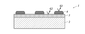
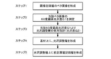
- Schematic sectional view showing an example of the configuration of an image recording material in which an image recording layer is formed on a substrate having a gloss adjustment layer Flow chart showing an example of an image forming process by the image recording method of the present invention.
- the image recording method of the present invention is an image recording method in which a gloss adjustment layer is provided on a base material and an image recording layer is formed on the gloss adjustment layer, and the 60-degree mirror gloss G1 of the image recording layer is previously determined.
- the 60-degree specular gloss G2 of the gloss adjusting layer is adjusted according to the information of the measured and obtained 60-degree specular gloss G1.
- the 60-degree specular gloss of the gloss adjustment layer is
- the gloss difference (G2-G1) between the degree G2 and the 60-degree specular gloss G1 of the image recording layer is in the range of ⁇ 20 to +20, and the gloss difference (G2-G1) is ⁇ 10 to +20.
- the range of +5 is preferable in that the difference in gloss between the image forming portion and the non-image forming portion can be further reduced and an image having no uncomfortable feeling can be formed.
- the gloss adjusting layer may be formed by a wet-type coating method using a coating liquid for forming a gloss adjusting layer containing 0.1 to 20% by mass of organic or inorganic fine particles having a specific particle size in the resin dispersion. It is preferable that the glossiness of the gloss adjustment layer can be adjusted to a desired 60-degree specular gloss G2 by applying an ink-jet printing method as a wet coating method, and further, by applying the ink-jet printing method.
- the image recording layer is formed using an actinic ray-curable inkjet ink
- the adhesiveness with the gloss adjusting layer is excellent, and the spread of wet dots is suppressed, and high scratch resistance with high quality is obtained. This is preferable in that an image can be obtained.
- the image recording layer with an actinic ray-curable inkjet ink containing a gelling agent prevents oxygen inhibition on the surface of the formed recorded image, and furthermore, as the gelling agent, the general formula (G1) or (G1).
- the general formula (G1) or (G1) any one of the compounds having the structure represented by G2) in a range of 0.1 to 5.0% by mass based on the total mass of the actinic ray-curable inkjet ink, and as a photopolymerizable compound; Containing an acrylate compound having a molecular weight in the range of 280 to 1500 and a ClogP value in the range of 4.0 to 7.0 in the range of 10 to 40% by mass, the effect of the present invention can be improved. It is preferable in that it can be expressed more.
- the average particle diameter r of the organic or inorganic fine particles contained in the gloss adjusting layer is in the range of 1.5 to 7.0 ⁇ m, and the film thickness hd after drying is in the range of 1.0 to 3.0 ⁇ m, Further, by designing the average particle diameter r of the organic or inorganic fine particles to be larger than the dried film thickness hd of the gloss adjusting layer, the 60-degree specular gloss G2 of the gloss adjusting layer can be adjusted to a desired condition. This is a more preferable aspect in that it can be set to.
- the resin dispersion contained in the gloss adjusting layer is a resin containing an acrylic component, or the organic fine particles contained in the gloss adjusting layer are acrylic fine particles, the object effect of the present invention, It is preferable in that it can be expressed.
- the image recording method of the present invention is an image recording method in which a gloss adjusting layer is provided on a base material and an image recording layer is formed on the gloss adjusting layer, and the image recording layer has a 60-degree specular glossiness (hereinafter referred to as “gloss”).
- G1 is measured by the method described below, and the 60-degree specular gloss G2 of the gloss adjustment layer is adjusted according to the obtained information of the 60-degree specular gloss G1 to record an image. It is characterized by doing.
- FIG. 1 is a schematic sectional view showing an example of the configuration of an image recording material in which an image recording layer is formed on a substrate having a gloss adjusting layer.
- the image recording material (1) formed by the image recording method of the present invention is adjusted to a gloss G2 (G2) on the substrate (2) in accordance with the gloss G1 (G1) of the image forming layer (4).
- a gloss adjusting layer (3) is provided on the entire surface, and an image forming material, for example, an inkjet ink is ejected onto the entire surface of the gloss adjusting layer (3) or to a specific region in accordance with a pattern of a formed image to form an image. How to do.
- FIG. 2 shows a process flow of image formation by the image recording method of the present invention.
- Step 1 First, a solid image of the image recording layer is formed on a base material, and a sample of an image recording layer single layer for measuring the glossiness of the image recording layer is prepared.
- Step 2 A 60-degree surface gloss G1 is measured for the solid image of the image recording layer prepared above in accordance with the method defined in JIS Z 8741.
- Step 3 Set the 60-degree surface gloss G2 of the gloss adjustment layer according to the obtained information of the 60-degree surface gloss G1 of the image recording layer.
- the gloss difference ⁇ G (G2 ⁇ G1) between the 60 ° surface gloss G2 of the gloss adjusting layer and the 60 ° surface gloss G1 of the image recording layer is preferably in the range of ⁇ 20 to +20, more preferably.
- the composition of the gloss adjusting layer is appropriately adjusted so as to fall within the range of ⁇ 10 to +5.
- the most effective method of adjusting the glossiness of the gloss adjustment layer is to form the gloss adjustment layer at least by dispersing a resin dispersion containing an aqueous solvent as a component (1) and a component (2).
- a gloss adjusting layer composed of organic or inorganic fine particles having a particle size in the range of 1.0 to 20 ⁇ m and containing the following component (2) in the range of 0.1 to 20% by mass with respect to the component (1).
- the type, particle size, and amount of the organic or inorganic fine particles are appropriately adjusted, and the composition of the coating liquid for forming a gloss adjusting layer for adjusting the gloss to a desired level is determined. I do.
- the average particle diameter r of the organic or inorganic fine particles is set to be larger than the thickness hd of the gloss adjusting layer after drying, that is, a form in which the upper surface of the organic or inorganic fine particles is exposed on the surface of the gloss adjusting layer. It is preferable to form an uneven structure.
- Step 4 The coating liquid for forming a gloss adjusting layer, the composition of which has been determined in Step 3, is applied to the substrate by an inkjet printing method or a wet coating method to form a gloss adjusting layer.
- Step 5 Finally, an image recording layer having the same configuration as that described in Step 1 is formed.
- the 60-degree specular glossiness referred to in the present invention is a value measured in accordance with a measurement method defined in JIS Z8741.
- Examples of the measuring device that can be used for measuring the 60-degree specular glossiness according to the present invention include, for example, a precision glossmeter GM-26D, a True Gloss GM-26DPRO, and a variable-angle glossmeter GM-3D (Murakami Color Technology Research) Incorporated), a variable-angle gloss meter VGS-10001DP (manufactured by Nippon Denshoku Industries Co., Ltd.), a digital variable-angle gloss meter (Suga Test Instruments Co., Ltd.) and the like.
- values measured using a gonio-gloss meter PG-1M and VGS-10001DP are applied.
- the substrate applicable to the image recording method of the present invention is not particularly limited as long as it can stably hold a gloss adjustment layer or an image recording layer formed thereon. It is preferable that the substrate has a gloss that does not largely deviate from the surface gloss G2.
- Examples of the base material applicable to the present invention include, for example, plain paper used for copying and the like, paper base material such as art paper, ordinary uncoated paper, and a base paper coated on both sides with a resin or the like.
- various non-absorbable plastics and films thereof used in so-called flexible packaging can be used.
- plastic films include polyethylene terephthalate (PET) and stretched polystyrene. (OPS), stretched polypropylene (OPP), stretched nylon (ONy), polyvinyl chloride (PVC), polyethylene (PE), and triacetyl cellulose (TAC) film.
- PET polyethylene terephthalate
- OPS stretched polystyrene.
- OPS stretched polypropylene
- PVC stretched nylon
- PVC polyvinyl chloride
- PE polyethylene
- TAC triacetyl cellulose
- polycarbonate (PP) acrylic resin
- ABS resin polyacetal
- PVA polyacetal
- rubbers and the like can be used.
- Examples of the plain paper applicable to the present invention include special printing paper such as high-grade printing paper, intermediate-grade printing paper, lower-grade printing paper, thin printing paper, finely-coated printing paper, color high-quality paper, foam paper, and PPC paper ( Copy paper) and other information papers.
- special printing paper such as high-grade printing paper, intermediate-grade printing paper, lower-grade printing paper, thin printing paper, finely-coated printing paper, color high-quality paper, foam paper, and PPC paper ( Copy paper) and other information papers.
- Examples of the art paper include OK Kinto N, Satin Kinto N, SA Kinto, Ultra Satin Kinto N, OK Ultra Aqua Satin, OK Kanto One Side, N Art Post, NK Special Double Side Art, Raitou Super Art N, Raito Super Art MN, Thunderbird Art N, Thunderbird Dall Art N, and the like.
- coated paper examples include POD gloss coat, OK top coat +, OK top coat S, aurora coat, mu coat, mu white, thunderbird coat N, utrilo coat, pearl coat, white pearl coat, POD mat coat, New Age, New Age W, OK Top Coat Mat N, OK Royal Court, OK Top Coat Dal, and the like.
- the gloss adjusting layer according to the present invention is obtained by coating a coating liquid for forming a gloss adjusting layer containing the following component (2) in the range of 0.1 to 20% by mass with respect to the following component (1) by inkjet printing or wet coating. It is preferably formed by a method.
- Component (1) a resin dispersion using an aqueous solvent as a dispersion medium
- Component (2) organic or inorganic fine particles having an average particle size in a range of 1.0 to 20 ⁇ m.
- the resin dispersion (hereinafter also referred to as resin emulsion or polymer latex) constituting the component (1) refers to a dispersion in which a water-insoluble hydrophobic polymer is dispersed as fine particles in water or a water-soluble dispersion medium.
- the polymer is emulsified in a dispersion medium, emulsion-polymerized, micelle-dispersed, or partially dispersed in polymer molecules and molecular chains themselves are molecularly dispersed. Any of them may be used.
- Examples of the main skeleton of the polymer dispersible in an aqueous solvent include polyethylene, polyethylene-polyvinyl alcohol (PVA), polyethylene-polyvinyl acetate, polyethylene-polyurethane, polybutadiene, polybutadiene-polystyrene, polyolefin copolymer, and polyamide (nylon).
- PVA polyethylene-polyvinyl alcohol
- polyethylene-polyvinyl acetate polyethylene-polyurethane
- polybutadiene polybutadiene-polystyrene
- polyolefin copolymer polyamide
- nylon polyamide
- Polyvinylidene chloride polyester, polyacrylate, polyacrylate-polyester, polyacrylate-polystyrene, polyvinyl acetate, polyurethane-polycarbonate, polyurethane-polyether, polyurethane-polyester, polyurethane-polyacrylate, silicone, silicone-polyurethane, silicone- Polyacrylate, polyvinylidene fluoride-polyacrylate, polyfluoroolefin-polyvinyl acrylate Le, and the like. Further, based on these skeletons, copolymerization using other monomers may be the main skeleton.
- polyester resin emulsions having an ester skeleton acrylic resin emulsions, polyester-acrylic resin emulsions, vinyl chloride-acrylic resin copolymer emulsions, and polyethylene resin emulsions having an ethylene skeleton are preferable, and particularly include an acrylic component.
- a resin emulsion is preferred in that the desired effects of the present invention can be further exhibited.
- Polysol FP3000 polyethylene resin, anion, core: acrylic, shell: polyester, manufactured by Showa Denko KK
- Vylonal MD1480 polyyester resin, anion, manufactured by Toyobo Co., Ltd.
- Vironal MD1245 polyyester resin, anion, Toyobo Co., Ltd.
- Vironal MD1500 polyyester resin, anion, manufactured by Toyobo
- Vironal MD2000 polyyester resin, anion, manufactured by Toyobo
- Vironal MD1930 polyyester resin, anion, manufactured by Toyobo
- Pluscoat RZ105 polyyester resin, anion
- Plus coat RZ570 polyyester resin, anion, made by TOKYO CHEMICAL
- plus coat RZ571 polyyester resin, anion, made by TOKYO CHEMICAL
- Polyester resins such as Elitel (manufactured by Unitika) and Byron (manufactured
- Polyethylene resins such as high-tech S-9242 (polyethylene resin, anion, manufactured by Toho Chemical Co., Ltd.) Resin, Movinyl 7720 (acrylic resin, nonion, manufactured by Nippon Synthetic Chemical Company), Movinyl 7820 (acrylic resin, nonion, manufactured by Nippon Synthetic Chemical Company), John Krill (manufactured by Johnson Polymer), Eslek P (manufactured by Sekisui Chemical Co., Ltd.) ), MFR 1924 (made by Michelman), Polytron (made by Asahi Kasei), Nipol series (made by ZEON) and the like.
- the polymer dispersible in the aqueous solvent may be one containing one of the above-mentioned polymers or a plurality thereof.
- Aqueous solvents applicable to the resin dispersion include not only pure water (including distilled water and deionized water), but also aqueous solutions containing acids, alkalis, salts, etc., aqueous organic solvents, or hydrophilic organic solvents. Solvent. Examples of the aqueous solvent include pure water (including distilled water and deionized water), alcoholic solvents such as methanol and ethanol, and mixed solvents of water and alcohol.
- the average particle size of the dispersed particles of the resin dispersion according to the present invention is not particularly limited, but is preferably in the range of 5 to 200 nm.
- the average particle size is 5 nm or more, aggregation of the particles can be suppressed, the dispersion stability can be improved, and the smoothness of the coated surface can be improved.
- the average particle size is 200 nm or less, haze of the gloss adjusting layer can be suppressed, and suitable performance as an image forming unit (substrate / gloss adjusting layer / image forming layer) to be formed can be obtained.
- the average particle diameter r of the organic or inorganic fine particles contained in the gloss adjusting layer is in the range of 1.5 to 7.0 ⁇ m, and the film thickness hd after drying is adjusted. Is in the range of 1.0 to 3.0 ⁇ m, and the thickness hd of the gloss adjusting layer after drying and the average particle diameter r of the organic or inorganic fine particles satisfy the condition defined by the following formula (1). Is a preferred embodiment.
- FIG. 3 is a schematic sectional view showing an example of the configuration of the gloss adjusting layer according to the present invention.
- the thickness of the gloss adjusting layer (3) mainly formed of a resin dispersion serving as a binder is defined as hd, and
- the average particle diameter of the organic or inorganic fine particles (5) contained in r is r
- the condition that each particle diameter satisfies r> hd is satisfied, and the organic or inorganic fine particles (5) are separated from the surface of the gloss adjusting layer (3).
- the upper portion of the fine particles (5) is exposed to form a convex structure, and by controlling the density of the convex structure or the height of the convex structure, the gloss G2 of the gloss adjusting layer is controlled to a desired characteristic. be able to.
- the value of the ratio of the average particle diameter r of the organic or inorganic fine particles / the thickness hd of the gloss adjusting layer is 1.01 or more, preferably 1.01 to 2.6, and more preferably 1.4. It is in the range of 2.12.1.
- organic or inorganic fine particles having an average particle size defined by component (2) in the range of 1.0 to 20 ⁇ m are mixed with the resin dispersion as component (1).
- the content is preferably in the range of 0.1 to 20% by mass.
- the average particle size in the present invention refers to a primary average particle size, which can be measured from an electron micrograph by a scanning electron microscope (SEM) or the like. It may be measured by a particle size distribution analyzer using a dynamic light scattering method, a static light scattering method, or the like.
- the average particle diameter of the primary particles, the particle itself or particles that appeared on the cross section or surface of the gloss adjustment layer is observed with an electron microscope, and the particle diameter of 1,000 arbitrary particles is measured. It is obtained as a simple average value (number average).
- the particle size of each particle is represented by a diameter assuming a circle equal to its projected area.
- inorganic fine particles As the inorganic fine particles applicable to the gloss adjusting layer according to the present invention, for example, SiO 2 , Al 2 O 3 , TiO 2 , SnO 2 , Sb 2 O 5 , Fe 2 O 3 , ZrO 2 , CeO 2 , Y 2 Examples include inorganic fine particles such as O 3 .
- Examples of commercially available inorganic fine particles include, for example, functional spherical silica HPS series (manufactured by Toagosei Co., Ltd.), “Sea Hostar” KE series (manufactured by Nippon Shokubai Co., Ltd.), and “particle size standard particles” 8000 series (manufactured by Nippon Shokubai Co., Ltd.).
- Allumina spherical fine particles such as Thermo @ Fisher @ Scientific
- Admatechs "Admafine” series (manufactured by Admatechs) and “High Pressica” series (Ube Nitto Kasei Co., Ltd.) Micron)
- Admatechs "Admafine” series (manufactured by Admatechs)
- Alumina manufactured by Nippon Light Metal Co., Ltd.
- Allumina Beads CB series (manufactured by Showa Denko KK), etc. Can be.
- silica particles are preferable, and examples thereof include Seahoster KE-P100 (average particle size: 1.0 ⁇ m) and KE-P150 (average particle size: 1.5 ⁇ m) manufactured by Nippon Shokubai Co., Ltd.
- organic fine particles examples include, for example, polyacrylate particles, acrylic resin particles such as polymethacrylate particles, polyamide resin particles such as nylon particles, polyethylene particles, and polyolefin particles such as polypropylene particles.
- Spherical resin particles made of generally known resins, such as resin particles, silicone resin particles, phenolic resin particles, polyurethane resin particles, styrene resin particles, and benzoguanamine resin particles.
- acrylic resin fine particles examples include acrylic resin fine particles manufactured by Soken Chemical Co., Ltd., such as Chemisnow MX-300 (average particle size: 3 ⁇ m) and MX-500. (Average particle size: 5 ⁇ m), MX-1000, MX-1500H, MR-2HG, MR-7HG, MR-10HG, MR-3GSN, MR-5GSN, MR-7G, MR-10G, MR-5C, MR- 7GC (average particle size: 6 ⁇ m), as acrylic resin fine particles manufactured by Sekisui Chemical Co., Ltd., MBX-5, MBX-8, MBX-12 MBX-15, MBX-20, MB20X-5, MB30X-5, MB30X-8, MB30X SBX-6, SBX-8, SBX-12, SBX-17, etc.
- acrylic resin fine particles manufactured by Soken Chemical Co., Ltd. such as Chemisnow MX-300 (average particle size: 3 ⁇ m) and MX-500. (Average
- Well is a chemical made of polyolefin resin fine particles Chemipearl W100, W200, W300, W308, W310, W400, W401, W405, W410, W500, WF640, W700, W800, W900, W950, WP100, and the like.
- the nylon particles include SP-500 (average particle size: 5 ⁇ m), SP-10 (average particle size: 10 ⁇ m), TR-1 (average particle size: 13 ⁇ m), and TR-2 (average particle size) manufactured by Toray Industries, Inc. (Diameter: 20 ⁇ m).
- the coating liquid for forming a gloss-adjusting layer used for forming the gloss-adjusting layer according to the present invention comprises, as a component (1), a resin dispersion containing an aqueous solvent as a dispersion medium, and as a component (2), an average particle diameter of 1.0 to It is a preferred embodiment to include organic or inorganic fine particles in the range of 20 ⁇ m, but there is no particular limitation on the preparation method, but there is no aggregation of the organic or inorganic fine particles, and a coating for forming a gloss adjusting layer having a uniform composition.
- organic or inorganic fine particles are added little by little to a dispersing solvent, for example, isopropanol (abbreviation: IPA) with stirring, predispersed, and the fine particles are aggregated.
- IPA isopropanol
- the gloss adjusting layer is preferably formed by a wet coating method using a coating liquid for forming a gloss adjusting layer containing the above-described components, and more preferably, inkjet printing is performed as the wet coating method. It is preferred to apply the method.
- An antioxidant an ultraviolet absorber, a plasticizer, a surfactant, and the like can be added to the coating liquid for forming a gloss adjusting layer, if necessary.
- wet coating method applicable to the present invention examples include spin coating, casting, screen printing, die coating, blade coating, roll coating, spray coating, curtain coating, and LB (Langmuir-blowing). Jet method), an ink jet printing method, etc., and it is particularly preferable to apply the ink jet printing method from the viewpoint of easily obtaining a uniform thin film and high productivity.
- an ink jet recording method using an ink jet ink as an image forming material a color toner containing a coloring material is electrophotographically processed on paper or a thin film film.
- the method can be applied to an electrophotographic method in which an image is formed by applying and fixing, a screen printing method or an offset printing method in which a pattern or the like is formed on a variety of substrates using a printing ink. It is preferable to apply the present invention to an ink jet recording system using an ink jet ink.
- aqueous inkjet inks die type, pigment type
- solvent inks actinic ray curable inkjet inks
- solid inkjet inks hot melt inks
- the image recording layer according to the present invention is preferably formed using an actinic ray-curable inkjet ink containing a photopolymerizable compound.
- an actinic ray-curable inkjet ink (hereinafter also referred to as an actinic ray-curable ink, a UV-curable ink, or simply an ink) suitable as a method for forming an image recording layer using a representative inkjet ink was applied. The method will be described in detail.
- the actinic ray-curable ink according to the present invention is mainly composed of a coloring material (eg, a pigment or a dye), a photopolymerizable compound, a photopolymerization initiator, a polymerization inhibitor, and the like.
- the actinic ray-curable ink according to the present invention contains a gelling agent.
- the actinic ray curable ink suitable for the present invention preferably contains at least a photopolymerizable compound having a function of curing with actinic light.
- the photopolymerizable compound may be any of a monomer, a polymerizable oligomer, a prepolymer, and a mixture thereof.
- the ink according to the present invention may contain only one kind of the photopolymerizable compound, or may contain two or more kinds thereof.
- the actinic rays referred to here are, for example, energy rays such as electron rays, ultraviolet rays, ⁇ rays, ⁇ rays, and X rays, preferably ultraviolet rays or electron rays.
- energy rays such as electron rays, ultraviolet rays, ⁇ rays, ⁇ rays, and X rays, preferably ultraviolet rays or electron rays.
- the photopolymerizable compound include a radical polymerizable compound and a cationic polymerizable compound, and are preferably a radical polymerizable compound.
- the content of the photopolymerizable compound is, for example, preferably in the range of 1 to 97% by mass based on the total mass of the ink according to the present invention, from the viewpoint of film properties such as curability and flexibility, and 30 to 70% by mass. More preferably, it is in the range of 95% by mass.
- the radical polymerizable compound applicable to the present invention is preferably an unsaturated carboxylate, and more preferably (meth) acrylate.
- (meth) acrylate means acrylate or methacrylate
- (meth) acryloyl group means acryloyl group or methacryloyl group
- (meth) acryl means acrylic Or methacrylic.
- Examples of the (meth) acrylate include isoamyl (meth) acrylate, stearyl (meth) acrylate, lauryl (meth) acrylate, octyl (meth) acrylate, decyl (meth) acrylate, isomyristyl (meth) acrylate, and isostearyl (meth).
- Examples of the above-mentioned modified products include ethylene oxide-modified (EO-modified) acrylate having an ethylene oxide group inserted therein and propylene oxide-modified (PO-modified) acrylate having propylene oxide inserted therein.
- EO-modified ethylene oxide-modified
- PO-modified propylene oxide-modified
- ⁇ Acrylate compound A with defined molecular weight and ClogP value> In the actinic ray-curable ink according to the present invention, as the radical polymerizable compound, a (meth) acrylate compound having a molecular weight in the range of 280 to 1500 and a ClogP value in the range of 4.0 to 7.0. (Hereinafter, also simply referred to as “(meth) acrylate compound A”).
- (Meth) acrylate compound A more preferably has two or more (meth) acrylate groups.
- the molecular weight of the (meth) acrylate compound A is in the range of 280 to 1500 as described above, and more preferably in the range of 300 to 800.
- the ink viscosity at 80 ° C. can be set to 3 to 20, preferably 7 to 14 mPa ⁇ s.
- the viscosity of the ink after landing is increased, and the penetration of the ink into the recording medium can be suppressed.
- the effect of suppressing a decrease in curability can be expected.
- a (meth) acrylate compound having a molecular weight of 1500 or less an excessive increase in the sol viscosity of the ink can be suppressed, and an improvement in the gloss uniformity of the coating film can be expected.
- the molecular weight of the (meth) acrylate compound A can be measured using the following commercially available software package 1 or 2.
- the actinic light type ink contains the (meth) acrylate compound A as at least a part of the photopolymerizable compound
- the (meth) acrylate compound having a ClogP value of less than 4.0 is converted to the photopolymerizable compound.
- the gloss value tends to be lower than that of the actinic ray curable ink used as the ink. Therefore, the use of the ink for forming an image on a recording medium having a relatively low 60 ° gloss value before the corona discharge treatment is preferable because the gloss difference between the printed portion and the non-printed portion can be reduced.
- the (meth) acrylate compound A has a higher hydrophobicity than the (meth) acrylate compound having a ClogP value of less than 4.0, a larger amount of the gelling agent repels and moves to the surface of the cured film of the ink to increase unevenness. As a result, it is considered that the gloss value of the printing portion decreases. Further, the ClogP value of the (meth) acrylate compound A is more preferably in the range of 4.5 to 6.0.
- log P value is a coefficient indicating the affinity of an organic compound for water and 1-octanol.
- the 1-octanol / water partition coefficient P is a distribution equilibrium when a trace amount of a compound is dissolved as a solute in a solvent of a two-liquid phase of 1-octanol and water, and is a ratio of equilibrium concentrations of the compounds in the respective solvents. Indicated by their log logP relative to the base 10. That is, the “log P value” is a logarithmic value of the partition coefficient of 1-octanol / water, and is known as an important parameter representing the hydrophilic / hydrophobic property of the molecule.
- ClogP value is a logP value calculated by calculation.
- the ClogP value can be calculated by a fragment method, an atom approach method, or the like. More specifically, to calculate the ClogP value, reference can be made to the literature (C. Hansch and A. Leo, "Substitute ⁇ Constants ⁇ For ⁇ Correlation ⁇ Analysis ⁇ in ⁇ Chemistry ⁇ and ⁇ Biology” (John, Wiley, N.Way, & Fragment). Or the following commercially available software package 1 or 2.
- the amount of the (meth) acrylate compound A contained in the ink is not particularly limited, but is preferably in the range of 1 to 40% by mass, and more preferably in the range of 5 to 30% by mass based on the total mass of the ink. More preferred.
- the amount of the (meth) acrylate compound A is 1% by mass or more, the ink does not become too hydrophilic, and the gelling agent is sufficiently dissolved in the ink, so that the ink easily undergoes a sol-gel phase transition.
- the photopolymerization initiator can be sufficiently dissolved in the ink.
- More preferred examples of the (meth) acrylate compound A include (1) a trifunctional or higher functional compound having 3 to 14 structures represented by (—C (CH 3 ) H—CH 2 —O—) in the molecule. Methacrylate or acrylate compounds and (2) bifunctional or higher methacrylate or acrylate compounds having a cyclic structure in the molecule are included. These (meth) acrylate compounds have high photocurability and little shrinkage when cured. Furthermore, the reproducibility of the sol-gel phase transition is high.
- a trifunctional or higher methacrylate or acrylate compound having 3 to 14 structures represented by (—C (CH 3 ) H—CH 2 —O—) in a molecule is, for example, a compound having three or more hydroxy groups.
- the compound has a hydroxy group modified with propylene oxide, and the resulting modified product is esterified with (meth) acrylic acid.
- this compound examples include: 3PO-modified trimethylolpropane triacrylate Photomer 4072 (molecular weight: 471, ClogP: 4.90, manufactured by Cognis), 3PO-modified trimethylolpropane triacrylate Miramer M360 (molecular weight: 471, ClogP: 4.90, manufactured by Miwon) Etc. are included.
- the bifunctional or higher methacrylate or acrylate compound having a cyclic structure in the molecule is, for example, a compound obtained by esterifying a hydroxy group of a compound having two or more hydroxy groups and tricycloalkane with (meth) acrylic acid. .
- Tricyclodecane dimethanol diacrylate NK ester A-DCP (molecular weight: 304, ClogP: 4.69)
- Tricyclodecane dimethanol dimethacrylate NK ester DCP (molecular weight: 332, ClogP: 5.12) Etc.
- (meth) acrylate compound A examples include 1,10-decanediol dimethacrylate ⁇ NK ester DOD-N (molecular weight: 310, ClogP: 5.75, manufactured by Shin-Nakamura Chemical Co., Ltd.).
- the photopolymerizable compound may further contain a photopolymerizable compound other than the (meth) acrylate compound A.
- photopolymerizable compounds include, for example, (meth) acrylate monomers or oligomers having a ClogP value of less than 4.0, (meth) acrylate monomers or oligomers having a ClogP value of more than 7.0, and other polymerizable compounds. Oligomers and the like.
- Examples of these (meth) acrylate monomers or oligomers include 4EO-modified hexanediol diacrylate (CD561, manufactured by Sartomer, molecular weight 358); 3EO-modified trimethylolpropane triacrylate (SR454, manufactured by Sartomer, molecular weight 429); 4EO-modified pentaerythritol tetraacrylate (SR494, manufactured by Sartomer, molecular weight 528); 6EO-modified trimethylolpropane triacrylate (SR499, manufactured by Sartomer, molecular weight 560); caprolactone acrylate (SR495B, manufactured by Sartomer, molecular weight 344); polyethylene glycol Diacrylate (NK ester A-400, manufactured by Shin-Nakamura Chemical Co., molecular weight 508), (NK ester A-600, Shin-Nakamura Chemical Polyethylene glycol dimethacrylate (NK ester 9G, manufactured by Shin-Nakamura Chemical
- Examples of other polymerizable oligomers include epoxy acrylate, aliphatic urethane acrylate, aromatic urethane acrylate, polyester acrylate, linear acrylic oligomer and the like.
- Examples of the cationically polymerizable compound applicable to the present invention include an epoxy compound, a vinyl ether compound, and an oxetane compound.
- the ink may contain only one kind of the cationic polymerizable compound or two or more kinds thereof.
- the epoxy compound is an aromatic epoxide, an alicyclic epoxide, an aliphatic epoxide, or the like, and is preferably an aromatic epoxide or an alicyclic epoxide in order to enhance curability.
- the aromatic epoxide can be a di- or polyglycidyl ether obtained by reacting a polyhydric phenol or an alkylene oxide adduct thereof with epichlorohydrin.
- polyhydric phenol or its alkylene oxide adduct to be reacted examples include bisphenol A or its alkylene oxide adduct.
- the alkylene oxide in the alkylene oxide adduct may be ethylene oxide, propylene oxide, or the like.
- the alicyclic epoxide may be a cycloalkane oxide-containing compound obtained by epoxidizing a cycloalkane-containing compound with an oxidizing agent such as hydrogen peroxide or peracid.
- the cycloalkane in the cycloalkane oxide-containing compound can be cyclohexene or cyclopentene.
- the aliphatic epoxide can be a di- or polyglycidyl ether obtained by reacting an aliphatic polyhydric alcohol or an alkylene oxide adduct thereof with epichlorohydrin.
- Examples of aliphatic polyhydric alcohols include alkylene glycols such as ethylene glycol, propylene glycol, and 1,6-hexanediol.
- the alkylene oxide in the alkylene oxide adduct may be ethylene oxide, propylene oxide, or the like.
- vinyl ether compounds include ethyl vinyl ether, n-butyl vinyl ether, isobutyl vinyl ether, octadecyl vinyl ether, cyclohexyl vinyl ether, hydroxybutyl vinyl ether, 2-ethylhexyl vinyl ether, cyclohexane dimethanol monovinyl ether, n-propyl vinyl ether, isopropyl vinyl ether, and isopropenyl ether.
- Monovinyl ether compounds such as -o-propylene carbonate, dodecyl vinyl ether, diethylene glycol monovinyl ether, octadecyl vinyl ether; Diethylene glycol divinyl ether, diethylene glycol divinyl ether, triethylene glycol divinyl ether, propylene glycol divinyl ether, dipropylene glycol divinyl ether, butanediol divinyl ether, hexanediol divinyl ether, cyclohexane dimethanol divinyl ether, trimethylolpropane trivinyl ether, etc. Or a trivinyl ether compound.
- a di- or trivinyl ether compound is preferable in consideration of curability and adhesion.
- the oxetane compound is a compound having an oxetane ring, and examples thereof include oxetane compounds described in JP-A-2001-220526, JP-A-2001-310937, JP-A-2005-255821, and the like. .
- the compound represented by the general formula (1) described in paragraph (0089) of JP-A-2005-255821 and the compound represented by the general formula (2) described in paragraph (0092) of the same publication Compound, compound represented by general formula (7) described in paragraph number (0107) of the same publication, compound represented by general formula (8) described in paragraph number (0109) of the same publication, Examples include the compound represented by the general formula (9) described in paragraph (0116) of the gazette.
- the actinic ray-curable ink applied to the image recording method of the present invention preferably contains a gelling agent, and further, the gelling agent is represented by the following general formula (G1) or general formula (G2). It is preferable that the compound has the structure represented.
- the gelling agent has a function of temporarily fixing (pinning) the ink droplets that have landed on the base material or the gloss adjusting layer in a gel state.
- the ink containing the gelling agent is pinned in a gel state, the spread of the ink is suppressed and the adjacent dots are hardly united, so that a higher definition image can be formed.
- the gelling agent preferably crystallizes at a temperature equal to or lower than the gelling temperature of the ink.
- the gelling temperature refers to a temperature at which the gelling agent undergoes a phase transition from a sol to a gel when the sol or liquid ink is cooled by heating, and the viscosity of the ink rapidly changes. Specifically, the sol or liquid ink is cooled while measuring the viscosity with a viscoelasticity measuring device (for example, MCR300, manufactured by Anton Paar), and the temperature at which the viscosity sharply rises is measured. Gelation temperature.
- a so-called card house structure When the gelling agent crystallizes in the ink, a structure in which the photopolymerizable compound is included in the three-dimensional space formed by the gelling agent crystallized in a plate shape, a so-called card house structure is formed.
- the card house structure When the card house structure is formed, the liquid photopolymerizable compound is held in the space, so that the ink droplets are less likely to wet and spread, and the pinning property of the ink is further improved.
- the ink pinning property increases, ink droplets that have landed on the recording medium are less likely to coalesce, and a higher definition image can be formed.
- the photopolymerizable compound dissolved in the ink and the gelling agent are compatible.
- gelling agents suitable for forming a card house structure include aliphatic ketones, aliphatic esters, petroleum waxes, vegetable waxes, animal waxes, mineral waxes, hydrogenated castor oil, modified waxes, higher fatty acids, Includes higher alcohols, hydroxystearic acid, fatty acid amides including N-substituted fatty acid amides and special fatty acid amides, higher amines, esters of sucrose fatty acids, synthetic waxes, dibenzylidene sorbitol, dimer acid and dimer diol.
- aliphatic ketones, aliphatic esters, higher fatty acids, and higher alcohols having a hydrocarbon group having 9 to 25 carbon atoms are preferable from the viewpoint of further improving pinning properties.
- the gelling agent only one kind may be contained in the ink, or two or more kinds may be contained in the ink.
- aliphatic ketones examples include dilignoseryl ketone, dibehenyl ketone, distearyl ketone, dieicosyl ketone, dipalmityl ketone, dilauryl ketone, dimyristyl ketone, myristyl palmityl ketone and palmityl stearyl ketone. It is.
- aliphatic ester examples include fatty acid esters of monoalcohols such as behenyl behenate, icosyl icosanoate, oleyl palmitate; glycerin fatty acid ester, sorbitan fatty acid ester, propylene glycol fatty acid ester, ethylene glycol fatty acid ester and polyoxyethylene fatty acid ester. And fatty acid esters of polyhydric alcohols.
- Examples of commercially available products of the above-mentioned aliphatic esters include the EMALEX series, manufactured by Nippon Emulsion Co., Ltd. (“EMALEX” is a registered trademark of the company), the Riquemar series and Poem series, manufactured by Riken Vitamin Co., Ltd. (“Riquemar” and “Poem” are Both are registered trademarks of the company).
- higher fatty acids examples include behenic acid, arachidic acid, stearic acid, palmitic acid, myristic acid, lauric acid, oleic acid, and erucic acid.
- Examples of higher alcohols include stearyl alcohol and behenyl alcohol.
- an aliphatic ketone represented by the following general formula (G1) or an aliphatic ester represented by the following general formula (G2) is particularly preferable.
- R 1 —CO—R 2 R 1 —CO—R 2
- R 1 and R 2 each independently represent an alkyl group containing a straight-chain portion having 12 to 26 carbon atoms and optionally containing a branch.
- R 3 —COO—R 4 each independently represent an alkyl group containing a straight-chain portion having 12 to 26 carbon atoms and optionally containing a branch.
- the linear or branched hydrocarbon group has 12 or more carbon atoms, and therefore, the aliphatic ketone represented by the general formula (G1) or the general formula (G2)
- the crystallinity of the aliphatic ester represented by the formula (1) is higher, and more sufficient space is generated in the card house structure. Therefore, the photopolymerizable compound is easily included in the space sufficiently, and the pinning property of the ink is further improved.
- the aliphatic ketone represented by the general formula (G1) or the aliphatic ester represented by the general formula (G2) has a melting point of There is no need to overheat the ink when ejecting it without rising too much.
- Examples of the aliphatic ketone represented by the general formula (G1) include dilignoseryl ketone (carbon number: 23 to 24), dibehenyl ketone (carbon number: 21 to 22), and distearyl ketone (carbon number: 17 to 17).
- dieicosyl ketone (carbon number: 19 to 20), dipalmityl ketone (carbon number: 15 to 16), dimyristyl ketone (carbon number: 13 to 14), dilauryl ketone (carbon number: 11) To 12), lauryl myristyl ketone (carbon number: 11 to 14), lauryl palmityl ketone (carbon number: 11 to 16), myristyl palmityl ketone (carbon number: 13 to 16), myristyl stearyl ketone (carbon number: 13) To 18), myristyl behenyl ketone (C: 13 to 22), palmityl stearyl ketone (C: 15 to 18), and valmicil behenyl ketone (C: 15-22) and stearyl behenyl ketone (carbon number: 17-22) are included.
- the carbon number in parentheses indicates the carbon number of each of the two hydrocarbon groups separated by the carbonyl group.
- Examples of commercial products of the aliphatic ketone represented by the general formula (G1) include 18-Pentriacontanon, manufactured by Alfa Aeser, Hentriacontan-16-on, manufactured by Alfa Aeser, Kaowax T-1, and Kao. included.
- Examples of the aliphatic ester represented by the general formula (G2) include behenyl behenate (carbon number: 21 to 22), icosyl icosanoate (carbon number: 19 to 20), stearyl stearate (carbon number: 17 to 20).
- Examples of commercially available products of the aliphatic ester represented by the general formula (G2) include Unistar M-2222SL andsperm Acet, manufactured by NOF Corporation (“UNISTAR” is a registered trademark of the company), Exepar SS and Exepal MY-M, Manufactured by Kao Corporation (“Exepearl” is a registered trademark of the company), EMALEX @ CC-18 and EMALEX @ CC-10, manufactured by Nippon Emulsion Co., Ltd. (“EMALEX” is a registered trademark of the company) Includes the company's registered trademark).
- the content of the gelling agent is preferably in the range of 1.0 to 10.0% by mass based on the total mass of the ink.
- the content of the gelling agent is preferably in the range of 1.0 to 10.0% by mass based on the total mass of the ink.
- the content of the gelling agent is more preferably in the range of 1.0 to 7.0% by mass, and more preferably in the range of 2.0 to 5.0% by mass, based on the total mass of the ink. More preferably, it is most preferably in the range of 2.5 to 4.0% by mass.
- the photopolymerization initiator is a photoradical initiator when the photopolymerizable compound is a radical polymerizable compound, and is a photoacid generator when the photopolymerizable compound is a cationic polymerizable compound.
- the photopolymerization initiator may contain only one type or two or more types in the ink.
- the photopolymerization initiator may be a combination of both a photoradical initiator and a photoacid generator.
- the photo radical initiator may be a cleavage type radical initiator or a hydrogen abstraction type radical initiator.
- cleavage radical initiators include diethoxyacetophenone, 2-hydroxy-2-methyl-1-phenylpropan-1-one, benzyldimethylketal, 1- (4-isopropylphenyl) -2-hydroxy-2- Methylpropan-1-one, 4- (2-hydroxyethoxy) phenyl- (2-hydroxy-2-propyl) ketone, 1-hydroxycyclohexyl-phenylketone, 2-methyl-2-morpholino (4-thiomethylphenyl) Acetophenone-based initiators including propan-1-one and 2-benzyl-2-dimethylamino-1- (4-morpholinophenyl) -butanone; benzoin-based initiators including benzoin, benzoin methyl ether and benzoin isopropyl ether; 2,4,6-trimethylbenzoin dife Acylphosphine oxide initiators including Le phosphine oxide, benzyl and methyl phenylglyoxylate ester.
- hydrogen abstracting radical initiators include benzophenone, methyl-4-phenylbenzophenone o-benzoylbenzoate, 4,4'-dichlorobenzophenone, hydroxybenzophenone, 4-benzoyl-4'-methyl-diphenyl sulfide, acrylated Benzophenone-based initiators including benzophenone, 3,3 ', 4,4'-tetra (t-butylperoxycarbonyl) benzophenone and 3,3'-dimethyl-4-methoxybenzophenone, 2-isopropylthioxanthone, 2,4- Thioxanthone-based initiators including dimethylthioxanthone, 2,4-diethylthioxanthone and 2,4-dichlorothioxanthone, aminobenzophenone-based initiators including Michler's ketone and 4,4'-diethylaminobenzophenone, 1 - butyl-2-chloro acridone, 2-
- photoacid generators examples include compounds described in “Organic Materials for Imaging”, edited by Society for Research on Organic Electronics Materials, Bunshin Publishing (1993), pp. 187-192.
- the content of the photopolymerization initiator may be within a range that can sufficiently cure the photopolymerizable compound, and may be, for example, within a range of 0.01 to 10% by mass based on the total mass of the ink.
- the actinic ray-curable ink applied to the present invention further includes other components such as a photopolymerization initiator auxiliary, a polymerization inhibitor, a polymer dispersant, and a surfactant within a range where the effects of the present invention can be obtained. It may be.
- the actinic ray-curable ink applied to the present invention may further contain a photopolymerization initiator auxiliary agent, a polymerization inhibitor, and the like, if necessary.
- the photopolymerization initiator assistant may be a tertiary amine compound, and is preferably an aromatic tertiary amine compound.
- aromatic tertiary amine compounds include N, N-dimethylaniline, N, N-diethylaniline, N, N-dimethyl-p-toluidine, N, N-dimethylamino-p-benzoic acid ethyl ester, N, N-dimethylamino-p-benzoic acid isoamylethyl ester, N, N-dihydroxyethylaniline, triethylamine, N, N-dimethylhexylamine and the like are included.
- N, N-dimethylamino-p-benzoic acid ethyl ester and N, N-dimethylamino-p-benzoic acid isoamylethyl ester are preferred. These compounds may be used alone or in combination of two or more.
- polymerization inhibitors include (alkyl) phenol, hydroquinone, catechol, resorcinol, p-methoxyphenol, t-butylcatechol, t-butylhydroquinone, pyrogallol, 1,1-picrylhydrazyl, phenothiazine, p-benzoquinone , Nitrosobenzene, 2,5-di-t-butyl-p-benzoquinone, dithiobenzoyl disulfide, picric acid, cuperon, aluminum N-nitrosophenylhydroxylamine, tri-p-nitrophenylmethyl, N- (3-oxyanilino- 1,3-dimethylbutylidene) aniline oxide, dibutyl cresol, cyclohexanone oxime cresol, guaiacol, o-isopropylphenol, butyraldoxime, methyl ethyl ketoxime, cyclohexanone oxime
- polymer dispersant for example, a hydroxy group-containing carboxylic acid ester, a salt of a long-chain polyaminoamide and a high-molecular-weight acid ester, a salt of a high-molecular-weight polycarboxylic acid, a salt of a long-chain polyaminoamide and a polar acid ester, and a high-molecular-weight unsaturated ester Acid esters, polymer copolymers, modified polyurethanes, modified polyacrylates, polyetherester-type anionic activators, naphthalenesulfonic acid formalin condensate salts, aromatic sulfonic acid formalin condensate salts, polyoxyethylene alkyl phosphate, Polyoxyethylene nonylphenyl ether, stearylamine acetate and the like can be mentioned.
- polymer dispersant for example, a comb-type block copolymer having a basic group may be used.
- the comb-type block copolymer in the comb-type block copolymer having a basic group refers to a graft polymer formed on a linear polymer forming a main chain and each structural unit derived from a monomer forming the linear main chain. And another type of polymer.
- a long-chain polyoxyalkyl group (EO-PO copolymer group) is preferable.
- the comb-type block copolymer include those in which the main chain is a polymer of an acrylate ester and the side chain is a long-chain polyoxyalkyl group (EO-PO copolymer group).
- the basic group in the comb-type block copolymer having a basic group is preferably a quaternary, tertiary, secondary or primary amine group.
- the weight average molecular weight of the polymer dispersant is preferably in the range of 1,000 to 50,000, more preferably in the range of 5,000 to 30,000.
- the weight average molecular weight of the polymer dispersant can be determined by gel permeation chromatography (GPC method) in terms of polystyrene.
- Examples of commercially available polymer dispersants containing a basic group include DISPERBYK-109, 161, 168, 180, 2013, 2155, BYKJET-9150 and BYKJET-9151 manufactured by BYK; Efka-4431 manufactured by BASF. PX4701; PB-821, 822, 824 manufactured by Ajinomoto Fine-Techno; Solsperse 24000GR, 32000, 39000, 71000, and J-200 manufactured by Lubrizol.
- DISPERBYK” and “BYKJET” are registered trademarks of BYK
- "Efka” is a registered trademark of BASF
- Solsperse” is a registered trademark of Lubrizol.
- the content of the polymer dispersant is preferably in the range of 30 to 70% by mass based on the total mass of the pigment.
- the content of the polymer dispersant is 30% by mass or more with respect to the pigment, not only can the aggregation of the pigment be less likely to occur, but also the interaction between the pigment and the gelling agent can be effectively suppressed, Gloss variation and dot diameter variation under high-temperature storage can be further suppressed.
- the content of the polymer dispersant is more than 70% by mass with respect to the pigment, the extra polymer dispersant that does not contribute to the pigment dispersion causes gelation inhibition, resulting in an increase in the initial gloss value and the initial dot diameter. I will.
- the content of the polymer dispersant is more preferably in the range of 35 to 65% by mass based on the total mass of the pigment.
- the inkjet dispersant of the present invention may contain only one kind of polymer dispersant or two or more kinds thereof.
- the pigment and the polymer dispersant can be dispersed by, for example, a ball mill, sand mill, attritor, roll mill, agitator, Henschel mixer, colloid mill, ultrasonic homogenizer, pearl mill, wet jet mill, or paint shaker.
- surfactants examples include anionic surfactants such as dialkyl sulfosuccinates, alkyl naphthalene sulfonates and fatty acid salts, polyoxyethylene alkyl ethers, polyoxyethylene alkyl allyl ethers, acetylene glycols and polyoxy Nonionic surfactants such as ethylene-polyoxypropylene block copolymers, cationic surfactants such as alkylamine salts and quaternary ammonium salts, and silicone-based and fluorine-based surfactants are included.
- anionic surfactants such as dialkyl sulfosuccinates, alkyl naphthalene sulfonates and fatty acid salts
- polyoxyethylene alkyl ethers polyoxyethylene alkyl allyl ethers
- acetylene glycols acetylene glycols
- Nonionic surfactants such as ethylene-polyoxypropylene block copolymers
- silicone-based surfactant examples include polyether-modified polysiloxane compounds, specifically, KF-351A, KF-352A, KF-642 and X-22-4272, BYK307, BYK345, manufactured by Shin-Etsu Chemical Co., Ltd. BYK347 and BYK348, manufactured by Big Chemie (“BYK” is a registered trademark of the company), and TSF4452, manufactured by Momentive Performance Materials.
- fluorinated surfactant means a substance in which part or all of a normal surfactant is replaced with fluorine instead of hydrogen bonded to carbon of a hydrophobic group.
- fluorine-based surfactants include Megafac @ F, manufactured by DIC ("Megafac” is a registered trademark of the company), Surflon, AGC Seika Chemical Co., Ltd. (“Sulflon” is a registered trademark of the company), Fluorad @ FC, 3M (“Fluorad” is a registered trademark of the company), Monflor, manufactured by Imperial Chemical Industry Co., Ltd., Zonyls, manufactured by E. I. Dupont de Nemours & Company, Licowet® VPF, manufactured by Rubeberke Hoechst, And FTERGENT, manufactured by Neos (“FTERGENT” is a registered trademark of the company).
- the amount of the surfactant can be arbitrarily set as long as the effects of the present invention can be obtained.
- the amount of the surfactant can be, for example, 0.001% by mass or more and less than 1.0% by mass based on the total mass of the ink.
- Color material As the coloring material applicable to the actinic ray-curable ink according to the present invention, a dye or a pigment can be applied, and the ink has good dispersibility with respect to the components of the ink, and has excellent weather resistance. And pigments are more preferred.
- an oil-soluble dye or the like can be used as the dye.
- the oil-soluble dye include the following various dyes.
- magenta dyes include MS Magenta VP, MS Magenta HM-1450, MS Magenta HSo-147 (all manufactured by Mitsui Toatsu), AIZENSOT Red-1, AIZEN SOT Red-2, AIZEN SOTRed-3, AIZEN SOT Pink-1, SPIRON Red GEH SPECIAL (all manufactured by Hodogaya Chemical Co., Ltd.), RESOLIN Red FB 200%, MACROLEX Red Violet R, MACROLEX ROT5B (all manufactured by Bayer Japan), KAYASET RedB, KAYASET REDA 802 (all manufactured by Nippon Kayaku Co., Ltd.), PHLOXIN, ROSE BENGAL, ACID Red (all manufactured by Daiwa Kasei), HSR-31, DIAR SIN Red K (manufactured by Mitsubishi Kasei Co.,
- cyan dyes examples include MS Cyan HM-1238, MS Cyan HSo-16, Cyan HSo-144, and MS Cyan VPG (all manufactured by Mitsui Toatsu), AIZEN SOT Blue-4 (manufactured by Hodogaya Chemical), RESOLIN @ BR. Blue BGLN 200%, MACROLEX Blue RR, CERES Blue GN, SIRIUS SUPRATURQ. Blue @ Z-BGL, SIRIUS @ SUPRA @ TURQ. Blue FB-LL 330% (all manufactured by Bayer Japan), KAYASET Blue FR, KAYASET Blue N, KAYASET Blue 814, Turq.
- Blue GL-5 200 Light Blue BGL-5 200 (manufactured by Nippon Kayaku), DAIWA Blue 7000, Oleosol Fast Blue GL (manufactured by Daiwa Kasei), DIAREIN Blue P (manufactured by Mitsubishi Chemical Corporation) Blue 670, NEOPEN Blue 808, and ZAPON Blue 806 (all manufactured by BASF Japan).
- yellow dyes examples include MS Yellow HSm-41, Yellow KX-7, Yellow EX-27 (Mitsui Toatsu), AIZEN SOT Yellow-1, AIZEN SOT YellowW-3, AIZEN SOT Yellow-6 (or more, Hodogaya) MACROLEX Yellow 6G, MACROLEX FLUOR.
- black dyes examples include MS Black VPC (manufactured by Mitsui Toatsu), AIZEN SOT Black-1, AIZEN SOT Black-5 (manufactured by Hodogaya Chemical Co., Ltd.), RESOLIN Black GSN 200%, RESOLIN Black BS (managed by KAYASET Black AN (manufactured by Nippon Kayaku), DAIWA Black MSC (manufactured by Daiwa Kasei), HSB-202 (manufactured by Mitsubishi Chemical), NEPTUNE Black X60, NEOPEN Black X58 (above, BASF) Japan Co., Ltd.).
- a pigment as a coloring material it is preferable to apply a pigment as a coloring material to the actinic ray-curable ink according to the present invention, and the pigment is not particularly limited.
- organic pigments having the following numbers described in the color index (CI) or Inorganic pigments can be mentioned.
- red or magenta pigments examples include Pigment Red 3, 5, 19, 22, 31, 38, 43, 48: 1, 48: 2, 48: 3, 48: 4, 48: 5, 49: 1, 53 : 1, 57: 1, 57: 2, 58: 4, 63: 1, 81, 81: 1, 81: 2, 81: 3, 81: 4, 88, 104, 108, 112, 122, 123, 144 , 146, 149, 166, 168, 169, 170, 177, 178, 179, 184, 185, 208, 216, 226, 257, Pigment Violet 3, 19, 23, 29, 30, 37, 50, 88, Pigment Orange # 13, 16, 20, 36, etc. are included.
- Examples of blue or cyan pigments include Pigment Blue 1, 15, 15: 1, 15: 2, 15: 3, 15: 4, 15: 6, 16, 17-1, 22, 27, 28, 29, 36. , 60 etc. are included.
- Examples of green pigments include Pigment Green 7, 26, 36, 50.
- Examples of yellow pigments include Pigment Yellow 1, 3, 12, 13, 14, 17, 34, 35, 37, 55, 74, 81, 83, 93, 94, 95, 97, 108, 109, 110, and 137. , 138, 139, 153, 154, 155, 157, 166, 167, 168, 180, 185, 193 and the like.
- Examples of black pigments include Pigment Black 7, 28, 26, and the like.
- Examples of commercially available pigments include Chromofine Yellow 2080, 5900, 5930, AF-1300, 2700L, Chromofine Orange 3700L, 6730, Chromofine Scarlet 6750, Chromofine Magenta 6880, 6886, 6891N, 6790, 6887, and Chromofine Yellow.
- Fine Violet RE Chromo Fine Red 6820, 6830, Chromo Fine Blue HS-3, 5187, 5108, 5197, 5085N, SR-5020, 5026, 5050, 4920, 4927, 4937, 4824, 4933GN-EP, 4940, 4973, 5205, 5208, 5214, 5221, 5000P, Chromofine Green 2GN, 2GO, 2G-550D, 5310, 5370, 6830, Chromofine Black A-1103, Seika Fast Yellow 10GH, A-3, 2035, 2054, 2200, 2270, 2300, 2400 (B), 2500, 2600, ZAY-260, 2700 (B), 2770, Seika Fast Red 8040, C405 (F), CA120, LR-116, 1531B, 8060R, 1547, ZAW-262, 1537B, GY, 4R-4016, 3820, 3891, ZA-215, Seika Fast Carmin 6B1476T-7, 1483LT, 3840, 3870
- titanium oxide particularly rutile type titanium dioxide
- white pigment can be used as the white pigment.
- the volume average particle diameter of the pigment is preferably 0.08 to 0.5 ⁇ m.
- the maximum particle size of the pigment is preferably 0.3 to 10 ⁇ m, more preferably 0.3 to 3 ⁇ m.
- the amount of the coloring material contained in the actinic ray-curable ink is preferably in the range of 0.1 to 20% by mass, and more preferably in the range of 0.4 to 10% by mass based on the total mass of the ink. Is more preferable. If the content of the pigment or the dye is too small, the color of the obtained image is not sufficient, and if the content is too large, the viscosity of the ink is increased, and the ejection property is reduced.
- Image recording method As a method that can suitably use the image recording method of the present invention, an ink jet recording method, an electrophotographic method, a printing method using ink, and the like can be applied. The method will be described.
- Ink jet recording apparatuses of the actinic ray curable ink jet type include a line recording method (also referred to as a single pass recording method) and a serial recording method (also referred to as a scanning method).
- the line recording method is preferable from the viewpoint of high-speed recording, though it may be selected according to the required image resolution and recording speed.
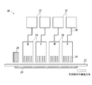
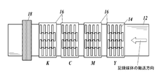
- the ink jet recording apparatus shown in FIGS. 4A and 4B is a recording apparatus for a line recording system.
- FIG. 4A is a side view of an example of a configuration of a main part of the ink jet recording apparatus
- FIG. 4B is a top view thereof.
- the ink jet recording apparatus (10) includes a head carriage (16) accommodating a plurality of ink discharge recording heads (14), and a base material (12) on which a gloss adjusting layer is formed. And an temperature control unit (18) disposed on the lower surface of the base material (12) and an actinic ray irradiation unit (18) disposed on the downstream side of the head carriage (16) in the conveyance direction of the base material. 19).
- a plurality of recording heads (14) for each color ink are fixedly arranged on the head carriage (16) so as to cover the entire width of the base material (12).
- Ink is supplied to the ink discharge recording head (14).
- ink is supplied to the recording head (14) for ink ejection directly from the ink cartridge (31) or the like, which is detachably mounted on the ink jet recording apparatus (10), or by the ink supply means (30). May be.
- An image recording layer is formed by transporting the base material (12) having a gloss adjustment layer with a controlled glossiness under the fixed head carriage (16).
- a plurality of ink discharge recording heads (14) are arranged in the transport direction of the base material (12) for each color.
- the number of ink discharge recording heads (14) arranged in the transport direction of the substrate (12) is set according to the nozzle density of the ink discharge recording head (14) and the resolution of a printed image. For example, when an image having a resolution of 1440 dpi is formed using a recording head (14) for ink ejection having a droplet amount of 2 pL and a nozzle density of 360 dpi, four ink ejection heads are arranged in the transport direction of the substrate (12). What is necessary is just to displace the recording head (14).
- dpi represents the number of ink droplets (dots) per inch. One inch is 2.54 cm.
- the actinic ray irradiator (18) covers the entire width of the substrate (12), and is disposed downstream of the head carriage (16) in the transport direction of the substrate (12).
- the actinic ray irradiating section (18) irradiates actinic rays to droplets ejected by the ink ejection recording head (14) and landed on the gloss adjustment layer of the base material (12), thereby curing the droplets.
- an actinic ray irradiation unit such as a metal halide lamp or an LED lamp is disposed so as to cover the entire width of the substrate (12), and after the ink lands on the substrate (12). Immediately, the metal is irradiated with ultraviolet rays by a ride lamp or the like, and the image is completely fixed.
- examples of the actinic ray irradiation section include a fluorescent tube (for example, a low-pressure mercury lamp, a germicidal lamp, etc.), a cold cathode tube, an ultraviolet laser, and several hundred Pa to 1 MPa.
- an ultraviolet irradiation unit that irradiates ultraviolet light having an illuminance of 100 mW / cm 2 or more, specifically, a high-pressure mercury lamp, a metal halide lamp, or an LED is preferable.
- a water-cooled LED manufactured by Phoseon Technology (wavelength: 395 nm) can be used.
- examples of the actinic ray irradiator include electron beam irradiating means such as a scanning method, a curtain beam method, and a broad beam method. From the viewpoint, curtain beam type electron beam irradiation means is preferable.
- Examples of the electron beam irradiation means include “Curetron EBC-200-20-30” manufactured by Nissin High Voltage Co., Ltd., “Min-EB” manufactured by AIT, and the like.
- the temperature control unit (19) is arranged on the lower surface of the substrate (12) and maintains the substrate (12) at a predetermined temperature.
- the temperature control unit (19) By adjusting the temperature of the base material (12), the glossiness of the gloss adjusting layer and the image recording layer to be formed can be appropriately controlled.
- various heaters and the like can be applied to the temperature control unit (19).
- the substrate (12) is transported between the head carriage (16) of the ink jet recording apparatus (10) and the temperature controller (19). On the other hand, the temperature of the substrate (12) is adjusted to a predetermined temperature by the temperature controller (19). Next, high-temperature ink is ejected from the ink ejection recording head (14) of the head carriage (16), and is attached (landed) on the gloss adjustment layer provided on the base material (12). Then, the actinic ray irradiating section (18) irradiates the ink droplets adhered on the base material (12) with actinic ray to be cured.
- the temperature of the ink in the recording head (14) is adjusted so that the ink contains a gelling agent in order to improve the ejection property of the ink.
- the temperature is preferably set to be higher by 10 to 30 ° C. than the gelation temperature of the ink. If the ink temperature in the recording head for ink ejection (14) is lower than (gelling temperature + 10) ° C., the ink is gelled in the recording head for ink ejection (14) or on the nozzle surface, and the ink ejection property is improved. Tends to decrease. On the other hand, if the temperature of the ink in the recording head (14) for ink ejection exceeds (gelling temperature + 30) ° C., the temperature of the ink becomes too high, and the ink component may deteriorate.
- the amount of ink droplets ejected from each nozzle of the ink ejection recording head (14) depends on the resolution of the image, but is in the range of 1 to 10 pL to form a high-resolution image. And more preferably within the range of 0.5 to 4.0 pL. In particular, in the present invention, it is preferable to form an image by discharging a small droplet having an ink droplet amount in the range of 0.5 to 2.5 pL in order to form a high-definition image.
- Irradiation with actinic light is performed within 10 seconds, preferably 0.001 to 5.0 seconds, after the ink droplets adhere to the base material, in order to suppress the coalescence of the adjacent ink droplets. It is preferable to carry out within the range, more preferably within the range of 0.01 to 2.0 seconds. Irradiation with actinic rays is preferably performed collectively after ink is ejected from all the ink ejection recording heads (14) housed in the head carriage (16).
- the accelerating voltage for electron beam irradiation is preferably in the range of 30 to 250 kV, more preferably in the range of 30 to 100 kV, in order to perform sufficient curing.
- the acceleration voltage is in the range of 100 to 250 kV
- the irradiation amount of the electron beam is preferably in the range of 30 to 100 kGy, and more preferably in the range of 30 to 60 kGy.
- the total ink film thickness after curing is preferably in the range of 2 to 25 ⁇ m.
- the “total ink film thickness” is the maximum value of the ink film thickness drawn on the base material.
- FIG. 5 is a diagram showing an example of a configuration of a main part of a serial recording type inkjet recording apparatus (20). As shown in FIG. 5, the serial recording system is different from the line recording system described above in which the head carriage (16) in which the inkjet recording device (20) is fixedly arranged so as to cover the entire width of the base material is arranged. Then, as shown in FIG.
- a head carriage (26) having a width smaller than the width of the base material and accommodating a plurality of ink discharge recording heads (24), and a head carriage (26) formed of the base material ( 12) having a guide portion (27) for movement in the width direction, and the other components of the recording head for ink ejection, the actinic ray irradiation portion (18), and the like have been described with reference to FIGS. 4A and 4B.
- the same configuration as that of the line recording type ink jet recording apparatus can be adopted.
- the ink contained in the head carriage (26) moves while the head carriage (26) moves in the width direction of the base material (12) along the guide portion (27). Ink is ejected from the ejection recording head (24) onto the gloss adjustment layer. Both ends of the head carriage (26) are provided with actinic ray irradiators (28) for irradiating actinic rays. Except for these operations, an image is recorded in substantially the same manner as the above-described line recording type ink jet recording apparatus (10).
- Electrophotographic recording method Although details of an image recording method using an electrophotographic method are omitted, for example, JP-A-2012-053099, JP-A-2012-242578, JP-A-2013-203818, JP-A-2014-188950, JP-A-2014-203056, JP-A-2016-188950, JP-A-2017-015810, JP-A-2017-161712, JP-A-2017-181743, etc.
- the present invention can be applied with reference to a device or the like.
- Preparation of coating liquid for forming gloss adjusting layer >> [Preparation of coating liquid A-1 for forming gloss adjusting layer]
- a resin dispersion Byron 8210 (a polyester-urethane resin manufactured by Toyobo Co., Ltd.) was used as a coating liquid A-1 for forming a gloss adjusting layer.
- Organic fine particles Chemisnow MX-150 (manufactured by Soken Chemical Co., Ltd., acrylic fine particles, average particle size: 1.5 ⁇ m) 10 parts by mass Water 80 parts by mass Isopropanol (IPA) 10 parts by mass.
- a gloss adjusting layer forming coating liquid A-4 having the following composition was prepared.
- Inorganic fine particles KE-P100 (manufactured by Nippon Shokubai Co., Ltd., Seahoster KE-P100, silica fine particles, average particle size: 1.0 ⁇ m) 10 parts by mass Isopropanol (IPA) 10 parts by mass Resin dispersion 1: SB-1230N (manufactured by Unitika Ltd.) , Arrow base SB-1230N, water-based chlorinated polyolefin) 80 parts by mass
- the preparation procedure is as follows. Isopropanol is placed in a stainless beaker, and while stirring at 300 rpm, inorganic fine particles (KE-P100) are added little by little, and then the whole amount is added. The mixture was stirred at room temperature for 5 minutes.
- the above resin dispersion 1 was added to the prepared inorganic fine particle / isopropanol liquid and mixed to prepare a coating liquid A-4 for forming a gloss adjusting layer.
- a coating liquid A-4 for forming a gloss adjusting layer the types and amounts of the resin dispersion 1, the resin dispersion 2 (acrylic), the organic fine particles 1, the inorganic fine particles, and the organic fine particles 2 (acrylic) were determined as follows. Preparations of coating liquids A-5 to A-25 for forming a gloss adjusting layer were prepared in the same manner except that the constitutions were changed to those shown in Tables I and II.
- Resin dispersion 1 Byron 8210: Toyobo, polyester-urethane resin SB-1230N: Unitika, Arrowbase SB-1230N, aqueous chlorinated polyolefin (Resin dispersion 2 (acrylic)) VINIBLAN 278: PVC / acrylic copolymer resin manufactured by Nissin Chemical Co., Ltd.
- MFR1924 Acrylic resin manufactured by Michelman (organic fine particles 1) TR-2: manufactured by Toray Industries, nylon fine particles, average particle size: 20 ⁇ m SX-500H: manufactured by Soken Chemical Co., Ltd., styrene fine particles, average particle size: 5 ⁇ m KSR-3A: manufactured by Soken Chemical Co., Ltd., styrene fine particles, average particle size: 3 ⁇ m (Inorganic fine particles) KE-P150: Nippon Shokubai Co., Ltd., Seahoster KE-P150, silica fine particles, average particle size: 1.5 ⁇ m KE-P100: Nippon Shokubai Co., Ltd., Seahoster KE-P100, silica fine particles, average particle size: 1.0 ⁇ m (Organic fine particles 2 (acrylic)) MR-7GC: manufactured by Soken Chemical Co., Ltd., Chemisnow MR-7GC, acrylic fine particles, average particle size: 6 ⁇ m MX-300: manufactured by Soken Chemical Co.
- inks B-1 to B-5 which are actinic ray curable inks, were prepared.
- EFKA4130 manufactured by BASF 9.0 parts by mass APG-100 (dipropylene glycol diacrylate, molecular weight 242 manufactured by Shin-Nakamura Chemical Co., Ltd.) 71 parts by mass The mixture was cooled to room temperature, and the following pigment was further added. This solution was put in a glass bottle together with 200 g of zirconia beads having a diameter of 0.5 mm, sealed, and subjected to a dispersion treatment with a paint shaker for 5 hours. Thereafter, the zirconia beads were removed to obtain a pigment dispersion a.
- APG-100 dipropylene glycol diacrylate, molecular weight 242 manufactured by Shin-Nakamura Chemical Co., Ltd.
- Ink B-2 to B-5 were prepared in the same manner as in the preparation of Ink B-1, except that the type and amount of each additive were changed to those shown in Table III.
- the heating temperature of the mixed solution was 85 ° C.
- APG-200 NK ester APG-200, manufactured by Shin-Nakamura Chemical Co., Ltd., tripropylene glycol diacrylate STA: manufactured by Osaka Organic Co., Ltd., octadecyl acrylate A-TMM-3L: NK ester A-TMM-3L, manufactured by Shin-Nakamura Chemical , Tetramethylol methane triacrylate SR355: manufactured by Sartomer, ditrimethylolpropane tetraacrylate G3414: GENOMER 3414, manufactured by RAHN, polyester acrylate SR230: manufactured by Sartomer, diethylene glycol diacrylate A-9550: NK ester A-9550, Shin-Nakamura Chemical Co., Ltd.
- Dipentaerythritol polyacrylate ETERCURE 6234 Choko Chemical, epoxy acrylate oligomer A-9300: NK ester A-9 00, Shin-Nakamura Chemical Co., Ltd., isocyanurate triacrylate.
- ⁇ Photopolymerizable compound 2 ClogP 4.0 to 7.0> Miramer M360: manufactured by Miwon, trimethylolpropane 3PO-modified triacrylate, molecular weight: 471, ClogP value: 4.90 Miramer M166: Nonylphenol 8EO-modified acrylate, manufactured by Miwon, molecular weight: 626, ClogP value: 6.42 A-DCP: NK ester A-DCP, manufactured by Shin-Nakamura Chemical Co., Ltd., tricyclodecane dimethanol diacrylate, molecular weight: 304, ClogP value: 4.69.
- WEP-2 Nissan Elector WEP-2, manufactured by NOF Corporation, ester wax, melting point 60 ° C
- Kaowax T1 Distearyl Ketone Unistar M-9676, manufactured by Kao Corporation; Stearyl stearate WEP-4, manufactured by NOF Corporation; Nissan Electol WEP-4, manufactured by NOF Corporation, ester wax, melting point 70 ° C.
- Suriade S Stearoamidoethyl stearate manufactured by Nippon Kasei Co.
- BYK-307 a polyether-modified polydimethylsiloxane manufactured by BYK Japan KK.
- Irgacure 819 Bis (2,4,6-trimethylbenzoyl) -phenylphosphine oxide, manufactured by BASF
- Irgacure 369 2-benzyl-2-dimethylamino-1- (4-morpholinophenyl) -butanone-, manufactured by BASF 1
- DETX 2,4-diethylthioxanthone manufactured by Lambson.
- Each black ink was loaded into an ink jet recording apparatus having an ink jet recording head having a piezo type ink jet nozzle having the configuration shown in FIG. 4A. From this apparatus, each ink was discharged onto a PET film to form a black solid image.
- the ink supply system was composed of an ink tank, an ink flow path, a sub-ink tank immediately before an inkjet recording head, a pipe with a filter, and a piezo head.
- piezo heads having a resolution of 360 dpi were arranged in four rows in the transport direction, and the recording resolution was set to 1440 ⁇ 1440 dpi while heating the PET film at a predetermined temperature.
- the heating temperature of the PET film is 25 ° C. for the ink (B-1 and B-2) containing no gelling agent, and 40 to 55 ° C. for the ink (B-3 to B-5) containing the gelling agent. did.
- the ink was cured by irradiating light having a wavelength of 395 nm from a water-cooled LED lamp manufactured by Heraeus.
- the distance from the LED lamp surface to the recording medium surface was 50 mm.
- the maximum illuminance on the surface of the recording medium was 3.5 W / cm 2
- the conveyance speed of the recording medium was 60 m / min.
- the irradiated light amount was 400 mJ / cm 2 .
- the black solid image created above was measured using a gonio-gloss meter PG-1M and VGS-10001DP (manufactured by Nippon Denshoku Industries Co., Ltd.) in accordance with the measurement method specified in JIS Z8741.
- the 60 ° specular gloss of a solid black image formed by each ink is shown below.
- the temperature in parentheses indicates the PET film temperature during image formation.
- Ink B-2: Gloss 15 (image forming temperature: 25 ° C.)
- Ink B-3: Gloss 52 (image forming temperature: 55 ° C.)
- Ink B-4: Gloss 36 (image forming temperature: 40 ° C.)
- Ink B-5: Gloss 21 (image formation temperature: 25 ° C.).
- the ink supply system was composed of an ink tank, a supply pipe, an ink tank in the front chamber immediately before the head, a piping with a filter, and a piezo head.
- the piezo head is driven so that multi-size dots of 2 to 15 pL can be ejected at a resolution of 720 ⁇ 720 dpi (dpi represents the number of dots per 2.54 cm), and the ink B-1 is driven by the image shown in FIG.
- the images were formed in a separated state so that the printing rate was 50%.
- the scanning speed of the carriage was 750 mm / s.
- the actinic rays were instantaneously (less than 1 second after impact) by the irradiation means provided on both sides of the carriage to form an image.
- the irradiating means uses a high-pressure mercury lamp VZero085 (manufactured by INTEGRATION TECHNOLOGY), and irradiates the ink with ultraviolet light at an energy density of 140 W / cm and an illuminance of 20 mJ / cm 2 (integrated light quantity) to cure the ink.
- VZero085 manufactured by INTEGRATION TECHNOLOGY
- the used toner was prepared by the following method.
- Ink B-4 was loaded into an ink jet recording apparatus having an ink jet recording head having a piezo type ink jet nozzle having the configuration shown in FIG. 4A. From this apparatus, the ink B-4 was printed on a PET film in a state where the images were separated so that the printing rate was 50%, as shown in the image forming layer in FIG. 1, and the image recording layer 3 was printed. Formed.
- the ink supply system was composed of an ink tank, an ink flow path, a sub-ink tank immediately before an inkjet recording head, a pipe with a filter, and a piezo head.
- piezo heads having a resolution of 360 dpi were arranged in four rows in the transport direction, and a recording resolution of 1440 ⁇ 1440 dpi was set while heating the PET film at a temperature of 40 ° C.
- the ink was heated from the ink tank to the head portion to a gelling temperature Tgel + 30 ° C. Further, a voltage was applied to the piezo head so that the amount of ink droplets became 3 pL, and a monochromatic lattice-like black image was formed.
- the ink was cured by irradiating light having a wavelength of 395 nm from a water-cooled LED lamp manufactured by Heraeus.
- the distance from the LED lamp surface to the recording medium surface was 50 mm.
- the maximum illuminance on the surface of the recording medium was 3.5 W / cm 2
- the conveyance speed of the recording medium was 60 m / min.
- the irradiated light amount was 400 mJ / cm 2 .
- A-3 was selected as a coating liquid for forming a gloss adjusting layer so as to satisfy the above, a gloss adjusting layer having a gloss of 60 was formed between the base material and the image recording layer, and an image having the configuration shown in FIG. 1 was formed.
- An image recording material 4 was produced in the same manner except that the recording material was used.
- each gloss adjusting layer is formed on a base material in the image recording materials 4 to 33 in accordance with a measurement method defined in JIS Z 8741.
- the gloss adjusting layer was measured for a 60-degree specular gloss G2 using a gonio-gloss meter PG-1M and VGS-10001DP (manufactured by Nippon Denshoku Industries Co., Ltd.).
- the gloss difference ⁇ G (G2-G1) was determined.
- the reference values, the glossiness of the substrate, and the glossiness difference of the image recording layer are shown.
- Absolute value of gloss difference is 10 or less :: Absolute value of gloss difference is 11 or more and less than 20 ⁇ : Absolute value of gloss difference is 20 or more and less than 30 ⁇ : The absolute value of the gloss difference is 30 or more.
- the image recording material of the present invention having a gloss adjusting layer designed to have a desired gloss based on the gloss information of the image recording layer specified in the present invention is As compared with the comparative example having no gloss adjusting layer, an image excellent in gloss can be obtained, and an image excellent in adhesion and wettability can be obtained.
- the gloss difference ⁇ G (G2 ⁇ G1) between the gloss G2 of the gloss adjusting layer and the gloss G1 of the image recording layer is in the range of ⁇ 20 to +20, and further, the gloss difference ⁇ G
- (G2 ⁇ G1) in the range of ⁇ 10 to +5
- the gloss difference between the image forming portion (the glossiness G1 of the image recording layer) and the non-image forming portion (the glossiness G2 of the gloss adjustment layer) is obtained. This is preferable in that an image with reduced discomfort can be formed.
- the image recording method of the present invention includes an ink jet recording method in which an image is formed using an ink jet ink containing a dye or a pigment, and an image forming method in which a toner containing a coloring material is applied and fixed on paper or a thin film by an electrophotographic process.
- an ink jet recording method in which an image is formed using an ink jet ink containing a dye or a pigment
- an image forming method in which a toner containing a coloring material is applied and fixed on paper or a thin film by an electrophotographic process.
Landscapes
- Physics & Mathematics (AREA)
- Chemical & Material Sciences (AREA)
- General Physics & Mathematics (AREA)
- Materials Engineering (AREA)
- Wood Science & Technology (AREA)
- Organic Chemistry (AREA)
- Life Sciences & Earth Sciences (AREA)
- Engineering & Computer Science (AREA)
- Inks, Pencil-Leads, Or Crayons (AREA)
- Ink Jet (AREA)
- Color Electrophotography (AREA)
- Liquid Developers In Electrophotography (AREA)
- Ink Jet Recording Methods And Recording Media Thereof (AREA)
Abstract
The present invention addresses the problem of providing an image-recording method in which a difference in gloss between an image-forming part and a non-image-forming part is reduced and with which there is formed an image having exceptional adhesion and wettability. This image-recording method involves providing a gloss adjustment layer on an image-forming part and a non-image-forming part of a substrate, and forming an image-recording layer on an image-forming part of the gloss adjustment layer, wherein the method is characterized in that the 60° specular gloss G1 of the image-recording layer provided directly on the substrate is measured in advance, and the 60° specular gloss G2 of the gloss adjustment layer is adjusted in accordance the resultant information pertaining to the 60° specular gloss G1.
Description
本発明は、各種基材上に印刷画像を形成する画像記録方法に関し、更に詳しくは、画像形成部と非画像形成部間の光沢差を縮小し、かつ密着性及び濡れ性に優れた画像を形成する画像記録方法に関する。
The present invention relates to an image recording method for forming a printed image on various substrates, and more specifically, to reduce an gloss difference between an image forming portion and a non-image forming portion, and to form an image having excellent adhesion and wettability. The present invention relates to an image recording method to be formed.
現在、各種の画像記録方法としては、例えば、専用紙や繊維製品上に、染料や顔料を含むインクジェットインクを用いて画像形成するインクジェット記録方式や、色材を含むトナーを電子写真プロセスにより、紙や薄膜フィルム上に付与・定着して画像形成する電子写真方式や、各種基材上に、印刷用インキを用いて絵柄等を形成するスクリーン印刷法やオフセット印刷法等、様々な分野において広く普及している。
At present, various image recording methods include, for example, an ink jet recording method in which an image is formed on a special paper or a textile using an ink jet ink containing a dye or a pigment, or a toner containing a coloring material by an electrophotographic process. Widely used in various fields, such as electrophotography, which forms an image by applying and fixing it on a thin film or a thin film, and screen printing, offset printing, and the like, in which a pattern is formed on various substrates using printing ink. are doing.
上記画像記録分野の中でも、インクジェット記録方式は、簡易な装置を用い、かつ安価に画像を形成できることから、各種印刷分野で用いられている。
イ ン ク ジ ェ ッ ト Among the image recording fields described above, the ink jet recording method is used in various printing fields because a simple apparatus can be used and an image can be formed at low cost.
更に、近年、インクジェット記録方式の一つとして、活性光線の照射によって硬化する特性を有する光硬化性化合物を含有する活性光線硬化型インクジェットインクを用い、当該インクジェットインクのインク液滴を基材(以下、「記録媒体」ともいう。)上に着弾させた後、活性光線を照射して当該インクジェットインクを硬化させて画像を形成する方法が盛んに検討されている。このような活性光線硬化型インクジェットインクを用いることにより、インク吸収性を有していない非吸収性基材を含め、様々な特性を有する記録媒体に対し、ドットの濡れ広がりが抑制された高品位で高い耐擦過性を有する画像を形成することできる。
Further, in recent years, as one of the ink jet recording methods, an actinic ray curable inkjet ink containing a photocurable compound having a property of being cured by irradiation with actinic light is used, and the ink droplets of the inkjet ink are used as a substrate (hereinafter, referred to as a substrate). A method of forming an image by irradiating with an actinic ray and then curing the ink-jet ink after landing on the recording medium has been actively studied. By using such an actinic ray-curable inkjet ink, it is possible to prevent dots from spreading and spreading on recording media having various properties, including non-absorbing base materials that do not have ink absorbency. To form an image having high scratch resistance.
一方、各種画像記録方法では、その様々な用途に対応し、形成された画像部の光沢と記録媒体の非印刷領域(未印字部)の光沢とを綿密に合わせ、未印字部と画像形成部との光沢差を小さくすることが、違和感の少ない画像を得る観点から強く求められている。特に、商業印刷の分野では、印刷紙面の光沢と印字面の光沢が異なると光沢違和感として感じられるため、その商品価値が低下してしまうため、紙種によって印字領域の光沢と非印刷領域の光沢を密接に合わせる要望が強い。
On the other hand, in various image recording methods, the gloss of the formed image portion and the gloss of the non-printed area (non-printed portion) of the recording medium are closely matched, and the unprinted portion and the image forming portion are adjusted. It is strongly required to reduce the difference in gloss from the image from the viewpoint of obtaining an image with less discomfort. Particularly in the field of commercial printing, if the gloss of the printing paper differs from the gloss of the printing surface, it is perceived as a sense of incongruity, and the product value is reduced.Therefore, the gloss of the printing area and the gloss of the non-printing area depend on the paper type. There is a strong demand to match closely.
上述の活性光線硬化型インクジェットインクを用いたインクジェット記録方式では、あらゆる基材に対し印刷を行う際、基材と形成画像との密着性の観点から、下地層(プライマー層ともいう。)を必要とする基材がある。しかしながら、高光沢の下地層を基材一面に形成すると、下地層の光沢が優先され、基材の光沢感が損なわれるという問題が生じる。加えて、活性光線硬化型インクジェットインクが形成する画像の光沢は、相対的に低光沢である場合が多く、下地層を設けた基材の未印字部との光沢差が拡大し、違和感のある画像となってしまう。
In the above-described inkjet recording method using the actinic ray-curable inkjet ink, when printing on any substrate, an underlayer (also referred to as a primer layer) is required from the viewpoint of adhesion between the substrate and the formed image. There is a base material. However, when a high-gloss base layer is formed over the entire surface of the base material, the gloss of the base layer is prioritized, and the glossiness of the base material is impaired. In addition, the gloss of the image formed by the actinic ray-curable inkjet ink is often relatively low gloss, and the difference in gloss from the unprinted portion of the base material provided with the base layer increases, giving a sense of incongruity. It becomes an image.
上記のような印字部と非印字部との光沢差を調整する方法として、以下の方法が提案されている。
以下 The following method has been proposed as a method for adjusting the gloss difference between the printed portion and the non-printed portion as described above.
光沢差を解消する一つの方法は、基材上に画像形成した後、画像層の上にオーバーコート層を設ける方法が挙げられ、例えば、インクジェット記録方式においては、印刷された画像に光沢を持たせたり、外部からの衝撃への耐性を持たせたりする目的で、活性光線硬化型インクジェットインクに活性光線を照射して形成した画像層上に、更にオーバーコート液を付与し、コーティングする技術が知られている。その一例として、ゲル化剤、硬化性モノマー、硬化性ワックス及び光開始剤を含むオーバーコート液を用いて、画像の光沢を制御する技術が開示されている(例えば、特許文献1参照。)。
One method for eliminating the gloss difference is to form an image on a base material and then provide an overcoat layer on the image layer.For example, in an inkjet recording method, the printed image has gloss. In order to make the active light-curable inkjet ink irradiate with actinic rays, an overcoat liquid is further applied to the actinic ray-curable ink-jet ink to coat the actinic ray-curable inkjet ink. Are known. As one example, a technique for controlling the gloss of an image using an overcoat liquid containing a gelling agent, a curable monomer, a curable wax, and a photoinitiator is disclosed (for example, see Patent Document 1).
しかしながら、特許文献1で提案されているような画像層上にオーバーコート層を付与する方法では、その構成により、画像層自身の光沢を打ち消してしまうため、形成した画像の質感が失われ、かつ、画像層として所定の厚さとし、高光沢を発現させたい場合には、レリーフ感が際立ってしまうという問題を抱えている。
However, in the method of providing an overcoat layer on an image layer as proposed in Patent Literature 1, the gloss of the image layer itself is canceled due to the configuration, and the texture of the formed image is lost. However, when the image layer is required to have a predetermined thickness and to exhibit high gloss, there is a problem that the relief feeling becomes noticeable.
印字部と非印字部との光沢差を解消する他の方法としては、有色トナーや有色インクととともに、画素単位の領域で、透明トナーや透明インクを適用して光沢調整を行う方法が知られている。電子写真方式では、例えば、特開平7-266614号公報や特開平11-7174号公報には、有色トナーとともに、光沢調整材として有色トナーと近似の光沢性を有する透明トナーを適用し、画像領域での画像の高さを同一に揃えることにより、光沢差を低減する方法が開示されている。また、インクジェット記録方式においては、有色インクとともに透明インクを用い、有色インクの吐出量に基づき、透明インクの付与量を調整することにより、光沢ムラを抑制する方法が開示されている(例えば、特許文献2参照。)。
As another method for eliminating the difference in gloss between the printed portion and the non-printed portion, there is known a method of adjusting the gloss by applying a transparent toner or a transparent ink in a pixel unit area together with a colored toner or a colored ink. ing. In the electrophotographic method, for example, Japanese Patent Application Laid-Open No. Hei 7-266614 and Japanese Patent Application Laid-Open No. Hei 11-7174 apply a transparent toner having gloss similar to that of a colored toner as a gloss adjusting material together with a colored toner. There is disclosed a method of reducing the difference in gloss by making the heights of images at the same level. Further, in the ink jet recording method, a method is disclosed in which glossiness is suppressed by using transparent ink together with colored ink, and adjusting the applied amount of the transparent ink based on the ejection amount of the colored ink. Reference 2).
しかしながら、上記開示されている方法では、画素単位で光沢調整材である透明トナーや透明インクを適用する方法であり、最終画像を形成する過程で、工程数の増加等でコスト高となり、また有色トナーや有色インクで形成したカラー画像の相対的な濃度が低下し、画像全体としての均一感を得ることが難しくなるという問題がある。
However, the method disclosed above is a method in which a transparent toner or a transparent ink as a gloss adjusting material is applied for each pixel. In the process of forming a final image, the cost increases due to an increase in the number of steps and the like. There is a problem that the relative density of a color image formed with toner or colored ink is reduced, and it is difficult to obtain a uniform feeling as the entire image.
本発明は、上記問題・状況に鑑みてなされたものであり、その解決課題は、画像形成部と非画像形成部間の光沢差を縮小し、かつ密着性及び濡れ性に優れた画像を形成する画像記録方法を提供することである。
The present invention has been made in view of the above problems and circumstances, and a solution to the problem is to reduce the gloss difference between an image forming unit and a non-image forming unit, and to form an image having excellent adhesion and wettability. To provide an image recording method.
本発明者は、上記課題を解決すべく、上記問題の原因等について検討する過程において、様々な基材上に画像記録する際に、基材と画像記録層との間に光沢調整層を設けることで、基材と画像記録層間の密着性を向上させるとともに、画像記録層の光沢度G1をあらかじめ測定し、その測定した光沢度G1の情報を基に、光沢調整層の光沢度G2を最適条件に調整することにより、印字部と非印字部間での光沢差を低減し、違和感のない画像を形成する画像記録方法を提供することができることを見いだし、本発明に至った。
ものである。 The present inventor, in order to solve the above problems, in the process of examining the cause of the above problems, etc., when recording an image on various substrates, providing a gloss adjustment layer between the substrate and the image recording layer This improves the adhesion between the base material and the image recording layer, measures the gloss G1 of the image recording layer in advance, and optimizes the gloss G2 of the gloss adjustment layer based on the measured information of the gloss G1. It has been found that by adjusting the conditions, it is possible to provide an image recording method capable of reducing the difference in gloss between a printed portion and a non-printed portion and forming an image without a sense of discomfort.
Things.
すなわち、本発明の上記課題は、下記の手段により解決される。
That is, the above object of the present invention is solved by the following means.
1.基材上に光沢調整層を設け、前記光沢調整層上に画像記録層を形成する画像記録方法であって、
予め前記画像記録層の60度鏡面光沢度G1を測定し、得られた当該60度鏡面光沢度G1の情報に従って、前記光沢調整層の60度鏡面光沢度G2を調整することを特徴とする画像記録方法。 1. An image recording method for providing a gloss adjustment layer on a base material and forming an image recording layer on the gloss adjustment layer,
An image characterized in that the 60-degree specular gloss G1 of the image recording layer is measured in advance, and the 60-degree specular gloss G2 of the gloss adjustment layer is adjusted according to the obtained information of the 60-degree specular gloss G1. Recording method.
2.前記光沢調整層の60度鏡面光沢度G2と前記画像記録層の60度鏡面光沢度G1との光沢度差ΔG(G2-G1)を、-20~+20の範囲内とすることを特徴とする第1項に記載の画像記録方法。
{2. A gloss difference ΔG (G2−G1) between the 60 ° specular gloss G2 of the gloss adjusting layer and the 60 ° specular gloss G1 of the image recording layer is within a range of −20 to +20. Item 2. The image recording method according to Item 1.
3.前記光沢調整層の60度鏡面光沢度G2と前記画像記録層の60度鏡面光沢度G1との光沢度差ΔG(G2-G1)を、-10~+5の範囲内とすることを特徴とする第1項又は第2項に記載の画像記録方法。
{3. A gloss difference ΔG (G2-G1) between the 60-degree specular gloss G2 of the gloss adjusting layer and the 60-degree specular gloss G1 of the image recording layer is within a range of -10 to +5. Item 3. The image recording method according to Item 1 or 2.
4.前記光沢調整層を、下記成分(1)に対し、下記成分(2)を0.1~20質量%の範囲内で含有する光沢調整層形成用塗布液を用い、湿式塗布法により形成すること特徴とする第1項から第3項までのいずれか一項に記載の画像記録方法。
4. The gloss adjusting layer is formed by a wet coating method using a coating liquid for forming a gloss adjusting layer containing the following component (2) in the range of 0.1 to 20% by mass based on the following component (1). 4. The image recording method according to any one of items 1 to 3, which is characterized by the following.
成分(1):水系溶媒を分散媒とした樹脂分散体
成分(2):平均粒径が1.0~20μmの範囲内にある有機又は無機微粒子
5.前記湿式塗布法が、インクジェットプリント法であることを特徴とする第4項に記載の画像記録方法。 Component (1): a resin dispersion using an aqueous solvent as a dispersion medium Component (2): organic or inorganic fine particles having an average particle size in a range of 1.0 to 20 μm. The image recording method according toclaim 4, wherein the wet coating method is an inkjet printing method.
成分(2):平均粒径が1.0~20μmの範囲内にある有機又は無機微粒子
5.前記湿式塗布法が、インクジェットプリント法であることを特徴とする第4項に記載の画像記録方法。 Component (1): a resin dispersion using an aqueous solvent as a dispersion medium Component (2): organic or inorganic fine particles having an average particle size in a range of 1.0 to 20 μm. The image recording method according to
6.前記画像記録層が、活性光線硬化型インクジェットインクにより形成されていることを特徴とする第1項から第5項までのいずれか一項に記載の画像記録方法。
6. The image recording method according to any one of claims 1 to 5, wherein the image recording layer is formed of an actinic ray curable inkjet ink.
7.前記画像記録層が、ゲル化剤を含む活性光線硬化型インクジェットインクにより形成されていることを特徴とする第1項から第6項までのいずれか一項に記載の画像記録方法。
$ 7. The image recording method according to any one of claims 1 to 6, wherein the image recording layer is formed of an actinic ray curable inkjet ink containing a gelling agent.
8.前記ゲル化剤が、下記一般式(G1)又は(G2)で表される構造を有する化合物のいずれか1種を、前記活性光線硬化型インクジェットインク全質量の0.1~5.0質量%の範囲内で含有し、
かつ、光重合性化合物を前記活性光線硬化型インクジェットインク全質量の10~40質量%の範囲内で含有し、前記光重合性化合物が、分子量が280~1500の範囲内であり、ClogP値が4.0~7.0の範囲内にあるアクリレート化合物である
ことを特徴とする第7項に記載の画像記録方法。 8. The gelling agent may be a compound having a structure represented by the following general formula (G1) or (G2), and may be used in an amount of 0.1 to 5.0% by mass based on the total mass of the actinic ray-curable inkjet ink. Contained within the range of
And, the photopolymerizable compound is contained within the range of 10 to 40% by mass of the total mass of the actinic ray-curable inkjet ink, the photopolymerizable compound has a molecular weight within the range of 280 to 1500, and has a ClogP value. 8. The image recording method according to claim 7, wherein the acrylate compound is in the range of 4.0 to 7.0.
一般式(G1):R1-CO-R2
一般式(G2):R3-COO-R4
〔式中、R1~R4は、それぞれ独立に、炭素数が12~26の範囲内である直鎖状又は分岐鎖状のアルキル基を表す。〕
9.前記光沢調整層が含有する前記有機又は無機微粒子の平均粒径rを1.5~7.0μmの範囲内とし、乾燥後の膜厚hdを1.0~3.0μmの範囲内とし、
かつ、前記光沢調整層の乾燥後の膜厚hdと、前記有機又は無機微粒子の平均粒径rが、下式(1)で規定する条件を満たすことを特徴とする第4項から第8項までのいずれか一項に記載の画像記録方法。 General formula (G1): R 1 —CO—R 2
General formula (G2): R 3 —COO—R 4
[In the formula, R 1 to R 4 each independently represent a linear or branched alkyl group having 12 to 26 carbon atoms. ]
9. The average particle diameter r of the organic or inorganic fine particles contained in the gloss adjusting layer is in the range of 1.5 to 7.0 μm, the thickness hd after drying is in the range of 1.0 to 3.0 μm,
9. The method according toclaim 4, wherein the thickness hd of the gloss adjusting layer after drying and the average particle diameter r of the organic or inorganic fine particles satisfy the condition defined by the following expression (1). The image recording method according to any one of the above.
一般式(G2):R3-COO-R4
〔式中、R1~R4は、それぞれ独立に、炭素数が12~26の範囲内である直鎖状又は分岐鎖状のアルキル基を表す。〕
9.前記光沢調整層が含有する前記有機又は無機微粒子の平均粒径rを1.5~7.0μmの範囲内とし、乾燥後の膜厚hdを1.0~3.0μmの範囲内とし、
かつ、前記光沢調整層の乾燥後の膜厚hdと、前記有機又は無機微粒子の平均粒径rが、下式(1)で規定する条件を満たすことを特徴とする第4項から第8項までのいずれか一項に記載の画像記録方法。 General formula (G1): R 1 —CO—R 2
General formula (G2): R 3 —COO—R 4
[In the formula, R 1 to R 4 each independently represent a linear or branched alkyl group having 12 to 26 carbon atoms. ]
9. The average particle diameter r of the organic or inorganic fine particles contained in the gloss adjusting layer is in the range of 1.5 to 7.0 μm, the thickness hd after drying is in the range of 1.0 to 3.0 μm,
9. The method according to
式(1)
光沢調整層の乾燥後の膜厚hd<有機又は無機微粒子の平均粒径r
10.前記光沢調整層が含有する前記樹脂分散体が、アクリル成分を含む樹脂を含有することを特徴とする第4項から第9項までのいずれか一項に記載の画像記録方法。 Equation (1)
Film thickness hd of the gloss adjusting layer after drying <average particle size r of organic or inorganic fine particles
10. 10. The image recording method according toclaim 4, wherein the resin dispersion contained in the gloss adjusting layer contains a resin containing an acrylic component.
光沢調整層の乾燥後の膜厚hd<有機又は無機微粒子の平均粒径r
10.前記光沢調整層が含有する前記樹脂分散体が、アクリル成分を含む樹脂を含有することを特徴とする第4項から第9項までのいずれか一項に記載の画像記録方法。 Equation (1)
Film thickness hd of the gloss adjusting layer after drying <average particle size r of organic or inorganic fine particles
10. 10. The image recording method according to
11.前記光沢調整層が含有する前記有機微粒子が、アクリル微粒子であることを特徴とする第4項から第10項までのいずれか一項に記載の画像記録方法。
{11. The image recording method according to any one of claims 4 to 10, wherein the organic fine particles contained in the gloss adjusting layer are acrylic fine particles.
本発明によれば、画像形成部と非画像形成部間の光沢差を縮小し、かつ密着性及び濡れ性に優れた画像を形成する画像記録方法を提供することができる。
According to the present invention, it is possible to provide an image recording method which reduces a difference in gloss between an image forming portion and a non-image forming portion and forms an image having excellent adhesion and wettability.
本発明で規定する構成からなる画像記録方法の効果発現機構又は作用機構については、明確にはなっていないが、以下のように推察している。
効果 The effect manifestation mechanism or action mechanism of the image recording method having the configuration specified in the present invention has not been clarified, but is presumed as follows.
様々な表面特性(例えば、表面光沢度、凹凸構造、密着特性等)を有す各種基材(記録媒体)上に、画像形成を行う場合、その基材の特性により、画像形成層と基材間での密着性が低下すること、印字部である画像形成部と非印字部である基材との光沢度差により、違和感のある画像となるケースが多い。上記問題に対し、画像記録後にオーバーコート層を設けて光沢度差を縮小する方法や、透明トナーや透明インクを用いて平滑化する方法があるが、いずれの方法も工数が増加してコスト上昇を招くこと、様々な基材に対する光沢差を縮小する効果が十分でなく、汎用性という点で問題があった。
When forming an image on various substrates (recording media) having various surface characteristics (for example, surface glossiness, uneven structure, adhesion characteristics, etc.), the image forming layer and the substrate may be formed depending on the characteristics of the substrate. In many cases, an image with a sense of incongruity is formed due to a decrease in the adhesiveness between them and a difference in glossiness between the image forming portion as the printing portion and the base material as the non-printing portion. To solve the above problems, there is a method of reducing the gloss difference by providing an overcoat layer after image recording, and a method of smoothing using a transparent toner or a transparent ink, but both methods increase man-hours and increase costs. And the effect of reducing the difference in gloss for various substrates is not sufficient, and there is a problem in terms of versatility.
本発明では、上記問題を踏まえ鋭意検討を進めた結果、基材上に画像記録層を形成する画像記録方法において、画像形成部と、非画像形成部である基材部との間での光沢差を低減するため、基材と画像記録層との間に、画像記録層の光沢度に合わせるように設計された光沢調整層を設けることにより、従来技術では達成することができなかった画像形成部の質感を生かし、自然で違和感のない光沢感を全面に持つ画像形成を実現することができた。特に、光沢調整層の光沢度は、具体的には、適用する無機又は有機微粒子の平均粒径や添加量を適宜調整することにより、可能となることを見いだした。
In the present invention, as a result of diligent studies based on the above problems, in an image recording method for forming an image recording layer on a substrate, the gloss between the image forming portion and the substrate portion which is a non-image forming portion In order to reduce the difference, by providing a gloss adjusting layer designed to match the glossiness of the image recording layer between the base material and the image recording layer, image formation that could not be achieved by the prior art By making use of the texture of the part, it was possible to realize image formation having a natural and natural feeling of glossiness. In particular, it has been found that the glossiness of the gloss adjusting layer can be specifically achieved by appropriately adjusting the average particle size and the amount of inorganic or organic fine particles to be applied.
更に、本発明で規定する構成の画像記録方法では、光沢調整層を基材と画像記録層との間に設けることにより、両者間の密着性や、画層記録層の形成に用いる色材を含むインク液等の塗布性が向上することにより、画質の向上を達成することができた。
Furthermore, in the image recording method having the configuration defined in the present invention, by providing a gloss adjusting layer between the base material and the image recording layer, the adhesion between the two and the coloring material used for forming the image recording layer can be reduced. By improving the applicability of the contained ink liquid or the like, it was possible to achieve an improvement in image quality.
本願発明の光沢調整層を適用し、画像形成部の光沢度に合わせて、当該光沢調整層の光沢度を調整するという設計思想は、全く新規であり、代表的なインクジェット記録方式のみでなく、電子写真方式や広く普及しているスクリーン印刷法やオフセット印刷法等の印刷分野においても、広く活用することができる。
The design concept of applying the gloss adjustment layer of the present invention and adjusting the gloss of the gloss adjustment layer in accordance with the gloss of the image forming unit is completely new, and is not only a typical inkjet recording method, It can also be widely used in printing fields such as electrophotography and widely used screen printing and offset printing.
その中でも、インクジェット記録方式に適用することが有効であり、活性光線硬化型インクジェットインクを用いたインクジェット記録方式において、より効果を発揮し、更には、ゲル化剤を含む活性光線硬化型インクジェットインクを用いたインクジェット記録方式に適用することにより、画像記録層表面での酸素阻害が防止されるため、活性光線照射によるインクの硬化が均一に進行し、画像形成膜の強度が高まり、密着性をさらに向上させることができる。
Among them, it is effective to apply to the ink jet recording method, more effective in the ink jet recording method using the actinic ray curable inkjet ink, furthermore, the actinic ray curable inkjet ink containing a gelling agent. By applying to the inkjet recording method used, oxygen inhibition on the surface of the image recording layer is prevented, so that curing of the ink by irradiation with actinic light proceeds uniformly, the strength of the image forming film is increased, and the adhesion is further improved. Can be improved.
本発明の画像記録方法は、基材上に光沢調整層を設け、前記光沢調整層上に画像記録層を形成する画像記録方法であって、予め前記画像記録層の60度鏡面光沢度G1を測定し、得られた当該60度鏡面光沢度G1の情報に従って、前記光沢調整層の60度鏡面光沢度G2を調整することを特徴とする。この特徴は、下記各実施形態に係る発明に共通する技術的特徴である
本発明の実施形態としては、本発明の目的とする効果をより発現できる観点から、前記光沢調整層の60度鏡面光沢度G2と前記画像記録層の60度鏡面光沢度G1との光沢度差(G2-G1)を-20~+20の範囲内とすること、更には光沢度差(G2-G1)を-10~+5の範囲内とすることが、より画像形成部と非画像形成部間の光沢差を縮小し、違和感のない画像を形成することができる点で好ましい。 The image recording method of the present invention is an image recording method in which a gloss adjustment layer is provided on a base material and an image recording layer is formed on the gloss adjustment layer, and the 60-degree mirror gloss G1 of the image recording layer is previously determined. The 60-degree specular gloss G2 of the gloss adjusting layer is adjusted according to the information of the measured and obtained 60-degree specular gloss G1. This feature is a technical feature common to the invention according to each of the embodiments described below. As an embodiment of the present invention, from the viewpoint of more achieving the effect desired by the present invention, the 60-degree specular gloss of the gloss adjustment layer is The gloss difference (G2-G1) between the degree G2 and the 60-degree specular gloss G1 of the image recording layer is in the range of −20 to +20, and the gloss difference (G2-G1) is −10 to +20. The range of +5 is preferable in that the difference in gloss between the image forming portion and the non-image forming portion can be further reduced and an image having no uncomfortable feeling can be formed.
本発明の実施形態としては、本発明の目的とする効果をより発現できる観点から、前記光沢調整層の60度鏡面光沢度G2と前記画像記録層の60度鏡面光沢度G1との光沢度差(G2-G1)を-20~+20の範囲内とすること、更には光沢度差(G2-G1)を-10~+5の範囲内とすることが、より画像形成部と非画像形成部間の光沢差を縮小し、違和感のない画像を形成することができる点で好ましい。 The image recording method of the present invention is an image recording method in which a gloss adjustment layer is provided on a base material and an image recording layer is formed on the gloss adjustment layer, and the 60-degree mirror gloss G1 of the image recording layer is previously determined. The 60-degree specular gloss G2 of the gloss adjusting layer is adjusted according to the information of the measured and obtained 60-degree specular gloss G1. This feature is a technical feature common to the invention according to each of the embodiments described below. As an embodiment of the present invention, from the viewpoint of more achieving the effect desired by the present invention, the 60-degree specular gloss of the gloss adjustment layer is The gloss difference (G2-G1) between the degree G2 and the 60-degree specular gloss G1 of the image recording layer is in the range of −20 to +20, and the gloss difference (G2-G1) is −10 to +20. The range of +5 is preferable in that the difference in gloss between the image forming portion and the non-image forming portion can be further reduced and an image having no uncomfortable feeling can be formed.
また、前記光沢調整層を、樹脂分散体に対し、特定の粒径範囲にある有機又は無機微粒子を0.1~20質量%の範囲内で含有する光沢調整層形成用塗布液を用い、湿式塗布法により形成すること、更には湿式塗布法として、インクジェットプリント法を適用することにより、光沢調整層の光沢度を所望の60度鏡面光沢度G2に調整することができる点で好ましい。
The gloss adjusting layer may be formed by a wet-type coating method using a coating liquid for forming a gloss adjusting layer containing 0.1 to 20% by mass of organic or inorganic fine particles having a specific particle size in the resin dispersion. It is preferable that the glossiness of the gloss adjustment layer can be adjusted to a desired 60-degree specular gloss G2 by applying an ink-jet printing method as a wet coating method, and further, by applying the ink-jet printing method.
また、前記画像記録層を、活性光線硬化型インクジェットインクを用いて形成することが、光沢調整層との密着性に優れ、かつドットの濡れ広がりが抑制され、高品位で高い耐擦過性を有する画像を得ることができる点で好ましい。
Further, when the image recording layer is formed using an actinic ray-curable inkjet ink, the adhesiveness with the gloss adjusting layer is excellent, and the spread of wet dots is suppressed, and high scratch resistance with high quality is obtained. This is preferable in that an image can be obtained.
また、画像記録層を、ゲル化剤を含む活性光線硬化型インクジェットインクにより形成することが、形成した記録画像表面における酸素阻害が防止され、また、ゲル化剤として前記一般式(G1)又は(G2)で表される構造を有する化合物のいずれか1種を、前記活性光線硬化型インクジェットインク全質量の0.1~5.0質量%の範囲内で含有し、かつ、光重合性化合物として、分子量が280~1500の範囲内であり、ClogP値が4.0~7.0の範囲内にあるアクリレート化合物を10~40質量%の範囲内で含有することが、本発明の目的効果をより発現させることができ点で好ましい。
In addition, forming the image recording layer with an actinic ray-curable inkjet ink containing a gelling agent prevents oxygen inhibition on the surface of the formed recorded image, and furthermore, as the gelling agent, the general formula (G1) or (G1). Any one of the compounds having the structure represented by G2) in a range of 0.1 to 5.0% by mass based on the total mass of the actinic ray-curable inkjet ink, and as a photopolymerizable compound; Containing an acrylate compound having a molecular weight in the range of 280 to 1500 and a ClogP value in the range of 4.0 to 7.0 in the range of 10 to 40% by mass, the effect of the present invention can be improved. It is preferable in that it can be expressed more.
また、光沢調整層が含有する前記有機又は無機微粒子の平均粒径rを1.5~7.0μmの範囲内とし、乾燥後の膜厚hdを1.0~3.0μmの範囲内とし、かつ、前記光沢調整層の乾燥後の膜厚hdに対し、前記有機又は無機微粒子の平均粒径rが大きくなるように設計することにより、光沢調整層の60度鏡面光沢度G2を所望の条件に設定することができる点でより好ましい態様である。
Further, the average particle diameter r of the organic or inorganic fine particles contained in the gloss adjusting layer is in the range of 1.5 to 7.0 μm, and the film thickness hd after drying is in the range of 1.0 to 3.0 μm, Further, by designing the average particle diameter r of the organic or inorganic fine particles to be larger than the dried film thickness hd of the gloss adjusting layer, the 60-degree specular gloss G2 of the gloss adjusting layer can be adjusted to a desired condition. This is a more preferable aspect in that it can be set to.
また、前記光沢調整層が含有する前記樹脂分散体が、アクリル成分を含む樹脂であること、又は前記光沢調整層が含有する前記有機微粒子がアクリル微粒子であることが、本発明の目的効果をより発現させることができ点で好ましい。
Further, the resin dispersion contained in the gloss adjusting layer is a resin containing an acrylic component, or the organic fine particles contained in the gloss adjusting layer are acrylic fine particles, the object effect of the present invention, It is preferable in that it can be expressed.
以下、本発明とその構成要素及び本発明を実施するための形態・態様について説明をする。なお、本願において、「~」は、その前後に記載される数値を下限値及び上限値として含む意味で使用する。また、以下の図を用いた説明において、各構成成分のあとの括弧内に記載の数字は、各図に記載した各構成成分の符号を表す。
Hereinafter, the present invention, its components, and embodiments and modes for carrying out the present invention will be described. In addition, in this application, "~" is used in the meaning including the numerical value described before and after it as a lower limit and an upper limit. Further, in the description using the following drawings, the numbers in parentheses after each component represent the reference numerals of each component described in each drawing.
《画像記録方法》
本発明の画像記録方法は、基材上に光沢調整層を設け、前記光沢調整層上に画像記録層を形成する画像記録方法であって、予め前記画像記録層の60度鏡面光沢度(以下、単に光沢度ともいう。)G1を下記の記載の方法で測定し、得られた当該60度鏡面光沢度G1の情報に従って、前記光沢調整層の60度鏡面光沢度G2を調整して画像記録することを特徴とする。 《Image recording method》
The image recording method of the present invention is an image recording method in which a gloss adjusting layer is provided on a base material and an image recording layer is formed on the gloss adjusting layer, and the image recording layer has a 60-degree specular glossiness (hereinafter referred to as “gloss”). G1 is measured by the method described below, and the 60-degree specular gloss G2 of the gloss adjustment layer is adjusted according to the obtained information of the 60-degree specular gloss G1 to record an image. It is characterized by doing.
図1は、光沢調整層を有する基材上に画像記録層を形成した画像記録材料の構成の一例を示す概略断面図である。
FIG. 1 is a schematic sectional view showing an example of the configuration of an image recording material in which an image recording layer is formed on a substrate having a gloss adjusting layer.
本発明の画像記録方法で形成する画像記録材料(1)は、基材(2)上に、画像形成層(4)の光沢度G1(G1)に合わせて、光沢度G2(G2)に調整した光沢調整層(3)を全面に設け、光沢調整層(3)上に、全面、又は形成画像のパターンに合わせて特定の領域に画像形成材料、例えば、インクジェットインクを出射して、画像形成を行う方法である。
The image recording material (1) formed by the image recording method of the present invention is adjusted to a gloss G2 (G2) on the substrate (2) in accordance with the gloss G1 (G1) of the image forming layer (4). A gloss adjusting layer (3) is provided on the entire surface, and an image forming material, for example, an inkjet ink is ejected onto the entire surface of the gloss adjusting layer (3) or to a specific region in accordance with a pattern of a formed image to form an image. How to do.
図2に、本発明の画像記録方法による画像形成の工程フローを示す。
FIG. 2 shows a process flow of image formation by the image recording method of the present invention.
ステップ1:はじめに、画像記録層のベタ画像を基材上に形成し、画像記録層の光沢度測定用の画層記録層単層のサンプルを作製する。
Step 1: First, a solid image of the image recording layer is formed on a base material, and a sample of an image recording layer single layer for measuring the glossiness of the image recording layer is prepared.
ステップ2:上記作製した画層記録層のベタ画像について、JIS Z 8741で規定されている方法に準拠し、60度表面光沢度G1を測定する。
Step 2: A 60-degree surface gloss G1 is measured for the solid image of the image recording layer prepared above in accordance with the method defined in JIS Z 8741.
ステップ3:上記得られた画層記録層の60度表面光沢度G1の情報に従い、光沢調整層の60度表面光沢度G2を設定する。この時、光沢調整層の60度表面光沢度G2と画層記録層の60度表面光沢度G1との光沢度差ΔG(G2-G1)が、好ましくは-20~+20の範囲内、より好ましくは、-10~+5の範囲内となるように、光沢調整層の構成を適宜調整する。
{Circle around (3)} Step 3: Set the 60-degree surface gloss G2 of the gloss adjustment layer according to the obtained information of the 60-degree surface gloss G1 of the image recording layer. At this time, the gloss difference ΔG (G2−G1) between the 60 ° surface gloss G2 of the gloss adjusting layer and the 60 ° surface gloss G1 of the image recording layer is preferably in the range of −20 to +20, more preferably. The composition of the gloss adjusting layer is appropriately adjusted so as to fall within the range of −10 to +5.
本発明において、光沢調整層の光沢度を調整する最も有効な方法は、光沢調整層を、少なくとも、成分(1)として水系溶媒を分散媒とした樹脂分散体と、成分(2)して平均粒径が1.0~20μmの範囲内にある有機又は無機微粒子で構成し、成分(1)に対し、下記成分(2)を0.1~20質量%の範囲で含有する光沢調整層形成用塗布液を用いて形成することにより、所望の60度表面光沢度G2を有する光沢調整層を得ることができる。すなわち、光沢度の高い樹脂分散体に対し、有機又は無機微粒子の種類、粒径、添加量を適宜調整し、目的とする光沢度に調整するための光沢調整層形成用塗布液の組成を決定する。
In the present invention, the most effective method of adjusting the glossiness of the gloss adjustment layer is to form the gloss adjustment layer at least by dispersing a resin dispersion containing an aqueous solvent as a component (1) and a component (2). Forming a gloss adjusting layer composed of organic or inorganic fine particles having a particle size in the range of 1.0 to 20 μm and containing the following component (2) in the range of 0.1 to 20% by mass with respect to the component (1). By using the coating liquid for application, a gloss adjusting layer having a desired 60-degree surface glossiness G2 can be obtained. In other words, for the resin dispersion having a high gloss, the type, particle size, and amount of the organic or inorganic fine particles are appropriately adjusted, and the composition of the coating liquid for forming a gloss adjusting layer for adjusting the gloss to a desired level is determined. I do.
更に好ましくは、前記有機又は無機微粒子の平均粒径rを、光沢調整層の乾燥後の膜厚hdより大きい設定、すなわち、光沢調整層の表面に、有機又は無機微粒子の上面部が露出した形態で、凹凸構造を形成することが好ましい。
More preferably, the average particle diameter r of the organic or inorganic fine particles is set to be larger than the thickness hd of the gloss adjusting layer after drying, that is, a form in which the upper surface of the organic or inorganic fine particles is exposed on the surface of the gloss adjusting layer. It is preferable to form an uneven structure.
ステップ4:ステップ3にてその構成を決定した光沢調整層形成用塗布液を、基材上にインクジェットプリント法又は湿式塗布法により付与して、光沢調整層を形成する。
{Circle around (4)} Step 4: The coating liquid for forming a gloss adjusting layer, the composition of which has been determined in Step 3, is applied to the substrate by an inkjet printing method or a wet coating method to form a gloss adjusting layer.
ステップ5:最後に、ステップ1で記載したのと同様の構成からなる画像記録層を形成する。
Step 5: Finally, an image recording layer having the same configuration as that described in Step 1 is formed.
〔60度鏡面光沢度〕
本発明でいう60度鏡面光沢度とは、JIS Z 8741で規定された測定方法に準拠して測定した値である。本発明に係る60度鏡面光沢度の測定に用いることのできる測定装置としては、例えば、精密光沢計GM-26D、True Gross GM-26DPRO、変角光沢計GM-3D(以上、村上色彩技術研究所製)、変角光沢度計VGS-10001DP(日本電色工業社製)、デジタル変角光沢計(スガ試験機株式会社)等を挙げることができる。本発明においては、変角光沢度計PG-1M、VGS-10001DP(日本電色工業社製)を用いて測定した値を適用する。 [60 degree mirror gloss]
The 60-degree specular glossiness referred to in the present invention is a value measured in accordance with a measurement method defined in JIS Z8741. Examples of the measuring device that can be used for measuring the 60-degree specular glossiness according to the present invention include, for example, a precision glossmeter GM-26D, a True Gloss GM-26DPRO, and a variable-angle glossmeter GM-3D (Murakami Color Technology Research) Incorporated), a variable-angle gloss meter VGS-10001DP (manufactured by Nippon Denshoku Industries Co., Ltd.), a digital variable-angle gloss meter (Suga Test Instruments Co., Ltd.) and the like. In the present invention, values measured using a gonio-gloss meter PG-1M and VGS-10001DP (manufactured by Nippon Denshoku Industries Co., Ltd.) are applied.
《各構成要素》
次いで、本発明の画素記録方法に適用する各構成要素の詳細について、説明する。 《Each component》
Next, details of each component applied to the pixel recording method of the present invention will be described.
次いで、本発明の画素記録方法に適用する各構成要素の詳細について、説明する。 《Each component》
Next, details of each component applied to the pixel recording method of the present invention will be described.
〔基材〕
本発明の画像記録方法に適用可能な基材としては、その上に形成する光沢調整層や画像記録層を安定して保持できるものであれば、特に制限はないが、光沢調整層の60度表面光沢度G2と大きく乖離していない光沢度を有する基材であることが好ましい。 〔Base material〕
The substrate applicable to the image recording method of the present invention is not particularly limited as long as it can stably hold a gloss adjustment layer or an image recording layer formed thereon. It is preferable that the substrate has a gloss that does not largely deviate from the surface gloss G2.
本発明に適用可能な基材としては、例えば、コピー等で使用されている普通紙、アート紙等の紙製の基材、通常の非コート紙、基紙の両面を樹脂等で被覆したコート紙、各種貼合紙、合成紙などの他、いわゆる軟包装に用いられる各種非吸収性のプラスチック及びそのフィルムを用いることができ、各種プラスチックフィルムとしては、例えば、ポリエチレンテレフタレート(PET)、延伸ポリスチレン(OPS)、延伸ポリプロピレン(OPP)、延伸ナイロン(ONy)、ポリ塩化ビニル(PVC)、ポリエチレン(PE)、トリアセチルセルロース(TAC)フィルムを挙げることができる。その他のプラスチックとしては、ポリカーボネート(PP)、アクリル樹脂、ABS樹脂、ポリアセタール、PVA、ゴム類などが使用できる。また、金属類やガラス類にも適用可能である。上記基材の中でも、プラスチックフィルムが好ましい。
Examples of the base material applicable to the present invention include, for example, plain paper used for copying and the like, paper base material such as art paper, ordinary uncoated paper, and a base paper coated on both sides with a resin or the like. In addition to paper, various types of laminated paper, synthetic paper, and the like, various non-absorbable plastics and films thereof used in so-called flexible packaging can be used. Examples of various plastic films include polyethylene terephthalate (PET) and stretched polystyrene. (OPS), stretched polypropylene (OPP), stretched nylon (ONy), polyvinyl chloride (PVC), polyethylene (PE), and triacetyl cellulose (TAC) film. As other plastics, polycarbonate (PP), acrylic resin, ABS resin, polyacetal, PVA, rubbers and the like can be used. Further, the present invention is applicable to metals and glasses. Among the above substrates, a plastic film is preferable.
本発明に適用可能な普通紙としては、例えば、上級印刷紙、中級印刷紙、下級印刷紙、薄様印刷紙、微塗工印刷用紙、色上質紙等特殊印刷用紙、フォーム用紙、PPC用紙(コピー用紙)、その他情報用紙等が挙げられる。
Examples of the plain paper applicable to the present invention include special printing paper such as high-grade printing paper, intermediate-grade printing paper, lower-grade printing paper, thin printing paper, finely-coated printing paper, color high-quality paper, foam paper, and PPC paper ( Copy paper) and other information papers.
また、アート紙としては、例えば、OK金藤N、サテン金藤N、SA金藤、ウルトラサテン金藤N、OKウルトラアクアサテン、OK金藤片面、Nアートポスト、NK特両面アート、雷鳥スーパーアートN、雷鳥スーパーアートMN、雷鳥アートN、雷鳥ダルアートN等が挙げられる。
Examples of the art paper include OK Kinto N, Satin Kinto N, SA Kinto, Ultra Satin Kinto N, OK Ultra Aqua Satin, OK Kanto One Side, N Art Post, NK Special Double Side Art, Raitou Super Art N, Raito Super Art MN, Thunderbird Art N, Thunderbird Dall Art N, and the like.
また、コート紙としては、例えば、PODグロスコート、OKトップコート+、OKトップコートS、オーロラコート、ミューコート、ミューホワイト、雷鳥コートN、ユトリロコート、パールコート、ホワイトパールコート、PODマットコート、ニューエイジ、ニューエイジW、OKトップコートマットN、OKロイヤルコート、OKトップコートダル等が挙げられる。
Examples of the coated paper include POD gloss coat, OK top coat +, OK top coat S, aurora coat, mu coat, mu white, thunderbird coat N, utrilo coat, pearl coat, white pearl coat, POD mat coat, New Age, New Age W, OK Top Coat Mat N, OK Royal Court, OK Top Coat Dal, and the like.
《光沢調整層》
本発明に係る光沢調整層は、下記成分(1)に対し、下記成分(2)を0.1~20質量%の範囲で含有する光沢調整層形成用塗布液を、インクジェットプリント法又は湿式塗布法により形成することが好ましい。 《Gloss adjustment layer》
The gloss adjusting layer according to the present invention is obtained by coating a coating liquid for forming a gloss adjusting layer containing the following component (2) in the range of 0.1 to 20% by mass with respect to the following component (1) by inkjet printing or wet coating. It is preferably formed by a method.
成分(1):水系溶媒を分散媒とした樹脂分散体
成分(2):平均粒径が1.0~20μmの範囲内にある有機又は無機微粒子。 Component (1): a resin dispersion using an aqueous solvent as a dispersion medium Component (2): organic or inorganic fine particles having an average particle size in a range of 1.0 to 20 μm.
成分(2):平均粒径が1.0~20μmの範囲内にある有機又は無機微粒子。 Component (1): a resin dispersion using an aqueous solvent as a dispersion medium Component (2): organic or inorganic fine particles having an average particle size in a range of 1.0 to 20 μm.
以下、光沢調整層を構成する樹脂分散体、無機微粒子、有機微粒子の詳細について説明する。
Hereinafter, the details of the resin dispersion, the inorganic fine particles, and the organic fine particles constituting the gloss adjusting layer will be described.
〔樹脂分散体〕
成分(1)を構成する樹脂分散体(以下、樹脂エマルジョン、ポリマーラテックスともいう。)は、水不溶な疎水性ポリマーが微細な粒子として水又は水溶性の分散媒中に分散したものを指す。分散状態としてはポリマーが分散媒中に乳化されているもの、乳化重合されたもの、ミセル分散されたもの、又はポリマー分子中に部分的に親水的な構造を持ち分子鎖自身が分子状分散したものなどいずれでもよい。なお、ポリマーラテックスについては「合成樹脂エマルジョン(奥田平、稲垣寛編集、高分子刊行会発行(1978))」、「合成ラテックスの応用(杉村孝明、片岡靖男、鈴木聡一、笠原啓司編集、高分子刊行会発行(1993))」、「合成ラテックスの化学(室井宗一著、高分子刊行会発行(1970))」等に記載されており、それらを参照することができる。 (Resin dispersion)
The resin dispersion (hereinafter also referred to as resin emulsion or polymer latex) constituting the component (1) refers to a dispersion in which a water-insoluble hydrophobic polymer is dispersed as fine particles in water or a water-soluble dispersion medium. As the dispersion state, the polymer is emulsified in a dispersion medium, emulsion-polymerized, micelle-dispersed, or partially dispersed in polymer molecules and molecular chains themselves are molecularly dispersed. Any of them may be used. For polymer latex, see "Synthetic Resin Emulsion (edited by Tadashi Okuda and Hiroshi Inagaki, published by the Polymer Publishing Association (1978))" and "Applications of Synthetic Latex (Takaaki Sugimura, Yasuo Kataoka, Soichi Suzuki, Keiji Kasahara, edited by Keiji Kasahara) Publications (1993)), "Synthesis of Synthetic Latex (Souichi Muroi, published by the Society of Polymer Publishing (1970))" and the like, and these can be referred to.
水系溶剤に分散可能なポリマーの主骨格としては、例えば、ポリエチレン、ポリエチレン-ポリビニルアルコール(PVA)、ポリエチレン-ポリ酢酸ビニル、ポリエチレン-ポリウレタン、ポリブタジエン、ポリブタジエン-ポリスチレン、ポリオレフィン共重合体、ポリアミド(ナイロン)、ポリ塩化ビニリデン、ポリエステル、ポリアクリレート、ポリアクリレート-ポリエステル、ポリアクリレート-ポリスチレン、ポリ酢酸ビニル、ポリウレタン-ポリカーボネート、ポリウレタン-ポリエーテル、ポリウレタン-ポリエステル、ポリウレタン-ポリアクリレート、シリコーン、シリコーン-ポリウレタン、シリコーン-ポリアクリレート、ポリフッ化ビニリデン-ポリアクリレート、ポリフルオロオレフィン-ポリビニルエーテル等が挙げられる。また、これらの骨格をベースに、さらに他のモノマーを使用した共重合が主骨格であってもよい。これらの中では、エステル骨格を有するポリエステル樹脂エマルジョン、アクリル樹脂エマルジョン、ポリエステル-アクリル樹脂エマルジョン、塩化ビニル-アクリル樹脂共重合体エマルジョン、エチレン骨格を有するポリエチレン樹脂エマルジョンが好ましく、特には、アクリル成分を含む樹脂エマルジョンであることが、本発明の目的効果をより発現させることができる点で好ましい。
Examples of the main skeleton of the polymer dispersible in an aqueous solvent include polyethylene, polyethylene-polyvinyl alcohol (PVA), polyethylene-polyvinyl acetate, polyethylene-polyurethane, polybutadiene, polybutadiene-polystyrene, polyolefin copolymer, and polyamide (nylon). , Polyvinylidene chloride, polyester, polyacrylate, polyacrylate-polyester, polyacrylate-polystyrene, polyvinyl acetate, polyurethane-polycarbonate, polyurethane-polyether, polyurethane-polyester, polyurethane-polyacrylate, silicone, silicone-polyurethane, silicone- Polyacrylate, polyvinylidene fluoride-polyacrylate, polyfluoroolefin-polyvinyl acrylate Le, and the like. Further, based on these skeletons, copolymerization using other monomers may be the main skeleton. Of these, polyester resin emulsions having an ester skeleton, acrylic resin emulsions, polyester-acrylic resin emulsions, vinyl chloride-acrylic resin copolymer emulsions, and polyethylene resin emulsions having an ethylene skeleton are preferable, and particularly include an acrylic component. A resin emulsion is preferred in that the desired effects of the present invention can be further exhibited.
市販品としては、ポリゾールFP3000(ポリエステル樹脂、アニオン、コア:アクリル、シェル:ポリエステル、昭和電工社製)、バイロナールMD1480(ポリエステル樹脂、アニオン、東洋紡社製)、バイロナールMD1245(ポリエステル樹脂、アニオン、東洋紡社製)、バイロナールMD1500(ポリエステル樹脂、アニオン、東洋紡社製)、バイロナールMD2000(ポリエステル樹脂、アニオン、東洋紡社製)、バイロナールMD1930(ポリエステル樹脂、アニオン、東洋紡社製)、プラスコートRZ105(ポリエステル樹脂、アニオン、互応化学社製)、プラスコートRZ570(ポリエステル樹脂、アニオン、互応化学社製)、プラスコートRZ571(ポリエステル樹脂、アニオン、互応化学社製)、エリーテル(ユニチカ社製)、バイロン(東洋紡社製)等のポリエステル系樹脂、エバフレックス(三井・デュポンポリケミカル社製)等のエチレン-酢酸ビニル共重合樹脂、エスレック(積水化学社製)等のブチラール樹脂、バイロンUR(東洋紡社製)、NT-ハイラミック(大日精化社製)、クリスボン(大日本インキ化学工業社製)、ニッポラン(日本ポリウレタン社製)等のポリウレタン系樹脂、SOLBIN(日信化学工業社製)、ビニブラン(日信化学工業社製)、サランラテックス(旭化成ケミカルズ社製)、スミエリート(住友化学社製)、セキスイPVC(積水化学社製)、UCAR(ダウケミカル社製)等の塩化ビニル系樹脂、ハイテックS-9242(ポリエチレン樹脂、アニオン、東邦化学社製)等のポリエチレン系樹脂、モビニール7720(アクリル樹脂、ノニオン、日本合成化学社製)、モビニール7820(アクリル樹脂、ノニオン、日本合成化学社製)、ジョンクリル(ジョンソンポリマー社製)、エスレックP(積水化学社製)、MFR1924(Michelman社製)、ポリトロン(旭化成社製)、Nipolシリーズ(ZEON社製)等のアクリル系樹脂を用いることができる。また、水系溶剤に分散可能なポリマーは、前記したものを1種含有するものであってもよく、複数種含有するものであってもよい。
Commercially available products include Polysol FP3000 (polyester resin, anion, core: acrylic, shell: polyester, manufactured by Showa Denko KK), Vylonal MD1480 (polyester resin, anion, manufactured by Toyobo Co., Ltd.), and Vironal MD1245 (polyester resin, anion, Toyobo Co., Ltd.) ), Vironal MD1500 (polyester resin, anion, manufactured by Toyobo), Vironal MD2000 (polyester resin, anion, manufactured by Toyobo), Vironal MD1930 (polyester resin, anion, manufactured by Toyobo), Pluscoat RZ105 (polyester resin, anion) , Plus coat RZ570 (polyester resin, anion, made by TOKYO CHEMICAL), plus coat RZ571 (polyester resin, anion, made by TOKYO CHEMICAL) Polyester resins such as Elitel (manufactured by Unitika) and Byron (manufactured by Toyobo); ethylene-vinyl acetate copolymer resins such as Evaflex (manufactured by DuPont Mitsui Polychemicals); butyral such as Eslek (manufactured by Sekisui Chemical) Resin, polyurethane resin such as Byron UR (manufactured by Toyobo), NT-Hyramic (manufactured by Dainichi Seika), crisbon (manufactured by Dainippon Ink and Chemicals), Nipporan (manufactured by Nippon Polyurethane), SOLBIN (Nisshin Chemical) Industrial Co., Ltd.), Vinibran (Nisshin Chemical Co., Ltd.), Saran Latex (Asahi Kasei Chemicals Co., Ltd.), Sumilite (Sumitomo Chemical Co., Ltd.), Sekisui PVC (Sekisui Chemical Co., Ltd.), UCAR (Dow Chemical Co., Ltd.), etc. Polyethylene resins such as high-tech S-9242 (polyethylene resin, anion, manufactured by Toho Chemical Co., Ltd.) Resin, Movinyl 7720 (acrylic resin, nonion, manufactured by Nippon Synthetic Chemical Company), Movinyl 7820 (acrylic resin, nonion, manufactured by Nippon Synthetic Chemical Company), John Krill (manufactured by Johnson Polymer), Eslek P (manufactured by Sekisui Chemical Co., Ltd.) ), MFR 1924 (made by Michelman), Polytron (made by Asahi Kasei), Nipol series (made by ZEON) and the like. Further, the polymer dispersible in the aqueous solvent may be one containing one of the above-mentioned polymers or a plurality thereof.
上記樹脂分散体に適用可能な水系溶媒としては、純水(蒸留水、脱イオン水を含む)のみならず、酸、アルカリ、塩等を含む水溶液、含水の有機溶剤、又は、親水性の有機溶剤である。水系溶剤としては、純水(蒸留水、脱イオン水を含む)、メタノール、エタノール等のアルコール系溶剤、水とアルコールとの混合溶剤等が挙げられる。
Aqueous solvents applicable to the resin dispersion include not only pure water (including distilled water and deionized water), but also aqueous solutions containing acids, alkalis, salts, etc., aqueous organic solvents, or hydrophilic organic solvents. Solvent. Examples of the aqueous solvent include pure water (including distilled water and deionized water), alcoholic solvents such as methanol and ethanol, and mixed solvents of water and alcohol.
本発明に係る樹脂分散体の分散粒子の平均粒径としては、特に制限はないが、5~200nmの範囲内であることが好ましい。平均粒径が5nm以上であれば、粒子同士の凝集を抑え、分散安定性を向上させ、塗布面の平滑性を高めることができる。また、平均粒径が200nm以下であれば、光沢調整層のヘイズを抑え、形成する画像形成ユニット(基材/光沢調整層/画像形成層)としての好適な性能を得ることができる。
平均 The average particle size of the dispersed particles of the resin dispersion according to the present invention is not particularly limited, but is preferably in the range of 5 to 200 nm. When the average particle size is 5 nm or more, aggregation of the particles can be suppressed, the dispersion stability can be improved, and the smoothness of the coated surface can be improved. Further, when the average particle size is 200 nm or less, haze of the gloss adjusting layer can be suppressed, and suitable performance as an image forming unit (substrate / gloss adjusting layer / image forming layer) to be formed can be obtained.
また、本発明に係る光沢調整層においては、前述のとおり、光沢調整層が含有する有機又は無機微粒子の平均粒径rを1.5~7.0μmの範囲内とし、乾燥後の膜厚hdを1.0~3.0μmの範囲内とし、かつ、光沢調整層の乾燥後の膜厚hdと、有機又は無機微粒子の平均粒径rが、下式(1)で規定する条件を満たすことが好ましい態様である。
Further, in the gloss adjusting layer according to the present invention, as described above, the average particle diameter r of the organic or inorganic fine particles contained in the gloss adjusting layer is in the range of 1.5 to 7.0 μm, and the film thickness hd after drying is adjusted. Is in the range of 1.0 to 3.0 μm, and the thickness hd of the gloss adjusting layer after drying and the average particle diameter r of the organic or inorganic fine particles satisfy the condition defined by the following formula (1). Is a preferred embodiment.
式(1)
光沢調整層の乾燥後の膜厚hd<有機又は無機微粒子の平均粒径r
図3は、本発明に係る光沢調整層の構成の一例を示す概略断面図である。 Equation (1)
Film thickness hd of the gloss adjusting layer after drying <average particle size r of organic or inorganic fine particles
FIG. 3 is a schematic sectional view showing an example of the configuration of the gloss adjusting layer according to the present invention.
図3で示すように、基材(2)上に形成した光沢調整層(3)では、主にバインダーである樹脂分散体により形成される光沢調整層(3)の膜厚をhdとし、そこに含有される有機又は無機の微粒子(5)の平均粒径をrとしたとき、それぞれの粒径がr>hdとなる条件を満たし、光沢調整層(3)の表面より、有機又は無機の微粒子(5)の上部が露出した構成となり、凸構造を形成し、この凸構造の密度、又は凸構造の高さを制御することにより、光沢調整層の光沢度G2を所望の特性に制御することができる。
As shown in FIG. 3, in the gloss adjusting layer (3) formed on the base material (2), the thickness of the gloss adjusting layer (3) mainly formed of a resin dispersion serving as a binder is defined as hd, and When the average particle diameter of the organic or inorganic fine particles (5) contained in r is r, the condition that each particle diameter satisfies r> hd is satisfied, and the organic or inorganic fine particles (5) are separated from the surface of the gloss adjusting layer (3). The upper portion of the fine particles (5) is exposed to form a convex structure, and by controlling the density of the convex structure or the height of the convex structure, the gloss G2 of the gloss adjusting layer is controlled to a desired characteristic. be able to.
有機又は無機微粒子の平均粒径r/光沢調整層の膜厚hdの比の値としては、1.01以上であり、好ましくは1.01~2.6であり、更に好ましくは、1.4~2.1の範囲内である。
The value of the ratio of the average particle diameter r of the organic or inorganic fine particles / the thickness hd of the gloss adjusting layer is 1.01 or more, preferably 1.01 to 2.6, and more preferably 1.4. It is in the range of 2.12.1.
〔微粒子〕
本発明に係る光沢調整層においては、上記成分(1)である樹脂分散体に対して、成分(2)で規定する平均粒径が1.0~20μmの範囲内にある有機又は無機微粒子を0.1~20質量%の範囲内で含有することが好ましい。 (Fine particles)
In the gloss adjusting layer according to the present invention, organic or inorganic fine particles having an average particle size defined by component (2) in the range of 1.0 to 20 μm are mixed with the resin dispersion as component (1). The content is preferably in the range of 0.1 to 20% by mass.
本発明でいう平均粒径とは、一次平均粒径をいい、走査型電子顕微鏡(SEM)等による電子顕微鏡写真から計測することができる。動的光散乱法や静的光散乱法等を利用する粒度分布計等によって計測してもよい。
平均 The average particle size in the present invention refers to a primary average particle size, which can be measured from an electron micrograph by a scanning electron microscope (SEM) or the like. It may be measured by a particle size distribution analyzer using a dynamic light scattering method, a static light scattering method, or the like.
また、電子顕微鏡から求める場合、一次粒子の平均粒径は、粒子そのもの又は光沢調整層の断面や表面に現れた粒子を電子顕微鏡で観察し、1000個の任意の粒子の粒径を測定し、その単純平均値(個数平均)として求められる。ここで個々の粒子の粒径は、その投影面積に等しい円を仮定したときの直径で表したものである。
In addition, when determined from an electron microscope, the average particle diameter of the primary particles, the particle itself or particles that appeared on the cross section or surface of the gloss adjustment layer is observed with an electron microscope, and the particle diameter of 1,000 arbitrary particles is measured. It is obtained as a simple average value (number average). Here, the particle size of each particle is represented by a diameter assuming a circle equal to its projected area.
〔無機微粒子〕
本発明に係る光沢調整層に適用可能な無機微粒子としては、例えば、SiO2、Al2O3、TiO2、SnO2、Sb2O5、Fe2O3、ZrO2、CeO2、Y2O3などの無機微粒子を挙げることができる。 (Inorganic fine particles)
As the inorganic fine particles applicable to the gloss adjusting layer according to the present invention, for example, SiO 2 , Al 2 O 3 , TiO 2 , SnO 2 , Sb 2 O 5 , Fe 2 O 3 , ZrO 2 , CeO 2 , Y 2 Examples include inorganic fine particles such as O 3 .
市販の無機微粒子としては、例えば、シリカ粒子としては、機能性球状シリカHPSシリーズ(東亞合成(株)製)、“シーホスター”KEシリーズ(日本触媒社製)、“粒子径標準粒子”8000シリーズ(Thermo Fisher Scientific社製)、“アドマファイン”シリーズ((株)アドマテックス製)、“ハイプレシカ”シリーズ(宇部日東化成(株)製)など、アルミナ粒子として、“アルミナ球状微粒子”シリーズ(新日鉄マテリアルズ マイクロン社製)、“アドマファイン”シリーズ((株)アドマテックス製)、“アルミナ”シリーズ(日本軽金属(株)製)、“アルミナビーズ”CBシリーズ(昭和電工(株)製)などを挙げることができる。これらの中でもシリカ粒子が好ましく、例えば、日本触媒社製のシーホスターKE-P100(平均粒径:1.0μm)、KE-P150(平均粒径:1.5μm)等を挙げることができる。
Examples of commercially available inorganic fine particles include, for example, functional spherical silica HPS series (manufactured by Toagosei Co., Ltd.), “Sea Hostar” KE series (manufactured by Nippon Shokubai Co., Ltd.), and “particle size standard particles” 8000 series (manufactured by Nippon Shokubai Co., Ltd.). "Alumina spherical fine particles" series (Nippon Steel Materials) such as Thermo @ Fisher @ Scientific), "Admafine" series (manufactured by Admatechs) and "High Pressica" series (Ube Nitto Kasei Co., Ltd.) Micron), "Admafine" series (manufactured by Admatechs), "Alumina" series (manufactured by Nippon Light Metal Co., Ltd.), "Alumina Beads" CB series (manufactured by Showa Denko KK), etc. Can be. Among these, silica particles are preferable, and examples thereof include Seahoster KE-P100 (average particle size: 1.0 μm) and KE-P150 (average particle size: 1.5 μm) manufactured by Nippon Shokubai Co., Ltd.
〔有機微粒子〕
本発明に係る光沢調整層に適用可能な有機微粒子としては、例えば、ポリアクリレート粒子、ポリメタクリレート粒子等のアクリル系樹脂粒子、ナイロン粒子等のポリアミド系樹脂粒子、ポリエチレン粒子、ポリプロピレン粒子等のポリオレフィン系樹脂粒子、シリコーン系樹脂粒子、フェノール系樹脂粒子、ポリウレタン系樹脂粒子、スチレン系樹脂粒子、ベンゾグアナミン樹脂粒子等の、一般に公知の樹脂によって作製された球状の樹脂粒子が挙げられる。 (Organic fine particles)
Examples of the organic fine particles applicable to the gloss adjusting layer according to the present invention include, for example, polyacrylate particles, acrylic resin particles such as polymethacrylate particles, polyamide resin particles such as nylon particles, polyethylene particles, and polyolefin particles such as polypropylene particles. Spherical resin particles made of generally known resins, such as resin particles, silicone resin particles, phenolic resin particles, polyurethane resin particles, styrene resin particles, and benzoguanamine resin particles.
これらの有機微粒子は市販品としても入手が可能であり、アクリル系樹脂微粒子としては、例えば、綜研化学株式会社製のアクリル樹脂微粒子として、ケミスノーMX-300(平均粒径:3μm)、MX-500(平均粒径:5μm)、MX-1000、MX-1500H、MR-2HG、MR-7HG,MR-10HG、MR-3GSN、MR-5GSN、MR-7G、MR-10G、MR-5C、MR-7GC(平均粒径:6μm)、積水化学社製のアクリル樹脂微粒子として、MBX-5、MBX-8、MBX-12MBX-15、MBX-20,MB20X-5、MB30X-5、MB30X-8、MB30X-20等、積水化学社製のポリスチレン樹脂微粒子として、SBX-6、SBX-8、SBX-12、SBX-17等、三井化学製のポリオレフィン樹脂微粒子であるケミパールW100、W200、W300、W308、W310、W400、W401、W405、W410、W500、WF640、W700、W800、W900、W950、WP100などが挙げられる。
These organic fine particles can be obtained as a commercial product. Examples of the acrylic resin fine particles include acrylic resin fine particles manufactured by Soken Chemical Co., Ltd., such as Chemisnow MX-300 (average particle size: 3 μm) and MX-500. (Average particle size: 5 μm), MX-1000, MX-1500H, MR-2HG, MR-7HG, MR-10HG, MR-3GSN, MR-5GSN, MR-7G, MR-10G, MR-5C, MR- 7GC (average particle size: 6 μm), as acrylic resin fine particles manufactured by Sekisui Chemical Co., Ltd., MBX-5, MBX-8, MBX-12 MBX-15, MBX-20, MB20X-5, MB30X-5, MB30X-8, MB30X SBX-6, SBX-8, SBX-12, SBX-17, etc. as polystyrene resin fine particles manufactured by Sekisui Chemical Co., Ltd. Well is a chemical made of polyolefin resin fine particles Chemipearl W100, W200, W300, W308, W310, W400, W401, W405, W410, W500, WF640, W700, W800, W900, W950, WP100, and the like.
また、ナイロン粒子としては、東レ社製のSP-500(平均粒径:5μm)、SP-10(平均粒径:10μm)、TR-1(平均粒径:13μm)、TR-2(平均粒径:20μm)等が挙げられる。
The nylon particles include SP-500 (average particle size: 5 μm), SP-10 (average particle size: 10 μm), TR-1 (average particle size: 13 μm), and TR-2 (average particle size) manufactured by Toray Industries, Inc. (Diameter: 20 μm).
〔光沢調整層の形成方法〕
本発明に係る光沢調整層の形成に用いる光沢調整層形成用塗布液は、成分(1)として水系溶媒を分散媒とした樹脂分散体と、成分(2)として平均粒径が1.0~20μmの範囲内にある有機又は無機微粒子を含むことが好ましい態様であるが、その調製方法としては、特に制限はないが、有機又は無機微粒子の凝集がなく、均一組成の光沢調整層形成用塗布液を調製する観点からは、第1ステップとして、有機又は無機微粒子を、分散溶媒、例えば、イソプロパノール(略称:IPA)中に、撹拌しながら少量ずつ添加して、プレ分散し、微粒子を凝集のない安定した状態としたのち、樹脂分散体を添加して、光沢調整層形成用塗布液を調製する方法を取ることが好ましい。 (Method of forming gloss adjusting layer)
The coating liquid for forming a gloss-adjusting layer used for forming the gloss-adjusting layer according to the present invention comprises, as a component (1), a resin dispersion containing an aqueous solvent as a dispersion medium, and as a component (2), an average particle diameter of 1.0 to It is a preferred embodiment to include organic or inorganic fine particles in the range of 20 μm, but there is no particular limitation on the preparation method, but there is no aggregation of the organic or inorganic fine particles, and a coating for forming a gloss adjusting layer having a uniform composition. From the viewpoint of preparing a liquid, as a first step, organic or inorganic fine particles are added little by little to a dispersing solvent, for example, isopropanol (abbreviation: IPA) with stirring, predispersed, and the fine particles are aggregated. It is preferable to take a method of preparing a coating liquid for forming a gloss adjusting layer by adding a resin dispersion after making the composition stable.
本発明においては、光沢調整層を、上記説明した各構成要素を含む光沢調整層形成用塗布液を用いて、湿式塗布法により形成することが好ましく、更に好ましくは、湿式塗布法として、インクジェットプリント法を適用することが好ましい。
In the present invention, the gloss adjusting layer is preferably formed by a wet coating method using a coating liquid for forming a gloss adjusting layer containing the above-described components, and more preferably, inkjet printing is performed as the wet coating method. It is preferred to apply the method.
光沢調整層形成用塗布液には、必要に応じて、酸化防止剤、紫外線吸収剤、可塑剤、界面活性剤等を添加することができる。
(4) An antioxidant, an ultraviolet absorber, a plasticizer, a surfactant, and the like can be added to the coating liquid for forming a gloss adjusting layer, if necessary.
本発明に適用可能な湿式塗布法としては、例えば、スピンコート法、キャスト法、スクリーン印刷法、ダイコート法、ブレードコート法、ロールコート法、スプレーコート法、カーテンコート法、LB法(ラングミュア-ブロジェット法)、インクジェットプリント法等が挙げられ、均質な薄膜が得られやすく、かつ高生産性の点から、インクジェットプリント法を適用することが特に好ましい。
Examples of the wet coating method applicable to the present invention include spin coating, casting, screen printing, die coating, blade coating, roll coating, spray coating, curtain coating, and LB (Langmuir-blowing). Jet method), an ink jet printing method, etc., and it is particularly preferable to apply the ink jet printing method from the viewpoint of easily obtaining a uniform thin film and high productivity.
なお、インクジェット記録ヘッドを用いたインクジェットプリント法の詳細については後述する。
The details of the inkjet printing method using the inkjet recording head will be described later.
《画像記録層》
次いで、画層記録層の詳細について説明する。 《Image recording layer》
Next, details of the image recording layer will be described.
次いで、画層記録層の詳細について説明する。 《Image recording layer》
Next, details of the image recording layer will be described.
本発明の画像記録方法を用いた画像記録層の形成としては、例えば、画像形成材料としてインクジェットインクを用いたインクジェット記録方式、色材を含むカラートナーを電子写真プロセスにより、紙や薄膜フィルム上に付与・定着して画像形成する電子写真方式や、各種基材上に、印刷用インキを用いて絵柄等を形成するスクリーン印刷法やオフセット印刷法等に適用することができるが、その中でも、特に、インクジェットインクを用いたインクジェット記録方式に適用することが好ましい。
As the formation of the image recording layer using the image recording method of the present invention, for example, an ink jet recording method using an ink jet ink as an image forming material, a color toner containing a coloring material is electrophotographically processed on paper or a thin film film. The method can be applied to an electrophotographic method in which an image is formed by applying and fixing, a screen printing method or an offset printing method in which a pattern or the like is formed on a variety of substrates using a printing ink. It is preferable to apply the present invention to an ink jet recording system using an ink jet ink.
以下、インクジェットインクを用いた画像記録層の形成方法について、説明する。
Hereinafter, a method for forming an image recording layer using an inkjet ink will be described.
インクジェットインクとしては、水性インクジェットインク(染料タイプ、顔料タイプ)、溶剤インク、活性光線硬化型インクジェットインク、固体インクジェットインク(ホットメルトインク)等が広く用いられているが、本発明では、特に、本発明に係る画像記録層を、光重合性化合物を含有する活性光線硬化型インクジェットインクを用いて形成することが好ましい。
As the inkjet ink, aqueous inkjet inks (dye type, pigment type), solvent inks, actinic ray curable inkjet inks, solid inkjet inks (hot melt inks), and the like are widely used. The image recording layer according to the present invention is preferably formed using an actinic ray-curable inkjet ink containing a photopolymerizable compound.
以下、代表的なインクジェットインクを用いた画像記録層の形成方法として好適な、活性光線硬化型インクジェットインク(以下、活性光線硬化型インク、UV硬化型インク、又は単にインクともいう。)を適用した方法について、その詳細を説明する。
Hereinafter, an actinic ray-curable inkjet ink (hereinafter also referred to as an actinic ray-curable ink, a UV-curable ink, or simply an ink) suitable as a method for forming an image recording layer using a representative inkjet ink was applied. The method will be described in detail.
[活性光線硬化型インク]
本発明に係る活性光線硬化型インクは、主には、色材(例えば、顔料や染料等。)、光重合性化合物、光重合開始剤、重合禁止剤等から構成されている。 [Actinic ray curable ink]
The actinic ray-curable ink according to the present invention is mainly composed of a coloring material (eg, a pigment or a dye), a photopolymerizable compound, a photopolymerization initiator, a polymerization inhibitor, and the like.
更に、本発明に係る活性光線硬化型インクでは、ゲル化剤を含有することが好ましい態様である。以下、本発明に係る活性光線硬化型インクの各構成要素の詳細について説明する。
In a preferred embodiment, the actinic ray-curable ink according to the present invention contains a gelling agent. Hereinafter, details of each component of the actinic ray curable ink according to the present invention will be described.
〔光重合性化合物〕
本発明に好適な活性光線硬化型インクでは、少なくとも活性光線により硬化する機能を有する光重合性化合物を含有することが好ましい。 (Photopolymerizable compound)
The actinic ray curable ink suitable for the present invention preferably contains at least a photopolymerizable compound having a function of curing with actinic light.
本発明に好適な活性光線硬化型インクでは、少なくとも活性光線により硬化する機能を有する光重合性化合物を含有することが好ましい。 (Photopolymerizable compound)
The actinic ray curable ink suitable for the present invention preferably contains at least a photopolymerizable compound having a function of curing with actinic light.
光重合性化合物は、モノマー、重合性オリゴマー、プレポリマー又はこれらの混合物のいずれであってもよい。光重合性化合物は、本発明に係るインク中に、1種のみが含まれていてもよく、2種類以上が含まれていてもよい。
(4) The photopolymerizable compound may be any of a monomer, a polymerizable oligomer, a prepolymer, and a mixture thereof. The ink according to the present invention may contain only one kind of the photopolymerizable compound, or may contain two or more kinds thereof.
ここでいう活性光線とは、例えば、電子線、紫外線、α線、γ線、及びエックス線等のエネルギー線であり、好ましくは、紫外線又は電子線である。光重合性化合物としては、ラジカル重合性化合物又はカチオン重合性化合物を挙げることができ、好ましくはラジカル重合性化合物である。
活性 The actinic rays referred to here are, for example, energy rays such as electron rays, ultraviolet rays, α rays, γ rays, and X rays, preferably ultraviolet rays or electron rays. Examples of the photopolymerizable compound include a radical polymerizable compound and a cationic polymerizable compound, and are preferably a radical polymerizable compound.
光重合性化合物の含有量は、例えば、本発明に係るインクの全質量に対して1~97質量%の範囲内とすることが硬化性や柔軟性などの膜物性の観点で好ましく、30~95質量%の範囲内であることがより好ましい。
The content of the photopolymerizable compound is, for example, preferably in the range of 1 to 97% by mass based on the total mass of the ink according to the present invention, from the viewpoint of film properties such as curability and flexibility, and 30 to 70% by mass. More preferably, it is in the range of 95% by mass.
(ラジカル重合性化合物)
本発明に適用可能なラジカル重合性化合物としては、不飽和カルボン酸エステルであることが好ましく、(メタ)アクリレートであることがより好ましい。 (Radical polymerizable compound)
The radical polymerizable compound applicable to the present invention is preferably an unsaturated carboxylate, and more preferably (meth) acrylate.
本発明に適用可能なラジカル重合性化合物としては、不飽和カルボン酸エステルであることが好ましく、(メタ)アクリレートであることがより好ましい。 (Radical polymerizable compound)
The radical polymerizable compound applicable to the present invention is preferably an unsaturated carboxylate, and more preferably (meth) acrylate.
なお、本発明において、「(メタ)アクリレート」は、アクリレート又はメタアクリレートを意味し、「(メタ)アクリロイル基」は、アクリロイル基又はメタアクリロイル基を意味し、「(メタ)アクリル」は、アクリル又はメタクリルを意味する。
In the present invention, “(meth) acrylate” means acrylate or methacrylate, “(meth) acryloyl group” means acryloyl group or methacryloyl group, and “(meth) acryl” means acrylic Or methacrylic.
(メタ)アクリレートの例には、イソアミル(メタ)アクリレート、ステアリル(メタ)アクリレート、ラウリル(メタ)アクリレート、オクチル(メタ)アクリレート、デシル(メタ)アクリレート、イソミルスチル(メタ)アクリレート、イソステアリル(メタ)アクリレート、2-エチルヘキシル-ジグリコール(メタ)アクリレート、2-ヒドロキシブチル(メタ)アクリレート、2-(メタ)アクリロイロキシエチルヘキサヒドロフタル酸、ブトキシエチル(メタ)アクリレート、エトキシジエチレングリコール(メタ)アクリレート、メトキシジエチレングリコール(メタ)アクリレート、メトキシポリエチレングリコール(メタ)アクリレート、メトキシプロピレングリコール(メタ)アクリレート、フェノキシエチル(メタ)アクリレート、テトラヒドロフルフリル(メタ)アクリレート、イソボルニル(メタ)アクリレート、2-ヒドロキシエチル(メタ)アクリレート、2-ヒドロキシプロピル(メタ)アクリレート、2-ヒドロキシ-3-フェノキシプロピル(メタ)アクリレート、2-(メタ)アクリロイロキシエチルコハク酸、2-(メタ)アクリロイロキシエチルフタル酸、2-(メタ)アクリロイロキシエチル-2-ヒドロキシエチル-フタル酸及びt-ブチルシクロヘキシル(メタ)アクリレートを含む単官能のアクリレート、トリエチレングリコールジ(メタ)アクリレート、テトラエチレングリコールジ(メタ)アクリレート、ポリエチレングリコールジ(メタ)アクリレート、トリプロピレングリコールジ(メタ)アクリレート、ポリプロピレングリコールジ(メタ)アクリレート、1,4-ブタンジオールジ(メタ)アクリレート、1,6-ヘキサンジオールジ(メタ)アクリレート、1,9-ノナンジオールジ(メタ)アクリレート、ネオペンチルグリコールジ(メタ)アクリレート、ジメチロール-トリシクロデカンジ(メタ)アクリレート、ビスフェノールA構造を有するジ(メタ)アクリレート、ヒドロキシピバリン酸ネオペンチルグリコールジ(メタ)アクリレート、ポリテトラメチレングリコールジ(メタ)アクリレート、ポリエチレングリコールジアクリレート及びトリプロピレングリコールジアクリレートを含む2官能の(メタ)アクリレート、並びに、トリメチロールプロパントリ(メタ)アクリレート、ペンタエリスリトールトリ(メタ)アクリレート、ペンタエリスリトールテトラ(メタ)アクリレート、ジペンタエリスリトールヘキサ(メタ)アクリレート、ジトリメチロールプロパンテトラ(メタ)アクリレート、グリセリンプロポキシトリ(メタ)アクリレート及びペンタエリスリトールエトキシテトラ(メタ)アクリレートを含む3官能以上の(メタ)アクリレート、ポリエステルアクリレートオリゴマーを含む(メタ)アクリロイル基を有するオリゴマー、並びにこれらの変性物が含まれる。
Examples of the (meth) acrylate include isoamyl (meth) acrylate, stearyl (meth) acrylate, lauryl (meth) acrylate, octyl (meth) acrylate, decyl (meth) acrylate, isomyristyl (meth) acrylate, and isostearyl (meth). Acrylate, 2-ethylhexyl-diglycol (meth) acrylate, 2-hydroxybutyl (meth) acrylate, 2- (meth) acryloyloxyethyl hexahydrophthalic acid, butoxyethyl (meth) acrylate, ethoxydiethylene glycol (meth) acrylate, Methoxydiethylene glycol (meth) acrylate, methoxypolyethylene glycol (meth) acrylate, methoxypropylene glycol (meth) acrylate, phenoxyethyl (meth ) Acrylate, tetrahydrofurfuryl (meth) acrylate, isobornyl (meth) acrylate, 2-hydroxyethyl (meth) acrylate, 2-hydroxypropyl (meth) acrylate, 2-hydroxy-3-phenoxypropyl (meth) acrylate, 2- Including (meth) acryloyloxyethyl succinic acid, 2- (meth) acryloyloxyethyl phthalic acid, 2- (meth) acryloyloxyethyl-2-hydroxyethyl-phthalic acid and t-butylcyclohexyl (meth) acrylate Monofunctional acrylate, triethylene glycol di (meth) acrylate, tetraethylene glycol di (meth) acrylate, polyethylene glycol di (meth) acrylate, tripropylene glycol di (meth) acrylate, polyp Pyrene glycol di (meth) acrylate, 1,4-butanediol di (meth) acrylate, 1,6-hexanediol di (meth) acrylate, 1,9-nonanediol di (meth) acrylate, neopentyl glycol di (meth) A) acrylate, dimethylol-tricyclodecane di (meth) acrylate, di (meth) acrylate having a bisphenol A structure, neopentyl glycol di (meth) acrylate hydroxypivalate, polytetramethylene glycol di (meth) acrylate, polyethylene glycol di) Bifunctional (meth) acrylates including acrylate and tripropylene glycol diacrylate, and trimethylolpropane tri (meth) acrylate, pentaerythritol tri (meth) acrylate, Trifunctional or higher functional (meta) including pentaerythritol tetra (meth) acrylate, dipentaerythritol hexa (meth) acrylate, ditrimethylolpropanetetra (meth) acrylate, glycerinpropoxytri (meth) acrylate and pentaerythritol ethoxytetra (meth) acrylate And acrylates and oligomers having (meth) acryloyl groups, including polyester acrylate oligomers, and modified products thereof.
上記変性物の例には、エチレンオキサイド基を挿入したエチレンオキサイド変性(EO変性)アクリレート、及びプロピレンオキサイドを挿入したプロピレンオキサイド変性(PO変性)アクリレートが含まれる。
例 Examples of the above-mentioned modified products include ethylene oxide-modified (EO-modified) acrylate having an ethylene oxide group inserted therein and propylene oxide-modified (PO-modified) acrylate having propylene oxide inserted therein.
〈分子量及びClogP値を規定したアクリレート化合物A〉
本発明に係る活性光線硬化型インクにおいては、ラジカル重合性化合物として、分子量が280~1500の範囲内であり、かつ、ClogP値が4.0~7.0の範囲内の(メタ)アクリレート化合物(以下、単に「(メタ)アクリレート化合物A」ともいう)を含むことが好ましい。 <Acrylate compound A with defined molecular weight and ClogP value>
In the actinic ray-curable ink according to the present invention, as the radical polymerizable compound, a (meth) acrylate compound having a molecular weight in the range of 280 to 1500 and a ClogP value in the range of 4.0 to 7.0. (Hereinafter, also simply referred to as “(meth) acrylate compound A”).
(メタ)アクリレート化合物Aは、(メタ)アクリレート基を2以上有することがより好ましい。
(Meth) acrylate compound A more preferably has two or more (meth) acrylate groups.
(メタ)アクリレート化合物Aの分子量は、上記のように280~1500の範囲内であり、300~800の範囲内であることがより好ましい。
分子 The molecular weight of the (meth) acrylate compound A is in the range of 280 to 1500 as described above, and more preferably in the range of 300 to 800.
インクジェット記録ヘッドからインクを安定に吐出するためには、80℃でのインク粘度を3~20、好ましくは7~14mPa・sの間にすることができる。
に は In order to stably eject the ink from the ink jet recording head, the ink viscosity at 80 ° C. can be set to 3 to 20, preferably 7 to 14 mPa · s.
分子量が280以上の(メタ)アクリレート化合物と、後述するゲル化剤とをインク組成物に含ませることで、着弾後のインク粘度が高まり、記録媒体へのインクの浸透を抑制することができるので、硬化性の低下を抑える効果が期待できる。一方、分子量が1500以下の(メタ)アクリレート化合物を含ませることで、インクのゾル粘度の過剰な高まりを抑えることができ、塗膜の光沢均一性の向上が期待できる。
By including the (meth) acrylate compound having a molecular weight of 280 or more and a gelling agent described later in the ink composition, the viscosity of the ink after landing is increased, and the penetration of the ink into the recording medium can be suppressed. The effect of suppressing a decrease in curability can be expected. On the other hand, by including a (meth) acrylate compound having a molecular weight of 1500 or less, an excessive increase in the sol viscosity of the ink can be suppressed, and an improvement in the gloss uniformity of the coating film can be expected.
ここで、(メタ)アクリレート化合物Aの分子量は、下記市販のソフトウェアパッケージ1又は2を用いて測定することができる。
Here, the molecular weight of the (meth) acrylate compound A can be measured using the following commercially available software package 1 or 2.
ソフトウェアパッケージ1:MedChem Software (Release 3.54,1991年8月、Medicinal Chemistry Project, Pomona College,Claremont,CA)、
ソフトウェアパッケージ2:Chem Draw Ultra ver.8.0.(2003年4月、CambridgeSoft Corporation,USA)。 Software Package 1: MedChem Software (Release 3.54, August 1991, Medicinal Chemistry Project, Pomona College, Claremont, CA),
Software Package 2: Chem Draw Ultra ver. 8.0. (April 2003, CambridgeSoft Corporation, USA).
ソフトウェアパッケージ2:Chem Draw Ultra ver.8.0.(2003年4月、CambridgeSoft Corporation,USA)。 Software Package 1: MedChem Software (Release 3.54, August 1991, Medicinal Chemistry Project, Pomona College, Claremont, CA),
Software Package 2: Chem Draw Ultra ver. 8.0. (April 2003, CambridgeSoft Corporation, USA).
本発明においては、活性光線光型インクが光重合性化合物の少なくとも一部として(メタ)アクリレート化合物Aを含んでいると、ClogP値が4.0未満の(メタ)アクリレート化合物を光重合性化合物として使用した活性光線硬化型インクよりも光沢値が低下する傾向にある。よって、コロナ放電処理前の60°光沢値が比較的低い記録媒体に画像形成するためのインクに使用すると、印字部と非印字部と光沢差を小さくすることができるので好ましい。(メタ)アクリレート化合物AはClogP値が4.0未満の(メタ)アクリレート化合物よりも疎水性が高いため、より多くのゲル化剤が反発してインクの硬化膜表面に移動し、凹凸を増やすことによって、印字部の光沢値が低下すると考えられる。さらに、(メタ)アクリレート化合物AのClogP値は、4.5~6.0の範囲内であることがより好ましい。
In the present invention, when the actinic light type ink contains the (meth) acrylate compound A as at least a part of the photopolymerizable compound, the (meth) acrylate compound having a ClogP value of less than 4.0 is converted to the photopolymerizable compound. The gloss value tends to be lower than that of the actinic ray curable ink used as the ink. Therefore, the use of the ink for forming an image on a recording medium having a relatively low 60 ° gloss value before the corona discharge treatment is preferable because the gloss difference between the printed portion and the non-printed portion can be reduced. Since the (meth) acrylate compound A has a higher hydrophobicity than the (meth) acrylate compound having a ClogP value of less than 4.0, a larger amount of the gelling agent repels and moves to the surface of the cured film of the ink to increase unevenness. As a result, it is considered that the gloss value of the printing portion decreases. Further, the ClogP value of the (meth) acrylate compound A is more preferably in the range of 4.5 to 6.0.
ここで「logP値」とは、水と1-オクタノールに対する有機化合物の親和性を示す係数である。
Here, “log P value” is a coefficient indicating the affinity of an organic compound for water and 1-octanol.
1-オクタノール/水分配係数Pは、1-オクタノールと水の二液相の溶媒に微量の化合物が溶質として溶け込んだときの分配平衡で、それぞれの溶媒中における化合物の平衡濃度の比であり、底10に対するそれらの対数logPで示す。すなわち、「logP値」とは、1-オクタノール/水の分配係数の対数値であり、分子の親疎水性を表す重要なパラメータとして知られている。
The 1-octanol / water partition coefficient P is a distribution equilibrium when a trace amount of a compound is dissolved as a solute in a solvent of a two-liquid phase of 1-octanol and water, and is a ratio of equilibrium concentrations of the compounds in the respective solvents. Indicated by their log logP relative to the base 10. That is, the “log P value” is a logarithmic value of the partition coefficient of 1-octanol / water, and is known as an important parameter representing the hydrophilic / hydrophobic property of the molecule.
「ClogP値」とは、計算により算出したlogP値である。ClogP値は、フラグメント法や、原子アプローチ法等により算出されうる。より具体的に、ClogP値を算出するには、文献(C.Hansch及びA.Leo、“Substituent Constants for Correlation Analysis in Chemistry and Biology”(John Wiley & Sons, New York, 1969))に記載のフラグメント法又は下記市販のソフトウェアパッケージ1又は2を用いればよい。
“ClogP value” is a logP value calculated by calculation. The ClogP value can be calculated by a fragment method, an atom approach method, or the like. More specifically, to calculate the ClogP value, reference can be made to the literature (C. Hansch and A. Leo, "Substitute \ Constants \ For \ Correlation \ Analysis \ in \ Chemistry \ and \ Biology" (John, Wiley, N.Way, & Fragment). Or the following commercially available software package 1 or 2.
ソフトウェアパッケージ1:MedChem Software (Release 3.54,1991年8月、Medicinal Chemistry Project, Pomona College,Claremont,CA)、
ソフトウェアパッケージ2:Chem Draw Ultra ver.8.0.(2003年4月、CambridgeSoft Corporation,USA)。 Software Package 1: MedChem Software (Release 3.54, August 1991, Medicinal Chemistry Project, Pomona College, Claremont, CA),
Software Package 2: Chem Draw Ultra ver. 8.0. (April 2003, CambridgeSoft Corporation, USA).
ソフトウェアパッケージ2:Chem Draw Ultra ver.8.0.(2003年4月、CambridgeSoft Corporation,USA)。 Software Package 1: MedChem Software (Release 3.54, August 1991, Medicinal Chemistry Project, Pomona College, Claremont, CA),
Software Package 2: Chem Draw Ultra ver. 8.0. (April 2003, CambridgeSoft Corporation, USA).
本発明でいう「ClogP値」の数値は、ソフトウェアパッケージ2を用いて計算した「ClogP値」である。
数 値 The numerical value of “ClogP value” in the present invention is a “ClogP value” calculated using software package 2.
インクに含まれる(メタ)アクリレート化合物Aの量に特に限定はないが、インク全質量中、1~40質量%の範囲内であることが好ましく、5~30質量%の範囲内であることがより好ましい。(メタ)アクリレート化合物Aの量を1質量%以上とすることで、インクが親水的になりすぎず、ゲル化剤がインクに十分に溶解するため、インクがゾル-ゲル相転移しやすくなる。一方、(メタ)アクリレート化合物Aの量を40質量%以下とすることで、光重合開始剤をインクに十分に溶解させることができる。
The amount of the (meth) acrylate compound A contained in the ink is not particularly limited, but is preferably in the range of 1 to 40% by mass, and more preferably in the range of 5 to 30% by mass based on the total mass of the ink. More preferred. When the amount of the (meth) acrylate compound A is 1% by mass or more, the ink does not become too hydrophilic, and the gelling agent is sufficiently dissolved in the ink, so that the ink easily undergoes a sol-gel phase transition. On the other hand, by setting the amount of the (meth) acrylate compound A to 40% by mass or less, the photopolymerization initiator can be sufficiently dissolved in the ink.
(メタ)アクリレート化合物Aのより好ましい例には、(1)分子内に(-C(CH3)H-CH2-O-)で表される構造を3~14個有する、三官能以上のメタクリレート又はアクリレート化合物、及び(2)分子内に環状構造を持つ二官能以上のメタクリレート又はアクリレート化合物が含まれる。これらの(メタ)アクリレート化合物は、光硬化性が高く、かつ硬化したときの収縮が少ない。さらに、ゾル-ゲル相転移の繰り返し再現性が高い。
More preferred examples of the (meth) acrylate compound A include (1) a trifunctional or higher functional compound having 3 to 14 structures represented by (—C (CH 3 ) H—CH 2 —O—) in the molecule. Methacrylate or acrylate compounds and (2) bifunctional or higher methacrylate or acrylate compounds having a cyclic structure in the molecule are included. These (meth) acrylate compounds have high photocurability and little shrinkage when cured. Furthermore, the reproducibility of the sol-gel phase transition is high.
分子内に(-C(CH3)H-CH2-O-)で表される構造を3~14個有する、三官能以上のメタクリレート又はアクリレート化合物とは、例えば、3個以上のヒドロキシ基を有する化合物のヒドロキシ基をプロピレンオキシド変性し、得られた変性物を(メタ)アクリル酸でエステル化したものである。
A trifunctional or higher methacrylate or acrylate compound having 3 to 14 structures represented by (—C (CH 3 ) H—CH 2 —O—) in a molecule is, for example, a compound having three or more hydroxy groups. The compound has a hydroxy group modified with propylene oxide, and the resulting modified product is esterified with (meth) acrylic acid.
この化合物の具体例としては、
3PO変性トリメチロールプロパントリアクリレート Photomer 4072(分子量:471、ClogP:4.90、Cognis社製)、
3PO変性トリメチロールプロパントリアクリレート Miramer M360(分子量:471、ClogP:4.90、Miwon社製)
等が含まれる。 Specific examples of this compound include:
3PO-modified trimethylolpropane triacrylate Photomer 4072 (molecular weight: 471, ClogP: 4.90, manufactured by Cognis),
3PO-modified trimethylolpropane triacrylate Miramer M360 (molecular weight: 471, ClogP: 4.90, manufactured by Miwon)
Etc. are included.
分子内に環状構造を持つ二官能以上のメタクリレート又はアクリレート化合物とは、例えば、2以上のヒドロキシ基とトリシクロアルカンとを有する化合物のヒドロキシ基を、(メタ)アクリル酸でエステル化したものである。
The bifunctional or higher methacrylate or acrylate compound having a cyclic structure in the molecule is, for example, a compound obtained by esterifying a hydroxy group of a compound having two or more hydroxy groups and tricycloalkane with (meth) acrylic acid. .
この化合物の具体例には、
トリシクロデカンジメタノールジアクリレート NKエステルA-DCP(分子量:304、ClogP:4.69)、
トリシクロデカンジメタノールジメタクリレート NKエステルDCP(分子量:332、ClogP:5.12)
等が含まれる。 Specific examples of this compound include:
Tricyclodecane dimethanol diacrylate NK ester A-DCP (molecular weight: 304, ClogP: 4.69),
Tricyclodecane dimethanol dimethacrylate NK ester DCP (molecular weight: 332, ClogP: 5.12)
Etc. are included.
(メタ)アクリレート化合物Aの別の具体例としては、1,10-デカンジオールジメタクリレート NKエステルDOD-N(分子量:310、ClogP:5.75、新中村化学社製)なども含まれる。
{Other specific examples of (meth) acrylate compound A include 1,10-decanediol dimethacrylate} NK ester DOD-N (molecular weight: 310, ClogP: 5.75, manufactured by Shin-Nakamura Chemical Co., Ltd.).
光重合性化合物には、(メタ)アクリレート化合物A以外の光重合性化合物がさらに含まれていてもよい。
The photopolymerizable compound may further contain a photopolymerizable compound other than the (meth) acrylate compound A.
その他の光重合性化合物には、例えば、ClogP値が4.0未満である(メタ)アクリレートモノマー、又はオリゴマー、ClogP値が7.0を超える(メタ)アクリレートモノマー、又はオリゴマー、その他の重合性オリゴマー等がある。
Other photopolymerizable compounds include, for example, (meth) acrylate monomers or oligomers having a ClogP value of less than 4.0, (meth) acrylate monomers or oligomers having a ClogP value of more than 7.0, and other polymerizable compounds. Oligomers and the like.
これらの(メタ)アクリレートモノマー、又はオリゴマーの例には、4EO変性ヘキサンジオールジアクリレート(CD561、Sartomer社製、分子量358);3EO変性トリメチロールプロパントリアクリレート(SR454、Sartomer社製、分子量429);4EO変性ペンタエリスリトールテトラアクリレート(SR494、Sartomer社製、分子量528);6EO変性トリメチロールプロパントリアクリレート(SR499、Sartomer社製、分子量560);カプロラクトンアクリレート(SR495B、Sartomer社製、分子量344);ポリエチレングリコールジアクリレート(NKエステルA-400、新中村化学社製、分子量508)、(NKエステルA-600、新中村化学社製、分子量708);ポリエチレングリコールジメタクリレート(NKエステル9G、新中村化学社製、分子量536)、(NKエステル14G、新中村化学社製);テトラエチレングリコールジアクリレート(V#335HP、大阪有機化学社製、分子量302);ステアリルアクリレート(STA、大阪有機化学社製);フェノールEO変性アクリレート(M144、Miwon社製);ノニルフェノールEO変性アクリレート(M166、Miwon社製)等が含まれる。
Examples of these (meth) acrylate monomers or oligomers include 4EO-modified hexanediol diacrylate (CD561, manufactured by Sartomer, molecular weight 358); 3EO-modified trimethylolpropane triacrylate (SR454, manufactured by Sartomer, molecular weight 429); 4EO-modified pentaerythritol tetraacrylate (SR494, manufactured by Sartomer, molecular weight 528); 6EO-modified trimethylolpropane triacrylate (SR499, manufactured by Sartomer, molecular weight 560); caprolactone acrylate (SR495B, manufactured by Sartomer, molecular weight 344); polyethylene glycol Diacrylate (NK ester A-400, manufactured by Shin-Nakamura Chemical Co., molecular weight 508), (NK ester A-600, Shin-Nakamura Chemical Polyethylene glycol dimethacrylate (NK ester 9G, manufactured by Shin-Nakamura Chemical Co., molecular weight 536), (NK ester 14G, manufactured by Shin-Nakamura Chemical Co.); tetraethylene glycol diacrylate (V # 335HP, Osaka Organic Chemical) Inc., molecular weight 302); stearyl acrylate (STA, manufactured by Osaka Organic Chemicals); phenol EO-modified acrylate (M144, manufactured by Miwon); nonylphenol EO-modified acrylate (M166, manufactured by Miwon).
その他の重合性オリゴマーの例には、エポキシアクリレート、脂肪族ウレタンアクリレート、芳香族ウレタンアクリレート、ポリエステルアクリレート、直鎖アクリルオリゴマー等が含まれる。
例 Examples of other polymerizable oligomers include epoxy acrylate, aliphatic urethane acrylate, aromatic urethane acrylate, polyester acrylate, linear acrylic oligomer and the like.
(カチオン重合性化合物)
本発明に適用可能なカチオン重合性化合物としては、例えば、エポキシ化合物、ビニルエーテル化合物及びオキセタン化合物等を挙げることができる。 (Cationically polymerizable compound)
Examples of the cationically polymerizable compound applicable to the present invention include an epoxy compound, a vinyl ether compound, and an oxetane compound.
本発明に適用可能なカチオン重合性化合物としては、例えば、エポキシ化合物、ビニルエーテル化合物及びオキセタン化合物等を挙げることができる。 (Cationically polymerizable compound)
Examples of the cationically polymerizable compound applicable to the present invention include an epoxy compound, a vinyl ether compound, and an oxetane compound.
カチオン重合性化合物は、インク中に、1種のみが含まれていてもよく、2種類以上が含まれていてもよい。
The ink may contain only one kind of the cationic polymerizable compound or two or more kinds thereof.
エポキシ化合物は、芳香族エポキシド、脂環式エポキシド又は脂肪族エポキシド等であり、硬化性を高めるためには、芳香族エポキシド及び脂環式エポキシドが好ましい。
The epoxy compound is an aromatic epoxide, an alicyclic epoxide, an aliphatic epoxide, or the like, and is preferably an aromatic epoxide or an alicyclic epoxide in order to enhance curability.
芳香族エポキシドは、多価フェノール又はそのアルキレンオキサイド付加体と、エピクロルヒドリンとを反応させて得られるジ又はポリグリシジルエーテルでありうる。
The aromatic epoxide can be a di- or polyglycidyl ether obtained by reacting a polyhydric phenol or an alkylene oxide adduct thereof with epichlorohydrin.
反応させる多価フェノール又はそのアルキレンオキサイド付加体の例には、ビスフェノールA又はそのアルキレンオキサイド付加体等が含まれる。
Examples of the polyhydric phenol or its alkylene oxide adduct to be reacted include bisphenol A or its alkylene oxide adduct.
アルキレンオキサイド付加体におけるアルキレンオキサイドは、エチレンオキサイド及びプロピレンオキサイド等でありうる。
ア ル キ レ ン The alkylene oxide in the alkylene oxide adduct may be ethylene oxide, propylene oxide, or the like.
脂環式エポキシドは、シクロアルカン含有化合物を、過酸化水素や過酸等の酸化剤でエポキシ化して得られるシクロアルカンオキサイド含有化合物でありうる。シクロアルカンオキサイド含有化合物におけるシクロアルカンは、シクロヘキセン又はシクロペンテンでありうる。
The alicyclic epoxide may be a cycloalkane oxide-containing compound obtained by epoxidizing a cycloalkane-containing compound with an oxidizing agent such as hydrogen peroxide or peracid. The cycloalkane in the cycloalkane oxide-containing compound can be cyclohexene or cyclopentene.
脂肪族エポキシドは、脂肪族多価アルコール又はそのアルキレンオキサイド付加体と、エピクロルヒドリンとを反応させて得られるジ又はポリグリシジルエーテルでありうる。
The aliphatic epoxide can be a di- or polyglycidyl ether obtained by reacting an aliphatic polyhydric alcohol or an alkylene oxide adduct thereof with epichlorohydrin.
脂肪族多価アルコールの例には、エチレングリコール、プロピレングリコール、1,6-ヘキサンジオール等のアルキレングリコール等が含まれる。アルキレンオキサイド付加体におけるアルキレンオキサイドは、エチレンオキサイド及びプロピレンオキサイド等でありうる。
例 Examples of aliphatic polyhydric alcohols include alkylene glycols such as ethylene glycol, propylene glycol, and 1,6-hexanediol. The alkylene oxide in the alkylene oxide adduct may be ethylene oxide, propylene oxide, or the like.
ビニルエーテル化合物の例には、エチルビニルエーテル、n-ブチルビニルエーテル、イソブチルビニルエーテル、オクタデシルビニルエーテル、シクロヘキシルビニルエーテル、ヒドロキシブチルビニルエーテル、2-エチルヘキシルビニルエーテル、シクロヘキサンジメタノールモノビニルエーテル、n-プロピルビニルエーテル、イソプロピルビニルエーテル、イソプロペニルエーテル-o-プロピレンカーボネート、ドデシルビニルエーテル、ジエチレングリコールモノビニルエーテル、オクタデシルビニルエーテル等のモノビニルエーテル化合物;
エチレングリコールジビニルエーテル、ジエチレングリコールジビニルエーテル、トリエチレングリコールジビニルエーテル、プロピレングリコールジビニルエーテル、ジプロピレングリコールジビニルエーテル、ブタンジオールジビニルエーテル、ヘキサンジオールジビニルエーテル、シクロヘキサンジメタノールジビニルエーテル、トリメチロールプロパントリビニルエーテル等のジ又はトリビニルエーテル化合物等が含まれる。これらのビニルエーテル化合物のうち、硬化性や密着性などを考慮すると、ジ又はトリビニルエーテル化合物が好ましい。 Examples of vinyl ether compounds include ethyl vinyl ether, n-butyl vinyl ether, isobutyl vinyl ether, octadecyl vinyl ether, cyclohexyl vinyl ether, hydroxybutyl vinyl ether, 2-ethylhexyl vinyl ether, cyclohexane dimethanol monovinyl ether, n-propyl vinyl ether, isopropyl vinyl ether, and isopropenyl ether. Monovinyl ether compounds such as -o-propylene carbonate, dodecyl vinyl ether, diethylene glycol monovinyl ether, octadecyl vinyl ether;
Diethylene glycol divinyl ether, diethylene glycol divinyl ether, triethylene glycol divinyl ether, propylene glycol divinyl ether, dipropylene glycol divinyl ether, butanediol divinyl ether, hexanediol divinyl ether, cyclohexane dimethanol divinyl ether, trimethylolpropane trivinyl ether, etc. Or a trivinyl ether compound. Among these vinyl ether compounds, a di- or trivinyl ether compound is preferable in consideration of curability and adhesion.
オキセタン化合物は、オキセタン環を有する化合物であり、その例には、特開2001-220526号公報、特開2001-310937号公報、特開2005-255821号公報等に記載のオキセタン化合物等が含まれる。中でも、特開2005-255821号公報の段落番号(0089)に記載の一般式(1)で表される化合物、同号公報の段落番号(0092)に記載の一般式(2)で表される化合物、同号公報の段落番号(0107)に記載の一般式(7)で表される化合物、同号公報の段落番号(0109)に記載の一般式(8)で表される化合物、同号公報の段落番号(0116)に記載一般式(9)で表される化合物等が挙げられる。
The oxetane compound is a compound having an oxetane ring, and examples thereof include oxetane compounds described in JP-A-2001-220526, JP-A-2001-310937, JP-A-2005-255821, and the like. . Among them, the compound represented by the general formula (1) described in paragraph (0089) of JP-A-2005-255821 and the compound represented by the general formula (2) described in paragraph (0092) of the same publication Compound, compound represented by general formula (7) described in paragraph number (0107) of the same publication, compound represented by general formula (8) described in paragraph number (0109) of the same publication, Examples include the compound represented by the general formula (9) described in paragraph (0116) of the gazette.
〔ゲル化剤〕
本発明の画像記録方法に適用する活性光線硬化型インクには、ゲル化剤を含有することが好ましく、更には、当該ゲル化剤が、後述する一般式(G1)又は一般式(G2)で表される構造を有する化合物であることが好ましい。 (Geling agent)
The actinic ray-curable ink applied to the image recording method of the present invention preferably contains a gelling agent, and further, the gelling agent is represented by the following general formula (G1) or general formula (G2). It is preferable that the compound has the structure represented.
ゲル化剤は、基材や光沢調整層上に着弾したインク液滴をゲル状態にして仮固定(ピニング)する機能を有する。ゲル化剤を含むインクは、ゲル状態でピニングされると、インクの濡れ広がりが抑えられて隣り合うドットが合一しにくくなるため、より高精細な画像を形成することができる。
The gelling agent has a function of temporarily fixing (pinning) the ink droplets that have landed on the base material or the gloss adjusting layer in a gel state. When the ink containing the gelling agent is pinned in a gel state, the spread of the ink is suppressed and the adjacent dots are hardly united, so that a higher definition image can be formed.
ゲル化剤は、インクのゲル化温度以下の温度で結晶化することが好ましい。ゲル化温度とは、加熱によりゾル化又は液体化したインクを冷却したときに、ゲル化剤がゾルからゲルに相転移し、インクの粘度が急変する温度をいう。具体的には、ゾル化又は液体化したインクを、粘弾性測定装置(例えば、MCR300、アントンパール社製)で粘度を測定しながら冷却していき、粘度が急激に上昇した温度を、そのインクのゲル化温度とすることができる。
The gelling agent preferably crystallizes at a temperature equal to or lower than the gelling temperature of the ink. The gelling temperature refers to a temperature at which the gelling agent undergoes a phase transition from a sol to a gel when the sol or liquid ink is cooled by heating, and the viscosity of the ink rapidly changes. Specifically, the sol or liquid ink is cooled while measuring the viscosity with a viscoelasticity measuring device (for example, MCR300, manufactured by Anton Paar), and the temperature at which the viscosity sharply rises is measured. Gelation temperature.
ゲル化剤がインク中で結晶化すると、板状に結晶化したゲル化剤によって形成された三次元空間に光重合性化合物が内包される構造、いわゆるカードハウス構造が形成される。カードハウス構造が形成されると、液体の光重合性化合物が前記空間内に保持されるため、インク液滴がより濡れ広がりにくくなり、インクのピニング性がより高まる。インクのピニング性が高まると、記録媒体に着弾したインク液滴同士が合一しにくくなり、より高精細な画像を形成することができる。
When the gelling agent crystallizes in the ink, a structure in which the photopolymerizable compound is included in the three-dimensional space formed by the gelling agent crystallized in a plate shape, a so-called card house structure is formed. When the card house structure is formed, the liquid photopolymerizable compound is held in the space, so that the ink droplets are less likely to wet and spread, and the pinning property of the ink is further improved. When the ink pinning property increases, ink droplets that have landed on the recording medium are less likely to coalesce, and a higher definition image can be formed.
カードハウス構造を形成するには、インク中で溶解している光重合性化合物とゲル化剤とが相溶していることが好ましい。
In order to form a card house structure, it is preferable that the photopolymerizable compound dissolved in the ink and the gelling agent are compatible.
カードハウス構造の形成に適したゲル化剤の例には、脂肪族ケトン、脂肪族エステル、石油系ワックス、植物系ワックス、動物系ワックス、鉱物系ワックス、硬化ヒマシ油、変性ワックス、高級脂肪酸、高級アルコール、ヒドロキシステアリン酸、N-置換脂肪酸アミド及び特殊脂肪酸アミドを含む脂肪酸アミド、高級アミン、ショ糖脂肪酸のエステル、合成ワックス、ジベンジリデンソルビトール、ダイマー酸並びにダイマージオールが含まれる。中でも、ピニング性をより高める観点から、炭素数9~25の範囲内の炭化水素基を有する、脂肪族ケトン、脂肪族エステル、高級脂肪酸、及び高級アルコールが好ましい。ゲル化剤は、インク中に、1種のみが含まれていてもよく、2種類以上が含まれていてもよい。
Examples of gelling agents suitable for forming a card house structure include aliphatic ketones, aliphatic esters, petroleum waxes, vegetable waxes, animal waxes, mineral waxes, hydrogenated castor oil, modified waxes, higher fatty acids, Includes higher alcohols, hydroxystearic acid, fatty acid amides including N-substituted fatty acid amides and special fatty acid amides, higher amines, esters of sucrose fatty acids, synthetic waxes, dibenzylidene sorbitol, dimer acid and dimer diol. Among them, aliphatic ketones, aliphatic esters, higher fatty acids, and higher alcohols having a hydrocarbon group having 9 to 25 carbon atoms are preferable from the viewpoint of further improving pinning properties. As the gelling agent, only one kind may be contained in the ink, or two or more kinds may be contained in the ink.
脂肪族ケトンの例には、ジリグノセリルケトン、ジベヘニルケトン、ジステアリルケトン、ジエイコシルケトン、ジパルミチルケトン、ジラウリルケトン、ジミリスチルケトン、ミリスチルパルミチルケトン及びパルミチルステアリルケトンが含まれる。
Examples of aliphatic ketones include dilignoseryl ketone, dibehenyl ketone, distearyl ketone, dieicosyl ketone, dipalmityl ketone, dilauryl ketone, dimyristyl ketone, myristyl palmityl ketone and palmityl stearyl ketone. It is.
脂肪族エステルの例には、ベヘニン酸ベヘニル、イコサン酸イコシル、パルミチン酸オレイル等のモノアルコールの脂肪酸エステル;グリセリン脂肪酸エステル、ソルビタン脂肪酸エステル、プロピレングリコール脂肪酸エステル、エチレングリコール脂肪酸エステル及びポリオキシエチレン脂肪酸エステル等の多価アルコールの脂肪酸エステルが含まれる。
Examples of the aliphatic ester include fatty acid esters of monoalcohols such as behenyl behenate, icosyl icosanoate, oleyl palmitate; glycerin fatty acid ester, sorbitan fatty acid ester, propylene glycol fatty acid ester, ethylene glycol fatty acid ester and polyoxyethylene fatty acid ester. And fatty acid esters of polyhydric alcohols.
上記脂肪族エステルの市販品の例には、EMALEXシリーズ、日本エマルジョン社製(「EMALEX」は同社の登録商標)、リケマールシリーズ及びポエムシリーズ、理研ビタミン社製(「リケマール」及び「ポエム」はいずれも同社の登録商標)が含まれる。
Examples of commercially available products of the above-mentioned aliphatic esters include the EMALEX series, manufactured by Nippon Emulsion Co., Ltd. (“EMALEX” is a registered trademark of the company), the Riquemar series and Poem series, manufactured by Riken Vitamin Co., Ltd. (“Riquemar” and “Poem” are Both are registered trademarks of the company).
高級脂肪酸の例には、ベヘン酸、アラキジン酸、ステアリン酸、パルミチン酸、ミリスチン酸、ラウリン酸、オレイン酸、及びエルカ酸が含まれる。
Examples of higher fatty acids include behenic acid, arachidic acid, stearic acid, palmitic acid, myristic acid, lauric acid, oleic acid, and erucic acid.
高級アルコールの例には、ステアリルアルコール及びベヘニルアルコールが含まれる。
例 Examples of higher alcohols include stearyl alcohol and behenyl alcohol.
中でも、本発明においては、ゲル化剤として、下記一般式(G1)で表される脂肪族ケトン又は下記一般式(G2)で表される脂肪族エステルが、特に好ましい。
Among them, in the present invention, as the gelling agent, an aliphatic ketone represented by the following general formula (G1) or an aliphatic ester represented by the following general formula (G2) is particularly preferable.
一般式(G1):R1-CO-R2
一般式(G1)において、R1及びR2は、それぞれ独立に、炭素数が12~26の範囲内の直鎖部分を含み、かつ、分岐を含んでもよいアルキル基を表す。 General formula (G1): R 1 —CO—R 2
In the general formula (G1), R 1 and R 2 each independently represent an alkyl group containing a straight-chain portion having 12 to 26 carbon atoms and optionally containing a branch.
一般式(G1)において、R1及びR2は、それぞれ独立に、炭素数が12~26の範囲内の直鎖部分を含み、かつ、分岐を含んでもよいアルキル基を表す。 General formula (G1): R 1 —CO—R 2
In the general formula (G1), R 1 and R 2 each independently represent an alkyl group containing a straight-chain portion having 12 to 26 carbon atoms and optionally containing a branch.
一般式(G2):R3-COO-R4
一般式(G2)において、R3及びR4は、それぞれ独立に、炭素数が12~26の範囲内の直鎖部分を含み、かつ、分岐を含んでもよいアルキル基を表す。 General formula (G2): R 3 —COO—R 4
In Formula (G2), R 3 and R 4 each independently represent an alkyl group containing a straight-chain portion having 12 to 26 carbon atoms and optionally containing a branch.
一般式(G2)において、R3及びR4は、それぞれ独立に、炭素数が12~26の範囲内の直鎖部分を含み、かつ、分岐を含んでもよいアルキル基を表す。 General formula (G2): R 3 —COO—R 4
In Formula (G2), R 3 and R 4 each independently represent an alkyl group containing a straight-chain portion having 12 to 26 carbon atoms and optionally containing a branch.
一般式(G1)及び(G2)において、直鎖状又は分岐鎖状の炭化水素基の炭素数が12以上であるため、一般式(G1)で表される脂肪族ケトンや一般式(G2)で表される脂肪族エステルの結晶性がより高まり、かつ上記カードハウス構造においてより十分な空間が生じる。そのため、光重合性化合物が上記空間内に十分に内包されやすくなり、インクのピニング性がより高くなる。直鎖状又は分岐鎖状の炭化水素基の炭素原子数が26以下であるため、一般式(G1)で表される脂肪族ケトンや一般式(G2)で表される脂肪族エステルの融点が過度に高まらず、インクを出射するときにインクを過度に加熱する必要がない。
In the general formulas (G1) and (G2), the linear or branched hydrocarbon group has 12 or more carbon atoms, and therefore, the aliphatic ketone represented by the general formula (G1) or the general formula (G2) The crystallinity of the aliphatic ester represented by the formula (1) is higher, and more sufficient space is generated in the card house structure. Therefore, the photopolymerizable compound is easily included in the space sufficiently, and the pinning property of the ink is further improved. Since the linear or branched hydrocarbon group has 26 or less carbon atoms, the aliphatic ketone represented by the general formula (G1) or the aliphatic ester represented by the general formula (G2) has a melting point of There is no need to overheat the ink when ejecting it without rising too much.
インクのゲル化温度を高くして、着弾後により急速にインクをゲル化させ、かつ特定の低分子量化合物との相溶性を高める観点からは、R1とR2の少なくとも一方又はR3とR4の少なくとも一方が、炭素数14~22の範囲内の飽和炭化水素基であることが好ましく、R1とR2の両方又はR3とR4の両方が、炭素数が14~22の範囲内にある飽和炭化水素基であることがより好ましい。
From the viewpoint of increasing the gelling temperature of the ink, gelling the ink more rapidly after landing, and increasing the compatibility with a specific low molecular weight compound, at least one of R 1 and R 2 or R 3 and R at least one of 4, preferably a saturated hydrocarbon group having in the range of 14 to 22 carbon atoms, both R 1 and R 2 both or R 3 and R 4, number range is 14 to 22 carbon atoms More preferably, it is a saturated hydrocarbon group within.
一般式(G1)で表される脂肪族ケトンの例には、ジリグノセリルケトン(炭素数:23~24)、ジベヘニルケトン(炭素数:21~22)、ジステアリルケトン(炭素数:17~18)、ジエイコシルケトン(炭素数:19~20)、ジパルミチルケトン(炭素数:15~16)、ジミリスチルケトン(炭素数:13~14)、ジラウリルケトン(炭素数:11~12)、ラウリルミリスチルケトン(炭素数:11~14)、ラウリルパルミチルケトン(炭素数:11~16)、ミリスチルパルミチルケトン(炭素数:13~16)、ミリスチルステアリルケトン(炭素数:13~18)、ミリスチルベヘニルケトン(炭素数:13~22)、パルミチルステアリルケトン(炭素数:15~18)、バルミチルベヘニルケトン(炭素数:15~22)及びステアリルベヘニルケトン(炭素数:17~22)が含まれる。括弧内の炭素数は、カルボニル基で分断される2つの炭化水素基それぞれの炭素数を表す。
Examples of the aliphatic ketone represented by the general formula (G1) include dilignoseryl ketone (carbon number: 23 to 24), dibehenyl ketone (carbon number: 21 to 22), and distearyl ketone (carbon number: 17 to 17). To 18), dieicosyl ketone (carbon number: 19 to 20), dipalmityl ketone (carbon number: 15 to 16), dimyristyl ketone (carbon number: 13 to 14), dilauryl ketone (carbon number: 11) To 12), lauryl myristyl ketone (carbon number: 11 to 14), lauryl palmityl ketone (carbon number: 11 to 16), myristyl palmityl ketone (carbon number: 13 to 16), myristyl stearyl ketone (carbon number: 13) To 18), myristyl behenyl ketone (C: 13 to 22), palmityl stearyl ketone (C: 15 to 18), and valmicil behenyl ketone (C: 15-22) and stearyl behenyl ketone (carbon number: 17-22) are included. The carbon number in parentheses indicates the carbon number of each of the two hydrocarbon groups separated by the carbonyl group.
一般式(G1)で表される脂肪族ケトンの市販品の例には、18-Pentatriacontanon、Alfa Aeser社製、Hentriacontan-16-on、Alfa Aeser社製及びカオーワックスT-1、花王社製が含まれる。
Examples of commercial products of the aliphatic ketone represented by the general formula (G1) include 18-Pentriacontanon, manufactured by Alfa Aeser, Hentriacontan-16-on, manufactured by Alfa Aeser, Kaowax T-1, and Kao. included.
一般式(G2)で表される脂肪族エステルの例には、ベヘニン酸ベヘニル(炭素数:21~22)、イコサン酸イコシル(炭素数:19~20)、ステアリン酸ステアリル(炭素数:17~18)、ステアリン酸パルミチル(炭素数:17~16)、ステアリン酸ラウリル(炭素数:17~12)、パルミチン酸セチル(炭素数:15~6)、パルミチン酸ステアリル(炭素数:15~18)、ミリスチン酸ミリスチル(炭素数:13~14)、ミリスチン酸セチル(炭素数:13~16)、ミリスチン酸オクチルドデシル(炭素数:13~20)、オレイン酸ステアリル(炭素数:17~18)、エルカ酸ステアリル(炭素数:21~18)、リノール酸ステアリル(炭素数:17~18)、オレイン酸ベヘニル(炭素数:18~22)及びリノール酸アラキジル(炭素数:17~20)が含まれる。括弧内の炭素数は、エステル基で分断される2つの炭化水素基それぞれの炭素数を表す。
Examples of the aliphatic ester represented by the general formula (G2) include behenyl behenate (carbon number: 21 to 22), icosyl icosanoate (carbon number: 19 to 20), stearyl stearate (carbon number: 17 to 20). 18), palmityl stearate (carbon number: 17 to 16), lauryl stearate (carbon number: 17 to 12), cetyl palmitate (carbon number: 15 to 6), stearyl palmitate (carbon number: 15 to 18) , Myristyl myristate (carbon number: 13 to 14), cetyl myristate (carbon number: 13 to 16), octyl dodecyl myristate (carbon number: 13 to 20), stearyl oleate (carbon number: 17 to 18), Stearyl erucate (carbon number: 21-18), stearyl linoleate (carbon number: 17-18), behenyl oleate (carbon number: 18-22) Fine linoleic acid arachidyl (carbon number: 17-20) are included. The number of carbons in parentheses indicates the number of carbons of each of the two hydrocarbon groups separated by the ester group.
一般式(G2)で表される脂肪族エステルの市販品の例には、ユニスターM-2222SL及びスパームアセチ、日油社製(「ユニスター」は同社の登録商標)、エキセパールSS及びエキセパールMY-M、花王社製(「エキセパール」は同社の登録商標)、EMALEX CC-18及びEMALEX CC-10、日本エマルジョン社製(「EMALEX」は同社の登録商標)並びにアムレプスPC、高級アルコール工業社製(「アムレプス」は同社の登録商標)が含まれる。
Examples of commercially available products of the aliphatic ester represented by the general formula (G2) include Unistar M-2222SL and Sperm Acet, manufactured by NOF Corporation (“UNISTAR” is a registered trademark of the company), Exepar SS and Exepal MY-M, Manufactured by Kao Corporation (“Exepearl” is a registered trademark of the company), EMALEX @ CC-18 and EMALEX @ CC-10, manufactured by Nippon Emulsion Co., Ltd. (“EMALEX” is a registered trademark of the company) Includes the company's registered trademark).
ゲル化剤の含有量は、インクの全質量に対して1.0~10.0質量%の範囲内であることが好ましい。ゲル化剤の含有量を1.0質量%以上とすることで、インクのピニング性を十分に高め、より高精細な画像を形成することができる。また、インクのピニング性を高めることで、特に吸水性の記録媒体に画像を形成したときに、インクが記録媒体の内部に入り込むことによる発色不足を抑制しうる。ゲル化剤の含有量を10.0質量%以下とすることで、形成した画像の表面からのゲル化剤の析出を抑制でき、かつインクジェットヘッドからのインクの吐出性を損ないにくい。
The content of the gelling agent is preferably in the range of 1.0 to 10.0% by mass based on the total mass of the ink. By setting the content of the gelling agent to 1.0% by mass or more, the pinning properties of the ink can be sufficiently increased, and a higher definition image can be formed. In addition, by improving the pinning properties of the ink, it is possible to suppress insufficient color formation due to the ink entering the inside of the recording medium, particularly when an image is formed on a water-absorbing recording medium. By setting the content of the gelling agent to 10.0% by mass or less, the precipitation of the gelling agent from the surface of the formed image can be suppressed, and the ejection property of the ink from the inkjet head is hardly impaired.
ゲル化剤の含有量は、インクの全質量に対して1.0~7.0質量%の範囲内であることがより好ましく、2.0~5.0質量%の範囲内であることがさらに好ましく、2.5~4.0質量%の範囲内であることが最も好ましい。
The content of the gelling agent is more preferably in the range of 1.0 to 7.0% by mass, and more preferably in the range of 2.0 to 5.0% by mass, based on the total mass of the ink. More preferably, it is most preferably in the range of 2.5 to 4.0% by mass.
〔光重合開始剤〕
光重合開始剤は、光重合性化合物がラジカル重合性化合物であるときは、光ラジカル開始剤であり、光重合性化合物がカチオン重合性化合物であるときは、光酸発生剤である。 (Photopolymerization initiator)
The photopolymerization initiator is a photoradical initiator when the photopolymerizable compound is a radical polymerizable compound, and is a photoacid generator when the photopolymerizable compound is a cationic polymerizable compound.
光重合開始剤は、インク中に、1種のみが含まれていてもよく、2種類以上が含まれていてもよい。光重合開始剤は、光ラジカル開始剤と光酸発生剤の両方の組み合わせであってもよい。
The photopolymerization initiator may contain only one type or two or more types in the ink. The photopolymerization initiator may be a combination of both a photoradical initiator and a photoacid generator.
光ラジカル開始剤は、開裂型ラジカル開始剤又は水素引き抜き型ラジカル開始剤でありうる。
The photo radical initiator may be a cleavage type radical initiator or a hydrogen abstraction type radical initiator.
開裂型ラジカル開始剤の例には、ジエトキシアセトフェノン、2-ヒドロキシ-2-メチル-1-フェニルプロパン-1-オン、ベンジルジメチルケタール、1-(4-イソプロピルフェニル)-2-ヒドロキシ-2-メチルプロパン-1-オン、4-(2-ヒドロキシエトキシ)フェニル-(2-ヒドロキシ-2-プロピル)ケトン、1-ヒドロキシシクロヘキシル-フェニルケトン、2-メチル-2-モルホリノ(4-チオメチルフェニル)プロパン-1-オン及び2-ベンジル-2-ジメチルアミノ-1-(4-モルホリノフェニル)-ブタノンを含むアセトフェノン系の開始剤、ベンゾイン、ベンゾインメチルエーテル及びベンゾインイソプロピルエーテルを含むベンゾイン系の開始剤、2,4,6-トリメチルベンゾインジフェニルホスフィンオキシドを含むアシルホスフィンオキシド系の開始剤、ベンジル及びメチルフェニルグリオキシエステルが含まれる。
Examples of cleavage radical initiators include diethoxyacetophenone, 2-hydroxy-2-methyl-1-phenylpropan-1-one, benzyldimethylketal, 1- (4-isopropylphenyl) -2-hydroxy-2- Methylpropan-1-one, 4- (2-hydroxyethoxy) phenyl- (2-hydroxy-2-propyl) ketone, 1-hydroxycyclohexyl-phenylketone, 2-methyl-2-morpholino (4-thiomethylphenyl) Acetophenone-based initiators including propan-1-one and 2-benzyl-2-dimethylamino-1- (4-morpholinophenyl) -butanone; benzoin-based initiators including benzoin, benzoin methyl ether and benzoin isopropyl ether; 2,4,6-trimethylbenzoin dife Acylphosphine oxide initiators including Le phosphine oxide, benzyl and methyl phenylglyoxylate ester.
水素引き抜き型ラジカル開始剤の例には、ベンゾフェノン、o-ベンゾイル安息香酸メチル-4-フェニルベンゾフェノン、4,4′-ジクロロベンゾフェノン、ヒドロキシベンゾフェノン、4-ベンゾイル-4′-メチル-ジフェニルサルファイド、アクリル化ベンゾフェノン、3,3′,4,4′-テトラ(t-ブチルペルオキシカルボニル)ベンゾフェノン及び3,3′-ジメチル-4-メトキシベンゾフェノンを含むベンゾフェノン系の開始剤、2-イソプロピルチオキサントン、2,4-ジメチルチオキサントン、2,4-ジエチルチオキサントン及び2,4-ジクロロチオキサントンを含むチオキサントン系の開始剤、ミヒラーケトン及び4,4′-ジエチルアミノベンゾフェノンを含むアミノベンゾフェノン系の開始剤、10-ブチル-2-クロロアクリドン、2-エチルアンスラキノン、9,10-フェナンスレンキノン及びカンファーキノンが含まれる。
Examples of hydrogen abstracting radical initiators include benzophenone, methyl-4-phenylbenzophenone o-benzoylbenzoate, 4,4'-dichlorobenzophenone, hydroxybenzophenone, 4-benzoyl-4'-methyl-diphenyl sulfide, acrylated Benzophenone-based initiators including benzophenone, 3,3 ', 4,4'-tetra (t-butylperoxycarbonyl) benzophenone and 3,3'-dimethyl-4-methoxybenzophenone, 2-isopropylthioxanthone, 2,4- Thioxanthone-based initiators including dimethylthioxanthone, 2,4-diethylthioxanthone and 2,4-dichlorothioxanthone, aminobenzophenone-based initiators including Michler's ketone and 4,4'-diethylaminobenzophenone, 1 - butyl-2-chloro acridone, 2-ethyl anthraquinone, include 9,10-phenanthrenequinone and camphorquinone.
光酸発生剤の例には、有機エレクトロニクス材料研究会編、「イメージング用有機材料」、ぶんしん出版(1993年)、187~192ページに記載の化合物が含まれる。
Examples of photoacid generators include compounds described in “Organic Materials for Imaging”, edited by Society for Research on Organic Electronics Materials, Bunshin Publishing (1993), pp. 187-192.
光重合開始剤の含有量は、光重合性化合物を十分に硬化させうる範囲であればよく、例えばインクの全質量に対して0.01~10質量%の範囲内とすることができる。
含有 The content of the photopolymerization initiator may be within a range that can sufficiently cure the photopolymerizable compound, and may be, for example, within a range of 0.01 to 10% by mass based on the total mass of the ink.
〔その他の添加剤〕
本発明に適用する活性光線硬化型インクは、本発明の効果が得られる範囲において、光重合開始剤助剤、重合禁止剤、高分子分散剤、界面活性剤等の他の成分をさらに含んでいてもよい。 [Other additives]
The actinic ray-curable ink applied to the present invention further includes other components such as a photopolymerization initiator auxiliary, a polymerization inhibitor, a polymer dispersant, and a surfactant within a range where the effects of the present invention can be obtained. It may be.
(光重合開始剤助剤及び重合禁止剤)
本発明に適用する活性光線硬化型インクには、必要に応じて光重合開始剤助剤や重合禁止剤などをさらに含んでもよい。光重合開始剤助剤は、第3級アミン化合物であってよく、芳香族第3級アミン化合物が好ましい。芳香族第3級アミン化合物の例には、N,N-ジメチルアニリン、N,N-ジエチルアニリン、N,N-ジメチル-p-トルイジン、N,N-ジメチルアミノ-p-安息香酸エチルエステル、N,N-ジメチルアミノ-p-安息香酸イソアミルエチルエステル、N,N-ジヒドロキシエチルアニリン、トリエチルアミン及びN,N-ジメチルヘキシルアミン等が含まれる。なかでも、N,N-ジメチルアミノ-p-安息香酸エチルエステル、N,N-ジメチルアミノ-p-安息香酸イソアミルエチルエステルが好ましい。これらの化合物は、単独で用いられてもよいし、2種類以上が併用されてもよい。 (Photopolymerization initiator assistant and polymerization inhibitor)
The actinic ray-curable ink applied to the present invention may further contain a photopolymerization initiator auxiliary agent, a polymerization inhibitor, and the like, if necessary. The photopolymerization initiator assistant may be a tertiary amine compound, and is preferably an aromatic tertiary amine compound. Examples of aromatic tertiary amine compounds include N, N-dimethylaniline, N, N-diethylaniline, N, N-dimethyl-p-toluidine, N, N-dimethylamino-p-benzoic acid ethyl ester, N, N-dimethylamino-p-benzoic acid isoamylethyl ester, N, N-dihydroxyethylaniline, triethylamine, N, N-dimethylhexylamine and the like are included. Of these, N, N-dimethylamino-p-benzoic acid ethyl ester and N, N-dimethylamino-p-benzoic acid isoamylethyl ester are preferred. These compounds may be used alone or in combination of two or more.
重合禁止剤の例には、(アルキル)フェノール、ハイドロキノン、カテコール、レゾルシン、p-メトキシフェノール、t-ブチルカテコール、t-ブチルハイドロキノン、ピロガロール、1,1-ピクリルヒドラジル、フェノチアジン、p-ベンゾキノン、ニトロソベンゼン、2,5-ジ-t-ブチル-p-ベンゾキノン、ジチオベンゾイルジスルフィド、ピクリン酸、クペロン、アルミニウムN-ニトロソフェニルヒドロキシルアミン、トリ-p-ニトロフェニルメチル、N-(3-オキシアニリノ-1,3-ジメチルブチリデン)アニリンオキシド、ジブチルクレゾール、シクロヘキサノンオキシムクレゾール、グアヤコール、o-イソプロピルフェノール、ブチラルドキシム、メチルエチルケトキシム、シクロヘキサノンオキシム等が含まれる。
Examples of polymerization inhibitors include (alkyl) phenol, hydroquinone, catechol, resorcinol, p-methoxyphenol, t-butylcatechol, t-butylhydroquinone, pyrogallol, 1,1-picrylhydrazyl, phenothiazine, p-benzoquinone , Nitrosobenzene, 2,5-di-t-butyl-p-benzoquinone, dithiobenzoyl disulfide, picric acid, cuperon, aluminum N-nitrosophenylhydroxylamine, tri-p-nitrophenylmethyl, N- (3-oxyanilino- 1,3-dimethylbutylidene) aniline oxide, dibutyl cresol, cyclohexanone oxime cresol, guaiacol, o-isopropylphenol, butyraldoxime, methyl ethyl ketoxime, cyclohexanone oxime It is included.
(高分子分散剤)
高分子分散剤として、例えば、ヒドロキシ基含有カルボン酸エステル、長鎖ポリアミノアマイドと高分子量酸エステルの塩、高分子量ポリカルボン酸の塩、長鎖ポリアミノアマイドと極性酸エステルの塩、高分子量不飽和酸エステル、高分子共重合物、変性ポリウレタン、変性ポリアクリレート、ポリエーテルエステル型アニオン系活性剤、ナフタレンスルホン酸ホルマリン縮合物塩、芳香族スルホン酸ホルマリン縮合物塩、ポリオキシエチレンアルキルリン酸エステル、ポリオキシエチレンノニルフェニルエーテル、ステアリルアミンアセテート等が挙げられる。 (Polymer dispersant)
As the polymer dispersant, for example, a hydroxy group-containing carboxylic acid ester, a salt of a long-chain polyaminoamide and a high-molecular-weight acid ester, a salt of a high-molecular-weight polycarboxylic acid, a salt of a long-chain polyaminoamide and a polar acid ester, and a high-molecular-weight unsaturated ester Acid esters, polymer copolymers, modified polyurethanes, modified polyacrylates, polyetherester-type anionic activators, naphthalenesulfonic acid formalin condensate salts, aromatic sulfonic acid formalin condensate salts, polyoxyethylene alkyl phosphate, Polyoxyethylene nonylphenyl ether, stearylamine acetate and the like can be mentioned.
また、高分子分散剤として、例えば、塩基性基を有するくし型ブロックコポリマーを用いてもよい。
Further, as the polymer dispersant, for example, a comb-type block copolymer having a basic group may be used.
塩基性基を有するくし型ブロックコポリマーにおけるくし型ブロックコポリマーとは、主鎖を形成する直鎖状のポリマーと、直鎖状の主鎖を構成するモノマー由来のそれぞれの構成単位に対してグラフト重合した別の種類のポリマーとを有するコポリマーをいう。
The comb-type block copolymer in the comb-type block copolymer having a basic group refers to a graft polymer formed on a linear polymer forming a main chain and each structural unit derived from a monomer forming the linear main chain. And another type of polymer.
側鎖としては、長鎖ポリオキシアルキル基(EO-PO共重合基)が好ましい。くし型ブロックコポリマーの例には、主鎖がアクリル酸エステルのポリマーであり、側鎖が長鎖ポリオキシアルキル基(EO-PO共重合基)であるものが含まれる。
As the side chain, a long-chain polyoxyalkyl group (EO-PO copolymer group) is preferable. Examples of the comb-type block copolymer include those in which the main chain is a polymer of an acrylate ester and the side chain is a long-chain polyoxyalkyl group (EO-PO copolymer group).
塩基性基を有するくし型ブロックコポリマーにおける塩基性基は、4級、3級、2級又は1級のアミン基であることが好ましい。
The basic group in the comb-type block copolymer having a basic group is preferably a quaternary, tertiary, secondary or primary amine group.
高分子分散剤の重量平均分子量は、1000~50000の範囲内であることが好ましく、5000~30000の範囲内であることがより好ましい。高分子分散剤の重量平均分子量は、ゲルパーミエーションクロマトグラフィー(GPC法)によりポリスチレン換算にて求めることができる。
重量 The weight average molecular weight of the polymer dispersant is preferably in the range of 1,000 to 50,000, more preferably in the range of 5,000 to 30,000. The weight average molecular weight of the polymer dispersant can be determined by gel permeation chromatography (GPC method) in terms of polystyrene.
塩基性基を含む高分子分散剤の市販品の例には、BYK社製のDISPERBYK-109、161、168、180、2013、2155、BYKJET-9150及びBYKJET-9151;BASF社製のEfka-4431、PX4701;味の素ファインテクノ社製のPB-821、822、824;Lubrizol社製のSolsperse 24000GR、32000、39000、71000及びJ-200等が含まれる。「DISPERBYK」、「BYKJET」はBYK社の登録商標であり、「Efka」はBASF社の登録商標であり、「Solsperse」はLubrizol社の登録商標である。
Examples of commercially available polymer dispersants containing a basic group include DISPERBYK-109, 161, 168, 180, 2013, 2155, BYKJET-9150 and BYKJET-9151 manufactured by BYK; Efka-4431 manufactured by BASF. PX4701; PB-821, 822, 824 manufactured by Ajinomoto Fine-Techno; Solsperse 24000GR, 32000, 39000, 71000, and J-200 manufactured by Lubrizol. "DISPERBYK" and "BYKJET" are registered trademarks of BYK, "Efka" is a registered trademark of BASF, and "Solsperse" is a registered trademark of Lubrizol.
高分子分散剤の含有量は、顔料の全質量に対して30~70質量%の範囲内であることが好ましい。高分子分散剤の含有量が、顔料に対して30質量%以上であると、顔料の凝集をより生じにくくしうるだけでなく、顔料とゲル化剤との相互作用を効果的に抑制し、高温保存下の光沢変動、ドット径変動をより抑制しうる。高分子分散剤の含有量が、顔料に対して70質量%より多いと、顔料分散に寄与しない余分な高分子分散剤が、ゲル化阻害を起こし、初期光沢値、初期ドット径が大きくなってしまう。
含有 The content of the polymer dispersant is preferably in the range of 30 to 70% by mass based on the total mass of the pigment. When the content of the polymer dispersant is 30% by mass or more with respect to the pigment, not only can the aggregation of the pigment be less likely to occur, but also the interaction between the pigment and the gelling agent can be effectively suppressed, Gloss variation and dot diameter variation under high-temperature storage can be further suppressed. If the content of the polymer dispersant is more than 70% by mass with respect to the pigment, the extra polymer dispersant that does not contribute to the pigment dispersion causes gelation inhibition, resulting in an increase in the initial gloss value and the initial dot diameter. I will.
高分子分散剤の含有量は、顔料の全質量に対して35~65質量%の範囲内であることがより好ましい。
含有 The content of the polymer dispersant is more preferably in the range of 35 to 65% by mass based on the total mass of the pigment.
高分子分散剤は、本発明のインクジェットインク中に、1種のみが含まれていてもよく、2種類以上が含まれていてもよい。
The inkjet dispersant of the present invention may contain only one kind of polymer dispersant or two or more kinds thereof.
顔料と高分子分散剤の分散は、例えばボールミル、サンドミル、アトライター、ロールミル、アジテータ、ヘンシェルミキサ、コロイドミル、超音波ホモジナイザー、パールミル、湿式ジェットミル又はペイントシェーカーにより行うことができる。
The pigment and the polymer dispersant can be dispersed by, for example, a ball mill, sand mill, attritor, roll mill, agitator, Henschel mixer, colloid mill, ultrasonic homogenizer, pearl mill, wet jet mill, or paint shaker.
(界面活性剤)
界面活性剤の例には、ジアルキルスルホコハク酸塩類、アルキルナフタレンスルホン酸塩類及び脂肪酸塩類等のアニオン性界面活性剤、ポリオキシエチレンアルキルエーテル類、ポリオキシエチレンアルキルアリルエーテル類、アセチレングリコール類及びポリオキシエチレン・ポリオキシプロピレンブロックコポリマー類等のノニオン性界面活性剤、アルキルアミン塩類、及び第四級アンモニウム塩類等のカチオン性界面活性剤、並びにシリコーン系やフッ素系の界面活性剤が含まれる。 (Surfactant)
Examples of surfactants include anionic surfactants such as dialkyl sulfosuccinates, alkyl naphthalene sulfonates and fatty acid salts, polyoxyethylene alkyl ethers, polyoxyethylene alkyl allyl ethers, acetylene glycols and polyoxy Nonionic surfactants such as ethylene-polyoxypropylene block copolymers, cationic surfactants such as alkylamine salts and quaternary ammonium salts, and silicone-based and fluorine-based surfactants are included.
シリコーン系の界面活性剤の例には、ポリエーテル変性ポリシロキサン化合物、具体的には、KF-351A、KF-352A、KF-642及びX-22-4272、信越化学工業製、BYK307、BYK345、BYK347及びBYK348、ビッグケミー製(「BYK」は同社の登録商標)、並びにTSF4452、モメンティブ・パフォーマンス・マテリアルズ社製が含まれる。
Examples of the silicone-based surfactant include polyether-modified polysiloxane compounds, specifically, KF-351A, KF-352A, KF-642 and X-22-4272, BYK307, BYK345, manufactured by Shin-Etsu Chemical Co., Ltd. BYK347 and BYK348, manufactured by Big Chemie (“BYK” is a registered trademark of the company), and TSF4452, manufactured by Momentive Performance Materials.
フッ素系の界面活性剤は、通常の界面活性剤の疎水性基の炭素に結合した水素の代わりに、その一部又は全部をフッ素で置換したものを意味する。フッ素系の界面活性剤の例には、Megafac F、DIC社製(「Megafac」は同社の登録商標)、Surflon、AGCセイケミカル社製(「Surflon」は同社の登録商標)、Fluorad FC、3M社製(「Fluorad」は同社の登録商標)、Monflor、インペリアル・ケミカル・インダストリー社製、Zonyls、イー・アイ・デュポン・ド・ヌムール・アンド・カンパニー社製、Licowet VPF、ルベベルケ・ヘキスト社製、及びFTERGENT、ネオス社製(「FTERGENT」は同社の登録商標)が含まれる。
(4) The term “fluorinated surfactant” means a substance in which part or all of a normal surfactant is replaced with fluorine instead of hydrogen bonded to carbon of a hydrophobic group. Examples of fluorine-based surfactants include Megafac @ F, manufactured by DIC ("Megafac" is a registered trademark of the company), Surflon, AGC Seika Chemical Co., Ltd. ("Sulflon" is a registered trademark of the company), Fluorad @ FC, 3M (“Fluorad” is a registered trademark of the company), Monflor, manufactured by Imperial Chemical Industry Co., Ltd., Zonyls, manufactured by E. I. Dupont de Nemours & Company, Licowet® VPF, manufactured by Rubeberke Hoechst, And FTERGENT, manufactured by Neos (“FTERGENT” is a registered trademark of the company).
界面活性剤の量は、本発明の効果が得られる範囲において、任意に設定することができる。界面活性剤の量は、インクの全質量に対して、例えば0.001質量%以上1.0質量%未満とすることができる。
量 The amount of the surfactant can be arbitrarily set as long as the effects of the present invention can be obtained. The amount of the surfactant can be, for example, 0.001% by mass or more and less than 1.0% by mass based on the total mass of the ink.
(色材)
本発明に係る活性光線硬化型インクに適用可能な色材としては、染料又は顔料を適用することができ、インクの構成成分に対して良好な分散性を有し、かつ耐候性に優れることから、顔料がより好ましい。 (Color material)
As the coloring material applicable to the actinic ray-curable ink according to the present invention, a dye or a pigment can be applied, and the ink has good dispersibility with respect to the components of the ink, and has excellent weather resistance. And pigments are more preferred.
〈染料〉
染料としては、油溶性染料等を適用することができる。油溶性染料は、以下の各種染料が挙げられる。マゼンタ染料の例には、MS Magenta VP、MS Magenta HM-1450、MS Magenta HSo-147(以上、三井東圧社製)、AIZENSOT Red-1、AIZEN SOT Red-2、AIZEN SOTRed-3、AIZEN SOT Pink-1、SPIRON Red GEH SPECIAL(以上、保土谷化学社製)、RESOLIN Red FB 200%、MACROLEX Red Violet R、MACROLEX ROT5B(以上、バイエルジャパン社製)、KAYASET Red B、KAYASET Red 130、KAYASET Red 802(以上、日本化薬社製)、PHLOXIN、ROSE BENGAL、ACID Red(以上、ダイワ化成社製)、HSR-31、DIARESIN Red K(以上、三菱化成社製)、Oil Red(BASFジャパン社製)が含まれる。 <dye>
As the dye, an oil-soluble dye or the like can be used. Examples of the oil-soluble dye include the following various dyes. Examples of magenta dyes include MS Magenta VP, MS Magenta HM-1450, MS Magenta HSo-147 (all manufactured by Mitsui Toatsu), AIZENSOT Red-1, AIZEN SOT Red-2, AIZEN SOTRed-3, AIZEN SOT Pink-1, SPIRON Red GEH SPECIAL (all manufactured by Hodogaya Chemical Co., Ltd.), RESOLIN Red FB 200%, MACROLEX Red Violet R, MACROLEX ROT5B (all manufactured by Bayer Japan), KAYASET RedB, KAYASET REDA 802 (all manufactured by Nippon Kayaku Co., Ltd.), PHLOXIN, ROSE BENGAL, ACID Red (all manufactured by Daiwa Kasei), HSR-31, DIAR SIN Red K (manufactured by Mitsubishi Kasei Co., Ltd.), is included Oil Red (manufactured by BASF Japan Co., Ltd.).
シアン染料の例には、MS Cyan HM-1238、MS Cyan HSo-16、Cyan HSo-144、MS Cyan VPG(以上、三井東圧社製)、AIZEN SOT Blue-4(保土谷化学社製)、RESOLIN BR.Blue BGLN 200%、MACROLEX Blue RR、CERES Blue GN、SIRIUS SUPRATURQ.Blue Z-BGL、SIRIUS SUPRA TURQ.Blue FB-LL 330%(以上、バイエルジャパン社製)、KAYASET Blue FR、KAYASET Blue N、KAYASET Blue 814、Turq.Blue GL-5 200、Light Blue BGL-5 200(以上、日本化薬社製)、DAIWA Blue 7000、Oleosol Fast Blue GL(以上、ダイワ化成社製)、DIARESIN Blue P(三菱化成社製)、SUDAN Blue 670、NEOPEN Blue 808、ZAPON Blue 806(以上、BASFジャパン社製)等が含まれる。
Examples of cyan dyes include MS Cyan HM-1238, MS Cyan HSo-16, Cyan HSo-144, and MS Cyan VPG (all manufactured by Mitsui Toatsu), AIZEN SOT Blue-4 (manufactured by Hodogaya Chemical), RESOLIN @ BR. Blue BGLN 200%, MACROLEX Blue RR, CERES Blue GN, SIRIUS SUPRATURQ. Blue @ Z-BGL, SIRIUS @ SUPRA @ TURQ. Blue FB-LL 330% (all manufactured by Bayer Japan), KAYASET Blue FR, KAYASET Blue N, KAYASET Blue 814, Turq. Blue GL-5 200, Light Blue BGL-5 200 (manufactured by Nippon Kayaku), DAIWA Blue 7000, Oleosol Fast Blue GL (manufactured by Daiwa Kasei), DIAREIN Blue P (manufactured by Mitsubishi Chemical Corporation) Blue 670, NEOPEN Blue 808, and ZAPON Blue 806 (all manufactured by BASF Japan).
イエロー染料の例には、MS Yellow HSm-41、Yellow KX-7、Yellow EX-27(三井東圧)、AIZEN SOT Yellow-1、AIZEN SOT YelloW-3、AIZEN SOT Yellow-6(以上、保土谷化学社製)、MACROLEX Yellow 6G、MACROLEX FLUOR.Yellow 10GN(以上、バイエルジャパン社製)、KAYASET Yellow SF-G、KAYASET Yellow2G、KAYASET Yellow A-G、KAYASET Yellow E-G(以上、日本化薬社製)、DAIWA Yellow 330HB(ダイワ化成社製)、HSY-68(三菱化成社製)、SUDAN Yellow 146、NEOPEN Yellow 075(以上、BASFジャパン社製)等が含まれる。
Examples of yellow dyes include MS Yellow HSm-41, Yellow KX-7, Yellow EX-27 (Mitsui Toatsu), AIZEN SOT Yellow-1, AIZEN SOT YellowW-3, AIZEN SOT Yellow-6 (or more, Hodogaya) MACROLEX Yellow 6G, MACROLEX FLUOR. Yellow 10GN (manufactured by Bayer Japan), KAYASET Yellow SF-G, KAYASET Yellow 2G, KAYASET Yellow A-G, KAYASET Yellow EG (manufactured by Nippon Kayaku), DAIWA Chemical YBlo , HSY-68 (manufactured by Mitsubishi Kasei Corporation), SUDAN Yellow 146, NEOPEN Yellow 075 (all manufactured by BASF Japan) and the like.
ブラック染料の例には、MS Black VPC(三井東圧社製)、AIZEN SOT Black-1、AIZEN SOT Black-5(以上、保土谷化学社製)、RESORIN Black GSN 200%、RESOLIN BlackBS(以上、バイエルジャパン社製)、KAYASET Black A-N(日本化薬社製)、DAIWA Black MSC(ダイワ化成社製)、HSB-202(三菱化成社製)、NEPTUNE Black X60、NEOPEN Black X58(以上、BASFジャパン社製)等が含まれる。
Examples of black dyes include MS Black VPC (manufactured by Mitsui Toatsu), AIZEN SOT Black-1, AIZEN SOT Black-5 (manufactured by Hodogaya Chemical Co., Ltd.), RESOLIN Black GSN 200%, RESOLIN Black BS (managed by KAYASET Black AN (manufactured by Nippon Kayaku), DAIWA Black MSC (manufactured by Daiwa Kasei), HSB-202 (manufactured by Mitsubishi Chemical), NEPTUNE Black X60, NEOPEN Black X58 (above, BASF) Japan Co., Ltd.).
〈顔料〉
本発明に係る活性光線硬化型インクには、色材として顔料を適用することが好ましく、顔料として特に限定されないが、例えば、カラーインデックス(C.I.)に記載される下記番号の有機顔料又は無機顔料を挙げることができる。 <Pigment>
It is preferable to apply a pigment as a coloring material to the actinic ray-curable ink according to the present invention, and the pigment is not particularly limited. For example, organic pigments having the following numbers described in the color index (CI) or Inorganic pigments can be mentioned.
赤あるいはマゼンタ顔料の例には、Pigment Red 3、5、19、22、31、38、43、48:1、48:2、48:3、48:4、48:5、49:1、53:1、57:1、57:2、58:4、63:1、81、81:1、81:2、81:3、81:4、88、104、108、112、122、123、144、146、149、166、168、169、170、177、178、179、184、185、208、216、226、257、Pigment Violet 3、19、23、29、30、37、50、88、Pigment Orange 13、16、20、36等が含まれる。青又はシアン顔料の例には、Pigment Blue 1、15、15:1、15:2、15:3、15:4、15:6、16、17-1、22、27、28、29、36、60等が含まれる。緑顔料の例には、Pigment Green 7、26、36、50が含まれる。黄顔料の例には、Pigment Yellow 1、3、12、13、14、17、34、35、37、55、74、81、83、93、94,95、97、108、109、110、137、138、139、153、154、155、157、166、167、168、180、185、193等が含まれる。黒顔料の例には、Pigment Black 7、28、26等が含まれる。
Examples of red or magenta pigments include Pigment Red 3, 5, 19, 22, 31, 38, 43, 48: 1, 48: 2, 48: 3, 48: 4, 48: 5, 49: 1, 53 : 1, 57: 1, 57: 2, 58: 4, 63: 1, 81, 81: 1, 81: 2, 81: 3, 81: 4, 88, 104, 108, 112, 122, 123, 144 , 146, 149, 166, 168, 169, 170, 177, 178, 179, 184, 185, 208, 216, 226, 257, Pigment Violet 3, 19, 23, 29, 30, 37, 50, 88, Pigment Orange # 13, 16, 20, 36, etc. are included. Examples of blue or cyan pigments include Pigment Blue 1, 15, 15: 1, 15: 2, 15: 3, 15: 4, 15: 6, 16, 17-1, 22, 27, 28, 29, 36. , 60 etc. are included. Examples of green pigments include Pigment Green 7, 26, 36, 50. Examples of yellow pigments include Pigment Yellow 1, 3, 12, 13, 14, 17, 34, 35, 37, 55, 74, 81, 83, 93, 94, 95, 97, 108, 109, 110, and 137. , 138, 139, 153, 154, 155, 157, 166, 167, 168, 180, 185, 193 and the like. Examples of black pigments include Pigment Black 7, 28, 26, and the like.
顔料の市販品の例には、クロモファインイエロー2080、5900、5930、AF-1300、2700L、クロモファインオレンジ3700L、6730、クロモファインスカーレット6750、クロモファインマゼンタ6880、6886、6891N、6790、6887、クロモファインバイオレット RE、クロモファインレッド6820、6830、クロモファインブルーHS-3、5187、5108、5197、5085N、SR-5020、5026、5050、4920、4927、4937、4824、4933GN-EP、4940、4973、5205、5208、5214、5221、5000P、クロモファイングリーン2GN、2GO、2G-550D、5310、5370、6830、クロモファインブラックA-1103、セイカファストエロー10GH、A-3、2035、2054、2200、2270、2300、2400(B)、2500、2600、ZAY-260、2700(B)、2770、セイカファストレッド8040、C405(F)、CA120、LR-116、1531B、8060R、1547、ZAW-262、1537B、GY、4R-4016、3820、3891、ZA-215、セイカファストカーミン6B1476T-7、1483LT、3840、3870、セイカファストボルドー10B-430、セイカライトローズR40、セイカライトバイオレットB800、7805、セイカファストマルーン460N、セイカファストオレンジ900、2900、セイカライトブルーC718、A612、シアニンブルー4933M、4933GN-EP、4940、4973(大日精化工業製);
KET Yellow 401、402、403、404、405、406、416、424、KET Orange 501、KET Red 301、302、303、304、305、306、307、308、309、310、336、337、338、346、KET Blue 101、102、103、104、105、106、111、118、124、KET Green 201(大日本インキ化学製);
Colortex Yellow 301、314、315、316、P-624、314、U10GN、U3GN、UNN、UA-414、U263、Finecol Yellow T-13、T-05、Pigment Yellow1705、Colortex Orange 202、Colortex Red101、103、115、116、D3B、P-625、102、H-1024、105C、UFN、UCN、UBN、U3BN、URN、UGN、UG276、U456、U457、105C、USN、Colortex Maroon601、Colortex BrownB610N、Colortex Violet600、Pigment Red 122、Colortex Blue516、517、518、519、A818、P-908、510、Colortex Green402、403、Colortex Black 702、U905(山陽色素製);
Lionol Yellow1405G、Lionol Blue FG7330、FG7350、FG7400G、FG7405G、ES、ESP-S(東洋インキ製)、 Toner Magenta E02、Permanent RubinF6B、Toner Yellow HG、Permanent Yellow GG-02、Hostapeam BlueB2G(ヘキストインダストリ製);
Novoperm P-HG、Hostaperm Pink E、Hostaperm Blue B2G(クラリアント製);
カーボンブラック#2600、#2400、#2350、#2200、#1000、#990、#980、#970、#960、#950、#850、MCF88、#750、#650、MA600、MA7、MA8、MA11、MA100、MA100R、MA77、#52、#50、#47、#45、#45L、#40、#33、#32、#30、#25、#20、#10、#5、#44、CF9(三菱化学製)などが挙げられる。 Examples of commercially available pigments include Chromofine Yellow 2080, 5900, 5930, AF-1300, 2700L, Chromofine Orange 3700L, 6730, Chromofine Scarlet 6750, Chromofine Magenta 6880, 6886, 6891N, 6790, 6887, and Chromofine Yellow. Fine Violet RE, Chromo Fine Red 6820, 6830, Chromo Fine Blue HS-3, 5187, 5108, 5197, 5085N, SR-5020, 5026, 5050, 4920, 4927, 4937, 4824, 4933GN-EP, 4940, 4973, 5205, 5208, 5214, 5221, 5000P, Chromofine Green 2GN, 2GO, 2G-550D, 5310, 5370, 6830, Chromofine Black A-1103, Seika Fast Yellow 10GH, A-3, 2035, 2054, 2200, 2270, 2300, 2400 (B), 2500, 2600, ZAY-260, 2700 (B), 2770, Seika Fast Red 8040, C405 (F), CA120, LR-116, 1531B, 8060R, 1547, ZAW-262, 1537B, GY, 4R-4016, 3820, 3891, ZA-215, Seika Fast Carmin 6B1476T-7, 1483LT, 3840, 3870, Seika Fast Bordeaux 10B-430, Seika Light Rose R40, Seika Light Violet B800, 7805, Seika Fast Maroon 460N, Seika Fast Orange 900, 2900, Seika Light Blue C718,A6 2, Cyanine Blue 4933M, 4933GN-EP, 4940,4973 (manufactured by Dainichiseika Color & Chemicals Mfg.);
KET Yellow 401, 402, 403, 404, 405, 406, 416, 424, KET Orange 501, KET Red 301, 302, 303, 304, 305, 306, 307, 308, 309, 310, 336, 337, 338, 346, KET Blue 101, 102, 103, 104, 105, 106, 111, 118, 124, KET Green 201 (manufactured by Dainippon Ink and Chemicals);
Colortex Yellow 301, 314, 315, 316, P-624, 314, U10GN, U3GN, UNN, UA-414, U263, Finecol Yellow T-13, T-05, Pigment Yellow 1705, Colortex Orange 101, Coledex 103, Coledex Orange 202 115, 116, D3B, P-625, 102, H-1024, 105C, UFN, UCN, UBN, U3BN, URN, UGN, UG276, U456, U457, 105C, USN, Colortex Maroon601, Colortex BrownB610mCol. Red 122, Colortex Blue 516, 517, 518, 519, A8 8, P-908,510, Colortex Green402,403, Colortex Black 702, U905 (manufactured by Sanyo Color Works);
Lionol Yellow 1405G, Lionol Blue FG7330, FG7350, FG7400G, FG7405G, ES, ESP-S (manufactured by Toyo Ink), Toner Magenta E02, Permanent RubinF6B, Toner YellowB, GYP, Yellow, HG
Novoperm P-HG, Hostaperm Pink E, Hostaperm Blue B2G (manufactured by Clariant);
Carbon black # 2600, # 2400, # 2350, # 2200, # 1000, # 990, # 980, # 970, # 960, # 950, # 850, MCF88, # 750, # 650, MA600, MA7, MA8, MA11 , MA100, MA100R, MA77, # 52, # 50, # 47, # 45, # 45L, # 40, # 33, # 32, # 30, # 25, # 20, # 10, # 5, # 44, CF9 (Manufactured by Mitsubishi Chemical Corporation).
KET Yellow 401、402、403、404、405、406、416、424、KET Orange 501、KET Red 301、302、303、304、305、306、307、308、309、310、336、337、338、346、KET Blue 101、102、103、104、105、106、111、118、124、KET Green 201(大日本インキ化学製);
Colortex Yellow 301、314、315、316、P-624、314、U10GN、U3GN、UNN、UA-414、U263、Finecol Yellow T-13、T-05、Pigment Yellow1705、Colortex Orange 202、Colortex Red101、103、115、116、D3B、P-625、102、H-1024、105C、UFN、UCN、UBN、U3BN、URN、UGN、UG276、U456、U457、105C、USN、Colortex Maroon601、Colortex BrownB610N、Colortex Violet600、Pigment Red 122、Colortex Blue516、517、518、519、A818、P-908、510、Colortex Green402、403、Colortex Black 702、U905(山陽色素製);
Lionol Yellow1405G、Lionol Blue FG7330、FG7350、FG7400G、FG7405G、ES、ESP-S(東洋インキ製)、 Toner Magenta E02、Permanent RubinF6B、Toner Yellow HG、Permanent Yellow GG-02、Hostapeam BlueB2G(ヘキストインダストリ製);
Novoperm P-HG、Hostaperm Pink E、Hostaperm Blue B2G(クラリアント製);
カーボンブラック#2600、#2400、#2350、#2200、#1000、#990、#980、#970、#960、#950、#850、MCF88、#750、#650、MA600、MA7、MA8、MA11、MA100、MA100R、MA77、#52、#50、#47、#45、#45L、#40、#33、#32、#30、#25、#20、#10、#5、#44、CF9(三菱化学製)などが挙げられる。 Examples of commercially available pigments include Chromofine Yellow 2080, 5900, 5930, AF-1300, 2700L, Chromofine Orange 3700L, 6730, Chromofine Scarlet 6750, Chromofine Magenta 6880, 6886, 6891N, 6790, 6887, and Chromofine Yellow. Fine Violet RE, Chromo Fine Red 6820, 6830, Chromo Fine Blue HS-3, 5187, 5108, 5197, 5085N, SR-5020, 5026, 5050, 4920, 4927, 4937, 4824, 4933GN-EP, 4940, 4973, 5205, 5208, 5214, 5221, 5000P, Chromofine Green 2GN, 2GO, 2G-550D, 5310, 5370, 6830, Chromofine Black A-1103, Seika Fast Yellow 10GH, A-3, 2035, 2054, 2200, 2270, 2300, 2400 (B), 2500, 2600, ZAY-260, 2700 (B), 2770, Seika Fast Red 8040, C405 (F), CA120, LR-116, 1531B, 8060R, 1547, ZAW-262, 1537B, GY, 4R-4016, 3820, 3891, ZA-215, Seika Fast Carmin 6B1476T-7, 1483LT, 3840, 3870, Seika Fast Bordeaux 10B-430, Seika Light Rose R40, Seika Light Violet B800, 7805, Seika Fast Maroon 460N, Seika Fast Orange 900, 2900, Seika Light Blue C718,
KET Yellow 401, 402, 403, 404, 405, 406, 416, 424, KET Orange 501, KET Red 301, 302, 303, 304, 305, 306, 307, 308, 309, 310, 336, 337, 338, 346, KET Blue 101, 102, 103, 104, 105, 106, 111, 118, 124, KET Green 201 (manufactured by Dainippon Ink and Chemicals);
Colortex Yellow 301, 314, 315, 316, P-624, 314, U10GN, U3GN, UNN, UA-414, U263, Finecol Yellow T-13, T-05, Pigment Yellow 1705, Colortex Orange 101, Coledex 103, Coledex Orange 202 115, 116, D3B, P-625, 102, H-1024, 105C, UFN, UCN, UBN, U3BN, URN, UGN, UG276, U456, U457, 105C, USN, Colortex Maroon601, Colortex BrownB610mCol. Red 122, Colortex Blue 516, 517, 518, 519, A8 8, P-908,510, Colortex Green402,403, Colortex Black 702, U905 (manufactured by Sanyo Color Works);
Lionol Yellow 1405G, Lionol Blue FG7330, FG7350, FG7400G, FG7405G, ES, ESP-S (manufactured by Toyo Ink), Toner Magenta E02, Permanent RubinF6B, Toner YellowB, GYP, Yellow, HG
Novoperm P-HG, Hostaperm Pink E, Hostaperm Blue B2G (manufactured by Clariant);
Carbon black # 2600, # 2400, # 2350, # 2200, # 1000, # 990, # 980, # 970, # 960, # 950, # 850, MCF88, # 750, # 650, MA600, MA7, MA8, MA11 , MA100, MA100R, MA77, # 52, # 50, # 47, # 45, # 45L, # 40, # 33, # 32, # 30, # 25, # 20, # 10, # 5, # 44, CF9 (Manufactured by Mitsubishi Chemical Corporation).
また、白色顔料として、酸化チタン(特にルチル型の二酸化チタン)を用いることもできる。
チ タ ン Also, titanium oxide (particularly rutile type titanium dioxide) can be used as the white pigment.
顔料の体積平均粒子径は0.08~0.5μmであることが好ましい。顔料の最大粒子径は0.3~10μmであることが好ましく、より好ましくは0.3~3μmである。顔料の粒子径を調整することによって、インクジェット記録ヘッドのノズルの詰まりを抑制し、インクの保存安定性、インク透明性及び硬化感度を維持することができる。
(4) The volume average particle diameter of the pigment is preferably 0.08 to 0.5 μm. The maximum particle size of the pigment is preferably 0.3 to 10 μm, more preferably 0.3 to 3 μm. By adjusting the particle size of the pigment, clogging of the nozzles of the ink jet recording head can be suppressed, and the storage stability, ink transparency and curing sensitivity of the ink can be maintained.
本発明において、活性光線硬化型インクが含有する色材の量は、インク全質量に対して0.1~20質量%の範囲内であることが好ましく、0.4~10質量%の範囲内であることがより好ましい。顔料又は染料の含有量が少なすぎると、得られる画像の発色が十分ではなく、多すぎるとインクの粘度が高くなり、吐出性が低下するからである。
In the present invention, the amount of the coloring material contained in the actinic ray-curable ink is preferably in the range of 0.1 to 20% by mass, and more preferably in the range of 0.4 to 10% by mass based on the total mass of the ink. Is more preferable. If the content of the pigment or the dye is too small, the color of the obtained image is not sufficient, and if the content is too large, the viscosity of the ink is increased, and the ejection property is reduced.
《画像記録方式》
はじめに、本発明の画像記録方法を好適に用いることができる方式としては、インクジェット記録方法、電子写真方式、インキを用いた印刷方式等の適用することができるが、以下、代表例として、インク記録方法について説明する。 《Image recording method》
First, as a method that can suitably use the image recording method of the present invention, an ink jet recording method, an electrophotographic method, a printing method using ink, and the like can be applied. The method will be described.
〔インクジェット記録方法〕
以下、活性光線硬化型インクジェット方式のインクジェット記録方法及び適用するインクジェット記録装置について、図を交えて説明する。なお、各図の説明において、構成要素の末尾に括弧内で記載した数字は、各図における符号を表す。 [Inkjet recording method]
Hereinafter, an inkjet recording method using an actinic ray curable inkjet method and an applicable inkjet recording apparatus will be described with reference to the drawings. In the description of each drawing, the numbers described in parentheses at the end of the components represent the reference numerals in each drawing.
活性光線硬化型インクジェット方式のインクジェット記録装置には、ライン記録方式(シングルパス記録方式ともいう。)と、シリアル記録方式(スキャン方式ともいう。)がある。求められる画像の解像度や記録速度に応じて選択されればよいが、高速記録の観点では、ライン記録方式(シングルパス記録方式)が好ましい。
Ink jet recording apparatuses of the actinic ray curable ink jet type include a line recording method (also referred to as a single pass recording method) and a serial recording method (also referred to as a scanning method). The line recording method (single-pass recording method) is preferable from the viewpoint of high-speed recording, though it may be selected according to the required image resolution and recording speed.
(ライン記録方式)
図4A及び図4Bで示したインクジェット記録装置は、ライン記録方式用の記録装置である。図4Aはインクジェット記録装置の要部の構成の一例の側面図であり、図4Bはその上面図である。図4A及び図4Bに示されるように、インクジェット記録装置(10)は、複数のインク吐出用記録ヘッド(14)を収容するヘッドキャリッジ(16)と、光沢調整層を形成した基材(12)の全巾を覆い、かつヘッドキャリッジ(16)の基材の搬送方向である下流側に配置された活性光線照射部(18)と、基材(12)の下面に配置された温度制御部(19)と、を有する。 (Line recording method)
The ink jet recording apparatus shown in FIGS. 4A and 4B is a recording apparatus for a line recording system. FIG. 4A is a side view of an example of a configuration of a main part of the ink jet recording apparatus, and FIG. 4B is a top view thereof. As shown in FIGS. 4A and 4B, the ink jet recording apparatus (10) includes a head carriage (16) accommodating a plurality of ink discharge recording heads (14), and a base material (12) on which a gloss adjusting layer is formed. And an temperature control unit (18) disposed on the lower surface of the base material (12) and an actinic ray irradiation unit (18) disposed on the downstream side of the head carriage (16) in the conveyance direction of the base material. 19).
ヘッドキャリッジ(16)に各色インクの複数個の吐出用記録ヘッド(14)が、基材(12)の全巾をカバーするようにして固定配置されている。インク吐出用記録ヘッド(14)にはインクが供給されるようになっている。例えば、インクジェット記録装置(10)に着脱自在に装着されたインクカートリッジ(31)等から、直接又はインク供給手段(30)により、インク吐出用記録ヘッド(14)にインクが供給されるようになっていてもよい。
(4) A plurality of recording heads (14) for each color ink are fixedly arranged on the head carriage (16) so as to cover the entire width of the base material (12). Ink is supplied to the ink discharge recording head (14). For example, ink is supplied to the recording head (14) for ink ejection directly from the ink cartridge (31) or the like, which is detachably mounted on the ink jet recording apparatus (10), or by the ink supply means (30). May be.
光沢度が制御された光沢調整層を有する基材(12)が、それら固定されたヘッドキャリッジ(16)下を搬送されることで、画像記録層を形成する。
(4) An image recording layer is formed by transporting the base material (12) having a gloss adjustment layer with a controlled glossiness under the fixed head carriage (16).
インク吐出用記録ヘッド(14)は、色ごとに、基材(12)の搬送方向に複数配置される。基材(12)の搬送方向に配置されるインク吐出用記録ヘッド(14)の数は、インク吐出用記録ヘッド(14)のノズル密度と、印刷画像の解像度によって設定される。例えば、液滴量2pL、ノズル密度360dpiのインク吐出用記録ヘッド(14)を用いて1440dpiの解像度の画像を形成する場合には、基材(12)の搬送方向に対して4つのインク吐出用記録ヘッド(14)をずらして配置すればよい。また、液滴量6pl、ノズル密度360dpiのインク吐出用記録ヘッド(14)を用いて720×720dpiの解像度の画像を形成する場合には、2つのインク吐出用記録ヘッド(14)をずらして配置すればよい。dpiとは、1インチ当たりのインク滴(ドット)の数を表す。1インチは、2.54cmである。
(4) A plurality of ink discharge recording heads (14) are arranged in the transport direction of the base material (12) for each color. The number of ink discharge recording heads (14) arranged in the transport direction of the substrate (12) is set according to the nozzle density of the ink discharge recording head (14) and the resolution of a printed image. For example, when an image having a resolution of 1440 dpi is formed using a recording head (14) for ink ejection having a droplet amount of 2 pL and a nozzle density of 360 dpi, four ink ejection heads are arranged in the transport direction of the substrate (12). What is necessary is just to displace the recording head (14). When an image with a resolution of 720 × 720 dpi is formed by using an ink ejection recording head (14) having a droplet amount of 6 pl and a nozzle density of 360 dpi, the two ink ejection recording heads (14) are arranged to be shifted. do it. dpi represents the number of ink droplets (dots) per inch. One inch is 2.54 cm.
活性光線照射部(18)は、基材(12)の全巾を覆い、かつ基材(12)の搬送方向にで、ヘッドキャリッジ(16)の下流側に配置されている。活性光線照射部(18)は、インク吐出用記録ヘッド(14)により吐出されて、基材(12)の光沢調整層上に着弾した液滴に活性光線を照射し、液滴を硬化させる。
(4) The actinic ray irradiator (18) covers the entire width of the substrate (12), and is disposed downstream of the head carriage (16) in the transport direction of the substrate (12). The actinic ray irradiating section (18) irradiates actinic rays to droplets ejected by the ink ejection recording head (14) and landed on the gloss adjustment layer of the base material (12), thereby curing the droplets.
ヘッドキャリッジ(16)の下流側には、メタルハライドランプやLEDランプ等の活性光線照射部が基材(12)の全巾をカバーするように配置され、インクが基材(12)に着弾した後、速やかにメタルはライドランプ等により紫外線が照射され画像が完全に定着される。
On the downstream side of the head carriage (16), an actinic ray irradiation unit such as a metal halide lamp or an LED lamp is disposed so as to cover the entire width of the substrate (12), and after the ink lands on the substrate (12). Immediately, the metal is irradiated with ultraviolet rays by a ride lamp or the like, and the image is completely fixed.
活性光線が紫外線である場合、活性光線照射部(18、紫外線照射手段)の例には、蛍光管(例えば、低圧水銀ランプ、殺菌灯等)、冷陰極管、紫外レーザー、数100Pa~1MPaまでの動作圧力を有する低圧、中圧、高圧水銀ランプ、メタルハライドランプ及びLED等が含まれる。硬化性の観点から、照度が100mW/cm2以上の紫外線を照射する紫外線照射手段、具体的には、高圧水銀ランプ、メタルハライドランプ、又はLED等が好ましく、消費電力の少ない点から、LEDがより好ましい。具体的には、Phoseon Technology社製(波長:395nm)、水冷LEDを用いることができる。
When the actinic ray is ultraviolet light, examples of the actinic ray irradiation section (18, ultraviolet irradiation means) include a fluorescent tube (for example, a low-pressure mercury lamp, a germicidal lamp, etc.), a cold cathode tube, an ultraviolet laser, and several hundred Pa to 1 MPa. Low, medium and high pressure mercury lamps, metal halide lamps, LEDs, etc. From the viewpoint of curability, an ultraviolet irradiation unit that irradiates ultraviolet light having an illuminance of 100 mW / cm 2 or more, specifically, a high-pressure mercury lamp, a metal halide lamp, or an LED is preferable. preferable. More specifically, a water-cooled LED manufactured by Phoseon Technology (wavelength: 395 nm) can be used.
活性光線が電子線である場合、活性光線照射部(18、電子線照射手段)の例には、スキャニング方式、カーテンビーム方式、ブロードビーム方式等の電子線照射手段が含まれるが、処理能力の観点から、カーテンビーム方式の電子線照射手段が好ましい。電子線照射手段の例には、日新ハイボルテージ(株)製の「キュアトロンEBC-200-20-30」、AIT(株)製の「Min-EB」等が含まれる。
When the actinic ray is an electron beam, examples of the actinic ray irradiator (18, electron beam irradiating means) include electron beam irradiating means such as a scanning method, a curtain beam method, and a broad beam method. From the viewpoint, curtain beam type electron beam irradiation means is preferable. Examples of the electron beam irradiation means include “Curetron EBC-200-20-30” manufactured by Nissin High Voltage Co., Ltd., “Min-EB” manufactured by AIT, and the like.
温度制御部(19)は、基材(12)の下面に配置されており、基材(12)を所定の温度に維持する。基材(12)の温度を調整することにより、形成される光沢調整層や画像記録層の光沢度を適宜制御することができる。温度制御部(19)は、例えば、各種ヒータ等を適用することができる。
The temperature control unit (19) is arranged on the lower surface of the substrate (12) and maintains the substrate (12) at a predetermined temperature. By adjusting the temperature of the base material (12), the glossiness of the gloss adjusting layer and the image recording layer to be formed can be appropriately controlled. For example, various heaters and the like can be applied to the temperature control unit (19).
以下、ライン記録方式のインクジェット記録装置(10)を用いた画像記録方法を説明する。基材(12)を、インクジェット記録装置(10)のヘッドキャリッジ(16)と温度制御部(19)との間に搬送する。一方で、基材(12)を、温度制御部(19)により所定の温度に調整する。次いで、ヘッドキャリッジ(16)のインク吐出用記録ヘッド(14)から高温のインクを吐出し、基材(12)に設けた光沢調整層上に付着(着弾)させる。そして、活性光線照射部(18)により、基材(12)上に付着したインク滴に活性光線を照射して硬化させる。
Hereinafter, an image recording method using the line recording type ink jet recording apparatus (10) will be described. The substrate (12) is transported between the head carriage (16) of the ink jet recording apparatus (10) and the temperature controller (19). On the other hand, the temperature of the substrate (12) is adjusted to a predetermined temperature by the temperature controller (19). Next, high-temperature ink is ejected from the ink ejection recording head (14) of the head carriage (16), and is attached (landed) on the gloss adjustment layer provided on the base material (12). Then, the actinic ray irradiating section (18) irradiates the ink droplets adhered on the base material (12) with actinic ray to be cured.
インク吐出用記録ヘッド(14)からインクを吐出する際の、インク吐出用記録ヘッド(14)内のインクの温度は、インクの射出性を高めるためには、当該インクがゲル化剤を含有する場合には、インクのゲル化温度よりも10~30℃高い温度に設定されることが好ましい。インク吐出用記録ヘッド(14)内のインク温度が、(ゲル化温度+10)℃未満であると、インク吐出用記録ヘッド(14)内、又はノズル表面でインクがゲル化して、インクの射出性が低下しやすい。一方、インク吐出用記録ヘッド(14)内のインクの温度が(ゲル化温度+30)℃を超えると、インクが高温になりすぎるため、インク成分が劣化することがある。
When the ink is discharged from the recording head (14), the temperature of the ink in the recording head (14) is adjusted so that the ink contains a gelling agent in order to improve the ejection property of the ink. In this case, the temperature is preferably set to be higher by 10 to 30 ° C. than the gelation temperature of the ink. If the ink temperature in the recording head for ink ejection (14) is lower than (gelling temperature + 10) ° C., the ink is gelled in the recording head for ink ejection (14) or on the nozzle surface, and the ink ejection property is improved. Tends to decrease. On the other hand, if the temperature of the ink in the recording head (14) for ink ejection exceeds (gelling temperature + 30) ° C., the temperature of the ink becomes too high, and the ink component may deteriorate.
インク吐出用記録ヘッド(14)の各ノズルから吐出される1滴あたりのインク液滴量は、画像の解像度にもよるが、高解像度の画像を形成するためには、1~10pLの範囲内であることが好ましく、0.5~4.0pLの範囲内であることがより好ましい。特に本発明においては、インク液滴量が0.5~2.5pLの範囲内にある小液滴で吐出し画像形成することが、高精細な画像を形成するために好ましい。
The amount of ink droplets ejected from each nozzle of the ink ejection recording head (14) depends on the resolution of the image, but is in the range of 1 to 10 pL to form a high-resolution image. And more preferably within the range of 0.5 to 4.0 pL. In particular, in the present invention, it is preferable to form an image by discharging a small droplet having an ink droplet amount in the range of 0.5 to 2.5 pL in order to form a high-definition image.
活性光線の照射は、隣り合うインク液滴同士が合一するのを抑制するために、インク液滴が基材上に付着した後、10秒以内、好ましくは0.001~5.0秒の範囲内で、より好ましくは0.01~2.0秒の範囲内に行うことが好ましい。活性光線の照射は、ヘッドキャリッジ(16)に収容された全てのインク吐出用記録ヘッド(14)からインクを吐出した後、一括して照射することが好ましい。
Irradiation with actinic light is performed within 10 seconds, preferably 0.001 to 5.0 seconds, after the ink droplets adhere to the base material, in order to suppress the coalescence of the adjacent ink droplets. It is preferable to carry out within the range, more preferably within the range of 0.01 to 2.0 seconds. Irradiation with actinic rays is preferably performed collectively after ink is ejected from all the ink ejection recording heads (14) housed in the head carriage (16).
活性光線が電子線である場合、電子線照射の加速電圧は、十分な硬化を行うためには、30~250kVの範囲内とすることが好ましく、30~100kVの範囲内とすることがより好ましい。加速電圧が100~250kVの範囲内である場合、電子線照射量は30~100kGyの範囲内であることが好ましく、30~60kGyの範囲内であることがより好ましい。
When the actinic ray is an electron beam, the accelerating voltage for electron beam irradiation is preferably in the range of 30 to 250 kV, more preferably in the range of 30 to 100 kV, in order to perform sufficient curing. . When the acceleration voltage is in the range of 100 to 250 kV, the irradiation amount of the electron beam is preferably in the range of 30 to 100 kGy, and more preferably in the range of 30 to 60 kGy.
硬化後の総インク膜厚は、2~25μmの範囲内であることが好ましい。「総インク膜厚」とは、基材に描画されたインク膜厚の最大値である。
総 The total ink film thickness after curing is preferably in the range of 2 to 25 μm. The “total ink film thickness” is the maximum value of the ink film thickness drawn on the base material.
(シリアル記録方式(スキャン方式))
図5は、シリアル記録方式のインクジェット記録装置(20)の要部の構成の一例を示す図である。図5に示されるように、インクジェット記録装置(20)が基材の全巾を覆うように固定配置されたヘッドキャリッジ(16)が配置されている上記説明したライン記録方式に対し、シリアル記録方式では、図5に示されるように、基材の巾よりも狭い巾で、かつ複数のインク吐出用記録ヘッド(24)を収容するヘッドキャリッジ(26)と、ヘッドキャリッジ(26)を基材(12)の幅方向に可動させるためのガイド部(27)とを有し、それ以外のインク吐出用記録ヘッドや活性光線照射部(18)等の構成は、上記図4A及び図4Bで説明したライン記録方式のインクジェット記録装置と同様の構成をとることができる。 (Serial recording method (scan method))
FIG. 5 is a diagram showing an example of a configuration of a main part of a serial recording type inkjet recording apparatus (20). As shown in FIG. 5, the serial recording system is different from the line recording system described above in which the head carriage (16) in which the inkjet recording device (20) is fixedly arranged so as to cover the entire width of the base material is arranged. Then, as shown in FIG. 5, a head carriage (26) having a width smaller than the width of the base material and accommodating a plurality of ink discharge recording heads (24), and a head carriage (26) formed of the base material ( 12) having a guide portion (27) for movement in the width direction, and the other components of the recording head for ink ejection, the actinic ray irradiation portion (18), and the like have been described with reference to FIGS. 4A and 4B. The same configuration as that of the line recording type ink jet recording apparatus can be adopted.
シリアル記録方式のインクジェット記録装置(20)では、ヘッドキャリッジ(26)がガイド部(27)に沿って基材(12)の巾手方向に移動しながら、ヘッドキャリッジ(26)に収容されたインク吐出用記録ヘッド(24)からインクを光沢調整層上に吐出する。ヘッドキャリッジ(26)の両端部には活性光線照射部(28)を有し、活性光線を照射する。これらの操作以外は、前述のライン記録方式のインクジェット記録装置(10)とほぼ同様にして画像を記録する。
In the ink jet recording apparatus (20) of the serial recording system, the ink contained in the head carriage (26) moves while the head carriage (26) moves in the width direction of the base material (12) along the guide portion (27). Ink is ejected from the ejection recording head (24) onto the gloss adjustment layer. Both ends of the head carriage (26) are provided with actinic ray irradiators (28) for irradiating actinic rays. Except for these operations, an image is recorded in substantially the same manner as the above-described line recording type ink jet recording apparatus (10).
〔電子写真記録方法〕
電子写真方式を用いた画像記録方法詳細について省略するが、例えば、特開2012-053099号公報、特開2012-242578号公報、特開2013-203818号公報、特開2014-188950号公報、特開2014-203056号公報、特開2016-188950号公報、特開2017-015810号公報、特開2017-161712号公報、特開2017-181743号公報等に記載されているトナー構成や電子写真記録装置等を参照して、適用することができる。 [Electrophotographic recording method]
Although details of an image recording method using an electrophotographic method are omitted, for example, JP-A-2012-053099, JP-A-2012-242578, JP-A-2013-203818, JP-A-2014-188950, JP-A-2014-203056, JP-A-2016-188950, JP-A-2017-015810, JP-A-2017-161712, JP-A-2017-181743, etc. The present invention can be applied with reference to a device or the like.
以下、実施例により本発明を具体的に説明するが、本発明はこれにより限定されるものではない。なお、実施例において「部」又は「%」の表示を用いるが、特に断りがない限り「質量部」又は「質量%」を表す。また、特記しない限り、各操作は、室温(25℃)で行った。
Hereinafter, the present invention will be described specifically with reference to examples, but the present invention is not limited thereto. In the examples, “parts” or “%” is used, but “parts by weight” or “% by weight” is used unless otherwise specified. Unless otherwise specified, each operation was performed at room temperature (25 ° C.).
《光沢調整層形成用塗布液の調製》
〔光沢調整層形成用塗布液A-1の調製〕
樹脂分散体として、バイロン8210(東洋紡社製、ポリエステル-ウレタン系樹脂)を、光沢調整層形成用塗布液A-1として用いた。 << Preparation of coating liquid for forming gloss adjusting layer >>
[Preparation of coating liquid A-1 for forming gloss adjusting layer]
As a resin dispersion, Byron 8210 (a polyester-urethane resin manufactured by Toyobo Co., Ltd.) was used as a coating liquid A-1 for forming a gloss adjusting layer.
〔光沢調整層形成用塗布液A-2の調製〕
樹脂分散体として、アローベースSB-1230N(ユニチカ社製、水系塩素化ポリオレフィン)を、光沢調整層形成用塗布液A-2として用いた。 [Preparation of coating liquid A-2 for forming gloss adjusting layer]
As a resin dispersion, Arrow Base SB-1230N (aqueous chlorinated polyolefin manufactured by Unitika Ltd.) was used as a coating liquid A-2 for forming a gloss adjusting layer.
〔光沢調整層形成用塗布液A-3の調製〕
下記の各添加剤をステンレスビーカーに順次添加、混合して、光沢調整層形成用塗布液A-3を調製した。 [Preparation of coating liquid A-3 for forming gloss adjusting layer]
The following additives were sequentially added to a stainless beaker and mixed to prepare a gloss adjusting layer forming coating solution A-3.
下記の各添加剤をステンレスビーカーに順次添加、混合して、光沢調整層形成用塗布液A-3を調製した。 [Preparation of coating liquid A-3 for forming gloss adjusting layer]
The following additives were sequentially added to a stainless beaker and mixed to prepare a gloss adjusting layer forming coating solution A-3.
有機微粒子:ケミスノーMX-150(綜研化学社製、アクリル微粒子 平均粒径:1.5μm) 10質量部
水 80質量部
イソプロパノール(IPA) 10質量部。 Organic fine particles: Chemisnow MX-150 (manufactured by Soken Chemical Co., Ltd., acrylic fine particles, average particle size: 1.5 μm) 10 parts by mass Water 80 parts by mass Isopropanol (IPA) 10 parts by mass.
水 80質量部
イソプロパノール(IPA) 10質量部。 Organic fine particles: Chemisnow MX-150 (manufactured by Soken Chemical Co., Ltd., acrylic fine particles, average particle size: 1.5 μm) 10 parts by mass Water 80 parts by mass Isopropanol (IPA) 10 parts by mass.
〔光沢調整層形成用塗布液A-4の調製〕
下記の構成からなる光沢調整層形成用塗布液A-4を調製した。 [Preparation of coating liquid A-4 for forming gloss adjusting layer]
A gloss adjusting layer forming coating liquid A-4 having the following composition was prepared.
下記の構成からなる光沢調整層形成用塗布液A-4を調製した。 [Preparation of coating liquid A-4 for forming gloss adjusting layer]
A gloss adjusting layer forming coating liquid A-4 having the following composition was prepared.
無機微粒子:KE-P100(日本触媒社製、シーホスターKE-P100、シリカ微粒子、平均粒径:1.0μm) 10質量部
イソプロパノール(IPA) 10質量部
樹脂分散体1:SB-1230N(ユニチカ社製、アローベースSB-1230N、水系塩素化ポリオレフィン) 80質量部
調製手順としては、ステンレスビーカーにイソプロパノールを入れ、300rpmで撹拌させながら、無機微粒子(KE-P100)を少量ずつ添加し、全量添加した後、室温で5分間撹拌を行った。 Inorganic fine particles: KE-P100 (manufactured by Nippon Shokubai Co., Ltd., Seahoster KE-P100, silica fine particles, average particle size: 1.0 μm) 10 parts by mass Isopropanol (IPA) 10 parts by mass Resin dispersion 1: SB-1230N (manufactured by Unitika Ltd.) , Arrow base SB-1230N, water-based chlorinated polyolefin) 80 parts by mass The preparation procedure is as follows. Isopropanol is placed in a stainless beaker, and while stirring at 300 rpm, inorganic fine particles (KE-P100) are added little by little, and then the whole amount is added. The mixture was stirred at room temperature for 5 minutes.
次いで、上記調製した無機微粒子/イソプロパノール液に、上記樹脂分散体1を添加、混合して、光沢調整層形成用塗布液A-4を調製した。
〔光沢調整層形成用塗布液A-5~A-25の調製〕
上記光沢調整層形成用塗布液A-4の調製において、樹脂分散体1、樹脂分散体2(アクリル系)、有機微粒子1、無機微粒子、有機微粒子2(アクリル系)の種類及び添加量を、表I及び表IIに記載の構成に変更した以外は同様にして、光沢調整層形成用塗布液A-5~A-25の調製を調製した。 Next, theabove resin dispersion 1 was added to the prepared inorganic fine particle / isopropanol liquid and mixed to prepare a coating liquid A-4 for forming a gloss adjusting layer.
[Preparation of coating liquids A-5 to A-25 for forming gloss adjusting layer]
In the preparation of the coating liquid A-4 for forming a gloss adjusting layer, the types and amounts of theresin dispersion 1, the resin dispersion 2 (acrylic), the organic fine particles 1, the inorganic fine particles, and the organic fine particles 2 (acrylic) were determined as follows. Preparations of coating liquids A-5 to A-25 for forming a gloss adjusting layer were prepared in the same manner except that the constitutions were changed to those shown in Tables I and II.
〔光沢調整層形成用塗布液A-5~A-25の調製〕
上記光沢調整層形成用塗布液A-4の調製において、樹脂分散体1、樹脂分散体2(アクリル系)、有機微粒子1、無機微粒子、有機微粒子2(アクリル系)の種類及び添加量を、表I及び表IIに記載の構成に変更した以外は同様にして、光沢調整層形成用塗布液A-5~A-25の調製を調製した。 Next, the
[Preparation of coating liquids A-5 to A-25 for forming gloss adjusting layer]
In the preparation of the coating liquid A-4 for forming a gloss adjusting layer, the types and amounts of the
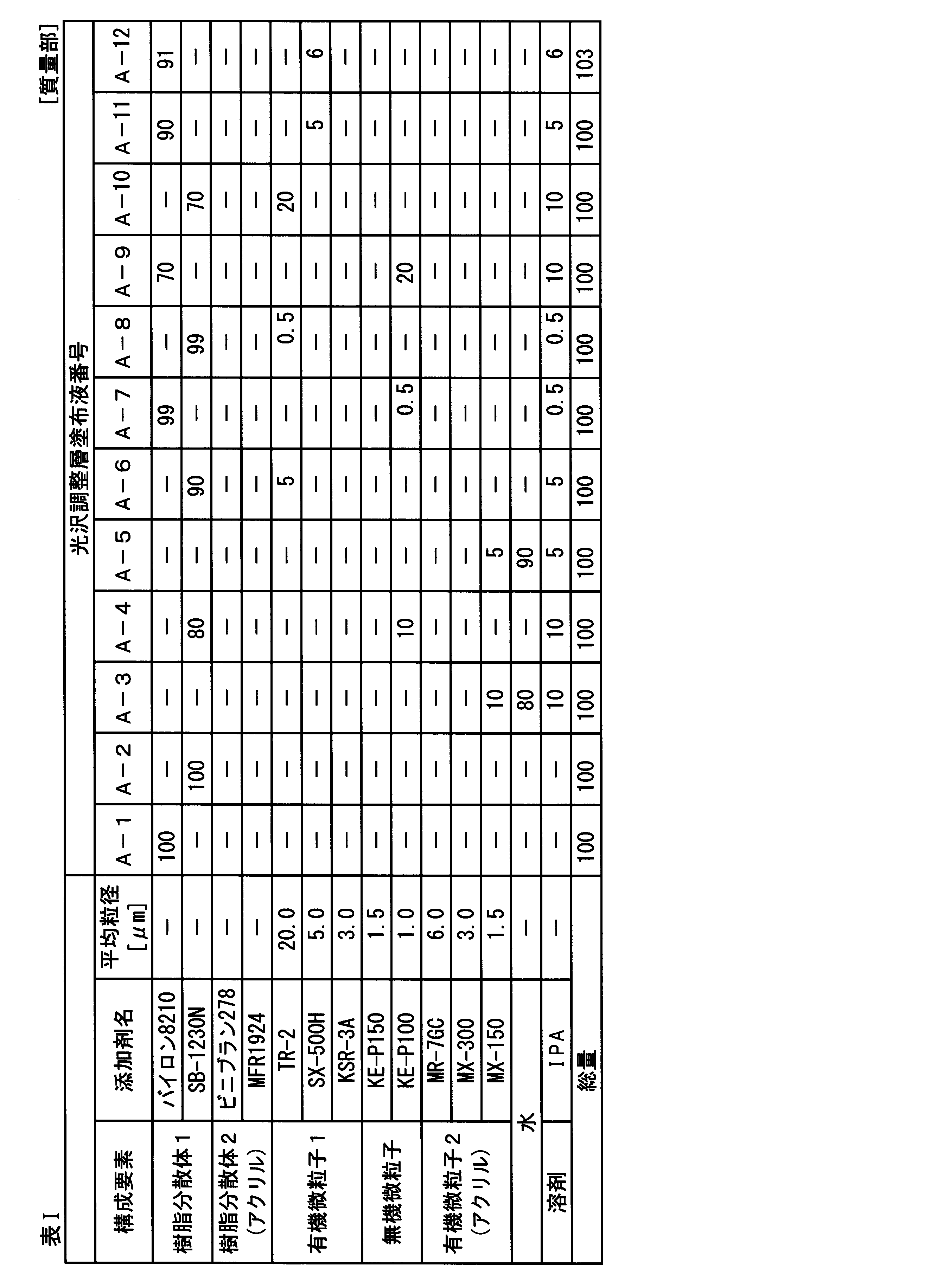
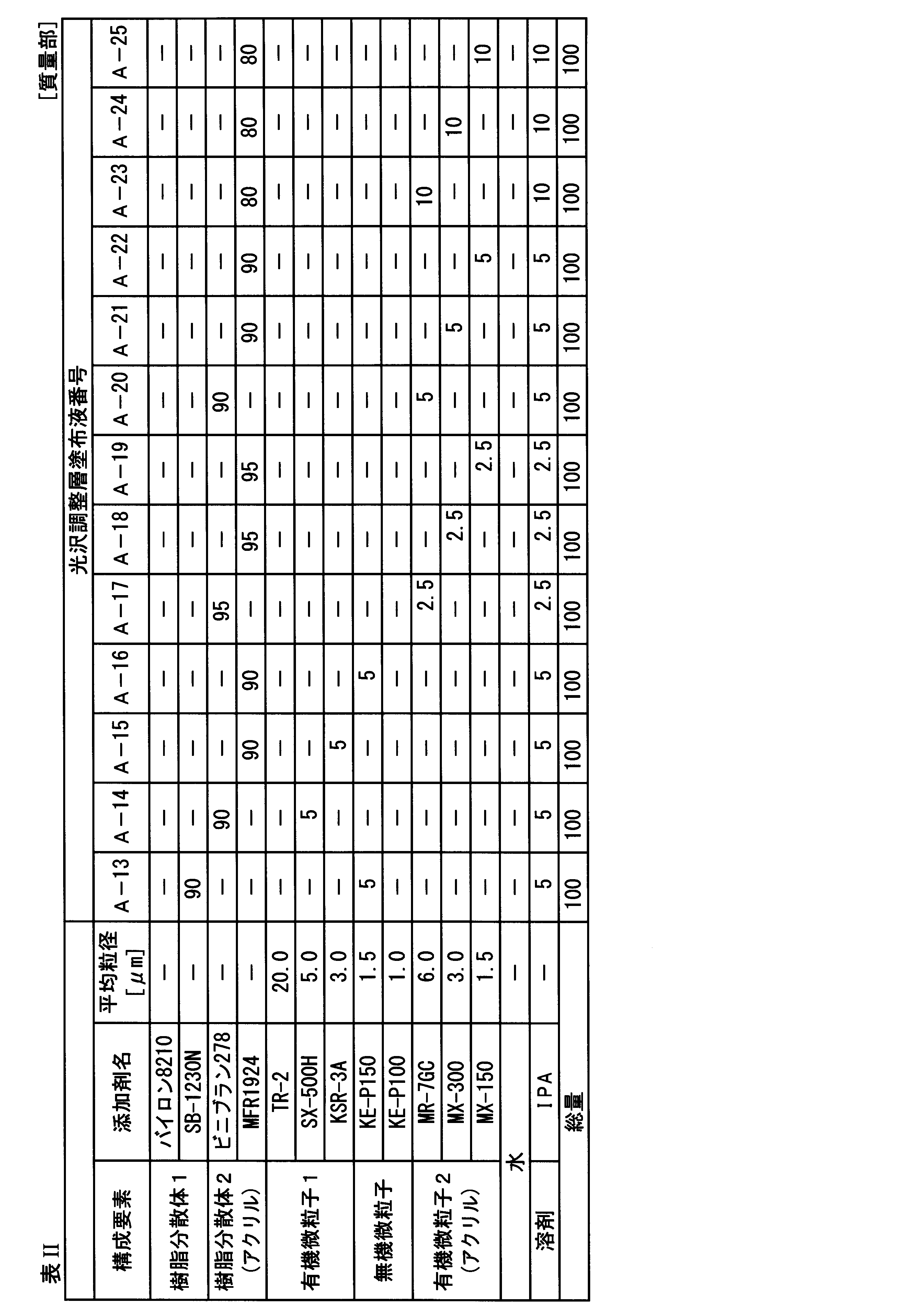
上記、表I及び表IIに略称で記載した各添加剤の詳細は、以下の通りである。
詳細 The details of each additive described in the abbreviations in Table I and Table II are as follows.
(樹脂分散体1)
バイロン8210:東洋紡社製、ポリエステル-ウレタン系樹脂
SB-1230N:ユニチカ社製、アローベースSB-1230N、水系塩素化ポリオレフィン
(樹脂分散体2(アクリル系))
ビニブラン278:日信化学工業社製、塩ビ・アクリル共重合樹脂
MFR1924:Michelman社製、アクリル樹脂
(有機微粒子1)
TR-2:東レ社製、ナイロン微粒子、平均粒径:20μm
SX-500H:綜研化学社製、スチレン微粒子、平均粒径:5μm
KSR-3A:綜研化学社製、スチレン微粒子、平均粒径:3μm
(無機微粒子)
KE-P150:日本触媒社製、シーホスターKE-P150、シリカ微粒子、平均粒径:1.5μm
KE-P100:日本触媒社製、シーホスターKE-P100、シリカ微粒子、平均粒径:1.0μm
(有機微粒子2(アクリル系))
MR-7GC:綜研化学社製、ケミスノーMR-7GC、アクリル微粒子、平均粒径:6μm
MX-300:綜研化学社製、ケミスノーMX-300、アクリル微粒子、平均粒径:3μm
MX-150:綜研化学社製、ケミスノーMX-150、アクリル微粒子、平均粒径:1.5μm。 (Resin dispersion 1)
Byron 8210: Toyobo, polyester-urethane resin SB-1230N: Unitika, Arrowbase SB-1230N, aqueous chlorinated polyolefin (Resin dispersion 2 (acrylic))
VINIBLAN 278: PVC / acrylic copolymer resin manufactured by Nissin Chemical Co., Ltd. MFR1924: Acrylic resin manufactured by Michelman (organic fine particles 1)
TR-2: manufactured by Toray Industries, nylon fine particles, average particle size: 20 μm
SX-500H: manufactured by Soken Chemical Co., Ltd., styrene fine particles, average particle size: 5 μm
KSR-3A: manufactured by Soken Chemical Co., Ltd., styrene fine particles, average particle size: 3 μm
(Inorganic fine particles)
KE-P150: Nippon Shokubai Co., Ltd., Seahoster KE-P150, silica fine particles, average particle size: 1.5 μm
KE-P100: Nippon Shokubai Co., Ltd., Seahoster KE-P100, silica fine particles, average particle size: 1.0 μm
(Organic fine particles 2 (acrylic))
MR-7GC: manufactured by Soken Chemical Co., Ltd., Chemisnow MR-7GC, acrylic fine particles, average particle size: 6 μm
MX-300: manufactured by Soken Chemical Co., Ltd., Chemisnow MX-300, acrylic fine particles, average particle size: 3 μm
MX-150: Chemisnow MX-150, manufactured by Soken Chemical Co., Ltd., acrylic fine particles, average particle size: 1.5 μm.
《画像記録層形成用のインクの調製》
下記の方法に従って、活性光線硬化型インクであるインクB-1~B-5を調製した。 << Preparation of ink for forming image recording layer >>
According to the following method, inks B-1 to B-5, which are actinic ray curable inks, were prepared.
下記の方法に従って、活性光線硬化型インクであるインクB-1~B-5を調製した。 << Preparation of ink for forming image recording layer >>
According to the following method, inks B-1 to B-5, which are actinic ray curable inks, were prepared.
〔インクB-1の調製〕
下記に示す構成で各化合物を混合し、混合液を50℃で加熱攪拌してインクを調製した。次いで、ADVANTEC社製のテフロン(登録商標)3μmメンブランフィルターで濾過して、活性光線硬化型インクであるインクB-1を調製した。 [Preparation of Ink B-1]
Each compound was mixed with the composition shown below, and the mixture was heated and stirred at 50 ° C. to prepare an ink. Then, the mixture was filtered through a Teflon (registered trademark) 3 μm membrane filter manufactured by ADVANTEC to prepare an ink B-1 as an actinic ray-curable ink.
〈色材〉
顔料分散液a(下記参照) 12.5質量部
〈光重合性化合物1〉
APG-200(NKエステルAPG-200、新中村化学工業社製、トリプロピレングリコールジアクリレート) 20.2質量部
SR355(Sartomer社製、ジトリメチロールプロパンテトラアクリレート) 13.0質量部
A-9550(NKエステルA-9550、新中村化学社製、ジペンタエリスリトールポリアクリレート) 13.0質量部
ETERCURE6234(長興化学、エポキシアクリレートオリゴマー)
5.0質量部
〈光重合性化合物2:ClogP4.0~7.0〉
Miramer M360(Miwon社製、トリメチロールプロパン3PO変性トリアクリレート、分子量:471、ClogP値:4.90) 15.0質量部
Miramer M166(Miwon社製、ノニルフェノール8EO変性アクリレート、分子量:626、ClogP値:6.42) 10.0質量部
〈界面活性剤〉
BYK-307(ビックケミージャパン社製、ポリエーテル変性ポリジメチルシロキサン) 0.1質量部
〈光開始剤〉
イルガキュア819(BASF社製、ビス(2,4,6-トリメチルベンゾイル)-フェニルフォスフィンオキサイド) 4.0質量部
イルガキュア369(BASF社製、2-ベンジル-2-ジメチルアミノ-1-(4-モルホリノフェニル)-ブタノン-1) 3.0質量部
DETX(Lambson社製、2,4-ジエチルチオキサントン) 2.0質量部
〈増感助剤〉
スピードキュアEHA(Lambson社製、3級アミン化合物) 2.0質量部
〈重合禁止剤〉
UV-10(BASF社製、イルガスタブUV-10)
〈顔料分散液aの調製〉
以下に示す2種の化合物を、ステンレスビーカーに入れ、これを65℃のホットプレート上で加熱しながら1時間加熱攪拌して、混合液を調製した。 <Color materials>
Pigment dispersion liquid a (see below) 12.5 parts by mass <Photopolymerizable compound 1>
APG-200 (NK ester APG-200, manufactured by Shin-Nakamura Chemical Co., Ltd., tripropylene glycol diacrylate) 20.2 parts by mass SR355 (manufactured by Sartomer, ditrimethylolpropane tetraacrylate) 13.0 parts by mass A-9550 (NK Ester A-9550, manufactured by Shin-Nakamura Chemical Co., Ltd., dipentaerythritol polyacrylate) 13.0 parts by mass ETERCURE 6234 (Changko Chemical, epoxy acrylate oligomer)
5.0 parts by mass <Photopolymerizable compound 2: ClogP 4.0 to 7.0>
Miramer M360 (manufactured by Miwon, trimethylolpropane 3PO modified triacrylate, molecular weight: 471, ClogP value: 4.90) 15.0 parts by mass Miramer M166 (manufactured by Miwon, nonylphenol 8EO modified acrylate, molecular weight: 626, ClogP value: 6.42) 10.0 parts by mass <surfactant>
BYK-307 (manufactured by BYK Japan KK, polyether-modified polydimethylsiloxane) 0.1 parts by mass <photoinitiator>
Irgacure 819 (manufactured by BASF, bis (2,4,6-trimethylbenzoyl) -phenylphosphine oxide) 4.0 parts by mass Irgacure 369 (manufactured by BASF, 2-benzyl-2-dimethylamino-1- (4- Morpholinophenyl) -butanone-1) 3.0 parts by mass DETX (manufactured by Lambson, 2,4-diethylthioxanthone) 2.0 parts by mass <Sensitization aid>
2.0 parts by mass of Speed Cure EHA (tertiary amine compound, manufactured by Lambson) <Polymerization inhibitor>
UV-10 (Ilgas Tab UV-10, manufactured by BASF)
<Preparation of pigment dispersion a>
The following two compounds were placed in a stainless beaker, and heated and stirred for 1 hour while being heated on a hot plate at 65 ° C. to prepare a mixed solution.
顔料分散液a(下記参照) 12.5質量部
〈光重合性化合物1〉
APG-200(NKエステルAPG-200、新中村化学工業社製、トリプロピレングリコールジアクリレート) 20.2質量部
SR355(Sartomer社製、ジトリメチロールプロパンテトラアクリレート) 13.0質量部
A-9550(NKエステルA-9550、新中村化学社製、ジペンタエリスリトールポリアクリレート) 13.0質量部
ETERCURE6234(長興化学、エポキシアクリレートオリゴマー)
5.0質量部
〈光重合性化合物2:ClogP4.0~7.0〉
Miramer M360(Miwon社製、トリメチロールプロパン3PO変性トリアクリレート、分子量:471、ClogP値:4.90) 15.0質量部
Miramer M166(Miwon社製、ノニルフェノール8EO変性アクリレート、分子量:626、ClogP値:6.42) 10.0質量部
〈界面活性剤〉
BYK-307(ビックケミージャパン社製、ポリエーテル変性ポリジメチルシロキサン) 0.1質量部
〈光開始剤〉
イルガキュア819(BASF社製、ビス(2,4,6-トリメチルベンゾイル)-フェニルフォスフィンオキサイド) 4.0質量部
イルガキュア369(BASF社製、2-ベンジル-2-ジメチルアミノ-1-(4-モルホリノフェニル)-ブタノン-1) 3.0質量部
DETX(Lambson社製、2,4-ジエチルチオキサントン) 2.0質量部
〈増感助剤〉
スピードキュアEHA(Lambson社製、3級アミン化合物) 2.0質量部
〈重合禁止剤〉
UV-10(BASF社製、イルガスタブUV-10)
〈顔料分散液aの調製〉
以下に示す2種の化合物を、ステンレスビーカーに入れ、これを65℃のホットプレート上で加熱しながら1時間加熱攪拌して、混合液を調製した。 <Color materials>
Pigment dispersion liquid a (see below) 12.5 parts by mass <
APG-200 (NK ester APG-200, manufactured by Shin-Nakamura Chemical Co., Ltd., tripropylene glycol diacrylate) 20.2 parts by mass SR355 (manufactured by Sartomer, ditrimethylolpropane tetraacrylate) 13.0 parts by mass A-9550 (NK Ester A-9550, manufactured by Shin-Nakamura Chemical Co., Ltd., dipentaerythritol polyacrylate) 13.0 parts by mass ETERCURE 6234 (Changko Chemical, epoxy acrylate oligomer)
5.0 parts by mass <Photopolymerizable compound 2: ClogP 4.0 to 7.0>
Miramer M360 (manufactured by Miwon, trimethylolpropane 3PO modified triacrylate, molecular weight: 471, ClogP value: 4.90) 15.0 parts by mass Miramer M166 (manufactured by Miwon, nonylphenol 8EO modified acrylate, molecular weight: 626, ClogP value: 6.42) 10.0 parts by mass <surfactant>
BYK-307 (manufactured by BYK Japan KK, polyether-modified polydimethylsiloxane) 0.1 parts by mass <photoinitiator>
Irgacure 819 (manufactured by BASF, bis (2,4,6-trimethylbenzoyl) -phenylphosphine oxide) 4.0 parts by mass Irgacure 369 (manufactured by BASF, 2-benzyl-2-dimethylamino-1- (4- Morpholinophenyl) -butanone-1) 3.0 parts by mass DETX (manufactured by Lambson, 2,4-diethylthioxanthone) 2.0 parts by mass <Sensitization aid>
2.0 parts by mass of Speed Cure EHA (tertiary amine compound, manufactured by Lambson) <Polymerization inhibitor>
UV-10 (Ilgas Tab UV-10, manufactured by BASF)
<Preparation of pigment dispersion a>
The following two compounds were placed in a stainless beaker, and heated and stirred for 1 hour while being heated on a hot plate at 65 ° C. to prepare a mixed solution.
EFKA4130(BASF社製) 9.0質量部
APG-100(ジプロピレングリコールジアクリレート、新中村化学社製 分子量242) 71質量部
混合液を室温まで冷却し、さらに以下に示す顔料を加えた。この溶液を、直径0.5mmのジルコニアビーズ200gと共にガラス瓶に入れて密栓し、ペイントシェーカーにて5時間分散処理した。その後、ジルコニアビーズを除去して、顔料分散液aを得た。 EFKA4130 (manufactured by BASF) 9.0 parts by mass APG-100 (dipropylene glycol diacrylate, molecular weight 242 manufactured by Shin-Nakamura Chemical Co., Ltd.) 71 parts by mass The mixture was cooled to room temperature, and the following pigment was further added. This solution was put in a glass bottle together with 200 g of zirconia beads having a diameter of 0.5 mm, sealed, and subjected to a dispersion treatment with a paint shaker for 5 hours. Thereafter, the zirconia beads were removed to obtain a pigment dispersion a.
Pigment Black 7(三菱化学社製、MA7) 20質量部
〔インクB-2~B-5の調製〕
上記インクB-1の調製において、各添加剤の種類、添加量を、表IIIに記載の構成に変更した以外は同様にして、インクB-2~B-5を調製した。なお、B-2~B-5の調製においては、混合液の加熱温度は85℃で行った。 Pigment Black 7 (MA7, manufactured by Mitsubishi Chemical Corporation) 20 parts by mass [Preparation of inks B-2 to B-5]
Ink B-2 to B-5 were prepared in the same manner as in the preparation of Ink B-1, except that the type and amount of each additive were changed to those shown in Table III. In the preparation of B-2 to B-5, the heating temperature of the mixed solution was 85 ° C.
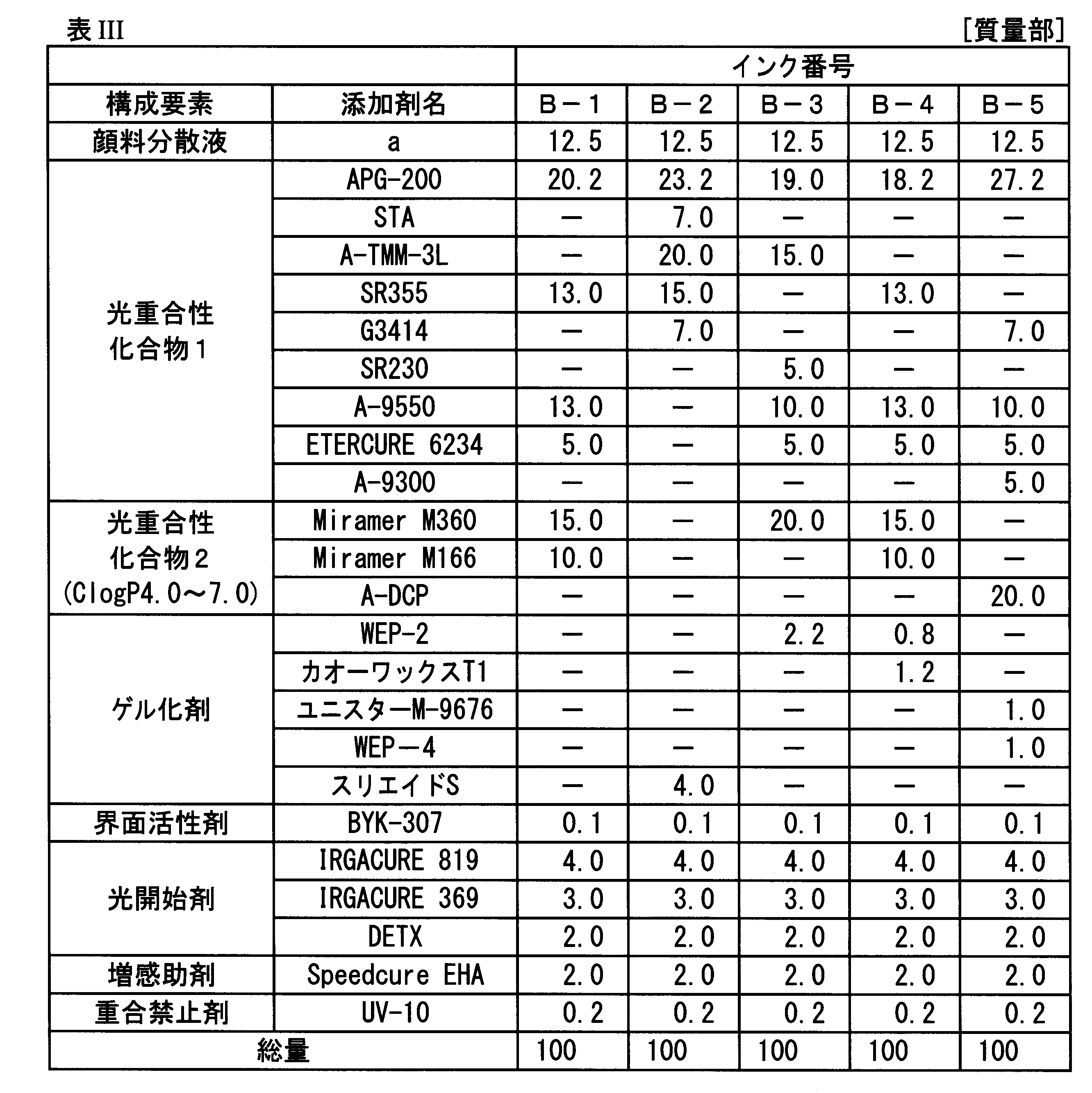
上記、表IIIに略称で記載した各添加剤の詳細は、以下のとおりである。
詳細 The details of each additive described above in Table III by abbreviations are as follows.
〈光重合性化合物1〉
APG-200:NKエステルAPG-200、新中村化学工業社製、トリプロピレングリコールジアクリレート
STA:大阪有機社製、オクタデシルアクリレート
A-TMM-3L:NKエステルA-TMM-3L、新中村化学社製、テトラメチロールメタントリアクリレート
SR355:Sartomer社製、ジトリメチロールプロパンテトラアクリレート
G3414:GENOMER3414、RAHN社製、ポリエステルアクリレート
SR230:Sartomer社製、ジエチレングリコールジアクリレート
A-9550:NKエステルA-9550、新中村化学社製、ジペンタエリスリトールポリアクリレート
ETERCURE6234:長興化学、エポキシアクリレートオリゴマー
A-9300:NKエステルA-9300、新中村化学社製、イソシアヌレートトリアクリレート。 <Photopolymerizable compound 1>
APG-200: NK ester APG-200, manufactured by Shin-Nakamura Chemical Co., Ltd., tripropylene glycol diacrylate STA: manufactured by Osaka Organic Co., Ltd., octadecyl acrylate A-TMM-3L: NK ester A-TMM-3L, manufactured by Shin-Nakamura Chemical , Tetramethylol methane triacrylate SR355: manufactured by Sartomer, ditrimethylolpropane tetraacrylate G3414: GENOMER 3414, manufactured by RAHN, polyester acrylate SR230: manufactured by Sartomer, diethylene glycol diacrylate A-9550: NK ester A-9550, Shin-Nakamura Chemical Co., Ltd. Dipentaerythritol polyacrylate ETERCURE 6234: Choko Chemical, epoxy acrylate oligomer A-9300: NK ester A-9 00, Shin-Nakamura Chemical Co., Ltd., isocyanurate triacrylate.
APG-200:NKエステルAPG-200、新中村化学工業社製、トリプロピレングリコールジアクリレート
STA:大阪有機社製、オクタデシルアクリレート
A-TMM-3L:NKエステルA-TMM-3L、新中村化学社製、テトラメチロールメタントリアクリレート
SR355:Sartomer社製、ジトリメチロールプロパンテトラアクリレート
G3414:GENOMER3414、RAHN社製、ポリエステルアクリレート
SR230:Sartomer社製、ジエチレングリコールジアクリレート
A-9550:NKエステルA-9550、新中村化学社製、ジペンタエリスリトールポリアクリレート
ETERCURE6234:長興化学、エポキシアクリレートオリゴマー
A-9300:NKエステルA-9300、新中村化学社製、イソシアヌレートトリアクリレート。 <
APG-200: NK ester APG-200, manufactured by Shin-Nakamura Chemical Co., Ltd., tripropylene glycol diacrylate STA: manufactured by Osaka Organic Co., Ltd., octadecyl acrylate A-TMM-3L: NK ester A-TMM-3L, manufactured by Shin-Nakamura Chemical , Tetramethylol methane triacrylate SR355: manufactured by Sartomer, ditrimethylolpropane tetraacrylate G3414: GENOMER 3414, manufactured by RAHN, polyester acrylate SR230: manufactured by Sartomer, diethylene glycol diacrylate A-9550: NK ester A-9550, Shin-Nakamura Chemical Co., Ltd. Dipentaerythritol polyacrylate ETERCURE 6234: Choko Chemical, epoxy acrylate oligomer A-9300: NK ester A-9 00, Shin-Nakamura Chemical Co., Ltd., isocyanurate triacrylate.
〈光重合性化合物2:ClogP4.0~7.0〉
Miramer M360:Miwon社製、トリメチロールプロパン3PO変性トリアクリレート、分子量:471、ClogP値:4.90
Miramer M166:Miwon社製、ノニルフェノール8EO変性アクリレート、分子量:626、ClogP値:6.42
A-DCP:NKエステルA-DCP、新中村化学社製、トリシクロデカンジメタノールジアクリレート、分子量:304、ClogP値:4.69。 <Photopolymerizable compound 2: ClogP 4.0 to 7.0>
Miramer M360: manufactured by Miwon, trimethylolpropane 3PO-modified triacrylate, molecular weight: 471, ClogP value: 4.90
Miramer M166: Nonylphenol 8EO-modified acrylate, manufactured by Miwon, molecular weight: 626, ClogP value: 6.42
A-DCP: NK ester A-DCP, manufactured by Shin-Nakamura Chemical Co., Ltd., tricyclodecane dimethanol diacrylate, molecular weight: 304, ClogP value: 4.69.
〈ゲル化剤〉
WEP-2:ニッサンエレクトール WEP-2、日油社製、エステルワックス、融点60℃
カオーワックスT1:花王社製、ジステアリルケトン
ユニスターM-9676:日油社製、ステアリン酸ステアリル
WEP-4:ニッサンエレクトール WEP-4、日油社製、エステルワックス、融点70℃
スリエイドS:日本化成社製、ステアロアミドエチルステアレート。 <Gelling agent>
WEP-2: Nissan Elector WEP-2, manufactured by NOF Corporation, ester wax, melting point 60 ° C
Kaowax T1: Distearyl Ketone Unistar M-9676, manufactured by Kao Corporation; Stearyl stearate WEP-4, manufactured by NOF Corporation; Nissan Electol WEP-4, manufactured by NOF Corporation, ester wax, melting point 70 ° C.
Suriade S: Stearoamidoethyl stearate manufactured by Nippon Kasei Co.
〈界面活性剤〉
BYK-307:ビックケミージャパン社製、ポリエーテル変性ポリジメチルシロキサン。 <Surfactant>
BYK-307: a polyether-modified polydimethylsiloxane manufactured by BYK Japan KK.
BYK-307:ビックケミージャパン社製、ポリエーテル変性ポリジメチルシロキサン。 <Surfactant>
BYK-307: a polyether-modified polydimethylsiloxane manufactured by BYK Japan KK.
〈光開始剤〉
イルガキュア819:BASF社製、ビス(2,4,6-トリメチルベンゾイル)-フェニルフォスフィンオキサイド
イルガキュア369:BASF社製、2-ベンジル-2-ジメチルアミノ-1-(4-モルホリノフェニル)-ブタノン-1
DETX:Lambson社製、2,4-ジエチルチオキサントン。 <Photo initiator>
Irgacure 819: Bis (2,4,6-trimethylbenzoyl) -phenylphosphine oxide, manufactured by BASF Irgacure 369: 2-benzyl-2-dimethylamino-1- (4-morpholinophenyl) -butanone-, manufactured byBASF 1
DETX: 2,4-diethylthioxanthone manufactured by Lambson.
イルガキュア819:BASF社製、ビス(2,4,6-トリメチルベンゾイル)-フェニルフォスフィンオキサイド
イルガキュア369:BASF社製、2-ベンジル-2-ジメチルアミノ-1-(4-モルホリノフェニル)-ブタノン-1
DETX:Lambson社製、2,4-ジエチルチオキサントン。 <Photo initiator>
Irgacure 819: Bis (2,4,6-trimethylbenzoyl) -phenylphosphine oxide, manufactured by BASF Irgacure 369: 2-benzyl-2-dimethylamino-1- (4-morpholinophenyl) -butanone-, manufactured by
DETX: 2,4-diethylthioxanthone manufactured by Lambson.
〈増感助剤〉
スピードキュアEHA:Lambson社製、3級アミン化合物
〈重合禁止剤〉
UV-10:BASF社製、イルガスタブUV-10。 <Sensitization aid>
Speed cure EHA: Lambson's tertiary amine compound <Polymerization inhibitor>
UV-10: Irgas Tab UV-10 manufactured by BASF.
スピードキュアEHA:Lambson社製、3級アミン化合物
〈重合禁止剤〉
UV-10:BASF社製、イルガスタブUV-10。 <Sensitization aid>
Speed cure EHA: Lambson's tertiary amine compound <Polymerization inhibitor>
UV-10: Irgas Tab UV-10 manufactured by BASF.
《画像記録》
〔インクB-1~B-5の60度鏡面光沢度の事前測定〕
上記調製したインクB-1~B-5について、基材として厚さ50μmの透明ポリエチレンテレフタレートフィルム(以下、PETと略記する。)を用い、下記のインクジェット記録方法(スキャン方式)を用いて、60度鏡面光沢度測定用サンプルを作製した。 《Image recording》
[Preliminary measurement of 60-degree specular gloss of inks B-1 to B-5]
For the inks B-1 to B-5 prepared above, a transparent polyethylene terephthalate film (hereinafter abbreviated as PET) having a thickness of 50 μm was used as a substrate, and the ink jet recording method (scan method) described below was used for the ink. A sample for measuring specular gloss was prepared.
(インクジェット記録装置)
各ブラックインクを図4Aに記載の構成からなるピエゾ型インクジェットノズルを備えたインクジェット記録ヘッドを有するインクジェット記録装置に装填した。この装置から、PETフィルム上に各インクを吐出し、ブラックベタ画像を作成した。 (Inkjet recording device)
Each black ink was loaded into an ink jet recording apparatus having an ink jet recording head having a piezo type ink jet nozzle having the configuration shown in FIG. 4A. From this apparatus, each ink was discharged onto a PET film to form a black solid image.
インク供給系は、インクタンク、インク流路、インクジェット記録ヘッド直前のサブインクタンク、フィルター付き配管、ピエゾヘッドからなるものとした。インクジェット記録装置には、解像度が360dpiのピエゾヘッドを、搬送方向に4列配置し、PETフィルムを所定の温度で加熱しながら、1440×1440dpiの記録解像度とした。
The ink supply system was composed of an ink tank, an ink flow path, a sub-ink tank immediately before an inkjet recording head, a pipe with a filter, and a piezo head. In the inkjet recording apparatus, piezo heads having a resolution of 360 dpi were arranged in four rows in the transport direction, and the recording resolution was set to 1440 × 1440 dpi while heating the PET film at a predetermined temperature.
PETフィルムの加熱温度は、ゲル化剤を含有しないインク(B-1及びB-2)は25℃とし、ゲル化剤を含有するインク(B-3~B-5)は40~55℃とした。
The heating temperature of the PET film is 25 ° C. for the ink (B-1 and B-2) containing no gelling agent, and 40 to 55 ° C. for the ink (B-3 to B-5) containing the gelling agent. did.
インクタンクからヘッド部分までインクをゲル化温度Tgel+30℃に加温した。さらに各液滴量が3pLとなるように、ピエゾヘッドに電圧を印加し、単色のブラックベタ画像を形成した。
ま で The ink was heated from the ink tank to the head portion to a gelling temperature Tgel + 30 ° C. Further, a voltage was applied to the piezo head so that the amount of each droplet became 3 pL, to form a monochromatic black solid image.
画像形成後、ヘレウス社製の水冷式LEDランプから、波長395nmの光を照射し、インクを硬化させた。LEDランプ表面から記録媒体面までの距離は50mmとした。このとき、記録媒体表面での最高照度は3.5W/cm2とし、記録媒体の搬送速度は60m/minとした。照射した光量は、400mJ/cm2であった。
After the image formation, the ink was cured by irradiating light having a wavelength of 395 nm from a water-cooled LED lamp manufactured by Heraeus. The distance from the LED lamp surface to the recording medium surface was 50 mm. At this time, the maximum illuminance on the surface of the recording medium was 3.5 W / cm 2, and the conveyance speed of the recording medium was 60 m / min. The irradiated light amount was 400 mJ / cm 2 .
(ブラックベタ画像の60度鏡面光沢度の測定)
上記作成したブラックベタ画像について、JIS Z 8741で規定された測定方法に準拠して、変角光沢度計PG-1M、VGS-10001DP(日本電色工業社製)を用いて測定した。以下に、各インクにより形成したブラックベタ画像の60度鏡面光沢度を示す。なお、カッコ内の温度は、画像形成時のPETフィルム温度を示す。 (Measurement of 60-degree specular glossiness of black solid image)
The black solid image created above was measured using a gonio-gloss meter PG-1M and VGS-10001DP (manufactured by Nippon Denshoku Industries Co., Ltd.) in accordance with the measurement method specified in JIS Z8741. The 60 ° specular gloss of a solid black image formed by each ink is shown below. The temperature in parentheses indicates the PET film temperature during image formation.
インクB-1:光沢度=81(画像形成温度:25℃)
インクB-2:光沢度=15(画像形成温度:25℃)
インクB-3:光沢度=52(画像形成温度:55℃)
インクB-4:光沢度=36(画像形成温度:40℃)
インクB-5:光沢度=21(画像形成温度:25℃)。 Ink B-1: Gloss = 81 (image forming temperature: 25 ° C.)
Ink B-2: Gloss = 15 (image forming temperature: 25 ° C.)
Ink B-3: Gloss = 52 (image forming temperature: 55 ° C.)
Ink B-4: Gloss = 36 (image forming temperature: 40 ° C.)
Ink B-5: Gloss = 21 (image formation temperature: 25 ° C.).
〔画像記録材料の作製〕
下記の方法に従って、上記測定したインクB-1~B-5の60度鏡面光沢度の情報を基に、表IVに記載の各60度鏡面光沢度を有する光沢調整層と組み合わせて、画像記録材料4~33を形成した。なお、表IVに記載の画像記録材料1~3は、光沢調整層を設けない比較例である。 (Preparation of image recording material)
According to the following method, based on the information on the 60-degree specular glossiness of the inks B-1 to B-5 measured above, image recording was performed in combination with a gloss adjustment layer having each 60-degree specular glossiness described in Table IV. Materials 4-33 were formed. Theimage recording materials 1 to 3 shown in Table IV are comparative examples in which no gloss adjusting layer was provided.
下記の方法に従って、上記測定したインクB-1~B-5の60度鏡面光沢度の情報を基に、表IVに記載の各60度鏡面光沢度を有する光沢調整層と組み合わせて、画像記録材料4~33を形成した。なお、表IVに記載の画像記録材料1~3は、光沢調整層を設けない比較例である。 (Preparation of image recording material)
According to the following method, based on the information on the 60-degree specular glossiness of the inks B-1 to B-5 measured above, image recording was performed in combination with a gloss adjustment layer having each 60-degree specular glossiness described in Table IV. Materials 4-33 were formed. The
以下の各画像形成に用いた基材の詳細は、以下の通りである。
基材 Details of the base material used for the following image formation are as follows.
(基材)
NewDV:北越紀州販売社製、再生紙(光沢度=7)
PET:厚さ50μmの透明ポリエチレンテレフタレートフィルム(光沢度:95)
PVC:PSL-685、カネカ社製、ペーストPVCを100μmの膜厚で塗布し乾燥させた原反(光沢度:20)
OKTC:OKトップコートプラス、王子製紙社製(光沢度=40)
PP:コロナ処理二軸延伸ポリプロピレンフィルムOPP、オカモト社製。 (Base material)
New DV: manufactured by Hokuetsu Kishu Sales Co., Ltd., recycled paper (gloss = 7)
PET: 50 μm thick transparent polyethylene terephthalate film (gloss: 95)
PVC: PSL-685, manufactured by Kaneka Corporation, paste PVC having a thickness of 100 μm applied and dried (glossiness: 20)
OKTC: OK Topcoat Plus, manufactured by Oji Paper (gloss level = 40)
PP: corona-treated biaxially oriented polypropylene film OPP, manufactured by Okamoto Corporation.
(画像記録材料1の作製)
基材としてNewDV上に、インクB-1(光沢度=81)を用い、ブラック画像(画像記録層1)を下記のスキャン方式のインクジェット記録装置を用いて、画像記録材料1を作製した。 (Preparation of image recording material 1)
Animage recording material 1 was prepared by using the ink B-1 (gloss = 81) on NewDV as a base material, and using a scan-type inkjet recording apparatus for a black image (image recording layer 1) as described below.
基材としてNewDV上に、インクB-1(光沢度=81)を用い、ブラック画像(画像記録層1)を下記のスキャン方式のインクジェット記録装置を用いて、画像記録材料1を作製した。 (Preparation of image recording material 1)
An
〈シリアル記録方式のインクジェット記録装置を用いた画像記録層1の形成〉
図5に記載のシリアル記録方式(スキャン方式ともいう。)のインクジェット記録装置を用いた。 <Formation ofImage Recording Layer 1 Using Serial Recording Type Inkjet Recording Apparatus>
An ink jet recording apparatus of a serial recording system (also referred to as a scanning system) shown in FIG. 5 was used.
図5に記載のシリアル記録方式(スキャン方式ともいう。)のインクジェット記録装置を用いた。 <Formation of
An ink jet recording apparatus of a serial recording system (also referred to as a scanning system) shown in FIG. 5 was used.
インク供給系は、インクタンク、供給パイプ、ヘッド直前の前室インクタンク、フィルター付き配管、ピエゾヘッドからなり、前室タンクからヘッド部分まで断熱して50℃の加温を行った。ピエゾヘッドは、2~15pLのマルチサイズドットを720×720dpi(dpiとは、2.54cm当たりのドット数を表す)の解像度で吐出できるよう駆動して、インクB-1を、図1の画像形成層に示すように、印字率が50%となるように、画像を離間した状態で形成した。キャリッジの走査速度は750mm/sとした。着弾した後、キャリッジ両脇に設けた照射手段により、活性光線を瞬時(着弾後1秒未満)に照射して画像形成を行った。照射手段は、高圧水銀ランプVZero085(INTEGRATION TECHNOLOGY社製)を用い、140W/cmのエネルギー密度、照度20mJ/cm2(積算光量)で紫外線を照射してインクを硬化して、画像記録層1を形成し、画像記録材料1を作製した。
The ink supply system was composed of an ink tank, a supply pipe, an ink tank in the front chamber immediately before the head, a piping with a filter, and a piezo head. The piezo head is driven so that multi-size dots of 2 to 15 pL can be ejected at a resolution of 720 × 720 dpi (dpi represents the number of dots per 2.54 cm), and the ink B-1 is driven by the image shown in FIG. As shown in the formation layer, the images were formed in a separated state so that the printing rate was 50%. The scanning speed of the carriage was 750 mm / s. After the impact, the actinic rays were instantaneously (less than 1 second after impact) by the irradiation means provided on both sides of the carriage to form an image. The irradiating means uses a high-pressure mercury lamp VZero085 (manufactured by INTEGRATION TECHNOLOGY), and irradiates the ink with ultraviolet light at an energy density of 140 W / cm and an illuminance of 20 mJ / cm 2 (integrated light quantity) to cure the ink. Thus, an image recording material 1 was produced.
(画像記録材料2の作製)
画像記録材料2は、電子写真方式を用いて、基材であるPET上にトナー画像(画像記録層2、光沢度=23)を形成した。 (Preparation of image recording material 2)
As theimage recording material 2, a toner image (image recording layer 2, glossiness = 23) was formed on PET as a base material by using an electrophotographic method.
画像記録材料2は、電子写真方式を用いて、基材であるPET上にトナー画像(画像記録層2、光沢度=23)を形成した。 (Preparation of image recording material 2)
As the
使用したトナーは、下記の方法で調製した。
The used toner was prepared by the following method.
60gのヌクレル(Nucrel)699樹脂(デュポン社によるエチレンメタクリル酸コポリマー)、240gのAC5120樹脂(アライドシグナル(Allied Signal)社によるエチレンアクリル酸コポリマー)、及び1800gのイソパール(Isopar)-L(エクソン社)を、150℃に設定された加熱浴により予熱した。次いで、ロス(Ross)複式遊星形ミキサー内に充填した。これらの成分は、スピード制御設定3で約1.5時間混合して、ペースト状物質を得た。
60 g Nucrel 699 resin (ethylene methacrylic acid copolymer from DuPont), 240 g AC5120 resin (ethylene acrylic acid copolymer from Allied @ Signal), and 1800 g Isopar-L (Exxon) Was preheated with a heating bath set at 150 ° C. It was then charged into a Ross double planetary mixer. These components were mixed for about 1.5 hours at a speed control setting of 3 to give a paste.
次いで、971.75gのペースト状物質を、55.66gのHelliogen Blue顔料7080(BASF社)、4.14gのHelliogen Green顔料(BASF社)、11.5gのステアリン酸アルミニウム(Riedel de Haen社)、及び1257gのイソパールLとともに、クロム鋼研磨媒体を含む1S磨耗機(ユニオンプロセス社)に充填し、58℃で約1.5時間粉砕し、次いで、45℃で10.5時間粉砕を行い、トナーを調製した。トナーには、電荷制御剤をトナー固形物1g当り35mgの量で添加した。
Then, 971.75 g of the paste-like substance was added to 55.66 g of Heliogen Blue pigment 7080 (BASF), 4.14 g of Heliogen Green pigment (BASF), 11.5 g of aluminum stearate (Riedel de Haen), And 1257 g of Isopearl L together with a 1S abrasion machine (Union Process Co., Ltd.) containing a chrome steel polishing medium, pulverized at 58 ° C. for about 1.5 hours, and then pulverized at 45 ° C. for 10.5 hours to obtain a toner. Was prepared. To the toner, a charge control agent was added in an amount of 35 mg / g of toner solids.
次いで、特表2003-520997号公報の図2に記載の液体トナー印刷システムを用いて、図1の画像形成層に示すように、PET上に上記トナーを印字率が50%となる条件で印刷し、画像記録層2を形成した画像記録材料2を作製した。
Then, using the liquid toner printing system shown in FIG. 2 of JP-T-2003-520997, the above toner was printed on PET under the condition that the printing rate was 50% as shown in the image forming layer of FIG. Then, an image recording material 2 on which the image recording layer 2 was formed was produced.
(画像記録材料3の作製)
基材としてPET上に、インクB-4(光沢度=36)によりブラック画像を下記のライン記録方式(シンブルパス方式)のインクジェット記録装置を用いて、画像記録層3を形成し、画像記録材料3を作製した。 (Preparation of image recording material 3)
Animage recording layer 3 is formed on PET as a base material by using an ink jet recording apparatus of the following line recording system (thimble path system) on a black image with ink B-4 (gloss = 36), and an image recording material is formed. 3 was produced.
基材としてPET上に、インクB-4(光沢度=36)によりブラック画像を下記のライン記録方式(シンブルパス方式)のインクジェット記録装置を用いて、画像記録層3を形成し、画像記録材料3を作製した。 (Preparation of image recording material 3)
An
〈ライン記録方式による画像記録層3の形成〉
図4Aに記載のライン記録方式のインクジェット記録装置を用いた。 <Formation ofImage Recording Layer 3 by Line Recording Method>
The line recording type ink jet recording apparatus shown in FIG. 4A was used.
図4Aに記載のライン記録方式のインクジェット記録装置を用いた。 <Formation of
The line recording type ink jet recording apparatus shown in FIG. 4A was used.
インクB-4を図4Aに記載の構成からなるピエゾ型インクジェットノズルを備えたインクジェット記録ヘッドを有するインクジェット記録装置に装填した。この装置から、PETフィルム上にインクB-4を、図1の画像形成層に示すように、印字率が50%となるように、画像を離間した状態で印字して、画像記録層3を形成した。
Ink B-4 was loaded into an ink jet recording apparatus having an ink jet recording head having a piezo type ink jet nozzle having the configuration shown in FIG. 4A. From this apparatus, the ink B-4 was printed on a PET film in a state where the images were separated so that the printing rate was 50%, as shown in the image forming layer in FIG. 1, and the image recording layer 3 was printed. Formed.
インク供給系は、インクタンク、インク流路、インクジェット記録ヘッド直前のサブインクタンク、フィルター付き配管、ピエゾヘッドからなるものとした。インクジェット記録装置には、解像度が360dpiのピエゾヘッドを、搬送方向に4列配置し、PETフィルムを40℃の温度で加熱しながら、1440×1440dpiの記録解像度とした。
The ink supply system was composed of an ink tank, an ink flow path, a sub-ink tank immediately before an inkjet recording head, a pipe with a filter, and a piezo head. In the inkjet recording apparatus, piezo heads having a resolution of 360 dpi were arranged in four rows in the transport direction, and a recording resolution of 1440 × 1440 dpi was set while heating the PET film at a temperature of 40 ° C.
インクタンクからヘッド部分までインクをゲル化温度Tgel+30℃に加温した。さらにインク液滴量が3pLとなるように、ピエゾヘッドに電圧を印加し、単色の格子状のブラック画像を形成した。
ま で The ink was heated from the ink tank to the head portion to a gelling temperature Tgel + 30 ° C. Further, a voltage was applied to the piezo head so that the amount of ink droplets became 3 pL, and a monochromatic lattice-like black image was formed.
画像形成後、ヘレウス社製の水冷式LEDランプから、波長395nmの光を照射し、インクを硬化させた。LEDランプ表面から記録媒体面までの距離は50mmとした。このとき、記録媒体表面での最高照度は3.5W/cm2とし、記録媒体の搬送速度は60m/minとした。照射した光量は、400mJ/cm2であった。
After the image formation, the ink was cured by irradiating light having a wavelength of 395 nm from a water-cooled LED lamp manufactured by Heraeus. The distance from the LED lamp surface to the recording medium surface was 50 mm. At this time, the maximum illuminance on the surface of the recording medium was 3.5 W / cm 2, and the conveyance speed of the recording medium was 60 m / min. The irradiated light amount was 400 mJ / cm 2 .
(画像記録材料4の作製)
上記画像記録材料3の作製において、画像記録層としてインクB-4により形成する画像記録層(光沢度=36)を選択し、画像記録層の光沢度情報を基に、本発明で規定する条件を満たすように、光沢調整層形成用塗布液としてA-3を選択し、光沢度が60の光沢調整層を基材と画像記録層の間に形成し、図1に記載の構成からなる画像記録材料とした以外は同様にして、画像記録材料4を作製した。 (Preparation of image recording material 4)
In the preparation of theimage recording material 3, an image recording layer (gloss = 36) to be formed with the ink B-4 is selected as the image recording layer, and the conditions specified in the present invention based on the gloss information of the image recording layer. A-3 was selected as a coating liquid for forming a gloss adjusting layer so as to satisfy the above, a gloss adjusting layer having a gloss of 60 was formed between the base material and the image recording layer, and an image having the configuration shown in FIG. 1 was formed. An image recording material 4 was produced in the same manner except that the recording material was used.
上記画像記録材料3の作製において、画像記録層としてインクB-4により形成する画像記録層(光沢度=36)を選択し、画像記録層の光沢度情報を基に、本発明で規定する条件を満たすように、光沢調整層形成用塗布液としてA-3を選択し、光沢度が60の光沢調整層を基材と画像記録層の間に形成し、図1に記載の構成からなる画像記録材料とした以外は同様にして、画像記録材料4を作製した。 (Preparation of image recording material 4)
In the preparation of the
〈光沢調整層の形成〉
前記調製した光沢調整層形成用塗布液A-3を用い、基材であるPET上に、前記ライン記録方式のインクジェット記録装置を用い、乾燥後の層厚が8μmとなる条件で印字し、光沢調整層(光沢度=60)を形成した。ただし、活性光線の照射は行わなかった。 <Formation of gloss adjustment layer>
Using the above-prepared coating liquid A-3 for forming a gloss adjusting layer, printing was carried out on PET as a base material under the condition that the layer thickness after drying was 8 μm using the above-mentioned line recording type ink jet recording apparatus. An adjustment layer (gloss = 60) was formed. However, irradiation with actinic rays was not performed.
(画像記録材料5~33の作製)
上記画像記録材料4の作製において、基材の種類、各層形成時の基材の加熱温度、光沢調整層形成用塗布液の種類と光沢形成層の膜厚、画像記録層形成用インク液の種類と画像記録方式について、表IVに記載の組み合わせに変更した以外は同様にして、画像記録材料5~33を作製した。 (Preparation of image recording materials 5-33)
In the preparation of theimage recording material 4, the type of the substrate, the heating temperature of the substrate when forming each layer, the type of the coating liquid for forming the gloss adjusting layer and the thickness of the gloss forming layer, and the type of the ink liquid for forming the image recording layer The image recording materials 5 to 33 were produced in the same manner except that the combination of the recording method and the image recording method were changed to those shown in Table IV.
上記画像記録材料4の作製において、基材の種類、各層形成時の基材の加熱温度、光沢調整層形成用塗布液の種類と光沢形成層の膜厚、画像記録層形成用インク液の種類と画像記録方式について、表IVに記載の組み合わせに変更した以外は同様にして、画像記録材料5~33を作製した。 (Preparation of image recording materials 5-33)
In the preparation of the
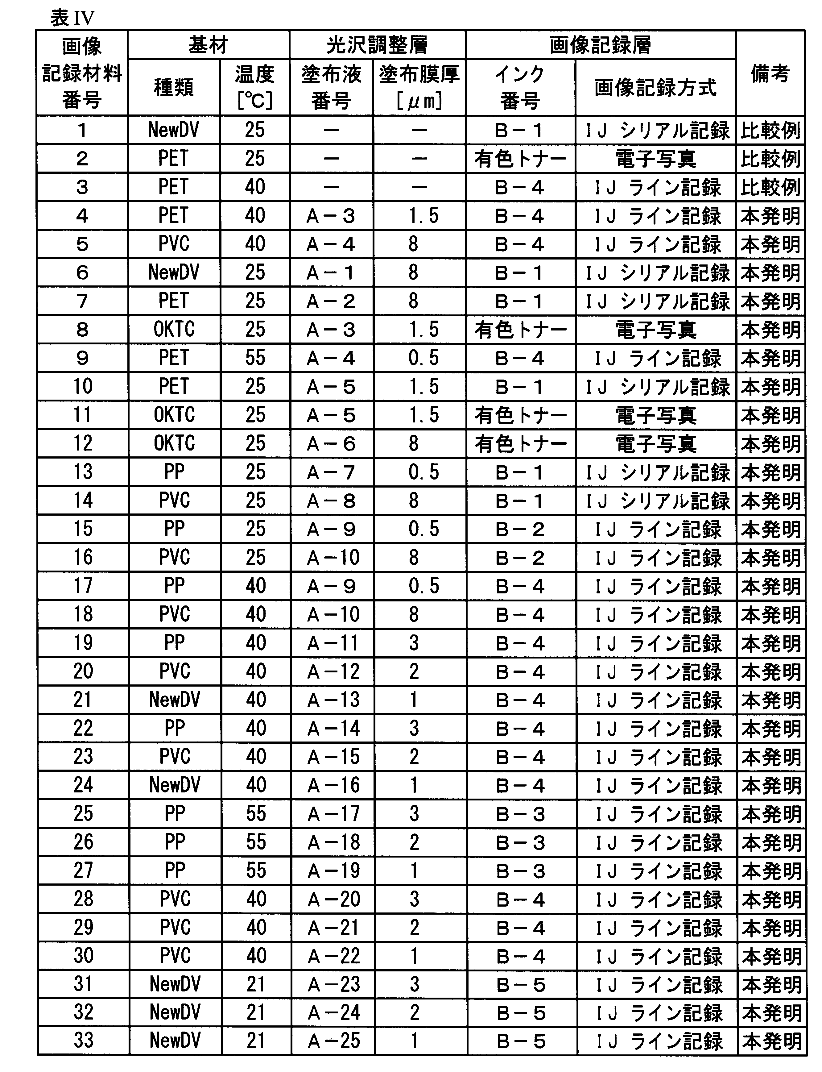
《60度鏡面光沢度の測定》
画像記録層の60度鏡面光沢度については、それぞれの画層記録層形成用のインク液を、PETフィルム上に形成し、形成した画像記録層について、JIS Z 8741で規定された測定方法に準拠して、変角光沢度計PG-1M、VGS-10001DP(日本電色工業社製)を用いて、画像記録層の60度鏡面光沢度G1測定した。 << Measurement of 60 degree specular gloss >>
Regarding the 60-degree specular glossiness of the image recording layer, an ink liquid for forming each image recording layer was formed on a PET film, and the formed image recording layer was measured in accordance with the measurement method specified in JIS Z8741. Then, using a gonio-gloss meter PG-1M and VGS-10001DP (manufactured by Nippon Denshoku Industries Co., Ltd.), a 60-degree specular gloss G1 of the image recording layer was measured.
また、光沢調整層の60度鏡面光沢度については、画像記録材料4~33において、基材上に各光沢調整層を形成したサンプルを用い、JIS Z 8741で規定された測定方法に準拠して、変角光沢度計PG-1M、VGS-10001DP(日本電色工業社製)により、光沢調整層の60度鏡面光沢度G2測定した。
Regarding the 60-degree specular glossiness of the gloss adjusting layer, a sample in which each gloss adjusting layer is formed on a base material in the image recording materials 4 to 33 is used in accordance with a measurement method defined in JIS Z 8741. The gloss adjusting layer was measured for a 60-degree specular gloss G2 using a gonio-gloss meter PG-1M and VGS-10001DP (manufactured by Nippon Denshoku Industries Co., Ltd.).
次いで、光沢度差ΔG(G2-G1)を求めた。なお、光沢調整層を有していない画像記録材料1~3については、参考値と基材の光沢度と画像記録層の光沢度差を示した。
Next, the gloss difference ΔG (G2-G1) was determined. For the image recording materials 1 to 3 having no gloss adjusting layer, the reference values, the glossiness of the substrate, and the glossiness difference of the image recording layer are shown.
《画像記録材料の評価》
上記作製した各画像記録材料について、下記の各評価を行った。 << Evaluation of image recording material >>
The following evaluations were performed for each of the image recording materials prepared above.
上記作製した各画像記録材料について、下記の各評価を行った。 << Evaluation of image recording material >>
The following evaluations were performed for each of the image recording materials prepared above.
〔光沢性の評価〕
上記測定に求めた光沢度差ΔG(G2-G1)又は基材と画像記録層の光沢度差について、下記の評価ランクに従って、光沢度の評価を行った。 [Evaluation of gloss]
With respect to the gloss difference ΔG (G2-G1) obtained in the above measurement or the gloss difference between the substrate and the image recording layer, the gloss was evaluated according to the following evaluation rank.
◎:光沢度差の絶対値が、10以下である
○:光沢度差の絶対値が、11以上、20未満である
△:光沢度差の絶対値が、20以上、30未満である
×:光沢度差の絶対値が30以上である。 ◎: Absolute value of gloss difference is 10 or less :: Absolute value of gloss difference is 11 or more and less than 20 △: Absolute value of gloss difference is 20 or more and less than 30 ×: The absolute value of the gloss difference is 30 or more.
〔密着性の評価〕
画像記録層表面に、カッターにより1mm間隔で、縦横にそれぞれ6本の格子状の切込みを入れ、25個の碁盤状のマス目を作成し、その表面に3M社製のセロファンテープを貼付し、当該セロファンテープを垂直方向に引きはがし、剥離されずに残留した画像記録層のマス目数をカウントし、これを密着性の尺度とした。 [Evaluation of adhesion]
On the surface of the image recording layer, six lattice-shaped incisions were made vertically and horizontally at intervals of 1 mm with a cutter to form 25 grids, and 3M cellophane tape was attached to the surface, The cellophane tape was peeled off in the vertical direction, and the number of squares of the image recording layer remaining without being peeled was counted, and this was used as a measure of adhesion.
〔濡れ性の評価〕
上記作製した各画像記録材料の10nm×10cmの面積の画層記録層表面を目視観察し、形成時に発生しているハジキ等による白ヌケ故障数をカウント、下記の基準に従って、濡れ性の評価を行った。 [Evaluation of wettability]
The surface of the image recording layer having an area of 10 nm × 10 cm of each of the image recording materials prepared above was visually observed, the number of white spot defects caused by repelling or the like generated during formation was counted, and the wettability was evaluated according to the following criteria. went.
5:白ヌケ故障の発生は全くない
4:白ヌケ故障の発生数は1~2箇所程度であり、実用上全く問題ないレベル
3:3~4箇所の白ヌケ故障はあるが、実用上問題ないレベル
2:5~6箇所の白ヌケ故障はあるが、実用上許容される品質である
1:7箇所以上で白ヌケ故障が発生しており、実用上問題となる品質である
以上により得られた結果を、表Vに示す。 5: There is no occurrence of white spot failures 4: The number of occurrences of white spot failures is about 1 to 2 places, and there is no practical problem at all. 3: There are 3 to 4 white spots failures, but there is a practical problem No level 2: There are 5 to 6 white spots, but the quality is acceptable for practical use 1: 1: 7 or more spots have white spots, which is a quality that is problematic for practical use The results obtained are shown in Table V.

表Vに記載の結果より明らかなように、本発明で規定する画像記録層の光沢度情報を基に、所望の光沢度となるように設計した光沢調整層を有する本発明の画像記録材料は、光沢調整層を有していない比較例に対し、光沢性に優れた画像が得られ、かつ密着性及び濡れ性に優れた画像を得ることができる。
As is clear from the results described in Table V, the image recording material of the present invention having a gloss adjusting layer designed to have a desired gloss based on the gloss information of the image recording layer specified in the present invention is As compared with the comparative example having no gloss adjusting layer, an image excellent in gloss can be obtained, and an image excellent in adhesion and wettability can be obtained.
より好ましくは、光沢調整層の光沢度G2と画像記録層の光沢度G1との光沢度差ΔG(G2-G1)を、-20~+20の範囲内とすること、更には、光沢度差ΔG(G2-G1)を-10~+5の範囲内とすることにより、画像形成部(画像記録層の光沢度G1)と、非画像形成部(光沢調整層の光沢度G2)との光沢度差が縮小し、違和感の少ない画像を形成することができる点で好ましい。
More preferably, the gloss difference ΔG (G2−G1) between the gloss G2 of the gloss adjusting layer and the gloss G1 of the image recording layer is in the range of −20 to +20, and further, the gloss difference ΔG By setting (G2−G1) in the range of −10 to +5, the gloss difference between the image forming portion (the glossiness G1 of the image recording layer) and the non-image forming portion (the glossiness G2 of the gloss adjustment layer) is obtained. This is preferable in that an image with reduced discomfort can be formed.
本発明の画像記録方法は、染料や顔料を含むインクジェットインクを用いて画像形成するインクジェット記録方式や、色材を含むトナーを電子写真プロセスにより、紙や薄膜フィルム上に付与・定着して画像形成する電子写真方式や、各種基材上に、印刷用インキを用いて絵柄等を形成するスクリーン印刷法やオフセット印刷法に適用でき、画像形成部と非画像形成部間の光沢差を縮小し、かつ密着性及び濡れ性に優れた画像の形成に好適に利用できる。
The image recording method of the present invention includes an ink jet recording method in which an image is formed using an ink jet ink containing a dye or a pigment, and an image forming method in which a toner containing a coloring material is applied and fixed on paper or a thin film by an electrophotographic process. To the screen printing method and the offset printing method to form a pattern etc. using printing ink on various substrates, and to reduce the gloss difference between the image forming part and the non-image forming part, In addition, it can be suitably used for forming an image having excellent adhesion and wettability.
1 画像記録材料
2、12 基材
3 光沢調整層
4 画像記録層
5 微粒子
10 ライン記録方式のインクジェット記録装置
14、24 インク吐出用記録ヘッド
16、26 ヘッドキャリッジ
18、28 活性光線照射部
19 温度制御部
20 シリアル記録方式のインクジェット記録装置
27 ガイド部
30 インク供給手段
31 インクカートリッジ
G1 画像記録層の光沢度
G2 光沢調整層の光沢度
hd 光沢調整層の膜厚
r 微粒子の平均粒径 DESCRIPTION OFSYMBOLS 1 Image recording material 2, 12 Substrate 3 Gloss adjustment layer 4 Image recording layer 5 Fine particles 10 Line recording type inkjet recording apparatus 14, 24 Ink ejection recording head 16, 26 Head carriage 18, 28 Active ray irradiation part 19 Temperature control Unit 20 serial recording type inkjet recording device 27 guide unit 30 ink supply means 31 ink cartridge G1 glossiness of image recording layer G2 glossiness of gloss adjustment layer hd film thickness of gloss adjustment layer r average particle diameter of fine particles
2、12 基材
3 光沢調整層
4 画像記録層
5 微粒子
10 ライン記録方式のインクジェット記録装置
14、24 インク吐出用記録ヘッド
16、26 ヘッドキャリッジ
18、28 活性光線照射部
19 温度制御部
20 シリアル記録方式のインクジェット記録装置
27 ガイド部
30 インク供給手段
31 インクカートリッジ
G1 画像記録層の光沢度
G2 光沢調整層の光沢度
hd 光沢調整層の膜厚
r 微粒子の平均粒径 DESCRIPTION OF
Claims (11)
- 基材上に光沢調整層を設け、前記光沢調整層上に画像記録層を形成する画像記録方法であって、
予め前記画像記録層の60度鏡面光沢度G1を測定し、得られた当該60度鏡面光沢度G1の情報に従って、前記光沢調整層の60度鏡面光沢度G2を調整することを特徴とする画像記録方法。 An image recording method for providing a gloss adjustment layer on a base material and forming an image recording layer on the gloss adjustment layer,
An image characterized in that the 60-degree specular gloss G1 of the image recording layer is measured in advance, and the 60-degree specular gloss G2 of the gloss adjustment layer is adjusted according to the obtained information of the 60-degree specular gloss G1. Recording method. - 前記光沢調整層の60度鏡面光沢度G2と前記画像記録層の60度鏡面光沢度G1との光沢度差ΔG(G2-G1)を、-20~+20の範囲内とすることを特徴とする請求項1に記載の画像記録方法。 A gloss difference ΔG (G2−G1) between the 60 ° specular gloss G2 of the gloss adjusting layer and the 60 ° specular gloss G1 of the image recording layer is within a range of −20 to +20. The image recording method according to claim 1.
- 前記光沢調整層の60度鏡面光沢度G2と前記画像記録層の60度鏡面光沢度G1との光沢度差ΔG(G2-G1)を、-10~+5の範囲内とすることを特徴とする請求項1又は請求項2に記載の画像記録方法。 A gloss difference ΔG (G2-G1) between the 60-degree specular gloss G2 of the gloss adjusting layer and the 60-degree specular gloss G1 of the image recording layer is within a range of -10 to +5. The image recording method according to claim 1.
- 前記光沢調整層を、下記成分(1)に対し、下記成分(2)を0.1~20質量%の範囲内で含有する光沢調整層形成用塗布液を用い、湿式塗布法により形成すること特徴とする請求項1から請求項3までのいずれか一項に記載の画像記録方法。
成分(1):水系溶媒を分散媒とした樹脂分散体
成分(2):平均粒径が1.0~20μmの範囲内にある有機又は無機微粒子 The gloss adjusting layer is formed by a wet coating method using a coating liquid for forming a gloss adjusting layer containing the following component (2) in the range of 0.1 to 20% by mass based on the following component (1). The image recording method according to any one of claims 1 to 3, wherein:
Component (1): a resin dispersion using an aqueous solvent as a dispersion medium Component (2): organic or inorganic fine particles having an average particle size in a range of 1.0 to 20 μm - 前記湿式塗布法が、インクジェットプリント法であることを特徴とする請求項4に記載の画像記録方法。 The image recording method according to claim 4, wherein the wet coating method is an inkjet printing method.
- 前記画像記録層が、活性光線硬化型インクジェットインクにより形成されていることを特徴とする請求項1から請求項5までのいずれか一項に記載の画像記録方法。 The image recording method according to any one of claims 1 to 5, wherein the image recording layer is formed of an actinic ray curable inkjet ink.
- 前記画像記録層が、ゲル化剤を含む活性光線硬化型インクジェットインクにより形成されていることを特徴とする請求項1から請求項6までのいずれか一項に記載の画像記録方法。 The image recording method according to any one of claims 1 to 6, wherein the image recording layer is formed of an actinic ray curable inkjet ink containing a gelling agent.
- 前記ゲル化剤が、下記一般式(G1)又は(G2)で表される構造を有する化合物のいずれか1種を、前記活性光線硬化型インクジェットインク全質量の0.1~5.0質量%の範囲内で含有し、
かつ、光重合性化合物を前記活性光線硬化型インクジェットインク全質量の10~40質量%の範囲内で含有し、前記光重合性化合物が、分子量が280~1500の範囲内であり、ClogP値が4.0~7.0の範囲内にあるアクリレート化合物である
ことを特徴とする請求項7に記載の画像記録方法。
一般式(G1):R1-CO-R2
一般式(G2):R3-COO-R4
〔式中、R1~R4は、それぞれ独立に、炭素数が12~26の範囲内である直鎖状又は分岐鎖状のアルキル基を表す。〕 The gelling agent may be a compound having a structure represented by the following general formula (G1) or (G2), and may be used in an amount of 0.1 to 5.0% by mass based on the total mass of the actinic ray-curable inkjet ink. Contained within the range of
And, the photopolymerizable compound is contained within the range of 10 to 40% by mass of the total mass of the actinic ray-curable inkjet ink, the photopolymerizable compound has a molecular weight within the range of 280 to 1500, and has a ClogP value. The image recording method according to claim 7, wherein the acrylate compound is in a range of 4.0 to 7.0.
General formula (G1): R 1 —CO—R 2
General formula (G2): R 3 —COO—R 4
[In the formula, R 1 to R 4 each independently represent a linear or branched alkyl group having 12 to 26 carbon atoms. ] - 前記光沢調整層が含有する前記有機又は無機微粒子の平均粒径rを1.5~7.0μmの範囲内とし、乾燥後の膜厚hdを1.0~3.0μmの範囲内とし、
かつ、前記光沢調整層の乾燥後の膜厚hdと、前記有機又は無機微粒子の平均粒径rが、下式(1)で規定する条件を満たすことを特徴とする請求項4から請求項8までのいずれか一項に記載の画像記録方法。
式(1)
光沢調整層の乾燥後の膜厚hd<有機又は無機微粒子の平均粒径r The average particle diameter r of the organic or inorganic fine particles contained in the gloss adjusting layer is in the range of 1.5 to 7.0 μm, the thickness hd after drying is in the range of 1.0 to 3.0 μm,
The thickness hd of the gloss adjusting layer after drying and the average particle diameter r of the organic or inorganic fine particles satisfy the condition defined by the following expression (1). The image recording method according to any one of the above.
Equation (1)
Film thickness hd of the gloss adjusting layer after drying <average particle size r of organic or inorganic fine particles - 前記光沢調整層が含有する前記樹脂分散体が、アクリル成分を含む樹脂を含有することを特徴とする請求項4から請求項9までのいずれか一項に記載の画像記録方法。 The image recording method according to any one of claims 4 to 9, wherein the resin dispersion contained in the gloss adjusting layer contains a resin containing an acrylic component.
- 前記光沢調整層が含有する前記有機微粒子が、アクリル微粒子であることを特徴とする請求項4から請求項10までのいずれか一項に記載の画像記録方法。 The image recording method according to any one of claims 4 to 10, wherein the organic fine particles contained in the gloss adjusting layer are acrylic fine particles.
Priority Applications (2)
| Application Number | Priority Date | Filing Date | Title |
|---|---|---|---|
| JP2020528557A JP7081665B2 (en) | 2018-07-02 | 2018-07-02 | Image recording method |
| PCT/JP2018/025088 WO2020008508A1 (en) | 2018-07-02 | 2018-07-02 | Image-recording method |
Applications Claiming Priority (1)
| Application Number | Priority Date | Filing Date | Title |
|---|---|---|---|
| PCT/JP2018/025088 WO2020008508A1 (en) | 2018-07-02 | 2018-07-02 | Image-recording method |
Publications (1)
| Publication Number | Publication Date |
|---|---|
| WO2020008508A1 true WO2020008508A1 (en) | 2020-01-09 |
Family
ID=69060944
Family Applications (1)
| Application Number | Title | Priority Date | Filing Date |
|---|---|---|---|
| PCT/JP2018/025088 WO2020008508A1 (en) | 2018-07-02 | 2018-07-02 | Image-recording method |
Country Status (2)
| Country | Link |
|---|---|
| JP (1) | JP7081665B2 (en) |
| WO (1) | WO2020008508A1 (en) |
Cited By (4)
| Publication number | Priority date | Publication date | Assignee | Title |
|---|---|---|---|---|
| JP2022016981A (en) * | 2020-07-13 | 2022-01-25 | コニカミノルタ株式会社 | Image formation method |
| US11458741B2 (en) * | 2019-11-12 | 2022-10-04 | Canon Production Printing Holding B.V. | Method for applying an image |
| WO2023171615A1 (en) * | 2022-03-09 | 2023-09-14 | 三井化学株式会社 | Aqueous dispersion, layered body, and method for producing layered body |
| US12084585B2 (en) | 2020-01-10 | 2024-09-10 | Kao Corporation | Aqueous energy curable inkjet inks |
Citations (6)
| Publication number | Priority date | Publication date | Assignee | Title |
|---|---|---|---|---|
| JP2012240240A (en) * | 2011-05-17 | 2012-12-10 | Konica Minolta Holdings Inc | Inkjet recording method |
| JP2013050611A (en) * | 2011-08-31 | 2013-03-14 | Canon Inc | Image forming apparatus |
| JP2015101022A (en) * | 2013-11-26 | 2015-06-04 | 株式会社リコー | Image forming method and image forming apparatus |
| JP2015174332A (en) * | 2014-03-14 | 2015-10-05 | 株式会社リコー | Image formation apparatus, image formation system, and method of producing printed matter |
| WO2015156326A1 (en) * | 2014-04-09 | 2015-10-15 | コニカミノルタ株式会社 | Inkjet recording method and inkjet recording apparatus |
| WO2017187905A1 (en) * | 2016-04-28 | 2017-11-02 | コニカミノルタ株式会社 | Image forming method and image forming apparatus |
-
2018
- 2018-07-02 JP JP2020528557A patent/JP7081665B2/en active Active
- 2018-07-02 WO PCT/JP2018/025088 patent/WO2020008508A1/en active Application Filing
Patent Citations (6)
| Publication number | Priority date | Publication date | Assignee | Title |
|---|---|---|---|---|
| JP2012240240A (en) * | 2011-05-17 | 2012-12-10 | Konica Minolta Holdings Inc | Inkjet recording method |
| JP2013050611A (en) * | 2011-08-31 | 2013-03-14 | Canon Inc | Image forming apparatus |
| JP2015101022A (en) * | 2013-11-26 | 2015-06-04 | 株式会社リコー | Image forming method and image forming apparatus |
| JP2015174332A (en) * | 2014-03-14 | 2015-10-05 | 株式会社リコー | Image formation apparatus, image formation system, and method of producing printed matter |
| WO2015156326A1 (en) * | 2014-04-09 | 2015-10-15 | コニカミノルタ株式会社 | Inkjet recording method and inkjet recording apparatus |
| WO2017187905A1 (en) * | 2016-04-28 | 2017-11-02 | コニカミノルタ株式会社 | Image forming method and image forming apparatus |
Cited By (5)
| Publication number | Priority date | Publication date | Assignee | Title |
|---|---|---|---|---|
| US11458741B2 (en) * | 2019-11-12 | 2022-10-04 | Canon Production Printing Holding B.V. | Method for applying an image |
| US12084585B2 (en) | 2020-01-10 | 2024-09-10 | Kao Corporation | Aqueous energy curable inkjet inks |
| JP2022016981A (en) * | 2020-07-13 | 2022-01-25 | コニカミノルタ株式会社 | Image formation method |
| JP7405029B2 (en) | 2020-07-13 | 2023-12-26 | コニカミノルタ株式会社 | Image forming method |
| WO2023171615A1 (en) * | 2022-03-09 | 2023-09-14 | 三井化学株式会社 | Aqueous dispersion, layered body, and method for producing layered body |
Also Published As
| Publication number | Publication date |
|---|---|
| JP7081665B2 (en) | 2022-06-07 |
| JPWO2020008508A1 (en) | 2021-08-12 |
Similar Documents
| Publication | Publication Date | Title |
|---|---|---|
| US9382434B2 (en) | Actinic radiation-curable inkjet ink and image forming method using same | |
| JP5991371B2 (en) | Ink jet ink set and image forming method using the same | |
| JP6176240B2 (en) | Actinic ray curable inkjet ink and image forming method using the same | |
| WO2020008508A1 (en) | Image-recording method | |
| WO2015133605A1 (en) | Image formation process | |
| JP6222030B2 (en) | Actinic ray curable inkjet ink and image forming method | |
| WO2013161298A1 (en) | Active ray-curable inkjet ink and image forming method using same | |
| JP7043822B2 (en) | Active ray curable inkjet ink | |
| JP7088213B2 (en) | Active ray curable inkjet ink set and inkjet recording method | |
| EP3130475A1 (en) | Inkjet recording method and inkjet recording apparatus | |
| JP2015040281A (en) | Ink set and image forming method using the same | |
| JP7275494B2 (en) | TRANSFER, INKJET IMAGE FORMING APPARATUS, AND INKJET IMAGE FORMING METHOD | |
| JP7243166B2 (en) | Image forming method | |
| EP3524439B1 (en) | Image forming method and image forming system | |
| EP3326828B1 (en) | Inkjet recording method using colored ink | |
| JP6991705B2 (en) | image | |
| JP6809457B2 (en) | Activated light curable inkjet ink, cured film manufacturing method and inkjet image forming method | |
| US10661591B2 (en) | Inkjet recording method and set of substrate and ink | |
| WO2013118500A1 (en) | Image-forming method using radiation-curable inkjet ink | |
| JP2016104538A (en) | Image formation method | |
| JP2019104865A (en) | Active ray curable inkjet ink and inkjet image formation method |
Legal Events
| Date | Code | Title | Description |
|---|---|---|---|
| 121 | Ep: the epo has been informed by wipo that ep was designated in this application |
Ref document number: 18925485 Country of ref document: EP Kind code of ref document: A1 |
|
| ENP | Entry into the national phase |
Ref document number: 2020528557 Country of ref document: JP Kind code of ref document: A |
|
| NENP | Non-entry into the national phase |
Ref country code: DE |
|
| 122 | Ep: pct application non-entry in european phase |
Ref document number: 18925485 Country of ref document: EP Kind code of ref document: A1 |