WO2020004489A1 - 通信システム及び通信方法 - Google Patents
通信システム及び通信方法 Download PDFInfo
- Publication number
- WO2020004489A1 WO2020004489A1 PCT/JP2019/025447 JP2019025447W WO2020004489A1 WO 2020004489 A1 WO2020004489 A1 WO 2020004489A1 JP 2019025447 W JP2019025447 W JP 2019025447W WO 2020004489 A1 WO2020004489 A1 WO 2020004489A1
- Authority
- WO
- WIPO (PCT)
- Prior art keywords
- communication
- model
- learning
- host
- test
- Prior art date
- Legal status (The legal status is an assumption and is not a legal conclusion. Google has not performed a legal analysis and makes no representation as to the accuracy of the status listed.)
- Ceased
Links
Images











Classifications
-
- H—ELECTRICITY
- H04—ELECTRIC COMMUNICATION TECHNIQUE
- H04L—TRANSMISSION OF DIGITAL INFORMATION, e.g. TELEGRAPHIC COMMUNICATION
- H04L63/00—Network architectures or network communication protocols for network security
- H04L63/14—Network architectures or network communication protocols for network security for detecting or protecting against malicious traffic
- H04L63/1408—Network architectures or network communication protocols for network security for detecting or protecting against malicious traffic by monitoring network traffic
- H04L63/1425—Traffic logging, e.g. anomaly detection
-
- G—PHYSICS
- G06—COMPUTING OR CALCULATING; COUNTING
- G06N—COMPUTING ARRANGEMENTS BASED ON SPECIFIC COMPUTATIONAL MODELS
- G06N20/00—Machine learning
-
- H—ELECTRICITY
- H04—ELECTRIC COMMUNICATION TECHNIQUE
- H04L—TRANSMISSION OF DIGITAL INFORMATION, e.g. TELEGRAPHIC COMMUNICATION
- H04L12/00—Data switching networks
- H04L12/66—Arrangements for connecting between networks having differing types of switching systems, e.g. gateways
-
- H—ELECTRICITY
- H04—ELECTRIC COMMUNICATION TECHNIQUE
- H04L—TRANSMISSION OF DIGITAL INFORMATION, e.g. TELEGRAPHIC COMMUNICATION
- H04L63/00—Network architectures or network communication protocols for network security
- H04L63/14—Network architectures or network communication protocols for network security for detecting or protecting against malicious traffic
- H04L63/1408—Network architectures or network communication protocols for network security for detecting or protecting against malicious traffic by monitoring network traffic
- H04L63/1416—Event detection, e.g. attack signature detection
-
- H—ELECTRICITY
- H04—ELECTRIC COMMUNICATION TECHNIQUE
- H04L—TRANSMISSION OF DIGITAL INFORMATION, e.g. TELEGRAPHIC COMMUNICATION
- H04L63/00—Network architectures or network communication protocols for network security
- H04L63/14—Network architectures or network communication protocols for network security for detecting or protecting against malicious traffic
- H04L63/1441—Countermeasures against malicious traffic
- H04L63/1466—Active attacks involving interception, injection, modification, spoofing of data unit addresses, e.g. hijacking, packet injection or TCP sequence number attacks
-
- H—ELECTRICITY
- H04—ELECTRIC COMMUNICATION TECHNIQUE
- H04L—TRANSMISSION OF DIGITAL INFORMATION, e.g. TELEGRAPHIC COMMUNICATION
- H04L63/00—Network architectures or network communication protocols for network security
- H04L63/20—Network architectures or network communication protocols for network security for managing network security; network security policies in general
Definitions
- the present invention relates to a communication system and a communication method.
- an ICT environment for example, in an environment where all objects represented by the IoT (Internet of Things) are connected to a network, many devices targeted for cyber attacks are attacked via the network. For this reason, monitoring communication flowing through the network is effective as a security measure, and applying an anomaly detection method to network communication monitoring is a more effective method.
- IoT Internet of Things
- the current trend is to learn the definition of the normal state, and when applying the anomaly detection method to network communication monitoring, the normal state of the communication group flowing through the network is learned. Use the defining method.
- a learning phase the period during which communication flowing in a network defined as a normal state is learned as communication in a normal state
- the communication flowing through the network after learning is completed are the same as those in the learned state.
- Two phases are provided: a period in which it is detected that there is an abnormality when there is no identification (hereinafter, a detection phase).
- a detection phase a period in which it is detected that there is an abnormality when there is no identification
- the data expressing the normal state generated in the learning phase is represented by a value or a character string such as a communication destination or a protocol in the case of communication flow information.
- data representing a normal state is represented by a mathematical model (a collection of mathematical expressions and parameters) as long as communication characteristics are input to machine learning.
- a model a collection of mathematical expressions and parameters
- a network switch product having a whitelist function including a learning / detection function.
- This network switch product learns (defined as a whitelist) each of the communication flows (communication destinations, protocols, etc.) of the traffic flowing through the network in the learning phase, and communicates differently from the normal ones in the detection phase. Anomaly detection of the flow is performed (see Non-Patent Document 1).
- anomaly detection is performed by modeling a normal communication pattern of a device by machine learning mainly for IoT devices, defining this as a normal state, and identifying communication of a pattern that does not apply to the model. (See Non-Patent Document 2).
- a learning phase is indispensable for realizing the above anomaly detection method.
- the anomaly detection method if abnormal communication is mixed during the learning phase, the communication is learned as a part of a normal state, and the abnormal communication mixed in the subsequent detection phase cannot be detected. is there.
- the anomaly detection method using learning means has a weak point that the learning phase is a fragile period.
- the network is initially constructed based on the trusted devices, the learning phase is performed on that environment, and then the detection phase is shifted. Special arrangements for security are required.
- Non-Patent Document 1 when the technique described in Non-Patent Document 1 is used, it is difficult to ensure that no abnormality is mixed during the learning phase when performing the re-learning, that is, it is difficult to ensure the soundness of the learning phase of the re-learning. There are issues.
- Non-Patent Literature 2 In order to solve such a problem, a mechanism for monitoring individual devices as in the technology described in Non-Patent Literature 2 and performing a process of creating a normal state for each connected device can be performed during the learning phase by switching the phase of each device. The vulnerable period can be minimized for each device.
- the technology described in Non-Patent Document 2 is not different from the technology described in Non-Patent Document 1 in that there is a problem that it is difficult to ensure soundness of a learning phase in re-learning.
- Non-Patent Document 1 Even if an abnormality can be detected during the learning phase, whether the detection is due to a real abnormality or a normal is erroneously detected. If the learning phase is not analyzed unless it is determined whether or not the learning state is taken into a normal state, the learning phase cannot be advanced.
- the present invention has been made in view of the above, and an object of the present invention is to provide a communication system and a communication method that more securely execute a learning phase when detecting abnormal communication.
- a communication system is a communication system having a first network and a second network, wherein the first network is a first network.
- a communication device a test device that transmits a test communication in a normal state to the first communication device and performs a communication test for receiving communication by the first communication device, and learns the test communication and the communication by the first communication device.
- a first server device for generating an initial model for detecting abnormal communication of the first communication device and transmitting the initial model to the second network. While monitoring the communication of the second communication device using the second communication device of the same type as the device and the initial model received from the first server device, while learning the communication of the second communication device, Communication error of communication device A second server for generating a first model knowledge, and having.
- the learning phase for detecting abnormal communication is executed more securely.
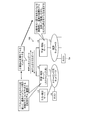
- FIG. 1 is a diagram illustrating an example of a configuration of a communication system according to the first embodiment.
- FIG. 2 is a block diagram showing an example of a configuration of the learning / detection server shown in FIG.
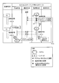
- FIG. 3 is a diagram for explaining the flow of processing in the communication system shown in FIG.
- FIG. 4 is a diagram schematically showing a state of communication and learning with the host in the staging network shown in FIG.
- FIG. 5 is a diagram schematically showing a state of communication and monitoring with respect to the host in the operation network shown in FIG.
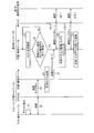
- FIG. 6 is a sequence diagram illustrating a processing procedure of the communication processing according to the first embodiment.
- FIG. 7 is a diagram schematically showing a state of communication and monitoring with respect to a host in a learning / detection server according to the related art.
- FIG. 8 is a diagram illustrating a flow of a communication process according to the second embodiment.
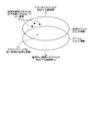
- FIG. 9 is a diagram illustrating a relationship between communication learned by the model and communication of the host.
- FIG. 10 is a diagram schematically illustrating states of communication, learning, and monitoring with respect to a host in the staging network according to the second embodiment.
- FIG. 11 is a diagram showing a relationship between communication learned by the model and communication of the host.
- FIG. 12 is a diagram schematically illustrating states of communication, learning, and monitoring with respect to the host in the staging network according to the second embodiment.
- FIG. 13 is a sequence diagram illustrating a processing procedure of communication processing according to the second embodiment.
- FIG. 14 is a diagram illustrating a relationship between communication learned by the model and communication of the host.
- FIG. 15 is a diagram illustrating a relationship between communication learned by the model and communication of the host.
- FIG. 16 is a diagram schematically illustrating states of communication, learning, and monitoring with respect to the host in the operation network according to the third embodiment.
- FIG. 17 is a sequence diagram illustrating a processing procedure of the communication processing according to the third embodiment.
- FIG. 18 is a diagram illustrating communication monitoring and learning of over-detection communication in the related art.
- FIG. 19 is a diagram illustrating communication monitoring and learning of over-detection communication according to the third embodiment.
- FIG. 20 is a diagram illustrating an example of a computer that implements a learning / detection server by executing a program.
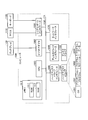
- FIG. 1 is a diagram illustrating an example of a configuration of a communication system according to the first embodiment.
- the communication system 100 has a staging network 1 (first network) and an operation network 2 (second network).
- the operation network 2 is a system environment in which IoT devices and the like are actually operated.
- the operation network 2 has hosts 5a, 5b, 5c (second communication devices) and a learning / detection server 8 (second server device).
- the hosts 5a, 5b, 5c are communication devices such as IoT devices. Note that when the plurality of hosts 5a, 5b, 5c are collectively referred to without distinction, they are simply referred to as hosts 5.
- the operation network 2 illustrated in FIG. 1 has three hosts 5a, 5b, and 5c, but the number of hosts 5 may be one or more.
- the learning / detection server 9 detects an abnormality in communication between the hosts 5a, 5b, and 5c using a model that has learned normal communication.
- the learning / detection server 9 learns normal communication and generates a model.
- the learning / detection server 9 has the same function as the learning / detection server 8 (described later), and can exchange models.
- the learning / detection server 9 monitors the communication of the hosts 5a, 5b, 5c using the initial model received from the learning / detection server 8, and learns the communication of 5a, 5b, 5c to monitor the communication of 5a, 5b, 5c.
- a first model for detecting abnormal communication is generated for each of 5a, 5b, and 5c.
- the staging network 1 is a system environment similar to the operation network 2, and is used for verification (for testing).
- the staging network 1 has a host 4t (first communication device) of the same type as the host 5, a test execution server 3 (test device), and a learning / detection server 8 (first server device).
- the test execution server 3 transmits a test communication in a normal state to the host 4t, which is a test device, and performs a communication test for receiving communication by the host 4t.
- the learning / detection server 8 learns the test communication by the test execution server 3 and the communication generated from the host 4t, and generates an initial model for detecting the abnormal communication of the host 4t.
- the learning / detection server 8 transmits the initial model to the learning / detection server 9.
- the learning / detection server 8 of the staging network 1 and the model exchange between the learning / detection server 9 exchange the model of the staging network 1 with the learning / detection server 8 of the operation network 2.
- the transfer to the detection server 9 is defined as import, and the reverse direction is defined as export.
- an initial model is generated in advance using the host 4t of the same type as the host 5.
- the pre-generated initial model is imported from the staging network 1 to the operation network 2.
- FIG. 2 is a block diagram showing an example of a configuration of the learning / detection servers 8 and 9 shown in FIG.
- the learning / detection servers 8 and 9 include a communication unit 11, a storage unit 12, and a control unit 13.
- the communication unit 11 is a communication interface for transmitting and receiving various information to and from other devices connected via a network or the like.
- the communication unit 11 is realized by an NIC (Network Interface Card) or the like, and performs communication between another device and a control unit 13 (described later) via a telecommunication line such as a LAN (Local Area Network) or the Internet.
- the storage unit 12 is realized by, for example, a semiconductor memory element such as a RAM (Random Access Memory) or a flash memory (Flash Memory), or a storage device such as a hard disk or an optical disk, and operates the learning / detection servers 8 and 9. A program, data used during execution of the processing program, and the like are stored.
- the storage unit 12 has a model 121.
- the model 121 is used to learn communication between the hosts 4t and 5 and detect abnormal communication between the hosts 4t and 5.
- the model 121 includes arithmetic expressions and parameters used for detecting abnormal communication.
- the control unit 13 controls the entire learning / detection servers 8 and 9.
- the control unit 13 has an internal memory for storing a program that defines various processing procedures and the like and required data, and executes various processes by using these.
- the control unit 13 is an electronic circuit such as a CPU (Central Processing Unit) or an MPU (Micro Processing Unit).
- the control unit 13 also functions as various processing units when various programs operate.
- the control unit 13 includes a learning unit 131, a monitoring / detecting unit 132, and a model transmitting / receiving unit 133.
- the learning unit 131 captures communication between the hosts 4t and 5 and learns communication between the hosts 4t and 5 to generate a model or update the model.
- the learning unit 131 stores the model parameters of the generated model or the model parameters of the updated model in the storage unit 12.
- the learning unit 131 learns the test communication by the test execution server 3 and the communication generated from the host 4t and performs the abnormal communication of the host 4t when the communication test is performed by the test execution server 3. Generate an initial model to detect.
- the learning unit 131 generates a first model that learns communication of the host 5 and detects abnormal communication of the host 5 for each host 5.
- the monitoring / detecting unit 132 monitors communication between the hosts 4t and 5 using the model 121, and detects abnormal communication.
- the model transmission / reception unit 133 transmits the model generated by the learning unit 131 to the other learning / detection servers 8 and 9. Further, the model transmission / reception unit 133 receives the model generated by the other learning / detection servers 8 and 9.
- FIG. 3 is a diagram for explaining the flow of processing in the communication system 100 shown in FIG.
- the learning / detection server 8 learns the test communication by the test execution server 3 and the communication generated from the host 4t by the communication test to the host 4t by the test execution server 3. Specifically, the learning / detection server 8 uses the test scenario by the test execution server 3 and the host 4t to generate the latest initial model t0 for the operation network 2 (see (1) in FIG. 3). Subsequently, the learning / detection server 8 imports the latest initial model into the learning / detection server 9 of the operation network 2 (see (2) in FIG. 3).
- the learning / detection server 9 monitors the communication of the host 5a using the latest initial model t0 when the new host (host 5a in the figure) is connected, and uses the model a1 for the host 4a. (First model) is generated (see (3) in FIG. 3). Then, the learning / detection server 9 monitors the communication of the host 5a using the generated model a1, and detects abnormal communication.
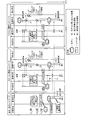
- FIG. 4 is a diagram schematically showing a state of communication and learning with the host 4t in the staging network 1 shown in FIG.
- FIG. 4 are diagrams with the time axis on the vertical axis, and schematically show the communication / monitoring state in the host described in the upper part. Similar diagrams after FIG. 4 show, along the time axis, the status of the test for the host among the statuses for the host, the lane labeled “test status” (hereinafter, “test status lane”), and the status for communication.
- the lane labeled “Communication Status” hereinafter “Communication Status Lane”
- the monitoring status is labeled “Monitoring Status” (hereinafter “Monitoring Status Lane”)
- the detection status is “Detection Status”.
- detection state lanes The states of communication, learning, monitoring / detection will be described separately for lanes with labels (hereinafter, “detection state lanes”).
- detection state lanes the communication taken into the model is represented by an arrow starting from a black circle (for example, an arrow extending to the left from the communication section P3-1).
- test status lane a test scenario T0 relating to test communication to the test host 4t is shown, and the test execution server 3 sets a period during which the test scenario T0 is performed as a test period P2- As 1, a comprehensive test communication for comprehensively checking all functions is performed.
- the communication generated by the host 4t is shown in the communication section P3-1 of the “communication status lane”.
- the learning / detection server 8 captures the communication in the communication section P3-1 to generate the initial model t0 as shown in the “learning situation lane” (see (1) in FIG. 4).
- This initial model t0 corresponds to a template of the model of the operation network 2.
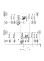
- FIG. 5 is a diagram schematically showing a state of communication and monitoring with respect to the host 5a in the operation network 2 shown in FIG.
- the learning / detection server 9 monitors the communication of the host 5a during the communication section P2-2 of the “monitoring status lane” using the initial model t0 generated in FIG. (See (1) in FIG. 5).
- the delivery of the initial model t0 is realized by being imported from the staging network 1 to the operation network 2 by communication between the learning / detection server 8 of the staging network 1 and the learning / detection server 9 of the operation network 2. Is done.
- the learning / detection server 9 actually monitors the communication of the host 5a in the communication section P2-2 using the initial model t0, and actually communicates between the own device and the host 5a in the operation network 2.
- a model a1 is generated by taking in communication between them (see (2) in FIG. 5).
- the learning / detection server 9 monitors the communication of the host 5a using the generated model a1 (see (3) in FIG. 5).
- FIG. 6 illustrates a processing flow in the communication system 100.
- FIG. 6 is a sequence diagram illustrating a processing procedure of the communication processing according to the first embodiment.
- the learning / detection server 8 captures the communication (step S2) between the host 4t and the test execution server 3 generated by the test communication (step S1) by the test execution server 3 (step S2). S3), learn the communication of the host 4t and generate an initial model (step S4).
- the learning / detection server 9 checks the host status (Step S5), and determines whether a new host has been added or a host that has not been monitored has been found (Step S6). If the learning / detection server 9 determines that a new host has not been added and no unmonitored host has been found (step S6: No), the process returns to step S5 and continues to check the host status.
- the learning / detection server 9 determines that a new host has been added or a host not monitored has been found (step S6: Yes).
- the learning / detection server 9 receives the import of the initial model from the staging network 1 (step S7), and uses this initial model to create a new host 5 and another device (for example, a first communication destination).
- a model of the host 5 is generated (step S9) while capturing and monitoring communication (step S8-1) with the device (step S8-1).
- the learning / detection server 9 captures the communication (step S10-1) between the host 5 and the first communication destination device using the generated model of the host 5 (step S10-1).
- step S10-2 the communication of the host 5 is monitored (step S11), and abnormal communication is detected.
- FIG. 7 is a diagram schematically illustrating a state of communication and monitoring with respect to the host x in the learning / detection server according to the related art.
- the conventional learning / detection server captures the communication of the host x in the communication section P2-3 with respect to the host x which has newly started the connection / communication, as shown in the “learning status lane”.
- x1 is generated (see (1) in FIG. 7).
- the conventional learning / detection server monitors the communication in the communication section P5-3 of the “communication status lane” using the model x1, as shown in the “monitoring status lane” ((2 in FIG. 7). )), To detect the presence or absence of abnormal communication. Therefore, in the related art, communication is not monitored when learning is performed, and communication is monitored after learning is completed. Therefore, there is a problem that a fragile period occurs during the learning phase. .
- an initial model for the host 4t is generated by learning test communication with the host 4t of the same type as the host 5 of the operation network 2 in the staging network 1 in advance.
- the initial model is imported into the operation network 2, and the learning / detection server 9 learns the communication of the host 5a while monitoring the communication of the host 5a using the initial model t0.
- a model a1 corresponding to 5a is generated. Therefore, since the learning / detection server 9 also performs monitoring during the learning phase, it is possible to suppress the occurrence of a vulnerable period during the learning phase, and to more securely execute the learning phase when detecting abnormal communication. .
- FIG. 8 is a diagram illustrating a flow of a communication process according to the second embodiment.
- FIG. 8 illustrates a process after the learning / detection server 9 monitors communication between the hosts 5a, 5b, and 5c using the generated model a1. That is, in the learning / detection server 9, the models of the hosts 5a, 5b, and 5c are completed (see (1) in FIG. 8). In this state, the learning / detection server 9 exports the models (a1, b1, c1) of the hosts 5a, 5b, 5c to the learning / detection server 8 of the staging network 1 (see (2) in FIG. 8). .
- the learning / detection server 8 generates a more accurate initial model by using the test scenario by the test execution server 3 and the models (a1, b1, c1) of the hosts 5a, 5b, 5c ((3 in FIG. 8). )reference).
- the learning / detection server 8 generates an initial model (t1) for the operation network 2 using the test scenario by the test execution server 3 and the host 4t, and updates the initial model (see FIG. 8). (4)).
- the learning / detection server 8 imports the generated latest initial model t1 into the learning / detection server 9 (see (5) in FIG. 8).
- the learning / detection server 9 generates a model for the host 5n while monitoring the communication of the host 5n with the latest initial model t1 when a new host (host 5n in FIG. 8) is connected ((FIG. 8) 6)). That is, the learning / detection server 9 learns the newly connected host 5n while monitoring using the new initial model (see (7) in FIG. 8).
- the staging network 1 updates the initial model by using the model of each host 5 exported from the operation network 2 and imports the latest initial model into the operation network 2. .
- the device is the same type as the host 4t of the staging network 1, when the host 5 of the operation network 2 is introduced, the initial model t0 generated by the staging network 1 is operated. By importing the data into the network 2, the communication can be monitored using the initial model t0 even during the learning phase.
- FIG. 9 is a diagram illustrating a relationship between communication learned by the model and communication of the host.
- the test group by the test communication by the test execution server 3 and the communication group Gt generated by the host 4t during the test shown in FIG. 9 are the input information of the initial model t0.
- the communication Ct is a communication included in the communication group Ga that is actually generated by the host 5a during operation, and is a communication that really needs to be monitored during the test traffic.
- the communication Cj is a communication that is not included in the communication group Ga, and is an unused function that is not used during operation, and therefore does not need to be included in a normal state.
- This communication Cj is a communication identified as normal when monitored using the initial model. However, if a cyber attack is performed via the same communication as this communication Cj, the communication Cj is overlooked. It becomes a risk. In other words, since the communication Cj is an unused function in the operation network 2, even when the model of the staging network 1 is generated, the communication should not be included in the normal state.
- FIG. 10 is a diagram schematically illustrating states of communication, learning, and monitoring with respect to the host 4t in the staging network 1 according to the second embodiment.
- the process until the learning / detection server 8 generates a new initial model t1 using the model a1 of the host 5a generated in the operation network 2 is shown.
- the model a1 is a model that has been exported from the operation network 2 to the staging network 1, and is used for monitoring communication of the staging network 1.
- the learning / detection server 8 causes the communication extracted using the model a1, out of the communication of the host 4t during the test section P3-4, that is, the model a1 is different from normal.
- the communication Cj4 identified as the communication is detected.
- the learning / detection server 8 determines which communication Cj4 is in the test communication, such as “detection in test n” or “detection in test n + 1” in the test communication. Whether or not a test has occurred can be identified by cooperation with the test execution server 3 (see (1) in FIG. 10).
- the learning / detection server 8 can extract the communication Cj4 detected as abnormal communication in the model a1 by monitoring the communication of the host 4t with the model a1.
- the test execution server 3 creates a test scenario T1 excluding the test that generates the communication Cj4 from the test scenario T0 (see (2) in FIG. 10).
- the learning / detection server 8 generates the initial model t1 from the communication of the host 4t during the test section P6-4 by executing the test scenario T1 ((FIG. 10 ( 4)). No model a1 is detected for the communication of the host 4t during the communication section P2-2 corresponding to the test section P6-4 (see (3) in FIG. 10). Therefore, the learning / detection server 8 can generate an initial model t1 with higher accuracy than the initial model t0, in which unnecessary communication Cj4 is not taken into the learning.
- FIG. 11 is a diagram showing a relationship between communication learned by the model and communication of the host.
- the initial model t1 is a model generated from the communication in the area At in FIG. That is, the initial model t1 is generated by using, as an input, a communication in an area At that excludes unnecessary communication Cj and includes only communication Ct that really needs to be monitored, among the communication group Gt generated by the host 4t.
- the learning / detection server 8 imports the latest initial model t1 into the operation network 2 and uses it as a model of the host 5n newly connected in the operation network 2 to more appropriately monitor in the operation network 2. A model can be generated safely while performing.
- FIG. 10 shows an example in which the initial model is updated using the model a1 of the host 5a, but the present invention is not limited to this.
- FIG. 12 is a diagram schematically illustrating a state of communication, learning, and monitoring with respect to the host 4t in the staging network 1 according to the second embodiment.
- the staging network 1 when the models a1, b1, and c1 generated by the three hosts 5a, 5b, and 5c are exported as shown in FIG. , C1 and performing the same processing as in FIG. 10, it is possible to generate an initial model t1 that further extracts the features of the host group.
- the learning / detection server 8 changes the communication Cj4a, Cj4b, Cj4c detected using the models a1, b1, c1 among the communication of the host 4t during the test section P3-4. Detect.
- the learning / detection server 8 detects the communication CJ4a in the test m
- the model b1 detects the communication Cj4b in the test m + 1
- the model c1 It is possible to identify that the communication Cj4c has been detected in the test m + 2 (see (1-a), (1-b), and (1-c) in FIG. 12).
- the test execution server 3 creates a test scenario T1 excluding the test that generates the communication Cj4a to Cj4c from the test scenario T0 (see (2) in FIG. 12). Then, as shown in the "test status lane", the learning / detection server 8 generates the initial model t1 from the communication of the host 4t during the test section P6-4 by executing the test scenario T1. Thereby, the learning / detection server 8 can generate an initial model t1 in which unnecessary communication Cj4a, Cj4b, and Cj4c are not taken into the learning, and which is more accurate than the initial model t0 ((FIG. 12) 4)). There is no detection of the models a1, b1, and c1 for the communication of the host 4t during this test section P6-4 (see (3-a, 3-b, 3-c) in FIG. 12).
- FIG. 13 is a sequence diagram illustrating a processing procedure of communication processing according to the second embodiment.
- Steps S21 to S31 shown in FIG. 13 have the same processing contents as steps S1 to S11 shown in FIG. Then, the learning / detection server 9 exports the generated model to the learning / detection server 8 (Step S32).
- the learning / detection server 8 communicates between the host 4t and the test execution server 3 generated by the test communication by the test execution server 3 to the host 4t (step S33) (step S34). Is captured (step S35), and the communication of the host 4t is monitored using the model generated by the learning / detection server 9 (step S36).
- the learning / detection server 8 determines whether or not there is a communication detected by the model generated by the learning / detection server 9 (Step S37).
- the learning / detection server 8 determines whether or not there is a communication detected by the model generated by the learning / detection server 9 (Step S37).
- the learning / detection server 8 notifies the test execution server 3 of the detected communication (step S38).
- the test execution server 3 excludes the communication detected by the model generated by the learning / detection server 9 from the test communication (Step S39), and performs the test communication (Step S40).
- the learning / detection server 8 captures the communication between the host 4t and the test execution server 3 (Step S41) (Step S42).
- the learning / detection server 8 learns the communication of the host 4t and generates the latest initial model while monitoring the communication of the host 4t with the model generated by the learning / detection server 9 (step S43).
- the learning / detection server 9 checks the host status (step S44), and determines whether a new host has been added or a host that has not been monitored has been found (step S46). If the learning / detection server 9 determines that a new host has not been added and no unmonitored host has been found, the process returns to step S44, and the host status check is continued.
- the learning / detection server 9 determines that a new host has been added or a host not monitored has been discovered by the new connection of the host 5n (step S45).
- the learning / detection server 9 receives the latest initial model from the staging network 1 (step S47), and uses this initial model to connect the new host 5n to another device (for example, the second communication).
- a model of the host 5n is generated (step S49) while capturing and monitoring the communication (step S48-1) with the previous device (step S48-1).
- the learning / detection server 9 captures the communication (step S50-1) between the host 5n and, for example, the second communication destination device using the generated model of the host 5n (step S50). -2), the communication of the host 5n is monitored (step S51), and abnormal communication is detected.
- the learning / detection server 9 of the operation network 2 exports the model (first model) of the host 5 generated by its own device to the learning / detection server of the staging network 1. .
- the test execution server 3 performs a first communication test.
- the learning / detection server 8 detects abnormal communication from the test communication and the communication by the host 4t in the first communication test using the first model.
- the test execution server 3 performs the second communication test excluding the test communication detected by the learning / detection server 8 as abnormal communication.
- the learning / detection server 8 learns the test communication and the communication by the host 4t in the second communication test, generates a new initial model, and imports the new initial model into the learning / detection server 9.
- the second embodiment it is possible to improve the accuracy of the initial model by excluding, from the learning target of the initial model, communications that are unused functions that are not used during operation and that need not be included in the normal state. it can.
- the communication of the host 5 of the operation network 2 of the host 5 is based on a subset of the communication generated from the host 4t by a comprehensive test that comprehensively checks all functions of the host 4t.
- a comprehensive test that comprehensively checks all functions of the host 4t.
- An example was shown.
- communication unique to the operation network 2 may occur. For example, when a monitoring system already exists in the operation network 2, and unusual communication occurs due to use of an unusual function such as health check communication or maintenance to the newly connected host 5. It is.
- FIG. 14 is a diagram illustrating the relationship between the communication learned by the model and the communication of the host 4d.
- FIG. 15 is a diagram illustrating a relationship between the communication learned by the model and the communication of the host 4e.
- FIGS. 14 and 15 assume a case where the learning / detection server 9 monitors using the initial model t1 imported from the staging network 1.
- the areas Ad and Ae are sets of communication learned by the latest initial model t1 imported from the staging network 1, and are communication information input to the initial model t1.
- communication unique to the operation network 2 may occur.
- the communications Cd and Ce in the communication groups Gd and Ge in which the hosts 5d and 5e actually occur during operation are communications that occur when the host 4d and the host 4e are used in a specific manner during operation. .
- these communications Cd and Ce are not included in the input information of the initial model t1.
- the learning / detection server 9 performs monitoring / detection using the initial model t1
- the communication Cd and Ce are detected as communication that is not abnormal but is determined to be abnormal.
- the communications Cd and Ce are communications that should not normally be detected as abnormal.
- overdetection communications such communications Cd and Ce are referred to as overdetection communications.
- over-detection communication is communication that should be learned as a normal state.
- the learning / detection server 9 captures the over-detected communication at the host 5d into the model of the host 5d, and learns the over-detected communication at the host 5e by capturing it in the model of the host 5e. Over-detection communication can be suppressed.
- the learning / detection server 9 learns the over-detection communication by taking it into the model of each host 5, a certain time lag occurs until the learning / detection server 9 takes in the model. This is because, in a predetermined analyzer, the detected communication is analyzed to determine whether the communication is abnormal or overdetected, and after it is determined that the communication is overdetected, the communication is taken into learning. That's why. The occurrence of this time lag leads to a longer learning phase.
- the time lag until the completion of the learning phase is referred to as a “delay problem”.
- This delay problem has the effect of delaying model completion, that is, delaying the start of monitoring with a newer model. Therefore, the third embodiment proposes a method for suppressing the over-detection communication without causing the delay problem.
- FIG. 16 is a diagram schematically illustrating states of communication, learning, and monitoring with respect to the hosts 5d and 5e in the operation network 2 according to the third embodiment.
- the left diagram shows the learning status and monitoring status of the learning / detection server 9 for the entire operation network
- the central diagram shows the learning status and monitoring status of the learning / detection server 9 for the host 5d.
- the right diagram shows the learning status and monitoring status of the learning / detection server 9 for the host 5e.
- the learning / detection server 9 performs the communication between the hosts 5d and 5e during the communication sections P1-5 and P2-5 with the latest communication generated in the staging network 1. While monitoring using the initial model t1, the communication between the hosts 5d and 5e is taken in to generate models d'1 and e'1. At this time, in the communication sections P1-5, P2-5, it is detected by the initial model t1 that the communication Cd1, Cd2, Ce1, Ce2 is abnormal. In the example of FIG.
- the learning / detection server 9 determines that the communication Cd1 and Ce1 are “detected by the traffic r1” by the initial model t1, and that the communication Cd2 is the initial model t1 as shown in the “detection state lane”. Can be identified as “detected by traffic s1” and that the communication Ce2 has been “detected by traffic s6” by the initial model t1 ((1-d1) and (1-d2) in FIG. 16). , (1-e1), (1-e2)).
- the learning / detection server 9 does not include the communication Cd1, Cd2, Ce1, Ce2 detected by the initial model t1 in the learning of 5d and 5e (see FIG. 16). (See (2-d) and (2-e)), and generate models for the respective hosts 5d and 5e (see (3-d) and (3-e) in FIG. 16). That is, the learning / detection server 9 learns the communication excluding the communication detected as the abnormal communication using the initial model t1 from the communication of 5d and 5e, and obtains the model d′ 1 for the host 5d (first communication). Model) and a model e′1 (first model) for the host 5e. The learning / detection server 9 monitors the hosts 5d and 5e using the generated model d'1 and the model e'1 for the host 5e.
- the learning / detection server 9 performs the overdetection communication as shown in the left diagram.
- a model u1 (second model) for detecting abnormal communication other than overdetected communication is generated (see (4) and (5) in FIG. 16).
- the learning / detection server 9 monitors the communication of the entire operation network 2 using the model u1 for the entire operation network 2 (see (6) in FIG. 16). Therefore, in the example shown in FIG. 16, finally, the learning / detection server 9 monitors the entire operation network 2 using the model u1 (see the communication section P7-5), and the model d ′ for the host 5d. 1 (see communication section P3-5), and the host 5e is monitored by model e'1 (see communication section P9-5).
- the learning / detection server 9 monitors the communication between the hosts 5d and 5e using the model u1 that has learned the over-detection communication (see arrows Yd and Ye in FIG. 16). Monitoring is performed using the models d′ 1 and e′1 generated in each of 5d and 5e.
- the learning / detection server 9 determines whether or not the detected event is overdetection communication, that is, whether or not it can be determined as normal, based on the difference in the detection status between these models. (See (7) in FIG. 16).
- the learning / detection server 9 regards communication detected as abnormal communication using the model d′ 1 or model e′1 and not detected as abnormal communication using the model u1 as overdetected communication. Identify. On the other hand, the learning / detection server 9 regards communication detected as abnormal communication using the model d′ 1 or model e′1 and communication detected as abnormal communication using the model u1 as communication to be analyzed. Output. Thereafter, the learning / detection server 9 learns communication excluding communication detected as abnormal communication using the model d′ 1 or model e′1 from the communication between the hosts 5d and 5e, and performs model d′ 1 or model e′1 is updated. At the same time, the learning / detection server 9 learns the over-detection communication among the communication detected as abnormal communication by the model d'1 or the model e'1, and updates the model u1.
- FIG. 17 is a sequence diagram illustrating a processing procedure of the communication processing according to the third embodiment.
- Steps S61 to S66 shown in FIG. 17 have the same processing contents as steps S1 to S6 shown in FIG. Then, the learning / detection server 9 performs learning for generating a model of the host 5 while monitoring communication between the new host 5 and another device using the initial model (step S67). At this time, the learning / detection server 9 determines whether there is communication detected in the model for the host 5 (initial model) (Step S68).
- step S68 determines that there is a communication detected in the model for the host 5
- step S69 the learning / detection server 9 removes the detected communication from the communication of the host 5
- step S69 the learning / detection server 9 determines that there is no communication detected in the model for the host 5
- step S70 the learning / detection server 9 learns the communication of the host 5 as it is and generates a model of the host 5.
- step S68 If the learning / detection server 9 determines that there is communication detected in the model for the host 5 (step S68: Yes), and if the detected communication is overdetection communication, the learning / detection server 9 learns the detected overdetection communication. (Step S71) to generate a model for the entire operation network 2 (step S72).
- the learning / detection server 9 captures the communication (step S73-1) between the host 5 and another device (for example, the first communication device) (step S73-2) and converts the model generated in step S70.
- the monitoring of the host 5 is performed using the model (step S74), and the monitoring of the entire operation network 2 is performed using the model for the entire operation network 2 generated in step S72 (step S75).
- the learning / detection server 9 determines whether there is communication detected by the model for the host 5 (Step S76). If the learning / detection server 9 determines that there is no communication detected by the model for the host 5 (step S76: No), the learning / detection server 9 learns using communication not detected by the model for the host 5, and performs learning for the host 5. The model is updated (step S77).
- step S76 determines whether this communication is also detected by the entire model. ).
- step S78 determines whether this communication is not detected in the overall model.
- step S79 the learning / detection server 9 identifies this communication as overdetected communication, that is, normal (step S79). Return to monitoring / detection of communication.
- step S78 determines that this communication is also detected in the overall model
- step S78 determines that this communication is also detected in the overall model
- step S80 the learning / detection server 9 outputs the communication to an external analysis device or the like as an analysis target (step S80).
- step S81 abnormal
- step S82 the learning / detection server 9 outputs a notification requesting a response to the communication to an external response device or the like
- step S83 receives an instruction to include this communication in the learning as an overdetection communication.
- the communication is included in the learning as overdetection (step S71), and the overall model is updated (step S72).
- FIG. 18 is a diagram illustrating communication monitoring and learning of over-detection communication in the related art.
- FIG. 19 is a diagram illustrating communication monitoring and learning of over-detection communication according to the third embodiment.
- the learning / detection server 9 detects an abnormality in the communication cd1, ce1 while generating a model by capturing the communication of the hosts 5d, 5e. If the communication is detected, the communication cd1 and ce1 are excluded from learning targets, and the models of the hosts 5d and 5e are completed. Then, if the communication cd1 and ce1 are overdetection communications, the learning / detection server 9 learns the overdetection communication and generates a model of the entire operation network 2.
- the model of the host 5 (first model) and the model for the entire operation network 2 (second model) are separated, and the model of the entire operation network 2 is used.
- the learning / detection server 9 does not need the time periods Td ′ and Te ′ from the time when the communication abnormality is detected until the time when the detected communication is analyzed as over-detected communication and taken into learning.
- the time required to generate the models of the hosts 5d and 5e can be reduced to td ( ⁇ td ') and te ( ⁇ te').
- the learning / detection server 9 when abnormal communication occurs, the learning / detection server 9 performs detection using a model for each host 5 and also performs detection using a model for the entire operation network 2. Then, the learning / detection server 9 can distinguish between abnormal communication and over-detection communication by comparing the detection result of the model for each host 5 with the detection result of the overall model.
- the third embodiment a separate learning method in which over-detection communication is not included in learning of the model (first model) of the host 5 but is included in learning of a model (second model) of the entire operation network 2 is described. take.
- generation and over-detection of a model of each host are performed without being affected by communication (over-detection) due to the use of the operation network 2 that is unique to the host 5 and without causing a delay problem. It is possible to learn communication, and it is possible to suppress a prolonged fragile period during the learning phase.
- each component of each device illustrated is a functional concept and does not necessarily need to be physically configured as illustrated.
- the specific form of distribution / integration of each device is not limited to the illustrated one, and all or a part thereof may be functionally or physically distributed / arbitrarily divided into arbitrary units in accordance with various loads and usage conditions. Can be integrated and configured.
- all or any part of each processing function performed by each device can be realized by a CPU and a program analyzed and executed by the CPU, or can be realized as hardware by wired logic.
- the estimation devices 10 and 210 according to the present embodiment can be realized by a computer and a program, and the program can be recorded on a recording medium or provided through a network.
- FIG. 20 is a diagram illustrating an example of a computer in which the learning and detection servers 8 and 9 are realized by executing a program.
- the computer 1000 has, for example, a memory 1010 and a CPU 1020. Further, the computer 1000 has a hard disk drive interface 1030, a disk drive interface 1040, a serial port interface 1050, a video adapter 1060, and a network interface 1070. These units are connected by a bus 1080.
- the memory 1010 includes a ROM (Read Only Memory) 1011 and a RAM 1012.
- the ROM 1011 stores, for example, a boot program such as a BIOS (Basic Input Output System).
- BIOS Basic Input Output System
- the hard disk drive interface 1030 is connected to the hard disk drive 1090.
- the disk drive interface 1040 is connected to the disk drive 1100.
- a removable storage medium such as a magnetic disk or an optical disk is inserted into the disk drive 1100.
- the serial port interface 1050 is connected to, for example, a mouse 1110 and a keyboard 1120.
- the video adapter 1060 is connected to the display 1130, for example.
- the hard disk drive 1090 stores, for example, the OS 1091, the application program 1092, the program module 1093, and the program data 1094. That is, the program that defines each process of the learning / detection servers 8 and 9 is implemented as a program module 1093 in which codes executable by the computer 1000 are described.
- the program module 1093 is stored in, for example, the hard disk drive 1090.
- a program module 1093 for executing the same processing as the functional configuration in the learning / detection servers 8 and 9 is stored in the hard disk drive 1090.
- the hard disk drive 1090 may be replaced by an SSD (Solid State Drive).
- the setting data used in the processing of the above-described embodiment is stored as the program data 1094 in the memory 1010 or the hard disk drive 1090, for example. Then, the CPU 1020 reads out the program module 1093 and the program data 1094 stored in the memory 1010 and the hard disk drive 1090 to the RAM 1012 as needed, and executes them.
- the program module 1093 and the program data 1094 are not limited to being stored in the hard disk drive 1090, but may be stored in, for example, a removable storage medium and read by the CPU 1020 via the disk drive 1100 or the like. Alternatively, the program module 1093 and the program data 1094 may be stored in another computer connected via a network (LAN, Wide Area Network (WAN), or the like). The program module 1093 and the program data 1094 may be read from another computer by the CPU 1020 via the network interface 1070.
- LAN Local Area Network
- WAN Wide Area Network
Landscapes
- Engineering & Computer Science (AREA)
- Computer Security & Cryptography (AREA)
- Computer Networks & Wireless Communication (AREA)
- Signal Processing (AREA)
- Computing Systems (AREA)
- General Engineering & Computer Science (AREA)
- Computer Hardware Design (AREA)
- Software Systems (AREA)
- Theoretical Computer Science (AREA)
- Computer Vision & Pattern Recognition (AREA)
- Data Mining & Analysis (AREA)
- Evolutionary Computation (AREA)
- Medical Informatics (AREA)
- Artificial Intelligence (AREA)
- Physics & Mathematics (AREA)
- General Physics & Mathematics (AREA)
- Mathematical Physics (AREA)
- Data Exchanges In Wide-Area Networks (AREA)
- Debugging And Monitoring (AREA)
Abstract
通信システム(100)は、ホスト(5)と学習・検知サーバ(9)とを有する運用ネットワーク(2)と、ホスト(5)と同型のホスト(4t)とテスト実行サーバ(3)と学習・検知サーバ(8)とを有するステージング用ネットワーク(1)とを有する第2のネットワークとを有する通信システムであって、テスト実行サーバ(3)は、ホスト(4t)に正常状態のテスト通信を送信し、ホスト(4t)による通信を受信する通信テストを行い、学習・検知サーバ(8)が、ホスト(4t)の通信を学習してホスト(4t)の異常通信を検知する初期モデルを生成し、初期モデルを学習・検知サーバ(9)に送信し、学習・検知サーバ(9)は、学習・検知サーバ(8)から受信した初期モデルを用いてホスト(5)の通信を監視しながら、ホスト(5)の通信を学習してホスト(5)の異常通信を検知するモデルを生成する。
Description
本発明は、通信システム及び通信方法に関する。
近年の経済活動や生活環境のICT(Information and Communication Technology)化は、便利さが供給される反面、セキュリティインシデント発生時の影響度が大きくなっており、セキュリティ対策の重要性は、日々高まっている。
刻々と変化するサイバー分野での脅威に対し、セキュリティベンダや研究機関によりセキュリティ対策技術の研究開発が進められている。しかしながら、現在、ゼロデイ攻撃といった既存の検知ルールでは検知できない未知の攻撃は、大きな脅威となっている。このような未知の攻撃への対抗策として、正常状態を定義し、正常状態と識別できない状態を異常状態と識別するアノマリ検出手法の採用が始まっている。
ICT環境、例えば、IoT(Internet of Things)に代表される全てのモノがネットワークに繋がる環境下において、サイバー攻撃の標的とされる機器の多くがネットワーク経由で攻撃を受ける。このため、ネットワークに流れる通信を監視することは、セキュリティ対策として効果的であり、ネットワークの通信監視にアノマリ検出手法を適用することは、さらに効果的な手法であるといえる。
アノマリ検出手法では、正常状態の定義を、学習することが現在のトレンドとなっており、アノマリ検出手法をネットワーク通信監視に適用する場合には、ネットワークに流れる通信群に対し、学習により正常状態を定義する方法を用いる。
ネットワーク通信監視におけるアノマリ検出手法は、正常状態と定義したネットワークに流れる通信を正常状態の通信として学習する期間(以降、学習フェーズ)と、学習完了後にネットワークに流れる通信が、学習した状態と同じであることが識別できない場合に異常であると検知する期間(以降、検知フェーズ)との2つのフェーズを設けている。実際にアノマリ検出手法が使用される際は、学習フェーズを行い、その後、検知フェーズを行う。
ここで、学習フェーズにおいて生成される正常状態を表現するデータは、例えば、通信フロー情報の場合であれば、通信先やプロトコルなど値や文字列で表される。また、正常状態を表現するデータは、通信の特徴を機械学習の入力とするものであれば、数理モデル(数式やパラメータの集まり)で表される。アノマリ検出手法の実装の仕方によって、正常状態を表現するデータは様々である。以降、この正常状態を表現するデータをモデルと呼ぶこととする。
アノマリ検出手法の一例として、学習・検知機能からなるホワイトリスト機能を有するネットワークスイッチ製品がある。このネットワークスイッチ製品は、学習フェーズではネットワークに流れたトラフィックの通信フロー(通信先やプロトコルなど)のそれぞれを正常なものとして学習(ホワイトリストとして定義)し、検知フェーズでは正常なものとは異なる通信フローをアノマリ検出する(非特許文献1参照)。
また、他の例として、主にIoT機器を対象に、機器の通信の正常パターンを機械学習によりモデル化し、これを正常状態と定義し、モデルに当てはまらないパターンの通信を識別することでアノマリ検出を行うという技術がある(非特許文献2参照)。
アラクサラネットワークス ネットワーク・セキュリティホワイトリスト機能、[online]、[平成30年6月14日検索]、インターネット<URL:https://www.alaxala.com/jp/solution/security/wl/>
Zingbox Enabling the Internet of Trusted Things、[online]、[平成30年6月14日検索]、インターネット<URL:https://www.zingbox.com/>
上記のアノマリ検出手法を実現するにあたり学習フェーズが不可欠である。ここで、アノマリ検出手法においては、学習フェーズ中に異常通信が混入した場合、その通信が正常状態の一部として学習され、その後の検知フェーズにおいて混入した異常通信を検出することができないという問題がある。
すなわち、学習という手段を使うアノマリ検出手法には、学習フェーズ中が脆弱な期間になるという弱点がある。
このため、学習フェーズを行う際は、信頼された機器群を基にネットワークを初期構築し、その環境上で学習フェーズを行い、その後検知フェーズに移行するという、学習フェーズ時のネットワークの健全性を担保するための特別な段取りが必要となる。
しかしながら、ネットワークの運用上、初期構築から始められない場合がある。例えばネットワーク運用中の接続機器のソフトウェア改変がある場合や、運用ポリシーの変更の場面によって通信の正常状態が刻々と変化していく場合である。非特許文献1に記載の技術の場合、運用中のネットワークの正常状態に変化があると、再度学習フェーズに切り替え、正常状態の定義のアップデートが必要となる。
ここで、非特許文献1記載の技術を用いる場合には、再学習を行う際に学習フェーズ時に異常が混入していないことの担保、つまり、再学習の学習フェーズの健全性の担保が難しいという課題がある。
このような課題に対し、非特許文献2記載の技術のように、個々の機器を監視する仕組みとし、接続機器ごとに正常状態を作る処理を行えば、機器ごとのフェーズ切り替えにより、学習フェーズ中の脆弱な期間を機器毎に極小化はできる。しかしながら、非特許文献2記載の技術でも、再学習において学習フェーズの健全性の担保が難しいという課題がある点は、非特許文献1に記載の技術とは何ら変わりない。
また、非特許文献1記載の技術と非特許文献2記載の技術において、仮に学習フェーズ中に異常の検知ができたとしても、この検知が本当の異常によるものか、誤って正常を検知してしまったものかを分析し、正常状態に取り込むか否かを判断しなければ、学習フェーズが進められないため、学習期間が長期化するという課題も潜在している。
本発明は、上記に鑑みてなされたものであって、異常通信を検知する際の学習フェーズをよりセキュアに実行する通信システム及び通信方法を提供することを目的とする。
上述した課題を解決し、目的を達成するために、本発明に係る通信システムは、第1のネットワークと、第2のネットワークとを有する通信システムであって、第1のネットワークは、第1の通信装置と、第1の通信装置に正常状態のテスト通信を送信し、第1の通信装置による通信を受信する通信テストを行うテスト装置と、テスト通信と第1の通信装置による通信とを学習して第1の通信装置の異常通信を検知する初期モデルを生成し、初期モデルを第2のネットワークに送信する第1のサーバ装置と、を有し、第2のネットワークは、第1の通信装置と同型の第2の通信装置と、第1のサーバ装置から受信した初期モデルを用いて第2の通信装置の通信を監視しながら、第2の通信装置の通信を学習して第2の通信装置の異常通信を検知する第1のモデルを生成する第2のサーバ装置と、有することを特徴とする。
本発明によれば、異常通信を検知する際の学習フェーズをよりセキュアに実行する。
以下、図面を参照して、本発明の一実施形態を詳細に説明する。なお、この実施の形態により本発明が限定されるものではない。また、図面の記載において、同一部分には同一の符号を付して示している。
[実施の形態1]
まず、本発明の実施の形態1について説明する。図1は、実施の形態1における通信システムの構成の一例を示す図である。
まず、本発明の実施の形態1について説明する。図1は、実施の形態1における通信システムの構成の一例を示す図である。
図1に示すように、実施の形態1に係る通信システム100は、ステージング用ネットワーク1(第1のネットワーク)と、運用ネットワーク2(第2のネットワーク)とを有する。
運用ネットワーク2は、実際にIoT機器等が運用されるシステム環境である。運用ネットワーク2は、ホスト5a,5b,5c(第2の通信装置)と、学習・検知サーバ8(第2のサーバ装置)とを有する。
ホスト5a,5b,5cは、IoT機器等の通信装置である。なお、複数のホスト5a,5b,5cのそれぞれを区別することなく総称する場合に単にホスト5と記載する。また、図1に例示された運用ネットワーク2は、3台のホスト5a,5b,5cを有するが、ホスト5の台数は、一以上であればよい。
学習・検知サーバ9は、正常通信を学習したモデルを用いて、ホスト5a,5b,5cの通信の異常を検知する。学習・検知サーバ9は、正常通信を学習してモデルを生成する。学習・検知サーバ9は、学習・検知サーバ8(後述)と同じ機能を有し、モデルを相互に交換できる。学習・検知サーバ9は、学習・検知サーバ8から受信した初期モデルを用いてホスト5a,5b,5cの通信を監視しながら、5a,5b,5cの通信を学習して5a,5b,5cの異常通信を検知する第1のモデルを、5a,5b,5cごとに生成する。
ステージング用ネットワーク1は、運用ネットワーク2と類似するシステム環境であり、検証用(テスト用)に使用される。ステージング用ネットワーク1は、ホスト5と同型のホスト4t(第1の通信装置)と、テスト実行サーバ3(テスト装置)と、学習・検知サーバ8(第1のサーバ装置)とを有する。
テスト実行サーバ3は、テスト機器であるホスト4tに、正常状態のテスト通信を送信し、ホスト4tによる通信を受信する通信テストを行う。
学習・検知サーバ8は、テスト実行サーバ3によるテスト通信及びホスト4tから発生した通信を学習してホスト4tの異常通信を検知する初期モデルを生成する。学習・検知サーバ8は、初期モデルを学習・検知サーバ9に送信する。
なお、本実施の形態1において、ステージング用ネットワーク1における学習・検知サーバ8と学習・検知サーバ9とにおけるモデルの交換のうち、ステージング用ネットワーク1の学習・検知サーバ8から運用ネットワーク2の学習・検知サーバ9への受け渡しをインポートとし、その逆方向をエクスポートとする。
実施の形態1に係る通信システム100では、ステージング用ネットワーク1において、ホスト5と同型のホスト4tを用いて初期モデルを事前に生成しておく。通信システム100では、監視対象機器であるホスト5が運用ネットワーク2で実際に使用される際に、事前生成した初期モデルを、ステージング用ネットワーク1から運用ネットワーク2へインポートする。
そして、運用ネットワーク2では、この初期モデルを、各通信装置の通信の監視に使用しながら、ホスト5の通信を学習して、ホスト5ごとに第1のモデルを生成する。これによって、通信システム100では、検知フェーズと学習フェーズとの同時実行を可能とし、学習フェーズ中の脆弱な期間の発生を抑止してリスクを低減している。
[学習・検知サーバの構成]
次に、学習・検知サーバ8,9の構成について説明する。図2は、図1に示す学習・検知サーバ8,9の構成の一例を示すブロック図である。図2に示すように、学習・検知サーバ8,9は、通信部11、記憶部12及び制御部13を有する。
次に、学習・検知サーバ8,9の構成について説明する。図2は、図1に示す学習・検知サーバ8,9の構成の一例を示すブロック図である。図2に示すように、学習・検知サーバ8,9は、通信部11、記憶部12及び制御部13を有する。
通信部11は、ネットワーク等を介して接続された他の装置との間で、各種情報を送受信する通信インタフェースである。通信部11は、NIC(Network Interface Card)等で実現され、LAN(Local Area Network)やインターネットなどの電気通信回線を介した他の装置と制御部13(後述)との間の通信を行う。
記憶部12は、例えば、RAM(Random Access Memory)、フラッシュメモリ(Flash Memory)等の半導体メモリ素子、又は、ハードディスク、光ディスク等の記憶装置によって実現され、学習・検知サーバ8,9を動作させる処理プログラムや、処理プログラムの実行中に使用されるデータなどが記憶される。記憶部12は、モデル121を有する。モデル121は、ホスト4t,5の通信を学習して、ホスト4t,5の異常通信を検知するために使用される。モデル121は、異常通信検知のために使用される演算式やパラメータを含む。
制御部13は、学習・検知サーバ8,9全体を制御する。制御部13は、各種の処理手順などを規定したプログラム及び所要データを格納するための内部メモリを有し、これらによって種々の処理を実行する。例えば、制御部13は、CPU(Central Processing Unit)やMPU(Micro Processing Unit)などの電子回路である。また、制御部13は、各種のプログラムが動作することにより各種の処理部として機能する。制御部13は、学習部131、監視・検知部132及びモデル送受信部133を有する。
学習部131は、ホスト4t,5の通信をキャプチャして、ホスト4t,5の通信を学習し、モデルの生成、或いは、モデルの更新を行う。学習部131は、生成したモデルのモデルパラメータ、或いは、更新したモデルのモデルパラメータを記憶部12に格納する。
ここで、学習・検知サーバ8の場合、学習部131は、テスト実行サーバ3による通信テスト実行時に、テスト実行サーバ3によるテスト通信及びホスト4tから発生した通信を学習してホスト4tの異常通信を検知する初期モデルを生成する。また、学習・検知サーバ9の場合、学習部131は、ホスト5の通信を学習してホスト5の異常通信を検知する第1のモデルをホスト5ごとに生成する。
監視・検知部132は、モデル121を用いて、ホスト4t,5の通信を監視し、異常通信を検知する。
モデル送受信部133は、学習部131が生成したモデルを、他方の学習・検知サーバ8,9に送信する。また、モデル送受信部133は、他方の学習・検知サーバ8,9が生成したモデルを受信する。
[全体の処理の流れ]
次に、通信システム100における処理の流れについて説明する。図3は、図1に示す通信システム100における処理の流れについて説明する図である。
次に、通信システム100における処理の流れについて説明する。図3は、図1に示す通信システム100における処理の流れについて説明する図である。
まず、ステージング用ネットワーク1では、学習・検知サーバ8は、テスト実行サーバ3によるテスト通信、及び、テスト実行サーバ3によるホスト4tへの通信テストによってホスト4tから発生した通信を学習する。具体的には、学習・検知サーバ8は、テスト実行サーバ3によるテストシナリオとホスト4tとを用いて、運用ネットワーク2用の最新の初期モデルt0を生成する(図3の(1)参照)。続いて、学習・検知サーバ8は、最新の初期モデルを、運用ネットワーク2の学習・検知サーバ9にインポートする(図3の(2)参照)。
そして、運用ネットワーク2では、学習・検知サーバ9が、新ホスト(図ではホスト5a)の接続時に、ホスト5aの通信を、最新の初期モデルt0を使って監視しながら、ホスト4a用のモデルa1(第1のモデル)を生成する(図3の(3)参照)。そして、学習・検知サーバ9は、生成したモデルa1を用いて、ホスト5aの通信を監視し、異常通信の検知を行う。
[ステージング用ネットワークの処理の流れ]
次に、ステージング用ネットワーク1における初期モデルの生成処理の流れについて説明する。図4は、図1に示すステージング用ネットワーク1におけるホスト4tに対する通信及び学習の状態を模式的に示した図である。
次に、ステージング用ネットワーク1における初期モデルの生成処理の流れについて説明する。図4は、図1に示すステージング用ネットワーク1におけるホスト4tに対する通信及び学習の状態を模式的に示した図である。
図4以降の同様の図は、縦軸に時間軸を取った図で、上段に記載しているホストにおける通信・監視状態を模式的に表している。図4以降の同様の図は、時間軸に沿って、ホストに対する状況のうち、ホストに対する試験の状況を「試験状況」ラベルを振ったレーン(以降、「試験状況レーン」)、通信に関する状況を「通信状況」ラベルを振ったレーン(以降、「通信状況レーン」)、監視に関する状況を「監視状況」ラベルを振ったレーン(以降、「監視状況レーン」)、検知に関する状況を「検知状況」ラベルを振ったレーン(以降、「検知状況レーン」)に分けて、通信、学習、監視・検知の状況を説明する。図4以降の図において、モデルに取り込んだ通信は黒丸を始点とする矢印(例えば、通信区間P3-1から左に伸びる矢印)で表現している。
図4に示すように、ステージング用ネットワーク1では、運用ネットワーク2での動作確認をするため、一般に、運用ネットワーク2のホスト5と同型機であるホスト4tを用いた全機能を網羅的にチェックする総合的なテストが行われる。
まず、図4の「試験状況レーン」では、テスト用のホスト4tへのテスト通信に関する試験シナリオT0が示され、テスト実行サーバ3は、この試験シナリオT0が行われた期間を、試験期間P2-1として、全機能を網羅的にチェックする総合的なテスト通信を行う。この際に、ホスト4tが発生する通信は「通信状況レーン」の通信区間P3-1に示す。
そして、学習・検知サーバ8は、通信区間P3-1の通信を取り込むことによって、「学習状況レーン」に示すように、初期モデルt0を生成する(図4の(1)参照)。この初期モデルt0は、運用ネットワーク2のモデルのテンプレートにあたるものとなる。
[運用ネットワークの処理の流れ]
次に、運用ネットワーク2における監視及びモデル生成の処理の流れについて説明する。図5は、図1に示す運用ネットワーク2におけるホスト5aに対する通信及び監視の状態を模式的に示した図である。
次に、運用ネットワーク2における監視及びモデル生成の処理の流れについて説明する。図5は、図1に示す運用ネットワーク2におけるホスト5aに対する通信及び監視の状態を模式的に示した図である。
図5に示すように、学習・検知サーバ9は、「監視状況レーン」の通信区間P2-2の間のホスト5aの通信を、図4で生成した初期モデルt0を使用して監視している(図5の(1)参照)。この初期モデルt0の受け渡しは、ステージング用ネットワーク1の学習・検知サーバ8と運用ネットワーク2の学習・検知サーバ9との間の通信により、ステージング用ネットワーク1から運用ネットワーク2にインポートされることで実現される。
これにより、図5では、学習・検知サーバ9は、初期モデルt0を使用して通信区間P2-2におけるホスト5aの通信を監視しながら、運用ネットワーク2で実際に、自装置とホスト5aとの間の通信を取り込んでモデルa1を生成する(図5の(2)参照)。その後の通信期間P3-2以降、学習・検知サーバ9は、生成したモデルa1を使用して、ホスト5aの通信を監視する(図5の(3)参照)。
[通信処理の処理手順]
図6は、通信システム100における処理の流れについて説明する。図6は、実施の形態1に係る通信処理の処理手順を示すシーケンス図である。
図6は、通信システム100における処理の流れについて説明する。図6は、実施の形態1に係る通信処理の処理手順を示すシーケンス図である。
まず、ステージング用ネットワーク1では、学習・検知サーバ8は、テスト実行サーバ3によるテスト通信(ステップS1)によって発生したホスト4tとテスト実行サーバ3との間の通信(ステップS2)をキャプチャし(ステップS3)、ホスト4tの通信を学習して初期モデルを生成する(ステップS4)。
運用ネットワーク2では、学習・検知サーバ9は、ホスト状況を確認し(ステップS5)、新規ホスト追加または監視外のホストを発見したかを判定する(ステップS6)。学習・検知サーバ9は、新規ホスト追加及び監視外のホストを発見していないと判定した場合(ステップS6:No)、ステップS5に戻り、ホスト状況の確認を継続する。
これに対し、学習・検知サーバ9が、新規ホスト追加または監視外のホストを発見したと判定した場合(ステップS6:Yes)について説明する。この場合、学習・検知サーバ9は、ステージング用ネットワーク1から初期モデルのインポートを受け(ステップS7)、この初期モデルを用いて、新たなホスト5と他の装置(例えば、第1の通信先の装置)との間の通信(ステップS8-1)をキャプチャして(ステップS8-2)監視しながら、ホスト5のモデルを生成する(ステップS9)。
学習・検知サーバ9は、ホスト5のモデル生成後、生成したホスト5のモデルを用いて、ホスト5と第1の通信先の装置との間の通信(ステップS10-1)をキャプチャして(ステップS10-2)、ホスト5の通信を監視し(ステップS11)、異常通信の検知を行う。
[実施の形態1の効果]
ここで、従来技術について説明する。図7は、従来技術による学習・検知サーバにおけるホストxに対する通信及び監視の状態を模式的に示した図である。図7に示すように、従来の学習・検知サーバは、新規接続・通信を開始したホストxに対し、「学習状況レーン」に示すように通信区間P2-3でホストxの通信を取り込んでモデルx1を生成する(図7の(1)参照)。その後、従来の学習・検知サーバは、「監視状況レーン」に示すように、モデルx1を用いて、「通信状況レーン」の通信区間P5-3の通信を監視することによって(図7の(2)参照)、異常通信の有無を検知する。したがって、従来技術では、学習を行っている際に通信の監視は行っておらず、学習終了後から、通信の監視を実行するため、学習フェーズ中に脆弱な期間が発生するという問題があった。
ここで、従来技術について説明する。図7は、従来技術による学習・検知サーバにおけるホストxに対する通信及び監視の状態を模式的に示した図である。図7に示すように、従来の学習・検知サーバは、新規接続・通信を開始したホストxに対し、「学習状況レーン」に示すように通信区間P2-3でホストxの通信を取り込んでモデルx1を生成する(図7の(1)参照)。その後、従来の学習・検知サーバは、「監視状況レーン」に示すように、モデルx1を用いて、「通信状況レーン」の通信区間P5-3の通信を監視することによって(図7の(2)参照)、異常通信の有無を検知する。したがって、従来技術では、学習を行っている際に通信の監視は行っておらず、学習終了後から、通信の監視を実行するため、学習フェーズ中に脆弱な期間が発生するという問題があった。
これに対し、本実施の形態1では、予め、ステージング用ネットワーク1において、運用ネットワーク2のホスト5と同型のホスト4tに対するテスト通信を学習してホスト4t用の初期モデルを生成している。本実施の形態1では、この初期モデルが運用ネットワーク2にインポートされ、学習・検知サーバ9は、この初期モデルt0を用いてホスト5aの通信も監視しながら、ホスト5aの通信を学習してホスト5aに対応するモデルa1を生成する。したがって、学習・検知サーバ9は、学習フェーズ中も監視を実行するため、学習フェーズ中の脆弱な期間の発生を抑止でき、異常通信を検知する際の学習フェーズをよりセキュアに実行することができる。
[実施の形態2]
次に、実施の形態2について説明する。実施の形態2では、実施の形態1で説明した初期モデルをさらに高精度化する方法について説明する。実施の形態2に係る通信システムは、実施の形態1に係る通信システム100と同じ構成を有する。
次に、実施の形態2について説明する。実施の形態2では、実施の形態1で説明した初期モデルをさらに高精度化する方法について説明する。実施の形態2に係る通信システムは、実施の形態1に係る通信システム100と同じ構成を有する。
[全体の処理の流れ]
次に、実施の形態2における通信処理の流れについて説明する。図8は、実施の形態2における通信処理の流れについて説明する図である。図8では、学習・検知サーバ9が、生成したモデルa1を用いて、ホスト5a,5b,5cの通信を監視した後の処理について説明する。すなわち、学習・検知サーバ9では、ホスト5a,5b,5cのモデルが完成している状態である(図8の(1)参照)。この状態において、学習・検知サーバ9は、ホスト5a,5b,5cのモデル(a1,b1,c1)を、ステージング用ネットワーク1の学習・検知サーバ8にエクスポートする(図8の(2)参照)。
次に、実施の形態2における通信処理の流れについて説明する。図8は、実施の形態2における通信処理の流れについて説明する図である。図8では、学習・検知サーバ9が、生成したモデルa1を用いて、ホスト5a,5b,5cの通信を監視した後の処理について説明する。すなわち、学習・検知サーバ9では、ホスト5a,5b,5cのモデルが完成している状態である(図8の(1)参照)。この状態において、学習・検知サーバ9は、ホスト5a,5b,5cのモデル(a1,b1,c1)を、ステージング用ネットワーク1の学習・検知サーバ8にエクスポートする(図8の(2)参照)。
学習・検知サーバ8は、テスト実行サーバ3によるテストシナリオと、ホスト5a,5b,5cのモデル(a1,b1,c1)を使って、より精度の高い初期モデルを生成する(図8の(3)参照)。言い換えると、学習・検知サーバ8は、テスト実行サーバ3によるテストシナリオと、ホスト4tを使って、運用ネットワーク2用の初期モデル(t1)を生成して、初期モデルを最新化する(図8の(4)参照)。そして、学習・検知サーバ8は、生成した最新の初期モデルt1を学習・検知サーバ9にインポートする(図8の(5)参照)。
続いて、学習・検知サーバ9は、新ホスト(図8ではホスト5n)接続時に、最新の初期モデルt1でホスト5nの通信を監視しながら、ホスト5n用のモデルを生成する(図8の(6)参照)。すなわち、学習・検知サーバ9は、新たに接続するホスト5nについては、新しい初期モデルを使って、監視しながら、学習をする(図8の(7)参照)。
このように、本実施の形態2では、ステージング用ネットワーク1は、運用ネットワーク2からエクスポートされた各ホスト5のモデルを用いて、初期モデルを最新化し、最新の初期モデルを運用ネットワーク2にインポートする。
ここで、実施の形態1においても説明したように、ステージング用ネットワーク1のホスト4tと同型の機器であれば、運用ネットワーク2のホスト5導入時に、ステージング用ネットワーク1で生成した初期モデルt0を運用ネットワーク2にインポートしてくることで、学習フェーズ中も、この初期モデルt0を用いて、通信を監視することができる。
ただし、実施の形態1では、初期モデルは、ホスト4tの全機能の網羅的なテスト通信に応じた全通信を用いて生成しているため、運用ネットワーク2では実際には使われない通信も学習として取り込まれている。図9は、モデルが学習した通信とホストの通信との関係を示す図である。
具体的には、図9に示すテスト中にテスト実行サーバ3によるテスト通信及びホスト4tが発生する通信群Gtが、初期モデルt0の入力情報となる。この通信群Gtの通信のうち、通信Ctは、運用中に、実際にホスト5aが発生する通信群Gaに含まれる通信であり、テストトラフィック中、真に監視が必要な通信である。
これに対し、通信Cjは、通信群Gaに含まれない通信であり、運用中には使用されない未使用機能であるため、正常状態に含めないでよい通信である。この通信Cjは、初期モデルを使って監視した場合には、正常なものと識別される通信であるものの、仮に、この通信Cjと同様の通信を介してサイバー攻撃が行われた場合、見逃しのリスクとなってしまう。言い換えると、通信Cjは、運用ネットワーク2では未使用機能であるため、ステージング用ネットワーク1のモデル生成時においても、正常状態に含めるべきではない通信となる。
このため、本実施の形態2では、ステージング用ネットワーク1において2回目以降に初期モデルを生成する場合、この通信Cjを、初期モデルt1の学習対象から排除することによって、初期モデルの精度を上げている。具体的に、図10を参照して、ステージング用ネットワーク1における初期モデルt1生成について説明する。図10は、実施の形態2におけるステージング用ネットワーク1におけるホスト4tに対する通信、学習及び監視の状態を模式的に示した図である。
図10に示すように、学習・検知サーバ8が、運用ネットワーク2で生成したホスト5aのモデルa1を使用し、新しい初期モデルt1を生成するまでの処理を示す。まず、図10の「監視状況レーン」に示すように、モデルa1は、運用ネットワーク2からステージング用ネットワーク1にエクスポートしてきたモデルであり、ステージング用ネットワーク1の通信の監視に使用される。
そして、試験シナリオT0の実施によって、学習・検知サーバ8は、試験区間P3-4の間のホスト4tの通信のうち、モデルa1を使って抽出される通信、つまり、モデルa1で正常とは異なるものと識別される通信Cj4を検知する。図10の例では、学習・検知サーバ8は、「検知状況レーン」にあるように、テスト通信のうち「テストnでの検知」や「テストn+1での検知」というように、通信Cj4がどのテストにより発生させられたかを、テスト実行サーバ3との連携により識別できる(図10の(1)参照)。
したがって、学習・検知サーバ8は、モデルa1でホスト4tの通信を監視することによって、モデルa1において異常通信と検知される通信Cj4を抽出できる。
続いて、テスト実行サーバ3は、試験シナリオT0から、通信Cj4を発生するテストを除外した(図10の(2)参照)試験シナリオT1を作成する。そして、学習・検知サーバ8は、「試験状況レーン」に示すように、試験シナリオT1の実施によって、試験区間P6-4の間のホスト4tの通信から初期モデルt1を生成する(図10の(4)参照)。この試験区間P6-4に対応する通信区間P2-2の間のホスト4tの通信に対し、モデルa1の検知はない(図10の(3)参照)。したがって、学習・検知サーバ8は、不要な通信Cj4が学習に取り込まれていない、初期モデルt0より高精度の初期モデルt1を生成できる。
図11は、モデルが学習した通信とホストの通信との関係を示す図である。図11に示すように、初期モデルt1は、図11の領域Atの通信から生成されたモデルとなる。すなわち、初期モデルt1は、ホスト4tが発生する通信群Gtのうち、不要な通信Cjを除外した、真に監視が必要な通信Ctのみが含まれる領域Atの通信を入力として生成される。
学習・検知サーバ8は、この最新の初期モデルt1を運用ネットワーク2にインポートし、運用ネットワーク2において新たに接続されるホスト5nのモデルとして使用することによって、運用ネットワーク2において、より適切に監視を行いながら安全にモデルを生成することができる。
なお、図10では、ホスト5aのモデルa1を用いて初期モデルを最新化する場合を例として示したが、もちろんこれに限らない。図12は、実施の形態2におけるステージング用ネットワーク1におけるホスト4tに対する通信、学習及び監視の状態を模式的に示した図である。
ステージング用ネットワーク1では、学習・検知サーバ8は、図12のように3つのホスト5a,5b,5cのそれぞれが生成したモデルa1,b1,c1がエクスポートされた場合、この3つのモデルa1,b1,c1を使用し、図10と同様の処理を行うことで、ホスト群の特徴をより抜き出した初期モデルt1を生成することが可能となる。
例えば、試験シナリオT0の実施によって、学習・検知サーバ8は、試験区間P3-4の間のホスト4tの通信のうち、モデルa1,b1,c1を使って検知される通信Cj4a,Cj4b,Cj4cを検知する。図12の例では、学習・検知サーバ8は、「検知状況レーン」にあるように、モデルa1はテストmで通信CJ4aを検知し、モデルb1はテストm+1で通信Cj4bを検知し、モデルc1はテストm+2で通信Cj4cを検知したことを識別できる(図12の(1-a),(1-b),(1-c)参照)。
続いて、テスト実行サーバ3は、試験シナリオT0から、通信Cj4a~Cj4cを発生するテストを除外した(図12の(2)参照)試験シナリオT1を作成する。そして、学習・検知サーバ8は、「試験状況レーン」に示すように、試験シナリオT1の実施によって、試験区間P6-4の間のホスト4tの通信から初期モデルt1を生成する。これによって、学習・検知サーバ8は、不要な通信Cj4a,Cj4b,Cj4cが学習に取り込まれていない初期モデルt1であって、初期モデルt0より精度の高い初期モデルt1を生成できる(図12の(4)参照)。この試験区間P6-4の間のホスト4tの通信に対し、モデルa1,b1,c1の検知はない(図12の(3-a,3-b,3-c)参照)。
[通信処理の処理手順]
次に、実施の形態2における通信処理の流れについて説明する。図13は、実施の形態2に係る通信処理の処理手順を示すシーケンス図である。
次に、実施の形態2における通信処理の流れについて説明する。図13は、実施の形態2に係る通信処理の処理手順を示すシーケンス図である。
図13に示すステップS21~ステップS31は、図6に示すステップS1~ステップS11と同じ処理内容である。そして、学習・検知サーバ9は、生成したモデルを学習・検知サーバ8にエクスポートする(ステップS32)。
続いて、ステージング用ネットワーク1では、学習・検知サーバ8は、テスト実行サーバ3によるホスト4tへのテスト通信(ステップS33)によって発生したホスト4tとテスト実行サーバ3との間の通信(ステップS34)をキャプチャし(ステップS35)、ホスト4tの通信を、学習・検知サーバ9が生成したモデルを用いて監視する(ステップS36)。
そして、学習・検知サーバ8は、学習・検知サーバ9が生成したモデルが検知した通信があるか否かを判定する(ステップS37)。学習・検知サーバ8は、学習・検知サーバ9が生成したモデルが検知した通信があると判定した場合(ステップS37:Yes)、検知した通信をテスト実行サーバ3に通知する(ステップS38)。
テスト実行サーバ3は、学習・検知サーバ9が生成したモデルが検知した通信をテスト通信から除外し(ステップS39)、テスト通信を行う(ステップS40)。これに応じて、学習・検知サーバ8は、ホスト4tとテスト実行サーバ3との間の通信(ステップS41)とをキャプチャする(ステップS42)。学習・検知サーバ8は、学習・検知サーバ9が生成したモデルでホスト4tの通信を監視しながら、ホスト4tの通信を学習して最新の初期モデルを生成する(ステップS43)。
運用ネットワーク2では、学習・検知サーバ9は、ホスト状況を確認し(ステップS44)、新規ホスト追加または監視外のホストを発見したかを判定する(ステップS46)。学習・検知サーバ9は、新規ホスト追加及び監視外のホストを発見していないと判定した場合、ステップS44に戻り、ホスト状況の確認を継続する。
これに対し、学習・検知サーバ9は、ホスト5nの新規接続(ステップS45)によって、新規ホスト追加または監視外のホストを発見したと判定した場合について説明する。この場合、学習・検知サーバ9は、ステージング用ネットワーク1から最新の初期モデルのインポートを受け(ステップS47)、この初期モデルを用いて、新たなホスト5nと他の装置(例えば、第2の通信先の装置)と間の通信(ステップS48-1)をキャプチャして(ステップS48-2)監視しながら、ホスト5nのモデルを生成する(ステップS49)。続いて、学習・検知サーバ9は、生成したホスト5nのモデルを用いて、ホスト5nと例えば、第2の通信先の装置との間の通信(ステップS50-1)をキャプチャして(ステップS50-2)、ホスト5nの通信を監視し(ステップS51)、異常通信の検知を行う。
[実施の形態2の効果]
このように、実施の形態2では、運用ネットワーク2の学習・検知サーバ9は、自装置が生成したホスト5のモデル(第1のモデル)を、ステージング用ネットワーク1の学習・検知サーバにエクスポートする。そして、テスト実行サーバ3は、第1の通信テストを行う。この際、学習・検知サーバ8は、第1のモデルを用いて、第1の通信テストにおいてテスト通信とホスト4tによる通信とから異常通信を検知する。そして、テスト実行サーバ3は、学習・検知サーバ8が異常通信として検知したテスト通信を除外して第2の通信テストを行う。そして、学習・検知サーバ8は、第2の通信テストにおいてテスト通信とホスト4tによる通信とを学習して新たな初期モデルを生成して、新たな初期モデルを学習・検知サーバ9にインポートする。
このように、実施の形態2では、運用ネットワーク2の学習・検知サーバ9は、自装置が生成したホスト5のモデル(第1のモデル)を、ステージング用ネットワーク1の学習・検知サーバにエクスポートする。そして、テスト実行サーバ3は、第1の通信テストを行う。この際、学習・検知サーバ8は、第1のモデルを用いて、第1の通信テストにおいてテスト通信とホスト4tによる通信とから異常通信を検知する。そして、テスト実行サーバ3は、学習・検知サーバ8が異常通信として検知したテスト通信を除外して第2の通信テストを行う。そして、学習・検知サーバ8は、第2の通信テストにおいてテスト通信とホスト4tによる通信とを学習して新たな初期モデルを生成して、新たな初期モデルを学習・検知サーバ9にインポートする。
したがって、実施の形態2では、運用中には使用されない未使用機能であるため正常状態に含めないでよい通信を、初期モデルの学習対象から排除することによって、初期モデルの精度を向上することができる。
[実施の形態3]
次に、実施の形態3について説明する。実施の形態3では、運用ネットワーク2において、監視・検知処理の過程において異常と検知された正常な過検知通信が発生した場合であっても、学習・検知サーバ9における学習フェーズ完了の長期化を防止しながら過検知通信を学習・検知する方法について説明する。実施の形態3に係る通信システムは、実施の形態1に係る通信システム100と同じ構成を有する。実施の形態3では、運用ネットワーク2におけるホストとしてホスト5d,5eが接続された場合を例に説明する。
次に、実施の形態3について説明する。実施の形態3では、運用ネットワーク2において、監視・検知処理の過程において異常と検知された正常な過検知通信が発生した場合であっても、学習・検知サーバ9における学習フェーズ完了の長期化を防止しながら過検知通信を学習・検知する方法について説明する。実施の形態3に係る通信システムは、実施の形態1に係る通信システム100と同じ構成を有する。実施の形態3では、運用ネットワーク2におけるホストとしてホスト5d,5eが接続された場合を例に説明する。
実施の形態1,2では、ホスト5の運用ネットワーク2のホスト5の通信として、ホスト4tの全機能を網羅的にチェックする総合的なテストによりホスト4tから発生する通信のサブセットを基にする場合の例を示した。しかしながら、運用ネットワーク2によっては、その運用ネットワーク2特有の通信が発生することが考えられる。例えば、既に運用ネットワーク2に監視システムが存在しており、新規に接続したホスト5に対し、ヘルスチェックの通信や、メンテナンスなどの普段とは違う機能の使い方による普段とは異なる通信が発生する場合である。
この状況を、運用ネットワーク2に新たにホスト4dとホスト4eが接続した場合を例に説明する。図14は、モデルが学習した通信とホスト4dの通信との関係を示す図である。図15は、モデルが学習した通信とホスト4eの通信との関係を示す図である。
図14及び図15は、学習・検知サーバ9が、ステージング用ネットワーク1からインポートしてきた初期モデルt1を使用して監視をしている場合を想定する。領域Ad,Aeは、ステージング用ネットワーク1からインポートされた最新の初期モデルt1が学習した通信の集合であり、初期モデルt1に入力された通信情報である。前述のように、運用ネットワーク2によっては、その運用ネットワーク2特有の通信が発生することが考えられる。例えば、運用中に実際にホスト5d,5eが発生する通信群Gd,Ge内の通信Cd,Ceは、運用中にホスト4dおよびホスト4eに対して特有の使い方をした場合に発生する通信である。しかしながら、これらの通信Cd,Ceは、初期モデルt1の入力情報には含まれない。
この結果、学習・検知サーバ9が、初期モデルt1を用いて監視・検知を行った場合、通信Cd,Ceは、異常ではないのに異常と判断される通信として検知されてしまうことになる。この通信Cd,Ceは、本来なら異常として検知されるべきではない通信である。以降、このような通信Cd,Ceを、過検知通信とする。
ここで、過検知通信は、正常状態として学習すべき通信である。具体的には、学習・検知サーバ9は、ホスト5dでの過検知通信を、ホスト5dのモデルに取り込み、ホスト5eでの過検知通信は、ホスト5eのモデルに取り込んで学習することによって、その後の過検知通信を抑制することができる。
しかしながら、学習・検知サーバ9が、過検知通信を各ホスト5のモデルに取り込んで学習する場合、モデルへ取り込みまでに一定のタイムラグが発生する。これは、所定の分析装置において、検知された通信を分析し、異常であるか過検知通信であるかを識別してから、過検知通信であることが判明した後に、この通信を学習に取り込むためである。このタイムラグの発生が、学習フェーズの長期化を招くことになる。以降、この学習フェーズ完了までのタイムラグを「遅延問題」と呼ぶこととする。この遅延問題は、モデルの完成が遅れる、つまり、より新しいモデルでの監視の開始が遅れるという影響を及ぼす。そこで、本実施の形態3では、この遅延問題を発生させず過検知通信の抑止も行う方法を提案する。
[運用ネットワークにおける処理の流れ]
図16は、実施の形態3における運用ネットワーク2におけるホスト5d,5eに対する通信、学習及び監視の状態を模式的に示した図である。図16の模式図のうち、左図は、学習・検知サーバ9における運用ネットワーク全体に対する学習状況及び監視状況を示し、中央図は、学習・検知サーバ9におけるホスト5dに対する学習状況及び監視状況を示し、右図は、学習・検知サーバ9におけるホスト5eに対する学習状況及び監視状況を示す。
図16は、実施の形態3における運用ネットワーク2におけるホスト5d,5eに対する通信、学習及び監視の状態を模式的に示した図である。図16の模式図のうち、左図は、学習・検知サーバ9における運用ネットワーク全体に対する学習状況及び監視状況を示し、中央図は、学習・検知サーバ9におけるホスト5dに対する学習状況及び監視状況を示し、右図は、学習・検知サーバ9におけるホスト5eに対する学習状況及び監視状況を示す。
図16の中央図及び右図に示すように、学習・検知サーバ9は、通信区間P1-5,P2-5の間のホスト5d,5eの通信を、ステージング用ネットワーク1において生成された最新の初期モデルt1を使用して監視しながら、ホスト5d,5eの通信を取り込んでモデルd´1,e´1を生成する。この際、通信区間P1-5,P2-5において、初期モデルt1によって、通信Cd1,Cd2,Ce1,Ce2が異常であると検知される。なお、図16の例では、学習・検知サーバ9は、「検知状況レーン」にあるように、通信Cd1,Ce1が初期モデルt1によって「トラフィックr1で検知」されたこと、通信Cd2が初期モデルt1によって「トラフィックs1で検知」されたこと、及び、通信Ce2が初期モデルt1によって「トラフィックs6で検知」されたことを識別できるものとする(図16の(1-d1),(1-d2),(1-e1),(1-e2)参照)。
学習・検知サーバ9は、中央図及び右図に示すように、5d,5eの通信のうち、初期モデルt1によって検知された通信Cd1,Cd2,Ce1,Ce2は学習に含めずに(図16の(2-d),(2-e)参照)、各ホスト5d,5eに対するモデルを生成する(図16の(3-d),(3-e)参照)。すなわち、学習・検知サーバ9は、5d,5eの通信から、初期モデルt1を用いて異常通信と検知された通信を除外した通信を学習して、ホスト5d用のモデルd´1(第1のモデル)及びホスト5e用のモデルe´1(第1のモデル)を生成する。そして、学習・検知サーバ9は、それぞれ生成したモデルd´1及びホスト5e用のモデルe´1を用いて、ホスト5d,5eを監視する。
さらに、学習・検知サーバ9は、左図に示すように、運用ネットワーク2全体について、初期モデルt1によって異常通信であると検知された通信が過検知通信の場合に、この過検知通信である通信Cd,Ceを学習して、過検知通信以外の異常通信を検知するモデルu1(第2のモデル)を生成する(図16の(4),(5)参照)。
そして、学習・検知サーバ9は、運用ネットワーク2全体については、モデルu1を用いて、運用ネットワーク2全体の通信を監視する(図16の(6)参照)。したがって、図16に示す例では、最終的に、学習・検知サーバ9は、運用ネットワーク2全体については、モデルu1による監視を行い(通信区間P7-5参照)、ホスト5dについては、モデルd’1による監視を行い(通信区間P3-5参照)、ホスト5eについては、モデルe’1による監視を行う(通信区間P9-5参照)。
具体的な監視の処理は、学習・検知サーバ9は、ホスト5d,5eの通信を、過検知通信を学習したモデルu1を用いて監視を行うとともに(図16の矢印Yd,Ye参照)、ホスト5d,5eそれぞれで生成したモデルd’1とモデルe’1とを用いた監視を行う。
そして、ホスト5d,5eの通信において、仮に過検知通信があった場合、モデルd’1またはモデルe’1では検知されるが、モデルu1では検知されない。このため、学習・検知サーバ9は、これらのモデル間の検知状況の違いから、検知された事象が過検知通信であるか否か、つまり正常として判断してよいか否か、を識別することができる(図16の(7)参照)。
すなわち、学習・検知サーバ9は、モデルd’1またはモデルe’1を用いて異常通信と検知された通信であって、モデルu1を用いて異常通信と検知されなかった通信を過検知通信として識別する。一方、学習・検知サーバ9は、モデルd’1またはモデルe’1を用いて異常通信と検知された通信であって、モデルu1を用いて異常通信と検知された通信を分析対象の通信として出力する。以降、学習・検知サーバ9は、ホスト5d,5eの通信から、モデルd’1またはモデルe’1を用いて異常通信と検知された通信を除外した通信を学習してモデルd’1またはモデルe’1を更新する。これとともに、学習・検知サーバ9は、モデルd’1またはモデルe’1によって異常通信と検知された通信のうち過検知通信を学習しモデルu1を更新する。
[通信処理の処理手順]
次に、実施の形態3における通信処理の流れについて説明する。図17は、実施の形態3に係る通信処理の処理手順を示すシーケンス図である。
次に、実施の形態3における通信処理の流れについて説明する。図17は、実施の形態3に係る通信処理の処理手順を示すシーケンス図である。
図17に示すステップS61~ステップS66は、図6に示すステップS1~ステップS6と同じ処理内容である。そして、学習・検知サーバ9は、初期モデルを用いて、新たなホスト5と他の装置との通信を監視しながら、ホスト5のモデル生成のために学習を行う(ステップS67)。この際、学習・検知サーバ9は、ホスト5用のモデル(初期モデル)において検知した通信があるか否かを判定する(ステップS68)。
学習・検知サーバ9は、ホスト5用のモデルにおいて検知した通信があると判定した場合(ステップS68:Yes)、ホスト5の通信から検知した通信を除去して(ステップS69)、ホスト5の通信を学習し、ホスト5のモデルを生成する(ステップS70)。これに対し、学習・検知サーバ9は、ホスト5用のモデルにおいて検知した通信がないと判定した場合には(ステップS68:No)、そのままホスト5の通信を学習し、ホスト5のモデルを生成する(ステップS70)。
そして、学習・検知サーバ9は、ホスト5用のモデルにおいて検知した通信があると判定した場合(ステップS68:Yes)、この検知した通信が過検知通信の場合、この検知した過検知通信を学習に含めて(ステップS71)、運用ネットワーク2全体用のモデルを生成する(ステップS72)。
学習・検知サーバ9は、ホスト5と他の装置(例えば、第1の通信装置)との間の通信(ステップS73-1)をキャプチャし(ステップS73-2)、ステップS70において生成したモデルを用いてホスト5の監視を行う(ステップS74)とともに、ステップS72において生成した運用ネットワーク2全体用のモデルを用いて、運用ネットワーク2全体の監視を行う(ステップS75)。
そして、学習・検知サーバ9は、ホスト5用のモデルで検知した通信があるか否かを判定する(ステップS76)。学習・検知サーバ9は、ホスト5用のモデルで検知した通信がないと判定した場合(ステップS76:No)、ホスト5用のモデルで検知されていない通信を用いて学習を行いホスト5用のモデルを更新する(ステップS77)。
これに対し、学習・検知サーバ9は、ホスト5用のモデルで検知した通信があると判定した場合(ステップS76:Yes)、この通信が全体モデルでも検知されたか否かを判定する(ステップS78)。学習・検知サーバ9は、この通信が全体モデルでは検知されないと判定した場合(ステップS78:No)、この通信は、過検知通信である、すなわち、正常であると識別し(ステップS79)、次の通信に対する監視・検知に戻る。
一方、学習・検知サーバ9は、この通信が全体モデルでも検知されたと判定した場合(ステップS78:Yes)、分析対象として外部の分析装置等に出力する(ステップS80)。学習・検知サーバ9は、この通信に対する分析結果が異常である場合には(ステップS81:異常)、本通信に対する対処の依頼通知を外部の対処装置等に出力する(ステップS82)。また、学習・検知サーバ9は、この通信に対する分析結果が正常である場合には(ステップS81:正常)、本通信が過検知通信であるとして学習に含める指示を受け付けると(ステップS83)、この通信を過検知として学習に含め(ステップS71)、全体用モデルを更新する(ステップS72)。
[従来技術との比較]
従来技術と本実施の形態3とにおける通信処理の流れについて説明する。図18は、従来技術における通信の監視及び過検知通信の学習について説明する図である。図19は、実施の形態3における通信の監視及び過検知通信の学習について説明する図である。
従来技術と本実施の形態3とにおける通信処理の流れについて説明する。図18は、従来技術における通信の監視及び過検知通信の学習について説明する図である。図19は、実施の形態3における通信の監視及び過検知通信の学習について説明する図である。
図18に示すように、従来では、ホスト5d,5eの通信を取り込んでモデルを生成している最中に、異常を検知した通信(例えば、通信cd1,ce1)を取り込むか否かは、他の分析装置或いは解析担当者の分析結果を待つ必要があった。したがって、従来では、通信の異常を検知した時から、この検知した通信が過検知通信であると分析され学習に取り込むまでの期間Td´,Te´が長く、ホスト5d,5eのモデルを生成するまで時間がかかっていた(例えば、時間td´,te´)。
これに対し、本実施の形態3では、図19に示すように、学習・検知サーバ9は、ホスト5d,5eの通信を取り込んでモデルを生成している最中に通信cd1,ce1の異常を検知した場合、この通信cd1,ce1を学習対象から除外して、ホスト5d,5eそれぞれのモデルを完成させる。そして、学習・検知サーバ9は、通信cd1,ce1が過検知通信である場合には、この過検知通信を学習して、運用ネットワーク2全体のモデルを生成する。
このように、本実施の形態3では、ホスト5のモデル(第1のモデル)と、運用ネットワーク2全体用のモデル(第2のモデル)とを分離して、運用ネットワーク2全体のモデルに過検知通信を学習させる手法を取る。この結果、学習・検知サーバ9は、通信の異常を検知した時から、この検知した通信が過検知通信であると分析され学習に取り込むまでの期間Td´,Te´を必要としないため、従来と比して、ホスト5d,5eのモデルを生成するまでの時間がtd(<td´),te(<te´)に短縮することができる。
以上より、実施の形態3においては、学習・検知サーバ9は、異常通信が発生した場合に、ホスト5ごとのモデルで検知するほか、運用ネットワーク2全体用のモデルでも検知を行う。そして、学習・検知サーバ9は、ホスト5ごとのモデルと、全体用のモデルとにおける検知結果を比較することによって、異常通信と過検知通信との識別が可能となる。
すなわち、実施の形態3では、過検知通信をホスト5のモデル(第1のモデル)の学習に含めず、運用ネットワーク2全体のモデル(第2のモデル)の学習に含めるという分離した学習手法を取る。この結果、実施の形態3では、運用ネットワーク2のホスト5特有の使用による通信(過検知)に影響を受けない形で、かつ、遅延問題を発生させずに各ホストのモデルの生成と過検知通信の学習とが可能となり、学習フェーズ中の脆弱な期間の長期化を抑止することができる。
[システム構成等]
図示した各装置の各構成要素は機能概念的なものであり、必ずしも物理的に図示の如く構成されていることを要しない。すなわち、各装置の分散・統合の具体的形態は図示のものに限られず、その全部又は一部を、各種の負荷や使用状況等に応じて、任意の単位で機能的又は物理的に分散・統合して構成することができる。さらに、各装置にて行なわれる各処理機能は、その全部又は任意の一部が、CPU及び当該CPUにて解析実行されるプログラムにて実現され、あるいは、ワイヤードロジックによるハードウェアとして実現され得る。本実施の形態に係る推定装置10,210は、コンピュータとプログラムによっても実現でき、プログラムを記録媒体に記録することも、ネットワークを通して提供することも可能である。
図示した各装置の各構成要素は機能概念的なものであり、必ずしも物理的に図示の如く構成されていることを要しない。すなわち、各装置の分散・統合の具体的形態は図示のものに限られず、その全部又は一部を、各種の負荷や使用状況等に応じて、任意の単位で機能的又は物理的に分散・統合して構成することができる。さらに、各装置にて行なわれる各処理機能は、その全部又は任意の一部が、CPU及び当該CPUにて解析実行されるプログラムにて実現され、あるいは、ワイヤードロジックによるハードウェアとして実現され得る。本実施の形態に係る推定装置10,210は、コンピュータとプログラムによっても実現でき、プログラムを記録媒体に記録することも、ネットワークを通して提供することも可能である。
また、本実施の形態において説明した各処理のうち、自動的に行われるものとして説明した処理の全部又は一部を手動的におこなうこともでき、あるいは、手動的に行なわれるものとして説明した処理の全部又は一部を公知の方法で自動的におこなうこともできる。この他、上記文書中や図面中で示した処理手順、制御手順、具体的名称、各種のデータやパラメータを含む情報については、特記する場合を除いて任意に変更することができる。
[プログラム]
図20は、プログラムが実行されることにより、学習・検知サーバ8,9が実現されるコンピュータの一例を示す図である。コンピュータ1000は、例えば、メモリ1010、CPU1020を有する。また、コンピュータ1000は、ハードディスクドライブインタフェース1030、ディスクドライブインタフェース1040、シリアルポートインタフェース1050、ビデオアダプタ1060、ネットワークインタフェース1070を有する。これらの各部は、バス1080によって接続される。
図20は、プログラムが実行されることにより、学習・検知サーバ8,9が実現されるコンピュータの一例を示す図である。コンピュータ1000は、例えば、メモリ1010、CPU1020を有する。また、コンピュータ1000は、ハードディスクドライブインタフェース1030、ディスクドライブインタフェース1040、シリアルポートインタフェース1050、ビデオアダプタ1060、ネットワークインタフェース1070を有する。これらの各部は、バス1080によって接続される。
メモリ1010は、ROM(Read Only Memory)1011及びRAM1012を含む。ROM1011は、例えば、BIOS(Basic Input Output System)等のブートプログラムを記憶する。ハードディスクドライブインタフェース1030は、ハードディスクドライブ1090に接続される。ディスクドライブインタフェース1040は、ディスクドライブ1100に接続される。例えば磁気ディスクや光ディスク等の着脱可能な記憶媒体が、ディスクドライブ1100に挿入される。シリアルポートインタフェース1050は、例えばマウス1110、キーボード1120に接続される。ビデオアダプタ1060は、例えばディスプレイ1130に接続される。
ハードディスクドライブ1090は、例えば、OS1091、アプリケーションプログラム1092、プログラムモジュール1093、プログラムデータ1094を記憶する。すなわち、学習・検知サーバ8,9の各処理を規定するプログラムは、コンピュータ1000により実行可能なコードが記述されたプログラムモジュール1093として実装される。プログラムモジュール1093は、例えばハードディスクドライブ1090に記憶される。例えば、学習・検知サーバ8,9における機能構成と同様の処理を実行するためのプログラムモジュール1093が、ハードディスクドライブ1090に記憶される。なお、ハードディスクドライブ1090は、SSD(Solid State Drive)により代替されてもよい。
また、上述した実施形態の処理で用いられる設定データは、プログラムデータ1094として、例えばメモリ1010やハードディスクドライブ1090に記憶される。そして、CPU1020が、メモリ1010やハードディスクドライブ1090に記憶されたプログラムモジュール1093やプログラムデータ1094を必要に応じてRAM1012に読み出して実行する。
なお、プログラムモジュール1093やプログラムデータ1094は、ハードディスクドライブ1090に記憶される場合に限らず、例えば着脱可能な記憶媒体に記憶され、ディスクドライブ1100等を介してCPU1020によって読み出されてもよい。あるいは、プログラムモジュール1093及びプログラムデータ1094は、ネットワーク(LAN、WAN(Wide Area Network)等)を介して接続された他のコンピュータに記憶されてもよい。そして、プログラムモジュール1093及びプログラムデータ1094は、他のコンピュータから、ネットワークインタフェース1070を介してCPU1020によって読み出されてもよい。
以上、本発明者によってなされた発明を適用した実施形態について説明したが、本実施形態による本発明の開示の一部をなす記述及び図面により本発明は限定されることはない。すなわち、本実施形態に基づいて当業者等によりなされる他の実施形態、実施例及び運用技術等は全て本発明の範疇に含まれる。
1 ステージング用ネットワーク
2 運用ネットワーク
3 テスト実行サーバ
4t,5,5a~5e,5n ホスト
8,9 学習・検知サーバ
11 通信部
12 記憶部
13 制御部
121 モデル
131 学習部
132 監視・検知部
133 モデル送受信部
2 運用ネットワーク
3 テスト実行サーバ
4t,5,5a~5e,5n ホスト
8,9 学習・検知サーバ
11 通信部
12 記憶部
13 制御部
121 モデル
131 学習部
132 監視・検知部
133 モデル送受信部
Claims (5)
- 第1のネットワークと、第2のネットワークとを有する通信システムであって、
前記第1のネットワークは、
第1の通信装置と、
前記第1の通信装置に正常状態のテスト通信を送信し、前記第1の通信装置による通信を受信する通信テストを行うテスト装置と、
前記テスト通信と前記第1の通信装置による通信とを学習して前記第1の通信装置の異常通信を検知する初期モデルを生成し、前記初期モデルを前記第2のネットワークに送信する第1のサーバ装置と、
を有し、
前記第2のネットワークは、
前記第1の通信装置と同型の第2の通信装置と、
前記第1のサーバ装置から受信した前記初期モデルを用いて前記第2の通信装置の通信を監視しながら、前記第2の通信装置の通信を学習して前記第2の通信装置の異常通信を検知する第1のモデルを生成する第2のサーバ装置と、
有することを特徴とする通信システム。 - 前記第2のサーバ装置は、前記第1のモデルを前記第1のサーバ装置に送信し、
前記テスト装置は、第1の前記通信テストを行い、
前記第1のサーバ装置は、前記第1のモデルを用いて、前記第1の通信テストにおいて前記テスト通信と前記第1の通信装置による通信とから異常通信を検知し、
前記テスト装置は、前記第1のサーバ装置が異常通信として検知した前記テスト通信を除外して第2の前記通信テストを行い、
前記第1のサーバ装置は、前記第2の通信テストにおいて前記テスト通信と前記第1の通信装置による通信とを学習して新たな前記初期モデルを生成し、前記新たな初期モデルを前記第2のサーバ装置に送信することを特徴とする請求項1に記載の通信システム。 - 前記第2のサーバ装置は、前記第2の通信装置の通信から、前記初期モデルまたは前記第1のモデルを用いて異常通信と検知された通信を除外した通信を学習して、前記第1のモデルを生成或いは更新するとともに、前記異常通信と検知された通信のうち正常である過検知通信を学習して前記過検知通信以外の異常通信を検知する第2のモデルを生成することを特徴とする請求項1または2に記載の通信システム。
- 前記第2のサーバ装置は、前記第1のモデルを用いて異常通信と検知された通信であって前記第2のモデルを用いて異常通信と検知されなかった通信を前記過検知通信として識別し、前記第1のモデルを用いて異常通信と検知された通信であって前記第2のモデルを用いて異常通信と検知された通信を分析対象の通信として出力することを特徴とする請求項3に記載の通信システム。
- 第1の通信装置とテスト装置と第1のサーバ装置とを有する第1のネットワークと、前記第1の通信装置と同型の第2の通信装置と第2のサーバ装置とを有する第2のネットワークと、を有する通信システムが実行する通信方法であって、
前記テスト装置が、前記第1の通信装置に正常状態のテスト通信を送信し、前記第1の通信装置による通信を受信する通信テストを行う工程と、
前記第1のサーバ装置が、前記テスト通信と前記第1の通信装置による通信とを学習して前記第1の通信装置の異常通信を検知する初期モデルを生成する工程と、
前記第1のサーバ装置が、前記初期モデルを前記第2のサーバ装置に送信する工程と、
前記第2のサーバ装置が、前記第1のサーバ装置から受信した前記初期モデルを用いて前記第2の通信装置の通信を監視しながら、前記第2の通信装置の通信を学習して前記第2の通信装置の異常通信を検知する第1のモデルを生成する工程と、
を含んだことを特徴とする通信方法。
Priority Applications (1)
| Application Number | Priority Date | Filing Date | Title |
|---|---|---|---|
| US17/252,740 US11805142B2 (en) | 2018-06-29 | 2019-06-26 | Communication system and communication method |
Applications Claiming Priority (2)
| Application Number | Priority Date | Filing Date | Title |
|---|---|---|---|
| JP2018-124884 | 2018-06-29 | ||
| JP2018124884A JP7047636B2 (ja) | 2018-06-29 | 2018-06-29 | 通信システム及び通信方法 |
Publications (1)
| Publication Number | Publication Date |
|---|---|
| WO2020004489A1 true WO2020004489A1 (ja) | 2020-01-02 |
Family
ID=68984894
Family Applications (1)
| Application Number | Title | Priority Date | Filing Date |
|---|---|---|---|
| PCT/JP2019/025447 Ceased WO2020004489A1 (ja) | 2018-06-29 | 2019-06-26 | 通信システム及び通信方法 |
Country Status (3)
| Country | Link |
|---|---|
| US (1) | US11805142B2 (ja) |
| JP (1) | JP7047636B2 (ja) |
| WO (1) | WO2020004489A1 (ja) |
Families Citing this family (3)
| Publication number | Priority date | Publication date | Assignee | Title |
|---|---|---|---|---|
| JP2022097250A (ja) * | 2020-12-18 | 2022-06-30 | トヨタ自動車株式会社 | 情報収集装置、情報収集システム、情報収集方法及びプログラム |
| AU2021450034B2 (en) | 2021-06-10 | 2024-11-21 | Ntt, Inc. | Analysis device, analysis method, and analysis program |
| JP7407152B2 (ja) * | 2021-08-20 | 2023-12-28 | Lineヤフー株式会社 | 情報処理装置、情報処理方法及び情報処理プログラム |
Citations (2)
| Publication number | Priority date | Publication date | Assignee | Title |
|---|---|---|---|---|
| JP2001044993A (ja) * | 1999-07-26 | 2001-02-16 | Fujitsu Ltd | ネットワークのシミュレーションモデル生成装置、その方法、及びその方法を実現するプログラムを記録した記録媒体 |
| JP2004312083A (ja) * | 2003-04-02 | 2004-11-04 | Kddi Corp | 学習データ作成装置、侵入検知システムおよびプログラム |
Family Cites Families (4)
| Publication number | Priority date | Publication date | Assignee | Title |
|---|---|---|---|---|
| WO2007053708A2 (en) * | 2005-10-31 | 2007-05-10 | The Trustees Of Columbia University In The City Of New York | Methods, media, and systems for securing communications between a first node and a second node |
| CN106603324A (zh) * | 2015-10-20 | 2017-04-26 | 富士通株式会社 | 训练集的获取装置以及方法 |
| US11977958B2 (en) * | 2017-11-22 | 2024-05-07 | Amazon Technologies, Inc. | Network-accessible machine learning model training and hosting system |
| US10614214B2 (en) * | 2018-01-02 | 2020-04-07 | Honeywell International Inc. | Using machine learning to detect communication channel abnormalities in an ICS/IIoT application |
-
2018
- 2018-06-29 JP JP2018124884A patent/JP7047636B2/ja active Active
-
2019
- 2019-06-26 WO PCT/JP2019/025447 patent/WO2020004489A1/ja not_active Ceased
- 2019-06-26 US US17/252,740 patent/US11805142B2/en active Active
Patent Citations (2)
| Publication number | Priority date | Publication date | Assignee | Title |
|---|---|---|---|---|
| JP2001044993A (ja) * | 1999-07-26 | 2001-02-16 | Fujitsu Ltd | ネットワークのシミュレーションモデル生成装置、その方法、及びその方法を実現するプログラムを記録した記録媒体 |
| JP2004312083A (ja) * | 2003-04-02 | 2004-11-04 | Kddi Corp | 学習データ作成装置、侵入検知システムおよびプログラム |
Also Published As
| Publication number | Publication date |
|---|---|
| JP2020005184A (ja) | 2020-01-09 |
| JP7047636B2 (ja) | 2022-04-05 |
| US11805142B2 (en) | 2023-10-31 |
| US20210160270A1 (en) | 2021-05-27 |
Similar Documents
| Publication | Publication Date | Title |
|---|---|---|
| Maeda et al. | Automating post-exploitation with deep reinforcement learning | |
| US12335275B2 (en) | System for monitoring and managing datacenters | |
| US12375521B2 (en) | Training method for detection model, system, device, and storage medium | |
| Huda et al. | Securing the operations in SCADA-IoT platform based industrial control system using ensemble of deep belief networks | |
| Hu et al. | GANFuzz: A GAN-based industrial network protocol fuzzing framework | |
| Bures et al. | Software engineering for smart cyber-physical systems: Challenges and promising solutions | |
| US12081580B2 (en) | System and method for emulating a multi-stage attack on a node within a target network | |
| US11438359B2 (en) | Increasing edge data confidence via trusted ethical hacking | |
| Rasouli et al. | A supervisory control approach to dynamic cyber-security | |
| US10678721B1 (en) | Communication link testing | |
| Letteri et al. | Security in the internet of things: botnet detection in software-defined networks by deep learning techniques | |
| JP7047636B2 (ja) | 通信システム及び通信方法 | |
| JP7069399B2 (ja) | コンピュータセキュリティインシデントを報告するためのシステムおよび方法 | |
| US11763006B1 (en) | Comparative real-time end-to-end security vulnerabilities determination and visualization | |
| Xiong et al. | A distributed security SDN cluster architecture for smart grid based on blockchain technology | |
| Ari et al. | Ensuring security continuum from edge to cloud: Adaptive security for iot-based critical infrastructures using fl at the edge | |
| Jabr et al. | Penetration testing and attack automation simulation: Deep reinforcement learning approach | |
| Nam et al. | Virtual machine failure prediction using log analysis | |
| CN110572296B (zh) | 一种物联网终端设备通信协议一致性安全检测方法 | |
| US20240202326A1 (en) | Anomaly Detection on MIL-STD-1553 Dataset Using Machine Learning | |
| Wetzig et al. | Unsupervised anomaly alerting for iot-gateway monitoring using adaptive thresholds and half-space trees | |
| Pathirana et al. | Joint security and dependability modeling: An updated overview | |
| CN107251519B (zh) | 用于检测通信网络上的假信息的攻击的系统、方法和介质 | |
| US20240098102A1 (en) | Social graph enabled lateral movement detection | |
| CN108848093B (zh) | 路由计算单元和网络节点设备 |
Legal Events
| Date | Code | Title | Description |
|---|---|---|---|
| 121 | Ep: the epo has been informed by wipo that ep was designated in this application |
Ref document number: 19825392 Country of ref document: EP Kind code of ref document: A1 |
|
| NENP | Non-entry into the national phase |
Ref country code: DE |
|
| 122 | Ep: pct application non-entry in european phase |
Ref document number: 19825392 Country of ref document: EP Kind code of ref document: A1 |