WO2020004385A1 - Hydrophilic copolymer and medical instrument - Google Patents
Hydrophilic copolymer and medical instrument Download PDFInfo
- Publication number
- WO2020004385A1 WO2020004385A1 PCT/JP2019/025155 JP2019025155W WO2020004385A1 WO 2020004385 A1 WO2020004385 A1 WO 2020004385A1 JP 2019025155 W JP2019025155 W JP 2019025155W WO 2020004385 A1 WO2020004385 A1 WO 2020004385A1
- Authority
- WO
- WIPO (PCT)
- Prior art keywords
- group
- hydrophilic copolymer
- oso
- medical device
- monomer
- Prior art date
Links
Images


Classifications
-
- C—CHEMISTRY; METALLURGY
- C09—DYES; PAINTS; POLISHES; NATURAL RESINS; ADHESIVES; COMPOSITIONS NOT OTHERWISE PROVIDED FOR; APPLICATIONS OF MATERIALS NOT OTHERWISE PROVIDED FOR
- C09D—COATING COMPOSITIONS, e.g. PAINTS, VARNISHES OR LACQUERS; FILLING PASTES; CHEMICAL PAINT OR INK REMOVERS; INKS; CORRECTING FLUIDS; WOODSTAINS; PASTES OR SOLIDS FOR COLOURING OR PRINTING; USE OF MATERIALS THEREFOR
- C09D139/00—Coating compositions based on homopolymers or copolymers of compounds having one or more unsaturated aliphatic radicals, each having only one carbon-to-carbon double bond, and at least one being terminated by a single or double bond to nitrogen or by a heterocyclic ring containing nitrogen; Coating compositions based on derivatives of such polymers
- C09D139/04—Homopolymers or copolymers of monomers containing heterocyclic rings having nitrogen as ring member
- C09D139/06—Homopolymers or copolymers of N-vinyl-pyrrolidones
-
- A—HUMAN NECESSITIES
- A61—MEDICAL OR VETERINARY SCIENCE; HYGIENE
- A61L—METHODS OR APPARATUS FOR STERILISING MATERIALS OR OBJECTS IN GENERAL; DISINFECTION, STERILISATION OR DEODORISATION OF AIR; CHEMICAL ASPECTS OF BANDAGES, DRESSINGS, ABSORBENT PADS OR SURGICAL ARTICLES; MATERIALS FOR BANDAGES, DRESSINGS, ABSORBENT PADS OR SURGICAL ARTICLES
- A61L29/00—Materials for catheters, medical tubing, cannulae, or endoscopes or for coating catheters
- A61L29/08—Materials for coatings
- A61L29/085—Macromolecular materials
-
- A—HUMAN NECESSITIES
- A61—MEDICAL OR VETERINARY SCIENCE; HYGIENE
- A61L—METHODS OR APPARATUS FOR STERILISING MATERIALS OR OBJECTS IN GENERAL; DISINFECTION, STERILISATION OR DEODORISATION OF AIR; CHEMICAL ASPECTS OF BANDAGES, DRESSINGS, ABSORBENT PADS OR SURGICAL ARTICLES; MATERIALS FOR BANDAGES, DRESSINGS, ABSORBENT PADS OR SURGICAL ARTICLES
- A61L29/00—Materials for catheters, medical tubing, cannulae, or endoscopes or for coating catheters
- A61L29/14—Materials characterised by their function or physical properties, e.g. lubricating compositions
-
- A—HUMAN NECESSITIES
- A61—MEDICAL OR VETERINARY SCIENCE; HYGIENE
- A61L—METHODS OR APPARATUS FOR STERILISING MATERIALS OR OBJECTS IN GENERAL; DISINFECTION, STERILISATION OR DEODORISATION OF AIR; CHEMICAL ASPECTS OF BANDAGES, DRESSINGS, ABSORBENT PADS OR SURGICAL ARTICLES; MATERIALS FOR BANDAGES, DRESSINGS, ABSORBENT PADS OR SURGICAL ARTICLES
- A61L31/00—Materials for other surgical articles, e.g. stents, stent-grafts, shunts, surgical drapes, guide wires, materials for adhesion prevention, occluding devices, surgical gloves, tissue fixation devices
- A61L31/08—Materials for coatings
- A61L31/10—Macromolecular materials
-
- C—CHEMISTRY; METALLURGY
- C08—ORGANIC MACROMOLECULAR COMPOUNDS; THEIR PREPARATION OR CHEMICAL WORKING-UP; COMPOSITIONS BASED THEREON
- C08F—MACROMOLECULAR COMPOUNDS OBTAINED BY REACTIONS ONLY INVOLVING CARBON-TO-CARBON UNSATURATED BONDS
- C08F216/00—Copolymers of compounds having one or more unsaturated aliphatic radicals, each having only one carbon-to-carbon double bond, and at least one being terminated by an alcohol, ether, aldehydo, ketonic, acetal or ketal radical
- C08F216/12—Copolymers of compounds having one or more unsaturated aliphatic radicals, each having only one carbon-to-carbon double bond, and at least one being terminated by an alcohol, ether, aldehydo, ketonic, acetal or ketal radical by an ether radical
- C08F216/14—Monomers containing only one unsaturated aliphatic radical
- C08F216/16—Monomers containing no hetero atoms other than the ether oxygen
- C08F216/18—Acyclic compounds
-
- C—CHEMISTRY; METALLURGY
- C08—ORGANIC MACROMOLECULAR COMPOUNDS; THEIR PREPARATION OR CHEMICAL WORKING-UP; COMPOSITIONS BASED THEREON
- C08F—MACROMOLECULAR COMPOUNDS OBTAINED BY REACTIONS ONLY INVOLVING CARBON-TO-CARBON UNSATURATED BONDS
- C08F216/00—Copolymers of compounds having one or more unsaturated aliphatic radicals, each having only one carbon-to-carbon double bond, and at least one being terminated by an alcohol, ether, aldehydo, ketonic, acetal or ketal radical
- C08F216/36—Copolymers of compounds having one or more unsaturated aliphatic radicals, each having only one carbon-to-carbon double bond, and at least one being terminated by an alcohol, ether, aldehydo, ketonic, acetal or ketal radical by a ketonic radical
-
- C—CHEMISTRY; METALLURGY
- C08—ORGANIC MACROMOLECULAR COMPOUNDS; THEIR PREPARATION OR CHEMICAL WORKING-UP; COMPOSITIONS BASED THEREON
- C08F—MACROMOLECULAR COMPOUNDS OBTAINED BY REACTIONS ONLY INVOLVING CARBON-TO-CARBON UNSATURATED BONDS
- C08F220/00—Copolymers of compounds having one or more unsaturated aliphatic radicals, each having only one carbon-to-carbon double bond, and only one being terminated by only one carboxyl radical or a salt, anhydride ester, amide, imide or nitrile thereof
- C08F220/02—Monocarboxylic acids having less than ten carbon atoms; Derivatives thereof
- C08F220/10—Esters
- C08F220/38—Esters containing sulfur
- C08F220/382—Esters containing sulfur and containing oxygen, e.g. 2-sulfoethyl (meth)acrylate
-
- C—CHEMISTRY; METALLURGY
- C08—ORGANIC MACROMOLECULAR COMPOUNDS; THEIR PREPARATION OR CHEMICAL WORKING-UP; COMPOSITIONS BASED THEREON
- C08F—MACROMOLECULAR COMPOUNDS OBTAINED BY REACTIONS ONLY INVOLVING CARBON-TO-CARBON UNSATURATED BONDS
- C08F220/00—Copolymers of compounds having one or more unsaturated aliphatic radicals, each having only one carbon-to-carbon double bond, and only one being terminated by only one carboxyl radical or a salt, anhydride ester, amide, imide or nitrile thereof
- C08F220/02—Monocarboxylic acids having less than ten carbon atoms; Derivatives thereof
- C08F220/52—Amides or imides
- C08F220/54—Amides, e.g. N,N-dimethylacrylamide or N-isopropylacrylamide
- C08F220/56—Acrylamide; Methacrylamide
-
- C—CHEMISTRY; METALLURGY
- C09—DYES; PAINTS; POLISHES; NATURAL RESINS; ADHESIVES; COMPOSITIONS NOT OTHERWISE PROVIDED FOR; APPLICATIONS OF MATERIALS NOT OTHERWISE PROVIDED FOR
- C09D—COATING COMPOSITIONS, e.g. PAINTS, VARNISHES OR LACQUERS; FILLING PASTES; CHEMICAL PAINT OR INK REMOVERS; INKS; CORRECTING FLUIDS; WOODSTAINS; PASTES OR SOLIDS FOR COLOURING OR PRINTING; USE OF MATERIALS THEREFOR
- C09D129/00—Coating compositions based on homopolymers or copolymers of compounds having one or more unsaturated aliphatic radicals, each having only one carbon-to-carbon double bond, and at least one being terminated by an alcohol, ether, aldehydo, ketonic, acetal, or ketal radical; Coating compositions based on hydrolysed polymers of esters of unsaturated alcohols with saturated carboxylic acids; Coating compositions based on derivatives of such polymers
- C09D129/02—Homopolymers or copolymers of unsaturated alcohols
-
- C—CHEMISTRY; METALLURGY
- C09—DYES; PAINTS; POLISHES; NATURAL RESINS; ADHESIVES; COMPOSITIONS NOT OTHERWISE PROVIDED FOR; APPLICATIONS OF MATERIALS NOT OTHERWISE PROVIDED FOR
- C09D—COATING COMPOSITIONS, e.g. PAINTS, VARNISHES OR LACQUERS; FILLING PASTES; CHEMICAL PAINT OR INK REMOVERS; INKS; CORRECTING FLUIDS; WOODSTAINS; PASTES OR SOLIDS FOR COLOURING OR PRINTING; USE OF MATERIALS THEREFOR
- C09D129/00—Coating compositions based on homopolymers or copolymers of compounds having one or more unsaturated aliphatic radicals, each having only one carbon-to-carbon double bond, and at least one being terminated by an alcohol, ether, aldehydo, ketonic, acetal, or ketal radical; Coating compositions based on hydrolysed polymers of esters of unsaturated alcohols with saturated carboxylic acids; Coating compositions based on derivatives of such polymers
- C09D129/12—Homopolymers or copolymers of unsaturated ketones
-
- C—CHEMISTRY; METALLURGY
- C09—DYES; PAINTS; POLISHES; NATURAL RESINS; ADHESIVES; COMPOSITIONS NOT OTHERWISE PROVIDED FOR; APPLICATIONS OF MATERIALS NOT OTHERWISE PROVIDED FOR
- C09D—COATING COMPOSITIONS, e.g. PAINTS, VARNISHES OR LACQUERS; FILLING PASTES; CHEMICAL PAINT OR INK REMOVERS; INKS; CORRECTING FLUIDS; WOODSTAINS; PASTES OR SOLIDS FOR COLOURING OR PRINTING; USE OF MATERIALS THEREFOR
- C09D133/00—Coating compositions based on homopolymers or copolymers of compounds having one or more unsaturated aliphatic radicals, each having only one carbon-to-carbon double bond, and at least one being terminated by only one carboxyl radical, or of salts, anhydrides, esters, amides, imides, or nitriles thereof; Coating compositions based on derivatives of such polymers
- C09D133/24—Homopolymers or copolymers of amides or imides
- C09D133/26—Homopolymers or copolymers of acrylamide or methacrylamide
-
- A—HUMAN NECESSITIES
- A61—MEDICAL OR VETERINARY SCIENCE; HYGIENE
- A61L—METHODS OR APPARATUS FOR STERILISING MATERIALS OR OBJECTS IN GENERAL; DISINFECTION, STERILISATION OR DEODORISATION OF AIR; CHEMICAL ASPECTS OF BANDAGES, DRESSINGS, ABSORBENT PADS OR SURGICAL ARTICLES; MATERIALS FOR BANDAGES, DRESSINGS, ABSORBENT PADS OR SURGICAL ARTICLES
- A61L2400/00—Materials characterised by their function or physical properties
- A61L2400/10—Materials for lubricating medical devices
-
- A—HUMAN NECESSITIES
- A61—MEDICAL OR VETERINARY SCIENCE; HYGIENE
- A61L—METHODS OR APPARATUS FOR STERILISING MATERIALS OR OBJECTS IN GENERAL; DISINFECTION, STERILISATION OR DEODORISATION OF AIR; CHEMICAL ASPECTS OF BANDAGES, DRESSINGS, ABSORBENT PADS OR SURGICAL ARTICLES; MATERIALS FOR BANDAGES, DRESSINGS, ABSORBENT PADS OR SURGICAL ARTICLES
- A61L2420/00—Materials or methods for coatings medical devices
- A61L2420/02—Methods for coating medical devices
-
- C—CHEMISTRY; METALLURGY
- C08—ORGANIC MACROMOLECULAR COMPOUNDS; THEIR PREPARATION OR CHEMICAL WORKING-UP; COMPOSITIONS BASED THEREON
- C08F—MACROMOLECULAR COMPOUNDS OBTAINED BY REACTIONS ONLY INVOLVING CARBON-TO-CARBON UNSATURATED BONDS
- C08F218/00—Copolymers of compounds having one or more unsaturated aliphatic radicals, each having only one carbon-to-carbon double bond, and at least one being terminated by an acyloxy radical of a saturated carboxylic acid, of carbonic acid or of a haloformic acid
- C08F218/02—Esters of monocarboxylic acids
- C08F218/04—Vinyl esters
- C08F218/08—Vinyl acetate
-
- C—CHEMISTRY; METALLURGY
- C08—ORGANIC MACROMOLECULAR COMPOUNDS; THEIR PREPARATION OR CHEMICAL WORKING-UP; COMPOSITIONS BASED THEREON
- C08F—MACROMOLECULAR COMPOUNDS OBTAINED BY REACTIONS ONLY INVOLVING CARBON-TO-CARBON UNSATURATED BONDS
- C08F226/00—Copolymers of compounds having one or more unsaturated aliphatic radicals, each having only one carbon-to-carbon double bond, and at least one being terminated by a single or double bond to nitrogen or by a heterocyclic ring containing nitrogen
- C08F226/06—Copolymers of compounds having one or more unsaturated aliphatic radicals, each having only one carbon-to-carbon double bond, and at least one being terminated by a single or double bond to nitrogen or by a heterocyclic ring containing nitrogen by a heterocyclic ring containing nitrogen
- C08F226/10—N-Vinyl-pyrrolidone
Definitions
- the present invention relates to a medical device having a hydrophilic copolymer and a coating layer containing the hydrophilic copolymer.
- a medical device such as a catheter inserted into a living body is required to have high slidability in order to reduce damage to a living tissue and improve operability of an operator. Furthermore, the above-mentioned medical device reaches the diseased part while moving or rotating in the longitudinal direction, but in the process, friction with the inner wall of the living organ is frequently generated, so that the medical device can withstand a plurality of frictions. Required. Therefore, the medical device described above is required to exhibit high slidability until reaching the affected part (that is, high initial slidability and high slidability even after multiple rubs). . On the other hand, medical devices used in some procedures of the intervention are required to exhibit low slidability after reaching the diseased part so as not to be displaced when performing treatment on the diseased part.
- Japanese Patent No. 4198348 discloses a medical device having a coating layer containing a temperature-sensitive polymer and a reactive polymer having a photoreactive group, and the medical device before and after reaching a target site. It describes that the lubricity changes.
- the coating layer described in Japanese Patent No. 4198348 has a low initial slidability in a steady environment (25 ° C.) and a large slidability when rubbed a plurality of times. It was found to fluctuate. Such a coating layer does not satisfy the need for a medical device that exhibits high slidability until it reaches the affected part.
- an object of the present invention is to exhibit high slidability until reaching the affected part (the initial slidability is high and high slidability can be maintained even after a plurality of frictions), and after reaching the affected part.
- An object of the present invention is to provide means capable of realizing a medical device exhibiting low slidability.
- the homopolymer has a structural unit derived from the polymerizable monomer (A) having a lower critical solution temperature (LCST) of more than 50 mol%.
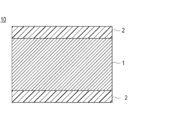
- FIG. 1 is a partial cross-sectional view schematically illustrating a layered configuration on a surface of a typical embodiment of a medical device (hereinafter, also simply referred to as a medical device) according to the present invention.
- FIG. 2 is a partial cross-sectional view schematically showing a configuration example having a different surface lamination configuration as an application example of the embodiment of FIG. 1.
- It is a schematic diagram of the friction measuring machine used for the sliding property test of an Example. It is a graph showing the change of the test force (sliding resistance value) at the time of performing 10 reciprocal sliding tests in water of 25 degreeC about the coating layer of an Example and a comparative example. It is a graph showing the test force (sliding resistance value) at the time of carrying out one reciprocation of the sliding property test in the water of 60 degreeC about the coating layer of an Example and a comparative example.
- X to Y indicating a range includes X and Y, and means “X or more and Y or less”. Unless otherwise specified, the operation, physical properties, and the like are measured at room temperature (20 to 25 ° C.) / Relative humidity of 40 to 60% RH.
- the term “(meth) acryl” includes both acryl and methacryl.
- the term “(meth) acrylic acid” includes both acrylic acid and methacrylic acid.
- the term “(meth) acryloyl” includes both acryloyl and methacryloyl.
- the term “(meth) acryloyl group” includes both acryloyl and methacryloyl groups.
- the homopolymer has a structural unit derived from a polymerizable monomer (A) having a lower critical solution temperature (LCST) (hereinafter, also referred to as monomer A).
- A polymerizable monomer having a lower critical solution temperature (LCST)
- sulfonic acid groups —SO 3 H
- sulfate groups —OSO 3 H
- sulfite groups —OSO 2 H
- salts thereof a structural unit derived from a polymerizable monomer (B) (hereinafter also referred to as monomer B) having a polymerizable monomer (C) having a photoreactive group (hereinafter also referred to as monomer C) And a structural unit derived therefrom.
- the coating layer containing the hydrophilic copolymer according to one embodiment of the present invention has a high initial slidability in a steady environment (25 ° C.) and can maintain a high slidability even after multiple rubs. it can.
- the coating layer containing the hydrophilic copolymer has significantly reduced slidability when heated. Therefore, by controlling the temperature, the medical device having the coating layer on the surface can exhibit high slidability until reaching the affected part and low slidability after reaching the affected part.
- the coating layer described in Japanese Patent No. 4198348 has low slidability at an initial stage (first reciprocation of sliding) in a steady environment (25 ° C.) (described later). Comparative Example 4-1).
- the inventors of the present invention have conducted intensive studies on the configuration of the coating layer, and have found that the use of the monomer B as a raw material dramatically improves the initial slidability in a steady environment (25 ° C.). I found it.
- the sulfonic acid group (—SO 3 H), the sulfate group (—OSO 3 H), the sulfite group (—OSO 2 H) or the group of these salts contained in the monomer B has more water than other substituents. Since the sum energy is large, it is easily anionized and easily hydrated with surrounding water. Therefore, it is considered that the coating layer containing the structural unit derived from the monomer B has improved slidability.
- the structural unit derived from the monomer A has a property that the homopolymer has LSCT (that is, is temperature-sensitive), in other words, changes from hydrophilic to hydrophobic when the temperature increases. Therefore, it is considered that when the coating layer containing the constituent units is heated, the moisture contained in the coating layer is released, and the coating layer shrinks to roughen the surface, thereby lowering the slidability.
- LSCT temperature-sensitive
- the photoreactive group contained in the structural unit derived from the monomer C generates a reactive species by irradiation with an active energy ray, and is converted from a hydrocarbon group present in a base material (base material layer) or a copolymer. Withdraw hydrogen atoms to form covalent bonds. Therefore, the coating layer containing the constituent unit is firmly fixed on the substrate. Further, since the coating layer itself is crosslinked, the strength of the coating layer is improved. Therefore, it is considered that the formed coating layer is hardly broken by friction (the friction resistance is improved).
- the coating layer described in Japanese Patent No. 4198348 contains a photoreactive group, it was found that the slidability fluctuated significantly when rubbed a plurality of times (see Comparative Example 4-1 described later). ).
- the present inventors believe that the coating layer disclosed in Japanese Patent No. 4198348 is composed of a mixture of polymers, so that the temperature-sensitive polymer is easily eluted. As a result, the upper layer of the coating layer is It was presumed that it was not firmly fixed to the base material and might be peeled off by friction.
- the monomer A is preferably a homopolymer having a lower critical solution temperature (LCST) of 30 to 70 ° C., for example, N-isopropylacrylamide (NIPAAm) (about 32 ° C.), N-vinyl isopropyl acrylamide ( About 39 ° C.), N-vinyl-n-propylacrylamide (about 32 ° C.), vinyl methyl ether (about 34 ° C.), 2-ethyl-2-oxazoline (about 65 ° C.), 2-isopropyl-2-oxazoline (about 38 ° C.).
- NIPAAm N-isopropylacrylamide
- NIPAAm N-isopropylacrylamide
- NIPAAm N-vinyl isopropyl acrylamide
- N-vinyl-n-propylacrylamide about 32 ° C.
- vinyl methyl ether about 34 ° C.
- 2-ethyl-2-oxazoline about 65 ° C.
- the lower critical solution temperature (LCST) of the obtained hydrophilic copolymer can be in a desired range (40 to 70 ° C.).
- the monomer A is particularly preferably N-isopropylacrylamide (NIPAAm).
- the monomer A may be used alone or in combination of two or more.
- the monomer A either a synthetic product or a commercially available product may be used.
- a commercial product it can be obtained from Sigma-Aldrich Corporation or the like.
- the content of the structural units derived from the monomer A is more than 50 mol% when the total of the structural units derived from all the monomers is 100 mol%.
- the coating layer formed does not have a reduced slidability to a desired range even when heated (see Comparative Example 5-2 described later). Therefore, even after the medical device reaches the diseased part, the slidability remains high even after the heat treatment, and there is a possibility that a positional shift may occur.
- the lower limit of the content is preferably 60 mol% or more, more preferably 70 mol% or more, and still more preferably 80 mol% or more. It is preferably at least 85 mol%, most preferably at least 90 mol%.
- the upper limit of the content is preferably 98 mol% from the viewpoint of further improving the slidability after initial or / and multiple friction in a steady environment (25 ° C.) and allowing the medical device to more smoothly reach the affected part. Or less, more preferably 96 mol% or less, and most preferably 94 mol% or less.
- the content is substantially the same as the ratio of the charged amount (mol) of the monomer A to the total charged amount (mol) of the monomer in producing the polymer.
- the monomer B is at least one group selected from the group consisting of a sulfonic acid group (—SO 3 H), a sulfate group (—OSO 3 H), a sulfite group (—OSO 2 H), and a salt group thereof.
- a polymerizable monomer having The salt is not particularly limited, and examples thereof include a sodium salt, a potassium salt, and an ammonium salt.
- the monomer B preferably has an ethylenically unsaturated group such as a (meth) acryloyl group, a vinyl group and an allyl group, in addition to the above groups.
- the monomer B is preferably a compound represented by the following formula (2), (3) or (4), from the viewpoint of further improving the slidability in a steady environment (25 ° C.), More preferably, it is a compound represented by the following formula (2).
- R 21 is a hydrogen atom or a methyl group, preferably a hydrogen atom.
- Z 2 is an oxygen atom (—O—) or —NH—, preferably —NH—.
- R 22 is a linear or branched alkylene group having 1 to 20 carbon atoms, preferably carbon atom, from the viewpoint of further improving the slidability in a steady environment (25 ° C.).
- It is a chain or branched alkylene group, particularly preferably a branched alkylene group having 3 to 5 carbon atoms.
- the branched alkylene group having 3 to 5 carbon atoms includes -CH (CH 3 ) -CH 2- , -C (CH 3 ) 2 -CH 2- , -CH (CH 3 ) -CH (CH 3 )- , -C (CH 3) 2 -CH 2 -CH 2 -, - CH (CH 3) -CH (CH 3) -CH 2 -, - CH (CH 3) -CH 2 -CH (CH 3) —, —CH 2 —C (CH 3 ) 2 —CH 2 —, —C (CH 3 ) 2 —CH (CH 3 ) — and the like (provided that the above groups in formula (2) are linked together)
- the order is not particularly limited.) Among them, a group represented by —C (CH 3 ) 2 —CH 2 — is particularly preferable.
- X is selected from the group consisting of a sulfonic acid group (—SO 3 H), a sulfate group (—OSO 3 H), a sulfite group (—OSO 2 H), and a salt group thereof.
- a sulfonic acid group, a sulfuric acid group, and a group of these salts since the acid dissociation degree is high (that is, it is easy to be anionized), and further improvement in slidability in a steady environment (25 ° C.) can be expected.
- a sulfonic acid group or a salt thereof in view of the availability of monomers.
- Examples of the compound represented by the above formula (2) include 2- (meth) acrylamido-2-methyl-1-propanesulfonic acid, 1-[(meth) acryloyloxymethyl] -1-propanesulfonic acid, -[(Meth) acryloyloxy] -2-propanesulfonic acid, 3-[(meth) acryloyloxy] -1-methyl-1-propanesulfonic acid, 2-sulfoethyl (meth) acrylate, 3-sulfopropyl (meth) Acrylates and salts thereof are exemplified.
- the salt is not particularly limited, and examples thereof include a sodium salt, a potassium salt, and an ammonium salt. These compounds may be used alone or in combination of two or more. Among them, 2-acrylamido-2-methyl-1-propanesulfonic acid (AMPS) and a salt thereof are preferable.
- AMPS 2-acrylamido-2-methyl-1-propanesulfonic acid
- the compound represented by the above formula (2) may be either a synthetic product or a commercially available product, and a commercially available product can be obtained from Tokyo Chemical Industry Co., Ltd. or the like.
- R 31 is a hydrogen atom or a methyl group.
- R 32 is a single bond or a linear or branched alkylene group having 1 to 20 carbon atoms, preferably a single bond or a linear or branched alkylene group having 1 to 12 carbon atoms.
- An alkylene group more preferably a single bond or a linear or branched alkylene group having 1 to 8 carbon atoms, still more preferably a single bond or a linear or branched alkylene group having 1 to 4 carbon atoms. And particularly preferably a single bond.
- specific examples of the alkylene group are the same as those in the above formula (2), and thus description thereof is omitted here.
- X is selected from the group consisting of a sulfonic acid group (—SO 3 H), a sulfate group (—OSO 3 H), a sulfite group (—OSO 2 H), and a salt group thereof.
- a sulfonic acid group, a sulfuric acid group, and a group of these salts since the acid dissociation degree is high (that is, it is easy to be anionized), and further improvement in slidability in a steady environment (25 ° C.) can be expected.
- a sulfonic acid group or a salt thereof in view of the availability of monomers.
- Examples of the compound represented by the above formula (3) include vinyl sulfonic acid, allyl sulfonic acid, methallyl sulfonic acid, 2-propene-1-sulfonic acid, 2-methyl-2-propene-1-sulfonic acid and These salts and the like can be mentioned. These compounds may be used alone or in combination of two or more.
- either a synthetic product or a commercially available product may be used.
- the commercially available product include Asahi Kasei Finechem Co., Ltd. and Tokyo Chemical Industry Co., Ltd. (for example, 2-methyl-2-propene). -1-sulfonic acid sodium salt).
- R 41 is a hydrogen atom or a methyl group.
- R 42 is a linear or branched alkylene group having 1 to 20 carbon atoms, preferably a linear or branched alkylene group having 1 to 12 carbon atoms, Preferred are straight-chain or branched-chain alkylene groups having 1 to 8 carbon atoms, and even more preferred are straight-chain or branched-chain alkylene groups having 1 to 6 carbon atoms.
- specific examples of the alkylene group are the same as those in the above formula (2), and thus description thereof is omitted here.
- X is selected from the group consisting of a sulfonic acid group (—SO 3 H), a sulfate group (—OSO 3 H), a sulfite group (—OSO 2 H), and a salt group thereof.
- a sulfonic acid group, a sulfuric acid group, and a group of these salts since the acid dissociation degree is high (that is, it is easy to be anionized), and further improvement in slidability in a steady environment (25 ° C.) can be expected.
- a sulfonic acid group or a salt thereof in view of the availability of monomers.
- Examples of the compound represented by the above formula (4) include 2-sulfoxyethyl vinyl ether, 3-sulfoxy-n-propyl vinyl ether and salts thereof. These compounds may be used alone or in combination of two or more.
- the lower limit of the content of the structural units derived from the monomer B is preferably 0.5 mol when the total of the structural units derived from all the monomers is 100 mol%. %, More preferably 1 mol% or more, even more preferably 2 mol% or more, and particularly preferably 4 mol% or more.
- the value is equal to or more than the above lower limit, the slidability at the initial stage and / or after a plurality of rubs in a steady environment (25 ° C.) increases, so that the medical device can reach the affected part more smoothly.
- the upper limit of the content is preferably 30 mol% or less, more preferably 20 mol% or less, still more preferably 10 mol% or less, and particularly preferably 8 mol% or less. If it is less than the upper limit, the slidability can be significantly reduced by heating. Therefore, after the medical device reaches the diseased part and is then subjected to the heat treatment, it is possible to prevent the displacement from being properly performed.
- the content is substantially equal to the ratio of the charged amount (mol) of the monomer B to the total charged amount (mol) of all the monomers in producing the polymer.
- the content molar ratio of the structural unit derived from the monomer A and the structural unit derived from the monomer B is preferably 70: 30 to 99.5: 0.5, more preferably 80:20 to 99: 1, even more preferably 85:15 to 98: 2, particularly preferably 90:10 to 97: 3. is there. If the lower limit of the range of the ratio is 70:30 or more, the slidability of the coating layer is sufficiently reduced by heating. Therefore, after the medical device reaches the diseased part, misalignment can be prevented by heat treatment. it can.
- the upper limit of the range of the ratio is 99.5: 0.5 or less, the slidability after initial or / and multiple friction in a steady environment (25 ° C.) becomes higher, so that the medical device can be more smoothly. It can reach the affected area.
- the monomer C is a polymerizable monomer having a photoreactive group.
- the photoreactive group refers to a group capable of generating a reactive species such as a radical, nitrene, or carbene by irradiation with an active energy ray and reacting with a base material layer to form a chemical bond.
- the monomer C preferably has an ethylenically unsaturated group such as a (meth) acryloyl group, a vinyl group and an allyl group in addition to the photoreactive group.
- Examples of the photoreactive group include an azide group, a diazo group, a diazirine group, a ketone group, and a quinone group.
- azide group examples include aryl azide groups such as phenyl azide and 4-fluoro-3-nitrophenyl azide; acyl azide groups such as benzoyl azide and p-methyl benzoyl azide; A sulfonyl azide group such as benzenesulfonyl azide; a phosphoryl azide group such as diphenylphosphoryl azide and diethylphosphoryl azide;
- diazo group examples include diazoalkanes such as diazomethane and diphenyldiazomethane; diazoketones such as diazoacetophenone and 1-trifluoromethyl-1-diazo-2-pentanone; diazoacetates such as t-butyldiazoacetate and phenyldiazoacetate; groups derived from ⁇ -diazoacetoacetate such as t-butyl- ⁇ -diazoacetoacetate; and the like.
- diazoalkanes such as diazomethane and diphenyldiazomethane
- diazoketones such as diazoacetophenone and 1-trifluoromethyl-1-diazo-2-pentanone
- diazoacetates such as t-butyldiazoacetate and phenyldiazoacetate
- groups derived from ⁇ -diazoacetoacetate such as t-butyl- ⁇ -diazoacetoacetate
- diazirine group examples include groups derived from 3-trifluoromethyl-3-phenyldiazirine and the like.
- ketone group examples include groups having a structure such as acetophenone, benzophenone, anthrone, xanthine, and thioxanthone.
- Examples of the quinone group include groups derived from anthraquinone and the like.
- photoreactive groups are appropriately selected according to the type of the substrate layer of the medical device.
- the base material layer is formed from a polyolefin resin such as a polyethylene resin, a polyamide resin, a polyurethane resin, a polyester resin, or the like, it is preferably a ketone group or a phenylazide group, and the availability of the monomer is improved.
- a group having a benzophenone structure is more preferable. That is, in one embodiment of the present invention, the monomer C has a benzophenone structure.
- Examples of the monomer C include 2-azidoethyl (meth) acrylate, 2-azidopropyl (meth) acrylate, 3-azidopropyl (meth) acrylate, 4-azidobutyl (meth) acrylate, 4- (meth) acryloyloxy Benzophenone, 4- (meth) acryloyloxyethoxybenzophenone, 4- (meth) acryloyloxy-4′-methoxybenzophenone, 4- (meth) acryloyloxyethoxy-4′-methoxybenzophenone, 4- (meth) acryloyloxy-4 '-Bromobenzophenone, 4- (meth) acryloyloxyethoxy-4'-bromobenzophenone, 4-styrylmethoxybenzophenone, 4- (meth) acryloyloxythioxanthone and the like. Among them, 4- (meth) acryloyloxybenzoph
- the monomer C either a synthetic product or a commercially available product may be used, and a commercially available product can be obtained from MRC Unitech Corporation or the like.
- the lower limit of the content of the structural units derived from the monomer C is preferably 0.1 mol%, when the total of the structural units derived from all the monomers is 100 mol%. It is at least 0.2 mol%, still more preferably at least 0.5 mol%, particularly preferably at least 1 mol%.
- the hydrophilic copolymer can be sufficiently bonded to the base material (base material layer), and thus the formed coating layer can be firmly fixed to the base material. Further, since the coating layer itself is crosslinked, the strength of the coating layer is improved. Therefore, the formed coating layer is less likely to be broken by friction (friction resistance is improved).
- the upper limit of the content is preferably 40 mol% or less, more preferably 20 mol% or less, still more preferably 10 mol% or less, particularly preferably 5 mol% or less. It is preferably at most 3 mol%.
- the content is equal to or less than the upper limit, the synthesis of the copolymer is easy.
- the formed coating layer has high slidability in a steady environment (25 ° C.), and greatly increases slidability by heating. To decline. Therefore, it is advantageous in achieving both smooth arrival of the medical device at the affected part and prevention of displacement at the affected part.
- the content is substantially equivalent to the ratio of the charged amount (mol) of the monomer C to the total charged amount (mol) of all the monomers in producing the polymer.
- the hydrophilic copolymer of the present invention is a polymerizable monomer other than the above-mentioned monomer A, monomer B, and monomer C (hereinafter, referred to as “other polymers”) as long as the effects of the present invention are not impaired.
- a monomer a polymerizable monomer other than the above-mentioned monomer A, monomer B, and monomer C (hereinafter, referred to as “other polymers”) as long as the effects of the present invention are not impaired.
- the content of structural units derived from other monomers is preferably less than 10 mol%, based on 100 mol% of the total amount of structural units derived from all monomers, More preferably, it is less than 5 mol%, and still more preferably, it is less than 1 mol% (lower limit: 0 mol%).
- the hydrophilic copolymer of the present invention is composed of monomer A, monomer B and monomer C.
- the content is substantially the same as the ratio of the charged amount (mol) of the other monomers to the total charged amount (mol) of all the monomers in producing the polymer.
- the terminal of the hydrophilic copolymer according to the present invention is not particularly limited and is appropriately defined depending on the type of the raw material used, but is usually a hydrogen atom.
- the structure of the copolymer is not particularly limited, and may be any of a random copolymer, an alternating copolymer, a periodic copolymer, and a block copolymer. From the viewpoint of maintaining, it is preferably a random copolymer.
- the lower limit of the lower critical solution temperature (LCST) of the hydrophilic copolymer of the present invention is preferably 40 ° C. or higher, more preferably 45 ° C. or higher, and even more preferably 50 ° C. or higher.
- the temperature is at least 40 ° C., when the coating layer containing the copolymer is introduced into the body, the slidability does not significantly decrease due to the influence of body temperature. In other words, even if the coating layer is introduced into the body, high slidability can be exhibited unless heat treatment is intentionally performed.
- the upper limit of the LCST of the hydrophilic copolymer of the present invention is preferably 70 ° C. or lower, more preferably 65 ° C. or lower, and even more preferably 60 ° C. or lower.
- the hydrophilic copolymer according to one embodiment of the present invention has a lower critical solution temperature (LCST) of 40 to 70 ° C.
- LCST of a hydrophilic copolymer is measured by the following method.
- ⁇ LCST measurement method The coating solution is prepared by dissolving the hydrophilic copolymer in methanol to a concentration of 10% by weight. Next, a nylon elastomer sheet (12.5 mm ⁇ 100 mm) is dipped in the above-mentioned coating solution and pulled up at a speed of 15 mm / sec. Next, the nylon elastomer sheet is dried at room temperature (25 ° C.) for 1 hour to remove the solvent. Next, a sample of the sample is obtained by irradiating the nylon elastomer sheet with UV light having a wavelength of 365 nm and a lamp power of 1 kW until the integrated light amount becomes 500 mJ / cm 2 . The UV irradiator uses UVC-1212 / 1M NLC3-AA04 (high-pressure mercury lamp) manufactured by Ushio Inc.
- UVC-1212 / 1M NLC3-AA04 high-pressure mercury lamp
- the slidability of the obtained sample is evaluated using a friction measuring device (manufactured by Trinity Lab Co., Ltd., Handy Tribomaster TL201) 20 shown in FIG. 3 according to the following method.
- the sample 16 is fixed in the petri dish 12, immersed in water 17 at a predetermined temperature at a height at which the entire sample 16 is immersed, and left standing for 10 seconds.
- This petri dish 12 is placed on the moving table 15 of the friction measuring machine 20 shown in FIG.
- a silicon terminal ( ⁇ 10 mm, R1 mm) 13 is brought into contact with the sheet, and a load 14 of 50 g is applied on the terminal.
- the sliding resistance value (gf) when the moving table 15 is reciprocated once horizontally is measured.
- the temperature of the water 17 in which the sample 16 is immersed was changed at an interval of 5 ° C. from 25 ° C., and the sliding resistance value (gf) at the time of the first reciprocation at each temperature was measured, and the value was 20 gf. Is the lowest critical solution temperature (LCST) of the hydrophilic copolymer.
- the weight average molecular weight of the hydrophilic copolymer of the present invention is preferably from 1,000 to 500,000, more preferably from 2,000 to 200,000, and still more preferably from 5,000 to 100,000. And particularly preferably from 10,000 to 50,000, and most preferably from 20,000 to 40,000.
- a value measured by gel permeation chromatography (GPC) using polystyrene as a standard substance is adopted as the weight average molecular weight.
- the method for producing the hydrophilic copolymer according to the present invention is not particularly limited, and known polymerization methods such as radical polymerization, anionic polymerization, and cationic polymerization can be adopted, and preferably, radical polymerization which is easy to produce is used.
- the polymerization method is usually carried out by stirring and heating the above-mentioned monomer A, monomer B, monomer C and, if necessary, other monomers together with a polymerization initiator in a polymerization solvent.
- a method of polymerizing is employed.
- the polymerization temperature is not particularly limited, but is preferably 25 to 100 ° C, more preferably 30 to 80 ° C.
- the polymerization time is also not particularly limited, but is preferably 30 minutes to 24 hours, more preferably 1 to 5 hours.
- polymerization solvent examples include water; alcohols such as methanol, ethanol, propanol, n-butanol, and 2,2,2-trifluoroethanol; polyhydric alcohols such as ethylene glycol, diethylene glycol, propylene glycol, and dipropylene glycol; Is preferably an aqueous solvent. From the viewpoint of dissolving the raw materials used for the polymerization, these may be used alone or in combination of two or more.
- the concentration of the polymerizable monomer is not particularly limited, but is preferably 0.05 to 1 g / mL as a total solid content (g) of each polymerizable monomer with respect to the polymerization solvent (mL), more preferably 0.1-0.5 g / mL.
- the preferred range of the ratio of the charged amount (mol) of each monomer to the total charged amount (mol) of all the monomers is as described above.
- the reaction solution containing the polymerizable monomer may be subjected to a degassing treatment before adding the polymerization initiator.
- the degassing treatment may be performed by bubbling the reaction solution with an inert gas such as nitrogen gas or argon gas for about 0.5 to 5 hours. During the degassing treatment, the reaction solution may be heated to about 30 to 100 ° C.
- polymerization initiators can be used and are not particularly limited.
- KPS potassium
- persulfates such as sodium persulfate and ammonium persulfate
- peroxides such as hydrogen peroxid
- the amount of the polymerization initiator is preferably 0.01 to 10 mol%, more preferably 0.1 to 5 mol%, based on the total amount (mol) of the polymerizable monomer.
- a chain transfer agent e.g., ethylene glycol dimethacrylate, ethylene glycol dimethacrylate, ethylene glycol dimethacrylate, ethylene glycol dimethacrylate, ethylene glycol dimethacrylate, ethylene glycol dimethacrylate, ethylene glycol dimethacrylate, ethylene glycol dimethacrylate, ethylene glycol dimethacrylate, ethylene glycol dimethacrylate, ethylene glycol dimethacrylate, ethylene glycol dimethacrylate, ethylene glycol dimethacrylate, ethylene glycol dimethacrylate, ethylene glycol dimethacrylate, ethylene glycol dimethacrylate, ethylene glycol dimethacrylate, ethylene glycol dimethacrylate, ethylene glycol dimethacrylate, ethylene glycol dimethacrylate, ethylene glycol dimethacrylate, ethylene glycol dimethacrylate, ethylene glycol dimethacrylate, sulfate, ethylene glycol dimeth
- the environment (atmosphere) in which the polymerization reaction is performed is not particularly limited, and the polymerization reaction may be performed in an air atmosphere, an inert gas atmosphere such as a nitrogen gas or an argon gas, or the like. During the polymerization reaction, the reaction solution may be stirred.
- the copolymer may precipitate during the polymerization reaction.
- the copolymer after polymerization can be purified by a general purification method such as a reprecipitation method, a dialysis method, an ultrafiltration method, and an extraction method.
- the purified copolymer can be dried by any method such as freeze-drying, reduced-pressure drying, spray-drying, or heat-drying.However, from the viewpoint that the effect on the physical properties of the polymer is small, lyophilization or reduced-pressure Drying is preferred.
- the ratio of the constituent units derived from each polymerizable monomer in the obtained copolymer is confirmed by analyzing the peak intensity of the group contained in each constituent unit using a known means such as NMR or IR. Can be.
- the amount of unreacted monomer contained in the obtained copolymer is preferably 0.01% by weight or less based on the whole copolymer.
- the content of the remaining monomer can be measured by a known means such as high performance liquid chromatography.
- the present invention also provides a medical device having a substrate layer and a coating layer formed on at least a part of the surface of the substrate layer and containing the above-mentioned hydrophilic copolymer.
- FIG. 1 is a partial cross-sectional view schematically showing a laminated structure on the surface of a typical embodiment of the medical device according to the present invention.
- FIG. 2 is a partial cross-sectional view schematically showing a configuration example having a different laminated structure on the surface as an application example of the present embodiment.
- 1 and 2 1 represents a substrate layer, 1a represents a substrate layer core, 1b represents a substrate surface layer, 2 represents a coating layer, and 10 represents a medical device.
- the base material layer 1 is fixed to at least a part of the base material layer 1 (in the drawings, the base material layer in the drawings).
- a coating layer 2 containing a hydrophilic copolymer shown as an example immobilized on the entire surface (entire surface)).
- the coating layer 2 is bonded to the base material layer 1 via a photoreactive group of the hydrophilic copolymer.
- the substrate layer used in the present embodiment may be composed of any material as long as it can react with the photoreactive group contained in the above-mentioned hydrophilic copolymer to form a chemical bond.
- examples of the material forming (forming) the base layer 1 include a metal material, a polymer material, and ceramics.
- the base material layer 1 may be formed (formed) of the entire base material layer 1 (all) with any of the above materials as shown in FIG. 1 or as shown in FIG.
- the surface of the base material layer core portion 1a formed (formed) of any of the above materials is coated (coated) with any of the above materials by an appropriate method to form (formed) the base material surface layer 1b. May have a modified structure.
- the surface of the base layer core 1a formed of a resin material or the like is coated (coated) with a metal material by an appropriate method (a conventionally known method such as plating, metal deposition, and sputtering).
- the molecular material is coated (coated) by a suitable method (a conventionally known method such as dipping (dipping), spraying (spraying), application / printing, etc.) or the reinforcing material of the base layer core portion 1a and the height of the base material surface layer 1b are increased.
- the base material layer core portion 1a has a multilayer structure in which different materials are laminated in multiple layers, or a structure (composite) in which members made of different materials are connected to each other for each part of the medical device. Is also good. Further, another middle layer (not shown) may be formed between the base layer core 1a and the base surface layer 1b. Further, the substrate surface layer 1b may be a multilayer structure in which different materials are laminated in multiple layers, or a structure (composite) in which members made of different materials are connected to each other for each part of the medical device. Good.
- the metal material is not particularly limited, and may be a balloon, a catheter, a guide wire, a micro balloon, a micro catheter, a micro guide wire, a stent delivery catheter, and ablation.
- Metal materials generally used for medical devices such as catheters are used.
- various stainless steels such as SUS304, SUS316, SUS316L, SUS420J2 and SUS630, gold, platinum, silver, copper, nickel, cobalt, titanium, iron, aluminum, tin or nickel-titanium (Ni-Ti ) Alloy, nickel-cobalt (Ni-Co) alloy, cobalt-chromium (Co-Cr) alloy, zinc-tungsten (Zn-W) alloy and the like. These may be used alone or in combination of two or more.
- an optimum metal material may be appropriately selected as a base material layer for a balloon, a catheter, a guide wire, a micro balloon, a micro catheter, a micro guide wire, a stent delivery catheter, an ablation catheter, or the like.
- the polymer material is not particularly limited, but may be a balloon, a catheter, a guidewire, a microballoon, a microcatheter, a microguidewire, or a stent delivery.
- a polymer material for example, an elastomer generally used for a medical device such as a catheter and an ablation catheter is used.
- polyamide resin polyamide elastomer (for example, nylon elastomer), linear low density polyethylene (LLDPE), low density polyethylene (LDPE), polyethylene such as high density polyethylene (HDPE), polyolefin resin such as polypropylene, polyethylene Polyester resin such as terephthalate, polyester elastomer, styrene resin such as polystyrene, cyclic polyolefin resin, modified polyolefin resin, epoxy resin, urethane resin, diallyl phthalate resin (allyl resin), polycarbonate resin, fluorine resin, amino resin (urea resin, melamine Resin, benzoguanamine resin), acrylic resin, polyacetal resin, vinyl acetate resin, phenol resin, vinyl chloride resin, silicone resin (silicon resin) Polyether resin, and polyimide resin.
- LLDPE linear low density polyethylene
- LDPE low density polyethylene
- HDPE high density polyethylene
- polyolefin resin such as polypropylene
- polymer material it is possible to appropriately select an optimum polymer material as a base layer of a balloon, a catheter, a guide wire, a micro balloon, a micro catheter, a micro guide wire, a stent delivery catheter, an ablation catheter, etc. which are used. Good.
- the shape of the base material layer is not particularly limited, and is appropriately selected depending on a use mode such as a sheet shape, a wire shape, and a tubular shape.
- the method for producing a medical device according to the present invention is not particularly limited except for using the above-mentioned hydrophilic copolymer, and may be the same as a known method or It can be applied with appropriate modification.
- a method is preferred in which the coating liquid is prepared by dissolving the hydrophilic copolymer according to the present invention in a solvent, and the coating liquid is coated on the substrate layer of the medical device.
- a solvent used to dissolve the hydrophilic copolymer can be appropriately selected, and examples thereof include methanol, ethanol, n-propanol, and isopropanol.
- the concentration of the hydrophilic copolymer in the coating solution is not particularly limited, but is preferably 0.01 to 50% by weight, more preferably 0.05 to 40% by weight, and still more preferably 0 to 40% by weight. From 1 to 30% by weight. Within such a range, the coatability of the coating liquid will be good. In addition, a uniform coating layer having a desired thickness can be easily obtained by one coating, which is preferable in terms of production efficiency.
- concentration of the hydrophilic copolymer is less than 0.01% by weight, a sufficient amount of the hydrophilic copolymer may not be fixed on the surface of the base material layer in some cases.
- the concentration of the hydrophilic copolymer exceeds 50% by weight, the viscosity of the coating solution may be too high to obtain a coating layer having a uniform thickness. However, even if it deviates from the above range, it can be sufficiently used as long as it does not affect the operation and effect of the present invention.
- the surface of the base material layer may be preliminarily treated by ultraviolet irradiation treatment, plasma treatment, corona discharge treatment, flame treatment, oxidation treatment, silane coupling treatment, phosphoric acid coupling treatment, or the like.
- the solvent of the coating liquid is only water, it is difficult to apply the solvent to the surface of the hydrophobic base material layer, but the surface of the base material layer becomes hydrophilic by plasma treatment of the base material layer surface. Thereby, the wettability of the coating liquid to the surface of the base material layer is improved, and a uniform coating layer can be formed.
- a covalent bond with a photoreactive group of a hydrophilic copolymer can be formed.
- the method for applying the coating liquid on the surface of the base material layer is not particularly limited, but may be a coating / printing method, a dipping method (dipping method, dip coating method), a spraying method (spray method), a spin coating method, or a mixing method.
- a conventionally known method such as a solution impregnation sponge coating method can be applied.
- the dipping method (dipping method, dip coating method) is preferred.
- the base layer may be immersed in a coating solution and the inside of the system may be depressurized and defoamed. By defoaming under reduced pressure, the solution can be quickly penetrated into the narrow and narrow inner surface, and the formation of the coating layer can be promoted.
- a coating layer can be formed on a desired surface portion of the base material layer.
- an appropriate member or material capable of attaching / detaching (attaching / detaching) the surface part of the base material layer which does not need to form a coating layer in advance.
- the base material layer After protecting (coating, etc.) with the coating solution, the base material layer is immersed in the coating solution, and the coating solution is coated on the base material layer.
- a coating layer can be formed on a desired surface portion of the base material layer.
- the formation method is not limited at all, and the coating layer can be formed by appropriately using a conventionally known method.
- a coating solution is applied to a predetermined surface portion of a medical device,
- a coating method using a coating device such as a spray device, a bar coater, a die coater, a reverse coater, a comma coater, a gravure coater, a spray coater, a doctor knife, etc.
- a coating device such as a spray device, a bar coater, a die coater, a reverse coater, a comma coater, a gravure coater, a spray coater, a doctor knife, etc.
- the dipping method is preferably used.
- drying process After immersing the substrate layer in the coating liquid containing the hydrophilic copolymer of the present invention as described above, it is preferable to take out the substrate layer from the coating liquid and dry the coating.
- the drying conditions are not particularly limited as long as the solvent of the coating solution can be removed.
- the drying may be performed by using a dryer or the like, or by natural drying.
- the pressure conditions during drying are not particularly limited, and the drying may be performed under normal pressure (atmospheric pressure), or may be performed under increased or reduced pressure.
- the drying means (apparatus) for example, an oven, a vacuum dryer, or the like can be used, but in the case of natural drying, the drying means (apparatus) is not particularly required.
- the coating after the drying step is irradiated with an active energy ray. Thereby, the photoreactive group of the hydrophilic copolymer in the coating is activated, and a covalent bond is formed between the copolymer and the base material layer or between the copolymers.
- the remaining radicals in the photoreactive group are combined with the radicals on the polyethylene base layer to form a covalent bond between the hydrophilic copolymer and the polyethylene base layer.
- the coating layer containing the hydrophilic copolymer of the present invention is firmly fixed on the surface of the base material layer.
- the active energy ray examples include an ultraviolet ray, an electron beam, a gamma ray, and the like, and are preferably an ultraviolet ray or an electron beam, and more preferably an ultraviolet ray in consideration of an influence on a human body.
- a wavelength at which the photoreactive group can be activated can be appropriately selected as the irradiation wavelength.
- the irradiation intensity of the ultraviolet ray is not particularly limited, but is preferably 1 to 5000 mW / cm 2 .
- the accumulated light quantity of ultraviolet rays is not particularly limited, preferably 50 ⁇ 5000mJ / cm 2, more preferably 100 ⁇ 1000mJ / cm 2.
- the device for irradiating ultraviolet rays include a high-pressure mercury lamp, a low-pressure mercury lamp, a metal halide lamp, a xenon lamp, and a halogen lamp.
- the surface of the base material layer may be washed with a solvent (for example, a solvent used for preparing a coating solution) to remove an unreacted hydrophilic copolymer.
- a solvent for example, a solvent used for preparing a coating solution
- ⁇ Immobilization of the coating film (coating layer) on the base material layer can be confirmed by using a known analysis means such as FT-IR and XPS. For example, it can be confirmed by performing FT-IR measurement before and after irradiation with an active energy ray and comparing the ratio of the peak of a bond formed by irradiation with the active energy ray to the peak of an invariable bond.
- a coating layer containing the hydrophilic copolymer of the present invention is formed on the surface of the medical device of the present invention.
- the coating layer has a high initial slidability in a steady environment (25 ° C.) and can maintain a high slidability even after a plurality of frictions.
- the coating layer is heated, the slidability is significantly reduced. Therefore, by controlling the temperature, the medical device having the coating layer on its surface can exhibit high slidability until reaching the affected part and low slidability after reaching the affected part.
- the coating layer of the medical device according to the present invention has a sliding resistance value in a steady environment (25 ° C.) of preferably 20 gf or less, more preferably 15 gf or less, and even more preferably 10 gf or less. It is particularly preferably 5 gf or less (lower limit: 0 gf). If the medical device can be maintained at or below the upper limit even after a plurality of rubs, the medical device can smoothly reach the affected part or be collected smoothly from the affected part.
- the coating layer of the medical device according to the present invention has a sliding resistance at 60 ° C. of preferably 25 gf or more, more preferably 30 gf or more, and even more preferably 40 gf or more, It is particularly preferred that it is 50 gf or more.
- the sliding resistance at 60 ° C. preferably 25 gf or more, more preferably 30 gf or more, and even more preferably 40 gf or more, It is particularly preferred that it is 50 gf or more.
- the upper limit of the value is not particularly limited, but is, for example, 200 gf or less.
- the sliding resistance at 25 ° C. and 60 ° C. of the coating layer is measured by using a friction measuring machine (manufactured by Trinity Lab Co., Ltd., Handy Tribomaster TL201) 20 shown in FIG. 3 according to the following method. Specifically, as shown in FIG. 3, a sample 16 having a coating layer on the upper surface is fixed in a petri dish 12 and immersed in water 17 at 25 ° C. or 60 ° C. at a height at which the entire sample 16 is immersed. Let stand for seconds. This petri dish 12 is placed on the moving table 15 of the friction measuring machine 20. A silicon terminal ( ⁇ 10 mm, R1 mm) 13 is brought into contact with the sheet, and a load 14 of 50 g is applied on the terminal. With the sliding distance set to 20 mm and the sliding speed set to 16.7 mm / sec, the moving table 15 is reciprocated horizontally 10 times and the sliding resistance value (gf) is measured.
- a friction measuring machine manufactured by Trinity Lab Co., Ltd., Handy Tri
- ⁇ Slidability of the medical device obtained as described above can be controlled by temperature. Therefore, another embodiment of the present invention is a method for using a medical device, in which the medical device is heated after the medical device reaches the affected part (target site).
- the method of heating the medical device is not particularly limited.
- a method of connecting a fluid supply source to the medical device and supplying a heated fluid (for example, physiological saline) from the fluid supply source to the inside of the medical device particularly, Japanese Patent Application Laid-Open No. 2015-97547 (corresponding to U.S. Patent Application Publication No. 2015/018873) and the like, a method of connecting an energy supply source to a medical device and supplying electric energy from the energy supply source to the medical device (particularly). No. 2017-195910).
- the lower limit of the heating temperature of the medical device is preferably 40 ° C. or higher, and more preferably 50 ° C. or higher from the viewpoint of shortening the working time.
- the upper limit of the heating temperature is preferably 70 ° C. or lower, more preferably 65 ° C. or lower, and still more preferably 60 ° C. or lower, in consideration of safety for living organisms.
- the heating time of the medical device varies depending on the heating temperature and the like, but is preferably within 1 minute.
- the heating of the medical device is stopped, so that the coating layer is naturally cooled to about body temperature. Thereby, the slidability of the coating layer is restored, and the medical device can be smoothly collected from the affected part.
- the medical device may be intentionally cooled for the purpose of shortening the operation time. Examples of a method for cooling the medical device include a method in which a coolant supply source is connected to the medical device, and a coolant is supplied from the coolant supply source to the inside of the medical device.
- the medical device according to the present invention is not particularly limited as long as it can be heated by the above method after reaching the diseased part.
- a balloon, a catheter, a guide wire, a micro balloon, a micro catheter, a micro guide wire, and a stent Delivery catheters, ablation catheters, and the like More specifically, the following medical devices are exemplified: (A) Catheters, such as gastric tube catheters, feeding catheters, and tubes for tube feeding, which are orally or nasally inserted or placed in the digestive tract.
- this reaction solution was placed in a 30 mL eggplant-shaped flask, oxygen was removed by sufficient nitrogen bubbling, and 28 mg (0.100 mmol) of a polymerization initiator (V-501 manufactured by Wako Pure Chemical Industries, Ltd.) was added.
- the container was quickly sealed and polymerized in a water bath at 80 ° C. for 2 hours.
- the precipitate was reprecipitated in ether, the supernatant was removed by decantation, and dried under reduced pressure to obtain a copolymer.
- the obtained copolymer was a random body and had a weight average molecular weight of about 30,000.
- the weight average molecular weight is a value measured by gel permeation chromatography (GPC) using polystyrene as a standard substance.
- this reaction solution was placed in a 30 mL eggplant-shaped flask, oxygen was removed by sufficient nitrogen bubbling, and 28 mg (0.100 mmol) of a polymerization initiator (V-501 manufactured by Wako Pure Chemical Industries, Ltd.) was added.
- the container was quickly sealed and polymerized in a water bath at 80 ° C. for 2 hours.
- the precipitate was reprecipitated in ether, the supernatant was removed by decantation, and dried under reduced pressure to obtain a copolymer.
- the obtained copolymer was a random body and had a weight average molecular weight of about 30,000.
- this reaction solution was placed in a 30 mL eggplant-shaped flask, oxygen was removed by sufficient nitrogen bubbling, and 28 mg (0.100 mmol) of a polymerization initiator (V-501 manufactured by Wako Pure Chemical Industries, Ltd.) was added.
- the container was quickly sealed and polymerized in a water bath at 80 ° C. for 2 hours.
- the precipitate was reprecipitated in acetone, the supernatant was removed by decantation, and the residue was dried under reduced pressure to obtain a copolymer.
- the obtained copolymer was a random body and had a weight average molecular weight of about 30,000.
- this reaction solution was placed in a 30 mL eggplant-shaped flask, oxygen was removed by sufficient nitrogen bubbling, and 28 mg (0.100 mmol) of a polymerization initiator (V-501 manufactured by Wako Pure Chemical Industries, Ltd.) was added.
- the container was quickly sealed and polymerized in a water bath at 80 ° C. for 2 hours.
- the precipitate was reprecipitated in ether, the supernatant was removed by decantation, and dried under reduced pressure to obtain a copolymer.
- the obtained copolymer was a random body and had a weight average molecular weight of about 30,000.
- the container was quickly sealed and polymerized in a water bath at 80 ° C. for 2 hours. Next, the precipitate was reprecipitated in ether, the supernatant was removed by decantation, and the residue was dried under reduced pressure to obtain a copolymer (corresponding to a reactive polymer disclosed in Japanese Patent No. 4198348).
- the obtained copolymer was a random body and had a weight average molecular weight of about 30,000.
- the obtained copolymer was a random body and had a weight average molecular weight of about 30,000.
- NIPAAm N-isopropylacrylamide (corresponding to monomer A)
- VP 1-vinyl-2-pyrrolidone
- NAV N-vinylacetamide
- VA vinyl acetate AMPS
- Na 2-acrylamido-2-methyl-1-propanesulfonic acid sodium salt
- MBP 4-methacryloyloxybenzophenone (corresponding to monomer C).
- Example 1-1 The copolymer obtained in Production Example 1 (corresponding to the hydrophilic copolymer according to the present invention) was dissolved in methanol to a concentration of 10% by weight to prepare a coating solution. Next, a nylon elastomer sheet (12.5 mm ⁇ 100 mm) was dipped in the above coating solution and pulled up at a speed of 15 mm / sec. Next, the nylon elastomer sheet was dried at room temperature for 1 hour to remove the solvent.
- a nylon elastomer sheet was irradiated with UV light having a wavelength of 365 nm and a lamp power of 1 kW until the integrated light amount became 500 mJ / cm 2 to obtain a sample.
- the UV irradiation device used was UVC-1212 / 1M NLC3-AA04 (high-pressure mercury lamp) from Ushio Inc.
- the sample 16 was fixed in the petri dish 12, immersed in water 17 at a temperature of 25 ° C. at which the entire sample 16 was immersed, and allowed to stand for 10 seconds.
- This petri dish 12 was placed on the moving table 15 of the friction measuring machine 20 shown in FIG.
- a silicon terminal ( ⁇ 10 mm, R1 mm) 13 was brought into contact with the sheet, and a load 14 of 50 g was applied on the terminal.
- the sliding resistance (gf) was measured when the moving table 15 was reciprocated horizontally 10 times with the sliding distance set to 20 mm and the sliding speed set to 16.7 mm / sec.
- the change in the sliding resistance value for 10 repetitions of sliding was evaluated by averaging the sliding resistance values during the forward trip from the first reciprocation to the 10th reciprocation for each number of reciprocations and plotting them on a graph as a test force. .
- Example 2-1 A sample was prepared and the sliding resistance was measured in the same manner as in Example 1-1, except that the copolymer obtained in Production Example 2 was used instead of the copolymer obtained in Production Example 1. Was.
- Example 2-1 A sample was prepared in the same manner as in Example 1-1 except that the copolymer obtained in Production Example 4 was used instead of the copolymer obtained in Production Example 1, and acetone was used instead of methanol as a coating solvent. Was prepared and the sliding resistance value was measured.
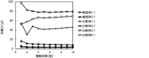
- FIG. 4 shows the results of the slidability test at a water temperature of 25 ° C.
- the samples of Example 1-1, Example 2-1 and Comparative example 1-1 exhibited a sliding resistance value of 20 gf or less at 25 ° C. through the first to tenth reciprocating strokes, and exhibited high sliding resistance at the initial stage and after a plurality of rubs. Showed sex.
- the samples of Comparative Example 2-1, Comparative Example 3-1 and Comparative Example 4-1 had a sliding resistance value exceeding 20 gf at the initial stage (first reciprocation of sliding). This is presumed to be because it does not have a structural unit derived from the monomer B, which is a slidable component. Further, in the samples of Comparative Example 3-1 and Comparative Example 4-1, the sliding resistance value was significantly disturbed at the first to fourth round trips, and the sliding resistance value was significantly increased at the 5 to 10 round trips.
- the coating layer of these samples was composed of a mixture of polymers, it is considered that PNIPAAm having no photoreactive group or the copolymer obtained in Production Example 6 eluted from the coating layer.
- Example 1-1 and Example 1-2 ⁇ LCST measurement of hydrophilic copolymer>
- the sliding resistance value (gf) was measured.
- the lowest temperature at which the sliding resistance value at the first reciprocation exceeded 20 gf was defined as the lower critical solution temperature (LCST) of the hydrophilic copolymer.
- Example 3-2 The copolymer obtained in Production Example 1 (corresponding to the hydrophilic copolymer according to the present invention) was dissolved in methanol to a concentration of 10% by weight to prepare a coating solution. Next, a nylon elastomer sheet (12.5 mm ⁇ 100 mm) was dipped in the above coating solution and pulled up at a speed of 15 mm / sec. Next, the nylon elastomer sheet was dried at room temperature for 1 hour to remove the solvent.
- the nylon elastomer sheet was irradiated with UV light having a wavelength of 365 nm and a lamp power of 1 kW until the integrated light amount became 500 mJ / cm 2 .
- the UV irradiation device used was UVC-1212 / 1M NLC3-AA04 (high-pressure mercury lamp) from Ushio Inc.
- the sample 16 was fixed in the petri dish 12, immersed in water 17 at 60 ° C. at a height at which the entire sample 16 was immersed, and allowed to stand for 10 seconds.
- This petri dish 12 was placed on the moving table 15 of the friction measuring machine 20 shown in FIG.
- a silicon terminal ( ⁇ 10 mm, R1 mm) 13 was brought into contact with the sheet, and a load 14 of 50 g was applied on the terminal.
- the sliding resistance (gf) was measured when the moving table 15 was reciprocated once horizontally in a setting of a sliding distance of 20 mm and a sliding speed of 16.7 mm / sec.
- the change of the initial sliding resistance value with respect to the temperature rise was evaluated by averaging the sliding resistance values at the time of the first reciprocating outward trip and plotting them as a test force on a graph.
- Example 4-2 A sample was prepared and the sliding resistance was measured in the same manner as in Example 3-2 except that the copolymer obtained in Production Example 2 was used instead of the copolymer obtained in Production Example 1. Was.
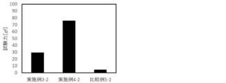
- FIG. 5 shows the results of the slidability test at a water temperature of 60 ° C.
- the samples of Example 3-2 and Example 4-2 showed a sliding resistance value of 25 gf or more at 60 ° C.
- Comparative Example 5-2 exhibited a low sliding resistance value even at 60 ° C. Since the copolymer according to Production Example 3 had too few constituent units derived from monomer A, the contribution of the constituent units derived from monomer B was large, and the slidability did not decrease even when heated. Conceivable.
- the coating layer containing the hydrophilic copolymer according to the present invention has high initial (first reciprocal sliding) slidability and a plurality of rubs in a steady environment (25 ° C.). High slidability was maintained even after (sliding 10 reciprocations). On the other hand, when the coating layer containing the hydrophilic copolymer according to the present invention was heated, the slidability was significantly reduced. Therefore, by controlling the temperature, the medical device having the coating layer on its surface can exhibit high slidability until reaching the affected part and low slidability after reaching the affected part.
- 1 base material layer 1 base material layer, 1a base material layer core, 1b substrate surface layer, 2 coating layer, 10 medical equipment, 12 Petri dishes, 13 HDPE terminal, 14 load, 15 moving table, 16 samples, 17 water, 20 Friction measuring machine.
Abstract
The present invention provides a means for achieving a medical instrument that has high slidability until reaching a lesion but low slidability after reaching the lesion. The present invention relates to a hydrophilic copolymer that includes: more than 50 mol% of a structural unit that is derived from a polymerizable monomer (A) that has a lower critical solution temperature (LCST) as a homopolymer; a structural unit that is derived from a polymerizable monomer (B) that has at least one group selected from among the sulfonic acid group (-SO3H), the sulfuric acid group (-OSO3H), the sulfurous acid group (-OSO2H), and salts thereof; and a structural unit that is derived from a polymerizable monomer (C) that has a photoreactive group.
Description
本発明は、親水性共重合体および当該親水性共重合体を含む被覆層を有する医療用具に関する。
The present invention relates to a medical device having a hydrophilic copolymer and a coating layer containing the hydrophilic copolymer.
カテーテル等の生体内に挿入される医療用具は、生体組織の損傷を低減させ、かつ術者の操作性を向上させるため、高い摺動性が要求される。さらに、上記の医療用具は、長手方向に移動させたり回転させたりしながら患部に到達されるが、その過程で生体器官の内壁との摩擦がたびたび生じるため、複数回の摩擦に耐えうることが要求される。したがって、上記の医療用具は、患部に到達するまでは高い摺動性を示す(すなわち、初期の摺動性が高く、かつ複数回摩擦後も高い摺動性を維持できる)ことが要求される。一方、インターベンションの一部の手技において使用される医療用具は、患部にて施術する際に位置がずれないよう、患部に到達した後は低い摺動性を示すことが要求される。
医療 A medical device such as a catheter inserted into a living body is required to have high slidability in order to reduce damage to a living tissue and improve operability of an operator. Furthermore, the above-mentioned medical device reaches the diseased part while moving or rotating in the longitudinal direction, but in the process, friction with the inner wall of the living organ is frequently generated, so that the medical device can withstand a plurality of frictions. Required. Therefore, the medical device described above is required to exhibit high slidability until reaching the affected part (that is, high initial slidability and high slidability even after multiple rubs). . On the other hand, medical devices used in some procedures of the intervention are required to exhibit low slidability after reaching the diseased part so as not to be displaced when performing treatment on the diseased part.
特許第4198348号公報には、感温性高分子と光反応性基を有する反応性高分子とを含む被覆層を有する医療用具が開示されており、当該医療用具は目的部位への到達前後で潤滑性が変化することが記載されている。
Japanese Patent No. 4198348 discloses a medical device having a coating layer containing a temperature-sensitive polymer and a reactive polymer having a photoreactive group, and the medical device before and after reaching a target site. It describes that the lubricity changes.
しかしながら、本発明者らの検討によれば、特許第4198348号公報に記載の被覆層は、定常環境(25℃)において、初期の摺動性が低く、かつ複数回摩擦すると摺動性が大きく変動することが判明した。かような被覆層では、患部に到達するまで高い摺動性を示すという医療用具に対するニーズを満たさない。
However, according to the study of the present inventors, the coating layer described in Japanese Patent No. 4198348 has a low initial slidability in a steady environment (25 ° C.) and a large slidability when rubbed a plurality of times. It was found to fluctuate. Such a coating layer does not satisfy the need for a medical device that exhibits high slidability until it reaches the affected part.
したがって、本発明の目的は、患部に到達するまでは高い摺動性を示し(初期の摺動性が高く、かつ複数回摩擦後も高い摺動性を維持でき)、かつ患部に到達した後は低い摺動性を示す医療用具を実現しうる手段を提供することにある。
Therefore, an object of the present invention is to exhibit high slidability until reaching the affected part (the initial slidability is high and high slidability can be maintained even after a plurality of frictions), and after reaching the affected part. An object of the present invention is to provide means capable of realizing a medical device exhibiting low slidability.
本発明者らは、上記の課題を解決すべく鋭意検討を行った結果、単独重合体が下限臨界溶液温度(LCST)を有する重合性単量体(A)由来の構成単位50モル%超と、スルホン酸基(-SO3H)、硫酸基(-OSO3H)および亜硫酸基(-OSO2H)ならびにこれらの塩の基からなる群より選択される少なくとも1つの基を有する重合性単量体(B)由来の構成単位と、光反応性基を有する重合性単量体(C)由来の構成単位と、を含む親水性共重合体によって、上記目的を達成できることを見出し、本発明を完成させるに至った。
The present inventors have conducted intensive studies in order to solve the above-mentioned problems, and as a result, it has been determined that the homopolymer has a structural unit derived from the polymerizable monomer (A) having a lower critical solution temperature (LCST) of more than 50 mol%. , A sulfonic acid group (—SO 3 H), a sulfate group (—OSO 3 H), a sulfite group (—OSO 2 H) and a polymerizable monomer having at least one group selected from the group consisting of salts thereof. It has been found that the above object can be achieved by a hydrophilic copolymer containing a structural unit derived from the monomer (B) and a structural unit derived from the polymerizable monomer (C) having a photoreactive group. Was completed.
以下、本発明を実施するための形態について、詳細に説明する。なお、本発明は、以下の実施の形態のみには限定されない。また、本明細書において、範囲を示す「X~Y」は、XおよびYを含み、「X以上Y以下」を意味する。また、特記しない限り、操作および物性等の測定は室温(20~25℃)/相対湿度40~60%RHの条件で測定する。
Hereinafter, embodiments for carrying out the present invention will be described in detail. Note that the present invention is not limited to only the following embodiments. Further, in this specification, “X to Y” indicating a range includes X and Y, and means “X or more and Y or less”. Unless otherwise specified, the operation, physical properties, and the like are measured at room temperature (20 to 25 ° C.) / Relative humidity of 40 to 60% RH.
本明細書において、「(メタ)アクリル」との語は、アクリルおよびメタクリルの双方を包含する。よって、例えば、「(メタ)アクリル酸」との語は、アクリル酸およびメタクリル酸の双方を包含する。同様に、「(メタ)アクリロイル」との語は、アクリロイルおよびメタクリロイルの双方を包含する。よって、例えば、「(メタ)アクリロイル基」との語は、アクリロイル基およびメタクリロイル基の双方を包含する。
に お い て As used herein, the term “(meth) acryl” includes both acryl and methacryl. Thus, for example, the term "(meth) acrylic acid" includes both acrylic acid and methacrylic acid. Similarly, the term "(meth) acryloyl" includes both acryloyl and methacryloyl. Thus, for example, the term "(meth) acryloyl group" includes both acryloyl and methacryloyl groups.
また、本明細書において、ある構成単位がある単量体に「由来する」とされる場合には、当該構成単位が、その構成単位に対応する単量体に存在する重合性不飽和二重結合(C=C)が単結合(-C-C-)になることにより生じる2価の構成単位であることを意味する。
Further, in the present specification, when a certain structural unit is referred to as “derived” from a certain monomer, the structural unit is a polymerizable unsaturated double present in a monomer corresponding to the structural unit. It means that the bond (C = C) is a divalent constitutional unit that is generated when the bond becomes a single bond (-CC-).
<親水性共重合体>
本発明の一実施形態に係る親水性共重合体は、単独重合体が下限臨界溶液温度(LCST)を有する重合性単量体(A)(以下、単量体Aとも称する)由来の構成単位50モル%超と、スルホン酸基(-SO3H)、硫酸基(-OSO3H)および亜硫酸基(-OSO2H)ならびにこれらの塩の基からなる群より選択される少なくとも1つの基を有する重合性単量体(B)(以下、単量体Bとも称する)由来の構成単位と、光反応性基を有する重合性単量体(C)(以下、単量体Cとも称する)由来の構成単位と、を含むことを特徴とする。 <Hydrophilic copolymer>
In the hydrophilic copolymer according to one embodiment of the present invention, the homopolymer has a structural unit derived from a polymerizable monomer (A) having a lower critical solution temperature (LCST) (hereinafter, also referred to as monomer A). More than 50 mol% and at least one group selected from the group consisting of sulfonic acid groups (—SO 3 H), sulfate groups (—OSO 3 H) and sulfite groups (—OSO 2 H), and salts thereof And a structural unit derived from a polymerizable monomer (B) (hereinafter also referred to as monomer B) having a polymerizable monomer (C) having a photoreactive group (hereinafter also referred to as monomer C) And a structural unit derived therefrom.
本発明の一実施形態に係る親水性共重合体を含む被覆層は、定常環境(25℃)において、初期の摺動性が高く、かつ複数回摩擦後も高い摺動性を維持することができる。一方、当該親水性共重合体を含む被覆層は、加熱すると摺動性が大幅に低下する。ゆえに、当該被覆層を表面に有する医療用具は、温度を制御することで、患部に到達するまでは高い摺動性を示し、患部に到達した後は低い摺動性を示しうる。
The coating layer containing the hydrophilic copolymer according to one embodiment of the present invention has a high initial slidability in a steady environment (25 ° C.) and can maintain a high slidability even after multiple rubs. it can. On the other hand, the coating layer containing the hydrophilic copolymer has significantly reduced slidability when heated. Therefore, by controlling the temperature, the medical device having the coating layer on the surface can exhibit high slidability until reaching the affected part and low slidability after reaching the affected part.
本発明者らの検討によれば、特許第4198348号公報に記載の被覆層は、定常環境(25℃)において、初期(摺動1往復目)の摺動性が低いことが判明した(後述の比較例4-1参照)。そこで、本発明者らは、被覆層の構成について鋭意検討した結果、上記単量体Bを原料として用いることで、定常環境(25℃)における初期の摺動性が飛躍的に向上することを見出した。単量体Bに含まれるスルホン酸基(-SO3H)、硫酸基(-OSO3H)、亜硫酸基(-OSO2H)またはこれらの塩の基は、他の置換基に比べて水和エネルギーが大きいため、容易にアニオン化しやすく、周囲の水と水和しやすい。ゆえに、単量体B由来の構成単位を含む被覆層は、摺動性が向上するものと考えられる。
According to the study of the present inventors, it has been found that the coating layer described in Japanese Patent No. 4198348 has low slidability at an initial stage (first reciprocation of sliding) in a steady environment (25 ° C.) (described later). Comparative Example 4-1). The inventors of the present invention have conducted intensive studies on the configuration of the coating layer, and have found that the use of the monomer B as a raw material dramatically improves the initial slidability in a steady environment (25 ° C.). I found it. The sulfonic acid group (—SO 3 H), the sulfate group (—OSO 3 H), the sulfite group (—OSO 2 H) or the group of these salts contained in the monomer B has more water than other substituents. Since the sum energy is large, it is easily anionized and easily hydrated with surrounding water. Therefore, it is considered that the coating layer containing the structural unit derived from the monomer B has improved slidability.
また、単量体A由来の構成単位は、単独重合体がLSCTを有し(すなわち温度感受性であり)、言い換えれば、温度が上昇すると親水性から疎水性に変化する性質を有する。ゆえに、当該構成単位を含む被覆層を加熱すると、被覆層に含まれていた水分が放出され、被覆層が収縮して表面が粗面化し、摺動性が低下すると考えられる。
構成 In addition, the structural unit derived from the monomer A has a property that the homopolymer has LSCT (that is, is temperature-sensitive), in other words, changes from hydrophilic to hydrophobic when the temperature increases. Therefore, it is considered that when the coating layer containing the constituent units is heated, the moisture contained in the coating layer is released, and the coating layer shrinks to roughen the surface, thereby lowering the slidability.
また、単量体C由来の構成単位に含まれる光反応性基は、活性エネルギー線の照射により反応活性種を生成し、基材(基材層)や共重合体に存在する炭化水素基から水素原子を引き抜き、共有結合を形成する。ゆえに、当該構成単位を含む被覆層は、基材上に強固に固定化される。また、被覆層自身も架橋するため、被覆層の強度が向上する。ゆえに、形成される被覆層は、摩擦によって破壊されにくくなる(耐摩擦性が向上する)と考えられる。
In addition, the photoreactive group contained in the structural unit derived from the monomer C generates a reactive species by irradiation with an active energy ray, and is converted from a hydrocarbon group present in a base material (base material layer) or a copolymer. Withdraw hydrogen atoms to form covalent bonds. Therefore, the coating layer containing the constituent unit is firmly fixed on the substrate. Further, since the coating layer itself is crosslinked, the strength of the coating layer is improved. Therefore, it is considered that the formed coating layer is hardly broken by friction (the friction resistance is improved).
ただし、特許第4198348号公報に記載の被覆層は、光反応性基を含むにもかかわらず、複数回摩擦すると摺動性が大幅に変動することが判明した(後述の比較例4-1参照)。本発明者らは、この理由として、特許第4198348号公報の被覆層は、高分子の混合物で構成されているため、感温性高分子が溶出し易く、その結果、被覆層の上層部分は基材に強固に固定化されず、摩擦によって剥離するではないかと推測した。この推測のもと、単量体A、単量体Bおよび単量体Cの共重合体の形態としたところ、形成される被覆層が複数回摩擦(摺動10往復)後も高い摺動性を維持できることを見出した。かような形態とすることで、単量体Aおよび単量体Bに由来する成分の溶出が抑制され、その結果、被覆層全体にわたって基材に強固に固定化され、摩擦によって剥離しにくくなったと考えられる。
However, although the coating layer described in Japanese Patent No. 4198348 contains a photoreactive group, it was found that the slidability fluctuated significantly when rubbed a plurality of times (see Comparative Example 4-1 described later). ). The present inventors believe that the coating layer disclosed in Japanese Patent No. 4198348 is composed of a mixture of polymers, so that the temperature-sensitive polymer is easily eluted. As a result, the upper layer of the coating layer is It was presumed that it was not firmly fixed to the base material and might be peeled off by friction. Based on this presumption, when the copolymer was formed in the form of a copolymer of monomer A, monomer B, and monomer C, the formed coating layer exhibited high sliding even after multiple frictions (10 reciprocations of sliding). It was found that sex could be maintained. By adopting such a form, the elution of the components derived from the monomers A and B is suppressed, and as a result, the components are firmly fixed to the base material over the entire coating layer and are hardly peeled off by friction. It is considered that
なお、上記メカニズムは推定であり、本発明は上記推定によって限定されない。
Note that the above mechanism is an estimation, and the present invention is not limited by the above estimation.
以下、本発明に係る親水性共重合体を構成する各重合性単量体について説明する。
Hereinafter, each polymerizable monomer constituting the hydrophilic copolymer according to the present invention will be described.
[重合性単量体]
(単量体A)
単量体Aとしては、単独重合体が30~70℃の下限臨界溶液温度(LCST)を有するものが好ましく、例えば、N-イソプロピルアクリルアミド(NIPAAm)(約32℃)、N-ビニルイソプロピルアクリルアミド(約39℃)、N-ビニル-n-プロピルアクリルアミド(約32℃)、ビニルメチルエーテル(約34℃)、2-エチル-2-オキサゾリン(約65℃)、2-イソプロピル-2-オキサゾリン(約38℃)等が挙げられる。上記中、括弧内の数値は、単独重合体のLCSTを表す。かような単量体Aを用いることで、得られる親水性共重合体の下限臨界溶液温度(LCST)が所望の範囲内(40~70℃)となりうる。中でも、単量体Aは、N-イソプロピルアクリルアミド(NIPAAm)であることが特に好ましい。 [Polymerizable monomer]
(Monomer A)
The monomer A is preferably a homopolymer having a lower critical solution temperature (LCST) of 30 to 70 ° C., for example, N-isopropylacrylamide (NIPAAm) (about 32 ° C.), N-vinyl isopropyl acrylamide ( About 39 ° C.), N-vinyl-n-propylacrylamide (about 32 ° C.), vinyl methyl ether (about 34 ° C.), 2-ethyl-2-oxazoline (about 65 ° C.), 2-isopropyl-2-oxazoline (about 38 ° C.). In the above, the numerical values in parentheses represent the LCST of the homopolymer. By using such a monomer A, the lower critical solution temperature (LCST) of the obtained hydrophilic copolymer can be in a desired range (40 to 70 ° C.). Among them, the monomer A is particularly preferably N-isopropylacrylamide (NIPAAm).
単量体Aは、1種単独で使用してもよいし、2種以上を併用してもよい。また、単量体Aは、合成品または市販品のいずれを用いてもよい。市販品としては、シグマアルドリッチ株式会社等より入手することができる。
The monomer A may be used alone or in combination of two or more. As the monomer A, either a synthetic product or a commercially available product may be used. As a commercial product, it can be obtained from Sigma-Aldrich Corporation or the like.
本発明の親水性共重合体において、単量体A由来の構成単位の含有量は、全単量体由来の構成単位の合計を100モル%としたとき、50モル%超である。当該含有量が50モル%以下の場合、形成される被覆層は、加熱しても所望の範囲まで摺動性が低下しない(後述の比較例5-2参照)。ゆえに、医療用具を患部に到達させた後、加熱処理しても摺動性が高いままとなり、位置ずれが生じるおそれがある。よって、このような不具合を防止する観点から、当該含有量の下限は、好ましくは60モル%以上であり、より好ましくは70モル%以上であり、さらにより好ましくは80モル%以上であり、特に好ましくは85モル%以上であり、最も好ましくは90モル%以上である。また、当該含有量の上限は、定常環境(25℃)における初期または/および複数回摩擦後の摺動性をさらに高め、医療用具をより円滑に患部に到達させる観点から、好ましくは98モル%以下であり、より好ましくは96モル%以下であり、最も好ましくは94モル%以下である。なお、当該含有量は、重合体を製造する際の単量体の合計仕込み量(モル)に対する単量体Aの仕込み量(モル)の割合と実質的に同等である。
に お い て In the hydrophilic copolymer of the present invention, the content of the structural units derived from the monomer A is more than 50 mol% when the total of the structural units derived from all the monomers is 100 mol%. When the content is 50 mol% or less, the coating layer formed does not have a reduced slidability to a desired range even when heated (see Comparative Example 5-2 described later). Therefore, even after the medical device reaches the diseased part, the slidability remains high even after the heat treatment, and there is a possibility that a positional shift may occur. Therefore, from the viewpoint of preventing such problems, the lower limit of the content is preferably 60 mol% or more, more preferably 70 mol% or more, and still more preferably 80 mol% or more. It is preferably at least 85 mol%, most preferably at least 90 mol%. In addition, the upper limit of the content is preferably 98 mol% from the viewpoint of further improving the slidability after initial or / and multiple friction in a steady environment (25 ° C.) and allowing the medical device to more smoothly reach the affected part. Or less, more preferably 96 mol% or less, and most preferably 94 mol% or less. The content is substantially the same as the ratio of the charged amount (mol) of the monomer A to the total charged amount (mol) of the monomer in producing the polymer.
(単量体B)
単量体Bは、スルホン酸基(-SO3H)、硫酸基(-OSO3H)および亜硫酸基(-OSO2H)ならびにこれらの塩の基からなる群より選択される少なくとも1つの基を有する重合性単量体である。塩としては、特に制限されず、ナトリウム塩、カリウム塩、アンモニウム塩等が挙げられる。また、単量体Bは、上記基以外に、(メタ)アクリロイル基、ビニル基、アリル基等のエチレン性不飽和基を有することが好ましい。 (Monomer B)
The monomer B is at least one group selected from the group consisting of a sulfonic acid group (—SO 3 H), a sulfate group (—OSO 3 H), a sulfite group (—OSO 2 H), and a salt group thereof. Is a polymerizable monomer having The salt is not particularly limited, and examples thereof include a sodium salt, a potassium salt, and an ammonium salt. Further, the monomer B preferably has an ethylenically unsaturated group such as a (meth) acryloyl group, a vinyl group and an allyl group, in addition to the above groups.
中でも、定常環境(25℃)での摺動性のさらなる向上の観点から、単量体Bは、下記式(2)、(3)または(4)で表される化合物であることが好ましく、下記式(2)で表される化合物であることがより好ましい。
Among them, the monomer B is preferably a compound represented by the following formula (2), (3) or (4), from the viewpoint of further improving the slidability in a steady environment (25 ° C.), More preferably, it is a compound represented by the following formula (2).
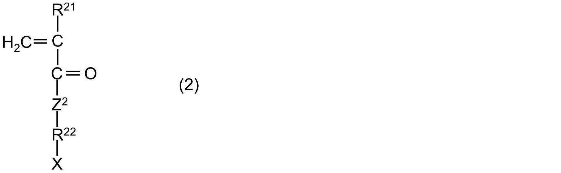
上記式(2)中、R21は、水素原子またはメチル基であり、好ましくは水素原子である。また、Z2は、酸素原子(-O-)または-NH-であり、好ましくは-NH-である。
In the above formula (2), R 21 is a hydrogen atom or a methyl group, preferably a hydrogen atom. Z 2 is an oxygen atom (—O—) or —NH—, preferably —NH—.
上記式(2)中、R22は、定常環境(25℃)での摺動性のさらなる向上の観点から、炭素原子数1~20の直鎖または分岐鎖のアルキレン基であり、好ましくは炭素原子数1~12の直鎖または分岐鎖のアルキレン基であり、より好ましくは炭素原子数1~8の直鎖または分岐鎖のアルキレン基であり、さらにより好ましくは炭素原子数1~6の直鎖または分岐鎖のアルキレン基であり、特に好ましくは炭素原子数3~5の分岐鎖のアルキレン基である。炭素原子数3~5の分岐鎖のアルキレン基は、-CH(CH3)-CH2-、-C(CH3)2-CH2-、-CH(CH3)-CH(CH3)-、-C(CH3)2-CH2-CH2-、-CH(CH3)-CH(CH3)-CH2-、-CH(CH3)-CH2-CH(CH3)-、-CH2-C(CH3)2-CH2-、-C(CH3)2-CH(CH3)-等で表される基であり(但し、上記式(2)における上記基の連結順序は特に制限されない)、中でも、-C(CH3)2-CH2-で表される基が特に好ましい。
In the above formula (2), R 22 is a linear or branched alkylene group having 1 to 20 carbon atoms, preferably carbon atom, from the viewpoint of further improving the slidability in a steady environment (25 ° C.). A linear or branched alkylene group having 1 to 12 atoms, more preferably a linear or branched alkylene group having 1 to 8 carbon atoms, still more preferably a straight or branched alkylene group having 1 to 6 carbon atoms. It is a chain or branched alkylene group, particularly preferably a branched alkylene group having 3 to 5 carbon atoms. The branched alkylene group having 3 to 5 carbon atoms includes -CH (CH 3 ) -CH 2- , -C (CH 3 ) 2 -CH 2- , -CH (CH 3 ) -CH (CH 3 )- , -C (CH 3) 2 -CH 2 -CH 2 -, - CH (CH 3) -CH (CH 3) -CH 2 -, - CH (CH 3) -CH 2 -CH (CH 3) -, —CH 2 —C (CH 3 ) 2 —CH 2 —, —C (CH 3 ) 2 —CH (CH 3 ) — and the like (provided that the above groups in formula (2) are linked together) The order is not particularly limited.) Among them, a group represented by —C (CH 3 ) 2 —CH 2 — is particularly preferable.
上記式(2)中、Xは、スルホン酸基(-SO3H)、硫酸基(-OSO3H)および亜硫酸基(-OSO2H)ならびにこれらの塩の基からなる群より選択される基であり、酸の解離度が高く(すなわちアニオン化しやすく)、定常環境(25℃)での摺動性のさらなる向上が見込めることから、好ましくはスルホン酸基および硫酸基ならびにこれらの塩の基からなる群より選択される基であり、モノマーの入手のし易さという点で、より好ましくはスルホン酸基またはその塩の基である。
In the above formula (2), X is selected from the group consisting of a sulfonic acid group (—SO 3 H), a sulfate group (—OSO 3 H), a sulfite group (—OSO 2 H), and a salt group thereof. And a sulfonic acid group, a sulfuric acid group, and a group of these salts, since the acid dissociation degree is high (that is, it is easy to be anionized), and further improvement in slidability in a steady environment (25 ° C.) can be expected. And more preferably a sulfonic acid group or a salt thereof in view of the availability of monomers.
上記式(2)で表される化合物の例としては、2-(メタ)アクリルアミド-2-メチル-1-プロパンスルホン酸、1-[(メタ)アクリロイルオキシメチル]-1-プロパンスルホン酸、2-[(メタ)アクリロイルオキシ]-2-プロパンスルホン酸、3-[(メタ)アクリロイルオキシ]-1-メチル-1-プロパンスルホン酸、2-スルホエチル(メタ)アクリレート、3-スルホプロピル(メタ)アクリレートおよびこれらの塩等が挙げられる。塩としては、特に制限されず、ナトリウム塩、カリウム塩、アンモニウム塩等が挙げられる。これらの化合物は、単独で用いてもよいし2種以上併用してもよい。中でも、2-アクリルアミド-2-メチル-1-プロパンスルホン酸(AMPS)およびその塩が好ましい。
Examples of the compound represented by the above formula (2) include 2- (meth) acrylamido-2-methyl-1-propanesulfonic acid, 1-[(meth) acryloyloxymethyl] -1-propanesulfonic acid, -[(Meth) acryloyloxy] -2-propanesulfonic acid, 3-[(meth) acryloyloxy] -1-methyl-1-propanesulfonic acid, 2-sulfoethyl (meth) acrylate, 3-sulfopropyl (meth) Acrylates and salts thereof are exemplified. The salt is not particularly limited, and examples thereof include a sodium salt, a potassium salt, and an ammonium salt. These compounds may be used alone or in combination of two or more. Among them, 2-acrylamido-2-methyl-1-propanesulfonic acid (AMPS) and a salt thereof are preferable.
上記式(2)で表される化合物は、合成品または市販品のいずれを用いてもよく、市販品としては、東京化成工業株式会社等より入手することができる。
化合物 The compound represented by the above formula (2) may be either a synthetic product or a commercially available product, and a commercially available product can be obtained from Tokyo Chemical Industry Co., Ltd. or the like.

上記式(3)中、R31は、水素原子またはメチル基である。
In the above formula (3), R 31 is a hydrogen atom or a methyl group.
上記式(3)中、R32は、単結合または炭素原子数1~20の直鎖もしくは分岐鎖のアルキレン基であり、好ましくは単結合または炭素原子数1~12の直鎖もしくは分岐鎖のアルキレン基であり、より好ましくは単結合または炭素原子数1~8の直鎖もしくは分岐鎖のアルキレン基であり、さらにより好ましくは単結合または炭素原子数1~4の直鎖もしくは分岐鎖のアルキレン基であり、特に好ましくは単結合である。ここで、アルキレン基の具体的な例示は、上記式(2)と同様であるため、ここでは説明を省略する。
In the above formula (3), R 32 is a single bond or a linear or branched alkylene group having 1 to 20 carbon atoms, preferably a single bond or a linear or branched alkylene group having 1 to 12 carbon atoms. An alkylene group, more preferably a single bond or a linear or branched alkylene group having 1 to 8 carbon atoms, still more preferably a single bond or a linear or branched alkylene group having 1 to 4 carbon atoms. And particularly preferably a single bond. Here, specific examples of the alkylene group are the same as those in the above formula (2), and thus description thereof is omitted here.
上記式(3)中、Xは、スルホン酸基(-SO3H)、硫酸基(-OSO3H)および亜硫酸基(-OSO2H)ならびにこれらの塩の基からなる群より選択される基であり、酸の解離度が高く(すなわちアニオン化しやすく)、定常環境(25℃)での摺動性のさらなる向上が見込めることから、好ましくはスルホン酸基および硫酸基ならびにこれらの塩の基からなる群より選択される基であり、モノマーの入手のし易さという点で、より好ましくはスルホン酸基またはその塩の基である。
In the above formula (3), X is selected from the group consisting of a sulfonic acid group (—SO 3 H), a sulfate group (—OSO 3 H), a sulfite group (—OSO 2 H), and a salt group thereof. And a sulfonic acid group, a sulfuric acid group, and a group of these salts, since the acid dissociation degree is high (that is, it is easy to be anionized), and further improvement in slidability in a steady environment (25 ° C.) can be expected. And more preferably a sulfonic acid group or a salt thereof in view of the availability of monomers.
上記式(3)で表される化合物の例としては、ビニルスルホン酸、アリルスルホン酸、メタリルスルホン酸、2-プロペン-1-スルホン酸、2-メチル-2-プロペン-1-スルホン酸およびこれらの塩等が挙げられる。これらの化合物は、単独で用いてもよいし2種以上併用してもよい。
Examples of the compound represented by the above formula (3) include vinyl sulfonic acid, allyl sulfonic acid, methallyl sulfonic acid, 2-propene-1-sulfonic acid, 2-methyl-2-propene-1-sulfonic acid and These salts and the like can be mentioned. These compounds may be used alone or in combination of two or more.
上記式(3)で表される化合物は、合成品または市販品のいずれを用いてもよく、市販品としては、旭化成ファインケム株式会社、東京化成工業株式会社(例えば、2-メチル-2-プロペン-1-スルホン酸ナトリウム塩)等より入手することができる。
As the compound represented by the above formula (3), either a synthetic product or a commercially available product may be used. Examples of the commercially available product include Asahi Kasei Finechem Co., Ltd. and Tokyo Chemical Industry Co., Ltd. (for example, 2-methyl-2-propene). -1-sulfonic acid sodium salt).

上記式(4)中、R41は、水素原子またはメチル基である。
In the above formula (4), R 41 is a hydrogen atom or a methyl group.
上記式(4)中、R42は、炭素原子数1~20の直鎖または分岐鎖のアルキレン基であり、好ましくは炭素原子数1~12の直鎖または分岐鎖のアルキレン基であり、より好ましくは炭素原子数1~8の直鎖または分岐鎖のアルキレン基であり、さらにより好ましくは炭素原子数1~6の直鎖もしくは分岐鎖のアルキレン基である。ここで、アルキレン基の具体的な例示は、上記式(2)と同様であるため、ここでは説明を省略する。
In the above formula (4), R 42 is a linear or branched alkylene group having 1 to 20 carbon atoms, preferably a linear or branched alkylene group having 1 to 12 carbon atoms, Preferred are straight-chain or branched-chain alkylene groups having 1 to 8 carbon atoms, and even more preferred are straight-chain or branched-chain alkylene groups having 1 to 6 carbon atoms. Here, specific examples of the alkylene group are the same as those in the above formula (2), and thus description thereof is omitted here.
上記式(4)中、Xは、スルホン酸基(-SO3H)、硫酸基(-OSO3H)および亜硫酸基(-OSO2H)ならびにこれらの塩の基からなる群より選択される基であり、酸の解離度が高く(すなわちアニオン化しやすく)、定常環境(25℃)での摺動性のさらなる向上が見込めることから、好ましくはスルホン酸基および硫酸基ならびにこれらの塩の基からなる群より選択される基であり、モノマーの入手のし易さという点で、より好ましくはスルホン酸基またはその塩の基である。
In the above formula (4), X is selected from the group consisting of a sulfonic acid group (—SO 3 H), a sulfate group (—OSO 3 H), a sulfite group (—OSO 2 H), and a salt group thereof. And a sulfonic acid group, a sulfuric acid group, and a group of these salts, since the acid dissociation degree is high (that is, it is easy to be anionized), and further improvement in slidability in a steady environment (25 ° C.) can be expected. And more preferably a sulfonic acid group or a salt thereof in view of the availability of monomers.
上記式(4)で表される化合物の例としては、2-スルホキシエチルビニルエーテル、3-スルホキシ-n-プロピルビニルエーテルおよびこれらの塩等が挙げられる。これらの化合物は、単独で用いてもよいし2種以上併用してもよい。
化合物 Examples of the compound represented by the above formula (4) include 2-sulfoxyethyl vinyl ether, 3-sulfoxy-n-propyl vinyl ether and salts thereof. These compounds may be used alone or in combination of two or more.
上記式(4)で表される化合物は、合成品または市販品のいずれを用いてもよい。
化合物 As the compound represented by the formula (4), either a synthetic product or a commercially available product may be used.
本発明の親水性共重合体中、単量体B由来の構成単位の含有量の下限値は、全単量体由来の構成単位の合計を100モル%としたとき、好ましくは0.5モル%以上であり、より好ましくは1モル%以上であり、さらにより好ましくは2モル%以上であり、特に好ましくは4モル%以上である。上記下限値以上であれば、定常環境(25℃)における初期または/および複数回摩擦後の摺動性が高くなるため、医療用具をより円滑に患部に到達させることが可能となる。一方、当該含有量の上限値は、好ましくは30モル%以下であり、より好ましくは20モル%以下であり、さらにより好ましくは10モル%以下であり、特に好ましくは8モル%以下である。当該上限値以下であれば、加熱により摺動性を大幅に低下させることができる。ゆえに、医療用具を患部に到達させた後、加熱処理することで、位置ずれを良好に防止することができる。なお、当該含有量は、重合体を製造する際の全単量体の合計仕込み量(モル)に対する単量体Bの仕込み量(モル)の割合と実質的に同等である。
In the hydrophilic copolymer of the present invention, the lower limit of the content of the structural units derived from the monomer B is preferably 0.5 mol when the total of the structural units derived from all the monomers is 100 mol%. %, More preferably 1 mol% or more, even more preferably 2 mol% or more, and particularly preferably 4 mol% or more. When the value is equal to or more than the above lower limit, the slidability at the initial stage and / or after a plurality of rubs in a steady environment (25 ° C.) increases, so that the medical device can reach the affected part more smoothly. On the other hand, the upper limit of the content is preferably 30 mol% or less, more preferably 20 mol% or less, still more preferably 10 mol% or less, and particularly preferably 8 mol% or less. If it is less than the upper limit, the slidability can be significantly reduced by heating. Therefore, after the medical device reaches the diseased part and is then subjected to the heat treatment, it is possible to prevent the displacement from being properly performed. The content is substantially equal to the ratio of the charged amount (mol) of the monomer B to the total charged amount (mol) of all the monomers in producing the polymer.
また、本発明の親水性共重合体において、単量体A由来の構成単位および単量体B由来の構成単位の含有モル比(単量体A:単量体B)は、好ましくは70:30~99.5:0.5であり、より好ましくは80:20~99:1であり、さらにより好ましくは85:15~98:2であり、特に好ましくは90:10~97:3である。当該比の範囲の下限が70:30以上であれば、加熱によって被覆層の摺動性が十分に低下するため、医療用具を患部に到達させた後、加熱処理により位置ずれを防止することができる。当該比の範囲の上限が99.5:0.5以下であれば、定常環境(25℃)における初期または/および複数回摩擦後の摺動性がより高くなるため、医療用具をより円滑に患部に到達させることができる。
In the hydrophilic copolymer of the present invention, the content molar ratio of the structural unit derived from the monomer A and the structural unit derived from the monomer B (monomer A: monomer B) is preferably 70: 30 to 99.5: 0.5, more preferably 80:20 to 99: 1, even more preferably 85:15 to 98: 2, particularly preferably 90:10 to 97: 3. is there. If the lower limit of the range of the ratio is 70:30 or more, the slidability of the coating layer is sufficiently reduced by heating. Therefore, after the medical device reaches the diseased part, misalignment can be prevented by heat treatment. it can. When the upper limit of the range of the ratio is 99.5: 0.5 or less, the slidability after initial or / and multiple friction in a steady environment (25 ° C.) becomes higher, so that the medical device can be more smoothly. It can reach the affected area.
(単量体C)
単量体Cは、光反応性基を有する重合性単量体である。ここで、光反応性基は、活性エネルギー線を照射することで、ラジカル、ナイトレン、カルベン等の反応活性種を生成し、基材層と反応して化学結合を形成しうる基をいう。また、単量体Cは、上記光反応性基以外に、(メタ)アクリロイル基、ビニル基、アリル基等のエチレン性不飽和基を有することが好ましい。 (Monomer C)
The monomer C is a polymerizable monomer having a photoreactive group. Here, the photoreactive group refers to a group capable of generating a reactive species such as a radical, nitrene, or carbene by irradiation with an active energy ray and reacting with a base material layer to form a chemical bond. Further, the monomer C preferably has an ethylenically unsaturated group such as a (meth) acryloyl group, a vinyl group and an allyl group in addition to the photoreactive group.
光反応性基の例としては、アジド基、ジアゾ基、ジアジリン基、ケトン基、キノン基等が挙げられる。
例 Examples of the photoreactive group include an azide group, a diazo group, a diazirine group, a ketone group, and a quinone group.
アジド基としては、例えば、フェニルアジド、4-フルオロ-3-ニトロフェニルアジド等のアリールアジド基;ベンゾイルアジド、p-メチルベンゾイルアジド等のアシルアジド基;エチルアジドホルメート、フェニルアジドホルメート等のアジドホルメート基;ベンゼンスルホニルアジド等のスルホニルアジド基;ジフェニルホスホリルアジド、ジエチルホスホリルアジド等のホスホリルアジド基;等が挙げられる。
Examples of the azide group include aryl azide groups such as phenyl azide and 4-fluoro-3-nitrophenyl azide; acyl azide groups such as benzoyl azide and p-methyl benzoyl azide; A sulfonyl azide group such as benzenesulfonyl azide; a phosphoryl azide group such as diphenylphosphoryl azide and diethylphosphoryl azide;
ジアゾ基としては、例えば、ジアゾメタン、ジフェニルジアゾメタン等のジアゾアルカン;ジアゾアセトフェノン、1-トリフルオロメチル-1-ジアゾ-2-ペンタノン等のジアゾケトン;t-ブチルジアゾアセテート、フェニルジアゾアセテート等のジアゾアセテート;t-ブチル-α-ジアゾアセトアセテート等のα-ジアゾアセトアセテート;等から誘導される基等が挙げられる。
Examples of the diazo group include diazoalkanes such as diazomethane and diphenyldiazomethane; diazoketones such as diazoacetophenone and 1-trifluoromethyl-1-diazo-2-pentanone; diazoacetates such as t-butyldiazoacetate and phenyldiazoacetate; groups derived from α-diazoacetoacetate such as t-butyl-α-diazoacetoacetate; and the like.
ジアジリン基としては、例えば、3-トリフルオロメチル-3-フェニルジアジリン等から誘導される基等が挙げられる。
(4) Examples of the diazirine group include groups derived from 3-trifluoromethyl-3-phenyldiazirine and the like.
ケトン基としては、例えば、アセトフェノン、ベンゾフェノン、アントロン、キサンチン、チオキサントン等の構造を有する基等が挙げられる。
(4) Examples of the ketone group include groups having a structure such as acetophenone, benzophenone, anthrone, xanthine, and thioxanthone.
キノン基としては、例えば、アントラキノン等から誘導される基等が挙げられる。
@Examples of the quinone group include groups derived from anthraquinone and the like.
これらの光反応性基は、医療用具の基材層の種類などに応じて、適宜選択される。例えば、基材層がポリエチレン樹脂等のポリオレフィン樹脂、ポリアミド樹脂、ポリウレタン樹脂、ポリエステル樹脂等から形成される場合には、ケトン基またはフェニルアジド基であることが好ましく、モノマーの入手のし易さの点で、ベンゾフェノン構造を有する基(ベンゾフェノン基)であることがより好ましい。すなわち、本発明の一実施形態において、単量体Cは、ベンゾフェノン構造を有する。
These photoreactive groups are appropriately selected according to the type of the substrate layer of the medical device. For example, when the base material layer is formed from a polyolefin resin such as a polyethylene resin, a polyamide resin, a polyurethane resin, a polyester resin, or the like, it is preferably a ketone group or a phenylazide group, and the availability of the monomer is improved. From the viewpoint, a group having a benzophenone structure (benzophenone group) is more preferable. That is, in one embodiment of the present invention, the monomer C has a benzophenone structure.
単量体Cの例としては、2-アジドエチル(メタ)アクリレート、2-アジドプロピル(メタ)アクリレート、3-アジドプロピル(メタ)アクリレート、4-アジドブチル(メタ)アクリレート、4-(メタ)アクリロイルオキシベンゾフェノン、4-(メタ)アクリロイルオキシエトキシベンゾフェノン、4-(メタ)アクリロイルオキシ-4’-メトキシベンゾフェノン、4-(メタ)アクリロイルオキシエトキシ-4’-メトキシベンゾフェノン、4-(メタ)アクリロイルオキシ-4’-ブロモベンゾフェノン、4-(メタ)アクリロイルオキシエトキシ-4’-ブロモベンゾフェノン、4-スチリルメトキシベンゾフェノン、4-(メタ)アクリロイルオキシチオキサントン等が挙げられる。中でも、4-(メタ)アクリロイルオキシベンゾフェノンが好ましい。
Examples of the monomer C include 2-azidoethyl (meth) acrylate, 2-azidopropyl (meth) acrylate, 3-azidopropyl (meth) acrylate, 4-azidobutyl (meth) acrylate, 4- (meth) acryloyloxy Benzophenone, 4- (meth) acryloyloxyethoxybenzophenone, 4- (meth) acryloyloxy-4′-methoxybenzophenone, 4- (meth) acryloyloxyethoxy-4′-methoxybenzophenone, 4- (meth) acryloyloxy-4 '-Bromobenzophenone, 4- (meth) acryloyloxyethoxy-4'-bromobenzophenone, 4-styrylmethoxybenzophenone, 4- (meth) acryloyloxythioxanthone and the like. Among them, 4- (meth) acryloyloxybenzophenone is preferable.
単量体Cは、合成品または市販品のいずれを用いてもよく、市販品としては、MRCユニテック株式会社等より入手することができる。
As the monomer C, either a synthetic product or a commercially available product may be used, and a commercially available product can be obtained from MRC Unitech Corporation or the like.
本発明の親水性共重合体において、単量体C由来の構成単位の含有量の下限は、全単量体由来の構成単位の合計を100モル%としたとき、好ましくは0.1モル%以上であり、より好ましくは0.2モル%以上であり、さらにより好ましくは0.5モル%以上であり、特に好ましくは1モル%以上である。上記下限値以上であれば、親水性共重合体は基材(基材層)と十分に結合できるため、形成される被覆層は、基材により強固に固定化されうる。また、被覆層自体も架橋するため、被覆層の強度が向上する。ゆえに、形成される被覆層は、摩擦により破壊されにくくなる(耐摩擦性が向上する)。また、当該含有量の上限は、好ましくは40モル%以下であり、より好ましくは20モル%以下であり、さらにより好ましくは10モル%以下であり、特に好ましくは5モル%以下であり、最も好ましくは3モル%以下である。当該上限値以下であれば、共重合体の合成が容易である。また、他の単量体(単量体AおよびB)が十分量存在できるため、形成される被覆層は、定常環境(25℃)での摺動性が高く、加熱により摺動性が大幅に低下する。ゆえに、医療用具の患部への円滑な到達および患部での位置ずれ防止を両立する上で有利となる。なお、当該含有量は、重合体を製造する際の全単量体の合計仕込み量(モル)に対する単量体Cの仕込み量(モル)の割合と実質的に同等である。
In the hydrophilic copolymer of the present invention, the lower limit of the content of the structural units derived from the monomer C is preferably 0.1 mol%, when the total of the structural units derived from all the monomers is 100 mol%. It is at least 0.2 mol%, still more preferably at least 0.5 mol%, particularly preferably at least 1 mol%. When the value is equal to or more than the lower limit, the hydrophilic copolymer can be sufficiently bonded to the base material (base material layer), and thus the formed coating layer can be firmly fixed to the base material. Further, since the coating layer itself is crosslinked, the strength of the coating layer is improved. Therefore, the formed coating layer is less likely to be broken by friction (friction resistance is improved). The upper limit of the content is preferably 40 mol% or less, more preferably 20 mol% or less, still more preferably 10 mol% or less, particularly preferably 5 mol% or less. It is preferably at most 3 mol%. When the content is equal to or less than the upper limit, the synthesis of the copolymer is easy. In addition, since a sufficient amount of other monomers (monomer A and B) can be present, the formed coating layer has high slidability in a steady environment (25 ° C.), and greatly increases slidability by heating. To decline. Therefore, it is advantageous in achieving both smooth arrival of the medical device at the affected part and prevention of displacement at the affected part. The content is substantially equivalent to the ratio of the charged amount (mol) of the monomer C to the total charged amount (mol) of all the monomers in producing the polymer.
本発明の親水性共重合体は、本発明の効果を損なわない範囲で、上記の単量体A、単量体B、および単量体C以外の重合性単量体(以下、「その他の単量体」とも称する)に由来する構成単位を含んでもよい。本発明の親水性共重合体において、その他の単量体に由来する構成単位の含有量は、全単量体由来の構成単位の合計量100モル%に対して、好ましくは10モル%未満、より好ましくは5モル%未満、さらにより好ましくは1モル%未満である(下限値:0モル%)。好ましくは、本発明の親水性共重合体は、単量体A、単量体Bおよび単量体Cから構成される。なお、当該含有量は、重合体を製造する際の全単量体の合計仕込み量(モル)に対するその他の単量体の仕込み量(モル)の割合と実質的に同等である。
The hydrophilic copolymer of the present invention is a polymerizable monomer other than the above-mentioned monomer A, monomer B, and monomer C (hereinafter, referred to as “other polymers”) as long as the effects of the present invention are not impaired. A monomer). In the hydrophilic copolymer of the present invention, the content of structural units derived from other monomers is preferably less than 10 mol%, based on 100 mol% of the total amount of structural units derived from all monomers, More preferably, it is less than 5 mol%, and still more preferably, it is less than 1 mol% (lower limit: 0 mol%). Preferably, the hydrophilic copolymer of the present invention is composed of monomer A, monomer B and monomer C. The content is substantially the same as the ratio of the charged amount (mol) of the other monomers to the total charged amount (mol) of all the monomers in producing the polymer.
本発明に係る親水性共重合体の末端は特に制限されず、使用される原料の種類によって適宜規定されるが、通常、水素原子である。共重合体の構造も特に制限されず、ランダム共重合体、交互共重合体、周期的共重合体、ブロック共重合体のいずれであってもよいが、複数回摩擦後も高い摺動性を維持する観点から、好ましくはランダム共重合体である。
末端 The terminal of the hydrophilic copolymer according to the present invention is not particularly limited and is appropriately defined depending on the type of the raw material used, but is usually a hydrogen atom. The structure of the copolymer is not particularly limited, and may be any of a random copolymer, an alternating copolymer, a periodic copolymer, and a block copolymer. From the viewpoint of maintaining, it is preferably a random copolymer.
[親水性共重合体の物性]
(下限臨界溶液温度(LCST))
本発明の親水性共重合体の下限臨界溶液温度(LCST)の下限は、好ましくは40℃以上であり、より好ましくは45℃以上であり、さらにより好ましくは50℃以上である。40℃以上であれば、当該共重合体を含む被覆層を体内に導入した際、体温の影響により摺動性が大幅に低下することがない。言い換えれば、被覆層を体内に導入しても、意図的に加熱処理を行わない限り、高い摺動性を発現することができる。一方、本発明の親水性共重合体のLCSTの上限は、好ましくは70℃以下であり、より好ましくは65℃以下であり、さらにより好ましくは60℃以下である。70℃以下であれば、穏やかな加熱処理により被覆層の摺動性が低下するため、血液成分が変性する等、被施術者に及ぼす悪影響が少ない。したがって、本発明の一実施形態に係る親水性共重合体は、下限臨界溶液温度(LCST)が40~70℃である。なお、本明細書中、親水性共重合体のLCSTは、下記方法により測定される。 [Physical properties of hydrophilic copolymer]
(Lower critical solution temperature (LCST))
The lower limit of the lower critical solution temperature (LCST) of the hydrophilic copolymer of the present invention is preferably 40 ° C. or higher, more preferably 45 ° C. or higher, and even more preferably 50 ° C. or higher. When the temperature is at least 40 ° C., when the coating layer containing the copolymer is introduced into the body, the slidability does not significantly decrease due to the influence of body temperature. In other words, even if the coating layer is introduced into the body, high slidability can be exhibited unless heat treatment is intentionally performed. On the other hand, the upper limit of the LCST of the hydrophilic copolymer of the present invention is preferably 70 ° C. or lower, more preferably 65 ° C. or lower, and even more preferably 60 ° C. or lower. When the temperature is 70 ° C. or lower, the slidability of the coating layer is reduced by gentle heat treatment, so that adverse effects on the subject such as denaturation of blood components are small. Therefore, the hydrophilic copolymer according to one embodiment of the present invention has a lower critical solution temperature (LCST) of 40 to 70 ° C. In addition, in this specification, LCST of a hydrophilic copolymer is measured by the following method.
≪LCSTの測定方法≫
親水性共重合体を10重量%になるようにメタノールに溶解し、コート液を調製する。次にナイロンエラストマーのシート(12.5mm×100mm)を上記コート液にディップし、15mm/secの速度で引き上げる。次に、ナイロンエラストマーのシートを室温(25℃)で1時間乾燥させ、溶媒を除去する。次に、ナイロンエラストマーのシートに波長365nm、ランプ電力1kWのUVを積算光量:500mJ/cm2となるまで照射し、サンプルを得る。UV照射装置はウシオ電機株式会社のUVC-1212/1MNLC3-AA04(高圧水銀ランプ)を使用する。 << LCST measurement method >>
The coating solution is prepared by dissolving the hydrophilic copolymer in methanol to a concentration of 10% by weight. Next, a nylon elastomer sheet (12.5 mm × 100 mm) is dipped in the above-mentioned coating solution and pulled up at a speed of 15 mm / sec. Next, the nylon elastomer sheet is dried at room temperature (25 ° C.) for 1 hour to remove the solvent. Next, a sample of the sample is obtained by irradiating the nylon elastomer sheet with UV light having a wavelength of 365 nm and a lamp power of 1 kW until the integrated light amount becomes 500 mJ / cm 2 . The UV irradiator uses UVC-1212 / 1M NLC3-AA04 (high-pressure mercury lamp) manufactured by Ushio Inc.
次に、得られたサンプルについて、下記方法にしたがって、図3に示される摩擦測定機(トリニティーラボ社製、ハンディートライボマスターTL201)20を用いて、摺動性を評価する。具体的には、上記サンプル16をシャーレ12中に固定し、サンプル16全体が浸る高さの所定温度の水17中に浸漬し、10秒間静置する。このシャーレ12を、図3に示される摩擦測定機20の移動テーブル15に載置する。シリコン端子(φ10mm、R1mm)13をシートに接触させ、端子上に50gの荷重14をかける。摺動距離20mm、摺動速度16.7mm/secの設定で、移動テーブル15を水平に1回往復移動させた際の摺動抵抗値(gf)を測定する。
Next, the slidability of the obtained sample is evaluated using a friction measuring device (manufactured by Trinity Lab Co., Ltd., Handy Tribomaster TL201) 20 shown in FIG. 3 according to the following method. Specifically, the sample 16 is fixed in the petri dish 12, immersed in water 17 at a predetermined temperature at a height at which the entire sample 16 is immersed, and left standing for 10 seconds. This petri dish 12 is placed on the moving table 15 of the friction measuring machine 20 shown in FIG. A silicon terminal (φ10 mm, R1 mm) 13 is brought into contact with the sheet, and a load 14 of 50 g is applied on the terminal. With the sliding distance set to 20 mm and the sliding speed set to 16.7 mm / sec, the sliding resistance value (gf) when the moving table 15 is reciprocated once horizontally is measured.
上記にて、サンプル16を浸漬させる水17の温度を25℃から5℃間隔で変化させ、各温度での1往復目の往路時の摺動抵抗値(gf)を測定し、当該値が20gfを超えた温度のうち最低温度を、親水性共重合体の下限臨界溶液温度(LCST)とする。
As described above, the temperature of the water 17 in which the sample 16 is immersed was changed at an interval of 5 ° C. from 25 ° C., and the sliding resistance value (gf) at the time of the first reciprocation at each temperature was measured, and the value was 20 gf. Is the lowest critical solution temperature (LCST) of the hydrophilic copolymer.
(分子量)
本発明の親水性共重合体の重量平均分子量は、好ましくは1,000~500,000であり、より好ましくは2,000~200,000であり、さらにより好ましくは5,000~100,000であり、特に好ましくは10,000~50,000であり、最も好ましくは20,000~40,000である。本明細書において、重量平均分子量は、ポリスチレンを標準物質とするゲル浸透クロマトグラフィー(Gel Permeation Chromatography、GPC)により測定した値を採用するものとする。 (Molecular weight)
The weight average molecular weight of the hydrophilic copolymer of the present invention is preferably from 1,000 to 500,000, more preferably from 2,000 to 200,000, and still more preferably from 5,000 to 100,000. And particularly preferably from 10,000 to 50,000, and most preferably from 20,000 to 40,000. In the present specification, a value measured by gel permeation chromatography (GPC) using polystyrene as a standard substance is adopted as the weight average molecular weight.
[親水性共重合体の製造方法]
本発明に係る親水性共重合体の製造方法は、特に制限されず、ラジカル重合、アニオン重合、カチオン重合などの公知の重合方法を採用でき、好ましくは製造が容易なラジカル重合を使用する。 [Method for producing hydrophilic copolymer]
The method for producing the hydrophilic copolymer according to the present invention is not particularly limited, and known polymerization methods such as radical polymerization, anionic polymerization, and cationic polymerization can be adopted, and preferably, radical polymerization which is easy to produce is used.
重合方法は、通常、上記の単量体A、単量体B、単量体C、および必要に応じてその他の単量体を、重合溶媒中で重合開始剤と共に撹拌および加熱することにより共重合させる方法が採用される。
The polymerization method is usually carried out by stirring and heating the above-mentioned monomer A, monomer B, monomer C and, if necessary, other monomers together with a polymerization initiator in a polymerization solvent. A method of polymerizing is employed.
重合温度は、特に制限されないが、好ましくは25~100℃であり、より好ましくは30~80℃である。重合時間も、特に制限されないが、好ましくは30分~24時間であり、より好ましくは1~5時間である。
The polymerization temperature is not particularly limited, but is preferably 25 to 100 ° C, more preferably 30 to 80 ° C. The polymerization time is also not particularly limited, but is preferably 30 minutes to 24 hours, more preferably 1 to 5 hours.
重合溶媒としては、水;メタノール、エタノール、プロパノール、n-ブタノール、2,2,2-トリフルオロエタノール等のアルコール類;エチレングリコール、ジエチレングリコール、プロピレングリコール、ジプロピレングリコール等の多価アルコール類;などの水性溶媒であることが好ましい。重合に用いる原料を溶解させる観点から、これらを1種単独で用いてもよく、2種以上を併用してもよい。
Examples of the polymerization solvent include water; alcohols such as methanol, ethanol, propanol, n-butanol, and 2,2,2-trifluoroethanol; polyhydric alcohols such as ethylene glycol, diethylene glycol, propylene glycol, and dipropylene glycol; Is preferably an aqueous solvent. From the viewpoint of dissolving the raw materials used for the polymerization, these may be used alone or in combination of two or more.
重合性単量体の濃度は、特に制限されないが、重合溶媒(mL)に対する各重合性単量体の合計固形分量(g)として、好ましくは0.05~1g/mLであり、より好ましくは0.1~0.5g/mLである。また、全単量体の合計仕込み量(モル)に対する各単量体の仕込み量(モル)の割合の好適な範囲は、上述したとおりである。
The concentration of the polymerizable monomer is not particularly limited, but is preferably 0.05 to 1 g / mL as a total solid content (g) of each polymerizable monomer with respect to the polymerization solvent (mL), more preferably 0.1-0.5 g / mL. The preferred range of the ratio of the charged amount (mol) of each monomer to the total charged amount (mol) of all the monomers is as described above.
重合性単量体を含む反応溶液は、重合開始剤を添加する前に脱気処理を行ってもよい。脱気処理は、例えば、窒素ガスやアルゴンガス等の不活性ガスにて、反応溶液を0.5~5時間程度バブリングすればよい。脱気処理の際は、反応溶液を30~100℃程度に加温しても良い。
(4) The reaction solution containing the polymerizable monomer may be subjected to a degassing treatment before adding the polymerization initiator. The degassing treatment may be performed by bubbling the reaction solution with an inert gas such as nitrogen gas or argon gas for about 0.5 to 5 hours. During the degassing treatment, the reaction solution may be heated to about 30 to 100 ° C.
重合体の製造には、従来公知の重合開始剤を用いることができ、特に制限されるものではないが、例えば2、2’-アゾビスイソブチロニトリル、2,2’-アゾビス(4-メトキシ-2,4-ジメチルバレロニトリル)、4,4’-アゾビス(4-シアノ吉草酸)、2,2’-アゾビス(2,4-ジメチルバレロニトリル)等のアゾ系重合開始剤;過硫酸カリウム(KPS)、過硫酸ナトリウム、過硫酸アンモニウム等の過硫酸塩、過酸化水素、t-ブチルパーオキシド、メチルエチルケトンパーオキシド等の過酸化物等の酸化剤に、亜硫酸ナトリウム、亜硫酸水素ナトリウム、アスコルビン酸等の還元剤を組み合わせたレドックス系重合開始剤等が使用できる。
For the production of the polymer, conventionally known polymerization initiators can be used and are not particularly limited. For example, 2,2′-azobisisobutyronitrile, 2,2′-azobis (4- Azo-based polymerization initiators such as methoxy-2,4-dimethylvaleronitrile), 4,4'-azobis (4-cyanovaleric acid) and 2,2'-azobis (2,4-dimethylvaleronitrile); persulfuric acid Oxidizing agents such as potassium (KPS), persulfates such as sodium persulfate and ammonium persulfate, peroxides such as hydrogen peroxide, t-butyl peroxide and methyl ethyl ketone peroxide; sodium sulfite, sodium bisulfite, ascorbic acid Redox-based polymerization initiators in combination with reducing agents such as the above can be used.
重合開始剤の配合量は、重合性単量体の合計量(モル)に対して、好ましくは0.01~10モル%であり、より好ましくは0.1~5モル%である。
(4) The amount of the polymerization initiator is preferably 0.01 to 10 mol%, more preferably 0.1 to 5 mol%, based on the total amount (mol) of the polymerizable monomer.
さらに、必要に応じて、連鎖移動剤、重合速度調整剤、界面活性剤、およびその他の添加剤を、重合の際に適宜使用してもよい。
Further, if necessary, a chain transfer agent, a polymerization rate regulator, a surfactant, and other additives may be appropriately used in the polymerization.
重合反応を行う環境(雰囲気)は特に制限されるものではなく、大気雰囲気下、窒素ガスやアルゴンガス等の不活性ガス雰囲気下等で行うこともできる。また、重合反応中は、反応液を攪拌しても良い。
環境 The environment (atmosphere) in which the polymerization reaction is performed is not particularly limited, and the polymerization reaction may be performed in an air atmosphere, an inert gas atmosphere such as a nitrogen gas or an argon gas, or the like. During the polymerization reaction, the reaction solution may be stirred.
共重合体は、重合反応中に析出してもよい。重合後の共重合体は、再沈澱法、透析法、限外濾過法、抽出法など一般的な精製法により精製することができる。
The copolymer may precipitate during the polymerization reaction. The copolymer after polymerization can be purified by a general purification method such as a reprecipitation method, a dialysis method, an ultrafiltration method, and an extraction method.
精製後の共重合体は、凍結乾燥、減圧乾燥、噴霧乾燥、または加熱乾燥等、任意の方法によって乾燥することもできるが、重合体の物性に与える影響が小さいという観点から、凍結乾燥または減圧乾燥が好ましい。
The purified copolymer can be dried by any method such as freeze-drying, reduced-pressure drying, spray-drying, or heat-drying.However, from the viewpoint that the effect on the physical properties of the polymer is small, lyophilization or reduced-pressure Drying is preferred.
得られた共重合体における各重合性単量体由来の構成単位の割合は、NMR、IR等の公知の手段を用い、各構成単位に含まれる基のピーク強度を分析することで確認することができる。
The ratio of the constituent units derived from each polymerizable monomer in the obtained copolymer is confirmed by analyzing the peak intensity of the group contained in each constituent unit using a known means such as NMR or IR. Can be.
得られた共重合体に含まれる未反応単量体は、共重合体全体に対して0.01重量%以下であることが好ましい。未反応単量体は少ないほど好ましい(下限値:0重量%)。残留する単量体の含量は、高速液体クロマトグラフィー等公知の手段で測定できる。
未 The amount of unreacted monomer contained in the obtained copolymer is preferably 0.01% by weight or less based on the whole copolymer. The less unreacted monomer, the better (lower limit: 0% by weight). The content of the remaining monomer can be measured by a known means such as high performance liquid chromatography.
<医療用具>
本発明は、基材層と、前記基材層表面の少なくとも一部に形成され、上記の親水性共重合体を含む被覆層とを有する医療用具をも提供する。 <Medical equipment>
The present invention also provides a medical device having a substrate layer and a coating layer formed on at least a part of the surface of the substrate layer and containing the above-mentioned hydrophilic copolymer.
以下、添付した図面を参照して、本発明に係る医療用具の好ましい実施形態について説明する。
Hereinafter, preferred embodiments of the medical device according to the present invention will be described with reference to the attached drawings.
図1は、本発明に係る医療用具の代表的な実施形態の表面の積層構造を模式的に表した部分断面図である。図2は、本実施形態の応用例として、表面の積層構造の異なる構成例を模式的に表した部分断面図である。なお、図1および図2中、1は基材層を、1aは基材層コア部を、1bは基材表面層を、2は被覆層を、10は医療用具を、それぞれ表す。
FIG. 1 is a partial cross-sectional view schematically showing a laminated structure on the surface of a typical embodiment of the medical device according to the present invention. FIG. 2 is a partial cross-sectional view schematically showing a configuration example having a different laminated structure on the surface as an application example of the present embodiment. 1 and 2, 1 represents a substrate layer, 1a represents a substrate layer core, 1b represents a substrate surface layer, 2 represents a coating layer, and 10 represents a medical device.
図1および図2に示されるように、本実施形態の医療用具10では、基材層1と、基材層1の少なくとも一部に固定化された(図中では、図面内の基材層1表面の全体(全面)に固定化された例を示す)親水性共重合体を含む被覆層2と、を備える。被覆層2は、親水性共重合体の光反応性基を介して基材層1に結合している。
As shown in FIGS. 1 and 2, in the medical device 10 of the present embodiment, the base material layer 1 is fixed to at least a part of the base material layer 1 (in the drawings, the base material layer in the drawings). And a coating layer 2 containing a hydrophilic copolymer (shown as an example immobilized on the entire surface (entire surface)). The coating layer 2 is bonded to the base material layer 1 via a photoreactive group of the hydrophilic copolymer.
以下、本実施形態の医療用具の各構成について説明する。
Hereinafter, each configuration of the medical device of the present embodiment will be described.
[基材層(基材)]
本実施形態で用いられる基材層としては、上記の親水性共重合体に含まれる光反応性基と反応して化学結合を形成しうるものであれば、いずれの材料から構成されてもよい。具体的には、基材層1を構成(形成)する材料は、金属材料、高分子材料、セラミックス等が挙げられる。ここで、基材層1は、図1に示されるように、基材層1全体(全部)が上記いずれかの材料で構成(形成)されても、または、図2に示されるように、上記いずれかの材料で構成(形成)された基材層コア部1aの表面に他の上記いずれかの材料を適当な方法で被覆(コーティング)して、基材表面層1bを構成(形成)した構造を有していてもよい。後者の場合の例としては、樹脂材料等で形成された基材層コア部1aの表面に金属材料が適当な方法(メッキ、金属蒸着、スパッタ等従来公知の方法)で被覆(コーティング)されて、基材表面層1bを形成してなるもの;金属材料やセラミックス材料等の硬い補強材料で形成された基材層コア部1aの表面に、金属材料等の補強材料に比して柔軟な高分子材料が適当な方法(浸漬(ディッピング)、噴霧(スプレー)、塗布・印刷等の従来公知の方法)で被覆(コーティング)あるいは基材層コア部1aの補強材料と基材表面層1bの高分子材料とが複合化(適当な反応処理)されて、基材表面層1bを形成してなるもの等が挙げられる。よって、基材層コア部1aが、異なる材料を多層に積層してなる多層構造体、あるいは医療用具の部分ごとに異なる材料で形成された部材を繋ぎ合わせた構造(複合体)などであってもよい。また、基材層コア部1aと基材表面層1bとの間に、さらに別のミドル層(図示せず)が形成されていてもよい。さらに、基材表面層1bに関しても異なる材料を多層に積層してなる多層構造体、あるいは医療用具の部分ごとに異なる材料で形成された部材を繋ぎ合わせた構造(複合体)などであってもよい。 [Base material layer (base material)]
The substrate layer used in the present embodiment may be composed of any material as long as it can react with the photoreactive group contained in the above-mentioned hydrophilic copolymer to form a chemical bond. . Specifically, examples of the material forming (forming) thebase layer 1 include a metal material, a polymer material, and ceramics. Here, the base material layer 1 may be formed (formed) of the entire base material layer 1 (all) with any of the above materials as shown in FIG. 1 or as shown in FIG. The surface of the base material layer core portion 1a formed (formed) of any of the above materials is coated (coated) with any of the above materials by an appropriate method to form (formed) the base material surface layer 1b. May have a modified structure. As an example of the latter case, the surface of the base layer core 1a formed of a resin material or the like is coated (coated) with a metal material by an appropriate method (a conventionally known method such as plating, metal deposition, and sputtering). A substrate surface layer 1b formed on the surface of the substrate layer core portion 1a formed of a hard reinforcing material such as a metal material or a ceramic material. The molecular material is coated (coated) by a suitable method (a conventionally known method such as dipping (dipping), spraying (spraying), application / printing, etc.) or the reinforcing material of the base layer core portion 1a and the height of the base material surface layer 1b are increased. A material obtained by forming a base material surface layer 1b by forming a complex with a molecular material (appropriate reaction treatment) is exemplified. Therefore, the base material layer core portion 1a has a multilayer structure in which different materials are laminated in multiple layers, or a structure (composite) in which members made of different materials are connected to each other for each part of the medical device. Is also good. Further, another middle layer (not shown) may be formed between the base layer core 1a and the base surface layer 1b. Further, the substrate surface layer 1b may be a multilayer structure in which different materials are laminated in multiple layers, or a structure (composite) in which members made of different materials are connected to each other for each part of the medical device. Good.
本実施形態で用いられる基材層としては、上記の親水性共重合体に含まれる光反応性基と反応して化学結合を形成しうるものであれば、いずれの材料から構成されてもよい。具体的には、基材層1を構成(形成)する材料は、金属材料、高分子材料、セラミックス等が挙げられる。ここで、基材層1は、図1に示されるように、基材層1全体(全部)が上記いずれかの材料で構成(形成)されても、または、図2に示されるように、上記いずれかの材料で構成(形成)された基材層コア部1aの表面に他の上記いずれかの材料を適当な方法で被覆(コーティング)して、基材表面層1bを構成(形成)した構造を有していてもよい。後者の場合の例としては、樹脂材料等で形成された基材層コア部1aの表面に金属材料が適当な方法(メッキ、金属蒸着、スパッタ等従来公知の方法)で被覆(コーティング)されて、基材表面層1bを形成してなるもの;金属材料やセラミックス材料等の硬い補強材料で形成された基材層コア部1aの表面に、金属材料等の補強材料に比して柔軟な高分子材料が適当な方法(浸漬(ディッピング)、噴霧(スプレー)、塗布・印刷等の従来公知の方法)で被覆(コーティング)あるいは基材層コア部1aの補強材料と基材表面層1bの高分子材料とが複合化(適当な反応処理)されて、基材表面層1bを形成してなるもの等が挙げられる。よって、基材層コア部1aが、異なる材料を多層に積層してなる多層構造体、あるいは医療用具の部分ごとに異なる材料で形成された部材を繋ぎ合わせた構造(複合体)などであってもよい。また、基材層コア部1aと基材表面層1bとの間に、さらに別のミドル層(図示せず)が形成されていてもよい。さらに、基材表面層1bに関しても異なる材料を多層に積層してなる多層構造体、あるいは医療用具の部分ごとに異なる材料で形成された部材を繋ぎ合わせた構造(複合体)などであってもよい。 [Base material layer (base material)]
The substrate layer used in the present embodiment may be composed of any material as long as it can react with the photoreactive group contained in the above-mentioned hydrophilic copolymer to form a chemical bond. . Specifically, examples of the material forming (forming) the
上記基材層1を構成(形成)する材料のうち、金属材料としては、特に制限されるものではなく、バルーン、カテーテル、ガイドワイヤ、マイクロバルーン、マイクロカテーテル、マイクロガイドワイヤ、ステントデリバリーカテーテル、アブレーションカテーテル等の医療用具に一般的に使用される金属材料が使用される。具体的には、SUS304、SUS316、SUS316L、SUS420J2、SUS630等の各種ステンレス鋼(SUS)、金、白金、銀、銅、ニッケル、コバルト、チタン、鉄、アルミニウム、スズあるいはニッケル-チタン(Ni-Ti)合金、ニッケル-コバルト(Ni-Co)合金、コバルト-クロム(Co-Cr)合金、亜鉛-タングステン(Zn-W)合金等の各種合金が挙げられる。これらは1種単独で使用してもよいし、2種以上を併用してもよい。上記金属材料には、使用用途であるバルーン、カテーテル、ガイドワイヤ、マイクロバルーン、マイクロカテーテル、マイクロガイドワイヤ、ステントデリバリーカテーテル、アブレーションカテーテル等の基材層として最適な金属材料を適宜選択すればよい。
Among the materials constituting (forming) the base layer 1, the metal material is not particularly limited, and may be a balloon, a catheter, a guide wire, a micro balloon, a micro catheter, a micro guide wire, a stent delivery catheter, and ablation. Metal materials generally used for medical devices such as catheters are used. Specifically, various stainless steels (SUS) such as SUS304, SUS316, SUS316L, SUS420J2 and SUS630, gold, platinum, silver, copper, nickel, cobalt, titanium, iron, aluminum, tin or nickel-titanium (Ni-Ti ) Alloy, nickel-cobalt (Ni-Co) alloy, cobalt-chromium (Co-Cr) alloy, zinc-tungsten (Zn-W) alloy and the like. These may be used alone or in combination of two or more. As the above-mentioned metal material, an optimum metal material may be appropriately selected as a base material layer for a balloon, a catheter, a guide wire, a micro balloon, a micro catheter, a micro guide wire, a stent delivery catheter, an ablation catheter, or the like.
また、上記基材層1を構成(形成)する材料のうち、高分子材料としては、特に制限されるものではなく、バルーン、カテーテル、ガイドワイヤ、マイクロバルーン、マイクロカテーテル、マイクロガイドワイヤ、ステントデリバリーカテーテル、アブレーションカテーテル等の医療用具に一般的に使用される高分子材料(例えばエラストマー)が使用される。具体的には、ポリアミド樹脂、ポリアミドエラストマー(例えばナイロンエラストマー)、直鎖状低密度ポリエチレン(LLDPE)、低密度ポリエチレン(LDPE)、高密度ポリエチレン(HDPE)等のポリエチレン、ポリプロピレン等のポリオレフィン樹脂、ポリエチレンテレフタレート等のポリエステル樹脂、ポリエステルエラストマー、ポリスチレン等のスチロール樹脂、環状ポリオレフィン樹脂、変性ポリオレフィン樹脂、エポキシ樹脂、ウレタン樹脂、ジアリルフタレート樹脂(アリル樹脂)、ポリカーボネート樹脂、フッ素樹脂、アミノ樹脂(ユリア樹脂、メラミン樹脂、ベンゾグアナミン樹脂)、アクリル樹脂、ポリアセタール樹脂、酢酸ビニル樹脂、フェノール樹脂、塩化ビニル樹脂、シリコーン樹脂(ケイ素樹脂)、ポリエーテル樹脂、ポリイミド樹脂などが挙げられる。これらは1種単独で使用してもよいし、2種以上を併用してもよい。上記高分子材料には、使用用途であるバルーン、カテーテル、ガイドワイヤ、マイクロバルーン、マイクロカテーテル、マイクロガイドワイヤ、ステントデリバリーカテーテル、アブレーションカテーテル等の基材層として最適な高分子材料を適宜選択すればよい。
Further, among the materials constituting (forming) the base layer 1, the polymer material is not particularly limited, but may be a balloon, a catheter, a guidewire, a microballoon, a microcatheter, a microguidewire, or a stent delivery. A polymer material (for example, an elastomer) generally used for a medical device such as a catheter and an ablation catheter is used. Specifically, polyamide resin, polyamide elastomer (for example, nylon elastomer), linear low density polyethylene (LLDPE), low density polyethylene (LDPE), polyethylene such as high density polyethylene (HDPE), polyolefin resin such as polypropylene, polyethylene Polyester resin such as terephthalate, polyester elastomer, styrene resin such as polystyrene, cyclic polyolefin resin, modified polyolefin resin, epoxy resin, urethane resin, diallyl phthalate resin (allyl resin), polycarbonate resin, fluorine resin, amino resin (urea resin, melamine Resin, benzoguanamine resin), acrylic resin, polyacetal resin, vinyl acetate resin, phenol resin, vinyl chloride resin, silicone resin (silicon resin) Polyether resin, and polyimide resin. These may be used alone or in combination of two or more. In the above-mentioned polymer material, it is possible to appropriately select an optimum polymer material as a base layer of a balloon, a catheter, a guide wire, a micro balloon, a micro catheter, a micro guide wire, a stent delivery catheter, an ablation catheter, etc. which are used. Good.
また、上記基材層の形状は、特に制限されることはなく、シート状、線(ワイヤ)状、管状など使用態様により適宜選択される。
The shape of the base material layer is not particularly limited, and is appropriately selected depending on a use mode such as a sheet shape, a wire shape, and a tubular shape.
[医療用具の製造方法]
本発明に係る医療用具の製造方法(基材層上への被覆層の形成方法)は、上記の親水性共重合体を使用すること以外は特に制限されず、公知の方法を同様にしてあるいは適宜改変して適用できる。例えば、本発明に係る親水性共重合体を溶剤に溶解してコート液を調製し、このコート液を医療用具の基材層上にコーティングする方法が好ましい。 [Medical device manufacturing method]
The method for producing a medical device according to the present invention (the method for forming a coating layer on a substrate layer) is not particularly limited except for using the above-mentioned hydrophilic copolymer, and may be the same as a known method or It can be applied with appropriate modification. For example, a method is preferred in which the coating liquid is prepared by dissolving the hydrophilic copolymer according to the present invention in a solvent, and the coating liquid is coated on the substrate layer of the medical device.
(塗布工程)
上記方法において、親水性共重合体を溶解するのに使用される溶剤は適宜選択されうるが、例えば、メタノール、エタノール、n-プロパノール、イソプロパノール等が挙げられる。 (Coating process)
In the above method, a solvent used to dissolve the hydrophilic copolymer can be appropriately selected, and examples thereof include methanol, ethanol, n-propanol, and isopropanol.
上記方法において、親水性共重合体を溶解するのに使用される溶剤は適宜選択されうるが、例えば、メタノール、エタノール、n-プロパノール、イソプロパノール等が挙げられる。 (Coating process)
In the above method, a solvent used to dissolve the hydrophilic copolymer can be appropriately selected, and examples thereof include methanol, ethanol, n-propanol, and isopropanol.
また、コート液中の親水性共重合体の濃度は、特に限定されないが、好ましくは0.01~50重量%であり、より好ましくは0.05~40重量%であり、さらにより好ましくは0.1~30重量%である。かような範囲であれば、コート液の塗工性が良好となる。また、1回のコーティングで所望の厚みの均一な被覆層を容易に得ることができ、生産効率の点で好ましい。なお、親水性共重合体の濃度が0.01重量%未満の場合、基材層表面に十分な量の親水性共重合体を固定できない場合がある。また、親水性共重合体の濃度が50重量%を超える場合、コート液の粘度が高くなりすぎて、均一な厚さの被覆層を得られない場合がある。但し、上記範囲を外れても、本発明の作用効果に影響を及ぼさない範囲であれば、十分に利用可能である。
The concentration of the hydrophilic copolymer in the coating solution is not particularly limited, but is preferably 0.01 to 50% by weight, more preferably 0.05 to 40% by weight, and still more preferably 0 to 40% by weight. From 1 to 30% by weight. Within such a range, the coatability of the coating liquid will be good. In addition, a uniform coating layer having a desired thickness can be easily obtained by one coating, which is preferable in terms of production efficiency. When the concentration of the hydrophilic copolymer is less than 0.01% by weight, a sufficient amount of the hydrophilic copolymer may not be fixed on the surface of the base material layer in some cases. If the concentration of the hydrophilic copolymer exceeds 50% by weight, the viscosity of the coating solution may be too high to obtain a coating layer having a uniform thickness. However, even if it deviates from the above range, it can be sufficiently used as long as it does not affect the operation and effect of the present invention.
コート液を塗布する前に、紫外線照射処理、プラズマ処理、コロナ放電処理、火炎処理、酸化処理、シランカップリング処理、リン酸カップリング処理等により基材層表面を予め処理してもよい。コート液の溶剤が水のみである場合、疎水性の基材層表面に塗布することは困難であるが、基材層表面をプラズマ処理することで基材層表面が親水化する。これにより、コート液の基材層表面への濡れ性が向上し、均一な被覆層を形成することができる。また、金属やフッ素系樹脂等のC-H結合を持たない基材層表面に上記処理を施すことで、親水性共重合体の光反応性基との共有結合の形成が可能となる。
表面 Before applying the coating solution, the surface of the base material layer may be preliminarily treated by ultraviolet irradiation treatment, plasma treatment, corona discharge treatment, flame treatment, oxidation treatment, silane coupling treatment, phosphoric acid coupling treatment, or the like. When the solvent of the coating liquid is only water, it is difficult to apply the solvent to the surface of the hydrophobic base material layer, but the surface of the base material layer becomes hydrophilic by plasma treatment of the base material layer surface. Thereby, the wettability of the coating liquid to the surface of the base material layer is improved, and a uniform coating layer can be formed. In addition, by performing the above-described treatment on the surface of a base material layer having no CH bond, such as a metal or a fluorine-based resin, a covalent bond with a photoreactive group of a hydrophilic copolymer can be formed.
基材層表面にコート液を塗布する方法としては、特に制限されるものではなく、塗布・印刷法、浸漬法(ディッピング法、ディップコート法)、噴霧法(スプレー法)、スピンコート法、混合溶液含浸スポンジコート法など、従来公知の方法を適用することができる。これらのうち、浸漬法(ディッピング法、ディップコート法)が好ましい。
The method for applying the coating liquid on the surface of the base material layer is not particularly limited, but may be a coating / printing method, a dipping method (dipping method, dip coating method), a spraying method (spray method), a spin coating method, or a mixing method. A conventionally known method such as a solution impregnation sponge coating method can be applied. Of these, the dipping method (dipping method, dip coating method) is preferred.
なお、カテーテル等の内径が細い医療用具の内表面に被覆層を形成させる場合、コート液中に基材層を浸漬して、系内を減圧にして脱泡させてもよい。減圧にして脱泡させることにより、細く狭い内面に素早く溶液を浸透させ、被覆層の形成を促進できる。
In the case where a coating layer is formed on the inner surface of a medical device such as a catheter having a small inner diameter, the base layer may be immersed in a coating solution and the inside of the system may be depressurized and defoamed. By defoaming under reduced pressure, the solution can be quickly penetrated into the narrow and narrow inner surface, and the formation of the coating layer can be promoted.
また、基材層の一部にのみ被覆層を形成させる場合には、基材層の一部のみをコート液中に浸漬して、コート液を基材層の一部にコーティングすることで、基材層の所望の表面部位に、被覆層を形成することができる。
Also, when forming a coating layer only on a part of the base material layer, by immersing only a part of the base material layer in the coating liquid, and coating the coating liquid on a part of the base material layer, A coating layer can be formed on a desired surface portion of the base material layer.
基材層の一部のみをコート液中に浸漬するのが困難な場合には、予め被覆層を形成する必要のない基材層の表面部分を着脱(装脱着)可能な適当な部材や材料で保護(被覆等)した上で、基材層をコート液中に浸漬して、コート液を基材層にコーティングした後、被覆層を形成する必要のない基材層の表面部分の保護部材(材料)を取り外し、その後、加熱操作等により反応させることで、基材層の所望の表面部位に被覆層を形成することができる。ただし、本発明では、これらの形成法に何ら制限されるものではなく、従来公知の方法を適宜利用して、被覆層を形成することができる。例えば、基材層の一部のみを混合溶液中に浸漬するのが困難な場合には、浸漬法に代えて、他のコーティング手法(例えば、医療用具の所定の表面部分に、コート液を、スプレー装置、バーコーター、ダイコーター、リバースコーター、コンマコーター、グラビアコーター、スプレーコーター、ドクターナイフなどの塗布装置を用いて、塗布する方法など)を適用してもよい。なお、医療用具の構造上、円筒状の用具の外表面と内表面の双方が、被覆層を有する必要があるような場合には、一度に外表面と内表面の双方をコーティングすることができる点で、浸漬法(ディッピング法)が好ましく使用される。
When it is difficult to immerse only a part of the base material layer in the coating liquid, an appropriate member or material capable of attaching / detaching (attaching / detaching) the surface part of the base material layer which does not need to form a coating layer in advance. After protecting (coating, etc.) with the coating solution, the base material layer is immersed in the coating solution, and the coating solution is coated on the base material layer. By removing the (material) and then reacting by a heating operation or the like, a coating layer can be formed on a desired surface portion of the base material layer. However, in the present invention, the formation method is not limited at all, and the coating layer can be formed by appropriately using a conventionally known method. For example, when it is difficult to immerse only a part of the base material layer in the mixed solution, instead of the immersion method, another coating method (for example, a coating solution is applied to a predetermined surface portion of a medical device, A coating method using a coating device such as a spray device, a bar coater, a die coater, a reverse coater, a comma coater, a gravure coater, a spray coater, a doctor knife, etc.) may be applied. In the case where both the outer surface and the inner surface of the cylindrical device need to have a coating layer due to the structure of the medical device, both the outer surface and the inner surface can be coated at a time. In this respect, the dipping method (dipping method) is preferably used.
(乾燥工程)
上記のように本発明の親水性共重合体を含むコート液中に基材層を浸漬した後、コート液から基材層を取り出して、被膜を乾燥させることが好ましい。乾燥条件は、コート液の溶剤を除去できれば特に制限されず、ドライヤー等を用いて温風処理を行ってもよいし、自然乾燥させてもよい。また、乾燥時の圧力条件も何ら制限されるものではなく、常圧(大気圧)下で行うことができるほか、加圧下または減圧下で行ってもよい。乾燥手段(装置)としては、例えば、オーブン、減圧乾燥機などを利用することができるが、自然乾燥の場合には、特に乾燥手段(装置)は不要である。 (Drying process)
After immersing the substrate layer in the coating liquid containing the hydrophilic copolymer of the present invention as described above, it is preferable to take out the substrate layer from the coating liquid and dry the coating. The drying conditions are not particularly limited as long as the solvent of the coating solution can be removed. The drying may be performed by using a dryer or the like, or by natural drying. The pressure conditions during drying are not particularly limited, and the drying may be performed under normal pressure (atmospheric pressure), or may be performed under increased or reduced pressure. As the drying means (apparatus), for example, an oven, a vacuum dryer, or the like can be used, but in the case of natural drying, the drying means (apparatus) is not particularly required.
(固定化工程)
上記乾燥工程後の被膜に対し、活性エネルギー線を照射する。これにより、被膜中の親水性共重合体の光反応性基が活性化し、共重合体と基材層との間や、共重合体同士で共有結合を形成する。 (Immobilization process)
The coating after the drying step is irradiated with an active energy ray. Thereby, the photoreactive group of the hydrophilic copolymer in the coating is activated, and a covalent bond is formed between the copolymer and the base material layer or between the copolymers.
光反応性基としてベンゾフェノン構造を有する親水性共重合体と、ポリエチレン基材層との組み合わせを例に、親水性共重合体と基材層との共有結合の形成について、以下説明する。親水性共重合体がベンゾフェノン構造を有する光反応性基を含む場合、紫外線を照射することで光反応性基内に2個のラジカルが生成する。このうち1個のラジカルがポリエチレン基材層から水素原子を引き抜き、代わりにポリエチレン基材層上に1個のラジカルが生成する。その後、光反応性基内の残りのラジカルとポリエチレン基材層上のラジカルとが結合することにより、親水性共重合体とポリエチレン基材層との間で共有結合が形成される。かような機構により、本発明の親水性共重合体を含む被覆層は、基材層表面に強固に固定化される。
(4) Taking the combination of a hydrophilic copolymer having a benzophenone structure as a photoreactive group and a polyethylene base layer as an example, formation of a covalent bond between the hydrophilic copolymer and the base layer will be described below. When the hydrophilic copolymer contains a photoreactive group having a benzophenone structure, two radicals are generated in the photoreactive group by irradiating ultraviolet rays. One of the radicals abstracts a hydrogen atom from the polyethylene base layer, and instead generates one radical on the polyethylene base layer. Thereafter, the remaining radicals in the photoreactive group are combined with the radicals on the polyethylene base layer to form a covalent bond between the hydrophilic copolymer and the polyethylene base layer. By such a mechanism, the coating layer containing the hydrophilic copolymer of the present invention is firmly fixed on the surface of the base material layer.
活性エネルギー線としては、紫外線、電子線、ガンマ線等が挙げられるが、好ましくは紫外線または電子線であり、人体への影響を考慮すると、より好ましくは紫外線である。紫外線を用いる場合、照射波長としては、光反応性基が活性化しうる波長を適宜選択することができる。紫外線の照射強度は、特に制限されないが、好ましくは1~5000mW/cm2である。また、紫外線の積算光量も、特に制限されないが、好ましくは50~5000mJ/cm2であり、より好ましくは100~1000mJ/cm2である。紫外線を照射する装置としては、高圧水銀ランプ、低圧水銀ランプ、メタルハライドランプ、キセノンランプ、ハロゲンランプ等を例示することができる。
Examples of the active energy ray include an ultraviolet ray, an electron beam, a gamma ray, and the like, and are preferably an ultraviolet ray or an electron beam, and more preferably an ultraviolet ray in consideration of an influence on a human body. When ultraviolet light is used, a wavelength at which the photoreactive group can be activated can be appropriately selected as the irradiation wavelength. The irradiation intensity of the ultraviolet ray is not particularly limited, but is preferably 1 to 5000 mW / cm 2 . Further, the accumulated light quantity of ultraviolet rays is not particularly limited, preferably 50 ~ 5000mJ / cm 2, more preferably 100 ~ 1000mJ / cm 2. Examples of the device for irradiating ultraviolet rays include a high-pressure mercury lamp, a low-pressure mercury lamp, a metal halide lamp, a xenon lamp, and a halogen lamp.
上記の活性エネルギー線照射を行った後、溶剤(例えば、コート液調製に用いる溶剤)で基材層表面を洗浄し、未反応の親水性共重合体を除去してもよい。
After performing the above-described active energy ray irradiation, the surface of the base material layer may be washed with a solvent (for example, a solvent used for preparing a coating solution) to remove an unreacted hydrophilic copolymer.
基材層への被膜(被覆層)の固定化は、FT-IR、XPS等の公知の分析手段を用いて確認することができる。例えば、活性エネルギー線の照射前後でFT-IR測定を行い、活性エネルギー線照射によって形成される結合のピークと不変である結合のピークとの比を比較することにより、確認することができる。
固定 Immobilization of the coating film (coating layer) on the base material layer can be confirmed by using a known analysis means such as FT-IR and XPS. For example, it can be confirmed by performing FT-IR measurement before and after irradiation with an active energy ray and comparing the ratio of the peak of a bond formed by irradiation with the active energy ray to the peak of an invariable bond.
上記方法により、本発明に係る医療用具の表面には、本発明の親水性共重合体を含む被覆層が表面に形成される。当該被覆層は、定常環境(25℃)では、初期の摺動性が高く、複数回摩擦後も高い摺動性を維持できる。一方、当該被覆層は、加熱すると摺動性が大幅に低下する。ゆえに、当該被覆層を表面に有する医療用具は、温度を制御することで、患部に到達するまでは高い摺動性を示し、かつ患部に到達した後は低い摺動性を示しうる。
被覆 By the above method, a coating layer containing the hydrophilic copolymer of the present invention is formed on the surface of the medical device of the present invention. The coating layer has a high initial slidability in a steady environment (25 ° C.) and can maintain a high slidability even after a plurality of frictions. On the other hand, when the coating layer is heated, the slidability is significantly reduced. Therefore, by controlling the temperature, the medical device having the coating layer on its surface can exhibit high slidability until reaching the affected part and low slidability after reaching the affected part.
本発明に係る医療用具の被覆層は、定常環境(25℃)での摺動抵抗値が、20gf以下であることが好ましく、15gf以下であることがより好ましく、10gf以下であることがさらにより好ましく、5gf以下であることが特に好ましい(下限値:0gf)。複数回摩擦後も上記上限値以下を維持できれば、医療用具を患部に円滑に到達させ、または患部から円滑に回収することができる。
The coating layer of the medical device according to the present invention has a sliding resistance value in a steady environment (25 ° C.) of preferably 20 gf or less, more preferably 15 gf or less, and even more preferably 10 gf or less. It is particularly preferably 5 gf or less (lower limit: 0 gf). If the medical device can be maintained at or below the upper limit even after a plurality of rubs, the medical device can smoothly reach the affected part or be collected smoothly from the affected part.
一方、本発明に係る医療用具の被覆層は、60℃での摺動抵抗値が、25gf以上であることが好ましく、30gf以上であることがより好ましく、40gf以上であることがさらにより好ましく、50gf以上であることが特に好ましい。上記下限値以上であれば、医療用具を患部に到達させた後、加熱処理により低摺動化させ、位置ずれを起こさずに的確に治療を行うことができる。なお、当該値の上限は、特に制限されないが、例えば200gf以下である。
On the other hand, the coating layer of the medical device according to the present invention has a sliding resistance at 60 ° C. of preferably 25 gf or more, more preferably 30 gf or more, and even more preferably 40 gf or more, It is particularly preferred that it is 50 gf or more. When the value is equal to or more than the lower limit, after the medical device reaches the diseased part, the sliding can be reduced by heat treatment, and the treatment can be accurately performed without causing displacement. The upper limit of the value is not particularly limited, but is, for example, 200 gf or less.
被覆層の25℃および60℃での摺動抵抗値は、下記方法にしたがって、図3に示される摩擦測定機(トリニティーラボ社製、ハンディートライボマスターTL201)20を用いて測定する。具体的には、図3に示すように、被覆層を上面に有するサンプル16をシャーレ12中に固定し、サンプル16全体が浸る高さの25℃または60℃の水17中に浸漬し、10秒間静置する。このシャーレ12を、摩擦測定機20の移動テーブル15に載置する。シリコン端子(φ10mm、R1mm)13をシートに接触させ、端子上に50gの荷重14をかける。摺動距離20mm、摺動速度16.7mm/secの設定で、移動テーブル15を水平に10回往復移動させ、摺動抵抗値(gf)を測定する。
(3) The sliding resistance at 25 ° C. and 60 ° C. of the coating layer is measured by using a friction measuring machine (manufactured by Trinity Lab Co., Ltd., Handy Tribomaster TL201) 20 shown in FIG. 3 according to the following method. Specifically, as shown in FIG. 3, a sample 16 having a coating layer on the upper surface is fixed in a petri dish 12 and immersed in water 17 at 25 ° C. or 60 ° C. at a height at which the entire sample 16 is immersed. Let stand for seconds. This petri dish 12 is placed on the moving table 15 of the friction measuring machine 20. A silicon terminal (φ10 mm, R1 mm) 13 is brought into contact with the sheet, and a load 14 of 50 g is applied on the terminal. With the sliding distance set to 20 mm and the sliding speed set to 16.7 mm / sec, the moving table 15 is reciprocated horizontally 10 times and the sliding resistance value (gf) is measured.
上記説明したようにして得られる医療用具は、温度により摺動性を制御することができる。したがって、本発明の他の実施形態は、上記医療用具を患部(目的部位)まで到達させた後、医療用具を加熱する、医療用具の使用方法である。
医療 Slidability of the medical device obtained as described above can be controlled by temperature. Therefore, another embodiment of the present invention is a method for using a medical device, in which the medical device is heated after the medical device reaches the affected part (target site).
医療用具を加熱する方法は、特に制限されないが、例えば、医療用具に流体供給源を接続し、流体供給源から医療用具の内部に加温した流体(例えば生理食塩水)を供給する方法(特開2015-97547号公報(米国特許出願公開第2015/018873号明細書に対応)等参照)、医療用具にエネルギー供給源を接続し、エネルギー供給源から医療用具に電気エネルギーを供給する方法(特開2017-195910号公報等参照)等が挙げられる。
The method of heating the medical device is not particularly limited. For example, a method of connecting a fluid supply source to the medical device and supplying a heated fluid (for example, physiological saline) from the fluid supply source to the inside of the medical device (particularly, Japanese Patent Application Laid-Open No. 2015-97547 (corresponding to U.S. Patent Application Publication No. 2015/018873) and the like, a method of connecting an energy supply source to a medical device and supplying electric energy from the energy supply source to the medical device (particularly). No. 2017-195910).
医療用具の加熱温度の下限は、好ましくは40℃以上であり、作業時間を短縮する観点から、より好ましくは50℃以上である。一方、加熱温度の上限は、生体への安全性を考慮すると、好ましくは70℃以下であり、より好ましくは65℃以下であり、さらにより好ましくは60℃以下である。また、医療用具の加熱時間は、加熱温度等により異なるが、好ましくは1分以内である。
下限 The lower limit of the heating temperature of the medical device is preferably 40 ° C. or higher, and more preferably 50 ° C. or higher from the viewpoint of shortening the working time. On the other hand, the upper limit of the heating temperature is preferably 70 ° C. or lower, more preferably 65 ° C. or lower, and still more preferably 60 ° C. or lower, in consideration of safety for living organisms. The heating time of the medical device varies depending on the heating temperature and the like, but is preferably within 1 minute.
患部にて施術した後、医療用具の加熱を停止することで、被覆層は体温程度まで自然冷却される。これにより、被覆層の摺動性が回復し、医療用具を患部から円滑に回収することができる。この際、作業時間の短縮を目的として、意図的に医療用具を冷却してもよい。医療用具を冷却する方法としては、医療用具に冷媒供給源を接続し、冷媒供給源から医療用具の内部に冷媒を供給する方法等が挙げられる。
し た After performing the treatment in the affected area, the heating of the medical device is stopped, so that the coating layer is naturally cooled to about body temperature. Thereby, the slidability of the coating layer is restored, and the medical device can be smoothly collected from the affected part. At this time, the medical device may be intentionally cooled for the purpose of shortening the operation time. Examples of a method for cooling the medical device include a method in which a coolant supply source is connected to the medical device, and a coolant is supplied from the coolant supply source to the inside of the medical device.
本発明に係る医療用具は、患部に到達させた後、上記方法等により加熱できるものであれば特に制限されないが、例えば、バルーン、カテーテル、ガイドワイヤ、マイクロバルーン、マイクロカテーテル、マイクロガイドワイヤ、ステントデリバリーカテーテル、アブレーションカテーテル等が挙げられる。より具体的には、以下の医療用具が例示される:
(a)胃管カテーテル、栄養カテーテル、経管栄養用チューブなどの経口もしくは経鼻的に消化器官内に挿入ないし留置されるカテーテル類
(b)酸素カテーテル、酸素カヌラ、気管内チューブのチューブやカフ、気管切開チューブのチューブやカフ、気管内吸引カテーテルなどの経口または経鼻的に気道ないし気管内に挿入ないし留置されるカテーテル類
(c)尿道カテーテル、導尿カテーテル、尿道バルーンカテーテルのカテーテルやバルーンなどの尿道ないし尿管内に挿入ないし留置されるカテーテル類
(d)吸引カテーテル、排液カテーテル、直腸カテーテルなどの各種体腔、臓器、組内に挿入ないし留置されるカテーテル類
(e)留置針、IVHカテーテル、サーモダイリューションカテーテル、血管造影用カテーテル、マイクロカテーテル、血管拡張用バルーンカテーテル、マイクロバルーンカテーテル、ステントデリバリーカテーテル、ダイレーターあるいはイントロデューサーなどの血管内に挿入ないし留置されるカテーテル類、あるいは、これらのカテーテル用のガイドワイヤ、マイクロガイドワイヤ、スタイレットなど
(f)人工気管、人工気管支など
(g)体外循環治療用の医療用具(人工肺、人工心臓、人工腎臓など)やその回路類
(h)アブレーションカテーテル。 The medical device according to the present invention is not particularly limited as long as it can be heated by the above method after reaching the diseased part. For example, a balloon, a catheter, a guide wire, a micro balloon, a micro catheter, a micro guide wire, and a stent Delivery catheters, ablation catheters, and the like. More specifically, the following medical devices are exemplified:
(A) Catheters, such as gastric tube catheters, feeding catheters, and tubes for tube feeding, which are orally or nasally inserted or placed in the digestive tract. (B) Oxygen catheters, oxygen cannulas, endotracheal tube tubes and cuffs Catheters inserted or placed in the airway or trachea orally or nasally, such as tubes or cuffs of tracheostomy tubes, intratracheal suction catheters, etc. (c) Catheters or balloons of urethral catheters, urinary catheters, urethral balloon catheters Catheters inserted or placed in the urethra or ureter such as (d) catheters inserted or placed in various body cavities, organs, and sets such as suction catheters, drainage catheters, and rectal catheters (e) indwelling needles, IVH Catheter, thermodilution catheter, angiographic catheter, microphone Catheters such as catheters, vascular dilatation balloon catheters, micro-balloon catheters, stent delivery catheters, dilators and introducers, and other catheters inserted or placed in blood vessels, or guidewires, microguidewires, and stylings for these catheters (F) Artificial trachea, artificial bronchi, etc. (g) Medical devices (external lung, artificial heart, artificial kidney, etc.) for extracorporeal circulation treatment and circuits thereof (h) Ablation catheter.
以下に、実施例によって本発明を具体的に説明するが、本発明はこれら実施例によって限定されるものではない。なお、各例中の部および%はいずれも重量基準である。以下、特に規定のない室温放置条件は全て、23℃/55%RHである。
本 Hereinafter, the present invention will be described specifically with reference to examples, but the present invention is not limited to these examples. In addition, all parts and% in each example are based on weight. Hereinafter, all room temperature storage conditions that are not particularly specified are 23 ° C./55% RH.
<親水性共重合体の製造>
[製造例1]
東京化成工業株式会社製N-イソプロピルアクリルアミド(NIPAAm)1.06g(9.4mmol)、2-アクリルアミド-2-メチル-1-プロパンスルホン酸ナトリウム塩(AMPS(Na))0.183g(0.4mmol)およびMRCユニテック株式会社製4-メタクリロイルオキシベンゾフェノン(MBP)0.053g(0.2mmol)を2,2,2-トリフルオロエタノール/水(9/1 v/v)混合溶媒10mLに溶解させて、反応液を調製した。次に、この反応液を30mLのナス型フラスコに入れ、十分な窒素バブリングによって酸素を除き、重合開始剤(和光純薬工業株式会社製V-501)28mg(0.100mmol)を添加した後、素早く密閉し、80℃の水浴で2時間重合を行った。次に、エーテル中で再沈殿し、デカンテーションで上澄みを除去し、減圧乾燥し、共重合体を得た。得られた共重合体はランダム体であり、重量平均分子量は約30,000であった。なお、重量平均分子量は、ポリスチレンを標準物質とするゲル浸透クロマトグラフィー(Gel Permeation Chromatography、GPC)により測定した値である。 <Production of hydrophilic copolymer>
[Production Example 1]
1.06 g (9.4 mmol) of N-isopropylacrylamide (NIPAAm) manufactured by Tokyo Chemical Industry Co., Ltd., 0.183 g (0.4 mmol) of 2-acrylamido-2-methyl-1-propanesulfonic acid sodium salt (AMPS (Na)) ) And 4-methacryloyloxybenzophenone (MBP) 0.053 g (0.2 mmol) manufactured by MRC Unitech Co., Ltd. were dissolved in 10 mL of 2,2,2-trifluoroethanol / water (9/1 v / v) mixed solvent. A reaction solution was prepared. Next, this reaction solution was placed in a 30 mL eggplant-shaped flask, oxygen was removed by sufficient nitrogen bubbling, and 28 mg (0.100 mmol) of a polymerization initiator (V-501 manufactured by Wako Pure Chemical Industries, Ltd.) was added. The container was quickly sealed and polymerized in a water bath at 80 ° C. for 2 hours. Next, the precipitate was reprecipitated in ether, the supernatant was removed by decantation, and dried under reduced pressure to obtain a copolymer. The obtained copolymer was a random body and had a weight average molecular weight of about 30,000. The weight average molecular weight is a value measured by gel permeation chromatography (GPC) using polystyrene as a standard substance.
[製造例2]
東京化成工業株式会社製N-イソプロピルアクリルアミド(NIPAAm)1.02g(9.0mmol)、2-アクリルアミド-2-メチル-1-プロパンスルホン酸ナトリウム塩(AMPS(Na))0.367g(0.8mmol)およびMRCユニテック株式会社製4-メタクリロイルオキシベンゾフェノン(MBP)0.053g(0.2mmol)を2,2,2-トリフルオロエタノール/水(9/1 v/v)混合溶媒10mLに溶解させて、反応液を調製した。次に、この反応液を30mLのナス型フラスコに入れ、十分な窒素バブリングによって酸素を除き、重合開始剤(和光純薬工業株式会社製V-501)28mg(0.100mmol)を添加した後、素早く密閉し、80℃の水浴で2時間重合を行った。次に、エーテル中で再沈殿し、デカンテーションで上澄みを除去し、減圧乾燥し、共重合体を得た。得られた共重合体はランダム体であり、重量平均分子量は約30,000であった。 [Production Example 2]
1.02 g (9.0 mmol) of N-isopropylacrylamide (NIPAAm) manufactured by Tokyo Chemical Industry Co., Ltd., 0.367 g (0.8 mmol) of 2-acrylamido-2-methyl-1-propanesulfonic acid sodium salt (AMPS (Na)) ) And 4-methacryloyloxybenzophenone (MBP) 0.053 g (0.2 mmol) manufactured by MRC Unitech Co., Ltd. were dissolved in 10 mL of 2,2,2-trifluoroethanol / water (9/1 v / v) mixed solvent. A reaction solution was prepared. Next, this reaction solution was placed in a 30 mL eggplant-shaped flask, oxygen was removed by sufficient nitrogen bubbling, and 28 mg (0.100 mmol) of a polymerization initiator (V-501 manufactured by Wako Pure Chemical Industries, Ltd.) was added. The container was quickly sealed and polymerized in a water bath at 80 ° C. for 2 hours. Next, the precipitate was reprecipitated in ether, the supernatant was removed by decantation, and dried under reduced pressure to obtain a copolymer. The obtained copolymer was a random body and had a weight average molecular weight of about 30,000.
[製造例3]
東京化成工業株式会社製N-イソプロピルアクリルアミド(NIPAAm)0.566g(5.0mmol)、2-アクリルアミド-2-メチル-1-プロパンスルホン酸ナトリウム塩(AMPS(Na))2.20g(4.8mmol)およびMRCユニテック株式会社製4-メタクリロイルオキシベンゾフェノン(MBP)0.053g(0.2mmol)を2,2,2-トリフルオロエタノール/水(9/1 v/v)混合溶媒10mLに溶解させて、反応液を調製した。次に、この反応液を30mLのナス型フラスコに入れ、十分な窒素バブリングによって酸素を除き、重合開始剤(和光純薬工業株式会社製V-501)28mg(0.100mmol)を添加した後、素早く密閉し、80℃の水浴で2時間重合を行った。次に、アセトン中で再沈殿し、デカンテーションで上澄みを除去し、減圧乾燥し、共重合体を得た。得られた共重合体はランダム体であり、重量平均分子量は約30,000であった。 [Production Example 3]
0.566 g (5.0 mmol) of N-isopropylacrylamide (NIPAAm) manufactured by Tokyo Chemical Industry Co., Ltd. 2.20 g (4.8 mmol) of 2-acrylamido-2-methyl-1-propanesulfonic acid sodium salt (AMPS (Na)) ) And 4-methacryloyloxybenzophenone (MBP) 0.053 g (0.2 mmol) manufactured by MRC Unitech Co., Ltd. were dissolved in 10 mL of 2,2,2-trifluoroethanol / water (9/1 v / v) mixed solvent. A reaction solution was prepared. Next, this reaction solution was placed in a 30 mL eggplant-shaped flask, oxygen was removed by sufficient nitrogen bubbling, and 28 mg (0.100 mmol) of a polymerization initiator (V-501 manufactured by Wako Pure Chemical Industries, Ltd.) was added. The container was quickly sealed and polymerized in a water bath at 80 ° C. for 2 hours. Next, the precipitate was reprecipitated in acetone, the supernatant was removed by decantation, and the residue was dried under reduced pressure to obtain a copolymer. The obtained copolymer was a random body and had a weight average molecular weight of about 30,000.
[製造例4]
東京化成工業株式会社製N-イソプロピルアクリルアミド(NIPAAm)1.11g(9.8mmol)、MRCユニテック株式会社製4-メタクリロイルオキシベンゾフェノン(MBP)0.053g(0.2mmol)を2,2,2-トリフルオロエタノール/水(9/1 v/v)混合溶媒10mLに溶解させて、反応液を調製した。次に、この反応液を30mLのナス型フラスコに入れ、十分な窒素バブリングによって酸素を除き、重合開始剤(和光純薬工業株式会社製V-501)28mg(0.100mmol)を添加した後、素早く密閉し、80℃の水浴で2時間重合を行った。次に、エーテル中で再沈殿し、デカンテーションで上澄みを除去し、減圧乾燥し、共重合体を得た。得られた共重合体はランダム体であり、重量平均分子量は約30,000であった。 [Production Example 4]
1.11 g (9.8 mmol) of N-isopropylacrylamide (NIPAAm) manufactured by Tokyo Chemical Industry Co., Ltd. and 0.053 g (0.2 mmol) of 4-methacryloyloxybenzophenone (MBP) manufactured by MRC Unitech Co., Ltd. were 2,2,2- The reaction mixture was dissolved in 10 mL of a trifluoroethanol / water (9/1 v / v) mixed solvent to prepare a reaction solution. Next, this reaction solution was placed in a 30 mL eggplant-shaped flask, oxygen was removed by sufficient nitrogen bubbling, and 28 mg (0.100 mmol) of a polymerization initiator (V-501 manufactured by Wako Pure Chemical Industries, Ltd.) was added. The container was quickly sealed and polymerized in a water bath at 80 ° C. for 2 hours. Next, the precipitate was reprecipitated in ether, the supernatant was removed by decantation, and dried under reduced pressure to obtain a copolymer. The obtained copolymer was a random body and had a weight average molecular weight of about 30,000.
[製造例5]
東京化成工業株式会社製1-ビニル-2-ピロリドン(VP)1.09g(9.8mmol)、MRCユニテック株式会社製4-メタクリロイルオキシベンゾフェノン(MBP)0.053g(0.2mmol)を2,2,2-トリフルオロエタノール/水(9/1 v/v)混合溶媒10mLに溶解させて、反応液を調製した。次に、この反応液を30mLのナス型フラスコに入れ、十分な窒素バブリングによって酸素を除き、重合開始剤(和光純薬工業株式会社製V-501)28mg(0.100mmol)を添加した後、素早く密閉し、80℃の水浴で2時間重合を行った。次に、エーテル中で再沈殿し、デカンテーションで上澄みを除去し、減圧乾燥し、共重合体(特許第4198348号公報の反応性高分子に相当)を得た。得られた共重合体はランダム体であり、重量平均分子量は約30,000であった。 [Production Example 5]
1.29 g (9.8 mmol) of 1-vinyl-2-pyrrolidone (VP) manufactured by Tokyo Chemical Industry Co., Ltd. and 0.053 g (0.2 mmol) of 4-methacryloyloxybenzophenone (MBP) manufactured by MRC Unitech Co., Ltd. , 2-trifluoroethanol / water (9/1 v / v) was dissolved in 10 mL of a mixed solvent to prepare a reaction solution. Next, this reaction solution was placed in a 30 mL eggplant-shaped flask, oxygen was removed by sufficient nitrogen bubbling, and 28 mg (0.100 mmol) of a polymerization initiator (V-501 manufactured by Wako Pure Chemical Industries, Ltd.) was added. The container was quickly sealed and polymerized in a water bath at 80 ° C. for 2 hours. Next, the precipitate was reprecipitated in ether, the supernatant was removed by decantation, and the residue was dried under reduced pressure to obtain a copolymer (corresponding to a reactive polymer disclosed in Japanese Patent No. 4198348). The obtained copolymer was a random body and had a weight average molecular weight of about 30,000.
[製造例6]
東京化成工業株式会社製N-ビニルアセタミド(NAV)4.13g(48.5mmol)、東京化成工業株式会社製ビニルアセテート(VA)20.8g(242mmol)をエタノール37.5mLに溶解させて、反応液を調製した。次に、この反応液を100mLのナス型フラスコに入れ、十分な窒素バブリングによって酸素を除き、重合開始剤(和光純薬工業株式会社製AIBN)0.4g(2.44mmol)を添加した後、素早く密閉し、60℃の水浴で2時間重合を行った。次に、エーテル中で再沈殿し、デカンテーションで上澄みを除去し、減圧乾燥し、共重合体(特許第4198348号公報の感温性高分子に相当)を得た。得られた共重合体はランダム体であり、重量平均分子量は約30,000であった。 [Production Example 6]
4.13 g (48.5 mmol) of N-vinylacetamide (NAV) manufactured by Tokyo Kasei Kogyo Co., Ltd. and 20.8 g (242 mmol) of vinyl acetate (VA) manufactured by Tokyo Kasei Kogyo Co., Ltd. were dissolved in 37.5 mL of ethanol. Was prepared. Next, this reaction solution was put into a 100 mL eggplant-shaped flask, oxygen was removed by sufficient nitrogen bubbling, and 0.4 g (2.44 mmol) of a polymerization initiator (AIBN manufactured by Wako Pure Chemical Industries, Ltd.) was added. The container was quickly sealed and polymerized in a water bath at 60 ° C. for 2 hours. Next, the precipitate was reprecipitated in ether, the supernatant was removed by decantation, and dried under reduced pressure to obtain a copolymer (corresponding to a temperature-sensitive polymer disclosed in Japanese Patent No. 4198348). The obtained copolymer was a random body and had a weight average molecular weight of about 30,000.

上記表1中、各略称は以下のとおりである:
NIPAAm:N-イソプロピルアクリルアミド(単量体Aに相当)
VP:1-ビニル-2-ピロリドン
NAV:N-ビニルアセタミド
VA:ビニルアセテート
AMPS(Na):2-アクリルアミド-2-メチル-1-プロパンスルホン酸ナトリウム塩(単量体Bに相当)
MBP:4-メタクリロイルオキシベンゾフェノン(単量体Cに相当)。 In Table 1 above, each abbreviation is as follows:
NIPAAm: N-isopropylacrylamide (corresponding to monomer A)
VP: 1-vinyl-2-pyrrolidone NAV: N-vinylacetamide VA: vinyl acetate AMPS (Na): 2-acrylamido-2-methyl-1-propanesulfonic acid sodium salt (corresponding to monomer B)
MBP: 4-methacryloyloxybenzophenone (corresponding to monomer C).
<水温25℃での摺動性試験>
[実施例1-1]
製造例1で得られた共重合体(本発明に係る親水性共重合体に相当)を10重量%になるように、メタノールに溶解し、コート液を調製した。次にナイロンエラストマーのシート(12.5mm×100mm)を上記コート液にディップし、15mm/secの速度で引き上げた。次に、ナイロンエラストマーのシートを室温で1時間乾燥させ、溶媒を除去した。次に、ナイロンエラストマーのシートに波長365nm、ランプ電力1kWのUVを積算光量:500mJ/cm2となるまで照射して、サンプルを得た。UV照射装置はウシオ電機株式会社のUVC-1212/1MNLC3-AA04(高圧水銀ランプ)を使用した。 <Slidability test at a water temperature of 25 ° C>
[Example 1-1]
The copolymer obtained in Production Example 1 (corresponding to the hydrophilic copolymer according to the present invention) was dissolved in methanol to a concentration of 10% by weight to prepare a coating solution. Next, a nylon elastomer sheet (12.5 mm × 100 mm) was dipped in the above coating solution and pulled up at a speed of 15 mm / sec. Next, the nylon elastomer sheet was dried at room temperature for 1 hour to remove the solvent. Next, a nylon elastomer sheet was irradiated with UV light having a wavelength of 365 nm and a lamp power of 1 kW until the integrated light amount became 500 mJ / cm 2 to obtain a sample. The UV irradiation device used was UVC-1212 / 1M NLC3-AA04 (high-pressure mercury lamp) from Ushio Inc.
次に、得られたサンプルについて、下記方法にしたがって、図3に示される摩擦測定機(トリニティーラボ社製、ハンディートライボマスターTL201)20を用いて、摺動性を評価した。
Next, the slidability of the obtained sample was evaluated according to the following method using a friction measuring machine (Handy Tribomaster TL201, manufactured by Trinity Lab) 20 shown in FIG.
すなわち、上記サンプル16をシャーレ12中に固定し、サンプル16全体が浸る高さの25℃の水17中に浸漬し、10秒間静置した。このシャーレ12を、図3に示される摩擦測定機20の移動テーブル15に載置した。シリコン端子(φ10mm、R1mm)13をシートに接触させ、端子上に50gの荷重14をかけた。摺動距離20mm、摺動速度16.7mm/secの設定で、移動テーブル15を水平に10回往復移動させた際の摺動抵抗値(gf)を測定した。1往復目から10往復目までの往路時における摺動抵抗値を往復回数毎に平均し、試験力としてグラフにプロットすることにより、10回の繰り返し摺動に対する摺動抵抗値の変化を評価した。
That is, the sample 16 was fixed in the petri dish 12, immersed in water 17 at a temperature of 25 ° C. at which the entire sample 16 was immersed, and allowed to stand for 10 seconds. This petri dish 12 was placed on the moving table 15 of the friction measuring machine 20 shown in FIG. A silicon terminal (φ10 mm, R1 mm) 13 was brought into contact with the sheet, and a load 14 of 50 g was applied on the terminal. The sliding resistance (gf) was measured when the moving table 15 was reciprocated horizontally 10 times with the sliding distance set to 20 mm and the sliding speed set to 16.7 mm / sec. The change in the sliding resistance value for 10 repetitions of sliding was evaluated by averaging the sliding resistance values during the forward trip from the first reciprocation to the 10th reciprocation for each number of reciprocations and plotting them on a graph as a test force. .
[実施例2-1]
製造例1で得られた共重合体の代わりに製造例2で得られた共重合体を用いた以外は実施例1-1と同様にして、サンプルの作製および摺動抵抗値の測定を行った。 [Example 2-1]
A sample was prepared and the sliding resistance was measured in the same manner as in Example 1-1, except that the copolymer obtained in Production Example 2 was used instead of the copolymer obtained in Production Example 1. Was.
[比較例1-1]
製造例1で得られた共重合体の代わりに製造例3で得られた共重合体を用いた以外は実施例1-1と同様にして、サンプルの作製および摺動抵抗値の測定を行った。 [Comparative Example 1-1]
Preparation of a sample and measurement of sliding resistance were carried out in the same manner as in Example 1-1, except that the copolymer obtained in Production Example 3 was used instead of the copolymer obtained in Production Example 1. Was.
[比較例2-1]
製造例1で得られた共重合体の代わりに製造例4で得られた共重合体を用い、コート溶媒としてメタノールの代わりにアセトンを用いた以外は実施例1-1と同様にして、サンプルの作製および摺動抵抗値の測定を行った。 [Comparative Example 2-1]
A sample was prepared in the same manner as in Example 1-1 except that the copolymer obtained in Production Example 4 was used instead of the copolymer obtained in Production Example 1, and acetone was used instead of methanol as a coating solvent. Was prepared and the sliding resistance value was measured.
[比較例3-1]
製造例5で得られた共重合体の0.12gと、シグマアルドリッチ社製ポリ(N-イソプロピルアクリルアミド)(PNIPAAm)の1.4gをエタノール/水(4/1 v/v)の25mLに溶解し、コート液を調製した以外は実施例1-1と同様にして、サンプルの作製および摺動抵抗値の測定を行った。 [Comparative Example 3-1]
Dissolve 0.12 g of the copolymer obtained in Production Example 5 and 1.4 g of poly (N-isopropylacrylamide) (PNIPAAm) manufactured by Sigma-Aldrich in 25 mL of ethanol / water (4/1 v / v). A sample was prepared and the sliding resistance was measured in the same manner as in Example 1-1 except that the coating solution was prepared.
[比較例4-1]
製造例5で得られた共重合体の0.12gと、製造例6で得られた共重合体の1.4gとをエタノール/水(2/1 v/v)の15mLに溶解し、コート液を調製した以外は実施例1-1と同様にして、サンプルの作製および摺動抵抗値の測定を行った。 [Comparative Example 4-1]
0.12 g of the copolymer obtained in Production Example 5 and 1.4 g of the copolymer obtained in Production Example 6 were dissolved in 15 mL of ethanol / water (2/1 v / v), and coated. A sample was prepared and the sliding resistance was measured in the same manner as in Example 1-1 except that the liquid was prepared.
水温25℃での摺動性試験の結果を図4に示す。実施例1-1、実施例2-1、比較例1-1のサンプルは、25℃では1~10往復目を通じて20gf以下の摺動抵抗値を示し、初期および複数回摩擦後において高い摺動性を示した。
FIG. 4 shows the results of the slidability test at a water temperature of 25 ° C. The samples of Example 1-1, Example 2-1 and Comparative example 1-1 exhibited a sliding resistance value of 20 gf or less at 25 ° C. through the first to tenth reciprocating strokes, and exhibited high sliding resistance at the initial stage and after a plurality of rubs. Showed sex.
一方、比較例2-1、比較例3-1および比較例4-1のサンプルは、初期(摺動1往復目)の時点で摺動抵抗値が20gfを超えていた。これは、摺動性成分である単量体B由来の構成単位を有していないためであると推測される。さらに、比較例3-1および比較例4-1のサンプルについては、1~4往復目で摺動抵抗値が大幅に乱れ、5~10往復目でも摺動抵抗値の有意な上昇が見られた。これらのサンプルの被覆層は、高分子の混合物で構成されているため、光反応性基を有さないPNIPAAmあるいは製造例6で得られた共重合体が被覆層から溶出したと考えられる。
On the other hand, the samples of Comparative Example 2-1, Comparative Example 3-1 and Comparative Example 4-1 had a sliding resistance value exceeding 20 gf at the initial stage (first reciprocation of sliding). This is presumed to be because it does not have a structural unit derived from the monomer B, which is a slidable component. Further, in the samples of Comparative Example 3-1 and Comparative Example 4-1, the sliding resistance value was significantly disturbed at the first to fourth round trips, and the sliding resistance value was significantly increased at the 5 to 10 round trips. Was. Since the coating layer of these samples was composed of a mixture of polymers, it is considered that PNIPAAm having no photoreactive group or the copolymer obtained in Production Example 6 eluted from the coating layer.
<親水性共重合体のLCST測定>
実施例1-1および実施例1-2において、水17の温度を30、35、40、45、50、55、60、65または70℃に変更したこと以外は同様にして、各温度での摺動抵抗値(gf)を測定した。1往復目での摺動抵抗値が20gfを超えた温度のうち最低温度を、親水性共重合体の下限臨界溶液温度(LCST)とした。 <LCST measurement of hydrophilic copolymer>
In Example 1-1 and Example 1-2, except that the temperature of thewater 17 was changed to 30, 35, 40, 45, 50, 55, 60, 65 or 70 ° C., The sliding resistance value (gf) was measured. The lowest temperature at which the sliding resistance value at the first reciprocation exceeded 20 gf was defined as the lower critical solution temperature (LCST) of the hydrophilic copolymer.
実施例1-1および実施例1-2において、水17の温度を30、35、40、45、50、55、60、65または70℃に変更したこと以外は同様にして、各温度での摺動抵抗値(gf)を測定した。1往復目での摺動抵抗値が20gfを超えた温度のうち最低温度を、親水性共重合体の下限臨界溶液温度(LCST)とした。 <LCST measurement of hydrophilic copolymer>
In Example 1-1 and Example 1-2, except that the temperature of the
上記試験の結果、製造例1および製造例2で得られた親水性共重合体のLCSTは、いずれも40~70℃の範囲であった。
結果 As a result of the above test, the LCST of each of the hydrophilic copolymers obtained in Production Examples 1 and 2 was in the range of 40 to 70 ° C.
<水温60℃での摺動試験>
[実施例3-2]
製造例1で得られた共重合体(本発明に係る親水性共重合体に相当)を10重量%になるように、メタノールに溶解し、コート液を調製した。次にナイロンエラストマーのシート(12.5mm×100mm)を上記コート液にディップし、15mm/secの速度で引き上げた。次に、ナイロンエラストマーのシートを室温で1時間乾燥させ、溶媒を除去した。次に、ナイロンエラストマーのシートに波長365nm、ランプ電力1kWのUVを積算光量:500mJ/cm2となるまで照射した。UV照射装置はウシオ電機株式会社のUVC-1212/1MNLC3-AA04(高圧水銀ランプ)を使用した。 <Sliding test at a water temperature of 60 ° C>
[Example 3-2]
The copolymer obtained in Production Example 1 (corresponding to the hydrophilic copolymer according to the present invention) was dissolved in methanol to a concentration of 10% by weight to prepare a coating solution. Next, a nylon elastomer sheet (12.5 mm × 100 mm) was dipped in the above coating solution and pulled up at a speed of 15 mm / sec. Next, the nylon elastomer sheet was dried at room temperature for 1 hour to remove the solvent. Next, the nylon elastomer sheet was irradiated with UV light having a wavelength of 365 nm and a lamp power of 1 kW until the integrated light amount became 500 mJ / cm 2 . The UV irradiation device used was UVC-1212 / 1M NLC3-AA04 (high-pressure mercury lamp) from Ushio Inc.
次に、得られたサンプルについて、下記方法にしたがって、図3に示される摩擦測定機(トリニティーラボ社製、ハンディートライボマスターTL201)20を用いて、摺動性を評価した。
Next, the slidability of the obtained sample was evaluated according to the following method using a friction measuring machine (Handy Tribomaster TL201, manufactured by Trinity Lab) 20 shown in FIG.
すなわち、上記サンプル16をシャーレ12中に固定し、サンプル16全体が浸る高さの60℃の水17中に浸漬し、10秒間静置した。このシャーレ12を、図3に示される摩擦測定機20の移動テーブル15に載置した。シリコン端子(φ10mm、R1mm)13をシートに接触させ、端子上に50gの荷重14をかけた。摺動距離20mm、摺動速度16.7mm/secの設定で、移動テーブル15を水平に1回往復移動させた際の摺動抵抗値(gf)を測定した。1往復目の往路時における摺動抵抗値を平均し、試験力としてグラフにプロットすることにより、温度上昇に対する初期摺動抵抗値の変化を評価した。
That is, the sample 16 was fixed in the petri dish 12, immersed in water 17 at 60 ° C. at a height at which the entire sample 16 was immersed, and allowed to stand for 10 seconds. This petri dish 12 was placed on the moving table 15 of the friction measuring machine 20 shown in FIG. A silicon terminal (φ10 mm, R1 mm) 13 was brought into contact with the sheet, and a load 14 of 50 g was applied on the terminal. The sliding resistance (gf) was measured when the moving table 15 was reciprocated once horizontally in a setting of a sliding distance of 20 mm and a sliding speed of 16.7 mm / sec. The change of the initial sliding resistance value with respect to the temperature rise was evaluated by averaging the sliding resistance values at the time of the first reciprocating outward trip and plotting them as a test force on a graph.
[実施例4-2]
製造例1で得られた共重合体の代わりに製造例2で得られた共重合体を用いた以外は実施例3-2と同様にして、サンプルの作製および摺動抵抗値の測定を行った。 [Example 4-2]
A sample was prepared and the sliding resistance was measured in the same manner as in Example 3-2 except that the copolymer obtained in Production Example 2 was used instead of the copolymer obtained in Production Example 1. Was.
[比較例5-2]
製造例1で得られた共重合体の代わりに製造例3で得られた共重合体を用いた以外は実施例3-2と同様にして、サンプルの作製および摺動抵抗値の測定を行った。 [Comparative Example 5-2]
A sample was prepared and the sliding resistance was measured in the same manner as in Example 3-2 except that the copolymer obtained in Production Example 3 was used instead of the copolymer obtained in Production Example 1. Was.
水温60℃での摺動性試験の結果を図5に示す。実施例3-2および実施例4-2のサンプルは、60℃では25gf以上の摺動抵抗値を示した。
摺 動 FIG. 5 shows the results of the slidability test at a water temperature of 60 ° C. The samples of Example 3-2 and Example 4-2 showed a sliding resistance value of 25 gf or more at 60 ° C.
一方、比較例5-2は、60℃でも低い摺動抵抗値を示した。製造例3に係る共重合体は、単量体A由来の構成単位が少なすぎるため、単量体B由来の構成単位の寄与が大きく、加熱しても摺動性が低下しなかったものと考えられる。
On the other hand, Comparative Example 5-2 exhibited a low sliding resistance value even at 60 ° C. Since the copolymer according to Production Example 3 had too few constituent units derived from monomer A, the contribution of the constituent units derived from monomer B was large, and the slidability did not decrease even when heated. Conceivable.
以上の結果からわかるように、本発明に係る親水性共重合体を含む被覆層は、定常環境(25℃)において、初期(摺動1往復目)の摺動性が高く、かつ複数回摩擦(摺動10往復)後も高い摺動性を維持していた。一方、本発明に係る親水性共重合体を含む被覆層は、加熱すると摺動性が大幅に低下した。ゆえに、当該被覆層を表面に有する医療用具は、温度を制御することで、患部に到達するまでは高い摺動性を示し、かつ患部に到達した後は低い摺動性を示しうる。
As can be seen from the above results, the coating layer containing the hydrophilic copolymer according to the present invention has high initial (first reciprocal sliding) slidability and a plurality of rubs in a steady environment (25 ° C.). High slidability was maintained even after (sliding 10 reciprocations). On the other hand, when the coating layer containing the hydrophilic copolymer according to the present invention was heated, the slidability was significantly reduced. Therefore, by controlling the temperature, the medical device having the coating layer on its surface can exhibit high slidability until reaching the affected part and low slidability after reaching the affected part.
本出願は、2018年6月27日に出願された日本特許出願第2018-122005号に基づいており、その開示内容は、参照され、全体として、組み入れられている。
This application is based on Japanese Patent Application No. 2018-122005 filed on June 27, 2018, the disclosure of which is incorporated by reference.
1 基材層、
1a 基材層コア部、
1b 基材表面層、
2 被覆層、
10 医療用具、
12 シャーレ、
13 HDPE端子、
14 荷重、
15 移動テーブル、
16 サンプル、
17 水、
20 摩擦測定機。 1 base material layer,
1a base material layer core,
1b substrate surface layer,
2 coating layer,
10 medical equipment,
12 Petri dishes,
13 HDPE terminal,
14 load,
15 moving table,
16 samples,
17 water,
20 Friction measuring machine.
Claims (7)
- 単独重合体が下限臨界溶液温度(LCST)を有する重合性単量体(A)由来の構成単位50モル%超と、
スルホン酸基(-SO3H)、硫酸基(-OSO3H)および亜硫酸基(-OSO2H)ならびにこれらの塩の基からなる群より選択される少なくとも1つの基を有する重合性単量体(B)由来の構成単位と、
光反応性基を有する重合性単量体(C)由来の構成単位と、
を含む、親水性共重合体。 A homopolymer having a lower critical solution temperature (LCST) and a structural unit derived from the polymerizable monomer (A) having a molar ratio of more than 50 mol%;
A polymerizable monomer having at least one group selected from the group consisting of a sulfonic acid group (—SO 3 H), a sulfate group (—OSO 3 H) and a sulfite group (—OSO 2 H), and a salt thereof. A structural unit derived from the body (B),
A structural unit derived from a polymerizable monomer (C) having a photoreactive group,
A hydrophilic copolymer comprising: - 下限臨界溶液温度(LCST)が40~70℃である、請求項1に記載の親水性共重合体。 親水 The hydrophilic copolymer according to claim 1, having a lower critical solution temperature (LCST) of 40 to 70 ° C.
- 前記重合性単量体(A)は、N-イソプロピルアクリルアミド、N-ビニルイソプロピルアクリルアミド、N-ビニル-n-プロピルアクリルアミド、ビニルメチルエーテル、2-エチル-2-オキサゾリンおよび2-イソプロピル-2-オキサゾリンからなる群より選択される少なくとも1種である、請求項1または2に記載の親水性共重合体。 The polymerizable monomer (A) includes N-isopropylacrylamide, N-vinylisopropylacrylamide, N-vinyl-n-propylacrylamide, vinyl methyl ether, 2-ethyl-2-oxazoline and 2-isopropyl-2-oxazoline The hydrophilic copolymer according to claim 1, wherein the hydrophilic copolymer is at least one selected from the group consisting of:
- 前記重合性単量体(B)は、下記式(2)、(3)または(4)で表される、請求項1~3のいずれか1項に記載の親水性共重合体:

上記式(2)中、
R21は、水素原子またはメチル基であり、
Z2は、酸素原子または-NH-であり、
R22は、炭素原子数1~20の直鎖または分岐鎖のアルキレン基であり、
Xは、スルホン酸基(-SO3H)、硫酸基(-OSO3H)および亜硫酸基(-OSO2H)ならびにこれらの塩の基からなる群より選択される基である;
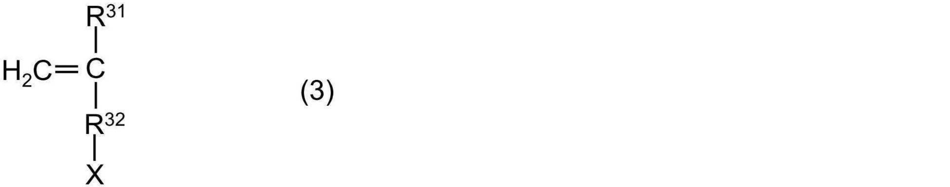
上記式(3)中、
R31は、水素原子またはメチル基であり、
R32は、単結合または炭素原子数1~20の直鎖もしくは分岐鎖のアルキレン基であり、
Xは、スルホン酸基(-SO3H)、硫酸基(-OSO3H)および亜硫酸基(-OSO2H)ならびにこれらの塩の基からなる群より選択される基である;
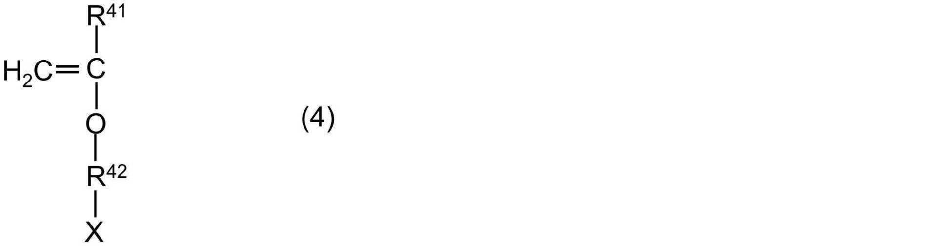
上記式(4)中、
R41は、水素原子またはメチル基であり、
R42は、炭素原子数1~20の直鎖または分岐鎖のアルキレン基であり、
Xは、スルホン酸基(-SO3H)、硫酸基(-OSO3H)および亜硫酸基(-OSO2H)ならびにこれらの塩の基からなる群より選択される基である。 The hydrophilic copolymer according to any one of claims 1 to 3, wherein the polymerizable monomer (B) is represented by the following formula (2), (3) or (4):
In the above equation (2),
R 21 is a hydrogen atom or a methyl group,
Z 2 is an oxygen atom or —NH—;
R 22 is a linear or branched alkylene group having 1 to 20 carbon atoms,
X is a group selected from the group consisting of a sulfonic acid group (—SO 3 H), a sulfate group (—OSO 3 H) and a sulfite group (—OSO 2 H), and a salt group thereof;
In the above equation (3),
R 31 is a hydrogen atom or a methyl group,
R 32 is a single bond or a linear or branched alkylene group having 1 to 20 carbon atoms;
X is a group selected from the group consisting of a sulfonic acid group (—SO 3 H), a sulfate group (—OSO 3 H) and a sulfite group (—OSO 2 H), and a salt group thereof;
In the above equation (4),
R 41 is a hydrogen atom or a methyl group,
R 42 is a linear or branched alkylene group having 1 to 20 carbon atoms,
X is a group selected from the group consisting of a sulfonic acid group (—SO 3 H), a sulfate group (—OSO 3 H), a sulfite group (—OSO 2 H), and a salt group thereof. - 前記重合性単量体(C)は、ベンゾフェノン構造を有する、請求項1~4のいずれか1項に記載の親水性共重合体。 親水 The hydrophilic copolymer according to any one of claims 1 to 4, wherein the polymerizable monomer (C) has a benzophenone structure.
- 基材層と、
前記基材層表面の少なくとも一部に形成され、請求項1~5のいずれか1項に記載の親水性共重合体を含む被覆層と、
を有する医療用具。 A base material layer,
A coating layer formed on at least a part of the surface of the base material layer and containing the hydrophilic copolymer according to any one of claims 1 to 5;
Medical device having. - 前記医療用具は、バルーン、カテーテル、ガイドワイヤ、マイクロバルーン、マイクロカテーテル、マイクロガイドワイヤ、ステントデリバリーカテーテルまたはアブレーションカテーテルである、請求項6に記載の医療用具。 The medical device according to claim 6, wherein the medical device is a balloon, a catheter, a guidewire, a microballoon, a microcatheter, a microguidewire, a stent delivery catheter, or an ablation catheter.
Priority Applications (3)
| Application Number | Priority Date | Filing Date | Title |
|---|---|---|---|
| JP2020527543A JP7252225B2 (en) | 2018-06-27 | 2019-06-25 | Hydrophilic copolymers and medical devices |
| CN201980039654.6A CN112368309B (en) | 2018-06-27 | 2019-06-25 | Hydrophilic copolymer and medical device |
| US17/126,978 US20210102019A1 (en) | 2018-06-27 | 2020-12-18 | Hydrophilic copolymer and medical device |
Applications Claiming Priority (2)
| Application Number | Priority Date | Filing Date | Title |
|---|---|---|---|
| JP2018-122005 | 2018-06-27 | ||
| JP2018122005 | 2018-06-27 |
Related Child Applications (1)
| Application Number | Title | Priority Date | Filing Date |
|---|---|---|---|
| US17/126,978 Continuation US20210102019A1 (en) | 2018-06-27 | 2020-12-18 | Hydrophilic copolymer and medical device |
Publications (1)
| Publication Number | Publication Date |
|---|---|
| WO2020004385A1 true WO2020004385A1 (en) | 2020-01-02 |
Family
ID=68986673
Family Applications (1)
| Application Number | Title | Priority Date | Filing Date |
|---|---|---|---|
| PCT/JP2019/025155 WO2020004385A1 (en) | 2018-06-27 | 2019-06-25 | Hydrophilic copolymer and medical instrument |
Country Status (4)
| Country | Link |
|---|---|
| US (1) | US20210102019A1 (en) |
| JP (1) | JP7252225B2 (en) |
| CN (1) | CN112368309B (en) |
| WO (1) | WO2020004385A1 (en) |
Cited By (2)
| Publication number | Priority date | Publication date | Assignee | Title |
|---|---|---|---|---|
| WO2021033767A1 (en) * | 2019-08-21 | 2021-02-25 | テルモ株式会社 | Medical instrument and manufacturing method therefor |
| WO2021033764A1 (en) * | 2019-08-21 | 2021-02-25 | テルモ株式会社 | Medical instrument and production method therefor |
Citations (6)
| Publication number | Priority date | Publication date | Assignee | Title |
|---|---|---|---|---|
| JP2014212685A (en) * | 2013-04-01 | 2014-11-13 | 独立行政法人産業技術総合研究所 | Amplification method of drive displacement of soft actuator and actuator with drive displacement amplified by that method |
| JP2015503998A (en) * | 2012-01-18 | 2015-02-05 | サーモディクス,インコーポレイテッド | Lubricant coating for medical devices with low particulates |
| JP2016511646A (en) * | 2013-01-04 | 2016-04-21 | サーモディクス,インコーポレイティド | Low particle lubricity coating with a layer containing vinylpyrrolidone polymer and acidic polymer |
| WO2018038063A1 (en) * | 2016-08-25 | 2018-03-01 | テルモ株式会社 | Hydrophilic copolymer and medical device |
| JP2018058050A (en) * | 2016-10-07 | 2018-04-12 | トヨタ自動車株式会社 | Temperature-responsive hygroscopic material |
| JP2018087316A (en) * | 2016-08-03 | 2018-06-07 | 東ソー株式会社 | Block copolymer and surface treatment agent using same |
Family Cites Families (1)
| Publication number | Priority date | Publication date | Assignee | Title |
|---|---|---|---|---|
| CN108137841B (en) * | 2015-09-30 | 2021-07-06 | 3M创新有限公司 | Hydrogel compositions bonded to polymeric substrates |
-
2019
- 2019-06-25 WO PCT/JP2019/025155 patent/WO2020004385A1/en active Application Filing
- 2019-06-25 CN CN201980039654.6A patent/CN112368309B/en active Active
- 2019-06-25 JP JP2020527543A patent/JP7252225B2/en active Active
-
2020
- 2020-12-18 US US17/126,978 patent/US20210102019A1/en active Pending
Patent Citations (6)
| Publication number | Priority date | Publication date | Assignee | Title |
|---|---|---|---|---|
| JP2015503998A (en) * | 2012-01-18 | 2015-02-05 | サーモディクス,インコーポレイテッド | Lubricant coating for medical devices with low particulates |
| JP2016511646A (en) * | 2013-01-04 | 2016-04-21 | サーモディクス,インコーポレイティド | Low particle lubricity coating with a layer containing vinylpyrrolidone polymer and acidic polymer |
| JP2014212685A (en) * | 2013-04-01 | 2014-11-13 | 独立行政法人産業技術総合研究所 | Amplification method of drive displacement of soft actuator and actuator with drive displacement amplified by that method |
| JP2018087316A (en) * | 2016-08-03 | 2018-06-07 | 東ソー株式会社 | Block copolymer and surface treatment agent using same |
| WO2018038063A1 (en) * | 2016-08-25 | 2018-03-01 | テルモ株式会社 | Hydrophilic copolymer and medical device |
| JP2018058050A (en) * | 2016-10-07 | 2018-04-12 | トヨタ自動車株式会社 | Temperature-responsive hygroscopic material |
Cited By (2)
| Publication number | Priority date | Publication date | Assignee | Title |
|---|---|---|---|---|
| WO2021033767A1 (en) * | 2019-08-21 | 2021-02-25 | テルモ株式会社 | Medical instrument and manufacturing method therefor |
| WO2021033764A1 (en) * | 2019-08-21 | 2021-02-25 | テルモ株式会社 | Medical instrument and production method therefor |
Also Published As
| Publication number | Publication date |
|---|---|
| US20210102019A1 (en) | 2021-04-08 |
| CN112368309A (en) | 2021-02-12 |
| JPWO2020004385A1 (en) | 2021-08-02 |
| CN112368309B (en) | 2022-09-09 |
| JP7252225B2 (en) | 2023-04-04 |
Similar Documents
| Publication | Publication Date | Title |
|---|---|---|
| JP7368446B2 (en) | Hydrophilic copolymers and medical devices | |
| US9782521B2 (en) | Medical device and method for producing medical device | |
| US10022478B2 (en) | Medical device | |
| US11872326B2 (en) | Medical instrument | |
| JPWO2016084716A1 (en) | Medical device and manufacturing method thereof | |
| US20220177618A1 (en) | Medical device and method for manufacturing same | |
| US20210102019A1 (en) | Hydrophilic copolymer and medical device | |
| US9956324B2 (en) | Medical material, and medical device using the medical material | |
| US20220168479A1 (en) | Medical device and method for manufacturing same | |
| EP4006069A1 (en) | Medical instrument and production method therefor | |
| US20220168476A1 (en) | Medical device and method for manufacturing same | |
| JP7389102B2 (en) | Medical device manufacturing method and medical device | |
| EP3669901B1 (en) | Method for producing medical instrument |
Legal Events
| Date | Code | Title | Description |
|---|---|---|---|
| 121 | Ep: the epo has been informed by wipo that ep was designated in this application |
Ref document number: 19825502 Country of ref document: EP Kind code of ref document: A1 |
|
| ENP | Entry into the national phase |
Ref document number: 2020527543 Country of ref document: JP Kind code of ref document: A |
|
| NENP | Non-entry into the national phase |
Ref country code: DE |
|
| 122 | Ep: pct application non-entry in european phase |
Ref document number: 19825502 Country of ref document: EP Kind code of ref document: A1 |