WO2020004365A1 - Sound-emitting container - Google Patents
Sound-emitting container Download PDFInfo
- Publication number
- WO2020004365A1 WO2020004365A1 PCT/JP2019/025085 JP2019025085W WO2020004365A1 WO 2020004365 A1 WO2020004365 A1 WO 2020004365A1 JP 2019025085 W JP2019025085 W JP 2019025085W WO 2020004365 A1 WO2020004365 A1 WO 2020004365A1
- Authority
- WO
- WIPO (PCT)
- Prior art keywords
- container
- cap
- sound
- lid
- main body
- Prior art date
Links
Images


Classifications
-
- A—HUMAN NECESSITIES
- A61—MEDICAL OR VETERINARY SCIENCE; HYGIENE
- A61J—CONTAINERS SPECIALLY ADAPTED FOR MEDICAL OR PHARMACEUTICAL PURPOSES; DEVICES OR METHODS SPECIALLY ADAPTED FOR BRINGING PHARMACEUTICAL PRODUCTS INTO PARTICULAR PHYSICAL OR ADMINISTERING FORMS; DEVICES FOR ADMINISTERING FOOD OR MEDICINES ORALLY; BABY COMFORTERS; DEVICES FOR RECEIVING SPITTLE
- A61J7/00—Devices for administering medicines orally, e.g. spoons; Pill counting devices; Arrangements for time indication or reminder for taking medicine
- A61J7/04—Arrangements for time indication or reminder for taking medicine, e.g. programmed dispensers
-
- B—PERFORMING OPERATIONS; TRANSPORTING
- B65—CONVEYING; PACKING; STORING; HANDLING THIN OR FILAMENTARY MATERIAL
- B65D—CONTAINERS FOR STORAGE OR TRANSPORT OF ARTICLES OR MATERIALS, e.g. BAGS, BARRELS, BOTTLES, BOXES, CANS, CARTONS, CRATES, DRUMS, JARS, TANKS, HOPPERS, FORWARDING CONTAINERS; ACCESSORIES, CLOSURES, OR FITTINGS THEREFOR; PACKAGING ELEMENTS; PACKAGES
- B65D41/00—Caps, e.g. crown caps or crown seals, i.e. members having parts arranged for engagement with the external periphery of a neck or wall defining a pouring opening or discharge aperture; Protective cap-like covers for closure members, e.g. decorative covers of metal foil or paper
- B65D41/32—Caps or cap-like covers with lines of weakness, tearing-strips, tags, or like opening or removal devices, e.g. to facilitate formation of pouring openings
- B65D41/34—Threaded or like caps or cap-like covers provided with tamper elements formed in, or attached to, the closure skirt
-
- B—PERFORMING OPERATIONS; TRANSPORTING
- B65—CONVEYING; PACKING; STORING; HANDLING THIN OR FILAMENTARY MATERIAL
- B65D—CONTAINERS FOR STORAGE OR TRANSPORT OF ARTICLES OR MATERIALS, e.g. BAGS, BARRELS, BOTTLES, BOXES, CANS, CARTONS, CRATES, DRUMS, JARS, TANKS, HOPPERS, FORWARDING CONTAINERS; ACCESSORIES, CLOSURES, OR FITTINGS THEREFOR; PACKAGING ELEMENTS; PACKAGES
- B65D51/00—Closures not otherwise provided for
- B65D51/24—Closures not otherwise provided for combined or co-operating with auxiliary devices for non-closing purposes
Definitions
- the present invention relates to a container with a cap having a sound-producing function.
- Patent Document 1 discloses a capped container including a container having an opening and a cap attached to the container to close the opening of the container.
- the cap of this capped container includes a cap body that engages with the container, and a lid that engages with the container and is connected to the cap body so that the opening of the container can be opened and closed.
- the cap is rotated with respect to the container so that the lid is in a closed position where the lid is engaged with the container to close the opening, and an open position where the lid is disengaged from the container to open the opening.
- the position can be changed.
- This container with a cap once the cap is attached to the container, the projecting portion of the cap body is locked by the locking portion of the container. For this reason, the cap body cannot be easily removed from the container.
- This capped container can be used, for example, as a container for pharmaceuticals.
- Patent Document 2 discloses a device which is attached to a tablet container and alerts a user when a tablet or medicine has to be taken.
- the device comprises timer electronics, alarm means, LCD unit and the like. It is disclosed that the user is alerted by an alarm means and an LCD unit.
- the present invention provides a novel sound container that can solve the above-mentioned problems.
- a sounding container includes a container having an opening, and a cap for closing the opening, which has a sounding function.
- a first sensor that detects that the cap is closed and outputs a first signal
- a second sensor that detects that the cap is opened and outputs a second signal
- An electronic circuit connected to the first sensor and the second sensor; and a sounding member connected to the electronic circuit.
- the electronic circuit causes the sounding member to emit a first sound when the first signal is output from the first sensor, and causes the sounding member to emit a first sound when the second signal is output from the second sensor.
- a second voice different from the first voice is uttered.
- the embodiment of the present invention it is possible to make an appropriate announcement at each timing when the container with the cap is opened and closed. For this reason, the convenience can be improved as compared with a conventional container having a sound generation function.
- FIG. 1A is a front view of the sounding container with the cap closed.
- FIG. 1B is a diagram illustrating a state in which the sounding container illustrated in FIG. 1A is rotated by 90 degrees around a central axis of the container.
- FIG. 1C is a diagram illustrating a state in which the sounding container illustrated in FIG. 1B is further rotated by 90 degrees around a central axis.
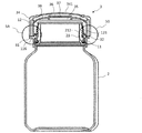
- FIG. 2A is a front view of the sounding container with the cap opened.
- FIG. 2B is a diagram illustrating a state in which the sounding container illustrated in FIG. 2A is rotated by 90 degrees around a central axis.
- FIG. 2C is a diagram illustrating a state in which the sounding container illustrated in FIG.
- FIG. 1B is further rotated by 90 degrees around a central axis.
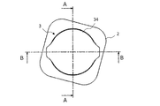
- FIG. 3 is a top view of the sounding container with the cap closed.
- FIG. 4A is a sectional view taken along line AA of the sounding container shown in FIG.
- FIG. 4B is a cross-sectional view taken along the line BB of the sounding container shown in FIG.
- FIG. 5A is an enlarged view of a portion surrounded by a circle 5A in FIG. 4B.
- FIG. 5B is an enlarged view showing a portion surrounded by a circle 5B in FIG. 4B.
- FIG. 6 is a top view of the sounding container with the cap opened.
- FIG. 7A is a sectional view taken along line AA of the sounding container shown in FIG. FIG.
- FIG. 7B is a sectional view of the sounding container shown in FIG. 6 taken along line BB.
- FIG. 8A is an enlarged view showing a portion surrounded by a circle 8A in FIG. 7B.
- FIG. 8B is an enlarged view showing a portion surrounded by a circle 8B in FIG. 7B.
- FIG. 9 is a block diagram schematically illustrating an electrical connection relationship among the first switch, the second switch, the electronic circuit, the sound-emitting member, and the battery.
- FIG. 10A is a cross-sectional view showing another embodiment.
- FIG. 10B is a top view of a cap according to another embodiment.
- FIG. 11A is a diagram illustrating a configuration of an electronic circuit according to still another embodiment.
- FIG. 11B is a diagram illustrating a sounding container according to still another embodiment.
- FIG. 12 is a side view of the capped container showing a state in which the cap closes the opening of the container.
- FIG. 13 is a side view of the container with the cap showing a state where the closing of the opening by the cap is released.
- FIG. 14 is a side view of the container with the cap showing a state where the lid is separated from the opening of the container.
- FIG. 15 is a partial cross-sectional view of the container with the cap showing a state in which the cap closes the opening of the container.
- FIG. 16 is a partial cross-sectional view of the container with the cap showing a state where the closing of the opening by the cap is released.
- FIG. 12 is a side view of the capped container showing a state in which the cap closes the opening of the container.
- FIG. 13 is a side view of the container with the cap showing a state where the closing of the opening by the cap is released.
- FIG. 17 is a longitudinal sectional view of the cap showing a state where the lid is fitted to the cap body.
- FIG. 18 is a bottom view of the cap showing a state where the lid is separated from the cap body.
- FIG. 19 is a sectional view taken along line VIII-VIII in FIG.
- FIG. 20 is a plan view of the container.
- FIG. 21 is a side view of the container.
- FIG. 22 is a partial cross-sectional view taken along line XI-XI shown in FIG.
- FIG. 23 is a side view of the container in a state where the position of the container in FIG. 21 is shifted by 90 degrees around the axis.
- FIG. 24 is a side view of the container in a state where the position of the container in FIG. 23 is shifted by 90 degrees around the axis.
- FIG. 25 is a partial cross-sectional view taken along line XIV-XIV shown in FIG.
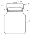
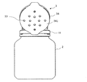
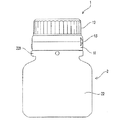
- FIGS. 1A to 2C are views showing the appearance of a sounding container according to an exemplary embodiment of the present invention.
- FIG. 1A is a front view of the sounding container with the cap closed.
- FIG. 1B is a diagram illustrating a state in which the sounding container illustrated in FIG. 1A is rotated by 90 degrees around a central axis of the container.
- FIG. 1C is a diagram illustrating a state in which the sounding container illustrated in FIG. 1B is further rotated by 90 degrees around a central axis.
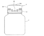
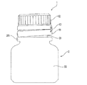
- FIG. 2A is a front view of the sounding container with the cap opened.
- FIG. 2B is a diagram illustrating a state in which the sounding container illustrated in FIG. 2A is rotated by 90 degrees around a central axis.
- FIG. 2C is a diagram illustrating a state in which the sounding container illustrated in FIG. 1B is further rotated by 90 degrees around a central axis.
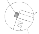
- the sounding container of the present embodiment includes a container 2 and a cap 3.
- the cap 3 has a sound generation function as described later.
- the cap 3 may be referred to as “sound cap 3”.
- the container 2 has an opening 211a as shown in FIG. 2A.
- the cap 3 includes a first switch 31 and a second switch 32 (see FIGS. 1B and 1C).
- the first switch 31 functions as a first sensor that detects that the cap 3 is closed and outputs a first signal.
- the second switch 32 functions as a second sensor that detects that the cap 3 has been opened and outputs a second signal.
- the sounding container is further connected to an electronic circuit connected to the first switch 31 (first sensor) and the second switch 32 (second sensor), and to the electronic circuit.
- Sounding member The sound generating member may be a device that converts an electric signal into a sound wave, such as a piezoelectric speaker.
- the sounding container also includes a first sensor, a second sensor, an electronic circuit, and a battery (secondary battery) that supplies power to the sounding member.
- the electronic circuit, the sound member, and the battery are housed inside the cap 3.
- the electronic circuit receives the signals output from the first switch 31 and the second switch 32 and causes the sounding member to emit a preset sound. When the first signal is output from the first switch 31, the electronic circuit causes the sounding member to emit the first sound.
- the sounding member makes the second sound different from the first sound.
- a different sound can be emitted from the sounding member each time the cap 3 is opened and closed. Details of this operation will be described later.
- FIG. 3 is a top view of the sounding container with the sounding cap 3 closed.
- FIG. 4A is a sectional view taken along line AA of the sounding container shown in FIG.
- FIG. 4B is a cross-sectional view taken along the line BB of the sounding container shown in FIG.
- FIG. 5A is an enlarged view of a portion surrounded by a circle 5A in FIG. 4B.
- FIG. 5B is an enlarged view showing a portion surrounded by a circle 5B in FIG. 4B.
- FIG. 6 is a top view of the sounding container with the cap 3 opened.
- FIG. 7A is a sectional view taken along line AA of the sounding container shown in FIG.
- FIG. 7B is a sectional view of the sounding container shown in FIG. 6 taken along line BB.
- FIG. 8A is an enlarged view showing a portion surrounded by a circle 8A in FIG. 7B.
- FIG. 8B is an enlarged view showing a portion
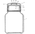
- the container 2 in the present embodiment includes a distal end 21 that defines an opening 211 a and a container screw portion 212 provided on the outer periphery of the distal end 21.
- the tip portion 21 of the container 2 is a portion where the cap 3 is mounted, and is also referred to as a “mounting portion”.
- the tip 21 of the container 2 has a substantially cylindrical shape.
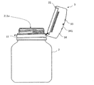
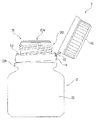
- the cap 3 includes a cap body 11 attached around the distal end portion 21 of the container 2, a lid 12 connected to the cap body 11, and a cover 34 that covers the lid 12.
- the cap body 11, the lid 12, and the cover 34 may be formed of a hard material such as plastic.
- the lid 12 has a lid screw portion 123 screwed into the container screw portion 212 therein.
- the cap body 11 in the present embodiment has a generally annular shape.
- the cap main body 11 is attached to the periphery of the distal end portion 21 of the container 2 so as not to separate from the container 2 during use. Therefore, even if the cap 3 is pulled with the cap 3 opened, the lid 12 and the cover 34 are not easily separated from the container 2.
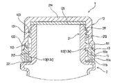
- the electronic circuit 35, the sound-generating member 36, and the battery 37 are arranged in a space between the cover 34 and the lid 12.
- the electronic circuit 35, the sounding member 36, the battery 37, and the switches 31 and 32 are connected to each other via a wiring 38.
- the first switch 31 and the second switch 32 are attached to a lower end of the cover 34.
- the second switch 32 is located near the connection portion 13 (see FIG. 8B) between the cap body 11 and the lid 12.
- the first switch 31 is located at the lower end of the cover 34 on the side opposite to the second switch 32.
- Each of the first switch 31 and the second switch 32 is a push-button switch such as a micro switch. Each switch is turned on when pressed with a certain force or more.
- the first switch 31 is turned on when the lid 12 is rotated while covering the distal end portion 21 of the container 2 to complete the tightening of the lid 12 and the container 2 (see FIGS. 4B and 5A). ). At this time, the first switch 31 contacts the cap body 11. More specifically, the first switch 31 is turned on when it comes into contact with and presses the outwardly protruding protrusion 116 of the cap body 11. As described above, the first switch 31 is disposed at a position where the first switch 31 is turned on when the opening 211a is closed by the lid 12.
- the “closed state” indicates a state in which the lid 12 and the container 2 are completely tightened.
- the first switch 31 is turned off in a state where the lid 12 and the container 2 are not fully tightened, and in a state where the lid 12 is lifted to expose the opening 211a (see FIG. 8A). When turned on, the first switch 31 outputs a first signal.
- the second switch 32 is turned on when the lid body 12 is opened and comes into contact with the cap body 11 and is pressed.
- the state shown in FIG. 7B is maintained.
- the second switch 32 is turned on (see FIG. 8B).
- the second switch 32 is turned on when the opening 211a is opened and the lid 12 reaches a predetermined position.
- the second switch 32 outputs a second signal when turned on.
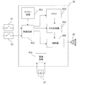
- FIG. 9 is a block diagram schematically showing an electrical connection relationship among the first switch 31, the second switch 32, the electronic circuit 35, the sound generating member 36, and the battery 37.
- the electronic circuit 35 drives a control circuit 352, a timer circuit 351, a memory 353 for recording audio data, a digital / analog (D / A) converter 354, and a sounding member 36. 355, and a power supply circuit 356.
- the control circuit 352 is electrically connected to the first switch 31, the second switch 32, the timer circuit 351, the memory 353, the D / A converter 354, and the amplifier 355.
- the control circuit 352 outputs the audio signal to be reproduced based on the first signal output from the first switch 31, the second signal output from the second switch 32, and the time information output from the timer circuit 351. Determine the content and timing of pronunciation.
- the memory 353 stores various data such as audio data to be reproduced and programs executed by the control circuit 352.
- the control circuit 352 determines the audio data to be reproduced from the audio data recorded in the memory 353 in advance, and causes the sounding member 36 to emit a voice based on the audio data. More specifically, under the control of the control circuit 352, the D / A converter 354 converts the determined audio data into an analog signal.
- the amplifier 355 amplifies the analog signal and drives the sound generating member 36. As a result, sound is emitted from the sounding member 36.
- the cap 3 of the sounding container is often fastened. This is because, in the case where a substance (for example, a drug) that easily deteriorates is stored in the container 2, it is preferable to close the cap 3 except for a short time for taking out the contents in order to prevent the deterioration. Therefore, it is considered that the period during which the first switch 31 is on is longer than the period during which the first switch 31 is off. Conversely, with respect to the second switch 32, it is considered that the off period is longer than the on period. In general, the longer the state in which a voltage is applied to the terminal of the control circuit 352, the greater the consumption of the battery 37.
- the first switch 31 may be configured so as not to energize the control circuit 352 at the ON timing, but to energize the control circuit 352 at the OFF timing.
- the second switch 32 may be configured so as not to energize the control circuit 352 at the off timing, but to energize the control circuit 352 at the on timing.
- the control circuit 352 can detect the above-described first signal indicating the closed state by detecting a decrease in the current or the voltage supplied from the first switch 31.
- the control circuit 352 can also detect the above-mentioned second signal indicating that it has been opened by detecting an increase in the current or voltage supplied from the second switch 32.
- the first switch 31 in the present embodiment detects that the opening 211 a is closed by the lid 12 and outputs the first signal to the electronic circuit 35.
- the second switch 32 detects that the opening 211 a has been opened and the lid 12 has reached a predetermined position, and outputs a second signal to the electronic circuit 35.
- the electronic circuit 35 causes the sounding member 36 to emit the first sound.
- the electronic circuit 35 causes the sounding member 36 to emit the second sound.
- the sounding member 36 may be, for example, a piezoelectric speaker.
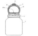
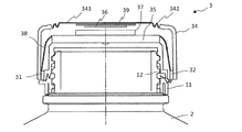
- the upper surface 341 of the cover 34 of the cap 3 has, for example, a dome shape. As shown in FIG. 2C, upper surface 341 of cover 34 may have a plurality of holes 33 for facilitating the passage of sound waves. Further, the upper surface 341 of the cover 34 may function as a diaphragm. In this case, the upper surface 341 of the cover 34 vibrates when the sounding member 36 operates, and increases the volume of the sound emitted from the sounding member 36. Further, the space between the cover 34 and the lid 12 may have a structure that resonates the sound emitted from the sounding member 36 and increases the volume of the sound.
- Piezoelectric speakers are thin and consume little power, and have features suitable for the purpose of sounding bottles. However, by itself, the volume is low and the reproduction range is narrow. For this reason, it is difficult to produce a sound that is easy to hear. In general, good sound quality is obtained by attaching a diaphragm having an area larger than that of the piezoelectric speaker main body or resonating with a resonance box. However, such a configuration requires additional components such as a diaphragm or a resonance box, which may increase costs or complicate the assembly process. Therefore, a structure in which a piezoelectric speaker is attached to a diaphragm integrally formed with the cover 34 of the cap 3 may be adopted. With such a structure, better sound quality can be obtained than when a piezoelectric speaker is used alone.
- FIG. 10A is a cross-sectional view schematically illustrating an embodiment in which the upper surface 341 of the cover 34 functions as a diaphragm.
- FIG. 10B is a top view of the cap 3 in this embodiment.
- an upper surface 341 of the cover 34 functioning as a diaphragm is fixed to an outer peripheral portion of the cover 34 via a diaphragm support 342.
- the diaphragm support 342 has a circular shape in plan view, and is made of a flexible material.
- the sound generating member 36 is a thin plate made of, for example, piezoelectric ceramics, and is disposed on the back surface of the upper surface 341 of the cover 34 via the metal plate 39.
- the sounding member 36 and the metal plate 39 constitute a piezoelectric speaker.
- the upper surface 341 of the cover 34 can vibrate independently of the outer peripheral portion of the cover 34.
- the upper surface 341 (diaphragm) of the cover 34 and the diaphragm support 342 can be formed integrally with the cover 34. This can suppress an increase in cost due to an increase in the number of parts and an increase in the number of manufacturing steps.
- the sounding container is a container for internal medicine such as a tablet.
- the first switch 31 outputs the first signal when detecting that the cap 3 of the sound-generating container has changed from the open state to the closed state.
- the electronic circuit 35 causes the sounding member 36 to emit the first sound.
- the first voice may include, for example, at least one of a voice notifying the next medication timing and a voice notifying that the cap 3 has been properly closed.
- the voice for notifying the next medication timing may be, for example, a voice such as “The next medication is 8 hours later” or “The next medication is tomorrow at 7:00 am”.
- the voice notifying that the cap 3 has been closed properly may be, for example, a voice such as “The cap has been closed properly.”
- the second switch 32 outputs a second signal when detecting that the cap 3 of the sound-generating container has changed from the closed state to the opened state.
- the electronic circuit 35 causes the sounding member 36 to emit the second sound.
- the second sound may include, for example, a sound indicating at least one of the name and the dose of the medicine in the container. For example, a voice such as "This drug is XX" or a voice such as "Please take a pill" may be reproduced as the second voice.
- the electronic circuit 35 includes a timer circuit 351 having a clock function.
- the electronic circuit 35 causes the sounding member 36 to generate a third sound different from the first sound and the second sound when the first signal is not output after a predetermined time has elapsed since the output of the second signal. You may. In this case, it is considered that the cap 3 is not properly tightened even if a predetermined time has elapsed since the cap 3 was opened.
- the electronic circuit 35 may generate, as the third sound, a sound that prompts the cap to be properly tightened, for example, on the sounding member 36. For example, a sound such as "Please tighten cap securely" may be reproduced as the third sound. By reproducing such sound, it is possible to prevent forgetting to tighten the cap 3.
- the above-mentioned predetermined time can be set to an appropriate time according to the type of the medicine, for example, a time of about several tens of seconds to several minutes.
- the first sound data indicating the first sound, the second sound data indicating the second sound, and the third sound data indicating the third sound are recorded in the memory 353 in advance. These audio data may be updated later.
- the sound cap 3 may have a recording function. Such a sound cap 3 may include an operation unit and a microphone for recording.
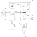
- FIG. 11A is a diagram illustrating a configuration of an electronic circuit 35 that performs such communication.
- the electronic circuit 35 in this example includes a communication circuit 357 that performs wireless communication with an external device.
- the external device may be, for example, an information device such as a smartphone, a tablet computer, or a server computer on a cloud.
- the electronic circuit 35 can receive a command to change at least one of the first to third audio data from an external device via the communication circuit 357. When receiving such a command, the electronic circuit 35 updates the audio data on the memory 353. According to such an embodiment, the sound uttered from the sounding member 36 can be changed afterwards.
- the sounding container may have a function different from the above examples.
- the electronic circuit 35 may include a voiceprint authentication function.
- voiceprint authentication when the electronic circuit 35 detects that the container has been opened via the second switch 32, the electronic circuit 35 inquires, for example, whether or not the person who is going to take is the person who has prescribed the medicine in the container. A voice is uttered from the sounding member 36. If there is a response to the voice, the electronic circuit 35 analyzes the frequency of the voice to determine whether the voice matches the voice of the person. If the voice matches the person's voice, a voice indicating the name or quantity of the medicine may be announced, and if not, a voice for calling attention may be announced.
- the electronic circuit 35 causes the sounding member 36 to generate a sound prompting the user to take the medicine.
- You may.
- the first time may be set to 8 hours. If the cap 3 is not opened even after issuing such a sound, a similar sound may be repeatedly emitted, for example, at regular intervals. By providing such a function, it is easy to prevent forgetting to take the medicine.
- the lid 12 and the cover 34 of the sounding container according to the present embodiment are fitted to each other in such a manner that they cannot be detached from each other.
- the lid 12 and the cover 34 are independent members in the manufacturing process, but are configured so that they cannot be removed during distribution unless they are broken. For this reason, the sounding container of the present embodiment is also useful for the purpose of preventing counterfeiting of pharmaceuticals.
- the fact that the cover 34 having a sound-producing function is attached to the lid 12 and that the sound set by the drug maker is emitted from the sound-producing member 36 of the cover 34 proves that the medicine is genuine. obtain.
- the sound cap 3 may have a structure or a function of preventing a switch from being operated by mistake.
- the first switch 31 at the tip of the cover 34 projects from the lower end of the cap 3. Therefore, when the user touches the cap 3, there is a possibility that the first switch 31 is erroneously pressed.
- the following configuration (1) or (2) may be applied.
- the tip of the first switch 31 does not protrude from the lower end of the cap 3. That is, in the axial direction of the cap 3, the tip of the first switch 31 is configured to be located at the same position as the lower end of the cap 3 or at a deeper position.
- the first switch 31 cannot be pressed in a state where the cap 3 is opened, so that malfunction can be prevented.
- a projection 117 is provided on the cap body 11.
- the electronic circuit 35 is configured to ignore the signal output from the first switch 31 while the opening of the cap 3 is detected by the second switch 32. Is also good. Thereby, even if the first switch 31 is carelessly operated in the state where the cap 3 is opened, malfunction can be prevented.
- the electronic circuit 35 can also be configured to ignore the signal from the first switch 31 when the second switch 32 is pressed. With such a configuration, even when the first switch 31 is inadvertently pressed while the second switch 32 is being pressed, malfunction can be prevented.
- the mechanism for preventing the malfunction described above may be applied not only to the first switch 31 but also to the second switch 32.
- a structure may be employed in which the tip of the second switch 32 does not protrude from the lower end of the cap 3, and a projection for pushing the second switch 32 may be provided on the cap body 11.
- the electronic circuit 35 may be configured to ignore the signal from the second switch 32 when the first switch 31 is pressed.
- both the first sensor and the second sensor are realized by mechanical switches.
- the first sensor and the second sensor may be configured to detect an open state or a closed state of the cap 3 by detecting, for example, light, sound, brightness, temperature, and other physical changes.
- the container with a cap in which the cover 34 is removed from the sounding container of the above embodiment may have the same structure as the container with a cap disclosed in Patent Document 1, for example.
- a specific example of a container with a cap in which the cover 34 is removed from the sounding container will be described.
- FIG. 12 is a side view of the container with the cap showing a state in which the cap closes the opening of the container.
- FIG. 13 is a side view of the container with the cap showing a state where the closing of the opening by the cap is released.
- FIG. 14 is a side view of the container with the cap showing a state where the lid is separated from the opening of the container.
- the container with a cap includes a container 2 having an opening 211a and a cap 1 attached to the container 2 to close the opening 211a of the container 2.
- the cap-equipped container is in a closed position where the opening 211 a cannot be opened (FIG. 12) and an open position where the opening 211 a can be opened (FIGS. 13 and 14).
- the rotation position of the cap 1 can be changed.
- the open side that is, the lower side (lower end) in FIGS. 12 to 14 is referred to as the “tip side” in the axial direction and the spiral direction.
- the upper side (upper end) in FIG. 12 to FIG. 14 is referred to as “proximal side” in the axial direction and the spiral direction.
- the side of the opening 211a that is, the upper side (upper end) in FIGS. 12 to 14 is referred to as the “tip side” in the axial direction and the spiral direction.
- the lower side (lower end) in FIGS. 12 to 14 is referred to as “proximal side (proximal end)” in the axial direction and the spiral direction.
- FIG. 15 is a partial cross-sectional view of the container with the cap showing a state in which the cap closes the opening of the container.
- FIG. 16 is a partial cross-sectional view of the container with the cap showing a state where the closing of the opening by the cap is released.
- FIG. 17 is a longitudinal sectional view of the cap showing a state where the lid is fitted to the cap body.
- FIG. 18 is a bottom view of the cap showing a state where the lid is separated from the cap body.
- FIG. 19 is a sectional view taken along line VIII-VIII in FIG.
- the cap 1 includes a cap body 11 that engages with the container 2, and a lid 12 that engages with the container 2 and closes the opening 211 a of the container 2. I have.
- the cap 1 also includes a connection portion 13 that connects the cap body 11 and the lid 12 so that the lid 12 can open and close the opening 211a of the container 2.
- the cap 1 is rotated with respect to the container 2 so that the lid 12 is engaged with the container 2 to close the opening 211a (the position shown in FIG. 12), and the lid 12 is opened to open the opening 211a.
- the cap 1 is formed of a hard resin (for example, plastic).
- the cap body 11 includes a base body 111 formed in a cylindrical shape, and a fitting portion (hereinafter, also referred to as a “body fitting portion”) 112 that fits with the lid 12.
- the cap main body 11 has a female thread-shaped screw portion (hereinafter, also referred to as a “main body screw portion”) 113 to be screwed with the container 2 on the inner peripheral portion of the base portion 111 so as to engage with the container 2. .
- axial direction refers to the axial direction of the cap 1, the cap body 11, the base portion 111, and the main body screw portion 113
- radial direction refers to the cap 1
- the cap The “circumferential direction” refers to the circumferential direction of the cap 1, the cap main body 11, the base portion 111, and the main body screw portion 113
- the “spiral direction” refers to the circumferential direction of the main body 11, the base portion 111, and the main body screw portion 113. It refers to the spiral direction of the main body screw portion 113 (the direction in which the screw thread extends).
- the base portion 111 is provided with a slit 111a on the distal end side (lower side) in the axial direction, so that the distal end side (lower side) in the axial direction has a double structure of the inner peripheral wall 111b and the outer peripheral wall 111c. ing.
- the base portion 111 is configured such that the inner peripheral wall 111b can be elastically deformed in the radial direction.
- the body fitting portion 112 is formed so as to protrude from the base end (upper end) in the axial direction of the base portion 111 so as to project in the axial direction (upward).
- the main body fitting portion 112 is arranged at a position facing the connecting portion 13 in the radial direction. That is, the main body fitting portion 112 is arranged at a position 180 degrees opposite to the connection portion 13 in the cylindrical base portion 111.
- the main body fitting portion 112 fits with the lid 12 when the cap 1 is located at the closed position.
- the main body screw portion 113 has a pair of protruding portions (hereinafter, also referred to as “main body protruding portions”) 113a and 113b protruding radially inward.
- the pair of main body protrusions 113a and 113b are arranged so as to face each other in the radial direction, that is, at positions 180 ° opposite to each other in the cylindrical base 111.
- first main body projecting portion 113a is located at a position facing the connecting portion 13 in the radial direction. It is formed on the inner peripheral surface of the base portion 111.
- the other main body protruding portion (hereinafter, also referred to as “second main body protruding portion”) 113b is formed on the inner peripheral surface of the base portion 111 so as to face the first main body protruding portion 113a in the radial direction.
- the second main body protruding portion 113b is formed to protrude radially inward from the inner peripheral surface of the base portion 111, corresponding to the position of the connection portion 13 formed on the outer peripheral surface of the base portion 111. I have.
- the first main body protruding portion 113a is formed on the distal end side (lower side) in the axial direction of the base portion 111 having a double structure.
- the second main body projecting portion 113b is formed on the base end side (upper side) of the base portion 111 in the axial direction.
- the first main body protrusion 113a and the second main body protrusion 113b are configured to be in sliding contact with the container 2 when the cap 1 is attached to the container 2.
- the lid 12 is engaged with the container 2, a lid main body 121 formed in a cylindrical shape, a fitting portion (hereinafter, also referred to as a “lid fitting portion”) 122 that fits with the main body fitting portion 112.
- a female screw-shaped screw portion (hereinafter also referred to as “lid screw portion”) 123 to be screwed with the container 2 is provided.
- the lid 12 closes the base end (upper end) of the lid main body 121 and covers the opening 211 a of the container 2, and the lid 12 is disposed inside the lid 124 and covers the opening 211 a of the container 2.
- An elastic portion (packing) 125 for sealing.
- the “axial direction” refers to the axial direction of the cap 1, the lid 12, the lid body 121, and the lid screw 123.
- the “radial direction” refers to a radial direction of the cap 1, the lid 12, the lid main body 121, and the lid screw 123.
- the “circumferential direction” refers to the circumferential direction of the cap 1, the lid 12, the lid main body 121, and the lid screw 123.
- the “spiral direction” refers to the helical direction (the direction in which the screw thread extends) of the cover screw portion 123.
- the lid body fitting portion 122 is formed so as to be concave at the lower end in the axial direction of the lid body portion 121 so as to fit with the convex body fitting portion 112.
- the lid fitting portion 122 is arranged at a position facing the connecting portion 13 in the radial direction. That is, the lid fitting portion 122 is arranged at a position 180 degrees opposite to the connection portion 13 in the cylindrical lid main body 121.
- the lid fitting portion 122 fits with the main body fitting portion 112 when the cap 1 is located at the closed position.
- the lid screw portion 123 is formed to be the same lead as the main body screw portion 113.
- connection unit 13 is a hinge mechanism in the present embodiment.
- the connecting portion 13 is not limited to the hinge mechanism, and may be, for example, a string having flexibility or elasticity.
- the connection portion 13 may connect the cap body 11 and the lid 12, and may have any configuration as long as the lid 12 can be displaced (contacted or separated) with respect to the cap body 11.
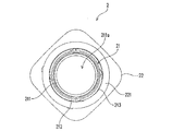
- FIG. 20 is a plan view of the container.
- FIG. 21 is a side view of the container.
- FIG. 22 is a partial cross-sectional view taken along line XI-XI shown in FIG.
- FIG. 23 is a side view of the container in a state where the position of the container in FIG. 21 is shifted by 90 degrees around the axis.
- FIG. 24 is a side view of the container in a state where the position of the container in FIG. 23 is shifted by 90 degrees around the axis.
- FIG. 25 is a partial cross-sectional view taken along line XIV-XIV shown in FIG.
- the container 2 has a mounting portion 21 to which the cap 1 is mounted, and a container main body 22 formed to have a larger diameter than the mounting portion 21 and capable of storing contents. And A base end (lower end) in the axial direction of the mounting portion 21 and an upper end 221 in the axial direction of the container body 22 are connected to each other.
- the container 2 is formed of a hard resin (for example, plastic).
- the mounting portion 21 is formed in a cylindrical shape, and has a mounting portion main body 211 having an opening 211a at an upper end portion, and a screw portion (disposed on an outer peripheral portion of the mounting portion main body 211 and having a plurality of male screw portions).
- a screw portion disposed on an outer peripheral portion of the mounting portion main body 211 and having a plurality of male screw portions.
- the mounting portion 21 includes a first guide portion 213, a second guide portion 214, and a locking portion (hereinafter, also referred to as a "container locking portion”) 216.
- the first guide part 213 guides the cap 1 to the mounting position when the cap 1 is mounted on the mounting part 21.
- the second guide portion 214 guides the cap 1 so as to release the fitting between the main body fitting portion 112 and the lid body fitting portion 122 by separating the cap body 11 and the lid body 12 from each other.
- the container locking portion 216 locks the first main body projecting portion 113a in order to prevent the cap 1 from rotating from the open position in the loosening direction and being detached from the container 2.
- the “axial direction” refers to the axial direction of the container 2, the mounting portion 21, the mounting portion main body 211, and the container screw portion 212.
- “Radial direction” refers to the radial direction of the container 2, the mounting portion 21, the mounting portion main body 211, and the container screw portion 212.
- the “circumferential direction” refers to the circumferential direction of the container 2, the mounting portion 21, the mounting portion main body 211, and the container screw portion 212.
- the “spiral direction” refers to the spiral direction of the container screw portion 212 (the direction in which the thread extends).
- the container screw portion 212 is screwed with the main body screw portion 113 and screwed with the lid screw portion 123. As shown in FIG. 12, when the cap 1 is located at the closed position, the cover screw 123 is screwed with the container screw 212. Therefore, the opening 211a cannot be opened. As shown in FIGS. 13 and 14, when the cap 1 is located at the open position, the screw thread of the lid body 123 and the screw thread of the container 212 are released. Therefore, the opening 211a can be opened.
- the container screw portion 212 includes four male screw portions 212a to 212d.
- each of the four external thread portions 212a to 212d is referred to as a first container screw portion 212a, a second container screw portion 212b, a third container screw portion 212c, and a fourth container screw portion 212d.
- One of the first container screw portion 212a to the fourth container screw portion 212d is desirably formed integrally with the first guide portion 213.
- the second container screw portion 212b is formed integrally with the first guide portion 213.
- the container screw portions 212a to 212d are formed on the outer peripheral surface of the cylindrical mounting portion main body 211 in a state where the phases are shifted by 90 degrees.
- the cap 1 can be screwed into each of the container screw portions 212a to 212d from the upper end thereof. Therefore, in the present embodiment, the cap 1 can be screwed at four positions of the mounting portion main body 211 corresponding to the upper ends of the four container screw portions 212a to 212d.
- the first guide 213 guides the cap 1 to the closed position, which is the mounting position. Specifically, the first guide portion 213 guides the cap 1 to the closed position by guiding the first main body protruding portion 113a of the cap main body 11.
- the first guide portion 213 includes a portion 211b of the outer surface of the mounting portion main body 211, an annular protrusion 2131 protruding from the mounting portion main body 211, and a connecting portion 2132 connecting the second container screw portion 212b and the annular protrusion 2131.
- the annular projection 2131 is formed at a position away from the container screw 212 in the axial direction. As a result, the outer surface of the cylindrical mounting portion main body 211 is exposed between the annular protrusion 2131 and the container screw portion 212.
- the container screw portion 212 is not formed on the cylindrical outer surface portion 211 b of the mounting portion main body 211. For this reason, the first main body projecting portion 113a and the second main body projecting portion 113b of the main body screw portion 113 of the cap 1 are unscrewed when they reach the outer surface portion 211b after being screwed into the container screw portion 212. It becomes possible to idle.
- the annular projection 2131 is not formed in a spiral shape as in the case of the container screw portion 212, but is formed so as to be parallel to the circumferential direction of the mounting portion main body 211.
- the annular projection 2131 has a front (upper) surface (hereinafter also referred to as a “first guide surface”) 2131a and a proximal (lower) surface.
- the first main body protrusion 113a and the second main body protrusion 113b are guided by a surface (hereinafter, also referred to as a "second guide surface”) 2131b.
- the annular projection 2131 is divided at an intermediate part, and the first main body projection 113 a is moved from the distal side (upper side) to the base end side (upper side) of the annular projection 2131. (Lower side).
- a guide surface (hereinafter, referred to as a “figure”) for guiding the first main body protrusion 113a guided by the first guide surface 2131a to the base end side of the annular protrusion 2131 is provided at an end of the annular protrusion 2131 in the circumferential direction. 3131c) is formed.
- the third guide surface 2131c moves from the distal side (upper side) to the proximal side (lower side) in the axial direction from the distal side in the spiral direction to the proximal side.
- the inclined surface is inclined.
- the connecting portion 2132 is connected to the second container screw portion 212b and the first guide surface such that one surface (upper surface) of the second container screw portion 212b and the first guide surface 2131a of the annular protrusion 2131 are continuously connected. It has a connecting surface 2132a for connecting to the 2131a. As shown in FIG. 21, the connection surface 2132a is an inclined surface that is inclined toward the base end side (downward) in the axial direction from the distal end side in the spiral direction to the base end side.
- the second guide portion 214 releases the cap body 11 and the lid body so that the fitting between the main body fitting portion 112 and the lid body fitting portion 122 is released.
- the cap 1 is guided so that the cap 12 is separated from the cap 12.
- the second guide portion 214 is arranged at a position 180 degrees opposite to the first guide portion 213 in the cylindrical base portion 111. As shown in FIG. 24, the second guide portion 214 is formed between the annular protrusion 2131 of the first guide portion 213 and the container screw portion 212 in the axial direction.
- the second guide portion 214 includes a push-up portion 214a that pushes up the second main body protrusion 113b to the distal end side (upward), a support portion 214b that supports the second main-body protrusion 113b pushed up by the push-up portion 214a, and a support portion.
- the push-up portion 214a is located on the tip side (upper side) of the first guide surface 2131a of the first guide portion 213 as shown in FIG.
- the push-up portion 214a is configured as a curved surface that connects the first guide surface 2131a of the first guide portion 213 and the support portion 214b.
- the push-up portion 214a is an arc-shaped curved surface having a predetermined radius of curvature, but is not limited to this.
- the support portion 214b is configured as a flat surface substantially parallel to the first guide surface 2131a of the first guide portion 213.
- the support portion 214b supports the second main body projecting portion 113b by abutting on the lower surface which is the surface on the distal end side of the second main body projecting portion 113b.
- the position restricting portion 214c is located closer to the distal end than the supporting portion 214b in the spiral direction.
- the position restricting portion 214c contacts the second main body projecting portion 113b so that the second main body projecting portion 113b does not move toward the distal end in the helical direction when the second main body projecting portion 113b is supported by the support portion 214b. It is configured as an abutting contact portion.
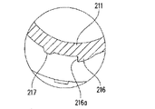
- the container locking portion 216 is disposed on the base end side (lower side) of the annular projection 2131 of the first guide portion 213 in the axial direction.
- the container locking portion 216 locks the first main body protruding portion 113a in the spiral direction on the surface 216a on the base end side (lower side) in the spiral direction.
- the surface (hereinafter, also referred to as “container locking surface”) 216 a of the container locking portion 216 is formed in a flat shape along the radial direction and a flat shape along the axial direction.
- a protrusion 217 is formed at a position near the container locking portion 216 so as to project radially outward from the outer surface of the mounting portion main body 211.
- the protrusion 217 contacts the first main body protrusion 113 a of the main body screw portion 113 of the cap main body 11.
- the inner peripheral wall 111b of the base portion 111 is elastically deformed. In this state, when the first main body protrusion 113a passes through the protrusion 217, the elastic deformation of the inner peripheral wall 111b is released, and the inner peripheral wall 111b returns to its original shape.
- the user of the container with a cap can feel the resistance when the first main body projection 113a comes into contact with the projection 217, and can hear the elastic deformation and the sound generated at the time of its release. Thereby, the user can feel that the movement of the cap 1 to the closed position is completed as a so-called click feeling.
- a protrusion 218 for producing a click feeling is also formed at a position near the second guide portion 214.
- the cap 1 In order to attach the cap 1 to the container 2, first, after the cap 1 is detached from the container 2, the cap 1 is put on the attachment portion main body 211 of the container 2, and then the cap 1 is fastened to the container 2. Rotate in the direction (clockwise). As a result, the container screw portion 212 and the main body screw portion 113 start to be screwed into each other from the front end side. Specifically, the first main body protruding portion 113a of the cap 1 is screwed to the container screw portion 212, and then the second main body protruding portion 113b is screwed to the container screw portion 212. At this time, the main body fitting portion 112 and the lid body fitting portion 122 are in a fitted state.
- the first main body protruding portion 113a slides on the first guide surface 2131a formed on the annular protrusion 2131 of the first guide portion 213 while spinning.
- the first main body projecting portion 113a moves in the rotation direction while being in contact with the first guide surface 2131a.
- the second main body protruding portion 113b remains screwed to the container screw portion 212.
- the first main body projecting portion 113a guided by the first guide surface 2131a passes over the second guide portion 214 during the movement, and is positioned near the second guide portion 214. Projecting part 218 passes over. Further, the first main body protrusion 113a moves to the third guide surface 2131c. The first main body projecting portion 113a is guided by the third guide surface 2131c, and moves toward a region closer to the base end (lower side) than the annular projecting portion 2131. Further, the screwing of the second main body protruding portion 113b to the container screw portion 212 is released.
- the first main body protruding portion 113a passes over the container locking portion 216 and further passes over the protrusion 217 located near the container locking portion 216. Further, the first main body protrusion 113a is guided in sliding contact with the second guide surface 2131b of the annular protrusion 2131.
- the second main body projecting portion 113b is guided in contact with the first guide surface 2131a of the first guide portion 213.
- the second main body protrusion 113b passes over the second guide 214 while being guided by the first guide surface 2131a, and also passes over the protrusion 218 located near the second guide 214. Further, the cover screw portion 123 of the cap 1 is screwed into the container screw portion 212.
- the movement of the cap 1 to the closed position is completed (the state of FIG. 12). That is, the attachment of the cap 1 to the container 2 is completed.
- the lid 12 is fixed to the container 2 so as not to open because the lid screw 123 is screwed into the container screw 212.
- the annular projection 2131 of the first guide 213 is sandwiched between the first main body projection 113a and the second main body projection 113b.
- the cap 1 is rotated in the loosening direction (left direction) with respect to the container 2. Then, the first main body projecting portion 113a of the main body screw portion 113 formed on the base portion 111 of the cap main body 11 comes into contact with the second guide surface 2131b of the first guide portion 213 and is guided. Further, the second main body projecting portion 113b of the main body screw portion 113 is guided in contact with the first guide surface 2131a of the first guide portion 213.
- the first main body protruding portion 113a comes into contact with the protruding portion 217 near the container locking portion 216.
- the second main body protrusion 113b contacts a protrusion 218 located near the second guide 214.
- the cap 1 is further rotated in the loosening direction in this state, the first main body protruding portion 113a passes over the protruding portion 217.
- the second main body protrusion 113b passes over the protrusion 218.
- the second main body projecting portion 113b comes into contact with the push-up portion 214a of the second guide portion 214. Due to the rotation of the cap 1, the second main body projecting portion 113b is guided by the curved push-up portion 214a and is pushed up to the support portion 214b. As described above, when the second body projecting portion 113b is pushed up by the push-up portion 214a, the portion of the cap body 11 where the connecting portion 13 is formed is pushed up so as to be separated from the first guide portion 213 (FIG. 13 and FIG. 14).
- the screwing of the cover screw 123 to the container screw 212 is released.
- the first main body protrusion 113a is kept in contact with the second guide surface 2131b of the first guide 213. That is, when the cap 1 is moved from the closed position to the open position, the first main body protruding portion 113a is always in contact with the second guide surface 2131b, and the distal end side (upper side) of the container 2 in the axial direction. It is regulated not to move to.
- the main body fitting portion 112 of the cap main body 11, which is formed at the same position as the first main body projecting portion 113a, is regulated so as not to move toward the distal end (upward) in the axial direction.
- the second main body projecting portion 113b is moved to the distal end side (upper side) of the container 2 in the axial direction by the push-up portion 214a of the second guide portion 214.
- the part 13 also moves to the tip side (upward) in the axial direction.
- the first main body protrusion 113a of the cap main body 11 is locked by the container locking surface 216a of the container locking portion 216 so as not to move any more in the loosening direction of the cap 1.
- the lid fitting part 122 of the lid 12 is fitted to the main body fitting part 112 of the container main body 22.
- the cap 1 is rotated in the tightening direction (right direction) to move from the open position to the closed position.
- the second guide portion 214 that guides the cap body 11 when the cap 1 is changed from the closed position to the open position is provided.
- the second guide portion 214 guides the cap body 11, so that the cap body 11 and the lid 12 are separated from each other. Therefore, when the cap 1 is located at the open position, the fitting between the lid fitting portion 122 and the main body fitting portion 112 is released, so that the opening 211a of the container 2 can be easily opened.
- the first main body projecting portion 113 a idles when the first main body projecting portion 113 a is unscrewed from the container screw portion 212 while the first main projecting portion 113 a is unscrewed. It has a first guide portion 213 that guides the cap 1 to the closed position by slidingly contacting the main body protruding portion 113a. Therefore, even if the container main body 22 has a structure in which the plurality of container screw portions 212a to 212d are formed and the cap 1 can be engaged with the container 2 at a plurality of positions, the first main body projecting portion 113a of the cap main body 11 can be used.
- the cap 1 When the cap 1 is mounted on the container 2, the cap 1 can be reliably guided to one closed position when the cap 1 is mounted on the container 2 by releasing the screwing of the cap 1 into the container screw portion 212. With such a configuration, the structure of the container with a cap can be simplified. Therefore, it is possible to keep the airtightness of the container 2 high and to attach the cap 1 to the container 2 by a machine (for example, a capper device).
- a machine for example, a capper device
- the cap 1 can be securely and firmly attached to the container 2.
- the cap-equipped container has a support portion 214b that contacts and supports the lower surface of the second main body protrusion 113b so that the cap 1 does not move downward when the cap 1 is moved from the closed position to the open position. . Therefore, when the cap 1 is moved to the open position, the cap 1 can be fixed so as not to move downward, and the positioning can be performed, so that the portion of the cap body 11 on the connection portion 13 side is surely lifted, Thereby, the opening and closing of the lid 12 can be performed reliably.
- the container with a cap is not limited to the configuration of the above embodiment. Further, the container with the cap is not limited to the above-described effects. The configuration of the container with a cap can be variously changed without departing from the gist of the present invention. Further, the sound-generating container is not limited to the one using the container with a cap of the above embodiment, and various changes are possible.
Landscapes
- Engineering & Computer Science (AREA)
- Health & Medical Sciences (AREA)
- Mechanical Engineering (AREA)
- Medical Informatics (AREA)
- Life Sciences & Earth Sciences (AREA)
- Animal Behavior & Ethology (AREA)
- General Health & Medical Sciences (AREA)
- Public Health (AREA)
- Veterinary Medicine (AREA)
- Closures For Containers (AREA)
- Medical Preparation Storing Or Oral Administration Devices (AREA)
Abstract
This sound-emitting container comprises: a container having an opening part; and a cap for closing the opening part, the cap having a sound emission function. The cap comprises a first sensor for detecting that the cap is closed and outputting a first signal, a second sensor for detecting that the cap is opened and outputting a second signal, an electronic circuit connected to the first sensor and the second sensor, and a sound-emitting member connected to the electronic circuit. When the first signal is outputted from the first sensor, the electronic circuit causes the sound-emitting member to emit a first voice sound. When the second signal is outputted from the second sensor, the electronic circuit causes the sound-emitting member to emit a second voice sound different from the first voice sound.
Description
本発明は、発音機能を有するキャップ付き容器に関する。
The present invention relates to a container with a cap having a sound-producing function.
特許文献1は、開口部を有する容器と、容器の開口部を閉じるべく容器に装着されるキャップとを備えるキャップ付き容器を開示している。このキャップ付き容器におけるキャップは、容器と係合するキャップ本体と、容器と係合し且つ容器の開口部を開閉できるようにキャップ本体に接続される蓋体とを備える。キャップは、容器に対して回転されることにより、開口部を閉じるべく蓋体が容器と係合する閉位置と、開口部を開くべく蓋体が容器との係合を解除する開位置とに位置変更可能に構成されている。このキャップ付き容器は、キャップを容器に一旦装着すると、キャップ本体における突出部が、容器の係止部によって係止される。このため、キャップ本体を容器から容易に取り外すことができなくなる。このキャップ付き容器は、例えば医薬品用の容器として使用され得る。
Patent Document 1 discloses a capped container including a container having an opening and a cap attached to the container to close the opening of the container. The cap of this capped container includes a cap body that engages with the container, and a lid that engages with the container and is connected to the cap body so that the opening of the container can be opened and closed. The cap is rotated with respect to the container so that the lid is in a closed position where the lid is engaged with the container to close the opening, and an open position where the lid is disengaged from the container to open the opening. The position can be changed. In this container with a cap, once the cap is attached to the container, the projecting portion of the cap body is locked by the locking portion of the container. For this reason, the cap body cannot be easily removed from the container. This capped container can be used, for example, as a container for pharmaceuticals.
一方、特許文献2は、錠剤容器に取り付けられ、錠剤または薬剤が服用されなければならないときに、服用者に注意を促す装置を開示している。この装置は、タイマー電子回路、アラーム手段、およびLCDユニットなどを備える。アラーム手段およびLCDユニットによって服用者に注意を促すことが開示されている。
On the other hand, Patent Document 2 discloses a device which is attached to a tablet container and alerts a user when a tablet or medicine has to be taken. The device comprises timer electronics, alarm means, LCD unit and the like. It is disclosed that the user is alerted by an alarm means and an LCD unit.
容器に取り付けられ、使用者に注意を喚起する従来の装置の機能は、単に所定の時刻にアラームを鳴らしたり、液晶表示部に情報を表示したりする機能に留まっていた。また、従来の装置を、特許文献1に開示されているようなキャップ付き容器に取り付けることは困難であった。
機能 The function of the conventional device attached to the container and calling the user's attention has merely been to sound an alarm at a predetermined time or to display information on a liquid crystal display. Moreover, it was difficult to attach the conventional device to a container with a cap as disclosed in Patent Document 1.
本発明は、上記の課題を解決し得る新規な発音容器を提供する。
The present invention provides a novel sound container that can solve the above-mentioned problems.
本発明の一態様に係る発音容器は、開口部を有する容器と、前記開口部を閉じるためのキャップであって、発音機能を有するキャップと、を備える。前記キャップは、前記キャップが閉じられたことを検知して第1信号を出力する第1センサと、前記キャップが開けられたことを検知して第2信号を出力する第2センサと、前記第1センサおよび前記第2センサに接続された電子回路と、前記電子回路に接続された発音部材と、を備える。前記電子回路は、前記第1センサから前記第1信号が出力されたとき、前記発音部材に第1音声を発声させ、前記第2センサから前記第2信号が出力されたとき、前記発音部材に前記第1音声とは異なる第2音声を発声させる。
発 音 A sounding container according to one embodiment of the present invention includes a container having an opening, and a cap for closing the opening, which has a sounding function. A first sensor that detects that the cap is closed and outputs a first signal, a second sensor that detects that the cap is opened and outputs a second signal, An electronic circuit connected to the first sensor and the second sensor; and a sounding member connected to the electronic circuit. The electronic circuit causes the sounding member to emit a first sound when the first signal is output from the first sensor, and causes the sounding member to emit a first sound when the second signal is output from the second sensor. A second voice different from the first voice is uttered.
本開示における包括的または具体的な態様は、装置、システム、方法、集積回路、コンピュータプログラム、または記録媒体によって実現され得る。あるいは、装置、システム、方法、集積回路、コンピュータプログラム、および記録媒体の任意の組み合わせによって実現されてもよい。
包括 Comprehensive or specific aspects of the present disclosure can be realized by an apparatus, a system, a method, an integrated circuit, a computer program, or a recording medium. Alternatively, the present invention may be realized by any combination of an apparatus, a system, a method, an integrated circuit, a computer program, and a recording medium.
本発明の実施形態によれば、キャップ付き容器の開閉時のそれぞれのタイミングで、適切なアナウンスを行うことが可能である。このため、従来の発音機能付きの容器と比較して、利便性を向上させることができる。
According to the embodiment of the present invention, it is possible to make an appropriate announcement at each timing when the container with the cap is opened and closed. For this reason, the convenience can be improved as compared with a conventional container having a sound generation function.
以下、本発明の実施形態を説明する。ただし、必要以上に詳細な説明は省略する場合がある。例えば、既によく知られた事項の詳細説明や実質的に同一の構成に対する重複説明を省略する場合がある。これは、以下の説明が不必要に冗長になることを避け、当業者の理解を容易にするためである。なお、発明者らは、当業者が本開示を十分に理解するために添付図面および以下の説明を提供するのであって、これらによって特許請求の範囲に記載の主題を限定することを意図するものではない。本明細書においては、同一のまたは類似する構成要素には、同一の参照符号を付している。
Hereinafter, embodiments of the present invention will be described. However, an unnecessary detailed description may be omitted. For example, a detailed description of well-known matters and a repeated description of substantially the same configuration may be omitted. This is to prevent the following description from being unnecessarily redundant and to facilitate understanding of those skilled in the art. The inventors provide the accompanying drawings and the following description for those skilled in the art to fully understand the present disclosure, and they are intended to limit the subject matter described in the claims. is not. In this specification, the same or similar components are denoted by the same reference symbols.
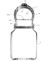
図1Aから図2Cは、本発明の例示的な実施形態による発音容器の外観を示す図である。図1Aは、キャップが閉じられた状態における発音容器の正面図である。図1Bは、図1Aに示す発音容器を、容器の中心軸のまわりに90度回転させた状態を示す図である。図1Cは、図1Bに示す発音容器を、中心軸のまわりにさらに90度回転させた状態を示す図である。図2Aは、キャップが開けられた状態における発音容器の正面図である。図2Bは、図2Aに示す発音容器を、中心軸のまわりに90度回転させた状態を示す図である。図2Cは、図1Bに示す発音容器を、中心軸のまわりにさらに90度回転させた状態を示す図である。
FIGS. 1A to 2C are views showing the appearance of a sounding container according to an exemplary embodiment of the present invention. FIG. 1A is a front view of the sounding container with the cap closed. FIG. 1B is a diagram illustrating a state in which the sounding container illustrated in FIG. 1A is rotated by 90 degrees around a central axis of the container. FIG. 1C is a diagram illustrating a state in which the sounding container illustrated in FIG. 1B is further rotated by 90 degrees around a central axis. FIG. 2A is a front view of the sounding container with the cap opened. FIG. 2B is a diagram illustrating a state in which the sounding container illustrated in FIG. 2A is rotated by 90 degrees around a central axis. FIG. 2C is a diagram illustrating a state in which the sounding container illustrated in FIG. 1B is further rotated by 90 degrees around a central axis.
これらの図に示されるように、本実施形態の発音容器は、容器2と、キャップ3とを備える。キャップ3は、後述するように、発音機能を有する。以下の説明において、キャップ3を「発音キャップ3」と称することがある。容器2は、図2Aに示すように、開口部211aを有する。キャップ3は、第1スイッチ31と、第2スイッチ32(図1Bおよび図1C参照)とを備える。第1スイッチ31は、キャップ3が閉じられたことを検知して第1信号を出力する第1センサとして機能する。第2スイッチ32は、キャップ3が開けられたことを検知して第2信号を出力する第2センサとして機能する。
発 音 As shown in these figures, the sounding container of the present embodiment includes a container 2 and a cap 3. The cap 3 has a sound generation function as described later. In the following description, the cap 3 may be referred to as “sound cap 3”. The container 2 has an opening 211a as shown in FIG. 2A. The cap 3 includes a first switch 31 and a second switch 32 (see FIGS. 1B and 1C). The first switch 31 functions as a first sensor that detects that the cap 3 is closed and outputs a first signal. The second switch 32 functions as a second sensor that detects that the cap 3 has been opened and outputs a second signal.
これらの図には示されていないが、発音容器は、さらに、第1スイッチ31(第1センサ)および第2スイッチ32(第2センサ)に接続された電子回路と、当該電子回路に接続された発音部材とを備える。発音部材は、例えば圧電スピーカなどの、電気信号を音波に変換するデバイスであり得る。発音容器はまた、第1センサ、第2センサ、電子回路、および発音部材に電力を供給するバッテリ(二次電池)も備える。電子回路、発音部材、およびバッテリは、キャップ3の内部に収容されている。電子回路は、第1スイッチ31および第2スイッチ32から出力された信号を受けて、発音部材に、予め設定された音声を発声させる。電子回路は、第1スイッチ31から第1信号が出力されたとき、発音部材に第1音声を発声させる。また、第2スイッチ32から第2信号が出力されたとき、発音部材に第1音声とは異なる第2音声を発声させる。このような動作により、キャップ3の開閉時のそれぞれで異なる音声を発音部材から発することができる。この動作の詳細については後述する。
Although not shown in these figures, the sounding container is further connected to an electronic circuit connected to the first switch 31 (first sensor) and the second switch 32 (second sensor), and to the electronic circuit. Sounding member. The sound generating member may be a device that converts an electric signal into a sound wave, such as a piezoelectric speaker. The sounding container also includes a first sensor, a second sensor, an electronic circuit, and a battery (secondary battery) that supplies power to the sounding member. The electronic circuit, the sound member, and the battery are housed inside the cap 3. The electronic circuit receives the signals output from the first switch 31 and the second switch 32 and causes the sounding member to emit a preset sound. When the first signal is output from the first switch 31, the electronic circuit causes the sounding member to emit the first sound. Further, when the second signal is output from the second switch 32, the sounding member makes the second sound different from the first sound. By such an operation, a different sound can be emitted from the sounding member each time the cap 3 is opened and closed. Details of this operation will be described later.
図3から図8Bを参照しながら、本実施形態における発音容器の構造をより詳細に説明する。
構造 The structure of the sounding container according to the present embodiment will be described in more detail with reference to FIGS. 3 to 8B.
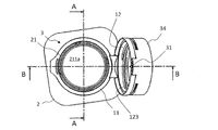
図3は、発音キャップ3が閉じた状態における発音容器の上面図である。図4Aは、図3に示す発音容器のA-A線断面図である。図4Bは、図3に示す発音容器のB-B線断面図である。図5Aは、図4Bにおける円5Aで囲まれる部分を拡大して示す図である。図5Bは、図4Bにおける円5Bで囲まれる部分を拡大して示す図である。図6は、キャップ3が開いた状態における発音容器の上面図である。図7Aは、図6に示す発音容器のA-A線断面図である。図7Bは、図6に示す発音容器のB-B線断面図である。図8Aは、図7Bにおける円8Aで囲まれる部分を拡大して示す図である。図8Bは、図7Bにおける円8Bで囲まれる部分を拡大して示す図である。
FIG. 3 is a top view of the sounding container with the sounding cap 3 closed. FIG. 4A is a sectional view taken along line AA of the sounding container shown in FIG. FIG. 4B is a cross-sectional view taken along the line BB of the sounding container shown in FIG. FIG. 5A is an enlarged view of a portion surrounded by a circle 5A in FIG. 4B. FIG. 5B is an enlarged view showing a portion surrounded by a circle 5B in FIG. 4B. FIG. 6 is a top view of the sounding container with the cap 3 opened. FIG. 7A is a sectional view taken along line AA of the sounding container shown in FIG. FIG. 7B is a sectional view of the sounding container shown in FIG. 6 taken along line BB. FIG. 8A is an enlarged view showing a portion surrounded by a circle 8A in FIG. 7B. FIG. 8B is an enlarged view showing a portion surrounded by a circle 8B in FIG. 7B.
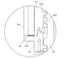
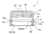
図7Aおよび図7Bに示されるように、本実施形態における容器2は、開口部211aを規定する先端部21と、先端部21の外周に設けられた容器ネジ部212とを備える。容器2の先端部21は、キャップ3が装着される部位であり、「装着部」とも称する。容器2の先端部21は、概略的に円筒形状を有する。キャップ3は、容器2の先端部21の周囲に取り付けられたキャップ本体11と、キャップ本体11に接続された蓋体12と、蓋体12を覆うカバー34とを備える。キャップ本体11、蓋体12、およびカバー34は、例えばプラスチックなどの硬質の材料によって形成され得る。蓋体12は、容器ネジ部212に螺合する蓋体ネジ部123を内部に有する。蓋体12が容器2の先端部21を覆った状態でキャップ3を回転することにより、蓋体12と容器2の先端部21とが締め付けられる。これにより、容器2の密閉状態が保たれる。
As shown in FIGS. 7A and 7B, the container 2 in the present embodiment includes a distal end 21 that defines an opening 211 a and a container screw portion 212 provided on the outer periphery of the distal end 21. The tip portion 21 of the container 2 is a portion where the cap 3 is mounted, and is also referred to as a “mounting portion”. The tip 21 of the container 2 has a substantially cylindrical shape. The cap 3 includes a cap body 11 attached around the distal end portion 21 of the container 2, a lid 12 connected to the cap body 11, and a cover 34 that covers the lid 12. The cap body 11, the lid 12, and the cover 34 may be formed of a hard material such as plastic. The lid 12 has a lid screw portion 123 screwed into the container screw portion 212 therein. By rotating the cap 3 with the lid 12 covering the tip 21 of the container 2, the lid 12 and the tip 21 of the container 2 are tightened. Thereby, the sealed state of the container 2 is maintained.
本実施形態におけるキャップ本体11は、概略的に円環形状を有する。キャップ本体11は、使用時に容器2から離れない態様で容器2の先端部21の周囲に取り付けられている。このため、キャップ3を空けた状態において、キャップ3を引っ張ったとしても、蓋体12およびカバー34が容器2から容易に分離することはない。
キ ャ ッ プ The cap body 11 in the present embodiment has a generally annular shape. The cap main body 11 is attached to the periphery of the distal end portion 21 of the container 2 so as not to separate from the container 2 during use. Therefore, even if the cap 3 is pulled with the cap 3 opened, the lid 12 and the cover 34 are not easily separated from the container 2.
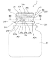
図4Bおよび図7Bに示すように、電子回路35、発音部材36、およびバッテリ37は、カバー34と蓋体12との間の空間に配置されている。電子回路35、発音部材36、バッテリ37、およびスイッチ31、32は、配線38を介して互いに接続されている。第1スイッチ31および第2スイッチ32は、カバー34の下端部に取り付けられている。第2スイッチ32は、キャップ本体11と蓋体12との接続部13(図8B参照)の近傍に位置している。第1スイッチ31は、カバー34の下端部のうち、第2スイッチ32の反対側の部位に位置している。第1スイッチ31および第2スイッチ32の各々は、例えばマイクロスイッチなどの押ボタン式のスイッチである。各スイッチは、一定以上の力で押されたときにオンになる。
As shown in FIGS. 4B and 7B, the electronic circuit 35, the sound-generating member 36, and the battery 37 are arranged in a space between the cover 34 and the lid 12. The electronic circuit 35, the sounding member 36, the battery 37, and the switches 31 and 32 are connected to each other via a wiring 38. The first switch 31 and the second switch 32 are attached to a lower end of the cover 34. The second switch 32 is located near the connection portion 13 (see FIG. 8B) between the cap body 11 and the lid 12. The first switch 31 is located at the lower end of the cover 34 on the side opposite to the second switch 32. Each of the first switch 31 and the second switch 32 is a push-button switch such as a micro switch. Each switch is turned on when pressed with a certain force or more.
第1スイッチ31は、蓋体12が容器2の先端部21を覆った状態で回転されることによって蓋体12と容器2との締め付けが完了したときにオンになる(図4Bおよび図5A参照)。このとき、第1スイッチ31は、キャップ本体11に接触する。より具体的には、第1スイッチ31は、キャップ本体11における外側に突出した突起部116に接触して押されることによってオンになる。このように、第1スイッチ31は、蓋体12によって開口部211aが閉状態になったときにオンになる位置に配置される。ここで「閉状態」とは、蓋体12と容器2との締め付けが完全に行われた状態を指す。第1スイッチ31は、蓋体12と容器2との締め付けが不完全な状態、および蓋体12が持ち上げられて開口部211aが露出している状態(図8A参照)では、オフになる。第1スイッチ31は、オンの状態になると、第1信号を出力する。
The first switch 31 is turned on when the lid 12 is rotated while covering the distal end portion 21 of the container 2 to complete the tightening of the lid 12 and the container 2 (see FIGS. 4B and 5A). ). At this time, the first switch 31 contacts the cap body 11. More specifically, the first switch 31 is turned on when it comes into contact with and presses the outwardly protruding protrusion 116 of the cap body 11. As described above, the first switch 31 is disposed at a position where the first switch 31 is turned on when the opening 211a is closed by the lid 12. Here, the “closed state” indicates a state in which the lid 12 and the container 2 are completely tightened. The first switch 31 is turned off in a state where the lid 12 and the container 2 are not fully tightened, and in a state where the lid 12 is lifted to expose the opening 211a (see FIG. 8A). When turned on, the first switch 31 outputs a first signal.
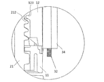
一方、第2スイッチ32は、蓋体12が開けられたときにキャップ本体11に接触して押されることによってオンになる。本実施形態においては、キャップ3をある角度以上に持ち上げて手を離すと、図7Bに示す状態で維持される。この状態において、第2スイッチ32がオンになる(図8B参照)。このように、第2スイッチ32は、開口部211aが開放され、蓋体12が所定の位置に達したとき、オンになる。第2スイッチ32は、オンの状態になると、第2信号を出力する。
On the other hand, the second switch 32 is turned on when the lid body 12 is opened and comes into contact with the cap body 11 and is pressed. In the present embodiment, when the cap 3 is lifted beyond a certain angle and released, the state shown in FIG. 7B is maintained. In this state, the second switch 32 is turned on (see FIG. 8B). Thus, the second switch 32 is turned on when the opening 211a is opened and the lid 12 reaches a predetermined position. The second switch 32 outputs a second signal when turned on.
図9は、第1スイッチ31、第2スイッチ32、電子回路35、発音部材36、およびバッテリ37の電気的な接続関係を模式的に示すブロック図である。図示されるように、電子回路35は、制御回路352と、タイマー回路351と、音声データを記録するメモリ353と、デジタル/アナログ(D/A)変換器354と、発音部材36を駆動するための増幅器355と、電源回路356とを含む。制御回路352は、第1スイッチ31、第2スイッチ32、タイマー回路351、メモリ353、D/A変換器354、および増幅器355に電気的に接続されている。
FIG. 9 is a block diagram schematically showing an electrical connection relationship among the first switch 31, the second switch 32, the electronic circuit 35, the sound generating member 36, and the battery 37. As shown, the electronic circuit 35 drives a control circuit 352, a timer circuit 351, a memory 353 for recording audio data, a digital / analog (D / A) converter 354, and a sounding member 36. 355, and a power supply circuit 356. The control circuit 352 is electrically connected to the first switch 31, the second switch 32, the timer circuit 351, the memory 353, the D / A converter 354, and the amplifier 355.
制御回路352は、第1スイッチ31から出力される第1信号と、第2スイッチ32から出力される第2信号と、タイマー回路351から出力される時間情報とに基づいて、再生すべき音声の内容および発音のタイミングを決定する。メモリ353は、再生される音声データ、および制御回路352によって実行されるプログラムなどの各種のデータを格納する。制御回路352は、メモリ353に予め記録された音声データから、再生すべき音声データを決定し、発音部材36に当該音声データに基づく音声を発声させる。より具体的には、制御回路352の制御に従い、D/A変換器354が、決定された音声データをアナログ信号に変換する。増幅器355は、当該アナログ信号を増幅して発音部材36を駆動する。これにより、発音部材36から音声が発せられる。
The control circuit 352 outputs the audio signal to be reproduced based on the first signal output from the first switch 31, the second signal output from the second switch 32, and the time information output from the timer circuit 351. Determine the content and timing of pronunciation. The memory 353 stores various data such as audio data to be reproduced and programs executed by the control circuit 352. The control circuit 352 determines the audio data to be reproduced from the audio data recorded in the memory 353 in advance, and causes the sounding member 36 to emit a voice based on the audio data. More specifically, under the control of the control circuit 352, the D / A converter 354 converts the determined audio data into an analog signal. The amplifier 355 amplifies the analog signal and drives the sound generating member 36. As a result, sound is emitted from the sounding member 36.
通常の使用態様では、発音容器のキャップ3は締められていることが多い。容器2の内部に変質し易い物質(例えば医薬品)が収容される場合、変質を防ぐために、内容物を取り出すための短い時間を除き、キャップ3を締めることが好ましいからである。したがって、第1スイッチ31に関しては、オフである期間よりもオンである期間の方が長いと考えられる。逆に、第2スイッチ32に関しては、オンである期間よりもオフである期間の方が長いと考えられる。一般に、制御回路352の端子に電圧が印加された状態が長いほど、バッテリ37の消耗が大きくなる。そこで、第1スイッチ31は、オンのタイミングでは制御回路352に通電せず、オフのタイミングにおいて制御回路352に通電するように構成され得る。逆に、第2スイッチ32は、オフのタイミングでは制御回路352に通電せず、オンのタイミングにおいて制御回路352に通電するように構成され得る。制御回路352は、第1スイッチ31から供給される電流または電圧の低下を検知することにより、閉状態になったことを示す上記の第1信号を検知することができる。制御回路352はまた、第2スイッチ32から供給される電流または電圧の増加を検知することにより、開状態になったことを示す上記の第2信号を検知することができる。
で は In a normal use mode, the cap 3 of the sounding container is often fastened. This is because, in the case where a substance (for example, a drug) that easily deteriorates is stored in the container 2, it is preferable to close the cap 3 except for a short time for taking out the contents in order to prevent the deterioration. Therefore, it is considered that the period during which the first switch 31 is on is longer than the period during which the first switch 31 is off. Conversely, with respect to the second switch 32, it is considered that the off period is longer than the on period. In general, the longer the state in which a voltage is applied to the terminal of the control circuit 352, the greater the consumption of the battery 37. Therefore, the first switch 31 may be configured so as not to energize the control circuit 352 at the ON timing, but to energize the control circuit 352 at the OFF timing. Conversely, the second switch 32 may be configured so as not to energize the control circuit 352 at the off timing, but to energize the control circuit 352 at the on timing. The control circuit 352 can detect the above-described first signal indicating the closed state by detecting a decrease in the current or the voltage supplied from the first switch 31. The control circuit 352 can also detect the above-mentioned second signal indicating that it has been opened by detecting an increase in the current or voltage supplied from the second switch 32.
このように、本実施形態における第1スイッチ31は、蓋体12によって開口部211aが閉状態になったことを検知して第1信号を電子回路35に出力する。一方、第2スイッチ32は、開口部211aが開放され、蓋体12が所定の位置に達したことを検知して第2信号を電子回路35に出力する。電子回路35は、第1信号を受けると、発音部材36に、第1音声を発声させる。電子回路35はまた、第2信号を受けると、発音部材36に、第2音声を発声させる。
As described above, the first switch 31 in the present embodiment detects that the opening 211 a is closed by the lid 12 and outputs the first signal to the electronic circuit 35. On the other hand, the second switch 32 detects that the opening 211 a has been opened and the lid 12 has reached a predetermined position, and outputs a second signal to the electronic circuit 35. When receiving the first signal, the electronic circuit 35 causes the sounding member 36 to emit the first sound. When receiving the second signal, the electronic circuit 35 causes the sounding member 36 to emit the second sound.
発音部材36は、例えば圧電スピーカであり得る。キャップ3のカバー34の上面341は、例えばドーム形状を有する。図2Cに示すように、カバー34の上面341は、音波を通過させ易くするための複数の孔33を有していてもよい。また、カバー34の上面341は、振動板として機能してもよい。その場合、カバー34の上面341は、発音部材36の動作時に振動し、発音部材36から発せられた音声の音量を増加させる。また、カバー34と蓋体12との間の空間が、発音部材36から発せられた音声を共鳴させ、音声の音量を増加させる構造を有していてもよい。
The sounding member 36 may be, for example, a piezoelectric speaker. The upper surface 341 of the cover 34 of the cap 3 has, for example, a dome shape. As shown in FIG. 2C, upper surface 341 of cover 34 may have a plurality of holes 33 for facilitating the passage of sound waves. Further, the upper surface 341 of the cover 34 may function as a diaphragm. In this case, the upper surface 341 of the cover 34 vibrates when the sounding member 36 operates, and increases the volume of the sound emitted from the sounding member 36. Further, the space between the cover 34 and the lid 12 may have a structure that resonates the sound emitted from the sounding member 36 and increases the volume of the sound.
圧電スピーカは薄型で消費電力も小さく、発音ボトルの目的に適した特徴を持っている。しかし、それ単体では音量が小さく、再生音域も狭い。このため、聞き取りやすい音声を発声させることは難しい。一般的には、圧電スピーカ本体よりも面積の大きい振動板を取り付けたり、共鳴箱に共鳴させたりする方法により、良好な音質を得ることが行われている。しかし、そのような構成では、振動板または共鳴箱などの追加部品が必要となり、コストの上昇または組み立て工程の煩雑化などを招くおそれがある。そこで、キャップ3のカバー34と一体的に成形された振動板に圧電スピーカを取り付けた構造を採用してもよい。そのような構造により、圧電スピーカを単体で用いる場合よりも良好な音質を得ることができる。
Piezoelectric speakers are thin and consume little power, and have features suitable for the purpose of sounding bottles. However, by itself, the volume is low and the reproduction range is narrow. For this reason, it is difficult to produce a sound that is easy to hear. In general, good sound quality is obtained by attaching a diaphragm having an area larger than that of the piezoelectric speaker main body or resonating with a resonance box. However, such a configuration requires additional components such as a diaphragm or a resonance box, which may increase costs or complicate the assembly process. Therefore, a structure in which a piezoelectric speaker is attached to a diaphragm integrally formed with the cover 34 of the cap 3 may be adopted. With such a structure, better sound quality can be obtained than when a piezoelectric speaker is used alone.
図10Aは、カバー34の上面341が振動板として機能する実施形態を模式的に示す断面図である。図10Bは、この実施形態におけるキャップ3の上面図である。この実施形態では、振動板として機能するカバー34の上面341が、振動板サポート342を介してカバー34の外周部に固定されている。振動板サポート342は、平面視において円形状を有し、柔軟性をもつ材料で構成されている。発音部材36は、例えば圧電セラミックスによる薄板であり、金属板39を介してカバー34の上面341の裏面に配置されている。発音部材36と金属板39とによって圧電スピーカが構成されている。このような構造により、カバー34の上面341は、カバー34の外周部とは独立して振動することができる。カバー34の上面341(振動板)および振動板サポート342は、カバー34と一体に成形され得る。これにより、部品点数の増加によるコストの上昇、および製造工程の増加を抑えることができる。
FIG. 10A is a cross-sectional view schematically illustrating an embodiment in which the upper surface 341 of the cover 34 functions as a diaphragm. FIG. 10B is a top view of the cap 3 in this embodiment. In this embodiment, an upper surface 341 of the cover 34 functioning as a diaphragm is fixed to an outer peripheral portion of the cover 34 via a diaphragm support 342. The diaphragm support 342 has a circular shape in plan view, and is made of a flexible material. The sound generating member 36 is a thin plate made of, for example, piezoelectric ceramics, and is disposed on the back surface of the upper surface 341 of the cover 34 via the metal plate 39. The sounding member 36 and the metal plate 39 constitute a piezoelectric speaker. With such a structure, the upper surface 341 of the cover 34 can vibrate independently of the outer peripheral portion of the cover 34. The upper surface 341 (diaphragm) of the cover 34 and the diaphragm support 342 can be formed integrally with the cover 34. This can suppress an increase in cost due to an increase in the number of parts and an increase in the number of manufacturing steps.
次に、発音部材36から発声される音声の例を説明する。以下の説明では、発音容器が錠剤などの内服薬用の容器であるものとする。
Next, an example of a sound uttered from the sounding member 36 will be described. In the following description, it is assumed that the sounding container is a container for internal medicine such as a tablet.
前述のように、第1スイッチ31は、発音容器のキャップ3が開いた状態からキャップ3が閉じた状態になったことを検出すると、第1信号を出力する。電子回路35は、第1信号を受けると、第1音声を発音部材36から発声させる。この第1音声は、例えば、次回の服薬タイミングを通知する音声、およびキャップ3が正常に締まったことを通知する音声の少なくとも一方を含み得る。次回の服薬タイミングを通知する音声は、例えば、「次回の服薬は8時間後です。」または「次回の服薬は明日の午前7時です。」といった音声であり得る。キャップ3が正常に締まったことを通知する音声は、例えば「キャップが正常に締まりました。」といった音声であり得る。キャップ3が締められたときにこのような音声が再生されることにより、服用者の安心感を向上させることができる。
As described above, the first switch 31 outputs the first signal when detecting that the cap 3 of the sound-generating container has changed from the open state to the closed state. When receiving the first signal, the electronic circuit 35 causes the sounding member 36 to emit the first sound. The first voice may include, for example, at least one of a voice notifying the next medication timing and a voice notifying that the cap 3 has been properly closed. The voice for notifying the next medication timing may be, for example, a voice such as “The next medication is 8 hours later” or “The next medication is tomorrow at 7:00 am”. The voice notifying that the cap 3 has been closed properly may be, for example, a voice such as “The cap has been closed properly.” By reproducing such a sound when the cap 3 is tightened, the user's sense of security can be improved.
一方、第2スイッチ32は、発音容器のキャップ3が閉じた状態からキャップ3が開いた状態になったことを検出すると、第2信号を出力する。電子回路35は、この第2信号を受けると、第2音声を発音部材36から発声させる。この第2音声は、例えば、容器内の内服薬の名称および服薬量の少なくとも一方を示す音声を含み得る。例えば、「この薬は○○です。」といった音声、または「○錠服用してください。」といった音声が第2音声として再生され得る。キャップ3が開けられたときにこのような音声が再生されることにより、使用者は、服用すべき薬の種類または量を誤ることなく、安心して服用することができる。
On the other hand, the second switch 32 outputs a second signal when detecting that the cap 3 of the sound-generating container has changed from the closed state to the opened state. Upon receiving the second signal, the electronic circuit 35 causes the sounding member 36 to emit the second sound. The second sound may include, for example, a sound indicating at least one of the name and the dose of the medicine in the container. For example, a voice such as "This drug is XX" or a voice such as "Please take a pill" may be reproduced as the second voice. By playing such a sound when the cap 3 is opened, the user can take the medicine without worrying about the type or amount of medicine to be taken.
図9に示すように、本実施形態における電子回路35は、計時機能を有するタイマー回路351を含む。電子回路35は、第2信号が出力されてから所定の時間が経過しても第1信号が出力されない場合、発音部材36に、第1音声および第2音声とは異なる第3音声を発生させてもよい。この場合、キャップ3が開けられてから所定の時間が経過してもキャップ3が正常に締められていないと考えられる。そこで、電子回路35は、第3音声として、例えばキャップを正常に締めることを促す音声を発音部材36に発生させてもよい。例えば「キャップを確実に締めてください。」といった音声が第3音声として再生され得る。このような音声が再生されることにより、キャップ3の締め忘れを防止することができる。上記の所定の時間は、医薬品の種類に応じて適切な時間、例えば数十秒から数分程度の時間に設定され得る。
As shown in FIG. 9, the electronic circuit 35 according to the present embodiment includes a timer circuit 351 having a clock function. The electronic circuit 35 causes the sounding member 36 to generate a third sound different from the first sound and the second sound when the first signal is not output after a predetermined time has elapsed since the output of the second signal. You may. In this case, it is considered that the cap 3 is not properly tightened even if a predetermined time has elapsed since the cap 3 was opened. Thus, the electronic circuit 35 may generate, as the third sound, a sound that prompts the cap to be properly tightened, for example, on the sounding member 36. For example, a sound such as "Please tighten cap securely" may be reproduced as the third sound. By reproducing such sound, it is possible to prevent forgetting to tighten the cap 3. The above-mentioned predetermined time can be set to an appropriate time according to the type of the medicine, for example, a time of about several tens of seconds to several minutes.
第1音声を示す第1音声データ、第2音声を示す第2音声データ、および第3音声を示す第3音声データは、予めメモリ353に記録されている。これらの音声データを、事後的に更新できるようにしてもよい。例えば、発音キャップ3が録音機能を有していてもよい。そのような発音キャップ3は、録音のための操作部およびマイクを備え得る。ユーザが自己の音声を録音して上記の各音声データを更新できるようにすることにより、ユーザの嗜好に合った音声アナウンスを実現できる。例えば、子供のいたずらを防止するために家族の声で注意喚起のためのアナウンスをすることもできる。
The first sound data indicating the first sound, the second sound data indicating the second sound, and the third sound data indicating the third sound are recorded in the memory 353 in advance. These audio data may be updated later. For example, the sound cap 3 may have a recording function. Such a sound cap 3 may include an operation unit and a microphone for recording. By enabling the user to record his / her own voice and update the above-described voice data, it is possible to realize a voice announcement that matches the user's preference. For example, an announcement for calling attention can be made with the voice of a family member to prevent mischief of a child.
本実施形態における発音容器は、ネットワークに接続して外部の機器と通信できるようにしてもよい。図11Aは、そのような通信を実行する電子回路35の構成を示す図である。この例における電子回路35は、外部機器との間で無線通信を行う通信回路357を含む。外部機器は、例えばスマートフォン、タブレットコンピュータ、クラウド上のサーバコンピュータなどの情報機器であり得る。電子回路35は、通信回路357を介して外部機器から上記の第1から第3音声データの少なくとも1つを変更すべき旨の指令を受けることができる。そのような指令を受けたとき、電子回路35は、メモリ353上の音声データを更新する。このような形態によれば、発音部材36から発声させる音声を事後的に変更することができる。
The sounding container in the present embodiment may be connected to a network so that it can communicate with an external device. FIG. 11A is a diagram illustrating a configuration of an electronic circuit 35 that performs such communication. The electronic circuit 35 in this example includes a communication circuit 357 that performs wireless communication with an external device. The external device may be, for example, an information device such as a smartphone, a tablet computer, or a server computer on a cloud. The electronic circuit 35 can receive a command to change at least one of the first to third audio data from an external device via the communication circuit 357. When receiving such a command, the electronic circuit 35 updates the audio data on the memory 353. According to such an embodiment, the sound uttered from the sounding member 36 can be changed afterwards.
発音容器は、上記の各例とは異なる機能を備えていてもよい。例えば、カバー34がマイクを備えている場合、電子回路35は、声紋認証の機能を備えていてもよい。声紋認証を行う場合、電子回路35は、第2スイッチ32を介して容器が開封されたことを検出すると、例えば、服用しようとしている人が容器内の薬剤が処方された本人か否かを問い合せる音声を発音部材36から発声させる。その音声に対して返答があった場合、電子回路35は、その声の周波数を解析することにより、本人の声に合致するかを判断する。本人の声に合致する場合には、薬剤の名称または分量を示す音声をアナウンスし、合致しない場合には、注意喚起を行う音声をアナウンスしてもよい。
The sounding container may have a function different from the above examples. For example, when the cover 34 includes a microphone, the electronic circuit 35 may include a voiceprint authentication function. In the case of performing voiceprint authentication, when the electronic circuit 35 detects that the container has been opened via the second switch 32, the electronic circuit 35 inquires, for example, whether or not the person who is going to take is the person who has prescribed the medicine in the container. A voice is uttered from the sounding member 36. If there is a response to the voice, the electronic circuit 35 analyzes the frequency of the voice to determine whether the voice matches the voice of the person. If the voice matches the person's voice, a voice indicating the name or quantity of the medicine may be announced, and if not, a voice for calling attention may be announced.
上記の他にも、例えば、前回キャップ3が閉じられてから予め設定された時間が経過しても第2信号が出力されない場合、電子回路35は、服用を促す音声を発音部材36から発生させてもよい。一例として、8時間ごとに服用すべき薬剤においては、第1の時間は8時間に設定され得る。このような音声を発した後もキャップ3が開かれない場合、同様の音声を、例えば一定時間毎に繰り返し発してもよい。このような機能を備えることにより、薬剤を服用し忘れることを防止し易くなる。
In addition to the above, for example, when the second signal is not output even after a preset time has elapsed since the cap 3 was previously closed, the electronic circuit 35 causes the sounding member 36 to generate a sound prompting the user to take the medicine. You may. As an example, for a drug to be taken every 8 hours, the first time may be set to 8 hours. If the cap 3 is not opened even after issuing such a sound, a similar sound may be repeatedly emitted, for example, at regular intervals. By providing such a function, it is easy to prevent forgetting to take the medicine.
本実施形態の発音容器における蓋体12およびカバー34は、互いに取り外しができない態様で互いに嵌合されている。蓋体12およびカバー34は、製造工程においては独立した部材であるが、流通時には、破壊しない限り取り外しができないように構成されている。このため、本実施形態の発音容器は、医薬品の偽造を防止する目的にも有用である。発音機能を有するカバー34が蓋体12に取り付けられていること、およびカバー34の発音部材36から、薬品メーカによって設定された音声が発せられることが、その医薬品が正規品であることの証明となり得る。
蓋 The lid 12 and the cover 34 of the sounding container according to the present embodiment are fitted to each other in such a manner that they cannot be detached from each other. The lid 12 and the cover 34 are independent members in the manufacturing process, but are configured so that they cannot be removed during distribution unless they are broken. For this reason, the sounding container of the present embodiment is also useful for the purpose of preventing counterfeiting of pharmaceuticals. The fact that the cover 34 having a sound-producing function is attached to the lid 12 and that the sound set by the drug maker is emitted from the sound-producing member 36 of the cover 34 proves that the medicine is genuine. obtain.
次に、発音容器の他の構成例を説明する。
Next, another configuration example of the sounding container will be described.
発音キャップ3は、誤ってスイッチが作動することを防止する構造または機能を備えていてもよい。図7Bに示す構成では、カバー34の先端の第1スイッチ31が、キャップ3の下端から突出している。このため、使用者がキャップ3を触ったときに、誤って第1スイッチ31を押してしまう可能性がある。このような誤操作に伴う誤作動を防止するために、以下の(1)または(2)の構成を適用してもよい。
The sound cap 3 may have a structure or a function of preventing a switch from being operated by mistake. In the configuration shown in FIG. 7B, the first switch 31 at the tip of the cover 34 projects from the lower end of the cap 3. Therefore, when the user touches the cap 3, there is a possibility that the first switch 31 is erroneously pressed. In order to prevent a malfunction caused by such a malfunction, the following configuration (1) or (2) may be applied.
(1)構造による誤作動の防止
第1スイッチ31の先端部がキャップ3の下端から突出しない構造にする。すなわち、キャップ3の軸方向において、第1スイッチ31の先端が、キャップ3の下端と同じ位置、またはより奥に位置するように構成する。このような構造を採用することにより、キャップ3を開封した状態では第1スイッチ31を押すことができないため、誤作動を防止できる。この場合、例えば図11Bに示すように、キャップ本体11に突起117が設けられる。キャップ3を閉じたとき、突起117によって第1スイッチ31が押されることで、閉状態を検知できる。 (1) Prevention of malfunction due to the structure The tip of thefirst switch 31 does not protrude from the lower end of the cap 3. That is, in the axial direction of the cap 3, the tip of the first switch 31 is configured to be located at the same position as the lower end of the cap 3 or at a deeper position. By employing such a structure, the first switch 31 cannot be pressed in a state where the cap 3 is opened, so that malfunction can be prevented. In this case, for example, as shown in FIG. 11B, a projection 117 is provided on the cap body 11. When the cap 3 is closed, when the first switch 31 is pressed by the projection 117, the closed state can be detected.
第1スイッチ31の先端部がキャップ3の下端から突出しない構造にする。すなわち、キャップ3の軸方向において、第1スイッチ31の先端が、キャップ3の下端と同じ位置、またはより奥に位置するように構成する。このような構造を採用することにより、キャップ3を開封した状態では第1スイッチ31を押すことができないため、誤作動を防止できる。この場合、例えば図11Bに示すように、キャップ本体11に突起117が設けられる。キャップ3を閉じたとき、突起117によって第1スイッチ31が押されることで、閉状態を検知できる。 (1) Prevention of malfunction due to the structure The tip of the
(2)電子回路による誤作動の防止
電子回路35は、第2スイッチ32によってキャップ3の開封が検出されている間は、第1スイッチ31から出力される信号を無視するように構成されていてもよい。これにより、キャップ3が開封されている状態で、不用意に第1スイッチ31が操作されても、誤作動を防止することができる。電子回路35はまた、第2スイッチ32が押されている状態においては第1スイッチ31からの信号を無視するように構成され得る。そのような構成により、第2スイッチ32が押されている状態において、第1スイッチ31が不用意に押された場合でも、誤作動を防止できる。 (2) Prevention of Malfunction by Electronic Circuit Theelectronic circuit 35 is configured to ignore the signal output from the first switch 31 while the opening of the cap 3 is detected by the second switch 32. Is also good. Thereby, even if the first switch 31 is carelessly operated in the state where the cap 3 is opened, malfunction can be prevented. The electronic circuit 35 can also be configured to ignore the signal from the first switch 31 when the second switch 32 is pressed. With such a configuration, even when the first switch 31 is inadvertently pressed while the second switch 32 is being pressed, malfunction can be prevented.
電子回路35は、第2スイッチ32によってキャップ3の開封が検出されている間は、第1スイッチ31から出力される信号を無視するように構成されていてもよい。これにより、キャップ3が開封されている状態で、不用意に第1スイッチ31が操作されても、誤作動を防止することができる。電子回路35はまた、第2スイッチ32が押されている状態においては第1スイッチ31からの信号を無視するように構成され得る。そのような構成により、第2スイッチ32が押されている状態において、第1スイッチ31が不用意に押された場合でも、誤作動を防止できる。 (2) Prevention of Malfunction by Electronic Circuit The
以上のような誤作動を防止するための機構は、第1スイッチ31に限らず第2スイッチ32について適用してもよい。例えば、第2スイッチ32の先端部がキャップ3の下端から突出しない構造を採用し、かつキャップ本体11に、第2スイッチ32を押すための突起を設けてもよい。あるいは、第1スイッチ31が押されている状態では第2スイッチ32からの信号を無視するように電子回路35が構成されていてもよい。
The mechanism for preventing the malfunction described above may be applied not only to the first switch 31 but also to the second switch 32. For example, a structure may be employed in which the tip of the second switch 32 does not protrude from the lower end of the cap 3, and a projection for pushing the second switch 32 may be provided on the cap body 11. Alternatively, the electronic circuit 35 may be configured to ignore the signal from the second switch 32 when the first switch 31 is pressed.
以上の実施形態において、第1センサおよび第2センサは、いずれも機械式のスイッチによって実現されている。しかし、本発明はこのような構成に限定されない。第1センサおよび第2センサは、例えば光、音、明るさ、温度その他の物理的変化を検知してキャップ3の開状態または閉状態を検知するように構成されていてもよい。
In the above embodiments, both the first sensor and the second sensor are realized by mechanical switches. However, the present invention is not limited to such a configuration. The first sensor and the second sensor may be configured to detect an open state or a closed state of the cap 3 by detecting, for example, light, sound, brightness, temperature, and other physical changes.
以上の実施形態の発音容器からカバー34を取り外したキャップ付き容器は、例えば特許文献1に開示されたキャップ付き容器と同様の構造を備え得る。以下、発音容器からカバー34を取り外したキャップ付き容器の具体例を説明する。
容器 The container with a cap in which the cover 34 is removed from the sounding container of the above embodiment may have the same structure as the container with a cap disclosed in Patent Document 1, for example. Hereinafter, a specific example of a container with a cap in which the cover 34 is removed from the sounding container will be described.
図12は、キャップが容器の開口部を閉塞した状態を示すキャップ付き容器の側面図である。図13は、キャップによる開口部の閉塞が解除された状態を示すキャップ付き容器の側面図である。図14は、蓋体が容器の開口部から離反された状態を示すキャップ付き容器の側面図である。
FIG. 12 is a side view of the container with the cap showing a state in which the cap closes the opening of the container. FIG. 13 is a side view of the container with the cap showing a state where the closing of the opening by the cap is released. FIG. 14 is a side view of the container with the cap showing a state where the lid is separated from the opening of the container.
キャップ付き容器は、図12から図14に示すように、開口部211aを有する容器2と、容器2の開口部211aを閉じるべく容器2に装着されるキャップ1とを備える。キャップ付き容器は、キャップ1が容器2に対して回転されることにより、開口部211aを開放できない閉位置(図12)と、開口部211aを開放できる開位置(図13および図14)とに、キャップ1の回転位置を変更できるように構成されている。
As shown in FIGS. 12 to 14, the container with a cap includes a container 2 having an opening 211a and a cap 1 attached to the container 2 to close the opening 211a of the container 2. When the cap 1 is rotated with respect to the container 2, the cap-equipped container is in a closed position where the opening 211 a cannot be opened (FIG. 12) and an open position where the opening 211 a can be opened (FIGS. 13 and 14). , The rotation position of the cap 1 can be changed.
キャップ1において、開放されている側、即ち、図12から図14における下方側(下端部)を軸線方向および螺旋方向の「先端側」という。図12から図14における上方側(上端部)を軸線方向および螺旋方向の「基端側」という。容器2において、開口部211a側、即ち、図12から図14における上方側(上端部)を軸線方向および螺旋方向の「先端側」という。図12から図14における下方側(下端部)を軸線方向および螺旋方向の「基端側(基端部)」という。
In the cap 1, the open side, that is, the lower side (lower end) in FIGS. 12 to 14 is referred to as the “tip side” in the axial direction and the spiral direction. The upper side (upper end) in FIG. 12 to FIG. 14 is referred to as “proximal side” in the axial direction and the spiral direction. In the container 2, the side of the opening 211a, that is, the upper side (upper end) in FIGS. 12 to 14 is referred to as the “tip side” in the axial direction and the spiral direction. The lower side (lower end) in FIGS. 12 to 14 is referred to as “proximal side (proximal end)” in the axial direction and the spiral direction.
図15は、キャップが容器の開口部を閉塞した状態を示すキャップ付き容器の部分断面図である。図16は、キャップによる開口部の閉塞が解除された状態を示すキャップ付き容器の部分断面図である。図17は、キャップ本体に蓋体が嵌合した状態を示すキャップの縦断面図である。図18は、蓋体がキャップ本体から離れた状態を示すキャップの底面図である。図19は、図18におけるVIII-VIII線断面図である。
FIG. 15 is a partial cross-sectional view of the container with the cap showing a state in which the cap closes the opening of the container. FIG. 16 is a partial cross-sectional view of the container with the cap showing a state where the closing of the opening by the cap is released. FIG. 17 is a longitudinal sectional view of the cap showing a state where the lid is fitted to the cap body. FIG. 18 is a bottom view of the cap showing a state where the lid is separated from the cap body. FIG. 19 is a sectional view taken along line VIII-VIII in FIG.
キャップ1は、図12から図19に示すように、容器2と係合するキャップ本体11と、容器2と係合し、容器2の開口部211aを閉塞するための蓋体12とを備えている。キャップ1は、蓋体12が容器2の開口部211aを開閉できるように、キャップ本体11と蓋体12とを接続する接続部13も備えている。
As shown in FIGS. 12 to 19, the cap 1 includes a cap body 11 that engages with the container 2, and a lid 12 that engages with the container 2 and closes the opening 211 a of the container 2. I have. The cap 1 also includes a connection portion 13 that connects the cap body 11 and the lid 12 so that the lid 12 can open and close the opening 211a of the container 2.
キャップ1は、容器2に対して回転されることにより、開口部211aを閉じるべく蓋体12が容器2と係合する閉位置(図12の位置)と、開口部211aを開くべく蓋体12が容器2との係合を解除する開位置(図13および図14の位置)とに位置変更可能に構成されている。キャップ1は、本実施形態において、硬質樹脂(例えば、プラスチック)で形成されている。
The cap 1 is rotated with respect to the container 2 so that the lid 12 is engaged with the container 2 to close the opening 211a (the position shown in FIG. 12), and the lid 12 is opened to open the opening 211a. Is configured to be changeable to an open position (position shown in FIGS. 13 and 14) for releasing engagement with the container 2. In this embodiment, the cap 1 is formed of a hard resin (for example, plastic).
キャップ本体11は、円筒状に形成される基体部111と、蓋体12と嵌合する嵌合部(以下、「本体嵌合部」ともいう)112とを備えている。キャップ本体11は、容器2と係合すべく、容器2と螺合する雌ネジ形状のネジ部(以下、「本体ネジ部」ともいう)113を、基体部111の内周部に備えている。
The cap body 11 includes a base body 111 formed in a cylindrical shape, and a fitting portion (hereinafter, also referred to as a “body fitting portion”) 112 that fits with the lid 12. The cap main body 11 has a female thread-shaped screw portion (hereinafter, also referred to as a “main body screw portion”) 113 to be screwed with the container 2 on the inner peripheral portion of the base portion 111 so as to engage with the container 2. .
なお、キャップ本体11(およびその各構成)において、「軸線方向」は、キャップ1、キャップ本体11、基体部111および本体ネジ部113の軸線方向をいい、「径方向」は、キャップ1、キャップ本体11、基体部111および本体ネジ部113の径方向をいい、「周方向」は、キャップ1、キャップ本体11、基体部111および本体ネジ部113の周方向をいい、「螺旋方向」は、本体ネジ部113の螺旋方向(ネジ山が延設される方向)をいう。
In the cap body 11 (and its respective components), “axial direction” refers to the axial direction of the cap 1, the cap body 11, the base portion 111, and the main body screw portion 113, and “radial direction” refers to the cap 1, the cap The “circumferential direction” refers to the circumferential direction of the cap 1, the cap main body 11, the base portion 111, and the main body screw portion 113, and the “spiral direction” refers to the circumferential direction of the main body 11, the base portion 111, and the main body screw portion 113. It refers to the spiral direction of the main body screw portion 113 (the direction in which the screw thread extends).
基体部111は、軸線方向の先端側(下方側)にスリット111aを備えており、これにより、軸線方向の先端側(下方側)が内周壁111bと外周壁111cとの二重構造で形成されている。基体部111は、内周壁111bが径方向に弾性変形可能に構成されている。
The base portion 111 is provided with a slit 111a on the distal end side (lower side) in the axial direction, so that the distal end side (lower side) in the axial direction has a double structure of the inner peripheral wall 111b and the outer peripheral wall 111c. ing. The base portion 111 is configured such that the inner peripheral wall 111b can be elastically deformed in the radial direction.
本体嵌合部112は、基体部111における軸線方向の基端部(上端部)から該軸線方向(上方向)に向けて凸状となるように突出して形成されている。本体嵌合部112は、径方向で接続部13と対面する位置に配置されている。即ち、本体嵌合部112は、接続部13に対して、円筒状の基体部111における180度反対の位置に配置されている。本体嵌合部112は、キャップ1が閉位置に位置する際に、蓋体12と嵌合する。
The body fitting portion 112 is formed so as to protrude from the base end (upper end) in the axial direction of the base portion 111 so as to project in the axial direction (upward). The main body fitting portion 112 is arranged at a position facing the connecting portion 13 in the radial direction. That is, the main body fitting portion 112 is arranged at a position 180 degrees opposite to the connection portion 13 in the cylindrical base portion 111. The main body fitting portion 112 fits with the lid 12 when the cap 1 is located at the closed position.
本体ネジ部113は、径方向内方に突出する一対の突出部(以下、「本体突出部」ともいう)113a,113bを有する。一対の本体突出部113a,113bは、径方向で互いに対面するように、即ち、円筒状の基体部111における180度反対の位置にそれぞれ配置されている。
The main body screw portion 113 has a pair of protruding portions (hereinafter, also referred to as “main body protruding portions”) 113a and 113b protruding radially inward. The pair of main body protrusions 113a and 113b are arranged so as to face each other in the radial direction, that is, at positions 180 ° opposite to each other in the cylindrical base 111.
より具体的には、一対の本体突出部113a,113bのうち、一方の本体突出部(以下、「第1本体突出部」ともいう)113aは、径方向において接続部13と対面する位置で、基体部111の内周面に形成されている。
More specifically, one of the main body projecting portions 113a and 113b (hereinafter, also referred to as “first main body projecting portion”) 113a is located at a position facing the connecting portion 13 in the radial direction. It is formed on the inner peripheral surface of the base portion 111.
他方の本体突出部(以下、「第2本体突出部」ともいう)113bは、径方向において、第1本体突出部113aと対向するように、基体部111の内周面に形成されている。換言すれば、第2本体突出部113bは、基体部111の外周面に形成される接続部13の位置に対応して、基体部111の内周面から径方向内方に突出して形成されている。
The other main body protruding portion (hereinafter, also referred to as “second main body protruding portion”) 113b is formed on the inner peripheral surface of the base portion 111 so as to face the first main body protruding portion 113a in the radial direction. In other words, the second main body protruding portion 113b is formed to protrude radially inward from the inner peripheral surface of the base portion 111, corresponding to the position of the connection portion 13 formed on the outer peripheral surface of the base portion 111. I have.
第1本体突出部113aは、二重構造である基体部111の軸線方向の先端側(下方側)に形成されている。第2本体突出部113bは、基体部111の軸線方向の基端側(上方側)に形成されている。第1本体突出部113aおよび第2本体突出部113bは、キャップ1が容器2に取り付けられる際に、容器2と摺接するように構成される。
The first main body protruding portion 113a is formed on the distal end side (lower side) in the axial direction of the base portion 111 having a double structure. The second main body projecting portion 113b is formed on the base end side (upper side) of the base portion 111 in the axial direction. The first main body protrusion 113a and the second main body protrusion 113b are configured to be in sliding contact with the container 2 when the cap 1 is attached to the container 2.
蓋体12は、円筒状に形成される蓋本体部121と、本体嵌合部112と嵌合する嵌合部(以下、「蓋体嵌合部」ともいう)122と、容器2と係合すべく、容器2と螺合する雌ネジ形状のネジ部(以下、「蓋体ネジ部」ともいう)123とを備える。蓋体12は、蓋本体部121の基端部(上端部)を閉塞し且つ容器2の開口部211aを覆う蓋部124と、蓋部124の内側に配置され、容器2の開口部211aを封止する弾性部(パッキン)125とを備える。
The lid 12 is engaged with the container 2, a lid main body 121 formed in a cylindrical shape, a fitting portion (hereinafter, also referred to as a “lid fitting portion”) 122 that fits with the main body fitting portion 112. For the sake of simplicity, a female screw-shaped screw portion (hereinafter also referred to as “lid screw portion”) 123 to be screwed with the container 2 is provided. The lid 12 closes the base end (upper end) of the lid main body 121 and covers the opening 211 a of the container 2, and the lid 12 is disposed inside the lid 124 and covers the opening 211 a of the container 2. An elastic portion (packing) 125 for sealing.
蓋体12において、「軸線方向」は、キャップ1、蓋体12、蓋本体部121および蓋体ネジ部123の軸線方向をいう。「径方向」は、キャップ1、蓋体12、蓋本体部121および蓋体ネジ部123の径方向をいう。「周方向」は、キャップ1、蓋体12、蓋本体部121および蓋体ネジ部123の周方向をいう。「螺旋方向」は、蓋体ネジ部123の螺旋方向(ネジ山が延設される方向)をいう。
に お い て In the lid 12, the “axial direction” refers to the axial direction of the cap 1, the lid 12, the lid body 121, and the lid screw 123. The “radial direction” refers to a radial direction of the cap 1, the lid 12, the lid main body 121, and the lid screw 123. The “circumferential direction” refers to the circumferential direction of the cap 1, the lid 12, the lid main body 121, and the lid screw 123. The “spiral direction” refers to the helical direction (the direction in which the screw thread extends) of the cover screw portion 123.
蓋体嵌合部122は、凸状の本体嵌合部112と嵌合すべく、蓋本体部121における軸線方向の下端部に凹状となるように形成されている。蓋体嵌合部122は、径方向において接続部13と対面する位置に配置されている。即ち、蓋体嵌合部122は、接続部13に対して、円筒状の蓋本体部121における180度反対の位置に配置されている。蓋体嵌合部122は、キャップ1が閉位置に位置する際に、本体嵌合部112と嵌合する。
The lid body fitting portion 122 is formed so as to be concave at the lower end in the axial direction of the lid body portion 121 so as to fit with the convex body fitting portion 112. The lid fitting portion 122 is arranged at a position facing the connecting portion 13 in the radial direction. That is, the lid fitting portion 122 is arranged at a position 180 degrees opposite to the connection portion 13 in the cylindrical lid main body 121. The lid fitting portion 122 fits with the main body fitting portion 112 when the cap 1 is located at the closed position.
蓋体ネジ部123は、本体ネジ部113と同じリードとなるように形成されている。
The lid screw portion 123 is formed to be the same lead as the main body screw portion 113.
接続部13は、本実施形態においては、ヒンジ機構である。なお、接続部13は、ヒンジ機構に限られず、例えば、可撓性または弾性を有する紐状体でもよい。接続部13は、キャップ本体11と蓋体12とを接続し、蓋体12がキャップ本体11に対して変位(接離)できる構成であればよい。
The connection unit 13 is a hinge mechanism in the present embodiment. The connecting portion 13 is not limited to the hinge mechanism, and may be, for example, a string having flexibility or elasticity. The connection portion 13 may connect the cap body 11 and the lid 12, and may have any configuration as long as the lid 12 can be displaced (contacted or separated) with respect to the cap body 11.
次に、容器2の構成を説明する。図20は、容器の平面図である。図21は、容器の側面図である。図22は、図21に示すXI-XI線における部分断面図である。図23は、図21における容器の位置を軸線周りに90度ずらした状態における容器の側面図である。図24は、図23における容器の位置を軸線周りに90度ずらした状態における容器の側面図である。図25は、図24に示すXIV-XIV線における部分断面図である。
Next, the configuration of the container 2 will be described. FIG. 20 is a plan view of the container. FIG. 21 is a side view of the container. FIG. 22 is a partial cross-sectional view taken along line XI-XI shown in FIG. FIG. 23 is a side view of the container in a state where the position of the container in FIG. 21 is shifted by 90 degrees around the axis. FIG. 24 is a side view of the container in a state where the position of the container in FIG. 23 is shifted by 90 degrees around the axis. FIG. 25 is a partial cross-sectional view taken along line XIV-XIV shown in FIG.
容器2は、図14から図16および図20から図25に示すように、キャップ1を装着する装着部21と、装着部21よりも大径に形成され、内容物を収容可能な容器本体22とを備える。装着部21の軸線方向における基端部(下端部)と、容器本体22の軸線方向における上端部221とが連結して構成されている。容器2は、本実施形態において、硬質樹脂(例えば、プラスチック)で形成されている。
As shown in FIGS. 14 to 16 and FIGS. 20 to 25, the container 2 has a mounting portion 21 to which the cap 1 is mounted, and a container main body 22 formed to have a larger diameter than the mounting portion 21 and capable of storing contents. And A base end (lower end) in the axial direction of the mounting portion 21 and an upper end 221 in the axial direction of the container body 22 are connected to each other. In the present embodiment, the container 2 is formed of a hard resin (for example, plastic).
装着部21は、円筒状に形成され且つ上端部に開口部211aを配置している装着部本体211と、装着部本体211の外周部に配置され、複数条の雄ネジ部を有するネジ部(以下、「容器ネジ部」ともいう)212とを備えている。装着部21は、第1案内部213と、第2案内部214と、係止部(以下、「容器係止部」ともいう)216とを備える。第1案内部213は、キャップ1を装着部21に装着する際に、キャップ1を装着位置まで案内する。第2案内部214は、キャップ本体11と蓋体12とを離反させることで、本体嵌合部112と蓋体嵌合部122との嵌合を解除させるべく、キャップ1を案内する。容器係止部216は、キャップ1が開位置から緩め方向に回転されて容器2から離脱されることを防止すべく、第1本体突出部113aを係止する。
The mounting portion 21 is formed in a cylindrical shape, and has a mounting portion main body 211 having an opening 211a at an upper end portion, and a screw portion (disposed on an outer peripheral portion of the mounting portion main body 211 and having a plurality of male screw portions). Hereinafter, it is also referred to as a “container screw part”) 212. The mounting portion 21 includes a first guide portion 213, a second guide portion 214, and a locking portion (hereinafter, also referred to as a "container locking portion") 216. The first guide part 213 guides the cap 1 to the mounting position when the cap 1 is mounted on the mounting part 21. The second guide portion 214 guides the cap 1 so as to release the fitting between the main body fitting portion 112 and the lid body fitting portion 122 by separating the cap body 11 and the lid body 12 from each other. The container locking portion 216 locks the first main body projecting portion 113a in order to prevent the cap 1 from rotating from the open position in the loosening direction and being detached from the container 2.
容器2(およびその各構成)において、「軸線方向」は、容器2、装着部21、装着部本体211および容器ネジ部212の軸線方向をいう。「径方向」は、容器2、装着部21、装着部本体211および容器ネジ部212の径方向をいう。「周方向」は、容器2、装着部21、装着部本体211および容器ネジ部212の周方向をいう。「螺旋方向」は、容器ネジ部212の螺旋方向(ネジ山が延設される方向)をいう。
に お い て In the container 2 (and each component thereof), the “axial direction” refers to the axial direction of the container 2, the mounting portion 21, the mounting portion main body 211, and the container screw portion 212. "Radial direction" refers to the radial direction of the container 2, the mounting portion 21, the mounting portion main body 211, and the container screw portion 212. The “circumferential direction” refers to the circumferential direction of the container 2, the mounting portion 21, the mounting portion main body 211, and the container screw portion 212. The “spiral direction” refers to the spiral direction of the container screw portion 212 (the direction in which the thread extends).
容器ネジ部212は、本体ネジ部113と螺合すると共に、蓋体ネジ部123と螺合する。図12に示すように、キャップ1が閉位置に位置する際には、蓋体ネジ部123が容器ネジ部212と螺合している。このため、開口部211aを開放できない状態となる。図13および図14に示すように、キャップ1が開位置に位置する際には、蓋体ネジ部123が容器ネジ部212との螺合を解除している。このため、開口部211aを開放できる状態となる。
The container screw portion 212 is screwed with the main body screw portion 113 and screwed with the lid screw portion 123. As shown in FIG. 12, when the cap 1 is located at the closed position, the cover screw 123 is screwed with the container screw 212. Therefore, the opening 211a cannot be opened. As shown in FIGS. 13 and 14, when the cap 1 is located at the open position, the screw thread of the lid body 123 and the screw thread of the container 212 are released. Therefore, the opening 211a can be opened.
本実施形態において、容器ネジ部212は、4条の雄ネジ部212aから212dを含む。以下、4条の雄ネジ部212aから212dのそれぞれを、第1容器ネジ部212a、第2容器ネジ部212b、第3容器ネジ部212c、および第4容器ネジ部212dという。第1容器ネジ部212aから第4容器ネジ部212dのうちの1つは、第1案内部213と一体に形成されていることが望ましい。本実施形態では、第2容器ネジ部212bが第1案内部213と一体に形成されている。
In the present embodiment, the container screw portion 212 includes four male screw portions 212a to 212d. Hereinafter, each of the four external thread portions 212a to 212d is referred to as a first container screw portion 212a, a second container screw portion 212b, a third container screw portion 212c, and a fourth container screw portion 212d. One of the first container screw portion 212a to the fourth container screw portion 212d is desirably formed integrally with the first guide portion 213. In the present embodiment, the second container screw portion 212b is formed integrally with the first guide portion 213.
各容器ネジ部212aから212dは、円筒状の装着部本体211の外周面において、位相が90度ずれた状態で形成されている。各容器ネジ部212aから212dには、その上端部からキャップ1が螺合可能である。したがって、本実施形態では、4条の容器ネジ部212aから212dの上端部に対応して、装着部本体211の4カ所の位置でキャップ1を螺合させることができる。
容器 The container screw portions 212a to 212d are formed on the outer peripheral surface of the cylindrical mounting portion main body 211 in a state where the phases are shifted by 90 degrees. The cap 1 can be screwed into each of the container screw portions 212a to 212d from the upper end thereof. Therefore, in the present embodiment, the cap 1 can be screwed at four positions of the mounting portion main body 211 corresponding to the upper ends of the four container screw portions 212a to 212d.
第1案内部213は、キャップ1を容器2に装着する際に、キャップ1を装着位置である閉位置に案内する。具体的には、第1案内部213は、キャップ本体11における第1本体突出部113aを案内することによって、キャップ1を閉位置まで案内する。
When the cap 1 is mounted on the container 2, the first guide 213 guides the cap 1 to the closed position, which is the mounting position. Specifically, the first guide portion 213 guides the cap 1 to the closed position by guiding the first main body protruding portion 113a of the cap main body 11.
第1案内部213は、装着部本体211の外面の一部211bと、装着部本体211から突出する環状突起部2131と、第2容器ネジ部212bと環状突起部2131とを連結する連結部2132とを含む。
The first guide portion 213 includes a portion 211b of the outer surface of the mounting portion main body 211, an annular protrusion 2131 protruding from the mounting portion main body 211, and a connecting portion 2132 connecting the second container screw portion 212b and the annular protrusion 2131. And
図21、図23および図24に示すように、環状突起部2131は、軸線方向において、容器ネジ部212から離れた位置に形成されている。これにより、環状突起部2131と容器ネジ部212との間には、円筒状の装着部本体211の外面が露出した状態となっている。
As shown in FIGS. 21, 23, and 24, the annular projection 2131 is formed at a position away from the container screw 212 in the axial direction. As a result, the outer surface of the cylindrical mounting portion main body 211 is exposed between the annular protrusion 2131 and the container screw portion 212.
この装着部本体211の円筒形状における外面部分211bには、容器ネジ部212が形成されていない。このため、キャップ1の本体ネジ部113における第1本体突出部113aおよび第2本体突出部113bは、容器ネジ部212に螺合した後、外面部分211bに到達したときに、螺合が解除されて空転可能になる。
容器 The container screw portion 212 is not formed on the cylindrical outer surface portion 211 b of the mounting portion main body 211. For this reason, the first main body projecting portion 113a and the second main body projecting portion 113b of the main body screw portion 113 of the cap 1 are unscrewed when they reach the outer surface portion 211b after being screwed into the container screw portion 212. It becomes possible to idle.
環状突起部2131は、容器ネジ部212のような螺旋状ではなく、装着部本体211の円周方向に対して平行となるように形成されている。
The annular projection 2131 is not formed in a spiral shape as in the case of the container screw portion 212, but is formed so as to be parallel to the circumferential direction of the mounting portion main body 211.
環状突起部2131は、図21、図23および図24に示すように、先端側(上方側)の面(以下、「第1案内面」ともいう)2131aと、基端側(下方側)の面(以下、「第2案内面」ともいう)2131bとにより、第1本体突出部113aと第2本体突出部113bを案内する。
As shown in FIG. 21, FIG. 23, and FIG. 24, the annular projection 2131 has a front (upper) surface (hereinafter also referred to as a “first guide surface”) 2131a and a proximal (lower) surface. The first main body protrusion 113a and the second main body protrusion 113b are guided by a surface (hereinafter, also referred to as a "second guide surface") 2131b.
図23、図24に示すように、環状突起部2131は、中途部が分断されており、第1本体突出部113aを環状突起部2131よりも先端側(上方側)の部分から基端側(下方側)の部分へと移動させることができる。環状突起部2131の周方向における端部には、第1案内面2131aによって案内される第1本体突出部113aを環状突起部2131よりも基端側に案内するための案内面(以下、「第3案内面」という)2131cが形成されている。この第3案内面2131cは、図21、図23に示すように、螺旋方向の先端側から基端側へ向かうにつれて、軸線方向における先端側(上方側)から基端側(下方側)に向かって傾斜する傾斜面である。
As shown in FIG. 23 and FIG. 24, the annular projection 2131 is divided at an intermediate part, and the first main body projection 113 a is moved from the distal side (upper side) to the base end side (upper side) of the annular projection 2131. (Lower side). A guide surface (hereinafter, referred to as a “figure”) for guiding the first main body protrusion 113a guided by the first guide surface 2131a to the base end side of the annular protrusion 2131 is provided at an end of the annular protrusion 2131 in the circumferential direction. 3131c) is formed. As shown in FIGS. 21 and 23, the third guide surface 2131c moves from the distal side (upper side) to the proximal side (lower side) in the axial direction from the distal side in the spiral direction to the proximal side. The inclined surface is inclined.
連結部2132は、第2容器ネジ部212bの一方の面(上面)と、環状突起部2131の第1案内面2131aとが連続的に繋がるように、第2容器ネジ部212bと第1案内面2131aとを連結する連結面2132aを有する。この連結面2132aは、図21に示すように、螺旋方向の先端側から基端側に向かうにつれて、軸線方向の基端側(下方側)に傾斜する傾斜面である。
The connecting portion 2132 is connected to the second container screw portion 212b and the first guide surface such that one surface (upper surface) of the second container screw portion 212b and the first guide surface 2131a of the annular protrusion 2131 are continuously connected. It has a connecting surface 2132a for connecting to the 2131a. As shown in FIG. 21, the connection surface 2132a is an inclined surface that is inclined toward the base end side (downward) in the axial direction from the distal end side in the spiral direction to the base end side.
第2案内部214は、キャップ1が閉位置から開位置に位置変更する際に、本体嵌合部112と蓋体嵌合部122との嵌合が解除されるべく、キャップ本体11と蓋体12とが離反するように、キャップ1を案内する。第2案内部214は、第1案内部213とともに、キャップ本体11における第2本体突出部113bを案内することによって、キャップ1を開位置まで案内する。
When the cap 1 is changed from the closed position to the open position, the second guide portion 214 releases the cap body 11 and the lid body so that the fitting between the main body fitting portion 112 and the lid body fitting portion 122 is released. The cap 1 is guided so that the cap 12 is separated from the cap 12. The second guide 214, together with the first guide 213, guides the cap 1 to the open position by guiding the second main body protrusion 113b of the cap main body 11.
第2案内部214は、第1案内部213に対して、円筒状の基体部111における180度反対の位置に配置されている。第2案内部214は、図24に示すように、軸線方向において、第1案内部213における環状突起部2131と容器ネジ部212との間に形成されている。
The second guide portion 214 is arranged at a position 180 degrees opposite to the first guide portion 213 in the cylindrical base portion 111. As shown in FIG. 24, the second guide portion 214 is formed between the annular protrusion 2131 of the first guide portion 213 and the container screw portion 212 in the axial direction.
第2案内部214は、第2本体突出部113bを先端側(上方側)に押し上げる押上部214aと、押上部214aによって押し上げられた第2本体突出部113bを支持する支持部214bと、支持部214bによって支持される第2本体突出部113bの位置を規制する位置規制部214cとを備える。
The second guide portion 214 includes a push-up portion 214a that pushes up the second main body protrusion 113b to the distal end side (upward), a support portion 214b that supports the second main-body protrusion 113b pushed up by the push-up portion 214a, and a support portion. A position restricting portion 214c for restricting the position of the second main body projecting portion 113b supported by the second main body 214b.
押上部214aは、図24に示すように、第1案内部213の第1案内面2131aよりも先端側(上方側)に位置している。押上部214aは、第1案内部213の第1案内面2131aと支持部214bとを連結する湾曲面として構成される。本実施形態において、この押上部214aは、所定の曲率半径を有する円弧状の湾曲面であるが、これに限定されるものではない。
The push-up portion 214a is located on the tip side (upper side) of the first guide surface 2131a of the first guide portion 213 as shown in FIG. The push-up portion 214a is configured as a curved surface that connects the first guide surface 2131a of the first guide portion 213 and the support portion 214b. In the present embodiment, the push-up portion 214a is an arc-shaped curved surface having a predetermined radius of curvature, but is not limited to this.
支持部214bは、第1案内部213の第1案内面2131aとほぼ平行な平坦面として構成される。支持部214bは、第2本体突出部113bの先端側の面である下面に当接することにより、第2本体突出部113bを支持する。
The support portion 214b is configured as a flat surface substantially parallel to the first guide surface 2131a of the first guide portion 213. The support portion 214b supports the second main body projecting portion 113b by abutting on the lower surface which is the surface on the distal end side of the second main body projecting portion 113b.
位置規制部214cは、螺旋方向において、支持部214bよりも先端側に位置している。位置規制部214cは、第2本体突出部113bが支持部214bに支持されている状態において、第2本体突出部113bが螺旋方向の先端側に移動しないように、第2本体突出部113bに当接する当接部として構成される。
The position restricting portion 214c is located closer to the distal end than the supporting portion 214b in the spiral direction. The position restricting portion 214c contacts the second main body projecting portion 113b so that the second main body projecting portion 113b does not move toward the distal end in the helical direction when the second main body projecting portion 113b is supported by the support portion 214b. It is configured as an abutting contact portion.
容器係止部216は、軸線方向において、第1案内部213の環状突起部2131よりも基端側(下方側)に配置されている。容器係止部216は、キャップ1が開位置から緩め方向に回転される場合、螺旋方向の基端側(下方側)の面216aで、螺旋方向にて第1本体突出部113aを係止する。なお、容器係止部216の当該面(以下、「容器係止面」ともいう)216aは、径方向に沿う平面状で且つ軸線方向に沿う平面状に形成されている。
The container locking portion 216 is disposed on the base end side (lower side) of the annular projection 2131 of the first guide portion 213 in the axial direction. When the cap 1 is rotated in the loosening direction from the open position, the container locking portion 216 locks the first main body protruding portion 113a in the spiral direction on the surface 216a on the base end side (lower side) in the spiral direction. . In addition, the surface (hereinafter, also referred to as “container locking surface”) 216 a of the container locking portion 216 is formed in a flat shape along the radial direction and a flat shape along the axial direction.
図21、図22に示すように、容器係止部216の近傍位置に、装着部本体211の外面から径方向外方に突出する突起部217が形成されている。この突起部217は、キャップ1が閉位置から開位置へ、または、開位置から閉位置へと移動する際に、キャップ本体11における本体ネジ部113の第1本体突出部113aに接触しながらこれを通過させるためのものである。第1本体突出部113aが突起部217を通過する際にこの突起部217に接触すると、基体部111の内周壁111bが弾性変形する。この状態で、第1本体突出部113aが突起部217を通過すると、内周壁111bの弾性変形が解除され、内周壁111bは元の形状に復元する。
As shown in FIGS. 21 and 22, a protrusion 217 is formed at a position near the container locking portion 216 so as to project radially outward from the outer surface of the mounting portion main body 211. When the cap 1 moves from the closed position to the open position or from the open position to the closed position, the protrusion 217 contacts the first main body protrusion 113 a of the main body screw portion 113 of the cap main body 11. For passing through. When the first main body projecting portion 113a contacts the projecting portion 217 when passing through the projecting portion 217, the inner peripheral wall 111b of the base portion 111 is elastically deformed. In this state, when the first main body protrusion 113a passes through the protrusion 217, the elastic deformation of the inner peripheral wall 111b is released, and the inner peripheral wall 111b returns to its original shape.
キャップ付き容器の使用者は、第1本体突出部113aが突起部217に接触したときに、その抵抗を感じることができ、この弾性変形とその解除の際に生じる音を聞くことができる。これにより、使用者は、キャップ1の閉位置への移動が完了したことを、いわゆるクリック感として感じることができる。
使用 The user of the container with a cap can feel the resistance when the first main body projection 113a comes into contact with the projection 217, and can hear the elastic deformation and the sound generated at the time of its release. Thereby, the user can feel that the movement of the cap 1 to the closed position is completed as a so-called click feeling.
同様に、図24、図25に示すように、第2案内部214の近傍位置にも、クリック感を演出するための突起部218が形成されている。
Similarly, as shown in FIGS. 24 and 25, a protrusion 218 for producing a click feeling is also formed at a position near the second guide portion 214.
本実施形態に係るキャップ付き容器の構成については以上の通りである。次に、キャップ1を容器2に装着する方法、およびキャップ付き容器の使用方法について説明する。
構成 The configuration of the container with a cap according to the present embodiment is as described above. Next, a method of attaching the cap 1 to the container 2 and a method of using the container with the cap will be described.
キャップ1を容器2に装着するには、まず、キャップ1が容器2から離脱されている状態から、キャップ1を容器2の装着部本体211に被せた後、キャップ1を容器2に対して締め方向(右回り)に回転させる。これにより、容器ネジ部212と本体ネジ部113とがそれぞれの先端側から螺合し始める。具体的には、キャップ1における第1本体突出部113aが容器ネジ部212に螺合し、次に第2本体突出部113bが容器ネジ部212に螺合する。このとき、本体嵌合部112と蓋体嵌合部122とは、嵌合した状態となっている。
In order to attach the cap 1 to the container 2, first, after the cap 1 is detached from the container 2, the cap 1 is put on the attachment portion main body 211 of the container 2, and then the cap 1 is fastened to the container 2. Rotate in the direction (clockwise). As a result, the container screw portion 212 and the main body screw portion 113 start to be screwed into each other from the front end side. Specifically, the first main body protruding portion 113a of the cap 1 is screwed to the container screw portion 212, and then the second main body protruding portion 113b is screwed to the container screw portion 212. At this time, the main body fitting portion 112 and the lid body fitting portion 122 are in a fitted state.
第1本体突出部113aと第2本体突出部113bとが容器ネジ部212に螺合した状態で、さらにキャップ1を締め方向に回転させると、第1本体突出部113aによる容器ネジ部212との螺合が解除される。
When the cap 1 is further rotated in the tightening direction with the first main body projecting portion 113a and the second main body projecting portion 113b screwed into the container screw portion 212, the first main body projecting portion 113a and the container screw portion 212 are connected. The screw engagement is released.
より具体的には、第1本体突出部113aが第1容器ネジ部212a、第3容器ネジ部212c、および第4容器ネジ部212dに螺合していた場合には、その螺合が解除されたときに、容器ネジ部212と第1案内部213との間の領域で空転する。また、第1本体突出部113aが第2容器ネジ部212bに螺合していた場合には、その螺合が解除され、第1本体突出部113aは、第1案内部213の連結部2132に移行する。
More specifically, when the first main body projecting portion 113a is screwed with the first container screw portion 212a, the third container screw portion 212c, and the fourth container screw portion 212d, the screwing is released. When this occurs, idle rotation occurs in a region between the container screw portion 212 and the first guide portion 213. When the first main body protrusion 113a is screwed into the second container screw 212b, the screwing is released, and the first main body protrusion 113a is connected to the connecting portion 2132 of the first guide 213. Transition.
さらにキャップ1を回転させると、第1本体突出部113aは、空転しながら、第1案内部213の環状突起部2131に形成される第1案内面2131aに摺接する。第1本体突出部113aは、第1案内面2131aに接触した状態で回転方向に移動する。このとき、第2本体突出部113bは、容器ネジ部212に螺合したままである。
When the cap 1 is further rotated, the first main body protruding portion 113a slides on the first guide surface 2131a formed on the annular protrusion 2131 of the first guide portion 213 while spinning. The first main body projecting portion 113a moves in the rotation direction while being in contact with the first guide surface 2131a. At this time, the second main body protruding portion 113b remains screwed to the container screw portion 212.
キャップ1の回転が進むと、第1案内面2131aに案内される第1本体突出部113aは、移動の途中で、第2案内部214を乗り越えて通過し、第2案内部214の近傍に位置する突起部218も乗り越えて通過する。さらに、第1本体突出部113aは、第3案内面2131cに移行する。第1本体突出部113aは第3案内面2131cに案内されて、環状突起部2131よりも基端側(下方側)の領域へと向かう。さらに、容器ネジ部212に対する第2本体突出部113bの螺合が解除される。
As the rotation of the cap 1 proceeds, the first main body projecting portion 113a guided by the first guide surface 2131a passes over the second guide portion 214 during the movement, and is positioned near the second guide portion 214. Projecting part 218 passes over. Further, the first main body protrusion 113a moves to the third guide surface 2131c. The first main body projecting portion 113a is guided by the third guide surface 2131c, and moves toward a region closer to the base end (lower side) than the annular projecting portion 2131. Further, the screwing of the second main body protruding portion 113b to the container screw portion 212 is released.
キャップ1の回転がさらに進むと、第1本体突出部113aは、容器係止部216を乗り越えて通過し、さらに、容器係止部216の近傍に位置する突起部217を乗り越えて通過する。さらに、第1本体突出部113aは、環状突起部2131の第2案内面2131bに摺接して案内される。
As the rotation of the cap 1 further proceeds, the first main body protruding portion 113a passes over the container locking portion 216 and further passes over the protrusion 217 located near the container locking portion 216. Further, the first main body protrusion 113a is guided in sliding contact with the second guide surface 2131b of the annular protrusion 2131.
また、このとき、第2本体突出部113bは、第1案内部213の第1案内面2131aに接触して案内されている。第2本体突出部113bは、第1案内面2131aに案内されながら、第2案内部214を乗り越えて通過し、第2案内部214の近傍に位置する突起部218も乗り越えて通過する。さらに、キャップ1の蓋体ネジ部123が容器ネジ部212に螺合する。
こ の At this time, the second main body projecting portion 113b is guided in contact with the first guide surface 2131a of the first guide portion 213. The second main body protrusion 113b passes over the second guide 214 while being guided by the first guide surface 2131a, and also passes over the protrusion 218 located near the second guide 214. Further, the cover screw portion 123 of the cap 1 is screwed into the container screw portion 212.
キャップ1をさらに回転させ、容器ネジ部212に対する蓋体ネジ部123の螺合が完了したとき、キャップ1の閉位置への移動が完了する(図12の状態)。すなわち、キャップ1の容器2に対する装着が完了する。キャップ1が閉位置にあるとき、蓋体ネジ部123が容器ネジ部212に螺合していることによって、蓋体12は開かないように容器2に固定される。このとき、図15に示すように、第1本体突出部113aと第2本体突出部113bとによって、第1案内部213の環状突起部2131を挟持した状態になっている。
When the cap 1 is further rotated and the screwing of the cover screw 123 with the container screw 212 is completed, the movement of the cap 1 to the closed position is completed (the state of FIG. 12). That is, the attachment of the cap 1 to the container 2 is completed. When the cap 1 is in the closed position, the lid 12 is fixed to the container 2 so as not to open because the lid screw 123 is screwed into the container screw 212. At this time, as shown in FIG. 15, the annular projection 2131 of the first guide 213 is sandwiched between the first main body projection 113a and the second main body projection 113b.
次に、キャップ付き容器の使用方法(キャップ1の開閉方法)について説明する。
Next, a method of using the container with a cap (a method of opening and closing the cap 1) will be described.
まず、閉位置から開位置へと移動させるために、キャップ1を容器2に対して緩め方向(左方向)に回転させる。そうすると、キャップ本体11の基体部111に形成される本体ネジ部113の第1本体突出部113aは、第1案内部213の第2案内面2131bに接触して案内される。また、本体ネジ部113における第2本体突出部113bは、第1案内部213の第1案内面2131aに接触して案内される。
First, to move the cap 1 from the closed position to the open position, the cap 1 is rotated in the loosening direction (left direction) with respect to the container 2. Then, the first main body projecting portion 113a of the main body screw portion 113 formed on the base portion 111 of the cap main body 11 comes into contact with the second guide surface 2131b of the first guide portion 213 and is guided. Further, the second main body projecting portion 113b of the main body screw portion 113 is guided in contact with the first guide surface 2131a of the first guide portion 213.
その後、第1本体突出部113aは、容器係止部216の近傍位置にある突起部217に接触する。第2本体突出部113bは、第2案内部214の近傍位置にある突起部218に接触する。
After that, the first main body protruding portion 113a comes into contact with the protruding portion 217 near the container locking portion 216. The second main body protrusion 113b contacts a protrusion 218 located near the second guide 214.
この状態でさらにキャップ1を緩め方向に回転させると、第1本体突出部113aは、突起部217を乗り越えて通過する。第2本体突出部113bは、突起部218を乗り越えて通過する。
で If the cap 1 is further rotated in the loosening direction in this state, the first main body protruding portion 113a passes over the protruding portion 217. The second main body protrusion 113b passes over the protrusion 218.
その後、第2本体突出部113bは、第2案内部214における押上部214aに接触する。キャップ1の回転により、第2本体突出部113bは、湾曲形状の押上部214aに案内されて支持部214bへと押し上げられる。このように、第2本体突出部113bが押上部214aによって押し上げられることによって、キャップ本体11において接続部13が形成されている部分が第1案内部213から離れるように押し上げられる(図13、図14参照)。このとき、第2本体突出部113bは、蓋体12における軸線方向の先端側の面、すなわち、下面が支持部214bによって支持されることになる。これによって、キャップ1の開位置への移動が完了する。
Thereafter, the second main body projecting portion 113b comes into contact with the push-up portion 214a of the second guide portion 214. Due to the rotation of the cap 1, the second main body projecting portion 113b is guided by the curved push-up portion 214a and is pushed up to the support portion 214b. As described above, when the second body projecting portion 113b is pushed up by the push-up portion 214a, the portion of the cap body 11 where the connecting portion 13 is formed is pushed up so as to be separated from the first guide portion 213 (FIG. 13 and FIG. 14). At this time, the surface of the lid 12 on the tip side in the axial direction, that is, the lower surface of the second main body protruding portion 113b is supported by the support portion 214b. Thus, the movement of the cap 1 to the open position is completed.
キャップ1が開位置に移動したとき、蓋体ネジ部123の容器ネジ部212への螺合が解除される。また、キャップ1が開位置にあるとき、第1本体突出部113aは、第1案内部213の第2案内面2131bに接触したままの状態である。すなわち、キャップ1を閉位置から開位置へと移動させたときに、第1本体突出部113aは、常に第2案内面2131bに接触しており、容器2における軸線方向の先端側(上方側)に移動しないように規制される。同様に、この第1本体突出部113aと同じ位置に形成される、キャップ本体11の本体嵌合部112に関しても、軸線方向の先端側(上方側)に移動しないように規制される。
と き When the cap 1 moves to the open position, the screwing of the cover screw 123 to the container screw 212 is released. When the cap 1 is in the open position, the first main body protrusion 113a is kept in contact with the second guide surface 2131b of the first guide 213. That is, when the cap 1 is moved from the closed position to the open position, the first main body protruding portion 113a is always in contact with the second guide surface 2131b, and the distal end side (upper side) of the container 2 in the axial direction. It is regulated not to move to. Similarly, the main body fitting portion 112 of the cap main body 11, which is formed at the same position as the first main body projecting portion 113a, is regulated so as not to move toward the distal end (upward) in the axial direction.
一方、第2本体突出部113bは、第2案内部214における押上部214aによって容器2における軸線方向の先端側(上方側)に移動するため、この第2本体突出部113bと同じ位置にある接続部13も軸線方向の先端側(上方)に移動する。また、キャップ1が緩め方向に回転させられることで、蓋体ネジ部123と容器ネジ部212との螺合関係により、蓋体12には、キャップ本体11から離れるように、軸線方向の力(下方から上方への力)が作用する。
On the other hand, the second main body projecting portion 113b is moved to the distal end side (upper side) of the container 2 in the axial direction by the push-up portion 214a of the second guide portion 214. The part 13 also moves to the tip side (upward) in the axial direction. Further, when the cap 1 is rotated in the loosening direction, an axial force (to the cap body 11) is applied to the cover 12 by the screwing relationship between the cover screw 123 and the container screw 212. Force from below) acts.
このような状態において、キャップ1が開位置に移動したとき、すなわち、第2本体突出部113bが第2案内部214に位置したとき、蓋体ネジ部123と容器ネジ部212との螺合が解除されるとともに、キャップ本体11における本体嵌合部112と蓋体12における蓋体嵌合部122との嵌合が解除され、蓋体12がキャップ本体11から離反可能になる(図13参照)。
In such a state, when the cap 1 is moved to the open position, that is, when the second main body protruding portion 113b is positioned on the second guide portion 214, the screwing of the lid screw portion 123 and the container screw portion 212 is stopped. At the same time, the fitting between the body fitting portion 112 of the cap body 11 and the lid fitting portion 122 of the lid 12 is released, and the lid 12 can be separated from the cap body 11 (see FIG. 13). .
なお、この状態において、キャップ本体11における第1本体突出部113aは、キャップ1の緩め方向にこれ以上移動しないように、容器係止部216の容器係止面216aによって係止される。
In this state, the first main body protrusion 113a of the cap main body 11 is locked by the container locking surface 216a of the container locking portion 216 so as not to move any more in the loosening direction of the cap 1.
蓋体12を閉じて容器2の開口部211aを閉塞するには、まず、蓋体12の蓋体嵌合部122を容器本体22の本体嵌合部112に嵌合させる。次に、キャップ1を締め方向(右方向)に回転させて、開位置から閉位置へと移動させる。
To close the lid 211 and close the opening 211 a of the container 2, first, the lid fitting part 122 of the lid 12 is fitted to the main body fitting part 112 of the container main body 22. Next, the cap 1 is rotated in the tightening direction (right direction) to move from the open position to the closed position.
以上説明した本実施形態におけるキャップ付き容器によれば、キャップ1が閉位置から開位置に位置変更する際に、キャップ本体11を案内する第2案内部214を備えている。これにより、キャップ1が閉位置から開位置に位置変更すると、第2案内部214がキャップ本体11を案内するため、キャップ本体11と蓋体12とが離反する。したがって、キャップ1が開位置に位置すると、蓋体嵌合部122と本体嵌合部112の嵌合が解除されるため、容器2の開口部211aを容易に開けることができる。
According to the above-described container with a cap according to the present embodiment, the second guide portion 214 that guides the cap body 11 when the cap 1 is changed from the closed position to the open position is provided. Thereby, when the position of the cap 1 is changed from the closed position to the open position, the second guide portion 214 guides the cap body 11, so that the cap body 11 and the lid 12 are separated from each other. Therefore, when the cap 1 is located at the open position, the fitting between the lid fitting portion 122 and the main body fitting portion 112 is released, so that the opening 211a of the container 2 can be easily opened.
キャップ付き容器は、キャップ1を容器2に装着する際、容器ネジ部212に対する第1本体突出部113aの螺合が解除されたときに、第1本体突出部113aを空転させながら、この第1本体突出部113aに摺接することによりキャップ1を閉位置へと案内する第1案内部213を有する。したがって、容器本体22に複数の容器ネジ部212aから212dが形成されて、複数箇所でキャップ1を容器2に係合させることができる構造であっても、キャップ本体11の第1本体突出部113aの容器ネジ部212への螺合を解除して空転させる状態を形成することによって、キャップ1を容器2に装着する場合に、1カ所の閉位置にキャップ1を確実に案内できるようになる。このような構成により、キャップ付き容器の構造を簡素化できるようになる。したがって、容器2の気密性を高く維持するとともに、キャップ1を機械(例えばキャッパー装置)によって容器2に装着することが可能になる。
When the cap 1 is attached to the container 2, the first main body projecting portion 113 a idles when the first main body projecting portion 113 a is unscrewed from the container screw portion 212 while the first main projecting portion 113 a is unscrewed. It has a first guide portion 213 that guides the cap 1 to the closed position by slidingly contacting the main body protruding portion 113a. Therefore, even if the container main body 22 has a structure in which the plurality of container screw portions 212a to 212d are formed and the cap 1 can be engaged with the container 2 at a plurality of positions, the first main body projecting portion 113a of the cap main body 11 can be used. When the cap 1 is mounted on the container 2, the cap 1 can be reliably guided to one closed position when the cap 1 is mounted on the container 2 by releasing the screwing of the cap 1 into the container screw portion 212. With such a configuration, the structure of the container with a cap can be simplified. Therefore, it is possible to keep the airtightness of the container 2 high and to attach the cap 1 to the container 2 by a machine (for example, a capper device).
さらに、キャップ1を容器2に一旦装着すると、キャップ本体11における第1本体突出部113aが、容器係止部216の容器係止面216aによって係止されることにより、キャップ本体11を容器2から容易に取り外すことができなくなる。したがって、キャップ1を容器2に対して確実かつ強固に装着できる。
Further, once the cap 1 is attached to the container 2, the first main body protruding portion 113 a of the cap main body 11 is locked by the container locking surface 216 a of the container locking portion 216, so that the cap main body 11 is separated from the container 2. It cannot be easily removed. Therefore, the cap 1 can be securely and firmly attached to the container 2.
キャップ付き容器は、キャップ1を閉位置から開位置へと移動させたときに、キャップ1が下方に移動しないように、第2本体突出部113bの下面に当接して支持する支持部214bを有する。したがって、キャップ1を開位置に移動させたときに、キャップ1が下方に移動しないように固定でき、位置決めが可能となったことにより、確実にキャップ本体11における接続部13側の部分が持ち上がり、これによって、蓋体12の開閉を確実に行うことができるようになる。
The cap-equipped container has a support portion 214b that contacts and supports the lower surface of the second main body protrusion 113b so that the cap 1 does not move downward when the cap 1 is moved from the closed position to the open position. . Therefore, when the cap 1 is moved to the open position, the cap 1 can be fixed so as not to move downward, and the positioning can be performed, so that the portion of the cap body 11 on the connection portion 13 side is surely lifted, Thereby, the opening and closing of the lid 12 can be performed reliably.
キャップ付き容器は、上記実施形態の構成に限定されるものではない。また、キャップ付き容器は、上記の作用効果に限定されるものでもない。キャップ付き容器の構成は、本発明の要旨を逸脱しない範囲で種々の変更が可能である。また、発音容器は、上記実施形態のキャップ付き容器を利用するものに限定されず、種々の変更が可能である。
容器 The container with a cap is not limited to the configuration of the above embodiment. Further, the container with the cap is not limited to the above-described effects. The configuration of the container with a cap can be variously changed without departing from the gist of the present invention. Further, the sound-generating container is not limited to the one using the container with a cap of the above embodiment, and various changes are possible.
1 キャップ
2 容器
11 キャップ本体
12 蓋体
112 本体嵌合部
113 本体ネジ部
113a 第1本体突出部
113b 第2本体突出部
116 突起部
122 蓋体嵌合部
123 蓋体ネジ部
21 容器の先端部(装着部)
211a 開口部
212 容器ネジ部
213 第1案内部
214 第2案内部
214b 支持部
3 発音キャップ
31 第1スイッチ(第1センサ)
32 第2スイッチ(第2センサ)
33 孔
34 カバー
341 カバーの上面
342 振動板サポート
35 電子回路
36 発音部材
37 バッテリ
38 配線
39 金属板 DESCRIPTION OFSYMBOLS 1 Cap 2 Container 11 Cap main body 12 Lid body 112 Main body fitting part 113 Main body screw part 113a First main body protruding part 113b Second main body protruding part 116 Projecting part 122 Lid body fitting part 123 Lid part 21 (Mounting part)
211a Opening part 212 Container screw part 213 First guide part 214 Second guide part 214b Support part 3 Sounding cap 31 First switch (first sensor)
32 Second switch (second sensor)
33hole 34 cover 341 upper surface of cover 342 diaphragm support 35 electronic circuit 36 sounding member 37 battery 38 wiring 39 metal plate
2 容器
11 キャップ本体
12 蓋体
112 本体嵌合部
113 本体ネジ部
113a 第1本体突出部
113b 第2本体突出部
116 突起部
122 蓋体嵌合部
123 蓋体ネジ部
21 容器の先端部(装着部)
211a 開口部
212 容器ネジ部
213 第1案内部
214 第2案内部
214b 支持部
3 発音キャップ
31 第1スイッチ(第1センサ)
32 第2スイッチ(第2センサ)
33 孔
34 カバー
341 カバーの上面
342 振動板サポート
35 電子回路
36 発音部材
37 バッテリ
38 配線
39 金属板 DESCRIPTION OF
32 Second switch (second sensor)
33
Claims (15)
- 開口部を有する容器と、
前記開口部を閉じるためのキャップであって、発音機能を有するキャップと、
を備え、
前記キャップは、
前記キャップが閉じられたことを検知して第1信号を出力する第1センサと、
前記キャップが開けられたことを検知して第2信号を出力する第2センサと、
前記第1センサおよび前記第2センサに接続された電子回路と、
前記電子回路に接続された発音部材と、
を備え、
前記電子回路は、
前記第1センサから前記第1信号が出力されたとき、前記発音部材に第1音声を発声させ、
前記第2センサから前記第2信号が出力されたとき、前記発音部材に前記第1音声とは異なる第2音声を発声させる、
発音容器。 A container having an opening,
A cap for closing the opening, a cap having a sound generating function,
With
The cap is
A first sensor that detects that the cap is closed and outputs a first signal;
A second sensor that detects that the cap has been opened and outputs a second signal;
An electronic circuit connected to the first sensor and the second sensor;
A sounding member connected to the electronic circuit;
With
The electronic circuit includes:
When the first signal is output from the first sensor, the sounding member emits a first sound,
When the second signal is output from the second sensor, the sounding member emits a second sound different from the first sound,
Pronunciation container. - 前記容器は、
前記開口部を規定する先端部と、
前記先端部の外周に設けられた容器ネジ部と、
を備え、
前記キャップは、
前記先端部の周囲に取り付けられたキャップ本体と、
前記キャップ本体に接続され、前記容器ネジ部に螺合する蓋体ネジ部を内側に有する蓋体と、
前記蓋体を覆うカバーと、
を備え、
前記電子回路および前記発音部材は、前記カバーと前記蓋体との間に配置され、
前記第1センサは、前記カバーに取り付けられた第1スイッチであり、
前記第2センサは、前記カバーに取り付けられた第2スイッチであり、
前記第1スイッチは、前記蓋体によって前記開口部が閉状態になったことを検知して前記第1信号を出力し、
前記第2スイッチは、前記開口部が開放され、前記蓋体が所定の位置に達したことを検知して前記第2信号を出力する、
請求項1に記載の発音容器。 The container is
A tip defining the opening,
A container screw portion provided on the outer periphery of the tip portion,
With
The cap is
A cap body attached around the tip,
A lid which is connected to the cap main body and has a lid screw portion screwed into the container screw portion inside,
A cover that covers the lid,
With
The electronic circuit and the sounding member are disposed between the cover and the lid,
The first sensor is a first switch attached to the cover,
The second sensor is a second switch attached to the cover,
The first switch outputs the first signal by detecting that the opening is closed by the lid,
The second switch outputs the second signal by detecting that the opening has been opened and the lid has reached a predetermined position.
The sounding container according to claim 1. - 前記キャップ本体は、使用時に前記容器から離れない態様で前記容器の前記先端部の周囲に取り付けられ、
前記第2スイッチは、前記カバーの下端部のうち、前記キャップ本体と前記蓋体との接続部の近傍に位置し、前記蓋体が開けられたときに前記キャップ本体に接触することによってオンになる、
請求項2に記載の発音容器。 The cap body is attached around the distal end of the container so as not to separate from the container during use,
The second switch is located in a lower end portion of the cover near a connection portion between the cap body and the lid, and is turned on by contacting the cap body when the lid is opened. Become,
The sounding container according to claim 2. - 前記第1スイッチは、前記カバーの下端部のうち、前記第2スイッチの反対側の部位に位置し、前記キャップと前記容器との締め付けが完了したときに前記第1スイッチが前記キャップ本体に接触することによってオンになる、請求項3に記載の発音容器。 The first switch is located at a portion of the lower end of the cover opposite to the second switch, and the first switch contacts the cap body when tightening of the cap and the container is completed. The sounding container according to claim 3, wherein the sounding container is turned on when the sound is turned on.
- 前記カバーは、前記蓋体から分離しない態様で前記蓋体に取り付けられている、請求項2から4のいずれかに記載の発音容器。 The sound container according to any one of claims 2 to 4, wherein the cover is attached to the lid so as not to be separated from the lid.
- 前記カバーの上面は、前記発音部材の動作時に振動し、前記発音部材から発せられた音声の音量を増加させる振動板として機能する、請求項2から5のいずれかに記載の発音容器。 6. The sounding container according to claim 2, wherein an upper surface of the cover vibrates when the sounding member is operated, and functions as a diaphragm that increases the volume of sound emitted from the sounding member. 7.
- 前記カバーと前記蓋体との間の空間は、前記発音部材から発せられた音声を共鳴させ、前記音声の音量を増加させる、請求項2から6のいずれかに記載の発音容器。 The sounding container according to any one of claims 2 to 6, wherein the space between the cover and the lid resonates the sound emitted from the sounding member and increases the volume of the sound.
- 前記カバーの上面は、複数の孔を有する、請求項2から7のいずれかに記載の発音容器。 The sound container according to any one of claims 2 to 7, wherein the upper surface of the cover has a plurality of holes.
- 前記容器は、内服薬用の容器であり、
前記第1音声は、次回の服薬タイミングを通知する音声、および前記キャップが正常に閉まったことを通知する音声の少なくとも一方を含む、
請求項1から8のいずれかに記載の発音容器。 The container is a container for internal medicine,
The first voice includes at least one of a voice notifying the next medication timing and a voice notifying that the cap has been normally closed,
The sound-generating container according to claim 1. - 前記容器は、内服薬用の容器であり、
前記第2音声は、前記内服薬の名称および服薬量の少なくとも一方を示す音声を含む、請求項1から9のいずれかに記載の発音容器。 The container is a container for internal medicine,
The sound container according to any one of claims 1 to 9, wherein the second sound includes a sound indicating at least one of a name and a dose of the medicine. - 前記電子回路は、
前記第1音声を示す第1音声データ、および前記第2音声を示す第2音声データを記録するメモリと、
外部機器との間で無線通信を行う通信回路と、
を含み、
前記電子回路は、前記通信回路を介して前記外部機器から前記第1音声データおよび/または前記第2音声データを変更すべき旨の指令を受けたとき、前記メモリ内の前記第1音声データおよび/または前記第2音声データを変更する、
請求項1から10のいずれかに記載の発音容器。 The electronic circuit includes:
A memory for recording first audio data indicating the first audio and second audio data indicating the second audio;
A communication circuit for performing wireless communication with an external device;
Including
The electronic circuit, when receiving a command to change the first audio data and / or the second audio data from the external device via the communication circuit, the first audio data in the memory and Changing the second audio data;
The sound production container according to claim 1. - 前記電子回路は、タイマー回路を含み、前記第2信号が出力されてから所定の時間が経過しても前記第1信号が出力されない場合、前記発音部材に、前記第1音声および前記第2音声とは異なる第3音声を発声させる、請求項1から11のいずれかに記載の発音容器。 The electronic circuit includes a timer circuit, and when the first signal is not output after a predetermined time has elapsed from the output of the second signal, the first sound and the second sound are output to the sounding member. The pronunciation container according to any one of claims 1 to 11, wherein a third voice different from the first voice is produced.
- 前記第3音声は、前記キャップを正常に締めることを促す音声を含む、請求項12に記載の発音容器。 The sound container according to claim 12, wherein the third sound includes a sound that prompts the user to properly tighten the cap.
- 前記キャップは、前記容器に対して回転されることにより、前記開口部を閉じるために前記蓋体が前記容器の前記先端部に係合する閉位置と、前記開口部を開くために前記蓋体が前記容器の前記先端部との係合を解除する開位置とに回転位置を変更可能に構成され、
前記キャップ本体は、前記容器と係合すべく前記容器ネジ部と螺合する本体ネジ部を備え、
前記容器の前記先端部は、前記キャップを前記容器に装着するときに、前記キャップを回転させることによって前記キャップ本体の前記本体ネジ部を前記容器ネジ部に螺合させた後、前記キャップをさらに回転させることによって前記容器ネジ部に対する前記本体ネジ部の螺合を解除して空転させ、前記キャップをさらに回転させることによって前記蓋体ネジ部の前記容器ネジ部との螺合が完了したときに、前記キャップが前記閉位置に位置するように構成され、
前記容器の前記先端部は、さらに、前記キャップを前記容器に装着する際、前記容器ネジ部に対する螺合が解除され且つ前記容器ネジ部に対して空転させている前記本体ネジ部を摺接させることによって前記キャップを前記閉位置へと案内する第1案内部を有する、請求項2から4のいずれかに記載の発音容器。 The cap is rotated with respect to the container so that the lid is engaged with the distal end of the container to close the opening, and the lid is opened to open the opening. Is configured to be able to change the rotation position to an open position to disengage the container from the tip portion,
The cap body includes a main body screw portion that is screwed with the container screw portion to engage with the container,
The tip portion of the container, when attaching the cap to the container, after screwing the main body screw portion of the cap body to the container screw portion by rotating the cap, the cap further comprises When the screwing of the main body screw portion to the container screw portion is released by rotating and idling, and the cap is further rotated, the screwing of the lid screw portion with the container screw portion is completed. , The cap is configured to be located in the closed position,
The tip portion of the container further slides the main body screw portion, which is unscrewed from the container screw portion and is idled with respect to the container screw portion, when the cap is attached to the container. The sounding container according to any one of claims 2 to 4, further comprising a first guide portion that guides the cap to the closed position. - 前記キャップ本体および前記蓋体は、前記キャップが閉位置に位置する際に、互いに嵌合する嵌合部を備え、
前記容器は、前記キャップが閉位置から開位置に回転位置を変更する際に各嵌合部の嵌合が解除されるべく、前記キャップ本体と前記蓋体とが離反するように、前記キャップを案内する第2案内部を備える、請求項14に記載の発音容器。 The cap body and the lid, when the cap is located at the closed position, includes a fitting portion that fits together,
The container is configured such that the cap body and the lid are separated from each other so that the fitting portions are released when the cap changes the rotation position from the closed position to the open position. The sounding container according to claim 14, further comprising a second guiding portion for guiding.
Priority Applications (1)
| Application Number | Priority Date | Filing Date | Title |
|---|---|---|---|
| JP2020527532A JP7345762B2 (en) | 2018-06-25 | 2019-06-25 | pronunciation container |
Applications Claiming Priority (2)
| Application Number | Priority Date | Filing Date | Title |
|---|---|---|---|
| JP2018-119712 | 2018-06-25 | ||
| JP2018119712 | 2018-06-25 |
Publications (1)
| Publication Number | Publication Date |
|---|---|
| WO2020004365A1 true WO2020004365A1 (en) | 2020-01-02 |
Family
ID=68987153
Family Applications (1)
| Application Number | Title | Priority Date | Filing Date |
|---|---|---|---|
| PCT/JP2019/025085 WO2020004365A1 (en) | 2018-06-25 | 2019-06-25 | Sound-emitting container |
Country Status (2)
| Country | Link |
|---|---|
| JP (1) | JP7345762B2 (en) |
| WO (1) | WO2020004365A1 (en) |
Citations (5)
| Publication number | Priority date | Publication date | Assignee | Title |
|---|---|---|---|---|
| JP2003144524A (en) * | 2001-11-09 | 2003-05-20 | Matsushita Electric Ind Co Ltd | Drug preserving container |
| JP2003241775A (en) * | 2002-02-15 | 2003-08-29 | 達成 ▲桑▼野 | Voice generating medicine container |
| JP2005530988A (en) * | 2002-06-07 | 2005-10-13 | リマインド・キャップ・ピーティーイー・リミテッド | Electronic timing circuit for alarm signal |
| KR20060000067A (en) * | 2004-06-28 | 2006-01-06 | 김윤희 | Cap with sound means |
| JP2009538169A (en) * | 2006-05-22 | 2009-11-05 | カジム・キラン | Alarm system for timely administration of drugs to be administered at specific times |
Family Cites Families (4)
| Publication number | Priority date | Publication date | Assignee | Title |
|---|---|---|---|---|
| US4939705A (en) * | 1988-11-23 | 1990-07-03 | Aprex Corporation | Drug dispensing event detector |
| WO2012102759A1 (en) | 2011-01-28 | 2012-08-02 | Say It Corporation | Method and apparatus for automated messaging in beverage containers |
| JP6295084B2 (en) | 2014-01-09 | 2018-03-14 | 大成化工株式会社 | Container with cap |
| CA2869491A1 (en) | 2014-11-04 | 2016-05-04 | Intelligent Devices Inc. | A reusable watertight medicine cap for detecting and recording openings and closings |
-
2019
- 2019-06-25 WO PCT/JP2019/025085 patent/WO2020004365A1/en active Application Filing
- 2019-06-25 JP JP2020527532A patent/JP7345762B2/en active Active
Patent Citations (5)
| Publication number | Priority date | Publication date | Assignee | Title |
|---|---|---|---|---|
| JP2003144524A (en) * | 2001-11-09 | 2003-05-20 | Matsushita Electric Ind Co Ltd | Drug preserving container |
| JP2003241775A (en) * | 2002-02-15 | 2003-08-29 | 達成 ▲桑▼野 | Voice generating medicine container |
| JP2005530988A (en) * | 2002-06-07 | 2005-10-13 | リマインド・キャップ・ピーティーイー・リミテッド | Electronic timing circuit for alarm signal |
| KR20060000067A (en) * | 2004-06-28 | 2006-01-06 | 김윤희 | Cap with sound means |
| JP2009538169A (en) * | 2006-05-22 | 2009-11-05 | カジム・キラン | Alarm system for timely administration of drugs to be administered at specific times |
Also Published As
| Publication number | Publication date |
|---|---|
| JPWO2020004365A1 (en) | 2021-09-24 |
| JP7345762B2 (en) | 2023-09-19 |
Similar Documents
| Publication | Publication Date | Title |
|---|---|---|
| US6008720A (en) | Portable timer alarm device with ear attachment | |
| US8212779B2 (en) | Digital audio/video playing device | |
| US20090078670A1 (en) | Medicine cap timing apparatus | |
| JP2014510677A (en) | Automatic message sending device and method for beverage containers | |
| CA2356206A1 (en) | Scheduled timing apparatus attachable to a container | |
| WO2020004365A1 (en) | Sound-emitting container | |
| US8344902B2 (en) | Cup assembly with circuit actuating capability | |
| CN204050351U (en) | Timed reminding formula Medicine box composed of several small boxes | |
| US4735191A (en) | Musical teakettle apparatus | |
| JP2008278064A (en) | Waterproof electrical-electronic equipment | |
| JP2005530988A (en) | Electronic timing circuit for alarm signal | |
| TWI707665B (en) | Diaphragm set for stethoscope | |
| JP2008276429A (en) | Push button structure in electronic equipment | |
| JP2005191766A (en) | Portable electronic device | |
| US20240253875A1 (en) | Closure | |
| GB2168521A (en) | Musical teakettle apparatus | |
| JP7365666B2 (en) | cap | |
| CN215010614U (en) | Multifunctional alarm clock sound box | |
| CN221306095U (en) | Fire-fighting tweeter | |
| US20050225438A1 (en) | Message reporting devices | |
| US20230293392A1 (en) | Container Having A Cap With Recordable Device And Improved Packaging Profile | |
| WO2024160699A1 (en) | Child resistant closure | |
| JPH0436836Y2 (en) | ||
| JP2004142768A (en) | Hinge cap | |
| JP2003241775A (en) | Voice generating medicine container |
Legal Events
| Date | Code | Title | Description |
|---|---|---|---|
| 121 | Ep: the epo has been informed by wipo that ep was designated in this application |
Ref document number: 19826820 Country of ref document: EP Kind code of ref document: A1 |
|
| ENP | Entry into the national phase |
Ref document number: 2020527532 Country of ref document: JP Kind code of ref document: A |
|
| NENP | Non-entry into the national phase |
Ref country code: DE |
|
| 122 | Ep: pct application non-entry in european phase |
Ref document number: 19826820 Country of ref document: EP Kind code of ref document: A1 |