WO2020003975A1 - 通信制御装置及び通信制御方法 - Google Patents
通信制御装置及び通信制御方法 Download PDFInfo
- Publication number
- WO2020003975A1 WO2020003975A1 PCT/JP2019/022734 JP2019022734W WO2020003975A1 WO 2020003975 A1 WO2020003975 A1 WO 2020003975A1 JP 2019022734 W JP2019022734 W JP 2019022734W WO 2020003975 A1 WO2020003975 A1 WO 2020003975A1
- Authority
- WO
- WIPO (PCT)
- Prior art keywords
- data rate
- queue
- rate
- shaping
- flow
- Prior art date
- Legal status (The legal status is an assumption and is not a legal conclusion. Google has not performed a legal analysis and makes no representation as to the accuracy of the status listed.)
- Ceased
Links
Images



Classifications
-
- H—ELECTRICITY
- H04—ELECTRIC COMMUNICATION TECHNIQUE
- H04L—TRANSMISSION OF DIGITAL INFORMATION, e.g. TELEGRAPHIC COMMUNICATION
- H04L47/00—Traffic control in data switching networks
- H04L47/10—Flow control; Congestion control
- H04L47/22—Traffic shaping
- H04L47/225—Determination of shaping rate, e.g. using a moving window
-
- H—ELECTRICITY
- H04—ELECTRIC COMMUNICATION TECHNIQUE
- H04L—TRANSMISSION OF DIGITAL INFORMATION, e.g. TELEGRAPHIC COMMUNICATION
- H04L47/00—Traffic control in data switching networks
- H04L47/10—Flow control; Congestion control
- H04L47/22—Traffic shaping
-
- H—ELECTRICITY
- H04—ELECTRIC COMMUNICATION TECHNIQUE
- H04L—TRANSMISSION OF DIGITAL INFORMATION, e.g. TELEGRAPHIC COMMUNICATION
- H04L47/00—Traffic control in data switching networks
- H04L47/50—Queue scheduling
- H04L47/62—Queue scheduling characterised by scheduling criteria
- H04L47/625—Queue scheduling characterised by scheduling criteria for service slots or service orders
- H04L47/6255—Queue scheduling characterised by scheduling criteria for service slots or service orders queue load conditions, e.g. longest queue first
-
- H—ELECTRICITY
- H04—ELECTRIC COMMUNICATION TECHNIQUE
- H04L—TRANSMISSION OF DIGITAL INFORMATION, e.g. TELEGRAPHIC COMMUNICATION
- H04L47/00—Traffic control in data switching networks
- H04L47/50—Queue scheduling
- H04L47/62—Queue scheduling characterised by scheduling criteria
- H04L47/625—Queue scheduling characterised by scheduling criteria for service slots or service orders
- H04L47/627—Queue scheduling characterised by scheduling criteria for service slots or service orders policing
Definitions
- the present invention relates to a layer 2 (hereinafter, referred to as “L2”) network technology.
- L2 layer 2
- Non-Patent Document 1 Centralized Radio Access Network
- REs Radio @ Equipment
- RECs Radio @ Equipment @ Controls
- L2 network L2 network
- delay-allowed traffic delay-allowed traffic
- IoT Internet of Things
- each L2 switch In a service flowing through a multi-service network, a large number of terminals may simultaneously connect to an application server on the network. As a result, a data flow (hereinafter, referred to as “flow”) increases, and a load may be applied to the connection destination server and the L2 network. In contrast, each L2 switch generally shapes the flow flowing through the L2 switch so that an unexpected load is not applied to the server and the L2 network.
- a queue and a shaper are individually assigned to a plurality of flows transferred by the L2 switch, for example, when a specific flow is input at an extremely higher data rate than a normally assumed input data rate However, only the specific flow can be shaped. As described above, since shaping can be performed only on the flow in which a problem has occurred, the fairness of the entire network is improved. However, in an actual L2 switch, the number of queues and shapers may be smaller than the number of transferred flows. In this case, a plurality of flows are aggregated, and the aggregated flows are input to one queue or shaper.
- the entire aggregated flow is The input data rate may be higher than the input data rate.
- the shaper cannot select a flow that causes an increase in the input data rate (a flow input at a data rate much higher than an assumed input data rate) from the aggregated flows. Therefore, the shaper performs shaping on the entire aggregated flow. As a result, flows other than the flow causing the increase in the input data rate are collectively shaped at a shaping rate corresponding to a data rate higher than the normally assumed input data rate. As a result, there is a problem that the fairness of the entire network is impaired.
- One aspect of the present invention is an observation data rate acquisition unit that acquires an observation data rate that indicates an input data rate for each queue, observed in a layer 2 switch, and a threshold storage unit that stores a predetermined threshold value for each queue.
- a shaping rate determining unit that determines a shaping rate for each queue based on observation data based on the observation data rate acquired by the observation data rate acquisition unit and a threshold stored in the threshold storage unit;
- a shaping rate setting unit that sets the shaping rate for each queue determined by the shaping rate determining unit for the layer 2 switch.
- one aspect of the present invention is the communication control device described above, wherein the threshold is a registered data rate indicating a predetermined input data rate for each of the queues, and the shaping rate determining unit determines that the observed data rate is When the registered data rate is exceeded, an abnormal flow indicating a flow that causes the observed data rate to exceed the registered data rate is specified.
- one aspect of the present invention is the communication control device described above, wherein the shaping rate determination unit is configured to include a plurality of flows each assigned to the queue whose observation data rate exceeds the registration data rate. And assigns the flow to the queue whose observed data rate exceeds the registered data rate in the changed allocation, as the abnormal flow.
- one aspect of the present invention is the communication control device described above, wherein the threshold value is a data rate increase amount indicating a predetermined increase amount of the input data rate for each queue, and the shaping rate determining unit is When the amount of increase in the observed data rate exceeds the amount of increase in the data rate, a flow that causes the amount of increase in the observed data rate to exceed the amount of increase in the data rate is specified.
- the threshold value is a data rate increase amount indicating a predetermined increase amount of the input data rate for each queue
- the shaping rate determining unit is When the amount of increase in the observed data rate exceeds the amount of increase in the data rate, a flow that causes the amount of increase in the observed data rate to exceed the amount of increase in the data rate is specified.
- one aspect of the present invention is an observation data rate acquisition step of acquiring an observation data rate indicating an input data rate for each queue, observed in a layer 2 switch, and a threshold storage for storing a predetermined threshold for each queue. And a shaping rate determining step of determining a shaping rate for each queue based on observation data based on the observation data rate acquired by the observation data rate acquisition step and a threshold stored by the threshold storage step. A shaping rate setting step of setting the shaping rate for each queue determined by the shaping rate determining step for the layer 2 switch.
- shaping can be performed in an L2 network without impairing the fairness of the entire network.
- FIG. 1 is a diagram illustrating a configuration of a network system using a network controller 11 according to a first embodiment of the present invention.
- FIG. 4 is a diagram illustrating a configuration of a registration data list Ls1 stored by the network controller 11 according to the first embodiment of the present invention.
- FIG. 3 is a diagram illustrating a configuration of an observation data list Ls2 generated by the network controller 11 according to the first embodiment of the present invention.
- FIG. 4 is a schematic diagram for explaining an abnormal flow selection process performed by the network controller 11 according to the first embodiment of the present invention.
- 5 is a flowchart illustrating an operation of the network controller 11 according to the first embodiment of the present invention.
- FIG. 2 is a block diagram illustrating a functional configuration of the network controller 11 according to the first embodiment of the present invention. It is a figure showing composition of observation data list Ls2 'which network controller 11 concerning a 2nd embodiment of the present invention generates.
- FIG. 1 is a diagram showing a configuration of a network system using a network controller 11 according to the first embodiment of the present invention.
- the network system includes an L2 network 1, 30 terminals (terminal 20-1, terminal 20-2,..., And terminal 20-30), and an application server 30. It consists of.
- the terminals 20-1, 20-2,..., And 20-30 are respectively provided with identification numbers.
- the identification numbers of the terminals 20-1, 20-2, ..., and 20-30 are "# 1", "# 2", ..., and "# 30", respectively.
- the terminal 20-1, the terminal 20-2,..., And the terminal 20-30 may be simply referred to as the "terminal 20" unless it is necessary to distinguish each of them.
- the terminal 20 and the application server 30 are connected via the L2 network 1 and a transfer device (not shown).
- the L2 network 1 and the application server 30 are directly connected, but a configuration in which a plurality of transfer devices are interposed therebetween may be used.
- the L2 network 1 is configured as a multi-service network. As shown in FIG. 1, the L2 network 1 includes four L2 switches (L2 switch 10-1, L2 switch 10-2,..., And L2 switch 10-4) and a network controller 11. You.
- the L2 switch 10-1, the L2 switch 10-2,..., And the L2 switch 10-4 are given identification numbers.
- the identification numbers of the L2 switch 10-1, L2 switch 10-2,... And L2 switch 10-4 are "# 1", "# 2",.
- the L2 switch 10-1, L2 switch 10-2,..., And L2 switch 10-4 may be simply referred to as "L2 switch 10" unless it is necessary to distinguish them.
- the network controller 11 may be configured to be housed in the same housing as the transfer device (not shown).
- the L2 switch 10-1, the L2 switch 10-2,..., And the L2 switch 10-4 are connected to the network controller 11.
- the L2 switch 10-1 is connected to the L2 switch 10-2 and the L2 switch 10-3.
- the L2 switch 10-2 is connected to the L2 switch 10-1 and the L2 switch 10-4.
- the L2 switch 10-3 is connected to the L2 switch 10-1 and the L2 switch 10-4.
- the L2 switch 10-4 is connected to the L2 switch 10-2 and the L2 switch 10-3.
- terminal 20-1, terminal 20-2. , And the terminal 20-10 are communicatively connected to the L2 switch 10-1. Also, the terminals 20-11, 20-12. , And the terminal 20-20 are communicatively connected to the L2 switch 10-3. Also, the terminals 20-21, 20-22. , And the terminal 20-30 are communicatively connected to the L2 switch 10-4.
- the number of terminals 20 is not limited to 30. Further, the number of L2 switches 10 is not limited to four. Further, the number of terminals 20 that are connected to each L2 switch 10 for communication is not limited to the number according to the configuration of the network system shown in FIG. The other L2 switches 10 to which the respective L2 switches 10 are connected are not limited to the L2 switches 10 having the configuration of the L2 network 1 shown in FIG.
- the L2 switch 10 outputs the input frame to another adjacent L2 switch 10.
- the L2 network 1 relays a frame (frame to be transferred) input from the terminal 20 and transmits the frame to another terminal 20 via a server in a higher-level network (core network) connected to the L2 network 1.
- core network higher-level network
- the L2 network 1 relays a frame to be transferred and outputs the frame to another terminal 20 from an edge close to the destination of the frame. can do.
- the network controller 11 stores in advance a registration data list Ls1, which is a list of registration data in which an identification number for identifying a flow input to each L2 switch 10 and an input data rate are associated with each other.
- the value of the input data rate (hereinafter, referred to as “registered data rate”) indicated by the registered data is used as a threshold described in detail later.
- the input data rate indicates, for example, the total amount of packets flowing into the queue during a certain period of time.
- the unit of the input data rate is, for example, B / s (byte @ per @ second; byte per second).
- the network controller 11 generates and stores the registration data list Ls1 in advance based on information acquired from the application server 30, for example. Alternatively, the network controller 11 previously acquires the registration data list Ls1 from, for example, the application server 30 and stores it.
- the network controller 11 monitors all queues of each L2 switch 10. Specifically, the network controller 11 periodically acquires the value of the input data rate of each queue from each L2 switch 10. The network controller 11 associates the identification number for identifying the flow input to each L2 switch 10 with the obtained input data rate (hereinafter referred to as “observation data rate”) based on the obtained information.
- the network controller 11 compares the observed data rate with the registered data rate which is a threshold. Then, based on the comparison result, the network controller 11 selects a flow that causes an increase in the input data rate (hereinafter, referred to as “abnormal flow”). The selection process for selecting an abnormal flow will be described later in detail.
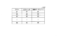
- FIG. 2 is a diagram illustrating a configuration of the registration data list Ls1 stored by the network controller 11 according to the first embodiment of the present invention.
- the registration data list Ls1 includes the identification numbers (“# 1”, “# 2”,..., And “#m”) of the flows input to each L2 switch 10 and each L2 switch.
- the identification number (“# 1”, “# 2”,..., And “#s”) of the switch 10 and the registered data rate are associated with each other in a list format.
- D1 and D2 are described as values of the registered data rate, but actually, specific set values of the registered data rate are registered.
- the registered data rate is identified for each flow and managed as a field.
- FIG. 3 is a diagram illustrating a configuration of the observation data list Ls2 generated by the network controller 11 according to the first embodiment of the present invention.
- the observation data list Ls2 includes the identification numbers (“# 1”, “# 2”,..., And “#n”) of the flows input to each L2 switch 10 and each L2
- the identification data of the switch 10 (“# 1”, “# 2”,..., And “#s”) is data in a list format in which observation data rates are associated with each other.
- the flow indicated by the identification number in the observation data list Ls2 may be a flow in which a plurality of flows are aggregated.
- D1 ′ and D2 ′ and the like are described as the values of the observation data rate, but actually, actual measurement values of the observation data rate are registered. I have.
- the configuration of the registered data list Ls1 illustrated in FIG. 2 and the configuration of the observation data list Ls2 illustrated in FIG. 3 are configured to be able to manage the same flow input from a plurality of L2 switches 10. No, but not limited to this.
- the configuration of the registration data list Ls1 and the observation data list Ls2 may be configured to be able to manage the same flow input from a plurality of L2 switches 10.
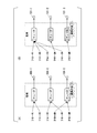
- FIG. 4 is a schematic diagram illustrating an abnormal flow selection process performed by the network controller 11 according to the first embodiment of the present invention.
- flow # 1, flow # 2,..., And flow # 6 are input to a certain L2 switch 10. Then, the network controller 11 aggregates the input six flows into three corresponding to the number of queues. The network controller 11 allocates the three aggregated flows to three queues (queue # 1, queue # 2, and queue # 3). The three flows assigned to each queue are shaped by three shapers (101-1, 101-2, and 101-3) respectively corresponding to the three queues.
- the network controller 11 compares the registered data data rate and the observed data rate for each queue.
- a flow in which a plurality of flows are aggregated for one queue may be input.
- the network controller 11 compares the sum of the registered data rates corresponding to the respective flows included in the plurality of flows with the sum of the observed data rates.
- the network controller 11 starts to select an abnormal flow.
- the network controller 11 outputs a flow # 1 and a flow # out of the six inputted flows (flow # 1, flow # 2,... And flow # 6). 2 is assigned to queue # 1. Further, the network controller 11 allocates the flow # 3 and the flow # 5 to the queue # 2. Further, the network controller 11 allocates the flow # 4 and the flow # 6 to the queue # 3.
- the network controller 11 separates the flow # 4 and the flow # 6 assigned to the queue # 3 whose observation data rate exceeds the threshold, and individually separates the queues # 2 and # 2. And to queue # 3 again.
- the network controller 11 transmits the flows (that is, the flows # 1, # 2, # 3, and # 3) assigned to the queues whose observed data rates do not exceed the threshold (that is, queue # 2 and queue # 3).
- the flow # 5) is allocated again to the remaining queues (that is, the queue # 1).
- the network controller 11 separates the flows assigned to the queues exceeding the threshold into individual flows, and reassigns the separated flows to the individual queues. Then, the network controller 11 again specifies a queue whose observation data rate exceeds the threshold.
- the network controller 11 separates the flows into individual flows again, and separates the separated flows. Repeat the process of assigning individual queues. By repeating the above processing until the flow assigned to the queue whose observation data rate exceeds the threshold is not a flow in which a plurality of flows are aggregated, the network controller 11 can uniquely select an abnormal flow. .
- FIG. 5 is a flowchart showing the operation of the network controller 11 according to the first embodiment of the present invention.
- the abnormal flow selection process shown in the flowchart of FIG. 5 is periodically executed.
- the network controller 11 acquires the observation data rate of each monitored queue from each L2 switch 10. The network controller 11 compares the obtained observed data rate for each queue with the registered data rate of the flow assigned to the queue (or the sum of the registered data rates if the flow is a flow in which a plurality of flows are aggregated). (Step S101).
- the network controller 11 performs the following determination processing for each of the monitored queues.
- step S102 if the observed data rate does not exceed the registered data rate (step S102, No), the network controller 11 proceeds to the determination processing for the next queue.
- the determination processing for all the queues to be subjected to the determination processing ends, the abnormal flow selection processing illustrated in the flowchart of FIG. 5 ends.
- step S102 if the observed data rate exceeds the registered data rate (step S102: Yes), the network controller 11 sends a message to the queue (queue j) targeted for the determination process. It is confirmed whether or not a plurality of flows are accommodated (that is, whether or not a flow in which a plurality of flows are aggregated is allocated) (step S103).
- the network controller 11 specifies the flow accommodated in the queue (queue j) as an abnormal flow. (Step S105). Then, the network controller 11 proceeds to a determination process for the next queue. Alternatively, when the determination processing for all the queues to be subjected to the determination processing ends, the abnormal flow selection processing illustrated in the flowchart of FIG. 5 ends.
- step S103 When a plurality of flows are accommodated in the queue (queue j) targeted for the determination process (step S103: Yes), the network controller 11 determines whether or not the elapsed time is equal to or less than a preset value. Confirm (step S104).
- step S104 If the elapsed time is not less than or equal to the preset value (step S104: No) (that is, if the elapsed time exceeds a predetermined time), the network controller 11 is stored in the queue (queue j).
- the specified flow is specified as an abnormal flow (step S105).
- the identified abnormal flow may be a flow in which a plurality of flows are aggregated. Then, the network controller 11 proceeds to a determination process for the next queue. Alternatively, when the determination processing for all the queues to be subjected to the determination processing ends, the abnormal flow selection processing illustrated in the flowchart of FIG. 5 ends.
- the network controller 11 separates the flow accommodated in the queue (queue j) targeted for the determination process into two flows. Are assigned to two queues (queue j1 and queue j2), respectively. Then, the network controller 11 monitors each of the two queues (queue j1 and queue j2) (Step S106).
- the network controller 11 monitors the two queues (queue j1 and queue j2), and as a result, when the observed data rate exceeds the registered data rate in only one of the queues j1 and j2 (step S107). Yes), returning to step S103 to determine whether or not a plurality of flows are accommodated in the queue (queue j1 or queue j2) in which the observation data rate exceeds the registered data rate (that is, the plurality of flows are aggregated). Check if a flow is assigned).
- the network controller 11 monitors the two queues (queue j1 and queue j2), and as a result, if both the queue j1 and the queue j2 have the observation data rate exceeding the registered data rate (No in step S107), The combination of flows accommodated in the queue j1 and the queue j2 is changed (step S108). Then, returning to step S103, the network controller 11 determines whether a plurality of flows are accommodated in the queues (queue j1 and queue j2) whose observation data rate exceeds the registered data rate (that is, whether a plurality of flows are included). Is assigned or not).
- the network controller 11 determines that only one flow is accommodated in the queue to be subjected to the determination process for identifying the abnormal flow (No in step S103), or that the abnormal flow is selected. If a predetermined time has elapsed since the start of the process (No in step S104), the abnormal flow selection process ends.
- the former is an end condition when there is only one abnormal flow and the abnormal flow can be identified.
- the latter is an end condition when the time is up because the abnormal flow cannot be uniquely specified within the predetermined time.
- the process from assigning a flow to a queue to observing an input data rate is defined as one cycle, and The determination may be made based on
- step S108 In the process of changing the combination of the flows accommodated in the queue j1 and the queue j2 shown in step S108, for example, all combinations in which a plurality of flows can be assigned to two queues are sequentially tried. You may do so.
- abnormal flow selection processing when only one flow is accommodated in the queue by the above-described abnormal flow selection processing, the flow can be uniquely selected as an abnormal flow, and the abnormal flow can be isolated. can do.
- abnormal flow selection and isolation can be performed constantly and continuously.
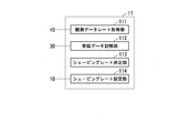
- FIG. 6 is a block diagram illustrating a functional configuration of the network controller 11 according to the first embodiment of the present invention.
- the network controller 11 (communication control device) includes an observation data rate acquisition unit 111, a registration data storage unit 112, a shaping rate determination unit 113, and a shaping rate setting unit 114. Is done.
- the observation data rate acquisition unit 111 periodically acquires the observation data rate for each queue observed in the L2 switch 10 from each L2 switch 10.
- the registration data storage unit 112 (threshold storage unit) stores a registration data list Ls1 including a registration data rate that is a predetermined threshold for each queue. Note that the registered data rate or the registered data list Ls1 is obtained from the application server 30.
- the registration data storage unit 112 includes a storage medium such as a semiconductor memory or a magnetic disk device.
- the shaping rate determination unit 113 determines a shaping rate for each queue based on the observation data rate acquired by the observation data rate acquisition unit 111 and the registration data rate stored in the registration data storage unit 112.
- the shaping rate setting unit 114 sets the shaping rate for each queue for each L2 switch 10 by transmitting the shaping rate for each queue determined by the shaping rate determining unit 113 to each L2 switch 10.
- the network controller 11 is configured to select an abnormal flow by comparing an input data rate (observed data rate) with a threshold (registered data rate) as observation data.
- the network controller 11 is configured to select an abnormal flow by using an increase in the input data rate as observation data instead of the input data rate.
- the increase in the input data rate (hereinafter referred to as “data rate increase”) is calculated, for example, by subtracting the observation data rate observed one cycle before from the currently observed observation data rate. .
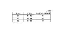
- FIG. 7 is a diagram illustrating a configuration of the observation data list Ls2 ′ generated by the network controller 11 according to the second embodiment of the present invention.
- observation data list Ls2 is assigned to the queue identification numbers (“# 1”, “# 2”, and “# 3”) input to each L2 switch 10 and each queue.
- This is data in the form of a list, in which flow identification numbers (such as “# 1” and “# 2”) are associated with data rate increments.
- R1 and R2 are described as values of the data rate increase amount, but actually, actual measured values of the data rate increase amount are registered. I have.
- the network controller 11 performs the processing based on the fact that the data rate increase exceeds the preset threshold even when the observation data rate does not exceed the registered data rate.
- abnormal flows can be sorted out.
- an abnormal flow can be specified before the observed data rate exceeds the registered data rate, so that appropriate shaping can be performed at an earlier timing. Will be possible.
- the L2 network may generally accommodate more flows than the number of queues that can be set.
- the conventional L2 switch collectively inputs a plurality of flows to one queue or shaper when more flows than the number of queues that can be set flow in.
- the conventional L2 switch cannot identify the flow (abnormal flow) that causes the input data rate to increase when the input data rate is higher than the assumed input data rate. Therefore, the conventional L2 switch performs shaping on the entire flow in which a plurality of flows are aggregated. As a result, flows other than the abnormal flows are also shaped, so that the fairness of the entire network is impaired.
- the network controller 11 of the L2 network 1 in each of the embodiments described above periodically acquires the input data rate from the plurality of L2 switches 10. Then, when the observation data rate exceeds the registered data rate (the threshold of the data rate registered in advance), the network controller 11 specifies an abnormal flow. Specifically, as described above, the network controller 11 inputs a plurality of flows that have flowed into the queue exceeding the threshold into individual queues, and compares the observed data rate with the registered data rate, respectively. An abnormal flow causing an increase in the input data rate can be selected.
- the L2 network 1 in each of the above-described embodiments can reduce flows other than abnormal flows with low delay and perform shaping without impairing fairness of the entire network.
- the network controller 11 in the above-described embodiment may be realized by a computer.
- a program for realizing this function may be recorded on a computer-readable recording medium, and the program recorded on this recording medium may be read and executed by a computer system.
- the “computer system” includes an OS and hardware such as peripheral devices.
- the “computer-readable recording medium” refers to a portable medium such as a flexible disk, a magneto-optical disk, a ROM, and a CD-ROM, and a storage device such as a hard disk built in a computer system.
- a “computer-readable recording medium” refers to a communication line for transmitting a program via a network such as the Internet or a communication line such as a telephone line, which dynamically holds the program for a short time.
- a program may include a program that holds a program for a certain period of time, such as a volatile memory in a computer system serving as a server or a client in that case.
- the program may be for realizing a part of the functions described above, or may be a program that can realize the functions described above in combination with a program already recorded in a computer system, It may be realized by using a programmable logic device such as an FPGA (Field Programmable Gate Array).
- FPGA Field Programmable Gate Array
Landscapes
- Engineering & Computer Science (AREA)
- Computer Networks & Wireless Communication (AREA)
- Signal Processing (AREA)
- Data Exchanges In Wide-Area Networks (AREA)
Abstract
通信制御装置は、レイヤー2スイッチにおいて観測された、キューごとの入力データレートを示す観測データレートを取得する観測データレート取得部と、所定の閾値を前記キューごとに記憶する閾値記憶部と、前記観測データレート取得部によって取得された観測データレートに基づく観測データと、前記閾値記憶部に記憶された閾値とに基づいて、前記キューごとのシェーピングレートを決定するシェーピングレート決定部と、前記シェーピングレート決定部によって決定された前記キューごとの前記シェーピングレートを前記レイヤー2スイッチに対して設定するシェーピングレート設定部と、を備える。
Description
本発明は、レイヤー2(以下「L2」という。)のネットワークの技術に関する。
近年、増加するモバイルトラヒックを効率的に収容するため、C-RAN(Centralized Radio Access Network)構成が検討されている(非特許文献1参照)。C-RANでは、多数のRE(Radio Equipment)が高密度で配置され、集約配置されたRECs(Radio Equipment Controls)に接続される。また、IEEE 802.1CMにおいて、フロントホールのトラヒックをL2ネットワークに収容する検討が進められている(非特許文献2参照)。一方、IoT(Internet of Things)の一部に代表される、遅延を許容するトラヒック(遅延許容トラヒック)をアクセスネットワークに収容する検討も進められている。これらを鑑みて、フロントホール、バックホールに加え、遅延許容トラヒックを同一のL2ネットワークに収容したマルチサービス収容アクセスネットワーク(マルチサービスネットワーク)を検討した報告がなされている(非特許文献3参照)。
マルチサービスネットワークを流れるサービスにおいては、多数の端末がネットワーク上のアプリケーションサーバに同時に接続することがある。これによってデータフロー(以下「フロー」という。)が増加し、接続先サーバ及びL2ネットワークに負荷がかかることがある。
これに対し各L2スイッチは、一般に、サーバ及びL2ネットワークに想定外の負荷がかからないように、L2スイッチを流れるフローをシェーピングする。
これに対し各L2スイッチは、一般に、サーバ及びL2ネットワークに想定外の負荷がかからないように、L2スイッチを流れるフローをシェーピングする。
ドコモ5Gホワイトペーパー, https://www.nttdocomo.co.jp/corporate/technology/whitepaper_5g/
Craig Gunther, "What's New in the World of IEEE 802.1 TSN",Standards News, IEEE Communications Magazine, Communications Standards Supplement, September 2016
久保尊広 他,「マルチサービスを収容したL2ネットワークにおける遅延の評価」,2016年電子情報通信学会通信ソサイエティ大会 通信講演論文集2 B-8-25,p.155,2016年
ところで、L2スイッチによって転送される複数のフローに対してキュー及びシェーパーをそれぞれ個別に割り当てた場合、例えば、特定のフローが、通常想定される入力データレートよりも極めて高いデータレートで入力された場合であっても、当該特定のフローのみをシェーピングすることができる。このように、問題が生じたフローのみに対してシェーピングを行うことができるため、ネットワーク全体としての公平性が高くなる。
しかしながら、実際のL2スイッチにおいては、転送されるフローの数よりも、キュー及びシェーパーの数のほうが少ない場合がある。この場合、複数のフローが集約され、集約されたフローが1つのキュー又はシェーパーに入力される。
しかしながら、実際のL2スイッチにおいては、転送されるフローの数よりも、キュー及びシェーパーの数のほうが少ない場合がある。この場合、複数のフローが集約され、集約されたフローが1つのキュー又はシェーパーに入力される。
このような場合において、例えば、集約されたフローの中に含まれる1つのフローが、通常想定される入力データレートよりも極めて高いデータレートで入力されると、集約されたフロー全体が、通常想定される入力データレートよりも高いデータレートとなることがある。
シェーパーは、集約されたフローの中から、入力データレートを上昇させる原因となっているフロー(通常想定される入力データレートよりも極めて高いデータレートで入力されたフロー)を選別することはできない。そのため、シェーパーは、集約されたフロー全体に対してシェーピングを行う。その結果として、入力データレートを上昇させる原因となっているフロー以外のフローもまとめて、通常想定される入力データレートよりも高いデータレートに応じたシェーピングレートでシェーピングされてしまう。これにより、ネットワーク全体としての公平性が損なわれるという課題がある。
上記事情に鑑み、本発明は、L2ネットワークにおいてネットワーク全体としての公平性を損なうことなくシェーピングすることができる技術の提供を目的としている。
本発明の一態様は、レイヤー2スイッチにおいて観測された、キューごとの入力データレートを示す観測データレートを取得する観測データレート取得部と、所定の閾値を前記キューごとに記憶する閾値記憶部と、前記観測データレート取得部によって取得された観測データレートに基づく観測データと、前記閾値記憶部に記憶された閾値とに基づいて、前記キューごとのシェーピングレートを決定するシェーピングレート決定部と、前記シェーピングレート決定部によって決定された前記キューごとの前記シェーピングレートを前記レイヤー2スイッチに対して設定するシェーピングレート設定部と、を備える通信制御装置である。
また、本発明の一態様は、上記の通信制御装置であって、前記閾値は前記キューごとの所定の入力データレートを示す登録データレートであり、前記シェーピングレート決定部は、前記観測データレートが前記登録データレートを超過した場合、前記観測データレートが前記登録データレートを超過させる原因となるフローを示す異常フローを特定する。
また、本発明の一態様は、上記の通信制御装置であって、前記シェーピングレート決定部は、前記観測データレートが前記登録データレートを超過した前記キューに割り当てられた複数のフローを、それぞれ複数のキューに個別に割り当てるように割り当てを変更し、変更された前記割り当てにおいて前記観測データレートが前記登録データレートを超過するキューに割り当てられたフローを、前記異常フローとして特定する。
また、本発明の一態様は、上記の通信制御装置であって、前記閾値は前記キューごとの入力データレートの所定の増加量を示すデータレート増加量であり、前記シェーピングレート決定部は、前記観測データレートの増加量が前記データレート増加量を超過した場合、前記観測データレートの増加量が前記データレート増加量を超過させる原因となるフローを特定する。
また、本発明の一態様は、レイヤー2スイッチにおいて観測された、キューごとの入力データレートを示す観測データレートを取得する観測データレート取得ステップと、所定の閾値を前記キューごとに記憶する閾値記憶ステップと、前記観測データレート取得ステップによって取得された観測データレートに基づく観測データと、前記閾値記憶ステップによって記憶された閾値とに基づいて、前記キューごとのシェーピングレートを決定するシェーピングレート決定ステップと、前記シェーピングレート決定ステップによって決定された前記キューごとの前記シェーピングレートを前記レイヤー2スイッチに対して設定するシェーピングレート設定ステップと、を有する通信制御方法である。
本発明により、L2ネットワークにおいてネットワーク全体としての公平性を損なうことなくシェーピングすることができる。
<第1の実施形態>
以下、本発明の第1の実施形態について、図面を参照しながら説明する。
以下、本発明の第1の実施形態について、図面を参照しながら説明する。
[ネットワークシステムの構成]
以下、ネットワークコントローラ11を用いたネットワークシステムの構成の一例について説明する。
図1は、本発明の第1の実施形態に係るネットワークコントローラ11を用いたネットワークシステムの構成を示す図である。図1に示すように、ネットワークシステムは、L2ネットワーク1と、30台の端末(端末20-1、端末20-2、・・・、及び端末20-30)と、アプリケーションサーバ30と、を含んで構成される。
以下、ネットワークコントローラ11を用いたネットワークシステムの構成の一例について説明する。
図1は、本発明の第1の実施形態に係るネットワークコントローラ11を用いたネットワークシステムの構成を示す図である。図1に示すように、ネットワークシステムは、L2ネットワーク1と、30台の端末(端末20-1、端末20-2、・・・、及び端末20-30)と、アプリケーションサーバ30と、を含んで構成される。
なお、端末20-1、端末20-2、・・・、及び端末20-30には、それぞれ識別番号が与えられている。端末20-1、端末20-2、・・・、及び端末20-30の識別番号は、それぞれ「#1」、「#2」、・・・、及び「#30」である。
なお、以下の説明において、端末20-1、端末20-2、・・・、及び端末20-30をそれぞれ区別する必要がない場合には、単に「端末20」ということがある。
なお、以下の説明において、端末20-1、端末20-2、・・・、及び端末20-30をそれぞれ区別する必要がない場合には、単に「端末20」ということがある。
図1に示すように、端末20とアプリケーションサーバ30とは、L2ネットワーク1及び転送装置(図示せず)を介して接続されている。なお、図1に示すネットワークシステムにおいては、L2ネットワーク1とアプリケーションサーバ30とが直接接続されているが、これらの間に複数の転送装置が介在している構成であってもよい。
L2ネットワーク1は、マルチサービスネットワークとして構成されている。
図1に示すように、L2ネットワーク1は、4つのL2スイッチ(L2スイッチ10-1、L2スイッチ10-2、・・・、及びL2スイッチ10-4)と、ネットワークコントローラ11と、から構成される。
図1に示すように、L2ネットワーク1は、4つのL2スイッチ(L2スイッチ10-1、L2スイッチ10-2、・・・、及びL2スイッチ10-4)と、ネットワークコントローラ11と、から構成される。
なお、L2スイッチ10-1、L2スイッチ10-2、・・・、及びL2スイッチ10-4には、それぞれ識別番号が与えられている。L2スイッチ10-1、L2スイッチ10-2、・・・、及びL2スイッチ10-4の識別番号は、それぞれ「#1」、「#2」、・・・、及び「#4」である。
なお、以下の説明において、L2スイッチ10-1、L2スイッチ10-2、・・・、及びL2スイッチ10-4をそれぞれ区別する必要がない場合には、単に「L2スイッチ10」ということがある。
なお、ネットワークコントローラ11は、転送装置(図示せず)と同一の筐体に納められている構成であってもよい。
なお、以下の説明において、L2スイッチ10-1、L2スイッチ10-2、・・・、及びL2スイッチ10-4をそれぞれ区別する必要がない場合には、単に「L2スイッチ10」ということがある。
なお、ネットワークコントローラ11は、転送装置(図示せず)と同一の筐体に納められている構成であってもよい。
図1に示すように、L2スイッチ10-1、L2スイッチ10-2、・・・、及びL2スイッチ10-4と、ネットワークコントローラ11とは、それぞれ接続している。
図1に示すように、L2スイッチ10-1は、L2スイッチ10-2及びL2スイッチ10-3と接続している。また、L2スイッチ10-2は、L2スイッチ10-1及びL2スイッチ10-4と接続している。また、L2スイッチ10-3は、L2スイッチ10-1及びL2スイッチ10-4と接続している。また、L2スイッチ10-4は、L2スイッチ10-2及びL2スイッチ10-3と接続している。
図1に示すように、端末20-1、端末20-2.・・・、及び端末20-10は、L2スイッチ10-1と通信接続する。また、端末20-11、端末20-12.・・・、及び端末20-20は、L2スイッチ10-3と通信接続する。また、端末20-21、端末20-22.・・・、及び端末20-30は、L2スイッチ10-4と通信接続する。
なお、端末20の台数は30台に限られるものではない。また、L2スイッチ10の台数は4台に限られるものではない。また、各L2スイッチ10に通信接続する端末20の台数についても、図1に示したネットワークシステムの構成による台数に限られるものではない。
なお、各L2スイッチ10がそれぞれ接続するその他のL2スイッチ10は、図1に示したL2ネットワーク1の構成によるL2スイッチ10に限られるものではない。
なお、各L2スイッチ10がそれぞれ接続するその他のL2スイッチ10は、図1に示したL2ネットワーク1の構成によるL2スイッチ10に限られるものではない。
L2スイッチ10は、入力されたフレームを、隣接する他のL2スイッチ10へ出力する。これにより、L2ネットワーク1は、端末20から入力されるフレーム(転送対象となるフレーム)を中継し、L2ネットワーク1に接続された上位ネットワーク(コアネットワーク)にあるサーバを介して、他の端末20へフレームを出力することができる。なお、例えば、エッジノードから下の端末同士が接続するモバイルエッジコンピューティングにおいては、L2ネットワーク1は、転送対象となるフレームを中継し、フレームの宛先に近いエッジから他の端末20へフレームを出力することができる。
ネットワークコントローラ11は、各L2スイッチ10に入力されるフローを識別する識別番号と、入力データレートと、が対応付けられた登録データのリストである登録データリストLs1を予め記憶している。この登録データが示す入力データレート(以下「登録データレート」という。)の値は、後に詳しく説明する閾値として用いられる。
なお、入力データレートとは、例えば、一定時間の間にキューに流入するパケット量の総和を示すものである。入力データレートの単位は、例えば、B/s(byte per second;バイト毎秒)である。
ネットワークコントローラ11は、例えばアプリケーションサーバ30から取得する情報に基づいて、登録データリストLs1を予め生成し、記憶する。あるいは、ネットワークコントローラ11は、例えばアプリケーションサーバ30から登録データリストLs1を予め取得し、記憶する。
また、ネットワークコントローラ11は、各L2スイッチ10の全てのキューを監視する。具体的には、ネットワークコントローラ11は、各L2スイッチ10から定期的に、各キューの入力データレートの値を取得する。ネットワークコントローラ11は、取得した情報に基づいて、各L2スイッチ10に入力されるフローを識別する識別番号と、取得した入力データレート(以下「観測データレート」という。)と、が対応付けられた観測データのリストである観測データリストLs2を生成する。
また、ネットワークコントローラ11は、観測データレートと、閾値である登録データレートとを比較する。そして、ネットワークコントローラ11は、比較結果に基づいて、入力データレートを上昇させる原因となるフロー(以下「異常フロー」という。)を選別する。異常フローを選別する選別処理については、後に詳しく説明する。
[登録データリストの構成]
以下、登録データリストLs1の構成の一例について説明する。
図2は、本発明の第1の実施形態に係るネットワークコントローラ11が記憶する登録データリストLs1の構成を示す図である。
以下、登録データリストLs1の構成の一例について説明する。
図2は、本発明の第1の実施形態に係るネットワークコントローラ11が記憶する登録データリストLs1の構成を示す図である。
図2に示すように、登録データリストLs1は、各L2スイッチ10に入力されるフローの識別番号(「#1」、「#2」、・・・、及び「#m」)と、各L2スイッチ10の識別番号(「#1」、「#2」、・・・、及び「#s」)と、登録データレートと、が対応付けられたリスト形式のデータである。
なお、図2に示す登録データリストLs1においては、登録データレートの値として、D1及びD2等が記載されているが、実際には、登録データレートの具体的な設定値が登録されている。
このように、登録データリストLs1において、登録データレートはフローごとに識別され、フィールドとして管理されている。
[観測データリストの構成]
以下、観測データリストLs2の構成の一例について説明する。
図3は、本発明の第1の実施形態に係るネットワークコントローラ11が生成する観測データリストLs2の構成を示す図である。
以下、観測データリストLs2の構成の一例について説明する。
図3は、本発明の第1の実施形態に係るネットワークコントローラ11が生成する観測データリストLs2の構成を示す図である。
図3に示すように、観測データリストLs2は、各L2スイッチ10に入力されるフローの識別番号(「#1」、「#2」、・・・、及び「#n」)と、各L2スイッチ10の識別番号(「#1」、「#2」、・・・、及び「#s」)と、観測データレートと、が対応付けられたリスト形式のデータである。
ここで、観測データリストLs2における識別番号が示すフローは、複数のフローが集約されたフローである場合がある。
ここで、観測データリストLs2における識別番号が示すフローは、複数のフローが集約されたフローである場合がある。
なお、図3に示す観測データリストLs2においては、観測データレートの値として、D1’及びD2’等が記載されているが、実際には、観測データレートの具体的な実測値が登録されている。
なお、図2に例示した登録データリストLs1、及び図3に例示した観測データリストLs2の構成は、複数のL2スイッチ10から入力される同一フローについても管理をすることができる構成にはなっていないが、これに限られるものではない。登録データリストLs1及び観測データリストLs2の構成を、複数のL2スイッチ10から入力される同一フローについても管理をすることができるような構成にしてもよい。
[異常フローの選別処理]
以下、ネットワークコントローラ11による、異常フローの選別処理の一例について説明する。
図4は、本発明の第1の実施形態に係るネットワークコントローラ11による異常フローの選別処理を説明するための模式図である。
以下、ネットワークコントローラ11による、異常フローの選別処理の一例について説明する。
図4は、本発明の第1の実施形態に係るネットワークコントローラ11による異常フローの選別処理を説明するための模式図である。
図4(A)に示すように、あるL2スイッチ10には6つのフロー(フロー#1、フロー#2、・・・、及びフロー#6)が入力される。そして、ネットワークコントローラ11は、入力された6つのフローを、キューの数に相当する3つに集約する。ネットワークコントローラ11は、集約された3つのフローを、それぞれ3つのキュー(キュー#1、キュー#2、及びキュー#3)に割り当てる。各キューに割り当てられた3つのフローは、3つのキューにそれぞれ対応する3つのシェーパー(101-1、シェーパー101-2、及びシェーパー101-3)によってそれぞれシェーピングされる。
ネットワークコントローラ11は、各キューについて、登録データデータレートと観測データレートとを比較する。なお、ここで、図4(A)に示す例のように、一つのキューに対して複数のフローが集約されたフローが入力されている場合がある。この場合、ネットワークコントローラ11は、複数のフローに含まれるそれぞれのフローに対応する登録データレートの和と、観測データレートの和と、を比較する。
比較の結果、あるキューにおいて、観測データデータレートが、予め設定した閾値(すなわち、登録データレート)を超過している場合、ネットワークコントローラ11は、異常フローの選別を開始する。
例えば、図4(A)に示すように、ネットワークコントローラ11は、入力された6つのフロー(フロー#1、フロー#2、・・・、及びフロー#6)のうち、フロー#1及びフロー#2をキュー#1に割り当てる。また、ネットワークコントローラ11は、フロー#3及びフロー#5をキュー#2に割り当てる。また、ネットワークコントローラ11は、フロー#4及びフロー#6をキュー#3に割り当てる。
ここで、キュー#3において観測データレートが閾値を超過した場合を考える。すなわち、キュー#3の観測データレートが、フロー#4及びフロー#6の登録データレートの和を超過した場合である。
この場合、図4(B)に示すように、ネットワークコントローラ11は、観測データレートが閾値を超過したキュー#3に割り当てられたフロー#4及びフロー#6を分離し、それぞれ個別にキュー#2及びキュー#3に、再度、割り当てを行う。また、ネットワークコントローラ11は、観測データレートが閾値を超過していないキュー(すなわち、キュー#2及びキュー#3)に割り当てられたフロー(すなわち、フロー#1、フロー#2、フロー#3、及びフロー#5)を、残りのキュー(すなわち、キュー#1)に、再度、割り当てを行う。
このように、ネットワークコントローラ11は、閾値を超過したキューに割り当てられたフローを個別のフローに分離して、分離したフローをそれぞれ個別のキューに、再度、割り当てを行う。そして、ネットワークコントローラ11は、再度、観測データレートが閾値を超過するキューを特定する。ここで、特定されたキューに割り当てられたフローが、複数のフローが集約されたフローである場合には、ネットワークコントローラ11は、再度、フローを個別のフローに分離して、分離したフローをそれぞれ個別のキューに割り当てる処理を繰り返す。観測データレートが閾値を超過するキューに割り当てられたフローが、複数のフローが集約されたフローではなくなるまで上記の処理を繰り返すことにより、ネットワークコントローラ11は、異常フローを一意に選別することができる。
[ネットワークコントローラの動作]
以下、異常フローの選別処理における、ネットワークコントローラ11の動作の一例について説明する。
図5は、本発明の第1の実施形態に係るネットワークコントローラ11の動作を示すフローチャートである。なお、図5のフローチャートが示す異常フローの選別処理は定期的に実行される。
以下、異常フローの選別処理における、ネットワークコントローラ11の動作の一例について説明する。
図5は、本発明の第1の実施形態に係るネットワークコントローラ11の動作を示すフローチャートである。なお、図5のフローチャートが示す異常フローの選別処理は定期的に実行される。
ネットワークコントローラ11は、監視するキューごとの観測データレートを、各L2スイッチ10からそれぞれ取得する。ネットワークコントローラ11は、取得したキューごとの観測データレートと、当該キューに割り当てられたフローの登録データレート(複数フローが集約されたフローである場合には、登録データレートの和)と、を比較する(ステップS101)。
ネットワークコントローラ11は、監視するキューそれぞれについて、以下の判定処理を行う。
観測データレートと登録データレートとを比較した結果、観測データレートが登録データレートを超過していない場合(ステップS102・No)、ネットワークコントローラ11は、次のキューについての判定処理に進む。あるいは、判定処理の対象としている全てのキューについての判定処理が終了した場合には、図5のフローチャートが示す異常フローの選別処理が終了する。
観測データレートと登録データレートとを比較した結果、観測データレートが登録データレートを超過している場合(ステップS102・Yes)、ネットワークコントローラ11は、判定処理の対象としているキュー(キューj)に複数のフローが収容されているか否か(すなわち、複数のフローが集約されたフローが割り当てられているか否か)を確認する(ステップS103)。
判定処理の対象としているキュー(キューj)に複数のフローが収容されていない場合(ステップS103・No)、ネットワークコントローラ11は、当該キュー(キューj)に収容されているフローを異常フローとして特定する(ステップS105)。
そして、ネットワークコントローラ11は、次のキューについての判定処理に進む。あるいは、判定処理の対象としている全てのキューについての判定処理が終了した場合には、図5のフローチャートが示す異常フローの選別処理が終了する。
そして、ネットワークコントローラ11は、次のキューについての判定処理に進む。あるいは、判定処理の対象としている全てのキューについての判定処理が終了した場合には、図5のフローチャートが示す異常フローの選別処理が終了する。
判定処理の対象としているキュー(キューj)に複数のフローが収容されている場合(ステップS103・Yes)、ネットワークコントローラ11は、経過時間が、予め設定された設定値以下であるか否かを確認する(ステップS104)。
経過時間が、予め設定された設定値以下ではない場合(ステップS104・No)(すなわち、経過時間が所定の時間を超過した場合)、ネットワークコントローラ11は、当該キュー(キューj)に収容されているフローを異常フローとして特定する(ステップS105)。なお、この場合、特定された異常フローは、複数のフローが集約されたフローである場合がある。
そして、ネットワークコントローラ11は、次のキューについての判定処理に進む。あるいは、判定処理の対象としている全てのキューについての判定処理が終了した場合には、図5のフローチャートが示す異常フローの選別処理が終了する。
そして、ネットワークコントローラ11は、次のキューについての判定処理に進む。あるいは、判定処理の対象としている全てのキューについての判定処理が終了した場合には、図5のフローチャートが示す異常フローの選別処理が終了する。
経過時間が、予め設定された設定値以下である場合(ステップS104・Yes)、ネットワークコントローラ11は、判定処理の対象としているキュー(キューj)に収容されたフローを2つのフローに分離して、それぞれ2つのキュー(キューj1及びキューj2)に割り当てる。そして、ネットワークコントローラ11は、2つのキュー(キューj1及びキューj2)をそれぞれ監視する(ステップS106)。
ネットワークコントローラ11は、2つのキュー(キューj1及びキューj2)をそれぞれ監視した結果、キューj1及びキューj2のうちいずれか一方のみ、観測データレートが登録データレートを超過している場合(ステップS107・Yes)、上記ステップS103に戻り、観測データレートが登録データレートを超過しているキュー(キューj1又はキューj2)に複数のフローが収容されているか否か(すなわち、複数のフローが集約されたフローが割り当てられているか否か)を確認する。
ネットワークコントローラ11は、2つのキュー(キューj1及びキューj2)をそれぞれ監視した結果、キューj1及びキューj2の双方が、観測データレートが登録データレートを超過している場合(ステップS107・No)、キューj1及びキューj2に収容するフローの組み合わせを変更する(ステップS108)。
そして、上記ステップS103に戻り、ネットワークコントローラ11は、観測データレートが登録データレートを超過しているキュー(キューj1及びキューj2)に複数のフローが収容されているか否か(すなわち、複数のフローが集約されたフローが割り当てられているか否か)を、それぞれ確認する。
そして、上記ステップS103に戻り、ネットワークコントローラ11は、観測データレートが登録データレートを超過しているキュー(キューj1及びキューj2)に複数のフローが収容されているか否か(すなわち、複数のフローが集約されたフローが割り当てられているか否か)を、それぞれ確認する。
このように、ネットワークコントローラ11は、異常フローを特定するための判定処理行う対象のキューに、一つのフローしか収容されていない状態となった場合(ステップS103・No)、又は、異常フローの選別処理を開始してから所定の時間が経過した場合(ステップS104・No)に、異常フローの選別処理を終了する。
前者は、異常フローが一つしか存在せず、かつ、異常フローを特定できた場合の終了条件である。一方、後者は、所定の時間内に異常フローを一意に特定することができずにタイムアップとなった場合の終了条件である。
前者は、異常フローが一つしか存在せず、かつ、異常フローを特定できた場合の終了条件である。一方、後者は、所定の時間内に異常フローを一意に特定することができずにタイムアップとなった場合の終了条件である。
なお、異常フローの選別処理を開始してからの経過時間に基づいて判定を行う代わりに、例えば、キューへのフローの割り当てから入力データレートの観測までの処理を1サイクルとして、このサイクルの数に基づいて判定を行う構成にしてもよい。
なお、ステップS108に示した、キューj1及びキューj2に収容するフローの組み合わせを変更する処理において、例えば、2つのキューに対して複数のフローを割り当て可能な全ての組み合わせについて、順に試行していくようにしてもよい。
このように、上述した異常フローの選別処理により、キューに1つのフローしか収容されていない状態になった場合には、当該フローを異常フローとして一意に選別することができ、当該異常フローを隔離することができる。また、上述した異常フローの選別処理を定期的に繰り返すことによって、異常フローの選別及び隔離を、常時、継続的に行うことができる。
[ネットワークコントローラの機能構成]
以下、ネットワークコントローラ11の機能構成について説明する。
図6は、本発明の第1の実施形態に係るネットワークコントローラ11の機能構成を示すブロック図である。図6に示すように、ネットワークコントローラ11(通信制御装置)は、観測データレート取得部111と、登録データ記憶部112と、シェーピングレート決定部113と、シェーピングレート設定部114と、を含んで構成される。
以下、ネットワークコントローラ11の機能構成について説明する。
図6は、本発明の第1の実施形態に係るネットワークコントローラ11の機能構成を示すブロック図である。図6に示すように、ネットワークコントローラ11(通信制御装置)は、観測データレート取得部111と、登録データ記憶部112と、シェーピングレート決定部113と、シェーピングレート設定部114と、を含んで構成される。
観測データレート取得部111は、L2スイッチ10において観測された、キューごとの観測データレートを、各L2スイッチ10から定期的に取得する。
登録データ記憶部112(閾値記憶部)は、キューごとの所定の閾値である登録データレートを含む登録データリストLs1を記憶する。なお、登録データレート又は登録データリストLs1は、アプリケーションサーバ30から取得される。
なお、登録データ記憶部112は、例えば、半導体メモリ又は磁気ディスク装置等の記憶媒体を含んで構成される。
なお、登録データ記憶部112は、例えば、半導体メモリ又は磁気ディスク装置等の記憶媒体を含んで構成される。
シェーピングレート決定部113は、観測データレート取得部111によって取得された観測データレートと、登録データ記憶部112に記憶された登録データレートとに基づいて、キューごとのシェーピングレートを決定する。
シェーピングレート設定部114は、シェーピングレート決定部113によって決定されたキューごとのシェーピングレートを各L2スイッチ10へ送信することによって、各L2スイッチ10に対して当該キューごとのシェーピングレートを設定する。
<第2の実施形態>
以下、第2の実施形態について説明する。
上述した第1の実施形態では、ネットワークコントローラ11は、入力データレート(観測データレート)を観測データとして、閾値(登録データレート)と比較することによって、異常フローの選別を行う構成であった。
一方、第2の実施形態では、ネットワークコントローラ11は、入力データレートの代わりに入力データレートの増加量を観測データとして、異常フローの選別を行う構成である。
以下、第2の実施形態について説明する。
上述した第1の実施形態では、ネットワークコントローラ11は、入力データレート(観測データレート)を観測データとして、閾値(登録データレート)と比較することによって、異常フローの選別を行う構成であった。
一方、第2の実施形態では、ネットワークコントローラ11は、入力データレートの代わりに入力データレートの増加量を観測データとして、異常フローの選別を行う構成である。
なお、入力データレートの増加量(以下「データレート増加量」という。)は、例えば、現在観測された観測データレートから、1サイクル前に観測された観測データレートを減算することによって算出される。
[観測データリストの構成]
以下、観測データリストLs2’の構成の一例について説明する。
図7は、本発明の第2の実施形態に係るネットワークコントローラ11が生成する観測データリストLs2’の構成を示す図である。
以下、観測データリストLs2’の構成の一例について説明する。
図7は、本発明の第2の実施形態に係るネットワークコントローラ11が生成する観測データリストLs2’の構成を示す図である。
図7に示すように、観測データリストLs2は、各L2スイッチ10に入力されるキューの識別番号(「#1」、「#2」、及び「#3」)と、各キューに割り当てられたフローの識別番号(「#1」及び「#2」等)と、データレート増加量とが対応付けられた、リスト形式のデータである。
なお、図7に示す観測データリストLs2’においては、データレート増価量の値としてR1及びR2等が記載されているが、実際には、データレート増加量の具体的な実測値が登録されている。
このように、第2の実施形態に係るネットワークコントローラ11は、観測データレートが登録データレートを超過していない場合であっても、データレート増加量が予め設定された閾値を超過したことに基づいて、異常フローを選別することができる。これにより、第2の実施形態に係るネットワークコントローラ11によれば、観測データレートが登録データレートを超過する前に異常フローを特定することができるため、より早いタイミングで適切なシェーピングを行うことが可能になる。
以上説明したように、L2ネットワークは、一般に、設定可能なキュー数よりも多い数のフローを収容することがある。従来のL2スイッチは、設定可能なキュー数よりも多い数のフローが流入する場合には、複数のフローをまとめて1つのキュー又はシェーパーに入力する。
そのため、従来のL2スイッチは、想定される入力データレートよりも高い入力データレートである場合に、入力データレートを上昇させる原因となっているフロー(異常フロー)を識別することができない。そのため、従来のL2スイッチは、複数フローが集約されたフロー全体に対してシェーピングを行ってしまう。これにより、異常フロー以外のフローもシェーピングされてしまうため、ネットワーク全体としての公平性が損なわれるという課題があった。
一方、上述した各実施形態におけるL2ネットワーク1のネットワークコントローラ11は、複数のL2スイッチ10から定期的に入力データレートを取得する。そして、観測データレートが登録データレート(予め登録されたデータレートの閾値)を超過した場合、ネットワークコントローラ11は、異常フローの特定を行う。具体的には、ネットワークコントローラ11は、上述したように、閾値を超過したキューに流入した複数のフローをそれぞれ個別のキューに入力し、観測データレートと登録データレートとをそれぞれ比較することによって、入力データレートを上昇させる原因となっている異常フローを選別することができる。
上述した各実施形態におけるL2ネットワーク1は、上記の構成を備えることにより、異常フロー以外のフローを低遅延化させ、ネットワーク全体としての公平性を損なうことなくシェーピングすることができる。
以上、図面を参照して本発明の実施の形態を説明してきたが、上記実施の形態は本発明の例示に過ぎず、本発明が上記実施の形態に限定されるものではないことは明らかである。したがって、本発明の技術思想及び範囲を逸脱しない範囲で構成要素の追加、省略、置換、その他の変更を行ってもよい。
上述した実施形態におけるネットワークコントローラ11をコンピュータで実現するようにしてもよい。その場合、この機能を実現するためのプログラムをコンピュータ読み取り可能な記録媒体に記録して、この記録媒体に記録されたプログラムをコンピュータシステムに読み込ませ、実行することによって実現してもよい。なお、ここでいう「コンピュータシステム」とは、OSや周辺機器等のハードウェアを含むものとする。また、「コンピュータ読み取り可能な記録媒体」とは、フレキシブルディスク、光磁気ディスク、ROM、CD-ROM等の可搬媒体、コンピュータシステムに内蔵されるハードディスク等の記憶装置のことをいう。さらに「コンピュータ読み取り可能な記録媒体」とは、インターネット等のネットワークや電話回線等の通信回線を介してプログラムを送信する場合の通信線のように、短時間の間、動的にプログラムを保持するもの、その場合のサーバやクライアントとなるコンピュータシステム内部の揮発性メモリのように、一定時間プログラムを保持しているものも含んでもよい。また上記プログラムは、前述した機能の一部を実現するためのものであってもよく、さらに前述した機能をコンピュータシステムにすでに記録されているプログラムとの組み合わせで実現できるものであってもよく、FPGA(Field Programmable Gate Array)等のプログラマブルロジックデバイスを用いて実現されるものであってもよい。
1…L2ネットワーク、10…L2スイッチ、11…ネットワークコントローラ、20…端末、30…アプリケーションサーバ、101-1~101-3…シェーパー
Claims (5)
- レイヤー2スイッチにおいて観測された、キューごとの入力データレートを示す観測データレートを取得する観測データレート取得部と、
所定の閾値を前記キューごとに記憶する閾値記憶部と、
前記観測データレート取得部によって取得された観測データレートに基づく観測データと、前記閾値記憶部に記憶された閾値とに基づいて、前記キューごとのシェーピングレートを決定するシェーピングレート決定部と、
前記シェーピングレート決定部によって決定された前記キューごとの前記シェーピングレートを前記レイヤー2スイッチに対して設定するシェーピングレート設定部と、
を備える通信制御装置。 - 前記閾値は前記キューごとの所定の入力データレートを示す登録データレートであり、
前記シェーピングレート決定部は、前記観測データレートが前記登録データレートを超過した場合、前記観測データレートが前記登録データレートを超過させる原因となるフローを示す異常フローを特定する
請求項1に記載の通信制御装置。 - 前記シェーピングレート決定部は、前記観測データレートが前記登録データレートを超過した前記キューに割り当てられた複数のフローを、それぞれ複数のキューに個別に割り当てるように割り当てを変更し、変更された前記割り当てにおいて前記観測データレートが前記登録データレートを超過するキューに割り当てられたフローを、前記異常フローとして特定する
請求項2に記載の通信制御装置。 - 前記閾値は前記キューごとの入力データレートの所定の増加量を示すデータレート増加量であり、
前記シェーピングレート決定部は、前記観測データレートの増加量が前記データレート増加量を超過した場合、前記観測データレートの増加量が前記データレート増加量を超過させる原因となるフローを特定する
請求項1に記載の通信制御装置。 - レイヤー2スイッチにおいて観測された、キューごとの入力データレートを示す観測データレートを取得する観測データレート取得ステップと、
所定の閾値を前記キューごとに記憶する閾値記憶ステップと、
前記観測データレート取得ステップによって取得された観測データレートに基づく観測データと、前記閾値記憶ステップによって記憶された閾値とに基づいて、前記キューごとのシェーピングレートを決定するシェーピングレート決定ステップと、
前記シェーピングレート決定ステップによって決定された前記キューごとの前記シェーピングレートを前記レイヤー2スイッチに対して設定するシェーピングレート設定ステップと、
を有する通信制御方法。
Priority Applications (1)
| Application Number | Priority Date | Filing Date | Title |
|---|---|---|---|
| US17/252,346 US11582155B2 (en) | 2018-06-28 | 2019-06-07 | Communication control apparatus and communication control method |
Applications Claiming Priority (2)
| Application Number | Priority Date | Filing Date | Title |
|---|---|---|---|
| JP2018-123576 | 2018-06-28 | ||
| JP2018123576A JP6955171B2 (ja) | 2018-06-28 | 2018-06-28 | 通信制御装置及び通信制御方法 |
Publications (1)
| Publication Number | Publication Date |
|---|---|
| WO2020003975A1 true WO2020003975A1 (ja) | 2020-01-02 |
Family
ID=68985631
Family Applications (1)
| Application Number | Title | Priority Date | Filing Date |
|---|---|---|---|
| PCT/JP2019/022734 Ceased WO2020003975A1 (ja) | 2018-06-28 | 2019-06-07 | 通信制御装置及び通信制御方法 |
Country Status (3)
| Country | Link |
|---|---|
| US (1) | US11582155B2 (ja) |
| JP (1) | JP6955171B2 (ja) |
| WO (1) | WO2020003975A1 (ja) |
Citations (3)
| Publication number | Priority date | Publication date | Assignee | Title |
|---|---|---|---|---|
| JP2004266389A (ja) * | 2003-02-28 | 2004-09-24 | Matsushita Electric Ind Co Ltd | パケット転送制御方法及びパケット転送制御回路 |
| JP2005277804A (ja) * | 2004-03-25 | 2005-10-06 | Hitachi Ltd | 情報中継装置 |
| JP2015149537A (ja) * | 2014-02-05 | 2015-08-20 | 株式会社日立製作所 | 経路制御装置及びシステム及び方法 |
Family Cites Families (7)
| Publication number | Priority date | Publication date | Assignee | Title |
|---|---|---|---|---|
| US7197044B1 (en) * | 1999-03-17 | 2007-03-27 | Broadcom Corporation | Method for managing congestion in a network switch |
| US7243351B2 (en) * | 2002-12-17 | 2007-07-10 | International Business Machines Corporation | System and method for task scheduling based upon the classification value and probability |
| US9185036B2 (en) * | 2005-03-23 | 2015-11-10 | Alcatel Lucent | Method and apparatus for flow control of data in a network |
| US7583677B1 (en) * | 2006-11-03 | 2009-09-01 | Juniper Networks, Inc. | Dynamic flow-based multi-path load balancing with quality of service assurances |
| US8923125B2 (en) * | 2008-10-24 | 2014-12-30 | Qualcomm Incorporated | Wireless network resource adaptation |
| US9036481B1 (en) * | 2010-05-05 | 2015-05-19 | Marvell International Ltd. | Method and apparatus for adaptive packet load balancing |
| US9197528B2 (en) * | 2011-03-02 | 2015-11-24 | 3Inova Networks Inc. | Traffic management in distributed wireless networks |
-
2018
- 2018-06-28 JP JP2018123576A patent/JP6955171B2/ja active Active
-
2019
- 2019-06-07 WO PCT/JP2019/022734 patent/WO2020003975A1/ja not_active Ceased
- 2019-06-07 US US17/252,346 patent/US11582155B2/en active Active
Patent Citations (3)
| Publication number | Priority date | Publication date | Assignee | Title |
|---|---|---|---|---|
| JP2004266389A (ja) * | 2003-02-28 | 2004-09-24 | Matsushita Electric Ind Co Ltd | パケット転送制御方法及びパケット転送制御回路 |
| JP2005277804A (ja) * | 2004-03-25 | 2005-10-06 | Hitachi Ltd | 情報中継装置 |
| JP2015149537A (ja) * | 2014-02-05 | 2015-08-20 | 株式会社日立製作所 | 経路制御装置及びシステム及び方法 |
Also Published As
| Publication number | Publication date |
|---|---|
| JP2020005145A (ja) | 2020-01-09 |
| US11582155B2 (en) | 2023-02-14 |
| JP6955171B2 (ja) | 2021-10-27 |
| US20210266263A1 (en) | 2021-08-26 |
Similar Documents
| Publication | Publication Date | Title |
|---|---|---|
| US11588757B2 (en) | Traffic management in a network switching system with remote physical ports | |
| Sridharan et al. | On multiple controller mapping in software defined networks with resilience constraints | |
| JP7288980B2 (ja) | 仮想サービスネットワークにおけるサービス品質 | |
| EP3687125B1 (en) | Congestion flow identification method and network device | |
| WO2017078922A1 (en) | Apparatus and method for network flow scheduling | |
| JP6569374B2 (ja) | スイッチ装置及びスイッチ装置の制御方法 | |
| CN111181873A (zh) | 数据发送方法、装置、存储介质和电子设备 | |
| TW201329741A (zh) | 動態佇列臨界值限制方法、能實現動態佇列臨界值限制的交換機及其系統 | |
| JP5208445B2 (ja) | 待ち時間と占有率とに基づく無線ネットワークのスケジューリング方法および装置 | |
| Saleh et al. | Cross-layer minimum-delay scheduling and maximum-throughput resource allocation for multiuser cognitive networks | |
| WO2023116611A1 (zh) | 一种队列控制的方法及装置 | |
| JP6055553B2 (ja) | キュースケジューリング方法、装置及びシステム | |
| US7209750B2 (en) | Communication system, communication unit and method of power saving therein | |
| US20240049043A1 (en) | Prioritizing data packets in wireless communication network | |
| KR20070106939A (ko) | 데이터 블록 스케줄링 방법과 장치 및 이를 포함하는 집적회로 | |
| RU2598293C1 (ru) | Способ и устройство для передачи стандартных данных конфигурации усовершенствованной системы выбора протокола передачи | |
| CN112104564A (zh) | 一种负载分担方法及设备 | |
| CN116318554A (zh) | 网络传输方法及装置 | |
| JP6955171B2 (ja) | 通信制御装置及び通信制御方法 | |
| KR20090057228A (ko) | 데이터 블록 스케줄링 방법, 데이터 블록 스케줄링 장치, 집적 회로 및 통신 시스템 | |
| US20060026192A1 (en) | Frame mapping scheduler | |
| JP7704215B2 (ja) | 変換装置、変換方法及び変換プログラム | |
| JP7718575B2 (ja) | パケット転送装置、パケット転送方法およびプログラム | |
| JP7687393B2 (ja) | 送信装置、送信方法、及びプログラム | |
| CN118802791A (zh) | 报文转发方法、报文排序方法、装置及网络设备 |
Legal Events
| Date | Code | Title | Description |
|---|---|---|---|
| 121 | Ep: the epo has been informed by wipo that ep was designated in this application |
Ref document number: 19827556 Country of ref document: EP Kind code of ref document: A1 |
|
| NENP | Non-entry into the national phase |
Ref country code: DE |
|
| 122 | Ep: pct application non-entry in european phase |
Ref document number: 19827556 Country of ref document: EP Kind code of ref document: A1 |