WO2020003864A1 - Negative electrode, battery cell sheet, and secondary battery - Google Patents
Negative electrode, battery cell sheet, and secondary battery Download PDFInfo
- Publication number
- WO2020003864A1 WO2020003864A1 PCT/JP2019/021111 JP2019021111W WO2020003864A1 WO 2020003864 A1 WO2020003864 A1 WO 2020003864A1 JP 2019021111 W JP2019021111 W JP 2019021111W WO 2020003864 A1 WO2020003864 A1 WO 2020003864A1
- Authority
- WO
- WIPO (PCT)
- Prior art keywords
- negative electrode
- active material
- mass
- electrode active
- solvent
- Prior art date
Links
Images
Classifications
-
- H—ELECTRICITY
- H01—ELECTRIC ELEMENTS
- H01M—PROCESSES OR MEANS, e.g. BATTERIES, FOR THE DIRECT CONVERSION OF CHEMICAL ENERGY INTO ELECTRICAL ENERGY
- H01M10/00—Secondary cells; Manufacture thereof
- H01M10/05—Accumulators with non-aqueous electrolyte
- H01M10/052—Li-accumulators
-
- H—ELECTRICITY
- H01—ELECTRIC ELEMENTS
- H01M—PROCESSES OR MEANS, e.g. BATTERIES, FOR THE DIRECT CONVERSION OF CHEMICAL ENERGY INTO ELECTRICAL ENERGY
- H01M10/00—Secondary cells; Manufacture thereof
- H01M10/05—Accumulators with non-aqueous electrolyte
- H01M10/056—Accumulators with non-aqueous electrolyte characterised by the materials used as electrolytes, e.g. mixed inorganic/organic electrolytes
- H01M10/0564—Accumulators with non-aqueous electrolyte characterised by the materials used as electrolytes, e.g. mixed inorganic/organic electrolytes the electrolyte being constituted of organic materials only
- H01M10/0566—Liquid materials
- H01M10/0567—Liquid materials characterised by the additives
-
- H—ELECTRICITY
- H01—ELECTRIC ELEMENTS
- H01M—PROCESSES OR MEANS, e.g. BATTERIES, FOR THE DIRECT CONVERSION OF CHEMICAL ENERGY INTO ELECTRICAL ENERGY
- H01M10/00—Secondary cells; Manufacture thereof
- H01M10/05—Accumulators with non-aqueous electrolyte
- H01M10/056—Accumulators with non-aqueous electrolyte characterised by the materials used as electrolytes, e.g. mixed inorganic/organic electrolytes
- H01M10/0564—Accumulators with non-aqueous electrolyte characterised by the materials used as electrolytes, e.g. mixed inorganic/organic electrolytes the electrolyte being constituted of organic materials only
- H01M10/0566—Liquid materials
- H01M10/0569—Liquid materials characterised by the solvents
-
- H—ELECTRICITY
- H01—ELECTRIC ELEMENTS
- H01M—PROCESSES OR MEANS, e.g. BATTERIES, FOR THE DIRECT CONVERSION OF CHEMICAL ENERGY INTO ELECTRICAL ENERGY
- H01M4/00—Electrodes
- H01M4/02—Electrodes composed of, or comprising, active material
- H01M4/13—Electrodes for accumulators with non-aqueous electrolyte, e.g. for lithium-accumulators; Processes of manufacture thereof
- H01M4/133—Electrodes based on carbonaceous material, e.g. graphite-intercalation compounds or CFx
-
- H—ELECTRICITY
- H01—ELECTRIC ELEMENTS
- H01M—PROCESSES OR MEANS, e.g. BATTERIES, FOR THE DIRECT CONVERSION OF CHEMICAL ENERGY INTO ELECTRICAL ENERGY
- H01M4/00—Electrodes
- H01M4/02—Electrodes composed of, or comprising, active material
- H01M4/36—Selection of substances as active materials, active masses, active liquids
- H01M4/58—Selection of substances as active materials, active masses, active liquids of inorganic compounds other than oxides or hydroxides, e.g. sulfides, selenides, tellurides, halogenides or LiCoFy; of polyanionic structures, e.g. phosphates, silicates or borates
- H01M4/583—Carbonaceous material, e.g. graphite-intercalation compounds or CFx
- H01M4/587—Carbonaceous material, e.g. graphite-intercalation compounds or CFx for inserting or intercalating light metals
-
- Y—GENERAL TAGGING OF NEW TECHNOLOGICAL DEVELOPMENTS; GENERAL TAGGING OF CROSS-SECTIONAL TECHNOLOGIES SPANNING OVER SEVERAL SECTIONS OF THE IPC; TECHNICAL SUBJECTS COVERED BY FORMER USPC CROSS-REFERENCE ART COLLECTIONS [XRACs] AND DIGESTS
- Y02—TECHNOLOGIES OR APPLICATIONS FOR MITIGATION OR ADAPTATION AGAINST CLIMATE CHANGE
- Y02E—REDUCTION OF GREENHOUSE GAS [GHG] EMISSIONS, RELATED TO ENERGY GENERATION, TRANSMISSION OR DISTRIBUTION
- Y02E60/00—Enabling technologies; Technologies with a potential or indirect contribution to GHG emissions mitigation
- Y02E60/10—Energy storage using batteries
Definitions
- the present invention relates to a negative electrode, a battery cell sheet, and a secondary battery.
- Patent Literature 1 discloses the following technology as a technology in which an electrode active material layer contains active material particles and a metal oxide as a binder.
- an electrode plate for a non-aqueous electrolyte secondary battery including a current collector and an electrode active material layer formed on at least a part of the surface of the current collector, the electrode active material layer includes active material particles and a binder.
- the electrode active material layer contains a metal oxide as a deposition material, and the maximum peak value of the pore size distribution of the electrode active material layer is 200 nm or more and 600 nm or less.
- Patent Literature 1 describes that a metal oxide acts as a binder and exhibits a high discharge capacity retention rate, but no suggestion regarding the above is found.
- the present invention has been made in view of the above circumstances, and an object of the present invention is to provide a negative electrode and a battery cell sheet that can improve the life of a secondary battery, and to provide a secondary battery with an improved life. .
- Non-aqueous electrolyte, inorganic oxide, a negative electrode having a negative electrode active material wherein the non-aqueous electrolyte has a non-aqueous solvent, the reaction potential of the negative electrode active material, than the reductive decomposition potential of the non-aqueous solvent Low, the non-aqueous solvent has an ether-based solvent, the inorganic oxide is formed on the surface of the negative electrode active material, the metal element contained in the inorganic oxide with respect to the mass of the negative electrode active material in the negative electrode And the product of the mass ratio of the non-aqueous solvent to the mass of the non-aqueous electrolyte in the negative electrode is greater than 0 and 0.0065 or less.
- Non-aqueous electrolyte, inorganic oxide, a negative electrode having a negative electrode active material wherein the non-aqueous electrolyte has a non-aqueous solvent, the reaction potential of the negative electrode active material, than the reductive decomposition potential of the non-aqueous solvent Low, the non-aqueous solvent has a low-viscosity organic solvent, the inorganic oxide is formed on the surface of the negative electrode active material, and the metal contained in the inorganic oxide with respect to the mass of the negative electrode active material in the negative electrode A negative electrode in which the product of the mass ratio of the element and the mass ratio of the nonaqueous solvent to the mass of the nonaqueous electrolyte in the negative electrode is greater than 0 and 0.0123 or less.
- a battery cell sheet having the above-described negative electrode and an insulating layer having the above-described negative electrode and an insulating layer.
- a secondary battery including the above-described negative electrode, a positive electrode, and an insulating layer formed between the positive electrode and the negative electrode.
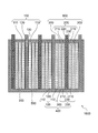
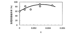
- FIG. 1 is a schematic cross-sectional view illustrating a configuration of a secondary battery according to one embodiment of the present invention. It is a plot diagram which compared discharge capacity maintenance rates in an example and a comparative example.
- the horizontal axis is the product “X” of the mass ratio of the metal element contained in the inorganic oxide to the mass of the negative electrode active material in the negative electrode and the mass ratio of the ether-based solvent to the mass of the nonaqueous electrolyte in the negative electrode.
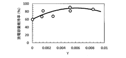
- the axis is the discharge capacity retention rate (%) at the time of 500 cycle discharge. It is a plot diagram which compared discharge capacity maintenance rates in an example and a comparative example.
- the horizontal axis is the product ⁇ Y '' of the mass ratio of the metal element contained in the inorganic oxide to the mass of the negative electrode active material in the negative electrode and the mass ratio of the low-viscosity organic solvent to the mass of the non-aqueous electrolyte in the negative electrode,
- the vertical axis represents the discharge capacity retention rate (%) at the time of 500 cycle discharge. It is a plot diagram which compared discharge capacity maintenance rates in an example and a comparative example.
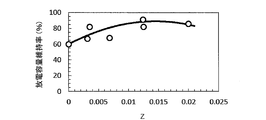
- the horizontal axis represents the mass ratio “Z” of the metal element contained in the inorganic oxide to the mass of the negative electrode active material in the negative electrode, and the vertical axis represents the discharge capacity retention (%) at 500 cycles.
- a lithium ion secondary battery is an electrochemical device that stores or uses electrical energy by inserting and extracting lithium ions into and from an electrode in an electrolyte. This is referred to by another name such as a lithium ion battery, a non-aqueous electrolyte secondary battery, and a non-aqueous electrolyte secondary battery, and any of the batteries is an object of the present invention.
- the technical idea of the present invention can be applied to a sodium ion secondary battery, a magnesium ion secondary battery, a calcium ion secondary battery, a zinc secondary battery, an aluminum ion secondary battery, and the like.
- ⁇ ⁇ In the present specification, one or a combination of a plurality of the materials described in the present specification may be used. Further, it may be composed of only the material described in this specification, or may have another material as long as the effects of the present invention are not impaired.
- FIG. 1 is a schematic sectional view illustrating the configuration of a secondary battery according to one embodiment of the present invention.
- FIG. 1 illustrates a stacked secondary battery.
- the secondary battery 1000 includes a positive electrode 100, a negative electrode 200, a package 500, and an insulating layer 300.
- the exterior body 500 houses the insulating layer 300, the positive electrode 100, and the negative electrode 200.
- the material of the exterior body 500 can be selected from materials having corrosion resistance to a non-aqueous electrolyte, such as aluminum, stainless steel, and nickel-plated steel.
- the present invention can also be applied to a wound type secondary battery.
- An electrode body 400 including the positive electrode 100, the insulating layer 300, and the negative electrode 200 is stacked in the secondary battery 1000.
- the positive electrode 100 or the negative electrode 200 may be referred to as an electrode. What has the positive electrode 100 and the negative electrode 200 or the insulating layer 300 may be called a sheet
- One having the insulating layer 300 and the positive electrode 100 or the negative electrode 200, and particularly having an integrated structure, may be referred to as a battery cell sheet.
- an electrode group can be manufactured only by stacking battery cell sheets.
- a battery cell sheet 600 having the insulating layer 300 and the negative electrode 200 and having these integrated structures can be suitably used.
- the positive electrode 100 has a positive electrode current collector 120 and a positive electrode mixture layer 110. Positive electrode mixture layers 110 are formed on both surfaces of positive electrode current collector 120.
- the negative electrode 200 has a negative electrode current collector 220 and a negative electrode mixture layer 210. Negative electrode mixture layers 210 are formed on both surfaces of negative electrode current collector 220.
- the negative electrode 200 according to the embodiment has a nonaqueous electrolyte, an inorganic oxide, and a negative electrode active material.
- the positive electrode mixture layer 110 or the negative electrode mixture layer 210 may be referred to as an electrode mixture layer
- the positive electrode current collector 120 or the negative electrode current collector 220 may be referred to as an electrode current collector.
- the positive electrode current collector 120 has the positive electrode tab 130.
- the negative electrode current collector 220 has a negative electrode tab 230.
- the positive electrode tab 130 or the negative electrode tab 230 may be referred to as an electrode tab.
- No electrode mixture layer is formed on the electrode tab.
- an electrode mixture layer may be formed on the electrode tab within a range that does not adversely affect the performance of the secondary battery 1000.
- the positive electrode tab 130 and the negative electrode tab 230 protrude to the outside of the outer package 500, and the plurality of protruding positive electrode tabs 130 and the plurality of negative electrode tabs 230 are joined to each other by, for example, ultrasonic bonding.
- a parallel connection is formed in the secondary battery 1000.
- the present invention can be applied to a bipolar secondary battery in which an electric series connection is formed in the secondary battery 1000.
- the positive electrode mixture layer 110 has a positive electrode active material, a positive electrode conductive agent, and a positive electrode binder.
- the negative electrode mixture layer 210 includes a negative electrode active material, a negative electrode conductive agent, and a negative electrode binder.
- the positive electrode active material or the negative electrode active material may be referred to as an electrode active material
- the positive electrode conductive agent or the negative electrode conductive agent may be referred to as an electrode conductive agent
- the positive electrode binder or the negative electrode binder may be referred to as an electrode binder.
- the electrode conductive agent improves the conductivity of the electrode mixture layer.
- Examples of the electrode conductive agent include Ketjen black, acetylene black, graphite, and the like.
- the electrode binder binds an electrode active material and an electrode conductive agent in the electrode.
- the electrode binder include styrene-butadiene rubber, carboxymethyl cellulose, polyvinylidene fluoride (PVDF), and a copolymer of vinylidene fluoride (VDF) and hexafluoropropylene (HFP) (P (VdF-HFP)). And the like.
- ⁇ Positive electrode active material> In the positive electrode active material having a noble potential, lithium ions are desorbed in a charging process, and lithium ions desorbed from the negative electrode active material in the negative electrode mixture layer 210 are inserted in a discharging process.
- a lithium composite oxide having a transition metal is desirable.
- x is the concentration of oxygen contained in the compound, and is an integer of 0 or more. Can be taken.). Further, part of oxygen in these materials may be replaced with another element such as fluorine.
- a chalcogenide such as sulfur, TiS 2 , MoS 2 , Mo 6 S 8 , TiSe 2 , a vanadium-based oxide such as V 2 O 5 , and FeF 3 Oxides such as Fe (MoO 4 ) 3 , Fe 2 (SO 4 ) 3 , and Li 3 Fe 2 (PO 4 ) 3 constituting halides and polyanions, and quinone-based organic crystals can also be used.
- the element ratio may deviate from the stoichiometric composition.
- Examples of the positive electrode current collector 120 include an aluminum foil having a thickness of 1 to 100 ⁇ m, an aluminum perforated foil having a thickness of 10 to 100 ⁇ m and a hole diameter of 0.1 to 10 mm, an expanded metal, a foamed metal plate, and a stainless steel. Examples include steel foil and titanium foil.
- ⁇ Negative electrode active material> In the negative electrode active material having a low potential, lithium ions are eliminated in a discharging process, and lithium ions eliminated from the positive electrode active material in the positive electrode mixture layer 110 are inserted in a charging process.
- the negative electrode active material for example, a carbon-based material (graphite, easily graphitized carbon material, amorphous carbon material, organic crystal, activated carbon, etc.), a conductive polymer material (polyacene, polyparaphenylene, polyaniline, polyacetylene, etc.) , Metal lithium, a metal alloyed with lithium (having at least one kind of aluminum, silicon, tin and the like), and oxides thereof.
- the reaction potential of the negative electrode active material on the basis of lithium can be measured by producing a half-cell with the counter electrode or reference electrode being metallic lithium and applying a constant current to measure the voltage, or by measuring the voltage at a constant voltage sweep rate. It can be measured by measuring the value.
- the solvent is easily inserted into graphite.
- a negative electrode interface stabilizer such as vinylene carbonate (VC)
- VC vinylene carbonate
- a stable SEI (Solid Electrolyte Interphase) film is formed on the surface of the negative electrode active material, and the non-aqueous solvent undergoes reductive decomposition and coexistence. Insertion can be suppressed.
- the SEI film formed by the negative electrode interface stabilizer may not be a sufficiently dense film to suppress reductive decomposition and co-insertion of the non-aqueous solvent.
- the reaction active point of the solvent is increased. Is reduced. Therefore, even if the negative electrode active material expands and contracts due to the repetitive charge / discharge operation of the secondary battery 1000, the negative electrode 200 in which the film formed on the surface of the negative electrode active material does not easily crack can be manufactured.
- the inorganic oxide is a material having a lower non-aqueous solvent reductive decomposition activity than that of the negative electrode 200 from the viewpoint of suppressing reductive decomposition of the non-aqueous solvent. Further, it is desirable that the inorganic oxide be a material having a high fracture toughness value from the viewpoint of suppressing the destruction of the film formed on the surface of the negative electrode active material.
- the inorganic oxide include titanium oxide, silicon oxide, tin oxide, nickel oxide, iron oxide (eg, Fe 3 O 4 and Fe 2 O 3 ), and cobalt oxide. In the present embodiment, it is preferable to have at least one selected from these groups.
- the negative electrode active material may have a portion where the inorganic oxide is not formed on the surface of the negative electrode active material, or a crack formed by expansion and contraction of the negative electrode active material at the beginning of the repetitive charge / discharge operation of the secondary battery 1000.
- active sites for reductive decomposition reaction of the nonaqueous electrolyte remain on the surface of the substance. Therefore, the life of the secondary battery 1000 can be further improved by adding the negative electrode interface stabilizer to the nonaqueous electrolyte.
- the mass ratio of the metal element contained in the inorganic oxide to the mass of the negative electrode active material in the negative electrode 200 and the ether solvent to the mass of the nonaqueous electrolyte in the negative electrode 200 The product of the mass ratios is greater than 0 and not more than 0.0065.
- the product when the non-aqueous solvent has an ether solvent, the product is preferably 0.0005 to 0.0059, and more preferably 0.0009 to 0.0055.
- the mass ratio of the metal element contained in the inorganic oxide to the mass of the negative electrode active material in the negative electrode 200 and the low-viscosity organic solvent to the mass of the non-aqueous electrolyte in the negative electrode 200 The product of the mass ratios is greater than 0 and equal to or less than 0.0123.
- the product when the non-aqueous solvent has a low-viscosity organic solvent, the product is desirably 0.0011 to 0.0111, and more desirably 0.0018 to 0.0104.
- the mass ratio of the metal element contained in the inorganic oxide can be measured by X-ray fluorescence analysis.
- the mass ratio of the ether-based solvent to the mass of the non-aqueous electrolyte and the mass ratio of the low-viscosity organic solvent to the mass of the non-aqueous electrolyte can be measured by NMR.
- the definition of the low-viscosity organic solvent and exemplary substances will be described later.
- any one of the numerical ranges described above may be satisfied, and both numerical ranges are satisfied. It is more desirable.
- the mass ratio of the metal element contained in the inorganic oxide to the mass of the negative electrode active material in the negative electrode 200 is desirably greater than 0 and 0.0290 or less, and is preferably 0.0028 to 0.0262. More preferably, it is more preferably 0.0044 to 0.0246.
- a method of forming the inorganic oxide on the surface of the negative electrode active material for example, there are a method of mechanically mixing the inorganic oxide with the negative electrode active material and a method of chemically treating the negative electrode active material. Any of the methods is preferably a method that suppresses structural destruction of the surface of the negative electrode active material.
- the inorganic oxide be a material that can form a film on the surface of the negative electrode active material at a relatively low temperature. Examples of such an inorganic oxide include titanium oxide, silicon oxide, and tin oxide.
- An electrode mixture layer is prepared by applying an electrode slurry obtained by mixing an electrode active material, an electrode conductive agent, an electrode binder and a solvent to an electrode current collector by a coating method such as a doctor blade method, a dipping method, or a spray method.
- a coating method such as a doctor blade method, a dipping method, or a spray method.
- the solvent include, but are not limited to, N-methylpyrrolidone (NMP) and water. Thereafter, the electrode mixture layer is dried to remove the solvent, and the electrode mixture layer is pressure-formed by a roll press to produce an electrode.
- the content of the non-aqueous electrolyte in the electrode mixture layer is desirably 20 to 40 vol%.
- the content of the non-aqueous electrolyte in the electrode mixture layer is in this range, an ion conduction path inside the electrode mixture layer is sufficiently formed, and good rate characteristics can be obtained.
- the non-aqueous electrolyte in the electrode mixture layer is within this range, the non-aqueous electrolyte does not leak from the electrode mixture layer, the electrode active material can be sufficiently secured, and a high energy density can be obtained. can get.
- a non-aqueous electrolyte is injected into the secondary battery 1000 from a vacant side or the injection hole of the outer package 500, and the pores of the electrode mixture layer are filled with the non-aqueous electrolyte.
- the particles such as the electrode active material and the electrode conductive agent in the electrode mixture layer function as the support particles without the need for the support particles contained in the semi-solid electrolyte, and these particles hold the nonaqueous electrolyte. I do.
- a slurry in which a nonaqueous electrolyte, an electrode active material, an electrode conductive agent, and an electrode binder are mixed is prepared, and the prepared slurry is subjected to electrode current collection. There is a method of applying together on the body.
- the thickness of the electrode mixture layer is desirably equal to or larger than the average particle size of the electrode active material.
- the thickness of the electrode mixture layer is set in this manner, the electron conductivity between adjacent electrode active materials can be improved. If the electrode active material powder contains coarse particles having an average particle size equal to or greater than the thickness of the electrode mixture layer, the coarse particles are removed in advance by sieving, airflow classification, etc. It is desirable that
- the insulating layer 300 serves as a medium for transmitting ions between the positive electrode 100 and the negative electrode 200.
- the insulating layer 300 also functions as an electron insulator, and prevents a short circuit between the positive electrode 100 and the negative electrode 200.
- the insulating layer 300 has a separator or a semi-solid electrolyte layer. As the insulating layer 300, a separator and a semi-solid electrolyte layer may be used in combination.
- a porous sheet can be used as the separator.
- the material of the porous sheet include cellulose, denatured cellulose (such as carboxymethyl cellulose (CMC) and hydroxypropyl cellulose (HPC)), polyolefin (such as a copolymer of polypropylene (PP) and propylene), and polyester (polyethylene).
- Resins such as terephthalate (PET), polyethylene naphthalate (PEN), polybutylene terephthalate (PBT), polyacrylonitrile (PAN), polyaramid, polyamideimide, polyimide, and the like, and glass.
- the separator may be formed by applying a separator-forming mixture having separator particles, a separator binder, and a solvent to the electrode mixture layer. Further, a separator-forming mixture may be applied to the porous sheet to form a separator.
- the separator particles include oxide inorganic particles in the below-described carrier particles. The average particle diameter of the separator particles is desirably 1/100 to 1/2 of the thickness of the separator.
- the separator binder include polyethylene (PE), PP, polytetrafluoroethylene (PTFE), PVDF, P (VdF-HFP), styrene butadiene rubber (SBR), polyalginic acid, and polyacrylic acid.
- the separator is filled with the nonaqueous electrolyte by injecting the nonaqueous electrolyte into the secondary battery 1000 from one of the open sides or the injection hole of the outer package 500.
- the semi-solid electrolyte layer has a semi-solid electrolyte binder and a semi-solid electrolyte.
- the semi-solid electrolyte has carrier particles and a non-aqueous electrolyte.
- the semi-solid electrolyte has pores formed by the aggregate of the supporting particles, in which the non-aqueous electrolyte is held. By retaining the non-aqueous electrolyte in the semi-solid electrolyte, the semi-solid electrolyte allows lithium ions to permeate.
- a semi-solid electrolyte layer is used as the insulating layer 300 and the electrode mixture layer is filled with a non-aqueous electrolyte, it is not necessary to inject the non-aqueous electrolyte into the secondary battery 1000.
- a nonaqueous electrolyte may be injected into the secondary battery 1000 from one of the open sides or the injection hole of the outer package 500.
- Examples of the method for producing the semi-solid electrolyte layer include a method in which the semi-solid electrolyte powder is compression-molded into a pellet using a molding die or the like, and a method in which a semi-solid electrolyte binder is added to and mixed with the semi-solid electrolyte powder to form a sheet. is there.
- a semi-solid electrolyte binder is added to and mixed with the semi-solid electrolyte powder to form a sheet. is there.
- a solution of a binder obtained by dissolving a semi-solid electrolyte binder in a dispersion solvent is added to and mixed with the semi-solid electrolyte, the mixture is applied on a substrate such as an electrode, and the dispersion solvent is distilled off by drying. Then, a semi-solid electrolyte layer may be produced.
- the supporting particles are preferably insulating particles and insoluble in the nonaqueous electrolyte from the viewpoint of electrochemical stability.
- the carrier particles for example, oxide inorganic particles such as SiO 2 particles, Al 2 O 3 particles, ceria (CeO 2 ) particles, and ZrO 2 particles can be preferably used.
- oxide inorganic particles such as SiO 2 particles, Al 2 O 3 particles, ceria (CeO 2 ) particles, and ZrO 2 particles can be preferably used.
- the oxide inorganic particles can be held at a high concentration in the semi-solid electrolyte layer.
- the semi-solid electrolyte layer can be manufactured by a roll-to-roll process in the air.
- a solid electrolyte may be used as the supporting particles.
- the solid electrolyte include particles of an inorganic solid electrolyte such as an oxide solid electrolyte such as Li-La-Zr-O and a sulfide solid electrolyte such as Li 10 Ge 2 PS
- the average particle size of the primary particles of the carrier particles is preferably 1 nm to 10 ⁇ m.
- the carrier particles can appropriately hold a sufficient amount of the non-aqueous electrolyte, so that the formation of a semi-solid electrolyte is facilitated.
- the average particle size of the primary particles of the supported particles is in this range, the surface force between the supported particles is appropriately obtained, and the supported particles are less likely to aggregate with each other, so that the formation of a semi-solid electrolyte is facilitated.
- the average particle size of the primary particles of the carrier particles is more preferably 1 to 50 nm, further preferably 1 to 10 nm.
- the average particle size of the primary particles of the supported particles can be measured using a TEM.
- the non-aqueous electrolyte has a non-aqueous solvent.
- the non-aqueous solvent has a low-viscosity organic solvent, an ionic liquid, or a mixture (complex) of an ether-based solvent and a solvated electrolyte salt exhibiting properties similar to the ionic liquid.
- a low-viscosity organic solvent, ionic liquid, or ether solvent may be referred to as a main solvent.
- the nonaqueous electrolyte may use these materials alone or in combination.
- An ionic liquid is a compound that dissociates into a cation and an anion at room temperature and maintains a liquid state.
- the ionic liquid may be referred to as an ionic liquid, a low melting point molten salt or a room temperature molten salt.
- Non-aqueous solvent from the viewpoint of stability in the air and heat resistance in the secondary battery, low volatility, specifically, those having a vapor pressure of 150 Pa or less at room temperature are desirable, but are not limited thereto. Absent. By using a hardly volatile solvent such as an ionic liquid or an ether-based solvent having properties similar to the ionic liquid as the nonaqueous electrolyte, volatilization of the nonaqueous electrolyte from the semi-solid electrolyte layer can be suppressed.
- the reduction decomposition potential of the non-aqueous solvent is determined by applying a constant current to a half-cell in which the counter electrode is a negative electrode having graphite as the active material or an electrode having a metal such as gold, platinum, stainless steel or nickel, and the reference electrode is metallic lithium. Then, the voltage value can be measured, or the current value can be measured at a constant voltage sweep speed.
- the content of the non-aqueous electrolyte in the semi-solid electrolyte layer is not particularly limited, but is preferably 40 to 90 vol%.
- the content of the non-aqueous electrolyte is in this range, the interface resistance between the electrode and the semi-solid electrolyte layer does not easily increase.
- the content of the non-aqueous electrolyte is in this range, the non-aqueous electrolyte hardly leaks from the semi-solid electrolyte layer.
- the content of the non-aqueous electrolyte in the semi-solid electrolyte layer is desirably 50 to 80 vol%, and more desirably 60 to 80 vol%.
- the non-aqueous electrolyte contained in the semi-solid electrolyte layer is contained.
- the amount is desirably 40 to 60 vol%.
- the mass ratio of the main solvent in the non-aqueous electrolyte is not particularly limited, the mass ratio of the main solvent to the total solvent in the non-aqueous electrolyte is 30 to 70 mass% from the viewpoint of battery stability and high-speed charge / discharge. Preferably, it is 40 to 60% by mass, more preferably 45 to 55% by mass.
- the low-viscosity organic solvent lowers the viscosity of the non-aqueous electrolyte and improves the ionic conductivity.
- the internal resistance of the non-aqueous electrolyte is large, the internal resistance of the non-aqueous electrolyte can be reduced by adding a low-viscosity organic solvent to increase the ionic conductivity of the non-aqueous electrolyte.
- the low-viscosity organic solvent for example, when used with a mixture of an ether solvent and a solvated electrolyte salt, may be a solvent having a viscosity of less than 140 Pas at 25 ° C.
- low-viscosity organic solvents include carbonates such as ethylene carbonate (EC) and propylene carbonate (PC), ⁇ -butyrolactone (GBL), formamide, dimethylformamide, trimethyl phosphate (TMP), triethyl phosphate (TEP), Tris (2,2,2-trifluoroethyl) phosphite (TFP), dimethyl methylphosphonate (DMMP) and the like.
- Carbonates such as butylene carbonate (BC), dimethyl carbonate (DMC), diethyl carbonate (DEC), and methyl ethyl carbonate (MEC) may be contained in the low-viscosity organic solvent.
- Ionic liquids are composed of cations and anions. Ionic liquids are classified into imidazolium-based, ammonium-based, pyrrolidinium-based, piperidinium-based, pyridinium-based, morpholinium-based, phosphonium-based, and sulfonium-based, depending on the cation type. Examples of the cation constituting the imidazolium-based ionic liquid include an alkyl imidazolium cation such as 1-butyl-3-methylimidazorium (BMI).
- BMI 1-butyl-3-methylimidazorium
- Examples of the cation constituting the ammonium-based ionic liquid include an alkylammonium cation such as N, N, N-trimethyl-N-propylammonium in addition to tetraamylammonium.
- Examples of the cations constituting the pyrrolidinium-based ionic liquid include alkylpyrrolidinium cations such as N-methyl-N-propylpyrrolidinium (Py13) and 1-butyl-1-methylpyrrolidinium.
- Examples of the cation constituting the piperidinium-based ionic liquid include alkylpiperidinium cations such as N-methyl-N-propylpiperidinium (PP13) and 1-butyl-1-methylpiperidinium.
- Examples of the cation constituting the pyridinium-based ionic liquid include an alkylpyridinium cation such as 1-butylpyridinium and 1-butyl-4-methylpyridinium.
- Examples of the cation constituting the morpholinium-based ionic liquid include alkylmorpholinium such as 4-ethyl-4-methylmorpholinium.
- Examples of the cation constituting the phosphonium-based ionic liquid include an alkylphosphonium cation such as tetrabutylphosphonium and tributylmethylphosphonium.
- Examples of the cation constituting the sulfonium-based ionic liquid include an alkylsulfonium cation such as trimethylsulfonium and tributylsulfonium.
- Examples of the anion to be paired with these cations include bis (trifluoromethanesulfonyl) imide (TFSI), bis (fluorosulfonyl) imide, tetrafluoroborate (BF 4 ), hexafluorophosphate (PF 6 ), bis (pentafluoroethanesulfonyl) imide (BETI), and trifluoromethanesulfonate (Triflate), acetate, dimethyl phosphate, dicyanamide, trifluoro (trifluoromethyl) borate and the like.
- TFSI bis (trifluoromethanesulfonyl) imide
- BF 4 tetrafluoroborate
- PF 6 bis (pentafluor
- the non-aqueous electrolyte has an electrolyte salt. It is desirable that the electrolyte salt be capable of being uniformly dispersed in the main solvent.
- the electrolyte salt a lithium salt composed of a lithium cation and the above-mentioned anion can be used.
- electrolyte salt examples include lithium bis (fluorosulfonyl) imide (LiFSI), lithium bis (trifluoromethanesulfonyl) imide (LiTFSI), lithium bis (pentafluoroethanesulfonyl) imide (LiBETI), and lithium tetrafluoroborate (LiBF 4). ), Lithium hexafluorophosphate (LiPF 6 ), lithium triflate, and the like.
- LiFSI lithium bis (fluorosulfonyl) imide
- LiTFSI lithium bis (trifluoromethanesulfonyl) imide
- LiBETI lithium bis (pentafluoroethanesulfonyl) imide
- LiBF 4 lithium tetrafluoroborate
- LiPF 6 Lithium hexafluorophosphate
- LiPF 6 lithium triflate
- the ether solvent forms a solvated ionic liquid with the solvated electrolyte salt.
- a known glyme (RO (CH 2 CH 2 O) n-R ′ (R and R ′ are saturated hydrocarbons, n is an integer) exhibiting properties similar to an ionic liquid is symmetric. Glycol diether).
- tetraglyme tetraethylene dimethyl glycol, G4
- triglyme triethylene glycol dimethyl ether, G3
- pentaglyme pentaglyme
- hexaglyme hexaethylene glycol dimethyl ether, G6
- a crown ether a general term for a macrocyclic ether represented by (—CH 2 —CH 2 —O) n (n is an integer)
- 12-crown-4, 15-crown-5, 18-crown-6, dibenzo-18-crown-6 and the like can be preferably used. It is preferable to use tetraglyme or triglyme in that a complex structure can be formed with the solvate electrolyte salt.
- solvated electrolyte salt a lithium salt such as LiFSI, LiTFSI, LiBETI, LiBF 4 , and LiPF 6 can be used.
- non-aqueous solvent a mixture of an ether solvent and a solvated electrolyte salt may be used alone or in combination.
- the non-aqueous electrolyte may have a negative electrode interface stabilizer.
- the addition amount of the negative electrode interface stabilizer is preferably 30% by mass or less, particularly preferably 10% by mass or less based on the mass of the nonaqueous electrolyte. By doing so, it is possible to prevent the ionic conductivity from being hindered or from increasing the resistance by reacting with the electrode.
- the negative electrode interface stabilizer include vinylene carbonate (VC) and fluoroethylene carbonate (FEC).
- the non-aqueous electrolyte may have a corrosion inhibitor.
- the corrosion inhibitor forms a film from which metal is less likely to elute even when the positive electrode current collector 120 is exposed to a high electrochemical potential. It is desirable that the corrosion inhibitor has an anionic species such as PF 6 and BF 4 . Further, as the corrosion inhibitor, it is desirable to use a material containing a cationic species having a strong chemical bond for forming a stable compound in an atmosphere containing water.
- One index indicating that the compound is stable in the air includes solubility in water and the presence or absence of hydrolysis. When the corrosion inhibitor is a solid, the solubility in water is preferably less than 1%.
- the presence or absence of hydrolysis can be evaluated by molecular structure analysis of the sample after mixing with water.
- “not hydrolyzed” means that 95% of the residue after the corrosion inhibitor is heated at 100 ° C. or more to remove moisture after absorbing or mixing with water has the same molecular structure as the additive. Means that.
- the corrosion inhibitor is represented by (MR) + An ⁇ .
- the cation of (MR) + An ⁇ is (MR) + , where M is any one of nitrogen (N), boron (B), phosphorus (P), and sulfur (S), and R is It is composed of hydrocarbon groups.
- the anion of (MR) + An ⁇ is An ⁇ , and BF 4 ⁇ and PF 6 ⁇ are preferably used.
- the anions of corrosion inhibitor BF 4 - or PF 6 - is to be in, it can be efficiently suppressed the elution of the positive electrode current collector 120. This is considered to be caused by the fact that the F anion of BF 4 ⁇ or PF 6 ⁇ reacts with SUS or aluminum of the electrode current collector to form a passive film.
- the corrosion inhibitor examples include tetrabutylammonium hexafluorophosphate (NBu 4 PF 6 ), quaternary ammonium salt of tetrabutylammonium tetrafluoroborate (NBu 4 BF 4 ), 1-ethyl-3-methylimidazolium tetrafluoroborate (EMI-BF 4 ), 1-ethyl-3-methylimidazolium hexafluorophosphate (EMI-PF 6 ), 1-butyl-3-methylimidazolium tetrafluoroborate (BMI-BF 4 ), 1-butyl-3 Imidazolium salts such as -methylimidazolium hexafluorophosphate (BMI-PF 6 ).
- the anion is if PF 6, can be suppressed elution of the positive electrode current collector 120.
- the content of the corrosion inhibitor is preferably 0.5 to 20% by mass, more preferably 1 to 10% by mass, based on the total mass of the nonaqueous electrolyte.
- the content of the corrosion inhibitor is within this range, elution of the electrode current collector can be suppressed, so that a decrease in battery capacity due to charge and discharge hardly occurs.
- the content of the corrosion inhibitor is in this range, the lithium ion conductivity is not easily reduced, and further, the storage energy is not consumed for decomposing the corrosion inhibitor, so that the battery capacity is reduced. Hard to drop.
- a fluorine-based resin is preferably used as the semi-solid electrolyte binder.
- the fluorine-based resin include PTFE, PVDF, P (VdF-HFP) and the like.
- PVDF or P (VdF-HFP) the adhesion between the insulating layer 300 and the electrode current collector is improved, so that the battery performance is improved.
- the semi-solid electrolyte is constituted by the non-aqueous electrolyte being carried or held by the carrier particles.
- a method for producing a semi-solid electrolyte for example, a non-aqueous electrolyte solution and supported particles were mixed at a specific volume ratio, a low-viscosity organic solvent such as methanol was added and mixed, and a slurry of a semi-solid electrolyte was prepared. Thereafter, the slurry is spread on a petri dish, and the low-viscosity organic solvent is distilled off to obtain a semi-solid electrolyte powder.
- Example 1> ⁇ Preparation of semi-solid electrolyte> A non-aqueous electrolyte was prepared by mixing LiTFSI as a solvating electrolyte salt, G4 as an ether solvent, PC as a low-viscosity organic solvent, VC as a negative electrode interface stabilizer, and NBu 4 PF 6 as a corrosion inhibitor. This mixed solvent and fumed silica nanoparticles having a particle diameter of 7 nm were weighed and mixed so as to have a volume ratio of 80:20 to obtain a powdery semi-solid electrolyte.
- LiTFSI as a solvating electrolyte salt
- G4 as an ether solvent
- PC a low-viscosity organic solvent
- VC a negative electrode interface stabilizer
- NBu 4 PF 6 as a corrosion inhibitor.
- the thickness was rolled with a roll press to a thickness of 200 ⁇ m
- the mass of VC was 3 mass% with respect to the sum of the masses of lithium glyme complex (Li (G4) TFSI) and PC
- the mass of NBu 4 PF 6 was A sheet-like semi-solid electrolyte layer of 2.5% by mass with respect to the sum of the masses of the lithium glyme complex and PC was obtained.
- LiTFSI contained in the semisolid electrolyte layer was 31.3% by mass
- G4 was 24.2% by mass
- PC was 44.5% by mass. This was punched out at a diameter of 16 mm and used as a semi-solid electrolyte layer.
- the mass ratio of the liquid components contained in the semi-solid electrolyte layer was evaluated by chemical analysis such as NMR.
- a rotary CVD (Chemical Vapor Deposition) method was selected as a coating method.
- the temperature of titanium tetraisopropoxide as a starting material was adjusted to 50 ° C.
- a starting material was placed in a chamber containing graphite as a negative electrode active material and maintained at a temperature of 380 ° C. and a pressure of 500 Pa. Steam was introduced.
- the titanium oxide was uniformly formed on the surface of the negative electrode active material by rotating the chamber at 10 rpm.
- the time for forming the titanium oxide on the surface of the negative electrode active material was set to 2 hours.
- the mass ratio of the titanium metal element contained in the titanium oxide (inorganic oxide) to the negative electrode active material was 2.00 mass% (1 mass of the coating material in Table 1 described later). Ratio and total mass ratio).
- Graphite coated with the above-mentioned inorganic oxide was used as a negative electrode active material.
- the negative electrode conductive agent and the negative electrode binder are the same as those of the positive electrode 100. These were weighed and mixed so that the mass ratio became 88: 2: 10 to obtain a negative electrode slurry.
- the negative electrode sheet was punched out at a diameter of 13 mm and pressed uniaxially to obtain a negative electrode 200 having a coating amount of 18 g / cm 2 on both sides and a density of 1.6 g / cm 3 .
- Example 1 was repeated except that inorganic oxides and the like were changed as shown in Table 1 below.
- Example 1 was repeated except that inorganic oxides and the like were changed as shown in Table 1 below.
- Table 1 shows the results of Examples and Comparative Examples.
- the discharge capacity retention rate at the time of 500 cycle discharge shown in Table 1 was determined by changing the mass ratio of the metal element contained in the inorganic oxide to the mass of the negative electrode active material in the anode 200 and the ether to the mass of the non-aqueous electrolyte in the anode 200.
- FIG. 2 shows a plot of the product (hereinafter referred to as X) of the mass ratio of the system solvent (G4).
- FIG. 2 is a comparison of the discharge capacity retention ratio (%) in the example and the comparative example. Table 1 shows the product X thus obtained.
- the discharge capacity retention rates of the secondary batteries 1000 according to Examples 1 to 6 were higher than the discharge capacity retention rates of the secondary batteries according to Comparative Example 1.
- the reason that the discharge capacity retention rate monotonously increased with the increase of X was that the inorganic oxide was formed on the surface of the graphite used for the negative electrode, This is probably because the reductive decomposition reaction and co-insertion reaction of the system solvent were effectively suppressed.
- Equation 1 is derived from the plots of the secondary batteries 1000 according to Examples 1 to 6 and the secondary battery according to Comparative Example 1 illustrated in FIG.
- y represents a discharge capacity maintenance ratio.
- Equation 1 does not depend on the composition of the inorganic oxide. That is, from this (Equation 1), when the range of X is 0 ⁇ X ⁇ 0.0065, the discharge capacity retention ratio is lower than that of the secondary battery according to Comparative Example 1 in which the inorganic oxide is not formed on the surface of graphite. It turned out to be higher. Furthermore, it was found that when 0.0005 ⁇ X ⁇ 0.0059, the discharge capacity retention ratio was 70% or more, and when 0.0009 ⁇ X ⁇ 0.0055, the discharge capacity retention ratio was 75% or more.
- FIG. 3 shows the discharge capacity retention rate at the time of 500 cycle discharge, the mass ratio of the metal element contained in the inorganic oxide to the mass of the negative electrode active material in the anode 200, and the low viscosity with respect to the mass of the nonaqueous electrolyte in the anode 200.
- the plot was plotted against the product of the mass ratio of the organic solvent (PC) (hereinafter referred to as Y).
- PC organic solvent
- the discharge capacity retention ratio increased with the increase of Y, and in the region of Y> 0.0061, the discharge capacity retention ratio turned to decrease with the increase of Y.
- the reason for the monotonic increase in the discharge capacity retention rate with the increase in Y is that the inorganic oxide was formed on the surface of graphite, and the reductive decomposition of PC, which is a low-viscosity solvent, occurred. It is considered that the reaction and the co-insertion reaction were effectively suppressed.
- the resistance of the secondary battery 1000 increased because the content of the inorganic oxide was large.
- Equation 2 is derived from the plots of the secondary batteries 1000 according to Examples 1 to 6 and the secondary battery according to Comparative Example 1 illustrated in FIG.
- y represents a discharge capacity maintenance ratio.
- Equation 2 does not depend on the composition of the inorganic oxide. That is, from this (Equation 2), when the range of Y is 0 ⁇ Y ⁇ 0.0123, the discharge capacity retention ratio is lower than that of the secondary battery according to Comparative Example 1 in which the inorganic oxide is not formed on the surface of graphite. It turned out to be higher. Furthermore, it was found that when 0.0011 ⁇ Y ⁇ 0.0111, the discharge capacity retention ratio was 70% or more, and when 0.0018 ⁇ Y ⁇ 0.0104, the discharge capacity retention ratio was 75% or more.
Landscapes
- Chemical & Material Sciences (AREA)
- General Chemical & Material Sciences (AREA)
- Chemical Kinetics & Catalysis (AREA)
- Electrochemistry (AREA)
- Engineering & Computer Science (AREA)
- Manufacturing & Machinery (AREA)
- Inorganic Chemistry (AREA)
- Materials Engineering (AREA)
- Physics & Mathematics (AREA)
- Condensed Matter Physics & Semiconductors (AREA)
- General Physics & Mathematics (AREA)
- Secondary Cells (AREA)
- Battery Electrode And Active Subsutance (AREA)
Abstract
Provided are: a negative electrode capable of extending the life of a secondary battery; a battery cell sheet; and a secondary battery having an extended life. The negative electrode (200) has a non-aqueous electrolyte, an inorganic oxide, and a negative electrode active material, wherein the non-aqueous electrolyte has a non-aqueous solvent, the non-aqueous solvent has an ether-based solvent, the inorganic oxide is formed on the surface of the negative electrode active material, and the product of the ratio of the mass of metal elements contained in the inorganic oxide to the mass of the negative electrode active material in the negative electrode (200) and the ratio of the mass of the non-aqueous solvent to the mass of the non-aqueous electrolyte in the negative electrode (200) is greater than 0 and at most 0.0065. In addition, when the non-aqueous solvent has a low-viscosity organic solvent, the product of the ratio of the mass of metal elements contained in the inorganic oxide to the mass of the negative electrode active material in the negative electrode (200) and the ratio of the mass of the non-aqueous solvent to the mass of the non-aqueous electrolyte in the negative electrode (200) is greater than 0 and at most 0.0123. The battery cell sheet (600) and the secondary battery (1000) have the negative electrode (200).
Description
本発明は、負極、電池セルシートおよび二次電池に関する。
The present invention relates to a negative electrode, a battery cell sheet, and a secondary battery.
電極活物質層に活物質粒子および結着物質として金属酸化物を含む技術として、特許文献1には以下の内容が開示されている。集電体と、前記集電体の表面の少なくとも一部に形成される電極活物質層とを備える非水電解液二次電池用電極板において、前記電極活物質層に、活物質粒子および結着物質として金属酸化物を含み、前記電極活物質層の細孔径分布の最大ピーク値を200nm以上600nm以下となるよう構成する。
Patent Literature 1 discloses the following technology as a technology in which an electrode active material layer contains active material particles and a metal oxide as a binder. In an electrode plate for a non-aqueous electrolyte secondary battery including a current collector and an electrode active material layer formed on at least a part of the surface of the current collector, the electrode active material layer includes active material particles and a binder. The electrode active material layer contains a metal oxide as a deposition material, and the maximum peak value of the pore size distribution of the electrode active material layer is 200 nm or more and 600 nm or less.
二次電池の充放電を繰り返した場合、特定の負極活物質および金属酸化物を有する負極中の金属酸化物の含有量と負極中の特定の非水溶媒の含有量次第で二次電池の放電容量が低下する場合がある。つまり、二次電池の寿命が短い場合がある。特許文献1には金属酸化物が結着物質として作用して、高い放電容量維持率を示すことが記載されているが、前記に関する示唆は見受けられない。
When the charge and discharge of the secondary battery is repeated, the discharge of the secondary battery depends on the content of the metal oxide in the negative electrode having the specific negative electrode active material and the metal oxide and the content of the specific nonaqueous solvent in the negative electrode. The capacity may decrease. That is, the life of the secondary battery may be short. Patent Literature 1 describes that a metal oxide acts as a binder and exhibits a high discharge capacity retention rate, but no suggestion regarding the above is found.
本発明は前記状況に鑑みてなされたものであり、二次電池の寿命を向上させることができる負極および電池セルシートを提供するとともに、寿命が向上した二次電池を提供することを目的とする。
The present invention has been made in view of the above circumstances, and an object of the present invention is to provide a negative electrode and a battery cell sheet that can improve the life of a secondary battery, and to provide a secondary battery with an improved life. .
前記課題を解決するための本発明の特徴は、例えば以下の通りである。
非水電解液、無機酸化物、負極活物質を有する負極であり、前記非水電解液は、非水溶媒を有し、前記負極活物質の反応電位は、前記非水溶媒の還元分解電位より低く、前記非水溶媒は、エーテル系溶媒を有し、前記負極活物質の表面に前記無機酸化物が形成され、前記負極中の前記負極活物質の質量に対する前記無機酸化物に含まれる金属元素の質量比および前記負極中の前記非水電解液の質量に対する前記非水溶媒の質量比の積が0より大きく0.0065以下である負極。 The features of the present invention for solving the above problems are, for example, as follows.
Non-aqueous electrolyte, inorganic oxide, a negative electrode having a negative electrode active material, wherein the non-aqueous electrolyte has a non-aqueous solvent, the reaction potential of the negative electrode active material, than the reductive decomposition potential of the non-aqueous solvent Low, the non-aqueous solvent has an ether-based solvent, the inorganic oxide is formed on the surface of the negative electrode active material, the metal element contained in the inorganic oxide with respect to the mass of the negative electrode active material in the negative electrode And the product of the mass ratio of the non-aqueous solvent to the mass of the non-aqueous electrolyte in the negative electrode is greater than 0 and 0.0065 or less.
非水電解液、無機酸化物、負極活物質を有する負極であり、前記非水電解液は、非水溶媒を有し、前記負極活物質の反応電位は、前記非水溶媒の還元分解電位より低く、前記非水溶媒は、低粘度有機溶媒を有し、前記負極活物質の表面に前記無機酸化物が形成され、前記負極中の前記負極活物質の質量に対する前記無機酸化物に含まれる金属元素の質量比および前記負極中の前記非水電解液の質量に対する前記非水溶媒の質量比の積が0より大きく0.0123以下である負極。
Non-aqueous electrolyte, inorganic oxide, a negative electrode having a negative electrode active material, wherein the non-aqueous electrolyte has a non-aqueous solvent, the reaction potential of the negative electrode active material, than the reductive decomposition potential of the non-aqueous solvent Low, the non-aqueous solvent has a low-viscosity organic solvent, the inorganic oxide is formed on the surface of the negative electrode active material, and the metal contained in the inorganic oxide with respect to the mass of the negative electrode active material in the negative electrode A negative electrode in which the product of the mass ratio of the element and the mass ratio of the nonaqueous solvent to the mass of the nonaqueous electrolyte in the negative electrode is greater than 0 and 0.0123 or less.
前記した負極と、絶縁層と、を有する電池セルシート。
電池 A battery cell sheet having the above-described negative electrode and an insulating layer.
前記した負極と、正極と、前記正極および前記負極の間に形成された絶縁層と、を有する二次電池。
二 A secondary battery including the above-described negative electrode, a positive electrode, and an insulating layer formed between the positive electrode and the negative electrode.
本発明によれば、二次電池の寿命を向上させることができる負極および電池セルシートを提供できるとともに、寿命が向上した二次電池を提供できる。
前記した以外の課題、構成および効果は以下の実施形態の説明により明らかにされる。 ADVANTAGE OF THE INVENTION According to this invention, while providing the negative electrode and battery cell sheet which can improve the life of a secondary battery, the secondary battery which life was improved can be provided.
Problems, configurations, and effects other than those described above will be apparent from the following description of the embodiments.
以下、図面などを用いて、本発明の実施形態について説明する。以下の説明は本発明の内容の具体例を示すものであり、本発明がこれらの説明に限定されるものではなく、本明細書に開示される技術的思想の範囲内において当業者による様々な変更および修正が可能である。また、本発明を説明するための全図において、同一の機能を有するものは、同一の符号を付け、その繰り返しの説明は省略する場合がある。
本明細書に記載される「~」は、その前後に記載される数値を下限値および上限値として有する意味で使用する。本明細書に段階的に記載されている数値範囲において、一つの数値範囲で記載された上限値または下限値は、他の段階的に記載されている上限値または下限値に置き換えてもよい。本明細書に記載される数値範囲の上限値または下限値は、実施例中に示されている値に置き換えてもよい。 Hereinafter, embodiments of the present invention will be described with reference to the drawings and the like. The following description shows specific examples of the content of the present invention, and the present invention is not limited to these descriptions, and various modifications by those skilled in the art within the technical idea disclosed in the present specification. Changes and modifications are possible. In all the drawings for describing the present invention, components having the same function are denoted by the same reference numerals, and the repeated description thereof may be omitted.
The term “to” described in this specification is used to mean that the numerical values described before and after it are used as a lower limit and an upper limit. In the numerical ranges described stepwise in this specification, the upper limit or the lower limit described in one numerical range may be replaced with the upper limit or the lower limit described in another step. The upper limit or the lower limit of the numerical range described in this specification may be replaced with the value shown in the examples.
本明細書では、二次電池としてリチウムイオン二次電池を例にして説明する。リチウムイオン二次電池とは、電解質中における電極へのリチウムイオンの吸蔵・放出により、電気エネルギーを貯蔵または利用可能とする電気化学デバイスである。これは、リチウムイオン電池、非水電解質二次電池、非水電解液二次電池などの別の名称で呼ばれており、いずれの電池も本発明の対象である。本発明の技術的思想は、ナトリウムイオン二次電池、マグネシウムイオン二次電池、カルシウムイオン二次電池、亜鉛二次電池、アルミニウムイオン二次電池などに対しても適用できる。
で は In this specification, a lithium ion secondary battery will be described as an example of a secondary battery. A lithium ion secondary battery is an electrochemical device that stores or uses electrical energy by inserting and extracting lithium ions into and from an electrode in an electrolyte. This is referred to by another name such as a lithium ion battery, a non-aqueous electrolyte secondary battery, and a non-aqueous electrolyte secondary battery, and any of the batteries is an object of the present invention. The technical idea of the present invention can be applied to a sodium ion secondary battery, a magnesium ion secondary battery, a calcium ion secondary battery, a zinc secondary battery, an aluminum ion secondary battery, and the like.
本明細書では、本明細書で記載している材料群の中から単独または複数組み合わせて使用してもよい。また、本明細書で記載した材料のみで構成されていてもよく、本発明の効果を損なわない範囲で他の材料を有していてもよい。
で は In the present specification, one or a combination of a plurality of the materials described in the present specification may be used. Further, it may be composed of only the material described in this specification, or may have another material as long as the effects of the present invention are not impaired.
図1は、本発明の一実施形態に係る二次電池の構成を説明する模式断面図である。図1は積層型の二次電池を図示している。図1に示すように、二次電池1000は、正極100、負極200、外装体500および絶縁層300を有する。外装体500は、絶縁層300、正極100、負極200を収容する。外装体500の材料としては、アルミニウム、ステンレス鋼、ニッケルメッキ鋼など、非水電解液に対し耐食性のある材料から選択することができる。本発明は、捲回型の二次電池にも適用できる。
FIG. 1 is a schematic sectional view illustrating the configuration of a secondary battery according to one embodiment of the present invention. FIG. 1 illustrates a stacked secondary battery. As shown in FIG. 1, the secondary battery 1000 includes a positive electrode 100, a negative electrode 200, a package 500, and an insulating layer 300. The exterior body 500 houses the insulating layer 300, the positive electrode 100, and the negative electrode 200. The material of the exterior body 500 can be selected from materials having corrosion resistance to a non-aqueous electrolyte, such as aluminum, stainless steel, and nickel-plated steel. The present invention can also be applied to a wound type secondary battery.
二次電池1000内で正極100、絶縁層300、負極200で構成される電極体400が積層されている。正極100または負極200を電極と称する場合がある。正極100と、負極200または絶縁層300と、を有するものを二次電池用シートと称する場合がある。絶縁層300と、正極100または負極200と、を有し、特に一体構造になっているものを電池セルシートと称する場合がある。絶縁層300および電極を一体構造とした場合、電池セルシートを積層するだけで電極群を作製できる。本実施形態においては、絶縁層300と、負極200とを有し、これらを一体構造にした電池セルシート600を好適に用いることができる。
電極 An electrode body 400 including the positive electrode 100, the insulating layer 300, and the negative electrode 200 is stacked in the secondary battery 1000. The positive electrode 100 or the negative electrode 200 may be referred to as an electrode. What has the positive electrode 100 and the negative electrode 200 or the insulating layer 300 may be called a sheet | seat for secondary batteries. One having the insulating layer 300 and the positive electrode 100 or the negative electrode 200, and particularly having an integrated structure, may be referred to as a battery cell sheet. When the insulating layer 300 and the electrode have an integral structure, an electrode group can be manufactured only by stacking battery cell sheets. In the present embodiment, a battery cell sheet 600 having the insulating layer 300 and the negative electrode 200 and having these integrated structures can be suitably used.
正極100は、正極集電体120および正極合剤層110を有する。正極集電体120の両面に正極合剤層110が形成されている。負極200は、負極集電体220および負極合剤層210を有する。負極集電体220の両面に負極合剤層210が形成されている。本実施形態に係る負極200は、非水電解液、無機酸化物、負極活物質を有する。正極合剤層110または負極合剤層210を電極合剤層と称し、正極集電体120または負極集電体220を電極集電体と称する場合がある。
The positive electrode 100 has a positive electrode current collector 120 and a positive electrode mixture layer 110. Positive electrode mixture layers 110 are formed on both surfaces of positive electrode current collector 120. The negative electrode 200 has a negative electrode current collector 220 and a negative electrode mixture layer 210. Negative electrode mixture layers 210 are formed on both surfaces of negative electrode current collector 220. The negative electrode 200 according to the embodiment has a nonaqueous electrolyte, an inorganic oxide, and a negative electrode active material. The positive electrode mixture layer 110 or the negative electrode mixture layer 210 may be referred to as an electrode mixture layer, and the positive electrode current collector 120 or the negative electrode current collector 220 may be referred to as an electrode current collector.
正極集電体120は正極タブ130を有する。負極集電体220は負極タブ230を有する。正極タブ130または負極タブ230を電極タブと称する場合がある。電極タブには電極合剤層が形成されていない。ただし、二次電池1000の性能に悪影響を与えない範囲で電極タブに電極合剤層を形成してもよい。正極タブ130および負極タブ230は、外装体500の外部に突出しており、突出した複数の正極タブ130同士、複数の負極タブ230同士が、例えば超音波接合などでそれぞれ接合されることで、二次電池1000内で並列接続が形成される。本発明は、二次電池1000中で電気的な直列接続を構成させたバイポーラ型の二次電池にも適用できる。
The positive electrode current collector 120 has the positive electrode tab 130. The negative electrode current collector 220 has a negative electrode tab 230. The positive electrode tab 130 or the negative electrode tab 230 may be referred to as an electrode tab. No electrode mixture layer is formed on the electrode tab. However, an electrode mixture layer may be formed on the electrode tab within a range that does not adversely affect the performance of the secondary battery 1000. The positive electrode tab 130 and the negative electrode tab 230 protrude to the outside of the outer package 500, and the plurality of protruding positive electrode tabs 130 and the plurality of negative electrode tabs 230 are joined to each other by, for example, ultrasonic bonding. A parallel connection is formed in the secondary battery 1000. The present invention can be applied to a bipolar secondary battery in which an electric series connection is formed in the secondary battery 1000.
正極合剤層110は、正極活物質、正極導電剤、正極バインダを有する。負極合剤層210は、負極活物質、負極導電剤、負極バインダを有する。正極活物質または負極活物質を電極活物質、正極導電剤または負極導電剤を電極導電剤、正極バインダまたは負極バインダを電極バインダと称する場合がある。
The positive electrode mixture layer 110 has a positive electrode active material, a positive electrode conductive agent, and a positive electrode binder. The negative electrode mixture layer 210 includes a negative electrode active material, a negative electrode conductive agent, and a negative electrode binder. The positive electrode active material or the negative electrode active material may be referred to as an electrode active material, the positive electrode conductive agent or the negative electrode conductive agent may be referred to as an electrode conductive agent, and the positive electrode binder or the negative electrode binder may be referred to as an electrode binder.
<電極導電剤>
電極導電剤は、電極合剤層の導電性を向上させる。電極導電剤としては、例えば、ケッチェンブラック、アセチレンブラック、黒鉛などが挙げられる。 <Electrode conductive agent>
The electrode conductive agent improves the conductivity of the electrode mixture layer. Examples of the electrode conductive agent include Ketjen black, acetylene black, graphite, and the like.
電極導電剤は、電極合剤層の導電性を向上させる。電極導電剤としては、例えば、ケッチェンブラック、アセチレンブラック、黒鉛などが挙げられる。 <Electrode conductive agent>
The electrode conductive agent improves the conductivity of the electrode mixture layer. Examples of the electrode conductive agent include Ketjen black, acetylene black, graphite, and the like.
<電極バインダ>
電極バインダは、電極中の電極活物質や電極導電剤などを結着させる。電極バインダとしては、例えば、スチレン-ブタジエンゴム、カルボキシメチルセルロ-ス、ポリフッ化ビニリデン(PVDF)、ビニリデンフルオライド(VDF)とヘキサフルオロプロピレン(HFP)の共重合体(P(VdF-HFP))などが挙げられる。 <Electrode binder>
The electrode binder binds an electrode active material and an electrode conductive agent in the electrode. Examples of the electrode binder include styrene-butadiene rubber, carboxymethyl cellulose, polyvinylidene fluoride (PVDF), and a copolymer of vinylidene fluoride (VDF) and hexafluoropropylene (HFP) (P (VdF-HFP)). And the like.
<正極活物質>
貴な電位を示す正極活物質は、充電過程においてリチウムイオンが脱離し、放電過程において負極合剤層210中の負極活物質から脱離したリチウムイオンが挿入される。正極活物質としては、遷移金属を有するリチウム複合酸化物が望ましい。正極活物質としては、例えば、LiMO2、Li過剰組成のLi[LiM]O2、LiM2O4、LiMPO4、LiMVOx、LiMBO3、Li2MSiO4(ただし、M=Co、Ni、Mn、Fe、Cr、Zn、Ta、Al、Mg、Cu、Cd、Mo、Nb、W、Ruなどを少なくとも1種類以上有する。xは化合物に含まれる酸素濃度であり、0以上の任意の整数を取り得る。)などが挙げられる。また、これらの材料における酸素の一部をフッ素などの他の元素に置換してもよい。さらに、本実施形態においては、正極活物質として、例えば、硫黄、TiS2、MoS2、Mo6S8、TiSe2などのカルコゲナイドや、V2O5などのバナジウム系酸化物、FeF3などのハライド、ポリアニオンを構成するFe(MoO4)3、Fe2(SO4)3、Li3Fe2(PO4)3などの酸化物や、キノン系有機結晶なども用いることができる。元素比は前記定比組成からずれていてもよい。 <Positive electrode active material>
In the positive electrode active material having a noble potential, lithium ions are desorbed in a charging process, and lithium ions desorbed from the negative electrode active material in the negativeelectrode mixture layer 210 are inserted in a discharging process. As the positive electrode active material, a lithium composite oxide having a transition metal is desirable. As the positive electrode active material, for example, LiMO 2 , Li [LiM] O 2 having a Li excess composition, LiM 2 O 4 , LiMPO 4 , LiMVO x , LiMBO 3 , Li 2 MSiO 4 (where M = Co, Ni, Mn , Fe, Cr, Zn, Ta, Al, Mg, Cu, Cd, Mo, Nb, W, Ru, etc. x is the concentration of oxygen contained in the compound, and is an integer of 0 or more. Can be taken.). Further, part of oxygen in these materials may be replaced with another element such as fluorine. Further, in the present embodiment, as the positive electrode active material, for example, a chalcogenide such as sulfur, TiS 2 , MoS 2 , Mo 6 S 8 , TiSe 2 , a vanadium-based oxide such as V 2 O 5 , and FeF 3 Oxides such as Fe (MoO 4 ) 3 , Fe 2 (SO 4 ) 3 , and Li 3 Fe 2 (PO 4 ) 3 constituting halides and polyanions, and quinone-based organic crystals can also be used. The element ratio may deviate from the stoichiometric composition.
貴な電位を示す正極活物質は、充電過程においてリチウムイオンが脱離し、放電過程において負極合剤層210中の負極活物質から脱離したリチウムイオンが挿入される。正極活物質としては、遷移金属を有するリチウム複合酸化物が望ましい。正極活物質としては、例えば、LiMO2、Li過剰組成のLi[LiM]O2、LiM2O4、LiMPO4、LiMVOx、LiMBO3、Li2MSiO4(ただし、M=Co、Ni、Mn、Fe、Cr、Zn、Ta、Al、Mg、Cu、Cd、Mo、Nb、W、Ruなどを少なくとも1種類以上有する。xは化合物に含まれる酸素濃度であり、0以上の任意の整数を取り得る。)などが挙げられる。また、これらの材料における酸素の一部をフッ素などの他の元素に置換してもよい。さらに、本実施形態においては、正極活物質として、例えば、硫黄、TiS2、MoS2、Mo6S8、TiSe2などのカルコゲナイドや、V2O5などのバナジウム系酸化物、FeF3などのハライド、ポリアニオンを構成するFe(MoO4)3、Fe2(SO4)3、Li3Fe2(PO4)3などの酸化物や、キノン系有機結晶なども用いることができる。元素比は前記定比組成からずれていてもよい。 <Positive electrode active material>
In the positive electrode active material having a noble potential, lithium ions are desorbed in a charging process, and lithium ions desorbed from the negative electrode active material in the negative
<正極集電体120>
正極集電体120としては、例えば、厚さが1~100μmのアルミニウム箔、厚さが10~100μmで孔径0.1~10mmの孔を有するアルミニウム製穿孔箔、エキスパンドメタル、発泡金属板、ステンレス鋼箔、チタン箔などが挙げられる。 <Positive electrodecurrent collector 120>
Examples of the positive electrodecurrent collector 120 include an aluminum foil having a thickness of 1 to 100 μm, an aluminum perforated foil having a thickness of 10 to 100 μm and a hole diameter of 0.1 to 10 mm, an expanded metal, a foamed metal plate, and a stainless steel. Examples include steel foil and titanium foil.
正極集電体120としては、例えば、厚さが1~100μmのアルミニウム箔、厚さが10~100μmで孔径0.1~10mmの孔を有するアルミニウム製穿孔箔、エキスパンドメタル、発泡金属板、ステンレス鋼箔、チタン箔などが挙げられる。 <Positive electrode
Examples of the positive electrode
<負極活物質>
卑な電位を示す負極活物質は、放電過程においてリチウムイオンが脱離し、充電過程において正極合剤層110中の正極活物質から脱離したリチウムイオンが挿入される。負極活物質としては、例えば、炭素系材料(黒鉛、易黒鉛化炭素材料、非晶質炭素材料、有機結晶、活性炭など)、導電性高分子材料(ポリアセン、ポリパラフェニレン、ポリアニリン、ポリアセチレンなど)、金属リチウム、リチウムと合金化する金属(アルミニウム、シリコン、スズなどを少なくとも1種類以上有する)やこれらの酸化物などが挙げられる。リチウム基準での負極活物質の反応電位は、対極あるいは参照極を金属リチウムとするハーフセルを作製して一定値の電流を通電して電圧を計測することで、あるいは、一定電圧掃印速度で電流値を計測することで測定できる。本発明において、負極活物質として特に黒鉛を用いることが望ましい。黒鉛は溶媒の還元分解を引き起こしやすい。また、リチウムイオンと非水溶媒が配位した状態で、黒鉛に溶媒が共挿入しやすい。 <Negative electrode active material>
In the negative electrode active material having a low potential, lithium ions are eliminated in a discharging process, and lithium ions eliminated from the positive electrode active material in the positiveelectrode mixture layer 110 are inserted in a charging process. As the negative electrode active material, for example, a carbon-based material (graphite, easily graphitized carbon material, amorphous carbon material, organic crystal, activated carbon, etc.), a conductive polymer material (polyacene, polyparaphenylene, polyaniline, polyacetylene, etc.) , Metal lithium, a metal alloyed with lithium (having at least one kind of aluminum, silicon, tin and the like), and oxides thereof. The reaction potential of the negative electrode active material on the basis of lithium can be measured by producing a half-cell with the counter electrode or reference electrode being metallic lithium and applying a constant current to measure the voltage, or by measuring the voltage at a constant voltage sweep rate. It can be measured by measuring the value. In the present invention, it is particularly desirable to use graphite as the negative electrode active material. Graphite tends to cause reductive decomposition of the solvent. In addition, in the state where lithium ions and the non-aqueous solvent are coordinated, the solvent is easily inserted into graphite.
卑な電位を示す負極活物質は、放電過程においてリチウムイオンが脱離し、充電過程において正極合剤層110中の正極活物質から脱離したリチウムイオンが挿入される。負極活物質としては、例えば、炭素系材料(黒鉛、易黒鉛化炭素材料、非晶質炭素材料、有機結晶、活性炭など)、導電性高分子材料(ポリアセン、ポリパラフェニレン、ポリアニリン、ポリアセチレンなど)、金属リチウム、リチウムと合金化する金属(アルミニウム、シリコン、スズなどを少なくとも1種類以上有する)やこれらの酸化物などが挙げられる。リチウム基準での負極活物質の反応電位は、対極あるいは参照極を金属リチウムとするハーフセルを作製して一定値の電流を通電して電圧を計測することで、あるいは、一定電圧掃印速度で電流値を計測することで測定できる。本発明において、負極活物質として特に黒鉛を用いることが望ましい。黒鉛は溶媒の還元分解を引き起こしやすい。また、リチウムイオンと非水溶媒が配位した状態で、黒鉛に溶媒が共挿入しやすい。 <Negative electrode active material>
In the negative electrode active material having a low potential, lithium ions are eliminated in a discharging process, and lithium ions eliminated from the positive electrode active material in the positive
<無機酸化物>
負極活物質の表面に皮膜がない場合、負極活物質の反応電位が非水電解液に含まれる非水溶媒の還元分解電位より低いと、二次電池1000の充放電の繰り返し動作に伴って、リチウムイオンと溶媒和を構成する非水溶媒が還元分解したり、負極活物質に非水溶媒が共挿入したりする。そのため、二次電池1000の寿命の指標となる放電容量維持率(初回充放電後の二次電池1000の放電容量に対する複数回充放電後の二次電池1000の放電容量の比)が低下する可能性がある。これに対し、ビニレンカーボネート(VC)などの負極界面安定化剤を負極200に添加すると、負極活物質の表面に安定なSEI(Solid Electrolyte Interphase)皮膜が形成され、非水溶媒の還元分解や共挿入を抑制できる。しかし、負極界面安定化剤によるSEI皮膜は、非水溶媒の還元分解や共挿入を抑制するために十分に緻密な皮膜とはならない場合がある。さらに、二次電池1000の充放電の繰り返し動作に伴う負極活物質の膨張および収縮によってSEI皮膜に亀裂が進展し、SEI皮膜が形成されてない負極活物質が露出し、二次電池1000の寿命が低下する可能性がある。 <Inorganic oxide>
When there is no film on the surface of the negative electrode active material, when the reaction potential of the negative electrode active material is lower than the reductive decomposition potential of the non-aqueous solvent contained in the non-aqueous electrolyte, with the repetitive operation of charging and discharging thesecondary battery 1000, The nonaqueous solvent that forms a solvate with lithium ions undergoes reductive decomposition, or the nonaqueous solvent co-inserts into the negative electrode active material. Therefore, the discharge capacity maintenance ratio (the ratio of the discharge capacity of the secondary battery 1000 after multiple charge / discharge operations to the discharge capacity of the secondary battery 1000 after the initial charge / discharge operation), which is an index of the life of the secondary battery 1000, may decrease. There is. On the other hand, when a negative electrode interface stabilizer such as vinylene carbonate (VC) is added to the negative electrode 200, a stable SEI (Solid Electrolyte Interphase) film is formed on the surface of the negative electrode active material, and the non-aqueous solvent undergoes reductive decomposition and coexistence. Insertion can be suppressed. However, the SEI film formed by the negative electrode interface stabilizer may not be a sufficiently dense film to suppress reductive decomposition and co-insertion of the non-aqueous solvent. Further, cracks develop in the SEI film due to expansion and contraction of the negative electrode active material due to repeated charging / discharging operations of the secondary battery 1000, the negative electrode active material on which the SEI film is not formed is exposed, and the life of the secondary battery 1000 is reduced. May decrease.
負極活物質の表面に皮膜がない場合、負極活物質の反応電位が非水電解液に含まれる非水溶媒の還元分解電位より低いと、二次電池1000の充放電の繰り返し動作に伴って、リチウムイオンと溶媒和を構成する非水溶媒が還元分解したり、負極活物質に非水溶媒が共挿入したりする。そのため、二次電池1000の寿命の指標となる放電容量維持率(初回充放電後の二次電池1000の放電容量に対する複数回充放電後の二次電池1000の放電容量の比)が低下する可能性がある。これに対し、ビニレンカーボネート(VC)などの負極界面安定化剤を負極200に添加すると、負極活物質の表面に安定なSEI(Solid Electrolyte Interphase)皮膜が形成され、非水溶媒の還元分解や共挿入を抑制できる。しかし、負極界面安定化剤によるSEI皮膜は、非水溶媒の還元分解や共挿入を抑制するために十分に緻密な皮膜とはならない場合がある。さらに、二次電池1000の充放電の繰り返し動作に伴う負極活物質の膨張および収縮によってSEI皮膜に亀裂が進展し、SEI皮膜が形成されてない負極活物質が露出し、二次電池1000の寿命が低下する可能性がある。 <Inorganic oxide>
When there is no film on the surface of the negative electrode active material, when the reaction potential of the negative electrode active material is lower than the reductive decomposition potential of the non-aqueous solvent contained in the non-aqueous electrolyte, with the repetitive operation of charging and discharging the
それに対して、黒鉛などの皮膜がないか、またはSEI皮膜が形成された負極活物質表面にSEI皮膜より機械強度に優れる無機酸化物を部分的または全体に形成することにより、溶媒の反応活性点の濃度が低減する。そのため、二次電池1000の充放電の繰り返し動作に伴う負極活物質の膨張および収縮が起こっても、負極活物質表面に形成された皮膜に亀裂が発生しにくい負極200を作製できる。
On the other hand, when there is no coating such as graphite, or when an inorganic oxide having better mechanical strength than the SEI coating is partially or entirely formed on the surface of the negative electrode active material on which the SEI coating is formed, the reaction active point of the solvent is increased. Is reduced. Therefore, even if the negative electrode active material expands and contracts due to the repetitive charge / discharge operation of the secondary battery 1000, the negative electrode 200 in which the film formed on the surface of the negative electrode active material does not easily crack can be manufactured.
無機酸化物として、非水溶媒の還元分解を抑制する点で、負極200よりも非水溶媒の還元分解活性が低い材料であることが望ましい。また、無機酸化物として、負極活物質の表面に形成された皮膜の破壊を抑制する点で、破壊靭性値が高い材料であることが望ましい。無機酸化物としては、例えば、チタン酸化物、シリコン酸化物、スズ酸化物、ニッケル酸化物、鉄酸化物(例えば、Fe3O4やFe2O3など)、コバルト酸化物などが挙げられ、本実施形態ではこれらの群から選択されるいずれか一種以上を有することが好ましい。また、これらの酸化物は還元雰囲気にさらされることによってリチウムと反応し、電子伝導性を持つ無機酸化物であっても、負極活物質の表面で反応活性点と非水溶媒の直接接触を防げるため、二次電池1000の寿命を向上できる。なお、負極活物質の表面で一部無機酸化物が形成されていない箇所や、二次電池1000の充放電の繰り返し動作初期での負極活物質の膨張・収縮により形成される亀裂など、負極活物質の表面に非水電解液の還元分解反応活性点が残存する可能性がある。このため、非水電解液に負極界面安定化剤を添加することにより、二次電池1000の寿命をより向上できる。
It is desirable that the inorganic oxide is a material having a lower non-aqueous solvent reductive decomposition activity than that of the negative electrode 200 from the viewpoint of suppressing reductive decomposition of the non-aqueous solvent. Further, it is desirable that the inorganic oxide be a material having a high fracture toughness value from the viewpoint of suppressing the destruction of the film formed on the surface of the negative electrode active material. Examples of the inorganic oxide include titanium oxide, silicon oxide, tin oxide, nickel oxide, iron oxide (eg, Fe 3 O 4 and Fe 2 O 3 ), and cobalt oxide. In the present embodiment, it is preferable to have at least one selected from these groups. In addition, these oxides react with lithium when exposed to a reducing atmosphere, and can prevent direct contact between a reactive active site and a non-aqueous solvent on the surface of the negative electrode active material, even if the oxide is an inorganic oxide having electron conductivity. Therefore, the life of the secondary battery 1000 can be improved. Note that the negative electrode active material may have a portion where the inorganic oxide is not formed on the surface of the negative electrode active material, or a crack formed by expansion and contraction of the negative electrode active material at the beginning of the repetitive charge / discharge operation of the secondary battery 1000. There is a possibility that active sites for reductive decomposition reaction of the nonaqueous electrolyte remain on the surface of the substance. Therefore, the life of the secondary battery 1000 can be further improved by adding the negative electrode interface stabilizer to the nonaqueous electrolyte.
負極活物質に対する無機酸化物の質量が大きいほど、負極活物質の表面における非水溶媒の還元分解反応活性点の濃度を下げることができるため、二次電池1000の寿命を向上できる。一方、負極活物質に対する無機酸化物の質量が大きくなりすぎると、負極200内の抵抗上昇を誘発するため、二次電池1000の寿命向上を阻害する可能性がある。また、非水溶媒の還元分解や共挿入の起こりやすさのパラメータとして、非水電解液に対する非水溶媒の濃度が挙げられる。非水電解液に対する非水溶媒の濃度を大きくすることにより、非水溶媒の還元分解反応や共挿入が起こりやすくなる。
(4) The larger the mass of the inorganic oxide with respect to the negative electrode active material, the lower the concentration of the active site of the reductive decomposition reaction of the non-aqueous solvent on the surface of the negative electrode active material can be, so that the life of the secondary battery 1000 can be improved. On the other hand, if the mass of the inorganic oxide with respect to the negative electrode active material becomes too large, the resistance inside the negative electrode 200 is increased, which may hinder the improvement of the life of the secondary battery 1000. Further, as a parameter of the likelihood of reductive decomposition and co-insertion of the non-aqueous solvent, there is a concentration of the non-aqueous solvent with respect to the non-aqueous electrolyte. By increasing the concentration of the non-aqueous solvent with respect to the non-aqueous electrolyte, reductive decomposition reaction and co-insertion of the non-aqueous solvent are likely to occur.
以上より、非水溶媒がエーテル系溶媒を有する場合、負極200中の負極活物質の質量に対する無機酸化物に含まれる金属元素の質量比および負極200中の非水電解液の質量に対するエーテル系溶媒の質量比の積は、0より大きく0.0065以下とする。本実施形態においては、非水溶媒がエーテル系溶媒を有する場合における前記積が0.0005~0.0059であることが望ましく、0.0009~0.0055であることがより望ましい。非水溶媒が低粘度有機溶媒を有する場合、負極200中の負極活物質の質量に対する無機酸化物に含まれる金属元素の質量比および負極200中の非水電解液の質量に対する低粘度有機溶媒の質量比の積は、0より大きく0.0123以下とする。本実施形態においては、非水溶媒が低粘度有機溶媒を有する場合における前記積が0.0011~0.0111であることが望ましく、0.0018~0.0104であることがより望ましい。無機酸化物に含まれる金属元素の質量比は蛍光X線分析で計測できる。非水電解液の質量に対するエーテル系溶媒の質量比および非水電解液の質量に対する低粘度有機溶媒の質量比はNMRで計測できる。低粘度有機溶媒の定義および例示物質については後述する。
As described above, when the nonaqueous solvent has an ether solvent, the mass ratio of the metal element contained in the inorganic oxide to the mass of the negative electrode active material in the negative electrode 200 and the ether solvent to the mass of the nonaqueous electrolyte in the negative electrode 200 The product of the mass ratios is greater than 0 and not more than 0.0065. In the present embodiment, when the non-aqueous solvent has an ether solvent, the product is preferably 0.0005 to 0.0059, and more preferably 0.0009 to 0.0055. When the non-aqueous solvent has a low-viscosity organic solvent, the mass ratio of the metal element contained in the inorganic oxide to the mass of the negative electrode active material in the negative electrode 200 and the low-viscosity organic solvent to the mass of the non-aqueous electrolyte in the negative electrode 200 The product of the mass ratios is greater than 0 and equal to or less than 0.0123. In the present embodiment, when the non-aqueous solvent has a low-viscosity organic solvent, the product is desirably 0.0011 to 0.0111, and more desirably 0.0018 to 0.0104. The mass ratio of the metal element contained in the inorganic oxide can be measured by X-ray fluorescence analysis. The mass ratio of the ether-based solvent to the mass of the non-aqueous electrolyte and the mass ratio of the low-viscosity organic solvent to the mass of the non-aqueous electrolyte can be measured by NMR. The definition of the low-viscosity organic solvent and exemplary substances will be described later.
非水溶媒がエーテル系溶媒および低粘度有機溶媒の両方を有する場合、二次電池1000の寿命を向上するには、前記で挙げた数値範囲のどちらかを満たせばよく、両方の数値範囲を満たすことがより望ましい。
When the non-aqueous solvent has both an ether-based solvent and a low-viscosity organic solvent, to improve the life of the secondary battery 1000, any one of the numerical ranges described above may be satisfied, and both numerical ranges are satisfied. It is more desirable.
非水溶媒の種類に限らず、負極200中の負極活物質の質量に対する無機酸化物に含まれる金属元素の質量比を制御しても、負極活物質の表面に無機酸化物を形成することによる放電容量維持率の低下抑制効果を期待できる。この場合、負極200中の負極活物質の質量に対する無機酸化物に含まれる金属元素の質量比は、0より大きく0.0290以下であることが望ましく、0.0028~0.0262であることがより望ましく、0.0044~0.0246であることがさらに望ましい。
Not only by the type of the non-aqueous solvent but also by controlling the mass ratio of the metal element contained in the inorganic oxide to the mass of the negative electrode active material in the negative electrode 200, by forming the inorganic oxide on the surface of the negative electrode active material An effect of suppressing a decrease in the discharge capacity maintenance ratio can be expected. In this case, the mass ratio of the metal element contained in the inorganic oxide to the mass of the negative electrode active material in the negative electrode 200 is desirably greater than 0 and 0.0290 or less, and is preferably 0.0028 to 0.0262. More preferably, it is more preferably 0.0044 to 0.0246.
無機酸化物を負極活物質の表面に形成する方法として、例えば、負極活物質に無機酸化物を機械的に混合する方法と、負極活物質に化学処理する方法がある。いずれの方法についても、負極活物質の表面の構造破壊を抑制するような方法であることが望ましい。特に、化学処理の場合、無機酸化物の結晶性が負極活物質の表面で成長する際、または、加熱により負極活物質の表面に皮膜を形成する際、負極活物質の表面構造の破壊を抑制するような方法であることが望ましい。換言すれば、無機酸化物として、比較的低い温度で負極活物質の表面に皮膜を形成できるような材料であることが望ましい。このような無機酸化物としては、例えば、チタン酸化物、シリコン酸化物、スズ酸化物などが挙げられる。
方法 As a method of forming the inorganic oxide on the surface of the negative electrode active material, for example, there are a method of mechanically mixing the inorganic oxide with the negative electrode active material and a method of chemically treating the negative electrode active material. Any of the methods is preferably a method that suppresses structural destruction of the surface of the negative electrode active material. In particular, in the case of chemical treatment, when the crystallinity of the inorganic oxide grows on the surface of the negative electrode active material, or when a film is formed on the surface of the negative electrode active material by heating, the surface structure of the negative electrode active material is suppressed from being destroyed. It is desirable that such a method be used. In other words, it is desirable that the inorganic oxide be a material that can form a film on the surface of the negative electrode active material at a relatively low temperature. Examples of such an inorganic oxide include titanium oxide, silicon oxide, and tin oxide.
<負極集電体220>
負極集電体220として、厚さが1~100μmの銅箔、厚さが1~100μmで孔径0.1~10mmの銅製穿孔箔、エキスパンドメタル、発泡金属板、ステンレス鋼箔、チタン箔、ニッケル箔などが挙げられる。 <Negative electrodecurrent collector 220>
As the negative electrodecurrent collector 220, a copper foil having a thickness of 1 to 100 μm, a perforated copper foil having a thickness of 1 to 100 μm and a hole diameter of 0.1 to 10 mm, an expanded metal, a foamed metal plate, a stainless steel foil, a titanium foil, nickel Foil and the like.
負極集電体220として、厚さが1~100μmの銅箔、厚さが1~100μmで孔径0.1~10mmの銅製穿孔箔、エキスパンドメタル、発泡金属板、ステンレス鋼箔、チタン箔、ニッケル箔などが挙げられる。 <Negative electrode
As the negative electrode
<電極>
電極活物質、電極導電剤、電極バインダおよび溶剤を混合した電極スラリーを、ドクターブレード法、ディッピング法、スプレー法などの塗工方法によって電極集電体へ付着させることで電極合剤層が作製される。溶剤として、N-メチルピロリドン(NMP)、水などが挙げられるが、これらに限られない。その後、溶剤を除去するために電極合剤層を乾燥し、ロールプレスによって電極合剤層を加圧成形することにより電極が作製される。 <Electrode>
An electrode mixture layer is prepared by applying an electrode slurry obtained by mixing an electrode active material, an electrode conductive agent, an electrode binder and a solvent to an electrode current collector by a coating method such as a doctor blade method, a dipping method, or a spray method. You. Examples of the solvent include, but are not limited to, N-methylpyrrolidone (NMP) and water. Thereafter, the electrode mixture layer is dried to remove the solvent, and the electrode mixture layer is pressure-formed by a roll press to produce an electrode.
電極合剤層に非水電解液が含まれている場合、電極合剤層中の非水電解液の含有量は20~40vol%であることが望ましい。電極合剤層中の非水電解液の含有量がこの範囲であると、電極合剤層内部でのイオン伝導経路が十分に形成され、良好なレート特性が得られる。また、電極合剤層中の非水電解液の含有量がこの範囲であると、電極合剤層から非水電解液が漏れ出すこともなく、電極活物質を十分確保でき、高いエネルギー密度が得られる。
場合 When the non-aqueous electrolyte is contained in the electrode mixture layer, the content of the non-aqueous electrolyte in the electrode mixture layer is desirably 20 to 40 vol%. When the content of the non-aqueous electrolyte in the electrode mixture layer is in this range, an ion conduction path inside the electrode mixture layer is sufficiently formed, and good rate characteristics can be obtained. Further, when the content of the non-aqueous electrolyte in the electrode mixture layer is within this range, the non-aqueous electrolyte does not leak from the electrode mixture layer, the electrode active material can be sufficiently secured, and a high energy density can be obtained. can get.
電極が半固体電解質を有する場合、外装体500の空いている一辺や注液孔から二次電池1000に非水電解液を注入し、電極合剤層の細孔に非水電解液を充填させてもよい。これにより、半固体電解質に含まれる担持粒子を要せず、電極合剤層中の電極活物質や電極導電剤などの粒子が担持粒子として機能して、それらの粒子が非水電解液を保持する。電極合剤層の細孔に非水電解液を充填する別の方法として、非水電解液、電極活物質、電極導電剤、電極バインダを混合したスラリーを調製し、調製したスラリーを電極集電体上に一緒に塗布する方法などがある。
When the electrode has a semi-solid electrolyte, a non-aqueous electrolyte is injected into the secondary battery 1000 from a vacant side or the injection hole of the outer package 500, and the pores of the electrode mixture layer are filled with the non-aqueous electrolyte. You may. As a result, the particles such as the electrode active material and the electrode conductive agent in the electrode mixture layer function as the support particles without the need for the support particles contained in the semi-solid electrolyte, and these particles hold the nonaqueous electrolyte. I do. As another method of filling the pores of the electrode mixture layer with the nonaqueous electrolyte, a slurry in which a nonaqueous electrolyte, an electrode active material, an electrode conductive agent, and an electrode binder are mixed is prepared, and the prepared slurry is subjected to electrode current collection. There is a method of applying together on the body.
電極合剤層の厚さは、電極活物質の平均粒径以上とすることが望ましい。電極合剤層の厚さをこのようにすると、隣接する電極活物質間の電子伝導性を良好なものとできる。電極活物質粉末中に電極合剤層の厚さ以上の平均粒径を有する粗粒がある場合、ふるい分級、風流分級などにより粗粒を予め除去し、電極合剤層の厚さ以下の粒子とすることが望ましい。
The thickness of the electrode mixture layer is desirably equal to or larger than the average particle size of the electrode active material. When the thickness of the electrode mixture layer is set in this manner, the electron conductivity between adjacent electrode active materials can be improved. If the electrode active material powder contains coarse particles having an average particle size equal to or greater than the thickness of the electrode mixture layer, the coarse particles are removed in advance by sieving, airflow classification, etc. It is desirable that
<絶縁層300>
絶縁層300は、正極100と負極200の間にイオンを伝達させる媒体となる。絶縁層300は電子の絶縁体としても働き、正極100と負極200の短絡を防止する。絶縁層300は、セパレータまたは半固体電解質層を有する。絶縁層300として、セパレータと半固体電解質層を併用してもよい。 <Insulatinglayer 300>
The insulatinglayer 300 serves as a medium for transmitting ions between the positive electrode 100 and the negative electrode 200. The insulating layer 300 also functions as an electron insulator, and prevents a short circuit between the positive electrode 100 and the negative electrode 200. The insulating layer 300 has a separator or a semi-solid electrolyte layer. As the insulating layer 300, a separator and a semi-solid electrolyte layer may be used in combination.
絶縁層300は、正極100と負極200の間にイオンを伝達させる媒体となる。絶縁層300は電子の絶縁体としても働き、正極100と負極200の短絡を防止する。絶縁層300は、セパレータまたは半固体電解質層を有する。絶縁層300として、セパレータと半固体電解質層を併用してもよい。 <Insulating
The insulating
<セパレータ>
セパレータとして、多孔質シートを用いることができる。多孔質シートの材料としては、例えば、セルロース、セルロースの変成体(カルボキシメチルセルロース(CMC)、ヒドロキシプロピルセルロース(HPC)など)、ポリオレフィン(ポリプロピレン(PP)、プロピレンの共重合体など)、ポリエステル(ポリエチレンテレフタレート(PET)、ポリエチレンナフタレート(PEN)、ポリブチレンテレフタレート(PBT)など)、ポリアクリロニトリル(PAN)、ポリアラミド、ポリアミドイミド、ポリイミドなどの樹脂、ガラスなどが挙げられる。セパレータを正極100または負極200より大面積にすることで、正極100と負極200の短絡を防止できる。 <Separator>
A porous sheet can be used as the separator. Examples of the material of the porous sheet include cellulose, denatured cellulose (such as carboxymethyl cellulose (CMC) and hydroxypropyl cellulose (HPC)), polyolefin (such as a copolymer of polypropylene (PP) and propylene), and polyester (polyethylene). Resins such as terephthalate (PET), polyethylene naphthalate (PEN), polybutylene terephthalate (PBT), polyacrylonitrile (PAN), polyaramid, polyamideimide, polyimide, and the like, and glass. By making the separator larger in area than thepositive electrode 100 or the negative electrode 200, a short circuit between the positive electrode 100 and the negative electrode 200 can be prevented.
セパレータとして、多孔質シートを用いることができる。多孔質シートの材料としては、例えば、セルロース、セルロースの変成体(カルボキシメチルセルロース(CMC)、ヒドロキシプロピルセルロース(HPC)など)、ポリオレフィン(ポリプロピレン(PP)、プロピレンの共重合体など)、ポリエステル(ポリエチレンテレフタレート(PET)、ポリエチレンナフタレート(PEN)、ポリブチレンテレフタレート(PBT)など)、ポリアクリロニトリル(PAN)、ポリアラミド、ポリアミドイミド、ポリイミドなどの樹脂、ガラスなどが挙げられる。セパレータを正極100または負極200より大面積にすることで、正極100と負極200の短絡を防止できる。 <Separator>
A porous sheet can be used as the separator. Examples of the material of the porous sheet include cellulose, denatured cellulose (such as carboxymethyl cellulose (CMC) and hydroxypropyl cellulose (HPC)), polyolefin (such as a copolymer of polypropylene (PP) and propylene), and polyester (polyethylene). Resins such as terephthalate (PET), polyethylene naphthalate (PEN), polybutylene terephthalate (PBT), polyacrylonitrile (PAN), polyaramid, polyamideimide, polyimide, and the like, and glass. By making the separator larger in area than the
セパレータ粒子、セパレータバインダおよび溶剤を有するセパレータ形成用混合物を電極合剤層に塗布することにより、セパレータを形成してもよい。また、セパレータ形成用混合物を前記の多孔質シートに塗布してセパレータを形成してもよい。
セパレータ粒子としては、後述する担持粒子中の酸化物無機粒子などが挙げられる。セパレータ粒子の平均粒子径は、セパレータの厚さの1/100~1/2とすることが望ましい。
セパレータバインダとしては、例えば、ポリエチレン(PE)、PP、ポリテトラフルオロエチレン(PTFE)、PVDF、P(VdF-HFP)、スチレンブタジエンゴム(SBR)、ポリアルギン酸、ポリアクリル酸などが挙げられる。 The separator may be formed by applying a separator-forming mixture having separator particles, a separator binder, and a solvent to the electrode mixture layer. Further, a separator-forming mixture may be applied to the porous sheet to form a separator.
Examples of the separator particles include oxide inorganic particles in the below-described carrier particles. The average particle diameter of the separator particles is desirably 1/100 to 1/2 of the thickness of the separator.
Examples of the separator binder include polyethylene (PE), PP, polytetrafluoroethylene (PTFE), PVDF, P (VdF-HFP), styrene butadiene rubber (SBR), polyalginic acid, and polyacrylic acid.
絶縁層300としてセパレータを用いる場合、外装体500の空いている一辺や注液孔から二次電池1000に非水電解液を注入することで、セパレータ中に非水電解液が充填される。
In the case where a separator is used as the insulating layer 300, the separator is filled with the nonaqueous electrolyte by injecting the nonaqueous electrolyte into the secondary battery 1000 from one of the open sides or the injection hole of the outer package 500.
<半固体電解質層>
半固体電解質層は、半固体電解質バインダおよび半固体電解質を有する。半固体電解質は、担持粒子および非水電解液を有する。半固体電解質は、担持粒子の集合体によって形成される細孔を有し、その中に非水電解液が保持されている。半固体電解質中に非水電解液が保持されることによって、半固体電解質はリチウムイオンを透過させる。絶縁層300として半固体電解質層を用い、電極合剤層に非水電解液が充填される場合、二次電池1000への非水電解液の注入は不要になる。絶縁層300がセパレータを有する場合など、外装体500の空いている一辺や注液孔から二次電池1000へ非水電解液を注入してもよい。 <Semi-solid electrolyte layer>
The semi-solid electrolyte layer has a semi-solid electrolyte binder and a semi-solid electrolyte. The semi-solid electrolyte has carrier particles and a non-aqueous electrolyte. The semi-solid electrolyte has pores formed by the aggregate of the supporting particles, in which the non-aqueous electrolyte is held. By retaining the non-aqueous electrolyte in the semi-solid electrolyte, the semi-solid electrolyte allows lithium ions to permeate. When a semi-solid electrolyte layer is used as the insulatinglayer 300 and the electrode mixture layer is filled with a non-aqueous electrolyte, it is not necessary to inject the non-aqueous electrolyte into the secondary battery 1000. For example, when the insulating layer 300 has a separator, a nonaqueous electrolyte may be injected into the secondary battery 1000 from one of the open sides or the injection hole of the outer package 500.
半固体電解質層は、半固体電解質バインダおよび半固体電解質を有する。半固体電解質は、担持粒子および非水電解液を有する。半固体電解質は、担持粒子の集合体によって形成される細孔を有し、その中に非水電解液が保持されている。半固体電解質中に非水電解液が保持されることによって、半固体電解質はリチウムイオンを透過させる。絶縁層300として半固体電解質層を用い、電極合剤層に非水電解液が充填される場合、二次電池1000への非水電解液の注入は不要になる。絶縁層300がセパレータを有する場合など、外装体500の空いている一辺や注液孔から二次電池1000へ非水電解液を注入してもよい。 <Semi-solid electrolyte layer>
The semi-solid electrolyte layer has a semi-solid electrolyte binder and a semi-solid electrolyte. The semi-solid electrolyte has carrier particles and a non-aqueous electrolyte. The semi-solid electrolyte has pores formed by the aggregate of the supporting particles, in which the non-aqueous electrolyte is held. By retaining the non-aqueous electrolyte in the semi-solid electrolyte, the semi-solid electrolyte allows lithium ions to permeate. When a semi-solid electrolyte layer is used as the insulating
半固体電解質層の作製方法として、半固体電解質の粉末を成型ダイスなどでペレット状に圧縮成型する方法や、半固体電解質バインダを半固体電解質の粉末に添加・混合し、シート化する方法などがある。半固体電解質に半固体電解質バインダの粉末を添加・混合することにより、柔軟性の高いシート状の半固体電解質層を作製できる。また、半固体電解質に、分散溶媒に半固体電解質バインダを溶解させた結着剤の溶液を添加・混合し、電極などの基材上に混合物を塗布し、乾燥により分散溶媒を留去することで、半固体電解質層を作製してもよい。
Examples of the method for producing the semi-solid electrolyte layer include a method in which the semi-solid electrolyte powder is compression-molded into a pellet using a molding die or the like, and a method in which a semi-solid electrolyte binder is added to and mixed with the semi-solid electrolyte powder to form a sheet. is there. By adding and mixing the powder of the semi-solid electrolyte binder to the semi-solid electrolyte, a highly flexible sheet-like semi-solid electrolyte layer can be produced. In addition, a solution of a binder obtained by dissolving a semi-solid electrolyte binder in a dispersion solvent is added to and mixed with the semi-solid electrolyte, the mixture is applied on a substrate such as an electrode, and the dispersion solvent is distilled off by drying. Then, a semi-solid electrolyte layer may be produced.
<担持粒子>
担持粒子としては、電気化学的安定性の観点から、絶縁性粒子であり非水電解液に不溶であることが好ましい。担持粒子として、例えば、SiO2粒子、Al2O3粒子、セリア(CeO2)粒子、ZrO2粒子などの酸化物無機粒子を好ましく用いることができる。担持粒子として酸化物無機粒子を用いることにより、半固体電解質層内で非水電解液を高濃度で保持できる。また、酸化物無機粒子からガスが発生することがないため、大気中のロールtoロールプロセスで半固体電解質層を作製できる。担持粒子として固体電解質を用いてもよい。固体電解質としては、例えば、Li-La-Zr-Oなどの酸化物系固体電解質やLi10Ge2PS12などの硫化物系固体電解質といった無機系固体電解質の粒子が挙げられる。 <Supported particles>
The supporting particles are preferably insulating particles and insoluble in the nonaqueous electrolyte from the viewpoint of electrochemical stability. As the carrier particles, for example, oxide inorganic particles such as SiO 2 particles, Al 2 O 3 particles, ceria (CeO 2 ) particles, and ZrO 2 particles can be preferably used. By using the oxide inorganic particles as the support particles, the non-aqueous electrolyte can be held at a high concentration in the semi-solid electrolyte layer. Further, since no gas is generated from the oxide inorganic particles, the semi-solid electrolyte layer can be manufactured by a roll-to-roll process in the air. A solid electrolyte may be used as the supporting particles. Examples of the solid electrolyte include particles of an inorganic solid electrolyte such as an oxide solid electrolyte such as Li-La-Zr-O and a sulfide solid electrolyte such as Li 10 Ge 2 PS 12 .
非水電解液の保持量は担持粒子の比表面積に比例すると考えられるため、担持粒子の一次粒子の平均粒径は、1nm~10μmが好ましい。担持粒子の一次粒子の平均粒径がこの範囲にあると、担持粒子が十分な量の非水電解液を適切に保持できるので、半固体電解質の形成が容易となる。また、担持粒子の一次粒子の平均粒径がこの範囲にあると、担持粒子間の表面間力が適切に得られ担持粒子同士が凝集しにくくなるので、半固体電解質の形成が容易となる。担持粒子の一次粒子の平均粒径は、1~50nmがより好ましく、1~10nmがさらに好ましい。担持粒子の一次粒子の平均粒径は、TEMを用いて測定できる。
た め Since the holding amount of the non-aqueous electrolyte is considered to be proportional to the specific surface area of the carrier particles, the average particle size of the primary particles of the carrier particles is preferably 1 nm to 10 μm. When the average particle size of the primary particles of the carrier particles is in this range, the carrier particles can appropriately hold a sufficient amount of the non-aqueous electrolyte, so that the formation of a semi-solid electrolyte is facilitated. When the average particle size of the primary particles of the supported particles is in this range, the surface force between the supported particles is appropriately obtained, and the supported particles are less likely to aggregate with each other, so that the formation of a semi-solid electrolyte is facilitated. The average particle size of the primary particles of the carrier particles is more preferably 1 to 50 nm, further preferably 1 to 10 nm. The average particle size of the primary particles of the supported particles can be measured using a TEM.
<非水電解液>
非水電解液は、非水溶媒を有する。非水溶媒は、低粘度有機溶媒、イオン液体またはイオン液体に類似の性質を示すエーテル系溶媒および溶媒和電解質塩の混合物(錯体)を有する。低粘度有機溶媒、イオン液体またはエーテル系溶媒を主溶媒と称する場合がある。非水電解液は、これらの材料を単独または複数組み合わせて使用してもよい。イオン液体とは、常温でカチオンとアニオンに解離する化合物であって、液体の状態を保持するものである。イオン液体は、イオン性液体、低融点溶融塩あるいは常温溶融塩と称されることがある。非水溶媒は、大気中での安定性や二次電池内での耐熱性の観点から、低揮発性、具体的には室温における蒸気圧が150Pa以下であるものが望ましいが、これに限られない。非水電解液にイオン液体またはイオン液体に類似の性質を示すエーテル系溶媒等の難揮発性の溶媒を用いることで、半固体電解質層からの非水電解液の揮発を抑制できる。 <Non-aqueous electrolyte>
The non-aqueous electrolyte has a non-aqueous solvent. The non-aqueous solvent has a low-viscosity organic solvent, an ionic liquid, or a mixture (complex) of an ether-based solvent and a solvated electrolyte salt exhibiting properties similar to the ionic liquid. A low-viscosity organic solvent, ionic liquid, or ether solvent may be referred to as a main solvent. The nonaqueous electrolyte may use these materials alone or in combination. An ionic liquid is a compound that dissociates into a cation and an anion at room temperature and maintains a liquid state. The ionic liquid may be referred to as an ionic liquid, a low melting point molten salt or a room temperature molten salt. Non-aqueous solvent, from the viewpoint of stability in the air and heat resistance in the secondary battery, low volatility, specifically, those having a vapor pressure of 150 Pa or less at room temperature are desirable, but are not limited thereto. Absent. By using a hardly volatile solvent such as an ionic liquid or an ether-based solvent having properties similar to the ionic liquid as the nonaqueous electrolyte, volatilization of the nonaqueous electrolyte from the semi-solid electrolyte layer can be suppressed.
非水溶媒の還元分解電位は、対極を活物質として黒鉛を有する負極や金、白金、ステンレスまたはニッケルなどの金属を有する電極とし、参照極を金属リチウムとするハーフセルを作製して一定電流を通電して電圧値を計測するか、または、一定電圧の掃印速度で電流値を計測することで測定できる。
The reduction decomposition potential of the non-aqueous solvent is determined by applying a constant current to a half-cell in which the counter electrode is a negative electrode having graphite as the active material or an electrode having a metal such as gold, platinum, stainless steel or nickel, and the reference electrode is metallic lithium. Then, the voltage value can be measured, or the current value can be measured at a constant voltage sweep speed.
半固体電解質層中の非水電解液の含有量は特には限定されないが、40~90vol%であることが望ましい。非水電解液の含有量がこの範囲であると、電極と半固体電解質層との界面抵抗が増加しにくい。また、非水電解液の含有量がこの範囲であると、半固体電解質層から非水電解液が漏れ出しにくい。半固体電解質層がシート状に形成されている場合、半固体電解質層中の非水電解液の含有量は50~80vol%であることが望ましく、60~80vol%であることがより望ましい。さらに、半固体電解質と分散溶媒に半固体電解質バインダを溶解させた溶液との混合物を電極上に塗布することにより半固体電解質層を形成する場合、半固体電解質層中の非水電解液の含有量は40~60vol%であることが望ましい。
非 The content of the non-aqueous electrolyte in the semi-solid electrolyte layer is not particularly limited, but is preferably 40 to 90 vol%. When the content of the non-aqueous electrolyte is in this range, the interface resistance between the electrode and the semi-solid electrolyte layer does not easily increase. When the content of the non-aqueous electrolyte is in this range, the non-aqueous electrolyte hardly leaks from the semi-solid electrolyte layer. When the semi-solid electrolyte layer is formed in a sheet shape, the content of the non-aqueous electrolyte in the semi-solid electrolyte layer is desirably 50 to 80 vol%, and more desirably 60 to 80 vol%. Furthermore, when forming a semi-solid electrolyte layer by applying a mixture of a semi-solid electrolyte and a solution in which a semi-solid electrolyte binder is dissolved in a dispersion solvent on an electrode, the non-aqueous electrolyte contained in the semi-solid electrolyte layer is contained. The amount is desirably 40 to 60 vol%.
非水電解液における主溶媒の質量比率は特には限定されないが、電池安定性および高速充放電の観点から非水電解液中の溶媒の総和に占める主溶媒の質量比率は30~70質量%であることが望ましく、40~60質量%であることがより望ましく、45~55質量%であることがさらに望ましい。
Although the mass ratio of the main solvent in the non-aqueous electrolyte is not particularly limited, the mass ratio of the main solvent to the total solvent in the non-aqueous electrolyte is 30 to 70 mass% from the viewpoint of battery stability and high-speed charge / discharge. Preferably, it is 40 to 60% by mass, more preferably 45 to 55% by mass.
<低粘度有機溶媒>
低粘度有機溶媒は、非水電解液の粘度を下げ、イオン伝導率を向上させる。非水電解液の内部抵抗が大きい場合、低粘度有機溶媒を添加して非水電解液のイオン伝導率を上げることにより、非水電解液の内部抵抗を下げることができる。低粘度有機溶媒は、例えば、エーテル系溶媒および溶媒和電解質塩の混合物と共に用いられる場合、エーテル系溶媒および溶媒和電解質塩の混合物の25℃における粘度140Pa・sより粘度の小さい溶媒であることが望ましいが、これに限られない。
低粘度有機溶媒として、例えば、エチレンカーボネート(EC)、プロピレンカーボネート(PC)などの炭酸エステル、γ-ブチロラクトン(GBL)、ホルムアミド、ジメチルホルムアミド、リン酸トリメチル(TMP)、リン酸トリエチル(TEP)、亜リン酸トリス(2,2,2-トリフルオロエチル)(TFP)、メチルホスホン酸ジメチル(DMMP)などが挙げられる。低粘度有機溶媒にブチレンカーボネート(BC)、ジメチルカーボネート(DMC)、ジエチルカーボネート(DEC)、メチルエチルカーボネート(MEC)などの炭酸エステルが含まれていてもよい。 <Low viscosity organic solvent>
The low-viscosity organic solvent lowers the viscosity of the non-aqueous electrolyte and improves the ionic conductivity. When the internal resistance of the non-aqueous electrolyte is large, the internal resistance of the non-aqueous electrolyte can be reduced by adding a low-viscosity organic solvent to increase the ionic conductivity of the non-aqueous electrolyte. The low-viscosity organic solvent, for example, when used with a mixture of an ether solvent and a solvated electrolyte salt, may be a solvent having a viscosity of less than 140 Pas at 25 ° C. of the mixture of the ether solvent and the solvated electrolyte salt. Desirable, but not limited to.
Examples of low-viscosity organic solvents include carbonates such as ethylene carbonate (EC) and propylene carbonate (PC), γ-butyrolactone (GBL), formamide, dimethylformamide, trimethyl phosphate (TMP), triethyl phosphate (TEP), Tris (2,2,2-trifluoroethyl) phosphite (TFP), dimethyl methylphosphonate (DMMP) and the like. Carbonates such as butylene carbonate (BC), dimethyl carbonate (DMC), diethyl carbonate (DEC), and methyl ethyl carbonate (MEC) may be contained in the low-viscosity organic solvent.
<イオン液体>
イオン液体はカチオンおよびアニオンで構成される。イオン液体は、カチオン種に応じ、イミダゾリウム系、アンモニウム系、ピロリジニウム系、ピペリジニウム系、ピリジニウム系、モルホリニウム系、ホスホニウム系、スルホニウム系などに分類される。イミダゾリウム系イオン液体を構成するカチオンには、例えば、1-butyl-3-methylimidazorium(BMI)などのアルキルイミダゾリウムカチオンなどがある。アンモニウム系イオン液体を構成するカチオンには、例えば、tetraamylammoniumなどのほかに、N,N,N-trimethyl-N-propylammoniumなどのアルキルアンモニウムカチオンがある。ピロリジニウム系イオン液体を構成するカチオンには、例えば、N-methyl-N-propylpyrrolidinium(Py13)や1-butyl-1-methylpyrrolidiniumなどのアルキルピロリジニウムカチオンなどがある。ピペリジニウム系イオン液体を構成するカチオンには、例えば、N-methyl-N-propylpiperidinium(PP13)や1-butyl-1-methylpiperidiniumなどのアルキルピペリジニウムカチオンなどがある。ピリジニウム系イオン液体を構成するカチオンには、例えば、1-butylpyridiniumや1-butyl-4-methylpyridiniumなどのアルキルピリジニウムカチオンなどがある。モルホリニウム系イオン液体を構成するカチオンには、例えば、4-ethyl-4-methylmorpholiniumなどのアルキルモルホリニウムなどがある。ホスホニウム系イオン液体を構成するカチオンには、例えば、tetrabutylphosphoniumやtributylmethylphosphoniumなどのアルキルホスホニウムカチオンなどがある。スルホニウム系イオン液体を構成するカチオンには、例えば、trimethylsulfoniumやtributylsulfoniumなどのアルキルスルホニウムカチオンなどがある。これらのカチオンと対になるアニオンとしては、例えば、bis(trifluoromethanesulfonyl)imide(TFSI)、bis(fluorosulfonyl)imide、tetrafluoroborate(BF4)、hexafluorophosphate(PF6)、bis(pentafluoroethanesulfonyl)imide(BETI)、trifluoromethanesulfonate(トリフラート)、acetate、dimethyl phosphate、dicyanamide、trifluoro(trifluoromethyl)borateなどが挙げられる。 <Ionic liquid>
Ionic liquids are composed of cations and anions. Ionic liquids are classified into imidazolium-based, ammonium-based, pyrrolidinium-based, piperidinium-based, pyridinium-based, morpholinium-based, phosphonium-based, and sulfonium-based, depending on the cation type. Examples of the cation constituting the imidazolium-based ionic liquid include an alkyl imidazolium cation such as 1-butyl-3-methylimidazorium (BMI). Examples of the cation constituting the ammonium-based ionic liquid include an alkylammonium cation such as N, N, N-trimethyl-N-propylammonium in addition to tetraamylammonium. Examples of the cations constituting the pyrrolidinium-based ionic liquid include alkylpyrrolidinium cations such as N-methyl-N-propylpyrrolidinium (Py13) and 1-butyl-1-methylpyrrolidinium. Examples of the cation constituting the piperidinium-based ionic liquid include alkylpiperidinium cations such as N-methyl-N-propylpiperidinium (PP13) and 1-butyl-1-methylpiperidinium. Examples of the cation constituting the pyridinium-based ionic liquid include an alkylpyridinium cation such as 1-butylpyridinium and 1-butyl-4-methylpyridinium. Examples of the cation constituting the morpholinium-based ionic liquid include alkylmorpholinium such as 4-ethyl-4-methylmorpholinium. Examples of the cation constituting the phosphonium-based ionic liquid include an alkylphosphonium cation such as tetrabutylphosphonium and tributylmethylphosphonium. Examples of the cation constituting the sulfonium-based ionic liquid include an alkylsulfonium cation such as trimethylsulfonium and tributylsulfonium. Examples of the anion to be paired with these cations include bis (trifluoromethanesulfonyl) imide (TFSI), bis (fluorosulfonyl) imide, tetrafluoroborate (BF 4 ), hexafluorophosphate (PF 6 ), bis (pentafluoroethanesulfonyl) imide (BETI), and trifluoromethanesulfonate (Triflate), acetate, dimethyl phosphate, dicyanamide, trifluoro (trifluoromethyl) borate and the like.
<電解質塩>
非水溶媒が低粘度有機溶媒またはイオン液体を有する場合、非水電解液は電解質塩を有する。電解質塩として、主溶媒に均一に分散できるものが望ましい。電解質塩としては、リチウムカチオンと、前記アニオンと、からなるリチウム塩を使用することができる。電解質塩としては、例えば、リチウムビス(フルオロスルホニル)イミド(LiFSI)、リチウムビス(トリフルオロメタンスルホニル)イミド(LiTFSI)、リチウムビス(ペンタフルオロエタンスルホニル)イミド(LiBETI)、リチウムテトラフルオロボレート(LiBF4)、リチウムヘキサフルオロホスファート(LiPF6)、リチウムトリフラートなどが挙げられる。 <Electrolyte salt>
When the non-aqueous solvent has a low-viscosity organic solvent or an ionic liquid, the non-aqueous electrolyte has an electrolyte salt. It is desirable that the electrolyte salt be capable of being uniformly dispersed in the main solvent. As the electrolyte salt, a lithium salt composed of a lithium cation and the above-mentioned anion can be used. Examples of the electrolyte salt include lithium bis (fluorosulfonyl) imide (LiFSI), lithium bis (trifluoromethanesulfonyl) imide (LiTFSI), lithium bis (pentafluoroethanesulfonyl) imide (LiBETI), and lithium tetrafluoroborate (LiBF 4). ), Lithium hexafluorophosphate (LiPF 6 ), lithium triflate, and the like.
<エーテル系溶媒>
エーテル系溶媒は、溶媒和電解質塩と溶媒和イオン液体を構成する。エーテル系溶媒として、イオン液体に類似の性質を示す公知のグライム(R-O(CH2CH2O)n-R’(R、R’は飽和炭化水素、nは整数)で表される対称グリコールジエーテルの総称)を利用できる。イオン伝導性の観点から、テトラグライム(テトラエチレンジメチルグリコール、G4)、トリグライム(トリエチレングリコールジメチルエーテル、G3)、ペンタグライム(ペンタエチレングリコールジメチルエーテル、G5)、ヘキサグライム(ヘキサエチレングリコールジメチルエーテル、G6)を好ましく用いることができる。また、エーテル系溶媒として、クラウンエーテル((-CH2-CH2-O)n(nは整数)で表される大環状エーテルの総称)を利用できる。具体的には、12-クラウン-4、15-クラウン-5、18-クラウン-6、ジベンゾ-18-クラウン-6などを好ましく用いることができる。溶媒和電解質塩と錯体構造を形成できる点で、テトラグライム、トリグライムを用いることが好ましい。 <Ether solvent>
The ether solvent forms a solvated ionic liquid with the solvated electrolyte salt. As an ether-based solvent, a known glyme (RO (CH 2 CH 2 O) n-R ′ (R and R ′ are saturated hydrocarbons, n is an integer) exhibiting properties similar to an ionic liquid is symmetric. Glycol diether). From the viewpoint of ion conductivity, tetraglyme (tetraethylene dimethyl glycol, G4), triglyme (triethylene glycol dimethyl ether, G3), pentaglyme (pentaethylene glycol dimethyl ether, G5), and hexaglyme (hexaethylene glycol dimethyl ether, G6) It can be preferably used. In addition, a crown ether (a general term for a macrocyclic ether represented by (—CH 2 —CH 2 —O) n (n is an integer)) can be used as the ether solvent. Specifically, 12-crown-4, 15-crown-5, 18-crown-6, dibenzo-18-crown-6 and the like can be preferably used. It is preferable to use tetraglyme or triglyme in that a complex structure can be formed with the solvate electrolyte salt.
溶媒和電解質塩としては、LiFSI、LiTFSI、LiBETI、LiBF4、LiPF6などのリチウム塩を利用できる。非水溶媒として、エーテル系溶媒および溶媒和電解質塩の混合物を単独または複数組み合わせて使用してもよい。
As the solvated electrolyte salt, a lithium salt such as LiFSI, LiTFSI, LiBETI, LiBF 4 , and LiPF 6 can be used. As the non-aqueous solvent, a mixture of an ether solvent and a solvated electrolyte salt may be used alone or in combination.
<負極界面安定化剤>
非水電解液は負極界面安定化剤を有していてもよい。非水電解液が負極界面安定化剤を有することにより、二次電池のレート特性の向上や電池寿命を向上できる。負極界面安定化剤の添加量は、非水電解液の質量に対して30質量%以下、特に10質量%以下が好ましい。このようにすると、イオン伝導率を阻害したり、電極と反応して抵抗が上昇したりするのを防ぐことができる。負極界面安定化剤として、例えば、ビニレンカーボネート(VC)、フルオロエチレンカーボネート(FEC)などが挙げられる。 <Negative electrode interface stabilizer>
The non-aqueous electrolyte may have a negative electrode interface stabilizer. When the nonaqueous electrolyte has the negative electrode interface stabilizer, the rate characteristics of the secondary battery and the battery life can be improved. The addition amount of the negative electrode interface stabilizer is preferably 30% by mass or less, particularly preferably 10% by mass or less based on the mass of the nonaqueous electrolyte. By doing so, it is possible to prevent the ionic conductivity from being hindered or from increasing the resistance by reacting with the electrode. Examples of the negative electrode interface stabilizer include vinylene carbonate (VC) and fluoroethylene carbonate (FEC).
<腐食防止剤>
非水電解液は腐食防止剤を有していてもよい。腐食防止剤により、正極集電体120が高い電気化学電位にさらされても金属が溶出しにくい皮膜が形成される。腐食防止剤としては、PF6やBF4といったアニオン種を有することが望ましい。また、腐食防止剤としては、水分を含んだ大気で安定な化合物を形成するための強い化学結合を有するカチオン種を含んだ材料を用いることが望ましい。
大気で安定な化合物であることを示す一指標としては、水に対する溶解度や加水分解の有無を挙げることができる。腐食防止剤が固体の場合、水に対する溶解度が1%未満であることが望ましい。また、加水分解の有無は、水と混合後の試料の分子構造解析で評価できる。ここで、加水分解しない、とは、腐食防止剤が吸湿あるいは水と混和した後、100℃以上で加熱し水分を除去した後の残留物の95%が添加剤と同じ分子構造を示していることを意味する。 <Corrosion inhibitor>
The non-aqueous electrolyte may have a corrosion inhibitor. The corrosion inhibitor forms a film from which metal is less likely to elute even when the positive electrodecurrent collector 120 is exposed to a high electrochemical potential. It is desirable that the corrosion inhibitor has an anionic species such as PF 6 and BF 4 . Further, as the corrosion inhibitor, it is desirable to use a material containing a cationic species having a strong chemical bond for forming a stable compound in an atmosphere containing water.
One index indicating that the compound is stable in the air includes solubility in water and the presence or absence of hydrolysis. When the corrosion inhibitor is a solid, the solubility in water is preferably less than 1%. The presence or absence of hydrolysis can be evaluated by molecular structure analysis of the sample after mixing with water. Here, “not hydrolyzed” means that 95% of the residue after the corrosion inhibitor is heated at 100 ° C. or more to remove moisture after absorbing or mixing with water has the same molecular structure as the additive. Means that.
非水電解液は腐食防止剤を有していてもよい。腐食防止剤により、正極集電体120が高い電気化学電位にさらされても金属が溶出しにくい皮膜が形成される。腐食防止剤としては、PF6やBF4といったアニオン種を有することが望ましい。また、腐食防止剤としては、水分を含んだ大気で安定な化合物を形成するための強い化学結合を有するカチオン種を含んだ材料を用いることが望ましい。
大気で安定な化合物であることを示す一指標としては、水に対する溶解度や加水分解の有無を挙げることができる。腐食防止剤が固体の場合、水に対する溶解度が1%未満であることが望ましい。また、加水分解の有無は、水と混合後の試料の分子構造解析で評価できる。ここで、加水分解しない、とは、腐食防止剤が吸湿あるいは水と混和した後、100℃以上で加熱し水分を除去した後の残留物の95%が添加剤と同じ分子構造を示していることを意味する。 <Corrosion inhibitor>
The non-aqueous electrolyte may have a corrosion inhibitor. The corrosion inhibitor forms a film from which metal is less likely to elute even when the positive electrode
One index indicating that the compound is stable in the air includes solubility in water and the presence or absence of hydrolysis. When the corrosion inhibitor is a solid, the solubility in water is preferably less than 1%. The presence or absence of hydrolysis can be evaluated by molecular structure analysis of the sample after mixing with water. Here, “not hydrolyzed” means that 95% of the residue after the corrosion inhibitor is heated at 100 ° C. or more to remove moisture after absorbing or mixing with water has the same molecular structure as the additive. Means that.
腐食防止剤は(M-R)+An-で表される。(M-R)+An-のカチオンは、(M-R)+であり、Mは窒素(N)、ホウ素(B)、リン(P)、硫黄(S)のいずれかからなり、Rは炭化水素基から構成される。また、(M-R)+An-のアニオンはAn-であり、BF4
-やPF6
-が好適に用いられる。腐食防止剤のアニオンをBF4
-やPF6
-にすることで、正極集電体120の溶出を効率的に抑制できる。これは、BF4
-やPF6
-のFアニオンが電極集電体のSUSやアルミニウムと反応し、不動態皮膜を形成することが影響すると考えられる。
The corrosion inhibitor is represented by (MR) + An − . The cation of (MR) + An − is (MR) + , where M is any one of nitrogen (N), boron (B), phosphorus (P), and sulfur (S), and R is It is composed of hydrocarbon groups. The anion of (MR) + An − is An − , and BF 4 − and PF 6 − are preferably used. The anions of corrosion inhibitor BF 4 - or PF 6 - is to be in, it can be efficiently suppressed the elution of the positive electrode current collector 120. This is considered to be caused by the fact that the F anion of BF 4 − or PF 6 − reacts with SUS or aluminum of the electrode current collector to form a passive film.
腐食防止剤の例として、テトラブチルアンモニウムヘキサフルオロホスフェート(NBu4PF6)、テトラブチルアンモニウムテトラフルオロボレート(NBu4BF4)の4級アンモニウム塩、1-エチル-3-メチルイミダゾリウムテトラフルオロボレート(EMI-BF4)、1-エチル-3-メチルイミダゾリウムヘキサフルオロホスフェート(EMI-PF6)、1-ブチル-3-メチルイミダゾリウムテトラフルオロボレート(BMI-BF4)、1-ブチル-3-メチルイミダゾリウムヘキサフルオロホスフェート(BMI-PF6)などのイミダゾリウム塩が挙げられる。特に、アニオンがPF6であれば、正極集電体120の溶出を抑制できる。これらの材料を単独または複数組み合わせて使用してもよい。
Examples of the corrosion inhibitor include tetrabutylammonium hexafluorophosphate (NBu 4 PF 6 ), quaternary ammonium salt of tetrabutylammonium tetrafluoroborate (NBu 4 BF 4 ), 1-ethyl-3-methylimidazolium tetrafluoroborate (EMI-BF 4 ), 1-ethyl-3-methylimidazolium hexafluorophosphate (EMI-PF 6 ), 1-butyl-3-methylimidazolium tetrafluoroborate (BMI-BF 4 ), 1-butyl-3 Imidazolium salts such as -methylimidazolium hexafluorophosphate (BMI-PF 6 ). In particular, the anion is if PF 6, can be suppressed elution of the positive electrode current collector 120. These materials may be used alone or in combination.
腐食防止剤の含有量は、非水電解液の総質量に対して、0.5~20質量%であることが望ましく、1~10質量%であることがより望ましい。腐食防止剤の含有量がこの範囲であると、電極集電体の溶出を抑制できるので、充放電に伴う電池容量の低下が生じにくい。また、腐食防止剤の含有量がこの範囲であると、リチウムイオン伝導度が低下しにくく、さらに、腐食防止剤を分解させるために蓄電エネルギーが消費されるということもないことから、電池容量が低下しにくい。
(4) The content of the corrosion inhibitor is preferably 0.5 to 20% by mass, more preferably 1 to 10% by mass, based on the total mass of the nonaqueous electrolyte. When the content of the corrosion inhibitor is within this range, elution of the electrode current collector can be suppressed, so that a decrease in battery capacity due to charge and discharge hardly occurs. When the content of the corrosion inhibitor is in this range, the lithium ion conductivity is not easily reduced, and further, the storage energy is not consumed for decomposing the corrosion inhibitor, so that the battery capacity is reduced. Hard to drop.
<半固体電解質バインダ>
半固体電解質バインダは、フッ素系の樹脂が好適に用いられる。フッ素系の樹脂としては、例えば、PTFE、PVDF、P(VdF-HFP)などが挙げられる。PVDFやP(VdF-HFP)を用いることで、絶縁層300と電極集電体の密着性が向上するため、電池性能が向上する。 <Semi-solid electrolyte binder>
As the semi-solid electrolyte binder, a fluorine-based resin is preferably used. Examples of the fluorine-based resin include PTFE, PVDF, P (VdF-HFP) and the like. By using PVDF or P (VdF-HFP), the adhesion between the insulatinglayer 300 and the electrode current collector is improved, so that the battery performance is improved.
半固体電解質バインダは、フッ素系の樹脂が好適に用いられる。フッ素系の樹脂としては、例えば、PTFE、PVDF、P(VdF-HFP)などが挙げられる。PVDFやP(VdF-HFP)を用いることで、絶縁層300と電極集電体の密着性が向上するため、電池性能が向上する。 <Semi-solid electrolyte binder>
As the semi-solid electrolyte binder, a fluorine-based resin is preferably used. Examples of the fluorine-based resin include PTFE, PVDF, P (VdF-HFP) and the like. By using PVDF or P (VdF-HFP), the adhesion between the insulating
<半固体電解質>
非水電解液が担持粒子に担持または保持されることにより半固体電解質が構成される。半固体電解質の作製方法としては、例えば、非水電解液と担持粒子とを特定の体積比率で混合し、メタノールなどの低粘度有機溶媒を添加して混合し、半固体電解質のスラリーを調合した後、スラリーをシャーレに広げ、低粘度有機溶媒を留去して半固体電解質の粉末を得ることなどが挙げられる。 <Semi-solid electrolyte>
The semi-solid electrolyte is constituted by the non-aqueous electrolyte being carried or held by the carrier particles. As a method for producing a semi-solid electrolyte, for example, a non-aqueous electrolyte solution and supported particles were mixed at a specific volume ratio, a low-viscosity organic solvent such as methanol was added and mixed, and a slurry of a semi-solid electrolyte was prepared. Thereafter, the slurry is spread on a petri dish, and the low-viscosity organic solvent is distilled off to obtain a semi-solid electrolyte powder.
以下、実施例を挙げて本発明をさらに具体的に説明するが、本発明はこれらの実施例に限定されるものではない。
Hereinafter, the present invention will be described more specifically with reference to Examples, but the present invention is not limited to these Examples.
<実施例1>
<半固体電解質の作製>
溶媒和電解質塩としてLiTFSI、エーテル系溶媒としてG4、低粘度有機溶媒としてPC、負極界面安定化剤としてVC、腐食防止剤としてNBu4PF6を混合し、非水電解液を調製した。この混合溶媒と、粒子径7nmのヒュームドシリカナノ粒子が体積比80:20となるよう秤量して混合し、粉末状の半固体電解質を得た。 <Example 1>
<Preparation of semi-solid electrolyte>
A non-aqueous electrolyte was prepared by mixing LiTFSI as a solvating electrolyte salt, G4 as an ether solvent, PC as a low-viscosity organic solvent, VC as a negative electrode interface stabilizer, and NBu 4 PF 6 as a corrosion inhibitor. This mixed solvent and fumed silica nanoparticles having a particle diameter of 7 nm were weighed and mixed so as to have a volume ratio of 80:20 to obtain a powdery semi-solid electrolyte.
<半固体電解質層の作製>
半固体電解質とPTFEが、質量比95:5となるよう、それぞれ秤量して乳鉢に投入し、均一混合した。この混合物を、PTFEシートを介して油圧プレス機にセットし、39.2MPa(400kgf/cm2)でプレスした。さらに、ロールプレス機で圧延して厚みを200μmとし、VCの質量が、リチウムグライム錯体(Li(G4)TFSI)とPCの質量の和に対して3質量%、NBu4PF6の質量が、リチウムグライム錯体とPCの質量の和に対して2.5質量%のシート状の半固体電解質層を得た。半固体電解質層に含まれるLiTFSIは31.3質量%、G4は24.2質量%、PCは44.5質量%であった。これを直径16mmで打ち抜き、半固体電解質層として使用した。半固体電解質層に含まれる液体成分の質量比は、NMRなどの化学分析で評価した。 <Preparation of semi-solid electrolyte layer>
The semi-solid electrolyte and PTFE were each weighed so as to have a mass ratio of 95: 5, put into a mortar, and uniformly mixed. The mixture was set on a hydraulic press via a PTFE sheet and pressed at 39.2 MPa (400 kgf / cm 2 ). Further, the thickness was rolled with a roll press to a thickness of 200 μm, the mass of VC was 3 mass% with respect to the sum of the masses of lithium glyme complex (Li (G4) TFSI) and PC, and the mass of NBu 4 PF 6 was A sheet-like semi-solid electrolyte layer of 2.5% by mass with respect to the sum of the masses of the lithium glyme complex and PC was obtained. LiTFSI contained in the semisolid electrolyte layer was 31.3% by mass, G4 was 24.2% by mass, and PC was 44.5% by mass. This was punched out at a diameter of 16 mm and used as a semi-solid electrolyte layer. The mass ratio of the liquid components contained in the semi-solid electrolyte layer was evaluated by chemical analysis such as NMR.
<正極100の作製>
正極活物質としてLiNi0.33Mn0.33Co0.33O2、正極導電剤としてアセチレンブラック、正極バインダとしてN-メチルピロリドンへ溶解させたPVDFの質量比が84:7:9となるよう秤量して混合し、正極スラリーとした。これを正極集電体120であるアルミニウム箔上へ塗布し、100℃で2時間乾燥してN-メチルピロリドンを除去し、正極シートを得た。正極シートを、直径13mmで打ち抜き、一軸プレスすることにより、両面塗工量37.5g/cm2、密度2.5g/cm3とする正極100を得た。 <Preparation ofpositive electrode 100>
The mass ratio of LiNi 0.33 Mn 0.33 Co 0.33 O 2 as the positive electrode active material, acetylene black as the positive electrode conductive agent, and PVDF dissolved in N-methylpyrrolidone as the positive electrode binder becomes 84: 7: 9. The positive electrode slurry was weighed and mixed. This was applied on an aluminum foil as the positive electrodecurrent collector 120 and dried at 100 ° C. for 2 hours to remove N-methylpyrrolidone, thereby obtaining a positive electrode sheet. The positive electrode sheet was punched out at a diameter of 13 mm and pressed uniaxially to obtain a positive electrode 100 having a coating amount of 37.5 g / cm 2 on both sides and a density of 2.5 g / cm 3 .
正極活物質としてLiNi0.33Mn0.33Co0.33O2、正極導電剤としてアセチレンブラック、正極バインダとしてN-メチルピロリドンへ溶解させたPVDFの質量比が84:7:9となるよう秤量して混合し、正極スラリーとした。これを正極集電体120であるアルミニウム箔上へ塗布し、100℃で2時間乾燥してN-メチルピロリドンを除去し、正極シートを得た。正極シートを、直径13mmで打ち抜き、一軸プレスすることにより、両面塗工量37.5g/cm2、密度2.5g/cm3とする正極100を得た。 <Preparation of
The mass ratio of LiNi 0.33 Mn 0.33 Co 0.33 O 2 as the positive electrode active material, acetylene black as the positive electrode conductive agent, and PVDF dissolved in N-methylpyrrolidone as the positive electrode binder becomes 84: 7: 9. The positive electrode slurry was weighed and mixed. This was applied on an aluminum foil as the positive electrode
<負極活物質への無機酸化物の被覆>
被覆方法として、回転CVD(Chemical Vapor Deposition;化学気相蒸着)法を選定した。まず、出発原料であるチタンテトライソプロポキシドの温度を50℃に調整した。次に、20ccm(Cubic Centimetre per Minute)のアルゴンと、10ccmの酸素との混合ガス気流中で、負極活物質である黒鉛を含み、温度380℃、圧力500Paに保たれたチャンバに、出発原料の蒸気を導入した。出発原料の導入中、チャンバを10rpmで回転することにより、負極活物質の表面にチタン酸化物を均一に形成した。負極活物質の表面へのチタン酸化物の成膜時間は2hとした。蛍光X線分析で計測したところ、負極活物質に対する、チタン酸化物(無機酸化物)に含まれるチタン金属元素の質量比は2.00質量%であった(後記する表1の被覆材1質量比および合計質量比参照)。 <Coating of inorganic oxide on negative electrode active material>
A rotary CVD (Chemical Vapor Deposition) method was selected as a coating method. First, the temperature of titanium tetraisopropoxide as a starting material was adjusted to 50 ° C. Next, in a mixed gas stream of 20 ccm (Cubic Centimetre per Minute) of argon and 10 ccm of oxygen, a starting material was placed in a chamber containing graphite as a negative electrode active material and maintained at a temperature of 380 ° C. and a pressure of 500 Pa. Steam was introduced. During the introduction of the starting material, the titanium oxide was uniformly formed on the surface of the negative electrode active material by rotating the chamber at 10 rpm. The time for forming the titanium oxide on the surface of the negative electrode active material was set to 2 hours. When measured by X-ray fluorescence analysis, the mass ratio of the titanium metal element contained in the titanium oxide (inorganic oxide) to the negative electrode active material was 2.00 mass% (1 mass of the coating material in Table 1 described later). Ratio and total mass ratio).
<負極200の作製>
負極活物質として前記の無機酸化物が被覆された黒鉛を使用した。負極導電剤と負極バインダは正極100と同様である。これらを質量比が88:2:10となるよう秤量して混合し、負極スラリーとした。これを負極集電体220である銅箔上へ塗布し、100℃で2時間乾燥してN-メチルピロリドンを除去し、負極シートを得た。負極シートを、直径13mmで打ち抜き、一軸プレスすることにより、両面塗工量18g/cm2、密度1.6g/cm3とする負極200を得た。 <Preparation ofnegative electrode 200>
Graphite coated with the above-mentioned inorganic oxide was used as a negative electrode active material. The negative electrode conductive agent and the negative electrode binder are the same as those of thepositive electrode 100. These were weighed and mixed so that the mass ratio became 88: 2: 10 to obtain a negative electrode slurry. This was applied onto a copper foil as the negative electrode current collector 220 and dried at 100 ° C. for 2 hours to remove N-methylpyrrolidone, thereby obtaining a negative electrode sheet. The negative electrode sheet was punched out at a diameter of 13 mm and pressed uniaxially to obtain a negative electrode 200 having a coating amount of 18 g / cm 2 on both sides and a density of 1.6 g / cm 3 .
負極活物質として前記の無機酸化物が被覆された黒鉛を使用した。負極導電剤と負極バインダは正極100と同様である。これらを質量比が88:2:10となるよう秤量して混合し、負極スラリーとした。これを負極集電体220である銅箔上へ塗布し、100℃で2時間乾燥してN-メチルピロリドンを除去し、負極シートを得た。負極シートを、直径13mmで打ち抜き、一軸プレスすることにより、両面塗工量18g/cm2、密度1.6g/cm3とする負極200を得た。 <Preparation of
Graphite coated with the above-mentioned inorganic oxide was used as a negative electrode active material. The negative electrode conductive agent and the negative electrode binder are the same as those of the
<二次電池1000の作製>
正極100、負極200、半固体電解質層を積層し、2032型コインセルに封入して実施例1~6に係る二次電池1000と比較例1に係る二次電池を作製した。 <Preparation ofsecondary battery 1000>
Thepositive electrode 100, the negative electrode 200, and the semi-solid electrolyte layer were laminated, and sealed in a 2032 type coin cell to produce the secondary batteries 1000 according to Examples 1 to 6 and the secondary battery according to Comparative Example 1.
正極100、負極200、半固体電解質層を積層し、2032型コインセルに封入して実施例1~6に係る二次電池1000と比較例1に係る二次電池を作製した。 <Preparation of
The
<放電容量維持率の評価方法>
初回充電は0.05Cにて定電流モード4.2Vまで充電し、電圧が4.2Vに到達した後、電流値が0.005Cとなるまで定電位で保持した。初回放電は0.05Cで行い、放電容量を計測して初回放電容量とした。2サイクル目から49サイクル目までは、4.2Vまで0.3Cでの定電流と0.03Cまでの定電圧充電、0.3Cでの定電流放電を行った。50サイクル目は再び、4.2Vまで0.05Cで定電流充電と0.005Cまでの定電圧充電、0.05Cでの定電流放電を行った。これを、500サイクル繰り返した。初回放電容量に対する、500サイクルでの放電容量を百分率で表現し、放電容量維持率とした。 <Evaluation method of discharge capacity retention rate>
In the initial charging, the battery was charged to a constant current mode of 4.2 V at 0.05 C, and after the voltage reached 4.2 V, the battery was held at a constant potential until the current value became 0.005 C. The initial discharge was performed at 0.05 C, and the discharge capacity was measured and used as the initial discharge capacity. From the second cycle to the 49th cycle, a constant current at 0.3 C up to 4.2 V, a constant voltage charge up to 0.03 C, and a constant current discharge at 0.3 C were performed. In the 50th cycle, constant-current charging at 0.05 C to 4.2 V, constant-voltage charging to 0.005 C, and constant-current discharging at 0.05 C were performed again. This was repeated for 500 cycles. The discharge capacity at 500 cycles with respect to the initial discharge capacity was expressed as a percentage, and was defined as a discharge capacity retention rate.
<実施例2~6>
無機酸化物などを下記表1のようにした以外は実施例1と同様にした。
<比較例1>
無機酸化物などを下記表1のようにした以外は実施例1と同様にした。 <Examples 2 to 6>
Example 1 was repeated except that inorganic oxides and the like were changed as shown in Table 1 below.
<Comparative Example 1>
Example 1 was repeated except that inorganic oxides and the like were changed as shown in Table 1 below.

なお、表1中、被覆材1、2の組成に関する「-」は用いていないことを示しており、質量比および合計の質量比に関する「-」は該当する被覆材が用いられていないため含んでいないことを示している。出発原料、出発原料温度、チャンバ温度、チャンバ圧力、成膜時間に関する「-」は該当する出発原料が用いられていないことや、成膜のための操作をしていないことなどを示している。「↑」は、該当欄の上欄と同様であることを示している。
In Table 1, "-" for the composition of the coating materials 1 and 2 indicates that it was not used, and "-" for the mass ratio and the total mass ratio was included because the corresponding coating material was not used. It is not. “-” Regarding the starting material, starting material temperature, chamber temperature, chamber pressure, and film forming time indicates that the corresponding starting material is not used, that no film forming operation is performed, and the like. “↑” indicates the same as the upper column of the corresponding column.
<結果と考察>
表1に実施例および比較例の結果を示す。表1に示した500サイクル放電時の放電容量維持率を、負極200中の負極活物質の質量に対する無機酸化物に含まれる金属元素の質量比および負極200中の非水電解液の質量に対するエーテル系溶媒(G4)の質量比の積(以下、Xとする)に対してプロットし、図2に示す。図2は、実施例および比較例における放電容量維持率(%)の比較である。また、このようにして求めた積Xを表1に示す。 <Results and Discussion>
Table 1 shows the results of Examples and Comparative Examples. The discharge capacity retention rate at the time of 500 cycle discharge shown in Table 1 was determined by changing the mass ratio of the metal element contained in the inorganic oxide to the mass of the negative electrode active material in theanode 200 and the ether to the mass of the non-aqueous electrolyte in the anode 200. FIG. 2 shows a plot of the product (hereinafter referred to as X) of the mass ratio of the system solvent (G4). FIG. 2 is a comparison of the discharge capacity retention ratio (%) in the example and the comparative example. Table 1 shows the product X thus obtained.
表1に実施例および比較例の結果を示す。表1に示した500サイクル放電時の放電容量維持率を、負極200中の負極活物質の質量に対する無機酸化物に含まれる金属元素の質量比および負極200中の非水電解液の質量に対するエーテル系溶媒(G4)の質量比の積(以下、Xとする)に対してプロットし、図2に示す。図2は、実施例および比較例における放電容量維持率(%)の比較である。また、このようにして求めた積Xを表1に示す。 <Results and Discussion>
Table 1 shows the results of Examples and Comparative Examples. The discharge capacity retention rate at the time of 500 cycle discharge shown in Table 1 was determined by changing the mass ratio of the metal element contained in the inorganic oxide to the mass of the negative electrode active material in the
表1に示すように、実施例1~6に係る二次電池1000の放電容量維持率は比較例1に係る二次電池の放電容量維持率よりも高くなった。図2に示すように、実施例1~6に係る二次電池1000は、X=0.0032付近まではXの増加に伴い放電容量維持率は単調に増加した後、減少に転じた。このように、X≦0.0032の領域において、Xの増加に伴って放電容量維持率が単調に増加した理由は、負極に用いた黒鉛の表面に無機酸化物が形成されたことにより、エーテル系溶媒の還元分解反応や共挿入反応が効果的に抑制されたからであると考えられる。一方、X>0.0032の領域では、黒鉛の表面に無機酸化物が形成されたことにより、黒鉛の表面に無機酸化物が形成されていない比較例1の二次電池よりも放電容量維持率は高いものの、無機酸化物の含有量が大きいために、二次電池1000の抵抗が上昇したと考えられる。図2に示した実施例1~6に係る二次電池1000および比較例1に係る二次電池のプロットから、(式1)が導かれる。なお、yは放電容量維持率を表す。
y=-2887600×X2+18499×X+60 ・・・(式1) As shown in Table 1, the discharge capacity retention rates of thesecondary batteries 1000 according to Examples 1 to 6 were higher than the discharge capacity retention rates of the secondary batteries according to Comparative Example 1. As shown in FIG. 2, in the secondary batteries 1000 according to Examples 1 to 6, the discharge capacity retention ratio monotonically increased with the increase of X up to around X = 0.0032, and then began to decrease. As described above, in the region where X ≦ 0.0032, the reason that the discharge capacity retention rate monotonously increased with the increase of X was that the inorganic oxide was formed on the surface of the graphite used for the negative electrode, This is probably because the reductive decomposition reaction and co-insertion reaction of the system solvent were effectively suppressed. On the other hand, in the region of X> 0.0032, since the inorganic oxide was formed on the graphite surface, the discharge capacity retention ratio was lower than that of the secondary battery of Comparative Example 1 in which the inorganic oxide was not formed on the graphite surface. Is high, but it is considered that the resistance of the secondary battery 1000 has increased due to the large content of the inorganic oxide. (Equation 1) is derived from the plots of the secondary batteries 1000 according to Examples 1 to 6 and the secondary battery according to Comparative Example 1 illustrated in FIG. Here, y represents a discharge capacity maintenance ratio.
y = −2887600 × X 2 + 18499 × X + 60 (Formula 1)
y=-2887600×X2+18499×X+60 ・・・(式1) As shown in Table 1, the discharge capacity retention rates of the
y = −2887600 × X 2 + 18499 × X + 60 (Formula 1)
この(式1)は、無機酸化物の組成に依存しないことが分かった。すなわち、この(式1)より、Xの範囲が0<X≦0.0065の場合、黒鉛の表面に無機酸化物が形成されていない比較例1に係る二次電池よりも放電容量維持率が高くなることが分かった。さらに、0.0005≦X≦0.0059では、放電容量維持率が70%以上となり、0.0009≦X≦0.0055では、放電容量維持率が75%以上となることが分かった。
It was found that this (Equation 1) does not depend on the composition of the inorganic oxide. That is, from this (Equation 1), when the range of X is 0 <X ≦ 0.0065, the discharge capacity retention ratio is lower than that of the secondary battery according to Comparative Example 1 in which the inorganic oxide is not formed on the surface of graphite. It turned out to be higher. Furthermore, it was found that when 0.0005 ≦ X ≦ 0.0059, the discharge capacity retention ratio was 70% or more, and when 0.0009 ≦ X ≦ 0.0055, the discharge capacity retention ratio was 75% or more.
図3に、500サイクル放電時の放電容量維持率を、負極200中の負極活物質の質量に対する無機酸化物に含まれる金属元素の質量比および負極200中の非水電解液の質量に対する低粘度有機溶媒(PC)の質量比の積(以下、Yとする)に対してプロットした。図3に示すように、放電容量維持率はY=0.0061付近(約0.0065まで)で最も高くなり、図2と同様の挙動を示した。Y≦0.0061の領域では、Yの増加に伴って放電容量維持率が高くなり、Y>0.0061の領域ではYの増加に伴い、放電容量維持率は減少に転じた。Y≦0.0061の領域において、Yの増加に伴って放電容量維持率が単調に増加した理由は、黒鉛の表面に無機酸化物が形成されたことにより、低粘度溶媒であるPCの還元分解反応や共挿入反応が効果的に抑制されたからであると考えられる。一方、Y>0.0061の領域では、無機酸化物の含有量が大きいために、二次電池1000の抵抗が上昇したと考えられる。図3に示した実施例1~6に係る二次電池1000および比較例1に係る二次電池のプロットから、(式2)が導かれる。なお、yは放電容量維持率を表す。
y=-775439×Y2+9472.9×Y+60 ・・・(式2) FIG. 3 shows the discharge capacity retention rate at the time of 500 cycle discharge, the mass ratio of the metal element contained in the inorganic oxide to the mass of the negative electrode active material in theanode 200, and the low viscosity with respect to the mass of the nonaqueous electrolyte in the anode 200. The plot was plotted against the product of the mass ratio of the organic solvent (PC) (hereinafter referred to as Y). As shown in FIG. 3, the discharge capacity retention ratio was highest around Y = 0.0061 (up to about 0.0065), and exhibited the same behavior as that of FIG. In the region of Y ≦ 0.0061, the discharge capacity retention ratio increased with the increase of Y, and in the region of Y> 0.0061, the discharge capacity retention ratio turned to decrease with the increase of Y. In the region of Y ≦ 0.0061, the reason for the monotonic increase in the discharge capacity retention rate with the increase in Y is that the inorganic oxide was formed on the surface of graphite, and the reductive decomposition of PC, which is a low-viscosity solvent, occurred. It is considered that the reaction and the co-insertion reaction were effectively suppressed. On the other hand, in the region where Y> 0.0061, it is considered that the resistance of the secondary battery 1000 increased because the content of the inorganic oxide was large. (Equation 2) is derived from the plots of the secondary batteries 1000 according to Examples 1 to 6 and the secondary battery according to Comparative Example 1 illustrated in FIG. Here, y represents a discharge capacity maintenance ratio.
y = −775439 × Y 2 + 9472.9 × Y + 60 (formula 2)
y=-775439×Y2+9472.9×Y+60 ・・・(式2) FIG. 3 shows the discharge capacity retention rate at the time of 500 cycle discharge, the mass ratio of the metal element contained in the inorganic oxide to the mass of the negative electrode active material in the
y = −775439 × Y 2 + 9472.9 × Y + 60 (formula 2)
この(式2)は、無機酸化物の組成に依存しないことが分かった。すなわち、この(式2)より、Yの範囲が0<Y≦0.0123の場合、黒鉛の表面に無機酸化物が形成されていない比較例1に係る二次電池よりも放電容量維持率が高くなることが分かった。さらに、0.0011≦Y≦0.0111では、放電容量維持率が70%以上となり、0.0018≦Y≦0.0104では、放電容量維持率が75%以上となることが分かった。
It was found that this (Equation 2) does not depend on the composition of the inorganic oxide. That is, from this (Equation 2), when the range of Y is 0 <Y ≦ 0.0123, the discharge capacity retention ratio is lower than that of the secondary battery according to Comparative Example 1 in which the inorganic oxide is not formed on the surface of graphite. It turned out to be higher. Furthermore, it was found that when 0.0011 ≦ Y ≦ 0.0111, the discharge capacity retention ratio was 70% or more, and when 0.0018 ≦ Y ≦ 0.0104, the discharge capacity retention ratio was 75% or more.
また、表1に示した500サイクルでの放電容量維持率を、負極200中の負極活物質の質量に対する無機酸化物に含まれる金属元素の質量比(以下、Zとする)でプロットし、図4に示す。図4は、実施例1~6に係る二次電池1000および比較例1に係る二次電池における放電容量維持率の比較である。図4より、(式3)が導かれる。なお、yは放電容量維持率を表す。
y=-137963×Z2+3995.7×Z+60 ・・・(式3) Further, the discharge capacity retention rate at 500 cycles shown in Table 1 is plotted by the mass ratio of the metal element contained in the inorganic oxide to the mass of the negative electrode active material in the negative electrode 200 (hereinafter, referred to as Z). It is shown in FIG. FIG. 4 is a comparison of the discharge capacity retention ratio between thesecondary batteries 1000 according to Examples 1 to 6 and the secondary battery according to Comparative Example 1. (Equation 3) is derived from FIG. Here, y represents a discharge capacity maintenance ratio.
y = -137963 × Z 2 + 3995.7 × Z + 60 (formula 3)
y=-137963×Z2+3995.7×Z+60 ・・・(式3) Further, the discharge capacity retention rate at 500 cycles shown in Table 1 is plotted by the mass ratio of the metal element contained in the inorganic oxide to the mass of the negative electrode active material in the negative electrode 200 (hereinafter, referred to as Z). It is shown in FIG. FIG. 4 is a comparison of the discharge capacity retention ratio between the
y = -137963 × Z 2 + 3995.7 × Z + 60 (formula 3)
この(式3)より、Zの範囲が0<Z≦0.0290の場合、黒鉛の表面に無機酸化物が形成されていない比較例1に係る二次電池よりも放電容量維持率が高くなることが分かった。さらに、0.0028≦Z≦0.0262では、放電容量維持率が70%以上となり、0.0044≦Z≦0.0246では、放電容量維持率が75%以上となることが分かった。
From this (Equation 3), when the range of Z is 0 <Z ≦ 0.0290, the discharge capacity retention ratio is higher than that of the secondary battery according to Comparative Example 1 in which the inorganic oxide is not formed on the surface of graphite. I found out. Furthermore, it was found that when 0.0028 ≦ Z ≦ 0.0262, the discharge capacity retention ratio was 70% or more, and when 0.0044 ≦ Z ≦ 0.0246, the discharge capacity retention ratio was 75% or more.
1000 二次電池
100 正極
110 正極合剤層
120 正極集電体
130 正極タブ
200 負極
210 負極合剤層
220 負極集電体
230 負極タブ
300 絶縁層
400 電極体
500 外装体
600 電池セルシート 1000Secondary battery 100 Positive electrode 110 Positive electrode mixture layer 120 Positive electrode current collector 130 Positive electrode tab 200 Negative electrode 210 Negative electrode mixture layer 220 Negative electrode current collector 230 Negative electrode tab 300 Insulating layer 400 Electrode body 500 Outer body 600 Battery cell sheet
100 正極
110 正極合剤層
120 正極集電体
130 正極タブ
200 負極
210 負極合剤層
220 負極集電体
230 負極タブ
300 絶縁層
400 電極体
500 外装体
600 電池セルシート 1000
Claims (8)
- 非水電解液、無機酸化物、負極活物質を有する負極であり、
前記非水電解液は、非水溶媒を有し、
前記負極活物質の反応電位は、前記非水溶媒の還元分解電位より低く、
前記非水溶媒は、エーテル系溶媒を有し、
前記負極活物質の表面に前記無機酸化物が形成され、
前記負極中の前記負極活物質の質量に対する前記無機酸化物に含まれる金属元素の質量比および前記負極中の前記非水電解液の質量に対する前記非水溶媒の質量比の積が0より大きく0.0065以下である負極。 Non-aqueous electrolyte, inorganic oxide, a negative electrode having a negative electrode active material,
The non-aqueous electrolyte has a non-aqueous solvent,
The reaction potential of the negative electrode active material is lower than the reductive decomposition potential of the non-aqueous solvent,
The non-aqueous solvent has an ether solvent,
The inorganic oxide is formed on the surface of the negative electrode active material,
The product of the mass ratio of the metal element contained in the inorganic oxide to the mass of the anode active material in the anode and the mass ratio of the non-aqueous solvent to the mass of the non-aqueous electrolyte in the anode is greater than 0. A negative electrode of not more than .0065. - 非水電解液、無機酸化物、負極活物質を有する負極であり、
前記非水電解液は、非水溶媒を有し、
前記負極活物質の反応電位は、前記非水溶媒の還元分解電位より低く、
前記非水溶媒は、低粘度有機溶媒を有し、
前記負極活物質の表面に前記無機酸化物が形成され、
前記負極中の前記負極活物質の質量に対する前記無機酸化物に含まれる金属元素の質量比および前記負極中の前記非水電解液の質量に対する前記非水溶媒の質量比の積が0より大きく0.0123以下である負極。 Non-aqueous electrolyte, inorganic oxide, a negative electrode having a negative electrode active material,
The non-aqueous electrolyte has a non-aqueous solvent,
The reaction potential of the negative electrode active material is lower than the reductive decomposition potential of the non-aqueous solvent,
The non-aqueous solvent has a low-viscosity organic solvent,
The inorganic oxide is formed on the surface of the negative electrode active material,
The product of the mass ratio of the metal element contained in the inorganic oxide to the mass of the anode active material in the anode and the mass ratio of the non-aqueous solvent to the mass of the non-aqueous electrolyte in the anode is greater than 0. A negative electrode of not more than 0.0123; - 請求項1において、
前記負極中の前記負極活物質の質量に対する前記無機酸化物に含まれる金属元素の質量比は0より大きく0.0290以下である負極。 In claim 1,
The negative electrode, wherein a mass ratio of the metal element contained in the inorganic oxide to the mass of the negative electrode active material in the negative electrode is greater than 0 and equal to or less than 0.0290. - 請求項1において、
前記負極活物質は黒鉛を有する負極。 In claim 1,
The negative electrode active material is a negative electrode including graphite. - 請求項1において、
前記無機酸化物はチタン酸化物、シリコン酸化物およびスズ酸化物の群から選択されるいずれか一種以上を有する負極。 In claim 1,
A negative electrode having at least one selected from the group consisting of titanium oxide, silicon oxide and tin oxide as the inorganic oxide. - 請求項1において、
前記非水電解液は負極界面安定化剤を有する負極。 In claim 1,
The non-aqueous electrolyte is a negative electrode having a negative electrode interface stabilizer. - 請求項1に記載の負極と、絶縁層と、を有する電池セルシート。 A battery cell sheet comprising the negative electrode according to claim 1 and an insulating layer.
- 請求項1に記載の負極と、
正極と、
前記正極および前記負極の間に形成された絶縁層と、を有する二次電池。 A negative electrode according to claim 1,
A positive electrode,
A secondary battery comprising: an insulating layer formed between the positive electrode and the negative electrode.
Applications Claiming Priority (2)
| Application Number | Priority Date | Filing Date | Title |
|---|---|---|---|
| JP2018-119897 | 2018-06-25 | ||
| JP2018119897A JP2020004499A (en) | 2018-06-25 | 2018-06-25 | Negative electrode, battery cell sheet and secondary battery |
Publications (1)
| Publication Number | Publication Date |
|---|---|
| WO2020003864A1 true WO2020003864A1 (en) | 2020-01-02 |
Family
ID=68985614
Family Applications (1)
| Application Number | Title | Priority Date | Filing Date |
|---|---|---|---|
| PCT/JP2019/021111 WO2020003864A1 (en) | 2018-06-25 | 2019-05-28 | Negative electrode, battery cell sheet, and secondary battery |
Country Status (2)
| Country | Link |
|---|---|
| JP (1) | JP2020004499A (en) |
| WO (1) | WO2020003864A1 (en) |
Citations (3)
| Publication number | Priority date | Publication date | Assignee | Title |
|---|---|---|---|---|
| JP2013157339A (en) * | 2013-05-23 | 2013-08-15 | Jfe Chemical Corp | Negative electrode mixture for lithium ion secondary battery |
| WO2015163356A1 (en) * | 2014-04-22 | 2015-10-29 | 三菱化学株式会社 | Positive electrode active material for non-aqueous secondary cell, and non-aqueous secondary cell |
| WO2017110661A1 (en) * | 2015-12-25 | 2017-06-29 | 株式会社日立製作所 | Lithium ion secondary battery |
-
2018
- 2018-06-25 JP JP2018119897A patent/JP2020004499A/en active Pending
-
2019
- 2019-05-28 WO PCT/JP2019/021111 patent/WO2020003864A1/en active Application Filing
Patent Citations (3)
| Publication number | Priority date | Publication date | Assignee | Title |
|---|---|---|---|---|
| JP2013157339A (en) * | 2013-05-23 | 2013-08-15 | Jfe Chemical Corp | Negative electrode mixture for lithium ion secondary battery |
| WO2015163356A1 (en) * | 2014-04-22 | 2015-10-29 | 三菱化学株式会社 | Positive electrode active material for non-aqueous secondary cell, and non-aqueous secondary cell |
| WO2017110661A1 (en) * | 2015-12-25 | 2017-06-29 | 株式会社日立製作所 | Lithium ion secondary battery |
Also Published As
| Publication number | Publication date |
|---|---|
| JP2020004499A (en) | 2020-01-09 |
Similar Documents
| Publication | Publication Date | Title |
|---|---|---|
| EP2330675B1 (en) | Secondary battery | |
| JP6686229B2 (en) | Semi-solid electrolyte layer, battery cell sheet and secondary battery | |
| KR20110005880A (en) | Secondary battery | |
| WO2019234977A1 (en) | Semisolid electrolyte layer and secondary battery | |
| JP5082714B2 (en) | Positive electrode body, lithium secondary battery and manufacturing method thereof | |
| JP6925972B2 (en) | Lithium-ion secondary battery and its manufacturing method | |
| JP6924264B2 (en) | Semi-solid electrolyte, semi-solid electrolyte, semi-solid electrolyte layer and secondary battery | |
| WO2019176174A1 (en) | Positive electrode slurry, positive electrode, cell sheet, secondary battery | |
| CN113169379B (en) | Nonaqueous electrolyte solution, semisolid electrolyte layer, sheet for secondary battery, and secondary battery | |
| CN110521049B (en) | Semi-solid electrolyte, electrode with semi-solid electrolyte layer, and secondary battery | |
| JP2020004598A (en) | battery | |
| JP2020202158A (en) | Insulation layer, battery cell sheet, and battery cell | |
| WO2020003864A1 (en) | Negative electrode, battery cell sheet, and secondary battery | |
| WO2019225078A1 (en) | Insulating layer, battery cell sheet, and secondary battery | |
| JP2018156724A (en) | Lithium ion secondary battery | |
| JP2021089875A (en) | Nonaqueous electrolyte solution, semisolid electrolyte layer, sheet for secondary battery and secondary battery | |
| JP7553044B2 (en) | Non-aqueous electrolytes, semi-solid electrolyte layers, secondary battery sheets and secondary batteries | |
| KR20190025994A (en) | Rechargeable electrochemical lithium ion battery | |
| WO2019225077A1 (en) | Cell sheet and cell | |
| WO2019142502A1 (en) | Negative electrode, half secondary battery and secondary battery | |
| JP2020087640A (en) | Method of diagnosing battery cell | |
| US20200411900A1 (en) | Insulation layer, battery cell sheet, and battery | |
| JP2020177779A (en) | Nonaqueous electrolytic solution, non-volatile electrolyte, and secondary battery | |
| JP2019083095A (en) | Positive electrode mixture layer, positive electrode, semi secondary battery, and secondary battery | |
| WO2019064645A1 (en) | Half secondary battery and secondary battery |
Legal Events
| Date | Code | Title | Description |
|---|---|---|---|
| 121 | Ep: the epo has been informed by wipo that ep was designated in this application |
Ref document number: 19827449 Country of ref document: EP Kind code of ref document: A1 |
|
| NENP | Non-entry into the national phase |
Ref country code: DE |
|
| 122 | Ep: pct application non-entry in european phase |
Ref document number: 19827449 Country of ref document: EP Kind code of ref document: A1 |