WO2020003849A1 - 分散深層学習システム、分散深層学習方法、およびコンピューティングインタコネクト装置 - Google Patents
分散深層学習システム、分散深層学習方法、およびコンピューティングインタコネクト装置 Download PDFInfo
- Publication number
- WO2020003849A1 WO2020003849A1 PCT/JP2019/020906 JP2019020906W WO2020003849A1 WO 2020003849 A1 WO2020003849 A1 WO 2020003849A1 JP 2019020906 W JP2019020906 W JP 2019020906W WO 2020003849 A1 WO2020003849 A1 WO 2020003849A1
- Authority
- WO
- WIPO (PCT)
- Prior art keywords
- unit
- data
- packet
- reception
- computing interconnect
- Prior art date
Links
Images


Classifications
-
- G—PHYSICS
- G06—COMPUTING; CALCULATING OR COUNTING
- G06N—COMPUTING ARRANGEMENTS BASED ON SPECIFIC COMPUTATIONAL MODELS
- G06N3/00—Computing arrangements based on biological models
- G06N3/02—Neural networks
- G06N3/08—Learning methods
- G06N3/084—Backpropagation, e.g. using gradient descent
-
- G—PHYSICS
- G06—COMPUTING; CALCULATING OR COUNTING
- G06N—COMPUTING ARRANGEMENTS BASED ON SPECIFIC COMPUTATIONAL MODELS
- G06N3/00—Computing arrangements based on biological models
- G06N3/02—Neural networks
- G06N3/04—Architecture, e.g. interconnection topology
- G06N3/045—Combinations of networks
-
- G—PHYSICS
- G06—COMPUTING; CALCULATING OR COUNTING
- G06N—COMPUTING ARRANGEMENTS BASED ON SPECIFIC COMPUTATIONAL MODELS
- G06N3/00—Computing arrangements based on biological models
- G06N3/02—Neural networks
- G06N3/06—Physical realisation, i.e. hardware implementation of neural networks, neurons or parts of neurons
- G06N3/063—Physical realisation, i.e. hardware implementation of neural networks, neurons or parts of neurons using electronic means
-
- G—PHYSICS
- G06—COMPUTING; CALCULATING OR COUNTING
- G06N—COMPUTING ARRANGEMENTS BASED ON SPECIFIC COMPUTATIONAL MODELS
- G06N5/00—Computing arrangements using knowledge-based models
- G06N5/04—Inference or reasoning models
- G06N5/043—Distributed expert systems; Blackboards
Definitions
- the present invention relates to a distributed learning system, a distributed learning method, and a computing interconnect device that execute deep learning, which is machine learning using a neural network, in a distributed and cooperative manner with a plurality of learning nodes.
- Machine learning By using machine learning for various information and data, services are being enhanced and added value is being actively provided. Machine learning at that time often requires large computational resources. In particular, in machine learning using a neural network called deep learning, it is necessary to process a large amount of learning data in learning, which is a step of optimizing the configuration parameters of the neural network. In order to speed up the learning process, one solution is to perform parallel processing with a plurality of arithmetic units.
- Non-Patent Document 1 For example, in Non-Patent Document 1, as shown in FIG. 26, four learning nodes 300-1 to 300-4, an InfiniBand switch 301, and a head node 302 are connected via an InfiniBand network (InfiniBand @ network). A connected distributed deep learning system is disclosed. Each of the learning nodes 300-1 to 300-4 is equipped with four GPUs (Graphics Processing Unit). In the distributed deep learning system disclosed in Non-Patent Document 1, the speed is increased by performing learning operations in parallel by four learning nodes 300-1 to 300-4.
- GPUs Graphics Processing Unit
- Non-Patent Document 2 discloses a configuration in which a learning node (GPU server) equipped with eight GPUs and an Ethernet (registered trademark) switch are connected via an Ethernet network.
- Non-Patent Document 2 discloses an example in which one, two, four, eight, 16, 16, 32, and 44 learning nodes are used, respectively.
- machine learning is performed by using a distributed synchronized stochastic gradient descent method (Distributed ⁇ synchronous ⁇ SGD (Stostatic ⁇ Gradient ⁇ Decent)). Specifically, the following procedure is performed.
- each GPU a partial differential value (gradient) of each component parameter of the neural network (weight of the neural network, etc.) with respect to the loss function value determined in (III) is determined.
- the gradient for the configuration parameter of each layer is calculated in order from the layer on the output side of the neural network to the layer on the input side, so this step is referred to as back propagation.
- V Calculate the average of the gradient calculated for each GPU.
- the loss function L (w) becomes smaller, Update each configuration parameter of the neural network.
- the stochastic gradient descent method is a calculation process in which the loss function L (w) is reduced by slightly changing the value of each configuration parameter in the gradient direction. By repeating this process, the neural network is updated to one with a small loss function L (w), that is, a highly accurate one that outputs close to the correct answer.
- Non-Patent Document 3 discloses a distributed deep learning system having a configuration in which 128 learning nodes equipped with eight GPUs are connected via an InfiniBand network (InfiniBand network).
- InfiniBand network InfiniBand network
- any of the distributed deep learning systems of Non-Patent Documents 1 to 3 it is shown that as the number of learning nodes increases, the learning speed increases and the learning time can be reduced.
- these configuration parameters are transmitted and received between the learning nodes, or between the learning node and the head node of Non-Patent Document 1. It is necessary to perform calculations such as calculation of an average value by transmitting and receiving data between them.
- Non-Patent Document 3 discloses the relationship between the time required for performing 100 cycles of the learning process, the time required for communication among them, and the number of GPUs. According to this relationship, as the number of GPUs increases, the time required for communication increases, and especially when the number of GPUs is 512 or more, it rapidly increases.
- the present invention has been made in order to solve the above-described problems, and each learning node connected to a communication network is connected to a plurality of learning nodes connected to the communication network while speeding up learning by parallel processing. It is an object of the present invention to provide a distributed deep learning system capable of performing a cooperative process between devices at a higher speed.
- a distributed deep learning system includes a plurality of computing interconnect devices connected to each other via a ring-type communication network capable of communicating in one direction, and the plurality of computing devices.
- a plurality of learning nodes connected one-to-one with each of the interconnecting devices, and each computing interconnect device receives a packet transmitted from a learning node connected to its own device, and A first receiving unit that obtains stored node data, and receives a packet transmitted from an upstream computing interconnect device of the communication network adjacent to the own device, and transfers the transfer data stored in the packet.
- a second receiving unit to be obtained, and a packet included in the packet received by the second receiving unit.
- a first distribution unit that distributes the transfer data obtained by the second reception unit according to a reception completion flag indicating completion or non-completion of reception of a packet and a role assigned in advance to the own device;
- a second distribution unit that distributes the node data acquired by the first reception unit according to the reception completion flag and the role included in the packet received by the first reception unit;
- a second transmitting unit for transmitting the packet.
- the first distribution unit transmits the transfer data to the second transmission unit. 1 transmission unit and the second transmission unit, and when the reception completion flag indicates completion of packet reception and the role is a parent, the transfer data is discarded, and the second distribution unit
- the node data is distributed to the first transmission unit, and each learning node transmits the learning data to the first transmission unit.
- a third transmission unit for packetizing data and transmitting the packetized data to a computing interconnect device connected to the own node, and a neural network connected to the own node.
- a third transmission unit that receives a packet transmitted from the interconnect device and obtains the transfer data stored in the packet; and a third network unit based on the transfer data obtained by the third reception unit.
- a configuration parameter updating unit that updates configuration parameter data.
- the computing interconnect device may include the transfer data distributed by the first distribution unit and the node data distributed by the second distribution unit. Further comprising a computing unit that performs a computation as an input, wherein the first distribution unit transmits the transfer data when the reception completion flag indicates that the reception of the packet has not been completed and the role is a child. And distributing the node data to the computing device, when the reception completion flag indicates that the reception of the packet has not been completed, and the role is a child, The computing unit may output a computation result having the transfer data and the node data as inputs to the first transmission unit.
- the computing interconnect device may include a configuration parameter memory having a function of storing the node data, the transfer data distributed by the first distribution unit, and the configuration data memory.
- a configuration parameter update calculation unit configured to calculate updated configuration parameter data using the data stored in the parameter memory as input, and to update the data stored in the configuration parameter memory; The unit, if the reception completion flag indicates that the reception of the packet has not been completed, and the role is a parent, the transfer data is distributed to the configuration parameter update calculation unit, the configuration parameter update calculation unit, Outputting the calculated updated configuration parameter data to the first transmission unit and the second transmission unit
- the first transmission unit packetizes the updated configuration parameter data and transmits the packetized configuration parameter data to a downstream computing interconnect device of the communication network adjacent to the own device, and the second transmission unit
- the subsequent configuration parameter data may be packetized and transmitted to the learning node connected to the own device.
- the distributed deep learning method includes a plurality of computing interconnect devices connected to each other via a ring communication network capable of communicating in one direction, and each of the plurality of computing interconnect devices.
- a distributed deep learning method in a distributed deep learning system including a plurality of learning nodes connected one-to-one, wherein each computing interconnect device receives a packet transmitted from a learning node connected to the own device.
- a second receiving step of obtaining the transferred data According to a reception completion flag indicating completion or non-completion of reception of a packet included in the packet received in the reception step and a role assigned in advance to the own device, the reception acquired in the second reception step A first distribution step of distributing the transfer data; and the node data acquired in the first reception step according to the reception completion flag and the role included in the packet received in the first reception step.
- the computing interconnect device may include a configuration parameter storing step of storing the node data in a configuration parameter memory, and the transfer data distributed in the first distribution step.
- a configuration parameter update calculation step of calculating the updated configuration parameter data by using the data stored in the configuration parameter memory as input and updating the data stored in the configuration parameter memory. .
- the computing interconnect device includes a plurality of computing interconnects that are connected to each other via a ring-type communication network capable of communicating in one direction, and that are connected one-to-one with each of the plurality of learning nodes.
- An interconnect device comprising: a first receiving unit that receives a packet transmitted from a learning node connected to the device and obtains node data stored in the packet; and a communication network adjacent to the device. Receiving a packet transmitted from the upstream computing interconnect device and acquiring the transfer data stored in the packet; and a packet included in the packet received by the second receiving unit. Between the reception completion flag indicating completion or non-completion of reception and the role assigned in advance to the own device.
- a first distribution unit that distributes the transfer data acquired by the second reception unit, and the reception completion flag and the role included in the packet received by the first reception unit
- a second distribution unit that distributes the node data acquired by the first reception unit
- a packet that stores the node data distributed by the second distribution unit or the transfer data distributed by the first distribution unit.
- a first transmitting unit for transmitting to a computing interconnect device downstream of the communication network adjacent to the own device, and packetizing the transfer data distributed by the first distribution unit and connecting to the own device.
- a second transmission unit for transmitting to the learned node wherein the first distribution unit indicates that the reception completion flag indicates that packet reception has not been completed,
- the transfer data is distributed to the first transmission unit and the second transmission unit, the reception completion flag indicates completion of packet reception, and the role is a parent.
- the transfer data is discarded, and the second distribution unit determines that the reception completion flag indicates that the reception of the packet has not been completed, and when the role is a parent, the node data is deleted. It is characterized in that it is distributed to the first transmission unit.
- an operation for performing an operation using the transfer data distributed by the first distribution unit and the node data distributed by the second distribution unit as inputs Further comprising a device, wherein the first distribution unit distributes the transfer data to the arithmetic unit when the reception completion flag indicates that the reception of the packet has not been completed, and when the role is a child, When the reception completion flag indicates that the reception of the packet has not been completed and the role is a child, the second distribution unit distributes the node data to the computing unit. An operation result that receives data and the node data may be output to the first transmission unit.
- a configuration parameter memory having a function of storing the node data, the transfer data distributed by the first distribution unit, and data stored in the configuration parameter memory.
- a configuration parameter update calculation unit that calculates updated configuration parameter data by using the input as an input, and updates data stored in the configuration parameter memory. If the reception of the packet is not completed, and the role is a parent, the transfer data is distributed to the configuration parameter update operation unit, and the configuration parameter update operation unit calculates the updated configuration parameter after the update.
- the computing interconnect device calculates the sum of the values of the gradients calculated at each learning node, and returns the calculated result to each learning node.
- the transmission and reception processing of the communication packet is executed simultaneously and in parallel. Therefore, while learning is performed in parallel by a large number of learning nodes connected to the communication network to achieve high speed, cooperative processing between the learning nodes connected to the communication network can be performed at higher speed.
- FIG. 1 is a block diagram showing the configuration of the distributed deep learning system according to the first embodiment of the present invention.
- FIG. 2 is a block diagram showing a configuration of the two-layer neural network.
- FIG. 3 is a diagram illustrating a procedure of a conventional distributed deep learning process.
- FIG. 4 is a block diagram showing a configuration of the learning node according to the first embodiment of the present invention.
- FIG. 5 is a diagram for explaining the procedure of the distributed learning process according to the first embodiment of the present invention.
- FIG. 6 is a diagram illustrating the procedure of the distributed learning process according to the first embodiment of the present invention.
- FIG. 7A is a diagram illustrating the operation of the distributed deep learning processing system according to the first embodiment of the present invention.
- FIG. 7B is a diagram illustrating the operation of the distributed deep learning processing system according to the first embodiment of the present invention.
- FIG. 7C is a diagram illustrating the operation of the distributed deep learning processing system according to the first embodiment of the present invention.
- FIG. 7D is a diagram showing the calculation information tables of FIGS. 7A to 7C.
- FIG. 8A is a diagram illustrating the operation of the distributed deep learning system according to the first embodiment of the present invention.
- FIG. 8B is a diagram illustrating the operation of the distributed deep learning system according to the first embodiment of the present invention.
- FIG. 8C is a diagram illustrating the operation of the distributed deep learning system according to the first embodiment of the present invention.
- FIG. 8D is a diagram illustrating the operation of the distributed deep learning system according to the first embodiment of the present invention.
- FIG. 8E is a diagram for explaining the operation of the distributed deep learning system according to the first embodiment of the present invention.
- FIG. 8F is a diagram illustrating the operation of the distributed deep learning system according to the first embodiment of the present invention.
- FIG. 8G is a diagram for explaining the operation of the distributed deep learning system according to the first embodiment of the present invention.
- FIG. 9 is a block diagram illustrating a configuration of the computing interconnect device according to the first embodiment of the present invention.
- FIG. 10 is a diagram illustrating the operation of the computing interconnect device (1CI_0) according to the first embodiment of the present invention.
- FIG. 11 is a diagram for explaining the operation of the computing interconnect device (1CI_1) according to the first embodiment of the present invention.
- FIG. 12 is a diagram illustrating the operation of the computing interconnect device (1CI_2) according to the first embodiment of the present invention.
- FIG. 13 is a diagram illustrating the operation of the computing interconnect device (1CI_0) according to the first embodiment of the present invention.
- FIG. 14 is a diagram illustrating an operation of the computing interconnect device (1CI_1) according to the first embodiment of the present invention.
- FIG. 15 is a diagram for explaining the operation of the computing interconnect device (1CI_2) according to the first embodiment of the present invention.
- FIG. 16 is a diagram for explaining the operation of the computing interconnect device (1CI_0) according to the first embodiment of the present invention.
- FIG. 17A is a diagram illustrating the operation of the distributed deep learning system according to the second embodiment of the present invention.
- FIG. 17B is a diagram illustrating the operation of the distributed deep learning system according to the second embodiment of the present invention.
- FIG. 17C is a diagram illustrating the operation of the distributed deep learning system according to the second embodiment of the present invention.
- FIG. 17D is a diagram illustrating the operation of the distributed deep learning system according to the second embodiment of the present invention.
- FIG. 17E is a diagram illustrating the operation of the distributed deep learning system according to the second embodiment of the present invention.
- FIG. 17F is a diagram illustrating the operation of the distributed deep learning system according to the second embodiment of the present invention.
- FIG. 17G is a diagram illustrating the operation of the distributed deep learning system according to the second embodiment of the present invention.
- FIG. 18 is a block diagram illustrating a configuration of a computing interconnect device according to the second embodiment of the present invention.
- FIG. 19 is a diagram for explaining the operation of the computing interconnect device (1CI_0 ') according to the second embodiment of the present invention.
- FIG. 20 is a diagram for explaining the operation of the computing interconnect device (1CI_1 ') according to the second embodiment of the present invention.
- FIG. 21 is a diagram for explaining the operation of the computing interconnect device (1CI_2 ') according to the second embodiment of the present invention.
- FIG. 22 is a diagram for explaining the operation of the computing interconnect device (1CI_0 ') according to the second embodiment of the present invention.
- FIG. 23 is a diagram illustrating the operation of the computing interconnect device (1CI_1 ') according to the second embodiment of the present invention.
- FIG. 24 is a diagram for explaining the operation of the computing interconnect device (1CI_2 ') according to the second embodiment of the present invention.
- FIG. 25 is a diagram illustrating the operation of the computing interconnect device (1CI_0 ') according to the second embodiment of the present invention.
- FIG. 26 is a block diagram showing a configuration of a conventional distributed deep learning system.
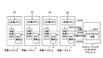
- FIG. 1 is a block diagram showing the configuration of the distributed deep learning system according to the first embodiment of the present invention.
- a plurality of Computing Interconnect (CI) devices 1CI_0 to 1CI_3 are connected to each other via a ring-type communication network 3, and each of the computing interconnect devices 1CI_0 to 1CI_3.
- CI Computing Interconnect
- the term “computing interconnect device” refers to devices distributed on a network.
- the computing interconnect devices 1CI_0 to 1CI_3 may be collectively referred to as a computing interconnect 1.
- the learning nodes 2-0 to 2-3 may be collectively referred to as a learning node 2.
- the learning node 2 may be realized by, for example, a computer having arithmetic resources such as a CPU (Central Processing Unit) and a GPU (Graphics Processing Unit), a storage device and an interface, and a program for controlling these hardware resources.
- a computer having arithmetic resources such as a CPU (Central Processing Unit) and a GPU (Graphics Processing Unit), a storage device and an interface, and a program for controlling these hardware resources.
- LSI Large Scale Integration
- FPGA Field Programmable Gate Array
- ASIC Application Specific Integrated Circuit
- the computing interconnect devices 1CI_0 to 1CI_3 are connected to each other by a communication network such as Ethernet (registered trademark) or InfiniBand (registered trademark) that performs communication by exchanging communication packets.
- a communication network such as Ethernet (registered trademark) or InfiniBand (registered trademark) that performs communication by exchanging communication packets.
- the computing interconnect devices 1CI_0 to 1CI_3 and the learning nodes 2-0 to 2-3 may be connected to each other by a communication network such as Ethernet or InfiniBand.
- a connection configuration in which the computing interconnect devices 1CI_0 to 1CI_3 are directly inserted into I / O interfaces such as PCI Express (registered trademark) in the learning nodes 2-0 to 2-3 may be adopted.
- the learning node 2 is a device having a learning function of calculating an output value of a neural network, which is a mathematical model, and further updating a configuration parameter of the neural network according to the learning data to improve the accuracy of the output value.
- a neural network is constructed in each of the learning nodes 2-0 to 2-3. The details of each functional block included in the learning nodes 2-0 to 2-3 will be described later.
- FIG. 2 shows a simple two-layer neural network including an input layer (first layer), an intermediate layer (second layer), and an output layer (third layer) as an example of the neural network.
- Nk (i) in FIG. 2 is the k-th layer and the i-th neuron.
- x1, x2 are inputs
- y1, y2 are outputs
- w1 (11), w1 (12),..., w1 (23) are weighting parameters of the first layer
- w2 (11), w2 (12),. .., W2 (32) are weight parameters of the second layer.
- the configuration parameters of the neural network in the case of the example of FIG. 2 include weights w1 (11), w1 (12),..., W1 (23), w2 (11), w2 (12),. 32). By optimizing these configuration parameters, the accuracy of the neural network is improved.
- a loss function as an index of how much the output value of the neural network deviates from the teacher data is determined, and the configuration parameters are updated so that the loss function becomes smaller.
- the loss function L is represented by the following equation, for example.
- a vector having a component of a partial differential value of each component parameter of the neural network with respect to the loss function L (this is called a gradient) is obtained.
- the gradient is:
- each component parameter of the neural network is updated using the gradient so that the loss function L becomes smaller.
- the respective weight parameters are updated as follows using a gradient descent method.
- ⁇ is a constant called a learning rate.
- each weight parameter is changed in a direction opposite to the gradient, that is, in a direction to decrease the loss function L by an amount proportional to the learning rate ⁇ . Therefore, the loss function L of the updated neural network becomes smaller than before the update.
- the processing of calculating the loss function L, calculating the gradient, and updating the configuration parameters is performed on a set of input learning data. Then, the same processing is performed by inputting the next input learning data to the neural network having the updated configuration parameters, and the configuration parameters are updated. By repeating this cycle, the neural network is updated by updating the neural network with a small loss function L, thereby learning the neural network.
- the output value is calculated in order from the input layer to the output layer of the neural network, so this step is referred to as forward propagation.
- a method called back propagation is often used in which the gradient for the configuration parameter of each layer is calculated in order from the output layer to the input layer of the neural network.
- a plurality of learning nodes 2 of the same neural network are prepared, and the learning data is divided into the respective learning nodes 2 and learned in parallel, thereby reducing the total learning time. Learning techniques are taken.
- the learning data x is divided into the number of learning nodes 400-0 to 400-3 and assigned to each of the learning nodes 400-0 to 400-3.
- x0 to x3 are described one by one as representatives of the learning data to be assigned to each of the learning nodes 400-0 to 400-3. Consists of a set.
- each of the learning nodes 400-0 to 400-3 inputs the learning data x0 to x3 to the neural network and obtains a loss function L by a forward propagation method (step S100 in FIG. 3).
- the obtained loss function L is one for each learning node 400-0 to 400-3 (each neural network).
- each of the learning nodes 400-0 to 400-3 obtains the gradient of the loss function L obtained in step S100 by the method of back propagation (back S propagation) (step S101 in FIG. 3).
- the gradient of the loss function L is a vector including a component for each configuration parameter as shown in Expression (2).
- the average of the gradients calculated by the learning nodes 400-0 to 400-3 is calculated, for example, in the head node 402, and the calculated result is returned from the head node 402 to each of the learning nodes 400-0 to 400-3.
- This process is called “All-reduce process”.
- the sum of the gradients may be calculated instead of the average of the gradients.
- the learning rate ⁇ at the time of the next weight parameter update processing is multiplied by (1 / the number of learning nodes)
- the same result as that of calculating the average value of the gradient is obtained.
- a weighted constant may be used by multiplying each gradient by a weighting constant, or the sum of squares of each gradient may be used.
- each of the learning nodes 400-0 to 400-3 updates the weight parameter of the neural network using the average value of the gradient calculated in step S102 (step S103 in FIG. 3). Thus, one cycle of the distributed learning is completed.
- FIG. 4 is a block diagram illustrating a configuration example of the learning node 2.
- the learning node 2 includes an input unit 20, a loss function calculating unit 21, a gradient calculating unit 22, a transmitting unit 23, a receiving unit 24, a configuration parameter updating unit 25, and a neural network 26.
- the learning nodes 2-0 to 2-3 have the same configuration.
- the input unit 20 receives the learning data.
- the loss function calculation unit 21 calculates a loss function L for each of the configuration parameters of the neural network 26 and for each of the learning data.
- the gradient calculation unit 22 After calculating the gradient of the loss function L for each learning data, the gradient calculation unit 22 generates a value obtained by summing up the gradient for each configuration parameter.
- the transmission unit 23 (third transmission unit) packetizes the gradient value calculated by the gradient calculation unit 22 and transmits the packet to the computing interconnect device 1. More specifically, the transmission unit 23 transmits a calculation result of the gradient calculated by the gradient calculation unit 22, a sequential number unique to a configuration parameter corresponding to the calculation result, and an operation ID corresponding to the calculation result to a communication packet data described later. The data is written in the payload and transmitted to the computing interconnect device 1 connected to the own node.
- the receiving unit 24 receives the communication packet transmitted from the computing interconnect device 1. More specifically, the receiving unit 24 of the learning node calculates the sum of the gradient (transfer data), the sequential number, and the calculation from the data payload of the communication packet received from the computing interconnect device 1 connected to the own node. Take out the ID.
- the configuration parameter updating unit 25 updates the configuration parameters (weight parameters) of the neural network using the sum of the gradient stored in the communication packet transmitted from the computing interconnect device 1. More specifically, the configuration parameter updating unit 25 updates the configuration parameters of the neural network 26 specified by the sequential number based on the calculation result of the gradient sum.
- the neural network 26 calculates the output value of the neural network, which is a mathematical model.
- the configuration of the neural network 26 of each learning node 2 to be operated on by one operation ID is the same, and the same applies to other embodiments described below.
- each of the learning nodes 2-0 to 2-3 inputs the learning data x0 to x3 to the neural network 26 and calculates the loss function L, respectively, as in the conventional example (step S200 in FIG. 5). ).
- learning data is input to the input unit 20. Thereafter, when the learning data is input, the loss function calculator 21 calculates a loss function L for each of the configuration parameters of the neural network 26 and for each of the learning data.
- the gradient calculation unit 22 calculates the gradient of the calculated loss function L (Step S201 in FIG. 5). More specifically, after calculating the gradient of the loss function L for each learning data, the gradient calculation unit 22 generates a value obtained by summing up the gradient for each configuration parameter.
- the transmission unit 23 of each of the learning nodes 2-0 to 2-3 transmits the calculated gradient value to the computing interconnect device 1CI_0 to 1CI_3 connected to each of the learning nodes 2-0 to 2-3. (Step S202 in FIG. 5).
- x0 to x3 are described one by one as representatives of the learning data to be allocated to the learning nodes 2-0 to 2-3, but the learning data x0 to x3 Consists of one or a plurality of sets of learning data.
- the computing interconnect devices 1CI_0 to 1CI_3 transmit the calculated values of the gradients transmitted from the transmission units 23 of the learning nodes 2-0 to 2-3 to the communication network between the computing interconnect devices 1CI_0 to 1CI_3. Add in order using 3. The average value of all gradients obtained as a result is transmitted to each of the learning nodes 2-0 to 2-3 (steps S203 and S204 in FIG. 5). As described above, in the present embodiment, the All-reduce process is performed using the computing interconnect devices 1CI_0 to 1CI_3.
- the receiving unit 24 of each of the learning nodes 2-0 to 2-3 receives the average value of the gradient transmitted from the computing interconnect device 1CI_0 to 1CI_3.
- the configuration parameter updating unit 25 updates the configuration parameters of the neural network 26 using the received average value of the gradient (Step S205 in FIG. 5).
- the sum of the gradients may be calculated instead of the average of the gradients.
- the learning rate ⁇ at the time of the next weight parameter update processing is multiplied by (1 / the number of learning nodes)
- the same result as that of calculating the average value of the gradient is obtained.
- a weighted average may be used by multiplying each gradient by a weighting constant, or a root mean square of the gradient may be taken.
- the gradient components for the configuration parameters (weight parameters) of each layer are sequentially calculated from the output layer to the input layer of the neural network 26 in accordance with the back propagation method. Therefore, when transmitting the gradient calculation results of the learning nodes 2-0 to 2-3 to the computing interconnect devices 1CI_0 to 1CI_3, it is not necessary to wait until the gradient calculation of all the layers is completed.
- the loss function calculator 21 of each of the learning nodes 2-0 to 2-3 first calculates the loss function L in the same manner as described above (step S200 in FIG. 6), and calculates the gradient of the loss function L. Is calculated (step S201 in FIG. 6). After that, in step S201, without waiting for the gradient calculation unit 22 to complete the calculation of the gradient components for all the configuration parameters, the transmission unit 23 calculates the computing interconnect devices 1CI_0 to 1CI_3 from the gradient components for the calculated configuration parameters. (Step S206 in FIG. 6).
- the computing interconnect devices 1CI_0 to 1CI_3 calculate the average value of the gradient components transmitted from each of the learning nodes 2-0 to 2-3 (step S207 in FIG. 6), and calculate the average value of the calculated gradient components.
- the data is transmitted to the learning nodes 2-0 to 2-3 (step S208 in FIG. 6).
- the configuration parameter updating unit 25 does not wait until all the calculation results are received.
- the corresponding configuration parameter is updated using the average value of the received gradient components (step S209 in FIG. 6).
- the gradient calculation, the All-reduce process, and the configuration parameter update can be processed in a pipeline manner, so that the learning process can be further speeded up.
- FIGS. 7A, 7B, and 7C are diagrams illustrating a typical operation example of the distributed deep learning system according to the present embodiment.
- four learning operations (operations 1 to 4) in which the neural network model and the input learning data are different from each other are sequentially processed.
- operation 1 is first performed in parallel by four learning nodes 2-0 to 2-3 of learning nodes 2-0 to 2-3.
- operation 2 is performed in parallel by three learning nodes, learning node 2-0, learning node 2-1 and learning node 2-3.
- calculation 3 and calculation 4 are simultaneously performed. At this time, operation 3 is performed in parallel by the learning nodes 2-0 and 2-1 and operation 4 is performed in parallel by the learning nodes 2-2 and 2-3.
- one of the computing interconnect devices 1CI_0 to 1CI_3 connected to the learning node 2 performing the parallel learning operation operates as a parent, and the others operate as children.
- the computing interconnect device 1CI_0 operates as a parent
- the computing interconnect devices 1CI_1 to 1CI_3 operate as children.
- the computing interconnect device 1CI_0 operates as a parent, and the computing interconnect devices 1CI_1 and 1CI_3 operate as children.
- the scale of the learning data is not large or when it is not necessary to process the data at such a high speed, as shown in FIG. It is also expected to be used.
- the computing interconnect device 1CI_0 is set as a parent and the computing interconnect device 1CI_1 is set as a child.
- the computing interconnect device 1CI_2 is operated as a parent and the computing interconnect device 1CI_3 is operated as a child.
- an operation information table (FIG. 7D) indicating, for each operation, which of the computing interconnect device 1 is assigned a role of “parent”, “child”, or “non-target”. ) Is used.
- Each of the learning nodes 2-0 to 2-3 and the computing interconnect devices 1CI_1 to 1CI_3 share this operation information table, and perform an operation specified for each operation according to the contents.
- the gradient calculation result G0 is transmitted from the learning node 2-0 connected to the computing interconnect device 1CI_0 to the computing interconnect device 1CI_0.
- the computing interconnect device 1CI_0 transfers the gradient calculation result G0 to the computing interconnect device 1CI_1 via the communication network 3.
- the computing interconnect device 1CI_1 transmits the gradient calculation result G0 transmitted from the computing interconnect device 1CI_0 and the learning node 2-1 immediately below the computing interconnect device 1CI_1.
- the sum G0 + G1 with the gradient calculation result G1 is calculated.
- the computing interconnect device 1CI_1 transmits the calculation result G0 + G1 to the computing interconnect device 1CI_2 via the communication network 3.
- the computing interconnect device 1CI_2 performs a sum operation on the gradient calculation result G0 + G1 transmitted from the computing interconnect device 1CI_1. Do not do.
- the computing interconnect device 1CI_2 transmits the calculation result G0 + G1 to the computing interconnect device 1CI_3 via the communication network 3 as it is.
- the computing interconnect device 1CI_3 performs the same operation as the computing interconnect device 1CI_1.
- the computing interconnect device 1CI_3 calculates the sum G0 + G1 of the sum of the gradients transmitted from the computing interconnect device 1CI_2 and the gradient calculation result G3 transmitted from the learning node 2-3 immediately below the computing interconnect device 1CI_3.
- ⁇ G G0 + G1 + G3.
- the computing interconnect device 1CI_3 transmits the calculation result ⁇ G to the computing interconnect device 1CI_0 via the communication network 3.
- the computing interconnect device 1CI_0 that has received the gradient sum calculation result ⁇ G transmits the received gradient sum ⁇ G to the immediately below learning node 2-0 and the computing interconnect device 1CI_1. Send.
- the computing interconnect device 1CI_1 that has received the gradient sum ⁇ G transmits the gradient sum ⁇ G to the immediately below learning node 2-1 and the computing interconnect device 1CI_2.
- the computing interconnect device 1CI_2 that has received the gradient sum ⁇ G does not transmit the gradient sum ⁇ G to the learning node 2-2 immediately below, and communicates only to the computing interconnect device 1CI_3. 3 to be transmitted.
- the computing interconnect device 1CI_3 transmits the sum of gradients ⁇ ⁇ G transmitted from the computing interconnect device 1CI_2 to the learning node 2-3 immediately below and the computing interconnect device 1CI_0.
- the computing interconnect device 1CI_0 having received the gradient sum ⁇ G discards the gradient sum ⁇ G.
- the gradient sum ⁇ G is transmitted to each of the learning nodes 2-0, 2-1 and 2-3.
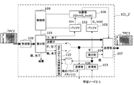
- FIG. 9 is a block diagram illustrating a configuration example of the computing interconnect device 1.
- the computing interconnect device 1 includes reception units 100 and 103, distribution units 101 and 104, buffer memories 102 and 105, adders 106, transmission units 107 and 108, and a control unit 109.
- the receiving unit 100 is an adjacent upstream-side computing interconnect device 1 in the ring-type communication network 3 that performs communication only in one direction (in the present embodiment, counterclockwise direction). (For example, each receives a communication packet from a computing interconnect device 1 on the left side in FIG. 1) and acquires data (transfer data) stored in this packet.
- the allocating unit 101 (first allocating unit) allocates a reception completion flag (completion / incomplete) indicating whether or not the reception of the data included in the communication packet has been completed to the computing interconnect apparatus 1.
- Data from the receiving unit 100 is distributed according to the role (parent / child / non-calculation target (non-parent / child)).
- the buffer memory 102 temporarily stores data from the distribution unit 101.
- the receiving unit 103 receives a communication packet from the learning node 2 provided immediately below the computing interconnect device 1, and acquires data (node data) stored in the packet.
- the distribution unit 104 (second distribution unit) distributes the data from the reception unit 103 according to the role assigned to the computing interconnect device 1 that is its own device.
- the buffer memory 105 temporarily stores data from the distribution unit 104.
- the adder 106 (arithmetic unit) reads the value of the gradient temporarily stored in the buffer memories 102 and 105 and calculates the sum of the gradient.
- the transmission unit 107 (first transmission unit) transmits the distribution unit 101 or the distribution unit 104 to the downstream-side computing interconnect device 1 (the right-side computing interconnect device 1) in the ring-type network 3. It transmits a communication packet obtained by packetizing the data sorted by the above.
- the transmission unit 108 (second transmission unit) transmits a communication packet obtained by packetizing the data distributed by the distribution unit 101 to the learning node 2 provided immediately below the computing interconnect 1.
- the control unit 109 controls the buffer memories 102 and 105.
- FIG. 10 is a diagram illustrating the operation of the computing interconnect device 1CI_0 in FIG. 8A. As shown in FIG. 10, a communication packet includes a communication header and a data payload.
- the data payload of the communication packet RP0 transmitted from the learning node 2-0 includes the gradient value “G0” calculated by the learning node 2-0, the operation ID “002”, and the sequential number “003” of the gradient value. And a reception completion flag (“incomplete” in the example of FIG. 10) indicating completion or incompletion of the sum of the gradients in the computing interconnect device 1CI_0.
- the receiving unit 103 of the computing interconnect device 1CI_0 extracts the gradient value G0, the operation ID, the sequential number, and the reception completion flag from the data payload of the received communication packet RP0 and passes them to the distribution unit 104.
- the transmission unit 107 stores the gradient value G0, the operation ID, the sequential number, and the reception completion flag received from the distribution unit 104 in the data payload of the communication packet TPC1. Then, the transmission unit 107 transmits the communication packet TPC1 to the downstream computing interconnect device (the computing interconnect device 1CI_1 in the example of FIG. 8A) adjacent to the computing interconnect device 1CI_0 via the communication network 3. I do.
- FIG. 11 illustrates an operation of the computing interconnect device 1CI_1 in FIG. 8B.
- the receiving unit 100 of the computing interconnect device 1CI_1 extracts the gradient value G0, the operation ID, the sequential number, and the reception completion flag from the data payload of the communication packet TPC1 received from the computing interconnect device 1CI_1, and sends it to the distribution unit 101. hand over.
- the switching interconnect device 1CI_1 identifies that it should operate as a “child”. Thereby, the distribution unit 101 stores the gradient value G0, the operation ID, the sequential number, and the reception completion flag in the buffer memory 102.
- the receiving unit 103 of the computing interconnect device 1CI_1 converts the gradient value G1, the operation ID, the sequential number, and the reception completion flag from the data payload of the communication packet RP1 received from the learning node 2-1 connected immediately below. It is taken out and passed to the distribution unit 104.
- the control unit 109 of the computing interconnect device 1CI_1 When the gradient values “G0” and “G1” of the same sequential number are aligned in the buffer memory 102 and the buffer memory 105, the control unit 109 of the computing interconnect device 1CI_1 outputs the gradient value “G0” from the buffer memory 102. And a sequential number and a reception completion flag. At the same time, the control unit 109 reads the gradient value “G1”, the sequential number, and the reception completion flag from the buffer memory 105, and passes the gradient values “G0” and “G1” to the adder 106.
- the adder 106 adds the gradient values “G0” and “G1”. Further, the control unit 109 passes the operation ID, the sequential number, and the reception completion flag read from the buffer memory 102 to the transmission unit 107.
- the transmitting unit 107 of the computing interconnect device 1CI_1 adds the gradient sum “G0 + G1” calculated by the adder 106 and the operation ID, sequential number, and reception completion flag received from the control unit 109 to the data payload of the communication packet TPC2. Store. Then, the transmission unit 107 transmits the communication packet TPC2 to the downstream computing interconnect device (the computing interconnect device 1CI_2 in the example of FIG. 8B) adjacent to the computing interconnect device 1CI_1 via the communication network 3. .
- FIG. 12 shows the operation of the computing interconnect device 1CI_2 in FIG. 8C.
- the receiving unit 100 of the computing interconnect device 1CI_2 extracts the gradient value “G0 + G1”, the operation ID, the sequential number, and the reception completion flag from the data payload of the communication packet TPC2 received from the computing interconnect device 1CI_1, and Hand over to 101.
- the transmitting unit 107 stores the gradient value “G0 + GI”, the operation ID, the sequential number, and the reception completion flag received from the distribution unit 101 in the data payload of the communication packet TPC3. Then, the transmitting unit 107 transmits the communication packet TPC3 to the downstream computing interconnect device (the computing interconnect device 1CI_3 in the example of FIG. 8C) adjacent to the computing interconnect device 1CI_2 via the communication network 3. .
- FIG. 13 illustrates an operation of the computing interconnect device 1CI_0 in FIG. 8D.
- the switching interconnect device 1CI_0 identifies that it should operate as a “parent”. Accordingly, the distribution unit 101 passes the gradient sum ⁇ G, the operation ID, the sequential number, and the reception completion flag to the transmission unit 107 and the transmission unit 108.
- the distribution unit 101 of the computing interconnect device 1CI_0 changes the reception completion flag received from the reception unit 100 from “not completed” to a value indicating “completed”, and then sets the transmission unit 107 and the transmission unit 108 Pass the data to.
- the transmission unit 107 of the computing interconnect device 1CI_0 stores the sum of the gradient ⁇ G, the operation ID, the sequential number, and the reception completion flag received from the distribution unit 101 in the data payload of the communication packet TPC1. Then, the transmission unit 107 transmits the communication packet TPC1 to the downstream computing interconnect device (the computing interconnect device 1CI_1 in the example of FIG. 8D) adjacent to the computing interconnect device 1CI_0 via the communication network 3. I do.
- the transmission unit 108 of the computing interconnect device 1CI_0 stores the sum of the gradient ⁇ G, the operation ID, the sequential number, and the reception completion flag received from the distribution unit 101 in the data payload of the communication packet TP0, and transmits the communication packet TP0. It is transmitted to the learning node 2-0.
- FIG. 14 illustrates an operation of the computing interconnect device 1CI_1 in FIG. 8E.
- the receiving unit 100 of the computing interconnect device 1CI_1 extracts the gradient sum ⁇ G, the operation ID, the sequential number, and the reception completion flag from the data payload of the communication packet TPC1 received from the computing interconnect device 1CI_0, and Pass to.
- the interconnect device 1CI_1 identifies that it should operate as a “child”. Accordingly, the distribution unit 101 passes the gradient sum ⁇ G, the operation ID, the sequential number, and the reception completion flag to the transmission unit 107 and the transmission unit 108.
- Transmission section 107 stores sum of gradient ⁇ ⁇ G, operation ID, sequential number and reception completion flag received from distribution section 104 in the data payload of communication packet TPC2. Then, the transmitting unit 107 transmits the communication packet TPC2 to the downstream-side computing interconnect device (the computing interconnect device 1CI_2 in the example of FIG. 8E) adjacent to the computing interconnect device 1CI_1.
- the transmission unit 108 of the computing interconnect device 1CI_1 stores the sum of the gradient ⁇ G received from the distribution unit 101, the operation ID, the sequential number, and the reception completion flag in the data payload of the communication packet TP1, and stores the communication packet TP1. It transmits to the learning node 2-1.
- FIG. 15 illustrates an operation of the computing interconnect device 1CI_2 in FIG. 8F.
- the receiving unit 100 of the computing interconnect device 1CI_2 extracts the gradient sum ⁇ G, the operation ID, the sequential number, and the reception completion flag from the data payload of the communication packet TPC2 received from the computing interconnect device 1CI_1, and Pass to.
- the transmission unit 107 stores the sum of the gradients ⁇ G received from the distribution unit 101, the operation ID, the sequential number, and the reception completion flag in the data payload of the communication packet TPC3. Then, the transmission unit 107 transmits the communication packet TPC3 to the downstream computing interconnect device (the computing interconnect device 1CI_3 in the example of FIG. 8F) adjacent to the computing interconnect device 1CI_2 via the communication network 3. .
- FIG. 16 shows the operation of the computing interconnect device 1CI_0 in FIG. 8G.
- the receiving unit 100 of the computing interconnect device 1CI_0 includes the payload of the communication packet TPC0 received from the upstream computing interconnect device (the computing interconnect device 1CI_3 in the example of FIG. 8G) adjacent to the computing interconnect device 1CI_0.
- the sum of the gradient ⁇ G, the sequential number, and the reception completion flag are extracted and passed to the distribution unit 101.
- the interconnect device 1CI_0 identifies that it should operate as a “parent”. Then, the distribution unit 101 discards the gradient sum ⁇ G, the operation ID, the sequential number, and the reception completion flag received from the reception unit 100.
- the weight parameter updating process is performed using the sum of the gradients.
- the adder 106 is used instead of the sum of the gradients.
- a weighted sum calculator for Gin and G_local may be used.
- the sum of squares of each gradient is used instead of the sum of each gradient, a square sum calculator for Gin and G_local may be used instead of the adder 106. That is, the present invention can be applied to a case where an arbitrary arithmetic unit having Gin and G_local as inputs is used instead of the adder 106.
- the sum of gradient ⁇ G is transmitted to the learning nodes 2-0 to 2-1 and 2-3 to be operated, and the learning nodes 2-0 to 2-1 and 2-3 each calculate the sum of gradient ⁇ G Is used to update the configuration parameters of the neural network, and one cycle of distributed learning ends.
- the computing interconnect device 1 executes the communication packet transmission / reception process between the learning nodes 2 and the All-reduce process simultaneously and in parallel. Therefore, learning can be speeded up as compared with the case where communication processing and All-reduce processing are executed by the head node, and cooperative processing between the learning nodes 2 connected by the communication network 3 can be performed faster.
- the learning nodes 2 are connected to the ring-type communication network 3 through the computing interconnect device 1 connected in pairs. Even if the number of nodes 2 increases, there is an advantage that the communication band of the ring communication network 3 may be constant regardless of the number of learning nodes 2.
- the distributed deep learning system according to the second embodiment is different from the first embodiment in that the computing interconnect device 1 ′ further performs the operation of updating the configuration parameters of the neural network.
- FIGS. 17A to 17G are diagrams illustrating the operation of the distributed deep learning system according to the second embodiment.
- the learning node 2-0 connected to the computing interconnect device 1CI_0 transmits a gradient calculation result G0 to the computing interconnect device 1CI_0'.
- the computing interconnect device 1CI_1 ′ receives the gradient calculation result G0 transmitted from the computing interconnect device 1CI_1 ′ and the learning node 2-1 immediately below the computing interconnect device 1CI_1 ′.
- the sum G0 + G1 with the transmitted gradient calculation result G1 is calculated.
- the computing interconnect device 1CI_2 since the learning node 2-2 is out of the operation target, the computing interconnect device 1CI_2 'calculates the gradient calculation result G0 + G1 transmitted from the computing interconnect device 1CI_1'. Does not perform sum operation. The computing interconnect device 1CI_2 'transmits the calculation result G0 + G1 to the computing interconnect device 1CI_3' via the communication network 3 as it is.
- the computing interconnect device 1CI_3 ’ transmits the calculation result ⁇ G to the computing interconnect device 1CI_0’ via the communication network 3.
- the computing interconnect device 1CI_0 ′ that receives the gradient sum calculation result ⁇ G calculates the updated value w_new of the configuration parameter of the neural network using the gradient sum ⁇ G.
- the computing interconnect device 1CI_0 ' transmits the calculation result via the communication network 3 to the learning node 2-0 immediately below the computing interconnect device 1CI_0' and the computing interconnect device 1CI_1 '.
- the computing interconnect device 1CI_1 ′ that has received the updated configuration parameter value w_new transmits the updated configuration parameter w_new value to the learning node 2 immediately below the computing interconnect device 1CI_1 ′. 1 and the computing interconnect device 1CI_2 '.
- the computing interconnect device 1CI_2 ′ that has received the updated value w_new of the configuration parameter does not transmit the updated value w_new of the configuration parameter to the learning node 2-2 immediately below, and The data is transmitted only to the switching interconnect device 1CI_3 ′ via the communication network 3.
- the computing interconnect device 1CI_3 ′ sends the updated value w_new of the configuration parameter transmitted from the computing interconnect device 1CI_2 ′ to the learning node 2 immediately below the computing interconnect device 1CI_3 ′. 3 and the computing interconnect device 1CI_0 '.
- the computing interconnect device 1CI_0 ′ that has received the updated value w_new of the configuration parameter discards the updated value w_new of the configuration parameter.
- the updated value w_new of the configuration parameter is transmitted to the learning nodes 2-0 to 2 to be operated.
- the configuration of the computing interconnect device 1 according to the first embodiment (except that the computing interconnect device 1 ′ further includes a neural network (NN) configuration parameter update operation unit 110 and a configuration parameter memory 111) It is the same as FIG. 9).
- NN neural network
- the NN configuration parameter update operation unit 110 performs an update operation of the configuration parameters of the neural network.
- the update parameter memory 111 stores the configuration parameters received by the receiving unit 103 from the learning node 2 connected immediately below the computing interconnect device 1 '.
- FIG. 19 illustrates an operation of the computing interconnect device 1CI_0 ′ in FIG. 17A.
- the data payload of the communication packet RP0 transmitted from the learning node 2-0 includes the gradient value “G0” calculated by the learning node 2-0, the operation ID “002”, and the sequential number “003” of the gradient value. , And a reception completion flag “not completed”.
- the receiving unit 103 of the computing interconnect device 1CI_0 ’ extracts the gradient value G0, the operation ID, the sequential number, and the reception completion flag from the data payload of the received communication packet RP0 and passes them to the distribution unit 104.
- the transmission unit 107 stores the gradient value G0, the operation ID, the sequential number, and the reception completion flag received from the distribution unit 104 in the data payload of the communication packet TPC1, and transmits the communication packet TPC1 to the adjacent To the downstream computing interconnect device (the computing interconnect device 1CI_1 'in the example of FIG. 17A).
- FIG. 20 illustrates an operation of the computing interconnect device 1CI_1 ′ in FIG. 17B.
- the receiving unit 100 of the computing interconnect device 1CI_1 extracts the gradient value G0, the operation ID, the sequential number, and the reception completion flag from the data payload of the communication packet TPC1 received from the computing interconnect device 1CI_1', and Hand over to 101.
- the switching interconnect device 1CI_1 ' identifies that it should operate as a "child”. Thereby, the distribution unit 101 stores the gradient value G0, the operation ID, the sequential number, and the reception completion flag in the buffer memory 102.
- the receiving unit 103 of the computing interconnect device 1CI_1 receives the gradient value G1, the operation ID, and the sequential number from the data payload of the communication packet RP1 received from the learning node 2-1 immediately below the computing interconnect device 1CI_1'.
- the reception completion flag is extracted and passed to the distribution unit 104.
- the control unit 109 of the computing interconnect device 1CI_1 ′ sequentially transmits the gradient value G0 and the gradient value G0 from the buffer memory 102.
- the number and the reception completion flag are read.
- the control unit 109 reads the gradient value G1, the sequential number, and the reception completion flag from the buffer memory 105, and passes the gradient values “G0” and “G1” to the adder.
- the adder 106 adds the gradient values “G0” and “G1”. Further, the control unit 109 passes the operation ID, the sequential number, and the reception completion flag read from the buffer memory 102 to the transmission unit 107.
- the transmitting unit 107 of the computing interconnect device 1CI_1 ′ transmits the sum of the gradient “G0 + G1” calculated by the adder 106 and the operation ID, sequential number and reception completion flag received from the control unit 109 to the data payload of the communication packet TPC2. To be stored. Then, the transmitting unit 107 transmits the communication packet TPC2 to the downstream computing interconnect device adjacent to the computing interconnect device 1CI_1 'via the communication network 3 (the computing interconnect device 1CI_2' in the example of FIG. 17B). Send to
- FIG. 21 illustrates an operation of the computing interconnect device 1CI_2 ′ in FIG. 17C.
- the receiving unit 100 of the computing interconnect device 1CI_2 extracts the gradient value G0 + G1, the operation ID, the sequential number, and the reception completion flag from the data payload of the communication packet TPC2 received from the computing interconnect device 1CI_1', and Hand over to 101.
- the transmission unit 107 stores the gradient value G0 + GI, the operation ID, the sequential number, and the reception completion flag received from the distribution unit 101 in the data payload of the communication packet TPC3.
- the transmission unit 107 transmits the communication packet TPC3 to the downstream computing interconnect device (the computing interconnect device 1CI_3 ′ in the example of FIG. 17C) adjacent to the computing interconnect device 1CI_2 ′ via the communication network 3. I do.
- FIG. 22 illustrates the operation of the computing interconnect device 1CI_0 ′ in FIG. 17D.
- the receiving unit 100 of the computing interconnect device 1CI_0 ' transmits the communication packet received from the upstream computing interconnect device (the computing interconnect device 1CI_3' in the example of FIG. 17D) adjacent to the computing interconnect device 1CI_0 '.
- the gradient sum ⁇ G, the operation ID, the sequential number, and the reception completion flag are extracted from the payload of the TPC 0 and passed to the distribution unit 101.
- the switching interconnect device 1CI_0 ' identifies that it should operate as a "parent”.
- the distribution unit 101 passes the gradient sum ⁇ G, the operation ID, the sequential number, and the reception completion flag to the NN configuration parameter update operation unit 110. At this time, the distribution unit 101 changes the reception completion flag received from the reception unit 100 from “not completed” to a value indicating “completed”, and then passes the value to the NN configuration parameter update calculation unit 110.
- the initial values of the same configuration parameters are set in the neural networks of the learning nodes 2-0, 2-1 and 2-3 to be operated.
- the initial values of the configuration parameters are stored in the configuration parameter memory 111 of the computing interconnect device 1CI_0 '.
- the NN configuration parameter update calculation unit 110 uses the sum ⁇ ⁇ G of the gradient received from the distribution unit 101 and the configuration parameter value w_old stored in the configuration parameter memory 111 to update the configuration parameters of the neural network.
- the value w_new is calculated for each configuration parameter.
- the NN configuration parameter update calculation unit 110 outputs the calculation result, the calculation ID, the sequential number, and the reception completion flag received from the distribution unit 101 to the transmission units 107 and 108.
- the NN configuration parameter update operation unit 110 performs a calculation as in Expression (3).
- the NN configuration parameter update operation unit 110 outputs the updated value w_new of the configuration parameter to the transmission units 107 and 108 and, at the same time, updates the configuration parameter value stored in the configuration parameter memory 111 with the updated value w_new. Overwrite by
- the transmission unit 107 stores the updated value w_new, the operation ID, the sequential number, and the reception completion flag of the configuration parameter received from the NN configuration parameter update calculation unit 110 in the data payload of the communication packet TPC1.
- the transmitting unit 107 transmits the communication packet TPC1 to the downstream computing interconnect device (the computing interconnect device 1CI_1 'in the example of FIG. 17D) adjacent to the computing interconnect device 1CI_0' via the communication network 3. I do.
- the transmission unit 108 of the computing interconnect device 1CI_0 ′ transmits the updated value w_new of the configuration parameter received from the NN configuration parameter update operation unit 110, the operation ID, the sequential number, and the reception completion flag to the data payload of the communication packet TP0. It stores the packet and transmits the communication packet TP0 to the learning node 2-0.
- FIG. 23 illustrates an operation of the computing interconnect device 1CI_1 ′ in FIG. 17E.
- the receiving unit 100 of the computing interconnect device 1CI_1 ′ transmits the updated value w_new of the configuration parameter, the operation ID, the sequential number, and the reception completion flag from the data payload of the communication packet TPC1 received from the computing interconnect device 1CI_1 ′. It is taken out and passed to the distribution unit 101.
- the interconnect device 1CI_1 ' identifies that it should operate as a "child”. Thereby, the distribution unit 101 passes the updated value w_new of the configuration parameter, the operation ID, the sequential number, and the reception completion flag to the transmission unit 107 and the transmission unit 108.
- the transmission unit 107 stores the updated value w_new of the configuration parameter received from the distribution unit 101, the operation ID, the sequential number, and the reception completion flag in the data payload of the communication packet TPC2.
- the transmitting unit 107 transmits the communication packet TPC2 to the downstream computing interconnect device adjacent to the computing interconnect device 1CI_1 'via the communication network 3 (the computing interconnect device 1CI_2' in the example of FIG. 17E). Send to
- the transmission unit 108 stores the updated value w_new of the configuration parameter received from the distribution unit 101, the operation ID, the sequential number, and the reception completion flag in the data payload of the communication packet TP1, and stores the communication packet TP1 in the learning node 2. Send to -1.
- FIG. 24 illustrates the operation of the computing interconnect device 1CI_2 ′ in FIG. 17F.
- the receiving unit 100 of the computing interconnect device 1CI_2 ′ transmits the updated value w_new of the configuration parameter, the operation ID, the sequential number, and the reception completion flag from the data payload of the communication packet TPC2 received from the computing interconnect device 1CI_1 ′. It is taken out and passed to the distribution unit 101.
- the transmission unit 107 stores the updated values w_new, the operation ID, the sequential number, and the reception completion flag of the configuration parameters received from the distribution unit 101 in the data payload of the communication packet TPC3. After that, the transmitting unit 107 transmits the communication packet TPC3 to the downstream computing interconnect device (the computing interconnect device 1CI_3 'in the example of FIG. 17F) adjacent to the computing interconnect device 1CI_2' via the communication network 3. Send.
- the downstream computing interconnect device the computing interconnect device 1CI_3 'in the example of FIG. 17F
- FIG. 25 illustrates the operation of the computing interconnect device 1CI_0 ′ in FIG. 17G.
- the receiving unit 100 of the computing interconnect device 1CI_0 transmits the communication packet received from the upstream computing interconnect device adjacent to the computing interconnect device 1CI_0' (the computing interconnect device 1CI_3 'in the example of FIG. 17G).
- the updated value w_new of the configuration parameter, the sequential number, and the reception completion flag are extracted from the payload of the TPC0 and passed to the distribution unit 101.
- the interconnect device 1CI_0 ' identifies that it should operate as a "parent”. After that, the distribution unit 101 discards the updated value w_new, the operation ID, the sequential number, and the reception completion flag of the configuration parameter received from the reception unit 100.
- the updated value w_new of the configuration parameter is transmitted to the learning nodes 2-0, 2-1 and 2-3 to be operated.
- the learning nodes 2-0, 2-1 and 2-3 to be operated over the neural network 26 by overwriting the configuration parameters of the neural network 26 specified by the sequential numbers with the updated values w_new of the configuration parameters. To update.
- a weighted sum calculator for Gin and G_local may be used instead of the adder 106.
- a square sum calculator for Gin and G_local may be used instead of the adder 106. That is, the present invention can be applied to a case where an arbitrary arithmetic unit having Gin and G_local as inputs is used instead of the adder 106.
- the dedicated arithmetic circuit is provided by the NN parameter update arithmetic unit 110 that performs the update arithmetic processing of the configuration parameters of the neural network, the learning processing can be further speeded up. it can.
- the same operation may be performed independently for each configuration parameter regardless of the configuration of the neural network 26 included in the learning node 2 for both the gradient sum calculation and the configuration parameter update calculation. Therefore, even when the configuration of the neural network 26 included in the learning nodes 2-0 to 2-3 is changed, there is an advantage that the same dedicated arithmetic circuit can be used for the arithmetic unit of the computing interconnect device 1 '.
- the computing interconnect device 1 ′ can simultaneously perform high-speed hardware processing of transmission / reception processing of communication packets between the learning nodes 2 and All-reduce processing. Therefore, learning can be speeded up as compared with the case where communication processing and All-reduce processing are performed by software in the head node as in the related art, and cooperative processing between the learning nodes 2 connected by the communication network 3 can be improved. Can be done at high speed.
- the learning nodes 2 are connected to the ring-type communication network 3 through the computing interconnect device 1 connected in pairs. Even if the number of nodes 2 increases, there is an advantage that the communication band of the ring communication network 3 may be constant regardless of the number of learning nodes 2.
- 1, 1 ', 1CI_0 to 1CI_3 Computing interconnect device, 2, 2-0 to 2-3: Learning node, 3: Communication network, 20: Input unit, 21: Loss function calculator, 22: Gradient calculator , 23 ... transmitting unit, 24 ... receiving unit, 25 ... configuration parameter updating unit, 26 ... neural network, 100, 103 ... receiving unit, 101,104 ... distributing unit, 102,105 ... buffer memory, 106 ... adder, 107, 108: transmission unit, 109: control unit, 110: NN parameter update operation unit, 111: configuration parameter memory.
Landscapes
- Engineering & Computer Science (AREA)
- Physics & Mathematics (AREA)
- Theoretical Computer Science (AREA)
- Health & Medical Sciences (AREA)
- Life Sciences & Earth Sciences (AREA)
- Biomedical Technology (AREA)
- Biophysics (AREA)
- Mathematical Physics (AREA)
- Artificial Intelligence (AREA)
- Evolutionary Computation (AREA)
- Data Mining & Analysis (AREA)
- Software Systems (AREA)
- Computing Systems (AREA)
- General Engineering & Computer Science (AREA)
- General Physics & Mathematics (AREA)
- Computational Linguistics (AREA)
- Molecular Biology (AREA)
- General Health & Medical Sciences (AREA)
- Neurology (AREA)
- Data Exchanges In Wide-Area Networks (AREA)
- Multi Processors (AREA)
Abstract
通信ネットワークに接続された多数の学習ノードによって学習を並列処理して高速化を図りつつ、通信ネットワークで接続された各学習ノード間での協調処理をより高速に行うことができる分散深層学習システムを提供することを目的とする。 分散深層学習システムは、1方向に通信可能なリング型の通信ネットワーク3を介して互いに接続された複数のコンピューティングインタコネクト装置1と、複数のコンピューティングインタコネクト装置1のそれぞれと一対一に接続された複数の学習ノード2とを備え、コンピューティングインタコネクト装置1は、各学習ノード2間の通信パケットの送受信処理とAll-reduce処理とを同時並行して実行する。
Description
本発明は、ニューラルネットワークを用いた機械学習である深層学習を複数の学習ノードで分散協調して実行する分散学習システム、分散学習方法、およびコンピューティングインタコネクト装置に関する。
様々な情報、データに対する機械学習の活用により、サービスの高度化・付加価値の提供が盛んに行われている。その際の機械学習には大きな計算リソースが必要である場合が多い。特に、深層学習と呼ばれるニューラルネットワークを用いた機械学習においては、ニューラルネットワークの構成パラメータを最適化する工程である学習において、大量の学習用データを処理する必要がある。この学習処理を高速化するために、複数の演算装置で並列処理することが1つの解決法になる。
例えば、非特許文献1には、図26のように、4台の学習ノード300-1~300-4と、インフィニバンドスイッチ301と、ヘッドノード302とがインフィニバンドネットワーク(InfiniBand network)を介して接続された分散深層学習システムが開示されている。各学習ノード300-1~300-4には、それぞれ4台のGPU(Graphics Processing Unit)が搭載されている。この非特許文献1に開示された分散深層学習システムでは、4台の学習ノード300-1~300-4によって、学習演算を並列処理することによって高速化を図っている。
非特許文献2には、8台のGPUを搭載した学習ノード(GPUサーバ)とイーサネット(登録商標)スイッチとがイーサネットネットワークを介して接続された構成が開示されている。この非特許文献2には、学習ノードを1台、2台、4台、8台、16台、32台、44台用いた場合の例がそれぞれ開示されている。非特許文献2に開示されたシステム上で、分散同期確率的勾配降下法(Distributed synchronous SGD(Stochastic Gradient Descent))を用いて機械学習を行う。具体的には、以下の手順で行う。
(I)学習データの一部を抜き出す。抜き出した学習データの集合をミニバッチと呼ぶ。
(II)ミニバッチをGPUの台数分に分けて、各GPUに割り当てる。
(III)各GPUにおいて、(II)で割り当てられた学習データを入力した場合のニューラルネットワークからの出力値が、正解(教師データと呼ぶ)からどれだけ乖離しているかの指標となる損失関数L(w)を求める。この損失関数を求める工程では、ニューラルネットワークの入力側の層から出力側の層に向かって順番に出力値を計算していくことから、この工程を順伝搬(forward propagation)と呼ぶ。
(II)ミニバッチをGPUの台数分に分けて、各GPUに割り当てる。
(III)各GPUにおいて、(II)で割り当てられた学習データを入力した場合のニューラルネットワークからの出力値が、正解(教師データと呼ぶ)からどれだけ乖離しているかの指標となる損失関数L(w)を求める。この損失関数を求める工程では、ニューラルネットワークの入力側の層から出力側の層に向かって順番に出力値を計算していくことから、この工程を順伝搬(forward propagation)と呼ぶ。
(IV)各GPUにおいて、(III)で求めた損失関数値に対するニューラルネットワークの各構成パラメータ(ニューラルネットワークの重み等)による偏微分値(勾配)を求める。この工程では、ニューラルネットワークの出力側の層から入力側の層に向かって順番に各層の構成パラメータに対する勾配を計算していくことから、この工程を逆伝搬(back propagation)と呼ぶ。
(V)各GPU毎に計算した勾配の平均を計算する。
(V)各GPU毎に計算した勾配の平均を計算する。
(VI)各GPUにおいて、(V)で計算した勾配の平均値を用いて、確率的勾配降下法(SGD:Stochastic Gradient Descent)を用いて、損失関数L(w)がより小さくなるように、ニューラルネットワークの各構成パラメータを更新する。確率的勾配降下法は、各構成パラメータの値を勾配の方向に微少量変更することにより、損失関数L(w)を小さくするという計算処理である。この処理を繰り返すことによって、ニューラルネットワークは、損失関数L(w)が小さい、すなわち、正解に近い出力をする精度の高いものに更新されていく。
また、非特許文献3には、8台のGPUを搭載した学習ノード128台がインフィニバンドネットワーク(InfiniBand network)を介して接続された構成の分散深層学習システムが開示されている。
非特許文献1~3のいずれの分散深層学習システムにおいても、学習ノード数が増えるに従い、学習速度が上がり、学習時間を短縮できることが示されている。この場合、各学習ノードで算出した勾配等のニューラルネットワーク構成パラメータの平均値を計算するため、これらの構成パラメータを学習ノード間で送受信するか、あるいは学習ノードと非特許文献1のヘッドノードとの間で送受信することにより、平均値算出等の計算を行う必要がある。
一方、並列処理数を増やすために、ノード数を増やすにつれ、必要な通信処理は急速に増大する。従来技術のように、学習ノードやヘッドノード上で平均値算出等の演算処理やデータの送受信処理をソフトウェアで行う場合、通信処理に伴うオーバーヘッドが大きくなり、学習効率を十分に上げることが難しくなるという課題があった。
非特許文献3には、学習処理を100サイクル行うのにかかる所要時間とこのうちの通信にかかる時間と、GPU数との関係が開示されている。この関係によると、GPU数が増えるにつれて通信にかかる時間が増えており、特にGPU数が512以上のところで急激に増加している。
Rengan Xu and Nishanth Dandapanthu.,"NVIDIA(登録商標) Tesla(登録商標) P100 GPUによるディープラーニングのパフォーマンス",デル株式会社,2016年,インターネット<http://ja.community.dell.com/techcenter/m/mediagallery/3765/download>
Priya Goyal,Piotr Dollar,Ross Girshick,Pieter Noordhuis,Lukasz Wesolowski,Aapo Kyrola,Andrew Tulloch,Yangqing Jia,Kaiming He,"Accurate,Large Minibatch SGD:Training ImageNet in 1 Hour",米国コーネル大学ライブラリー,arXiv:1706.02677,2017,インターネット<https://arxiv.org/abs/1706.02677>
Takuya Akiba,Shuji Suzuki,Keisuke Fukuda,"Extremely Large Minibatch SGD: Training ResNet-50 on ImageNet in 15 Minutes",米国コーネル大学ライブラリー,arXiv:1711.04325,2017,インターネット<https://arxiv.org/abs/1711.04325>
本発明は、上述した課題を解決するためになされたものであり、通信ネットワークに接続された多数の学習ノードによって学習を並列処理して高速化を図りつつ、通信ネットワークで接続された各学習ノード間での協調処理をより高速に行うことができる分散深層学習システムを提供することを目的とする。
上述した課題を解決するために、本発明に係る分散深層学習システムは、1方向に通信可能なリング型の通信ネットワークを介して互いに接続された複数のコンピューティングインタコネクト装置と、前記複数のコンピューティングインタコネクト装置のそれぞれと一対一に接続された複数の学習ノードとを備え、各コンピューティングインタコネクト装置は、自装置に接続された学習ノードから送信されたパケットを受信して、このパケットに格納されたノードデータを取得する第1受信部と、自装置に隣接する前記通信ネットワークの上流側のコンピューティングインタコネクト装置から送信されたパケットを受信して、このパケットに格納された転送データを取得する第2受信部と、この第2受信部が受信した前記パケットに含まれるパケットの受信の完了または未了を示す受信完了フラグと自装置に対して予め割り当てられた役割とに応じて、前記第2受信部によって取得された前記転送データを振り分ける第1振分部と、前記第1受信部が受信した前記パケットに含まれる前記受信完了フラグと前記役割とに応じて、前記第1受信部によって取得された前記ノードデータを振り分ける第2振分部と、前記第2振分部によって振り分けられた前記ノードデータ、または前記第1振分部により振り分けられた前記転送データをパケット化して、自装置に隣接する前記通信ネットワークの下流側のコンピューティングインタコネクト装置に送信する第1送信部と、前記第1振分部によって振り分けられた前記転送データをパケット化して自装置と接続された前記学習ノードに送信する第2送信部とを備え、前記第1振分部は、前記受信完了フラグがパケットの受信の未了を示し、かつ、前記役割が親である場合には、前記転送データを前記第1送信部および前記第2送信部に振り分け、前記受信完了フラグがパケットの受信の完了を示し、かつ、前記役割が親である場合には、前記転送データを廃棄し、前記第2振分部は、前記受信完了フラグがパケットの受信の未了を示し、かつ、前記役割が親である場合には、前記ノードデータを前記第1送信部に振り分け、各学習ノードは、学習データの入力に対して演算結果を出力するニューラルネットワークと、データをパケット化して、自ノードと接続されたコンピューティングインタコネクト装置に送信する第3送信部と、自ノードと接続された前記コンピューティングインタコネクト装置から送信されたパケットを受信して、このパケットに格納された前記転送データを取得する第3受信部と、この第3受信部が取得した前記転送データに基づいて前記ニューラルネットワークの構成パラメータデータを更新する構成パラメータ更新部とを備えることを特徴とする。
また、本発明に係る分散深層学習システムにおいて、前記コンピューティングインタコネクト装置は、前記第1振分部によって振り分けられた前記転送データと、前記第2振分部によって振り分けられた前記ノードデータとを入力とする演算を行う演算器をさらに備え、前記第1振分部は、前記受信完了フラグがパケットの受信の未了を示し、かつ、前記役割が子である場合には、前記転送データを前記演算器に振り分け、前記第2振分部は、前記受信完了フラグがパケットの受信の未了を示し、かつ、前記役割が子である場合には、前記ノードデータを前記演算器に振り分け、前記演算器は、前記転送データおよび前記ノードデータを入力とする演算結果を前記第1送信部に出力してもよい。
また、本発明に係る分散深層学習システムにおいて、前記コンピューティングインタコネクト装置は、前記ノードデータを記憶する機能をもつ構成パラメータメモリと、前記第1振分部によって振り分けられた前記転送データと前記構成パラメータメモリに記憶されたデータを入力として、更新後の構成パラメータデータを計算して、前記構成パラメータメモリに記憶されたデータを更新する構成パラメータ更新演算部と、をさらに備え、前記第1振分部は、前記受信完了フラグがパケットの受信の未了を示し、かつ、前記役割が親である場合には、前記転送データを前記構成パラメータ更新演算部に振り分け、前記構成パラメータ更新演算部は、算出した前記更新後の構成パラメータデータを前記第1送信部および前記第2送信部に出力し、前記第1送信部は、前記更新後の構成パラメータデータをパケット化して、自装置に隣接する前記通信ネットワークの下流側のコンピューティングインタコネクト装置に送信し、前記第2送信部は、前記更新後の構成パラメータデータをパケット化して、自装置と接続された前記学習ノードに送信してもよい。
また、本発明に係る分散深層学習方法は、1方向に通信可能なリング型の通信ネットワークを介して互いに接続された複数のコンピューティングインタコネクト装置と、前記複数のコンピューティングインタコネクト装置のそれぞれと一対一に接続された複数の学習ノードとを備える分散深層学習システムにおける分散深層学習方法であって、各コンピューティングインタコネクト装置が、自装置に接続された学習ノードから送信されたパケットを受信して、このパケットに格納されたノードデータを取得する第1受信ステップと、自装置に隣接する前記通信ネットワークの上流側のコンピューティングインタコネクト装置から送信されたパケットを受信して、このパケットに格納された転送データを取得する第2受信ステップと、この第2受信ステップで受信された前記パケットに含まれるパケットの受信の完了または未了を示す受信完了フラグと自装置に対して予め割り当てられた役割とに応じて、前記第2受信ステップで取得された前記転送データを振り分ける第1振分ステップと、前記第1受信ステップで受信された前記パケットに含まれる前記受信完了フラグと前記役割とに応じて、前記第1受信ステップで取得された前記ノードデータを振り分ける第2振分ステップと、前記第2振分ステップで振り分けられた前記ノードデータ、または前記第1振分ステップで振り分けられた前記転送データをパケット化して、自装置に隣接する前記通信ネットワークの下流側のコンピューティングインタコネクト装置に送信する第1送信ステップと、前記第1振分ステップで振り分けられた前記転送データをパケット化して自装置と接続された前記学習ノードに送信する第2送信ステップとを備え、各学習ノードが、ニューラルネットワークに学習データを入力して演算結果を出力するニューラルネットワーク演算ステップと、データをパケット化して、自ノードと接続された前記コンピューティングインタコネクト装置に送信する第3送信ステップと、自ノードと接続された前記コンピューティングインタコネクト装置から送信されたパケットを受信して、このパケットに格納された前記転送データを取得する第3受信ステップと、この第3受信ステップで取得された前記転送データに基づいて前記ニューラルネットワークの構成パラメータデータを更新する構成パラメータ更新ステップとを備えることを特徴とする。
また、本発明に係る分散深層学習方法において、前記コンピューティングインタコネクト装置が、前記ノードデータを構成パラメータメモリに記憶する構成パラメータ記憶ステップと、前記第1振分ステップで振り分けられた前記転送データと前記構成パラメータメモリに記憶されたデータを入力として、更新後の構成パラメータデータを計算して、前記構成パラメータメモリに記憶されたデータを更新する構成パラメータ更新演算ステップと、をさらに備えていてもよい。
また、本発明に係るコンピューティングインタコネクト装置は、1方向に通信可能なリング型の通信ネットワークを介して互いに接続され、かつ、複数の学習ノードのそれぞれと一対一に接続された複数のコンピューティングインタコネクト装置であって、自装置に接続された学習ノードから送信されたパケットを受信して、このパケットに格納されたノードデータを取得する第1受信部と、自装置に隣接する前記通信ネットワークの上流側のコンピューティングインタコネクト装置から送信されたパケットを受信して、このパケットに格納された転送データを取得する第2受信部と、この第2受信部が受信した前記パケットに含まれるパケットの受信の完了または未了を示す受信完了フラグと自装置に対して予め割り当てられた役割とに応じて、前記第2受信部によって取得された前記転送データを振り分ける第1振分部と、前記第1受信部が受信した前記パケットに含まれる前記受信完了フラグと前記役割とに応じて、前記第1受信部によって取得された前記ノードデータを振り分ける第2振分部と、前記第2振分部によって振り分けられた前記ノードデータ、または前記第1振分部により振り分けられた前記転送データをパケット化して、自装置に隣接する前記通信ネットワークの下流側のコンピューティングインタコネクト装置に送信する第1送信部と、前記第1振分部によって振り分けられた前記転送データをパケット化して自装置と接続された前記学習ノードに送信する第2送信部とを備え、前記第1振分部は、前記受信完了フラグがパケットの受信の未了を示し、かつ、前記役割が親である場合には、前記転送データを前記第1送信部および前記第2送信部に振り分け、前記受信完了フラグがパケットの受信の完了を示し、かつ、前記役割が親である場合には、前記転送データを廃棄し、前記第2振分部は、記受信完了フラグがパケットの受信の未了を示し、かつ、前記役割が親である場合には、前記ノードデータを前記第1送信部に振り分けることを特徴とする。
また、本発明に係るコンピューティングインタコネクト装置において、前記第1振分部によって振り分けられた前記転送データと、前記第2振分部によって振り分けられた前記ノードデータとを入力とする演算を行う演算器をさらに備え、前記第1振分部は、前記受信完了フラグがパケットの受信の未了を示し、かつ、前記役割が子である場合には、前記転送データを前記演算器に振り分け、前記第2振分部は、前記受信完了フラグがパケットの受信の未了を示し、かつ、前記役割が子である場合には、前記ノードデータを前記演算器に振り分け、前記演算器は、前記転送データおよび前記ノードデータを入力とする演算結果を前記第1送信部に出力してもよい。
また、本発明に係るコンピューティングインタコネクト装置において、前記ノードデータを記憶する機能をもつ構成パラメータメモリと、前記第1振分部によって振り分けられた前記転送データと前記構成パラメータメモリに記憶されたデータを入力として更新後の構成パラメータデータを計算して、前記構成パラメータメモリに記憶されているデータを更新する構成パラメータ更新演算部とをさらに備え、前記第1振分部は、前記受信完了フラグがパケットの受信の未了を示し、かつ、前記役割が親である場合には、前記転送データを前記構成パラメータ更新演算部に振り分け、前記構成パラメータ更新演算部は、算出した前記更新後の構成パラメータデータを前記第1送信部および前記第2送信部に出力し、前記第1送信部は、前記更新後の構成パラメータデータをパケット化して、自装置に隣接する前記通信ネットワークの下流側のコンピューティングインタコネクト装置に送信し、前記第2送信部は、前記更新後の構成パラメータデータをパケット化して、自装置と接続された前記学習ノードに送信してもよい。
本発明によれば、コンピューティングインタコネクト装置が各学習ノードで計算された勾配の値の和を計算し、計算した結果を各学習ノードに返送する処理を行い、この処理と各学習ノード間の通信パケットの送受信処理とが同時並行して実行される。そのため、通信ネットワークに接続された多数の学習ノードによって学習を並列処理して高速化を図りつつ、通信ネットワークで接続された各学習ノード間での協調処理をより高速に行うことができる。
以下、本発明の好適な実施の形態について、図1から図25を参照して詳細に説明する。
[第1の実施の形態]
図1は、本発明の第1の実施の形態に係る分散深層学習システムの構成を示すブロック図である。本実施の形態に係る分散深層学習システムは、複数のコンピューティングインタコネクト(Computing Interconnect:CI)装置1CI_0~1CI_3がリング型の通信ネットワーク3で互いに接続され、コンピューティングインタコネクト装置1CI_0~1CI_3のそれぞれに学習ノード2-0~2-3のそれぞれが一対一となるように接続された構造を有する。
図1は、本発明の第1の実施の形態に係る分散深層学習システムの構成を示すブロック図である。本実施の形態に係る分散深層学習システムは、複数のコンピューティングインタコネクト(Computing Interconnect:CI)装置1CI_0~1CI_3がリング型の通信ネットワーク3で互いに接続され、コンピューティングインタコネクト装置1CI_0~1CI_3のそれぞれに学習ノード2-0~2-3のそれぞれが一対一となるように接続された構造を有する。
なお、本発明において、コンピューティングインタコネクト装置とは、ネットワーク上に分散配置されている機器を意味する。以下、コンピューティングインタコネクト装置1CI_0~1CI_3を総称してコンピューティングインタコネクト1ということがある。同様に、学習ノード2-0~2-3を総称して学習ノード2ということがある。
学習ノード2は、例えば、CPU(Central Processing Unit)、GPU(Graphics Processing Unit)等の演算資源、記憶装置およびインタフェースを備えたコンピュータと、これらのハードウェア資源を制御するプログラムによって実現してもよいし、FPGA(Field Programmable Gate Array)やASIC(Application Specific Integrated Circuit)に形成したLSI(Large Scale Integration)回路で実現してもよい。
コンピューティングインタコネクト装置1CI_0~1CI_3間は、イーサネット(登録商標)や、インフィニバンド(InfiniBand、登録商標)などの、通信パケットをやりとりすることで通信を行う通信ネットワークで互いに接続されている。
コンピューティングインタコネクト装置1CI_0~1CI_3と学習ノード2-0~2-3との間は、イーサネットや、インフィニバンド(InfiniBand)などの通信ネットワークで互いに接続されていてもよい。あるいは、学習ノード2-0~2-3内のPCI Express(登録商標)などのI/Oインタフェースにコンピューティングインタコネクト装置1CI_0~1CI_3を直に挿入する接続構成を採用してもよい。
[学習ノードの説明]
学習ノード2は、数学モデルであるニューラルネットワークの出力値を計算し、さらに、学習データに応じてニューラルネットワークの構成パラメータを更新して出力値の精度を向上させていく学習機能をもつ装置である。ニューラルネットワークは、各学習ノード2-0~2-3内に構築される。なお、学習ノード2-0~2-3が備える各機能ブロックの詳細については後述する。
学習ノード2は、数学モデルであるニューラルネットワークの出力値を計算し、さらに、学習データに応じてニューラルネットワークの構成パラメータを更新して出力値の精度を向上させていく学習機能をもつ装置である。ニューラルネットワークは、各学習ノード2-0~2-3内に構築される。なお、学習ノード2-0~2-3が備える各機能ブロックの詳細については後述する。
[学習についての説明]
学習ノード2におけるニューラルネットワークの学習処理について、教師データ付き学習を例に説明する。図2にニューラルネットワークの例として入力層(第1層)、中間層(第2層)、出力層(第3層)からなるごく単純な2層ニューラルネットワークを示す。図2のNk(i)は第k層、i番目のニューロンである。x1,x2は入力、y1,y2は出力、w1(11),w1(12),・・・,w1(23)は第1層目の重みパラメータ、w2(11),w2(12),・・・,w2(32)は第2層目の重みパラメータである。
学習ノード2におけるニューラルネットワークの学習処理について、教師データ付き学習を例に説明する。図2にニューラルネットワークの例として入力層(第1層)、中間層(第2層)、出力層(第3層)からなるごく単純な2層ニューラルネットワークを示す。図2のNk(i)は第k層、i番目のニューロンである。x1,x2は入力、y1,y2は出力、w1(11),w1(12),・・・,w1(23)は第1層目の重みパラメータ、w2(11),w2(12),・・・,w2(32)は第2層目の重みパラメータである。
教師データ付き学習の場合、各学習データには対応する教師データ(正解データ)が予め用意されており、ニューラルネットワークの出力値が教師データに近くなるように、ニューラルネットワークの構成パラメータを更新していく。図2の例の場合のニューラルネットワークの構成パラメータは、重みw1(11),w1(12),・・・,w1(23),w2(11),w2(12),・・・,w2(32)である。これらの構成パラメータを最適化していくことにより、ニューラルネットワークの精度を上げていく。
具体的には、ニューラルネットワークの出力値が教師データとどれだけ乖離しているかの指標となる損失関数を定め、この損失関数が小さくなるように構成パラメータを更新していく。この例では、入力学習データx1,x2に対応する出力値をy1,y2、教師データをt1,t2とすると、損失関数Lは、例えば次式のようになる。
次に、この損失関数Lに対するニューラルネットワークの各構成パラメータによる偏微分値を成分とするベクトル(これを勾配と呼ぶ)を求める。この例では、勾配は以下のようになる。

次に、勾配を用いて、損失関数Lがより小さくなるように、ニューラルネットワークの各構成パラメータを更新する。更新の方法はいろいろあるが、例えば勾配降下法を用いて、それぞれの重みパラメータを以下のように更新する。

ここで、ηは学習率と呼ばれる定数である。式(3)により、各重みパラメータを、勾配と逆の方向、すなわち、損失関数Lを減少させる方向に学習率ηに比例する量だけ変化させている。そのため、更新後のニューラルネットワークの損失関数Lは更新前より小さくなる。
このように、1組の入力学習データに対して、損失関数Lの計算、勾配の計算、構成パラメータの更新の処理を行う。そして、この構成パラメータの更新されたニューラルネットワークに対して、次の入力学習データを入力して同じ処理を行い、構成パラメータを更新する。このサイクルを繰り返すことにより、損失関数Lが小さいニューラルネットワークに更新していくことで、ニューラルネットワークの学習を行う。
ここで、損失関数Lを求める工程では、ニューラルネットワークの入力層から出力層に向かって順番に出力値を計算していくことから、この工程を順伝搬(forward propagation)と呼ぶ。一方、勾配を求める工程では、ニューラルネットワークの出力層から入力層に向かって順番に各層の構成パラメータに対する勾配を計算していく逆伝搬(back propagation)と呼ぶ手法を用いることが多い。
[複数の学習ノードによる分散学習処理]
以上のようなニューラルネットワークの学習で十分な精度を達成するには、大量の学習データをニューラルネットワークに入力して学習処理を繰り返す必要があり、長い時間を要する。この学習にかかる所要時間を短縮することは大きなメリットがある。
以上のようなニューラルネットワークの学習で十分な精度を達成するには、大量の学習データをニューラルネットワークに入力して学習処理を繰り返す必要があり、長い時間を要する。この学習にかかる所要時間を短縮することは大きなメリットがある。
学習にかかる所要時間を短縮するため、同じニューラルネットワークの学習ノード2を複数用意して、学習データをそれぞれの学習ノード2に分けて並列で学習させることにより、トータルの学習時間を短縮する分散協調学習の手法がとられる。
以下、従来の分散学習処理の手順を図3を用いて説明する。
最初に、学習データxを学習ノード400-0~400-3の台数分に分けて、各学習ノード400-0~400-3に割り当てる。なお、図3では、各学習ノード400-0~400-3に割り当てる学習データの代表としてx0~x3を1つずつ記載しているが、学習データx0~x3はそれぞれ1または複数の学習データの集合からなる。
最初に、学習データxを学習ノード400-0~400-3の台数分に分けて、各学習ノード400-0~400-3に割り当てる。なお、図3では、各学習ノード400-0~400-3に割り当てる学習データの代表としてx0~x3を1つずつ記載しているが、学習データx0~x3はそれぞれ1または複数の学習データの集合からなる。
次に、各学習ノード400-0~400-3は、それぞれ学習データx0~x3をニューラルネットワークに入力して順伝搬(forward propagation)の手法によりそれぞれ損失関数Lを求める(図3ステップS100)。なお、得られる損失関数Lは、各学習ノード400-0~400-3(各ニューラルネットワーク)につき1つである。
続いて、各学習ノード400-0~400-3は、ステップS100で求めた損失関数Lの勾配を逆伝搬(back propagation)の手法により求める(図3ステップS101)。損失関数Lの勾配とは、式(2)に示すように構成パラメータ毎の成分を含むベクトルである。
次に、各学習ノード400-0~400-3でそれぞれ計算した勾配の平均を例えばヘッドノード402において計算して、計算した結果をヘッドノード402から各学習ノード400-0~400-3に返送する(図3ステップS102)。この処理を「All-reduce処理」と呼ぶ。
なお、勾配の平均の代わりに勾配の和を計算するようにしてもよい。このとき、例えば、次の重みパラメータの更新処理時の学習率ηに(1/学習ノード数)を乗じれば、勾配の平均値を求めるのと同じ結果になる。
さらに、勾配の平均の代わりに、各勾配に重みづけ定数をかけて重み付き平均を用いるようにしてもよいし、各勾配の二乗の和をとるようにしてもよい。
なお、勾配の平均の代わりに勾配の和を計算するようにしてもよい。このとき、例えば、次の重みパラメータの更新処理時の学習率ηに(1/学習ノード数)を乗じれば、勾配の平均値を求めるのと同じ結果になる。
さらに、勾配の平均の代わりに、各勾配に重みづけ定数をかけて重み付き平均を用いるようにしてもよいし、各勾配の二乗の和をとるようにしてもよい。
最後に、各学習ノード400-0~400-3は、ステップS102で計算された勾配の平均値を用いて、ニューラルネットワークの重みパラメータを更新する(図3ステップS103)。
以上で、分散学習の1サイクルが終了する。
以上で、分散学習の1サイクルが終了する。
[学習ノードの機能ブロック]
次に、本実施の形態に係る分散深層学習システムの動作の概要についての説明に先立って学習ノード2の機能構成を説明する。図4は学習ノード2の構成例を示すブロック図である。
学習ノード2は、入力部20、損失関数計算部21、勾配計算部22、送信部23、受信部24、構成パラメータ更新部25、およびニューラルネットワーク26を備える。なお、学習ノード2-0~2-3はそれぞれ同様の構成を有する。
次に、本実施の形態に係る分散深層学習システムの動作の概要についての説明に先立って学習ノード2の機能構成を説明する。図4は学習ノード2の構成例を示すブロック図である。
学習ノード2は、入力部20、損失関数計算部21、勾配計算部22、送信部23、受信部24、構成パラメータ更新部25、およびニューラルネットワーク26を備える。なお、学習ノード2-0~2-3はそれぞれ同様の構成を有する。
入力部20は、学習データを受け取る。
損失関数計算部21は、学習データが入力されたときに、損失関数Lをニューラルネットワーク26の構成パラメータ毎および学習データ毎に計算する。
勾配計算部22は、損失関数Lの勾配を学習データ毎に計算した後に、勾配を集計した値を構成パラメータ毎に生成する。
損失関数計算部21は、学習データが入力されたときに、損失関数Lをニューラルネットワーク26の構成パラメータ毎および学習データ毎に計算する。
勾配計算部22は、損失関数Lの勾配を学習データ毎に計算した後に、勾配を集計した値を構成パラメータ毎に生成する。
送信部23(第3送信部)は、勾配計算部22によって計算された勾配の値をパケット化してコンピューティングインタコネクト装置1に送信する。より詳細には、送信部23は、勾配計算部22によって計算された勾配の計算結果と、この計算結果に対応する構成パラメータに固有のシーケンシャル番号と対応する演算IDとを後述する通信パケットのデータペイロードに書き込んで、自ノードと接続されているコンピューティングインタコネクト装置1に送信する。
受信部24(第3受信部)は、コンピューティングインタコネクト装置1から送信された通信パケットを受信する。より詳細には、学習ノードの受信部24は、自ノードと接続されているコンピューティングインタコネクト装置1から受信した通信パケットのデータペイロードから勾配の和(転送データ)の計算結果とシーケンシャル番号と演算IDとを取り出す。
構成パラメータ更新部25は、コンピューティングインタコネクト装置1から送信された通信パケットに格納されている勾配の和を用いてニューラルネットワークの構成パラメータ(重みパラメータ)を更新する。より詳細には、構成パラメータ更新部25は、勾配の和の計算結果を基に、シーケンシャル番号で特定される、ニューラルネットワーク26の構成パラメータを更新する。
ニューラルネットワーク26は、数学モデルであるニューラルネットワークの出力値を計算する。本実施の形態では、1つの演算IDの演算対象となっている各学習ノード2のニューラルネットワーク26の構成は同一であるものとし、以下の他の実施の形態でも同様とする。
[本実施の形態の分散処理]
次に、本実施の形態に係る学習ノード2-0~2-3とコンピューティングインタコネクト装置1CI_0~1CI_3とで行われる分散学習処理の手順を図5を用いて説明する。本実施の形態では、各学習ノード2-0~2-3は、従来例と同様に、それぞれ学習データx0~x3をニューラルネットワーク26に入力して損失関数Lをそれぞれ計算する(図5ステップS200)。
次に、本実施の形態に係る学習ノード2-0~2-3とコンピューティングインタコネクト装置1CI_0~1CI_3とで行われる分散学習処理の手順を図5を用いて説明する。本実施の形態では、各学習ノード2-0~2-3は、従来例と同様に、それぞれ学習データx0~x3をニューラルネットワーク26に入力して損失関数Lをそれぞれ計算する(図5ステップS200)。
より詳細には、入力部20に学習データが入力される。その後、損失関数計算部21は、学習データが入力されると、損失関数Lをニューラルネットワーク26の構成パラメータ毎および学習データ毎に計算する。
続いて、勾配計算部22は、算出された損失関数Lの勾配を計算する(図5ステップS201)。より詳細には、勾配計算部22は、損失関数Lの勾配を学習データ毎に計算した後に、勾配を集計した値を構成パラメータ毎に生成する。
そして、各学習ノード2-0~2-3の送信部23は、それぞれ算出された勾配の値を、各学習ノード2-0~2-3とそれぞれ接続されたコンピューティングインタコネクト装置1CI_0~1CI_3に送信する(図5ステップS202)。
なお、図3の従来例と同様に、図5では、各学習ノード2-0~2-3に割り当てる学習データの代表としてx0~x3を1つずつ記載しているが、学習データx0~x3はそれぞれ1または複数の学習データの集合からなる。
次に、コンピューティングインタコネクト装置1CI_0~1CI_3は、各学習ノード2-0~2-3の送信部23から送信された各勾配の計算値を、コンピューティングインタコネクト装置1CI_0~1CI_3間の通信ネットワーク3を使って順番に加算していく。この結果得られる全勾配の平均値を各学習ノード2-0~2-3に送信する(図5ステップS203,S204)。このように本実施の形態では、コンピューティングインタコネクト装置1CI_0~1CI_3を用いてAll-reduce処理を行う。
最後に、各学習ノード2-0~2-3の受信部24は、コンピューティングインタコネクト装置1CI_0~1CI_3から送信された勾配の平均値を受信する。構成パラメータ更新部25は、受信された勾配の平均値を用いて、ニューラルネットワーク26の構成パラメータを更新する(図5ステップS205)。
なお、勾配の平均の代わりに勾配の和を計算するようにしてもよい。このとき、例えば、次の重みパラメータの更新処理時の学習率ηに(1/学習ノード数)を乗じれば、勾配の平均値を求めるのと同じ結果になる。また、各勾配に重みづけ定数をかけて重み付き平均を用いるようにしてもよいし、勾配の二乗平均平方根をとるようにしてもよい。
以上で、本実施の形態の分散学習の1サイクルが終了する。
以上で、本実施の形態の分散学習の1サイクルが終了する。
通常、勾配計算は逆伝搬の手法に従って、ニューラルネットワーク26の出力層から入力層に向かって順番に各層の構成パラメータ(重みパラメータ)に対する勾配の成分を計算していく。したがって、各学習ノード2-0~2-3の勾配計算結果をコンピューティングインタコネクト装置1CI_0~1CI_3に送信するにあたっては、全ての層の勾配計算が終わるまで待つ必要はない。
そこで、図6に示すように、各学習ノード2-0~2-3の損失関数計算部21は、まず上記と同様に損失関数Lを計算し(図6ステップS200)、損失関数Lの勾配を計算する(図6ステップS201)。その後、ステップS201において勾配計算部22がすべての構成パラメータに対する勾配成分の計算が終了するのを待つことなく、送信部23は計算が終わった構成パラメータに対する勾配成分からコンピューティングインタコネクト装置1CI_0~1CI_3に送信することができる(図6ステップS206)。
コンピューティングインタコネクト装置1CI_0~1CI_3は、各学習ノード2-0~2-3から送信された勾配成分の平均値を計算し(図6ステップS207)、計算が終わった勾配成分の平均値を各学習ノード2-0~2-3に送信する(図6ステップS208)。
各学習ノード2-0~2-3の受信部24は、コンピューティングインタコネクト装置1CI_0~1CI_3から計算結果を受信すると、構成パラメータ更新部25は、すべての計算結果を受信するまで待つことなく、受信した勾配成分の平均値を用いて、対応する構成パラメータを更新する(図6ステップS209)。
こうして、本実施の形態では勾配計算とAll-reduce処理と構成パラメータ更新とをパイプライン式に処理できるので、学習処理の更なる高速化が可能である。
こうして、本実施の形態では勾配計算とAll-reduce処理と構成パラメータ更新とをパイプライン式に処理できるので、学習処理の更なる高速化が可能である。
[分散深層学習システムの動作の概要]
図7A、図7B、図7Cは、本実施の形態の分散深層学習システムの典型的な動作例を説明する図である。
分散深層学習システムでは、ニューラルネットワークモデル、入力学習データがそれぞれ異なる4つの学習演算(演算1~4)を順番に処理している。
図7A、図7B、図7Cは、本実施の形態の分散深層学習システムの典型的な動作例を説明する図である。
分散深層学習システムでは、ニューラルネットワークモデル、入力学習データがそれぞれ異なる4つの学習演算(演算1~4)を順番に処理している。
図7Aに示すように、まず、演算1が学習ノード2-0~2-3の4台の学習ノード2-0~2-3で並列演算される。これを終了後、図7Bに示すように、演算2が学習ノード2-0、学習ノード2-1、学習ノード2-3の3台の学習ノードで並列演算される。
最後に、図7Cに示すように演算3と演算4が同時に処理されている。このとき、演算3は学習ノード2-0および学習ノード2-1で、演算4は学習ノード2-2および学習ノード2-3で並列処理されている。
本発明の分散深層学習システムでは、並列学習演算している学習ノード2に接続するコンピューティングインタコネクト装置1CI_0~1CI_3のうち、1台が親として動作し、それ以外は子として動作する。図7Aの例では、コンピューティングインタコネクト装置1CI_0が親、コンピューティングインタコネクト装置1CI_1~1CI_3が子として動作している。
また、図7Bでは、コンピューティングインタコネクト装置1CI_0が親、コンピューティングインタコネクト装置1CI_1,1CI_3が子として動作している。学習データの規模が大きくない場合やそれほど高速に処理する必要がない場合は、図7Bのように、リング型の通信ネットワーク3に接続される学習ノード2-0~2-3の一部だけを使うことも想定される。
図7Cでは、演算3に対しては、コンピューティングインタコネクト装置1CI_0を親、コンピューティングインタコネクト装置1CI_1を子としている。また、演算4に対しては、コンピューティングインタコネクト装置1CI_2を親、コンピューティングインタコネクト装置1CI_3を子として動作させている。
このような動作を進めるにあたって、各演算ごとに、各コンピューティングインタコネクト装置1が、「親」、「子」、「対象外」のいずれの役割を割り当てられているか示す演算情報テーブル(図7D)を用いる。各学習ノード2-0~2-3およびコンピューティングインタコネクト装置1CI_1~1CI_3はこの演算情報テーブルを共有し、この内容に従って、各演算ごとに指定された動作を行う。
[分散深層学習システムの動作の具体例]
以下、図7Bの場合(演算ID=2の場合)を例にとって、図8Aから図8Gを用いて本実施の形態の分散深層学習システムの動作を説明する。
以下、図7Bの場合(演算ID=2の場合)を例にとって、図8Aから図8Gを用いて本実施の形態の分散深層学習システムの動作を説明する。
図8Aに示すように、コンピューティングインタコネクト装置1CI_0に接続された学習ノード2-0から勾配の計算結果G0をコンピューティングインタコネクト装置1CI_0に送信する。コンピューティングインタコネクト装置1CI_0は、勾配の計算結果G0を通信ネットワーク3を介してコンピューティングインタコネクト装置1CI_1に転送する。
図8Bに示すように、コンピューティングインタコネクト装置1CI_1は、コンピューティングインタコネクト装置1CI_0から送信された勾配の計算結果G0と、コンピューティングインタコネクト装置1CI_1の直下の学習ノード2-1から送信された勾配の計算結果G1との和G0+G1を計算する。コンピューティングインタコネクト装置1CI_1は、この計算結果G0+G1を通信ネットワーク3を介してコンピューティングインタコネクト装置1CI_2に送信する。
図8Cに示すように、本演算では、学習ノード2-2は演算対象外なので、コンピューティングインタコネクト装置1CI_2は、コンピューティングインタコネクト装置1CI_1から送信された勾配の計算結果G0+G1に対して和演算を行わない。コンピューティングインタコネクト装置1CI_2は、計算結果G0+G1をそのまま通信ネットワーク3を介してコンピューティングインタコネクト装置1CI_3へ送信する。
図8Dに示すように、コンピューティングインタコネクト装置1CI_3では、コンピューティングインタコネクト装置1CI_1と同様の演算を行う。コンピューティングインタコネクト装置1CI_3は、コンピューティングインタコネクト装置1CI_2から送信された勾配の和の計算結果G0+G1と、コンピューティングインタコネクト装置1CI_3の直下の学習ノード2-3から送信された勾配の計算結果G3との和ΣG=G0+G1+G3を計算する。コンピューティングインタコネクト装置1CI_3は、この計算結果ΣGを通信ネットワーク3を介してコンピューティングインタコネクト装置1CI_0に送信する。
また、図8Dに示すように、勾配の和の計算結果ΣGを受信したコンピューティングインタコネクト装置1CI_0は、受信した勾配の和ΣGを直下の学習ノード2-0とコンピューティングインタコネクト装置1CI_1とに送信する。
図8Eに示すように、勾配の和ΣGを受信したコンピューティングインタコネクト装置1CI_1は、勾配の和ΣGを直下の学習ノード2-1とコンピューティングインタコネクト装置1CI_2とに送信する。
図8Fに示すように、勾配の和ΣGを受信したコンピューティングインタコネクト装置1CI_2は、勾配の和ΣGを直下の学習ノード2-2へは送信せず、コンピューティングインタコネクト装置1CI_3のみに通信ネットワーク3を介して送信する。
図8Gに示すように、コンピューティングインタコネクト装置1CI_3は、コンピューティングインタコネクト装置1CI_2から送信された勾配の和ΣGを直下の学習ノード2-3とコンピューティングインタコネクト装置1CI_0とに送信する。
最後に、図8Gに示すように、勾配の和ΣGを受信したコンピューティングインタコネクト装置1CI_0は、勾配の和ΣGを廃棄する。
以上の動作により、各学習ノード2-0,2-1,2-3に勾配の和ΣGが送信される。
以上の動作により、各学習ノード2-0,2-1,2-3に勾配の和ΣGが送信される。
[コンピューティングインタコネクト装置の構成]
図9は、コンピューティングインタコネクト装置1の構成例を示すブロック図である。
コンピューティングインタコネクト装置1は、受信部100,103、振分部101,104、バッファメモリ102,105、加算器106、送信部107,108、および制御部109を備える。
図9は、コンピューティングインタコネクト装置1の構成例を示すブロック図である。
コンピューティングインタコネクト装置1は、受信部100,103、振分部101,104、バッファメモリ102,105、加算器106、送信部107,108、および制御部109を備える。
受信部100(第2受信部)は、1方向(本実施の形態では反時計回りの方向)に限定して通信を行うリング型の通信ネットワーク3において隣接する上流側のコンピューティングインタコネクト装置1(例えば、図1においてそれぞれ左隣のコンピューティングインタコネクト装置1)からの通信パケットを受信し、このパケットに格納されたデータ(転送データ)を取得する。
振分部101(第1振分部)は、通信パケットに含まれるデータの受信が完了されたか否かを示す受信完了フラグ(完了/未了)とそのコンピューティングインタコネクト装置1に割り当てられた役割(親/子/計算対象外(非親子))に応じて受信部100からのデータを振り分ける。
バッファメモリ102は、振分部101からのデータを一時的に記憶する。
バッファメモリ102は、振分部101からのデータを一時的に記憶する。
受信部103(第1受信部)は、コンピューティングインタコネクト装置1の直下に設けられている学習ノード2からの通信パケットを受信し、このパケットに格納されたデータ(ノードデータ)を取得する。
振分部104(第2振分部)は、自装置であるコンピューティングインタコネクト装置1に割り当てられた役割に応じて受信部103からのデータを振り分ける。
振分部104(第2振分部)は、自装置であるコンピューティングインタコネクト装置1に割り当てられた役割に応じて受信部103からのデータを振り分ける。
バッファメモリ105は、振分部104からのデータを一時的に記憶する。
加算器106(演算器)は、バッファメモリ102,105に一時的に記憶された勾配の値を読み出して勾配の和を計算する。
送信部107(第1送信部)は、リング型のネットワーク3において隣接する下流側のコンピューティングインタコネクト装置1(右隣のコンピューティングインタコネクト装置1)へ、振分部101または振分部104によって振り分けられたデータをパケット化した通信パケットを送信する。
加算器106(演算器)は、バッファメモリ102,105に一時的に記憶された勾配の値を読み出して勾配の和を計算する。
送信部107(第1送信部)は、リング型のネットワーク3において隣接する下流側のコンピューティングインタコネクト装置1(右隣のコンピューティングインタコネクト装置1)へ、振分部101または振分部104によって振り分けられたデータをパケット化した通信パケットを送信する。
送信部108(第2送信部)は、コンピューティングインタコネクト1の直下に設けられている学習ノード2に、振分部101によって振り分けられたデータをパケット化した通信パケットを送信する。
制御部109は、バッファメモリ102,105を制御する。
制御部109は、バッファメモリ102,105を制御する。
[コンピューティングインタコネクト装置の動作の具体例]
図10は、図8Aにおけるコンピューティングインタコネクト装置1CI_0の動作を説明する図である。図10に示すように、通信パケットは、通信ヘッダとデータペイロードとからなる。
図10は、図8Aにおけるコンピューティングインタコネクト装置1CI_0の動作を説明する図である。図10に示すように、通信パケットは、通信ヘッダとデータペイロードとからなる。
学習ノード2-0から送信される通信パケットRP0のデータペイロードには、学習ノード2-0で計算された勾配値「G0」と、演算ID「002」と、勾配値のシーケンシャル番号「003」と、コンピューティングインタコネクト装置1CI_0で勾配の和の取得完了または未了を示す受信完了フラグ(図10の例では「未了」)とが格納されている。
コンピューティングインタコネクト装置1CI_0の受信部103は、受信した通信パケットRP0のデータペイロードから勾配値G0と演算IDとシーケンシャル番号と受信完了フラグとを取り出して振分部104に渡す。
振分部104では、受信部103から受け取った演算IDと演算情報テーブルをつきあわせて、この演算ID=2に対しては、コンピューティングインタコネクト装置1CI_0は「親」として動作すべきことを識別する。これにより、振分部104は勾配値G0と演算IDとシーケンシャル番号と受信完了フラグとを送信部107に渡す。
送信部107は、振分部104から受け取った勾配値G0と演算IDとシーケンシャル番号と受信完了フラグとを通信パケットTPC1のデータペイロードに格納する。そして、送信部107は、通信パケットTPC1を、通信ネットワーク3を介してコンピューティングインタコネクト装置1CI_0に隣接する下流側のコンピューティングインタコネクト装置(図8Aの例ではコンピューティングインタコネクト装置1CI_1)へ送信する。
図11は、図8Bにおけるコンピューティングインタコネクト装置1CI_1の動作を示している。
コンピューティングインタコネクト装置1CI_1の受信部100は、コンピューティングインタコネクト装置1CI_0から受信した通信パケットTPC1のデータペイロードから勾配値G0と演算IDとシーケンシャル番号と受信完了フラグとを取り出して振分部101に渡す。
コンピューティングインタコネクト装置1CI_1の受信部100は、コンピューティングインタコネクト装置1CI_0から受信した通信パケットTPC1のデータペイロードから勾配値G0と演算IDとシーケンシャル番号と受信完了フラグとを取り出して振分部101に渡す。
振分部101は、受信部100から受け取った受信完了フラグが「未了」を示していること、また、受け取った演算IDと演算情報テーブルをつきあわせてこの演算ID=2に対してはコンピューティングインタコネクト装置1CI_1は「子」として動作すべきことを識別する。これにより、振分部101は、勾配値G0と演算IDとシーケンシャル番号と受信完了フラグとをバッファメモリ102に格納する。
一方、コンピューティングインタコネクト装置1CI_1の受信部103は、直下に接続されている学習ノード2-1から受信した通信パケットRP1のデータペイロードから勾配値G1と演算IDとシーケンシャル番号と受信完了フラグとを取り出して振分部104に渡す。
コンピューティングインタコネクト装置1CI_1の振分部104では、受信部103から受け取った演算IDと演算情報テーブルをつきあわせて、この演算ID=2に対しては、コンピューティングインタコネクト装置1CI_1は「子」として動作すべきことを識別する。これにより、振分部104は、勾配値G0と演算IDとシーケンシャル番号と受信完了フラグとをバッファメモリ105に格納する。
コンピューティングインタコネクト装置1CI_1の制御部109は、バッファメモリ102とバッファメモリ105に同一のシーケンシャル番号の勾配値「G0」と「G1」とが揃った時点で、バッファメモリ102から勾配値「G0」とシーケンシャル番号と受信完了フラグとを読み出す。これと同時に、制御部109は、バッファメモリ105から勾配値「G1」とシーケンシャル番号と受信完了フラグとを読み出し、勾配値「G0」と「G1」とを加算器106に渡す。
加算器106は、勾配値「G0」と「G1」とを加算する。また、制御部109は、バッファメモリ102から読み出した演算IDとシーケンシャル番号と受信完了フラグとを送信部107に渡す。
コンピューティングインタコネクト装置1CI_1の送信部107は、加算器106によって計算された勾配の和「G0+G1」、および制御部109から受け取った演算IDとシーケンシャル番号と受信完了フラグを通信パケットTPC2のデータペイロードに格納する。そして送信部107は、通信パケットTPC2を、通信ネットワーク3を介してコンピューティングインタコネクト装置1CI_1に隣接する下流側のコンピューティングインタコネクト装置(図8Bの例ではコンピューティングインタコネクト装置1CI_2)へ送信する。
図12は、図8Cにおけるコンピューティングインタコネクト装置1CI_2の動作を示している。
コンピューティングインタコネクト装置1CI_2の受信部100は、コンピューティングインタコネクト装置1CI_1から受信した通信パケットTPC2のデータペイロードから勾配値「G0+G1」と演算IDとシーケンシャル番号と受信完了フラグとを取り出して振分部101に渡す。
コンピューティングインタコネクト装置1CI_2の受信部100は、コンピューティングインタコネクト装置1CI_1から受信した通信パケットTPC2のデータペイロードから勾配値「G0+G1」と演算IDとシーケンシャル番号と受信完了フラグとを取り出して振分部101に渡す。
振分部101は、受け取った演算IDと演算情報テーブルをつきあわせてこの演算ID=2に対しては、コンピューティングインタコネクト装置1CI_2は「演算対象外(非親子)」として動作すべきことを識別する。これにより、振分部101は、勾配値「G0+G1」と演算IDとシーケンシャル番号と受信完了フラグとを送信部107に送信する。
送信部107は、振分部101から受け取った勾配値「G0+GI」と演算IDとシーケンシャル番号と受信完了フラグとを通信パケットTPC3のデータペイロードに格納する。そして、送信部107は、通信パケットTPC3を通信ネットワーク3を介してコンピューティングインタコネクト装置1CI_2に隣接する下流側のコンピューティングインタコネクト装置(図8Cの例ではコンピューティングインタコネクト装置1CI_3)へ送信する。
図13は、図8Dにおけるコンピューティングインタコネクト装置1CI_0の動作を示している。
コンピューティングインタコネクト装置1CI_0の受信部100は、コンピューティングインタコネクト装置1CI_0に隣接する上流側のコンピューティングインタコネクト装置(図8Dの例ではコンピューティングインタコネクト装置1CI_3)から受信した通信パケットTPC0のペイロードから勾配の和ΣG(=G0+G1+G3)と演算IDとシーケンシャル番号と受信完了フラグとを取り出して振分部101に渡す。
コンピューティングインタコネクト装置1CI_0の受信部100は、コンピューティングインタコネクト装置1CI_0に隣接する上流側のコンピューティングインタコネクト装置(図8Dの例ではコンピューティングインタコネクト装置1CI_3)から受信した通信パケットTPC0のペイロードから勾配の和ΣG(=G0+G1+G3)と演算IDとシーケンシャル番号と受信完了フラグとを取り出して振分部101に渡す。
振分部101は、受信部100から受け取った受信完了フラグが「未了」を示していること、また、受け取った演算IDと演算情報テーブルをつきあわせてこの演算ID=2に対してはコンピューティングインタコネクト装置1CI_0は「親」として動作すべきことを識別する。これにより、振分部101は、勾配の和ΣGと演算IDとシーケンシャル番号と受信完了フラグとを送信部107、および送信部108に渡す。
このとき、「親」であるコンピューティングインタコネクト装置1CI_0が隣接する上流側のコンピューティングインタコネクト装置1CI_3から受信完了フラグが「未了」である通信パケットを受信したということは、通信パケットがリング型の通信ネットワーク3を一巡し、勾配の和の計算が完了したことを意味する。そこで、コンピューティングインタコネクト装置1CI_0の振分部101は、受信部100から受け取った受信完了フラグを、「未了」から「完了」を示す値に変更した上で送信部107と送信部108とにデータを渡す。
コンピューティングインタコネクト装置1CI_0の送信部107は、振分部101から受け取った勾配の和ΣGと演算IDとシーケンシャル番号と受信完了フラグとを通信パケットTPC1のデータペイロードに格納する。そして、送信部107は、通信パケットTPC1を、通信ネットワーク3を介してコンピューティングインタコネクト装置1CI_0に隣接する下流側のコンピューティングインタコネクト装置(図8Dの例ではコンピューティングインタコネクト装置1CI_1)へ送信する。
コンピューティングインタコネクト装置1CI_0の送信部108は、振分部101から受け取った勾配の和ΣGと演算IDとシーケンシャル番号と受信完了フラグとを通信パケットTP0のデータペイロードに格納して、通信パケットTP0を学習ノード2-0へ送信する。
図14は、図8Eにおけるコンピューティングインタコネクト装置1CI_1の動作を示している。
コンピューティングインタコネクト装置1CI_1の受信部100は、コンピューティングインタコネクト装置1CI_0から受信した通信パケットTPC1のデータペイロードから勾配の和ΣGと演算IDとシーケンシャル番号と受信完了フラグとを取り出して振分部101に渡す。
コンピューティングインタコネクト装置1CI_1の受信部100は、コンピューティングインタコネクト装置1CI_0から受信した通信パケットTPC1のデータペイロードから勾配の和ΣGと演算IDとシーケンシャル番号と受信完了フラグとを取り出して振分部101に渡す。
振分部101は、受信部100から受け取った受信完了フラグが「完了」を示していること、また、受け取った演算IDと演算情報テーブルをつきあわせてこの演算ID=2に対してはコンピューティングインタコネクト装置1CI_1は「子」として動作すべきことを識別する。これにより、振分部101は、勾配の和ΣGと演算IDとシーケンシャル番号と受信完了フラグとを送信部107、および送信部108に渡す。
送信部107は、振分部104から受け取った勾配の和ΣGと演算IDとシーケンシャル番号と受信完了フラグとを通信パケットTPC2のデータペイロードに格納する。そして送信部107は、通信パケットTPC2を、コンピューティングインタコネクト装置1CI_1に隣接する下流側のコンピューティングインタコネクト装置(図8Eの例ではコンピューティングインタコネクト装置1CI_2)へ送信する。
コンピューティングインタコネクト装置1CI_1の送信部108は、振分部101から受け取った勾配の和ΣGと演算IDとシーケンシャル番号と受信完了フラグとを通信パケットTP1のデータペイロードに格納して、通信パケットTP1を学習ノード2-1へ送信する。
図15は、図8Fにおけるコンピューティングインタコネクト装置1CI_2の動作を示している。
コンピューティングインタコネクト装置1CI_2の受信部100は、コンピューティングインタコネクト装置1CI_1から受信した通信パケットTPC2のデータペイロードから勾配の和ΣGと演算IDとシーケンシャル番号と受信完了フラグとを取り出して振分部101に渡す。
コンピューティングインタコネクト装置1CI_2の受信部100は、コンピューティングインタコネクト装置1CI_1から受信した通信パケットTPC2のデータペイロードから勾配の和ΣGと演算IDとシーケンシャル番号と受信完了フラグとを取り出して振分部101に渡す。
振分部101は、受け取った演算IDと演算情報テーブルをつきあわせてこの演算ID=2に対しては「演算対象外(非親子)」として動作すべきことを識別する。これにより、振分部101は、勾配の和ΣGと演算IDとシーケンシャル番号と受信完了フラグとを送信部107に送信する。
送信部107は、振分部101から受け取った勾配の和ΣGと演算IDとシーケンシャル番号と受信完了フラグとを通信パケットTPC3のデータペイロードに格納する。そして、送信部107は、通信パケットTPC3を通信ネットワーク3を介してコンピューティングインタコネクト装置1CI_2に隣接する下流側のコンピューティングインタコネクト装置(図8Fの例ではコンピューティングインタコネクト装置1CI_3)へ送信する。
図16は、図8Gにおけるコンピューティングインタコネクト装置1CI_0の動作を示している。
コンピューティングインタコネクト装置1CI_0の受信部100は、コンピューティングインタコネクト装置1CI_0に隣接する上流側のコンピューティングインタコネクト装置(図8Gの例ではコンピューティングインタコネクト装置1CI_3)から受信した通信パケットTPC0のペイロードから勾配の和ΣGとシーケンシャル番号と受信完了フラグとを取り出して振分部101に渡す。
コンピューティングインタコネクト装置1CI_0の受信部100は、コンピューティングインタコネクト装置1CI_0に隣接する上流側のコンピューティングインタコネクト装置(図8Gの例ではコンピューティングインタコネクト装置1CI_3)から受信した通信パケットTPC0のペイロードから勾配の和ΣGとシーケンシャル番号と受信完了フラグとを取り出して振分部101に渡す。
振分部101は、受信部100から受け取った受信完了フラグが「完了」を示していること、また、受け取った演算IDと演算情報テーブルをつきあわせてこの演算ID=2に対してはコンピューティングインタコネクト装置1CI_0は「親」として動作すべきことを識別する。そして、振分部101は、受信部100から受け取った勾配の和ΣGと演算IDとシーケンシャル番号と受信完了フラグとを廃棄する。
なお、ここでは、各勾配の和を用いて重みパラメータの更新処理を行う場合を例に説明したが、各勾配の和の代わりに各勾配の重み付き和を用いる場合は、加算器106の代わりにGinとG_localに対する重み付き和演算器を用いてもよい。また、各勾配の和の代わりに各勾配の二乗和を用いる場合は、加算器106の代わりにGinとG_localに対する二乗和演算器を用いてもよい。すなわち、加算器106の代わりにGinとG_localを入力とする任意の演算器を用いた場合も本発明を適用することが出来る。
以上の動作により、演算対象の学習ノード2-0~2-1,2-3に勾配の和ΣGが送信され、各学習ノード2-0~2-1,2-3は、勾配の和ΣGを用いてニューラルネットワークの構成パラメータを更新し、分散学習の1サイクルが終了する。
以上説明したように、第1の実施の形態によれば、コンピューティングインタコネクト装置1が各学習ノード2間の通信パケットの送受信処理とAll-reduce処理とを同時並行して実行する。そのため、ヘッドノードで通信処理やAll-reduce処理を実行する場合に比べて学習を高速化でき、通信ネットワーク3で接続された各学習ノード2間での協調処理をより高速に行うことができる。
また、第1の実施の形態によれば、各学習ノード2が対になって接続されたコンピューティングインタコネクト装置1を通じてリング型の通信ネットワーク3に接続される構成であるので、接続される学習ノード2の数が増えた場合でも、リング型の通信ネットワーク3の通信帯域は、学習ノード2の数によらず一定でよいという利点がある。
[第2の実施の形態]
次に、本発明の第2の実施の形態について説明する。なお、以下の説明では、上述した第1の実施の形態と同じ構成については同一の符号を付し、その説明を省略する。
次に、本発明の第2の実施の形態について説明する。なお、以下の説明では、上述した第1の実施の形態と同じ構成については同一の符号を付し、その説明を省略する。
第1の実施の形態では、コンピューティングインタコネクト装置1がAll-reduce処理のみを行う場合について説明した。これに対し、第2の実施の形態に係る分散深層学習システムでは、コンピューティングインタコネクト装置1’においてニューラルネットワークの構成パラメータの更新演算についてもさらに行う点で第1の実施の形態とは異なる。
[分散深層学習システムの動作]
図17A~図17Gは、第2の実施の形態に係る分散深層学習システムの動作を説明する図である。
まず、図17Aに示すように、コンピューティングインタコネクト装置1CI_0’に接続された学習ノード2-0から勾配の計算結果G0をコンピューティングインタコネクト装置1CI_0’に送信する。そして、コンピューティングインタコネクト装置1CI_0’は、勾配の計算結果G0をコンピューティングインタコネクト装置1CI_1’に転送する。
図17A~図17Gは、第2の実施の形態に係る分散深層学習システムの動作を説明する図である。
まず、図17Aに示すように、コンピューティングインタコネクト装置1CI_0’に接続された学習ノード2-0から勾配の計算結果G0をコンピューティングインタコネクト装置1CI_0’に送信する。そして、コンピューティングインタコネクト装置1CI_0’は、勾配の計算結果G0をコンピューティングインタコネクト装置1CI_1’に転送する。
図17Bに示すように、コンピューティングインタコネクト装置1CI_1’は、コンピューティングインタコネクト装置1CI_0’から送信された勾配の計算結果G0と、コンピューティングインタコネクト装置1CI_1’の直下の学習ノード2-1から送信された勾配の計算結果G1との和G0+G1を計算する。コンピューティングインタコネクト装置1CI_1’はこの計算結果G0+G1を通信ネットワーク3を介してコンピューティングインタコネクト装置1CI_2’に送信する。
図17Cに示すように、本演算では、学習ノード2-2は演算対象外なので、コンピューティングインタコネクト装置1CI_2’は、コンピューティングインタコネクト装置1CI_1’から送信された勾配の計算結果G0+G1に対して和演算を行わない。コンピューティングインタコネクト装置1CI_2’は、計算結果G0+G1をそのまま通信ネットワーク3を介してコンピューティングインタコネクト装置1CI_3’へ送信する。
図17Dに示すように、コンピューティングインタコネクト装置1CI_3’では、コンピューティングインタコネクト装置1CI_1’と同様の演算を行う。より詳細には、コンピューティングインタコネクト装置1CI_3’は、コンピューティングインタコネクト装置1CI_2’から送信された勾配の和の計算結果G0+G1と、コンピューティングインタコネクト装置1CI_3’の直下の学習ノード2-3から送信された勾配の計算結果G3との和ΣG=G0+G1+G3を計算する。
コンピューティングインタコネクト装置1CI_3’は、この計算結果ΣGを通信ネットワーク3を介してコンピューティングインタコネクト装置1CI_0’に送信する。
また、図17Dに示すように、勾配の和の計算結果ΣGを受信したコンピューティングインタコネクト装置1CI_0’は、勾配の和ΣGを用いてニューラルネットワークの構成パラメータの更新後の値w_newを計算する。コンピューティングインタコネクト装置1CI_0’は、その計算結果をコンピューティングインタコネクト装置1CI_0’の直下の学習ノード2-0とコンピューティングインタコネクト装置1CI_1’とに通信ネットワーク3を介して送信する。
図17Eに示すように、構成パラメータの更新後の値w_newを受信したコンピューティングインタコネクト装置1CI_1’は、構成パラメータの更新後の値w_newをコンピューティングインタコネクト装置1CI_1’の直下の学習ノード2-1とコンピューティングインタコネクト装置1CI_2’とに送信する。
図17Fに示すように、構成パラメータの更新後の値w_newを受信したコンピューティングインタコネクト装置1CI_2’は、構成パラメータの更新後の値w_newを直下の学習ノード2-2へは送信せず、コンピューティングインタコネクト装置1CI_3’のみに通信ネットワーク3を介して送信する。
図17Fに示すように、コンピューティングインタコネクト装置1CI_3’は、コンピューティングインタコネクト装置1CI_2’から送信された構成パラメータの更新後の値w_newをコンピューティングインタコネクト装置1CI_3’の直下の学習ノード2-3とコンピューティングインタコネクト装置1CI_0’とに送信する。
最後に、図17Gに示すように構成パラメータの更新後の値w_newを受信したコンピューティングインタコネクト装置1CI_0’は、構成パラメータの更新後の値w_newを廃棄する。
以上の動作により、演算対象の学習ノード2-0~2に構成パラメータの更新後の値w_newが送信される。
以上の動作により、演算対象の学習ノード2-0~2に構成パラメータの更新後の値w_newが送信される。
[コンピューティングインタコネクト装置の構成]
次に、本実施の形態に係るコンピューティングインタコネクト装置1’の構成について、図18を参照して説明する。なお、本実施の形態に係る学習ノード2の構成は、第1の実施の形態と同様である。
次に、本実施の形態に係るコンピューティングインタコネクト装置1’の構成について、図18を参照して説明する。なお、本実施の形態に係る学習ノード2の構成は、第1の実施の形態と同様である。
コンピューティングインタコネクト装置1’は、ニューラルネットワーク(NN)構成パラメータ更新演算部110と構成パラメータメモリ111とをさらに備える点以外は、第1の実施の形態に係るコンピューティングインタコネクト装置1の構成(図9)と同様である。
NN構成パラメータ更新演算部110は、ニューラルネットワークの構成パラメータの更新演算を行う。
更新パラメータメモリ111は、受信部103によってコンピューティングインタコネクト装置1’の直下に接続されている学習ノード2から受信された構成パラメータを記憶する。
更新パラメータメモリ111は、受信部103によってコンピューティングインタコネクト装置1’の直下に接続されている学習ノード2から受信された構成パラメータを記憶する。
[コンピューティングインタコネクト装置の動作の具体例]
図19は、図17Aにおけるコンピューティングインタコネクト装置1CI_0’の動作を示している。
学習ノード2-0から送信される通信パケットRP0のデータペイロードには、学習ノード2-0で計算された勾配値「G0」と、演算ID「002」と、勾配値のシーケンシャル番号「003」と、受信完了フラグ「未了」とが格納されている。
図19は、図17Aにおけるコンピューティングインタコネクト装置1CI_0’の動作を示している。
学習ノード2-0から送信される通信パケットRP0のデータペイロードには、学習ノード2-0で計算された勾配値「G0」と、演算ID「002」と、勾配値のシーケンシャル番号「003」と、受信完了フラグ「未了」とが格納されている。
コンピューティングインタコネクト装置1CI_0’の受信部103は、受信した通信パケットRP0のデータペイロードから勾配値G0と演算IDとシーケンシャル番号と受信完了フラグとを取り出して振分部104に渡す。
振分部104では、受信部103から受け取った演算IDと演算情報テーブルをつきあわせて、この演算ID=2に対しては、コンピューティングインタコネクト装置1CI_0’は「親」として動作すべきことを識別する。これにより、振分部104は、勾配値G0と演算IDとシーケンシャル番号と受信完了フラグとを送信部107に渡す。
送信部107は、振分部104から受け取った勾配値G0と演算IDとシーケンシャル番号と受信完了フラグとを通信パケットTPC1のデータペイロードに格納して、通信パケットTPC1を通信ネットワーク3を介して、隣接する下流側のコンピューティングインタコネクト装置(図17Aの例ではコンピューティングインタコネクト装置1CI_1’)へ送信する。
図20は、図17Bにおけるコンピューティングインタコネクト装置1CI_1’の動作を示している。
コンピューティングインタコネクト装置1CI_1’の受信部100は、コンピューティングインタコネクト装置1CI_0’から受信した通信パケットTPC1のデータペイロードから勾配値G0と演算IDとシーケンシャル番号と受信完了フラグとを取り出して振分部101に渡す。
コンピューティングインタコネクト装置1CI_1’の受信部100は、コンピューティングインタコネクト装置1CI_0’から受信した通信パケットTPC1のデータペイロードから勾配値G0と演算IDとシーケンシャル番号と受信完了フラグとを取り出して振分部101に渡す。
振分部101は、受信部100から受け取った受信完了フラグが「未了」を示していること、また、受け取った演算IDと演算情報テーブルをつきあわせてこの演算ID=2に対してはコンピューティングインタコネクト装置1CI_1’は「子」として動作すべきことを識別する。これにより、振分部101は、勾配値G0と演算IDとシーケンシャル番号と受信完了フラグとをバッファメモリ102に格納する。
一方、コンピューティングインタコネクト装置1CI_1’の受信部103は、コンピューティングインタコネクト装置1CI_1’の直下の学習ノード2-1から受信した通信パケットRP1のデータペイロードから勾配値G1と演算IDとシーケンシャル番号と受信完了フラグとを取り出して振分部104に渡す。
振分部104では、受信部103から受け取った演算IDと演算情報テーブルをつきあわせて、この演算ID=2に対しては、コンピューティングインタコネクト装置1CI_1’は「子」として動作すべきことを識別する。これにより、振分部104は勾配値G0と演算IDとシーケンシャル番号と受信完了フラグとをバッファメモリ105に格納する。
コンピューティングインタコネクト装置1CI_1’の制御部109は、バッファメモリ102とバッファメモリ105に同一のシーケンシャル番号の勾配値「G0」と「G1」が揃った時点で、バッファメモリ102から勾配値G0とシーケンシャル番号と受信完了フラグとを読み出す。これと共に、制御部109は、バッファメモリ105から勾配値G1とシーケンシャル番号と受信完了フラグとを読み出し、勾配値「G0」と「G1」とを加算器に渡す。
加算器106は、勾配値「G0」と「G1」とを加算する。また、制御部109は、バッファメモリ102から読み出した演算IDとシーケンシャル番号と受信完了フラグとを送信部107に渡す。
コンピューティングインタコネクト装置1CI_1’の送信部107は、加算器106によって計算された勾配の和「G0+G1」、および制御部109から受け取った演算IDとシーケンシャル番号と受信完了フラグを通信パケットTPC2のデータペイロードに格納する。そして、送信部107は、通信パケットTPC2を、通信ネットワーク3を介してコンピューティングインタコネクト装置1CI_1’に隣接する下流側のコンピューティングインタコネクト装置(図17Bの例ではコンピューティングインタコネクト装置1CI_2’)へ送信する。
図21は、図17Cにおけるコンピューティングインタコネクト装置1CI_2’の動作を示している。
コンピューティングインタコネクト装置1CI_2’の受信部100は、コンピューティングインタコネクト装置1CI_1’から受信した通信パケットTPC2のデータペイロードから勾配値G0+G1と演算IDとシーケンシャル番号と受信完了フラグとを取り出して振分部101に渡す。
コンピューティングインタコネクト装置1CI_2’の受信部100は、コンピューティングインタコネクト装置1CI_1’から受信した通信パケットTPC2のデータペイロードから勾配値G0+G1と演算IDとシーケンシャル番号と受信完了フラグとを取り出して振分部101に渡す。
振分部101は、受け取った演算IDと演算情報テーブルをつきあわせてこの演算ID=2に対してはコンピューティングインタコネクト装置1CI_2’は「演算対象外(非親子)」として動作すべきことを識別する。これにより、振分部101は、勾配値G0+G1と演算IDとシーケンシャル番号と受信完了フラグとを送信部107に送信する。
送信部107は、振分部101から受け取った勾配値G0+GIと演算IDとシーケンシャル番号と受信完了フラグとを通信パケットTPC3のデータペイロードに格納する。送信部107は、通信パケットTPC3を、通信ネットワーク3を介してコンピューティングインタコネクト装置1CI_2’に隣接する下流側のコンピューティングインタコネクト装置(図17Cの例ではコンピューティングインタコネクト装置1CI_3’)へ送信する。
図22は、図17Dにおけるコンピューティングインタコネクト装置1CI_0’の動作を示している。
コンピューティングインタコネクト装置1CI_0’の受信部100は、コンピューティングインタコネクト装置1CI_0’に隣接する上流側のコンピューティングインタコネクト装置(図17Dの例ではコンピューティングインタコネクト装置1CI_3’)から受信した通信パケットTPC0のペイロードから勾配の和ΣGと演算IDとシーケンシャル番号と受信完了フラグとを取り出して振分部101に渡す。
コンピューティングインタコネクト装置1CI_0’の受信部100は、コンピューティングインタコネクト装置1CI_0’に隣接する上流側のコンピューティングインタコネクト装置(図17Dの例ではコンピューティングインタコネクト装置1CI_3’)から受信した通信パケットTPC0のペイロードから勾配の和ΣGと演算IDとシーケンシャル番号と受信完了フラグとを取り出して振分部101に渡す。
振分部101は、受信部100から受け取った受信完了フラグが「未了」を示していること、また、受け取った演算IDと演算情報テーブルをつきあわせてこの演算ID=2に対してはコンピューティングインタコネクト装置1CI_0’は「親」として動作すべきことを識別する。
これにより、振分部101は、勾配の和ΣGと演算IDとシーケンシャル番号と受信完了フラグとをNN構成パラメータ更新演算部110に渡す。このとき、振分部101は、受信部100から受け取った受信完了フラグを、「未了」から「完了」を示す値に変更した上でNN構成パラメータ更新演算部110に渡す。
一方、学習開始時点において、演算対象の学習ノード2-0,2-1,2-3のニューラルネットワークは、同じ構成パラメータの初期値が設定されている。この構成パラメータの初期値をコンピューティングインタコネクト装置1CI_0’の構成パラメータメモリ111に記憶しておく。
NN構成パラメータ更新演算部110は、振分部101から受け取った勾配の和ΣGと、構成パラメータメモリ111に記憶されている構成パラメータの値w_oldとを基に、ニューラルネットワークの構成パラメータの更新後の値w_newを構成パラメータ毎に計算する。
NN構成パラメータ更新演算部110は、この計算結果と振分部101から受け取った演算IDとシーケンシャル番号と受信完了フラグとを送信部107,108に出力する。NN構成パラメータ更新演算部110は、更新方法として例えば、勾配降下法を用いる場合は式(3)のような計算を行う。
また、NN構成パラメータ更新演算部110は、構成パラメータの更新後の値w_newを送信部107,108に出力すると同時に、構成パラメータメモリ111に格納されている構成パラメータの値を、更新後の値w_newによって上書きする。
送信部107は、NN構成パラメータ更新演算部110から受け取った構成パラメータの更新後の値w_newと演算IDとシーケンシャル番号と受信完了フラグとを通信パケットTPC1のデータペイロードに格納する。送信部107は、通信パケットTPC1を、通信ネットワーク3を介してコンピューティングインタコネクト装置1CI_0’に隣接する下流側のコンピューティングインタコネクト装置(図17Dの例ではコンピューティングインタコネクト装置1CI_1’)へ送信する。
コンピューティングインタコネクト装置1CI_0’の送信部108は、NN構成パラメータ更新演算部110から受け取った構成パラメータの更新後の値w_newと演算IDとシーケンシャル番号と受信完了フラグとを通信パケットTP0のデータペイロードに格納して、通信パケットTP0を学習ノード2-0へ送信する。
図23は、図17Eにおけるコンピューティングインタコネクト装置1CI_1’の動作を示している。
コンピューティングインタコネクト装置1CI_1’の受信部100は、コンピューティングインタコネクト装置1CI_0’から受信した通信パケットTPC1のデータペイロードから構成パラメータの更新後の値w_newと演算IDとシーケンシャル番号と受信完了フラグとを取り出して振分部101に渡す。
コンピューティングインタコネクト装置1CI_1’の受信部100は、コンピューティングインタコネクト装置1CI_0’から受信した通信パケットTPC1のデータペイロードから構成パラメータの更新後の値w_newと演算IDとシーケンシャル番号と受信完了フラグとを取り出して振分部101に渡す。
振分部101は、受信部100から受け取った受信完了フラグが「完了」を示していること、また、受け取った演算IDと演算情報テーブルをつきあわせてこの演算ID=2に対してはコンピューティングインタコネクト装置1CI_1’は「子」として動作すべきことを識別する。これにより、振分部101は、構成パラメータの更新後の値w_newと演算IDとシーケンシャル番号と受信完了フラグとを送信部107、および送信部108に渡す。
送信部107は、振分部101から受け取った構成パラメータの更新後の値w_newと演算IDとシーケンシャル番号と受信完了フラグとを通信パケットTPC2のデータペイロードに格納する。そして、送信部107は、通信パケットTPC2を、通信ネットワーク3を介してコンピューティングインタコネクト装置1CI_1’に隣接する下流側のコンピューティングインタコネクト装置(図17Eの例ではコンピューティングインタコネクト装置1CI_2’)へ送信する。
送信部108は、振分部101から受け取った構成パラメータの更新後の値w_newと演算IDとシーケンシャル番号と受信完了フラグとを通信パケットTP1のデータペイロードに格納して、通信パケットTP1を学習ノード2-1へ送信する。
図24は、図17Fにおけるコンピューティングインタコネクト装置1CI_2’の動作を示している。
コンピューティングインタコネクト装置1CI_2’の受信部100は、コンピューティングインタコネクト装置1CI_1’から受信した通信パケットTPC2のデータペイロードから構成パラメータの更新後の値w_newと演算IDとシーケンシャル番号と受信完了フラグとを取り出して振分部101に渡す。
コンピューティングインタコネクト装置1CI_2’の受信部100は、コンピューティングインタコネクト装置1CI_1’から受信した通信パケットTPC2のデータペイロードから構成パラメータの更新後の値w_newと演算IDとシーケンシャル番号と受信完了フラグとを取り出して振分部101に渡す。
振分部101は、受け取った演算IDと演算情報テーブルをつきあわせてこの演算ID=2に対してはコンピューティングインタコネクト装置1CI_2’は「演算対象外(非親子)」として動作すべきことを識別する。これにより、振分部101は、構成パラメータの更新後の値w_newと演算IDとシーケンシャル番号と受信完了フラグとを送信部107に送信する。
送信部107は、振分部101から受け取った構成パラメータの更新後の値w_newと演算IDとシーケンシャル番号と受信完了フラグとを通信パケットTPC3のデータペイロードに格納する。その後、送信部107は、通信パケットTPC3を通信ネットワーク3を介してコンピューティングインタコネクト装置1CI_2’に隣接する下流側のコンピューティングインタコネクト装置(図17Fの例ではコンピューティングインタコネクト装置1CI_3’)へ送信する。
図25は、図17Gにおけるコンピューティングインタコネクト装置1CI_0’の動作を示している。
コンピューティングインタコネクト装置1CI_0’の受信部100は、コンピューティングインタコネクト装置1CI_0’に隣接する上流側のコンピューティングインタコネクト装置(図17Gの例ではコンピューティングインタコネクト装置1CI_3’)から受信した通信パケットTPC0のペイロードから構成パラメータの更新後の値w_newとシーケンシャル番号と受信完了フラグとを取り出して振分部101に渡す。
コンピューティングインタコネクト装置1CI_0’の受信部100は、コンピューティングインタコネクト装置1CI_0’に隣接する上流側のコンピューティングインタコネクト装置(図17Gの例ではコンピューティングインタコネクト装置1CI_3’)から受信した通信パケットTPC0のペイロードから構成パラメータの更新後の値w_newとシーケンシャル番号と受信完了フラグとを取り出して振分部101に渡す。
振分部101は、受信部100から受け取った受信完了フラグが「完了」を示していること、また、受け取った演算IDと演算情報テーブルをつきあわせてこの演算ID=2に対してはコンピューティングインタコネクト装置1CI_0’は「親」として動作すべきことを識別する。その後、振分部101は、受信部100から受け取った構成パラメータの更新後の値w_newと演算IDとシーケンシャル番号と受信完了フラグとを廃棄する。
以上の動作により、演算対象の学習ノード2-0,2-1,2-3に構成パラメータの更新後の値w_newが送信される。演算対象の学習ノード2-0,2-1,2-3は、シーケンシャル番号で特定される、ニューラルネットワーク26の構成パラメータを、構成パラメータの更新後の値w_newによって上書きすることにより、ニューラルネットワーク26を更新する。
なお、ここでは、各勾配の和を用いて重みパラメータの更新処理を行う場合を例に説明したが、各勾配の和の代わりに各勾配の重み付き和を用いる場合は、第1の実施の形態と同様に加算器106の代わりにGinとG_localに対する重み付き和演算器を用いてもよい。また、各勾配の和の代わりに各勾配の二乗和を用いる場合は、加算器106の代わりにGinとG_localに対する二乗和演算器を用いてもよい。すなわち、加算器106の代わりにGinとG_localを入力とする任意の演算器を用いた場合も本発明を適用することが出来る。
以上説明したように、第2の実施の形態によれば、ニューラルネットワークの構成パラメータの更新演算処理を行うNNパラメータ更新演算部110による専用演算回路を備えるので、学習処理をより高速化することができる。また、勾配の和演算も、構成パラメータの更新演算も、学習ノード2が有するニューラルネットワーク26の構成に依らず、構成パラメータ毎に独立して同じ演算を行えばよい。そのため、学習ノード2-0~2-3が備えるニューラルネットワーク26の構成を変えた場合でも、コンピューティングインタコネクト装置1’の演算器には同じ専用演算回路を用いることができるというメリットがある。
また、第2の実施の形態によれば、コンピューティングインタコネクト装置1’が各学習ノード2間の通信パケットの送受信処理とAll-reduce処理とを同時並行して高速にハードウェア処理できる。そのため、従来技術のようにヘッドノードで通信処理やAll-reduce処理をソフトウェア処理する場合に比べて、学習を高速化でき、通信ネットワーク3で接続された各学習ノード2間での協調処理をより高速に行うことができる。
また、第2の実施の形態によれば、各学習ノード2が対になって接続されたコンピューティングインタコネクト装置1を通じてリング型の通信ネットワーク3に接続される構成であるので、接続される学習ノード2の数が増えた場合でも、リング型の通信ネットワーク3の通信帯域は、学習ノード2の数によらず一定でよいという利点がある。
以上、本発明の分散深層学習システム、分散深層学習方法、およびコンピューティングインタコネクト装置における実施の形態について説明したが、本発明は説明した実施の形態に限定されるものではなく、請求項に記載した発明の範囲において当業者が想定し得る各種の変形を行うことが可能である。
1,1’,1CI_0~1CI_3…コンピューティングインタコネクト装置、2,2-0~2-3…学習ノード、3…通信ネットワーク、20…入力部、21…損失関数計算部、22…勾配計算部、23…送信部、24…受信部、25…構成パラメータ更新部、26…ニューラルネットワーク、100,103…受信部、101,104…振分部、102,105…バッファメモリ、106…加算器、107,108…送信部、109…制御部、110…NNパラメータ更新演算部、111…構成パラメータメモリ。
Claims (8)
- 1方向に通信可能なリング型の通信ネットワークを介して互いに接続された複数のコンピューティングインタコネクト装置と、
前記複数のコンピューティングインタコネクト装置のそれぞれと一対一に接続された複数の学習ノードとを備え、
各コンピューティングインタコネクト装置は、
自装置に接続された学習ノードから送信されたパケットを受信して、このパケットに格納されたノードデータを取得する第1受信部と、
自装置に隣接する前記通信ネットワークの上流側のコンピューティングインタコネクト装置から送信されたパケットを受信して、このパケットに格納された転送データを取得する第2受信部と、
この第2受信部が受信した前記パケットに含まれるパケットの受信の完了または未了を示す受信完了フラグと自装置に対して予め割り当てられた役割とに応じて、前記第2受信部によって取得された前記転送データを振り分ける第1振分部と、
前記第1受信部が受信した前記パケットに含まれる前記受信完了フラグと前記役割とに応じて、前記第1受信部によって取得された前記ノードデータを振り分ける第2振分部と、
前記第2振分部によって振り分けられた前記ノードデータ、または前記第1振分部により振り分けられた前記転送データをパケット化して、自装置に隣接する前記通信ネットワークの下流側のコンピューティングインタコネクト装置に送信する第1送信部と、
前記第1振分部によって振り分けられた前記転送データをパケット化して自装置と接続された前記学習ノードに送信する第2送信部とを備え、
前記第1振分部は、
前記受信完了フラグがパケットの受信の未了を示し、かつ、前記役割が親である場合には、前記転送データを前記第1送信部および前記第2送信部に振り分け、
前記受信完了フラグがパケットの受信の完了を示し、かつ、前記役割が親である場合には、前記転送データを廃棄し、
前記第2振分部は、
前記受信完了フラグがパケットの受信の未了を示し、かつ、前記役割が親である場合には、前記ノードデータを前記第1送信部に振り分け、
各学習ノードは、
学習データの入力に対して演算結果を出力するニューラルネットワークと、
データをパケット化して、自ノードと接続されたコンピューティングインタコネクト装置に送信する第3送信部と、
自ノードと接続された前記コンピューティングインタコネクト装置から送信されたパケットを受信して、このパケットに格納された前記転送データを取得する第3受信部と、
この第3受信部が取得した前記転送データに基づいて前記ニューラルネットワークの構成パラメータデータを更新する構成パラメータ更新部と
を備えることを特徴とする分散深層学習システム。 - 請求項1に記載の分散深層学習システムにおいて、
前記コンピューティングインタコネクト装置は、
前記第1振分部によって振り分けられた前記転送データと、前記第2振分部によって振り分けられた前記ノードデータとを入力とする演算を行う演算器をさらに備え、
前記第1振分部は、前記受信完了フラグがパケットの受信の未了を示し、かつ、前記役割が子である場合には、前記転送データを前記演算器に振り分け、
前記第2振分部は、前記受信完了フラグがパケットの受信の未了を示し、かつ、前記役割が子である場合には、前記ノードデータを前記演算器に振り分け、
前記演算器は、前記転送データおよび前記ノードデータを入力とする演算結果を前記第1送信部に出力する
ことを特徴とする分散深層学習システム。 - 請求項1または請求項2に記載の分散深層学習システムにおいて、
前記コンピューティングインタコネクト装置は、
前記ノードデータを記憶する機能をもつ構成パラメータメモリと、
前記第1振分部によって振り分けられた前記転送データと前記構成パラメータメモリに記憶されたデータを入力として、更新後の構成パラメータデータを計算して、前記構成パラメータメモリに記憶されたデータを更新する構成パラメータ更新演算部と、
をさらに備え、
前記第1振分部は、前記受信完了フラグがパケットの受信の未了を示し、かつ、前記役割が親である場合には、前記転送データを前記構成パラメータ更新演算部に振り分け、
前記構成パラメータ更新演算部は、算出した前記更新後の構成パラメータデータを前記第1送信部および前記第2送信部に出力し、
前記第1送信部は、前記更新後の構成パラメータデータをパケット化して、自装置に隣接する前記通信ネットワークの下流側のコンピューティングインタコネクト装置に送信し、
前記第2送信部は、前記更新後の構成パラメータデータをパケット化して、自装置と接続された前記学習ノードに送信する
ことを特徴とする分散深層学習システム。 - 1方向に通信可能なリング型の通信ネットワークを介して互いに接続された複数のコンピューティングインタコネクト装置と、
前記複数のコンピューティングインタコネクト装置のそれぞれと一対一に接続された複数の学習ノードとを備える分散深層学習システムにおける分散深層学習方法であって、
各コンピューティングインタコネクト装置が、
自装置に接続された学習ノードから送信されたパケットを受信して、このパケットに格納されたノードデータを取得する第1受信ステップと、
自装置に隣接する前記通信ネットワークの上流側のコンピューティングインタコネクト装置から送信されたパケットを受信して、このパケットに格納された転送データを取得する第2受信ステップと、
この第2受信ステップで受信された前記パケットに含まれるパケットの受信の完了または未了を示す受信完了フラグと自装置に対して予め割り当てられた役割とに応じて、前記第2受信ステップで取得された前記転送データを振り分ける第1振分ステップと、
前記第1受信ステップで受信された前記パケットに含まれる前記受信完了フラグと前記役割とに応じて、前記第1受信ステップで取得された前記ノードデータを振り分ける第2振分ステップと、
前記第2振分ステップで振り分けられた前記ノードデータ、または前記第1振分ステップで振り分けられた前記転送データをパケット化して、自装置に隣接する前記通信ネットワークの下流側のコンピューティングインタコネクト装置に送信する第1送信ステップと、
前記第1振分ステップで振り分けられた前記転送データをパケット化して自装置と接続された前記学習ノードに送信する第2送信ステップとを備え、
各学習ノードが、
ニューラルネットワークに学習データを入力して演算結果を出力するニューラルネットワーク演算ステップと、
データをパケット化して、自ノードと接続された前記コンピューティングインタコネクト装置に送信する第3送信ステップと、
自ノードと接続された前記コンピューティングインタコネクト装置から送信されたパケットを受信して、このパケットに格納された前記転送データを取得する第3受信ステップと、
この第3受信ステップで取得された前記転送データに基づいて前記ニューラルネットワークの構成パラメータデータを更新する構成パラメータ更新ステップと
を備えることを特徴とする分散深層学習方法。 - 請求項4に記載の分散深層学習方法において、
前記コンピューティングインタコネクト装置が、
前記ノードデータを構成パラメータメモリに記憶する構成パラメータ記憶ステップと、
前記第1振分ステップで振り分けられた前記転送データと前記構成パラメータメモリに記憶されたデータを入力として、更新後の構成パラメータデータを計算して、前記構成パラメータメモリに記憶されたデータを更新する構成パラメータ更新演算ステップと、
をさらに備えることを特徴とする分散深層学習方法。 - 1方向に通信可能なリング型の通信ネットワークを介して互いに接続され、かつ、複数の学習ノードのそれぞれと一対一に接続された複数のコンピューティングインタコネクト装置であって、
自装置に接続された学習ノードから送信されたパケットを受信して、このパケットに格納されたノードデータを取得する第1受信部と、
自装置に隣接する前記通信ネットワークの上流側のコンピューティングインタコネクト装置から送信されたパケットを受信して、このパケットに格納された転送データを取得する第2受信部と、
この第2受信部が受信した前記パケットに含まれるパケットの受信の完了または未了を示す受信完了フラグと自装置に対して予め割り当てられた役割とに応じて、前記第2受信部によって取得された前記転送データを振り分ける第1振分部と、
前記第1受信部が受信した前記パケットに含まれる前記受信完了フラグと前記役割とに応じて、前記第1受信部によって取得された前記ノードデータを振り分ける第2振分部と、
前記第2振分部によって振り分けられた前記ノードデータ、または前記第1振分部により振り分けられた前記転送データをパケット化して、自装置に隣接する前記通信ネットワークの下流側のコンピューティングインタコネクト装置に送信する第1送信部と、
前記第1振分部によって振り分けられた前記転送データをパケット化して自装置と接続された前記学習ノードに送信する第2送信部と
を備え、
前記第1振分部は、
前記受信完了フラグがパケットの受信の未了を示し、かつ、前記役割が親である場合には、前記転送データを前記第1送信部および前記第2送信部に振り分け、
前記受信完了フラグがパケットの受信の完了を示し、かつ、前記役割が親である場合には、前記転送データを廃棄し、
前記第2振分部は、
記受信完了フラグがパケットの受信の未了を示し、かつ、前記役割が親である場合には、前記ノードデータを前記第1送信部に振り分ける
ことを特徴とするコンピューティングインタコネクト装置。 - 請求項6に記載のコンピューティングインタコネクト装置において、
前記第1振分部によって振り分けられた前記転送データと、前記第2振分部によって振り分けられた前記ノードデータとを入力とする演算を行う演算器をさらに備え、
前記第1振分部は、前記受信完了フラグがパケットの受信の未了を示し、かつ、前記役割が子である場合には、前記転送データを前記演算器に振り分け、
前記第2振分部は、前記受信完了フラグがパケットの受信の未了を示し、かつ、前記役割が子である場合には、前記ノードデータを前記演算器に振り分け、
前記演算器は、前記転送データおよび前記ノードデータを入力とする演算結果を前記第1送信部に出力する
ことを特徴とするコンピューティングインタコネクト装置。 - 請求項6または請求項7に記載のコンピューティングインタコネクト装置において、
前記ノードデータを記憶する機能をもつ構成パラメータメモリと、
前記第1振分部によって振り分けられた前記転送データと前記構成パラメータメモリに記憶されたデータを入力として更新後の構成パラメータデータを計算して、前記構成パラメータメモリに記憶されているデータを更新する構成パラメータ更新演算部と
をさらに備え、
前記第1振分部は、前記受信完了フラグがパケットの受信の未了を示し、かつ、前記役割が親である場合には、前記転送データを前記構成パラメータ更新演算部に振り分け、
前記構成パラメータ更新演算部は、算出した前記更新後の構成パラメータデータを前記第1送信部および前記第2送信部に出力し、
前記第1送信部は、前記更新後の構成パラメータデータをパケット化して、自装置に隣接する前記通信ネットワークの下流側のコンピューティングインタコネクト装置に送信し、
前記第2送信部は、前記更新後の構成パラメータデータをパケット化して、自装置と接続された前記学習ノードに送信する
ことを特徴とするコンピューティングインタコネクト装置。
Priority Applications (1)
| Application Number | Priority Date | Filing Date | Title |
|---|---|---|---|
| US17/255,209 US20210216855A1 (en) | 2018-06-25 | 2019-05-27 | Distributed Deep Learning System, Distributed Deep Learning Method, and Computing Interconnect Device |
Applications Claiming Priority (2)
| Application Number | Priority Date | Filing Date | Title |
|---|---|---|---|
| JP2018119727A JP7001004B2 (ja) | 2018-06-25 | 2018-06-25 | 分散深層学習システム、分散深層学習方法、およびコンピューティングインタコネクト装置 |
| JP2018-119727 | 2018-06-25 |
Publications (1)
| Publication Number | Publication Date |
|---|---|
| WO2020003849A1 true WO2020003849A1 (ja) | 2020-01-02 |
Family
ID=68986412
Family Applications (1)
| Application Number | Title | Priority Date | Filing Date |
|---|---|---|---|
| PCT/JP2019/020906 WO2020003849A1 (ja) | 2018-06-25 | 2019-05-27 | 分散深層学習システム、分散深層学習方法、およびコンピューティングインタコネクト装置 |
Country Status (3)
| Country | Link |
|---|---|
| US (1) | US20210216855A1 (ja) |
| JP (1) | JP7001004B2 (ja) |
| WO (1) | WO2020003849A1 (ja) |
Cited By (1)
| Publication number | Priority date | Publication date | Assignee | Title |
|---|---|---|---|---|
| WO2021199396A1 (ja) * | 2020-04-02 | 2021-10-07 | 日本電信電話株式会社 | 分散処理ノードおよび分散処理システム |
Families Citing this family (2)
| Publication number | Priority date | Publication date | Assignee | Title |
|---|---|---|---|---|
| WO2021095196A1 (ja) * | 2019-11-14 | 2021-05-20 | 日本電信電話株式会社 | 分散深層学習システムおよび分散深層学習方法 |
| JP2022136575A (ja) | 2021-03-08 | 2022-09-21 | オムロン株式会社 | 推論装置、モデル生成装置、推論方法、及び推論プログラム |
Citations (2)
| Publication number | Priority date | Publication date | Assignee | Title |
|---|---|---|---|---|
| JP2017168950A (ja) * | 2016-03-15 | 2017-09-21 | 株式会社日立製作所 | 通信制御装置、通信システム、および、通信制御方法 |
| JP2018036779A (ja) * | 2016-08-30 | 2018-03-08 | 株式会社東芝 | 電子装置、方法及び情報処理システム |
Family Cites Families (5)
| Publication number | Priority date | Publication date | Assignee | Title |
|---|---|---|---|---|
| PL3607453T3 (pl) * | 2017-04-07 | 2022-11-28 | Intel Corporation | Sposoby i urządzenie dla potoku wykonawczego sieci głębokiego uczenia na platformie multiprocesorowej |
| US10417731B2 (en) * | 2017-04-24 | 2019-09-17 | Intel Corporation | Compute optimization mechanism for deep neural networks |
| US10728091B2 (en) * | 2018-04-04 | 2020-07-28 | EMC IP Holding Company LLC | Topology-aware provisioning of hardware accelerator resources in a distributed environment |
| US10698766B2 (en) * | 2018-04-18 | 2020-06-30 | EMC IP Holding Company LLC | Optimization of checkpoint operations for deep learning computing |
| US11315013B2 (en) * | 2018-04-23 | 2022-04-26 | EMC IP Holding Company LLC | Implementing parameter server in networking infrastructure for high-performance computing |
-
2018
- 2018-06-25 JP JP2018119727A patent/JP7001004B2/ja active Active
-
2019
- 2019-05-27 WO PCT/JP2019/020906 patent/WO2020003849A1/ja active Application Filing
- 2019-05-27 US US17/255,209 patent/US20210216855A1/en active Pending
Patent Citations (2)
| Publication number | Priority date | Publication date | Assignee | Title |
|---|---|---|---|---|
| JP2017168950A (ja) * | 2016-03-15 | 2017-09-21 | 株式会社日立製作所 | 通信制御装置、通信システム、および、通信制御方法 |
| JP2018036779A (ja) * | 2016-08-30 | 2018-03-08 | 株式会社東芝 | 電子装置、方法及び情報処理システム |
Cited By (2)
| Publication number | Priority date | Publication date | Assignee | Title |
|---|---|---|---|---|
| WO2021199396A1 (ja) * | 2020-04-02 | 2021-10-07 | 日本電信電話株式会社 | 分散処理ノードおよび分散処理システム |
| JP7396463B2 (ja) | 2020-04-02 | 2023-12-12 | 日本電信電話株式会社 | 分散処理ノードおよび分散処理システム |
Also Published As
| Publication number | Publication date |
|---|---|
| US20210216855A1 (en) | 2021-07-15 |
| JP7001004B2 (ja) | 2022-01-19 |
| JP2020003848A (ja) | 2020-01-09 |
Similar Documents
| Publication | Publication Date | Title |
|---|---|---|
| JP6981329B2 (ja) | 分散深層学習システム | |
| JP6753874B2 (ja) | 分散深層学習システム | |
| WO2020003849A1 (ja) | 分散深層学習システム、分散深層学習方法、およびコンピューティングインタコネクト装置 | |
| Yu et al. | A simple parallel algorithm with an O(1/t) convergence rate for general convex programs | |
| CN112733967A (zh) | 联邦学习的模型训练方法、装置、设备及存储介质 | |
| WO2021244354A1 (zh) | 神经网络模型的训练方法和相关产品 | |
| Doan et al. | On the convergence rate of distributed gradient methods for finite-sum optimization under communication delays | |
| CN108111335A (zh) | 一种调度和链接虚拟网络功能的方法及系统 | |
| WO2023035691A1 (zh) | 一种数据处理方法、系统、存储介质及电子设备 | |
| Fang et al. | Grid: Gradient routing with in-network aggregation for distributed training | |
| Wang et al. | Toward efficient parallel routing optimization for large-scale SDN networks using GPGPU | |
| US20210357723A1 (en) | Distributed Processing System and Distributed Processing Method | |
| WO2019159784A1 (ja) | 分散処理システムおよび分散処理方法 | |
| Mighan et al. | On block delivery time in Ethereum network | |
| Subramanian et al. | Rebalancing in acyclic payment networks | |
| JP7192984B2 (ja) | 分散処理システムおよび分散処理方法 | |
| JP7074017B2 (ja) | 分散処理システムおよび分散処理方法 | |
| JP7287493B2 (ja) | 分散深層学習システムおよび分散深層学習方法 | |
| JP7248110B2 (ja) | 分散深層学習システム | |
| US20230004787A1 (en) | Distributed Deep Learning System | |
| Durand et al. | Distributed dynamic rate adaptation on a network on chip with traffic distortion | |
| JP7283577B2 (ja) | 分散深層学習システムおよび分散深層学習方法 | |
| Huang et al. | LWSBFT: Leaderless weakly synchronous BFT protocol | |
| CN117763376A (zh) | 一种数据聚合方法及装置 | |
| CN116723110A (zh) | 有向网络下基于rr机制的隐私保护平均一致性方法与系统 |
Legal Events
| Date | Code | Title | Description |
|---|---|---|---|
| 121 | Ep: the epo has been informed by wipo that ep was designated in this application |
Ref document number: 19825941 Country of ref document: EP Kind code of ref document: A1 |
|
| NENP | Non-entry into the national phase |
Ref country code: DE |
|
| 122 | Ep: pct application non-entry in european phase |
Ref document number: 19825941 Country of ref document: EP Kind code of ref document: A1 |