WO2020003731A1 - Electrical connector set - Google Patents
Electrical connector set Download PDFInfo
- Publication number
- WO2020003731A1 WO2020003731A1 PCT/JP2019/017833 JP2019017833W WO2020003731A1 WO 2020003731 A1 WO2020003731 A1 WO 2020003731A1 JP 2019017833 W JP2019017833 W JP 2019017833W WO 2020003731 A1 WO2020003731 A1 WO 2020003731A1
- Authority
- WO
- WIPO (PCT)
- Prior art keywords
- terminal
- connector
- wall
- engagement
- electrical connector
- Prior art date
Links
Images


Classifications
-
- H—ELECTRICITY
- H01—ELECTRIC ELEMENTS
- H01R—ELECTRICALLY-CONDUCTIVE CONNECTIONS; STRUCTURAL ASSOCIATIONS OF A PLURALITY OF MUTUALLY-INSULATED ELECTRICAL CONNECTING ELEMENTS; COUPLING DEVICES; CURRENT COLLECTORS
- H01R12/00—Structural associations of a plurality of mutually-insulated electrical connecting elements, specially adapted for printed circuits, e.g. printed circuit boards [PCB], flat or ribbon cables, or like generally planar structures, e.g. terminal strips, terminal blocks; Coupling devices specially adapted for printed circuits, flat or ribbon cables, or like generally planar structures; Terminals specially adapted for contact with, or insertion into, printed circuits, flat or ribbon cables, or like generally planar structures
- H01R12/70—Coupling devices
- H01R12/71—Coupling devices for rigid printing circuits or like structures
- H01R12/72—Coupling devices for rigid printing circuits or like structures coupling with the edge of the rigid printed circuits or like structures
- H01R12/73—Coupling devices for rigid printing circuits or like structures coupling with the edge of the rigid printed circuits or like structures connecting to other rigid printed circuits or like structures
-
- H—ELECTRICITY
- H01—ELECTRIC ELEMENTS
- H01R—ELECTRICALLY-CONDUCTIVE CONNECTIONS; STRUCTURAL ASSOCIATIONS OF A PLURALITY OF MUTUALLY-INSULATED ELECTRICAL CONNECTING ELEMENTS; COUPLING DEVICES; CURRENT COLLECTORS
- H01R12/00—Structural associations of a plurality of mutually-insulated electrical connecting elements, specially adapted for printed circuits, e.g. printed circuit boards [PCB], flat or ribbon cables, or like generally planar structures, e.g. terminal strips, terminal blocks; Coupling devices specially adapted for printed circuits, flat or ribbon cables, or like generally planar structures; Terminals specially adapted for contact with, or insertion into, printed circuits, flat or ribbon cables, or like generally planar structures
- H01R12/70—Coupling devices
- H01R12/71—Coupling devices for rigid printing circuits or like structures
-
- H—ELECTRICITY
- H01—ELECTRIC ELEMENTS
- H01R—ELECTRICALLY-CONDUCTIVE CONNECTIONS; STRUCTURAL ASSOCIATIONS OF A PLURALITY OF MUTUALLY-INSULATED ELECTRICAL CONNECTING ELEMENTS; COUPLING DEVICES; CURRENT COLLECTORS
- H01R13/00—Details of coupling devices of the kinds covered by groups H01R12/70 or H01R24/00 - H01R33/00
- H01R13/62—Means for facilitating engagement or disengagement of coupling parts or for holding them in engagement
- H01R13/639—Additional means for holding or locking coupling parts together, after engagement, e.g. separate keylock, retainer strap
-
- H—ELECTRICITY
- H01—ELECTRIC ELEMENTS
- H01R—ELECTRICALLY-CONDUCTIVE CONNECTIONS; STRUCTURAL ASSOCIATIONS OF A PLURALITY OF MUTUALLY-INSULATED ELECTRICAL CONNECTING ELEMENTS; COUPLING DEVICES; CURRENT COLLECTORS
- H01R13/00—Details of coupling devices of the kinds covered by groups H01R12/70 or H01R24/00 - H01R33/00
- H01R13/646—Details of coupling devices of the kinds covered by groups H01R12/70 or H01R24/00 - H01R33/00 specially adapted for high-frequency, e.g. structures providing an impedance match or phase match
- H01R13/6473—Impedance matching
-
- H—ELECTRICITY
- H01—ELECTRIC ELEMENTS
- H01R—ELECTRICALLY-CONDUCTIVE CONNECTIONS; STRUCTURAL ASSOCIATIONS OF A PLURALITY OF MUTUALLY-INSULATED ELECTRICAL CONNECTING ELEMENTS; COUPLING DEVICES; CURRENT COLLECTORS
- H01R13/00—Details of coupling devices of the kinds covered by groups H01R12/70 or H01R24/00 - H01R33/00
- H01R13/648—Protective earth or shield arrangements on coupling devices, e.g. anti-static shielding
- H01R13/658—High frequency shielding arrangements, e.g. against EMI [Electro-Magnetic Interference] or EMP [Electro-Magnetic Pulse]
- H01R13/6581—Shield structure
- H01R13/6585—Shielding material individually surrounding or interposed between mutually spaced contacts
-
- H—ELECTRICITY
- H01—ELECTRIC ELEMENTS
- H01R—ELECTRICALLY-CONDUCTIVE CONNECTIONS; STRUCTURAL ASSOCIATIONS OF A PLURALITY OF MUTUALLY-INSULATED ELECTRICAL CONNECTING ELEMENTS; COUPLING DEVICES; CURRENT COLLECTORS
- H01R13/00—Details of coupling devices of the kinds covered by groups H01R12/70 or H01R24/00 - H01R33/00
- H01R13/646—Details of coupling devices of the kinds covered by groups H01R12/70 or H01R24/00 - H01R33/00 specially adapted for high-frequency, e.g. structures providing an impedance match or phase match
- H01R13/6473—Impedance matching
- H01R13/6474—Impedance matching by variation of conductive properties, e.g. by dimension variations
Definitions
- the present invention relates to an electric connector set configured by fitting a first connector and a second connector so as to face each other.
- a terminal (GND terminal) connected to a ground potential arranged next to a terminal for transmitting a high-frequency signal according to a transmission band is radiated from the terminal for transmitting the high-frequency signal and supplied with power.
- GND terminal connected to a ground potential arranged next to a terminal for transmitting a high-frequency signal according to a transmission band is radiated from the terminal for transmitting the high-frequency signal and supplied with power.
- an object of the present invention is to provide an electrical connector that can suppress terminal resonance even in high-frequency transmission.
- An electrical connector set is an electrical connector set configured by fitting a first connector and a second connector so as to face each other, A first engaging terminal formed by spring-engaging a first convex terminal of the first connector and a first concave terminal of the second connector; A second engagement terminal is configured by spring-engaging a second convex terminal of the first connector and a second concave terminal of the second connector, and is disposed along the first direction with respect to the first engagement terminal. Mating terminal, In the first direction, the first projection terminal of the first connector of the first engagement terminal and the first projection terminal of the second connector are disposed between the first engagement terminal and the second engagement terminal.
- a first recessed terminal extending along a second direction intersecting the first direction and the fitting direction over a region including a contour of a projection region in a first direction of a portion in which the first concave terminal is spring-engaged;
- a wall-shaped terminal having substantially the same height as the height of the electrical connector set in the fitting direction, Is provided.
- FIG. 2 is a schematic perspective view of the electrical connector set according to Embodiment 1.
- FIG. 1B is a plan view of the electrical connector set of FIG. 1A.
- FIG. 1B is a side view of the electrical connector set of FIG. 1A.
- FIG. 2 is a schematic cross-sectional view showing a cross-sectional structure taken along line AA in FIG. 1B.
- FIG. 3 is a schematic partial perspective view illustrating an arrangement relationship among a first engagement terminal, a second engagement terminal, and a wall-shaped terminal of the electrical connector set according to Embodiment 1.
- FIG. 3B is a schematic partial perspective view showing an arrangement relationship among a first engagement terminal, a second engagement terminal, and a wall-shaped terminal as viewed from a direction different from FIG. 3A.
- FIG. 5B is a schematic perspective view showing the arrangement relationship between the first engagement terminal and the wall-shaped terminal as viewed from a direction different from FIG. 5A.
- FIG. 5B is a schematic perspective view showing the state which comprises a wall-shaped terminal with a 1st partial wall terminal and a 2nd partial wall terminal.
- FIG. 6B is a schematic perspective view illustrating a state in which the wall-shaped terminal is configured by the first partial wall terminal and the second partial wall terminal as viewed from a direction different from FIG. 6A. It is a schematic perspective view which shows the mode at the time of fitting when a 1st connector and a 2nd connector are fitted and a wall-shaped terminal comprises a 1st partial wall terminal and a 2nd partial wall terminal.
- FIG. 7A is a schematic perspective view showing a state at the time of fitting when the first connector and the second connector are fitted together and the wall-shaped terminal is composed of the first partial wall terminal and the second partial wall terminal, as viewed from a direction different from FIG. 7A. It is.
- FIG. 7A is a schematic perspective view showing a state at the time of fitting when the first connector and the second connector are fitted together and the wall-shaped terminal is composed of the first partial wall terminal and the second partial wall terminal, as viewed from a direction different from FIG. 7A. It is.
- FIG. 7A is
- FIG. 3 is a cross-sectional view illustrating a cross-sectional structure of the fixed terminal of the electric connector set according to Embodiment 1 as viewed from the x-axis direction.
- FIG. 9 is a schematic cross-sectional view showing a state at the time of fitting when the first connector and the second connector are fitted to each other and the fixed terminal is composed of a convex fixed terminal and a concave fixed terminal.
- FIG. 2 is a schematic perspective view of a first connector included in the electrical connector set according to the first embodiment.
- FIG. 10B is a plan view of the first connector of FIG. 10A.
- FIG. 3 is a schematic perspective view of a second connector included in the electrical connector set according to the first embodiment. It is a bottom view of the 2nd connector of FIG. 11A.
- FIG. 2 is a schematic perspective view showing a state at the time of fitting in which the electrical connector set according to Embodiment 1 is configured by fitting a first connector and a second connector so as to face each other.
- FIG. 12B is a schematic perspective view illustrating the electrical connector set according to the first embodiment when viewed from a direction different from FIG. 12A, illustrating a fitting state in which the first connector and the second connector are fitted to face each other.
- FIG. 10 is a schematic perspective view of an electrical connector set according to Embodiment 2. It is a top view of FIG. 13A.
- FIG. 9 is a plan view of a first connector included in the electrical connector set according to the second embodiment.
- FIG. 10 is a bottom view of a second connector included in the electrical connector set according to the second embodiment.
- FIG. 13 is a schematic cross-sectional view showing a state in which a first connector and a second connector are overlapped in a fitting direction in a modification of the electric connector set according to Embodiment 2.
- FIG. 10 is a schematic partial cross-sectional view showing a state in which a first connector and a second connector are overlapped in a fitting direction in the electrical connector set according to the second embodiment.
- FIG. 10 is a schematic perspective view showing a state in which a first connector and a second connector are overlapped in a fitting direction in the electrical connector set according to the second embodiment.
- FIG. 13 is a schematic perspective view of a first connector included in an electrical connector set according to Embodiment 3.
- FIG. 16B is a plan view of the first connector of FIG. 16A.
- FIG. 14 is a schematic perspective view of a first connector included in an electrical connector set according to a fourth embodiment.
- FIG. 17B is a plan view of the first connector of FIG. 17A.
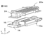
- FIG. 15 is a schematic perspective view of a first connector included in an electrical connector set according to a fifth embodiment.
- FIG. 18B is a plan view of the first connector of FIG. 18A.
- a terminal connected to a ground potential disposed next to a terminal transmitting a high-frequency signal is connected to the high-frequency band.
- An electric field radiated from a signal transmission terminal and fed is likely to cause resonance, generating radiation noise and hindering signal transmission.
- the wiring distance from the first convex terminal and the first concave terminal to the soldering portion of the GND terminal is increased. Due to the configuration of the spring engagement, the electric field radiated and fed from the signal transmission path causes resonance in a frequency band corresponding to the wavelength between the soldered portions of the GND terminals, generating radiation noise, This prevents signal transmission at the first engagement terminal.
- the present inventor provides a wall-shaped terminal having the same height as the height in the fitting direction of the electric connector set between the first engagement terminal and the second engagement terminal, so that the terminal can be used even in high-frequency transmission.
- the wall-shaped terminal defines the outer shape of the projection area of the portion where the first convex terminal and the first concave terminal forming the first engagement terminal from the x-axis direction are spring-engaged. It has been found that it is more preferable to extend in the y-axis direction over the included region.
- “the same height as the height of the electrical connector set in the fitting direction” does not mean that the height is completely the same as the height of the electrical connector set in the fitting direction. In view of the above, it is meant that the heights are almost the same.
- An electrical connector set is an electrical connector set configured by fitting a first connector and a second connector so as to face each other, A first engaging terminal formed by spring-engaging a first convex terminal of the first connector and a first concave terminal of the second connector; A second engagement terminal is configured by spring-engaging a second convex terminal of the first connector and a second concave terminal of the second connector, and is disposed along the first direction with respect to the first engagement terminal. Mating terminal, In the first direction, the first projection terminal of the first connector of the first engagement terminal and the first projection terminal of the second connector are disposed between the first engagement terminal and the second engagement terminal.
- a first recessed terminal extending along a second direction intersecting the first direction and the fitting direction over a region including a contour of a projection region in a first direction of a portion in which the first concave terminal is spring-engaged;
- a wall-shaped terminal having substantially the same height as the height of the electrical connector set in the fitting direction, Is provided.
- the wall-shaped terminal is provided between the first engagement terminal used for high-frequency transmission and the other second engagement terminal, resonance of the terminal can be suppressed even in high-frequency transmission.
- the wall-shaped terminal may be made of a metal material and may be connected to a ground potential.
- An electrical connector set according to a third aspect is the electrical connector set according to the first or second aspect, wherein the wall-like terminal has a planar shape including an outer shape of a projection area of the first engagement terminal from the first direction. May have.
- the wall-shaped terminal may be provided on at least one of the first connector and the second connector.
- An electrical connector set according to a fifth aspect is the electrical connector set according to any one of the first to fourth aspects, wherein the wall-like terminal includes a first partial wall terminal of the first connector and a second partial wall terminal of the second connector. It may be configured to engage with a wall terminal.
- At least one of the first partial wall terminal and the second partial wall terminal may be elastically deformable.
- the first partial wall terminal and the second partial wall terminal engage with each other, even if stress is applied, at least one of the first and second partial wall terminals can be stably engaged by elastically deforming. Further, the electrical connection can be stabilized.
- An electric connector set according to a seventh aspect is the electric connector set according to the sixth aspect, wherein blocks each including the first engagement terminal and the wall-shaped terminal are provided at two places along the first direction. And a length A in the first direction between the first partial wall terminals of the respective blocks of the first connector and a length A in the first direction between the second partial wall terminals of the respective blocks of the second connector. The relationship between the length B and the length A in the first direction ⁇ the length B in the first direction may be satisfied.
- An electrical connector set according to an eighth aspect is the electrical connector set according to any one of the first to sixth aspects, wherein the block formed by the first engagement terminal and the wall-shaped terminal extends along the first direction. It may be provided at two places.
- the electrical connector set according to a ninth aspect is the electrical connector set according to the sixth aspect, further comprising a fixed terminal having a lock mechanism for holding the first connector and the second connector in the fitting direction.
- the terminal is configured such that a convex curved surface of the convex fixed terminal of the first connector and a concave curved surface of the concave fixed terminal of the second connector are in contact with each other, and the convex portion of the first connector is formed.
- An electrical connector set according to a tenth aspect is the electrical connector set according to any one of the first to eighth aspects, further comprising a fixing terminal having a lock mechanism for holding the first connector and the second connector in the fitting direction. It may further have.
- the second connector can be received on the bottom dead surface after the fitting, and the height variation after the fitting can be suppressed. Therefore, the impedance of the transmission signal line can be easily adjusted.
- An electrical connector set according to an eleventh aspect is the electrical connector set according to the tenth aspect, wherein the metal surface of the convex fixed terminal of the first connector and the metal surface of the concave fixed terminal of the second connector are mutually different. It may be configured in contact.
- An electrical connector set according to a twelfth aspect is the electrical connector set according to the eleventh aspect, wherein at least one of the protrusion fixing terminal of the first connector and the recess fixing terminal of the second connector and the wall terminal , May be formed of the same member, and a connection portion thereof may be connected to a ground potential.
- An electrical connector set according to a thirteenth aspect is the electrical connector set according to any one of the first to twelfth aspects, wherein at least one of the first connector and the second connector has a metal terminal arranged annularly over the entire circumference. May be.
- An electrical connector set according to a fourteenth aspect is the electrical connector set according to any one of the first to thirteenth aspects, wherein the first engagement terminals have two rows of multipolar configurations along the first direction, and are adjacent to each other. And a second wall-shaped terminal disposed between the two first engagement terminals.
- An electrical connector set according to a fifteenth aspect is the electrical connector set according to any one of the first to fourteenth aspects, wherein the first engagement terminal is configured such that the first convex terminal and the first concave terminal are spring-engaged.
- the portion protruding to both sides along the second direction from the portion may be inside a range of the wall-shaped terminal extending along the second direction.
- the length from the soldering of the mounting portion to the portion engaged with the spring can be shortened, and the stray capacitance can be reduced, so that the impedance adjusting portion can be easily configured.
- An electrical connector set according to a sixteenth aspect is the electrical connector set according to any one of the first to fifteenth aspects, wherein the wall-like terminal is detachable from the first connector or the second connector, At least one of the first connector and the second connector may be capable of disposing the wall-shaped terminal at at least one location along the first direction.
- An electrical connector set according to a seventeenth aspect is the electrical connector set according to any one of the first to tenth aspects, wherein the first engagement terminal is a millimeter-wave connection terminal, and the first connector and the second connector May be 1 mm or less in the fitting direction.
- An electric connector set according to an eighteenth aspect is the electric connector set according to any one of the first to seventeenth aspects, wherein the second engagement terminal has a multi-pole configuration in two rows along the first direction. Good.
- FIG. 1A is a schematic perspective view of the electrical connector set 30 according to the first embodiment.
- FIG. 1B is a plan view of the electrical connector set 30 of FIG. 1A.
- FIG. 1C is a side view of the electrical connector set 30 of FIG. 1A.
- FIG. 2 is a schematic sectional view showing a sectional structure taken along line AA in FIG. 1B.
- the fitting direction of the first connector 10 and the second connector 20 is shown as a z-axis direction for convenience.
- the direction in which the first engagement terminal 31, the wall-shaped terminal 33, and the second engagement terminals 32a to 32f are arranged is defined as the x-axis direction, and the direction in which the wall-shaped terminal 33 extends is defined as the y-axis direction.
- the electrical connector set 30 is configured such that the first connector 10 and the second connector 20 face each other and are fitted in the z-axis direction.
- the electrical connector set 30 is characterized in that a wall-shaped terminal 33 is arranged between a first engagement terminal 31 and second engagement terminals 32a to 32f.
- the first engagement terminal 31 is configured such that the first convex terminal 11 of the first connector 10 and the first concave terminal 21 of the second connector 20 are spring-engaged.
- the second engaging terminals 32a to 32f are configured by spring-engaging the second convex terminals 12a to 12f of the first connector 10 and the second concave terminals 22a to 22f of the second connector 20.
- the second engagement terminals 32a to 32f are arranged along a first direction (x-axis direction). Further, the wall-shaped terminal 33 has a portion x where the first convex terminal 11 of the first connector 10 and the first concave terminal 21 of the second connector 20 that constitute the first engagement terminal 31 are spring-engaged. It extends in the y-axis direction over a region encompassing the contour of the axial projection region. The wall terminals 33 have a height substantially equal to the height of the electrical connector set 30 in the fitting direction (z-axis direction).
- the wall-shaped terminal 33 is provided between the first engagement terminal 31 used for high-frequency transmission and the other second engagement terminals 32a to 32f, radiation of electromagnetic waves from the first engagement terminal 31 And the resonance of the first engagement terminal 31 can be suppressed even in high-frequency transmission.
- the electric connector set 30 has one block 46 including the first engagement terminal 31 and the wall-shaped terminal 33, but is not limited thereto.
- two blocks 46a and 46b as shown in FIGS. 13A and 13B are configured by the first engagement terminal 31 and the wall-shaped terminal 33. There may be more. Thereby, the number of transmission signal lines can be increased.
- the block composed of the first engagement terminal and the wall-shaped terminal is disposed at one end of the electric connector set, but is not limited thereto. Is also good. As a result, the degree of freedom in designing the transmission signal line can be improved.
- a wall-shaped terminal may be provided between the first engagement terminal and the adjacent second engagement terminals on both sides.
- the electric connector set 30 may further include a fixed terminal 34 having a lock mechanism 15 for holding the first connector 10 and the second connector 20 in the fitting direction (z-axis direction).
- FIG. 3A is a schematic partial perspective view illustrating an arrangement relationship among the first engagement terminal 31, the second engagement terminals 32a to 32f, and the wall terminal 33 of the electrical connector set 30 according to the first embodiment.
- FIG. 3B is a schematic partial perspective view showing an arrangement relationship among the first engagement terminal 31, the second engagement terminals 32a to 32f, and the wall terminal 33 as viewed from a direction different from FIG. 3A.
- the first engagement terminal 31 is configured such that the first convex terminal 11 of the first connector 10 and the first concave terminal 21 of the second connector 20 are spring-engaged.
- the first convex terminal 11 of the first connector 10 and the first concave terminal 21 of the second connector 20 may be opposite to each other.
- the first engagement terminal may be configured such that the first concave terminal of the first connector and the first convex terminal of the second connector are spring-engaged.
- the first engagement terminal 31 may be, for example, a connection terminal for transmitting a millimeter wave signal.
- the millimeter wave has a wavelength in a range of 1 mm to 10 mm and a frequency in a range of about 30 GHz to about 300 GHz.
- the first engagement terminal 31 may be, for example, a millimeter-wave signal transmission connection terminal in a range of 40 GHz to 100 GHz.
- the first engagement terminal 31 has a portion projecting in the + y direction and the ⁇ y direction from a portion engaged with the spring inside the range of the wall-shaped terminal 33 in the y-axis direction.
- first engagement terminal 31 a plurality of first engagement terminals 31 may be arranged. In this case, a multi-pole configuration of two or more rows along the x-axis direction may be used. Also, a plurality may be arranged along the x-axis direction. In these cases, it further includes a second wall-shaped terminal disposed between two adjacent first engagement terminals 31. Thus, digital signals and other signals can be transmitted by the first engagement terminals.
- the second engaging terminals 32a to 32f are configured by spring-engaging the second convex terminals 12a to 12f of the first connector 10 and the second concave terminals 22a to 22f of the second connector 20.
- the second engagement terminals 32a to 32f are arranged along a first direction (x-axis direction). Note that the second convex terminals 12a to 12f of the first connector 10 and the second concave terminals 22a to 22f of the second connector 20 may be opposite to each other.
- the second engagement terminal may be configured such that the second concave terminal of the first connector and the second convex terminal of the second connector are spring-engaged.
- the second engagement terminals 32a to 32f may have a multi-pole configuration of two or more rows along the x-axis direction.
- digital signals and other signals can be transmitted by the second engagement terminals.
- the length of the second protrusion terminals 12a to 12f of the second engagement terminals 32a to 32f in the ⁇ y-axis direction is the same as that of the first protrusion terminal 11 of the first engagement terminal 31.
- -It is longer than the length in the y-axis direction. That is, the length 11 in the ⁇ y axis direction ⁇ the length 12a to 12f in the ⁇ y axis direction.
- the length of the second recessed terminals 22a to 22f of the second engagement terminals 32a to 32f in the y-axis direction is the same as the length of the first recessed terminal 21 of the first engagement terminal 31 in the y-axis direction. Longer than the length of That is, the length 21 in the y-axis direction ⁇ the length 22a to 22f in the y-axis direction.
- FIG. 4 is a schematic diagram showing the relationship between the outer shape inclusion area 42 of the projection area of the spring engagement portion of the first engagement terminal 31 and the wall-shaped terminal 33 as viewed from the negative direction in the x-axis direction to the positive direction.
- FIG. 5A is a schematic perspective view showing an arrangement relationship between the first engagement terminal 31 and the wall-shaped terminal 33.
- FIG. 5B is a schematic perspective view showing an arrangement relationship between the first engagement terminal 31 and the wall-shaped terminal 33 as viewed from a direction different from FIG. 5A.
- the wall-shaped terminal 33 is arranged between the first engagement terminal 31 and the second engagement terminals 32a to 32f. As shown in FIG.
- the wall-shaped terminal 33 is configured such that the first convex terminal 11 of the first connector 10 and the first concave terminal 21 of the second connector 20 that constitute the first engagement terminal 31 are spring-engaged.
- the portion extending in the y-axis direction extends over the outer shape encompassing region 42 that includes the outer shape of the projected region from the x-axis direction of the portion where the light is projected.
- the wall-shaped terminal 33 has substantially the same height as the height of the electric connector set 30 in the fitting direction (z-axis direction). That is, when viewed from the second engagement terminal 32, the first engagement terminal 31 is completely covered by the wall-shaped terminal 33 as shown in FIG. 5B.
- the first engagement terminal 31 and the second engagement terminal 32 can be separated by the wall-shaped terminal 33.
- the wall terminal 33 may be made of a metal material. Further, the wall terminal 33 may be connected to a ground potential.
- the wall-shaped terminals 33 can shield electromagnetic waves radiated from the first engagement terminals 31. Further, by making the wall-shaped terminal 33 approximately the same height as the fitting direction (z-axis direction) of the electrical connector set 30, unnecessary resonance of the GND terminal is generated even in a high-frequency band wavelength, for example, a millimeter wave signal transmission. Can be suppressed.
- the wall-shaped terminal 33 may have a planar shape including the outer shape of the projection area of the first engagement terminal 31 from the x-axis direction.
- the transmission signal line can be transmitted with an ideal coplanar configuration. Further, it becomes easy to capture the electric field of the transmission signal line. Therefore, radiation loss of the transmission signal line can be suppressed. Further, the separability from other transmission signal lines in the electrical connector set 30 can be improved.
- the planar shape is not limited to a flat plate shape, but may be a concave or convex surface including irregularities, or a curved surface including partial concave and convex portions.
- the wall terminal 33 may be a flat plate extending in the y-axis direction. Note that the thickness of the wall-shaped terminal 33 in the x-axis direction may not be constant in the plane. Further, at least a part of the wall-shaped terminal may have a strip shape, a comb shape, a net shape, or the like. Note that the wall-shaped terminal only needs to be able to shield the electromagnetic wave radiated from the first engagement terminal 31, and may have a hole or notch having a size that does not leak the electromagnetic wave. For example, it is preferable that the longest distance of a straight portion that can be taken inside the hole is equal to or less than the wavelength of the electromagnetic wave radiated from the first engagement terminal.
- the wall-shaped terminal 33 may be composed of one member, or may be composed of two or more members. Further, the wall terminal may be detachable from the first connector or the second connector.
- a wall-shaped terminal for example, a member that can be fitted or inserted and fixed to the first connector or the second connector may be arranged at a plurality of locations. In this case, at least one of the first connector and the second connector may be capable of disposing the wall-shaped terminal at at least one position along the first direction.
- the wall-shaped terminal 33 is formed of one member, it may be provided on at least one of the first connector 10 and the second connector 20.
- FIG. 6A is a schematic perspective view showing a state in which the wall-shaped terminal 33 is composed of the first partial wall terminal 13 and the second partial wall terminal 23.
- FIG. 6B is a schematic perspective view showing a state in which the wall-shaped terminal 33 is configured by the first partial wall terminal 13 and the second partial wall terminal 23 when viewed from a direction different from FIG. 6A.
- FIG. 7A is a schematic diagram showing a state in which the first connector 10 and the second connector 20 are fitted to each other, and the wall-shaped terminal 33 is fitted with the first partial wall terminal 13 and the second partial wall terminal 23. It is a perspective view.
- FIG. 6A is a schematic perspective view showing a state in which the wall-shaped terminal 33 is composed of the first partial wall terminal 13 and the second partial wall terminal 23.
- FIG. 6B is a schematic perspective view showing a state in which the wall-shaped terminal 33 is configured by the first partial wall terminal 13 and the second partial wall terminal 23 when viewed from a direction different from FIG. 6A.
- 7B is a diagram showing a state at the time of fitting when the first connector 10 and the second connector 20 are fitted together and the wall-shaped terminal 33 is composed of the first partial wall terminal 13 and the second partial wall terminal 23. It is the schematic perspective view seen from the direction different from 7A.
- the wall-shaped terminal 33 is configured by engaging the first partial wall terminal 13 of the first connector 10 with the second partial wall terminal 23 of the second connector 20. Will be described.
- the wall-shaped terminal 33 is not a single member, but is configured by engaging the first partial wall terminal 13 and the second partial wall terminal 23.
- the first partial wall terminal 13 and the second partial wall terminal 23 are electrically connected.
- At least one of the first partial wall terminal 13 and the second partial wall terminal 23 has a spring property and may be, for example, elastically deformable.
- the first partial wall terminal 13 and the second partial wall terminal 23 engage with each other, even if stress is applied, at least one of the first and second partial wall terminals 13 is elastically deformed, so that stable engagement can be achieved.
- not only elastic deformation in the z-axis direction but also elastic deformation in the x-axis direction may be performed as shown in FIG. 15A or 15B.
- a difference in distance (dimension) or a change in distance (dimension) in the x-axis direction can be allowed.
- the electrical connection can be stabilized.
- the first partial wall terminal 13 and the second partial wall terminal 23 may be arranged so as to be slightly shifted in the x direction.
- they may be arranged so as to be shifted in a range of not less than half the thickness in the x direction and not more than the thickness.
- they when engaged, they are shifted in the x direction, receive stresses in the x axis direction, and can be brought into close contact with each other.
- the lower surface of the wall-shaped terminal 33 may be connected to a substrate that forms the bottom surface of the entire first connector 10. Further, two wall-shaped terminals 33 may be provided so as to sandwich the first engagement terminal 31 from the ⁇ x direction and the + x direction. Accordingly, it is possible to shield the electromagnetic field from the outside toward the first engagement terminal 31 and to shield the electromagnetic field radiated from the first engagement terminal 31 in the x-axis direction. Therefore, EMC performance can be improved.
- FIG. 8 is a cross-sectional view showing a cross-sectional structure of fixed terminal 34 of electric connector set 30 according to Embodiment 1 as viewed from the x-axis direction.
- FIG. 9 is a schematic cross-sectional view showing a fitting state in which the first connector and the second connector are fitted to each other, and the fixed terminal 34 is formed by the convex fixed terminal 14 and the concave fixed terminal 24.
- the fixed terminal 34 has a lock mechanism 15 that holds the first connector 10 and the second connector 20 in the fitting direction (z-axis direction). Specifically, the claw portion 25 of the second connector 20 is held by the lock mechanism 15 of the first connector 10, and the first connector 10 and the second connector 20 can be fixed.
- the bottom surface of the lock mechanism 15 functions as a movable bottom dead surface of the second connector 20 in the ⁇ z direction.
- the bottom dead surface is a surface located in the ⁇ z direction in the region where the second connector 20 can move in the z direction.
- the surface of the substrate constituting the bottom surface of the first connector 10 may be used as the bottom dead surface.
- the fixed terminal 34 is formed of the convex curved surface 16 made of the metal of the convex fixed terminal 14 of the first connector 10 and the metal of the concave fixed terminal 24 of the second connector 20.
- the concave curved surfaces 26 are in contact with each other. That is, the convex portion fixing terminal 14 and the concave portion fixing terminal 24 are electrically connected. As a result, resonance occurring between the fixed terminal 34 and the board of the electrical connector set 30 can be suppressed.
- FIG. 10A is a schematic perspective view of the first connector 10 included in the electrical connector set 30 according to Embodiment 1.
- FIG. 10B is a plan view of the first connector 10 of FIG. 10A.
- the convex fixing terminal 14, the first convex terminal 11, the first partial wall terminal 13, and the second convex terminals 12a to 12f are arranged along the x-axis direction.
- the first protruding terminal 11 and the second protruding terminals 12a to 12f may each have a multi-pole configuration of two or more rows along the x-axis direction.
- the first protruding terminal 11 and the second protruding terminals 12a to 12f are spring-engageable members, and may be formed of, for example, phosphor bronze.
- the first partial wall terminal 13 is a flat plate perpendicular to the x-axis direction.
- a substrate electrically connected to the first partial wall terminal 13 may be provided on the bottom surface.
- FIG. 11A is a schematic perspective view of the second connector 20 included in the electrical connector set 30 according to the first embodiment.
- FIG. 11B is a bottom view of the second connector 20 of FIG. 11A.
- the concave fixing terminal 24, the first concave terminal 21, the second partial wall terminal 23, and the second concave terminals 22a to 22f are arranged along the x-axis direction.
- the first concave terminal 21 and the second concave terminals 22a to 22f are members which can be spring-engaged, and may be formed of, for example, phosphor bronze. As shown in FIGS.
- the second partial wall terminal 23 has an upper end located at substantially the same x position as the first partial wall terminal 13, and has a first partial wall terminal 13 extending from the center to the lower end.
- FIG. 12A is a schematic perspective view showing a fitting state in which the electrical connector set 30 according to Embodiment 1 is configured by fitting the first connector 10 and the second connector 20 so as to face each other.
- FIG. 12B is a schematic diagram illustrating a state when the electric connector set 30 according to the first embodiment is configured by fitting the first connector 10 and the second connector 20 so as to face each other and viewed from a direction different from FIG. 12A. It is a perspective view.
- the electric connector set 30 is configured by fitting the first connector 10 and the second connector 20 so as to face each other.
- the first convex terminal 11 and the first concave terminal 21 are engaged to form the first engagement terminal 31.
- the second protrusion terminals 12a to 12f and the second recess terminals 22a to 22f are engaged with each other to form second engagement terminals 32a to 32f.
- the first partial wall terminal 13 and the second partial wall terminal 23 are engaged to form a wall-shaped terminal.
- the fixed terminal 34 is configured by the engagement of the convex fixed terminal 14 and the concave fixed terminal 24. As described above, the fixed terminal 34 holds the first connector 10 and the second connector 20 in the fitting direction (z-axis direction).
- FIG. 13A is a schematic perspective view of the electrical connector set 30a according to the second embodiment.
- FIG. 13B is a plan view of FIG. 13A.
- FIG. 14A is a plan view of the first connector 10a included in the electrical connector set 30a according to the second embodiment.
- FIG. 14B is a bottom view of the second connector 20a included in the electrical connector set 30a according to the second embodiment.
- FIG. 15B is a schematic partial cross-sectional view showing a state where the first connector 10c and the second connector 20c are overlapped in the fitting direction (z-axis direction) in the electrical connector set according to Embodiment 4.
- FIG. 14A is a plan view of the first connector 10a included in the electrical connector set 30a according to the second embodiment.
- FIG. 14B is a bottom view of the second connector 20a included in the electrical connector set 30a according to the second embodiment.
- FIG. 15B is a schematic partial cross-sectional view showing a state where the first connector 10c and the second connector 20c
- the electrical connector set 30a according to the second embodiment includes a block 46a of a wall-shaped terminal 33a and a first engagement terminal 31a at both ends in the x-axis direction, and a wall-shaped terminal 33b. And a block 46b with the first engagement terminal 31b.
- the number of transmission signal lines can be increased.
- the distance A in the x-axis direction between the first partial wall terminals 13a and 13b of each block of the first connector 10a, and the second partial wall of each block of the second connector 20a is smaller than the distance B in the x-axis direction. That is, for the second engagement terminals 32a to 32f sandwiched between the two wall-shaped terminals 33a and 33b, the distance A in the x-axis direction of the first connector 10a and the distance B in the x-axis direction of the second connector 20a.
- the wall terminals 33a and 33b are elastically deformed, it is possible to prevent the positional relationship between the wall terminals 33a and 33b and the first engagement terminals 31a and 31b from shifting in the x-axis direction. it can. Thereby, the fluctuation of the impedance can be reduced.
- the distance D in the x-axis direction with respect to the second partial wall terminal 23a has a relationship of distance C in the x-axis direction> distance D in the x-axis direction. That is, even when the first connector 10a and the second connector 20a are displaced in the x-axis direction at the time of fitting, the positional relationship between the wall-shaped terminal 33a and the first engagement terminal 31a is caused by the elastic deformation of the wall-shaped terminal 33a. Deviation can be prevented. Thereby, the fluctuation of the impedance can be reduced.
- FIG. 16A is a schematic perspective view of the first connector 10b included in the electrical connector set according to Embodiment 3.
- FIG. 16B is a plan view of the first connector 10b of FIG. 16A.
- the electrical connector set according to the third embodiment has a first connector 10b having an annular external metal terminal 44 on the outer periphery as shown in FIGS. 16A and 16B.
- the ring-shaped external metal terminal is provided as described above, noise resistance can be improved. Further, the easiness of impedance matching can be improved.
- FIG. 17A is a schematic perspective view of the first connector 10c included in the electrical connector set according to Embodiment 4.
- FIG. 17B is a plan view of the first connector 10c of FIG. 17A.
- the first connector 10c constituting the electric connector set according to the fourth embodiment is configured such that the first partial wall terminal 13a and the protrusion fixing terminal 14a are integrally formed of the same member. ing.
- the first partial wall terminal 13a and the protrusion fixing terminal 14a are formed of the same member, and the connection portion is grounded to the substrate, so that the potential difference between the fixed terminal 34a and the wall terminal 33a can be substantially eliminated.
- noise immunity is improved, and the first partial wall terminal 13a and the protrusion fixing terminal 14a can be integrally handled in the manufacturing process, so that productivity can be improved.
- FIG. 18A is a schematic perspective view of a first connector 10d included in the electrical connector set according to Embodiment 5.
- FIG. 18B is a plan view of the first connector 10d of FIG. 18A.
- the first connector 10d included in the electrical connector set according to the fifth embodiment includes two rows of second convex terminals 12a to 12f extending in parallel along the x-axis direction. Thereby, the second engagement terminals 32a to 32f can be efficiently arranged, and the length in the x-axis direction can be reduced.
Abstract
Description
前記第1コネクタの第1凸部端子と、前記第2コネクタの第1凹部端子とがばね係合して構成されている第1係合端子と、
前記第1コネクタの第2凸部端子と、前記第2コネクタの第2凹部端子とがばね係合して構成され、前記第1係合端子について第1方向に沿って配置された第2係合端子と、
前記第1方向について、前記第1係合端子と前記第2係合端子との間に配置され、前記第1係合端子の前記第1コネクタの前記第1凸部端子と前記第2コネクタの前記第1凹部端子とがばね係合している部分の第1方向への投影領域の外形を包含する領域にわたって前記第1方向及び嵌合方向と交差する第2方向に沿って延在し、前記電気コネクタセットの嵌合方向の高さとほぼ同じ高さを有する壁状端子と、
を備える。 An electrical connector set according to the present invention is an electrical connector set configured by fitting a first connector and a second connector so as to face each other,
A first engaging terminal formed by spring-engaging a first convex terminal of the first connector and a first concave terminal of the second connector;
A second engagement terminal is configured by spring-engaging a second convex terminal of the first connector and a second concave terminal of the second connector, and is disposed along the first direction with respect to the first engagement terminal. Mating terminal,
In the first direction, the first projection terminal of the first connector of the first engagement terminal and the first projection terminal of the second connector are disposed between the first engagement terminal and the second engagement terminal. A first recessed terminal extending along a second direction intersecting the first direction and the fitting direction over a region including a contour of a projection region in a first direction of a portion in which the first concave terminal is spring-engaged; A wall-shaped terminal having substantially the same height as the height of the electrical connector set in the fitting direction,
Is provided.
上述の課題に挙げたように、高周波伝送等の高い伝送帯域、例えば、ミリ波信号伝送では、高周波信号を伝送する端子の隣に配置された接地電位に接続した端子(GND端子)が前記高周波信号を伝送する端子から輻射され給電される電界によって共振を起こしやすく、放射ノイズを発生させ信号伝送の妨げになる。ばね係合の構成では、第1凸部端子と第1凹部端子とからGND端子のはんだ付け部間への配線距離が長くなる。このばね係合の構成が原因となって、信号伝送路から輻射して給電された電界が、GND端子のはんだ付け部間で波長に応じた周波数帯で共振を起こし、放射ノイズを発生させ、第1係合端子における信号の伝送を妨げる。 (About the process leading to the present invention)
As described in the above-mentioned problem, in a high transmission band such as high-frequency transmission, for example, in millimeter-wave signal transmission, a terminal (GND terminal) connected to a ground potential disposed next to a terminal transmitting a high-frequency signal is connected to the high-frequency band. An electric field radiated from a signal transmission terminal and fed is likely to cause resonance, generating radiation noise and hindering signal transmission. In the configuration of the spring engagement, the wiring distance from the first convex terminal and the first concave terminal to the soldering portion of the GND terminal is increased. Due to the configuration of the spring engagement, the electric field radiated and fed from the signal transmission path causes resonance in a frequency band corresponding to the wavelength between the soldered portions of the GND terminals, generating radiation noise, This prevents signal transmission at the first engagement terminal.
第1の態様に係る電気コネクタセットは、第1コネクタと第2コネクタとを対向させて嵌合して構成された電気コネクタセットであって、
前記第1コネクタの第1凸部端子と、前記第2コネクタの第1凹部端子とがばね係合して構成されている第1係合端子と、
前記第1コネクタの第2凸部端子と、前記第2コネクタの第2凹部端子とがばね係合して構成され、前記第1係合端子について第1方向に沿って配置された第2係合端子と、
前記第1方向について、前記第1係合端子と前記第2係合端子との間に配置され、前記第1係合端子の前記第1コネクタの前記第1凸部端子と前記第2コネクタの前記第1凹部端子とがばね係合している部分の第1方向への投影領域の外形を包含する領域にわたって前記第1方向及び嵌合方向と交差する第2方向に沿って延在し、前記電気コネクタセットの嵌合方向の高さとほぼ同じ高さを有する壁状端子と、
を備える。 (Aspects of the present invention)
An electrical connector set according to a first aspect is an electrical connector set configured by fitting a first connector and a second connector so as to face each other,
A first engaging terminal formed by spring-engaging a first convex terminal of the first connector and a first concave terminal of the second connector;
A second engagement terminal is configured by spring-engaging a second convex terminal of the first connector and a second concave terminal of the second connector, and is disposed along the first direction with respect to the first engagement terminal. Mating terminal,
In the first direction, the first projection terminal of the first connector of the first engagement terminal and the first projection terminal of the second connector are disposed between the first engagement terminal and the second engagement terminal. A first recessed terminal extending along a second direction intersecting the first direction and the fitting direction over a region including a contour of a projection region in a first direction of a portion in which the first concave terminal is spring-engaged; A wall-shaped terminal having substantially the same height as the height of the electrical connector set in the fitting direction,
Is provided.
前記第1コネクタ又は前記第2コネクタの少なくとも一方は、前記第1方向に沿って、少なくとも1箇所において前記壁状端子を配置可能であってもよい。 An electrical connector set according to a sixteenth aspect is the electrical connector set according to any one of the first to fifteenth aspects, wherein the wall-like terminal is detachable from the first connector or the second connector,
At least one of the first connector and the second connector may be capable of disposing the wall-shaped terminal at at least one location along the first direction.
図1Aは、実施の形態1に係る電気コネクタセット30の概略斜視図である。図1Bは、図1Aの電気コネクタセット30の平面図である。図1Cは、図1Aの電気コネクタセット30の側面図である。図2は、図1BのA-A線で切断した断面構造を示す概略断面図である。なお、図面において、便宜上、第1コネクタ10と第2コネクタ20との嵌合方向をz軸方向として示している。また、第1係合端子31、壁状端子33、第2係合端子32a~32fの配置方向をx軸方向とし、壁状端子33の延在する方向をy軸方向としている。 (Embodiment 1)
FIG. 1A is a schematic perspective view of the electrical connector set 30 according to the first embodiment. FIG. 1B is a plan view of the electrical connector set 30 of FIG. 1A. FIG. 1C is a side view of the electrical connector set 30 of FIG. 1A. FIG. 2 is a schematic sectional view showing a sectional structure taken along line AA in FIG. 1B. In the drawings, the fitting direction of the
図3Aは、実施の形態1に係る電気コネクタセット30の第1係合端子31と第2係合端子32a~32fと壁状端子33との配置関係を示す概略部分斜視図である。図3Bは、図3Aと異なる方向からみた第1係合端子31と第2係合端子32a~32fと壁状端子33との配置関係を示す概略部分斜視図である。
第1係合端子31は、第1コネクタ10の第1凸部端子11と、第2コネクタ20の第1凹部端子21とがばね係合して構成されている。なお、第1コネクタ10の第1凸部端子11と、第2コネクタ20の第1凹部端子21とは、互いに逆であってもよい。例えば、第1係合端子は、第1コネクタの第1凹部端子と、第2コネクタの第1凸部端子とがばね係合して構成されていてもよい。 <First engagement terminal>
FIG. 3A is a schematic partial perspective view illustrating an arrangement relationship among the
The
また、第1係合端子31は、ばね係合している部分から+y方向及び-y方向に突出している部分が、壁状端子33のy軸方向の範囲より内側にある。これによって、実装部のはんだ付けからばね係合している部分までの長さを短くでき、浮遊容量を減らせるので、インピーダンス調整部を容易に構成できる。
さらに、ここでは、第1係合端子31は、一つしか示していないが、複数配置してもよい。この場合、x軸方向に沿って2列以上の多極構成であってもよい。また、x軸方向に沿って複数配置してもよい。これらの場合には、隣接する2つの第1係合端子31の間に配置された第2壁状端子をさらに備える。これによって、第1係合端子によって、デジタル信号や他の信号の伝送が可能となる。 The
Further, the
Further, although only one
第2係合端子32a~32fは、第1コネクタ10の第2凸部端子12a~12fと、第2コネクタ20の第2凹部端子22a~22fとがばね係合して構成されている。この第2係合端子32a~32fは、第1方向(x軸方向)に沿って配置されている。なお、第1コネクタ10の第2凸部端子12a~12fと、第2コネクタ20の第2凹部端子22a~22fとは、互いに逆であってもよい。例えば、第2係合端子は、第1コネクタの第2凹部端子と、第2コネクタの第2凸部端子とがばね係合して構成されていてもよい。
また、第2係合端子32a~32fは、x軸方向に沿って2列以上の多極構成を有してもよい。これによって、第2係合端子によって、デジタル信号や他の信号の伝送が可能となる。
なお、x軸方向からみたとき、第2係合端子32a~32fの第2凸部端子12a~12fの-y軸方向の長さは、第1係合端子31の第1凸部端子11の-y軸方向の長さより長い。つまり、-y軸方向の長さ11<-y軸方向の長さ12a~12fである。また、x軸方向からみたとき、第2係合端子32a~32fの第2凹部端子22a~22fのy軸方向の長さは、第1係合端子31の第1凹部端子21のy軸方向の長さより長い。つまり、y軸方向の長さ21<y軸方向の長さ22a~22fである。 <Second engagement terminal>
The second
Further, the
When viewed from the x-axis direction, the length of the
図4は、x軸方向の負方向から正方向に向ってみた第1係合端子31のばね係合部分の投影領域の外形包含領域42と壁状端子33との関係を示す概略図である。図5Aは、第1係合端子31と壁状端子33との配置関係を示す概略斜視図である。図5Bは、図5Aと異なる方向からみた第1係合端子31と壁状端子33との配置関係を示す概略斜視図である。
壁状端子33は、第1係合端子31と、第2係合端子32a~32fとの間に配置されている。この壁状端子33は、図4に示すように、第1係合端子31を構成する第1コネクタ10の第1凸部端子11と第2コネクタ20の第1凹部端子21とがばね係合している部分のx軸方向からの投影領域の外形を包含する外形包含領域42にわたってy軸方向に延在する。また、この壁状端子33は、図4,図5A及び図5Bに示すように、電気コネクタセット30の嵌合方向(z軸方向)の高さとほぼ同じ高さを有する。つまり、第2係合端子32から見た場合、図5Bに示すように、壁状端子33によって第1係合端子31が完全に覆われている。これによって、壁状端子33により第1係合端子31と第2係合端子32とを仕切ることができる。
また、壁状端子33は、金属材料で構成されていてもよい。さらに、壁状端子33は、接地電位に接続されていてもよい。この壁状端子33によって、第1係合端子31から放射される電磁波をシールドすることができる。さらに、壁状端子33を電気コネクタセット30の嵌合方向(z軸方向)の高さとほぼ同じ高さとすることで、高周波帯域の波長、例えば、ミリ波信号伝送でもGND端子の不要共振の発生を抑制できる。 <Wall terminal>
FIG. 4 is a schematic diagram showing the relationship between the outer
The wall-shaped
Further, the
また、壁状端子は、少なくとも一部が短冊形状、櫛形形状、網状形状等であってもよい。なお、壁状端子は、第1係合端子31から放射される電磁波をシールドできればよく、電磁波が漏洩しない程度の大きさの孔、切り欠きを有してもよい。例えば、孔は、その内部で取り得る直線部分の最長距離が第1係合端子から放射される電磁波の波長以下であることが好ましい。 Further, the wall-shaped
Further, at least a part of the wall-shaped terminal may have a strip shape, a comb shape, a net shape, or the like. Note that the wall-shaped terminal only needs to be able to shield the electromagnetic wave radiated from the
壁状端子33が一つの部材から構成されている場合には、第1コネクタ10又は第2コネクタ20の少なくとも一方に設けられていればよい。 In addition, the wall-shaped
When the wall-shaped
また、壁状端子33は、第1係合端子31を-x方向及び+x方向から挟むように2つ設けてもよい。これによって、外部から第1係合端子31に向かう電磁界を遮蔽することができるとともに第1係合端子31からx軸方向に放射される電磁界を遮蔽できる。そこで、EMC性能を向上させることができる。 In addition, the lower surface of the wall-shaped
Further, two wall-shaped
図8は、実施の形態1に係る電気コネクタセット30の固定端子34のx軸方向からみた断面構造を示す断面図である。図9は、第1コネクタと第2コネクタとを嵌合して、固定端子34を凸部固定端子14と凹部固定端子24とで構成する嵌合時の様子を示す概略断面図である。
固定端子34は、嵌合方向(z軸方向)について、第1コネクタ10と第2コネクタ20とを保持するロック機構15を有する。具体的には、第2コネクタ20のツメ部25が第1コネクタ10のロック機構15に保持され、第1コネクタ10と第2コネクタ20とを固定できる。この場合、第2コネクタ20のツメ部25と第1コネクタ10のロック機構15との少なくとも一方が弾性変形してツメ部25がロック機構15の奥まで入り込み、固定される。なお、ロック機構15の底面は、第2コネクタ20の-z方向の移動可能な下死面として機能する。下死面とは、この場合、第2コネクタ20のz方向への移動可能な領域において、最も-z方向に位置する面のことである。あるいは、第1コネクタ10の底面を構成する基板の面を下死面として用いてもよい。これによって、嵌合後に第2コネクタ20のツメ部25を下死面で受けることができ、嵌合後の高さ変動を抑制できる。そこで、伝送信号線のインピーダンス調整を容易に行うことができる。
また、固定端子34は、図8及び図9に示すように、第1コネクタ10の凸部固定端子14の金属からなる凸部湾曲面16と第2コネクタ20の凹部固定端子24の金属からなる凹部湾曲面26とが互いに接触して構成されている。つまり、凸部固定端子14と凹部固定端子24とは、電気的に接続されている。これによって固定端子34と電気コネクタセット30の基板との間で発生する共振を抑制できる。 <Fixed terminal>
FIG. 8 is a cross-sectional view showing a cross-sectional structure of fixed
The fixed
As shown in FIGS. 8 and 9, the fixed
図10Aは、実施の形態1に係る電気コネクタセット30を構成する第1コネクタ10の概略斜視図である。図10Bは、図10Aの第1コネクタ10の平面図である。
第1コネクタ10は、凸部固定端子14と、第1凸部端子11と、第1部分壁端子13と、第2凸部端子12a~12fと、がx軸方向に沿って配置されている。第1凸部端子11と、第2凸部端子12a~12fとは、それぞれx軸方向に沿って2列以上の多極構成を有してもよい。
第1凸部端子11と、第2凸部端子12a~12fとは、ばね係合可能な部材であって、例えば、リン青銅で形成してもよい。第1部分壁端子13は、図10A及び図10Bに示すように、x軸方向に垂直な平板状である。
なお、各部材を配置するための絶縁性部材を有してもよい。また、底面に第1部分壁端子13と電気的に接続された基板を設けてもよい。 <First connector>
FIG. 10A is a schematic perspective view of the
In the
The first protruding
In addition, you may have an insulating member for arrange | positioning each member. Further, a substrate electrically connected to the first
図11Aは、実施の形態1に係る電気コネクタセット30を構成する第2コネクタ20の概略斜視図である。図11Bは、図11Aの第2コネクタ20の底面図である。
第2コネクタ20は、凹部固定端子24と、第1凹部端子21と、第2部分壁端子23と、第2凹部端子22a~22fと、がx軸方向に沿って配置されている。第1凹部端子21と、第2凹部端子22a~22fとは、ばね係合可能な部材であって、例えば、リン青銅で形成してもよい。第2部分壁端子23は、図11A及び図11Bに示すように、上端部は第1部分壁端子13とほぼ同じx位置であって、中央部から下端部にかけては、第1部分壁端子13に対してx軸方向の幅のおよそ半分程度シフトして配置されている。これによって、図6A及び図6Bに示すように、係合時にそれぞれx軸方向にシフトして互いにx軸方向への応力を受け、密着させることができる。
なお、各部材を配置するための絶縁性部材を有してもよい。 <Second connector>
FIG. 11A is a schematic perspective view of the
In the
In addition, you may have an insulating member for arrange | positioning each member.
図12Aは、実施の形態1に係る電気コネクタセット30を第1コネクタ10と第2コネクタ20とを対向させて嵌合して構成する嵌合時の様子を示す概略斜視図である。図12Bは、実施の形態1に係る電気コネクタセット30を第1コネクタ10と第2コネクタ20とを対向させて嵌合して構成する嵌合時の様子を示す図12Aと異なる方向からみた概略斜視図である。 <About the structure of the electrical connector set by fitting the first connector and the second connector>
FIG. 12A is a schematic perspective view showing a fitting state in which the electrical connector set 30 according to Embodiment 1 is configured by fitting the
図13Aは、実施の形態2に係る電気コネクタセット30aの概略斜視図である。図13Bは、図13Aの平面図である。図14Aは、実施の形態2に係る電気コネクタセット30aを構成する第1コネクタ10aの平面図である。図14Bは、実施の形態2に係る電気コネクタセット30aを構成する第2コネクタ20aの底面図である。図15Bは、実施の形態4に係る電気コネクタセットにおいて、第1コネクタ10cと第2コネクタ20cとを嵌合方向(z軸方向)に重ねた状態を示す概略部分断面図である。図15Cは、実施の形態4に係る電気コネクタセットにおいて、第1コネクタ10cと第2コネクタ20cとを嵌合方向(z軸方向)に重ねた状態を示す概略斜視図である。
実施の形態2に係る電気コネクタセット30aは、図13A及び図13Bに示すように、x軸方向について両端に壁状端子33aと第1係合端子31aとのブロック46aと、壁状端子33bと第1係合端子31bとのブロック46bと、を有することを特徴とする。
これによって、伝送信号線を増やすことができる。 (Embodiment 2)
FIG. 13A is a schematic perspective view of the electrical connector set 30a according to the second embodiment. FIG. 13B is a plan view of FIG. 13A. FIG. 14A is a plan view of the
As shown in FIGS. 13A and 13B, the electrical connector set 30a according to the second embodiment includes a
Thereby, the number of transmission signal lines can be increased.
図16Aは、実施の形態3に係る電気コネクタセットを構成する第1コネクタ10bの概略斜視図である。図16Bは、図16Aの第1コネクタ10bの平面図である。
実施の形態1及び2に係る電気コネクタセットと対比すると、実施の形態3に係る電気コネクタセットは、図16A及び図16Bに示すように、第1コネクタ10bは、外周に環状の外部金属端子44が配置されている点で相違する。
このように環状の外部金属端子を有するので、ノイズ耐性を向上させることができる。また、インピーダンス整合の容易性を向上させることができる。 (Embodiment 3)
FIG. 16A is a schematic perspective view of the
In contrast to the electrical connector sets according to the first and second embodiments, the electrical connector set according to the third embodiment has a
Since the ring-shaped external metal terminal is provided as described above, noise resistance can be improved. Further, the easiness of impedance matching can be improved.
図17Aは、実施の形態4に係る電気コネクタセットを構成する第1コネクタ10cの概略斜視図である。図17Bは、図17Aの第1コネクタ10cの平面図である。
実施の形態4に係る電気コネクタセットを構成する第1コネクタ10cは、図17A及び図17Bに示すように、第1部分壁端子13aと凸部固定端子14aとが同一部材で一体的に構成されている。
このように第1部分壁端子13aと凸部固定端子14aとを同一部材で形成し、接続部を基板に接地させることで、固定端子34aと壁状端子33aとの電位差をほぼなくすことができる。また、対ノイズ性が向上すると共に、製造工程において、第1部分壁端子13aと凸部固定端子14aとを一体的に扱うことができるので、生産性を向上させることができる。 (Embodiment 4)
FIG. 17A is a schematic perspective view of the
As shown in FIGS. 17A and 17B, the
As described above, the first
図18Aは、実施の形態5に係る電気コネクタセットを構成する第1コネクタ10dの概略斜視図である。図18Bは、図18Aの第1コネクタ10dの平面図である。
実施の形態5に係る電気コネクタセットを構成する第1コネクタ10dは、第2凸部端子12a~12fがx軸方向に沿って平行に延在する2列で構成されている。これによって第2係合端子32a~32fを効率よく配置でき、x軸方向の長さを短くできる。 (Embodiment 5)
FIG. 18A is a schematic perspective view of a
The
11 第1凸部端子
12a、12b、12c、12d、12e、12f 第2凸部端子
13、13a、13b 第1部分壁端子
14、14a、14b 凸部固定端子
15 ロック機構
16 凸部湾曲面
20、20a、20b 第2コネクタ
21 第1凹部端子
22a、22b、22c、22d、22e、22f 第2凹部端子
23、23a、23b 第2部分壁端子
24 凹部固定端子
25 ツメ部
26 凹部湾曲面
30、30a、30b、30c 電気コネクタセット
31、31a、31b 第1係合端子
32a、32b、32c、32d、32e、32f 第2係合端子
33、33a、33b 壁状端子
34 固定端子
42 ばね係合部分の投影領域の外形包含領域
44 外部金属端子
46、46a、46b ブロック 10, 10a, 10b, 10c,
Claims (18)
- 第1コネクタと第2コネクタとを対向させて嵌合して構成された電気コネクタセットであって、
前記第1コネクタの第1凸部端子と、前記第2コネクタの第1凹部端子とがばね係合して構成されている第1係合端子と、
前記第1コネクタの第2凸部端子と、前記第2コネクタの第2凹部端子とがばね係合して構成され、前記第1係合端子について第1方向に沿って配置された第2係合端子と、
前記第1方向について、前記第1係合端子と前記第2係合端子との間に配置され、前記第1係合端子の前記第1コネクタの前記第1凸部端子と前記第2コネクタの前記第1凹部端子とがばね係合している部分の前記第1方向への投影領域の外形を包含する領域にわたって前記第1方向及び嵌合方向と交差する第2方向に沿って延在し、前記電気コネクタセットの嵌合方向の高さと同じ高さを有する壁状端子と、
を備えた、電気コネクタセット。 An electrical connector set configured by fitting a first connector and a second connector so as to face each other,
A first engaging terminal formed by spring-engaging a first convex terminal of the first connector and a first concave terminal of the second connector;
A second engagement terminal is configured by spring-engaging a second convex terminal of the first connector and a second concave terminal of the second connector, and is disposed along the first direction with respect to the first engagement terminal. Mating terminal,
In the first direction, the first projection terminal of the first connector of the first engagement terminal and the first projection terminal of the second connector are disposed between the first engagement terminal and the second engagement terminal. The first recessed terminal extends along a second direction intersecting the first direction and the fitting direction over a region including a contour of a projection region in the first direction of a portion in which the first concave terminal is spring-engaged. A wall-shaped terminal having the same height as the height of the electrical connector set in the fitting direction,
, Electrical connector set. - 前記壁状端子は、金属材料で構成されていると共に、接地電位に接続されている、請求項1に記載の電気コネクタセット。 The electrical connector set according to claim 1, wherein the wall-shaped terminal is made of a metal material and is connected to a ground potential.
- 前記壁状端子は、前記第1方向からの前記第1係合端子の投影領域の外形を含む面状形状を有する、請求項1又は2に記載の電気コネクタセット。 The electrical connector set according to claim 1 or 2, wherein the wall-shaped terminal has a planar shape including an outer shape of a projection area of the first engagement terminal from the first direction.
- 前記壁状端子は、前記第1コネクタ又は前記第2コネクタの少なくとも一方に設けられている、請求項1から3のいずれか一項に記載の電気コネクタセット。 4. The electrical connector set according to claim 1, wherein the wall terminal is provided on at least one of the first connector and the second connector. 5.
- 前記壁状端子は、前記第1コネクタの第1部分壁端子と、前記第2コネクタの第2部分壁端子とが係合して構成されている、請求項1から4のいずれか一項に記載の電気コネクタセット。 The wall-shaped terminal according to any one of claims 1 to 4, wherein the first partial wall terminal of the first connector and the second partial wall terminal of the second connector are engaged with each other. Electrical connector set as described.
- 前記第1部分壁端子又は前記第2部分壁端子の少なくとも一方は弾性変形可能である、請求項5に記載の電気コネクタセット。 The electrical connector set according to claim 5, wherein at least one of the first partial wall terminal and the second partial wall terminal is elastically deformable.
- 前記第1係合端子と前記壁状端子とで構成されるブロックは、前記第1方向に沿って2箇所に設けられていると共に、前記第1コネクタのそれぞれのブロックの第1部分壁端子の間の第1方向における長さAと、前記第2コネクタのそれぞれのブロックの第2部分壁端子の間の第1方向における長さBと、について、第1方向における長さA<第1方向における長さBの関係となる、請求項6に記載の電気コネクタセット。 Blocks composed of the first engagement terminals and the wall-shaped terminals are provided at two places along the first direction, and blocks of the first partial wall terminals of the respective blocks of the first connector. The length A in the first direction between the length A in the first direction and the length B in the first direction between the second partial wall terminals of the respective blocks of the second connector is smaller than the length A in the first direction. The electrical connector set according to claim 6, wherein a relationship of a length B is satisfied.
- 前記第1係合端子と前記壁状端子とで構成されるブロックは、前記第1方向に沿って2箇所に設けられている、請求項1から6のいずれか一項に記載の電気コネクタセット。 The electrical connector set according to any one of claims 1 to 6, wherein the block including the first engagement terminal and the wall-shaped terminal is provided at two locations along the first direction. .
- 前記嵌合方向について、前記第1コネクタと前記第2コネクタとを保持するロック機構を有する固定端子をさらに有し、前記固定端子は、前記第1コネクタの凸部固定端子の凸部湾曲面と前記第2コネクタの凹部固定端子の凹部湾曲面とが互いに接触して構成されていると共に、前記第1コネクタの前記凸部湾曲面の内側と前記第1部分壁端子との第1方向における長さCと、前記第2コネクタの前記凹部湾曲面の内側と前記第2部分壁端子との第1方向における長さDと、について、第1方向における長さC>第1方向における長さDの関係となる、請求項6に記載の電気コネクタセット。 The connector further includes a fixed terminal having a lock mechanism for holding the first connector and the second connector in the fitting direction, wherein the fixed terminal has a convex curved surface of a convex fixed terminal of the first connector. The concave curved surface of the concave fixed terminal of the second connector is configured to contact each other, and the length in the first direction between the inside of the convex curved surface of the first connector and the first partial wall terminal. The length C in the first direction and the length D in the first direction of the length C in the first direction with respect to the length C and the length D in the first direction between the inside of the concave curved surface of the second connector and the second partial wall terminal. The electrical connector set according to claim 6, wherein:
- 前記嵌合方向について、前記第1コネクタと前記第2コネクタとを保持するロック機構を有する固定端子をさらに有する、請求項1から8のいずれか一項に記載の電気コネクタセット。 The electric connector set according to any one of claims 1 to 8, further comprising: a fixed terminal having a lock mechanism for holding the first connector and the second connector in the fitting direction.
- 前記固定端子は、前記第1コネクタの凸部固定端子の凸部湾曲面と前記第2コネクタの凹部固定端子の凹部湾曲面とが互いに接触して構成されている、請求項10に記載の電気コネクタセット。 The electric terminal according to claim 10, wherein the fixed terminal is configured such that a convex curved surface of the convex fixed terminal of the first connector and a concave curved surface of the concave fixed terminal of the second connector are in contact with each other. Connector set.
- 前記第1コネクタの前記凸部固定端子、及び、前記第2コネクタの前記凹部固定端子の少なくとも一方と前記壁状端子とは、同一部材で形成されており、その接続部分は、接地電位に接続される、請求項11に記載の電気コネクタセット。 At least one of the protrusion fixing terminal of the first connector and the recess fixing terminal of the second connector and the wall-shaped terminal are formed of the same member, and a connection portion thereof is connected to a ground potential. The electrical connector set according to claim 11, wherein the electrical connector set is provided.
- 前記第1コネクタ又は前記第2コネクタの少なくとも一方は、全周にわたって環状に配置された金属端子を有する、請求項1から12のいずれか一項に記載の電気コネクタセット。 The electrical connector set according to any one of claims 1 to 12, wherein at least one of the first connector and the second connector has metal terminals arranged in a ring around the entire circumference.
- 前記第1係合端子は、前記第1方向に沿って2列の多極構成を有し、隣接する2つの前記第1係合端子の間に配置された第2壁状端子をさらに備える、請求項1から13のいずれか一項に記載の電気コネクタセット。 The first engagement terminal has a multi-pole configuration in two rows along the first direction, and further includes a second wall-shaped terminal disposed between two adjacent first engagement terminals. An electrical connector set according to any one of claims 1 to 13.
- 前記第1係合端子は、前記第1凸部端子と前記第1凹部端子とがばね係合している部分から前記第2方向に沿って両側に突出している部分が、前記壁状端子の前記第2方向に沿って延在する範囲より内側にある、請求項1から14のいずれか一項に記載の電気コネクタセット。 The first engagement terminal has a portion projecting to both sides along the second direction from a portion where the first protrusion terminal and the first recess terminal are spring-engaged. The electrical connector set according to any one of claims 1 to 14, wherein the electrical connector set is inside a range extending along the second direction.
- 前記壁状端子は、前記第1コネクタ又は前記第2コネクタに対して着脱可能であって、
前記第1コネクタ又は前記第2コネクタの少なくとも一方は、前記第1方向に沿って、少なくとも1箇所において前記壁状端子を配置可能である、請求項1から15のいずれか一項に記載の電気コネクタセット。 The wall-like terminal is detachable from the first connector or the second connector,
The electric device according to any one of claims 1 to 15, wherein at least one of the first connector and the second connector is capable of arranging the wall-shaped terminal at at least one position along the first direction. Connector set. - 前記第1係合端子は、ミリ波用接続端子であって、前記第1コネクタと前記第2コネクタとの嵌合方向の合計厚さは、1mm以下である、請求項1から16のいずれか一項に記載の電気コネクタセット。 The said 1st engagement terminal is a connection terminal for millimeter waves, The total thickness of the fitting direction of the said 1st connector and the said 2nd connector is 1 mm or less, any one of Claims 1-16. An electrical connector set according to claim 1.
- 前記第2係合端子は、前記第1方向に沿って2列の多極構成を有する、請求項1から17のいずれか一項に記載の電気コネクタセット。 The electric connector set according to any one of claims 1 to 17, wherein the second engagement terminal has a multi-row configuration in two rows along the first direction.
Priority Applications (4)
| Application Number | Priority Date | Filing Date | Title |
|---|---|---|---|
| CN201980043324.4A CN112368892B (en) | 2018-06-27 | 2019-04-26 | Electric connector set |
| KR1020207036056A KR102522299B1 (en) | 2018-06-27 | 2019-04-26 | electrical connector set |
| JP2019555988A JP6635242B1 (en) | 2018-06-27 | 2019-04-26 | Electrical connector set |
| US17/129,881 US11804676B2 (en) | 2018-06-27 | 2020-12-21 | Electric connector set |
Applications Claiming Priority (2)
| Application Number | Priority Date | Filing Date | Title |
|---|---|---|---|
| JP2018122470 | 2018-06-27 | ||
| JP2018-122470 | 2018-06-27 |
Related Child Applications (1)
| Application Number | Title | Priority Date | Filing Date |
|---|---|---|---|
| US17/129,881 Continuation US11804676B2 (en) | 2018-06-27 | 2020-12-21 | Electric connector set |
Publications (1)
| Publication Number | Publication Date |
|---|---|
| WO2020003731A1 true WO2020003731A1 (en) | 2020-01-02 |
Family
ID=68984798
Family Applications (1)
| Application Number | Title | Priority Date | Filing Date |
|---|---|---|---|
| PCT/JP2019/017833 WO2020003731A1 (en) | 2018-06-27 | 2019-04-26 | Electrical connector set |
Country Status (6)
| Country | Link |
|---|---|
| US (1) | US11804676B2 (en) |
| JP (2) | JP6635242B1 (en) |
| KR (1) | KR102522299B1 (en) |
| CN (1) | CN112368892B (en) |
| TW (1) | TWI741312B (en) |
| WO (1) | WO2020003731A1 (en) |
Cited By (7)
| Publication number | Priority date | Publication date | Assignee | Title |
|---|---|---|---|---|
| WO2021002129A1 (en) * | 2019-07-04 | 2021-01-07 | I-Pex株式会社 | Connector device |
| JPWO2021020533A1 (en) * | 2019-08-01 | 2021-02-04 | ||
| JP2021111597A (en) * | 2020-01-15 | 2021-08-02 | パナソニックIpマネジメント株式会社 | Connector and connector device |
| JP2021118145A (en) * | 2020-01-29 | 2021-08-10 | 京セラ株式会社 | Connector, connector module, and electronic device |
| WO2022190987A1 (en) * | 2021-03-08 | 2022-09-15 | パナソニックIpマネジメント株式会社 | Connector assembly |
| US11469538B2 (en) | 2020-05-13 | 2022-10-11 | Japan Aviation Electronics Industry, Limited | Board-to-board electrical connector assembly with plate portions on the connector and mating connectors |
| JP7348135B2 (en) | 2020-05-26 | 2023-09-20 | 日本航空電子工業株式会社 | connector assembly |
Families Citing this family (5)
| Publication number | Priority date | Publication date | Assignee | Title |
|---|---|---|---|---|
| CN112368892B (en) * | 2018-06-27 | 2022-05-13 | 株式会社村田制作所 | Electric connector set |
| JP7411882B2 (en) | 2019-08-08 | 2024-01-12 | パナソニックIpマネジメント株式会社 | connector |
| JP7403085B2 (en) * | 2020-01-15 | 2023-12-22 | パナソニックIpマネジメント株式会社 | Connectors and connector devices |
| US11652323B2 (en) * | 2020-05-13 | 2023-05-16 | Japan Aviation Electronics Industry, Limited | Connector assembly comprising a connector encolsed by a shell and a mating connector enclosed by a mating shell |
| JP2022176435A (en) | 2021-05-17 | 2022-11-30 | 日本航空電子工業株式会社 | connector assembly |
Citations (4)
| Publication number | Priority date | Publication date | Assignee | Title |
|---|---|---|---|---|
| JPH0629047U (en) * | 1992-09-09 | 1994-04-15 | 日本航空電子工業株式会社 | connector |
| JPH11329594A (en) * | 1998-05-06 | 1999-11-30 | Kel Corp | Connector equipped with grounding plate |
| WO2007063636A1 (en) * | 2005-12-01 | 2007-06-07 | Ddk Ltd. | Electrical connector |
| US20180175561A1 (en) * | 2016-12-21 | 2018-06-21 | Foxconn Interconnect Technology Limited | Shielded board-to-board connector assembly |
Family Cites Families (52)
| Publication number | Priority date | Publication date | Assignee | Title |
|---|---|---|---|---|
| US3871728A (en) * | 1973-11-30 | 1975-03-18 | Itt | Matched impedance printed circuit board connector |
| US4616893A (en) * | 1984-04-25 | 1986-10-14 | Amp Incorporated | Surface mount, miniature, bussing connector |
| US4695106A (en) * | 1985-05-13 | 1987-09-22 | Amp Incorporated | Surface mount, miniature connector |
| US4824383A (en) * | 1986-11-18 | 1989-04-25 | E. I. Du Pont De Nemours And Company | Terminator and corresponding receptacle for multiple electrical conductors |
| US4836791A (en) * | 1987-11-16 | 1989-06-06 | Amp Incorporated | High density coax connector |
| US5046960A (en) * | 1990-12-20 | 1991-09-10 | Amp Incorporated | High density connector system |
| DE69216288T2 (en) * | 1991-05-13 | 1997-04-24 | Fujitsu Ltd | Impedance-matched electrical connector |
| JP2583839B2 (en) * | 1991-07-24 | 1997-02-19 | ヒロセ電機株式会社 | High speed transmission electrical connector |
| US5183405A (en) * | 1991-12-20 | 1993-02-02 | Amp Incorporated | Grounded electrical connector assembly |
| US5201664A (en) * | 1992-02-12 | 1993-04-13 | Amp Incorporated | Alignment member for use with surface mount contacts |
| JP3108239B2 (en) * | 1993-02-19 | 2000-11-13 | 富士通株式会社 | Impedance matched electrical connector |
| US5403206A (en) * | 1993-04-05 | 1995-04-04 | Teradyne, Inc. | Shielded electrical connector |
| JPH07122335A (en) * | 1993-10-20 | 1995-05-12 | Minnesota Mining & Mfg Co <3M> | Connector for high-speed transmission |
| US5813871A (en) * | 1996-07-31 | 1998-09-29 | The Whitaker Corporation | High frequency electrical connector |
| JP3685908B2 (en) * | 1997-05-30 | 2005-08-24 | 富士通コンポーネント株式会社 | High-speed transmission connector |
| US6565369B1 (en) * | 1998-03-17 | 2003-05-20 | Intel Corporation | Board-stacking connector |
| JP3277154B2 (en) * | 1998-05-06 | 2002-04-22 | ケル株式会社 | connector |
| US6095821A (en) * | 1998-07-22 | 2000-08-01 | Molex Incorporated | Card edge connector with improved reference terminals |
| JP2000067955A (en) * | 1998-08-17 | 2000-03-03 | Fujitsu Takamisawa Component Ltd | Jack, plug, and connector device |
| JP2000067956A (en) * | 1998-08-24 | 2000-03-03 | Fujitsu Takamisawa Component Ltd | Plug, jack, and connector device |
| US6336826B1 (en) * | 1998-12-17 | 2002-01-08 | Steelcase Development Corporation | Communications cabling system with twisted wire pairs |
| JP3397303B2 (en) * | 1999-06-17 | 2003-04-14 | エヌイーシートーキン株式会社 | Connector and manufacturing method thereof |
| US6464537B1 (en) * | 1999-12-29 | 2002-10-15 | Berg Technology, Inc. | High speed card edge connectors |
| US6338635B1 (en) * | 2000-08-01 | 2002-01-15 | Hon Hai Precision Ind. Co., Ltd. | Electrical connector with improved grounding bus |
| JP2003109701A (en) * | 2001-09-27 | 2003-04-11 | D D K Ltd | Connector |
| US6645005B2 (en) * | 2001-11-29 | 2003-11-11 | Hon Hai Precision Ind. Co., Ltd. | Electrical connector assembly with latching metal ears |
| JP3086881U (en) | 2001-12-21 | 2002-07-05 | 連展科技股▲分▼有限公司 | Male electrical connector |
| US6899566B2 (en) * | 2002-01-28 | 2005-05-31 | Erni Elektroapparate Gmbh | Connector assembly interface for L-shaped ground shields and differential contact pairs |
| DE60208885T2 (en) * | 2002-01-30 | 2006-08-31 | Fujitsu Component Ltd. | INTERCONNECTS |
| US6942525B2 (en) * | 2002-05-24 | 2005-09-13 | Fci Americas Technology, Inc. | Plug |
| US6666696B1 (en) * | 2002-08-12 | 2003-12-23 | Hon Hai Precision Ind. Co., Ltd. | Electrical connector with improved grounding terminal arrangement |
| TW553540U (en) * | 2002-12-13 | 2003-09-11 | Hon Hai Prec Ind Co Ltd | Electrical connector assembly |
| US6974225B2 (en) * | 2003-04-24 | 2005-12-13 | Ming-Bi Weng | Sequence lighting system for footwear |
| JP4212955B2 (en) * | 2003-05-27 | 2009-01-21 | 富士通コンポーネント株式会社 | Plug connector for balanced transmission |
| JP4494251B2 (en) * | 2004-07-26 | 2010-06-30 | 富士通コンポーネント株式会社 | Connector unit for balanced transmission |
| US7150652B1 (en) * | 2006-02-21 | 2006-12-19 | Myoungsoo Jeon | Connector having a pair of printed circuits and facing sets of contact beams |
| CN201196992Y (en) * | 2008-01-29 | 2009-02-18 | 富士康(昆山)电脑接插件有限公司 | Electric Connector |
| CN102318143B (en) * | 2008-12-12 | 2015-03-11 | 莫列斯公司 | Resonance modifying connector |
| US8790122B2 (en) * | 2012-06-19 | 2014-07-29 | Hon Hai Precision Industry Co., Ltd. | Electrical connector having improved housing |
| EP2888786B1 (en) * | 2012-08-27 | 2021-11-10 | Amphenol FCI Asia Pte. Ltd. | High speed electrical connector |
| US8944863B1 (en) * | 2013-07-26 | 2015-02-03 | All Best Precision Technology Co., Ltd. | Terminal set of electrical connector |
| JP6199666B2 (en) * | 2013-09-04 | 2017-09-20 | モレックス エルエルシー | Board to board connector |
| JP5972855B2 (en) * | 2013-12-24 | 2016-08-17 | ヒロセ電機株式会社 | Electrical connector |
| TW201530919A (en) * | 2014-01-17 | 2015-08-01 | Aces Electronics Co Ltd | Electric connector |
| JP6167997B2 (en) | 2014-06-05 | 2017-07-26 | 株式会社村田製作所 | Connector set and connector |
| US9570857B2 (en) * | 2015-03-27 | 2017-02-14 | Tyco Electronics Corporation | Electrical connector and interconnection system having resonance control |
| JP6399063B2 (en) | 2016-09-07 | 2018-10-03 | 第一精工株式会社 | Electrical connector and connector device |
| CN108258484B (en) * | 2016-12-28 | 2020-02-21 | 富士康(昆山)电脑接插件有限公司 | Electric connector and combination thereof |
| JP6885730B2 (en) * | 2017-01-06 | 2021-06-16 | ヒロセ電機株式会社 | Connector with shielding shield plate |
| US10170849B2 (en) * | 2017-04-07 | 2019-01-01 | Molex, Llc | Connector and connector assembly with slidable latch |
| CN112368892B (en) * | 2018-06-27 | 2022-05-13 | 株式会社村田制作所 | Electric connector set |
| CN209571614U (en) * | 2019-04-18 | 2019-11-01 | 富士康(昆山)电脑接插件有限公司 | Electric connector and its docking connector |
-
2019
- 2019-04-26 CN CN201980043324.4A patent/CN112368892B/en active Active
- 2019-04-26 WO PCT/JP2019/017833 patent/WO2020003731A1/en active Application Filing
- 2019-04-26 KR KR1020207036056A patent/KR102522299B1/en active IP Right Grant
- 2019-04-26 JP JP2019555988A patent/JP6635242B1/en active Active
- 2019-06-25 TW TW108122088A patent/TWI741312B/en active
- 2019-12-18 JP JP2019228241A patent/JP6908099B2/en active Active
-
2020
- 2020-12-21 US US17/129,881 patent/US11804676B2/en active Active
Patent Citations (4)
| Publication number | Priority date | Publication date | Assignee | Title |
|---|---|---|---|---|
| JPH0629047U (en) * | 1992-09-09 | 1994-04-15 | 日本航空電子工業株式会社 | connector |
| JPH11329594A (en) * | 1998-05-06 | 1999-11-30 | Kel Corp | Connector equipped with grounding plate |
| WO2007063636A1 (en) * | 2005-12-01 | 2007-06-07 | Ddk Ltd. | Electrical connector |
| US20180175561A1 (en) * | 2016-12-21 | 2018-06-21 | Foxconn Interconnect Technology Limited | Shielded board-to-board connector assembly |
Cited By (17)
| Publication number | Priority date | Publication date | Assignee | Title |
|---|---|---|---|---|
| KR20220024862A (en) * | 2019-07-04 | 2022-03-03 | 아이펙스 가부시키가이샤 | connector device |
| JPWO2021002129A1 (en) * | 2019-07-04 | 2021-01-07 | ||
| WO2021002129A1 (en) * | 2019-07-04 | 2021-01-07 | I-Pex株式会社 | Connector device |
| JP7156532B2 (en) | 2019-07-04 | 2022-10-19 | I-Pex株式会社 | connector device |
| KR102646125B1 (en) | 2019-07-04 | 2024-03-08 | 아이펙스 가부시키가이샤 | connector device |
| WO2021020533A1 (en) * | 2019-08-01 | 2021-02-04 | 株式会社村田製作所 | Female multipolar connector and multipolar connector set equipped therewith |
| JP7184200B2 (en) | 2019-08-01 | 2022-12-06 | 株式会社村田製作所 | Female multi-pole connector and multi-pole connector set including the same |
| JPWO2021020533A1 (en) * | 2019-08-01 | 2021-02-04 | ||
| JP2021111597A (en) * | 2020-01-15 | 2021-08-02 | パナソニックIpマネジメント株式会社 | Connector and connector device |
| US11769970B2 (en) | 2020-01-15 | 2023-09-26 | Panasonic Intellectual Property Management Co., Ltd. | Connector and connector device |
| JP7417855B2 (en) | 2020-01-15 | 2024-01-19 | パナソニックIpマネジメント株式会社 | connector device |
| JP2021118145A (en) * | 2020-01-29 | 2021-08-10 | 京セラ株式会社 | Connector, connector module, and electronic device |
| CN115039288A (en) * | 2020-01-29 | 2022-09-09 | 京瓷株式会社 | Connector, connector module, and electronic device |
| EP4099508A4 (en) * | 2020-01-29 | 2024-02-28 | Kyocera Corp | Connector, connector module, and electronic equipment |
| US11469538B2 (en) | 2020-05-13 | 2022-10-11 | Japan Aviation Electronics Industry, Limited | Board-to-board electrical connector assembly with plate portions on the connector and mating connectors |
| JP7348135B2 (en) | 2020-05-26 | 2023-09-20 | 日本航空電子工業株式会社 | connector assembly |
| WO2022190987A1 (en) * | 2021-03-08 | 2022-09-15 | パナソニックIpマネジメント株式会社 | Connector assembly |
Also Published As
| Publication number | Publication date |
|---|---|
| TWI741312B (en) | 2021-10-01 |
| US20210111521A1 (en) | 2021-04-15 |
| CN112368892A (en) | 2021-02-12 |
| US11804676B2 (en) | 2023-10-31 |
| JP2020043092A (en) | 2020-03-19 |
| JPWO2020003731A1 (en) | 2020-07-02 |
| JP6635242B1 (en) | 2020-01-22 |
| KR102522299B1 (en) | 2023-04-17 |
| TW202002430A (en) | 2020-01-01 |
| CN112368892B (en) | 2022-05-13 |
| KR20210010536A (en) | 2021-01-27 |
| JP6908099B2 (en) | 2021-07-21 |
Similar Documents
| Publication | Publication Date | Title |
|---|---|---|
| JP6635242B1 (en) | Electrical connector set | |
| KR102522302B1 (en) | Electrical connector set and circuit board on which the electrical connector set is mounted | |
| US10446985B2 (en) | Electrical connector with shield plate | |
| US11563284B2 (en) | Connector assembly and connector | |
| US20210359474A1 (en) | Connector assembly | |
| CN113924700B (en) | Female multipolar connector and multipolar connector set provided with same | |
| CN214849393U (en) | Connector assembly | |
| US11888268B2 (en) | Multi-pole connector set including a shield for suppressing electromagnetic wave interference | |
| JPWO2020039666A1 (en) | Electric connector set and circuit board on which the electric connector set is mounted | |
| US20220021159A1 (en) | Electrical connector and electrical connector set | |
| WO2020255648A1 (en) | Connector | |
| US20230327352A1 (en) | Electrical connector and electrical connector set provided with the electrical connector | |
| WO2020255700A1 (en) | Multi-pole connector and multi-pole connector set | |
| WO2022185950A1 (en) | Electric connector and electric connector set having said electric connector | |
| WO2020116149A1 (en) | Electrical connector set and mounting structure for electrical connector set | |
| JP2023028801A (en) | connector | |
| CN115706363A (en) | Connector with a locking member | |
| TW202044691A (en) | Electrical connector device |
Legal Events
| Date | Code | Title | Description |
|---|---|---|---|
| ENP | Entry into the national phase |
Ref document number: 2019555988 Country of ref document: JP Kind code of ref document: A |
|
| 121 | Ep: the epo has been informed by wipo that ep was designated in this application |
Ref document number: 19827546 Country of ref document: EP Kind code of ref document: A1 |
|
| ENP | Entry into the national phase |
Ref document number: 20207036056 Country of ref document: KR Kind code of ref document: A |
|
| NENP | Non-entry into the national phase |
Ref country code: DE |
|
| 122 | Ep: pct application non-entry in european phase |
Ref document number: 19827546 Country of ref document: EP Kind code of ref document: A1 |