WO2020003703A1 - 画像符号化装置、画像復号装置、画像符号化方法、画像復号方法、コンピュータプログラム - Google Patents
画像符号化装置、画像復号装置、画像符号化方法、画像復号方法、コンピュータプログラム Download PDFInfo
- Publication number
- WO2020003703A1 WO2020003703A1 PCT/JP2019/016614 JP2019016614W WO2020003703A1 WO 2020003703 A1 WO2020003703 A1 WO 2020003703A1 JP 2019016614 W JP2019016614 W JP 2019016614W WO 2020003703 A1 WO2020003703 A1 WO 2020003703A1
- Authority
- WO
- WIPO (PCT)
- Prior art keywords
- dimensional vector
- quantization
- decoding
- encoding
- vector
- Prior art date
- Legal status (The legal status is an assumption and is not a legal conclusion. Google has not performed a legal analysis and makes no representation as to the accuracy of the status listed.)
- Ceased
Links
Images




















Classifications
-
- H—ELECTRICITY
- H04—ELECTRIC COMMUNICATION TECHNIQUE
- H04N—PICTORIAL COMMUNICATION, e.g. TELEVISION
- H04N19/00—Methods or arrangements for coding, decoding, compressing or decompressing digital video signals
- H04N19/10—Methods or arrangements for coding, decoding, compressing or decompressing digital video signals using adaptive coding
- H04N19/102—Methods or arrangements for coding, decoding, compressing or decompressing digital video signals using adaptive coding characterised by the element, parameter or selection affected or controlled by the adaptive coding
- H04N19/124—Quantisation
- H04N19/126—Details of normalisation or weighting functions, e.g. normalisation matrices or variable uniform quantisers
-
- H—ELECTRICITY
- H04—ELECTRIC COMMUNICATION TECHNIQUE
- H04N—PICTORIAL COMMUNICATION, e.g. TELEVISION
- H04N19/00—Methods or arrangements for coding, decoding, compressing or decompressing digital video signals
- H04N19/46—Embedding additional information in the video signal during the compression process
- H04N19/463—Embedding additional information in the video signal during the compression process by compressing encoding parameters before transmission
-
- H—ELECTRICITY
- H04—ELECTRIC COMMUNICATION TECHNIQUE
- H04N—PICTORIAL COMMUNICATION, e.g. TELEVISION
- H04N19/00—Methods or arrangements for coding, decoding, compressing or decompressing digital video signals
- H04N19/60—Methods or arrangements for coding, decoding, compressing or decompressing digital video signals using transform coding
- H04N19/61—Methods or arrangements for coding, decoding, compressing or decompressing digital video signals using transform coding in combination with predictive coding
-
- H—ELECTRICITY
- H04—ELECTRIC COMMUNICATION TECHNIQUE
- H04N—PICTORIAL COMMUNICATION, e.g. TELEVISION
- H04N19/00—Methods or arrangements for coding, decoding, compressing or decompressing digital video signals
- H04N19/70—Methods or arrangements for coding, decoding, compressing or decompressing digital video signals characterised by syntax aspects related to video coding, e.g. related to compression standards
-
- H—ELECTRICITY
- H04—ELECTRIC COMMUNICATION TECHNIQUE
- H04N—PICTORIAL COMMUNICATION, e.g. TELEVISION
- H04N19/00—Methods or arrangements for coding, decoding, compressing or decompressing digital video signals
- H04N19/90—Methods or arrangements for coding, decoding, compressing or decompressing digital video signals using coding techniques not provided for in groups H04N19/10-H04N19/85, e.g. fractals
- H04N19/94—Vector quantisation
Definitions
- the present invention relates to an image encoding / decoding technique.
- HEVC High Efficiency Video Coding
- HEVC High Efficiency Video Coding
- a basic block having a size larger than that of a conventional macroblock (16 ⁇ 16 pixels) is employed to improve coding efficiency.
- This large-sized basic block is called CTU (Coding @ Tree @ Unit), and its size is 64 ⁇ 64 pixels at the maximum.
- the CTU is further divided into sub-blocks that are units for performing prediction and conversion.
- Patent Literature 1 discloses a technique for encoding such a quantization matrix.
- VVC Very Video Coding
- HEVC High Efficiency Video Coding
- HEVC supports only four types of orthogonal transforms, 4 ⁇ 4, 8 ⁇ 8, 16 ⁇ 16, and 32 ⁇ 32, but VVC subdivides these into binary and ternary trees. Blocks and orthogonal transforms are under consideration and need to support more types.
- the optimal quantization matrix differs depending on the shape of the orthogonal transform. Therefore, in order to realize encoding with optimal image quality, it is necessary to set a quantization matrix suitable for each orthogonal transform.
- the present invention provides a technique for reducing the amount of data for obtaining a quantization matrix suitable for orthogonal transform.
- One embodiment of the present invention provides a first one-dimensional vector having M (M is an integer of 2 or more) elements and a second one-dimensional vector having N (N is an integer of 2 or more) elements.
- the amount of data for obtaining a quantization matrix suitable for orthogonal transform can be reduced.
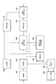
- FIG. 2 is a block diagram illustrating a functional configuration example of the image encoding device.
- FIG. 3 is a block diagram illustrating a functional configuration example of the image decoding device. 9 is a flowchart of an encoding process. 15 is a flowchart of a decoding process.
- FIG. 2 is a block diagram illustrating a hardware configuration example of a computer device.
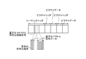
- FIG. 3 is a diagram showing a configuration example of a bit stream.
- FIG. 3 is a diagram showing a configuration example of a bit stream.
- FIG. 3 is a diagram showing a configuration example of a bit stream.
- FIG. 3 is a diagram showing a configuration example of a bit stream.
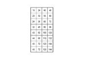
- FIG. 5 is a diagram illustrating an example of a quantization vector for generating a quantization matrix.
- FIG. 5 is a diagram illustrating an example of a quantization vector for generating a quantization matrix.
- FIG. 5 is a diagram illustrating an example of a quantization vector for generating a quantization matrix.
- FIG. 5 is a diagram illustrating an example of a quantization vector for generating a quantization matrix.
- FIG. 5 is a diagram illustrating an example of a quantization vector for generating a quantization matrix.
- FIG. 5 is a diagram illustrating an example of a quantization vector for generating a quantization matrix.
- FIG. 5 is a diagram illustrating an example of a quantization vector for generating a quantization matrix.
- FIG. 5 is a diagram illustrating an example of a quantization vector for generating a quantization matrix.
- FIG. 5 is a diagram illustrating an example of a quantization vector for generating a quantization matrix.
- FIG. 5 is a diagram illustrating an example of a quantization vector for generating a quantization matrix.
- FIG. 5 is a diagram illustrating an example of a quantization vector for generating a quantization matrix.
- FIG. 5 is a diagram illustrating an example of a quantization vector for generating a quantization matrix.
- FIG. 5 is a diagram illustrating an example of a quantization vector for generating a quantization matrix.
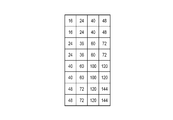
- the figure which shows an example of a quantization matrix. The figure which shows an example of a quantization matrix.
- the figure which shows an example of a quantization matrix. which shows an example of a quantization matrix.
- the figure which shows an example of a quantization matrix The figure which shows an example of a quantization matrix.
- the dividing unit 102 divides an input image into a plurality of basic blocks (CTU).
- the input image may be an image of each frame that constitutes a moving image captured by the imaging device, may be a still image that is periodically or irregularly captured by the imaging device, or may be a single image. Image. Further, such an input image may be obtained directly or indirectly from an imaging device, or may be obtained from a device holding an input image group.
- the size of the basic block is not limited to a specific size, and may be an arbitrary size having a maximum size of, for example, 64 pixels ⁇ 64 pixels.
- the prediction unit 104 divides the basic block into a plurality of sub-blocks (blocks smaller in size than the basic block), and performs intra-frame prediction (intra prediction), inter-frame prediction (inter prediction), and the like on a sub-block basis. Generate a prediction image. Then, the prediction unit 104 obtains a difference between the input image newly input from the division unit 102 and the prediction image in units of sub-blocks as a prediction error, and calculates the prediction error and information necessary for prediction (for example, a sub-block division method, Prediction mode, motion vector, etc.).
- the generation unit 103 includes a one-dimensional vector (quantized vector) having M (M is an integer of 2 or more) elements and a one-dimensional vector (quantized vector) having N (N is an integer of 2 or more) elements. ) Is used to generate a quantization matrix having a size of M ⁇ N.
- the quantization vector used to generate the quantization matrix may be acquired by any acquisition method.
- the quantization matrix refers to a matrix having a component for weighting a transform coefficient after performing an orthogonal transform according to a frequency component. Note that the quantization matrix may be called a quantization scaling list.
- the generation unit 103 may obtain the quantization vector generated by the user specifying the value of each element, or may obtain the quantization vector generated according to the image characteristics of the input image. , A quantization vector having an element for which an initial value is set may be obtained.
- Transform / quantization section 105 generates a transform coefficient group for each sub-block by performing orthogonal transform on the prediction error for each sub-block. Then, the transform / quantization unit 105 performs quantization on the transform coefficient group of each sub-block using the quantization matrix generated by the generation unit 103, thereby obtaining a quantized transform coefficient group for each sub-block.
- the inverse quantization / inverse transform unit 106 performs inverse quantization on the quantized transform coefficient group for each sub-block using the quantization matrix generated by the generation unit 103, and thereby obtains the transform coefficient for each sub-block. Create a group. Then, the inverse quantization / inverse transform unit 106 performs an inverse orthogonal transform on the transform coefficient group of each sub-block, thereby generating a prediction error of each sub-block.
- the reproduction unit 107 uses the prediction information output from the prediction unit 104 to generate a predicted image by appropriately referring to a reproduced image group stored in the frame memory 108. Then, the reproducing unit 107 generates (reproduces) a reproduced image from the predicted image and the prediction error of each sub-block obtained by the inverse quantization / inverse transforming unit 106, and stores the generated reproduced image in the frame memory 108. Store.
- the filter unit 109 performs an in-loop filter process such as a deblocking filter and a sample adaptive offset on each of the reproduced images stored in the frame memory 108, and outputs the processed images to the frame memory 108.
- the output destination of the reproduced image by the filter unit 109 is not limited to a specific output destination.
- the reproduced image may be output to an external device via a network to which the image encoding device is connected.
- the encoding unit 110 encodes the quantized transform coefficient group quantized by the transform / quantization unit 105 and the prediction information output from the prediction unit 104, thereby obtaining the quantized transform coefficient group. Encoded data including an encoding result and an encoding result of prediction information is generated.
- the encoding unit 113 encodes and encodes the quantization vectors (the quantization vector having M elements and the quantization vector having N elements) used by the generation unit 103 to generate the quantization matrix. Generate data.
- the integrated encoding unit 111 generates a bit stream in which the encoded data generated by the encoding unit 110 and the encoded data generated by the encoding unit 113 are integrated, and outputs the generated bit stream. .
- the output destination of the bit stream is not limited to a specific output destination.
- the bit stream may be output to a memory included in the image encoding device, may be output to an external device via a network to which the image encoding device is connected, or may be used for broadcasting. It may be transmitted to the outside.
- the generation unit 103 generates a quantization matrix prior to the encoding process on the input image (for example, prior to the quantization process using the quantization matrix).
- the generation unit 103 generates a quantization matrix having a size corresponding to the size of the sub-block to be coded.
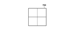
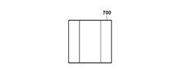
- FIGS. 7A to 7F show an example of the types of sub-block division.
- FIG. 7B shows an example of a conventional square sub-block division, in which a basic block 700 of 8 ⁇ 8 pixels is divided into sub-blocks of 4 ⁇ 4 pixels.
- FIGS. 7C to 7F show examples of the types of rectangular sub-block division.
- the basic block 700 of 8 pixels ⁇ 8 pixels is divided into sub-blocks of 4 pixels (horizontal direction) ⁇ 8 pixels (vertical direction).
- the basic block 700 of 8 pixels ⁇ 8 pixels is divided into units of 8 pixels (horizontal direction) ⁇ 4 pixels (vertical direction).
- a basic block 700 of 8 pixels ⁇ 8 pixels is a sub-block of 2 pixels (horizontal direction) ⁇ 8 pixels (vertical direction), a sub-block of 4 pixels (horizontal direction) ⁇ 8 pixels (vertical direction), It is divided into sub-blocks of pixels (horizontal direction) ⁇ 8 pixels (vertical direction).
- a basic block 700 of 8 pixels ⁇ 8 pixels is a sub-block of 8 pixels (horizontal direction) ⁇ 2 pixels (vertical direction), a sub-block of 8 pixels (horizontal direction) ⁇ 4 pixels (vertical direction), and 8 sub-blocks. It is divided into sub-blocks of pixels (horizontal direction) ⁇ 2 pixels (vertical direction).
- the encoding process is performed using not only a square but also a rectangular sub-block.
- the generation unit 103 obtains a quantization vector having M elements and a quantization vector having N elements, and uses these quantization vectors to obtain M ⁇ N Is generated.
- the dividing unit 102 divides a basic block of 8 pixels ⁇ 8 pixels into units of vertically long sub-blocks of 4 pixels (horizontal direction) ⁇ 8 pixels (vertical direction) as shown in FIG. 7C. .
- the generation unit 103 to generate a quantization matrix in which the number of elements in the horizontal direction is “4” and the number of elements in the vertical direction is “8”, the generation unit 103 generates a quantization vector having four elements, And a quantization vector having the elements of Using a quantization vector having four elements and a quantization vector having eight elements, a quantization matrix in which the number of elements in the horizontal direction is “4” and the number of elements in the vertical direction is “8”
- the method for generating the will be described with reference to FIGS. 8A to 8L.
- FIGS. 8A, 8C, 8E, 8G, 8I, and 8K show an example of a quantization vector 800 having four elements
- FIGS. 8B, 8D, 8F, 8H, 8J, and 8L show eight elements.
- An example of the quantization vector 801 having the following is shown.
- the numerical value described in each rectangle is the value of each element in the quantization vector.
- FIGS. 8A to 8L several examples of a method of generating a quantization matrix will be described with reference to FIGS. 8A to 8L.
- the generation unit 103 calculates the value of the i-th (1 ⁇ i ⁇ 4) element from the left in the quantization vector 800 and the value of the j-th (1 ⁇ j ⁇ 8) element in the quantization vector 801 from the left. Find the product value (product value). Then, the generation unit 103 calculates the obtained product value as the position (i, j) in the quantization matrix (the horizontal position i and the vertical position when the position of the upper left corner of the quantization matrix is (1, 1)). j) is the value of the element.
- the product value of the value of the i-th element from the left in the quantization vector 800 of FIG. 8A and the value of the j-th element from the left in the quantization vector 801 of FIG. 8B is the element at the position (i, j).
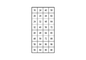
- FIG. 9A shows a quantization matrix having the value of.
- the generation unit 103 calculates the value of the i-th (1 ⁇ i ⁇ 4) element from the left in the quantization vector 800 and the value of the j-th (1 ⁇ j ⁇ 8) element in the quantization vector 801 from the left. Find the total value. Then, the generation unit 103 sets the sum as the value of the element at the position (i, j) in the quantization matrix.
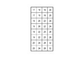
- the sum of the value of the i-th element from the left in the quantization vector 800 of FIG. 8C and the value of the j-th element from the left in the quantization vector 801 of FIG. FIG. 9B shows a quantization matrix used as the value of.
- the generation unit 103 calculates the value of the i-th (1 ⁇ i ⁇ 4) element from the left in the quantization vector 800 and the value of the j-th (1 ⁇ j ⁇ 8) element in the quantization vector 801 from the left. Find the total value. Then, the generation unit 103 sets the value obtained by adding the specified value to the total value as the value of the element at the position (i, j) in the quantization matrix.
- the prescribed value “16” is added to the sum of the value of the i-th element from the left of the quantization vector 800 in FIG. 8E and the value of the j-th element from the left of the quantization vector 801 in FIG. 8F.
- FIG. 9C shows a quantization matrix in which the value is the value of the element at the position (i, j).
- the generation unit 103 calculates the value of the i-th (1 ⁇ i ⁇ 4) element from the left in the quantization vector 800 and the value of the j-th (1 ⁇ j ⁇ 8) element in the quantization vector 801 from the left. Find the product value (product value). Then, the generation unit 103 calculates the value obtained by adding the specified value to the obtained product value to the position (i, j) in the quantization matrix (the horizontal It is the value of the element at the directional position i and the vertical position j).
- FIG. 9D shows a quantization matrix in which the values are the values of the elements at the position (i, j).
- the encoding unit 113 encodes each of the quantization vectors acquired by the generation unit 103 to generate the quantization matrix, and generates encoded data including an encoding result of each of the quantization vectors.
- the value of the element at the head (the leftmost element) and the difference value between the value of the element of interest other than the leftmost element and the value of the element on the left of the element of interest are encoded.
- the generation unit 103 encodes the quantization vector 800 in FIG. 8A
- the following values are acquired as encoding target values.
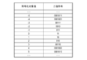
- the encoding unit 113 refers to the encoding table illustrated in FIG. 10A or the encoding table illustrated in FIG. 10B, specifies a binary code corresponding to each encoding target value, and specifies the specified binary code. Encode the sign.
- the configuration of the encoding table used for encoding is not limited to the encoding tables shown in FIGS. 10A and 10B.
- the value “4” of the leftmost element is used as the encoding target value.
- the present invention is not limited to this, and the difference between the value “4” of the leftmost element and a prescribed initial value (for example, 4) is calculated. It may be an encoding target value.
- the quantization vector having the number of elements “4” and the quantization vector having the number of elements “8” are encoded. Therefore, the code amount of data necessary for obtaining the quantization matrix can be reduced.
- the dividing unit 102 divides an input image into a plurality of basic blocks
- the prediction unit 104 divides a basic block into a plurality of sub-blocks, and performs intra prediction such as horizontal prediction and vertical prediction in sub-block units. Determine the prediction mode. Then, the prediction unit 104 generates a prediction image from the determined intra prediction mode and the encoded pixels, generates a prediction error from the input image and the prediction image, and outputs the prediction error to the transform / quantization unit 105. Output. On the other hand, the prediction unit 104 outputs “information necessary for prediction” such as sub-block division and intra prediction mode to the encoding unit 110 and the reproduction unit 107 as prediction information.
- the transform / quantization unit 105 generates a group of transform coefficients for each sub-block, and quantizes the group of transform coefficients using the quantization matrix generated by the generation unit 103. Generate a group of quantized transform coefficients for. For example, a quantized transform coefficient group is generated by performing a quantization process using the quantization matrix shown in FIG. 9A on the transform coefficient group of each sub-block shown in FIG. 7C.
- the inverse quantization / inverse transform unit 106 performs inverse quantization on the quantized transform coefficient group for each sub-block using the quantization matrix generated by the generation unit 103, and thereby obtains the transform coefficient for each sub-block. Create a group. Then, the inverse quantization / inverse transform unit 106 performs an inverse orthogonal transform on the transform coefficient group of each sub-block, thereby generating a prediction error of each sub-block.
- the reproduction unit 107 uses the prediction information output from the prediction unit 104 to generate a predicted image by appropriately referring to a reproduced image group stored in the frame memory 108. Then, the reproducing unit 107 generates a reproduced image from the predicted image and the prediction error of each sub-block obtained by the inverse quantization / inverse transforming unit 106, and stores the generated reproduced image in the frame memory 108.
- the filter unit 109 performs in-loop filter processing such as a deblocking filter and a sample adaptive offset on each of the reproduced images stored in the frame memory 108, and outputs the reproduced images.
- the encoding unit 110 performs entropy encoding on the quantized transform coefficient group quantized by the transform / quantization unit 105 and the prediction information output from the prediction unit 104 to obtain a quantized transform coefficient group. And coded data including the coding result of the prediction information and the coding result of the prediction information.
- the type of entropy coding is not limited to a specific type, and Golomb coding, arithmetic coding, Huffman coding, or the like can be used.
- the integrated encoding unit 111 multiplexes the encoded data generated by the encoding unit 110 and the encoded data generated by the encoding unit 113 to generate a bit stream, and outputs the generated bit stream. I do.
- FIG. 6A shows a configuration example of the bit stream according to the present embodiment.
- the sequence header includes encoded data of the quantization vector used to generate the quantization matrix, and is configured by encoding results of each element of the quantization vector.
- the quantization vector in FIG. 8A and the quantization vector in FIG. 8B have been encoded.
- the position in the bit stream of the encoded data of the quantization vector is not limited to the position shown in FIG. 8A, but may be a position in a picture header or another header.
- the quantization matrix corresponding to the quantization matrix can be updated by newly encoding the quantization vector.
- the bit stream (for example, in the sequence header) also includes information indicating a method of generating a quantization matrix from the quantization vector (for example, any of the above-described generation methods 1 to 4).
- step S301 the generation unit 103 generates a quantization matrix having a size of M ⁇ N by using a quantization vector having M elements and a quantization vector having N elements.
- step S302 the encoding unit 113 encodes each of the quantization vectors used to generate the quantization matrix in step S301 to generate encoded data.
- step S304 the dividing unit 102 divides the input image into a plurality of basic blocks.
- step S305 the prediction unit 104 selects an unselected basic block from among the plurality of basic blocks as a selected basic block. Then, the prediction unit 104 divides the selected basic block into a plurality of sub-blocks, performs prediction coding in sub-block units, obtains a prediction error, and acquires prediction information.
- step S306 the transform / quantization unit 105 generates a group of transform coefficients for each sub-block, and quantizes the group of transform coefficients using the quantization matrix generated in step S301. Generate a quantized transform coefficient group for the block.
- step S307 the inverse quantization / inverse transform unit 106 performs inverse quantization on the quantized transform coefficient group for each sub-block using the quantization matrix generated in step S301, thereby obtaining each sub-block. Is generated. Then, the inverse quantization / inverse transform unit 106 performs an inverse orthogonal transform on the transform coefficient group of each sub-block, thereby generating a prediction error of each sub-block.
- step S308 the reproducing unit 107 generates a predicted image by appropriately referring to the reproduced image group stored in the frame memory 108 using the prediction information obtained by the prediction unit 104 in step S305. Then, the reproducing unit 107 generates a reproduced image from the predicted image and the prediction error of each sub-block obtained by the inverse quantization / inverse transforming unit 106, and stores the generated reproduced image in the frame memory 108.
- step S309 the encoding unit 110 performs entropy encoding on the quantized transform coefficient group quantized in step S306 and the prediction information acquired by the prediction unit 104 in step S305, and performs encoding. Generate encrypted data. Then, the integrated encoding unit 111 multiplexes the encoded data generated by the encoding unit 110 and the encoded data such as the quantization vector generated by the encoding unit 113 in step S302 to generate a bit stream. I do.
- step S305 If the unselected basic block remains among the plurality of basic blocks, the process proceeds to step S305 via step S310. On the other hand, when all of the plurality of basic blocks have been selected as the selected basic block, the process proceeds to step S311 via step S310.
- step S311 the filter unit 109 performs in-loop filter processing such as a deblocking filter and a sample adaptive offset on each of the reproduced images stored in the frame memory 108, and outputs the processed images.
- in-loop filter processing such as a deblocking filter and a sample adaptive offset
- step S302 the one-dimensional quantization vector is encoded instead of the two-dimensional quantization matrix, thereby reducing the code amount of information necessary to obtain the quantization matrix. be able to. As a result, the data amount of the entire generated bit stream is reduced, so that the compression efficiency can be improved.
- FIG. 7C a case has been described in which a basic block of 8 pixels ⁇ 8 pixels is divided into units of vertically long sub-blocks of 4 pixels (horizontal direction) ⁇ 8 pixels (vertical direction).
- the sub-block division method is not limited to this.
- quad-tree division as shown in FIG. 7B, ternary tree division as shown in FIGS. 7E and 7F, or non-division as shown in FIG. 7A may be used.
- the generation unit 103 generates a quantization vector for a quantization matrix corresponding to the sub-block.
- the quantization vectors shown in FIGS. 8A to 8L may be applied to other types of sub-blocks. For example, for a sub-block of 8 pixels (horizontal direction) ⁇ 8 pixels (vertical direction) in FIG. 7A, the quantization vector having eight coefficients in FIG. 8B is applied for the horizontal direction and the vertical direction, respectively. That is, the vector of FIG. 8B is used twice.
- the quantization vector having four coefficients in FIG. 8A is applied for the horizontal direction and the vertical direction, respectively. That is, the vector of FIG. 8A is used twice.
- the quantization vector having eight coefficients in FIG. 8B is applied in the horizontal direction of the sub-block.
- the quantization vector having the four coefficients of FIG. 8A is applied in the vertical direction of the sub-block.
- a combination of arbitrary two coefficients among the quantization vectors having four coefficients in FIG. Apply to For example, the first two coefficients of the four coefficients in FIG. 8A may be selected. Then, the quantization vector having eight coefficients in FIG. 8B is applied in the vertical direction of the sub-block.
- information on a method of generating a quantization vector applied to each type of sub-block is also encoded so as to be generated by an image decoding device described later.
- quantized vector groups (2, 4, 8, 16, and 32) of different numbers of coefficients may be prepared in the horizontal and vertical directions, respectively, and may be encoded. In this case, an identifiable index is given to each vector. Then, the indexes of the horizontal quantization vector and the vertical quantization vector are associated with each sub-block so that the desired vector is applied to the sub-block.
- ⁇ Modification> all the quantization vectors used for generating the quantization matrix are encoded. This is to notify the decoding side of the quantization vector required for generating the quantization matrix on the encoding side.
- the decoding side decodes the other quantized vector, generates one quantized vector from the decoded other quantized vector, and generates a quantized vector from the one quantized vector and the other quantized vector.
- a matrix can be generated.
- the decoding side may be notified of the quantization vector in FIG. 8I. That is, the decoding side can generate the quantization vector of FIG. 8J from the quantization vector of FIG. 8I, and generate, for example, the quantization matrix of FIG. 9E from the quantization vector of FIG. 8J and the quantization vector of FIG. 8I. it can.
- the quantization vector in FIG. 8I is encoded without encoding the quantization vector in FIG. 8J. This makes it possible to further reduce the code amount of data required to obtain the quantization matrix of FIG. 9E. Since the quantization vector of FIG. 8I can be generated from the quantization vector of FIG. 8J by a process reverse to the above-described interpolation process, the quantization vector of FIG. May be encoded. In this case, although the amount of code applied to the quantization matrix slightly increases, finer control of the quantization matrix can be performed.
- the method of generating one quantization vector from the other quantization vector is not limited to the above-described interpolation processing.
- the quantization matrix of FIG. 9F is generated by the above-described generation method 1 using the quantization vector of FIG. 8K and the quantization vector of FIG. 8L.
- the quantization vector of FIG. 8L may not be encoded, and the quantization vector of FIG. 8K may be encoded, whereby the code amount of data necessary to obtain the quantization matrix of FIG. 9F is obtained. Can be further reduced. Since the quantization vector in FIG. 8K can be generated from the quantization vector in FIG. 8L, the quantization vector in FIG. 8K is not encoded, and the quantization vector in FIG. 8L is encoded. May be. In this case, although the amount of code applied to the quantization matrix slightly increases, finer control of the quantization matrix can be performed.
- the quantization matrix is encoded without encoding the quantization matrix.
- the quantization matrix may be selectively encoded.
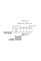
- the quantization vector coding according to the present embodiment and the conventional quantization matrix coding are selectively performed by newly introducing a quantization matrix coding information code. For example, when the quantization matrix coding information code indicates “0”, the one-dimensional quantization vector coding of the present embodiment is used, and the bit stream in FIG. 6B is generated. On the other hand, when the quantization matrix coding information code indicates “1”, the conventional two-dimensional quantization matrix coding is used, and the bit stream in FIG. 6C is generated.
- the quantization matrix coding information code indicates “0”, it may indicate that “quantization matrix is not used”. In this case, neither the quantization vector nor the quantization matrix is encoded. In such an example, when the quantization matrix coding information code indicates “1”, the one-dimensional quantization vector coding of the present embodiment is used, and the bit stream of FIG. 6B is generated. . When the quantization matrix coding information code indicates “2”, the conventional two-dimensional quantization matrix coding is used, and the bit stream in FIG. 6C is generated.
- the configuration may be such that the quantization vector coding of the present embodiment and the conventional quantization matrix coding can be switched for each quantization matrix. This makes it possible to selectively realize the quantization matrix code amount reduction and the quantization matrix control.
- one-dimensional quantization vector coding may be selected when the code amount at the time of coding of a conventional two-dimensional quantization matrix is expected to be reduced by a predetermined amount or more.
- a two-dimensional quantization matrix may be employed when a quantization vector cannot completely represent a high-resolution image or the like.
- an image decoding device that decodes a bit stream generated by the image encoding device in FIG. 1 will be described.
- the image decoding device according to the present embodiment may be a device integrated with the image encoding device in FIG. 1 or may be a separate device.
- an example of a functional configuration of the image decoding device according to the present embodiment will be described with reference to the block diagram of FIG.
- the separation unit 201 obtains the bit stream generated by the image encoding device, and separates each piece of the information included in the bit stream from the bit stream. That is, the demultiplexing unit 201 separates each piece of the information included in the bit stream by performing an operation reverse to the operation performed by the unified encoding unit 111.
- bit stream may be a bit stream of an image of each frame constituting a moving image, or a bit stream of each still image that is periodically or irregularly captured by the imaging device. Alternatively, it may be a bit stream of one image. Further, such a bit stream may be obtained directly or indirectly from an image encoding device, or may be obtained from a device that holds a group of bit streams.
- the reproduction unit 209 decodes the encoded data of the quantization vector to restore (reproduce) the quantization vector, and generates a quantization matrix from the restored quantization vector.
- Information indicating a method of generating the quantization matrix from the quantization vector (for example, any of the above-described generation methods 1 to 4) is stored in the header of the above-described bit stream. Therefore, the reproducing unit 209 generates a quantization matrix from the quantization vector according to the method indicated by this information. If a method of generating a quantization vector from a quantization vector is known in advance between the image encoding device and the image decoding device, information indicating a method of generating a quantization matrix from the quantization vector is included in a header or the like. You do not need to include it.
- the decoding unit 203 decodes the encoded data including the encoding result of the quantized transform coefficient group and the encoding result of the prediction information by performing an operation reverse to the operation performed by the encoding unit 110, Acquire the quantized transform coefficient group and prediction information.
- the inverse quantization / inverse transformation unit 204 operates in the same manner as the above-described inverse quantization / inverse transformation unit 106, and performs the quantization generated by the reproduction unit 209 on the quantized transform coefficient group acquired by the decoding unit 203. By performing inverse quantization using a matrix, a group of transform coefficients for each sub-block is generated. Then, the inverse quantization / inverse transform unit 204 generates a prediction error of each sub-block by performing an inverse orthogonal transform on the transform coefficient group of each sub-block.
- the reproducing unit 205 operates in the same manner as the above-described reproducing unit 107, and generates a predicted image by appropriately referring to the reproduced image group stored in the frame memory 206 using the prediction information decoded by the decoding unit 203. Then, the reproducing unit 205 generates (reproduces) a reproduced image from the predicted image and the prediction error of each subblock obtained by the inverse quantization / inverse transforming unit 204, and stores the generated reproduced image in the frame memory 206. Store.
- the filter unit 207 operates in the same manner as the filter unit 109 described above. That is, the filter unit 207 performs in-loop filter processing such as a deblocking filter and a sample adaptive offset on each of the reproduced images stored in the frame memory 206, and outputs the reproduced images to the frame memory 206.
- the output destination of the reproduced image by the filter unit 207 is not limited to a specific output destination.
- the reproduced image may be output to an external device via a network to which the image decoding device is connected.
- the separation unit 201 obtains the bit stream in FIG. 6A and separates each piece of the information included in the bit stream from the bit stream. As a result, the separation unit 201 acquires a sequence header, encoded data including the encoded result of the quantized transform coefficient group and the encoded result of the prediction information, encoded data of the quantized vector, and the like.
- the encoded data of the quantized vector is the encoded data of the quantized vector of FIG. 8A and the encoded data of the quantized vector of FIG. 8B.
- the reproducing unit 209 decodes the encoded data of the quantized vector and restores the quantized vector of FIG. 8A and the quantized vector of FIG. 8B.
- the decoding a process opposite to the encoding of the quantization vector is performed, and the encoding target value corresponding to the binary code is specified with reference to the encoding table illustrated in FIG. 10A and the encoding table illustrated in FIG. 10B.
- the reproduction unit 209 acquires “information indicating a method of generating a quantization matrix from a quantization vector (here, the above-described generation method 1)” from the sequence header.
- the reproducing unit 209 generates the quantization matrix of FIG. 9A from the quantization vector of FIG. 8A and the quantization vector of FIG. 8B according to the generation method 1 indicated by the information.
- the encoding table used for decoding the quantization vector only needs to be used for encoding the quantization vector, and is not limited to the encoding tables shown in FIGS. 10A and 10B.
- FIGS. 8A to 8L When the quantization vectors shown in FIGS. 8A to 8L are applied to sub-blocks other than 4 pixels (horizontal direction) ⁇ 8 pixels (vertical direction), first, a method of generating a quantization vector applied to each type of sub-block is described. Decrypts information about A quantization vector for each sub-block is generated based on the quantization vector generation method. Similarly to a sub-block of 4 pixels (horizontal direction) ⁇ 8 pixels (vertical direction), a quantization matrix corresponding to each sub-block is generated from a bit stream based on information on a generation method based on a quantization vector. .
- the operation of the decoding unit 203 is as described above.
- the inverse quantization / inverse transform unit 204 performs inverse quantization on the quantized transform coefficient group acquired by the decoding unit 203 using the quantization matrix of FIG. A transform coefficient group for each sub-block of 7C is generated. Then, the inverse quantization / inverse transform unit 204 generates a prediction error of each sub-block by performing an inverse orthogonal transform on the transform coefficient group of each sub-block.
- the operations of the reproduction unit 205 and the filter unit 207 are as described above.
- step S401 the separation unit 201 acquires a bit stream, and separates each piece of the information included in the bit stream from the bit stream.
- step S402 the reproducing unit 209 decodes the encoded data of the quantization vector to restore the quantization vector, and generates a quantization matrix from the restored quantization vector.
- step S403 the decoding unit 203 decodes the encoded data including the encoded result of the quantized transform coefficient group and the encoded result of the prediction information, and acquires the quantized transform coefficient group and the prediction information.
- step S404 the inverse quantization / inverse transformation unit 204 performs inverse quantization on the quantized transform coefficient group acquired in step S403 using the quantization matrix generated in step S402, and Generate a group of transform coefficients for the block. Then, the inverse quantization / inverse transform unit 204 generates a prediction error of each sub-block by performing an inverse orthogonal transform on the transform coefficient group of each sub-block.
- step S405 the reproducing unit 205 generates a predicted image by appropriately referring to the reproduced image group stored in the frame memory 206 using the prediction information acquired in step S403. Then, the reproducing unit 205 generates (reproduces) a reproduced image from the predicted image and the prediction error of each sub-block generated in step S404, and stores the generated reproduced image in the frame memory 206.
- step S407 the filter unit 207 performs an in-loop filter process such as a deblocking filter or a sample adaptive offset on each of the reproduced images stored in the frame memory 206, and outputs the processed images to the frame memory 206.
- an in-loop filter process such as a deblocking filter or a sample adaptive offset
- ⁇ Modification> As described above, when one of the quantization vectors required for generating the quantization matrix on the encoding side can be generated from the other, it is not necessary to encode both quantization vectors. That is, it is not necessary to encode one quantized vector and encode the other quantized vector.
- the decoding side generates another quantization vector from the decoded quantization vector, and performs quantization using the decoded quantization vector and the quantization vector generated from the decoded quantization vector. Generate a matrix.
- the encoded data of the quantized vector of FIG. 8I is obtained as the encoded data of the quantized vector
- the encoded data is decoded to obtain the quantized vector of FIG. 8I.
- the quantization vector of FIG. 8J is generated from the quantization vector of FIG. 8I by the above-described interpolation processing, and the quantization matrix of FIG. 9E is generated from the quantization vector of FIG. 8I and the quantization vector of FIG. 8J.
- the quantized vector of FIG. 8I and the encoded data of the quantized vector of FIG. 8J are obtained as the encoded data of the quantized vector. If even the quantized vector of FIG. A quantization vector can be generated.
- the configuration is such that the encoded data of the quantization vector of FIG. 8J is acquired as the encoded data of the quantization vector. It is good.
- the encoded data of the quantization vector of FIG. 8J is decoded to obtain the quantization vector
- the quantization vector of FIG. 8I is generated from the quantization vector
- the quantization matrix of FIG. 9E is generated from the quantization vector. This is the same when the encoded data of the quantized vector of FIG. 8I and the encoded data of the quantized vector of FIG. 8J are obtained as the encoded data of the quantized vector.
- the encoded data of the quantized vector of FIG. 8K is obtained as the encoded data of the quantized vector
- the encoded data is decoded to obtain the quantized vector of FIG. 8K.
- the quantization vector of FIG. 8L is generated from the quantization vector of FIG. 8K by the above-described duplicate copy
- the quantization matrix of FIG. 9F is generated from the quantization vector of FIG. 8K and the quantization vector of FIG. 8L.
- the quantized vector of FIG. 8K and the encoded data of the quantized vector of FIG. 8L are obtained as the quantized vector encoded data. If even the quantized vector of FIG. A quantization vector can be generated.
- the quantization vector of FIG. 8K can be generated from the quantization vector of FIG. 8L, the configuration for acquiring the encoded data of the quantization vector of FIG. 8L as the encoded data of the quantization vector. It is good.
- the coded data of the quantization vector of FIG. 8L is decoded to obtain the quantization vector
- the quantization vector of FIG. 8K is generated from the quantization vector
- the quantization matrix of FIG. 9F is generated from the quantization vector. This is the same also when the encoded data of the quantized vector of FIG. 8K and the encoded data of the quantized vector of FIG. 8L are acquired as the encoded data of the quantized vector.
- the quantization matrix is not encoded and the bit stream obtained by encoding the quantization vector is decoded.
- the bit stream obtained by selectively encoding the quantization matrix is decoded. No problem.
- the quantization matrix coding information code (included in the sequence header) indicates “0”, the quantization vector coding of the present embodiment is used, and the bit stream of FIG. 6B is generated. Therefore, the decoding operation as described above is performed. Thereby, the bit stream of FIG. 6B is decoded.
- the quantization matrix coding information code indicates “1”
- the conventional quantization matrix coding is used and the bit stream shown in FIG. 6C is generated. Perform the operation.
- the above-mentioned different code assignment may be used. That is, when the quantization matrix coding information code indicates “0”, it may indicate that “quantization matrix is not used”. In this case, neither the quantization vector nor the quantization matrix is encoded. In such an example, when the quantization matrix coding information code indicates “1”, the one-dimensional quantization vector coding of the present embodiment is used, and the bit stream of FIG. 6B is generated. . When the quantization matrix coding information code indicates “2”, the conventional two-dimensional quantization matrix coding is used, and the bit stream in FIG. 6C is generated.
- the configuration may be such that the quantization vector decoding of the present embodiment and the conventional quantization matrix decoding can be switched in units of quantization matrix. In this case, the decoding operation is switched in units of quantization matrix. . As a result, it is possible to decode a bit stream in which quantization matrix code amount reduction and quantization matrix control are selectively realized.
- Each functional unit shown in FIG. 1 and each functional unit shown in FIG. 2 may be implemented by hardware, but each functional unit except the frame memories 108 and 206 may be implemented by software (computer program). good.
- a computer device that can execute the computer program is applicable to the above-described image encoding device and image decoding device.
- An example of a hardware configuration of a computer device applicable to the above-described image encoding device and image decoding device will be described with reference to the block diagram of FIG.
- the CPU 501 executes various processes using computer programs and data stored in the RAM 502 and the ROM 503. Accordingly, the CPU 501 controls the operation of the entire computer device, and executes or controls the processes described above as performed by the image encoding device and the image decoding device to which the computer device is applied.
- the RAM 502 has an area for storing computer programs and data loaded from the ROM 503 and the external storage device 506, and data (such as an input image and a bit stream) externally received via an I / F (interface) 507. Further, the RAM 502 has a work area used when the CPU 501 executes various processes. As described above, the RAM 502 can appropriately provide various areas.
- the ROM 503 stores information that does not need to be rewritten, such as setting data of a computer device and a startup program.
- the operation unit 504 is configured by a user interface such as a keyboard, a mouse, and a touch panel, and can input various instructions to the CPU 501 by operating the user.
- a user interface such as a keyboard, a mouse, and a touch panel
- the display unit 505 includes a liquid crystal screen, a touch panel screen, and the like, and can display a processing result of the CPU 501 as an image, characters, or the like.
- the display unit 505 may be a projection device that projects images and characters.
- the external storage device 506 is a large-capacity information storage device such as a hard disk drive.
- the external storage device 506 stores an OS (Operating System), a computer program and data for causing the CPU 501 to execute or control each of the above-described processes performed by the image encoding device and the image decoding device.
- the computer programs stored in the external storage device 506 include computer programs for causing the CPU 501 to realize the functions of the functional units (excluding the frame memories 108 and 206) illustrated in FIGS.
- the data stored in the external storage device 506 includes information handled as known information in the above description.
- the computer programs and data stored in the external storage device 506 are appropriately loaded into the RAM 502 under the control of the CPU 501, and are processed by the CPU 501.
- the frame memories 108 and 206 can be implemented by the RAM 502 and the external storage device 506.
- the I / F 507 is an interface for performing data communication with an external device. For example, an input image or a bit stream is received via the I / F 507 and stored in the RAM 502 or the external storage device 506. You. Also, the bit stream generated by the image encoding device or the image decoded by the image decoding device is transmitted to an external device (display device, server device, or the like) via the I / F 507. good.
- the CPU 501, the RAM 502, the ROM 503, the operation unit 504, the display unit 505, the external storage device 506, and the I / F 507 are all connected to the bus 508.
- the configuration illustrated in FIG. 5 is merely an example of a hardware configuration of a computer device that can be applied to the above-described image encoding device and image decoding device, and can be appropriately changed or modified.
- the numerical values and the processing order used in the description of each of the above-described embodiments and the modified examples are merely examples.
- the encoding / decoding processing of each of the above-described embodiments and modifications is an example of encoding / decoding processing including processing of quantizing / dequantizing a sub-block using a quantization matrix.
- the present invention is not limited to the encoding / decoding processing described in each of the above embodiments and modifications.
- the present invention supplies a program for realizing one or more functions of the above-described embodiments to a system or an apparatus via a network or a storage medium, and one or more processors in a computer of the system or the apparatus read and execute the program. It can also be realized by the following processing. Further, it can be realized by a circuit (for example, an ASIC) that realizes one or more functions.
- a circuit for example, an ASIC
Landscapes
- Engineering & Computer Science (AREA)
- Multimedia (AREA)
- Signal Processing (AREA)
- Compression Or Coding Systems Of Tv Signals (AREA)
Abstract
M(Mは2以上の整数)個の要素を有する第1の1次元ベクトルと、N(Nは2以上の整数)個の要素を有する第2の1次元ベクトルと、を用いて、M×Nのサイズを有する量子化マトリクスを生成する。M画素×N画素のサイズを有するサブブロックに対する直交変換で得られる変換係数群を量子化マトリクスを用いて量子化する。
Description
本発明は、画像の符号化/復号技術に関するものである。
動画像の圧縮記録の符号化方式として、HEVC(High Efficiency Video Coding)符号化方式(以下、HEVCと記す)が知られている。HEVCでは符号化効率向上のため、従来のマクロブロック(16×16画素)より大きなサイズの基本ブロックが採用された。この大きなサイズの基本ブロックはCTU(Coding Tree Unit)と呼ばれ、そのサイズは最大64×64画素である。CTUはさらに予測や変換を行う単位となるサブブロックに分割される。
また、HEVCにおいては、量子化マトリクスと呼ばれる、直交変換を施した後の係数(以下、直交変換係数と記す)を周波数成分に応じて重み付けするマトリクスを用いた処理が用いられている。人間の視覚には劣化が目立ちにくい高周波成分のデータをより削減することで、画質を維持しながら圧縮効率を高めることが可能となっている。特許文献1には、このような量子化マトリクスを符号化する技術が開示されている。
近年、HEVCの後継としてさらに高効率な符号化方式の国際標準化を行う活動が開始された。JVET(Joint Video Experts Team)がISO/IECとITU-Tの間で設立され、VVC(Versatile Video Coding)符号化方式(以下、VVC)として標準化が進められている。符号化効率向上のため、従来の正方形サブブロックベースのイントラ予測・直交変換方法に加え、長方形サブブロックベースのイントラ予測・直交変換方法が検討されている。
VVCにおいても、HEVCと同様に量子化マトリクスの導入が検討されている。さらにVVCでは、正方形だけでなく長方形のサブブロック分割およびそれに対応した直交変換の形状が検討されている。HEVCではサポートされている直交変換の大きさは、4×4、8×8、16×16、32×32の4通りのみであったが、VVCではこれらを二分木、三分木分割したサブブロックや直交変換が検討されており、より多くの種類に対応する必要がある。また、それぞれの直交変換係数の分布は直交変換の形状によって異なるため、直交変換の形状に応じて最適な量子化マトリクスは異なる。そのため、最適な画質での符号化を実現するためには、それぞれの直交変換に適した量子化マトリクスの設定が必要となる。本発明では、直交変換に適した量子化マトリクスを得るためのデータ量を軽減させるための技術を提供する。
本発明の一様態は、M(Mは2以上の整数)個の要素を有する第1の1次元ベクトルと、N(Nは2以上の整数)個の要素を有する第2の1次元ベクトルと、を用いて、M×Nのサイズを有する量子化マトリクスを生成する生成手段と、M画素×N画素のサイズを有するサブブロックに対する直交変換で得られる変換係数群を前記量子化マトリクスを用いて量子化する量子化手段とを備えることを特徴とする。
本発明によれば、直交変換に適した量子化マトリクスを得るためのデータ量を軽減させることができる。
本発明のその他の特徴及び利点は、添付図面を参照とした以下の説明により明らかになるであろう。なお、添付図面においては、同じ若しくは同様の構成には、同じ参照番号を付す。
添付図面は明細書に含まれ、その一部を構成し、本発明の実施の形態を示し、その記述と共に本発明の原理を説明するために用いられる。
画像符号化装置の機能構成例を示すブロック図。
画像復号装置の機能構成例を示すブロック図。
符号化処理のフローチャート。
復号処理のフローチャート。
コンピュータ装置のハードウェア構成例を示すブロック図。
ビットストリームの構成例を示す図。
ビットストリームの構成例を示す図。
ビットストリームの構成例を示す図。
サブブロックの分割の種類の一例を示す図。
サブブロックの分割の種類の一例を示す図。
サブブロックの分割の種類の一例を示す図。
サブブロックの分割の種類の一例を示す図。
サブブロックの分割の種類の一例を示す図。
サブブロックの分割の種類の一例を示す図。
量子化マトリクスを生成するための量子化ベクトルの一例を示す図。
量子化マトリクスを生成するための量子化ベクトルの一例を示す図。
量子化マトリクスを生成するための量子化ベクトルの一例を示す図。
量子化マトリクスを生成するための量子化ベクトルの一例を示す図。
量子化マトリクスを生成するための量子化ベクトルの一例を示す図。
量子化マトリクスを生成するための量子化ベクトルの一例を示す図。
量子化マトリクスを生成するための量子化ベクトルの一例を示す図。
量子化マトリクスを生成するための量子化ベクトルの一例を示す図。
量子化マトリクスを生成するための量子化ベクトルの一例を示す図。
量子化マトリクスを生成するための量子化ベクトルの一例を示す図。
量子化マトリクスを生成するための量子化ベクトルの一例を示す図。
量子化マトリクスを生成するための量子化ベクトルの一例を示す図。
量子化マトリクスの一例を示す図。
量子化マトリクスの一例を示す図。
量子化マトリクスの一例を示す図。
量子化マトリクスの一例を示す図。
量子化マトリクスの一例を示す図。
量子化マトリクスの一例を示す図。
符号化テーブルの構成例を示す図。
符号化テーブルの構成例を示す図。
以下、添付図面を参照し、本発明の実施形態について説明する。なお、以下説明する実施形態は、本発明を具体的に実施した場合の一例を示すもので、特許請求の範囲に記載した構成の具体的な実施形態の1つである。
先ず、本実施形態に係る画像符号化装置の機能構成例について、図1のブロック図を用いて説明する。分割部102は、入力画像を複数の基本ブロック(CTU)に分割する。入力画像は、撮像装置が撮像した動画像を構成する各フレームの画像であっても良いし、撮像装置が定期的若しくは不定期的に撮像したそれぞれの静止画像であっても良いし、1枚の画像であっても良い。また、このような入力画像は撮像装置から直接的若しくは間接的に取得するようにしても良いし、入力画像群を保持している装置から取得するようにしても良い。また、基本ブロックのサイズについては特定のサイズに限らず、例えば、64画素×64画素を最大サイズとする任意のサイズであっても良い。
予測部104は、基本ブロックを複数のサブブロック(基本ブロックよりも小さいサイズのブロック)に分割し、サブブロック単位でフレーム内予測(イントラ予測)やフレーム間予測(インター予測)等を行うことで予測画像を生成する。そして予測部104は、新たに分割部102から入力された入力画像とサブブロック単位の予測画像との差分を予測誤差として求め、該予測誤差と、予測に必要な情報(例えばサブブロック分割方法、予測モード、動きベクトル等)である予測情報と、を出力する。
生成部103は、M(Mは2以上の整数)個の要素を有する1次元ベクトル(量子化ベクトル)と、N(Nは2以上の整数)個の要素を有する1次元ベクトル(量子化ベクトル)と、を用いて、M×Nのサイズを有する量子化マトリクスを生成する。量子化マトリクスを生成するために用いる量子化ベクトルは、どのような取得方法で取得しても良い。量子化マトリクスとは、直交変換を施した後の変換係数に対して、周波数成分に応じて重み付けするための成分を有するマトリクスのことを指す。なお、量子化マトリクスは、量子化スケーリングリストと呼ばれることもある。
例えば生成部103は、ユーザが各要素の値を指定することで生成した量子化ベクトルを取得しても良いし、入力画像の画像特性に応じて生成した量子化ベクトルを取得しても良いし、初期値が設定された要素を有する量子化ベクトルを取得しても良い。
変換・量子化部105は、サブブロックごとの予測誤差に対して直交変換を行うことで、それぞれのサブブロックに対する変換係数群を生成する。そして変換・量子化部105は、それぞれのサブブロックの変換係数群に対して、生成部103が生成した量子化マトリクスを用いて量子化を行うことで、各サブブロックに対する量子化済み変換係数群を生成する。
逆量子化・逆変換部106は、各サブブロックに対する量子化済み変換係数群に対して、生成部103が生成した量子化マトリクスを用いて逆量子化を行うことで、各サブブロックに対する変換係数群を生成する。そして逆量子化・逆変換部106は、それぞれのサブブロックの変換係数群に対して逆直交変換を行うことで、それぞれのサブブロックの予測誤差を生成する。
再生部107は、予測部104から出力された予測情報を用いて、フレームメモリ108に格納されている再生画像群を適宜参照して予測画像を生成する。そして再生部107は、該予測画像と、逆量子化・逆変換部106により得られる各サブブロックの予測誤差と、から再生画像を生成(再生)し、該生成した再生画像をフレームメモリ108に格納する。
フィルタ部109は、フレームメモリ108に格納されているそれぞれの再生画像に対し、デブロッキングフィルタやサンプルアダプティブオフセットなどのインループフィルタ処理を行ってからフレームメモリ108に対して出力する。なお、フィルタ部109による再生画像の出力先については特定の出力先に限らない。例えば、再生画像は画像符号化装置が接続されているネットワークを介して外部の装置に対して出力しても良い。
符号化部110は、変換・量子化部105により量子化された量子化済み変換係数群と、予測部104から出力された予測情報と、を符号化することで、量子化済み変換係数群の符号化結果と、予測情報の符号化結果と、を含む符号化データを生成する。
符号化部113は、生成部103が量子化マトリクスを生成するために用いた量子化ベクトル(M個の要素を有する量子化ベクトルとN個の要素を有する量子化ベクトル)を符号化して符号化データを生成する。
統合符号化部111は、符号化部110により生成された符号化データと、符号化部113により生成された符号化データと、を統合したビットストリームを生成し、該生成したビットストリームを出力する。
なお、ビットストリームの出力先については特定の出力先に限らない。例えば、ビットストリームは、画像符号化装置が有するメモリに出力しても良いし、画像符号化装置が接続されているネットワークを介して外部の装置に対して出力しても良いし、放送用として外部に送信しても良い。
次に、図1に示した各機能部の動作について、具体例を挙げて説明する。以下では説明を簡単にするために、イントラ予測符号化の処理のみを説明するが、これに限定されずインター予測符号化の処理においても適用可能である。
生成部103は、入力画像に対する符号化処理に先立ち(例えば、量子化マトリクスを用いた量子化処理に先立ち)、量子化マトリクスを生成する。生成部103は、符号化を行うサブブロックのサイズに応じたサイズを有する量子化マトリクスを生成する。
図7A~7Fにサブブロックの分割の種類の一例を示す。図7Aは、サブブロックに分割されていない8画素×8画素の基本ブロック700(=サブブロック)を示す。図7Bは、従来の正方形サブブロック分割の一例を表しており、8画素×8画素の基本ブロック700が4画素×4画素のサブブロックを単位に分割されている。
図7C~7Fは、長方形サブブロック分割の種類の一例を表している。図7Cでは8画素×8画素の基本ブロック700は、4画素(水平方向)×8画素(垂直方向)のサブブロックを単位に分割されている。また、図7Dでは8画素×8画素の基本ブロック700は、8画素(水平方向)×4画素(垂直方向)のサブブロックを単位に分割されている。
図7Eでは、8画素×8画素の基本ブロック700は、2画素(水平方向)×8画素(垂直方向)のサブブロック、4画素(水平方向)×8画素(垂直方向)のサブブロック、2画素(水平方向)×8画素(垂直方向)のサブブロック、に分割されている。
図7Fでは、8画素×8画素の基本ブロック700は、8画素(水平方向)×2画素(垂直方向)のサブブロック、8画素(水平方向)×4画素(垂直方向)のサブブロック、8画素(水平方向)×2画素(垂直方向)のサブブロック、に分割されている。
このように、図7C~7Fに示す如く、正方形だけではなく、長方形のサブブロックも用いて符号化処理を行っている。
M画素(水平方向)×N画素(垂直方向)のサイズを有するサブブロックの変換係数群の量子化には、水平方向の要素数が「M」で垂直方向の要素数が「N」である量子化マトリクスが必要である。本実施形態ではこの場合、生成部103は、M個の要素を有する量子化ベクトルと、N個の要素を有する量子化ベクトルと、を取得し、これらの量子化ベクトルを用いて、M×Nのサイズを有する量子化マトリクスを生成する。
以下では、分割部102が、図7Cに示す如く、8画素×8画素の基本ブロックを4画素(水平方向)×8画素(垂直方向)の縦長のサブブロックを単位に分割するケースについて説明する。この場合、生成部103は、水平方向の要素数が「4」で垂直方向の要素数が「8」である量子化マトリクスを生成するべく、4個の要素を有する量子化ベクトルと、8個の要素を有する量子化ベクトルと、を取得する。4個の要素を有する量子化ベクトルと、8個の要素を有する量子化ベクトルと、を用いて、水平方向の要素数が「4」で垂直方向の要素数が「8」である量子化マトリクスを生成する方法について図8A~8Lを用いて説明する。
図8A、8C、8E、8G、8I、8Kには4個の要素を有する量子化ベクトル800の一例が示されており、図8B、8D、8F、8H、8J、8Lには8個の要素を有する量子化ベクトル801の一例が示されている。各矩形の中に記されている数値は、量子化ベクトルにおける各要素の値である。以下では、図8A~8Lを用いて量子化マトリクスの生成方法として幾つかの例を挙げて説明する。
<量子化マトリクスの生成方法1>
生成部103は、量子化ベクトル800において左からi(1≦i≦4)番目の要素の値と、量子化ベクトル801において左からj(1≦j≦8)番目の要素の値と、の積の値(積値)を求める。そして生成部103は、該求めた積値を、量子化マトリクスにおいて位置(i,j)(量子化マトリクスの左上隅の位置を(1、1)としたときの水平方向位置i及び垂直方向位置j)における要素の値とする。
生成部103は、量子化ベクトル800において左からi(1≦i≦4)番目の要素の値と、量子化ベクトル801において左からj(1≦j≦8)番目の要素の値と、の積の値(積値)を求める。そして生成部103は、該求めた積値を、量子化マトリクスにおいて位置(i,j)(量子化マトリクスの左上隅の位置を(1、1)としたときの水平方向位置i及び垂直方向位置j)における要素の値とする。
例えば、図8Aの量子化ベクトル800において左からi番目の要素の値と、図8Bの量子化ベクトル801において左からj番目の要素の値と、の積値を位置(i,j)における要素の値とする量子化マトリクスを図9Aに示す。
<量子化マトリクスの生成方法2>
生成部103は、量子化ベクトル800において左からi(1≦i≦4)番目の要素の値と、量子化ベクトル801において左からj(1≦j≦8)番目の要素の値と、の合計値を求める。そして生成部103は、該合計値を、量子化マトリクスにおいて位置(i,j)における要素の値とする。
生成部103は、量子化ベクトル800において左からi(1≦i≦4)番目の要素の値と、量子化ベクトル801において左からj(1≦j≦8)番目の要素の値と、の合計値を求める。そして生成部103は、該合計値を、量子化マトリクスにおいて位置(i,j)における要素の値とする。
例えば、図8Cの量子化ベクトル800において左からi番目の要素の値と、図8Dの量子化ベクトル801において左からj番目の要素の値と、の合計値を位置(i,j)における要素の値とする量子化マトリクスを図9Bに示す。
<量子化マトリクスの生成方法3>
生成部103は、量子化ベクトル800において左からi(1≦i≦4)番目の要素の値と、量子化ベクトル801において左からj(1≦j≦8)番目の要素の値と、の合計値を求める。そして生成部103は、該合計値に規定値を加えた値を、量子化マトリクスにおいて位置(i,j)における要素の値とする。
生成部103は、量子化ベクトル800において左からi(1≦i≦4)番目の要素の値と、量子化ベクトル801において左からj(1≦j≦8)番目の要素の値と、の合計値を求める。そして生成部103は、該合計値に規定値を加えた値を、量子化マトリクスにおいて位置(i,j)における要素の値とする。
例えば、図8Eの量子化ベクトル800の左からi番目の要素の値と、図8Fの量子化ベクトル801の左からj番目の要素の値と、の合計値に規定値「16」を加えた値を位置(i,j)における要素の値とする量子化マトリクスを図9Cに示す。
<量子化マトリクスの生成方法4>
生成部103は、量子化ベクトル800において左からi(1≦i≦4)番目の要素の値と、量子化ベクトル801において左からj(1≦j≦8)番目の要素の値と、の積の値(積値)を求める。そして生成部103は、該求めた積値に規定値を加えた値を、量子化マトリクスにおいて位置(i,j)(量子化マトリクスの左上隅の位置を(1、1)としたときの水平方向位置i及び垂直方向位置j)における要素の値とする。
生成部103は、量子化ベクトル800において左からi(1≦i≦4)番目の要素の値と、量子化ベクトル801において左からj(1≦j≦8)番目の要素の値と、の積の値(積値)を求める。そして生成部103は、該求めた積値に規定値を加えた値を、量子化マトリクスにおいて位置(i,j)(量子化マトリクスの左上隅の位置を(1、1)としたときの水平方向位置i及び垂直方向位置j)における要素の値とする。
例えば、図8Gの量子化ベクトル800の左からi番目の要素の値と、図8Hの量子化ベクトル801の左からj番目の要素の値と、の積値に規定値「16」を加えた値を位置(i,j)における要素の値とする量子化マトリクスを図9Dに示す。
このように、M個の要素を有する量子化ベクトルのi(1≦i≦M)番目の要素の値と、N個の要素を有する量子化ベクトルのj(1≦j≦N)番目の要素の値と、に基づいて量子化マトリクスにおいて水平方向位置iおよび垂直方向位置jの要素の値を求める。
符号化部113は、生成部103が量子化マトリクスを生成するために取得したそれぞれの量子化ベクトルを符号化し、該それぞれの量子化ベクトルの符号化結果を含む符号化データを生成する。
量子化ベクトルの符号化では、先頭(左端の要素)の要素の値と、左端の要素以外の着目要素の値と該着目要素の左隣の要素の値との差分値と、を符号化する。例えば、生成部103が図8Aの量子化ベクトル800を符号化する場合には、先ず、以下の値を符号化対象値として取得する。
・ 左端の要素の値「4」
・ 左端から2番目の要素の値「5」と左端の要素の値「4」との差分値「1」
・ 左端から3番目の要素の値「7」と左端から2番目の要素の値「5」との差分値「2」
・ 左端から4番目の要素の値「8」と左端から3番目の要素の値「7」との差分値「1」
次に符号化部113は、図10Aに例示する符号化テーブルや図10Bに例示する符号化テーブルを参照し、それぞれの符号化対象値に対応する二値符号を特定し、該特定した二値符号を符号化する。なお、符号化に用いる符号化テーブルの構成は図10Aや図10Bに示した符号化テーブルに限らない。
・ 左端から2番目の要素の値「5」と左端の要素の値「4」との差分値「1」
・ 左端から3番目の要素の値「7」と左端から2番目の要素の値「5」との差分値「2」
・ 左端から4番目の要素の値「8」と左端から3番目の要素の値「7」との差分値「1」
次に符号化部113は、図10Aに例示する符号化テーブルや図10Bに例示する符号化テーブルを参照し、それぞれの符号化対象値に対応する二値符号を特定し、該特定した二値符号を符号化する。なお、符号化に用いる符号化テーブルの構成は図10Aや図10Bに示した符号化テーブルに限らない。
なお、上記の例では、左端の要素の値「4」を符号化対象値としたが、これに限らず、左端の要素の値「4」と規定の初期値(例えば4)との差分を符号化対象値としても良い。
このように本実施形態では、要素数が「32」の量子化マトリクスを符号化するのではなく、要素数が「4」の量子化ベクトル及び要素数が「8」の量子化ベクトルを符号化するので、量子化マトリクスを得るために必要なデータの符号量が削減できる。
図1に戻って、分割部102は、入力画像を複数の基本ブロックに分割し、予測部104は、基本ブロックを複数のサブブロックに分割し、サブブロック単位で水平予測や垂直予測などのイントラ予測モードを決定する。そして予測部104は、決定したイントラ予測モードおよび符号化済の画素から予測画像を生成し、入力された画像と予測画像から予測誤差を生成し、該予測誤差を変換・量子化部105に対して出力する。一方、予測部104は、サブブロック分割やイントラ予測モードなどの「予測に必要な情報」は予測情報として、符号化部110及び再生部107に対して出力する。変換・量子化部105は、それぞれのサブブロックに対する変換係数群を生成し、該変換係数群に対して、生成部103が生成した量子化マトリクスを用いて量子化を行うことで、各サブブロックに対する量子化済み変換係数群を生成する。例えば、図7Cに示したそれぞれのサブブロックの変換係数群に対して、図9Aに示した量子化マトリクスを用いた量子化処理を行うことで、量子化済み変換係数群を生成する。
逆量子化・逆変換部106は、各サブブロックに対する量子化済み変換係数群に対して、生成部103が生成した量子化マトリクスを用いて逆量子化を行うことで、各サブブロックに対する変換係数群を生成する。そして逆量子化・逆変換部106は、それぞれのサブブロックの変換係数群に対して逆直交変換を行うことで、それぞれのサブブロックの予測誤差を生成する。
再生部107は、予測部104から出力された予測情報を用いて、フレームメモリ108に格納されている再生画像群を適宜参照して予測画像を生成する。そして再生部107は、該予測画像と、逆量子化・逆変換部106により得られる各サブブロックの予測誤差と、から再生画像を生成し、該生成した再生画像をフレームメモリ108に格納する。
フィルタ部109は、フレームメモリ108に格納されているそれぞれの再生画像に対し、デブロッキングフィルタやサンプルアダプティブオフセットなどのインループフィルタ処理を行ってから出力する。
符号化部110は、変換・量子化部105により量子化された量子化済み変換係数群と予測部104から出力された予測情報とに対してエントロピー符号化を行って、量子化済み変換係数群の符号化結果と予測情報の符号化結果とを含む符号化データを生成する。エントロピー符号化の種別については特定の種別に限定せず、ゴロム符号化、算術符号化、ハフマン符号化などを用いることができる。
統合符号化部111は、符号化部110により生成された符号化データと、符号化部113により生成された符号化データと、を多重化してビットストリームを生成し、該生成したビットストリームを出力する。
本実施形態に係るビットストリームの構成例を図6Aに示す。シーケンスヘッダには、量子化マトリクスの生成に用いられた量子化ベクトルの符号化データが含まれており、量子化ベクトルの各要素の符号化結果で構成されている。ここでは、図8Aの量子化ベクトルおよび図8Bの量子化ベクトルが符号化されているものとしている。なお、量子化ベクトルの符号化データのビットストリームにおける位置は図8Aに示した位置に限らず、ピクチャヘッダやその他のヘッダ内の位置であっても良い。また、1つのシーケンスの中で量子化マトリクスの変更を行う場合、量子化マトリクスに対応する量子化ベクトルを新たに符号化することで更新することも可能である。この際、全ての量子化マトリクスを書き換えても良いし、書き換える量子化マトリクスに対応する量子化ベクトルのサイズを指定することでその一部を変更するようにすることも可能である。また、ビットストリームには(例えば、シーケンスヘッダには)、量子化ベクトルから量子化マトリクスを生成する方法(例えば上記の生成方法1~4の何れであるのか)を示す情報も含まれている。
次に、画像符号化装置が1フレーム分の入力画像について行う符号化処理について、同処理のフローチャートを示す図3を用いて説明する。ステップS301では、生成部103は、M個の要素を有する量子化ベクトルと、N個の要素を有する量子化ベクトルと、を用いて、M×Nのサイズを有する量子化マトリクスを生成する。
ステップS302では、符号化部113は、ステップS301において量子化マトリクスを生成するために用いたそれぞれの量子化ベクトルを符号化して符号化データを生成する。
ステップS304では、分割部102は、入力画像を複数の基本ブロックに分割する。ステップS305では予測部104は、複数の基本ブロックのうち未選択の基本ブロックを選択基本ブロックとして選択する。そして予測部104は、該選択基本ブロックを複数のサブブロックに分割し、サブブロック単位で予測符号化を行って予測誤差を求めると共に予測情報を取得する。
ステップS306で変換・量子化部105は、それぞれのサブブロックに対する変換係数群を生成し、該変換係数群に対し、ステップS301で生成した量子化マトリクスを用いて量子化を行うことで、各サブブロックに対する量子化済み変換係数群を生成する。
ステップS307では、逆量子化・逆変換部106は、各サブブロックに対する量子化済み変換係数群に対して、ステップS301で生成した量子化マトリクスを用いて逆量子化を行うことで、各サブブロックに対する変換係数群を生成する。そして逆量子化・逆変換部106は、それぞれのサブブロックの変換係数群に対して逆直交変換を行うことで、それぞれのサブブロックの予測誤差を生成する。
ステップS308では、再生部107は、ステップS305にて予測部104が取得した予測情報を用いて、フレームメモリ108に格納されている再生画像群を適宜参照して予測画像を生成する。そして再生部107は、該予測画像と、逆量子化・逆変換部106により得られる各サブブロックの予測誤差と、から再生画像を生成し、該生成した再生画像をフレームメモリ108に格納する。
ステップS309では、符号化部110は、ステップS306にて量子化された量子化済み変換係数群と、ステップS305にて予測部104が取得した予測情報と、に対してエントロピー符号化を行って符号化データを生成する。そして統合符号化部111は、符号化部110により生成された符号化データと、ステップS302において符号化部113により生成された量子化ベクトルなどの符号化データと、を多重化してビットストリームを生成する。
そして、複数の基本ブロックのうち未選択の基本ブロックが残っている場合には、処理はステップS310を介してステップS305に進む。一方、複数の基本ブロックの全てが選択基本ブロックとして選択された場合には、処理はステップS310を介してステップS311に進む。
ステップS311では、フィルタ部109は、フレームメモリ108に格納されているそれぞれの再生画像に対し、デブロッキングフィルタやサンプルアダプティブオフセットなどのインループフィルタ処理を行ってから出力する。
以上の構成と動作により、特にステップS302において、二次元の量子化マトリクスの代わりに一次元の量子化ベクトルを符号化することで、量子化マトリクスを得るために必要な情報の符号量を削減することができる。結果として、生成されるビットストリーム全体のデータ量を削減することになるため、圧縮効率を向上させることができる。
なお、本実施形態では、図7Cに示す如く、8画素×8画素の基本ブロックを4画素(水平方向)×8画素(垂直方向)の縦長のサブブロックを単位に分割するケースについて説明した。しかし、サブブロック分割方法はこれに限定されない。例えば、図7Bのような四分木分割や、図7E、7Fのような三分木分割または図7Aのような無分割を用いても構わない。図7C以外のサブブロック分割も用いられる場合には、生成部103では、サブブロックに対応する量子化マトリクスのための量子化ベクトルが生成される。
また、図8A~8Lに示す量子化ベクトルを他の種類のサブブロックに適用してもよい。例えば、図7Aの8画素(水平方向)x8画素(垂直方向)のサブブロックに関しては、図8Bの8つの係数を有する量子化ベクトルを水平方向及び垂直方向のためにそれぞれ適用する。すなわち、図8Bのベクトルを2回使用する。
例えば、図7Bの4画素(水平方向)x4画素(垂直方向)のサブブロックに関しては、図8Aの4つの係数を有する量子化ベクトルを水平方向及び垂直方向のためにそれぞれ適用する。すなわち、図8Aのベクトルを2回使用する。
例えば、図7D、7Fの8画素(水平方向)x4画素(垂直方向)のサブブロックに関しては、図8Bの8つの係数を有する量子化ベクトルをサブブロックの水平方向に適用する。また、図8Aの4つの係数を有する量子化ベクトルをサブブロックの垂直方向に適用する。
例えば、図7Eの2画素(水平方向)x8画素(垂直方向)のサブブロックに関しては、図8Aの4つの係数を有する量子化ベクトルのうち、任意の2つの係数の組み合わせをサブブロックの水平方向に適用する。例えば、図8Aの4つの係数のうち最初の2つの係数が選択されてもよい。そして、図8Bの8つの係数を有する量子化ベクトルをサブブロックの垂直方向に適用する。このように各種類のサブブロックに適用される量子化ベクトルの生成方法に関する情報も後述の画像復号装置で生成可能なように符号化される。
また、異なる数の係数の量子化ベクトル群(2個、4個、8個、16個、32個)を水平方向および垂直方向についてそれぞれ用意し、それらを符号化してもよい。この場合、それぞれのベクトルに対して識別可能なインデックスが与えられる。そして、サブブロックに対して所望のベクトルが適用されるように、各サブブロックに対して水平方向の量子化ベクトルおよび垂直方向の量子化ベクトルのインデックスを関連付けることになる。
<変形例>
本実施形態では、量子化マトリクスの生成に用いられる量子化ベクトルは全て符号化する構成とした。これは、符号化側で量子化マトリクスの生成に要した量子化ベクトルを復号側に通知するためである。しかし、一方の量子化ベクトルが他方の量子化ベクトルから生成可能である場合には、必ずしも両方の量子化ベクトルを復号側に通知する必要はなく、該他方の量子化ベクトルを通知するようにしても良い。この場合、復号側では、該他方の量子化ベクトルを復号し、該復号した他方の量子化ベクトルから一方の量子化ベクトルを生成し、該一方の量子化ベクトル及び該他方の量子化ベクトルから量子化マトリクスを生成することができる。
本実施形態では、量子化マトリクスの生成に用いられる量子化ベクトルは全て符号化する構成とした。これは、符号化側で量子化マトリクスの生成に要した量子化ベクトルを復号側に通知するためである。しかし、一方の量子化ベクトルが他方の量子化ベクトルから生成可能である場合には、必ずしも両方の量子化ベクトルを復号側に通知する必要はなく、該他方の量子化ベクトルを通知するようにしても良い。この場合、復号側では、該他方の量子化ベクトルを復号し、該復号した他方の量子化ベクトルから一方の量子化ベクトルを生成し、該一方の量子化ベクトル及び該他方の量子化ベクトルから量子化マトリクスを生成することができる。
例えば、図8Jの量子化ベクトルは図8Iの量子化ベクトルから補間処理により生成可能である。つまり、図8Iの量子化ベクトルにおいて左端からi(i=1,2,3,4)番目の要素の値を、図8Jの量子化ベクトルにおいて左端から(2×i-1)番目の要素の値とする。そして図8Jの量子化ベクトルにおいて左端からj(j=2,4,6)番目の要素の値を、図8Jの量子化ベクトルにおいて左端から(j-1)番目の要素の値と(j+1)番目の要素の値との平均値とする。そして、図8Jの量子化ベクトルにおいて右端の要素の値を、図8Iの量子化ベクトルにおいて右端の要素の値とする。
然るにこのような場合、復号側には、図8Iの量子化ベクトルを通知すれば良い。つまり、復号側は、図8Iの量子化ベクトルから図8Jの量子化ベクトルを生成し、図8Jの量子化ベクトルと図8Iの量子化ベクトルとから例えば図9Eの量子化マトリクスを生成することができる。然るにこのような場合は、図8Jの量子化ベクトルは符号化せずに、図8Iの量子化ベクトルを符号化する。これにより、図9Eの量子化マトリクスを得るために必要なデータの符号量をさらに削減することができる。なお、上記の補間処理の逆の処理により、図8Jの量子化ベクトルから図8Iの量子化ベクトルを生成することが可能であるため、図8Iの量子化ベクトルは符号化せずに、図8Jの量子化ベクトルを符号化するようにしても良い。この場合、量子化マトリクスにかかる符号量は若干増加するが、より細かい量子化マトリクスの制御を行うことが可能となる。
また、一方の量子化ベクトルから他方の量子化ベクトルを生成する方法は上記の補間処理に限らない。例えば、図8Kの量子化ベクトルと図8Lの量子化ベクトルとを用いて上記の生成方法1により図9Fの量子化マトリクスが生成されるケースを想定する。この場合、図8Kの量子化ベクトルと図8Lの量子化ベクトルの両方を符号化しても良いが、図8Lの量子化ベクトルは図8Kの量子化ベクトルの要素の重複コピーにより生成することが可能である。つまり、図8Kの量子化ベクトルにおいて左端からi(i=1,2,3,4)番目の要素の値を、図8Lの量子化ベクトルにおいて左端から(2×i-1)番目及び(2×i)番目の要素の値とする。然るに、図8Lの量子化ベクトルは符号化せずに、図8Kの量子化ベクトルを符号化するようにしても良く、これにより、図9Fの量子化マトリクスを得るために必要なデータの符号量をさらに削減することができる。なお、図8Kの量子化ベクトルは図8Lの量子化ベクトルから生成することが可能であるから、図8Kの量子化ベクトルは符号化せずに、図8Lの量子化ベクトルを符号化するようにしても良い。この場合、量子化マトリクスにかかる符号量は若干増加するが、より細かい量子化マトリクスの制御を行うことが可能となる。
また、本実施形態では、量子化マトリクスは符号化せずに量子化ベクトルを符号化する構成としたが、量子化マトリクスを選択的に符号化する構成としても構わない。例えば、図6Bおよび図6Cは、量子化マトリクス符号化情報符号を新たに導入することで、本実施形態の量子化ベクトル符号化と従来の量子化マトリクス符号化を選択的にしたものである。例えば、量子化マトリクス符号化情報符号が「0」を示している場合には、本実施形態の1次元の量子化ベクトル符号化が用いられ、図6Bのビットストリームが生成される。一方、量子化マトリクス符号化情報符号が「1」を示している場合には、従来の2次元の量子化マトリクス符号化が用いられ、図6Cのビットストリームが生成される。
また、量子化マトリクス符号化情報符号が「0」を示している場合には、「量子化マトリクス不使用」であることを示してもよい。この場合、量子化ベクトルおよび量子化マトリクスのいずれも符号化されない。このような例において、量子化マトリクス符号化情報符号が「1」を示している場合には、本実施形態の1次元の量子化ベクトル符号化が用いられ、図6Bのビットストリームが生成される。そして、量子化マトリクス符号化情報符号が「2」を示している場合には、従来の2次元の量子化マトリクス符号化が用いられ、図6Cのビットストリームが生成される。
さらには量子化マトリクス単位で、本実施形態の量子化ベクトル符号化と従来の量子化マトリクス符号化とを切り替えることができる構成としても良い。これにより、量子化マトリクス符号量削減と量子化マトリクス制御とを選択的に実現することが可能となる。
なお、従来の2次元の量子化マトリクスの符号化の際の符号量に対して、所定量以上の符号量の削減が見込まれる場合に1次元の量子化ベクトル符号化を選択してもよい。あるいは、高解像度の画像など、量子化ベクトルでは表現しきれない場合に2次元の量子化マトリクスを採用してもよい。
本実施形態では、図1の画像符号化装置において生成されたビットストリームを復号する画像復号装置について説明する。なお、本実施形態に係る画像復号装置は、図1の画像符号化装置と一体化した装置であっても良いし、別個の装置であっても良い。先ず、本実施形態に係る画像復号装置の機能構成例について、図2のブロック図を用いて説明する。
分離部201は、画像符号化装置によって生成されたビットストリームを取得し、該ビットストリームからビットストリームに含まれている上記の各情報を分離する。つまり、分離部201は、上記の統合符号化部111が行った動作と逆の動作を行うことで、ビットストリームに含まれている上記の各情報を分離する。
なお、ビットストリームは、動画像を構成する各フレームの画像のビットストリームであっても良いし、撮像装置が定期的若しくは不定期的に撮像したそれぞれの静止画像のビットストリームであっても良いし、1枚の画像のビットストリームであっても良い。また、このようなビットストリームは画像符号化装置から直接的若しくは間接的に取得するようにしても良いし、ビットストリーム群を保持している装置から取得するようにしても良い。
再生部209は、量子化ベクトルの符号化データを復号して量子化ベクトルを復元(再生)し、該復元した量子化ベクトルから量子化マトリクスを生成する。量子化ベクトルから量子化マトリクスを生成する方法(例えば上記の生成方法1~4の何れであるのか)を示す情報は上記のビットストリームのヘッダ等に格納されている。然るに、再生部209は、この情報が示す方法に従って、量子化ベクトルから量子化マトリクスを生成する。なお、画像符号化装置と画像復号装置との間で予め量子化ベクトルから量子化ベクトルを生成する方法が既知であれば、量子化ベクトルから量子化マトリクスを生成する方法を示す情報をヘッダ等に含めなくても良い。
復号部203は、符号化部110が行った動作と逆の動作を行うことで、量子化済み変換係数群の符号化結果と予測情報の符号化結果とを含む符号化データを復号して、量子化済み変換係数群および予測情報を取得する。
逆量子化・逆変換部204は、上記の逆量子化・逆変換部106と同様に動作し、復号部203が取得した量子化済み変換係数群に対して、再生部209が生成した量子化マトリクスを用いて逆量子化を行うことで各サブブロックに対する変換係数群を生成する。そして逆量子化・逆変換部204は、それぞれのサブブロックの変換係数群に対して逆直交変換を行うことで、それぞれのサブブロックの予測誤差を生成する。
再生部205は、上記の再生部107と同様に動作し、復号部203が復号した予測情報を用いて、フレームメモリ206に格納されている再生画像群を適宜参照して予測画像を生成する。そして再生部205は、該予測画像と、逆量子化・逆変換部204により得られる各サブブロックの予測誤差と、から再生画像を生成(再生)し、該生成した再生画像をフレームメモリ206に格納する。
フィルタ部207は、上記のフィルタ部109と同様に動作する。つまりフィルタ部207は、フレームメモリ206に格納されているそれぞれの再生画像に対し、デブロッキングフィルタやサンプルアダプティブオフセットなどのインループフィルタ処理を行ってからフレームメモリ206に対して出力する。なお、フィルタ部207による再生画像の出力先については特定の出力先に限らない。例えば、再生画像は画像復号装置が接続されているネットワークを介して外部の装置に対して出力しても良い。
次に、図2に示した各機能部の動作について、具体例を挙げて説明する。以下では説明を簡単にするために、イントラ予測符号化の処理のみを説明するが、これに限定されずインター予測符号化の処理においても適用可能である。
分離部201は、図6Aのビットストリームを取得し、該ビットストリームからビットストリームに含まれている上記の各情報を分離する。これにより分離部201は、シーケンスヘッダ、量子化済み変換係数群の符号化結果と予測情報の符号化結果とを含む符号化データ、量子化ベクトルの符号化データ、等を取得する。以下では、量子化ベクトルの符号化データは、図8Aの量子化ベクトル及び図8Bの量子化ベクトルの符号化データであるものとする。
再生部209は、量子化ベクトルの符号化データを復号して図8Aの量子化ベクトル及び図8Bの量子化ベクトルを復元する。復号では量子化ベクトルの符号化と逆の処理を行い、図10Aに例示する符号化テーブルや図10Bに例示する符号化テーブルを参照して、二値符号に対応する符号化対象値を特定し、該符号化対象値から量子化ベクトルの各要素の値を復元する。そして再生部209は、シーケンスヘッダから「量子化ベクトルから量子化マトリクスを生成する方法(ここでは上記の生成方法1)を示す情報」を取得する。そして再生部209は、該情報が示す生成方法1に従って、図8Aの量子化ベクトル及び図8Bの量子化ベクトルから図9Aの量子化マトリクスを生成する。なお、量子化ベクトルの復号に用いる符号化テーブルは、量子化ベクトルの符号化に用いたものであれば良く、図10Aや図10Bに示した符号化テーブルに限らない。
また、図8A~8Lに示す量子化ベクトルを4画素(水平方向)x8画素(垂直方向)以外のサブブロックに適用させる場合、まず、各種類のサブブロックに適用される量子化ベクトルの生成方法に関する情報を復号する。この量子化ベクトルの生成方法に基づいて、それぞれのサブブロックに対する量子化ベクトルが生成される。また、4画素(水平方向)x8画素(垂直方向)のサブブロックと同様に、ビットストリームから生成方法に関する情報に基づいて各サブブロックに対応する量子化マトリクスが量子化ベクトルに基づいて生成される。
復号部203の動作は上記の通りである。逆量子化・逆変換部204は、復号部203が取得した量子化済み変換係数群に対して、再生部209が生成した図9Aの量子化マトリクスを用いて逆量子化を行うことで、図7Cの各サブブロックに対する変換係数群を生成する。そして逆量子化・逆変換部204は、それぞれのサブブロックの変換係数群に対して逆直交変換を行うことで、それぞれのサブブロックの予測誤差を生成する。再生部205及びフィルタ部207の動作は上記の通りである。
次に、画像復号装置が1フレーム分のビットストリームについて行う復号処理について、同処理のフローチャートを示す図4を用いて説明する。ステップS401では、分離部201は、ビットストリームを取得し、該ビットストリームからビットストリームに含まれている上記の各情報を分離する。ステップS402では、再生部209は、量子化ベクトルの符号化データを復号して量子化ベクトルを復元し、該復元した量子化ベクトルから量子化マトリクスを生成する。
ステップS403では、復号部203は、量子化済み変換係数群の符号化結果と予測情報の符号化結果とを含む符号化データを復号して、量子化済み変換係数群および予測情報を取得する。
ステップS404では、逆量子化・逆変換部204は、ステップS403で取得した量子化済み変換係数群に対して、ステップS402で生成した量子化マトリクスを用いて逆量子化を行うことで、各サブブロックに対する変換係数群を生成する。そして逆量子化・逆変換部204は、それぞれのサブブロックの変換係数群に対して逆直交変換を行うことで、それぞれのサブブロックの予測誤差を生成する。
ステップS405では、再生部205は、ステップS403で取得した予測情報を用いて、フレームメモリ206に格納されている再生画像群を適宜参照して予測画像を生成する。そして再生部205は、該予測画像と、ステップS404で生成した各サブブロックの予測誤差と、から再生画像を生成(再生)し、該生成した再生画像をフレームメモリ206に格納する。
ステップS407では、フィルタ部207は、フレームメモリ206に格納されているそれぞれの再生画像に対し、デブロッキングフィルタやサンプルアダプティブオフセットなどのインループフィルタ処理を行ってからフレームメモリ206に対して出力する。
<変形例>
前述したように、符号化側で量子化マトリクスの生成に要した量子化ベクトルのうち一方が他方から生成可能である場合、両方の量子化ベクトルを符号化する必要はない。すなわち、一方の量子化ベクトルを符号化し、該他方の量子化ベクトルを符号化しなくてもよい。この場合、復号側では、復号した量子化ベクトルからもう一方の量子化ベクトルを生成し、該復号した量子化ベクトルと、該復号した量子化ベクトルから生成した量子化ベクトルと、を用いて量子化マトリクスを生成する。
前述したように、符号化側で量子化マトリクスの生成に要した量子化ベクトルのうち一方が他方から生成可能である場合、両方の量子化ベクトルを符号化する必要はない。すなわち、一方の量子化ベクトルを符号化し、該他方の量子化ベクトルを符号化しなくてもよい。この場合、復号側では、復号した量子化ベクトルからもう一方の量子化ベクトルを生成し、該復号した量子化ベクトルと、該復号した量子化ベクトルから生成した量子化ベクトルと、を用いて量子化マトリクスを生成する。
例えば、量子化ベクトルの符号化データとして、図8Iの量子化ベクトルの符号化データを取得した場合、該符号化データを復号して図8Iの量子化ベクトルを取得する。そして図8Iの量子化ベクトルから上記の補間処理によって図8Jの量子化ベクトルを生成し、図8Iの量子化ベクトルと図8Jの量子化ベクトルとから図9Eの量子化マトリクスを生成する。これは、量子化ベクトルの符号化データとして図8Iの量子化ベクトル及び図8Jの量子化ベクトルの符号化データを取得した場合も同様で、図8Iの量子化ベクトルさえ復号すれば、図8Jの量子化ベクトルは生成することができる。
また上記のように、図8Jの量子化ベクトルから図8Iの量子化ベクトルを生成することもできるため、量子化ベクトルの符号化データとして、図8Jの量子化ベクトルの符号化データを取得する構成としても良い。この場合も同様に、図8Jの量子化ベクトルの符号化データを復号して該量子化ベクトルを取得し、該量子化ベクトルから図8Iの量子化ベクトルを生成し、図8Iおよび図8Jの量子化ベクトルから図9Eの量子化マトリクスを生成する。これは、量子化ベクトルの符号化データとして図8Iの量子化ベクトル及び図8Jの量子化ベクトルの符号化データを取得した場合も同様である。
また例えば、量子化ベクトルの符号化データとして、図8Kの量子化ベクトルの符号化データを取得した場合、該符号化データを復号して図8Kの量子化ベクトルを取得する。そして図8Kの量子化ベクトルから上記の重複コピーによって図8Lの量子化ベクトルを生成し、図8Kの量子化ベクトルと図8Lの量子化ベクトルとから図9Fの量子化マトリクスを生成する。これは、量子化ベクトルの符号化データとして図8Kの量子化ベクトル及び図8Lの量子化ベクトルの符号化データを取得した場合も同様で、図8Kの量子化ベクトルさえ復号すれば、図8Lの量子化ベクトルは生成することができる。
また上記のように、図8Lの量子化ベクトルから図8Kの量子化ベクトルを生成することもできるため、量子化ベクトルの符号化データとして、図8Lの量子化ベクトルの符号化データを取得する構成としても良い。この場合も同様に、図8Lの量子化ベクトルの符号化データを復号して該量子化ベクトルを取得し、該量子化ベクトルから図8Kの量子化ベクトルを生成し、図8Kおよび図8Lの量子化ベクトルから図9Fの量子化マトリクスを生成する。これは、量子化ベクトルの符号化データとして図8Kの量子化ベクトル及び図8Lの量子化ベクトルの符号化データを取得した場合も同様である。
また、本実施形態では、量子化マトリクスは符号化せずに量子化ベクトルを符号化したビットストリームを復号する構成としたが、量子化マトリクスを選択的に符号化したビットストリームを復号する構成としても構わない。例えば、量子化マトリクス符号化情報符号(シーケンスヘッダに含まれている)が「0」を示している場合には、本実施形態の量子化ベクトル符号化が用いられ、図6Bのビットストリームが生成されるので、上記の通りの復号動作を行う。これにより、図6Bのビットストリームが復号される。一方、量子化マトリクス符号化情報符号が「1」を示している場合には、従来の量子化マトリクス符号化が用いられ、図6Cのビットストリームが生成されるので、従来の量子化マトリクスの復号動作を行う。
また、上述の異なる符号の割り当てを用いてもよい。すなわち、量子化マトリクス符号化情報符号が「0」を示している場合には、「量子化マトリクス不使用」であることを示してもよい。この場合、量子化ベクトルおよび量子化マトリクスのいずれも符号化されない。このような例において、量子化マトリクス符号化情報符号が「1」を示している場合には、本実施形態の1次元の量子化ベクトル符号化が用いられ、図6Bのビットストリームが生成される。そして、量子化マトリクス符号化情報符号が「2」を示している場合には、従来の2次元の量子化マトリクス符号化が用いられ、図6Cのビットストリームが生成される。
さらには量子化マトリクス単位で、本実施形態の量子化ベクトル復号と従来の量子化マトリクス復号とを切り替えることができる構成としても良く、その場合は、量子化マトリクス単位で復号動作を切り替えることになる。これにより、量子化マトリクス符号量削減と量子化マトリクス制御とを選択的に実現したビットストリームを復号することが可能となる。
図1に示した各機能部や図2に示した各機能部はハードウェアで実装しても良いが、フレームメモリ108、206を除く各機能部についてはソフトウェア(コンピュータプログラム)で実装しても良い。後者の場合、このコンピュータプログラムを実行可能なコンピュータ装置は、上記の画像符号化装置や画像復号装置に適用可能である。上記の画像符号化装置や画像復号装置に適用可能なコンピュータ装置のハードウェア構成例について、図5のブロック図を用いて説明する。
CPU501は、RAM502やROM503に格納されているコンピュータプログラムやデータを用いて各種の処理を実行する。これによりCPU501は、コンピュータ装置全体の動作制御を行うと共に、該コンピュータ装置を適用した上記の画像符号化装置や画像復号装置が行うものとして上述した各処理を実行若しくは制御する。
RAM502は、ROM503や外部記憶装置506からロードされたコンピュータプログラムやデータ、I/F(インターフェース)507を介して外部から受信したデータ(入力画像やビットストリームなど)を格納するためのエリアを有する。さらにRAM502は、CPU501が各種の処理を実行する際に用いるワークエリアを有する。このようにRAM502は、各種のエリアを適宜提供することができる。ROM503には、コンピュータ装置の設定データや起動プログラムなど、書換不要の情報が格納されている。
操作部504は、キーボード、マウス、タッチパネルなどのユーザインターフェースにより構成されており、ユーザが操作することで各種の指示をCPU501に対して入力することができる。
表示部505は、液晶画面やタッチパネル画面などにより構成されており、CPU501による処理結果を画像や文字などでもって表示することができる。また表示部505は、画像や文字を投影する投影装置であっても良い。
外部記憶装置506は、ハードディスクドライブ装置などの大容量情報記憶装置である。外部記憶装置506には、OS(オペレーティングシステム)や、上記の画像符号化装置や画像復号装置が行うものとして上述した各処理をCPU501に実行若しくは制御させるためのコンピュータプログラムやデータが保存されている。外部記憶装置506に保存されているコンピュータプログラムには、図1,2に示した各機能部(フレームメモリ108、206を除く)の機能をCPU501に実現させるためのコンピュータプログラムが含まれている。また、外部記憶装置506に保存されているデータには、上記の説明において既知の情報として取り扱った情報が含まれている。
外部記憶装置506に保存されているコンピュータプログラムやデータは、CPU501による制御に従って適宜RAM502にロードされ、CPU501による処理対象となる。なお、上記のフレームメモリ108、206は、上記のRAM502や外部記憶装置506などでもって実装可能である。
I/F507は、外部装置との間のデータ通信を行うためのインターフェースであり、例えば、入力画像やビットストリームなどはこのI/F507を介して受信して、RAM502や外部記憶装置506に格納される。また、上記の画像符号化装置によって生成されたビットストリームや上記の画像復号装置によって復号された画像をI/F507を介して外部の装置(表示装置、サーバ装置など)に対して送信しても良い。
CPU501、RAM502、ROM503、操作部504、表示部505、外部記憶装置506、I/F507は何れも、バス508に接続されている。なお、図5に示した構成は、上記の画像符号化装置や画像復号装置に適用可能なコンピュータ装置のハードウェア構成の一例に過ぎず、適宜変更/変形が可能である。
なお、上記の各実施形態や各変形例における説明で使用した数値や処理順序は一例である。また、上記の各実施形態や各変形例の符号化処理/復号処理は、量子化マトリクスを用いてサブブロックを量子化/逆量子化する処理を含む符号化処理/復号処理の一例であり、上記の各実施形態や変形例において説明した符号化処理/復号処理に限らない。
なお、以上説明した各実施形態や各変形例の一部若しくは全部を適宜組み合わせて使用しても構わない。また、以上説明した各実施形態や各変形例の一部若しくは全部を選択的に使用しても構わない。
(その他の実施例)
本発明は、上述の実施形態の1以上の機能を実現するプログラムを、ネットワーク又は記憶媒体を介してシステム又は装置に供給し、そのシステム又は装置のコンピュータにおける1つ以上のプロセッサーがプログラムを読出し実行する処理でも実現可能である。また、1以上の機能を実現する回路(例えば、ASIC)によっても実現可能である。
本発明は、上述の実施形態の1以上の機能を実現するプログラムを、ネットワーク又は記憶媒体を介してシステム又は装置に供給し、そのシステム又は装置のコンピュータにおける1つ以上のプロセッサーがプログラムを読出し実行する処理でも実現可能である。また、1以上の機能を実現する回路(例えば、ASIC)によっても実現可能である。
本発明は上記実施の形態に制限されるものではなく、本発明の精神及び範囲から離脱することなく、様々な変更及び変形が可能である。従って、本発明の範囲を公にするために、以下の請求項を添付する。
本願は、2018年6月28日提出の日本国特許出願特願2018-123523を基礎として優先権を主張するものであり、その記載内容の全てを、ここに援用する。
102:分割部 103:生成部 104:予測部 105:変換・量子化部 106:逆量子化・逆変換部 107:再生部 108:フレームメモリ 109:フィルタ部 110:符号化部 111:統合符号化部 113:符号化部
Claims (13)
- M(Mは2以上の整数)個の要素を有する第1の1次元ベクトルと、N(Nは2以上の整数)個の要素を有する第2の1次元ベクトルと、を用いて、M×Nのサイズを有する量子化マトリクスを生成する生成手段と、
M画素×N画素のサイズを有するサブブロックに対する直交変換で得られる変換係数群を前記量子化マトリクスを用いて量子化する量子化手段と
を備えることを特徴とする画像符号化装置。 - 前記生成手段は、前記第1の1次元ベクトルにおけるi(1≦i≦M)番目の要素の値と、前記第2の1次元ベクトルにおけるj(1≦j≦N)番目の要素の値と、に基づいて、前記量子化マトリクスにおいて水平方向位置iおよび垂直方向位置jにおける要素の値を求めることを特徴とする請求項1に記載の画像符号化装置。
- 前記画像符号化装置は更に、
前記第1の1次元ベクトルと、前記第2の1次元ベクトルと、を符号化する第1の符号化手段と、
前記量子化手段により量子化された変換係数群を符号化する第2の符号化手段と、
前記第1の符号化手段による符号化結果と、前記第2の符号化手段による符号化結果と、を出力する出力手段と
を備えることを特徴とする請求項1に記載の画像符号化装置。 - 前記画像符号化装置は更に、
前記第1の1次元ベクトルおよび前記第2の1次元ベクトルのうち一方を符号化する第1の符号化手段と、
前記量子化手段により量子化された変換係数群を符号化する第2の符号化手段と、
前記第1の符号化手段による符号化結果と、前記第2の符号化手段による符号化結果と、を出力する出力手段と
を備えることを特徴とする請求項1に記載の画像符号化装置。 - 前記第1の1次元ベクトルおよび前記第2の1次元ベクトルのうち他方は前記一方から生成可能であることを特徴とする請求項4に記載の画像符号化装置。
- M(Mは2以上の整数)画素×N(Nは2以上の整数)画素のサイズを有するサブブロックに対する直交変換で得られる変換係数群を、M個の要素を有する第1の1次元ベクトルとN個の要素を有する第2の1次元ベクトルとを用いて生成されたM×Nのサイズの量子化マトリクスを用いて量子化した変換係数群の符号化結果と、前記第1の1次元ベクトルの符号化結果と、前記第2の1次元ベクトルの符号化結果と、を復号する復号手段と、
前記復号手段により復号された前記第1の1次元ベクトルと前記第2の1次元ベクトルとを用いてM×Nのサイズを有する量子化マトリクスを生成し、前記復号手段が復号した変換係数群を該生成した量子化マトリクスを用いて逆量子化する逆量子化手段と、
前記逆量子化手段により得られる変換係数群に対して逆直交変換を行うことでサブブロックを復号する手段と
を備えることを特徴とする画像復号装置。 - M(Mは2以上の整数)画素×N(Nは2以上の整数)画素のサイズを有するサブブロックに対する直交変換で得られる変換係数群を、M個の要素を有する第1の1次元ベクトルとN個の要素を有する第2の1次元ベクトルとを用いて生成されたM×Nのサイズの量子化マトリクスを用いて量子化した変換係数群の符号化結果と、前記第1の1次元ベクトルの符号化結果と、を復号する復号手段と、
前記復号手段により復号された前記第1の1次元ベクトルと、該復号された第1の1次元ベクトルから生成されたN個の要素を有する第2の1次元ベクトルと、を用いてM×Nのサイズを有する量子化マトリクスを生成し、前記復号手段が復号した変換係数群を該生成した量子化マトリクスを用いて逆量子化する逆量子化手段と、
前記逆量子化手段により得られる変換係数群に対して逆直交変換を行うことでサブブロックを復号する手段と
を備えることを特徴とする画像復号装置。 - 画像符号化装置が行う画像符号化方法であって、
前記画像符号化装置の生成手段が、M(Mは2以上の整数)個の要素を有する第1の1次元ベクトルと、N(Nは2以上の整数)個の要素を有する第2の1次元ベクトルと、を用いて、M×Nのサイズを有する量子化マトリクスを生成する生成工程と、
前記画像符号化装置の量子化手段が、M画素×N画素のサイズを有するサブブロックに対する直交変換で得られる変換係数群を前記量子化マトリクスを用いて量子化する量子化工程と
を備えることを特徴とする画像符号化方法。 - 画像復号装置が行う画像復号方法であって、
前記画像復号装置の第1の復号手段が、M(Mは2以上の整数)画素×N(Nは2以上の整数)画素のサイズを有するサブブロックに対する直交変換で得られる変換係数群を、M個の要素を有する第1の1次元ベクトルとN個の要素を有する第2の1次元ベクトルとを用いて生成されたM×Nのサイズの量子化マトリクスを用いて量子化した変換係数群の符号化結果と、前記第1の1次元ベクトルの符号化結果と、前記第2の1次元ベクトルの符号化結果と、を復号する復号工程と、
前記画像復号装置の逆量子化手段が、前記復号工程で復号された前記第1の1次元ベクトルと前記第2の1次元ベクトルとを用いてM×Nのサイズを有する量子化マトリクスを生成し、前記復号工程で復号した変換係数群を該生成した量子化マトリクスを用いて逆量子化する逆量子化工程と、
前記画像復号装置の第2の復号手段が、前記逆量子化工程で得られる変換係数群に対して逆直交変換を行うことでサブブロックを復号する工程と
を備えることを特徴とする画像復号方法。 - 画像復号装置が行う画像復号方法であって、
前記画像復号装置の第1の復号手段が、M(Mは2以上の整数)画素×N(Nは2以上の整数)画素のサイズを有するサブブロックに対する直交変換で得られる変換係数群を、M個の要素を有する第1の1次元ベクトルとN個の要素を有する第2の1次元ベクトルとを用いて生成されたM×Nのサイズの量子化マトリクスを用いて量子化した変換係数群の符号化結果と、前記第1の1次元ベクトルの符号化結果と、を復号する復号工程と、
前記画像復号装置の逆量子化手段が、前記復号工程で復号された前記第1の1次元ベクトルと、該復号された第1の1次元ベクトルから生成されたN個の要素を有する第2の1次元ベクトルと、を用いてM×Nのサイズを有する量子化マトリクスを生成し、前記復号工程で復号した変換係数群を該生成した量子化マトリクスを用いて逆量子化する逆量子化工程と、
前記画像復号装置の第2の復号手段が、前記逆量子化工程で得られる変換係数群に対して逆直交変換を行うことでサブブロックを復号する工程と
を備えることを特徴とする画像復号方法。 - コンピュータを、
M(Mは2以上の整数)個の要素を有する第1の1次元ベクトルと、N(Nは2以上の整数)個の要素を有する第2の1次元ベクトルと、を用いて、M×Nのサイズを有する量子化マトリクスを生成する生成手段、
M画素×N画素のサイズを有するサブブロックに対する直交変換で得られる変換係数群を前記量子化マトリクスを用いて量子化する量子化手段
として機能させるためのコンピュータプログラム。 - コンピュータを、
M(Mは2以上の整数)画素×N(Nは2以上の整数)画素のサイズを有するサブブロックに対する直交変換で得られる変換係数群を、M個の要素を有する第1の1次元ベクトルとN個の要素を有する第2の1次元ベクトルとを用いて生成されたM×Nのサイズの量子化マトリクスを用いて量子化した変換係数群の符号化結果と、前記第1の1次元ベクトルの符号化結果と、前記第2の1次元ベクトルの符号化結果と、を復号する復号手段、
前記復号手段により復号された前記第1の1次元ベクトルと前記第2の1次元ベクトルとを用いてM×Nのサイズを有する量子化マトリクスを生成し、前記復号手段が復号した変換係数群を該生成した量子化マトリクスを用いて逆量子化する逆量子化手段、
前記逆量子化手段により得られる変換係数群に対して逆直交変換を行うことでサブブロックを復号する手段
として機能させるためのコンピュータプログラム。 - コンピュータを、
M(Mは2以上の整数)画素×N(Nは2以上の整数)画素のサイズを有するサブブロックに対する直交変換で得られる変換係数群を、M個の要素を有する第1の1次元ベクトルとN個の要素を有する第2の1次元ベクトルとを用いて生成されたM×Nのサイズの量子化マトリクスを用いて量子化した変換係数群の符号化結果と、前記第1の1次元ベクトルの符号化結果と、を復号する復号手段、
前記復号手段により復号された前記第1の1次元ベクトルと、該復号された第1の1次元ベクトルから生成されたN個の要素を有する第2の1次元ベクトルと、を用いてM×Nのサイズを有する量子化マトリクスを生成し、前記復号手段が復号した変換係数群を該生成した量子化マトリクスを用いて逆量子化する逆量子化手段、
前記逆量子化手段により得られる変換係数群に対して逆直交変換を行うことでサブブロックを復号する手段
として機能させるためのコンピュータプログラム。
Applications Claiming Priority (2)
| Application Number | Priority Date | Filing Date | Title |
|---|---|---|---|
| JP2018123523A JP7090490B2 (ja) | 2018-06-28 | 2018-06-28 | 画像符号化装置、画像復号装置、画像符号化方法、画像復号方法 |
| JP2018-123523 | 2018-06-28 |
Publications (1)
| Publication Number | Publication Date |
|---|---|
| WO2020003703A1 true WO2020003703A1 (ja) | 2020-01-02 |
Family
ID=68987035
Family Applications (1)
| Application Number | Title | Priority Date | Filing Date |
|---|---|---|---|
| PCT/JP2019/016614 Ceased WO2020003703A1 (ja) | 2018-06-28 | 2019-04-18 | 画像符号化装置、画像復号装置、画像符号化方法、画像復号方法、コンピュータプログラム |
Country Status (3)
| Country | Link |
|---|---|
| JP (1) | JP7090490B2 (ja) |
| TW (1) | TW202002634A (ja) |
| WO (1) | WO2020003703A1 (ja) |
Citations (2)
| Publication number | Priority date | Publication date | Assignee | Title |
|---|---|---|---|---|
| WO2007094100A1 (ja) * | 2006-02-13 | 2007-08-23 | Kabushiki Kaisha Toshiba | 動画像符号化/復号化方法及び装置並びにプログラム |
| JP2012186617A (ja) * | 2011-01-31 | 2012-09-27 | Sony Corp | 画像処理装置および方法 |
-
2018
- 2018-06-28 JP JP2018123523A patent/JP7090490B2/ja active Active
-
2019
- 2019-04-18 WO PCT/JP2019/016614 patent/WO2020003703A1/ja not_active Ceased
- 2019-04-30 TW TW108115008A patent/TW202002634A/zh unknown
Patent Citations (2)
| Publication number | Priority date | Publication date | Assignee | Title |
|---|---|---|---|---|
| WO2007094100A1 (ja) * | 2006-02-13 | 2007-08-23 | Kabushiki Kaisha Toshiba | 動画像符号化/復号化方法及び装置並びにプログラム |
| JP2012186617A (ja) * | 2011-01-31 | 2012-09-27 | Sony Corp | 画像処理装置および方法 |
Also Published As
| Publication number | Publication date |
|---|---|
| JP2020005143A (ja) | 2020-01-09 |
| TW202002634A (zh) | 2020-01-01 |
| JP7090490B2 (ja) | 2022-06-24 |
Similar Documents
| Publication | Publication Date | Title |
|---|---|---|
| KR102782659B1 (ko) | 화상 부호화 장치, 화상 부호화 방법 및 저장 매체 | |
| JP7610690B2 (ja) | 画像復号装置及び方法及びプログラム | |
| JP2023080359A (ja) | 画像復号装置、画像復号方法、及びプログラム | |
| JP2023113858A (ja) | 画像復号装置、画像復号方法、及びプログラム | |
| JP2024149754A (ja) | 画像符号化装置及び画像復号装置及びそれらの制御方法及びプログラム | |
| JP2025013665A (ja) | 画像符号化装置、画像符号化方法、画像復号装置、画像復号方法 | |
| WO2020129489A1 (ja) | 画像符号化装置及び画像復号装置及びそれらの制御方法及びプログラム | |
| WO2020003703A1 (ja) | 画像符号化装置、画像復号装置、画像符号化方法、画像復号方法、コンピュータプログラム | |
| JP2020010320A (ja) | 画像符号化装置及び画像復号装置及びそれらの制御方法及びプログラム | |
| JP2023140150A (ja) | 画像符号化装置、画像復号装置、画像符号化方法、および画像復号方法 | |
| WO2025069744A1 (ja) | 画像符号化装置、画像符号化方法、画像復号装置、画像復号方法、コンピュータプログラム | |
| JP2021150723A (ja) | 画像符号化装置、画像符号化方法、及びプログラム、画像復号装置、画像復号方法、及びプログラム | |
| WO2020183859A1 (ja) | 画像符号化装置、画像復号装置、画像符号化方法、画像復号方法、及びプログラム |
Legal Events
| Date | Code | Title | Description |
|---|---|---|---|
| 121 | Ep: the epo has been informed by wipo that ep was designated in this application |
Ref document number: 19826675 Country of ref document: EP Kind code of ref document: A1 |
|
| NENP | Non-entry into the national phase |
Ref country code: DE |
|
| 122 | Ep: pct application non-entry in european phase |
Ref document number: 19826675 Country of ref document: EP Kind code of ref document: A1 |