WO2020003701A1 - 受信装置、通信システム、および、受信装置の制御方法 - Google Patents
受信装置、通信システム、および、受信装置の制御方法 Download PDFInfo
- Publication number
- WO2020003701A1 WO2020003701A1 PCT/JP2019/016400 JP2019016400W WO2020003701A1 WO 2020003701 A1 WO2020003701 A1 WO 2020003701A1 JP 2019016400 W JP2019016400 W JP 2019016400W WO 2020003701 A1 WO2020003701 A1 WO 2020003701A1
- Authority
- WO
- WIPO (PCT)
- Prior art keywords
- divided data
- unit
- block
- frame
- fec block
- Prior art date
- Legal status (The legal status is an assumption and is not a legal conclusion. Google has not performed a legal analysis and makes no representation as to the accuracy of the status listed.)
- Ceased
Links
Images






Classifications
-
- H—ELECTRICITY
- H04—ELECTRIC COMMUNICATION TECHNIQUE
- H04L—TRANSMISSION OF DIGITAL INFORMATION, e.g. TELEGRAPHIC COMMUNICATION
- H04L1/00—Arrangements for detecting or preventing errors in the information received
-
- H—ELECTRICITY
- H04—ELECTRIC COMMUNICATION TECHNIQUE
- H04L—TRANSMISSION OF DIGITAL INFORMATION, e.g. TELEGRAPHIC COMMUNICATION
- H04L27/00—Modulated-carrier systems
- H04L27/26—Systems using multi-frequency codes
Definitions
- the present technology relates to a receiving device, a communication system, and a control method of the receiving device. More specifically, the present invention relates to a receiving device for receiving terrestrial digital television broadcasting, a communication system, and a method for controlling the receiving device.
- the transmission device encodes the content to be broadcast into a plurality of codewords by a forward error correction (FEC) system. Then, the transmitting apparatus further divides the sequence of FEC blocks in which the codewords are carrier-modulated and arranged, stores the divided FEC blocks in a plurality of symbols, and transmits the symbols in frame units.
- FEC forward error correction
- the head of the FEC block in each symbol is allowed to be shifted without being coincident with the head of the symbol. Therefore, there has been proposed a transmission apparatus that stores a pointer indicating the head position of the first FEC block in a frame next to the current frame in the current frame and transmits the pointer (for example, see Patent Document 1).
- the receiving device can acquire the head position of the FEC block in the next frame by referring to the pointer stored in the current frame, and can start decoding the FEC block.
- the pointer indicating the head position of the first FEC block in the current frame is stored in the frame before the current frame. For this reason, the receiving device cannot acquire the head position of the encoded block in the first received frame without the previous frame, and cannot start decoding until the next frame.
- the above-described receiving apparatus cannot decode the first frame, and thus has a problem that the decoding start timing is delayed with respect to the reception timing of the first frame.
- the present technology has been created in view of such a situation, and aims to shorten a delay time until decoding starts in a receiving device that receives and decodes a frame.
- a first aspect of the present technology is that a plurality of divided data obtained by dividing a block sequence in which a predetermined number of encoded blocks are arranged and the plurality of divided data
- a receiving unit that receives a frame including a last position of the last coded block in the last divided data of the coded block in a specific divided data among the plurality of divided data based on the last position.
- a control method therefor comprising: a start position obtaining unit for obtaining a start position of the receiving device.
- the start position acquisition unit may calculate the start position from the size of the encoded block, a division unit that is a unit obtained by dividing the block sequence, and the end position. As a result, there is an effect that the head position according to the size of the encoded block and the division unit is obtained.
- the first aspect may further include a deinterleaver for deinterleaving the plurality of divided data. This brings about an effect that data before interleaving is acquired.
- a demodulation unit that demodulates the frame and supplies identification information for identifying the specific divided data
- a delay unit that delays the identification information and supplies the identification information to a head position acquisition unit
- the head position obtaining unit may obtain the head position of the divided data according to the identification information. This brings about the effect that the head position related to the delayed identification information is obtained.
- the apparatus further comprises a transmission control signal processing unit that acquires the end position from a transmission control signal and supplies the acquired end position to the start position acquisition unit, wherein the frame stores the end position. It may include a control signal.
- a coded block extracting unit that extracts each of the coded blocks from the plurality of divided data based on the obtained start position, and decodes the extracted coded block. And a coded block decoding unit. This brings about an effect that an encoded block is decoded based on the head position.
- a plurality of divided data obtained by dividing a block sequence in which a predetermined number of encoded blocks are arranged, and the end of the last encoded block in the last divided data of the plurality of divided data.
- a transmitting device that transmits a frame including a position, a receiving unit that receives the frame, and obtains a start position of the encoded block in a specific divided data among the plurality of divided data based on the end position.
- a receiving device including a head position acquisition unit.
- FIG. 1 is a block diagram illustrating a configuration example of a communication system according to a first embodiment of the present technology.
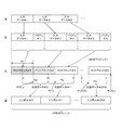
- FIG. 7 is a diagram for describing a procedure up to OFDM (Orthogonal Frequency Division Multiplexing) frame generation according to the first embodiment of the present technology.
- FIG. 3 is a diagram illustrating an example of a data structure of a TMCC carrier according to the first embodiment of the present technology.
- FIG. 3 is a diagram illustrating an example of a data structure of an OFDM frame according to the first embodiment of the present technology.
- FIG. 2 is a block diagram illustrating a configuration example of a receiving device according to the first embodiment of the present technology. 6 is a timing chart for explaining a pointer calculation method according to the first embodiment of the present technology.
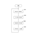
- FIG. 5 is a flowchart illustrating an example of an operation of the transmission device according to the first embodiment of the present technology.
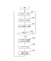
- 5 is a flowchart illustrating an example of an operation of the receiving device according to the first embodiment of the present technology.
- FIG. 13 is a diagram for describing a procedure up to OFDM frame generation according to the second embodiment of the present technology.
- FIG. 21 is a block diagram illustrating a configuration example of a decoding unit according to the second embodiment of the present technology.
- 15 is a flowchart illustrating an example of an operation of the reception device according to the second embodiment of the present technology.
- First embodiment example of calculating a specific pointer backward from the next frame pointer
- Second embodiment example in which deinterleaving processing is performed and a specific pointer is back-calculated from the pointer of the next frame
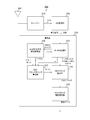
- FIG. 1 is a block diagram illustrating a configuration example of a communication system according to the first embodiment of the present technology.
- This communication system is for providing a terrestrial digital television broadcasting service of the next-generation standard of ISDB-T, and includes a transmitting device 100 and a receiving device 200.
- the transmitting device 100 includes the antenna 101.
- Transmitting apparatus 100 generates an OFDM frame subjected to orthogonal frequency division multiplexing modulation, and antenna 101 generates a radio signal on which the frame is superimposed and transmits the radio signal to receiving apparatus 200 by radio.
- the receiving device 200 includes an antenna 201, a tuner 210, an AD (Analog to digital) converter 220, and a decoder 230.
- the antenna 201 receives a wireless signal from the transmitting apparatus 100 and generates an analog signal.
- the antenna 201 supplies an analog signal to the tuner 210.
- the antenna 201 is an example of a receiving unit described in the claims.
- the tuner 210 selects a signal of a predetermined channel from the signal from the antenna 201 and outputs the signal to the AD conversion unit 220 via the signal line 219.
- the AD converter 220 converts an analog output signal from the tuner 210 into a digital signal.
- This digital signal includes an OFDM frame.
- the AD conversion unit 220 supplies the digital signal as a reception signal to the decoding unit 230 via a signal line 229.
- the decoding unit 230 decodes an OFDM frame. This decoding section 230 outputs the decoding result as decoded data.
- FIG. 2 is a diagram for describing a procedure up to OFDM frame generation according to the first embodiment of the present technology.
- a shows an example of an input data sequence
- b in the figure shows an example of an encoded sequence
- C in the figure shows an example of a series of FEC blocks.
- d in the figure indicates a symbol group in the OFDM frame.
- the transmitting device 100 divides the content into a plurality of pieces of input data having a certain size such as input data # 1, # 2, and # 3 as illustrated in FIG. I do.
- the transmitting apparatus 100 performs Forward Error Correction (FEC) coding on each of the input data.
- FEC Forward Error Correction
- BCH coding and LDPC (Low-Density @ Parity-Check) coding are sequentially performed.
- LDPC Low-Density @ Parity-Check
- the transmission apparatus 100 performs carrier modulation to generate a plurality of FEC blocks such as FEC blocks # 1, # 2, and # 3, as illustrated in c in FIG.
- This FEC block is a sequence obtained by carrier-modulating a codeword.
- the size of each FEC block is constant, and the size (here, the number of carriers) is m (m is an integer). Note that the FEC block is an example of an encoded block described in the claims.
- the transmitting apparatus 100 divides an FEC block sequence in which a predetermined number of FEC blocks are arranged by a predetermined division unit to generate a plurality of divided data.
- This division unit is set to the number of data carriers Ns (Ns is an integer) that can be stored in one symbol.
- the transmitting apparatus 100 generates a transmission control signal (TMCC: Transmission and Multiplexing Configuration and control), stores the TMCC and each of the divided data in a plurality of symbols, and transmits the symbols as an OFDM frame.
- TMCC Transmission and Multiplexing Configuration and control
- a fixed number for example, 204
- Each of the symbols stores divided data and other data such as TMCC.
- the number of symbols is “204”
- the number of data carriers in a symbol is Ns, so the total number of data carriers in one OFDM frame is Ns ⁇ 204.
- the ISDB-T next-generation standard proposes that the size m of the FEC block is not limited to a divisor of the number of data carriers (eg, Ns ⁇ 204) in an OFDM frame from the viewpoint of improving transmission efficiency. ing. For this reason, when the size m does not correspond to a divisor of the total number of data carriers, the head of the OFDM frame does not coincide with the head of the first FEC block in the OFDM frame and shifts. In each symbol, the head of the FEC block is shifted from the head of the symbol. For this reason, the receiving apparatus 200 cannot extract the FEC block from the OFDM frame without acquiring the shift (in other words, the offset).
- the information indicating the start position of the FEC block in each symbol is hereinafter referred to as “FEC block pointer”.
- P [s] indicates the FEC block pointer of the s-th (s is an integer) symbol.
- the transmitting apparatus 100 stores, in each TMCC of the OFDM frame, an FEC block pointer indicating the head position of the first FEC block in the next OFDM frame.
- an FEC block pointer indicating the head position of the first FEC block in the next OFDM frame.
- a certain OFDM frame is set as the current frame, and the TMCC in the current frame stores the first FEC block pointer in the next OFDM frame.
- P [0] _c indicates the first FEC block pointer in the current frame
- P [0] _n indicates the first FEC block pointer next to the current frame.
- P [0] _n is also the end position of the last FEC block #N in the last divided data in the current frame.
- FIG. 3 is a diagram illustrating an example of a data structure of a TMCC carrier according to the first embodiment of the present technology.
- Transmission apparatus 100 performs difference set cyclic coding on TMCC including the number of segments, modulation order, code length and reserved area, and further performs differential modulation to generate a TMCC carrier.
- the modulation order indicates the number of bits mapped to one symbol of the FEC block.
- the code length indicates the code length of a code word forming the FEC block.
- the first FEC block pointer P [0] _n in the next frame is stored in, for example, a reserved area in the TMCC.
- the transmitting apparatus 100 stores the FEC block pointer P [0] _n in the TMCC
- the transmitting apparatus 100 may store the FEC block pointer P [0] _n in the data frame header instead of the TMCC.
- the receiving device 200 may extract the FEC block pointer P [0] _n from the header.
- FIG. 4 is a diagram illustrating an example of a data structure of an OFDM frame according to the first embodiment of the present technology.
- the vertical axis in the figure is a time axis, and the horizontal axis is a frequency axis.
- This figure is described in ARIB STD-B31 “Digital Terrestrial Television Broadcasting Transmission System”.
- the example shown in the figure is an example of a case where QAM (Quadrature Amplitude Modulation) modulation is adopted as a modulation method.
- QAM Quadrature Amplitude Modulation
- the number on the time axis is a symbol number for identifying a symbol. For example, when 204 symbols are stored in one OFDM frame, symbol numbers “0” to “203” are assigned.
- the number on the frequency axis is a carrier number for identifying a carrier.
- the symbol number is an example of identification information described in the claims.
- one carrier in one OFDM frame is used for TMCC transmission. Also, an SP (Scattered @ Pilot) signal is inserted at a predetermined position.
- Ns data carriers are stored for each symbol. The data composed of the Ns data carriers corresponds to the aforementioned “divided data”.
- FIG. 5 is a block diagram illustrating a configuration example of the receiving device 200 according to the first embodiment of the present technology.
- the decoding section 230 in the receiving apparatus 200 includes an OFDM demodulation section 231, a transmission control signal demodulation decoding section 232, an FEC block pointer calculation section 233, an FEC block extraction section 234, and an FEC block demodulation decoding section 235.
- the OFDM demodulation unit 231 demodulates an OFDM frame.
- the OFDM demodulation section 231 performs OFDM demodulation such as fast Fourier transform and equalization processing on the received signal from the AD conversion section 220, and separates the signal into a TMCC carrier and a data carrier as a payload.
- the OFDM demodulator 231 supplies the TMCC carrier to the transmission control signal demodulator / decoder 232 and supplies the data carrier to the FEC block extractor 234. Further, the OFDM demodulation unit 231 supplies the FEC block extraction unit 234 with an OFDM symbol start, which is information indicating the first carrier in each symbol. Note that the OFDM demodulation unit 231 is an example of the demodulation unit described in the claims.
- the TMCC acquisition flag F_tmcc is input to the OFDM demodulation section 231 when the transmission control signal demodulation decoding section 232 successfully decodes and acquires the TMCC.
- the method of arranging the TMCC carriers in the frame is specified, so that the OFDM demodulation section 231 synchronizes the OFDM frame with the TMCC acquisition flag F_tmcc.
- the OFDM demodulation unit 231 performs the equalization processing using the SP as necessary after synchronizing with successful decoding of the TMCC carrier. I do.
- the data carrier is output to the FEC block extraction unit 234 after generating the TMCC acquisition flag F_tmcc.
- the OFDM demodulation unit 231 specifies the symbol number s indicating the symbol when the TMCC acquisition flag F_tmcc is input, and supplies the symbol number s to the FEC block pointer calculation unit 233.
- the transmission control signal demodulation and decoding unit 232 demodulates and decodes the TMCC carrier. For example, in ISDB-T, a synchronization word and a difference-set cyclically encoded transmission control signal are differentially modulated and transmitted. Therefore, the transmission control signal demodulation / decoding section 232 performs differential demodulation of the TMCC carrier, confirmation of coincidence with the synchronization word, decoding of the difference set cyclic code, and the like. Through these processes, the transmission control signal demodulation / decoding section 232 acquires P [0] _n indicating the first FEC block pointer in the next OFDM frame, in addition to the transmission parameters such as the modulation order and the code length.
- the transmission control signal demodulation / decoding section 232 interprets the TMCC, obtains the number Ns of data carriers in the symbol and the size m of the FEC block, and calculates the FEC block pointer calculation section together with the FEC block pointer P [0] _n. 233.
- the FFT Fast ⁇ Fourier ⁇ Transform
- the transmission control signal demodulation / decoding section 232 obtains the number Ns of data carriers using the FFT size as necessary.
- the transmission control signal demodulation / decoding section 232 generates a TMCC acquisition flag F_tmcc and supplies it to the OFEM demodulation section 231 and the FEC block pointer calculation section 233.
- the transmission control signal demodulation / decoding section 232 is an example of the transmission control signal processing section described in the claims.
- the FEC block pointer calculation unit 233 acquires the FEC block pointer corresponding to a specific symbol in the current frame based on the FEC block pointer P [0] _n. .
- the FEC block pointer calculation unit 233 is an example of a head position acquisition unit described in the claims.
- the number Ns of data carriers in the OFDM frame and the size m of the FEC block are uniquely determined by transmission parameters in the TMCC. Therefore, the FEC block pointer of a specific symbol in the current frame can be calculated backward from the first FEC block pointer P [0] _n of the next OFDM frame, the size m, and the number of data carriers Ns.
- the FEC block pointer calculation unit 233 sets a variable k (k is an integer) from the symbol number s from the OFDM demodulation unit 231 according to the following equation.
- k S ⁇ s + 1 Equation 1
- S is the maximum value of the symbol number in the OFDM frame (eg, “203”). For example, when the maximum value S is “203” and the symbol number s to be calculated is “200”, “4” is set to the variable k from the above equation.
- the FEC block pointer calculation unit 233 sets an initial value “1” to the variable i, and calculates the FEC block pointer P [ ⁇ i] by the following equation.
- P [ ⁇ i] (P [ ⁇ i + 1] + Ns) mod m Equation 2
- “mod” is a function that returns the remainder obtained by dividing the immediately preceding value by the immediately following value.
- the FEC block pointer calculation unit 233 increments the variable i and executes the operation exemplified in Expression 2 again.
- the increment of the variable i and the calculation of Expression 2 are repeatedly executed until the variable i becomes equal to the variable k.
- the FEC block pointer calculation unit 233 first initializes the variable i to “1” and substitutes the initial value into Expression 2 to obtain the value.
- P [ ⁇ 1] is calculated by the following equation.
- P [ ⁇ 1] (P [0] + Ns) mod m Equation 3
- the first FEC block pointer P [0] _n of the next frame acquired by the transmission control signal demodulation and decoding unit 232 is substituted for P [0].
- the FEC block pointer calculation unit 233 increments the variable i and calculates P [ ⁇ 2] by the following equation.
- P [ ⁇ 2] (P [ ⁇ 1] + Ns) mod m Equation 4
- the value calculated by Equation 3 is substituted for P [ ⁇ 1].
- the FEC block pointer calculation unit 233 increments the variable i and calculates P [ ⁇ 3] by the following equation.
- P [ ⁇ 3] (P [ ⁇ 2] + Ns) mod m Equation 5
- the value calculated by Equation 4 is substituted for P [-2].
- the FEC block pointer calculation unit 233 increments the variable i, and calculates P [ ⁇ 4] by the following equation.
- P [ ⁇ 4] (P [ ⁇ 3] + Ns) mod m Equation 6
- the value calculated by Equation 6 is substituted for P [ ⁇ 3].
- the FEC block pointer calculation unit 233 calculates the FEC block pointer P [-k] (P [-4], etc.) of a specific symbol from the FEC block pointer P [0]. can do.
- the FEC block pointer calculation unit 233 supplies the calculated FEC block pointer P [-k] to the FEC block extraction unit 234.
- the FEC block extraction unit 234 extracts an FEC block using the calculated FEC block pointer P [-k].
- the FEC block extracting section 234 initializes a predetermined count value to “0” when an OFDM symbol start is input, and counts up the count value each time a data carrier is input. Then, the FEC block extracting unit 234 ends counting when the count value becomes equal to the FEC block pointer [ ⁇ k], and extracts m data carrier groups after the counting end as FEC blocks from the OFDM frame. . Thereafter, similarly, the process of extracting m data carrier groups as one FEC block is repeatedly executed.
- the FEC block extraction unit 234 supplies the extracted FEC block to the FEC block demodulation / decoding unit 235. Note that the FEC block extraction unit 234 is an example of an encoded block extraction unit described in the claims.
- the FEC block demodulation / decoding section 235 demodulates and decodes FEC blocks.
- the FEC block demodulation / decoding unit 235 performs carrier demodulation and decoding of an error correction code on the extracted FEC block. Then, FEC block demodulation / decoding section 235 outputs decoded data indicating the decoding result. Note that the FEC block demodulation and decoding unit 235 is an example of an encoded block decoding unit described in the claims.
- FIG. 6 is a timing chart for explaining a pointer calculation method according to the first embodiment of the present technology.
- a portion having the same filled pattern indicates one FEC block.
- the receiving apparatus 200 receives the first OFDM frame # 0.
- This OFDM frame # 0 includes, for example, 204 symbols of symbol numbers “0” to “203”.
- the receiving apparatus 200 starts decoding the TMCC carrier in the OFDM frame # 0 at the timing T10, and completes the decoding and acquires the TMCC at the timing T11 before the start of the next OFDM frame # 1.
- the timing T11 for acquiring the TMCC depends on the performance of the receiving device 200.
- the receiving apparatus 200 acquires the first FEC block pointer P [0] _n in the next OFDM frame # 1 from the TMCC. Further, the FEC block pointer P [0] _n is also the end position of the last FEC block in the last divided data in the OFDM frame # 0.
- the receiving apparatus 200 calculates the FEC block pointer P [ ⁇ 1] of the symbol number “203” by Expression 3. Then, the receiving apparatus 200 sequentially calculates the FEC block pointers P [ ⁇ 2], P [ ⁇ 3], and P [ ⁇ 4] using Expressions 4 to 6.
- the receiving apparatus 200 extracts and decodes the FEC block (the part filled with oblique lines) starting from the pointer.
- the receiving apparatus needs to wait for the start of decoding until the start timing T20 of the next OFDM frame. Since the length of one OFDM frame is, for example, 400 milliseconds (ms), the start of decoding is delayed by 400 milliseconds (ms) with respect to the reception timing T10 of the first OFDM frame # 0. . As a result, the time required for the television or the like to output video or audio as broadcast content is delayed by at least 400 milliseconds (m).
- the receiving apparatus 200 that performs the back calculation of the FEC block pointer P [ ⁇ 4] back calculates the FEC block pointer P [ ⁇ 4] from the FEC block P [0] _n of the next OFEM frame. Therefore, receiving apparatus 200 can start decoding at timing T11 before timing T20. Thereby, the delay time until the start of decoding can be made shorter than in the comparative example.
- FIG. 7 is a flowchart illustrating an example of an operation of the transmission device 100 according to the first embodiment of the present technology. This operation is started, for example, when a predetermined application for transmission is executed.
- the transmitting apparatus 100 performs carrier modulation such as QAM mapping on a codeword obtained by coding input data and codes the FEC block (step S901), divides a sequence in which the blocks are arranged, and sets a data carrier. It is generated (step S902). Then, transmitting apparatus 100 generates a TMCC carrier (step S903), and transmits an OFDM frame including the data carrier and the TMCC carrier (step S904). After step S904, transmitting apparatus 100 repeats step S901 and subsequent steps.
- carrier modulation such as QAM mapping on a codeword obtained by coding input data and codes the FEC block
- step S903 divides a sequence in which the blocks are arranged, and sets a data carrier. It is generated (step S902).
- transmitting apparatus 100 generates a TM
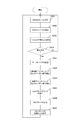
- FIG. 8 is a flowchart illustrating an example of an operation of the reception device 200 according to the first embodiment of the present technology. This operation is started, for example, when a predetermined application for reception is executed.
- the receiving device 200 receives the OFDM frame (Step S951) and extracts a TMCC carrier (Step S952).
- the receiving apparatus 200 demodulates and decodes the TMCC carrier (step S953), and determines whether or not the decoding has been successful (step S954).
- step S954 No
- the receiving apparatus 200 repeats step S951 and subsequent steps.
- step S954 the receiving apparatus 200 calculates the FEC block pointer P [-k] while demodulating the data carrier (step S955).
- the receiving apparatus 200 extracts an FEC block using the calculated FEC block pointer P [-k] (step S956), and performs demodulation and decoding of the FEC block (step S957). After step S957, the receiving apparatus 200 repeatedly executes step S951 and subsequent steps.
- the receiving apparatus 200 calculates the FEC block pointer of the specific symbol preceding the FEC block pointer P [0] from the FEC block pointer P [0]. Prior to reception, decoding of the FEC block can begin. This makes it possible to reduce the delay time until the start of decoding as compared with the case where decoding of the FEC block is started after receiving the next frame.
- the communication system does not perform interleaving and deinterleaving. However, with this configuration, when a burst error occurs, the error correction capability may be insufficient.
- the communication system of the second embodiment differs from the first embodiment in that interleaving and deinterleaving are further performed.
- FIG. 9 is a diagram for describing a procedure up to OFDM frame generation according to the second embodiment of the present technology.
- a shows an example of an input data sequence
- b in the figure shows an example of an encoded sequence.
- c indicates a sequence after interleaving.
- D in the figure shows an example of a sequence of the FEC block.
- e in the figure indicates a symbol group in the OFDM frame.
- the transmission device 100 divides the content into a plurality of pieces of input data as illustrated in FIG.
- the transmission device 100 performs carrier modulation and generates a plurality of codewords as illustrated in FIG.
- the transmitting apparatus 100 performs frequency interleaving and time interleaving to generate a rearranged bit string illustrated in c of FIG.
- the transmitting apparatus 100 generates a sequence of FEC blocks by QAM mapping as illustrated in d in FIG. Further, transmitting apparatus 100 divides a series of FEC blocks and generates a plurality of pieces of divided data. Then, transmitting apparatus 100 stores the TMCC and each of the divided data in a plurality of symbols, as illustrated in e in the figure, and transmits them as an OFDM frame.
- FIG. 10 is a block diagram illustrating a configuration example of the decoding unit 230 according to the second embodiment of the present technology.
- the decoding unit 230 according to the second embodiment differs from the first embodiment in that the decoding unit 230 further includes a frequency deinterleaver 236, a time deinterleaver 237, a delay unit 238, and a delay unit 239.
- the OFDM demodulation unit 231 of the second embodiment supplies the symbol number s of the symbol to be calculated to the delay unit 238, and supplies the data carrier and the OFDM symbol start to the frequency deinterleaver 236.
- the frequency deinterleaver 236 performs frequency deinterleaving on data carriers.
- the frequency deinterleaver 236 supplies the deinterleaved data carrier to the time deinterleaver 237 together with the OFDM symbol start.
- the time deinterleaver 237 performs time deinterleaving on data carriers.
- the time deinterleaver 237 supplies the deinterleaved data carrier to the FEC block extractor 234 together with the OFDM symbol start.
- the delay unit 238 delays the symbol number s in accordance with the processing time of the frequency deinterleaver 236, and outputs the result to the delay unit 239.
- the delay unit 239 delays the symbol number s in accordance with the processing time of the time deinterleaver 237, and outputs the result to the FEC block pointer calculation unit 233.
- FIG. 11 is a flowchart illustrating an example of an operation of the reception device 200 according to the second embodiment of the present technology.
- the operation of the receiving apparatus 200 according to the second embodiment is different from the first embodiment in that steps S961 to S964 are executed instead of step S955.
- step S954 If the TMCC carrier has been successfully decoded (step S954: Yes), the receiving apparatus 200 demodulates the data carrier (step S961) and delays the symbol number while performing frequency deinterleaving (step S962). Then, receiving apparatus 200 delays the symbol number while performing time deinterleaving (step S963). Receiving apparatus 200 calculates an FEC block pointer corresponding to the symbol number after the delay (step S964), and executes step S956 and subsequent steps.
- the transmitting apparatus 100 and the receiving apparatus 200 perform interleaving and deinterleaving, so that it is possible to improve resistance to burst errors.
- the processing procedure described in the above embodiment may be considered as a method having a series of these procedures, and a program for causing a computer to execute the series of procedures or a recording medium for storing the program. May be caught.
- a recording medium for example, a CD (Compact Disc), an MD (MiniDisc), a DVD (Digital Versatile Disc), a memory card, a Blu-ray Disc (Blu-ray (registered trademark) Disc), or the like can be used.
- the present technology may have the following configurations.
- Department and A receiving unit comprising: a start position obtaining unit that obtains a start position of the encoded block in a specific divided data among the plurality of divided data based on the end position.
- the start position acquiring unit calculates the start position from the size of the encoded block, a division unit that is a unit obtained by dividing the block sequence, and the end position.
- the receiving device further including a deinterleaver that performs deinterleaving on the plurality of pieces of divided data.
- a demodulation unit that demodulates the frame and supplies identification information for identifying the specific divided data; And a delay unit for delaying the identification information and supplying the head position acquisition unit with a delay,
- the head position obtaining unit obtains the head position of the divided data related to the identification information.
- a transmission control signal processing unit that acquires the end position from a transmission control signal and supplies the acquired end position to the start position acquisition unit;
- the receiving device according to any one of (1) to (4), wherein the frame includes the transmission control signal storing the end position.
- a coded block extracting unit that extracts each of the coded blocks from the plurality of divided data based on the obtained start position;
- the receiving device according to any one of (1) to (5), further including: a coded block decoding unit that decodes the extracted coded block.
- a transmitting device comprising: a receiving unit that receives the frame; and a head position obtaining unit that obtains a head position of the encoded block in specific divided data among the plurality of divided data based on the end position.
- a frame including a plurality of divided data obtained by dividing a block sequence in which a predetermined number of encoded blocks are arranged, and a last position of the last encoded block in the last divided data of the plurality of divided data is received.
Landscapes
- Engineering & Computer Science (AREA)
- Computer Networks & Wireless Communication (AREA)
- Signal Processing (AREA)
- Detection And Prevention Of Errors In Transmission (AREA)
Abstract
Description
1.第1の実施の形態(次のフレームのポインタから特定のポインタを逆算する例)
2.第2の実施の形態(デインターリーブ処理を行い、次のフレームのポインタから特定のポインタを逆算する例)
[通信システムの構成例]
図1は、本技術の第1の実施の形態における通信システムの一構成例を示すブロック図である。この通信システムは、ISDB-Tの次世代規格の地上波デジタルテレビジョン放送サービスを提供するためのものであり、送信装置100および受信装置200を備える。
図5は、本技術の第1の実施の形態における受信装置200の一構成例を示すブロック図である。受信装置200内の復号部230は、OFDM復調部231、伝送制御信号復調復号部232、FECブロックポインタ算出部233、FECブロック抽出部234およびFECブロック復調復号部235とを備える。
k=S-s+1 ・・・式1
上式においてSは、OFDMフレーム内のシンボル番号の最大値(「203」など)である。例えば、最大値Sが「203」で、算出対象のシンボル番号sが「200」である場合には、上式より、変数kに「4」が設定される。
P[-i]=(P[-i+1]+Ns) mod m ・・・式2
上式において「mod」は、その直前の値を、直後の値により除算した余りを返す関数である。
P[-1]=(P[0]+Ns) mod m ・・・式3
上式において、P[0]には、伝送制御信号復調復号部232により取得された、次のフレームの最初のFECブロックポインタP[0]_nが代入される。
P[-2]=(P[-1]+Ns) mod m ・・・式4
上式において、P[-1]には、式3で算出された値が代入される。
P[-3]=(P[-2]+Ns) mod m ・・・式5
上式において、P[-2]には、式4で算出された値が代入される。
P[-4]=(P[-3]+Ns) mod m ・・・式6
上式において、P[-3]には、式6で算出された値が代入される。
図7は、本技術の第1の実施の形態における送信装置100の動作の一例を示すフローチャートである。この動作は、例えば、送信のための所定のアプリケーションが実行されたときに開始される。送信装置100は、入力データを符号化した符号語に対してQAMマッピング等のキャリア変調を行ってFECブロックに符号化し(ステップS901)、それらのブロックを配列した系列を分割して、データキャリアを生成する(ステップS902)。そして、送信装置100は、TMCCキャリアを生成し(ステップS903)、データキャリアおよびTMCCキャリアを含むOFDMフレームを送信する(ステップS904)。ステップS904の後に送信装置100は、ステップS901以降を繰り返す。
図8は、本技術の第1の実施の形態における受信装置200の動作の一例を示すフローチャートである。この動作は、例えば、受信のための所定のアプリケーションが実行されたときに開始される。受信装置200は、OFDMフレームを受信し(ステップS951)、TMCCキャリアを抽出する(ステップS952)。受信装置200は、TMCCキャリアの復調および復号を行い(ステップS953)、復号に成功したか否かを判断する(ステップS954)。復号に失敗した場合に(ステップS954:No)、受信装置200は、ステップS951以降を繰り返す。
上述の第1の実施の形態では、通信システムは、インターリーブおよびデインターリーブを行っていなかったが、この構成では、バーストエラーが生じた際に、誤り訂正能力が不足するおそれがある。この第2の実施の形態の通信システムは、インターリーブおよびデインターリーブをさらに実行する点において第1の実施の形態と異なる。
(1)所定数の符号化ブロックを配列したブロック系列を分割した複数の分割データと前記複数の分割データの最後の分割データ内の最後の符号化ブロックの末尾位置とを含むフレームを受信する受信部と、
前記末尾位置に基づいて前記複数の分割データのうち特定の分割データ内の前記符号化ブロックの先頭位置を取得する先頭位置取得部と
を具備する受信装置。
(2)前記先頭位置取得部は、前記符号化ブロックのサイズと前記ブロック系列を分割した単位である分割単位と前記末尾位置とから前記先頭位置を算出する
前記(1)記載の受信装置。
(3)前記複数の分割データに対してデインターリーブを行うデインターリーバをさらに具備する前記(1)または(2)に記載の受信装置。
(4)前記フレームを復調して前記特定の分割データを識別するための識別情報を供給する復調部と、
前記識別情報を遅延させて先頭位置取得部に供給する遅延部と
をさらに具備し、
前記先頭位置取得部は、前記識別情報に係る前記分割データの前記先頭位置を取得する
前記(3)記載の受信装置。
(5)伝送制御信号から前記末尾位置を取得して前記先頭位置取得部に供給する伝送制御信号処理部をさらに具備し、
前記フレームは、前記末尾位置を格納した前記伝送制御信号を含む
前記(1)から(4)のいずれかに記載の受信装置。
(6)前記取得された前記先頭位置に基づいて前記複数の分割データから前記符号化ブロックのそれぞれを抽出する符号化ブロック抽出部と、
前記抽出された符号化ブロックを復号する符号化ブロック復号部と
をさらに具備する
前記(1)から(5)のいずれかに記載の受信装置。
(7)所定数の符号化ブロックを配列したブロック系列を分割した複数の分割データと前記複数の分割データの最後の分割データ内の最後の前記符号化ブロックの末尾位置とを含むフレームを送信する送信装置と、
前記フレームを受信する受信部と、前記末尾位置に基づいて前記複数の分割データのうち特定の分割データ内の前記符号化ブロックの先頭位置を取得する先頭位置取得部とを備える受信装置と
を具備する通信システム。
(8)所定数の符号化ブロックを配列したブロック系列を分割した複数の分割データと前記複数の分割データの最後の分割データ内の最後の前記符号化ブロックの末尾位置とを含むフレームを受信する受信手順と、
前記末尾位置に基づいて前記複数の分割データのうち特定の分割データ内の前記符号化ブロックの先頭位置を取得する先頭位置取得手順と
を具備する受信装置の制御方法。
101、201 アンテナ
200 受信装置
210 チューナー
220 AD変換部
230 復号部
231 OFDM復調部
232 伝送制御信号復調復号部
233 FECブロックポインタ算出部
234 FECブロック抽出部
235 FECブロック復調復号部
236 周波数デインターリーバ
237 時間デインターリーバ
238、239 遅延部
Claims (8)
- 所定数の符号化ブロックを配列したブロック系列を分割した複数の分割データと前記複数の分割データの最後の分割データ内の最後の前記符号化ブロックの末尾位置とを含むフレームを受信する受信部と、
前記末尾位置に基づいて前記複数の分割データのうち特定の分割データ内の前記符号化ブロックの先頭位置を取得する先頭位置取得部と
を具備する受信装置。 - 前記先頭位置取得部は、前記符号化ブロックのサイズと前記ブロック系列を分割した単位である分割単位と前記末尾位置とから前記先頭位置を算出する
請求項1記載の受信装置。 - 前記複数の分割データに対してデインターリーブを行うデインターリーバをさらに具備する
請求項1記載の受信装置。 - 前記フレームを復調して前記特定の分割データを識別するための識別情報を供給する復調部と、
前記識別情報を遅延させて先頭位置取得部に供給する遅延部と
をさらに具備し、
前記先頭位置取得部は、前記識別情報に係る前記分割データの前記先頭位置を取得する
請求項3記載の受信装置。 - 伝送制御信号から前記末尾位置を取得して前記先頭位置取得部に供給する伝送制御信号処理部をさらに具備し、
前記フレームは、前記末尾位置を格納した前記伝送制御信号を含む
請求項1記載の受信装置。 - 前記取得された前記先頭位置に基づいて前記複数の分割データから前記符号化ブロックのそれぞれを抽出する符号化ブロック抽出部と、
前記抽出された符号化ブロックを復号する符号化ブロック復号部と
をさらに具備する
請求項1記載の受信装置。 - 所定数の符号化ブロックを配列したブロック系列を分割した複数の分割データと前記複数の分割データの最後の分割データ内の最後の前記符号化ブロックの末尾位置とを含むフレームを送信する送信装置と、
前記フレームを受信する受信部と、前記末尾位置に基づいて前記複数の分割データのうち特定の分割データ内の前記符号化ブロックの先頭位置を取得する先頭位置取得部とを備える受信装置と
を具備する通信システム。 - 所定数の符号化ブロックを配列したブロック系列を分割した複数の分割データと前記複数の分割データの最後の分割データ内の最後の前記符号化ブロックの末尾位置とを含むフレームを受信する受信手順と、
前記末尾位置に基づいて前記複数の分割データのうち特定の分割データ内の前記符号化ブロックの先頭位置を取得する先頭位置取得手順と
を具備する受信装置の制御方法。
Priority Applications (2)
| Application Number | Priority Date | Filing Date | Title |
|---|---|---|---|
| JP2020527228A JP7161531B2 (ja) | 2018-06-29 | 2019-04-17 | 受信装置、通信システム、および、受信装置の制御方法 |
| BR112020026364-8A BR112020026364A2 (pt) | 2018-06-29 | 2019-04-17 | Dispositivo de recepção, sistema de comunicação, e, método para controlar um dispositivo de recepção. |
Applications Claiming Priority (2)
| Application Number | Priority Date | Filing Date | Title |
|---|---|---|---|
| JP2018124346 | 2018-06-29 | ||
| JP2018-124346 | 2018-06-29 |
Publications (1)
| Publication Number | Publication Date |
|---|---|
| WO2020003701A1 true WO2020003701A1 (ja) | 2020-01-02 |
Family
ID=68987023
Family Applications (1)
| Application Number | Title | Priority Date | Filing Date |
|---|---|---|---|
| PCT/JP2019/016400 Ceased WO2020003701A1 (ja) | 2018-06-29 | 2019-04-17 | 受信装置、通信システム、および、受信装置の制御方法 |
Country Status (3)
| Country | Link |
|---|---|
| JP (1) | JP7161531B2 (ja) |
| BR (1) | BR112020026364A2 (ja) |
| WO (1) | WO2020003701A1 (ja) |
Cited By (2)
| Publication number | Priority date | Publication date | Assignee | Title |
|---|---|---|---|---|
| WO2023218981A1 (ja) * | 2022-05-13 | 2023-11-16 | ソニーグループ株式会社 | 送信装置、送信方法、受信装置、及び受信方法 |
| WO2024106194A1 (ja) * | 2022-11-18 | 2024-05-23 | ソニーグループ株式会社 | 送信装置、送信方法、受信装置、及び受信方法 |
Citations (3)
| Publication number | Priority date | Publication date | Assignee | Title |
|---|---|---|---|---|
| JP2015065627A (ja) * | 2013-09-26 | 2015-04-09 | 日本放送協会 | 送信装置、受信装置、デジタル放送システム及びチップ |
| JP2015080029A (ja) * | 2013-10-15 | 2015-04-23 | 日本放送協会 | 送信装置、受信装置、デジタル放送システム及びチップ |
| JP2016122934A (ja) * | 2014-12-24 | 2016-07-07 | 日本放送協会 | 送信装置、受信装置、デジタル放送システム及びチップ |
-
2019
- 2019-04-17 WO PCT/JP2019/016400 patent/WO2020003701A1/ja not_active Ceased
- 2019-04-17 JP JP2020527228A patent/JP7161531B2/ja active Active
- 2019-04-17 BR BR112020026364-8A patent/BR112020026364A2/pt not_active IP Right Cessation
Patent Citations (3)
| Publication number | Priority date | Publication date | Assignee | Title |
|---|---|---|---|---|
| JP2015065627A (ja) * | 2013-09-26 | 2015-04-09 | 日本放送協会 | 送信装置、受信装置、デジタル放送システム及びチップ |
| JP2015080029A (ja) * | 2013-10-15 | 2015-04-23 | 日本放送協会 | 送信装置、受信装置、デジタル放送システム及びチップ |
| JP2016122934A (ja) * | 2014-12-24 | 2016-07-07 | 日本放送協会 | 送信装置、受信装置、デジタル放送システム及びチップ |
Cited By (2)
| Publication number | Priority date | Publication date | Assignee | Title |
|---|---|---|---|---|
| WO2023218981A1 (ja) * | 2022-05-13 | 2023-11-16 | ソニーグループ株式会社 | 送信装置、送信方法、受信装置、及び受信方法 |
| WO2024106194A1 (ja) * | 2022-11-18 | 2024-05-23 | ソニーグループ株式会社 | 送信装置、送信方法、受信装置、及び受信方法 |
Also Published As
| Publication number | Publication date |
|---|---|
| BR112020026364A2 (pt) | 2021-03-30 |
| JP7161531B2 (ja) | 2022-10-26 |
| JPWO2020003701A1 (ja) | 2021-07-15 |
Similar Documents
| Publication | Publication Date | Title |
|---|---|---|
| US10355817B2 (en) | Transmitting apparatus and interleaving method thereof | |
| JP5298622B2 (ja) | 送信装置および方法、受信装置および方法 | |
| US8208533B2 (en) | Methods and apparatus for fast signal acquisition in a digital video receiver | |
| US11637655B2 (en) | Transmitting apparatus and interleaving method thereof | |
| US8443269B2 (en) | System and method for handling forward error correction code blocks in a receiver | |
| US20120063407A1 (en) | Digital broadcasting transmitter, digital broadcasting receiver, and methods for configuring and processing a stream for same | |
| US11303299B2 (en) | Transmitting apparatus and interleaving method thereof | |
| KR20120041251A (ko) | 저밀도 패리티 검사 코딩 및 성상 매핑을 사용한 데이터 송신 | |
| JP5860379B2 (ja) | シグナリング情報の送信および受信方法 | |
| CN111669253B (zh) | 发送器及其附加奇偶校验产生方法 | |
| CN107408951B (zh) | 发送器及其奇偶校验置换方法 | |
| KR20160052313A (ko) | 송신 장치, 수신 장치 및 그 신호 처리 방법 | |
| WO2011091850A1 (en) | Error correction based on replacing padding bits by additional parity check bits | |
| CN111865499A (zh) | 接收设备和接收方法 | |
| JP7161531B2 (ja) | 受信装置、通信システム、および、受信装置の制御方法 | |
| EP2695320B1 (en) | Signaling data transmission transmitting split signaling data | |
| US20150033279A1 (en) | Transmitting apparatus, receiving apparatus and control methods thereof | |
| US9379843B2 (en) | Transmitting apparatus and receiving apparatus and signal processing method thereof | |
| US10355716B2 (en) | Transmitting apparatus and interleaving method thereof | |
| JP7157807B2 (ja) | 受信装置、通信システムおよび受信方法 | |
| JP3691307B2 (ja) | ディジタル放送受信機 | |
| JP2009201117A (ja) | データ受信装置及びそのプログラム | |
| EP2695319B1 (en) | Apparatus and method for transmitting static signaling data in a broadcast system | |
| KR20170002187A (ko) | 송신 장치, 수신 장치 및 그 제어방법 | |
| KR100848909B1 (ko) | 디지털 방송 수신기와 그 처리 방법 |
Legal Events
| Date | Code | Title | Description |
|---|---|---|---|
| 121 | Ep: the epo has been informed by wipo that ep was designated in this application |
Ref document number: 19826050 Country of ref document: EP Kind code of ref document: A1 |
|
| ENP | Entry into the national phase |
Ref document number: 2020527228 Country of ref document: JP Kind code of ref document: A |
|
| NENP | Non-entry into the national phase |
Ref country code: DE |
|
| REG | Reference to national code |
Ref country code: BR Ref legal event code: B01A Ref document number: 112020026364 Country of ref document: BR |
|
| ENP | Entry into the national phase |
Ref document number: 112020026364 Country of ref document: BR Kind code of ref document: A2 Effective date: 20201222 |
|
| 122 | Ep: pct application non-entry in european phase |
Ref document number: 19826050 Country of ref document: EP Kind code of ref document: A1 |