WO2020003469A1 - User terminal - Google Patents
User terminal Download PDFInfo
- Publication number
- WO2020003469A1 WO2020003469A1 PCT/JP2018/024723 JP2018024723W WO2020003469A1 WO 2020003469 A1 WO2020003469 A1 WO 2020003469A1 JP 2018024723 W JP2018024723 W JP 2018024723W WO 2020003469 A1 WO2020003469 A1 WO 2020003469A1
- Authority
- WO
- WIPO (PCT)
- Prior art keywords
- signal
- resource
- transmission
- base station
- reception
- Prior art date
Links
- 230000005540 biological transmission Effects 0.000 claims abstract description 217
- 230000004044 response Effects 0.000 claims abstract description 37
- 238000000034 method Methods 0.000 abstract description 107
- 238000004891 communication Methods 0.000 abstract description 54
- 238000012545 processing Methods 0.000 description 77
- 238000005259 measurement Methods 0.000 description 31
- 230000011664 signaling Effects 0.000 description 19
- 238000013507 mapping Methods 0.000 description 18
- 230000007274 generation of a signal involved in cell-cell signaling Effects 0.000 description 17
- 238000010586 diagram Methods 0.000 description 16
- 230000008569 process Effects 0.000 description 16
- 238000010295 mobile communication Methods 0.000 description 8
- 230000006870 function Effects 0.000 description 7
- 238000005516 engineering process Methods 0.000 description 6
- 238000007726 management method Methods 0.000 description 5
- 230000007774 longterm Effects 0.000 description 4
- 125000004122 cyclic group Chemical group 0.000 description 3
- 238000013468 resource allocation Methods 0.000 description 3
- 230000002776 aggregation Effects 0.000 description 2
- 238000004220 aggregation Methods 0.000 description 2
- 238000004364 calculation method Methods 0.000 description 2
- 238000012790 confirmation Methods 0.000 description 2
- 238000012937 correction Methods 0.000 description 2
- 230000008878 coupling Effects 0.000 description 2
- 238000010168 coupling process Methods 0.000 description 2
- 238000005859 coupling reaction Methods 0.000 description 2
- 238000001914 filtration Methods 0.000 description 2
- 238000012986 modification Methods 0.000 description 2
- 230000004048 modification Effects 0.000 description 2
- 239000013307 optical fiber Substances 0.000 description 2
- 230000010363 phase shift Effects 0.000 description 2
- 230000007704 transition Effects 0.000 description 2
- 101000741965 Homo sapiens Inactive tyrosine-protein kinase PRAG1 Proteins 0.000 description 1
- 102100038659 Inactive tyrosine-protein kinase PRAG1 Human genes 0.000 description 1
- 230000006978 adaptation Effects 0.000 description 1
- 239000000969 carrier Substances 0.000 description 1
- 239000003795 chemical substances by application Substances 0.000 description 1
- 239000000470 constituent Substances 0.000 description 1
- 230000001934 delay Effects 0.000 description 1
- 238000009795 derivation Methods 0.000 description 1
- 230000009977 dual effect Effects 0.000 description 1
- 239000000835 fiber Substances 0.000 description 1
- 238000011835 investigation Methods 0.000 description 1
- 239000006249 magnetic particle Substances 0.000 description 1
- 238000012544 monitoring process Methods 0.000 description 1
- 230000003287 optical effect Effects 0.000 description 1
- 230000002093 peripheral effect Effects 0.000 description 1
- 238000011084 recovery Methods 0.000 description 1
- 208000037918 transfusion-transmitted disease Diseases 0.000 description 1
- 238000013519 translation Methods 0.000 description 1
- 238000012384 transportation and delivery Methods 0.000 description 1
- CSRZQMIRAZTJOY-UHFFFAOYSA-N trimethylsilyl iodide Substances C[Si](C)(C)I CSRZQMIRAZTJOY-UHFFFAOYSA-N 0.000 description 1
- 238000011144 upstream manufacturing Methods 0.000 description 1
Images


Classifications
-
- H—ELECTRICITY
- H04—ELECTRIC COMMUNICATION TECHNIQUE
- H04W—WIRELESS COMMUNICATION NETWORKS
- H04W74/00—Wireless channel access, e.g. scheduled or random access
- H04W74/002—Transmission of channel access control information
-
- H—ELECTRICITY
- H04—ELECTRIC COMMUNICATION TECHNIQUE
- H04W—WIRELESS COMMUNICATION NETWORKS
- H04W74/00—Wireless channel access, e.g. scheduled or random access
- H04W74/002—Transmission of channel access control information
- H04W74/004—Transmission of channel access control information in the uplink, i.e. towards network
-
- H—ELECTRICITY
- H04—ELECTRIC COMMUNICATION TECHNIQUE
- H04W—WIRELESS COMMUNICATION NETWORKS
- H04W74/00—Wireless channel access, e.g. scheduled or random access
- H04W74/08—Non-scheduled or contention based access, e.g. random access, ALOHA, CSMA [Carrier Sense Multiple Access]
- H04W74/0833—Non-scheduled or contention based access, e.g. random access, ALOHA, CSMA [Carrier Sense Multiple Access] using a random access procedure
- H04W74/0841—Non-scheduled or contention based access, e.g. random access, ALOHA, CSMA [Carrier Sense Multiple Access] using a random access procedure with collision treatment
-
- H—ELECTRICITY
- H04—ELECTRIC COMMUNICATION TECHNIQUE
- H04W—WIRELESS COMMUNICATION NETWORKS
- H04W74/00—Wireless channel access, e.g. scheduled or random access
- H04W74/08—Non-scheduled or contention based access, e.g. random access, ALOHA, CSMA [Carrier Sense Multiple Access]
- H04W74/0833—Non-scheduled or contention based access, e.g. random access, ALOHA, CSMA [Carrier Sense Multiple Access] using a random access procedure
Definitions
- the present disclosure relates to a user terminal in a next-generation mobile communication system.
- LTE Long Term Evolution
- Non-Patent Document 1 LTE: Long Term Evolution
- LTE-A LTE Advanced, also called LTE @ Rel. 10, 11 or 12
- LTE-A Succession system eg, FRA (Future Radio Access), 5G (5th generation mobile communication system), NR (New Radio), NX (New radio access), FX (Future generation radio access), LTE Rel. 15 etc.
- a user terminal uses downlink control information (DCI: Downlink @ Control @ Information, DL assignment, etc.) from a radio base station (base station).
- DCI Downlink @ Control @ Information, DL assignment, etc.
- the reception of a downlink shared channel (for example, PDSCH: Physical Downlink Shared ⁇ ⁇ Channel) is controlled.
- the user terminal controls transmission of an uplink shared channel (for example, PUSCH: Physical Uplink Shared Channel) based on DCI (also referred to as UL grant or the like).
- the random access procedure of the existing LTE system supports four steps (messages 1-4). For example, in the random access procedure, the user terminal transmits a random access preamble (PRACH) corresponding to message 1 to the base station, and transmits a response signal (random access response or message 2) from the radio base station for the PRACH. Get information about transmission timing. Thereafter, the user terminal transmits a message (message 3) on the uplink shared channel based on the information acquired in message 2, and then receives message 4 (also referred to as contention-resolution) transmitted from the base station. I do.
- PRACH random access preamble
- message 2 random access response signal
- E-UTRA Evolved Universal Terrestrial Radio Access
- E-UTRAN Evolved Universal Universal Terrestrial Radio Access Network
- BF beamforming
- the present disclosure has been made in view of such a point, and has an object to provide a user terminal capable of appropriately performing communication even when performing a random access procedure with fewer steps than existing ones. .
- a user terminal is configured to transmit a first UL signal including a preamble used for random access and a second UL signal including a message, and the transmitting unit to transmit the second UL signal after transmitting the second UL signal.
- a receiving unit that receives a response signal to the first UL signal and the second UL signal, and applying at least one of frequency multiplexing and time multiplexing to the first UL signal and the second UL signal And a control unit for controlling transmission.
- communication can be appropriately performed even when a random access procedure is performed with fewer steps than existing ones.
- FIG. 4 is a diagram illustrating an example of a transmission method when there is beam correspondence.
- FIG. 5 is a diagram illustrating an example of a transmission method when there is no beam correspondence. It is a figure which shows an example of the retransmission control of 2-step RACH. It is a figure which shows another example of the retransmission control of 2-step RACH.
- 1 is a diagram illustrating an example of a schematic configuration of a wireless communication system according to the present embodiment.
- FIG. 3 is a diagram illustrating an example of an overall configuration of a wireless base station according to the present embodiment.
- FIG. 1 is a diagram illustrating an example of a schematic configuration of a wireless communication system according to the present embodiment.
- FIG. 3 is a diagram illustrating an example of an overall configuration of a wireless base station according to the present embodiment.
- FIG. 3 is a diagram illustrating an example of a functional configuration of a wireless base station according to the present embodiment.
- FIG. 2 is a diagram illustrating an example of an overall configuration of a user terminal according to the present embodiment.
- FIG. 3 is a diagram illustrating an example of a functional configuration of a user terminal according to the present embodiment.
- FIG. 3 is a diagram illustrating an example of a hardware configuration of a radio base station and a user terminal according to the present embodiment.
- LTE Rel. 8-13 support a random access procedure for establishing UL synchronization.
- the random access procedure includes contention-based random access (CBRA: also referred to as Contention-Based Random Access), non-contention-based random access (Non-CBRA, contention-free random access (CFRA), etc.). ).
- CBRA contention-based random access
- Non-CBRA non-contention-based random access
- CFRA contention-free random access
- CBRA collision type random access
- a user terminal randomly selects a preamble from a plurality of preambles (random access preamble, random access channel (PRACH: Physical Random Access Channel), RACH preamble, etc.) defined in each cell.
- Send The collision type random access is a random access procedure led by the user terminal, and can be used, for example, at the time of initial access, at the time of starting or resuming UL transmission, and the like.
- Non-collision type random access (Non-CBRA, CFRA: Contention-Free Random Access)
- the radio base station uses a downlink (DL) control channel (PDCCH: Physical Downlink Control Channel, EPDCCH: Enhanced PDCCH, etc.) to preamble. Is uniquely assigned to the user terminal, and the user terminal transmits the preamble assigned from the radio base station.
- the non-collision random access is a network-initiated random access procedure, and can be used, for example, at the time of handover, at the time of starting or resuming DL transmission (at the time of starting or resuming transmission of UL retransmission instruction information in UL), and the like. .
- FIG. 1 is a diagram showing an example of a collision type random access.
- a user terminal transmits a random access channel (for example, MIB (Mater @ Information @ Block) and / or SIB (System @ Information @ Block)) and higher layer signaling (for example, RRC (Radio @ Resource @ Control) signaling).
- a random access channel for example, MIB (Mater @ Information @ Block) and / or SIB (System @ Information @ Block)
- higher layer signaling for example, RRC (Radio @ Resource @ Control) signaling.
- PRACH configuration information indicating the configuration (PRACH configuration, RACH configuration) of the PRACH is received in advance.
- the PRACH configuration information includes, for example, a plurality of preambles (for example, a preamble format) defined for each cell, a time resource (for example, a system frame number, a subframe number) used for PRACH transmission, and a frequency resource (for example, 6 resource blocks).
- An offset (prach-FrequencyOffset) indicating the start position of (PRB: Physical ⁇ Resource ⁇ Block) can be indicated.
- the user terminal transitions from the idle (RRC_IDLE) state to the RRC connected (RRC_CONNECTED) state (for example, at the time of initial access), the user terminal is in the RRC connected state but UL synchronization is not established ( For example, at the start or restart of UL transmission), one of a plurality of preambles indicated by the PRACH configuration information is randomly selected, and the selected preamble is transmitted by the PRACH (message 1).
- the wireless base station Upon detecting the preamble, the wireless base station transmits a random access response (RAR: Random Access Response) as a response (message 2). If the user terminal fails to receive the RAR within a predetermined period (RAR window) after transmitting the preamble, the user terminal increases the transmission power of the PRACH and transmits (retransmits) the preamble again. Note that increasing the transmission power at the time of retransmission is also called power ramping.
- RAR Random Access Response
- the user terminal that has received the RAR adjusts the UL transmission timing based on the timing advance (TA) included in the RAR, and establishes UL synchronization. Further, the user terminal transmits a control message of an upper layer (L2 / L3: LayerLa2 / Layer 3) using a UL resource specified by a UL grant included in the RAR (message 3).
- the control message includes an identifier (UE-ID) of the user terminal.
- the identifier of the user terminal may be, for example, C-RNTI (Cell-Radio Network Network Temporary Identifier) in the RRC connection state, or S-TMSI (System Architecture Architecture Evolution-Temporary Mobile) in the idle state. It may be UE-ID of a higher layer such as (Subscriber @ Identity).
- the radio base station transmits a collision resolution message in response to the control message of the upper layer (message 4).
- the collision resolution message is transmitted based on the user terminal identifier included in the control message.
- the user terminal that has successfully detected the collision resolution message transmits an acknowledgment (ACK: Acknowledge) in HARQ (Hybrid Automatic Repeat reQuest) to the radio base station. Thereby, the user terminal in the idle state transitions to the RRC connection state.
- ACK Acknowledge
- HARQ Hybrid Automatic Repeat reQuest
- the user terminal that failed to detect the collision resolution message determines that a collision has occurred, reselects a preamble, and repeats the random access procedure of messages 1 to 4.
- the radio base station Upon detecting that the collision has been resolved by the ACK from the user terminal, the radio base station transmits an UL grant to the user terminal. The user terminal starts UL data using the UL resource allocated by the UL grant.
- the user terminal when the user terminal desires to transmit UL data, the user terminal can start a random access procedure autonomously. Also, since UL synchronization is established, UL data is transmitted using a UL resource that is uniquely assigned to a user terminal by a UL grant, so that highly reliable UL transmission is possible.
- the random access procedure using two steps is also called a two-step random access procedure, a two-step RACH, or a 2-step @ RACH.
- the # 2 step RACH may include a first step of transmitting from the UE to the base station and a second step of transmitting from the base station to the UE (see FIG. 2).
- a UL signal and a UL channel (hereinafter also referred to as UL signal / UL channel) including a preamble and a message (message) may be transmitted from the UE to the base station.
- the preamble may be configured to play the same role as message 1 (PRACH) in the existing random access procedure.
- the message may be configured to play the same role as message 3 (PUSCH) in the existing random access procedure.
- a DL signal and a DL channel including a response and contention-resolution (hereinafter also referred to as a DL signal / DL channel) is transmitted from the base station to the UE.
- the response may be configured to play the same role as message 2 (random access response (RAR) transmitted on PDSCH) in the existing random access procedure.
- RAR random access response
- the contention resolution may be configured to play the same role as message 4 (PDSCH) in the existing random access procedure.
- a UL signal / UL channel transmitted in the first step includes a preamble part and a message part, and a first UL signal / UL channel including a preamble part. And transmitting the second UL signal / UL channel including the message part using different resources.
- the transmission of the first step may fail.
- a problem is how to control the two-step RACH when at least one of the transmission of the preamble part and the transmission of the message part fails.
- the transmission of the preamble part and the transmission of the message part may fail, and based on the transmission results of the preamble part and the message part, retransmission (for example, retransmission Control of presence / absence, UL signal / channel to be retransmitted, etc.).
- retransmission for example, retransmission Control of presence / absence, UL signal / channel to be retransmitted, etc.
- first UL signal / UL channel includes a preamble portion and the second UL signal / UL channel includes a message portion, but is not limited thereto.
- the first UL signal / UL channel may include a part of the message part, and the second UL signal / UL channel may include a part of the preamble part.
- a two-step random access procedure (two-step RACH) is shown, but the present embodiment is not limited to this.
- the present invention may be applied to a random access procedure other than two steps (for example, three steps including a PDCCH order (message 0)).
- a second UL signal) is subjected to at least frequency multiplexing (FDM) for a second resource used for transmission.
- the first resource corresponds to a radio resource (for example, a time and frequency resource) for the preamble portion.
- the second resource corresponds to a radio resource for the message part.
- the first resource and the second resource may be set to be adjacent in the frequency direction. Alternatively, the first resource and the second resource may be set so as not to be adjacent (formed apart) in the frequency direction.
- the resource may be configured in at least one of a PRB unit, a slot unit, a minislot unit, and a symbol unit.
- a plurality of first resources and second resources may be set respectively.
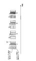
- the first resource and the second resource may be set to correspond to a plurality of TRPs / a plurality of beams, respectively (see FIG. 3).
- FIG. 3 shows a case where a plurality of combinations of the first resource and the second resource to be frequency-multiplexed are set.
- the plurality of first resources # 1 to # 4 may be arranged in different time domains (for example, time multiplexing), and the plurality of second resources # 1 to # 4 may be arranged in different time domains. .
- the first resource # 1 and the second resource # 1 correspond to the same TRP # 1 (or the same beam # 1).
- the first resource # 2 and the second resource # 2 correspond to the same TRP # 2 (or the same beam # 2)
- the first resource # 3 and the second resource # 3 are the same TRP # 3 (or the same beam # 3)
- the first resource # 4 and the second resource # 4 may correspond to the same TRP # 4 (or the same beam # 4).
- the information on the set of the first resource and the second resource may be notified from the base station to the UE using at least one of higher layer signaling (for example, RRC signaling), MAC ⁇ CE, and downlink control information.
- higher layer signaling for example, RRC signaling
- MAC ⁇ CE for example, MAC ⁇ CE
- downlink control information for example, MAC ⁇ CE
- a set of the first resource and the second resource may be defined in advance in the specification.
- the base station notifies the UE of one of the first resources (or the second resources), and determines the corresponding second resources (or the first resources) based on predetermined conditions. May be.
- the predetermined condition (for example, frequency offset or the like) may be reported from the base station to the UE or may be defined in advance in the specification.
- the UE may select a predetermined resource set from a plurality of resource sets based on at least one of a predetermined DL signal and a DL channel (DL signal / DL channel). For example, the UE determines a predetermined TRP / predetermined beam corresponding to a DL signal / DL channel having the highest received power (eg, RSRP). Next, the UE selects a predetermined resource set associated with (or most relevant to) the predetermined TRP / predetermined beam.
- the DL signal / DL channel may be a DL reference signal (DL-RS) or another DL signal.
- the DL signal / DL channel includes a synchronization signal (SS: Synchronization Signal), a broadcast channel (PBCH: Physical Broadcast Channel), a synchronization signal block (SSB: Synchronization Signal Block), a mobility reference signal (MRS: Mobility RS), and a channel.
- SS Synchronization Signal
- PBCH Physical Broadcast Channel
- SSB Synchronization Signal Block
- MRS Mobility RS
- CSI-RS State information reference signal
- CSI-RS Track CSI-RS
- a beam-specific signal or a signal configured by expanding or changing these (for example, A signal configured by changing at least one of the density and the period).
- the synchronization signal may be, for example, at least one of a primary synchronization signal (PSS: Primary Synchronaization Signal) and a secondary synchronization signal (SSS: Secondary Synchronaization Signal).
- PSS Primary Synchronaization Signal
- SSS Secondary Synchronaization Signal
- the SSB is a signal block including a synchronization signal and a broadcast channel, and may be called an SS / PBCH block or the like.
- the UE selects a first resource (or a first UL signal including a preamble) and a second resource (or a second UL signal including a message) based on a predetermined DL signal / DL channel.
- a predetermined association may be assumed.
- the UE assumes that at least one of the selected first and second resources and a pseudo-colocation (QCL), TCI state, and spatial association between a given DL signal / DL channel are the same. Then, the transmission process may be controlled.
- QCL pseudo-colocation
- the base station transmits a pseudo collocation (QCL) between a first resource (or a first UL signal including a preamble) and a second resource (or a second UL signal including a message),
- QCL pseudo collocation
- QCL Quasi-Co-Location
- the UE may control the reception process or the transmission process of the channel / signal based on the information (QCL information) on the QCL of at least one of the predetermined channel and the signal (channel / signal).
- the receiving process corresponds to, for example, at least one of demapping, demodulation, and decoding.
- the transmission processing corresponds to at least one of mapping, modulation, and code.
- a Doppler shift (doppler shift), a Doppler spread (doppler spread), an average delay (average delay), and a delay spread (delay) among these different signals. spread) and at least one of the spatial parameters (Spatial @ parameter) (e.g., the spatial reception parameter (Spatial @ Rx @ Parameter)) may be assumed to be the same (QCL for at least one of these).
- the spatial reception parameter may correspond to a reception beam (for example, a reception analog beam) or a transmission beam (for example, a transmission analog beam) of the user terminal, and the beam may be specified based on the spatial QCL.
- the QCL and at least one element of the QCL in the present disclosure may be read as sQCL (spatial @ QCL).
- the TCI (Transmission Configuration Indication or Transmission Configuration Indicator) state is also called a transmission configuration instruction state or TCI-state, and may indicate QCL information of a predetermined signal / channel (for example, PDSCH, PDCCH, PUCCH or PUSCH, etc.). Good.
- the TCI state is identified by a predetermined identifier (TCI state ID (TCI-StateId)), and a target channel / signal (or a reference signal for the channel (or an antenna port of the reference signal)) and another signal (For example, information (QCL information (QCL-Info)) related to QCL with another downlink reference signal (DL-RS: Downlink Reference Signal) or uplink reference signal (UL-RS: Uplink Reference Signal) may be shown. (May include).
- the spatial relation information corresponds to information indicating a configuration of a spatial association between the reference RS and the UL signal / UL channel.
- a plurality of candidate beams for PUSCH transmission may be set by PUSCH space-related information (PUSCH ⁇ Spatial ⁇ Relation ⁇ Information).
- the space related information is notified to the UE by a higher layer (for example, RRC signaling).
- the space-related information may be defined for another channel (for example, PRACH or the like), or the space-related information corresponding to PUSCH may be applied to another channel or the like.
- a plurality of TRPs / a plurality of beams may be read as a TCI state or a sounding reference signal resource indicator (SRI: SRS resource indicator).
- SRI sounding reference signal resource indicator
- FIG. 4 shows an example of the UE operation in the first step in the two-step RACH.
- a case is shown where four combinations are set as the first resource and the second resource to be frequency-multiplexed (resource sets), but the number of resource sets to be set is not limited to this.
- the UE selects a predetermined resource set from a plurality of resource sets based on predetermined conditions (for example, received power of a DL signal / DL channel). For example, the UE selects a resource set associated with the SS / PBCH block or CSI-RS with the highest received power (eg, RSRP).
- the association information between the SS / PBCH block or CSI-RS and the resource set may be notified from the base station to the UE in advance, or may be defined in advance in the specification.
- the resource set related to the SS / PBCH block or the CSI-RS with high received power is a combination of the first resource # 2 and the second resource # 2 (resource set # 2).
- the UE selects the resource set # 2, transmits the preamble portion using the first resource # 2 (or the first beam # 2), and transmits the second resource # 2 (or the second beam).
- the message part is transmitted using # 2).
- the first beam # 2 and the second beam # 2 may be the same beam.
- the UE may transmit the preamble portion (first UL signal) and the message portion (second UL signal) using different channels.
- the preamble part may be transmitted using the PRACH
- the message part may be transmitted using the PUSCH.
- both the preamble part and the message part may be transmitted using the PRACH or PUSCH.
- the base station When the base station receives the first UL signal and the second UL signal transmitted from the UE, the base station transmits a response signal to the UE after a predetermined period.
- the response signal may include a random access response, a message for contention resolution (contention resolution), and the like.
- the base station may transmit the response signal using a TRP or a beam corresponding to the resource set used by the UE for transmission (or the timing received by the base station).
- the preamble portion and the message portion Resource allocation can be flexibly controlled.
- At least time multiplexing is performed on a first resource used for transmitting the first UL signal and a second resource used for transmitting the second UL signal.
- the first resource corresponds to a radio resource (for example, a time and frequency resource) for the preamble portion.
- the second resource corresponds to a radio resource of the message part.
- the resource may be configured in at least one of a PRB unit, a slot unit, a minislot unit, and a symbol unit.
- a plurality of first resources and second resources may be set respectively.
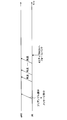
- the first resource and the second resource may be set to correspond to a plurality of TRPs / a plurality of beams, respectively (see FIG. 5).
- FIG. 5 shows a case where a plurality of combinations of the first resource and the second resource to be time-multiplexed are set.
- the plurality of first resources # 1 to # 4 may be arranged in different time domains (for example, time multiplexing), and the plurality of second resources # 1 to # 4 may be arranged in different time domains. .
- the first resource # 1 and the second resource # 1 correspond to the same TRP # 1 (or the same beam # 1).
- the first resource # 2 and the second resource # 2 correspond to the same TRP # 2 (or the same beam # 2)
- the first resource # 3 and the second resource # 3 are the same TRP # 3 (or the same beam # 3)
- the first resource # 4 and the second resource # 4 may correspond to the same TRP # 4 (or the same beam # 4).
- the information on the set of the first resource and the second resource may be notified from the base station to the UE using at least one of higher layer signaling (for example, RRC signaling), MAC ⁇ CE, and downlink control information.
- higher layer signaling for example, RRC signaling
- MAC ⁇ CE for example, MAC ⁇ CE
- downlink control information for example, MAC ⁇ CE
- a set of the first resource and the second resource may be defined in advance in the specification.
- the base station notifies the UE of one of the first resources (or the second resources), and determines the corresponding second resources (or the first resources) based on predetermined conditions. May be.
- the predetermined condition (for example, frequency offset or the like) may be reported from the base station to the UE or may be defined in advance in the specification.
- the UE may select a predetermined resource set from a plurality of resource sets based on a predetermined DL signal / DL channel. For example, the UE determines a predetermined TRP / predetermined beam corresponding to a DL signal / DL channel having the highest received power. Next, the UE selects a predetermined resource set associated with (or most relevant to) the predetermined TRP / predetermined beam.
- the UE selects a first resource (or a first UL signal including a preamble) and a second resource (or a second UL signal including a message) based on a predetermined DL signal / DL channel.
- a predetermined association may be assumed.
- the UE assumes that at least one of the selected first and second resources and a pseudo-colocation (QCL), TCI state, and spatial association between a given DL signal / DL channel are the same. Then, the transmission process may be controlled.
- QCL pseudo-colocation
- the base station transmits a pseudo collocation (QCL) between a first resource (or a first UL signal including a preamble) and a second resource (or a second UL signal including a message),
- QCL pseudo collocation
- the UE selects a predetermined first resource from a plurality of first resources (or a preamble portion) based on a predetermined DL signal / DL channel, and selects the first resource based on a predetermined condition. May be determined for the second resource. For example, the UE determines a predetermined TRP / predetermined beam corresponding to a DL signal / DL channel having the highest received power. Next, the UE selects a first resource associated (or most relevant) with the given TRP / given beam and determines a second resource corresponding to the first resource set. Is also good.
- the UE may control the transmission process on the assumption that at least one of the pseudo colocation (QCL), the TCI state, and the spatial association between the selected first and second resources is the same. Further, the base station controls the reception process on the assumption that at least one of pseudo colocation (QCL), TCI state, and spatial association between signals received by the first resource and the second resource is the same. May be.
- a gap (GP) section is set between the first resources and the second resources. Is also good. For example, a gap (GP) is formed between the first resource and the second resource corresponding to different TRPs / beams (or different resource sets) (see FIG. 6).
- FIG. 6 shows a case where a gap section is set at the end of the second resource.
- the gap section is arranged in the. Accordingly, even when the timing advance (TA) is applied to transmit the preamble portion (PRACH) or the like, the transmission can be appropriately performed.
- TA timing advance
- PRACH preamble portion
- a gap may be formed between a first resource (for example, first resource # 1) and a second resource (for example, second resource # 1) corresponding to the same TRP / beam.
- no gap may be formed between a first resource (for example, first resource # 1) and a second resource (for example, second resource # 1) corresponding to the same TRP / beam.
- first resource # 1 for example, first resource # 1
- second resource # 1 for example, second resource # 1
- resource utilization efficiency can be improved.
- even if it is a structure which does not provide a gap between the 1st resource and the 2nd resource corresponding to the same TRP / beam since the same UE uses for transmission, even if a timing advance is applied, the influence is small. .
- FIG. 7 shows an example of the UE operation in the first step in the two-step RACH.
- a case is shown where four combinations are set as the first resource and the second resource to be time-multiplexed (resource set), but the number of resource sets to be set is not limited to this.
- the UE selects a predetermined resource set from a plurality of resource sets based on predetermined conditions (for example, received power of a DL signal / DL channel). For example, the UE selects the SS / PBCH block or the resource set associated with the CSI-RS with the highest received power.
- the association information between the SS / PBCH block or CSI-RS and the resource set may be notified from the base station to the UE in advance, or may be defined in advance in the specification.
- the resource set related to the SS / PBCH block or the CSI-RS with high received power is a combination of the first resource # 2 and the second resource # 2 (resource set # 2).
- the UE selects the resource set # 2, transmits the preamble portion using the first resource # 2 (or the first beam # 2), and transmits the second resource # 2 (or the second beam).
- the message part is transmitted using # 2).
- the first beam # 2 and the second beam # 2 may be the same beam.
- the UE may transmit the preamble portion (first UL signal) and the message portion (second UL signal) using different channels.
- the preamble part may be transmitted using the PRACH
- the message part may be transmitted using the PUSCH.
- both the preamble part and the message part may be transmitted using the PRACH or PUSCH.
- the base station When the base station receives the first UL signal and the second UL signal transmitted from the UE, the base station transmits a response signal to the UE after a predetermined period.
- the response signal may include a random access response, a message for contention resolution (contention resolution), and the like.
- the base station may transmit the response signal using a TRP or a beam corresponding to the resource set used by the UE for transmission (or the timing received by the base station).
- the preamble part and the message part Resource allocation can be flexibly controlled.
- FIGS. 5 to 7 show the case where the second resources are separately set for the plurality of first resources, but the present invention is not limited to this.
- a second resource may be commonly set for a plurality of first resources.
- a first resource may be set so as to correspond to each of a plurality of TRPs / a plurality of beams, and less than N second resources may be set for a plurality (for example, N) of first resources.
- FIG. 8 shows a case where the second resource # 0 is set commonly (only one) corresponding to the plurality of first resources # 1 to # 4.
- the plurality of first resources and second resources are arranged in a time-multiplexed manner.
- the number of the second resources is not limited to one.
- the second resources corresponding to the first resources # 1- # 2 and the second resources corresponding to the first resources # 3- # 4 Each may be set.
- the information on the first resource and the second resource may be notified from the base station to the UE using at least one of higher layer signaling (for example, RRC signaling), MAC $ CE, and downlink control information.
- higher layer signaling for example, RRC signaling
- MAC $ CE for example, MAC $ CE
- downlink control information for example, MAC $ CE
- the first resource and the second resource may be defined in advance by specifications.
- one of the first resources may be notified from the base station to the UE, and the corresponding second resource may be determined based on a predetermined condition.
- the predetermined condition (for example, frequency offset or the like) may be reported from the base station to the UE or may be defined in advance in the specification.
- the UE may select a predetermined first resource from a plurality of first resources based on a predetermined DL signal / DL channel. For example, the UE determines a predetermined TRP / predetermined beam corresponding to a DL signal / DL channel having the highest received power. Next, the UE selects a predetermined first resource associated with (or most relevant to) the predetermined TRP / predetermined beam.
- the UE When transmitting the message portion using the second resource, the UE uses the transmission characteristic (or transmission condition) corresponding to the selected first resource. For example, when transmitting the preamble portion using a predetermined beam or the like, the UE transmits the message portion using the predetermined beam used for transmitting the preamble portion. As described above, by performing transmission using the second resource using the transmission characteristic corresponding to the selected first resource, even when the second resource is commonly set, transmission of the message portion is performed. Can be appropriately performed.
- a gap (GP) section is set between the first resource and the second resource.
- a predetermined time section also referred to as a gap section
- the predetermined time section may be a predetermined value (for example, 4 ms) set in advance, or may be a value set from the base station to the UE.
- the reception timing of the preamble part and the reception timing of the message part in the base station can be shifted.
- the base station can appropriately determine which preamble part the message part is related to.
- a gap section may be set at the end of the second resource.
- FIG. 9 shows an example of the UE operation in the first step in the two-step RACH.
- a case is shown where four first resources and one second resource corresponding to the four first resources are set, but the number of each resource is not limited to this.
- the UE selects a predetermined first resource from among the plurality of first resources based on a predetermined condition (for example, received power of a DL signal / DL channel). For example, the UE selects the SS / PBCH block or the first resource associated with the CSI-RS with the highest received power.
- the association information between the SS / PBCH block or CSI-RS and the first resource may be notified from the base station to the UE in advance, or may be defined in advance in the specification.
- the first resource related to the SS / PBCH block or the CSI-RS with high received power is the first resource # 2.
- the UE selects the first resource # 2, and transmits the preamble portion using the first resource # 2 (or the first beam # 2). Then, the UE transmits the message portion using the common second resource # 0 (or the first beam # 2).
- the base station When the base station receives the first UL signal and the second UL signal transmitted from the UE, the base station transmits a response signal to the UE after a predetermined period.
- the response signal may include a random access response, a message for contention resolution (contention resolution), and the like.
- the base station may transmit the response signal using a TRP or a beam corresponding to the first resource used by the UE for transmission (or the timing received by the base station).
- a beam In beam transmission / reception between a base station and a UE, a beam is used depending on whether a beam (TxBF) applied to transmission by the base station (or UE) matches a beam (RxBF) applied to reception, or not.
- the transmitted transmission method may be appropriately controlled.
- the beam applied to transmission matches the beam applied to reception at the base station or the like, it may be referred to as having (supporting) beam correspondence.
- the beam applied to transmission does not match the beam applied to reception, it may be referred to as having no (not supporting) beam correspondence.
- the beam correspondence includes transmit / receive beam correspondence (Tx / Rx correspondence), beam reciprocity (beam reciprocity), beam calibration (beam calibration), calibrated / non-calibrated, and reciprocity. It may be referred to as calibrated / uncalibrated (reciprocity calibrated / non-calibrated), correspondence, coincidence, or simply correspondence.
- the base station can determine a beam suitable for transmission / reception to / from the UE by recognizing the DL signal / channel (or beam) having high reception characteristics (for example, reception power) in the UE.
- the base station transmits a plurality of synchronization signal blocks (SSBs) or CSI-RSs using different DL resources (or DL beams) in the time direction (see FIG. 10).
- the UE selects a predetermined SSB based on reception characteristics (eg, received power) and the like, and uses the RACH occasion (or UL resource, UL beam) associated with the predetermined SSB to perform random access in the first step.
- a procedure transmission of a preamble part and a message part may be performed.
- the base station performs a reception process on each UL resource associated with each SSB, and determines a predetermined beam suitable for DL and UL based on the UL resource used for transmission from the UE. Then, the base station performs a second step (transmission of a random access response and contention resolution) using the predetermined beam.
- the base station when the base station has no beam correspondence, the beam applied to the transmission of the DL signal / channel at the base station and the beam applied to the reception of the UL signal / channel transmitted from the UE match (or link). do not do.
- the base station can determine a beam suitable for DL transmission by recognizing a DL signal / channel having a high reception characteristic (for example, reception power) in the UE. Also, the base station can determine a beam suitable for UL reception by grasping a UL signal / channel (or beam) having a high reception characteristic among UL signals / channels transmitted from the UE.
- the base station transmits a plurality of SSBs or CSI-RSs using different DL resources (or DL beams) in the time direction (see FIG. 11).
- the UE selects a predetermined SSB based on reception characteristics (for example, reception power) and the like, and uses the RACH occasion (or UL resource or UL beam) associated with the predetermined SSB to perform random access in the first step. Perform the procedure (transmission of the preamble part and the message part). Also, the UE may perform UL transmission as a UL resource over a plurality of symbols.
- the base station performs a reception process on each UL resource associated with each SSB, and determines a predetermined transmission beam suitable for DL based on the UL resource used for transmission from the UE. Further, the base station determines a predetermined reception beam suitable for UL based on reception characteristics of a UL signal transmitted every predetermined period (for example, a symbol) in the UL resource associated with the predetermined SSB. . Then, the base station performs a second step (transmission of a random access response and contention resolution) using a predetermined transmission beam.
- FIGS. 3 to 7 The configurations shown in FIGS. 3 to 7 can be suitably applied when the base station has beam correspondence.
- the configurations shown in FIGS. 8 to 9 can be suitably applied when the base station has no beam correspondence.
- the UE transmits the preamble portion (first UL signal) with different symbols, and the base station performs a reception process using a different reception beam for each symbol.
- the base station may perform the reception processing on the second UL signal using the reception beam determined based on the reception of the first UL signal.
- the base station can receive using the appropriate reception beam in the reception processing of the second UL signal.
- the UE since the UE does not need to transmit the second UL signal over a plurality of symbols, it is possible to improve resource use efficiency.
- the configurations shown in FIGS. 8 to 9 may be applied when the base station has the beam correspondence, and the configurations shown in FIGS. 3 to 7 may be applied when the base station does not have the beam response.
- the base station transmits a response signal (for example, RAR and contention resolution) for the first signal (preamble part) and the second signal (message part) transmitted in the first step.
- a response signal for example, RAR and contention resolution
- the base station may schedule a downlink shared channel using a downlink control channel (or DCI format) to which a predetermined identifier (RNTI) is applied.
- RNTI predetermined identifier
- the UE monitors the PDCCH (or DCI format) CRC-scrambled by a predetermined RNTI, and receives a response signal.
- the predetermined RNTI may be a random access RNTI (RA-RNTI: Random @ Access @ RNTI).
- the PDCCH (or DCI format) CRC-scrambled by the C-RNTI may be used as the predetermined RNTI.
- the random access procedure after acquiring the cell RNTI includes a random access procedure after RRC connection (for example, a random access procedure for RRC reconfiguration) and a random access procedure using a PDCCH order (for example, a contention free procedure) And a random access procedure for beam failure recovery (beam @ failure @ recovery).
- RRC connection for example, a random access procedure for RRC reconfiguration
- a random access procedure using a PDCCH order for example, a contention free procedure
- beam failure recovery beam failure recovery
- the base station may transmit downlink control information (or PDCCH) for instructing retransmission to the UE.
- the UE may perform retransmission when a response signal is not received within a predetermined period.
- a case is shown in which the base station issues a retransmission instruction (for example, a signal to be retransmitted) to the UE, but the present invention is not limited to this.
- retransmission control is not limited to the following cases.
- Case 1 Successful transmission of first UL signal / UL channel and successful transmission of second UL signal / UL channel
- Case 2 Successful transmission of first UL signal / UL channel, and successful transmission of second UL signal / UL Channel
- transmission failure case 3 transmission failure of first UL signal / UL channel and transmission failure of second UL signal / UL channel
- the transmission success in Cases 1 and 2 may be read as the success of the reception processing at the base station (eg, the success of decoding or demodulation).
- the transmission failure in Cases 2 and 3 may be read as a failure of the reception processing at the base station (for example, a failure of decoding or demodulation).
- the UE does not need to retransmit the preamble part and the message part.
- the UE may determine that the random access procedure has been successful by receiving the response signal transmitted from the base station. For transmission (scheduling) of the response signal, C-RNTI may be applied.
- the UE may perform control such that retransmission is performed only for the second UL signal including the message part whose transmission has failed.
- the base station may instruct the UE to retransmit the message part using the downlink control information (or PDCCH).
- the base station notifies the UE of a signal (for example, only a message portion) to be retransmitted, whereby the UL signal retransmitted by the UE can be reduced.
- the message portion may perform retransmission control in the same manner as message 3 in a four-step random access procedure (for example, a random access procedure defined in Rel. 15 or earlier).
- the UE may assume that the UE falls back to a four-step random access procedure.
- the information included in message 2 (RAR) in the four-step random access procedure may be included in the retransmission instruction notified from the base station.
- At least one of RA-RNTI and TC-RNTI may be applied as the RNTI applied to the PDCCH (or DCI format) instructing retransmission of the message part (or message 3).
- RA-RNTI MAC @ CE may be used
- TC-RNTI DCI may be used.
- the DCI monitoring operation and the retransmission timing of the message part in the UE may be separately set.
- the retransmission control of the message part can be flexibly controlled.
- both RA-RNTI and TC-RNTI may be applied.
- RA-RNTI may be applied in the first retransmission
- TC-RNTI may be applied in the second (or the second or later) retransmission.
- the UE may be notified to the RA-RNTI that controls the first retransmission, including information about the TC-RNTI.
- the first UL signal / UL channel including the preamble part may be retransmitted.
- the UE controls to retransmit both the first UL signal including the preamble part and the second UL signal including the message part.
- the UE may fall back to the four-step random access procedure and perform the random access procedure if the retransmission of the first UL signal and the second UL signal is not successful even after performing the predetermined number of times (for example, X).
- FIG. 13 shows a case in which retransmission of the preamble portion and the message portion has failed for a predetermined number of times (X) (or failed in the predetermined number of times (X)), and a fallback to a 4-step RACH is shown.
- the UE may perform control in consideration of failure of the two-step random access procedure in the four-step random access procedure. For example, in a four-step random access procedure, the maximum number of preamble transmissions is set to an upper layer parameter (eg, preambleTransMax) from the base station to the UE. Based on the maximum number of preamble transmissions, the UE determines a criterion for failure of the random access procedure and determines whether or not to report a problem (failure) of the random access procedure to an upper layer.
- an upper layer parameter eg, preambleTransMax
- the 4-step random access procedure may be controlled by including the number of failures (X) of the 2-step random access procedure in the maximum number of preamble transmissions set by an upper layer parameter (for example, preambleTransMax). That is, the interpretation of the upper layer parameters set in the four-step random access procedure may be changed according to the failure of the two-step random access procedure. In this case, since the failure of the two-step random access procedure is also taken into consideration, unnecessary random access procedures can be reduced.
- an upper layer parameter for example, preambleTransMax
- the four-step random access procedure may be controlled without including the number of failures (X) of the two-step random access procedure in the maximum number of preamble transmissions set by an upper layer parameter (for example, preambleTransMax). That is, the interpretation of the upper layer parameters set in the four-step random access procedure may not be changed in accordance with the failure of the two-step random access procedure. In this case, if the success probability of the four-step random access procedure is higher, the probability of success of the random access procedure can be improved by falling back.
- an upper layer parameter for example, preambleTransMax
- wireless communication system Wireless communication system
- communication is performed using at least one combination of the plurality of aspects.
- FIG. 14 is a diagram showing an example of a schematic configuration of the wireless communication system according to the present embodiment.
- carrier aggregation (CA) and / or dual connectivity (DC) in which a plurality of basic frequency blocks (component carriers) each having a system bandwidth (for example, 20 MHz) of the LTE system as one unit are applied. can do.
- DC dual connectivity
- the wireless communication system 1 includes LTE (Long Term Evolution), LTE-A (LTE-Advanced), LTE-B (LTE-Beyond), SUPER 3G, IMT-Advanced, 4G (4th generation mobile communication system), and 5G. (5th generation mobile communication system), NR (New Radio), FRA (Future Radio Access), New-RAT (Radio Access Technology), etc., or a system for realizing these.
- LTE Long Term Evolution
- LTE-A LTE-Advanced
- LTE-B LTE-Beyond
- SUPER 3G IMT-Advanced
- 4G 4th generation mobile communication system
- 5G 5th generation mobile communication system
- NR New Radio
- FRA Full Radio Access
- New-RAT Radio Access Technology
- the radio communication system 1 includes a radio base station 11 forming a macro cell C1 having a relatively wide coverage, and a radio base station 12 (12a-12c) arranged in the macro cell C1 and forming a small cell C2 smaller than the macro cell C1. , Is provided. Further, user terminals 20 are arranged in the macro cell C1 and each small cell C2. The arrangement, number, and the like of each cell and the user terminals 20 are not limited to the modes shown in the figure.
- the user terminal 20 can be connected to both the radio base station 11 and the radio base station 12. It is assumed that the user terminal 20 uses the macro cell C1 and the small cell C2 simultaneously using CA or DC. In addition, the user terminal 20 may apply CA or DC using a plurality of cells (CCs) (for example, five or less CCs, six or more CCs).
- CCs cells
- Communication between the user terminal 20 and the radio base station 11 can be performed using a carrier having a relatively low frequency band (for example, 2 GHz) and a narrow bandwidth (also referred to as an existing carrier or a legacy carrier).
- a carrier having a relatively high frequency band for example, 3.5 GHz, 5 GHz or the like
- the same carrier as that between may be used.
- the configuration of the frequency band used by each wireless base station is not limited to this.
- the user terminal 20 can perform communication using time division duplex (TDD: Time Division Duplex) and / or frequency division duplex (FDD: Frequency Division Duplex) in each cell.
- TDD Time Division Duplex
- FDD Frequency Division Duplex
- a single numerology may be applied, or a plurality of different numerologies may be applied.
- Numerology may be a communication parameter applied to transmission and / or reception of a certain signal and / or channel, for example, subcarrier interval, bandwidth, symbol length, cyclic prefix length, subframe length. , TTI length, number of symbols per TTI, radio frame configuration, filtering process, windowing process, and the like.
- the wireless base station 11 and the wireless base station 12 are connected by wire (for example, an optical fiber compliant with CPRI (Common Public Radio Interface), an X2 interface, or the like) or wirelessly. May be done.
- the wireless base station 11 and each wireless base station 12 are connected to the upper station device 30 and connected to the core network 40 via the upper station device 30.
- the higher station apparatus 30 includes, for example, an access gateway apparatus, a radio network controller (RNC), and a mobility management entity (MME), but is not limited thereto.
- RNC radio network controller
- MME mobility management entity
- each wireless base station 12 may be connected to the higher station apparatus 30 via the wireless base station 11.
- the radio base station 11 is a radio base station having relatively wide coverage, and may be called a macro base station, an aggregation node, an eNB (eNodeB), a transmission / reception point, or the like.
- the wireless base station 12 is a wireless base station having local coverage, and includes a small base station, a micro base station, a pico base station, a femto base station, a HeNB (Home eNodeB), an RRH (Remote Radio Head), and transmission / reception. It may be called a point or the like.
- the wireless base stations 11 and 12 are not distinguished, they are collectively referred to as a wireless base station 10.
- Each user terminal 20 is a terminal corresponding to various communication systems such as LTE and LTE-A, and may include not only mobile communication terminals (mobile stations) but also fixed communication terminals (fixed stations).
- Orthogonal Frequency Division Multiple Access (OFDMA) is applied to the downlink as a wireless access scheme, and Single-Carrier Frequency Division Multiple Access (SC-FDMA: Single Carrier) is applied to the uplink. Frequency Division Multiple Access) and / or OFDMA is applied.
- OFDMA Orthogonal Frequency Division Multiple Access
- SC-FDMA Single Carrier Frequency Division Multiple Access
- OFDMA is a multicarrier transmission scheme in which a frequency band is divided into a plurality of narrow frequency bands (subcarriers), and data is mapped to each subcarrier to perform communication.
- SC-FDMA divides a system bandwidth into bands each composed of one or a continuous resource block for each terminal, and a single carrier transmission that reduces interference between terminals by using different bands for a plurality of terminals. It is a method.
- the uplink and downlink radio access schemes are not limited to these combinations, and other radio access schemes may be used.
- a downlink shared channel (PDSCH: Physical Downlink Shared Channel), a broadcast channel (PBCH: Physical Broadcast Channel), a downlink L1 / L2 control channel, and the like shared by each user terminal 20 are used. Used.
- the PDSCH transmits user data, upper layer control information, SIB (System Information Block), and the like.
- SIB System Information Block
- MIB Master ⁇ Information ⁇ Block
- Downlink L1 / L2 control channels include downlink control channels (PDCCH (Physical Downlink Control Channel) and / or EPDCCH (Enhanced Physical Downlink Control Channel)), PCFICH (Physical Control Format Indicator Channel), and PHICH (Physical Hybrid-ARQ Indicator Channel).
- PDCH Physical Downlink Control Channel
- EPDCCH Enhanced Physical Downlink Control Channel
- PCFICH Physical Control Format Indicator Channel
- PHICH Physical Hybrid-ARQ Indicator Channel
- DCI Downlink Control Information
- DCI Downlink Control Information
- the scheduling information may be notified by DCI.
- a DCI that schedules DL data reception may be called a DL assignment
- a DCI that schedules UL data transmission may be called an UL grant.
- PCFICH transmits the number of OFDM symbols used for PDCCH.
- the PHICH transmits acknowledgment information (for example, retransmission control information, HARQ-ACK, ACK / NACK, etc.) of HARQ (Hybrid Automatic Repeat Repeat request) for the PUSCH.
- the EPDCCH is frequency-division multiplexed with a PDSCH (Downlink Shared Data Channel) and used for transmission of DCI and the like like the PDCCH.
- PDSCH Downlink Shared Data Channel
- an uplink shared channel (PUSCH: Physical Uplink Shared Channel), an uplink control channel (PUCCH: Physical Uplink Control Channel), a random access channel (PRACH: Physical Random Access Channel) or the like is used.
- PUSCH Physical Uplink Shared Channel
- PUCCH Physical Uplink Control Channel
- PRACH Physical Random Access Channel
- user data higher layer control information, etc. are transmitted.
- downlink radio link quality information CQI: Channel Quality Indicator
- delivery confirmation information delivery confirmation information
- scheduling request (SR: Scheduling Request), and the like are transmitted by PUCCH.
- the PRACH transmits a random access preamble for establishing a connection with a cell.
- a cell-specific reference signal CRS: Cell-specific Reference Signal
- CSI-RS Channel State Information-Reference Signal
- DMRS Demodulation Reference Signal
- PRS Positioning Reference Signal
- a measurement reference signal SRS: Sounding Reference Signal
- DMRS demodulation reference signal
- PRS Positioning Reference Signal
- the transmitted reference signal is not limited to these.
- FIG. 15 is a diagram showing an example of the overall configuration of the radio base station according to the present embodiment.
- the wireless base station 10 includes a plurality of transmitting / receiving antennas 101, an amplifier unit 102, a transmitting / receiving unit 103, a baseband signal processing unit 104, a call processing unit 105, and a transmission path interface 106.
- the transmitting / receiving antenna 101, the amplifier unit 102, and the transmitting / receiving unit 103 may be configured to include at least one each.
- the baseband signal processing unit 104 regarding user data, processing of a PDCP (Packet Data Convergence Protocol) layer, division / combination of user data, transmission processing of an RLC layer such as RLC (Radio Link Control) retransmission control, and MAC (Medium Access) Control)
- the transmission / reception unit performs retransmission control (for example, HARQ transmission processing), scheduling, transmission format selection, channel coding, inverse fast Fourier transform (IFFT) processing, precoding processing, and so on.
- HARQ transmission processing for example, HARQ transmission processing
- IFFT inverse fast Fourier transform
- precoding processing precoding processing
- the downlink control signal is also subjected to transmission processing such as channel coding and inverse fast Fourier transform, and transferred to the transmission / reception unit 103.
- the transmission / reception section 103 converts the baseband signal precoded and output from the baseband signal processing section 104 for each antenna into a radio frequency band, and transmits the radio frequency band.
- the radio frequency signal frequency-converted by the transmitting / receiving section 103 is amplified by the amplifier section 102 and transmitted from the transmitting / receiving antenna 101.
- the transmission / reception unit 103 can be configured from a transmitter / receiver, a transmission / reception circuit, or a transmission / reception device described based on common recognition in the technical field according to the present disclosure. Note that the transmission / reception unit 103 may be configured as an integrated transmission / reception unit, or may be configured from a transmission unit and a reception unit.
- a radio frequency signal received by the transmission / reception antenna 101 is amplified by the amplifier unit 102.
- the transmitting / receiving section 103 receives the upstream signal amplified by the amplifier section 102.
- Transmitting / receiving section 103 frequency-converts the received signal into a baseband signal and outputs the baseband signal to baseband signal processing section 104.
- the baseband signal processing unit 104 performs fast Fourier transform (FFT: Fast Fourier Transform), inverse discrete Fourier transform (IDFT), and error correction on user data included in the input uplink signal. Decoding, reception processing of MAC retransmission control, reception processing of the RLC layer and PDCP layer are performed, and the data is transferred to the upper station apparatus 30 via the transmission path interface 106.
- the call processing unit 105 performs call processing (setting, release, etc.) of a communication channel, state management of the wireless base station 10, management of wireless resources, and the like.
- the transmission path interface 106 transmits and receives signals to and from the higher-level station device 30 via a predetermined interface.
- the transmission path interface 106 transmits and receives signals (backhaul signaling) to and from another wireless base station 10 via an interface between base stations (for example, an optical fiber compliant with CPRI (Common Public Radio Interface), an X2 interface). You may.
- CPRI Common Public Radio Interface
- X2 interface X2 interface
- the transmission / reception unit 103 may further include an analog beamforming unit that performs analog beamforming.
- the analog beam forming unit includes an analog beam forming circuit (for example, a phase shifter, a phase shift circuit) or an analog beam forming device (for example, a phase shifter) described based on common recognition in the technical field according to the present invention. can do.
- the transmitting / receiving antenna 101 can be constituted by, for example, an array antenna.
- the transmission / reception unit 103 is configured to be able to apply single BF and multi BF.
- Transceiving section 103 may transmit a signal using a transmission beam or may receive a signal using a reception beam.
- the transmission / reception unit 103 may transmit and / or receive a signal using a predetermined beam determined by the control unit 301.
- the transmitting / receiving section 103 transmits a downlink (DL) signal (including at least one of a DL data signal (downlink shared channel), a DL control signal (downlink control channel), and a DL reference signal) to the user terminal 20.
- DL downlink
- UL uplink
- the transmission / reception unit 103 receives a first UL signal (or a first UL channel) including a preamble used for random access and a second UL signal (or a second UL channel) including a message. .
- the transmission / reception unit 103 transmits a response signal to the first UL signal and the second UL signal after transmitting the second UL signal.
- the transmission / reception unit 103 performs retransmission of at least one of the first UL signal and the second UL signal based on transmission failure of at least one of the first UL signal and the second UL signal transmitted from the UE. Instructing downlink control information may be transmitted.
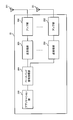
- FIG. 16 is a diagram showing an example of a functional configuration of the radio base station according to the present embodiment. Note that, in this example, functional blocks of characteristic portions in the present embodiment are mainly shown, and it may be assumed that the wireless base station 10 also has other functional blocks necessary for wireless communication.
- the baseband signal processing unit 104 includes at least a control unit (scheduler) 301, a transmission signal generation unit 302, a mapping unit 303, a reception signal processing unit 304, and a measurement unit 305. Note that these configurations may be included in the radio base station 10, and some or all of the configurations need not be included in the baseband signal processing unit 104.
- the control unit (scheduler) 301 controls the entire wireless base station 10.
- the control unit 301 can be configured from a controller, a control circuit, or a control device described based on common recognition in the technical field according to the present disclosure.
- the control unit 301 controls, for example, signal generation in the transmission signal generation unit 302, signal assignment in the mapping unit 303, and the like. Further, the control unit 301 controls a signal reception process in the reception signal processing unit 304, a signal measurement in the measurement unit 305, and the like.
- the control unit 301 performs scheduling (for example, resources) of system information, a downlink data signal (for example, a signal transmitted on the PDSCH), and a downlink control signal (for example, a signal transmitted on the PDCCH and / or the EPDCCH; acknowledgment information and the like). Allocation). Further, control section 301 controls generation of a downlink control signal, a downlink data signal, and the like based on a result of determining whether or not retransmission control is required for an uplink data signal.
- scheduling for example, resources
- a downlink data signal for example, a signal transmitted on the PDSCH
- a downlink control signal for example, a signal transmitted on the PDCCH and / or the EPDCCH; acknowledgment information and the like. Allocation.
- control section 301 controls generation of a downlink control signal, a downlink data signal, and the like based on a result of determining whether or not retransmission control is required for an uplink data signal.
- the control unit 301 controls transmission of a response signal (at least one of a random access response and contention resolution) for transmission of a first UL signal including a preamble and a second UL signal including a message transmitted from the UE. I do.
- the control unit 301 retransmits at least one of the first UL signal and the second UL signal. Do. In addition, when the reception of the first UL signal has failed, the control unit 301 instructs retransmission of the first UL signal and the second UL signal regardless of whether the second UL signal is received. Is also good.
- Transmission signal generation section 302 generates a downlink signal (downlink control signal, downlink data signal, downlink reference signal, etc.) based on an instruction from control section 301, and outputs the generated downlink signal to mapping section 303.
- the transmission signal generation unit 302 can be configured from a signal generator, a signal generation circuit, or a signal generation device described based on common recognition in the technical field according to the present disclosure.
- the transmission signal generation unit 302 generates a DL assignment for notifying downlink data allocation information and / or a UL grant for notifying uplink data allocation information, based on an instruction from the control unit 301, for example.
- the DL assignment and the UL grant are both DCI and follow the DCI format.
- the downlink data signal is subjected to an encoding process, a modulation process, and the like according to an encoding rate, a modulation method, and the like determined based on channel state information (CSI: Channel ⁇ State ⁇ Information) from each user terminal 20 or the like.
- CSI Channel ⁇ State ⁇ Information
- Mapping section 303 maps the downlink signal generated by transmission signal generating section 302 to a predetermined radio resource based on an instruction from control section 301, and outputs it to transmitting / receiving section 103.
- the mapping unit 303 can be configured from a mapper, a mapping circuit, or a mapping device described based on common recognition in the technical field according to the present disclosure.
- the reception signal processing unit 304 performs reception processing (for example, demapping, demodulation, decoding, and the like) on the reception signal input from the transmission / reception unit 103.
- the received signal is, for example, an uplink signal (uplink control signal, uplink data signal, uplink reference signal, etc.) transmitted from the user terminal 20.
- the reception signal processing unit 304 can be configured from a signal processor, a signal processing circuit, or a signal processing device described based on common recognition in the technical field according to the present disclosure.
- the reception signal processing unit 304 outputs the information decoded by the reception processing to the control unit 301. For example, when a PUCCH including HARQ-ACK is received, HARQ-ACK is output to control section 301. Further, the reception signal processing unit 304 outputs the reception signal and / or the signal after the reception processing to the measurement unit 305.
- the measurement unit 305 performs measurement on the received signal.
- the measurement unit 305 can be configured from a measurement device, a measurement circuit, or a measurement device described based on common recognition in the technical field according to the present disclosure.
- the measurement unit 305 may perform RRM (Radio Resource Management) measurement, CSI (Channel State Information) measurement, or the like based on the received signal.
- the measurement unit 305 is configured to receive power (for example, RSRP (Reference Signal Received Power)), reception quality (for example, RSRQ (Reference Signal Received Quality), SINR (Signal to Interference plus Noise Ratio, SNR (Signal to Noise Ratio)). , Signal strength (for example, RSSI (Received @ Signal @ Strength @ Indicator)), channel information (for example, CSI), and the like.
- the measurement result may be output to the control unit 301.
- FIG. 17 is a diagram illustrating an example of the overall configuration of the user terminal according to the present embodiment.
- the user terminal 20 includes a plurality of transmitting / receiving antennas 201, an amplifier unit 202, a transmitting / receiving unit 203, a baseband signal processing unit 204, and an application unit 205.
- the transmitting / receiving antenna 201, the amplifier unit 202, and the transmitting / receiving unit 203 may be configured to include at least one each.
- the radio frequency signal received by the transmitting / receiving antenna 201 is amplified by the amplifier unit 202.
- the transmission / reception unit 203 receives the downlink signal amplified by the amplifier unit 202.
- the transmission / reception section 203 converts the frequency of the received signal into a baseband signal, and outputs the baseband signal to the baseband signal processing section 204.
- the transmission / reception unit 203 can be configured from a transmitter / receiver, a transmission / reception circuit, or a transmission / reception device described based on common recognition in the technical field according to the present disclosure. Note that the transmission / reception unit 203 may be configured as an integrated transmission / reception unit, or may be configured from a transmission unit and a reception unit.
- the baseband signal processing unit 204 performs FFT processing, error correction decoding, reception processing for retransmission control, and the like on the input baseband signal.
- the downlink user data is transferred to the application unit 205.
- the application unit 205 performs processing related to layers higher than the physical layer and the MAC layer. Also, of the downlink data, broadcast information may be transferred to the application unit 205.
- uplink user data is input from the application unit 205 to the baseband signal processing unit 204.
- the baseband signal processing unit 204 performs retransmission control transmission processing (eg, HARQ transmission processing), channel coding, precoding, discrete Fourier transform (DFT) processing, IFFT processing, and the like, and performs transmission / reception processing. Transferred to 203.
- the transmission / reception unit 203 converts the baseband signal output from the baseband signal processing unit 204 into a radio frequency band and transmits the radio frequency band.
- the radio frequency signal frequency-converted by the transmitting / receiving section 203 is amplified by the amplifier section 202 and transmitted from the transmitting / receiving antenna 201.
- the transmission / reception unit 203 may further include an analog beamforming unit that performs analog beamforming.
- the analog beam forming unit includes an analog beam forming circuit (for example, a phase shifter, a phase shift circuit) or an analog beam forming device (for example, a phase shifter) described based on common recognition in the technical field according to the present invention. can do.
- the transmission / reception antenna 201 can be configured by, for example, an array antenna. Further, the transmission / reception unit 203 is configured so that a single BF and a multi BF can be applied.
- the transmission / reception unit 203 may transmit a signal using a transmission beam or may receive a signal using a reception beam.
- the transmission / reception unit 203 may transmit and / or receive a signal using a predetermined beam determined by the control unit 401.
- the transmitting / receiving section 203 receives a downlink (DL) signal (including at least one of a DL data signal (downlink shared channel), a DL control signal (downlink control channel), and a DL reference signal) from the radio base station 10,
- DL downlink
- DL control signal downlink control channel
- UL uplink
- the transmission / reception unit 203 transmits a first UL signal (or a first UL channel) including a preamble used for random access and a second UL signal (or a second UL channel) including a message. .
- the transmission / reception unit 203 receives the first UL signal and a response signal to the second UL signal after transmitting the second UL signal.
- the transmission / reception unit 203 performs retransmission of at least one of the first UL signal and the second UL signal based on transmission failure of at least one of the first UL signal and the second UL signal. Further, transmitting / receiving section 203 may receive downlink control information instructing the retransmission.
- FIG. 18 is a diagram showing an example of a functional configuration of the user terminal according to the present embodiment. Note that, in this example, functional blocks of characteristic portions in the present embodiment are mainly shown, and it may be assumed that the user terminal 20 also has other functional blocks necessary for wireless communication.
- the baseband signal processing unit 204 of the user terminal 20 includes at least a control unit 401, a transmission signal generation unit 402, a mapping unit 403, a reception signal processing unit 404, and a measurement unit 405. Note that these configurations need only be included in the user terminal 20, and some or all of the configurations need not be included in the baseband signal processing unit 204.
- the control unit 401 controls the entire user terminal 20.
- the control unit 401 can be configured by a controller, a control circuit, or a control device described based on common recognition in the technical field according to the present disclosure.
- the control unit 401 controls, for example, signal generation in the transmission signal generation unit 402, signal assignment in the mapping unit 403, and the like. Further, the control unit 401 controls signal reception processing in the reception signal processing unit 404, signal measurement in the measurement unit 405, and the like.
- the control unit 401 acquires the downlink control signal and the downlink data signal transmitted from the radio base station 10 from the reception signal processing unit 404.
- the control unit 401 controls generation of an uplink control signal and / or an uplink data signal based on a result of determining whether or not retransmission control is required for a downlink control signal and / or a downlink data signal.
- the control unit 401 controls transmission by applying at least one of frequency multiplexing and time multiplexing to the first UL signal and the second UL signal. For example, the control unit 401 may select a predetermined combination from a combination of a first UL signal and a second UL signal to which at least one of frequency multiplexing and time multiplexing is applied based on a DL signal.
- the transmission period of the second UL signal may be set separately for each first UL signal.
- the transmission period of the second UL signal may be commonly set for a plurality of first UL signals.
- a predetermined gap section may be set between the first UL signal having the latest transmission timing among the plurality of first UL signals and the transmission timing of the second transmission. Further, a gap section may be set between the second UL signal and the first UL signal associated with different DL signals.
- the control unit 401 may retransmit at least one of the first UL signal and the second UL signal based on transmission failure of at least one of the first UL signal and the second UL signal. Further, control section 401 may control retransmission based on a retransmission instruction transmitted from the base station.
- the control unit 401 uses the uplink shared channel scheduled in the downlink control information to transmit the second UL signal. Retransmission may be performed.
- the downlink control channel through which the downlink control information is transmitted may be a random access RNTI (RA-RNTI: Random @ Access @ RNTI) or a temporary cell RNTI (TC-RNTI: Temporary @ Cell @ RNTI).
- the control unit 401 may retransmit the first UL signal and the second UL signal. For example, when the reception of the first UL signal fails, the control unit 401 instructs retransmission of the first UL signal and the second UL signal regardless of whether the second UL signal is received. Is also good.
- the control unit 401 When the transmission of the first UL signal and the transmission of the second UL signal have failed a predetermined number of times, the control unit 401 performs a random access procedure including a procedure from message 1 to message 4 (fallback to a 4-step RACH). You may.
- control section 401 counts the number of times of transmission of at least one of the first UL signal and the second UL signal in counting the maximum number of random access preamble transmissions in the random access procedure including the procedure from message 1 to message 4. It is good also as composition which includes.
- control section 401 counts the number of times of transmission of at least one of the first UL signal and the second UL signal in counting the maximum number of random access preamble transmissions in the random access procedure including the procedure from message 1 to message 4. It is good also as a structure which is not included.
- Transmission signal generating section 402 generates an uplink signal (uplink control signal, uplink data signal, uplink reference signal, etc.) based on an instruction from control section 401 and outputs the generated signal to mapping section 403.
- the transmission signal generation unit 402 can be configured from a signal generator, a signal generation circuit, or a signal generation device described based on common recognition in the technical field according to the present disclosure.
- the transmission signal generation unit 402 generates an uplink control signal related to acknowledgment information, channel state information (CSI), and the like based on an instruction from the control unit 401, for example. Further, transmission signal generating section 402 generates an uplink data signal based on an instruction from control section 401. For example, the transmission signal generation unit 402 is instructed by the control unit 401 to generate an uplink data signal when the downlink control signal notified from the radio base station 10 includes an UL grant.
- CSI channel state information
- Mapping section 403 maps the uplink signal generated by transmission signal generation section 402 to a radio resource based on an instruction from control section 401, and outputs the result to transmission / reception section 203.
- the mapping unit 403 can be configured from a mapper, a mapping circuit, or a mapping device described based on common recognition in the technical field according to the present disclosure.
- the reception signal processing unit 404 performs reception processing (for example, demapping, demodulation, and decoding) on the reception signal input from the transmission / reception unit 203.
- the received signal is, for example, a downlink signal (a downlink control signal, a downlink data signal, a downlink reference signal, etc.) transmitted from the radio base station 10.
- the reception signal processing unit 404 can be configured from a signal processor, a signal processing circuit, or a signal processing device described based on common recognition in the technical field according to the present disclosure.
- the reception signal processing unit 404 can configure a reception unit according to the present disclosure.
- the reception signal processing unit 404 outputs the information decoded by the reception processing to the control unit 401.
- the reception signal processing unit 404 outputs, for example, broadcast information, system information, RRC signaling, DCI, and the like to the control unit 401. Further, the reception signal processing unit 404 outputs the reception signal and / or the signal after the reception processing to the measurement unit 405.
- the measurement unit 405 performs measurement on the received signal.
- the measurement unit 405 can be configured from a measurement device, a measurement circuit, or a measurement device described based on common recognition in the technical field according to the present disclosure.
- the measurement unit 405 may perform RRM measurement, CSI measurement, and the like based on the received signal.
- the measurement unit 405 may measure reception power (for example, RSRP), reception quality (for example, RSRQ, SINR, SNR), signal strength (for example, RSSI), channel information (for example, CSI), and the like.
- the measurement result may be output to the control unit 401.
- each functional block may be realized using one device physically or logically coupled, or directly or indirectly (for example, two or more devices physically or logically separated from each other). , Wired, wireless, etc.) and using these multiple devices.
- the functional block may be realized by combining one device or the plurality of devices with software.
- the functions include judgment, decision, judgment, calculation, calculation, processing, derivation, investigation, search, confirmation, reception, transmission, output, access, resolution, selection, selection, establishment, comparison, assumption, expectation, and deemed. , Broadcasting, notifying, communicating, forwarding, configuring, reconfiguring, allocating, mapping, assigning, etc.
- a functional block that makes transmission function may be referred to as a transmitting unit (transmitting unit), a transmitter (transmitter), or the like.
- the realization method is not particularly limited.
- a base station, a user terminal, and the like may function as a computer that performs processing of the wireless communication method according to the present disclosure.
- FIG. 19 is a diagram illustrating an example of a hardware configuration of the base station and the user terminal according to the embodiment.
- the above-described base station 10 and user terminal 20 may be physically configured as a computer device including a processor 1001, a memory 1002, a storage 1003, a communication device 1004, an input device 1005, an output device 1006, a bus 1007, and the like. .
- the term “apparatus” can be read as a circuit, a device, a unit, or the like.
- the hardware configuration of the base station 10 and the user terminal 20 may be configured to include one or more devices illustrated in the drawing, or may be configured without including some devices.
- processor 1001 may be implemented by one or more chips.
- the functions of the base station 10 and the user terminal 20 are performed, for example, by reading predetermined software (program) on hardware such as the processor 1001 and the memory 1002 so that the processor 1001 performs an arithmetic operation and communicates via the communication device 1004. And controlling at least one of reading and writing of data in the memory 1002 and the storage 1003.
- predetermined software program
- the processor 1001 performs an arithmetic operation and communicates via the communication device 1004.
- the processor 1001 controls the entire computer by operating an operating system, for example.
- the processor 1001 may be configured by a central processing unit (CPU: Central Processing Unit) including an interface with a peripheral device, a control device, an arithmetic device, a register, and the like.
- CPU Central Processing Unit
- the above-described baseband signal processing unit 104 (204), call processing unit 105, and the like may be realized by the processor 1001.
- the processor 1001 reads out a program (program code), a software module, data, and the like from at least one of the storage 1003 and the communication device 1004 to the memory 1002, and executes various processes according to these.
- a program program code
- a program that causes a computer to execute at least a part of the operation described in the above embodiment is used.
- the control unit 401 of the user terminal 20 may be implemented by a control program stored in the memory 1002 and operated by the processor 1001, and other functional blocks may be similarly implemented.
- the memory 1002 is a computer-readable recording medium, and includes, for example, at least one of a ROM (Read Only Memory), an EPROM (Erasable Programmable ROM), an EEPROM (Electrically EPROM), a RAM (Random Access Memory), and other appropriate storage media. It may be constituted by one.
- the memory 1002 may be called a register, a cache, a main memory (main storage device), or the like.
- the memory 1002 can store a program (program code), a software module, and the like that can be executed to implement the wireless communication method according to an embodiment of the present disclosure.
- the storage 1003 is a computer-readable recording medium such as a flexible disk, a floppy (registered trademark) disk, a magneto-optical disk (for example, a compact disk (CD-ROM (Compact Disc) ROM, etc.)), a digital versatile disc, At least one of a Blu-ray (registered trademark) disk, a removable disk, a hard disk drive, a smart card, a flash memory device (eg, a card, a stick, a key drive), a magnetic stripe, a database, a server, and other suitable storage media. May be configured.
- the storage 1003 may be called an auxiliary storage device.
- the communication device 1004 is hardware (transmission / reception device) for performing communication between computers via at least one of a wired network and a wireless network, and is also referred to as, for example, a network device, a network controller, a network card, a communication module, or the like.
- the communication device 1004 includes a high-frequency switch, a duplexer, a filter, a frequency synthesizer, and the like, for example, in order to realize at least one of frequency division duplex (FDD: Frequency Division Duplex) and time division duplex (TDD: Time Division Duplex). May be configured.
- FDD Frequency Division Duplex
- TDD Time Division Duplex
- the transmission / reception antenna 101 (201), the amplifier unit 102 (202), the transmission / reception unit 103 (203), the transmission line interface 106, and the like may be realized by the communication device 1004.
- the transmission / reception unit 103 may be mounted physically or logically separated between the transmission unit 103a and the reception unit 103b.
- the input device 1005 is an input device (for example, a keyboard, a mouse, a microphone, a switch, a button, a sensor, and the like) that receives an external input.
- the output device 1006 is an output device that performs output to the outside (for example, a display, a speaker, an LED (Light Emitting Diode) lamp, and the like). Note that the input device 1005 and the output device 1006 may have an integrated configuration (for example, a touch panel).
- the devices such as the processor 1001 and the memory 1002 are connected by a bus 1007 for communicating information.
- the bus 1007 may be configured using a single bus, or may be configured using a different bus for each device.
- the base station 10 and the user terminal 20 include hardware such as a microprocessor, a digital signal processor (DSP), an ASIC (Application Specific Integrated Circuit), a PLD (Programmable Logic Device), and an FPGA (Field Programmable Gate Array). It may be configured to include hardware, and some or all of the functional blocks may be realized using the hardware.
- the processor 1001 may be implemented using at least one of these hardware.
- the channel and the symbol may be a signal (signaling).
- the signal may be a message.
- the reference signal may be abbreviated as RS (Reference Signal), and may be referred to as a pilot, a pilot signal, or the like according to an applied standard.
- a component carrier (CC: Component Carrier) may be called a cell, a frequency carrier, a carrier frequency, or the like.
- the radio frame may be configured by one or a plurality of periods (frames) in the time domain.
- the one or more respective periods (frames) forming the radio frame may be referred to as a subframe.
- a subframe may be configured by one or more slots in the time domain.
- the subframe may be of a fixed length of time (eg, 1 ms) that does not depend on numerology.
- the new melology may be a communication parameter applied to at least one of transmission and reception of a certain signal or channel.
- Numerology includes, for example, subcarrier interval (SCS: SubCarrier @ Spacing), bandwidth, symbol length, cyclic prefix length, transmission time interval (TTI: Transmission @ Time @ Interval), number of symbols per TTI, radio frame configuration, transmission and reception.
- SCS SubCarrier @ Spacing
- TTI Transmission @ Time @ Interval
- TTI Transmission @ Time @ Interval
- radio frame configuration transmission and reception.
- At least one of a specific filtering process performed by the transceiver in the frequency domain and a specific windowing process performed by the transceiver in the time domain may be indicated.
- the slot may be configured by one or more symbols (OFDM (Orthogonal Frequency Division Multiplexing) symbol, SC-FDMA (Single Carrier Frequency Division Multiple Access) symbol, etc.) in the time domain. Further, the slot may be a time unit based on numerology.
- OFDM Orthogonal Frequency Division Multiplexing
- SC-FDMA Single Carrier Frequency Division Multiple Access
- the slot may include a plurality of mini slots.
- Each minislot may be constituted by one or more symbols in the time domain.
- minislots may be called subslots.
- a minislot may be made up of a smaller number of symbols than slots.
- a PDSCH (or PUSCH) transmitted in time units larger than minislots may be referred to as PDSCH (PUSCH) mapping type A.
- a PDSCH (or PUSCH) transmitted using minislots may be referred to as PDSCH (PUSCH) mapping type B.
- Radio frames, subframes, slots, minislots, and symbols all represent time units when transmitting signals.
- the radio frame, the subframe, the slot, the minislot, and the symbol may have different names corresponding thereto. Note that time units such as frames, subframes, slots, minislots, and symbols in the present disclosure may be interchanged with each other.
- one subframe may be called a transmission time interval (TTI: Transmission @ Time @ Interval)
- TTI Transmission @ Time @ Interval
- TTI Transmission Time interval
- a plurality of consecutive subframes may be called a TTI
- one slot or one minislot is called a TTI.
- You may. That is, at least one of the subframe and the TTI may be a subframe (1 ms) in the existing LTE, a period shorter than 1 ms (for example, 1 to 13 symbols), or a period longer than 1 ms. It may be.
- the unit representing the TTI may be called a slot, a minislot, or the like instead of a subframe.
- TTI means, for example, a minimum time unit of scheduling in wireless communication.
- the base station performs scheduling for allocating radio resources (frequency bandwidth, transmission power, and the like that can be used in each user terminal) to each user terminal in TTI units.
- radio resources frequency bandwidth, transmission power, and the like that can be used in each user terminal
- the TTI may be a transmission time unit such as a channel-encoded data packet (transport block), a code block, a code word, or a processing unit such as scheduling and link adaptation. Note that when a TTI is given, a time section (for example, the number of symbols) in which a transport block, a code block, a codeword, and the like are actually mapped may be shorter than the TTI.
- one slot or one minislot is called a TTI
- one or more TTIs may be the minimum time unit for scheduling. Further, the number of slots (mini-slot number) constituting the minimum time unit of the scheduling may be controlled.
- a TTI having a time length of 1 ms may be called a normal TTI (TTI in LTE@Rel.8-12), a normal TTI, a long TTI, a normal subframe, a normal subframe, a long subframe, a slot, and the like.
- a TTI shorter than the normal TTI may be called a shortened TTI, a short TTI, a partial TTI (partial or fractional TTI), a shortened subframe, a short subframe, a minislot, a subslot, a slot, and the like.
- a long TTI (for example, a normal TTI, a subframe, etc.) may be read as a TTI having a time length exceeding 1 ms, and a short TTI (for example, a shortened TTI, etc.) may be replaced with a TTI shorter than the long TTI and 1 ms.
- the TTI having the TTI length described above may be replaced with the TTI.
- the resource block (RB: Resource Block) is a resource allocation unit in the time domain and the frequency domain, and may include one or a plurality of continuous subcarriers (subcarriers) in the frequency domain.
- the number of subcarriers included in the RB may be the same irrespective of the numerology, and may be, for example, 12.
- the number of subcarriers included in the RB may be determined based on numerology.
- the RB may include one or more symbols in the time domain, and may have a length of one slot, one minislot, one subframe, or one TTI.
- One TTI, one subframe, and the like may each be configured by one or a plurality of resource blocks.
- one or a plurality of RBs include a physical resource block (PRB: Physical @ RB), a subcarrier group (SCG: Sub-Carrier @ Group), a resource element group (REG: Resource @ Element @ Group), a PRB pair, an RB pair, and the like. May be called.
- PRB Physical @ RB
- SCG Sub-Carrier @ Group
- REG Resource @ Element @ Group
- PRB pair an RB pair, and the like. May be called.
- a resource block may be composed of one or more resource elements (RE: Resource @ Element).
- RE Resource @ Element
- one RE may be a radio resource area of one subcarrier and one symbol.
- a bandwidth part (which may also be referred to as a partial bandwidth or the like) may represent a subset of contiguous common RBs (common @ resource @ blocks) for a certain numerology in a certain carrier. Good.
- the common RB may be specified by an index of the RB based on the common reference point of the carrier.
- a PRB may be defined in a BWP and numbered within the BWP.
- $ BWP may include a BWP for UL (UL @ BWP) and a BWP for DL (DL @ BWP).
- BWP for a UE, one or more BWPs may be configured in one carrier.
- At least one of the configured BWPs may be active, and the UE may not have to assume transmitting and receiving a given signal / channel outside the active BWP.
- “cell”, “carrier”, and the like in the present disclosure may be replaced with “BWP”.
- the structures of the above-described radio frame, subframe, slot, minislot, and symbol are merely examples.
- the number of subframes included in a radio frame, the number of slots per subframe or radio frame, the number of minislots included in a slot, the number of symbols and RBs included in a slot or minislot, included in an RB The number of subcarriers, the number of symbols in a TTI, the symbol length, the configuration such as the cyclic prefix (CP) length can be variously changed.
- the information, parameters, and the like described in the present disclosure may be represented using an absolute value, may be represented using a relative value from a predetermined value, or may be represented using another corresponding information. May be represented.
- a radio resource may be indicated by a predetermined index.
- Names used for parameters and the like in the present disclosure are not limited in any way. Further, the formulas and the like using these parameters may be different from those explicitly disclosed in the present disclosure.
- the various channels (PUCCH (Physical Uplink Control Channel), PDCCH (Physical Downlink Control Channel), etc.) and information elements can be identified by any suitable name, so the various names assigned to these various channels and information elements Is not a limiting name in any way.
- the information, signals, etc. described in this disclosure may be represented using any of a variety of different technologies.
- data, instructions, commands, information, signals, bits, symbols, chips, etc. that can be referred to throughout the above description are not limited to voltages, currents, electromagnetic waves, magnetic or magnetic particles, optical or photons, or any of these. May be represented by a combination of
- information, signals, and the like can be output from the upper layer to at least one of the lower layer and the lower layer to at least one of the upper layer.
- Information, signals, and the like may be input and output via a plurality of network nodes.
- Information and signals input and output may be stored in a specific location (for example, a memory) or may be managed using a management table. Information and signals that are input and output can be overwritten, updated, or added. The output information, signal, and the like may be deleted. The input information, signal, and the like may be transmitted to another device.
- Notification of information is not limited to the aspect / embodiment described in the present disclosure, and may be performed using another method.
- the information is notified by physical layer signaling (for example, downlink control information (DCI: Downlink Control Information), uplink control information (UCI: Uplink Control Information)), upper layer signaling (for example, RRC (Radio Resource Control) signaling, It may be implemented by broadcast information (master information block (MIB: Master Information Block), system information block (SIB: System Information Block), etc.), MAC (Medium Access Control) signaling), other signals, or a combination thereof.
- DCI Downlink Control Information
- UCI Uplink Control Information
- RRC Radio Resource Control
- MIB Master Information Block
- SIB System Information Block
- MAC Medium Access Control
- the physical layer signaling may be called L1 / L2 (Layer 1 / Layer 2) control information (L1 / L2 control signal), L1 control information (L1 control signal), or the like.
- the RRC signaling may be called an RRC message, and may be, for example, an RRC connection setup (RRCConnectionSetup) message, an RRC connection reconfiguration (RRCConnectionReconfiguration) message, or the like.
- the MAC signaling may be notified using, for example, a MAC control element (MAC @ CE (Control @ Element)).
- the notification of the predetermined information is not limited to an explicit notification, and is implicit (for example, by not performing the notification of the predetermined information or by another information). May be performed).
- the determination may be made by a value represented by 1 bit (0 or 1) or by a boolean value represented by true or false. , May be performed by comparing numerical values (for example, comparison with a predetermined value).
- software, instructions, information, and the like may be transmitted and received via a transmission medium.
- a transmission medium For example, if the software uses at least one of wired technology (coaxial cable, fiber optic cable, twisted pair, digital subscriber line (DSL), etc.) and wireless technology (infrared, microwave, etc.), the website, When transmitted from a server or other remote source, at least one of these wired and / or wireless technologies is included within the definition of a transmission medium.
- system and “network” may be used interchangeably.
- precoding In the present disclosure, “precoding”, “precoder”, “weight (precoding weight)”, “pseudo collocation (QCL: Quasi-Co-Location)”, “transmission power”, “phase rotation”, “antenna port” , “Antenna port group”, “layer”, “number of layers”, “rank”, “beam”, “beam width”, “beam angle”, “antenna”, “antenna element”, “panel”, etc. The terms may be used interchangeably.
- base station (BS: Base @ Station)”, “wireless base station”, “fixed station (fixed @ station)”, “NodeB”, “eNodeB (eNB)”, “gNodeB (gNB)”, “ “Access point (access @ point)”, “transmission point (TP: Transmission @ Point)”, “reception point (RP: Reception @ Point)”, “transmission / reception point (TRP: Transmission / Reception @ Point)", “panel”, “cell” Terms such as, “sector”, “cell group”, “carrier”, “component carrier” may be used interchangeably.
- a base station may be referred to by a term such as a macro cell, a small cell, a femto cell, a pico cell, and the like.
- a base station can accommodate one or more (eg, three) cells. If the base station accommodates multiple cells, the entire coverage area of the base station can be partitioned into multiple smaller areas, each smaller area being a base station subsystem (eg, a small indoor base station (RRH: Communication services can also be provided by Remote Radio ⁇ Head)).
- a base station subsystem eg, a small indoor base station (RRH: Communication services can also be provided by Remote Radio ⁇ Head).
- RRH Small indoor base station
- the term “cell” or “sector” refers to part or all of the coverage area of at least one of a base station and a base station subsystem that provides communication services in this coverage.
- MS mobile station
- UE user equipment
- terminal terminal
- a mobile station is a subscriber station, mobile unit, subscriber unit, wireless unit, remote unit, mobile device, wireless device, wireless communication device, remote device, mobile subscriber station, access terminal, mobile terminal, wireless terminal, remote terminal. , A handset, a user agent, a mobile client, a client or some other suitable terminology.
- At least one of the base station and the mobile station may be called a transmitting device, a receiving device, a communication device, or the like.
- at least one of the base station and the mobile station may be a device mounted on the mobile unit, the mobile unit itself, or the like.
- the moving object may be a vehicle (for example, a car, an airplane, etc.), an unmanned moving object (for example, a drone, a self-driving car, etc.), or a robot (maned or unmanned). ).
- at least one of the base station and the mobile station includes a device that does not necessarily move during a communication operation.
- at least one of the base station and the mobile station may be an IoT (Internet of Things) device such as a sensor.
- IoT Internet of Things
- the base station in the present disclosure may be replaced with a user terminal.
- communication between a base station and a user terminal is replaced with communication between a plurality of user terminals (for example, may be called D2D (Device-to-Device), V2X (Vehicle-to-Everything), etc.).
- D2D Device-to-Device
- V2X Vehicle-to-Everything
- Each aspect / embodiment of the present disclosure may be applied to the configuration.
- the configuration may be such that the user terminal 20 has the function of the base station 10 described above.
- words such as “up” and “down” may be read as words corresponding to communication between terminals (for example, “side”).
- an uplink channel, a downlink channel, and the like may be replaced with a side channel.
- the user terminal in the present disclosure may be replaced with a base station.
- the base station 10 may have the function of the user terminal 20 described above.
- an operation performed by the base station may be performed by an upper node (upper node) in some cases.
- various operations performed for communication with a terminal include a base station, one or more network nodes other than the base station (eg, Obviously, it can be performed by MME (Mobility @ Management @ Entity), S-GW (Serving-Gateway), etc., but not limited thereto, or a combination thereof.
- Each aspect / embodiment described in the present disclosure may be used alone, may be used in combination, or may be switched and used in execution. Further, the processing procedure, sequence, flowchart, and the like of each aspect / embodiment described in the present disclosure may be interchanged as long as there is no inconsistency. For example, the methods described in this disclosure use various exemplary steps to present elements of the various steps, and are not limited to the specific order presented.
- LTE Long Term Evolution
- LTE-A Long Term Evolution
- LTE-B Long Term Evolution-Beyond
- SUPER 3G IMT-Advanced
- 4G 4th generation mobile communication
- system 5G (5th generation mobile communication system)
- FRA Fluture Radio Access
- New-RAT Radio Access Technology
- NR New Radio
- NX New radio access
- FX Fluture generation radio access
- GSM Registered trademark
- CDMA2000 Code Division Multiple Access
- UMB Ultra Mobile Broadband
- IEEE 802.11 Wi-Fi (registered trademark)
- IEEE 802.16 WiMAX (registered trademark)
- UWB Ultra-WideBand
- Bluetooth registered trademark
- a system using other suitable wireless communication methods and a next-generation system extended based on these methods.
- a plurality of systems may be combined (for example, a combination of LTE or LTE-A and 5G) and applied.
- any reference to elements using designations such as "first,” “second,” etc., as used in this disclosure, does not generally limit the quantity or order of those elements. These designations may be used in the present disclosure as a convenient way to distinguish between two or more elements. Thus, reference to a first and second element does not mean that only two elements can be employed or that the first element must precede the second element in some way.
- determining means judging, calculating, computing, processing, deriving, investigating, searching (up, search, inquiry) ( For example, a search in a table, database, or another data structure), ascertaining, etc., may be regarded as "deciding".
- determination includes receiving (eg, receiving information), transmitting (eg, transmitting information), input (input), output (output), and access ( accessing) (e.g., accessing data in a memory) or the like.
- judgment (decision) is regarded as “judgment (decision)” of resolving, selecting, selecting, establishing, comparing, and the like. Is also good. That is, “judgment (decision)” may be regarded as “judgment (decision)” of any operation.
- “judgment (decision)” may be read as “assuming”, “expecting”, “considering”, or the like.
- connection refers to any direct or indirect connection or coupling between two or more elements. And may include the presence of one or more intermediate elements between two elements “connected” or “coupled” to each other.
- the coupling or connection between the elements may be physical, logical, or a combination thereof. For example, “connection” may be read as “access”.
- the radio frequency domain, microwave It can be considered to be “connected” or “coupled” to each other using electromagnetic energy having a wavelength in the region, the light (both visible and invisible) regions, and the like.
- the term “A and B are different” may mean that “A and B are different from each other”.
- the term may mean that “A and B are different from C”.
- Terms such as “separate” and “coupled” may be construed similarly to “different.”
Abstract
Description
第1の態様では、複数の送受信ポイント(TRP)及び複数のビームの少なくとも一方(以下、複数TRP/複数ビームとも記す)を利用する場合の2ステップRACHについて説明する。もちろん、本実施の形態が適用可能なシステム構成はこれに限られない。 (First aspect)
In the first example, a two-step RACH in which at least one of a plurality of transmission / reception points (TRP) and a plurality of beams (hereinafter, also referred to as a plurality of TRPs / a plurality of beams) is used will be described. Of course, the system configuration to which the present embodiment is applicable is not limited to this.
図4に2ステップRACHにおける第1ステップのUE動作の一例を示す。ここでは、周波数多重する第1のリソースと第2のリソースの組み合わせ(リソースセット)として、4つ設定される場合を示すが、リソースセットの設定数はこれに限られない。 <UE operation>
FIG. 4 shows an example of the UE operation in the first step in the two-step RACH. Here, a case is shown where four combinations are set as the first resource and the second resource to be frequency-multiplexed (resource sets), but the number of resource sets to be set is not limited to this.
第2の態様では、第1のステップにおいて、第1のUL信号の送信に利用する第1のリソースと、第2のUL信号の送信に利用する第2のリソースを少なくとも時間多重(TDM)する。第1のリソースは、プリアンブル部分用の無線リソース(例えば、時間及び周波数リソース)に相当する。第2のリソースは、メッセージ部分の無線リソースに相当する。リソースは、PRB単位、スロット単位、ミニスロット単位、及びシンボル単位の少なくとも一つで構成されてもよい。 (Second aspect)
In the second aspect, in the first step, at least time multiplexing (TDM) is performed on a first resource used for transmitting the first UL signal and a second resource used for transmitting the second UL signal. . The first resource corresponds to a radio resource (for example, a time and frequency resource) for the preamble portion. The second resource corresponds to a radio resource of the message part. The resource may be configured in at least one of a PRB unit, a slot unit, a minislot unit, and a symbol unit.
図7に2ステップRACHにおける第1ステップのUE動作の一例を示す。ここでは、時間数多重する第1のリソースと第2のリソースの組み合わせ(リソースセット)として、4つ設定される場合を示すが、リソースセットの設定数はこれに限られない。 <UE operation>
FIG. 7 shows an example of the UE operation in the first step in the two-step RACH. Here, a case is shown where four combinations are set as the first resource and the second resource to be time-multiplexed (resource set), but the number of resource sets to be set is not limited to this.
上記図5-図7では、複数の第1のリソースに対して第2のリソースをそれぞれ別々に設定する場合を示したが、これに限られない。複数の第1のリソースに対して第2のリソースを共通に設定してもよい。 <Commonization of second resource>
FIGS. 5 to 7 show the case where the second resources are separately set for the plurality of first resources, but the present invention is not limited to this. A second resource may be commonly set for a plurality of first resources.
図9に2ステップRACHにおける第1ステップのUE動作の一例を示す。ここでは、4つの第1のリソースと、当該4つの第1のリソースに対応する1つの第2のリソースが設定される場合を示すが、各リソースの数はこれに限られない。 <UE operation>
FIG. 9 shows an example of the UE operation in the first step in the two-step RACH. Here, a case is shown where four first resources and one second resource corresponding to the four first resources are set, but the number of each resource is not limited to this.
基地局とUE間のビーム送受信において、基地局(又は、UE)が送信に適用するビーム(Tx BF)と受信に適用するビーム(Rx BF)が一致しているか否かに応じてビームを利用した送信方法を適宜制御してもよい。 <Beam form>
In beam transmission / reception between a base station and a UE, a beam is used depending on whether a beam (TxBF) applied to transmission by the base station (or UE) matches a beam (RxBF) applied to reception, or not. The transmitted transmission method may be appropriately controlled.
第3の態様では、2ステップRACHの第1のステップにおけるプリアンブル部分を含む第1のUL信号/ULチャネルとメッセージ部分を含む第2のUL信号/ULチャネルの送信に対する応答信号の送信と、第1のステップの送信が失敗した場合の再送制御について説明する。なお、第3の態様は、第1の態様と第2の態様についてそれぞれ適用してもよい。 (Third aspect)
In a third aspect, the transmission of a response signal to the transmission of the first UL signal / UL channel including the preamble part and the second UL signal / UL channel including the message part in the first step of the two-step RACH; A description will be given of retransmission control when transmission of
第1ステップにおけるプリアンブル部分を含む第1のUL信号及びメッセージ部分を含む第2のUL信号の少なくとも一方の送信が失敗した場合、再送を行うように制御してもよい(図12参照)。この場合、基地局からUEに再送を指示する下り制御情報(又は、PDCCH)を送信してもよい。あるいは、UEは、第1のUL信号及び第2のUL信号の送信した後、所定期間の範囲において応答信号を受信しない場合に再送を行ってもよい。以下の説明では、基地局からUEに再送指示(例えば、再送する信号等)を行う場合を示すが、これに限られない。 <Retransmission control of first step>
If the transmission of at least one of the first UL signal including the preamble part and the second UL signal including the message part in the first step fails, control may be performed to perform retransmission (see FIG. 12). In this case, the base station may transmit downlink control information (or PDCCH) for instructing retransmission to the UE. Alternatively, after transmitting the first UL signal and the second UL signal, the UE may perform retransmission when a response signal is not received within a predetermined period. In the following description, a case is shown in which the base station issues a retransmission instruction (for example, a signal to be retransmitted) to the UE, but the present invention is not limited to this.
ケース2:第1のUL信号/ULチャネルの送信成功、且つ第2のUL信号/ULチャネルの送信失敗
ケース3:第1のUL信号/ULチャネルの送信失敗、且つ第2のUL信号/ULチャネルの送信失敗 Case 1: Successful transmission of first UL signal / UL channel and successful transmission of second UL signal / UL channel Case 2: Successful transmission of first UL signal / UL channel, and successful transmission of second UL signal / UL Channel transmission failure case 3: transmission failure of first UL signal / UL channel and transmission failure of second UL signal / UL channel
以下、本実施の形態に係る無線通信システムの構成について説明する。この無線通信システムでは、上記複数の態様の少なくとも一つの組み合わせを用いて通信が行われる。 (Wireless communication system)
Hereinafter, the configuration of the wireless communication system according to the present embodiment will be described. In this wireless communication system, communication is performed using at least one combination of the plurality of aspects.
図15は、本実施の形態に係る無線基地局の全体構成の一例を示す図である。無線基地局10は、複数の送受信アンテナ101と、アンプ部102と、送受信部103と、ベースバンド信号処理部104と、呼処理部105と、伝送路インターフェース106と、を備えている。なお、送受信アンテナ101、アンプ部102、送受信部103は、それぞれ1つ以上を含むように構成されればよい。 <Wireless base station>
FIG. 15 is a diagram showing an example of the overall configuration of the radio base station according to the present embodiment. The
図17は、本実施の形態に係るユーザ端末の全体構成の一例を示す図である。ユーザ端末20は、複数の送受信アンテナ201と、アンプ部202と、送受信部203と、ベースバンド信号処理部204と、アプリケーション部205と、を備えている。なお、送受信アンテナ201、アンプ部202、送受信部203は、それぞれ1つ以上を含むように構成されればよい。 <User terminal>
FIG. 17 is a diagram illustrating an example of the overall configuration of the user terminal according to the present embodiment. The
なお、上記実施形態の説明に用いたブロック図は、機能単位のブロックを示している。これらの機能ブロック(構成部)は、ハードウェア及びソフトウェアの少なくとも一方の任意の組み合わせによって実現される。また、各機能ブロックの実現方法は特に限定されない。すなわち、各機能ブロックは、物理的又は論理的に結合した1つの装置を用いて実現されてもよいし、物理的又は論理的に分離した2つ以上の装置を直接的又は間接的に(例えば、有線、無線などを用いて)接続し、これら複数の装置を用いて実現されてもよい。機能ブロックは、上記1つの装置又は上記複数の装置にソフトウェアを組み合わせて実現されてもよい。 (Hardware configuration)
Note that the block diagram used in the description of the above-described embodiment shows blocks in functional units. These functional blocks (components) are realized by an arbitrary combination of at least one of hardware and software. In addition, a method for implementing each functional block is not particularly limited. That is, each functional block may be realized using one device physically or logically coupled, or directly or indirectly (for example, two or more devices physically or logically separated from each other). , Wired, wireless, etc.) and using these multiple devices. The functional block may be realized by combining one device or the plurality of devices with software.
なお、本開示において説明した用語及び本開示の理解に必要な用語については、同一の又は類似する意味を有する用語と置き換えてもよい。例えば、チャネル及びシンボルの少なくとも一方は信号(シグナリング)であってもよい。また、信号はメッセージであってもよい。参照信号は、RS(Reference Signal)と略称することもでき、適用される標準によってパイロット(Pilot)、パイロット信号などと呼ばれてもよい。また、コンポーネントキャリア(CC:Component Carrier)は、セル、周波数キャリア、キャリア周波数などと呼ばれてもよい。 (Modification)
Note that terms described in the present disclosure and terms necessary for understanding the present disclosure may be replaced with terms having the same or similar meaning. For example, at least one of the channel and the symbol may be a signal (signaling). Also, the signal may be a message. The reference signal may be abbreviated as RS (Reference Signal), and may be referred to as a pilot, a pilot signal, or the like according to an applied standard. A component carrier (CC: Component Carrier) may be called a cell, a frequency carrier, a carrier frequency, or the like.
Claims (6)
- ランダムアクセスに利用するプリアンブルを含む第1のUL信号及びメッセージを含む第2のUL信号を送信する送信部と、
前記第2のUL信号の送信後に前記第1のUL信号及び前記第2のUL信号に対する応答信号を受信する受信部と、
前記第1のUL信号と前記第2のUL信号に対して周波数多重及び時間多重の少なくとも一方を適用して送信を制御する制御部と、を有することを特徴とするユーザ端末。 A transmitting unit that transmits a first UL signal including a preamble used for random access and a second UL signal including a message;
A receiving unit that receives a response signal to the first UL signal and the second UL signal after transmitting the second UL signal;
A user terminal, comprising: a control unit that controls transmission by applying at least one of frequency multiplexing and time multiplexing to the first UL signal and the second UL signal. - 前記制御部は、DL信号に基づいて周波数多重及び時間多重の少なくとも一方が適用された前記第1のUL信号と第2のUL信号の組み合わせの中から所定の組み合わせを選択することを特徴とする請求項1に記載のユーザ端末。 The control unit selects a predetermined combination from a combination of the first UL signal and the second UL signal to which at least one of frequency multiplexing and time multiplexing is applied based on a DL signal. The user terminal according to claim 1.
- 前記第1のUL信号と前記第2のUL信号が時間多重される場合、第1のUL信号毎に第2のUL信号の送信期間が別々に設定されることを特徴とする請求項1又は請求項2に記載のユーザ端末。 The transmission period of the second UL signal is set separately for each first UL signal when the first UL signal and the second UL signal are time-multiplexed. The user terminal according to claim 2.
- 前記第1のUL信号と前記第2のUL信号が時間多重される場合、複数の第1のUL信号に対して第2のUL信号の送信期間が共通に設定されることを特徴とする請求項1又は請求項2に記載のユーザ端末。 When the first UL signal and the second UL signal are time-multiplexed, a transmission period of the second UL signal is set in common for a plurality of first UL signals. The user terminal according to claim 1 or 2.
- 複数の第1のUL信号のうち送信タイミングが最も遅い第1のUL信号と、第2の送信の送信タイミングとの間に所定のギャップ区間が設定されることを特徴とする請求項4に記載のユーザ端末。 The predetermined gap section is set between the transmission timing of the second transmission and the first UL signal having the latest transmission timing among the plurality of first UL signals. User terminal.
- 異なるDL信号に関連付けられた第2のUL信号と第1のUL信号間にギャップ区間が設定されることを特徴とする請求項3から請求項5のいずれかに記載のユーザ端末。 The user terminal according to any one of claims 3 to 5, wherein a gap section is set between a second UL signal and a first UL signal associated with different DL signals.
Priority Applications (6)
| Application Number | Priority Date | Filing Date | Title |
|---|---|---|---|
| US17/255,133 US20210250985A1 (en) | 2018-06-28 | 2018-06-28 | User terminal |
| PCT/JP2018/024723 WO2020003469A1 (en) | 2018-06-28 | 2018-06-28 | User terminal |
| CN201880096861.0A CN112602368A (en) | 2018-06-28 | 2018-06-28 | User terminal |
| EP18925026.9A EP3817496A4 (en) | 2018-06-28 | 2018-06-28 | User terminal |
| JP2020526830A JP7248675B2 (en) | 2018-06-28 | 2018-06-28 | Terminal, wireless communication method, base station and system |
| US17/745,386 US11818754B2 (en) | 2018-06-28 | 2022-05-16 | Terminal, radio communication method, base station, and system |
Applications Claiming Priority (1)
| Application Number | Priority Date | Filing Date | Title |
|---|---|---|---|
| PCT/JP2018/024723 WO2020003469A1 (en) | 2018-06-28 | 2018-06-28 | User terminal |
Related Child Applications (2)
| Application Number | Title | Priority Date | Filing Date |
|---|---|---|---|
| US17/255,133 A-371-Of-International US20210250985A1 (en) | 2018-06-28 | 2018-06-28 | User terminal |
| US17/745,386 Continuation US11818754B2 (en) | 2018-06-28 | 2022-05-16 | Terminal, radio communication method, base station, and system |
Publications (1)
| Publication Number | Publication Date |
|---|---|
| WO2020003469A1 true WO2020003469A1 (en) | 2020-01-02 |
Family
ID=68986802
Family Applications (1)
| Application Number | Title | Priority Date | Filing Date |
|---|---|---|---|
| PCT/JP2018/024723 WO2020003469A1 (en) | 2018-06-28 | 2018-06-28 | User terminal |
Country Status (5)
| Country | Link |
|---|---|
| US (2) | US20210250985A1 (en) |
| EP (1) | EP3817496A4 (en) |
| JP (1) | JP7248675B2 (en) |
| CN (1) | CN112602368A (en) |
| WO (1) | WO2020003469A1 (en) |
Families Citing this family (2)
| Publication number | Priority date | Publication date | Assignee | Title |
|---|---|---|---|---|
| US20200288506A1 (en) * | 2019-02-15 | 2020-09-10 | Qualcomm Incorporated | Techniques for supporting co-existence between 2-step random access and 4-step random access |
| CN113544980A (en) * | 2019-03-28 | 2021-10-22 | 苹果公司 | Beam fault recovery |
Family Cites Families (25)
| Publication number | Priority date | Publication date | Assignee | Title |
|---|---|---|---|---|
| ES2618152T3 (en) * | 2008-02-11 | 2017-06-21 | Nokia Corporation | RACH preamble response with flexible uplink assignment |
| EP2352340B1 (en) * | 2008-11-04 | 2013-05-29 | NTT DoCoMo, Inc. | Mobile station and mobile communication method |
| EP3474621B1 (en) * | 2009-09-25 | 2022-05-04 | BlackBerry Limited | System and method for multi-carrier network operation |
| CN102281535A (en) | 2010-06-10 | 2011-12-14 | 华为技术有限公司 | Key updating method and apparatus thereof |
| US8923255B2 (en) * | 2012-03-16 | 2014-12-30 | Blackberry Limited | Uplink control channel resource collision avoidance in carrier aggregation systems |
| US10278163B2 (en) * | 2014-07-18 | 2019-04-30 | Lg Electronics Inc. | Uplink data transmission method in wireless communication system and apparatus for the same |
| CN106162923A (en) | 2015-04-10 | 2016-11-23 | 中兴通讯股份有限公司 | Random access signaling resend method and device |
| JP6797807B2 (en) * | 2015-08-21 | 2020-12-09 | 株式会社Nttドコモ | Terminal and wireless communication method |
| WO2017191833A1 (en) * | 2016-05-06 | 2017-11-09 | 株式会社Nttドコモ | User terminal and wireless communications method |
| WO2018025908A1 (en) * | 2016-08-03 | 2018-02-08 | 株式会社Nttドコモ | User terminal and wireless communication method |
| US11129201B2 (en) * | 2017-01-06 | 2021-09-21 | Sony Corporation | Telecommunications apparatus using a first random access procedure and a second random access procedure |
| JP2020065095A (en) | 2017-02-20 | 2020-04-23 | シャープ株式会社 | Terminal device, base station device, communication method, and integrated circuit |
| US11057935B2 (en) * | 2017-03-22 | 2021-07-06 | Comcast Cable Communications, Llc | Random access process in new radio |
| US11533758B2 (en) | 2017-09-27 | 2022-12-20 | Lg Electronics Inc. | Method for transmitting and receiving uplink data between terminal and base station in wireless communication system and device supporting same |
| CN111096055A (en) * | 2017-09-28 | 2020-05-01 | 索尼公司 | Terminal device, base station device, method, and recording medium |
| BR112020016028A2 (en) | 2018-02-15 | 2020-12-08 | Sharp Kabushiki Kaisha | USER EQUIPMENT, BASE STATIONS AND METHODS |
| EP3766300A1 (en) * | 2018-04-04 | 2021-01-20 | Convida Wireless, LLC | Random access with new radio unlicensed cells |
| US11490428B2 (en) * | 2018-04-06 | 2022-11-01 | Mediatek Inc. | Initial access in new radio unlicensed spectrum |
| CN110636613B (en) * | 2018-06-21 | 2023-05-02 | 中兴通讯股份有限公司 | Random access method, terminal, base station, storage medium and electronic device |
| US11245499B2 (en) * | 2018-06-22 | 2022-02-08 | Qualcomm Incorporated | Signaling overhead reduction in NOMA |
| JP7185758B2 (en) * | 2018-07-25 | 2022-12-07 | オッポ広東移動通信有限公司 | Signal transmission method and its device, terminal device and network device |
| EP3858079A1 (en) * | 2018-09-26 | 2021-08-04 | Lenovo (Singapore) Pte. Ltd. | Performing a two-step random access channel procedure |
| US11445549B2 (en) * | 2018-10-10 | 2022-09-13 | Qualcomm Incorporated | Two-step random access channel (RACH) procedure to four-step RACH procedure fallback |
| CN112672433B (en) * | 2019-05-10 | 2022-10-21 | Oppo广东移动通信有限公司 | Method and device for random access |
| US20220132572A1 (en) * | 2019-07-10 | 2022-04-28 | Zte Corporation | Adjustable multi-link clear channel assessment for wireless communication networks |
-
2018
- 2018-06-28 US US17/255,133 patent/US20210250985A1/en not_active Abandoned
- 2018-06-28 EP EP18925026.9A patent/EP3817496A4/en not_active Withdrawn
- 2018-06-28 JP JP2020526830A patent/JP7248675B2/en active Active
- 2018-06-28 WO PCT/JP2018/024723 patent/WO2020003469A1/en active Application Filing
- 2018-06-28 CN CN201880096861.0A patent/CN112602368A/en active Pending
-
2022
- 2022-05-16 US US17/745,386 patent/US11818754B2/en active Active
Non-Patent Citations (3)
| Title |
|---|
| "Evolved Universal Terrestrial Radio Access (E-UTRA) and Evolved Universal Terrestrial Radio Access Network (E-UTRAN); Overall description; Stage 2 (Release 8", 3GPP TS 36.300 V8.12.0, April 2010 (2010-04-01) |
| "Samsung, NR 2-step random access procedure", 3GPP TSG RAN WG1 ADHOC_NR_AH_1701 R1- 1700892, 20 January 2017 (2017-01-20), XP051208408, Retrieved from the Internet <URL:http://www.3gpp.org/ftp/tsg_ran/WG1_RL1/TSGR1_AH/NR_AH_1701/Docs/Rl-1700892.zip> * |
| INTERDIGITAL COMMUNICATIONS: "2-step random access procedure", 3GPP DRAFT; R1-1700703, vol. RAN WG1, 20 January 2017 (2017-01-20), Spokane, USA, pages 1 - 4, XP051203022 * |
Also Published As
| Publication number | Publication date |
|---|---|
| US20220279571A1 (en) | 2022-09-01 |
| EP3817496A4 (en) | 2022-01-26 |
| US20210250985A1 (en) | 2021-08-12 |
| EP3817496A1 (en) | 2021-05-05 |
| JPWO2020003469A1 (en) | 2021-07-15 |
| US11818754B2 (en) | 2023-11-14 |
| CN112602368A (en) | 2021-04-02 |
| JP7248675B2 (en) | 2023-03-29 |
Similar Documents
| Publication | Publication Date | Title |
|---|---|---|
| JP7429679B2 (en) | Terminals, wireless communication methods, base stations and systems | |
| WO2020012618A1 (en) | User equipment | |
| JP7284175B2 (en) | Terminal, wireless communication method and system | |
| WO2020012594A1 (en) | User equipment | |
| JP7284174B2 (en) | Terminal, wireless communication method and system | |
| US11889564B2 (en) | Terminal, radio communication method, and system | |
| WO2020031386A1 (en) | User terminal and wireless communication method | |
| US11665767B2 (en) | Terminal, radio communication method, and base station | |
| US11595103B2 (en) | User terminal and radio communication method | |
| WO2020031353A1 (en) | User terminal and wireless communication method | |
| WO2020031387A1 (en) | User equipment and wireless communication method | |
| WO2020017044A1 (en) | User terminal and base station | |
| WO2020054077A1 (en) | Wireless communication device and wireless communication method | |
| US20220174750A1 (en) | User terminal and radio communication method | |
| US11818754B2 (en) | Terminal, radio communication method, base station, and system | |
| WO2020054074A1 (en) | User terminal and wireless communication method | |
| EP3843471A1 (en) | User terminal and wireless communication method | |
| WO2020031354A1 (en) | User terminal and wireless communication method | |
| WO2020031323A1 (en) | User terminal and wireless communication method | |
| WO2020166077A1 (en) | User terminal and wireless communication method | |
| WO2020054025A1 (en) | User equipment and wireless communication method | |
| JP7362677B2 (en) | Terminals, wireless communication methods, base stations and systems | |
| JP7407197B2 (en) | Terminals, wireless communication methods, base stations and systems | |
| WO2020031390A1 (en) | User equipment | |
| WO2019211917A1 (en) | User terminal and base station device |
Legal Events
| Date | Code | Title | Description |
|---|---|---|---|
| 121 | Ep: the epo has been informed by wipo that ep was designated in this application |
Ref document number: 18925026 Country of ref document: EP Kind code of ref document: A1 |
|
| ENP | Entry into the national phase |
Ref document number: 2020526830 Country of ref document: JP Kind code of ref document: A |
|
| NENP | Non-entry into the national phase |
Ref country code: DE |
|
| WWE | Wipo information: entry into national phase |
Ref document number: 2018925026 Country of ref document: EP |
|
| ENP | Entry into the national phase |
Ref document number: 2018925026 Country of ref document: EP Effective date: 20210128 |