WO2020003339A1 - 無線通信装置、無線通信システム及び無線通信方法 - Google Patents
無線通信装置、無線通信システム及び無線通信方法 Download PDFInfo
- Publication number
- WO2020003339A1 WO2020003339A1 PCT/JP2018/023941 JP2018023941W WO2020003339A1 WO 2020003339 A1 WO2020003339 A1 WO 2020003339A1 JP 2018023941 W JP2018023941 W JP 2018023941W WO 2020003339 A1 WO2020003339 A1 WO 2020003339A1
- Authority
- WO
- WIPO (PCT)
- Prior art keywords
- data
- transmission
- mmtc
- urllc
- radio resource
- Prior art date
- Legal status (The legal status is an assumption and is not a legal conclusion. Google has not performed a legal analysis and makes no representation as to the accuracy of the status listed.)
- Ceased
Links
Images





Classifications
-
- H—ELECTRICITY
- H04—ELECTRIC COMMUNICATION TECHNIQUE
- H04W—WIRELESS COMMUNICATION NETWORKS
- H04W72/00—Local resource management
- H04W72/12—Wireless traffic scheduling
-
- H—ELECTRICITY
- H04—ELECTRIC COMMUNICATION TECHNIQUE
- H04W—WIRELESS COMMUNICATION NETWORKS
- H04W72/00—Local resource management
- H04W72/50—Allocation or scheduling criteria for wireless resources
- H04W72/56—Allocation or scheduling criteria for wireless resources based on priority criteria
Definitions
- the present invention relates to a wireless communication device, a wireless communication system, and a wireless communication method.
- LTE Long Term Evolution
- LTE-Advanced technologies for large-capacity and high-speed wireless network systems.
- 5G fifth generation mobile communication
- eMBB enhanced Mobile Brad Band
- eMBB communication it is important to improve the peak data rate, the area traffic, and the frequency use efficiency.
- communication satisfying the requirements of eMBB it can be expected to provide a stable communication environment with respect to an increase in traffic demand.
- the other is communication between a large number of devices called mMTC (massive ⁇ Machine ⁇ Type ⁇ Communications).
- mMTC massive ⁇ Machine ⁇ Type ⁇ Communications
- a low data rate is sufficient, but a large number of terminal connections are required, and the network delay time has a low priority.
- the other one is ultra-reliable and low-delay communication called URL-LC (Ultra-Reliable and Low Latency Communication).
- URLLC communication low delay and high reliability of the wireless network are most important, and the data rate may be low.
- Communication that satisfies the requirements of URLLC is expected to be used in use cases different from conventional high-speed and large-capacity communication such as automatic driving, telemedicine, tactile communication using tactile sensation, industrial equipment, and IoT.
- 5G-NR New @ Radio
- 5G-NR New @ Radio
- the minimum time transmission unit of communication between the base station and the terminal device is called a slot.
- control information including a radio resource, a data size, a modulation and demodulation method, and a coding rate, and data transmitted according to the control information are transmitted in the same slot.
- the same slot scheduling aims at shortening the network delay time.
- This same slot scheduling is mainly assumed as a scheduling method for URLLC. However, regarding the downlink, it is assumed that this scheduling method is also used in the eMBB.
- the minimum time transmission unit of communication between the base station and the terminal device is proposed as a slot.
- control information including a radio resource, a data size, a modulation / demodulation method, and a coding rate, and data transmitted according to the control information are transmitted in different slots.
- a time interval is set between the transmission and reception times of control information and data in consideration of the processing performance of the terminal. That is, the cross slot scheduling aims at providing stable communication in consideration of the processing performance of the terminal. For example, in the case of uplink communication, the processing time from the reception of control information from the base station to the actual transmission of data from the terminal device is controlled according to the capability of the terminal device. In this case, the base station indicates the time interval between the control information and the data to the terminal using the control information.
- This cross slot scheduling is assumed as a scheduling method for mMTC and eMBB.
- a cell to which uplink control information included in a cell group to which a cell receiving a predetermined channel belongs belongs is a cell that transmits uplink control information.
- a terminal device interprets an instruction from a base station and determines that slot selection logic uses the same or different time slots.
- the same base station mixes the same slot scheduling and the cross slot scheduling.
- these two scheduling methods are mixed, it is required to control the allocation of the radio resources for data allocation in consideration of the timing of transmission and reception of control information and data.
- the conventional technique using the same or different time slots based on an instruction from the base station is a technique for simply using the same time slot and a different time slot for data transmission selectively. Therefore, even with this conventional technique, it is difficult to perform appropriate communication by mixing the two methods of the same slot scheduling and the cross slot scheduling.
- the disclosed technology has been made in view of the above, and has as its object to provide a wireless communication device, a wireless communication system, and a wireless communication method that effectively utilize wireless resources when different services are mixed.
- the first scheduling unit allocates a wireless resource to transmission of the first data.
- a second scheduling unit configured to, when a predetermined radio resource is assigned to the transmission of the first data by the first scheduling unit, perform the first scheduling for a part of the first radio resource among the predetermined radio resources; Release the assignment by department. Then, the second scheduling unit allocates the first radio resource to the transmission of the second data.
- the present invention can effectively utilize wireless resources when different services are mixed.
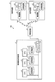
- FIG. 1 is a hardware configuration diagram of the wireless communication system.
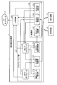
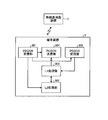
- FIG. 2 is a block diagram of the wireless base station device according to the embodiment.
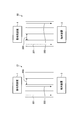
- FIG. 3 is a diagram for explaining cross slot scheduling in downlink communication.
- FIG. 4 is a diagram for explaining cross slot scheduling in uplink communication.
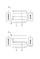
- FIG. 5 is a diagram for explaining the same slot scheduling.
- FIG. 6 is a diagram illustrating a radio resource allocation state when cross slot scheduling and same slot scheduling are mixed.
- FIG. 7 is a block diagram of the terminal device.
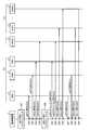
- FIG. 8 is a sequence diagram illustrating an outline of uplink communication by the base station device according to the embodiment.
- FIG. 9 is a sequence diagram illustrating transmission of a control signal and transmission of data in detail.
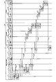
- FIG. 10 is a sequence diagram of uplink communication in the wireless communication system according to the embodiment.
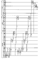
- FIG. 11 is a sequence diagram of downlink communication in the wireless communication system according to the embodiment.
- FIG. 12 is a sequence diagram illustrating a first method in which scheduling methods are mixed.
- FIG. 13 is a sequence diagram illustrating a second method in which scheduling methods are mixed.
- FIG. 1 is a hardware configuration diagram of a wireless communication system.
- the wireless communication system 100 includes a wireless base station device 1 and a plurality of terminal devices 3.
- FIG. 1 illustrates two terminal devices 3, but the number of terminal devices 3 is not particularly limited.
- the wireless base station device 1 and each terminal device 3 perform wireless communication.
- the terminal device 3 may be represented as UE (User @ Equipment).
- the wireless base station device 1 has CPUs (Central Processing Units) 11 to 13, storage devices 14 to 16, and a network interface 17.
- the CPU 11 is a processor for implementing the L (Layer) 2 function.
- the CPU 12 is a processor for realizing a scheduler function.
- the CPU 13 is a processor for implementing the L1 function.
- Each of the CPUs 11 to 13 is connected by a bus.
- the CPUs 11 to 13 are provided, but these may be integrated into one, or a larger number of processors may be used.
- the storage device 14 is connected to the CPU 11.
- the storage device 14 stores various programs executed by the CPU 11.
- the storage device 14 stores data when the CPU 11 executes a program.
- the storage device 15 is connected to the CPU 12.
- the storage device 15 stores various programs executed by the CPU 12.
- the storage device 15 stores data when the CPU 12 executes the program.
- the storage device 16 is connected to the CPU 13.
- the storage device 16 stores various programs executed by the CPU 13.
- the storage device 16 stores data when the CPU 13 executes the program.
- the network interface 17 is connected to a bus to which the CPUs 11 to 13 are connected.
- the network interface 17 is a communication interface for communicating with the wireless device 2.
- the wireless device 2 is connected to the network interface 17 of the wireless base station device 1.
- the wireless device 2 performs wireless communication with the terminal device 3 via an antenna.
- the wireless device 2 performs wireless communication control such as generation of a beam having directivity for the terminal device 3 and transmission and reception of a wireless signal.
- the terminal device 3 includes a CPU 31, a storage device 32, and a wireless device 33.
- the CPU 31 is connected to the storage device 32 and the wireless device 33 via a bus.
- the storage device 32 stores various programs executed by the CPU 31.
- the storage device 32 is a storage location of data when the CPU 31 executes the program.
- the CPU 31 executes various programs related to wireless communication by executing various programs stored in the storage device 32. For example, the CPU 31 executes a PDCCH (Physical Downlink Control Channel) reception process, a PUSCH (Physical Uplink Shared Channel) transmission process, a PDSCH (Physical Downlink Shared Channel) reception process, a baseband process, and the like.
- a PDCCH Physical Downlink Control Channel
- PUSCH Physical Uplink Shared Channel
- PDSCH Physical Downlink Shared Channel
- the wireless device 33 performs wireless communication with the wireless device 2 via an antenna.
- the wireless device 33 transmits the transmission data output by the CPU 31 to the wireless device 2 via the antenna.
- the wireless device 33 receives the data transmitted from the wireless device 2 and transfers the data to the CPU 31.
- FIG. 2 is a block diagram of the wireless base station device according to the embodiment.
- the radio base station apparatus 1 actually communicates with the terminal apparatus 3 via the radio apparatus 2, but here, for simplicity of explanation, the relay by the radio apparatus 2 is omitted. Will be explained.
- the radio base station device 1 includes a scheduling unit 101, an L1 processing unit 102, and an L2 processing unit 103, as shown in FIG.
- the scheduling unit 101 allocates wireless resources for transmitting data for performing wireless communication, generates control signals, and the like.
- the function of the scheduling unit 101 is realized by the CPU 12 in FIG.
- the scheduling unit 101 includes an mMTC scheduler 111, a URLLC scheduler 112, a radio resource management unit 113, a PDCCH transmission control unit 114, and a UL reception control unit 115.
- the mMTC scheduler 111 performs scheduling when performing communication for mMTC. In this scheduling, the mMTC scheduler 111 uses cross slot scheduling for data transmission for mMTC. That is, the mMTC scheduler 111 performs scheduling so that data transmission for the mMTC is performed in the same slot as the slot in which the control information is transmitted by the PDCCH.
- FIG. 3 is a diagram for explaining cross slot scheduling in downlink communication.
- a radio resource is divided in units of slots 200 in the time direction.
- the communication 21 represents a case where data transmission by PDSCH is performed in the slot 200 next to the control signal.
- the communication 22 indicates a case where data transmission by PDSCH is performed in the slot 200 which is three places ahead of the control signal.
- the slot 200 is an example of a “time-divided time section”.
- the mMTC scheduler 111 performs data transmission from the wireless base station device 1 indicated by the transmission process 202 in the slot 200 next to the transmission of the control signal represented by the transmission process 201 as in the communication 21, for example. Schedule as follows. In addition, in the downlink communication, the mMTC scheduler 111 transmits the control signal from the radio base station apparatus 1 indicated by the transmission process 203 in the slot 200 three times ahead of the transmission of the control signal represented by the transmission process 201 as in the communication 22. Is scheduled to be performed. As described above, the mMTC scheduler 111 notifies the control signal that data transmission is to be performed using the radio resource of any one of the slots 200 after the slot 200 that has transmitted the control signal, and then transmits the notified radio resource. Is used to transmit data.
- FIG. 4 is a diagram for explaining cross slot scheduling in uplink communication.
- Communication 23 in FIG. 4 represents a case where data transmission by PUSCH is performed in the next slot 200 of the control signal.
- the communication 24 represents a case where data transmission by PUSCH is performed in the slot 200 three places ahead of the control signal.
- the mMTC scheduler 111 causes the data transmission from the terminal device 3 indicated by the transmission process 212 to be performed in the slot 200 next to the transmission of the control signal represented by the transmission process 211 as in the communication 23, for example, in the uplink communication. Schedule.
- the mMTC scheduler 111 transmits data from the terminal device 3 indicated by the transmission process 213 in the slot 200 three times ahead of the transmission of the control signal represented by the transmission process 211 as in the communication 24, for example. Schedule transmission to occur.
- an arrow extending from the transmission process 211 to the transmission process 212 or 213 in the communication 23 or 24 indicates that the terminal device 3 performs the transmission process 212 or 213 based on the control signal transmitted in the transmission process 211.
- the mMTC scheduler 111 notifies the control signal that data transmission is to be performed using the radio resource of any one of the slots 200 after the slot 200 that has transmitted the control signal. Thereafter, the mMTC scheduler 111 receives the data transmitted from the terminal device 3 using the notified radio resource.
- the details of the scheduling operation of the mMTC scheduler 111 will be described.
- the mMTC scheduler 111 selects a terminal device 3 that performs communication for mMTC from among a plurality of terminal devices 3 accommodated by the wireless base station device 1. Next, the mMTC scheduler 111 inquires the radio resource management unit 113 of a radio resource that can be used for communication with the selected terminal device 3. After that, the mMTC scheduler 111 obtains information on available radio resources from the radio resource management unit 113.
- the mMTC scheduler 111 allocates available radio resources for data transmission for the mMTC.
- the mMTC scheduler 111 does not consider radio resource allocation for data transmission for URLLC.
- the mMTC scheduler 111 notifies the radio resource management unit 113 of the radio resource allocation.
- the mMTC scheduler 111 notifies the PDCCH transmission control unit 114 of a PDCCH transmission instruction for communication for mMTC, including notification of a radio resource allocated to data transmission for mMTC.
- the mMTC scheduler 111 notifies the UL reception control unit 115 of the information of the selected terminal device 3 and the radio resource for receiving the data for mMTC.
- the mMTC scheduler 111 notifies the L2 processing unit 103 of an instruction to transmit data by PDSCH using the allocated radio resources.
- the mMTC scheduler 111 performs retransmission scheduling of the data.
- the mMTC scheduler 111 is an example of a “first scheduling unit”.
- the URLLC scheduler 112 performs scheduling when performing communication for URLLC. In this scheduling, the URLLC scheduler 112 uses the same slot scheduling for data transmission for URLLC. That is, the URLLC scheduler 112 performs scheduling so that data transmission for URLLC is performed in the same slot in which the control information is transmitted by the PDCCH.
- the radio resource of the slot in which the control information is transmitted by the PDCCH is an example of a “predetermined radio resource”.
- FIG. 5 is a diagram for explaining the same slot scheduling.
- Communication 25 in FIG. 5 represents downlink communication, and communication 26 represents uplink communication.
- the URLLC scheduler 112 For downlink communication, the URLLC scheduler 112 performs data transmission from the wireless base station apparatus 1 indicated by the transmission process 222 in the same slot 200 as the transmission of the control signal represented by the transmission process 221 as in the communication 25. Schedule as follows. In the case of uplink communication, the URLLC scheduler 112 performs data transmission from the terminal device 3 indicated by the transmission process 223 in the same slot 200 as the transmission of the control signal represented by the transmission process 221 as in the communication 26. Schedule as follows. An arrow extending from the transmission process 221 to the transmission process 223 in the communication 26 indicates that the terminal device 3 performs the transmission process 223 based on the control signal transmitted in the transmission process 221. Returning to FIG. 2, the scheduling operation of the URLLC scheduler 112 will be described.
- the URLLC scheduler 112 selects a terminal device 3 that performs URLLC communication from a plurality of terminal devices 3 accommodated by the wireless base station device 1.
- the URLLC scheduler 112 inquires of the radio resource management unit 113 about radio resources that can be used for communication with the selected terminal device 3.
- the URLLC scheduler 112 sets the radio resources already allocated to the transmission of the data for the mMTC as the usable radio resources. This is because the communication for the URLLC requires a lower delay than the communication for the mMTC, and therefore, the communication for the URLLC is prioritized even if the communication for the mMTC is delayed.
- the URLLC scheduler 112 obtains information on available radio resources and information on radio resources from the radio resource management unit 113.
- the URLLC scheduler 112 determines the notified usable radio resources as radio resources to be used for URLLC communication.
- the URLLC scheduler 112 determines whether or not the radio resource determined to be used is a radio resource allocated to data communication for mMTC. If the radio resource determined to be used is a radio resource allocated for mMTC, the URLLC scheduler 112 allocates the radio resource determined to be used for transmission of data for URLLC. Among the radio resources already allocated for the mMTC, the radio resources for which the re-allocation to the URLLC is determined correspond to an example of the “first radio resource”. Then, another wireless resource in the same slot as the first wireless resource is an example of a “second wireless resource”.
- FIG. 6 is a diagram illustrating a radio resource allocation state when cross slot scheduling and same slot scheduling are mixed.
- FIG. 6 shows frequency in the vertical direction and slots in the horizontal direction.
- radio resources 230 are allocated to the communication for the mMTC, and the remaining radio resources 232 are the communication for the URLLC. Assigned to. That is, in order to allocate the radio resource 232 already allocated to the radio resource for mMTC to the communication for URLLC, the allocation of the radio resource 232 for the communication for mMTC which has been already performed is canceled.
- the URLLC scheduler 112 cancels the allocation of the data transmission for mMTC to which the radio resource has already been allocated. Then, the URLLC scheduler 112 specifies the communication target terminal device 3 for transmitting the canceled data for the mMTC.
- the URLLC scheduler 112 notifies the radio resource management unit 113 of the allocation of the radio resource determined to be used for the data transmission for the URLLC.
- the URLLC scheduler 112 notifies the PDCCH transmission control unit 114 of a PDCCH transmission instruction for URLLC communication including notification of a radio resource allocated to data transmission for the URLLC. Further, the URLLC scheduler 112 notifies the PDCCH transmission control unit 114 of a PDCCH transmission instruction for notifying the transmission of the data transmission for the mMTC allocated to the radio resource allocated to the transmission of the data for the URLLC.
- the URLLC scheduler 112 notifies the UL reception control unit 115 of information on the selected terminal device 3 that is a transmission source of the data for the URLLC and information on the radio resource used for receiving the data for the URLLC. I do. Further, the URLLC scheduler 112 notifies the UL reception control unit 115 of the information of the terminal device 3 that is the transmission source of the data for the mMTC allocated to the radio resource, together with the cancellation of the data reception.
- the URLLC scheduler 112 notifies the L2 processing unit 103 of an instruction to transmit data to the terminal device 3 selected by the PDSCH using the allocated radio resources. Further, the URLLC scheduler 112 notifies the PDSCH transmitting unit 123 of the cancellation of the data transmission to the terminal device 3 selected by the mMTC scheduler 111 using the radio resource allocated to the data transmission for the URLLC.
- the URLLC scheduler 112 allocates a radio resource that can be used for URLLC data transmission. Then, the URLLC scheduler 112 notifies the radio resource management unit 113 of the radio resource allocation. In addition, the URLLC scheduler 112 notifies the PDCCH transmission control unit 114 of a PDCCH transmission instruction for URLLC communication including a notification of a radio resource allocated to data transmission.
- the URLLC scheduler 112 notifies the UL reception control unit 115 of information on the selected terminal device 3 that is the transmission source of the data for URLLC and information on the radio resource used for receiving the data for URLLC. .
- the URLLC scheduler 112 notifies the L2 processing unit 103 of an instruction to transmit data by PDSCH using the allocated radio resources.
- the URLLC scheduler 112 performs retransmission scheduling of the data.
- the URLLC scheduler 112 is an example of a “second scheduling unit”.
- the radio resource management unit 113 receives an inquiry about allocation of usable radio resources from the mMTC scheduler 111. Then, the radio resource management unit 113 selects the radio resource of the slot with the earliest timing among the unallocated radio resources as a usable radio resource. After that, the radio resource management unit 113 notifies the mMTC scheduler 111 of the selected radio resource.
- the radio resource management unit 113 receives from the mMTC scheduler 111 a notification of the radio resource allocated to the transmission of the data for the mMTC. Then, the radio resource management unit 113 stores that the notified radio resource is allocated to the transmission of the data for the mMTC.
- the radio resource management unit 113 receives an inquiry about allocation of usable radio resources from the URLLC scheduler 112. Then, the radio resource management unit 113 selects the radio resource of the slot with the earliest timing among the radio resources that have not been allocated and the radio resources that have been allocated to the transmission of data for the mMTC as usable radio resources. After that, the radio resource management unit 113 notifies the URLLC scheduler 112 of the selected radio resource.
- the radio resource management unit 113 receives from the URLLC scheduler 112 a notification of the radio resource allocated to the transmission of the data for the URLLC. Then, the radio resource management unit 113 stores that the notified radio resource is allocated to the data transmission for the URLLC. At this time, if the radio resource newly assigned to the data transmission for the URLLC has already been assigned to the data transmission for the mMTC, the radio resource management unit 113 overwrites the assignment information. That is, the radio resource management unit 113 cancels the allocation of the radio resource to data transmission for mMTC, and newly allocates the radio resource to data transmission for URLLC.
- the PDCCH transmission control unit 114 receives from the mMTC scheduler 111 a PDCCH transmission instruction for communication for mMTC including notification of a radio resource allocated to data transmission for mMTC. Then, PDCCH transmission control section 114 generates a control signal for communication for mMTC including notification of a radio resource allocated to data transmission for mMTC. Thereafter, PDCCH transmission control section 114 instructs PDCCH transmission section 121 to transmit a control signal for communication for mMTC including notification of a radio resource allocated to data transmission for mMTC.
- the PDCCH transmission control unit 114 receives from the mMTC scheduler 111 a PDCCH transmission instruction for communication for mMTC including notification of a radio resource allocated to data transmission for mMTC. Then, PDCCH transmission control section 114 generates a control signal for communication for mMTC including notification of a radio resource allocated to data transmission for mMTC. Thereafter, PDCCH transmission control section 114 instructs PDCCH transmission section 121 to transmit a control signal for communication for mMTC including notification of a radio resource allocated to data transmission for mMTC.
- the PDCCH transmission control unit 114 receives, from the URLLC scheduler 112, a PDCCH transmission instruction for communication for URLLC including notification of a radio resource allocated to data transmission for URLLC. Further, when the radio resource already allocated for the mMTC has been allocated for the URLLC, the PDCCH transmission control unit 114 performs the following processing.
- the PDCCH transmission control unit 114 receives from the URLLC scheduler 112 a PDCCH transmission instruction for notifying the cancellation of the allocation of the radio resource to the data transmission for the mMTC. Then, PDCCH transmission control section 114 generates a control signal for communication for mMTC including notification of a radio resource allocated to data transmission for URLLC. Further, when the radio resource already allocated for the mMTC has been allocated for the URLLC, the PDCCH transmission control unit 114 generates the next signal. That is, PDCCH transmission control section 114 generates a control signal for notifying the cancellation of the allocation of the radio resource allocated to the data transmission for the URLLC to the data transmission for the mMTC.
- the PDCCH transmission control unit 114 instructs the PDCCH transmission unit 121 to transmit a control signal for URLLC communication including a notification of a radio resource allocated to data transmission for URLLC. Furthermore, when the radio resource already allocated for mMTC is allocated for URLLC, PDCCH transmission control section 114 issues the following instruction to PDCCH transmission section 121. That is, PDCCH transmission control section 114 instructs PDCCH transmission section 121 to transmit a control signal for notifying the cancellation of the allocation of the radio resource allocated to the data transmission for the URLLC to the data transmission for the mMTC.
- the PDCCH transmission control unit 114 is an example of a “control information transmission unit”.
- the UL reception control unit 115 receives, from the mMTC scheduler 111, a notification of information on a plurality of terminal devices 3 selected as a source of data for mMTC and information of wireless resources for receiving data for mMTC. Then, UL reception control section 115 instructs PUSCH receiving section 122 to receive the data transmitted by PUSCH from the selected terminal apparatus 3 and transmitted using the allocated radio resources.
- the URLLC scheduler 112 performs reception of the data for URLLC transmitted by the PUSCH from the selected terminal device 3 and transmitted using the allocated radio resource, by the PUSCH receiving unit. Instruct 122. Further, the URLLC scheduler 112 instructs the PUSCH receiving unit 122 to cancel reception of data for the mMTC transmitted using the radio resource allocated from the terminal device 3 selected by the mMTC scheduler 111.
- the UL reception control unit 115 also receives, from the URLLC scheduler 112, a notification of the information of the selected terminal device 3 that is the transmission source of the URLLC data and the information of the radio resource used for receiving the URLLC data. Further, when the radio resource already allocated for the mMTC is allocated for the URLLC, the UL reception control unit 115 receives a notification of the cancellation of the reception of the data for the mMTC from the URLLC scheduler 112. Specifically, UL reception control section 115 receives, from URL URL scheduler 112, a notification of cancellation of data reception together with information on terminal apparatus 3 serving as a transmission source of mMTC data allocated to the radio resource.
- the UL reception control unit 115 instructs the PUSCH reception unit 122 to receive data for URLLC transmitted by the PUSCH from the selected terminal device 3 and transmitted using the allocated radio resources. . Further, when the radio resources already allocated for the mMTC are allocated for the URLLC, the UL reception control unit 115 notifies the reception cancellation of the data for the mMTC as follows. Specifically, UL reception control section 115 instructs PUSCH receiving section 122 to cancel reception of data for mMTC transmitted using the radio resource allocated from terminal apparatus 3 selected by mMTC scheduler 111. .
- the L1 processing unit 102 performs processing in the physical layer such as modulation / demodulation processing and coding / decoding processing according to an instruction from the scheduling unit 101.
- the L1 processing unit 102 includes a PDCCH transmitting unit 121, a PUSCH receiving unit 122, and a PDSCH transmitting unit 123.
- the PDCCH transmission unit 121 receives from the PDCCH transmission control unit 114 an instruction to transmit a control signal for communication for mMTC including a notification of a radio resource allocated to data transmission for mMTC. Then, the PDCCH transmission unit 121 transmits a control signal for mMTC communication including a notification of the radio resource allocated to data transmission for mMTC to the terminal device 3 that performs communication for mMTC selected by the mMTC scheduler 111. I do.
- PDCCH transmission section 121 receives from PDCCH transmission control section 114 an instruction to transmit a control signal for communication for URLLC including notification of a radio resource allocated to data transmission for URLLC. Further, when the radio resource already allocated for the mMTC is allocated for the URLLC, the PDCCH transmission unit 121 transmits a control signal transmission instruction for notifying the cancellation of the communication for the mMTC using the radio resource to the PDCCH transmission control. Received from unit 114.
- the PDCCH transmission unit 121 transmits a control signal for URLLC communication including a notification of the radio resource allocated to the data transmission for URLLC to the terminal device 3 that performs the URLLC communication selected by the URLLC scheduler 1121. Send. Furthermore, when the radio resource already allocated for the mMTC is allocated for the URLLC, the PDCCH transmitting unit 121 notifies the cancellation of the communication for the mMTC using the radio resource. Specifically, PDCCH transmitting section 121 transmits a control signal for notifying the cancellation of the communication for mMTC using the radio resource, to terminal device 3 that performs communication for mMTC using the radio resource. Send to
- PUSCH receiving section 122 receives, from UL reception control section 115, an instruction to receive data transmitted using the radio resources allocated by mMTC scheduler 111. In this case, the PUSCH receiving unit 122 is instructed to receive data from the terminal device 3 selected by the mMTC scheduler 111. Then, the PUSCH receiving unit 122 receives the data for mMTC transmitted using the designated radio resource from the terminal device 3 selected by the mMTC scheduler 111.
- the PUSCH receiving unit 122 receives the data for mMTC from the terminal devices 3 other than the terminal device 3 using the radio resources allocated to the data transmission for URLLC.
- the PUSCH receiving unit 122 receives, from the UL reception control unit 115, an instruction to receive data transmitted using the radio resources allocated by the URLLC scheduler 112. In this case, the PUSCH receiving unit 122 is instructed to receive data from the terminal device 3 selected by the URLLC scheduler 112. Then, the PUSCH receiving unit 122 receives the data for the URLLC transmitted using the specified radio resource from the terminal device 3 selected by the URLLC scheduler 112.
- the PUSCH receiving unit 122 performs demodulation processing and decoding processing on the received data. Then, if the data has been successfully received, PUSCH receiving section 122 outputs the received data to L2 processing section 103. On the other hand, when the data reception has failed, the PUSCH receiving unit 122 notifies the mMTC scheduler 111 or the URLLC scheduler 112 that has scheduled the communication regarding the data of the data reception failure.
- the PDSCH transmission unit 123 receives an input of an instruction to transmit data for mMTC from the L2 processing unit 103. Then, PDSCH transmitting section 123 performs an encoding process and a modulation process on the data to be transmitted. Thereafter, the PDSCH transmitting unit 123 transmits the data to the terminal device 3 selected by the mMTC scheduler 111 in accordance with the data transmission instruction.
- the PDSCH transmitting unit 123 receives a notification of the cancellation of the data transmission for the mMTC from the URLLC scheduler 112 using the radio resource. In this case, the PDSCH transmission unit 123 transmits data other than the data notified of the transmission cancellation to the destination terminal device 3.
- the PDSCH transmitting unit 123 receives an input of a data transmission instruction for URLLC from the L2 processing unit 103. Then, PDSCH transmitting section 123 performs an encoding process and a modulation process on the data to be transmitted. Thereafter, the PDSCH transmission unit 123 transmits the data to the terminal device 3 selected by the URLLC scheduler 112 according to the data transmission instruction.
- the PUSCH receiving unit 122 and the PDSCH transmitting unit 123 are an example of a “first communication unit”.
- L2 processing section 103 receives input of data transmitted from terminal apparatus 3 from PUSCH receiving section 122 in the case of uplink communication. Then, the L2 processing unit 103 removes the header and extracts the main body of the data. Further, the L2 processing unit 103 determines a route to the data destination, and sends the data to the core network 4 according to the determination.
- the L2 processing unit 103 receives, from the mMTC scheduler 111, a data transmission instruction designating a radio resource allocated to data transmission for mMTC. Then, the L2 processing unit 103 adds a header to the data to be transmitted. After that, the L2 processing unit 103 notifies the PDSCH transmitting unit 123 of an instruction to transmit data for mMTC, together with information on the radio resources to be used.
- the L2 processing unit 103 receives, from the URLLC scheduler 112, a data transmission instruction designating a radio resource allocated to data transmission for URLLC. Then, the L2 processing unit 103 adds a header to the data to be transmitted. After that, the L2 processing unit 103 notifies the PDSCH transmitting unit 123 of the transmission instruction of the data for the URLLC together with the information of the radio resource to be used.
- FIG. 7 is a block diagram of the terminal device. Although there are a plurality of terminal devices 3, all have the same function, and therefore a specific one will be described here as an example.
- the terminal device 3 includes a PDCCH receiving unit 301, an L2 processing unit 302, an L1 processing unit 303, a PUSCH transmitting unit 304, and a PDSCH receiving unit 305.
- PDCCH receiving section 301 receives control information from radio base station apparatus 1 by PDCCH. Then, PDCCH receiving section 301 determines whether to perform uplink communication or downlink communication from the received control information. In the case of uplink communication, PDCCH receiving section 301 outputs an instruction to generate a packet for transmitting data to L2 processing section 302. At this time, PDCCH receiving section 301 also notifies L2 processing section 302 of information on radio resources used for data transmission. Thereafter, when receiving control information for notifying the cancellation by the PDCCH from the wireless base station device 1, the PDCCH receiving unit 301 instructs the PUSCH transmitting unit 304 to cancel the data transmission.
- the PDCCH receiving unit 301 In the case of downlink communication, the PDCCH receiving unit 301 notifies the PDSCH receiving unit 305 of an instruction to receive data transmitted from the radio base station apparatus 1 together with information on the radio resources used for data reception. Thereafter, when receiving control information for notifying cancellation by the PDCCH from the wireless base station device 1, the PDCCH receiving unit 301 instructs the PDSCH receiving unit 305 to cancel data reception.
- L2 processing section 302 receives from PDCCH receiving section 301 an instruction to generate a packet for transmitting data. Then, the L2 processing unit 302 assembles a PDU (Protocol @ Data @ Unit) for the data to be transmitted, and packetizes the data. Then, L2 processing section 302 outputs the PDU to L1 processing section 303. In the case of downlink communication, the L2 processing unit 302 receives a MAC (Media Access Control) -PDU input from the L1 processing unit 303. Then, the L2 processing unit 302 extracts data from the acquired MAC-PDU.
- PDU Protocol @ Data @ Unit
- the L1 processing unit 303 receives an input of a PDU from the L2 processing unit 302 in the case of uplink communication. Then, the L1 processing unit 303 performs an encoding process and a modulation process on the obtained PDU. After that, the L1 processing unit 303 transmits the data to be transmitted to the PUSCH transmitting unit 304 and notifies the PUSCH transmitting unit 304 of the transmission timing. In the case of downlink communication, the L1 processing unit 303 receives an input of data transmitted from the wireless base station device 1 from the PDSCH receiving unit 305. Then, the L1 processing unit 303 performs demodulation processing and decoding processing on the obtained data to obtain a MAC-PDU. Then, L1 processing section 303 outputs the MAC-PDU to L2 processing section 302.
- PUSCH transmitting section 304 receives notification of transmission timing from L1 processing section 303 together with input of transmission data. Then, PUSCH transmission section 304 waits for data transmission until the notified transmission timing. Thereafter, when receiving an instruction to cancel data transmission from the PDCCH receiving unit 301 while waiting for data transmission, the PUSCH transmitting unit 304 stops transmitting data. On the other hand, when the transmission timing arrives without receiving the cancellation instruction, the PUSCH transmission unit 304 transmits the data acquired from the L1 processing unit 303 to the wireless base station device 1.
- PDSCH receiving section 305 receives, from PDCCH receiving section 301, an instruction to receive data transmitted from radio base station apparatus 1 together with information on radio resources used for data reception. Then, PDSCH receiving section 305 waits until the timing of the designated radio resource. Thereafter, when receiving an instruction to cancel data reception from the PDCCH receiving unit 301 during standby, the PDSCH receiving unit 305 stops receiving data. On the other hand, when the reception timing arrives without receiving the cancel instruction, PDSCH receiving section 305 receives the data transmitted from wireless base station apparatus 1. Thereafter, PDSCH receiving section 305 outputs the obtained data to L1 processing section 303.
- the PUSCH transmitting unit 304 and the PDSCH receiving unit 305 are an example of a “second communication unit”.
- FIG. 8 is a sequence diagram illustrating an outline of uplink communication by the base station device according to the embodiment.
- the upper side with respect to the dashed line in FIG. 8 indicates the mMTC side processing
- the lower side indicates the URLLC side processing.
- UEs # 1 to # 14 exist as terminal devices 3
- UEs # 1 to # 10 perform communication for mMTC
- UEs # 11 to # 14 perform communication for URLLC.
- the scheduling results 241 and 242 indicate the allocation state of the radio resources of the slot 240.
- the mMTC scheduler 111 schedules data transmission for the mMTC (step S1). At this stage, as indicated by the scheduling result 241, the radio resources of the slot 240 are allocated to data transmission for the mMTC from each of the UEs # 1 to # 10. Then, the mMTC scheduler 111 notifies the PDCCH transmission control unit 114 of data transmission for the mMTC using the radio resources of the slot 240 to the UEs # 1 to # 10. Further, the mMTC scheduler 111 notifies the UL reception control unit 115 of reception of data for mMTC transmitted from the UEs # 1 to # 10 using the radio resources of the slot 240.
- PDCCH transmission control section 114 generates a control signal and instructs PDCCH transmission section 121 to transmit.
- PDCCH transmitting section 121 transmits a control signal for notifying data transmission for mMTC using the radio resource of slot 240 to UEs # 1 to # 10 (step S2).
- UL reception control section 115 instructs PUSCH receiving section 122 to receive data for mMTC transmitted from UEs # 1 to # 10 using the radio resources of slot 240.
- step S3 data transmission for URLLC occurs, and the URLLC scheduler 112 performs scheduling of data transmission for URLLC (step S3).
- URLLC scheduler 112 allocates the radio resources allocated for data transmission from UEs # 7 to # 10 to data transmission from UEs # 11 to # 14.
- the radio resource of the slot 240 is used for data transmission for mMTC from each of the UEs # 1 to # 6 and data transmission for URLLC from each of the UEs # 11 to # 14. Assigned.
- URLLC scheduler 112 notifies PDCCH transmission control section 114 of data transmission for URLLC using the radio resource of slot 240 to UEs # 11 to # 14.
- URLLC scheduler 112 notifies PDCCH transmission control section 114 of cancellation of data transmission for mMTC using the radio resource of slot 240 to UEs # 7 to # 10. In addition, the URLLC scheduler 112 notifies the UL reception control unit 115 of reception of URLLC data transmitted from the UEs # 11 to # 14 using the radio resources of the slot 240. Further, the URLLC scheduler 112 notifies the UL reception control unit 115 of the cancellation of the reception of the data for the mMTC transmitted from the UEs # 7 to # 10 using the radio resources of the slot 240.
- the PDCCH transmission control unit 114 generates a control signal for notifying the cancellation of data transmission for the mMTC using the radio resources of the slot 240 to the UEs # 7 to # 10. Then, PDCCH transmission control section 114 instructs PDCCH transmission section 121 to transmit a control signal for notifying the cancellation of data transmission for mMTC using the radio resources of slot 240 to UEs # 7 to # 10. In response to this instruction, PDCCH transmitting section 121 transmits a control signal for notifying the cancellation of data transmission for mMTC using the radio resource of slot 240 to UEs # 7 to # 10 (step S4).
- the PDCCH transmission control unit 114 generates a control signal for data transmission for URLLC to the UEs # 11 to # 14 using the radio resources of the slot 240. Then, PDCCH transmission control section 114 instructs PDCCH transmission section 121 to transmit a control signal for data transmission for URLLC using the radio resources of slot 240 to UEs # 11 to # 14. In response to this instruction, PDCCH transmitting section 121 transmits a control signal for data transmission for URLLC using the radio resources of slot 240 to UEs # 11 to # 14 (step S5).
- the UEs # 1 to 10 each transmit data based on the control signal transmitted in step S2, and the PUSCH receiving unit 122 receives the data G1 from the UEs # 1 to # 10. .
- the UEs # 7 to # 10 do not perform data transmission for mMTC. Therefore, PUSCH receiving section 122 does not receive data G1 based on the control signal transmitted in step S2 (step S6).
- PUSCH receiving section 122 receives data for mMTC from UEs # 1 to # 6, and transmits data for URLLC. Are received from UEs # 10 to # 14 (step S7).
- the PUSCH receiving unit 122 performs a demodulation process and a decoding process on the received signal (Step S8).
- the mMTC scheduler 111 schedules retransmission of data for the mMTC to the UEs # 1 to # 10 (step S9).
- the URLLC scheduler 112 schedules retransmission of data for URLLC to the UEs # 11 to # 14 (step S10).
- the radio resources allocated to data transmission for mMTC and the radio resources allocated to data transmission for URLLC are different. Therefore, the URLLC scheduler 112 does not need to cancel data transmission for mMTC.
- PDCCH transmission control section 114 generates a control signal for retransmission of data for mMTC to UEs # 1 to # 10, and instructs PDCCH transmission section 121 to transmit a control signal.
- PDCCH transmitting section 121 transmits a control signal for retransmission of data for mMTC to UEs # 1 to # 10 (step S11).
- PDCCH transmission control section 114 generates a control signal for retransmission of data for URLLC to UEs # 11 to # 14, and instructs PDCCH transmission section 121 to transmit a control signal.
- PDCCH transmitting section 121 transmits a control signal for retransmission of data for URLLC to UEs # 11 to # 14 (step S12).
- the PUSCH receiving unit 122 receives the data for mMTC retransmitted from the UEs # 1 to # 10 (Step S13). Further, PUSCH receiving section 122 receives the data for URLLC retransmitted from UEs # 11 to # 14 (step S14).
- FIG. 9 is a sequence diagram illustrating transmission of a control signal and transmission of data in detail.
- the terminal devices 3 represented by the UEs # 1 to # 10 belong to the mMTC group 311 and the terminal devices 3 represented by the UEs # 11 to # 14 belong to the URLLC group 312.
- the mMTC scheduler 111 of the wireless base station device 1 performs scheduling of data transmission for mMTC (step S21).
- the PDCCH transmitting unit 121 of the wireless base station device 1 transmits a control signal for data transmission for mMTC to the UEs # 1 to # 10 belonging to the group 311 for mMTC by PDCCH (Steps S22 to S25).
- the control signal for data transmission for mMTC transmitted by PDCCH is represented as PDCCH for mMTC.
- the URLLC scheduler 112 of the wireless base station device 1 performs scheduling of data transmission for URLLC (step S26).
- the PDCCH transmitting unit 121 of the wireless base station device 1 transmits a control signal for canceling data transmission for mMTC to the UEs # 7 to # 10 via the PDCCH (Steps S27 to S28). Further, PDCCH transmitting section 121 of wireless base station apparatus 1 transmits a control signal for data transmission for URLLC to UEs # 11 to # 14 via PDCCH (steps S29 to S30).
- the control signal for canceling the data transmission for the mMTC transmitted by the PDCCH is represented as the PTCCH for the mMTC cancellation.
- a control signal for data transmission for URCCL transmitted by the PDCCH is represented as a URLLC PDCCH.
- the UEs # 1 to # 6 transmit data for the mMTC to the radio base station apparatus 1 using the PUSCH using the radio resources specified by the PDCCH.
- the PUSCH receiving unit 122 of the wireless base station device 1 receives the data for the mMTC transmitted from the UEs # 1 to # 6 by the PUSCH (Steps S31 to S32).
- UEs # 11 to # 14 transmit data for URLLC to the radio base station apparatus 1 by PUSCH using radio resources in the same slots as radio resources used by UEs # 1 to # 6.
- the PUSCH receiving unit 122 of the radio base station apparatus 1 receives the data for the URLLC transmitted by the PUSCH from the UEs # 11 to # 14 (Steps S33 to S34).
- the data for the mMTC transmitted by the PUSCH is represented as the PUSCH for the mMTC.
- data for URCCL transmitted by PUSCH is represented as URLSCH PUSCH.
- FIG. 10 is a sequence diagram of uplink communication in the wireless communication system according to the embodiment.
- the terminal device 3M includes a terminal device 3M that performs communication for mMTC and a terminal device 3U that performs communication for URLLC.
- the terminal device 3M and 3U is shown as a representative one, but a plurality of terminal devices actually exist.
- the terminal device 3M described in FIG. 10 is a terminal device 3M from which data transmission for mMTC is canceled.
- each unit of the terminal device 3M is referred to as a PDCCH receiving unit 301M, an L2 processing unit 302M, an L1 processing unit 303M, a PUSCH transmitting unit 304M, and a PDSCH receiving unit 305M.
- Each unit of the terminal device 3U is represented as a PDCCH receiving unit 301U, an L2 processing unit 302U, an L1 processing unit 303U, a PUSCH transmitting unit 304U, and a PDSCH receiving unit 305U.
- the operation of UL reception control section 115 will be omitted. Further, here, a case will be described where radio resources of a specific slot are assigned data transmission for mMTC and data transmission for URLLC.
- the mMTC scheduler 111 selects the terminal device 3M to be the data transmission source, triggered by the occurrence of data transmission for the mMTC (step S101).
- the mMTC scheduler 111 checks the available radio resources to the radio resource management unit 113 and determines the radio resources to be used (step S102).
- the radio resource determined to be used here is referred to as a target radio resource of a specific slot.
- the mMTC scheduler 111 allocates a target wireless resource for data transmission to the mMTC destined for the terminal device 3M (step S103).
- the mMTC scheduler 111 notifies the wireless resource management unit 113 of the allocation of the target wireless resource for the data transmission for the mMTC from the terminal device 3M (step S104).
- the radio resource management unit 113 stores that the target radio resource has been allocated to data transmission for the mMTC having the terminal device 3M as the transmission source.
- the mMTC scheduler 111 instructs the PDCCH transmission control unit 114 to transmit control information to the terminal device 3M using the PDCCH for notifying the allocation of the target radio resource for the data transmission for the mMTC (step S105).
- the mMTC scheduler 111 notifies the PUSCH receiving unit 122 of reception information of data transmitted from the terminal device 3M using the target radio resource (Step S106).
- the PDCCH transmission control unit 114 generates control information for notifying the allocation of the target radio resource for the data transmission for the mMTC. Then, PDCCH transmission control section 114 outputs the generated control information to PDCCH transmission section 121, and instructs PDCCH transmission section 121 to transmit control information by PDCCH (step S107).
- the PDCCH transmission unit 121 transmits the control information received from the PDCCH transmission control unit 114 to the PDCCH reception unit 301M of the terminal device 3M via the PDCCH (Step S108).
- the PDCCH receiving unit 301M acquires information on a target wireless resource used for data transmission for the mMTC to the wireless base station device 1 from the control information received from the PDCCH transmitting unit 121. Then, PDCCH receiving section 301M instructs L2 processing section 302M to transmit data for mMTC to radio base station apparatus 1 using the target radio resource (step S109).
- the L2 processing unit 302M receives the instruction from the PDCCH receiving unit 301M and performs PDU assembly of data to be transmitted (step S110).
- the L2 processing unit 302M outputs the PDU of the data to be transmitted to the L1 processing unit 303M (Step S111).
- the L1 processing unit 303M performs an encoding process and a modulation process on the PDU acquired from the L2 processing unit 302M (Step S112).
- the L1 processing unit 303M outputs the encoded and decoded PDU to the PUSCH transmitting unit 304M, and notifies the data transmission timing (step S113).
- the PUSCH transmission unit 304M receives the PDU of the transmission data from the L1 processing unit 303M. Then, PUSCH transmission section 304M waits until the transmission timing of the notified data (step S114).
- data transmission for URLLC occurs between steps S103 and S114, and the URLLC scheduler 112 selects the terminal device 3U to be the data transmission source (step S115).
- the URLLC scheduler 112 checks available radio resources with the radio resource management unit 113, and determines the target radio resources as radio resources to be used (step S116).
- the URLLC scheduler 112 allocates a part of the target radio resource to the data transmission for the URLLC from the terminal device 3U as the transmission source (step S117). At this time, the URLLC scheduler 112 specifies the terminal device 3M from which data transmission is canceled by this assignment. Hereinafter, the terminal device 3M whose data transmission is canceled is referred to as “cancelled terminal device 3M”. In addition, a part of the target radio resources allocated by the URLLC scheduler 112 is referred to as an updated radio resource.
- the URLLC scheduler 112 notifies the radio resource management unit 113 of the allocation of the updated radio resource for the data transmission for the mMTC from the terminal device 3U as the transmission source (step S118).
- the radio resource management unit 113 stores that the allocation of the updated radio resources has been changed from the data transmission for the mMTC with the terminal device 3M as the transmission source to the data transmission for the URLLC with the terminal device 3U as the transmission source.
- the URLLC scheduler 112 instructs the PDCCH transmission control unit 114 to transmit the control information to the terminal device 3U by the PDCCH for notifying the allocation of the updated radio resource for the data transmission for the URLLC. Further, the URLLC scheduler 112 instructs the PDCCH transmission control unit 114 to transmit the control information for notifying the cancellation of the allocation of the updated radio resource for the data transmission for the mMTC to the terminal device 3M to be canceled (step S119).
- the URLLC scheduler 112 notifies the PUSCH receiving unit 122 of reception information of data transmitted from the terminal device 3U using the updated radio resources. Further, the URLLC scheduler 112 notifies the PUSCH receiving unit 122 of the cancellation of the reception of the data transmitted from the terminal device 3M to be canceled using the updated radio resource (step S120).
- the PDCCH transmission control unit 114 generates control information for notifying the terminal device 3U of the allocation of the updated radio resource for the data transmission for the URLLC. Also, the PDCCH transmission control unit 114 generates control information for notifying the cancellation target terminal device 3M of the cancellation of the allocation of the updated radio resource for the data transmission for the mMTC. Then, PDCCH transmission control section 114 outputs the generated control information to PDCCH transmission section 121, and instructs PDCCH transmission section 121 to transmit control information by PDCCH (step S121).
- PDCCH transmission section 121 receives control information from PDCCH transmission control section 114. Then, the PDCCH transmission unit 121 transmits control information for notifying the cancellation of the allocation of the updated radio resource for the data transmission for the mMTC to the terminal device 3M to be canceled (Step S122).
- the PDCCH transmitting unit 121 transmits control information for notifying the allocation of the updated radio resource for the data transmission for the URLLC to the terminal device 3U (Step S123).
- the PDCCH receiving unit 301M of the terminal device 3M to be canceled receives, from the PDCCH transmitting unit 121, control information for notifying the cancellation of the update wireless resource allocation for the data transmission for the mMTC. Then, PDCCH receiving section 301M instructs PUSCH transmitting section 304M to cancel data transmission for mMTC (step S124).
- the PUSCH transmission unit 304 cancels the data transmission for the mMTC using the updated radio resource (step S125). .
- the PDCCH receiving unit 301U of the terminal device 3U acquires information on updated radio resources used for transmitting data for URLLC to the radio base station device 1 from the control information received from the PDCCH transmitting unit 121. Then, PDCCH receiving section 301U instructs L2 processing section 302U to transmit data for URLLC to radio base station apparatus 1 using the updated radio resources (step S126).
- the L2 processing unit 302U receives the instruction from the PDCCH receiving unit 301U, and assembles the PDU of the data to be transmitted (step S127).
- the L2 processing unit 302U outputs the PDU of the data to be transmitted to the L1 processing unit 303U (Step S128).
- the L1 processing unit 303U performs an encoding process and a modulation process on the PDU acquired from the L2 processing unit 302U (step S129).
- the L1 processing unit 303U outputs the PDU that has been subjected to the encoding process and the decoding process to the PUSCH transmitting unit 304U, and notifies the data transmission timing (step S130).
- PUSCH transmitting section 304U receives PDU of transmission data from L1 processing section 303U. Then, PUSCH transmitting section 304M waits until the transmission timing of the notified data (step S131).
- the PUSCH transmitting unit 304U transmits the data for URLLC to the PUSCH receiving unit 122 of the wireless base station device 1 by the PUSCH (step S132).
- the PUSCH receiving unit 122 receives the data for the URLLC by the PUSCH and performs the PUSCH receiving process (Step S133).
- FIG. 11 is a sequence diagram of downlink communication in the wireless communication system according to the embodiment.
- the mMTC scheduler 111 selects the terminal device 3M to be transmitted, triggered by the occurrence of data transmission for mMTC (step S201).
- the mMTC scheduler 111 checks the radio resource management unit 113 for available radio resources, and determines a target radio resource to be used (step S202).
- the mMTC scheduler 111 allocates a target wireless resource to data transmission for the mMTC destined for the terminal device 3M (Step S203).
- the mMTC scheduler 111 notifies the wireless resource management unit 113 of the allocation of the target wireless resource for the data transmission for the mMTC destined for the terminal device 3M (step S204).
- the radio resource management unit 113 stores that the target radio resource has been allocated to data transmission for the mMTC destined for the terminal device 3M.
- the mMTC scheduler 111 instructs the L2 processing unit 103 to transmit data for mMTC by PDSCH using the target radio resource (Step 205).
- the L2 processing unit 103 receives the instruction from the mMTC scheduler 111 and performs MACPDU assembly of the transmission data for the mMTC (step S206).
- the L2 processing unit 103 outputs the MAC PDU to the PDSCH transmitting unit 123 (Step S207).
- the PDSCH transmission unit 123 performs an encoding process and a modulation process on the acquired MAC PDU (step S208).
- the mMTC scheduler 111 also instructs the PDCCH transmission control unit 114 to transmit control information to the terminal device 3M using the PDCCH for notifying the allocation of the target radio resource for the data transmission for the mMTC (step S209).
- the PDCCH transmission control unit 114 generates control information for notifying the allocation of the target radio resource for the data transmission for the mMTC. Then, PDCCH transmission control section 114 outputs the generated control information to PDCCH transmission section 121, and instructs PDCCH transmission section 121 to transmit control information by PDCCH (step S210).
- the PDCCH transmission unit 121 transmits the control information received from the PDCCH transmission control unit 114 to the PDCCH reception unit 301M of the terminal device 3M via the PDCCH (Step S211).
- PDCCH receiving section 301M acquires information on target radio resources used for data transmission for mMTC from radio base station apparatus 1 from control information received from PDCCH transmitting section 121. Then, PDCCH receiving section 301M instructs PDSCH receiving section 305M to receive data for mMTC from radio base station apparatus 1 using the target radio resource (step S212).
- the PDSCH receiving unit 305M receives the instruction from the PDCCH receiving unit 301M and waits until data reception timing (step S213).
- data transmission for URLLC occurs between steps S203 to S213, and the URLLC scheduler 112 selects the terminal device 3U to be the data destination (step S214).
- the URLLC scheduler 112 checks available radio resources to the radio resource management unit 113, and determines the target radio resources as radio resources to be used (step S215).
- the URLLC scheduler 112 allocates an updated radio resource that is a part of the target radio resource for data transmission to the URLLC destined for the terminal device 3U (step S216). At this time, the URLLC scheduler 112 specifies the cancellation target terminal device 3M whose data transmission is canceled by this assignment.
- the URLLC scheduler 112 notifies the radio resource management unit 113 of the allocation of the updated radio resource for the data transmission for the mMTC destined for the terminal device 3U (step S217).
- the radio resource management unit 113 stores that the allocation of the updated radio resources has been changed from the data transmission for the mMTC destined for the terminal device 3M to the data transmission for the URLLC destined for the terminal device 3U.
- the URLLC scheduler 112 instructs the L2 processing unit 103 to transmit data for URLLC by PDSCH using the target radio resource (step S218).
- the URLLC scheduler 112 instructs the L2 processing unit 103 to cancel data transmission for the mMTC by the PDSCH using the target radio resource (step S219).
- the L2 processing unit 103 receives the instruction from the URLLC scheduler 112 and performs MACPDU assembly of the transmission data for the URLLC (step S220).
- the L2 processing unit 103 outputs the MAC PDU to the PDSCH transmitting unit 123 (Step S221).
- the PDSCH transmission unit 123 performs an encoding process and a modulation process on the obtained MAC PDU (step S222).
- the mMTC scheduler 111 also instructs the PDCCH transmission control unit 114 to transmit control information to the terminal device 3U using the PDCCH for notifying the allocation of the target radio resource for the data transmission for the URLLC. Further, the mMTC scheduler 111 instructs the PDCCH transmission control unit 114 to transmit the control information to the terminal device 3M using the PDCCH for notifying the cancellation of the allocation of the target radio resource for the data transmission for the mMTC (Step S223).
- the PDCCH transmission control unit 114 generates control information for notifying the allocation of the target radio resource for the data transmission for the URLLC. Further, PDCCH transmission control section 114 generates control information for notifying the cancellation of the assignment of the target radio resource for data transmission for mMTC. Then, PDCCH transmission control section 114 outputs the generated control information to PDCCH transmission section 121, and instructs PDCCH transmission section 121 to transmit control information by PDCCH (step S224).
- PDCCH transmission section 121 receives control information from PDCCH transmission control section 114. Then, PDCCH transmitting section 121 transmits control information for notifying the cancellation of the allocation of the target radio resource for the data transmission for mMTC to PDCCH receiving section 301M of terminal apparatus 3M to be canceled by PDCCH. (Step S225).
- the PDCCH receiving unit 301M of the terminal device 3M to be canceled receives the control information from the PDCCH transmitting unit 121. Then, PDCCH receiving section 301M instructs PDSCH receiving section 305M to cancel reception of data for mMTC from radio base station apparatus 1 (step S226).
- the PDSCH receiving unit 305 receives the instruction from the PDCCH receiving unit 301M while waiting until the reception timing, and cancels the reception of the data for the mMTC by the PDSCH (step S227).
- PDCCH transmitting section 121 transmits control information for notifying the allocation of the target radio resource for data transmission for URLLC to PDCCH receiving section 301U of terminal apparatus 3U via PDCCH (step S228).
- PDCCH receiving section 301U acquires information on target radio resources used for data transmission for URLLC from radio base station apparatus 1 from control information received from PDCCH transmitting section 121. Then, PDCCH receiving section 301U instructs PDSCH receiving section 305U to receive data for URLLC from radio base station apparatus 1 using the target radio resource (step S229).
- @PDSCH receiving section 305M receives an instruction from PDCCH receiving section 301M and waits for data reception timing (step S230).
- the PDSCH transmitting unit 123 transmits the data for the URLLC to the PDSCH receiving unit 305U of the terminal device 3U by the PDSCH using the updated radio resource (Step S231).
- @PDSCH receiving section 305U outputs the data for URLLC received from PDSCH transmitting section 123 to L1 processing section 303U (step S232).
- the L1 processing unit 303 performs a demodulation process and a decoding process on the acquired data for the URLLC (step S233).
- the L1 processing unit 303 outputs the data for the URLLC subjected to the demodulation processing and the decoding processing to the L2 processing unit 302U (Step S234).
- the L2 processing unit 302U performs an L2 process on the acquired data for the URLLC and provides the data to the user.
- the base station apparatus reallocates the radio resources already allocated to data transmission for mMTC to data transmission for URLLC, and uses the radio resources to Communicates with By this means, when services using different scheduling methods coexist, radio resources can be effectively used.
- FIG. 12 is a sequence diagram illustrating a first method in which scheduling methods are mixed.
- the first method is a method in which scheduling for mMTC and scheduling for URLLC are performed by one scheduler. Specifically, scheduling 901 including scheduling for mMTC and scheduling for URLLC is performed. After that, the control signal 902 for the mMTC is transmitted by the PDCCH. Then, the control signal 903 for URLLC by PDCCH is transmitted. Then, the wireless base station device 1 receives the data 904 for the mMTC and the data 905 for the URLLC in the same slot as the slot in which the control signal 903 was transmitted. Thereafter, the wireless base station apparatus 1 performs demodulation processing and decoding processing, and if reception is not performed normally, data is retransmitted.
- the radio resource of one slot can be allocated to the data transmission for the mMTC and the data transmission for the URLLC.
- the base station apparatus operates a different scheduler for each scheduling method, and can reassign radio resources already allocated for data transmission for mMTC to data transmission for URLLC. .
- communication for URLLC can be performed without waiting for data transmission for mMTC, and delay in data transmission for URLLC can be reduced as compared with the first method.
- FIG. 13 is a sequence diagram illustrating a second method in which scheduling methods are mixed.
- the second method is a method in which a radio resource is previously opened for data transmission for URLLC when scheduling for mMTC.
- the radio resource indicated by the scheduling result 93 is allocated by the scheduling 911 for the URLLC.
- the control signal 912 for the mMTC is transmitted by the PDCCH.
- allocation is performed using a vacant radio resource among radio resources of one slot.
- the radio resource indicated by the scheduling result 94 is allocated.
- a control signal 914 for URLLC is transmitted by the PDCCH.
- the wireless base station device 1 receives the data 915 for mMTC and the data 916 for URLLC in the same slot as the slot in which the control signal 914 was transmitted.
- the wireless base station apparatus 1 performs demodulation processing and decoding processing, and if reception is not performed normally, data is retransmitted.
- the radio resource of one slot can be allocated to data transmission for mMTC and data transmission for URLLC.
- a free radio resource for URLLC is secured in the radio resource of each slot.
- a method of securing the empty radio resources there are a method of keeping the radio resources fixed and a method of estimating the radio resource amount according to the communication traffic amount.
- the radio base station apparatus can reassign radio resources already allocated to data transmission for mMTC to data transmission for URLLC.
- the wireless base station apparatus can be used even when the communication for the eMBB and the communication for the URLLC are mixed.
Landscapes
- Engineering & Computer Science (AREA)
- Computer Networks & Wireless Communication (AREA)
- Signal Processing (AREA)
- Mobile Radio Communication Systems (AREA)
Abstract
無線リソースの割り当て方法が異なる通信の混在時に無線リソースを有効活用する無線通信装置、無線通信システム及び無線通信方法を提供する。mMTCスケジューラ111は、第1データの送信に無線リソースを割り当てる。URLLCスケジューラ112は、mMTCスケジューラ111により第1データの送信に所定の無線リソースが割り当てられている場合、所定の無線リソースのうちの一部の第1無線リソースに対するmMTCスケジューラ111による割り当てを解除し、第2データの送信に第1無線リソースを割り当てる。
Description
本発明は、無線通信装置、無線通信システム及び無線通信方法に関する。
現在、標準化団体である3GPP(3rd Generation Partnership Project)では、大容量で高速の無線ネットワークシステムの技術として、LTE(Long Term Evolution)及びLTE-Advancedの後継システムが検討されている。このようなシステムは第5世代移動通信(5G:the 5th Generation mobile communication)と呼ばれている。
そして、近年、交通システム及びスマートメータ装置などの監視システムといったIoT(Internet of a Things)サービスの展開やモバイル端末によるトラフィックの増大にあわせて、多種多様な要求条件を有するサービスに対応することが求められている。そのため、5Gの通信規格では、4G(第4世代移動体通信)の技術に加えて、さらなる高データレート化、大容量化、低遅延化及び大量接続を実現する技術が求められている。そして、多種多様なサービスに対応するために、5Gでは以下の3種のユースケースが定められている。
1つは、eMBB(enhanced Mobile Brad Band)と呼ばれる進化したモバイルブロードバンド通信である。eMBBの通信では、ピークデータレートの向上、エリアトラフィックの向上及び周波数利用効率の向上が重要となる。eMBBの要件を満たした通信では、トラフィックの需要増加に対して安定した通信環境を提供することが期待できる。
他の1つは、mMTC(massive Machine Type Communications)と呼ばれる大量の機器間の通信である。mMTCでは、低データレートでよいが大量の端末接続が求められ、ネットワークの遅延時間は低優先である。
残りの1つは、URLLC(Ultra-Reliable and Low Latency Communication)と呼ばれる超高信頼且つ低遅延の通信である。URLLCの通信では、無線ネットワークの低遅延、高信頼性が最も重要視され、データレートは低くてもよい。URLLCの要件を満たした通信には、自動運転、遠隔医療、触覚を活用したタクタイルコミュニケーション、産業機器やIoTなど、これまでの高速大容量通信とは異なるユースケースでの活用が期待される。
そして、同じ無線周波数リソースにおいて以上のような通信を行う場合、同一システム上にて様々な性能条件に対応することが求められる。そこで、様々な性質の通信に対応するため、5G-NR(New Radio)では以下の2つのスケジューリング方法に対応することが、3GPP標準化において議論されている。1つは、同一スロットスケジューリング(same-slot scheduling)であり、もう1つはクロススロットスケジューリング(cross-slot scheduling)である。この2つのスケジューリング方法は、ダウンリンク(DL:Down Link)及びアップリンク(UL:Up link)の双方で適用される。
同一スロットスケジューリングでは、基地局と端末装置との間の通信の最小時間送信単位がスロットと提起されている。そして、同一スロットスケジューリングでは、無線リソース、データサイズ、変復調方式及び符号化率を含む制御情報とその制御情報にしたがって送信されるデータとが同一スロットで送信される。同一スロットスケジューリングは、ネットワークの遅延時間の短縮を目的とする。この同一スロットスケジューリングは、主にURLLC向けのスケジューリング方式として想定されている。ただし、ダウンリンクに関しては、eMBBでもこのスケジューリング方式を利用することも想定されている。
一方、クロススロットスケジューリングにおいても、基地局と端末装置との間の通信の最小時間送信単位がスロットと提起されている。そして、クロススロットスケジューリングでは、無線リソース、データサイズ、変復調方式及び符号化率を含む制御情報とその制御情報にしたがって送信されるデータとが異なるスロットで送信される。クロススロットスケジューリングでは、端末の処理性能を考慮し、制御情報とデータの送受信時間に時間間隔が開けられる。すなわち、クロススロットスケジューリングは、端末の処理性能を考慮した安定した通信の提供を目的とする。例えば、アップリンク通信の場合、基地局からの制御情報を受信後に端末装置から実際にデータが送信されるまでの処理時間が、端末装置の能力に応じて制御される。この場合、基地局は、制御情報とデータとの時間間隔を制御情報で端末に指示する。このクロススロットスケジューリングは、mMTC向け及びeMBB向けのスケジューリング方式として想定されている。
なお、クロスキャリアスケジューリングを行う場合に、所定のチャネルを受信するセルが属するセルグループに含まれる上り制御情報を割り当て可能なセルを、上り制御情報を送信するセルとする従来技術がある。また、端末装置において、基地局からの指示を解釈して、スロット選択ロジックが同一又は異なるタイムスロットを使用することを決定する従来技術がある。
ここで、同じ周波数帯域を使用して異なるサービスを行う場合、同一基地局において同一スロットスケジューリングとクロススロットスケジューリングとを混在させることが要求される。これら2つのスケジューリング方式を混在させる場合、制御情報及びデータの送受信のタイミングを考慮してデータ割当用無線リソースの割り当て制御を行うことが求められる。
しかしながら、同一スロットスケジューリングとクロススロットスケジューリングという2つの方式が混在する場合については、現在の所どのように通信を行うかは具体的な提案がなされていない。そのため、同一スロットスケジューリングとクロススロットスケジューリングという2つの方式を混在させて通信を行うことは困難である。
また、クロスキャリアスケジューリングの際に所定のチャネルを受信するセルが属するセルグループからセルを選択する従来技術では、同一スロットスケジューリングとクロススロットスケジューリングとの混在については考慮されていない。そのため、この従来技術を用いても同一スロットスケジューリングとクロススロットスケジューリングという2つの方式を混在させて通信を行うことは困難である。
また、基地局からの指示に基づき同一又は異なるタイムスロットを使用する従来技術は、単に同一のタイムスロットと異なるタイムスロットとを選択的にデータ送信に使用するための技術である。そのため、この従来技術を用いても、同一スロットスケジューリングとクロススロットスケジューリングという2つの方式を混在させて適切な通信を行うことは困難である。
開示の技術は、上記に鑑みてなされたものであって、異なるサービスの混在時に無線リソースを有効活用する無線通信装置、無線通信システム及び無線通信方法を提供することを目的とする。
本願の開示する無線通信装置、無線通信システム及び無線通信方法は、一つの態様において、第1スケジューリング部は、第1データの送信に無線リソースを割り当てる。第2スケジューリング部は、前記第1スケジューリング部により前記第1データの送信に所定の無線リソースが割り当てられている場合、前記所定の無線リソースのうちの一部の第1無線リソースに対する前記第1スケジューリング部による割り当てを解除する。そして、第2スケジューリング部は、第2データの送信に前記第1無線リソースを割り当てる。
1つの側面では、本発明は、異なるサービスの混在時に無線リソースを有効活用することができる。
以下に、本願の開示する無線通信装置、無線通信システム及び無線通信方法の実施例を図面に基づいて詳細に説明する。なお、以下の実施例により本願の開示する無線通信装置、無線通信システム及び無線通信方法が限定されるものではない。
図1は、無線通信システムのハードウェア構成図である。本実施例に係る無線通信システム100は、無線基地局装置1及び複数の端末装置3を有する。ここで、図1では、2台の端末装置3を記載したが、端末装置3の数は特に制限は無い。無線基地局装置1と各端末装置3とは、無線通信を行う。以下では、端末装置3をUE(User Equipment)と表す場合がある。
無線基地局装置1は、CPU(Central Processing Unit)11~13、記憶装置14~16及びネットワークインタフェース17を有する。CPU11は、L(Layer)2機能を実現するためのプロセッサである。CPU12は、スケジューラ機能を実現するためのプロセッサである。CPU13は、L1機能を実現するためのプロセッサである。各CPU11~13は、それぞれバスで接続される。ここで、本実施例では、CPU11~13を設けたが、これらはまとめて1つにしてもよいし、さらに多くの個数のプロセッサを用いてもよい。
記憶装置14は、CPU11に接続される。記憶装置14は、CPU11が実行する各種プログラムを格納する。また、記憶装置14には、CPU11がプログラムを実行する際のデータが格納される。記憶装置15は、CPU12に接続される。記憶装置15は、CPU12が実行する各種プログラムを格納する。また、記憶装置15には、CPU12がプログラムを実行する際のデータが格納される。記憶装置16は、CPU13に接続される。記憶装置16は、CPU13が実行する各種プログラムを格納する。また、記憶装置16には、CPU13がプログラムを実行する際のデータが格納される。
ネットワークインタフェース17は、CPU11~13が接続されるバスに繋がる。ネットワークインタフェース17は、無線装置2と通信を行うための通信インタフェースである。
無線装置2は、無線基地局装置1のネットワークインタフェース17と接続する。また、無線装置2は、アンテナを介して端末装置3と無線通信を行う。無線装置2は、端末装置3向けの指向性を持ったビームの生成及び無線信号の送受信などの無線通信制御を行う。
端末装置3は、CPU31、記憶装置32及び無線機33を有する。CPU31は、バスを介して記憶装置32及び無線機33と接続される。
記憶装置32は、CPU31が実行する各種プログラムを格納する。また、記憶装置32は、CPU31がプログラムを実行する際のデータの格納場所となる。
CPU31は、記憶装置32に格納された各種プログラムを実行することで、無線通信に関する各種処理を実行する。例えば、CPU31は、PDCCH(Physical Downlink Control Channel)受信処理、PUSCH(Physical Uplink Shared Channel)送信処理、PDSCH(Physical Downlink Shared Channel)受信処理及びベースバンド処理などを実行する。
無線機33は、アンテナを介して無線装置2と無線通信を行う。無線機33は、CPU31が出力した送信用データをアンテナを介して無線装置2へ送信する。また、無線機33は、無線装置2から送出されたデータを受信してCPU31へ転送する。
次に、図2を参照して、本実施例に係る無線基地局装置1の各種機能について説明する。図2は、実施例に係る無線基地局装置のブロック図である。ここで、実際には図1に示したように無線基地局装置1は無線装置2を介して端末装置3と通信を行うが、ここでは説明を分かり易くするため、無線装置2による中継を省略して説明する。
無線基地局装置1は、図2に示すように、スケジューリング部101、L1処理部102及びL2処理部103を有する。
スケジューリング部101は、無線通信を行うためにデータを送信するための無線リソースの割り当てや制御信号の生成などを行う。スケジューリング部101の機能は、図1におけるCPU12により実現される。スケジューリング部101は、mMTCスケジューラ111、URLLCスケジューラ112、無線リソース管理部113、PDCCH送信制御部114及びUL受信制御部115を有する。
mMTCスケジューラ111は、mMTC用の通信を行う際のスケジューリングを行う。このスケジューリングにおいて、mMTCスケジューラ111は、mMTC向けのデータ送信に関してクロススロットスケジューリングを用いる。すなわち、mMTCスケジューラ111は、PDCCHにより制御情報を送信したスロットと同じスロットでmMTC向けのデータ送信を行うようにスケジューリングする。
図3は、下り通信におけるクロススロットスケジューリングを説明するための図である。図3に示すように、mMTCスケジューラ111がスケジューリングを行う場合、無線リソースは時間方向にスロット200の単位で分割される。そして、通信21は、制御信号の次のスロット200でPDSCHによるデータ送信を行った場合を表す。また、通信22は、制御信号の3つ先のスロット200でPDSCHによるデータ送信を行った場合を表す。このスロット200が「時分割された時間区画」の一例にあたる。
mMTCスケジューラ111は、下り通信において、例えば通信21のように送信処理201で表される制御信号の送信の次のスロット200で、送信処理202で示す無線基地局装置1からのデータ送信が行われるようにスケジューリングする。他にも、mMTCスケジューラ111は、下り通信において、例えば通信22のように送信処理201で表される制御信号の送信の3つ先のスロット200で、送信処理203で示す無線基地局装置1からのデータ送信が行われるようにスケジューリングする。このように、mMTCスケジューラ111は、制御信号を送信したスロット200の後の何れかのスロット200の無線リソースを用いてデータの送信を行うことを制御信号により通知し、その後、通知した無線リソースを用いてデータの送信を行う。
また、図4は、上り通信におけるクロススロットスケジューリングを説明するための図である。図4における通信23は、制御信号の次のスロット200でPUSCHによるデータ送信を行った場合を表す。また、通信24は、制御信号の3つ先のスロット200でPUSCHによるデータ送信を行った場合を表す。
mMTCスケジューラ111は、上り通信において、例えば通信23のように送信処理211で表される制御信号の送信の次のスロット200で、送信処理212で示す端末装置3からのデータ送信が行われるようにスケジューリングする。他にも、mMTCスケジューラ111は、上り通信において、例えば通信24のように送信処理211で表される制御信号の送信の3つ先のスロット200で、送信処理213で示す端末装置3からのデータ送信が行われるようにスケジューリングする。ここで、通信23及び24における送信処理211から送信処理212又は213へ延びる矢印は、送信処理211で送られた制御信号に基づいて端末装置3による送信処理212又は213が行われることを表す。
このように、mMTCスケジューラ111は、制御信号を送信したスロット200の後の何れかのスロット200の無線リソースを用いてデータの送信を行うことを制御信号により通知する。その後、mMTCスケジューラ111は、通知した無線リソースを用いて端末装置3から送信されたデータを受信する。図2に戻って、mMTCスケジューラ111のスケジューリングの動作の詳細について説明する。
mMTCスケジューラ111は、mMTC用の通信が発生した場合、無線基地局装置1が収容する複数の端末装置3の中からmMTC用の通信を行う端末装置3を選択する。次に、mMTCスケジューラ111は、選択した端末装置3との通信に使用可能な無線リソースを無線リソース管理部113に問い合わせる。その後、mMTCスケジューラ111は、使用可能な無線リソースの情報を無線リソースの情報を無線リソース管理部113から取得する。
次に、mMTCスケジューラ111は、mMTC向けのデータ送信に対して使用可能な無線リソースを割り当てる。ここで、mMTCスケジューラ111は、URLLC向けのデータ送信に対する無線リソースの割り当てについては考慮しない。そして、mMTCスケジューラ111は、無線リソースの割り当てを無線リソース管理部113へ通知する。また、mMTCスケジューラ111は、mMTC向けのデータ送信に割り当てた無線リソースの通知を含むmMTC用の通信のためのPDCCH送信指示をPDCCH送信制御部114に通知する。
さらに、上り通信の場合、mMTCスケジューラ111は、選択した端末装置3及びmMTC用のデータの受信のための無線リソースの情報をUL受信制御部115へ通知する。これに対して、下り通信の場合、mMTCスケジューラ111は、割り当てた無線リソースを利用してPDSCHによりデータを送信する指示をL2処理部103に通知する。
その後、データの受信又は送信の失敗の通知をPUSCH受信部122又はPDSCH送信部123から受けた場合、mMTCスケジューラ111は、そのデータの再送のスケジューリングを行う。このmMTCスケジューラ111が、「第1スケジューリング部」の一例にあたる。
URLLCスケジューラ112は、URLLC用の通信を行う際のスケジューリングを行う。このスケジューリングにおいて、URLLCスケジューラ112は、URLLC向けのデータ送信に関して同一スロットスケジューリングを用いる。すなわち、URLLCスケジューラ112は、PDCCHにより制御情報を送信したスロットと同じスロットでURLLC向けのデータ送信を行うようにスケジューリングする。この、PDCCHにより制御情報を送信したスロットの無線リソースが、「所定の無線リソース」の一例にあたる。
図5は、同一スロットスケジューリングを説明するための図である。図5における通信25は下り通信を表し、通信26は上り通信を表す。
URLLCスケジューラ112は、下り通信であれば、通信25のように送信処理221で表される制御信号の送信と同じスロット200で、送信処理222で示す無線基地局装置1からのデータ送信が行われるようにスケジューリングする。また、上り通信であれば、URLLCスケジューラ112は、通信26のように送信処理221で表される制御信号の送信と同じスロット200で、送信処理223で示す端末装置3からのデータ送信が行われるようにスケジューリングする。通信26における送信処理221から送信処理223へ延びる矢印は、送信処理221で送られた制御信号に基づいて端末装置3による送信処理223が行われることを表す。図2に戻って、URLLCスケジューラ112のスケジューリングの動作について説明する。
URLLCスケジューラ112は、URLLC用の通信が発生した場合、無線基地局装置1が収容する複数の端末装置3の中からURLLC用の通信を行う端末装置3を選択する。次に、URLLCスケジューラ112は、選択した端末装置3との通信に使用可能な無線リソースを無線リソース管理部113に問い合わせる。ここで、URLLCスケジューラ112は、mMTC向けのデータの送信に既に割り当てられた無線リソースも使用可能な無線リソースとする。これは、URLLC向けの通信はmMTC向けの通信に比べて低遅延が要求されるので、mMTC向けの通信を遅らせてでもURLLC向けの通信を優先させるためである。
その後、URLLCスケジューラ112は、使用可能な無線リソースの情報を無線リソースの情報を無線リソース管理部113から取得する。URLLCスケジューラ112は、通知を受けた使用可能な無線リソースを、URLLC用の通信に使用する無線リソースに決定する。
次に、URLLCスケジューラ112は、使用すると決定した無線リソースが、mMTC向けのデータ通信に割り当てられた無線リソースか否かを判定する。使用すると決定した無線リソースが、mMTC向けに割り当てられた無線リソースの場合、URLLCスケジューラ112は、URLLC向けのデータの送信に対して、使用すると決定した無線リソースを割り当てる。既にmMTC向けに割り当てられた無線リソースのうちのURLLC向けへの再度の割り当てが決定された無線リソースが、「第1無線リソース」の一例にあたる。そして、第1無線リソースと同じスロットの他の無線リソースが、「第2無線リソース」の一例にあたる。
ここで、図6を参照して、クロススロットスケジューリングと同一スロットスケジューリングとが混在した場合の無線リソースの割り当てについて説明する。図6は、クロススロットスケジューリングと同一スロットスケジューリングとが混在した場合の無線リソースの割り当て状態を表す図である。図6は、縦方向で周波数を表し、横方向でスロットを表す。
図6に示すように、クロススロットスケジューリングと同一スロットスケジューリングとが混在した場合、無線リソース230は、一部の無線リソース231がmMTC用の通信に割り当てられ、残りの無線リソース232がURLLC用の通信に割り当てられる。すなわち、既にmMTC用の無線リソースに割り当てられた無線リソース232をURLLC用の通信に割り当てるには、既に行われたmMTC用の通信に対する無線リソース232の割り当てはキャンセルされる。
そこで、mMTC向けの無線リソースをURLLC向けのデータ送信に割り当てた場合、URLLCスケジューラ112は、既に無線リソースが割り当てられていたmMTC向けのデータの送信の割り当てをキャンセルする。そして、URLLCスケジューラ112は、キャンセルされたmMTC向けのデータの送信の通信対象の端末装置3を特定する。
次に、URLLCスケジューラ112は、URLLC向けのデータ送信に対する使用すると決定した無線リソースの割り当てを無線リソース管理部113へ通知する。
次に、URLLCスケジューラ112は、URLLC向けのデータ送信に割り当てた無線リソースの通知を含むURLLC用の通信のためのPDCCH送信指示をPDCCH送信制御部114に通知する。さらに、URLLCスケジューラ112は、URLLC向けのデータの送信に割り当てた無線リソースに割り当てられていたmMTC向けのデータの送信のキャンセルの通知を行うPDCCH送信指示をPDCCH送信制御部114に通知する。
次に、上り通信の場合、URLLCスケジューラ112は、URLLC向けのデータの送信元となる選択した端末装置3の情報及びURLLC向けのデータの受信に用いる無線リソースの情報をUL受信制御部115に通知する。さらに、URLLCスケジューラ112は、その無線リソースに割り当てられていたmMTC向けのデータの送信元となる端末装置3の情報をデータの受信のキャンセルとともにUL受信制御部115に通知する。
これに対して、下り通信の場合、URLLCスケジューラ112は、割り当てた無線リソースを利用してPDSCHにより選択した端末装置3へデータを送信する指示をL2処理部103に通知する。さらに、URLLCスケジューラ112は、URLLC向けのデータ送信に割り当てた無線リソースを利用したmMTCスケジューラ111により選択された端末装置3へのデータ送信のキャンセルをPDSCH送信部123に通知する。
一方、使用すると決定した無線リソースがmMTC向けに割り当てられた無線リソースでなければ、URLLCスケジューラ112は、URLLC用のデータ送信に対して使用可能な無線リソースを割り当てる。そして、URLLCスケジューラ112は、無線リソースの割り当てを無線リソース管理部113へ通知する。また、URLLCスケジューラ112は、データ送信に割り当てた無線リソースの通知を含むURLLC用の通信のためのPDCCH送信指示をPDCCH送信制御部114に通知する。
さらに、上り通信の場合、URLLCスケジューラ112は、URLLC向けのデータの送信元となる選択した端末装置3の情報及びURLLC向けのデータの受信に用いる無線リソースの情報をUL受信制御部115に通知する。これに対して、下り通信の場合、URLLCスケジューラ112は、割り当てた無線リソースを利用してPDSCHによりデータを送信する指示をL2処理部103に通知する。
その後、データの受信又は送信の失敗の通知をPUSCH受信部122又はPDSCH送信部123から受けた場合、URLLCスケジューラ112は、そのデータの再送のスケジューリングを行う。このURLLCスケジューラ112が、「第2スケジューリング部」の一例にあたる。
無線リソース管理部113は、使用可能な無線リソースの割り当ての問い合わせをmMTCスケジューラ111から受ける。そして、無線リソース管理部113は、未割り当ての無線リソースのうち最も早いタイミングのスロットの無線リソースを使用可能な無線リソースとして選択する。その後、無線リソース管理部113は、選択した無線リソースをmMTCスケジューラ111に通知する。
その後、無線リソース管理部113は、mMTC向けのデータの送信に割り当てられた無線リソースの通知をmMTCスケジューラ111から受ける。そして、無線リソース管理部113は、通知された無線リソースがmMTC向けのデータの送信に対して割り当てられたことを記憶する。
また、無線リソース管理部113は、使用可能な無線リソースの割り当ての問い合わせをURLLCスケジューラ112から受ける。そして、無線リソース管理部113は、未割り当ての無線リソース及びmMTC向けのデータの送信に割り当てられた無線リソースのうち最も早いタイミングのスロットの無線リソースを使用可能な無線リソースとして選択する。その後、無線リソース管理部113は、選択した無線リソースをURLLCスケジューラ112に通知する。
その後、無線リソース管理部113は、URLLC向けのデータの送信に割り当てられた無線リソースの通知をURLLCスケジューラ112から受ける。そして、無線リソース管理部113は、通知された無線リソースがURLLC向けのデータ送信に対して割り当てられたことを記憶する。この時、新たにURLLC向けのデータ送信に割り当てられた無線リソースが、既にmMTC向けのデータ送信に割り当てられていた場合、無線リソース管理部113は、割り当ての情報を上書きする。すなわち、無線リソース管理部113は、mMTC向けのデータ送信への当該無線リソースの割り当てを解除して、新たにURLLC向けのデータ送信にその無線リソースを割り当てる。
PDCCH送信制御部114は、mMTC向けのデータ送信に割り当てた無線リソースの通知を含むmMTC用の通信のためのPDCCH送信指示をmMTCスケジューラ111から受ける。そして、PDCCH送信制御部114は、mMTC向けのデータ送信に割り当てた無線リソースの通知を含むmMTC用の通信のための制御信号を生成する。その後、PDCCH送信制御部114は、mMTC向けのデータ送信に割り当てた無線リソースの通知を含むmMTC用の通信のための制御信号の送信をPDCCH送信部121に指示する。
また、PDCCH送信制御部114は、mMTC向けのデータ送信に割り当てられた無線リソースの通知を含むmMTC用の通信のためのPDCCH送信指示をmMTCスケジューラ111から受ける。そして、PDCCH送信制御部114は、mMTC向けのデータ送信に割り当てた無線リソースの通知を含むmMTC用の通信のための制御信号を生成する。その後、PDCCH送信制御部114は、mMTC向けのデータ送信に割り当てた無線リソースの通知を含むmMTC用の通信のための制御信号の送信をPDCCH送信部121に指示する。
また、PDCCH送信制御部114は、URLLC向けのデータ送信に割り当てられた無線リソースの通知を含むURLLC用の通信のためのPDCCH送信指示をURLLCスケジューラ112から受ける。さらに、既にmMTC向けに割り当てられた無線リソースがURLLC向けに割り当てられた場合、PDCCH送信制御部114は、次の処理を行う。
すなわち、PDCCH送信制御部114は、その無線リソースのmMTC向けのデータ送信への割り当てのキャンセルを通知するためのPDCCH送信指示をURLLCスケジューラ112から受ける。そして、PDCCH送信制御部114は、URLLC向けのデータ送信に割り当てた無線リソースの通知を含むmMTC用の通信のための制御信号を生成する。さらに、既にmMTC向けに割り当てられた無線リソースがURLLC向けに割り当てられた場合、PDCCH送信制御部114は、次の信号生成を行う。すなわち、PDCCH送信制御部114は、そのURLLC向けのデータ送信に割り当てられた無線リソースのmMTC向けのデータ送信への割り当てのキャンセルを通知するための制御信号を生成する。
その後、PDCCH送信制御部114は、URLLC向けのデータ送信に割り当てた無線リソースの通知を含むURLLC用の通信のための制御信号の送信をPDCCH送信部121に指示する。さらに、既にmMTC向けに割り当てられた無線リソースがURLLC向けに割り当てられた場合、PDCCH送信制御部114は、次の指示をPDCCH送信部121に対して行う。すなわち、PDCCH送信制御部114は、そのURLLC向けのデータ送信に割り当てられた無線リソースのmMTC向けのデータ送信への割り当てのキャンセルを通知するための制御信号の送信をPDCCH送信部121に指示する。このPDCCH送信制御部114が、「制御情報送信部」の一例にあたる。
UL受信制御部115は、mMTC向けのデータの送信元として選択された複数の端末装置3の情報及びmMTC向けのデータを受信するための無線リソースの情報の通知をmMTCスケジューラ111から受ける。そして、UL受信制御部115は、選択された端末装置3からPUSCHにより送信されるデータであって、割り当てられた無線リソースを利用して送信されるデータの受信をPUSCH受信部122に指示する。
次に、上り通信の場合、URLLCスケジューラ112は、選択した端末装置3からPUSCHにより送信されるURLLC向けのデータであって、割り当てた無線リソースを利用して送信されるデータの受信をPUSCH受信部122に指示する。さらに、URLLCスケジューラ112は、mMTCスケジューラ111により選択された端末装置3から割り当てた無線リソースを用いて送信されるmMTC向けのデータの受信のキャンセルをPUSCH受信部122に指示する。
また、UL受信制御部115は、URLLC向けのデータの送信元となる選択された端末装置3の情報及びURLLC向けのデータの受信に用いる無線リソースの情報の通知をURLLCスケジューラ112から受ける。さらに、既にmMTC向けに割り当てられた無線リソースがURLLC向けに割り当てられた場合、UL受信制御部115は、mMTC向けのデータの受信のキャンセルの通知をURLLCスケジューラ112から受ける。具体的には、UL受信制御部115は、その無線リソースに割り当てられていたmMTC向けのデータの送信元となる端末装置3の情報とともにデータの受信のキャンセルの通知をURLLCスケジューラ112から受ける。
その後、UL受信制御部115は、選択した端末装置3からPUSCHにより送信されるURLLC向けのデータであって、割り当てた無線リソースを利用して送信されるデータの受信をPUSCH受信部122に指示する。さらに、既にmMTC向けに割り当てられた無線リソースがURLLC向けに割り当てられた場合、UL受信制御部115は、以下のようにmMTC向けのデータの受信のキャンセルの通知を行う。具体的には、UL受信制御部115は、mMTCスケジューラ111により選択された端末装置3から割り当てた無線リソースを利用して送信されるmMTC向けのデータの受信のキャンセルをPUSCH受信部122に指示する。
L1処理部102は、スケジューリング部101からの指示にしたがい変復調処理及び符号化復号化処理などの物理レイヤにおける処理を行う。L1処理部102は、PDCCH送信部121、PUSCH受信部122及びPDSCH送信部123を有する。
PDCCH送信部121は、mMTC向けのデータ送信に割り当てた無線リソースの通知を含むmMTC用の通信のための制御信号の送信の指示をPDCCH送信制御部114から受ける。そして、PDCCH送信部121は、mMTC向けのデータ送信に割り当てた無線リソースの通知を含むmMTC用の通信のための制御信号をmMTCスケジューラ111により選択されたmMTC用の通信を行う端末装置3へ送信する。
また、PDCCH送信部121は、URLLC向けのデータ送信に割り当てた無線リソースの通知を含むURLLC用の通信のための制御信号の送信の指示をPDCCH送信制御部114から受ける。さらに、既にmMTC向けに割り当てられた無線リソースがURLLC向けに割り当てられた場合、PDCCH送信部121は、その無線リソースを用いたmMTC用の通信のキャンセルを通知する制御信号の送信指示をPDCCH送信制御部114から受ける。
その後、PDCCH送信部121は、URLLC向けのデータ送信に割り当てた無線リソースの通知を含むURLLC用の通信のための制御信号を、URLLCスケジューラ1121により選択されたURLLC用の通信を行う端末装置3へ送信する。さらに、既にmMTC向けに割り当てられた無線リソースがURLLC向けに割り当てられた場合、PDCCH送信部121は、その無線リソースを用いたmMTC用の通信のキャンセルを通知する。具体的には、PDCCH送信部121は、その無線リソースを用いたmMTC用の通信のキャンセルを通知するための制御信号を、その無線リソースを用いてmMTC用の通信を行うとされた端末装置3へ送信する。
PUSCH受信部122は、mMTCスケジューラ111により割り当てられた無線リソースを利用して送信されるデータの受信の指示をUL受信制御部115から受ける。この場合、PUSCH受信部122は、mMTCスケジューラ111により選択された端末装置3からのデータの受信が指示される。そして、PUSCH受信部122は、指定された無線リソースを用いて送信されたmMTC向けのデータを、mMTCスケジューラ111により選択された端末装置3から受信する。
ただし、URLLCスケジューラ112により既にmMTC向けに割り当てられた無線リソースがURLLC向けに割り当てられた場合、その無線リソースを使用するはずであったmMTC用の通信を行う端末装置3からは、データが送られてこない。その場合、PUSCH受信部122は、URLLC向けのデータ送信に割り当てられた無線リソースを使用する端末装置3以外の端末装置3からmMTC向けのデータを受信する。
また、PUSCH受信部122は、URLLCスケジューラ112により割り当てられた無線リソースを利用して送信されるデータの受信の指示をUL受信制御部115から受ける。この場合、PUSCH受信部122は、URLLCスケジューラ112により選択された端末装置3からのデータの受信が指示される。そして、PUSCH受信部122は、指定された無線リソースを用いて送信されたURLLC向けのデータを、URLLCスケジューラ112により選択された端末装置3から受信する。
そして、PUSCH受信部122は、受信したデータに対して復調処理及び復号化処理を施す。そして、データを正常に受信できていれば、PUSCH受信部122は、受信したデータをL2処理部103へ出力する。これに対して、データの受信が失敗した場合、PUSCH受信部122は、そのデータに関する通信をスケジューリングしたmMTCスケジューラ111又はURLLCスケジューラ112にデータ受信の失敗を通知する。
PDSCH送信部123は、mMTC向けのデータの送信指示の入力をL2処理部103から受ける。そして、PDSCH送信部123は、送信するデータに対して符号化処理及び変調処理を施す。その後、PDSCH送信部123は、データの送信指示にしたがいmMTCスケジューラ111により選択された端末装置3へ向けてデータを送信する。
ただし、既にmMTC向けに割り当てられた無線リソースがURLLC向けに割り当てられた場合、PDSCH送信部123は、その無線リソースを用いてmMTC向けのデータ送信のキャンセルの通知をURLLCスケジューラ112から受ける。その場合、PDSCH送信部123は、送信のキャンセルが通知されたデータ以外のデータを宛先の端末装置3へ送信する。
また、PDSCH送信部123は、URLLC向けのデータの送信指示の入力をL2処理部103から受ける。そして、PDSCH送信部123は、送信するデータに対して符号化処理及び変調処理を施す。その後、PDSCH送信部123は、データの送信指示にしたがいURLLCスケジューラ112により選択された端末装置3へ向けてデータを送信する。PUSCH受信部122及びPDSCH送信部123が、「第1通信部」の一例にあたる。
L2処理部103は、上り通信の場合、端末装置3から送信されたデータの入力をPUSCH受信部122から受ける。そして、L2処理部103は、ヘッダを取り除きデータの本体を取り出す。さらに、L2処理部103は、データの宛先への経路を決定し、その決定に従ってコアネットワーク4へデータを送出する。
また、L2処理部103は、下り通信であってmMTC向けのデータ送信の場合、mMTC向けのデータ送信に割り当てられた無線リソースを指定するデータ送信の指示をmMTCスケジューラ111から受ける。そして、L2処理部103は、送信するデータに対してヘッダを付加する。その後、L2処理部103は、mMTC向けのデータの送信指示を、使用する無線リソースの情報とともにPDSCH送信部123に通知する。
一方、下り通信であってURLLC向けのデータ送信の場合、L2処理部103は、URLLC向けのデータ送信に割り当てられた無線リソースを指定するデータ送信の指示をURLLCスケジューラ112から受ける。そして、L2処理部103は、送信するデータに対してヘッダを付加する。その後、L2処理部103は、URLLC向けのデータの送信指示を、使用する無線リソースの情報とともにPDSCH送信部123に通知する。
次に、図7を参照して、端末装置3について説明する。図7は、端末装置のブロック図である。端末装置3は複数存在するが、いずれも同じ機能を有するので、ここでは特定の1台を例に説明する。端末装置3は、PDCCH受信部301、L2処理部302、L1処理部303、PUSCH送信部304及びPDSCH受信部305を有する。
PDCCH受信部301は、PDCCHにより制御情報を無線基地局装置1から受信する。そして、PDCCH受信部301は、受信した制御情報から上り通信か下り通信かを判定する。上り通信の場合、PDCCH受信部301は、データを送信するパケットの生成指示をL2処理部302に対して出力する。この時、PDCCH受信部301は、データの送信に使用する無線リソースの情報もL2処理部302へ通知する。その後、PDCCHによりキャンセルを通知する制御情報を無線基地局装置1から受信すると、PDCCH受信部301は、データ送信のキャンセルをPUSCH送信部304に指示する。
下り通信の場合、PDCCH受信部301は、データの受信に使用する無線リソースの情報とともに無線基地局装置1から送られてくるデータの受信の指示をPDSCH受信部305に通知する。その後、PDCCHによりキャンセルを通知する制御情報を無線基地局装置1から受信すると、PDCCH受信部301は、データの受信のキャンセルをPDSCH受信部305に指示する。
L2処理部302は、上り通信の場合、データを送信するパケットの生成指示をPDCCH受信部301から受ける。そして、L2処理部302は、送信するデータに対してPDU(Protocol Data Unit)の組み立てを行い、データをパケット化する。そして、L2処理部302は、PDUをL1処理部303へ出力する。下り通信の場合、L2処理部302は、MAC(Media Access Control)-PDUの入力をL1処理部303から受ける。そして、L2処理部302は、取得したMAC-PDUからデータを取り出す。
L1処理部303は、上り通信の場合、PDUの入力をL2処理部302から受ける。そして、L1処理部303は、取得したPDUに対して符号化処理及び変調処理を施す。その後、L1処理部303は、送信するデータをPUSCH送信部304へ送信するとともに、送信タイミングをPUSCH送信部304に通知する。下り通信の場合、L1処理部303は、無線基地局装置1から送信されたデータの入力をPDSCH受信部305から受ける。そして、L1処理部303は、取得したデータに復調処理及び復号化処理を施しMAC-PDUを取得する。そして、L1処理部303は、MAC-PDUをL2処理部302へ出力する。
PUSCH送信部304は、送信データの入力とともに送信タイミングの通知をL1処理部303から受ける。そして、PUSCH送信部304は、通知された送信タイミングまでデータの送信を待機する。その後、データの送信の待機中にPDCCH受信部301からデータ送信のキャンセルの指示を受けた場合、PUSCH送信部304は、データの送信を取り止める。これに対して、キャンセルの指示を受けないまま送信タイミングが到来した場合、PUSCH送信部304は、L1処理部303から取得したデータを無線基地局装置1へ送信する。
PDSCH受信部305は、データの受信に使用する無線リソースの情報とともに無線基地局装置1から送られてくるデータの受信の指示をPDCCH受信部301から受ける。そして、PDSCH受信部305は、指定された無線リソースのタイミングまで待機する。その後、待機中にPDCCH受信部301からデータ受信のキャンセルの指示を受けた場合、PDSCH受信部305は、データの受信を取り止める。これに対して、キャンセルの指示を受けないまま受信のタイミングが到来した場合、PDSCH受信部305は、無線基地局装置1から送信されたデータを受信する。その後、PDSCH受信部305は、取得したデータをL1処理部303へ出力する。PUSCH送信部304及びPDSCH受信部305が、「第2通信部」の一例にあたる。
次に、図8を参照して、本実施例に係る無線基地局装置1による上り通信の大まかな流れについて説明する。図8は、実施例に係る基地局装置による上り通信の概要を表すシーケンス図である。図8において、紙面に向かって一点鎖線に対して上側はmMTC側処理を表し、下部はURLLC側処理を表す。さらにここでは、端末装置3としてUE#1~#14が存在し、UE#1~#10がmMTC用の通信を行い、UE#11~#14がURLLC用の通信を行う場合で説明する。また、スケジューリング結果241及び242は、スロット240の無線リソースの割り当て状態を表す。
mMTCスケジューラ111は、mMTC向けのデータ送信のスケジューリングを行う(ステップS1)。この段階で、スケジューリング結果241に示すように、スロット240の無線リソースは、UE#1~#10のそれぞれからのmMTC向けのデータ送信に割り当てられる。そして、mMTCスケジューラ111は、UE#1~#10へのスロット240の無線リソースを用いたmMTC向けのデータ送信をPDCCH送信制御部114に通知する。さらに、mMTCスケジューラ111は、スロット240の無線リソースを用いてUE#1~#10から送信されるmMTC向けのデータの受信をUL受信制御部115に通知する。
PDCCH送信制御部114は、制御信号を生成してPDCCH送信部121へ送信を指示する。PDCCH送信部121は、スロット240の無線リソースを用いたmMTC向けのデータ送信を通知する制御信号をUE#1~#10へ送信する(ステップS2)。また、UL受信制御部115は、スロット240の無線リソースを用いてUE#1~#10から送信されるmMTC向けのデータの受信をPUSCH受信部122に指示する。
この間に、URLLC向けのデータ送信が発生し、URLLCスケジューラ112は、URLLC向けのデータ送信のスケジューリングを行う(ステップS3)。ここでは、URLLCスケジューラ112は、UE#7~#10からのデータ送信に割り当てた無線リソースをUE#11~#14からのデータ送信に割り当てる。この場合、スケジューリング結果242に示すように、スロット240の無線リソースは、UE#1~#6のそれぞれからのmMTC向けのデータ送信及びUE#11~#14のそれぞれからのURLLC向けのデータ送信に割り当てられる。そして、URLLCスケジューラ112は、UE#11~#14へのスロット240の無線リソースを用いたURLLC向けのデータ送信をPDCCH送信制御部114に通知する。さらに、URLLCスケジューラ112は、UE#7~#10へのスロット240の無線リソースを用いたmMTC向けのデータ送信のキャンセルをPDCCH送信制御部114に通知する。また、URLLCスケジューラ112は、スロット240の無線リソースを用いてUE#11~#14から送信されるURLLC向けのデータの受信をUL受信制御部115に通知する。さらに、URLLCスケジューラ112は、スロット240の無線リソースを用いてUE#7~#10から送信されるmMTC向けのデータの受信のキャンセルをUL受信制御部115に通知する。
PDCCH送信制御部114は、UE#7~#10へのスロット240の無線リソースを用いたmMTC向けのデータ送信のキャンセルを通知する制御信号を生成する。そして、PDCCH送信制御部114は、UE#7~#10へのスロット240の無線リソースを用いたmMTC向けのデータ送信のキャンセルを通知する制御信号の送信をPDCCH送信部121に指示する。この指示を受けて、PDCCH送信部121は、スロット240の無線リソースを用いたmMTC向けのデータ送信のキャンセルを通知する制御信号をUE#7~#10へ送信する(ステップS4)。
PDCCH送信制御部114は、UE#11~#14へのスロット240の無線リソースを用いたURLLC向けのデータ送信の制御信号を生成する。そして、PDCCH送信制御部114は、UE#11~#14へのスロット240の無線リソースを用いたURLLC向けのデータ送信の制御信号の送信をPDCCH送信部121に指示する。この指示を受けて、PDCCH送信部121は、スロット240の無線リソースを用いたURLLC向けのデータ送信の制御信号をUE#11~#14へ送信する(ステップS5)。
URLLCスケジューラ112によるスケジューリングが無ければ、UE#1~10は、それぞれがステップS2で送信された制御信号に基づくデータを送信し、PUSCH受信部122は、UE#1~10からデータG1を受信する。しかし、URLLCスケジューラ112によるスケジューリングによりUE#7~#10は、mMTC向けのデータ送信を行わない。そのため、PUSCH受信部122は、ステップS2で送信された制御信号に基づくデータG1の受信は行わない(ステップS6)。
これに対して、PUSCH受信部122は、ステップS2で送信された制御信号及びステップS5で送信された制御信号に基づき、mMTC向けのデータをUE#1~#6から受信し、URLLC向けのデータをUE#10~#14から受信する(ステップS7)。
その後、PUSCH受信部122は、受信した信号に対して復調処理及び復号化処理を施す(ステップS8)。
そして、PUSCH受信部122が信号の受信に失敗すると、mMTCスケジューラ111は、UE#1~#10に対するmMTC向けのデータの再送のスケジューリングを行う(ステップS9)。一方、URLLCスケジューラ112は、PUSCH受信部122が信号の受信に失敗すると、UE#11~#14に対するURLLC向けのデータの再送のスケジューリングを行う(ステップS10)。この場合、mMTC向けのデータ送信に割り当てられた無線リソースと、URLLC向けのデータ送信に割り当てられた無線リソースは異なる。そのため、URLLCスケジューラ112は、mMTC向けのデータ送信のキャンセルを行わなくて良い。
そして、PDCCH送信制御部114は、UE#1~#10に対するmMTC向けのデータの再送の制御信号を生成し、PDCCH送信部121に制御信号の送信を指示する。PDCCH送信部121は、mMTC向けのデータの再送の制御信号をUE#1~#10へ送信する(ステップS11)。また、PDCCH送信制御部114は、UE#11~#14に対するURLLC向けのデータの再送の制御信号を生成し、PDCCH送信部121に制御信号の送信を指示する。PDCCH送信部121は、URLLC向けのデータの再送の制御信号をUE#11~#14へ送信する(ステップS12)。
この場合、PUSCH受信部122は、UE#1~10から再送されたmMTC向けのデータを受信する(ステップS13)。また、PUSCH受信部122は、UE#11~#14から再送されたURLLC向けのデータを受信する(ステップS14)。
次に、図9を参照して、図8に示した通信におけるPDCCHによる制御信号の送信及びPUSCHによるデータの送信について詳細に説明する。図9は、制御信号の送信及びデータの送信を詳しく示したシーケンス図である。
ここでは、UE#1~#10で表される端末装置3をmMTC用グループ311に属するとし、UE#11~#14で表される端末装置3をURLLC用グループ312に属するとする。
無線基地局装置1のmMTCスケジューラ111は、mMTC向けのデータ送信のスケジューリングを行う(ステップS21)。
その後、無線基地局装置1のPDCCH送信部121は、mMTC向けのデータ送信のための制御信号をPDCCHによりmMTC用グループ311に属するUE#1~#10へ送信する(ステップS22~S25)。図9では、PDCCHにより送られるmMTC向けのデータ送信のための制御信号をmMTC用PDCCHとして表した。
次に、無線基地局装置1のURLLCスケジューラ112は、URLLC向けのデータ送信のスケジューリングを行う(ステップS26)。
次に、無線基地局装置1のPDCCH送信部121は、mMTC向けのデータ送信をキャンセルするための制御信号をPDCCHによりUE#7~#10へ送信する(ステップS27~S28)。さらに、無線基地局装置1のPDCCH送信部121は、URLLC向けのデータ送信のための制御信号をPDCCHによりUE#11~#14へ送信する(ステップS29~S30)。図9では、PDCCHにより送られるmMTC向けのデータ送信をキャンセルするための制御信号をmMTCキャンセル用PDCCHとして表した。また、PDCCHにより送られるURCCL向けのデータ送信のための制御信号をURLLC用PDCCHとして表した。
その後、UE#1~#6は、PDCCHにより指定された無線リソースを用いてmMTC向けのデータをPUSCHにより無線基地局装置1へ送信する。無線基地局装置1のPUSCH受信部122は、UE#1~#6からPUSCHにより送信されたmMTC向けのデータを受信する(ステップS31~S32)。
また、UE#11~#14は、UE#1~#6が用いた無線リソースと同じスロットの無線リソースを用いてURLLC向けのデータをPUSCHにより無線基地局装置1へ送信する。無線基地局装置1のPUSCH受信部122は、UE#11~#14からPUSCHにより送信されたURLLC向けのデータを受信する(ステップS33~34)。図9では、PUSCHにより送られるmMTC向けのデータをmMTCル用PUSCHとして表した。また、PUSCHにより送られるURCCL向けのデータをURLLC用PUSCHとして表した。
次に、図10を参照して、本実施例に係る無線通信システム100における上り通信における各部の動作の連系について詳細に説明する。図10は、実施例に係る無線通信システムにおける上り通信のシーケンス図である。
ここでは、端末装置3としてmMTC用の通信を行う端末装置3M及びURLLC用の通信を行う端末装置3Uが存在する場合で説明する。ただし、図10では、端末装置3M及び3Uをそれぞれ代表の1台を記載したが、実際にはそれぞれ複数台存在する。図10で記載した端末装置3Mは、mMTC向けのデータ送信がキャンセルされる端末装置3Mである。
以下では、端末装置3Mの各部は、PDCCH受信部301M、L2処理部302M、L1処理部303M、PUSCH送信部304M及びPDSCH受信部305Mと表す。また、端末装置3Uの各部は、PDCCH受信部301U、L2処理部302U、L1処理部303U、PUSCH送信部304U及びPDSCH受信部305Uと表す。また、ここでは、説明を簡略化するため、UL受信制御部115の動作を省略して説明する。さらに、ここでは、特定のスロットの無線リソースがmMTC向けのデータ送信及びURLLC向けのデータ送信が割り当てられる場合で説明する。
mMTCスケジューラ111は、mMTC向けのデータ送信の発生を契機として、データの送信元となる端末装置3Mを選択する(ステップS101)。
次に、mMTCスケジューラ111は、無線リソース管理部113に対して使用可能な無線リソースの確認を行い、使用する無線リソースを決定する(ステップS102)。以下では、ここで使用が決定された無線リソースを、特定のスロットの対象無線リソースと呼ぶ。
次に、mMTCスケジューラ111は、端末装置3Mを宛先とするmMTC向けのデータ送信に対して対象無線リソースを割り当てる(ステップS103)。
次に、mMTCスケジューラ111は、端末装置3Mを送信元とするmMTC向けのデータ送信に対して対象無線リソースの割り当てを無線リソース管理部113に通知する(ステップS104)。これにより、無線リソース管理部113は、対象無線リソースが端末装置3Mを送信元とするmMTC向けのデータ送信に割り当たられたと記憶する。
次に、mMTCスケジューラ111は、mMTC向けのデータ送信に対する対象無線リソースの割り当てを通知するPDCCHによる制御情報の端末装置3Mへの送信をPDCCH送信制御部114に指示する(ステップS105)。
次に、mMTCスケジューラ111は、対象無線リソースを用いて端末装置3Mから送信されるデータの受信情報をPUSCH受信部122に通知する(ステップS106)。
次に、PDCCH送信制御部114は、mMTC向けのデータ送信に対する対象無線リソースの割り当てを通知する制御情報を生成する。そして、PDCCH送信制御部114は、生成した制御情報をPDCCH送信部121へ出力して、PDCCHによる制御情報の送信をPDCCH送信部121に指示する(ステップS107)。
PDCCH送信部121は、PDCCH送信制御部114から受信した制御情報をPDCCHにより端末装置3MのPDCCH受信部301Mへ送信する(ステップS108)。
PDCCH受信部301Mは、PDCCH送信部121から受信した制御情報から無線基地局装置1へのmMTC向けのデータ送信に用いる対象無線リソースの情報を取得する。そして、PDCCH受信部301Mは、対象無線リソースを用いた無線基地局装置1へのmMTC向けのデータ送信をL2処理部302Mに指示する(ステップS109)。
L2処理部302Mは、PDCCH受信部301Mからの指示を受けて、送信するデータのPDU組立を行う(ステップS110)。
次に、L2処理部302Mは、送信するデータのPDUをL1処理部303Mへ出力する(ステップS111)。
L1処理部303Mは、L2処理部302Mから取得したPDUに対して符号化処理及び変調処理を施す(ステップS112)。
次に、L1処理部303Mは、符号化処理及び復号化処理を施したPDUをPUSCH送信部304Mへ出力するとともに、データの送信タイミングを通知する(ステップS113)。
PUSCH送信部304Mは、L1処理部303Mから送信データのPDUを受信する。そして、PUSCH送信部304Mは、通知されたデータの送信タイミングまで待機する(ステップS114)。
ここで、ステップS103~ステップS114の間に、URLLC向けのデータ送信が発生し、URLLCスケジューラ112は、データの送信元となる端末装置3Uを選択する(ステップS115)。
次に、URLLCスケジューラ112は、無線リソース管理部113に対して使用可能な無線リソースの確認を行い、対象無線リソースを使用する無線リソースとして決定する(ステップS116)。
次に、URLLCスケジューラ112は、端末装置3Uを送信元とするURLLC向けのデータ送信に対して対象無線リソースの一部を割り当てる(ステップS117)。この時、URLLCスケジューラ112は、この割り当てによりデータ送信がキャンセルされる端末装置3Mを特定する。以下では、データ送信がキャンセルされる端末装置3Mを「キャンセル対象の端末装置3M」という。また、URLLCスケジューラ112により割り当てが行われた対象無線リソースの一部の無線リソースを、更新無線リソースと言う。
次に、URLLCスケジューラ112は、端末装置3Uを送信元とするmMTC向けのデータ送信に対して更新無線リソースの割り当てを無線リソース管理部113に通知する(ステップS118)。無線リソース管理部113は、更新無線リソースの割り当てが、端末装置3Mを送信元とするmMTC向けのデータ送信から端末装置3Uを送信元とするURLLC向けのデータ送信に変更されたと記憶する。
次に、URLLCスケジューラ112は、URLLC向けのデータ送信に対する更新無線リソースの割り当てを通知するPDCCHによる制御情報の端末装置3Uへの送信をPDCCH送信制御部114に指示する。また、URLLCスケジューラ112は、mMTC向けのデータ送信に対する更新無線リソースの割り当てのキャンセルを通知する制御情報のキャンセル対象の端末装置3Mへの送信をPDCCH送信制御部114に指示する(ステップS119)。
次に、URLLCスケジューラ112は、更新無線リソースを用いて端末装置3Uから送信されるデータの受信情報をPUSCH受信部122に通知する。さらに、URLLCスケジューラ112は、更新無線リソースを用いてキャンセル対象の端末装置3Mから送信されるデータの受信のキャンセルをPUSCH受信部122に通知する(ステップS120)。
次に、PDCCH送信制御部114は、URLLC向けのデータ送信に対する更新無線リソースの割り当てを端末装置3Uへ通知する制御情報を生成する。また、PDCCH送信制御部114は、mMTC向けのデータ送信に対する更新無線リソースの割り当てのキャンセルをキャンセル対象の端末装置3Mへ通知する制御情報を生成する。そして、PDCCH送信制御部114は、生成した制御情報をPDCCH送信部121へ出力して、PDCCHによる制御情報の送信をPDCCH送信部121に指示する(ステップS121)。
PDCCH送信部121は、PDCCH送信制御部114から制御情報を受信する。そして、PDCCH送信部121は、mMTC向けのデータ送信に対する更新無線リソースの割り当てのキャンセルを通知する制御情報をキャンセル対象の端末装置3Mへ送信する(ステップS122)。
次に、PDCCH送信部121は、URLLC向けのデータ送信に対する更新無線リソースの割り当てを通知する制御情報を端末装置3Uへ送信する(ステップS123)。
キャンセル対象の端末装置3MのPDCCH受信部301Mは、mMTC向けのデータ送信に対する更新無線リソースの割り当てのキャンセルを通知する制御情報をPDCCH送信部121から受信する。そして、PDCCH受信部301Mは、mMTC向けのデータ送信のキャンセルをPUSCH送信部304Mに指示する(ステップS124)。
PUSCH送信部304は、ステップS114におけるデータの送信タイミングまでの待機中に、mMTC向けのデータ送信のキャンセルの指示を受けると、更新無線リソースを用いたmMTC向けのデータ送信をキャンセルする(ステップS125)。
一方、端末装置3UのPDCCH受信部301Uは、PDCCH送信部121から受信した制御情報から無線基地局装置1へのURLLC向けのデータ送信に用いる更新無線リソースの情報を取得する。そして、PDCCH受信部301Uは、更新無線リソースを用いた無線基地局装置1へのURLLC向けのデータ送信をL2処理部302Uに指示する(ステップS126)。
L2処理部302Uは、PDCCH受信部301Uからの指示を受けて、送信するデータのPDU組立を行う(ステップS127)。
次に、L2処理部302Uは、送信するデータのPDUをL1処理部303Uへ出力する(ステップS128)。
L1処理部303Uは、L2処理部302Uから取得したPDUに対して符号化処理及び変調処理を施す(ステップS129)。
次に、L1処理部303Uは、符号化処理及び復号化処理を施したPDUをPUSCH送信部304Uへ出力するとともに、データの送信タイミングを通知する(ステップS130)。
PUSCH送信部304Uは、L1処理部303Uから送信データのPDUを受信する。そして、PUSCH送信部304Mは、通知されたデータの送信タイミングまで待機する(ステップS131)。
その後、送信タイミングが到来すると、PUSCH送信部304Uは、URLLC向けのデータをPUSCHにより無線基地局装置1のPUSCH受信部122へ送信する(ステップS132)。
PUSCH受信部122は、URLLC向けのデータをPUSCHにより受信しPUSCH受信処理を行う(ステップS133)。
次に、図11を参照して、本実施例に係る無線通信システム100における下り通信における各部の動作の連系について詳細に説明する。図11は、実施例に係る無線通信システムにおける下り通信のシーケンス図である。
mMTCスケジューラ111は、mMTC向けのデータ送信の発生を契機として、送信対象とする端末装置3Mを選択する(ステップS201)。
次に、mMTCスケジューラ111は、無線リソース管理部113に対して使用可能な無線リソースの確認を行い、使用する対象無線リソースを決定する(ステップS202)。
次に、mMTCスケジューラ111は、端末装置3Mを宛先とするmMTC向けのデータ送信に対して対象無線リソースを割り当てる(ステップS203)。
次に、mMTCスケジューラ111は、端末装置3Mを宛先とするmMTC向けのデータ送信に対して対象無線リソースの割り当てを無線リソース管理部113に通知する(ステップS204)。これにより、無線リソース管理部113は、対象無線リソースが端末装置3Mを宛先とするmMTC向けのデータ送信に割り当たられたと記憶する。
次に、mMTCスケジューラ111は、対象無線リソースを用いたPDSCHによるmMTC向けのデータ送信をL2処理部103に指示する(ステップ205)。
L2処理部103は、mMTCスケジューラ111からの指示を受けて、mMTC向けの送信データのMACPDU組立を行う(ステップS206)。
次に、L2処理部103は、MACPDUをPDSCH送信部123へ出力する(ステップS207)。
PDSCH送信部123は、取得したMACPDUに対して符号化処理及び変調処理を施す(ステップS208)。
また、mMTCスケジューラ111は、mMTC向けのデータ送信に対する対象無線リソースの割り当てを通知するPDCCHによる制御情報の端末装置3Mへの送信をPDCCH送信制御部114に指示する(ステップS209)。
次に、PDCCH送信制御部114は、mMTC向けのデータ送信に対する対象無線リソースの割り当てを通知する制御情報を生成する。そして、PDCCH送信制御部114は、生成した制御情報をPDCCH送信部121へ出力して、PDCCHによる制御情報の送信をPDCCH送信部121に指示する(ステップS210)。
PDCCH送信部121は、PDCCH送信制御部114から受信した制御情報をPDCCHにより端末装置3MのPDCCH受信部301Mへ送信する(ステップS211)。
PDCCH受信部301Mは、無線基地局装置1からのmMTC向けのデータ送信に用いる対象無線リソースの情報をPDCCH送信部121から受信した制御情報から取得する。そして、PDCCH受信部301Mは、対象無線リソースを用いた無線基地局装置1からのmMTC向けのデータの受信をPDSCH受信部305Mに指示する(ステップS212)。
PDSCH受信部305Mは、PDCCH受信部301Mからの指示を受けて、データの受信タイミングまで待機する(ステップS213)。
ここで、ステップS203~ステップS213の間に、URLLC向けのデータ送信が発生し、URLLCスケジューラ112は、データの宛先となる端末装置3Uを選択する(ステップS214)。
次に、URLLCスケジューラ112は、無線リソース管理部113に対して使用可能な無線リソースの確認を行い、対象無線リソースを使用する無線リソースとして決定する(ステップS215)。
次に、URLLCスケジューラ112は、端末装置3Uを宛先とするURLLC向けのデータ送信に対して対象無線リソースの一部である更新無線リソースを割り当てる(ステップS216)。この時、URLLCスケジューラ112は、この割り当てによりデータ送信がキャンセルされるキャンセル対象の端末装置3Mを特定する。
次に、URLLCスケジューラ112は、端末装置3Uを宛先とするmMTC向けのデータ送信に対して更新無線リソースの割り当てを無線リソース管理部113に通知する(ステップS217)。無線リソース管理部113は、更新無線リソースの割り当てが、端末装置3Mを宛先とするmMTC向けのデータ送信から端末装置3Uを宛先とするURLLC向けのデータ送信に変更されたと記憶する。
次に、URLLCスケジューラ112は、対象無線リソースを用いたPDSCHによるURLLC向けのデータ送信をL2処理部103に指示する(ステップS218)。
さらに、URLLCスケジューラ112は、対象無線リソースを用いたPDSCHによるmMTC向けのデータ送信のキャンセルをL2処理部103に指示する(ステップS219)。
L2処理部103は、URLLCスケジューラ112からの指示を受けて、URLLC向けの送信データのMACPDU組立を行う(ステップS220)。
次に、L2処理部103は、MACPDUをPDSCH送信部123へ出力する(ステップS221)。
PDSCH送信部123は、取得したMACPDUに対して符号化処理及び変調処理を施す(ステップS222)。
また、mMTCスケジューラ111は、URLLC向けのデータ送信に対する対象無線リソースの割り当てを通知するPDCCHによる制御情報の端末装置3Uへの送信をPDCCH送信制御部114に指示する。さらに、mMTCスケジューラ111は、mMTC向けのデータ送信に対する対象無線リソースの割り当てのキャンセルを通知するPDCCHによる制御情報の端末装置3Mへの送信をPDCCH送信制御部114に指示する(ステップS223)。
次に、PDCCH送信制御部114は、URLLC向けのデータ送信に対する対象無線リソースの割り当てを通知する制御情報を生成する。また、PDCCH送信制御部114は、mMTC向けのデータ送信に対する対象無線リソースの割り当てのキャンセルを通知する制御情報を生成する。そして、PDCCH送信制御部114は、生成した制御情報をPDCCH送信部121へ出力して、PDCCHによる制御情報の送信をPDCCH送信部121に指示する(ステップS224)。
PDCCH送信部121は、制御情報をPDCCH送信制御部114から受信する。そして、PDCCH送信部121は、mMTC向けのデータ送信に対する対象無線リソースの割り当てのキャンセルを通知する制御情報をPDCCHによりキャンセル対象の端末装置3MのPDCCH受信部301Mへ送信する。(ステップS225)。
キャンセル対象の端末装置3MのPDCCH受信部301Mは、PDCCH送信部121からの制御情報を受信する。そして、PDCCH受信部301Mは、無線基地局装置1からのmMTC向けのデータの受信のキャンセルをPDSCH受信部305Mに指示する(ステップS226)。
PDSCH受信部305は、受信タイミングまでの待機中にPDCCH受信部301Mからの指示を受けて、PDSCHによるmMTC向けのデータの受信をキャンセルする(ステップS227)。
また、PDCCH送信部121は、URLLC向けのデータ送信に対する対象無線リソースの割り当てを通知する制御情報をPDCCHにより端末装置3UのPDCCH受信部301Uへ送信する(ステップS228)。
PDCCH受信部301Uは、無線基地局装置1からのURLLC向けのデータ送信に用いる対象無線リソースの情報をPDCCH送信部121から受信した制御情報から取得する。そして、PDCCH受信部301Uは、対象無線リソースを用いた無線基地局装置1からのURLLC向けのデータの受信をPDSCH受信部305Uに指示する(ステップS229)。
PDSCH受信部305Mは、PDCCH受信部301Mからの指示を受けて、データの受信タイミングまで待機する(ステップS230)。
その後、PDSCH送信部123は、更新無線リソースを用いてPDSCHによりURLLC向けのデータを端末装置3UのPDSCH受信部305Uへ送信する(ステップS231)。
PDSCH受信部305Uは、PDSCH送信部123から受信したURLLC向けのデータをL1処理部303Uへ出力する(ステップS232)。
L1処理部303は、取得したURLLC向けのデータに対して復調処理及び復号化処理を施す(ステップS233)。
その後、L1処理部303は、復調処理及び復号化処理を施したURLLC向けのデータをL2処理部302Uへ出力する(ステップS234)。L2処理部302Uは、取得したURLLC向けのデータに対してL2処理を施し、利用者に提供する。
以上に説明したように、本実施例に係る基地局装置は、既にmMTC向けのデータ送信に割り当てた無線リソースを新たにURLLC向けのデータ送信に割り当てなおして、その無線リソースを用いて各端末装置と通信を行う。これにより、異なるスケジューリング方法を用いるサービスが混在する場合に、無線リソースを有効活用することができる。
例えば、異なるスケジューリング方法を混在させる手法として、以下の2つの方法が考えられる。1つの方法として、図12に示す第1手法が考えられる。図12は、スケジューリング方法を混在させる第1手法を表すシーケンス図である。
第1手法は、mMTC向けのスケジューリングとURLLC向けのスケジューリングとを1つのスケジューラで行う方法である。具体的には、mMTC向けのスケジューリングとURLLC向けのスケジューリングを含むスケジューリング901が行われる。その後、PDCCHによるmMTC向けの制御信号902の送信が行われる。その後、PDCCHによるURLLC向けの制御信号903の送信が行われる。そして、制御信号903を送信したスロットと同じスロットで、無線基地局装置1は、mMTC向けのデータ904及びURLLC向けのデータ905を受信する。その後、無線基地局装置1は復調処理及び復号化処理を行い、受信が正常に行われなかった場合、データの再送が行われる。
これにより、2つのスケジューリングが同じタイミングで実行されるため、スケジューリング結果91及び92に示すように、1つのスロットの無線リソースをmMTC向けのデータ送信とURLLC向けデータ送信とに割り当てることができる。
ただし、この手法では、URLLC向けのデータ送信をmMTC向けのデータ送信に合わせることになる。そのため、mMTC向けのデータ送信を考慮しなければ、最初のスケジューリングにより、PDCCHにより制御信号G2が送られ、PUSCHによりデータG3が受信できたはずである。しかしながら、実際には、制御信号及びデータの送受信が為されるまでに遅延P1が発生する。また、再送が発生した場合にも同様に、再送のスケジューリングにより、PDCCHにより制御信号G4が送られ、PUSCHによりデータG5が受信できたはずである。しかしながら、実際には、制御信号及びデータの送受信がなされるまでに遅延P2が発生する。
本来であれば、URLLC向けのデータは、一刻も早く通信されることが好ましい。しかし、第1手法では、mMTC向けのデータ送信に合わせることで、大きな遅延が発生するおそれがある。
これに対して、本実施例に係る基地局装置は、スケジューリング方法毎に異なるスケジューラを動作させ、既にmMTC向けのデータ送信に割り当てられた無線リソースを、URLLC向けのデータ送信に割り当て直すことができる。これにより、mMTC向けのデータ送信を待つことなくURLLC用の通信を行うことができ、URLLC向けのデータ送信における遅延を第1手法に比べて短縮することができる。
また、他の手法として、図13に示す第2手法が考えられる。図13は、スケジューリング方法を混在させる第2手法を表すシーケンス図である。
第2手法は、mMTC向けのスケジューリングを行う際に予めURLLC向けのデータ送信用に無線リソースを開けておく方法である。
具体的な手順としては、URLLC向けのスケジューリング911により、スケジューリング結果93で示される無線リソースの割り当てが行われる。その後、PDCCHによりmMTC向けの制御信号912が送信される。また、mMTC向けのスケジューリング913により、1つのスロットの無線リソースのうちの空いている無線リソースを用いて割り当てが行われる。この場合、スケジューリング結果94で示される無線リソースの割り当てが行われる。その後、PDCCHによりURLLC向けの制御信号914が送信される。そして、制御信号914を送信したスロットと同じスロットで、無線基地局装置1は、mMTC向けのデータ915及びURLLC向けのデータ916を受信する。その後、無線基地局装置1は復調処理及び復号化処理を行い、受信が正常に行われなかった場合、データの再送が行われる。これにより、1つのスロットの無線リソースをmMTC向けのデータ送信とURLLC向けデータ送信とに割り当てることができる。
しかしながら、第2手法では、各スロットの無線リソースにURLLC用に空きの無線リソースを確保することになる。この空の無線リソース確保の方法としては、固定的に開けておく方法や通信トラフィック量に応じて無線リソース量を予測する方法がある。しかし、いずれにしても、URLLC用のデータが常に発生するか否かは確実ではなく、第2手法を用いる場合、使用しない無線リソースが増加するおそれがある。
これに対して、本実施例に係る無線基地局装置は、既にmMTC向けのデータ送信に割り当てられた無線リソースを、URLLC向けのデータ送信に割り当て直すことができる。これにより、予めURLLC用に無線リソースを確保しなくてもよく、第2手法に比べて無線リソースの無駄を軽減することができる。
また、以上では、URLLC用の通信とmMTC用の通信とが混在する場合で説明したが、スケジューリング方式が異なる通信を混在させる場合であれば他の種類の通信の混在の場合でも、本実施例に係る無線基地局装置は、同様の手法により同様の効果が得られる。特に、クロススロットスケジューリングはeMBB用の通信においても使用されるので、eMBB用の通信とURLLC用の通信を混在させる場合にも本実施例に係る無線基地局装置を用いることができる。
1 無線基地局装置
2 無線装置
3 端末装置
4 コアネットワーク
11~13 CPU
14~16 記憶装置
17 ネットワークインタフェース
31 CPU
32 記憶装置
33 無線機
100 無線通信システム
101 スケジューリング部
102 L1処理部
103 L2処理部
111 mMTCスケジューラ
112 URLLCスケジューラ
113 無線リソース管理部
114 PDCCH送信制御部
115 UL受信制御部
121 PDCCH送信部
122 PUSCH受信部
123 PDSCH送信部
301 PDCCH受信部
302 L2処理部
303 L1処理部
304 PUSCH送信部
305 PDSCH受信部
2 無線装置
3 端末装置
4 コアネットワーク
11~13 CPU
14~16 記憶装置
17 ネットワークインタフェース
31 CPU
32 記憶装置
33 無線機
100 無線通信システム
101 スケジューリング部
102 L1処理部
103 L2処理部
111 mMTCスケジューラ
112 URLLCスケジューラ
113 無線リソース管理部
114 PDCCH送信制御部
115 UL受信制御部
121 PDCCH送信部
122 PUSCH受信部
123 PDSCH送信部
301 PDCCH受信部
302 L2処理部
303 L1処理部
304 PUSCH送信部
305 PDSCH受信部
Claims (6)
- 第1データの送信に無線リソースを割り当てる第1スケジューリング部と、
前記第1スケジューリング部により前記第1データの送信に所定の無線リソースが割り当てられている場合、前記所定の無線リソースのうちの一部の第1無線リソースに対する前記第1スケジューリング部による割り当てを解除し、第2データの送信に前記第1無線リソースを割り当てる第2スケジューリング部と、
を備えたことを特徴とする無線通信装置。 - 前記第1スケジューリング部は、時分割された時間区画に対して、第1制御情報を送信する時間区画よりも後の時間区画の無線リソースを前記第1データに割り当て、
前記第2スケジューリング部は、時分割された時間区画に対して、第2制御情報を送信する時間区画の無線リソースを前記所定の無線リソースとして、前記第2データの送信に対する前記第1無線リソースの割り当てを行う
ことを特徴とする請求項1に記載の無線通信装置。 - 他の無線通信装置に対するデータ送信を行う場合、
前記第1スケジューリング部は、前記第1データの送信に対する前記所定の無線リソースの割り当てを前記他の無線通信装置に通知し、
前記第2スケジューリング部は、前記第1無線リソースに対する前記第1スケジューリング部による割り当ての解除の通知及び前記第2データの送信に対する前記第1無線リソースの割り当ての通知を前記他の無線通信装置に行う
ことを特徴とする請求項1に記載の無線通信装置。 - 他の無線通信装置から前記無線通信装置へのデータ送信が行われる場合、前記所定の無線リソースのうちの前記第1無線リソース以外の第2無線リソースの前記第1スケジューリング部による割り当て及び前記第1無線リソースの前記第2スケジューリング部による割り当てにしたがい、前記所定の無線リソースを用いて前記第1データ及び前記第2データを前記他の無線通信装置へ送信する送信部をさらに備えたことを特徴とする請求項1に記載の無線通信装置。
- 基地局装置及び複数の端末装置を有する無線通信システムであって、
前記基地局装置は、
第1データの送信に所定の無線リソースを割り当てる第1スケジューリング部と、
前記第1スケジューリング部により前記第1データの送信に所定の無線リソースが割り当てられている場合、前記所定の無線リソースのうちの一部の第1無線リソースに対する前記第1スケジューリング部による割り当てを解除し、第2データの送信に前記第1無線リソースを割り当てる第2スケジューリング部と、
前記第1スケジューリング部による割り当ての情報及び前記第2スケジューリング部による割り当ての情報を各前記端末装置へ送信するする制御情報送信部と、
前記第1スケジューリング部による割り当ての情報及び前記第2スケジューリング部による割り当ての情報を基に、前記第1データ及び前記第2データの送信又は受信を行う第1通信部を備え
各前記端末装置は、
前記制御情報送信部により送信された前記第1スケジューリング部による割り当ての情報及び前記第2スケジューリング部による割り当ての情報を基に、前記第1データ及び前記第2データの送信又は受信を行う第2通信部とを備えた
ことを特徴とする無線通信システム。 - 第1データの送信に無線リソースを割り当て、
第2データの送信に所定の無線リソースを使用する場合に、前記第1データの送信に前記所定の無線リソースが割り当てられていれば、前記所定の無線リソースのうちの一部の第1無線リソースに対する割り当てを解除し、
前記第2データの送信に前記第1無線リソースを割り当てる
ことを特徴とする無線通信方法。
Priority Applications (1)
| Application Number | Priority Date | Filing Date | Title |
|---|---|---|---|
| PCT/JP2018/023941 WO2020003339A1 (ja) | 2018-06-25 | 2018-06-25 | 無線通信装置、無線通信システム及び無線通信方法 |
Applications Claiming Priority (1)
| Application Number | Priority Date | Filing Date | Title |
|---|---|---|---|
| PCT/JP2018/023941 WO2020003339A1 (ja) | 2018-06-25 | 2018-06-25 | 無線通信装置、無線通信システム及び無線通信方法 |
Publications (1)
| Publication Number | Publication Date |
|---|---|
| WO2020003339A1 true WO2020003339A1 (ja) | 2020-01-02 |
Family
ID=68984727
Family Applications (1)
| Application Number | Title | Priority Date | Filing Date |
|---|---|---|---|
| PCT/JP2018/023941 Ceased WO2020003339A1 (ja) | 2018-06-25 | 2018-06-25 | 無線通信装置、無線通信システム及び無線通信方法 |
Country Status (1)
| Country | Link |
|---|---|
| WO (1) | WO2020003339A1 (ja) |
Citations (1)
| Publication number | Priority date | Publication date | Assignee | Title |
|---|---|---|---|---|
| WO2017195338A1 (ja) * | 2016-05-12 | 2017-11-16 | 富士通株式会社 | 基地局、端末、無線通信システム、および通信方法 |
-
2018
- 2018-06-25 WO PCT/JP2018/023941 patent/WO2020003339A1/ja not_active Ceased
Patent Citations (1)
| Publication number | Priority date | Publication date | Assignee | Title |
|---|---|---|---|---|
| WO2017195338A1 (ja) * | 2016-05-12 | 2017-11-16 | 富士通株式会社 | 基地局、端末、無線通信システム、および通信方法 |
Non-Patent Citations (2)
| Title |
|---|
| "3rd Generation Partnership Project Technical Specification Group Radio Access Network ; Study on New Radio Access Technology Physical Layer Aspects (Release 14", 3GPP TR 38.802 V14.2.0, 26 September 2017 (2017-09-26), pages 1 - 143, XP051337340, Retrieved from the Internet <URL:http://www.3gpp.org/ftp/Specs/archive/38_series/38.802/38802-e20.zip> [retrieved on 20180706] * |
| CATT: "NR scheduling procedure", 3GPP TSG RAN WG1 MEETING #87 RL-1611396, 5 November 2016 (2016-11-05), pages 1 - 3, XP051189930 * |
Similar Documents
| Publication | Publication Date | Title |
|---|---|---|
| JP7680439B2 (ja) | Nr v2x再送信手順 | |
| JP7601121B2 (ja) | サイドリンク中継におけるフィードバック及びトラフィックの区別 | |
| EP3634058B1 (en) | Data transmission method and apparatus | |
| JP7533667B2 (ja) | 通信システム | |
| KR102810505B1 (ko) | Urllc 서비스를 위한 낮은 레이턴시 harq 프로토콜 | |
| KR102800963B1 (ko) | Harq 프로세스/엔티티 기반 업링크 다중화 | |
| US9521662B2 (en) | Uplink synchronization management in wireless networks | |
| US7680156B2 (en) | System and method for transmitting random access data using orthogonal frequency division multiple access | |
| CN109076528A (zh) | 无线通信系统设计 | |
| US10004068B2 (en) | Method, device and system for uplink resource allocation | |
| US20230199757A1 (en) | Use of multiple configured grants for variable packet sizes or variable reliability requirements for wireless networks | |
| US20210037563A1 (en) | Methods and apparatus for scheduling and/or granting uplink resources | |
| US20190254043A1 (en) | Apparatuses, methods and computer programs for implementing fairness and complexity-constrained a non-orthogonal multiple access (noma) scheme | |
| JP2009296522A (ja) | 無線通信システム、基地局、スケジューリング方法及びプログラム | |
| CN114503501B (zh) | 用于处理无线通信网络中已配置的和动态的下行链路传输的方法和装置 | |
| CN118573341A (zh) | 用户设备、基础设施设备及其操作方法、存储介质 | |
| EP3689102B1 (en) | Enabling concurrent use of multiple cellular network technologies | |
| JP6845310B2 (ja) | アップリンクデータオペレーションのための方法及び装置 | |
| CN111147193B (zh) | 一种车联网的重传请求方法、终端和网络侧设备 | |
| WO2020003339A1 (ja) | 無線通信装置、無線通信システム及び無線通信方法 | |
| CN114451052A (zh) | 用于控制通信网络中对上行链路传输的抢占的方法和装置 | |
| CN121286077A (zh) | 用于网络内传输的资源结构化 | |
| KR20170130678A (ko) | 무선 통신 시스템 |
Legal Events
| Date | Code | Title | Description |
|---|---|---|---|
| 121 | Ep: the epo has been informed by wipo that ep was designated in this application |
Ref document number: 18923863 Country of ref document: EP Kind code of ref document: A1 |
|
| NENP | Non-entry into the national phase |
Ref country code: DE |
|
| 122 | Ep: pct application non-entry in european phase |
Ref document number: 18923863 Country of ref document: EP Kind code of ref document: A1 |
|
| NENP | Non-entry into the national phase |
Ref country code: JP |