WO2019244698A1 - Plasma treatment device and method for generating plasma - Google Patents
Plasma treatment device and method for generating plasma Download PDFInfo
- Publication number
- WO2019244698A1 WO2019244698A1 PCT/JP2019/022954 JP2019022954W WO2019244698A1 WO 2019244698 A1 WO2019244698 A1 WO 2019244698A1 JP 2019022954 W JP2019022954 W JP 2019022954W WO 2019244698 A1 WO2019244698 A1 WO 2019244698A1
- Authority
- WO
- WIPO (PCT)
- Prior art keywords
- frequency power
- signal
- frequency
- period
- power supply
- Prior art date
Links
Images


Classifications
-
- H—ELECTRICITY
- H01—ELECTRIC ELEMENTS
- H01J—ELECTRIC DISCHARGE TUBES OR DISCHARGE LAMPS
- H01J37/00—Discharge tubes with provision for introducing objects or material to be exposed to the discharge, e.g. for the purpose of examination or processing thereof
- H01J37/32—Gas-filled discharge tubes
- H01J37/32009—Arrangements for generation of plasma specially adapted for examination or treatment of objects, e.g. plasma sources
- H01J37/32082—Radio frequency generated discharge
- H01J37/32174—Circuits specially adapted for controlling the RF discharge
- H01J37/32183—Matching circuits
-
- C—CHEMISTRY; METALLURGY
- C23—COATING METALLIC MATERIAL; COATING MATERIAL WITH METALLIC MATERIAL; CHEMICAL SURFACE TREATMENT; DIFFUSION TREATMENT OF METALLIC MATERIAL; COATING BY VACUUM EVAPORATION, BY SPUTTERING, BY ION IMPLANTATION OR BY CHEMICAL VAPOUR DEPOSITION, IN GENERAL; INHIBITING CORROSION OF METALLIC MATERIAL OR INCRUSTATION IN GENERAL
- C23C—COATING METALLIC MATERIAL; COATING MATERIAL WITH METALLIC MATERIAL; SURFACE TREATMENT OF METALLIC MATERIAL BY DIFFUSION INTO THE SURFACE, BY CHEMICAL CONVERSION OR SUBSTITUTION; COATING BY VACUUM EVAPORATION, BY SPUTTERING, BY ION IMPLANTATION OR BY CHEMICAL VAPOUR DEPOSITION, IN GENERAL
- C23C16/00—Chemical coating by decomposition of gaseous compounds, without leaving reaction products of surface material in the coating, i.e. chemical vapour deposition [CVD] processes
- C23C16/44—Chemical coating by decomposition of gaseous compounds, without leaving reaction products of surface material in the coating, i.e. chemical vapour deposition [CVD] processes characterised by the method of coating
- C23C16/50—Chemical coating by decomposition of gaseous compounds, without leaving reaction products of surface material in the coating, i.e. chemical vapour deposition [CVD] processes characterised by the method of coating using electric discharges
- C23C16/505—Chemical coating by decomposition of gaseous compounds, without leaving reaction products of surface material in the coating, i.e. chemical vapour deposition [CVD] processes characterised by the method of coating using electric discharges using radio frequency discharges
-
- H—ELECTRICITY
- H01—ELECTRIC ELEMENTS
- H01J—ELECTRIC DISCHARGE TUBES OR DISCHARGE LAMPS
- H01J37/00—Discharge tubes with provision for introducing objects or material to be exposed to the discharge, e.g. for the purpose of examination or processing thereof
- H01J37/32—Gas-filled discharge tubes
- H01J37/32009—Arrangements for generation of plasma specially adapted for examination or treatment of objects, e.g. plasma sources
- H01J37/32082—Radio frequency generated discharge
- H01J37/32137—Radio frequency generated discharge controlling of the discharge by modulation of energy
- H01J37/32146—Amplitude modulation, includes pulsing
-
- H—ELECTRICITY
- H01—ELECTRIC ELEMENTS
- H01J—ELECTRIC DISCHARGE TUBES OR DISCHARGE LAMPS
- H01J37/00—Discharge tubes with provision for introducing objects or material to be exposed to the discharge, e.g. for the purpose of examination or processing thereof
- H01J37/32—Gas-filled discharge tubes
- H01J37/32431—Constructional details of the reactor
- H01J37/32715—Workpiece holder
-
- H—ELECTRICITY
- H01—ELECTRIC ELEMENTS
- H01L—SEMICONDUCTOR DEVICES NOT COVERED BY CLASS H10
- H01L21/00—Processes or apparatus adapted for the manufacture or treatment of semiconductor or solid state devices or of parts thereof
- H01L21/02—Manufacture or treatment of semiconductor devices or of parts thereof
- H01L21/04—Manufacture or treatment of semiconductor devices or of parts thereof the devices having at least one potential-jump barrier or surface barrier, e.g. PN junction, depletion layer or carrier concentration layer
- H01L21/18—Manufacture or treatment of semiconductor devices or of parts thereof the devices having at least one potential-jump barrier or surface barrier, e.g. PN junction, depletion layer or carrier concentration layer the devices having semiconductor bodies comprising elements of Group IV of the Periodic System or AIIIBV compounds with or without impurities, e.g. doping materials
- H01L21/30—Treatment of semiconductor bodies using processes or apparatus not provided for in groups H01L21/20 - H01L21/26
- H01L21/302—Treatment of semiconductor bodies using processes or apparatus not provided for in groups H01L21/20 - H01L21/26 to change their surface-physical characteristics or shape, e.g. etching, polishing, cutting
- H01L21/306—Chemical or electrical treatment, e.g. electrolytic etching
- H01L21/3065—Plasma etching; Reactive-ion etching
-
- H—ELECTRICITY
- H05—ELECTRIC TECHNIQUES NOT OTHERWISE PROVIDED FOR
- H05H—PLASMA TECHNIQUE; PRODUCTION OF ACCELERATED ELECTRICALLY-CHARGED PARTICLES OR OF NEUTRONS; PRODUCTION OR ACCELERATION OF NEUTRAL MOLECULAR OR ATOMIC BEAMS
- H05H1/00—Generating plasma; Handling plasma
- H05H1/24—Generating plasma
- H05H1/46—Generating plasma using applied electromagnetic fields, e.g. high frequency or microwave energy
-
- H—ELECTRICITY
- H01—ELECTRIC ELEMENTS
- H01J—ELECTRIC DISCHARGE TUBES OR DISCHARGE LAMPS
- H01J2237/00—Discharge tubes exposing object to beam, e.g. for analysis treatment, etching, imaging
- H01J2237/002—Cooling arrangements
-
- H—ELECTRICITY
- H01—ELECTRIC ELEMENTS
- H01J—ELECTRIC DISCHARGE TUBES OR DISCHARGE LAMPS
- H01J2237/00—Discharge tubes exposing object to beam, e.g. for analysis treatment, etching, imaging
- H01J2237/32—Processing objects by plasma generation
- H01J2237/33—Processing objects by plasma generation characterised by the type of processing
- H01J2237/334—Etching
- H01J2237/3341—Reactive etching
-
- H—ELECTRICITY
- H01—ELECTRIC ELEMENTS
- H01J—ELECTRIC DISCHARGE TUBES OR DISCHARGE LAMPS
- H01J37/00—Discharge tubes with provision for introducing objects or material to be exposed to the discharge, e.g. for the purpose of examination or processing thereof
- H01J37/32—Gas-filled discharge tubes
- H01J37/32431—Constructional details of the reactor
- H01J37/32623—Mechanical discharge control means
- H01J37/32642—Focus rings
Definitions
- the exemplary embodiments of the present disclosure relate to a plasma processing apparatus and a method for generating plasma.
- Plasma treatment is performed for the manufacture of electronic devices.
- a plasma processing apparatus is used.
- the plasma processing apparatus includes a chamber and a high-frequency power supply.
- the high-frequency power supply is configured to output high-frequency power in order to generate plasma from gas in the chamber.
- a matching device is provided between the high-frequency power supply and the load to reduce a reflected wave with respect to the high-frequency power.
- the matching device is described in Patent Documents 1 to 3.
- Plasma processing equipment sometimes uses pulsed high-frequency power to generate plasma. Even when pulsed high-frequency power is used, it is required to reduce reflected waves.
- a plasma processing apparatus includes a chamber, a high-frequency power supply, and a correction signal generator.
- the high-frequency power supply unit is configured to output pulsed high-frequency power or combined high-frequency power to generate plasma from gas in the chamber.
- the composite high-frequency power is a composite power of the pulsed high-frequency power and the corrected high-frequency power.
- the corrected high-frequency power is power that oscillates in the opposite phase to the reflected wave with respect to the pulsed high-frequency power.
- the correction signal generator is configured to generate a correction signal.
- the correction signal is a signal that oscillates in the opposite phase to the reflected wave monitor signal representing the reflected wave with respect to the pulsed high-frequency power.
- the high-frequency power supply unit is configured to output pulsed high-frequency power during the first period.
- the correction signal generation unit is configured to generate a correction signal from the reflected wave monitor signal in the first period.
- the high-frequency power supply unit is configured to output a composite high-frequency power generated using the correction signal in each of one or more second periods after the first period.
- the high-frequency power supply unit is configured to alternately repeat the output of the pulsed high-frequency power in the first period and the output of the combined high-frequency power in one or more second periods.
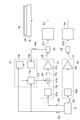
- FIG. 1 schematically illustrates a plasma processing apparatus according to one exemplary embodiment.
- FIG. 2 is a diagram illustrating an example of a configuration of a high-frequency power supply unit and an example of a configuration of a correction signal generation unit of the plasma processing apparatus illustrated in FIG. 1.
- FIG. 2 is a diagram illustrating an example of a timing chart related to generation of plasma in the plasma processing apparatus illustrated in FIG. 1.
- FIG. 2 is a diagram illustrating an example of a reflected wave monitor signal and an example of an inverted-phase signal generated in the plasma processing apparatus illustrated in FIG. 1.
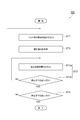
- 5 is a flowchart illustrating a method for generating a plasma according to one exemplary embodiment.
- a plasma processing apparatus in one exemplary embodiment, includes a chamber, a high-frequency power supply, and a correction signal generator.
- the high-frequency power supply unit is configured to output pulsed high-frequency power or combined high-frequency power to generate plasma from gas in the chamber.
- the composite high-frequency power is a composite power of the pulsed high-frequency power and the corrected high-frequency power.
- the corrected high-frequency power is power that oscillates in the opposite phase to the reflected wave with respect to the pulsed high-frequency power.
- the correction signal generator is configured to generate a correction signal.
- the correction signal is a signal that oscillates in the opposite phase to the reflected wave monitor signal representing the reflected wave with respect to the pulsed high-frequency power.
- the high-frequency power supply unit is configured to output pulsed high-frequency power during the first period.
- the correction signal generation unit is configured to generate a correction signal from the reflected wave monitor signal in the first period.
- the high-frequency power supply unit is configured to output a composite high-frequency power generated using the correction signal in each of one or more second periods after the first period.
- the high-frequency power supply unit is configured to alternately repeat the output of the pulsed high-frequency power in the first period and the output of the combined high-frequency power in one or more second periods.
- the combined high-frequency power is output in each of the one or more second periods.
- the corrected high-frequency power included in the combined high-frequency power is generated using a correction signal that oscillates in a phase opposite to the reflected wave monitor signal. Therefore, according to the plasma processing apparatus, the reflected wave is reduced in each of the one or more second periods.
- the combined high-frequency power is generated using the correction signal in each of one or more second periods. The first period and the one or more second periods are alternately repeated. Therefore, the synthesized high-frequency power suitable for reducing the reflected wave can be updated in a timely manner.
- the plasma processing apparatus further includes a directional coupler.
- the directional coupler is provided on an electric path through which the pulsed high-frequency power and the combined high-frequency power output from the high-frequency power supply are transmitted.
- the correction signal generation unit is configured to generate a correction signal from the reflected wave monitor signal output by the directional coupler.
- the high-frequency power supply includes a high-frequency signal generator, an adder, and an amplifier.
- the high frequency signal generator is configured to generate a pulsed high frequency signal.
- the adder is configured to generate a composite high-frequency signal by adding the correction signal to the pulse-like high-frequency signal.
- the amplifier is configured to generate pulsed high-frequency power by amplifying a pulsed high-frequency signal and generate composite high-frequency power by amplifying the composite high-frequency signal. In the first period, the correction signal is not added to the pulsed high-frequency signal.
- the first period and the one or more second periods may be the same periods as a plurality of consecutive periods defined by a predetermined frequency.
- the correction signal generation unit generates an anti-phase signal of the reflected wave monitor signal, and corrects the anti-phase signal so as to eliminate the dependence of the amplification factor on the amplitude of the input signal of the amplifier.
- the amplification factor of the amplifier may have a dependency on the amplitude of the input signal, that is, an amplitude dependency of the amplification factor.
- the correction signal is generated such that the amplitude dependency of the amplification factor of the amplifier is canceled in advance.
- the plasma processing apparatus includes the high-frequency power supply unit as a first high-frequency power supply unit.
- the plasma processing apparatus further includes a support, a second high-frequency power supply, and a synchronization signal generator.
- the support has a lower electrode.
- the support is configured to support the substrate in the chamber.
- the second high-frequency power supply unit is electrically connected to the support table, and is configured to output another high-frequency power.
- the frequency of the other high frequency power is lower than the frequency of the pulsed high frequency power.
- the synchronization signal generator is configured to generate a synchronization signal synchronized with another high-frequency power.
- the first period and the one or more second periods are respectively the same as a plurality of successive periods of another high-frequency power.
- the first high-frequency power supply unit generates pulsed high-frequency power in a first period in response to a synchronization signal, and generates combined high-frequency power in each of one or more second periods in response to the synchronization signal. It is configured.
- a method for generating a plasma in a chamber of a plasma processing apparatus.
- the method includes the steps of (i) outputting a pulsed high-frequency power in a first period to generate plasma from a gas in a chamber; and (ii) a reflected wave representing a reflected wave with respect to the pulsed high-frequency power.
- the composite high-frequency power is a composite power of the pulsed high-frequency power and the corrected high-frequency power.
- the corrected high-frequency power is power that oscillates in the opposite phase to the reflected wave with respect to the pulsed high-frequency power.
- the corrected high frequency power is generated using the correction signal.
- the output of pulsed high-frequency power in the first period and the output of combined high-frequency power in one or more second periods are alternately repeated. And so on.
- FIG. 1 is a view schematically showing a plasma processing apparatus according to one exemplary embodiment.
- the plasma processing apparatus 1 shown in FIG. 1 is a capacitively coupled plasma etching apparatus.
- the plasma processing apparatus 1 includes a chamber 10.
- the chamber 10 provides an internal space 10s therein.
- the chamber 10 includes a chamber body 12.
- the chamber main body 12 has a substantially cylindrical shape.
- the internal space 10 s is provided inside the chamber main body 12.
- the chamber main body 12 is formed of, for example, aluminum.
- a film having corrosion resistance is provided on the inner wall surface of the chamber main body 12.
- the film having corrosion resistance may be a film formed from a ceramic such as aluminum oxide or yttrium oxide.
- a passage 12p is formed in the side wall of the chamber body 12.
- the substrate W passes through the passage 12p when transported between the internal space 10s and the outside of the chamber 10.
- the passage 12p can be opened and closed by a gate valve 12g.
- the gate valve 12g is provided along the side wall of the chamber main body 12.
- a support 13 is provided on the bottom of the chamber body 12.
- the support 13 is formed from an insulating material.
- the support part 13 has a substantially cylindrical shape.
- the support portion 13 extends upward from the bottom of the chamber body 12 in the internal space 10s.
- the support section 13 supports a support base 14.
- the support 14 is provided in the internal space 10s.
- the support base 14 is configured to support the substrate W in the chamber 10, that is, in the internal space 10s.
- the support 14 has a lower electrode 18 and an electrostatic chuck 20.
- the support 14 may further include an electrode plate 16.
- the electrode plate 16 is formed of a conductor such as aluminum, for example, and has a substantially disk shape.
- the lower electrode 18 is provided on the electrode plate 16.
- the lower electrode 18 is formed of a conductor such as aluminum, and has a substantially disk shape.
- the lower electrode 18 is electrically connected to the electrode plate 16.
- the electrostatic chuck 20 is provided on the lower electrode 18.
- the substrate W is placed on the upper surface of the electrostatic chuck 20.
- the electrostatic chuck 20 has a main body and an electrode.
- the main body of the electrostatic chuck 20 has a substantially disk shape and is formed of a dielectric.
- the electrode of the electrostatic chuck 20 is a film-shaped electrode, and is provided in the main body of the electrostatic chuck 20.
- the electrode of the electrostatic chuck 20 is connected to a DC power supply 20p via a switch 20s. When a voltage from the DC power supply 20p is applied to the electrodes of the electrostatic chuck 20, an electrostatic attraction is generated between the electrostatic chuck 20 and the substrate W.
- the substrate W is attracted to the electrostatic chuck 20 by the generated electrostatic attraction, and is held by the electrostatic chuck 20.
- a focus ring FR is arranged on the periphery of the lower electrode 18 so as to surround the edge of the substrate W.
- the focus ring FR is provided to improve the in-plane uniformity of the plasma processing on the substrate W.
- the focus ring FR can be formed from, but not limited to, silicon, silicon carbide, or quartz.
- a flow path 18f is provided inside the lower electrode 18.
- a heat exchange medium for example, a refrigerant
- the heat exchange medium supplied to the flow path 18f is returned to the chiller unit 22 via the pipe 22b.
- the temperature of the substrate W placed on the electrostatic chuck 20 is adjusted by heat exchange between the heat exchange medium and the lower electrode 18.
- the plasma processing apparatus 1 is provided with a gas supply line 24.
- the gas supply line 24 supplies the heat transfer gas (for example, He gas) from the heat transfer gas supply mechanism between the upper surface of the electrostatic chuck 20 and the back surface of the substrate W.
- the plasma processing apparatus 1 further includes an upper electrode 30.
- the upper electrode 30 is provided above the support base 14.
- the upper electrode 30 is supported on the upper part of the chamber main body 12 via a member 32.
- the member 32 is formed from a material having an insulating property. The upper electrode 30 and the member 32 close the upper opening of the chamber body 12.
- the upper electrode 30 may include a top plate 34 and a support 36.
- the lower surface of the top plate 34 is the lower surface on the side of the internal space 10s, and defines the internal space 10s.
- the top plate 34 may be formed of a low-resistance conductor or semiconductor having low Joule heat.
- a plurality of gas discharge holes 34a are formed in the top plate 34. The plurality of gas discharge holes 34a penetrate the top plate 34 in the plate thickness direction.
- the support 36 detachably supports the top plate 34.
- the support 36 is formed from a conductive material such as aluminum.
- a gas diffusion chamber 36 a is provided inside the support 36.
- the support 36 has a plurality of gas holes 36b.
- the plurality of gas holes 36b extend downward from the gas diffusion chamber 36a.
- the plurality of gas holes 36b communicate with the plurality of gas discharge holes 34a, respectively.
- the support 36 has a gas inlet 36c formed therein.
- the gas inlet 36c is connected to the gas diffusion chamber 36a.
- a gas supply pipe 38 is connected to the gas inlet 36c.
- a gas source group 40 is connected to the gas supply pipe 38 via a valve group 41, a flow controller group 42, and a valve group 43.
- the gas source group 40 includes a plurality of gas sources.
- Each of the valve group 41 and the valve group 43 includes a plurality of open / close valves.
- the flow controller group 42 includes a plurality of flow controllers.
- Each of the plurality of flow controllers of the flow controller group 42 is a mass flow controller or a pressure control type flow controller.
- Each of the plurality of gas sources of the gas source group 40 is connected to a gas supply pipe via a corresponding open / close valve of the valve group 41, a corresponding flow controller of the flow controller group 42, and a corresponding open / close valve of the valve group 43. 38.
- the shield 46 is provided detachably along the inner wall surface of the chamber main body 12.
- the shield 46 is also provided on the outer periphery of the support 13.
- the shield 46 prevents the etching by-product from adhering to the chamber body 12.
- the shield 46 is formed by forming a film having corrosion resistance on the surface of a member formed of, for example, aluminum.
- the corrosion resistant film may be a film formed from a ceramic such as yttrium oxide.
- a baffle plate 48 is provided between the support 13 and the side wall of the chamber body 12.
- the baffle plate 48 is formed by forming a film having corrosion resistance on the surface of a member formed of, for example, aluminum.
- the corrosion resistant film may be a film formed from a ceramic such as yttrium oxide.
- the baffle plate 48 has a plurality of through holes.
- An exhaust port 12 e is provided below the baffle plate 48 and at the bottom of the chamber body 12.
- An exhaust device 50 is connected to the exhaust port 12e via an exhaust pipe 52.
- the exhaust device 50 has a vacuum pump such as a pressure regulating valve and a turbo molecular pump.
- the plasma processing apparatus 1 further includes a high frequency power supply unit 61.
- the high-frequency power supply 61 is an example of a first high-frequency power supply.
- the high-frequency power supply 61 is configured to output high-frequency power HF in order to generate plasma from gas in the chamber 10.
- the fundamental frequency of the high-frequency power HF is, for example, a frequency in a range of 27 MHz to 100 MHz. In one example, the fundamental frequency of the high frequency power HF is 40.68 MHz.
- the high-frequency power supply 61 is electrically connected to the lower electrode 18 via the matching unit 63.
- the matching unit 63 has a matching circuit.
- the matching circuit of the matching unit 63 is configured to match the impedance on the load side (lower electrode side) of the high-frequency power supply unit 61 with the output impedance of the high-frequency power supply unit 61.
- the high-frequency power supply unit 61 may be electrically connected to the upper electrode 30 via the matching unit 63.
- the plasma processing apparatus 1 may further include a directional coupler 65.
- the directional coupler 65 is provided on the electric path EP1.
- the high frequency power HF is output by the high frequency power supply 61 and transmitted on the electric path EP1.
- the directional coupler 65 is provided between the high-frequency power supply unit 61 and the matching unit 63.
- the directional coupler 65 branches a part of the reflected wave with respect to the high-frequency power HF from the electric path EP1.
- the directional coupler 65 outputs a part of the reflected wave as a reflected wave monitor signal MS.
- the plasma processing apparatus 1 may further include a high-frequency power supply unit 62.
- the high-frequency power supply unit 62 is an example of a second high-frequency power supply unit.
- the high frequency power supply unit 62 is configured to output the high frequency power LF.
- the high-frequency power LF has a frequency suitable for mainly drawing ions into the substrate W.
- the fundamental frequency of the high-frequency power LF is, for example, a frequency in the range of 400 kHz to 13.56 MHz. In one example, the fundamental frequency of the high-frequency power LF is 400 kHz.
- the high frequency power supply unit 62 is electrically connected to the lower electrode 18 via the matching unit 64.
- the matching unit 64 has a matching circuit.
- the matching circuit of the matching unit 64 is configured to match the impedance on the load side (lower electrode side) of the high-frequency power supply unit 62 with the output impedance of the high-frequency power supply unit 62.
- the plasma processing apparatus 1 may further include a directional coupler 66.
- the directional coupler 66 is provided on the electric path EP2.
- the high-frequency power LF is output by the high-frequency power supply unit 62 and transmitted on the electric path EP2.
- the directional coupler 66 is provided between the high-frequency power supply unit 62 and the matching unit 64.
- the directional coupler 66 branches a part of the reflected wave with respect to the high-frequency power LF from the electric path EP2.
- the directional coupler 66 outputs a part of the reflected wave as a reflected wave monitor signal.
- the reflected wave monitor signal from the directional coupler 66 is used, for example, for power control of the high-frequency power LF.
- the plasma processing apparatus 1 may further include a control unit 80.
- the control unit 80 may be a computer including a processor, a storage unit such as a memory, an input device, a display device, a signal input / output interface, and the like.
- the control unit 80 controls each unit of the plasma processing apparatus 1.
- an operator can perform a command input operation or the like for managing the plasma processing apparatus 1 using the input device.
- the operation status of the plasma processing apparatus 1 can be visualized and displayed on the display device.
- a control program and recipe data are stored in the storage unit of the control unit 80.
- the control program is executed by the processor of the control unit 80 to execute various processes in the plasma processing apparatus 1.
- the processor of the control unit 80 executes the control program and controls each unit of the plasma processing apparatus 1 according to the recipe data, so that the plasma processing apparatus 1 executes a method MT described later.
- FIG. 2 is a diagram illustrating an example of a configuration of a power supply unit and an example of a configuration of a correction signal generation unit of the plasma processing apparatus illustrated in FIG.
- FIG. 3 is a diagram showing an example of a timing chart related to generation of plasma in the plasma processing apparatus shown in FIG.
- FIG. 4 is a diagram illustrating an example of a reflected wave monitor signal and an example of an inverted-phase signal generated in the plasma processing apparatus illustrated in FIG.
- the high-frequency power supply 61 is configured to output a pulsed high-frequency power PHF or a combined high-frequency power SHF as the high-frequency power HF.
- the pulsed high-frequency power PHF is high-frequency power whose power level is set such that the power level in a certain period is higher than the power levels in periods before and after the period.
- the pulsed high-frequency power PHF is set to an ON state during a certain period, and is set to an OFF state before and after the period. That is, in one example, the pulsed high-frequency power PHF has a power level for generating plasma in a certain period, and is set to 0 W before and after the period.
- the combined high-frequency power SHF is a composite power of the pulsed high-frequency power PHF and the corrected high-frequency power.
- the corrected high-frequency power is power that vibrates in a phase opposite to the reflected wave with respect to the pulsed high-frequency power PHF.
- the high-frequency power supply 61 is configured to output a pulsed high-frequency power PHF in the first period P1.
- the timing at which the output of the pulsed high-frequency power PHF is started within the first period P1 and the length of time during which the pulsed high-frequency power PHF is output within the first period P1 are determined by the control unit 80 by the high-frequency power supply unit 61. Is specified.
- the high-frequency power supply unit 61 is configured to output the combined high-frequency power SHF in each of the one or more second periods P2.
- One or more second periods P2 are periods after the first period P1.
- One or more second periods P2 may sequentially follow the first period P1.
- the time length of each of the one or more second periods P2 may be the same as the time length of the first period P1.
- the first period P1 and the one or more second periods P2 may be the same periods as a plurality of continuous periods defined by a predetermined frequency.
- the high-frequency power supply 61 is configured to alternately repeat the output of the pulsed high-frequency power PHF in the first period P1 and the output of the combined high-frequency power SHF in one or more second periods P2. Note that, in the example illustrated in FIG. 3, four second periods P2 follow the first period P1, but the number of second periods after the first period P1 is not limited. .
- the high-frequency power supply 61 is configured to generate the composite high-frequency power SHF using the correction signal CS.
- the correction signal CS is generated by the correction signal generator 70.
- the correction signal generator 70 is configured to generate a correction signal CS from the reflected wave monitor signal MS in the first period P1.
- the reflected wave monitor signal MS is output by the directional coupler 65.
- the correction signal CS is a signal that oscillates in the opposite phase to the reflected wave monitor signal MS.
- the correction signal generation unit 70 includes an A / D converter 70a, a calculator 70b, and a D / A converter 70c.
- the A / D converter 70a performs A / D conversion on the reflected wave monitor signal MS to generate a digital signal.
- the digital signal generated by the A / D converter 70a is provided to the calculator 70b as a reflected wave monitor digital signal.
- the computing unit 70b is, for example, a processor.
- the arithmetic unit 70b generates an inverted signal RS of the reflected wave monitor digital signal.
- the anti-phase signal RS is a signal that oscillates in the opposite phase to the reflected wave monitor signal MS, and the anti-phase signal RS is obtained by performing only a 180 ° phase inversion process on the reflected wave monitor signal MS. Generated.
- the correction signal CS may be an analog signal generated by D / A conversion of the negative-phase signal RS. That is, the computing unit 70b may output the inverted-phase signal RS as a correction digital signal.
- the correction signal generation unit 70 may be configured to generate a correction signal by correcting the negative-phase signal RS. Specifically, the arithmetic unit 70b corrects the amplitude of the negative-phase signal RS so as to eliminate the dependency of the amplification factor on the amplitude of the input signal of the amplifier 61c (non-linear dependency), thereby converting the corrected digital signal. May be generated.
- the correction digital signal generated by the arithmetic unit 70b is provided to the D / A converter 70c.
- the D / A converter 70c performs a D / A conversion on the input correction digital signal to generate a correction signal CS (analog signal).
- the correction signal CS generated by the D / A converter 70c is provided to the high-frequency power supply unit 61.
- the correction signal generation unit 70 does not supply the correction signal CS to the high frequency power supply unit 61 in the first period P1.
- the correction signal generation section 70 supplies the correction signal CS to the high-frequency power supply section 61 in each of one or more second periods P2 after the first period P1.
- the high-frequency power supply unit 61 includes a high-frequency signal generator 61a, an adder 61b, and an amplifier 61c.
- the high-frequency signal generator 61a is configured to generate a pulsed high-frequency signal PS.
- the high-frequency signal generator 61a is, for example, a function generator.
- the fundamental frequency of the pulsed high-frequency signal PS generated by the high-frequency signal generator 61a is the same as the fundamental frequency of the high-frequency power HF.
- the high-frequency signal generator 61a is configured to output a pulsed high-frequency signal PS in each of the first period P1 and one or more second periods P2.
- the timing at which the high-frequency signal generator 61a starts outputting the pulsed high-frequency signal PS is specified by the control unit 80 to the high-frequency signal generator 61a.
- the time length during which the high-frequency signal generator 61a outputs the pulsed high-frequency signal PS is specified by the control unit 80 to the high-frequency signal generator 61a. Is done.
- the adder 61b receives the pulsed high-frequency signal PS from the high-frequency signal generator 61a. Further, the adder 61b receives the correction signal CS from the correction signal generator 70. The adder 61b is configured to add the correction signal CS to the pulsed high-frequency signal PS and generate a composite high-frequency signal AS. When the correction signal CS is not provided, the adder 61b outputs a pulsed high-frequency signal PS.
- the amplifier 61c is configured to generate a pulsed high frequency power PHF by amplifying the pulsed high frequency signal PS. The amplifier 61c is configured to generate the combined high-frequency power SHF by amplifying the combined high-frequency signal AS.
- the high-frequency power supply unit 62 has a high-frequency signal generator 62a and an amplifier 62c.
- the high frequency signal generator 62a is configured to generate a high frequency signal.
- the high-frequency signal generator 62a is, for example, a function generator.
- the frequency of the high-frequency signal generated by the high-frequency signal generator 62a is the same as the frequency of the high-frequency power LF.
- the amplifier 62c amplifies the high-frequency signal from the high-frequency signal generator 62a to generate a high-frequency power LF.
- the high frequency signal generator 62a may generate a high frequency signal continuously. That is, the high-frequency power supply unit 62 may continuously output the high-frequency power LF.
- the high frequency signal generator 62a may generate a pulsed high frequency signal. That is, the high-frequency power supply unit 62 may output the pulsed high-frequency power LF.
- the first period P1 and the one or more second periods P2 are the same as a plurality of continuous periods of the high-frequency power LF. That is, the output of the pulsed high-frequency power PHF and the combined high-frequency power SHF is performed within the corresponding cycle of the high-frequency power LF.
- the plasma processing apparatus 1 may further include a synchronization signal generator 76.
- the synchronization signal generator 76 generates the synchronization signal SS and outputs the synchronization signal SS.
- the synchronization signal SS includes, for example, a synchronization pulse at the start of each cycle of the high-frequency power LF.
- the high-frequency power supply unit 62 outputs the high-frequency power LF so that each cycle is synchronized with the synchronization signal SS (the synchronization pulse) given from the synchronization signal generator 76.
- the synchronization signal is also supplied to the correction signal generation unit 70 and the high frequency power supply unit 61.
- the correction signal generation unit 70 sends the correction signal CS to the high-frequency power supply unit 61 at a timing specified by the delay time given from the control unit 80 with reference to the synchronization pulse of the synchronization signal SS.
- the high-frequency signal generator 61a of the high-frequency power supply unit 61 determines the timing defined by the delay time given from the control unit 80 with reference to the synchronization pulse of the synchronization signal SS in each of the first period P1 and the second period P2. Then, the output of the high frequency signal PS is started.
- the combined high-frequency power SHF is output in each of the one or more second periods P2.
- the corrected high-frequency power included in the combined high-frequency power SHF is generated using a correction signal CS that oscillates in the opposite phase to the reflected wave monitor signal MS. Therefore, according to the plasma processing apparatus 1, the reflected wave is reduced in each of the one or more second periods P2.
- the correction signal CS is generated by outputting the pulsed high-frequency power PHF in the first period P1
- the combined high-frequency power SHF is generated using the correction signal CS in each of one or more second periods. Is done.
- the first period P1 and one or more second periods P2 are alternately repeated. Therefore, the plasma processing apparatus 1 can update the combined high-frequency power SHF suitable for reducing the reflected wave in a timely manner.
- the correction signal CS is generated so that the amplitude dependency (non-linear dependency) of the amplification factor of the amplifier 61c is canceled in advance.
- the reflected wave can be further reduced.
- the correction signal CS has a delay time adjusted so as to cancel the reflected wave with respect to the pulsed high-frequency power PHF, and can be used for generating the composite high-frequency power SHF.
- the correction signal CS can be added to the pulsed high-frequency signal PS with a delay time adjusted to cancel the reflected wave for the pulsed high-frequency power PHF.
- FIG. 5 is a flowchart illustrating a method of generating a plasma according to one exemplary embodiment.
- the method MT will be described using the case where the plasma processing apparatus 1 is used as an example. However, the method MT may be performed using another plasma processing apparatus capable of performing the plurality of steps.
- Step ST1 pulsed high-frequency power PHF is output from the high-frequency power supply 61 to generate plasma from gas in the chamber 10.
- the pulsed high-frequency power PHF is output in the first period P1.
- the correction signal CS is generated by the correction signal generation unit 70.
- the correction signal CS is a signal that oscillates in the opposite phase to the reflected wave monitor signal MS.
- the reflected wave monitor signal MS is a signal representing a reflected wave with respect to the pulsed high-frequency power PHF.
- the reflected wave monitor signal MS is provided to the correction signal generator 70 by the directional coupler 65.
- Step ST3 includes step ST3a and step ST3b.
- step ST3a the combined high-frequency power SHF is output to generate plasma from gas in the chamber 10.
- the combined high-frequency power SHF is output in the second period P2.
- the composite high frequency power SHF is a composite power of the pulsed high frequency power PHF and the corrected high frequency power.
- the corrected high-frequency power is power that oscillates in the opposite phase to the reflected wave.
- the combined high-frequency power SHF is generated using the correction signal CS.
- step ST3b it is determined whether a stop condition is satisfied.
- step ST3b it is determined that the stop condition is satisfied when the number of times of execution of step ST3a has reached a predetermined number. If it is determined in step ST3b that the stop condition is not satisfied, step ST3a is executed again. On the other hand, if it is determined in step ST3b that the stop condition is satisfied, step ST4 is performed. When the predetermined number of times is 1, the step ST3b is unnecessary.
- step ST4 it is determined whether another stop condition is satisfied.
- step ST4 when the number of executions of the sequence including step ST1, step ST2, and step ST3 has reached a predetermined number, it is determined that the other stop condition is satisfied.
- the predetermined number is a plurality of times. If it is determined in step ST4 that the other stop condition is not satisfied, the above sequence is executed again. On the other hand, when it is determined in step ST4 that the other stop condition is satisfied, the method MT ends.
- the step ST1 is executed, so that the pulsed high-frequency power PHF is output in the first period P1.
- the combined high-frequency power SHF is output in each of one or more second periods P2 after the first period P1.
- the process ST1 and the process ST3 are such that the output of the pulsed high-frequency power in the first period P1 and the output of the combined high-frequency power in one or more second periods P2 are alternately repeated. Be executed.
- the high-frequency power LF may be supplied.
- each of the first period P1 and the one or more second periods P2 may be synchronized with a corresponding cycle of the high-frequency power LF.
- the plasma processing apparatus may include only a single high-frequency power supply unit that outputs pulsed high-frequency power, similarly to the high-frequency power supply unit 61.
- the fundamental frequency of the high-frequency power output from the single high-frequency power supply unit may be any frequency as long as plasma can be generated.
- the plasma processing apparatus may be an inductively coupled plasma processing apparatus.
- the high-frequency power supply unit 61 may be electrically connected to an antenna.
- the antenna creates a magnetic field in the chamber for generating a plasma.
- An antenna may be provided on the top of the chamber.
- the high frequency power supply unit 61 and the high frequency power supply unit 62 may be connected to the lower electrode, and another high frequency power supply may be connected to the antenna.
- a plasma processing apparatus may be a plasma processing apparatus that uses microwaves to generate plasma. Microwaves can be introduced from an antenna provided on the top of the chamber.
- the high frequency power supply 61 and the high frequency power supply 62 are connected to the lower electrode.
- the combined high-frequency power SHF is generated by amplifying the combined high-frequency signal AS by the amplifier 61c.
- the correction RF signal may be generated by amplifying the correction signal CS by another amplifier.
- the combined high-frequency power SHF is generated by adding the corrected high-frequency power to the pulsed high-frequency power PHF at the subsequent stage of the amplifier 61c.
Abstract
A plasma treatment device in an illustrative embodiment is provided with a chamber, a high-frequency power supply unit, and a correction signal generation unit. The high-frequency power supply unit outputs pulsed high-frequency power in a first period. The high-frequency power supply unit outputs composite high-frequency power in one or more second periods subsequent to the first period. The correction signal generation unit generates a correction signal oscillating in an opposite phase to that of a reflected wave monitor signal in the first period. The high-frequency power supply unit generates the composite high-frequency power by using the correction signal. The power supply unit is configured so as to repeat the output of the pulsed high-frequency power in the first period and the output of the composite high-frequency power in the one or more second periods in an alternating manner.
Description
本開示の例示的実施形態は、プラズマ処理装置及びプラズマを生成する方法に関するものである。
The exemplary embodiments of the present disclosure relate to a plasma processing apparatus and a method for generating plasma.
電子デバイスの製造のために、プラズマ処理が行われている。プラズマ処理では、プラズマ処理装置が用いられる。プラズマ処理装置は、チャンバ及び高周波電源を備える。高周波電源は、チャンバ内のガスからプラズマを生成するために、高周波電力を出力するように構成されている。
プ ラ ズ マ Plasma treatment is performed for the manufacture of electronic devices. In the plasma processing, a plasma processing apparatus is used. The plasma processing apparatus includes a chamber and a high-frequency power supply. The high-frequency power supply is configured to output high-frequency power in order to generate plasma from gas in the chamber.
プラズマ処理装置では、高周波電力に対する反射波を低減するために、整合器が高周波電源と負荷との間に設けられている。整合器については、特許文献1~3に記載されている。
In the plasma processing apparatus, a matching device is provided between the high-frequency power supply and the load to reduce a reflected wave with respect to the high-frequency power. The matching device is described in Patent Documents 1 to 3.
プラズマ処理装置では、プラズマの生成のためにパルス状の高周波電力が利用されることがある。パルス状の高周波電力が利用される場合においても、反射波を低減することが求められる。
パ ル ス Plasma processing equipment sometimes uses pulsed high-frequency power to generate plasma. Even when pulsed high-frequency power is used, it is required to reduce reflected waves.
一つの例示的実施形態によれば、プラズマ処理装置が提供される。プラズマ処理装置は、チャンバ、高周波電源部、及び補正信号生成部を備える。高周波電源部は、チャンバ内でガスからプラズマを生成するために、パルス状の高周波電力又は合成高周波電力を出力するように構成されている。合成高周波電力は、パルス状の高周波電力と補正高周波電力との合成電力である。補正高周波電力は、パルス状の高周波電力に対する反射波に対して逆位相で振動する電力である。補正信号生成部は、補正信号を生成するよう構成されている。補正信号は、パルス状の高周波電力に対する反射波を表す反射波モニタ信号に対して逆位相で振動する信号である。高周波電源部は、第1の期間においてパルス状の高周波電力を出力するように構成されている。補正信号生成部は、第1の期間における反射波モニタ信号から補正信号を生成するように構成されている。高周波電源部は、第1の期間の後の一以上の第2の期間の各々において、補正信号を用いて生成した合成高周波電力を出力するように構成されている。高周波電源部は、第1の期間におけるパルス状の高周波電力の出力と一以上の第2の期間における合成高周波電力の出力を交互に繰り返すように構成されている。
According to one exemplary embodiment, a plasma processing apparatus is provided. The plasma processing apparatus includes a chamber, a high-frequency power supply, and a correction signal generator. The high-frequency power supply unit is configured to output pulsed high-frequency power or combined high-frequency power to generate plasma from gas in the chamber. The composite high-frequency power is a composite power of the pulsed high-frequency power and the corrected high-frequency power. The corrected high-frequency power is power that oscillates in the opposite phase to the reflected wave with respect to the pulsed high-frequency power. The correction signal generator is configured to generate a correction signal. The correction signal is a signal that oscillates in the opposite phase to the reflected wave monitor signal representing the reflected wave with respect to the pulsed high-frequency power. The high-frequency power supply unit is configured to output pulsed high-frequency power during the first period. The correction signal generation unit is configured to generate a correction signal from the reflected wave monitor signal in the first period. The high-frequency power supply unit is configured to output a composite high-frequency power generated using the correction signal in each of one or more second periods after the first period. The high-frequency power supply unit is configured to alternately repeat the output of the pulsed high-frequency power in the first period and the output of the combined high-frequency power in one or more second periods.
パルス状の高周波電力が利用される場合において、反射波を低減することが可能となる。
反射 When pulsed high-frequency power is used, reflected waves can be reduced.
以下、種々の例示的実施形態について説明する。
Hereinafter, various exemplary embodiments will be described.
一つの例示的実施形態においては、プラズマ処理装置が提供される。プラズマ処理装置は、チャンバ、高周波電源部、及び補正信号生成部を備える。高周波電源部は、チャンバ内でガスからプラズマを生成するために、パルス状の高周波電力又は合成高周波電力を出力するように構成されている。合成高周波電力は、パルス状の高周波電力と補正高周波電力との合成電力である。補正高周波電力は、パルス状の高周波電力に対する反射波に対して逆位相で振動する電力である。補正信号生成部は、補正信号を生成するよう構成されている。補正信号は、パルス状の高周波電力に対する反射波を表す反射波モニタ信号に対して逆位相で振動する信号である。高周波電源部は、第1の期間においてパルス状の高周波電力を出力するように構成されている。補正信号生成部は、第1の期間における反射波モニタ信号から補正信号を生成するように構成されている。高周波電源部は、第1の期間の後の一以上の第2の期間の各々において、補正信号を用いて生成した合成高周波電力を出力するように構成されている。高周波電源部は、第1の期間におけるパルス状の高周波電力の出力と一以上の第2の期間における合成高周波電力の出力を交互に繰り返すように構成されている。
In one exemplary embodiment, a plasma processing apparatus is provided. The plasma processing apparatus includes a chamber, a high-frequency power supply, and a correction signal generator. The high-frequency power supply unit is configured to output pulsed high-frequency power or combined high-frequency power to generate plasma from gas in the chamber. The composite high-frequency power is a composite power of the pulsed high-frequency power and the corrected high-frequency power. The corrected high-frequency power is power that oscillates in the opposite phase to the reflected wave with respect to the pulsed high-frequency power. The correction signal generator is configured to generate a correction signal. The correction signal is a signal that oscillates in the opposite phase to the reflected wave monitor signal representing the reflected wave with respect to the pulsed high-frequency power. The high-frequency power supply unit is configured to output pulsed high-frequency power during the first period. The correction signal generation unit is configured to generate a correction signal from the reflected wave monitor signal in the first period. The high-frequency power supply unit is configured to output a composite high-frequency power generated using the correction signal in each of one or more second periods after the first period. The high-frequency power supply unit is configured to alternately repeat the output of the pulsed high-frequency power in the first period and the output of the combined high-frequency power in one or more second periods.
一つの例示的実施形態に係るプラズマ処理装置では、一以上の第2の期間の各々において、合成高周波電力が出力される。合成高周波電力に含まれる補正高周波電力は、反射波モニタ信号に対して逆位相で振動する補正信号を用いて生成されている。したがって、このプラズマ処理装置によれば、一以上の第2の期間の各々において、反射波が低減される。また、第1の期間においてパルス状の高周波電力を出力することにより補正信号が生成された後に、一以上の第2の期間の各々において当該補正信号を用いて合成高周波電力が生成される。第1の期間と一以上の第2の期間とは交互に繰り返す。したがって、反射波の低減に適した合成高周波電力を適時に更新することができる。
In the plasma processing apparatus according to one exemplary embodiment, the combined high-frequency power is output in each of the one or more second periods. The corrected high-frequency power included in the combined high-frequency power is generated using a correction signal that oscillates in a phase opposite to the reflected wave monitor signal. Therefore, according to the plasma processing apparatus, the reflected wave is reduced in each of the one or more second periods. After the correction signal is generated by outputting the pulsed high-frequency power in the first period, the combined high-frequency power is generated using the correction signal in each of one or more second periods. The first period and the one or more second periods are alternately repeated. Therefore, the synthesized high-frequency power suitable for reducing the reflected wave can be updated in a timely manner.
一つの例示的実施形態において、プラズマ処理装置は、方向性結合器を更に備える。方向性結合器は、高周波電源部から出力されたパルス状の高周波電力及び合成高周波電力がその上で伝送される電気経路上に設けられている。補正信号生成部は、方向性結合器によって出力された反射波モニタ信号から補正信号を生成するよう構成されている。高周波電源部は、高周波信号発生器、加算器、及び増幅器を有する。高周波信号発生器は、パルス状の高周波信号を発生するよう構成されている。加算器は、パルス状の高周波信号に補正信号を加算することにより合成高周波信号を生成するように構成されている。増幅器は、パルス状の高周波信号を増幅することによりパルス状の高周波電力を生成し、合成高周波信号を増幅することにより合成高周波電力を生成するように構成されている。第1の期間では、補正信号がパルス状の高周波信号に加算されない。
に お い て In one exemplary embodiment, the plasma processing apparatus further includes a directional coupler. The directional coupler is provided on an electric path through which the pulsed high-frequency power and the combined high-frequency power output from the high-frequency power supply are transmitted. The correction signal generation unit is configured to generate a correction signal from the reflected wave monitor signal output by the directional coupler. The high-frequency power supply includes a high-frequency signal generator, an adder, and an amplifier. The high frequency signal generator is configured to generate a pulsed high frequency signal. The adder is configured to generate a composite high-frequency signal by adding the correction signal to the pulse-like high-frequency signal. The amplifier is configured to generate pulsed high-frequency power by amplifying a pulsed high-frequency signal and generate composite high-frequency power by amplifying the composite high-frequency signal. In the first period, the correction signal is not added to the pulsed high-frequency signal.
一つの例示的実施形態において、第1の期間及び一以上の第2の期間は、所定の周波数で規定される連続する複数の周期とそれぞれ同一の期間であってもよい。
In one exemplary embodiment, the first period and the one or more second periods may be the same periods as a plurality of consecutive periods defined by a predetermined frequency.
一つの例示的実施形態において、補正信号生成部は、反射波モニタ信号の逆相信号を生成し、増幅器の入力信号の振幅に対する増幅率の依存性を解消するように逆相信号を補正することにより補正信号を生成するように構成されている。増幅器の増幅率は、入力信号の振幅に対して依存性、即ち増幅率の振幅依存性を有することがある。この実施形態によれば、増幅器の増幅率の振幅依存性を予め打ち消すように補正信号が生成される。
In one exemplary embodiment, the correction signal generation unit generates an anti-phase signal of the reflected wave monitor signal, and corrects the anti-phase signal so as to eliminate the dependence of the amplification factor on the amplitude of the input signal of the amplifier. To generate a correction signal. The amplification factor of the amplifier may have a dependency on the amplitude of the input signal, that is, an amplitude dependency of the amplification factor. According to this embodiment, the correction signal is generated such that the amplitude dependency of the amplification factor of the amplifier is canceled in advance.
一つの例示的実施形態において、プラズマ処理装置は、上記高周波電源部を第1の高周波電源部として備える。プラズマ処理装置は、支持台、第2の高周波電源部、及び同期信号発生器を更に備える。支持台は、下部電極を有する。支持台は、チャンバの中で基板を支持するように構成されている。第2の高周波電源部は、支持台に電気的に接続されており、別の高周波電力を出力するように構成されている。別の高周波電力の周波数は、パルス状の高周波電力の周波数よりも低い。同期信号発生器は、別の高周波電力に同期した同期信号を発生するように構成されている。第1の期間及び一以上の第2の期間は、別の高周波電力の連続する複数の周期とそれぞれ同一である。第1の高周波電源部は、同期信号に応じて第1の期間においてパルス状の高周波電力を生成し、同期信号に応じて一以上の第2の期間の各々において合成高周波電力を生成するように構成されている。
In one exemplary embodiment, the plasma processing apparatus includes the high-frequency power supply unit as a first high-frequency power supply unit. The plasma processing apparatus further includes a support, a second high-frequency power supply, and a synchronization signal generator. The support has a lower electrode. The support is configured to support the substrate in the chamber. The second high-frequency power supply unit is electrically connected to the support table, and is configured to output another high-frequency power. The frequency of the other high frequency power is lower than the frequency of the pulsed high frequency power. The synchronization signal generator is configured to generate a synchronization signal synchronized with another high-frequency power. The first period and the one or more second periods are respectively the same as a plurality of successive periods of another high-frequency power. The first high-frequency power supply unit generates pulsed high-frequency power in a first period in response to a synchronization signal, and generates combined high-frequency power in each of one or more second periods in response to the synchronization signal. It is configured.
別の例示的実施形態においては、プラズマ処理装置のチャンバ内でプラズマを生成する方法が提供される。この方法は、(i)チャンバ内でガスからプラズマを生成するために、第1の期間においてパルス状の高周波電力を出力する工程と、(ii)パルス状の高周波電力に対する反射波を表す反射波モニタ信号に対して逆位相で振動する補正信号を生成する工程と、(iii)チャンバ内でガスからプラズマを生成するために、第1の期間の後の一以上の第2の期間の各々において、合成高周波電力を出力する工程と、を含む。合成高周波電力は、パルス状の高周波電力と補正高周波電力との合成電力である。補正高周波電力は、パルス状の高周波電力に対する反射波に対して逆位相で振動する電力である。補正高周波電力は、補正信号を用いて生成される。パルス状の高周波電力を出力する工程及び合成高周波電力を出力する工程は、第1の期間におけるパルス状の高周波電力の出力と一以上の第2の期間における合成高周波電力の出力が交互に繰り返されるように、実行される。
In another exemplary embodiment, a method is provided for generating a plasma in a chamber of a plasma processing apparatus. The method includes the steps of (i) outputting a pulsed high-frequency power in a first period to generate plasma from a gas in a chamber; and (ii) a reflected wave representing a reflected wave with respect to the pulsed high-frequency power. Generating a correction signal that oscillates in phase with respect to the monitor signal; and (iii) in each of one or more second periods after the first period to generate plasma from gas in the chamber. And outputting a combined high-frequency power. The composite high-frequency power is a composite power of the pulsed high-frequency power and the corrected high-frequency power. The corrected high-frequency power is power that oscillates in the opposite phase to the reflected wave with respect to the pulsed high-frequency power. The corrected high frequency power is generated using the correction signal. In the step of outputting pulsed high-frequency power and the step of outputting combined high-frequency power, the output of pulsed high-frequency power in the first period and the output of combined high-frequency power in one or more second periods are alternately repeated. And so on.
以下、図面を参照して種々の例示的実施形態について詳細に説明する。なお、各図面において同一又は相当の部分に対しては同一の符号を附すこととする。
Hereinafter, various exemplary embodiments will be described in detail with reference to the drawings. In the drawings, the same or corresponding portions are denoted by the same reference numerals.
図1は、一つの例示的実施形態に係るプラズマ処理装置を概略的に示す図である。図1に示すプラズマ処理装置1は、容量結合型プラズマエッチング装置である。プラズマ処理装置1は、チャンバ10を備えている。チャンバ10は、その中に内部空間10sを提供している。
FIG. 1 is a view schematically showing a plasma processing apparatus according to one exemplary embodiment. The plasma processing apparatus 1 shown in FIG. 1 is a capacitively coupled plasma etching apparatus. The plasma processing apparatus 1 includes a chamber 10. The chamber 10 provides an internal space 10s therein.
チャンバ10は、チャンバ本体12を含んでいる。チャンバ本体12は、略円筒形状を有している。内部空間10sは、チャンバ本体12の内側に提供されている。チャンバ本体12は、例えばアルミニウムから形成されている。チャンバ本体12の内壁面上には、耐腐食性を有する膜が設けられている。耐腐食性を有する膜は、酸化アルミニウム、酸化イットリウムといったセラミックから形成された膜であり得る。
The chamber 10 includes a chamber body 12. The chamber main body 12 has a substantially cylindrical shape. The internal space 10 s is provided inside the chamber main body 12. The chamber main body 12 is formed of, for example, aluminum. On the inner wall surface of the chamber main body 12, a film having corrosion resistance is provided. The film having corrosion resistance may be a film formed from a ceramic such as aluminum oxide or yttrium oxide.
チャンバ本体12の側壁には、通路12pが形成されている。基板Wは、内部空間10sとチャンバ10の外部との間で搬送されるときに、通路12pを通過する。通路12pは、ゲートバルブ12gにより開閉可能となっている。ゲートバルブ12gは、チャンバ本体12の側壁に沿って設けられている。
通路 A passage 12p is formed in the side wall of the chamber body 12. The substrate W passes through the passage 12p when transported between the internal space 10s and the outside of the chamber 10. The passage 12p can be opened and closed by a gate valve 12g. The gate valve 12g is provided along the side wall of the chamber main body 12.
チャンバ本体12の底部上には、支持部13が設けられている。支持部13は、絶縁材料から形成されている。支持部13は、略円筒形状を有している。支持部13は、内部空間10sの中で、チャンバ本体12の底部から上方に延在している。支持部13は、支持台14を支持している。支持台14は、内部空間10sの中に設けられている。支持台14は、チャンバ10内、即ち内部空間10sの中で、基板Wを支持するように構成されている。
支持 A support 13 is provided on the bottom of the chamber body 12. The support 13 is formed from an insulating material. The support part 13 has a substantially cylindrical shape. The support portion 13 extends upward from the bottom of the chamber body 12 in the internal space 10s. The support section 13 supports a support base 14. The support 14 is provided in the internal space 10s. The support base 14 is configured to support the substrate W in the chamber 10, that is, in the internal space 10s.
支持台14は、下部電極18及び静電チャック20を有している。支持台14は、電極プレート16を更に有し得る。電極プレート16は、例えばアルミニウムといった導体から形成されており、略円盤形状を有している。下部電極18は、電極プレート16上に設けられている。下部電極18は、例えばアルミニウムといった導体から形成されており、略円盤形状を有している。下部電極18は、電極プレート16に電気的に接続されている。
The support 14 has a lower electrode 18 and an electrostatic chuck 20. The support 14 may further include an electrode plate 16. The electrode plate 16 is formed of a conductor such as aluminum, for example, and has a substantially disk shape. The lower electrode 18 is provided on the electrode plate 16. The lower electrode 18 is formed of a conductor such as aluminum, and has a substantially disk shape. The lower electrode 18 is electrically connected to the electrode plate 16.
静電チャック20は、下部電極18上に設けられている。静電チャック20の上面の上には、基板Wが載置される。静電チャック20は、本体及び電極を有する。静電チャック20の本体は、略円盤形状を有し、誘電体から形成されている。静電チャック20の電極は、膜状の電極であり、静電チャック20の本体内に設けられている。静電チャック20の電極は、スイッチ20sを介して直流電源20pに接続されている。静電チャック20の電極に直流電源20pからの電圧が印加されると、静電チャック20と基板Wとの間で静電引力が発生する。発生した静電引力により、基板Wは、静電チャック20に引き付けられ、静電チャック20によって保持される。
The electrostatic chuck 20 is provided on the lower electrode 18. The substrate W is placed on the upper surface of the electrostatic chuck 20. The electrostatic chuck 20 has a main body and an electrode. The main body of the electrostatic chuck 20 has a substantially disk shape and is formed of a dielectric. The electrode of the electrostatic chuck 20 is a film-shaped electrode, and is provided in the main body of the electrostatic chuck 20. The electrode of the electrostatic chuck 20 is connected to a DC power supply 20p via a switch 20s. When a voltage from the DC power supply 20p is applied to the electrodes of the electrostatic chuck 20, an electrostatic attraction is generated between the electrostatic chuck 20 and the substrate W. The substrate W is attracted to the electrostatic chuck 20 by the generated electrostatic attraction, and is held by the electrostatic chuck 20.
下部電極18の周縁部上には、基板Wのエッジを囲むように、フォーカスリングFRが配置される。フォーカスリングFRは、基板Wに対するプラズマ処理の面内均一性を向上させるために設けられている。フォーカスリングFRは、限定されるものではないが、シリコン、炭化シリコン、又は石英から形成され得る。
(4) A focus ring FR is arranged on the periphery of the lower electrode 18 so as to surround the edge of the substrate W. The focus ring FR is provided to improve the in-plane uniformity of the plasma processing on the substrate W. The focus ring FR can be formed from, but not limited to, silicon, silicon carbide, or quartz.
下部電極18の内部には、流路18fが設けられている。流路18fには、チャンバ10の外部に設けられているチラーユニット22から配管22aを介して熱交換媒体(例えば冷媒)が供給される。流路18fに供給された熱交換媒体は、配管22bを介してチラーユニット22に戻される。プラズマ処理装置1では、静電チャック20上に載置された基板Wの温度が、熱交換媒体と下部電極18との熱交換により、調整される。
流 路 A flow path 18f is provided inside the lower electrode 18. A heat exchange medium (for example, a refrigerant) is supplied to the flow path 18f from a chiller unit 22 provided outside the chamber 10 via a pipe 22a. The heat exchange medium supplied to the flow path 18f is returned to the chiller unit 22 via the pipe 22b. In the plasma processing apparatus 1, the temperature of the substrate W placed on the electrostatic chuck 20 is adjusted by heat exchange between the heat exchange medium and the lower electrode 18.
プラズマ処理装置1には、ガス供給ライン24が設けられている。ガス供給ライン24は、伝熱ガス供給機構からの伝熱ガス(例えばHeガス)を、静電チャック20の上面と基板Wの裏面との間に供給する。
The plasma processing apparatus 1 is provided with a gas supply line 24. The gas supply line 24 supplies the heat transfer gas (for example, He gas) from the heat transfer gas supply mechanism between the upper surface of the electrostatic chuck 20 and the back surface of the substrate W.
プラズマ処理装置1は、上部電極30を更に備えている。上部電極30は、支持台14の上方に設けられている。上部電極30は、部材32を介して、チャンバ本体12の上部に支持されている。部材32は、絶縁性を有する材料から形成されている。上部電極30と部材32は、チャンバ本体12の上部開口を閉じている。
The plasma processing apparatus 1 further includes an upper electrode 30. The upper electrode 30 is provided above the support base 14. The upper electrode 30 is supported on the upper part of the chamber main body 12 via a member 32. The member 32 is formed from a material having an insulating property. The upper electrode 30 and the member 32 close the upper opening of the chamber body 12.
上部電極30は、天板34及び支持体36を含み得る。天板34の下面は、内部空間10sの側の下面であり、内部空間10sを画成している。天板34は、ジュール熱の少ない低抵抗の導電体又は半導体から形成され得る。天板34には、複数のガス吐出孔34aが形成されている。複数のガス吐出孔34aは、天板34をその板厚方向に貫通している。
The upper electrode 30 may include a top plate 34 and a support 36. The lower surface of the top plate 34 is the lower surface on the side of the internal space 10s, and defines the internal space 10s. The top plate 34 may be formed of a low-resistance conductor or semiconductor having low Joule heat. A plurality of gas discharge holes 34a are formed in the top plate 34. The plurality of gas discharge holes 34a penetrate the top plate 34 in the plate thickness direction.
支持体36は、天板34を着脱自在に支持する。支持体36は、アルミニウムといった導電性材料から形成される。支持体36の内部には、ガス拡散室36aが設けられている。支持体36には、複数のガス孔36bが形成されている。複数のガス孔36bは、ガス拡散室36aから下方に延びている。複数のガス孔36bは、複数のガス吐出孔34aにそれぞれ連通している。支持体36には、ガス導入口36cが形成されている。ガス導入口36cは、ガス拡散室36aに接続している。ガス導入口36cには、ガス供給管38が接続されている。
(4) The support 36 detachably supports the top plate 34. The support 36 is formed from a conductive material such as aluminum. A gas diffusion chamber 36 a is provided inside the support 36. The support 36 has a plurality of gas holes 36b. The plurality of gas holes 36b extend downward from the gas diffusion chamber 36a. The plurality of gas holes 36b communicate with the plurality of gas discharge holes 34a, respectively. The support 36 has a gas inlet 36c formed therein. The gas inlet 36c is connected to the gas diffusion chamber 36a. A gas supply pipe 38 is connected to the gas inlet 36c.
ガス供給管38には、バルブ群41、流量制御器群42、及びバルブ群43を介して、ガスソース群40が接続されている。ガスソース群40は、複数のガスソースを含んでいる。バルブ群41及びバルブ群43の各々は、複数の開閉バルブを含んでいる。流量制御器群42は、複数の流量制御器を含んでいる。流量制御器群42の複数の流量制御器の各々は、マスフローコントローラ又は圧力制御式の流量制御器である。ガスソース群40の複数のガスソースの各々は、バルブ群41の対応の開閉バルブ、流量制御器群42の対応の流量制御器、及びバルブ群43の対応の開閉バルブを介して、ガス供給管38に接続されている。
A gas source group 40 is connected to the gas supply pipe 38 via a valve group 41, a flow controller group 42, and a valve group 43. The gas source group 40 includes a plurality of gas sources. Each of the valve group 41 and the valve group 43 includes a plurality of open / close valves. The flow controller group 42 includes a plurality of flow controllers. Each of the plurality of flow controllers of the flow controller group 42 is a mass flow controller or a pressure control type flow controller. Each of the plurality of gas sources of the gas source group 40 is connected to a gas supply pipe via a corresponding open / close valve of the valve group 41, a corresponding flow controller of the flow controller group 42, and a corresponding open / close valve of the valve group 43. 38.
プラズマ処理装置1では、チャンバ本体12の内壁面に沿って、シールド46が着脱自在に設けられている。シールド46は、支持部13の外周にも設けられている。シールド46は、チャンバ本体12にエッチング副生物が付着することを防止する。シールド46は、例えば、アルミニウムから形成された部材の表面に耐腐食性を有する膜を形成することにより構成される。耐腐食性を有する膜は、酸化イットリウムといったセラミックから形成された膜であり得る。
In the plasma processing apparatus 1, the shield 46 is provided detachably along the inner wall surface of the chamber main body 12. The shield 46 is also provided on the outer periphery of the support 13. The shield 46 prevents the etching by-product from adhering to the chamber body 12. The shield 46 is formed by forming a film having corrosion resistance on the surface of a member formed of, for example, aluminum. The corrosion resistant film may be a film formed from a ceramic such as yttrium oxide.
支持部13とチャンバ本体12の側壁との間には、バッフルプレート48が設けられている。バッフルプレート48は、例えば、アルミニウムから形成された部材の表面に耐腐食性を有する膜を形成することにより構成される。耐腐食性を有する膜は、酸化イットリウムといったセラミックから形成された膜であり得る。バッフルプレート48には、複数の貫通孔が形成されている。バッフルプレート48の下方、且つ、チャンバ本体12の底部には、排気口12eが設けられている。排気口12eには、排気管52を介して排気装置50が接続されている。排気装置50は、圧力調整弁及びターボ分子ポンプといった真空ポンプを有している。
バ ッ A baffle plate 48 is provided between the support 13 and the side wall of the chamber body 12. The baffle plate 48 is formed by forming a film having corrosion resistance on the surface of a member formed of, for example, aluminum. The corrosion resistant film may be a film formed from a ceramic such as yttrium oxide. The baffle plate 48 has a plurality of through holes. An exhaust port 12 e is provided below the baffle plate 48 and at the bottom of the chamber body 12. An exhaust device 50 is connected to the exhaust port 12e via an exhaust pipe 52. The exhaust device 50 has a vacuum pump such as a pressure regulating valve and a turbo molecular pump.
プラズマ処理装置1は、高周波電源部61を更に備えている。高周波電源部61は、一例の第1の高周波電源部である。高周波電源部61は、チャンバ10内でガスからプラズマを生成するために、高周波電力HFを出力するように構成されている。高周波電力HFの基本周波数は、例えば27MHz~100MHzの範囲内の周波数である。一例では、高周波電力HFの基本周波数は、40.68MHzである。
The plasma processing apparatus 1 further includes a high frequency power supply unit 61. The high-frequency power supply 61 is an example of a first high-frequency power supply. The high-frequency power supply 61 is configured to output high-frequency power HF in order to generate plasma from gas in the chamber 10. The fundamental frequency of the high-frequency power HF is, for example, a frequency in a range of 27 MHz to 100 MHz. In one example, the fundamental frequency of the high frequency power HF is 40.68 MHz.
高周波電源部61は、整合器63を介して下部電極18に電気的に接続されている。整合器63は、整合回路を有している。整合器63の整合回路は、高周波電源部61の負荷側(下部電極側)のインピーダンスを、高周波電源部61の出力インピーダンスに整合させるよう構成されている。別の実施形態では、高周波電源部61は、整合器63を介して上部電極30に電気的に接続されていてもよい。
The high-frequency power supply 61 is electrically connected to the lower electrode 18 via the matching unit 63. The matching unit 63 has a matching circuit. The matching circuit of the matching unit 63 is configured to match the impedance on the load side (lower electrode side) of the high-frequency power supply unit 61 with the output impedance of the high-frequency power supply unit 61. In another embodiment, the high-frequency power supply unit 61 may be electrically connected to the upper electrode 30 via the matching unit 63.
一実施形態において、プラズマ処理装置1は、方向性結合器65を更に備え得る。方向性結合器65は、電気経路EP1上に設けられている。高周波電力HFは、高周波電源部61によって出力されて電気経路EP1上で伝送される。一実施形態において、方向性結合器65は、高周波電源部61と整合器63との間に設けられている。方向性結合器65は、高周波電力HFに対する反射波の一部を電気経路EP1から分岐させる。方向性結合器65は、当該反射波の一部を反射波モニタ信号MSとして出力する。
In one embodiment, the plasma processing apparatus 1 may further include a directional coupler 65. The directional coupler 65 is provided on the electric path EP1. The high frequency power HF is output by the high frequency power supply 61 and transmitted on the electric path EP1. In one embodiment, the directional coupler 65 is provided between the high-frequency power supply unit 61 and the matching unit 63. The directional coupler 65 branches a part of the reflected wave with respect to the high-frequency power HF from the electric path EP1. The directional coupler 65 outputs a part of the reflected wave as a reflected wave monitor signal MS.
一実施形態において、プラズマ処理装置1は、高周波電源部62を更に備え得る。高周波電源部62は、第2の高周波電源部の一例である。高周波電源部62は、高周波電力LFを出力するように構成されている。高周波電力LFは、主としてイオンを基板Wに引き込むことに適した周波数を有する。高周波電力LFの基本周波数は、例えば400kHz~13.56MHzの範囲内の周波数である。一例では、高周波電力LFの基本周波数は、400kHzである。
In one embodiment, the plasma processing apparatus 1 may further include a high-frequency power supply unit 62. The high-frequency power supply unit 62 is an example of a second high-frequency power supply unit. The high frequency power supply unit 62 is configured to output the high frequency power LF. The high-frequency power LF has a frequency suitable for mainly drawing ions into the substrate W. The fundamental frequency of the high-frequency power LF is, for example, a frequency in the range of 400 kHz to 13.56 MHz. In one example, the fundamental frequency of the high-frequency power LF is 400 kHz.
高周波電源部62は、整合器64を介して下部電極18に電気的に接続されている。整合器64は、整合回路を有している。整合器64の整合回路は、高周波電源部62の負荷側(下部電極側)のインピーダンスを、高周波電源部62の出力インピーダンスに整合させるよう構成されている。
The high frequency power supply unit 62 is electrically connected to the lower electrode 18 via the matching unit 64. The matching unit 64 has a matching circuit. The matching circuit of the matching unit 64 is configured to match the impedance on the load side (lower electrode side) of the high-frequency power supply unit 62 with the output impedance of the high-frequency power supply unit 62.
一実施形態において、プラズマ処理装置1は、方向性結合器66を更に備え得る。方向性結合器66は、電気経路EP2上に設けられている。高周波電力LFは、高周波電源部62によって出力されて電気経路EP2上で伝送される。一実施形態において、方向性結合器66は、高周波電源部62と整合器64との間に設けられている。方向性結合器66は、高周波電力LFに対する反射波の一部を電気経路EP2から分岐させる。方向性結合器66は、当該反射波の一部を反射波モニタ信号として出力する。方向性結合器66からの反射波モニタ信号は、例えば高周波電力LFのパワー制御のために利用される。
In one embodiment, the plasma processing apparatus 1 may further include a directional coupler 66. The directional coupler 66 is provided on the electric path EP2. The high-frequency power LF is output by the high-frequency power supply unit 62 and transmitted on the electric path EP2. In one embodiment, the directional coupler 66 is provided between the high-frequency power supply unit 62 and the matching unit 64. The directional coupler 66 branches a part of the reflected wave with respect to the high-frequency power LF from the electric path EP2. The directional coupler 66 outputs a part of the reflected wave as a reflected wave monitor signal. The reflected wave monitor signal from the directional coupler 66 is used, for example, for power control of the high-frequency power LF.
プラズマ処理装置1は、制御部80を更に備え得る。制御部80は、プロセッサ、メモリといった記憶部、入力装置、表示装置、信号の入出力インターフェイス等を備えるコンピュータであり得る。制御部80は、プラズマ処理装置1の各部を制御する。制御部80では、入力装置を用いて、オペレータがプラズマ処理装置1を管理するためにコマンドの入力操作等を行うことができる。また、制御部80では、表示装置により、プラズマ処理装置1の稼働状況を可視化して表示することができる。さらに、制御部80の記憶部には、制御プログラム及びレシピデータが格納されている。制御プログラムは、プラズマ処理装置1で各種処理を実行するために、制御部80のプロセッサによって実行される。制御部80のプロセッサが、制御プログラムを実行し、レシピデータに従ってプラズマ処理装置1の各部を制御することにより、後述する方法MTがプラズマ処理装置1で実行される。
The plasma processing apparatus 1 may further include a control unit 80. The control unit 80 may be a computer including a processor, a storage unit such as a memory, an input device, a display device, a signal input / output interface, and the like. The control unit 80 controls each unit of the plasma processing apparatus 1. In the control unit 80, an operator can perform a command input operation or the like for managing the plasma processing apparatus 1 using the input device. In the control unit 80, the operation status of the plasma processing apparatus 1 can be visualized and displayed on the display device. Further, a control program and recipe data are stored in the storage unit of the control unit 80. The control program is executed by the processor of the control unit 80 to execute various processes in the plasma processing apparatus 1. The processor of the control unit 80 executes the control program and controls each unit of the plasma processing apparatus 1 according to the recipe data, so that the plasma processing apparatus 1 executes a method MT described later.
以下、図1に加えて、図2、図3、及び図4を参照する。図2は、図1に示すプラズマ処理装置の電源部の構成の一例及び補正信号生成部の構成の一例を示す図である。図3は、図1に示すプラズマ処理装置におけるプラズマの生成に関連するタイミングチャートの一例を示す図である。図4は、図1に示すプラズマ処理装置において生成される反射波モニタ信号の一例及び逆相信号の一例を示す図である。
Hereinafter, reference will be made to FIGS. 2, 3 and 4 in addition to FIG. FIG. 2 is a diagram illustrating an example of a configuration of a power supply unit and an example of a configuration of a correction signal generation unit of the plasma processing apparatus illustrated in FIG. FIG. 3 is a diagram showing an example of a timing chart related to generation of plasma in the plasma processing apparatus shown in FIG. FIG. 4 is a diagram illustrating an example of a reflected wave monitor signal and an example of an inverted-phase signal generated in the plasma processing apparatus illustrated in FIG.
高周波電源部61は、図3に示すように、高周波電力HFとして、パルス状の高周波電力PHF又は合成高周波電力SHFを出力するように構成されている。パルス状の高周波電力PHFは、ある期間内での電力レベルが当該期間の前後の期間内での電力レベルよりも高くなるようにその電力レベルが設定された高周波電力である。一例では、パルス状の高周波電力PHFは、ある期間においてON状態に設定され、当該期間の前後の期間においてOFF状態に設定される。即ち、一例では、パルス状の高周波電力PHFは、ある期間においてプラズマを生成するための電力レベルを有し、当該期間の前後の期間において0Wに設定される。
(3) As shown in FIG. 3, the high-frequency power supply 61 is configured to output a pulsed high-frequency power PHF or a combined high-frequency power SHF as the high-frequency power HF. The pulsed high-frequency power PHF is high-frequency power whose power level is set such that the power level in a certain period is higher than the power levels in periods before and after the period. In one example, the pulsed high-frequency power PHF is set to an ON state during a certain period, and is set to an OFF state before and after the period. That is, in one example, the pulsed high-frequency power PHF has a power level for generating plasma in a certain period, and is set to 0 W before and after the period.
合成高周波電力SHFは、パルス状の高周波電力PHFと補正高周波電力との合成電力である。補正高周波電力は、パルス状の高周波電力PHFに対する反射波に対して逆位相で振動する電力である。
The combined high-frequency power SHF is a composite power of the pulsed high-frequency power PHF and the corrected high-frequency power. The corrected high-frequency power is power that vibrates in a phase opposite to the reflected wave with respect to the pulsed high-frequency power PHF.
高周波電源部61は、第1の期間P1においてパルス状の高周波電力PHFを出力するように構成されている。第1の期間P1内でパルス状の高周波電力PHFの出力が開始されるタイミング及び第1の期間P1内でパルス状の高周波電力PHFが出力される時間長は、制御部80から高周波電源部61に指定される。高周波電源部61は、一以上の第2の期間P2の各々において、合成高周波電力SHFを出力するように構成されている。一以上の第2の期間P2は、第1の期間P1の後の期間である。一以上の第2の期間P2は、第1の期間P1に順に続いてもよい。一以上の第2の期間P2の各々の時間長は、第1の期間P1の時間長と同一であり得る。第1の期間P1及び一以上の第2の期間P2は、所定の周波数で規定される連続する複数の周期とそれぞれ同一の期間であってもよい。
The high-frequency power supply 61 is configured to output a pulsed high-frequency power PHF in the first period P1. The timing at which the output of the pulsed high-frequency power PHF is started within the first period P1 and the length of time during which the pulsed high-frequency power PHF is output within the first period P1 are determined by the control unit 80 by the high-frequency power supply unit 61. Is specified. The high-frequency power supply unit 61 is configured to output the combined high-frequency power SHF in each of the one or more second periods P2. One or more second periods P2 are periods after the first period P1. One or more second periods P2 may sequentially follow the first period P1. The time length of each of the one or more second periods P2 may be the same as the time length of the first period P1. The first period P1 and the one or more second periods P2 may be the same periods as a plurality of continuous periods defined by a predetermined frequency.
高周波電源部61は、第1の期間P1におけるパルス状の高周波電力PHFの出力と一以上の第2の期間P2における合成高周波電力SHFの出力を交互に繰り返すように構成されている。なお、図3に示す例では、第1の期間P1の後に四つの第2の期間P2が続いているが、第1の期間P1の後の第2の期間の数は限定されるものではない。
The high-frequency power supply 61 is configured to alternately repeat the output of the pulsed high-frequency power PHF in the first period P1 and the output of the combined high-frequency power SHF in one or more second periods P2. Note that, in the example illustrated in FIG. 3, four second periods P2 follow the first period P1, but the number of second periods after the first period P1 is not limited. .
高周波電源部61は、補正信号CSを用いて合成高周波電力SHFを生成するように構成されている。補正信号CSは、補正信号生成部70によって生成される。補正信号生成部70は、第1の期間P1における反射波モニタ信号MSから補正信号CSを生成するように構成されている。反射波モニタ信号MSは、方向性結合器65によって出力される。補正信号CSは、反射波モニタ信号MSに対して逆位相で振動する信号である。
The high-frequency power supply 61 is configured to generate the composite high-frequency power SHF using the correction signal CS. The correction signal CS is generated by the correction signal generator 70. The correction signal generator 70 is configured to generate a correction signal CS from the reflected wave monitor signal MS in the first period P1. The reflected wave monitor signal MS is output by the directional coupler 65. The correction signal CS is a signal that oscillates in the opposite phase to the reflected wave monitor signal MS.
一実施形態において、補正信号生成部70は、A/D変換器70a、演算器70b、及び、D/A変換器70cを有する。A/D変換器70aは、反射波モニタ信号MSに対してA/D変換を実行して、デジタル信号を生成する。A/D変換器70aによって生成されたデジタル信号は、反射波モニタデジタル信号として、演算器70bに与えられる。演算器70bは、例えばプロセッサである。演算器70bは、反射波モニタデジタル信号の逆相信号RSを生成する。図4に示すように、逆相信号RSは、反射波モニタ信号MSに対して逆位相で振動する信号であり、逆相信号RSは、反射波モニタ信号MSに対する180°の位相反転処理のみによって生成される。
In one embodiment, the correction signal generation unit 70 includes an A / D converter 70a, a calculator 70b, and a D / A converter 70c. The A / D converter 70a performs A / D conversion on the reflected wave monitor signal MS to generate a digital signal. The digital signal generated by the A / D converter 70a is provided to the calculator 70b as a reflected wave monitor digital signal. The computing unit 70b is, for example, a processor. The arithmetic unit 70b generates an inverted signal RS of the reflected wave monitor digital signal. As shown in FIG. 4, the anti-phase signal RS is a signal that oscillates in the opposite phase to the reflected wave monitor signal MS, and the anti-phase signal RS is obtained by performing only a 180 ° phase inversion process on the reflected wave monitor signal MS. Generated.
一実施形態では、補正信号CSは、逆相信号RSのD/A変換により生成されるアナログ信号であってもよい。即ち、演算器70bは、逆相信号RSを補正デジタル信号として出力してもよい。別の実施形態では、補正信号生成部70は、逆相信号RSを補正することにより補正信号を生成するように構成されていてもよい。具体的には、演算器70bは、増幅器61cの入力信号の振幅に対する増幅率の依存性(非線形の依存性)を解消するように逆相信号RSの振幅を補正することにより、補正デジタル信号を生成してもよい。
In one embodiment, the correction signal CS may be an analog signal generated by D / A conversion of the negative-phase signal RS. That is, the computing unit 70b may output the inverted-phase signal RS as a correction digital signal. In another embodiment, the correction signal generation unit 70 may be configured to generate a correction signal by correcting the negative-phase signal RS. Specifically, the arithmetic unit 70b corrects the amplitude of the negative-phase signal RS so as to eliminate the dependency of the amplification factor on the amplitude of the input signal of the amplifier 61c (non-linear dependency), thereby converting the corrected digital signal. May be generated.
演算器70bによって生成された補正デジタル信号は、D/A変換器70cに与えられる。D/A変換器70cは、入力された補正デジタル信号に対してD/A変換を実行して、補正信号CS(アナログ信号)を生成する。D/A変換器70cによって生成された補正信号CSは、高周波電源部61に与えられる。
The correction digital signal generated by the arithmetic unit 70b is provided to the D / A converter 70c. The D / A converter 70c performs a D / A conversion on the input correction digital signal to generate a correction signal CS (analog signal). The correction signal CS generated by the D / A converter 70c is provided to the high-frequency power supply unit 61.
補正信号生成部70は、第1の期間P1においては補正信号CSを高周波電源部61に与えない。一方、補正信号生成部70は、第1の期間P1の後の一以上の第2の期間P2の各々においては、補正信号CSを高周波電源部61に与える。
The correction signal generation unit 70 does not supply the correction signal CS to the high frequency power supply unit 61 in the first period P1. On the other hand, the correction signal generation section 70 supplies the correction signal CS to the high-frequency power supply section 61 in each of one or more second periods P2 after the first period P1.
一実施形態において、高周波電源部61は、高周波信号発生器61a、加算器61b、及び増幅器61cを有している。高周波信号発生器61aは、パルス状の高周波信号PSを発生するように構成されている。高周波信号発生器61aは、例えばファンクションジェネレータである。高周波信号発生器61aによって発生されるパルス状の高周波信号PSの基本周波数は、高周波電力HFの基本周波数と同一である。
In one embodiment, the high-frequency power supply unit 61 includes a high-frequency signal generator 61a, an adder 61b, and an amplifier 61c. The high-frequency signal generator 61a is configured to generate a pulsed high-frequency signal PS. The high-frequency signal generator 61a is, for example, a function generator. The fundamental frequency of the pulsed high-frequency signal PS generated by the high-frequency signal generator 61a is the same as the fundamental frequency of the high-frequency power HF.
高周波信号発生器61aは、第1の期間P1及び一以上の第2の期間P2の各々においてパルス状の高周波信号PSを出力するように構成されている。第1の期間P1及び一以上の第2の期間P2の各々において、高周波信号発生器61aがパルス状の高周波信号PSの出力を開始するタイミングは、制御部80から高周波信号発生器61aに指定される。また、第1の期間P1及び一以上の第2の期間P2の各々において、高周波信号発生器61aがパルス状の高周波信号PSを出力する時間長は、制御部80から高周波信号発生器61aに指定される。
The high-frequency signal generator 61a is configured to output a pulsed high-frequency signal PS in each of the first period P1 and one or more second periods P2. In each of the first period P1 and the one or more second periods P2, the timing at which the high-frequency signal generator 61a starts outputting the pulsed high-frequency signal PS is specified by the control unit 80 to the high-frequency signal generator 61a. You. In each of the first period P1 and the one or more second periods P2, the time length during which the high-frequency signal generator 61a outputs the pulsed high-frequency signal PS is specified by the control unit 80 to the high-frequency signal generator 61a. Is done.
加算器61bは、高周波信号発生器61aからパルス状の高周波信号PSを受ける。また、加算器61bは、補正信号生成部70から補正信号CSを受ける。加算器61bは、パルス状の高周波信号PSに補正信号CSを加算して、合成高周波信号ASを生成するように構成されている。補正信号CSが与えられない場合には、加算器61bは、パルス状の高周波信号PSを出力する。増幅器61cは、パルス状の高周波信号PSを増幅することによりパルス状の高周波電力PHFを生成するように構成されている。また、増幅器61cは、合成高周波信号ASを増幅することにより合成高周波電力SHFを生成するように構成されている。
The adder 61b receives the pulsed high-frequency signal PS from the high-frequency signal generator 61a. Further, the adder 61b receives the correction signal CS from the correction signal generator 70. The adder 61b is configured to add the correction signal CS to the pulsed high-frequency signal PS and generate a composite high-frequency signal AS. When the correction signal CS is not provided, the adder 61b outputs a pulsed high-frequency signal PS. The amplifier 61c is configured to generate a pulsed high frequency power PHF by amplifying the pulsed high frequency signal PS. The amplifier 61c is configured to generate the combined high-frequency power SHF by amplifying the combined high-frequency signal AS.
一実施形態において、高周波電源部62は、高周波信号発生器62a及び増幅器62cを有している。高周波信号発生器62aは、高周波信号を発生するように構成されている。高周波信号発生器62aは、例えばファンクションジェネレータである。高周波信号発生器62aによって発生される高周波信号の周波数は、高周波電力LFの周波数と同一である。増幅器62cは、高周波信号発生器62aからの高周波信号を増幅して、高周波電力LFを生成する。高周波信号発生器62aは、連続的に高周波信号を発生してもよい。即ち、高周波電源部62は、連続的に高周波電力LFを出力してもよい。或いは、高周波信号発生器62aは、パルス状の高周波信号を発生してもよい。即ち、高周波電源部62は、パルス状の高周波電力LFを出力してもよい。
In one embodiment, the high-frequency power supply unit 62 has a high-frequency signal generator 62a and an amplifier 62c. The high frequency signal generator 62a is configured to generate a high frequency signal. The high-frequency signal generator 62a is, for example, a function generator. The frequency of the high-frequency signal generated by the high-frequency signal generator 62a is the same as the frequency of the high-frequency power LF. The amplifier 62c amplifies the high-frequency signal from the high-frequency signal generator 62a to generate a high-frequency power LF. The high frequency signal generator 62a may generate a high frequency signal continuously. That is, the high-frequency power supply unit 62 may continuously output the high-frequency power LF. Alternatively, the high frequency signal generator 62a may generate a pulsed high frequency signal. That is, the high-frequency power supply unit 62 may output the pulsed high-frequency power LF.
一実施形態においては、図3に示すように、第1の期間P1及び一以上の第2の期間P2は、高周波電力LFの連続する複数の周期とそれぞれ同一である。即ち、パルス状の高周波電力PHF及び合成高周波電力SHFの各々の出力は、高周波電力LFの対応の周期内で行われる。このため、一実施形態において、プラズマ処理装置1は、同期信号発生器76を更に備え得る。
In one embodiment, as shown in FIG. 3, the first period P1 and the one or more second periods P2 are the same as a plurality of continuous periods of the high-frequency power LF. That is, the output of the pulsed high-frequency power PHF and the combined high-frequency power SHF is performed within the corresponding cycle of the high-frequency power LF. For this reason, in one embodiment, the plasma processing apparatus 1 may further include a synchronization signal generator 76.
同期信号発生器76は、同期信号SSを発生し、同期信号SSを出力する。同期信号SSは、例えば、高周波電力LFの各周期の開始時点において同期パルスを含む。高周波電源部62は、同期信号発生器76から与えられる同期信号SS(その同期パルス)に各周期が同期するように、高周波電力LFを出力する。
The synchronization signal generator 76 generates the synchronization signal SS and outputs the synchronization signal SS. The synchronization signal SS includes, for example, a synchronization pulse at the start of each cycle of the high-frequency power LF. The high-frequency power supply unit 62 outputs the high-frequency power LF so that each cycle is synchronized with the synchronization signal SS (the synchronization pulse) given from the synchronization signal generator 76.
同期信号は、補正信号生成部70及び高周波電源部61にも与えられる。補正信号生成部70は、第2の期間P2の各々では、同期信号SSの同期パルスを基準として制御部80から与えられた遅延時間で規定されるタイミングで、補正信号CSを高周波電源部61に出力する。高周波電源部61の高周波信号発生器61aは、第1の期間P1及び第2の期間P2の各々において、同期信号SSの同期パルスを基準として制御部80から与えられた遅延時間で規定されるタイミングで、高周波信号PSの出力を開始する。
The synchronization signal is also supplied to the correction signal generation unit 70 and the high frequency power supply unit 61. In each of the second periods P2, the correction signal generation unit 70 sends the correction signal CS to the high-frequency power supply unit 61 at a timing specified by the delay time given from the control unit 80 with reference to the synchronization pulse of the synchronization signal SS. Output. The high-frequency signal generator 61a of the high-frequency power supply unit 61 determines the timing defined by the delay time given from the control unit 80 with reference to the synchronization pulse of the synchronization signal SS in each of the first period P1 and the second period P2. Then, the output of the high frequency signal PS is started.
以上説明したプラズマ処理装置1によれば、一以上の第2の期間P2の各々においては、合成高周波電力SHFが出力される。合成高周波電力SHFに含まれる補正高周波電力は、反射波モニタ信号MSに対して逆位相で振動する補正信号CSを用いて生成されている。したがって、プラズマ処理装置1によれば、一以上の第2の期間P2の各々において、反射波が低減される。また、第1の期間P1においてパルス状の高周波電力PHFを出力することにより補正信号CSが生成された後に、一以上の第2の期間の各々において補正信号CSを用いて合成高周波電力SHFが生成される。第1の期間P1と一以上の第2の期間P2とは交互に繰り返す。したがって、プラズマ処理装置1は、反射波の低減に適した合成高周波電力SHFを適時に更新することができる。
According to the plasma processing apparatus 1 described above, the combined high-frequency power SHF is output in each of the one or more second periods P2. The corrected high-frequency power included in the combined high-frequency power SHF is generated using a correction signal CS that oscillates in the opposite phase to the reflected wave monitor signal MS. Therefore, according to the plasma processing apparatus 1, the reflected wave is reduced in each of the one or more second periods P2. After the correction signal CS is generated by outputting the pulsed high-frequency power PHF in the first period P1, the combined high-frequency power SHF is generated using the correction signal CS in each of one or more second periods. Is done. The first period P1 and one or more second periods P2 are alternately repeated. Therefore, the plasma processing apparatus 1 can update the combined high-frequency power SHF suitable for reducing the reflected wave in a timely manner.
一実施形態においては、上述したように、増幅器61cの増幅率の振幅依存性(非線形の依存性)を予め打ち消すように補正信号CSが生成される。この実施形態によれば、反射波がより低減され得る。なお、補正信号CSは、パルス状の高周波電力PHFに対する反射波を打ち消すように調整された遅延時間で、合成高周波電力SHFの生成に用いられ得る。一実施形態では、補正信号CSは、パルス状の高周波電力PHFに対する反射波を打ち消すように調整された遅延時間で、パルス状の高周波信号PSに対して加算され得る。
In one embodiment, as described above, the correction signal CS is generated so that the amplitude dependency (non-linear dependency) of the amplification factor of the amplifier 61c is canceled in advance. According to this embodiment, the reflected wave can be further reduced. Note that the correction signal CS has a delay time adjusted so as to cancel the reflected wave with respect to the pulsed high-frequency power PHF, and can be used for generating the composite high-frequency power SHF. In one embodiment, the correction signal CS can be added to the pulsed high-frequency signal PS with a delay time adjusted to cancel the reflected wave for the pulsed high-frequency power PHF.
以下、図5を参照して、一つの例示的実施形態に係るプラズマを生成する方法について説明する。図5は、一つの例示的実施形態に係るプラズマを生成する方法を示す流れ図である。以下の説明では、プラズマ処理装置1が用いられる場合を例として、方法MTを説明する。しかしながら、方法MTは、その複数の工程を実行し得る他のプラズマ処理装置を用いて実行されてもよい。
Hereinafter, a method for generating a plasma according to an exemplary embodiment will be described with reference to FIG. FIG. 5 is a flowchart illustrating a method of generating a plasma according to one exemplary embodiment. In the following description, the method MT will be described using the case where the plasma processing apparatus 1 is used as an example. However, the method MT may be performed using another plasma processing apparatus capable of performing the plurality of steps.
方法MTは、工程ST1で開始する。工程ST1では、チャンバ10内でガスからプラズマを生成するために、高周波電源部61からパルス状の高周波電力PHFが出力される。パルス状の高周波電力PHFは、第1の期間P1において出力される。
Method MT starts in step ST1. In step ST1, pulsed high-frequency power PHF is output from the high-frequency power supply 61 to generate plasma from gas in the chamber 10. The pulsed high-frequency power PHF is output in the first period P1.
工程ST2では、補正信号生成部70によって補正信号CSが生成される。補正信号CSは、反射波モニタ信号MSに対して逆位相で振動する信号である。反射波モニタ信号MSは、パルス状の高周波電力PHFに対する反射波を表す信号である。反射波モニタ信号MSは、方向性結合器65によって補正信号生成部70に与えられる。
で は In step ST2, the correction signal CS is generated by the correction signal generation unit 70. The correction signal CS is a signal that oscillates in the opposite phase to the reflected wave monitor signal MS. The reflected wave monitor signal MS is a signal representing a reflected wave with respect to the pulsed high-frequency power PHF. The reflected wave monitor signal MS is provided to the correction signal generator 70 by the directional coupler 65.
工程ST3は、工程ST3a及び工程ST3bを含む。工程ST3aでは、チャンバ10内でガスからプラズマを生成するために、合成高周波電力SHFが出力される。合成高周波電力SHFは、第2の期間P2において出力される。合成高周波電力SHFは、パルス状の高周波電力PHFと補正高周波電力との合成電力である。補正高周波電力は、反射波に対して逆位相で振動する電力である。合成高周波電力SHFは、補正信号CSを用いて生成される。
{Step ST3 includes step ST3a and step ST3b. In step ST3a, the combined high-frequency power SHF is output to generate plasma from gas in the chamber 10. The combined high-frequency power SHF is output in the second period P2. The composite high frequency power SHF is a composite power of the pulsed high frequency power PHF and the corrected high frequency power. The corrected high-frequency power is power that oscillates in the opposite phase to the reflected wave. The combined high-frequency power SHF is generated using the correction signal CS.
工程ST3bでは、停止条件が満たされるか否かが判定される。工程ST3bでは、工程ST3aの実行回数が所定回数に達している場合に停止条件が満たされていると判定される。工程ST3bにおいて停止条件が満たされていないと判定されると、工程ST3aが再び実行される。一方、工程ST3bにおいて停止条件が満たされていると判定されると、工程ST4が実行される。なお、所定回数が1回の場合には、工程ST3bは不要である。
で は In step ST3b, it is determined whether a stop condition is satisfied. In step ST3b, it is determined that the stop condition is satisfied when the number of times of execution of step ST3a has reached a predetermined number. If it is determined in step ST3b that the stop condition is not satisfied, step ST3a is executed again. On the other hand, if it is determined in step ST3b that the stop condition is satisfied, step ST4 is performed. When the predetermined number of times is 1, the step ST3b is unnecessary.
工程ST4では、別の停止条件が満たされるか否かが判定される。工程ST4では、工程ST1、工程ST2、及び工程ST3を含むシーケンスの実行回数が所定回数に達している場合に当該別の停止条件が満たされていると判定される。この所定回数は複数の回数である。工程ST4において当該別の停止条件が満たされていないと判定されると、上記シーケンスが再び実行される。一方、工程ST4において当該別の停止条件が満たされていると判定されると、方法MTは終了する。
In step ST4, it is determined whether another stop condition is satisfied. In step ST4, when the number of executions of the sequence including step ST1, step ST2, and step ST3 has reached a predetermined number, it is determined that the other stop condition is satisfied. The predetermined number is a plurality of times. If it is determined in step ST4 that the other stop condition is not satisfied, the above sequence is executed again. On the other hand, when it is determined in step ST4 that the other stop condition is satisfied, the method MT ends.
方法MTでは、工程ST1が実行されることにより、第1の期間P1においてパルス状の高周波電力PHFが出力される。工程ST3が実行されることにより、第1の期間P1の後の一以上の第2の期間P2の各々において合成高周波電力SHFが出力される。工程ST1及び工程ST3は、図3に示すように、第1の期間P1におけるパルス状の高周波電力の出力と一以上の第2の期間P2における合成高周波電力の出力が交互に繰り返されるように、実行される。
In the method MT, the step ST1 is executed, so that the pulsed high-frequency power PHF is output in the first period P1. By performing step ST3, the combined high-frequency power SHF is output in each of one or more second periods P2 after the first period P1. As shown in FIG. 3, the process ST1 and the process ST3 are such that the output of the pulsed high-frequency power in the first period P1 and the output of the combined high-frequency power in one or more second periods P2 are alternately repeated. Be executed.
方法MTにおいては、高周波電力LFが供給されてもよい。上述したように、第1の期間P1及び一以上の第2の期間P2の各々は、高周波電力LFの対応の周期に同期されていてもよい。
高周波 In the method MT, the high-frequency power LF may be supplied. As described above, each of the first period P1 and the one or more second periods P2 may be synchronized with a corresponding cycle of the high-frequency power LF.
以上、種々の例示的実施形態について説明してきたが、上述した例示的実施形態に限定されることなく、様々な省略、置換、及び変更がなされてもよい。また、異なる実施形態における要素を組み合わせて他の実施形態を形成することが可能である。
Although various exemplary embodiments have been described above, various omissions, substitutions, and changes may be made without being limited to the exemplary embodiments described above. Also, other embodiments can be formed by combining elements in different embodiments.
例えば、別の実施形態において、プラズマ処理装置は、高周波電源部61と同様にパルス状の高周波電力を出力する単一の高周波電源部のみを備えていてもよい。単一の高周波電源部によって出力される高周波電力の基本周波数は、プラズマを生成することができれば、任意の周波数であってもよい。
For example, in another embodiment, the plasma processing apparatus may include only a single high-frequency power supply unit that outputs pulsed high-frequency power, similarly to the high-frequency power supply unit 61. The fundamental frequency of the high-frequency power output from the single high-frequency power supply unit may be any frequency as long as plasma can be generated.
更に別の実施形態において、プラズマ処理装置は、誘導結合型のプラズマ処理装置であってもよい。誘導結合型のプラズマ処理装置においては、高周波電源部61は、アンテナに電気的に接続されていてもよい。アンテナは、プラズマの生成のためにチャンバ内で磁界を形成する。アンテナは、チャンバの天部の上に設けられ得る。或いは、誘導結合型のプラズマ処理装置においては、高周波電源部61及び高周波電源部62は下部電極に接続され、別の高周波電源がアンテナに接続されていてもよい。
に お い て In yet another embodiment, the plasma processing apparatus may be an inductively coupled plasma processing apparatus. In the inductively coupled plasma processing apparatus, the high-frequency power supply unit 61 may be electrically connected to an antenna. The antenna creates a magnetic field in the chamber for generating a plasma. An antenna may be provided on the top of the chamber. Alternatively, in the inductively coupled plasma processing apparatus, the high frequency power supply unit 61 and the high frequency power supply unit 62 may be connected to the lower electrode, and another high frequency power supply may be connected to the antenna.
更に別の実施形態のプラズマ処理装置は、プラズマの生成のためにマイクロ波を用いるプラズマ処理装置であってもよい。マイクロ波は、チャンバの天部の上に設けられたアンテナから導入され得る。このタイプのプラズマ処理装置においては、高周波電源部61及び高周波電源部62は下部電極に接続される。
プ ラ ズ マ A plasma processing apparatus according to still another embodiment may be a plasma processing apparatus that uses microwaves to generate plasma. Microwaves can be introduced from an antenna provided on the top of the chamber. In this type of plasma processing apparatus, the high frequency power supply 61 and the high frequency power supply 62 are connected to the lower electrode.
また、プラズマ処理装置1では、上述したように、合成高周波信号ASを増幅器61cによって増幅することにより合成高周波電力SHFが生成されている。別の実施形態では、補正信号CSを別の増幅器によって増幅することによって補正高周波電力を生成してもよい。この場合には、増幅器61cの後段で、パルス状の高周波電力PHFに補正高周波電力を加算することによって、合成高周波電力SHFが生成される。
In addition, in the plasma processing apparatus 1, as described above, the combined high-frequency power SHF is generated by amplifying the combined high-frequency signal AS by the amplifier 61c. In another embodiment, the correction RF signal may be generated by amplifying the correction signal CS by another amplifier. In this case, the combined high-frequency power SHF is generated by adding the corrected high-frequency power to the pulsed high-frequency power PHF at the subsequent stage of the amplifier 61c.
以上の説明から、本開示の種々の実施形態は、説明の目的で本明細書で説明されており、本開示の範囲及び主旨から逸脱することなく種々の変更をなし得ることが、理解されるであろう。したがって、本明細書に開示した種々の実施形態は限定することを意図しておらず、真の範囲と主旨は、添付の特許請求の範囲によって示される。
From the above description, it is understood that various embodiments of the present disclosure have been described herein for purposes of explanation, and that various changes may be made without departing from the scope and spirit of the present disclosure. Will. Accordingly, the various embodiments disclosed herein are not intended to be limiting, with the true scope and spirit being indicated by the appended claims.
1…プラズマ処理装置、10…チャンバ、61…高周波電源部、70…補正信号生成部、P1…第1の期間、P2…第2の期間、PHF…パルス状の高周波電力、SHF…合成高周波電力、CS…補正信号、MS…反射波モニタ信号。
DESCRIPTION OF SYMBOLS 1 ... Plasma processing apparatus, 10 ... Chamber, 61 ... High frequency power supply part, 70 ... Correction signal generation part, P1: 1st period, P2 ... 2nd period, PHF ... Pulse-shaped high frequency power, SHF ... Synthetic high frequency power , CS: correction signal, MS: reflected wave monitor signal.
Claims (6)
- チャンバと、
前記チャンバ内でガスからプラズマを生成するために、パルス状の高周波電力又は合成高周波電力を出力するように構成された高周波電源部であり、該合成高周波電力は、該パルス状の高周波電力と該パルス状の高周波電力に対する反射波に対して逆位相で振動する補正高周波電力との合成電力である、該高周波電源部と、
前記パルス状の高周波電力に対する前記反射波を表す反射波モニタ信号に対して逆位相で振動する補正信号を生成するよう構成された補正信号生成部と、
を備え、
前記高周波電源部は、第1の期間において前記パルス状の高周波電力を出力するように構成されており、
前記補正信号生成部は、前記第1の期間における前記反射波モニタ信号から前記補正信号を生成するように構成されており、
前記高周波電源部は、前記第1の期間の後の一以上の第2の期間の各々において、前記補正信号を用いて生成した前記合成高周波電力を出力するように構成されており、前記第1の期間における前記パルス状の高周波電力の出力と前記一以上の第2の期間における前記合成高周波電力の出力を交互に繰り返すように構成されている、
プラズマ処理装置。 A chamber;
A high-frequency power supply unit configured to output pulsed high-frequency power or combined high-frequency power to generate plasma from gas in the chamber, wherein the combined high-frequency power includes the pulsed high-frequency power and the high-frequency power. The high-frequency power supply unit, which is a composite power of the corrected high-frequency power that oscillates in an opposite phase to the reflected wave with respect to the pulsed high-frequency power,
A correction signal generation unit configured to generate a correction signal that oscillates in an opposite phase to a reflected wave monitor signal representing the reflected wave with respect to the pulsed high-frequency power,
With
The high-frequency power supply unit is configured to output the pulsed high-frequency power in a first period,
The correction signal generation unit is configured to generate the correction signal from the reflected wave monitor signal in the first period,
The high-frequency power supply unit is configured to output the combined high-frequency power generated using the correction signal in each of one or more second periods after the first period, and Is configured to alternately repeat the output of the pulsed high-frequency power in the period and the output of the combined high-frequency power in the one or more second periods.
Plasma processing equipment. - 前記高周波電源部から出力された前記パルス状の高周波電力及び前記合成高周波電力がその上で伝送される電気経路上に設けられた方向性結合器を更に備え、
前記補正信号生成部は、前記方向性結合器によって出力された前記反射波モニタ信号から前記補正信号を生成するよう構成されており、
前記高周波電源部は、
パルス状の高周波信号を発生するよう構成された高周波信号発生器と、
前記パルス状の高周波信号に前記補正信号を加算することにより合成高周波信号を生成するように構成された加算器と、
前記パルス状の高周波信号を増幅することにより前記パルス状の高周波電力を生成し、前記合成高周波信号を増幅することにより前記合成高周波電力を生成するように構成された増幅器と、
を有し、
前記第1の期間では、前記補正信号が前記パルス状の高周波信号に加算されない、
請求項1に記載のプラズマ処理装置。 The apparatus further includes a directional coupler provided on an electric path through which the pulsed high-frequency power and the combined high-frequency power output from the high-frequency power supply unit are transmitted,
The correction signal generation unit is configured to generate the correction signal from the reflected wave monitor signal output by the directional coupler,
The high-frequency power supply,
A high frequency signal generator configured to generate a pulsed high frequency signal,
An adder configured to generate a composite high-frequency signal by adding the correction signal to the pulse-like high-frequency signal;
An amplifier configured to generate the pulsed high-frequency power by amplifying the pulsed high-frequency signal and generate the composite high-frequency power by amplifying the composite high-frequency signal,
Has,
In the first period, the correction signal is not added to the pulsed high-frequency signal,
The plasma processing apparatus according to claim 1. - 前記補正信号生成部は、前記反射波モニタ信号の逆相信号を生成し、前記増幅器の入力信号の振幅に対する増幅率の依存性を解消するように前記逆相信号を補正することにより前記補正信号を生成するように構成されている、請求項2に記載のプラズマ処理装置。 The correction signal generation unit generates a reverse-phase signal of the reflected wave monitor signal, and corrects the correction signal by correcting the negative-phase signal so as to eliminate the dependency of the amplification factor on the amplitude of the input signal of the amplifier. The plasma processing apparatus according to claim 2, wherein the plasma processing apparatus is configured to generate the plasma.
- 前記第1の期間及び前記一以上の第2の期間は、所定の周波数で規定される連続する複数の周期とそれぞれ同一の期間である、請求項1~3の何れか一項に記載のプラズマ処理装置。 The plasma according to any one of claims 1 to 3, wherein the first period and the one or more second periods are the same period as a plurality of continuous periods defined by a predetermined frequency. Processing equipment.
- 該プラズマ処理装置は、前記高周波電源部を第1の高周波電源部として備え、
下部電極を有し、前記チャンバの中で基板を支持するように構成された支持台と、
前記支持台に電気的に接続されており、別の高周波電力を出力するように構成された第2の高周波電源部であり、該別の高周波電力の周波数は、前記パルス状の高周波電力の周波数よりも低い、該第2の高周波電源部と、
前記別の高周波電力に同期した同期信号を発生するように構成された同期信号発生器と、
を更に備え、
前記第1の期間及び前記一以上の第2の期間は、前記別の高周波電力の連続する複数の周期とそれぞれ同一であり、
前記第1の高周波電源部は、前記同期信号に応じて前記第1の期間において前記パルス状の高周波電力を生成し、前記同期信号に応じて前記一以上の第2の期間の各々において前記合成高周波電力を生成するように構成されている、
請求項1~3の何れか一項に記載のプラズマ処理装置。 The plasma processing apparatus includes the high-frequency power supply unit as a first high-frequency power supply unit,
A support having a lower electrode and configured to support a substrate in the chamber;
A second high-frequency power supply unit electrically connected to the support base and configured to output another high-frequency power, wherein the frequency of the another high-frequency power is the frequency of the pulsed high-frequency power; Lower second power supply,
A synchronization signal generator configured to generate a synchronization signal synchronized with the another high-frequency power,
Further comprising
The first period and the one or more second periods are respectively the same as a plurality of continuous periods of the another high-frequency power,
The first high-frequency power supply unit generates the pulsed high-frequency power in the first period according to the synchronization signal, and performs the combining in each of the one or more second periods in response to the synchronization signal. Configured to generate high frequency power,
The plasma processing apparatus according to any one of claims 1 to 3. - プラズマ処理装置のチャンバ内でプラズマを生成する方法であって、
前記チャンバ内でガスからプラズマを生成するために、第1の期間においてパルス状の高周波電力を出力する工程と、
前記パルス状の高周波電力に対する反射波を表す反射波モニタ信号に対して逆位相で振動する補正信号を生成する工程と、
前記チャンバ内でガスからプラズマを生成するために、前記第1の期間の後の一以上の第2の期間の各々において、合成高周波電力を出力する工程であり、該合成高周波電力は、該パルス状の高周波電力と該パルス状の高周波電力に対する反射波に対して逆位相で振動する補正高周波電力との合成電力であり、前記補正信号を用いて生成される、該工程と、
を含み、
パルス状の高周波電力を出力する前記工程及び合成高周波電力を出力する前記工程は、前記第1の期間における前記パルス状の高周波電力の出力と前記一以上の第2の期間における前記合成高周波電力の出力が交互に繰り返されるように、実行される、
プラズマを生成する方法。 A method for generating plasma in a chamber of a plasma processing apparatus, comprising:
Outputting pulsed high-frequency power during a first period to generate plasma from gas in the chamber;
A step of generating a correction signal that oscillates in antiphase with respect to a reflected wave monitor signal representing a reflected wave with respect to the pulsed high-frequency power,
Outputting, in each of one or more second periods after the first period, a combined high-frequency power to generate plasma from a gas in the chamber, the combined high-frequency power comprising the pulse Is a composite power of a corrected high-frequency power that oscillates in an opposite phase to a reflected wave with respect to the pulse-shaped high-frequency power and the pulse-shaped high-frequency power, and is generated using the correction signal.
Including
The step of outputting the pulsed high-frequency power and the step of outputting the combined high-frequency power include: outputting the pulsed high-frequency power during the first period and the combined high-frequency power during the one or more second periods. Executed so that the output is repeated alternately,
A method of generating plasma.
Priority Applications (3)
| Application Number | Priority Date | Filing Date | Title |
|---|---|---|---|
| US16/645,188 US10978274B2 (en) | 2018-06-22 | 2019-06-10 | Plasma processing apparatus and method for generating plasma |
| CN201980004388.3A CN111052874B (en) | 2018-06-22 | 2019-06-10 | Plasma processing apparatus and method of generating plasma |
| KR1020207006605A KR20210021441A (en) | 2018-06-22 | 2019-06-10 | Plasma processing apparatus and method of generating plasma |
Applications Claiming Priority (2)
| Application Number | Priority Date | Filing Date | Title |
|---|---|---|---|
| JP2018119084A JP6842443B2 (en) | 2018-06-22 | 2018-06-22 | Plasma processing equipment and method of generating plasma |
| JP2018-119084 | 2018-06-22 |
Publications (1)
| Publication Number | Publication Date |
|---|---|
| WO2019244698A1 true WO2019244698A1 (en) | 2019-12-26 |
Family
ID=68983385
Family Applications (1)
| Application Number | Title | Priority Date | Filing Date |
|---|---|---|---|
| PCT/JP2019/022954 WO2019244698A1 (en) | 2018-06-22 | 2019-06-10 | Plasma treatment device and method for generating plasma |
Country Status (6)
| Country | Link |
|---|---|
| US (1) | US10978274B2 (en) |
| JP (1) | JP6842443B2 (en) |
| KR (1) | KR20210021441A (en) |
| CN (1) | CN111052874B (en) |
| TW (1) | TWI812738B (en) |
| WO (1) | WO2019244698A1 (en) |
Cited By (10)
| Publication number | Priority date | Publication date | Assignee | Title |
|---|---|---|---|---|
| US11476145B2 (en) | 2018-11-20 | 2022-10-18 | Applied Materials, Inc. | Automatic ESC bias compensation when using pulsed DC bias |
| US11699572B2 (en) | 2019-01-22 | 2023-07-11 | Applied Materials, Inc. | Feedback loop for controlling a pulsed voltage waveform |
| US11791138B2 (en) | 2021-05-12 | 2023-10-17 | Applied Materials, Inc. | Automatic electrostatic chuck bias compensation during plasma processing |
| US11798790B2 (en) | 2020-11-16 | 2023-10-24 | Applied Materials, Inc. | Apparatus and methods for controlling ion energy distribution |
| US11848176B2 (en) | 2020-07-31 | 2023-12-19 | Applied Materials, Inc. | Plasma processing using pulsed-voltage and radio-frequency power |
| US11887813B2 (en) | 2021-06-23 | 2024-01-30 | Applied Materials, Inc. | Pulsed voltage source for plasma processing |
| US11901157B2 (en) | 2020-11-16 | 2024-02-13 | Applied Materials, Inc. | Apparatus and methods for controlling ion energy distribution |
| US11948780B2 (en) | 2021-05-12 | 2024-04-02 | Applied Materials, Inc. | Automatic electrostatic chuck bias compensation during plasma processing |
| US11967483B2 (en) | 2021-06-02 | 2024-04-23 | Applied Materials, Inc. | Plasma excitation with ion energy control |
| US11972924B2 (en) | 2022-06-08 | 2024-04-30 | Applied Materials, Inc. | Pulsed voltage source for plasma processing applications |
Families Citing this family (9)
| Publication number | Priority date | Publication date | Assignee | Title |
|---|---|---|---|---|
| US11508554B2 (en) | 2019-01-24 | 2022-11-22 | Applied Materials, Inc. | High voltage filter assembly |
| KR102593142B1 (en) * | 2020-05-19 | 2023-10-25 | 세메스 주식회사 | Apparatus for treating substrate and method for controlling temperature of ferrite core |
| US20230274913A1 (en) * | 2020-09-29 | 2023-08-31 | Lam Research Corporation | Synchronization of rf generators |
| US11495470B1 (en) | 2021-04-16 | 2022-11-08 | Applied Materials, Inc. | Method of enhancing etching selectivity using a pulsed plasma |
| US11810760B2 (en) | 2021-06-16 | 2023-11-07 | Applied Materials, Inc. | Apparatus and method of ion current compensation |
| US11776788B2 (en) | 2021-06-28 | 2023-10-03 | Applied Materials, Inc. | Pulsed voltage boost for substrate processing |
| US11476090B1 (en) | 2021-08-24 | 2022-10-18 | Applied Materials, Inc. | Voltage pulse time-domain multiplexing |
| US11694876B2 (en) | 2021-12-08 | 2023-07-04 | Applied Materials, Inc. | Apparatus and method for delivering a plurality of waveform signals during plasma processing |
| US20230230806A1 (en) * | 2022-01-05 | 2023-07-20 | Applied Materials, Inc. | Methods and apparatus for processing a substrate |
Citations (4)
| Publication number | Priority date | Publication date | Assignee | Title |
|---|---|---|---|---|
| JP2000049000A (en) * | 1998-07-31 | 2000-02-18 | Kem Kk | Frequency adjusting device |
| JP2012174736A (en) * | 2011-02-17 | 2012-09-10 | Mitsubishi Electric Corp | Plasma deposition apparatus and plasma deposition method |
| WO2017062083A1 (en) * | 2015-10-05 | 2017-04-13 | Applied Materials, Inc. | Rf power delivery regulation for processing substrates |
| JP2017228558A (en) * | 2016-06-20 | 2017-12-28 | 東京エレクトロン株式会社 | Plasma processing apparatus, and waveform correction method |
Family Cites Families (24)
| Publication number | Priority date | Publication date | Assignee | Title |
|---|---|---|---|---|
| JPS629705A (en) | 1985-07-05 | 1987-01-17 | Kawasaki Steel Corp | Method and apparatus for heat treatment for working of metallic material |
| JPH10241895A (en) | 1996-11-04 | 1998-09-11 | Applied Materials Inc | Improvement of plasma process efficiency by filtering plasma sheath generation harmonic |
| JP3629705B2 (en) | 1997-06-06 | 2005-03-16 | 東京エレクトロン株式会社 | Plasma processing equipment |
| JP3027572B1 (en) * | 1998-12-24 | 2000-04-04 | 日本高周波株式会社 | Impedance measuring device for plasma processing |
| KR100807724B1 (en) * | 2003-08-07 | 2008-02-28 | 가부시키가이샤 히다치 고쿠사이 덴키 | Substrate processing apparatus and substrate processing method |
| JP3998630B2 (en) * | 2003-11-19 | 2007-10-31 | 株式会社東芝 | Power amplifier |
| JP4879548B2 (en) * | 2005-09-30 | 2012-02-22 | 株式会社ダイヘン | High frequency power supply |
| JP2007134849A (en) * | 2005-11-09 | 2007-05-31 | Nagano Japan Radio Co | Amplifier |
| JP5210659B2 (en) * | 2008-02-28 | 2013-06-12 | 株式会社日立ハイテクノロジーズ | Plasma processing equipment |
| JP5319150B2 (en) * | 2008-03-31 | 2013-10-16 | 東京エレクトロン株式会社 | Plasma processing apparatus, plasma processing method, and computer-readable storage medium |
| JP4891384B2 (en) * | 2009-12-10 | 2012-03-07 | 株式会社新川 | Plasma generator |
| JP2012174668A (en) * | 2011-02-24 | 2012-09-10 | Mitsubishi Electric Corp | High-frequency power supply device, plasma processing apparatus, and method for manufacturing semiconductor thin film |
| JP5867701B2 (en) * | 2011-12-15 | 2016-02-24 | 東京エレクトロン株式会社 | Plasma processing equipment |
| JP5808012B2 (en) * | 2011-12-27 | 2015-11-10 | 東京エレクトロン株式会社 | Plasma processing equipment |
| US9462672B2 (en) * | 2012-02-22 | 2016-10-04 | Lam Research Corporation | Adjustment of power and frequency based on three or more states |
| US9171700B2 (en) * | 2012-06-15 | 2015-10-27 | COMET Technologies USA, Inc. | Plasma pulse tracking system and method |
| WO2015029937A1 (en) * | 2013-08-26 | 2015-03-05 | 株式会社日立国際電気 | Power supply device for plasma generation |
| JP6512962B2 (en) * | 2014-09-17 | 2019-05-15 | 東京エレクトロン株式会社 | Plasma processing system |
| KR101677748B1 (en) * | 2014-10-29 | 2016-11-29 | 삼성전자 주식회사 | Pulse plasma apparatus and method for operating the same |
| CN105826154B (en) | 2015-01-06 | 2017-12-19 | 北京北方华创微电子装备有限公司 | For the impedance matching methods and device of pulse radiation frequency power supply |
| JP6396822B2 (en) * | 2015-02-16 | 2018-09-26 | 東京エレクトロン株式会社 | Method for controlling potential of susceptor of plasma processing apparatus |
| WO2018038398A1 (en) * | 2016-08-25 | 2018-03-01 | 한국전기연구원 | Pulse power compensation device and high-voltage pulse power supply system comprising same |
| WO2018061617A1 (en) * | 2016-09-28 | 2018-04-05 | 株式会社日立国際電気 | High-frequency power supply device |
| US10546724B2 (en) * | 2017-05-10 | 2020-01-28 | Mks Instruments, Inc. | Pulsed, bidirectional radio frequency source/load |
-
2018
- 2018-06-22 JP JP2018119084A patent/JP6842443B2/en active Active
-
2019
- 2019-06-10 WO PCT/JP2019/022954 patent/WO2019244698A1/en active Application Filing
- 2019-06-10 US US16/645,188 patent/US10978274B2/en active Active
- 2019-06-10 KR KR1020207006605A patent/KR20210021441A/en unknown
- 2019-06-10 CN CN201980004388.3A patent/CN111052874B/en active Active
- 2019-06-18 TW TW108120965A patent/TWI812738B/en active
Patent Citations (4)
| Publication number | Priority date | Publication date | Assignee | Title |
|---|---|---|---|---|
| JP2000049000A (en) * | 1998-07-31 | 2000-02-18 | Kem Kk | Frequency adjusting device |
| JP2012174736A (en) * | 2011-02-17 | 2012-09-10 | Mitsubishi Electric Corp | Plasma deposition apparatus and plasma deposition method |
| WO2017062083A1 (en) * | 2015-10-05 | 2017-04-13 | Applied Materials, Inc. | Rf power delivery regulation for processing substrates |
| JP2017228558A (en) * | 2016-06-20 | 2017-12-28 | 東京エレクトロン株式会社 | Plasma processing apparatus, and waveform correction method |
Cited By (10)
| Publication number | Priority date | Publication date | Assignee | Title |
|---|---|---|---|---|
| US11476145B2 (en) | 2018-11-20 | 2022-10-18 | Applied Materials, Inc. | Automatic ESC bias compensation when using pulsed DC bias |
| US11699572B2 (en) | 2019-01-22 | 2023-07-11 | Applied Materials, Inc. | Feedback loop for controlling a pulsed voltage waveform |
| US11848176B2 (en) | 2020-07-31 | 2023-12-19 | Applied Materials, Inc. | Plasma processing using pulsed-voltage and radio-frequency power |
| US11798790B2 (en) | 2020-11-16 | 2023-10-24 | Applied Materials, Inc. | Apparatus and methods for controlling ion energy distribution |
| US11901157B2 (en) | 2020-11-16 | 2024-02-13 | Applied Materials, Inc. | Apparatus and methods for controlling ion energy distribution |
| US11791138B2 (en) | 2021-05-12 | 2023-10-17 | Applied Materials, Inc. | Automatic electrostatic chuck bias compensation during plasma processing |
| US11948780B2 (en) | 2021-05-12 | 2024-04-02 | Applied Materials, Inc. | Automatic electrostatic chuck bias compensation during plasma processing |
| US11967483B2 (en) | 2021-06-02 | 2024-04-23 | Applied Materials, Inc. | Plasma excitation with ion energy control |
| US11887813B2 (en) | 2021-06-23 | 2024-01-30 | Applied Materials, Inc. | Pulsed voltage source for plasma processing |
| US11972924B2 (en) | 2022-06-08 | 2024-04-30 | Applied Materials, Inc. | Pulsed voltage source for plasma processing applications |
Also Published As
| Publication number | Publication date |
|---|---|
| US10978274B2 (en) | 2021-04-13 |
| JP6842443B2 (en) | 2021-03-17 |
| CN111052874A (en) | 2020-04-21 |
| TWI812738B (en) | 2023-08-21 |
| US20200286714A1 (en) | 2020-09-10 |
| TW202002727A (en) | 2020-01-01 |
| JP2019220435A (en) | 2019-12-26 |
| CN111052874B (en) | 2023-02-28 |
| KR20210021441A (en) | 2021-02-26 |
Similar Documents
| Publication | Publication Date | Title |
|---|---|---|
| WO2019244698A1 (en) | Plasma treatment device and method for generating plasma | |
| WO2019244734A1 (en) | Control method and plasma treatment device | |
| JP2020004710A (en) | Control method and plasma treatment device | |
| JP7374362B2 (en) | Plasma treatment method and plasma treatment device | |
| JP2020109838A (en) | Plasma processing apparatus and control method | |
| JP2017228558A (en) | Plasma processing apparatus, and waveform correction method | |
| JP7122268B2 (en) | Plasma processing equipment | |
| JP7395645B2 (en) | plasma processing equipment | |
| US11282701B2 (en) | Plasma processing method and plasma processing apparatus | |
| JP2021097033A (en) | Plasma processing apparatus and plasma processing method | |
| JP6180890B2 (en) | Plasma processing method | |
| TW201630068A (en) | Plasma etching method | |
| TWI521594B (en) | Plasma treatment method and plasma treatment apparatus | |
| KR20200144479A (en) | Plasma processing method and plasma processing apparatus | |
| JP6762410B2 (en) | Plasma processing equipment and control method | |
| JP2022018484A (en) | Plasma processing apparatus and plasma processing method | |
| JPH01236629A (en) | Plasma processor | |
| JP6960421B2 (en) | Plasma processing equipment and plasma processing method | |
| JP2016111033A (en) | Method performing ashing |
Legal Events
| Date | Code | Title | Description |
|---|---|---|---|
| 121 | Ep: the epo has been informed by wipo that ep was designated in this application |
Ref document number: 19822705 Country of ref document: EP Kind code of ref document: A1 |
|
| NENP | Non-entry into the national phase |
Ref country code: DE |
|
| 122 | Ep: pct application non-entry in european phase |
Ref document number: 19822705 Country of ref document: EP Kind code of ref document: A1 |