WO2019239702A1 - パケット通信システム - Google Patents
パケット通信システム Download PDFInfo
- Publication number
- WO2019239702A1 WO2019239702A1 PCT/JP2019/015935 JP2019015935W WO2019239702A1 WO 2019239702 A1 WO2019239702 A1 WO 2019239702A1 JP 2019015935 W JP2019015935 W JP 2019015935W WO 2019239702 A1 WO2019239702 A1 WO 2019239702A1
- Authority
- WO
- WIPO (PCT)
- Prior art keywords
- packet
- data
- server device
- address
- communication system
- Prior art date
- Legal status (The legal status is an assumption and is not a legal conclusion. Google has not performed a legal analysis and makes no representation as to the accuracy of the status listed.)
- Ceased
Links
Images


Classifications
-
- G—PHYSICS
- G06—COMPUTING OR CALCULATING; COUNTING
- G06F—ELECTRIC DIGITAL DATA PROCESSING
- G06F13/00—Interconnection of, or transfer of information or other signals between, memories, input/output devices or central processing units
-
- H—ELECTRICITY
- H04—ELECTRIC COMMUNICATION TECHNIQUE
- H04L—TRANSMISSION OF DIGITAL INFORMATION, e.g. TELEGRAPHIC COMMUNICATION
- H04L12/00—Data switching networks
- H04L12/66—Arrangements for connecting between networks having differing types of switching systems, e.g. gateways
Definitions
- the present invention relates to a packet communication system, and more particularly, to a system for communicating with each other by exchanging data packets according to a packet communication protocol with a specific server device via a network.
- Patent Document 1 discloses a packet communication method in which communication with the same level of reliability as the TCP / IP protocol is performed using the UDP / IP protocol.
- Patent Document 2 discloses a method of performing communication control using a TCP / IP protocol by using an encapsulation technique between a communication terminal and a host connected via a LAN.
- JP 10-056479 A Japanese Patent Laid-Open No. 10-233820
- the first problem is that when the user accesses a specific server device from the client device, the source address indicating the location of the client device is transmitted to the server device.
- the masking property is lost. For example, when a specific Web server device is accessed using a Web browser incorporated in the client device, it is necessary to transmit the IP address of the client device to the Web server device as a transmission source address.
- the source address sent directly to the Web server device was assigned to the router, not the private IP address assigned to the client device.
- the router as the transmission source is still specified as the global IP address.
- each client device connected to the router is identified as a port number.
- the client device of the transmission source is specified by analyzing the port number. There is also a risk of being done.
- the second problem is that information leakage may occur in the communication path between the client device and the server device. If a data packet transmitted and received between the two is acquired by a third party in an unauthorized manner, information is leaked. In particular, recently, due to the spread of wireless routers and the like, there are not a few cases where access is performed in an environment where a wireless communication path is interposed. In such a case, information is leaked if the wireless communication path is eavesdropped.
- the present invention provides a packet communication system capable of ensuring anonymity and masking of an access source and preventing information leakage in a communication path when accessing an arbitrary server device via a network.
- the purpose is to improve the security of personal information.
- a packet communication system for performing packet communication by connecting to a target server device to be accessed via a network.
- a client device that performs packet communication with the target server device, and a relay server device that relays packet communication between the client device and the target server device,
- the client device A communication control unit that performs processing for creating a first packet including, in the data part, predetermined transmission data to be transmitted to the target server device, with the client device as a source and the target server device as a destination;
- An encryption processing unit for a client that encrypts at least a part of the first packet to create encrypted data for transmission;
- a packet transmission unit that creates and transmits a second packet including encrypted data for transmission in the data part, with the client device as the transmission source and the relay server device as the destination;
- Have The relay server device A relay server decryption processing unit that receives the second packet, decrypts the encrypted data for transmission included in the data part, and restores the first packet;
- a packet transfer unit that creates a third packet by
- the communication control unit A process of creating a first packet including a header part and a data part; In the data portion of the first packet, predetermined transmission data to be transmitted to the target server device is stored, The header portion of the first packet stores a source address indicating the address of the client device and a destination address indicating the address of the target server device.
- the communication control unit A process for creating an IP packet including an IP header part and an IP data part as the first packet is performed.
- a TCP packet including a TCP header part and a TCP data part is stored in the IP data part, and transmission data is stored in the TCP data part.
- a fourth aspect of the present invention is the packet communication system according to the second or third aspect described above,
- the client encryption processing unit encrypts all or part of the data portion of the first packet to create transmission encrypted data
- the packet transmitter A process of creating a second packet including a header part and a data part; In the data portion of the second packet, an encapsulating process for storing the encrypted data for transmission is performed, In the header part of the second packet, a transmission source address indicating the address of the client device and a destination address indicating the address of the relay server device are stored.
- the packet transmitter As the second packet, a process of creating an IP packet including an IP header part and an IP data part is performed, Encapsulation processing is performed by storing transmission encryption data in the IP data portion, and the second packet is transmitted according to the TCP / IP protocol.
- the packet forwarding unit A process for creating a third packet including a header part and a data part is performed,
- the data part of the third packet stores the data part of the restored first packet;
- the header portion of the third packet stores a transmission source address indicating the address of the relay server device and a destination address indicating the address of the target server device.
- the packet forwarding unit As the third packet, a process for creating an IP packet including an IP header portion and an IP data portion is performed. The data portion of the restored first packet is stored in the IP data portion, and the third packet is transmitted according to the TCP / IP protocol.
- An eighth aspect of the present invention is the packet communication system according to the first to seventh aspects described above,
- the encryption processing unit for the relay server receives the fourth packet including the header part and the data part, and encrypts all or part of the data part of the received fourth packet to create reply encrypted data.
- the packet reply part A process for creating a fifth packet including a header part and a data part is performed, In the data portion of the fifth packet, an encapsulating process for storing return encrypted data is performed, In the header portion of the fifth packet, a transmission source address indicating the address of the relay server device and a destination address indicating the address of the client device are stored.
- a ninth aspect of the present invention is the packet communication system according to the eighth aspect described above,
- the packet reply part As the fifth packet, a process of creating an IP packet including an IP header part and an IP data part is performed,
- the return encryption data is stored in the IP data portion to perform the encapsulation process, and the fifth packet is transmitted according to the TCP / IP protocol.
- a tenth aspect of the present invention is the packet communication system according to the eighth or ninth aspect described above,
- the packet receiver A process for creating a sixth packet including a header part and a data part is performed,
- the data part stores the data part of the restored fourth packet,
- the header portion of the sixth packet stores a source address indicating the address of the target server device and a destination address indicating the address of the client device.
- An eleventh aspect of the present invention is the packet communication system according to the tenth aspect described above,
- the packet receiver As the sixth packet, a process of creating an IP packet including an IP header part and an IP data part is performed, The reply data included in the restored fourth packet is stored in the IP data portion.
- a twelfth aspect of the present invention is the packet communication system according to the first to eleventh aspects described above, A plurality of n client devices and n relay server devices associated with each of the n client devices; The packet transmission unit of each client device transmits a second packet addressed to a specific relay server device associated with each, The packet reply unit of each relay server device transmits the fifth packet to a specific client device associated with each relay server device.
- a thirteenth aspect of the present invention is the packet communication system according to the first to eleventh aspects described above,
- the packet transfer unit performs processing to embed information indicating the source of the restored first packet in the third packet
- the relay server encryption processing unit reads the information indicating the transmission source embedded in the received fourth packet and transmits the information to the packet reply unit.
- the packet reply unit creates a fifth packet having the information indicating the transmission source as a destination client device.
- the packet transfer unit creates a third packet according to the TCP / IP protocol, and at this time, the source of the first packet is set as the source port number in the TCP header part included in the third packet.
- the packet reply unit determines the transmission destination of the fifth packet based on the information embedded as the destination port number in the TCP header part included in the fourth packet.
- the relay server device further includes a communication information recording unit, When the packet transfer unit transmits the third packet, it records correspondence information indicating the correspondence between the restored transmission source of the first packet and the third packet in the communication information recording unit. Process When the packet return unit transmits the fifth packet, the transmission destination of the fifth packet is determined based on the correspondence information recorded in the communication information recording unit.
- a sixteenth aspect of the present invention is the packet communication system according to the fifteenth aspect described above,
- the packet transfer unit creates a third packet in accordance with the TCP / IP protocol, and at that time, in the TCP header part included in the third packet, a packet identifier for indicating the third packet is a port number.
- the packet reply unit uses the packet identifier embedded as the port number in the TCP header part included in the fourth packet to refer to the correspondence information recorded in the communication information recording unit, thereby The fifth packet is transmitted to the source of the packet.
- the relay server device is installed in the region of the first country, the client device is installed in the region of the second country, and the client device is installed in the target server device installed in the region of the first country.
- access is made via a relay by a relay server device installed in the region of the first country.
- An eighteenth aspect of the present invention is the packet communication system according to the first to seventeenth aspects described above,
- the client device is configured by a computer in which a predetermined OS program and one or more application programs that operate under the OS program are installed.
- the client encryption processing unit, the packet transmission unit, the client decryption processing unit, and the packet reception unit function by executing an application program.
- a computer as a client encryption processing unit, a packet transmission unit, a client decryption processing unit, and a packet reception unit in the packet communication system according to the first to seventeenth aspects described above.
- the program to make it function is provided.
- the relay server device is configured by a computer in which a predetermined OS program and one or more application programs that operate under the OS program are installed.
- the relay server decryption processing unit, the packet transfer unit, the relay server encryption processing unit, and the packet return unit function by executing the application program.
- a twenty-third aspect of the present invention provides a relay server decryption processing unit, a packet transfer unit, a relay server encryption processing unit, and a packet reply unit in the packet communication system according to the first to seventeenth aspects described above.
- a program for causing a computer to function is provided.
- the packet communication system since communication between the client device and the server device is performed via the relay server device, when accessing any server device via the network, the access source Anonymity and masking can be secured.
- the possibility of information leakage in the communication path can be reduced. Thus, security regarding personal information can be improved.
- FIG. 2 is a block diagram illustrating a structure of an HTTP request transmission packet transmitted from a client device to a server device in the communication mode illustrated in FIG. 1.
- FIG. 2 is a block diagram illustrating a structure of an HTTP response reply packet transmitted from a server device to a client device in the communication mode illustrated in FIG. 1.
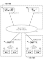
- It is a block diagram which shows the communication form using the packet communication system which concerns on fundamental embodiment of this invention.
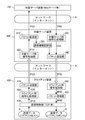
- It is a block diagram which shows the structure of the packet communication system which concerns on fundamental embodiment of this invention.
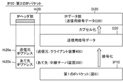
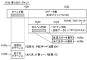
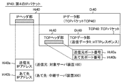
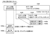
- FIG. 6 is a block diagram showing an example of the structure of a first IP packet IP10 created by the communication control unit 430 in the client device 400 in the configuration shown in FIG. 6 is a block diagram illustrating an example of a structure of a second IP packet IP20 transmitted from the client device 400 toward the relay server device 300 in the configuration illustrated in FIG. 6 is a block diagram illustrating an example of a structure of a third IP packet IP30 transmitted from the relay server device 300 toward the target server device 100 in the configuration illustrated in FIG. 6 is a block diagram illustrating an example of a structure of a fourth IP packet IP40 transmitted from the target server device 100 toward the relay server device 300 in the configuration illustrated in FIG.
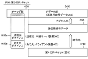
- FIG. 6 is a block diagram illustrating an example of a structure of a fifth IP packet IP50 transmitted from the relay server device 300 toward the client device 400 in the configuration illustrated in FIG. 6 is a block diagram showing an example of the structure of a sixth IP packet IP60 created by a packet receiving unit 450 in the client device 400 in the configuration shown in FIG. It is a block diagram which shows the structure of the packet communication system which concerns on the modification of this invention. It is a block diagram which shows the example which installed the packet communication system which concerns on this invention ranging over the area
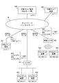
- FIG. 1 is a block diagram showing a communication form through a network between a general client device and a server device that has been conventionally performed using the TCP / IP protocol.
- FIG. 1 an example in which five client apparatuses 201 to 205 are accessing via the network N with respect to the target server apparatus 100 to be accessed.
- each of the client apparatuses 201 to 205 is configured by a computer having a communication function via a network, such as a personal computer, a mobile phone, and a tablet terminal, and the target server apparatus 100 is a computer that serves as such a client.
- a network such as a personal computer, a mobile phone, and a tablet terminal
- the target server apparatus 100 is a computer that serves as such a client.
- a Web server or the like for example, a Web server or the like.
- Such communication between the client and the server is usually performed using the IP protocol.
- IP protocol IP protocol
- a global IP address “xx.5.1.1” is assigned to the client device 201.
- the first byte of the address is indicated by a code such as “xx”, “yy”, “zz”, etc. in order to avoid the description of a specific existing address.
- predetermined one-byte data is placed in the head “xx” of the global IP address “xx.5.1.1” assigned to the client apparatus 201.
- the client device 201 to which such a global IP address “xx.5.1.1” is assigned can be directly connected to the Internet N as shown in the figure.
- the target server device (for example, Web server) 100 is also given a global IP address “yy.6.1.1”, and this target server device 100 is also directly connected to the Internet N.
- the client device 201 accesses the target server device 100, the client device 201 transmits a data packet having the source as the transmission source and the target server device 100 as the destination.
- the description “201: xx.5.1.1 ⁇ 100: yy.6.1.1” written along the connection path from the client device 201 to the Internet N is the IP address “xx.5.1 of the client device 201. .1 ”indicates that a data packet is transmitted with the source being the IP address“ yy.6.1.1 ”of the target server device 100.
- the target server apparatus 100 that has received such a data packet returns a data packet for responding to the data packet.
- the returned data packet has the IP address “yy.6.1.1” of the target server device 100 as the transmission source and the IP address “xx.5.1.1” of the client device 201 as the destination. In this way, communication between the client apparatus 201 and the target server apparatus 100 is performed as an exchange of data packets.
- the target server device 100 is a Web server
- data to be transmitted is usually created by an embedded Web browser, and the received data is processed.
- an HTTP request is created by the Web browser in the client device 201 and transmitted to the Web server 100.
- the Web server 100 creates an HTTP response and sends it back to the client device 201.
- the Web browser in the client apparatus 201 performs processing such as displaying a Web screen on the display based on, for example, HTML format data included in the HTTP response.
- the client devices 202 and 203 are connected to the Internet N via the router R1.
- the client apparatuses 202 and 203 and the router R1 are connected by wire using an Ethernet (registered trademark) cable or the like.
- a predetermined private IP address is assigned to a client device connected to the Internet N via a router based on the specifications such as DHCP.
- the client device 201 is assigned a private IP address “192.168.2.1”
- the client device 203 is assigned a private IP address “192.168.2.2”. Since such a private IP address does not allow direct access to the Internet N, when data is transmitted from each client device 202, 203 to the Internet N, the source address is changed from the private IP address to the global IP address by the router R1. Is converted to
- a global IP address “xx.5.2.1” is assigned to the router R1, and any data transmission from each of the client devices 202 and 203 is performed using this global IP address “xx. “5.2.1” is used as a transmission source.
- the port number is used to distinguish the client devices 202 and 203 from each other.
- the router R1 assigns a port number P1 to the client device 202, and assigns a port number P2 to the client device 203. These port numbers are assigned to the global IP address “xx.5.2.1”. ”And the address indicating the transmission source.
- the private IP address “192.168.2.1” of the client device 202 is converted to the global IP address “xx.5.2.1 (P1)” with the port number by the function of the router R1, and the private IP address of the client device 203 is converted.
- “192.168.2.2” is converted to a global IP address “xx.5.2.1 (P2)” with a port number.
- the description “202: xx.5.2.1 (P1) ⁇ 100: yy.6.1.1” written on the side of the connection path from the router R1 to the Internet N is the global IP corresponding to the client device 202.
- .5.2.1 (P2) ⁇ 100: yy.6.1.1 ” is a global IP address“ xx.5.2.1 (P2) ”corresponding to the client device 203, and the IP address of the target server device 100 This indicates that a data packet destined for the address “yy.6.1.1” is transmitted.
- the target server device 100 that has received such a data packet returns a data packet for responding to the data packet.
- the returned data packet has the IP address “yy.6.1.1” of the target server device 100 as the transmission source, the IP address “xx.5.2.1 (P1)” of the client device 202 and the IP address “of the client device 203”.
- xx.5.2.1 (P2) "will be the destination.
- the router R1 that has received these reply packets performs processing for transferring the packets to the client device 202 or 203 based on the port numbers P1 and P2 described in the destination. Since the processing function of such a router is a known process called NAPT, detailed description thereof is omitted here.
- the illustrated client devices 204 and 205 are connected to the Internet N via a wireless router R2.
- the basic function of the wireless router R2 is the same as that of the router R1, but the client devices 204 and 205 and the wireless router R2 are wirelessly connected.
- client apparatuses are equipped with a WiFi function, and can connect to the Internet N by wirelessly connecting to a wireless router.
- each client apparatus is given a predetermined private IP address from the router.
- the client device 204 is assigned a private IP address “192.168.10.1”
- the client device 205 is assigned a private IP address “192.168.10.2”.
- the wireless router R2 also has a NAPT processing function, and can convert a private IP address into a global IP address with a port number.
- the port number P1 is assigned to the client device 204 by the wireless router R2, and the port number P2 is assigned to the client device 205.
- the description “204: xx.5.3.1 (P1) ⁇ 100: yy.6.1.1” written on the side of the connection path from the wireless router R2 to the Internet N is the global corresponding to the client device 204.
- the description “xx.5.3.1 (P2) ⁇ 100: yy.6.1.1” uses the global IP address “xx.5.3.1 (P2)” corresponding to the client device 205 as a transmission source, and This indicates that a data packet destined for the IP address “yy.6.1.1” is transmitted.
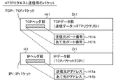
- FIG. 2 is a block diagram showing the structure of an HTTP request transmission packet transmitted from the client apparatuses 201 to 205 toward the target server apparatus 100 in the communication mode shown in FIG.
- This example shows the structure of a data packet according to the TCP / IP protocol, and the TCP packet is encapsulated in the IP packet.
- the TCP packet TCP1 shown in the upper part of FIG. 2 has a TCP header portion Ht1 and a TCP data portion Dt1, and is transmitted from the main body to be transmitted to the target server device 100 (in this example, the Web server 100).
- HTTP request is stored in the TCP data part Dt1
- the TCP header part Ht1 stores the source port number Ht1a and the destination port number Ht1b as necessary.
- the TCP packet from the client device 201 does not need a port number, but the TCP packets from the client devices 202 to 205 have port numbers P1, P2, etc. determined by each router.
- the source port number Ht1a is stored.
- the IP packet IP1 shown in the lower part of FIG. 2 has an IP header part Hi1 and an IP data part Di1, and the TCP packet shown in the upper part is stored in the IP data part Di1.
- IP header portion Hi1 a source IP address Hi1a and a destination IP address Hi1b are stored.
- the global IP address assigned to the client device 201 itself “xx.5.1.1” is stored in the transmission source IP address Hi1a.
- the global IP address of the router R1 of “xx.5.2.1” is stored in the transmission source IP address Hi1a and transmitted from the client device 204 or 205.
- the source IP address Hi1a stores the global IP address of the wireless router R2 “xx.5.3.1”.
- the global IP address “yy.6.1.1” of the target server device (Web server) 100 is stored in the destination IP address Hi1b. Therefore, the IP packet IP1 shown in FIG. 2 reaches the Web server 100 indicated by the destination IP address “yy.6.1.1”.
- the Web server 100 extracts the TCP packet TCP1 encapsulated in the IP packet IP1, and interprets transmission data (HTTP request) included in the TCP data part Dt1. Then, an HTTP response corresponding to the HTTP request is created as reply data.
- FIG. 3 is a block diagram showing the structure of an HTTP response reply packet (IP packet IP2) created by the Web server 100 in response to the HTTP request transmission packet (IP packet IP1) shown in FIG.
- IP packet IP2 An HTTP response reply packet
- IP packet IP1 An HTTP request transmission packet
- This example also shows the structure of the data packet according to the TCP / IP protocol, and the TCP packet is encapsulated in the IP packet.
- the TCP packet TCP2 shown in the upper part of FIG. 3 has a TCP header part Ht2 and a TCP data part Dt2, and the reply data of the main body to be returned to the client device that is the transmission source of the HTTP request (for example, an HTTP response including text and image data to be displayed on the Web page requested to be browsed is stored in the TCP data portion Dt2, and the transmission source port number Ht2a and the destination are stored in the TCP header portion Ht2 as necessary.
- the port number Ht2b is stored.
- this transmission source port number Ht1a is stored as the destination port number Ht2b in the TCP packet TCP2 shown in FIG. It will be.
- IP 3 has an IP header part Hi2 and an IP data part Di2, and the TCP packet shown in the upper part is stored in the IP data part Di2.
- IP header portion Hi2 a source IP address Hi2a and a destination IP address Hi2b are stored.
- the source IP address Hi2a is the destination IP address Hi1b stored in the IP packet IP1 shown in FIG. 2
- the destination IP address Hi2b is the source IP address stored in the IP packet IP1 shown in FIG. Address Hi1a.
- the source IP address in the IP packet IP2 returned from the target server device 100 is “yy.6.1.1”, and the destination IP address transmits an HTTP request. It becomes the global IP address of the sending client device.
- the destination IP address in the IP packet IP2 is “xx.5.1.1”.
- the HTTP response is in response to an HTTP request from the client device 202 or 203, the destination IP address in the IP packet IP2 is “xx.5.2.1”, and the HTTP request from the client device 204 or 205 is In the case of a corresponding HTTP response, the destination IP address in the IP packet IP2 is “xx.5.3.1”.
- an HTTP response reply packet IP2 as shown in FIG. 3 is returned to the client apparatus that has transmitted the HTTP request transmission packet IP1 as shown in FIG.
- the client device Upon receiving the reply, the client device extracts the TCP packet TCP2 encapsulated in the IP packet IP2, interprets the reply data (HTTP response) included in the TCP data portion Dt2, and executes necessary processing. .
- FIGS. 1 to 3 have two problems that impair security related to personal information.
- the first problem is that since the source address indicating the location of the client device is transmitted to the target server device 100 side, the anonymity and masking property of the access source are lost.
- the IP packet IP1 reaching the target server device 100 includes the source IP address Hi1a and the source port number Ht1a, the access is made when accessed by the client device 201 shown in FIG.
- the original global IP address “xx.5.1.1” is known to the administrator of the target server device 100, and the anonymity and masking property for the administrator are lost.
- the client apparatuses 202 to 205 shown in FIG. 1 when accessed by the client apparatuses 202 to 205 shown in FIG. 1, at least the global IP addresses “xx.5.2.1” and “xx.5.3.1” of the routers R1 and R2 are given to the administrator of the target server apparatus 100.
- the port numbers P1 and P2 are also known. Therefore, there is a possibility that even the access source client device may be specified by the analysis of the port number. Therefore, if the administrator of the target server device 100 is a malicious person, an unauthorized attack may be performed on the client device that is the access source.
- the second problem is an information leakage problem in the communication path between the client device and the server device.
- communication using the Internet there is always a risk of information leakage.
- information leakage is caused by wiretapping of the wireless communication path.
- the risk of increases As described above, some websites take measures to send and receive important information after establishing a secure communication path using SSL, etc., but to spread to general websites Not reached. Therefore, when an individual user accesses an arbitrary Web site using a WiFi spot or the like, the risk of eavesdropping becomes very high, and information leakage is likely to occur.
- the present invention was devised to solve such a problem, and when accessing an arbitrary server device via a network, while ensuring the anonymity and coverability of the access source, the communication
- An object of the present invention is to provide a packet communication system capable of preventing information leakage in a route and to improve security related to personal information.
- FIG. 4 is a block diagram showing a communication form using the packet communication system according to the basic embodiment of the present invention.
- FIG. 4 is a block diagram showing a communication form using the packet communication system according to the basic embodiment of the present invention.
- FIG. 1 an example is shown in which five client apparatuses 401 to 405 are accessing the target server apparatus 100 to be accessed via the network N.
- a feature of the present invention lies in that a relay server device 300 is newly provided, and each client device 401 to 405 is provided with a function of accessing the target server device 100 via the relay server device 300.
- Each client device 401 to 405 is configured by a computer having a communication function via a network, such as a personal computer, a mobile phone, and a tablet terminal, like the client devices 201 to 205 shown in FIG.
- the target server device 100 is the same as the target server device 100 shown in FIG. 1, and is configured by a server computer that provides necessary information upon receiving access from a client computer.
- the target server device 100 is a Web server.
- TCP / IP protocol Global IP address and private IP address
- port number assigned to each of the client apparatuses 401 to 405 shown in FIG. 4 and the connection form to the Internet N relating to each of the client apparatuses 401 to 405 (configuration of the router) ) Is the same as that related to each of the client apparatuses 201 to 205 shown in FIG.
- the conventional client apparatuses 201 to 205 (hereinafter referred to as client apparatus 200) shown in FIG. 1 and the client apparatuses 401 to 405 (hereinafter referred to as client apparatus 400) according to the present invention shown in FIG.
- client apparatus 200 The conventional client apparatuses 201 to 205 (hereinafter referred to as client apparatus 200) shown in FIG. 1 and the client apparatuses 401 to 405 (hereinafter referred to as client apparatus 400) according to the present invention shown in FIG.
- the encryption processing function for encrypting the packet to be transmitted and the decryption of the received packet, and the transmission destination of the packet to be transmitted to the target server device 100 are specified in the latter.
- the relay server device 300 which is a component unique to the present invention, decrypts the packet received from the client device 400 and transfers it to the target server device 100, and encrypts the packet received from the target server device 100.
- a function of transferring to the client device 400 is provided.
- the packet communication system has two major features.
- the first feature is that a transmission packet to be addressed from the client device 400 to the target server device 100 is first transmitted to the relay server device 300, and then transferred to the target server device 100 by the relay server device 300.
- a reply packet that should be addressed from the device 100 to the client device 400 is first sent back to the relay server device 300 and then transferred to the client device 400 by the relay server device 300.
- a second feature is that data packets are exchanged between the client device 400 and the relay server device 300 in an encrypted state.
- the above first problem can solve the first problem described above. That is, in the transmission packet to be addressed from the client apparatus 400 to the target server apparatus 100, the address of the client apparatus 400 is stored as the transmission source address, but this transmission source address is rewritten by the relay server apparatus 300, and the relay server apparatus In the transmission packet addressed from 300 to the target server apparatus 100, the address of the relay server apparatus 300 is stored as the transmission source address. For this reason, the reply packet from the target server device 100 is returned to the relay server device 300 that is the source of the transmission packet, and the reply packet is transferred to the client device 400 by the relay server device 300. .
- the address of the client device 400 is concealed, and anonymity and coverability for the administrator of the target server device 100 are ensured. Therefore, even if the administrator of the target server device 100 is malicious, even if an attack is made against the transmission source, the relay server device 300 is damaged. The security of the client device 400 is ensured.
- the second feature described above can solve a part of the second problem described above. That is, since data packets are exchanged between the client device 400 and the relay server device 300 in an encrypted state, information leakage between them can be prevented.
- there are many cases of connecting to the Internet N using a WiFi spot or the like so information leakage is likely to occur between the client device 400 and the Internet N.
- the description “401: xx.5.1.1 ⁇ 300: zz.7.1.1” written on the side of the connection path from the client device 401 to the Internet N is the IP address “xx.5.1” of the client device 401. .1 ”as a transmission source and a data packet destined for the IP address“ zz.7.1.1 ”of the relay server device 300 is transmitted.
- the data packet is transmitted from its own IP address “zz.7.1.1” and the IP address “yy.6.1.1” of the target server device 100. Is transmitted to the target server apparatus 100.
- the target server apparatus 100 returns a data packet having its own IP address “yy.6.1.1” as the transmission source and the IP address “zz.7.1.1” of the relay server apparatus 300 as the destination. .
- the data packet is sent from its own IP address “zz.7.1.1” and the IP address “xx.5.1.1” of the client device 401. Is converted to a data packet addressed to and sent back to the client apparatus 401.
- the transfer process to the relay server apparatus 300 is performed in the same manner.
- the description “402: xx.5.2.1 (P1) ⁇ 300: zz.7.1.1” written on the side of the connection path from the router R1 to the Internet N is the global corresponding to the client device 402. This indicates that a data packet having the IP address “xx.5.2.1 (P1)” as the transmission source and the IP address “zz.7.1.1” of the relay server device 300 as the destination is transmitted.
- the description “xx.5.2.1 (P2) ⁇ 300: zz.7.1.1” has the global IP address “xx.5.2.1 (P2)” corresponding to the client device 403 as the transmission source, and the relay server device 300 This indicates that a data packet destined for the IP address “zz.7.1.1” is transmitted.
- the description “404: xx.5.3.1 (P1) ⁇ 300: zz.7.1.1” written on the side of the connection path from the wireless router R2 to the Internet N is the client device 404.
- “405: xx.5.3.1 (P2) ⁇ 300: zz.7.1.1” is a relay with the global IP address “xx.5.3.1 (P2)” corresponding to the client device 405 as the transmission source This indicates that a data packet destined for the IP address “zz.7.1.1” of the server apparatus 300 is transmitted.
- a proxy server device is known as a server device that performs a function similar to that of the relay server device 300 according to the present invention, but as described in detail in ⁇ 3 and later, the configuration of the relay server device 300 according to the present invention.
- the processing operation is different from that of the conventional proxy server device.
- secure communication by encryption is ensured between the client device 400 and the relay server device 300.
- not only a specific communication protocol but also a network service compliant with any communication protocol is possible.
- the client device 400 when using a proxy server device, it is necessary to make settings for using the proxy server for each application program to be used for each client device.
- the client device 400 according to the present invention will be described later. As described above, by installing the client application program, the client device 400 can be configured, and individual setting for each application program is not necessary.
- FIG. 4 in order to describe the overall configuration of the packet communication system according to the present invention, the relay server device 300 and the client device 400 which are the components are shown as a simple block diagram. Here, the detailed configuration of the relay server device 300 and the client device 400 and the flow of data packets are shown.
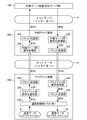
- FIG. 5 is a block diagram showing the configuration of the packet communication system according to the basic embodiment of the present invention.
- This packet communication system is a packet communication system for performing packet communication by connecting to a target server device 100 to be accessed via a network N, and includes a relay server device 300 and a client device 400. ing.
- the components unique to the present invention are the relay server device 300 and the client device 400 shown in the figure, and the target server device (for example, Web server) 100 and the network (for example, the Internet) N shown in FIG.
- the target server device 100 to be accessed does not need to be specially devised, and an existing device such as a general Web server is used as the target server device 100. do it. Therefore, in the present application, description of the internal configuration of the target server device 100 is omitted.
- the target server device 100 to be accessed in the present invention has a processing function for performing some response to the transmission packet transmitted from the client device and returning a predetermined reply packet. It ’s enough.
- a Web server as described in ⁇ 1
- any general Web server having a function of returning an HTTP response in response to an HTTP request can be used as the target server device 100 in the present invention.
- the client device 400 is a component that performs packet communication with the target server device 100, and as illustrated, a packet transmission unit 410, a client encryption processing unit 420, a communication control unit 430, and a client decryption processing unit 440.
- the packet receiving unit 450 is included.
- the entity of the client device 400 is a computer having a communication function via a network, such as a personal computer, a mobile phone, and a tablet terminal.
- the client device 400 includes various components not shown such as a CPU, a memory, a display, and an input device. However, for the sake of convenience, only the components involved in the packet communication according to the present invention are illustrated here, and descriptions of components not shown are omitted.
- the client device 400 is configured by a computer in which a predetermined OS program and one or a plurality of application programs that operate under the OS program are installed.
- the client encryption processing unit 420, the client decryption processing unit 440, and the packet receiving unit 450 function by incorporating and executing the client application program according to the present invention in a computer.
- the client application program can be distributed independently, and the user installs the client application program on a general-purpose computer (such as a personal computer, a mobile phone, or a tablet terminal), thereby enabling the client according to the present invention.
- the apparatus 400 can be configured.
- the communication control unit 430 generates a transmission IP packet IP10 in order to transmit the desired transmission data S created by a component not shown to the outside based on the TCP / IP protocol.
- a component that performs a process of extracting the reply data R included in the IP packet IP60 transmitted from the outside based on the TCP / IP protocol, and such processing functions include a personal computer, a mobile phone, and a tablet.
- a type terminal or the like is usually a standard function provided as an OS program or a library program used by the OS program. Therefore, in general, the client application program according to the present invention described above does not need to include the function as the communication control unit 430.
- the relay server device 300 is a component newly provided for carrying out the present invention, and plays a role of relaying packet communication between the client device 400 and the target server device 100.
- the relay server device 300 includes a packet transfer unit 310, a relay server decryption processing unit 320, a relay server encryption processing unit 330, and a packet return unit 340.
- the entity of the relay server device 300 is a server computer having a function of connecting to the Internet N.
- the relay server device 300 is configured by a computer in which a predetermined OS program and one or a plurality of application programs that operate under the OS program are installed. 310, the relay server decryption processing unit 320, the relay server encryption processing unit 330, and the packet return unit 340 function by incorporating and executing the server application program according to the present invention in a computer.
- This server application program can be distributed alone, and the user can configure the relay server device 300 according to the present invention by installing the server application program in a general-purpose server computer. .
- an HTTP request is created by a component not shown (for example, a Web browser program).
- This HTTP request is given to the communication control unit 430 as transmission data S.
- the communication control unit 430 creates a first IP packet IP10 including, in the data part, predetermined transmission data S to be transmitted to the target server device 100, with the client device 400 as a transmission source and the target server device 100 as a destination. Process.
- the transmission data S is an HTTP request addressed to the target server device 100.
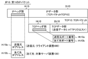
- FIG. 6 is a block diagram showing an example of the structure of the first IP packet IP10 created by the communication control unit 430.
- the transmission data S to be transmitted to the target server device 100 is an HTTP request. Therefore, the contents of the first IP packet IP10 shown in FIG. It is the same as the contents of the IP packet IP1 shown.
- the first IP packet IP10 shown in FIG. 6 includes an IP header portion Hi10 and an IP data portion Di10.
- the IP header portion Hi10 includes a transmission source IP address indicating the address of the client device 400.
- the Hi 10a and the destination IP address Hi10b indicating the address of the target server device 100 are stored.
- the IP address “xx.5.1.1” of the client device 401 is written as the transmission source IP address Hi10a.
- the IP address “yy.6.1.1” of the target server device 100 is written as the destination IP address Hi10b.
- the IP data part Di10 stores a TCP packet TCP10 including transmission data S to be transmitted to the target server device 100 (in this example, an HTTP request).
- the TCP packet TCP10 includes a TCP header part Ht10 and a TCP data part Dt10. Transmission data S (in this example, an HTTP request) is stored in the TCP data part Dt10.
- the TCP header portion Ht10 can store a transmission source port number Ht10a and a destination port number Ht10b.
- the source port number Ht10a is assigned by the NAPT function of the router and written in the TCP header portion Ht10.
- the client encryption processing unit 420 performs processing for encrypting at least a part of the first IP packet IP10 shown in FIG.
- the object of encryption is basically the IP data portion Di10. If it is necessary to refer to or rewrite data (for example, a port number) in the TCP header portion Ht10, only the TCP data portion Dt10 may be the target of encryption. Of course, only a part of the TCP data part Dt10 may be subject to encryption.
- the first IP packet IP10 is converted into encrypted data for transmission C20.
- the packet transmission unit 410 has a function of creating and transmitting a second IP packet IP20 that includes the client device 400 as a transmission source and the relay server device 300 as a destination, and the transmission encryption data C20 in the data portion.
- FIG. 7 is a block diagram showing an example of the structure of the second IP packet IP20 created in this way. As shown in the upper part of FIG. 7, the second IP packet IP20 includes an IP header part Hi20 and an IP data part Di20. On the other hand, the lower part of FIG. 7 shows encryption processing by the client encryption processing unit 420.
- the client encryption processing unit 420 uses the encrypted data C20 for transmission as data obtained by encrypting all or part of the IP data part Di10 (for example, the TCP data part Dt10) of the first IP packet IP10. create.
- the transmission encryption data C20 thus created is stored as it is.
- the process of encapsulating the first IP packet IP10 shown in FIG. 6 in the second IP packet IP20 in an encrypted state has been performed.
- a source IP address Hi20a indicating the address of the client apparatus 400 and a destination IP address Hi20b indicating the address of the relay server apparatus 300 are stored.
- the IP address “xx.5.1.1” of the client apparatus 401 is written as the transmission source IP address Hi20a.
- the IP address “zz.7.1.1” of the relay server device 300 is written as the destination IP address Hi20b.
- the packet transmission unit 410 performs processing for creating an IP packet including the IP header portion Hi20 and the IP data portion Di20 as the second IP packet IP20, and stores the transmission encryption data C20 in the IP data portion Di20.
- the encapsulation process is performed, and the second IP packet IP20 is transmitted according to the TCP / IP protocol.
- the second IP packet IP20 transmitted in this way reaches the relay server device 300 as the destination via the network N.
- the communication path of the second IP packet IP20 from the client apparatus 400 to the relay server apparatus 300 is indicated by a white arrow. This is because the communication path is an encrypted communication path. Indicates. Therefore, the risk of information leakage can be eliminated even if wiretapping is performed because a wireless communication path is present on the communication path indicated by the white arrow.
- the relay server decryption processing unit 320 receives the second IP packet IP20, decrypts the transmission encryption data C20 included in the IP data unit Di20, and performs the first IP packet shown in FIG. A process of restoring IP10 is performed.
- the decryption processing by the relay server decryption processing unit 320 is executed based on the encryption processing performed by the client encryption processing unit 420.
- the decryption processing unit 320 for the relay server can identify the client device 400 that is the transmission source of the second IP packet IP20 based on the transmission source IP address Hi20a.
- the encrypted data for transmission C20 is stored in the first encrypted data C20.
- a process of converting to the IP packet IP10 can be performed.
- the packet transfer unit 310 changes the transmission source of the first IP packet IP10 restored by the relay server decoding processing unit 320 from the client device 400 to the relay server device 300, thereby changing the third IP packet IP30. It has a function of creating and transmitting the created third IP packet IP30.
- FIG. 8 is a block diagram showing an example of the structure of the third IP packet IP30 created in this way.
- the third IP packet IP30 includes an IP header portion Hi30 and an IP data portion Di30.
- the packet transfer unit 310 stores the IP data part Di10 of the restored first IP packet IP10 (see FIG. 6) in the IP data part Di30 of the third IP packet IP30.
- FIG. 8 shows a state in which the TCP packet TCP30 is stored in the IP data portion Di30. Actually, the TCP packet TCP30 is the same as the TCP packet TCP10 shown in FIG.
- the TCP header part Ht30 shown in FIG. 8 is the same as the TCP header part Ht10 shown in FIG. 6, and the TCP data part Dt30 shown in FIG. 8 is shown in FIG. This is the same as the TCP data part Dt10. Therefore, transmission data S (in this example, an HTTP request) is stored in the TCP data portion Dt30.
- transmission data S in this example, an HTTP request
- the source port number Ht30a and the destination port number Ht30b shown in FIG. 8 are the same as the source port number Ht10a and the destination port number Ht10b shown in FIG.
- the content of the IP header portion Hi30 of the third IP packet IP30 shown in FIG. 8 is slightly different from the content of the IP header portion Hi10 of the first IP packet IP10 shown in FIG.
- the IP address Hi30a the address of the relay server device 300 is stored, and as the destination IP address Hi30b, the address of the target server device 100 is stored. That is, the IP address of the first IP packet IP10 shown in FIG. 6 changed from the client device 400 to the relay server device 300 is the third IP packet IP30 shown in FIG.
- the IP header portion Hi30 of the third IP packet IP30 has a relay server as the source IP address Hi30a.
- the IP address “zz.7.1.1” of the device 300 is written, and the IP address “yy.6.1.1” of the target server device 100 is written as the destination IP address Hi30b.
- the packet transfer unit 310 performs processing for creating an IP packet including the IP header portion Hi30 and the IP data portion Di30 as the third IP packet IP30, and the restored first data is stored in the IP data portion Di30.
- the data part Di10 of the IP packet IP10 is stored, and the IP header part Hi30 stores the address of the relay server device 300 as the source IP address Hi30a, and stores the address of the target server device 100 as the destination IP address Hi30b.
- the third IP packet IP30 thus created is transmitted according to the TCP / IP protocol.
- the third IP packet IP30 transmitted in this way reaches the target server device 100 as the destination via the network N.
- the communication path of the third IP packet IP30 from the relay server apparatus 300 to the target server apparatus 100 is indicated by a normal arrow.
- this communication path is a normal communication path in plain text. Indicates that Therefore, when eavesdropping is performed on this normal communication path, information leakage may occur, but the third IP packet IP30 that has reached the target server device 100 is a normal IP packet in plain text. Therefore, there is no need to perform decryption processing or the like in the target server device 100.
- the target server device 100 does not have to be a special device based on cryptographic communication.
- any Web server can be selected as the target server device 100.
- the above is a series of processing processes when an HTTP request is transmitted from the client device 400 to the target server device 100 that is a Web server. Since the address of the relay server device 300 is stored as the source IP address in the IP header portion Hi30 of the third IP packet IP30, the address of the client device 400 is kept secret from the target server device 100. Will be. Therefore, even if the administrator of the target server device 100 is malicious, the client device 400 is secured with anonymity and coverability, so that the security of the client device 400 is ensured.
- HTTP response reply process Subsequently, an example of a processing process when the target server device 100 formed of a Web server creates an HTTP response in response to an HTTP request transmitted from the client device 400 via the relay server device 300 and returns the HTTP response is shown as an example. The specific processing function of each related component will be described below.
- FIG. 9 is a block diagram showing an example of the structure of the fourth IP packet IP40 created by the target server device 100.
- the fourth IP packet IP40 is transmitted from the target server device 100 toward the relay server device 300.
- the target server device 100 since the transmission data S included in the third IP packet IP30 received by the target server device 100 is an HTTP request, the target server device 100 first sends an HTTP response corresponding to the HTTP request. Created as reply data R.
- This HTTP response includes, for example, text and image data to be displayed on the web page requested to be browsed.
- a fourth IP packet IP40 shown in FIG. 9 includes an IP header portion Hi40 and an IP data portion Di40.
- the IP header portion Hi40 includes a source IP address Hi40a indicating the address of the target server device 100 itself, A destination IP address Hi40b indicating the address of the relay server 300, which is a direct reply destination, is stored.
- the reason why the destination IP address Hi40b is not the address of the client device 400 but the address of the relay server 300 is that the transmission source of the third IP packet IP30 is the address of the relay server 300.
- the target server device 100 since the HTTP request is transmitted from the relay server device 300, the target server device 100 performs a process of returning an HTTP response corresponding to the HTTP request to the relay server device 300. This is a normal process performed by a general Web server. Specifically, in the case of the example illustrated in FIG. 4, the IP address “yy.6.1.1” of the target server device 100 is written in the IP header portion Hi40 of the fourth IP packet IP40 as the source IP address Hi40a. Thus, the IP address “zz.7.1.1” of the relay server device 300 is written as the destination IP address Hi40b.
- a TCP packet TCP40 including reply data R to be returned to the relay server device 300 (in this example, an HTTP response) is stored.
- the TCP packet TCP40 includes a TCP header part Ht40 and a TCP data part Dt40, and reply data R (in this example, an HTTP response) is stored in the TCP data part Dt40.
- the TCP header portion Ht40 can store a transmission source port number Ht40a and a destination port number Ht40b as necessary.
- the target server apparatus 100 returns the fourth IP packet IP40 shown in FIG. 9 as a response to the third IP packet IP30 shown in FIG. As illustrated in FIG. 5, the relay server device 300 receives such a fourth IP packet IP40 via the network N, and performs the following processing.
- the relay server encryption processing unit 330 receives the fourth IP packet IP40, encrypts at least a part thereof, and creates return encrypted data C50.
- the object of encryption is basically the IP data portion Di40.
- the TCP header portion Ht40 for example, a port number
- only the TCP data portion Dt40 may be subject to encryption.
- only a part of the TCP data part Dt40 may be subject to encryption.
- the fourth IP packet IP40 is converted into reply encrypted data C50.
- the encryption processing unit for relay server 330 receives the fourth IP packet IP40 including the IP header part Hi40 and the IP data part Di40 as shown in FIG. 9, and receives the data of the received fourth IP packet IP40. A process of encrypting all or a part of the part Di40 and creating the reply encrypted data C50 is performed.
- the packet reply unit 340 has a function of creating and sending a fifth IP packet IP50 including the reply encrypted data C50 in the data part with the relay server device 300 as a transmission source and the client device 400 as a destination.
- FIG. 10 is a block diagram showing an example of the structure of the fifth IP packet IP50 created in this way. As shown in the upper part of FIG. 10, the fifth IP packet IP50 includes an IP header part Hi50 and an IP data part Di50. On the other hand, the lower part of FIG. 10 shows encryption processing by the encryption processing unit 330 for the relay server.
- the relay server encryption processing unit 330 returns the reply encryption data C50 as data obtained by encrypting all or part of the IP data part Di40 (for example, the TCP data part Dt40) of the fourth IP packet IP40. Create In the IP data portion Di50 of the fifth IP packet IP50, the reply encryption data C50 created in this way is stored as it is.
- the packet reply unit 340 performs processing for creating the fifth IP packet IP50 including the IP header part Hi50 and the IP data part Di50, and the IP data part Di50 has a reply encryption. Encapsulation processing for storing data C50 is performed, and in IP header portion Hi50, transmission source IP address Hi50a indicating the address of relay server device 300 and destination IP address Hi50b indicating the address of client device 400 are stored Will do.
- This process can be said to be a process of encapsulating the fourth IP packet IP40 shown in FIG. 9 in the fifth IP packet IP50 in an encrypted state.
- the IP header portion Hi50 in the fifth IP packet IP50 is returned.
- the IP address “zz.7.1.1” of the relay server device 300 is written as the source IP address Hi50a, and the IP address “xx.5.1.1” of the client device 401 is written as the destination IP address Hi50b. .
- the packet reply unit 340 needs to write the IP address “xx.5.1.1” of the client apparatus 401 as the reply destination to the IP header part Hi50 as the destination IP address Hi50b when creating the fifth IP packet IP50. Therefore, it is necessary to obtain the IP address “xx.5.1.1” of this client device 401 by some method.
- the IP header portion Hi40 of the fourth IP packet IP40 shown in FIG. 9 stores the address “yy.5.1.1” of the target server device 100 as the source IP address Hi40a, and the destination IP address Hi40b. Only the address “zz.7.1.1” of the relay server device 300 is stored, and the address “xx.5.1.1” of the client device 401 that is the return destination of the fifth IP packet IP50 is stored. Absent. Therefore, the packet reply unit 340 needs to specify a client device as a reply destination by some method and obtain the address. For convenience of explanation, a method for specifying the client device as the reply destination will be described in ⁇ 4-2 described later.
- the packet reply unit 340 performs processing for creating an IP packet including the IP header part Hi50 and the IP data part Di50 as the fifth IP packet IP50, and stores the reply encryption data C50 in the IP data part Di50.
- the encapsulation process is performed, and the fifth IP packet IP50 is transmitted according to the TCP / IP protocol.
- the fifth IP packet IP50 returned in this way reaches the destination client apparatus 400 via the network N.
- the communication path of the fifth IP packet IP50 from the relay server apparatus 300 to the client apparatus 400 is indicated by a white arrow, but this is because the communication path is an encrypted communication path. Indicates. Therefore, the risk of information leakage can be eliminated even if wiretapping is performed because a wireless communication path is present on the communication path indicated by the white arrow.
- the client decryption processing unit 440 receives the fifth IP packet IP50, decrypts the reply encryption data C50 included in the IP data unit Di50, and performs the fourth IP packet IP40 shown in FIG. Process to restore.
- the decryption processing by the client decryption processing unit 440 is executed based on the encryption processing performed by the relay server encryption processing unit 330.
- the client decryption processing unit 440 can identify the relay server device 300 that is the transmission source of the fifth IP packet IP50 based on the transmission source IP address Hi50a.
- the return encrypted data C50 is converted into the fourth encrypted data C50.
- the IP packet IP40 can be converted.
- the packet receiving unit 450 creates the sixth IP packet IP60 by changing the destination of the fourth IP packet IP40 restored by the client decoding processing unit 440 from the relay server device 300 to the client device 400. It has a function.
- FIG. 11 is a block diagram showing an example of the structure of the sixth IP packet IP60 created in this way.
- the sixth IP packet IP60 includes an IP header portion Hi60 and an IP data portion Di60.
- the packet receiving unit 450 stores the IP data part Di40 of the restored fourth IP packet IP40 (see FIG. 9) in the IP data part Di60 of the sixth IP packet IP60.
- FIG. 11 shows a state in which the TCP packet TCP60 is stored in the IP data portion Di60. Actually, the TCP packet TCP60 is the same as the TCP packet TCP40 shown in FIG.
- the TCP header portion Ht60 shown in FIG. 11 is the same as the TCP header portion Ht40 shown in FIG. 9, and the TCP data portion Dt60 shown in FIG. 11 is shown in FIG. This is the same as the TCP data part Dt40. Therefore, reply data R (in this example, an HTTP response) is stored in the TCP data portion Dt60.
- reply data R in this example, an HTTP response
- the source port number Ht60a and the destination port number Ht60b shown in FIG. 11 are the same as the source port number Ht40a and the destination port number Ht40b shown in FIG.
- the content of the IP header portion Hi60 of the sixth IP packet IP60 shown in FIG. 11 is slightly different from the content of the IP header portion Hi40 of the fourth IP packet IP40 shown in FIG.
- the address of the target server device 100 is stored as the IP address Hi60a
- the address of the client device 400 is stored as the destination IP address Hi60b. That is, the IP address IP address of the fourth IP packet IP40 shown in FIG. 9 changed from the relay server device 300 to the client device 400 is the sixth IP packet IP60 shown in FIG.
- the IP header portion Hi 60 of the sixth IP packet IP 60 contains The IP address “yy.6.1.1” of the target server device 100 is written as the source IP address Hi60a, and the IP address “xx.5.1.1” of the client device 401 is written as the destination IP address Hi60b.
- the packet receiving unit 450 performs processing for creating an IP packet including the IP header portion Hi60 and the IP data portion Di60 as the sixth IP packet IP60, and the restored fourth IP is stored in the IP data portion Di60.
- Processing for storing reply data R (in this example, an HTTP response) included in the packet IP40 is performed.
- the communication control unit 430 performs processing for extracting the reply data R (in this example, an HTTP response) included in the data part Di60 of the sixth IP packet IP60.
- reply data R HTTP response
- This reply data R HTTP response
- the relay server device 300 includes two types of a second IP packet IP20 transmitted from the client device 400 and a fourth IP packet IP40 transmitted from the target server device 100.
- An IP packet arrives.
- the former is processed by the relay server decryption processing unit 320, and the latter is processed by the relay server encryption processing unit 330. Therefore, it is actually determined whether the IP packet that has arrived at the relay server device 300 is the second IP packet IP20 or the fourth IP packet IP40.
- a selection process to be processed by the relay server encryption processing unit 330 is required. As a method for performing such a sorting process, several methods are conceivable.
- the second IP packet IP20 includes an IP header portion Hi20, in which various information other than the source IP address Hi20a and the destination IP address Hi20b shown in FIG. Can be stored. Therefore, when the packet transmitting unit 410 creates the second IP packet IP20, a packet identification code indicating that “the IP packet is the second IP packet IP20” is added to a specific portion of the IP header portion Hi20. Just write it.
- the relay server device 300 that has received an IP packet from the outside first determines whether or not the packet identification code is written in the specific location of the IP header portion. If the packet identification code has been written, the received IP packet is determined to be the second IP packet IP20, and is set as the processing target of the relay server decoding processing unit 320, and the packet identification code has been written. If not, it is determined that the received IP packet is the fourth IP packet IP40, and the processing is performed by the relay server encryption processing unit 330.
- the relay server device 300 that has received an external IP packet is assumed to be the second IP packet IP20 and is decrypted by the relay server decoding processing unit 320. If there is no abnormality in the data structure of the decrypted packet after the process is attempted, the IP packet is determined to be the second IP packet IP20 and the process is continued.
- a method can be adopted in which the IP packet is determined to be the fourth IP packet IP40 and is processed by the relay server encryption processing unit 330.
- the encryption data C20 for transmission is encapsulated in the IP data portion Di20 of the second IP packet IP20, and when this portion is decrypted, the first IP packet IP10 should be restored. It is.
- the restored first IP packet IP10 should have a normal data structure defined as an IP packet. Therefore, when an IP packet having such a normal data structure is not restored as a result of the decryption process performed by the relay server decryption processing unit 320, the IP packet that is the target of the decryption process is It can be determined that the packet is not the IP packet IP20 but the fourth IP packet IP40.
- the embodiment shown in FIG. 4 is an example in which a single global IP address “zz.7.1.1” is set in the relay server device 300, but two types of IP addresses are set, and one of them is transmitted / received to / from the client device 400. If it is used as a window and the other is used as a transmission / reception window for the target server apparatus 100, the second IP packet IP20 and the fourth IP packet are recognized by recognizing which transmission / reception window the IP packet has reached. Selection with IP40 is possible.
- the packet transmission unit 410 of the client device 400 transmits the second IP packet IP20 to the IP address “zz.7.1.1”, and the packet return unit 340 of the relay server device 300 receives the IP address.
- the fifth IP packet IP50 is returned with “zz.7.1.1” as the transmission source.
- the packet transfer unit 310 of the relay server device 300 transmits the third IP packet IP30 with the IP address “zz.8.1.1” as the transmission source, the IP address “ The fourth IP packet is returned to “zz.8.1.1”.
- the relay server device 300 when an IP packet reaches the IP address “zz.7.1.1”, it is determined as the second IP packet IP20 and is processed by the relay server decoding processing unit 320. If an IP packet arrives at the IP address “zz.8.1.1”, it is determined as the fourth IP packet IP40 and may be processed by the relay server encryption processing unit 330.
- the packet reply unit 340 in the relay server device 300 performs a process of creating the fifth IP packet IP50 as illustrated in FIG.
- the IP address of the relay server device 300 itself is stored as the source IP address Hi50a
- the IP address of the client device 400 is stored as the destination IP address Hi50b. Has been. Therefore, in order to write the IP address of the client device 400, the packet reply unit 340 needs to specify a client device that is a reply destination.
- the relay server device 300 receives access for relay requests (transmission of the second IP packet IP20) from the five client devices 401 to 405. Then, the relay server device 300 needs to return a reply packet obtained from the target server device 100 by executing this relay request to the specific client device that is the request source (transmission of the fifth IP packet IP50).
- the reply packet obtained from the target server device 100 by the relay request (transmission of the second IP packet IP20) from the client device 401 (IP address “xx.5.1.1”) is The client device 401 (IP address “xx.5.1.1”) as the request source needs to be returned as the fifth IP packet IP50. Therefore, the packet reply unit 340 in the relay server device 300 uses the IP address “xx.5.1.1” of the client device 401 as a reply destination as the destination IP address Hi50b, and the IP header portion Hi50 in the fifth IP packet IP50. Need to write to.
- the IP header portion Hi40 of the fourth IP packet IP40 stores the address “yy.6.1.1” of the target server device 100 as the source IP address Hi40a, and the destination IP address Hi40b. Only the address “zz.7.1.1” of the relay server device 300 is stored, and the address “xx.5.1.1” of the client device 401 that is the return destination of the fifth IP packet IP50 is stored. Absent. Therefore, the packet reply unit 340 needs to specify a client device as a reply destination by some method and obtain the address. Hereinafter, several specific methods for the packet reply unit 340 to identify a client device as a reply destination will be described.
- the first method is a method of assigning one relay server device to one client device and performing operation in a one-to-one correspondence.
- the packet reply unit 340 determines which of the five client devices is a reply destination. It is necessary to identify what.
- the packet reply unit 340 determines which of the five client devices is a reply destination. It is necessary to identify what.
- the packet reply unit 340 always returns the fifth IP packet IP50 to the one client device. .
- a plurality of n client apparatuses 400 and n relay server apparatuses 300 associated with each of the n client apparatuses 400 are provided, and a packet transmission unit of each client apparatus 400 is provided.
- 410 transmits the second IP packet IP20 addressed to the corresponding specific relay server device 300, and the packet reply unit 340 of each relay server device 300 is addressed to the corresponding specific client device 400.
- the fifth IP packet IP50 may be transmitted.
- a single server device may be installed in hardware according to the software to be incorporated. It is sufficient to make it function as a single relay server device 300.
- the one server device is designated as 5 in the present invention.
- the packet transfer unit 310, the relay server decryption processing unit 320, the relay server encryption processing unit 330, and the packet return unit 340 can be used in common.
- the second method is a method of embedding information indicating the requesting client device that has made the relay request in the third IP packet IP30 transmitted to the target server device 100.
- the packet transfer unit 310 uses the third IP packet IP30 as the information indicating the transmission source of the restored first IP packet IP10 (the requesting client device that has made the relay request). Process to embed in.
- the relay server encryption processing unit 330 performs a process of reading the information indicating the transmission source embedded in the received fourth IP packet IP40 and transmitting the information to the packet reply unit 340, and the packet reply unit 340 may create the fifth IP packet IP50 that uses the information indicating the transmission source as the destination client device 400.
- information embedded in the third IP packet IP30 may be returned from the target server device 100 in a state where it is embedded in the fourth IP packet IP40 as it is. It is a premise.
- information indicating the transmission source may be embedded as a port number in a TCP packet.
- the packet transfer unit 310 creates the third IP packet IP30 according to the TCP / IP protocol as shown in FIG. Therefore, at this time, the packet transfer unit 310 performs processing for embedding information indicating the transmission source of the first IP packet IP10 as the transmission source port number Ht30a in the TCP header unit Ht30 included in the third IP packet IP30. You just have to do it. Then, the embedded information is included as the destination port number Ht40b in the fourth IP packet IP40 returned from the target server device 100.
- the target server apparatus 100 that has received the third IP packet IP30 shown in FIG. 8 returns the fourth IP packet IP40 shown in FIG.
- Source IP address Hi30a is the destination IP address Hi40b in the fourth IP packet IP40
- the source port number Ht30a in the TCP packet TCP30 included in the third IP packet IP30 is the fourth IP packet IP40.
- Processing for setting the destination port number Ht40b in the included TCP packet TCP40 is performed. Therefore, if necessary information is written as the source port number Ht30a in the third IP packet IP30, the information can be read as the destination port number Ht40b in the fourth IP packet IP40.
- the packet reply unit 340 uses the information embedded in the TCP header part Ht40 included in the fourth IP packet IP40 as the destination port number Ht40b (information indicating the requesting client apparatus that made the relay request). Based on this, the transmission destination of the fifth IP packet IP50 can be determined.
- the third method is a method in which the correspondence relationship between the client device that made the relay request and the third IP packet is recorded in the relay server device 300.
- FIG. 12 is a block diagram showing a configuration of a packet communication system according to a modification of the present invention that employs the third method. The only difference between the basic embodiment shown in FIG. 5 and the modification shown in FIG. 12 is that the former relay server device 300 is replaced with a relay server device 300 ′ in the latter. 12 replaces the packet transfer unit 310 in the relay server device 300 shown in FIG. 5 with a packet transfer unit 310 ′, replaces the packet return unit 340 with a packet return unit 340 ′, A communication information recording unit 350 is added as a new component.
- the communication information recording unit 350 has a function of recording a correspondence relationship between the client device that has made the relay request and the third IP packet.
- the packet transfer unit 310 ′ of the relay server device 300 ′ further restores when transmitting the third IP packet IP30.
- the communication information recording unit 350 performs processing for recording information indicating the transmission source of the first IP packet IP10 and the corresponding relationship information indicating the corresponding relationship with the third IP packet IP30.
- the packet reply unit 340 ′ of the relay server device 300 ′ further transmits the fifth IP packet IP50 in addition to the function of the packet reply unit 340 of the relay server device 300 according to the basic embodiment. Based on the correspondence information recorded in the communication information recording unit 350, processing for determining the transmission destination of the fifth IP packet IP50 is performed.
- the packet reply unit 340 ′ is based on the correspondence relationship information recorded in the communication information recording unit 350 (ie, the transmission destination of the fifth IP packet IP 50 (ie, In order to determine the transmission source of the first IP packet IP10), information for specifying the third IP packet IP30 is included in the fourth IP packet IP40 that is the source of the fifth IP packet IP50. Must be included.
- information for specifying the third IP packet IP30 may be embedded as a port number in the TCP packet.
- the packet transfer unit 310 ′ creates the third IP packet IP30 as shown in FIG. 8 according to the TCP / IP protocol, the TCP header part included in the third IP packet IP30.
- a packet identifier for indicating the third IP packet IP30 is embedded as a port number in Ht30, and the correspondence between the packet identifier and information indicating the source of the restored first IP packet IP10 is correspondence information.
- the process of recording in the communication information recording unit 350 may be performed.
- the second IP packet IP20 is transmitted as a relay request from the client device 401 (IP address “xx.5.1.1”), and the packet transfer unit 310 ′ performs the second request.
- a third IP packet IP30 as shown in FIG. 8 is created based on the IP packet IP20.
- the packet transfer unit 310 ′ performs a process of embedding a packet identifier (for example, data “1234”) for indicating the third IP packet IP30 as a port number in the TCP header part Ht30 (source) It may be embedded as the port number Ht30a or may be embedded as the destination port number Ht30b).
- a packet identifier for example, data “1234”
- the packet transfer unit 310 ′ then sends information indicating the packet identifier (eg, data “1234”) and the source of the restored first IP packet IP 10 (in the above example, for example, the IP of the client device 401).
- the correspondence relationship with the address “xx.5.1.1”) is recorded in the communication information recording unit 350 as correspondence relationship information.
- correspondence information “1234: xx.5.1.1” is recorded in the communication information recording unit 350.
- a fourth IP packet IP40 as shown in FIG. 9 is returned in response thereto.
- the transmission source port number Ht30a in the third IP packet IP30 is set as the destination port number Ht40b in the fourth IP packet IP40, and the transmission source in the third IP packet IP30.
- a process of setting the port number Ht30a as the destination port number Ht40b in the fourth IP packet IP40 is performed. Therefore, the packet identifier (“1234” in the above example) embedded by the packet transfer unit 310 ′ as the port number in the TCP header part Ht30 in the third IP packet IP30 is the TCP header in the fourth IP packet IP40. It remains as a port number in the part Ht40.
- the packet reply unit 340 ′ uses the packet identifier (“1234” in the above example) embedded as a port number in the TCP header part Ht40 included in the fourth IP packet IP40 to record the communication information.
- the fifth IP packet IP50 can be transmitted to the transmission source of the first IP packet IP10. That is, in the above example, the packet reply unit 340 ′ performs a search using the packet identifier “1234” with respect to the communication information recording unit 350, whereby the correspondence information “1234: xx.5.1.1” is obtained.
- the IP address “xx.5.1.1” of the client device 401 can be written as the destination IP address of the IP header portion Hi50 of the fifth IP packet IP50.
- FIG. 13 is a block diagram showing a modification in which the packet communication system according to the present invention is installed across two countries.
- the packet communication system according to this modified example includes one relay server device 300 and four client devices 401 to 404, and is connected to the target server device 100 to be accessed via the network N. It has a function to connect and perform packet communication.
- the configurations and functions of the relay server device 300 and the client devices 401 to 404 are exactly the same as those of the embodiments described so far.
- the feature of this modification is that the two client devices 401 and 402 and the relay server device 300 are installed in the same region of country A as the target server device 100, whereas the two client devices 403 , 404 are installed in an area of country B different from the installation area of the target server device 100.
- the relay server device 300 is installed in the region of the first country A, and the client devices 403 and 404 are installed in the region of the second country B.
- the client devices 403 and 404 access the target server device 100 installed in the area of the first country A
- the client apparatuses 403 and 404 are installed in the area of the first country A.
- access is performed via relay by the relay server device 300.
- the specific access process in this modification is as already described in Section 3.
- this packet communication system is used, anonymity and masking of the access source can be ensured, and information leakage in the communication path can be prevented, and the unique effect of improving security regarding personal information can be obtained.
- the points to be obtained are as described above.
- client apparatuses 401 and 402 installed in the region of country A are connected to the Internet N via a wireless router Ra with a domain name “xxxx@xxx.ne.aa”.
- the client apparatuses 403 and 403 installed in the region of country B are connected to the Internet N via a wireless router Rb with a domain name “gggg@ggg.ne.bb”.
- the target server device 100 is given a domain name “yyyy@yyy.co.aa”
- the relay server device 300 is given a domain name “zzzz@zzz.ne.aa”.
- Each of these domain names is converted into a specific global IP address (not shown) by using DNS.
- each domain name are the top-level domain indicating the country in which each device is installed, and devices with the domain name “aa” at the end are regions in country A.
- the device with the domain name ending in “bb” is installed in the territory of country B.
- Access between hosts via the Internet N is basically free, but there are many sites that restrict access from abroad due to security reasons and political and economic circumstances.
- the target server device 100 performs an operation of restricting access from a foreign country and the target server device 100 is configured as described above, the end “aa” Access from a host with a domain name is allowed, but access from hosts with other domain names is rejected.
- the client devices 401 and 402 can access the target server device 100, but the client devices 403 and 404 cannot access the target server device 100.
- the client server 403, 404 can access the target server apparatus 100. That is, when the client device 403, 404 accesses the target server device 100 directly via the wireless router Rb, it is confirmed that the access source is a foreign host with the domain name having the end “bb”. Therefore, the access is denied. However, when the packet communication system according to the present invention is used, if the client device 403, 404 tries to access the target server device 100 via the wireless router Rb, the access is actually relayed by the relay server device 300. Therefore, the direct access source to the target server apparatus 100 is the host in A with the domain name “aa” at the end, and the access is permitted.
- a Web server is used as the target server device 100.
- the target server device 100 is not limited to a Web server, and mail. It is also possible to use a server or a data server.
- the packet communication system according to the present invention can be widely applied when performing communication between a client and a server.
- secure communication such as SSL encryption communication may be set.
- the transmission data S and reply data Encryption is performed on R.
- double encryption by the client encryption processing unit 420 and the relay server encryption processing unit 330 may be performed, or encryption by these processing units 420 and 330 may be omitted.
- the client devices 402 and 403 are connected to the subnet constructed by the router R1, and the client devices 404 and 405 are connected to the subnet constructed by the wireless router R2. Yes.
- the target server device 100 is connected outside these subnets. In such a case, the operation as described above may be performed. However, when the target server device is a server device connected in the same subnet, the transmission data S addressed to the server device, With respect to the corresponding reply data R, it is possible not to perform encryption processing unique to the present invention or relay processing via the relay server device 300.
- the printer server 109 is connected to the subnet constructed by the router R1 and the client device 402 accesses the printer server 109.
- the access-source client device 402 and the access-destination printer server 109 belong to the same subnet, measures for ensuring anonymity and masking of the access source and preventing information leakage on the communication path There is little need to perform data encryption, and there is little need to perform data encryption or relay by the relay server device 300.
- the communication control unit 430 in the client device 400 shown in FIG. 5 is provided with a function for determining whether or not the target server device to be accessed belongs to the same subnet. If it belongs to the network, the first IP packet may be transmitted to the subnet as it is without passing through the client encryption processing unit 420 or the packet transmission unit 410. Further, when a reply is received from the target server device belonging to the same subnet to the client device 400, communication control is performed on the returned IP packet without passing through the client decoding processing unit 440 and the packet receiving unit 450.
- the unit 430 may receive directly.
- the packet communication system according to the present invention can be introduced in combination with a system according to another invention.
- the applicant of the present application discloses a network communication system invention in International Publication No. WO2017 / 145984 as another invention related to the present invention.
- the packet communication system according to the present invention can be introduced in combination with the network communication system according to another invention.
- the network N is provided with the relay server device 300 according to the present invention and the connection mediating device according to the other invention, but these devices are a single server in terms of hardware. It can be configured by a device.
- the packet communication system is a secure communication with any server device in a state where various client devices that can be connected to a desired server device via a network such as a personal computer, a mobile phone, and a tablet terminal are used. It provides the environment and has sufficient industrial applicability.
- Target server device (Web server, etc.) 200: client devices 201 to 205: client devices 300, 300 ′: relay server devices 310, 310 ′: packet transfer unit 320: relay server decryption processing unit 330: relay server encryption processing units 340, 340 ′: packet reply Unit 350: communication information recording unit 400: client device 401 to 405: client device 410: packet transmission unit 420: client encryption processing unit 430: communication control unit 440: client decryption processing unit 450: packet reception unit C20: transmission Trusted cipher data C50: Reply cipher data Dt1, Dt2: TCP data parts Di1, Di2: IP data parts Ht1 to Ht60: TCP header parts Ht1a to Ht60a: Source port numbers Ht1b to Ht60b: Source port numbers Hi1 to Hi60: IP header part H 1a to Hi60a: source IP address Hi1b to Hi60b: destination IP address IP1, IP2: IP packet IP10: first IP packet IP20: second IP packet IP
Landscapes
- Engineering & Computer Science (AREA)
- Theoretical Computer Science (AREA)
- Computer Networks & Wireless Communication (AREA)
- Signal Processing (AREA)
- Physics & Mathematics (AREA)
- General Engineering & Computer Science (AREA)
- General Physics & Mathematics (AREA)
- Data Exchanges In Wide-Area Networks (AREA)
- Information Transfer Between Computers (AREA)
Abstract
任意のサーバ装置に対してネットワークを介してアクセスする際に、アクセス元の匿名性を確保し、通信経路における情報漏洩を防ぐ。クライアント装置(400)から対象サーバ装置(100)にHTTPリクエストSを行う際に暗号化し、中継サーバ装置(300)宛にIPパケット(IP20)として送信する。中継サーバ装置(300)では、これを復号し、送信元情報を中継サーバ装置(300)に書き換え、対象サーバ装置(100)にIPパケット(IP30)として転送する。中継サーバ装置(300)は、対象サーバ装置(100)からのHTTPレスポンスRをIPパケット(IP40)として受信したら、これを暗号化し、クライアント装置(400)にIPパケット(IP50)として返信する。クライアント装置(400)は、これを復号し、送信元情報を対象サーバ装置(100)に書き換えて、HTTPレスポンスRを取り出す。
Description
本発明は、パケット通信システムに関し、特に、ネットワークを介して特定のサーバ装置との間でパケット通信プロトコルに従ったデータパケットのやりとりにより、相互に通信を行うシステムに関する。
インターネットに代表されるネットワークを介したデータ通信では、TCP/IPやUDP/IP等のパケット通信プロトコルに従って、データを個々のパケットとして送受信する方法が一般化している。また、基本的には、これらの既存の通信プロトコルに従いつつ、より多様な通信方式を実現する工夫も種々提案されている。
たとえば、下記の特許文献1には、TCP/IPプロトコルと同程度の信頼性を確保した通信を、UDP/IPプロトコルを利用して行うパケット通信方式が開示されている。また、特許文献2には、LANで接続された通信端末とホストとの間において、カプセル化の技術を用いることにより、TCP/IPプロトコルを利用して通信制御を行う方法が開示されている。
インターネット等の通信環境の普及により、現在は、個人ユーザが、パソコン、携帯電話、タブレット型端末などのクライアント装置を利用して、世界中の様々なサーバ装置にアクセスを行い、必要な情報を得るようになってきている。このような個人ユーザのプライバシーを保護するために、どの個人ユーザが、どのクライアント装置から、どのサーバ装置にアクセスし、どのようなデータを取得したか、といった個人情報を保護することが非常に重要になってきている。しかしながら、現在普及している通信システムでは、必ずしも個人情報の保護を十分に行うことはできない。
第1の問題は、ユーザがクライアント装置から特定のサーバ装置に対してアクセスした場合、当該サーバ装置に対して、クライアント装置の所在を示す送信元アドレスが送信されるため、アクセス元の匿名性、覆面性が失われる点である。たとえば、クライアント装置に組み込まれたWebブラウザを用いて、特定のWebサーバ装置をアクセスする際には、当該クライアント装置のIPアドレスを送信元アドレスとして、当該Webサーバ装置に送信する必要がある。
最近は、ルータを介した通信が一般的になってきているため、Webサーバ装置に直接的に送信される送信元アドレスは、クライアント装置に付されたプライベートIPアドレスではなく、ルータに付与されたグローバルIPアドレスということになるが、それでも、送信元としてのルータがグローバルIPアドレスとして特定されてしまう。また、当該ルータに接続された個々のクライアント装置はポート番号として区別されることになるが、当該ポート番号もWebサーバ装置に送信されるため、ポート番号の解析により、送信元のクライアント装置まで特定されてしまうおそれもある。その結果、Webサーバ装置に対してアクセスを行ったユーザの匿名性、覆面性が失われる可能性があり、当該Webサーバ装置の管理者が悪意をもった者であった場合、送信元のクライアント装置に対して不正な攻撃が行われるおそれもある。
第2の問題は、クライアント装置とサーバ装置との間の通信経路において、情報漏洩が生じる可能性がある点である。両者間で送受されるデータパケットが不正な方法で第三者に取得されると、情報が漏れてしまう。特に、最近は、無線ルータなどの普及により、無線通信経路が介在する環境でアクセスを行うケースも少なくない。このようなケースでは、無線通信経路が盗聴されると、情報が漏洩することになる。
最近は、SSL等を利用したセキュアな通信経路も普及してきており、オンラインバンキングサービスを提供するWebサイトなど、情報を暗号化してやりとりするサイトも増えてきているが、そのためには、Webサーバ装置側に対応機能を設ける必要があり、一般のWebサイトにまで普及するには至っていない。実際、個人ユーザが一般的なWebサイトを閲覧する場合、クライアント装置とサーバ装置との間には、十分セキュアな通信経路が確立されていないケースがほとんどである。特に、移動中のユーザがWiFiスポットなどを利用してWebサイトにアクセスした場合、盗聴の危険性が非常に高くなり、情報漏洩が生じやすい。
そこで本発明は、任意のサーバ装置に対してネットワークを介してアクセスする際に、アクセス元の匿名性、覆面性を確保するとともに、通信経路における情報漏洩を防ぐことができるパケット通信システムを提供し、個人情報に関するセキュリティを向上させることを目的とする。
(1) 本発明の第1の態様は、アクセスの対象となる対象サーバ装置に対してネットワークを介して接続し、パケット通信を行うためのパケット通信システムにおいて、
対象サーバ装置との間でパケット通信を行うクライアント装置と、クライアント装置と対象サーバ装置との間のパケット通信を中継する中継サーバ装置と、を設け、
クライアント装置は、
当該クライアント装置を送信元とし対象サーバ装置をあて先として、対象サーバ装置に対して送信すべき所定の送信データをデータ部に含む第1のパケットを作成する処理を行う通信制御部と、
第1のパケットの少なくとも一部を暗号化して送信用暗号データを作成するクライアント用暗号化処理部と、
クライアント装置を送信元とし中継サーバ装置をあて先として、送信用暗号データをデータ部に含む第2のパケットを作成して送信するパケット送信部と、
を有し、
中継サーバ装置は、
第2のパケットを受信し、そのデータ部に含まれている送信用暗号データを復号して第1のパケットを復元する中継サーバ用復号処理部と、
復元された第1のパケットの送信元を中継サーバ装置に変更することにより第3のパケットを作成し、作成した第3のパケットを送信するパケット転送部と、
第3のパケットに対する応答として対象サーバ装置から返信されてきた第4のパケットを受信し、その少なくとも一部を暗号化して返信用暗号データを作成する中継サーバ用暗号化処理部と、
中継サーバ装置を送信元としクライアント装置をあて先として、返信用暗号データをデータ部に含む第5のパケットを作成し、作成した第5のパケットを送信するパケット返信部と、
を有し、
クライアント装置は、更に、
第5のパケットを受信し、そのデータ部に含まれている返信用暗号データを復号して第4のパケットを復元するクライアント用復号処理部と、
復元された第4のパケットのあて先をクライアント装置に変更することにより第6のパケットを作成するパケット受信部と、
を有し、
通信制御部は、更に、第6のパケットのデータ部に含まれている返信データを取り出す処理を行うようにしたものである。
(2) 本発明の第2の態様は、上述した第1の態様に係るパケット通信システムにおいて、
通信制御部が、
ヘッダ部とデータ部とを含む第1のパケットを作成する処理を行い、
第1のパケットのデータ部には、対象サーバ装置に対して送信すべき所定の送信データを格納し、
第1のパケットのヘッダ部には、クライアント装置のアドレスを示す送信元アドレスと、対象サーバ装置のアドレスを示すあて先アドレスと、を格納するようにしたものである。
通信制御部が、
ヘッダ部とデータ部とを含む第1のパケットを作成する処理を行い、
第1のパケットのデータ部には、対象サーバ装置に対して送信すべき所定の送信データを格納し、
第1のパケットのヘッダ部には、クライアント装置のアドレスを示す送信元アドレスと、対象サーバ装置のアドレスを示すあて先アドレスと、を格納するようにしたものである。
(3) 本発明の第3の態様は、上述した第2の態様に係るパケット通信システムにおいて、
通信制御部が、
第1のパケットとして、IPヘッダ部とIPデータ部とを含むIPパケットを作成する処理を行い、
IPデータ部には、TCPヘッダ部とTCPデータ部とを含むTCPパケットを格納し、TCPデータ部には、送信データを格納するようにしたものである。
通信制御部が、
第1のパケットとして、IPヘッダ部とIPデータ部とを含むIPパケットを作成する処理を行い、
IPデータ部には、TCPヘッダ部とTCPデータ部とを含むTCPパケットを格納し、TCPデータ部には、送信データを格納するようにしたものである。
(4) 本発明の第4の態様は、上述した第2または第3の態様に係るパケット通信システムにおいて、
クライアント用暗号化処理部が、第1のパケットのデータ部の全部もしくは一部を暗号化して送信用暗号データを作成し、
パケット送信部が、
ヘッダ部とデータ部とを含む第2のパケットを作成する処理を行い、
第2のパケットのデータ部には、送信用暗号データを格納するカプセル化処理を行い、
第2のパケットのヘッダ部には、クライアント装置のアドレスを示す送信元アドレスと、中継サーバ装置のアドレスを示すあて先アドレスと、を格納するようにしたものである。
クライアント用暗号化処理部が、第1のパケットのデータ部の全部もしくは一部を暗号化して送信用暗号データを作成し、
パケット送信部が、
ヘッダ部とデータ部とを含む第2のパケットを作成する処理を行い、
第2のパケットのデータ部には、送信用暗号データを格納するカプセル化処理を行い、
第2のパケットのヘッダ部には、クライアント装置のアドレスを示す送信元アドレスと、中継サーバ装置のアドレスを示すあて先アドレスと、を格納するようにしたものである。
(5) 本発明の第5の態様は、上述した第4の態様に係るパケット通信システムにおいて、
パケット送信部が、
第2のパケットとして、IPヘッダ部とIPデータ部とを含むIPパケットを作成する処理を行い、
IPデータ部に、送信用暗号データを格納することによりカプセル化処理を行い、第2のパケットをTCP/IPのプロトコルに従って送信するようにしたものである。
パケット送信部が、
第2のパケットとして、IPヘッダ部とIPデータ部とを含むIPパケットを作成する処理を行い、
IPデータ部に、送信用暗号データを格納することによりカプセル化処理を行い、第2のパケットをTCP/IPのプロトコルに従って送信するようにしたものである。
(6) 本発明の第6の態様は、上述した第4または第5の態様に係るパケット通信システムにおいて、
パケット転送部が、
ヘッダ部とデータ部とを含む第3のパケットを作成する処理を行い、
第3のパケットのデータ部には、復元された第1のパケットのデータ部を格納し、
第3のパケットのヘッダ部には、中継サーバ装置のアドレスを示す送信元アドレスと、対象サーバ装置のアドレスを示すあて先アドレスと、を格納するようにしたものである。
パケット転送部が、
ヘッダ部とデータ部とを含む第3のパケットを作成する処理を行い、
第3のパケットのデータ部には、復元された第1のパケットのデータ部を格納し、
第3のパケットのヘッダ部には、中継サーバ装置のアドレスを示す送信元アドレスと、対象サーバ装置のアドレスを示すあて先アドレスと、を格納するようにしたものである。
(7) 本発明の第7の態様は、上述した第6の態様に係るパケット通信システムにおいて、
パケット転送部が、
第3のパケットとして、IPヘッダ部とIPデータ部とを含むIPパケットを作成する処理を行い、
IPデータ部に、復元された第1のパケットのデータ部を格納し、第3のパケットをTCP/IPのプロトコルに従って送信するようにしたものである。
パケット転送部が、
第3のパケットとして、IPヘッダ部とIPデータ部とを含むIPパケットを作成する処理を行い、
IPデータ部に、復元された第1のパケットのデータ部を格納し、第3のパケットをTCP/IPのプロトコルに従って送信するようにしたものである。
(8) 本発明の第8の態様は、上述した第1~第7の態様に係るパケット通信システムにおいて、
中継サーバ用暗号化処理部が、ヘッダ部とデータ部とを含む第4のパケットを受信し、受信した第4のパケットのデータ部の全部もしくは一部を暗号化して返信用暗号データを作成し、
パケット返信部が、
ヘッダ部とデータ部とを含む第5のパケットを作成する処理を行い、
第5のパケットのデータ部には、返信用暗号データを格納するカプセル化処理を行い、
第5のパケットのヘッダ部には、中継サーバ装置のアドレスを示す送信元アドレスと、クライアント装置のアドレスを示すあて先アドレスと、を格納するようにしたものである。
中継サーバ用暗号化処理部が、ヘッダ部とデータ部とを含む第4のパケットを受信し、受信した第4のパケットのデータ部の全部もしくは一部を暗号化して返信用暗号データを作成し、
パケット返信部が、
ヘッダ部とデータ部とを含む第5のパケットを作成する処理を行い、
第5のパケットのデータ部には、返信用暗号データを格納するカプセル化処理を行い、
第5のパケットのヘッダ部には、中継サーバ装置のアドレスを示す送信元アドレスと、クライアント装置のアドレスを示すあて先アドレスと、を格納するようにしたものである。
(9) 本発明の第9の態様は、上述した第8の態様に係るパケット通信システムにおいて、
パケット返信部が、
第5のパケットとして、IPヘッダ部とIPデータ部とを含むIPパケットを作成する処理を行い、
IPデータ部に、返信用暗号データを格納することによりカプセル化処理を行い、第5のパケットをTCP/IPのプロトコルに従って送信するようにしたものである。
パケット返信部が、
第5のパケットとして、IPヘッダ部とIPデータ部とを含むIPパケットを作成する処理を行い、
IPデータ部に、返信用暗号データを格納することによりカプセル化処理を行い、第5のパケットをTCP/IPのプロトコルに従って送信するようにしたものである。
(10) 本発明の第10の態様は、上述した第8または第9の態様に係るパケット通信システムにおいて、
パケット受信部が、
ヘッダ部とデータ部とを含む第6のパケットを作成する処理を行い、
データ部には、復元された第4のパケットのデータ部を格納し、
第6のパケットのヘッダ部には、対象サーバ装置のアドレスを示す送信元アドレスと、クライアント装置のアドレスを示すあて先アドレスと、を格納するようにしたものである。
パケット受信部が、
ヘッダ部とデータ部とを含む第6のパケットを作成する処理を行い、
データ部には、復元された第4のパケットのデータ部を格納し、
第6のパケットのヘッダ部には、対象サーバ装置のアドレスを示す送信元アドレスと、クライアント装置のアドレスを示すあて先アドレスと、を格納するようにしたものである。
(11) 本発明の第11の態様は、上述した第10の態様に係るパケット通信システムにおいて、
パケット受信部が、
第6のパケットとして、IPヘッダ部とIPデータ部とを含むIPパケットを作成する処理を行い、
IPデータ部に、復元された第4のパケットに含まれていた返信データを格納するようにしたものである。
パケット受信部が、
第6のパケットとして、IPヘッダ部とIPデータ部とを含むIPパケットを作成する処理を行い、
IPデータ部に、復元された第4のパケットに含まれていた返信データを格納するようにしたものである。
(12) 本発明の第12の態様は、上述した第1~第11の態様に係るパケット通信システムにおいて、
複数n台のクライアント装置とこれらn台のクライアント装置のそれぞれに対応づけられたn台の中継サーバ装置とを設け、
各クライアント装置のパケット送信部は、それぞれ対応づけられた特定の中継サーバ装置宛に第2のパケットを送信し、
各中継サーバ装置のパケット返信部は、それぞれ対応づけられた特定のクライアント装置宛に第5のパケットを送信するようにしたものである。
複数n台のクライアント装置とこれらn台のクライアント装置のそれぞれに対応づけられたn台の中継サーバ装置とを設け、
各クライアント装置のパケット送信部は、それぞれ対応づけられた特定の中継サーバ装置宛に第2のパケットを送信し、
各中継サーバ装置のパケット返信部は、それぞれ対応づけられた特定のクライアント装置宛に第5のパケットを送信するようにしたものである。
(13) 本発明の第13の態様は、上述した第1~第11の態様に係るパケット通信システムにおいて、
パケット転送部が、復元された第1のパケットの送信元を示す情報を第3のパケットに埋め込む処理を行い、
中継サーバ用暗号化処理部が、受信した第4のパケットに埋め込まれていた上記送信元を示す情報を読み出してパケット返信部に伝達する処理を行い、
パケット返信部が、上記送信元を示す情報をあて先となるクライアント装置とする第5のパケットを作成するようにしたものである。
パケット転送部が、復元された第1のパケットの送信元を示す情報を第3のパケットに埋め込む処理を行い、
中継サーバ用暗号化処理部が、受信した第4のパケットに埋め込まれていた上記送信元を示す情報を読み出してパケット返信部に伝達する処理を行い、
パケット返信部が、上記送信元を示す情報をあて先となるクライアント装置とする第5のパケットを作成するようにしたものである。
(14) 本発明の第14の態様は、上述した第13の態様に係るパケット通信システムにおいて、
パケット転送部が、TCP/IPのプロトコルに従った第3のパケットを作成し、その際に、第3のパケットに含まれるTCPヘッダ部内に、送信元ポート番号として第1のパケットの送信元を示す情報を埋め込む処理を行い、
パケット返信部が、第4のパケットに含まれるTCPヘッダ部内に、あて先ポート番号として埋め込まれていた情報に基づいて、第5のパケットの送信先を決定するようにしたものである。
パケット転送部が、TCP/IPのプロトコルに従った第3のパケットを作成し、その際に、第3のパケットに含まれるTCPヘッダ部内に、送信元ポート番号として第1のパケットの送信元を示す情報を埋め込む処理を行い、
パケット返信部が、第4のパケットに含まれるTCPヘッダ部内に、あて先ポート番号として埋め込まれていた情報に基づいて、第5のパケットの送信先を決定するようにしたものである。
(15) 本発明の第15の態様は、上述した第1~第11の態様に係るパケット通信システムにおいて、
中継サーバ装置が、更に、通信情報記録部を有し、
パケット転送部が、第3のパケットを送信する際に、復元された第1のパケットの送信元を示す情報と第3のパケットとの対応関係を示す対応関係情報を通信情報記録部に記録する処理を行い、
パケット返信部が、第5のパケットを送信する際に、通信情報記録部に記録されている対応関係情報に基づいて、第5のパケットの送信先を決定するようにしたものである。
中継サーバ装置が、更に、通信情報記録部を有し、
パケット転送部が、第3のパケットを送信する際に、復元された第1のパケットの送信元を示す情報と第3のパケットとの対応関係を示す対応関係情報を通信情報記録部に記録する処理を行い、
パケット返信部が、第5のパケットを送信する際に、通信情報記録部に記録されている対応関係情報に基づいて、第5のパケットの送信先を決定するようにしたものである。
(16) 本発明の第16の態様は、上述した第15の態様に係るパケット通信システムにおいて、
パケット転送部が、TCP/IPのプロトコルに従った第3のパケットを作成し、その際に、第3のパケットに含まれるTCPヘッダ部内に、第3のパケットを示すためのパケット識別子をポート番号として埋め込み、当該パケット識別子と復元された第1のパケットの送信元を示す情報との対応関係を対応関係情報として通信情報記録部に記録する処理を行い、
パケット返信部が、第4のパケットに含まれるTCPヘッダ部内にポート番号として埋め込まれていたパケット識別子を利用して、通信情報記録部に記録されている対応関係情報を参照することにより、第1のパケットの送信元に対して、第5のパケットを送信するようにしたものである。
パケット転送部が、TCP/IPのプロトコルに従った第3のパケットを作成し、その際に、第3のパケットに含まれるTCPヘッダ部内に、第3のパケットを示すためのパケット識別子をポート番号として埋め込み、当該パケット識別子と復元された第1のパケットの送信元を示す情報との対応関係を対応関係情報として通信情報記録部に記録する処理を行い、
パケット返信部が、第4のパケットに含まれるTCPヘッダ部内にポート番号として埋め込まれていたパケット識別子を利用して、通信情報記録部に記録されている対応関係情報を参照することにより、第1のパケットの送信元に対して、第5のパケットを送信するようにしたものである。
(17) 本発明の第17の態様は、上述した第1~第16の態様に係るパケット通信システムにおいて、
中継サーバ装置が第1国の領域内に設置されており、クライアント装置が第2国の領域内に設置されており、クライアント装置が、第1国の領域内に設置されている対象サーバ装置に対してアクセスを行う際に、第1国の領域内に設置されている中継サーバ装置による中継を介してアクセスを行うようにしたものである。
中継サーバ装置が第1国の領域内に設置されており、クライアント装置が第2国の領域内に設置されており、クライアント装置が、第1国の領域内に設置されている対象サーバ装置に対してアクセスを行う際に、第1国の領域内に設置されている中継サーバ装置による中継を介してアクセスを行うようにしたものである。
(18) 本発明の第18の態様は、上述した第1~第17の態様に係るパケット通信システムにおいて、
クライアント装置が、所定のOSプログラムと、このOSプログラムの下で動作する1つもしくは複数のアプリケーションプログラムと、をインストールしたコンピュータによって構成されており、
クライアント用暗号化処理部、パケット送信部、クライアント用復号処理部およびパケット受信部が、アプリケーションプログラムの実行により機能するようにしたものである。
クライアント装置が、所定のOSプログラムと、このOSプログラムの下で動作する1つもしくは複数のアプリケーションプログラムと、をインストールしたコンピュータによって構成されており、
クライアント用暗号化処理部、パケット送信部、クライアント用復号処理部およびパケット受信部が、アプリケーションプログラムの実行により機能するようにしたものである。
(19) 本発明の第19の態様は、上述した第1~第17の態様に係るパケット通信システムを構成する1台のクライアント装置を提供するものである。
(20) 本発明の第20の態様は、上述した第1~第17の態様に係るパケット通信システムにおけるクライアント用暗号化処理部、パケット送信部、クライアント用復号処理部およびパケット受信部としてコンピュータを機能させるプログラムを提供するものである。
(21) 本発明の第21の態様は、上述した第1~第17の態様に係るパケット通信システムにおいて、
中継サーバ装置が、所定のOSプログラムと、このOSプログラムの下で動作する1つもしくは複数のアプリケーションプログラムと、をインストールしたコンピュータによって構成されており、
中継サーバ用復号処理部、パケット転送部、中継サーバ用暗号化処理部およびパケット返信部が、アプリケーションプログラムの実行により機能するようにしたものである。
中継サーバ装置が、所定のOSプログラムと、このOSプログラムの下で動作する1つもしくは複数のアプリケーションプログラムと、をインストールしたコンピュータによって構成されており、
中継サーバ用復号処理部、パケット転送部、中継サーバ用暗号化処理部およびパケット返信部が、アプリケーションプログラムの実行により機能するようにしたものである。
(22) 本発明の第22の態様は、上述した第1~第17の態様に係るパケット通信システムを構成する1台の中継サーバ装置を提供するものである。
(23) 本発明の第23の態様は、上述した第1~第17の態様に係るパケット通信システムにおける中継サーバ用復号処理部、パケット転送部、中継サーバ用暗号化処理部およびパケット返信部としてコンピュータを機能させるプログラムを提供するものである。
本発明に係るパケット通信システムによれば、クライアント装置とサーバ装置との間の通信は中継サーバ装置を介して行われるため、任意のサーバ装置に対してネットワークを介してアクセスする際に、アクセス元の匿名性、覆面性を確保することができるようになる。また、少なくともクライアント装置と中継サーバ装置との間の通信は、暗号化して行われるため、通信経路における情報漏洩の可能性を低減することができる。かくして、個人情報に関するセキュリティを向上させることができる。
以下、本発明を図示する実施形態に基づいて説明する。
<<< §1. ネットワークを介した一般的な通信形態 >>>
はじめに、説明の便宜上、ネットワークを介した一般的な通信形態を簡単に説明しておく。図1は、TCP/IPプロトコルを利用して、従来から行われている一般的なクライアント装置とサーバ装置との間のネットワークを介した通信形態を示すブロック図である。図には、アクセスの対象となる対象サーバ装置100に対して、5台のクライアント装置201~205がネットワークNを介してアクセスしている例が示されている。
はじめに、説明の便宜上、ネットワークを介した一般的な通信形態を簡単に説明しておく。図1は、TCP/IPプロトコルを利用して、従来から行われている一般的なクライアント装置とサーバ装置との間のネットワークを介した通信形態を示すブロック図である。図には、アクセスの対象となる対象サーバ装置100に対して、5台のクライアント装置201~205がネットワークNを介してアクセスしている例が示されている。
ここで、各クライアント装置201~205は、パソコン、携帯電話、タブレット型端末など、ネットワークを介した通信機能を備えたコンピュータによって構成されており、対象サーバ装置100は、このようなクライアントとなるコンピュータからのアクセスを受けて必要な情報を提供するサーバコンピュータによって構成されており、たとえば、Webサーバ等によって構成される。
このようなクライアント・サーバ間の通信は、通常、IPプロトコルを用いて行われる。図には、各装置に付与されたIPアドレスの一例が示されている。たとえば、クライアント装置201には、「xx.5.1.1」なるグローバルIPアドレスが付与されている。なお、本願では、グローバルIPアドレスを例示する際に、実在する特定のアドレスの記載を避けるため、アドレス先頭の1バイトのデータを「xx」,「yy」,「zz」などの符号で示すことにする。したがって、クライアント装置201に付与された「xx.5.1.1」なるグローバルIPアドレスの先頭「xx」には、実際には、所定の1バイトのデータが入ることになる。
このようなグローバルIPアドレス「xx.5.1.1」が付与されたクライアント装置201は、図示のように、インターネットNに直接接続することができる。一方、対象サーバ装置(たとえば、Webサーバ)100にも、グローバルIPアドレス「yy.6.1.1」が付与されており、この対象サーバ装置100もインターネットNに直接接続されている。ここで、クライアント装置201が、対象サーバ装置100にアクセスする際には、自己を送信元とし、対象サーバ装置100をあて先とするデータパケットを送信することになる。
図において、クライアント装置201からインターネットNへの接続経路脇に記載されている「201: xx.5.1.1 → 100: yy.6.1.1」なる記述は、クライアント装置201のIPアドレス「xx.5.1.1」を送信元とし、対象サーバ装置100のIPアドレス「yy.6.1.1」をあて先とするデータパケットが送信されることを示している。このようなデータパケットの送信を受けた対象サーバ装置100では、これに応答するためのデータパケットを返信することになる。返信されるデータパケットは、対象サーバ装置100のIPアドレス「yy.6.1.1」を送信元とし、クライアント装置201のIPアドレス「xx.5.1.1」をあて先とするものになる。こうして、クライアント装置201と対象サーバ装置100との間でのデータパケットのやりとりとして、両者間の通信が実行されることになる。
対象サーバ装置100がWebサーバの場合、クライアント装置201側では、通常、組み込まれたWebブラウザによって、送信すべきデータが作成され、受信したデータに対する処理が行われる。具体的には、Web閲覧に一般的に用いられているHTTPプロトコルに従った通信では、クライアント装置201内のWebブラウザによってHTTPリクエストが作成され、Webサーバ100に対して送信される。Webサーバ100は、このHTTPリクエストに応じて、HTTPレスポンスを作成し、これをクライアント装置201に返信する。クライアント装置201内のWebブラウザは、たとえば、このHTTPレスポンスに含まれるHTML形式のデータに基づいて、ディスプレイ上へのWeb画面の表示などの処理を行う。
一方、クライアント装置202,203は、ルータR1を介してインターネットNに接続されている。ここに示す例の場合、クライアント装置202,203とルータR1との間は、イーサネット(登録商標)ケーブルなどを用いて有線接続されている。このように、ルータを介してインターネットNに接続されたクライアント装置には、当該ルータから、DHCPなどの仕様に基づいて、所定のプライベートIPアドレスが付与される。図示の例の場合、クライアント装置201には、プライベートIPアドレス「192.168.2.1」が付与されており、クライアント装置203には、プライベートIPアドレス「192.168.2.2」が付与されている。このようなプライベートIPアドレスでは、インターネットNへの直接アクセスはできないので、各クライアント装置202,203からインターネットNへデータ送信を行う場合、ルータR1によって、送信元のアドレスが、プライベートIPアドレスからグローバルIPアドレスに変換される。
図示の例の場合、ルータR1には、「xx.5.2.1」なるグローバルIPアドレスが付与されており、各クライアント装置202,203からのデータ送信は、いずれも、このグローバルIPアドレス「xx.5.2.1」を送信元として行われる。ただ、クライアント装置202,203を相互に区別するために、ポート番号が利用される。図示の例では、ルータR1によって、クライアント装置202にはポート番号P1が付与され、クライアント装置203にはポート番号P2が付与されており、これらのポート番号が、グローバルIPアドレス「xx.5.2.1」とともに、送信元を示すアドレスとして用いられることになる。結局、ルータR1の機能により、クライアント装置202のプライベートIPアドレス「192.168.2.1」は、ポート番号付きのグローバルIPアドレス「xx.5.2.1(P1)」に変換され、クライアント装置203のプライベートIPアドレス「192.168.2.2」は、ポート番号付きのグローバルIPアドレス「xx.5.2.1(P2)」に変換されることになる。
図において、ルータR1からインターネットNへの接続経路脇に記載されている「202: xx.5.2.1(P1) → 100: yy.6.1.1」なる記述は、クライアント装置202に対応するグローバルIPアドレス「xx.5.2.1(P1)」を送信元とし、対象サーバ装置100のIPアドレス「yy.6.1.1」をあて先とするデータパケットが送信されることを示しており、「203: xx.5.2.1(P2) → 100: yy.6.1.1」なる記述は、クライアント装置203に対応するグローバルIPアドレス「xx.5.2.1(P2)」を送信元とし、対象サーバ装置100のIPアドレス「yy.6.1.1」をあて先とするデータパケットが送信されることを示している。
このようなデータパケットの送信を受けた対象サーバ装置100が、これに応答するためのデータパケットを返信する点は、上述したとおりである。返信されるデータパケットは、対象サーバ装置100のIPアドレス「yy.6.1.1」を送信元とし、クライアント装置202のIPアドレス「xx.5.2.1(P1)」やクライアント装置203のIPアドレス「xx.5.2.1(P2)」をあて先とするものになる。これらの返信パケットを受け取ったルータR1は、あて先に記載されたポート番号P1,P2に基づいて、当該パケットをクライアント装置202もしくは203に転送する処理を行う。このようなルータの処理機能は、NAPTと呼ばれる公知の処理であるため、ここでは詳しい説明は省略する。
図示のクライアント装置204,205は、無線ルータR2を介してインターネットNに接続されている。無線ルータR2の基本的な機能は、ルータR1と同様であるが、クライアント装置204,205と無線ルータR2との間は、無線接続されている。最近は、多くのクライアント装置がWiFi機能を搭載しており、無線ルータに対して無線接続することにより、インターネットNに接続することができる。
このような無線ルータR2を用いた場合も、各クライアント装置には、当該ルータから、所定のプライベートIPアドレスが付与される。図示の例の場合、クライアント装置204には、プライベートIPアドレス「192.168.10.1」が付与されており、クライアント装置205には、プライベートIPアドレス「192.168.10.2」が付与されている。無線ルータR2もNAPTの処理機能を有しており、プライベートIPアドレスをポート番号付きのグローバルIPアドレスに変換することができる。図示の例では、無線ルータR2によって、クライアント装置204にはポート番号P1が付与され、クライアント装置205にはポート番号P2が付与されている。
図において、無線ルータR2からインターネットNへの接続経路脇に記載されている「204: xx.5.3.1(P1) → 100: yy.6.1.1」なる記述は、クライアント装置204に対応するグローバルIPアドレス「xx.5.3.1(P1)」を送信元とし、対象サーバ装置100のIPアドレス「yy.6.1.1」をあて先とするデータパケットが送信されることを示しており、「205: xx.5.3.1(P2) → 100: yy.6.1.1」なる記述は、クライアント装置205に対応するグローバルIPアドレス「xx.5.3.1(P2)」を送信元とし、対象サーバ装置100のIPアドレス「yy.6.1.1」をあて先とするデータパケットが送信されることを示している。
図2は、図1に示す通信形態において、クライアント装置201~205から対象サーバ装置100に向けて送信されるHTTPリクエスト送信用のパケットの構造を示すブロック図である。この例は、TCP/IPのプロトコルに従ったデータパケットの構造を示すものであり、TCPパケットがIPパケット内にカプセル化された構造になっている。
すなわち、図2の上段に示すTCPパケットTCP1は、TCPヘッダ部Ht1とTCPデータ部Dt1とを有しており、対象サーバ装置100に送信すべき本体の送信データ(この例の場合、Webサーバ100に宛てたHTTPリクエスト)がTCPデータ部Dt1に格納され、TCPヘッダ部Ht1には、必要に応じて、送信元ポート番号Ht1aおよびあて先ポート番号Ht1bが格納されている。図1に示す例の場合、クライアント装置201からのTCPパケットにはポート番号は不要であるが、クライアント装置202~205からのTCPパケットには、各ルータによって決められたポート番号P1,P2等が、送信元ポート番号Ht1aに格納されることになる。
図2の下段に示すIPパケットIP1は、IPヘッダ部Hi1とIPデータ部Di1とを有しており、IPデータ部Di1には、上段に示すTCPパケットがそっくり格納される。IPヘッダ部Hi1には、送信元IPアドレスHi1aとあて先IPアドレスHi1bとが格納される。
たとえば、図1に示すクライアント装置201から送信されるIPパケットの場合は、送信元IPアドレスHi1aには「xx.5.1.1」なるクライアント装置201自身に付与されたグローバルIPアドレスが格納される。一方、クライアント装置202または203から送信されるIPパケットの場合は、送信元IPアドレスHi1aには「xx.5.2.1」なるルータR1のグローバルIPアドレスが格納され、クライアント装置204または205から送信されるIPパケットの場合は、送信元IPアドレスHi1aには「xx.5.3.1」なる無線ルータR2のグローバルIPアドレスが格納される。
また、あて先IPアドレスHi1bには、対象サーバ装置(Webサーバ)100のグローバルIPアドレス「yy.6.1.1」が格納される。したがって、この図2に示すIPパケットIP1は、あて先IPアドレス「yy.6.1.1」によって示されたWebサーバ100に届くことになる。Webサーバ100では、このIPパケットIP1にカプセル化されているTCPパケットTCP1を抽出し、TCPデータ部Dt1に含まれている送信データ(HTTPリクエスト)を解釈する。そして、返信データとして、このHTTPリクエストに応じたHTTPレスポンスを作成する。
図3は、Webサーバ100が、図2に示すHTTPリクエスト送信用のパケット(IPパケットIP1)に応じて作成したHTTPレスポンス返信用のパケット(IPパケットIP2)の構造を示すブロック図である。この例も、TCP/IPのプロトコルに従ったデータパケットの構造を示すものであり、TCPパケットがIPパケット内にカプセル化された構造になっている。
具体的には、図3の上段に示すTCPパケットTCP2は、TCPヘッダ部Ht2とTCPデータ部Dt2とを有しており、HTTPリクエストの送信元となるクライアント装置に返信すべき本体の返信データ(たとえば、閲覧要求のあったWebページに表示すべきテキストや画像データを含むHTTPレスポンス)がTCPデータ部Dt2に格納され、TCPヘッダ部Ht2には、必要に応じて、送信元ポート番号Ht2aおよびあて先ポート番号Ht2bが格納されている。たとえば、図2に示すTCPパケットTCP1内に送信元ポート番号Ht1aが格納されていた場合、図3に示すTCPパケットTCP2内には、この送信元ポート番号Ht1aが、あて先ポート番号Ht2bとして格納されることになる。
図3の下段に示すIPパケットIP2は、IPヘッダ部Hi2とIPデータ部Di2とを有しており、IPデータ部Di2には、上段に示すTCPパケットがそっくり格納される。IPヘッダ部Hi2には、送信元IPアドレスHi2aとあて先IPアドレスHi2bとが格納される。ここで、送信元IPアドレスHi2aは、図2に示すIPパケットIP1に格納されていたあて先IPアドレスHi1bであり、あて先IPアドレスHi2bは、図2に示すIPパケットIP1に格納されていた送信元IPアドレスHi1aである。
したがって、図1に示す例の場合、対象サーバ装置100から返信されるIPパケットIP2内の送信元IPアドレスは、いずれも「yy.6.1.1」になり、あて先IPアドレスは、HTTPリクエストを送信してきた送信元のクライアント装置のグローバルIPアドレスになる。たとえば、図1に示すクライアント装置201からのHTTPリクエストに応じたHTTPレスポンスであれば、IPパケットIP2内のあて先IPアドレスは「xx.5.1.1」になる。同様に、クライアント装置202,203からのHTTPリクエストに応じたHTTPレスポンスであれば、IPパケットIP2内のあて先IPアドレスは「xx.5.2.1」になり、クライアント装置204,205からのHTTPリクエストに応じたHTTPレスポンスであれば、IPパケットIP2内のあて先IPアドレスは「xx.5.3.1」になる。
かくして、図2に示すようなHTTPリクエスト送信用のパケットIP1を送信したクライアント装置には、図3に示すようなHTTPレスポンス返信用のパケットIP2が返信されてくる。返信を受けたクライアント装置では、このIPパケットIP2にカプセル化されているTCPパケットTCP2を抽出し、TCPデータ部Dt2に含まれている返信データ(HTTPレスポンス)を解釈し、必要な処理を実行する。
ここで、図1~図3に例示した従来の通信形態には、既に述べたように、個人情報に関するセキュリティを損なう2つの問題がある。
第1の問題は、対象サーバ装置100側に、クライアント装置の所在を示す送信元アドレスが送信されるため、アクセス元の匿名性、覆面性が失われる点である。図2に示すように、対象サーバ装置100に届くIPパケットIP1には、送信元IPアドレスHi1aや送信元ポート番号Ht1aが含まれているため、図1に示すクライアント装置201によってアクセスした場合、アクセス元のグローバルIPアドレス「xx.5.1.1」が対象サーバ装置100の管理者に知られることになり、当該管理者に対する匿名性、覆面性が失われる。
一方、図1に示すクライアント装置202~205によってアクセスした場合、少なくとも、ルータR1,R2のグローバルIPアドレス「xx.5.2.1」,「xx.5.3.1」が対象サーバ装置100の管理者に知られることになり、更に、ポート番号P1,P2も知られることになる。よって、ポート番号の解析により、アクセス元のクライアント装置まで特定されてしまうおそれもある。したがって、対象サーバ装置100の管理者が悪意をもった者であった場合、アクセス元のクライアント装置に対して不正な攻撃が行われるおそれもある。
第2の問題は、クライアント装置とサーバ装置との間の通信経路における情報漏洩の問題である。インターネットを利用した通信には、常に情報漏洩の危険性が存在することになるが、特に、図1に示すような無線ルータR2を介した通信を行う場合、無線通信経路の盗聴により、情報漏洩の危険性が高まる。前述したとおり、一部のWebサイトなどでは、SSL等を利用したセキュアな通信経路を確立させた後に重要な情報の送受を行う対策を講じているが、一般のWebサイトにまで普及するには至っていない。したがって、個人ユーザがWiFiスポットなどを利用して任意のWebサイトにアクセスした場合、盗聴の危険性が非常に高くなり、情報漏洩が生じやすい。
本発明は、このような問題を解決するために発案されたものであり、任意のサーバ装置に対してネットワークを介してアクセスする際に、アクセス元の匿名性、覆面性を確保するとともに、通信経路における情報漏洩を防ぐことができるパケット通信システムを提供し、個人情報に関するセキュリティを向上させることを目的としている。
<<< §2. 本発明の基本概念 >>>
図4は、本発明の基本的な実施形態に係るパケット通信システムを利用した通信形態を示すブロック図である。図1に示す従来例と同様に、アクセスの対象となる対象サーバ装置100に対して、5台のクライアント装置401~405がネットワークNを介してアクセスしている例が示されている。本発明の特徴は、新たに中継サーバ装置300を設けるとともに、各クライアント装置401~405に、この中継サーバ装置300を介して対象サーバ装置100にアクセスする機能を設けた点にある。
図4は、本発明の基本的な実施形態に係るパケット通信システムを利用した通信形態を示すブロック図である。図1に示す従来例と同様に、アクセスの対象となる対象サーバ装置100に対して、5台のクライアント装置401~405がネットワークNを介してアクセスしている例が示されている。本発明の特徴は、新たに中継サーバ装置300を設けるとともに、各クライアント装置401~405に、この中継サーバ装置300を介して対象サーバ装置100にアクセスする機能を設けた点にある。
各クライアント装置401~405は、図1に示す各クライアント装置201~205と同様に、パソコン、携帯電話、タブレット型端末など、ネットワークを介した通信機能を備えたコンピュータによって構成されている。また、対象サーバ装置100は、図1に示す対象サーバ装置100と同一のものであり、クライアントとなるコンピュータからのアクセスを受けて必要な情報を提供するサーバコンピュータによって構成されている。
なお、本発明に係るパケット通信システムでは、TCP/IPプロトコル、UDP/IPプロトコルなど、様々な通信プロトコルを利用することが可能であるが、ここでは、説明の便宜上、対象サーバ装置100がWebサーバである例を説明し、Web閲覧で一般的に利用されているTCP/IPプロトコルを用いて通信を行う実施例を述べることにする。また、図4に示す各クライアント装置401~405に対して付与されたIPアドレス(グローバルIPアドレスおよびプライベートIPアドレス)やポート番号、各クライアント装置401~405に関するインターネットNへの接続形態(ルータの構成)は、図1に示す各クライアント装置201~205に関するものと同一であるため、説明は省略する。
図1に示す従来のクライアント装置201~205(以下、代表して、クライアント装置200と呼ぶ)と、図4に示す本発明に係るクライアント装置401~405(以下、代表して、クライアント装置400と呼ぶ)と、の相違点は、後者には、送信するパケットを暗号化するとともに受信したパケットを復号する暗号処理機能と、対象サーバ装置100へ送信すべきパケットの送信先を、中継サーバ装置300に変更する中継転送機能と、が備わっている点である。一方、本発明に固有の構成要素である中継サーバ装置300には、クライアント装置400から受信したパケットを復号して対象サーバ装置100へ転送するとともに、対象サーバ装置100から受信したパケットを暗号化してクライアント装置400へ転送する機能が備わっている。
この図4に示す実施形態に係るパケット通信システムには、大きな2つの特徴が備わっている。第1の特徴は、クライアント装置400から対象サーバ装置100へ宛てるべき送信パケットは、まず、中継サーバ装置300へ送信された後、この中継サーバ装置300によって対象サーバ装置100へ転送され、対象サーバ装置100からクライアント装置400へ宛てるべき返信パケットは、まず、中継サーバ装置300へ返信された後、この中継サーバ装置300によってクライアント装置400へ転送される点である。そして、第2の特徴は、クライアント装置400と中継サーバ装置300との間では、暗号化された状態でデータパケットのやりとりが行われる点である。
上記第1の特徴により、前述した第1の問題が解決できる。すなわち、クライアント装置400から対象サーバ装置100へ宛てるべき送信パケットでは、クライアント装置400のアドレスが送信元アドレスとして格納されているが、中継サーバ装置300によってこの送信元アドレスが書き換えられ、中継サーバ装置300から対象サーバ装置100へ宛てた送信パケットでは、中継サーバ装置300のアドレスが送信元アドレスとして格納されることになる。このため、対象サーバ装置100からの返信パケットは、送信パケットの送信元である中継サーバ装置300宛てに返信されることになり、返信パケットは、中継サーバ装置300によってクライアント装置400宛てに転送される。
結局、対象サーバ装置100に対しては、クライアント装置400のアドレスは秘匿され、対象サーバ装置100の管理者に対する匿名性、覆面性が確保されることになる。したがって、万一、対象サーバ装置100の管理者が悪意をもった者であり、送信元に対して何らかの攻撃を仕掛けた場合であっても、被害を受けるのは中継サーバ装置300ということになり、クライアント装置400のセキュリティは確保される。
そして、上記第2の特徴により、前述した第2の問題の一部が解決できる。すなわち、クライアント装置400と中継サーバ装置300との間では、暗号化された状態でデータパケットのやりとりが行われるので、これらの間での情報漏洩を防ぐことができる。特に、図4に示す例の場合、クライアント装置404,405のように、無線ルータR2を介してインターネットNに接続する設定がなされたクライアント装置400について、無線通信経路の盗聴による情報漏洩の危険性が高くなる。個人ユーザの場合、WiFiスポットなどを利用してインターネットNに接続するケースが多いため、クライアント装置400とインターネットNとの間では情報漏洩が生じやすい。
本発明では、WiFiスポットなどを利用してインターネットNに接続するケースであっても、クライアント装置400と中継サーバ装置300との間では暗号通信が行われるため、クライアント装置400とWiFiスポットとの間の無線通信を盗聴されることにより情報漏洩が生じることを防ぐことができる。
図において、クライアント装置401からインターネットNへの接続経路脇に記載されている「401: xx.5.1.1 → 300: zz.7.1.1」なる記述は、クライアント装置401のIPアドレス「xx.5.1.1」を送信元とし、中継サーバ装置300のIPアドレス「zz.7.1.1」をあて先とするデータパケットが送信されることを示している。このようなデータパケットの送信を受けた中継サーバ装置300では、当該データパケットを、自己のIPアドレス「zz.7.1.1」を送信元とし、対象サーバ装置100のIPアドレス「yy.6.1.1」をあて先とするデータパケットに変換して、対象サーバ装置100宛てに送信する。
これに応じて、対象サーバ装置100は、自己のIPアドレス「yy.6.1.1」を送信元とし、中継サーバ装置300のIPアドレス「zz.7.1.1」をあて先とするデータパケットを返信する。このようなデータパケットの返信を受けた中継サーバ装置300では、当該データパケットを、自己のIPアドレス「zz.7.1.1」を送信元とし、クライアント装置401のIPアドレス「xx.5.1.1」をあて先とするデータパケットに変換して、クライアント装置401宛てに返信する。
クライアント装置402~405が対象サーバ装置100にアクセスする場合も、同様に、中継サーバ装置300への転送処理が行われる。
図4において、ルータR1からインターネットNへの接続経路脇に記載されている「402: xx.5.2.1(P1) → 300: zz.7.1.1」なる記述は、クライアント装置402に対応するグローバルIPアドレス「xx.5.2.1(P1)」を送信元とし、中継サーバ装置300のIPアドレス「zz.7.1.1」をあて先とするデータパケットが送信されることを示しており、「403: xx.5.2.1(P2) → 300: zz.7.1.1」なる記述は、クライアント装置403に対応するグローバルIPアドレス「xx.5.2.1(P2)」を送信元とし、中継サーバ装置300のIPアドレス「zz.7.1.1」をあて先とするデータパケットが送信されることを示している。
同様に、図4において、無線ルータR2からインターネットNへの接続経路脇に記載されている「404: xx.5.3.1(P1) → 300: zz.7.1.1」なる記述は、クライアント装置404に対応するグローバルIPアドレス「xx.5.3.1(P1)」を送信元とし、中継サーバ装置300のIPアドレス「zz.7.1.1」をあて先とするデータパケットが送信されることを示しており、「405: xx.5.3.1(P2) → 300: zz.7.1.1」なる記述は、クライアント装置405に対応するグローバルIPアドレス「xx.5.3.1(P2)」を送信元とし、中継サーバ装置300のIPアドレス「zz.7.1.1」をあて先とするデータパケットが送信されることを示している。
なお、本発明に係る中継サーバ装置300に類似した機能を果たすサーバ装置として、プロキシサーバ装置が知られているが、§3以降で詳述するように、本発明に係る中継サーバ装置300の構成および処理動作は、従来のプロキシサーバ装置とは異なるものである。特に、本発明では、クライアント装置400から中継サーバ装置300の間について、暗号化によるセキュア通信が担保されることになる。また、本発明では、特定の通信プロトコルに限らず、あらゆる通信プロトコルに準拠したネットワークサービスが可能になる。
更に、プロキシサーバ装置を利用する場合は、各クライアント装置に対して、使用するアプリケーションプログラムごとにそれぞれプロキシサーバ利用のための設定を行う必要があるが、本発明に係るクライアント装置400では、後述するように、クライアント用アプリケーションプログラムをインストールすることにより、クライアント装置400を構成することができ、各アプリケーションプログラムについての個別設定は不要である。
<<< §3. 本発明の基本的な実施形態 >>>
図4では、本発明に係るパケット通信システムの全体構成を説明するために、その構成要素である中継サーバ装置300とクライアント装置400とを簡単なブロック図として示した。ここでは、中継サーバ装置300とクライアント装置400の詳細な構成とデータパケットの流れを示す。
図4では、本発明に係るパケット通信システムの全体構成を説明するために、その構成要素である中継サーバ装置300とクライアント装置400とを簡単なブロック図として示した。ここでは、中継サーバ装置300とクライアント装置400の詳細な構成とデータパケットの流れを示す。
<3-1. 本発明に係るパケット通信システムの基本構成>
図5は、本発明の基本的な実施形態に係るパケット通信システムの構成を示すブロック図である。このパケット通信システムは、アクセスの対象となる対象サーバ装置100に対してネットワークNを介して接続し、パケット通信を行うためのパケット通信システムであり、中継サーバ装置300とクライアント装置400とを有している。
図5は、本発明の基本的な実施形態に係るパケット通信システムの構成を示すブロック図である。このパケット通信システムは、アクセスの対象となる対象サーバ装置100に対してネットワークNを介して接続し、パケット通信を行うためのパケット通信システムであり、中継サーバ装置300とクライアント装置400とを有している。
ここで、本発明に固有の構成要素は、図示する中継サーバ装置300とクライアント装置400であり、図示されている対象サーバ装置(たとえば、Webサーバ)100や、ネットワーク(たとえば、インターネット)Nは、公知である既存の設備をそのまま利用すればよい。別言すれば、本発明を実施するに際して、アクセスの対象となる対象サーバ装置100には、特別な工夫を施す必要はなく、一般的なWebサーバなどの既存の装置を対象サーバ装置100として利用すればよい。したがって、本願では、対象サーバ装置100の内部構成についての説明は省略する。
要するに、本発明においてアクセスの対象となる対象サーバ装置100としては、クライアント装置から送信されてきた送信パケットに対して、何らかの応答を行い、所定の返信パケットを返送する処理機能を有していれば足りる。たとえば、Webサーバの場合、§1で述べたように、HTTPリクエストに応じてHTTPレスポンスを返信する機能をもった一般的なWebサーバであれば、本発明における対象サーバ装置100として利用可能であり、本発明に係るパケット通信システムを利用すれば、任意のWebサーバにアクセスしてWebページの閲覧が可能である。
ここでは、まず、クライアント装置400の構成を説明する。クライアント装置400は、対象サーバ装置100との間でパケット通信を行う構成要素であり、図示のとおり、パケット送信部410、クライアント用暗号化処理部420、通信制御部430、クライアント用復号処理部440、パケット受信部450を有している。前述したとおり、クライアント装置400の実体は、パソコン、携帯電話、タブレット型端末など、ネットワークを介した通信機能を備えたコンピュータである。
したがって、実際には、クライアント装置400には、CPU、メモリ、ディスプレイ、入力機器など、図示されていない様々な構成要素が含まれている。ただ、ここでは便宜上、本発明に係るパケット通信に関与する構成要素のみを図示し、図示されていない構成要素についての説明は省略する。
ここに示す実施例の場合、クライアント装置400は、所定のOSプログラムと、このOSプログラムの下で動作する1つもしくは複数のアプリケーションプログラムと、をインストールしたコンピュータによって構成されており、パケット送信部410、クライアント用暗号化処理部420、クライアント用復号処理部440およびパケット受信部450は、本発明に係るクライアント用アプリケーションプログラムをコンピュータに組み込んで実行することにより機能する。このクライアント用アプリケーションプログラムは、単独で配布することができ、ユーザは、汎用のコンピュータ(パソコン、携帯電話、タブレット型端末など)に、このクライアント用アプリケーションプログラムをインストールすることにより、本発明に係るクライアント装置400を構成することができる。
なお、通信制御部430は、図示されていない構成要素によって作成された所望の送信データSを、TCP/IPプロトコルに基づいて外部に送信するために、送信用のIPパケットIP10を作成する処理と、TCP/IPプロトコルに基づいて外部から送信されてきたIPパケットIP60に含まれている返信データRを取り出す処理と、を行う構成要素であり、そのような処理機能は、パソコン、携帯電話、タブレット型端末などには、通常、OSプログラムもしくはOSプログラムが利用するライブラリプログラムとして備わっている標準機能である。したがって、一般的には、上述した本発明に係るクライアント用アプリケーションプログラムには、通信制御部430としての機能を含ませておく必要はない。
一方、中継サーバ装置300は、本発明を実施するために新たに設けれらた構成要素であり、クライアント装置400と対象サーバ装置100との間のパケット通信を中継する役割を果たす。図示のとおり、中継サーバ装置300は、パケット転送部310、中継サーバ用復号処理部320、中継サーバ用暗号化処理部330、パケット返信部340を有している。この中継サーバ装置300の実体は、インターネットNに接続する機能をもったサーバコンピュータである。
ここに示す実施例の場合、中継サーバ装置300は、所定のOSプログラムと、このOSプログラムの下で動作する1つもしくは複数のアプリケーションプログラムと、をインストールしたコンピュータによって構成されており、パケット転送部310、中継サーバ用復号処理部320、中継サーバ用暗号化処理部330およびパケット返信部340は、本発明に係るサーバ用アプリケーションプログラムをコンピュータに組み込んで実行することにより機能する。このサーバ用アプリケーションプログラムは、単独で配布することができ、ユーザは、汎用のサーバ用コンピュータに、このサーバ用アプリケーションプログラムをインストールすることにより、本発明に係る中継サーバ装置300を構成することができる。
<3-2. HTTPリクエストの送信プロセス>
続いて、Webサーバからなる対象サーバ装置100に対して、クライアント装置400からHTTPリクエストを送信する際の処理プロセスを例にとりながら、関連する各構成要素の具体的な処理機能を説明する。
続いて、Webサーバからなる対象サーバ装置100に対して、クライアント装置400からHTTPリクエストを送信する際の処理プロセスを例にとりながら、関連する各構成要素の具体的な処理機能を説明する。
まず、図示されていない構成要素(たとえば、Webブラウザプログラム)によって、HTTPリクエストが作成される。このHTTPリクエストは、送信データSとして通信制御部430に与えられる。通信制御部430は、クライアント装置400を送信元とし対象サーバ装置100をあて先として、対象サーバ装置100に対して送信すべき所定の送信データSをデータ部に含む第1のIPパケットIP10を作成する処理を行う。ここに示す例の場合、送信データSは、対象サーバ装置100宛てのHTTPリクエストということになる。
図6は、通信制御部430で作成される第1のIPパケットIP10の構造の一例を示すブロック図である。ここに示す例の場合、対象サーバ装置100に対して送信すべき送信データSは、HTTPリクエストであるため、この図6に示す第1のIPパケットIP10の内容は、実質的に、図2に示すIPパケットIP1の内容と同じである。
具体的には、図6に示す第1のIPパケットIP10は、IPヘッダ部Hi10とIPデータ部Di10とを含んでおり、IPヘッダ部Hi10には、クライアント装置400のアドレスを示す送信元IPアドレスHi10aと、対象サーバ装置100のアドレスを示すあて先IPアドレスHi10bと、が格納されている。たとえば、図4に示す例において、クライアント装置401から対象サーバ装置100に対してHTTPリクエストを送信する場合、送信元IPアドレスHi10aとして、クライアント装置401のIPアドレス「xx.5.1.1」が書き込まれ、あて先IPアドレスHi10bとして、対象サーバ装置100のIPアドレス「yy.6.1.1」が書き込まれる。
一方、IPデータ部Di10には、対象サーバ装置100に対して送信すべき送信データS(この例の場合、HTTPリクエスト)を含んだTCPパケットTCP10が格納されている。このTCPパケットTCP10は、TCPヘッダ部Ht10とTCPデータ部Dt10とを含んでおり、TCPデータ部Dt10には、送信データS(この例の場合、HTTPリクエスト)が格納されている。また、TCPヘッダ部Ht10には、送信元ポート番号Ht10a,あて先ポート番号Ht10bを格納することができる。クライアント装置400がルータを介してインターネットNに接続されている場合は、ルータのNAPT機能により送信元ポート番号Ht10aが付与され、TCPヘッダ部Ht10内に書き込まれる。
クライアント用暗号化処理部420は、図6に示す第1のIPパケットIP10の少なくとも一部を暗号化して送信用暗号データC20を作成する処理を行う。実際には、IPヘッダ部Hi10には、送信元IPアドレスHi10aやあて先IPアドレスHi10bが格納されているので、基本的には、暗号化の対象は、IPデータ部Di10ということになる。なお、TCPヘッダ部Ht10内のデータ(たとえば、ポート番号など)を参照したり、書き換えたりする必要がある場合は、TCPデータ部Dt10のみを暗号化の対象とすればよい。もちろん、TCPデータ部Dt10の一部分のみを暗号化の対象としてもよい。このような暗号化処理により、第1のIPパケットIP10は、送信用暗号データC20に変換される。
パケット送信部410は、クライアント装置400を送信元とし、中継サーバ装置300をあて先として、送信用暗号データC20をデータ部に含む第2のIPパケットIP20を作成して送信する機能を有する。図7は、こうして作成された第2のIPパケットIP20の構造の一例を示すブロック図である。図7の上段に示すとおり、第2のIPパケットIP20は、IPヘッダ部Hi20とIPデータ部Di20とを含んでいる。一方、図7の下段には、クライアント用暗号化処理部420による暗号化処理が示されている。上述したように、クライアント用暗号化処理部420は、第1のIPパケットIP10のIPデータ部Di10の全部もしくは一部(たとえば、TCPデータ部Dt10)を暗号化したデータとして送信用暗号データC20を作成する。第2のIPパケットIP20のIPデータ部Di20には、こうして作成された送信用暗号データC20がそのまま格納される。
いわば、図6に示す第1のIPパケットIP10を、暗号化した状態で、第2のIPパケットIP20内にカプセル化する処理が行われたことになる。そして、第2のIPパケットIP20のヘッダ部Hi20には、クライアント装置400のアドレスを示す送信元IPアドレスHi20aと、中継サーバ装置300のアドレスを示すあて先IPアドレスHi20bと、が格納される。たとえば、図4に示す例において、クライアント装置401から対象サーバ装置100に対してHTTPリクエストを送信する場合、送信元IPアドレスHi20aとして、クライアント装置401のIPアドレス「xx.5.1.1」が書き込まれ、あて先IPアドレスHi20bとして、中継サーバ装置300のIPアドレス「zz.7.1.1」が書き込まれる。
結局、パケット送信部410は、第2のIPパケットIP20として、IPヘッダ部Hi20とIPデータ部Di20とを含むIPパケットを作成する処理を行い、IPデータ部Di20に、送信用暗号データC20を格納することによりカプセル化処理を行い、第2のIPパケットIP20をTCP/IPのプロトコルに従って送信する処理を行うことになる。
こうして送信された第2のIPパケットIP20は、ネットワークNを介して、あて先となる中継サーバ装置300に到達する。図5では、クライアント装置400から中継サーバ装置300に至る第2のIPパケットIP20の通信経路が白抜矢印で示されているが、これは、当該通信経路が暗号化通信経路になっていることを示す。したがって、この白抜矢印で示す通信経路上に無線通信路が介在していたために盗聴が行われたとしても、情報漏洩の危険性は排除できる。
続いて、この第2のIPパケットIP20を受信した中継サーバ装置300内の処理を、関連する構成要素の機能とともに説明する。
まず、中継サーバ用復号処理部320は、第2のIPパケットIP20を受信し、そのIPデータ部Di20に含まれている送信用暗号データC20を復号して、図6に示す第1のIPパケットIP10を復元する処理を行う。もちろん、中継サーバ用復号処理部320による復号処理は、クライアント用暗号化処理部420で行われた暗号化処理を踏まえて実行される。具体的には、中継サーバ用復号処理部320は、第2のIPパケットIP20の送信元であるクライアント装置400を、送信元IPアドレスHi20aに基づいて特定することができるので、クライアント用暗号化処理部420で行われた暗号化処理のアルゴリズムとは逆の復号アルゴリズムを、暗号化に用いられた暗号化キーに応じた復号キーを用いて実行することにより、送信用暗号データC20を第1のIPパケットIP10に変換する処理を行うことができる。
一方、パケット転送部310は、中継サーバ用復号処理部320によって復元された第1のIPパケットIP10の送信元を、クライアント装置400から中継サーバ装置300に変更することにより第3のIPパケットIP30を作成し、作成した第3のIPパケットIP30を送信する機能を有する。
図8は、こうして作成された第3のIPパケットIP30の構造の一例を示すブロック図である。図示のとおり、第3のIPパケットIP30は、IPヘッダ部Hi30とIPデータ部Di30とを含んでいる。パケット転送部310は、第3のIPパケットIP30のIPデータ部Di30に、復元された第1のIPパケットIP10(図6参照)のIPデータ部Di10を格納する。図8には、IPデータ部Di30に、TCPパケットTCP30が格納されている状態が示されているが、実は、このTCPパケットTCP30は、図6に示すTCPパケットTCP10と同じものである。
従って、図8に示されているTCPヘッダ部Ht30は、図6に示されているTCPヘッダ部Ht10と同じものであり、図8に示されているTCPデータ部Dt30は、図6に示されているTCPデータ部Dt10と同じものである。よって、このTCPデータ部Dt30には、送信データS(この例の場合、HTTPリクエスト)が格納されている。同様に、図8に示されている送信元ポート番号Ht30aおよびあて先ポート番号Ht30bは、図6に示されている送信元ポート番号Ht10aおよびあて先ポート番号Ht10bと同じものである。
これに対して、図8に示す第3のIPパケットIP30のIPヘッダ部Hi30の内容は、図6に示す第1のIPパケットIP10のIPヘッダ部Hi10の内容とは若干異なっており、送信元IPアドレスHi30aとしては、中継サーバ装置300のアドレスが格納されており、あて先IPアドレスHi30bとしては、対象サーバ装置100のアドレスが格納されている。すなわち、図6に示す第1のIPパケットIP10の送信元IPアドレスを、クライアント装置400から中継サーバ装置300に変更したものが、図8に示す第3のIPパケットIP30ということになる。
たとえば、図4に示す例において、クライアント装置401から対象サーバ装置100に対してHTTPリクエストを送信する場合、第3のIPパケットIP30のIPヘッダ部Hi30には、送信元IPアドレスHi30aとして、中継サーバ装置300のIPアドレス「zz.7.1.1」が書き込まれ、あて先IPアドレスHi30bとして、対象サーバ装置100のIPアドレス「yy.6.1.1」が書き込まれる。
結局、パケット転送部310は、第3のIPパケットIP30として、IPヘッダ部Hi30とIPデータ部Di30とを含むIPパケットを作成する処理を行い、IPデータ部Di30には、復元された第1のIPパケットIP10のデータ部Di10を格納し、IPヘッダ部Hi30には、送信元IPアドレスHi30aとして中継サーバ装置300のアドレスを格納し、あて先IPアドレスHi30bとして対象サーバ装置100のアドレスを格納する処理を行い、こうして作成された第3のIPパケットIP30をTCP/IPのプロトコルに従って送信する処理を行うことになる。
こうして送信された第3のIPパケットIP30は、ネットワークNを介して、あて先となる対象サーバ装置100に到達する。図5では、中継サーバ装置300から対象サーバ装置100に至る第3のIPパケットIP30の通信経路が通常の矢印で示されているが、これは、当該通信経路が平文による通常の通信経路になっていることを示す。したがって、この通常の通信経路上で盗聴が行われた場合は、情報漏洩が生じる可能性があるが、対象サーバ装置100に到達した第3のIPパケットIP30は、平文による通常のIPパケットであるため、対象サーバ装置100内で復号処理などを行う必要はない。これは、対象サーバ装置100が、暗号通信を前提とした特別な装置である必要はないことを意味する。ここに示す例のように、Webサーバを対象サーバ装置100とする場合、任意のWebサーバを対象サーバ装置100として選択することが可能である。
以上が、Webサーバからなる対象サーバ装置100に対して、クライアント装置400からHTTPリクエストを送信する際の一連の処理プロセスである。第3のIPパケットIP30のIPヘッダ部Hi30には、送信元IPアドレスとして、中継サーバ装置300のアドレスが格納されているため、対象サーバ装置100に対しては、クライアント装置400のアドレスは秘匿されることになる。したがって、万一、対象サーバ装置100の管理者が悪意をもった者であっても、クライアント装置400については匿名性、覆面性が確保されているため、クライアント装置400のセキュリティは確保される。
<3-3. HTTPレスポンスの返信プロセス>
続いて、Webサーバからなる対象サーバ装置100が、クライアント装置400から中継サーバ装置300を介して送信されてきたHTTPリクエストに応じて、HTTPレスポンスを作成し、これを返信する際の処理プロセスを例にとりながら、関連する各構成要素の具体的な処理機能を説明する。
続いて、Webサーバからなる対象サーバ装置100が、クライアント装置400から中継サーバ装置300を介して送信されてきたHTTPリクエストに応じて、HTTPレスポンスを作成し、これを返信する際の処理プロセスを例にとりながら、関連する各構成要素の具体的な処理機能を説明する。
図9は、対象サーバ装置100によって作成された第4のIPパケットIP40の構造の一例を示すブロック図である。この第4のIPパケットIP40は、対象サーバ装置100から中継サーバ装置300に向けて送信される。ここに示す例の場合、対象サーバ装置100が受信した第3のIPパケットIP30に含まれる送信データSはHTTPリクエストであるため、対象サーバ装置100は、まず、このHTTPリクエストに応じたHTTPレスポンスを返信データRとして作成する。このHTTPレスポンスには、たとえば、閲覧要求のあったWebページに表示すべきテキストや画像データが含まれている。
図9に示す第4のIPパケットIP40は、IPヘッダ部Hi40とIPデータ部Di40とを含んでおり、IPヘッダ部Hi40には、対象サーバ装置100自身のアドレスを示す送信元IPアドレスHi40aと、直接的な返信先である中継サーバ300のアドレスを示すあて先IPアドレスHi40bと、が格納されている。あて先IPアドレスHi40bが、クライアント装置400のアドレスではなく、中継サーバ300のアドレスになっているのは、第3のIPパケットIP30の送信元が中継サーバ300のアドレスになっていたためである。
別言すれば、対象サーバ装置100は、中継サーバ装置300からHTTPリクエストが送信されてきたので、これに応じたHTTPレスポンスを、中継サーバ装置300に対して返信する処理を行うことになる。これは、一般的なWebサーバで行われている通常の処理である。具体的には、図4に示す例の場合、第4のIPパケットIP40のIPヘッダ部Hi40には、送信元IPアドレスHi40aとして、対象サーバ装置100のIPアドレス「yy.6.1.1」が書き込まれ、あて先IPアドレスHi40bとして、中継サーバ装置300のIPアドレス「zz.7.1.1」が書き込まれる。
一方、第4のIPパケットIP40のIPデータ部Di40には、中継サーバ装置300に対して返信すべき返信データR(この例の場合、HTTPレスポンス)を含んだTCPパケットTCP40が格納されている。このTCPパケットTCP40は、TCPヘッダ部Ht40とTCPデータ部Dt40とを含んでおり、TCPデータ部Dt40には、返信データR(この例の場合、HTTPレスポンス)が格納されている。また、TCPヘッダ部Ht40には、必要に応じて、送信元ポート番号Ht40a,あて先ポート番号Ht40bを格納することができる。
結局、対象サーバ装置100からは、図8に示す第3のIPパケットIP30に対する応答として、図9に示す第4のIPパケットIP40が返信されることになる。図5に示すように、中継サーバ装置300は、このような第4のIPパケットIP40をネットワークNを介して受信し、次のような処理を行う。
まず、中継サーバ用暗号化処理部330は、この第4のIPパケットIP40を受信し、その少なくとも一部を暗号化して返信用暗号データC50を作成する。実際には、IPヘッダ部Hi40には、送信元IPアドレスHi40aやあて先IPアドレスHi40bが格納されているので、基本的には、暗号化の対象は、IPデータ部Di40ということになる。なお、TCPヘッダ部Ht40内のデータ(たとえば、ポート番号など)を参照したり、書き換えたりする必要がある場合は、TCPデータ部Dt40のみを暗号化の対象とすればよい。もちろん、TCPデータ部Dt40の一部分のみを暗号化の対象としてもよい。このような暗号化処理により、第4のIPパケットIP40は、返信用暗号データC50に変換される。
要するに、中継サーバ用暗号化処理部330は、図9に示すようなIPヘッダ部Hi40とIPデータ部Di40とを含む第4のIPパケットIP40を受信し、受信した第4のIPパケットIP40のデータ部Di40の全部もしくは一部を暗号化して返信用暗号データC50を作成する処理を行うことになる。
パケット返信部340は、中継サーバ装置300を送信元とし、クライアント装置400をあて先として、上記返信用暗号データC50をデータ部に含む第5のIPパケットIP50を作成して送信する機能を有する。図10は、こうして作成された第5のIPパケットIP50の構造の一例を示すブロック図である。図10の上段に示すとおり、第5のIPパケットIP50は、IPヘッダ部Hi50とIPデータ部Di50とを含んでいる。一方、図10の下段には、中継サーバ用暗号化処理部330による暗号化処理が示されている。上述したように、中継サーバ用暗号化処理部330は、第4のIPパケットIP40のIPデータ部Di40の全部もしくは一部(たとえば、TCPデータ部Dt40)を暗号化したデータとして返信用暗号データC50を作成する。第5のIPパケットIP50のIPデータ部Di50には、こうして作成された返信用暗号データC50がそのまま格納される。
要するに、パケット返信部340は、図10に示すように、IPヘッダ部Hi50とIPデータ部Di50とを含む第5のIPパケットIP50を作成する処理を行い、IPデータ部Di50には、返信用暗号データC50を格納するカプセル化処理を行い、IPヘッダ部Hi50には、中継サーバ装置300のアドレスを示す送信元IPアドレスHi50aと、クライアント装置400のアドレスを示すあて先IPアドレスHi50bと、を格納する処理を行うことになる。
この処理は、いわば、図9に示す第4のIPパケットIP40を、暗号化した状態で、第5のIPパケットIP50内にカプセル化する処理と言うことができる。ここで、図4に示す例において、クライアント装置401から対象サーバ装置100に対してHTTPリクエストを送信し、これに対するHTTPレスポンスが返信されてきた場合、第5のIPパケットIP50内のIPヘッダ部Hi50には、送信元IPアドレスHi50aとして、中継サーバ装置300のIPアドレス「zz.7.1.1」が書き込まれ、あて先IPアドレスHi50bとして、クライアント装置401のIPアドレス「xx.5.1.1」が書き込まれる。
なお、パケット返信部340は、第5のIPパケットIP50を作成する際に、返信先となるクライアント装置401のIPアドレス「xx.5.1.1」をあて先IPアドレスHi50bとしてIPヘッダ部Hi50に書き込む必要があるので、このクライアント装置401のIPアドレス「xx.5.1.1」を何らかの方法で入手する必要がある。別言すれば、図9に示す第4のIPパケットIP40のIPヘッダ部Hi40には、送信元IPアドレスHi40aとして対象サーバ装置100のアドレス「yy.5.1.1」が格納され、あて先IPアドレスHi40bとして中継サーバ装置300のアドレス「zz.7.1.1」が格納されているだけであり、第5のIPパケットIP50の返信先であるクライアント装置401のアドレス「xx.5.1.1」は格納されていない。したがって、パケット返信部340は、返信先となるクライアント装置を何らかの方法で特定し、そのアドレスを入手する必要がある。説明の便宜上、この返信先となるクライアント装置の特定方法については、後述する§4-2で述べることにする。
結局、パケット返信部340は、第5のIPパケットIP50として、IPヘッダ部Hi50とIPデータ部Di50とを含むIPパケットを作成する処理を行い、IPデータ部Di50に、返信用暗号データC50を格納することによりカプセル化処理を行い、第5のIPパケットIP50をTCP/IPのプロトコルに従って送信する処理を行うことになる。
こうして返信された第5のIPパケットIP50は、ネットワークNを介して、あて先となるクライアント装置400に到達する。図5では、中継サーバ装置300からクライアント装置400に至る第5のIPパケットIP50の通信経路が白抜矢印で示されているが、これは、当該通信経路が暗号化通信経路になっていることを示す。したがって、この白抜矢印で示す通信経路上に無線通信路が介在していたために盗聴が行われたとしても、情報漏洩の危険性は排除できる。
続いて、この第5のIPパケットIP50を受信したクライアント装置400内の処理を、関連する構成要素の機能とともに説明する。
まず、クライアント用復号処理部440は、第5のIPパケットIP50を受信し、そのIPデータ部Di50に含まれている返信用暗号データC50を復号して、図9に示す第4のIPパケットIP40を復元する処理を行う。もちろん、クライアント用復号処理部440による復号処理は、中継サーバ用暗号化処理部330で行われた暗号化処理を踏まえて実行される。具体的には、クライアント用復号処理部440は、第5のIPパケットIP50の送信元である中継サーバ装置300を、送信元IPアドレスHi50aに基づいて特定することができるので、中継サーバ用暗号化処理部330で行われた暗号化処理のアルゴリズムとは逆の復号アルゴリズムを、暗号化に用いられた暗号化キーに応じた復号キーを用いて実行することにより、返信用暗号データC50を第4のIPパケットIP40に変換する処理を行うことができる。
一方、パケット受信部450は、クライアント用復号処理部440によって復元された第4のIPパケットIP40のあて先を、中継サーバ装置300からクライアント装置400に変更することにより第6のIPパケットIP60を作成する機能を有する。
図11は、こうして作成された第6のIPパケットIP60の構造の一例を示すブロック図である。図示のとおり、第6のIPパケットIP60は、IPヘッダ部Hi60とIPデータ部Di60とを含んでいる。パケット受信部450は、第6のIPパケットIP60のIPデータ部Di60に、復元された第4のIPパケットIP40(図9参照)のIPデータ部Di40を格納する。図11には、IPデータ部Di60に、TCPパケットTCP60が格納されている状態が示されているが、実は、このTCPパケットTCP60は、図9に示すTCPパケットTCP40と同じものである。
従って、図11に示されているTCPヘッダ部Ht60は、図9に示されているTCPヘッダ部Ht40と同じものであり、図11に示されているTCPデータ部Dt60は、図9に示されているTCPデータ部Dt40と同じものである。よって、このTCPデータ部Dt60には、返信データR(この例の場合、HTTPレスポンス)が格納されている。同様に、図11に示されている送信元ポート番号Ht60aおよびあて先ポート番号Ht60bは、図9に示されている送信元ポート番号Ht40aおよびあて先ポート番号Ht40bと同じものである。
これに対して、図11に示す第6のIPパケットIP60のIPヘッダ部Hi60の内容は、図9に示す第4のIPパケットIP40のIPヘッダ部Hi40の内容とは若干異なっており、送信元IPアドレスHi60aとしては、対象サーバ装置100のアドレスが格納されており、あて先IPアドレスHi60bとしては、クライアント装置400のアドレスが格納されている。すなわち、図9に示す第4のIPパケットIP40のあて先IPアドレスを、中継サーバ装置300からクライアント装置400に変更したものが、図11に示す第6のIPパケットIP60ということになる。
たとえば、図4に示す例において、クライアント装置401から対象サーバ装置100に対してHTTPリクエストを送信し、これに対するHTTPレスポンスが返信されてきた場合、第6のIPパケットIP60のIPヘッダ部Hi60には、送信元IPアドレスHi60aとして、対象サーバ装置100のIPアドレス「yy.6.1.1」が書き込まれ、あて先IPアドレスHi60bとして、クライアント装置401のIPアドレス「xx.5.1.1」が書き込まれる。
結局、パケット受信部450は、第6のIPパケットIP60として、IPヘッダ部Hi60とIPデータ部Di60とを含むIPパケットを作成する処理を行い、IPデータ部Di60に、復元された第4のIPパケットIP40に含まれていた返信データR(この例では、HTTPレスポンス)を格納する処理を行うことになる。
最後に、通信制御部430が、この第6のIPパケットIP60のデータ部Di60に含まれている返信データR(この例では、HTTPレスポンス)を取り出す処理を行う。かくして、送信データS(HTTPリクエスト)に応じた返信データR(HTTPレスポンス)が得られることになる。この返信データR(HTTPレスポンス)は、たとえば、Webブラウザプログラムによって利用され、ディスプレイ画面上にWebページの表示が行われる。
<<< §4. 中継サーバ装置の処理機能についての補足説明 >>>
上述した§3では、図5を参照しながら、本発明の基本的な実施形態に係るパケット通信システムの基本構成およびIPパケットの流れを説明した。ここでは、§3で述べた中継サーバ装置300の処理機能について、若干の補足説明を行うことにする。
上述した§3では、図5を参照しながら、本発明の基本的な実施形態に係るパケット通信システムの基本構成およびIPパケットの流れを説明した。ここでは、§3で述べた中継サーバ装置300の処理機能について、若干の補足説明を行うことにする。
<4-1. 受信したパケットの選別>
図5に示すとおり、中継サーバ装置300には、クライアント装置400から送信されてきた第2のIPパケットIP20と、対象サーバ装置100から送信されてきた第4のIPパケットIP40と、の2通りのIPパケットが届くことになる。そして、§3で説明したように、前者は、中継サーバ用復号処理部320によって処理され、後者は、中継サーバ用暗号化処理部330によって処理される。したがって、実際には、中継サーバ装置300に届いたIPパケットが、第2のIPパケットIP20なのか、第4のIPパケットIP40なのかを判断し、前者であれば中継サーバ用復号処理部320による処理対象とし、後者であれば中継サーバ用暗号化処理部330の処理対象とする選別処理が必要となる。そのような選別処理を行うための方法としては、いくつかの方法が考えられる。
図5に示すとおり、中継サーバ装置300には、クライアント装置400から送信されてきた第2のIPパケットIP20と、対象サーバ装置100から送信されてきた第4のIPパケットIP40と、の2通りのIPパケットが届くことになる。そして、§3で説明したように、前者は、中継サーバ用復号処理部320によって処理され、後者は、中継サーバ用暗号化処理部330によって処理される。したがって、実際には、中継サーバ装置300に届いたIPパケットが、第2のIPパケットIP20なのか、第4のIPパケットIP40なのかを判断し、前者であれば中継サーバ用復号処理部320による処理対象とし、後者であれば中継サーバ用暗号化処理部330の処理対象とする選別処理が必要となる。そのような選別処理を行うための方法としては、いくつかの方法が考えられる。
(1) たとえば、第1の方法として、パケット送信部410において、第2のIPパケットIP20に対して何らかのマーキングを行う方法を採ることができる。図7に示すとおり、第2のIPパケットIP20は、IPヘッダ部Hi20を含んでおり、ここには、図示されている送信元IPアドレスHi20aやあて先IPアドレスHi20bの他にも、様々な情報を格納しておくことができる。そこで、パケット送信部410が、第2のIPパケットIP20を作成する際に、IPヘッダ部Hi20の特定箇所に、「当該IPパケットが第2のIPパケットIP20である」ことを示すパケット識別コードを書き込むようにすればよい。
この第1の方法を採る場合、外部からのIPパケットを受け取った中継サーバ装置300は、まず、IPヘッダ部の上記特定箇所に、上記パケット識別コードが書き込まれているか否かを判断する。そして、パケット識別コードが書き込まれていた場合には、届いたIPパケットを第2のIPパケットIP20であると判断し、中継サーバ用復号処理部320の処理対象とし、パケット識別コードが書き込まれていなかった場合には、届いたIPパケットを第4のIPパケットIP40であると判断し、中継サーバ用暗号化処理部330の処理対象とすればよい。
(2) あるいは、第2の方法として、外部からのIPパケットを受け取った中継サーバ装置300は、とりあえず、これを第2のIPパケットIP20であると仮定し、中継サーバ用復号処理部320で復号処理を試行し、復号されたパケットのデータ構造に異常がなければ、当該IPパケットを第2のIPパケットIP20であると判断して処理を続けるようにし、異常が認められた場合には、当該IPパケットを第4のIPパケットIP40であると判断して、中継サーバ用暗号化処理部330の処理対象とする方法を採ることができる。
図7に示すように、第2のIPパケットIP20のIPデータ部Di20には、送信用暗号データC20がカプセル化されており、この部分を復号すると、第1のIPパケットIP10が復元されるはずである。そして、この復元された第1のIPパケットIP10は、IPパケットとして定められた正規のデータ構造を有しているはずである。したがって、中継サーバ用復号処理部320で復号処理を試行した結果、このような正規のデータ構造を有するIPパケットが復元されなかった場合は、復号処理の対象となったIPパケットは、第2のIPパケットIP20ではなく、第4のIPパケットIP40であると判断することができる。
(3) また、第3の方法として、中継サーバ装置300に、2通りのIPアドレスを設定する方法を採ることも可能である。図4に示す実施例は、中継サーバ装置300に単一のグローバルIPアドレス「zz.7.1.1」を設定した例であるが、2通りのIPアドレスを設定し、一方をクライアント装置400に対する送受信窓口として用い、他方を対象サーバ装置100に対する送受信窓口として用いるようにすれば、いずれの送受信窓口に届いたIPパケットであるかを認識することにより、第2のIPパケットIP20と第4のIPパケットIP40との選別が可能である。
たとえば、クライアント装置400に対する送受信窓口としてIPアドレス「zz.7.1.1」を用い、対象サーバ装置100に対する送受信窓口としてIPアドレス「zz.8.1.1」を用いるようにした場合を考えてみよう。この場合、クライアント装置400のパケット送信部410は、IPアドレス「zz.7.1.1」宛に第2のIPパケットIP20を送信することになり、中継サーバ装置300のパケット返信部340は、IPアドレス「zz.7.1.1」を送信元として第5のIPパケットIP50を返信することになる。一方、中継サーバ装置300のパケット転送部310は、IPアドレス「zz.8.1.1」を送信元として第3のIPパケットIP30を送信することになるので、対象サーバ装置100からは、IPアドレス「zz.8.1.1」宛に第4のIPパケットが返信されてくることになる。
したがって、中継サーバ装置300では、IPアドレス「zz.7.1.1」宛にIPパケットが届いた場合には、これを第2のIPパケットIP20と判断して中継サーバ用復号処理部320の処理対象とし、IPアドレス「zz.8.1.1」宛にIPパケットが届いた場合には、これを第4のIPパケットIP40と判断して中継サーバ用暗号化処理部330の処理対象とすればよい。
以上、中継サーバ装置300に届いたIPパケットが、第2のIPパケットIP20なのか、第4のIPパケットIP40なのかを選別する方法の例として、3つの方法を述べたが、もちろん、本発明は、これら3つの方法に限定されるものではなく、この他にも任意の選別方法を採用することができる。
<4-2. 返信先となるクライアント装置の特定方法>
§3-3で説明したとおり、中継サーバ装置300内のパケット返信部340は、図10に例示するような第5のIPパケットIP50を作成する処理を行う。この第5のIPパケットIP50のIPヘッダ部Hi50には、送信元IPアドレスHi50aとして、中継サーバ装置300自身のIPアドレスが格納されており、あて先IPアドレスHi50bとして、クライアント装置400のIPアドレスが格納されている。したがって、パケット返信部340は、このクライアント装置400のIPアドレスを書き込むために、返信先となるクライアント装置を特定する必要がある。
§3-3で説明したとおり、中継サーバ装置300内のパケット返信部340は、図10に例示するような第5のIPパケットIP50を作成する処理を行う。この第5のIPパケットIP50のIPヘッダ部Hi50には、送信元IPアドレスHi50aとして、中継サーバ装置300自身のIPアドレスが格納されており、あて先IPアドレスHi50bとして、クライアント装置400のIPアドレスが格納されている。したがって、パケット返信部340は、このクライアント装置400のIPアドレスを書き込むために、返信先となるクライアント装置を特定する必要がある。
具体的には、図4に示す実施例の場合、中継サーバ装置300は、5台のクライアント装置401~405から中継依頼のアクセス(第2のIPパケットIP20の送信)を受けることになる。そして、中継サーバ装置300は、この中継依頼の実行によって対象サーバ装置100から得られる返信パケットを、依頼元である特定のクライアント装置に返信(第5のIPパケットIP50の送信)する必要がある。
たとえば、図4に示す実施例において、クライアント装置401(IPアドレス「xx.5.1.1」)からの中継依頼(第2のIPパケットIP20の送信)によって対象サーバ装置100から得られた返信パケットは、第5のIPパケットIP50として、依頼元であるクライアント装置401(IPアドレス「xx.5.1.1」)へ返信する必要がある。したがって、中継サーバ装置300内のパケット返信部340は、返信先となるクライアント装置401のIPアドレス「xx.5.1.1」を、あて先IPアドレスHi50bとして第5のIPパケットIP50内のIPヘッダ部Hi50に書き込む必要がある。
ただ、図9に示すように、第4のIPパケットIP40のIPヘッダ部Hi40には、送信元IPアドレスHi40aとして対象サーバ装置100のアドレス「yy.6.1.1」が格納され、あて先IPアドレスHi40bとして中継サーバ装置300のアドレス「zz.7.1.1」が格納されているだけであり、第5のIPパケットIP50の返信先であるクライアント装置401のアドレス「xx.5.1.1」は格納されていない。したがって、パケット返信部340は、返信先となるクライアント装置を何らかの方法で特定し、そのアドレスを入手する必要がある。以下、パケット返信部340が返信先となるクライアント装置を特定するための具体的な方法をいくつか述べる。
(1) 第1の方法は、1台のクライアント装置に1台の中継サーバ装置を割り当て、1対1に対応させた運用を行う方法である。図4に示す実施例では、1台の中継サーバ装置300が、5台のクライアント装置401~405を受け持っているため、パケット返信部340は、返信先となるクライアント装置が5台のうちのどれかを特定する必要がある。これに対して、5台の中継サーバ装置301~305を設けるようにし、それぞれがクライアント装置401~405のいずれか1台をを受け持つようにすれば、各中継サーバ装置301~305は、常に、受け持ちの1台のクライアント装置からの中継依頼を受けることになるので、パケット返信部340は、常に、受け持ちの1台のクライアント装置に対して第5のIPパケットIP50を返信すればよいことになる。
要するに、この第1の方法では、複数n台のクライアント装置400とこれらn台のクライアント装置400のそれぞれに対応づけられたn台の中継サーバ装置300とを設け、各クライアント装置400のパケット送信部410は、それぞれ対応づけられた特定の中継サーバ装置300宛に第2のIPパケットIP20を送信し、各中継サーバ装置300のパケット返信部340は、それぞれ対応づけられた特定のクライアント装置400宛に第5のIPパケットIP50を送信するようにすればよい。
なお、実用上は、複数n台の中継サーバ装置300として、それぞれハードウェアとして別個独立したサーバ装置を設置する必要はなく、組み込むソフトウェアによって、ハードウェア的には1台のサーバ装置を、複数n台の中継サーバ装置300として機能させるようにすれば十分である。たとえば、ハードウェア的には1台のサーバ装置に、5つのIPアドレス「zz.7.1.1」~「zz.7.1.5」を設定すれば、当該1台のサーバ装置を、本発明における5台の中継サーバ装置300として機能させることができる。もちろん、この5台の中継サーバ装置300については、パケット転送部310、中継サーバ用復号処理部320、中継サーバ用暗号化処理部330、パケット返信部340を共通して利用することが可能であり、ハードウェア的には1台のサーバ装置に、上記各構成要素としての機能を実行する共通プログラムをインストールすれば足りる。
(2) 第2の方法は、対象サーバ装置100に送信する第3のIPパケットIP30に、中継依頼を行った依頼元のクライアント装置を示す情報を埋め込む方法である。この方法を採る場合は、まず、パケット転送部310が、復元された第1のIPパケットIP10の送信元(中継依頼を行った依頼元のクライアント装置)を示す情報を、第3のIPパケットIP30に埋め込む処理を行うようにする。そして、中継サーバ用暗号化処理部330が、受信した第4のIPパケットIP40に埋め込まれていた上記送信元を示す情報を読み出してパケット返信部340に伝達する処理を行うようにし、パケット返信部340が、上記送信元を示す情報をあて先となるクライアント装置400とする第5のIPパケットIP50を作成するようにすればよい。
もっとも、この第2の方法を採る場合は、第3のIPパケットIP30に埋め込まれた情報が、そのまま第4のIPパケットIP40にも埋め込まれた状態で、対象サーバ装置100から戻ってくることが前提となる。そのためには、たとえば、上記送信元を示す情報を、TCPパケット内のポート番号として埋め込むようにすればよい。
これまで述べてきた実施例では、パケット転送部310は、図8に示すように、TCP/IPのプロトコルに従った第3のIPパケットIP30を作成する。そこで、その際に、パケット転送部310が、第3のIPパケットIP30に含まれるTCPヘッダ部Ht30内に、送信元ポート番号Ht30aとして第1のIPパケットIP10の送信元を示す情報を埋め込む処理を行うようにすればよい。そうすれば、対象サーバ装置100から返信されてくる第4のIPパケットIP40には、埋め込んだ情報があて先ポート番号Ht40bとして含まれることになる。
すなわち、図8に示す第3のIPパケットIP30を受信した対象サーバ装置100は、図9に示す第4のIPパケットIP40を返信することになるが、その際に、第3のIPパケットIP30内の送信元IPアドレスHi30aを、第4のIPパケットIP40内のあて先IPアドレスHi40bとし、第3のIPパケットIP30に含まれるTCPパケットTCP30内の送信元ポート番号Ht30aを、第4のIPパケットIP40に含まれるTCPパケットTCP40内のあて先ポート番号Ht40bとする処理が行われる。したがって、必要な情報を、第3のIPパケットIP30内に送信元ポート番号Ht30aとして書き込んでおけば、当該情報は、第4のIPパケットIP40内のあて先ポート番号Ht40bとして読み出すことが可能になる。
そこで、パケット返信部340は、第4のIPパケットIP40に含まれるTCPヘッダ部Ht40内に、あて先ポート番号Ht40bとして埋め込まれていた情報(中継依頼を行った依頼元のクライアント装置を示す情報)に基づいて、第5のIPパケットIP50の送信先を決定することができる。
(3) 第3の方法は、中継依頼を行った依頼元のクライアント装置と、第3のIPパケットとの対応関係を、中継サーバ装置300内に記録しておく方法である。図12は、この第3の方法を採用した本発明の変形例に係るパケット通信システムの構成を示すブロック図である。図5に示す基本的な実施形態と図12に示す変形例との相違は、前者の中継サーバ装置300が、後者では中継サーバ装置300′に置き換えられている点だけである。ここで、図12に示す中継サーバ装置300′は、図5に示す中継サーバ装置300におけるパケット転送部310をパケット転送部310′に置き換え、パケット返信部340をパケット返信部340′に置き換え、更に、新たな構成要素として、通信情報記録部350を付加したものである。この通信情報記録部350は、中継依頼を行った依頼元のクライアント装置と、第3のIPパケットとの対応関係を記録しておく機能を果たす。
中継サーバ装置300′のパケット転送部310′は、基本的な実施形態に係る中継サーバ装置300のパケット転送部310の機能に加えて、更に、第3のIPパケットIP30を送信する際に、復元された第1のIPパケットIP10の送信元を示す情報と、当該第3のIPパケットIP30との対応関係を示す対応関係情報を通信情報記録部350に記録する処理を行う。一方、中継サーバ装置300′のパケット返信部340′は、基本的な実施形態に係る中継サーバ装置300のパケット返信部340の機能に加えて、更に、第5のIPパケットIP50を送信する際に、通信情報記録部350に記録されている対応関係情報に基づいて、第5のIPパケットIP50の送信先を決定する処理を行う。
もっとも、この第3の方法を採る場合は、第4のIPパケットIP40内に第3のIPパケットIP30との対応を示す情報が残されていることが前提となる。すなわち、通信情報記録部350には、パケット転送部310′が第3のIPパケットIP30を送信する際に、第1のIPパケットIP10の送信元を示す情報と、第3のIPパケットIP30との対応関係を示す対応関係情報が記録されているので、パケット返信部340′が、この通信情報記録部350に記録されている対応関係情報に基づいて、第5のIPパケットIP50の送信先(すなわち、第1のIPパケットIP10の送信元)を決定するためには、第5のIPパケットIP50の元になる第4のIPパケットIP40内に、第3のIPパケットIP30を特定するための情報が含まれている必要がある。
そのためには、たとえば、第3のIPパケットIP30を特定するための情報を、TCPパケット内のポート番号として埋め込むようにすればよい。具体的には、パケット転送部310′が、TCP/IPのプロトコルに従って、図8に示すような第3のIPパケットIP30を作成する際に、当該第3のIPパケットIP30に含まれるTCPヘッダ部Ht30内に、当該第3のIPパケットIP30を示すためのパケット識別子をポート番号として埋め込み、当該パケット識別子と復元された第1のIPパケットIP10の送信元を示す情報との対応関係を対応関係情報として通信情報記録部350に記録する処理を行えばよい。
たとえば、図4に示す実施例において、クライアント装置401(IPアドレス「xx.5.1.1」)からの中継依頼として、第2のIPパケットIP20が送信され、パケット転送部310′が、この第2のIPパケットIP20に基づいて、図8に示すような第3のIPパケットIP30を作成したものとしよう。このとき、パケット転送部310′は、TCPヘッダ部Ht30内に、当該第3のIPパケットIP30を示すためのパケット識別子(たとえば、「1234」なるデータ)をポート番号として埋め込む処理をする(送信元ポート番号Ht30aとして埋め込んでもよいし、あて先ポート番号Ht30bとして埋め込んでもよい)。
そして、パケット転送部310′は、当該パケット識別子(たとえば、「1234」なるデータ)と復元された第1のIPパケットIP10の送信元を示す情報(上例の場合、たとえば、クライアント装置401のIPアドレス「xx.5.1.1」)との対応関係を、対応関係情報として通信情報記録部350に記録する。具体的には、上例の場合、通信情報記録部350には、「1234:xx.5.1.1」なる対応関係情報が記録されることになる。
上記プロセスで作成された第3のIPパケットIP30が対象サーバ装置100に送信されると、これに応じて、図9に示すような第4のIPパケットIP40が返信されてくる。前述したように、対象サーバ装置100では、第3のIPパケットIP30内の送信元ポート番号Ht30aを、第4のIPパケットIP40内のあて先ポート番号Ht40bとし、第3のIPパケットIP30内の送信元ポート番号Ht30aを、第4のIPパケットIP40内のあて先ポート番号Ht40bとする処理が行われる。したがって、パケット転送部310′が第3のIPパケットIP30内のTCPヘッダ部Ht30内にポート番号として埋め込んだパケット識別子(上例の場合「1234」)は、第4のIPパケットIP40内のTCPヘッダ部Ht40内にポート番号として残存していることになる。
そこで、パケット返信部340′は、第4のIPパケットIP40に含まれるTCPヘッダ部Ht40内にポート番号として埋め込まれていたパケット識別子(上例の場合「1234」)を利用して、通信情報記録部350に記録されている対応関係情報を参照することにより、第1のIPパケットIP10の送信元に対して、第5のIPパケットIP50を送信することができる。すなわち、上例の場合、パケット返信部340′は、通信情報記録部350に対して、パケット識別子「1234」を用いた検索を行うことにより、「1234:xx.5.1.1」なる対応関係情報を取得することができるので、第5のIPパケットIP50のIPヘッダ部Hi50のあて先IPアドレスとして、クライアント装置401のIPアドレス「xx.5.1.1」を書き込むことができる。
以上、パケット返信部340′が返信先となるクライアント装置を特定するための具体的な方法の例として、3つの方法を述べたが、もちろん、本発明は、これら3つの方法に限定されるものではなく、この他にも任意の特定方法を採用することができる。
<<< §5. 2つの国の領域を跨いだ設置例 >>>
ここでは、本発明に係るパケット通信システムを、2つの国の領域を跨いで設置した変形例を示すとともに、当該変形例に基づいて得られる付加的な効果を説明する。
ここでは、本発明に係るパケット通信システムを、2つの国の領域を跨いで設置した変形例を示すとともに、当該変形例に基づいて得られる付加的な効果を説明する。
図13は、本発明に係るパケット通信システムを2つの国の領域を跨いで設置した変形例を示すブロック図である。この変形例に係るパケット通信システムは、1台の中継サーバ装置300と、4台のクライアント装置401~404と、によって構成され、アクセスの対象となる対象サーバ装置100に対してネットワークNを介して接続し、パケット通信を行う機能を有している。ここで中継サーバ装置300および各クライアント装置401~404の構成および機能は、これまで述べてきた実施例と全く同様である。
この変形例の特徴は、2台のクライアント装置401,402および中継サーバ装置300が、対象サーバ装置100と同一のA国の領域内に設置されているのに対して、2台のクライアント装置403,404が、対象サーバ装置100の設置領域とは異なるB国の領域内に設置されている点である。
要するに、図13に示す変形例の場合、中継サーバ装置300が第1国Aの領域内に設置されており、クライアント装置403,404が第2国Bの領域内に設置されている。このような設置状態において、クライアント装置403,404が、第1国Aの領域内に設置されている対象サーバ装置100に対してアクセスを行う際には、第1国Aの領域内に設置されて中継サーバ装置300による中継を介してアクセスを行うことになる。この変形例における具体的なアクセスのプロセスは、既に§3で述べたとおりである。また、このパケット通信システムを利用すれば、アクセス元の匿名性、覆面性を確保するとともに、通信経路における情報漏洩を防ぐことができるようになり、個人情報に関するセキュリティが向上するという特有の効果が得られる点も既に述べたとおりである。
ただ、この変形例によれば、国外からのアクセスを拒否しているWebサイト等への外国からのアクセスを可能にする、という付加的な効果が得られる。以下、この付加的な効果について説明しよう。
図13に示す例では、A国の領域に設置されたクライアント装置401,402は、「xxxx@xxx.ne.aa」なるドメイン名が付された無線ルータRaを介してインターネットNに接続されており、B国の領域に設置されたクライアント装置403,403は、「gggg@ggg.ne.bb」なるドメイン名が付された無線ルータRbを介してインターネットNに接続されている。また、対象サーバ装置100には、「yyyy@yyy.co.aa」なるドメイン名が付され、中継サーバ装置300には、「zzzz@zzz.ne.aa」なるドメイン名が付されている。これらの各ドメイン名は、DNSを利用することにより、特定のグローバルIPアドレス(図示省略)に変換される。
ここで、各ドメイン名の末尾「aa」および「bb」は、各装置が設置されている国を示すトップレベルドメインであり、末尾「aa」のドメイン名が付された装置はA国の領域内に設置されていることを示し、末尾「bb」のドメイン名が付された装置はB国の領域内に設置されていることを示している。インターネットNを介したホスト間のアクセスは、基本的には自由であるが、セキュリテイ上の理由や、政治的・経済的な事情により、外国からのアクセスを制限するサイトも少なくない。
たとえば、図13に示す例において、対象サーバ装置100の運営者が、外国からのアクセスを制限する運用を行っており、対象サーバ装置100にそのような設定がなされていると、末尾「aa」のドメイン名が付されたホストからのアクセスは認容されるが、それ以外のドメイン名が付されたホストからのアクセスは拒絶されてしまう。具体的には、クライアント装置401,402は、対象サーバ装置100にアクセスすることは可能であるが、クライアント装置403,404は、対象サーバ装置100にアクセスすることができなくなる。
このような場合であっても、本発明に係るパケット通信システムを利用すれば、クライアント装置403,404から対象サーバ装置100へのアクセスが可能になる。すなわち、クライアント装置403,404から無線ルータRbを介して直接的に対象サーバ装置100にアクセスした場合、アクセス元が末尾「bb」のドメイン名が付された外国のホストであることが確認されてしまうため、当該アクセスは拒絶される。しかしながら、本発明に係るパケット通信システムを利用した場合、クライアント装置403,404から無線ルータRbを介して対象サーバ装置100にアクセスしようとすると、実際には、当該アクセスは中継サーバ装置300により中継されることになるので、対象サーバ装置100に対する直接的なアクセス元は、末尾「aa」のドメイン名が付されたA国内のホストということになり、当該アクセスは認容される。
このように、本発明に係るパケット通信システムを、2つの国の領域を跨いで設置すると、上例のように、国外からのアクセスを拒否しているWebサイト等への外国からのアクセスを可能にする、という付加的な効果が得られることになる。
<<< §6. その他の変形例 >>>
最後に、これまで述べてきた基本的な実施形態やその変形例に加えて、更なる変形例の態様を記載しておく。
最後に、これまで述べてきた基本的な実施形態やその変形例に加えて、更なる変形例の態様を記載しておく。
(1) これまで述べてきた実施例では、いずれもTCP/IPプロトコルを用いた通信を前提としていたが、本発明を実施する上では、UDP/IPプロトコルなど、様々な通信プロトコルを利用することが可能である。
(2) これまで述べてきた実施例では、対象サーバ装置100として、Webサーバを用いているが、本発明を実施する上で、対象サーバ装置100はWebサーバに限定されるものではなく、メールサーバやデータサーバなどを利用することも可能である。要するに、本発明に係るパケット通信システムは、クライアント・サーバ間通信を行う場合に広く適用可能である。
(3) これまで述べてきた実施例では、単一のIPパケットの送受を行うプロセスを説明してきたが、単一のIPパケットに収容可能なデータ容量には制限があり、実際には、1つのデータを複数のIPパケットに分割して送信するケースも少なくない。たとえば、Webページを表示するためにWebサーバに対して送信するHTTPリクエストは、通常、単一のIPパケットに収容することが可能であるが、これに応じてWebサーバから返信されるHTTPレスポンスは、画像データなども含まれているため、複数のIPパケットに分割されることが多い。この場合、送信データS(HTTPリクエスト)として単一のIPパケットを送信すると、返信データR(HTTPレスポンス)として複数のIPパケットが返信されることになるが、個々のIPパケットの基本的な処理プロセスに変わりはない。
(4) 対象サーバ装置100によっては、SSLの暗号通信などのセキュアな通信を行う設定がなされている場合もあり、その場合は、当該セキュアな通信を確保するために、送信データSや返信データRに対して暗号化が行われることになる。この場合、クライアント用暗号化処理部420や中継サーバ用暗号化処理部330による二重の暗号化を行ってもよいし、これらの処理部420,330による暗号化を省略するようにしてもよい。
(5) 図4に示す基本的な実施形態の場合、ルータR1によって構築されたサブネットにクライアント装置402,403が接続され、無線ルータR2によって構築されたサブネットにクライアント装置404,405が接続されている。そして、対象サーバ装置100は、これらサブネット外に接続されている。このような場合、これまで述べてきたとおりの運用を行えばよいが、対象サーバ装置が同一のサブネット内に接続されたサーバ装置であった場合、当該サーバ装置宛ての送信データSや、これに応じた返信データRについては、本発明に固有の暗号化処理や中継サーバ装置300を介した中継処理を行わないようにすることも可能である。
たとえば、図4に示す実施例において、ルータR1によって構築されたサブネットに、プリンタサーバ109が接続されており、クライアント装置402から上記プリンタサーバ109にアクセスする場合を考えてみる。この場合、アクセス元のクライアント装置402とアクセス先のプリンタサーバ109は、同一のサブネットに所属しているため、アクセス元の匿名性、覆面性を確保したり、通信経路における情報漏洩を防止する対策をとったりする必要性は低く、データの暗号化を行ったり、中継サーバ装置300による中継を行ったりする必要性に乏しい。
そこで、クライアント装置が同一のサブネットに所属する対象サーバ装置にアクセスする場合には、本発明に固有の通信プロセスを実行せず、通常の通信プロセスを行うようにしてもかまわない。具体的には、図5に示すクライアント装置400内の通信制御部430に、アクセスの対象となる対象サーバ装置が、同一のサブネットに所属しているか否かを判定する機能をもたせ、同一のサブネットに所属していた場合には、クライアント用暗号化処理部420やパケット送信部410を通さずに、第1のIPパケットをそのままサブネットに送信する機能をもたせておけばよい。また、クライアント装置400に同一のサブネットに所属する対象サーバ装置からの返信があった場合には、クライアント用復号処理部440やパケット受信部450を通さずに、返信されてきたIPパケットを通信制御部430が直接受信するようにしておけばよい。
(6) 本発明に係るパケット通信システムは、別な発明に係るシステムと併用して導入することが可能である。たとえば、本願出願人は、本発明に関連する別発明として、国際公開第WO2017/145984号にネットワーク通信システムの発明を開示している。本発明に係るパケット通信システムは、前記別発明に係るネットワーク通信システムと併用して導入することが可能である。この場合、ネットワークNには、本発明に係る中継サーバ装置300と、前記別発明に係る接続仲介装置とが併設されることになるが、これらの装置は、ハードウェア的には単一のサーバ装置によって構成することができる。
本発明に係るパケット通信システムは、パソコン、携帯電話、タブレット型端末など、ネットワークを介して所望のサーバ装置に接続可能な様々クライアント装置が利用されている状態において、任意のサーバ装置に対するセキュアな通信環境を提供するものであり、産業上、十分な利用可能性を有している。
100:対象サーバ装置(Webサーバ等)
200:クライアント装置
201~205:クライアント装置
300,300′:中継サーバ装置
310,310′:パケット転送部
320:中継サーバ用復号処理部
330:中継サーバ用暗号化処理部
340,340′:パケット返信部
350:通信情報記録部
400:クライアント装置
401~405:クライアント装置
410:パケット送信部
420:クライアント用暗号化処理部
430:通信制御部
440:クライアント用復号処理部
450:パケット受信部
C20:送信用暗号データ
C50:返信用暗号データ
Dt1,Dt2:TCPデータ部
Di1,Di2:IPデータ部
Ht1~Ht60:TCPヘッダ部
Ht1a~Ht60a:送信元ポート番号
Ht1b~Ht60b:あて元ポート番号
Hi1~Hi60:IPヘッダ部
Hi1a~Hi60a:送信元IPアドレス
Hi1b~Hi60b:あて元IPアドレス
IP1,IP2:IPパケット
IP10:第1のIPパケット
IP20:第2のIPパケット
IP30:第3のIPパケット
IP40:第4のIPパケット
IP50:第5のIPパケット
IP60:第6のIPパケット
N:ネットワーク(インターネット)
P1,P2:ポート番号
R:返信データ(HTTPレスポンス)
R1:ルータ
R2,Ra,Rb:無線ルータ
S:送信データ(HTTPリクエスト)
TCP1,TCP2:TCPパケット
Claims (23)
- アクセスの対象となる対象サーバ装置(100)に対してネットワーク(N)を介して接続し、パケット通信を行うためのパケット通信システムであって、
前記対象サーバ装置(100)との間でパケット通信を行うクライアント装置(400)と、前記クライアント装置(400)と前記対象サーバ装置(100)との間のパケット通信を中継する中継サーバ装置(300)と、を備え、
前記クライアント装置(400)は、
前記クライアント装置(400)を送信元とし前記対象サーバ装置(100)をあて先として、前記対象サーバ装置(100)に対して送信すべき所定の送信データ(S)をデータ部に含む第1のパケット(IP10)を作成する処理を行う通信制御部(430)と、
前記第1のパケット(IP10)の少なくとも一部を暗号化して送信用暗号データ(C20)を作成するクライアント用暗号化処理部(420)と、
前記クライアント装置(400)を送信元とし前記中継サーバ装置(300)をあて先として、前記送信用暗号データ(C20)をデータ部に含む第2のパケット(IP20)を作成して送信するパケット送信部(410)と、
を有し、
前記中継サーバ装置(300)は、
前記第2のパケット(IP20)を受信し、そのデータ部に含まれている前記送信用暗号データ(C20)を復号して前記第1のパケット(IP10)を復元する中継サーバ用復号処理部(320)と、
復元された前記第1のパケット(IP10)の送信元を前記中継サーバ装置(300)に変更することにより第3のパケット(IP30)を作成し、作成した前記第3のパケット(IP30)を送信するパケット転送部(310)と、
前記第3のパケット(IP30)に対する応答として前記対象サーバ装置(100)から返信されてきた第4のパケット(IP40)を受信し、その少なくとも一部を暗号化して返信用暗号データ(C50)を作成する中継サーバ用暗号化処理部(330)と、
前記中継サーバ装置(300)を送信元とし前記クライアント装置(400)をあて先として、前記返信用暗号データ(C50)をデータ部に含む第5のパケット(IP50)を作成し、作成した前記第5のパケット(IP50)を送信するパケット返信部(340)と、
を有し、
前記クライアント装置(400)は、更に、
前記第5のパケット(IP50)を受信し、そのデータ部に含まれている前記返信用暗号データ(C50)を復号して前記第4のパケット(IP40)を復元するクライアント用復号処理部(440)と、
復元された前記第4のパケット(IP40)のあて先を前記クライアント装置(400)に変更することにより第6のパケット(IP60)を作成するパケット受信部(450)と、
を有し、
前記通信制御部(430)は、更に、前記第6のパケット(IP60)のデータ部に含まれている返信データ(R)を取り出す処理を行うことを特徴とするパケット通信システム。 - 請求項1に記載のパケット通信システムにおいて、
通信制御部(430)が、
ヘッダ部とデータ部とを含む第1のパケット(IP10)を作成する処理を行い、
前記第1のパケット(IP10)のデータ部には、対象サーバ装置(100)に対して送信すべき所定の送信データ(S)を格納し、
前記第1のパケット(IP10)のヘッダ部には、クライアント装置(400)のアドレスを示す送信元アドレス(Hi10a)と、対象サーバ装置(100)のアドレスを示すあて先アドレス(Hi10b)と、を格納することを特徴とするパケット通信システム。 - 請求項2に記載のパケット通信システムにおいて、
通信制御部(430)が、
第1のパケット(IP10)として、IPヘッダ部(Hi10)とIPデータ部(Di10)とを含むIPパケットを作成する処理を行い、
前記IPデータ部(Di10)には、TCPヘッダ部(Ht10)とTCPデータ部(Dt10)とを含むTCPパケット(TCP10)を格納し、前記TCPデータ部(Dt10)には、送信データ(S)を格納することを特徴とするパケット通信システム。 - 請求項2または3に記載のパケット通信システムにおいて、
クライアント用暗号化処理部(420)が、第1のパケット(IP10)のデータ部の全部もしくは一部を暗号化して送信用暗号データ(C20)を作成し、
パケット送信部(410)が、
ヘッダ部とデータ部とを含む第2のパケット(IP20)を作成する処理を行い、
前記第2のパケット(IP20)のデータ部には、前記送信用暗号データ(C20)を格納するカプセル化処理を行い、
前記第2のパケット(IP20)のヘッダ部には、クライアント装置(400)のアドレスを示す送信元アドレス(Hi20a)と、中継サーバ装置(300)のアドレスを示すあて先アドレス(Hi20b)と、を格納することを特徴とするパケット通信システム。 - 請求項4に記載のパケット通信システムにおいて、
パケット送信部(410)が、
第2のパケット(IP20)として、IPヘッダ部(Hi20)とIPデータ部(Di20)とを含むIPパケットを作成する処理を行い、
前記IPデータ部(Di20)に、送信用暗号データ(C20)を格納することによりカプセル化処理を行い、前記第2のパケット(IP20)をTCP/IPのプロトコルに従って送信することを特徴とするパケット通信システム。 - 請求項4または5に記載のパケット通信システムにおいて、
パケット転送部(310)が、
ヘッダ部とデータ部とを含む第3のパケット(IP30)を作成する処理を行い、
前記第3のパケット(IP30)のデータ部には、復元された第1のパケット(IP10)のデータ部を格納し、
前記第3のパケット(IP30)のヘッダ部には、中継サーバ装置(300)のアドレスを示す送信元アドレス(Hi30a)と、対象サーバ装置(100)のアドレスを示すあて先アドレス(Hi30b)と、を格納することを特徴とするパケット通信システム。 - 請求項6に記載のパケット通信システムにおいて、
パケット転送部(310)が、
第3のパケット(IP30)として、IPヘッダ部(Hi30)とIPデータ部(Di30)とを含むIPパケットを作成する処理を行い、
前記IPデータ部(Di30)に、復元された第1のパケット(IP10)のデータ部を格納し、前記第3のパケット(IP30)をTCP/IPのプロトコルに従って送信することを特徴とするパケット通信システム。 - 請求項1~7のいずれかに記載のパケット通信システムにおいて、
中継サーバ用暗号化処理部(330)が、ヘッダ部とデータ部とを含む第4のパケット(IP40)を受信し、受信した前記第4のパケット(IP40)のデータ部の全部もしくは一部を暗号化して返信用暗号データ(C50)を作成し、
パケット返信部(340)が、
ヘッダ部とデータ部とを含む第5のパケット(IP50)を作成する処理を行い、
前記第5のパケット(IP50)のデータ部には、前記返信用暗号データ(C50)を格納するカプセル化処理を行い、
前記第5のパケット(IP50)のヘッダ部には、中継サーバ装置(300)のアドレスを示す送信元アドレス(Hi50a)と、クライアント装置(400)のアドレスを示すあて先アドレス(Hi50b)と、を格納することを特徴とするパケット通信システム。 - 請求項8に記載のパケット通信システムにおいて、
パケット返信部(340)が、
第5のパケット(IP50)として、IPヘッダ部(Hi50)とIPデータ部(Di50)とを含むIPパケットを作成する処理を行い、
前記IPデータ部(Di50)に、返信用暗号データ(C50)を格納することによりカプセル化処理を行い、前記第5のパケット(IP50)をTCP/IPのプロトコルに従って送信することを特徴とするパケット通信システム。 - 請求項8または9に記載のパケット通信システムにおいて、
パケット受信部(450)が、
ヘッダ部とデータ部とを含む第6のパケット(IP60)を作成する処理を行い、
前記データ部には、復元された第4のパケット(IP40)のデータ部を格納し、
前記第6のパケット(IP60)のヘッダ部には、対象サーバ装置(100)のアドレスを示す送信元アドレス(Hi60a)と、クライアント装置(400)のアドレスを示すあて先アドレス(Hi60b)と、を格納することを特徴とするパケット通信システム。 - 請求項10に記載のパケット通信システムにおいて、
パケット受信部(450)が、
第6のパケット(IP60)として、IPヘッダ部(Hi60)とIPデータ部(Di60)とを含むIPパケットを作成する処理を行い、
前記IPデータ部(Di60)に、復元された第4のパケット(IP40)に含まれていた返信データ(R)を格納することを特徴とするパケット通信システム。 - 請求項1~11のいずれかに記載のパケット通信システムにおいて、
複数n台のクライアント装置(400)とこれらn台のクライアント装置(400)のそれぞれに対応づけられたn台の中継サーバ装置(300)とを備え、
各クライアント装置(400)のパケット送信部(410)は、それぞれ対応づけられた特定の中継サーバ装置(300)宛に第2のパケット(IP20)を送信し、
各中継サーバ装置(300)のパケット返信部(340)は、それぞれ対応づけられた特定のクライアント装置(400)宛に第5のパケット(IP50)を送信することを特徴とするパケット通信システム。 - 請求項1~11のいずれかに記載のパケット通信システムにおいて、
パケット転送部(310)が、復元された第1のパケット(IP10)の送信元を示す情報を第3のパケット(IP30)に埋め込む処理を行い、
中継サーバ用暗号化処理部(330)が、受信した第4のパケット(IP40)に埋め込まれていた前記送信元を示す情報を読み出してパケット返信部(340)に伝達する処理を行い、
パケット返信部(340)が、前記送信元を示す情報をあて先となるクライアント装置(400)とする第5のパケット(IP50)を作成することを特徴とするパケット通信システム。 - 請求項13に記載のパケット通信システムにおいて、
パケット転送部(310)が、TCP/IPのプロトコルに従った第3のパケット(IP30)を作成し、その際に、第3のパケット(IP30)に含まれるTCPヘッダ部(Ht30)内に、送信元ポート番号(Ht30a)として第1のパケット(IP10)の送信元を示す情報を埋め込む処理を行い、
パケット返信部(340)が、第4のパケット(IP40)に含まれるTCPヘッダ部(Ht40)内に、あて先ポート番号(Ht40b)として埋め込まれていた情報に基づいて、第5のパケット(IP50)の送信先を決定することを特徴とするパケット通信システム。 - 請求項1~11のいずれかに記載のパケット通信システムにおいて、
中継サーバ装置(300′)が、更に、通信情報記録部(350)を有し、
パケット転送部(310′)が、第3のパケット(IP30)を送信する際に、復元された第1のパケット(IP10)の送信元を示す情報と前記第3のパケット(IP30)との対応関係を示す対応関係情報を前記通信情報記録部(350)に記録する処理を行い、
パケット返信部(340′)が、第5のパケット(IP50)を送信する際に、前記通信情報記録部(350)に記録されている前記対応関係情報に基づいて、第5のパケット(IP50)の送信先を決定することを特徴とするパケット通信システム。 - 請求項15に記載のパケット通信システムにおいて、
パケット転送部(310′)が、TCP/IPのプロトコルに従った第3のパケット(IP30)を作成し、その際に、第3のパケット(IP30)に含まれるTCPヘッダ部(Ht30)内に、前記第3のパケット(IP30)を示すためのパケット識別子をポート番号として埋め込み、当該パケット識別子と復元された第1のパケット(IP10)の送信元を示す情報との対応関係を対応関係情報として通信情報記録部(350)に記録する処理を行い、
パケット返信部(340′)が、第4のパケット(IP40)に含まれるTCPヘッダ部(Ht40)内にポート番号として埋め込まれていたパケット識別子を利用して、前記通信情報記録部(350)に記録されている前記対応関係情報を参照することにより、前記第1のパケット(IP10)の送信元に対して、第5のパケット(IP50)を送信することを特徴とするパケット通信システム。 - 請求項1~16のいずれかに記載のパケット通信システムにおいて、
中継サーバ装置(300)が第1国の領域内に設置されており、クライアント装置(403,404)が第2国の領域内に設置されており、前記クライアント装置(403,404)が、前記第1国の領域内に設置されている対象サーバ装置(100)に対してアクセスを行う際に、前記第1国の領域内に設置されている中継サーバ装置(300)による中継を介してアクセスを行うことを特徴とするパケット通信システム。 - 請求項1~17のいずれかに記載のパケット通信システムにおいて、
クライアント装置(400)が、所定のOSプログラムと、このOSプログラムの下で動作する1つもしくは複数のアプリケーションプログラムと、をインストールしたコンピュータによって構成されており、
クライアント用暗号化処理部(420)、パケット送信部(410)、クライアント用復号処理部(440)およびパケット受信部(450)が、前記アプリケーションプログラムの実行により機能することを特徴とするパケット通信システム。 - 請求項1~17のいずれかに記載のパケット通信システムにおける1台のクライアント装置(400)。
- 請求項1~17のいずれかに記載のパケット通信システムにおけるクライアント用暗号化処理部(420)、パケット送信部(410)、クライアント用復号処理部(440)およびパケット受信部(450)としてコンピュータを機能させるプログラム。
- 請求項1~17のいずれかに記載のパケット通信システムにおいて、
中継サーバ装置(300)が、所定のOSプログラムと、このOSプログラムの下で動作する1つもしくは複数のアプリケーションプログラムと、をインストールしたコンピュータによって構成されており、
中継サーバ用復号処理部(320)、パケット転送部(310)、中継サーバ用暗号化処理部(330)およびパケット返信部(340)が、前記アプリケーションプログラムの実行により機能することを特徴とするパケット通信システム。 - 請求項1~17のいずれかに記載のパケット通信システムにおける1台の中継サーバ装置(300)。
- 請求項1~17のいずれかに記載のパケット通信システムにおける中継サーバ用復号処理部(320)、パケット転送部(310)、中継サーバ用暗号化処理部(330)およびパケット返信部(340)としてコンピュータを機能させるプログラム。
Applications Claiming Priority (2)
| Application Number | Priority Date | Filing Date | Title |
|---|---|---|---|
| JP2018-111204 | 2018-06-11 | ||
| JP2018111204A JP7391496B2 (ja) | 2018-06-11 | 2018-06-11 | パケット通信システム |
Publications (1)
| Publication Number | Publication Date |
|---|---|
| WO2019239702A1 true WO2019239702A1 (ja) | 2019-12-19 |
Family
ID=68843144
Family Applications (1)
| Application Number | Title | Priority Date | Filing Date |
|---|---|---|---|
| PCT/JP2019/015935 Ceased WO2019239702A1 (ja) | 2018-06-11 | 2019-04-12 | パケット通信システム |
Country Status (2)
| Country | Link |
|---|---|
| JP (1) | JP7391496B2 (ja) |
| WO (1) | WO2019239702A1 (ja) |
Cited By (1)
| Publication number | Priority date | Publication date | Assignee | Title |
|---|---|---|---|---|
| JP2022157995A (ja) * | 2021-04-01 | 2022-10-14 | 株式会社フライトシステムコンサルティング | 個人情報利用システム、携帯型の読み取り端末、及び個人情報利用方法 |
Citations (1)
| Publication number | Priority date | Publication date | Assignee | Title |
|---|---|---|---|---|
| JP2003316742A (ja) * | 2002-04-24 | 2003-11-07 | Nippon Telegr & Teleph Corp <Ntt> | シングルサインオン機能を有する匿名通信方法および装置 |
Family Cites Families (3)
| Publication number | Priority date | Publication date | Assignee | Title |
|---|---|---|---|---|
| JP4107213B2 (ja) * | 2003-10-06 | 2008-06-25 | 松下電工株式会社 | パケット判定装置 |
| JP5848570B2 (ja) * | 2011-09-30 | 2016-01-27 | ラピスセミコンダクタ株式会社 | 通信装置、受信制御方法及び送信制御方法 |
| US9185130B2 (en) | 2012-05-29 | 2015-11-10 | Panasonic Intellectual Property Management Co., Ltd. | Transmission apparatus, reception apparatus, communication system, transmission method, and reception method |
-
2018
- 2018-06-11 JP JP2018111204A patent/JP7391496B2/ja active Active
-
2019
- 2019-04-12 WO PCT/JP2019/015935 patent/WO2019239702A1/ja not_active Ceased
Patent Citations (1)
| Publication number | Priority date | Publication date | Assignee | Title |
|---|---|---|---|---|
| JP2003316742A (ja) * | 2002-04-24 | 2003-11-07 | Nippon Telegr & Teleph Corp <Ntt> | シングルサインオン機能を有する匿名通信方法および装置 |
Cited By (2)
| Publication number | Priority date | Publication date | Assignee | Title |
|---|---|---|---|---|
| JP2022157995A (ja) * | 2021-04-01 | 2022-10-14 | 株式会社フライトシステムコンサルティング | 個人情報利用システム、携帯型の読み取り端末、及び個人情報利用方法 |
| JP7217768B2 (ja) | 2021-04-01 | 2023-02-03 | 株式会社フライトシステムコンサルティング | 個人情報利用システム、携帯型の読み取り端末、及び個人情報利用方法 |
Also Published As
| Publication number | Publication date |
|---|---|
| JP7391496B2 (ja) | 2023-12-05 |
| JP2019216309A (ja) | 2019-12-19 |
Similar Documents
| Publication | Publication Date | Title |
|---|---|---|
| JP4752510B2 (ja) | 暗号化通信システム | |
| JP4483786B2 (ja) | 暗号化通信方法 | |
| JP3651721B2 (ja) | 移動計算機装置、パケット処理装置及び通信制御方法 | |
| JP3992579B2 (ja) | 鍵交換代理ネットワークシステム | |
| JP3641112B2 (ja) | パケット中継装置、移動計算機装置、移動計算機管理装置、パケット中継方法、パケット送信方法及び移動計算機位置登録方法 | |
| JP3688830B2 (ja) | パケット転送方法及びパケット処理装置 | |
| US20060280191A1 (en) | Method for verifying and creating highly secure anonymous communication path in peer-to-peer anonymous proxy | |
| US10341286B2 (en) | Methods and systems for updating domain name service (DNS) resource records | |
| WO2004086718A1 (en) | Communication between a private network and a roaming mobile terminal | |
| CN100525304C (zh) | 网络系统、内部服务器、终端设备、存储介质和分组中继方法 | |
| CN119547381A (zh) | 经加密业务的隐私保护筛选 | |
| US20170317836A1 (en) | Service Processing Method and Apparatus | |
| CN109981820B (zh) | 一种报文转发方法及装置 | |
| US11736516B2 (en) | SSL/TLS spoofing using tags | |
| JP4933286B2 (ja) | 暗号化パケット通信システム | |
| CN113497788A (zh) | 数据处理方法及装置 | |
| JP7391496B2 (ja) | パケット通信システム | |
| JP4003634B2 (ja) | 情報処理装置 | |
| Ferreira et al. | Repositioning privacy concerns: Web servers controlling URL metadata | |
| JP4420057B2 (ja) | 通信方法、情報処理システム及び情報処理装置 | |
| JP6762735B2 (ja) | 端末間通信システム及び端末間通信方法及びコンピュータプログラム | |
| JP6075871B2 (ja) | ネットワークシステム、通信制御方法、通信制御装置及び通信制御プログラム | |
| CN106464684A (zh) | 业务处理方法及装置 | |
| CN112470438B (zh) | 用于发现中间功能和选择两个通信装置之间的路径的方法 | |
| JP3962050B2 (ja) | パケット暗号化方法及びパケット復号化方法 |
Legal Events
| Date | Code | Title | Description |
|---|---|---|---|
| 121 | Ep: the epo has been informed by wipo that ep was designated in this application |
Ref document number: 19819290 Country of ref document: EP Kind code of ref document: A1 |
|
| NENP | Non-entry into the national phase |
Ref country code: DE |
|
| 122 | Ep: pct application non-entry in european phase |
Ref document number: 19819290 Country of ref document: EP Kind code of ref document: A1 |