WO2019239669A1 - 非正規車載装置の検出システム、ハーネスシステム、検出装置、及びコンピュータプログラム - Google Patents
非正規車載装置の検出システム、ハーネスシステム、検出装置、及びコンピュータプログラム Download PDFInfo
- Publication number
- WO2019239669A1 WO2019239669A1 PCT/JP2019/011779 JP2019011779W WO2019239669A1 WO 2019239669 A1 WO2019239669 A1 WO 2019239669A1 JP 2019011779 W JP2019011779 W JP 2019011779W WO 2019239669 A1 WO2019239669 A1 WO 2019239669A1
- Authority
- WO
- WIPO (PCT)
- Prior art keywords
- detection
- vehicle
- crosstalk signal
- regular
- data
- Prior art date
- Legal status (The legal status is an assumption and is not a legal conclusion. Google has not performed a legal analysis and makes no representation as to the accuracy of the status listed.)
- Ceased
Links
Images



Classifications
-
- B—PERFORMING OPERATIONS; TRANSPORTING
- B60—VEHICLES IN GENERAL
- B60R—VEHICLES, VEHICLE FITTINGS, OR VEHICLE PARTS, NOT OTHERWISE PROVIDED FOR
- B60R16/00—Electric or fluid circuits specially adapted for vehicles and not otherwise provided for; Arrangement of elements of electric or fluid circuits specially adapted for vehicles and not otherwise provided for
- B60R16/02—Electric or fluid circuits specially adapted for vehicles and not otherwise provided for; Arrangement of elements of electric or fluid circuits specially adapted for vehicles and not otherwise provided for electric constitutive elements
- B60R16/023—Electric or fluid circuits specially adapted for vehicles and not otherwise provided for; Arrangement of elements of electric or fluid circuits specially adapted for vehicles and not otherwise provided for electric constitutive elements for transmission of signals between vehicle parts or subsystems
-
- G—PHYSICS
- G06—COMPUTING OR CALCULATING; COUNTING
- G06F—ELECTRIC DIGITAL DATA PROCESSING
- G06F21/00—Security arrangements for protecting computers, components thereof, programs or data against unauthorised activity
- G06F21/30—Authentication, i.e. establishing the identity or authorisation of security principals
- G06F21/44—Program or device authentication
Definitions
- the present invention relates to a detection system for a non-regular vehicle-mounted device, a harness system, a detection device, and a computer program.
- the control program (firmware) of the in-vehicle device installed in the car may be illegally rewritten or the in-vehicle device may be illegally replaced.
- Such non-regular in-vehicle devices operate differently from regular in-vehicle devices, and power control, brake control, steering control, meters or in-vehicle devices (navigation devices, ETC (Electronic Toll Collection System) for engines or motors) Etc.) may be abnormal.
- Patent Document 1 discloses a communication system in which a gateway device receives signals from a plurality of controllers via an in-vehicle network, and detects an unauthorized controller based on the order of signal reception.
- a detection system for a non-regular vehicle-mounted device is connected to each of a plurality of vehicle-mounted devices, and has a wire harness having a plurality of communication lines that transmit electrical signals, and extends along the plurality of communication lines.
- a harness system is connected to each of a plurality of in-vehicle devices, and includes a wire harness having a plurality of communication lines that transmit electrical signals, and extends along the plurality of communication lines, and is used as a detection device.
- a detecting electric wire to be connected, and the detecting device detects a non-regular in-vehicle device included in the plurality of in-vehicle devices based on a crosstalk signal from the communication line generated in the detecting electric wire. Perform detection processing.
- a detection device is a detection device for detecting a non-regular vehicle-mounted device connected to a wire harness having a plurality of communication lines, the detection device extending along the plurality of communication lines An input / output interface for receiving a crosstalk signal from the communication line generated in the electric wire, and an irregularity included in a plurality of in-vehicle devices connected to the wire harness based on the crosstalk signal received by the input / output interface And a processor that executes a detection process for detecting the in-vehicle device.
- a computer program is a computer program for detecting a non-regular vehicle-mounted device connected to a wire harness having a plurality of communication lines, the computer program along the plurality of communication lines A step of receiving a crosstalk signal from the communication line generated in the extending detection wire, and detecting a non-regular vehicle-mounted device included in a plurality of vehicle-mounted devices connected to the wire harness based on the received crosstalk signal And executing a step.
- the present disclosure can be realized not only as a detection apparatus including such a characteristic processing unit and a program for causing a computer to execute such characteristic processing, but also as a non-regular step having such characteristic processing as a step. It can also be realized as a detection method for an in-vehicle device. In addition, a part or all of the detection device can be realized as a semiconductor integrated circuit, or can be realized as a detection system for a non-regular vehicle-mounted device including the detection device.
- the detection system of the non-regular vehicle-mounted device is connected to each of the plurality of vehicle-mounted devices and includes a wire harness having a plurality of communication lines that transmit electric signals, and the plurality of communication lines.
- the non-regular vehicle-mounted device can be detected for a plurality of vehicle-mounted devices with a simple configuration by monitoring the crosstalk signal generated in the detection electric wire provided along the communication line.
- one end of the detection electric wire may be opened. Thereby, a detection electric wire can be made into a simple structure.
- both ends of the detection electric wire may be grounded via a terminating resistor.
- the detection process may be a process of analyzing the crosstalk signal in at least one of a time domain and a frequency domain.
- the feature of the crosstalk signal can be analyzed in at least one of the time domain and the frequency domain, and the detection accuracy of the non-regular vehicle-mounted device is improved.
- the detection processing is based on a normal crosstalk signal that is the crosstalk signal generated by an electrical signal transmitted from a regular vehicle-mounted device.
- Processing for detecting an abnormal crosstalk signal which is the crosstalk signal generated by an electrical signal transmitted from the in-vehicle device, may be performed.
- irregular firmware There are various types of irregular firmware, and the waveform of the output signal or the output timing of the signal varies depending on the irregular firmware. Therefore, it is difficult to extract common features from various abnormal crosstalk signals.
- a vehicle-mounted device in which regular firmware is mounted outputs a signal with a specified waveform and output timing, it is possible to extract a common feature from a normal crosstalk signal. Therefore, with the above configuration, it is possible to detect an abnormal crosstalk signal having a feature different from the feature extracted from the normal crosstalk signal.
- the detection process is executed by giving input data based on the crosstalk signal to a learning model, and the learning model It may be constructed by machine learning using a talk signal as learning data. Thereby, an abnormal crosstalk signal can be detected from input data by a learning model constructed by machine learning.
- the harness system according to the present embodiment is connected to each of the plurality of in-vehicle devices and has a wire harness having a plurality of communication lines for transmitting electrical signals, and extends along the plurality of communication lines.
- a detecting electric wire to be connected and the detecting device detects a non-regular in-vehicle device included in the plurality of in-vehicle devices based on a crosstalk signal from the communication line generated in the detecting electric wire. Perform detection processing.
- the non-regular vehicle-mounted device can be detected for a plurality of vehicle-mounted devices with a simple configuration by monitoring the crosstalk signal generated in the detection electric wire provided along the communication line.
- the detection device is a detection device for detecting a non-regular vehicle-mounted device connected to a wire harness having a plurality of communication lines, and for detection extending along the plurality of communication lines.
- An input / output interface for receiving a crosstalk signal from the communication line generated in the electric wire, and an irregularity included in a plurality of in-vehicle devices connected to the wire harness based on the crosstalk signal received by the input / output interface
- a processor that executes a detection process for detecting the in-vehicle device.
- the computer program according to the present embodiment is a computer program for detecting a non-regular vehicle-mounted device connected to a wire harness having a plurality of communication lines, and is arranged on the computer along the plurality of communication lines.
- the non-regular vehicle-mounted device can be detected for a plurality of vehicle-mounted devices with a simple configuration by monitoring the crosstalk signal generated in the detection electric wire provided along the communication line.
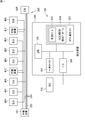
- FIG. 1 is a diagram illustrating an example of a configuration of a detection system for a non-regular vehicle-mounted device according to the present embodiment.
- the detection system 100 of the non-regular vehicle equipment which concerns on this embodiment is mounted in a motor vehicle.
- the detection system 100 includes a harness system 200 and a detection device 300.
- the harness system 200 includes a wire harness 210 and a detection electric wire 220.
- the wire harness 210 has a plurality of communication lines.
- Each communication line 221 is connected to one or more ECUs (Electronic Control Unit) 400.
- ECU 400 is an example of an in-vehicle device.
- Each communication line 221 is, for example, CAN (Controller Area Network), CAN FD (CAN with Flexible Data Rate), LIN (Local Interconnect Network), Ethernet (registered trademark), or MOST (Media Oriented Systems Transport: MOST is a registered trademark).
- the cable conforms to the communication standards of the above, and transmits electrical signals of protocols according to the respective communication standards.
- the wire harness 210 is connected to the relay devices 411, 412 and 413.
- Each of relay devices 411, 412 and 413 relays communication between ECUs 400 connected to different in-vehicle networks. That is, each of the relay devices 411, 412, 413 converts the protocol and data format of data transmitted from one ECU 400 and transfers the data to the destination ECU 400.
- the detection electric wire 220 extends along the plurality of communication lines 221.
- the detection electric wire 220 is not connected to the ECU 400 and does not transmit an electric signal output from the ECU 400.
- the detection electric wire 220 is connected to the detection device 300 via the A / D converter 230.
- a crosstalk signal is generated in the detection wire 220.
- the crosstalk signal generated in the detection electric wire 220 is A / D converted by the A / D converter 230 and applied to the detection device 300.
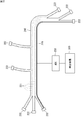
- FIG. 2 is a diagram illustrating an example of the configuration of the harness system 200 according to the present embodiment.
- the wire harness 210 is a bundle of a plurality of communication lines 221. The end of each communication line 221 is connected to the coupler 222.
- One coupler 222 is connected to one end of the detection electric wire 220. Further, the other end of the detection electric wire 220 may be connected to the coupler 222 or may not be connected to the coupler 222.
- the detection electric wire 220 runs along the communication line 221.
- the detection electric wire 220 is provided along the wire harness 210 and attached to the wire harness 210 with a vinyl tape or a binding band.
- the detection electric wire 220 may be bundled with the communication wire 221 by an insulating coating made of vinyl tape or synthetic resin, and may be integrated with the wire harness 210.
- FIG. 3A is a circuit diagram illustrating an example of an electrical connection configuration between the detection electric wire 220 and the detection device 300.
- one end of the detection electric wire 220 is opened and the other end is grounded.
- the electric wire 220 for a detection can be made into a simple structure.
- the detection electric wire 220 having such a configuration when a current flows through the communication line 221 arranged in the vicinity, a voltage is induced in the detection electric wire 220 by electrostatic coupling, and a crosstalk signal is generated.
- one end of the detection electric wire 220 is connected to the coupler 222, but the tip of the coupler 222 is not grounded.
- FIG. 3B is a circuit diagram illustrating another example of an electrical connection configuration between the detection electric wire 220 and the detection device 300.
- both ends of the detection electric wire 220 are grounded via a terminating resistor.
- a current flows through the detection electric wire 220 due to electromagnetic coupling, and a crosstalk signal is generated.
- both ends of the detection electric wire 220 are connected to the coupler 222, and the other end is grounded via the terminating resistor. Thereby, a clear crosstalk signal can be obtained, and the detection accuracy of the non-regular ECU is improved.
- the termination resistance can be a resistance value matched to the impedance of the detection electric wire 220, for example.
- the detection device 300 includes a processor 301, a transient memory 302, a non-transient memory 303, and an input / output interface 309.
- the processor 301, the transient memory 302, the non-transient memory 303, and the input / output interface 309 are interconnected by a bus.
- the temporary memory 302 is a volatile memory such as SRAM (Static Random Access Memory) or DRAM (Dynamic Random Access Memory).
- the non-transitory memory 303 is a non-volatile memory such as a flash memory, a hard disk, and a ROM (Read Only Memory).
- the non-transitory memory 303 stores data used for executing the non-regular ECU detection program 305 and the non-normal ECU detection program 305 which are computer programs.
- the detection device 300 includes a computer, and each function of the detection device 300 is executed by a processor 301 in which an irregular ECU detection program 305 that is a computer program stored in a storage device of the computer is a CPU. Demonstrated in The irregular ECU detection program 305 can be stored in a recording medium such as a flash memory, a ROM, or a CD-ROM.
- the processor 301 executes an irregular ECU detection program 305 and performs detection as described later.
- the processor 301 is not limited to a CPU.
- the processor 301 may be a hardware logic circuit such as an ASIC (Application Specific Integrated Circuit), a gate array, or an FPGA (Field Programmable Gate Array).
- the hardware logic circuit is configured to be able to execute the same processing as the non-regular ECU detection program 304.
- the detection process is a process for detecting a non-regular ECU (non-regular vehicle-mounted device) based on the crosstalk signal.
- the crosstalk signal is a process of analyzing the crosstalk signal in at least one of the time domain and the frequency domain. Based on the normal crosstalk signal, the crosstalk signal (abnormal (Crosstalk signal) is detected. By analyzing the characteristics of the crosstalk signal in at least one of the time domain and the frequency domain, the non-regular ECU can be detected with high accuracy.
- the detection process is executed by giving the learning model 305 input data based on the crosstalk signal.
- FIG. 4 is a schematic diagram illustrating an example of the configuration of the learning model 305.
- the learning model 305 is configured by a convolutional neural network.
- the learning model 305 includes an input layer 351, a convolution layer (CONV layer) 352, a deconvolution layer (DECONV layer) 353, and an output layer 354.
- the convolution layer 352 is an example of a layer that dimensionally compresses the input data 306 and performs dimensional compression by performing convolution integration on the input data 306.
- the deconvolution layer 353 is an example of a layer that restores the dimensionally compressed data to the original dimension.
- the deconvolution layer 353 performs an operation reverse to that of the convolution layer 352 and performs convolution integration on the data that is convolved and integrated in the convolution layer 352. Perform deconvolution processing to restore the original dimension.
- FIG. 4 shows an example in which each of the convolution layer 352 and the deconvolution layer 353 is provided in two layers, each may have a structure of one layer or three or more layers.
- the input data 306 of the learning model 305 is time-series data (data expressed in the time domain) or spectrum data (data expressed in the frequency domain) of the crosstalk signal generated in the detection electric wire 220.
- the spectrum data is obtained by frequency-converting the time series data of the crosstalk signal.
- the input data 306 may be image data of a graph of time series data or spectrum data.
- the construction of the learning model 305 will be described.
- the learning model 305 is constructed by machine learning using time-series data or spectrum data of a normal crosstalk signal as learning data. In this machine learning, learning is performed so that learning data is input to the learning model 305 as input data 306 and output data is the same as the input data 306. Such machine learning is repeatedly performed using a plurality of learning data. When the machine learning is completed, the learning model 305 outputs output data (hereinafter, also referred to as “feature extraction data”) 307 from which the features of the normal crosstalk signal are extracted from the input data 306.
- output data hereinafter, also referred to as “feature extraction data”
- the learning model 305 learns features common to normal crosstalk signals. Therefore, the abnormal crosstalk signal can be detected using the learning model 305 constructed in this way.
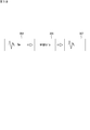
- FIG. 5A is a diagram for explaining feature extraction data 307 when the input data 306 generated from the normal crosstalk signal is given to the learning model 305.
- the feature extraction data 307 output from the learning model 305 is input data generated from the normal crosstalk signal as shown in FIG. 5A. The data is almost the same as 306.
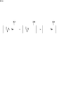
- FIG. 5B is a diagram for explaining the feature extraction data 307 when the input data 306 generated from the abnormal crosstalk signal is given to the learning model 305. Since the learning model 305 performs machine learning using learning data created from a normal crosstalk signal, an abnormal portion (a portion different from the normal crosstalk signal) included in the abnormal crosstalk signal is detected as a normal crosstalk signal. Replace with the features of and output.
- the feature extraction data 307 output from the learning model 305 is a feature common to the normal crosstalk signal as shown in FIG. 5B.
- the feature extraction data 307 in this case is data obtained by extracting a portion that overlaps the feature of the normal crosstalk signal from the abnormal crosstalk signal.
- the abnormal portion (normal crosstalk) of the abnormal crosstalk signal This is data in a state in which a portion different from the feature of the talk signal) is lost (in the case of image data, the image may be thinly reflected).
- an abnormal crosstalk signal is detected using the feature extraction data 307 obtained as described above. If the input data 306 is compared with the feature extraction data (output data) 307, the input data 306 is generated based on elements that are different from the features common to the normal crosstalk signal, or based on the input data 306 and the normal crosstalk signal. The similarity of the obtained data (time series data or spectrum data) can be grasped. An abnormal crosstalk signal is detected based on such different elements or similarities. Moreover, since the feature extraction data 307 is the same dimension as the input data 306, both can be appropriately compared.
- FIG. 6 is a schematic diagram for explaining an outline of detection of an abnormal crosstalk signal using the feature extraction data 307.
- difference data 308 between the input data 306 and the feature extraction data 307 is generated.
- the difference data 308 is data obtained by extracting an abnormal part included in the abnormal crosstalk signal. For this reason, an abnormal crosstalk signal is detected by determining whether or not the data amount of the difference data 308 is greater than or equal to a reference value.
- abnormal crosstalk signals are detected by determining whether or not the number of pixels whose difference between the input data 306 and the feature extraction data 307 is equal to or greater than a reference value. It can be carried out.
- the input data 306 is multi-gradation image data
- An abnormal crosstalk signal can be detected.
- FIG. 7 is a flowchart showing a procedure of detection processing by the detection apparatus 300 according to the present embodiment. Hereinafter, the detection process will be described with reference to FIG.
- the processor 301 receives the crosstalk signal (step S101), and generates input data 306 for the learning model 305 (step S102).
- the processor 301 accumulates output data from the A / D converter 230 for a predetermined time and uses it as input data 306.
- the processor 301 performs a frequency conversion process such as FFT (Fast Fourier Transform) on the time series data.
- FFT Fast Fourier Transform
- the processor 301 creates a two-dimensional coordinate graph of the time series data or spectrum data obtained as described above, and the graph Image data is generated.
- the processor 301 inputs the generated input data 306 to the learning model 305, and generates feature extraction data 307 (step S103).
- the processor 301 generates difference data 308 between the generated feature extraction data 307 and the input data 306 (step 104).
- the processor 301 compares the data amount of the difference data (difference data amount) with a reference value, and determines whether or not the data amount is greater than or equal to the reference value (step S105).
- the data amount can be the difference pixel count.
- the data amount is the sum of the differences between the gradation values of the same pixels in the input data 306 and the feature extraction data (multi-gradation image data) 307. You can also.
- step S105 If the difference data amount is less than the reference value (NO in step S105), it is determined that the crosstalk signal is a normal crosstalk signal. In this case, the processor 301 does not detect the abnormal crosstalk signal and ends the detection process.
- the processor 301 detects an abnormal crosstalk signal and executes an abnormality notification process for notifying that there is an unauthorized ECU (step S106).
- the processor 301 transmits an abnormality notification signal to the ECU 400 that controls the navigation device, and displays information indicating that an irregular ECU exists on the screen of the navigation device. Thereby, it is possible to notify the user of the presence of the non-regular ECU.
- the processor 301 displays, with the vehicle identification information or the user identification information, abnormal information indicating that an unauthorized ECU exists with respect to a server outside the vehicle. You may send it. Thereby, for example, the presence of the non-regular ECU can be notified to the manufacturer or the automobile manufacturer of the ECU, and it is possible to prompt the non-regular ECU to deal with (provide the regular firmware or replace the ECU). This completes the detection process.
- the learning model 305 is a neural network, but is not limited to this.
- a learning model based on another machine learning algorithm such as a support vector machine may be used.
- a normal crosstalk signal condition may be defined, and an abnormal crosstalk signal may be detected by determining whether the crosstalk signal meets this condition. .
Landscapes
- Engineering & Computer Science (AREA)
- Computer Security & Cryptography (AREA)
- Theoretical Computer Science (AREA)
- Computer Hardware Design (AREA)
- Software Systems (AREA)
- Physics & Mathematics (AREA)
- General Engineering & Computer Science (AREA)
- General Physics & Mathematics (AREA)
- Mechanical Engineering (AREA)
- Testing Of Short-Circuits, Discontinuities, Leakage, Or Incorrect Line Connections (AREA)
- Small-Scale Networks (AREA)
Abstract
非正規車載装置の検出システムは、複数の車載装置のそれぞれに接続され、電気信号を伝送する複数の通信線を有するワイヤハーネスと、前記複数の通信線に沿って延びる検出用電線と、前記検出用電線に発生する前記通信線からのクロストーク信号に基づいて、前記複数の車載装置に含まれる非正規車載装置を検出する検出処理を実行する検出装置と、を備える。
Description
本発明は、非正規車載装置の検出システム、ハーネスシステム、検出装置、及びコンピュータプログラムに関する。本出願は、2018年6月14日出願の日本出願第2018-113801号に基づく優先権を主張し、前記日本出願に記載された全ての内容を援用するものである。
自動車に搭載される車載装置の制御プログラム(ファームウェア)が不正に書き換えられたり、車載装置が不正に交換されたりすることがある。このような非正規の車載装置は、正規の車載装置とは異なる動作を行い、エンジン又はモータ等の動力制御、ブレーキ制御、ステアリング制御、メータ又は車載機器(ナビゲーション装置、ETC(Electronic Toll Collection System)等)の動作制御等に異常が生じる虞がある。
特許文献1には、ゲートウェイ装置が車載ネットワークを介して複数のコントローラから信号を受信し、信号の受信順に基づいて、非正規のコントローラを検知する通信システムが開示されている。
本開示の一態様に係る非正規車載装置の検出システムは、複数の車載装置のそれぞれに接続され、電気信号を伝送する複数の通信線を有するワイヤハーネスと、前記複数の通信線に沿って延びる検出用電線と、前記検出用電線に発生する前記通信線からのクロストーク信号に基づいて、前記複数の車載装置に含まれる非正規車載装置を検出する検出処理を実行する検出装置と、を備える。
本開示の一の態様に係るハーネスシステムは、複数の車載装置のそれぞれに接続され、電気信号を伝送する複数の通信線を有するワイヤハーネスと、前記複数の通信線に沿って延び、検出装置に接続される検出用電線と、を備え、前記検出装置は、前記検出用電線に発生する前記通信線からのクロストーク信号に基づいて、前記複数の車載装置に含まれる非正規車載装置を検出する検出処理を実行する。
本開示の一の態様に係る検出装置は、複数の通信線を有するワイヤハーネスに接続される非正規車載装置を検出するための検出装置であって、前記複数の通信線に沿って延びる検出用電線において発生する前記通信線からのクロストーク信号を受け付ける入出力インタフェースと、前記入出力インタフェースによって受け付けられる前記クロストーク信号に基づいて、前記ワイヤハーネスに接続される複数の車載装置に含まれる非正規車載装置を検出する検出処理を実行するプロセッサと、を備える。
本開示の一の態様に係るコンピュータプログラムは、複数の通信線を有するワイヤハーネスに接続される非正規車載装置を検出するためのコンピュータプログラムであって、コンピュータに、前記複数の通信線に沿って延びる検出用電線において発生する前記通信線からのクロストーク信号を受け付けるステップと、受け付けられる前記クロストーク信号に基づいて、前記ワイヤハーネスに接続される複数の車載装置に含まれる非正規車載装置を検出するステップと、を実行させる。
本開示は、このような特徴的な処理部を備える検出装置及びかかる特徴的な処理をコンピュータに実行させるためのプログラムとして実現することができるだけでなく、かかる特徴的な処理をステップとする非正規車載装置の検出方法としても実現することができる。また、検出装置の一部又は全部を半導体集積回路として実現したり、検出装置を含む非正規車載装置の検出システムとして実現したりすることができる。
<本開示が解決しようとする課題>
しかしながら、特許文献1に開示されている通信システムでは、車載ネットワークによってゲートウェイ装置に接続されるコントローラしか検知対象とすることができない。自動車には、複数の車載ネットワークが設けられ、ゲートウェイ装置が全ての車載ネットワークに接続されない場合がある。このような場合には、上記の検知機能を有するゲートウェイ装置を複数設ける必要があり、システムの大型化及び複雑化、並びにコストの増大を招く。
しかしながら、特許文献1に開示されている通信システムでは、車載ネットワークによってゲートウェイ装置に接続されるコントローラしか検知対象とすることができない。自動車には、複数の車載ネットワークが設けられ、ゲートウェイ装置が全ての車載ネットワークに接続されない場合がある。このような場合には、上記の検知機能を有するゲートウェイ装置を複数設ける必要があり、システムの大型化及び複雑化、並びにコストの増大を招く。
<本開示の効果>
本開示によれば、簡易な構成により複数の車載装置を対象として非正規車載装置の検出を行うことができる。
本開示によれば、簡易な構成により複数の車載装置を対象として非正規車載装置の検出を行うことができる。
<本開示の実施形態の概要>
以下、本開示の実施形態の概要を列記して説明する。
(1) 本実施形態に係る非正規車載装置の検出システムは、複数の車載装置のそれぞれに接続され、電気信号を伝送する複数の通信線を有するワイヤハーネスと、前記複数の通信線に沿って延びる検出用電線と、前記検出用電線に発生する前記通信線からのクロストーク信号に基づいて、前記複数の車載装置に含まれる非正規車載装置を検出する検出処理を実行する検出装置と、を備える。これにより、通信線に沿って設けた検出用電線に生じるクロストーク信号を監視することで、簡易な構成により複数の車載装置を対象として非正規車載装置の検出を行うことができる。
以下、本開示の実施形態の概要を列記して説明する。
(1) 本実施形態に係る非正規車載装置の検出システムは、複数の車載装置のそれぞれに接続され、電気信号を伝送する複数の通信線を有するワイヤハーネスと、前記複数の通信線に沿って延びる検出用電線と、前記検出用電線に発生する前記通信線からのクロストーク信号に基づいて、前記複数の車載装置に含まれる非正規車載装置を検出する検出処理を実行する検出装置と、を備える。これにより、通信線に沿って設けた検出用電線に生じるクロストーク信号を監視することで、簡易な構成により複数の車載装置を対象として非正規車載装置の検出を行うことができる。
(2) 本実施形態に係る非正規車載装置の検出システムにおいて、前記検出用電線は、一端が開放されてもよい。これにより、検出用電線を簡易な構成とすることができる。
(3) 本実施形態に係る非正規車載装置の検出システムにおいて、前記検出用電線は、両端が終端抵抗を介して接地されてもよい。これにより、明瞭なクロストーク信号を得ることができ、非正規車載装置の検出精度が向上する。
(4) 本実施形態に係る非正規車載装置の検出システムにおいて、前記検出処理は、前記クロストーク信号を時間領域及び周波数領域の少なくとも1つにおいて解析する処理であってもよい。これにより、クロストーク信号の特徴を時間領域及び周波数領域の少なくとも1つにおいて解析することができ、非正規車載装置の検出精度が向上する。
(5) 本実施形態に係る非正規車載装置の検出システムにおいて、前記検出処理は、正規の車載装置から送信される電気信号により生じる前記クロストーク信号である正常クロストーク信号に基づいて、非正規車載装置から送信される電気信号により生じる前記クロストーク信号である異常クロストーク信号を検出する処理であってもよい。非正規なファームウェアは種々存在し、出力信号の波形又は信号の出力タイミングは非正規なファームウェアによって様々である。したがって、様々な異常クロストーク信号から共通の特徴を抽出することは困難である。これに対して、正規のファームウェアが実装された車載装置からは、規定の波形及び出力タイミングで信号が出力されるため、正常クロストーク信号から共通の特徴を抽出することは可能である。このため、上記構成とすることにより、正常クロストーク信号から抽出される特徴とは異なる特徴を有する異常クロストーク信号を検出することができる。
(6) 本実施形態に係る非正規車載装置の検出システムにおいて、前記検出処理は、学習モデルに対して前記クロストーク信号に基づく入力データを与えることにより実行され、前記学習モデルは、前記正常クロストーク信号を学習データとする機械学習により構築されてもよい。これにより、機械学習によって構築された学習モデルにより、入力データから異常クロストーク信号を検出することができる。
(7) 本実施形態に係るハーネスシステムは、複数の車載装置のそれぞれに接続され、電気信号を伝送する複数の通信線を有するワイヤハーネスと、前記複数の通信線に沿って延び、検出装置に接続される検出用電線と、を備え、前記検出装置は、前記検出用電線に発生する前記通信線からのクロストーク信号に基づいて、前記複数の車載装置に含まれる非正規車載装置を検出する検出処理を実行する。これにより、通信線に沿って設けた検出用電線に生じるクロストーク信号を監視することで、簡易な構成により複数の車載装置を対象として非正規車載装置の検出を行うことができる。
(8) 本実施形態に係る検出装置は、複数の通信線を有するワイヤハーネスに接続される非正規車載装置を検出するための検出装置であって、前記複数の通信線に沿って延びる検出用電線において発生する前記通信線からのクロストーク信号を受け付ける入出力インタフェースと、前記入出力インタフェースによって受け付けられる前記クロストーク信号に基づいて、前記ワイヤハーネスに接続される複数の車載装置に含まれる非正規車載装置を検出する検出処理を実行するプロセッサと、を備える。これにより、通信線に沿って設けた検出用電線に生じるクロストーク信号を監視することで、簡易な構成により複数の車載装置を対象として非正規車載装置の検出を行うことができる。
(9) 本実施形態に係るコンピュータプログラムは、複数の通信線を有するワイヤハーネスに接続される非正規車載装置を検出するためのコンピュータプログラムであって、コンピュータに、前記複数の通信線に沿って延びる検出用電線において発生する前記通信線からのクロストーク信号を受け付けるステップと、受け付けられる前記クロストーク信号に基づいて、前記ワイヤハーネスに接続される複数の車載装置に含まれる非正規車載装置を検出するステップと、を実行させる。これにより、通信線に沿って設けた検出用電線に生じるクロストーク信号を監視することで、簡易な構成により複数の車載装置を対象として非正規車載装置の検出を行うことができる。
<本開示の実施形態の詳細>
[1.非正規車載装置の検出システムの構成]
図1は、本実施形態に係る非正規車載装置の検出システムの構成の一例を示す図である。本実施形態に係る非正規車載装置の検出システム100は、自動車に搭載される。検出システム100は、ハーネスシステム200と、検出装置300とを備える。
図1は、本実施形態に係る非正規車載装置の検出システムの構成の一例を示す図である。本実施形態に係る非正規車載装置の検出システム100は、自動車に搭載される。検出システム100は、ハーネスシステム200と、検出装置300とを備える。
ハーネスシステム200は、ワイヤハーネス210と、検出用電線220とを有する。ワイヤハーネス210は、複数の通信線を有する。各通信線221は、一又は複数のECU(Electronic Control Unit)400に接続される。なお、ECU400は、車載装置の一例である。各通信線221は、例えばCAN(Controller Area Network)、CANFD(CAN with Flexible Data Rate)、LIN(Local Interconnect Network)、Ethernet(登録商標)、又はMOST(Media Oriented Systems Transport:MOSTは登録商標)等の通信規格に準じたケーブルであり、それぞれの通信規格に応じたプロトコルの電気信号を伝送する。
ワイヤハーネス210は、中継装置411,412,413に接続される。中継装置411,412,413のそれぞれは、異なる車内ネットワークに接続されたECU400間の通信を中継する。つまり、中継装置411,412,413のそれぞれは、1つのECU400から送信されたデータのプロトコル及びデータ形式を変換し、宛先のECU400へと転送する。
検出用電線220は、複数の通信線221に沿って延びる。検出用電線220は、ECU400に接続されておらず、ECU400から出力される電気信号を伝送しない。検出用電線220は、A/Dコンバータ230を介して検出装置300に接続される。通信線221において電気信号が伝送されると、検出用電線220には、クロストーク信号が発生する。検出用電線220に発生したクロストーク信号は、A/Dコンバータ230によってA/D変換され、検出装置300に与えられる。
[2.ハーネスシステムの構成]
図2は、本実施形態に係るハーネスシステム200の構成の一例を示す図である。ワイヤハーネス210は、複数の通信線221の束である。各通信線221の端部はカプラ222に接続される。1つのカプラ222には、検出用電線220の一端部が接続される。また、検出用電線220の他端は、カプラ222に接続されてもよいし、カプラ222に接続されなくてもよい。
図2は、本実施形態に係るハーネスシステム200の構成の一例を示す図である。ワイヤハーネス210は、複数の通信線221の束である。各通信線221の端部はカプラ222に接続される。1つのカプラ222には、検出用電線220の一端部が接続される。また、検出用電線220の他端は、カプラ222に接続されてもよいし、カプラ222に接続されなくてもよい。
検出用電線220は、通信線221に沿わされる。例えば、検出用電線220は、ワイヤハーネス210に沿って設けられ、ビニールテープ又は結束バンドによってワイヤハーネス210に取り付けられる。検出用電線220は、ビニールテープ又は合成樹脂製の絶縁被覆によって通信線221と束ねられ、ワイヤハーネス210と一体化されてもよい。
図3Aは、検出用電線220と検出装置300との電気接続構成の一例を示す回路図である。この例では、検出用電線220の一端が開放され、他端が接地される。これにより、検出用電線220を簡易な構成とすることができる。このような構成の検出用電線220では、近傍に配置された通信線221に電流が流れると、静電結合によって検出用電線220に電圧が誘起され、クロストーク信号が発生する。本例の場合、検出用電線220の一端はカプラ222に接続されるが、カプラ222から先は接地されない。
図3Bは、検出用電線220と検出装置300との電気接続構成の他の例を示す回路図である。この例では、検出用電線220の両端が終端抵抗を介して接地される。このような構成の検出用電線220では、近傍に配置された通信線221の周囲に変動磁界が生じると、電磁結合によって検出用電線220に電流が流れ、クロストーク信号が発生する。本例の場合、検出用電線220の両端はカプラ222に接続され、さらにその先が終端抵抗を介して接地される。これにより、明瞭なクロストーク信号を得ることができ、非正規ECUの検出精度が向上する。上記の終端抵抗は、例えば検出用電線220のインピーダンスに整合した抵抗値とすることができる。
[3.検出装置の構成]
再び図1を参照する。検出装置300は、プロセッサ301と、一過性メモリ302と、非一過性メモリ303と、入出力インタフェース309とを備える。プロセッサ301、一過性メモリ302、非一過性メモリ303、及び入出力インタフェース309は、バスにより相互接続される。
再び図1を参照する。検出装置300は、プロセッサ301と、一過性メモリ302と、非一過性メモリ303と、入出力インタフェース309とを備える。プロセッサ301、一過性メモリ302、非一過性メモリ303、及び入出力インタフェース309は、バスにより相互接続される。
一過性メモリ302は、例えばSRAM(Static Random Access Memory)、DRAM(Dynamic Random Access Memory)等の揮発性メモリである。非一過性メモリ303は、例えばフラッシュメモリ、ハードディスク、ROM(Read Only Memory)等の不揮発性メモリである。非一過性メモリ303には、コンピュータプログラムである非正規ECU検出プログラム305及び非正規ECU検出プログラム305の実行に使用されるデータが格納される。検出装置300は、コンピュータを備えて構成され、検出装置300の各機能は、前記コンピュータの記憶装置に記憶されたコンピュータプログラムである非正規ECU検出プログラム305がCPUであるプロセッサ301によって実行されることで発揮される。非正規ECU検出プログラム305は、フラッシュメモリ、ROM、CD-ROMなどの記録媒体に記憶させることができる。プロセッサ301は、非正規ECU検出プログラム305を実行し、後述するような検出を行う。
なお、プロセッサ301は、CPUに限られない。プロセッサ301は、例えば、ASIC(Application Specific Integrated Circuit)、ゲートアレイ、FPGA(Field Programmable Gate Array)等のハードウェアロジック回路であってもよい。この場合、ハードウェアロジック回路は、非正規ECU検出プログラム304と同様の処理を実行可能に構成される。
検出処理は、クロストーク信号に基づいて、非正規ECU(非正規車載装置)を検出する処理である。さらに具体的には、クロストーク信号を時間領域及び周波数領域の少なくとも1つにおいて解析する処理であり、正常クロストーク信号に基づいて、非正規ECUから送信される電気信号により生じるクロストーク信号(異常クロストーク信号)を検出する処理である。時間領域及び周波数領域の少なくとも1つにおいてクロストーク信号の特徴を解析することで、高精度に非正規ECUの検出を行うことができる。また、検出処理は、学習モデル305にクロストーク信号に基づく入力データを与えることによって実行される。
[4.学習モデルの例]
以下、学習モデル305の一例を説明する。図4は、学習モデル305の構成の一例を示す模式図である。学習モデル305は、畳み込みニューラルネットワークにより構成される。学習モデル305は、入力層351と、コンボリューション層(CONV層)352と、デコンボリューション層(DECONV層)353と、出力層354とを含む。コンボリューション層352は、入力データ306を次元圧縮する層の一例であり、入力データ306に対して畳み込み積分を行って次元圧縮する。デコンボリューション層353は、次元圧縮されたデータを元の次元に復元する層の一例であり、コンボリューション層352とは逆の操作を行って、コンボリューション層352において畳み込み積分されたデータに対して逆畳み込み処理を行い元の次元に復元する。図4では、コンボリューション層352及びデコンボリューション層353のそれぞれが2層ずつ設けられる例を示しているが、それぞれが1層又は3層以上の構造であってもよい。
以下、学習モデル305の一例を説明する。図4は、学習モデル305の構成の一例を示す模式図である。学習モデル305は、畳み込みニューラルネットワークにより構成される。学習モデル305は、入力層351と、コンボリューション層(CONV層)352と、デコンボリューション層(DECONV層)353と、出力層354とを含む。コンボリューション層352は、入力データ306を次元圧縮する層の一例であり、入力データ306に対して畳み込み積分を行って次元圧縮する。デコンボリューション層353は、次元圧縮されたデータを元の次元に復元する層の一例であり、コンボリューション層352とは逆の操作を行って、コンボリューション層352において畳み込み積分されたデータに対して逆畳み込み処理を行い元の次元に復元する。図4では、コンボリューション層352及びデコンボリューション層353のそれぞれが2層ずつ設けられる例を示しているが、それぞれが1層又は3層以上の構造であってもよい。
学習モデル305の入力データ306は、検出用電線220に生じるクロストーク信号の時系列データ(時間領域で表現されるデータ)若しくはスペクトルデータ(周波数領域で表現されるデータ)である。スペクトルデータは、クロストーク信号の時系列データを周波数変換することにより得られる。また、入力データ306は、時系列データ又はスペクトルデータのグラフの画像データであってもよい。学習モデル305は、入力データ306が与えられると、当該入力データ306を次元圧縮し、その後、元の次元に復元する処理を行う。したがって、学習モデル305の出力データは、入力データ306と同次元のデータである。
学習モデル305の構築について説明する。学習モデル305は、正常クロストーク信号の時系列データ又はスペクトルデータを学習データとする機械学習によって構築される。この機械学習では、学習データが入力データ306として学習モデル305に入力され、出力データが入力データ306と同じになるように学習が行われる。このような機械学習は、複数の学習データを用いて繰り返し行われる。機械学習が終了すると、学習モデル305は、入力データ306に対して、正常クロストーク信号の特徴を抽出した出力データ(以下、「特徴抽出データ」ともいう)307を出力するようになる。
正規のECUからは、規定の波形及び出力タイミングで信号が出力されるため、正常クロストーク信号から共通の特徴を抽出することが可能である。このため、多数の学習データによって機械学習を行うと、学習モデル305は、正常クロストーク信号に共通する特徴を学習する。したがって、このようにして構築される学習モデル305を用いて、異常クロストーク信号の検出を行うことができる。
上記の機械学習によって構築された学習モデル305に、入力データ306を与えたときの処理について説明する。正規のECU400から電気信号が出力され、クロストーク信号が検出用電線220に生じる場合、当該クロストーク信号は正常クロストーク信号である。図5Aは、学習モデル305に正常クロストーク信号から生成された入力データ306を与えたときの特徴抽出データ307を説明する図である。正常クロストーク信号から生成された入力データ306が学習モデル305に与えられると、図5Aに示すように、学習モデル305から出力される特徴抽出データ307は、正常クロストーク信号から生成された入力データ306と殆ど同じデータとなる。
他方、非正規ECU400から電気信号が出力され、クロストーク信号が検出用電線220に生じる場合、当該クロストーク信号は異常クロストーク信号である。図5Bは、学習モデル305に異常クロストーク信号から生成された入力データ306を与えたときの特徴抽出データ307を説明する図である。学習モデル305は、正常クロストーク信号から作成された学習データを用いて機械学習しているため、異常クロストーク信号に含まれる異常な部分(正常クロストーク信号とは異なる部分)を正常クロストーク信号の特徴に置き換えて出力する。つまり、異常クロストーク信号から生成された入力データ306が学習モデル305に与えられると、図5Bに示すように、学習モデル305から出力される特徴抽出データ307は、正常クロストーク信号に共通する特徴を抽出したデータとなる。つまり、この場合の特徴抽出データ307は、異常クロストーク信号から、正常クロストーク信号の特徴と重なる部分が抽出されたデータであり、言い換えれば、異常クロストーク信号のうち、異常な部分(正常クロストーク信号の特徴とは異なる部分)が無くなった(画像データの場合、薄く写り込むこともある)状態のデータである。
検出処理では、上記のようにして得られた特徴抽出データ307を用いて、異常クロストーク信号の検出が行われる。入力データ306と特徴抽出データ(出力データ)307とを比較すれば、正常クロストーク信号に共通する特徴に対して入力データ306が相違する要素、あるいは、入力データ306と正常クロストーク信号に基づき生成されたデータ(時系列データ又はスペクトルデータ)の類似性を把握することができる。このような相違する要素、あるいは、類似性に基づいて、異常クロストーク信号の検出を行う。しかも、特徴抽出データ307は、入力データ306と同次元のデータであるため、両者を適切に比較できる。
図6は、特徴抽出データ307を用いた異常クロストーク信号の検出の概要を説明する模式図である。検出処理では、入力データ306と特徴抽出データ307との差分データ308を生成する。この差分データ308は、異常クロストーク信号に含まれる異常な部分が抽出されたデータである。このため、差分データ308のデータ量が基準値以上であるか否かを判定することで、異常クロストーク信号の検出が行われる。なお、入力データを画像データとする場合、入力データ306と特徴抽出データ307との差分が閾値以上の画素数が基準値以上であるか否かを判定することで、異常クロストーク信号の検出を行うことができる。また、入力データ306を多階調の画像データとする場合、入力データ306と特徴抽出データの同一画素同士の階調値の差分の合計が基準値以上であるか否かを判定することでも、異常クロストーク信号の検出を行うことができる。
[5.非正規車載装置の検出システムの動作]
次に、本実施形態に係る非正規車載装置の検出システム100の動作について説明する。ECU400から電気信号が出力されると、検出用電線220にクロストーク信号が発生する。クロストーク信号は、A/Dコンバータ230によってA/D変換され、検出装置300に与えられる。
次に、本実施形態に係る非正規車載装置の検出システム100の動作について説明する。ECU400から電気信号が出力されると、検出用電線220にクロストーク信号が発生する。クロストーク信号は、A/Dコンバータ230によってA/D変換され、検出装置300に与えられる。
検出装置300のプロセッサ301は、検出処理を実行する。図7は、本実施形態に係る検出装置300による検出処理の手順を示すフローチャートである。以下、図7を参照して、検出処理を説明する。
プロセッサ301は、クロストーク信号を受信し(ステップS101)、学習モデル305用の入力データ306を生成する(ステップS102)。入力データ306を時系列データとする場合、プロセッサ301はA/Dコンバータ230からの出力データを所定時間蓄積し、これを入力データ306とする。入力データ306をスペクトルデータとする場合、プロセッサ301は、上記の時系列データに対してFFT(Fast Fourier Transform)等の周波数変換処理を施す。また、入力データ306を時系列データ又はスペクトルデータをグラフにした画像データとする場合、プロセッサ301は、上記のようにして得た時系列データ又はスペクトルデータの2次元座標グラフを作成し、当該グラフの画像データを生成する。
プロセッサ301は、生成された入力データ306を、学習モデル305に入力し、特徴抽出データ307を生成する(ステップS103)。プロセッサ301は、生成された特徴抽出データ307と入力データ306との差分データ308を生成する(ステップ104)。
プロセッサ301は、差分データのデータ量(差分データ量)と基準値とを比較し、データ量が基準値以上であるか否かを判定する(ステップS105)。ここで、入力データ306が画像データである場合、データ量は差分の画素数とすることができる。また、入力データ306が多階調の画像データである場合、データ量は入力データ306と特徴抽出データ(多階調の画像データ)307との同一画素同士の階調値の差分の合計とすることもできる。
差分データ量が基準値未満である場合(ステップS105においてNO)、クロストーク信号は正常クロストーク信号であると判定される。この場合、プロセッサ301は、異常クロストーク信号を検出せず、検出処理を終了する。
差分データ量が基準値以上である場合(ステップS105においてYES)、クロストーク信号は異常クロストーク信号であると判定される。この場合、プロセッサ301は、異常クロストーク信号を検出し、非正規ECUが存在することを通知する異常通知処理を実行する(ステップS106)。異常通知処理では、例えばナビゲーション装置を制御するECU400にプロセッサ301が異常通知信号を送信し、ナビゲーション装置の画面に非正規ECUが存在することを示す情報を表示させる。これにより、ユーザに非正規ECUの存在を通知することができる。また、ユーザへの通知と共に、又はユーザへの通知に代えて、プロセッサ301は、車外のサーバに対して、非正規ECUが存在することを示す異常情報を、車両の識別情報又はユーザ識別情報と共に送信してもよい。これにより、例えばECUの製造メーカ又は自動車メーカに対して、非正規ECUの存在を通知することができ、非正規ECUへの対処(正規ファームウェアの提供又はECUの交換)を促すことができる。以上で、検出処理が終了する。
上記のような構成とすることにより、検出用電線220に生じるクロストーク信号を監視することで、簡易な構成により複数のECU400を対象として非正規ECUの検出を行うことができる。
[6.変形例]
なお、上記の実施形態では、学習モデル305をニューラルネットワークとしたが、これに限定されない。サポートベクタマシン等の他の機械学習アルゴリズムによる学習モデルとしてもよい。また、学習モデル305ではなく、例えば、正常クロストーク信号の条件を規定しておき、クロストーク信号がこの条件に適合するか否かを判定することで、異常クロストーク信号を検出してもよい。
なお、上記の実施形態では、学習モデル305をニューラルネットワークとしたが、これに限定されない。サポートベクタマシン等の他の機械学習アルゴリズムによる学習モデルとしてもよい。また、学習モデル305ではなく、例えば、正常クロストーク信号の条件を規定しておき、クロストーク信号がこの条件に適合するか否かを判定することで、異常クロストーク信号を検出してもよい。
[7.補記]
今回開示された実施の形態はすべての点で例示であって、制限的ではない。本発明の権利範囲は、上述の実施形態ではなく請求の範囲によって示され、請求の範囲と均等の意味及びその範囲内でのすべての変更が含まれる。
今回開示された実施の形態はすべての点で例示であって、制限的ではない。本発明の権利範囲は、上述の実施形態ではなく請求の範囲によって示され、請求の範囲と均等の意味及びその範囲内でのすべての変更が含まれる。
100 検出システム
200 ハーネスシステム
210 ワイヤハーネス
220 検出用電線
221 通信線
222 カプラ
230 コンバータ
300 検出装置
301 プロセッサ
302 一過性メモリ
303 非一過性メモリ
304 検出プログラム
305 学習モデル
351 入力層
352 コンボリューション層
353 デコンボリューション層
354 出力層
306 入力データ
307 特徴抽出データ
308 差分データ
309 入出力インタフェース
400 ECU(車載装置)
411,412,413 中継装置
200 ハーネスシステム
210 ワイヤハーネス
220 検出用電線
221 通信線
222 カプラ
230 コンバータ
300 検出装置
301 プロセッサ
302 一過性メモリ
303 非一過性メモリ
304 検出プログラム
305 学習モデル
351 入力層
352 コンボリューション層
353 デコンボリューション層
354 出力層
306 入力データ
307 特徴抽出データ
308 差分データ
309 入出力インタフェース
400 ECU(車載装置)
411,412,413 中継装置
Claims (9)
- 複数の車載装置のそれぞれに接続され、電気信号を伝送する複数の通信線を有するワイヤハーネスと、
前記複数の通信線に沿って延びる検出用電線と、
前記検出用電線に発生する前記通信線からのクロストーク信号に基づいて、前記複数の車載装置に含まれる非正規車載装置を検出する検出処理を実行する検出装置と、
を備える、
非正規車載装置の検出システム。 - 前記検出用電線は、一端が開放されている、
請求項1に記載の非正規車載装置の検出システム。 - 前記検出用電線は、両端が終端抵抗を介して接地される、
請求項1に記載の非正規車載装置の検出システム。 - 前記検出処理は、前記クロストーク信号を時間領域及び周波数領域の少なくとも1つにおいて解析する処理である、
請求項1から請求項3の何れか1項に記載の非正規車載装置の検出システム。 - 前記検出処理は、正規の車載装置から送信される電気信号により生じる前記クロストーク信号である正常クロストーク信号に基づいて、非正規車載装置から送信される電気信号により生じる前記クロストーク信号である異常クロストーク信号を検出する処理である、
請求項1から請求項4の何れか1項に記載の非正規車載装置の検出システム。 - 前記検出処理は、学習モデルに対して前記クロストーク信号に基づく入力データを与えることにより実行され、
前記学習モデルは、前記正常クロストーク信号を学習データとする機械学習により構築される、
請求項5に記載の非正規車載装置の検出システム。 - 複数の車載装置のそれぞれに接続され、電気信号を伝送する複数の通信線を有するワイヤハーネスと、
前記複数の通信線に沿って延び、検出装置に接続される検出用電線と、
を備え、
前記検出装置は、前記検出用電線に発生する前記通信線からのクロストーク信号に基づいて、前記複数の車載装置に含まれる非正規車載装置を検出する検出処理を実行する、
ハーネスシステム。 - 複数の通信線を有するワイヤハーネスに接続される非正規車載装置を検出するための検出装置であって、
前記複数の通信線に沿って延びる検出用電線において発生する前記通信線からのクロストーク信号を受け付ける入出力インタフェースと、
前記入出力インタフェースによって受け付けられる前記クロストーク信号に基づいて、前記ワイヤハーネスに接続される複数の車載装置に含まれる非正規車載装置を検出する検出処理を実行するプロセッサと、
を備える、
検出装置。 - 複数の通信線を有するワイヤハーネスに接続される非正規車載装置を検出するためのコンピュータプログラムであって、
コンピュータに、
前記複数の通信線に沿って延びる検出用電線において発生する前記通信線からのクロストーク信号を受け付けるステップと、
受け付けられる前記クロストーク信号に基づいて、前記ワイヤハーネスに接続される複数の車載装置に含まれる非正規車載装置を検出するステップと、
を実行させるための、
コンピュータプログラム。
Priority Applications (1)
| Application Number | Priority Date | Filing Date | Title |
|---|---|---|---|
| JP2020525270A JP7251545B2 (ja) | 2018-06-14 | 2019-03-20 | 非正規車載装置の検出システム、ハーネスシステム、検出装置、及びコンピュータプログラム |
Applications Claiming Priority (2)
| Application Number | Priority Date | Filing Date | Title |
|---|---|---|---|
| JP2018113801 | 2018-06-14 | ||
| JP2018-113801 | 2018-06-14 |
Publications (1)
| Publication Number | Publication Date |
|---|---|
| WO2019239669A1 true WO2019239669A1 (ja) | 2019-12-19 |
Family
ID=68841785
Family Applications (1)
| Application Number | Title | Priority Date | Filing Date |
|---|---|---|---|
| PCT/JP2019/011779 Ceased WO2019239669A1 (ja) | 2018-06-14 | 2019-03-20 | 非正規車載装置の検出システム、ハーネスシステム、検出装置、及びコンピュータプログラム |
Country Status (2)
| Country | Link |
|---|---|
| JP (1) | JP7251545B2 (ja) |
| WO (1) | WO2019239669A1 (ja) |
Cited By (1)
| Publication number | Priority date | Publication date | Assignee | Title |
|---|---|---|---|---|
| CN112906262A (zh) * | 2021-01-27 | 2021-06-04 | 哈尔滨工程大学 | 一种预估外界瞬态电磁干扰引起的架空电力线串扰的方法 |
Citations (4)
| Publication number | Priority date | Publication date | Assignee | Title |
|---|---|---|---|---|
| JP2007036512A (ja) * | 2005-07-26 | 2007-02-08 | Omron Corp | 不正接続検知装置 |
| JP2014143631A (ja) * | 2013-01-25 | 2014-08-07 | Toyota Motor Corp | 不正接続検出方法及び不正接続検出システム |
| JP2015005829A (ja) * | 2013-06-19 | 2015-01-08 | 株式会社オートネットワーク技術研究所 | 接続検出装置及び車載中継装置 |
| JP2016213789A (ja) * | 2015-05-13 | 2016-12-15 | 株式会社オートネットワーク技術研究所 | 通信システム、ハーネス及び検出装置 |
Family Cites Families (3)
| Publication number | Priority date | Publication date | Assignee | Title |
|---|---|---|---|---|
| JPH0613993A (ja) * | 1992-06-25 | 1994-01-21 | Matsushita Electric Works Ltd | 情報配線システム |
| JPH077842A (ja) * | 1993-06-17 | 1995-01-10 | Furukawa Electric Co Ltd:The | ワイヤーハーネスの保護装置 |
| EP3142289B1 (en) * | 2014-05-08 | 2020-10-07 | Panasonic Intellectual Property Corporation of America | In-vehicle network system, electronic control unit, and irregularity detection method |
-
2019
- 2019-03-20 WO PCT/JP2019/011779 patent/WO2019239669A1/ja not_active Ceased
- 2019-03-20 JP JP2020525270A patent/JP7251545B2/ja active Active
Patent Citations (4)
| Publication number | Priority date | Publication date | Assignee | Title |
|---|---|---|---|---|
| JP2007036512A (ja) * | 2005-07-26 | 2007-02-08 | Omron Corp | 不正接続検知装置 |
| JP2014143631A (ja) * | 2013-01-25 | 2014-08-07 | Toyota Motor Corp | 不正接続検出方法及び不正接続検出システム |
| JP2015005829A (ja) * | 2013-06-19 | 2015-01-08 | 株式会社オートネットワーク技術研究所 | 接続検出装置及び車載中継装置 |
| JP2016213789A (ja) * | 2015-05-13 | 2016-12-15 | 株式会社オートネットワーク技術研究所 | 通信システム、ハーネス及び検出装置 |
Cited By (2)
| Publication number | Priority date | Publication date | Assignee | Title |
|---|---|---|---|---|
| CN112906262A (zh) * | 2021-01-27 | 2021-06-04 | 哈尔滨工程大学 | 一种预估外界瞬态电磁干扰引起的架空电力线串扰的方法 |
| CN112906262B (zh) * | 2021-01-27 | 2023-03-17 | 哈尔滨工程大学 | 一种预估外界瞬态电磁干扰引起的架空电力线串扰的方法 |
Also Published As
| Publication number | Publication date |
|---|---|
| JPWO2019239669A1 (ja) | 2021-07-15 |
| JP7251545B2 (ja) | 2023-04-04 |
Similar Documents
| Publication | Publication Date | Title |
|---|---|---|
| CN108107875B (zh) | 一种汽车诊断方法、装置和车辆通讯接口 | |
| CN104228715B (zh) | 连接检测装置以及车载中继装置 | |
| Chang et al. | Wire mismatch detection using a convolutional neural network and fault localization based on time–frequency-domain reflectometry | |
| CA3048511C (en) | Method and system of vehicle diagnostics | |
| CN108983758B (zh) | 一种汽车诊断设备的软件防护方法、装置及终端 | |
| US12160279B2 (en) | Automotive physical layer (PHY) cable fault diagnosis | |
| JP7593336B2 (ja) | 検知システム、検知装置および検知方法 | |
| CN109039693B (zh) | 用于评估控制器局域网络的方法 | |
| DE102015122823A1 (de) | Verfahren und System zur reflektometriebasierten Überwachung, Intrusionserfassung und Mitteilungsauthentifizierung eines Kommunikationsnetzwerks | |
| CN118276553A (zh) | 车辆故障诊断方法、电子设备及车辆 | |
| JP7251545B2 (ja) | 非正規車載装置の検出システム、ハーネスシステム、検出装置、及びコンピュータプログラム | |
| US11552963B2 (en) | Relative voltage pattern for electronic control unit identification | |
| CN105635241A (zh) | 管理车辆异常状态的方法、系统和计算机可读记录介质 | |
| CN111988194B (zh) | 汽车线路的诊断方法及装置 | |
| CN112868012A (zh) | 用于检测车辆中未经授权连接的设备的系统和方法 | |
| Suwatthikul et al. | In-vehicle network level fault diagnostics using fuzzy inference systems | |
| JP5175641B2 (ja) | 通信システムの断線検出装置及び通信システム | |
| US10451655B2 (en) | Communication system, harness, and detection apparatus | |
| CN104901841A (zh) | 用于监视通信网络的方法 | |
| US20200117437A1 (en) | Automated Identification Of Generic Module Location Per Electrical Signatures | |
| CN218331805U (zh) | 一种电磁干扰测试系统 | |
| US11867771B2 (en) | Methods and devices for detecting an electrical arc | |
| KR20150115415A (ko) | 전동기의 고장진단 방법 | |
| KR101126640B1 (ko) | 무선 네트워크를 이용한 most 네트워크 진단 시스템 및 방법 | |
| US20250165363A1 (en) | Diagnosis of a shared bus using indicators applied to a vector based on the amplitude of an observed signal |
Legal Events
| Date | Code | Title | Description |
|---|---|---|---|
| 121 | Ep: the epo has been informed by wipo that ep was designated in this application |
Ref document number: 19819556 Country of ref document: EP Kind code of ref document: A1 |
|
| ENP | Entry into the national phase |
Ref document number: 2020525270 Country of ref document: JP Kind code of ref document: A |
|
| NENP | Non-entry into the national phase |
Ref country code: DE |
|
| 122 | Ep: pct application non-entry in european phase |
Ref document number: 19819556 Country of ref document: EP Kind code of ref document: A1 |