WO2019230461A1 - 映像表示装置、映像表示方法 - Google Patents
映像表示装置、映像表示方法 Download PDFInfo
- Publication number
- WO2019230461A1 WO2019230461A1 PCT/JP2019/019796 JP2019019796W WO2019230461A1 WO 2019230461 A1 WO2019230461 A1 WO 2019230461A1 JP 2019019796 W JP2019019796 W JP 2019019796W WO 2019230461 A1 WO2019230461 A1 WO 2019230461A1
- Authority
- WO
- WIPO (PCT)
- Prior art keywords
- contact
- detection
- video display
- sound
- state
- Prior art date
- Legal status (The legal status is an assumption and is not a legal conclusion. Google has not performed a legal analysis and makes no representation as to the accuracy of the status listed.)
- Ceased
Links
Images











Classifications
-
- G—PHYSICS
- G03—PHOTOGRAPHY; CINEMATOGRAPHY; ANALOGOUS TECHNIQUES USING WAVES OTHER THAN OPTICAL WAVES; ELECTROGRAPHY; HOLOGRAPHY
- G03B—APPARATUS OR ARRANGEMENTS FOR TAKING PHOTOGRAPHS OR FOR PROJECTING OR VIEWING THEM; APPARATUS OR ARRANGEMENTS EMPLOYING ANALOGOUS TECHNIQUES USING WAVES OTHER THAN OPTICAL WAVES; ACCESSORIES THEREFOR
- G03B21/00—Projectors or projection-type viewers; Accessories therefor
- G03B21/14—Details
-
- G—PHYSICS
- G06—COMPUTING OR CALCULATING; COUNTING
- G06F—ELECTRIC DIGITAL DATA PROCESSING
- G06F3/00—Input arrangements for transferring data to be processed into a form capable of being handled by the computer; Output arrangements for transferring data from processing unit to output unit, e.g. interface arrangements
- G06F3/01—Input arrangements or combined input and output arrangements for interaction between user and computer
- G06F3/03—Arrangements for converting the position or the displacement of a member into a coded form
- G06F3/041—Digitisers, e.g. for touch screens or touch pads, characterised by the transducing means
-
- G—PHYSICS
- G06—COMPUTING OR CALCULATING; COUNTING
- G06F—ELECTRIC DIGITAL DATA PROCESSING
- G06F3/00—Input arrangements for transferring data to be processed into a form capable of being handled by the computer; Output arrangements for transferring data from processing unit to output unit, e.g. interface arrangements
- G06F3/01—Input arrangements or combined input and output arrangements for interaction between user and computer
- G06F3/03—Arrangements for converting the position or the displacement of a member into a coded form
- G06F3/041—Digitisers, e.g. for touch screens or touch pads, characterised by the transducing means
- G06F3/042—Digitisers, e.g. for touch screens or touch pads, characterised by the transducing means by opto-electronic means
Definitions
- the present invention relates to a video display technique and an information processing technique, and relates to a technique for detecting an operation state such as contact with an operation surface by an operation object such as a user's finger.
- a video display device such as a projection-type video display device (projector) may have an operation surface provided so as to be superimposed on a planar object having a display surface on which video is displayed. On the operation surface, the user performs an operation such as contact with an operation object such as a finger or a stick held in the hand.
- the video display device or the operation detection device detects a state such as the presence or absence of contact with the operation object on the operation surface, contact point position coordinates, and the like.
- the video display device or the operation detection device determines a predetermined operation according to the detected state or position, and executes a predetermined control process associated therewith according to the operation.
- the operation detection apparatus captures and extracts an image including a shadow formed based on illumination on the operation surface and the finger with a camera, and estimates the state of the operation with the finger from the state of the shadow.
- Patent Document 1 JP, 2014-174832, A (patent documents 1) is mentioned as a prior art example about operation detection technology using the above-mentioned optical sensor.
- Patent Document 1 includes, as an operation detection device or the like, first and second illuminations that illuminate the operation surface from different positions, and a camera that images the operation surface, and the first and second shadows are captured from the captured image. It is described that the contact point is detected from the distance between the contour lines of each shadow extracted.
- a technique for detecting the state of the operation there is a technique using a non-optical sensor such as a microphone, an ultrasonic sensor, or a strain sensor.
- vibration such as sound waves from an object is detected using, for example, a microphone, and the state of contact of the operation article with the operation surface is estimated.
- Patent Document 2 Japanese Patent Laid-Open No. 8-263192 is given as an example of the prior art relating to the operation detection technique using the non-optical sensor.
- Patent Document 2 describes that, as an ultrasonic coordinate input device, highly accurate coordinate detection is possible, and that coordinate detection is repeatedly performed with a certain pause time.
- An object of the present invention is to provide a technique capable of improving detection accuracy with respect to an operation detection technique using an optical sensor.
- a representative embodiment of the present invention is a video display device having the following configuration.
- An image display apparatus is an image display apparatus that displays an image on a display surface, and includes an operation surface set in association with the display surface and an operation article including a user's finger with respect to the operation surface.
- An operation detection device that detects an operation including contact, an optical sensor that detects an image of the operation object on the operation surface, and a non-optical sensor that detects sound or vibration caused by the contact of the operation object on the operation surface
- the operation detection device detects a state including contact or non-contact by the operation object with respect to the operation surface using first detection information of the optical sensor and second detection information of the non-optical sensor. Detecting detection data, detecting a state of contact between the operation surface and the operation article from the first detection information, and detecting a sound corresponding to the state of contact from the second detection information or When detecting the motion is determined that a comprehensive contact.
- detection accuracy can be improved with respect to operation detection technology using an optical sensor.
- FIG. 5 is a diagram illustrating a correspondence relationship between a display surface and an operation surface in the first embodiment.
- it is a figure which shows the shadow etc. at the time of the non-contact of a 1st detection system.
- Embodiment 1 it is a figure which shows the case where a stick
- Embodiment 1 it is a figure which shows the example of a state, operation
- Embodiment 1 it is a figure which shows the processing flow of 1st detection.
- Embodiment 1 it is a figure which shows the processing flow of a 2nd detection.
- Embodiment 1 it is a figure which shows the relationship between an image process and a sound process.
- Embodiment 1 it is a figure which shows the processing flow of contact recognition. It is a modification of Embodiment 1, and is a figure which shows the processing flow of contact recognition.
- Embodiment 1 It is a modification of Embodiment 1, and is a figure which shows structures, such as an operation detection apparatus. It is a modification of Embodiment 1, and is a figure which shows the example of an installation structure of a video display apparatus. It is a modification of Embodiment 1, and is a figure which shows the structure of the operation surface of a 2nd detection system. It is a figure which shows the example of an installation structure of the video display apparatus of Embodiment 2 of this invention. It is a figure which shows the example of an installation structure of the video display apparatus of Embodiment 3 of this invention.
- FIG. 11 is a diagram illustrating an installation configuration example of a video display device according to a first modification of the third embodiment.
- FIG. 11 is a diagram illustrating an installation configuration example of a video display device according to a second modification of the third embodiment. It is a figure which shows the example of an installation structure of the video display apparatus of Embodiment 4 of this invention.
- the X direction, the Y direction, and the Z direction are used as directions.
- the X direction and the Y direction are two orthogonal directions constituting the operation surface (or display surface).
- the X direction is an in-plane horizontal direction (left-right direction)
- the Y direction is an in-plane vertical direction (up-down direction).
- the Z direction is a direction perpendicular to the XY plane of the operation surface.
- the video display device and video display method according to the first embodiment of the present invention will be described with reference to FIGS.
- the video display method of the first embodiment is a method having steps executed in the video display device of the first embodiment.
- a user performs an operation such as contact using a finger as an operation object on an operation surface superimposed on a display surface.
- the operation detection device of the video display device uses the optical sensor (camera) and the non-optical sensor (microphone) in combination, so that the state of contact between the finger and the operation surface and the contact point position coordinate can be accurately obtained.
- the video display device according to the first embodiment includes first and second illumination devices that illuminate the operation surface from different positions, a camera that captures an image including the operation surface, and a microphone that detects sound waves generated on the operation surface. Is provided.
- the video display device combines a method using a camera that is an optical sensor (referred to as a first detection method) and a method using a microphone that is a non-optical sensor (referred to as a second detection method). In this way, the state of operation such as contact with the operation article on the operation surface is detected. As a result, the video display apparatus according to the first embodiment enables highly accurate contact recognition even when accurate contact recognition is difficult with a technique using only an optical sensor or a technique using only a non-optical sensor.
- FIG. 1 shows a configuration of a system including a video display device 1 according to the first embodiment.
- the video display device 1 according to the first embodiment includes an operation detection device 2, a control unit 11, a video display unit 12, and an operation determination unit 13.
- the video display device 1 displays a video on the display surface 3 by the video display unit 12.
- the control unit 11 controls the entire video display device 1 including the video display unit 12.
- the control unit 11 performs predetermined control based on the detection data of the operation detection device 2 based on the operation state of the operation surface 4 by the user operation article 7 and based on the operation determination result data of the operation determination unit 13. I do.
- the predetermined control includes video display control of the video display unit 12.
- the video display unit 12 displays video on the display surface 3 based on the control from the control unit 11 and video data. On the display surface 3, a video / image is displayed based on a pixel matrix.
- the operation surface 4 is configured to be associated with the display surface 3.
- the operation surface 4 is a surface that at least partially overlaps the display surface 3 or an independent surface that does not overlap the display surface 3 (FIG. 4).
- the operation surface 4 is a surface on which a user performs an operation such as a contact using a finger (or a rod-like object held in the hand) as an operation object 7.
- the illumination device 50 includes an illumination device (first illumination device) 51 and an illumination device (second illumination device) 52 as two illumination devices installed at different positions with respect to the operation surface 4.
- the illuminating devices 51 and 52 provide respective illuminations (first illumination and second illumination) to the operation surface 4 from different positions.
- the camera 5 that is an optical sensor is an imaging device that captures the operation surface 4 together with an image of the user's operation article 7 based on the first illumination and the second illumination to obtain an image.
- the camera 5 outputs first detection information including an image.
- the microphone 6, which is a non-optical sensor, is a sound detection device that detects sound waves (vibration) generated by the operation of the operation object 7 contacting the operation surface 4 as sound signals / sound data.
- the microphone 6 outputs second detection information including a sound signal / sound data.
- the operation detection device 2 is a device having a contact recognition function that detects the state of operation such as contact with the operation object 7 of the user with respect to the operation surface 4.
- an operation detection device 2 is mounted in the video display device 1.
- the operation detection device 2 includes a contact recognition unit 20, a first detection unit 21, and a second detection unit 22.
- the first detection unit 21 is connected to the illumination device 50 and the camera 5 and includes a shadow contact detection unit 21A.
- the second detection unit 22 is connected to the microphone 6 and includes a vibration contact detection unit 22A.
- the first detection unit 21 inputs and stores the image data (first detection information) of the camera 5 and performs a first detection process.
- the 1st detection part 21 is a part which performs the 1st detection (especially contact detection based on a shadow) using the camera 5 which is an optical sensor as a 1st detection system.
- the first detection unit 21 obtains an optical image including a shadow of the operation article 7 on the operation surface 4 formed by illumination of the illumination device 50 as an image of the camera 5.
- the first detection unit 21 detects a state including the presence / absence of contact of the operation article 7 with the operation surface 4 based on the image, and outputs information / data of the first detection result.
- the first detection unit 21 controls lighting (ON) / extinguishing (OFF) of the illumination on the operation surface 4 by the lighting devices 51 and 52, control of the amount of light, and the like, and imaging of the operation surface 4 by the camera 5.
- the shadow contact detection unit 21A is a part that performs contact detection processing based on shadows in particular.
- the shadow contact detection unit 21A extracts the shadow of the operation article 7 based on the image of the camera 5, and determines whether the operation article 7 is in contact with the operation surface 4 based on the judgment of the state of the shadow shape or the like (contact / contact).
- the state of non-contact) and the position coordinates of contact candidate points in the case of contact are detected by calculation.
- the 2nd detection part 22 inputs and memorize
- the 2nd detection part 22 is a part which performs the 2nd detection (especially contact detection based on a sound) using the microphone 6 which is a non-optical sensor as a 2nd detection system.
- the second detection unit 22 inputs a sound wave (vibration) generated on the operation surface 4 as a sound signal of the microphone 6, and based on the sound signal, includes a state including the presence or absence of a contact sound from the operation article 7 on the operation surface 4. Detect and output information / data of the second detection result.
- the vibration contact detection unit 22A is a part that performs contact detection processing based on sound (vibration).
- the vibration contact detection unit 22A analyzes the loudness and frequency of the sound based on the sound signal of the microphone 6 and detects the presence or absence of the contact sound with respect to the operation surface 7 by calculation.
- the contact recognition unit 20 comprehensively operates the operation surface 4 using the first detection result of the first detection unit 21 and the second detection result of the second detection unit 22 obtained correspondingly on the time axis.
- the contact / non-contact state of the object 7 and the position coordinates of the contact point are determined. Such comprehensive determination may be described as contact recognition or operation detection.
- the contact recognition unit 20 outputs detection data including information such as a state and position coordinates as a result of contact recognition. For example, the contact recognition unit 20 is in a contact state when a contact (with contact) state is detected as a first detection result and a contact (with contact sound) state is detected as a second detection result. Overall judgment that there is. As described above, since the state is determined using the AND condition of two types of detection methods in the operation detection device 2, highly accurate contact recognition is possible.
- the video display device 1 or the operation detection device 2 may further include an operation determination unit 13.
- an operation determination unit 13 is provided outside the operation detection device 2 in the video display device 1.
- the contact recognition unit 20 basically detects a static state, and the motion determination unit 13 detects a dynamic state (predetermined motion). Note that the motion determination unit 13 may be integrated with the control unit 11 or may be integrated with the contact recognition unit 20.
- the operation determination unit 13 inputs the detection data of the contact recognition unit 20, and determines a predetermined operation of the operation article 7 with respect to the operation surface 4 using information such as a contact state and position coordinates in the detection data.
- the operation determination unit 13 outputs data representing the operation determination result.
- the operation determination unit 13 determines a predetermined operation by looking at a plurality of time-series states based on the detection data of the contact recognition unit 20 (FIG. 9). For example, when the operation determination unit 13 changes from a non-contact (no contact) state at the first time point to a contact (with contact) state at the second time point in the time series, the contact surface 4 contacts the contact surface 4 Judged as an action. For example, when the state of contact (with contact) at the first time point changes to the state of non-contact (without touch) at the second time point, the motion determination unit 13 determines that the operation is a separation operation with respect to the contact surface 4. To do.
- FIG. 2 shows a more detailed configuration example of the video display device 1 of the first embodiment shown in FIG.
- the video display device 1 according to the first embodiment shown in FIG. 2 is a projector (projection-type video display device).
- the video display device 1 includes an operation detection device 2, and includes a control unit (control device) 11, a video display unit (projection display unit) 12, a communication device 15, a cooling device 16, an operation device 17, and the like. Etc. are connected.
- the control device 11 includes an operation determination unit 13.
- the control device 11 of the main body of the video display device 1 corresponds to the operation target device. That is, the user can operate a predetermined function of the main body of the video display device 1 by performing a contact operation on the operation surface 4 using the contact recognition function.
- the predetermined function is a predetermined function such as a function of changing the display state of the projected video.
- the projection display unit 12 is a video display unit, and performs projection video display on the display surface 3 which is a projection display surface.
- the projection display unit 12 includes known elements such as a drive unit, a light source, a display element, and a projection optical system.
- the communication device 15 includes a predetermined communication interface, and performs communication processing with the communication device 14 of the operation detection device 2.
- the communication devices 14 and 15 may be configured by, for example, a LAN communication device, a USB communication device, a Bluetooth (registered trademark) communication device, an ultrasonic communication device, an infrared communication device, or the like.
- the cooling device 16 includes a cooling fan or the like, and cools the video display device 1 by blowing air.
- the operation device 17 is a part where a user performs basic operation input and the like, and includes, for example, an operation panel, a remote controller, and the like.
- the operation detection device 2 includes a processor 100, a camera 5 that is an optical sensor, a microphone 6 that is a non-optical sensor, an illumination device 50 (51, 52), a communication device 14, and the like, which are connected by a bus or the like.
- the processor 100 includes a control unit 110, an output unit 111, a shadow region extraction unit 101, a contact candidate detection unit 102, a contact sound detection unit 103, a contact state detection unit 104, and the like.
- the processor 101 implements each unit such as the control unit 110 and the shadow area extraction unit 101 by software program processing based on hardware such as LSI including a CPU, ROM, RAM, and the like. The implementation is not limited to this, and each unit such as the shadow region extraction unit 101 may be implemented by an individual circuit or the like.
- the processor 100 stores information / data to be processed in a memory in the operation detection device 2, an external memory, or the like as appropriate.
- the illumination device 50 (51, 52) can be composed of, for example, a light emitting diode (LED) element, a circuit board, a diffusion plate, or the like.
- the illumination devices 51 and 52 illuminate a predetermined illumination range including the imaging range of the camera 5.
- the camera 5 is configured by an image sensor, a lens, and the like, and images a predetermined imaging range including the operation surface 4.
- the camera 5 is a camera that can shoot a moving image (time-series image frame) in real time.
- the camera 5 may include an image memory, an image processing circuit, and the like.
- the microphone 6 inputs sound waves in a predetermined range including the operation surface 4.
- the microphone 6 detects a contact sound (vibration sound) generated when the operation article 7 contacts the operation surface 4 as an electric signal.
- the microphone 6 includes a diaphragm, an electric signal conversion unit, a connector, and the like as a general configuration example. In the microphone 6, the vibration captured by the diaphragm based on the sound wave is converted into an electric signal by the electric signal conversion unit, and is output as a sound signal via a connector or the like.
- the microphone 6 may be provided with a circuit or memory for recording or predetermined sound processing.
- the illumination light of the first detection method is invisible light. Therefore, especially the illuminating device 50 (51, 52) is comprised with the infrared illuminating device which irradiates infrared light.
- the camera 5 is composed of an infrared camera that can capture infrared light as an infrared image. Thereby, the visible light image on the display surface 3 and the operation detecting infrared light are visually separated, and the influence of mutual interference is small.
- the operation detection infrared light is hardly visible. A shadow caused by image light and a shadow caused by infrared light are distinguished.
- an optical image of a shadow by infrared light is used.
- the present invention is not limited to the above-described method, and in other embodiments, a laser light source or the like may be used as the light source of the illumination device 50.
- the control unit 110 performs an overall control process related to an operation detection function (contact recognition function) using both the first detection method and the second detection method of the first embodiment.
- the control unit 110 controls the operation of each unit such as the illumination devices 51 and 52, the camera 5, and the microphone 6 in synchronization with the operation detection (contact recognition).
- the control unit 110 controls lighting and extinguishing, the amount of light, and the like by the lighting devices 51 and 52.
- the control unit 110 controls imaging by the camera 5.
- the control unit 110 controls sound input from the microphone 6.
- the shadow region extraction unit 101 and the contact candidate detection unit 102 correspond to the first detection unit 11 in FIG. 1 and are portions that perform a first detection process using the camera 5 that is an optical sensor as a first detection method.
- the contact sound detection unit 103 corresponds to the second detection unit 12 of FIG. 1 and performs a second detection process using the microphone 6 that is a non-optical sensor as the second detection method.
- the contact state detection unit 103 corresponds to the contact recognition unit 20 in FIG. 1 and is a part that performs comprehensive determination processing based on the first detection result and the second detection result.
- the shadow area extraction unit 101 extracts a shadow area from the image of the camera 5 and performs processing for detecting a contour line, a tip point, and the like of the shadow area (FIG. 7).
- the shadow area is composed of a collection of pixels having luminance (gradation, etc.).
- the shadow area extraction unit 101 stores and outputs the extracted information.
- the shadow area is obtained by, for example, generating a difference image between a background image captured in advance and the latest image and binarizing the difference image with a predetermined luminance threshold.
- the shadow area extraction unit 101 detects the outline (contour line) of the shadow area. This contour is a portion of one of the binary values representing the shadow and the other value representing the background, such as a curve or straight line where one value representing the shadow is adjacent and continuous. Can be extracted.
- the outline is obtained by, for example, first obtaining one end of the shadow area, for example, the pixel at the upper left corner, and using a known algorithm for sequentially searching for adjacent pixels from the pixel.
- the pixel at the one end is, for example, a pixel at one end close to the upper side of the image based on the positional relationship that the illumination devices 51 and 52 are above the vertical direction (Y direction) with respect to the image of the camera 5. .
- the pixel at the one end is The pixel is the upper left pixel.
- the contact candidate detection unit 102 performs processing for detecting the presence / absence of contact of the operation article 7 with the operation surface 4, the position coordinates of the contact candidate points, and the like based on the shadow region information extracted by the shadow region extraction unit 101. (FIG. 10).
- the contact candidate detection unit 102 stores and outputs the detected information as a first detection result.
- the contact candidate detection unit 102 estimates the presence / absence of contact of the operation article 7 with the operation surface 4 based on the shape of the outline of the shadow region, the position in the image, and the distance, and calculates the position coordinates of the contact candidate point.
- the contact sound detection unit 103 performs a process of detecting the presence / absence of the contact sound of the operation article 7 with respect to the operation surface 4 based on the sound signal of the microphone 6 and analyzing the loudness (sound pressure) and frequency. (FIGS. 11 and 12).
- the contact sound detection unit 103 stores an input sound signal.
- the contact sound detection unit 103 stores and outputs the detected information as a second detection result.
- the contact state detection unit 104 uses both the first detection result from the contact candidate detection unit 102 and the second detection result from the contact sound detection unit 103 to determine a state related to the contact of the operation object 7 with the operation surface 4. Comprehensive determination is performed, and processing for detecting the state, contact point position coordinates, etc. is performed (FIG. 13).
- the contact state detection unit 104 stores and outputs a determination result (detection data).
- the output unit 111 configures, as output data, detection data D1 related to the operation detection function based on the detection data from the contact state detection unit 104.
- the output unit 111 transmits the detection data D1 to the control device 11 via the communication device 14 and the communication device 15.
- the detection data D1 is information that is output at each predetermined time point in time series. For each time point, the presence / absence of contact (contact state / non-contact state) and the contact point position coordinates when there is contact (contact state). including.
- the control device 11 is a part that controls the projection display unit 12 and the like, and includes a control program and the like.
- the control device 11 grasps the state and operation of the user's operation according to the detection data D1 and the determination result data by the operation determination unit 13, and performs predetermined control according to the state and operation.
- the operation determination unit 13 determines and detects a predetermined operation (contact surface operation or the like) by determining information such as a state between a plurality of time-series time points based on the detection data D1. For example, when there is a contact operation corresponding to an operation of pressing a predetermined button in the image on the display surface 3, the control device 11 performs a projection image display control process corresponding to the operation (corresponding button) to the projection display unit. 12 is performed.
- control device 11 performs control processing related to the second detection method on the cooling device 16 and the control unit 110.
- This control processing is control processing related to sound, and is control processing for facilitating detection of vibration sound by the second detection unit 21 (vibration sound detection unit 103).
- This control process includes, for example, a process of suppressing an operation sound generated by a cooling fan or the like by controlling an operation state of the cooling device 16. By suppressing the operation sound of the cooling fan or the like, it is easy to detect the contact sound using the microphone 6. Thereby, the precision of contact recognition can be raised more.
- the control device 11 changes the operation of the cooling device 16 in accordance with the operation state of the projected video display in cooperation with the control unit 110. For example, in response to a request from the control unit 110, the control device 11 temporarily stops the operation of the cooling device 16 or reduces the cooling fan rotation speed when detecting the contact sound of the operation detection device 2. .
- this control process includes, for example, a process of adjusting parameters such as a threshold for contact sound detection in the contact sound detection unit 103 according to the environment and situation at that time through the control unit 110.
- the control unit 110 variably sets parameters such as the contact sound detection unit 103 in cooperation with the control device 11. For example, the control device 11 notifies the control unit 110 of the driving situation.
- the controller 110 adjusts and sets threshold values such as sound pressure and time when detecting vibration sound according to the notified driving situation. Thereby, it is possible to easily detect the contact sound in accordance with the operation sound of the cooling device 16 or the like.
- the operation determination unit 105 may be provided after the contact state detection unit 104, and the operation determination unit 13 in the control device 11 may be omitted.
- the operation determination unit 105 performs a predetermined operation determination process in the same manner as the operation determination unit 13.
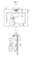
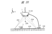
- FIG. 3 shows an appearance and an installation configuration example of the video display device 1 incorporating the operation detection device 2 of FIG. 2 and a state of a touch operation by the user on the operation surface 4.
- 3A shows a front view (XY plane) of the operation surface 4
- FIG. 3B shows a side view (YZ plane).
- the wall surface 201 is an indoor side wall or the like as an example of a planar object, and shows a case where it has a plane (XY plane) that stands vertically.
- the video display device 1 is fixed to one place on the wall surface 201 via an attachment tool.
- the video display device 1 is disposed at a position Z1 at a predetermined distance from the wall surface 201 in the Z direction. That is, the illumination device 50, the camera 5, and the microphone 6 are disposed slightly obliquely with respect to the imaging range 203 and the like.
- the rectangular display surface 3 is configured in the same range as the operation range 203 by the image light 205 projected from the image display device 1 in a part of the area.
- the rectangular operation surface 3 that is entirely superimposed on the display surface 3 is configured in the same range as the operation range 203.
- An operation range 203 indicates a range corresponding to the display surface 3 and the operation surface 4.
- the lighting device 50 (51, 52) has an illumination range 204.
- the illumination range 204 of each of the left and right illumination devices 51 and 25 includes an operation range 203.
- the camera 5 has an imaging range 202.
- the imaging range 202 includes an operation range 203.
- the sound detection range by the microphone 6 includes the operation range 203.
- the video display device 1 is disposed at a position Y1 above the operation range 203 in the Y direction (vertical) and at a center position X1 in the X direction (horizontal).
- the camera 5 and the microphone 6 are roughly arranged at the positions (X1, Y1).
- the illumination devices 51 and 52 are arranged at predetermined positions equidistantly symmetrical with respect to the position of the camera 5.
- the illumination devices 51 and 52 illuminate the illumination range 204 from the left and right positions toward the operation range 203.
- the camera 5 images the imaging range 202 from the center position toward the operation range 203.
- the microphone 6 inputs the sound generated in the operation range 203 at the center position via the air.
- the user performs an operation such as bringing the finger as the operation article 7 into contact with the wall surface 201 within the operation range 203 while viewing the image on the display surface 3.
- the operation detection device 2 detects the contact state and the contact point based on the image of the camera 5 and the sound of the microphone 6.
- FIG. 4 shows the relationship between the display surface 3 and the operation surface 4 and setting examples.
- the display surface 3 and the operation surface 4 are at least partially overlapped.
- the display surface 3 and the operation surface 4 have an independent positional relationship without overlapping at all.
- 4A is a setting example in the first embodiment corresponding to FIG. 3A, and the entire area of the operation surface 4 is superposed on the entire area of the display surface 3.
- (B) is another setting example, and the area of the operation surface 4 is superimposed on a partial area of the display surface 3.
- the user can perform a predetermined operation only on the operation surface 4 while viewing the image of the non-overlapping area of the display surface 3.
- a dedicated command or the like may be displayed in the area of the operation surface 4.
- (C) is another setting example, and the operation surface 4 is provided on an object such as a table or a pad having a horizontal surface at an independent position without overlapping the display surface 3 of the wall surface 201 at all. Yes.
- the coordinate system of the display surface 3 and the coordinate system of the operation surface 4 are correlated, and the in-plane position has a correspondence relationship.
- the user can perform a predetermined operation on the operation surface 4 at hand while viewing the display surface 3 at a position away from the display surface 3.
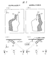
- FIGS. 5 to 7 show shadows according to the presence or absence of contact between the finger 300 as the operation article 7 and the operation range 203 of the wall surface 201 based on the illumination of the illumination device 50 (51, 52) in the first detection method. Examples of shapes are shown.
- FIG. 5 shows illumination light and shadow on the finger 300 in a non-contact state.
- 5A and 5B are front views (XY plane).
- C) and (D) of FIG. 5 show top views (XZ plane) viewed from vertically above corresponding to (A) and (B).
- the finger 300 for example, forefinger
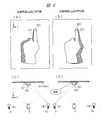
- FIG. 6 similarly shows illumination light and shadow on the finger 300 in contact.
- the finger 300 has a distance DF of 0 with respect to the wall surface 201 (imaging range 203) and is in contact (“contact state”).
- a left shadow 301 by the right illumination device 52 as shown in (A) and (C) and a right shadow 302 by the left illumination device 51 as shown in (B) and (D) are generated.
- the distance between the finger 300 and the left and right shadows 301 and 302 is small in the optical image of the imaging range 203 (image of the camera 5).
- FIG. 7 shows a comparison of the difference in shadow shape according to the distance DF between the finger 300 as the operation article 7 and the imaging range 203 of the wall surface 201 in the first detection method.
- FIG. 7 schematically illustrates a case where the left shadow 301 and the right shadow 302 are obtained as one image.
- 7A shows a case where the distance DF between the finger 300 and the wall surface 302 is small or 0.
- FIG. 7B shows a case where the distance DF is medium
- FIG. 7C shows a case where the distance DF is large. Is the case.
- the left shadow 301 and the right shadow 302 are close to each other at the fingertip position of the finger 300 as shown in FIG.
- the distance d1 between the shadow 301 and the shadow 302 related to the fingertip is small.
- the distance between the shadow 301 and the shadow 302 gradually increases as the finger 300 and the wall surface 201 are separated.
- the distance d2 is the distance d2.
- the distance between the finger 300 and the wall surface 201 is the longest, as shown in (C)
- the left shadow 301 and the right shadow 302 are separated from the fingertip position.
- the distance d3 between the shadow 301 and the shadow 302 related to the fingertip is large.
- the distances (d1, d2, d3) between the left shadow 301 and the right shadow 302 are correlated with the distance DF between the finger 300 and the wall surface 201.
- (A) it has a contour L1 on the left outer periphery in the region of the left shadow 301 and a contour L2 on the right outer periphery in the region of the right shadow 302. Further, the pixel of the tip point p1 that is the tip in the Y direction among the region of the shadow 301 and the contour line L1, and the pixel of the tip point p2 that is the tip in the direction of Y among the region of the shadow 302 and the contour line L2. . Similarly, (B) and (C) also have respective contour lines L1 and L2 and tip points p1 and p2.
- the distance between the pixels at the left and right tip points p1 and p2 is indicated by a distance d1.
- a fingertip point (intermediate point between the tip points) of the finger 300 is indicated by a point P1.
- it has a distance d2 and a point P2.
- it has a distance d3 and a point P3.
- the shadow area extraction unit 101 detects a shadow area, a contour line, a tip point, and the like as described above.
- the contact candidate detection unit 102 calculates the distance (distance between shadows) between the left and right shadow tip points, and compares the distance with a threshold value, whereby the fingertip (operation) on the imaging range 203 (operation surface 4) is calculated. Whether or not the object 7) is in contact can be determined. Specifically, the contact candidate detecting unit 102 estimates a contact state when the distance (distance between shadows) is equal to or smaller than the distance threshold, and estimates a non-contact state when the distance is larger than the distance threshold. . Further, the contact candidate detection unit 102 can estimate a pixel at an intermediate point between the left and right shadow tip points p1 and p2 as a contact candidate point. For example, in the case of (A), a point P1 (position coordinates of the corresponding pixel) is obtained as a contact candidate point.
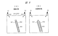
- FIG. 8 shows illumination and shadow in the case where the operation article 7 in contact with the operation surface 4 is a rod-shaped object 800 instead of a finger.
- (A) shows a contact state
- (B) shows a non-contact state.
- the user holds a stick-shaped object 800 in his hand, for example, a pointing stick, and similarly performs an operation on the operation surface 4 with the tip of the object 800.
- the contact state of (A) the distance between the left shadow 801 and the right shadow 802 is small.
- the non-contact state of (B) the distance between the left shadow 801 and the right shadow 802 is large.
- the same function can be realized even when the operation article 7 is the rod-shaped object 800.
- the object 800 does not have a mechanism for generating light, sound, or other signals.
- a configuration for detecting a signal transmitted from an operation article is adopted.
- the basic mechanism in the present invention does not employ a configuration for detecting a signal transmitted from an operation article.
- the finger or bar-like object that is the operation article 7 is not an object that generates a signal by itself.
- the operation detection device 2 is not an object that performs detection using a signal emitted from the operation object 7.
- FIG. 9A shows an example of the state and operation of the operation article 7 (finger) with respect to the operation surface 4, and FIG. 9B shows an example of time-series detection data D1 corresponding to (A).
- the operation detection device 2 is a device collectively detecting and recognizing a “state of contact”, and more specifically, “contact” as a static state (with contact, contact) It is a device having at least a contact recognition function that distinguishes between “non-contact” (which may be described as a state) and “non-contact” (which may be described as no contact or a non-contact state).
- FIG. 1 shows fingers 71 to 75 as examples of the state of the operation article 7 (finger) at each time point in time series.
- the finger 71 is in a non-contact state.
- the finger 72 is in a contact state.
- the change from the first state to the second state corresponds to the contact surface operation as the operation.
- the position coordinates of the first contact point in the second state at the second time point t2 are defined as (x1, y1).
- a contact sound is generated when the fingertip contacts the object (wall surface 201) of the operation surface 4 so as to strike the object, for example.
- the user moves the finger from the first contact point while keeping the finger in contact.
- the finger 73 is in a contact state.
- the position coordinate of the second contact point in the third state at the third time point t3 is defined as (x2, y2).
- the finger 74 is in a contact state.
- the position coordinates of the third contact point in the fourth state at the fourth time point t4 are (x3, y3).
- the user lifts his / her finger from the third contact point.
- the finger 75 is in a non-contact state.
- the change from the fourth state to the fifth state corresponds to the separation operation as the operation. No contact sound is generated during the separation operation.
- the operation detection device 2 can determine each state as described above by determining both the first detection result and the second detection result, and the operation determination unit 13 includes a plurality of time series. Each operation can be determined by determining the state.
- the detection data d1 at the first time point t1 includes a value indicating a non-contact state, for example, a value 0.
- the detection data d2 at the second time point t2 includes a value representing a contact state, for example, a value 1, and first contact point position coordinates (x1, y1).
- the detection data d3 at the third time point t3 includes the contact state value 1 and the second contact point position coordinates (x2, y2).
- the detection data d4 at the fourth time point t4 includes the contact state value 1 and the third contact point position coordinates (x3, y3).
- the detection data d5 at the fifth time point t5 includes the non-contact state value 0.
- the motion determination unit 13 can determine, from the information of the detection data D1 for each time point in the time series, a contact surface operation, a contact movement operation, a separation operation, and the like regarding the finger.
- the state is determined from both the image and the sound, and the state related to the separation operation is determined. At that time, since no contact sound is involved, the state is determined from the image.
- examples of the predetermined operation determined by the operation determination unit 13 include a touch operation, a tap operation, a swipe operation, and a flick operation.
- the touch operation is an operation that keeps touching the same position for a certain period of time.
- the tap operation is an operation in which a certain position is touched in a short time and then released.
- the swipe operation is an operation of moving from one position to another position while being in contact.
- the flick operation is an operation of moving to another position while touching a certain position and then releasing it.
- FIG. 10 shows a process flow of the first detection process of the first detection method.
- the first detection unit 21 (the shadow region detection unit 101 and the contact candidate detection unit 102) performs this first detection process.
- the processing flow in FIG. 10 includes steps S101 to S104.
- the flow of FIG. 10 shows a process for one time at a certain time point. This process is repeated continuously in a loop for each time point.
- each flow will be described in the order of steps.
- the shadow area detection unit 101 detects the area of the left shadow 301 and the area of the right shadow 302 of the finger 300 based on the input image, as shown in FIG. , And the tip point p2 of the right shadow 302 region is detected.
- the front end is a front end in a direction determined according to the positional relationship among the illumination device 50, the camera 5, the operation surface 4, and the operation article 7, and is the pixel on the uppermost side in the Y direction in the first embodiment.
- the contact candidate detection unit 102 calculates the distance (d) between the tip point p1 of the left shadow 301 and the tip point p2 of the right shadow 302. The contact candidate detection unit 102 determines whether or not the distance (d) is equal to or less than the set threshold value (dt). If the distance (d) is less than or equal to the threshold value (dt) (Y), the process proceeds to S103, and if the distance (d) is greater than the threshold value (dt) (N), the process proceeds to S104.
- the contact candidate detection unit 102 estimates that the finger is in the “contact state” where the finger is in contact with the operation range 203 of the wall surface 201. Then, as shown in FIG. 7, the contact candidate detection unit 102 takes a pixel at an intermediate point (P) between the tip point p1 and the tip point p2, and detects the position coordinates of the pixel as a contact candidate point.
- the contact candidate detection unit 102 (first detection unit 21) stores and outputs first detection result information including the “contact state” (for example, value 1) and the contact candidate point position coordinates.
- the contact candidate detecting unit 102 estimates that the finger is in a “non-contact state” in which the finger is not in contact with the operation range 203 of the wall surface 201.
- the contact candidate detection unit 102 stores and outputs first detection result information including “non-contact state” (for example, value 0). In the “non-contact state”, no information may be output, and the same effect can be obtained.
- the algorithm such as image processing performed by the shadow region extraction unit 101 is not limited to the above, and other algorithms may be used as long as they perform the same function.
- FIG. 11 shows a process flow of the second detection process of the second detection method.
- the second detection unit 22 (contact sound detection unit 103) performs this second detection process.
- the processing flow in FIG. 11 includes steps S201 to S204.
- the flow of FIG. 11 shows a process for one time at a certain time point, but this process is repeated continuously in a loop for each time point.
- the contact sound detection unit 103 performs sound volume (for example, sound pressure [dB]) for each set time interval (sound processing unit SU in FIG. 12) for input sound data from the microphone 6. Calculate The length of this time section (sound processing unit SU) is shorter than the time of the image frame of the first detection method as shown in FIG.
- the contact sound detection unit 103 continuously exceeds the set constant time threshold (Tt) based on the sound volume for each time interval calculated in S201, and the set constant is set. It is determined whether or not the sound is generated at a sound volume threshold (St) or more. In other words, the contact sound detection unit 103 determines whether or not the number of consecutive time intervals (sound processing units SU) having a sound volume equal to or greater than the threshold value (St) is equal to or greater than a predetermined number.
- the condition of S202 is satisfied (Y)
- the process proceeds to S203, and when not satisfied (N), the process proceeds to S204.
- the contact sound detection unit 103 determines that there is a “contact sound present” state corresponding to a state where a sound is generated by the operation object 7 coming into contact with the operation surface 4.
- the contact sound detection unit 103 stores and outputs second detection result information including “contact sound present” (for example, value 1).
- the contact sound detection unit 103 determines that there is a “no contact sound” state corresponding to a state in which no sound is generated from the operation surface 4.
- the contact sound detection unit 103 stores and outputs first detection result information including “no contact sound” (for example, value 0). In the case of “no contact sound”, no information may be output, and the same effect can be obtained.
- the operation sound when there is a portion that generates an operation sound such as the cooling device 16 in the vicinity of the operation detection device 2, the operation sound is input to the second through the microphone 6. May affect the detection process. Therefore, as described above, it is more preferable to have a function of performing control related to sound. With this function, a suitable value is adaptively set in consideration of the environment and the state of the operating sound, for the threshold value such as the sound volume threshold value (St) in the processing flow.
- the algorithm for the sound processing performed by the contact sound detection unit 103 is not limited to the above, and other algorithms may be used as long as they perform the same function. For example, when a specific frequency is included in the contact sound according to the wall surface 201 or the operation article 7, an algorithm for detecting the contact sound from the specific frequency may be used.
- FIG. 12 schematically shows a temporal relationship between the image processing of the first detection method and the sound processing of the second detection method and a processing example.
- the horizontal axis represents time
- each row in the vertical direction represents an image, a first detection, a sound wave, a sound processing unit SU, and a second detection.
- the image in the first row is an image frame of a moving image of the camera 5 and shows, for example, an image frame f1 and an image frame f2.
- the frame rate is, for example, 30 to 60 frames / second.
- the first detection in the second row indicates the detection result of the first detection process.
- the “non-contact state” is estimated for the image frame f1, and the “contact state” is estimated for the next image frame f2.
- the sound wave in the third row indicates an input sound signal of the microphone 6.
- the sound processing unit SU in the fourth row indicates a time interval for sound processing. For example, in the time of each image frame, there are eight intervals s1 to s8.
- the second detection in the fifth row indicates the detection result of the second detection process. As in S202 of FIG. 11, for each time interval, it is determined whether the sound volume is greater than or equal to a threshold value (St).
- a circle ( ⁇ ) indicates that the sound volume (sound pressure) is equal to or greater than the threshold (St), and a cross ( ⁇ ) indicates that the sound is less than the threshold (St).
- the state (O) is equal to or greater than the threshold (St).
- An example of a time during which a section in which the sound pressure is equal to or greater than the threshold (St) continues is shown as a duration TC.
- Tt threshold value
- time difference TD is the difference between the timing estimated as “contact state” in a certain image frame and the timing estimated as “contact sound present” in a smaller time unit.
- the operation detection device 2 validates the state estimation when the time difference TD is within a predetermined time difference threshold value, and invalidates the estimation when exceeding the predetermined time difference threshold value.
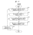
- FIG. 13 shows a processing flow of contact recognition processing (contact state detection processing) by the contact recognition unit 20 (contact state detection unit 104).
- the processing flow in FIG. 13 includes steps S301 to S305. Although the flow of FIG. 13 shows a process for one time, it is actually repeated continuously in a loop.
- the contact state detection unit 104 confirms and determines whether or not the contact candidate point position coordinates are detected in the first detection result information as “contact state”. When it is in the “contact state” (Y), the process proceeds to S202, and when it is not detected (N), the process proceeds to S305.
- the contact state detection unit 104 checks and determines whether or not it is estimated that “contact sound is present” in the second detection result information. If “contact sound is present” (Y), the process proceeds to S303, and if not (N), the process proceeds to S305.
- the contact state detection unit 104 sets the time difference (time difference TD in FIG. 12) between the detection timing of the “contact state” of the first detection result and the detection timing of “contact sound” of the second detection result. Whether or not it is within a predetermined time difference threshold (TDt). If the time difference is within the time difference threshold (TDt) (Y), the process proceeds to S304, and if it exceeds the time difference threshold (TDt) (Y), the process proceeds to S305.
- the time difference between the two detection timings is large, it can be estimated that the contact sound of the second detection result is not the contact sound corresponding to the contact state and the contact candidate point of the first detection result. Therefore, in this processing flow, the determination of S303 is performed.
- the contact state detection unit 104 determines “contact state” as a comprehensive determination in S304. Then, the contact state detection unit 104 determines the position coordinates of the contact candidate point corresponding to the “contact state” in the first detection result information as the position coordinates of the contact point.
- the contact state detection unit 104 stores information including “contact state” (for example, value 1) and the position coordinates of the contact point together with the identification information at the time point, and outputs the information as detection data.
- the contact state detection unit 104 determines “non-contact state” as the comprehensive determination.
- the contact state detection unit 104 stores information including “non-contact state” (for example, value 0) together with the identification information at the time, and outputs the information as detection data.
- “non-contact state” for example, value 0
- a single loop of the processing flow of FIG. 13 shows processing for recognizing a static state related to a finger at a certain time. Similarly, detection data obtained by this processing is obtained for each time point in time series.
- each state can be detected during the contact operation and the separation operation in FIG. 9. Particularly, since the judgment regarding the contact sound is reflected as an AND condition during the contact operation, the contact state during the contact operation can be detected with high accuracy. For example, if the user brings the fingertip close to the end of the operation surface 4 but is not touching, there is no contact sound. Therefore, according to the processing of FIG. 13, Y is S301, N is S302, and S305 is It can be determined as “non-contact state”. Further, when the user touches the operation surface 4 slowly and gently, there is almost no contact sound. Therefore, according to the processing of FIG. 13, Y in S301, N in S302, State ".
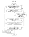
- FIG. 14 shows a processing flow of a modified example related to the contact recognition processing of FIG.
- the processing flow of FIG. 14 is an expanded version of the processing flow of FIG. In FIG. 14, steps S306 and S307 are added between S301 and S302 with respect to FIG.
- each state and operation can be performed by performing the same processing as in FIG. 13 in the operation of moving while the finger touches the operation surface 4. Can be detected. Furthermore, in order to achieve higher accuracy, the process of FIG. 14 may be applied.
- the contact recognition unit 20 (contact state detection unit 104) is a temporally previous image frame (processing of the previous loop), and as a result, “contact state” and contact point Confirm whether or not is detected. If it is detected (Y), the process proceeds to S307, and if not detected (N), the process proceeds to S302.
- the case of being detected in S306 (Y) corresponds to the “contact state” continuing in the previous image frame and the current image frame. In other words, in S306, it is possible to determine a state in which the finger has not touched the operation surface 4 and then left.
- S307 the contact recognition unit 20 looks at the distance (L) between the contact point of the previous image frame and the contact candidate point detected in the current image frame.
- the contact recognition unit 20 confirms and determines whether or not the distance L is smaller than a predetermined threshold (Lt). If it is equal to or less than the threshold (Lt) (Y), the process proceeds to S304, and if it is greater than the threshold (Lt) (N), the process proceeds to S302.
- the final determination is “contact state”.
- S302 as described above, the second detection result is confirmed.
- S307 the finger movement between time points (between images) is determined. If Y in S307, this corresponds to the finger not moving, and if N in S307, this corresponds to the finger moving.
- the state and operation can be detected more reliably.
- the contact sound is only at the time of the first contact, but Y in S306, Y in S307, and “Contact state” in S304.
- the contact sound is continuously generated.
- the operation determination is partially included in the processing flow of FIG. That is, the contact recognition unit 20 of the operation detection device 2 includes a part of the process of the motion determination unit 13.
- the video display device 1 displays information such as a GUI (graphical user interface) on the display surface 3, and the user operates the operation surface 4 on the display surface 3 with the operation article 7.
- a specific example when the control is performed is as follows.
- the control unit 11 of the video display device 1 displays a GUI part such as a button or a cursor (an image representing the position of the operation article 7) in accordance with the position coordinates of the operation article 7 in the image of the display surface 3.
- the operation detection device 2 detects the contact and position coordinates of the operation article 7 with respect to the operation surface 4 superimposed on the display surface 3, and outputs detection data D1.
- the control unit 11 of the video display device 1 displays a cursor in accordance with the position coordinates of the operation article 7 based on the detection data D1.
- control unit 11 determines that the position coordinate of the contact point of the operation article 7 is at the position of a predetermined button and the user specifies Then, it is determined that the operation is a press of the button (for example, a touch operation).
- the control unit 11 executes a command process defined in association with the button according to the operation of pressing the button.
- the operation detection using both the optical sensor and the non-optical sensor is realized, and the detection is performed as compared with the case of the detection method using only the optical sensor of the related art example.
- Accuracy can be improved.
- the user's operability can be improved, for example, the user can operate with less discomfort.
- the user can use the operation surface 4 that can be touched by a finger or the like by installing the operation detection device 2 on the wall surface 201 or other planar object. Since the detection accuracy increases, the number of planar objects that can constitute the operation surface 4 and the environment including the same increase, so that convenience for the user is enhanced.
- each component may be configured as one or more parts.
- the shadow area extraction unit 101 and the contact candidate detection unit 102 in FIG. 2 may be configured by one circuit.
- the shadow region extraction unit 101 may be configured separately into a processing unit that extracts a shadow region, a processing unit that extracts a contour line, and the like.
- an operation determination unit 105 may be further provided in the operation detection device 2.
- the operation determination unit 13 may not be provided on the control unit 11 side of the video display device 1.
- the operation determination unit 105 determines a predetermined operation (for example, the contact operation in FIG. 9) using the detection data output from the contact state detection unit 104 (or the contact recognition unit 20), and uses the operation information of the determination result.
- Output detection data including.
- the operation detection device 2 outputs detection data including a state and an operation to the control unit 11 of the video display device 1.
- the left and right lighting devices 50 (51, 52) are configured to be imaged by the camera 5 in a state in which the two lighting devices 50 (51, 52) are turned on simultaneously.
- the two lighting devices 51 and 52 may be alternately turned on at each timing separated in time, and the first image and the second image may be alternately captured by the camera 5 at each timing. .
- two images as shown in FIG. 5 are obtained.
- the operation detection device 2 may process the two images, integrate them into one image, and perform the determination as shown in FIG.
- the detection data D1 is output from the operation detection device 2 to the control unit 11 of the video display device 1.
- one or more external devices such as a PC may be further connected to the video display device 1.
- the PC transmits video data to be displayed to the video display device 1.
- the detection data is transmitted from the operation detection device 2 to the control unit 11 of the video display device 1, and the detection data or the control data based on the detection data from the control unit 11 of the video display device 1 is transmitted to one or more external devices such as a PC.
- You may output to an apparatus.
- a device such as a PC can perform predetermined control using detection data and control data.
- the present invention is not limited to this, and various configurations in which each element is separated from the video display device 1 (or the operation detection device 2) are possible.
- the arrangement positions of the elements such as the illumination device 50, the camera 5, and the microphone 6 with respect to the operation surface 4 are not limited to the installation configuration example of FIG. Other placement positions are possible.
- two or more cameras may be provided and these cameras may be arranged at different positions.
- one imaging range 202 is shared or overlapped by two or more cameras, and a contact state is detected using a plurality of images from the two or more cameras.
- the wall surface 201 in FIG. 3 shows a case where the operation surface 4 has a plane as a planar object.
- the operation object 4 is not limited to a plane object. Any object having a curved surface or the like is also applicable.
- the operation surface 4 can be configured for an object having a curved surface such as a school whiteboard.
- the setting of the first detection type illumination device 50 and the camera 5, the setting of the second detection type microphone 6 and the adjustment and setting of parameters such as the threshold of each process are performed when the video display device 1 is started.
- the adjustment / setting process may be performed by an initialization process or the like according to the environment.
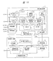
- FIG. 15 shows a configuration of a video display device 1 and an operation detection device 2 of a modification.
- the video display device 1 and the operation detection device 2 are configured as separate devices, and the video display device 1 and the operation detection device 2 are connected and linked through communication.
- the operation detection device 2 includes the operation determination unit 105, and the video display device 1 does not include the operation determination unit 13.
- the operation detection device 2 has an operation detection function (contact recognition function) as in the first embodiment, and transmits the detection data D1B to the video display device 1 through communication.
- the operation determination unit 105 receives the detection data of the contact state detection unit 104, determines a predetermined operation based on the analysis of the detection data, and outputs detection data including operation information of the determination result as described above. To do.
- the control unit 110 configures detection data D1B including the state and operation information using the detection data from the operation determination unit 105, controls the output unit 111, and transmits the detection data D1B to the control device 11 of the video display device 1.
- the video display device 1 receives the detection data D1B from the operation detection device 2, and performs predetermined control processing using information on the state, position coordinates, and operation in the detection data D1B. In the case of this modification, the video display device 1 and the operation detection device 2 can be installed at different positions.
- the contact state is detected by the determination of the shadow using the image of the camera 5 which is an optical sensor.
- the present invention is not limited to this method and can be applied. Specifically, the following methods are mentioned.
- light such as a linear laser beam is projected on a plane parallel to the operation surface 4 (for example, the XY plane in FIG. 3), and a finger (operation object 7) of the projection light is projected.
- a finger operation object 7 of the projection light
- FIG. 16 shows an installation configuration example and a first detection method of the video display device 1 of a modified example corresponding to the method of the first example.
- FIG. 16 shows the YZ plane.
- the video display device 1 is installed on a horizontal plane (XY plane) of an object 160 such as a desk.
- An operation range 203 is configured on the horizontal plane of the object 160.
- the video display device 1 includes a light projection / detection unit 161 as an optical sensor.
- the light projection / detection unit 161 projects linear light (projection light) 162 onto a parallel plane separated by a predetermined distance from the operation range 203 in the Z direction so as to cover the operation range 203. Scanning with light 162 is performed.
- the light 162 is reflected when it hits the operation object 7 such as a user's finger.
- the light projection / detection unit 161 detects the reflected light (reflected light) 163.
- the light projection / detection unit 161 can detect the contact / non-contact state of the operation article 7 with respect to the operation surface 4 based on the signal of the detection light, and can detect a contact candidate point at the time of contact.
- an optical sensor capable of acquiring three-dimensional information (object distance information) of an object such as a TOF (Time Of Flight) sensor or a TOF camera.
- object distance information object distance information
- the distance from the TOF camera to the finger is calculated based on the TOF principle.
- the position coordinates in the three-dimensional space related to the finger image can be calculated based on the distance. That is, from such three-dimensional information, the contact / non-contact state of the operation article 7 with respect to the operation surface 4 can be detected, and the contact candidate point at the time of contact can be detected.
- the position coordinates of the operation article in the three-dimensional space can be estimated with a certain degree of accuracy using two images from the two left and right cameras.
- the second detection type non-optical sensor (technical means for detecting contact sound and vibration) is not limited to the microphone 6, and other non-optical sensors having similar functions may be used.
- a non-optical sensor for example, a strain sensor, a bending sensor, or the like is applicable. Thereby, the effect similar to Embodiment 1 is acquired.
- a strain sensor or a bending sensor is installed on a surface corresponding to the operation range 203 in a state of directly contacting the wall surface 201 or other planar object in FIG.
- a detection circuit or the like may be connected to the strain sensor or the bending sensor.
- the operation detection device 2 detects vibration generated when the operation article 7 comes into contact with the operation surface 4 by using the strain sensor or the bending sensor.
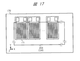
- FIG. 17 shows a configuration example of the operation surface 4 in the second detection method of the video display device according to the modification.
- a required number of strain sensors (strain gauges) 171 are arranged on the operation surface 4 on the planar object 170.
- the strain sensor 171 has a known configuration.
- resistors using a metal foil or a semiconductor are arranged in a zigzag shape on an insulator base. Lead wires and circuits are connected to both ends of the resistor.
- the strain sensor 171 detects the change in resistance value as a change in voltage value, and calculates the amount of strain.
- the operation detection device 2 uses the detection information of the strain sensor 171 to compare the strain amount with a predetermined threshold value, for example, to determine the presence / absence of contact sound of the operation article 7 with respect to the operation surface 4 and the position coordinates of the contact candidate points. It can be estimated.
- the bending sensor is a sensor that detects a change in resistance value according to the bending of a resistor, which is a material, and is similar in principle to a strain sensor.
- Embodiment 2 The video display apparatus according to the second embodiment will be described with reference to FIG.
- the basic configuration of the second embodiment is the same as that of the first embodiment.
- components different from those in the first embodiment in the second embodiment and the like will be described.
- the contact sound is detected using two microphones installed at different positions near the operation surface.
- FIG. 18 shows an installation configuration example in the video display device 1 of the second embodiment.
- (A) is a front view of the operation range 203 of the wall surface 201 (XY plane) standing vertically, and
- (B) is a side view of the YZ plane.
- the video display device 1 is installed at a central position X1 above the operation range 203, as in the case of FIG.
- the video display device 1 includes microphones 61 and 62 as two microphones as the microphone 6 that is a non-optical sensor.
- two microphones 6 are separated from the main body of the video display device 1 via the connection line 181 and are installed at positions separated from each other.
- Microphones 61 and 62 are installed at two positions XL and XR on the left and right of the center position X1 in the X direction.
- the left microphone 61 is disposed at a position XL near the upper left of the operation range 203
- the right microphone 62 is disposed at a position XR near the upper right of the operation range 203.
- the microphone 6 (61, 62) is in contact with the wall surface 201 and is installed at a position Y 2 in the vicinity above the operation range 203.
- the microphone 6 (61, 62) is installed at a position where the sound generated in the operation range 203 can be easily detected.
- the contact sound at that time is transmitted through the wall surface 201.
- the microphone 6 (61, 62) directly inputs the contact sound from the wall surface 201.
- the wall surface 201 and the microphone 6 are separated from each other, the contact sound is input from the wall surface 201 to the microphone 6 through the air.
- the second detection unit 22 uses the input sound data of the two microphones 6 (61, 62) to estimate the presence or absence of the contact sound of the operation article 7 with respect to the operation surface 4. Furthermore, the second detection unit 22 (contact sound detection unit 103) may estimate the position coordinates of the contact candidate point when there is a contact based on the analysis of the two left and right input sounds.
- the connection between the microphone 6 and the operation detection device 2 may be a wired connection such as LAN or USB, or a wireless connection such as Wi-Fi or Bluetooth (registered trademark).
- the processing flow of the second detection method in the video display device 1 of Embodiment 2 is as follows. This processing flow has the following as points different from the processing flow of FIG. 11 of the first embodiment. Before S201 in FIG. 11, an initialization step is included.
- the operation detection apparatus 2 first performs the following initialization process in this initialization step.
- the contact sound detection unit 103 of the operation detection device 2 initializes the positional relationship and the like of the plurality (two) of microphones 6 (61, 62) related to the second detection method, and performs the first detection method coordinate system and the second detection. Match the coordinate system of the method.
- the operation detection device 2 uses a difference in time when the specified position on the wall surface 201 is contacted with a user's finger and the contact sound at that time is input to each of the microphones 61 and 62. Thus, the positional relationship between the two microphones 61 and 62 and the operation range 203 of the wall surface 201 is initialized.
- the contact sound detection unit 103 calculates the sound volume for each section for each of the input sound data from the two microphones 61 and 62 in the same manner as described above.
- the contact sound detection unit 103 estimates the presence / absence of a contact sound by determining whether each input sound is generated for a time and a loudness equal to or greater than a threshold value. Further, when all (both) of the judgment results (contact sound presence / absence) of the plurality of (two) input sounds indicate “with contact sound” (Y), the contact sound detection unit 103 proceeds to S203. If not (N), the process proceeds to S204. In S203, the contact sound detection unit 103 determines “there is a contact sound” as the second detection result.
- the contact sound detection unit 103 can calculate the position coordinates of the contact candidate points from the information of plural (two) input sounds, for example, the difference in the input time of the contact sounds of the two microphones 61 and 62, calculate.
- the contact sound detection unit 103 outputs the “contact sound present” state and the position coordinates of the contact candidate points.
- the contact sound detection unit 103 determines “no contact sound” in S204.
- the processing flow of the contact recognition process in the second embodiment is as follows. This processing flow has the following as points different from the processing flow of FIG. 13 of the first embodiment.
- a position confirmation step is added between S303 and S304.
- the process proceeds to this step.
- the contact recognition unit 20 (contact state detection unit 104) of the operation detection device 2 detects the position coordinates of the contact candidate points of the first detection result (S103) and the contact candidate points (S203) of the second detection result (S203). Compare the position coordinates of the (sound source) and see the distance of the difference between those position coordinates.
- the contact state detection unit 104 determines whether the difference distance is equal to or less than a predetermined distance threshold, that is, whether the difference is a close position within a certain range. If the difference distance is equal to or smaller than the predetermined distance threshold (Y), the contact state detection unit 104 proceeds to S304, and if not (N), the process proceeds to S305.
- a predetermined distance threshold that is, whether the difference is a close position within a certain range.
- the contact state detection unit 104 comprehensively determines the “contact state”, and determines the position coordinates of the contact candidate point of the first detection result as the contact point position coordinates. In S304, the contact state detection unit 104 comprehensively determines the “non-contact state”. In S304, as another processing example, the contact state detection unit 104 takes an intermediate point between the position coordinates of the contact candidate point of the first detection result and the position coordinate of the contact candidate point of the second detection result, The point may be determined as the position coordinate of the contact point.
- the contact sound of the contact point of the second detection method may not be the contact sound of the finger of the contact point of the first detection method It is considered that the nature is high. Therefore, it is determined that the contact sound is caused by a finger only when the detected positions are close.
- steps S306 and S307 are similarly added.
- the contact sound is estimated using a plurality of (two) microphones 6, so that contact recognition with higher accuracy is possible.
- three or more microphones 6 may be installed, and the contact sound may be similarly estimated using three or more input sound data.
- a plurality of microphones 6 may be provided in the main body of the video display device 1 or the like, or the direction of the microphones 6 can be set variably.
- a microphone having sound input directivity may be used as the microphone 6 so that the direction of directivity of the microphone 6 faces the operation range 203.
- the video display apparatus according to the third embodiment will be described with reference to FIG.
- the video display device 1 is installed on the horizontal plane
- the operation surface 4 is configured on the horizontal plane
- the microphone 6 is installed on the horizontal plane.
- FIG. 19 shows an installation configuration example of the video display device 1 of the third embodiment.
- A shows a top view (XY plane) of an object (planar object) 190 such as a desk or table viewed from vertically above.
- B shows a side view (YZ plane) of the object 190 as viewed from the side.
- the coordinate system (X, Y, Z) is different from that in FIG.
- the video display device 1 is arranged at the center position (X1, Y1) on the far side in the Y direction with respect to the operation range 203 as seen from the user.
- the projection direction of the image light 205 of the image display device 1, the illumination direction of the illumination device 50, and the imaging direction of the camera 5 are directions from slightly above the horizontal plane of the object 190 to obliquely below.
- the microphone 6 is built in the bottom surface of the main body of the video display device 1.
- the microphone 6 is disposed at a position in contact with the horizontal plane of the object 190 and in the vicinity of the operation range 203. Similar to the second embodiment, the contact sound of the operation article 7 in the operation range 203 is transmitted to the object 190 and directly input to the microphone 6.
- the object 190 may be a general object such as a desk, or may be a dedicated flat object provided as a set with the video display device 1.
- the dedicated object is installed on a horizontal surface such as a desk or on a wall surface or the like, and is connected to the video display device 1.
- the dedicated object may be a display device having a display surface 3 or a screen medium.
- the dedicated object may include the microphone 6 or may be provided with the illumination device 50, the camera 5, and the like.
- the microphone 6 may be a plurality of microphones as in the second embodiment.
- FIG. 20 illustrates an installation configuration example of the video display device 1 according to the first modification of the third embodiment.
- FIG. 20 shows a side view (YZ plane) of an object 190 such as a desk viewed from the side.
- the operation range 203 is configured on the horizontal plane (XY plane).
- the video display device 1 is installed at a position spaced vertically upward (Z direction) with respect to the operation range 203 on the horizontal plane, for example, in a state of being hung from an indoor ceiling via an appliance.
- the projection direction, the illumination direction, and the imaging direction of the image light 205 of the image display device 1 are directions from vertically upward to downward.
- the microphone 6 is separated from the main body of the video display device 1 via a connection line, and is disposed at a position near the operation range 203 at a position in contact with the object 190.
- the connection line such as the microphone 6 and the communication interface may be wired or wireless.
- FIG. 21 illustrates an installation configuration example of the video display device 1 according to the second modification of the third embodiment.
- the video display device 1 of this modification has a screen medium 210 as a dedicated planar object instead of the wall surface 201 of FIG.
- the screen medium 210 is installed on a vertical wall or the like and has an XY plane.
- the video display device 1 that is a projector of the main body and the operation detection device 2 are separated and connected through a connection line 211 (wired or wireless).
- the video display device 1 is disposed at a predetermined distance in front of the screen medium 210.
- Video light 205 from the video display device 1 is roughly emitted in the Z direction and projected onto the display surface 3 (projection display surface) of the screen medium 210.
- an operation range 203 corresponding to the display surface 3 and the operation surface 4 is configured.
- the operation detection device 2 is installed at a central position (X1, Y1) above the operation range 203 of the screen medium 210.
- the camera 5 is arranged at the center position (X1, Y1).
- left and right illumination devices 50 (51, 52) are arranged through connection lines at left and right positions (near XL and XR) with respect to the center position.
- left and right microphones 6 (61, 62) are arranged through connection lines at left and right positions (near XL and XR) with respect to the center position.
- the screen medium 210 may include the lighting device 50, the microphone 6, and a connection line.
- the screen medium 210 and the operation detection device 2 may be integrally mounted.
- the arrangement position of the illuminating device 50 (51, 52) and the microphone 6 (61, 62) with respect to the screen medium 210 can be adjusted by the user via an attachment device.
- a sound detector is disposed at a position between the main body of the video display device and the operation range.
- FIG. 22 shows an installation configuration example of the video display device 1 according to the fourth embodiment.
- an operation range 203 corresponding to the display surface 3 and the operation surface 4 is configured on the wall surface 201, and the main body of the video display device 1 is positioned above the operation range 203 (X1, Y1). Is installed.
- the main body of the video display device 1 has a horizontally long shape, and is provided with lighting devices 50 (51, 52) at left and right positions with respect to the camera 5 at the center of the main body.
- a sound detector 60 is installed at a position (X1, Y4) between the main body of the video display device 1 and the upper side of the operation range 203.
- the sound detector 60 includes a microphone 6, a light emitting unit 63, and an internal circuit (not shown).
- the internal circuit includes a control circuit that controls the sound detector 60 and a contact sound detection circuit.
- the control circuit controls the light emission state of the light emitting unit 63 and the like.
- the contact sound detection circuit performs processing corresponding to the contact sound detection unit 103 described above.
- the sound detector 60 is mounted on an IC board or the like. In the fourth embodiment, since there is a contact sound detection circuit in the sound detector 60, the contact sound detection unit 103 in the operation detection device 2 is omitted.
- the microphone 6 is, for example, a microphone 6 having sound input directivity, and the directivity direction of the microphone 6 is set as a direction toward the operation range 203, that is, a downward direction in the Y direction.
- the microphone 6 detects a sound from the lower operation range 203 in the Y direction, and does not detect an operation sound or the like of the upper video display device 1.
- the contact sound detection circuit of the sound detector 60 performs a predetermined process corresponding to the process of the contact sound detection unit 103 based on the input sound of the microphone 6 to detect the presence or absence of the contact sound by the operation article 7. To do.
- the control circuit of the sound detector 60 causes the light emitting unit 63 to emit light for a time corresponding to the time during which the state is detected.
- the light emitted from the light emitting unit 63 is not limited to visible light, and may be light emitted at a wavelength that can be imaged by the camera 5, and may be infrared light or the like.
- the imaging range 202 of the camera 5 of the main body is defined by a size including the operation range 203 and the light emitting unit 63.
- the camera 5 obtains, as an image, the state of light emission or non-light emission from the light emitting unit 63 together with the operation range 203.
- the contact recognition unit 20 (contact state detection unit 104) of the operation detection device 2 detects the presence or absence of contact sound by detecting the light emission or non-light emission state of the region of the light emitting unit 63 in the image of the camera 5. The determination is performed in the same manner as described above.
- the operation detection device 2 may be provided with a light emission detection unit that is associated with the light emission unit 63 of the sound detector 60 separately from the camera 5.
- the light emission detection unit detects the light emission state of the light emission unit 63 of the sound detector 60, detects the presence or absence of a contact sound corresponding to the light emission state, and outputs detection information to the contact state detection unit 104.
- the sound detector 60 is not provided with the light emitting unit 63, and the sound detector 60 and the main body of the video display device 1 (or the operation detection device 2) are connected by communication through a connection line. Form may be sufficient.
- the sound detector 60 transmits information including the presence or absence of contact sound to the main body of the video display device 1 through a connection line.
Landscapes
- Engineering & Computer Science (AREA)
- General Engineering & Computer Science (AREA)
- Theoretical Computer Science (AREA)
- Physics & Mathematics (AREA)
- General Physics & Mathematics (AREA)
- Human Computer Interaction (AREA)
- Projection Apparatus (AREA)
- User Interface Of Digital Computer (AREA)
Abstract
検出の精度を向上できる技術を提供する。映像表示装置1は、表示面3に対応付けて設定された操作面4に対するユーザの手指を含む操作物7による接触を含む操作を検出する操作検出装置2と、操作面4上の操作物7による像を検出する光学センサであるカメラ5と、操作面4での操作物7の接触によって生じる音または振動を検出する非光学センサであるマイク6とを備える。操作検出装置2は、光学センサの第1検出情報および非光学センサの第2検出情報を用いて、操作面4に対する操作物7による接触または非接触を含む状態を検出し、検出データを出力する。操作検出装置2は、第1検出情報から操作面4と操作物7との接触有りの状態を検出し、かつ、第2検出情報から接触有りの状態に対応する音または振動を検出した場合に、総合的に接触状態であると判定する。
Description
本発明は、映像表示技術や情報処理技術に関し、ユーザの手指等の操作物による操作面に対する接触等の操作の状態を検出するための技術に関する。
投射型映像表示装置(プロジェクタ)等の映像表示装置では、映像が表示される表示面を持つ面状の物体に対して重畳するように設けられた操作面を持つ場合がある。その操作面に対し、ユーザは、手指や手に持った棒等の操作物によって、接触等の操作を行う。映像表示装置または操作検出装置は、操作面に対する操作物による接触有無等の状態や接触点位置座標等を検出する。映像表示装置または操作検出装置は、検出した状態や位置に応じて、所定の動作を判定し、その動作に応じて、対応付けられる所定の制御処理を実行する。
上記操作の状態を検出するための技術として、光学センサを用いる技術がある。例えば、操作検出装置は、操作面および手指に対する照明に基づいて形成される影を含む像を、カメラで撮像して抽出し、影の状態から手指による操作の状態を推定する。
上記光学センサを用いた操作検出技術に関する先行技術例として、特開2014-174832号公報(特許文献1)が挙げられる。特許文献1には、操作検出装置等として、操作面に異なる位置から照明する第1および第2の照明と、操作面を撮像するカメラとを備え、撮像画像から第1および第2の影を抽出し、各影の輪郭線間の距離から接触点を検出する旨が記載されている。
また、上記操作の状態を検出するための技術として、マイク、超音波センサ、または歪センサ等の非光学センサを用いる技術がある。この技術では、例えばマイクを用いて、物体からの音波等の振動を検出し、操作面に対する操作物の接触の状態を推定する。
上記非光学センサを用いた操作検出技術に関する先行技術例として、特開平8―263192(特許文献2)が挙げられる。特許文献2には、超音波座標入力装置として、高精度の座標検出を可能とする旨、座標検出が一定の休止時間を置いて繰り返し行われる旨が記載されている。
上記操作検出に係わる先行技術例では、検出の精度の観点で改善余地がある。例えば、カメラ等の光学センサを用いた技術の場合、特許文献1の例では、指の影の輪郭線等の不変特徴量を抽出し、操作面への接触を判定する接触認識を行っている。しかし、このような接触認識技術では、例えば実際に指先が操作面に近いが接触していない状態の場合でも、接触している状態と誤認識される可能性がある。上記光学センサを用いた操作検出方式では、状況によって高精度な検出が難しい場合がある。
また、マイク等の非光学センサを用いた技術の場合、音波等の振動のみからは状況によって高精度の判断が難しい場合がある。例えば、操作面に接触した指先が操作面から離れる場合、殆ど音が生じないので、非接触状態の検出は難しい。
本発明の目的は、光学センサを用いた操作検出技術に関して、検出の精度を向上できる技術を提供することである。
本発明のうち代表的な実施の形態は、映像表示装置であって、以下に示す構成を有することを特徴とする。一実施の形態の映像表示装置は、表示面に映像を表示する映像表示装置であって、前記表示面に対応付けて設定された操作面と、前記操作面に対するユーザの手指を含む操作物による接触を含む操作を検出する操作検出装置と、前記操作面上の前記操作物による像を検出する光学センサと、前記操作面での前記操作物の接触によって生じる音または振動を検出する非光学センサと、を備え、前記操作検出装置は、前記光学センサの第1検出情報および前記非光学センサの第2検出情報を用いて、前記操作面に対する前記操作物による接触または非接触を含む状態を検出し、検出データを出力し、前記第1検出情報から前記操作面と前記操作物との接触有りの状態を検出し、かつ、前記第2検出情報から前記接触有りの状態に対応する音または振動を検出した場合に、総合的に接触状態であると判定する。
本発明のうち代表的な実施の形態によれば、光学センサを用いた操作検出技術に関して、検出の精度を向上できる。
以下、本発明の実施の形態を図面に基づいて詳細に説明する。なお、実施の形態を説明するための全図において同一部には原則として同一符号を付し、その繰り返しの説明は省略する。なお、説明上、方向として、X方向、Y方向、Z方向を用いる。X方向、Y方向は、操作面(あるいは表示面)を構成する直交する2つの方向とし、例えばX方向は面内水平方向(左右方向)、Y方向は面内垂直方向(上下方向)とする。Z方向は、操作面のX-Y面に対して垂直な方向とする。
(実施の形態1)
図1~図17を用いて、本発明の実施の形態1の映像表示装置および映像表示方法について説明する。実施の形態1の映像表示方法は、実施の形態1の映像表示装置において実行されるステップを有する方法である。
図1~図17を用いて、本発明の実施の形態1の映像表示装置および映像表示方法について説明する。実施の形態1の映像表示方法は、実施の形態1の映像表示装置において実行されるステップを有する方法である。
[概要等]
実施の形態1の映像表示装置では、表示面に重畳される操作面においてユーザが手指を操作物として用いて接触等の操作を行う。その際、映像表示装置の操作検出装置では、光学センサ(カメラ)と非光学センサ(マイク)とを併用することで、手指と操作面との接触の状態および接触点位置座標を、高精度に検出する。実施の形態1の映像表示装置は、操作面に対して異なる位置から照明する第1および第2照明装置と、操作面を含む像を撮像するカメラと、操作面で生じる音波を検出するマイクとを備える。実施の形態1の映像表示装置は、光学センサであるカメラを用いた方式(第1検出方式とする)と、非光学センサであるマイクを用いた方式(第2検出方式とする)とを組み合わせた方式で、操作面上の操作物による接触等の操作の状態を検出する。これにより、実施の形態1の映像表示装置では、光学センサのみを用いた技術あるいは非光学センサのみを用いた技術では正確な接触認識が難しい場合でも、高精度の接触認識を可能とする。
実施の形態1の映像表示装置では、表示面に重畳される操作面においてユーザが手指を操作物として用いて接触等の操作を行う。その際、映像表示装置の操作検出装置では、光学センサ(カメラ)と非光学センサ(マイク)とを併用することで、手指と操作面との接触の状態および接触点位置座標を、高精度に検出する。実施の形態1の映像表示装置は、操作面に対して異なる位置から照明する第1および第2照明装置と、操作面を含む像を撮像するカメラと、操作面で生じる音波を検出するマイクとを備える。実施の形態1の映像表示装置は、光学センサであるカメラを用いた方式(第1検出方式とする)と、非光学センサであるマイクを用いた方式(第2検出方式とする)とを組み合わせた方式で、操作面上の操作物による接触等の操作の状態を検出する。これにより、実施の形態1の映像表示装置では、光学センサのみを用いた技術あるいは非光学センサのみを用いた技術では正確な接触認識が難しい場合でも、高精度の接触認識を可能とする。
[映像表示装置を含むシステム]
図1は、実施の形態1の映像表示装置1を含むシステムの構成を示す。実施の形態1の映像表示装置1は、操作検出装置2、制御部11、映像表示部12、動作判定部13を含む。映像表示装置1は、映像表示部12により表示面3に対し映像を表示する。
図1は、実施の形態1の映像表示装置1を含むシステムの構成を示す。実施の形態1の映像表示装置1は、操作検出装置2、制御部11、映像表示部12、動作判定部13を含む。映像表示装置1は、映像表示部12により表示面3に対し映像を表示する。
制御部11は、映像表示部12を含め、映像表示装置1の全体を制御する。制御部11は、ユーザの操作物7による操作面4の操作の状態に基づいた、操作検出装置2の検出データに基づいて、および動作判定部13の動作判定結果データに基づいて、所定の制御を行う。所定の制御は、映像表示部12の映像表示の制御を含む。
映像表示部12は、制御部11からの制御および映像データに基づいて、表示面3に対する映像の表示を行う。表示面3では、画素の行列に基づいて、映像・画像が表示される。表示面3に対し、対応付けられるように、操作面4が構成されている。操作面4は、表示面3と少なくとも一部が重畳する面、または表示面3とは重畳せずに独立した面である(図4)。操作面4は、ユーザが手指(あるいは手に持った棒状の物体)を操作物7として接触等の操作を行う面である。
操作面4の近傍には、照明装置50(51,52)と、光学センサであるカメラ5と、非光学センサであるマイク6とが設置されている。照明装置50(51,52)は、操作面4に対して異なる位置に設置される2つの照明装置として、照明装置(第1照明装置)51、照明装置(第2照明装置)52を有する。照明装置51,52は、操作面4に対して異なる位置からそれぞれの照明(第1照明および第2照明)を与える。
光学センサであるカメラ5は、第1照明および第2照明に基づいて、操作面4をユーザの操作物7の像とともに撮像して画像を得る撮像装置である。カメラ5は、画像を含む第1検出情報を出力する。
非光学センサであるマイク6は、操作面4に操作物7が接触する動作等によって発生する音波(振動)を音信号/音データとして検出する音検出装置である。マイク6は、音信号/音データを含む第2検出情報を出力する。
操作検出装置2は、操作面4に対するユーザの操作物7による接触等の操作の状態を検出する接触認識機能を有する装置である。図1の構成では、映像表示装置1内に操作検出装置2が実装されている。操作検出装置2は、接触認識部20、第1検出部21、第2検出部22を含む。第1検出部21は、照明装置50およびカメラ5と接続されており、影接触検出部21Aを含む。第2検出部22は、マイク6と接続されており、振動接触検出部22Aを含む。
第1検出部21は、カメラ5の画像データ(第1検出情報)を入力し、記憶して、第1検出処理を行う。第1検出部21は、第1検出方式として、光学センサであるカメラ5を用いた第1検出(特に影に基づいた接触検出)を行う部分である。第1検出部21は、照明装置50の照明によって形成される操作面4上の操作物7の影を含む光学像を、カメラ5の画像として得る。第1検出部21は、その画像に基づいて、操作面4に対する操作物7の接触有無を含む状態を検出し、第1検出結果の情報/データを出力する。第1検出部21は、照明装置51,52による操作面4への照明の点灯(オン)/消灯(オフ)や光量等の制御、およびカメラ5による操作面4の撮像の制御を行う。
影接触検出部21Aは、特に影に基づいた接触検出の処理を行う部分である。影接触検出部21Aは、カメラ5の画像に基づいて、操作物7の影を抽出して、影の形状等の状態の判断に基づいて、操作面4に対する操作物7の接触有無(接触/非接触)の状態、および接触の場合の接触候補点の位置座標等を、計算によって検出する。
第2検出部22は、マイク6の音信号/音データを入力し、記憶して、第2検出処理を行う。第2検出部22は、第2検出方式として、非光学センサであるマイク6を用いた第2検出(特に音に基づいた接触検出)を行う部分である。第2検出部22は、操作面4で生じる音波(振動)を、マイク6の音信号として入力し、その音信号に基づいて、操作面4に対する操作物7による接触音の有無を含む状態を検出し、第2検出結果の情報/データを出力する。振動接触検出部22Aは、音(振動)に基づいた接触検出の処理を行う部分である。振動接触検出部22Aは、マイク6の音信号に基づいて、音の大きさや周波数等の解析を行い、操作面7に対する接触音の有無等を、計算によって検出する。
接触認識部20は、時間軸で対応して得られた第1検出部21の第1検出結果と第2検出部22の第2検出結果とを用いて、総合的に、操作面4に対する操作物7の接触/非接触の状態や接触点の位置座標等を判定する。このような総合的な判定を、接触認識または操作検出と記載する場合がある。接触認識部20は、接触認識の結果である状態や位置座標等の情報を含む検出データを出力する。接触認識部20は、例えば、第1検出結果で接触(接触有り)の状態が検出され、かつ、第2検出結果で接触(接触音有り)の状態が検出された場合には、接触状態であると総合判定する。このように、操作検出装置2では、2種類の検出方式のAND条件を用いて状態を判定するので、高精度の接触認識が可能である。
映像表示装置1または操作検出装置2は、さらに、動作判定部13を備えてもよい。図1の構成では、映像表示装置1内で操作検出装置2の外側に動作判定部13を備える。接触認識部20では基本的に静的な状態を検出し、動作判定部13では動的な状態(所定の動作)を検出する。なお、動作判定部13は、制御部11に統合されてもよいし、接触認識部20に統合されてもよい。
動作判定部13は、接触認識部20の検出データを入力し、その検出データにおける接触の状態や位置座標等の情報を用いて、操作面4に対する操作物7の所定の動作を判定する。動作判定部13は、動作判定結果を表すデータを出力する。動作判定部13は、接触認識部20の検出データに基づいて、時系列上の複数の状態をみることで、所定の動作を判定する(図9)。動作判定部13は、例えば、時系列における第1時点での非接触(接触無し)の状態から第2時点での接触(接触有り)の状態に変化した場合には、接触面4に対する接面動作と判定する。動作判定部13は、例えば、第1時点での接触(接触有り)の状態から第2時点での非接触(接触無し)の状態に変化した場合には、接触面4に対する離面動作と判定する。
[映像表示装置、操作検出装置]
図2は、図1の実施の形態1の映像表示装置1のより詳しい構成例を示す。図2の実施の形態1の映像表示装置1は、プロジェクタ(投射型映像表示装置)である場合を示す。映像表示装置1は、操作検出装置2を含み、制御部(制御装置)11、映像表示部(投射表示部)12、通信装置15、冷却装置16、操作装置17等を有し、それらがバス等で接続されている。制御装置11は、動作判定部13を含む。
図2は、図1の実施の形態1の映像表示装置1のより詳しい構成例を示す。図2の実施の形態1の映像表示装置1は、プロジェクタ(投射型映像表示装置)である場合を示す。映像表示装置1は、操作検出装置2を含み、制御部(制御装置)11、映像表示部(投射表示部)12、通信装置15、冷却装置16、操作装置17等を有し、それらがバス等で接続されている。制御装置11は、動作判定部13を含む。
実施の形態1では、操作検出装置2の接触認識機能に関して、映像表示装置1の本体の制御装置11が、操作対象装置に相当する。すなわち、ユーザは、接触認識機能を利用して操作面4に対する接触操作を行うことで、映像表示装置1の本体が持つ所定の機能を操作することができる。所定の機能は、例えば投射映像の表示状態を変更する機能等の、予め規定された機能である。
投射表示部12は、映像表示部であり、投射表示面である表示面3に対する投射映像表示を行う。投射表示部12は、駆動部、光源、表示素子、投射光学系等の公知の要素で構成される。通信装置15は、所定の通信インタフェースを備え、操作検出装置2の通信装置14との通信処理等を行う。通信装置14,15は、例えば、LAN通信装置、USB通信装置、Bluetooth(登録商標)通信装置、超音波通信装置、赤外線通信装置等で構成されてもよい。冷却装置16は、冷却ファン等を含み、送風によって映像表示装置1を冷却する。操作装置17は、ユーザが基本的な操作入力等を行う部分であり、例えば操作パネルやリモコン等を有する。
操作検出装置2は、プロセッサ100、光学センサであるカメラ5、非光学センサであるマイク6、照明装置50(51,52)、通信装置14等を備え、それらがバス等で接続されている。プロセッサ100は、制御部110、出力部111、影領域抽出部101、接触候補検出部102、接触音検出部103、接触状態検出部104等を有する。プロセッサ101は、CPU、ROM、RAM等を含むLSI等のハードウェアに基づいて、ソフトウェアプログラム処理によって、制御部110、影領域抽出部101等の各部を実現する。なお、実装は、これに限らず可能であり、例えば影領域抽出部101等の各部が個別の回路等で実装されてもよい。プロセッサ100は、処理する情報/データを、適宜に、操作検出装置2内のメモリ、または外部メモリ等に記憶する。
照明装置50(51,52)は、例えば発光ダイオード(LED)素子、回路基板、拡散板等で構成できる。照明装置51,52は、カメラ5の撮像範囲を含む所定の照明範囲に照明する。カメラ5は、イメージセンサ、レンズ等で構成され、操作面4を含む所定の撮像範囲を撮像する。カメラ5は、リアルタイムで動画(時系列の画像フレーム)を撮影できるものを用いる。カメラ5は、画像メモリや画像処理回路等を備えてもよい。
マイク6は、操作面4を含む所定の範囲での音波を入力する。マイク6は、操作物7が操作面4に接触した際に生じる接触音(振動音)を電気信号として検出する。マイク6は、一般的な構成例としては、振動板、電気信号変換部、コネクタ等で構成される。マイク6では、音波に基づいて振動板で捉えられた振動が、電気信号変換部で電気信号に変換され、コネクタ等を経由して音信号として出力される。マイク6には、録音や所定の音処理のための回路やメモリ等を備えてもよい。
実施の形態1では、第1検出方式の照明光は、非可視光とする。そのため、特に、照明装置50(51,52)は、赤外光を照射する赤外照明装置で構成される。カメラ5は、赤外光を赤外画像として撮像できる赤外カメラで構成される。これにより、表示面3の可視光の映像と操作検出用の赤外光とが視覚的に分離され、相互干渉影響が小さい。ユーザは、表示面3の映像を見ている際に、操作検出用の赤外光は殆ど見えない。映像光による影と、赤外光による影とは区別される。第1検出方式では、赤外光による影の光学像を用いる。上記方式に限らず可能であり、他の実施の形態では、照明装置50の光源としてレーザ光源等を用いてもよい。
制御部110は、実施の形態1の第1検出方式および第2検出方式を併用した操作検出機能(接触認識機能)に関する全体的な制御処理を行う。制御部110は、操作検出(接触認識)の際に、タイミングを合わせて、照明装置51,52、カメラ5およびマイク6等の各部の動作を制御する。制御部110は、照明装置51,52による点灯や消灯、光量等を制御する。制御部110は、カメラ5による撮像を制御する。制御部110は、マイク6による音入力を制御する。
影領域抽出部101および接触候補検出部102は、図1の第1検出部11と対応し、第1検出方式として光学センサであるカメラ5を用いた第1検出処理を行う部分である。接触音検出部103は、図1の第2検出部12と対応し、第2検出方式として非光学センサであるマイク6を用いた第2検出処理を行う部分である。接触状態検出部103は、図1の接触認識部20と対応し、第1検出結果および第2検出結果に基づいた総合的な判定処理を行う部分である。
影領域抽出部101は、カメラ5の画像から影領域を抽出し、影領域の輪郭線や先端点等を検出する処理を行う(図7)。影領域は、輝度(階調等)を持つ画素の集まりから成る。影領域抽出部101は、抽出した情報を記憶および出力する。影領域抽出部101では、影領域は、例えば、予め撮像された背景画像と最新の画像との差分画像を生成し、差分画像を所定の輝度の閾値で二値化することで得られる。
影領域抽出部101は、影領域の輪郭(輪郭線)を検出する。この輪郭は、画素の二値のうち影を表す一方の値と背景を表す他方の値との境界部分における、影を表す一方の値が隣接して連続している曲線や直線等の部分として抽出できる。影領域抽出部101で、輪郭は、例えば、最初に影領域の一端、例えば左上端の画素を求め、その画素から逐次的に隣接する画素を探索する公知のアルゴリズムを用いることで得られる。上記一端の画素は、例えばカメラ5の画像に対して照明装置51,52が縦方向(Y方向)の上方にあるという位置関係に基づいて、画像のうちの上側に近い一端の画素とされる。また、例えば、画像における行列状の複数の画素を調べる際に、例えば左上の画素から右方向へ線的に走査し、線順次に下方へ走査する走査方式を用いる場合、上記一端の画素は、左上端の画素とされる。
接触候補検出部102は、影領域抽出部101で抽出した影領域の情報に基づいて、操作面4に対する操作物7の接触有無の状態や、接触候補点の位置座標等を検出する処理を行う(図10)。接触候補検出部102は、検出した情報を、第1検出結果として記憶および出力する。接触候補検出部102は、影領域の輪郭の形状や画像内の位置や距離に基づいて、操作面4に対する操作物7の接触有無を推定し、接触候補点の位置座標を計算する。
接触音検出部103は、マイク6の音信号に基づいて、音の大きさ(音圧)や周波数の解析によって、操作面4に対する操作物7の接触音の有無の状態を検出する処理を行う(図11、図12)。接触音検出部103は、入力音信号を記憶する。接触音検出部103は、検出した情報を、第2検出結果として記憶および出力する。
接触状態検出部104は、接触候補検出部102からの第1検出結果と、接触音検出部103からの第2検出結果との両方を用いて、操作面4に対する操作物7の接触に関する状態を総合判定し、状態や接触点位置座標等を検出する処理を行う(図13)。接触状態検出部104は、判定結果(検出データ)を記憶および出力する。
出力部111は、接触状態検出部104からの検出データに基づいて、操作検出機能に関する検出データD1を出力データとして構成し、出力する。実施の形態1では、制御部110の制御に基づいて、出力部111は、検出データD1を、通信装置14および通信装置15を介して、制御装置11に送信する。検出データD1は、時系列の所定の時点毎に出力される情報であり、時点毎に、接触有無(接触状態/非接触状態)と、接触有り(接触状態)の場合の接触点位置座標とを含む。
制御装置11は、投射表示部12等を制御する部分であり、制御プログラム等を含む。制御装置11は、検出データD1や、動作判定部13による判定結果データに応じて、ユーザによる操作の状態や動作を把握し、その状態や動作に応じて、所定の制御を行う。動作判定部13は、検出データD1に基づいて、時系列の複数の時点間での状態等の情報を判断することで、所定の動作(接面動作等)を判定して検出する。制御装置11は、例えば、表示面3の映像における所定のボタンが押される動作に対応する接面動作がある場合、その動作(対応するボタン)に応じた投射映像表示制御処理を、投射表示部12に対して行う。
また、制御装置11は、第2検出方式に関する制御処理を、冷却装置16や制御部110に対して行う。この制御処理は、音に関する制御処理であり、第2検出部21(振動音検出部103)による振動音検出がしやすくなるようにするための制御処理である。この制御処理は、例えば、冷却装置16の動作状態を制御することで、冷却ファン等が出す動作音を抑制する処理が挙げられる。冷却ファン等の動作音を抑制することで、マイク6を用いた接触音検出をしやすくする。これにより、接触認識の精度をより高めることができる。制御装置11は、制御部110との連携で、投射映像表示の運転状況に応じて、冷却装置16の動作を変更する。例えば、制御装置11は、制御部110からの要求に応じて、操作検出装置2の接触音検出の際に、冷却装置16の動作を一時的に休止させる、あるいは、冷却ファン回転数を減少させる。
また、この制御処理は、例えば、制御部110を通じて、接触音検出部103での接触音検出のための閾値等のパラメータを、その時の環境および状況に合わせて調整する処理が挙げられる。制御部110は、制御装置11との連携で、接触音検出部103等のパラメータを可変に設定する。例えば、制御装置11は、運転状況を制御部110に通知する。制御部110は、通知された運転状況に応じて、振動音検出の際の音圧や時間等の閾値を、増減調整して設定する。これにより、冷却装置16の動作音等の状況に合わせて、接触音を検出しやすくできる。
なお、変形例の映像表示装置1としては、接触状態検出部104の後段に動作判定部105を備え、制御装置11内の動作判定部13を省略してもよい。動作判定部105は、動作判定部13と同様に所定の動作の判定処理を行う。
[設置構成例、接触操作]
図3は、図2の操作検出装置2を内蔵する映像表示装置1の外観および設置構成例や、操作面4に対するユーザによる接触操作の様子を示す。図3の(A)は操作面4を見た正面図(X-Y面)、(B)は側面図(Y-Z面)を示す。壁面201は、面状物体の一例として室内の側壁等であり、鉛直に立つ平面(X-Y面)を持つ場合を示す。映像表示装置1は、壁面201の一箇所に、取り付け器具を介して固定されている。映像表示装置1は、壁面201からZ方向で所定の距離の位置Z1に配置されている。すなわち、照明装置50、カメラ5、マイク6は、撮像範囲203等に対し、やや斜め上に配置されている。
図3は、図2の操作検出装置2を内蔵する映像表示装置1の外観および設置構成例や、操作面4に対するユーザによる接触操作の様子を示す。図3の(A)は操作面4を見た正面図(X-Y面)、(B)は側面図(Y-Z面)を示す。壁面201は、面状物体の一例として室内の側壁等であり、鉛直に立つ平面(X-Y面)を持つ場合を示す。映像表示装置1は、壁面201の一箇所に、取り付け器具を介して固定されている。映像表示装置1は、壁面201からZ方向で所定の距離の位置Z1に配置されている。すなわち、照明装置50、カメラ5、マイク6は、撮像範囲203等に対し、やや斜め上に配置されている。
壁面201において、一部の領域には、映像表示装置1からの投射の映像光205によって、矩形の表示面3が、操作範囲203と同じ範囲で構成されている。図3では、表示面3にすべて重畳した矩形の操作面3が、操作範囲203と同じ範囲で構成されている。操作範囲203は、表示面3および操作面4に対応する範囲を示す。
また、照明装置50(51,52)は照明範囲204を有する。左右の各々の照明装置51,25の照明範囲204は、操作範囲203を包含している。また、カメラ5による撮像範囲202を有する。撮像範囲202は、操作範囲203を包含している。また、マイク6による音検出範囲は、操作範囲203を包含している。
映像表示装置1は、操作範囲203に対し、Y方向(縦)の上方の位置Y1で、X方向(横)の中央の位置X1に配置されている。カメラ5およびマイク6は、概略的にその位置(X1,Y1)に配置されている。また、照明装置51,52は、カメラ5の位置に対して左右対称で等距離の所定の位置に配置されている。照明装置51,52は、左右の各位置から、操作範囲203へ向けて、照明範囲204で照明する。カメラ5は、中央の位置から操作範囲203へ向けて、撮像範囲202を撮像する。マイク6は、操作範囲203で生じる音を、空気を介して、中央の位置で入力する。
ユーザは、表示面3の映像を見ながら、壁面201に対し、操作範囲203内で、操作物7である指を接触させる等の操作を行う。操作検出装置2は、カメラ5の画像およびマイク6の音に基づいて、その接触の状態や接触点を検出する。
[表示面と操作面との関係]
図4は、表示面3と操作面4との関係や設定例について示す。表示面3と操作面4とは、少なくとも一部の領域が重畳している。あるいは、表示面3と操作面4とは、全く重畳せずに独立した位置関係を有する。図4の(A)は、図3の(A)と対応した実施の形態1での設定例であり、表示面3の全領域に対し、操作面4の全領域が重畳している。この設定例では、ユーザは、表示面3の映像を指し示しながら、所定の操作を行うことができる。
図4は、表示面3と操作面4との関係や設定例について示す。表示面3と操作面4とは、少なくとも一部の領域が重畳している。あるいは、表示面3と操作面4とは、全く重畳せずに独立した位置関係を有する。図4の(A)は、図3の(A)と対応した実施の形態1での設定例であり、表示面3の全領域に対し、操作面4の全領域が重畳している。この設定例では、ユーザは、表示面3の映像を指し示しながら、所定の操作を行うことができる。
(B)は、他の設定例であり、表示面3の一部の領域に対し、操作面4の領域が重畳している。この設定例では、ユーザは、表示面3の非重畳の領域の映像を見ながら、操作面4のみで所定の操作を行うことができる。操作面4の領域には、例えば専用のコマンド等が表示されてもよい。
(C)は、他の設定例であり、壁面201の表示面3とは全く重畳せずに独立した位置に、例えば水平面を持つ台やパッド等の物体上に、操作面4が設けられている。表示面3の座標系と操作面4の座標系とが相関しており、面内位置が対応関係を有する。この設定例では、ユーザは、表示面3から離れた位置で、表示面3を見ながら、手元の操作面4で所定の操作を行うことができる。
[第1検出方式-光および影]
図5~図7は、第1検出方式で、照明装置50(51,52)の照明に基づいた、操作物7である指300と壁面201の操作範囲203との接触有無に応じた影の形状の例等を示す。図5は、非接触状態の指300に対する照明光および影について示す。図5の(A),(B)は、正面図(X-Y面)を示す。図5の(C),(D)は、(A),(B)に対応して、鉛直上方から見た上面図(X-Z面)を示す。(C),(D)のように、指300(例えば人差し指)は、壁面201(撮像範囲203)との間に距離DFを有し、接触していない状態(「非接触状態」)である。
図5~図7は、第1検出方式で、照明装置50(51,52)の照明に基づいた、操作物7である指300と壁面201の操作範囲203との接触有無に応じた影の形状の例等を示す。図5は、非接触状態の指300に対する照明光および影について示す。図5の(A),(B)は、正面図(X-Y面)を示す。図5の(C),(D)は、(A),(B)に対応して、鉛直上方から見た上面図(X-Z面)を示す。(C),(D)のように、指300(例えば人差し指)は、壁面201(撮像範囲203)との間に距離DFを有し、接触していない状態(「非接触状態」)である。
この場合、(C)のように、右側の照明装置52が点灯である場合には、右側の照明装置52からの照明光(赤外光)が指300に当たって遮断されて影が投影されることで、(A)のように、左側の影301が生じている。同様に、(D)のように、左側の照明装置51が点灯である場合には、左側の照明装置51からの照明光(赤外光)が指300に当たって遮断されて影が投影されることで、(B)のように、右側の影302が生じている。左右の照明装置51,52の両方が点灯している場合には、それらの影301,302が同時に生じる。このように、非接触状態では、撮像範囲203の光学像(カメラ5の画像)において、指300と左右の影301,302との間の距離が大きい。
図6は、同様に、接触状態の指300に対する照明光および影について示す。図6の(C),(D)のように、指300は、壁面201(撮像範囲203)との距離DFが0であり、接触している状態(「接触状態」)である。この場合、(A),(C)のように、右側の照明装置52による左側の影301と、(B),(D)のように、左側の照明装置51による右側の影302とが生じる。このように、接触状態では、撮像範囲203の光学像(カメラ5の画像)において、指300と左右の影301,302との間の距離が小さい。
図7は、第1検出方式において、操作物7である指300と壁面201の撮像範囲203との距離DFに応じた影の形状の違いを比較で示す。図7では、左側の影301および右側の影302が1つの画像で得られた場合の様子を模式的に示す。図7の(A)は、指300と壁面302との距離DFが小さいまたは0の場合であり、(B)は、距離DFが中程度の場合であり、(C)は、距離DFが大きい場合である。
指300と壁面201との距離が最も近い場合、(A)のように、左側の影301と右側の影302とが指300の指先位置で接近した状態となる。指先に関する影301と影302との距離d1が小さい。指300と壁面201とが離れるほど、影301と影302との距離が次第に大きくなる。距離DFが中程度である(B)の場合では、その距離が距離d2となる。指300と壁面201との距離が最も遠い場合では、(C)のように、左側の影301と右側の影302とが指先位置に対してそれぞれ離れた状態となる。指先に関する影301と影302との距離d3が大きい。このように、左側の影301と右側の影302との距離(d1,d2,d3)は、指300と壁面201との距離DFと相関している。
例えば、(A)で、左側の影301の領域における左外周側の輪郭線L1や、右側の影302の領域における右外周側の輪郭線L2を有する。さらに、影301の領域および輪郭線L1のうちY方向で最も先端にある先端点p1の画素や、影302の領域および輪郭線L2のうちY方向で最も先端にある先端点p2の画素を有する。同様に、(B),(C)の場合でも、それぞれの輪郭線L1,L2、先端点p1,p2を有する。また、例えば、(A)で、左右の先端点p1,p2の画素間の距離を、距離d1で示す。指300の指先点(先端点間の中間点)を点P1で示す。同様に、(B)の場合、距離d2、点P2を有する。(C)の場合、距離d3、点P3を有する。d1<d2<d3である。影領域抽出部101は、上記のような影領域、輪郭線、先端点等を検出する。
接触候補検出部102は、このような左右の影の先端点間の距離(影間距離)を算出し、その距離を閾値と比較することで、撮像範囲203(操作面4)に対する指先(操作物7)の接触有無を判定できる。具体的には、接触候補検出部102は、その距離(影間距離)が、距離閾値以下である場合には、接触状態と推定し、距離閾値より大きい場合には、非接触状態と推定する。また、接触候補検出部102は、左右の影の先端点p1,p2における中間点の画素を、接触候補点として推定することができる。例えば、(A)の場合、接触候補点として、点P1(対応する画素の位置座標)が得られる。
[棒状の物体の場合]
図8は、操作面4に接触する操作物7が、指ではなく棒状の物体800である場合の、照明および影について示す。(A)は接触状態、(B)は非接触状態の場合を示す。ユーザは、手に棒状の物体800、例えば指示棒を持ち、その物体800の先端によって、操作面4に対する操作を同様に行う。(A)の接触状態では、左側の影801と右側の影802との距離が小さい。(B)の非接触状態では、左側の影801と右側の影802との距離が大きい。このように、操作物7が棒状の物体800である場合にも、同様の機能が実現できる。
図8は、操作面4に接触する操作物7が、指ではなく棒状の物体800である場合の、照明および影について示す。(A)は接触状態、(B)は非接触状態の場合を示す。ユーザは、手に棒状の物体800、例えば指示棒を持ち、その物体800の先端によって、操作面4に対する操作を同様に行う。(A)の接触状態では、左側の影801と右側の影802との距離が小さい。(B)の非接触状態では、左側の影801と右側の影802との距離が大きい。このように、操作物7が棒状の物体800である場合にも、同様の機能が実現できる。
なお、物体800は、光や音や他の信号を自ら発生する機構を備えていない。特許文献2の例では、操作物から発信される信号を検出する構成を採っている。本発明における基本的な仕組みでは、操作物から発信される信号を検出する構成は採らない。各実施の形態で、操作物7である指または棒状の物体は、自ら信号を発生する物ではない。操作検出装置2は、操作物7から発する信号を用いて検出を行う物ではない。
[状態と動作の例]
図9の(A)は、操作面4に対する操作物7(指)の状態と動作の例を示し、(B)は、(A)に対応する時系列の検出データD1の例を示す。操作検出装置2は、総称して「接触の状態」(state of contact)を検出、認識する装置であるが、より詳しくは、静的な状態としての「接触(contact)」(接触有り、接触状態と記載する場合がある)と「非接触(non-contact)」(接触無し、非接触状態と記載する場合がある)とを区別して認識する接触認識機能を少なくとも備える装置である。
図9の(A)は、操作面4に対する操作物7(指)の状態と動作の例を示し、(B)は、(A)に対応する時系列の検出データD1の例を示す。操作検出装置2は、総称して「接触の状態」(state of contact)を検出、認識する装置であるが、より詳しくは、静的な状態としての「接触(contact)」(接触有り、接触状態と記載する場合がある)と「非接触(non-contact)」(接触無し、非接触状態と記載する場合がある)とを区別して認識する接触認識機能を少なくとも備える装置である。
(A)で、時系列上の各時点の操作物7(指)の状態の例として、指71~指75を示す。第1時点t1での第1状態として、指71は非接触状態である。第2時点t2での第2状態として、指72は接触状態である。第1状態から第2状態への変化は、動作として、接面動作に対応する。第2時点t2の第2状態の第1接触点の位置座標を(x1,y1)とする。この際、指先が操作面4の物体(壁面201)を例えば叩くように接触することで、接触音が発生する。
次に、ユーザは、第1接触点から指を接触させたまま横に移動させている。第3時点t3での第3状態として、指73は接触状態である。第3時点t3の第3状態の第2接触点の位置座標を(x2,y2)とする。第4時点t4での第4状態として、指74は接触状態である。第4時点t4の第4状態の第3接触点の位置座標を(x3,y3)とする。この際、指先が操作面4の物体(壁面201)上を例えば擦るように接触したまま移動することで、接触音が発生する。第2状態から第3状態、第4状態への変化は、動作として、接触移動動作に対応する。
次に、ユーザは、第3接触点から指を離している。第5時点での第5状態として、指75は、非接触状態である。第4状態から第5状態への変化は、動作として、離面動作に対応する。この離面動作の際には、接触音が生じない。
操作検出装置2(接触認識部20)は、第1検出結果と第2検出結果との両方を判断することで、上記のような各状態を判定でき、動作判定部13は、時系列の複数の状態を判断することで、各動作を判定することができる。
(B)で、時系列上の複数の検出データD1の例を示す。第1時点t1~第5時点t5では、検出データd1~d5が得られる。第1時点t1の検出データd1は、非接触状態を表す値、例えば値0を含む。第2時点t2の検出データd2は、接触状態を表す値、例えば値1と、第1接触点位置座標(x1,y1)とを含む。第3時点t3の検出データd3は、接触状態の値1と、第2接触点位置座標(x2,y2)とを含む。第4時点t4の検出データd4は、接触状態の値1と、第3接触点位置座標(x3,y3)とを含む。第5時点t5の検出データd5は、非接触状態の値0を含む。動作判定部13は、これらの時系列の時点毎の検出データD1の情報から、分析によって、指に関する接面動作、接触移動動作、離面動作等を判定できる。
実施の形態1の接触認識処理では、図9のように、接面動作に係わる状態を判定する際には、画像と音との両方から状態を判定し、離面動作に係わる状態を判定する際には、接触音を伴わないので、画像から状態を判定する。
なお、動作判定部13で判定される所定の動作の例は、タッチ動作、タップ動作、スワイプ動作、フリック動作が挙げられる。なお、ここでは、タッチパネルでの用語を流用している。タッチ動作は、一定時間以上同じ位置を接触し続ける動作である。タップ動作は、ある位置に短い時間で接触してから離す動作である。スワイプ動作は、ある位置から接触したまま別の位置へ移動する動作である。フリック動作は、ある位置に接触してから離しつつ別の位置へ移動する動作である。
[第1検出方式-処理]
図10は、第1検出方式の第1検出処理の処理フローを示す。第1検出部21(影領域検出部101および接触候補検出部102)は、この第1検出処理を行う。図10の処理フローは、ステップS101~S104を有する。図10のフローは、ある時点の1回分の処理を示すが、この処理がループで時点毎に同様に連続して繰り返される。以下、各フローについては、ステップの順に説明する。
図10は、第1検出方式の第1検出処理の処理フローを示す。第1検出部21(影領域検出部101および接触候補検出部102)は、この第1検出処理を行う。図10の処理フローは、ステップS101~S104を有する。図10のフローは、ある時点の1回分の処理を示すが、この処理がループで時点毎に同様に連続して繰り返される。以下、各フローについては、ステップの順に説明する。
(S101) 影領域検出部101では、入力画像に基づいて、図7のように、指300の左側の影301の領域、右側の影302の領域を検出し、特に、左側の影301の領域の先端点p1、右側の影302の領域の先端点p2を検出する。先端とは、照明装置50、カメラ5、操作面4、および操作物7の位置関係に応じて決まる方向の先端であり、実施の形態1では、Y方向で最も上側にある画素である。
(S102) 接触候補検出部102は、左側の影301の先端点p1と右側の影302の先端点p2との距離(d)を計算する。接触候補検出部102は、その距離(d)が、設定された閾値(dt)以下であるか否かを判断する。その距離(d)が閾値(dt)以下である場合(Y)にはS103へ進み、閾値(dt)より大きい場合(N)にはS104へ進む。
(S103) 接触候補検出部102は、指が壁面201の操作範囲203に接触している「接触状態」であると推定する。そして、接触候補検出部102は、図7のように、先端点p1と先端点p2との中間点(P)の画素をとり、その画素の位置座標を、接触候補点として検出する。接触候補検出部102(第1検出部21)は、上記「接触状態」(例えば値1)および接触候補点位置座標を含む第1検出結果情報を記憶し、出力する。
(S104) 接触候補検出部102は、指が壁面201の操作範囲203に接触していない「非接触状態」であると推定する。接触候補検出部102は、「非接触状態」(例えば値0)を含む第1検出結果情報を記憶し、出力する。なお、上記「非接触状態」の時には何の情報も出力しない形態としてもよく、同様の効果が得られる。
影領域抽出部101等で行う画像処理等のアルゴリズムは、上述のものに限らず、同様の機能を果たすものであれば、他のアルゴリズムを用いてもよい。
[第2検出方式-処理]
図11は、第2検出方式の第2検出処理の処理フローを示す。第2検出部22(接触音検出部103)は、この第2検出処理を行う。図11の処理フローは、ステップS201~S204を有する。図11のフローは、ある時点の1回分の処理を示すが、この処理はループで時点毎に同様に連続して繰り返される。
図11は、第2検出方式の第2検出処理の処理フローを示す。第2検出部22(接触音検出部103)は、この第2検出処理を行う。図11の処理フローは、ステップS201~S204を有する。図11のフローは、ある時点の1回分の処理を示すが、この処理はループで時点毎に同様に連続して繰り返される。
(S201) 接触音検出部103は、マイク6による入力音データに対し、設定された一定の時間区間(図12の音処理単位SU)毎に、音の大きさ(例えば音圧[dB])を計算する。この時間区間(音処理単位SU)の長さは、図12のように、第1検出方式の画像フレームの時間よりも短い。
(S202) 接触音検出部103は、S201で計算された時間区間毎の音の大きさに基づいて、設定された一定の時間閾値(Tt)以上で連続して、かつ、設定された一定の音の大きさの閾値(St)以上で、その音が生じているかどうかを判断する。言い換えると、接触音検出部103は、閾値(St)以上の音の大きさとなった時間区間(音処理単位SU)が連続している数が、所定数以上であるかを判断する。S202の条件を満たした場合(Y)にはS203に進み、満たさない場合(N)にはS204へ進む。
(S203) 接触音検出部103は、操作面4に操作物7が接触することで音が生じている状態に対応する「接触音有り」の状態と判断する。接触音検出部103は、「接触音有り」(例えば値1)を含む第2検出結果情報を記憶し、出力する。
(S204) 接触音検出部103は、操作面4から音が生じていない状態に対応する「接触音無し」の状態と判断する。接触音検出部103は、「接触音無し」(例えば値0)を含む第1検出結果情報を記憶し、出力する。なお、上記「接触音無し」の時には何の情報も出力しない形態としてもよく、同様の効果が得られる。
なお、前述の図2の構成のように、操作検出装置2の近くに、冷却装置16等の動作音を生じる部分が存在する場合、その動作音が、マイク6での入力を通じて、上記第2検出処理に影響する恐れがある。そのため、前述のように、音に関する制御を行う機能を有することがより好ましい。その機能により、上記処理フローにおける音の大きさの閾値(St)等の閾値について、環境や動作音の状況を考慮して適応的に好適な値が設定される。接触音検出部103で行う音処理のアルゴリズムは、上述のものに限らず、同様の機能を果たすものであれば、他のアルゴリズムを用いてもよい。例えば、壁面201や操作物7に応じて、接触音に特定の周波数が含まれる場合に、その特定の周波数から接触音を検出するアルゴリズムを用いてもよい。
[画像処理および音処理]
図12は、第1検出方式の画像処理と第2検出方式の音処理との時間関係および処理例を模式的に示す。図12は、横軸を時間とし、縦方向の各行には、画像、第1検出、音波、音処理単位SU、第2検出を示す。1行目の画像は、カメラ5の動画の画像フレームであり、例えば、画像フレームf1、画像フレームf2を示す。フレームレートは例えば30~60フレーム/秒である。2行目の第1検出は、第1検出処理の検出結果を示す。例えば、画像フレームf1については「非接触状態」、次の画像フレームf2については「接触状態」と推定されている。3行目の音波は、マイク6の入力音信号を示す。4行目の音処理単位SUは、音処理のための時間区間を示し、例えば、各画像フレームの時間において、区間s1~s8の8個の区間を有する場合を示す。5行目の第2検出は、第2検出処理の検出結果を示す。図11のS202のように、時間区間毎に、音の大きさが閾値(St)以上であるか等が判断される。丸印(○)は、音の大きさ(音圧)が閾値(St)以上であることを示し、バツ印(×)は閾値(St)未満であることを示す。例えば、画像フレームf2の時間のうちの区間s2~s4では、閾値(St)以上の状態(○)となっている。音圧が閾値(St)以上となる区間が連続する時間の例を、継続時間TCとして示す。図11のS202のように、継続時間TCが閾値(Tt)以上である場合、「接触音有り」と判断される。
図12は、第1検出方式の画像処理と第2検出方式の音処理との時間関係および処理例を模式的に示す。図12は、横軸を時間とし、縦方向の各行には、画像、第1検出、音波、音処理単位SU、第2検出を示す。1行目の画像は、カメラ5の動画の画像フレームであり、例えば、画像フレームf1、画像フレームf2を示す。フレームレートは例えば30~60フレーム/秒である。2行目の第1検出は、第1検出処理の検出結果を示す。例えば、画像フレームf1については「非接触状態」、次の画像フレームf2については「接触状態」と推定されている。3行目の音波は、マイク6の入力音信号を示す。4行目の音処理単位SUは、音処理のための時間区間を示し、例えば、各画像フレームの時間において、区間s1~s8の8個の区間を有する場合を示す。5行目の第2検出は、第2検出処理の検出結果を示す。図11のS202のように、時間区間毎に、音の大きさが閾値(St)以上であるか等が判断される。丸印(○)は、音の大きさ(音圧)が閾値(St)以上であることを示し、バツ印(×)は閾値(St)未満であることを示す。例えば、画像フレームf2の時間のうちの区間s2~s4では、閾値(St)以上の状態(○)となっている。音圧が閾値(St)以上となる区間が連続する時間の例を、継続時間TCとして示す。図11のS202のように、継続時間TCが閾値(Tt)以上である場合、「接触音有り」と判断される。
画像に現れる接触の状態と、音に現れる接触の状態とでは、時間差が生じる場合がある。時間差の例を、時間差TDで示す。時間差TDは、ある画像フレームで「接触状態」と推定されたタイミングと、それよりも細かい時間単位で「接触音有り」と推定されたタイミングとの差である。操作検出装置2は、時間差TDが、所定の時間差閾値以内である場合には、その状態の推定を有効とし、所定の時間差閾値を越える場合には、無効とする。
[接触認識処理(1)]
図13は、接触認識部20(接触状態検出部104)による接触認識処理(接触状態検出処理)の処理フローを示す。図13の処理フローは、ステップS301~S305を有する。図13のフローは、1回分の処理を示すが、実際にはループで同様に連続して繰り返される。
図13は、接触認識部20(接触状態検出部104)による接触認識処理(接触状態検出処理)の処理フローを示す。図13の処理フローは、ステップS301~S305を有する。図13のフローは、1回分の処理を示すが、実際にはループで同様に連続して繰り返される。
(S301) 接触状態検出部104は、第1検出結果情報において、「接触状態」と推定され、接触候補点位置座標が検出されているかどうかを確認、判定する。「接触状態」とされている場合(Y)にはS202に進み、検出されていない場合(N)にはS305に進む。
(S302) 接触状態検出部104は、第2検出結果情報において、「接触音有り」と推定されているかどうかを確認、判定する。「接触音有り」とされている場合(Y)にはS303に進み、されていない場合(N)にはS305に進む。
(S303) 接触状態検出部104は、第1検出結果の「接触状態」の検出タイミングと、第2検出結果の「接触音有り」の検出タイミングとの時間差(図12の時間差TD)が、設定された所定の時間差閾値(TDt)以内であるかどうかを確認、判定する。その時間差が、時間差閾値(TDt)以内である場合(Y)にはS304へ進み、時間差閾値(TDt)を超える場合(Y)にはS305へ進む。両方の検出タイミングの時間差が大きい場合、第2検出結果の接触音が第1検出結果の接触状態および接触候補点に対応する接触音ではないと推定できる。そのため、本処理フローでは、S303の判断を行っている。
(S304) 接触状態検出部104は、上記のように、S301、S302、S303の条件をAND条件として満たす場合に、S304で、総合判定として、「接触状態」と判定する。そして、接触状態検出部104は、第1検出結果情報における「接触状態」に対応する接触候補点の位置座標を、接触点の位置座標として決定する。接触状態検出部104は、時点の識別情報と共に、「接触状態」(例えば値1)および接触点の位置座標を含む情報を記憶し、検出データとして出力する。
(S305) 接触状態検出部104は、総合判定として、「非接触状態」と判定する。接触状態検出部104は、時点の識別情報と共に、「非接触状態」(例えば値0)を含む情報を記憶し、検出データとして出力する。なお、「非接触状態」と判定した場合には何の情報も出力しない形態としてもよい。図13の処理フローの1回のループは、ある時点での指に関する静的な状態を認識する処理を示す。この処理で得られた検出データが、同様に時系列の時点毎に得られる。
図13の処理によれば、図9の接面動作や離面動作の際に各状態を検出可能である。特に、接面動作の際に、接触音に関する判断をAND条件として反映するので、接面動作の際の接触状態を高精度に検出可能である。例えば、ユーザが、指先を、操作面4のぎりぎりまで近付けているが、接触していない場合、接触音が無いので、図13の処理によれば、S301でY、S302でNとなり、S305で「非接触状態」と判定できる。また、ユーザが、指先を、ゆっくりと静かに操作面4に接触させた場合、接触音が殆ど無いので、図13の処理によれば、S301でY、S302でNとなり、S305で「非接触状態」と判定される。
[接触認識処理(2)]
図14は、図13の接触認識処理に関する変形例の処理フローを示す。図14の処理フローは、図13の処理フローを一部変更して拡張したものである。図14では、図13に対し、S301とS302との間に、ステップS306,S307が追加されている。
図14は、図13の接触認識処理に関する変形例の処理フローを示す。図14の処理フローは、図13の処理フローを一部変更して拡張したものである。図14では、図13に対し、S301とS302との間に、ステップS306,S307が追加されている。
例えば、図9中の接触移動動作の例のように、操作面4に指が接触した後に接触したまま移動する動作の際にも、図13と同様の処理を行うことで、各状態および動作を検出可能である。さらに、より高精度を実現するために、図14の処理を適用してもよい。
(S306) S301の後のS306では、接触認識部20(接触状態検出部104)は、時間的に前の画像フレーム(1つ前のループの処理)で、結果として「接触状態」および接触点が検出されているかどうかを確認、判定する。検出されている場合(Y)にはS307へ進み、検出されていない場合(N)にはS302へ進む。このS306で、検出されている場合(Y)とは、前画像フレームおよび現画像フレームで「接触状態」が続いたことに対応する。すなわち、S306では、操作面4に指が一旦接触した後に離れていないという状態が判断可能である。
(S307) S307では、接触認識部20は、前画像フレームの接触点と現画像フレームで検出された接触候補点との距離(Lとする)をみる。接触認識部20は、その距離Lが、設定された所定の閾値(Lt)以下で小さいかどうかを確認、判定する。閾値(Lt)以下の場合(Y)にはS304へ進み、閾値(Lt)より大きい場合(N)にはS302へ進む。S304では、前述のように、「接触状態」と最終判定される。S302では、前述のように、第2検出結果が確認される。S307では、時点間(画像間)での指の動きを判断している。S307でYの場合、指が移動していないことに対応し、S307でNの場合、指が移動していることに対応する。
上記変形例の場合、図9の接触移動動作等の動作を行った場合にも、より確実にその状態や動作を検出できる。例えば、ユーザが、指先を、操作面4に接触させてからそのままの状態とした場合、接触音は最初の接触時のみであるが、S306でY、S307でYとなり、S304で「接触状態」と判定できる。また、例えば、ユーザが、指先を、操作面4に接触させてから接触したまま移動させた場合、接触音が継続して生じるが、S306でY、S307でN、S302でY、S303でYとなり、S304で「接触状態」と判定できる。なお、図14の処理フローでは、一部に動作判定が含まれているといえる。すなわち、操作検出装置2の接触認識部20に、動作判定部13の一部の処理を含む形態となっている。
[GUI操作例]
映像表示装置1が表示面3にGUI(グラフィカル・ユーザ・インタフェース)等の情報を表示し、ユーザが操作物7によって表示面3上の操作面4に対し動作を行い、動作に応じて所定の制御が行われる場合の具体例は以下である。映像表示装置1の制御部11は、表示面3の映像において、ボタン等のGUI部品や、操作物7の位置座標に合わせたカーソル(操作物7の位置を表す画像)を表示する。操作検出装置2は、表示面3に重畳された操作面4に対する操作物7の接触や位置座標を検出し、検出データD1を出力する。映像表示装置1の制御部11は、検出データD1に基づいて、操作物7の位置座標に合わせて、カーソルを表示する。また、制御部11は、検出データD1および動作判定部13に基づいて、操作物7の接触点の位置座標が、所定のボタンの位置にあり、接面動作である場合には、ユーザが指でそのボタンを押した動作(例えばタッチ動作)であると判断する。制御部11は、そのボタンを押した動作に応じて、そのボタンに対応付けられて規定されているコマンド処理を実行する。
映像表示装置1が表示面3にGUI(グラフィカル・ユーザ・インタフェース)等の情報を表示し、ユーザが操作物7によって表示面3上の操作面4に対し動作を行い、動作に応じて所定の制御が行われる場合の具体例は以下である。映像表示装置1の制御部11は、表示面3の映像において、ボタン等のGUI部品や、操作物7の位置座標に合わせたカーソル(操作物7の位置を表す画像)を表示する。操作検出装置2は、表示面3に重畳された操作面4に対する操作物7の接触や位置座標を検出し、検出データD1を出力する。映像表示装置1の制御部11は、検出データD1に基づいて、操作物7の位置座標に合わせて、カーソルを表示する。また、制御部11は、検出データD1および動作判定部13に基づいて、操作物7の接触点の位置座標が、所定のボタンの位置にあり、接面動作である場合には、ユーザが指でそのボタンを押した動作(例えばタッチ動作)であると判断する。制御部11は、そのボタンを押した動作に応じて、そのボタンに対応付けられて規定されているコマンド処理を実行する。
[効果等(1)]
上記のように、実施の形態1の映像表示装置1によれば、光学センサと非光学センサとを併用した操作検出を実現し、従来技術例の光学センサのみの検出方式の場合よりも、検出の精度を向上できる。高精度の接触認識の実現によって、ユーザが違和感少なく操作できる等、ユーザの操作性を向上できる。従来、操作面に対しユーザの操作物による接触の操作が行われた場合に、光学センサのみの方式の場合では、高精度に接触を認識できないような場合がある。実施の形態1によれば、この場合でも、非光学センサを同時利用することで、高精度に接触を認識することができる。また、従来、非光学センサのみを用いて接触音から接触を検出する方式の場合、操作面から操作物が離れる動作等の場合には、非接触状態が検出できない。実施の形態1によれば、その場合でも、光学センサを同時利用することで、高精度に非接触を認識することができる。
上記のように、実施の形態1の映像表示装置1によれば、光学センサと非光学センサとを併用した操作検出を実現し、従来技術例の光学センサのみの検出方式の場合よりも、検出の精度を向上できる。高精度の接触認識の実現によって、ユーザが違和感少なく操作できる等、ユーザの操作性を向上できる。従来、操作面に対しユーザの操作物による接触の操作が行われた場合に、光学センサのみの方式の場合では、高精度に接触を認識できないような場合がある。実施の形態1によれば、この場合でも、非光学センサを同時利用することで、高精度に接触を認識することができる。また、従来、非光学センサのみを用いて接触音から接触を検出する方式の場合、操作面から操作物が離れる動作等の場合には、非接触状態が検出できない。実施の形態1によれば、その場合でも、光学センサを同時利用することで、高精度に非接触を認識することができる。
ユーザは、壁面201や他の面状物体に、操作検出装置2を設置することで、指等による接触操作が可能な操作面4を利用可能となる。検出精度が上がることで、操作面4を構成できる面状物体やそれを含む環境が増えるので、ユーザの利便性が高くなる。
また、例えばユーザが壁面で指を接触させたまま移動させる動作、特に指の動きが速い動作(タッチパネルでいうフリック等の動作)の場合、カメラの画像からのみでは検出しにくい場合がある。実施の形態1によれば、その場合でも、第2検出方式の併用で、指の移動時の接触音を利用して検出することができる。
他の実施の形態(変形例)として以下も可能である。各実施の形態で、各構成要素は、1つまたは複数の部分として構成されてもよい。例えば、図2の影領域抽出部101および接触候補検出部102が1つの回路で構成されてもよい。例えば、影領域抽出部101が、影領域を抽出する処理部、輪郭線を抽出する処理部、等に分けて構成されてもよい。
(1) 図2のように、操作検出装置2内に、さらに動作判定部105を備えてもよい。この場合、映像表示装置1の制御部11側には、動作判定部13を備えなくてもよい。動作判定部105は、接触状態検出部104(または接触認識部20)の出力する検出データを用いて、所定の動作(例えば図9の接面動作等)を判定し、判定結果の動作情報を含む検出データを出力する。操作検出装置2は、状態および動作を含む検出データを、映像表示装置1の制御部11へ出力する。
(2) 実施の形態1では、左右の2つの照明装置50(51,52)を同時に点灯させた状態でカメラ5によって撮像する構成としたが、これに限らず可能である。変形例では、2つの照明装置51,52を時間的に分離した各タイミングで交互に点灯させて、カメラ5で各タイミングに合わせて第1画像と第2画像とを交互に撮像してもよい。この場合、図5のような2つの画像が得られる。操作検出装置2は、2つの画像をそれぞれ処理し、1つの画像に統合して、図7のような判定等を行えばよい。
(3) 実施の形態1では、操作検出装置2から検出データD1を映像表示装置1の制御部11に出力する構成としたが、これに限らず可能である。例えば、映像表示装置1には、さらに、PC等の外部の1台以上の装置が接続される場合がある。例えば、PCは、表示対象の映像データを映像表示装置1に送信する。操作検出装置2から検出データを映像表示装置1の制御部11に送信し、さらに映像表示装置1の制御部11から検出データまたはそれに基づいた制御データ等を、PC等の外部の1台以上の装置へ出力してもよい。PC等の装置は、検出データや制御データを用いて所定の制御を行うことができる。
(4) 実施の形態1では、図3のように、特に、映像表示装置1の1つの筐体に、各要素を統合的に具備することを優先した構成を示した。これに限らず、映像表示装置1(あるいは操作検出装置2)から各要素を分離して配置する各種の構成も可能である。実施の形態1における、操作面4に対する、照明装置50、カメラ5、マイク6等の各要素の配置位置については、図3の設置構成例に限らず、基本的にはある程度の自由な範囲内で他の配置位置が可能である。例えば、カメラ5については、2つ以上のカメラを設け、それらのカメラを異なる位置に配置してもよい。この変形例では、2つ以上のカメラによって1つの撮像範囲202を分担または重複して撮像し、2つ以上のカメラによる複数の画像を用いて、接触の状態を検出する。
(5) 図3の壁面201は、操作面4が構成される面状物体として平面を持つ場合を示したが、操作面4が構成される面状物体としては、平面を持つ物体に限らず、曲面等を持つ任意の物体も適用可能である。例えば、学校のホワイトボード等の曲面を持つ物体に対しても、操作面4を構成可能である。
(6) 第1検出方式の照明装置50やカメラ5の設定、第2検出方式のマイク6の設定、各処理の閾値等のパラメータの調整・設定については、映像表示装置1の起動時等に、環境に合わせた初期化処理等で、その調整・設定処理を行うようにしてもよい。
[変形例(1-1)]
図15は、変形例の映像表示装置1および操作検出装置2の構成を示す。この変形例では、映像表示装置1と操作検出装置2とが別の装置として分離されて構成されており、映像表示装置1と操作検出装置2とが通信で接続され連携する。また、操作検出装置2は、動作判定部105を備えており、映像表示装置1は動作判定部13を備えていない。操作検出装置2は、実施の形態1と同様に操作検出機能(接触認識機能)を有し、検出データD1Bを、通信を通じて、映像表示装置1へ送信する。
図15は、変形例の映像表示装置1および操作検出装置2の構成を示す。この変形例では、映像表示装置1と操作検出装置2とが別の装置として分離されて構成されており、映像表示装置1と操作検出装置2とが通信で接続され連携する。また、操作検出装置2は、動作判定部105を備えており、映像表示装置1は動作判定部13を備えていない。操作検出装置2は、実施の形態1と同様に操作検出機能(接触認識機能)を有し、検出データD1Bを、通信を通じて、映像表示装置1へ送信する。
動作判定部105は、接触状態検出部104の検出データを入力し、その検出データの分析に基づいて、前述と同様に、所定の動作を判定し、判定結果の動作情報を含む検出データを出力する。制御部110は、動作判定部105からの検出データを用いて、状態および動作情報を含む検出データD1Bを構成し、出力部111を制御して、映像表示装置1の制御装置11へ送信させる。映像表示装置1は、操作検出装置2からの検出データD1Bを受信し、その検出データD1B内の状態や位置座標や動作の情報を用いて、所定の制御処理を行う。この変形例の場合、映像表示装置1と操作検出装置2とを異なる位置に設置することができる。
[変形例(1-2)]
実施の形態1では、第1検出方式として、光学センサであるカメラ5の画像を用いて、影の判断によって接触の状態を検出する方式としたが、この方式に限らず適用可能である。具体的には、以下の方式が挙げられる。第1例の方式として、操作面4(例えば図3のX-Y面)に対して平行な面において、線状のレーザ光等の光を投射して、その投射光の指(操作物7)からの反射光を検出し、その反射光に基づいて指の接触の状態を検出する方式が挙げられる。
実施の形態1では、第1検出方式として、光学センサであるカメラ5の画像を用いて、影の判断によって接触の状態を検出する方式としたが、この方式に限らず適用可能である。具体的には、以下の方式が挙げられる。第1例の方式として、操作面4(例えば図3のX-Y面)に対して平行な面において、線状のレーザ光等の光を投射して、その投射光の指(操作物7)からの反射光を検出し、その反射光に基づいて指の接触の状態を検出する方式が挙げられる。
図16は、その第1例の方式に対応する変形例の映像表示装置1の設置構成例および第1検出方式を示す。図16ではY-Z面を示す。机等の物体160の水平面(X-Y面)上に、映像表示装置1が設置されている。物体160の水平面に操作範囲203が構成されている。映像表示装置1は、光学センサとして、光投射・検出部161を備える。光投射・検出部161は、操作範囲203からZ方向の上方に所定の距離で離れた平行面に、線状の光(投射光)162を投射し、操作範囲203をカバーするように、その光162による走査を行う。その光162は、ユーザの指等の操作物7に当たると反射される。光投射・検出部161は、その反射された光(反射光)163を検出する。光投射・検出部161は、この検出光の信号に基づいて、操作面4に対する操作物7の接触/非接触の状態を検出でき、接触時の接触候補点を検出できる。
第2例の方式として、TOF(Time Of Flight)センサまたはTOFカメラ等の、対象物の3次元情報(対象物距離情報)が取得可能な光学センサを用いる方式が挙げられる。この方式では、例えばTOFカメラで撮像した画像内に写っている指に関して、TOFカメラからその指までの距離を、TOF原理に基づいて計算する。この方式では、その距離に基づいて、指の画像に関する3次元空間内の位置座標が計算可能である。すなわち、そのような3次元情報から、操作面4に対する操作物7の接触/非接触の状態を検出でき、接触時の接触候補点を検出できる。他の方式として、ステレオカメラを用いる場合、例えば左右の2つのカメラからの2つの画像を用いて、操作物の3次元空間内の位置座標を、ある程度の精度で推定可能である。
[変形例(1-3)]
第2検出方式の非光学センサ(接触の音や振動を検出するための技術的手段)については、マイク6に限らず、類似の機能を持つ他の非光学センサを用いてもよい。そのような非光学センサとしては、例えば、歪センサ、曲げセンサ等が適用可能である。これにより、実施の形態1と類似の効果が得られる。具体的には、例えば図3の壁面201または他の面状物体に、直接的に接する状態で、操作範囲203に対応する面に、歪センサまたは曲げセンサが設置される。歪センサまたは曲げセンサには、検出回路等が接続されてもよい。操作検出装置2は、操作物7が操作面4に接触した際に発生する振動を、その歪センサまたは曲げセンサを用いて検出する。
第2検出方式の非光学センサ(接触の音や振動を検出するための技術的手段)については、マイク6に限らず、類似の機能を持つ他の非光学センサを用いてもよい。そのような非光学センサとしては、例えば、歪センサ、曲げセンサ等が適用可能である。これにより、実施の形態1と類似の効果が得られる。具体的には、例えば図3の壁面201または他の面状物体に、直接的に接する状態で、操作範囲203に対応する面に、歪センサまたは曲げセンサが設置される。歪センサまたは曲げセンサには、検出回路等が接続されてもよい。操作検出装置2は、操作物7が操作面4に接触した際に発生する振動を、その歪センサまたは曲げセンサを用いて検出する。
図17は、変形例の映像表示装置の第2検出方式における操作面4の構成例を示す。面状物体170上の操作面4において、必要な数の複数の歪センサ(歪ゲージ)171が配列されている。歪センサ171は、公知の構成を有する。歪センサ171は、絶縁体ベース上に、金属箔または半導体を用いた抵抗体がジグザグ形状に配置されている。抵抗体の両端には引き出し線および回路が接続されている。操作面4に対する操作物7の接触によって、歪センサ171の抵抗体に対し外力が作用した場合、抵抗体に応力が発生し、応力に比例する歪(ひずみ)が変形として発生し、その歪に応じて電気的抵抗値が変化する。歪センサ171は、その抵抗値の変化を電圧値の変化として検出し、ひずみ量を計算する。操作検出装置2は、歪センサ171の検出情報を用いて、例えばひずみ量を所定の閾値と比較することで、操作面4に対する操作物7の接触音の有無や、接触候補点の位置座標を推定可能である。公知の曲げセンサを用いる場合、曲げセンサは、材料である抵抗体の曲げに応じた抵抗値の変化を検出するセンサであり、原理的には歪センサと類似である。
(実施の形態2)
図18を用いて、実施の形態2の映像表示装置について説明する。実施の形態2等における基本的な構成は実施の形態1と同様である。以下では、実施の形態2等における実施の形態1とは異なる構成部分について説明する。実施の形態2では、第2検出方式に関して、操作面の近傍の異なる位置に設置された2つのマイクを用いて、接触音を検出する。
図18を用いて、実施の形態2の映像表示装置について説明する。実施の形態2等における基本的な構成は実施の形態1と同様である。以下では、実施の形態2等における実施の形態1とは異なる構成部分について説明する。実施の形態2では、第2検出方式に関して、操作面の近傍の異なる位置に設置された2つのマイクを用いて、接触音を検出する。
[映像表示装置]
図18は、実施の形態2の映像表示装置1における設置構成例を示す。(A)は、鉛直に立った壁面201(X-Y面)の操作範囲203等を見た正面図、(B)はY-Z面を見た側面図を示す。映像表示装置1は、図3と概略同様に、操作範囲203の上方の中央の位置X1に設置されている。
図18は、実施の形態2の映像表示装置1における設置構成例を示す。(A)は、鉛直に立った壁面201(X-Y面)の操作範囲203等を見た正面図、(B)はY-Z面を見た側面図を示す。映像表示装置1は、図3と概略同様に、操作範囲203の上方の中央の位置X1に設置されている。
実施の形態2の映像表示装置1は、非光学センサであるマイク6として、特に2つのマイクとしてマイク61,62を備える。(A)で、実施の形態2では、特に2つのマイク6(61,62)が、映像表示装置1の本体から接続線181を介して分離されて、離れた位置に設置されている。X方向で中央の位置X1に対し、左右の2つの位置XL,XRに、マイク61,62が設置されている。本例では、左側のマイク61が操作範囲203の左上の付近の位置XL、右側のマイク62が操作範囲203の右上の付近の位置XRに配置されている。
(B)で、マイク6(61,62)は、壁面201に接して、操作範囲203の上方の近傍の位置Y2に設置されている。マイク6(61,62)は、操作範囲203で発生する音を検出しやすい位置に設置されている。ユーザの操作物7が操作範囲203(操作面4)に接触した場合、その際の接触音が壁面201を伝わる。マイク6(61,62)は、壁面201からその接触音を直接的に入力する。なお、実施の形態1の場合、壁面201とマイク6とが離れているので、接触音は、壁面201から空気を介してマイク6に入力される。
第2検出部22(接触音検出部103)は、2つのマイク6(61,62)の入力音データを用いて、操作面4に対する操作物7の接触音の有無を推定する。また、さらに、第2検出部22(接触音検出部103)は、左右の2つの入力音の解析に基づいて、接触有りの場合の接触候補点の位置座標を推定してもよい。なお、マイク6と操作検出装置2との接続は、LANやUSB等の有線接続でもよいし、Wi-FiやBluetooth(登録商標)等の無線接続でもよい。
[第2検出方式-処理]
実施の形態2の映像表示装置1での第2検出方式の処理フローは以下である。この処理フローは、前述の実施の形態1の図11の処理フローに対して異なる構成点として以下を有する。図11のS201の前に、初期化ステップを有する。操作検出装置2は、まず、この初期化ステップで、以下のような初期化処理を行う。操作検出装置2の接触音検出部103は、第2検出方式に関する複数(2つ)のマイク6(61,62)について、位置関係等を初期化し、第1検出方式の座標系と第2検出方式の座標系とを合わせる。具体的には、例えば、操作検出装置2は、壁面201上の指定位置をユーザの指で接触してもらい、その際の接触音がそれぞれのマイク61,62に入力された時刻の差を用いて、2つのマイク61,62と壁面201の操作範囲203との位置関係を初期化する。
実施の形態2の映像表示装置1での第2検出方式の処理フローは以下である。この処理フローは、前述の実施の形態1の図11の処理フローに対して異なる構成点として以下を有する。図11のS201の前に、初期化ステップを有する。操作検出装置2は、まず、この初期化ステップで、以下のような初期化処理を行う。操作検出装置2の接触音検出部103は、第2検出方式に関する複数(2つ)のマイク6(61,62)について、位置関係等を初期化し、第1検出方式の座標系と第2検出方式の座標系とを合わせる。具体的には、例えば、操作検出装置2は、壁面201上の指定位置をユーザの指で接触してもらい、その際の接触音がそれぞれのマイク61,62に入力された時刻の差を用いて、2つのマイク61,62と壁面201の操作範囲203との位置関係を初期化する。
その後、S201で、接触音検出部103は、2つのマイク61,62からのそれぞれの入力音データについて、前述と同様に、区間毎の音の大きさを計算する。S202で、接触音検出部103は、それぞれの入力音が、閾値以上の時間および音の大きさで生じているかを判断することで、接触音の有無を推定する。また、接触音検出部103は、複数(2つ)の各々の入力音についての判断結果(接触音有無)におけるすべて(両方)において「接触音有り」となった場合(Y)にはS203へ進み、そうでない場合(N)にはS204へ進む。S203では、接触音検出部103は、第2検出結果として「接触音有り」と判定する。また、接触音検出部103は、複数(2つ)の入力音の情報、例えば2つのマイク61,62の接触音の入力の時刻の差から、接触候補点の位置座標を計算できる場合には計算する。接触音検出部103は、「接触音有り」の状態および接触候補点の位置座標を出力する。接触音検出部103は、S204では「接触音無し」と判定する。
[接触認識処理]
実施の形態2での接触認識処理の処理フローは以下である。この処理フローは、前述の実施の形態1の図13の処理フローに対して異なる構成点として以下を有する。この処理フローでは、S303とS304の間に、位置確認のステップが追加されている。S303でYの場合、このステップに進む。このステップで、操作検出装置2の接触認識部20(接触状態検出部104)は、第1検出結果(S103)の接触候補点の位置座標と、第2検出結果(S203)の接触候補点(音源)の位置座標とを比較し、それらの位置座標の差の距離をみる。接触状態検出部104は、その差の距離が、所定の距離閾値以下であるかどうか、すなわち一定の範囲内の近い位置であるかどうかを判断する。接触状態検出部104は、その差の距離が、所定の距離閾値以下である場合(Y)には、S304へ進み、否の場合(N)にはS305へ進む。
実施の形態2での接触認識処理の処理フローは以下である。この処理フローは、前述の実施の形態1の図13の処理フローに対して異なる構成点として以下を有する。この処理フローでは、S303とS304の間に、位置確認のステップが追加されている。S303でYの場合、このステップに進む。このステップで、操作検出装置2の接触認識部20(接触状態検出部104)は、第1検出結果(S103)の接触候補点の位置座標と、第2検出結果(S203)の接触候補点(音源)の位置座標とを比較し、それらの位置座標の差の距離をみる。接触状態検出部104は、その差の距離が、所定の距離閾値以下であるかどうか、すなわち一定の範囲内の近い位置であるかどうかを判断する。接触状態検出部104は、その差の距離が、所定の距離閾値以下である場合(Y)には、S304へ進み、否の場合(N)にはS305へ進む。
S304で、接触状態検出部104は、総合的に「接触状態」と判定し、第1検出結果の接触候補点の位置座標を、接触点位置座標として決定する。S304で、接触状態検出部104は、総合的に「非接触状態」と判定する。S304で、他の処理例としては、接触状態検出部104は、第1検出結果の接触候補点の位置座標と、第2検出結果の接触候補点の位置座標との中間点をとり、その中間点を、接触点の位置座標として決定してもよい。
上記位置確認のステップで、2つの検出方式の各検出位置のずれが大きい場合、第2検出方式の接触候補点の接触音は、第1検出方式の接触候補点の指による接触音ではない可能性が高いと考えられる。そのため、それらの検出位置が近い場合のみ、指による接触音であると判定している。なお、上記処理フローの変形例として、図14と同様の変形例が可能であり、S306,S307のステップが同様に追加される。
[効果等(2)]
上記のように、実施の形態2によれば、複数(2つ)のマイク6を用いて接触音に関する推定を行うので、より高精度の接触認識が可能である。
上記のように、実施の形態2によれば、複数(2つ)のマイク6を用いて接触音に関する推定を行うので、より高精度の接触認識が可能である。
実施の形態2の変形例として、マイク6については、3つ以上を設置し、3つ以上の入力音データを用いて、同様に接触音に関する推定を行ってもよい。また、実施の形態2の変形例として、複数のマイク6が、映像表示装置1等の本体に設けられていてもよいし、マイク6の方向が可変に設定できる形態でもよい。また、マイク6として音入力の指向性を持つマイクを用いて、そのマイク6の指向性の方向が操作範囲203を向くように設定してもよい。
(実施の形態3)
図19等を用いて、実施の形態3の映像表示装置について説明する。実施の形態3では、水平面に映像表示装置1が設置され、水平面に操作面4が構成され、水平面にマイク6が設置されている。
図19等を用いて、実施の形態3の映像表示装置について説明する。実施の形態3では、水平面に映像表示装置1が設置され、水平面に操作面4が構成され、水平面にマイク6が設置されている。
図19は、実施の形態3の映像表示装置1の設置構成例を示す。(A)は机や台等の物体(面状物体)190を鉛直上方から見た上面図(X-Y面)を示す。(B)は、物体190を横から見た側面図(Y-Z面)を示す。なお、座標系(X,Y,Z)は図3とは異なる。物体190の水平面(X-Y面)上に、映像表示装置1が設置され、表示面3および操作面4に対応する操作範囲203が構成されている。ユーザからみて操作範囲203に対しY方向の奥側の中央の位置(X1,Y1)に映像表示装置1が配置されている。映像表示装置1の映像光205の投射方向、照明装置50の照明方向、カメラ5の撮像方向は、物体190の水平面上のやや上方の位置から斜め下への方向である。
(B)で、マイク6は、映像表示装置1の本体の底面に内蔵されている。マイク6は、物体190の水平面に接する位置で、操作範囲203の近傍の位置に配置されている。実施の形態2と同様に、操作範囲203での操作物7の接触音は、物体190を伝わり、直接的にマイク6に入力される。
[効果等(3)]
上記のように、実施の形態3によれば、実施の形態1と概略同様の効果が得られる。実施の形態3では、特に、本体に各要素を統合して実装することよりも、音検出の精度を高めることを優先して本体から要素(マイク6)が分離される実装例を示した。物体190は、机等の一般的な物体としてもよいし、映像表示装置1とセットで設けられる専用の平板状の物体としてもよい。その専用の物体が、机等の水平面上や、壁面等に設置され、映像表示装置1と接続される。その専用の物体は、表示面3を持つ表示装置やスクリーン媒体としてもよい。その専用の物体には、マイク6が内蔵されてもよいし、照明装置50やカメラ5等が設けられてもよい。マイク6は、実施の形態2と同様に、複数のマイクとしてもよい。
上記のように、実施の形態3によれば、実施の形態1と概略同様の効果が得られる。実施の形態3では、特に、本体に各要素を統合して実装することよりも、音検出の精度を高めることを優先して本体から要素(マイク6)が分離される実装例を示した。物体190は、机等の一般的な物体としてもよいし、映像表示装置1とセットで設けられる専用の平板状の物体としてもよい。その専用の物体が、机等の水平面上や、壁面等に設置され、映像表示装置1と接続される。その専用の物体は、表示面3を持つ表示装置やスクリーン媒体としてもよい。その専用の物体には、マイク6が内蔵されてもよいし、照明装置50やカメラ5等が設けられてもよい。マイク6は、実施の形態2と同様に、複数のマイクとしてもよい。
[変形例(3-1)]
図20は、実施の形態3の第1変形例の映像表示装置1の設置構成例を示す。図20では、机等の物体190を横から見た側面図(Y-Z面)を示す。この変形例では、同様に、水平面(X-Y面)に操作範囲203が構成されている。映像表示装置1は、水平面の操作範囲203に対し、鉛直上方(Z方向)に離間した位置に、例えば室内天井から器具を介して吊り下げられた状態で設置されている。映像表示装置1の映像光205の投射方向、照明方向、および撮像方向は、鉛直上方から下方への方向である。また、この変形例では、マイク6は、映像表示装置1の本体から接続線を介して分離されており、物体190に接した位置で、操作範囲203の近傍の位置に配置されている。マイク6等の接続線および通信インタフェースは、有線でもよいし無線でもよい。
図20は、実施の形態3の第1変形例の映像表示装置1の設置構成例を示す。図20では、机等の物体190を横から見た側面図(Y-Z面)を示す。この変形例では、同様に、水平面(X-Y面)に操作範囲203が構成されている。映像表示装置1は、水平面の操作範囲203に対し、鉛直上方(Z方向)に離間した位置に、例えば室内天井から器具を介して吊り下げられた状態で設置されている。映像表示装置1の映像光205の投射方向、照明方向、および撮像方向は、鉛直上方から下方への方向である。また、この変形例では、マイク6は、映像表示装置1の本体から接続線を介して分離されており、物体190に接した位置で、操作範囲203の近傍の位置に配置されている。マイク6等の接続線および通信インタフェースは、有線でもよいし無線でもよい。
[変形例(3-2)]
図21は、実施の形態3の第2変形例の映像表示装置1の設置構成例を示す。この変形例の映像表示装置1では、図3の壁面201の代わりに、専用の面状物体としてスクリーン媒体210を有する。スクリーン媒体210は、鉛直に立った壁面等に設置され、X-Y面を有する。この変形例では、図15の構成と同様に、本体のプロジェクタである映像表示装置1と、操作検出装置2とが分離されて、接続線211(有線または無線)を通じて接続されている。映像表示装置1は、スクリーン媒体210に対して手前の所定の距離に位置に配置されている。映像表示装置1からの映像光205が、概略的にZ方向に出射され、スクリーン媒体210の表示面3(投射表示面)に投影される。スクリーン媒体210のX-Y面において、表示面3および操作面4に対応する操作範囲203が構成されている。
図21は、実施の形態3の第2変形例の映像表示装置1の設置構成例を示す。この変形例の映像表示装置1では、図3の壁面201の代わりに、専用の面状物体としてスクリーン媒体210を有する。スクリーン媒体210は、鉛直に立った壁面等に設置され、X-Y面を有する。この変形例では、図15の構成と同様に、本体のプロジェクタである映像表示装置1と、操作検出装置2とが分離されて、接続線211(有線または無線)を通じて接続されている。映像表示装置1は、スクリーン媒体210に対して手前の所定の距離に位置に配置されている。映像表示装置1からの映像光205が、概略的にZ方向に出射され、スクリーン媒体210の表示面3(投射表示面)に投影される。スクリーン媒体210のX-Y面において、表示面3および操作面4に対応する操作範囲203が構成されている。
操作検出装置2は、スクリーン媒体210の操作範囲203の上方の中央の位置(X1,Y1)に設置されている。その中央の位置(X1,Y1)にはカメラ5が配置されている。また、その中央の位置に対し、左右の各位置(XL,XRの付近)には、接続線を通じて、左右の照明装置50(51,52)が配置されている。また、その中央の位置に対し、左右の各位置(XL,XRの付近)には、接続線を通じて、左右のマイク6(61,62)が配置されている。なお、スクリーン媒体210に、照明装置50やマイク6や接続線が内蔵されていてもよい。スクリーン媒体210と操作検出装置2とが一体に実装されていてもよい。スクリーン媒体210に対する照明装置50(51,52)やマイク6(61,62)の配置位置は、取り付け器具を介してユーザによる調節が可能である。
(実施の形態4)
図22を用いて、実施の形態4の映像表示装置について説明する。実施の形態4では、映像表示装置の本体と操作範囲との間の位置に、音検出器が配置されている。
図22を用いて、実施の形態4の映像表示装置について説明する。実施の形態4では、映像表示装置の本体と操作範囲との間の位置に、音検出器が配置されている。
図22は、実施の形態4の映像表示装置1の設置構成例を示す。図22では、図3と同様に、壁面201に、表示面3および操作面4に対応する操作範囲203が構成され、操作範囲203の上方の位置(X1,Y1)に映像表示装置1の本体が設置されている。映像表示装置1の本体は、図22の例では横長形状として、本体の中央のカメラ5に対し左右の位置に照明装置50(51,52)を設けている。
映像表示装置1の本体と、操作範囲203の上辺との間の位置(X1,Y4)には、音検出器60が設置されている。音検出器60は、マイク6と、発光部63と、図示しない内部の回路とを含む。内部の回路は、音検出器60を制御する制御回路と、接触音検出回路とを含む。制御回路は、発光部63の発光状態等を制御する。接触音検出回路は、前述の接触音検出部103に相当する処理を行う。音検出器60は、IC基板等で実装されている。実施の形態4では、音検出器60内に接触音検出回路があるので、操作検出装置2内の接触音検出部103は省略される。
マイク6は、例えば音入力の指向性を持つマイク6とし、そのマイク6の指向性の方向が、操作範囲203を向く方向、すなわちY方向の下向きとして設定される。マイク6は、Y方向の下側の操作範囲203からの音を検出し、上側の映像表示装置1の動作音等を検出しない。
音検出器60の接触音検出回路は、マイク6の入力音に基づいて、接触音検出部103の処理に相当する所定の処理を行って、操作物7による接触音の有無を推定して検出する。そして、音検出器60の制御回路は、「接触音有り」の状態が検出された場合には、その状態を検出している時間に対応させた時間で、発光部63を発光させる。発光部63の発光は、可視光に限らず、カメラ5が撮像可能な波長の発光であればよく、赤外光等でもよい。
本体のカメラ5の撮像範囲202は、操作範囲203および発光部63を含む広さで規定されている。カメラ5は、操作範囲203と共に、発光部63での発光または非発光の状態を、画像として得る。操作検出装置2の接触認識部20(接触状態検出部104)は、カメラ5の画像内の発光部63の領域の発光または非発光の状態を検出することにより、接触音有無の状態を検出し、前述と同様に判定を行う。
[効果等(4)]
上記のように、実施の形態4によれば、実施の形態1と概略同様の効果が得られる。実施の形態4では、特に、マイク6および音処理を行う部分が、映像表示装置1の本体の外部の音検出器60として実装されている場合を示した。
上記のように、実施の形態4によれば、実施の形態1と概略同様の効果が得られる。実施の形態4では、特に、マイク6および音処理を行う部分が、映像表示装置1の本体の外部の音検出器60として実装されている場合を示した。
実施の形態4の変形例として、操作検出装置2に、カメラ5とは別に、音検出器60の発光部63と対応させた、発光検出部を設けてもよい。その発光検出部は、音検出器60の発光部63の発光状態を検出し、その発光状態に対応する接触音有無を検出し、検出情報を接触状態検出部104に出力する。
実施の形態4の変形例として、音検出器60に発光部63を備えず、音検出器60と映像表示装置1(または操作検出装置2)の本体とが、接続線を通じて通信で接続される形態でもよい。この音検出器60は、接触音有無を含む情報を、接続線を通じて映像表示装置1の本体に送信する。
以上、本発明を実施の形態に基づき具体的に説明したが、本発明は前記実施の形態に限定されず、その要旨を逸脱しない範囲で種々変更可能である。
1…映像表示装置、2…操作検出装置、3…表示面、4…操作面、5…カメラ(光学センサ)、6…マイク(非光学センサ)、7…操作物(手指)、11…制御部、12…映像表示部、13…動作判定部、20…接触認識部、21…第1検出部、21A…影接触検出部、22…第2検出部、22A…接触音検出部、50(51,52)…照明装置。
Claims (15)
- 表示面に映像を表示する映像表示装置であって、
前記表示面に対応付けて設定された操作面と、
前記操作面に対するユーザの手指を含む操作物による接触を含む操作を検出する操作検出装置と、
前記操作面上の前記操作物による像を検出する光学センサと、
前記操作面での前記操作物の接触によって生じる音または振動を検出する非光学センサと、
を備え、
前記操作検出装置は、
前記光学センサの第1検出情報および前記非光学センサの第2検出情報を用いて、前記操作面に対する前記操作物による接触または非接触を含む状態を検出し、検出データを出力し、
前記第1検出情報から前記操作面と前記操作物との接触有りの状態を検出し、かつ、前記第2検出情報から前記接触有りの状態に対応する音または振動を検出した場合に、総合的に接触状態であると判定する、
映像表示装置。 - 請求項1記載の映像表示装置において、
前記操作検出装置は、前記第1検出情報に基づいて、前記操作面に対する前記操作物の前記接触の場合の接触候補点の位置座標を計算し、前記総合的な判定結果で前記接触状態である場合には、前記接触候補点の位置座標を、接触点の位置座標として、前記検出データの一部として出力する、
映像表示装置。 - 請求項2記載の映像表示装置において、
前記操作面に照明を与える照明装置である第1照明装置および第2照明装置を備え、
前記非光学センサは、前記第1照明装置の第1照明による第1像と、前記第2照明装置の第2照明による第2像とを含む画像を撮像するカメラを有し、
前記操作検出装置は、前記カメラの前記第1検出情報である前記画像から、前記操作面上の前記操作物の影を検出し、前記影の状態の判断に基づいて、前記接触の有無の状態を判断し、前記接触候補点の位置座標を計算する、
映像表示装置。 - 請求項1記載の映像表示装置において、
前記非光学センサは、音を入力するマイクを有し、
前記操作検出装置は、前記マイクの前記第2検出情報である音信号から、時間区間毎の音の大きさまたは周波数の判断に基づいて、前記操作面での前記操作物の接触音の有無の状態を判断する、
映像表示装置。 - 請求項1記載の映像表示装置において、
動作判定部を備え、
前記操作検出装置は、時系列の時点毎に、前記状態を表す前記検出データを出力し、
前記動作判定部は、前記検出データにおける時点毎の状態の変化を判断することで、前記操作面に対する前記操作物による動作を判定し、判定結果を含むデータを出力し、
前記動作は、前記操作面に前記操作物が接触した接面動作と、前記操作面から前記操作物が離れた離面動作と、前記操作面に前記操作物が接触したまま移動する接触移動動作と、を含む、
映像表示装置。 - 請求項1記載の映像表示装置において、
前記操作検出装置は、前記第1検出情報に基づいた前記接触有りの状態のタイミングと、前記第2検出情報に基づいた前記音または振動のタイミングとの時間差が、閾値以下である場合には、前記総合的な判定結果を前記接触状態とする、
映像表示装置。 - 請求項1記載の映像表示装置において、
前記非光学センサは、音を入力する複数のマイクを有し、
前記操作検出装置は、前記複数のマイクの各々のマイクの前記第2検出情報である音信号に基づいて、前記接触有りの状態に対応する接触音の有無を推定し、前記複数のマイクの各々のマイクに基づいた複数の各々の推定結果のすべてにおいて接触音有りである場合には、前記総合的な判定結果を前記接触状態とする、
映像表示装置。 - 請求項2記載の映像表示装置において、
前記非光学センサは、音を入力する複数のマイクを有し、
前記操作検出装置は、
前記複数のマイクの各々のマイクの前記第2検出情報である音信号に基づいて、前記接触有りの状態に対応する接触音の有無を推定し、推定結果において接触音有りである場合には、接触候補点の位置座標を計算し、
前記第1検出情報に基づいた前記接触候補点の位置座標と、前記第2検出情報に基づいた前記接触候補点の位置座標との距離が、閾値以内である場合には、前記総合的な判定結果を前記接触状態とする、
映像表示装置。 - 請求項1記載の映像表示装置において、
前記非光学センサは、音を入力するマイクを有し、
前記マイクは、前記操作面が構成される面状物体の面に接する位置に配置されている、
映像表示装置。 - 請求項1記載の映像表示装置において、
前記非光学センサを含む検出器を備え、
前記操作面の一辺の外側の第1位置に、前記映像表示装置の本体が配置され、前記操作面の一辺と前記第1位置との間の第2位置に、前記検出器が配置され、
前記検出器は、前記第2検出情報から前記接触有りの状態に対応する音または振動を検出した場合、検出情報を前記操作検出装置に送信し、または前記検出情報を表す発光を行い、
前記操作検出装置は、前記検出器からの前記検出情報を受信する、または前記発光を検出することで前記検出情報を取得する、
映像表示装置。 - 表示面に映像を表示する映像表示装置における映像表示方法であって、
前記表示面に対応付けて設定された操作面に対するユーザの手指を含む操作物による接触を含む操作を検出する操作検出ステップを有し、
前記操作検出ステップは、
光学センサを用いて前記操作面上の前記操作物による像を検出する第1検出ステップと、
非光学センサを用いて前記操作面での前記操作物の接触によって生じる音または振動を検出する第2検出ステップと、
前記光学センサの第1検出情報および前記非光学センサの第2検出情報を用いて、前記操作面に対する前記操作物による接触または非接触を含む状態を検出し、検出データを出力する接触認識ステップと、
を含み、
前記接触認識ステップでは、前記第1検出情報から前記操作面と前記操作物との接触有りの状態を検出し、かつ、前記第2検出情報から前記接触有りの状態に対応する音または振動を検出した場合に、総合的に接触状態であると判定する、
映像表示方法。 - 請求項11記載の映像表示方法において、
前記操作検出ステップでは、前記第1検出情報に基づいて、前記操作面に対する前記操作物の前記接触の場合の接触候補点の位置座標を計算し、前記総合的な判定結果で前記接触状態である場合には、前記接触候補点の位置座標を、接触点の位置座標として、前記検出データの一部として出力する、
映像表示方法。 - 請求項12記載の映像表示方法において、
前記第1検出ステップでは、前記操作面に照明を与える照明装置である第1照明装置および第2照明装置と、前記非光学センサとして、前記第1照明装置の第1照明による第1像と前記第2照明装置の第2照明による第2像とを含む画像を撮像するカメラと、を用いて、前記カメラの前記第1検出情報である前記画像から、前記操作面での前記操作物の影を検出し、前記影の形状の判断に基づいて、前記接触の有無の状態を判断し、前記接触候補点の位置座標を計算する、
映像表示方法。 - 請求項11記載の映像表示方法において、
前記第2検出ステップでは、前記非光学センサとして、音を入力するマイクを用いて、前記マイクの前記第2検出情報である音信号から、時間区間毎の音の大きさまたは周波数の判断に基づいて、前記操作面での前記操作物の接触音の有無の状態を判断する、
映像表示方法。 - 請求項11記載の映像表示方法において、
動作判定ステップを有し、
前記操作検出ステップでは、時系列の時点毎に、前記状態を表す前記検出データを出力し、
前記動作判定ステップでは、前記検出データにおける時点毎の前記状態の変化を判断することで、前記操作面に対する前記操作物による動作を判定し、判定結果を含むデータを出力し、
前記動作は、前記操作面に前記操作物が接触した接面動作と、前記操作面から前記操作物が離れた離面動作と、前記操作面に前記操作物が接触したまま移動する接触移動動作と、を含む、
映像表示方法。
Applications Claiming Priority (2)
| Application Number | Priority Date | Filing Date | Title |
|---|---|---|---|
| JP2018101190A JP2019207451A (ja) | 2018-05-28 | 2018-05-28 | 映像表示装置、映像表示方法 |
| JP2018-101190 | 2018-05-28 |
Publications (1)
| Publication Number | Publication Date |
|---|---|
| WO2019230461A1 true WO2019230461A1 (ja) | 2019-12-05 |
Family
ID=68698129
Family Applications (1)
| Application Number | Title | Priority Date | Filing Date |
|---|---|---|---|
| PCT/JP2019/019796 Ceased WO2019230461A1 (ja) | 2018-05-28 | 2019-05-17 | 映像表示装置、映像表示方法 |
Country Status (2)
| Country | Link |
|---|---|
| JP (1) | JP2019207451A (ja) |
| WO (1) | WO2019230461A1 (ja) |
Families Citing this family (1)
| Publication number | Priority date | Publication date | Assignee | Title |
|---|---|---|---|---|
| JP7428675B2 (ja) * | 2021-02-24 | 2024-02-06 | 株式会社日立製作所 | 生体認証システム、認証端末、および認証方法 |
Citations (4)
| Publication number | Priority date | Publication date | Assignee | Title |
|---|---|---|---|---|
| JP2003122505A (ja) * | 2001-10-12 | 2003-04-25 | Sony Corp | 情報処理装置、情報処理システム、及びプログラム |
| JP2011253255A (ja) * | 2010-05-31 | 2011-12-15 | Canon Inc | 情報処理装置およびその動作方法 |
| JP2013508808A (ja) * | 2009-10-14 | 2013-03-07 | 株式会社ソニー・コンピュータエンタテインメント | タッチの衝撃強度を決定するためのマイクロフォンを有するタッチインタフェース |
| JP2014174832A (ja) * | 2013-03-11 | 2014-09-22 | Hitachi Consumer Electronics Co Ltd | 操作検出装置及び操作検出方法 |
-
2018
- 2018-05-28 JP JP2018101190A patent/JP2019207451A/ja active Pending
-
2019
- 2019-05-17 WO PCT/JP2019/019796 patent/WO2019230461A1/ja not_active Ceased
Patent Citations (4)
| Publication number | Priority date | Publication date | Assignee | Title |
|---|---|---|---|---|
| JP2003122505A (ja) * | 2001-10-12 | 2003-04-25 | Sony Corp | 情報処理装置、情報処理システム、及びプログラム |
| JP2013508808A (ja) * | 2009-10-14 | 2013-03-07 | 株式会社ソニー・コンピュータエンタテインメント | タッチの衝撃強度を決定するためのマイクロフォンを有するタッチインタフェース |
| JP2011253255A (ja) * | 2010-05-31 | 2011-12-15 | Canon Inc | 情報処理装置およびその動作方法 |
| JP2014174832A (ja) * | 2013-03-11 | 2014-09-22 | Hitachi Consumer Electronics Co Ltd | 操作検出装置及び操作検出方法 |
Also Published As
| Publication number | Publication date |
|---|---|
| JP2019207451A (ja) | 2019-12-05 |
Similar Documents
| Publication | Publication Date | Title |
|---|---|---|
| US8897499B2 (en) | Position detection system, position detection method, program, object determination system and object determination method | |
| JP5412227B2 (ja) | 映像表示装置、および、その表示制御方法 | |
| KR101688355B1 (ko) | 다수의 지각 감지 입력의 상호작용 | |
| US20140198130A1 (en) | Augmented reality user interface with haptic feedback | |
| CN107340875B (zh) | 内建传感器及光源模块的键盘装置 | |
| KR20070036075A (ko) | 3-d 터치 상호작용에서의 터치-다운 피드-포워드 | |
| JP6723814B2 (ja) | 情報処理装置、その制御方法、プログラム、及び記憶媒体 | |
| JP2016521894A (ja) | 検出されたジェスチャーに基づいてデバイス動作を実行するためのシステムおよび方法 | |
| JP7294350B2 (ja) | 情報処理装置、情報処理方法、およびプログラム | |
| EP2787415A1 (en) | Method and system for triggering and controlling human-computer interaction operating instruction | |
| US10048808B2 (en) | Input operation detection device, projection apparatus, interactive whiteboard, digital signage, and projection system | |
| JP5623138B2 (ja) | 情報処理装置およびその動作方法 | |
| US11698578B2 (en) | Information processing apparatus, information processing method, and recording medium | |
| US9310903B2 (en) | Displacement detection device with no hovering function and computer system including the same | |
| JP2019207451A (ja) | 映像表示装置、映像表示方法 | |
| US10725586B2 (en) | Presentation of a digital image of an object | |
| US9489077B2 (en) | Optical touch panel system, optical sensing module, and operation method thereof | |
| JP2018063555A (ja) | 情報処理装置、情報処理方法及びプログラム | |
| CN111813232A (zh) | Vr键盘和vr办公装置 | |
| WO2019235263A1 (ja) | 情報処理装置、情報処理方法、及びプログラム | |
| US20170285874A1 (en) | Capture and projection of an object image | |
| US20120182231A1 (en) | Virtual Multi-Touch Control Apparatus and Method Thereof | |
| US11460956B2 (en) | Determining the location of a user input device | |
| KR20160121963A (ko) | 제스처 인식이 가능한 적외선 터치스크린 시스템 | |
| KR20160031940A (ko) | 위치 또는 위치 변화를 이용한 사용자 입력 장치 |
Legal Events
| Date | Code | Title | Description |
|---|---|---|---|
| 121 | Ep: the epo has been informed by wipo that ep was designated in this application |
Ref document number: 19812516 Country of ref document: EP Kind code of ref document: A1 |
|
| NENP | Non-entry into the national phase |
Ref country code: DE |
|
| 122 | Ep: pct application non-entry in european phase |
Ref document number: 19812516 Country of ref document: EP Kind code of ref document: A1 |