WO2019230225A1 - 画像処理装置、画像処理方法、プログラム - Google Patents
画像処理装置、画像処理方法、プログラム Download PDFInfo
- Publication number
- WO2019230225A1 WO2019230225A1 PCT/JP2019/016198 JP2019016198W WO2019230225A1 WO 2019230225 A1 WO2019230225 A1 WO 2019230225A1 JP 2019016198 W JP2019016198 W JP 2019016198W WO 2019230225 A1 WO2019230225 A1 WO 2019230225A1
- Authority
- WO
- WIPO (PCT)
- Prior art keywords
- image
- moving
- processing apparatus
- information
- additional
- Prior art date
Links
Images


Classifications
-
- G—PHYSICS
- G09—EDUCATION; CRYPTOGRAPHY; DISPLAY; ADVERTISING; SEALS
- G09G—ARRANGEMENTS OR CIRCUITS FOR CONTROL OF INDICATING DEVICES USING STATIC MEANS TO PRESENT VARIABLE INFORMATION
- G09G5/00—Control arrangements or circuits for visual indicators common to cathode-ray tube indicators and other visual indicators
- G09G5/36—Control arrangements or circuits for visual indicators common to cathode-ray tube indicators and other visual indicators characterised by the display of a graphic pattern, e.g. using an all-points-addressable [APA] memory
- G09G5/39—Control of the bit-mapped memory
- G09G5/395—Arrangements specially adapted for transferring the contents of the bit-mapped memory to the screen
- G09G5/397—Arrangements specially adapted for transferring the contents of two or more bit-mapped memories to the screen simultaneously, e.g. for mixing or overlay
-
- G—PHYSICS
- G11—INFORMATION STORAGE
- G11B—INFORMATION STORAGE BASED ON RELATIVE MOVEMENT BETWEEN RECORD CARRIER AND TRANSDUCER
- G11B27/00—Editing; Indexing; Addressing; Timing or synchronising; Monitoring; Measuring tape travel
- G11B27/02—Editing, e.g. varying the order of information signals recorded on, or reproduced from, record carriers
- G11B27/031—Electronic editing of digitised analogue information signals, e.g. audio or video signals
- G11B27/036—Insert-editing
-
- G—PHYSICS
- G09—EDUCATION; CRYPTOGRAPHY; DISPLAY; ADVERTISING; SEALS
- G09G—ARRANGEMENTS OR CIRCUITS FOR CONTROL OF INDICATING DEVICES USING STATIC MEANS TO PRESENT VARIABLE INFORMATION
- G09G5/00—Control arrangements or circuits for visual indicators common to cathode-ray tube indicators and other visual indicators
- G09G5/36—Control arrangements or circuits for visual indicators common to cathode-ray tube indicators and other visual indicators characterised by the display of a graphic pattern, e.g. using an all-points-addressable [APA] memory
- G09G5/37—Details of the operation on graphic patterns
- G09G5/377—Details of the operation on graphic patterns for mixing or overlaying two or more graphic patterns
-
- G—PHYSICS
- G11—INFORMATION STORAGE
- G11B—INFORMATION STORAGE BASED ON RELATIVE MOVEMENT BETWEEN RECORD CARRIER AND TRANSDUCER
- G11B27/00—Editing; Indexing; Addressing; Timing or synchronising; Monitoring; Measuring tape travel
- G11B27/02—Editing, e.g. varying the order of information signals recorded on, or reproduced from, record carriers
- G11B27/031—Electronic editing of digitised analogue information signals, e.g. audio or video signals
-
- H—ELECTRICITY
- H04—ELECTRIC COMMUNICATION TECHNIQUE
- H04N—PICTORIAL COMMUNICATION, e.g. TELEVISION
- H04N5/00—Details of television systems
- H04N5/222—Studio circuitry; Studio devices; Studio equipment
- H04N5/2224—Studio circuitry; Studio devices; Studio equipment related to virtual studio applications
- H04N5/2226—Determination of depth image, e.g. for foreground/background separation
-
- G—PHYSICS
- G09—EDUCATION; CRYPTOGRAPHY; DISPLAY; ADVERTISING; SEALS
- G09G—ARRANGEMENTS OR CIRCUITS FOR CONTROL OF INDICATING DEVICES USING STATIC MEANS TO PRESENT VARIABLE INFORMATION
- G09G2320/00—Control of display operating conditions
- G09G2320/10—Special adaptations of display systems for operation with variable images
-
- G—PHYSICS
- G09—EDUCATION; CRYPTOGRAPHY; DISPLAY; ADVERTISING; SEALS
- G09G—ARRANGEMENTS OR CIRCUITS FOR CONTROL OF INDICATING DEVICES USING STATIC MEANS TO PRESENT VARIABLE INFORMATION
- G09G2340/00—Aspects of display data processing
- G09G2340/10—Mixing of images, i.e. displayed pixel being the result of an operation, e.g. adding, on the corresponding input pixels
-
- G—PHYSICS
- G09—EDUCATION; CRYPTOGRAPHY; DISPLAY; ADVERTISING; SEALS
- G09G—ARRANGEMENTS OR CIRCUITS FOR CONTROL OF INDICATING DEVICES USING STATIC MEANS TO PRESENT VARIABLE INFORMATION
- G09G2340/00—Aspects of display data processing
- G09G2340/12—Overlay of images, i.e. displayed pixel being the result of switching between the corresponding input pixels
- G09G2340/125—Overlay of images, i.e. displayed pixel being the result of switching between the corresponding input pixels wherein one of the images is motion video
Definitions
- This technology relates to an image processing apparatus, an image processing method, and a program for performing image editing on a moving image.
- an object of the present disclosure is to realize simple and effective video editing by using depth information.
- An image processing apparatus uses an additional image generation unit that generates an additional image to be added to moving image data, and pixel depth information in the moving image data to which the additional image is to be added, to add an additional image to the moving image data.
- An image editing processing unit that performs an image editing process to be added.
- image data of a plurality of frames as a moving image image data having depth information that is a value of a distance (depth) to a subject with respect to a pixel is set as a processing target.
- the depth information may be added for each pixel constituting the image data, or may be for each pixel block as a color pixel (for example, a unit of three pixels of R pixel, G pixel, and B pixel). It may be added. Or depth information may be added for every pixel block, such as 4 pixels and 9 pixels.
- the image processing apparatus performs image editing for adding an additional image to a moving image using depth information for each pixel (pixel block).
- the image editing processing unit reflects the context of the subject and the additional image using the depth information of the subject of the moving image data and the depth information set in the additional image. It is conceivable to perform image editing. That is, the depth information set for the additional image and the depth information of the subject (pixels in each frame of the moving image data) define the front-rear relationship between the additional image and the subject.
- the additional image may be adjusted in size according to depth information at the insertion position of the additional image in the moving image data and synthesized with the moving image data. That is, the additional image generation unit or the image editing processing unit adjusts the size of the additional image based on the depth information. As a result, the additional image itself is represented in a size corresponding to the perspective of the insertion position (a state along the perspective).
- the additional image may be an effect image generated using a moving object detection result in moving image data.
- an effect image that expresses the tracking of the movement of a moving subject in the moving image or the locus of the movement is generated as an additional image and is combined with the moving image.
- depth information corresponding to a moving object is set in the effect image
- the image editing processing unit includes depth information of the subject of the moving image data and the depth set in the effect image. It is conceivable to perform image editing that reflects the context of the subject and the additional image using information.
- depth information corresponding to the motion of the moving object is set so that the effect image becomes an image corresponding to the depth of the moving object.
- the additional image generation unit or the image editing processing unit adjusts the size of the effect image based on the depth information.
- the effect image itself is expressed in a size (a state along the perspective) according to the perspective of the insertion position (that is, the position of the moving object in each frame).
- the additional image may be an effect image representing a locus of a moving object in moving image data.
- an effect image representing a motion trajectory of a moving subject in a moving image is generated as an additional image and synthesized with the moving image.
- the additional image may be an effect image representing a motion mode or motion type of a moving object in moving image data.
- an effect image representing them is generated as an additional image and synthesized with the moving image.
- the additional image may be a telop image generated using a sound detection result in moving image data. An utterance of a person in the moving image is detected, the telop image is generated as an additional image, and is synthesized with the moving image.
- the telop image may be an image that displays text data based on voice recognition from moving image data. Recognizes the voice spoken in the video and obtains text data. The text data is displayed as a telop.
- the telop image is an image having a different aspect according to the sound volume recognized from the moving image data.
- telop images have different display modes such as different sizes and fonts according to the volume and volume of the recognized voice.
- the telop image may be an image having a different aspect according to the emotion information of the speaker in the moving image data.
- the emotion of the speaker is estimated from the recognized voice. Different display modes such as different sizes and fonts are used depending on emotions (anger, joy, surprise).
- the additional image may be an information presentation image generated using acquired information.
- Information about a moving image is acquired from an information source, and an image presenting the information is generated as an additional image. And it synthesize
- an editing operation image generation that generates an edited image expressing the time axis and the depth axis of the moving image It is conceivable to provide a part.
- the user wants to edit the composite state of the additional image, the user generates an editing operation image used for editing and displays it.
- the edited image represents the time axis and depth axis of the moving image.
- the editing operation image may have a display area in which one axis is a time axis and the other axis is a depth axis.
- one area for example, an area in which the horizontal direction is the time axis and the vertical direction is the depth axis is provided to form an editing screen.
- the editing operation image may be an image in which information in the time axis direction and an image at a certain time point are simultaneously displayed. For example, while information in the time axis direction is displayed as a timeline, images at some points in time are displayed at the same time.
- the editing operation image is displayed at the same time as the information in the time axis direction by designating a certain time point on the image indicating the information in the time axis direction. It is conceivable that this is an image to be processed. For example, by designating a certain time point while displaying information in the time axis direction as a time line, an image at that time point is displayed with the time line information being presented.
- the editing operation image may be an image that displays an image at a certain point in the time axis direction as a stereoscopic image. For example, while the information in the time axis direction is displayed as a timeline, an image at a certain point designated on the timeline is displayed as a stereoscopic image.
- An image processing method is an image that adds an additional image to moving image data using a procedure for generating an additional image to be added to moving image data and pixel depth information in the moving image data to which the additional image is to be added.
- This is an image processing method in which an information processing apparatus executes a procedure for performing an editing process.
- the program according to the present technology is a program that causes the information processing apparatus to execute processing steps corresponding to these procedures.
- an additional image as an image synthesis or image effect for a moving image is naturally added in the moving image, and a high-quality edited moving image can be easily generated.
- the effects described here are not necessarily limited, and may be any of the effects described in the present disclosure.
- FIG. 1 is a block diagram of an information processing apparatus that implements an image processing apparatus according to an embodiment. It is explanatory drawing of the effect image with respect to the moving body of 1st Embodiment. It is explanatory drawing of the effect image with respect to the moving body of 1st Embodiment. It is a flowchart of the example of the effect process with respect to the moving body of 1st Embodiment. It is a flowchart of the effect image setting process of 1st Embodiment. It is a flowchart of the example of another effect process with respect to the moving body of 1st Embodiment.
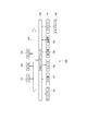
- FIG. 1 shows a functional configuration of the image processing apparatus 1 according to the present disclosure and a peripheral configuration of the image processing apparatus 1.
- the image processing apparatus 1 includes an image acquisition unit 2, a depth acquisition unit 3, an image analysis unit 4A, a speech recognition unit 4B, an information acquisition unit 4C, an additional image generation unit 5, an image editing processing unit 6, an image output unit 7, and an editing operation.
- An image generation unit 8 is included.
- an operation unit 10 As an example of the peripheral configuration of the image processing apparatus 1, an operation unit 10, a display unit 11, a communication unit 12, a storage unit 13, an image source 14, and an information source 15 are illustrated.
- Each of the operation unit 10, the display unit 11, the communication unit 12, the storage unit 13, the image source 14, and the information source 15 may be provided in a device integrated with the image processing apparatus 1 or may be a separate device. It may be connected to the image processing apparatus 1 by wired or wireless communication.
- the operation unit 10 detects various user operations for image editing.
- the operation unit 10 may be configured to detect an operation of an operator such as an actual key or switch, or may be a mouse or a keyboard in a computer device, or may detect an operation such as voice input, gesture input, or non-contact input. It may be configured.
- the operation unit 10 may be configured to detect a touch operation, a tap operation, or the like on a screen or a pad in an information processing apparatus such as a tablet or a smartphone.
- the display unit 11 is a display unit that performs various displays for a user (such as a user of the image processing apparatus 1).
- a user such as a user of the image processing apparatus 1.
- an LCD Liquid Crystal Display
- a display device such as an organic EL (Electro-Luminescence) display is used.
- the display unit 11 may be a separate display device from the apparatus having the image processing apparatus 1.
- the display unit 11 performs various displays for the user interface.
- the image processing apparatus 1 displays an image generated by editing processing, displays a moving image before editing, displays an operation element image such as an operation icon that functions as the operation unit 10, and other necessary display.
- the communication unit 12 performs communication with other devices by wired or wireless connection. For example, communication is performed by a communication method such as a wireless communication standard such as WIFI (Wireless Fidelity: registered trademark) or Bluetooth (registered trademark). Alternatively, the communication unit 12 performs communication of image data (still image file or moving image file) between external display devices, recording devices, playback devices, and the like, and as a network communication unit, for example, the Internet, home network, LAN It is also possible to perform communication through various networks such as (Local Area Network) and perform various data transmission / reception with servers, terminals, etc. on the network. For example, the communication unit 12 transmits an image generated by the image processing apparatus 1 through editing processing to an external device. The communication unit 12 may receive image data used for editing processing from the outside.
- a wireless communication standard such as WIFI (Wireless Fidelity: registered trademark) or Bluetooth (registered trademark).
- the communication unit 12 performs communication of image data (still image file or moving image file) between external display devices,
- the storage unit 13 includes, for example, a non-volatile memory, and stores original moving image data and edited image data obtained by editing the moving image data (in particular, adding an additional image).
- the storage unit 13 may be a solid-state memory such as a flash memory built in the apparatus housing, a memory card (for example, a portable flash memory) that can be attached to and detached from the apparatus, and a card that performs recording / reproduction access to the memory card.
- the form by a recording / reproducing part may be sufficient.
- it may be realized as an HDD (Hard Disk Drive), an optical disk, a disk drive, and the like.
- the storage unit 13 stores edited image data generated by the image processing apparatus 1.
- the image data used by the image processing apparatus 1 for editing processing may be read from the storage unit 13.
- the storage unit 13 may store a program for causing a computer device to execute processing as the image processing apparatus 1.
- the image source 14 indicates that the image processing apparatus 1 is a supplier of image data used for editing processing.
- Image data as a moving image to be processed is supplied from the image source 14 to the image processing apparatus 1.
- the image source 14 may be an imaging device that captures a moving image or a playback device that reads and outputs a moving image from a storage medium.
- the communication unit 12 and the storage unit 13 may correspond to the image source 14.
- the image data supplied by the image source 14 may be, for example, an imaging operation as a real-time broadcast such as sports, or may be a moving image captured or generated in the past.
- any moving image can be considered as an editing process target of the image processing apparatus 1.
- the information source 15 indicates that it is a supplier of some information to the image processing apparatus 1.
- information for example, information related to a moving image to be edited, information added to a moving image by editing, and the like are assumed. For example, there are information on athletes and teams, information on time, information on techniques, scores, etc. in sports broadcast videos.
- the information source 15 may be, for example, an information processing device that provides information via a network as an information server, or may be various sensor devices.
- the image acquisition unit 2 in the image processing apparatus 1 acquires image data to be edited from the image source 14. For example, a moving image that is broadcast in real time or a moving image selected by the user from among moving images that can be provided by the image source 14 as moving image content is a processing target.
- the depth acquisition unit 3 detects pixel depth information for the image to be processed.
- the depth information DP is added to each pixel of each frame in the image data as a moving image to be edited by the image processing apparatus 1.
- the depth information DP is information on the depth position of the subject when an image is captured. For example, as shown in FIG. 2, one frame of image data is composed of pixels (pixels) arranged in 0 rows to n rows and 0 columns to m columns, and ⁇ (m + 1) ⁇ (n + 1) ⁇ pixels PX0-0, It is assumed that PX0-1 ... PXn-m are formed. Depth information DP0-0, DP0-1... DPn-m is added to each pixel PX0-0, PX0-1.
- Each is depth information when the subject of the pixel is imaged.
- the depth acquisition unit 3 detects depth information DP0-0, DP0-1... DPn-m from the image to be processed.
- each of the pixels PX0-0 to PXn-m shown in FIG. 2 may be considered as one pixel for each color such as an R pixel, a G pixel, and a B pixel, or an R pixel, a G pixel,
- the B pixels may be considered as one color pixel. That is, the depth information DP (DP0-0 to DPn-m) may be added in units of individual pixels or may be added in units of color pixel units.
- depth information DP may be added to each pixel block in which a plurality of pixels (or a plurality of color pixels) are collected. Since the technique for adding the depth information of the subject to the captured image is known, the details are omitted.
- the depth acquisition unit 3 may receive and acquire depth information detected by other devices and sensors for image data to be processed, depth information registered in advance, and the like.
- the depth acquisition unit 3 may detect depth information arbitrarily set by the user.
- the pixel depth information detected by the depth acquisition unit 3 is used in the processing of the image editing processing unit 6 and the additional image generation unit 5.
- the image analysis unit 4A in FIG. 1 analyzes the image data acquired by the image acquisition unit 2, recognizes the subject in the image, recognizes the moving object, recognizes the background, determines the motion type and behavior of the moving object, Analysis processing necessary for additional image generation in the additional image generation unit 5, such as identification, human facial expression, emotion estimation, and motion estimation, is performed.
- An additional image is an image added to a moving image by image editing processing.
- the voice recognition unit 4B inputs voice data in the image data as the processing target moving image acquired by the image acquisition unit 2, and performs voice recognition / analysis. Information about the audio content is output to the additional image generating unit 5 for generating additional information.
- the voice recognition unit 4B outputs information such as the detected utterance timing and a period (frame period) during which an additional image is displayed based on voice recognition to the image editing processing unit 6.
- the voice recognition unit 4 discriminates and analyzes the voice uttered by the subject person in the voice recorded together with the moving image, for example, and converts the utterance content as text data. To do.
- the information acquisition unit 4C acquires information from the information source 15.
- the information to be acquired is information used for additional image generation in the additional image generation unit 5.
- the information acquisition unit 4 ⁇ / b> C acquires the above-described player and team information, time information, game score information, and the like for a sports broadcast video, and supplies the acquired information to the additional image generation unit 5 and the image editing processing unit 6. .
- the additional image generation unit 5 generates an additional image to be added to the moving image by image editing processing.
- an effect image, a telop image, and an information presentation image are generated as additional images.
- the additional image generation unit 5 generates an effect image corresponding to moving object recognition by the image analysis unit 4A.
- the additional image generation unit 5 generates a telop image corresponding to the voice recognition result by the voice recognition unit 4B.
- the additional image generation unit 5 generates an information presentation image indicating information acquired by the information acquisition unit 4C.
- the image editing processing unit 6 performs editing processing on the image data acquired by the image acquisition unit 2.
- the image editing processing unit 6 performs image editing for adding an additional image (an effect image, a telop image, an information presentation image, etc.) generated by the additional image generating unit 8 on the original moving image.
- the image editing processing unit 6 uses the pixel depth information DP0-0 to DPn-m from each frame from the depth acquisition unit 3.
- the image output unit 7 outputs image data as an edited image created by the image editing processing unit 6. That is, the image output unit 7 outputs and displays the edited moving image created by the editing process on the display unit 11.
- the image output unit 7 can also output the edited image data to the communication unit 12 to be transmitted to an external device.
- the image output unit 7 can also output the edited image data to the storage unit 13 and store it in the storage medium.
- the editing operation image generation unit 8 generates an interface image that enables manual editing by the user.
- the image editing processing unit 6 automatically edits the moving image acquired by the image acquiring unit 2 in real time according to the user's selection of an additional image, and the editing result moving image is output as an image. Output from the unit 7.
- the composition of the additional image is not necessarily real-time, and the content of the additional image can be adjusted or changed by the user. Therefore, an image for editing operation is prepared.
- the editing operation image generation unit 8 generates an image for the user operation and displays the image on the display unit 11 via the image output unit 7, for example.
- a user operation on the editing operation image is recognized by the image editing processing unit 6 as a function of the operation unit 10 (for example, a touch operation on the screen), and is reflected in the editing process.
- the editing operation image generation unit 8 switches the editing operation image in accordance with a user operation.
- the image processing apparatus 1 can perform various image editing described later to generate an edited image.
- Such an image processing apparatus 1 is realized by an information processing apparatus 100 having a hardware configuration as shown in FIG. 3, for example.
- the information processing apparatus 100 includes a CPU (Central Processing Unit) 151, a ROM (Read Only Memory) 152, and a RAM (Random Access Memory) 153.
- the CPU 151 executes various processes according to a program stored in the ROM 152 or a program loaded from the storage unit 159 to the RAM 153.
- the RAM 153 also appropriately stores data necessary for the CPU 151 to execute various processes.
- the CPU 151, ROM 152, and RAM 153 are connected to each other via a bus 154.
- An input / output interface 155 is also connected to the bus 154.
- the input / output interface 155 can be connected to a display 156 made of a liquid crystal panel or an organic EL panel, an input unit 157 made of a keyboard, a mouse, a storage unit 159 made up of a speaker 158, an HDD, etc., a communication unit 160, and the like. is there.
- the display 156 means the display unit 11.
- the display unit 11 may be a separate device from the information processing apparatus 100, and in that case, the display 156 may be a separate device connected to the input / output interface 155.
- An input unit 157 in FIG. 3 means an input device used by a user who uses the information processing apparatus 100, and includes a function as the operation unit 10 in FIG. 1, for example.
- the communication unit 160 performs communication processing via a network including the Internet and communication with devices in peripheral units, and includes, for example, a function as the communication unit 12 in FIG.
- a drive 161 is connected to the input / output interface 155 as necessary, a memory card 162 is mounted, and a computer program read from the memory card 162 is installed in the storage unit 159 as necessary, or the CPU 151 The data processed in is stored.
- the drive 161 may be a recording / reproducing drive for a removable storage medium such as a magnetic disk, an optical disk, or a magneto-optical disk.
- the drive 161 and the memory card 162 also have a function as the storage unit 13 in FIG.
- the additional image generation unit 5, the image editing processing unit 6, the image output unit 7, and the editing operation image generation unit 8 can be processed. That is, these processes are realized by software activated by the CPU 151.
- the program constituting the software is downloaded from the network or read from the removable storage medium and installed in the information processing apparatus 100 in FIG. Alternatively, the program may be stored in advance in an HDD or the like as the storage unit 159. Then, when the program is started in the CPU 151, various image editing processes can be performed as will be described in detail later.
- the image processing apparatus 1 is not limited to a single information processing apparatus (computer apparatus) 100 having a hardware configuration as illustrated in FIG. 3, and a plurality of computer apparatuses are systematized. It may be configured.
- the plurality of computer devices may be systemized by a LAN or the like, or may be arranged at a remote place by a VPN (Virtual Private Network) using the Internet or the like.
- the plurality of computer devices may include a computer device that can be used by a cloud computing service.
- the information processing apparatus 100 of FIG. 3 can be realized as a stationary computer, a laptop computer, or a portable terminal such as a tablet terminal or a smartphone.
- the image processing apparatus 1 according to the present embodiment can be mounted on an electronic apparatus such as a television apparatus, a monitor apparatus, an image editing apparatus, or an imaging apparatus that has a function as the information processing apparatus 100.
- An effect image for a moving object is, for example, -An image that emphasizes the motion of a moving object that appears in a movie-An image that shows the trajectory of the moving object that appears in a movie-An image that expresses the type of motion of a moving object that appears in a movie-An image that expresses the mode of motion of a moving object that appears in a movie ⁇
- a moving object is a subject object that moves on a moving image, and is assumed to be a person, an animal, an object, or a part thereof (for example, a human hand).
- FIGS. 4A to 4F show a scene of a movie of figure skating.
- FIG. 4A is an image before the performance starts.
- the moving body 80 is intended for skaters.
- FIG. 4B is an image to which an effect image EF for predicting the movement of the player is added before the performance starts.
- FIG. 4C is an image to which an effect image EF that shows the movement trajectory of the player and emphasizes the motion during the performance is added.
- FIG. 4D is an image to which an effect image EF expressing spin is added during the performance.
- a spiral line is displayed as an image representing the spin, but in this case, the rear part of the player (the part behind the player) is blocked by the player's body and cannot be seen. .
- FIG. 4A is an image before the performance starts.
- the moving body 80 is intended for skaters.
- FIG. 4B is an image to which an effect image EF for predicting the movement of the player is added before the performance starts.
- FIG. 4C is an image to which
- FIG. 4E is an image to which an effect image EF indicating, for example, a movement leading to a performance end pose is added.
- the effect image EF is an image corresponding to the position of the body from immediately before, and has a size corresponding to the position (depth) in the depth direction.
- FIG. 4F is an image to which the effect image EF is not added.
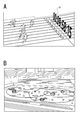
- FIG. 5A shows a soccer free kick scene.
- the ball kicked by the attacking player is used as a moving body 80, and an effect image EF expressing the locus of the ball is added.
- This effect image EF reflects the front-rear relationship with other players at each time point. For example, in the trajectory of the ball, the portion behind the defensive player is hidden behind the player's head. It is not visible.
- the effect image EF showing the trajectory of the ball is displayed in the correct context with the actual subject. I try to do it. Further, the width of the effect image EF for displaying the trajectory is reduced according to the position of the ball.
- FIG. 5B shows a scene of a kendo match.
- the bamboo swords of both players are used as a moving body 80, and an effect image EF that expresses and emphasizes the movement of the bamboo swords is added.
- Each effect image EF changes a color and a display mode with the bamboo sword of the right player and the bamboo sword of the left player. This makes it possible for viewers to understand the movement of both bamboo swords more clearly.
- the effect image EF showing the trajectory of each bamboo sword is in a state in which the context is reflected by the depth information of the bamboo sword and the player at each time point (each frame). As a result, the front-rear relationship as seen from the position where the imaging device exists is also reflected in the effect image EF.
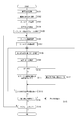
- the processing example in FIG. 6 is an example in the case where the moving image content recorded in the image source is acquired and the moving image is edited.
- An example in which editing processing is performed in real time on an input moving image, which can be applied in the case of real-time relay, will be described later with reference to FIG.
- the image processing apparatus 1 identifies a subject for the processing target moving image. That is, the information in the image is developed with a depth map, and the positional relationship between a person or an object as a subject is grasped.
- the depth map here is, for example, a map of depth information for each pixel as shown in FIG.
- the depth map can grasp the context of each subject.
- “front” of “front / rear” is a side closer to the imaging apparatus
- “rear” is a side farther from the imaging apparatus (back side).
- the pixel range in which each subject is shown can be determined from analysis of luminance information, color information, edge detection, etc., but by using the depth information of each pixel, the pixel range in which each subject is shown can be more accurately determined. Can judge well. This is because the depth value does not differ greatly in the pixel range in which one subject is shown.
- step S102 the image processing apparatus 1 grasps the state of the moving object. That is, the moving object and the static object are recognized with respect to the subject included in the image data, and the contents of each subject are grasped such as a background and a person.
- step S103 the image processing apparatus 1 selects an effect. That is, what kind of effect image EF is added to the moving object 80 is selected. For example, an effect image EF expressing rotation, an effect image EF expressing a trajectory, and the like are selected. Further, details such as the color and shape of the effect image EF and the effect duration are determined.
- the selection of the effects described above may be automatically set by the image processing apparatus 1 or may be set according to user input. Alternatively, it may be automatically set to some extent so that a part of the setting item can be corrected by the user.
- step S104 the image processing apparatus 1 determines the display position. This is a process of determining the display position of the effect image EF with respect to the moving object 80 in the image (relative position with respect to the moving object 80).
- the display position of the effect image EF for each frame is determined in step S107 according to the relative position determined here.
- step S ⁇ b> 105 the image processing apparatus 1 specifies an effect target frame. For example, the frame that starts the image effect is specified in the moving image. Alternatively, the frame range (start frame and end frame) may be specified. It is conceivable that the user designates and inputs a frame in a moving image scene, and the image processing apparatus 1 sets it as a start frame and an end frame.
- the image processing apparatus 1 detects the moving object 80 to which the effect image EF is added from the image data, automatically selects the scene in which the moving object 80 appears, and specifies the start frame and end frame of the scene. Also good. Further, the image processing apparatus 1 may automatically specify the frame section in which the moving object 80 appears and the moving object 80 is moving.
- step S105 it is determined which effect image EF is to be combined in which section of the moving image.
- the processing so far is mainly executed by the functions of the image acquisition unit 2, the depth acquisition unit 3, and the image analysis unit 4A in FIG.
- the setting relating to the user designation is processing by the function of the image editing processing unit 6 according to the input from the operation unit 10. Thereafter, the image processing apparatus 1 performs the processing of steps S106 to S116 for each frame constituting the moving image.
- step S106 the image processing apparatus 1 acquires (specifies) the frame image data to be processed. For example, first, image data of the first frame in the effect target section identified in step S105 is set as a processing target. In step S ⁇ b> 107, the image processing apparatus 1 sets an effect image EF to be an additional image for the acquired frame image data by the function of the additional image generation unit 5.
- step S201 the image processing apparatus 1 selects or generates an image to be added as an effect.
- an image corresponding to the selection of the effect selected in step S103 is prepared as an effect image EF to be added to the frame.
- the image to be prepared may be selected from images prepared in advance for each effect type or the like, and may be generated according to the image content of the frame.
- step S202 the image processing apparatus 1 sets an image mode such as an image size, a shape, and a color for an image prepared as an effect to be added. For example, these are set according to the size and operation mode of the moving object 80 in the image in the frame. With these image modes set, the effect image EF added to the frame is determined. It should be noted that the effect image EF added to one frame image is not limited to one image in which pixels are continuous, but may be a plurality of images.
- step S203 the image processing apparatus 1 sets depth information DPe of each pixel constituting the effect image EF itself.
- the depth information DPe is set based on the depth of the moving object 80 in the frame.
- step S204 the image processing apparatus 1 sets an insertion region in the frame for the effect image EF. That is, it is a process for determining where on the screen the effect image EF is to be added. This is set based on, for example, the position of the moving object 80 in the frame, the position of the effect image EF in the previous frame, and the like.
- an insertion area is set for each effect image EF.
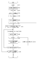
- the image processing apparatus 1 When the effect image EF is set as described above, the image processing apparatus 1 performs the processing after step S108 in FIG. After step S108, the image processing apparatus 1 sequentially compares each pixel PX included in the set insertion region with the depth information DPe set for each pixel of the effect image EF on the image data of the frame.
- the image processing apparatus 1 specifies one pixel PX in the region that is the insertion region in the frame image data, and specifies depth information DP of the pixel PX in step S109.
- one of the pixels in the insertion area is specified as a processing target.
- one of the pixels in the first insertion area is specified as a processing target.
- step S110 the image processing apparatus 1 compares the depth information DP of the target pixel PX with the depth information DPe of the pixel in the effect image EF that is to be inserted at the position of the pixel PX. If DP ⁇ DPe, the pixel PX in the frame image data is a subject pixel in front of the effect image EF. Therefore, the image processing apparatus 1 proceeds to step S112, and sets the pixel PX as a pixel to be displayed as it is on the edited image data. If DP ⁇ DPe, the pixel PX in the frame image data is a pixel of the subject on the back side after the depth of the effect image EF.
- the image processing apparatus 1 proceeds to step S111 and replaces the pixel data value of the image PX with the pixel data value corresponding to the pixel position in the effect image EF (additional image) on the image data. That is, the pixel for displaying the pixel data of the effect image EF is used.
- step S113 the image processing apparatus 1 confirms whether or not the above processing has been completed for all the pixels in the insertion area that is currently being processed. If not completed, the process returns to step S108, the pixel PX to be processed is specified in the insertion area currently being processed, and the processes of steps S109 to S112 are similarly performed. If it is determined in step S113 that the processing in steps S109 to S112 has been completed for all the pixels in one insertion region, the image processing apparatus 1 checks in step S114 whether there is another insertion region set. If there is only one insertion area set in step S204 in FIG. 7, the processing for the frame is completed. If a plurality of insertion areas are set and there is an unprocessed insertion area, the next insertion area is selected in step S115, and the processes in steps S108 to S113 are performed on the insertion area.
- step S114 the image processing device 1 finishes the processing for the current frame and proceeds to step S116. If the processing has not been completed for all the frames as the section in which the effect is performed, the image processing apparatus 1 returns to step S106, acquires frame image data of the next frame as a processing target, and similarly performs steps S107 to S107 for that frame. The process of S115 is performed. The image processing of FIG. 6 is finished by finishing the above processing for all the frames to which the effect image EF is added.
- edited image data to which the effect image EF is added is generated on the moving image as described with reference to FIGS. 4B to 4E, for example.
- the edited image data generated in this way is output by the image output unit 7 to be displayed on the display unit 11, transferred to an external device by the communication unit 12, or stored in a storage medium by the storage unit 13. .
- the effect image EF is synthesized with the original frame image data using the depth information DP and DPe, and the display mode such as the size is set according to the depth information DP and DPe. It is possible to realize an effect image EF having no sense of incongruity with the moving object 80 of the original moving image scene. This also makes it possible to express an image that naturally adapts the graphical effect to the subject space.
- FIG. 6 has been described as an example of processing performed on a moving image generated in advance by imaging or the like.
- FIG. 8 shows a processing example having such a real-time property.
- the image processing apparatus 1 adds the effect image EF in real time after that point.
- the start / end timing of the effect is instructed by the operator (or instructed by some automatic control).
- the effect image EF representing the trajectory of the moving object 80 as shown in FIGS. 5A and 5B is determined to be displayed at a position on the moving trajectory of the moving object.
- step S151 When the image processing apparatus 1 recognizes the instruction to start the effect in step S151, the process proceeds to step S152 and subsequent steps. Thereafter, the image processing apparatus 1 performs the processes of steps S152 to S154 and S107 to S115 for each frame that is captured and supplied until an effect end instruction is detected in step S155.
- step S152 the image processing apparatus 1 acquires frame image data. That is, one frame input in real time from the image source 14 (for example, an imaging device) is acquired. From this, it is assumed that the processes of steps S152 to S154 and S107 to S115 are performed within one frame period.
- the image source 14 for example, an imaging device
- step S153 the image processing apparatus 1 identifies a subject in the frame image data. That is, the information in the image is developed with a depth map, and the positional relationship between a person or an object as a subject is grasped.
- step S154 the image processing apparatus 1 grasps the state of the moving object. That is, for a subject included in the frame image data, a moving object and a static object are recognized, and the contents of each object such as a background and a person are grasped.
- step S107 the effect image EF is set.
- FIG. 9A shows an example of setting the effect image EF that represents the trajectory of the moving object.
- step S210 the image processing apparatus 1 acquires the effect image EF added to the previous frame.
- the image processing apparatus 1 acquires the position of the moving object 80 in the current frame.
- the position of the moving object 80 here is a position in the screen of the current frame, that is, a pixel range in which the moving object 80 is captured.
- step S212 the image processing apparatus 1 generates a trajectory image that becomes the effect image EF of the current frame. Specifically, an image is added to the effect image EF of the previous frame, that is, the trajectory image up to the time of the previous frame, according to the position of the moving object 80 of the current frame (the image representing the trajectory is extended), thereby A trajectory image of the frame (effect image EF) is generated. In the case of the first frame from the start of the effect, a trajectory image is generated according to the position of the moving body 80 in the current frame.
- step S203A the image processing apparatus 1 sets the depth information DPe of each pixel constituting the trajectory image (effect image EF), reflecting the position of the moving object 80 in each frame.
- the pixel position and depth can be already set for the locus portion up to the previous frame by using the effect image up to the previous frame as it is.
- the depth information DPe of the effect image EF may be set using the depth information DP given to the pixel of the moving object 80 in the current frame for the portion of the pixel extended as the current locus.
- the moving object may be hidden by another subject. In this case, the position and depth of the moving object in the current frame may be estimated from the trajectory of the moving object 80 up to the previous frame.
- step S204 the image processing apparatus 1 sets an insertion area in the frame for the effect image EF. That is, it is a process for determining where on the screen the effect image EF is to be added. This is set based on, for example, the position of the moving object 80 in the frame, the position of the effect image EF in the previous frame, and the like.
- Step S108 When the effect image EF is set as described above, the image processing apparatus 1 proceeds to step S108 and subsequent steps in FIG. Steps S108 to S115 are the same as steps S108 to S115 in FIG. That is, the image processing apparatus 1 sequentially compares each pixel PX included in the set insertion area with the depth information DPe set for each pixel of the effect image EF on the image data of the frame, and reflects the context. Then, it is determined which of the original image data of the frame or the effect image EF is used as a display pixel.
- step S107 may be performed as shown in FIG. 9B.
- Steps S210 and S211 in FIG. 9B are the same as in FIG. 9A, and the effect image EF of the previous frame is acquired, and the position of the moving object 80 of the current frame is acquired.
- the image processing apparatus 1 acquires information on the moving object 80 of the current frame.
- This is information such as the operation mode and the type of operation.
- the operation mode includes the speed, behavior, moving direction, moving posture, moving state, etc. of the moving body 80.
- the movement speed, rotation speed, movement direction, and the like of the ball are one of the operation modes.
- the ball type thrown by the baseball pitcher is also assumed as information on the movement mode.
- the type of action is assumed to be a type related to movement of the moving object, or a type of the moving object itself or a person moving the moving object.
- which team is the person who kicked the ball in the match between the A team and the B team in soccer, or the Kendo player is one of the types of people who move the moving body.
- a human or animal is a moving body 80
- the gender of the moving body 80, the age group, the animal are also referred to here. This is an example of the type of the moving object 80.
- step S223 the image processing apparatus 1 sets the image mode of the effect image EF according to the acquired information (mode / type) of the moving object 80. For example, the color, brightness, density, gradation and the like of the effect image EF to be displayed are set according to the information.
- step S212 a trajectory image, that is, an effect image EF to be added to the current frame is generated by reflecting the setting of the image mode. Steps S203A and S204 are the same as those in FIG. 9A.
- a trajectory image (effect image EF) that reflects the information on the mode and type of the moving object 80, it is easier for the viewer to grasp the operation or it is interesting.
- an image representing the number of rotations of the ball can be obtained by changing the color and density in a gradation in the locus of the ball in FIG. 5A.
- a video that makes it easy to grasp the movement of the bamboo sword of each player can be realized.
- a video that expresses the dominance rate of the ball for each team can be realized by using a color corresponding to the team of the player who always touched the ball trajectory in a soccer game.
- the processing example has been described with respect to the image effect on the moving object 80, but various image effects corresponding to the moving object 80 can be considered.
- the aspect of the effect image EF may be changed using personal identification information, facial expression information, emotion information estimated from facial expressions, voices, and the like. Conceivable.
- the effect image EF for the moving object 80 is not limited to a trajectory image, and an image indicating moving object tracking, an image indicating movement prediction of the moving object, an image indicating only the type and operation mode of the moving object, and the like are also assumed.
- Second Embodiment Telop Based on Speech Recognition>
- a telop based on speech recognition is displayed as an additional image for a moving image.
- a voice recognition technology it is possible to insert a telop on a moving image by real-time or non-real-time editing.
- By accurately reproducing the context of the spoken person and the telop it is possible to realize a telop display that is not uniform and easy for the speaker to understand, a telop display that does not give the scene a sense of incongruity, a telop display with higher expressiveness, and the like.
- FIG. 10A is an example in which each utterance content is shown as a telop image TP in the vicinity of each utterer 81 in a scene where many people appear. Note that this is an extreme example for explanation. In a video, there are not many scenes where many people speak at the same time at the same time. A large number of telops are rarely added to one frame.
- Each telop image TP is displayed according to the depth of the speaker 81, so that the telop image TP is combined with the image in a state in which the context with other subjects is reflected.
- the telop image TP refers to an image that represents sounds generated in a moving image with characters regardless of the display mode and display timing.
- step S171 the image processing apparatus 1 detects an utterance from audio data in the moving image.
- step S172 the image processing apparatus 1 performs voice recognition and speaker identification.
- step S173 the image processing apparatus 1 converts the utterance content into text data.
- step S174 the image processing apparatus 1 sets a frame section in which the detected utterance content is displayed as a telop image TP. That is, in the image processing apparatus 1, the speech recognition unit 4B detects an utterance in a moving image, analyzes the utterance, specifies the speaker 81 and the utterance content, and converts the utterance content into text data.
- the frame section for displaying the telop image TP is set, for example, as a frame about 1 to 2 seconds after the frame at the timing when the utterance ends from the frame at the timing when the utterance starts.
- These pieces of information are received by the additional image generating unit 5 and the image editing processing unit 6.
- the speaker 81 is specified when the subject whose mouth is moving is detected by the image analysis of the image analysis unit 4A, and the section where the mouth is moving is compared with the section of the utterance voice when they substantially match. It can be considered that the subject is the speaker 81. It is also conceivable to estimate male / female, age group, etc. by frequency analysis of speech, etc., and collate with image analysis results to estimate the speaker. If there is voiceprint information of a person appearing in the video, the speaker in the video can be accurately identified by voice analysis.
- step S175 the image processing apparatus 1 generates the telop image TP by the function of the additional image generation unit 5.
- the generation process of the telop image TP is shown in FIG. 12A.
- step S250 the image processing apparatus 1 acquires text information generated by voice analysis as a processing target.
- step S251 the image processing apparatus 1 converts the text information into a telop image.
- the telop image TP is generated based on settings such as a predetermined speech balloon, font, and color.
- step S176 the image processing apparatus 1 acquires, as a processing target, one frame of image data in a frame section in which telop display is performed.
- step S177 the image processing apparatus 1 determines whether the acquired frame has undergone a scene change from the previous frames. For example, the scene change determination is performed based on the difference of each pixel data from the previous frame, and if the scene change is determined, the processing in FIG. If it is not determined to be a scene change, the image processing apparatus 1 proceeds to step S178.
- step S178 the image processing apparatus 1 sets the telop image size of the telop image TP and the insertion area of the telop image TP in the frame. Further, depth information DPe of each pixel in the telop image TP is set.
- the depth information DPe of each pixel of the telop image TP is the depth information DP of the pixel in which the head of the subject as the speaker 81 is captured, the depth obtained by giving a predetermined offset amount from the head depth information DP, or the like. It is possible.
- the depth information DPe of each pixel in the telop image TP may be the same value, the depth value may be gradually changed.
- the size of the telop image TP may be a size corresponding to the depth information DPe.
- the size is increased, and when the value of the depth information DPe is large (deep), the size is decreased.
- a small telop can be used.
- an area corresponding to the size of the set telop image TP is set in the vicinity of the head of the speaker 81, for example.
- the set telop image TP is synthesized with the image of the current frame in steps S108 to S113. This is the same as steps S108 to S113 in FIG.
- the image processing apparatus 1 sequentially compares each pixel PX included in the set insertion area with the depth information DPe set for each pixel of the telop image TP on the image data of the frame, and reflects the context. Then, it is determined which of the original image data of the frame or the telop image TP is used as the display pixel.
- step S179 a moving image as shown in FIG. 10A in which the telop image TP is displayed for the speaker 81 in the moving image is realized.
- the presence / absence of display is set in units of pixels by comparing the depth information DPe and the depth information DP of the surrounding subject, so that the front side image is not hidden and the front-rear relationship in the image is maintained. Displayed in the reflected state.
- the telop image TP appropriately represents the situation (position) of the speaker 81.
- the telop image TP is displayed at a position close to the speaker 81, it becomes easy to see the image (the speaker 81 and the like) and the characters at the same time, and even when applied as a subtitle of a movie or the like, the contents of the moving image can be easily understood. It will be a thing.
- the process shown in FIG. 11 may be performed for each utterance detected in the moving image.
- buffering of moving image data is performed for several seconds so that each frame is read with a delay of several seconds.
- voice recognition of the buffered frames for several seconds is performed.
- the processing after step S176 may be performed on each frame read from the buffering.
- the telop image TP is displayed as a frame section set in step S174. This is, for example, a section from the utterance timing to when about 1 to 2 seconds have elapsed after the utterance is finished. As described above, the text content is displayed by displaying the telop image TP for some time after the utterance is finished. Is easy to read. However, if the scene change is determined in step S177, the telop image TP is not synthesized, and thus the telop up to the previous frame is not displayed in that frame. This prevents the image from becoming unnatural due to continued telop even if there is a scene change.
- the telop image TP is displayed for a period from the utterance to the timing slightly after the end of the utterance. If there is a scene change, the display of the telop image TP is also ended within that period. It will be. This makes it easy to read the telop and prevent unnatural telop display.
- the telop image TP is not a uniform image but an image having higher expressive power.
- FIG. 10B shows a case where the speaker 81 is laughing
- FIG. 10C shows a case where the speaker 81 is angry
- FIG. 10D shows a case where the speaker 81 is surprised.
- the display mode of the telop image TP is changed according to the laughing situation, the angry situation, and the surprised situation. For example, by changing the shape and color of the speech balloon, the font of the text, and the like, an image corresponding to the emotion of the speaker is obtained. By doing so, the telop image TP becomes more expressive.
- the image processing apparatus 1 acquires text information generated by voice analysis as a processing target.
- the image processing device 1 performs emotion estimation of the speaker. For example, the volume and frequency characteristics of the uttered voice are analyzed, and a calm state, an excited state, etc. are estimated. Also, the emotion is estimated from the facial expression and movement of the speaker 81 by image analysis.
- the image processing apparatus 1 sets a balloon shape, text size, font, color, and the like as the telop image TP in accordance with the estimated emotion of the speaker 81.
- the image processing apparatus 1 converts the text information into a telop image based on the setting in step S262.
- the image mode of the telop image TP can be set according to the estimated emotion of the speaker 81 and added to the moving image.
- the telop image TP generation process in step S175 of FIG. 11 is performed as shown in FIG. 12C.
- step S250 the image processing apparatus 1 acquires text information generated by voice analysis as a processing target.
- step S271 the image processing apparatus 1 acquires volume information of the speech sound.
- step S272 the image processing apparatus 1 sets a balloon shape, text size, font, color, and the like as the telop image TP according to the acquired volume information.
- step S273 the image processing apparatus 1 converts the text information into a telop image based on the setting in step S272. By doing in this way, it becomes possible to add the telop image TP expressing the volume of the speech sound to the moving image.
- the utterance of the person in the video is described as the telop image TP.
- the telop image is not limited to the utterance voice of the person, and represents the cry of animals and surrounding sounds (environmental sounds) using characters. It is also possible to add. Also in that case, it is appropriate to display the telop image TP according to the position and depth in the image of the sound source.
- Third Embodiment Addition of Information Presentation Image>
- an information presentation image IS is displayed as an additional image for a moving image.
- the information presentation image IS can be inserted into the moving image by real time or non-real time editing.
- reproducing the context with other subjects, or giving depth to the information presentation image itself presents information that is easy for the viewer to see, and makes the scene uncomfortable. It is possible to realize difficult information presentation.
- FIG. 13A is an example in which information on the time of track and field events (short-distance running) is acquired and the time is displayed as an information presentation image IS. For example, by displaying the time along the goal line, it is possible to provide an easy-to-understand, realistic and uplifting video to the viewer. In this case, the depth information DPe is given to the information presentation image IS itself, and the display becomes smaller as the distance increases along the perspective method.
- FIG. 13B is an example in which, for example, the trajectory of a skate performance is displayed as an effect image EF, and information in the performance (for example, the name and score of each technique) is displayed as an information presentation image IS.
- information in the performance for example, the name and score of each technique
- the viewer can easily understand the performance content.
- information in the information presentation image IS can be displayed in a state where it does not come before the skaters on the screen. That is, an information presentation image IS that does not interfere with the original player image can be displayed.
- FIG. 14 shows a processing example when displaying the information presentation image IS as real-time processing. Note that the same steps as those in FIG. 8 are given the same step numbers to avoid redundant description. After the effect is started, the image processing apparatus 1 performs steps S152 to S160 and S107A to S115 for each frame timing.
- the image processing apparatus 1 acquires the frame image data in step S152, identifies the subject in step S153, and performs the process of grasping the state of the moving object in step S154 as described with reference to FIG. Get information. For example, information on the sprint running time (time at the timing of the frame) in the case of FIG. 13A is acquired.
- step S107A the image processing apparatus 1 sets the information presentation image IS.
- the information presentation image IS may be set (generated) in the same manner as in FIG. 7 (“effect image EF” in FIG. 7 is replaced with “information presentation image IS”).
- step S201 an image as the information presentation image IS is generated. For example, an image indicating the acquired time information may be generated.
- step S202 the image processing apparatus 1 sets a display mode such as the image size, shape, and color of the information presentation image IS.
- a display mode such as the image size, shape, and color of the information presentation image IS.
- the image size and shape are matched to other subjects of the moving image.
- the shape and size are set in consideration of the perspective. In that sense, it is conceivable that the setting of the insertion area in the frame image data (S204) is also performed at this time.
- step S203 the image processing apparatus 1 sets the depth information DPe of each pixel of the information presentation image IS. For example, at this time, it is gradually changed according to the perspective of the subject to be synthesized. That is, the value that is one before the depth information DPe of each pixel in the information presentation image IS is set as the depth information DP of each pixel in the insertion area.
- the image processing apparatus 1 When the information presentation image IS is generated in this way, the image processing apparatus 1 performs the processing of steps S108 to S115 as described with reference to FIG. In other words, the image processing apparatus 1 sequentially compares each pixel PX included in the set insertion area with the depth information DPe set for each pixel of the information presentation image IS on the image data of the frame, and determines the context. Reflecting this, it is determined which of the original image data of the frame or the information presentation image IS is used as a display pixel.
- the processing of FIG. 14 is executed again from step S152 until the effect ends in step S155.
- the information presentation image IS indicating information such as time is displayed together with the moving image.
- the information presentation image IS has a size and shape according to the perspective according to the displayed position, and does not feel uncomfortable.
- the pixels constituting the information presentation image IS are depth information DPe along the depth information DP of the original pixels. For example, in the case of a moving image as shown in FIG. 13A, the runner will run through the time display portion, but the state of the runner's position and the context of each part of the information presentation image IS is reflected. Become. This is an image representation as if a numerical object indicating time is actually placed along the goal line, and information presentation with a high visual effect can be realized.
- the information presentation image IS can be added as a non-real time compositing process.
- Various information can be presented. For example, in the case of sports videos, competition scores, commentary texts, player information, and the like are assumed. It is also possible to present information based on detection data such as a sensor provided in a camera that is imaging, a sensor provided in a stadium.
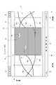
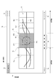
- FIG. 15 shows an example of an editing interface as the fourth embodiment.
- 15A and 15B show display screens of information processing apparatuses such as smartphones, tablets, and personal computers, for example.
- An image monitor area 60 and an operation area 61 for editing operations are provided on the display screen.
- a moving image to be edited is displayed.
- a normal display, a pause display, a variable speed playback display, and the like are possible for a moving image.
- a person as subjects 82 and 83 and an effect image EF are displayed.
- the effect image EF is a virtual object having a translucent wall shape.
- the subject 82 is an image that is in front of the effect image EF
- the subject 83 is an image that is in the back of the effect image EF.
- a trapezoidal depth map image 61c is displayed in the operation area 61.
- the front side represents the left and right sides of the image, and the side represents the depth direction along the depth axis 61b. That is, the trapezoid as the depth map image 61c is an image representing depth in perspective.
- the operation icon image 61a is displayed in the depth map image 61c.
- the operation icon image 61a is displayed in the depth map image 61c in a state corresponding to the depth position and horizontal position of the effect image EF in the image displayed in the image monitor area 60.
- the user can move the position of the operation icon image 61a in the depth map image 61c by dragging the operation icon image 61a or the like by a touch panel operation.
- FIG. 15B shows a state in which the operation icon image 61a is moved to the near side.
- the position of the effect image EF (the position in the depth direction and the horizontal direction) in the actual moving image can be changed.
- the effect image EF is moved to the right front side, and the subject 82 is also located on the back side of the effect image EF.
- the position and depth in the screen of the effect image EF or the like can be changed by an intuitive operation using the touch panel.
- the effect image EF but also the telop image TP and the information presentation image IS can be adjusted in the display position (depth direction and horizontal position) by the same operation.
- the wall-like effect image EF is shown here, if the opaque wall-like effect image EF of the entire screen is used, an image effect such that only a specific subject is displayed and other subjects are hidden by the wall is possible. It is. For example, this is an image in which only the subject 82 is displayed and the others are hidden by the effect image EF. In that case, by the operation, the wall can be moved back and forth to adjust the hidden area.
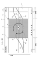
- FIG. 16 shows an example of an editing interface according to the fifth embodiment. This is an example in which a preview by three views is performed.
- FIG. 16 shows an editing screen displayed on the information processing apparatus. This screen is mainly divided into five areas and displayed. That is, a front view area 62, a top view area 63, a side view area 64, a setting area 65, and a timeline area 66.
- the front view area 62 is a normal video monitor screen, and the video content is displayed in a playback state, a pause state, a variable speed playback state, and the like.
- FIG. 15 an example in which subjects 82 and 83 and a translucent wall-like effect image EF are displayed is shown.
- the top view area 63 shows an image as a depth map as viewed from above.
- the depth axis 63a is displayed in the vertical direction of the top view area 63 to express the depth of the image.
- the subjects 82 and 83 and the effect image EF in the image are shown at positions of the depths set in them as viewed from above.
- the side view area 64 shows an image as a depth map as viewed from the side.
- the depth axis 64a is displayed in the left-right direction of the side view area 64, and the depth of the image is expressed.
- the subjects 82 and 83 and the effect image EF in the image are shown in the position of the depth set for them as viewed from the side.
- the setting area 65 an image of the effect image EF and setting information are displayed.
- the setting information is information about settings such as size, angle, position, color, and depth. Each setting value in the setting area 65 can be changed by a user operation.
- a timeline area 66 represents a timeline of a moving image along the time axis 66a.
- the appearance points and end points of the subjects 82 and 83 and the effect image EF and the current position being previewed are displayed.
- “human1” and “human2” represent the subjects 82 and 83
- “moll” represents the effect image EF
- ⁇ represents the appearance timing
- “ ⁇ ” represents the end timing (no longer on the screen).
- the bar 66b indicates the time point (frame) in which the preview image in the moving image shown in the front view area 62, the top view area 63, and the side view area 64 is previewed.
- the user can confirm the front-rear relationship with the top view area 63 and the side view area 64 while viewing the preview image of the front view area 62. While watching these, the setting of the effect image EF can be arbitrarily changed by an operation in the setting area 65.
- the depth setting of the effect image EF may be changed by a touch operation or a drag operation of the effect image EF in the top view region 63 or the side view region 64.
- the appearance timing and end timing of the effect image EF can be adjusted by an operation in the timeline area 66. That is, by moving the appearance timing and end timing marks (for example, “ ⁇ ” and “ ⁇ ”) in the timeline area 66 by moving the appearance section (effect execution frame section) of the effect image EF in the moving image by dragging or the like. It should be changeable. Thus, the user can easily adjust the size, color, and depth of the effect image EF and the appearance section of the effect image EF in the actual moving image.
- a preview of a moving image is displayed as the image monitor area 60. That is, the moving image content is displayed in a playback state, a pause state, a variable speed playback state, and the like.
- the moving image content is displayed in a playback state, a pause state, a variable speed playback state, and the like.
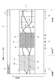
- five persons subject persons OB1, OB2, OB3, OB4, and OB5 as subjects and three effect images EF (EF1, EF2, and EF3) are displayed.
- the layers LOB1, LOB2, LOB3, LOB4, and LOB5 of the subject person OB1, OB2, OB3, OB4, and OB5 and the layers of the effect images EF1, EF2, and EF3 are shown in perspective.
- the front-rear relationship between the subject persons OB1 to OB5 and the effect images EF1, EF2, and EF3 can be clearly understood.
- the biaxial map area 68 is an area in which the horizontal direction is the time axis and the vertical direction is the depth axis. In the biaxial map area 68, the depths of the effect images EF1, EF2, and EF3 are shown at each time with respect to the depths of the subject persons OB1, OB2, OB3, OB4, and OB5.
- the line indicating the depth of the effect image EF on the time axis can be arbitrarily changed.
- the depth change of the effect image EF in the moving image can be easily edited.
- the depth change of each effect image EF1, EF2, EF3 and the depth positional relationship of the subject person OB1, OB2, OB3, OB4, OB5 are clear, and the image effect is also easy to understand.
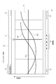
- FIG. 18 to 23 show various display modes as the editing operation image 70.
- FIG. 18 shows a state in which timeline display is performed as the biaxial map area 71.
- the biaxial map region 71 functions as a timeline with the left-right direction as a time axis. Further, the vertical axis is the depth axis, so that a biaxial map of time and depth is obtained.
- the editing operation image 70 also displays a tool icon 72, a screen switching icon 73, a current time display 74, a moving image operation icon 75, an enlargement / reduction operation element 76, a preview operation element 77, and the like.
- As the tool icon 72 an operator used for timeline operation, arrangement of the effect image EF, and the like is prepared.
- As the screen switching icon 73 an operator for switching preview screens such as an overhead view, a front view, and a perspective view, which will be described later, is prepared.
- the current time display 74 the current time in the timeline (time (time code) in the moving image of the image (frame) being previewed) is displayed.
- the moving image operation icon 75 an operator for operations such as playback / stop / frame advance / fast forward on the timeline is prepared.
- An enlargement / reduction operation element 76 enables an operation of enlarging or reducing the image.
- the preview operator 77 is an operator that designates the timing in the time axis direction of the biaxial map area 71 and instructs the preview display at that timing.
- the playback timing (playback time position) is indicated by the preview operator 77, and when the preview operator 77 is operated, the preview image 78 at that time is displayed as shown in FIG.
- the position of the preview operator 77 in the time direction may be arbitrarily specified, and an operation for requesting a preview at that time may be performed.
- a closing operator 79 is displayed, and an operation for terminating the display of the preview image 78 can be performed by this operation.
- each screen will be described, but here, for example, it will be described assuming that the subjects 82 and 83 and the effect image EF as shown in FIGS. 15 and 16 exist in the image.
- transitions in the time axis direction of the depth of the effect image EF and the subjects 82 and 83 are shown as depth display lines HL1, HL2, and HL3.
- the depth display line HL1 indicates a change in the depth of the effect image EF on the time axis.
- Depth display lines HL2 and HL3 indicate changes in the depth of the subjects 82 and 83 on the time axis.
- preview display is performed as shown in FIG.
- the preview image 78 is displayed when the subjects 82 and 83 and the effect image EF, which are image contents, are viewed from above.
- the designated timing of the biaxial map area 68 is extended to the left and right and interrupted. That is, the vertical depth axis in the biaxial map area 68 is also applied to the preview image 78, and the depth relationship between the subjects 82 and 83 and the effect image EF is expressed.
- the broken line portion (the portion of the preview image 78) is in a state in which the progress of time is stopped.
- the preview image 78 is inserted with the time axis cut off. Since the time axis is cut off, there is no change in the depths of the subjects 82 and 83 and the effect image EF on the left and right of the preview image 78. Therefore, the subjects 82 and 83 and the effect image EF in the preview image 78 are positioned on the broken lines connecting the left and right depth display lines HL1, HL2, and HL3, respectively. With such a preview image 78, the user can clearly grasp the depth relationship between the subjects 82 and 83 and the effect image EF at an arbitrary timing.
- the depth position of the effect image EF can be changed.
- the user adjusts the depth of the effect image EF by performing an operation to move the effect image EF up and down the screen (that is, in the depth axis direction).
- the depth of the effect image EF is changed in the frame of the preview image 78.
- the depth display line HL1 continuous on the left and right on the screen may also be changed in conjunction.
- the setting (size, position, type, etc.) of the effect image EF may be changed.
- FIG. 20 shows a reduced display state.
- the screen By operating the enlargement / reduction operation element 76, the screen can be enlarged or reduced.
- the size For example, by reducing the size, the user can see a timeline in a longer time range.
- the time range in which the depth display lines HL1, HL2, and HL3 are displayed as timelines is shortened.
- the user by reducing the display as shown in FIG. 20, it becomes possible to check the change in the depth relationship before and after the preview image 78 in a long time range. Note that the user can designate each timing on the timeline by moving the time bar 71a.
- FIG. 21 shows a state in which preview images 78 and 78A at a plurality of timings are displayed.
- the user can display an additional preview image 78A by performing a preview operation by designating an arbitrary timing on the time axis using the time bar 71a. That is, the preview images 78 and 78A at a plurality of timings can be confirmed simultaneously. This makes it easy to check the front-rear relationship between the subjects 82 and 83 and the effect image EF on the time axis, and to adjust the depth of the effect image EF at a plurality of time positions.
- FIG. 22 shows a state where a front image is displayed. Since the preview image 78 as shown in FIG. 19 is displayed in accordance with the depth axis of the biaxial map area 68, it is not the actual moving image content. The user can switch the mode of the preview image 78 by operating the screen switching icon 73.
- the front preview image 78F in FIG. 22 is a display of the original frame image of the moving image. In this case, since the depth axis is in the screen depth direction, the timeline display is temporarily deleted. However, the preview image 78 may be switched to the front preview image 78F while the timeline display is left and right as shown in FIG.
- FIG. 23 shows a state in which a stereoscopic image is displayed as the stereoscopic preview image 78R.
- This is an image obtained by adding an expression in the depth direction to the frame image of the moving image.
- the user can also switch to the stereoscopic preview image 78R by operating the screen switching icon 73.
- a timeline display (display of depth display lines HL1, HL2, and HL3) is also performed along with the stereoscopic preview image 78R. This makes it easy to understand the image in the context of the image and the transition in the time direction of the depths of the subjects 82 and 83 and the effect image EF.
- FIG. 24A, FIG. 24B, FIG. 24C, FIG. 24D, FIG. 24E, and FIG. 24F show image examples of each frame constituting a moving image.
- This is a moving image in which a light source EF1 as an effect image EF is rotating around a person as the subject 82.
- As the effect image EF it is assumed that a text EF3 that is slightly delayed with respect to the light source EF1 and a locus EF2 of the light source EF1 are displayed.
- FIG. 25 shows the transition of the display state.
- FIG. 25A is a timeline display (see FIG. 18). Transition from the timeline display to the preview display of FIG. 25B (see FIG. 19) can be made. From the preview display of FIG. 25B, the timeline display of FIG. 25A, the reduced display of FIG. 25C (see FIG. 20), the multiple preview display of FIG. 25D (see FIG. 21), the front view display of FIG. Transition to the 3D image display of FIG. 25F (see FIG. 23) is possible. You can also return to the preview display from each of these.
- the reduced display and the multiple preview display can transition to each other.
- the three-dimensional image display and the multiple preview display can be transitioned to each other.
- the three-dimensional image display and the front image display can be changed to each other.
- the above is an example, and there are various transition paths.
- the timeline display is as shown in FIG.
- the depth display lines HL1, HL2, and HL3 are displayed.
- the depth display line HL1 represents the transition of the depth of the light source EF1. Since the light source EF1 moves around the subject 82, a sine wave transition occurs in the time axis direction.
- the depth display line HL2 represents the transition of the depth of the subject 82. Since the subject 82 stops and does not move in the moving image, the depth display line HL2 is a straight line maintaining a certain depth.
- the depth display line HL3 represents the transition of the depth of the text EF3. Since the text EF3 moves around the subject 82 after the light source EF1, this also has a sine wave transition slightly delayed from the depth display line HL1 in the time axis direction.
- a preview image 78 at a certain timing is displayed, it is as shown in FIG.
- the light source EF1, the text EF3, and the light source locus EF2 are shown around the subject 82.
- the depth of the light source EF1 and the text EF3 can be adjusted.
- the settings (size, color, shape, etc.) of the light source EF1, the locus EF2, and the text EF3 may be changeable.
- the depth display lines HL1, HL2, and HL3 in the time before and after the preview image 78 clearly display the depth transition in the long time range for the light source EF1, the subject 82, and the text EF3.
- FIG. 29 shows a state in which a preview image 78A at another point in time is displayed.
- a front preview image 78F is displayed as shown in FIG.
- the user can confirm the frame image of the actual moving image.
- the user can easily confirm whether or not the desired adjustment has been made by checking the front preview image 78 while adjusting the depth or the like on the preview image 78, for example.
- the three-dimensional preview image 78R of FIG. 31 it is possible to confirm the moving image content and depth at the same time.
- the user can check the movement of the effect image EF in the three-dimensional space while performing various adjustment operations, and the editing work is facilitated.
- the editing interface as described above provides a user with an easy editing environment while changing various screens as the editing operation image 70 based on the biaxial map area 71.
- the various editing operation images 70 are generated by the image processing apparatus 1 by the function of the editing operation image generation unit 8 in FIG. 1 and displayed on the display unit 11 or the like.
- the image processing apparatus 1 performs the process of FIG. 32 in order to perform screen transitions according to user operations.
- the image processing apparatus 1 When the user is instructed to display the editing operation image 70, the image processing apparatus 1 proceeds from step S301 to step S302, and the editing operation image including the biaxial map region 71 with the time axis and the depth axis, that is, the timeline of FIG. Display. In this state, the image processing apparatus 1 performs an end operation (S303), a preview operation (S304), an enlargement / reduction operation (S305), a preview close operation (S306), a front image operation (S307), and a stereoscopic image operation as operations by the user. (S308) is monitored.
- S303 end operation
- S304 a preview operation
- S305 an enlargement / reduction operation
- S306 a preview close operation
- S307 a front image operation
- a stereoscopic image operation as operations by the user.
- the image processing apparatus 1 ends the display of the editing operation image 70 in step S317.
- step S304 the image processing apparatus 1 proceeds from step S304 to step S310 to check whether or not previewing is possible, and if possible, in step S311 the frame at the specified time point.
- a preview image 78 is displayed as an image. That is, the image processing apparatus 1 confirms the depth of each pixel in the frame image at the corresponding time, generates an image representing the depth of each subject and the effect image EF as a top view, and generates the image in the timing of the biaxial map area 71.
- the display image data is generated by inserting into the part.
- the display image data is supplied to the display unit 11 for display.
- the image processing apparatus 1 proceeds from step S305 to S312 to check whether the instructed enlargement or reduction is possible, and if possible, enlargement display is performed in step S313. Or, a reduced display is performed. That is, the image processing apparatus 1 changes the scale of the biaxial map region 71 and generates display image data in which the preview image 78 is arranged in the enlarged or reduced biaxial map region 71. The display image data is supplied to the display unit 11 for display.
- the image processing apparatus 1 returns to the monitoring loop of steps S303 to S308 as an invalid operation for the detected enlargement / reduction operation. .
- step S306 the image processing apparatus 1 proceeds from step S306 to step S314, ends the display of the designated preview image 78, and returns that portion to the display of the biaxial map area 71.
- the image processing apparatus 1 proceeds from step S307 to S315, and changes the designated preview image 78 to the front preview image 78F. That is, in this case, the image processing apparatus 1 displays the original frame image of the designated preview image 78. In this case, the display of the biaxial map area 71 is stopped.
- the image processing apparatus 1 proceeds from step S308 to 316, and changes the designated preview image 78 to the stereoscopic preview image 78R. That is, in this case, the image processing apparatus 1 generates a stereoscopic image for the original frame image of the designated preview image 78, generates display image data in a state of being inserted into the perspective biaxial map area 71, and displays the display image data. Part 11 is displayed.
- the image processing apparatus 1 provides the user with an editing interface based on the biaxial map area 71 while changing various screen states through the above processing.
- the image processing apparatus 1 uses the additional image generation unit 5 that generates an additional image to be added to the moving image data, and the pixel depth information in the moving image data to which the additional image is to be added, as the moving image data.
- the image editing processing unit 6 for performing an image editing process for adding an additional image to the image data.
- various image editing processes according to the depth of the subject for example, superimposition of an additional image such as an effect image EF on the subject, synthesis of graphics or characters as an additional image, addition of an optical effect, etc. It can be carried out.
- moving image editing it is possible to express an image that naturally adapts to a deep subject image space.
- by automatically synthesizing additional images according to depth it is possible to easily execute effective moving image editing for, for example, moving image broadcasting, and to provide broadcast content with high visual effects by real-time relay, for example.
- moving image with an image effect easily in a recorded broadcast.
- Various image expressions and ease of processing according to the present technology are considered to be easily accepted by a wider user group. It can contribute to further development of personal contents and social media as well as movies and dramas. In particular, sports can be expected to expand the fan base by increasing new ways of enjoying.
- an additional image is not limited to these. Even in a mode not included in these, an image added to a moving image for image effect or information presentation corresponds to the additional image referred to in the present disclosure. For example, an additional image in a mode in which an image obtained by copying a subject in a moving image or a subject in another moving image is added is also assumed. Of course, it is also conceivable to combine the effect image EF, the information presentation image IS, the telop image TP, etc. into a moving image.
- an example of performing image editing that reflects the anteroposterior relationship between the subject and the additional image using the depth information of the subject of the moving image data and the depth information set in the additional image.
- the front-rear relationship between the additional image and the subject is defined by the depth information set for the additional image and the depth information of the subject (pixels of each frame of the moving image data).
- the additional image (effect image EF, information presentation image IS, telop image TP, etc.) is synthesized with the original subject of the moving image to insert the additional image with the correct positional relationship in the three-dimensional space. it can. That is, when an additional image is added as a moving image editing, it is possible to synthesize the additional image without feeling uncomfortable with the subject space.
- the additional image is adjusted in size according to the depth information at the insertion position of the additional image in the moving image data and is combined with the moving image data.
- the additional image generation unit 5 or the image editing processing unit 6 adjusts the size of the additional image based on the depth information.
- the additional image itself is represented in a size corresponding to the perspective of the insertion position (a state along the perspective).
- the size of the additional image itself is adjusted according to the perspective, so that the additional image is synthesized with no sense of incongruity with the original subject. Thereby, a high-quality additional image can be synthesized.
- the effect image EF in FIG. 5A, the telop image TP in FIG. 10A, and the information presentation image IS in FIG. 13A are images reflecting the perspective, and naturally match the moving image.
- the additional image is the effect image EF generated using the moving object detection result in the moving image data. That is, an effect image EF that expresses the tracking of the movement of a moving subject in a moving image, a movement locus, and the like is generated as an additional image and is combined with the moving image (see FIGS. 6, 7, 8, and 9).
- an effect image EF that expresses the tracking of the movement of a moving subject in a moving image, a movement locus, and the like is generated as an additional image and is combined with the moving image (see FIGS. 6, 7, 8, and 9).
- FIGS. 6, 7, 8, and 9 various image representations according to the motion of the moving object in the moving image.
- the effect image EF is not limited to one corresponding to a moving object.
- an effect image EF that is not particularly related to a moving object is also conceivable.
- effect images EF such as an effect of hiding a part of a subject in a movie, an effect of emphasizing a part of a subject, especially insertion of a graphic unrelated to image contents, and superposition of a plurality of movies are assumed. .
- depth information corresponding to a moving object is set in the effect image EF, and the subject and the additional image before and after the depth information set in the effect image and the depth information set in the effect image are used.
- An example of image editing that reflects the relationship was described.
- depth information corresponding to the motion of the moving object is set for the effect image EF so that the effect image becomes an image corresponding to the depth of the moving object (see FIGS. 6, 7, 8, and 9).
- the effect image EF corresponding to the moving object defines the front-rear relationship with the surrounding subject.
- the effect image EF is synthesized with the original subject of the moving image, thereby realizing an image that expresses the effect image corresponding to the moving object with the correct positional relationship in the three-dimensional space. Therefore, an image corresponding to the moving object trajectory or the moving object can be expressed as the effect image EF that does not give a sense of incongruity to the space of the subject in the moving image.
- the effect image EF has been described in which depth information corresponding to a moving object is set, the size is adjusted according to the depth information, and the moving image data is combined. That is, the additional image generation unit 5 or the image editing processing unit 6 adjusts the size of the effect image EF based on the depth information.
- the effect image EF itself is expressed in a size (state along the perspective) according to the perspective of the insertion position (that is, the position of the moving object in each frame) (FIGS. 6, 7, 8, and 9). 9).
- a locus or the like is expressed with a feeling of size according to the size at which the moving object is visually recognized in the original moving image.
- the trajectory of the moving object 80 expressed as the effect image EF in FIG. 5A changes in size (in this case, the lateral width of the trajectory) according to the moving object position at each time point (frame).
- the displacement of the moving body 80 over time can be expressed in an easy-to-understand manner while naturally matching a moving image.
- the additional image is the effect image EF representing the locus of the moving object in the moving image data
- an effect image representing the motion trajectory of a moving subject in the moving image is generated as an additional image and synthesized with the moving image (see FIGS. 9A and 9B).
- FIGS. 9C, 4D, 4E, 5A, and 5B it is possible to realize an image representation that presents a moving locus of a moving object in a moving image in an easily understandable manner.
- the additional image is the effect image EF representing the motion mode or motion type of the moving object in the moving image data
- an effect image representing them is generated as an additional image and synthesized with the moving image (see FIG. 9B).
- FIGS. 4C and 4E show movement in a substantially horizontal direction
- FIG. 4D shows spin.
- the image has a color and density that change depending on the number of rotations of the ball as the moving body 80.
- the trajectory of one person's bamboo sword and the trajectory of the other person's bamboo sword are images representing different colors.
- the additional image is the telop image TP generated using the sound detection result in the moving image data. That is, the utterance of a person is detected in the moving image, the telop image is generated as an additional image, and is synthesized with the moving image (see FIGS. 11, 12A, 12B, and 12C). As a result, it is possible to realize an image expression including an audio telop in a moving image. For example, as illustrated in FIG. 10A, FIG. 10B, FIG. 10C, and FIG. Then, the telop image TP is synthesized using the depth information, so that an image expression reflecting the depth of the sound source (speaker) is obtained.
- the telop image TP is an image that displays text data based on voice recognition from moving image data. That is, the speech uttered in the moving image is recognized and text data is acquired.
- the text data is displayed as a telop (see FIGS. 11, 12A, 12B, and 12C).
- the telop is synthesized so as to be displayed in a state corresponding to the depth of the uttered subject person. Therefore, it is synthesized as a telop corresponding to the subject person who spoke, and an image expression that is easy for the speaker to understand can be realized.
- the telop image TP is an image having a different aspect according to the sound volume recognized from the moving image data.
- the telop image TP has different display modes, such as different sizes and fonts according to the volume and volume of the recognized voice (see FIG. 12C).
- the telop image TP having a different display mode depending on the volume of the utterance of the subject person in the video can be displayed in a state corresponding to the depth of the uttered subject person, which is interesting or expressive.
- a powerful telop display can be realized.
- the telop image TP is an image having a different mode according to the emotion information of the speaker in the moving image data.
- the emotion of the speaker is estimated from the recognized voice or image.
- different display modes such as different sizes and fonts are used depending on emotions (anger, joy, surprise) and the like (see FIG. 12B).
- the telop image TP that expresses emotion is obtained by changing the balloon mode, character size, font, and the like. Thereby, the emotion of the subject person in the moving image is reflected, and an interesting or highly expressive telop display can be realized.
- the additional image is an information presentation image generated using the acquired information. That is, information about the moving image is acquired from an information source, and an image that presents the information is generated as an additional image. And it synthesize
- information related to the moving image can be presented on the screen in an appropriate context and perspective state with no sense of incongruity. For example, even when the time display is performed as shown in FIG. 13A, when synthesizing in the vicinity of the goal line, the perspective is expressed, so that a moving image without a sense of incongruity can be provided to the viewer.
- an editing operation in which a time axis and a depth axis of a moving image are expressed as a user interface image for editing the additional image added to the moving image data.
- the editing operation image generation unit 8 for generating an image is provided. That is, when the user wants to edit the composite state of the additional image, the user generates an edited image used for editing and displays it.
- the edited image represents the time axis and depth axis of the moving image.
- a depth axis is provided on the editing interface screen so that the depth of the additional image can be adjusted intuitively. This also enables simple user editing.
- the editing screen has a display area in which one axis is a time axis and the other axis is a depth axis.
- one area for example, an area in which the horizontal direction is the time axis and the vertical direction is the depth axis is provided to form an editing screen.
- the biaxial map areas 68 and 71 are such areas.
- the editing operation image 70 according to the seventh embodiment is an image in which information in the time axis direction and an image at a certain time (preview image 78) are displayed simultaneously.
- a preview image 78 and a three-dimensional preview image 78R at a part of the time are displayed at the same time.
- an image at a certain point in time on the timeline can be easily confirmed, and the change in the context of the subject or the like can be easily understood. This facilitates efficient and easy editing work.
- the editing operation image 70 is an image in which an image at the time point is displayed simultaneously with the information in the time axis direction by designating a certain time point on the image indicating the information in the time axis direction. It was supposed to be. For example, by designating a certain time point while displaying information in the time axis direction as a time line, the preview image 78 at that time point is displayed as shown in FIG. 19 while the time line information is presented. did. As a result, an image at a certain point designated by the user on the timeline can be easily confirmed. Moreover, it is easy to understand the change in the context of the subject before and after that. This facilitates efficient and easy editing work.
- the editing operation image 70 is an image that displays a preview image at a certain time point in the time axis direction as a stereoscopic image.
- a stereoscopic preview image 78R is displayed as shown in FIG. This makes it easier to understand the relationship between the subject and the depth of the additional image, which also promotes the efficiency and ease of editing.
- the program according to the embodiment uses the information processing device to generate an additional image to be added to the moving image data, and the depth information of the pixel in the moving image data to which the additional image is to be added. And a step of executing an image editing process to be added. That is, it is a program that causes the information processing apparatus to execute the processes of FIGS. 6, 7, 8, 9, 11, 12, and 14.
- Such a program facilitates the realization of the image processing apparatus 1 of the present embodiment.
- a program can be stored in advance in a recording medium built in a device such as a computer device or a ROM in a microcomputer having a CPU.
- it can be stored (memorized) temporarily or permanently in a removable recording medium such as a semiconductor memory, a memory card, an optical disk, a magneto-optical disk, or a magnetic disk.
- a removable recording medium can be provided as so-called package software.
- Such a program can be downloaded from a removable recording medium to a personal computer or the like, or downloaded from a download site via a network such as a LAN or the Internet.
- An additional image generation unit for generating an additional image to be added to the video data
- An image processing apparatus comprising: an image editing processing unit that performs image editing processing for adding an additional image to moving image data using pixel depth information in moving image data to which an additional image is to be added.
- the image editing processing unit performs image editing that reflects the anteroposterior relationship between the subject and the additional image, using the depth information of the subject of the moving image data and the depth information set in the additional image.
- the image according to (1) above Processing equipment (3) The image processing apparatus according to (1) or (2), wherein the additional image is adjusted in size according to depth information at a position where the additional image is inserted in the moving image data and is combined with the moving image data.
- the image processing apparatus according to any one of (1) to (6), wherein the additional image is an effect image representing a locus of a moving object in moving image data.
- the image processing device according to any one of (1) to (7), wherein the additional image is an effect image representing a motion mode or motion type of a moving object in moving image data.
- the image processing apparatus according to any one of (1) to (3), wherein the additional image is a telop image generated using a sound detection result in moving image data.
- the image processing device according to (9), wherein the telop image is an image that displays text data based on voice recognition from moving image data.
- the image processing apparatus according to (9) or (10), wherein the telop image is an image having a different aspect depending on a sound volume recognized from moving image data.
- the image processing device according to any one of (9) to (11), wherein the telop image is an image having a different aspect according to emotion information of a speaker in moving image data.
- the image processing apparatus according to any one of (1) to (3), wherein the additional image is an information presentation image generated using acquired information.
- the editing operation image generating unit for generating an editing operation image expressing the time axis and the depth axis of the moving image is provided (1) to (13) ).
- the image processing apparatus wherein the editing operation image has a display area in which one axis is a time axis and the other axis is a depth axis.
- the editing operation image is an image in which information in a time axis direction and an image at a certain time point are simultaneously displayed.
- the editing operation image is an image in which an image at the time point is displayed simultaneously with the information in the time axis direction by designating a certain time point on the image indicating the information in the time axis direction. ).
- DESCRIPTION OF SYMBOLS 1 ... Image processing apparatus, 2 ... Image acquisition part, 3 ... Depth acquisition part, 4A ... Image analysis part, 4B ... Speech recognition part, 4C ... Information acquisition part, 5 ... Additional image generation part, 6 ... Image editing process part, DESCRIPTION OF SYMBOLS 7 ... Image output part, 8 ... Editing operation image generation part, 10 ... Operation part, 11 ... Display part, 12 ... Communication part, 13 ... Memory
- Front view area 63 Top view area 63a ... Depth axis 64 ... Side view area 64a ... Depth axis 65 ... setting area, 66 ... timeline area, 67 ... layer display area, 68 ... biaxial map area, 70 ... editing operation image, 71 ... biaxial map area, 72 ... tool icon, 73 ... screen switching icon, 7 ... current time display, 75 ... moving image operation icon, 76 ... enlargement / reduction operation element, 77 ... preview operation element, 78, 78A ... preview image, 78R ... three-dimensional preview image, 78F ... front preview image, 79 ... close operation element, 80 ... moving object, 81 ... speaker, 82,83 ... subject, 100 ... information processing device, EF ... effect image, TP ... telop image, IS ... information presentation image, HL1, HL2, HL3 ... depth display line
Abstract
動画において違和感のない画像エフェクト等を実現する。このため画像処理部は、動画データに付加する付加画像を生成する付加画像生成部と、付加画像を付加する対象とした動画データにおける画素の深度情報を用いて、動画データに付加画像を付加する画像編集処理を行う画像編集処理部とを備えるようにする。
Description
本技術は動画に対する画像編集を行うための画像処理装置、画像処理方法、プログラムに関する。
各種の画像編集を行う画像処理技術が知られている。
特許文献1には、複数の画像を配置して合成する際に位置関係を考慮してレイアウトを決める処理を行うことが記載されている。
特許文献1には、複数の画像を配置して合成する際に位置関係を考慮してレイアウトを決める処理を行うことが記載されている。
映画やドラマなどのコンテンツとしての動画において、背景を変更したり画像エフェクトを加えるのは一般的であるが、これら処理は特殊な撮像手法であったり編集ソフトを駆使して実現することが通常である。そしてこのような動画編集作業は、複雑で時間を要するだけでなく作業者にも高度なスキルを必要とする。
またスポーツ映像などにも画像エフェクトは有効である。そして画像エフェクトをリアルタイムに実現する上ではモーションキャプチャを応用することが主流だが、マーカーを使用するなど高度な処理が必要であり容易ではない。
そこで本開示では、奥行情報を活用することで簡易且つ有効な動画編集を実現することを目的とする。
またスポーツ映像などにも画像エフェクトは有効である。そして画像エフェクトをリアルタイムに実現する上ではモーションキャプチャを応用することが主流だが、マーカーを使用するなど高度な処理が必要であり容易ではない。
そこで本開示では、奥行情報を活用することで簡易且つ有効な動画編集を実現することを目的とする。
本技術に係る画像処理装置は、動画データに付加する付加画像を生成する付加画像生成部と、付加画像を付加する対象とした動画データにおける画素の深度情報を用いて、動画データに付加画像を付加する画像編集処理を行う画像編集処理部と、を備える。
この場合、動画としての複数フレームの画像データとして、画素について被写体までの距離(奥行き)の値となる深度情報を有する画像データを処理対象とする。なお、深度情報は、画像データを構成する1画素毎に付加されていても良いし、カラー画素としての画素ブロック毎(例えばR画素、G画素、B画素の3画素の単位)などでもよいに付加されていても良い。或いは4画素、9画素など、画素ブロック毎に深度情報が付加されていても良い。
画像処理装置は、このような画素(画素ブロック)毎に、深度情報を用いて付加画像を動画に付加する画像編集を行う。
この場合、動画としての複数フレームの画像データとして、画素について被写体までの距離(奥行き)の値となる深度情報を有する画像データを処理対象とする。なお、深度情報は、画像データを構成する1画素毎に付加されていても良いし、カラー画素としての画素ブロック毎(例えばR画素、G画素、B画素の3画素の単位)などでもよいに付加されていても良い。或いは4画素、9画素など、画素ブロック毎に深度情報が付加されていても良い。
画像処理装置は、このような画素(画素ブロック)毎に、深度情報を用いて付加画像を動画に付加する画像編集を行う。
上記した本技術に係る画像処理装置においては、前記画像編集処理部は、動画データの被写体の深度情報と前記付加画像に設定された深度情報とを用いて被写体と付加画像の前後関係を反映した画像編集を行うことが考えられる。
即ち付加画像について設定された深度情報と被写体(動画データの各フレームの画素)の深度情報により、付加画像と被写体の前後関係が規定される。
即ち付加画像について設定された深度情報と被写体(動画データの各フレームの画素)の深度情報により、付加画像と被写体の前後関係が規定される。
上記した本技術に係る画像処理装置においては、前記付加画像は、動画データにおける当該付加画像の挿入位置における深度情報に応じてサイズ調整されて動画データに合成されることが考えられる。
即ち付加画像生成部もしくは画像編集処理部は、付加画像を深度情報に基づいてサイズ調整する。これにより付加画像自体が挿入位置の遠近に応じたサイズ(遠近法に沿った状態)で表現されるようにする。
即ち付加画像生成部もしくは画像編集処理部は、付加画像を深度情報に基づいてサイズ調整する。これにより付加画像自体が挿入位置の遠近に応じたサイズ(遠近法に沿った状態)で表現されるようにする。
上記した本技術に係る画像処理装置においては、前記付加画像は、動画データにおける動体検出結果を用いて生成されるエフェクト画像であることが考えられる。
例えば動画内で動きのある被写体の動きの追尾や動きの軌跡などを表現するエフェクト画像を付加画像として生成し、動画に合成する。
例えば動画内で動きのある被写体の動きの追尾や動きの軌跡などを表現するエフェクト画像を付加画像として生成し、動画に合成する。
上記した本技術に係る画像処理装置においては、前記エフェクト画像には動体に応じた深度情報が設定され、前記画像編集処理部は、動画データの被写体の深度情報と前記エフェクト画像に設定された深度情報とを用いて被写体と付加画像の前後関係を反映した画像編集を行うことが考えられる。
エフェクト画像について、動体の動きに応じた深度情報を設定し、エフェクト画像が動体の深度に対応した画像となるようにする。
エフェクト画像について、動体の動きに応じた深度情報を設定し、エフェクト画像が動体の深度に対応した画像となるようにする。
上記した本技術に係る画像処理装置においては、前記エフェクト画像は、動体に応じた深度情報が設定され、深度情報に応じてサイズ調整されて動画データに合成されることが考えられる。
即ち付加画像生成部もしくは画像編集処理部は、エフェクト画像を深度情報に基づいてサイズ調整する。これによりエフェクト画像自体が挿入位置(つまり各フレームにおける動体の位置)の遠近に応じたサイズ(遠近法に沿った状態)で表現されるようにする。
即ち付加画像生成部もしくは画像編集処理部は、エフェクト画像を深度情報に基づいてサイズ調整する。これによりエフェクト画像自体が挿入位置(つまり各フレームにおける動体の位置)の遠近に応じたサイズ(遠近法に沿った状態)で表現されるようにする。
上記した本技術に係る画像処理装置においては、前記付加画像は、動画データにおける動体の軌跡を表すエフェクト画像であることが考えられる。
例えば動画内で動きのある被写体の動き軌跡を表現するエフェクト画像を付加画像として生成し、動画に合成する。
例えば動画内で動きのある被写体の動き軌跡を表現するエフェクト画像を付加画像として生成し、動画に合成する。
上記した本技術に係る画像処理装置においては、前記付加画像は、動画データにおける動体の動作態様又は動作種別を表すエフェクト画像であることが考えられる。
動画内で動体の動作として各種の態様や種別があるが、それらを表現するエフェクト画像を付加画像として生成し、動画に合成する。
動画内で動体の動作として各種の態様や種別があるが、それらを表現するエフェクト画像を付加画像として生成し、動画に合成する。
上記した本技術に係る画像処理装置においては、前記付加画像は、動画データにおける音声検出結果を用いて生成されるテロップ画像であることが考えられる。
動画内の人物の発話などを検出し、そのテロップ画像を付加画像として生成し、動画に合成する。
動画内の人物の発話などを検出し、そのテロップ画像を付加画像として生成し、動画に合成する。
上記した本技術に係る画像処理装置においては、前記テロップ画像は、動画データからの音声認識に基づいてテキストデータを表示する画像であることが考えられる。
動画内で発話される音声を認識しテキストデータを取得する。そしてそのテキストデータをテロップ表示する。
動画内で発話される音声を認識しテキストデータを取得する。そしてそのテキストデータをテロップ表示する。
上記した本技術に係る画像処理装置においては、前記テロップ画像は、動画データから認識される音声の音量に応じて異なる態様の画像とされることが考えられる。
例えばテロップ画像は、認識した音声の音量、声量に応じてサイズ、フォントなどが異なるなど、異なる表示態様とする。
例えばテロップ画像は、認識した音声の音量、声量に応じてサイズ、フォントなどが異なるなど、異なる表示態様とする。
上記した本技術に係る画像処理装置においては、前記テロップ画像は、動画データにおける発話者の感情情報に応じて異なる態様の画像とされることが考えられる。
例えば認識した音声から発話者の感情を推定する。そして感情(怒り、喜び、驚き)などにより、サイズ、フォントなどが異なるなど、異なる表示態様とする。
例えば認識した音声から発話者の感情を推定する。そして感情(怒り、喜び、驚き)などにより、サイズ、フォントなどが異なるなど、異なる表示態様とする。
上記した本技術に係る画像処理装置においては、前記付加画像は、取得情報を用いて生成される情報提示画像であることが考えられる。
動画に関して情報ソースから情報を取得し、その情報を提示する画像を付加画像として生成する。そして深度情報を用いて動画に合成する。
動画に関して情報ソースから情報を取得し、その情報を提示する画像を付加画像として生成する。そして深度情報を用いて動画に合成する。
上記した本技術に係る画像処理装置においては、動画データに付加した前記付加画像を編集するためのユーザインタフェース画像として、動画の時間軸と深度軸が表現される編集画像を生成する編集操作画像生成部を備えることが考えられる。
付加画像の合成状態を編集したい場合に、ユーザが編集に用いる編集操作画像を生成し、表示されるようにする。この場合に編集画像は、動画の時間軸と深度軸が表現されるものとする。
付加画像の合成状態を編集したい場合に、ユーザが編集に用いる編集操作画像を生成し、表示されるようにする。この場合に編集画像は、動画の時間軸と深度軸が表現されるものとする。
上記した本技術に係る画像処理装置においては、前記編集操作画像は、一方の軸が時間軸で他方の軸が深度軸とされる表示領域を有することが考えられる。
例えば1つの領域として、例えば横方向が時間軸、縦方向が深度軸となるような領域を設けて編集用の画面が形成されるようにする。
例えば1つの領域として、例えば横方向が時間軸、縦方向が深度軸となるような領域を設けて編集用の画面が形成されるようにする。
上記した本技術に係る画像処理装置においては、前記編集操作画像は、時間軸方向の情報と、ある時点の画像が同時に表示される画像であることが考えられる。
例えば時間軸方向の情報がタイムラインとして表示されつつ、その一部の時点の画像が同時に表示されるようにする。
例えば時間軸方向の情報がタイムラインとして表示されつつ、その一部の時点の画像が同時に表示されるようにする。
上記した本技術に係る画像処理装置においては、前記編集操作画像は、時間軸方向の情報を示す画像上で、ある時点を指定することで、当該時点の画像が時間軸方向の情報と同時に表示される画像であることが考えられる。
例えば時間軸方向の情報がタイムラインとして表示されつつ、或る時点を指定することで、タイムラインの情報が提示されたまま、当該時点の画像が表示されるようにする。
例えば時間軸方向の情報がタイムラインとして表示されつつ、或る時点を指定することで、タイムラインの情報が提示されたまま、当該時点の画像が表示されるようにする。
上記した本技術に係る画像処理装置においては、前記編集操作画像は、時間軸方向のある時点の画像を立体画像として表示する画像であることが考えられる。
例えば時間軸方向の情報がタイムラインとして表示されつつ、タイムライン上で指定した或る時点の画像が立体画像として表示されるようにする。
例えば時間軸方向の情報がタイムラインとして表示されつつ、タイムライン上で指定した或る時点の画像が立体画像として表示されるようにする。
本技術に係る画像処理方法は、動画データに付加する付加画像を生成する手順と、付加画像を付加する対象とした動画データにおける画素の深度情報を用いて、動画データに付加画像を付加する画像編集処理を行う手順とを情報処理装置が実行する画像処理方法である。
本技術に係るプログラムは、これらの各手順に相当する処理ステップを情報処理装置に実行させるプログラムである。
これらの方法又はプログラムにより、多様な画像編集を容易に実現できる画像処理装置を実現できる。
本技術に係るプログラムは、これらの各手順に相当する処理ステップを情報処理装置に実行させるプログラムである。
これらの方法又はプログラムにより、多様な画像編集を容易に実現できる画像処理装置を実現できる。
本技術によれば深度情報を用いることで、動画に対する画像合成や画像エフェクトとしての付加画像が、動画内において自然に加えられる状態となり、品質の高い編集動画を容易に生成できる。
なお、ここに記載された効果は必ずしも限定されるものではなく、本開示中に記載されたいずれかの効果であってもよい。
なお、ここに記載された効果は必ずしも限定されるものではなく、本開示中に記載されたいずれかの効果であってもよい。
以下、実施の形態を次の順序で説明する。
<1.画像処理装置の構成>
<2.第1の実施の形態:動体に対する画像エフェクト>
<3.第2の実施の形態:音声認識に基づくテロップ>
<4.第3の実施の形態:情報提示画像の付加>
<5.第4の実施の形態の:編集インタフェース>
<6.第5の実施の形態の:編集インタフェース>
<7.第6の実施の形態の:編集インタフェース>
<8.第7の実施の形態の:編集インタフェース>
<9.まとめ及び変形例>
<1.画像処理装置の構成>
<2.第1の実施の形態:動体に対する画像エフェクト>
<3.第2の実施の形態:音声認識に基づくテロップ>
<4.第3の実施の形態:情報提示画像の付加>
<5.第4の実施の形態の:編集インタフェース>
<6.第5の実施の形態の:編集インタフェース>
<7.第6の実施の形態の:編集インタフェース>
<8.第7の実施の形態の:編集インタフェース>
<9.まとめ及び変形例>
<1.画像処理装置の構成>
図1は本開示の画像処理装置1の機能構成と画像処理装置1の周辺構成を示している。画像処理装置1は、画像取得部2、深度取得部3、画像解析部4A、音声認識部4B、情報取得部4C、付加画像生成部5、画像編集処理部6、画像出力部7、編集操作画像生成部8を有している。
また画像処理装置1の周辺構成の一例として、操作部10、表示部11、通信部12、記憶部13、画像ソース14、情報ソース15を示している。
操作部10、表示部11、通信部12、記憶部13、画像ソース14、情報ソース15のそれぞれは画像処理装置1と一体の機器内に設けられてもよいし、別体の機器とされて画像処理装置1と有線又は無線通信により接続されるものであっても良い。
まず画像処理装置1の周辺構成について説明する。
操作部10は画像編集のためのユーザの各種操作を検知する。この操作部10は、実際のキー、スイッチ等の操作子の操作を検知する構成でもよいし、コンピュータ装置におけるマウスやキーボードであったり、音声入力、ジェスチャ入力、非接触入力等の操作を検知する構成でもよい。また操作部10は、例えばタブレット、スマートフォン等の情報処理装置において画面上或いはパッド上でのタッチ操作、タップ操作等を検知する構成などでもよい。
操作部10は画像編集のためのユーザの各種操作を検知する。この操作部10は、実際のキー、スイッチ等の操作子の操作を検知する構成でもよいし、コンピュータ装置におけるマウスやキーボードであったり、音声入力、ジェスチャ入力、非接触入力等の操作を検知する構成でもよい。また操作部10は、例えばタブレット、スマートフォン等の情報処理装置において画面上或いはパッド上でのタッチ操作、タップ操作等を検知する構成などでもよい。
表示部11は、ユーザ(画像処理装置1の使用者等)に対して各種表示を行う表示部であり、例えば画像処理装置1を含む装置の筐体に設けられたLCD(Liquid Crystal Display)や有機EL(Electro-Luminescence)ディスプレイ等のディスプレイデバイスとされる。或いは表示部11は画像処理装置1を有する装置とは別体の表示デバイスとされてもよい。
この表示部11ではユーザインタフェースのための各種表示を行う。例えば画像処理装置1が編集処理により生成した画像の表示、編集前の動画の表示、上記の操作部10として機能する操作アイコン等の操作子画像の表示、その他必要な表示を行う。
この表示部11ではユーザインタフェースのための各種表示を行う。例えば画像処理装置1が編集処理により生成した画像の表示、編集前の動画の表示、上記の操作部10として機能する操作アイコン等の操作子画像の表示、その他必要な表示を行う。
通信部12は他の機器との間での有線又は無線接続による通信を行う。例えばWIFI(Wireless Fidelity:登録商標)やブルートゥース(登録商標)等の無線通信規格等の通信方式による通信を行う。或いは通信部12は、外部の表示装置、記録装置、再生装置等の間で画像データ(静止画ファイルや動画ファイル)の通信を行うようにしたり、ネットワーク通信部として、例えばインターネット、ホームネットワーク、LAN(Local Area Network)等の各種のネットワークによる通信を行い、ネットワーク上のサーバ、端末等との間で各種データ送受信を行うものでもよい。
この通信部12は、例えば画像処理装置1が編集処理により生成した画像を外部機器に送信する。また通信部12が、編集処理に用いる画像データを外部から受信するようにしてもよい。
この通信部12は、例えば画像処理装置1が編集処理により生成した画像を外部機器に送信する。また通信部12が、編集処理に用いる画像データを外部から受信するようにしてもよい。
記憶部13は例えば不揮発性メモリからなり、元の動画データや動画データを編集(特には付加画像の付加)した編集画像データを記憶する。記憶部5の実際の形態は多様に考えられる。例えば記憶部13は、装置筐体に内蔵されるフラッシュメモリ等の固体メモリでもよいし、装置に着脱できるメモリカード(例えば可搬型のフラッシュメモリ)と該メモリカードに対して記録再生アクセスを行うカード記録再生部による形態でもよい。またHDD(Hard Disk Drive)、光ディスク及びディスクドライブなどとして実現されることもある。
この記憶部13は画像処理装置1が生成した編集画像データを記憶する。また画像処理装置1が編集処理に用いる画像データを記憶部13から読み出すようにしてもよい。
なお、記憶部13には、画像処理装置1としての処理をコンピュータ装置に実行させるためのプログラムが記憶されてもよい。
この記憶部13は画像処理装置1が生成した編集画像データを記憶する。また画像処理装置1が編集処理に用いる画像データを記憶部13から読み出すようにしてもよい。
なお、記憶部13には、画像処理装置1としての処理をコンピュータ装置に実行させるためのプログラムが記憶されてもよい。
画像ソース14は、画像処理装置1が編集処理に用いる画像データの供給元という意味で示している。処理対象の動画としての画像データが画像ソース14から画像処理装置1に供給される。
例えば画像ソース14は動画撮像を行う撮像装置であったり、記憶媒体から動画を読み出して出力する再生装置であったりする。或いは通信部12や記憶部13が画像ソース14に相当する場合もある。
画像ソース14によって供給される画像データは、例えばスポーツ等のリアルタイム放送としての撮像動作であってもよいし、過去に撮像又は生成された動画であってもよい。例えば映画、ドラマ等として制作された動画、一般ユーザが制作・投稿した動画、アニメーション動画、コンピュータグラフィックス等で生成された動画など、あらゆる動画が想定される。即ちあらゆる動画が画像処理装置1の編集処理対象として考えられる。
例えば画像ソース14は動画撮像を行う撮像装置であったり、記憶媒体から動画を読み出して出力する再生装置であったりする。或いは通信部12や記憶部13が画像ソース14に相当する場合もある。
画像ソース14によって供給される画像データは、例えばスポーツ等のリアルタイム放送としての撮像動作であってもよいし、過去に撮像又は生成された動画であってもよい。例えば映画、ドラマ等として制作された動画、一般ユーザが制作・投稿した動画、アニメーション動画、コンピュータグラフィックス等で生成された動画など、あらゆる動画が想定される。即ちあらゆる動画が画像処理装置1の編集処理対象として考えられる。
情報ソース15は、画像処理装置1に対して何らかの情報の供給元という意味で示している。情報とは、例えば編集対象の動画に対して関連する情報、編集により動画上に付加する情報などが想定される。例えばスポーツ中継の動画における、選手やチームの情報、タイムの情報、技や得点などの情報などがある。
この情報ソース15は例えば情報サーバとしてネットワークを介して情報を提供する情報処理装置であってもよいし、各種のセンサ装置であってもよい。
この情報ソース15は例えば情報サーバとしてネットワークを介して情報を提供する情報処理装置であってもよいし、各種のセンサ装置であってもよい。
続いて画像処理装置1の機能構成を説明する。
画像処理装置1における画像取得部2は編集処理の対象とする画像データを画像ソース14から取得する。例えばリアルタイム放送する動画であったり、動画コンテンツとして画像ソース14が提供可能な動画の中でユーザが選択した動画などが処理対象となる。
画像処理装置1における画像取得部2は編集処理の対象とする画像データを画像ソース14から取得する。例えばリアルタイム放送する動画であったり、動画コンテンツとして画像ソース14が提供可能な動画の中でユーザが選択した動画などが処理対象となる。
深度取得部3は、処理対象とした画像について画素の深度情報を検出する。本実施の形態では、画像処理装置1が編集処理の対象とする動画としての画像データには、各フレームの画素毎に深度情報DPが付加されている。この深度情報DPは、画像の撮像時の被写体の奥行き位置の情報である。
例えば1フレームの画像データが図2のように、0行~n行、0列~m列の画素(ピクセル)配置で構成され、{(m+1)×(n+1)}個の画素PX0-0、PX0-1・・・PXn-mで形成されているとする。
各画素PX0-0、PX0-1・・・PXn-mには、深度情報DP0-0、DP0-1・・・DPn-mが付加されている。それぞれ、その画素の被写体の撮像時の奥行き情報である。深度取得部3は、処理対象とした画像から深度情報DP0-0、DP0-1・・・DPn-mを検出する。
なお、この図2に示す各画素PX0-0~PXn-mは、それぞれがR画素、G画素、B画素のような色別の1つの画素と考えても良いし、R画素、G画素、B画素をまとめた1つのカラー画素と考えてもよい。つまり深度情報DP(DP0-0~DPn-m)は、個々の画素単位で付されても良いし、カラー画素ユニット単位で付加されていても良い。さらに、図示しないが、複数の画素(又は複数のカラー画素)をまとめた画素ブロック毎に深度情報DPが付加されていても良い。
撮像画像に被写体の深度情報が付加されるようにする技術は既知であるため詳細は省略する。
なお、深度取得部3は、処理対象の画像データについて他の機器やセンサで検出された深度情報や、あらかじめ登録された深度情報などを受信取得してもよい。また深度取得部3はユーザが任意に設定した深度情報を検出するものでもよい。
深度取得部3が検出した画素の深度情報は画像編集処理部6や付加画像生成部5の処理で用いられる。
図1の画像解析部4Aは、画像取得部2が取得した画像データの解析を行い、画像内の被写体の認識、動体の認識、背景の認識、動体の動作種別や動作態様の判定、人物の識別、人物の表情、感情の推定、動体の動きの推定など、付加画像生成部5での付加画像生成に必要な解析処理を行う。付加画像とは画像編集処理によって動画に付加する画像のことである。
音声認識部4Bは、画像取得部2が取得した処理対象の動画としての画像データにおける音声データを入力し、音声認識・解析を行う。そして音声内容に関する情報を付加情報生成のために付加画像生成部5に出力する。また音声認識部4Bは検出した発話のタイミングや音声認識に基づく付加画像表示を行う期間(フレーム期間)等の情報を画像編集処理部6に出力する。
後述の第2の実施の形態の処理で説明するが、例えば音声認識部4は例えば動画とともに収録された音声内で、被写体人物が発話した音声を判別、解析して、発話内容をテキストデータとすることなどを行う。もちろん、人の発話でない周囲の音に応じた擬音データを生成することも考えられる。例えば風の音を認識して「ヒュー」などと擬音のテキストデータを生成するなどである。
後述の第2の実施の形態の処理で説明するが、例えば音声認識部4は例えば動画とともに収録された音声内で、被写体人物が発話した音声を判別、解析して、発話内容をテキストデータとすることなどを行う。もちろん、人の発話でない周囲の音に応じた擬音データを生成することも考えられる。例えば風の音を認識して「ヒュー」などと擬音のテキストデータを生成するなどである。
情報取得部4Cは情報ソース15から情報を取得する。取得する情報とは付加画像生成部5での付加画像生成に用いる情報である。
例えば情報取得部4Cは、スポーツ中継の動画に対しては、上述した選手やチームの情報、タイム情報、試合のスコア情報などを取得し、付加画像生成部5や画像編集処理部6に供給する。
例えば情報取得部4Cは、スポーツ中継の動画に対しては、上述した選手やチームの情報、タイム情報、試合のスコア情報などを取得し、付加画像生成部5や画像編集処理部6に供給する。
付加画像生成部5は、画像編集処理により動画に付加する付加画像を生成する。実施の形態では、付加画像として、エフェクト画像、テロップ画像、情報提示画像を生成する例を述べる。
例えば第1の実施の形態の場合、付加画像生成部5は、画像解析部4Aによる動体認識に応じたエフェクト画像を生成する。
第2の実施の形態の場合、付加画像生成部5は、音声認識部4Bによる音声認識結果に応じたテロップ画像を生成する。
第3の実施の形態の場合、付加画像生成部5は、情報取得部4Cによって取得した情報を示す情報提示画像を生成する。
例えば第1の実施の形態の場合、付加画像生成部5は、画像解析部4Aによる動体認識に応じたエフェクト画像を生成する。
第2の実施の形態の場合、付加画像生成部5は、音声認識部4Bによる音声認識結果に応じたテロップ画像を生成する。
第3の実施の形態の場合、付加画像生成部5は、情報取得部4Cによって取得した情報を示す情報提示画像を生成する。
画像編集処理部6は、画像取得部2が取得した画像データに対する編集処理を行う。本実施の形態の場合、特に画像編集処理部6は、元の動画上に、付加画像生成部8が生成した付加画像(エフェクト画像、テロップ画像、情報提示画像等)を付加する画像編集を行う。またこの画像編集に際して画像編集処理部6は、深度取得部3からの各フレームの画素の深度情報DP0-0~DPn-mを用いる。
画像出力部7は、画像編集処理部6が作成した編集画像としての画像データを出力する。すなわち画像出力部7は、編集処理により作成された編集後の動画を表示部11に出力して表示させる。
また画像出力部7は、編集後の画像データを通信部12に出力して外部機器に送信させることもできる。
また画像出力部7は、編集後の画像データを記憶部13に出力して記憶媒体に記憶させることもできる。
また画像出力部7は、編集後の画像データを通信部12に出力して外部機器に送信させることもできる。
また画像出力部7は、編集後の画像データを記憶部13に出力して記憶媒体に記憶させることもできる。
編集操作画像生成部8は、ユーザの手動編集を可能とするインタフェース画像を生成する。
本実施の形態では、画像編集処理部6は、画像取得部2が取得した動画について、ユーザの付加画像の選択などに応じて、リアルタイムで自動的に編集と行い、編集結果の動画が画像出力部7から出力される。
但し、付加画像の合成は必ずしもリアルタイムに限らないし、付加画像の合成編集内容もユーザが調整したり変更してもよい。
そこで編集操作用の画像が用意される。編集操作画像生成部8は、このユーザの操作のための画像を生成して、例えば画像出力部7を介して表示部11で表示されるようにしている。
編集操作画像上でのユーザの操作は、操作部10の機能(例えば画面上のタッチ操作)として画像編集処理部6に認識されて、編集処理に反映される。また編集操作画像生成部8はユーザ操作に応じて編集操作画像の切替等を行う。
例えば以上の図1のような機能構成を備えることで、実施の形態の画像処理装置1は、後述する各種の画像編集を行い、編集画像を生成することができる。
このような画像処理装置1は、例えば図3のようなハードウエア構成の情報処理装置100で実現される。
このような画像処理装置1は、例えば図3のようなハードウエア構成の情報処理装置100で実現される。
図3に示すように情報処理装置100は、CPU(Central Processing Unit)151、ROM(Read Only Memory)152、RAM(Random Access Memory)153を有して構成される。
CPU151は、ROM152に記憶されているプログラム、または記憶部159からRAM153にロードされたプログラムに従って各種の処理を実行する。RAM153にはまた、CPU151が各種の処理を実行する上において必要なデータなども適宜記憶される。
CPU151、ROM152、およびRAM153は、バス154を介して相互に接続されている。このバス154にはまた、入出力インタフェース155も接続されている。
CPU151は、ROM152に記憶されているプログラム、または記憶部159からRAM153にロードされたプログラムに従って各種の処理を実行する。RAM153にはまた、CPU151が各種の処理を実行する上において必要なデータなども適宜記憶される。
CPU151、ROM152、およびRAM153は、バス154を介して相互に接続されている。このバス154にはまた、入出力インタフェース155も接続されている。
入出力インタフェース155には、液晶パネル或いは有機ELパネルなどよりなるディスプレイ156、キーボード、マウスなどよりなる入力部157、スピーカ158、HDDなどより構成される記憶部159、通信部160などが接続可能である。
図1の表示部11が情報処理装置100と一体機器の場合、ディスプレイ156は表示部11を意味する。もちろん表示部11は情報処理装置100とは別体機器とされてもよく、その場合、ディスプレイ156は入出力インタフェース155に接続される別体機器とされればよい。
図3の入力部157は、情報処理装置100を使用するユーザが用いる入力デバイスを意味するが、例えば図1の操作部10としての機能も含む。
通信部160は、インターネットを含むネットワークを介しての通信処理や、周辺各部の機器との間の通信を行うもので、例えば図1の通信部12としての機能も含む。
通信部160は、インターネットを含むネットワークを介しての通信処理や、周辺各部の機器との間の通信を行うもので、例えば図1の通信部12としての機能も含む。
入出力インタフェース155にはまた、必要に応じてドライブ161が接続され、メモリカード162が装着され、メモリカード162から読み出されたコンピュータプログラムが、必要に応じて記憶部159にインストールされたり、CPU151で処理したデータが記憶される。もちろんドライブ161は、磁気ディスク、光ディスク、光磁気ディスク等のリムーバブル記憶媒体に対する記録再生ドライブとされてもよい。
ドライブ161及びメモリカード162は図1の記憶部13としての機能も持つ。
ドライブ161及びメモリカード162は図1の記憶部13としての機能も持つ。
この図3のようなハードウエア構成において実施の形態の画像処理装置1としての処理、即ち図1の画像取得部2、深度取得部3、画像解析部4A、音声認識部4B、情報取得部4C、付加画像生成部5、画像編集処理部6、画像出力部7、編集操作画像生成部8としての処理を行うことができる。
即ちこれらの処理はCPU151で起動されるソフトウエアにより実現される。そのソフトウエアを構成するプログラムは、ネットワークからダウンロードされたり、リムーバブル記憶媒体から読み出されたりして図3の情報処理装置100にインストールされる。或いはそのプログラムが記憶部159としてのHDD等に予め記憶されていてもよい。
そしてCPU151において当該プログラムが起動されることで、詳しくは後述するように各種の画像編集処理を行うことができるようにされる。
即ちこれらの処理はCPU151で起動されるソフトウエアにより実現される。そのソフトウエアを構成するプログラムは、ネットワークからダウンロードされたり、リムーバブル記憶媒体から読み出されたりして図3の情報処理装置100にインストールされる。或いはそのプログラムが記憶部159としてのHDD等に予め記憶されていてもよい。
そしてCPU151において当該プログラムが起動されることで、詳しくは後述するように各種の画像編集処理を行うことができるようにされる。
なお、実施の形態の画像処理装置1は、図3のようなハードウエア構成の情報処理装置(コンピュータ装置)100が単一で構成されることに限らず、複数のコンピュータ装置がシステム化されて構成されてもよい。複数のコンピュータ装置は、LAN等によりシステム化されていてもよいし、インターネット等を利用したVPN(Virtual Private Network)等により遠隔地に配置されたものでもよい。複数のコンピュータ装置には、クラウドコンピューティングサービスによって利用可能なコンピュータ装置が含まれてもよい。
またこの図3の情報処理装置100は、据え置き型、ノート型等のパーソナルコンピュータ、タブレット端末やスマートフォン等の携帯端末として実現できる。さらには情報処理装置100としての機能を有するテレビジョン装置、モニタ装置、画像編集機器、撮像装置等の電子機器でも、本実施の形態の画像処理装置1を搭載することができる。
またこの図3の情報処理装置100は、据え置き型、ノート型等のパーソナルコンピュータ、タブレット端末やスマートフォン等の携帯端末として実現できる。さらには情報処理装置100としての機能を有するテレビジョン装置、モニタ装置、画像編集機器、撮像装置等の電子機器でも、本実施の形態の画像処理装置1を搭載することができる。
<2.第1の実施の形態:動体に対する画像エフェクト>
画像処理装置1による動画に対して付加画像を付加する編集処理の第1の実施の形態として、動体についてのエフェクト画像を付加する処理について説明する。
動体についてのエフェクト画像とは、例えば、
・動画に表れる動体についての動きを強調する画像
・動画に表れる動体の動きの軌跡を示す画像
・動画に表れる動体の動きの種別を表現する画像
・動画に表れる動体の動きの態様を表現する画像
・動画に表れる動体の動きの予測を表示する画像
・動画に表れる複数の動体の別を表現する画像
・これらの複合的な画像
などが考えられる。もちろん以上は例示で、エフェクト画像がこれらに限られるものではない。
また動体とは、動画上で動きの或る被写体オブジェクトであり、人、動物、物、これらの一部(例えば人の手など)などが想定される。
このような動体についてのエフェクト画像を加えた画像の例を図4,図5に示す。
図4Aから図4Fはフィギュアスケートの動画のシーンを示している。
図4Aは演技開始前の画像である。動体80としてスケート選手を対象とする。
図4Bは演技開始前に、選手の動き出しを予測させるエフェクト画像EFを付加した画像である。
図4Cは演技中において、選手の身体の移動の軌跡を示すとともに動作を強調するようなエフェクト画像EFを付加した画像である。
図4Dは演技中において、スピンを表現するエフェクト画像EFを付加した画像である。スピンを表す画像として渦巻き状のラインを表示しているが、この場合、選手の後ろ側の部分(選手より奥側となる部分)は、選手の体に遮られて見えない状態となっている。
図4Eは、例えば演技終了のポーズに至る動きを示すエフェクト画像EFを付加した画像である。エフェクト画像EFは直前からの身体の位置に応じた画像となっており、それは奥行き方向の位置(深度)に応じた大きさとなっている。
図4Fはエフェクト画像EFを付加していない画像である。
例えばスケート競技の動画において、このようなエフェクト画像EFを付加する編集を行うことで、より迫力のある動画、美観が向上する動画、選手の動きがわかりやすくなる動画などを実現できる。
図5Aはサッカーのフリーキックのシーンを示している。
この場合、攻撃側選手が蹴ったボールを動体80とし、そのボールの軌跡を表現するエフェクト画像EFが付加されている。
このエフェクト画像EFは、各時点での他の選手等との前後関係が反映されている、例えばボールの軌跡において、守備側選手よりも後方となっている部分は、選手の頭部に隠れて見えていない状態となっている。各時点(各フレーム)での各被写体(ボールや選手)の深度情報を用いることで、このようにボールの軌跡を示すエフェクト画像EFを、実際の被写体との間での正しい前後関係で表示されるようにしている。
またボールの位置に従って、軌跡を表示するエフェクト画像EFの幅が小さくなっている。これは、深度情報に基づいて、撮像位置からの各時点でのボールの距離(遠近)を表現するものとなる。
またボールの軌跡のエフェクト画像EFは、色或いは濃さなどが徐々に変化するようにされる。これは例えばボールの回転数の解析結果に応じた色や濃さとすることで、ボールの動作態様を示すものとしている。
図5Bは剣道の試合のシーンを示している。
この場合、両選手の竹刀を動体80とし、竹刀の動きを表現し、かつ強調するエフェクト画像EFを付加している。
各エフェクト画像EFは、右側の選手の竹刀と左側の選手の竹刀とで、色や表示態様を変化させる。これにより、両者の竹刀の動きを、視聴者が、より明確にわかるようにしている。
各竹刀の軌跡を示すエフェクト画像EFは、各時点(各フレーム)の竹刀や選手の深度情報により前後関係を反映した状態となるようにする。これにより撮像装置の存在する位置からみた前後関係がエフェクト画像EFにも反映される。
この場合、両選手の竹刀を動体80とし、竹刀の動きを表現し、かつ強調するエフェクト画像EFを付加している。
各エフェクト画像EFは、右側の選手の竹刀と左側の選手の竹刀とで、色や表示態様を変化させる。これにより、両者の竹刀の動きを、視聴者が、より明確にわかるようにしている。
各竹刀の軌跡を示すエフェクト画像EFは、各時点(各フレーム)の竹刀や選手の深度情報により前後関係を反映した状態となるようにする。これにより撮像装置の存在する位置からみた前後関係がエフェクト画像EFにも反映される。
以上のようなエフェクト画像EFを付加する画像処理装置1の処理例を説明する。
なお、以下説明する各実施の形態の処理例は、図1に示した各機能により画像処理装置1において実行される。
なお、以下説明する各実施の形態の処理例は、図1に示した各機能により画像処理装置1において実行される。
図6の処理例は、例えば画像ソースに記録された動画コンテンツを取得して、動画編集を行う場合の例としている。なお、リアルタイム中継の際などに適用できる、入力された動画に対してリアルタイムで編集処理を行う例は後に図8で述べる。
図6のステップS101で画像処理装置1は、処理対象の動画について被写体の識別を行う。即ち画像内の情報をデプスマップで展開し、被写体である人や物の位置関係を把握する。ここでいうデブスマップとは、例えば図2のような画素毎の深度情報のマップである。デプスマップにより、各被写体の前後関係が把握できる。ここでいう「前後」の「前」とは、撮像装置に近い側、「後」は撮像装置から遠い側(奥側)となる。
なお、各被写体が写っている画素範囲は、輝度情報、色情報、エッジ検出等の解析から判定できるが、各画素の深度情報を用いることで、各被写体が写されている画素範囲をより精度良く判定できる。1つの被写体が写っている画素範囲では、深度の値が、大きくは異ならないためである。
なお、各被写体が写っている画素範囲は、輝度情報、色情報、エッジ検出等の解析から判定できるが、各画素の深度情報を用いることで、各被写体が写されている画素範囲をより精度良く判定できる。1つの被写体が写っている画素範囲では、深度の値が、大きくは異ならないためである。
ステップS102で画像処理装置1は、動体の状態を把握する。即ち画像データに含まれる被写体について、動体、静体の認識を行い、例えば背景と人物などのように各被写体の内容を把握する。
ステップS103で画像処理装置1は、エフェクトの選定を行う。即ち動体80に対して付加するエフェクト画像EFとしてどのようなものを付加するかを選択する。例えば回転を表現するエフェクト画像EF、軌跡を表現するエフェクト画像EFなどを選択する。またそのエフェクト画像EFの色や形、効果継続時間などの詳細を決定する。
以上のエフェクトの選定は、画像処理装置1が自動設定してもよいし、ユーザ入力に応じて設定してもよい。或いはある程度は自動設定されて、一部をユーザが設定項目を修正できるようなものとしてもよい。
以上のエフェクトの選定は、画像処理装置1が自動設定してもよいし、ユーザ入力に応じて設定してもよい。或いはある程度は自動設定されて、一部をユーザが設定項目を修正できるようなものとしてもよい。
ステップS104で画像処理装置1は、表示位置の決定を行う。これは画像内の動体80に対するエフェクト画像EFの表示位置(動体80を基準とした相対的な位置)を決定する処理となる。各フレーム単位でのエフェクト画像EFの表示位置は、ここで決めた相対位置に応じてステップS107で決定される。
ステップS105で画像処理装置1は、エフェクト対象のフレームの特定を行う。例えば動画内で画像効果を開始するフレームを特定する。或いはフレーム範囲(開始フレームと終了フレーム)を特定しても良い。
これは、ユーザが動画のシーンのうちでフレームを指定入力し、それを画像処理装置1が開始フレーム、終了フレームとすることが考えられる。
或いは、画像処理装置1が画像データ内から、エフェクト画像EFを付加する動体80を検出し、その動体80が表れているシーンを自動選択し、そのシーンの開始フレーム、終了フレームを特定するものとしてもよい。
さらには、画像処理装置1が、動体80が表れており、かつ動体80が動いているフレーム区間を自動的に特定するものとしてもよい。
以上のステップS105までで、動画のどの区間でどのようなエフェクト画像EFの合成が行われるかが決定される。ここまでの処理は、動画に関しては主に図1の画像取得部2、深度取得部3、画像解析部4Aの機能により実行される。ユーザ指定に関する設定は操作部10からの入力に応じた画像編集処理部6の機能による処理となる。
以降、画像処理装置1は、動画を構成する各フレーム毎に、ステップS106~S116の処理を行っていく。
以降、画像処理装置1は、動画を構成する各フレーム毎に、ステップS106~S116の処理を行っていく。
ステップS106で画像処理装置1は、処理対象のフレーム画像データを取得(特定)する。例えば最初は、ステップS105で特定したエフェクト対象の区間の最初のフレームの画像データを処理対象とする。
ステップS107で画像処理装置1は付加画像生成部5の機能により、取得したフレーム画像データに対する付加画像となるエフェクト画像EFを設定する。
ステップS107で画像処理装置1は付加画像生成部5の機能により、取得したフレーム画像データに対する付加画像となるエフェクト画像EFを設定する。
このエフェクト画像EFの設定処理を図7に例示する。
まずステップS201で画像処理装置1はエフェクトとして付加する画像の選択又は生成を行う。これはステップS103で選定したエフェクトの選定に応じた画像を、当該フレームに付加するエフェクト画像EFとして用意する処理である。用意する画像は、エフェクトの種別毎等について予め用意された画像のうちから当該フレームに用いる画像を選択することとしても良いし、当該フレームの画像内容に応じて生成してもよい。
まずステップS201で画像処理装置1はエフェクトとして付加する画像の選択又は生成を行う。これはステップS103で選定したエフェクトの選定に応じた画像を、当該フレームに付加するエフェクト画像EFとして用意する処理である。用意する画像は、エフェクトの種別毎等について予め用意された画像のうちから当該フレームに用いる画像を選択することとしても良いし、当該フレームの画像内容に応じて生成してもよい。
ステップS202で画像処理装置1は、エフェクトとして付加するものとして用意した画像について、画像サイズ、形状、色等の画像態様を設定する。例えば画像における動体80の当該フレームでのサイズや動作態様に応じてこれらを設定する。
これらの画像態様が設定された状態で、当該フレームに付加されるエフェクト画像EFが決定されることになる。
なお、1フレームの画像に付加されるエフェクト画像EFは、画素が連続した1つの画像に限らず、複数の画像の場合も当然ある。
これらの画像態様が設定された状態で、当該フレームに付加されるエフェクト画像EFが決定されることになる。
なお、1フレームの画像に付加されるエフェクト画像EFは、画素が連続した1つの画像に限らず、複数の画像の場合も当然ある。
ステップS203で画像処理装置1は、エフェクト画像EF自体を構成する各画素の深度情報DPeを設定する。例えば、当該フレームでの動体80の深度に基づいて深度情報DPeを設定する。
ステップS204で画像処理装置1は、エフェクト画像EFについての当該フレーム内での挿入領域を設定する。つまり画面上のどこにエフェクト画像EFを付加するかを決定する処理である。これは例えば当該フレームでの動体80の位置や、前のフレームでのエフェクト画像EFの位置などに基づいて設定する。
なお、エフェクト画像EFが複数の場合は、それぞれのエフェクト画像EFに対して挿入領域が設定される。
ステップS204で画像処理装置1は、エフェクト画像EFについての当該フレーム内での挿入領域を設定する。つまり画面上のどこにエフェクト画像EFを付加するかを決定する処理である。これは例えば当該フレームでの動体80の位置や、前のフレームでのエフェクト画像EFの位置などに基づいて設定する。
なお、エフェクト画像EFが複数の場合は、それぞれのエフェクト画像EFに対して挿入領域が設定される。
以上のようにエフェクト画像EFの設定を行ったら、画像処理装置1は画像編集処理部6の機能により図6のステップS108以降の処理を行う。
画像処理装置1はステップS108以降で、当該フレームの画像データ上で、設定した挿入領域に含まれる各画素PXを、順次エフェクト画像EFの各画素について設定した深度情報DPeと比較していく。
画像処理装置1はステップS108以降で、当該フレームの画像データ上で、設定した挿入領域に含まれる各画素PXを、順次エフェクト画像EFの各画素について設定した深度情報DPeと比較していく。
まずステップS108で画像処理装置1は、フレーム画像データにおいて挿入領域とされた領域内の1つの画素PXを特定し、ステップS109でその画素PXの深度情報DPを特定する。
なお、ここでは、設定された挿入領域が1つであれば、当然、その挿入領域内の画素の1つを処理対象として特定する。
設定された挿入領域が複数であれば、例えば最初の挿入領域内の画素の1つを処理対象として特定する。
なお、ここでは、設定された挿入領域が1つであれば、当然、その挿入領域内の画素の1つを処理対象として特定する。
設定された挿入領域が複数であれば、例えば最初の挿入領域内の画素の1つを処理対象として特定する。
ステップS110で画像処理装置1は、対象としている画素PXの深度情報DPと、その画素PXの位置に挿入するとされた、エフェクト画像EFにおける画素の深度情報DPeを比較する。
DP<DPeであれば、フレーム画像データにおける当該画素PXは、エフェクト画像EFよりも手前側の被写体の画素である。そこで画像処理装置1はステップS112に進んで、当該画素PXを編集後の画像データ上でそのまま表示する画素に設定する。
DP<DPeでなければ、フレーム画像データにおける当該画素PXは、エフェクト画像EFの深度以降の奥側の被写体の画素である。そこでこの場合、画像処理装置1はステップS111に進んで、画像データ上で、当該画像PXの画素データ値をエフェクト画像EF(付加画像)における、その画素位置に対応する画素データ値に置換する。つまりエフェクト画像EFの画素データを表示する画素とする。
ステップS113で画像処理装置1は、現在処理対象としている挿入領域内の全ての画素について、以上の処理を終えたか否かを確認する。終えていなければステップS108に戻り、次に現在処理している挿入領域内で処理対象とする画素PXを特定して、同様にステップS109~S112の処理を行う。
ステップS113で、1つの挿入領域の全画素についてステップS109~S112の処理を終了したと判断したら、画像処理装置1はステップS114で、他に設定された挿入領域があるか否かを確認する。
図7のステップS204で設定された挿入領域が1つである場合は、以上で当該フレームについての処理を終える。
複数の挿入領域が設定されている場合であって、未処理の挿入領域がある場合は、ステップS115で次の挿入領域を選択し、その挿入領域についてステップS108~S113の処理を行う。
ステップS113で、1つの挿入領域の全画素についてステップS109~S112の処理を終了したと判断したら、画像処理装置1はステップS114で、他に設定された挿入領域があるか否かを確認する。
図7のステップS204で設定された挿入領域が1つである場合は、以上で当該フレームについての処理を終える。
複数の挿入領域が設定されている場合であって、未処理の挿入領域がある場合は、ステップS115で次の挿入領域を選択し、その挿入領域についてステップS108~S113の処理を行う。
画像処理装置1はステップS114で全ての挿入領域について処理が終了したことを確認した時点で、現在のフレームについての処理を終え、ステップS116に進む。
エフェクトを行う区間としての全フレームについての処理を完了していなければ、画像処理装置1はステップS106に戻り、処理対象として次のフレームのフレーム画像データを取得し、そのフレームについて同様にステップS107~S115の処理を行う。
エフェクト画像EFを付加する全てのフレームについて以上の処理を終えることで、図6の画像処理を終える。
エフェクトを行う区間としての全フレームについての処理を完了していなければ、画像処理装置1はステップS106に戻り、処理対象として次のフレームのフレーム画像データを取得し、そのフレームについて同様にステップS107~S115の処理を行う。
エフェクト画像EFを付加する全てのフレームについて以上の処理を終えることで、図6の画像処理を終える。
この図6の処理を終えた時点で、動画上で例えば図4B~図4Eで説明したようにエフェクト画像EFが付加された編集後の画像データが生成されていることになる。
このように生成された編集画像データは、画像出力部7が出力することで、表示部11に表示されたり、通信部12により外部機器に転送されたり、記憶部13で記憶媒体に記憶される。
このように生成された編集画像データは、画像出力部7が出力することで、表示部11に表示されたり、通信部12により外部機器に転送されたり、記憶部13で記憶媒体に記憶される。
以上の図6の処理では、深度情報DP、DPeを用いてエフェクト画像EFを元のフレーム画像データに合成したり、深度情報DP、DPeに応じてサイズ等の表示態様を設定しているため、元の動画のシーンの動体80に対して違和感のないエフェクト画像EFを実現できる。これはグラフィカルな効果を被写体空間に自然になじませるような画像表現ができることにもなる。
ところで、以上の図6の処理は、予め撮像等により生成された動画に対して行う処理例として述べたが、例えば放送等において、撮像した動画に対して、ほぼリアルタイムでエフェクト画像EFを付加したい場合もある。そのようなリアルタイム性をもった処理例を図8に示す。
例えば放送スタッフとしてのオペレータが、ある時点からエフェクト開始を指示する操作を行うことで、画像処理装置1が、その時点以降にリアルタイムでエフェクト画像EFを付加していく処理である。
なお、図8の場合、図6のステップS103、S104で説明したエフェクトの選定や表示位置の決定は予め行われており、そのエフェクトの開始/終了タイミングがオペレータによって指示(或いは何らかの自動制御による指示)されるものとする。例えば図5Aや図5Bのような動体80の軌跡を表現するエフェクト画像EFを、動体の移動軌跡上の位置に表示することなどが決定されているとする。
例えば放送スタッフとしてのオペレータが、ある時点からエフェクト開始を指示する操作を行うことで、画像処理装置1が、その時点以降にリアルタイムでエフェクト画像EFを付加していく処理である。
なお、図8の場合、図6のステップS103、S104で説明したエフェクトの選定や表示位置の決定は予め行われており、そのエフェクトの開始/終了タイミングがオペレータによって指示(或いは何らかの自動制御による指示)されるものとする。例えば図5Aや図5Bのような動体80の軌跡を表現するエフェクト画像EFを、動体の移動軌跡上の位置に表示することなどが決定されているとする。
ステップS151で画像処理装置1はエフェクト開始の指示を認識したら、ステップS152以降に進む。
その後は、ステップS155でエフェクト終了の指示を検知するまで、画像処理装置1は、撮像されて供給されてくる各フレームについて、ステップS152~S154及びS107~S115の処理を行う。
その後は、ステップS155でエフェクト終了の指示を検知するまで、画像処理装置1は、撮像されて供給されてくる各フレームについて、ステップS152~S154及びS107~S115の処理を行う。
ステップS152で画像処理装置1は、フレーム画像データを取得する。つまり画像ソース14(例えば撮像装置)からリアルタイムに入力されてくる1フレームを取得する。
なおこのことから、1フレーム期間内に、ステップS152~S154及びS107~S115の処理が行われるようにすることが想定される。
なおこのことから、1フレーム期間内に、ステップS152~S154及びS107~S115の処理が行われるようにすることが想定される。
ステップS153で画像処理装置1は、フレーム画像データにおける被写体の識別を行う。即ち画像内の情報をデプスマップで展開し、被写体である人や物の位置関係を把握する。
ステップS154で画像処理装置1は、動体の状態を把握する。即ちフレーム画像データに含まれる被写体について、動体、静体の認識を行い、例えば背景と人物などのように各オブジェクトの内容を把握する。
ステップS154で画像処理装置1は、動体の状態を把握する。即ちフレーム画像データに含まれる被写体について、動体、静体の認識を行い、例えば背景と人物などのように各オブジェクトの内容を把握する。
ステップS107でエフェクト画像EFの設定を行う。
動体の軌跡を表現するエフェクト画像EFの設定の例を図9Aに示す。
動体の軌跡を表現するエフェクト画像EFの設定の例を図9Aに示す。
図9Aの処理例の場合、ステップS210で画像処理装置1は、前フレームに付加したエフェクト画像EFを取得する。もちろんエフェクト開始から最初のフレームであれば、前フレームに付加したエフェクト画像EFは存在しないため、不要である。
ステップS211で画像処理装置1は、現フレームでの動体80の位置を取得する。ここでいう動体80の位置とは現フレームの画面内の位置、つまり動体80が写されている画素範囲のことである。
ステップS211で画像処理装置1は、現フレームでの動体80の位置を取得する。ここでいう動体80の位置とは現フレームの画面内の位置、つまり動体80が写されている画素範囲のことである。
ステップS212で画像処理装置1は、今回のフレームのエフェクト画像EFとなる軌跡画像を生成する。具体的には、前フレームのエフェクト画像EF、つまり前フレームの時点までの軌跡画像に、現フレームの動体80の位置に応じて画像を追加(軌跡を表現する画像を延長)することで、現フレームの軌跡画像(エフェクト画像EF)を生成する。エフェクト開始からの最初のフレームの場合は、現フレームの動体80の位置に応じて軌跡画像を生成する。
ステップS203Aで画像処理装置1は、各フレームでの動体80の位置を反映して、軌跡画像(エフェクト画像EF)自体を構成する各画素の深度情報DPeを設定する。
なお、前フレームまでの軌跡部分は、前フレームまでのエフェクト画像をそのまま利用することで、既に画素位置や深度は設定されているものとすることができる。ここでは、今回軌跡として延長した部分の画素について、現フレームの動体80の画素に付与された深度情報DPを用いて、エフェクト画像EFの深度情報DPeを設定すればよい。フレームによっては動体が他の被写体に隠れている場合もあるが、その場合は、前フレームまでの動体80の軌跡から、現フレームでの動体の位置や深度を推定すればよい。
なお、前フレームまでの軌跡部分は、前フレームまでのエフェクト画像をそのまま利用することで、既に画素位置や深度は設定されているものとすることができる。ここでは、今回軌跡として延長した部分の画素について、現フレームの動体80の画素に付与された深度情報DPを用いて、エフェクト画像EFの深度情報DPeを設定すればよい。フレームによっては動体が他の被写体に隠れている場合もあるが、その場合は、前フレームまでの動体80の軌跡から、現フレームでの動体の位置や深度を推定すればよい。
ステップS204で画像処理装置1は、エフェクト画像EFについての当該フレーム内での挿入領域を設定する。つまり画面上のどこにエフェクト画像EFを付加するかを決定する処理である。これは例えば当該フレームでの動体80の位置や、前のフレームでのエフェクト画像EFの位置などに基づいて設定する。
以上のようにエフェクト画像EFの設定を行ったら、画像処理装置1は図8のステップS108以降に進む。ステップS108~S115は、図6のステップS108~S115と同様である。即ち画像処理装置1は、当該フレームの画像データ上で、設定した挿入領域に含まれる各画素PXを、順次エフェクト画像EFの各画素について設定した深度情報DPeと比較していき、前後関係を反映して、当該フレームの元の画像データとエフェクト画像EFのいずれを表示画素とするかを決定していく。
以上の処理を1フレームについて行い、次のフレームでは、再び図8の処理をステップS152から実行する。
これにより、動画の進行に従って動体の移動軌跡を描くようなエフェクト画像EFが動画に付加される。
これにより、動画の進行に従って動体の移動軌跡を描くようなエフェクト画像EFが動画に付加される。
ところで、ステップS107のエフェクト画像EFの設定は図9Bのように行ってもよい。
図9BのステップS210,S211は図9Aと同様であり、前フレームのエフェクト画像EFを取得し、また現フレームの動体80の位置を取得する。
図9BのステップS210,S211は図9Aと同様であり、前フレームのエフェクト画像EFを取得し、また現フレームの動体80の位置を取得する。
ステップS222で画像処理装置1は、現フレームの動体80の情報を取得する。これは動作態様であったり、動作の種別などの情報である。
動作態様とは、動体80の速度、挙動、移動方向、移動姿勢、移動時の状態などである。
例えば図5Aのボールの場合、ボールの移動速度、回転速度、移動方向なども動作態様の一つとなる。野球のピッチャーの投げる球種も動作態様の情報として想定される。
動作の種別は、動体の移動に関しての種別であったり、動体自体の種別や動体を動かす人などの種別が想定される。例えばサッカーのAチームとBチームの試合でボールを蹴った人がいずれのチームであるかとか、剣道の選手の別というのは動体を動かす人の種別の一つである。また例えば人や動物を動体80としたときに、動体80としての男女の別、年齢層の別、動物の別(例えば犬や猫の別、飛んでいる鳥の種別など)などもここでいう動体80の種別の例となる。
ステップS223で画像処理装置1は、取得した動体80の情報(態様・種別)に応じて、エフェクト画像EFの画像態様を設定する。例えば情報に応じて表示するエフェクト画像EFの色、輝度、濃度、グラデーションなどを設定する。
そしてステップS212で、画像態様の設定を反映して軌跡画像、即ち現フレームに付加するエフェクト画像EFを生成する。
ステップS203A、S204は図9Aと同様である。
そしてステップS212で、画像態様の設定を反映して軌跡画像、即ち現フレームに付加するエフェクト画像EFを生成する。
ステップS203A、S204は図9Aと同様である。
例えばこの図9Bのように、動体80の態様や種別の情報を反映させるようにした軌跡画像(エフェクト画像EF)を生成することで、視聴者がより動作を把握し易かったり、或いは面白みのある動画を提供できることになる。
例えば図5Aのボールの軌跡においてグラデーション的に色や濃度が変化することで、ボールの回転数を表現する画像とすることができる。
また図5Bの場合、剣道の選手毎に竹刀の動きの軌跡を違う色で表示することで、各選手の竹刀の動きを把握しやすい動画が実現できる。
図示しないが、サッカーの試合でボールの軌跡をつねに最後にタッチした選手のチームに応じた色などとすることで、チーム毎のボールの支配率を表現するような動画も実現できる。
例えば図5Aのボールの軌跡においてグラデーション的に色や濃度が変化することで、ボールの回転数を表現する画像とすることができる。
また図5Bの場合、剣道の選手毎に竹刀の動きの軌跡を違う色で表示することで、各選手の竹刀の動きを把握しやすい動画が実現できる。
図示しないが、サッカーの試合でボールの軌跡をつねに最後にタッチした選手のチームに応じた色などとすることで、チーム毎のボールの支配率を表現するような動画も実現できる。
以上、第1の実施の形態としては、動体80に対する画像エフェクトに関して処理例を説明したが、動体80に応じた画像エフェクトは更に多様に考えられる。
動体80の情報としては、動体80が人間の場合、さらに個人識別の情報、表情の情報、表情や音声等から推定される感情の情報などを用いて、エフェクト画像EFの態様を変化させることも考えられる。
また動体80についてのエフェクト画像EFは、軌跡画像に限らず、動体追尾を示す画像、動体の移動予測を示す画像、動体の種別や動作態様のみを示す画像なども想定される。
動体80の情報としては、動体80が人間の場合、さらに個人識別の情報、表情の情報、表情や音声等から推定される感情の情報などを用いて、エフェクト画像EFの態様を変化させることも考えられる。
また動体80についてのエフェクト画像EFは、軌跡画像に限らず、動体追尾を示す画像、動体の移動予測を示す画像、動体の種別や動作態様のみを示す画像なども想定される。
<3.第2の実施の形態:音声認識に基づくテロップ>
第2の実施の形態として、動画に対する付加画像として音声認識に基づくテロップを表示する例を説明する。
例えば音声認識技術を用いることで、動画に対してリアルタイムもしくは非リアルタイムの編集でテロップを入れることができる。発話した人物とテロップの前後関係も厳密に再現することで、画一的でなく、発話者がわかりやすいテロップ表示、シーンに違和感を与えにくいテロップ表示、より表現力の高いテロップ表示等が実現できる。
第2の実施の形態として、動画に対する付加画像として音声認識に基づくテロップを表示する例を説明する。
例えば音声認識技術を用いることで、動画に対してリアルタイムもしくは非リアルタイムの編集でテロップを入れることができる。発話した人物とテロップの前後関係も厳密に再現することで、画一的でなく、発話者がわかりやすいテロップ表示、シーンに違和感を与えにくいテロップ表示、より表現力の高いテロップ表示等が実現できる。
図10Aは、多数の人が登場するシーンで、それぞれの発話内容を、それぞれの発話者81の近辺にテロップ画像TPとして示している例である。
なお、これは説明上の極端な例であり、動画では実際に多数の人が一斉に同時に発話するシーンは多くなく、時間的にずれて発話されることが多いため、図示の状態のように多数のテロップが1フレームに付加されることは少ない。
各テロップ画像TPは、その発話者81の深度に応じて表示されることで、他の被写体との前後関係が反映された状態で画像に合成されることになる。
また、テロップ画像TPとは、その表示態様、表示タイミングなどにかかわらず、動画内で発生した音を文字で表す画像のことを言う。
なお、これは説明上の極端な例であり、動画では実際に多数の人が一斉に同時に発話するシーンは多くなく、時間的にずれて発話されることが多いため、図示の状態のように多数のテロップが1フレームに付加されることは少ない。
各テロップ画像TPは、その発話者81の深度に応じて表示されることで、他の被写体との前後関係が反映された状態で画像に合成されることになる。
また、テロップ画像TPとは、その表示態様、表示タイミングなどにかかわらず、動画内で発生した音を文字で表す画像のことを言う。
このようなテロップ画像TPを付加する処理例を図11に示す。
ステップS171で画像処理装置1は動画内での音声データから発話検出を行う。
ステップS172で画像処理装置1は音声認識及び発話者の特定を行う。
ステップS173で画像処理装置1は、発話内容をテキストデータ化する。
ステップS174で画像処理装置1は、検出した発話内容をテロップ画像TPとして表示するフレーム区間を設定する。
即ち画像処理装置1は、音声認識部4Bが動画における発話を検出し、その解析を行って、発話者81や発話内容を特定し、また発話内容をテキストデータ化する。テロップ画像TPを表示するフレーム区間は、例えば発話開始のタイミングのフレームから、発話が終了したタイミングのフレームよりも1~2秒程度後のフレームなどとして設定する。これらの情報を付加画像生成部5と画像編集処理部6が受け取ることになる。
なお発話者81の特定には、画像解析部4Aの画像解析により、口が動いている被写体を検出し、その口が動いている区間と発話音声の区間と比較して、略一致した場合に、その被写体を発話者81とすることなどが考えられる。また、発話音声の周波数解析などにより、男性/女性の推定や年齢層の推定などを行い、画像解析結果と照合して発話者を推定することも考えられる。
動画に登場する人物の声紋情報などがあれば、音声解析により、動画内での発話者を正確に特定できる。
ステップS175で画像処理装置1は付加画像生成部5の機能によりテロップ画像TPを生成する。
テロップ画像TPの生成処理を図12Aに示す。
ステップS250で画像処理装置1は音声解析により生成したテキスト情報を処理対象として取得する。
ステップS251で画像処理装置1は、テキスト情報をテロップ画像化する。例えば所定の吹き出し、フォント、色等の設定に基づいてテロップ画像TPを生成する。
テロップ画像TPの生成処理を図12Aに示す。
ステップS250で画像処理装置1は音声解析により生成したテキスト情報を処理対象として取得する。
ステップS251で画像処理装置1は、テキスト情報をテロップ画像化する。例えば所定の吹き出し、フォント、色等の設定に基づいてテロップ画像TPを生成する。
テロップ画像を生成したら、その検出した発話についてテロップ表示を行う区間の各フレームについて、主に画像編集処理部6の機能によりステップS176~S178及びS108~S113の処理を行う。
ステップS176で画像処理装置1は、テロップ表示を行うフレーム区間における1フレームの画像データを処理対象として取得する。
ステップS177で画像処理装置1は、取得したフレームが、それまでのフレームからシーンチェンジしているか否かを判定する。例えば前フレームとの各画素データの差分などからシーンチェンジ判定を行い、もしシーンチェンジと判定した場合は図11の処理を終える。シーンチェンジと判定されなければ画像処理装置1はステップS178に進む。
ステップS176で画像処理装置1は、テロップ表示を行うフレーム区間における1フレームの画像データを処理対象として取得する。
ステップS177で画像処理装置1は、取得したフレームが、それまでのフレームからシーンチェンジしているか否かを判定する。例えば前フレームとの各画素データの差分などからシーンチェンジ判定を行い、もしシーンチェンジと判定した場合は図11の処理を終える。シーンチェンジと判定されなければ画像処理装置1はステップS178に進む。
ステップS178で画像処理装置1は、当該フレームでのテロップ画像TPのテロップ画像サイズ及びそのテロップ画像TPの挿入領域を設定する。またテロップ画像TPにおける各画素の深度情報DPeを設定する。
例えばテロップ画像TPの各画素の深度情報DPeは、発話者81としての被写体の頭部が写った画素の深度情報DP、また頭部の深度情報DPから所定のオフセット量を与えた深度などとすることが考えられる。
テロップ画像TP内の各画素の深度情報DPeは同じ値でよいが、特に徐々に深度の値を変化させるなどしてもよい。テロップの最初と最後で奥行き位置が変化するようなものとする場合である。
また、テロップ画像TPのサイズは、その深度情報DPeに応じたサイズとすることが考えられる。例えば深度情報DPeの値が小さい(浅い)場合はサイズを大きく、深度情報DPeの値が大きい(深い)場合はサイズを小さくすることで、遠近法に従って、近くの発話者81の場合は大きなテロップ、遠くの発話者81の場合は小さなテロップとすることができる。
挿入領域については、例えば発話者81の頭部近辺などにおいて、設定したテロップ画像TPのサイズに応じた領域を設定する。
現フレームについて以上の設定を行ったら、ステップS108~S113で、設定したテロップ画像TPを現フレームの画像に合成していく。これは図6のステップS108~S113と同様である。即ち画像処理装置1は、当該フレームの画像データ上で、設定した挿入領域に含まれる各画素PXを、順次テロップ画像TPの各画素について設定した深度情報DPeと比較していき、前後関係を反映して、当該フレームの元の画像データとテロップ画像TPのいずれを表示画素とするかを決定していく。
以上の処理を1フレームについて行い、ステップS179でテロップ画像TPを表示するフレーム区間までの処理が終了したと判定されるまで、再び処理をステップS176から次のフレームについて実行する。
これにより、動画内の発話者81に対してテロップ画像TPが表示される図10Aのような動画が実現される。
特にテロップ画像TPは、深度情報DPeと周囲の被写体の深度情報DPの比較により画素単位で表示有無が設定されることで、手前側の画像を隠してしまうことがなく、画像内の前後関係を反映した状態で表示される。これにより発話者81の状況(位置)を適切に表現したテロップ画像TPとなっている。
また発話者81に近い位置にテロップ画像TPが表示されることで、画像(発話者81等)と文字を同時に見やすくなり、映画等の字幕として応用しても、より動画の内容をわかりやすくできるものとなる。
これにより、動画内の発話者81に対してテロップ画像TPが表示される図10Aのような動画が実現される。
特にテロップ画像TPは、深度情報DPeと周囲の被写体の深度情報DPの比較により画素単位で表示有無が設定されることで、手前側の画像を隠してしまうことがなく、画像内の前後関係を反映した状態で表示される。これにより発話者81の状況(位置)を適切に表現したテロップ画像TPとなっている。
また発話者81に近い位置にテロップ画像TPが表示されることで、画像(発話者81等)と文字を同時に見やすくなり、映画等の字幕として応用しても、より動画の内容をわかりやすくできるものとなる。
なお非リアルタイムでテロップ付加編集を行う場合は、動画内で検出される発話毎に図11の処理が行われるようにすればよい。
リアルタイムでテロップ画像TPを付加していくには、動画を数秒程度遅延させて出力するようにすることが考えられる。例えば動画データについて数秒のバッファリングを行い、各フレームが数秒の遅延をもって読み出されるようにする。そのバッファリングの間に、当該バッファリングしている数秒間のフレームの音声認識を行う。
そして音声認識に応じた1又は複数のテロップ画像TPを用意したうえで、バッファリングから読み出した各フレームについて、ステップS176以降の処理を行っていくようにすればよい。
リアルタイムでテロップ画像TPを付加していくには、動画を数秒程度遅延させて出力するようにすることが考えられる。例えば動画データについて数秒のバッファリングを行い、各フレームが数秒の遅延をもって読み出されるようにする。そのバッファリングの間に、当該バッファリングしている数秒間のフレームの音声認識を行う。
そして音声認識に応じた1又は複数のテロップ画像TPを用意したうえで、バッファリングから読み出した各フレームについて、ステップS176以降の処理を行っていくようにすればよい。
また図11の処理例では、ステップS174で設定されてフレーム区間としてテロップ画像TPが表示される。これは、例えば発話タイミングから、発話が終了して1~2秒程度経過するまでの区間などとしたが、このように発話終了後も多少の時間はテロップ画像TPを表示させることで、テキスト内容を読みやすくするものである。
但し、ステップS177でシーンチェンジと判定された場合は、テロップ画像TPの合成を行わないことになるため、そのフレームでは、前フレームまでのテロップは表示されない。これはシーンチェンジがあってもテロップが続くことで不自然な画像となることを防止するものとなる。
つまり、シーンチェンジとならない限り、発話から発話終了から若干後のタイミングまでの期間、テロップ画像TPの表示が行われるが、シーンチェンジがあったら、その期間内でもテロップ画像TPの表示は終了されることになる。これによってテロップの読みやすさと、不自然なテロップ表示の防止とを両立する。
但し、ステップS177でシーンチェンジと判定された場合は、テロップ画像TPの合成を行わないことになるため、そのフレームでは、前フレームまでのテロップは表示されない。これはシーンチェンジがあってもテロップが続くことで不自然な画像となることを防止するものとなる。
つまり、シーンチェンジとならない限り、発話から発話終了から若干後のタイミングまでの期間、テロップ画像TPの表示が行われるが、シーンチェンジがあったら、その期間内でもテロップ画像TPの表示は終了されることになる。これによってテロップの読みやすさと、不自然なテロップ表示の防止とを両立する。
ところで、テロップ画像TPについては、画一的な画像ではなく、より表現力の高い画像とすることが考えられる。
例えば図10Bは発話者81が笑っている場合、図10Cは発話者81が怒っている場合、図10Dは発話者81が驚いている場合を示している。ここで、笑っている状況、怒っている状況、驚いている状況に応じて、テロップ画像TPの表示態様を変えている。例えば吹き出しの形状や色、テキストのフォントなどを変えることで、発話者の感情等に応じた画像とする。
このようにすることでテロップ画像TPは、より表現力が高いものとなる。
例えば図10Bは発話者81が笑っている場合、図10Cは発話者81が怒っている場合、図10Dは発話者81が驚いている場合を示している。ここで、笑っている状況、怒っている状況、驚いている状況に応じて、テロップ画像TPの表示態様を変えている。例えば吹き出しの形状や色、テキストのフォントなどを変えることで、発話者の感情等に応じた画像とする。
このようにすることでテロップ画像TPは、より表現力が高いものとなる。
そこで例えば図11のステップS175におけるテロップ画像TPの生成処理について、図12Bのような処理を行うことが考えられる。
ステップS250で画像処理装置1は音声解析により生成したテキスト情報を処理対象として取得する。
ステップS261で画像処理装置1は、発話者の感情推定を行う。例えば発話音声の音量や周波数特性等の解析を行い、平静状態、興奮状態などを推定する。また画像解析により発話者81の表情や動作等から感情を推定する。
ステップS262で画像処理装置1は、推定した発話者81の感情に応じて、テロップ画像TPとしての吹き出しの形状、テキストサイズ、フォント、色等を設定する。
ステップS263で画像処理装置1は、ステップS262での設定に基づいてテキスト情報をテロップ画像化する。
ステップS250で画像処理装置1は音声解析により生成したテキスト情報を処理対象として取得する。
ステップS261で画像処理装置1は、発話者の感情推定を行う。例えば発話音声の音量や周波数特性等の解析を行い、平静状態、興奮状態などを推定する。また画像解析により発話者81の表情や動作等から感情を推定する。
ステップS262で画像処理装置1は、推定した発話者81の感情に応じて、テロップ画像TPとしての吹き出しの形状、テキストサイズ、フォント、色等を設定する。
ステップS263で画像処理装置1は、ステップS262での設定に基づいてテキスト情報をテロップ画像化する。
このようにすることで、推定した発話者81の感情に応じてテロップ画像TPの画像態様を設定し、動画に付加することが可能となる。
また感情推定よりも簡易な処理としては、音量に応じてテロップ画像TPの画像態様を変化させることが考えられる。例えば図11のステップS175におけるテロップ画像TPの生成処理について、図12Cのような処理を行う。
ステップS250で画像処理装置1は音声解析により生成したテキスト情報を処理対象として取得する。
ステップS271で画像処理装置1は、発話音声の音量情報を取得する。
ステップS272で画像処理装置1は、取得した音量情報に応じて、テロップ画像TPとしての吹き出しの形状、テキストサイズ、フォント、色等を設定する。
ステップS273で画像処理装置1は、ステップS272での設定に基づいてテキスト情報をテロップ画像化する。
このようにすることで、発話音声の音量が表現されたテロップ画像TPを動画に付加することが可能となる。
ステップS271で画像処理装置1は、発話音声の音量情報を取得する。
ステップS272で画像処理装置1は、取得した音量情報に応じて、テロップ画像TPとしての吹き出しの形状、テキストサイズ、フォント、色等を設定する。
ステップS273で画像処理装置1は、ステップS272での設定に基づいてテキスト情報をテロップ画像化する。
このようにすることで、発話音声の音量が表現されたテロップ画像TPを動画に付加することが可能となる。
なお以上の例では動画内の人物の発話をテロップ画像TPとすることを述べたが、人物の発話音声に限らず、動物の鳴き声、周囲の音(環境音)を文字を用いて表すテロップ画像を付加することも考えられる。その場合も、音源の画像内の位置や深度に応じてテロップ画像TPの表示を行うことが適切となる。
<4.第3の実施の形態:情報提示画像の付加>
第3の実施の形態として、動画に対する付加画像として情報提示画像ISを表示する例を説明する。
例えば情報ソース15から取得した情報を用いて、動画に対してリアルタイムもしくは非リアルタイムの編集で情報提示画像ISを入れることができる。このときに、画像内の挿入領域に応じて、他の被写体との前後関係を再現したり、情報提示画像自体に奥行きを与えたりすることで、視聴者がみやすい情報提示、シーンに違和感を与えにくい情報提示等が実現できる。
第3の実施の形態として、動画に対する付加画像として情報提示画像ISを表示する例を説明する。
例えば情報ソース15から取得した情報を用いて、動画に対してリアルタイムもしくは非リアルタイムの編集で情報提示画像ISを入れることができる。このときに、画像内の挿入領域に応じて、他の被写体との前後関係を再現したり、情報提示画像自体に奥行きを与えたりすることで、視聴者がみやすい情報提示、シーンに違和感を与えにくい情報提示等が実現できる。
図13Aは、陸上競技(短距離走)のタイムの情報を取得し、そのタイムを情報提示画像ISとして表示している例である。
例えばゴールラインに沿ってタイム表示を行うことで、視聴者に対し、わかりやすく、かつ臨場感があり高揚するような動画を提供できる。この場合に、情報提示画像IS自体に深度情報DPeを与え、遠近法に沿って、遠くなる程小さくなる表示とすることで、画面上の違和感もないようにすることができる。
例えばゴールラインに沿ってタイム表示を行うことで、視聴者に対し、わかりやすく、かつ臨場感があり高揚するような動画を提供できる。この場合に、情報提示画像IS自体に深度情報DPeを与え、遠近法に沿って、遠くなる程小さくなる表示とすることで、画面上の違和感もないようにすることができる。
図13Bは例えばスケート演技の軌跡をエフェクト画像EFとして表示するとともに、その演技内の情報(例えば各技の名称や得点等)を情報提示画像ISとして表示させた例である。このような表示をリアルタイムで行ったり、演技後に俯瞰状態で表示できるようにすることで、視聴者が演技内容を理解しやすいものとなる。また情報提示画像ISに深度を設定し、深度の関係性をもって他の被写体と合成することで、例えば画面上でスケート選手の手前には来ない状態で情報表示が行われるなどすることができる。つまり本来の選手の画像の邪魔にならないような情報提示画像ISを表示できる。
リアルタイム処理として情報提示画像ISを表示させる場合の処理例を図14に示す。なお図8と同様の処理については同じステップ番号を付し、重複説明を避ける。
エフェクト開始後において、画像処理装置1は、フレームタイミング毎に、ステップS152~S160及びS107A~S115の処理を行う。
エフェクト開始後において、画像処理装置1は、フレームタイミング毎に、ステップS152~S160及びS107A~S115の処理を行う。
画像処理装置1はステップS152でフレーム画像データを取得し、ステップS153で被写体の識別を行い、ステップS154で動体の状態を把握する処理を、図8で説明したように行ったら、ステップS160で外部情報を取得する。例えば図13Aの場合の短距離走のタイム(当該フレームのタイミングにおけるタイム)の情報を取得する。
そしてステップS107Aで画像処理装置1は情報提示画像ISを設定する。
情報提示画像ISの設定(生成)については、概略図7と同様に行えば良い(図7の「エフェクト画像EF」を「情報提示画像IS」に読み替える)。
まずステップS201で情報提示画像ISとしての画像を生成する。これは、例えば取得したタイムの情報を示す画像を生成すればよい。
情報提示画像ISの設定(生成)については、概略図7と同様に行えば良い(図7の「エフェクト画像EF」を「情報提示画像IS」に読み替える)。
まずステップS201で情報提示画像ISとしての画像を生成する。これは、例えば取得したタイムの情報を示す画像を生成すればよい。
ステップS202で画像処理装置1は、情報提示画像ISの画像サイズ、形状、色等の表示態様を設定する。ここで、画像サイズや形状は、動画の他の被写体に合わせることが考えられる。例えば図13Aのゴールラインに沿って表示する場合には、その遠近を考慮して形状やサイズを設定する。その意味では、フレーム画像データへの挿入領域の設定(S204)も、この時点で同時に行うようにすることが考えられる。
ステップS203で画像処理装置1は、情報提示画像ISの各画素の深度情報DPeを設定する。例えばこのときに、合成する被写体の遠近法に従って徐々に変化させるようにする。即ち情報提示画像ISにおける各画素の深度情報DPeより1つ手前となる値を、挿入領域の各画素の深度情報DPとする。
ステップS203で画像処理装置1は、情報提示画像ISの各画素の深度情報DPeを設定する。例えばこのときに、合成する被写体の遠近法に従って徐々に変化させるようにする。即ち情報提示画像ISにおける各画素の深度情報DPeより1つ手前となる値を、挿入領域の各画素の深度情報DPとする。
このように情報提示画像ISを生成したら、画像処理装置1はステップS108~S115の処理を図8で説明したように行う。
即ち画像処理装置1は、当該フレームの画像データ上で、設定した挿入領域に含まれる各画素PXを、順次情報提示画像ISの各画素について設定した深度情報DPeと比較していき、前後関係を反映して、当該フレームの元の画像データと情報提示画像ISのいずれを表示画素とするかを決定していく。
即ち画像処理装置1は、当該フレームの画像データ上で、設定した挿入領域に含まれる各画素PXを、順次情報提示画像ISの各画素について設定した深度情報DPeと比較していき、前後関係を反映して、当該フレームの元の画像データと情報提示画像ISのいずれを表示画素とするかを決定していく。
以上の処理を1フレームについて行い、ステップS155でエフェクト終了とされるまでは、再び図14の処理をステップS152から実行する。
これにより、動画とともに例えばタイム等の情報を示す情報提示画像ISが表示される。しかも情報提示画像ISは、表示される位置に応じた遠近法に沿ったサイズや形状とされて、違和感がない。
また情報提示画像ISを構成する画素は、元の画素の深度情報DPに沿った深度情報DPeとされる。例えば図13Aのような動画である場合、その後、ランナーがタイム表示の部分を駆け抜けていくことになるが、その際もランナーの位置と情報提示画像ISの各部の前後関係が反映された状態となる。これは、あたかもタイムを示す数値の物体が実際にゴールラインに沿って置かれているような画像表現となり、視覚効果の高い情報提示を実現できる。
これにより、動画とともに例えばタイム等の情報を示す情報提示画像ISが表示される。しかも情報提示画像ISは、表示される位置に応じた遠近法に沿ったサイズや形状とされて、違和感がない。
また情報提示画像ISを構成する画素は、元の画素の深度情報DPに沿った深度情報DPeとされる。例えば図13Aのような動画である場合、その後、ランナーがタイム表示の部分を駆け抜けていくことになるが、その際もランナーの位置と情報提示画像ISの各部の前後関係が反映された状態となる。これは、あたかもタイムを示す数値の物体が実際にゴールラインに沿って置かれているような画像表現となり、視覚効果の高い情報提示を実現できる。
なお、非リアルタイムでの合成処理としても情報提示画像ISの付加が可能であることは言うまでもない。
また提示する情報は、多様に考えられる。例えばスポーツの動画であれば、競技のスコア、解説のためのテキスト、選手情報などが想定される。
撮像しているカメラに設けたセンサ、競技場に設けたセンサなどの検出データに基づく情報を提示することもできる。
また提示する情報は、多様に考えられる。例えばスポーツの動画であれば、競技のスコア、解説のためのテキスト、選手情報などが想定される。
撮像しているカメラに設けたセンサ、競技場に設けたセンサなどの検出データに基づく情報を提示することもできる。
<5.第4の実施の形態の:編集インタフェース>
以上の実施の形態では、動画に対する付加画像(エフェクト画像EF、テロップ画像TP、情報提示画像IS)を自動的に付加する例を述べたが、以下では、ユーザが付加画像の編集(例えば付加画像の表示の修正や付加画像自体の追加など)を手動で行うためのインタフェースについて説明する。
以上の実施の形態では、動画に対する付加画像(エフェクト画像EF、テロップ画像TP、情報提示画像IS)を自動的に付加する例を述べたが、以下では、ユーザが付加画像の編集(例えば付加画像の表示の修正や付加画像自体の追加など)を手動で行うためのインタフェースについて説明する。
図15により第4の実施の形態としての編集インタフェースの例を示す。図15A、図15Bは、それぞれ例えばスマートフォン、タブレット、パーソナルコンピュータ等の情報処理装置の表示画面を示している。
この表示画面上には、編集操作のための画像モニタ領域60、操作領域61が設けられる。
この表示画面上には、編集操作のための画像モニタ領域60、操作領域61が設けられる。
画像モニタ領域60には編集対象の動画が表示される。動画は通常表示、一時停止表示、変速再生表示などが可能とされる。図では被写体82,83としての人物と、エフェクト画像EFが表示されている例としている。
ここで、エフェクト画像EFは半透明の壁状とされた仮想的な物体としている。そして被写体82はエフェクト画像EFより手前側に、被写体83はエフェクト画像EFより奥側に居る状態の画像となっている。
ここで、エフェクト画像EFは半透明の壁状とされた仮想的な物体としている。そして被写体82はエフェクト画像EFより手前側に、被写体83はエフェクト画像EFより奥側に居る状態の画像となっている。
操作領域61には、台形状のデプスマップ画像61cが表示される。このデプスマップ画像61cは前端辺が画像の左右を表し、側辺は深度軸61bに沿ったものとして奥行き方向を表している。即ちデプスマップ画像61cとしての台形は遠近法で奥行きを表す画像とされている。
そして、そのデプスマップ画像61c内に、操作アイコン画像61aが表示される。
そして、そのデプスマップ画像61c内に、操作アイコン画像61aが表示される。
操作アイコン画像61aは、画像モニタ領域60に表示されている画像内でのエフェクト画像EFの奥行き位置及び水平位置に応じた状態でデプスマップ画像61c内に表示される。
そしてユーザは、タッチパネル操作により操作アイコン画像61aのドラッグ等を行うことで、デプスマップ画像61c内での操作アイコン画像61aの位置を移動させることができる。
例えば図15Bは、操作アイコン画像61aを手前側に移動させた状態である。
このような操作により、実際の動画内でのエフェクト画像EFの位置(深度方向及び水平方向の位置)を変化させることができる。図15Bにおける画像モニタ領域60では、エフェクト画像EFが、右手前側に移動され、被写体82もエフェクト画像EFよりも奥側になった状態が示されている。
そしてユーザは、タッチパネル操作により操作アイコン画像61aのドラッグ等を行うことで、デプスマップ画像61c内での操作アイコン画像61aの位置を移動させることができる。
例えば図15Bは、操作アイコン画像61aを手前側に移動させた状態である。
このような操作により、実際の動画内でのエフェクト画像EFの位置(深度方向及び水平方向の位置)を変化させることができる。図15Bにおける画像モニタ領域60では、エフェクト画像EFが、右手前側に移動され、被写体82もエフェクト画像EFよりも奥側になった状態が示されている。
例えば以上のようにすることで、エフェクト画像EF等の画面内の位置、深度をタッチパネルを用いた直観的操作により変更することができる。
なお、エフェクト画像EFに限らず、テロップ画像TPや情報提示画像ISについても同様の操作で表示位置(深度方向及び水平方向の位置)を調整することができる。
なお、エフェクト画像EFに限らず、テロップ画像TPや情報提示画像ISについても同様の操作で表示位置(深度方向及び水平方向の位置)を調整することができる。
なお、ここでは壁状のエフェクト画像EFを示したが、画面全体の不透明の壁状のエフェクト画像EFを用いれば、特定の被写体のみを表示させ、他の被写体を壁で隠すといった画像効果が可能である。例えば被写体82だけを表示させ、他をエフェクト画像EFで隠す画像である。
その場合、当該操作により、壁を前後させて、隠す領域を調整することもできる。
その場合、当該操作により、壁を前後させて、隠す領域を調整することもできる。
<6.第5の実施の形態の:編集インタフェース>
第5の実施の形態の編集インタフェース例を図16に示す。これは三面図によるプレビューを行うようにした例である。
第5の実施の形態の編集インタフェース例を図16に示す。これは三面図によるプレビューを行うようにした例である。
図16は情報処理装置において表示される編集画面であるが、この画面は主に5つの領域に分割されて表示が行われている。
即ちフロントビュー領域62、トップビュー領域63、サイドビュー領域64、設定領域65、タイムライン領域66である。
即ちフロントビュー領域62、トップビュー領域63、サイドビュー領域64、設定領域65、タイムライン領域66である。
フロントビュー領域62は通常の動画モニタ画面とされ、動画内容が再生状態、一時停止状態、変速再生状態などで表示される。ここでは先の図15と同様に、被写体82,83及び半透明の壁状のエフェクト画像EFが表示される例を示している。
トップビュー領域63は、上側から見た状態のデプスマップとして画像を示している。例えばトップビュー領域63の上下方向に深度軸63aが表示され、画像の深度が表現される。そして画像内の被写体82,83及びエフェクト画像EFが、上方からみた状態として、それらに設定された深度の位置に示される。
サイドビュー領域64は、側方から見た状態のデプスマップとして画像を示している。例えばサイドビュー領域64の左右方向に深度軸64aが表示され、画像の深度が表現される。そして画像内の被写体82,83及びエフェクト画像EFが、側方からみた状態として、それらに設定された深度の位置に示される。
設定領域65には、エフェクト画像EFの画像及び設定情報が表示される。設定情報とはサイズ、角度、位置、色、深度などの設定についての情報である。設定領域65の各設定値はユーザ操作により変更可能である。
タイムライン領域66は、時間軸66aに沿って動画のタイムラインを表している。特にタイムライン上において、被写体82,83やエフェクト画像EFの出現ポイント、終了ポイントやプレビューされている現在の位置が表示される。
例えば「human1」「human2」は被写体82,83を、「moll」はエフェクト画像EFを表し、○で登場タイミング、●で終了(画面からいなくなる)タイミングを示している。またバー66bにより、フロントビュー領域62、トップビュー領域63、サイドビュー領域64に示される動画内のプレビューされている時点(フレーム)が示される。
例えば「human1」「human2」は被写体82,83を、「moll」はエフェクト画像EFを表し、○で登場タイミング、●で終了(画面からいなくなる)タイミングを示している。またバー66bにより、フロントビュー領域62、トップビュー領域63、サイドビュー領域64に示される動画内のプレビューされている時点(フレーム)が示される。
このような編集インタフェースによれば、ユーザは、フロントビュー領域62のプレビュー画像をみながら、トップビュー領域63やサイドビュー領域64により前後関係を確認することができる。そして、これらをみながら、設定領域65での操作によりエフェクト画像EFの設定を任意に変更することができる。
エフェクト画像EFの深度の設定に関しては、トップビュー領域63やサイドビュー領域64におけるエフェクト画像EFのタッチ操作、ドラッグ操作で変更可能としてもよい。
エフェクト画像EFの深度の設定に関しては、トップビュー領域63やサイドビュー領域64におけるエフェクト画像EFのタッチ操作、ドラッグ操作で変更可能としてもよい。
またタイムライン領域66における操作により、エフェクト画像EFの登場タイミング、終了位タイミングも調整可能である。つまり動画内でのエフェクト画像EFの登場区間(エフェクト実行フレーム区間)を、タイムライン領域66での登場タイミングや終了タイミングのマーク(例えば「○」「●」)をドラッグ操作等により移動させることで変更可能とするとよい。
これらにより、ユーザは、実際の動画の中で、エフェクト画像EFのサイズ、色、深度や、エフェクト画像EFの登場区間を容易に調整できる。
これらにより、ユーザは、実際の動画の中で、エフェクト画像EFのサイズ、色、深度や、エフェクト画像EFの登場区間を容易に調整できる。
<7.第6の実施の形態の:編集インタフェース>
第6の実施の形態としての編集インタフェースの例を図17で説明する。これは深度軸と時間軸を表したタイムラインを表示する例である。
図17に示す編集インタフェース画面では、画像モニタ領域60、レイヤー表示領域67、二軸マップ領域68が設けられている。
第6の実施の形態としての編集インタフェースの例を図17で説明する。これは深度軸と時間軸を表したタイムラインを表示する例である。
図17に示す編集インタフェース画面では、画像モニタ領域60、レイヤー表示領域67、二軸マップ領域68が設けられている。
画像モニタ領域60として、動画のプレビュー表示が行われる。即ち動画内容が再生状態、一時停止状態、変速再生状態などで表示される。ここでは被写体としての5人の人物(被写体人物OB1,OB2,OB3,OB4,OB5)と、3つのエフェクト画像EF(EF1,EF2,EF3)が表示されている例としている。
レイヤー表示領域67では、被写体人物OB1,OB2,OB3,OB4,OB5の各レイヤーLOB1,LOB2,LOB3,LOB4,LOB5と、エフェクト画像EF1,EF2,EF3のレイヤーが斜視的に示されている。これによって被写体人物OB1~OB5とエフェクト画像EF1,EF2,EF3の前後関係が明確にわかるようにされる。
二軸マップ領域68は、横方向が時間軸、縦方向が深度軸とされる領域である。この二軸マップ領域68では、被写体人物OB1,OB2,OB3,OB4,OB5の深度に対して、エフェクト画像EF1,EF2,EF3の深度が各時間において示されている。
このようなインタフェース画面において、例えば二軸マップ領域68上で、エフェクト画像EFの深度を時間軸で示すラインを任意に変更できるようにする。これにより、動画内でのエフェクト画像EFの深度変化を容易に編集できることになる。
また、各エフェクト画像EF1,EF2,EF3の深度変化と被写体人物OB1,OB2,OB3,OB4,OB5の深度位置関係が明確であり、画像効果もわかりやすいものとなる。
また、各エフェクト画像EF1,EF2,EF3の深度変化と被写体人物OB1,OB2,OB3,OB4,OB5の深度位置関係が明確であり、画像効果もわかりやすいものとなる。
<8.第7の実施の形態の:編集インタフェース>
第7の実施の形態としての編集インタフェースの例を図18から図32を用いて説明する。これも時間軸と深度軸を有する二軸マップを表示する例であるが、さらに二軸マップを活用しながら多様なプレビューを実現する例である。
第7の実施の形態としての編集インタフェースの例を図18から図32を用いて説明する。これも時間軸と深度軸を有する二軸マップを表示する例であるが、さらに二軸マップを活用しながら多様なプレビューを実現する例である。
図18から図23は、編集操作画像70としての各種の表示態様を示している。
本例では、編集操作画像70として図18の二軸マップ領域71を表示させながら、多様な画像態様の切替が行われる。
本例では、編集操作画像70として図18の二軸マップ領域71を表示させながら、多様な画像態様の切替が行われる。
まず図18は二軸マップ領域71としてタイムライン表示を行っている状態である。
二軸マップ領域71は、左右方向が時間軸とされてタイムラインとしての機能を持つ。さらに上下方向が深度軸とされることで、時間と深度の二軸のマップとなる。
二軸マップ領域71は、左右方向が時間軸とされてタイムラインとしての機能を持つ。さらに上下方向が深度軸とされることで、時間と深度の二軸のマップとなる。
なお編集操作画像70には、ツールアイコン72、画面切替アイコン73、現在時間表示74、動画操作アイコン75、拡大縮小操作子76、プレビュー操作子77等も表示される。
ツールアイコン72としてはタイムライン操作、エフェクト画像EFの配置などに用いる操作子が用意されている。
画面切替アイコン73としては、後述する俯瞰、正面、斜視などのプレビュー画面の切替のための操作子が用意されている。
現在時間表示74として、タイムラインでの現在時間(プレビューされている画像(フレーム)についての動画内での時刻(タイムコード)が表示される。
動画操作アイコン75として、タイムラインによる再生/停止/コマ送り/早送りなどの操作のための操作子が用意される。
拡大縮小操作子76により、画像の拡大や縮小の操作が可能とされる。
ツールアイコン72としてはタイムライン操作、エフェクト画像EFの配置などに用いる操作子が用意されている。
画面切替アイコン73としては、後述する俯瞰、正面、斜視などのプレビュー画面の切替のための操作子が用意されている。
現在時間表示74として、タイムラインでの現在時間(プレビューされている画像(フレーム)についての動画内での時刻(タイムコード)が表示される。
動画操作アイコン75として、タイムラインによる再生/停止/コマ送り/早送りなどの操作のための操作子が用意される。
拡大縮小操作子76により、画像の拡大や縮小の操作が可能とされる。
プレビュー操作子77は、二軸マップ領域71の時間軸方向のタイミングを指定して、そのタイミングでのプレビュー表示を指示する操作子である。
例えば再生タイミング(再生時間位置)がプレビュー操作子77により示され、プレビュー操作子77を操作すると図19のように、その時点でのプレビュー画像78の表示が行われる。
また、プレビュー操作子77の時間方向の位置を任意に指定して、その時点でのプレビューを要求する操作ができるようにしてもよい。
図19のようにプレビュー画像78が表示された状態では、閉じ操作子79が表示され、この操作によりプレビュー画像78の表示を終了させる操作ができるようにされる。
例えば再生タイミング(再生時間位置)がプレビュー操作子77により示され、プレビュー操作子77を操作すると図19のように、その時点でのプレビュー画像78の表示が行われる。
また、プレビュー操作子77の時間方向の位置を任意に指定して、その時点でのプレビューを要求する操作ができるようにしてもよい。
図19のようにプレビュー画像78が表示された状態では、閉じ操作子79が表示され、この操作によりプレビュー画像78の表示を終了させる操作ができるようにされる。
以下では各画面内容について説明するが、ここでは、例えば図15,図16で示したような被写体82,83とエフェクト画像EFが画像内に存在するとして説明する。
図18に示すように、二軸マップ領域71には、エフェクト画像EFや被写体82,83の深度の時間軸方向の遷移が、深度表示ラインHL1,HL2,HL3として示される。
例えば深度表示ラインHL1は、エフェクト画像EFの深度の時間軸での変化を示すものとされる。深度表示ラインHL2、HL3は、被写体82,83についての深度の時間軸での変化を示すものとされる。
このように深度表示ラインHL1,HL2,HL3が示されることで、ユーザは動画内での時間進行に伴う被写体82,83とエフェクト画像EFの前後位置関係の変化が明確に把握できることとなる。
図18に示すように、二軸マップ領域71には、エフェクト画像EFや被写体82,83の深度の時間軸方向の遷移が、深度表示ラインHL1,HL2,HL3として示される。
例えば深度表示ラインHL1は、エフェクト画像EFの深度の時間軸での変化を示すものとされる。深度表示ラインHL2、HL3は、被写体82,83についての深度の時間軸での変化を示すものとされる。
このように深度表示ラインHL1,HL2,HL3が示されることで、ユーザは動画内での時間進行に伴う被写体82,83とエフェクト画像EFの前後位置関係の変化が明確に把握できることとなる。
この二軸マップ領域68におけるあるタイミングにおけるプレビュー操作子77が操作されることで、図19のようにプレビュー表示が行われる。
この場合、プレビュー画像78の表示は画像内容である被写体82,83とエフェクト画像EFを上方からみた状態とされる。そして二軸マップ領域68の指定されたタイミングを左右に広げて割り込むように行われる。
つまり二軸マップ領域68における縦方向の深度軸はプレビュー画像78についても適用され、被写体82,83とエフェクト画像EFの深度関係が表現される。
時間軸については、破線部分(プレビュー画像78の部分)は時間の進行が停止された状態となる。換言すれば時間軸が寸断されてプレビュー画像78が挿入される。
時間軸が寸断されるため、プレビュー画像78の左右では、被写体82,83とエフェクト画像EFの深度変化はない。このためプレビュー画像78における被写体82,83とエフェクト画像EFは、それぞれ左右の深度表示ラインHL1,HL2,HL3をつなぐ破線上に位置することになる。
このようなプレビュー画像78により、ユーザは任意のタイミングでの被写体82,83とエフェクト画像EFの深度関係が明確に把握できる。
プレビュー画像78に対して操作を行うことで、エフェクト画像EFの深度位置を変化させることができる。例えばユーザはエフェクト画像EFを画面上下(即ち深度軸方向)に移動させるように操作を行うことで、エフェクト画像EFの深度を調整する。これにより当該プレビュー画像78のフレームにおいてエフェクト画像EFの深度が変更される。 この場合に、画面上で左右に連続する深度表示ラインHL1も連動して変化するようにしてもよい。
また エフェクト画像EFの設定(サイズ、位置、種別等)を変化させることができるようにしてもよい。
また エフェクト画像EFの設定(サイズ、位置、種別等)を変化させることができるようにしてもよい。
図20は縮小表示した状態を示している。拡大縮小操作子76を操作することで、画面の拡大縮小を行うことができ、例えば縮小することで、ユーザはより長い時間範囲のタイムラインを見ることができる。
特に図19のようにプレビュー画像78を表示されると、タイムラインとして深度表示ラインHL1,HL2,HL3が表示される時間範囲が短くなる。その場合、図20のように縮小表示させることで、長い時間範囲でプレビュー画像78の前後の時点の深度関係の変化を確認できるようになる。
なお、ユーザはタイムバー71aを移動させることにより、タイムライン上の各タイミングを指定できる。
特に図19のようにプレビュー画像78を表示されると、タイムラインとして深度表示ラインHL1,HL2,HL3が表示される時間範囲が短くなる。その場合、図20のように縮小表示させることで、長い時間範囲でプレビュー画像78の前後の時点の深度関係の変化を確認できるようになる。
なお、ユーザはタイムバー71aを移動させることにより、タイムライン上の各タイミングを指定できる。
図21は複数のタイミングにおけるプレビュー画像78、78Aを表示させた状態である。ユーザは例えばタイムバー71aにより時間軸上での任意のタイミングを指定してプレビュー操作を行うことで、追加のプレビュー画像78Aを表示させることができる。つまり複数のタイミングでのプレビュー画像78,78Aを同時に確認できる。
これにより時間軸上での被写体82,83とエフェクト画像EFの前後関係を確認したり、エフェクト画像EFの深度を複数の時間位置で調整していくことが容易となる。
これにより時間軸上での被写体82,83とエフェクト画像EFの前後関係を確認したり、エフェクト画像EFの深度を複数の時間位置で調整していくことが容易となる。
図22は正面画表示を行っている状態である。図19のようなプレビュー画像78は、二軸マップ領域68の深度軸に合わせて表示されるため、実際の動画内容ではない。ユーザは画面切替アイコン73の操作により、プレビュー画像78の態様を切り替えることができる。図22の正面プレビュー画像78Fは、動画の元々のフレーム画像の表示となる。この場合、深度軸は画面奥行き方向となるため、タイムライン表示は一時的に消去される。但し、図19のように左右にタイムライン表示を残しながら、プレビュー画像78を正面プレビュー画像78Fに切り替えるようにしてもよい。
図23は立体プレビュー画像78Rとして立体画表示を行っている状態である。動画のフレーム画像に対して奥行き方向の表現を加えた画像となる。ユーザは画面切替アイコン73の操作により、この立体プレビュー画像78Rにも切り替えることができる。
この場合、時間軸方向と深度方向が斜視的に表現可能となるため、立体プレビュー画像78Rとともに、タイムライン表示(深度表示ラインHL1,HL2,HL3の表示)も行われている。
これにより画像の前後関係のイメージや、被写体82,83とエフェクト画像EFの深度の時間方向の遷移がわかりやすいものとなる。
この場合、時間軸方向と深度方向が斜視的に表現可能となるため、立体プレビュー画像78Rとともに、タイムライン表示(深度表示ラインHL1,HL2,HL3の表示)も行われている。
これにより画像の前後関係のイメージや、被写体82,83とエフェクト画像EFの深度の時間方向の遷移がわかりやすいものとなる。
以上のように画面態様を切替ながら編集が可能とされる。以下では、図24の動画イメージを用いて、図25から図31により編集インタフェースの利用例を説明する。
図24A,図24B,図24C、図24D、図24E,図24Fは、動画を構成する各フレームの画像例を示している。これは被写体82としての人物の周囲に、エフェクト画像EFとしての光源EF1が回っている動画であるとする。エフェクト画像EFとしては、光源EF1に少し遅れて回っているテキストEF3と、光源EF1の軌跡EF2が表示されているとする。
このような動画においてエフェクト画像の編集を行う。編集のための画面は上述のように各種表示状態の間で遷移可能である。図25は表示状態の遷移を示している。
図25Aはタイムライン表示(図18参照)である。
タイムライン表示からは図25Bのプレビュー表示(図19参照)に遷移できる。
図25Bのプレビュー表示からは、図25Aのタイムライン表示、図25Cの縮小表示(図20参照)、図25Dの複数プレビュー表示(図21参照)、図25Eの正面画表示(図22参照)、図25Fの立体画表示(図23参照)に遷移できる。これらのそれぞれからプレビュー表示に戻ることもできる。
縮小表示と、複数プレビュー表示は相互に遷移可能である。
立体画表示と、複数プレビュー表示は相互に遷移可能である。
立体画表示と、正面画表示は相互に遷移可能である。
もちろん以上は一例であり、遷移経路は多様に考えられる。
図24の動画の場合、タイムライン表示は図26のようになる。ここでは深度表示ラインHL1,HL2,HL3が表示される。深度表示ラインHL1は光源EF1の深度の遷移を表している。光源EF1は被写体82の周囲を回る移動を行っているため、時間軸方向には正弦波的な遷移となる。深度表示ラインHL2は被写体82の深度の遷移を表している。動画内で被写体82は立ち止まって移動していないことから深度表示ラインHL2は或る深度を保った直線となっている。
深度表示ラインHL3はテキストEF3の深度の遷移を表している。テキストEF3は光源EF1の後について被写体82の周囲を回る移動を行っているため、これも時間軸方向には、深度表示ラインHL1より少し遅れた正弦波的な遷移となる。
深度表示ラインHL3はテキストEF3の深度の遷移を表している。テキストEF3は光源EF1の後について被写体82の周囲を回る移動を行っているため、これも時間軸方向には、深度表示ラインHL1より少し遅れた正弦波的な遷移となる。
或るタイミングでのプレビュー画像78が表示されると図27のようになる。
プレビュー画像78では被写体82の周囲に光源EF1、テキストEF3、光源の軌跡EF2が示される。この画面上で、光源EF1やテキストEF3の深度を調整することができる。また光源EF1、軌跡EF2、テキストEF3の設定(サイズ、色、形状その他)を変更可能としても良い。
プレビュー画像78では被写体82の周囲に光源EF1、テキストEF3、光源の軌跡EF2が示される。この画面上で、光源EF1やテキストEF3の深度を調整することができる。また光源EF1、軌跡EF2、テキストEF3の設定(サイズ、色、形状その他)を変更可能としても良い。
縮小表示が行われると図28のようになる。これによりプレビュー画像78の前後の時間における深度表示ラインHL1,HL2,HL3により、光源EF1、被写体82、テキストEF3について長い時間範囲での深度遷移が明確に表示される。
さらに他のある時点のプレビュー画像78Aが表示された状態が図29である。このように複数時点のプレビュー画像78,78Aを開くことで、タイムラインでの関係を確認しながら、光源EF1やテキストEF3の深度や、光源EF1、軌跡EF2、テキストEF3の設定を変更することができる。
動画における画像を確認するには図30のように正面プレビュー画像78Fを表示させる。これによりユーザは実際の動画のフレーム画像を確認できる。特にユーザは、例えばプレビュー画像78で深度等の調整操作を行いながら正面プレビュー画像78を確認することで、より望むような調整ができているか否かを確認しやすい。
さらに図31の立体プレビュー画像78Rを表示することで、さらに動画内容と奥行きを同時に確認できる。これによりユーザは各種調整操作を行いながら、立体空間でのエフェクト画像EFの動きを確認でき、編集作業が容易となる。
さらに図31の立体プレビュー画像78Rを表示することで、さらに動画内容と奥行きを同時に確認できる。これによりユーザは各種調整操作を行いながら、立体空間でのエフェクト画像EFの動きを確認でき、編集作業が容易となる。
以上のような編集インタフェースでは、二軸マップ領域71を基本として編集操作画像70としての各種画面を遷移しながら、ユーザに容易な編集環境を提供するものとなる。
この各種編集操作画像70は、図1の編集操作画像生成部8の機能により画像処理装置1が生成し、表示部11等に表示させる。
画像処理装置1は、ユーザの操作に応じた画面遷移を行うために、図32の処理を行うことになる。
この各種編集操作画像70は、図1の編集操作画像生成部8の機能により画像処理装置1が生成し、表示部11等に表示させる。
画像処理装置1は、ユーザの操作に応じた画面遷移を行うために、図32の処理を行うことになる。
編集操作画像70の表示がユーザに指示されると、画像処理装置1はステップS301からS302に進み、時間軸と深度軸による二軸マップ領域71を備えた編集操作画像、即ち図18のタイムライン表示を行う。
その状態で画像処理装置1は、ユーザによる操作として、終了操作(S303)、プレビュー操作(S304)、拡大縮小操作(S305)、プレビュー閉じ操作(S306)、正面画操作(S307)、立体画操作(S308)を監視する。
その状態で画像処理装置1は、ユーザによる操作として、終了操作(S303)、プレビュー操作(S304)、拡大縮小操作(S305)、プレビュー閉じ操作(S306)、正面画操作(S307)、立体画操作(S308)を監視する。
終了操作が検知されたら、画像処理装置1はステップS317で編集操作画像70の表示を終了する。
例えばプレビュー操作子77等によるプレビュー操作を検知したら、画像処理装置1はステップS304からS310に進み、プレビュー可能な状態か否かを確認し、可能であればステップS311で、指定された時点のフレーム画像によるプレビュー画像78の表示を行う。
即ち画像処理装置1は、該当時点のフレーム画像における各画素の深度を確認し、各被写体やエフェクト画像EFの深度をトップビューとして表現した画像を生成し、それを二軸マップ領域71の当該タイミングの部分に挿入して表示画像データを生成する。そしてその表示画像データを表示部11に供給して表示させる。
なお、プレビュー不能な場合、例えば有効な画像が存在しない時点に対するプレビュー操作などの場合は、画像処理装置1は、検知したプレビュー操作は無効操作としてステップS303~S308の監視ループに戻る。
即ち画像処理装置1は、該当時点のフレーム画像における各画素の深度を確認し、各被写体やエフェクト画像EFの深度をトップビューとして表現した画像を生成し、それを二軸マップ領域71の当該タイミングの部分に挿入して表示画像データを生成する。そしてその表示画像データを表示部11に供給して表示させる。
なお、プレビュー不能な場合、例えば有効な画像が存在しない時点に対するプレビュー操作などの場合は、画像処理装置1は、検知したプレビュー操作は無効操作としてステップS303~S308の監視ループに戻る。
例えば拡大縮小操作子76による拡大縮小操作を検知したら、画像処理装置1はステップS305からS312に進み、指示された拡大又は縮小が可能か否かを確認し、可能であればステップS313で拡大表示又は縮小表示を行う。
即ち画像処理装置1は、二軸マップ領域71の縮尺を変更して、その拡大又は縮小した二軸マップ領域71内でプレビュー画像78が配置されるような表示画像データを生成する。そしてその表示画像データを表示部11に供給して表示させる。
なお、拡大又は縮小が不能な場合、例えば最大拡大率又は最小縮小率の状態にあるときなどは、画像処理装置1は、検知した拡大縮小操作は無効操作としてステップS303~S308の監視ループに戻る。
即ち画像処理装置1は、二軸マップ領域71の縮尺を変更して、その拡大又は縮小した二軸マップ領域71内でプレビュー画像78が配置されるような表示画像データを生成する。そしてその表示画像データを表示部11に供給して表示させる。
なお、拡大又は縮小が不能な場合、例えば最大拡大率又は最小縮小率の状態にあるときなどは、画像処理装置1は、検知した拡大縮小操作は無効操作としてステップS303~S308の監視ループに戻る。
例えば閉じ操作子79によるプレビュー閉じ操作を検知したら、画像処理装置1はステップS306からS314に進み、指定されたプレビュー画像78の表示を終了させ、その部分は二軸マップ領域71の表示に戻すようにする。
例えば画面切替アイコン73を用いた正面画表示の操作を検知したら、画像処理装置1はステップS307からS315に進み、指定されたプレビュー画像78を正面プレビュー画像78Fに変更する。つまりこの場合画像処理装置1は、指定されたプレビュー画像78の元のフレーム画像を表示させる。またこの場合は、二軸マップ領域71の表示を停止させる。
例えば画面切替アイコン73を用いた立体画表示の操作を検知したら、画像処理装置1はステップS308から316に進み、指定されたプレビュー画像78を立体プレビュー画像78Rに変更する。つまりこの場合画像処理装置1は、指定されたプレビュー画像78の元のフレーム画像についての立体画を生成し、斜視的な二軸マップ領域71に挿入した状態の表示画像データを生成して、表示部11で表示させる。
画像処理装置1は以上の処理により各種の画面状態を遷移させながら、ユーザに二軸マップ領域71を基本とした編集インタフェースを提供することになる。
<9.まとめ及び変形例>
以上の第1~第7の実施の形態によれば次のような効果が得られる。
各実施の形態では、画像処理装置1は、動画データに付加する付加画像を生成する付加画像生成部5と、付加画像を付加する対象とした動画データにおける画素の深度情報を用いて、動画データに付加画像を付加する画像編集処理を行う画像編集処理部6を備える。
これにより被写体の深度に応じた各種の画像編集処理、例えば被写体へのエフェクト画像EF等の付加画像の重ね合わせ、付加画像としてのグラフィックスや文字等の合成、光学的効果の付与等の処理を行うことができる。特にはこれらの動画編集において、奥行きのある被写体画像の空間に自然になじむような画像表現が可能になる。
特に自動的に深度に応じた付加画像の合成が行われることで、例えば動画放送のための効果的な動画編集が容易に実行でき、例えばリアルタイム中継で視覚効果の高い放送コンテンツを提供できる。もちろん録画放送において容易に画像エフェクトを施した動画を提供できることにもなる。
そして本技術による多彩な画像表現、処理の容易性は、より広いユーザ層に受け入れられ易いと考えられる。映画やドラマは勿論、パーソナルコンテンツやソーシャルメディアのさらなる発展に貢献できる。特にスポーツなどは新たな楽しみ方が増えることでよりファン層の拡大が期待できる。
また自動的に深度に応じた合成が行われることで、一般ユーザにとっても多様かつ高度な画像処理を容易かつ気軽に実行できるものとなる。特にユーザに高度なスキルを要求せずに、より自然な編集動画を生成できる。これによりユーザにとっては画像表現の拡大がもたらされる。
通常、画像表現はユーザのスキルやツールの機能や性能に制約を大きく受けていたが、本実施の形態の技術により表現の幅が大幅に広がることが期待される。ユーザはより容易に自らのイメージに近い表現をすることができるし、一般的なエフェクトと異なり組み合わせで使うことによる効果が期待できるため表現のバリエーションも大きく広がる。
また本実施の形態は、ソーシャルメディアの発展にも寄与できる。
実施の形態の技術は、表現の多彩さ、容易さにより広いユーザ層に受け入れられることが想定される。これによりソーシャルメディアでの表現が多彩となり、おもしろみのある動画によるコミュニケーション環境を提供できる。
なお付加画像としてエフェクト画像EF、情報提示画像IS、テロップ画像TPを例に挙げたが、付加画像はこれらに限定されるものではない。これらに含まれない態様であっても、動画に画像効果や情報提示のために付加される画像が本開示で言う付加画像に相当する。
例えば動画内の被写体をコピーした画像を追加したり、他の動画の被写体を追加するなどの態様の付加画像も想定される。
またエフェクト画像EF、情報提示画像IS、テロップ画像TPなどを複合して動画に合成することも当然考えられる。
第1,第2,第3の実施の形態では、動画データの被写体の深度情報と付加画像に設定された深度情報とを用いて被写体と付加画像の前後関係を反映した画像編集を行う例を述べた。
即ち付加画像について設定された深度情報と被写体(動画データの各フレームの画素)の深度情報により、付加画像と被写体の前後関係が規定されるようにする。
この前後関係を反映して、付加画像(エフェクト画像EF、情報提示画像IS、テロップ画像TP等)を動画の元々の被写体に合成することで、立体空間上での正しい位置関係で付加画像を挿入できる。つまり動画編集として付加画像を付加する際に、被写体の空間に対して違和感のない付加画像の合成が実現できる。
即ち付加画像について設定された深度情報と被写体(動画データの各フレームの画素)の深度情報により、付加画像と被写体の前後関係が規定されるようにする。
この前後関係を反映して、付加画像(エフェクト画像EF、情報提示画像IS、テロップ画像TP等)を動画の元々の被写体に合成することで、立体空間上での正しい位置関係で付加画像を挿入できる。つまり動画編集として付加画像を付加する際に、被写体の空間に対して違和感のない付加画像の合成が実現できる。
第1,第2,第3の実施の形態では、付加画像は、動画データにおける当該付加画像の挿入位置における深度情報に応じてサイズ調整されて動画データに合成されることを述べた。
例えば付加画像生成部5もしくは画像編集処理部6は、付加画像を深度情報に基づいてサイズ調整する。これにより付加画像自体が挿入位置の遠近に応じたサイズ(遠近法に沿った状態)で表現されるようにする。
付加画像自体が、その遠近によってサイズ調整されることで、元々の被写体と違和感の無い状態で合成される。これにより高品位な付加画像を合成することができる。例えば図5Aのエフェクト画像EF、図10Aのテロップ画像TPや図13Aの情報提示画像ISは、遠近を反映した画像となっていることで、自然に動画にマッチしている。
例えば付加画像生成部5もしくは画像編集処理部6は、付加画像を深度情報に基づいてサイズ調整する。これにより付加画像自体が挿入位置の遠近に応じたサイズ(遠近法に沿った状態)で表現されるようにする。
付加画像自体が、その遠近によってサイズ調整されることで、元々の被写体と違和感の無い状態で合成される。これにより高品位な付加画像を合成することができる。例えば図5Aのエフェクト画像EF、図10Aのテロップ画像TPや図13Aの情報提示画像ISは、遠近を反映した画像となっていることで、自然に動画にマッチしている。
第1の実施の形態では、付加画像は、動画データにおける動体検出結果を用いて生成されるエフェクト画像EFである例を述べた。
即ち動画内で動きのある被写体の動きの追尾や動きの軌跡などを表現するエフェクト画像EFを付加画像として生成し、動画に合成する(図6、図7、図8、図9参照)。
これにより動画における動体の動きに応じた多様な画像表現を実現できる。例えば図4C、図4D、図4E、図5A、図5Bに例示したように迫力のある動画、動きのわかりやすい動画などを提供できる。
なおエフェクト画像EFとしては動体に応じたものに限られない。例えば図15A、図15Bに例示したように、動体とは特に無関係のエフェクト画像EFも考えられる。動画内の被写体の一部を隠す効果、被写体の一部を強調する効果、特に画像内容とは無関係のグラフィックの挿入、複数の動画の重ね合わせなど、多様な例のエフェクト画像EFが想定される。
第1の実施の形態では、エフェクト画像EFには動体に応じた深度情報が設定され、動画データの被写体の深度情報と、エフェクト画像に設定された深度情報とを用いて被写体と付加画像の前後関係を反映した画像編集を行う例を述べた。
例えばエフェクト画像EFについて、動体の動きに応じた深度情報を設定し、エフェクト画像が動体の深度に対応した画像となるようにする(図6、図7、図8、図9参照)。
これにより動体に対応するエフェクト画像EFは、周囲の被写体との前後関係が規定される。この前後関係を反映して、エフェクト画像EFを動画の元々の被写体に合成することで、立体空間内での正しい位置関係で動体に応じた効果画像を表現するような画像が実現される。従って動画内の被写体の空間に対して違和感のないエフェクト画像EFとして動体軌跡や動体の動きに応じた画像が表現できる。
例えばエフェクト画像EFについて、動体の動きに応じた深度情報を設定し、エフェクト画像が動体の深度に対応した画像となるようにする(図6、図7、図8、図9参照)。
これにより動体に対応するエフェクト画像EFは、周囲の被写体との前後関係が規定される。この前後関係を反映して、エフェクト画像EFを動画の元々の被写体に合成することで、立体空間内での正しい位置関係で動体に応じた効果画像を表現するような画像が実現される。従って動画内の被写体の空間に対して違和感のないエフェクト画像EFとして動体軌跡や動体の動きに応じた画像が表現できる。
第1の実施の形態では、エフェクト画像EFは、動体に応じた深度情報が設定され、深度情報に応じてサイズ調整されて動画データに合成される例を述べた。
つまり付加画像生成部5もしくは画像編集処理部6は、エフェクト画像EFを深度情報に基づいてサイズ調整する。これによりエフェクト画像EF自体が挿入位置(つまり各フレームにおける動体の位置)の遠近に応じたサイズ(遠近法に沿った状態)で表現されるようにする(図6、図7、図8、図9参照)。
エフェクト画像EFが、その遠近によってサイズ調整されることで、元々の動画の中で動体が視認される大きさに応じたサイズ感で軌跡等が表現される。例えば図5Aのエフェクト画像EFとして表現される動体80の軌跡は、各時点(フレーム)の動体位置に応じてサイズ(この場合は軌跡の横幅)が変化する。このように遠近を反映した画像とすることで、自然に動画にマッチしつつ、時間経過に伴う動体80の変位をわかりやすく表現できることになる。
第1の実施の形態では、付加画像は、動画データにおける動体の軌跡を表すエフェクト画像EFである例を述べた。
即ち動画内で動きのある被写体の動き軌跡を表現するエフェクト画像を付加画像として生成し、動画に合成する(図9A、図9B参照)。
これにより動画における動体の動きの軌跡をわかりやすく提示する画像表現を実現できる(図4C、図4D、図4E、図5A、図5B参照)。
即ち動画内で動きのある被写体の動き軌跡を表現するエフェクト画像を付加画像として生成し、動画に合成する(図9A、図9B参照)。
これにより動画における動体の動きの軌跡をわかりやすく提示する画像表現を実現できる(図4C、図4D、図4E、図5A、図5B参照)。
第1の実施の形態では、付加画像は、動画データにおける動体の動作態様又は動作種別を表すエフェクト画像EFである例を述べた。
即ち動画内で動体の動作として各種の態様や種別があるが、それらを表現するエフェクト画像を付加画像として生成し、動画に合成する(図9B参照)。
これにより動画における動体の動きの態様や種別をわかりやすく提示する画像表現を実現できる。例えば図4C、図4Eは略水平方向の移動を表し、図4Dはスピンを表している。図5Aの例では、動体80としてのボールの回転数によって色や濃度が変化する画像とした。図5Bの場合、一方の人物の竹刀の軌跡と他方の人物の竹刀の軌跡を異なる色で表現する画像とした。
これらにより、迫力のある画像であるだけでなく、動きの態様や種別がわかりやすい画像を提供できることになる。
即ち動画内で動体の動作として各種の態様や種別があるが、それらを表現するエフェクト画像を付加画像として生成し、動画に合成する(図9B参照)。
これにより動画における動体の動きの態様や種別をわかりやすく提示する画像表現を実現できる。例えば図4C、図4Eは略水平方向の移動を表し、図4Dはスピンを表している。図5Aの例では、動体80としてのボールの回転数によって色や濃度が変化する画像とした。図5Bの場合、一方の人物の竹刀の軌跡と他方の人物の竹刀の軌跡を異なる色で表現する画像とした。
これらにより、迫力のある画像であるだけでなく、動きの態様や種別がわかりやすい画像を提供できることになる。
第2の実施の形態では、付加画像は、動画データにおける音声検出結果を用いて生成されるテロップ画像TPである例を述べた。
つまり動画内で人物の発話などを検出し、そのテロップ画像を付加画像として生成し、動画に合成する(図11、図12A、図12B、図12C参照)。
これにより動画において音声テロップを含む画像表現を実現できる。例えば図10A、図10B、図10C、図10Dに例示したように音声を表現する動画を提供できる。そしてこのテロップ画像TPが、深度情報を用いて合成されることで、音源(発話者)の深度を反映した画像表現となる。
つまり動画内で人物の発話などを検出し、そのテロップ画像を付加画像として生成し、動画に合成する(図11、図12A、図12B、図12C参照)。
これにより動画において音声テロップを含む画像表現を実現できる。例えば図10A、図10B、図10C、図10Dに例示したように音声を表現する動画を提供できる。そしてこのテロップ画像TPが、深度情報を用いて合成されることで、音源(発話者)の深度を反映した画像表現となる。
第2の実施の形態では、テロップ画像TPは、動画データからの音声認識に基づいてテキストデータを表示する画像であるとした。
即ち動画内で発話される音声を認識しテキストデータを取得する。そしてそのテキストデータをテロップ表示する(図11、図12A、図12B、図12C参照)。
これにより動画における被写体人物の発話を明示するとともに、そのテロップは例えば発話した被写体人物の深度に対応した状態で表示されるように合成される。従って発話した被写体人物に応じたテロップとして合成され、発話者がわかりやすい画像表現が実現できる。
即ち動画内で発話される音声を認識しテキストデータを取得する。そしてそのテキストデータをテロップ表示する(図11、図12A、図12B、図12C参照)。
これにより動画における被写体人物の発話を明示するとともに、そのテロップは例えば発話した被写体人物の深度に対応した状態で表示されるように合成される。従って発話した被写体人物に応じたテロップとして合成され、発話者がわかりやすい画像表現が実現できる。
第2の実施の形態では、テロップ画像TPは、動画データから認識される音声の音量に応じて異なる態様の画像とされる例を述べた。
テロップ画像TPは、例えば認識した音声の音量、声量に応じてサイズ、フォントなどが異なるなど、異なる表示態様とする(図12C参照)。
これにより動画における被写体人物の発話などの音量によって、表示態様が異なるテロップ画像TPを、その発話した被写体人物の深度に対応した状態で表示されるようにすることができ、面白みのある、或いは表現力の高いテロップ表示が実現できる。
テロップ画像TPは、例えば認識した音声の音量、声量に応じてサイズ、フォントなどが異なるなど、異なる表示態様とする(図12C参照)。
これにより動画における被写体人物の発話などの音量によって、表示態様が異なるテロップ画像TPを、その発話した被写体人物の深度に対応した状態で表示されるようにすることができ、面白みのある、或いは表現力の高いテロップ表示が実現できる。
第2の実施の形態では、テロップ画像TPは、動画データにおける発話者の感情情報に応じて異なる態様の画像とされる例を述べた。
例えば認識した音声や画像から発話者の感情を推定する。そして感情(怒り、喜び、驚き)などにより、サイズ、フォントなどが異なるなど、異なる表示態様とする(図12B参照)。
例えば図10B、図10C、図10Dに例示したように吹き出しの態様や文字サイズ、フォント等を変えることで感情を表現するテロップ画像TPとなる。
これにより動画における被写体人物の感情等を反映し、面白みのある、或いは表現力の高いテロップ表示が実現できる。
例えば認識した音声や画像から発話者の感情を推定する。そして感情(怒り、喜び、驚き)などにより、サイズ、フォントなどが異なるなど、異なる表示態様とする(図12B参照)。
例えば図10B、図10C、図10Dに例示したように吹き出しの態様や文字サイズ、フォント等を変えることで感情を表現するテロップ画像TPとなる。
これにより動画における被写体人物の感情等を反映し、面白みのある、或いは表現力の高いテロップ表示が実現できる。
第3の実施の形態では、付加画像は、取得情報を用いて生成される情報提示画像であるとした。
即ち動画に関して情報ソースから情報を取得し、その情報を提示する画像を付加画像として生成する。そして深度情報を用いて動画に合成する(図14参照)。
これにより動画に関連した情報を、適切な前後関係や遠近状態であって違和感ない状態で画面上に提示することができる。例えば図13Aのようにタイム表示を行う場合でも、ゴールライン近辺に合成する場合に、その遠近が表現されることで、違和感のない動画を視聴者に提供できることになる。
即ち動画に関して情報ソースから情報を取得し、その情報を提示する画像を付加画像として生成する。そして深度情報を用いて動画に合成する(図14参照)。
これにより動画に関連した情報を、適切な前後関係や遠近状態であって違和感ない状態で画面上に提示することができる。例えば図13Aのようにタイム表示を行う場合でも、ゴールライン近辺に合成する場合に、その遠近が表現されることで、違和感のない動画を視聴者に提供できることになる。
第5,第6,第7の実施の形態では、画像処理装置1において、動画データに付加した付加画像を編集するためのユーザインタフェース画像として、動画の時間軸と深度軸が表現される編集操作画像を生成する編集操作画像生成部8を備えるものとした。
即ち付加画像の合成状態を編集したい場合に、ユーザが編集に用いる編集画像を生成し、表示されるようにする。この場合に編集画像は、動画の時間軸と深度軸が表現されるものとする。
図16の例、図17の例、図18~図31で説明した例では、タイムラインとしての動画の時間軸が存在し、また被写体や付加情報の深度を示す軸が存在する。これによりユーザは、動画の進行とともに深度の状態を把握し易い。これによって付加画像の編集作業が容易化される。
なお、第4の実施の形態(図15)では、編集インタフェース画面上で深度軸を備えるようにして、付加画像の深度を直感的に調整できるようにしている。これによってもユーザの簡易な編集が実現できる。
第6,第7の実施の形態では、編集画面として一方の軸が時間軸で他方の軸が深度軸とされる表示領域を有するものとした。
例えば1つの領域として、例えば横方向が時間軸、縦方向が深度軸となるような領域を設けて編集用の画面が形成されるようにする。
図17の例や、図18~図31で説明した例では、二軸マップ領域68,71がこのような領域である。時間軸と深度軸から成る領域を設けることで、動画の進行と被写体や付加画像の深度の関係や変動が極めて認識し易くなり、編集作業の効率化、容易化が実現できる。
例えば1つの領域として、例えば横方向が時間軸、縦方向が深度軸となるような領域を設けて編集用の画面が形成されるようにする。
図17の例や、図18~図31で説明した例では、二軸マップ領域68,71がこのような領域である。時間軸と深度軸から成る領域を設けることで、動画の進行と被写体や付加画像の深度の関係や変動が極めて認識し易くなり、編集作業の効率化、容易化が実現できる。
第7の実施の形態の編集操作画像70は、時間軸方向の情報と、ある時点の画像(プレビュー画像78)が同時に表示される画像とした。
例えば時間軸方向の情報がタイムラインとして表示されつつ、その一部の時点のプレビュー画像78や立体プレビュー画像78Rが同時に表示されるようにする。
例えば図19や図23のように表示が行われることで、タイムライン上での或る時点の画像を容易に確認でき、しかも被写体等の前後関係の変化がわかりやすいものとなる。これによって編集作業の効率化、容易化が促進される。
例えば時間軸方向の情報がタイムラインとして表示されつつ、その一部の時点のプレビュー画像78や立体プレビュー画像78Rが同時に表示されるようにする。
例えば図19や図23のように表示が行われることで、タイムライン上での或る時点の画像を容易に確認でき、しかも被写体等の前後関係の変化がわかりやすいものとなる。これによって編集作業の効率化、容易化が促進される。
第7の実施の形態では、編集操作画像70は、時間軸方向の情報を示す画像上で、ある時点を指定することで、当該時点の画像が時間軸方向の情報と同時に表示される画像であるとした。
例えば時間軸方向の情報がタイムラインとして表示されつつ、或る時点を指定することで、タイムラインの情報が提示されたまま、当該時点のプレビュー画像78が図19のように表示されるようにした。
これにより、タイムライン上でユーザが指定した或る時点の画像を容易に確認できる。しかも、その前後での被写体等の前後関係の変化がわかりやすい。これによって編集作業の効率化、容易化が促進される。
例えば時間軸方向の情報がタイムラインとして表示されつつ、或る時点を指定することで、タイムラインの情報が提示されたまま、当該時点のプレビュー画像78が図19のように表示されるようにした。
これにより、タイムライン上でユーザが指定した或る時点の画像を容易に確認できる。しかも、その前後での被写体等の前後関係の変化がわかりやすい。これによって編集作業の効率化、容易化が促進される。
第7の実施の形態では、編集操作画像70は、時間軸方向のある時点のプレビュー画像を立体画像として表示する画像である例を述べた。
例えば時間軸方向の情報がタイムラインとして表示されつつ、タイムライン上で指定した或る時点の画像が立体プレビュー画像78Rとして図22のように表示される。
これにより被写体や付加画像の深度の関係がわかりやすくなり、これによっても編集作業の効率化、容易化が促進される。
例えば時間軸方向の情報がタイムラインとして表示されつつ、タイムライン上で指定した或る時点の画像が立体プレビュー画像78Rとして図22のように表示される。
これにより被写体や付加画像の深度の関係がわかりやすくなり、これによっても編集作業の効率化、容易化が促進される。
実施の形態のプログラムは、情報処理装置に、動画データに付加する付加画像を生成するステップと、付加画像を付加する対象とした動画データにおける画素の深度情報を用いて、動画データに付加画像を付加する画像編集処理を行うステップとを実行させるプログラムである。
即ち図6、図7、図8、図9、図11、図12、図14の処理を情報処理装置に実行させるプログラムである。
即ち図6、図7、図8、図9、図11、図12、図14の処理を情報処理装置に実行させるプログラムである。
このようなプログラムにより本実施の形態の画像処理装置1の実現が容易となる。
そしてこのようなプログラムはコンピュータ装置等の機器に内蔵されている記録媒体や、CPUを有するマイクロコンピュータ内のROM等に予め記憶しておくことができる。あるいはまた、半導体メモリ、メモリカード、光ディスク、光磁気ディスク、磁気ディスクなどのリムーバブル記録媒体に、一時的あるいは永続的に格納(記憶)しておくことができる。またこのようなリムーバブル記録媒体は、いわゆるパッケージソフトウェアとして提供することができる。
また、このようなプログラムは、リムーバブル記録媒体からパーソナルコンピュータ等にインストールする他、ダウンロードサイトから、LAN、インターネットなどのネットワークを介してダウンロードすることもできる。
なお、本明細書に記載された効果はあくまでも例示であって限定されるものではなく、また他の効果があってもよい。
なお本技術は以下のような構成も採ることができる。
(1)
動画データに付加する付加画像を生成する付加画像生成部と、
付加画像を付加する対象とした動画データにおける画素の深度情報を用いて、動画データに付加画像を付加する画像編集処理を行う画像編集処理部と、を備えた
画像処理装置。
(2)
前記画像編集処理部は、動画データの被写体の深度情報と前記付加画像に設定された深度情報とを用いて被写体と付加画像の前後関係を反映した画像編集を行う
上記(1)に記載の画像処理装置。
(3)
前記付加画像は、動画データにおける当該付加画像の挿入位置における深度情報に応じてサイズ調整されて動画データに合成される
上記(1)又は(2)に記載の画像処理装置。
(4)
前記付加画像は、動画データにおける動体検出結果を用いて生成されるエフェクト画像である
上記(1)乃至(3)のいずれかに記載の画像処理装置。
(5)
前記エフェクト画像には動体に応じた深度情報が設定され、
前記画像編集処理部は、動画データの被写体の深度情報と前記エフェクト画像に設定された深度情報とを用いて被写体と付加画像の前後関係を反映した画像編集を行う
上記(4)に記載の画像処理装置。
(6)
前記エフェクト画像は、動体に応じた深度情報が設定され、深度情報に応じてサイズ調整されて動画データに合成される
上記(4)又は(5)に記載の画像処理装置。
(7)
前記付加画像は、動画データにおける動体の軌跡を表すエフェクト画像である
上記(1)乃至(6)のいずれかに記載の画像処理装置。
(8)
前記付加画像は、動画データにおける動体の動作態様又は動作種別を表すエフェクト画像である
上記(1)乃至(7)のいずれかに記載の画像処理装置。
(9)
前記付加画像は、動画データにおける音声検出結果を用いて生成されるテロップ画像である
上記(1)乃至(3)のいずれかに記載の画像処理装置。
(10)
前記テロップ画像は、動画データからの音声認識に基づいてテキストデータを表示する画像である
上記(9)に記載の画像処理装置。
(11)
前記テロップ画像は、動画データから認識される音声の音量に応じて異なる態様の画像とされる
上記(9)又は(10)に記載の画像処理装置。
(12)
前記テロップ画像は、動画データにおける発話者の感情情報に応じて異なる態様の画像とされる
上記(9)乃至(11)のいずれかに記載の画像処理装置。
(13)
前記付加画像は、取得情報を用いて生成される情報提示画像である
上記(1)乃至(3)のいずれかに記載の画像処理装置。
(14)
動画データに付加した前記付加画像を編集するためのユーザインタフェース画像として、動画の時間軸と深度軸が表現される編集操作画像を生成する編集操作画像生成部を備えた
上記(1)乃至(13)のいずれかに記載の画像処理装置。
(15)
前記編集操作画像は、一方の軸が時間軸で他方の軸が深度軸とされる表示領域を有する
上記(14)に記載の画像処理装置。
(16)
前記編集操作画像は、時間軸方向の情報と、ある時点の画像が同時に表示される画像である
上記(14)又は(15)に記載の画像処理装置。
(17)
前記編集操作画像は、時間軸方向の情報を示す画像上で、ある時点を指定することで、当該時点の画像が時間軸方向の情報と同時に表示される画像である
上記(14)乃至(16)のいずれかに記載の画像処理装置。
(18)
前記編集操作画像は、時間軸方向のある時点の画像を立体画像として表示する画像である
上記(14)乃至(17)のいずれかに記載の画像処理装置。
(19)
動画データに付加する付加画像を生成する手順と、
付加画像を付加する対象とした動画データにおける画素の深度情報を用いて、動画データに付加画像を付加する画像編集処理を行う手順と、
を情報処理装置が実行する画像処理方法。
(20)
動画データに付加する付加画像を生成するステップと、
付加画像を付加する対象とした動画データにおける画素の深度情報を用いて、動画データに付加画像を付加する画像編集処理を行うステップと、
を情報処理装置に実行させるプログラム。
1…画像処理装置、2…画像取得部、3…深度取得部、4A…画像解析部、4B…音声認識部、4C…情報取得部、5…付加画像生成部、6…画像編集処理部、7…画像出力部、8…編集操作画像生成部、10…操作部、11…表示部、12…通信部、13…記憶部、14…画像ソース、15…情報ソース、60…画像モニタ領域、61…操作領域、61a…操作アイコン画像、61b…深度軸、61c…デプスマップ画像、62…フロントビュー領域、63…トップビュー領域、63a…深度軸、64…サイドビュー領域、64a…深度軸、65…設定領域、66…タイムライン領域、67…レイヤー表示領域、68…二軸マップ領域、70…編集操作画像、71…二軸マップ領域、72…ツールアイコン、73…画面切替アイコン、74…現在時間表示、75…動画操作アイコン、76…拡大縮小操作子、77…プレビュー操作子、78,78A…プレビュー画像、78R…立体プレビュー画像、78F…正面プレビュー画像、79…閉じ操作子、80…動体、81…発話者、82,83…被写体、100…情報処理装置、EF…エフェクト画像、TP…テロップ画像、IS…情報提示画像、HL1,HL2,HL3…深度表示ライン
Claims (20)
- 動画データに付加する付加画像を生成する付加画像生成部と、
付加画像を付加する対象とした動画データにおける画素の深度情報を用いて、動画データに付加画像を付加する画像編集処理を行う画像編集処理部と、を備えた
画像処理装置。 - 前記画像編集処理部は、動画データの被写体の深度情報と前記付加画像に設定された深度情報とを用いて被写体と付加画像の前後関係を反映した画像編集を行う
請求項1に記載の画像処理装置。 - 前記付加画像は、動画データにおける当該付加画像の挿入位置における深度情報に応じてサイズ調整されて動画データに合成される
請求項1に記載の画像処理装置。 - 前記付加画像は、動画データにおける動体検出結果を用いて生成されるエフェクト画像である
請求項1に記載の画像処理装置。 - 前記エフェクト画像には動体に応じた深度情報が設定され、
前記画像編集処理部は、動画データの被写体の深度情報と前記エフェクト画像に設定された深度情報とを用いて被写体と付加画像の前後関係を反映した画像編集を行う
請求項4に記載の画像処理装置。 - 前記エフェクト画像は、動体に応じた深度情報が設定され、深度情報に応じてサイズ調整されて動画データに合成される
請求項4に記載の画像処理装置。 - 前記付加画像は、動画データにおける動体の軌跡を表すエフェクト画像である
請求項1に記載の画像処理装置。 - 前記付加画像は、動画データにおける動体の動作態様又は動作種別を表すエフェクト画像である
請求項1に記載の画像処理装置。 - 前記付加画像は、動画データにおける音声検出結果を用いて生成されるテロップ画像である
請求項1に記載の画像処理装置。 - 前記テロップ画像は、動画データからの音声認識に基づいてテキストデータを表示する画像である
請求項9に記載の画像処理装置。 - 前記テロップ画像は、動画データから認識される音声の音量に応じて異なる態様の画像とされる
請求項9に記載の画像処理装置。 - 前記テロップ画像は、動画データにおける発話者の感情情報に応じて異なる態様の画像とされる
請求項9に記載の画像処理装置。 - 前記付加画像は、取得情報を用いて生成される情報提示画像である
請求項1に記載の画像処理装置。 - 動画データに付加した前記付加画像を編集するためのユーザインタフェース画像として、動画の時間軸と深度軸が表現される編集操作画像を生成する編集操作画像生成部を備えた
請求項1に記載の画像処理装置。 - 前記編集操作画像は、一方の軸が時間軸で他方の軸が深度軸とされる表示領域を有する
請求項14に記載の画像処理装置。 - 前記編集操作画像は、時間軸方向の情報と、ある時点の画像が同時に表示される画像である
請求項14に記載の画像処理装置。 - 前記編集操作画像は、時間軸方向の情報を示す画像上で、ある時点を指定することで、当該時点の画像が時間軸方向の情報と同時に表示される画像である
請求項14に記載の画像処理装置。 - 前記編集操作画像は、時間軸方向のある時点の画像を立体画像として表示する画像である
請求項14に記載の画像処理装置。 - 動画データに付加する付加画像を生成する手順と、
付加画像を付加する対象とした動画データにおける画素の深度情報を用いて、動画データに付加画像を付加する画像編集処理を行う手順と、
を情報処理装置が実行する画像処理方法。 - 動画データに付加する付加画像を生成するステップと、
付加画像を付加する対象とした動画データにおける画素の深度情報を用いて、動画データに付加画像を付加する画像編集処理を行うステップと、
を情報処理装置に実行させるプログラム。
Priority Applications (4)
| Application Number | Priority Date | Filing Date | Title |
|---|---|---|---|
| EP19812511.4A EP3787285B1 (en) | 2018-05-29 | 2019-04-15 | Image processing device, image processing method, and program |
| CN201980034120.4A CN112154658A (zh) | 2018-05-29 | 2019-04-15 | 图像处理装置、图像处理方法和程序 |
| US17/057,374 US11450352B2 (en) | 2018-05-29 | 2019-04-15 | Image processing apparatus and image processing method |
| JP2020521777A JP7272356B2 (ja) | 2018-05-29 | 2019-04-15 | 画像処理装置、画像処理方法、プログラム |
Applications Claiming Priority (2)
| Application Number | Priority Date | Filing Date | Title |
|---|---|---|---|
| JP2018-102028 | 2018-05-29 | ||
| JP2018102028 | 2018-05-29 |
Publications (1)
| Publication Number | Publication Date |
|---|---|
| WO2019230225A1 true WO2019230225A1 (ja) | 2019-12-05 |
Family
ID=68697453
Family Applications (1)
| Application Number | Title | Priority Date | Filing Date |
|---|---|---|---|
| PCT/JP2019/016198 WO2019230225A1 (ja) | 2018-05-29 | 2019-04-15 | 画像処理装置、画像処理方法、プログラム |
Country Status (5)
| Country | Link |
|---|---|
| US (1) | US11450352B2 (ja) |
| EP (1) | EP3787285B1 (ja) |
| JP (1) | JP7272356B2 (ja) |
| CN (1) | CN112154658A (ja) |
| WO (1) | WO2019230225A1 (ja) |
Cited By (5)
| Publication number | Priority date | Publication date | Assignee | Title |
|---|---|---|---|---|
| CN111246118A (zh) * | 2020-04-27 | 2020-06-05 | 成都派沃特科技股份有限公司 | Ar元素的显示方法、装置、设备及存储介质 |
| JP2021093618A (ja) * | 2019-12-10 | 2021-06-17 | 株式会社リチカ | 情報処理装置及びプログラム |
| WO2021220804A1 (ja) * | 2020-04-27 | 2021-11-04 | ソニーグループ株式会社 | 情報処理装置、合成映像の生成方法およびプログラム |
| JP7385289B2 (ja) | 2021-08-03 | 2023-11-22 | 株式会社フロンティアチャンネル | プログラム及び情報処理装置 |
| JP7403711B2 (ja) | 2020-07-23 | 2023-12-22 | 北京字節跳動網絡技術有限公司 | ビデオ処理方法、装置、設備及び記憶媒体 |
Families Citing this family (15)
| Publication number | Priority date | Publication date | Assignee | Title |
|---|---|---|---|---|
| US9854156B1 (en) | 2016-06-12 | 2017-12-26 | Apple Inc. | User interface for camera effects |
| DK180859B1 (en) | 2017-06-04 | 2022-05-23 | Apple Inc | USER INTERFACE CAMERA EFFECTS |
| US11722764B2 (en) | 2018-05-07 | 2023-08-08 | Apple Inc. | Creative camera |
| US11770601B2 (en) | 2019-05-06 | 2023-09-26 | Apple Inc. | User interfaces for capturing and managing visual media |
| US11321857B2 (en) | 2018-09-28 | 2022-05-03 | Apple Inc. | Displaying and editing images with depth information |
| US11128792B2 (en) | 2018-09-28 | 2021-09-21 | Apple Inc. | Capturing and displaying images with multiple focal planes |
| US11706521B2 (en) | 2019-05-06 | 2023-07-18 | Apple Inc. | User interfaces for capturing and managing visual media |
| US11054973B1 (en) | 2020-06-01 | 2021-07-06 | Apple Inc. | User interfaces for managing media |
| JP7148172B2 (ja) * | 2021-03-03 | 2022-10-05 | VoiceApp株式会社 | 字幕表示処理プログラム、字幕表示処理装置、サーバ。 |
| CN115529415A (zh) * | 2021-04-30 | 2022-12-27 | 苹果公司 | 用于更改视觉媒体的用户界面 |
| US11778339B2 (en) | 2021-04-30 | 2023-10-03 | Apple Inc. | User interfaces for altering visual media |
| KR20230151027A (ko) * | 2021-04-30 | 2023-10-31 | 애플 인크. | 시각적 미디어를 변경하기 위한 사용자 인터페이스들 |
| US11857877B2 (en) * | 2021-12-23 | 2024-01-02 | Ati Technologies Ulc | Automatic in-game subtitles and closed captions |
| DE102022108033A1 (de) | 2022-04-04 | 2023-10-05 | Frederik Merkel | Verfahren zur visuellen Darstellung von Sprache und eine Anordnung zur Ausführung des Verfahrens |
| CN115175005A (zh) * | 2022-06-08 | 2022-10-11 | 中央广播电视总台 | 视频处理方法、装置、电子设备及存储介质 |
Citations (13)
| Publication number | Priority date | Publication date | Assignee | Title |
|---|---|---|---|---|
| JPH06105231A (ja) * | 1992-09-24 | 1994-04-15 | Namco Ltd | 画像合成装置 |
| JP2002374494A (ja) * | 2001-06-14 | 2002-12-26 | Fuji Electric Co Ltd | ビデオコンテンツファイル生成システムおよびビデオコンテンツファイル検索方法。 |
| JP2004145448A (ja) * | 2002-10-22 | 2004-05-20 | Toshiba Corp | 端末装置、サーバ装置および画像加工方法 |
| JP2005123824A (ja) * | 2003-10-15 | 2005-05-12 | Nippon Hoso Kyokai <Nhk> | 映像オブジェクト軌跡合成装置、その方法及びそのプログラム |
| WO2006022071A1 (ja) * | 2004-08-25 | 2006-03-02 | Matsushita Electric Industrial Co., Ltd. | 映像表示装置及び映像表示方法 |
| JP2007027990A (ja) * | 2005-07-13 | 2007-02-01 | Canon Inc | 動画データから字幕を作成する装置及び方法、プログラム、並びに記憶媒体 |
| JP2010079570A (ja) | 2008-09-25 | 2010-04-08 | Canon Inc | 画像処理装置、制御方法、プログラム及び記録媒体 |
| JP2011010128A (ja) * | 2009-06-26 | 2011-01-13 | Canon Inc | 再生装置、撮像装置、及びその制御方法 |
| JP2013118468A (ja) * | 2011-12-02 | 2013-06-13 | Sony Corp | 画像処理装置および画像処理方法 |
| WO2014013627A1 (ja) * | 2012-07-20 | 2014-01-23 | 楽天株式会社 | 動画処理装置、動画処理方法、ならびに、情報記録媒体 |
| JP2014016670A (ja) * | 2012-07-05 | 2014-01-30 | Nikon Corp | 画像処理装置及び画像処理プログラム |
| JP2015156540A (ja) * | 2014-02-20 | 2015-08-27 | 富士通株式会社 | 画像処理装置、画像処理方法および画像処理プログラム |
| WO2018096775A1 (ja) * | 2016-11-28 | 2018-05-31 | ソニー株式会社 | 画像処理装置、画像処理方法、プログラム |
Family Cites Families (16)
| Publication number | Priority date | Publication date | Assignee | Title |
|---|---|---|---|---|
| JPH11316823A (ja) * | 1998-05-06 | 1999-11-16 | Nippon Telegr & Teleph Corp <Ntt> | 画像合成方法および装置および本方法を記録した記録媒体 |
| JP2004112112A (ja) * | 2002-09-13 | 2004-04-08 | Sony Corp | 情報処理装置 |
| JP5369952B2 (ja) * | 2009-07-10 | 2013-12-18 | ソニー株式会社 | 情報処理装置および情報処理方法 |
| JP2011118834A (ja) * | 2009-12-07 | 2011-06-16 | Sony Corp | 情報処理装置、情報処理方法およびプログラム |
| JP2011170282A (ja) * | 2010-02-22 | 2011-09-01 | Toshiba Corp | 再生装置および再生方法 |
| KR101691034B1 (ko) * | 2010-08-03 | 2016-12-29 | 삼성전자주식회사 | 3차원 그래픽 기반 단말기에서 객체 렌더링 시 부가정보 합성 장치 및 방법 |
| US9542975B2 (en) * | 2010-10-25 | 2017-01-10 | Sony Interactive Entertainment Inc. | Centralized database for 3-D and other information in videos |
| JP5750864B2 (ja) * | 2010-10-27 | 2015-07-22 | ソニー株式会社 | 画像処理装置、画像処理方法、プログラム |
| JP2015039063A (ja) * | 2010-12-21 | 2015-02-26 | 株式会社東芝 | 映像処理装置及び映像処理方法 |
| JP5868044B2 (ja) * | 2011-07-11 | 2016-02-24 | キヤノン株式会社 | 情報処理装置及びその制御方法、プログラム、コンピュータが読み取り可能なプログラム記憶媒体 |
| WO2014013689A1 (ja) * | 2012-07-20 | 2014-01-23 | パナソニック株式会社 | コメント付き動画像生成装置およびコメント付き動画像生成方法 |
| JP5254505B1 (ja) | 2012-07-20 | 2013-08-07 | 楽天株式会社 | 動画処理装置、動画処理方法、ならびに、情報記録媒体 |
| WO2014155877A1 (ja) | 2013-03-26 | 2014-10-02 | ソニー株式会社 | 画像処理装置、画像処理方法およびプログラム |
| US10475242B2 (en) * | 2014-01-10 | 2019-11-12 | Aisin Seiki Kabushiki Kaisha | Image display control device and image display system including image superimposition unit that superimposes a mirror image and a vehicle-body image |
| JP6484406B2 (ja) * | 2014-05-28 | 2019-03-13 | パナソニック インテレクチュアル プロパティ コーポレーション オブ アメリカPanasonic Intellectual Property Corporation of America | 情報提示装置、情報提示方法、およびコンピュータプログラム |
| JP6529267B2 (ja) | 2015-01-23 | 2019-06-12 | キヤノン株式会社 | 情報処理装置及びその制御方法、プログラム、並びに記憶媒体 |
-
2019
- 2019-04-15 WO PCT/JP2019/016198 patent/WO2019230225A1/ja unknown
- 2019-04-15 EP EP19812511.4A patent/EP3787285B1/en active Active
- 2019-04-15 JP JP2020521777A patent/JP7272356B2/ja active Active
- 2019-04-15 CN CN201980034120.4A patent/CN112154658A/zh active Pending
- 2019-04-15 US US17/057,374 patent/US11450352B2/en active Active
Patent Citations (13)
| Publication number | Priority date | Publication date | Assignee | Title |
|---|---|---|---|---|
| JPH06105231A (ja) * | 1992-09-24 | 1994-04-15 | Namco Ltd | 画像合成装置 |
| JP2002374494A (ja) * | 2001-06-14 | 2002-12-26 | Fuji Electric Co Ltd | ビデオコンテンツファイル生成システムおよびビデオコンテンツファイル検索方法。 |
| JP2004145448A (ja) * | 2002-10-22 | 2004-05-20 | Toshiba Corp | 端末装置、サーバ装置および画像加工方法 |
| JP2005123824A (ja) * | 2003-10-15 | 2005-05-12 | Nippon Hoso Kyokai <Nhk> | 映像オブジェクト軌跡合成装置、その方法及びそのプログラム |
| WO2006022071A1 (ja) * | 2004-08-25 | 2006-03-02 | Matsushita Electric Industrial Co., Ltd. | 映像表示装置及び映像表示方法 |
| JP2007027990A (ja) * | 2005-07-13 | 2007-02-01 | Canon Inc | 動画データから字幕を作成する装置及び方法、プログラム、並びに記憶媒体 |
| JP2010079570A (ja) | 2008-09-25 | 2010-04-08 | Canon Inc | 画像処理装置、制御方法、プログラム及び記録媒体 |
| JP2011010128A (ja) * | 2009-06-26 | 2011-01-13 | Canon Inc | 再生装置、撮像装置、及びその制御方法 |
| JP2013118468A (ja) * | 2011-12-02 | 2013-06-13 | Sony Corp | 画像処理装置および画像処理方法 |
| JP2014016670A (ja) * | 2012-07-05 | 2014-01-30 | Nikon Corp | 画像処理装置及び画像処理プログラム |
| WO2014013627A1 (ja) * | 2012-07-20 | 2014-01-23 | 楽天株式会社 | 動画処理装置、動画処理方法、ならびに、情報記録媒体 |
| JP2015156540A (ja) * | 2014-02-20 | 2015-08-27 | 富士通株式会社 | 画像処理装置、画像処理方法および画像処理プログラム |
| WO2018096775A1 (ja) * | 2016-11-28 | 2018-05-31 | ソニー株式会社 | 画像処理装置、画像処理方法、プログラム |
Non-Patent Citations (1)
| Title |
|---|
| See also references of EP3787285A4 |
Cited By (7)
| Publication number | Priority date | Publication date | Assignee | Title |
|---|---|---|---|---|
| JP2021093618A (ja) * | 2019-12-10 | 2021-06-17 | 株式会社リチカ | 情報処理装置及びプログラム |
| CN111246118A (zh) * | 2020-04-27 | 2020-06-05 | 成都派沃特科技股份有限公司 | Ar元素的显示方法、装置、设备及存储介质 |
| CN111246118B (zh) * | 2020-04-27 | 2020-08-21 | 成都派沃特科技股份有限公司 | Ar元素的显示方法、装置、设备及存储介质 |
| WO2021220804A1 (ja) * | 2020-04-27 | 2021-11-04 | ソニーグループ株式会社 | 情報処理装置、合成映像の生成方法およびプログラム |
| JP7403711B2 (ja) | 2020-07-23 | 2023-12-22 | 北京字節跳動網絡技術有限公司 | ビデオ処理方法、装置、設備及び記憶媒体 |
| US11887628B2 (en) | 2020-07-23 | 2024-01-30 | Beijing Bytedance Network Technology Co., Ltd. | Video processing method and apparatus, device, and storage medium |
| JP7385289B2 (ja) | 2021-08-03 | 2023-11-22 | 株式会社フロンティアチャンネル | プログラム及び情報処理装置 |
Also Published As
| Publication number | Publication date |
|---|---|
| CN112154658A (zh) | 2020-12-29 |
| JP7272356B2 (ja) | 2023-05-12 |
| EP3787285A4 (en) | 2021-03-03 |
| JPWO2019230225A1 (ja) | 2021-07-15 |
| US11450352B2 (en) | 2022-09-20 |
| EP3787285B1 (en) | 2023-04-12 |
| EP3787285A1 (en) | 2021-03-03 |
| US20210201953A1 (en) | 2021-07-01 |
Similar Documents
| Publication | Publication Date | Title |
|---|---|---|
| WO2019230225A1 (ja) | 画像処理装置、画像処理方法、プログラム | |
| US11682054B2 (en) | Apparatus, systems and methods for presenting content reviews in a virtual world | |
| US20230254465A1 (en) | System and method for presenting virtual reality content to a user | |
| US9782678B2 (en) | Methods and systems for computer video game streaming, highlight, and replay | |
| US10828570B2 (en) | System and method for visualizing synthetic objects within real-world video clip | |
| US11218783B2 (en) | Virtual interactive audience interface | |
| JP6944132B2 (ja) | 情報処理装置、情報処理方法、プログラム、動画像配信システム | |
| US9381429B2 (en) | Compositing multiple scene shots into a video game clip | |
| KR101304111B1 (ko) | 댄싱 가라오케 시스템 | |
| US9898850B2 (en) | Support and complement device, support and complement method, and recording medium for specifying character motion or animation | |
| US20110304629A1 (en) | Real-time animation of facial expressions | |
| TW201210663A (en) | Natural user input for driving interactive stories | |
| US20120093486A1 (en) | Information processing device, synchronization method, and program | |
| JP2007300562A (ja) | 画像処理装置および画像処理方法 | |
| WO2021241430A1 (ja) | 情報処理装置、情報処理方法、プログラム | |
| US20200104030A1 (en) | User interface elements for content selection in 360 video narrative presentations | |
| WO2018106461A1 (en) | Methods and systems for computer video game streaming, highlight, and replay | |
| CA3216229A1 (en) | System and method for performance in a virtual reality environment | |
| WO2020021651A1 (ja) | 自動映像演出装置、自動映像演出方法、及び、それに用いる映像記録媒体 | |
| JP2006073026A (ja) | 動画像編集方法 | |
| JP5509287B2 (ja) | 再生表示装置、再生表示プログラム、再生表示方法、および画像処理サーバー | |
| Doroski | Thoughts of Spirits in Madness: Virtual Production Animation and Digital Technologies for the Expansion of Independent Storytelling | |
| US20230368471A1 (en) | Method and system for converting 2-d video into a 3-d rendering with enhanced functionality | |
| JP5106240B2 (ja) | 画像処理装置および画像処理サーバー | |
| Rall et al. | Multi-layered Visual Realities: The Image-Image Relationship |
Legal Events
| Date | Code | Title | Description |
|---|---|---|---|
| 121 | Ep: the epo has been informed by wipo that ep was designated in this application |
Ref document number: 19812511 Country of ref document: EP Kind code of ref document: A1 |
|
| ENP | Entry into the national phase |
Ref document number: 2020521777 Country of ref document: JP Kind code of ref document: A |
|
| NENP | Non-entry into the national phase |
Ref country code: DE |
|
| ENP | Entry into the national phase |
Ref document number: 2019812511 Country of ref document: EP Effective date: 20201127 |