WO2019225239A1 - 画像解析装置、画像解析システムおよび画像解析方法 - Google Patents
画像解析装置、画像解析システムおよび画像解析方法 Download PDFInfo
- Publication number
- WO2019225239A1 WO2019225239A1 PCT/JP2019/016726 JP2019016726W WO2019225239A1 WO 2019225239 A1 WO2019225239 A1 WO 2019225239A1 JP 2019016726 W JP2019016726 W JP 2019016726W WO 2019225239 A1 WO2019225239 A1 WO 2019225239A1
- Authority
- WO
- WIPO (PCT)
- Prior art keywords
- image
- image analysis
- unit
- target
- divided
- Prior art date
- Legal status (The legal status is an assumption and is not a legal conclusion. Google has not performed a legal analysis and makes no representation as to the accuracy of the status listed.)
- Ceased
Links
Images



Classifications
-
- G—PHYSICS
- G06—COMPUTING OR CALCULATING; COUNTING
- G06T—IMAGE DATA PROCESSING OR GENERATION, IN GENERAL
- G06T7/00—Image analysis
Definitions
- a detection area is set in an imaging area captured by an imaging unit, and the detection area is divided into a plurality of division detection areas. The detection condition is varied for each divided detection area.
- An object of one embodiment of the present disclosure is to realize an image analysis apparatus, an image analysis system, and an image analysis method that can detect an object with a small amount of processing.
- an image analysis apparatus generates a detection unit that detects an image of a predetermined object included in an image, and a target image that is a processing target of the detection unit.
- the lower limit of the image size of the predetermined object that can be detected by the detection unit is different for each region of the target image.
- an image analysis method generates a target image that is a processing target in the detection process, and a detection process that detects an image of a predetermined object included in the image.
- the lower limit of the size of the image of the predetermined object that can be detected in the detection step is different for each region of the target image.
- an object can be detected with a small amount of processing.
- It is a figure which shows a mode that the imaging part with which the said image analysis system is provided is imaging.
- Embodiment 1 Hereinafter, an embodiment of the present disclosure will be described in detail.
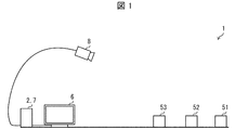
- FIG. 1 is a schematic diagram showing a configuration of an image analysis system 1 in the present embodiment.
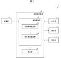
- FIG. 2 is a block diagram showing a main configuration of the image analysis system 1.
- the image analysis system 1 includes an imaging unit 8 (imaging device), an image analysis device 2, an input unit 5, a display unit 6 (display device), and a storage unit 7. I have.
- the imaging unit 8 captures an image used by the image analysis apparatus 2 and is, for example, a camera.
- the imaging unit 8 outputs a captured image (referred to as a captured image in the following description) to the image analysis device 2 (more specifically, the image processing unit 3).
- the imaging unit 8 outputs information indicating the imaging direction when the captured image is captured to the image analysis device 2.
- the imaging direction of the imaging unit 8 may be set by the user, or may be automatically determined by the imaging unit 8.
- FIG. 3 is a diagram illustrating a state in which the imaging unit 8 is imaging.
- the imaging unit 8 captures an image including the objects 51 to 54 with the diagonally downward direction as the imaging direction.
- the objects 51, 52, and 53 are the same objects that are detection targets, and the object 54 is a non-detection target and is an object that is smaller than the objects 51 to 53.
- the object 53, the object 52, and the object 51 exist in the order from the imaging unit 8.
- the image analysis device 2 detects an image of a predetermined object from the captured image captured by the imaging unit 8.
- the image analysis device 2 includes an image processing unit 3 and a detection unit 4.
- the image processing unit 3 generates an image (referred to as a target image in the following description) to be processed by the detection unit 4 described later.
- the image processing unit 3 includes a divided region setting unit 31 and a pixel density setting unit 32.
- the divided region setting unit 31 sets how many regions the captured image is divided into, and divides the target image into a plurality of regions. In the present embodiment, the divided region setting unit 31 divides the target image into a plurality of divided regions along the vertical direction.
- the divided region setting unit 31 may set the number of divided captured images according to the imaging direction of the imaging unit 8 (in other words, the angle with respect to the horizontal direction). For example, when the imaging unit 8 captures an image at an angle close to the horizontal direction, the range captured by the imaging unit 8 is increased. For this reason, when the same object exists in the captured image, the difference in size between the image of the object present at a position close to the image capturing unit 8 and the image of the object present at a position far from the image capturing unit 8 increases. Therefore, when the imaging unit 8 captures an image at an angle close to the horizontal direction, the divided region setting unit 31 preferably sets a large number of divided images. Note that the number of divided captured images by the divided region setting unit 31 is not particularly limited, and may be divided into at least two regions.
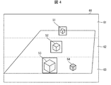
- FIG. 4 is a diagram illustrating an example of an image obtained by dividing the captured image 60 captured by the imaging unit 8 by the divided region setting unit 31.
- the divided region setting unit 31 divides the captured image 60 into three divided regions (a divided region 61, a divided region 62, and a divided region 63 from the top) along the vertical direction.
- the imaging unit 8 captures an image with the diagonally downward direction as the imaging direction. Therefore, the uppermost divided area 61 is the area farthest from the imaging unit 8, and the lowermost divided area 63 is the area closest to the imaging unit 8.
- the object 51 is included in the divided area 61
- the object 52 is included in the divided area 62
- the object 53 and the object 54 are included in the divided area 61.
- the divided area setting unit 31 outputs the divided captured image to the pixel density setting unit 32.
- the pixel density setting unit 32 sets the pixel density (resolution, image resolution) in each of the divided regions set by the divided region setting unit 31. More specifically, when an object of the same size exists in each divided area, the pixel density of the divided area is set so that the number of pixels constituting the object is substantially the same in each divided area. To do.
- the divided area 63 is an area obtained by imaging the area closest to the imaging unit 8. Therefore, in the captured image 60, the image of the object 53 existing in the divided area 63 is displayed larger than the image of the object 51 existing in the divided area 61 and the image of the object 52 existing in the divided area 62. Therefore, the pixel density setting unit 32 sets the pixel density of the divided region 63 to be smaller than the pixel density of the divided region 61 and the pixel density of the divided region 62. Further, the pixel density setting unit 32 sets the pixel density of the divided region 62 to be smaller than that of the divided region 61 and larger than the pixel density of the divided region 63.
- the pixel density setting unit 32 performs division so that the number of pixels constituting the object 51, the number of pixels constituting the object 52, and the number of pixels constituting the object 53 are substantially the same.
- the pixel density of the areas 61 to 63 is set. That is, the pixel density setting unit 32 sets the pixel density of the divided areas 61 to 63 so that the image resolution is lower in the lower divided area.
- the image processing unit 3 converts the captured image 60 so that the pixel density in each of the divided regions becomes the pixel density set by the pixel density setting unit 32, and generates a target image to be processed by the detection unit 4. To do.
- the image processing unit 3 may change the resolution for each divided region by thinning out signals from the imaging unit 8.
- the image processing unit 3 outputs the generated target image to the detection unit 4.
- the detection unit 4 detects a predetermined object included in the target image generated by the image processing unit 3.
- the detection unit 4 can detect an object having a resolution equal to or higher than a predetermined value (in other words, an object having a predetermined number of pixels or more) among objects existing in the image.
- the input unit 5 receives a user instruction to the image analysis device 2. For example, the user can set a detection target or set the pixel density of each divided region in the target image via the input unit 5.
- the display unit 6 outputs a detection result obtained by the image analysis device 2, and is, for example, a liquid crystal display.
- the storage unit 7 stores, for example, various control programs executed by the image analysis device 2, and is configured by a nonvolatile storage device such as a hard disk or a flash memory.
- FIG. 5 is a flowchart illustrating an example of the flow of processing (image analysis method) of the image analysis system 1.
- the imaging unit 8 captures an image (captured image) (S1).
- the divided area setting unit 31 divides the captured image output from the imaging unit 8 into a plurality of divided areas (S2).
- the pixel density setting unit 32 sets the pixel density in each of the divided regions set by the divided region setting unit 31 (S3).
- Steps S2 and S3 are image processing steps for generating a target image to be processed by the detection unit.
- the detection unit 4 detects the detection target specified by the user (S4, detection step).
- the pixel density setting unit 32 is configured so that the number of pixels constituting the object is substantially the same in each divided area.
- the pixel density of the divided area is set.
- the size of the image of the object that can be detected by the detection unit 4 is different for each divided region.
- the lower limit of the size of the object image that can be detected by the detection unit 4 is different for each divided region (more specifically, the lower limit of the size of the object image that can be detected by the detection unit 4).
- the lower divided area in the target image is larger). Therefore, the detection unit 4 detects only the image of an object having a predetermined size or larger among the object images included in each divided region of the target image.
- the detection unit 4 determines whether a detection target designated by the user has been detected (S5).
- the image processing unit 3 displays an image with a display (for example, display of a detection mark) that identifies the detection target unit detected for the target image.
- the detection result is displayed on the display unit 6 (S6).
- the process returns to step S3, and the pixel density setting unit 32 resets the pixel density in each of the divided regions. Specifically, the pixel density setting unit 32 sets the pixel density of each divided region to be higher than the previously set pixel density. Thus, the detection unit 4 can detect the detection target.
- the target image to be processed by the detection unit 4 is divided into a plurality of divided regions along the vertical direction, and the lower divided region in the target image.
- the lower limit of the size of the object image that can be detected by the detection unit 4 is larger as the lower divided area in the target image.
- the processing amount for the detection unit 4 to detect an object for the divided region 62 and the divided region 63 is smaller than the processing amount for the detection unit 4 to detect the object for the divided region 61, and the division is performed.
- the processing amount for the detection unit 4 to detect the object for the region 63 can be made smaller than the processing amount for the detection unit 4 to detect the object for the divided region 62.
- the processing amount for detecting an object can be reduced in the lower divided region in the target image.
- the image analysis system 1 can detect an object with a small amount of processing as a whole.
- the detection part 4 since the detection part 4 does not detect the image (for example, object 54) of an object smaller than a detection target object, the detection part 4 can further reduce processing amount.
- the configuration when the detection unit 4 does not detect the detection target (NO in S5), the configuration returns to step S3. Not limited. In one aspect of the present disclosure, when the detection unit 4 does not detect the detection target (NO in S5), the process returns to step S2, and the divided region setting unit 31 resets the divided region of the captured image. Also good. Further, in one aspect of the present disclosure, when the detection unit 4 does not detect the detection target (NO in S5), the process may be terminated as “no detection”.
- the pixel density setting unit 32 sets the pixel density of each divided region in the target image in accordance with an instruction from the user (that is, the size of the object image that can be detected by the detection unit). The lower limit of the height may be changed).
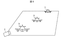
- FIG. 6 is a diagram illustrating a state in which the imaging unit 8 is imaging.
- FIG. 7 is a diagram illustrating an example of a captured image 80 captured by the imaging unit 8.
- the imaging unit 8 captures an image with the diagonally upward direction as the imaging direction.
- an object 73, an object 72, and an object 71 exist in the order from the imaging unit 8.
- the objects 71 to 73 are objects of the same size.
- the imaging unit 8 sets the imaging direction in an obliquely upward direction. Therefore, the uppermost divided area in the captured image 80 is an area closest to the imaging unit 8, and the lowermost divided area in the captured image 80 is an area farthest from the imaging unit 8. Therefore, the image of the object positioned on the upper side (for example, the object 73) in the captured image 80 is displayed larger than the image of the object positioned on the lower side (for example, the object 71) in the captured image 80. In addition, the image of the object 72 located near the center in the captured image 80 is displayed larger than the image of the object 71 and smaller than the image of the object 73.
- the pixel density setting unit 32 in the present embodiment sets the pixel density of the divided region so that the image resolution becomes lower in the upper divided region.
- the lower limit of the size of the object image that can be detected by the detection unit 4 is larger as the upper divided area in the target image.
- the processing amount for detecting an object can be reduced in the upper divided region in the target image.
- the image analysis system 1 according to the present embodiment can detect an object with a small amount of processing.
- the pixel density setting unit 32 sets the pixel density of each divided region in the target image based on information on the imaging direction of the imaging unit 8 (that is, the detection unit can detect the pixel density).
- the lower limit of the size of the object image may be changed).
- the pixel density setting unit 32 acquires information indicating the imaging direction of the imaging unit 8 from the imaging unit 8. For example, when acquiring information in which the imaging direction of the imaging unit 8 has changed from the diagonally downward direction to the diagonally upward direction, the pixel density setting unit 32 lowers the image resolution in the lower divided region in the target image.
- the setting may be changed to a setting in which the image resolution is lower in the upper divided area in the target image.
- control blocks (particularly the image processing unit 3 and the detection unit 4) of the image analysis apparatus 2 may be realized by a logic circuit (hardware) formed in an integrated circuit (IC chip) or the like, or by software. Also good.
- the image analysis apparatus 2 includes a computer that executes instructions of a program that is software for realizing each function.
- the computer includes, for example, at least one processor (control device) and at least one computer-readable recording medium storing the program.
- the processor reads the program from the recording medium and executes the program, thereby achieving the object of the present disclosure.
- a CPU Central Processing Unit
- the recording medium a “non-temporary tangible medium” such as a ROM (Read Only Memory), a tape, a disk, a card, a semiconductor memory, a programmable logic circuit, or the like can be used.
- a RAM Random Access Memory
- the program may be supplied to the computer via any transmission medium (such as a communication network or a broadcast wave) that can transmit the program.
- any transmission medium such as a communication network or a broadcast wave
- one aspect of the present disclosure can also be realized in the form of a data signal embedded in a carrier wave, in which the program is embodied by electronic transmission.
Landscapes
- Engineering & Computer Science (AREA)
- Computer Vision & Pattern Recognition (AREA)
- Physics & Mathematics (AREA)
- General Physics & Mathematics (AREA)
- Theoretical Computer Science (AREA)
- Studio Devices (AREA)
- Image Analysis (AREA)
Abstract
少ない処理量で物体を検出する。画像解析装置は、画像に含まれる所定の物体の像を検出する検出部と、検出部の処理対象となる対象画像を生成する画像処理部とを備える。検出部が検出可能な前記所定の物体の像の大きさの下限は、前記対象画像の領域ごとに異なっている。
Description
以下の開示は、画像解析により物体を検出する画像解析装置などに関する。本出願は、2018年5月23日に日本に出願された特願2018-099082号に優先権を主張し、その内容をここに援用する。
画像解析により物体を検出する技術の一例が特許文献1および2に記載されている。
特許文献1に記載の発明では、撮像部で撮像する撮像エリアのうち検知エリアを設定し、当該検知エリアを複数に分割して複数の分割検知エリアを設定している。そして、分割検知エリア毎に検知条件を可変させている。
特許文献2に記載の発明では、検知した物体の領域に基づいて画像を読み出す処理および解析対象の領域を決定する処理を繰り返すようにして、当該領域を絞り込みながら、画像の解像度を上げている。
しかしながら、上述の従来技術では、検知エリア毎に検知条件を可変させているため、または、解析対象の領域を絞り込みながら、画像の解像度を上げているため、処理量が増大し、処理速度が低下するという問題が生じる。
本開示の一態様は、少ない処理量で物体を検出できる画像解析装置、画像解析システムおよび画像解析方法を実現することを目的とする。
上記の課題を解決するために、本開示の一態様に係る画像解析装置は、画像に含まれる所定の物体の像を検出する検出部と、前記検出部の処理対象となる対象画像を生成する画像処理部とを備え、前記検出部が検出可能な前記所定の物体の像の大きさの下限は、前記対象画像の領域ごとに異なっている。
上記の課題を解決するために、本開示の一態様に係る画像解析方法は、画像に含まれる所定の物体の像を検出する検出工程と、前記検出工程において処理対象となる対象画像を生成する画像処理工程とを含み、前記検出工程における検出可能な前記所定の物体の像の大きさの下限は、前記対象画像の領域ごとに異なっている。
本開示の一態様によれば、少ない処理量で物体を検出できる。
〔実施形態1〕
以下、本開示の一実施形態について、詳細に説明する。
以下、本開示の一実施形態について、詳細に説明する。
(画像解析システム1の構成)
図1は、本実施形態における画像解析システム1の構成を示す概略図である。図2は、画像解析システム1の要部構成を示すブロック図である。
図1は、本実施形態における画像解析システム1の構成を示す概略図である。図2は、画像解析システム1の要部構成を示すブロック図である。
図1および図2に示すように、画像解析システム1は、撮像部8(撮像装置)と、画像解析装置2と、入力部5と、表示部6(表示装置)と、記憶部7とを備えている。
撮像部8は、画像解析装置2によって利用される画像を撮像するものであり、例えば、カメラである。撮像部8は、撮像した画像(以下の説明では、撮像画像と称する)を画像解析装置2(より詳細には、画像処理部3)に出力する。また、撮像部8は、撮像画像を撮像したときの撮像方向を示す情報を画像解析装置2に出力する。撮像部8の撮像方向は、ユーザによって設定されてもよいし、撮像部8が自動的に決定してもよい。
図3は、撮像部8が撮像している様子を示す図である。本実施形態では、図1および図3に示すように、撮像部8が、物体51~54を含む画像を、斜め下方向を撮像方向として撮像する場合について説明する。なお、物体51・52・53は、検出対象である同じ物体であり、物体54は、検出非対象であり、物体51~53よりも小さい物体であるものとする。また、図1および図3に示す例では、撮像部8から近い順に物体53、物体52、物体51が存在しているものとする。
画像解析装置2は、撮像部8が撮像した撮像画像内から所定の物体の像を検出する。画像解析装置2は、画像処理部3と、検出部4とを備えている。
画像処理部3は、後述する検出部4の処理対象となる画像(以降の説明では、対象画像と称する)を生成する。画像処理部3は、分割領域設定部31と、画素密度設定部32とを備えている。
分割領域設定部31は、撮像画像を何個の領域に分割するかを設定し、対象画像を複数の領域に分割する。本実施形態では、分割領域設定部31は、対象画像の上下方向に沿って複数の分割領域に分割する。
分割領域設定部31は、撮像部8の撮像方向(換言すれば、水平方向に対する角度)によって撮像画像の分割個数を設定してもよい。例えば、撮像部8が水平方向に近い角度で撮像する場合、撮像部8によって撮像される範囲が大きくなる。このため、同じ物体が撮像画像内に存在する場合、撮像部8に近い位置に存在する物体の像と、撮像部8から遠い位置に存在する物体の像との大きさの違いが大きくなる。したがって、撮像部8が水平方向に近い角度で撮像する場合には、分割領域設定部31は、撮像画像の分割個数を多く設定することが好ましい。なお、分割領域設定部31による撮像画像の分割個数は特に制限されるものではなく、少なくとも2つの領域に分割すればよい。
図4は、分割領域設定部31によって撮像部8が撮像した撮像画像60が分割された画像の一例を示す図である。図4に示す例では、分割領域設定部31は、撮像画像60を上下方向に沿って3つの分割領域(上から分割領域61、分割領域62、分割領域63)に分割している。
本実施形態では、撮像部8が斜め下方向を撮像方向として撮像している。そのため、最も上に位置する分割領域61は、撮像部8から最も遠い領域となり、最も下に位置する分割領域63は、撮像部8に最も近い領域となる。撮像画像60において、物体51は分割領域61に含まれ、物体52は分割領域62に含まれ、物体53および物体54は分割領域61に含まれる。
分割領域設定部31は、分割した撮像画像を画素密度設定部32に出力する。
画素密度設定部32は、分割領域設定部31が設定した分割領域のそれぞれにおける画素密度(解像度、画像解像度)を設定する。より詳細には、各分割領域に同じ大きさの物体が存在している場合に、当該物体を構成する画素数が各分割領域において実質的に同じになるように、分割領域の画素密度を設定する。
図4に示す例では、分割領域61~63のうち、分割領域63は、撮像部8から最も近い領域を撮像した領域となる。そのため、撮像画像60において、分割領域63に存在する物体53の像は、分割領域61に存在する物体51の像、および分割領域62に存在する物体52の像よりも大きく表示される。そのため、画素密度設定部32は、分割領域63の画素密度を、分割領域61の画素密度および分割領域62の画素密度よりも小さく設定する。また、画素密度設定部32は、分割領域62の画素密度を、分割領域61よりも小さく、かつ分割領域63の画素密度よりも大きく設定する。より具体的には、画素密度設定部32は、物体51を構成する画素数と、物体52を構成する画素数と、物体53を構成する画素数とが実質的に同じになるように、分割領域61~63の画素密度を設定する。すなわち、画素密度設定部32は、下側の分割領域ほど画像解像度が低くなるように、分割領域61~63の画素密度を設定する。
画像処理部3は、分割領域のそれぞれにおける画素密度が、画素密度設定部32が設定した画素密度となるように、撮像画像60を変換して、検出部4の処理対象となる対象画像を生成する。例えば、画像処理部3は、撮像部8からの信号を間引いて分割領域ごとの解像度を変更してもよい。画像処理部3は、生成した対象画像を検出部4に出力する。
検出部4は、画像処理部3が生成した対象画像に含まれる所定の物体を検出する。検出部4は、画像に存在する物体のうち、解像度が所定値以上の物体(換言すれば、構成する画素数が所定の画素数以上である物体)を検出できるようになっている。
入力部5は、画像解析装置2に対するユーザの指示を受け付ける。ユーザは、入力部5を介して、例えば、検出対象を設定したり、対象画像における各分割領域の画素密度を設定したりすることができる。
表示部6は、画像解析装置2による検出結果を出力するものであり、例えば、液晶ディスプレイである。
記憶部7は、例えば、画像解析装置2が実行する各種の制御プログラム等を記憶するものであり、例えばハードディスク、フラッシュメモリ等の不揮発性の記憶装置によって構成される。
(画像解析システム1の処理)
図5は、画像解析システム1の処理(画像解析方法)の流れの一例を示すフローチャートである。図5に示すように、画像解析システム1の処理では、まず、撮像部8が画像(撮像画像)を撮像する(S1)。
図5は、画像解析システム1の処理(画像解析方法)の流れの一例を示すフローチャートである。図5に示すように、画像解析システム1の処理では、まず、撮像部8が画像(撮像画像)を撮像する(S1)。
次に、分割領域設定部31が、撮像部8から出力された撮像画像を複数の分割領域に分割する(S2)。次に、画素密度設定部32が、分割領域設定部31が設定した分割領域のそれぞれにおける画素密度を設定する(S3)。ステップS2およびステップS3は、検出部の処理対象となる対象画像を生成する画像処理工程である。
次に、検出部4が、ユーザによって指定された検出対象物の検出を行う(S4、検出工程)。上述したように、画素密度設定部32は、各分割領域に同じ大きさの物体が存在している場合に、当該物体を構成する画素数が各分割領域において実質的に同じになるように、分割領域の画素密度を設定する。これにより、検出部4が検出できる物体の像の大きさが、分割領域ごとに異なっている。換言すれば、検出部4が検出可能な物体の像の大きさの下限が、分割領域ごとに異なっている(より具体的には、検出部4が検出可能な物体の像の大きさの下限が、対象画像における下側の分割領域ほど大きくなっている)。したがって、検出部4は、対象画像の各分割領域に含まれる物体の像のうち、所定の大きさ以上の物体の像のみを検出する。
次に、検出部4は、ユーザによって指定された検出対象物を検出したかどうかを判定する(S5)。検出部4が検出対象物を検出した場合(S5でYES)、画像処理部3は、対象画像に対して検出した検出対象部を特定する表示(例えば、検出マークの表示)を付した画像を検出結果として表示部6に表示させる(S6)。
一方、検出部4が検出対象物を検出しなかった場合(S5でNO)、ステップS3に戻り、画素密度設定部32が、分割領域のそれぞれにおける画素密度を再設定する。具体的には、画素密度設定部32は、各分割領域の画素密度を前回設定した画素密度よりも高く設定する。これにより、検出部4が検出対象物を検出できるようにする。
ここで、従来では、撮像部から遠い位置の領域の物体を検出するために、画像のすべての領域に対して、検出部が当該物体を検出できる解像度の画像を用いていた。そのため、物体を検出するための処理量が多くなってしまうという問題があった。
これに対して、本実施形態における画像解析システム1では、検出部4の処理対象となる対象画像は、上下方向に沿って複数の分割領域に分割されており、対象画像における下側の分割領域ほど画像解像度が低くなっている。これにより、検出部4が検出可能な物体の像の大きさの下限が、対象画像における下側の分割領域ほどに大きくなっている。これにより、分割領域62および分割領域63に対して検出部4が物体を検出するための処理量を分割領域61に対して検出部4が物体を検出する処理量よりも少なくし、かつ、分割領域63に対して検出部4が物体を検出するための処理量を分割領域62に対して検出部4が物体を検出する処理量よりも少なくすることができる。すなわち、対象画像における下側の分割領域ほど物体を検出するための処理量を少なくすることができる。その結果、画像解析システム1では、全体として少ない処理量で物体を検出できるようになっている。また、上記の構成によれば、検出部4は、検出対象物よりも小さい物体の像(例えば、物体54)を検出しないため、検出部4により処理量をさらに少なくすることができる。
なお、本実施形態における画像解析システム1では、検出部4が検出対象物を検出しなかった場合(S5でNO)、ステップS3に戻る構成であったが、本開示の画像解析システムはこれに限られない。本開示の一態様では、検出部4が検出対象物を検出しなかった場合(S5でNO)、ステップS2に戻り、分割領域設定部31が撮像画像の分割領域を再設定する態様であってもよい。また、本開示の一態様では、検出部4が検出対象物を検出しなかった場合(S5でNO)、「検出無し」として処理を終了してもよい。
なお、本開示の一態様の画像解析システムでは、画素密度設定部32がユーザからの指示に従って対象画像における各分割領域の画素密度を設定する(すなわち、検出部が検出可能な物体の像の大きさの下限を変化させる)態様であってもよい。
〔実施形態2〕
本開示の他の実施形態について、以下に説明する。なお、説明の便宜上、上記実施形態にて説明した部材と同じ機能を有する部材については、同じ符号を付記し、その説明を繰り返さない。本実施形態では、撮像部8が撮像する方向が実施形態1とは異なっている。
本開示の他の実施形態について、以下に説明する。なお、説明の便宜上、上記実施形態にて説明した部材と同じ機能を有する部材については、同じ符号を付記し、その説明を繰り返さない。本実施形態では、撮像部8が撮像する方向が実施形態1とは異なっている。
図6は、撮像部8が撮像している様子を示す図である。図7は、撮像部8が撮像した撮像画像80の一例を示す図である。
本実施形態では、図6に示すように、撮像部8が、斜め上方向を撮像方向として撮像する。図6に示す例では、撮像部8から近い順に物体73、物体72、物体71が存在しているものとする。なお、物体71~73は、同じ大きさの物体である。
本実施形態では、撮像部8が斜め上方向を撮像方向としている。そのため、撮像画像80において最も上に位置する分割領域は、撮像部8から最も近い領域となり、撮像画像80において最も下に位置する分割領域は、撮像部8に最も遠い領域となる。そのため、撮像画像80において上側に位置する物体(例えば、物体73)の像は、撮像画像80において下側に位置する物体(例えば、物体71)の像よりも大きく表示される。また、撮像画像80において中央付近に位置する物体72の像は、物体71の像よりも大きく、物体73の像よりも小さく表示される。
そこで、本実施形態における画素密度設定部32は、上側の分割領域ほど画像解像度が低くなるように、分割領域の画素密度を設定する。これにより、検出部4が検出可能な物体の像の大きさの下限が、対象画像における上側の分割領域ほどに大きくなっている。これにより、対象画像における上側の分割領域ほど物体を検出するための処理量を少なくすることができる。その結果、本実施形態における画像解析システム1においても、少ない処理量で物体を検出できるようになっている。
なお、本開示の一態様における画像解析システムでは、画素密度設定部32が撮像部8の撮像方向の情報に基づいて対象画像における各分割領域の画素密度を設定する(すなわち、検出部が検出可能な物体の像の大きさの下限を変化させる)態様であってもよい。具体的には、まず、画素密度設定部32は、撮像部8から撮像部8の撮像方向を示す情報を取得する。そして、画素密度設定部32は、例えば、撮像部8の撮像方向が斜め下方向から斜め上方向に変化した情報を取得した場合、対象画像における下側の分割領域ほど画像解像度を低くしている設定を、対象画像における上側の分割領域ほど画像解像度を低くしている設定に変化させてもよい。
〔ソフトウェアによる実現例〕
画像解析装置2の制御ブロック(特に画像処理部3および検出部4)は、集積回路(ICチップ)等に形成された論理回路(ハードウェア)によって実現してもよいし、ソフトウェアによって実現してもよい。
画像解析装置2の制御ブロック(特に画像処理部3および検出部4)は、集積回路(ICチップ)等に形成された論理回路(ハードウェア)によって実現してもよいし、ソフトウェアによって実現してもよい。
後者の場合、画像解析装置2は、各機能を実現するソフトウェアであるプログラムの命令を実行するコンピュータを備えている。このコンピュータは、例えば少なくとも1つのプロセッサ(制御装置)を備えていると共に、上記プログラムを記憶したコンピュータ読み取り可能な少なくとも1つの記録媒体を備えている。そして、上記コンピュータにおいて、上記プロセッサが上記プログラムを上記記録媒体から読み取って実行することにより、本開示の目的が達成される。上記プロセッサとしては、例えばCPU(Central Processing Unit)を用いることができる。上記記録媒体としては、「一時的でない有形の媒体」、例えば、ROM(Read Only Memory)等の他、テープ、ディスク、カード、半導体メモリ、プログラマブルな論理回路などを用いることができる。また、上記プログラムを展開するRAM(Random Access Memory)などをさらに備えていてもよい。また、上記プログラムは、該プログラムを伝送可能な任意の伝送媒体(通信ネットワークや放送波等)を介して上記コンピュータに供給されてもよい。なお、本開示の一態様は、上記プログラムが電子的な伝送によって具現化された、搬送波に埋め込まれたデータ信号の形態でも実現され得る。
本開示は上述した各実施形態に限定されるものではなく、請求項に示した範囲で種々の変更が可能であり、異なる実施形態にそれぞれ開示された技術的手段を適宜組み合わせて得られる実施形態についても本開示の技術的範囲に含まれる。さらに、各実施形態にそれぞれ開示された技術的手段を組み合わせることにより、新しい技術的特徴を形成することができる。
Claims (11)
- 画像に含まれる所定の物体の像を検出する検出部と、
前記検出部の処理対象となる対象画像を生成する画像処理部とを備え、
前記検出部が検出可能な前記所定の物体の像の大きさの下限は、前記対象画像の領域ごとに異なっている画像解析装置。 - 前記対象画像は、当該対象画像の上下方向に沿って複数の分割領域に分割されており、
前記下限は、前記分割領域ごとに異なっている、請求項1に記載の画像解析装置。 - 前記下限は、前記対象画像における下側の分割領域ほど大きい、請求項2に記載の画像解析装置。
- 前記対象画像における下側の分割領域ほど画像解像度が低い、請求項2または3に記載の画像解析装置。
- 前記下限は、前記対象画像における上側の分割領域ほど大きい、請求項2に記載の画像解析装置。
- 前記対象画像における上側の分割領域ほど画像解像度が低い、請求項2または5に記載の画像解析装置。
- 前記画像処理部は、前記対象画像の生成に用いられる撮像画像を撮像した撮像装置が当該撮像画像を撮像したときの撮像方向を示す情報を取得し、当該情報に基づいて前記下限を変化させる、請求項1から6のいずれか1項に記載の画像解析装置。
- 前記画像処理部は、ユーザからの指示に従って前記下限を変化させる、請求項1から6のいずれか1項に記載の画像解析装置。
- 請求項1から8のいずれか1項に記載の画像解析装置と、
前記画像解析装置が利用する画像を撮像する撮像装置とを備える画像解析システム。 - 前記画像解析装置による前記所定の物体の検出結果を表示する表示装置をさらに備える、請求項9に記載の画像解析システム。
- 画像に含まれる所定の物体の像を検出する検出工程と、
前記検出工程において処理対象となる対象画像を生成する画像処理工程とを含み、
前記検出工程における検出可能な前記所定の物体の像の大きさの下限は、前記対象画像の領域ごとに異なっている画像解析方法。
Applications Claiming Priority (2)
| Application Number | Priority Date | Filing Date | Title |
|---|---|---|---|
| JP2018-099082 | 2018-05-23 | ||
| JP2018099082A JP2021144254A (ja) | 2018-05-23 | 2018-05-23 | 画像解析装置、画像解析システムおよび画像解析方法 |
Publications (1)
| Publication Number | Publication Date |
|---|---|
| WO2019225239A1 true WO2019225239A1 (ja) | 2019-11-28 |
Family
ID=68615589
Family Applications (1)
| Application Number | Title | Priority Date | Filing Date |
|---|---|---|---|
| PCT/JP2019/016726 Ceased WO2019225239A1 (ja) | 2018-05-23 | 2019-04-19 | 画像解析装置、画像解析システムおよび画像解析方法 |
Country Status (2)
| Country | Link |
|---|---|
| JP (1) | JP2021144254A (ja) |
| WO (1) | WO2019225239A1 (ja) |
Citations (3)
| Publication number | Priority date | Publication date | Assignee | Title |
|---|---|---|---|---|
| JP2009157821A (ja) * | 2007-12-27 | 2009-07-16 | Toyota Central R&D Labs Inc | 距離画像生成装置、環境認識装置、及びプログラム |
| JP2012185684A (ja) * | 2011-03-07 | 2012-09-27 | Jvc Kenwood Corp | 対象物検出装置、対象物検出方法 |
| JP2015228164A (ja) * | 2014-06-02 | 2015-12-17 | 大日本印刷株式会社 | 物体検出システムおよび物体検出方法 |
-
2018
- 2018-05-23 JP JP2018099082A patent/JP2021144254A/ja active Pending
-
2019
- 2019-04-19 WO PCT/JP2019/016726 patent/WO2019225239A1/ja not_active Ceased
Patent Citations (3)
| Publication number | Priority date | Publication date | Assignee | Title |
|---|---|---|---|---|
| JP2009157821A (ja) * | 2007-12-27 | 2009-07-16 | Toyota Central R&D Labs Inc | 距離画像生成装置、環境認識装置、及びプログラム |
| JP2012185684A (ja) * | 2011-03-07 | 2012-09-27 | Jvc Kenwood Corp | 対象物検出装置、対象物検出方法 |
| JP2015228164A (ja) * | 2014-06-02 | 2015-12-17 | 大日本印刷株式会社 | 物体検出システムおよび物体検出方法 |
Also Published As
| Publication number | Publication date |
|---|---|
| JP2021144254A (ja) | 2021-09-24 |
Similar Documents
| Publication | Publication Date | Title |
|---|---|---|
| CN102859555B (zh) | 图像处理装置及图像处理方法 | |
| US8223218B2 (en) | Face detection apparatus | |
| US11790583B2 (en) | Image processing apparatus, image processing method, and non-transitory computer-readable storage medium | |
| KR101434484B1 (ko) | 영상 분할을 이용한 비전 검사 장치 및 비전 검사 방법 | |
| US10909365B2 (en) | Image processing apparatus, control method thereof, and non-transitory computer-readable storage medium | |
| JP6642970B2 (ja) | 注目領域検出装置、注目領域検出方法及びプログラム | |
| JP6932758B2 (ja) | 物体検出装置、物体検出方法、物体検出プログラム、学習装置、学習方法及び学習プログラム | |
| US20120014453A1 (en) | Image processing apparatus and image processing method | |
| JP6752360B2 (ja) | 画像処理装置、撮像装置、端末装置、画像補正方法および画像処理プログラム | |
| US8699753B2 (en) | Object detecting device, image dividing device, integrated circuit, method of detecting object, object detecting program, and recording medium | |
| US10810743B2 (en) | Image processing device, image processing method, and computer program product | |
| US20140079341A1 (en) | Image processing apparatus and image processing method | |
| KR101830077B1 (ko) | 화상처리장치, 그 제어 방법 및 기억매체 | |
| US9122935B2 (en) | Object detection method, storage medium, integrated circuit, and object detection apparatus | |
| US11704820B2 (en) | Image processing apparatus, image processing method, and storage medium | |
| JPWO2018030386A1 (ja) | 位置指定装置および位置指定方法 | |
| US20210256665A1 (en) | Generation apparatus, generation method, and storage medium | |
| US10084950B2 (en) | Image capturing apparatus | |
| WO2019225239A1 (ja) | 画像解析装置、画像解析システムおよび画像解析方法 | |
| US20190057278A1 (en) | Image processing device, image processing method, and computer program product | |
| US9741086B2 (en) | Image processing apparatus, image processing method, and storage medium storing program | |
| JP2011053456A (ja) | 画像表示方法、プログラム、画像表示装置、及び、この画像表示装置を有する撮像装置 | |
| US20250046050A1 (en) | Information processing apparatus, method of controlling information processing apparatus, and medium | |
| US20250131688A1 (en) | Information processing method, information processing apparatus, and storage medium | |
| JP6762779B2 (ja) | 画像処理装置、撮像装置、画像処理方法、及びプログラム |
Legal Events
| Date | Code | Title | Description |
|---|---|---|---|
| 121 | Ep: the epo has been informed by wipo that ep was designated in this application |
Ref document number: 19806526 Country of ref document: EP Kind code of ref document: A1 |
|
| NENP | Non-entry into the national phase |
Ref country code: DE |
|
| 122 | Ep: pct application non-entry in european phase |
Ref document number: 19806526 Country of ref document: EP Kind code of ref document: A1 |
|
| NENP | Non-entry into the national phase |
Ref country code: JP |