WO2019220591A1 - モータにより駆動可能である過給機の振動抑制方法および振動抑制装置 - Google Patents
モータにより駆動可能である過給機の振動抑制方法および振動抑制装置 Download PDFInfo
- Publication number
- WO2019220591A1 WO2019220591A1 PCT/JP2018/019121 JP2018019121W WO2019220591A1 WO 2019220591 A1 WO2019220591 A1 WO 2019220591A1 JP 2018019121 W JP2018019121 W JP 2018019121W WO 2019220591 A1 WO2019220591 A1 WO 2019220591A1
- Authority
- WO
- WIPO (PCT)
- Prior art keywords
- vibration
- rotor shaft
- motor
- supercharger
- execution
- Prior art date
- Legal status (The legal status is an assumption and is not a legal conclusion. Google has not performed a legal analysis and makes no representation as to the accuracy of the status listed.)
- Ceased
Links
Images







Classifications
-
- F—MECHANICAL ENGINEERING; LIGHTING; HEATING; WEAPONS; BLASTING
- F04—POSITIVE - DISPLACEMENT MACHINES FOR LIQUIDS; PUMPS FOR LIQUIDS OR ELASTIC FLUIDS
- F04D—NON-POSITIVE-DISPLACEMENT PUMPS
- F04D29/00—Details, component parts, or accessories
- F04D29/66—Combating cavitation, whirls, noise, vibration or the like; Balancing
- F04D29/661—Combating cavitation, whirls, noise, vibration or the like; Balancing especially adapted for elastic fluid pumps
- F04D29/668—Combating cavitation, whirls, noise, vibration or the like; Balancing especially adapted for elastic fluid pumps damping or preventing mechanical vibrations
-
- F—MECHANICAL ENGINEERING; LIGHTING; HEATING; WEAPONS; BLASTING
- F02—COMBUSTION ENGINES; HOT-GAS OR COMBUSTION-PRODUCT ENGINE PLANTS
- F02B—INTERNAL-COMBUSTION PISTON ENGINES; COMBUSTION ENGINES IN GENERAL
- F02B33/00—Engines characterised by provision of pumps for charging or scavenging
- F02B33/32—Engines with pumps other than of reciprocating-piston type
- F02B33/34—Engines with pumps other than of reciprocating-piston type with rotary pumps
- F02B33/40—Engines with pumps other than of reciprocating-piston type with rotary pumps of non-positive-displacement type
-
- F—MECHANICAL ENGINEERING; LIGHTING; HEATING; WEAPONS; BLASTING
- F02—COMBUSTION ENGINES; HOT-GAS OR COMBUSTION-PRODUCT ENGINE PLANTS
- F02B—INTERNAL-COMBUSTION PISTON ENGINES; COMBUSTION ENGINES IN GENERAL
- F02B37/00—Engines characterised by provision of pumps driven at least for part of the time by exhaust
- F02B37/04—Engines with exhaust drive and other drive of pumps, e.g. with exhaust-driven pump and mechanically-driven second pump
-
- F—MECHANICAL ENGINEERING; LIGHTING; HEATING; WEAPONS; BLASTING
- F02—COMBUSTION ENGINES; HOT-GAS OR COMBUSTION-PRODUCT ENGINE PLANTS
- F02B—INTERNAL-COMBUSTION PISTON ENGINES; COMBUSTION ENGINES IN GENERAL
- F02B39/00—Component parts, details, or accessories relating to, driven charging or scavenging pumps, not provided for in groups F02B33/00 - F02B37/00
- F02B39/02—Drives of pumps; Varying pump drive gear ratio
- F02B39/08—Non-mechanical drives, e.g. fluid drives having variable gear ratio
- F02B39/10—Non-mechanical drives, e.g. fluid drives having variable gear ratio electric
-
- F—MECHANICAL ENGINEERING; LIGHTING; HEATING; WEAPONS; BLASTING
- F04—POSITIVE - DISPLACEMENT MACHINES FOR LIQUIDS; PUMPS FOR LIQUIDS OR ELASTIC FLUIDS
- F04D—NON-POSITIVE-DISPLACEMENT PUMPS
- F04D17/00—Radial-flow pumps, e.g. centrifugal pumps; Helico-centrifugal pumps
- F04D17/08—Centrifugal pumps
- F04D17/10—Centrifugal pumps for compressing or evacuating
-
- F—MECHANICAL ENGINEERING; LIGHTING; HEATING; WEAPONS; BLASTING
- F04—POSITIVE - DISPLACEMENT MACHINES FOR LIQUIDS; PUMPS FOR LIQUIDS OR ELASTIC FLUIDS
- F04D—NON-POSITIVE-DISPLACEMENT PUMPS
- F04D25/00—Pumping installations or systems
- F04D25/02—Units comprising pumps and their driving means
- F04D25/06—Units comprising pumps and their driving means the pump being electrically driven
-
- F—MECHANICAL ENGINEERING; LIGHTING; HEATING; WEAPONS; BLASTING
- F04—POSITIVE - DISPLACEMENT MACHINES FOR LIQUIDS; PUMPS FOR LIQUIDS OR ELASTIC FLUIDS
- F04D—NON-POSITIVE-DISPLACEMENT PUMPS
- F04D29/00—Details, component parts, or accessories
- F04D29/66—Combating cavitation, whirls, noise, vibration or the like; Balancing
-
- F—MECHANICAL ENGINEERING; LIGHTING; HEATING; WEAPONS; BLASTING
- F05—INDEXING SCHEMES RELATING TO ENGINES OR PUMPS IN VARIOUS SUBCLASSES OF CLASSES F01-F04
- F05D—INDEXING SCHEME FOR ASPECTS RELATING TO NON-POSITIVE-DISPLACEMENT MACHINES OR ENGINES, GAS-TURBINES OR JET-PROPULSION PLANTS
- F05D2210/00—Working fluids
- F05D2210/10—Kind or type
- F05D2210/12—Kind or type gaseous, i.e. compressible
-
- F—MECHANICAL ENGINEERING; LIGHTING; HEATING; WEAPONS; BLASTING
- F05—INDEXING SCHEMES RELATING TO ENGINES OR PUMPS IN VARIOUS SUBCLASSES OF CLASSES F01-F04
- F05D—INDEXING SCHEME FOR ASPECTS RELATING TO NON-POSITIVE-DISPLACEMENT MACHINES OR ENGINES, GAS-TURBINES OR JET-PROPULSION PLANTS
- F05D2260/00—Function
- F05D2260/96—Preventing, counteracting or reducing vibration or noise
-
- Y—GENERAL TAGGING OF NEW TECHNOLOGICAL DEVELOPMENTS; GENERAL TAGGING OF CROSS-SECTIONAL TECHNOLOGIES SPANNING OVER SEVERAL SECTIONS OF THE IPC; TECHNICAL SUBJECTS COVERED BY FORMER USPC CROSS-REFERENCE ART COLLECTIONS [XRACs] AND DIGESTS
- Y02—TECHNOLOGIES OR APPLICATIONS FOR MITIGATION OR ADAPTATION AGAINST CLIMATE CHANGE
- Y02T—CLIMATE CHANGE MITIGATION TECHNOLOGIES RELATED TO TRANSPORTATION
- Y02T10/00—Road transport of goods or passengers
- Y02T10/10—Internal combustion engine [ICE] based vehicles
- Y02T10/12—Improving ICE efficiencies
Definitions
- This disclosure relates to vibration suppression of a supercharger including a motor.
- a supercharger that compresses a gas such as air to increase its density and supercharges the combustion chamber of an engine (internal combustion engine) as a combustion gas.
- the supercharger includes a rotor shaft (rotating shaft) and a turbine and a compressor disposed at both ends of the rotor shaft. Then, the energy of the exhaust gas discharged from the combustion chamber of the internal combustion engine to the exhaust passage is converted into rotational energy by the turbine, the compressor is driven, the gas such as air is compressed, and the combustion gas is sent to the combustion chamber.
- the effect of the supercharger is small during low-load operation of an engine with a small exhaust gas flow rate.
- deceleration operation may be performed in order to reduce fuel consumption (fuel cost).
- the flow rate of exhaust gas is small and the capacity of the supercharger is insufficient. Become prominent.
- an electric assist supercharger having a motor (electric motor) capable of rotating the rotor shaft irrespective of exhaust gas
- a motor electric motor
- the rotation of the rotor shaft is urged by the motor during low load operation to compensate for the lack of capacity of the supercharger.
- the motor is stopped because the energy of the exhaust gas is sufficient.
- a type of electric assist supercharger there is also known a hybrid supercharger that performs supercharging in the same manner as an electric assist supercharger and collects excess energy of exhaust gas as electric power during high-load operation of the engine. It has been.
- Patent Document 2 discloses a method for reducing noise and vibration of an electric supercharger (supercharger), and an elastic material is interposed between a turbocharger, an electric motor, and a casing that houses an inverter, and It is disclosed to take measures such as installing a sound absorbing material in the duct. Since vibration noise is mainly caused by propagation of the shaft vibration of the rotor shaft to the casing or the like, in Patent Document 2, it is possible to reduce the vibration by stopping the propagation of vibration by an elastic member.
- An electric assist supercharger having a motor overhang structure as disclosed in Patent Document 1 is accompanied by a large vibration when passing through a dangerous speed.
- the inventors have intensively researched, especially when the rotation of the rotor shaft is not energized by the motor or when the motor is not operating, such as when the motor is not generating power (during non-operation).
- the knowledge that a large vibration occurs when passing through the speed was obtained (see FIGS. 3A and 3B described later).
- At least one embodiment of the present invention aims to provide a turbocharger vibration suppressing method capable of suppressing the shaft vibration of the rotor shaft that occurs when the motor is not operating.
- a method for suppressing vibration of a supercharger includes: A turbocharger vibration suppressing method for suppressing shaft vibration of a turbocharger that can be driven by a motor, A specific vibration state determination step for determining whether or not the magnitude of the shaft vibration of the rotor shaft of the supercharger exceeds or exceeds a predetermined magnitude in a specific vibration state; An excitation state determination step for determining whether or not an excitation voltage is applied to the motor; When it is determined that the specific vibration state is determined by the specific vibration state determination step, and when it is determined that the excitation state is not the excitation state by the excitation state determination step, vibration suppression execution is performed to apply the excitation voltage to the motor. Steps.
- the motor when the rotation of the rotor shaft is energized by the motor or when the motor is operating (when operating) such as when the motor is generating power, the motor is in an excited state.
- a magnetic force is generated from the stator by applying a voltage (excitation voltage) for excitation to the stator (coil) of the motor and causing a current to flow through the stator.
- the present inventors suppress the relative movement of the motor rotor with respect to the stator by attracting the motor rotor to the stator by the magnetic force (attraction) from the stator of the motor in the excited state, and the rotor shaft attached to the motor rotor. It has been found that it is possible to reduce the shaft vibration level.
- the specific vibration state determination step includes: A vibration acquisition step of acquiring a vibration detection value of the shaft vibration of the rotor shaft; When the vibration detection value acquired in the vibration acquisition step is greater than a predetermined vibration threshold value, it is determined that the specific vibration state is such that the shaft vibration magnitude of the rotor shaft exceeds a predetermined magnitude. And a vibration determination step. According to the configuration of (2) above, whether or not the magnitude of the shaft vibration of the rotor shaft exceeds a predetermined magnitude based on the vibration detection value obtained by directly detecting the shaft vibration of the rotor shaft. Determination (determination of whether or not the rotor shaft is in a specific vibration state) can be performed.
- the specific vibration state determination step includes: An actual turbo rotation speed acquisition step of acquiring an actual turbo rotation speed of the rotor shaft; When the actual turbo rotation speed acquired in the actual turbo rotation speed acquisition step is in the critical speed range of the rotor shaft, the magnitude of the shaft vibration of the rotor shaft may exceed a predetermined magnitude And a dangerous speed range passage determination step for determining that the specific vibration state is present.
- the configuration of (3) above based on the rotational speed of the rotor shaft (actual turbo rotational speed), whether or not the magnitude of the shaft vibration of the rotor shaft may exceed a predetermined magnitude. Determination (determination of whether or not the rotor shaft is in a specific vibration state) can be performed.
- a dangerous speed range correction step for correcting the range of the dangerous speed range further comprising:
- the dangerous speed range correction step includes: A bearing temperature acquisition step of acquiring a bearing temperature of the bearing of the rotor shaft; And a correction execution step of correcting the range of the critical speed range based on the bearing temperature acquired in the bearing temperature acquisition step.
- the critical speed range is corrected based on the bearing temperature obtained based on the oil temperature of the lubricating oil of the bearing or the metal temperature of the bearing.
- the actual operating condition of the turbocharger should be taken into account when determining the specific vibration state based on the possibility of shaft vibration exceeding the predetermined magnitude based on the actual turbo rotation speed. Therefore, it is possible to determine the specific vibration state based on the actual turbo rotation speed with higher accuracy.
- the specific vibration state determination step includes: A bearing temperature acquisition step of acquiring a bearing temperature of the bearing of the rotor shaft; When the bearing temperature acquired in the bearing temperature acquisition step is larger than a predetermined bearing temperature threshold, the specific vibration state in which the magnitude of the shaft vibration of the rotor shaft may exceed a predetermined magnitude Bearing temperature determination step. According to the configuration of (5) above, based on the bearing temperature of the bearing that supports the rotor shaft, it is determined whether or not the magnitude of the shaft vibration of the rotor shaft may exceed a predetermined magnitude ( It is possible to determine whether the rotor shaft is in a specific vibration state).
- the electric assist supercharger has an overhang structure.
- the overhang structure there is a heavy object (motor) at the tip of the rotor shaft that is located outside the bearing, which is likely to cause shaft vibration, effectively suppressing the shaft vibration of the electric assist supercharger having the overhang structure.
- a heavy object (motor) at the tip of the rotor shaft that is located outside the bearing, which is likely to cause shaft vibration, effectively suppressing the shaft vibration of the electric assist supercharger having the overhang structure.
- the motor includes a stator disposed to surround the rotor shaft;
- the stator has a plurality of element stators arranged in series along the rotor axis,
- the vibration suppression execution step is configured to apply the excitation voltage to a target element stator composed of one or more element stators respectively defined for each of the vibration modes of the rotor shaft among the plurality of element stators. Is done.
- the stator of the motor is configured by a plurality of element stators arranged along the axial direction of the rotor shaft.
- the vibration of the rotor shaft differs in amplitude and position depending on each vibration mode such as primary, secondary, and tertiary.
- the excitation voltage is not applied to all element stators at the time of vibration suppression, but is limited to at least some of the plurality of element stators according to the magnitude of vibration, or the amplitude in each vibration mode is
- the excitation voltage is configured to be applied only to the limited element stator (target element stator), for example, by limiting to the element stator located in the enlarged portion.
- the power consumption can be suppressed as compared with the case where the excitation voltage is applied to all the element stators, and the vibration of the rotor shaft can be suppressed while suppressing the power consumption.
- a vibration suppression execution prohibiting step for prohibiting the execution of the vibration suppression execution step includes: An apparatus temperature acquisition step of acquiring an apparatus temperature of an apparatus including at least one of the motor or the inverter that drives the motor; And a prohibition execution step for prohibiting execution of the vibration suppression execution step when the device temperature is equal to or higher than a predetermined device temperature threshold.
- execution of vibration suppression is prohibited when the device temperature is excessively high. Thereby, it is possible to prevent the temperature of the device from further rising due to execution of vibration suppression, and to protect the device.
- a notification step of notifying execution of the vibration suppression execution prohibiting step is further provided. According to the configuration of (9) above, it is possible to notify the outside such as an operator or an external system that the vibration suppression execution step cannot be executed. In other words, it is possible to notify the outside that vibration (noise) of the supercharger that can be driven by the motor cannot be suppressed.
- a vibration suppression device for a supercharger according to at least one embodiment of the present invention, A turbocharger vibration suppressing device that suppresses shaft vibration of a turbocharger that can be driven by a motor, A specific vibration state determination unit that determines whether or not the magnitude of shaft vibration of the rotor shaft of the supercharger exceeds a predetermined magnitude, or may be exceeded, is a specific vibration state; An excitation state determination unit for determining whether or not an excitation voltage is applied to the motor; Vibration suppression execution for applying the excitation voltage to the motor when the specific vibration state determination unit determines that the specific vibration state is determined and when the excitation state determination unit determines that the excitation state is not the excitation state A section.
- the specific vibration state determination unit A vibration detection value acquisition unit for acquiring a vibration detection value of shaft vibration of the rotor shaft; When the vibration detection value acquired by the vibration detection value acquisition unit is greater than a predetermined vibration threshold, the magnitude of the shaft vibration of the rotor shaft exceeds the predetermined magnitude and is in the specific vibration state. A vibration determination unit for determining. According to the configuration of (11), the same effect as (2) can be obtained.
- the specific vibration state determination unit An actual turbo rotation speed acquisition unit for acquiring an actual turbo rotation speed of the rotor shaft;
- the magnitude of shaft vibration of the rotor shaft may exceed a predetermined magnitude
- a dangerous speed range passage determination unit that determines that the specific vibration state is present.
- a dangerous speed range correction unit for correcting the range of the dangerous speed range A dangerous speed range correction unit for correcting the range of the dangerous speed range
- the dangerous speed range correction unit A bearing temperature acquisition unit for acquiring a bearing temperature of the bearing of the rotor shaft; A correction execution unit that corrects the range of the critical speed range based on the bearing temperature acquired by the bearing temperature acquisition unit. According to the configuration of (13), the same effect as in (4) can be obtained.
- the specific vibration state determination unit A bearing temperature acquisition unit for acquiring a bearing temperature of the bearing of the rotor shaft;
- the bearing temperature acquired by the bearing temperature acquisition unit is larger than a predetermined bearing temperature threshold, the specific vibration state in which the magnitude of shaft vibration of the rotor shaft may exceed a predetermined magnitude A bearing temperature determination unit.
- the same effect as (5) can be achieved.
- the motor is attached to an end portion on the compressor side of the supercharger. According to the configuration of the above (15), the same effect as the above (6) can be obtained.
- the motor includes a stator disposed to surround the rotor shaft;
- the stator has a plurality of element stators arranged in series along the rotor axis,
- the vibration suppression execution unit is configured to apply the excitation voltage to a target element stator including one or more element stators that are respectively determined for each of the vibration modes of the rotor shaft among the plurality of element stators. Is done. According to the configuration of the above (16), the same effect as the above (7) can be obtained.
- the target element stator includes an element stator that is closest to the compressor-side end of the rotor shaft among the plurality of element stators.
- the element stator closest to the compressor side end of the rotor shaft is always included in the target element stator regardless of the type (order) of the vibration mode.
- the present inventors have noted that the end of the rotor shaft on the compressor side tends to have the largest amplitude in any vibration mode.
- the vibration of the rotor shaft can be more efficiently suppressed. it can.
- a vibration suppression execution prohibition unit that prohibits execution of the vibration suppression execution unit;
- the vibration suppression execution prohibition unit is An apparatus temperature acquisition unit for acquiring an apparatus temperature of an apparatus including at least one of the motor or the inverter that drives the motor; And a prohibition execution unit that prohibits execution of the vibration suppression execution unit when the device temperature is equal to or higher than a predetermined device temperature threshold. According to the configuration of (18), the same effect as in (8) can be obtained.
- a notification unit for notifying execution of the vibration suppression execution prohibition unit is further provided. According to the configuration of (19), the same effect as in (9) can be obtained.
- a turbocharger according to at least one embodiment of the present invention is: A turbocharger that can be driven by a motor, A rotor shaft; A turbine wheel driven by exhaust gas discharged from the engine; A compressor wheel coupled to the turbine wheel by the rotor shaft; The motor capable of applying a rotational force to the rotor shaft by electric power;
- the turbocharger vibration suppressing device according to any one of (10) to (19) above. According to the configuration of (20), the same effects as those of (10) to (19) can be obtained.
- turbocharger vibration suppressing method capable of suppressing the shaft vibration of the rotor shaft that occurs when the motor is not operating.
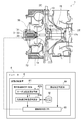
- FIG. 1 It is a figure which shows the principal part of the vibration suppression apparatus of the supercharger and electric assist supercharger which concern on one Embodiment of this invention. It is the figure which expanded the peripheral part of the motor shown by FIG. It is a figure for demonstrating the timing when the supercharging by the electrically assisted supercharger which concerns on one Embodiment of this invention is performed, and shows the relationship between an engine load and scavenging pressure. It is a figure for demonstrating the timing when the supercharging by the electrically assisted supercharger which concerns on one Embodiment of this invention is performed, and shows the relationship between an engine load and scavenging pressure.
- FIG. 1 It is a figure showing a motor which has a plurality of element stators concerning one embodiment of the present invention. It is a figure which shows the structure of the vibration suppression apparatus of a supercharger provided with the vibration suppression execution prohibition part and alerting
- an expression indicating that things such as “identical”, “equal”, and “homogeneous” are in an equal state not only represents an exactly equal state, but also has a tolerance or a difference that can provide the same function. It also represents the existing state.
- expressions representing shapes such as quadrangular shapes and cylindrical shapes represent not only geometrically strict shapes such as quadrangular shapes and cylindrical shapes, but also irregularities and chamfers as long as the same effects can be obtained. A shape including a part or the like is also expressed.
- the expressions “comprising”, “comprising”, “comprising”, “including”, or “having” one constituent element are not exclusive expressions for excluding the existence of the other constituent elements.
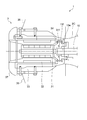
- FIG. 1 is a diagram showing a main part of a turbocharger vibration suppression device 6 and an electric assist supercharger 1 according to an embodiment of the present invention.
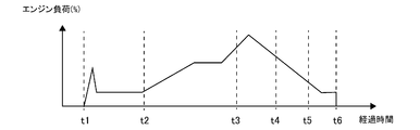
- FIG. 2 is an enlarged view of the periphery of the motor 3 shown in FIG. 3A and 3B are diagrams for explaining the timing at which supercharging by the electric assist supercharger 1 according to one embodiment of the present invention is performed, and shows the relationship between the engine load and the scavenging pressure.
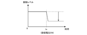
- FIG. 4 is a diagram for explaining the reduction effect of the shaft vibration level by exciting the motor 3 of the electric assist supercharger 1 according to the embodiment of the present invention.
- the electric assist supercharger 1 by the supercharger vibration suppression device 6 (hereinafter simply referred to as the vibration suppression device 6) and the supercharger vibration suppression method (hereinafter simply referred to as the vibration suppression method).
- the electric assist supercharger 1 may be a hybrid supercharger capable of supercharging similar to the electric assist supercharger 1 described later. .
- the hybrid turbocharger can perform supercharging similar to that of the electric assist supercharger 1, and when the engine is operated in a high load operation region where sufficient exhaust gas energy can be obtained, surplus energy of the exhaust gas Is recovered as electric power.
- the electric assist supercharger 1 when the turbine wheel 2T installed in the exhaust passage of the engine is rotated by the exhaust gas, the compressor wheel 2C connected by the rotor shaft 15 rotates and flows toward the combustion chamber of the engine.
- a turbocharger configured to compress a gas such as air in a scavenging passage.
- the electric assist supercharger 1 includes a motor 3 (electric motor) that can apply a rotational force to the rotor shaft 15 by electric power.
- the motor 3 applies a rotational force to the rotor shaft 15 by electric power when the energy of the exhaust gas that drives the turbine wheel 2T is insufficient, for example, when the engine is operated in a low load operation region. Configured to energize the rotation of.
- the electric assist supercharger 1 is provided in a uniflow scavenging two-cycle diesel engine that is a propulsion engine of a large vessel
- the hybrid supercharger and the electric assist supercharger 1 are appropriately referred to as a supercharger 1.
- the uniflow scavenging type two-cycle diesel engine when the piston pushed down by fuel combustion and explosion falls below the scavenging port opened at the bottom of the cylinder, the cleaning air (scavenging) flows into the cylinder.
- the exhaust valve at the upper part of the cylinder is opened, the exhaust gas and the combustion gas are exchanged, and the piston rises again to compress the combustion gas. For this reason, the supercharger 1 demonstrated below is used.
- the supercharger 1 includes an exhaust gas inlet casing 11, an exhaust gas outlet casing 12, a bearing base 13, and an air guide casing 14 on the compressor side that are integrally fastened by bolts (not shown). It is configured.
- the rotor shaft 15 is rotatably supported by a thrust bearing 17t and radial bearings 17a and 17b provided in the bearing base 13, and has a turbine wheel 2T constituting a turbine (turbine part) at one end and the other end.
- the part has a compressor wheel 2C constituting a compressor (compressor part).
- the turbine wheel 2T has a large number of blades 2Ta on the outer periphery, and the blade 2Ta of the turbine wheel 2T is provided in the exhaust gas inlet casing 11 and has an exhaust gas introduction path 22 for introducing exhaust gas into the turbine wheel 2T. It is disposed between the exhaust gas exhaust passage 23 provided in the exhaust gas outlet casing 12 and guiding the exhaust gas after passing through the turbine wheel 2T to the outside.
- the compressor wheel 2C has a large number of blades 2Ca on the outer periphery, and the blade 2Ca of the compressor wheel 2C is connected to the compressor wheel 2C provided in the air guide casing 14 which is a part of the supercharger casing.
- the intake air introduction path 24 that guides air and the vortex chamber 25 into which the combustion gas compressed by the compressor wheel 2C flows are arranged.
- the vortex chamber 25 is connected to the downstream side of a scavenging passage (not shown), and the combustion gas that has passed through the vortex chamber 25 flows toward the combustion chamber of the engine.
- the supercharger 1 of the embodiment shown in FIGS. 1 to 4 includes a silencer 26 on the upstream side of the intake air introduction path 24.
- the silencer 26 is installed on the upstream side of the inlet portion of the intake air introduction path 24 and has a silencing function for absorbing noise generated by air suction, and is supported by the air guide casing 14 via an intermediate piece 27. Has been. The same applies to the embodiments shown in FIGS. 6 to 18 described later.
- the motor 3 of the supercharger 1 includes a motor rotor 31, a stator 32, and a housing 33 as shown in FIGS. 1 to 2 and FIGS. 6, 8, 11, and 15 described later.
- the motor 3 is attached to a shaft extension 15e that extends the compressor side end of the rotor shaft, and the motor 3 has a motor overhang structure that does not have a dedicated bearing. That is, the motor 3 is supported by the thrust bearing 17t and the radial bearings 17a and 17b that support the rotor shaft 15 (see FIG. 1).
- the motor rotor 31 is a cylindrical member having a permanent magnet on the outer peripheral surface.
- the rotor shaft 15 is attached.
- the stator 32 is housed and installed in a cylindrical housing 33 so as to surround the outer periphery of the stator 32 in a state of being separated from the motor rotor 31.
- the motor rotor 31 is disposed in a non-contact state with respect to the stator 32 in a hollow portion formed inside the stator 32.
- the housing 33 is supported by the air guide casing 14 via a support member 35, and a cap 37 is fixedly attached to the front end portion of the housing 33 with bolts 38.
- the motor 3 of the supercharger 1 is a three-phase AC motor, for example, and is driven by a motor control device (for example, an inverter 4) that controls the motor 3.
- the motor control device independently sets the motor 3 in an excited state by applying an excitation voltage to the motor 3 and rotates the motor rotor 31 by rotating the direction of the magnetic field generated by the excitation voltage. Configured to be able to do. That is, the motor 3 is in a state in which a rotational force is applied to the motor rotor 31 (motor operating state) when the excitation voltage is applied and the direction of the magnetic field of the stator 32 generated by the application of the excitation voltage is rotated. .
- the motor control device described above determines the voltage (excitation voltage) and frequency applied to the stator 32.
- the inverter 4 can rotate the motor rotor 31 at a target rotational speed. More specifically, the inverter 4 periodically switches the three phases of the stator 32 through which a current flows by periodically switching switching elements (for example, six transistors) such as a plurality of transistors included in the inverter 4. Accordingly, the direction of the magnetic field of the stator 32 is sequentially switched so as to rotate in one direction, and the motor rotor 31 rotates by attracting a magnet (permanent magnet) on the motor rotor 31 side by the rotating magnetic field.
- switching elements for example, six transistors
- the inverter 4 applies the excitation voltage to the motor 3 and switches the direction of the current flowing through the stator 32 (winding) so that the above rotating magnetic field is generated, whereby the motor 3 can be put into the motor operating state. It is possible.
- the inverter 4 can place the motor 3 in the excitation restraint state by applying an excitation voltage at a frequency of 0 to the stator 32, for example.
- the motor 3 of the supercharger 1 having the above-described configuration is configured to be turned on / off according to the operating state of the engine.
- the motor 3 When the motor 3 is turned on, the motor operates as described above, and when the motor 3 is turned off, the application of the excitation voltage is stopped (motor non-operating state).
- the on / off timing of the motor 3 will be described with reference to FIGS. 3A and 3B.
- 3A and 3B as illustrated in FIG. 3A, as the engine load (%) changes, the supercharger 1 generates a scavenging pressure as shown in FIG. 3B. It is shown.
- a marine two-stroke engine may be configured such that an electric auxiliary blower is attached to the compressor outlet of the supercharger and the scavenging pressure is generated by turning on and off the auxiliary blower.
- the scavenging pressure by the auxiliary blower may be generated by the auxiliary blower before time t1, which will be described later, or after t5.
- the auxiliary blower includes a centrifugal impeller and an induction motor that are operated at a constant rotational speed, and is automatically started and stopped (on / off) according to a change in scavenging pressure of the engine of the engine. Note that the auxiliary blower is not essential, and in some other embodiments, the engine may not include the auxiliary blower.
- the engine is started at time t1 and is idling until time t2. Thereafter, the engine load starts to increase, for example, when the ship starts to sail from time t2, and the engine load increases step by step until time t3 is passed (see FIG. 3A).
- the motor 3 of the supercharger 1 is turned on from time t2 to time t3, and the motor 3 applies a rotational force to the rotor shaft 15, The rotation of the rotor shaft 15 driven by the exhaust gas is energized. Thereafter, between time t3 and time t4, the engine is operated in a high load state, and since the exhaust gas has sufficient energy to drive the turbine wheel 2T, the motor 3 of the supercharger 1 is turned off.
- the motor 3 is used as a generator in order to recover the surplus energy of the exhaust gas using the motor 3 from the time t3 to the time t4. May be.
- time t3 there is a peak of the engine load between time t3 and time t4, and after passing the peak, after time t4 and time t5, at time t6.
- the engine is stopped.
- time t4 after the peak of the engine load has passed, the engine operating state returns to the low load state again, so the motor 3 of the supercharger 1 is turned on. In this state, at time t5, the motor 3 of the supercharger 1 is turned off when it is determined that no boost is required.
- the supercharger 1 compresses air or the like while turning the motor 3 on and off according to the engine load.
- the shaft 15 rotates, for example, the rotor shaft 15 itself is unbalanced and the bearing 17 of the rotor shaft 15 (thrust bearings 17t and radial bearings 17a and 17b) vibrates, so that the shaft vibration is generated in the rotor shaft 15. Arise.
- the present inventors have noticed that the shaft vibration becomes relatively remarkable when the motor 3 of the supercharger 1 is turned off.
- the motor 3 is turned on, the motor 3 is energized and the rotation of the rotor shaft 15 is energized by the motor 3.
- the motor 3 when the motor 3 is turned off, the motor 3 is not energized but only by exhaust gas.
- the rotor shaft 15 is rotationally driven. Accordingly, as shown in FIG. 4, the inventors set the motor 3 in an excited state when shaft vibration is generated in the rotor shaft 15 of the supercharger 1, thereby causing the vibration level of shaft vibration. Has been found to be reduced. As illustrated in FIG. 4, when the excitation voltage is turned on at time tx when shaft vibration is occurring in the rotor shaft 15, the vibration level decreases after time tx.
- the present inventors suppress the relative movement of the motor rotor 31 with respect to the stator 32 by attracting the motor rotor 31 to the stator 32 by the magnetic force (attractive force) from the stator 32 of the motor 3 in an excited state. It has been found that the shaft vibration level of the rotor shaft 15 attached to can be reduced. In particular, by setting the motor 3 to the excitation restraint state without setting the motor to the motor operating state, the motor 3 does not urge the rotor shaft 15, so that the shaft vibration level of the rotor shaft 15 is reduced without affecting the scavenging pressure. It becomes possible to do.
- the vibration suppression device 6 is in operation of the electric assist supercharger 1 in which the motor 3 is attached to the compressor side end of the rotor shaft 15 as described above (after the engine is started including the idling state). Based on the above principle, it is configured to suppress the shaft vibration during the period from when the engine load is greater than 0% to when the engine is stopped.
- the motor of the supercharger 1 in the vibration suppression executable region that is the time zone between time t0 and time t2, between time t3 and time t4, and between time t5 and time t6. 3 is not in the motor operating state, and the shaft vibration of the rotor shaft 15 may occur.
- the vibration suppression device 6 is configured to determine a situation corresponding to such a vibration suppression executable region and to bring the motor 3 into an excited state when necessary.
- shaft vibration may occur due to the auxiliary blower in the ON state.
- the motor 3 in the non-excited state is similarly connected. By setting the excitation state, the shaft vibration level of the rotor shaft 15 can be reduced.
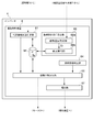
- the vibration suppression device 6 is the specific vibration state determination unit 61. And an excitation state determination unit 64 and a vibration suppression execution unit 65.
- the vibration suppression device 6 is configured by a computer, for example, and includes a CPU (processor) (not shown) and a memory M (storage device) such as a ROM and a RAM. And each said function part with which the vibration suppression apparatus 6 is provided is implement
- the vibration suppression device 6 is mounted as one functional unit of the inverter 4, but in some other embodiments, for example, communication with a motor control device serving as the inverter 4 is possible. It may be a separate connected device.
- a motor control device serving as the inverter 4
- It may be a separate connected device.
- the specific vibration state determination unit 61 determines whether or not the magnitude of the shaft vibration of the rotor shaft 15 of the supercharger 1 exceeds or exceeds a predetermined magnitude. To do. For example, as will be described later, the determination of the specific vibration state in which the rotor shaft vibrates to the extent that vibration suppression is necessary may be performed based on the vibration detection value F of the actually measured shaft vibration ( 6 to 7), or based on the actual turbo rotation speed V of the rotor shaft 15 of the supercharger 1 (see FIGS. 8 to 10), or the bearing of the bearing 17 of the supercharger 1. It may be performed based on the temperature Bt (see FIGS. 11 to 12).
- the excitation state determination unit 64 determines whether or not the excitation state in which the excitation voltage is applied to the motor 3 of the supercharger 1. For example, the motor 3 is turned on based on information on the motor control device side obtained by communicating with a control unit of a motor control device (such as the inverter 4) or by acquiring information on the memory of the motor control device. It may be determined whether or not it is done. In this case, when the motor 3 is turned on, it is determined that the motor 3 is in an excited state. Alternatively, it may be determined by the same logic as the logic that the turbocharger 1 is turned on and off, for example, confirming the engine operating state such as the engine load and the engine speed as shown in FIGS.
- the engine may be determined whether or not the engine is in an operating state in which the supercharger 1 is turned on and off. In this case, when the engine is in an operating state in which the supercharger 1 is turned on, it is determined that the motor 3 is in an excited state. Actually, the voltage of the motor 3 may be detected. When the excitation voltage is detected, it is determined that the motor 3 is in the excitation state.
- the vibration suppression execution unit 65 applies an excitation voltage to the motor 3 when the specific vibration state determination unit 61 determines that the vibration state is the specific vibration state and when the excitation state determination unit 64 determines that the vibration state is not the excitation state. To do. As shown in FIG. 4, the shaft vibration level can be reduced by applying an excitation voltage to the motor 3.
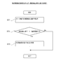
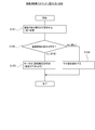
- FIG. 5 is a flow chart showing a turbocharger vibration suppression method according to an embodiment of the present invention.
- the vibration suppressing method according to at least one embodiment of the present invention is performed when the engine of the electric assist supercharger 1 in which the motor 3 is attached to the compressor-side end of the rotor shaft 15 is operating.
- a method for suppressing shaft vibration comprising a specific vibration state determination step (S51), an excitation state determination step (S52), and a vibration suppression execution step (S53 to S54).
- the vibration suppression method may be executed by the vibration suppression device 6 described above.
- the operator determines the specific vibration state by monitoring the operating state of the supercharger 1, and performs an operation (such as pressing a switch) to apply an excitation voltage to the motor 3 when it is determined that the operator is in the specific vibration state. For example, you may go by hand.
- the vibration suppression method will be described according to the flow of FIG.
- step S51 of FIG. 5 a specific vibration state determination step is executed. Whether or not the specific vibration state determination step (S51) is a specific vibration state in which the magnitude of the shaft vibration of the rotor shaft 15 of the turbocharger 1 exceeds or may exceed a predetermined magnitude. It is a step which determines. This step (S51) corresponds to the processing content executed by the above-described specific vibration state determination unit 61, and has already been described, so the details are omitted.
- the excitation state determination step (S52) is a step of determining whether or not an excitation state in which an excitation voltage is applied to the motor 3 of the supercharger 1 is performed. This step (S52) corresponds to the processing content executed by the above-described excitation state determination unit 64, and since it has already been described, its details are omitted.
- a vibration suppression execution step is executed.
- the vibration suppression execution step (S53 to S54) is performed on the motor 3 when the specific vibration state determination unit 61 determines that the vibration state is the specific vibration state and when the excitation state determination unit 64 determines that the vibration state is not the excitation state. Apply excitation voltage. More specifically, if it is determined in step S53 that the rotor shaft 15 is in a specific vibration state and the motor 3 is in a non-excitation state that is not an excitation state, an excitation voltage is applied to the motor 3 in step S54. Apply. That is, vibration suppression is executed. Conversely, if it is determined in step S53 that the vibration is not in a specific vibration state or the motor 3 is already in an excited state, the flow of FIG. 5 is terminated without executing vibration suppression in step S54.
- the motor 3 Excitation voltage is applied.
- the motor 3 in the excited state in this way, the relative movement of the motor rotor 31 with respect to the stator 32 can be suppressed by the attractive force (magnetic force) from the stator 32 (coil) generated in this excited state. It is possible to reduce the shaft vibration of the rotor shaft 15 rotating together.
- FIGS. 6 to 7 are diagrams illustrating an embodiment in which the vibration detection value F obtained by actually measuring vibration is monitored.
- FIG. 6 is a diagram illustrating a configuration of a vibration suppression device 6 for a supercharger that determines a specific vibration state by monitoring vibration according to an embodiment of the present invention.
- FIG. 7 is a flowchart showing details of the above-described specific vibration state determination step (step S51 in FIG. 5) in the turbocharger vibration suppressing method according to the embodiment of the present invention, and monitoring shaft vibration. It is determined whether it is a specific vibration state by this.
- FIGS. 8 to 10 are diagrams illustrating an embodiment in which the specific vibration state is determined based on the rotational speed of the rotor shaft 15 (actual turbo rotational speed V).
- FIG. 8 to 10 are diagrams illustrating an embodiment in which the specific vibration state is determined based on the rotational speed of the rotor shaft 15 (actual turbo rotational speed V).
- FIG. 8 is a diagram illustrating a configuration of the turbocharger vibration suppression device 6 that determines the specific vibration state based on the actual turbo rotation speed V of the rotor shaft 15 according to the embodiment of the present invention.
- FIG. 9 is a diagram for explaining a vibration mode of shaft vibration of the rotor shaft 15 according to an embodiment of the present invention.
- FIG. 10 is a flowchart showing details of the specific vibration state determination step (step S51 in FIG. 5) in the turbocharger vibration suppression method according to the embodiment of the present invention. The specific vibration state is determined based on the speed V.
- FIGS. 11 to 12 are diagrams illustrating an embodiment in which the specific vibration state is determined based on the bearing temperature Bt of the bearing 17 that supports the rotor shaft 15 of the supercharger 1.
- FIG. 11 is a diagram illustrating a configuration of a vibration suppression device 6 for a supercharger that determines a specific vibration state based on a bearing temperature Bt according to an embodiment of the present invention.
- FIG. 12 is a flowchart showing details of the specific vibration state determination step (step S51 in FIG. 5) in the turbocharger vibration suppression method according to the embodiment of the present invention, and is specified based on the bearing temperature Bt. It is determined whether or not it is in a vibration state.
- FIG. 13 is a figure which shows the structure of the vibration suppression apparatus 6 of the supercharger provided with the dangerous speed range correction
- FIG. 14 is a flowchart showing the dangerous speed range correction step according to the embodiment of the present invention.
- FIG. 15 is a diagram showing a motor 3 having a plurality of element stators according to an embodiment of the present invention.
- FIG. 16 is a diagram illustrating a configuration of a vibration suppression device 6 for a supercharger including a vibration suppression execution prohibition unit 66 and a notification unit 67 according to an embodiment of the present invention.
- FIG. 17 is a flowchart showing a vibration suppression execution prohibition step according to an embodiment of the present invention.
- FIG. 18 is a flowchart showing the vibration suppression execution step according to an embodiment of the present invention, which is performed together with FIG.
- the specific vibration state determination unit 61 includes a vibration detection value acquisition unit 62 a that acquires a vibration detection value F of the shaft vibration of the rotor shaft 15 of the supercharger 1, When the vibration detection value F acquired by the vibration detection value acquisition unit 62a is larger than a predetermined vibration threshold value Tf, it is in a specific vibration state in which the magnitude of the shaft vibration of the rotor shaft 15 exceeds a predetermined magnitude. And a vibration determination unit 63a for determination. As shown in FIG. 6, the supercharger 1 includes vibration detection means 71 that can detect shaft vibration.
- the vibration detection unit 71 is connected to the vibration detection value acquisition unit 62a, and the vibration detection value F detected by the vibration detection unit 71 is input to the vibration detection value acquisition unit 62a.
- the vibration detection value acquisition unit 62a can acquire the vibration detection value F of the rotor shaft 15.
- the vibration detection unit 71 may be, for example, a pickup capable of converting vibration and speed into a current corresponding to the magnitude.
- the vibration detecting means 71 is installed on the bearing base 13 and detects the bearing base speed Fs (mm / s) as the vibration detection value F. And the vibration determination part 63a determines with it being a specific vibration state, when the bearing stand speed Fs is larger than the vibration threshold value Tf used as a predetermined bearing stand speed (Tf ⁇ Fs).
- the vibration detection means 71 may detect the magnitude of the shaft vibration (vibration level Fi ( ⁇ )) as the vibration detection value F, and the vibration level Fi is a predetermined vibration level. Is greater than the vibration threshold value Tf (Tf ⁇ Fi), it is determined that the specific vibration state is present.
- the specific vibration state determination step (S51 of FIG. 5) includes a vibration acquisition step (S71) of acquiring a vibration detection value F of the shaft vibration of the rotor shaft 15.
- a vibration detection value F acquired in the vibration acquisition step (S71) is larger than a predetermined vibration threshold value Tf, it is in a specific vibration state in which the magnitude of the shaft vibration of the rotor shaft 15 exceeds a predetermined magnitude.
- step S ⁇ b> 71 the vibration detection value F of the rotor shaft 15 is acquired, for example, from the vibration detection means 71.
- the vibration detection means 71 may detect the bearing stand speed Fs and the vibration level Fi.
- the specific vibration state is determined in step S73. judge.
- step S72 if it is determined that the vibration detection value F is equal to or less than the vibration threshold Tf (Tf ⁇ F), the flow in FIG. 7 is terminated without executing step S73. Note that ending the flow in FIG. 7 is the same as ending step S51 in FIG. 5 described above, and therefore, as a vibration suppressing method, step S52 and subsequent steps in FIG. 5 are continuously executed.
- the magnitude of the shaft vibration of the rotor shaft 15 is based on the vibration detection value F obtained by directly detecting the shaft vibration of the rotor shaft 15. It is possible to determine whether or not the predetermined size is exceeded (determination whether or not the rotor shaft is in a specific vibration state).
- the specific vibration state determination unit 61 acquires the actual turbo rotation speed V of the rotor shaft 15 of the supercharger 1.
- the actual turbo rotation speed acquisition unit 62b and the actual turbo rotation speed V acquired by the actual turbo rotation speed acquisition unit 62b are in the dangerous speed region D of the rotor shaft 15, the magnitude of the shaft vibration of the rotor shaft 15 is large.
- a dangerous speed range passage determination unit 63b that determines that the vibration state is a specific vibration state that may exceed a predetermined magnitude.
- the supercharger 1 includes an actual turbo rotation speed detection unit 72 that can detect an actual turbo rotation speed V that is the rotation speed (rotation speed) of the rotor shaft 15 during operation.
- the actual turbo rotation speed detection unit 72 is connected to the actual turbo rotation speed acquisition unit 62b, and the actual turbo rotation speed V detected by the actual turbo rotation speed detection unit 72 is input to the actual turbo rotation speed acquisition unit 62b. It is comprised so that. Thus, the actual turbo rotation speed acquisition unit 62b can acquire the actual turbo rotation speed V.
- the actual turbo rotation speed detection means 72 may be a rotation speed sensor. In the embodiment shown in FIG. 8, the actual turbo rotational speed detection means 72 is supported by the air guide casing 14 of the supercharger 1 in a state of facing the shroud side edge of the blade 2Ta of the compressor wheel 2C. It is installed at.
- the dangerous speed range D of the rotor shaft 15 is a speed range in which the rotor shaft 15 may be broken due to deflection during rotation, and the like, when the rotational speed of the rotor shaft 15 is in the dangerous speed range D. Increases the shaft vibration. For this reason, when the rotational speed of the rotor shaft 15 is in the dangerous speed region D, the dangerous speed range passage determination unit 63b may cause the shaft vibration of the rotor shaft 15 to exceed a predetermined magnitude. It is determined that there is a specific vibration state. More specifically, as shown in FIG. 9, there are usually a plurality of dangerous speed ranges D, and the first dangerous speed range D1 and the second dangerous speed range D2 from the smaller rotational speed of the rotor shaft 15 toward the larger one.
- the primary vibration mode shown in FIG. 9A occurs.
- the upper limit Du of the nth critical speed range Dn is smaller than the lower limit Dd of the (n + 1) th critical speed range Dn + 1.
- FIG. 10 corresponds to a specific method of the specific vibration state determination step of S51 of FIG.
- the specific vibration state determination step (S ⁇ b> 51 in FIG. 5) acquires the actual turbo rotation speed acquisition of the actual turbo rotation speed V of the rotor shaft 15 of the supercharger 1.
- the magnitude of the shaft vibration of the rotor shaft 15 is predetermined.
- step S101 the actual turbo rotation speed V of the rotor shaft 15 is acquired, for example, by acquiring from the actual turbo rotation speed detecting means 72. If it is determined in step S102 that the actual turbo speed V is in the dangerous speed range D as a result of comparing the actual turbo speed V and the dangerous speed range D (Dd ⁇ V ⁇ Du), step S102 is performed. In S103, it is determined that the specific vibration state is present. Conversely, if it is determined in step S102 that the actual turbo rotation speed V is not within the dangerous speed range D (Dd> V, Du ⁇ V), the flow of FIG. 10 is performed without executing step S103. Exit.
- step S102 The determination as to whether the actual turbo rotation speed V is in the dangerous speed range D in step S102 is not included in either the actual turbo rotation speed V or all the dangerous speed ranges D (nth dangerous speed range Dn). Is determined, the actual turbo rotation speed V is determined not to be in the dangerous speed range D. Further, ending the flow of FIG. 7 is the same as ending step S51 of FIG. 5 described above, and therefore, the vibration suppression method continues to execute step S52 and subsequent steps of FIG.
- the magnitude of the shaft vibration of the rotor shaft 15 exceeds a predetermined magnitude based on the rotational speed of the rotor shaft (actual turbo rotational speed V). It is possible to determine whether or not there is a possibility that the rotor shaft is in a specific vibration state.
- the specific vibration state determination unit 61 includes a bearing temperature acquisition unit 62c that acquires the bearing temperature Bt of the bearing 17 of the rotor shaft 15, and a bearing temperature acquisition unit 62c.
- the bearing temperature Bt acquired in step (b) is larger than a predetermined bearing temperature threshold value Tb
- the bearing temperature is determined to be a specific vibration state in which the magnitude of the shaft vibration of the rotor shaft 15 may exceed the predetermined magnitude.
- a determination unit 63c As shown in FIG. 11, the rotor shaft 15 of the supercharger 1 is supported by bearings 17 (17 s, 17 a, 17 b). As the shaft vibration of the rotor shaft 15 increases, the temperature ( The bearing temperature Bt) tends to increase.
- the bearing temperature determination unit 63c is configured to determine whether or not the rotor shaft 15 is in a specific vibration state based on the bearing temperature Bt. For this reason, the supercharger 1 is provided with the bearing temperature detection means 73 (for example, thermometer) which can detect the bearing temperature Bt.
- the bearing temperature detection unit 73 is connected to the bearing temperature acquisition unit 62c, and the bearing temperature Bt detected by the bearing temperature detection unit 73 is input to the bearing temperature acquisition unit 62c.
- the bearing temperature acquisition unit 62c can acquire the bearing temperature Bt.
- the bearing temperature detecting means 73 is installed on the compressor-side radial bearing 17 a, which tends to have more vibration than the turbine-side radial bearing 17 b (see FIG. 9).
- the bearing temperature detecting means 73 detects the metal temperature of the radial bearing 17a as the bearing temperature Bt.
- the bearing temperature detecting means 73 may be installed in the radial bearing 17b on the turbine side or may be provided in the thrust bearing 17t.
- the bearing temperature detection means 73 may be provided in at least one of the bearings 17 (17a, 17b, 17t).
- the bearing temperature detecting means 73 is configured to detect the temperature of the lubricating oil supplied to the bearing 17 so as to detect the temperature of the lubricating oil as the bearing temperature Bt. Also good.
- the specific vibration state determination step (S51 of FIG. 5) includes a bearing temperature acquisition step (S121) of acquiring the bearing temperature Bt of the bearing 17 of the rotor shaft 15, When the bearing temperature Bt acquired by the bearing temperature acquisition unit 62c is larger than a predetermined bearing temperature threshold value Tb, the specific vibration state in which the magnitude of the shaft vibration of the rotor shaft 15 may exceed the predetermined magnitude.
- step S ⁇ b> 121 the bearing temperature Bt is acquired, for example, by acquiring from the bearing temperature detecting means 73.
- the metal temperature of the bearing 17 or the oil temperature of the lubricating oil may be detected by the bearing temperature detecting means 73.
- the specific vibration state is assumed in step S123. judge.
- step S122 determines that the bearing temperature Bt is equal to or lower than the bearing temperature threshold value Tb (Tb ⁇ Bt)
- the flow of FIG. 12 is terminated without executing step S123. Note that ending the flow of FIG. 12 is the same as ending step S51 of FIG. 5 described above, and therefore, step S52 and subsequent steps of FIG. 5 are continuously executed as the vibration suppression method.
- the critical speed range D of the embodiment in which the specific vibration state is determined based on the actual turbo rotational speed V is the same as the bearing 17 of the bearing 17 described above. You may correct
- the vibration suppression device 6 further includes a dangerous speed range correction unit 63 d that corrects the range of the dangerous speed range D.
- the critical speed range correction unit 63d corrects the range of the critical speed range D based on the bearing temperature acquisition unit 62c that acquires the bearing temperature Bt of the bearing of the rotor shaft 15 and the bearing temperature Bt acquired by the bearing temperature acquisition unit 62c.
- a correction execution unit 63e As described above, the bearing temperature acquisition unit 62 c acquires the bearing temperature Bt from the bearing temperature detection unit 73.
- the dangerous speed range correction unit 63d has information on the standard bearing temperature Bt with respect to the actual turbo rotation speed V (bearing standard temperature information Rt), and the actual turbo rotation speed V based on the bearing standard temperature information Rt. From this, the bearing standard temperature Bs can be calculated. When the bearing temperature Bt is higher than the bearing standard temperature Bs (Bt> Bs), it is suggested that the shaft vibration may be larger than the assumed (standard), and therefore depends on the degree of the difference (Bt ⁇ Bs). By increasing at least one of the upper limit value Du of the dangerous speed range D (Dn) or the lower limit value Dd, the region of the dangerous speed range D (Dn) is expanded. .
- the critical speed range D in which the actual turbo rotational speed V is closest to the actual critical speed range D among the plurality of critical speed ranges D (the nth critical speed range Dn) or the actual turbo rotational speed.
- Some dangerous speed zones D such as each dangerous speed zone D positioned before and after the speed V may be corrected, or all the dangerous speed zones D may be corrected.
- the actual turbo rotation speed acquisition unit 62b and the bearing temperature acquisition unit 62c are respectively connected to the correction execution unit 63e, and the actual turbo rotation speed V and the bearing temperature Bt are corrected from the respective function units. It is configured to be input to the execution unit 63e.
- the correction execution unit 63e acquires the bearing standard temperature Bs corresponding to the actual turbo rotational speed V using the bearing standard temperature information Rt on the memory M. Then, the detected bearing temperature Bt and the bearing standard temperature Bs are compared to determine whether the detected bearing temperature Bt is larger or smaller than the bearing standard temperature Bs, and as described above according to the degree of the difference. To correct the dangerous speed range D.
- the dangerous speed range correction unit 63d may directly correct the dangerous speed range D (Dn) stored in the memory M included in the vibration suppression device 6.
- Dn dangerous speed range
- the dangerous speed range correction unit 63d may directly correct the dangerous speed range D (Dn) stored in the memory M included in the vibration suppression device 6.
- the vibration suppression method further includes a dangerous speed range correction step (S ⁇ b> 140) for correcting the range of the dangerous speed range D.
- the dangerous speed range correction step is based on the bearing temperature acquisition step (S141) for acquiring the bearing temperature Bt of the bearing 17 of the rotor shaft 15 and the bearing temperature Bt acquired in the bearing temperature acquisition step (S141).
- step S ⁇ b> 141 the bearing temperature Bt is obtained by obtaining it from the bearing temperature detecting means 73.
- step S142 the actual turbo rotation speed V is acquired, for example, by acquiring from the actual turbo rotation speed detecting means 72.
- the bearing standard temperature Bs corresponding to the acquired actual turbo rotational speed V is calculated by referring to the bearing standard temperature information Rt.
- step S144 if the bearing temperature Bt is larger than the bearing standard temperature Bs (Bt> Bs), as described above, in step S145, the region The range of the dangerous speed range D (Dn) is corrected by responding to the difference (Bt ⁇ Bs) so as to spread. Conversely, if the bearing temperature Bt is not greater than the bearing standard temperature Bs (Bt ⁇ Bs) in step S144, the process proceeds to the next step S146 without executing step S145.
- step S147 When the bearing temperature Bt is smaller than the bearing standard temperature Bs as a result of comparing the bearing temperature Bt and the bearing standard temperature Bs in step S146 (Bt ⁇ Bs), the region is determined in step S147 as described above.
- the range of the dangerous speed range D (Dn) is corrected by responding to the difference (Bs ⁇ Bt) so as to narrow. Conversely, if the bearing temperature Bt is not smaller than the bearing standard temperature Bs in step S146 (Bt ⁇ Bs), the flow of FIG. 14 is terminated without executing step S147.
- the dangerous speed range D is corrected based on the bearing temperature Bt obtained based on the oil temperature of the lubricating oil of the bearing 17 or the metal temperature of the bearing.
- the actual operating condition of the turbocharger 1 is taken into account when determining the specific vibration state based on the possibility of the shaft vibration exceeding the predetermined magnitude based on the actual turbo rotation speed V.
- the specific vibration state based on the actual turbo rotation speed V can be determined with higher accuracy.
- the motor 3 includes the stator 32 that is disposed so as to surround the rotor shaft 15. Further, as shown in FIG. 15, the stator 32 has a plurality of element stators arranged in series along the rotor shaft 15 (3 in FIG. 15: 32a to 32c). And the vibration suppression execution part 65 with which the vibration suppression apparatus 6 is equipped, or the vibration suppression execution step (S54 of FIG. 5) in a vibration suppression method is with respect to each of the vibration mode of the rotor shaft 15 among several element stators.
- the excitation voltage may be applied to the target element stator 32t composed of one or more element stators each defined.
- the stator 32 of the motor 3 is configured such that an excitation voltage can be independently applied to each of the plurality of element stators.
- the stator 32 of the motor 3 is divided into three element stators (32 a to 32 C) along the axial direction of the rotor shaft 15.
- the present invention is not limited to this, and the number of element stators constituting the stator 32 may be two or more.
- the vibration suppressing device 6 includes target element stator information in which one or more element stators selected from a plurality of element stators are associated with each of a plurality of vibration modes (see FIG. 9) generated in the rotor shaft 15. ing.
- the target element stator information is information in which one or more element stators are associated with each of a plurality of vibration modes, in other words, each of a plurality of dangerous speed ranges D (n-th dangerous speed range Dn). It becomes.
- the vibration suppression execution unit 65 determines the vibration mode based on the comparison between the actual turbo rotation speed V and the dangerous speed range D (Dn), for example, and executes the above-described target element stator when performing vibration suppression.
- one or more target element stators 32t to which the excitation voltage should be applied are determined from the specified vibration mode.
- the target element stator 32t does not become all the element stators, it becomes possible to suppress power consumption rather than applying an excitation voltage to all the element stators.
- the target element stator 32t may be determined by paying attention to the amplitude of the vibration mode of the rotor shaft 15. Since the motor rotor 31 needs to be more strongly attracted to the stator 32 as the amplitude of the shaft vibration is larger, more element stators may be used as the target element stator. In some other embodiments, the element stator that is the target element stator 32t in each vibration mode may be determined by limiting to the element stator close to the position where the amplitude becomes larger in each vibration mode. Specifically, considering the case where the rotor shaft 15 (the motor 3 and the rotor shaft 15) vibrates as shown in FIG. 9, for example, the primary vibration mode as shown in FIG.
- the shaft vibration of the rotor shaft 15 is relatively large at any position, all the element stators are set as the target element stators 32t, and secondary to quaternary as shown in FIGS. 9B to 9D.
- the first element stator 32a and the second element stator 32b may be used as the target element stator 32t.
- the excitation voltage is not applied to the third element stator 32c, so that the power consumption is reduced accordingly.
- the stator 32 of the motor 3 is constituted by a plurality of element stators (three in FIG. 15, 32 a, 32 b, and 32 c) arranged along the axial direction of the rotor shaft 15.
- the vibration of the rotor shaft 15 differs in amplitude and position depending on each vibration mode such as primary, secondary, and tertiary.
- the excitation voltage is not applied to all element stators at the time of vibration suppression, but is limited to at least some of the plurality of element stators according to the magnitude of vibration, or the amplitude in each vibration mode is
- the excitation voltage is configured to be applied only to the limited element stator (target element stator 32t), for example, by limiting to the element stator located in the enlarged portion.
- the power consumption can be suppressed as compared with the case where the excitation voltage is applied to all the element stators, and the vibration of the rotor shaft 15 can be suppressed while suppressing the power consumption.
- each target element stator 32t corresponding to each vibration mode has a rotor shaft 15 of a plurality of element stators.
- An element stator closest to the compressor-side end of the compressor may be included.
- the first element stator 32a corresponds.
- the element stator (first element stator 32a in FIG. 15) that is closest to the compressor-side end of the rotor shaft 15 is always attached to the target element stator 32t regardless of the type of vibration mode (order n). Configured to be included.
- the end of the rotor shaft 15 on the compressor side tends to have the largest amplitude in any vibration mode.
- the vibration of the rotor shaft 15 can be more efficiently suppressed. It can be carried out.
- the vibration suppression device 6 further includes a vibration suppression execution prohibition unit 66 that prohibits the execution of the vibration suppression execution unit 65. Further, it may be provided.
- the vibration suppression execution prohibition unit 66 includes a device temperature acquisition unit 66a that acquires a device temperature Et of a device including at least one of the motor 3 of the supercharger 1 or the inverter 4 that drives the motor 3, and a device temperature. And a prohibition execution unit 66b that prohibits the execution of the vibration suppression execution unit 65 when the temperature is equal to or greater than the predetermined device temperature threshold Te.
- the device temperature acquisition unit 66a is connected to the device temperature detection means 74 capable of detecting the device temperature Et, and is configured to receive an input of the device temperature Et from the device temperature detection means 74. Further, for example, the prohibition execution unit 66b is configured to be able to update the execution permission / inhibition flag f indicating permission / prohibition of execution of vibration suppression stored in the memory M of the vibration suppression device 6, thereby executing vibration suppression execution.
- the unit 65 may be configured to permit or prohibit application of the excitation voltage to the motor 3 (execution of vibration suppression). In this case, the vibration suppression execution unit 65 is configured to check the execution feasibility flag f on the memory M and to determine whether vibration suppression can be performed according to the information of the execution feasibility flag f (described later). (See FIG. 18).
- the vibration suppression method further includes a vibration suppression execution prohibition step (S171 to S173) that prohibits execution of the vibration suppression execution step (step S54 in FIG. 5).
- the vibration suppression execution prohibition step acquires the device temperature Et of the device including at least one of the motor 3 of the supercharger 1 or the inverter 4 that drives the motor 3.
- step S ⁇ b> 171 the device temperature Et is acquired, for example, by acquiring from the device temperature detecting means 74. If the device temperature Et is larger than the device temperature threshold Te as a result of comparing the device temperature Et with the device temperature threshold Te in step S172 (Td> Te), for example, in the step S173, for example, whether or not the above-described execution is possible. By updating the flag f to prohibition, the execution of the vibration suppression execution step (S54 in FIG. 5) is prohibited. Conversely, in step S172, if the device temperature Et is equal to or lower than the device temperature threshold Te (Td ⁇ Te), the flow of FIG. 17 is terminated without executing step S173. In the embodiment shown in FIG. 17, if No in step S172 (Td ⁇ Te), execution of vibration suppression is permitted in step S174 by setting, for example, the above-described execution permission flag f. Thereafter, the flow of FIG. 17 is finished.
- the vibration suppression execution step of S54 in FIG. 5 is replaced with a flow as shown in FIG. Explaining along the flow of FIG. 18, in step S181, for example, by confirming the execution feasibility flag f on the memory M set (updated) in the vibration suppression execution prohibition step (FIG. 17) described above, It is determined whether or not vibration suppression can be executed. If it is determined in step S182 that execution of vibration suppression is permitted, vibration suppression is executed in step S183. That is, an excitation voltage is applied to the motor 3. Conversely, if it is determined in step S182 that execution of vibration suppression is prohibited, step S183 is not executed, and the flow of FIG. 18 (FIG. 5) ends.
- the vibration suppression device 6 may further include a notification unit 67 that notifies the execution of the vibration suppression execution prohibition unit 66.
- the notification unit 67 is connected to a notification device such as a display, voice, and light, and notification is executed by outputting information to the notification device.
- the vibration detection value F, the actual turbo rotation speed V, the bearing temperature Bt, the transition of the device temperature Et, and the like may be notified together.
- the vibration suppression method may further include a notification step (S184) for notifying execution of the vibration suppression execution prohibition step.
- the notification step (S184) is executed until the flow of FIG. 18 is ended when it is determined in step S182 of FIG. 18 that the execution of vibration suppression is prohibited. Is done.
- the vibration suppression device 6 includes a vibration suppression execution prohibition unit 66 and a notification unit 67, and in the embodiments shown in FIGS. 17 to 18, the vibration suppression method executes the vibration suppression execution.
- the prohibition step (S171 to S173) and the notification step (S184) are provided, the notification unit 67 and the notification step (S184) are not essential, and in some other embodiments, the notification unit 67 and the notification step (S184). Is not necessary.
- a dangerous speed range correction unit 63d and a dangerous speed range correction step may be provided.
- the electric assist supercharger 1 having the motor hangover structure according to the embodiment of the present invention has been described above by taking a marine 2-circle diesel engine as an example.
- the present invention is not limited to the above-described embodiments, and includes forms obtained by modifying the above-described embodiments and forms obtained by appropriately combining these forms.
- the electric assist supercharger 1 may be provided in a marine four-cycle diesel engine.
- the electric assist supercharger 1 may be provided in an engine that is not for ships, such as for vehicles.
- the present invention is also applicable to the electric assist supercharger 1 that does not have an overhang over structure.
- the electric assist supercharger 1 may be located between the two radial bearings 17a and 17b, as shown in FIG. 1, FIG. 2, FIG. 6, FIG.
- the position of the motor 3 shown in each is between the two radial bearings 17a, 17b.
Landscapes
- Engineering & Computer Science (AREA)
- Mechanical Engineering (AREA)
- General Engineering & Computer Science (AREA)
- Chemical & Material Sciences (AREA)
- Combustion & Propulsion (AREA)
- Supercharger (AREA)
Abstract
Description
モータにより駆動可能である過給機の軸振動を抑制する過給機の振動抑制方法であって、
前記過給機のロータ軸の軸振動の大きさが所定の大きさを超えているか、又は、超える可能性がある、特定振動状態であるか否かを判定する特定振動状態判定ステップと、
前記モータに励磁電圧が印加されている励磁状態であるか否かを判定する励磁状態判定ステップと、
前記特定振動状態判定ステップによって前記特定振動状態であると判定された場合、かつ、前記励磁状態判定ステップによって前記励磁状態でないと判定された場合に、前記モータに前記励磁電圧を印加する振動抑制実行ステップと、を備える。
前記特定振動状態判定ステップは、
前記ロータ軸の軸振動の振動検出値を取得する振動取得ステップと、
前記振動取得ステップで取得された前記振動検出値が所定の振動閾値よりも大きい場合に、前記ロータ軸の軸振動の大きさが所定の大きさを超えている前記特定振動状態であると判定する振動判定ステップと、を有する。
上記(2)の構成によれば、ロータ軸の軸振動を直接検出することにより得られる振動検出値に基づいて、ロータ軸の軸振動の大きさが所定の大きさを超えているか否かの判定(ロータ軸が特定振動状態にあるか否かの判定)を行うことができる。
前記特定振動状態判定ステップは、
前記ロータ軸の実ターボ回転速度を取得する実ターボ回転速度取得ステップと、
前記実ターボ回転速度取得ステップで取得された前記実ターボ回転速度が、前記ロータ軸の危険速度域に入っている場合に、前記ロータ軸の軸振動の大きさが所定の大きさを超える可能性がある前記特定振動状態であると判定する危険速度域通過判定ステップと、を有する。
上記(3)の構成によれば、ロータ軸の回転速度(実ターボ回転速度)に基づいて、ロータ軸の軸振動の大きさが所定の大きさを超えている可能性があるか否かの判定(ロータ軸が特定振動状態にあるか否かの判定)を行うことができる。
前記危険速度域の範囲を補正する危険速度域補正ステップを、さらに備え、
前記危険速度域補正ステップは、
前記ロータ軸の軸受の軸受温度を取得する軸受温度取得ステップと、
前記軸受温度取得ステップで取得した前記軸受温度に基づいて、前記危険速度域の範囲を補正する補正実行ステップと、を有する。
上記(4)の構成によれば、例えば、軸受の潤滑油の油温や軸受のメタル温度などに基づいて得られる軸受温度に基づいて、危険速度域が補正される。これによって、実ターボ回転速度に基づいて軸振動の大きさが所定の大きさを超えている可能性の有無により特定振動状態を判定するのに際して、過給機の実際の運転状況を考慮することができ、実ターボ回転速度に基づく特定振動状態の判定をより精度良く行うことができる。
前記特定振動状態判定ステップは、
前記ロータ軸の軸受の軸受温度を取得する軸受温度取得ステップと、
前記軸受温度取得ステップで取得された前記軸受温度が所定の軸受温度閾値よりも大きい場合に、前記ロータ軸の軸振動の大きさが所定の大きさを超える可能性がある前記特定振動状態であると判定する軸受温度判定ステップと、を有する。
上記(5)の構成によれば、ロータ軸を支持する軸受の軸受温度に基づいて、ロータ軸の軸振動の大きさが所定の大きさを超えている可能性があるか否かの判定(ロータ軸が特定振動状態にあるか否かの判定)を行うことができる。
前記モータは、前記過給機のコンプレッサ側の端部に取り付けられている。
上記(6)の構成によれば、電動アシスト過給機はオーバハング構造を有する。オーバハング構造では、ロータ軸における軸受の外側に位置する先端に重量物(モータ)があることから軸振動の原因となりやすく、オーバハング構造を有する電動アシスト過給機の軸振動を効果的に抑制することができる。
前記モータは、前記ロータ軸を取り囲むように配置されるステータを含み、
前記ステータは、前記ロータ軸に沿って直列に配列される複数の要素ステータを有し、
前記振動抑制実行ステップは、前記複数の要素ステータのうち、前記ロータ軸の振動モードの各々に対してそれぞれ定められた1以上の前記要素ステータからなる対象要素ステータに前記励磁電圧を印加するよう構成される。
上記(7)の構成によれば、モータのステータは、ロータ軸の軸方向に沿って配置された複数の要素ステータにより構成される。ここで、ロータ軸の振動は、1次、2次、3次といった各振動モードに応じて振幅の大きさや、その位置が異なる。このため、振動抑制の実行時において全ての要素ステータに励磁電圧を印加するのではなく、振動の大きさに応じて複数の要素ステータの少なくとも一部に限定し、あるいは、各振動モードにおける振幅が大きくなる部分に位置する要素ステータに限定するなどして、限定された要素ステータ(対象要素ステータ)にのみ励磁電圧を印加するよう構成される。これによって、全ての要素ステータに励起電圧を印加するよりも電力消費を抑制することができ、電力消費を抑制しつつ、ロータ軸の振動を抑制することができる。
前記振動抑制実行ステップの実行を禁止する振動抑制実行禁止ステップを、さらに備え、
前記振動抑制実行禁止ステップは、
前記モータ、あるいは、前記モータを駆動するインバータのうちの少なくとも一方を含む機器の機器温度を取得する機器温度取得ステップと、
前記機器温度が所定の機器温度閾値以上の場合には、前記振動抑制実行ステップの実行を禁止する禁止実行ステップと、を有する。
上記(8)の構成によれば、機器温度が過度に高い場合には振動抑制の実行が禁止される。これによって、振動抑制の実行により機器の温度がさらに上昇するのを防止することができ、機器の保護を図ることができる。
前記振動抑制実行禁止ステップの実行を報知する報知ステップを、さらに備える。
上記(9)の構成によれば、振動抑制実行ステップの実行ができないことをオペレータや外部システムなどの外部に知らせることができる。換言すれば、モータにより駆動可能である過給機の振動(騒音)の抑制ができないことを外部に知らせることができる。
モータにより駆動可能である過給機の軸振動を抑制する過給機の振動抑制装置であって、
前記過給機のロータ軸の軸振動の大きさが所定の大きさを超えているか、又は、超える可能性がある、特定振動状態であるか否かを判定する特定振動状態判定部と、
前記モータに励磁電圧が印加されている励磁状態であるか否かを判定する励磁状態判定部と、
前記特定振動状態判定部によって前記特定振動状態であると判定された場合、かつ、前記励磁状態判定部によって前記励磁状態でないと判定された場合に、前記モータに前記励磁電圧を印加する振動抑制実行部と、を備える。
前記特定振動状態判定部は、
前記ロータ軸の軸振動の振動検出値を取得する振動検出値取得部と、
前記振動検出値取得部で取得された前記振動検出値が所定の振動閾値よりも大きい場合に、前記ロータ軸の軸振動の大きさが所定の大きさを超えている前記特定振動状態であると判定する振動判定部と、を有する。
上記(11)の構成によれば、上記(2)と同様の効果を奏することができる。
前記特定振動状態判定部は、
前記ロータ軸の実ターボ回転速度を取得する実ターボ回転速度取得部と、
前記実ターボ回転速度取得部で取得された前記実ターボ回転速度が、前記ロータ軸の危険速度域に入っている場合に、前記ロータ軸の軸振動の大きさが所定の大きさを超える可能性がある前記特定振動状態であると判定する危険速度域通過判定部と、を有する。
上記(12)の構成によれば、上記(3)と同様の効果を奏することができる。
前記危険速度域の範囲を補正する危険速度域補正部を、さらに備え、
前記危険速度域補正部は、
前記ロータ軸の軸受の軸受温度を取得する軸受温度取得部と、
前記軸受温度取得部で取得した前記軸受温度に基づいて、前記危険速度域の範囲を補正する補正実行部と、を有する。
上記(13)の構成によれば、上記(4)と同様の効果を奏することができる。
前記特定振動状態判定部は、
前記ロータ軸の軸受の軸受温度を取得する軸受温度取得部と、
前記軸受温度取得部で取得された前記軸受温度が所定の軸受温度閾値よりも大きい場合に、前記ロータ軸の軸振動の大きさが所定の大きさを超える可能性がある前記特定振動状態であると判定する軸受温度判定部と、を有する。
上記(14)の構成によれば、上記(5)と同様の効果を奏することができる。
前記モータは、前記過給機のコンプレッサ側の端部に取り付けられている。
上記(15)の構成によれば、上記(6)と同様の効果を奏することができる。
前記モータは、前記ロータ軸を取り囲むように配置されるステータを含み、
前記ステータは、前記ロータ軸に沿って直列に配列される複数の要素ステータを有し、
前記振動抑制実行部は、前記複数の要素ステータのうち、前記ロータ軸の振動モードの各々に対してそれぞれ定められた1以上の前記要素ステータからなる対象要素ステータに前記励磁電圧を印加するよう構成される。
上記(16)の構成によれば、上記(7)と同様の効果を奏することができる。
前記対象要素ステータには、前記複数の要素ステータのうちの前記ロータ軸の前記コンプレッサ側の端部に最も近い要素ステータが含まれる。
上記(17)の構成によれば、ロータ軸のコンプレッサ側の端部に最も近い要素ステータは、振動モードの種類(次数)にかかわらず必ず対象要素ステータに含まれるよう構成される。ここで、ロータ軸のコンプレッサ側の端部は、いずれの振動モードにおいても最も振幅が大きくなる傾向にあることに本発明者らは着目した。このように、振動モードの種類(次数)にかかわらずロータ軸のコンプレッサ側の端部に最も近い要素ステータを対象要素ステータに含めることで、ロータ軸の振動の抑制をより効率的に行うことができる。
前記振動抑制実行部の実行を禁止する振動抑制実行禁止部を、さらに備え、
前記振動抑制実行禁止部は、
前記モータ、あるいは、前記モータを駆動するインバータのうちの少なくとも一方を含む機器の機器温度を取得する機器温度取得部と、
前記機器温度が所定の機器温度閾値以上の場合には、前記振動抑制実行部の実行を禁止する禁止実行部と、を有する。
上記(18)の構成によれば、上記(8)と同様の効果を奏することができる。
前記振動抑制実行禁止部の実行を報知する報知部を、さらに備える。
上記(19)の構成によれば、上記(9)と同様の効果を奏することができる。
モータにより駆動可能な過給機であって、
ロータ軸と、
エンジンから排出される排ガスにより駆動されるタービンホイールと、
前記ロータ軸によって、前記タービンホイールに連結されたコンプレッサホイールと、
電力により前記ロータ軸に回転力を付与することが可能な前記モータと、
上記(10)~(19)のいずれか1項に記載の過給機の振動抑制装置と、を備える。
上記(20)の構成によれば、上記(10)~(19)の各々と同様の効果を奏することができる。
例えば、「ある方向に」、「ある方向に沿って」、「平行」、「直交」、「中心」、「同心」或いは「同軸」等の相対的或いは絶対的な配置を表す表現は、厳密にそのような配置を表すのみならず、公差、若しくは、同じ機能が得られる程度の角度や距離をもって相対的に変位している状態も表すものとする。
例えば、「同一」、「等しい」及び「均質」等の物事が等しい状態であることを表す表現は、厳密に等しい状態を表すのみならず、公差、若しくは、同じ機能が得られる程度の差が存在している状態も表すものとする。
例えば、四角形状や円筒形状等の形状を表す表現は、幾何学的に厳密な意味での四角形状や円筒形状等の形状を表すのみならず、同じ効果が得られる範囲で、凹凸部や面取り部等を含む形状も表すものとする。
一方、一の構成要素を「備える」、「具える」、「具備する」、「含む」、又は、「有する」という表現は、他の構成要素の存在を除外する排他的な表現ではない。
以下では、過給機の振動抑制装置6(以下、単に、振動抑制装置6という。)および過給機の振動抑制方法(以下、単に、振動抑制方法という。)によって、電動アシスト過給機1の軸振動を抑制する場合を例として説明するが、この電動アシスト過給機1は、後述するような電動アシスト過給機1と同様な過給が可能なハイブリッド過給機であっても良い。ハイブリッド過給機は、電動アシスト過給機1と同様な過給が可能であると共に、十分な排ガスのエネルギーが得られる高負荷運転領域でエンジンが運転されている際には排ガスの余剰のエネルギーを電力として回収する。
図1~図4に示される実施形態の過給機1は、吸入空気導入路24の上流側にサイレンサ26を備えている。このサイレンサ26は、吸入空気導入路24の入口部の上流側に設置され、空気吸入によって発生する騒音を吸収する消音機能などを有しており、中間ピース27を介して空気案内ケーシング14に支持されている。なお、後述する図6~図18に示される実施形態でも同様となる。
以下、振動抑制装置6が備える各機能部について説明する。
図5に示されるように、本発明の少なくとも一実施形態に係る振動抑制方法は、ロータ軸15のコンプレッサ側の端部にモータ3が取り付けられた電動アシスト過給機1のエンジンの運転時における軸振動を抑制する方法であって、特定振動状態判定ステップ(S51)と、励磁状態判定ステップ(S52)と、振動抑制実行ステップ(S53~S54)と、を備える。なお、振動抑制方法は、上述した振動抑制装置6が実行しても良い。あるいは、オペレータが過給機1の運転状態を監視することにより特定振動状態を判断し、特定振動状態にあると判定した場合にモータ3に励磁電圧を印加する操作(スイッチの押下など)を行うなど、人手で行っても良い。図5のフローに従って振動抑制方法を説明する。
図8~図10は、ロータ軸15の回転速度(実ターボ回転速度V)に基づいて特定振動状態を判定する実施形態を説明する図である。図8は、本発明の一実施形態に係るロータ軸15の実ターボ回転速度Vに基づいて特定振動状態を判定する過給機の振動抑制装置6の構成を示す図である。図9は、本発明の一実施形態に係るロータ軸15の軸振動の振動モードを説明するための図である。また、図10は、本発明の一実施形態に係る過給機の振動抑制方法における特定振動状態判定ステップ(図5のステップS51)の詳細を示すフロー図であり、ロータ軸15の実ターボ回転速度Vに基づいて特定振動状態を判定する。
図11~図12は、過給機1のロータ軸15を支持する軸受17の軸受温度Btに基づいて特定振動状態を判定する実施形態を説明する図である。図11は、本発明の一実施形態に係る軸受温度Btに基づいて特定振動状態を判定する過給機の振動抑制装置6の構成を示す図である。また、図12は、本発明の一実施形態に係る過給機の振動抑制方法における特定振動状態判定ステップ(図5のステップS51)の詳細を示すフロー図であり、軸受温度Btに基づいて特定振動状態であるか否かを判定する。
その他、図13は、本発明の一実施形態に係る危険速度域補正部63dを備える過給機の振動抑制装置6の構成を示す図である。図14は、本発明の一実施形態に係る危険速度域補正ステップを示すフロー図である。図15は、本発明の一実施形態に係る複数の要素ステータを有するモータ3を示す図である。図16は、本発明の一実施形態に係る振動抑制実行禁止部66および報知部67を備える過給機の振動抑制装置6の構成を示す図である。図17は、本発明の一実施形態に係る振動抑制実行禁止ステップを示すフロー図である。また、図18は、本発明の一実施形態に係る振動抑制実行ステップを示すフロー図であり、図17と共に行われる。
幾つかの実施形態では、上述したように、モータ3は、ロータ軸15を取り囲むように配置されるステータ32を有している。また、図15に示されるように、ステータ32は、ロータ軸15に沿って直列に配列される複数の要素ステータを有している(図15では32a~32cの3)。そして、振動抑制装置6が備える振動抑制実行部65、あるいは、振動抑制方法における振動抑制実行ステップ(図5のS54)は、複数の要素ステータのうち、ロータ軸15の振動モードの各々に対してそれぞれ定められた1以上の要素ステータからなる対象要素ステータ32tに励磁電圧を印加するよう構成されても良い。すなわち、モータ3のステータ32は、複数の要素ステータの各々に対して、独立して個別に励磁電圧の印加が可能に構成されている。図15に示される実施形態では、モータ3のステータ32は、ロータ軸15の軸方向に沿って、3つの要素ステータ(32a~32C)に分割されている。ただし、これには限定されず、ステータ32を構成する要素ステータの数は2以上の複数であれば良い。
他の幾つかの実施形態では、各々の振動モードにおいて振幅がより大きくなる位置に近接する要素ステータに限定して、各々の振動モードにおける対象要素ステータ32tとなる要素ステータを決定しても良い。具体的には、図9に示されるようにロータ軸15(モータ3およびロータ軸15)が振動するとした場合を考えると、例えば、図9の(a)に示されるような1次振動モードの場合には、ロータ軸15の軸振動がどの位置でも比較的大きいので、全ての要素ステータを対象要素ステータ32tとし、図9の(b)~(d)に示されるような2次~4次の振動モードの場合には、例えば、第1要素ステータ32aおよび第2要素ステータ32bを対象要素ステータ32tとしても良い。この場合には、図15に示される実施形態では、2次~4次の振動モードの場合には、第3要素ステータ32cには励磁電圧が印加されないので、その分、電力消費量が抑制される。
上記の構成によれば、ロータ軸15のコンプレッサ側の端部に最も近い要素ステータ(図15では第1要素ステータ32a)は、振動モードの種類(次数n)にかかわらず必ず対象要素ステータ32tに含まれるよう構成される。ここで、ロータ軸15のコンプレッサ側の端部は、いずれの振動モードにおいても最も振幅が大きくなる傾向にあることに本発明者らは着目した。このように、振動モードの種類(次数)にかかわらずロータ軸15のコンプレッサ側の端部に最も近い要素ステータを対象要素ステータ32tに含めることで、ロータ軸15の振動の抑制をより効率的に行うことができる。
例えば、他の幾つかの実施形態では、電動アシスト過給機1は、舶用の4サイクルディーゼルエンジンに設けられても良い。また、その他の幾つかの実施形態では、電動アシスト過給機1は、例えば、車両用など、舶用ではないエンジンに設けられても良い。
また、本発明は、オーバハングオーバ構造を有していない電動アシスト過給機1にも適用できる。この場合には、例えば、電動アシスト過給機1は、2つのラジアル軸受17a、17bの間に位置していても良く、図1、図2、図6、図8、図11、図15の各々に示されモータ3の位置が2つのラジアル軸受17a、17bの間などになる。
11 排ガス入口ケーシング
12 排ガス出口ケーシング
13 軸受台
14 空気案内ケーシング
15 ロータ軸
15e 軸延長部
15f フランジ
17 軸受
17a ラジアル軸受(コンプレッサ側)
17b ラジアル軸受(タービン側)
17t スラスト軸受
2C コンプレッサホイール
2Ca ブレード
2T タービンホイール
2Ta ブレード
22 排ガス導入路
23 排ガス排出路
24 吸入空気導入路
25 渦室
26 サイレンサ
27 中間ピース
3 モータ
31 モータロータ
31f フランジ
32 ステータ
32a 第1要素ステータ
32b 第2要素ステータ
32t 対象要素ステータ
33 ハウジング
34 ボルト・ナット
35 サポート部材
37 キャップ
38 ボルト
4 インバータ
6 振動抑制装置6
61 特定振動状態判定部
62a 振動検出値取得部
62b 実ターボ回転速度取得部
62c 軸受温度取得部
63a 振動判定部
63b 危険速度域通過判定部
63c 軸受温度判定部
63d 危険速度域補正部
63e 補正実行部
64 励磁状態判定部
65 振動抑制実行部
66 振動抑制実行禁止部
66a 機器温度取得部
66b 禁止実行部
67 報知部
M メモリ
71 振動検出手段
72 実ターボ回転速度検出手段
73 軸受温度検出手段
74 機器温度検出手段
F 軸振動の検出値
Tf 振動閾値
Fi 振動レベル
Fs 軸受台速度
V 実ターボ回転速度
D 危険速度域
Dd 下限値
Du 上限値
Dn 第n危険速度域
D1 第1危険速度域
D2 第2危険速度域
D3 第3危険速度域
D4 第4危険速度域
Bt 軸受温度
Tb 軸受温度閾値
Rt 軸受標準温度情報
Bs 軸受標準温度
Et 機器温度
Te 機器温度閾値
f 実行可否フラグ
Claims (20)
- モータにより駆動可能である過給機の軸振動を抑制する過給機の振動抑制方法であって、
前記過給機のロータ軸の軸振動の大きさが所定の大きさを超えているか、又は、超える可能性がある、特定振動状態であるか否かを判定する特定振動状態判定ステップと、
前記モータに励磁電圧が印加されている励磁状態であるか否かを判定する励磁状態判定ステップと、
前記特定振動状態判定ステップによって前記特定振動状態であると判定された場合、かつ、前記励磁状態判定ステップによって前記励磁状態でないと判定された場合に、前記モータに前記励磁電圧を印加する振動抑制実行ステップと、を備えることを特徴とする過給機の振動抑制方法。 - 前記特定振動状態判定ステップは、
前記ロータ軸の軸振動の振動検出値を取得する振動取得ステップと、
前記振動取得ステップで取得された前記振動検出値が所定の振動閾値よりも大きい場合に、前記ロータ軸の軸振動の大きさが所定の大きさを超えている前記特定振動状態であると判定する振動判定ステップと、を有することを特徴とする請求項1に記載の過給機の振動抑制方法。 - 前記特定振動状態判定ステップは、
前記ロータ軸の実ターボ回転速度を取得する実ターボ回転速度取得ステップと、
前記実ターボ回転速度取得ステップで取得された前記実ターボ回転速度が、前記ロータ軸の危険速度域に入っている場合に、前記ロータ軸の軸振動の大きさが所定の大きさを超える可能性がある前記特定振動状態であると判定する危険速度域通過判定ステップと、を有することを特徴とする請求項1に記載の過給機の振動抑制方法。 - 前記危険速度域の範囲を補正する危険速度域補正ステップを、さらに備え、
前記危険速度域補正ステップは、
前記ロータ軸の軸受の軸受温度を取得する軸受温度取得ステップと、
前記軸受温度取得ステップで取得した前記軸受温度に基づいて、前記危険速度域の範囲を補正する補正実行ステップと、を有することを特徴とする請求項3に記載の過給機の振動抑制方法。 - 前記特定振動状態判定ステップは、
前記ロータ軸の軸受の軸受温度を取得する軸受温度取得ステップと、
前記軸受温度取得ステップで取得された前記軸受温度が所定の軸受温度閾値よりも大きい場合に、前記ロータ軸の軸振動の大きさが所定の大きさを超える可能性がある前記特定振動状態であると判定する軸受温度判定ステップと、を有することを特徴とする請求項1に記載の過給機の振動抑制方法。 - 前記モータは、前記過給機のコンプレッサ側の端部に取り付けられていることを特徴とする請求項1~5のいずれか1項に記載の過給機の振動抑制方法。
- 前記モータは、前記ロータ軸を取り囲むように配置されるステータを含み、
前記ステータは、前記ロータ軸に沿って直列に配列される複数の要素ステータを有し、
前記振動抑制実行ステップは、前記複数の要素ステータのうち、前記ロータ軸の振動モードの各々に対してそれぞれ定められた1以上の前記要素ステータからなる対象要素ステータに前記励磁電圧を印加するよう構成されることを特徴とする請求項6に記載の過給機の振動抑制方法。 - 前記振動抑制実行ステップの実行を禁止する振動抑制実行禁止ステップを、さらに備え、
前記振動抑制実行禁止ステップは、
前記モータ、あるいは、前記モータを駆動するインバータのうちの少なくとも一方を含む機器の機器温度を取得する機器温度取得ステップと、
前記機器温度が所定の機器温度閾値以上の場合には、前記振動抑制実行ステップの実行を禁止する禁止実行ステップと、を有することを特徴とする請求項1~7のいずれか1項に記載の過給機の振動抑制方法。 - 前記振動抑制実行禁止ステップの実行を報知する報知ステップを、さらに備えることを特徴とする請求項8に記載の過給機の振動抑制方法。
- モータにより駆動可能な過給機の軸振動を抑制する過給機の振動抑制装置であって、
前記過給機のロータ軸の軸振動の大きさが所定の大きさを超えているか、又は、超える可能性がある、特定振動状態であるか否かを判定する特定振動状態判定部と、
前記モータに励磁電圧が印加されている励磁状態であるか否かを判定する励磁状態判定部と、
前記特定振動状態判定部によって前記特定振動状態であると判定された場合、かつ、前記励磁状態判定部によって前記励磁状態でないと判定された場合に、前記モータに前記励磁電圧を印加する振動抑制実行部と、を備えることを特徴とする過給機の振動抑制装置。 - 前記特定振動状態判定部は、
前記ロータ軸の軸振動の振動検出値を取得する振動検出値取得部と、
前記振動検出値取得部で取得された前記振動検出値が所定の振動閾値よりも大きい場合に、前記ロータ軸の軸振動の大きさが所定の大きさを超えている前記特定振動状態であると判定する振動判定部と、を有することを特徴とする請求項10に記載の過給機の振動抑制装置。 - 前記特定振動状態判定部は、
前記ロータ軸の実ターボ回転速度を取得する実ターボ回転速度取得部と、
前記実ターボ回転速度取得部で取得された前記実ターボ回転速度が、前記ロータ軸の危険速度域に入っている場合に、前記ロータ軸の軸振動の大きさが所定の大きさを超える可能性がある前記特定振動状態であると判定する危険速度域通過判定部と、を有することを特徴とする請求項10に記載の過給機の振動抑制装置。 - 前記危険速度域の範囲を補正する危険速度域補正部を、さらに備え、
前記危険速度域補正部は、
前記ロータ軸の軸受の軸受温度を取得する軸受温度取得部と、
前記軸受温度取得部で取得した前記軸受温度に基づいて、前記危険速度域の範囲を補正する補正実行部と、を有することを特徴とする請求項12に記載の過給機の振動抑制装置。 - 前記特定振動状態判定部は、
前記ロータ軸の軸受の軸受温度を取得する軸受温度取得部と、
前記軸受温度取得部で取得された前記軸受温度が所定の軸受温度閾値よりも大きい場合に、前記ロータ軸の軸振動の大きさが所定の大きさを超える可能性がある前記特定振動状態であると判定する軸受温度判定部と、を有することを特徴とする請求項10に記載の過給機の振動抑制装置。 - 前記モータは、前記過給機のコンプレッサ側の端部に取り付けられていることを特徴とする請求項10~14のいずれか1項に記載の過給機の振動抑制装置。
- 前記モータは、前記ロータ軸を取り囲むように配置されるステータを含み、
前記ステータは、前記ロータ軸に沿って直列に配列される複数の要素ステータを有し、
前記振動抑制実行部は、前記複数の要素ステータのうち、前記ロータ軸の振動モードの各々に対してそれぞれ定められた1以上の前記要素ステータからなる対象要素ステータに前記励磁電圧を印加するよう構成されることを特徴とする請求項15に記載の過給機の振動抑制装置。 - 前記対象要素ステータには、前記複数の要素ステータのうちの前記過給機の前記コンプレッサ側の端部に最も近い要素ステータが含まれることを特徴とする請求項16に記載の過給機の振動抑制装置。
- 前記振動抑制実行部の実行を禁止する振動抑制実行禁止部を、さらに備え、
前記振動抑制実行禁止部は、
前記モータ、あるいは、前記モータを駆動するインバータのうちの少なくとも一方を含む機器の機器温度を取得する機器温度取得部と、
前記機器温度が所定の機器温度閾値以上の場合には、前記振動抑制実行部の実行を禁止する禁止実行部と、を有することを特徴とする請求項10~17のいずれか1項に記載の過給機の振動抑制装置。 - 前記振動抑制実行禁止部の実行を報知する報知部を、さらに備えることを特徴とする請求項18に記載の過給機の振動抑制装置。
- モータにより駆動可能な過給機であって、
ロータ軸と、
エンジンから排出される排ガスにより駆動されるタービンホイールと、
前記ロータ軸によって、前記タービンホイールに連結されたコンプレッサホイールと、
電力により前記ロータ軸に回転力を付与することが可能な前記モータと、
請求項10~19のいずれか1項に記載の過給機の振動抑制装置と、を備える過給機。
Priority Applications (3)
| Application Number | Priority Date | Filing Date | Title |
|---|---|---|---|
| KR1020197028361A KR102252548B1 (ko) | 2018-05-17 | 2018-05-17 | 모터에 의해 구동 가능한 과급기의 진동 억제 방법 및 진동 억제 장치 |
| CN201880018334.8A CN110730860B (zh) | 2018-05-17 | 2018-05-17 | 能够利用马达驱动的增压器的振动抑制方法和振动抑制装置 |
| PCT/JP2018/019121 WO2019220591A1 (ja) | 2018-05-17 | 2018-05-17 | モータにより駆動可能である過給機の振動抑制方法および振動抑制装置 |
Applications Claiming Priority (1)
| Application Number | Priority Date | Filing Date | Title |
|---|---|---|---|
| PCT/JP2018/019121 WO2019220591A1 (ja) | 2018-05-17 | 2018-05-17 | モータにより駆動可能である過給機の振動抑制方法および振動抑制装置 |
Publications (1)
| Publication Number | Publication Date |
|---|---|
| WO2019220591A1 true WO2019220591A1 (ja) | 2019-11-21 |
Family
ID=68540014
Family Applications (1)
| Application Number | Title | Priority Date | Filing Date |
|---|---|---|---|
| PCT/JP2018/019121 Ceased WO2019220591A1 (ja) | 2018-05-17 | 2018-05-17 | モータにより駆動可能である過給機の振動抑制方法および振動抑制装置 |
Country Status (3)
| Country | Link |
|---|---|
| KR (1) | KR102252548B1 (ja) |
| CN (1) | CN110730860B (ja) |
| WO (1) | WO2019220591A1 (ja) |
Families Citing this family (2)
| Publication number | Priority date | Publication date | Assignee | Title |
|---|---|---|---|---|
| KR102267350B1 (ko) * | 2020-01-16 | 2021-06-18 | 엘지전자 주식회사 | 압축기 및 이를 포함하는 칠러 |
| JP7593279B2 (ja) * | 2021-09-24 | 2024-12-03 | 株式会社豊田自動織機 | 電動ターボ式圧縮機 |
Citations (5)
| Publication number | Priority date | Publication date | Assignee | Title |
|---|---|---|---|---|
| JPH0598985A (ja) * | 1991-10-04 | 1993-04-20 | Isuzu Motors Ltd | ターボチヤージヤの回転制御装置 |
| US20030223892A1 (en) * | 2002-05-30 | 2003-12-04 | Woollenweber William E. | Compact turbocharger |
| JP2007056790A (ja) * | 2005-08-25 | 2007-03-08 | Mitsubishi Heavy Ind Ltd | 排気タービン過給機 |
| JP2007192092A (ja) * | 2006-01-18 | 2007-08-02 | Toyota Motor Corp | 電動過給機 |
| JP2015158161A (ja) * | 2014-02-24 | 2015-09-03 | 三菱重工業株式会社 | 過給機及びモータ冷却方法 |
Family Cites Families (5)
| Publication number | Priority date | Publication date | Assignee | Title |
|---|---|---|---|---|
| JPH11141342A (ja) * | 1997-11-11 | 1999-05-25 | Shimadzu Corp | 高速回転機器 |
| JP2007071165A (ja) * | 2005-09-09 | 2007-03-22 | Ishikawajima Harima Heavy Ind Co Ltd | 電動過給機の軸受構造 |
| JP2010174680A (ja) | 2009-01-28 | 2010-08-12 | Mitsubishi Heavy Ind Ltd | 過給機 |
| JP2012017688A (ja) * | 2010-07-08 | 2012-01-26 | Panasonic Corp | 圧縮機 |
| CN104533767B (zh) * | 2014-12-26 | 2018-02-16 | 沈阳鼓风机集团自动控制系统工程有限公司 | 压缩机启动控制方法 |
-
2018
- 2018-05-17 WO PCT/JP2018/019121 patent/WO2019220591A1/ja not_active Ceased
- 2018-05-17 KR KR1020197028361A patent/KR102252548B1/ko active Active
- 2018-05-17 CN CN201880018334.8A patent/CN110730860B/zh active Active
Patent Citations (5)
| Publication number | Priority date | Publication date | Assignee | Title |
|---|---|---|---|---|
| JPH0598985A (ja) * | 1991-10-04 | 1993-04-20 | Isuzu Motors Ltd | ターボチヤージヤの回転制御装置 |
| US20030223892A1 (en) * | 2002-05-30 | 2003-12-04 | Woollenweber William E. | Compact turbocharger |
| JP2007056790A (ja) * | 2005-08-25 | 2007-03-08 | Mitsubishi Heavy Ind Ltd | 排気タービン過給機 |
| JP2007192092A (ja) * | 2006-01-18 | 2007-08-02 | Toyota Motor Corp | 電動過給機 |
| JP2015158161A (ja) * | 2014-02-24 | 2015-09-03 | 三菱重工業株式会社 | 過給機及びモータ冷却方法 |
Also Published As
| Publication number | Publication date |
|---|---|
| CN110730860B (zh) | 2021-06-11 |
| KR102252548B1 (ko) | 2021-05-14 |
| CN110730860A (zh) | 2020-01-24 |
| KR20190132398A (ko) | 2019-11-27 |
Similar Documents
| Publication | Publication Date | Title |
|---|---|---|
| JP6449426B2 (ja) | モータにより駆動可能である過給機の振動抑制方法および振動抑制装置 | |
| US8146369B2 (en) | Integrated direct drive starter/generator for turbines | |
| KR900007816B1 (ko) | 내연기관의 과급기의 제어장치 | |
| JP6287979B2 (ja) | 内燃機関の制御装置 | |
| EP0159146A1 (en) | Turbocharger for internal combustion engines | |
| JP2015514895A (ja) | ターボ・アシスト | |
| US20100218498A1 (en) | Motor-driven supercharger | |
| US10693403B2 (en) | Torsional damping for generators | |
| WO2019220591A1 (ja) | モータにより駆動可能である過給機の振動抑制方法および振動抑制装置 | |
| JP2007336737A (ja) | モータロータ及びその回転バランス修正方法 | |
| JP2015094345A (ja) | タービン | |
| JPS6248932A (ja) | 内燃機関のタ−ボチヤ−ジヤの制御装置 | |
| CN110375971B (zh) | 径流式涡轮叶轮和压气机叶轮的加速寿命试验装置及方法 | |
| EP2546460A2 (en) | Turbine engine and load reduction device thereof | |
| JP6772945B2 (ja) | ターボチャージャの異常判定装置及び制御装置 | |
| JPH0598985A (ja) | ターボチヤージヤの回転制御装置 | |
| Ortolano et al. | Long arc shrouding—a reliability improvement for untuned steam turbine blading | |
| JP2005220863A (ja) | サージング防止装置、過給機およびサージング防止方法 | |
| JP2016017427A (ja) | 過給機のスラスト反力付与装置、これを備えた過給機、および過給機のスラスト反力付与方法 | |
| JP5589759B2 (ja) | 電動アシストターボチャージャ | |
| Phan et al. | Study on the Dynamic Unbalance of Turbocharger Rotors Effecting to the Operation of Marine Diesel Engine | |
| US12442303B1 (en) | Method of mitigating rotor bow in a turbine engine rotor | |
| RU2821119C1 (ru) | Турбогенератор | |
| JP2007092682A (ja) | エンジンの過給装置 | |
| US12196121B2 (en) | Drive system |
Legal Events
| Date | Code | Title | Description |
|---|---|---|---|
| ENP | Entry into the national phase |
Ref document number: 20197028361 Country of ref document: KR Kind code of ref document: A |
|
| 121 | Ep: the epo has been informed by wipo that ep was designated in this application |
Ref document number: 18918720 Country of ref document: EP Kind code of ref document: A1 |
|
| NENP | Non-entry into the national phase |
Ref country code: DE |
|
| 122 | Ep: pct application non-entry in european phase |
Ref document number: 18918720 Country of ref document: EP Kind code of ref document: A1 |
|
| NENP | Non-entry into the national phase |
Ref country code: JP |