WO2019220554A1 - 飛行時間型質量分析装置 - Google Patents
飛行時間型質量分析装置 Download PDFInfo
- Publication number
- WO2019220554A1 WO2019220554A1 PCT/JP2018/018853 JP2018018853W WO2019220554A1 WO 2019220554 A1 WO2019220554 A1 WO 2019220554A1 JP 2018018853 W JP2018018853 W JP 2018018853W WO 2019220554 A1 WO2019220554 A1 WO 2019220554A1
- Authority
- WO
- WIPO (PCT)
- Prior art keywords
- flight
- ions
- electrodes
- electrode
- transfer electrode
- Prior art date
- Legal status (The legal status is an assumption and is not a legal conclusion. Google has not performed a legal analysis and makes no representation as to the accuracy of the status listed.)
- Ceased
Links
Images



Classifications
-
- H—ELECTRICITY
- H01—ELECTRIC ELEMENTS
- H01J—ELECTRIC DISCHARGE TUBES OR DISCHARGE LAMPS
- H01J49/00—Particle spectrometers or separator tubes
- H01J49/26—Mass spectrometers or separator tubes
- H01J49/34—Dynamic spectrometers
- H01J49/40—Time-of-flight spectrometers
- H01J49/401—Time-of-flight spectrometers characterised by orthogonal acceleration, e.g. focusing or selecting the ions, pusher electrode
-
- H—ELECTRICITY
- H01—ELECTRIC ELEMENTS
- H01J—ELECTRIC DISCHARGE TUBES OR DISCHARGE LAMPS
- H01J37/00—Discharge tubes with provision for introducing objects or material to be exposed to the discharge, e.g. for the purpose of examination or processing thereof
- H01J37/02—Details
- H01J37/04—Arrangements of electrodes and associated parts for generating or controlling the discharge, e.g. electron-optical arrangement or ion-optical arrangement
- H01J37/09—Diaphragms; Shields associated with electron or ion-optical arrangements; Compensation of disturbing fields
-
- H—ELECTRICITY
- H01—ELECTRIC ELEMENTS
- H01J—ELECTRIC DISCHARGE TUBES OR DISCHARGE LAMPS
- H01J37/00—Discharge tubes with provision for introducing objects or material to be exposed to the discharge, e.g. for the purpose of examination or processing thereof
- H01J37/02—Details
- H01J37/16—Vessels; Containers
- H01J37/165—Means associated with the vessel for preventing the generation of or for shielding unwanted radiation, e.g. X-rays
-
- H—ELECTRICITY
- H01—ELECTRIC ELEMENTS
- H01J—ELECTRIC DISCHARGE TUBES OR DISCHARGE LAMPS
- H01J49/00—Particle spectrometers or separator tubes
- H01J49/26—Mass spectrometers or separator tubes
- H01J49/34—Dynamic spectrometers
- H01J49/40—Time-of-flight spectrometers
- H01J49/403—Time-of-flight spectrometers characterised by the acceleration optics and/or the extraction fields
Definitions
- the present invention accelerates ions incident on the orthogonal acceleration region in a direction orthogonal to the incident direction of the ions, and guides the accelerated ions into the flight space, thereby increasing the flight time of the ions in the flight space.
- the present invention relates to an orthogonal acceleration type time-of-flight mass spectrometer that analyzes the mass-to-charge ratio of ions.
- time-of-flight mass spectrometer As a time-of-flight mass spectrometer (TOFMS: Time-of-Flight-Mass-Spectrometer), an apparatus that accelerates ions by an orthogonal acceleration method is known (for example, see Patent Document 1 below).
- This type of time-of-flight mass spectrometer includes a transfer electrode unit, an orthogonal acceleration unit, a flight tube, and the like.
- the transfer electrode section is configured by arranging a plurality of annularly formed electrodes on the same axis. When a voltage is applied to each of these electrodes, an electric field is formed inside each electrode, and ions are guided to the orthogonal acceleration section through this electric field.
- the orthogonal acceleration portion is formed with an orthogonal acceleration region for accelerating ions incident from the transfer electrode portion in a direction orthogonal to the incident direction of the ions.
- the ions accelerated in the orthogonal acceleration region are guided to the flight space in the flight tube and detected by the detector after flying in the flight space. Thereby, the flight time of ions until reaching the detector is measured, and the mass-to-charge ratio m / z of the ions is calculated based on the flight time.
- a voltage of about several tens of volts is applied to each electrode constituting the transfer electrode section.
- a high voltage of, for example, about 7 kV is applied to the flight tube.
- the polarity of the voltage applied to the flight tube varies depending on the polarity of ions to be detected, and a voltage of ⁇ 7 kV is applied when positive ions are detected, and +7 kV is applied when negative ions are detected.
- a high voltage whose absolute value is, for example, 10 times or more than the voltage applied to at least some of the electrodes constituting the transfer electrode section is applied to the flight tube.
- the transfer electrode and the flight tube are located relatively close to each other, so the electric field derived from the high voltage applied to the flight tube enters the transfer electrode.
- the electric field in the transfer electrode portion varies.
- the present invention has been made in view of the above circumstances, and provides a time-of-flight mass spectrometer that can prevent fluctuations in the electric field in the transfer electrode portion due to the voltage applied to the flight tube.
- the purpose is to provide.
- the time-of-flight mass spectrometer accelerates ions incident on the orthogonal acceleration region in a direction orthogonal to the incident direction of the ions, and guides the accelerated ions into the flight space.
- An orthogonal acceleration time-of-flight mass spectrometer that analyzes the mass-to-charge ratio of ions based on the flight time of ions in the flight space, comprising a transfer electrode unit, a flight tube, and a shield unit .
- the transfer electrode portion is configured by coaxially arranging a plurality of electrodes formed in an annular shape, allowing ions to pass inside the plurality of electrodes to which voltages are respectively applied, and guiding the ions to the orthogonal acceleration region. .
- a voltage having an absolute value higher than the voltage applied to the plurality of electrodes is applied to the flight tube, and ions accelerated in the orthogonal acceleration region are introduced into the flight space formed therein.
- the shield part is provided between the transfer electrode part and the flight tube, and suppresses an electric field derived from a voltage applied to the flight tube from entering the transfer electrode part.
- the shield portion provided between the transfer electrode portion and the flight tube can suppress the electric field derived from the voltage applied to the flight tube from entering the transfer electrode portion. . Thereby, it is possible to prevent the electric field in the transfer electrode portion from fluctuating due to the voltage applied to the flight tube.
- the shield part may be formed by a part of the plurality of electrodes.
- the shield portion can be formed using a part of the plurality of electrodes constituting the transfer electrode portion. Therefore, since it is not necessary to provide a shield part as another member, manufacturing cost can be reduced.
- the time-of-flight mass spectrometer may further include a vacuum chamber.
- a vacuum chamber that is in a vacuum state during analysis is formed inside the vacuum chamber, and at least one of the plurality of electrodes and the flight tube are provided in the vacuum chamber.
- the shield part may be provided between the at least one electrode and the flight tube.
- the electric field derived from the voltage applied to the flight tube enters the transfer electrode portion by the shield portion between at least one electrode provided in the same vacuum chamber and the flight tube. Can be suppressed.
- the electric field derived from the voltage applied to the flight tube can be prevented from entering the transfer electrode part, the electric field in the transfer electrode part is caused by the voltage applied to the flight tube. Can be prevented from fluctuating.
- the liquid chromatograph mass spectrometer includes a liquid chromatograph unit 1 and a mass spectrometer unit 2.
- the liquid chromatograph unit 1 includes a mobile phase vessel 10, a pump 11, an injector 12, a column 13, and the like.
- a mobile phase is stored in the mobile phase container 10.
- the pump 11 sends the mobile phase in the mobile phase container 10 to the injector 12.
- the injector 12 a predetermined amount of sample is injected into the mobile phase from the mobile phase container 10.
- the mobile phase into which the sample is injected is introduced into the column 13, and each component in the sample is separated in the process of passing through the column 13.
- Each component in the sample separated by the column 13 is sequentially supplied to the mass spectrometer 2.
- the mass analyzer 2 is composed of a time-of-flight mass spectrometer (TOFMS: Time-of-Flight-Mass-Spectrometer), and includes an ionization chamber 20, a first intermediate chamber 21, a second intermediate chamber 22, a third intermediate chamber 23, and an analysis. A chamber 24 and the like are formed inside.
- the inside of the ionization chamber 20 is substantially atmospheric pressure.
- the first intermediate chamber 21, the second intermediate chamber 22, the third intermediate chamber 23, and the analysis chamber 24 are each brought into a vacuum state (negative pressure state) by driving a vacuum pump (not shown).
- the ionization chamber 20, the first intermediate chamber 21, the second intermediate chamber 22, the third intermediate chamber 23, and the analysis chamber 24 communicate with each other, and are configured so that the degree of vacuum increases stepwise according to this order. .
- the ionization chamber 20 is provided with a spray 201 made of, for example, an ESI (Electro Spray Ionization) spray.
- ESI Electro Spray Ionization
- the sample liquid containing each component in the sample supplied from the liquid chromatograph unit 1 is sprayed into the ionization chamber 20 by the spray 201 while being charged. Thereby, the ion derived from each component in a sample is produced
- the ionization method used in the mass spectrometer 2 is not limited to ESI, and other ionization methods such as APCI (Atmospheric Pressure Chemical Ionization) or PESI (Probe Electro Spray Ionization) may be used.
- the first intermediate chamber 21 communicates with the ionization chamber 20 via a heating capillary 202 made of a small diameter tube.
- the second intermediate chamber 22 communicates with the first intermediate chamber 21 via a skimmer 212 formed of a small hole.
- the first intermediate chamber 21 and the second intermediate chamber 22 are respectively provided with ion guides 211 and 221 for sending ions to the subsequent stage while converging the ions.
- a quadrupole mass filter 231 and a collision cell 232 are provided in the third intermediate chamber 23, for example.
- a CID (Collision Induced Dissociation) gas such as argon or nitrogen is supplied into the collision cell 232 continuously or intermittently.
- a multipole ion guide 233 is provided in the collision cell 232.
- the ions flowing from the second intermediate chamber 22 into the third intermediate chamber 23 are separated by the quadrupole mass filter 231 according to the mass to charge ratio, and only ions having a specific mass to charge ratio pass through the quadrupole mass filter 231. pass. Ions that have passed through the quadrupole mass filter 231 are introduced into the collision cell 232 as precursor ions and cleaved in contact with the CID gas, thereby generating product ions. The generated product ions are temporarily held by the multipole ion guide 233 and discharged from the collision cell 232 at a predetermined timing.
- the transfer electrode section 240 is provided in the third intermediate chamber 23 and the analysis chamber 24 so as to straddle these chambers.
- the transfer electrode unit 240 includes one or more first electrodes 234 provided in the third intermediate chamber 23 and one or more second electrodes 241 provided in the analysis chamber 24.
- the first electrode 234 and the second electrode 241 are each formed in an annular shape and arranged side by side on the same axis. Ions (product ions) emitted from the collision cell 232 are converged by passing inside the plurality of electrodes 234 and 241 in the transfer electrode unit 240.
- the analysis chamber 24 is provided with an orthogonal acceleration unit 242, an acceleration electrode unit 243, a reflectron 244, a detector 245, a flight tube 246, and the like.
- the flight tube 246 is, for example, a hollow member that is open at both ends, and the reflectron 244 is disposed therein.
- the orthogonal acceleration unit 242 includes a pair of electrodes 242A and 242B that face each other with a space therebetween.
- the pair of electrodes 242A and 242B extend in parallel to the incident direction of ions from the transfer electrode portion 240, and an orthogonal acceleration region 242C is formed between these electrodes.
- One electrode 242B is composed of a grid electrode having a plurality of openings. Ions entering the orthogonal acceleration region 242C are accelerated in a direction orthogonal to the incident direction of the ions, pass through the opening of one electrode 242B, and are guided to the acceleration electrode portion 243.
- the orthogonal acceleration unit 242 constitutes an ion ejection unit that ejects ions to be analyzed. Ions ejected from the orthogonal acceleration unit 242 are further accelerated by the acceleration electrode unit 243 and introduced into the flight tube 246. A voltage having a higher absolute value than the voltage applied to each electrode 234, 241 of the transfer electrode unit 240 is applied to the flight tube 246.
- the reflectron 244 provided in the flight tube 246 includes one or more first electrodes 244A and one or more second electrodes 244B.
- the first electrode 244 ⁇ / b> A and the second electrode 244 ⁇ / b> B are each formed in an annular shape, and are arranged coaxially along the axis of the flight tube 246. Different voltages are applied to the first electrode 244A and the second electrode 244B, respectively.
- the ions introduced into the flight tube 246 are guided into the flight space formed in the flight tube 246 and enter the detector 245 after flying in the flight space.
- the ions introduced into the flight tube 246 are formed inside the second electrode 244B after being decelerated in the first region (first stage) 244C formed inside the first electrode 244A.
- the second region (second stage) 244D By being reflected by the second region (second stage) 244D, it is folded back into a U shape and enters the detector 245.
- the flight time from when the ions are ejected from the orthogonal acceleration unit 242 to when they enter the detector 245 depends on the mass-to-charge ratio of the ions. Therefore, based on the time of flight of each ion ejected from the orthogonal acceleration unit 242, the mass-to-charge ratio of each ion can be calculated to create a mass spectrum.
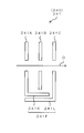
- the transfer electrode unit 240 in the present embodiment includes three second electrodes 241 (electrodes 241A, 241B, 241C) on the analysis chamber 24 side.
- the analysis chamber 24 constitutes a vacuum chamber that is in a vacuum state at the time of analysis, and electrodes 241A, 241B, 241C and a flight tube 246 are provided in the vacuum chamber.
- the vacuum chamber (analysis chamber 24) is formed in the vacuum chamber 247.
- the two electrodes 241A, 241C on both sides of the central electrode 241B have a shape in which some of them are bent or curved.
- the electrode 241A has an end on the flight tube 246 side bent in an L shape toward the electrode 241B, thereby forming a protruding piece 241D.
- the tip of the protruding piece 241D is located near the end of the electrode 241B on the flight tube 246 side, but is spaced so as not to contact the electrode 241B.
- the end of the electrode 241C on the side of the flight tube 246 is bent in an L shape on the side of the electrode 241B, whereby a protruding piece 241E is formed.
- the tip of the protruding piece 241E is located in the vicinity of the end of the electrode 241B on the flight tube 246 side and in the vicinity of the end of the protruding piece 241D, but is separated so as not to contact the electrodes 241A and 241B. .
- the electrodes 241A, 241B, and 241C are close to each other on the flight tube 246 side, but are separated to such an extent that no discharge occurs between the electrodes.
- Each of the projecting pieces 241D and 241E extends in the same straight line and is disposed so as to block between the center electrode 241 and the flight tube 246.
- the protruding pieces 241D and 241E arranged as described above constitute a shield part 241F for suppressing an electric field derived from a voltage applied to the flight tube 246 from entering the transfer electrode part 240. . That is, an electric field reaching the transfer electrode unit 240 is formed around the flight tube 246 to which a voltage having an absolute value higher than the voltage applied to the electrodes 234 and 241 of the transfer electrode unit 240 is applied. By blocking this electric field with the shield part 241F, the electric field does not enter the ion passage region in the transfer electrode part 240.
- the shield part 241F is formed integrally with the transfer electrode part 240, so that the shield part is provided between the transfer electrode part 240 (each electrode 241A, 241B, 241C) and the flight tube 246. 241F is provided.
- the electric field derived from the voltage applied to the flight tube 246 enters the transfer electrode portion 240 by the shield portion 241F provided between the transfer electrode portion 240 and the flight tube 246. Can be suppressed. Thereby, it is possible to prevent the electric field in the transfer electrode portion 240 from fluctuating due to the voltage applied to the flight tube 246.
- the shield part 241F can be formed by using a part of the plurality of electrodes 241A, 241B, 241C constituting the transfer electrode part 240. Thereby, since it is not necessary to provide the shield part 241F as a separate member, manufacturing cost can be reduced.
- a flight tube is formed between the at least one electrode 241A, 241B, 241C provided in the same vacuum chamber (inside the analysis chamber 24) and the flight tube 246 by the shield portion 241F. It is possible to suppress the electric field derived from the voltage applied to 246 from entering the transfer electrode portion 240.
- FIG. 2A is a schematic diagram illustrating a first modification of the second electrode 241 of the transfer electrode unit 240.
- this first modification of the three second electrodes 241 (electrodes 241A, 241B, 241C) provided on the analysis chamber 24 side, only the most upstream electrode 241A in the ion passage direction D is bent or curved. It has a shape.
- the electrode 241A has an end portion on the flight tube 246 side bent in an L shape on the electrode 241B side, thereby forming a protruding piece 241G.
- the tip of the protruding piece 241G is located near the end of the electrode 241C on the flight tube 246 side, but is separated so as not to contact the electrodes 241B and 241C.
- the protruding piece 241G arranged in this way constitutes a shield part 241F for suppressing the electric field derived from the voltage applied to the flight tube 246 from entering the transfer electrode part 240.
- FIG. 2B is a schematic diagram illustrating a second modification of the second electrode 241 of the transfer electrode unit 240.
- the second modification of the three second electrodes 241 (electrodes 241A, 241B, 241C) provided on the analysis chamber 24 side, only the most downstream electrode 241C in the ion passage direction D is bent or curved. It has a shape.
- the electrode 241C has an end on the flight tube 246 side bent in an L shape toward the electrode 241B, thereby forming a protruding piece 241H.
- the tip of the protruding piece 241H is located in the vicinity of the end of the electrode 241A on the flight tube 246 side, but is separated so as not to contact the electrodes 241A and 241B.
- the protruding piece 241H arranged in this way constitutes a shield part 241F for suppressing the electric field derived from the voltage applied to the flight tube 246 from entering the transfer electrode part 240.
- FIG. 2C is a schematic diagram illustrating a third modification of the second electrode 241 of the transfer electrode unit 240.
- the third modification of the three second electrodes 241 (electrodes 241A, 241B, and 241C) provided on the analysis chamber 24 side, the most upstream electrode 241A and the most downstream electrode in the ion passage direction D are used.
- 241C has a bent or curved shape.
- the electrode 241A has an end portion on the flight tube 246 side bent in an L shape toward the electrode 241B, thereby forming a protruding piece 241K.
- the tip of the protruding piece 241K is located in the vicinity of the electrode 241C, but is separated so as not to contact the electrodes 241B and 241C.
- the electrode 241C has an end on the flight tube 246 side bent in an L shape on the electrode 241B side, thereby forming a protruding piece 241L.
- the protruding piece 241L extends in parallel to the protruding piece 241K, and is separated so as not to contact the protruding piece 241K.
- the protruding pieces 241K and 241L arranged in this way constitute a shield part 241F for suppressing the electric field derived from the voltage applied to the flight tube 246 from entering the transfer electrode part 240. Since the plurality of protruding pieces 241K and 241L are arranged side by side in the electric field approach direction from the flight tube 246 side, the electric field can be effectively prevented from entering the transfer electrode portion 240.
- FIG. 2D is a schematic diagram illustrating a fourth modified example of the second electrode 241 of the transfer electrode unit 240.
- the fourth modification among the three second electrodes 241 (electrodes 241A, 241B, 241C) provided on the analysis chamber 24 side, only the central electrode 241B in the ion passage direction D is bent or curved. It has become.
- the electrode 241B is formed in a T shape by forming projecting pieces 241M projecting toward the electrode 241A side and the electrode 241C side at the end on the flight tube 246 side.
- the tip of one protruding piece 241M is located near the end of the electrode 241A on the flight tube 246 side, and the tip of the other protruding piece 241M is located near the end of the electrode 241C on the flight tube 246 side.
- the protruding pieces 241M are separated from each other so as not to contact the electrodes 241A and 241C.
- the protruding piece 241M arranged in this way constitutes a shield part 241F for suppressing the electric field derived from the voltage applied to the flight tube 246 from entering the transfer electrode part 240.
- the number of electrodes (second electrodes 241) provided on the analysis chamber 24 side in the transfer electrode unit 240 is not limited to three, and may be two or four or more. .
- the shield part 241 ⁇ / b> F may be configured by one second electrode 241.
- the shield part 241 ⁇ / b> F may be configured by two second electrodes 241 arranged at both ends, or any one or a plurality of second electrodes 241.
- the shield part 241F may be configured.
- the shield part 241F is not limited to the structure formed integrally with the transfer electrode part 240, and a shield part may be provided as a separate member between the transfer electrode part 240 and the flight tube 246.
- the shield part may be, for example, a plate-like member provided between the transfer electrode part 240 and the flight tube 246, or may be a cylindrical member covering the periphery of the transfer electrode part 240. Good.
- the transfer electrode unit 240 is not limited to the configuration provided so as to straddle the third intermediate chamber 23 and the analysis chamber 24, and the transfer electrode unit 240 (second electrode 241) is provided only in the analysis chamber 24. Also good.
- the time-of-flight mass spectrometer according to the present invention is not limited to being configured as a liquid chromatograph mass spectrometer by being connected to the liquid chromatograph unit 1, but uses, for example, MALDI (Matrix Assisted Laser Desorption / Ionization)
- MALDI Microx Assisted Laser Desorption / Ionization
Landscapes
- Chemical & Material Sciences (AREA)
- Analytical Chemistry (AREA)
- Physics & Mathematics (AREA)
- Optics & Photonics (AREA)
- Other Investigation Or Analysis Of Materials By Electrical Means (AREA)
Abstract
トランスファー電極部(240)は、環状に形成された複数の電極(241A,241B,241C)を同軸上に並べて構成され、それぞれ電圧が印加された複数の電極(241A,241B,241C)の内側にイオンを通過させ、当該イオンを直交加速領域(242C)へと導く。フライトチューブ(246)は、複数の電極(241A,241B,241C)に印加される電圧よりも絶対値が高い電圧が印加され、内部に形成された飛行空間内に、直交加速領域(242C)で加速されたイオンが導入される。シールド部(241F)は、トランスファー電極部(240)とフライトチューブ(246)との間に設けられ、フライトチューブ(246)に印加される電圧に由来する電場がトランスファー電極部(240)に進入するのを抑制する。
Description
本発明は、直交加速領域に入射するイオンを当該イオンの入射方向に対して直交方向に加速し、その加速されたイオンを飛行空間内に導くことにより、当該飛行空間内におけるイオンの飛行時間に基づいて当該イオンの質量電荷比を分析する直交加速方式の飛行時間型質量分析装置に関するものである。
飛行時間型質量分析装置(TOFMS:Time of Flight Mass Spectrometer)としては、直交加速方式でイオンを加速させるものが知られている(例えば、下記特許文献1参照)。この種の飛行時間型質量分析装置には、トランスファー電極部、直交加速部及びフライトチューブなどが備えられている。
トランスファー電極部は、環状に形成された複数の電極を同軸上に並べて構成されている。これらの各電極に電圧が印加されることにより、各電極の内側には電場が形成され、この電場を通ってイオンが直交加速部へと導かれる。直交加速部には、トランスファー電極部から入射するイオンを当該イオンの入射方向に対して直交方向に加速する直交加速領域が形成されている。
直交加速領域で加速されたイオンは、フライトチューブ内の飛行空間へと導かれ、当該飛行空間内を飛行した後、検出器で検出される。これにより、検出器に到達するまでのイオンの飛行時間が測定され、その飛行時間に基づいてイオンの質量電荷比m/zが算出される。
トランスファー電極部を構成する各電極には、例えば数10V程度の電圧が印加される。一方、フライトチューブには、例えば7kV程度の高電圧が印加される。通常、フライトチューブに印加される電圧の極性は検出対象のイオンの極性に応じて異なり、正イオン検出時には-7kV、負イオン検出時には+7kVの電圧が印加される。いずれにしても、トランスファー電極部を構成する少なくとも一部の電極に印加する電圧よりも、絶対値が例えば10倍以上の高電圧がフライトチューブに印加されることになる。直交加速方式の飛行時間型質量分析装置では、トランスファー電極部とフライトチューブとが比較的近い位置に配置されているため、フライトチューブに印加される高電圧に由来する電場が、トランスファー電極部に進入し、トランスファー電極部における電場に変動が生じるという問題があった。
上記のようなトランスファー電極部における電場の変動が生じた場合、トランスファー電極部を通過するイオンが曲げられてしまい、分解能の低下、感度の低下、測定精度の低下などが生じる。トランスファー電極部への電場の進入を少なくするために、各電極間の距離を小さくすることも考えられるが、電極の枚数が多くなって製造コストが高くなったり、部品の公差が累積することにより測定精度が悪化したりする原因になる。
本発明は、上記実情に鑑みてなされたものであり、フライトチューブに印加される電圧に起因して、トランスファー電極部における電場に変動が生じるのを防止することができる飛行時間型質量分析装置を提供することを目的とする。
(1)本発明に係る飛行時間型質量分析装置は、直交加速領域に入射するイオンを当該イオンの入射方向に対して直交方向に加速し、その加速されたイオンを飛行空間内に導くことにより、当該飛行空間内におけるイオンの飛行時間に基づいて当該イオンの質量電荷比を分析する直交加速方式の飛行時間型質量分析装置であって、トランスファー電極部と、フライトチューブと、シールド部とを備える。前記トランスファー電極部は、環状に形成された複数の電極を同軸上に並べて構成され、それぞれ電圧が印加された前記複数の電極の内側にイオンを通過させ、当該イオンを前記直交加速領域へと導く。前記フライトチューブは、前記複数の電極に印加される電圧よりも絶対値が高い電圧が印加され、内部に形成された前記飛行空間内に、前記直交加速領域で加速されたイオンが導入される。前記シールド部は、前記トランスファー電極部と前記フライトチューブとの間に設けられ、前記フライトチューブに印加される電圧に由来する電場が前記トランスファー電極部に進入するのを抑制する。
このような構成によれば、トランスファー電極部とフライトチューブとの間に設けられたシールド部により、フライトチューブに印加される電圧に由来する電場がトランスファー電極部に進入するのを抑制することができる。これにより、フライトチューブに印加される電圧に起因して、トランスファー電極部における電場に変動が生じるのを防止することができる。
(2)前記シールド部は、前記複数の電極の一部により形成されていてもよい。
このような構成によれば、トランスファー電極部を構成する複数の電極の一部を利用してシールド部を形成することができる。これにより、シールド部を別部材として設ける必要がないため、製造コストを低減することができる。
(3)前記飛行時間型質量分析装置は、真空チャンバをさらに備えていてもよい。前記真空チャンバには、分析時に真空状態となる真空室が内部に形成され、当該真空室内に前記複数の電極のうち少なくとも1つの電極と前記フライトチューブとが設けられている。この場合、前記シールド部は、前記少なくとも1つの電極と前記フライトチューブとの間に設けられていてもよい。
このような構成によれば、同一の真空室内に設けられている少なくとも1つの電極とフライトチューブとの間で、シールド部により、フライトチューブに印加される電圧に由来する電場がトランスファー電極部に進入するのを抑制することができる。
本発明によれば、フライトチューブに印加される電圧に由来する電場がトランスファー電極部に進入するのを抑制することができるため、フライトチューブに印加される電圧に起因して、トランスファー電極部における電場に変動が生じるのを防止することができる。
1.液体クロマトグラフ質量分析装置の全体構成
図1は、本発明の一実施形態に係る飛行時間型質量分析装置を備えた液体クロマトグラフ質量分析装置の構成例を示す概略図である。この液体クロマトグラフ質量分析装置は、液体クロマトグラフ部1及び質量分析部2を備えている。
図1は、本発明の一実施形態に係る飛行時間型質量分析装置を備えた液体クロマトグラフ質量分析装置の構成例を示す概略図である。この液体クロマトグラフ質量分析装置は、液体クロマトグラフ部1及び質量分析部2を備えている。
液体クロマトグラフ部1は、移動相容器10、ポンプ11、インジェクタ12及びカラム13などを備えている。移動相容器10には、移動相が貯留されている。ポンプ11は、移動相容器10内の移動相をインジェクタ12へと送り出す。インジェクタ12では、移動相容器10からの移動相に対して、所定量の試料が注入される。試料が注入された移動相はカラム13に導入され、カラム13を通過する過程で試料中の各成分が分離される。カラム13で分離された試料中の各成分は、質量分析部2に順次供給される。
質量分析部2は、飛行時間型質量分析装置(TOFMS:Time of Flight Mass Spectrometer)により構成されており、イオン化室20、第1中間室21、第2中間室22、第3中間室23及び分析室24などが内部に形成されている。イオン化室20内は、略大気圧となっている。第1中間室21、第2中間室22、第3中間室23及び分析室24は、それぞれ真空ポンプ(図示せず)の駆動により真空状態(負圧状態)とされる。イオン化室20、第1中間室21、第2中間室22、第3中間室23及び分析室24は、互いに連通しており、この順序に従って段階的に真空度が高くなるように構成されている。
イオン化室20には、例えばESI(Electro Spray Ionization)スプレーからなるスプレー201が設けられている。液体クロマトグラフ部1から供給される試料中の各成分を含む試料液は、スプレー201により、電荷が付与されながらイオン化室20内に噴霧される。これにより、試料中の各成分由来のイオンが生成される。ただし、質量分析部2で用いられるイオン化法は、ESIに限らず、例えばAPCI(Atmospheric Pressure Chemical Ionization)又はPESI(Probe Electro Spray Ionization)などの他のイオン化法が用いられてもよい。
第1中間室21は、小径の管からなる加熱キャピラリ202を介して、イオン化室20に連通している。また、第2中間室22は、小孔からなるスキマー212を介して、第1中間室21に連通している。第1中間室21及び第2中間室22には、それぞれイオンを収束させつつ後段へ送るためのイオンガイド211,221が設けられている。
第3中間室23には、例えば四重極マスフィルタ231及びコリジョンセル232などが設けられている。コリジョンセル232の内部には、アルゴン又は窒素などのCID(Collision Induced Dissociation)ガスが連続的又は間欠的に供給される。コリジョンセル232内には、多重極イオンガイド233が設けられている。
第2中間室22から第3中間室23に流入するイオンは、四重極マスフィルタ231により質量電荷比に応じて分離され、特定の質量電荷比を有するイオンのみが四重極マスフィルタ231を通過する。四重極マスフィルタ231を通過したイオンは、プリカーサイオンとしてコリジョンセル232内に導入され、CIDガスと接触して開裂されることにより、プロダクトイオンが生成される。生成されたプロダクトイオンは、多重極イオンガイド233により一時的に保持され、所定のタイミングでコリジョンセル232から放出される。
第3中間室23及び分析室24には、これらの室内を跨るようにトランスファー電極部240が設けられている。トランスファー電極部240は、第3中間室23に設けられた1つ又は複数の第1電極234と、分析室24に設けられた1つ又は複数の第2電極241とを含む。第1電極234及び第2電極241は、それぞれ環状に形成され、同軸上に並べて配置されている。コリジョンセル232から放出されたイオン(プロダクトイオン)は、トランスファー電極部240において複数の電極234,241の内側を通過することにより収束される。
分析室24には、上記第2電極241の他、直交加速部242、加速電極部243、リフレクトロン244、検出器245及びフライトチューブ246などが設けられている。フライトチューブ246は、例えば両端部が開放された中空状の部材であり、その内部にリフレクトロン244が配置されている。
直交加速部242には、トランスファー電極部240からイオンが入射する。直交加速部242は、互いに間隔を隔てて対向する1対の電極242A,242Bを備えている。1対の電極242A,242Bは、トランスファー電極部240からのイオンの入射方向に対して平行に延びており、これらの電極間には直交加速領域242Cが形成されている。
一方の電極242Bは、複数の開口を有するグリッド電極により構成されている。直交加速領域242Cに入射するイオンは、当該イオンの入射方向に対して直交方向に加速され、一方の電極242Bの開口を通過して、加速電極部243へと導かれる。本実施形態において、直交加速部242は、分析対象となるイオンを射出するイオン射出部を構成している。直交加速部242から射出されるイオンは、加速電極部243によりさらに加速され、フライトチューブ246内に導入される。フライトチューブ246には、トランスファー電極部240の各電極234,241に印加される電圧よりも絶対値が高い電圧が印加される。
フライトチューブ246内に設けられたリフレクトロン244は、1つ又は複数の第1電極244Aと、1つ又は複数の第2電極244Bとを含む。第1電極244A及び第2電極244Bは、それぞれ環状に形成され、フライトチューブ246の軸線に沿って同軸上に並べて配置されている。第1電極244A及び第2電極244Bには、それぞれ異なる電圧が印加される。
フライトチューブ246内に導入されたイオンは、フライトチューブ246内に形成された飛行空間内に導かれ、当該飛行空間内を飛行した後に検出器245に入射する。具体的には、フライトチューブ246内に導入されたイオンは、第1電極244Aの内側に形成された第1領域(第1ステージ)244Cで減速された後、第2電極244Bの内側に形成された第2領域(第2ステージ)244Dで反射されることにより、U字状に折り返されて検出器245に入射する。
イオンが直交加速部242から射出された時点から、検出器245に入射するまでの飛行時間は、イオンの質量電荷比に依存する。したがって、直交加速部242から射出される各イオンの飛行時間に基づいて、各イオンの質量電荷比を算出し、マススペクトルを作成することができる。
2.トランスファー電極部の具体的構成
本実施形態におけるトランスファー電極部240は、分析室24側に3つの第2電極241(電極241A,241B,241C)を備えている。分析室24は、分析時に真空状態となる真空室を構成しており、当該真空室に各電極241A,241B,241C及びフライトチューブ246が設けられている。上記真空室(分析室24)は、真空チャンバ247内に形成されている。
本実施形態におけるトランスファー電極部240は、分析室24側に3つの第2電極241(電極241A,241B,241C)を備えている。分析室24は、分析時に真空状態となる真空室を構成しており、当該真空室に各電極241A,241B,241C及びフライトチューブ246が設けられている。上記真空室(分析室24)は、真空チャンバ247内に形成されている。
同軸上に並ぶ3つの電極241A,241B,241Cのうち、中央の電極241Bを挟んで両側の2つの電極241A,241Cは、それらの一部が屈曲又は湾曲した形状となっている。
具体的には、電極241Aは、フライトチューブ246側の端部が電極241B側にL字状に屈曲されており、これにより突出片241Dが形成されている。突出片241Dの先端は、電極241Bのフライトチューブ246側の端部近傍に位置しているが、電極241Bには接触しないように離間している。
また、電極241Cは、フライトチューブ246側の端部が電極241B側にL字状に屈曲されており、これにより突出片241Eが形成されている。突出片241Eの先端は、電極241Bのフライトチューブ246側の端部近傍、かつ、突出片241Dの端部近傍に位置しているが、各電極241A,241Bには接触しないように離間している。
このように、各電極241A,241B,241Cは、フライトチューブ246側において互いに近接しているが、電極間で放電しない程度に離間している。各突出片241D,241Eは、同一直線状に延びており、中央の電極241とフライトチューブ246との間を遮るように配置されている。
上記のようにして配置された各突出片241D,241Eは、フライトチューブ246に印加される電圧に由来する電場がトランスファー電極部240に進入するのを抑制するためのシールド部241Fを構成している。すなわち、トランスファー電極部240の各電極234,241に印加される電圧よりも絶対値が高い電圧が印加されるフライトチューブ246の周辺には、トランスファー電極部240にまで到達する電場が形成される。この電場をシールド部241Fで遮ることにより、当該電場がトランスファー電極部240におけるイオンの通過領域まで進入しないように構成されている。
このように、本実施形態では、シールド部241Fがトランスファー電極部240と一体的に形成されることにより、トランスファー電極部240(各電極241A,241B,241C)とフライトチューブ246との間にシールド部241Fが設けられている。
3.作用効果
(1)本実施形態では、トランスファー電極部240とフライトチューブ246との間に設けられたシールド部241Fにより、フライトチューブ246に印加される電圧に由来する電場がトランスファー電極部240に進入するのを抑制することができる。これにより、フライトチューブ246に印加される電圧に起因して、トランスファー電極部240における電場に変動が生じるのを防止することができる。
(1)本実施形態では、トランスファー電極部240とフライトチューブ246との間に設けられたシールド部241Fにより、フライトチューブ246に印加される電圧に由来する電場がトランスファー電極部240に進入するのを抑制することができる。これにより、フライトチューブ246に印加される電圧に起因して、トランスファー電極部240における電場に変動が生じるのを防止することができる。
(2)また、本実施形態では、トランスファー電極部240を構成する複数の電極241A,241B,241Cの一部を利用してシールド部241Fを形成することができる。これにより、シールド部241Fを別部材として設ける必要がないため、製造コストを低減することができる。
(3)特に、本実施形態では、同一の真空室内(分析室24内)に設けられている少なくとも1つの電極241A,241B,241Cとフライトチューブ246との間で、シールド部241Fにより、フライトチューブ246に印加される電圧に由来する電場がトランスファー電極部240に進入するのを抑制することができる。
4.第1変形例
図2Aは、トランスファー電極部240の第2電極241の第1変形例を示す概略図である。この第1変形例では、分析室24側に設けられた3つの第2電極241(電極241A,241B,241C)のうち、イオンの通過方向Dにおける最も上流側の電極241Aのみが屈曲又は湾曲した形状となっている。
図2Aは、トランスファー電極部240の第2電極241の第1変形例を示す概略図である。この第1変形例では、分析室24側に設けられた3つの第2電極241(電極241A,241B,241C)のうち、イオンの通過方向Dにおける最も上流側の電極241Aのみが屈曲又は湾曲した形状となっている。
具体的には、電極241Aは、フライトチューブ246側の端部が電極241B側にL字状に屈曲されており、これにより突出片241Gが形成されている。突出片241Gの先端は、電極241Cのフライトチューブ246側の端部近傍に位置しているが、電極241B,241Cには接触しないように離間している。このようにして配置された突出片241Gは、フライトチューブ246に印加される電圧に由来する電場がトランスファー電極部240に進入するのを抑制するためのシールド部241Fを構成している。
5.第2変形例
図2Bは、トランスファー電極部240の第2電極241の第2変形例を示す概略図である。この第2変形例では、分析室24側に設けられた3つの第2電極241(電極241A,241B,241C)のうち、イオンの通過方向Dにおける最も下流側の電極241Cのみが屈曲又は湾曲した形状となっている。
図2Bは、トランスファー電極部240の第2電極241の第2変形例を示す概略図である。この第2変形例では、分析室24側に設けられた3つの第2電極241(電極241A,241B,241C)のうち、イオンの通過方向Dにおける最も下流側の電極241Cのみが屈曲又は湾曲した形状となっている。
具体的には、電極241Cは、フライトチューブ246側の端部が電極241B側にL字状に屈曲されており、これにより突出片241Hが形成されている。突出片241Hの先端は、電極241Aのフライトチューブ246側の端部近傍に位置しているが、電極241A,241Bには接触しないように離間している。このようにして配置された突出片241Hは、フライトチューブ246に印加される電圧に由来する電場がトランスファー電極部240に進入するのを抑制するためのシールド部241Fを構成している。
6.第3変形例
図2Cは、トランスファー電極部240の第2電極241の第3変形例を示す概略図である。この第3変形例では、分析室24側に設けられた3つの第2電極241(電極241A,241B,241C)のうち、イオンの通過方向Dにおける最も上流側の電極241Aと最も下流側の電極241Cが屈曲又は湾曲した形状となっている。
図2Cは、トランスファー電極部240の第2電極241の第3変形例を示す概略図である。この第3変形例では、分析室24側に設けられた3つの第2電極241(電極241A,241B,241C)のうち、イオンの通過方向Dにおける最も上流側の電極241Aと最も下流側の電極241Cが屈曲又は湾曲した形状となっている。
具体的には、電極241Aは、フライトチューブ246側の端部が電極241B側にL字状に屈曲されており、これにより突出片241Kが形成されている。突出片241Kの先端は、電極241Cの近傍に位置しているが、電極241B,241Cには接触しないように離間している。
また、電極241Cは、フライトチューブ246側の端部が電極241B側にL字状に屈曲されており、これにより突出片241Lが形成されている。突出片241Lは、突出片241Kに対して平行に延びており、突出片241Kには接触しないように離間している。
このようにして配置された突出片241K,241Lは、フライトチューブ246に印加される電圧に由来する電場がトランスファー電極部240に進入するのを抑制するためのシールド部241Fを構成している。複数の突出片241K,241Lが、フライトチューブ246側からの電場の進入方向に並べて配置されているため、トランスファー電極部240への電場の進入を効果的に抑制することができる。
7.第4変形例
図2Dは、トランスファー電極部240の第2電極241の第4変形例を示す概略図である。この第4変形例では、分析室24側に設けられた3つの第2電極241(電極241A,241B,241C)のうち、イオンの通過方向Dにおける中央の電極241Bのみが屈曲又は湾曲した形状となっている。
図2Dは、トランスファー電極部240の第2電極241の第4変形例を示す概略図である。この第4変形例では、分析室24側に設けられた3つの第2電極241(電極241A,241B,241C)のうち、イオンの通過方向Dにおける中央の電極241Bのみが屈曲又は湾曲した形状となっている。
具体的には、電極241Bは、フライトチューブ246側の端部に、電極241A側及び電極241C側にそれぞれ突出する突出片241Mが形成されることにより、T字状に構成されている。一方の突出片241Mの先端は、電極241Aのフライトチューブ246側の端部近傍に位置し、他方の突出片241Mの先端は、電極241Cのフライトチューブ246側の端部近傍に位置しているが、各突出片241Mは電極241A,241Cには接触しないように離間している。このようにして配置された突出片241Mは、フライトチューブ246に印加される電圧に由来する電場がトランスファー電極部240に進入するのを抑制するためのシールド部241Fを構成している。
8.その他の変形例
トランスファー電極部240が分析室24側に備えた電極(第2電極241)の数は、3つに限らず、2つであってもよいし、4つ以上であってもよい。第2電極241が2つである場合には、一方の第2電極241によりシールド部241Fが構成されてもよい。また、第2電極241が4つ以上である場合には、両端に配置された2つの第2電極241によりシールド部241Fが構成されてもよいし、いずれか1つ又は複数の第2電極241によりシールド部241Fが構成されてもよい。
トランスファー電極部240が分析室24側に備えた電極(第2電極241)の数は、3つに限らず、2つであってもよいし、4つ以上であってもよい。第2電極241が2つである場合には、一方の第2電極241によりシールド部241Fが構成されてもよい。また、第2電極241が4つ以上である場合には、両端に配置された2つの第2電極241によりシールド部241Fが構成されてもよいし、いずれか1つ又は複数の第2電極241によりシールド部241Fが構成されてもよい。
シールド部241Fは、トランスファー電極部240と一体的に形成された構成に限らず、トランスファー電極部240とフライトチューブ246との間に、別部材としてシールド部が設けられていてもよい。この場合、シールド部は、例えばトランスファー電極部240とフライトチューブ246との間に設けられた板状の部材であってもよいし、トランスファー電極部240の周囲を覆う円筒状の部材であってもよい。
トランスファー電極部240は、第3中間室23及び分析室24に跨るように設けられた構成に限らず、分析室24にのみトランスファー電極部240(第2電極241)が設けられた構成であってもよい。
本発明に係る飛行時間型質量分析装置は、液体クロマトグラフ部1と接続されることにより液体クロマトグラフ質量分析装置として構成されるものに限らず、例えばMALDI(Matrix Assisted Laser Desorption/Ionization)を用いた構成などのように、液体クロマトグラフ部1と接続されない構成であってもよい。
1 液体クロマトグラフ部
2 質量分析部
234 第1電極
240 トランスファー電極部
241 第2電極
241A~241C 電極
241D,241E 突出片
241F シールド部
241G~241M 突出片
242 直交加速部
242C 直交加速領域
244 リフレクトロン
246 フライトチューブ
247 真空チャンバ
2 質量分析部
234 第1電極
240 トランスファー電極部
241 第2電極
241A~241C 電極
241D,241E 突出片
241F シールド部
241G~241M 突出片
242 直交加速部
242C 直交加速領域
244 リフレクトロン
246 フライトチューブ
247 真空チャンバ
Claims (3)
- 直交加速領域に入射するイオンを当該イオンの入射方向に対して直交方向に加速し、その加速されたイオンを飛行空間内に導くことにより、当該飛行空間内におけるイオンの飛行時間に基づいて当該イオンの質量電荷比を分析する直交加速方式の飛行時間型質量分析装置であって、
環状に形成された複数の電極を同軸上に並べて構成され、それぞれ電圧が印加された前記複数の電極の内側にイオンを通過させ、当該イオンを前記直交加速領域へと導くトランスファー電極部と、
前記複数の電極に印加される電圧よりも絶対値が高い電圧が印加され、内部に形成された前記飛行空間内に、前記直交加速領域で加速されたイオンが導入されるフライトチューブと、
前記トランスファー電極部と前記フライトチューブとの間に設けられ、前記フライトチューブに印加される電圧に由来する電場が前記トランスファー電極部に進入するのを抑制するシールド部とを備えることを特徴とする飛行時間型質量分析装置。 - 前記シールド部は、前記複数の電極の一部により形成されていることを特徴とする請求項1に記載の飛行時間型質量分析装置。
- 分析時に真空状態となる真空室が内部に形成され、当該真空室内に前記複数の電極のうち少なくとも1つの電極と前記フライトチューブとが設けられた真空チャンバをさらに備え、
前記シールド部は、前記少なくとも1つの電極と前記フライトチューブとの間に設けられていることを特徴とする請求項1に記載の飛行時間型質量分析装置。
Priority Applications (3)
| Application Number | Priority Date | Filing Date | Title |
|---|---|---|---|
| JP2020518868A JP6874906B2 (ja) | 2018-05-16 | 2018-05-16 | 飛行時間型質量分析装置 |
| US17/051,891 US11152202B2 (en) | 2018-05-16 | 2018-05-16 | Time-of-flight mass spectrometer |
| PCT/JP2018/018853 WO2019220554A1 (ja) | 2018-05-16 | 2018-05-16 | 飛行時間型質量分析装置 |
Applications Claiming Priority (1)
| Application Number | Priority Date | Filing Date | Title |
|---|---|---|---|
| PCT/JP2018/018853 WO2019220554A1 (ja) | 2018-05-16 | 2018-05-16 | 飛行時間型質量分析装置 |
Publications (1)
| Publication Number | Publication Date |
|---|---|
| WO2019220554A1 true WO2019220554A1 (ja) | 2019-11-21 |
Family
ID=68539810
Family Applications (1)
| Application Number | Title | Priority Date | Filing Date |
|---|---|---|---|
| PCT/JP2018/018853 Ceased WO2019220554A1 (ja) | 2018-05-16 | 2018-05-16 | 飛行時間型質量分析装置 |
Country Status (3)
| Country | Link |
|---|---|
| US (1) | US11152202B2 (ja) |
| JP (1) | JP6874906B2 (ja) |
| WO (1) | WO2019220554A1 (ja) |
Cited By (4)
| Publication number | Priority date | Publication date | Assignee | Title |
|---|---|---|---|---|
| GB2601811A (en) * | 2020-12-11 | 2022-06-15 | Ascend Diagnostics Ltd | Apparatus and method |
| JP2023016583A (ja) * | 2021-07-21 | 2023-02-02 | 株式会社島津製作所 | 直交加速飛行時間型質量分析装置 |
| WO2023204187A1 (ja) * | 2022-04-18 | 2023-10-26 | 株式会社島津製作所 | 質量分析装置 |
| US12518957B2 (en) | 2020-12-04 | 2026-01-06 | Shimadzu Corporation | Orthogonal acceleration time-of-flight mass spectrometer |
Citations (7)
| Publication number | Priority date | Publication date | Assignee | Title |
|---|---|---|---|---|
| US5869829A (en) * | 1996-07-03 | 1999-02-09 | Analytica Of Branford, Inc. | Time-of-flight mass spectrometer with first and second order longitudinal focusing |
| JP2001523378A (ja) * | 1996-08-09 | 2001-11-20 | アナリチカ オブ ブランフォード,インコーポレーテッド | 飛行時間型質量分析計におけるイオン検知器の角度をつけた配列 |
| JP2005183328A (ja) * | 2003-12-24 | 2005-07-07 | Hitachi High-Technologies Corp | イオントラップ/飛行時間型質量分析計 |
| US20110186730A1 (en) * | 2010-01-29 | 2011-08-04 | Helmholtz-Zentrum Geesthacht Zentrum für Material-und Küstenforschung GmbH | Reflector for a Time-of-Flight Mass Spectrometer |
| JP2013527971A (ja) * | 2010-05-07 | 2013-07-04 | ディーエイチ テクノロジーズ デベロップメント プライベート リミテッド | 質量分析法のための超高速のパルサ極性切り替えを伝達するためのトリプルスイッチトポロジ |
| US20160005583A1 (en) * | 2014-07-03 | 2016-01-07 | Bruker Daltonik Gmbh | Reflectors for time-of-flight mass spectrometers |
| JP2018502429A (ja) * | 2014-12-23 | 2018-01-25 | クラトス・アナリテイカル・リミテツド | 飛行時間型質量分析計 |
Family Cites Families (3)
| Publication number | Priority date | Publication date | Assignee | Title |
|---|---|---|---|---|
| GB0408751D0 (en) * | 2004-04-20 | 2004-05-26 | Micromass Ltd | Mass spectrometer |
| US9029763B2 (en) * | 2013-08-30 | 2015-05-12 | Agilent Technologies, Inc. | Ion deflection in time-of-flight mass spectrometry |
| US10699892B2 (en) | 2014-09-18 | 2020-06-30 | Shimadzu Corporation | Time-of-flight mass spectrometer |
-
2018
- 2018-05-16 JP JP2020518868A patent/JP6874906B2/ja active Active
- 2018-05-16 US US17/051,891 patent/US11152202B2/en active Active
- 2018-05-16 WO PCT/JP2018/018853 patent/WO2019220554A1/ja not_active Ceased
Patent Citations (7)
| Publication number | Priority date | Publication date | Assignee | Title |
|---|---|---|---|---|
| US5869829A (en) * | 1996-07-03 | 1999-02-09 | Analytica Of Branford, Inc. | Time-of-flight mass spectrometer with first and second order longitudinal focusing |
| JP2001523378A (ja) * | 1996-08-09 | 2001-11-20 | アナリチカ オブ ブランフォード,インコーポレーテッド | 飛行時間型質量分析計におけるイオン検知器の角度をつけた配列 |
| JP2005183328A (ja) * | 2003-12-24 | 2005-07-07 | Hitachi High-Technologies Corp | イオントラップ/飛行時間型質量分析計 |
| US20110186730A1 (en) * | 2010-01-29 | 2011-08-04 | Helmholtz-Zentrum Geesthacht Zentrum für Material-und Küstenforschung GmbH | Reflector for a Time-of-Flight Mass Spectrometer |
| JP2013527971A (ja) * | 2010-05-07 | 2013-07-04 | ディーエイチ テクノロジーズ デベロップメント プライベート リミテッド | 質量分析法のための超高速のパルサ極性切り替えを伝達するためのトリプルスイッチトポロジ |
| US20160005583A1 (en) * | 2014-07-03 | 2016-01-07 | Bruker Daltonik Gmbh | Reflectors for time-of-flight mass spectrometers |
| JP2018502429A (ja) * | 2014-12-23 | 2018-01-25 | クラトス・アナリテイカル・リミテツド | 飛行時間型質量分析計 |
Cited By (8)
| Publication number | Priority date | Publication date | Assignee | Title |
|---|---|---|---|---|
| US12518957B2 (en) | 2020-12-04 | 2026-01-06 | Shimadzu Corporation | Orthogonal acceleration time-of-flight mass spectrometer |
| GB2601811A (en) * | 2020-12-11 | 2022-06-15 | Ascend Diagnostics Ltd | Apparatus and method |
| WO2022123251A1 (en) * | 2020-12-11 | 2022-06-16 | Ascend Diagnostics Limited | Ion optical device and method |
| GB2601811B (en) * | 2020-12-11 | 2025-01-22 | Ascend Diagnostics Ltd | Apparatus and method |
| JP2023016583A (ja) * | 2021-07-21 | 2023-02-02 | 株式会社島津製作所 | 直交加速飛行時間型質量分析装置 |
| US11862451B2 (en) | 2021-07-21 | 2024-01-02 | Shimadzu Corporation | Orthogonal acceleration time-of-flight mass spectrometer |
| JP7533393B2 (ja) | 2021-07-21 | 2024-08-14 | 株式会社島津製作所 | 直交加速飛行時間型質量分析装置 |
| WO2023204187A1 (ja) * | 2022-04-18 | 2023-10-26 | 株式会社島津製作所 | 質量分析装置 |
Also Published As
| Publication number | Publication date |
|---|---|
| JP6874906B2 (ja) | 2021-05-19 |
| US11152202B2 (en) | 2021-10-19 |
| US20210125819A1 (en) | 2021-04-29 |
| JPWO2019220554A1 (ja) | 2021-03-11 |
Similar Documents
| Publication | Publication Date | Title |
|---|---|---|
| US6348688B1 (en) | Tandem time-of-flight mass spectrometer with delayed extraction and method for use | |
| JP6287419B2 (ja) | 飛行時間型質量分析装置 | |
| US9123516B2 (en) | Multipole segments aligned in an offset manner in a mass spectrometer | |
| US7064319B2 (en) | Mass spectrometer | |
| JP6237908B2 (ja) | 飛行時間型質量分析装置 | |
| US7211792B2 (en) | Mass spectrometer | |
| US20030042412A1 (en) | Means and method for a quadrupole surface induced dissociation quadrupole time-of-flight mass spectrometer | |
| US20100171035A1 (en) | Mass spectrometer | |
| US9916971B2 (en) | Systems and methods of suppressing unwanted ions | |
| JP6874906B2 (ja) | 飛行時間型質量分析装置 | |
| WO2016103339A1 (ja) | 飛行時間型質量分析装置 | |
| EP3249680B1 (en) | Systems and methods for reducing the kinetic energy spread of ions radially ejected from a linear ion trap | |
| CN103650101B (zh) | 三重四极型质量分析装置 | |
| US20240105439A1 (en) | Mass and Kinetic Energy Ordering of Ions Prior to Orthogonal Extraction Using Dipolar DC | |
| JP6962460B2 (ja) | 飛行時間型質量分析装置 | |
| US7034288B2 (en) | Time-of-flight mass spectrometer | |
| US10957526B2 (en) | Spatial, mass and energy focused ion injection method and device | |
| CN114166922B (zh) | 质量分析方法以及质量分析装置 | |
| JP6881679B2 (ja) | 飛行時間型質量分析装置 | |
| JP2025181026A (ja) | 質量分析装置 | |
| JP2023016583A (ja) | 直交加速飛行時間型質量分析装置 |
Legal Events
| Date | Code | Title | Description |
|---|---|---|---|
| 121 | Ep: the epo has been informed by wipo that ep was designated in this application |
Ref document number: 18918694 Country of ref document: EP Kind code of ref document: A1 |
|
| ENP | Entry into the national phase |
Ref document number: 2020518868 Country of ref document: JP Kind code of ref document: A |
|
| NENP | Non-entry into the national phase |
Ref country code: DE |
|
| 122 | Ep: pct application non-entry in european phase |
Ref document number: 18918694 Country of ref document: EP Kind code of ref document: A1 |