WO2019208278A1 - Image processing device and image processing method - Google Patents
Image processing device and image processing method Download PDFInfo
- Publication number
- WO2019208278A1 WO2019208278A1 PCT/JP2019/016038 JP2019016038W WO2019208278A1 WO 2019208278 A1 WO2019208278 A1 WO 2019208278A1 JP 2019016038 W JP2019016038 W JP 2019016038W WO 2019208278 A1 WO2019208278 A1 WO 2019208278A1
- Authority
- WO
- WIPO (PCT)
- Prior art keywords
- image
- unit
- transparency
- imaging
- predetermined
- Prior art date
Links
Images


Classifications
-
- B—PERFORMING OPERATIONS; TRANSPORTING
- B61—RAILWAYS
- B61L—GUIDING RAILWAY TRAFFIC; ENSURING THE SAFETY OF RAILWAY TRAFFIC
- B61L23/00—Control, warning, or like safety means along the route or between vehicles or vehicle trains
- B61L23/04—Control, warning, or like safety means along the route or between vehicles or vehicle trains for monitoring the mechanical state of the route
- B61L23/041—Obstacle detection
-
- B—PERFORMING OPERATIONS; TRANSPORTING
- B61—RAILWAYS
- B61L—GUIDING RAILWAY TRAFFIC; ENSURING THE SAFETY OF RAILWAY TRAFFIC
- B61L15/00—Indicators provided on the vehicle or vehicle train for signalling purposes ; On-board control or communication systems
- B61L15/0081—On-board diagnosis or maintenance
-
- G—PHYSICS
- G06—COMPUTING; CALCULATING OR COUNTING
- G06T—IMAGE DATA PROCESSING OR GENERATION, IN GENERAL
- G06T1/00—General purpose image data processing
-
- H—ELECTRICITY
- H04—ELECTRIC COMMUNICATION TECHNIQUE
- H04N—PICTORIAL COMMUNICATION, e.g. TELEVISION
- H04N7/00—Television systems
- H04N7/18—Closed-circuit television [CCTV] systems, i.e. systems in which the video signal is not broadcast
Definitions
- the present invention relates to an image processing apparatus and an image processing method for performing image processing based on an image obtained by imaging a predetermined region located on a side portion of a vehicle.
- Patent Document 1 As such an image processing apparatus, there is a technique disclosed in Patent Document 1, for example.
- a plurality of cameras are installed on the side surface of a railway vehicle, the outside of the vehicle is set as an imaging range, a person on the platform is imaged while the train is stopped at the station, and an image of the captured camera is viewed from above. Converted and displayed in panorama on the driver's seat monitor.
- Patent Document 1 when images are joined by a plurality of cameras, there is a possibility that a person or the like reflected at the joint is lost.
- an object of the present invention is to provide an image processing apparatus and an image processing method capable of appropriately processing an image.
- an image processing apparatus of the present invention includes a first image obtained by imaging a first area including a predetermined area located on a side portion of the vehicle, and a predetermined area.
- An image acquisition unit configured to acquire a second image obtained by imaging the second region, a first transparency set to a predetermined image corresponding to the predetermined region included in the first image, and a second A transparency setting unit for setting a second transparency to a predetermined image corresponding to a predetermined region included in the image of the image, and the first transparency and the second transparency set by the transparency setting unit are applied.
- a combining unit that combines the first image and the second image as a continuous image.
- the composition unit applies the first transparency and the second transparency set by the transparency setting unit, and the synthesis unit performs the first image and the second image. Are combined as a continuous image.
- FIG. 1 is a block diagram illustrating an image processing apparatus and peripheral devices according to an embodiment.
- 1 is a functional block diagram illustrating a schematic configuration of an image processing apparatus according to an embodiment. It is a figure which shows the relationship between an example of the image output from the imaging part used for embodiment, and the state of an actual person. It is a figure which shows the relationship between a person's position, and an example of the image output from the imaging part used for embodiment. It is a figure which shows the relationship between a person's position, and an example of the image output from the image processing apparatus which is embodiment.
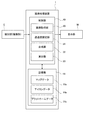
- FIG. 3 is a functional block diagram showing a schematic configuration of the image processing apparatus according to the embodiment of the present invention.
- the image processing apparatus 1 performs image processing and displays an image acquired from an imaging unit C that is a detection unit provided on the side of the railway vehicle T.
- the image after image processing is displayed on the part M.
- the imaging unit C captures a subject in front of it, such as a camera, and outputs an image related to the subject.
- a subject in front of it such as a camera
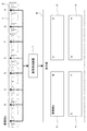
- FIG. 1A A plurality (two in one side for each vehicle T in the example shown in FIG. 1) are arranged on the upper side.
- each imaging unit C has an imaging range A that extends downward and outward from the side surface of the vehicle T (to the lower right in FIG. 1B). An image obtained by imaging a subject (person, platform, etc.) existing in A is output.
- a part of the imaging range A of the adjacent imaging units C is set to have an overlapping range AD.
- An imaging range A that covers the entire region located on the side is set.
- the image pickup unit C provided on one side surface of the vehicle T is illustrated in the illustrated relationship, but actually, the image pickup unit C is similarly provided on the other side surface of the vehicle T.
- the image processing apparatus 1 performs image processing of an image of a person or the like on the platform in a stopped state, from the imaging unit C provided on one side surface of the vehicle T. Therefore, it is sufficient to operate only the image pickup unit C provided on one side surface, more specifically, the side surface facing the platform.
- all the images output from each imaging unit C are input to the image processing apparatus 1 according to the present embodiment, and the image processed by the image processing apparatus 1 is output to the display unit M. Is done.
- the display unit M is not limited in its type and display format such as a liquid crystal display or CRT. There is no particular limitation on the installation location of the display unit M, and the display unit M may be provided at a position where a railroad worker such as a driver of the vehicle T, a conductor, a station staff, or an operation manager can visually recognize. Accordingly, the display unit M is a position where the driver or the conductor can visually recognize the driver's seat or the conductor's seat of the vehicle T, a position above the platform where the driver or the conductor can be visually recognized, and the station staff. It is provided at a position where station staff and operation manager can visually recognize in the waiting room and operation management section. In addition, the display unit M may be an information processing device such as a smartphone or a tablet possessed by a driver or a conductor.
- each imaging unit C is provided for each of the four-car train T, and therefore images from the eight imaging units C are input to the image processing apparatus 1 and image processing is performed.
- An image processed by the apparatus 1 is displayed on the display unit M.
- the display unit M has four display screens P, and each display screen P corresponds to an image obtained by performing image processing on an image acquired from the imaging unit C provided in one vehicle T. 2, the image captured by the imaging unit A is captured by the captured image A, the image captured by the imaging unit B is captured by the captured image B, and the image captured by the imaging unit C is captured by the captured image C and the imaging unit D.
- the captured image is the captured image D
- the image captured by the image capturing unit E is the captured image E
- the image captured by the image capturing unit F is the captured image F
- the image captured by the image capturing unit G is the captured image G
- the image capturing unit H The image captured in step S is defined as a captured image H.
- the image processing apparatus 1 is provided in the vehicle T and includes a control unit 10 and a storage unit 11.
- the control unit 10 includes an arithmetic element such as a CPU.
- An unillustrated control program stored in the storage unit 11 is executed when the image processing apparatus 1 is started. Based on this control program, the control unit 10 controls the entire image processing apparatus 1 including the storage unit 11 and the like. While performing control, the function as the image acquisition part 20, the transparency setting part 21, the synthetic
- the storage unit 11 includes a large-capacity storage medium such as a hard disk drive and a semiconductor storage medium such as ROM and RAM.
- the storage unit 11 stores the above-described control program and temporarily stores various data necessary for the control operation of the control unit 10.
- the storage unit 11 stores map data 11a, icon data 11b, and platform data 11c.
- the map data 11a is data relating to the platform of the station where the vehicle T stops. More specifically, the image captured by the imaging unit C is an image as shown in FIG. 1B (from the upper side of the side surface of the vehicle T). 1 (b), which is an image of a subject in the imaging range A that extends to the lower right, and is data for converting the image into a bird's-eye view in plan view of the platform. Therefore, this map data 11a reflects the shape of the platform (unevenness, inclination, shape of the end of the platform on the vehicle T side (length, curvature, etc.)). The map data 11a includes data indicating the conversion position in pixel units of the image acquired from the imaging unit C.
- the icon data 11b is data for displaying, on the display unit M, an icon image that is combined and superimposed on a region where a moving body such as a person is imaged by the combining unit 22 of the control unit 10 described later.
- the icon data 11b is stored in the multiple types storage unit 11 in accordance with the distance from the vehicle T to the moving object, the attributes of the moving object (such as the type of the moving object), and the like.
- the platform data 11c is data related to the platform of the station where the vehicle T stops, as in the case of the map data 11a, and more specifically is reference image data related to the stop position of the vehicle T.
- the synthesizing unit 22 converts the image acquired from the imaging unit C into an overhead image using the map data 11a and the platform data 11c.
- control unit 10 neither the control unit 10 nor the storage unit 11 needs to be provided in the vehicle T.
- the control unit 10 and the storage unit 11 are connected by a communication line, and only the storage unit 11 is installed outside the vehicle T. You may comprise by the made external server.
- control unit 10 each functional unit configured in the control unit 10 will be described.
- the image acquisition unit 20 captures a first image obtained by imaging a first area including a predetermined area located on the side of the vehicle T, and a second area including the predetermined area. A second image to be acquired.
- the image acquisition unit 20 acquires an image captured by the imaging unit C provided on the side of the vehicle T.
- a pair of adjacent image pickup units C for example, the image pickup unit A and the image pickup unit B in FIG. 2 of the image pickup units C according to the present embodiment have overlapping image pickup ranges (
- the overlapping region corresponding to the overlapping range AD corresponds to the predetermined region described above, and a pair of imaging units C that share the overlapping range AD (for example, in FIG. 2).
- the areas corresponding to the imaging range A of the imaging unit A and the imaging unit B) correspond to the first area and the second area.
- the images acquired from the pair of imaging units C correspond to the first image (for example, the captured image A in FIG. 2) and the second image (for example, the captured image B in FIG. 2).
- the transparency setting unit 21 sets the first transparency for a predetermined image corresponding to a predetermined area included in the first image, and sets the predetermined image corresponding to the predetermined area included in the second image. A second transparency is set.
- the transparency setting unit 21 sets the overlapping range AD of the imaging range A of the pair of imaging units C with respect to the first image and the second image acquired from the pair of adjacent imaging units C.
- First and second transmissivities are set for images in areas corresponding to corresponding overlapping areas (that is, predetermined areas), respectively.
- the transparency is a value of how much the pixel value of a pixel belonging to the overlapping portion is transmitted when the pair of images having the overlapping portion is displayed in the overlapping portion. This is a value indicating how much the image on the upper layer is transmitted (that is, how much the image on the lower layer is shown) when the images are arranged on the overlapping layers.
- the transparency has a real value from 0 to 1, with 0 being completely transparent (transparent) and 1 being completely opaque (opaque).
- the transparency setting operation by the transparency setting unit 21 is a known operation as so-called blend processing (alpha blending). How to set the first transparency and the second transparency is set depending on how much a subject to be imaged in this predetermined area, in particular, a moving body is visually recognized.
- the first transparency and the second transparency may be set to constant values within a predetermined area, or a linear function defined by the coordinate value of the predetermined area or a higher-order function higher than that. It may be defined as a function value.
- the synthesizing unit 22 synthesizes the first image and the second image as a continuous image by applying the first transparency and the second transparency set by the transparency setting unit 21.
- the combining unit 22 applies the first transmittance and the second transmittance set by the transmittance setting unit 21, and the first image acquired from the pair of adjacent imaging units C and For the second image, the first transparency and the second transparency are respectively applied to the predetermined image corresponding to the predetermined area, and a composite image is generated by performing blend processing in the predetermined area.
- the imaging unit C provided on the side portion of the vehicle T has an overlapping range AD in the imaging range A in a pair of adjacent imaging units C.
- the combining unit 22 can generate a combined image that is integrated for one organization (that is, four cars).
- the image processing apparatus 1 according to the present embodiment has already been described.
- the display unit M has four display screens P, and each display screen P is obtained by synthesizing images acquired from the imaging units C provided in one vehicle T.
- the synthesis unit 22 generates the synthesized image is arbitrary.
- the combining unit 22 combines a predetermined icon image at a position overlapping with the moving object in successive images based on this information.
- the synthesis unit 22 detects the imaging position of the person or the like in the first image and the second image, and the above-described procedure.
- a predetermined icon image is synthesized at one position overlapping the imaging position of the person or the like in the synthesized image generated by the above.
- the detection unit is not limited to the imaging unit C, and there is no limitation as long as it can detect information on a moving body located on the side of the vehicle.
- a radio wave (a mobile communication radio wave, or a so-called radio wave transmitted from an information processing device having a communication function such as a smartphone or tablet possessed by a human sensor or a person possessing a mobile object such as a person may be used.
- a sensor that detects a wireless LAN radio wave) may be included in the detection unit.
- the information on the moving body may be information on the imaging position of the moving body in the first image and the second image, and whether or not the moving body is located on the side of the vehicle. It may be information on
- the synthesizing unit 22 synthesizes a predetermined icon image at a position overlapping with the moving body in the continuous image based on this information after acquiring information on the moving body from the detection unit.
- the synthesis unit 22 detects the position of the moving body in a continuous image, that is, an image obtained by synthesizing the first image and the second image.
- a well-known image recognition method is preferably exemplified. If the detection unit is the imaging unit C, the image recognition is performed by detecting an imaging position of the person or the like in an image obtained by imaging a person or the like that is a moving body. Since the image recognition method itself is publicly known, further detailed explanation is omitted here.
- Calculating unit 23 calculates a predetermined value related to the moving body.
- the predetermined value preferably includes a distance from the vehicle to the moving object or an attribute of the moving object.
- the synthesizing unit 22 synthesizes a predetermined icon image based on the predetermined value calculated by the calculating unit 23 at a position overlapping the moving body in the continuous image.
- the calculation unit 23 uses the information about the moving object detected by the detection unit to calculate a predetermined value related to the moving object, preferably a distance from the vehicle T to the moving object, or an attribute of the moving object. To do.
- the calculation unit 23 uses the image recognition method to detect the imaging position of the moving body in the continuous images, and based on the imaging position, similarly to the synthesis unit 22 described above. The distance from the vehicle T to the moving object or the attribute of the moving object is calculated.
- the synthesis unit 22 synthesizes a predetermined icon image based on the distance from the vehicle T to the moving object calculated by the calculation unit 23 or the attribute of the moving object.
- a distance for example, within 1.5 m
- An icon image of a color different from that of the moving object at a distance is also synthesized.
- a predetermined icon image is based on the distance from the vehicle T to the moving object and the moving speed of the moving object. May be synthesized.
- the attribute of the moving object includes the type of moving object (for example, a person, a stroller, a wheelchair, etc.) considered to be detected by the detection unit.
- the synthesizing unit 22 prepares in advance the types of moving objects that are considered to be detected by the detecting unit, and prepares a reference image as a template for each type, and an image continuous with the reference image. And the image capturing position of the moving body and the type of the moving body are both detected, and different icon images are synthesized for each type. For this reason, when the synthesizing unit 22 performs pattern matching, a different icon image is prepared for each type of moving object as the icon data 11 b and stored in the storage unit 11.
- the imaging unit C captures an image so that the side of the vehicle T is looked down from one point above the side of the vehicle T.
- the imaging unit C In order to visually recognize a moving object such as a person and appropriately perform various image processing by the combining unit 22, it is necessary to convert the captured image of the imaging unit C into an overhead view image obtained by planarly viewing the platform.
- the platform of the station where the vehicle T stops may vary in height, plane shape, and inclination from station to station. It is necessary to prepare specific parameters for each station. If a continuous image is simply formed by the combining unit 22 in a state in which the heights of the imaging unit C and the platform are unmatched, a joint portion between images captured by different imaging units C is displayed in a shifted manner.
- the overlapping range AD of the imaging range A by the imaging unit C is also simple. Therefore, if a bird's-eye view image is generated in consideration of the height of the platform and the like, a continuous image can be generated by smoothly synthesizing joints of captured images of a plurality (a pair in the illustrated example) of the imaging units C.
- the platform has a predetermined curvature, in other words, when it is bent in a plan view, the overlapping range AD of the imaging range A by the imaging unit C depends on the curvature of the platform. Is transformed. Therefore, even if the overhead image is generated in consideration of the height of the platform, the joint between the captured images of the pair of imaging units C is shifted.
- the synthesizing unit 22 uses the map data 11a in the storage unit 11 to generate a uniform overhead view image in consideration of the height, shape, and inclination of the platform. is doing. Thereby, it can prevent that the joint part of the image imaged with the some image pick-up part C is shifted and displayed.
- the curvature of the platform when viewed in plan varies depending on the location. For example, if the platform is bent only at the top of the knitting, the angle formed by the connecting portion of the vehicle T varies depending on the stop position of the vehicle T. There is a possibility that.
- a mark serving as a stop position target is prepared for the platform and the vehicle T, and the combining unit 22 compares the image captured by the image capturing unit C with the reference image, which is the platform data 11c, to determine the actual stop position target.
- a deviation from the stop position of the vehicle T is calculated, and continuous images are generated in consideration of the actual stop position of the vehicle T.
- FIG. 9A a figure as shown in FIG. 9A is drawn with a white line on the platform of each station, and this figure is imaged by the imaging unit C.
- An example of an image obtained by imaging a figure by the imaging unit C is shown in FIG. Since the imaging unit C is imaging so that it looks down from above the side of the vehicle T, the image obtained by imaging follows a perspective method having a vanishing point in the upper part of the figure.
- the synthesizer 22 extracts (detects) the intersection CP of the white line from the image obtained by imaging as shown in FIG. 9C, and the pixel position of this intersection CP ( Find the coordinate value.
- the position of the pixel at the intersection point CP in the captured image is a position indicated by hatching in FIG.
- the synthesizing unit 22 displays a captured image such that a graphic as illustrated in FIG. 9A is displayed on the display screen of the display unit M that is an output of the image processing apparatus 1, that is, an overhead image is displayed.
- a conversion formula (conversion table) for converting the position of the pixel at the intersection CP in the display unit to a pixel on the display screen of the display unit M is obtained.
- FIG. 9E shows the position of the pixel at the intersection CP on the display screen of the target display unit M.
- Parameters for obtaining the conversion formula include the number of pixels on the display screen of the display unit (preferably vertical ⁇ horizontal), the number of pixels of the captured image of the imaging unit C (preferably vertical ⁇ horizontal), and the size of the white line figure.
- This conversion formula is stored as map data 11 a in the storage unit 11.
- the synthesis unit 22 converts the captured image of the imaging unit C illustrated in FIG. 9B based on the conversion formula obtained in FIG. 9E, and generates an overhead image as illustrated in FIG. Generate.
- the door of the vehicle T may be closed when the vehicle T departs for the purpose of allowing the driver or the like to visually recognize the output from the image processing apparatus 1 according to the present embodiment on the display screen of the display unit M.
- the passengers on the platform touch the vehicle T when the vehicle T is started after the door is closed. This is because it includes checking whether or not.
- the combining unit 22 calculates a conversion formula to be used for the next station while moving to the next station.
- the composition unit 22 calculates the conversion formula for each station every time, it is not necessary to calculate the conversion formulas corresponding to all stations in advance and store them in the storage unit 11. The storage capacity is small.
- the composition unit 22 corrects the conversion formula using the image recognition result of the stop position target.
- the conversion formula may not be calculated during movement to the next station, and the composition unit 22 may calculate the conversion formula using the image recognition result of the stop position target after the vehicle T has stopped.
- FIG. 4A is a diagram showing a state where a person H, which is a moving body standing on a side of the vehicle T, for example, a platform, is viewed with the naked eye
- FIG. 4B is a diagram illustrating FIG. It is a figure which shows the bird's-eye view image obtained by imaging the person H of the state shown to by the imaging part C.
- the image HP of the person H in the captured image is radially distorted as it goes to the periphery of the captured image (the left and right ends in FIG. 4B).
- FIG. 4B on the assumption that the image HP of the moving object (person H) is distorted even after conversion to the overhead image, the person H moves from the point A to the point as shown in FIG.
- FIG. 5B shows an image when the overhead images based on the images captured by the pair of adjacent imaging units C are simply connected when moving to B over time t0 to t4.
- the overlapping range AD is not provided in the imaging range A of the pair of adjacent imaging units C.
- the image HP of the person H at the times t0 and t4 is not distorted, but the image HP is distorted as the person H approaches the end of the captured image, that is, the joint, and the person H is just at the joint (time t2). Of the image HP disappears from the captured image. Therefore, there is a possibility that the driver or the like cannot visually recognize a moving body such as a person at the position of time t2.
- the first transmittance is given to a predetermined region included in the first image, that is, a region corresponding to the overlapping range AD of the imaging range A.
- the transparency setting unit 21 sets the second transparency in a predetermined area included in the second image, and the composition unit 22 applies the first and second transparency to the first unit 22.
- the image and the second image are combined as a continuous image. A procedure for synthesizing consecutive images by the synthesizing unit 22 will be described in detail below.
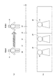
- FIG. 6 (a) shows a situation where the person H moves from point A to point B over time t0 to t4 as in FIG. 5 (a).
- FIG. 6B shows an example of a continuous image based on images captured by a pair of adjacent image capturing units C (that is, an image combined by the combining unit 22) is illustrated in FIG.
- the overlapping range AD is provided in the imaging range A of the pair of adjacent imaging units C.
- the transparency of a pair of images obtained by imaging a pair of adjacent imaging units C in an area corresponding to the overlapping range AD of the imaging range A for example, a diagram of the overlapping range AD.
- the transparency of the image from the left imaging unit C is 100%
- the transparency of the image from the right imaging unit C is 0%
- overlap is at the right end of the range AD in the figure (indicated by a straight line L2 in FIG. 6B)
- the transparency of the image from the left imaging unit C is 0%
- the transparency of the image from the right imaging unit C is 100.
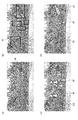
- FIG. 7 shows an actual composite image generated by the composite unit 22, that is, a result of generating continuous images. It can be confirmed that the moving body has not disappeared at the joint portion (portion indicated by an ellipse in the figure).
- the image from the imaging unit C on the left side in the figure is superimposed on the upper layer
- the image from the imaging unit C on the right side in the figure is superimposed on the lower layer. You may superimpose the image from the imaging part C located ahead as an upper layer.
- the synthesizing unit 22 recognizes a person as a moving body imaged in the synthesized image using an image recognition method with respect to the synthesized image as shown in FIG.
- the icon image is synthesized at the position to be superimposed.
- the composition unit 22 shows the icon image IP in the composite image, that is, continuous images, as shown in FIG. 10B. To display.
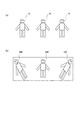
- the calculation unit 23 calculates a predetermined value related to the moving object, for example, the distance from the vehicle T to the person H as the moving object, the attribute of the moving object, and the moving speed of the moving object. Based on the calculation result of the unit 23, a predetermined icon image is synthesized. This procedure will be described with reference to FIG. In the example shown in FIG. 11, an image from a single imaging unit C is used, but it goes without saying that a composite image based on images from a pair of adjacent imaging units C may be used.
- the synthesizing unit 22 When an image as shown in FIG. 11A is captured by the image capturing unit C, the synthesizing unit 22 performs image recognition of the person H on the image using an image recognition technique.
- the result of image recognition by the combining unit 22 is shown in FIG. A region where a person H is captured by image recognition is indicated by a frame R.
- the calculation unit 23 calculates the distance from the vehicle T to the person H and the moving speed of the person H based on the image recognition result shown in FIG. Then, based on the calculation result of the calculating unit 23, the combining unit 22 combines different icon images IP corresponding to the distance from the vehicle T to the person H as shown in FIG. In the example shown in FIG. 11 (c), synthesis is performed depending on whether or not the distance from the end of the platform on the vehicle T side is within 1.5 m (the boundary is indicated by a straight line L3 in the figure). The unit 22 synthesizes different icon images IP.
- the composition unit 22 may extract the outline of the person H based on the image recognition result and synthesize the icon image IP having a shape having this outline.
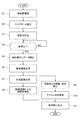
- step S1 the station where the image processing apparatus 1 arrives next is confirmed. What is necessary is just to acquire the information regarding the station which arrives next from the operation management system etc. of the vehicle T, for example.
- step S2 the synthesis unit 22 reads data corresponding to the next station confirmed in step S1 from the map data 11a in the storage unit 11, and in step S3, the synthesis unit 22 calculates a conversion formula.
- step S4 the image processing apparatus 1 waits for the vehicle T to stop at the station, and if it is determined that the vehicle T has stopped at the station (YES in step S4), the program proceeds to step S5.
- step S5 the image processing apparatus 1 waits for the vehicle T to stop at the station, and if it is determined that the vehicle T has stopped at the station (YES in step S4), the program proceeds to step S5.
- step S5 what is necessary is just to acquire the information of whether the vehicle T stopped at the station from the operation management system etc. of the vehicle T, for example.
- step S5 the image acquisition unit 20 acquires an image from a detection unit such as the imaging unit C.
- step S6 the synthesis unit 22 generates an overhead image based on the conversion formula calculated in step S3.
- step S ⁇ b> 7 based on the transparency set by the transparency setting unit 21, the synthesis unit 22 generates a synthesized image (continuous images) using images from a pair of adjacent imaging units C.
- step S8 the composition unit 22 performs image recognition on the composite image generated in step S8, thereby detecting the position of the moving object (person H or the like) in the composite image.
- step S9 the calculation part 23 calculates the distance from the vehicle T and the attribute of a moving body about the moving body detected by step S8.
- step S10 the synthesizing unit 22 synthesizes the icon image IP with the synthesized image based on the distance calculated by the calculating unit 23 in step S9.
- step S11 the image processing apparatus 1 displays the image generated in step S10 on the display screen of the display unit M.
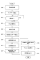
- the conversion formula is calculated before arrival of the vehicle T at the station (step S3).
- the synthesizing unit 22 may detect the actual stop position of the vehicle T (step S23), and the synthesizing unit 22 may perform the conversion formula creation operation based on the actual stop position (step S24).
- the other steps are the same as the steps in FIG.
- the image processing apparatus 1 includes a first image obtained by capturing an image of a first area including a predetermined area located on a side portion of the vehicle T, and An image acquisition unit 20 that acquires a second image obtained by imaging a second area including the predetermined area, and a first image that has a first transmittance corresponding to the predetermined area included in the first image. And a transparency setting unit 21 that sets the second transparency to a predetermined image corresponding to a predetermined region included in the second image, and the first transparency set by the transparency setting unit 21 And a combining unit 22 that combines the first image and the second image as a continuous image by applying the second transparency.
- the image processing apparatus 1 includes an imaging unit C that is a detection unit that detects information about a moving body located on the side of the vehicle T, and the combining unit 22 is moved by the detection unit.
- an imaging unit C that is a detection unit that detects information about a moving body located on the side of the vehicle T
- the combining unit 22 is moved by the detection unit.
- a predetermined icon image is synthesized at a position overlapping the moving object in the continuous image based on this information, so that the driver or the like visually recognizes the moving object in the predetermined area. It becomes easy.
- the image processing apparatus 1 includes a calculation unit 23 that calculates a predetermined value related to a moving object, and the combining unit 22 is positioned at a position where the composition unit 22 overlaps the moving object in a continuous image. Since a predetermined icon image based on the calculated predetermined value is synthesized, different icon images are synthesized based on a predetermined value related to the moving object, for example, a distance from the vehicle to the moving object, or an attribute of the moving object. As a result, it is possible for the driver or the like to easily identify a moving body that may be rushed on or contacted, and the driver or the like can be more easily identified.
- the image processing apparatus 1 includes a storage unit 11 in which predetermined reference data is stored, and the combining unit 22 uses at least one of the first image and the second image based on the reference data. Therefore, even if the stop position of the vehicle T is shifted, the first image and the second image can be appropriately combined, and the phenomenon that the moving body disappears due to the image combining performed by the combining unit 22 can be more effectively performed. Can be prevented.
- the range in which the synthesizing unit 22 sets the first transparency and the second transparency is the overlapping range AD of the imaging unit C in FIG.
- the range is based on the left end L1 in the figure and the right end L2 in the figure, a range from L1 to L2 may be designated.
- the transparency of these images is obtained.
- the degree of gradual increase / decrease may be changed.
- the degree of gradual increase / decrease of the transparency may be changed based on the moving direction of the moving body recognized by using a known image recognition method or sensor.
- the composition unit 22 has been described using the straight lines L ⁇ b> 1 and L ⁇ b> 2 in the figure as the positions that define the ranges in which the first transmittance and the second transmittance are set, but the positions are defined.
- the outer edge may be defined by a curve.
- the positions L1 and L2 that define the ranges for setting the first and second transmittances can be set to arbitrary positions.
- the moving body such as the person H on the platform of the station is imaged. It can also be used when the vehicle stops at a place other than the platform, as in the case of an emergency stop with the station.
- map data 11a it is advisable to prepare data relating to locations other than the platform in advance in the map data 11a. Since it is the railway vehicle T, since the place other than the platform is almost the roadbed of the railway track, it is sufficient to prepare map data 11a based on a typical roadbed shape such as a ballast roadbed and a concrete roadbed in advance.
- the image processing apparatus 1 includes a current position acquisition unit that can acquire the current position of the vehicle T such as a GPS unit, and the map data 11a includes data relating to the rail shape corresponding to the current position acquired by the current position acquisition unit. Can also generate a more precise composite image.
- a transparency setting unit that sets a second transparency for the predetermined image corresponding to the first image, and the first transparency and the second transparency set by the transparency setting unit are applied to the first image.
- An image processing apparatus comprising: a combining unit that combines one image and the second image as a continuous image.
- each of the first image and the second image is captured by an imaging unit provided on a side portion of the vehicle.
- It has a detection part which detects information about a moving object located in the side part of the vehicle, and if the information about the moving object is detected by the detection part, based on this information,
- a calculation unit that calculates a predetermined value related to the moving body, wherein the combining unit is configured to calculate the predetermined value calculated by the calculation unit at a position overlapping the moving body in the continuous images;
- the image processing apparatus according to (3), wherein a predetermined icon image based on the above is synthesized.
- a storage unit that stores predetermined reference data, and the combining unit processes at least one of the first image and the second image based on the reference data.
- the image processing apparatus according to any one of 3).
- An image processing method executed by the image processing apparatus the first image obtained by imaging a first area including a predetermined area located on a side portion of the vehicle, and the predetermined area A second image obtained by imaging the second region including the first image, and setting a first transparency to a predetermined image corresponding to the predetermined region included in the first image, A second transparency is set for the predetermined image corresponding to the predetermined area included in the second image, and the first image and the second transparency are applied by applying the first transparency and the second transparency.
- An image processing apparatus having a circuit, wherein the circuit includes a first image obtained by imaging a first area including a predetermined area located on a side portion of the vehicle, and the predetermined area A second image obtained by imaging the second region including the first image, and setting a first transparency to a predetermined image corresponding to the predetermined region included in the first image, A second transparency is set for the predetermined image corresponding to the predetermined area included in the second image, and the first image and the second transparency are applied by applying the first transparency and the second transparency.
- An image processing apparatus for synthesizing the second image as a continuous image.
Abstract
Provided are an image processing device and an image processing method capable of suitably processing images. The present invention includes: an image acquisition unit (20) that acquires a first image obtained by imaging a first region including a prescribed region located on a side section of a vehicle T, and a second image obtained by imaging a second region including a prescribed region; a transparency-degree setting unit (21) that sets a first transparency-degree for a prescribed image corresponding to the prescribed region included in the first image, and setting a second transparency-degree for a prescribed image corresponding to the prescribed region included in the second image; and a synthesizing unit (22) that synthesizes the first image and the second image to make a continuous image by applying the first transparency-degree and the second transparency-degree.
Description
本発明は、車両の側部に位置する所定の領域を撮像して得られる画像に基づいて画像処理を行う画像処理装置及び画像処理方法に関するものである。
The present invention relates to an image processing apparatus and an image processing method for performing image processing based on an image obtained by imaging a predetermined region located on a side portion of a vehicle.
このような画像処理装置としては、例えば特許文献1に開示された技術がある。この特許文献1では、鉄道車両の側面に複数のカメラが設置されており、車両の外側を撮像範囲とし、列車が駅に停車中にホーム上の人物を撮像し、撮影したカメラの映像を俯瞰変換し、運転席のモニタにパノラマ表示している。
As such an image processing apparatus, there is a technique disclosed in Patent Document 1, for example. In Patent Document 1, a plurality of cameras are installed on the side surface of a railway vehicle, the outside of the vehicle is set as an imaging range, a person on the platform is imaged while the train is stopped at the station, and an image of the captured camera is viewed from above. Converted and displayed in panorama on the driver's seat monitor.
しかしながら、上述の特許文献1に開示された技術では、複数のカメラで画像をつなぎ合わせる際に、このつなぎ目に映った人物等が消失する可能性があった。
However, in the technique disclosed in Patent Document 1 described above, when images are joined by a plurality of cameras, there is a possibility that a person or the like reflected at the joint is lost.
そこで、本発明は、画像を適切に処理することの可能な画像処理装置及び画像処理方法を提供することを目的としている。
Therefore, an object of the present invention is to provide an image processing apparatus and an image processing method capable of appropriately processing an image.
前記目的を達成するために、本発明の画像処理装置は、車両の側部に位置する所定の領域を含む第1の領域を撮像して得られる第1の画像、及び、所定の領域を含む第2の領域を撮像して得られる第2の画像を取得する画像取得部と、第1の画像に含まれる所定の領域に対応する所定の画像に第1の透過度を設定し、第2の画像に含まれる所定の領域に対応する所定の画像に第2の透過度を設定する透過度設定部と、透過度設定部により設定された第1の透過度及び第2の透過度を適用して第1の画像及び第2の画像を連続した画像として合成する合成部とを有することを特徴とする。
In order to achieve the above object, an image processing apparatus of the present invention includes a first image obtained by imaging a first area including a predetermined area located on a side portion of the vehicle, and a predetermined area. An image acquisition unit configured to acquire a second image obtained by imaging the second region, a first transparency set to a predetermined image corresponding to the predetermined region included in the first image, and a second A transparency setting unit for setting a second transparency to a predetermined image corresponding to a predetermined region included in the image of the image, and the first transparency and the second transparency set by the transparency setting unit are applied. And a combining unit that combines the first image and the second image as a continuous image.
このように構成された本発明の画像処理装置では、透過度設定部により設定された第1の透過度及び第2の透過度を適用して、合成部が第1の画像及び第2の画像を連続した画像として合成する。
In the image processing apparatus of the present invention configured as described above, the composition unit applies the first transparency and the second transparency set by the transparency setting unit, and the synthesis unit performs the first image and the second image. Are combined as a continuous image.
このようにすることで、第1の画像及び第2の画像を合成処理する作業において画像を適切に処理することが可能となる。
By doing so, it is possible to appropriately process the image in the process of combining the first image and the second image.
以下、この発明の実施の形態を図面に基づいて説明する。図3は、本発明の実施の形態である画像処理装置の概略構成を示す機能ブロック図である。
Hereinafter, embodiments of the present invention will be described with reference to the drawings. FIG. 3 is a functional block diagram showing a schematic configuration of the image processing apparatus according to the embodiment of the present invention.
本実施の形態である画像処理装置1は、一例として図1、2に示すように、鉄道車両Tの側部に設けられた検知部である撮像部Cから取得した画像を画像処理して表示部Mに画像処理後の画像を表示させるものである。
As shown in FIGS. 1 and 2 as an example, the image processing apparatus 1 according to the present embodiment performs image processing and displays an image acquired from an imaging unit C that is a detection unit provided on the side of the railway vehicle T. The image after image processing is displayed on the part M.
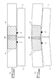
撮像部Cは、本実施の形態においてはカメラ等、その前方にある被写体を撮像してこの被写体に関する画像を出力するものであり、一例として図1(a)に示すように、鉄道車両Tの側面上部に複数個(図1に示す例では1車両T毎にその一側面に2個)配置されている。各々の撮像部Cは、図1(b)に示すように、車両Tの側面から下方にかつ外方に(図1(b)において右下方に)延びる撮像範囲Aを有し、この撮像範囲A内に存在する被写体(人物、プラットホームなど)を撮像して得られた画像を出力する。
In this embodiment, the imaging unit C captures a subject in front of it, such as a camera, and outputs an image related to the subject. As an example, as shown in FIG. A plurality (two in one side for each vehicle T in the example shown in FIG. 1) are arranged on the upper side. As shown in FIG. 1B, each imaging unit C has an imaging range A that extends downward and outward from the side surface of the vehicle T (to the lower right in FIG. 1B). An image obtained by imaging a subject (person, platform, etc.) existing in A is output.
図1(a)に示すように、隣り合う撮像部Cの撮像範囲Aの一部は重複範囲ADを有するように設定されており、これにより、一編成全体でみると、車両Tの編成の側部に位置する領域全体をカバーする撮像範囲Aが設定されていることになる。
As shown in FIG. 1 (a), a part of the imaging range A of the adjacent imaging units C is set to have an overlapping range AD. An imaging range A that covers the entire region located on the side is set.
なお、図示の関係で車両Tの一側面に設けられた撮像部Cのみ図示しているが、実際には、車両Tの他方の側面にも同様に撮像部Cが設けられている。但し、後述するように、画像処理装置1が、停車した状態におけるプラットホーム上の人物等が撮像された画像の画像処理を行うのであれば、車両Tの一方の側面に設けられた撮像部Cからの画像について画像処理を行えば足りるので、この一方の側面、より詳細にはプラットホームに対向する側面に設けられた撮像部Cのみ動作させれば足りる。
Note that only the image pickup unit C provided on one side surface of the vehicle T is illustrated in the illustrated relationship, but actually, the image pickup unit C is similarly provided on the other side surface of the vehicle T. However, as will be described later, if the image processing apparatus 1 performs image processing of an image of a person or the like on the platform in a stopped state, from the imaging unit C provided on one side surface of the vehicle T. Therefore, it is sufficient to operate only the image pickup unit C provided on one side surface, more specifically, the side surface facing the platform.
図2に示すように、各々の撮像部Cから出力される画像は全て本実施の形態である画像処理装置1に入力され、この画像処理装置1により画像処理された画像が表示部Mに出力される。
As shown in FIG. 2, all the images output from each imaging unit C are input to the image processing apparatus 1 according to the present embodiment, and the image processed by the image processing apparatus 1 is output to the display unit M. Is done.
表示部Mは液晶ディスプレイ、CRT等その種類や表示形式に限定はない。表示部Mの設置場所にも特段の限定はなく、車両Tの運転手、車掌、駅員、運行管理者といった鉄道係員が視認可能な位置に設けられればよい。従って、表示部Mは車両Tの運転席または車掌席において運転手または車掌が視認可能な位置や、プラットホームの上方であって同様に運転手または車掌が視認可能な位置、さらには、駅の駅員控室や運行管理部において駅員や運行管理者が視認可能な位置などに設けられる。加えて、表示部Mは、例えば運転手や車掌が所持するスマートフォン、タブレット等の情報処理装置であってもよい。
The display unit M is not limited in its type and display format such as a liquid crystal display or CRT. There is no particular limitation on the installation location of the display unit M, and the display unit M may be provided at a position where a railroad worker such as a driver of the vehicle T, a conductor, a station staff, or an operation manager can visually recognize. Accordingly, the display unit M is a position where the driver or the conductor can visually recognize the driver's seat or the conductor's seat of the vehicle T, a position above the platform where the driver or the conductor can be visually recognized, and the station staff. It is provided at a position where station staff and operation manager can visually recognize in the waiting room and operation management section. In addition, the display unit M may be an information processing device such as a smartphone or a tablet possessed by a driver or a conductor.
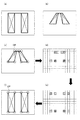
図2に示す例では、4両編成の車両Tのそれぞれに2個の撮像部Cが設けられており、従って、8個の撮像部Cからの画像が画像処理装置1に入力され、画像処理装置1によって画像処理された画像が表示部Mに表示される。表示部Mは4つの表示画面Pを有し、各々の表示画面Pは1両の車両Tに設けられた撮像部Cから取得された画像を画像処理したものに対応している。なお、図2に示す撮像部Aで撮影された画像を撮影画像A、撮像部Bで撮影された画像を撮影画像B、撮像部Cで撮影された画像を撮影画像C、撮像部Dで撮影された画像を撮影画像D、撮像部Eで撮影された画像を撮影画像E、撮像部Fで撮影された画像を撮影画像F、撮像部Gで撮影された画像を撮影画像G、撮像部Hで撮影された画像を撮影画像Hとする。
In the example shown in FIG. 2, two imaging units C are provided for each of the four-car train T, and therefore images from the eight imaging units C are input to the image processing apparatus 1 and image processing is performed. An image processed by the apparatus 1 is displayed on the display unit M. The display unit M has four display screens P, and each display screen P corresponds to an image obtained by performing image processing on an image acquired from the imaging unit C provided in one vehicle T. 2, the image captured by the imaging unit A is captured by the captured image A, the image captured by the imaging unit B is captured by the captured image B, and the image captured by the imaging unit C is captured by the captured image C and the imaging unit D. The captured image is the captured image D, the image captured by the image capturing unit E is the captured image E, the image captured by the image capturing unit F is the captured image F, the image captured by the image capturing unit G is the captured image G, and the image capturing unit H The image captured in step S is defined as a captured image H.
画像処理装置1は車両T内に設けられ、制御部10と記憶部11とを有する。制御部10はCPU等の演算素子を備える。記憶部11内に格納されている図略の制御用プログラムが画像処理装置1の起動時に実行され、この制御用プログラムに基づいて、制御部10は記憶部11等を含む画像処理装置1全体の制御を行うとともに、画像取得部20と、透過度設定部21と、合成部22と、算出部23としての機能を実行する。これら各機能部の動作については後述する。
The image processing apparatus 1 is provided in the vehicle T and includes a control unit 10 and a storage unit 11. The control unit 10 includes an arithmetic element such as a CPU. An unillustrated control program stored in the storage unit 11 is executed when the image processing apparatus 1 is started. Based on this control program, the control unit 10 controls the entire image processing apparatus 1 including the storage unit 11 and the like. While performing control, the function as the image acquisition part 20, the transparency setting part 21, the synthetic | combination part 22, and the calculation part 23 is performed. The operations of these functional units will be described later.
記憶部11はハードディスクドライブ等の大容量記憶媒体、及びROM、RAM等の半導体記憶媒体を備える。この記憶部11には上述の制御用プログラムが格納されているとともに、制御部10の制御動作時に必要とされる各種データが一時的に格納される。また、この記憶部11にはマップデータ11a、アイコンデータ11b及びプラットホームデータ11cが格納されている。
The storage unit 11 includes a large-capacity storage medium such as a hard disk drive and a semiconductor storage medium such as ROM and RAM. The storage unit 11 stores the above-described control program and temporarily stores various data necessary for the control operation of the control unit 10. The storage unit 11 stores map data 11a, icon data 11b, and platform data 11c.
マップデータ11aは、車両Tが停車する駅のプラットホームに関するデータであり、より詳細には、撮像部Cが撮像する画像が図1(b)に示すような画像である(車両Tの側面上部から図1(b)において右下方に延びる撮像範囲Aにある被写体を撮像した画像)ので、これを、プラットホームを平面視した俯瞰画像に変換するためのデータである。従って、このマップデータ11aは、プラットホームの形状(凹凸、傾斜、プラットホームの車両T側の端部形状(長さ、曲率など))を反映したものである。マップデータ11aは、撮像部Cから取得した画像の画素単位の変換位置を示すデータを含む。
The map data 11a is data relating to the platform of the station where the vehicle T stops. More specifically, the image captured by the imaging unit C is an image as shown in FIG. 1B (from the upper side of the side surface of the vehicle T). 1 (b), which is an image of a subject in the imaging range A that extends to the lower right, and is data for converting the image into a bird's-eye view in plan view of the platform. Therefore, this map data 11a reflects the shape of the platform (unevenness, inclination, shape of the end of the platform on the vehicle T side (length, curvature, etc.)). The map data 11a includes data indicating the conversion position in pixel units of the image acquired from the imaging unit C.
アイコンデータ11bは、後述する制御部10の合成部22により、人物等の移動体が撮像された領域に重畳して合成されるアイコン画像を表示部Mに表示するためのデータである。このアイコンデータ11bは、車両Tから移動体までの距離、及び移動体の属性(移動体の種別など)などに応じて複数種類記憶部11に格納されている。
The icon data 11b is data for displaying, on the display unit M, an icon image that is combined and superimposed on a region where a moving body such as a person is imaged by the combining unit 22 of the control unit 10 described later. The icon data 11b is stored in the multiple types storage unit 11 in accordance with the distance from the vehicle T to the moving object, the attributes of the moving object (such as the type of the moving object), and the like.
プラットホームデータ11cは、マップデータ11aと同様に、車両Tが停車する駅のプラットホームに関するデータであり、より詳細には、車両Tの停止位置に関する基準画像のデータである。合成部22は、マップデータ11a及びプラットホームデータ11cを用いて、撮像部Cから取得した画像を俯瞰画像に変換する。
The platform data 11c is data related to the platform of the station where the vehicle T stops, as in the case of the map data 11a, and more specifically is reference image data related to the stop position of the vehicle T. The synthesizing unit 22 converts the image acquired from the imaging unit C into an overhead image using the map data 11a and the platform data 11c.
なお、制御部10と記憶部11とがいずれも車両T内に設けられる必要はなく、これら制御部10と記憶部11との間を通信回線で結び、記憶部11のみ車両Tの外に設置された外部サーバにより構成してもよい。
Note that neither the control unit 10 nor the storage unit 11 needs to be provided in the vehicle T. The control unit 10 and the storage unit 11 are connected by a communication line, and only the storage unit 11 is installed outside the vehicle T. You may comprise by the made external server.
次に、制御部10に構成される各機能部の説明をする。
Next, each functional unit configured in the control unit 10 will be described.
画像取得部20は、車両Tの側部に位置する所定の領域を含む第1の領域を撮像して得られる第1の画像、及び、所定の領域を含む第2の領域を撮像して得られる第2の画像を取得する。
The image acquisition unit 20 captures a first image obtained by imaging a first area including a predetermined area located on the side of the vehicle T, and a second area including the predetermined area. A second image to be acquired.
より詳細には、画像取得部20は、車両Tの側部に設けられた撮像部Cが撮像した画像を取得する。ここで、図1及び図2に示すように、本実施の形態の撮像部Cのうち隣り合う一対の撮像部C(例えば、図2における撮像部Aと撮像部B)は重複した撮像範囲(例えば、図1における重複範囲AD)を有するので、この重複範囲ADに対応する重複領域が上述の所定の領域に相当し、この重複範囲ADを共有する一対の撮像部C(例えば、図2における撮像部Aと撮像部B)の撮像範囲Aに対応する領域が第1の領域及び第2の領域に相当する。そして、これら一対の撮像部Cから取得した画像が第1の画像(例えば、図2における撮影画像A)及び第2の画像(例えば、図2における撮影画像B)に相当する。
More specifically, the image acquisition unit 20 acquires an image captured by the imaging unit C provided on the side of the vehicle T. Here, as shown in FIGS. 1 and 2, a pair of adjacent image pickup units C (for example, the image pickup unit A and the image pickup unit B in FIG. 2) of the image pickup units C according to the present embodiment have overlapping image pickup ranges ( For example, since there is an overlapping range AD in FIG. 1, the overlapping region corresponding to the overlapping range AD corresponds to the predetermined region described above, and a pair of imaging units C that share the overlapping range AD (for example, in FIG. 2). The areas corresponding to the imaging range A of the imaging unit A and the imaging unit B) correspond to the first area and the second area. The images acquired from the pair of imaging units C correspond to the first image (for example, the captured image A in FIG. 2) and the second image (for example, the captured image B in FIG. 2).
透過度設定部21は、第1の画像に含まれる所定の領域に対応する所定の画像に第1の透過度を設定し、第2の画像に含まれる所定の領域に対応する所定の画像に第2の透過度を設定する。
The transparency setting unit 21 sets the first transparency for a predetermined image corresponding to a predetermined area included in the first image, and sets the predetermined image corresponding to the predetermined area included in the second image. A second transparency is set.
より詳細には、透過度設定部21は、隣り合う一対の撮像部Cから取得した第1の画像及び第2の画像に対して、これら一対の撮像部Cの撮像範囲Aの重複範囲ADに対応する重複領域(つまりは所定の領域)に対応する領域の画像にそれぞれ第1及び第2の透過度を設定する。
More specifically, the transparency setting unit 21 sets the overlapping range AD of the imaging range A of the pair of imaging units C with respect to the first image and the second image acquired from the pair of adjacent imaging units C. First and second transmissivities are set for images in areas corresponding to corresponding overlapping areas (that is, predetermined areas), respectively.
ここに、透過度とは、重複部分を有する一対の画像をこの重複部分で重複表示する際に、この重複部分に属する画素の画素値をどの程度透過させるかの値であり、言い換えれば、一対の画像をそれぞれ重なり合うレイヤ上に配置した際に、上方に位置するレイヤ上の画像をどの程度透過させるか(つまりは下方に位置するレイヤ上の画像をどの程度見せるか)を示す値である。透過度は0から1の実数値を持ち、0が完全透過(透明)、1が完全不透過(不透明)である。
Here, the transparency is a value of how much the pixel value of a pixel belonging to the overlapping portion is transmitted when the pair of images having the overlapping portion is displayed in the overlapping portion. This is a value indicating how much the image on the upper layer is transmitted (that is, how much the image on the lower layer is shown) when the images are arranged on the overlapping layers. The transparency has a real value from 0 to 1, with 0 being completely transparent (transparent) and 1 being completely opaque (opaque).
透過度設定部21による透過度設定動作は、いわゆるブレンド処理(アルファブレンディング)として公知の動作である。第1の透過度及び第2の透過度をどのように設定するかは、この所定の領域において撮像される被写体、特に移動体をどの程度視認させるかによって設定される。また、第1の透過度及び第2の透過度は所定の領域内で一定値に設定されてもよく、あるいは、所定の領域の座標値で定義される一次関数またはそれ以上の高次関数の関数値として定義されてもよい。
The transparency setting operation by the transparency setting unit 21 is a known operation as so-called blend processing (alpha blending). How to set the first transparency and the second transparency is set depending on how much a subject to be imaged in this predetermined area, in particular, a moving body is visually recognized. In addition, the first transparency and the second transparency may be set to constant values within a predetermined area, or a linear function defined by the coordinate value of the predetermined area or a higher-order function higher than that. It may be defined as a function value.
合成部22は、透過度設定部21により設定された第1の透過度及び第2の透過度を適用して第1の画像及び第2の画像を連続した画像として合成する。
The synthesizing unit 22 synthesizes the first image and the second image as a continuous image by applying the first transparency and the second transparency set by the transparency setting unit 21.
より詳細には、合成部22は、透過度設定部21により設定された第1の透過度及び第2の透過度を適用して、隣り合う一対の撮像部Cから取得した第1の画像及び第2の画像について、所定の領域に対応する所定の画像に対してそれぞれ第1の透過度及び第2の透過度を適用し、この所定の領域においてブレンド処理を行った合成画像を生成する。
More specifically, the combining unit 22 applies the first transmittance and the second transmittance set by the transmittance setting unit 21, and the first image acquired from the pair of adjacent imaging units C and For the second image, the first transparency and the second transparency are respectively applied to the predetermined image corresponding to the predetermined area, and a composite image is generated by performing blend processing in the predetermined area.
特に、本実施の形態の画像処理装置1では、車両Tの側部に設けられた撮像部Cは、隣り合う一対の撮像部Cにおいてその撮像範囲Aに重複範囲ADが設けられているので、図2に示す例では、合成部22は一編成(つまり4両)分の一体となった合成画像を生成することも可能であるが、本実施の形態の画像処理装置1では、既に説明したように、表示部Mが4つの表示画面Pを有し、各々の表示画面Pは1両の車両Tに設けられた撮像部Cから取得された画像を画像合成したものとしている。当然、合成部22がどのように合成画像を生成するかは任意である。
In particular, in the image processing apparatus 1 of the present embodiment, the imaging unit C provided on the side portion of the vehicle T has an overlapping range AD in the imaging range A in a pair of adjacent imaging units C. In the example shown in FIG. 2, the combining unit 22 can generate a combined image that is integrated for one organization (that is, four cars). However, the image processing apparatus 1 according to the present embodiment has already been described. As described above, the display unit M has four display screens P, and each display screen P is obtained by synthesizing images acquired from the imaging units C provided in one vehicle T. Of course, how the synthesis unit 22 generates the synthesized image is arbitrary.
ここで、合成部22は、検知部である撮像部Cにより移動体に関する情報が検知されたら、この情報に基づいて、連続した画像中の移動体と重畳する位置に所定のアイコン画像を合成する。
Here, when information related to the moving object is detected by the imaging unit C serving as the detection unit, the combining unit 22 combines a predetermined icon image at a position overlapping with the moving object in successive images based on this information. .
より詳細には、検知部である撮像部Cが移動体である人物等を撮像したら、合成部22は第1の画像、第2の画像中における人物等の撮像位置を検出し、上述の手順により生成した合成画像中に、この人物等の撮像位置と重複する一位置に所定のアイコン画像を合成する。
More specifically, when the imaging unit C serving as the detection unit captures a person or the like that is a moving body, the synthesis unit 22 detects the imaging position of the person or the like in the first image and the second image, and the above-described procedure. A predetermined icon image is synthesized at one position overlapping the imaging position of the person or the like in the synthesized image generated by the above.
ここに、検知部は撮像部Cに限定されず、車両の側部に位置する移動体に関する情報を検知できるものであれば限定はない。一例として、人物等の移動体の存在を検知する人感センサや、人物が所持するスマートフォン、タブレット等の通信機能を有する情報処理装置から発信される電波(移動体通信の電波でもよいし、いわゆる無線LANの電波でもよい)を検出するセンサ等もここにいう検知部に含みうる。
Here, the detection unit is not limited to the imaging unit C, and there is no limitation as long as it can detect information on a moving body located on the side of the vehicle. As an example, a radio wave (a mobile communication radio wave, or a so-called radio wave transmitted from an information processing device having a communication function such as a smartphone or tablet possessed by a human sensor or a person possessing a mobile object such as a person may be used. A sensor that detects a wireless LAN radio wave) may be included in the detection unit.
また、移動体に関する情報とは、上述したように第1の画像、第2の画像中における移動体の撮像位置に関する情報であってもよいし、車両の側部に移動体が位置するか否かに関する情報であってもよい。
Further, as described above, the information on the moving body may be information on the imaging position of the moving body in the first image and the second image, and whether or not the moving body is located on the side of the vehicle. It may be information on
合成部22は、検知部から移動体に関する情報を取得したら、この情報に基づいて連続した画像中の移動体と重畳する位置に所定のアイコン画像を合成する。このためには、合成部22は、連続した画像、つまり、第1の画像と第2の画像とを合成した画像中における移動体の位置を検出することが好ましい。このような検出手法の一例としては、周知の画像認識手法が好適に挙げられる。画像認識は、検知部が撮像部Cであれば、移動体である人物等を撮像した画像中においてこの人物等の撮像位置を検出することにより行われる。画像認識手法自体は公知であるので、ここではこれ以上の詳細な説明を省略する。
The synthesizing unit 22 synthesizes a predetermined icon image at a position overlapping with the moving body in the continuous image based on this information after acquiring information on the moving body from the detection unit. For this purpose, it is preferable that the synthesis unit 22 detects the position of the moving body in a continuous image, that is, an image obtained by synthesizing the first image and the second image. As an example of such a detection method, a well-known image recognition method is preferably exemplified. If the detection unit is the imaging unit C, the image recognition is performed by detecting an imaging position of the person or the like in an image obtained by imaging a person or the like that is a moving body. Since the image recognition method itself is publicly known, further detailed explanation is omitted here.
算出部23は、移動体に関する所定の値を算出する。ここに、所定の値は、車両から移動体までの距離、または移動体の属性を含むことが好ましい。そして、合成部22は、連続した画像中の移動体と重畳する位置に、算出部23により算出された所定の値に基づいた所定のアイコン画像を合成する。
Calculating unit 23 calculates a predetermined value related to the moving body. Here, the predetermined value preferably includes a distance from the vehicle to the moving object or an attribute of the moving object. The synthesizing unit 22 synthesizes a predetermined icon image based on the predetermined value calculated by the calculating unit 23 at a position overlapping the moving body in the continuous image.
より詳細には、算出部23は、検知部により検知された移動体に関する情報を用いて、この移動体に関する所定の値、好ましくは車両Tから移動体までの距離、または移動体の属性を算出する。
More specifically, the calculation unit 23 uses the information about the moving object detected by the detection unit to calculate a predetermined value related to the moving object, preferably a distance from the vehicle T to the moving object, or an attribute of the moving object. To do.
検知部が撮像部Cであれば、算出部23は、上述の合成部22と同様に、画像認識手法を用いて、連続した画像中における移動体の撮像位置を検知し、この撮像位置に基づいて車両Tから移動体までの距離、または移動体の属性を算出する。
If the detection unit is the imaging unit C, the calculation unit 23 uses the image recognition method to detect the imaging position of the moving body in the continuous images, and based on the imaging position, similarly to the synthesis unit 22 described above. The distance from the vehicle T to the moving object or the attribute of the moving object is calculated.
そして、合成部22は、算出部23により算出された車両Tから移動体までの距離、または移動体の属性に基づいた所定のアイコン画像を合成する。一例として、車両Tから移動体までの距離が、移動体が車両Tに接近しすぎて当接、接触する可能性があると考えられる距離(例えば1.5m以内)である場合、この距離よりも離れた距離にある移動体とは異なる色のアイコン画像を合成する。
Then, the synthesis unit 22 synthesizes a predetermined icon image based on the distance from the vehicle T to the moving object calculated by the calculation unit 23 or the attribute of the moving object. As an example, when the distance from the vehicle T to the moving body is a distance (for example, within 1.5 m) where the moving body may be too close to the vehicle T and come into contact with or contact with the vehicle T, for example, An icon image of a color different from that of the moving object at a distance is also synthesized.
加えて、算出部23が画像認識の結果、移動体に関する情報として移動体の移動速度まで算出するならば、車両Tから移動体までの距離と移動体の移動速度とに基づいて所定のアイコン画像を合成してもよい。
In addition, if the calculation unit 23 calculates the moving speed of the moving object as information on the moving object as a result of the image recognition, a predetermined icon image is based on the distance from the vehicle T to the moving object and the moving speed of the moving object. May be synthesized.
ここで、移動体の属性とは、検知部により検知されると考えられる移動体の種類(例えば人物、ベビーカー、車椅子など)を含む。好ましくは、合成部22は、検知部により検知されると考えられる移動体の種類を予め用意しておき、この種類毎にテンプレートとなる参照画像を用意しておき、この参照画像と連続した画像とのパターンマッチングを行い、移動体の撮像位置及び移動体の種類をともに検出して、種類毎に異なるアイコン画像を合成する。このため、合成部22がパターンマッチングを行う場合は、アイコンデータ11bとしてこの移動体の種類毎に異なるアイコン画像が用意され、記憶部11に格納される。
Here, the attribute of the moving object includes the type of moving object (for example, a person, a stroller, a wheelchair, etc.) considered to be detected by the detection unit. Preferably, the synthesizing unit 22 prepares in advance the types of moving objects that are considered to be detected by the detecting unit, and prepares a reference image as a template for each type, and an image continuous with the reference image. And the image capturing position of the moving body and the type of the moving body are both detected, and different icon images are synthesized for each type. For this reason, when the synthesizing unit 22 performs pattern matching, a different icon image is prepared for each type of moving object as the icon data 11 b and stored in the storage unit 11.
これら各機能部の動作についてはさらに詳細に後述する。
The operation of each functional unit will be described in detail later.
次に、図4~図11を参照して、本実施の形態である画像処理装置1の動作の一例について説明する。
Next, an example of the operation of the image processing apparatus 1 according to the present embodiment will be described with reference to FIGS.
図1(b)に示すように、撮像部Cは車両Tの側部上方の一点から車両Tの側方を見下ろすように撮像しているので、表示部Mを視認する運転手等が違和感なく人物等の移動物を視認し、また、合成部22により各種画像処理を適切に行うために、撮像部Cの撮像画像を、プラットホームを平面視した俯瞰画像に変換する必要がある。
As shown in FIG. 1 (b), the imaging unit C captures an image so that the side of the vehicle T is looked down from one point above the side of the vehicle T. In order to visually recognize a moving object such as a person and appropriately perform various image processing by the combining unit 22, it is necessary to convert the captured image of the imaging unit C into an overhead view image obtained by planarly viewing the platform.
ここで考慮すべきは、車両Tが停車する駅のプラットホームは駅毎にその高さ、平面形状、さらには傾斜が異なりうるので、撮像部Cが撮像した画像を俯瞰画像に変換する際の具体的なパラメータ等も駅毎に用意する必要がある。撮像部Cとプラットホームの高さ等がアンマッチな状態で単純に合成部22により連続した画像を形成すると、異なる撮像部Cで撮像した画像同士のつなぎ目部分がずれて表示されてしまう。
What should be considered here is that the platform of the station where the vehicle T stops may vary in height, plane shape, and inclination from station to station. It is necessary to prepare specific parameters for each station. If a continuous image is simply formed by the combining unit 22 in a state in which the heights of the imaging unit C and the platform are unmatched, a joint portion between images captured by different imaging units C is displayed in a shifted manner.
一例として、図8(a)に示す例では、プラットホームが直線状であるので、撮像部Cによる撮像範囲Aの重複範囲ADも単純なものとなる。従って、プラットホームの高さ等を考慮して俯瞰画像を生成すれば、複数(図示例では一対)の撮像部Cの撮像画像のつなぎ目をスムースに合成して連続した画像を生成することができる。一方、図8(b)に示すように、プラットホームが所定の曲率を有する、言い換えれば平面視した状態で曲がっている場合、撮像部Cによる撮像範囲Aの重複範囲ADはプラットホームの曲率に依存して変形される。従って、プラットホームの高さ等を考慮して俯瞰画像を生成しても、一対の撮像部Cの撮像画像のつなぎ目がずれてしまう。
As an example, in the example shown in FIG. 8A, since the platform is linear, the overlapping range AD of the imaging range A by the imaging unit C is also simple. Therefore, if a bird's-eye view image is generated in consideration of the height of the platform and the like, a continuous image can be generated by smoothly synthesizing joints of captured images of a plurality (a pair in the illustrated example) of the imaging units C. On the other hand, as shown in FIG. 8B, when the platform has a predetermined curvature, in other words, when it is bent in a plan view, the overlapping range AD of the imaging range A by the imaging unit C depends on the curvature of the platform. Is transformed. Therefore, even if the overhead image is generated in consideration of the height of the platform, the joint between the captured images of the pair of imaging units C is shifted.
そこで、本実施の形態である画像処理装置1では、合成部22が記憶部11内のマップデータ11aを用いて、プラットホームの高さ、形状、傾斜を考慮した上で一様な俯瞰画像を生成している。これにより、複数の撮像部Cで撮像した画像のつなぎ目部分がずれて表示されることを防ぐことができる。
Therefore, in the image processing apparatus 1 according to the present embodiment, the synthesizing unit 22 uses the map data 11a in the storage unit 11 to generate a uniform overhead view image in consideration of the height, shape, and inclination of the platform. is doing. Thereby, it can prevent that the joint part of the image imaged with the some image pick-up part C is shifted and displayed.
加えて、プラットホームを平面視した際の曲率が場所によって異なる、一例として、編成の先頭部のみ曲がっているようなプラットホームであると、車両Tの停止位置によって車両Tの連結部分のなす角度が変化してしまう可能性がある。
In addition, the curvature of the platform when viewed in plan varies depending on the location. For example, if the platform is bent only at the top of the knitting, the angle formed by the connecting portion of the vehicle T varies depending on the stop position of the vehicle T. There is a possibility that.
そこで、プラットホーム及び車両Tに停止位置目標となる目印を用意しておき、合成部22は、撮像部Cが撮像した画像とプラットホームデータ11cである基準画像とを比較することで停止位置目標と実際の停止位置とのずれを算出し、車両Tの実際の停止位置を考慮して連続した画像を生成している。これによって、車両Tの連結部の角度が停止位置によって変化することによる、複数の撮像部Cで撮像した画像のつなぎ目部分がずれて表示されることを防ぐことができる。
Therefore, a mark serving as a stop position target is prepared for the platform and the vehicle T, and the combining unit 22 compares the image captured by the image capturing unit C with the reference image, which is the platform data 11c, to determine the actual stop position target. A deviation from the stop position of the vehicle T is calculated, and continuous images are generated in consideration of the actual stop position of the vehicle T. Thereby, it is possible to prevent the joint portions of the images picked up by the plurality of image pickup portions C from being displayed in a shifted manner due to the change in the angle of the connecting portion of the vehicle T depending on the stop position.
なお、停止位置目標は編成の先頭車両及びこれに対応するプラットホームの箇所にのみ設ければ足りる。
It should be noted that it is sufficient to set the stop position target only on the first vehicle of the formation and the corresponding platform.
合成部22による俯瞰画像の生成手法の一例について、図9を参照して説明する。
An example of a method for generating an overhead image by the synthesis unit 22 will be described with reference to FIG.
まず、各駅のプラットホーム上に図9(a)に示すような図形を白線で描き、この図形を撮像部Cにより撮像する。撮像部Cにより図形を撮像して得られる画像の一例を図9(b)に示す。撮像部Cが車両Tの側部上方から見下ろすように撮像しているので、撮像して得られた画像は図中上方に消失点を有する遠近法に従ったものになる。
First, a figure as shown in FIG. 9A is drawn with a white line on the platform of each station, and this figure is imaged by the imaging unit C. An example of an image obtained by imaging a figure by the imaging unit C is shown in FIG. Since the imaging unit C is imaging so that it looks down from above the side of the vehicle T, the image obtained by imaging follows a perspective method having a vanishing point in the upper part of the figure.
合成部22は、画像認識手法等に基づいて、図9(c)に示すように、撮像して得られた画像から白線の交点CPを抽出(検出)し、この交点CPの画素の位置(座標値)を求める。一例として、撮像画像中の交点CPの画素の位置は図9(d)のハッチングで示す位置であるとする。
Based on the image recognition method or the like, the synthesizer 22 extracts (detects) the intersection CP of the white line from the image obtained by imaging as shown in FIG. 9C, and the pixel position of this intersection CP ( Find the coordinate value. As an example, it is assumed that the position of the pixel at the intersection point CP in the captured image is a position indicated by hatching in FIG.
次いで、合成部22は、画像処理装置1の出力である表示部Mの表示画面において、図9(a)に示すような図形が表示される、つまり俯瞰画像が表示されるように、撮像画像中の交点CPの画素の位置を表示部Mの表示画面の画素に変換するための変換式(変換テーブル)を求める。目標となる表示部Mの表示画面上での交点CPの画素の位置を図9(e)に示す。この変換式を求めるパラメータとしては、表示部の表示画面の画素数(好ましくは縦×横)、撮像部Cの撮像画像の画素数(好ましくは縦×横)、白線図形の大きさがある。この変換式は、記憶部11内のマップデータ11aとして格納される。
Next, the synthesizing unit 22 displays a captured image such that a graphic as illustrated in FIG. 9A is displayed on the display screen of the display unit M that is an output of the image processing apparatus 1, that is, an overhead image is displayed. A conversion formula (conversion table) for converting the position of the pixel at the intersection CP in the display unit to a pixel on the display screen of the display unit M is obtained. FIG. 9E shows the position of the pixel at the intersection CP on the display screen of the target display unit M. Parameters for obtaining the conversion formula include the number of pixels on the display screen of the display unit (preferably vertical × horizontal), the number of pixels of the captured image of the imaging unit C (preferably vertical × horizontal), and the size of the white line figure. This conversion formula is stored as map data 11 a in the storage unit 11.
そして、合成部22は、図9(e)で求めた変換式に基づいて、図9(b)に示す撮像部Cの撮像画像を変換し、図9(f)に示すような俯瞰画像を生成する。
Then, the synthesis unit 22 converts the captured image of the imaging unit C illustrated in FIG. 9B based on the conversion formula obtained in FIG. 9E, and generates an overhead image as illustrated in FIG. Generate.
図9に示す変換式算出動作は、車両Tが駅から発車する時点よりやや早く完了していることが好ましい。これは、本実施の形態における画像処理装置1からの出力を表示部Mの表示画面で運転手等が視認する目的に、車両Tの発車時点で車両Tのドアの閉止動作を行ってよいかどうか、つまり、プラットホーム上の乗客が全て車両Tに乗車したかどうかを確認することが含まれ、加えて、ドアの閉止後に車両Tを発車させる際に、プラットホーム上の乗客が車両Tに接触するかどうかを確認することが含まれるからである。
9 is preferably completed slightly earlier than the time point when the vehicle T departs from the station. This is because the door of the vehicle T may be closed when the vehicle T departs for the purpose of allowing the driver or the like to visually recognize the output from the image processing apparatus 1 according to the present embodiment on the display screen of the display unit M. Whether or not all passengers on the platform have boarded the vehicle T, and in addition, the passengers on the platform touch the vehicle T when the vehicle T is started after the door is closed. This is because it includes checking whether or not.
加えて、駅毎にプラットホーム形状は異なるので、合成部22は、次の駅への移動中にこの次の駅に用いるための変換式を算出することが好ましい。このように、駅毎に合成部22が都度変換式を算出することにより、全ての駅に対応する変換式を事前に算出して記憶部11に格納しておく必要がないため、記憶部11の記憶容量が小さくて足りる。
In addition, since the platform shape is different for each station, it is preferable that the combining unit 22 calculates a conversion formula to be used for the next station while moving to the next station. Thus, since the composition unit 22 calculates the conversion formula for each station every time, it is not necessary to calculate the conversion formulas corresponding to all stations in advance and store them in the storage unit 11. The storage capacity is small.
なお、このように次の駅への移動中に変換式を算出した場合、駅に停止した後に、合成部22は、停止位置目標の画像認識結果を用いてこの変換式を修正する。あるいは、次の駅への移動中には変換式を算出せず、車両Tが停止した後に、合成部22が停止位置目標の画像認識結果を用いて変換式を算出してもよい。
In addition, when the conversion formula is calculated during the movement to the next station in this way, after stopping at the station, the composition unit 22 corrects the conversion formula using the image recognition result of the stop position target. Alternatively, the conversion formula may not be calculated during movement to the next station, and the composition unit 22 may calculate the conversion formula using the image recognition result of the stop position target after the vehicle T has stopped.
次に、上述した手順により俯瞰画像を得た後の、合成部22による連続した画像の生成手順について説明する。
Next, a procedure for generating continuous images by the synthesis unit 22 after obtaining an overhead image by the above-described procedure will be described.
図4(a)は、車両Tの側部、例えばプラットホーム上に立っている移動体である人物Hを肉眼で見た状態を示す図であり、図4(b)は、図4(a)に示す状態の人物Hを撮像部Cにより撮像して得られた俯瞰画像を示す図である。撮像された画像中における人物Hの画像HPは、撮像画像の周辺部(図4(b)において左右端部)に行くに従って放射状に歪んでいる。
FIG. 4A is a diagram showing a state where a person H, which is a moving body standing on a side of the vehicle T, for example, a platform, is viewed with the naked eye, and FIG. 4B is a diagram illustrating FIG. It is a figure which shows the bird's-eye view image obtained by imaging the person H of the state shown to by the imaging part C. The image HP of the person H in the captured image is radially distorted as it goes to the periphery of the captured image (the left and right ends in FIG. 4B).
図4(b)に示すように、俯瞰画像に変換した後でも移動体(人物H)の画像HPが歪むことを前提として、図5(a)に示すように、人物Hが地点Aから地点Bまで時間t0~t4の時間をかけて移動した際に、隣り合う一対の撮像部Cにより撮像された画像に基づく俯瞰画像を単純につなぎ合わせた場合の画像を図5(b)に示す。なお、図5(b)に示す例では、隣り合う一対の撮像部Cの撮像範囲Aに重複範囲ADを設けていない。
As shown in FIG. 4B, on the assumption that the image HP of the moving object (person H) is distorted even after conversion to the overhead image, the person H moves from the point A to the point as shown in FIG. FIG. 5B shows an image when the overhead images based on the images captured by the pair of adjacent imaging units C are simply connected when moving to B over time t0 to t4. In the example shown in FIG. 5B, the overlapping range AD is not provided in the imaging range A of the pair of adjacent imaging units C.
時刻t0及びt4における人物Hの画像HPに歪みは生じていないが、人物Hが撮像画像の端部、つまりつなぎ目部分に近付くに従って画像HPに歪みが生じ、ちょうどつなぎ目部分(時刻t2)において人物Hの画像HPが撮像画像から消失する現象が生じる。従って、時刻t2の位置にいる人物等の移動体を運転手等が視認できない可能性が生じる。
The image HP of the person H at the times t0 and t4 is not distorted, but the image HP is distorted as the person H approaches the end of the captured image, that is, the joint, and the person H is just at the joint (time t2). Of the image HP disappears from the captured image. Therefore, there is a possibility that the driver or the like cannot visually recognize a moving body such as a person at the position of time t2.
そこで、本実施の形態である画像処理装置1では、既に説明したように、第1の画像に含まれる所定の領域、つまり撮像範囲Aの重複範囲ADに対応する領域に第1の透過度を透過度設定部21が設定するとともに、第2の画像に含まれる所定の領域に第2の透過度を設定し、これら第1及び第2の透過度を適用して合成部22が第1の画像及び第2の画像を連続した画像として合成している。合成部22による連続した画像の合成手順について以下詳細に説明する。
Therefore, in the image processing apparatus 1 according to the present embodiment, as described above, the first transmittance is given to a predetermined region included in the first image, that is, a region corresponding to the overlapping range AD of the imaging range A. The transparency setting unit 21 sets the second transparency in a predetermined area included in the second image, and the composition unit 22 applies the first and second transparency to the first unit 22. The image and the second image are combined as a continuous image. A procedure for synthesizing consecutive images by the synthesizing unit 22 will be described in detail below.
図6(a)では、図5(a)と同様に、人物Hが地点Aから地点Bまで時間t0~t4の時間をかけて移動する様子を示している。このとき、隣り合う一対の撮像部Cにより撮像された画像に基づく連続した画像(つまり合成部22により合成された画像)の一例を図6(b)に示す。図6(b)に示す例では、既に説明したように、隣り合う一対の撮像部Cの撮像範囲Aには重複範囲ADが設けられている。
FIG. 6 (a) shows a situation where the person H moves from point A to point B over time t0 to t4 as in FIG. 5 (a). At this time, an example of a continuous image based on images captured by a pair of adjacent image capturing units C (that is, an image combined by the combining unit 22) is illustrated in FIG. In the example illustrated in FIG. 6B, as already described, the overlapping range AD is provided in the imaging range A of the pair of adjacent imaging units C.
図6(b)において、撮像範囲Aの重複範囲ADに相当する領域を隣り合う一対の撮像部Cが撮像して得られた一対の画像について、その透過度を、例えば、重複範囲ADの図中左端(図6(b)において直線L1で示す)においては図中左側の撮像部Cからの画像の透過度を100%、右側の撮像部Cからの画像の透過度を0%とし、重複範囲ADの図中右端(図6(b)において直線L2で示す)においては図中左側の撮像部Cからの画像の透過度を0%、右側の撮像部Cからの画像の透過度を100%に設定し、その中間においては図中左端から右端に進むに従って図中左側の撮像部Cからの画像の透過度を漸減し、図中右側の撮像部Cからの画像の透過度を漸増して設定して合成した結果を、図6(b)において合成部画像MPとして示す。図6(b)に示すように、合成部画像MPにおいて人物が消失する現象を排除できていることがわかる。
In FIG. 6B, the transparency of a pair of images obtained by imaging a pair of adjacent imaging units C in an area corresponding to the overlapping range AD of the imaging range A, for example, a diagram of the overlapping range AD. At the middle left end (indicated by a straight line L1 in FIG. 6B), the transparency of the image from the left imaging unit C is 100%, the transparency of the image from the right imaging unit C is 0%, and overlap At the right end of the range AD in the figure (indicated by a straight line L2 in FIG. 6B), the transparency of the image from the left imaging unit C is 0%, and the transparency of the image from the right imaging unit C is 100. In the middle, the transparency of the image from the imaging unit C on the left side in the figure is gradually decreased and the transparency of the image from the imaging unit C on the right side in the figure is gradually increased as it proceeds from the left end to the right end in the figure. The result of setting and combining is shown in FIG. Show Te. As shown in FIG. 6B, it can be seen that the phenomenon that the person disappears in the synthesized part image MP can be eliminated.
合成部22による実際の合成画像、すなわち連続した画像の生成結果を図7に示す。つなぎ目部分(図中楕円で示した部分)において移動体が消失していないことが確認できる。
FIG. 7 shows an actual composite image generated by the composite unit 22, that is, a result of generating continuous images. It can be confirmed that the moving body has not disappeared at the joint portion (portion indicated by an ellipse in the figure).
ここで、図6(b)に示す例では図中左側の撮像部Cからの画像を上位レイヤに、図中右側の撮像部Cからの画像を下位レイヤにして重畳していたが、進行方向前方に位置する撮像部Cからの画像を上位レイヤにして重畳してもよい。
Here, in the example shown in FIG. 6B, the image from the imaging unit C on the left side in the figure is superimposed on the upper layer, and the image from the imaging unit C on the right side in the figure is superimposed on the lower layer. You may superimpose the image from the imaging part C located ahead as an upper layer.
さらに合成部22は、図6(b)に示すような合成画像に対して、画像認識手法を用いてこの合成画像中に撮像された移動体である人物を認識し、合成画像中における人物に重畳する位置にアイコン画像を合成する。一例として、図10(a)に示すように人物Hが移動するならば、その移動に伴って、合成部22は合成画像、つまり連続した画像中にアイコン画像IPを図10(b)に示すように表示する。
Further, the synthesizing unit 22 recognizes a person as a moving body imaged in the synthesized image using an image recognition method with respect to the synthesized image as shown in FIG. The icon image is synthesized at the position to be superimposed. As an example, if the person H moves as shown in FIG. 10A, the composition unit 22 shows the icon image IP in the composite image, that is, continuous images, as shown in FIG. 10B. To display.
加えて、算出部23は移動体に関する所定の値、一例として車両Tから移動体である人物Hまでの距離、移動体の属性、さらには移動体の移動速度を算出し、合成部22は算出部23の算出結果に基づいて所定のアイコン画像を合成する。図11を参照してこの手順を説明する。なお、図11に示す例では、単一の撮像部Cからの画像を用いているが、隣り合う一対の撮像部Cからの画像に基づく合成画像を用いてもよいことは言うまでもない。
In addition, the calculation unit 23 calculates a predetermined value related to the moving object, for example, the distance from the vehicle T to the person H as the moving object, the attribute of the moving object, and the moving speed of the moving object. Based on the calculation result of the unit 23, a predetermined icon image is synthesized. This procedure will be described with reference to FIG. In the example shown in FIG. 11, an image from a single imaging unit C is used, but it goes without saying that a composite image based on images from a pair of adjacent imaging units C may be used.
図11(a)に示すような画像が撮像部Cにより撮像されると、合成部22はこの画像に対して画像認識手法を用いて人物Hの画像認識を行う。合成部22による画像認識の結果を図11(b)に示す。画像認識により人物Hが撮像されているとされた領域を枠Rで示す。
When an image as shown in FIG. 11A is captured by the image capturing unit C, the synthesizing unit 22 performs image recognition of the person H on the image using an image recognition technique. The result of image recognition by the combining unit 22 is shown in FIG. A region where a person H is captured by image recognition is indicated by a frame R.
算出部23は、図11(b)に示す画像認識結果に基づいて、車両Tから人物Hまでの距離及び人物Hの移動速度を算出する。そして、合成部22は、この算出部23の算出結果に基づいて、図11(c)に示すように、車両Tから人物Hまでの距離に応じた異なるアイコン画像IPを合成する。図11(c)に示す例では、車両T側のプラットホームの端部からの距離が1.5m以内であるか否か(その境界を図中に直線L3で示している)に応じて、合成部22が異なるアイコン画像IPを合成している。
The calculation unit 23 calculates the distance from the vehicle T to the person H and the moving speed of the person H based on the image recognition result shown in FIG. Then, based on the calculation result of the calculating unit 23, the combining unit 22 combines different icon images IP corresponding to the distance from the vehicle T to the person H as shown in FIG. In the example shown in FIG. 11 (c), synthesis is performed depending on whether or not the distance from the end of the platform on the vehicle T side is within 1.5 m (the boundary is indicated by a straight line L3 in the figure). The unit 22 synthesizes different icon images IP.
あるいは、合成部22は、図11(d)に示すように、画像認識結果に基づいて人物Hの輪郭を抽出し、この輪郭を有する形状のアイコン画像IPを合成してもよい。
Alternatively, as shown in FIG. 11D, the composition unit 22 may extract the outline of the person H based on the image recognition result and synthesize the icon image IP having a shape having this outline.
次に、本実施の形態である画像処理装置1の動作の一例の概要を図12のフローチャートを参照して説明する。
Next, an outline of an example of the operation of the image processing apparatus 1 according to the present embodiment will be described with reference to the flowchart of FIG.
まず、ステップS1では、画像処理装置1が次に到着する駅を確認する。次に到着する駅に関する情報は、例えば車両Tの運行管理システム等から取得すればよい。
First, in step S1, the station where the image processing apparatus 1 arrives next is confirmed. What is necessary is just to acquire the information regarding the station which arrives next from the operation management system etc. of the vehicle T, for example.
ステップS2では、合成部22が記憶部11内のマップデータ11aのうち、ステップS1で確認した次の駅に対応するデータを読み込み、ステップS3では、合成部22が変換式を算出する。
In step S2, the synthesis unit 22 reads data corresponding to the next station confirmed in step S1 from the map data 11a in the storage unit 11, and in step S3, the synthesis unit 22 calculates a conversion formula.
ステップS4では、車両Tが駅に停止するのを画像処理装置1が待機し、車両Tが駅に停止したことが判定されたら(ステップS4においてYES)プログラムはステップS5に移行する。なお、車両Tが駅に停止したかどうかの情報は、例えば車両Tの運行管理システム等から取得すればよい。
In step S4, the image processing apparatus 1 waits for the vehicle T to stop at the station, and if it is determined that the vehicle T has stopped at the station (YES in step S4), the program proceeds to step S5. In addition, what is necessary is just to acquire the information of whether the vehicle T stopped at the station from the operation management system etc. of the vehicle T, for example.
ステップS5では、撮像部C等の検出部から画像取得部20が画像を取得する。ステップS6では、ステップS3で算出した変換式に基づいて合成部22が俯瞰画像を生成する。ステップS7では、透過度設定部21が設定した透過度に基づいて、合成部22が隣り合う一対の撮像部Cからの画像を用いた合成画像(連続した画像)を生成する。
In step S5, the image acquisition unit 20 acquires an image from a detection unit such as the imaging unit C. In step S6, the synthesis unit 22 generates an overhead image based on the conversion formula calculated in step S3. In step S <b> 7, based on the transparency set by the transparency setting unit 21, the synthesis unit 22 generates a synthesized image (continuous images) using images from a pair of adjacent imaging units C.
ステップS8では、ステップS8において生成された合成画像に対して合成部22が画像認識を行うことで、合成画像中の移動体(人物Hなど)の位置を検出する。ステップS9では、ステップS8で検出された移動体について、算出部23が車両Tからの距離や移動体の属性を算出する。ステップS10では、ステップS9において算出部23により算出された距離等に基づいて、合成部22がアイコン画像IPを合成画像に合成する。
In step S8, the composition unit 22 performs image recognition on the composite image generated in step S8, thereby detecting the position of the moving object (person H or the like) in the composite image. In step S9, the calculation part 23 calculates the distance from the vehicle T and the attribute of a moving body about the moving body detected by step S8. In step S10, the synthesizing unit 22 synthesizes the icon image IP with the synthesized image based on the distance calculated by the calculating unit 23 in step S9.
そして、ステップS11では、画像処理装置1がステップS10で生成された画像を表示部Mの表示画面に表示する。
In step S11, the image processing apparatus 1 displays the image generated in step S10 on the display screen of the display unit M.
また、図12に示す例では、車両Tの駅への到着前に変換式を算出していたが(ステップS3)、図13に示すように、車両Tの駅停止を検出してから(ステップS22)、合成部22が車両Tの実際の停止位置を検出し(ステップS23)、この実際の停止位置にも基づいて合成部22が変換式作成動作を行ってもよい(ステップS24)。これ以外のステップについては、図12のステップと同一であるので、説明を省略する。
In the example shown in FIG. 12, the conversion formula is calculated before arrival of the vehicle T at the station (step S3). However, as shown in FIG. S22) The synthesizing unit 22 may detect the actual stop position of the vehicle T (step S23), and the synthesizing unit 22 may perform the conversion formula creation operation based on the actual stop position (step S24). The other steps are the same as the steps in FIG.
以上のように構成された本実施の形態である画像処理装置1は、車両Tの側部に位置する所定の領域を含む第1の領域を撮像して得られる第1の画像、及び、前記所定の領域を含む第2の領域を撮像して得られる第2の画像を取得する画像取得部20と、第1の画像に含まれる所定の領域に対応する所定の画像に第1の透過度を設定し、第2の画像に含まれる所定の領域に対応する所定の画像に第2の透過度を設定する透過度設定部21と、透過度設定部21により設定された第1の透過度及び第2の透過度を適用して第1の画像及び第2の画像を連続した画像として合成する合成部22とを有する。
The image processing apparatus 1 according to the present embodiment configured as described above includes a first image obtained by capturing an image of a first area including a predetermined area located on a side portion of the vehicle T, and An image acquisition unit 20 that acquires a second image obtained by imaging a second area including the predetermined area, and a first image that has a first transmittance corresponding to the predetermined area included in the first image. And a transparency setting unit 21 that sets the second transparency to a predetermined image corresponding to a predetermined region included in the second image, and the first transparency set by the transparency setting unit 21 And a combining unit 22 that combines the first image and the second image as a continuous image by applying the second transparency.
従って、この所定の領域に移動体がある場合であっても、合成部22による画像合成によって移動体が消失する現象を防ぐことができ、合成された画像を適切に処理することの可能な画像処理装置及び画像処理方法を提供することが可能となる。
Therefore, even when there is a moving body in this predetermined region, it is possible to prevent the phenomenon that the moving body disappears due to image composition by the composition unit 22, and an image that can appropriately process the synthesized image. It is possible to provide a processing apparatus and an image processing method.
ここで、本実施の形態である画像処理装置1は車両Tの側部に位置する移動体に関する情報を検知する検知部である撮像部Cを有し、合成部22が、検知部により移動体に関する情報が検知されたら、この情報に基づいて、連続した画像中の移動体と重畳する位置に所定のアイコン画像を合成しているので、所定の領域にある移動体を運転手等が視認しやすくなる。
Here, the image processing apparatus 1 according to the present embodiment includes an imaging unit C that is a detection unit that detects information about a moving body located on the side of the vehicle T, and the combining unit 22 is moved by the detection unit. When the information on the detected object is detected, a predetermined icon image is synthesized at a position overlapping the moving object in the continuous image based on this information, so that the driver or the like visually recognizes the moving object in the predetermined area. It becomes easy.
また、本実施の形態である画像処理装置1は移動体に関する所定の値を算出する算出部23を有し、合成部22が、連続した画像中の移動体と重畳する位置に、算出部により算出された所定の値に基づいた所定のアイコン画像を合成するので、移動体に関する所定の値、一例として車両から移動体までの距離、または移動体の属性に基づいて異なるアイコン画像を合成することができ、これにより、駆け込み乗車や接触の可能性がある移動体を運転手等に容易に識別させることができ、運転手等による識別をより容易にさせることができる。
In addition, the image processing apparatus 1 according to the present embodiment includes a calculation unit 23 that calculates a predetermined value related to a moving object, and the combining unit 22 is positioned at a position where the composition unit 22 overlaps the moving object in a continuous image. Since a predetermined icon image based on the calculated predetermined value is synthesized, different icon images are synthesized based on a predetermined value related to the moving object, for example, a distance from the vehicle to the moving object, or an attribute of the moving object. As a result, it is possible for the driver or the like to easily identify a moving body that may be rushed on or contacted, and the driver or the like can be more easily identified.
さらに、本実施の形態である画像処理装置1は所定の基準データが格納された記憶部11を有し、合成部22が、基準データに基づいて第1の画像及び第2の画像の少なくとも一方を加工するので、車両Tの停止位置がずれても第1の画像及び第2の画像を適切に合成することができ、合成部22による画像合成によって移動体が消失する現象をより効果的に防ぐことができる。
Furthermore, the image processing apparatus 1 according to the present embodiment includes a storage unit 11 in which predetermined reference data is stored, and the combining unit 22 uses at least one of the first image and the second image based on the reference data. Therefore, even if the stop position of the vehicle T is shifted, the first image and the second image can be appropriately combined, and the phenomenon that the moving body disappears due to the image combining performed by the combining unit 22 can be more effectively performed. Can be prevented.
以上、図面を参照して、本発明の実施の形態を詳述してきたが、具体的な構成は、この実施の形態及び実施例に限らず、本発明の要旨を逸脱しない程度の設計的変更は、本発明に含まれる。
The embodiment of the present invention has been described in detail above with reference to the drawings. However, the specific configuration is not limited to the embodiment and the example, and the design change is within a range not departing from the gist of the present invention. Are included in the present invention.
一例として、上述の実施の形態である画像処理装置1では、合成部22が第1の透過度及び第2の透過度を設定する範囲を撮像部Cの重複範囲ADの図6(b)における図中左端L1及び図中右端L2を基準とした範囲としていたが、L1からL2までの範囲を指定するものであってもよい。
As an example, in the image processing apparatus 1 according to the above-described embodiment, the range in which the synthesizing unit 22 sets the first transparency and the second transparency is the overlapping range AD of the imaging unit C in FIG. Although the range is based on the left end L1 in the figure and the right end L2 in the figure, a range from L1 to L2 may be designated.
また、合成部22が、所定の情報に基づいて撮像範囲Aの重複範囲ADに相当する領域を隣り合う一対の撮像部Cが撮像して得られた一対の画像について、これら画像の透過度の漸増・漸減の程度を変化させてもよい。例えば、既知の画像認識手法やセンサ等を用いて認識された移動体の移動方向に基づいて、透過度の漸増・漸減の程度を変化させてもよい。このような合成部22による合成処理によって、人物等が消失する現象を排除でき、さらにより見やすい画像を合成することができる。
Further, for a pair of images obtained by the pair of adjacent imaging units C capturing an area corresponding to the overlapping range AD of the imaging range A based on predetermined information, the transparency of these images is obtained. The degree of gradual increase / decrease may be changed. For example, the degree of gradual increase / decrease of the transparency may be changed based on the moving direction of the moving body recognized by using a known image recognition method or sensor. By such composition processing by the composition unit 22, a phenomenon in which a person or the like disappears can be eliminated, and a more easily viewable image can be composed.
さらに、図6(b)において、合成部22が第1の透過度及び第2の透過度を設定する範囲を規定する位置として図中直線L1、L2を用いて説明したが、位置を規定する外縁を曲線で規定してもよい。また、第1及び第2の透過度を設定する範囲を規定する位置L1、L2は任意の位置に設定可能である。
Furthermore, in FIG. 6B, the composition unit 22 has been described using the straight lines L <b> 1 and L <b> 2 in the figure as the positions that define the ranges in which the first transmittance and the second transmittance are set, but the positions are defined. The outer edge may be defined by a curve. Further, the positions L1 and L2 that define the ranges for setting the first and second transmittances can be set to arbitrary positions.
さらに、上述の実施の形態である画像処理装置1では、車両Tが駅に停止した際にこの駅のプラットホーム上にいる人物H等の移動体を撮像していたが、例えば車両Tが駅と駅との間で緊急停止した場合のように、プラットホーム以外の場所で車両が停止した際にも用いることができる。
Furthermore, in the image processing apparatus 1 according to the above-described embodiment, when the vehicle T stops at the station, the moving body such as the person H on the platform of the station is imaged. It can also be used when the vehicle stops at a place other than the platform, as in the case of an emergency stop with the station.
この際、マップデータ11aに、プラットホーム以外の場所に関するデータを予め用意しておくとよい。鉄道車両Tであるので、プラットホーム以外の場所はほぼ鉄道線路の路盤であるから、例えばバラスト路盤、コンクリート路盤といった典型的な路盤形状に基づくマップデータ11aを予め用意すれば足りる。
At this time, it is advisable to prepare data relating to locations other than the platform in advance in the map data 11a. Since it is the railway vehicle T, since the place other than the platform is almost the roadbed of the railway track, it is sufficient to prepare map data 11a based on a typical roadbed shape such as a ballast roadbed and a concrete roadbed in advance.
より好ましくは、画像処理装置1がGPS部等の車両Tの現在位置が取得可能な現在位置取得部を備え、マップデータ11aに、現在位置取得部が取得した現在位置に対応したレール形状に関するデータも用意しておくと、より精密な合成画像生成を行うことができる。
More preferably, the image processing apparatus 1 includes a current position acquisition unit that can acquire the current position of the vehicle T such as a GPS unit, and the map data 11a includes data relating to the rail shape corresponding to the current position acquired by the current position acquisition unit. Can also generate a more precise composite image.
ここに、本実施形態は以下の技術思想を包含する。
(1)車両の側部に位置する所定の領域を含む第1の領域を撮像して得られる第1の画像、及び、前記所定の領域を含む第2の領域を撮像して得られる第2の画像を取得する画像取得部と、前記第1の画像に含まれる前記所定の領域に対応する所定の画像に第1の透過度を設定し、前記第2の画像に含まれる前記所定の領域に対応する前記所定の画像に第2の透過度を設定する透過度設定部と、前記透過度設定部により設定された前記第1の透過度及び前記第2の透過度を適用して前記第1の画像及び前記第2の画像を連続した画像として合成する合成部とを有する画像処理装置。
(2)前記第1の画像及び前記第2の画像は、前記車両の側部に設けられた撮像部によりそれぞれ撮像される(1)に記載の画像処理装置。
(3)前記車両の側部に位置する移動体に関する情報を検知する検知部を有し、前記合成部は、前記検知部により前記移動体に関する前記情報が検知されたら、この情報に基づいて、前記連続した画像中の前記移動体と重畳する位置に所定のアイコン画像を合成する(1)または(2)に記載の画像処理装置。
(4)前記移動体に関する所定の値を算出する算出部を有し、前記合成部は、前記連続した画像中の前記移動体と重畳する位置に、前記算出部により算出された前記所定の値に基づいた所定のアイコン画像を合成する(3)に記載の画像処理装置。
(5)前記所定の値は、前記車両から前記移動体までの距離、または前記移動体の属性を含む(4)に記載の画像処理装置。
(6)所定の基準データが格納された記憶部を有し、前記合成部は、前記基準データに基づいて前記第1の画像及び前記第2の画像の少なくとも一方を加工する(1)~(3)のいずれかに記載の画像処理装置。
(7)画像処理装置により実行される画像処理方法であって、車両の側部に位置する所定の領域を含む第1の領域を撮像して得られる第1の画像、及び、前記所定の領域を含む第2の領域を撮像して得られる第2の画像を取得し、前記第1の画像に含まれる前記所定の領域に対応する所定の画像に第1の透過度を設定し、前記第2の画像に含まれる前記所定の領域に対応する前記所定の画像に第2の透過度を設定し、前記第1の透過度及び前記第2の透過度を適用して前記第1の画像及び前記第2の画像を連続した画像として合成する画像処理方法。
(8)回路を有する画像処理装置であって、この回路は、車両の側部に位置する所定の領域を含む第1の領域を撮像して得られる第1の画像、及び、前記所定の領域を含む第2の領域を撮像して得られる第2の画像を取得し、前記第1の画像に含まれる前記所定の領域に対応する所定の画像に第1の透過度を設定し、前記第2の画像に含まれる前記所定の領域に対応する前記所定の画像に第2の透過度を設定し、前記第1の透過度及び前記第2の透過度を適用して前記第1の画像及び前記第2の画像を連続した画像として合成する画像処理装置。 Here, the present embodiment includes the following technical idea.
(1) A first image obtained by imaging a first area including a predetermined area located on the side of the vehicle, and a second image obtained by imaging a second area including the predetermined area. An image acquisition unit for acquiring an image of the first image, and a predetermined transparency corresponding to the predetermined area included in the first image, wherein the first transparency is set to the predetermined area included in the second image. A transparency setting unit that sets a second transparency for the predetermined image corresponding to the first image, and the first transparency and the second transparency set by the transparency setting unit are applied to the first image. An image processing apparatus comprising: a combining unit that combines one image and the second image as a continuous image.
(2) The image processing device according to (1), wherein each of the first image and the second image is captured by an imaging unit provided on a side portion of the vehicle.
(3) It has a detection part which detects information about a moving object located in the side part of the vehicle, and if the information about the moving object is detected by the detection part, based on this information, The image processing device according to (1) or (2), wherein a predetermined icon image is synthesized at a position overlapping the moving body in the continuous image.
(4) a calculation unit that calculates a predetermined value related to the moving body, wherein the combining unit is configured to calculate the predetermined value calculated by the calculation unit at a position overlapping the moving body in the continuous images; The image processing apparatus according to (3), wherein a predetermined icon image based on the above is synthesized.
(5) The image processing device according to (4), wherein the predetermined value includes a distance from the vehicle to the moving body or an attribute of the moving body.
(6) A storage unit that stores predetermined reference data, and the combining unit processes at least one of the first image and the second image based on the reference data. The image processing apparatus according to any one of 3).
(7) An image processing method executed by the image processing apparatus, the first image obtained by imaging a first area including a predetermined area located on a side portion of the vehicle, and the predetermined area A second image obtained by imaging the second region including the first image, and setting a first transparency to a predetermined image corresponding to the predetermined region included in the first image, A second transparency is set for the predetermined image corresponding to the predetermined area included in the second image, and the first image and the second transparency are applied by applying the first transparency and the second transparency. An image processing method for synthesizing the second image as a continuous image.
(8) An image processing apparatus having a circuit, wherein the circuit includes a first image obtained by imaging a first area including a predetermined area located on a side portion of the vehicle, and the predetermined area A second image obtained by imaging the second region including the first image, and setting a first transparency to a predetermined image corresponding to the predetermined region included in the first image, A second transparency is set for the predetermined image corresponding to the predetermined area included in the second image, and the first image and the second transparency are applied by applying the first transparency and the second transparency. An image processing apparatus for synthesizing the second image as a continuous image.
本出願は、2018年4月24日に日本国特許庁に出願された特願2018-082867に基づいて優先権を主張し、その全ての開示は完全に本明細書で参照により組み込まれる。
This application claims priority based on Japanese Patent Application No. 2018-082867 filed with the Japan Patent Office on April 24, 2018, the entire disclosure of which is fully incorporated herein by reference.
Claims (7)
- 車両の側部に位置する所定の領域を含む第1の領域を撮像して得られる第1の画像、及び、前記所定の領域を含む第2の領域を撮像して得られる第2の画像を取得する画像取得部と、
前記第1の画像に含まれる前記所定の領域に対応する所定の画像に第1の透過度を設定し、前記第2の画像に含まれる前記所定の領域に対応する前記所定の画像に第2の透過度を設定する透過度設定部と、
前記透過度設定部により設定された前記第1の透過度及び前記第2の透過度を適用して前記第1の画像及び前記第2の画像を連続した画像として合成する合成部と
を有することを特徴とする画像処理装置。 A first image obtained by imaging a first area including a predetermined area located on a side of the vehicle, and a second image obtained by imaging a second area including the predetermined area An image acquisition unit to acquire;
A first transparency is set for a predetermined image corresponding to the predetermined area included in the first image, and a second is set for the predetermined image corresponding to the predetermined area included in the second image. A transparency setting section for setting the transparency of
A synthesis unit that synthesizes the first image and the second image as a continuous image by applying the first transparency and the second transparency set by the transparency setting unit; An image processing apparatus. - 前記第1の画像及び前記第2の画像は、前記車両の側部に設けられた撮像部によりそれぞれ撮像されることを特徴とする請求項1に記載の画像処理装置。 The image processing apparatus according to claim 1, wherein the first image and the second image are respectively captured by an imaging unit provided on a side portion of the vehicle.
- 前記車両の側部に位置する移動体に関する情報を検知する検知部を有し、
前記合成部は、前記検知部により前記移動体に関する前記情報が検知されたら、この情報に基づいて、前記連続した画像中の前記移動体と重畳する位置に所定のアイコン画像を合成する
ことを特徴とする請求項1または2に記載の画像処理装置。 A detection unit for detecting information on a moving body located on a side of the vehicle;
When the information on the moving object is detected by the detecting unit, the combining unit combines a predetermined icon image at a position overlapping the moving object in the continuous images based on the information. The image processing apparatus according to claim 1 or 2. - 前記移動体に関する所定の値を算出する算出部を有し、
前記合成部は、前記連続した画像中の前記移動体と重畳する位置に、前記算出部により算出された前記所定の値に基づいた所定のアイコン画像を合成する
ことを特徴とする請求項3に記載の画像処理装置。 A calculation unit for calculating a predetermined value related to the moving object;
The said composition part synthesize | combines the predetermined | prescribed icon image based on the said predetermined value calculated by the said calculation part in the position which overlaps with the said mobile body in the said continuous image. The image processing apparatus described. - 前記所定の値は、前記車両から前記移動体までの距離、または前記移動体の属性を含むことを特徴とする請求項4に記載の画像処理装置。 The image processing apparatus according to claim 4, wherein the predetermined value includes a distance from the vehicle to the moving body or an attribute of the moving body.
- 所定の基準データが格納された記憶部を有し、
前記合成部は、前記基準データに基づいて前記第1の画像及び前記第2の画像の少なくとも一方を加工する
ことを特徴とする請求項1~3のいずれかに記載の画像処理装置。 Having a storage unit in which predetermined reference data is stored;
The image processing apparatus according to any one of claims 1 to 3, wherein the combining unit processes at least one of the first image and the second image based on the reference data. - 画像処理装置により実行される画像処理方法であって、
車両の側部に位置する所定の領域を含む第1の領域を撮像して得られる第1の画像、及び、前記所定の領域を含む第2の領域を撮像して得られる第2の画像を取得し、
前記第1の画像に含まれる前記所定の領域に対応する所定の画像に第1の透過度を設定し、前記第2の画像に含まれる前記所定の領域に対応する前記所定の画像に第2の透過度を設定し、
前記第1の透過度及び前記第2の透過度を適用して前記第1の画像及び前記第2の画像を連続した画像として合成する
ことを特徴とする画像処理方法。 An image processing method executed by an image processing apparatus,
A first image obtained by imaging a first area including a predetermined area located on a side of the vehicle, and a second image obtained by imaging a second area including the predetermined area Acquired,
A first transparency is set for a predetermined image corresponding to the predetermined area included in the first image, and a second is set for the predetermined image corresponding to the predetermined area included in the second image. Set the transparency of
An image processing method comprising applying the first transparency and the second transparency to synthesize the first image and the second image as a continuous image.
Applications Claiming Priority (2)
| Application Number | Priority Date | Filing Date | Title |
|---|---|---|---|
| JP2018082867A JP2019191853A (en) | 2018-04-24 | 2018-04-24 | Image processing device and image processing method |
| JP2018-082867 | 2018-04-24 |
Publications (1)
| Publication Number | Publication Date |
|---|---|
| WO2019208278A1 true WO2019208278A1 (en) | 2019-10-31 |
Family
ID=68295469
Family Applications (1)
| Application Number | Title | Priority Date | Filing Date |
|---|---|---|---|
| PCT/JP2019/016038 WO2019208278A1 (en) | 2018-04-24 | 2019-04-12 | Image processing device and image processing method |
Country Status (2)
| Country | Link |
|---|---|
| JP (1) | JP2019191853A (en) |
| WO (1) | WO2019208278A1 (en) |
Citations (4)
| Publication number | Priority date | Publication date | Assignee | Title |
|---|---|---|---|---|
| JP2008199505A (en) * | 2007-02-15 | 2008-08-28 | Mitsubishi Electric Corp | Video monitoring device |
| JP2009118415A (en) * | 2007-11-09 | 2009-05-28 | Alpine Electronics Inc | Method and apparatus for generating bird's-eye view image |
| WO2010137265A1 (en) * | 2009-05-25 | 2010-12-02 | パナソニック株式会社 | Device for monitoring area around vehicle |
| JP2012001191A (en) * | 2010-06-21 | 2012-01-05 | Hitachi Ltd | Status monitoring apparatus of railway vehicle |
Family Cites Families (1)
| Publication number | Priority date | Publication date | Assignee | Title |
|---|---|---|---|---|
| JP2004064441A (en) * | 2002-07-29 | 2004-02-26 | Sumitomo Electric Ind Ltd | Onboard image processor and ambient monitor system |
-
2018
- 2018-04-24 JP JP2018082867A patent/JP2019191853A/en active Pending
-
2019
- 2019-04-12 WO PCT/JP2019/016038 patent/WO2019208278A1/en active Application Filing
Patent Citations (4)
| Publication number | Priority date | Publication date | Assignee | Title |
|---|---|---|---|---|
| JP2008199505A (en) * | 2007-02-15 | 2008-08-28 | Mitsubishi Electric Corp | Video monitoring device |
| JP2009118415A (en) * | 2007-11-09 | 2009-05-28 | Alpine Electronics Inc | Method and apparatus for generating bird's-eye view image |
| WO2010137265A1 (en) * | 2009-05-25 | 2010-12-02 | パナソニック株式会社 | Device for monitoring area around vehicle |
| JP2012001191A (en) * | 2010-06-21 | 2012-01-05 | Hitachi Ltd | Status monitoring apparatus of railway vehicle |
Also Published As
| Publication number | Publication date |
|---|---|
| JP2019191853A (en) | 2019-10-31 |
Similar Documents
| Publication | Publication Date | Title |
|---|---|---|
| JP4863922B2 (en) | Driving support system and vehicle | |
| US8295644B2 (en) | Birds eye view virtual imaging for real time composited wide field of view | |
| CN108367714B (en) | Filling in areas of peripheral vision obscured by mirrors or other vehicle components | |
| JP2010200240A (en) | Device and method for displaying bird's eye view image of around vehicle | |
| JP6645151B2 (en) | Projection apparatus, projection method, and computer program for projection | |
| US20130057546A1 (en) | Panoramic expansion image display device and method of displaying panoramic expansion image | |
| JP4315968B2 (en) | Image processing apparatus and visibility support apparatus and method | |
| JP5349224B2 (en) | Image processing apparatus and image processing method | |
| CN107103627A (en) | A kind of auto-panorama camera external parameter scaling method based on lane line | |
| JP2008048345A (en) | Image processing unit, and sight support device and method | |
| JP7102890B2 (en) | Path simulation device | |
| JP6031819B2 (en) | Image processing apparatus and image processing method | |
| JP6379770B2 (en) | Vehicle display device | |
| JP2009188635A (en) | Vehicle peripheral image processor and vehicle peripheral condition presenting method | |
| JP6091720B2 (en) | Image generating apparatus, image generating method, and computer program | |
| WO2019208278A1 (en) | Image processing device and image processing method | |
| JP2004056497A (en) | Image processing apparatus and method therefor, and vehicle supervision system | |
| JP6585371B2 (en) | Image processing apparatus, image processing method, and in-vehicle apparatus | |
| JP2013200820A (en) | Image transmitting and receiving system | |
| JP2008230358A (en) | Display device | |
| JP6274936B2 (en) | Driving assistance device | |
| JP2013159482A (en) | Crane system | |
| JP5156211B2 (en) | Distance measurement method from vehicle to traffic light | |
| JP6196910B2 (en) | Simulation method and simulator | |
| JP2011250363A (en) | Video monitoring device |
Legal Events
| Date | Code | Title | Description |
|---|---|---|---|
| 121 | Ep: the epo has been informed by wipo that ep was designated in this application |
Ref document number: 19793960 Country of ref document: EP Kind code of ref document: A1 |
|
| NENP | Non-entry into the national phase |
Ref country code: DE |
|
| 122 | Ep: pct application non-entry in european phase |
Ref document number: 19793960 Country of ref document: EP Kind code of ref document: A1 |