WO2019205813A1 - 移动机器人的陀螺仪数据校正方法、设备和存储介质 - Google Patents
移动机器人的陀螺仪数据校正方法、设备和存储介质 Download PDFInfo
- Publication number
- WO2019205813A1 WO2019205813A1 PCT/CN2019/077000 CN2019077000W WO2019205813A1 WO 2019205813 A1 WO2019205813 A1 WO 2019205813A1 CN 2019077000 W CN2019077000 W CN 2019077000W WO 2019205813 A1 WO2019205813 A1 WO 2019205813A1
- Authority
- WO
- WIPO (PCT)
- Prior art keywords
- current frame
- lidar
- point set
- determining
- lidar point
- Prior art date
Links
Images
Classifications
-
- G—PHYSICS
- G01—MEASURING; TESTING
- G01C—MEASURING DISTANCES, LEVELS OR BEARINGS; SURVEYING; NAVIGATION; GYROSCOPIC INSTRUMENTS; PHOTOGRAMMETRY OR VIDEOGRAMMETRY
- G01C21/00—Navigation; Navigational instruments not provided for in groups G01C1/00 - G01C19/00
- G01C21/10—Navigation; Navigational instruments not provided for in groups G01C1/00 - G01C19/00 by using measurements of speed or acceleration
- G01C21/12—Navigation; Navigational instruments not provided for in groups G01C1/00 - G01C19/00 by using measurements of speed or acceleration executed aboard the object being navigated; Dead reckoning
- G01C21/16—Navigation; Navigational instruments not provided for in groups G01C1/00 - G01C19/00 by using measurements of speed or acceleration executed aboard the object being navigated; Dead reckoning by integrating acceleration or speed, i.e. inertial navigation
- G01C21/165—Navigation; Navigational instruments not provided for in groups G01C1/00 - G01C19/00 by using measurements of speed or acceleration executed aboard the object being navigated; Dead reckoning by integrating acceleration or speed, i.e. inertial navigation combined with non-inertial navigation instruments
- G01C21/1652—Navigation; Navigational instruments not provided for in groups G01C1/00 - G01C19/00 by using measurements of speed or acceleration executed aboard the object being navigated; Dead reckoning by integrating acceleration or speed, i.e. inertial navigation combined with non-inertial navigation instruments with ranging devices, e.g. LIDAR or RADAR
-
- G—PHYSICS
- G01—MEASURING; TESTING
- G01S—RADIO DIRECTION-FINDING; RADIO NAVIGATION; DETERMINING DISTANCE OR VELOCITY BY USE OF RADIO WAVES; LOCATING OR PRESENCE-DETECTING BY USE OF THE REFLECTION OR RERADIATION OF RADIO WAVES; ANALOGOUS ARRANGEMENTS USING OTHER WAVES
- G01S17/00—Systems using the reflection or reradiation of electromagnetic waves other than radio waves, e.g. lidar systems
- G01S17/86—Combinations of lidar systems with systems other than lidar, radar or sonar, e.g. with direction finders
-
- G—PHYSICS
- G01—MEASURING; TESTING
- G01C—MEASURING DISTANCES, LEVELS OR BEARINGS; SURVEYING; NAVIGATION; GYROSCOPIC INSTRUMENTS; PHOTOGRAMMETRY OR VIDEOGRAMMETRY
- G01C25/00—Manufacturing, calibrating, cleaning, or repairing instruments or devices referred to in the other groups of this subclass
- G01C25/005—Manufacturing, calibrating, cleaning, or repairing instruments or devices referred to in the other groups of this subclass initial alignment, calibration or starting-up of inertial devices
-
- G—PHYSICS
- G01—MEASURING; TESTING
- G01C—MEASURING DISTANCES, LEVELS OR BEARINGS; SURVEYING; NAVIGATION; GYROSCOPIC INSTRUMENTS; PHOTOGRAMMETRY OR VIDEOGRAMMETRY
- G01C21/00—Navigation; Navigational instruments not provided for in groups G01C1/00 - G01C19/00
- G01C21/10—Navigation; Navigational instruments not provided for in groups G01C1/00 - G01C19/00 by using measurements of speed or acceleration
- G01C21/12—Navigation; Navigational instruments not provided for in groups G01C1/00 - G01C19/00 by using measurements of speed or acceleration executed aboard the object being navigated; Dead reckoning
- G01C21/16—Navigation; Navigational instruments not provided for in groups G01C1/00 - G01C19/00 by using measurements of speed or acceleration executed aboard the object being navigated; Dead reckoning by integrating acceleration or speed, i.e. inertial navigation
- G01C21/183—Compensation of inertial measurements, e.g. for temperature effects
-
- G—PHYSICS
- G01—MEASURING; TESTING
- G01S—RADIO DIRECTION-FINDING; RADIO NAVIGATION; DETERMINING DISTANCE OR VELOCITY BY USE OF RADIO WAVES; LOCATING OR PRESENCE-DETECTING BY USE OF THE REFLECTION OR RERADIATION OF RADIO WAVES; ANALOGOUS ARRANGEMENTS USING OTHER WAVES
- G01S7/00—Details of systems according to groups G01S13/00, G01S15/00, G01S17/00
- G01S7/48—Details of systems according to groups G01S13/00, G01S15/00, G01S17/00 of systems according to group G01S17/00
- G01S7/4808—Evaluating distance, position or velocity data
Definitions
- the present application relates to the field of communications, and in particular, to a gyroscope data correction method, device, and storage medium for a mobile robot.
- the mobile robot after performing loopback detection, performs global optimization operation on all key frame data recorded by the radar sensor of the mobile robot, thereby obtaining the posture information of the optimized mobile robot in the current frame, and according to the current frame.
- the pose information in the inside corrects the gyroscope data of the mobile robot, thereby eliminating the interference of the accumulated error on the correction of the gyroscope data.
- the present application provides a gyroscope data correction method for a mobile robot, including:
- the iterative closest point ICP algorithm is adopted, according to the initial estimated position of the Y key frames of the mobile robot, the lidar point sets of the Y key frames, and the initial estimated angles of the Y key frames. Determining, by the set of lidar points of the current frame of the mobile robot, the Y candidate estimated pose positions of the current frame;
- the gyroscope data of the mobile robot is corrected according to the candidate estimated pose information corresponding to the largest quantized value among the Y quantized values.
- an embodiment of the present application provides a gyroscope data correcting apparatus for a mobile robot, including:
- the loop detection module is configured to perform loopback detection on the current frame of the lidar data
- a first determining module configured to: when the loopback detection is successful, adopt an iterative closest point ICP algorithm, according to an initial estimated position of the Y key frames of the mobile robot, a set of Y laser radar points of the key frames, and Y Determining an initial estimated angle of the key frame, a lidar point set of a current frame of the mobile robot, and determining Y candidate estimated pose positions of the current frame;
- a second determining module configured to determine, according to the lidar point set of the key frame and the lidar point set of the current frame, a quantized value of each candidate estimated pose of the current frame
- a correction module configured to correct the gyroscope data of the mobile robot according to the candidate estimated pose information corresponding to the largest quantized value among the Y quantized values.
- an embodiment of the present application provides an apparatus, including a memory, a processor, and a computer program executable on a processor, where the processor implements any one of the foregoing implementations when the computer program is executed. The steps of the method described in the examples.
- an embodiment of the present application provides a readable storage medium, on which a computer program is stored, and when the computer program is executed by a processor, the steps of the method in any of the foregoing embodiments are implemented.
- the gyro data correction method, device and storage medium of the mobile robot provided by the embodiment can make the mobile robot adopt the ICP algorithm, according to the initial estimation position of the Y key frames, the lidar point set of the Y key frames, and the Y key.
- the quantized value of each candidate pose that is selected for the current frame is determined, and the estimated pose information corresponding to the largest quantized value of the determined Y quantized values is corrected, and the gyroscope data of the mobile robot is corrected.
- the implementation of ICP algorithm has the characteristics of simple steps and low algorithm complexity. Therefore, using ICP algorithm to determine the Y candidate poses of the current frame can reduce the calculation amount and shorten the calculation time. Thereby improving the real-time performance of the gyroscope data correction.
- the gyro data of the mobile robot is corrected, which is equivalent to selecting the optimal candidate pose to correct the gyro data, which greatly improves
- the accuracy of the gyroscope data correction enables faster and more accurate correction of the gyroscope data and improves the robustness of the system operation.
- FIG. 1 is a system architecture diagram of a gyroscope data correction method applied to a mobile robot according to an embodiment of the present application
- FIG. 2 is a schematic flow chart of a method for correcting gyroscope data of a mobile robot according to an embodiment
- FIG. 3 is a schematic flow chart of a method for correcting gyroscope data of a mobile robot according to an embodiment
- FIG. 4 is a schematic flow chart of a method for correcting gyroscope data of a mobile robot according to an embodiment
- FIG. 5 is a schematic flow chart of a method for correcting gyroscope data of a mobile robot according to an embodiment
- FIG. 6 is a schematic flow chart of a method for correcting gyroscope data of a mobile robot according to an embodiment
- FIG. 7 is a schematic flow chart of a method for correcting gyroscope data of a mobile robot according to an embodiment
- FIG. 8 is a schematic flow chart of a method for correcting gyroscope data of a mobile robot according to an embodiment
- FIG. 9 is a schematic flow chart of a method for correcting gyroscope data of a mobile robot according to an embodiment
- FIG. 10 is a schematic structural diagram of a gyro data correcting apparatus of a mobile robot according to an embodiment
- FIG. 11 is a schematic structural diagram of a gyro data correcting apparatus of a mobile robot according to an embodiment
- FIG. 12 is a schematic structural diagram of a gyro data correcting apparatus of a mobile robot according to an embodiment
- FIG. 13 is a schematic structural diagram of a gyro data correcting apparatus of a mobile robot according to an embodiment
- FIG. 14 is a schematic structural diagram of an apparatus according to an embodiment.
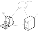
- the gyroscope data correction method of the mobile robot can be applied to the system shown in FIG. 1.
- the system can include a robot 11, a server 12, and a terminal 13.
- the robot 11 may be a cleaning robot, which may be a mobile robot.
- the server 12 may be a cloud server, and may be a remote server.
- the terminal 13 may be a mobile phone, a tablet computer, or a PDA ( Personal Digital Assistant, such as Personal Digital Assistant, has any Internet access function. This application does not limit the specific types of terminals and servers.
- the traditional mobile robot is based on the global optimization operation of all the key frame data recorded by the radar sensor, thereby obtaining the position of the optimized mobile robot in the current frame, and the gyroscope of the mobile robot according to the pose within the current frame.
- the data is corrected, but the global optimization operation in the data correction method has a large calculation amount and a long calculation time, which results in poor real-time correction of the gyroscope data by the mobile robot.
- the data correction method provided by the present application aims to solve the technical problems existing in the above conventional techniques.
- the gyroscope data correction method of the mobile robot provided by the embodiment of the present application not only can quickly estimate the estimated pose of the current frame of the mobile robot, completes the faster correction of the gyroscope data, and improves the robustness of the mobile robot system. Sex and positioning accuracy. Therefore, the mobile robot provided by the embodiment of the present application can be applied not only to industries such as industry, agriculture, medical care, and service, but also to harmful and dangerous situations such as urban security, national defense, and space detection.
- the execution subject of the following method embodiment may be any one of a mobile robot, a terminal, and a server.
- the execution subject of the following method embodiment will be described by taking a robot as an example.
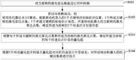
- FIG. 2 is a schematic flow chart of a method for correcting gyroscope data of a mobile robot according to an embodiment.
- This embodiment relates to a mobile robot using an iterative closest point algorithm, based on an initial estimated position of Y key frames, a lidar point set of Y key frames, an initial estimated angle of Y key frames, and a lidar point set of the current frame. Determining the Y candidate estimated pose information of the current frame, and determining a quantized value of each candidate pose that is selected for the current frame, and the gyroscope data of the mobile robot according to the candidate pose information corresponding to the maximum quantized value The specific process of making corrections. As shown in Figure 2, the method includes:
- the lidar sensor acquires the lidar data of the current frame, it detects whether there is a lidar data of a key frame that matches the lidar data of the current frame.
- an Iterative Closest Point (ICP) algorithm is adopted, according to an initial estimated position of the Y key frames of the mobile robot, a laser radar point set of the Y key frames, and Y locations.
- the initial estimated angle of the key frame, the lidar point set of the current frame of the mobile robot, and the Y candidate estimated pose information of the current frame are determined.
- the mobile robot acquires the lidar point set of the current frame through the lidar sensor, and after the loopback detection succeeds, acquires X key frames that match the lidar point set of the current frame, and from the X key frames.
- Y key frames are randomly selected. Since the similarity between the lidar point set of these key frames and the lidar point set of the current frame is extremely high, the Y frames of the current frame are determined according to the lidar data information in the Y key frames. The estimated pose information is to be selected.
- the initial estimated position of the key frame is the initial position of the mobile robot determined according to the data acquired by the lidar sensor at the key frame moment
- the lidar point set of the key frame is composed of the data points acquired by the lidar sensor in the key frame.
- the initial estimated angle of the key frame is the angle information of the mobile robot determined according to the data acquired by the lidar sensor at the key frame moment
- the lidar point set of the current frame of the mobile robot includes the data acquired by the lidar sensor in the current frame.
- a set of points, wherein the duration of each frame of the lidar sensor is the length of time that the lidar sensor rotates for one week.
- the mobile robot adopts the ICP algorithm and according to the initial estimated position of the Y key frames of the mobile robot, the lidar point set of the Y key frames, the initial estimated angle of the Y key frames, and the current frame of the mobile robot.
- the lidar point set determines the Y candidate estimated pose information of the current frame, but the specific implementation manner and flow of the ICP algorithm are not limited.
- the lidar point set may be a collection of lidar data or a collection of visual image points.
- the mobile robot may determine each candidate of the current frame according to the lidar point set of each key frame and the lidar point set of the current frame.
- the quantized value of the pose is estimated, and the Y candidate poses of the current frame are traversed, and the quantized values corresponding to the Y candidate poses are determined.
- the quantized value of each candidate pose can be determined according to the relative position between the data point in the lidar point set of the key frame and the data point in the lidar point set of the current frame. The closer the relative position is, the quantization The larger the value, the further the relative position, the smaller the quantized value.
- the Y quantized values may be sorted in descending order, and the quantized value ranked in the first bit is determined as the maximum quantized value; or the bubble sorting method is used to sort the Y quantized values to determine the maximum
- the quantized value is used to correct the gyroscope data of the mobile robot according to the candidate estimated pose information corresponding to the maximum quantized value.
- the mobile robot performs loopback detection on the current frame of the lidar data.
- the ICP algorithm is used, according to the initial estimated position of the Y key frames, and the lidar points of the Y key frames.
- the initial estimated angle of the Y key frames, the lidar point set of the current frame of the mobile robot determine the Y candidate estimated pose positions of the current frame, and according to the lidar point set and the current frame of each key frame
- the lidar point set determines a quantized value of each candidate pose that is to be selected in the current frame, and determines the estimated pose position information corresponding to the largest quantized value among the Y quantized values, and the gyroscope data of the mobile robot Make corrections.
- the implementation of ICP algorithm has the characteristics of simple steps and low algorithm complexity. Therefore, using ICP algorithm to determine the Y candidate poses of the current frame can reduce the calculation amount and shorten the calculation time. Thereby improving the real-time performance of the gyroscope data correction.
- the gyro data of the mobile robot is corrected, which is equivalent to selecting the optimal candidate pose to correct the gyro data, which greatly improves
- the accuracy of the gyroscope data correction enables faster and more accurate correction of the gyroscope data and improves the robustness of the system operation.
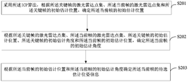
- FIG. 3 is a schematic flow chart of a method for correcting gyroscope data of a mobile robot according to an embodiment.
- This embodiment relates to a specific process in which a mobile robot uses an ICP algorithm to determine Y candidate estimated pose information of a current frame.
- S102 If the loopback detection is successful, the iterative closest point ICP algorithm is adopted, according to the initial estimated position of the Y key frames of the mobile robot, Y. a type of lidar point set of the key frame, an initial estimated angle of the Y key frames, a lidar point set of the current frame of the mobile robot, and a determination of Y candidate estimated pose information of the current frame.
- Implementations can include:
- S201 Determine, by using the ICP algorithm, an initial estimated position of the current frame according to a lidar point set of the key frame, a lidar point set of the current frame, and an initial estimated position of the key frame.
- the mobile robot acquires the lidar point set of the current frame through the lidar sensor, and obtains the lidar point set of the key frame and the initial estimated position of the key frame after the loop loop detection succeeds, and then adopts the ICP algorithm according to the key frame.
- the lidar point set, the lidar point set of the current frame, and the initial estimated position of the key frame determine the initial estimated position of the current frame.
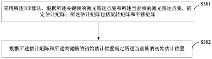
- S201 using the ICP algorithm, determining, according to a lidar point set of the key frame, a lidar point set of the current frame, and an initial estimated position of the key frame.
- One possible implementation of the initial estimated position of the current frame includes:
- the estimation matrix includes a rotation matrix and a translation matrix.
- the ICP algorithm is used to determine an estimation matrix according to a lidar point set of the key frame and a lidar point set of the current frame, wherein the estimation matrix includes a rotation matrix and a translation matrix.
- the formula Obtain the key point of the data center point p 0 in the lidar point set P, and according to the formula Obtaining the data center point q 0 in the lidar point set q of the current frame, and determining the laser of any point p i to the key frame of the lidar point set P of the key frame by the formula P i ' p i -p 0
- the distance P i ' between the radar data center points, determining any point q i of the current frame of the lidar point set q to the current frame of the lidar data center point according to the formula q i ' q i -q 0
- the distance q i ', and the partial point of the lidar point set P of the key frame and the lidar point set q of the current frame is selected to participate in the calculation of R i .
- the corresponding matrix is calculated by the following formula A i ;
- S302. Determine an initial estimated position of the current frame according to the estimation matrix and an initial estimated position of the key frame.
- the mobile robot determines an initial estimated position P Fi of the current frame according to the estimated matrix and the initial estimated position of the key frame.
- the gyro data correction method of the mobile robot uses an ICP algorithm to determine an estimation matrix according to a lidar point set of a key frame and a lidar point set of a current frame, and according to an estimation matrix and an initial estimated position of a key frame. , determine the initial estimated position of the current frame. Due to the ICP algorithm, the estimation matrix can be quickly determined according to the lidar point set of the key frame and the lidar point set of the current frame. The algorithm has simple steps and few parameters, and can quickly and accurately determine the initial estimated position of the current frame. .
- the mobile robot determines according to the lidar point set of the key frame, the lidar point set of the current frame, the initial estimated position of the key frame, and the initial estimated angle of the key frame.
- the initial estimated angle of the current frame is the initial estimated angle of the current frame.
- S202 is “based on a lidar point set of the key frame, a lidar point set of the current frame, an initial estimated position of the key frame, and an initial estimated angle of the key frame.
- a possible implementation manner of determining an initial estimated angle of the current frame, and an initial estimated position of the current frame includes:
- any point in the lidar point set of the key frame may be selected as the lidar data center point of the key frame; or, according to the formula Determining the lidar data center point p 0 in the key frame; wherein p i is any point in the lidar point set in the key frame; or, the lidar center point in the key frame may be determined according to the geometric mean method; Alternatively, the lidar data center point in the key frame can be determined based on the harmonic mean.
- any point in the lidar point set of the current frame may be selected as the center point of the current frame of the lidar data, optionally, according to the formula Determining the lidar data center point q 0 in the current frame; wherein q i is any point in the lidar point set in the current frame, or determining the lidar data center point in the current frame according to the geometric mean method
- the lidar data center point in the current frame can also be determined according to the harmonic mean.
- the mobile robot determines the lidar data center point of the key frame according to the lidar point set of the key frame, and determines the current frame of the lidar data center point according to the current frame of the lidar point set, and according to the key frame laser
- the radar data center point, the lidar data center point of the current frame, the initial estimated position of the key frame, the initial estimated angle of the key frame, and the initial estimated position of the current frame determine an initial estimated angle of the current frame.
- the initial estimated angle ⁇ Fi of the current frame may be determined according to the following formula.
- ⁇ 1 atan2(p 0i -p KFi )*y,(p 0i -p KFi )*x),
- ⁇ Fi ⁇ KFi +( ⁇ 2 - ⁇ 1 ),
- p 0i is the lidar data center point of the key frame
- p KFi is the initial estimated position of the key frame
- p 0F is the lidar data center point of the current frame
- p Fi is the initial estimated position of the current frame
- ⁇ KFi is the key The initial estimated angle of the frame
- a is a constant
- x is the abscissa of the current frame lidar data point
- y is the ordinate of the current frame lidar data point.
- the gyro data correction method of the mobile robot provided by the above embodiment provides that the mobile robot determines the lidar data center point of the key frame according to the lidar point set of the key frame, and determines the laser of the key frame according to the lidar point set of the current frame.
- the radar data center point determines an initial estimated angle of the current frame based on the lidar data center point of the key frame, the lidar data center point of the current frame, the initial estimated position of the key frame, and the initial estimated position of the current frame.
- the lidar data center point of the key frame and the lidar data center point of the key frame are respectively determined by the lidar point set of the key frame and the lidar point set of the current frame, and the lidar data center point is representative.
- the overall trend of the lidar point set of the key frame and the lidar point set of the current frame can be reflected, so that the initial estimated angle of the current frame is determined to be more accurate.
- S203 Determine, according to the initial estimated position of the current frame and an initial estimated angle of the current frame, the estimated estimated pose information of the current frame.
- the initial estimated position of the current frame is determined according to the lidar point set of the key frame, the lidar point set of the current frame, and the initial estimated position of the key frame, and the initial estimation of the current frame is determined.
- the estimated estimated pose information of the current frame is determined.
- the candidate estimated pose information includes an initial estimated position and an initial estimated angle of the current frame of the mobile robot.
- the gyro data correction method of the mobile robot adopts an ICP algorithm to determine an initial estimated position of the current frame according to a lidar point set of a key frame, a lidar point set of a current frame, and an initial estimated position of a key frame. And determining an initial estimated angle of the current frame according to an initial estimated angle of the key frame, a lidar point set of the key frame, a lidar point set of the current frame, an initial estimated position of the key frame, and an initial estimated position of the current frame, The estimated pose position information of the current frame is determined according to an initial estimated position of the current frame and an initial estimated angle of the current frame.
- the algorithm Due to the ICP algorithm, according to the lidar point set of the key frame, the lidar point set of the current frame and the initial estimated position of the key frame, the algorithm has fewer steps and the calculation algorithm has low complexity, so that the initial estimation of the current frame can be quickly determined.
- the position and the initial estimated angle thereby determining the initial estimated position and the initial estimated angle of the current frame, greatly improve the speed of determining the estimated pose position information of the current frame, and facilitating faster gyroscope data. Correction.
- FIG. 6 is a schematic flow chart of a method for correcting gyroscope data of a mobile robot according to an embodiment.
- the embodiment relates to a specific process for the mobile robot to determine the quantized value of each candidate pose estimated in the current frame according to the lidar point set of the key frame and the lidar point set of the current frame.
- the implementation of step 103 may include:
- the rotation and transformation operation of the lidar point set of the key frame may be performed first, and then the translation transformation operation may be performed, or may be performed first.
- the lidar point set of the key frame is subjected to translation transformation operation, and then the rotation transformation operation is performed to obtain the transformed lidar point set of each key frame.
- the above-mentioned rotational translation transformation is performed on the lidlet point sets of the Y key frames. Operation, in this way, obtains Y transformed lidar point sets.
- the corresponding rotation matrix R 0 and the translation matrix t 0 can be obtained according to the foregoing method of the embodiment of FIG. 4, and the calculated points R 0 and t 0 are used to perform a rotation translation transformation on the points in the key frames in the key frame.
- the transformed lidar point set P' is obtained by the following formula:
- P is the lidar point set of the key frame
- R 0 is the rotation matrix
- t 0 is the translation matrix
- the distance is compared with the first preset threshold to determine the point set of each transformed lidar point.
- the number of inner points and the number of outer points are different.
- S502 determining, according to each of the transformed lidar point sets, the lidar point set of the current frame, and a first preset threshold, determining each of the transformed lidar point sets
- One possible implementation of the number of inner points and the number of outer points includes:
- the mobile robot performs a rotational translation transformation operation on the lidar point set of the key frame, obtains the transformed lidar point set, and then determines the transformed lidar point concentration according to the transformed lidar point set and the current frame of the lidar point set.
- any point in the set of the lidar point can be selected first, and the lidar point of the current frame is concentrated and retrieved from the distance.
- the most recent data point is then calculated by the third distance between the point in the set of transformed lidar points and the data point in the lidar point set of the retrieved current frame.
- the third distance can be calculated by the following formula:
- S602. Determine, according to the third distance and the first preset threshold, the number of inner points and the number of outer points in each of the transformed lidar point sets.
- the first preset threshold is a threshold determined according to an actual situation, and when the mobile robot determines, according to the transformed lidar point set and the current frame of the lidar point set, the third distance corresponding to each data point in the transformed lidar point set is determined. Thereafter, the third distance is compared with the first preset threshold, and the number of inner points and the number of outer points in each transformed lidar point set are determined according to the comparison result.
- the third distance is less than the first preset threshold, determining that the point of the transformed lidar point set is an inner point; if the third distance is greater than three times the first preset threshold, determining the point of the transformed lidar point set The point is an outer point; then, according to the inner point and the outer point of each transformed lidar point set, the number of inner points and the number of outer points in each transformed lidar point set are determined.
- the inner and outer points of the transformed laser point set can be determined by the following formula, traversing all points in the set of laser spot points, and counting the number of inner points num 1 and the number of outer points num 2 in the set of points.
- P i ' is a set of transformed lidar points
- d i is a third distance
- ⁇ is a first preset threshold
- the gyro data correction method of the mobile robot provided by the above embodiment, after the mobile robot performs a rotational translation transformation operation on the lidar point set of the key frame, obtains the transformed lidar point set, and according to the transformed lidar point set and the current frame. a set of lidar points, determining a third distance corresponding to each of the data points in the set of lidar point points and the data points in the current frame of the nearest lidar point, and then according to the third distance and the first preset
- the magnitude relationship between the thresholds determines the number of inner points and the number of outer points in each transformed lidar point set.
- the third distance is a minimum distance between the data point of the transformed lidar point set and the data point of the current frame of the lidar point set, thereby transforming the data point of the lidar point set with the current frame
- the data points in the lidar point set are closer, so that the number of inner points and the number of outer points in the point set of the transformed lidar are more accurately determined.
- the quantized value of each candidate pose to be selected of the current frame may be determined according to the ratio of the number of inner points to the number of outer points.
- S503 "determines a quantized value of each candidate estimated pose of the current frame according to the number of inner points and the number of outer points in each of the transformed lidar point sets" Possible implementations include:
- the mobile machine determines the number of inner points and the number of outer points in each transformed lidar point set, and quotes the number of inner points in the i-th converted lidar point set and the number of outer points, Corresponding results, and determine that the result is the ratio of the number of inner points corresponding to the number of outer points corresponding to the i-th transform lidar point set.
- the ratio of the number of inner points to the number of outer points may be determined according to the number of inner points num 1 and the number of outer points num 2 in the i transformed lidar point sets P i '.
- the mobile robot determines the ratio of the number of inner points in the transformed lidar point set to the number of outer points and the second preset threshold. The relationship between the sizes and the corresponding judgment results.
- the determining result may be that the ratio of the number of inner points in the point set of the transformed lidar to the number of outer points is less than a second preset threshold, or the ratio of the number of inner points in the point set of the transformed lidar to the number of outer points is not It is smaller than the second preset threshold, that is, the ratio of the number of inner points in the transformed lidar point set to the number of outer points is greater than or equal to the second preset threshold.
- the mobile robot determines whether the ratio of the number of inner points corresponding to the i-th transform lidar point set to the number of outer points is less than a second preset threshold value, and obtains a corresponding judgment result, and then determines the transform laser radar according to the judgment result.
- the quantized value in the point set is less than a second preset threshold value, and obtains a corresponding judgment result, and then determines the transform laser radar according to the judgment result.
- the second preset threshold determines the number of inner points corresponding to the i-th transform lidar point set and the outer point The ratio of the number of points is a quantized value in the point set of the transformed lidar; if the result of the judgment is that the ratio of the number of inner points corresponding to the point set of the i-th transform lidar to the number of outer points is not less than the second preset threshold, the second preset threshold is determined. To transform the quantized values in the lidar point set.
- the judgment result can be determined by the following formula.
- K is the second preset threshold.
- KF i is the i-th transform lidar point set
- F j is the lidar point set of the current frame
- pose KFi is the candidate estimated pose of the i-th transform lidar point set.
- pose Fj is the estimated pose of the jth current frame to be selected.
- the mobile robot determines the ratio of the number of inner points and the number of outer points in the i-th transform lidar point set, and determines whether the ratio is smaller than the first Two preset thresholds are then determined according to the obtained judgment result, and the quantized values of the i-th transformed lidar point set are determined, and then the Y transform laser radar point sets are traversed. At this time, the Y transform laser radar point sets can be determined respectively. The Y quantized values are summed and summed to obtain a corresponding result, and the result is determined as the quantized value of the jth candidate estimated pose of the current frame.
- the quantized value of the jth candidate estimated pose of the current frame can be determined by the following formula:
- KF i is the i-th transform lidar point set
- F j is the lidar point set of the current frame
- pose KFi is the candidate estimated pose of the i-th transform lidar point set
- pose Fj is the jth current
- score j is the quantized value of the jth candidate estimated pose of the current frame
- score(KF i , F j , pose KFi , pose Fj ) is the jth candidate of the current frame.
- the foregoing process is an overall process for determining the quantized value of the jth candidate estimated pose corresponding to the current frame. For each candidate pose to be selected, it is necessary to traverse Y key frames and Y key frames. The sum of the quantized values of the corresponding Y-transformed lidar point sets is used as the quantized value of the estimated pose. And traversing each candidate pose of the current frame to determine the Y quantized values corresponding to the Y candidate poses of the current frame. And by comparing the size of the Y quantized values of the current frame, the maximum quantized value of the current frame is obtained.
- the gyro data of the mobile robot is corrected according to the candidate estimated pose information corresponding to the maximum quantization value.
- the candidate corresponding to the maximum quantization value is selected.
- the estimated pose information corrects the gyroscope data of the mobile robot.
- the mobile robot determines the number of interior points corresponding to the i-th converted lidar point set according to the number of inner points and the number of outer points in the i-th transforming lidar point set.
- the ratio of the number of outer points is then determined whether the ratio is less than the second predetermined threshold, and the corresponding judgment result is obtained, and according to the obtained judgment result, the quantized value of the i-th transformed lidar point set is determined, and the Y transform laser radars are traversed.
- the point set obtains the quantized values of the Y transformed lidar point sets, and the sum of the Y quantized values is determined as the quantized value of the jth candidate estimated pose, and then traverses the Y candidate estimated bits of the current frame.
- Position obtain corresponding Y quantized values, determine a maximum quantized value therein, and compare the maximum quantized value with a third preset threshold size, when the maximum quantized value is greater than a third preset threshold,
- the maximum estimated value corresponding to the estimated estimated pose information is corrected for the gyroscope.
- the mobile robot determines the relationship between the number of inner points and the number of outer points in the set of transformed radar points, the relationship between the number of inner points and the number of outer points is better determined, and the ratio is compared with the second preset threshold to be more accurate.
- the quantized value of the i-th transformed lidar point set is determined, and the obtained quantized values of the Y transformed lidar point sets are added, so that the determined quantized value of the j-th candidate estimated pose is more accurate. It is convenient to make more accurate correction of gyroscope data.
- the mobile robot first performs a rotational translation transformation operation on the laser radar point sets of the Y key frames, and obtains Y converted laser radar point sets, and according to each transform laser radar
- the point set, the lidar point set of the current frame, and the first preset threshold determine the number of inner points and the number of outer points in each transformed lidar point set, and then according to the number of inner points and the number of outer points in each transformed lidar point set For example, the quantized value of each candidate pose that is selected for the current frame is determined.
- the quantized value of each candidate pose of the current frame can be accurately determined, so that the mobile robot can more accurately determine the optimal posture of the current frame.
- the accuracy of the correction of the gyroscope data is greatly improved, thereby greatly improving the robustness of the system.
- FIG. 9 is a schematic flow chart of a method for correcting gyroscope data of a mobile robot according to an embodiment.
- This embodiment relates to a specific process of S104 "the mobile robot corrects the gyroscope data according to the estimated estimated pose information corresponding to the maximum quantized value". Based on the above embodiment, as shown in FIG. 9, the method includes:
- the corrected estimation angle of the current frame may be further determined.
- the modified estimation angle of the current frame can be determined by the following formula.
- ⁇ 1 atan2(p 0i -p KFK )*y,(p 0i -p KFK )*x),
- ⁇ FK ⁇ KFK +( ⁇ 2 - ⁇ 1 ),
- p 0i is the data center point of the lidar point set of the key frame
- p KFK is the initial estimated position of the key frame corresponding to the maximum quantization value
- p 0F is the data center point of the lidar point set of the current frame
- p FK is The maximum estimated value corresponds to the initial estimated position of the current frame
- ⁇ FK is the initial estimated angle of the key frame corresponding to the maximum quantized value
- ⁇ KFK is the corrected estimated angle of the current frame
- a is a constant
- x is the current frame lidar data point.
- y is the ordinate of the current frame lidar data point. .
- the mobile robot may further obtain the gyroscope data of the mobile robot according to the estimated estimated pose information of the key frame corresponding to the corrected estimation angle and the maximum quantization value of the current frame. Correction is performed to further improve the accuracy of the correction of the gyroscope.
- the gyro data correction method of the mobile robot provided by the embodiment, the mobile robot firstly according to the maximum quantized value corresponding to the key frame of the lidar data center point, the initial estimated position of the key frame, the initial estimated angle of the key frame, the current frame.
- the laser radar data center point, the initial estimated position of the current frame determine the corrected estimation angle of the current frame, and the gyroscope data of the mobile robot according to the corrected estimation angle of the current frame and the candidate estimated pose information corresponding to the key frame.
- Make corrections Since the angle of correction is determined by determining the correction of the current frame, the accuracy of correction of the gyroscope data is further improved.
- FIG. 10 is a schematic diagram of a gyroscope data correcting apparatus of a mobile robot according to an embodiment. As shown in FIG. 10, the apparatus includes: a loopback detection module 20, a first determination module 21, a second determination module 22, and a first correction module 23.
- the loop detection module 20 is configured to perform loopback detection on the current frame of the lidar data.
- the first determining module 21 is configured to: when the loopback detection succeeds, adopt an iterative closest point ICP algorithm, according to the initial estimated position of the Y key frames of the mobile robot, the lidar point sets of the Y key frames, and Y The initial estimated angle of the key frame, the lidar point set of the current frame of the mobile robot, and the Y candidate estimated pose information of the current frame are determined.
- the second determining module 22 is configured to determine, according to the lidar point set of the key frame and the lidar point set of the current frame, a quantized value of each candidate estimated pose of the current frame.
- the first correction module 23 is configured to correct the gyro data of the mobile robot according to the candidate estimated pose information corresponding to the largest quantized value among the Y quantized values.
- the gyro data correcting device of the mobile robot provided in this embodiment can perform the foregoing method embodiment of FIG. 2, and the implementation principle and technical effects thereof are similar, and details are not described herein again.
- FIG. 11 is a schematic diagram of a gyroscope data correcting apparatus of a mobile robot according to another embodiment.
- the first determining module 21 includes: a first determining unit 211 , a second determining unit 212 , and a third determining unit 213 .
- the first determining unit 211 is configured to determine, by using the ICP algorithm, according to a lidar point set of the key frame, a lidar point set of the current frame, and an initial estimated position of the key frame. The initial estimated position of the current frame.
- a second determining unit 212 configured to: according to the lidar point set of the key frame, a lidar point set of the current frame, an initial estimated position of the key frame, an initial estimated angle of the key frame, and the current An initial estimated position of the frame, the initial estimated angle of the current frame is determined.
- the third determining unit 213 is configured to determine, according to the initial estimated position of the current frame and an initial estimated angle of the current frame, the estimated estimated pose information of the current frame.
- the gyro data correcting device of the mobile robot provided in this embodiment can perform the above-mentioned method embodiment of FIG. 3, and the implementation principle and technical effects thereof are similar, and details are not described herein again.
- the first determining unit 211 is specifically configured to determine, according to the lidar point set of the key frame and the lidar point set of the current frame, by using the ICP algorithm.
- a matrix the estimation matrix includes a rotation matrix and a translation matrix; determining an initial estimated position of the current frame according to the estimation matrix and an initial estimated position of the key frame.
- the second determining unit 212 is configured to determine a lidar data center point of the key frame according to the lidar point set of the key frame; according to the current frame a lidar point set for determining a lidar data center point of the current frame; a lidar data center point of the key frame, a lidar data center point of the current frame, an initial estimated position of the key frame, Determining an initial estimated position of the key frame and an initial estimated position of the current frame to determine an initial estimated angle of the current frame.
- the foregoing second determining unit 212 is specifically configured according to a formula Determining a laser ray 1 in the key frame to a data center point p 0 ; wherein p i is any point in a lidar point set in the key frame; Determining a lidar data center point q 0 in the current frame; wherein q i is any point in the lidar point set in the current frame.
- FIG. 12 is a schematic diagram of a gyroscope data correcting apparatus of a mobile robot according to another embodiment.
- the second determining module 22 includes a transforming unit 221, a fourth determining unit 222, and a fifth determining unit 223.
- the transforming unit 221 is configured to perform a rotational translation transformation operation on the laser radar point sets of the Y key frames, respectively, to obtain Y transformed laser radar point sets.
- a fourth determining unit 222 configured to determine, according to each of the transformed lidar point sets, the lidar point set of the current frame, and a first preset threshold, a number of interior points in each of the transformed lidar point sets The number of external points.
- the fifth determining unit 223 is configured to determine, according to the number of inner points and the number of outer points in each of the transformed lidar point sets, a quantized value of each candidate estimated pose of the current frame.
- the gyro data correcting device of the mobile robot provided in this embodiment can perform the foregoing method embodiment of FIG. 6 , and the implementation principle and technical effects are similar, and details are not described herein again.
- the fourth determining unit 222 is configured to determine, according to the transformed lidar point set and the lidar point set of the current frame, each of the transformed lidar point sets. a third distance corresponding to the data points; the third distance is a minimum distance between the data point of the transformed lidar point set and the data point of the current frame of the lidar point set; The three distances and the first predetermined threshold determine the number of inner points and the number of outer points in each of the transformed lidar point sets.
- the fourth determining unit 222 is configured to: if the third distance is smaller than the first preset threshold, determine that the point of the transformed lidar point set is an inner point If the third distance is greater than three times the first preset threshold, determining that the point of the transformed lidar point set is an outer point; and according to each of the transforming lidar points, the inner point and the outer point And determining the number of inner points and the number of outer points in each of the transformed lidar point sets.
- the gyro data correcting device of the mobile robot provided in this embodiment can perform the foregoing method embodiment of FIG. 7 , and the implementation principle and technical effects thereof are similar, and details are not described herein again.
- the fifth determining unit 223 is configured to determine, according to the number of inner points and the number of outer points in the i-th transforming lidar point set, the corresponding point of the i-th transform laser radar point set. a ratio of the number of the inner points to the number of the outer points; wherein, 1 ⁇ i ⁇ Y; determining whether the ratio of the number of inner points corresponding to the i-th transform lidar point set to the number of outer points is less than a second predetermined threshold, and obtaining a judgment result; Determining, according to the determination result, a quantized value of the transformed lidar point set; determining a sum of quantized values of the Y transformed laser radar point sets as the jth candidate estimated pose of the current frame Quantitative value; wherein 1 ⁇ j ⁇ Y.
- the fifth determining unit 223 is configured to: when the determining result is that the ratio of the number of inner points corresponding to the i-th transform lidar point set to the number of outer points is smaller than the And determining, by the second preset threshold, a ratio of the number of inner points corresponding to the number of outer points of the i-th transformed lidar point set to the number of outer points in the converted lidar point set; When the ratio of the number of the inner points corresponding to the number of the outer laser pointers to the number of the outer points is not less than the second preset threshold, determining that the second preset threshold is a quantized value in the transformed lidar point set.
- the correction module 23 is configured to: when the maximum quantization value is greater than the third preset threshold, select the estimated pose information corresponding to the maximum quantization value, The gyroscope data is corrected.
- the gyro data correction device of the mobile robot provided in this embodiment can perform the above-mentioned method embodiment of FIG. 8 , and the implementation principle and technical effects thereof are similar, and details are not described herein again.
- FIG. 13 is a schematic diagram of a gyroscope data correcting apparatus of a mobile robot according to another embodiment. As shown in FIG. 13, on the basis of the above embodiment, the correction module 23 further includes a sixth determining unit 231 and a first correcting unit 232.
- the sixth determining unit 231 is configured to: according to a lidar data center point of the target key frame, an initial estimated position of the target key frame, an initial estimated angle of the target key frame, and a lidar data of the current frame. a central point, an initial estimated position of the current frame, and a modified estimated angle of the current frame; the target key frame is a key frame corresponding to the maximum quantized value.
- the first correcting unit 232 is configured to correct the gyroscope data of the mobile robot according to the modified estimated angle of the current frame and the candidate estimated pose information corresponding to the target key frame.
- the gyro data correction device of the mobile robot provided in this embodiment can perform the above-mentioned method embodiment of FIG. 9 , and the implementation principle and technical effects thereof are similar, and details are not described herein again.
- Each of the above-described data-corrected devices may be implemented in whole or in part by software, hardware, and combinations thereof.
- the above modules may be embedded in the hardware or independent of the processor in the robot, or may be stored in the memory in the robot in a software form, so that the processor calls the execution of the corresponding operations of the above modules.
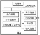
- an apparatus is provided, the internal structure of which can be as shown in FIG.
- the robot can include a processor, memory, network interface, display screen, and input device connected by a system bus.
- the robot's processor is used to provide calculation and control capabilities.
- the memory of the robot includes a non-volatile storage medium and an internal memory.
- the non-volatile storage medium stores an operating system and a computer program.
- the internal memory provides an environment for operation of an operating system and computer programs in a non-volatile storage medium.
- the robot's network interface is used to communicate with external terminals via a network connection.
- the computer program is executed by the processor to implement a method of correcting the data.
- the display screen of the robot may be a liquid crystal display or an electronic ink display.
- the input device of the robot may be a touch layer covered on the display screen, or a button, a trackball or a touchpad provided on the robot casing, or It is an external keyboard, trackpad or mouse.
- FIG. 14 is only a block diagram of a partial structure related to the solution of the present application, and does not constitute a limitation of the robot to which the solution of the present application is applied.
- the specific robot may include a ratio. More or fewer components are shown in the figures, or some components are combined, or have different component arrangements.
- an apparatus comprising a memory and a processor having a computer program stored therein that, when executed, implements the following steps:
- the iterative closest point ICP algorithm is adopted, according to the initial estimated position of the Y key frames of the mobile robot, the lidar point sets of the Y key frames, and the initial estimated angles of the Y key frames. Determining, by the set of lidar points of the current frame of the mobile robot, the Y candidate estimated pose positions of the current frame;
- the gyroscope data of the mobile robot is corrected according to the candidate estimated pose information corresponding to the largest quantized value among the Y quantized values.
- a computer readable storage medium having stored thereon a computer program that, when executed by a processor, implements the following steps:
- the iterative closest point ICP algorithm is adopted, according to the initial estimated position of the Y key frames of the mobile robot, the lidar point sets of the Y key frames, and the initial estimated angles of the Y key frames. Determining, by the set of lidar points of the current frame of the mobile robot, the Y candidate estimated pose positions of the current frame;
- the gyroscope data of the mobile robot is corrected according to the candidate estimated pose information corresponding to the largest quantized value among the Y quantized values.
- Non-volatile memory can include read only memory (ROM), programmable ROM (PROM), electrically programmable ROM (EPROM), electrically erasable programmable ROM (EEPROM), or flash memory.
- Volatile memory can include random access memory (RAM) or external cache memory.
- RAM is available in a variety of formats, such as static RAM (SRAM), dynamic RAM (DRAM), synchronous DRAM (SDRAM), double data rate SDRAM (DDRSDRAM), enhanced SDRAM (ESDRAM), synchronization chain.
- SRAM static RAM
- DRAM dynamic RAM
- SDRAM synchronous DRAM
- DDRSDRAM double data rate SDRAM
- ESDRAM enhanced SDRAM
- Synchlink DRAM SLDRAM
- Memory Bus Radbus
- RDRAM Direct RAM
- DRAM Direct Memory Bus Dynamic RAM
- RDRAM Memory Bus Dynamic RAM
Landscapes
- Engineering & Computer Science (AREA)
- Radar, Positioning & Navigation (AREA)
- Remote Sensing (AREA)
- Physics & Mathematics (AREA)
- General Physics & Mathematics (AREA)
- Computer Networks & Wireless Communication (AREA)
- Automation & Control Theory (AREA)
- Electromagnetism (AREA)
- Manufacturing & Machinery (AREA)
- Control Of Position, Course, Altitude, Or Attitude Of Moving Bodies (AREA)
- Gyroscopes (AREA)
Abstract
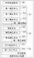
一种移动机器人的陀螺仪数据校正方法,包括:对当前帧的激光雷达数据进行回环检测(S101);若回环检测成功,则采用迭代最近点ICP算法,根据移动机器人的Y个关键帧的初始估计位置、Y个关键帧的激光雷达点集、Y个关键帧的初始估计角度、移动机器人的当前帧的激光雷达点集,确定当前帧的Y个待选估计位姿信息(S102);根据每个关键帧的激光雷达点集和当前帧的激光雷达点集,确定当前帧的每个待选估计位姿的量化值(S103);根据Y个量化值中的最大量化值对应的待选估计位姿信息,对移动机器人的陀螺仪数据进行校正(S104)。还涉及一种移动机器人的陀螺仪数据校正装置、设备和存储介质。
Description
相关申请的交叉引用
本申请要求于2018年04月26日提交中国专利局,申请号为2018103863078,申请名称为“移动机器人的陀螺仪数据校正方法、装置和设备”的中国专利申请的优先权,其全部内容通过引用结合在本申请中。
本申请涉及通信领域,特别是涉及一种移动机器人的陀螺仪数据校正方法、设备和存储介质。
随着智能化产品的不断发展,人们对智能家居产品的需求度大大提升,智能扫地机器人已经逐渐走进我们的生活,其凭借一定的人工智能,能够自动在房间内完成地面清理工作,极大的方便了人们的生活。
传统技术中,移动机器人在进行回环检测后,对移动机器人的雷达传感器记录的所有关键帧数据进行全局优化操作,从而获取到优化后的移动机器人在当前帧内的位姿信息,并根据当前帧内的位姿信息,对移动机器人的陀螺仪数据进行校正,进而消除累积误差对陀螺仪数据校正的干扰。
但是,现有技术中的全局优化操作计算量大且计算时间长,导致移动机器人的陀螺仪数据校正的实时性较差。
发明内容
基于此,有必要针对传统技术中的全局优化操作计算量大且计算时间长,导致移动机器人的陀螺仪数据校正的实时性较差问题,提供一种移动机器人的陀螺仪数据校正方法、设备和存储介质。
第一方面,本申请提供一种移动机器人的陀螺仪数据校正方法,包括:
对当前帧的激光雷达数据进行回环检测;
若回环检测成功,则采用迭代最近点ICP算法,根据移动机器人的Y个关键帧的初始估计位置、Y个所述关键帧的激光雷达点集、Y个所述关键帧的初始估计角度、所述移动机器人的当前帧的激光雷达点集,确定所述当前帧的Y个待选估计位姿信息;
根据每个所述关键帧的激光雷达点集和所述当前帧的激光雷达点集,确定所述当前帧的每个待选估计位姿的量化值;
根据Y个所述量化值中的最大量化值对应的待选估计位姿信息,对所述移动机器人的 陀螺仪数据进行校正。
第二方面,本申请实施例提供一种移动机器人的陀螺仪数据校正装置,包括:
回环检测模块,用于对当前帧的激光雷达数据进行回环检测;
第一确定模块,用于当回环检测成功时,则采用迭代最近点ICP算法,根据所述移动机器人的Y个关键帧的初始估计位置、Y个所述关键帧的激光雷达点集、Y个所述关键帧的初始估计角度、所述移动机器人的当前帧的激光雷达点集,确定所述当前帧的Y个待选估计位姿信息;
第二确定模块,用于根据所述关键帧的激光雷达点集和所述当前帧的激光雷达点集,确定所述当前帧的每个待选估计位姿的量化值;
校正模块,用于根据Y个所述量化值中的最大量化值对应的待选估计位姿信息,对所述移动机器人的陀螺仪数据进行校正。
第三方面,本申请实施例提供一种设备,包括存储器、处理器,所述存储器上存储有可在处理器上运行的计算机程序,所述处理器执行所述计算机程序时实现上述任一实施例中所述方法的步骤。
第四方面,本申请实施例提供一种可读存储介质,其上存储有计算机程序,所述计算机程序被处理器执行时实现上述任一实施例中所述方法的步骤。
本实施例提供的移动机器人的陀螺仪数据校正方法、设备和存储介质,能够使得移动机器人采用ICP算法,根据Y个关键帧的初始估计位置、Y个关键帧的激光雷达点集、Y个关键帧的初始估计角度、移动机器人的当前帧的激光雷达点集,确定当前帧的Y个待选估计位姿信息,并根据每个关键帧的激光雷达点集和当前帧的激光雷达点集,确定出当前帧的每个待选估计位姿的量化值,将确定出的Y个量化值中的最大量化值对应的待选估计位姿信息,对移动机器人的陀螺仪数据进行校正。相较于全局优化算法,ICP算法的实现方式具有步骤简单、算法复杂度低的特点,因此,采用ICP算法确定出其当前帧的Y个待选估计位姿可以减少计算量,缩短计算时间,从而提高了陀螺仪数据校正的实时性。同时,根据Y个量化值中的最大量化值对应的待选估计位姿信息,对移动机器人的陀螺仪数据进行校正,相当于选取了最优待选估计位姿对陀螺仪数据进行校正,大大提高了对陀螺仪数据校正的精确度,从而能够实现对陀螺仪数据更快速、更准确的校正,提高了系统工作的鲁棒性。
图1为本申请实施例提供的移动机器人的陀螺仪数据校正方法应用的系统架构图;
图2为一实施例提供的移动机器人的陀螺仪数据校正方法的流程示意图;
图3为一实施例提供的移动机器人的陀螺仪数据校正方法的流程示意图;
图4为一实施例提供的移动机器人的陀螺仪数据校正方法的流程示意图;
图5为一实施例提供的移动机器人的陀螺仪数据校正方法的流程示意图;
图6为一实施例提供的移动机器人的陀螺仪数据校正方法的流程示意图;
图7为一实施例提供的移动机器人的陀螺仪数据校正方法的流程示意图;
图8为一实施例提供的移动机器人的陀螺仪数据校正方法的流程示意图;
图9为一实施例提供的移动机器人的陀螺仪数据校正方法的流程示意图;
图10为一实施例提供的移动机器人的陀螺仪数据校正装置的结构示意图;
图11为一实施例提供的移动机器人的陀螺仪数据校正装置的结构示意图;
图12为一实施例提供的移动机器人的陀螺仪数据校正装置的结构示意图;
图13为一实施例提供的移动机器人的陀螺仪数据校正装置的结构示意图;
图14为一实施例提供的一种设备的结构示意图。
具体实施例方式
本申请实施例提供的移动机器人的陀螺仪数据校正方法,可以适用于图1所示的系统中。如图1所示,该系统可以包括机器人11、服务器12以及终端13。可选的,该机器人11可以是扫地机器人,可以是移动机器人;可选的,该服务器12可以是云端服务器,可以是远程服务器;可选的,该终端13可以为手机、平板电脑、PDA(Personal Digital Assistant,个人数字助理)等具有任何上网功能的智能终端,本申请对终端、服务器的具体类型并不做限定。
传统的移动机器人是对雷达传感器记录的所有关键帧数据根据全局优化操作,从而获取到优化后的移动机器人在当前帧内的位姿,并根据当前帧内的位姿,对移动机器人的陀螺仪数据进行校正,但是该数据校正方法中的全局优化操作计算量大其计算时间长,导致移动机器人对陀螺仪数据校正的实时性较差。为此,本申请提供的数据校正方法,旨在解决上述传统技术中存在的技术问题。
本申请实施例提供的移动机器人的陀螺仪数据校正方法不仅可以实现对移动机器人的当前帧的估计位姿的快速估算,完成对陀螺仪数据的更快速校正,提高了移动机器人系统工作的鲁棒性和定位的准确性。因此,本申请实施例提供的移动机器人不仅可以适用于工业、农业、医疗、服务等行业,而且在城市安全、国防和空间探测等有害与危险的场合也得到了很好的应用。
需要说明的是,下述方法实施例的执行主体可以是移动机器人、终端、服务器中的任意一个。下述方法实施例的执行主体以机器人为例来进行说明。
为了使本申请的目的、技术方案及优点更加清楚明白,通过下述实施例并结合附图,对本申请实施例中的技术方案的进一步详细说明。应当理解,此处所描述的具体实施例仅用以解释本申请,并不用于限定本申请。
图2为一实施例提供的移动机器人的陀螺仪数据校正方法的流程示意图。本实施例涉及的是移动机器人采用迭代最近点算法,根据Y个关键帧的初始估计位置、Y个关键帧的激光雷达点集、Y个关键帧的初始估计角度、当前帧的激光雷达点集,确定当前帧的Y个 待选估计位姿信息,并确定当前帧的每个待选估计位姿的量化值,根据最大量化值对应的待选估计位姿信息,对移动机器人的陀螺仪数据进行校正的具体过程。如图2所示,该方法包括:
S101、对当前帧的激光雷达数据进行回环检测。
具体的,当激光雷达传感器获取到当前帧的激光雷达数据时,检测是否存在与当前帧的激光雷达数据匹配的关键帧的激光雷达数据。
S102、若回环检测成功,则采用迭代最近点(Iterative Closest Point,简称ICP)算法,根据移动机器人的Y个关键帧的初始估计位置、Y个所述关键帧的激光雷达点集、Y个所述关键帧的初始估计角度、所述移动机器人的当前帧的激光雷达点集,确定所述当前帧的Y个待选估计位姿信息。
具体的,移动机器人通过激光雷达传感器获取到当前帧的激光雷达点集,并在回环检测成功后,获取到与当前帧的激光雷达点集匹配的X个关键帧,并从X个关键帧中随机选取Y个关键帧,由于这些关键帧的激光雷达点集与当前帧的的激光雷达点集的相似度极高,因此根据Y个关键帧中的激光雷达数据信息来确定当前帧的Y个待选估计位姿信息。
其中,关键帧的初始估计位置为根据激光雷达传感器在关键帧时刻获取到的数据确定的移动机器人的初始位置,关键帧的激光雷达点集为激光雷达传感器在关键帧获取到的数据点组成的集合,关键帧的初始估计角度为根据激光雷达传感器在关键帧时刻获取到的数据确定的移动机器人的角度信息,移动机器人的当前帧的激光雷达点集包括激光雷达传感器在当前帧获取到的数据点组成的集合,其中,激光雷达传感器的每一帧的时长为激光雷达传感器旋转一周的时长。
需要说明的是,移动机器人采用ICP算法,并根据移动机器人的Y个关键帧的初始估计位置、Y个关键帧的激光雷达点集、Y个关键帧的初始估计角度以及移动机器人的当前帧的激光雷达点集,确定出当前帧的Y个待选估计位姿信息,但对于ICP算法的具体实现方式和流程不加以限制。
可选的,该激光雷达点集可以为激光雷达数据组成的集合,也可以是视觉的图像点组成的集合。
S103、根据每个所述关键帧的激光雷达点集和所述当前帧的激光雷达点集,确定所述当前帧的每个待选估计位姿的量化值。
具体的,移动机器人在确定出当前帧的Y个待选估计位姿信息之后,其可以根据每个关键帧的激光雷达点集和当前帧的激光雷达点集,确定当前帧的每个待选估计位姿的量化值,并遍历当前帧的Y个待选估计位姿,确定出Y个待选估计位姿对应的量化值。
例如,可以根据关键帧的激光雷达点集中的数据点和当前帧的激光雷达点集中的数据点之间的相对位置确定每个待选估计位姿的量化值,相对位置越近,则该量化值越大,相对位置越远,则该量化值越小。
S104、根据Y个所述量化值中的最大量化值对应的待选估计位姿信息,对所述移动 机器人的陀螺仪数据进行校正。
具体的,可以将Y个量化值按照从大到小的顺序进行排序,将排在第一位的量化值确定为最大量化值;或者,采用冒泡排序方法对Y个量化值排序,确定最大量化值,根据最大量化值对应的待选估计位姿信息,对所述移动机器人的陀螺仪数据进行校正。
本实施例提供的数据校正方法,移动机器人对当前帧的激光雷达数据进行回环检测,当回环检测成功后,采用ICP算法,根据Y个关键帧的初始估计位置、Y个关键帧的激光雷达点集、Y个关键帧的初始估计角度、移动机器人的当前帧的激光雷达点集,确定当前帧的Y个待选估计位姿信息,并根据每个关键帧的激光雷达点集和当前帧的激光雷达点集,确定出当前帧的每个待选估计位姿的量化值,将确定出的Y个量化值中的最大量化值对应的待选估计位姿信息,对移动机器人的陀螺仪数据进行校正。相较于全局优化算法,ICP算法的实现方式具有步骤简单、算法复杂度低的特点,因此,采用ICP算法确定出其当前帧的Y个待选估计位姿可以减少计算量,缩短计算时间,从而提高了陀螺仪数据校正的实时性。同时,根据Y个量化值中的最大量化值对应的待选估计位姿信息,对移动机器人的陀螺仪数据进行校正,相当于选取了最优待选估计位姿对陀螺仪数据进行校正,大大提高了对陀螺仪数据校正的精确度,从而能够实现对陀螺仪数据更快速、更准确的校正,提高了系统工作的鲁棒性。
图3为一实施例提供的移动机器人的陀螺仪数据校正方法的流程示意图。本实施例涉及的是移动机器人采用ICP算法确定当前帧的Y个待选估计位姿信息的具体过程。基于上述图2所示实施例的基础上,如图3所示,S102“若回环检测成功,则采用迭代最近点ICP算法,根据移动机器人的Y个关键帧的初始估计位置、Y个所述关键帧的激光雷达点集、Y个所述关键帧的初始估计角度、所述移动机器人的当前帧的激光雷达点集,确定所述当前帧的Y个待选估计位姿信息”的一种实现方式可以包括:
S201、采用所述ICP算法,根据所述关键帧的激光雷达点集、所述当前帧的激光雷达点集和所述关键帧的初始估计位置,确定所述当前帧的初始估计位置。
具体的,移动机器人通过激光雷达传感器获取到当前帧的激光雷达点集,并通过回环检测成功后获取到关键帧的激光雷达点集以及关键帧的初始估计位置,然后采用ICP算法,根据关键帧的激光雷达点集、当前帧的激光雷达点集和关键帧的初始估计位置,确定所述当前帧的初始估计位置。
可选地,如图4所示,S201“采用所述ICP算法,根据所述关键帧的激光雷达点集、所述当前帧的激光雷达点集和所述关键帧的初始估计位置,确定所述当前帧的初始估计位置”的一种可能的实现方式包括:
S301、采用所述ICP算法,根据所述关键帧的激光雷达点集和所述当前帧的激光雷达点集,确定估计矩阵;所述估计矩阵包括旋转矩阵和平移矩阵。
具体的,采用ICP算法,根据关键帧的激光雷达点集和当前帧的激光雷达点集,确定估计矩阵,其中,估计矩阵包括旋转矩阵和平移矩阵。
可选的,本实施例中可以通过公式(R
i,t
i)=ICP(KF
i,F)得到估计矩阵,其中,KF
i表示关键帧的激光雷达点集,F表示当前帧的激光雷达点集,R
i为旋转矩阵,t
i为平移矩阵。
可选的,确定旋转矩阵R
i和平移矩阵t
i的过程如下:
根据公式
 获取关键帧的激光雷达点集P中的数据中心点p
0,并根据公式
获取关键帧的激光雷达点集P中的数据中心点p
0,并根据公式
 获取当前帧的激光雷达点集q中的数据中心点q
0,并通过公式P
i′=p
i-p
0确定出关键帧的激光雷达点集P中的任一点p
i到关键帧的激光雷达数据中心点之间的距离P
i′,根据公式q
i′=q
i-q
0确定当前帧的激光雷达点集q中的任一点q
i到当前帧的激光雷达数据中心点之间的距离q
i′,并从该关键帧的激光雷达点集P和当前帧的激光雷达点集q中选取部分点参与R
i的计算,对于第i对点对,通过下述公式计算对应的矩阵A
i;
获取当前帧的激光雷达点集q中的数据中心点q
0,并通过公式P
i′=p
i-p
0确定出关键帧的激光雷达点集P中的任一点p
i到关键帧的激光雷达数据中心点之间的距离P
i′,根据公式q
i′=q
i-q
0确定当前帧的激光雷达点集q中的任一点q
i到当前帧的激光雷达数据中心点之间的距离q
i′,并从该关键帧的激光雷达点集P和当前帧的激光雷达点集q中选取部分点参与R
i的计算,对于第i对点对,通过下述公式计算对应的矩阵A
i;

遍历所有A
i,通过公式
 计算矩阵B,并利用奇异值分解计算B最小的特征值和特征向量,由B的最小特征向量获取对应的旋转矩阵R
i,并根据R
i通过公式t
i=q
0-R
ip
0确定平移矩阵t
i。
计算矩阵B,并利用奇异值分解计算B最小的特征值和特征向量,由B的最小特征向量获取对应的旋转矩阵R
i,并根据R
i通过公式t
i=q
0-R
ip
0确定平移矩阵t
i。
S302、根据所述估计矩阵和所述关键帧的初始估计位置确定所述当前帧的初始估计位置。
具体的,移动机器人在确定出估计矩阵后,然后根据估计矩阵和关键帧的初始估计位置确定当前帧的初始估计位置P
Fi。
可选的,可以通过公式P
Fi=R
iP
KFi+t
i确定当前帧的初始估计位置P
Fi,其中,R
i为旋转矩阵,t
i为平移矩阵,P
KFi为关键帧的初始估计位置。
上述实施例提供的移动机器人的陀螺仪数据校正方法,采用ICP算法,根据关键帧的激光雷达点集和当前帧的激光雷达点集,确定估计矩阵,并根据估计矩阵和关键帧的初始估计位置,确定出当前帧的初始估计位置。由于采用ICP算法,根据关键帧的激光雷达点集和当前帧的激光雷达点集,可以快速确定估计矩阵,该算法步骤简单且使用参数少,可以快速、精确的确定出当前帧的初始估计位置。
S202、根据所述关键帧的激光雷达点集、所述当前帧的激光雷达点集、所述关键帧的初始估计位置、所述关键帧的初始估计角度和所述当前帧的初始估计位置,确定所述当前帧的初始估计角度。
具体的,移动机器人在确定出当前帧的初始估计位置之后,然后根据关键帧的激光雷达点集、当前帧的激光雷达点集、关键帧的初始估计位置、关键帧的初始估计角度,进而确定出当前帧的初始估计角度。
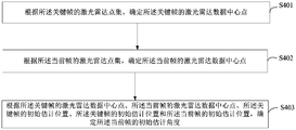
可选的,如图5所示,S202“根据所述关键帧的激光雷达点集、所述当前帧的激光雷达点集、所述关键帧的初始估计位置、所述关键帧的初始估计角度和所述当前帧的初始估计位置,确定所述当前帧的初始估计角度”的一种可能的实现方式包括:
S401、根据所述关键帧的激光雷达点集,确定所述关键帧的激光雷达数据中心点。
具体的,可以通过选取关键帧的激光雷达点集中的任一点作为关键帧的激光雷达数据中心点;或者,可以根据公式
 ,确定关键帧中的激光雷达数据中心点p
0;其中,p
i为关键帧中的激光雷达点集中的任意点;或者,可以根据几何平均数的方法确定关键帧中的激光雷达中心点,或者,还可以根据调和平均数的方法确定关键帧中的激光雷达数据中心点。
,确定关键帧中的激光雷达数据中心点p
0;其中,p
i为关键帧中的激光雷达点集中的任意点;或者,可以根据几何平均数的方法确定关键帧中的激光雷达中心点,或者,还可以根据调和平均数的方法确定关键帧中的激光雷达数据中心点。
S402、根据所述当前帧的激光雷达点集,确定所述当前帧的激光雷达数据中心点。
具体的,可以通过选取当前帧的激光雷达点集中的任一点作为当前帧的激光雷达数据中心点,可选的,可以根据公式
 ,确定当前帧中的激光雷达数据中心点q
0;其中,q
i为当前帧中的激光雷达点集中的任意点,或者,可以根据几何平均数的方法确定当前帧中的激光雷达数据中心点,或者,还可以根据调和平均数的方法确定当前帧中的激光雷达数据中心点。
,确定当前帧中的激光雷达数据中心点q
0;其中,q
i为当前帧中的激光雷达点集中的任意点,或者,可以根据几何平均数的方法确定当前帧中的激光雷达数据中心点,或者,还可以根据调和平均数的方法确定当前帧中的激光雷达数据中心点。
S403、根据所述关键帧的激光雷达数据中心点、所述当前帧的激光雷达数据中心点、所述关键帧的初始估计位置、所述关键帧的初始估计角度和所述当前帧的初始估计位置,确定所述当前帧的初始估计角度。
具体的,移动机器人根据关键帧的激光雷达点集,确定关键帧的激光雷达数据中心点,并根据当前帧的激光雷达点集,确定当前帧的激光雷达数据中心点,并根据关键帧的激光雷达数据中心点、当前帧的激光雷达数据中心点、关键帧的初始估计位置、关键帧的初始估计角度和当前帧的初始估计位置,确定所述当前帧的初始估计角度。
可选的,可以根据以下公式确定当前帧的初始估计角度θ
Fi,
θ
1=atan2(p
0i-p
KFi)*y,(p
0i-p
KFi)*x),
θ
2=atan2(p
0F-p
Fi)*y,(p
0F-p
Fi)*x),
θ
Fi=θ
KFi+(θ
2-θ
1),
其中,p
0i为关键帧的激光雷达数据中心点,p
KFi为关键帧的初始估计位置,p
0F为当前帧的激光雷达数据中心点,p
Fi为当前帧的初始估计位置,θ
KFi为关键帧的初始估计角度,a为常数,x为当前帧激光雷达数据点的横坐标,y为当前帧激光雷达数据点的纵坐标。
上述实施例提供的移动机器人的陀螺仪数据校正方法,移动机器人根据关键帧的激光 雷达点集,确定关键帧的激光雷达数据中心点,并根据当前帧的激光雷达点集,确定关键帧的激光雷达数据中心点,然后根据关键帧的激光雷达数据中心点、当前帧的激光雷达数据中心点、关键帧的初始估计位置以及当前帧的初始估计位置,确定出当前帧的初始估计角度。由于通过关键帧的激光雷达点集和当前帧的激光雷达点集,分别确定出了关键帧的激光雷达数据中心点和关键帧的激光雷达数据中心点,该激光雷达数据中心点具有代表性,能够反映关键帧的激光雷达点集和当前帧的激光雷达点集的整体趋势,使得确定当前帧的初始估计角度更加精确。
S203、根据所述当前帧的初始估计位置和所述当前帧的初始估计角度确定所述当前帧的待选估计位姿信息。
具体的,当移动机器人采用ICP算法,根据关键帧的激光雷达点集、当前帧的激光雷达点集和关键帧的初始估计位置确定出当前帧的初始估计位置后并确定出当前帧的初始估计角度后,并根据当前帧的初始估计位置和当前帧的初始估计角度,确定当前帧的待选估计位姿信息。其中,待选估计位姿信息包括移动机器人当前帧的初始估计位置和初始估计角度。
可选的,可以通过公式pose
Fi=(P
Fi,θ
Fi)确定当前帧的初始估计角度,其中P
Fi为当前帧的初始估计位置,θ
Fi为当前帧的初始估计角度,pose
Fi为当前帧的待选估计位姿。
本实施例提供的移动机器人的陀螺仪数据校正方法,采用ICP算法,根据关键帧的激光雷达点集、当前帧的激光雷达点集和关键帧的初始估计位置,确定出当前帧的初始估计位置,并根据关键帧的初始估计角度、关键帧的激光雷达点集、当前帧的激光雷达点集、关键帧的初始估计位置和当前帧的初始估计位置,确定所述当前帧的初始估计角度,根据当前帧的初始估计位置和当前帧的初始估计角度,确定当前帧的待选估计位姿信息。由于采用ICP算法,根据关键帧的激光雷达点集、当前帧的激光雷达点集和关键帧的初始估计位置,该算法步骤少且计算算法复杂度低,从而能够快速确定出当前帧的初始估计位置和初始估计角度,进而通过确定出的当前帧的初始估计位置和初始估计角度,很大程度上提高了确定当前帧的待选估计位姿信息的速度,便于更快速的对陀螺仪数据进行校正。
图6为一实施例提供的移动机器人的陀螺仪数据校正方法的流程示意图。本实施例涉及的是移动机器人根据关键帧的激光雷达点集和当前帧的激光雷达点集,确定当前帧的每个待选估计位姿量化值的具体过程。在上述实施例的基础上,如图6所示,步骤103的实现方式可以包括:
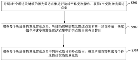
S501、分别对Y个所述关键帧的激光雷达点集进行旋转平移变换操作,获得Y个变换激光雷达点集。
具体的,在对每个关键帧的激光雷达点集进行旋转平移变换操作时,可以通过先对该关键帧的激光雷达点集进行旋转变换操作,再对其进行平移变换操作,也可以先对该关键帧的激光雷达点集进行平移变换操作,再对其进行旋转变换操作,获得每个关键帧的变换激光雷达点集,同样,对Y个关键帧的激光雷达点集进行上述旋转平移变换操作,这样, 获得Y个变换激光雷达点集。
可选的,可以根据上述图4实施例方法获得对应的旋转矩阵R
0和平移矩阵t
0,并利用计算得到的R
0和t
0,将关键帧中的点集中的点进行旋转平移变换,通过以下公式获得变换激光雷达点集P′:
P′=R
0P+t
0,
其中,P为关键帧的激光雷达点集,R
0为旋转矩阵,t
0为平移矩阵。
S502、根据每个所述变换激光雷达点集、所述当前帧的激光雷达点集和第一预设阈值,确定每个所述变换激光雷达点集中的内点数目和外点数目。
例如,可以通过变换激光雷达点集中的数据点与当前帧的激光雷达点集中的数据点之前的距离,将该距离与第一预设阈值进行对比,从而确定出每个变换激光雷达点集中的内点数目和外点数目。其中,不同的变换激光雷达点集中的内点数目和外点数目都不同。
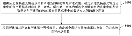
可选地,如图7所示,S502“根据每个所述变换激光雷达点集、所述当前帧的激光雷达点集和第一预设阈值,确定每个所述变换激光雷达点集中的内点数目和外点数目”的一种可能的实现方式包括:
S601、根据所述变换激光雷达点集和所述当前帧的激光雷达点集,确定所述变换激光雷达点集中的每个数据点对应的第三距离;所述第三距离为所述变换激光雷达点集中的所述数据点与所述当前帧的激光雷达点集中的数据点之间的最小距离。
具体的,移动机器人在对关键帧的激光雷达点集进行旋转平移变换操作,获得变换激光雷达点集后,然后根据变换激光雷达点集和当前帧的激光雷达点集,确定变换激光雷达点集中的每个数据点与当前帧的激光雷达点集中的数据点之间的最小距离,可选的,可以先选定变换激光雷达点集中的任一点,当前帧的激光雷达点集中并检索与其距离最近的的数据点,然后计算变换激光雷达点集中的该点与检索到的当前帧的激光雷达点集中的数据点之间的第三距离。
例如,可以通过以下公式计算第三距离:
其中,(x
1,y
1)为变换激光雷达点集中的点坐标,(x
2,y
2)为当前帧的激光雷达点集中的点坐标,d
i为第三距离。
S602、根据所述第三距离和所述第一预设阈值,确定每个所述变换激光雷达点集中的内点数目和外点数目。
具体的,第一预设阈值为根据实际情况确定的阈值,当移动机器人根据变换激光雷达点集和当前帧的激光雷达点集,确定变换激光雷达点集中的每个数据点对应的第三距离之后,将第三距离和第一预设阈值进行比较,根据比较结果确定每个变换激光雷达点集中的内点数目和外点数目。
可选的,若第三距离小于第一预设阈值,则确定变换激光雷达点集中的点为内点;若第三距离大于三倍的第一预设阈值,则确定变换激光雷达点集中的点为外点;然后根据每 个变换激光雷达点集中的内点和外点,确定每个变换激光雷达点集中的内点数目和外点数目。
例如,可以通过下述公式确定变换激光点集中的内点和外点,遍历变换激光点集中的所有点,并统计该点集中的内点数目num
1和外点数目num
2。

其中,P
i′为变换激光雷达点集,d
i为第三距离,ε为第一预设阈值。
上述实施例提供的移动机器人的陀螺仪数据校正方法,移动机器人在通过对关键帧的激光雷达点集进行旋转平移变换操作后,获得变换激光雷达点集,并根据变换激光雷达点集和当前帧的激光雷达点集,确定变换激光雷达点集中的每个数据点与当前帧中的与之距离最近的激光雷达点集中的数据点对应的第三距离,然后根据第三距离和第一预设阈值之间的大小关系,确定每个变换激光雷达点集中的内点数目和外点数目。由于第三距离为所述变换激光雷达点集中的所述数据点与所述当前帧的激光雷达点集中的数据点之间的最小距离,从而使得变换激光雷达点集中的数据点与当前帧的激光雷达点集中的数据点更接近,从而更精准的确定变换激光雷达点集中的内点数目和外点数目。
S503、根据每个所述变换激光雷达点集中的内点数目和外点数目,确定所述当前帧的每个待选估计位姿的量化值。
在本实施例中,确定出变换激光雷达点集中的内点数目和外点数目之后,可以根据内点数目和外点数目的比值确定当前帧的每个待选估计位姿的量化值。
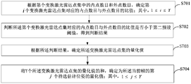
可选地,如图8所示,S503“根据每个所述变换激光雷达点集中的内点数目和外点数目,确定所述当前帧的每个待选估计位姿的量化值”的一种可能的实现方式包括:
S701、根据第i个变换激光雷达点集中的内点数目和外点数目,确定第i个变换激光雷达点集对应的内点数目与外点数目的比值;其中,1≤i≤Y。
具体的,在移动机器任确定出每个变换激光雷达点集中的内点数目和外点数目之后,并对其中的第i个变换激光雷达点集中的内点数目与外点数目作商,得到相应的结果,并确定该结果为第i个变换激光雷达点集对应的内点数目与外点数目的比值。
例如,可以根据i个变换激光雷达点集P
i′中的内点数目num
1和外点数目num
2,确定内点数目与外点数目的比值

S702、判断所述第i个变换激光雷达点集对应的内点数目与外点数目的比值是否小于第二预设阈值,得到判断结果。
具体的,移动机器人在确定出第i个变换激光雷达点集中的内点数目与外点数目的比值后,并判断该变换激光雷达点集中的内点数目与外点数目的比值与第二预设阈值之间的 大小关系,得到相应的判断结果。
可选的,该判断结果可以是该变换激光雷达点集中的内点数目与外点数目的比值小于第二预设阈值,也可以是该变换激光雷达点集中的内点数目与外点数目的比值不小于第二预设阈值,也就是说,该变换激光雷达点集中的内点数目与外点数目的比值大于或等于第二预设阈值。
S703、根据所述判断结果,确定所述变换激光雷达点集的量化值。
具体的,移动机器人通过判断第i个变换激光雷达点集对应的内点数目与外点数目的比值是否小于第二预设阈值,得到相应的判断结果后,然后根据该判断结果,确定变换激光雷达点集中的量化值。
可选的,若判断结果为第i个变换激光雷达点集对应的内点数目与外点数目的比值小于第二预设阈值,则确定第i个变换激光雷达点集对应的内点数目与外点数目的比值为变换激光雷达点集中的量化值;若判断结果为第i个变换激光雷达点集对应的内点数目与外点数目的比值不小于第二预设阈值,则确定第二预设阈值为变换激光雷达点集中的量化值。
例如,可以通过下述公式确定判断结果,

其中,
 为变换激光雷达点集中的内点数目与外点数目的比值,K为第二预设阈值,
 为变换激光雷达点集中的量化值,KF
i为第i个变换激光雷达点集,F
j为当前帧的激光雷达点集,pose
KFi为第i个变换激光雷达点集的待选估计位姿,pose
Fj为第j个当前帧的待选估计位姿。
为变换激光雷达点集中的量化值,KF
i为第i个变换激光雷达点集,F
j为当前帧的激光雷达点集,pose
KFi为第i个变换激光雷达点集的待选估计位姿,pose
Fj为第j个当前帧的待选估计位姿。
S704、将Y个所述变换激光雷达点集的量化值的和,确定为所述当前帧的第j个待选估计位姿的量化值;其中,1≤j≤Y。
具体的,移动机器人在确定当前帧的第j个待选估计位姿的量化值时,通过确定第i个变换激光雷达点集中的内点数目和外点数目的比值,并判断该比值是否小于第二预设阈值,然后根据得到的判断结果,确定第i个变换激光雷达点集中的量化值,然后遍历Y个变换激光雷达点集,这时,可以确定出Y个变换激光雷达点集分别对应的Y个量化值,将该Y个量化值累加求和,得到相应的结果,将该结果确定为当前帧的第j个待选估计位姿的量化值。
例如,可以通过下述公式确定当前帧的第j个待选估计位姿的量化值:
其中,KF
i为第i个变换激光雷达点集,F
j为当前帧的激光雷达点集,pose
KFi为第i个变换激光雷达点集的待选估计位姿,pose
Fj为第j个当前帧的待选估计位姿,score
j为当前帧的第j个待选估计位姿的量化值,score(KF
i,F
j,pose
KFi,pose
Fj)为当前帧的第j个待选估计位姿对应的第i个变换激光雷达点集中的量化值。
需要说明的是,上述过程为确定当前帧对应的第j个待选估计位姿的量化值的整体过程,对于每一个待选估计位姿,均需要遍历Y个关键帧,将Y个关键帧的对应的Y个变换激光雷达点集的量化值的和作为待选估计位姿的量化值。并遍历当前帧的每个待选估计位姿,可以确定出当前帧的Y个待选估计位姿对应的Y个量化值。并通过对比当前帧的Y个量化值的大小,得到当前帧的最大量化值。
可选的,若最大量化值大于第三预设阈值,则根据最大量化值对应的待选估计位姿信息,对移动机器人的陀螺仪数据进行校正。
具体的,在确定出当前帧的最大量化值之后,并将该最大量化值与第三预设阈值进行对比,当最大量化值大于第三预设阈值时,根据该最大量化值对应的待选估计位姿信息对移动机器人的陀螺仪数据进行校正。
上述实施例提供的移动机器人的陀螺仪数据校正方法,移动机器人根据第i个变换激光雷达点集中的内点数目和外点数目,确定出第i个变换激光雷达点集对应的内点数目与外点数目的比值,然后判断该比值是否小于第二预设阈值,得到相应的判断结果,并根据得到的判断结果,确定第i个变换激光雷达点集的量化值,并遍历Y个变换激光雷达点集,得到Y个变换激光雷达点集的量化值,并将Y个量化值累加的和,确定为第j个待选估计位姿的量化值,然后遍历当前帧的Y个待选估计位姿,得到对应的Y个量化值,确定其中的最大量化值,并将该最大量化值与第三预设阈值大小进行对比,当该最大量化值大于第三预设阈值时,最后根据确定给出的最大量化值对应的待选估计位姿信息对陀螺仪进行校正。由于移动机器人通过确定变换雷达点集中的内点数目与外点数目的比值,更好的确定内点数目与外点数目的关系,并通过将该比值与第二预设阈值进行对比,从而更精准的确定出第i个变换激光雷达点集的量化值,并将得到的Y个变换激光雷达点集的量化值相加,使得确定出的第j个待选估计位姿的量化值结果更加准确,便于对陀螺仪数据进行更精准的校正。
本实施例提供的移动机器人的陀螺仪数据校正方法,移动机器人先分别对Y个关键帧的激光雷达点集进行旋转平移变换操作,获得Y个变换激光雷达点集,并根据每个变换激光雷达点集、当前帧的激光雷达点集和第一预设阈值,确定每个变换激光雷达点集中的内点数目和外点数目,然后根据每个变换激光雷达点集中的内点数目和外点数目,确定当前帧的每个待选估计位姿的量化值。可以根据变换激光雷达点集中的内点数目和外点数目,步精准的确定当前帧的每个待选估计位姿的量化值,使得移动机器人更加准确的判定出当 前帧的最优待位姿,很大程度上提高了对陀螺仪数据校正的精准度,从而大大提高了系统的鲁棒性。
图9为一实施例提供的移动机器人的陀螺仪数据校正方法的流程示意图。本实施例涉及的是S104“移动机器人根据最大量化值对应的待选估计位姿信息,对陀螺仪数据进行校正”的具体过程。在上述实施例的基础上,如图9所示,该方法包括:
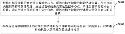
S801、根据目标关键帧的激光雷达数据中心点、所述目标关键帧的初始估计位置、所述目标关键帧的初始估计角度、所述当前帧的激光雷达数据中心点、所述当前帧的初始估计位置,确定所述当前帧的修正估计角度;所述目标关键帧为所述最大量化值对应的关键帧。
具体的,当移动机器人根据上述最大量化值对应的关键帧中的待选估计位姿信息对陀螺仪数据进行校正后,还可以进一步确定该当前帧的修正估计角度。
可选的,可以通过以下公式来确定当前帧的修正估计角度,
θ
1=atan2(p
0i-p
KFK)*y,(p
0i-p
KFK)*x),
θ
2=atan2(p
0F-p
FK)*y,(p
0F-p
FK)*x),
θ
FK=θ
KFK+(θ
2-θ
1),
其中,p
0i为关键帧的激光雷达点集的数据中心点,p
KFK为最大量化值对应的关键帧的初始估计位置,p
0F为当前帧的激光雷达点集的数据中心点,p
FK为最大量化值对应的当前帧的初始估计位置,θ
FK为最大量化值对应的关键帧的初始估计角度,θ
KFK为当前帧的修正估计角度,a为常数,x为当前帧激光雷达数据点的横坐标,y为当前帧激光雷达数据点的纵坐标。。
S802、根据所述当前帧的修正估计角度和所述目标关键帧对应的待选估计位姿信息,对所述移动机器人的陀螺仪数据进行校正。
具体的,移动机器人在确定出当前帧的修正估计角度后,然后根据该当前帧的修正估计角度和最大量化值对应的关键帧的待选估计位姿信息,可以进一步对移动机器人的陀螺仪数据进行校正,从而进一步提高了对陀螺仪校正的准确度。
本实施例提供的移动机器人的陀螺仪数据校正方法,移动机器人先根据最大量化值对应的关键帧的激光雷达数据中心点、该关键帧的初始估计位置、该关键帧的初始估计角度、当前帧的激光雷达数据中心点、当前帧的初始估计位置,确定当前帧的修正估计角度,并根据当前帧的修正估计角度和该关键帧对应的待选估计位姿信息,对移动机器人的陀螺仪数据进行校正。由于通过确定当前帧的修正估计角度,使得对陀螺仪数据校正的精确度进一步提高。
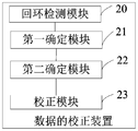
图10为一实施例提供的一种移动机器人的陀螺仪数据校正装置的示意图。如图10所示,该装置包括:回环检测模块20、第一确定模块21、第二确定模块22和第一校正模块23。
回环检测模块20,用于对当前帧的激光雷达数据进行回环检测。
第一确定模块21,用于当回环检测成功时,则采用迭代最近点ICP算法,根据所述移动机器人的Y个关键帧的初始估计位置、Y个所述关键帧的激光雷达点集、Y个所述关键帧的初始估计角度、所述移动机器人的当前帧的激光雷达点集,确定所述当前帧的Y个待选估计位姿信息。
第二确定模块22,用于根据所述关键帧的激光雷达点集和所述当前帧的激光雷达点集,确定所述当前帧的每个待选估计位姿的量化值。
第一校正模块23,用于根据Y个所述量化值中的最大量化值对应的待选估计位姿信息,对所述移动机器人的陀螺仪数据进行校正。
本实施例提供的移动机器人的陀螺仪数据校正装置,可以执行上述图2方法实施例,其实现原理和技术效果类似,在此不再赘述。
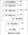
图11为另一实施例提供的一种移动机器人的陀螺仪数据校正装置的示意图。如图11所示,在上述图10所示的实施例的基础上,第一确定模块21包括:第一确定单元211、第二确定单元212、第三确定单元213。
具体的,第一确定单元211,用于采用所述ICP算法,根据所述关键帧的激光雷达点集、所述当前帧的激光雷达点集和所述关键帧的初始估计位置,确定所述当前帧的初始估计位置。
第二确定单元212,用于根据所述关键帧的激光雷达点集、所述当前帧的激光雷达点集、所述关键帧的初始估计位置、所述关键帧的初始估计角度和所述当前帧的初始估计位置,确定所述当前帧的初始估计角度。
第三确定单元213,用于根据所述当前帧的初始估计位置和所述当前帧的初始估计角度确定所述当前帧的待选估计位姿信息。
本实施例提供的移动机器人的陀螺仪数据校正装置,可以执行上述图3方法实施例,其实现原理和技术效果类似,在此不再赘述。
在其中一个实施例中,可选的,上述第一确定单元211,具体用于采用所述ICP算法,根据所述关键帧的激光雷达点集和所述当前帧的激光雷达点集,确定估计矩阵;所述估计矩阵包括旋转矩阵和平移矩阵;根据所述估计矩阵和所述关键帧的初始估计位置确定所述当前帧的初始估计位置。
在其中一个实施例中,可选的,上述第二确定单元212,具体用于根据所述关键帧的激光雷达点集,确定所述关键帧的激光雷达数据中心点;根据所述当前帧的激光雷达点集,确定所述当前帧的激光雷达数据中心点;根据所述关键帧的激光雷达数据中心点、所述当前帧的激光雷达数据中心点、所述关键帧的初始估计位置、所述关键帧的初始估计位置和所述当前帧的初始估计位置,确定所述当前帧的初始估计角度。
在其中一个实施例中,可选的,上述第二确定单元212,具体用于根据公式
 确定所述关键帧中的激光雷1达数据中心点p
0;其中,p
i为所述关键帧中的激光雷达点集中的任意点;根据公式
确定所述关键帧中的激光雷1达数据中心点p
0;其中,p
i为所述关键帧中的激光雷达点集中的任意点;根据公式
 ,确定所述当前帧中的激光雷达数据中心点q
0;其中, q
i为所述当前帧中的激光雷达点集中的任意点。
,确定所述当前帧中的激光雷达数据中心点q
0;其中, q
i为所述当前帧中的激光雷达点集中的任意点。
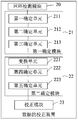
图12为另一实施例提供的一种移动机器人的陀螺仪数据校正装置的示意图。如图12所示,在上述图11所示的实施例的基础上,第二确定模块22包括:变换单元221、第四确定单元222、第五确定单元223。
具体的,变换单元221,用于分别对Y个所述关键帧的激光雷达点集进行旋转平移变换操作,获得Y个变换激光雷达点集。
第四确定单元222,用于根据每个所述变换激光雷达点集、所述当前帧的激光雷达点集和第一预设阈值,确定每个所述变换激光雷达点集中的内点数目和外点数目。
第五确定单元223,用于根据每个所述变换激光雷达点集中的内点数目和外点数目,确定所述当前帧的每个待选估计位姿的量化值。
本实施例提供的移动机器人的陀螺仪数据校正装置,可以执行上述图6方法实施例,其实现原理和技术效果类似,在此不再赘述。
在其中一个实施例中,可选的,上述第四确定单元222,具体用于根据所述变换激光雷达点集和所述当前帧的激光雷达点集,确定所述变换激光雷达点集中的每个数据点对应的第三距离;所述第三距离为所述变换激光雷达点集中的所述数据点与所述当前帧的激光雷达点集中的数据点之间的最小距离;根据所述第三距离和所述第一预设阈值,确定每个所述变换激光雷达点集中的内点数目和外点数目。
在其中一个实施例中,可选的,上述第四确定单元222,具体用于若所述第三距离小于所述第一预设阈值,则确定所述变换激光雷达点集中的点为内点;若所述第三距离大于三倍的所述第一预设阈值,则确定所述变换激光雷达点集中的点为外点;根据每个所述变换激光雷达点集中的内点和外点,确定每个所述变换激光雷达点集中的内点数目和外点数目。
本实施例提供的移动机器人的陀螺仪数据校正装置,可以执行上述图7方法实施例,其实现原理和技术效果类似,在此不再赘述。
在其中一个实施例中,可选的,上述第五确定单元223,具体用于根据第i个变换激光雷达点集中的内点数目和外点数目,确定第i个变换激光雷达点集对应的内点数目与外点数目的比值;其中,1≤i≤Y;判断所述第i个变换激光雷达点集对应的内点数目与外点数目的比值是否小于第二预设阈值,得到判断结果;根据所述判断结果,确定所述变换激光雷达点集的量化值;将Y个所述变换激光雷达点集的量化值的和,确定为所述当前帧的第j个待选估计位姿的量化值;其中,1≤j≤Y。
在其中一个实施例中,可选的,上述第五确定单元223,具体用于在所述判断结果为所述第i个变换激光雷达点集对应的内点数目与外点数目的比值小于所述第二预设阈值时,则确定所述第i个变换激光雷达点集对应的内点数目与外点数目的比值为所述变换激光雷达点集中的量化值;在所述判断结果为所述第i个变换激光雷达点集对应的内点数目与外点数目的比值不小于所述第二预设阈值时,则确定所述第二预设阈值为所述变换激光 雷达点集中的量化值。
在其中一个实施例中,可选的,上述校正模块23,具体用于在所述最大量化值大于第三预设阈值时,则根据所述最大量化值对应的待选估计位姿信息,对陀螺仪数据进行校正。
本实施例提供的移动机器人的陀螺仪数据校正装置,可以执行上述图8方法实施例,其实现原理和技术效果类似,在此不再赘述。
图13为另一实施例提供的一种移动机器人的陀螺仪数据校正装置的示意图。如图13所示,在上述实施例的基础上,上述校正模块23还包括:第六确定单元231、第一校正单元232。
具体的,第六确定单元231,用于根据目标关键帧的激光雷达数据中心点、所述目标关键帧的初始估计位置、所述目标关键帧的初始估计角度、所述当前帧的激光雷达数据中心点、所述当前帧的初始估计位置,确定所述当前帧的修正估计角度;所述目标关键帧为所述最大量化值对应的关键帧。
第一校正单元232,用于根据所述当前帧的修正估计角度和所述目标关键帧对应的待选估计位姿信息,对所述移动机器人的陀螺仪数据进行校正。
本实施例提供的移动机器人的陀螺仪数据校正装置,可以执行上述图9方法实施例,其实现原理和技术效果类似,在此不再赘述。
关于控制数据校正的装置的具体限定可以参见上文中对于数据校正的方法的限定,在此不再赘述。上述数据校正的装置中的各个模块可全部或部分通过软件、硬件及其组合来实现。上述各模块可以硬件形式内嵌于或独立于机器人中的处理器中,也可以以软件形式存储于机器人中的存储器中,以便于处理器调用执行以上各个模块对应的操作。
在一个实施例中,提供了一种设备,其内部结构图可以如图14所示。该机器人可以包括通过系统总线连接的处理器、存储器、网络接口、显示屏和输入装置。其中,该机器人的处理器用于提供计算和控制能力。该机器人的存储器包括非易失性存储介质、内存储器。该非易失性存储介质存储有操作系统和计算机程序。该内存储器为非易失性存储介质中的操作系统和计算机程序的运行提供环境。该机器人的网络接口用于与外部的终端通过网络连接通信。该计算机程序被处理器执行时以实现一种数据的校正方法。该机器人的显示屏可以是液晶显示屏或者电子墨水显示屏,该机器人的输入装置可以是显示屏上覆盖的触摸层,也可以是机器人外壳上设置的按键、轨迹球或触控板,还可以是外接的键盘、触控板或鼠标等。
本领域技术人员可以理解,图14中示出的结构,仅仅是与本申请方案相关的部分结构的框图,并不构成对本申请方案所应用于其上的机器人的限定,具体的机器人可以包括比图中所示更多或更少的部件,或者组合某些部件,或者具有不同的部件布置。
在一个实施例中,提供了一种设备,包括存储器和处理器,存储器中存储有计算机程序,该处理器执行计算机程序时实现以下步骤:
对当前帧的激光雷达数据进行回环检测;
若回环检测成功,则采用迭代最近点ICP算法,根据移动机器人的Y个关键帧的初始估计位置、Y个所述关键帧的激光雷达点集、Y个所述关键帧的初始估计角度、所述移动机器人的当前帧的激光雷达点集,确定所述当前帧的Y个待选估计位姿信息;
根据每个所述关键帧的激光雷达点集和所述当前帧的激光雷达点集,确定所述当前帧的每个待选估计位姿的量化值;
根据Y个所述量化值中的最大量化值对应的待选估计位姿信息,对所述移动机器人的陀螺仪数据进行校正。
在一个实施例中,提供了一种计算机可读存储介质,其上存储有计算机程序,计算机程序被处理器执行时实现以下步骤:
对当前帧的激光雷达数据进行回环检测;
若回环检测成功,则采用迭代最近点ICP算法,根据移动机器人的Y个关键帧的初始估计位置、Y个所述关键帧的激光雷达点集、Y个所述关键帧的初始估计角度、所述移动机器人的当前帧的激光雷达点集,确定所述当前帧的Y个待选估计位姿信息;
根据每个所述关键帧的激光雷达点集和所述当前帧的激光雷达点集,确定所述当前帧的每个待选估计位姿的量化值;
根据Y个所述量化值中的最大量化值对应的待选估计位姿信息,对所述移动机器人的陀螺仪数据进行校正。
本领域普通技术人员可以理解实现上述实施例方法中的全部或部分流程,是可以通过计算机程序来指令相关的硬件来完成,所述的计算机程序可存储于一非易失性计算机可读取存储介质中,该计算机程序在执行时,可包括如上述各方法的实施例的流程。其中,本申请所提供的各实施例中所使用的对存储器、存储、数据库或其它介质的任何引用,均可包括非易失性和/或易失性存储器。非易失性存储器可包括只读存储器(ROM)、可编程ROM(PROM)、电可编程ROM(EPROM)、电可擦除可编程ROM(EEPROM)或闪存。易失性存储器可包括随机存取存储器(RAM)或者外部高速缓冲存储器。作为说明而非局限,RAM以多种形式可得,诸如静态RAM(SRAM)、动态RAM(DRAM)、同步DRAM(SDRAM)、双数据率SDRAM(DDRSDRAM)、增强型SDRAM(ESDRAM)、同步链路(Synchlink)DRAM(SLDRAM)、存储器总线(Rambus)直接RAM(RDRAM)、直接存储器总线动态RAM(DRDRAM)、以及存储器总线动态RAM(RDRAM)等。
以上实施例的各技术特征可以进行任意的组合,为使描述简洁,未对上述实施例中的各个技术特征所有可能的组合都进行描述,然而,只要这些技术特征的组合不存在矛盾,都应当认为是本说明书记载的范围。
以上所述实施例仅表达了本申请的几种实施方式,其描述较为具体和详细,但并不能因此而理解为对本申请专利范围的限制。应当指出的是,对于本领域的普通技术人员来说,在不脱离本申请构思的前提下,还可以做出若干变形和改进,这些都属于本申请的保护范 围。因此,本申请专利的保护范围应以所附权利要求为准。
Claims (15)
- 一种移动机器人的陀螺仪数据校正方法,其特征在于,包括:对当前帧的激光雷达数据进行回环检测;若回环检测成功,则采用迭代最近点ICP算法,根据移动机器人的Y个关键帧的初始估计位置、Y个所述关键帧的激光雷达点集、Y个所述关键帧的初始估计角度、所述移动机器人的当前帧的激光雷达点集,确定所述当前帧的Y个待选估计位姿信息;根据每个所述关键帧的激光雷达点集和所述当前帧的激光雷达点集,确定所述当前帧的每个待选估计位姿的量化值;根据Y个所述量化值中的最大量化值对应的待选估计位姿信息,对所述移动机器人的陀螺仪数据进行校正。
- 根据权利要求1所述的方法,其特征在于,采用迭代最近点ICP算法,所述根据所述移动机器人的Y个关键帧的初始估计位置、Y个所述关键帧的激光雷达点集、Y个所述关键帧的初始估计角度、所述移动机器人的当前帧的激光雷达点集,确定所述当前帧的Y个待选估计位姿信息,包括:采用所述ICP算法,根据所述关键帧的激光雷达点集、所述当前帧的激光雷达点集和所述关键帧的初始估计位置,确定所述当前帧的初始估计位置;根据所述关键帧的激光雷达点集、所述当前帧的激光雷达点集、所述关键帧的初始估计位置、所述关键帧的初始估计角度和所述当前帧的初始估计位置,确定所述当前帧的初始估计角度;根据所述当前帧的初始估计位置和所述当前帧的初始估计角度确定所述当前帧的待选估计位姿信息。
- 根据权利要求2所述的方法,其特征在于,所述采用所述ICP算法,根据所述关键帧的激光雷达点集、所述当前帧的激光雷达点集确定和所述关键帧的初始估计位置,确定所述当前帧的初始估计位置,包括:采用所述ICP算法,根据所述关键帧的激光雷达点集和所述当前帧的激光雷达点集,确定估计矩阵;所述估计矩阵包括旋转矩阵和平移矩阵;根据所述估计矩阵和所述关键帧的初始估计位置确定所述当前帧的初始估计位置。
- 根据权利要求2或3所述的方法,其特征在于,所述根据所述关键帧的激光雷达点集、所述当前帧的激光雷达点集、所述关键帧的初始估计位置、所述关键帧的初始估计角度和所述当前帧的初始估计位置,确定所述当前帧的初始估计角度,包括:根据所述关键帧的激光雷达点集,确定所述关键帧的激光雷达数据中心点;根据所述当前帧的激光雷达点集,确定所述当前帧的激光雷达数据中心点;根据所述关键帧的激光雷达数据中心点、所述当前帧的激光雷达数据中心点、所述关键帧的初始估计位置、所述关键帧的初始估计位置和所述当前帧的初始估计位置,确定所述当前帧的初始估计角度。
- 根据权利要求4所述的方法,其特征在于,所述根据所述关键帧的激光雷达点集,确定所述关键帧的激光雷达数据中心点与根据所述当前帧的激光雷达点集,确定所述当前帧的激光雷达数据中心点,包括:根据公式确定所述关键帧中的激光雷达数据中心点p 0;其中,p i为所述关键帧中的激光雷达点集中的任意点;
 根据公式确定所述当前帧中的激光雷达数据中心点q 0;其中,q i为所述当前帧中的激光雷达点集中的任意点。
- 根据权利要求1-3任一项所述的方法,其特征在于,所述根据所述关键帧的激光雷达点集和所述当前帧的激光雷达点集,确定所述当前帧的每个待选估计位姿的量化值,包括:分别对Y个所述关键帧的激光雷达点集进行旋转平移变换操作,获得Y个变换激光雷达点集;根据每个所述变换激光雷达点集、所述当前帧的激光雷达点集和第一预设阈值,确定每个所述变换激光雷达点集中的内点数目和外点数目;根据每个所述变换激光雷达点集中的内点数目和外点数目,确定所述当前帧的每个待选估计位姿的量化值。
- 根据权利要求6所述的方法,其特征在于,所述根据所述变换激光雷达点集、所述当前帧的激光雷达点集和第一预设阈值,确定每个所述变换激光雷达点集中的内点数目和外点数目,包括:根据所述变换激光雷达点集和所述当前帧的激光雷达点集,确定所述变换激光雷达点集中的每个数据点对应的第三距离;所述第三距离为所述变换激光雷达点集中的所述数据点与所述当前帧的激光雷达点集中的数据点之间的最小距离;根据所述第三距离和所述第一预设阈值,确定每个所述变换激光雷达点集中的内点数目和外点数目。
- 根据权利要求7所述的方法,其特征在于,所述根据所述第三距离和所述第一预设阈值,确定每个所述变换激光雷达点集中的内点数目和外点数目,包括:若所述第三距离小于所述第一预设阈值,则确定所述变换激光雷达点集中的点为内点;若所述第三距离大于三倍的所述第一预设阈值,则确定所述变换激光雷达点集中的点为外点;根据每个所述变换激光雷达点集中的内点和外点,确定每个所述变换激光雷达点集中的内点数目和外点数目。
- 根据权利要求7或8所述的方法,其特征在于,根据每个所述变换激光雷达点集 中的内点数目和外点数目,确定所述当前帧的每个待选估计位姿的量化值,包括:根据第i个变换激光雷达点集中的内点数目和外点数目,确定第i个变换激光雷达点集对应的内点数目与外点数目的比值;其中,1≤i≤Y;判断所述第i个变换激光雷达点集对应的内点数目与外点数目的比值是否小于第二预设阈值,得到判断结果;根据所述判断结果,确定所述变换激光雷达点集的量化值;将Y个所述变换激光雷达点集的量化值的和,确定为所述当前帧的第j个待选估计位姿的量化值;其中,1≤j≤Y。
- 根据所述权利要求9所述的方法,其特征在于,所述根据所述判断结果,确定所述变换激光雷达点集的量化值,包括:若所述判断结果为所述第i个变换激光雷达点集对应的内点数目与外点数目的比值小于所述第二预设阈值,则确定所述第i个变换激光雷达点集对应的内点数目与外点数目的比值为所述变换激光雷达点集中的量化值;若所述判断结果为所述第i个变换激光雷达点集对应的内点数目与外点数目的比值不小于所述第二预设阈值,则确定所述第二预设阈值为所述变换激光雷达点集中的量化值。
- 根据权利要求1-3任一项所述的方法,其特征在于,所述根据Y个所述量化值中的最大量化值对应的待选估计位姿,对所述移动机器人的陀螺仪数据进行校正,包括:若所述最大量化值大于第三预设阈值,则根据所述最大量化值对应的待选估计位姿信息,对所述移动机器人的陀螺仪数据进行校正。
- 根据权利要求11所述的方法,其特征在于,所述根据最大量化值对应的待选估计位姿信息,对所述移动机器人的陀螺仪数据进行校正,包括:根据目标关键帧的激光雷达数据中心点、所述目标关键帧的初始估计位置、所述目标关键帧的初始估计角度、所述当前帧的激光雷达数据中心点、所述当前帧的初始估计位置,确定所述当前帧的修正估计角度;所述目标关键帧为所述最大量化值对应的关键帧;根据所述当前帧的修正估计角度和所述目标关键帧对应的待选估计位姿信息,对所述移动机器人的陀螺仪数据进行校正。
- 一种移动机器人的陀螺仪数据校正装置,其特征在于,包括:回环检测模块,用于对当前帧的激光雷达数据进行回环检测;第一确定模块,用于当回环检测成功时,则采用迭代最近点ICP算法,根据所述移动机器人的Y个关键帧的初始估计位置、Y个所述关键帧的激光雷达点集、Y个所述关键帧的初始估计角度、所述移动机器人的当前帧的激光雷达点集,确定所述当前帧的Y个待选估计位姿信息;第二确定模块,用于根据所述关键帧的激光雷达点集和所述当前帧的激光雷达点集,确定所述当前帧的每个待选估计位姿的量化值;校正模块,用于根据Y个所述量化值中的最大量化值对应的待选估计位姿信息,对所 述移动机器人的陀螺仪数据进行校正。
- 一种设备,包括存储器、处理器,所述存储器上存储有可在处理器上运行的计算机程序,其特征在于,所述处理器执行所述计算机程序时实现权利要求1至12中任一项所述方法的步骤。
- 一种可读存储介质,其上存储有计算机程序,其特征在于,所述计算机程序被处理器执行时实现权利要求1至12中任一项所述方法的步骤。
Priority Applications (2)
| Application Number | Priority Date | Filing Date | Title |
|---|---|---|---|
| EP19791932.7A EP3786588A4 (en) | 2018-04-26 | 2019-03-05 | GYROSCOPIC DATA CORRECTION PROCESS OF MOBILE ROBOT, DEVICE AND STORAGE MEDIA |
| US17/037,624 US20210025712A1 (en) | 2018-04-26 | 2020-09-29 | Method for correcting gyroscope data of mobile robot, device, and storage medium |
Applications Claiming Priority (2)
| Application Number | Priority Date | Filing Date | Title |
|---|---|---|---|
| CN201810386307.8A CN108680185B (zh) | 2018-04-26 | 2018-04-26 | 移动机器人的陀螺仪数据校正方法、装置和设备 |
| CN201810386307.8 | 2018-04-26 |
Related Child Applications (1)
| Application Number | Title | Priority Date | Filing Date |
|---|---|---|---|
| US17/037,624 Continuation US20210025712A1 (en) | 2018-04-26 | 2020-09-29 | Method for correcting gyroscope data of mobile robot, device, and storage medium |
Publications (1)
| Publication Number | Publication Date |
|---|---|
| WO2019205813A1 true WO2019205813A1 (zh) | 2019-10-31 |
Family
ID=63802425
Family Applications (1)
| Application Number | Title | Priority Date | Filing Date |
|---|---|---|---|
| PCT/CN2019/077000 WO2019205813A1 (zh) | 2018-04-26 | 2019-03-05 | 移动机器人的陀螺仪数据校正方法、设备和存储介质 |
Country Status (4)
| Country | Link |
|---|---|
| US (1) | US20210025712A1 (zh) |
| EP (1) | EP3786588A4 (zh) |
| CN (1) | CN108680185B (zh) |
| WO (1) | WO2019205813A1 (zh) |
Cited By (3)
| Publication number | Priority date | Publication date | Assignee | Title |
|---|---|---|---|---|
| CN112344933A (zh) * | 2020-08-21 | 2021-02-09 | 北京京东乾石科技有限公司 | 一种信息生成的方法、装置和存储介质 |
| CN112415535A (zh) * | 2020-10-22 | 2021-02-26 | 武汉万集信息技术有限公司 | 导航系统和导航方法 |
| CN112781594A (zh) * | 2021-01-11 | 2021-05-11 | 桂林电子科技大学 | 基于imu耦合的激光雷达迭代最近点改进算法 |
Families Citing this family (4)
| Publication number | Priority date | Publication date | Assignee | Title |
|---|---|---|---|---|
| CN108680185B (zh) * | 2018-04-26 | 2020-09-22 | 广东宝乐机器人股份有限公司 | 移动机器人的陀螺仪数据校正方法、装置和设备 |
| CN113253293B (zh) * | 2021-06-03 | 2021-09-21 | 中国人民解放军国防科技大学 | 一种激光点云畸变的消除方法和计算机可读存储介质 |
| CN114111593B (zh) * | 2021-11-25 | 2024-02-27 | 征图新视(江苏)科技股份有限公司 | 一种键盘自动检测设备及其成像方法 |
| CN116448088B (zh) * | 2023-06-07 | 2023-09-05 | 中国船舶集团有限公司第七〇七研究所 | 一种陀螺仪校正装置及校正方法 |
Citations (5)
| Publication number | Priority date | Publication date | Assignee | Title |
|---|---|---|---|---|
| CN105856230A (zh) * | 2016-05-06 | 2016-08-17 | 简燕梅 | 一种可提高机器人位姿一致性的orb关键帧闭环检测slam方法 |
| CN106780608A (zh) * | 2016-11-23 | 2017-05-31 | 北京地平线机器人技术研发有限公司 | 位姿信息估计方法、装置和可移动设备 |
| CN107607107A (zh) * | 2017-09-14 | 2018-01-19 | 斯坦德机器人(深圳)有限公司 | 一种基于先验信息的Slam方法和装置 |
| CN107869989A (zh) * | 2017-11-06 | 2018-04-03 | 东北大学 | 一种基于视觉惯导信息融合的定位方法及系统 |
| CN108680185A (zh) * | 2018-04-26 | 2018-10-19 | 广东宝乐机器人股份有限公司 | 移动机器人的陀螺仪数据校正方法、装置和设备 |
Family Cites Families (7)
| Publication number | Priority date | Publication date | Assignee | Title |
|---|---|---|---|---|
| SG10201700299QA (en) * | 2017-01-13 | 2018-08-30 | Otsaw Digital Pte Ltd | Three-dimensional mapping of an environment |
| US11348269B1 (en) * | 2017-07-27 | 2022-05-31 | AI Incorporated | Method and apparatus for combining data to construct a floor plan |
| GB201718507D0 (en) * | 2017-07-31 | 2017-12-27 | Univ Oxford Innovation Ltd | A method of constructing a model of the motion of a mobile device and related systems |
| CN108957466B (zh) * | 2018-04-18 | 2022-01-25 | 广东宝乐机器人股份有限公司 | 移动机器人的雷达数据补偿方法、装置、设备和存储介质 |
| EP3837492A1 (en) * | 2018-08-21 | 2021-06-23 | SZ DJI Technology Co., Ltd. | Distance measuring method and device |
| US20220049961A1 (en) * | 2020-08-14 | 2022-02-17 | Invensense, Inc. | Method and system for radar-based odometry |
| CA3177585A1 (en) * | 2021-04-16 | 2022-10-16 | Strong Force Vcn Portfolio 2019, Llc | Systems, methods, kits, and apparatuses for digital product network systems and biology-based value chain networks |
-
2018
- 2018-04-26 CN CN201810386307.8A patent/CN108680185B/zh active Active
-
2019
- 2019-03-05 EP EP19791932.7A patent/EP3786588A4/en not_active Withdrawn
- 2019-03-05 WO PCT/CN2019/077000 patent/WO2019205813A1/zh active Application Filing
-
2020
- 2020-09-29 US US17/037,624 patent/US20210025712A1/en not_active Abandoned
Patent Citations (5)
| Publication number | Priority date | Publication date | Assignee | Title |
|---|---|---|---|---|
| CN105856230A (zh) * | 2016-05-06 | 2016-08-17 | 简燕梅 | 一种可提高机器人位姿一致性的orb关键帧闭环检测slam方法 |
| CN106780608A (zh) * | 2016-11-23 | 2017-05-31 | 北京地平线机器人技术研发有限公司 | 位姿信息估计方法、装置和可移动设备 |
| CN107607107A (zh) * | 2017-09-14 | 2018-01-19 | 斯坦德机器人(深圳)有限公司 | 一种基于先验信息的Slam方法和装置 |
| CN107869989A (zh) * | 2017-11-06 | 2018-04-03 | 东北大学 | 一种基于视觉惯导信息融合的定位方法及系统 |
| CN108680185A (zh) * | 2018-04-26 | 2018-10-19 | 广东宝乐机器人股份有限公司 | 移动机器人的陀螺仪数据校正方法、装置和设备 |
Cited By (5)
| Publication number | Priority date | Publication date | Assignee | Title |
|---|---|---|---|---|
| CN112344933A (zh) * | 2020-08-21 | 2021-02-09 | 北京京东乾石科技有限公司 | 一种信息生成的方法、装置和存储介质 |
| CN112344933B (zh) * | 2020-08-21 | 2023-04-07 | 北京京东乾石科技有限公司 | 一种信息生成的方法、装置和存储介质 |
| CN112415535A (zh) * | 2020-10-22 | 2021-02-26 | 武汉万集信息技术有限公司 | 导航系统和导航方法 |
| CN112415535B (zh) * | 2020-10-22 | 2024-05-28 | 武汉万集信息技术有限公司 | 导航系统和导航方法 |
| CN112781594A (zh) * | 2021-01-11 | 2021-05-11 | 桂林电子科技大学 | 基于imu耦合的激光雷达迭代最近点改进算法 |
Also Published As
| Publication number | Publication date |
|---|---|
| US20210025712A1 (en) | 2021-01-28 |
| CN108680185A (zh) | 2018-10-19 |
| CN108680185B (zh) | 2020-09-22 |
| EP3786588A1 (en) | 2021-03-03 |
| EP3786588A4 (en) | 2021-12-15 |
Similar Documents
| Publication | Publication Date | Title |
|---|---|---|
| WO2019205813A1 (zh) | 移动机器人的陀螺仪数据校正方法、设备和存储介质 | |
| CN110221600B (zh) | 路径规划方法、装置、计算机设备和存储介质 | |
| CN108898142B (zh) | 一种手写公式的识别方法及计算设备 | |
| WO2020151153A1 (zh) | 图像处理方法、装置、计算机设备及存储介质 | |
| WO2020073444A1 (zh) | 基于神经网络的点云数据的处理方法和设备 | |
| CN110598559A (zh) | 检测运动方向的方法、装置、计算机设备和存储介质 | |
| WO2021262837A1 (en) | Systems and methods for fine adjustment of roof models | |
| CN110956131A (zh) | 单目标追踪方法、装置及系统 | |
| CN103714550A (zh) | 一种基于匹配曲线特征评估的图像配准自动优化算法 | |
| CN113344994B (zh) | 图像配准方法、装置、电子设备及存储介质 | |
| CN112101229B (zh) | 点云数据特征点提取方法、装置、计算机设备及存储介质 | |
| CN115810030A (zh) | 目标跟踪方法、装置、设备、存储介质和程序产品 | |
| CN108846856B (zh) | 图片特征点的跟踪方法和跟踪装置 | |
| CN113610709B (zh) | 模型量化方法、装置、电子设备和计算机可读存储介质 | |
| CN113324550B (zh) | 一种基于改进航迹积分的航迹修正方法及存储介质 | |
| CN111862163B (zh) | 一种轨迹优化方法及装置 | |
| CN110866535B (zh) | 视差图的获取方法、装置、计算机设备和存储介质 | |
| US9542043B2 (en) | Facilitation of error tolerant image tracing optimization | |
| CN116245942A (zh) | 目标对象的关节点检测位置校正方法及装置 | |
| CN108469604B (zh) | Tws雷达空时联合数据模拟方法及系统 | |
| CN111882069A (zh) | 单量子比特相对相位的判断方法、装置、设备及存储介质 | |
| CN113674411B (zh) | 基于位姿图调整的建图方法及相关设备 | |
| CN111950642B (zh) | 一种重定位方法及电子设备 | |
| US20240029427A1 (en) | Method for determining unmanned aerial vehicle acquisition viewpoints, computer apparatus, and storage medium | |
| CN111079723B (zh) | 目标物定位方法、装置、计算机设备和存储介质 |
Legal Events
| Date | Code | Title | Description |
|---|---|---|---|
| 121 | Ep: the epo has been informed by wipo that ep was designated in this application |
Ref document number: 19791932 Country of ref document: EP Kind code of ref document: A1 |
|
| NENP | Non-entry into the national phase |
Ref country code: DE |
|
| WWE | Wipo information: entry into national phase |
Ref document number: 2019791932 Country of ref document: EP |
|
| ENP | Entry into the national phase |
Ref document number: 2019791932 Country of ref document: EP Effective date: 20201126 |