WO2019198727A1 - Component having top plate and side wall - Google Patents
Component having top plate and side wall Download PDFInfo
- Publication number
- WO2019198727A1 WO2019198727A1 PCT/JP2019/015515 JP2019015515W WO2019198727A1 WO 2019198727 A1 WO2019198727 A1 WO 2019198727A1 JP 2019015515 W JP2019015515 W JP 2019015515W WO 2019198727 A1 WO2019198727 A1 WO 2019198727A1
- Authority
- WO
- WIPO (PCT)
- Prior art keywords
- side wall
- curved portion
- top plate
- cfrp
- convex curved
- Prior art date
Links
Images


Classifications
-
- B—PERFORMING OPERATIONS; TRANSPORTING
- B60—VEHICLES IN GENERAL
- B60G—VEHICLE SUSPENSION ARRANGEMENTS
- B60G7/00—Pivoted suspension arms; Accessories thereof
-
- B—PERFORMING OPERATIONS; TRANSPORTING
- B60—VEHICLES IN GENERAL
- B60G—VEHICLE SUSPENSION ARRANGEMENTS
- B60G2206/00—Indexing codes related to the manufacturing of suspensions: constructional features, the materials used, procedures or tools
- B60G2206/01—Constructional features of suspension elements, e.g. arms, dampers, springs
- B60G2206/10—Constructional features of arms
- B60G2206/122—Constructional features of arms the arm having L-shape
Definitions
- the present invention relates to a component having a top plate portion and a side wall portion.
- each part which comprises a vehicle body is thinned, For example, thickness reduction is also progressing also about suspension parts, such as a front lower arm and a rear lower arm.
- Patent Document 1 and Patent Document 2 disclose a front lower arm as a suspension part.
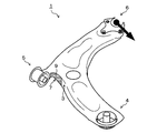
- FIG. 1 is a perspective view showing a front lower arm 50 of an automobile.
- a front lower arm 50 in FIG. 1 has a top plate portion 2 and side wall portions 3 formed by bending the top plate portion 2 around the top plate portion 2.
- the top plate 2 is formed so as to extend in three directions from the center in plan view.
- the ends on the front end side of the portions extending in three directions are respectively the first vehicle body attachment side end portion 4 which is an end portion attached to the vehicle body side and the second vehicle body attachment side end which is an end portion attached to the vehicle body side.
- Part 5 and a wheel attachment side end 6 which is an end attached to the wheel side.
- the portions that connect the end portions 4 to 6 include portions that are curved in plan view, and the side wall portion 3 is also formed in the curved portion.
- the side wall portion of the curved portion is formed by elongation deformation or contraction deformation during the blank press forming process. That is, a part having a side wall portion in the curved portion has at least one of a portion formed by expansion deformation and a portion formed by contraction deformation.
- a portion of the side wall portion formed by elongation deformation and having a curved shape that is convex toward the center of the member (front lower arm 50) is referred to as a “convex curved portion” and is recessed toward the center of the member.
- a portion having a curved shape which is a shape is referred to as a “concave curved portion”.
- stress since stress is generated at the base of the side wall 3, fatigue cracks may occur inside the base plate of the side wall 3 due to repeated stress acting on the base of the side wall 3 due to vibration. .
- a fatigue crack is more likely to occur at the base of the side wall portion 3 than other parts.
- the above-mentioned thinning performed from the viewpoint of weight reduction increases the stress generated by vibration, and fatigue cracks are likely to occur. Therefore, it is desired to suppress the occurrence of fatigue cracks while reducing the thickness for weight reduction.
- the present invention has been made in view of the above circumstances, and an object thereof is to suppress the occurrence of fatigue cracks in a component having a top plate portion and a side wall portion.
- a top plate portion and a side wall portion formed by bending the top plate portion around the top plate portion are provided, and are perpendicular to the top plate portion.
- a component is provided, wherein at least a part of the curved portion is provided with a reinforcing member joined to the side wall portion.
- the reinforcing member may be provided at least at the front end of the side wall in the extending direction.
- the reinforcing member may be provided in a curved portion that curves with a radius of curvature of 20 mm or more and 250 mm or less when viewed from a direction perpendicular to the top plate portion.
- the reinforcing member may be provided in a curved portion that is curved when a radius of curvature viewed from a direction perpendicular to the top plate portion is not less than 4 times and not more than 375 times the plate thickness of the side wall portion.
- the reinforcing member may be provided in the curved portion so as to include a portion having a minimum curvature radius when viewed from a direction perpendicular to the top plate portion.
- the length of the reinforcing member provided in the bending portion may be 80% or more of the length of the bending portion.
- the plate thickness of the side wall portion may be 5.0 mm or less.
- the reinforcing member may be a resin member made of resin.
- the resin may be FRP.
- the fiber orientation of the reinforcing fiber material included in the FRP may be within ⁇ 30 ° with respect to the circumferential direction of the curved portion.
- the FRP may be CFRP.
- the FRP may be GFRP.
- the reinforcing member may be a built-up part.
- the part may be an automobile part.
- the automobile part may be a suspension part.
- FIG. 1 It is a perspective view which shows the conventional front lower arm. It is a figure which shows the behavior of the side wall front-end
- CFRP carbon fiber reinforced resin
- a front lower arm of an automobile will be described as an example of a component having a side wall portion in a curved portion.
- elements having substantially the same functional configuration are denoted by the same reference numerals, and redundant description is omitted.
- the front lower arm 1 of the present embodiment has a top plate portion 2 and a side wall portion 3 formed by bending the top plate portion 2 around the top plate portion 2.
- the side wall portion 3 extends so that the side wall surface 3 a is perpendicular to the top surface of the top plate portion 2, and the longitudinal sectional shape of the front lower arm 1 is substantially U-shaped. That is, the front lower arm 1 has a side wall portion 3 formed by bending the top plate portion 2 around the top plate portion 2 and has an open cross section in a direction perpendicular to the top plate portion 2.
- the “side wall surface” in the present specification refers to a surface in the range from the tip position of the side wall part 3 to the bending start position of the connection part between the side wall part 3 and the top plate part 2 in a longitudinal sectional view.
- the direction in which the side wall 3 extends in the longitudinal sectional view of the component is referred to as “extending direction D of the side wall 3”.
- the angle formed between the top surface of the top plate portion 2 and the side wall surface 3a is 90 °, the view when the front lower arm 1 is viewed from the extending direction D of the side wall portion 3 is shown in FIG.
- the front lower arm 1 is viewed from directly below.
- the length direction of the arc of the side wall portion 3 viewed from the extending direction D of the side wall portion 3 is referred to as “circumferential direction C of the side wall portion 3”.
- the angle formed between the top surface of the top plate 2 and the side wall surface 3a is not limited to 90 °.
- the material of the front lower arm 1 is not particularly limited as long as the material is metal.
- the material of the front lower arm 1 may be an aluminum alloy or the like.
- the front lower arm 1 is mainly composed of a metal material, but other materials may be partially used.
- the front lower arm 1 is formed such that the top plate portion 2 extends from the center in three directions.
- the end portions on the front end side of the portions extending in three directions are respectively the first vehicle body attachment side end portion 4 which is an end portion attached to the vehicle body side, and the second vehicle body attachment which is an end portion similarly attached to the vehicle body side.
- a side end 5 and a wheel attachment side end 6 which is an end attached to the wheel side.
- the portion connecting the end portions 4 to 6 includes a curved portion, and the side wall portion 3 is also formed on the curved portion.
- the shape of the front lower arm 1 of this embodiment is an example, and the shape of the front lower arm 1 is suitably changed according to the suspension shape etc. of a motor vehicle.
- the plate thickness of the side wall portion 3 is designed to be, for example, 0.8 to 5.0 mm, more preferably 3.2 mm or less, further 2.9 mm or less, and 2.3 mm or less. If the thickness of the side wall 3 is less than 0.8 mm, the component strength is insufficient, and if it exceeds 5.0 mm, the weight of the component increases. Therefore, it is desirable to design the thickness of the side wall portion 3 as thin as possible within the above numerical range.
- the blank is deformed or contracted in the press molding process. Therefore, one or both of the convex curved portion and the concave curved portion are formed on the side wall portion of the curved portion. It is formed. Also in this embodiment, a convex curved portion 7 or a concave curved portion 8 is formed on the side wall portion 3 formed in the curved portion.
- the convex curved portion 7 is a convex portion in the component inner direction of the front lower arm 1 when viewed from the extending direction D of the side wall 3, and the concave curved portion 8 is the front viewed from the extending direction D of the side wall 3.
- the lower arm 1 is a concave portion in the component inner direction.
- the front lower arm 1 of the present embodiment there are a plurality of convex curved portions 7 and concave curved portions 8 respectively.
- the convex curved portions 7 and the concave curved portions 8 are shown for convenience of explanation. Each one is shown.
- the region in the circumferential direction C of the side wall portion 3 of the convex curved portion 7 and the concave curved portion 8 may be a portion that is curved in the circumferential direction C of the side wall portion 3.
- the region of the convex curved portion 7 and the concave curved portion 8 in the circumferential direction C of the side wall portion 3 may have a curvature radius of 20 mm or more and 250 mm or less.
- the thickness of the side wall portion 3 is, for example, 0.8 mm to 5.0 mm.
- the curvature radius is equal to the side wall portion.
- the radius of curvature is 250 mm or less, it can be said that the radius of curvature is preferably 300 times or less of the thickness of the side wall 3.
- the front lower arm 1 of the present embodiment has a CFRP member 9 made of CFRP (carbon fiber reinforced resin) as an example of a reinforcing member, in addition to a front lower arm main body having a top plate portion 2 and a side wall portion 3.
- CFRP member 9 is lightweight and excellent in strength and specific rigidity.
- the CFRP member 9 is joined to at least one outer surface of the side wall portion 3 (side wall surface 3 a) of the convex curved portion 7 and the side wall surface 3 a of the concave curved portion 8.
- the CFRP member 9 is joined to the side wall portion 3 to reinforce the thickness direction of the side wall portion 3.
- the method for joining the CFRP member 9 to the side wall 3 is not particularly limited, but is attached to the side wall 3 using, for example, an adhesive resin.
- an adhesive resin when the CFRP member 9 is affixed to the side wall part 3 with adhesive resin, if the cross section of the side wall part 3 of the said part is observed, an adhesive resin layer will exist between the side wall part 3 and the CFRP member 9. Can be confirmed.
- the bonding method of the FRP member including the CFRP member 9 and the resin used for bonding will be described later.
- the front lower arm 1 of the present embodiment is configured as described above.
- the side wall portion 3 opens outwardly due to vibration during vehicle travel, and the angle formed between the top surface of the top plate portion 2 and the side wall surface 3 a. 5 increases, a force in the contraction direction acts on the convex curved portion 7 as shown in FIG.
- the “shrink direction” refers to the convex curved portion 7 and the side wall portion 3 toward the middle point of the convex curved portion 7 in the cross-sectional view when the convex curved portion 7 is viewed in a cross section perpendicular to the side wall portion 3.
- FIG. 5 is an enlarged view of a portion where the CFRP member 9 of the convex curved portion 7 according to the present embodiment is joined as viewed from the extending direction D (downward direction in FIG. 3) of the side wall portion 3.
- the force which acts on the convex curve part 7 when the side wall part 3 opens outside is shown.
- the force is the convex curved portion. 7 as well as the CFRP member 9.
- the CFRP member 9 generates a reaction force that inhibits deformation of the convex curved portion 7 in the contraction direction. For this reason, the rigidity in the convex curve part 7 in which the CFRP member 9 is joined to the side wall surface 3a is increased, and deformation of the convex curve part 7 due to vibration is suppressed.
- the convex curved portion 7 is formed as shown in FIG.
- the force in the direction of elongation acts.
- the “extension direction” in the present embodiment refers to the convex curve portion 7 and the side wall portion 3 toward the middle point of the convex curve portion 7 in the cross-sectional view when the convex curve portion 7 is viewed in a cross section perpendicular to the side wall portion 3. The direction in which the boundary with the plane part of is separated.
- FIG. 6 is an enlarged view of a portion where the CFRP member 9 of the convex curved portion 7 according to the present embodiment is joined as viewed from the extending direction D (downward direction in FIG. 3) of the side wall portion 3.
- the force which acts on the convex curved part 7 when the side wall part 3 falls inward is shown.
- the CFRP member 9 is joined to the convex curved portion 7, even if a force in the extending direction acts on the convex curved portion 7, the force is the convex curved portion. 7 as well as the CFRP member 9.
- the CFRP member 9 generates a reaction force that inhibits deformation of the convex curved portion 7 in the extending direction. For this reason, the rigidity in the convex curve part 7 in which the CFRP member 9 is joined to the side wall surface 3a is increased, and deformation of the convex curve part 7 due to vibration is suppressed.
- the CFRP member 9 is joined to the convex curved portion 7 so that the convex curved portion is formed regardless of whether the side wall portion 3 opens outward or falls inward due to vibration.
- the deformation of the portion 7 can be suppressed.
- the outward opening of the side wall 3 in the convex curved portion 7 and the inner side collapse are accompanied by deformation of the convex curved portion 7, but in the front lower arm 1 of this embodiment, such convex curved portion 7 Since the deformation can be suppressed, as a result, the side wall 3 can be prevented from opening outward or falling inward.
- the stress which acts on the root of the side wall part 3 of the convex curved part 7 at the time of vibration generation becomes small, and it becomes possible to suppress the occurrence of fatigue cracks at the root of the side wall part 3.
- the joining position of the CFRP member 9 with respect to the side wall surface 3a of the convex curved portion 7 is not particularly limited. Regardless of the position of the CFRP member 9 joined to the side wall surface 3a, the portion where the CFRP member 9 is joined to the side wall surface 3a inhibits deformation of the convex curved portion 7 caused by vibration as shown in FIGS. Therefore, the deformation of the convex curved portion 7 can be suppressed as compared with the case where the CFRP member 9 is not provided. However, the deformation of the convex curved portion 7 is likely to occur at the distal end portion in the extending direction D of the side wall portion 3. Therefore, for example, as shown in FIG.
- the CFRP member 9 is joined to at least the tip 3 b of the convex curved portion 7. Thereby, since the deformation
- the CFRP member 9 is preferably joined so as to include the central portion 7 a in the circumferential direction C of the convex curved portion 7.
- the “center portion 7a” is a portion located at the center of the region in the circumferential direction C of the convex curved portion 7, and when the convex curved portion 7 is viewed from the extending direction D of the side wall portion 3 as shown in FIG.
- the distances from the portion 7a to both ends of the region in the circumferential direction C of the convex curved portion 7 are equal to each other.
- the deformation of the convex curved portion 7 at the time of vibration is likely to occur at the central portion 7a.
- the CFRP member 9 is joined to the central portion 7a in the circumferential direction C of the convex curved portion 7, so that the deformation of the convex curved portion 7 at the time of vibration is easily suppressed.
- the CFRP member 9 is joined so as to include the maximum curvature portion 7 b in the circumferential direction C of the convex curved portion 7.
- the “curvature maximum portion 7 b” is a portion where the radius of curvature R in the region of the convex curved portion 7 is minimized when the convex curved portion 7 is viewed from the extending direction D of the side wall portion 3.
- the central portion 7a is included in the maximum curvature portion 7b. The deformation of the convex curved portion 7 at the time of vibration is likely to occur at the maximum curvature portion 7b in the circumferential direction C where the curvature radius R is small.
- the CFRP member 9 is joined to the maximum curvature portion 7b in the circumferential direction C of the convex curved portion 7, so that deformation of the convex curved portion 7 when vibration is generated can be easily suppressed. This effect is further increased when the radius of curvature R of the convex curved portion 7 viewed from the extending direction D of the side wall portion 3 is 250 mm or less.
- the length L 1 in the circumferential direction C of the CFRP member 9 is preferably 80% or more with respect to the length L 2 in the circumferential direction C of the convex curved portion 7. Thereby, the effect which suppresses a deformation
- the thickness of the CFRP member 9 is not particularly limited. The thickness of the CFRP member 9 is appropriately changed according to the shape of the convex curved portion 7, the surrounding space, and the like, and is, for example, 1 to 5 mm.
- the fiber orientation of the CFRP member 9 is not particularly limited, it is preferably within ⁇ 30 ° with respect to the circumferential direction C viewed from the side wall surface 3 a of the convex curved portion 7. Thereby, the effect which suppresses a deformation
- a CFRP member 9 can be realized by using, for example, a UD (Unidirectional) material.
- the CFRP member 9 may be joined to a convex curved portion 7 different from the convex curved portion 7 described in the above embodiment as shown in FIG. Even in this case, deformation at the time of vibration is suppressed in the convex curved portion 7 to which the CFRP member 9 is joined.
- the CFRP member 9 is joined to the convex curved portion 7, but the CFRP member 9 may be joined to the concave curved portion 8 as shown in FIG. 9.
- the rigidity of the concave curved portion 8 can be increased, and the concave curved portion 8 can be deformed when vibration is generated. Can be suppressed.
- the CFRP member 9 may be joined to both the convex curved portion 7 and the concave curved portion 8. Further, when there are a plurality of convex curved portions 7 and concave curved portions 8, they may be joined to all the convex curved portions 7 and concave curved portions 8, but fatigue cracks occur from the viewpoint of weight reduction. It is preferable to be joined to the convex curved portion 7 or the concave curved portion 8 of the easy portion or both.
- CFRP The joining position of the member 9 may be determined.
- the CFRP member 9 is joined to at least the distal end portion 3 b of the concave curved portion 8 in the same manner as when the CFRP member 9 is joined to the convex curved portion 7. It is preferable. Similarly, the CFRP member 9 is preferably joined so as to include the central portion in the circumferential direction C of the concave curved portion 8. Similarly, the CFRP member 9 is preferably joined so as to include the maximum curvature portion in the circumferential direction C of the concave curved portion 8. Similarly, it is more preferable that the radius of curvature of the concave curved portion 8 when viewed from the extending direction D of the side wall portion 3 is 250 mm or less.
- the length of the CFRP member 9 in the circumferential direction C is preferably 80% or more with respect to the length of the concave curved portion 8 in the circumferential direction C.
- the fiber orientation of the CFRP member 9 is preferably within ⁇ 30 ° with respect to the circumferential direction C as viewed from the side wall surface 3 a of the concave curved portion 8.
- FIG. 10 is a schematic explanatory view showing a configuration of a CFRP member 9 according to another embodiment of the present invention, and shows an enlarged cross section in the circumferential direction C of the joint portion of the CFRP member 9.
- the CFRP member 9 may be joined to both the inside and the outside of the side wall portion 3, for example.
- the CFRP member 9 may be joined so as to cover the end surface portion 3 c of the side wall portion 3 in addition to both the inside and the outside of the side wall portion 3.
- the CFRP member 9 has been described as an example of the reinforcing member joined to at least one of the convex curved portion 7 and the concave curved portion 8, but the reinforcing member is, for example, GFRP (glass fiber reinforced resin).
- a GFRP member made of Further, the reinforcing member may be a resin member made of a resin other than the resin described above.
- the build-up part formed in the side wall surface 3a may be sufficient. That is, the material of the reinforcing member is not particularly limited as long as it is a member separate from the front lower arm 1 and can be joined to the side wall surface 3a.
- CFRP member As the reinforcing member.
- Specific examples of the type and joining method of the FRP member when the reinforcing member is an FRP member will be described later.
- the reinforcing member may be joined to the inside of the side wall surface 3a. Even in this case, it is possible to suppress the deformation of the convex curve portion or the concave curve portion at the time of vibration by the same mechanism as when the reinforcing member is joined to the outside of the side wall surface 3a.
- the part having the side wall portion 3 in the curved portion is not limited to the front lower arm 1 of the automobile described in the above embodiment, and for example, at least one of a rear lower arm, a trailing arm, an upper arm, a front subframe, and a rear subframe. Or a single component.
- the part having the side wall part 3 in the curved part may be another underbody part.
- the part which has the side wall part 3 in a curved part is not limited to the suspension part of a motor vehicle, The motor vehicle part attached to other parts other than a suspension part may be sufficient.
- the component which has the side wall part 3 in a curved part is not limited to a motor vehicle component, The component used for another field may be sufficient.
- the root of the side wall portion 3 is caused by the stress caused by the vibration. There is a risk of fatigue cracking.
- a reinforcing member is joined to at least one of the convex curved portion 7 and the concave curved portion 8, the occurrence of fatigue cracks in the portion is suppressed, and the reinforcing member is provided. Compared with parts that are not provided, the occurrence of fatigue cracks at the base of the side wall 3 can be suppressed.
- the FRP member that can be used as the reinforcing member means a fiber reinforced resin member that is composed of a matrix resin and a reinforced fiber material that is contained in the matrix resin and combined.
- the reinforcing fiber material for example, carbon fiber or glass fiber can be used.
- boron fiber, silicon carbide fiber, aramid fiber, or the like can be used as the reinforcing fiber material.
- examples of the reinforcing fiber base material used as the base material of the reinforcing fiber material include, for example, a nonwoven fabric base material using chopped fibers, a cloth material using continuous fibers, and a unidirectional reinforcing fiber base material (UD). Material) etc. can be used.
- UD unidirectional reinforcing fiber base material
- the CFRP member is an FRP member using carbon fiber as a reinforcing fiber material.
- the carbon fiber for example, a PAN-based or pitch-based one can be used. By using the carbon fiber, the strength with respect to weight can be improved efficiently.
- the GFRP member is an FRP member using glass fiber as a reinforcing fiber material. Although it is inferior to a carbon fiber in mechanical characteristics, it can suppress the electric corrosion of a metal member.
- thermosetting resin Both the thermosetting resin and the thermoplastic resin can be used as the matrix resin used for the FRP member.
- thermosetting resin include epoxy resins, unsaturated polyester resins, and vinyl ester resins.
- Thermoplastic resins include polyolefins (polyethylene, polypropylene, etc.) and acid-modified products thereof, polyamide resins such as nylon 6 and nylon 66, thermoplastic aromatic polyesters such as polyethylene terephthalate and polybutylene terephthalate, polycarbonate, polyethersulfone.
- polyphenylene ether and modified products thereof polyarylate, polyetherketone, polyetheretherketone, polyetherketoneketone, styrene resins such as vinyl chloride and polystyrene, and phenoxy resin.
- the matrix resin may be formed of a plurality of types of resin materials.
- thermoplastic resin As the matrix resin from the viewpoint of workability and productivity.
- the density of the reinforcing fiber material can be increased by using a phenoxy resin as the matrix resin.
- the phenoxy resin has a molecular structure very similar to that of an epoxy resin that is a thermosetting resin, the phenoxy resin has a heat resistance comparable to that of an epoxy resin.
- application to a high temperature environment is also possible by further adding a curing component.
- the addition amount may be appropriately determined in consideration of the impregnation property to the reinforcing fiber material, the brittleness of the FRP member, the tact time, the workability, and the like.
- the reinforcing member is formed of an FRP member or the like
- an adhesive resin layer is provided between the FRP member and the metal member (the front lower arm 1 in the above embodiment), and the FRP member and the metal member are joined by the adhesive resin layer. May be.
- the type of the adhesive resin composition that forms the adhesive resin layer is not particularly limited.
- the adhesive resin composition may be either a thermosetting resin or a thermoplastic resin.
- the kind of thermosetting resin and thermoplastic resin is not particularly limited.
- thermoplastic resins polyolefins and acid-modified products thereof, polystyrene, polymethyl methacrylate, AS resin, ABS resin, thermoplastic aromatic polyesters such as polyethylene terephthalate and polybutylene terephthalate, polycarbonate, polyimide, polyamide, polyamide
- a thermosetting resin 1 or more types chosen from an epoxy resin, a vinyl ester resin, a phenol resin, and a urethane resin can be used, for example
- the adhesive resin composition can be appropriately selected according to the characteristics of the matrix resin constituting the FRP member, the characteristics of the reinforcing member, or the characteristics of the metal member.
- the adhesiveness is improved by using a resin having a polar functional group or a resin subjected to acid modification as the adhesive resin layer.
- the adhesion between the FRP member and the metal member can be improved by adhering the FRP member to the metal member using the above-described adhesive resin layer. If it does so, the deformation
- the form of the adhesive resin composition used to form the adhesive resin layer can be, for example, a liquid such as powder or varnish, or a solid such as a film.
- a crosslinkable adhesive resin composition may be formed by blending a crosslinkable curable resin and a crosslinker into the adhesive resin composition.
- a crosslinkable curable resin for example, a bifunctional or higher functional epoxy resin or a crystalline epoxy resin can be used.
- an amine, an acid anhydride, etc. can be used as a crosslinking agent.
- various additives such as various rubber
- the compounding of the FRP member into the metal member can be realized by various methods. For example, it can be obtained by adhering an FRP forming prepreg which is an FRP member or an FRP molding prepreg thereof and a metal member with the above-described adhesive resin composition, and solidifying (or curing) the adhesive resin composition. .
- the FRP member and the metal member can be combined by performing thermocompression bonding.
- the above-mentioned adhesion of FRP or FRP molding prepreg to a metal member can be performed before molding, during molding, or after molding.
- FRP or FRP molding prepreg may be bonded to the metal member.
- the workpiece to which the FRP member is bonded may be molded to obtain a composite metal member.
- the matrix resin of the FRP member is a thermoplastic resin, it is possible to perform a bending process or the like on the portion to which the FRP member is bonded.
- composite batch molding in which the thermocompression bonding step and the molding step are integrated may be performed.
- the joining method of the FRP member and the metal member is not limited to the above-described adhesion by the adhesive resin layer.
- the FRP member and the metal member may be mechanically joined. More specifically, a fastening hole is formed at a position corresponding to each of the FRP member and the metal member, and these are fastened through the hole by a fastening means such as a bolt or a rivet.
- the member may be joined.
- the FRP member and the metal member may be joined by a known joining means.
- the FRP member and the metal member may be joined in a composite manner by a plurality of joining means.
- the adhesion by the adhesive resin layer and the fastening by the fastening means may be used in combination.
- the reinforcing member various materials can be used in addition to the FRP member.
- the reinforcing member may be formed of a resin composition other than the resin composition described above, such as a foamable resin formed of rigid polyurethane foam or the like.
- the reinforcing member may be formed by overlaying as the overlaying part.
- the type of metal used for overlaying is appropriately determined in view of the characteristics of the metal member with the base material.
- the joining method with a metal member is not restricted to welding, A various appropriate joining method can be used.
- the metal member according to the present invention may be plated. Thereby, corrosion resistance improves. In particular, it is more suitable when the metal member is a steel material.
- the type of plating is not particularly limited, and known plating can be used. For example, as galvanized steel sheets (steel materials), hot dip galvanized steel sheets, galvannealed steel sheets, Zn—Al—Mg alloy plated steel sheets, aluminum plated steel sheets, electrogalvanized steel sheets, electric Zn—Ni alloy plated steel sheets, etc. Can be used.
- the metal member may have a surface coated with a film called chemical conversion treatment.
- chemical conversion treatment a generally known chemical conversion treatment can be used.
- the chemical conversion treatment zinc phosphate treatment, chromate treatment, chromate-free treatment or the like can be used.
- the film may be a known resin film.
- the metal member may be one that is generally painted. Thereby, corrosion resistance improves more.
- a known resin can be used.
- an epoxy resin, a urethane resin, an acrylic resin, a polyester resin, or a fluorine resin can be used as a main resin.
- generally well-known pigment may be added to the coating as needed.
- the coating may be a clear coating to which no pigment is added. Such coating may be applied to the metal member in advance before the FRP member is combined, or may be applied to the metal member after the FRP member is combined. Alternatively, the FRP member may be combined after the metal member has been painted in advance, and then painted.
- the paint used for painting may be a solvent-based paint, a water-based paint, a powder paint, or the like.
- a known method can be applied as a method of painting.
- electrodeposition coating, spray coating, electrostatic coating, immersion coating, or the like can be used as a coating method. Since electrodeposition coating is suitable for coating the end face and gap portion of a metal member, it is excellent in corrosion resistance after coating. Moreover, coating film adhesion improves by performing generally well-known chemical conversion treatments, such as a zinc phosphate process and a zirconia process, on the surface of a metal member before coating.
- the analysis model is a front lower arm 1 shown in FIG. 11, and a CFRP member made of CFRP having a four-layer structure at a convex curved portion 7 between the first vehicle body mounting side end 4 and the second vehicle body mounting side end 5. 9 is affixed.
- the CFRP member 9 is pasted so as to cover the entire side wall surface of the convex curved portion 7, and the radius of curvature of the convex curved portion 7 to which the CFRP member 9 is pasted is about 50 mm.
- the thickness of the CFRP member 9 is 3 mm, and the plate thickness of the front lower arm main body (base material) is 2.3 mm.
- Three types of analysis models are prepared: a model in which the fiber direction of CFRP coincides with the circumferential direction C, a model in which the fiber direction is orthogonal to the circumferential direction C, and a model in which the CFRP member 9 is not attached.
- the steel type and shape of the front lower arm body (base material) in each analysis model are the same.
- Example 1 and Example 2 in which the CFRP member 9 is attached to the convex curved portion 7 the maximum principal stress is smaller than that in Comparative Example 1 in which the CFRP member 9 is not attached. ing. That is, even if a stress is repeatedly applied to the base of the side wall 3 of the convex curved portion 7 due to vibration, the stress is smaller than when the CFRP member 9 is not attached. Thus, the occurrence of fatigue cracks is suppressed.
- the CFRP member 9 is pasted so as to cover the entire side wall surface of the convex curved portion 7, and the radius of curvature of the convex curved portion 7 to which the CFRP member 9 is pasted is 250 mm.
- the thickness of the CFRP member 9 is 3 mm, and the plate thickness of the front lower arm main body (base material) is 2.3 mm.
- Three types of analysis models are prepared: a model in which the fiber direction of CFRP coincides with the circumferential direction C, a model in which the fiber direction is orthogonal to the circumferential direction C, and a model in which the CFRP member 9 is not attached.
- the steel type and shape of the front lower arm body (base material) in each analysis model are the same.
- Example 3 and Example 4 in which the CFRP member 9 is adhered to the convex curved portion 7 the maximum principal stress is smaller than that in Comparative Example 2 in which the CFRP member 9 is not adhered. ing. That is, even if a stress is repeatedly applied to the base of the side wall 3 of the convex curved portion 7 due to vibration, the stress is smaller than the stress when the CFRP member 9 is not attached, and therefore the CFRP member 9 is attached. The occurrence of fatigue cracks is suppressed as compared with the case where there is no.
- Example 3 and Example 4 are compared, the maximum principal stress is smaller in Example 4 in which the fiber direction of CFRP coincides with the circumferential direction C. According to the result of this simulation, it is possible to reduce the maximum principal stress by sticking the CFRP member 9 to the convex curved portion 7 regardless of the fiber direction of the CFRP. It is shown that the maximum principal stress can be further reduced by aligning in the circumferential direction C. According to the result of this simulation, it is presumed that the preferred fiber direction of CFRP is within ⁇ 30 ° with respect to the circumferential direction C. In this case, the effect of suppressing the occurrence of fatigue cracks at the base of the side wall 3 is enhanced. be able to.
- the present invention can be used as a front lower arm of an automobile.
Abstract
In a component having a side wall comprising a curved portion, vibration of the component causes elastic deformation of the side wall so as to open outwardly or incline inwardly. During such deformation, stress is generated in the base of the side wall, and repeated occurrence of stress causes fatigue cracks at the base. This component has a top plate and a side wall formed by bending the periphery of the top plate and has an open cross section in a direction perpendicular to the top plate. The side wall includes a curved portion that has a shape protruding or recessed toward the inner side of the component as viewed from a direction perpendicular to the top plate, and that is curved with a curvature radius of 300 mm or less. A reinforcing member which is joined to the side wall is provided at least on a portion of the curved portion.
Description
(関連出願の相互参照)
本願は、2018年4月9日に日本国に出願された特願2018-074634号に基づき、優先権を主張し、その内容をここに援用する。 (Cross-reference of related applications)
This application claims priority based on Japanese Patent Application No. 2018-074634 for which it applied to Japan on April 9, 2018, and uses the content here.
本願は、2018年4月9日に日本国に出願された特願2018-074634号に基づき、優先権を主張し、その内容をここに援用する。 (Cross-reference of related applications)
This application claims priority based on Japanese Patent Application No. 2018-074634 for which it applied to Japan on April 9, 2018, and uses the content here.
本発明は、天板部と側壁部を有する部品に関する。
The present invention relates to a component having a top plate portion and a side wall portion.
自動車の車体はCO2排出量の削減や燃費向上を目的として軽量化が求められる。これに伴い、車体を構成する各部品は薄肉化が図られており、例えばフロントロアアームやリアロアアームといった足回り部品についても薄肉化が進んでいる。特許文献1および特許文献2には足回り部品としてフロントロアアームが開示されている。
Auto bodies are required to be lighter for the purpose of reducing CO 2 emissions and improving fuel efficiency. In connection with this, each part which comprises a vehicle body is thinned, For example, thickness reduction is also progressing also about suspension parts, such as a front lower arm and a rear lower arm. Patent Document 1 and Patent Document 2 disclose a front lower arm as a suspension part.
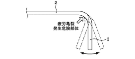
図1は自動車のフロントロアアーム50を示す斜視図である。図1のフロントロアアーム50は天板部2と、天板部2の周囲において当該天板部2を曲げて構成される側壁部3を有している。天板部2は、平面視において中央から三方に延びるように形成されている。三方に延びた部分の先端側の端部はそれぞれ、車体側に取り付けられる端部である第1の車体取付側端部4と、車体側に取り付けられる端部である第2の車体取付側端部5と、車輪側に取り付けられる端部である車輪取付側端部6である。各端部4~6を互いに繋ぐ部分にはそれぞれ平面視において湾曲した形状となる部分が含まれており、側壁部3はその湾曲部にも形成されている。
FIG. 1 is a perspective view showing a front lower arm 50 of an automobile. A front lower arm 50 in FIG. 1 has a top plate portion 2 and side wall portions 3 formed by bending the top plate portion 2 around the top plate portion 2. The top plate 2 is formed so as to extend in three directions from the center in plan view. The ends on the front end side of the portions extending in three directions are respectively the first vehicle body attachment side end portion 4 which is an end portion attached to the vehicle body side and the second vehicle body attachment side end which is an end portion attached to the vehicle body side. Part 5 and a wheel attachment side end 6 which is an end attached to the wheel side. The portions that connect the end portions 4 to 6 include portions that are curved in plan view, and the side wall portion 3 is also formed in the curved portion.
湾曲部の側壁部は、ブランクのプレス成形過程で伸び変形または縮み変形が生じることで形成される。すなわち、湾曲部に側壁部を有する部品には、伸び変形によって形成された部分と、縮み変形によって形成された部分の少なくともいずれか一方の部分が存在している。本明細書においては、側壁部の、伸び変形によって形成され、部材(フロントロアアーム50)中央に向かって凸形状である湾曲形状を有する部分を「凸湾曲部分」と称し、部材中央に向かって凹形状である湾曲形状を有する部分を「凹湾曲部分」と称する。
The side wall portion of the curved portion is formed by elongation deformation or contraction deformation during the blank press forming process. That is, a part having a side wall portion in the curved portion has at least one of a portion formed by expansion deformation and a portion formed by contraction deformation. In the present specification, a portion of the side wall portion formed by elongation deformation and having a curved shape that is convex toward the center of the member (front lower arm 50) is referred to as a “convex curved portion” and is recessed toward the center of the member. A portion having a curved shape which is a shape is referred to as a “concave curved portion”.
湾曲部に側壁部を有する部品の一例である図1のフロントロアアーム50は、自動車走行時の振動による側壁部3の伸び変形または縮み変形を伴いながら、側壁部3が図2のように外側に開いたり内側に倒れ込むように弾性変形する。このとき、側壁部3の根元に応力が発生することになるため、振動により側壁部3の根元に繰り返し応力が作用することで、側壁部3の根元の板内側に疲労亀裂が生じるおそれがある。特に、自動車の足回り部品は走行時の振動の影響を受けやすいため、他の部品よりも側壁部3の根元に疲労亀裂が生じやすい。さらに、軽量化の観点で行われる前述の薄肉化は振動による発生応力の増大を招き、疲労亀裂が発生しやすくなる。したがって、軽量化のための薄肉化を図りつつも、疲労亀裂の発生を抑えることが望まれる。
The front lower arm 50 shown in FIG. 1, which is an example of a part having a side wall portion in the curved portion, has the side wall portion 3 outward as shown in FIG. 2, while accompanying expansion or contraction deformation of the side wall portion 3 due to vibration during vehicle travel. Elastically deforms so that it opens or falls inward. At this time, since stress is generated at the base of the side wall 3, fatigue cracks may occur inside the base plate of the side wall 3 due to repeated stress acting on the base of the side wall 3 due to vibration. . In particular, since an underbody part of an automobile is easily affected by vibration during traveling, a fatigue crack is more likely to occur at the base of the side wall portion 3 than other parts. Furthermore, the above-mentioned thinning performed from the viewpoint of weight reduction increases the stress generated by vibration, and fatigue cracks are likely to occur. Therefore, it is desired to suppress the occurrence of fatigue cracks while reducing the thickness for weight reduction.
本発明は、上記事情に鑑みてなされたものであり、天板部と側壁部を有する部品において、疲労亀裂の発生を抑制することを目的とする。
The present invention has been made in view of the above circumstances, and an object thereof is to suppress the occurrence of fatigue cracks in a component having a top plate portion and a side wall portion.
上記課題を解決するため、本発明によれば、天板部と、前記天板部の周囲において当該天板部を曲げて構成される側壁部と、を有し、前記天板部に垂直な方向において開断面である部品であって、前記側壁部には、前記天板部に垂直な方向から見て部品内側方向に凹形状又は凸形状であり、曲率半径300mm以下で湾曲する湾曲部が含まれ、前記湾曲部の少なくとも一部には、前記側壁部に接合される補強部材が設けられることを特徴とする、部品が提供される。
In order to solve the above-described problem, according to the present invention, a top plate portion and a side wall portion formed by bending the top plate portion around the top plate portion are provided, and are perpendicular to the top plate portion. A part having an open cross section in a direction, wherein the side wall part has a concave part or a convex part in a part inner direction when viewed from a direction perpendicular to the top plate part, and a curved part curved with a curvature radius of 300 mm or less. A component is provided, wherein at least a part of the curved portion is provided with a reinforcing member joined to the side wall portion.
前記補強部材は、少なくとも前記側壁部の延伸方向先端部に設けられても良い。
The reinforcing member may be provided at least at the front end of the side wall in the extending direction.
前記補強部材は、前記天板部に垂直な方向から見て曲率半径20mm以上250mm以下で湾曲する湾曲部に設けられても良い。
The reinforcing member may be provided in a curved portion that curves with a radius of curvature of 20 mm or more and 250 mm or less when viewed from a direction perpendicular to the top plate portion.
前記補強部材は、前記天板部に垂直な方向から見た曲率半径が前記側壁部の板厚の4倍以上375倍以下で湾曲する湾曲部に設けられても良い。
The reinforcing member may be provided in a curved portion that is curved when a radius of curvature viewed from a direction perpendicular to the top plate portion is not less than 4 times and not more than 375 times the plate thickness of the side wall portion.
前記補強部材は、前記湾曲部において、前記天板部に垂直な方向から見て曲率半径が最小である部分を含むように設けられても良い。
The reinforcing member may be provided in the curved portion so as to include a portion having a minimum curvature radius when viewed from a direction perpendicular to the top plate portion.
前記湾曲部の周方向において、当該湾曲部に設けられる前記補強部材の長さは、当該湾曲部の長さの80%以上であっても良い。
In the circumferential direction of the bending portion, the length of the reinforcing member provided in the bending portion may be 80% or more of the length of the bending portion.
前記側壁部の板厚は5.0mm以下であっても良い。
The plate thickness of the side wall portion may be 5.0 mm or less.
前記補強部材は、樹脂からなる樹脂部材であっても良い。
The reinforcing member may be a resin member made of resin.
前記樹脂は、FRPであっても良い。
The resin may be FRP.
前記FRPに含まれる強化繊維材料の繊維配向が前記湾曲部の周方向に対して±30°以内であっても良い。
The fiber orientation of the reinforcing fiber material included in the FRP may be within ± 30 ° with respect to the circumferential direction of the curved portion.
前記FRPは、CFRPであっても良い。
The FRP may be CFRP.
前記FRPは、GFRPであっても良い。
The FRP may be GFRP.
前記補強部材は、肉盛部であっても良い。
The reinforcing member may be a built-up part.
前記部品は、自動車部品であっても良い。
The part may be an automobile part.
前記自動車部品は足回り部品であっても良い。
The automobile part may be a suspension part.
本発明によれば、天板部と側壁部を有する部品において、疲労亀裂の発生を抑制することができる。
According to the present invention, it is possible to suppress the occurrence of fatigue cracks in a component having a top plate portion and a side wall portion.
以下、本発明の実施形態について、図面を参照しながら説明する。本実施形態では湾曲部に側壁部を有する部品として自動車のフロントロアアームを例に挙げて説明を行う。なお、本明細書および図面において、実質的に同一の機能構成を有する要素においては、同一の符号を付することにより重複説明を省略する。
Hereinafter, embodiments of the present invention will be described with reference to the drawings. In the present embodiment, a front lower arm of an automobile will be described as an example of a component having a side wall portion in a curved portion. In the present specification and drawings, elements having substantially the same functional configuration are denoted by the same reference numerals, and redundant description is omitted.
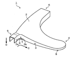
図3に示すように本実施形態のフロントロアアーム1は、天板部2と、天板部2の周囲において当該天板部2を曲げて構成される側壁部3を有している。側壁部3は、天板部2の頂面に対して側壁面3aが垂直となるように延びており、フロントロアアーム1の縦断面形状は略U字状となっている。即ち、フロントロアアーム1は天板部2の周囲において当該天板部2を曲げて構成される側壁部3を有し、天板部2に垂直な方向において開断面に構成されている。本明細書における“側壁面”とは、縦断面視における側壁部3の先端位置から側壁部3と天板部2との接続部の曲げ開始位置までの範囲にある面を指す。また、本明細書では、部品の縦断面視における側壁部3が延びる方向を“側壁部3の延伸方向D”と称す。本実施形態では天板部2の頂面と側壁面3aとのなす角が90°となっていることから、側壁部3の延伸方向Dからフロントロアアーム1を見た場合の図は、図4のようにフロントロアアーム1を真下から見上げた図となる。また、本明細書においては、側壁部3の延伸方向Dから見た当該側壁部3の弧の長さ方向を“側壁部3の周方向C”と称す。なお、天板部2の頂面と側壁面3aとのなす角は90°であることに限定されない。
As shown in FIG. 3, the front lower arm 1 of the present embodiment has a top plate portion 2 and a side wall portion 3 formed by bending the top plate portion 2 around the top plate portion 2. The side wall portion 3 extends so that the side wall surface 3 a is perpendicular to the top surface of the top plate portion 2, and the longitudinal sectional shape of the front lower arm 1 is substantially U-shaped. That is, the front lower arm 1 has a side wall portion 3 formed by bending the top plate portion 2 around the top plate portion 2 and has an open cross section in a direction perpendicular to the top plate portion 2. The “side wall surface” in the present specification refers to a surface in the range from the tip position of the side wall part 3 to the bending start position of the connection part between the side wall part 3 and the top plate part 2 in a longitudinal sectional view. In the present specification, the direction in which the side wall 3 extends in the longitudinal sectional view of the component is referred to as “extending direction D of the side wall 3”. In the present embodiment, since the angle formed between the top surface of the top plate portion 2 and the side wall surface 3a is 90 °, the view when the front lower arm 1 is viewed from the extending direction D of the side wall portion 3 is shown in FIG. Thus, the front lower arm 1 is viewed from directly below. Further, in the present specification, the length direction of the arc of the side wall portion 3 viewed from the extending direction D of the side wall portion 3 is referred to as “circumferential direction C of the side wall portion 3”. The angle formed between the top surface of the top plate 2 and the side wall surface 3a is not limited to 90 °.
なお、本実施形態に係るフロントロアアーム1は鋼製であることを想定しているが、フロントロアアーム1の材質は金属であれば特に限定されない。例えば、フロントロアアーム1の材質はアルミ合金等であってもよい。また、フロントロアアーム1は主として金属材料により構成されるが、部分的に他の材料が使用されるものであってもよい。
In addition, although it is assumed that the front lower arm 1 according to the present embodiment is made of steel, the material of the front lower arm 1 is not particularly limited as long as the material is metal. For example, the material of the front lower arm 1 may be an aluminum alloy or the like. The front lower arm 1 is mainly composed of a metal material, but other materials may be partially used.
図4に示すようにフロントロアアーム1は、天板部2が中央から三方に延びるように形成されている。三方に延びた部分の先端側の端部はそれぞれ、車体側に取り付けられる端部である第1の車体取付側端部4と、同様に車体側に取り付けられる端部である第2の車体取付側端部5と、車輪側に取り付けられる端部である車輪取付側端部6である。各端部4~6を互いに繋ぐ部分には湾曲した形状となる部分が含まれており、側壁部3はその湾曲部にも形成されている。なお、本実施形態のフロントロアアーム1の形状は一例であり、フロントロアアーム1の形状は自動車のサスペンション形状等に応じて適宜変更されるものである。側壁部3の板厚は例えば0.8~5.0mmに設計され、より好ましくは3.2mm以下、更には2.9mm以下、また、2.3mm以下に設計しても良い。側壁部3の板厚が0.8mm未満では部品強度が不十分となり、5.0mm超であると部品の重量が大きくなってしまう。そのため、側壁部3の板厚は上記数値範囲内においてなるべく薄く設計することが望ましい。
As shown in FIG. 4, the front lower arm 1 is formed such that the top plate portion 2 extends from the center in three directions. The end portions on the front end side of the portions extending in three directions are respectively the first vehicle body attachment side end portion 4 which is an end portion attached to the vehicle body side, and the second vehicle body attachment which is an end portion similarly attached to the vehicle body side. A side end 5 and a wheel attachment side end 6 which is an end attached to the wheel side. The portion connecting the end portions 4 to 6 includes a curved portion, and the side wall portion 3 is also formed on the curved portion. In addition, the shape of the front lower arm 1 of this embodiment is an example, and the shape of the front lower arm 1 is suitably changed according to the suspension shape etc. of a motor vehicle. The plate thickness of the side wall portion 3 is designed to be, for example, 0.8 to 5.0 mm, more preferably 3.2 mm or less, further 2.9 mm or less, and 2.3 mm or less. If the thickness of the side wall 3 is less than 0.8 mm, the component strength is insufficient, and if it exceeds 5.0 mm, the weight of the component increases. Therefore, it is desirable to design the thickness of the side wall portion 3 as thin as possible within the above numerical range.
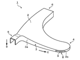
前述の通り、湾曲部に側壁部が形成される場合、プレス成形過程においてブランクの伸び変形または縮み変形が生じるため、湾曲部の側壁部には、凸湾曲部分および凹湾曲部分の一方または両方が形成される。本実施形態においても、湾曲部に形成されている側壁部3には、凸湾曲部分7または凹湾曲部分8が形成されている。凸湾曲部分7は、側壁部3の延伸方向Dから見て、フロントロアアーム1の部品内側方向に凸形状な部分であり、凹湾曲部分8は、側壁部3の延伸方向Dから見て、フロントロアアーム1の部品内側方向に凹形状な部分である。なお、本実施形態のフロントロアアーム1の場合、凸湾曲部分7と凹湾曲部分8はそれぞれ複数存在するが、図3および図4では説明の便宜のために凸湾曲部分7と凹湾曲部分8をそれぞれ1つずつ図示している。ここで、凸湾曲部分7および凹湾曲部分8の、側壁部3の周方向Cにおける領域は、側壁部3の周方向Cにおいて曲面になっている部分としても良い。すなわち、側壁部3の延伸方向Dから見て、例えば曲率半径が300mm以下となっている部分が、凸湾曲部分7および凹湾曲部分8の、側壁部3の周方向Cにおける領域であっても良い。また、より厳密には、凸湾曲部分7および凹湾曲部分8の、側壁部3の周方向Cにおける領域は、曲率半径が20mm以上250mm以下としても良い。上記の通り、側壁部3の板厚は例えば0.8mm~5.0mmであるので、側壁部3の延伸方向Dから見て、曲率半径が300mm以下の場合には、当該曲率半径は側壁部3の板厚の375倍以下が望ましく、曲率半径が250mm以下の場合には、当該曲率半径は側壁部3の板厚の300倍以下が望ましいと言える。
As described above, when the side wall portion is formed on the curved portion, the blank is deformed or contracted in the press molding process. Therefore, one or both of the convex curved portion and the concave curved portion are formed on the side wall portion of the curved portion. It is formed. Also in this embodiment, a convex curved portion 7 or a concave curved portion 8 is formed on the side wall portion 3 formed in the curved portion. The convex curved portion 7 is a convex portion in the component inner direction of the front lower arm 1 when viewed from the extending direction D of the side wall 3, and the concave curved portion 8 is the front viewed from the extending direction D of the side wall 3. The lower arm 1 is a concave portion in the component inner direction. In the case of the front lower arm 1 of the present embodiment, there are a plurality of convex curved portions 7 and concave curved portions 8 respectively. However, in FIG. 3 and FIG. 4, the convex curved portions 7 and the concave curved portions 8 are shown for convenience of explanation. Each one is shown. Here, the region in the circumferential direction C of the side wall portion 3 of the convex curved portion 7 and the concave curved portion 8 may be a portion that is curved in the circumferential direction C of the side wall portion 3. That is, even if the portion where the radius of curvature is 300 mm or less, for example, when viewed from the extending direction D of the side wall 3, is the region of the convex curved portion 7 and the concave curved portion 8 in the circumferential direction C of the side wall 3. good. Strictly speaking, the regions of the convex curved portion 7 and the concave curved portion 8 in the circumferential direction C of the side wall portion 3 may have a curvature radius of 20 mm or more and 250 mm or less. As described above, the thickness of the side wall portion 3 is, for example, 0.8 mm to 5.0 mm. Therefore, when the radius of curvature is 300 mm or less when viewed from the extending direction D of the side wall portion 3, the curvature radius is equal to the side wall portion. When the radius of curvature is 250 mm or less, it can be said that the radius of curvature is preferably 300 times or less of the thickness of the side wall 3.
本実施形態のフロントロアアーム1は、天板部2と側壁部3を有するフロントロアアーム本体に加え、補強部材の一例としてCFRP(炭素繊維強化樹脂)からなるCFRP部材9を有している。かかるCFRP部材9は、軽量でありながら強度および比剛性に優れる。CFRP部材9は、凸湾曲部分7の側壁部3(側壁面3a)及び凹湾曲部分8の側壁面3aのうち、少なくとも一方の外側の面に接合されている。CFRP部材9は側壁部3に接合されることにより、側壁部3の厚さ方向を補強する。側壁部3に対するCFRP部材9の接合方法は特に限定されないが、例えば接着樹脂を用いて側壁部3に貼付される。なお、CFRP部材9が接着樹脂で側壁部3に貼付されている場合、当該部分の側壁部3の断面を観察すれば、側壁部3とCFRP部材9との間に接着樹脂層が存在していることを確認することができる。かかるCFRP部材9を含むFRP部材の接着方法および接着に用いる樹脂等については後述する。
The front lower arm 1 of the present embodiment has a CFRP member 9 made of CFRP (carbon fiber reinforced resin) as an example of a reinforcing member, in addition to a front lower arm main body having a top plate portion 2 and a side wall portion 3. Such a CFRP member 9 is lightweight and excellent in strength and specific rigidity. The CFRP member 9 is joined to at least one outer surface of the side wall portion 3 (side wall surface 3 a) of the convex curved portion 7 and the side wall surface 3 a of the concave curved portion 8. The CFRP member 9 is joined to the side wall portion 3 to reinforce the thickness direction of the side wall portion 3. The method for joining the CFRP member 9 to the side wall 3 is not particularly limited, but is attached to the side wall 3 using, for example, an adhesive resin. In addition, when the CFRP member 9 is affixed to the side wall part 3 with adhesive resin, if the cross section of the side wall part 3 of the said part is observed, an adhesive resin layer will exist between the side wall part 3 and the CFRP member 9. Can be confirmed. The bonding method of the FRP member including the CFRP member 9 and the resin used for bonding will be described later.
本実施形態のフロントロアアーム1は以上のように構成されている。たとえば凸湾曲部分7にCFRP部材9が接合されているフロントロアアーム1においては、例えば自動車走行時の振動により側壁部3が外側に開き、天板部2の頂面と側壁面3aとのなす角が大きくなる場合、図5に示すように凸湾曲部分7には縮み方向の力が作用する。本実施形態における「縮み方向」とは、凸湾曲部分7を側壁部3に垂直な断面で見た場合の断面図における凸湾曲部分7の中点に向けて、凸湾曲部分7と側壁部3の平面部分との境界が近付く方向を示す。図5は、本実施形態に係る凸湾曲部分7のCFRP部材9が接合された部分を、側壁部3の延伸方向D(図3における下方向)から見た拡大図である。この図5では、側壁部3が外側に開く場合の凸湾曲部分7に作用する力を示している。このとき、本実施形態のフロントロアアーム1においては、凸湾曲部分7にCFRP部材9が接合されていることにより、凸湾曲部分7に縮み方向の力が作用しても、その力は凸湾曲部分7のみならずCFRP部材9にも付与される。このためCFRP部材9により、凸湾曲部分7の縮み方向への変形を阻害するような反力が生じる。このため、側壁面3aにCFRP部材9が接合された凸湾曲部分7における剛性が大きくなり、振動に起因する凸湾曲部分7の変形が抑制される。
The front lower arm 1 of the present embodiment is configured as described above. For example, in the front lower arm 1 in which the CFRP member 9 is joined to the convex curved portion 7, for example, the side wall portion 3 opens outwardly due to vibration during vehicle travel, and the angle formed between the top surface of the top plate portion 2 and the side wall surface 3 a. 5 increases, a force in the contraction direction acts on the convex curved portion 7 as shown in FIG. In the present embodiment, the “shrink direction” refers to the convex curved portion 7 and the side wall portion 3 toward the middle point of the convex curved portion 7 in the cross-sectional view when the convex curved portion 7 is viewed in a cross section perpendicular to the side wall portion 3. This indicates the direction in which the boundary with the plane portion approaches. FIG. 5 is an enlarged view of a portion where the CFRP member 9 of the convex curved portion 7 according to the present embodiment is joined as viewed from the extending direction D (downward direction in FIG. 3) of the side wall portion 3. In this FIG. 5, the force which acts on the convex curve part 7 when the side wall part 3 opens outside is shown. At this time, in the front lower arm 1 of the present embodiment, since the CFRP member 9 is joined to the convex curved portion 7, even if a force in the contracting direction acts on the convex curved portion 7, the force is the convex curved portion. 7 as well as the CFRP member 9. For this reason, the CFRP member 9 generates a reaction force that inhibits deformation of the convex curved portion 7 in the contraction direction. For this reason, the rigidity in the convex curve part 7 in which the CFRP member 9 is joined to the side wall surface 3a is increased, and deformation of the convex curve part 7 due to vibration is suppressed.
一方、例えば自動車走行時の振動により側壁部3が内側に倒れ込み、天板部2の頂面と側壁面3aとのなす角が小さくなる場合には、図6に示すように凸湾曲部分7には伸び方向の力が作用する。本実施形態における「伸び方向」とは、凸湾曲部分7を側壁部3に垂直な断面で見た場合の断面図における凸湾曲部分7の中点に向けて、凸湾曲部分7と側壁部3の平面部分との境界が離れる方向を示す。図6は、本実施形態に係る凸湾曲部分7のCFRP部材9が接合された部分を、側壁部3の延伸方向D(図3における下方向)から見た拡大図である。この図6では、側壁部3が内側に倒れる場合の凸湾曲部分7に作用する力を示している。このとき、本実施形態のフロントロアアーム1においては、凸湾曲部分7にCFRP部材9が接合されていることにより、凸湾曲部分7に伸び方向の力が作用しても、その力は凸湾曲部分7のみならずCFRP部材9にも付与される。このためCFRP部材9により、凸湾曲部分7の伸び方向への変形を阻害するような反力が生じる。このため、側壁面3aにCFRP部材9が接合された凸湾曲部分7における剛性が大きくなり、振動に起因する凸湾曲部分7の変形が抑制される。
On the other hand, for example, when the side wall portion 3 falls inward due to vibration during traveling of the automobile and the angle formed between the top surface of the top plate portion 2 and the side wall surface 3a becomes small, the convex curved portion 7 is formed as shown in FIG. The force in the direction of elongation acts. The “extension direction” in the present embodiment refers to the convex curve portion 7 and the side wall portion 3 toward the middle point of the convex curve portion 7 in the cross-sectional view when the convex curve portion 7 is viewed in a cross section perpendicular to the side wall portion 3. The direction in which the boundary with the plane part of is separated. FIG. 6 is an enlarged view of a portion where the CFRP member 9 of the convex curved portion 7 according to the present embodiment is joined as viewed from the extending direction D (downward direction in FIG. 3) of the side wall portion 3. In this FIG. 6, the force which acts on the convex curved part 7 when the side wall part 3 falls inward is shown. At this time, in the front lower arm 1 of the present embodiment, since the CFRP member 9 is joined to the convex curved portion 7, even if a force in the extending direction acts on the convex curved portion 7, the force is the convex curved portion. 7 as well as the CFRP member 9. For this reason, the CFRP member 9 generates a reaction force that inhibits deformation of the convex curved portion 7 in the extending direction. For this reason, the rigidity in the convex curve part 7 in which the CFRP member 9 is joined to the side wall surface 3a is increased, and deformation of the convex curve part 7 due to vibration is suppressed.
このように、本実施形態のフロントロアアーム1によれば、振動により側壁部3が外側に開く場合も内側に倒れ込む場合も、凸湾曲部分7にCFRP部材9が接合されていることで、凸湾曲部分7の変形を抑制することができる。凸湾曲部分7における側壁部3の外側への開きや内側の倒れ込みは、凸湾曲部分7の変形を伴うものであるが、本実施形態のフロントロアアーム1においては、そのような凸湾曲部分7の変形を抑制することができるため、結果として側壁部3の外側への開きや内側への倒れ込みを抑制することができる。これにより、振動発生時における凸湾曲部分7の側壁部3の根元に作用する応力が小さくなり、側壁部3の根元における疲労亀裂の発生を抑制することが可能となる。
As described above, according to the front lower arm 1 of the present embodiment, the CFRP member 9 is joined to the convex curved portion 7 so that the convex curved portion is formed regardless of whether the side wall portion 3 opens outward or falls inward due to vibration. The deformation of the portion 7 can be suppressed. The outward opening of the side wall 3 in the convex curved portion 7 and the inner side collapse are accompanied by deformation of the convex curved portion 7, but in the front lower arm 1 of this embodiment, such convex curved portion 7 Since the deformation can be suppressed, as a result, the side wall 3 can be prevented from opening outward or falling inward. Thereby, the stress which acts on the root of the side wall part 3 of the convex curved part 7 at the time of vibration generation becomes small, and it becomes possible to suppress the occurrence of fatigue cracks at the root of the side wall part 3.
なお、凸湾曲部分7の側壁面3aに対するCFRP部材9の接合位置は特に限定されない。側壁面3aに対するCFRP部材9の接合位置に関わらず、側壁面3aにCFRP部材9が接合されている部分においては、図5および図6のように振動に起因する凸湾曲部分7の変形を阻害する力が作用することになり、CFRP部材9が設けられない場合と比較して凸湾曲部分7の変形を抑制することができる。ただし、凸湾曲部分7の変形は側壁部3の延伸方向Dにおける先端部で起こりやすい。そのため、例えば、図7のようにCFRP部材9が少なくとも凸湾曲部分7の先端部3bに接合されていることがより好ましい。これにより、該先端部3bの変形が抑制されるので、凸湾曲部分7の変形をより効果的に抑制することができる。
In addition, the joining position of the CFRP member 9 with respect to the side wall surface 3a of the convex curved portion 7 is not particularly limited. Regardless of the position of the CFRP member 9 joined to the side wall surface 3a, the portion where the CFRP member 9 is joined to the side wall surface 3a inhibits deformation of the convex curved portion 7 caused by vibration as shown in FIGS. Therefore, the deformation of the convex curved portion 7 can be suppressed as compared with the case where the CFRP member 9 is not provided. However, the deformation of the convex curved portion 7 is likely to occur at the distal end portion in the extending direction D of the side wall portion 3. Therefore, for example, as shown in FIG. 7, it is more preferable that the CFRP member 9 is joined to at least the tip 3 b of the convex curved portion 7. Thereby, since the deformation | transformation of this front-end | tip part 3b is suppressed, the deformation | transformation of the convex curve part 7 can be suppressed more effectively.
また、CFRP部材9は図3および図4に示すように、凸湾曲部分7の周方向Cにおける中央部7aが含まれるように接合されていることが好ましい。“中央部7a”とは、凸湾曲部分7の周方向Cにおける領域の中央に位置する部分であり、図4のように凸湾曲部分7を側壁部3の延伸方向Dから見た場合、中央部7aから、凸湾曲部分7の周方向Cにおける領域の両端部までの距離は互いに等しくなる。振動発生時の凸湾曲部分7の変形は中央部7aで起こりやすい。このため、凸湾曲部分7の周方向Cにおける中央部7aにCFRP部材9が接合されていることで、振動発生時の凸湾曲部分7の変形を抑制しやすくなる。
Further, as shown in FIGS. 3 and 4, the CFRP member 9 is preferably joined so as to include the central portion 7 a in the circumferential direction C of the convex curved portion 7. The “center portion 7a” is a portion located at the center of the region in the circumferential direction C of the convex curved portion 7, and when the convex curved portion 7 is viewed from the extending direction D of the side wall portion 3 as shown in FIG. The distances from the portion 7a to both ends of the region in the circumferential direction C of the convex curved portion 7 are equal to each other. The deformation of the convex curved portion 7 at the time of vibration is likely to occur at the central portion 7a. For this reason, the CFRP member 9 is joined to the central portion 7a in the circumferential direction C of the convex curved portion 7, so that the deformation of the convex curved portion 7 at the time of vibration is easily suppressed.
また、CFRP部材9は、凸湾曲部分7の周方向Cにおける曲率最大部7bが含まれるように接合されていることが好ましい。“曲率最大部7b”とは、凸湾曲部分7を側壁部3の延伸方向Dから見た際の当該凸湾曲部分7の領域内における曲率半径Rが最小となる部分である。本実施形態においては、曲率最大部7bに上記の中央部7aが含まれている。振動発生時の凸湾曲部分7の変形は曲率半径Rが小さい周方向Cの曲率最大部7bで起こりやすい。このため、凸湾曲部分7の周方向Cにおける曲率最大部7bにCFRP部材9が接合されていることで、振動発生時の凸湾曲部分7の変形を抑制しやすくなる。この効果は、側壁部3の延伸方向Dから見た凸湾曲部分7の曲率半径Rが250mm以下である場合にさらに大きくなる。
Moreover, it is preferable that the CFRP member 9 is joined so as to include the maximum curvature portion 7 b in the circumferential direction C of the convex curved portion 7. The “curvature maximum portion 7 b” is a portion where the radius of curvature R in the region of the convex curved portion 7 is minimized when the convex curved portion 7 is viewed from the extending direction D of the side wall portion 3. In the present embodiment, the central portion 7a is included in the maximum curvature portion 7b. The deformation of the convex curved portion 7 at the time of vibration is likely to occur at the maximum curvature portion 7b in the circumferential direction C where the curvature radius R is small. For this reason, the CFRP member 9 is joined to the maximum curvature portion 7b in the circumferential direction C of the convex curved portion 7, so that deformation of the convex curved portion 7 when vibration is generated can be easily suppressed. This effect is further increased when the radius of curvature R of the convex curved portion 7 viewed from the extending direction D of the side wall portion 3 is 250 mm or less.
CFRP部材9の周方向Cの長さL1は、凸湾曲部分7の周方向Cの長さL2に対して80%以上の長さであることが好ましい。これにより振動発生時の凸湾曲部分7の変形を抑制する効果を高めることができる。また、凸湾曲部分7の周方向Cの長さL2に対して80%以上の長さL1を有し、かつ前述のような凸湾曲部分7の周方向Cにおける中央部7aが含まれるようにCFRP部材9が接合されることで、凸湾曲部分7の変形を抑制する効果をさらに高めることができる。なお、CFRP部材9の厚さは特に限定されない。CFRP部材9の厚さは、凸湾曲部分7の形状や周辺のスペース等に応じて適宜変更されるものであるが、例えば1~5mmである。
The length L 1 in the circumferential direction C of the CFRP member 9 is preferably 80% or more with respect to the length L 2 in the circumferential direction C of the convex curved portion 7. Thereby, the effect which suppresses a deformation | transformation of the convex curve part 7 at the time of a vibration generation can be heightened. Also has a circumferential direction C of the length L 2 with respect to the more than 80% of the length L 1 of the convex curved portion 7, and includes a central portion 7a in the circumferential direction C of the convex curved portion 7 as described above By joining the CFRP member 9 as described above, the effect of suppressing the deformation of the convex curved portion 7 can be further enhanced. The thickness of the CFRP member 9 is not particularly limited. The thickness of the CFRP member 9 is appropriately changed according to the shape of the convex curved portion 7, the surrounding space, and the like, and is, for example, 1 to 5 mm.
また、CFRP部材9の繊維配向は特に限定されないが、凸湾曲部分7の側壁面3aに正対して見た周方向Cに対して±30°以内であることが好ましい。これにより振動発生時の凸湾曲部分7の変形を抑制する効果を高めることができる。このようなCFRP部材9は、例えば、UD(Unidirectional)材を用いることで実現され得る。
Further, although the fiber orientation of the CFRP member 9 is not particularly limited, it is preferably within ± 30 ° with respect to the circumferential direction C viewed from the side wall surface 3 a of the convex curved portion 7. Thereby, the effect which suppresses a deformation | transformation of the convex curve part 7 at the time of a vibration generation can be heightened. Such a CFRP member 9 can be realized by using, for example, a UD (Unidirectional) material.
以上、本発明の実施形態について説明したが、本発明はかかる例に限定されない。当業者であれば、特許請求の範囲に記載された技術的思想の範疇内において、各種の変更例または修正例に想到しうることは明らかであり、それらについても当然に本発明の技術的範囲に属するものと了解される。
As mentioned above, although embodiment of this invention was described, this invention is not limited to this example. It is obvious for those skilled in the art that various changes or modifications can be conceived within the scope of the technical idea described in the claims. It is understood that it belongs to.
例えばCFRP部材9は、図8に示すように上記実施形態で説明した凸湾曲部分7とは異なる凸湾曲部分7に接合されていても良い。この場合であっても、CFRP部材9が接合された凸湾曲部分7においては振動発生時の変形が抑制される。
For example, the CFRP member 9 may be joined to a convex curved portion 7 different from the convex curved portion 7 described in the above embodiment as shown in FIG. Even in this case, deformation at the time of vibration is suppressed in the convex curved portion 7 to which the CFRP member 9 is joined.
また、以上の説明では、CFRP部材9が凸湾曲部分7に接合されていたが、CFRP部材9は図9に示すように凹湾曲部分8に接合されていても良い。この場合、上記実施形態のような凸湾曲部分7にCFRP部材9が接合された場合と同様に、凹湾曲部分8の剛性を大きくすることができ、振動発生時における凹湾曲部分8の変形を抑制することができる。
In the above description, the CFRP member 9 is joined to the convex curved portion 7, but the CFRP member 9 may be joined to the concave curved portion 8 as shown in FIG. 9. In this case, similarly to the case where the CFRP member 9 is joined to the convex curved portion 7 as in the above embodiment, the rigidity of the concave curved portion 8 can be increased, and the concave curved portion 8 can be deformed when vibration is generated. Can be suppressed.
例えば自動車走行時の振動により側壁部3が外側に開き、天板部2の頂面と側壁面3aとのなす角が大きくなる場合、凹湾曲部分8には伸び方向の力が作用する。このとき、凹湾曲部分8にCFRP部材9が接合されていれば、凹湾曲部分8の伸び方向への変形を阻害するような反力が生じる。このため、側壁面3aにCFRP部材9が接合された凹湾曲部分8における剛性が大きくなり、振動に起因する凹湾曲部分8の変形が抑制される。
For example, when the side wall 3 is opened to the outside due to vibration during traveling of the automobile and the angle formed between the top surface of the top plate 2 and the side wall 3a is increased, a force in the extending direction acts on the concave curved portion 8. At this time, if the CFRP member 9 is bonded to the concave curved portion 8, a reaction force that inhibits deformation of the concave curved portion 8 in the extending direction is generated. For this reason, the rigidity in the concave curved portion 8 in which the CFRP member 9 is joined to the side wall surface 3a is increased, and deformation of the concave curved portion 8 due to vibration is suppressed.
一方、例えば自動車走行時の振動により側壁部3が内側に倒れ込み、天板部2の頂面と側壁面3aとのなす角が小さくなる場合、凹湾曲部分8には縮み方向の力が作用する。このとき、凹湾曲部分8にCFRP部材9が接合されていれば、凹湾曲部分8の縮み方向への変形を阻害するような反力が生じる。このため、側壁面3aにCFRP部材9が接合された凹湾曲部分8における剛性が大きくなり、振動に起因する凹湾曲部分8の変形が抑制される。
On the other hand, for example, when the side wall portion 3 falls inward due to vibration during traveling of the automobile and the angle formed between the top surface of the top plate portion 2 and the side wall surface 3a becomes small, a force in the contraction direction acts on the concave curved portion 8. . At this time, if the CFRP member 9 is joined to the concave curved portion 8, a reaction force that inhibits deformation of the concave curved portion 8 in the contraction direction is generated. For this reason, the rigidity in the concave curved portion 8 in which the CFRP member 9 is joined to the side wall surface 3a is increased, and deformation of the concave curved portion 8 due to vibration is suppressed.
このように、凹湾曲部分8にCFRP部材9が接合されていた場合は、振動により側壁部3が外側に開く場合も内側に倒れ込む場合も、凹湾曲部分8の変形を抑制することができる。凹湾曲部分8における側壁部3の外側への開きや内側の倒れ込みは、凹湾曲部分8の変形を伴うものであるが、凹湾曲部分8にCFRP部材9が接合されることで、そのような凹湾曲部分8の変形を抑制することができるため、結果として側壁部3の外側への開きや内側への倒れ込みを抑制することができる。これにより、振動発生時における凹湾曲部分8の側壁部3の根元に作用する応力が小さくなり、側壁部3の根元における疲労亀裂の発生を抑制することが可能となる。
As described above, when the CFRP member 9 is joined to the concave curved portion 8, deformation of the concave curved portion 8 can be suppressed regardless of whether the side wall portion 3 opens outward or falls down due to vibration. The outward opening of the side wall portion 3 or the inner side collapse of the concave curved portion 8 is accompanied by deformation of the concave curved portion 8, but the CFRP member 9 is joined to the concave curved portion 8, so that Since the deformation of the concave curved portion 8 can be suppressed, as a result, the side wall portion 3 can be prevented from opening outward or falling inward. Thereby, the stress which acts on the root of the side wall part 3 of the concave curved part 8 at the time of vibration generation becomes small, and it becomes possible to suppress the occurrence of fatigue cracks at the base of the side wall part 3.
なお、CFRP部材9は、凸湾曲部分7と凹湾曲部分8の両方に接合されていても良い。また、凸湾曲部分7と凹湾曲部分8が複数存在する場合には、全ての凸湾曲部分7および凹湾曲部分8に接合されていても良いが、軽量化の観点においては疲労亀裂が発生しやすい部分の凸湾曲部分7もしくは凹湾曲部分8、またはその両方に接合されていることが好ましい。疲労亀裂が発生しやすい箇所はフロントロアアーム1の形状によって異なるが、例えばシミュレーションによって、複数存在する凸湾曲部分7または凹湾曲部分8の中から疲労亀裂が発生しやすい部分を推定することで、CFRP部材9の接合位置を決定しても良い。
The CFRP member 9 may be joined to both the convex curved portion 7 and the concave curved portion 8. Further, when there are a plurality of convex curved portions 7 and concave curved portions 8, they may be joined to all the convex curved portions 7 and concave curved portions 8, but fatigue cracks occur from the viewpoint of weight reduction. It is preferable to be joined to the convex curved portion 7 or the concave curved portion 8 of the easy portion or both. Although the location where fatigue cracks are likely to occur differs depending on the shape of the front lower arm 1, for example, by estimating a portion where fatigue cracks are likely to occur from a plurality of convex curved portions 7 or concave curved portions 8 by simulation, CFRP The joining position of the member 9 may be determined.
凹湾曲部分8にCFRP部材9が接合されている場合も、凸湾曲部分7にCFRP部材9が接合されている場合と同様に、CFRP部材9は少なくとも凹湾曲部分8の先端部3bに接合されていることが好ましい。同様に、CFRP部材9は、凹湾曲部分8の周方向Cにおける中央部が含まれるように接合されていることが好ましい。同様に、CFRP部材9は、凹湾曲部分8の周方向Cにおける曲率最大部が含まれるように接合されていることが好ましい。同様に、側壁部3の延伸方向Dから見た凹湾曲部分8の曲率半径は250mm以下であることがさらに好ましい。同様に、CFRP部材9の周方向Cの長さは、凹湾曲部分8の周方向Cの長さに対して80%以上の長さであることが好ましい。同様に、CFRP部材9の繊維の配向は、凹湾曲部分8の側壁面3aに正対して見た周方向Cに対して±30°以内であることが好ましい。
Even when the CFRP member 9 is joined to the concave curved portion 8, the CFRP member 9 is joined to at least the distal end portion 3 b of the concave curved portion 8 in the same manner as when the CFRP member 9 is joined to the convex curved portion 7. It is preferable. Similarly, the CFRP member 9 is preferably joined so as to include the central portion in the circumferential direction C of the concave curved portion 8. Similarly, the CFRP member 9 is preferably joined so as to include the maximum curvature portion in the circumferential direction C of the concave curved portion 8. Similarly, it is more preferable that the radius of curvature of the concave curved portion 8 when viewed from the extending direction D of the side wall portion 3 is 250 mm or less. Similarly, the length of the CFRP member 9 in the circumferential direction C is preferably 80% or more with respect to the length of the concave curved portion 8 in the circumferential direction C. Similarly, the fiber orientation of the CFRP member 9 is preferably within ± 30 ° with respect to the circumferential direction C as viewed from the side wall surface 3 a of the concave curved portion 8.
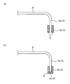
また、上記実施形態の説明では、凸湾曲部分7や凹湾曲部分8に対して接合された補強部材としてのCFRP部材9の構成について、側壁面3aや先端部3bの外側に接合されている場合について図示・説明したが、本発明におけるCFRP部材9の接合位置は任意であり、凸湾曲部分7や凹湾曲部分8のあらゆる箇所に対して接合可能である。図10は、本発明の別の実施形態に係るCFRP部材9の構成を示す概略説明図であり、CFRP部材9の接合部の周方向C断面を拡大して図示したものである。
Further, in the description of the above embodiment, the structure of the CFRP member 9 as the reinforcing member joined to the convex curved portion 7 or the concave curved portion 8 is joined to the outside of the side wall surface 3a or the tip portion 3b. However, the bonding position of the CFRP member 9 in the present invention is arbitrary, and can be bonded to any part of the convex curved part 7 and the concave curved part 8. FIG. 10 is a schematic explanatory view showing a configuration of a CFRP member 9 according to another embodiment of the present invention, and shows an enlarged cross section in the circumferential direction C of the joint portion of the CFRP member 9.
図10(a)に示すように、CFRP部材9は例えば側壁部3の内側と外側の両方に接合されても良い。また、図10(b)に示すように、CFRP部材9は側壁部3の内側と外側の両方に加え、側壁部3の端面部3cを覆うように接合されても良い。側壁部3の内側と外側の両方にCFRP部材9を接合することで、振動発生時の凸湾曲部分7や凹湾曲部分8の変形を抑制する効果をより高めることができる。また、端面部3cをCFRP部材9で覆うように接合することで、側壁部3の端面疲労や耐防食性を向上させることができる。
As shown in FIG. 10A, the CFRP member 9 may be joined to both the inside and the outside of the side wall portion 3, for example. As shown in FIG. 10B, the CFRP member 9 may be joined so as to cover the end surface portion 3 c of the side wall portion 3 in addition to both the inside and the outside of the side wall portion 3. By bonding the CFRP member 9 to both the inside and the outside of the side wall portion 3, it is possible to further enhance the effect of suppressing the deformation of the convex curved portion 7 and the concave curved portion 8 when vibration is generated. Further, by joining the end face portion 3c so as to be covered with the CFRP member 9, end face fatigue and corrosion resistance of the side wall portion 3 can be improved.
以上の説明では、凸湾曲部分7および凹湾曲部分8の少なくともいずれか一方の部分に接合される補強部材としてCFRP部材9を例に挙げて説明したが、補強部材は例えばGFRP(ガラス繊維強化樹脂)からなるGFRP部材であっても良い。また、補強部材は、上述した樹脂以外の樹脂からなる樹脂部材であっても良い。また、側壁面3aに形成された肉盛部であっても良い。すなわち、フロントロアアーム1と別体であり、側壁面3aへの接合が可能な部材であれば、補強部材の材質は特に限定されない。軽量化および比剛性向上の観点からは、補強部材としてCFRP部材を用いることが好ましい。補強部材がFRP部材である場合のFRP部材の種類、接合方法等の具体例については後述する。また、補強部材は側壁面3aの内側に接合されていても良い。この場合でも、補強部材が側壁面3aの外側に接合されている場合と同様のメカニズムで、振動発生時の凸湾曲部分または凹湾曲部分の変形を抑制することができる。
In the above description, the CFRP member 9 has been described as an example of the reinforcing member joined to at least one of the convex curved portion 7 and the concave curved portion 8, but the reinforcing member is, for example, GFRP (glass fiber reinforced resin). A GFRP member made of Further, the reinforcing member may be a resin member made of a resin other than the resin described above. Moreover, the build-up part formed in the side wall surface 3a may be sufficient. That is, the material of the reinforcing member is not particularly limited as long as it is a member separate from the front lower arm 1 and can be joined to the side wall surface 3a. From the viewpoint of weight reduction and specific rigidity improvement, it is preferable to use a CFRP member as the reinforcing member. Specific examples of the type and joining method of the FRP member when the reinforcing member is an FRP member will be described later. The reinforcing member may be joined to the inside of the side wall surface 3a. Even in this case, it is possible to suppress the deformation of the convex curve portion or the concave curve portion at the time of vibration by the same mechanism as when the reinforcing member is joined to the outside of the side wall surface 3a.
なお、湾曲部に側壁部3を有する部品は、上記実施形態で説明した自動車のフロントロアアーム1に限定されず、例えばリアロアアーム、トレーリングアーム、アッパーアーム、フロントサブフレームおよびリアサブフレームの少なくともいずれか1つの部品であっても良い。また、湾曲部に側壁部3を有する部品は、その他の足回り部品であっても良い。また、湾曲部に側壁部3を有する部品は自動車の足回り部品に限定されず、足回り以外の他の部位に取り付けられる自動車部品であっても良い。また、湾曲部に側壁部3を有する部品は自動車部品に限定されず、他の分野に用いられる部品であっても良い。
Note that the part having the side wall portion 3 in the curved portion is not limited to the front lower arm 1 of the automobile described in the above embodiment, and for example, at least one of a rear lower arm, a trailing arm, an upper arm, a front subframe, and a rear subframe. Or a single component. Further, the part having the side wall part 3 in the curved part may be another underbody part. Moreover, the part which has the side wall part 3 in a curved part is not limited to the suspension part of a motor vehicle, The motor vehicle part attached to other parts other than a suspension part may be sufficient. Moreover, the component which has the side wall part 3 in a curved part is not limited to a motor vehicle component, The component used for another field may be sufficient.
凸湾曲部分7および凹湾曲部分8の少なくともいずれか一方の部分を有する側壁部3が形成された部品は、用途に限らず何らかの振動に曝され得るため、振動により生じる応力で側壁部3の根元の疲労亀裂が発生するおそれはある。これに対して、凸湾曲部分7および凹湾曲部分8の少なくともいずれか一方の部分に補強部材が接合されていれば、当該部分における疲労亀裂の発生が抑制されることになり、補強部材が設けられていない部品と比較すれば、側壁部3の根元の疲労亀裂の発生を抑制することができる。
Since the part in which the side wall portion 3 having at least one of the convex curved portion 7 and the concave curved portion 8 is formed can be exposed to some vibrations without being limited to the use, the root of the side wall portion 3 is caused by the stress caused by the vibration. There is a risk of fatigue cracking. On the other hand, if a reinforcing member is joined to at least one of the convex curved portion 7 and the concave curved portion 8, the occurrence of fatigue cracks in the portion is suppressed, and the reinforcing member is provided. Compared with parts that are not provided, the occurrence of fatigue cracks at the base of the side wall 3 can be suppressed.
<FRP部材の種類>
補強部材として用いられ得るFRP部材は、マトリックス樹脂と、該マトリックス樹脂中に含有され、複合化された強化繊維材料からなる、繊維強化樹脂部材を意味する。 <Type of FRP member>
The FRP member that can be used as the reinforcing member means a fiber reinforced resin member that is composed of a matrix resin and a reinforced fiber material that is contained in the matrix resin and combined.
強化繊維材料としては、例えば、炭素繊維、ガラス繊維を用いることができる。他にも、強化繊維材料として、ボロン繊維、シリコンカーバイド繊維、アラミド繊維等を用いることができる。FRP部材に用いられるFRPにおいて、強化繊維材料の基材となる強化繊維基材としては、例えば、チョップドファイバーを使用した不織布基材や連続繊維を使用したクロス材、一方向強化繊維基材(UD材)等を使用することができる。これらの強化繊維基材は、強化繊維材料の配向性の必要に応じて、適宜選択され得る。
As the reinforcing fiber material, for example, carbon fiber or glass fiber can be used. In addition, boron fiber, silicon carbide fiber, aramid fiber, or the like can be used as the reinforcing fiber material. In the FRP used for the FRP member, examples of the reinforcing fiber base material used as the base material of the reinforcing fiber material include, for example, a nonwoven fabric base material using chopped fibers, a cloth material using continuous fibers, and a unidirectional reinforcing fiber base material (UD). Material) etc. can be used. These reinforcing fiber bases can be appropriately selected according to the orientation of the reinforcing fiber material.
CFRP部材は、強化繊維材料として炭素繊維を用いたFRP部材である。炭素繊維としては、例えば、PAN系またはピッチ系のものが使用できる。炭素繊維を用いることにより、重量に対する強度等を効率よく向上させることができる。
The CFRP member is an FRP member using carbon fiber as a reinforcing fiber material. As the carbon fiber, for example, a PAN-based or pitch-based one can be used. By using the carbon fiber, the strength with respect to weight can be improved efficiently.
GFRP部材は、強化繊維材料としてガラス繊維を用いたFRP部材である。炭素繊維よりも機械的特性に劣るが、金属部材の電蝕を抑制することができる。
The GFRP member is an FRP member using glass fiber as a reinforcing fiber material. Although it is inferior to a carbon fiber in mechanical characteristics, it can suppress the electric corrosion of a metal member.
FRP部材に用いられるマトリックス樹脂として、熱硬化性樹脂および熱可塑性樹脂のいずれも使用することができる。熱硬化性樹脂としては、エポキシ樹脂、不飽和ポリエステル樹脂、並びにビニルエステル樹脂等があげられる。熱可塑性樹脂としては、ポリオレフィン(ポリエチレン、ポリプロピレン等)およびその酸変性物、ナイロン6およびナイロン66等のポリアミド樹脂、ポリエチレンテレフタラートおよびポリブチレンテレフタラート等の熱可塑性芳香族ポリエステル、ポリカーボネート、ポリエーテルスルホン、ポリフェニレンエーテルおよびその変性物、ポリアリレート、ポリエーテルケトン、ポリエーテルエーテルケトン、ポリエーテルケトンケトン、塩化ビニル、ポリスチレン等のスチレン系樹脂、並びにフェノキシ樹脂等があげられる。なお、マトリックス樹脂は、複数種類の樹脂材料により形成されていてもよい。
Both the thermosetting resin and the thermoplastic resin can be used as the matrix resin used for the FRP member. Examples of the thermosetting resin include epoxy resins, unsaturated polyester resins, and vinyl ester resins. Thermoplastic resins include polyolefins (polyethylene, polypropylene, etc.) and acid-modified products thereof, polyamide resins such as nylon 6 and nylon 66, thermoplastic aromatic polyesters such as polyethylene terephthalate and polybutylene terephthalate, polycarbonate, polyethersulfone. And polyphenylene ether and modified products thereof, polyarylate, polyetherketone, polyetheretherketone, polyetherketoneketone, styrene resins such as vinyl chloride and polystyrene, and phenoxy resin. The matrix resin may be formed of a plurality of types of resin materials.
金属部材への適用を考慮すると、加工性、生産性の観点から、マトリックス樹脂として熱可塑性樹脂を用いることが好ましい。さらに、マトリックス樹脂としてフェノキシ樹脂を用いることで、強化繊維材料の密度を高くすることができる。また、フェノキシ樹脂は熱硬化性樹脂であるエポキシ樹脂と分子構造が酷似しているためエポキシ樹脂と同程度の耐熱性を有する。また、硬化成分をさらに添加することにより、高温環境への適用も可能となる。硬化成分を添加する場合、その添加量は、強化繊維材料への含浸性、FRP部材の脆性、タクトタイムおよび加工性等とを考慮し、適宜決めればよい。
In consideration of application to metal members, it is preferable to use a thermoplastic resin as the matrix resin from the viewpoint of workability and productivity. Furthermore, the density of the reinforcing fiber material can be increased by using a phenoxy resin as the matrix resin. Moreover, since the phenoxy resin has a molecular structure very similar to that of an epoxy resin that is a thermosetting resin, the phenoxy resin has a heat resistance comparable to that of an epoxy resin. Moreover, application to a high temperature environment is also possible by further adding a curing component. In the case of adding a curable component, the addition amount may be appropriately determined in consideration of the impregnation property to the reinforcing fiber material, the brittleness of the FRP member, the tact time, the workability, and the like.
<接着樹脂層>
補強部材がFRP部材等により形成される場合、FRP部材と金属部材(上記実施形態ではフロントロアアーム1)との間に接着樹脂層が設けられ、該接着樹脂層によりFRP部材と金属部材とが接合されてもよい。 <Adhesive resin layer>
When the reinforcing member is formed of an FRP member or the like, an adhesive resin layer is provided between the FRP member and the metal member (the frontlower arm 1 in the above embodiment), and the FRP member and the metal member are joined by the adhesive resin layer. May be.
補強部材がFRP部材等により形成される場合、FRP部材と金属部材(上記実施形態ではフロントロアアーム1)との間に接着樹脂層が設けられ、該接着樹脂層によりFRP部材と金属部材とが接合されてもよい。 <Adhesive resin layer>
When the reinforcing member is formed of an FRP member or the like, an adhesive resin layer is provided between the FRP member and the metal member (the front
接着樹脂層を形成する接着樹脂組成物の種類は特に限定されない。例えば、接着樹脂組成物は、熱硬化性樹脂、熱可塑性樹脂のいずれかであってもよい。熱硬化性樹脂および熱可塑性樹脂の種類は特に限定されない。例えば、熱可塑性樹脂としては、ポリオレフィンおよびその酸変性物、ポリスチレン、ポリメチルメタクリレート、AS樹脂、ABS樹脂、ポリエチレンテレフタラートやポリブチレンテレフタラート等の熱可塑性芳香族ポリエステル、ポリカーボネート、ポリイミド、ポリアミド、ポリアミドイミド、ポリエーテルイミド、ポリエーテルスルホン、ポリフェニレンエーテルおよびその変性物、ポリフェニレンスルフィド、ポリオキシメチレン、ポリアリレート、ポリエーテルケトン、ポリエーテルエーテルケトン、並びにポリエーテルケトンケトン等から選ばれる1種以上を使用することができる。また、熱硬化性樹脂としては、例えば、エポキシ樹脂、ビニルエステル樹脂、フェノール樹脂、およびウレタン樹脂から選ばれる1種以上を使用することができる。
The type of the adhesive resin composition that forms the adhesive resin layer is not particularly limited. For example, the adhesive resin composition may be either a thermosetting resin or a thermoplastic resin. The kind of thermosetting resin and thermoplastic resin is not particularly limited. For example, as thermoplastic resins, polyolefins and acid-modified products thereof, polystyrene, polymethyl methacrylate, AS resin, ABS resin, thermoplastic aromatic polyesters such as polyethylene terephthalate and polybutylene terephthalate, polycarbonate, polyimide, polyamide, polyamide Use one or more selected from imide, polyetherimide, polyethersulfone, polyphenylene ether and modified products thereof, polyphenylene sulfide, polyoxymethylene, polyarylate, polyetherketone, polyetheretherketone, and polyetherketoneketone can do. Moreover, as a thermosetting resin, 1 or more types chosen from an epoxy resin, a vinyl ester resin, a phenol resin, and a urethane resin can be used, for example.
接着樹脂組成物は、FRP部材を構成するマトリックス樹脂の特性、補強部材の特性または金属部材の特性に応じて適宜選択され得る。例えば、接着樹脂層として極性のある官能基を有する樹脂や酸変性などを施された樹脂を用いることで、接着性が向上する。
The adhesive resin composition can be appropriately selected according to the characteristics of the matrix resin constituting the FRP member, the characteristics of the reinforcing member, or the characteristics of the metal member. For example, the adhesiveness is improved by using a resin having a polar functional group or a resin subjected to acid modification as the adhesive resin layer.
このように、上述した接着樹脂層を用いてFRP部材を金属部材に接着させることにより、FRP部材と金属部材との密着性を向上させることができる。そうすると、金属部材に対し荷重が入力された際の、FRP部材の変形追従性を向上させることができる。この場合、金属部材の変形体に対するFRP部材の効果をより確実に発揮させることが可能となる。
Thus, the adhesion between the FRP member and the metal member can be improved by adhering the FRP member to the metal member using the above-described adhesive resin layer. If it does so, the deformation | transformation followable | trackability of an FRP member when a load is input with respect to a metal member can be improved. In this case, the effect of the FRP member on the deformed body of the metal member can be more reliably exhibited.
なお、接着樹脂層を形成するために用いられる接着樹脂組成物の形態は、例えば、粉体、ワニス等の液体、フィルム等の固体とすることができる。
The form of the adhesive resin composition used to form the adhesive resin layer can be, for example, a liquid such as powder or varnish, or a solid such as a film.
また、接着樹脂組成物に架橋硬化性樹脂および架橋剤を配合して、架橋性接着樹脂組成物を形成してもよい。これにより接着樹脂組成物の耐熱性が向上するため、高温環境下での適用が可能となる。架橋硬化性樹脂として、例えば2官能性以上のエポキシ樹脂や結晶性エポキシ樹脂を用いることができる。また、架橋剤として、アミンや酸無水物等を用いることができる。また、接着樹脂組成物には、その接着性や物性を損なわない範囲において、各種ゴム、無機フィラー、溶剤等その他添加物が配合されてもよい。
Also, a crosslinkable adhesive resin composition may be formed by blending a crosslinkable curable resin and a crosslinker into the adhesive resin composition. Thereby, since the heat resistance of the adhesive resin composition is improved, application under a high temperature environment becomes possible. As the cross-linking curable resin, for example, a bifunctional or higher functional epoxy resin or a crystalline epoxy resin can be used. Moreover, an amine, an acid anhydride, etc. can be used as a crosslinking agent. Moreover, various additives, such as various rubber | gum, an inorganic filler, a solvent, may be mix | blended with the adhesive resin composition in the range which does not impair the adhesiveness and physical property.
FRP部材の金属部材への複合化は、種々の方法により実現される。例えば、FRP部材となるFRPまたはその前駆体であるFRP成形用プリプレグと、金属部材とを、上述した接着樹脂組成物で接着し、該接着樹脂組成物を固化(または硬化)させることで得られる。この場合、例えば、加熱圧着を行うことにより、FRP部材と金属部材とを複合化させることができる。
The compounding of the FRP member into the metal member can be realized by various methods. For example, it can be obtained by adhering an FRP forming prepreg which is an FRP member or an FRP molding prepreg thereof and a metal member with the above-described adhesive resin composition, and solidifying (or curing) the adhesive resin composition. . In this case, for example, the FRP member and the metal member can be combined by performing thermocompression bonding.
上述したFRPまたはFRP成形用プリプレグの金属部材への接着は、部品の成形前、成形中または成形後に行われ得る。例えば、被加工材である金属材料を金属部材に成形した後に、FRPまたはFRP成形用プリプレグを該金属部材に接着しても良い。また、被加工材にFRPまたはFRP成形用プリプレグを加熱圧着により接着した後に、FRP部材が接着された該被加工材を成形して複合化された金属部材を得てもよい。FRP部材のマトリクス樹脂が熱可塑性樹脂であれば、FRP部材が接着された部分について曲げ加工等の成形を行うことも可能である。また、FRP部材のマトリクス樹脂が熱可塑樹脂である場合、加熱圧着工程と成形工程とが一体となった複合一括成形が行われてもよい。
The above-mentioned adhesion of FRP or FRP molding prepreg to a metal member can be performed before molding, during molding, or after molding. For example, after forming a metal material as a workpiece into a metal member, FRP or FRP molding prepreg may be bonded to the metal member. Alternatively, after FRP or FRP molding prepreg is bonded to the workpiece by thermocompression bonding, the workpiece to which the FRP member is bonded may be molded to obtain a composite metal member. If the matrix resin of the FRP member is a thermoplastic resin, it is possible to perform a bending process or the like on the portion to which the FRP member is bonded. In addition, when the matrix resin of the FRP member is a thermoplastic resin, composite batch molding in which the thermocompression bonding step and the molding step are integrated may be performed.
なお、FRP部材と金属部材との接合方法は、上述した接着樹脂層による接着に限られない。例えば、FRP部材と金属部材とは、機械的に接合されてもよい。より具体的には、FRP部材と金属部材のそれぞれ対応する位置に締結用の孔が形成され、これらがボルトやリベット等の締結手段により当該孔を介して締結されることにより、FRP部材と金属部材とが接合されていてもよい。他にも公知の接合手段によってFRP部材と金属部材とが接合されてもよい。また、複数の接合手段により複合的にFRP部材と金属部材とが接合されてもよい。例えば、接着樹脂層による接着と、締結手段による締結とが複合的に用いられてもよい。
In addition, the joining method of the FRP member and the metal member is not limited to the above-described adhesion by the adhesive resin layer. For example, the FRP member and the metal member may be mechanically joined. More specifically, a fastening hole is formed at a position corresponding to each of the FRP member and the metal member, and these are fastened through the hole by a fastening means such as a bolt or a rivet. The member may be joined. In addition, the FRP member and the metal member may be joined by a known joining means. Further, the FRP member and the metal member may be joined in a composite manner by a plurality of joining means. For example, the adhesion by the adhesive resin layer and the fastening by the fastening means may be used in combination.
補強部材としては、FRP部材のほかに、種々の材料が用いられ得る。例えば、補強部材は、硬質ポリウレタンフォーム等により形成される発泡性樹脂等、上述した樹脂組成物以外の樹脂組成物で形成されてもよい。また、補強部材は、肉盛部として肉盛により形成されていてもよい。この場合肉盛に用いられる金属の種類は、金属部材の母材との特性を鑑みて適宜決定される。また、金属部材との接合方法は溶接に限られず、種々の適切な接合方法を用いることができる。
As the reinforcing member, various materials can be used in addition to the FRP member. For example, the reinforcing member may be formed of a resin composition other than the resin composition described above, such as a foamable resin formed of rigid polyurethane foam or the like. Moreover, the reinforcing member may be formed by overlaying as the overlaying part. In this case, the type of metal used for overlaying is appropriately determined in view of the characteristics of the metal member with the base material. Moreover, the joining method with a metal member is not restricted to welding, A various appropriate joining method can be used.
<金属部材およびその表面処理>
本発明に係る金属部材は、めっきされていてもよい。これにより、耐食性が向上する。特に、金属部材が鋼材である場合は、より好適である。めっきの種類は特に限定されず、公知のめっきを用いることができる。例えば、めっき鋼板(鋼材)として、溶融亜鉛めっき鋼板、溶融合金化亜鉛めっき鋼板、Zn-Al-Mg系合金めっき鋼板、アルミニウムめっき鋼板、電気亜鉛めっき鋼板、電気Zn-Ni系合金めっき鋼板等が用いられ得る。 <Metal member and its surface treatment>
The metal member according to the present invention may be plated. Thereby, corrosion resistance improves. In particular, it is more suitable when the metal member is a steel material. The type of plating is not particularly limited, and known plating can be used. For example, as galvanized steel sheets (steel materials), hot dip galvanized steel sheets, galvannealed steel sheets, Zn—Al—Mg alloy plated steel sheets, aluminum plated steel sheets, electrogalvanized steel sheets, electric Zn—Ni alloy plated steel sheets, etc. Can be used.
また、金属部材は、表面に化成処理とよばれる皮膜が被覆されていてもよい。これにより、耐食性がより向上する。化成処理として、一般に公知の化成処理を用いることができる。例えば、化成処理として、りん酸亜鉛処理、クロメート処理、クロメートフリー処理等を用いることができる。また、上記皮膜は、公知の樹脂皮膜であってもよい。
Further, the metal member may have a surface coated with a film called chemical conversion treatment. Thereby, corrosion resistance improves more. As the chemical conversion treatment, a generally known chemical conversion treatment can be used. For example, as the chemical conversion treatment, zinc phosphate treatment, chromate treatment, chromate-free treatment or the like can be used. Further, the film may be a known resin film.
また、金属部材は、一般に公知の塗装が施されているものであってもよい。これにより、耐食性がより向上する。塗装として、公知の樹脂を用いることができる。例えば、塗装として、エポキシ樹脂、ウレタン樹脂、アクリル樹脂、ポリエステル樹脂またはふっ素系樹脂等を主樹脂としたものを用いることができる。また、塗装には、必要に応じて、一般に公知の顔料が添加されていてもよい。また、塗装は、顔料が添加されていないクリヤー塗装であってもよい。かかる塗装は、FRP部材を複合化する前に予め金属部材に施されていてもよいし、FRP部材を複合化した後に金属部材に施されてもよい。また、予め金属部材に塗装が施されたのちにFRP部材が複合化され、さらにその後塗装が施されてもよい。塗装に用いられる塗料は、溶剤系塗料、水系塗料または紛体塗料等であってもよい。塗装の施工方法として、一般に公知の方法が適用され得る。例えば、塗装の施工方法として、電着塗装、スプレー塗装、静電塗装または浸漬塗装等が用いられ得る。電着塗装は、金属部材の端面や隙間部を被覆するのに適しているため、塗装後の耐食性に優れる。また、塗装前に金属部材の表面にりん酸亜鉛処理やジルコニア処理等の一般に公知の化成処理を施すことにより、塗膜密着性が向上する。
In addition, the metal member may be one that is generally painted. Thereby, corrosion resistance improves more. As the coating, a known resin can be used. For example, as a coating, an epoxy resin, a urethane resin, an acrylic resin, a polyester resin, or a fluorine resin can be used as a main resin. Moreover, generally well-known pigment may be added to the coating as needed. The coating may be a clear coating to which no pigment is added. Such coating may be applied to the metal member in advance before the FRP member is combined, or may be applied to the metal member after the FRP member is combined. Alternatively, the FRP member may be combined after the metal member has been painted in advance, and then painted. The paint used for painting may be a solvent-based paint, a water-based paint, a powder paint, or the like. In general, a known method can be applied as a method of painting. For example, electrodeposition coating, spray coating, electrostatic coating, immersion coating, or the like can be used as a coating method. Since electrodeposition coating is suitable for coating the end face and gap portion of a metal member, it is excellent in corrosion resistance after coating. Moreover, coating film adhesion improves by performing generally well-known chemical conversion treatments, such as a zinc phosphate process and a zirconia process, on the surface of a metal member before coating.
<応力シミュレーション(A)>
本発明に係る湾曲部に側壁部を有する部品について応力シミュレーションを実施した。解析モデルは図11に示すフロントロアアーム1であり、第1の車体取付側端部4と第2の車体取付側端部5との間の凸湾曲部分7に4層構造のCFRPからなるCFRP部材9が貼付されている。 <Stress simulation (A)>
Stress simulation was performed on a part having a side wall portion in a curved portion according to the present invention. The analysis model is a frontlower arm 1 shown in FIG. 11, and a CFRP member made of CFRP having a four-layer structure at a convex curved portion 7 between the first vehicle body mounting side end 4 and the second vehicle body mounting side end 5. 9 is affixed.
本発明に係る湾曲部に側壁部を有する部品について応力シミュレーションを実施した。解析モデルは図11に示すフロントロアアーム1であり、第1の車体取付側端部4と第2の車体取付側端部5との間の凸湾曲部分7に4層構造のCFRPからなるCFRP部材9が貼付されている。 <Stress simulation (A)>
Stress simulation was performed on a part having a side wall portion in a curved portion according to the present invention. The analysis model is a front
CFRP部材9は凸湾曲部分7の側壁面全体を覆うように貼付され、CFRP部材9が貼付された凸湾曲部分7の曲率半径は50mm程度である。CFRP部材9の厚さは3mmであり、フロントロアアーム本体(母材)の板厚は2.3mmである。なお、解析モデルは、CFRPの繊維方向が周方向Cと一致したモデルと、繊維方向が周方向Cに直交したモデルと、CFRP部材9が貼付されていないモデルの3種類を準備している。各解析モデルにおけるフロントロアアーム本体(母材)の鋼種や形状は同一である。
The CFRP member 9 is pasted so as to cover the entire side wall surface of the convex curved portion 7, and the radius of curvature of the convex curved portion 7 to which the CFRP member 9 is pasted is about 50 mm. The thickness of the CFRP member 9 is 3 mm, and the plate thickness of the front lower arm main body (base material) is 2.3 mm. Three types of analysis models are prepared: a model in which the fiber direction of CFRP coincides with the circumferential direction C, a model in which the fiber direction is orthogonal to the circumferential direction C, and a model in which the CFRP member 9 is not attached. The steel type and shape of the front lower arm body (base material) in each analysis model are the same.
本シミュレーションでは、車両長さ方向の前方から後方への曲げ変形を想定し、図11に示す車輪取付側端部6の矢印方向に15kNの荷重を入力した。第1の車体取付側端部4と第2の車体取付側端部5は拘束されている。このような条件下で実施された応力シミュレーションの結果を下記表1に示す。なお、本シミュレーションでは、第1の車体取付側端部4と第2の車体取付側端部5との間にある凸湾曲部分7の側壁部3の根元における最大主応力に着目して評価を行う。
In this simulation, assuming a bending deformation from the front to the rear in the vehicle length direction, a load of 15 kN was input in the arrow direction of the wheel mounting side end portion 6 shown in FIG. The first vehicle body attachment side end 4 and the second vehicle body attachment side end 5 are restrained. The results of stress simulation performed under such conditions are shown in Table 1 below. In this simulation, the evaluation was performed by paying attention to the maximum principal stress at the base of the side wall portion 3 of the convex curved portion 7 between the first vehicle body attachment side end portion 4 and the second vehicle body attachment side end portion 5. Do.

表1に示されるように、凸湾曲部分7にCFRP部材9が貼付された実施例1および実施例2においては、CFRP部材9が貼付されていない比較例1に対して最大主応力が小さくなっている。すなわち、振動によって凸湾曲部分7の側壁部3の根元に繰り返し応力が作用したとしても、その応力はCFRP部材9が貼付されていない場合よりも小さいことから、CFRP部材9が貼付されていない場合よりも疲労亀裂の発生は抑制される。
As shown in Table 1, in Example 1 and Example 2 in which the CFRP member 9 is attached to the convex curved portion 7, the maximum principal stress is smaller than that in Comparative Example 1 in which the CFRP member 9 is not attached. ing. That is, even if a stress is repeatedly applied to the base of the side wall 3 of the convex curved portion 7 due to vibration, the stress is smaller than when the CFRP member 9 is not attached. Thus, the occurrence of fatigue cracks is suppressed.
<応力シミュレーション(B)>
次に、図12に示す解析モデルを作成して応力シミュレーションを実施した。本シミュレーションの解析モデルは、第1の車体取付側端部4と車輪取付側端部6との間の凸湾曲部分7に4層構造のCFRPからなるCFRP部材9が貼付されている。 <Stress simulation (B)>
Next, an analysis model shown in FIG. 12 was created and a stress simulation was performed. In the analysis model of this simulation, aCFRP member 9 made of CFRP having a four-layer structure is attached to a convex curved portion 7 between the first vehicle body attachment side end 4 and the wheel attachment side end 6.
次に、図12に示す解析モデルを作成して応力シミュレーションを実施した。本シミュレーションの解析モデルは、第1の車体取付側端部4と車輪取付側端部6との間の凸湾曲部分7に4層構造のCFRPからなるCFRP部材9が貼付されている。 <Stress simulation (B)>
Next, an analysis model shown in FIG. 12 was created and a stress simulation was performed. In the analysis model of this simulation, a
CFRP部材9は凸湾曲部分7の側壁面全体を覆うように貼付され、CFRP部材9が貼付された凸湾曲部分7の曲率半径は250mmである。CFRP部材9の厚さは3mmであり、フロントロアアーム本体(母材)の板厚は2.3mmである。なお、解析モデルは、CFRPの繊維方向が周方向Cと一致したモデルと、繊維方向が周方向Cに直交したモデルと、CFRP部材9が貼付されていないモデルの3種類を準備している。各解析モデルにおけるフロントロアアーム本体(母材)の鋼種や形状は同一である。
The CFRP member 9 is pasted so as to cover the entire side wall surface of the convex curved portion 7, and the radius of curvature of the convex curved portion 7 to which the CFRP member 9 is pasted is 250 mm. The thickness of the CFRP member 9 is 3 mm, and the plate thickness of the front lower arm main body (base material) is 2.3 mm. Three types of analysis models are prepared: a model in which the fiber direction of CFRP coincides with the circumferential direction C, a model in which the fiber direction is orthogonal to the circumferential direction C, and a model in which the CFRP member 9 is not attached. The steel type and shape of the front lower arm body (base material) in each analysis model are the same.
本シミュレーションでは、車両長さ方向の後方から前方への曲げ変形を想定し、図12に示す車輪取付側端部6の矢印方向に15kNの荷重を入力した。第1の車体取付側端部4と第2の車体取付側端部5は拘束されている。このような条件下で実施された応力シミュレーションの結果を下記表2に示す。なお、本シミュレーションでは、第1の車体取付側端部4と車輪取付側端部6との間にある凸湾曲部分7の側壁部3の根元における最大主応力に着目して評価を行う。
In this simulation, assuming a bending deformation from the rear to the front in the vehicle length direction, a load of 15 kN was input in the arrow direction of the wheel mounting side end 6 shown in FIG. The first vehicle body attachment side end 4 and the second vehicle body attachment side end 5 are restrained. The results of the stress simulation performed under such conditions are shown in Table 2 below. In this simulation, the evaluation is performed by paying attention to the maximum principal stress at the base of the side wall portion 3 of the convex curved portion 7 between the first vehicle body attachment side end 4 and the wheel attachment side end 6.

表2に示されるように、凸湾曲部分7にCFRP部材9が貼付された実施例3および実施例4においては、CFRP部材9が貼付されていない比較例2に対して最大主応力が小さくなっている。すなわち、振動によって凸湾曲部分7の側壁部3の根元に繰り返し応力が作用したとしても、その応力はCFRP部材9が貼付されていない場合の応力よりも小さいことから、CFRP部材9が貼付されていない場合よりも疲労亀裂の発生は抑制される。
As shown in Table 2, in Example 3 and Example 4 in which the CFRP member 9 is adhered to the convex curved portion 7, the maximum principal stress is smaller than that in Comparative Example 2 in which the CFRP member 9 is not adhered. ing. That is, even if a stress is repeatedly applied to the base of the side wall 3 of the convex curved portion 7 due to vibration, the stress is smaller than the stress when the CFRP member 9 is not attached, and therefore the CFRP member 9 is attached. The occurrence of fatigue cracks is suppressed as compared with the case where there is no.
また、実施例3と実施例4を比較すると、CFRPの繊維方向が周方向Cに一致した実施例4の方が最大主応力は小さくなっている。本シミュレーションの結果によれば、CFRPの繊維方向に関わらず、凸湾曲部分7にCFRP部材9を貼付することで最大主応力を小さくすることが可能であるが、CFRPの繊維方向が側壁部の周方向Cとなるように配向することで、さらに最大主応力を小さくできることが示される。本シミュレーションの結果によれば、CFRPの好ましい繊維方向は周方向Cに対して±30°以内であると推察され、この場合には側壁部3の根元における疲労亀裂の発生を抑制する効果を高めることができる。また、CFRPに代えてGFRPを用いる場合も繊維方向が与える影響はCFRPと同様であることから、GFRPの繊維方向が周方向Cに対して±30°以内であれば、側壁部3の根元における疲労亀裂の発生を抑制する効果を高めることができる。
Further, when Example 3 and Example 4 are compared, the maximum principal stress is smaller in Example 4 in which the fiber direction of CFRP coincides with the circumferential direction C. According to the result of this simulation, it is possible to reduce the maximum principal stress by sticking the CFRP member 9 to the convex curved portion 7 regardless of the fiber direction of the CFRP. It is shown that the maximum principal stress can be further reduced by aligning in the circumferential direction C. According to the result of this simulation, it is presumed that the preferred fiber direction of CFRP is within ± 30 ° with respect to the circumferential direction C. In this case, the effect of suppressing the occurrence of fatigue cracks at the base of the side wall 3 is enhanced. be able to. Further, when GFRP is used instead of CFRP, the influence of the fiber direction is the same as that of CFRP. Therefore, if the fiber direction of GFRP is within ± 30 ° with respect to the circumferential direction C, the root of the side wall 3 is The effect of suppressing the occurrence of fatigue cracks can be enhanced.
本発明は、自動車のフロントロアアームとして利用することができる。
The present invention can be used as a front lower arm of an automobile.
1 フロントロアアーム
2 天板部
3 側壁部
3a 側壁面
3b 先端部
4 第1の車体取付側端部
5 第2の車体取付側端部
6 車輪取付側端部
7 凸湾曲部分
7a 凸湾曲部分の中央部
7b 凸湾曲部分の曲率最大部
8 凹湾曲部分
9 CFRP部材
50 フロントロアアーム
C 側壁部の周方向
D 側壁部の延伸方向
R 曲率半径
L1 CFRP部材の周方向の長さ
L2 凸湾曲部分の周方向の長さ DESCRIPTION OFSYMBOLS 1 Front lower arm 2 Top plate part 3 Side wall part 3a Side wall surface 3b Tip part 4 1st vehicle body attachment side edge part 5 Car body attachment side edge part 6 Wheel attachment side edge part 7 Convex curve part 7a Center of convex curve part Part 7b Maximum curvature of convex curved portion 8 Concave curved portion 9 CFRP member 50 Front lower arm C Side wall circumferential direction D Side wall extending direction R Curvature radius L 1 CFRP member circumferential length L 2 Convex curved portion Circumferential length
2 天板部
3 側壁部
3a 側壁面
3b 先端部
4 第1の車体取付側端部
5 第2の車体取付側端部
6 車輪取付側端部
7 凸湾曲部分
7a 凸湾曲部分の中央部
7b 凸湾曲部分の曲率最大部
8 凹湾曲部分
9 CFRP部材
50 フロントロアアーム
C 側壁部の周方向
D 側壁部の延伸方向
R 曲率半径
L1 CFRP部材の周方向の長さ
L2 凸湾曲部分の周方向の長さ DESCRIPTION OF
Claims (15)
- 天板部と、前記天板部の周囲において当該天板部を曲げて構成される側壁部と、を有し、前記天板部に垂直な方向において開断面である部品であって、
前記側壁部には、前記天板部に垂直な方向から見て部品内側方向に凹形状又は凸形状であり、曲率半径300mm以下で湾曲する湾曲部が含まれ、
前記湾曲部の少なくとも一部には、前記側壁部に接合される補強部材が設けられることを特徴とする、部品。 A top plate part and a side wall part formed by bending the top plate part around the top plate part, and a component having an open cross section in a direction perpendicular to the top plate part,
The side wall portion includes a curved portion that is concave or convex in the component inner direction when viewed from a direction perpendicular to the top plate portion, and is curved with a curvature radius of 300 mm or less.
A component, wherein a reinforcing member joined to the side wall portion is provided on at least a part of the curved portion. - 前記補強部材は、少なくとも前記側壁部の延伸方向先端部に設けられることを特徴とする、請求項1に記載の部品。 The component according to claim 1, wherein the reinforcing member is provided at least at a front end portion in the extending direction of the side wall portion.
- 前記補強部材は、前記天板部に垂直な方向から見て曲率半径20mm以上250mm以下で湾曲する湾曲部に設けられることを特徴とする、請求項1又は2に記載の部品。 The component according to claim 1, wherein the reinforcing member is provided in a curved portion that is curved with a curvature radius of 20 mm or more and 250 mm or less when viewed from a direction perpendicular to the top plate portion.
- 前記補強部材は、前記天板部に垂直な方向から見た曲率半径が前記側壁部の板厚の4倍以上375倍以下で湾曲する湾曲部に設けられることを特徴とする、請求項1又は2に記載の部品。 The said reinforcing member is provided in the curved part which curves when the curvature radius seen from the direction perpendicular | vertical to the said top plate part is 4 times or more and 375 times or less of the plate | board thickness of the said side wall part, It is characterized by the above-mentioned. 2. The component according to 2.
- 前記補強部材は、前記湾曲部において、前記天板部に垂直な方向から見て曲率半径が最小である部分を含むように設けられることを特徴とする、請求項1~4のいずれか一項に記載の部品。 5. The reinforcing member according to claim 1, wherein the reinforcing member is provided so as to include a portion having a minimum curvature radius when viewed from a direction perpendicular to the top plate portion in the curved portion. The parts described in.
- 前記湾曲部の周方向において、当該湾曲部に設けられる前記補強部材の長さは、当該湾曲部の長さの80%以上であることを特徴とする、請求項1~5のいずれか一項に記載の部品。 The length of the reinforcing member provided in the bending portion in the circumferential direction of the bending portion is 80% or more of the length of the bending portion. The parts described in.
- 前記側壁部の板厚は5.0mm以下であることを特徴とする、請求項1~5のいずれか一項に記載の部品。 The component according to any one of claims 1 to 5, wherein a thickness of the side wall portion is 5.0 mm or less.
- 前記補強部材は、樹脂からなる樹脂部材であることを特徴とする、請求項1~7のいずれか一項に記載の部品。 The part according to any one of claims 1 to 7, wherein the reinforcing member is a resin member made of resin.
- 前記樹脂は、FRPであることを特徴とする、請求項8に記載の部品。 The component according to claim 8, wherein the resin is FRP.
- 前記FRPに含まれる強化繊維材料の繊維配向が前記湾曲部の周方向に対して±30°以内であることを特徴とする、請求項9に記載の部品。 The component according to claim 9, wherein a fiber orientation of a reinforcing fiber material included in the FRP is within ± 30 ° with respect to a circumferential direction of the curved portion.
- 前記FRPは、CFRPであることを特徴とする、請求項9又は10に記載の部品。 The component according to claim 9 or 10, wherein the FRP is CFRP.
- 前記FRPは、GFRPであることを特徴とする、請求項9又は10に記載の部品。 The component according to claim 9 or 10, wherein the FRP is GFRP.
- 前記補強部材は、肉盛部であることを特徴とする、請求項1~7のいずれか一項に記載の部品。 The component according to any one of claims 1 to 7, wherein the reinforcing member is a built-up portion.
- 自動車部品であることを特徴とする、請求項1~13のいずれか一項に記載の部品。 The part according to any one of claims 1 to 13, wherein the part is an automobile part.
- 前記自動車部品は足回り部品であることを特徴とする、請求項14に記載の部品。 The part according to claim 14, wherein the automobile part is an undercarriage part.
Priority Applications (2)
| Application Number | Priority Date | Filing Date | Title |
|---|---|---|---|
| CN201980022955.8A CN111918781B (en) | 2018-04-09 | 2019-04-09 | Component having top plate portion and side wall portion |
| JP2020513414A JP6822607B2 (en) | 2018-04-09 | 2019-04-09 | Parts with top plate and side walls |
Applications Claiming Priority (2)
| Application Number | Priority Date | Filing Date | Title |
|---|---|---|---|
| JP2018-074634 | 2018-04-09 | ||
| JP2018074634 | 2018-04-09 |
Publications (1)
| Publication Number | Publication Date |
|---|---|
| WO2019198727A1 true WO2019198727A1 (en) | 2019-10-17 |
Family
ID=68164162
Family Applications (1)
| Application Number | Title | Priority Date | Filing Date |
|---|---|---|---|
| PCT/JP2019/015515 WO2019198727A1 (en) | 2018-04-09 | 2019-04-09 | Component having top plate and side wall |
Country Status (3)
| Country | Link |
|---|---|
| JP (1) | JP6822607B2 (en) |
| CN (1) | CN111918781B (en) |
| WO (1) | WO2019198727A1 (en) |
Families Citing this family (1)
| Publication number | Priority date | Publication date | Assignee | Title |
|---|---|---|---|---|
| CN117141173B (en) * | 2023-10-31 | 2024-01-16 | 万向智造有限公司 | Control arm structure for improving suspension strength |
Citations (3)
| Publication number | Priority date | Publication date | Assignee | Title |
|---|---|---|---|---|
| JP2011116340A (en) * | 2009-12-04 | 2011-06-16 | Hyundai Motor Co Ltd | Suspension arm and method of manufacturing suspension arm |
| JP2015231780A (en) * | 2014-06-10 | 2015-12-24 | 株式会社ワイテック | Vehicle suspension arm |
| JP2017128244A (en) * | 2016-01-21 | 2017-07-27 | トヨタ自動車株式会社 | Suspension member of vehicle |
Family Cites Families (7)
| Publication number | Priority date | Publication date | Assignee | Title |
|---|---|---|---|---|
| JP3127764B2 (en) * | 1995-01-22 | 2001-01-29 | 三菱自動車工業株式会社 | Car rear wheel suspension arm |
| JP2010260513A (en) * | 2009-05-11 | 2010-11-18 | Toyota Motor Corp | Suspension arm |
| DE102010001100A1 (en) * | 2010-01-21 | 2011-07-28 | ZF Friedrichshafen AG, 88046 | Motor vehicle e.g. commercial vehicle, has wheel with planar structure formed from metal sheets with edge area provided with body in region of high force load of wheel, where body is designed as hollow section |
| US9266162B2 (en) * | 2010-05-19 | 2016-02-23 | Nippon Steel & Sumitomo Metal Corporation | Press-forming method of component with L shape |
| JP6784493B2 (en) * | 2016-01-25 | 2020-11-11 | 株式会社Subaru | Lower arm |
| KR101794067B1 (en) * | 2016-05-23 | 2017-11-06 | (주)넥스컴스 | Manufacture method of control arm for mobile suspension system using composite material |
| JP7020492B2 (en) * | 2017-11-27 | 2022-02-16 | 日本製鉄株式会社 | Structural members |
-
2019
- 2019-04-09 JP JP2020513414A patent/JP6822607B2/en active Active
- 2019-04-09 CN CN201980022955.8A patent/CN111918781B/en active Active
- 2019-04-09 WO PCT/JP2019/015515 patent/WO2019198727A1/en active Application Filing
Patent Citations (3)
| Publication number | Priority date | Publication date | Assignee | Title |
|---|---|---|---|---|
| JP2011116340A (en) * | 2009-12-04 | 2011-06-16 | Hyundai Motor Co Ltd | Suspension arm and method of manufacturing suspension arm |
| JP2015231780A (en) * | 2014-06-10 | 2015-12-24 | 株式会社ワイテック | Vehicle suspension arm |
| JP2017128244A (en) * | 2016-01-21 | 2017-07-27 | トヨタ自動車株式会社 | Suspension member of vehicle |
Also Published As
| Publication number | Publication date |
|---|---|
| JPWO2019198727A1 (en) | 2020-07-30 |
| CN111918781B (en) | 2023-12-19 |
| JP6822607B2 (en) | 2021-01-27 |
| CN111918781A (en) | 2020-11-10 |
Similar Documents
| Publication | Publication Date | Title |
|---|---|---|
| JP6760549B1 (en) | Curved panel member | |
| JP6801825B2 (en) | Structural members for vehicles | |
| WO2019198727A1 (en) | Component having top plate and side wall | |
| JP6969673B2 (en) | T-shaped joint structure | |
| JP7035743B2 (en) | Center pillar inner and center pillar | |
| JP6969674B2 (en) | Automotive structural members | |
| WO2020017645A1 (en) | Vehicle structural member | |
| JP2022103254A (en) | Flat panel structure | |
| US11731392B2 (en) | Panel structure | |
| JP6683293B2 (en) | Automotive T-joint structure | |
| JP7035742B2 (en) | Structural members for vehicles | |
| WO2020017647A1 (en) | Vehicle structural member | |
| JP6708323B1 (en) | Center pillar inner and center pillar | |
| JP7248936B2 (en) | curved panel member | |
| JP7087768B2 (en) | Structural members for vehicles | |
| JP2019209660A (en) | Curved surface panel member | |
| JP2020011688A (en) | Vehicle structural member |
Legal Events
| Date | Code | Title | Description |
|---|---|---|---|
| 121 | Ep: the epo has been informed by wipo that ep was designated in this application |
Ref document number: 19784229 Country of ref document: EP Kind code of ref document: A1 |
|
| ENP | Entry into the national phase |
Ref document number: 2020513414 Country of ref document: JP Kind code of ref document: A |
|
| NENP | Non-entry into the national phase |
Ref country code: DE |
|
| 122 | Ep: pct application non-entry in european phase |
Ref document number: 19784229 Country of ref document: EP Kind code of ref document: A1 |