WO2019198523A1 - Image processing device and method - Google Patents
Image processing device and method Download PDFInfo
- Publication number
- WO2019198523A1 WO2019198523A1 PCT/JP2019/013537 JP2019013537W WO2019198523A1 WO 2019198523 A1 WO2019198523 A1 WO 2019198523A1 JP 2019013537 W JP2019013537 W JP 2019013537W WO 2019198523 A1 WO2019198523 A1 WO 2019198523A1
- Authority
- WO
- WIPO (PCT)
- Prior art keywords
- data
- map
- image processing
- image
- absence
- Prior art date
Links
Images


Classifications
-
- G—PHYSICS
- G06—COMPUTING; CALCULATING OR COUNTING
- G06T—IMAGE DATA PROCESSING OR GENERATION, IN GENERAL
- G06T11/00—2D [Two Dimensional] image generation
- G06T11/20—Drawing from basic elements, e.g. lines or circles
- G06T11/206—Drawing of charts or graphs
-
- H—ELECTRICITY
- H04—ELECTRIC COMMUNICATION TECHNIQUE
- H04N—PICTORIAL COMMUNICATION, e.g. TELEVISION
- H04N19/00—Methods or arrangements for coding, decoding, compressing or decompressing digital video signals
- H04N19/10—Methods or arrangements for coding, decoding, compressing or decompressing digital video signals using adaptive coding
- H04N19/102—Methods or arrangements for coding, decoding, compressing or decompressing digital video signals using adaptive coding characterised by the element, parameter or selection affected or controlled by the adaptive coding
- H04N19/132—Sampling, masking or truncation of coding units, e.g. adaptive resampling, frame skipping, frame interpolation or high-frequency transform coefficient masking
-
- G—PHYSICS
- G06—COMPUTING; CALCULATING OR COUNTING
- G06T—IMAGE DATA PROCESSING OR GENERATION, IN GENERAL
- G06T11/00—2D [Two Dimensional] image generation
- G06T11/003—Reconstruction from projections, e.g. tomography
-
- G—PHYSICS
- G06—COMPUTING; CALCULATING OR COUNTING
- G06T—IMAGE DATA PROCESSING OR GENERATION, IN GENERAL
- G06T11/00—2D [Two Dimensional] image generation
- G06T11/60—Editing figures and text; Combining figures or text
-
- H—ELECTRICITY
- H04—ELECTRIC COMMUNICATION TECHNIQUE
- H04N—PICTORIAL COMMUNICATION, e.g. TELEVISION
- H04N19/00—Methods or arrangements for coding, decoding, compressing or decompressing digital video signals
- H04N19/10—Methods or arrangements for coding, decoding, compressing or decompressing digital video signals using adaptive coding
- H04N19/102—Methods or arrangements for coding, decoding, compressing or decompressing digital video signals using adaptive coding characterised by the element, parameter or selection affected or controlled by the adaptive coding
- H04N19/115—Selection of the code volume for a coding unit prior to coding
-
- H—ELECTRICITY
- H04—ELECTRIC COMMUNICATION TECHNIQUE
- H04N—PICTORIAL COMMUNICATION, e.g. TELEVISION
- H04N19/00—Methods or arrangements for coding, decoding, compressing or decompressing digital video signals
- H04N19/10—Methods or arrangements for coding, decoding, compressing or decompressing digital video signals using adaptive coding
- H04N19/134—Methods or arrangements for coding, decoding, compressing or decompressing digital video signals using adaptive coding characterised by the element, parameter or criterion affecting or controlling the adaptive coding
- H04N19/136—Incoming video signal characteristics or properties
-
- H—ELECTRICITY
- H04—ELECTRIC COMMUNICATION TECHNIQUE
- H04N—PICTORIAL COMMUNICATION, e.g. TELEVISION
- H04N19/00—Methods or arrangements for coding, decoding, compressing or decompressing digital video signals
- H04N19/10—Methods or arrangements for coding, decoding, compressing or decompressing digital video signals using adaptive coding
- H04N19/169—Methods or arrangements for coding, decoding, compressing or decompressing digital video signals using adaptive coding characterised by the coding unit, i.e. the structural portion or semantic portion of the video signal being the object or the subject of the adaptive coding
- H04N19/17—Methods or arrangements for coding, decoding, compressing or decompressing digital video signals using adaptive coding characterised by the coding unit, i.e. the structural portion or semantic portion of the video signal being the object or the subject of the adaptive coding the unit being an image region, e.g. an object
- H04N19/176—Methods or arrangements for coding, decoding, compressing or decompressing digital video signals using adaptive coding characterised by the coding unit, i.e. the structural portion or semantic portion of the video signal being the object or the subject of the adaptive coding the unit being an image region, e.g. an object the region being a block, e.g. a macroblock
-
- H—ELECTRICITY
- H04—ELECTRIC COMMUNICATION TECHNIQUE
- H04N—PICTORIAL COMMUNICATION, e.g. TELEVISION
- H04N19/00—Methods or arrangements for coding, decoding, compressing or decompressing digital video signals
- H04N19/50—Methods or arrangements for coding, decoding, compressing or decompressing digital video signals using predictive coding
- H04N19/597—Methods or arrangements for coding, decoding, compressing or decompressing digital video signals using predictive coding specially adapted for multi-view video sequence encoding
-
- H—ELECTRICITY
- H04—ELECTRIC COMMUNICATION TECHNIQUE
- H04N—PICTORIAL COMMUNICATION, e.g. TELEVISION
- H04N19/00—Methods or arrangements for coding, decoding, compressing or decompressing digital video signals
- H04N19/85—Methods or arrangements for coding, decoding, compressing or decompressing digital video signals using pre-processing or post-processing specially adapted for video compression
-
- H—ELECTRICITY
- H04—ELECTRIC COMMUNICATION TECHNIQUE
- H04N—PICTORIAL COMMUNICATION, e.g. TELEVISION
- H04N19/00—Methods or arrangements for coding, decoding, compressing or decompressing digital video signals
- H04N19/70—Methods or arrangements for coding, decoding, compressing or decompressing digital video signals characterised by syntax aspects related to video coding, e.g. related to compression standards
Definitions
- the present disclosure relates to an image processing apparatus and method, and more particularly, to an image processing apparatus and method capable of suppressing a reduction in image quality.
- Non-Patent Document 1 Conventionally, as a method for encoding 3D data representing a three-dimensional structure such as a point cloud, for example, there has been encoding using a voxel such as Octtree (for example, Non-Patent Document 1). reference).
- a voxel such as Octtree
- an occupancy map for determining the presence / absence of position information is defined in units of a fixed-size block NxN with respect to position information projected on a two-dimensional plane, and bits It is described in a stream (Bitstream). At this time, the value of N is also described in the bitstream under the name of occupancy precision (OccupancyPrecision).
- this occupancy precision N is fixed in the entire region that is the target of the occupancy map. Therefore, if the presence / absence of data is determined in small blocks in the occupancy map, PointCloud data with higher resolution can be expressed, but there is a trade-off relationship that the bit rate is increased. Therefore, in reality, there is a risk that the image quality of the decoded image may be reduced by the accuracy of determination of the presence / absence of data in the occupancy map (occupancy precision N).
- the present disclosure has been made in view of such a situation, and is intended to suppress a reduction in image quality.
- An image processing apparatus indicates whether or not there is data at each position with respect to a single frame image on which a patch that is an image obtained by projecting 3D data representing a three-dimensional structure onto a two-dimensional plane is arranged.
- a map generation unit that generates a plurality of maps; and a bit stream generation unit that generates a bit stream including encoded data of the frame image and a plurality of encoded data of the maps generated by the map generation unit.
- An image processing method indicates the presence or absence of data at each position with respect to a single frame image on which a patch that is an image obtained by projecting 3D data representing a three-dimensional structure onto a two-dimensional plane is arranged.
- a plurality of maps are generated, and a bit stream including the encoded data of the frame image and the generated encoded data of the plurality of maps is generated.
- An image processing apparatus indicates presence / absence of data at a plurality of positions corresponding to a frame image on which patches are arranged, which is an image obtained by projecting 3D data representing a three-dimensional structure onto a two-dimensional plane.
- the image processing apparatus includes a reconstruction unit that reconstructs the 3D data from the patch using a map.
- An image processing method indicates presence / absence of data at a plurality of positions corresponding to a frame image on which patches are arranged, which is an image obtained by projecting 3D data representing a three-dimensional structure onto a two-dimensional plane.
- the image processing method reconstructs the 3D data from the patch using a map.
- An image processing apparatus is a map indicating the presence / absence of data at each position of a frame image on which a patch, which is an image obtained by projecting 3D data representing a three-dimensional structure onto a two-dimensional plane, is provided.
- a bit stream including a map generation unit that generates a map in which a plurality of precisions indicating the presence / absence of the data are set, encoded data of the frame image, and encoded data of the map generated by the map generation unit And a bit stream generation unit that generates the image processing apparatus.
- An image processing method is a map indicating the presence / absence of data at each position of a frame image on which a patch, which is an image obtained by projecting 3D data representing a 3D structure onto a 2D plane, is provided. And an image processing method for generating a map in which a plurality of precisions indicating the presence or absence of the data are set, and generating a bit stream including the encoded data of the frame image and the generated encoded data of the map.
- An image processing apparatus is a map indicating the presence / absence of data at each position of a frame image on which a patch, which is an image obtained by projecting 3D data representing a 3D structure onto a 2D plane, is provided.
- the image processing apparatus includes a reconstruction unit that reconstructs the 3D data from the patch using a map in which a plurality of precisions indicating the presence or absence of the data are set.
- An image processing method is a map indicating the presence / absence of data at each position of a frame image on which a patch, which is an image obtained by projecting 3D data representing a 3D structure onto a 2D plane, is provided.
- the image processing method reconstructs the 3D data from the patch using a map in which a plurality of precisions indicating the presence or absence of the data are set.
- the data of each position is obtained with respect to one frame image in which patches, which are images obtained by projecting 3D data representing a 3D structure onto a 2D plane, are arranged.
- a plurality of maps indicating presence / absence are generated, and a bit stream including encoded data of the frame image and encoded data of the generated plurality of maps is generated.
- a plurality of pieces of data at each position corresponding to a frame image on which patches are arranged which is an image obtained by projecting 3D data representing a three-dimensional structure onto a two-dimensional plane.
- 3D data is reconstructed from the patch using a map indicating the presence or absence.
- a map indicating the presence / absence of data at each position of a frame image on which patches, which are images obtained by projecting 3D data representing a 3D structure onto a 2D plane is arranged Then, a map in which a plurality of precisions indicating the presence or absence of the data are set is generated, and a bit stream including the encoded data of the frame image and the encoded data of the generated map is generated.
- a map indicating the presence / absence of data at each position of a frame image on which patches, which are images obtained by projecting 3D data representing a 3D structure onto a 2D plane is arranged Then, 3D data is reconstructed from the patch using a map in which a plurality of precisions indicating the presence or absence of the data are set.
- an image can be processed.
- reduction in image quality can be suppressed.
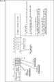
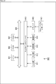
- An example of the data structure of the occupancy map will be described. It is a block diagram which shows the main structural examples of an encoding apparatus. It is a figure explaining the main structural examples of an OMap production
- FIG. 20 is a block diagram illustrating a main configuration example of a computer.
- Video-based approach> ⁇ Documents that support technical contents and technical terms>
- the scope disclosed in the present technology includes not only the contents described in the embodiments but also the contents described in the following non-patent documents that are known at the time of filing.
- Non-Patent Document 1 (above)
- Non-Patent Document 2 TELECOMMUNICATION STANDARDIZATION SECTOR OF ITU (International Telecommunication Union), "Advanced video coding for generic audiovisual services", H.264, 04/2017
- Non-Patent Document 3 TELECOMMUNICATION STANDARDIZATION SECTOR OF ITU (International Telecommunication Union), "High efficiency video coding", H.265, 12/2016
- Non-Patent Document 4 Jianle Chen, Maria Alshina, Gary J.
- ⁇ Point cloud> Conventionally, there are data such as point clouds that represent 3D structures based on point cloud position information and attribute information, and meshes that are composed of vertices, edges, and surfaces, and that define 3D shapes using polygonal representations. .
- a three-dimensional structure as shown in A of FIG. 1 is expressed as a set (point group) of a large number of points as shown in B of FIG. That is, the point cloud data is configured by position information and attribute information (for example, color) of each point in the point cloud. Therefore, the data structure is relatively simple, and an arbitrary three-dimensional structure can be expressed with sufficient accuracy by using a sufficiently large number of points.
- an input point cloud (Point ⁇ cloud) is divided into a plurality of segmentations (also referred to as regions), and each region is projected onto a two-dimensional plane.
- the data for each position of the point cloud (that is, the data of each point) is composed of the position information (Geometry (also referred to as Depth)) and the attribute information (Texture) as described above. Projected onto a dimensional plane.
- Each segmentation (also referred to as a patch) projected on the two-dimensional plane is arranged in a two-dimensional image.
- two-dimensional plane images such as AVC (Advanced Video Coding) and HEVC (High Efficiency Video Coding). It is encoded by the encoding method.
- AVC Advanced Video Coding
- HEVC High Efficiency Video Coding
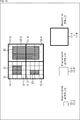
- ⁇ Occupancy Map> When 3D data is projected onto a two-dimensional plane by a video-based approach, a two-dimensional plane image (also referred to as a geometry image) on which position information is projected as described above, and a two-dimensional plane on which attribute information is projected In addition to an image (also referred to as a texture image), an occupancy map as shown in FIG. 3 is generated.
- the occupancy map is map information indicating the presence / absence of position information and attribute information at each position on the two-dimensional plane.
- geometry images (Depth) and occupancy maps (Occupancy) at positions corresponding to each other are arranged. In the case of the example of FIG.
- the white portion of the occupancy map indicates the position (coordinates) where the geometry image data (ie, position information) exists, and the black portion indicates the geometry image data ( That is, it indicates a position (coordinate) where no position information exists.
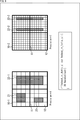
- FIG. 4 is a diagram showing a configuration example of this occupancy map.
- the occupancy map 10 is composed of a block 11 (thick line frame) called “Resolution”.
- the occupancy map 10 is composed of four 2 ⁇ 2 blocks 11.
- Each block 11 (Resolution) is composed of sub-blocks 12 (thin line frames) called Precision.
- each block 11 is composed of 4 ⁇ 4 sub-blocks 12.
- Patches 21 to 23 are arranged in a range corresponding to the occupancy map 10 of a certain frame image. In the occupancy map 10, the presence / absence of this patch data is determined for each sub-block 12.
- FIG. 5 shows an example of the data structure of the occupancy map.
- the occupancy map includes data as shown in FIG.
- Arithmetic encoded variables stores coordinate information (u0, v0, u1, v1) indicating the range for each patch. That is, in the occupancy map, the range of each patch area is indicated by the coordinates of the paired vertices ((u0, v0) and (u1, v1)).
- occupancy map In this occupancy map (OccupancyMap), the presence or absence of position information (and attribute information) is determined in units of a predetermined fixed size block NxN. As shown in FIG. 5, the value of N is also described in the bitstream under the name of Occupancy Precision.
- this occupancy precision N (also referred to as a precision value) is fixed in the entire region that is the target of the occupancy map. Therefore, if the presence / absence of data is determined in units of small blocks in the occupancy map, point cloud data with higher resolution can be expressed, but there is a trade-off relationship that the bit rate increases. Therefore, in reality, the accuracy of determining the presence or absence of data (occupancy precision N) in the occupancy map may reduce the resolution in a fine part of the pattern and reduce the image quality of the decoded image.
- the line becomes thicker as shown in the image 54 of FIG.
- the image quality of the decoded image obtained by decoding the 3D data encoded by the video-based approach depends on the precision value of the occupancy map, when this precision value is larger than the fineness of the image, There is a risk that the image quality of the decoded image is reduced.
- multiple maps indicating the presence or absence of data at each position are generated for a single frame image in which patches, which are images obtained by projecting 3D data representing a three-dimensional structure onto a two-dimensional plane, are generated. Then, a bit stream including the encoded data of the frame image and the encoded data of the plurality of generated maps is generated.
- a map indicating the presence / absence of data at each position on a single frame image in which patches, which are images obtained by projecting 3D data representing a 3D structure onto a 2D plane.
- a map generation unit that generates a plurality of maps, a bit stream generation unit that generates a bit stream including encoded data of the frame image, and encoded data of a plurality of maps generated by the map generation unit Like that.
- the Mac occupancy map
- maps (occupancy maps) having different precision values can be applied for each local area. That is, the precision value can be made substantially variable according to the position. Therefore, for example, at any position of the frame image, the presence / absence of data can be determined by a precision value map (occupancy map) suitable for the local resolution (fineness of the pattern) at that position. Therefore, it is possible to suppress a decrease in the image quality of the decoded image (the quality of the reconstructed 3D data) while suppressing an increase in code amount (decrease in encoding efficiency).
- a plurality of maps indicating the presence / absence of data at each position corresponding to a frame image in which patches, which are images obtained by projecting 3D data representing a three-dimensional structure onto a two-dimensional plane, are used. 3D data is reconstructed from the patch.
- a map indicating the presence / absence of data at a plurality of positions corresponding to a frame image in which patches are arranged, which is an image obtained by projecting 3D data representing a three-dimensional structure onto a two-dimensional plane.
- a reconstruction unit for reconstructing 3D data from the patch is provided.
- 3D data can be reconstructed by applying a map (occupancy map) with a different precision value for each local area of the frame image in which the patch is arranged. That is, the precision value can be made substantially variable according to the position. Therefore, for example, at any position of the frame image, 3D data can be reconstructed using a precision value map (occupancy map) suitable for the local resolution (fineness of the pattern) at that position. Therefore, it is possible to suppress a decrease in the image quality of the decoded image (the quality of the reconstructed 3D data) while suppressing an increase in code amount (decrease in encoding efficiency).
- a map occupancy map
- a map indicating the presence / absence of data at each position of a frame image in which patches, which are images obtained by projecting 3D data representing a 3D structure onto a 2D plane.
- a map in which a plurality of precisions indicating presence / absence are set is generated, and a bit stream including encoded data of the frame image and encoded data of the generated map is generated.
- a map indicating the presence / absence of data at each position of a frame image in which patches, which are images obtained by projecting 3D data representing a three-dimensional structure onto a two-dimensional plane
- a bit stream generation unit For example, in an image processing apparatus, a map (occupancy map) indicating the presence / absence of data at each position of a frame image in which patches, which are images obtained by projecting 3D data representing a three-dimensional structure onto a two-dimensional plane
- the precision value of the map can be changed for each local area of the frame image where the patch is arranged. That is, the precision value can be made variable according to the position. Therefore, for example, at any position of the frame image, the presence / absence of data can be determined by a precision value map (occupancy map) suitable for the local resolution (fineness of the pattern) at that position. Therefore, it is possible to suppress a decrease in the image quality of the decoded image (the quality of the reconstructed 3D data) while suppressing an increase in code amount (decrease in encoding efficiency).
- a map indicating the presence / absence of data at each position of a frame image in which patches, which are images obtained by projecting 3D data representing a 3D structure onto a 2D plane, is provided.
- 3D data is reconstructed from the patch using a map in which a plurality of precisions indicating presence / absence are set.
- a map indicating the presence / absence of data at each position of a frame image in which patches, which are images obtained by projecting 3D data representing a three-dimensional structure onto a two-dimensional plane
- a reconstruction unit that reconstructs 3D data from the patch using a map in which a plurality of precisions indicating the presence / absence of the data are set is provided.
- 3D data can be reconstructed by applying a map (occupancy map) in which the precision value is changed for each local area of the frame image in which the patch is arranged. That is, the precision value can be made variable according to the position. Therefore, for example, at any position of the frame image, 3D data can be reconstructed using a precision value map (occupancy map) suitable for the local resolution (fineness of the pattern) at that position. Therefore, it is possible to suppress a decrease in the image quality of the decoded image (the quality of the reconstructed 3D data) while suppressing an increase in code amount (decrease in encoding efficiency).
- a map occupancy map
- mapping specification 1 in which the accuracy is variable, a plurality of occupancy maps having different accuracy (precision values) are generated and transmitted.
- occupancy is expressed with one accuracy for each block (OR).
- the precision value can be made variable according to the position, the reduction in the image quality of the decoded image (the quality of the reconstructed 3D data) is suppressed while the reduction in the encoding efficiency is suppressed. be able to.
- the difference information from the low-precision occupancy may be expressed with high-precision occupancy (XOR).
- the presence / absence of data in the occupancy map 10-2 is determined by exclusive OR (XOR) with the determination result in the occupancy map 10-1, so that the patch 22-1 is included in the occupancy map 10-2. May also be determined.
- the precision value can be made variable according to the position. Therefore, the image quality of the decoded image (reconstructed 3D data can be reduced while suppressing the reduction in encoding efficiency). Reduction in quality) can be suppressed.
- FIG. 10 shows an example of the data structure of the occupancy map in the case of FIG. 8 and FIG.
- the underlined portion in FIG. 10 is a portion different from that in FIG. That is, in this case, the occupancy map data includes information on accuracy.
- the accuracy for example, the number of accuracy (Number of Occupancy Precision (n)) set in this data is set. Further, the n precisions (precision values) are set (Occupancy Precision (N1), Occupancy Precision (N2),).
- an occupancy map including blocks with different accuracy is generated and transmitted.
- an occupancy map 10 in which accuracy can be set for each block may be generated and transmitted.
- the precision value can be made variable according to the position, the reduction in the image quality of the decoded image (the quality of the reconstructed 3D data) is suppressed while the reduction in the encoding efficiency is suppressed. be able to.
- FIG. 13 shows an example of the data structure of the occupancy map in this case.
- the underlined portion in FIG. 13 is a portion different from that in FIG.
- the data of the occupancy map includes the number of precisions (Number of Occupancy Precision (n)) and its n precisions (Occupancy Precision (N1), Occupancy Precision (N2), ). Information is not included.
- the occupancy map 10 in which the accuracy can be set for each patch may be generated and transmitted.
- the precision value of each sub-block as shown in FIG. 11 may be set for each patch so that the precision value of the sub-block including the patch becomes the precision value corresponding to that patch.
- the precision value can be made variable according to the position, as in the case where the accuracy is set for each block. Therefore, the image quality (reproduction) of the decoded image can be reduced while suppressing the reduction in coding efficiency. Reduction of the quality of the constructed 3D data) can be suppressed.
- FIG. 12 shows an example of the data structure of the occupancy map in this case.
- the underlined portion in FIG. 12 is a portion different from that in FIG. That is, in this case, the occupancy map data includes the number of precisions (Number of Occupancy Precision (n)) and its n precisions (Occupancy Precision (N1), Occupancy Precision (N2), ). Information is not included.
- a precision value (Precision (N ')) is set for each patch (Foreach each pathc), and the precision value of a sub-block belonging to the patch is set to N' (N'xN ').
- a plurality of occupancy maps including blocks having different accuracy (precision values) are generated and transmitted.
- the precision value can be made variable according to the position, the reduction in the image quality of the decoded image (the quality of the reconstructed 3D data) is suppressed while the reduction in the encoding efficiency is suppressed. be able to.
- this accuracy determination method is arbitrary.
- an optimal precision value may be obtained based on the RD cost.
- the most effective value may be determined subjectively.
- the precision value may be determined based on characteristics of the local region (for example, “face”, “hair”, etc.), a region of interest (ROI), or the like.
- the precision value may be determined using the quality of the reconstructed point cloud and the bit amount necessary for transmission of the occupancy map as indices. Further, for example, the precision value may be determined from the relationship between the occupancy map and the number of pixels in the local area.
- FIG. 14 is a block diagram illustrating an example of a configuration of an encoding device that is an aspect of an image processing device to which the present technology is applied.
- An encoding apparatus 100 shown in FIG. 14 is an apparatus that encodes 3D data such as a point cloud onto a two-dimensional plane and performs encoding using an encoding method for a two-dimensional image (encoding apparatus using a video-based approach). ).
- FIG. 14 shows main components such as a processing unit and a data flow, and the ones shown in FIG. 14 are not all. That is, in the encoding apparatus 100, there may be a processing unit that is not shown as a block in FIG. 14, or there may be a process or data flow that is not shown as an arrow or the like in FIG. The same applies to other diagrams illustrating the processing unit and the like in the encoding device 100.
- the encoding apparatus 100 includes a patch decomposing unit 111, a packing unit 112, an OMap generating unit 113, an auxiliary patch information compressing unit 114, a video encoding unit 115, a video encoding unit 116, and an OMap encoding unit. 117 and a multiplexer 118.
- the patch decomposition unit 111 performs processing related to decomposition of 3D data. For example, the patch decomposing unit 111 acquires 3D data (for example, point cloud) that represents the three-dimensional structure input to the encoding device 100. Further, the patch decomposing unit 111 decomposes the acquired 3D data into a plurality of segmentations, projects the 3D data onto a two-dimensional plane for each segmentation, and generates a position information patch and an attribute information patch.
- 3D data for example, point cloud
- the patch decomposing unit 111 supplies information about each generated patch to the packing unit 112. Further, the patch decomposing unit 111 supplies auxiliary patch information, which is information relating to the decomposition, to the auxiliary patch information compressing unit 114.
- the packing unit 112 performs processing related to data packing. For example, the packing unit 112 acquires two-dimensional plane data (patch) on which 3D data is projected for each region supplied from the patch decomposition unit 111. The packing unit 112 arranges each acquired patch in a two-dimensional image and packs it as a video frame. For example, the packing unit 112 packs a patch of position information (Geometry) indicating the position of the point and a patch of attribute information (Texture) such as color information added to the position information as a video frame.
- position information Geometry
- Texture patch of attribute information
- the packing unit 112 supplies the generated video frame to the OMap generation unit 113. In addition, the packing unit 112 supplies control information regarding the packing to the multiplexer 118.
- the OMap generation unit 113 performs processing related to generation of an occupancy map. For example, the OMap generation unit 113 acquires data supplied from the packing unit 112. In addition, the OMap generation unit 113 generates an occupancy map corresponding to position information and attribute information. For example, the OMap generation unit 113 generates a plurality of occupancy maps for one frame image in which patches are arranged. Further, for example, the OMap generation unit 113 generates an occupancy map in which a plurality of precisions are set. The OMap generation unit 113 supplies the generated occupancy map and various types of information acquired from the packing unit 112 to the subsequent processing unit. For example, the OMap generation unit 113 supplies a video frame of position information (Geometry) to the video encoding unit 115. Further, for example, the OMap generation unit 113 supplies the video frame of the attribute information (Texture) to the video encoding unit 116. Further, for example, the OMap generation unit 113 supplies an occupancy map to the OMap encoding unit 117.
- the auxiliary patch information compression unit 114 performs processing related to compression of auxiliary patch information. For example, the auxiliary patch information compression unit 114 acquires data supplied from the patch decomposition unit 111. The auxiliary patch information compression unit 114 encodes (compresses) auxiliary patch information included in the acquired data. The auxiliary patch information compression unit 114 supplies the encoded data of the obtained auxiliary patch information to the multiplexer 118.
- the video encoding unit 115 performs processing related to encoding of a video frame of position information (Geometry). For example, the video encoding unit 115 acquires a video frame of position information (Geometry) supplied from the OMap generation unit 113. Further, the video encoding unit 115 encodes the acquired video frame of the position information (Geometry) by an arbitrary two-dimensional image encoding method such as AVC or HEVC. The video encoding unit 115 supplies encoded data (encoded data of a video frame of position information (Geometry)) obtained by the encoding to the multiplexer 118.
- encoded data encoded data of a video frame of position information (Geometry)
- the video encoding unit 116 performs processing related to encoding of a video frame of attribute information (Texture). For example, the video encoding unit 116 acquires a video frame of attribute information (Texture) supplied from the OMap generation unit 113. Further, the video encoding unit 116 encodes the acquired video frame of the attribute information (Texture) by an arbitrary two-dimensional image encoding method such as AVC or HEVC. The video encoding unit 116 supplies the encoded data (the encoded data of the video frame of the attribute information (Texture)) obtained by the encoding to the multiplexer 118.
- a video frame of attribute information (Texture) supplied from the OMap generation unit 113.
- the video encoding unit 116 encodes the acquired video frame of the attribute information (Texture) by an arbitrary two-dimensional image encoding method such as AVC or HEVC.
- the video encoding unit 116 supplies the encoded data (the encoded data of the video frame of the attribute information (Texture)) obtained
- the OMap encoding unit 117 performs processing related to encoding of the occupancy map. For example, the OMap encoding unit 117 acquires the occupancy map supplied from the OMap generation unit 113. The OMap encoding unit 117 encodes the acquired occupancy map by an arbitrary encoding method such as arithmetic encoding. The OMap encoding unit 117 supplies the encoded data (the encoded data of the occupancy map) obtained by the encoding to the multiplexer 118.
- the multiplexer 118 performs processing related to multiplexing. For example, the multiplexer 118 acquires encoded data of auxiliary patch information supplied from the auxiliary patch information compression unit 114. In addition, the multiplexer 118 acquires control information related to packing supplied from the packing unit 112. Further, the multiplexer 118 acquires encoded data of a video frame of position information (Geometry) supplied from the video encoding unit 115. Further, the multiplexer 118 acquires encoded data of a video frame of attribute information (Texture) supplied from the video encoding unit 116. Further, the multiplexer 118 acquires encoded data of an occupancy map supplied from the OMap encoding unit 117.
- the multiplexer 118 acquires encoded data of auxiliary patch information supplied from the auxiliary patch information compression unit 114. In addition, the multiplexer 118 acquires control information related to packing supplied from the packing unit 112. Further, the multiplexer 118 acquires encoded data of a video frame of position information (Geometry) supplied from
- the multiplexer 118 multiplexes the acquired information and generates a bitstream.
- the multiplexer 118 outputs the generated bit stream to the outside of the encoding device 100.
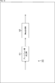
- FIG. 15 is a block diagram illustrating a main configuration example of the OMap generation unit 113 in FIG. As illustrated in FIG. 15, the OMap generation unit 113 includes a precision value determination unit 151 and an OMap generation unit 152.
- the precision value determination unit 151 performs processing related to determination of the precision value. For example, the precision value determination unit 151 acquires data supplied from the packing unit 112. Further, the precision value determining unit 151 determines the precision value of each position based on the data.
- the method for determining this precision value is arbitrary. For example, an optimal precision value may be obtained based on the RD cost. Further, for example, the most effective value may be determined subjectively. Further, for example, the precision value may be determined based on characteristics of the local region (for example, “face”, “hair”, etc.), a region of interest (ROI), or the like. Further, for example, the precision value may be determined using the quality of the reconstructed point cloud and the bit amount necessary for transmission of the occupancy map as indices. Further, for example, the precision value may be determined from the relationship between the occupancy map and the number of pixels in the local area.
- the precision value determining unit 151 supplies the data acquired from the packing unit 112 to the OMap generating unit 152 together with the information.
- the OMap generation unit 152 performs processing related to generation of an occupancy map. For example, the OMap generation unit 152 acquires data supplied from the precision value determination unit 151. Further, the OMap generation unit 152 refers to, for example, FIG. 8 to FIG. 13 based on the position information and the video frame of the attribute information supplied from the precision value determination unit 151, the precision value determined by the precision value determination unit 151, and the like. As described above, an occupancy map having a variable precision value according to the position is generated.
- the OMap generation unit 152 supplies various types of information acquired from the precision value determination unit 151 to the subsequent processing unit together with the generated occupancy map.
- FIG. 16 is a block diagram illustrating an example of a configuration of a decoding device that is an aspect of an image processing device to which the present technology is applied.
- the decoding device 200 shown in FIG. 16 decodes encoded data obtained by projecting 3D data such as a point cloud onto a two-dimensional plane and encoding it using a decoding method for a two-dimensional image, and projects the encoded data into a three-dimensional space.
- Device decoding device to which a video-based approach is applied).
- FIG. 16 shows main components such as a processing unit and a data flow, and the ones shown in FIG. 16 are not all. That is, in the decoding device 200, there may be a processing unit that is not shown as a block in FIG. 16, or there may be a process or data flow that is not shown as an arrow or the like in FIG. This is the same in other diagrams explaining the processing unit and the like in the decoding device 200.
- the decoding device 200 includes a demultiplexer 211, an auxiliary patch information decoding unit 212, a video decoding unit 213, a video decoding unit 214, an OMap decoding unit 215, an unpacking unit 216, and a 3D reconstruction unit 217.
- a demultiplexer 211 the demultiplexer 211
- an auxiliary patch information decoding unit 212 the decoding device 200
- a video decoding unit 213, a video decoding unit 214 includes a video decoding unit 214, an OMap decoding unit 215, an unpacking unit 216, and a 3D reconstruction unit 217.
- the demultiplexer 211 performs processing related to data demultiplexing. For example, the demultiplexer 211 acquires a bit stream input to the decoding device 200. This bit stream is supplied from the encoding device 100, for example. The demultiplexer 211 demultiplexes this bit stream, extracts the encoded data of the auxiliary patch information, and supplies it to the auxiliary patch information decoding unit 212. Further, the demultiplexer 211 extracts encoded data of a video frame of position information (Geometry) from the bit stream by demultiplexing and supplies it to the video decoding unit 213.
- a video frame of position information Gaometry
- the demultiplexer 211 extracts the encoded data of the video frame of the attribute information (Texture) from the bit stream by demultiplexing and supplies it to the video decoding unit 214. Also, the demultiplexer 211 extracts encoded data of the occupancy map from the bit stream by demultiplexing, and supplies it to the OMap decoding unit 215. Further, the demultiplexer 211 extracts control information related to packing from the bitstream by demultiplexing, and supplies it to the unpacking unit 216.
- the attribute information (Texture)
- the auxiliary patch information decoding unit 212 performs processing related to decoding of encoded data of auxiliary patch information. For example, the auxiliary patch information decoding unit 212 acquires encoded data of auxiliary patch information supplied from the demultiplexer 211. The auxiliary patch information decoding unit 212 decodes encoded data of auxiliary patch information included in the acquired data. The auxiliary patch information decoding unit 212 supplies the auxiliary patch information obtained by the decoding to the 3D reconstruction unit 217.
- the video decoding unit 213 performs processing related to decoding of encoded data of a video frame of position information (Geometry). For example, the video decoding unit 213 acquires encoded data of a video frame of position information (Geometry) supplied from the demultiplexer 211. In addition, the video decoding unit 213 decodes the encoded data acquired from the demultiplexer 211 to obtain a video frame of position information (Geometry). The video decoding unit 213 supplies the decoded encoding unit position information (Geometry) data to the unpacking unit 216.
- Geometry video frame of position information
- the video decoding unit 214 performs processing related to decoding of the encoded data of the video frame of the attribute information (Texture). For example, the video decoding unit 214 acquires encoded data of a video frame of attribute information (Texture) supplied from the demultiplexer 211. In addition, the video decoding unit 214 decodes the encoded data acquired from the demultiplexer 211 to obtain a video frame of attribute information (Texture). The video decoding unit 214 supplies the decoded attribute unit attribute information (Texture) data to the unpacking unit 216.
- the video decoding unit 214 acquires encoded data of a video frame of attribute information (Texture) supplied from the demultiplexer 211.
- the video decoding unit 214 decodes the encoded data acquired from the demultiplexer 211 to obtain a video frame of attribute information (Texture).
- the video decoding unit 214 supplies the decoded attribute unit attribute information (Texture) data to the unpacking unit 216.
- the OMap decoding unit 215 performs processing related to decoding of encoded data of the occupancy map. For example, the OMap decoding unit 215 acquires encoded data of an occupancy map supplied from the demultiplexer 211. The OMap decoding unit 215 decodes the encoded data acquired from the demultiplexer 211 to obtain an occupancy map. The OMap decoding unit 215 supplies the decoded occupancy map data of the coding unit to the unpacking unit 216.
- the unpacking unit 216 performs processing related to unpacking. For example, the unpacking unit 216 acquires the video frame of the position information (Geometry) from the video decoding unit 213, acquires the video frame of the attribute information (Texture) from the video decoding unit 214, and the occupancy map from the OMap decoding unit 215. To get. Further, the unpacking unit 216 unpacks the position information (Geometry) video frame and the attribute information (Texture) video frame based on the control information related to packing. The unpacking unit 216 converts the position information (Geometry) data (patch, etc.), the attribute information (Texture) data (patch, etc.), the occupancy map data, etc. obtained by unpacking into a 3D reconstruction unit. To 217.
- the 3D reconstruction unit 217 performs processing related to reconstruction of 3D data.
- the 3D reconstruction unit 217 includes auxiliary patch information supplied from the auxiliary patch information decoding unit 212, position information (Geometry) data, attribute information (Texture) data, and occupancy information supplied from the unpacking unit 216.
- 3D data Point (Cloud) is reconstructed based on pansy map data.
- the 3D reconstruction unit 217 reconstructs 3D data from the patches using a plurality of occupancy maps corresponding to patches of position information and attribute information (frame images on which patches are arranged).
- the 3D reconstruction unit 217 reconstructs 3D data from patches of position information and attribute information using an occupancy map in which a plurality of precisions indicating the presence / absence of data are set.
- the 3D reconstruction unit 217 outputs the 3D data obtained by such processing to the outside of the decoding device 200.
- the 3D data is supplied to a display unit to display the image, recorded on a recording medium, or supplied to another device via communication, for example.
- the precision value can be made substantially variable according to the position. Therefore, for example, at any position of the frame image, the presence / absence of data is determined by the occupancy map of the precision value suitable for the local resolution (detail of the pattern) at that position, or 3D data is reconstructed. Can be. Therefore, it is possible to suppress a decrease in the image quality of the decoded image (the quality of the reconstructed 3D data) while suppressing an increase in code amount (decrease in encoding efficiency).
- the precision value of the occupancy map can be changed for each local area of the frame image in which the patch is arranged. That is, the precision value can be made variable according to the position. Therefore, for example, at any position of the frame image, the presence / absence of data is determined by the occupancy map of the precision value suitable for the local resolution (detail of the pattern) at that position, or 3D data is reconstructed. Can be. Therefore, it is possible to suppress a decrease in the image quality of the decoded image (the quality of the reconstructed 3D data) while suppressing an increase in code amount (decrease in encoding efficiency).
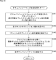
- the patch decomposing unit 111 of the encoding apparatus 100 projects 3D data onto a two-dimensional plane and decomposes it into patches in step S101.
- step S102 the auxiliary patch information compression unit 114 compresses the auxiliary patch information generated in step S101.
- step S103 the packing unit 112 performs packing. That is, the packing unit 112 packs each patch of position information and attribute information generated in step S101 as a video frame. In addition, the packing unit 112 generates control information regarding the packing.
- step S104 the OMap generation unit 113 generates an occupancy map corresponding to the video frame of the position information and attribute information generated in step S103.
- step S105 the video encoding unit 115 encodes the geometry video frame, which is the video frame of the position information generated in step S103, using a two-dimensional image encoding method.
- step S106 the video encoding unit 116 encodes the color video frame, which is the video frame of the attribute information generated in step S103, using a two-dimensional image encoding method.
- step S107 the OMap encoding unit 117 encodes the occupancy map generated in step S104 by a predetermined encoding method.
- step S108 the multiplexer 118 multiplexes various pieces of information generated as described above (for example, encoded data generated in steps S105 to S107, control information related to packing generated in step S103, and the like) A bit stream including these pieces of information is generated.
- step S109 the multiplexer 118 outputs the bit stream generated in step S108 to the outside of the encoding apparatus 100.
- step S109 When the process of step S109 is finished, the encoding process is finished.
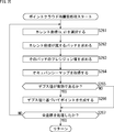
- the precision value determination unit 151 of the OMap generation unit 113 sets a precision value (a precision value) that can be set for the block specified by the occupancy resolution in step S121.
- a list of candidates) is derived.
- the precision value determining unit 151 determines the precision value of each block based on the list.
- the method for determining the precision value is arbitrary. For example, an optimal precision value may be obtained based on the RD cost. Further, for example, the most effective value may be determined subjectively. Further, for example, the precision value may be determined based on characteristics of the local region (for example, “face”, “hair”, etc.), a region of interest (ROI), or the like. Further, for example, the precision value may be determined using the quality of the reconstructed point cloud and the bit amount necessary for transmission of the occupancy map as indices. Further, for example, the precision value may be determined from the relationship between the occupancy map and the number of pixels in the local area.
- step S123 the OMap generation unit 152 derives the type of the precision value of the precision value for one frame determined as described above.
- step S124 the OMap generation unit 152 generates an occupancy map of each precision value so that the occupancy of each block is expressed by the precision value.
- step S125 the OMap generation unit 152 combines all the occupancy maps generated as described above, and generates data having a configuration as shown in FIG. 10, for example.
- step S125 the occupancy map generation process is terminated, and the process returns to FIG.
- the encoding apparatus 100 can change the occupancy map to be applied for each local area of the frame image in which the patch is arranged. Therefore, for example, occupancy maps having different precision values can be applied for each local area. That is, the precision value can be made substantially variable according to the position. Therefore, for example, at any position of the frame image, the presence / absence of data can be determined by a precision value occupancy map suitable for the local resolution (pattern fineness) at that position. Therefore, it is possible to suppress a decrease in the image quality of the decoded image (the quality of the reconstructed 3D data) while suppressing an increase in code amount (decrease in encoding efficiency).
- step S144 the OMap generation unit 152 generates an occupancy map representing the occupancy of residual information between the image data and the previous occupancy map in descending order of the precision values.
- step S145 the OMap generation unit 152 combines all the occupancy maps generated as described above, and generates data having a configuration as shown in FIG. 10, for example.
- step S145 the occupancy map generation process is terminated, and the process returns to FIG.
- the encoding apparatus 100 can change the occupancy map to be applied for each local area of the frame image in which the patch is arranged. Therefore, for example, occupancy maps having different precision values can be applied for each local area. That is, the precision value can be made substantially variable according to the position. Therefore, for example, at any position of the frame image, the presence / absence of data can be determined by a precision value occupancy map suitable for the local resolution (pattern fineness) at that position. Therefore, it is possible to suppress a decrease in the image quality of the decoded image (the quality of the reconstructed 3D data) while suppressing an increase in code amount (decrease in encoding efficiency).
- the precision value determination unit 151 derives a list of settable precision values (prediction value candidates) for each patch in step S161.
- the precision value determining unit 151 determines the precision value of each patch based on the list.
- the method for determining the precision value is arbitrary. For example, an optimal precision value may be obtained based on the RD cost. Further, for example, the most effective value may be determined subjectively. Further, for example, the precision value may be determined based on characteristics of the local region (for example, “face”, “hair”, etc.), a region of interest (ROI), or the like. Further, for example, the precision value may be determined using the quality of the reconstructed point cloud and the bit amount necessary for transmission of the occupancy map as indices. Further, for example, the precision value may be determined from the relationship between the occupancy map and the number of pixels in the local area.
- step S163 the OMap generation unit 152 obtains a patch to which each block belongs.
- step S164 the OMap generation unit 152 obtains a precision value corresponding to the patch for each block.
- step S165 the OMap generation unit 152 obtains an occupancy for each sub-block with the precision value for each block.
- step S166 the OMap generation unit 152 combines the occupancy of all the blocks and generates an occupancy map including blocks with different accuracy.
- step S166 the occupancy map generation process is terminated, and the process returns to FIG.
- the encoding apparatus 100 can change the precision value of the occupancy map for each local area of the frame image in which the patch is arranged. That is, the precision value can be made variable according to the position. Therefore, for example, at any position of the frame image, the presence / absence of data can be determined by a precision value occupancy map suitable for the local resolution (pattern fineness) at that position. Therefore, it is possible to suppress a decrease in the image quality of the decoded image (the quality of the reconstructed 3D data) while suppressing an increase in code amount (decrease in encoding efficiency).
- the precision value determination unit 151 displays a list of settable precision values (prediction value candidates) for the block specified by the occupancy resolution in step S181. To derive.
- the precision value determining unit 151 determines the precision value of each block based on the list.
- the method for determining the precision value is arbitrary. For example, an optimal precision value may be obtained based on the RD cost. Further, for example, the most effective value may be determined subjectively. Further, for example, the precision value may be determined based on characteristics of the local region (for example, “face”, “hair”, etc.), a region of interest (ROI), or the like. Further, for example, the precision value may be determined using the quality of the reconstructed point cloud and the bit amount necessary for transmission of the occupancy map as indices. Further, for example, the precision value may be determined from the relationship between the occupancy map and the number of pixels in the local area.
- step S183 the OMap generation unit 152 obtains an occupancy for each sub-block with the precision value for each block.
- step S184 the OMap generation unit 152 combines the occupancy of all the blocks and generates an occupancy map including blocks with different accuracy.
- step S184 the occupancy map generation process is terminated, and the process returns to FIG.
- the encoding apparatus 100 can change the precision value of the occupancy map for each local area of the frame image in which the patch is arranged. That is, the precision value can be made variable according to the position. Therefore, for example, at any position of the frame image, the presence / absence of data can be determined by a precision value occupancy map suitable for the local resolution (pattern fineness) at that position. Therefore, it is possible to suppress a decrease in the image quality of the decoded image (the quality of the reconstructed 3D data) while suppressing an increase in code amount (decrease in encoding efficiency).
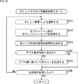
- the demultiplexer 211 of the decoding device 200 demultiplexes the bitstream in step S201.
- step S202 the auxiliary patch information decoding unit 212 decodes the auxiliary patch information extracted from the bitstream in step S201.
- step S203 the video decoding unit 213 decodes the encoded data of the geometry video frame (video frame of position information) extracted from the bit stream in step S201.
- step S204 the video decoding unit 214 decodes the encoded data of the color video frame (video frame of attribute information) extracted from the bit stream in step S201.
- step S205 the OMap decoding unit 215 decodes the encoded data of the occupancy map extracted from the bit stream in step S201.
- step S206 the unpacking unit 216 unpacks the geometry video frame and the color video frame decoded in steps S203 to S205, and extracts a patch.
- step S207 the 3D reconstruction unit 217 reconstructs 3D data such as a point cloud based on the auxiliary patch information obtained in step S202, the patch obtained in step S206, an occupancy map, and the like. To do.
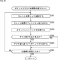
- the 3D reconstruction unit 217 selects a current coordinate (x, y) to be processed in step S221.
- step S222 the 3D reconstruction unit 217 selects a current precision value that is a precision value of the current coordinates, and acquires the occupancy map. That is, the 3D reconstruction unit 217 selects one of the unprocessed precision values for the current coordinate where the occupancy map exists, and acquires an occupancy map corresponding to the precision value.
- step S223 the 3D reconstruction unit 217 determines whether or not the depth value is valid at the current coordinates. If it is determined that position information exists at the current coordinates based on the occupancy map (that is, the depth value is valid), the process proceeds to step S224.
- step S224 the 3D reconstruction unit 217 generates a 3D data point based on the depth value of the current coordinate.
- the process of step S224 ends, the process proceeds to step S226.
- step S223 If it is determined in step S223 that the depth value of the current coordinate is not valid (that is, position information does not exist in the current coordinate), the process proceeds to step S225.
- step S225 the 3D reconstruction unit 217 determines whether or not all precision values for which the occupancy map exists have been processed for the current coordinates. If it is determined that there is an unprocessed precision value, the process returns to step S222, and the subsequent processes are performed.
- step S225 If it is determined in step S225 that all precision values have been processed for the current coordinate, the process proceeds to step S226.
- step S226 the 3D reconstruction unit 217 determines whether all the coordinates have been processed. If it is determined that unprocessed coordinates exist, the process returns to step S221, and the subsequent processes are executed.
- step S226 If it is determined in step S226 that all coordinates have been processed, the point cloud reconstruction process ends, and the process returns to FIG.
- the decoding apparatus 200 can reconstruct 3D data by applying an occupancy map with a different precision value for each local area of a frame image in which patches are arranged. . That is, the precision value can be made substantially variable according to the position. Therefore, for example, at any position of the frame image, 3D data can be reconstructed by using an occupancy map having a precision value suitable for the local resolution (fineness of the pattern) at that position. Therefore, it is possible to suppress a decrease in the image quality of the decoded image (the quality of the reconstructed 3D data) while suppressing an increase in code amount (decrease in encoding efficiency).
- the 3D reconstruction unit 217 selects a current coordinate (x, y) to be processed in step S241.
- step S242 the 3D reconstruction unit 217 acquires an occupancy map of all precision values.
- step S243 the 3D reconstruction unit 217 obtains an exclusive OR of each map.
- step S244 the 3D reconstruction unit 217 determines whether or not the depth value is valid at the current coordinates. If it is determined that position information exists at the current coordinates based on the occupancy map (that is, the depth value is valid), the process proceeds to step S245.
- step S245 the 3D reconstruction unit 217 generates 3D data points based on the depth value of the current coordinates.
- the process of step S245 ends, the process proceeds to step S246. If it is determined in step S244 that the depth value of the current coordinate is not valid (that is, position information does not exist at the current coordinate), the process of step S245 is omitted, and the process proceeds to step S246.
- step S246 the 3D reconstruction unit 217 determines whether all the coordinates have been processed. If it is determined that unprocessed coordinates exist, the process returns to step S241, and the subsequent processes are executed.
- step S246 If it is determined in step S246 that all coordinates have been processed, the point cloud reconstruction process ends, and the process returns to FIG.
- the decoding apparatus 200 can reconstruct 3D data by applying an occupancy map with a different precision value for each local area of a frame image in which patches are arranged. . That is, the precision value can be made substantially variable according to the position. Therefore, for example, at any position of the frame image, 3D data can be reconstructed by using an occupancy map having a precision value suitable for the local resolution (fineness of the pattern) at that position. Therefore, it is possible to suppress a decrease in the image quality of the decoded image (the quality of the reconstructed 3D data) while suppressing an increase in code amount (decrease in encoding efficiency).
- the 3D reconstruction unit 217 selects a current coordinate (x, y) to be processed in step S261.
- step S262 the 3D reconstruction unit 217 obtains a patch to which the current coordinate belongs.
- step S263 the 3D reconstruction unit 217 obtains the precision value of the patch.
- step S264 the 3D reconstruction unit 217 acquires an occupancy map.
- step S265 the 3D reconstruction unit 217 determines whether or not the depth value is valid at the current coordinates. If it is determined that position information exists at the current coordinates based on the occupancy map (that is, the depth value is valid), the process proceeds to step S266.
- step S266 the 3D reconstruction unit 217 generates a 3D data point based on the depth value of the current coordinate.
- the process of step S266 ends, the process proceeds to step S267. If it is determined in step S265 that the depth value of the current coordinate is not valid (that is, position information does not exist in the current coordinate), the process of step S266 is omitted, and the process proceeds to step S267.
- step S267 the 3D reconstruction unit 217 determines whether all the coordinates have been processed. If it is determined that unprocessed coordinates exist, the process returns to step S261, and the subsequent processes are executed.
- step S267 If it is determined in step S267 that all coordinates have been processed, the point cloud reconstruction process ends, and the process returns to FIG.
- the decoding apparatus 200 can reconstruct 3D data by applying an occupancy map in which a precision value is changed for each local area of a frame image in which patches are arranged. . That is, the precision value can be made variable according to the position. Therefore, for example, at any position of the frame image, 3D data can be reconstructed by using an occupancy map having a precision value suitable for the local resolution (fineness of the pattern) at that position. Therefore, it is possible to suppress a decrease in the image quality of the decoded image (the quality of the reconstructed 3D data) while suppressing an increase in code amount (decrease in encoding efficiency).
- the 3D reconstruction unit 217 selects a current coordinate (x, y) to be processed in step S281.
- step S282 the 3D reconstruction unit 217 obtains a precision value of the current coordinates.
- step S283 the 3D reconstruction unit 217 acquires an occupancy map.
- step S284 the 3D reconstruction unit 217 determines whether or not a depth value is valid at the current coordinates. If it is determined that position information exists at the current coordinates based on the occupancy map (that is, the depth value is valid), the process proceeds to step S285.
- step S285 the 3D reconstruction unit 217 generates 3D data points based on the depth values of the current coordinates.
- the process of step S285 ends, the process proceeds to step S286. If it is determined in step S284 that the depth value of the current coordinate is not valid (that is, position information does not exist at the current coordinate), the process of step S285 is omitted, and the process proceeds to step S286.
- step S286 the 3D reconstruction unit 217 determines whether all the coordinates have been processed. If it is determined that unprocessed coordinates exist, the process returns to step S281, and the subsequent processes are executed.
- step S286 If it is determined in step S286 that all coordinates have been processed, the point cloud reconstruction process ends, and the process returns to FIG.
- the decoding apparatus 200 can reconstruct 3D data by applying an occupancy map in which a precision value is changed for each local area of a frame image in which patches are arranged. . That is, the precision value can be made variable according to the position. Therefore, for example, at any position of the frame image, 3D data can be reconstructed by using an occupancy map having a precision value suitable for the local resolution (fineness of the pattern) at that position. Therefore, it is possible to suppress a decrease in the image quality of the decoded image (the quality of the reconstructed 3D data) while suppressing an increase in code amount (decrease in encoding efficiency).
- control information related to the present technology described in each of the above embodiments may be transmitted from the encoding side to the decoding side. For example, you may make it transmit the control information (for example, enabled_flag) which controls whether application (or prohibition) of applying this technique mentioned above is permitted.
- control that specifies a range (for example, an upper limit or a lower limit of the block size, or both, a slice, a picture, a sequence, a component, a view, a layer, etc.) that is permitted (or prohibited) to apply the present technology described above.
- Information may be transmitted.
- ⁇ Computer> The series of processes described above can be executed by hardware or can be executed by software.
- a program constituting the software is installed in the computer.
- the computer includes, for example, a general-purpose personal computer that can execute various functions by installing a computer incorporated in dedicated hardware and various programs.
- FIG. 27 is a block diagram showing an example of the hardware configuration of a computer that executes the above-described series of processing by a program.
- a CPU Central Processing Unit
- ROM Read Only Memory
- RAM Random Access Memory
- An input / output interface 910 is also connected to the bus 904.
- An input unit 911, an output unit 912, a storage unit 913, a communication unit 914, and a drive 915 are connected to the input / output interface 910.
- the input unit 911 includes, for example, a keyboard, a mouse, a microphone, a touch panel, an input terminal, and the like.
- the output unit 912 includes, for example, a display, a speaker, an output terminal, and the like.
- the storage unit 913 includes, for example, a hard disk, a RAM disk, a nonvolatile memory, and the like.
- the communication unit 914 includes a network interface, for example.
- the drive 915 drives a removable medium 921 such as a magnetic disk, an optical disk, a magneto-optical disk, or a semiconductor memory.
- the CPU 901 loads the program stored in the storage unit 913 into the RAM 903 via the input / output interface 910 and the bus 904 and executes the program, for example. Is performed.
- the RAM 903 also appropriately stores data necessary for the CPU 901 to execute various processes.
- the program executed by the computer can be recorded and applied to, for example, a removable medium 921 as a package medium or the like.
- the program can be installed in the storage unit 913 via the input / output interface 910 by attaching the removable medium 921 to the drive 915.
- This program can also be provided via a wired or wireless transmission medium such as a local area network, the Internet, or digital satellite broadcasting. In that case, the program can be received by the communication unit 914 and installed in the storage unit 913.
- a wired or wireless transmission medium such as a local area network, the Internet, or digital satellite broadcasting.
- the program can be received by the communication unit 914 and installed in the storage unit 913.
- this program can be installed in the ROM 902 or the storage unit 913 in advance.
- the encoding device 100 and the decoding device 200 have been described as application examples of the present technology. However, the present technology can be applied to any configuration.
- the present technology can be applied to transmitters and receivers (for example, television receivers and mobile phones) in satellite broadcasting, cable broadcasting such as cable TV, distribution on the Internet, and distribution to terminals via cellular communication, or
- the present invention can be applied to various electronic devices such as an apparatus (for example, a hard disk recorder or a camera) that records an image on a medium such as an optical disk, a magnetic disk, and a flash memory and reproduces an image from the storage medium.
- the present technology provides a processor (for example, a video processor) as a system LSI (Large Scale Integration) or the like, a module (for example, a video module) using a plurality of processors, or a unit (for example, a video unit) using a plurality of modules.
- a processor for example, a video processor
- LSI Large Scale Integration
- module for example, a video module
- unit for example, a video unit
- it may be implemented as a configuration of a part of the apparatus such as a set (for example, a video set) in which other functions are further added to the unit.
- the present technology can also be applied to a network system including a plurality of devices.
- the present technology may be implemented as cloud computing that is shared and processed by a plurality of devices via a network.
- this technology is implemented in a cloud service that provides services related to images (moving images) to arbitrary terminals such as computers, audio visual (AV) devices, portable information processing terminals, and Internet of Things (IoT) devices. You may make it do.
- AV audio visual
- IoT Internet of Things
- the system means a set of a plurality of constituent elements (devices, modules (parts), etc.), and it does not matter whether all the constituent elements are in the same casing. Therefore, a plurality of devices housed in separate housings and connected via a network, and a single device housing a plurality of modules in one housing are all systems. .
- Systems, devices, processing units, etc. to which this technology is applied can be used in any field such as traffic, medical care, crime prevention, agriculture, livestock industry, mining, beauty, factory, home appliances, weather, nature monitoring, etc. . Moreover, the use is also arbitrary.
- “flag” is information for identifying a plurality of states, and is not only information used for identifying two states of true (1) or false (0), but also three or more Information that can identify the state is also included. Therefore, the value that can be taken by the “flag” may be, for example, a binary value of 1/0, or may be three or more values. That is, the number of bits constituting this “flag” is arbitrary, and may be 1 bit or a plurality of bits.
- the identification information includes not only the form in which the identification information is included in the bitstream but also the form in which the difference information of the identification information with respect to certain reference information is included in the bitstream.
- the “flag” and “identification information” include not only the information but also difference information with respect to the reference information.
- various information (metadata, etc.) related to the encoded data may be transmitted or recorded in any form as long as it is associated with the encoded data.
- the term “associate” means, for example, that one data can be used (linked) when one data is processed. That is, the data associated with each other may be collected as one data, or may be individual data. For example, information associated with encoded data (image) may be transmitted on a different transmission path from the encoded data (image). Further, for example, information associated with encoded data (image) may be recorded on a recording medium different from the encoded data (image) (or another recording area of the same recording medium). Good.
- the “association” may be a part of the data, not the entire data. For example, an image and information corresponding to the image may be associated with each other in an arbitrary unit such as a plurality of frames, one frame, or a part of the frame.
- the configuration described as one device (or processing unit) may be divided and configured as a plurality of devices (or processing units).
- the configurations described above as a plurality of devices (or processing units) may be combined into a single device (or processing unit).
- a configuration other than that described above may be added to the configuration of each device (or each processing unit).
- a part of the configuration of a certain device (or processing unit) may be included in the configuration of another device (or other processing unit). .
- the above-described program may be executed in an arbitrary device.
- the device may have necessary functions (functional blocks and the like) so that necessary information can be obtained.
- each step of one flowchart may be executed by one device, or may be executed by a plurality of devices in a shared manner.
- the plurality of processes may be executed by one apparatus, or may be executed in a shared manner by a plurality of apparatuses.
- a plurality of processes included in one step can be executed as a process of a plurality of steps.
- the processing described as a plurality of steps can be collectively executed as one step.
- a program executed by a computer may be executed in a time series according to the order described in this specification, or in parallel or in a call process. It may be executed individually at a necessary timing such as when it is broken. That is, as long as no contradiction occurs, the processing of each step may be executed in an order different from the order described above. Furthermore, the processing of the steps describing this program may be executed in parallel with the processing of other programs, or may be executed in combination with the processing of other programs.
- a plurality of technologies related to the present technology can be independently implemented as long as no contradiction occurs.
- any of a plurality of present technologies can be used in combination.
- part or all of the present technology described in any of the embodiments can be combined with part or all of the present technology described in other embodiments.
- a part or all of the arbitrary present technology described above can be implemented in combination with other technologies not described above.
- a map generation unit that generates a plurality of maps indicating the presence / absence of data at each position for one frame image in which patches, which are images obtained by projecting 3D data representing a three-dimensional structure onto a two-dimensional plane, are arranged.
- An image processing apparatus comprising: a bitstream generation unit that generates a bitstream including encoded data of the frame image and a plurality of encoded data of the maps generated by the map generation unit.
- the image processing apparatus wherein the plurality of maps indicate the presence / absence of the data not only at different positions but also at the same position.
- the map generation unit combines a plurality of the maps into one data.
- the map generation unit generates the data including information on accuracy indicating presence / absence of the data of the map.
- the information related to the accuracy includes information indicating the number of the accuracy and information indicating a value of each accuracy.
- a plurality of maps corresponding to frame images in which patches are arranged, which are images obtained by projecting 3D data representing a three-dimensional structure onto a two-dimensional plane, are used to determine whether or not there is data from the patches.
- An image processing apparatus including a reconstruction unit that reconstructs 3D data.
- An image processing apparatus comprising: a bit stream generation unit that generates a bit stream including encoded data of the frame image and encoded data of the map generated by the map generation unit.
- the map generation unit generates the map in which the accuracy is set for each block.
- the map generation unit generates the map in which the accuracy is set for each patch.
- the image processing device (14) The image processing device according to (11), wherein the map generation unit generates the map indicating the presence / absence of the data for each sub-block having a size corresponding to the accuracy and formed in each block. . (15) The image processing device according to (11), wherein the map generation unit sets the accuracy based on a cost function. (16) The image processing device according to (11), wherein the map generation unit sets the accuracy based on a characteristic of a local region or a setting of a region of interest.
- Generate a map to be set An image processing method for generating a bitstream including encoded data of the frame image and encoded data of the generated map.
- An image processing apparatus comprising: a reconstruction unit that reconstructs the 3D data from the patch using a set map.
Abstract
The present disclosure pertains to an image processing device and method that make it possible to inhibit reductions in image quality. In the present disclosure, for one frame image in which 3D data representing a three-dimensional structure is projected upon a two-dimensional plane and in which patches are disposed, a plurality of maps indicating the presence or absence of data in each position are generated, and a bitstream is generated comprising encoded data for the frame image and encoded data for the plurality of generated maps. The present disclosure can be employed, for example, in information processing devices, image processing devices, electronic devices, image processing methods, and programs.
Description
本開示は、画像処理装置および方法に関し、特に、画質の低減を抑制することができるようにした画像処理装置および方法に関する。
The present disclosure relates to an image processing apparatus and method, and more particularly, to an image processing apparatus and method capable of suppressing a reduction in image quality.
従来、例えばポイントクラウド(Point cloud)のような3次元構造を表す3Dデータの符号化方法として、例えばOctree等のような、ボクセル(Voxel)を用いた符号化があった(例えば非特許文献1参照)。
Conventionally, as a method for encoding 3D data representing a three-dimensional structure such as a point cloud, for example, there has been encoding using a voxel such as Octtree (for example, Non-Patent Document 1). reference).
近年、その他の符号化方法として、例えば、ポイントクラウドの位置と色情報それぞれを、小領域毎に2次元平面に投影し、2次元画像用の符号化方法で符号化するアプローチ(以下、ビデオベースドアプローチ(Video-based approach)とも称する)が提案されている。
In recent years, as another encoding method, for example, an approach in which each point cloud position and color information is projected onto a two-dimensional plane for each small region and encoded by an encoding method for two-dimensional images (hereinafter referred to as video-based). An approach (also called Video-based approach) has been proposed.
このような符号化において、2次元平面に投影された位置情報に関して、ある固定サイズのブロックNxNの単位で、位置情報の有無を判定するためのオキュパンシーマップ(OccupancyMap)というものが定義され、ビットストリーム(Bitstream)に記述される。その際、このNの値もオキュパンシープレシジョン(OccupancyPrecision)という名前でビットストリームに記述される。
In such encoding, an occupancy map (OccupancyMap) for determining the presence / absence of position information is defined in units of a fixed-size block NxN with respect to position information projected on a two-dimensional plane, and bits It is described in a stream (Bitstream). At this time, the value of N is also described in the bitstream under the name of occupancy precision (OccupancyPrecision).
しかしながら、従来の方法では、このオキュパンシープレシジョンNは、オキュパンシーマップの対象となる全領域において固定であった。そのため、オキュパンシーマップにおいて小さいブロック単位でデータの有無を判定すればより解像度の高いPointCloudデータを表現することができるが、ビットレートが高くなってしまうというトレードオフの関係にあった。そのため、実際には、このオキュパンシーマップにおけるデータの有無の判定精度(オキュパンシープレシジョンN)によって、復号画像の画質が低減するおそれがあった。
However, in the conventional method, this occupancy precision N is fixed in the entire region that is the target of the occupancy map. Therefore, if the presence / absence of data is determined in small blocks in the occupancy map, PointCloud data with higher resolution can be expressed, but there is a trade-off relationship that the bit rate is increased. Therefore, in reality, there is a risk that the image quality of the decoded image may be reduced by the accuracy of determination of the presence / absence of data in the occupancy map (occupancy precision N).
本開示は、このような状況に鑑みてなされたものであり、画質の低減を抑制することができるようにするものである。
The present disclosure has been made in view of such a situation, and is intended to suppress a reduction in image quality.
本技術の一側面の画像処理装置は、3次元構造を表す3Dデータを2次元平面に投影した画像であるパッチが配置された1枚のフレーム画像に対して、各位置のデータの有無を示すマップを複数生成するマップ生成部と、前記フレーム画像の符号化データと、前記マップ生成部により生成された複数の前記マップの符号化データとを含むビットストリームを生成するビットストリーム生成部とを備える画像処理装置である。
An image processing apparatus according to an aspect of the present technology indicates whether or not there is data at each position with respect to a single frame image on which a patch that is an image obtained by projecting 3D data representing a three-dimensional structure onto a two-dimensional plane is arranged. A map generation unit that generates a plurality of maps; and a bit stream generation unit that generates a bit stream including encoded data of the frame image and a plurality of encoded data of the maps generated by the map generation unit. An image processing apparatus.
本技術の一側面の画像処理方法は、3次元構造を表す3Dデータを2次元平面に投影した画像であるパッチが配置された1枚のフレーム画像に対して、各位置のデータの有無を示すマップを複数生成し、前記フレーム画像の符号化データと、生成された複数の前記マップの符号化データとを含むビットストリームを生成する画像処理方法である。
An image processing method according to one aspect of the present technology indicates the presence or absence of data at each position with respect to a single frame image on which a patch that is an image obtained by projecting 3D data representing a three-dimensional structure onto a two-dimensional plane is arranged. In the image processing method, a plurality of maps are generated, and a bit stream including the encoded data of the frame image and the generated encoded data of the plurality of maps is generated.
本技術の他の側面の画像処理装置は、3次元構造を表す3Dデータを2次元平面に投影した画像であるパッチが配置されたフレーム画像に対応する複数の、各位置のデータの有無を示すマップを用いて、前記パッチから前記3Dデータを再構築する再構築部を備える画像処理装置である。
An image processing apparatus according to another aspect of the present technology indicates presence / absence of data at a plurality of positions corresponding to a frame image on which patches are arranged, which is an image obtained by projecting 3D data representing a three-dimensional structure onto a two-dimensional plane. The image processing apparatus includes a reconstruction unit that reconstructs the 3D data from the patch using a map.
本技術の他の側面の画像処理方法は、3次元構造を表す3Dデータを2次元平面に投影した画像であるパッチが配置されたフレーム画像に対応する複数の、各位置のデータの有無を示すマップを用いて、前記パッチから前記3Dデータを再構築する画像処理方法である。
An image processing method according to another aspect of the present technology indicates presence / absence of data at a plurality of positions corresponding to a frame image on which patches are arranged, which is an image obtained by projecting 3D data representing a three-dimensional structure onto a two-dimensional plane. The image processing method reconstructs the 3D data from the patch using a map.
本技術のさらに他の側面の画像処理装置は、3次元構造を表す3Dデータを2次元平面に投影した画像であるパッチが配置されたフレーム画像の各位置のデータの有無を示すマップであって、前記データの有無を示す精度が複数設定されるマップを生成するマップ生成部と、前記フレーム画像の符号化データと、前記マップ生成部により生成された前記マップの符号化データとを含むビットストリームを生成するビットストリーム生成部とを備える画像処理装置である。
An image processing apparatus according to still another aspect of the present technology is a map indicating the presence / absence of data at each position of a frame image on which a patch, which is an image obtained by projecting 3D data representing a three-dimensional structure onto a two-dimensional plane, is provided. A bit stream including a map generation unit that generates a map in which a plurality of precisions indicating the presence / absence of the data are set, encoded data of the frame image, and encoded data of the map generated by the map generation unit And a bit stream generation unit that generates the image processing apparatus.
本技術のさらに他の側面の画像処理方法は、3次元構造を表す3Dデータを2次元平面に投影した画像であるパッチが配置されたフレーム画像の各位置のデータの有無を示すマップであって、前記データの有無を示す精度が複数設定されるマップを生成し、前記フレーム画像の符号化データと、生成された前記マップの符号化データとを含むビットストリームを生成する画像処理方法である。
An image processing method according to still another aspect of the present technology is a map indicating the presence / absence of data at each position of a frame image on which a patch, which is an image obtained by projecting 3D data representing a 3D structure onto a 2D plane, is provided. And an image processing method for generating a map in which a plurality of precisions indicating the presence or absence of the data are set, and generating a bit stream including the encoded data of the frame image and the generated encoded data of the map.
本技術のさらに他の側面の画像処理装置は、3次元構造を表す3Dデータを2次元平面に投影した画像であるパッチが配置されたフレーム画像の各位置のデータの有無を示すマップであって、前記データの有無を示す精度が複数設定されるマップを用いて、前記パッチから前記3Dデータを再構築する再構築部を備える画像処理装置である。
An image processing apparatus according to still another aspect of the present technology is a map indicating the presence / absence of data at each position of a frame image on which a patch, which is an image obtained by projecting 3D data representing a 3D structure onto a 2D plane, is provided. The image processing apparatus includes a reconstruction unit that reconstructs the 3D data from the patch using a map in which a plurality of precisions indicating the presence or absence of the data are set.
本技術のさらに他の側面の画像処理方法は、3次元構造を表す3Dデータを2次元平面に投影した画像であるパッチが配置されたフレーム画像の各位置のデータの有無を示すマップであって、前記データの有無を示す精度が複数設定されるマップを用いて、前記パッチから前記3Dデータを再構築する画像処理方法である。
An image processing method according to still another aspect of the present technology is a map indicating the presence / absence of data at each position of a frame image on which a patch, which is an image obtained by projecting 3D data representing a 3D structure onto a 2D plane, is provided. The image processing method reconstructs the 3D data from the patch using a map in which a plurality of precisions indicating the presence or absence of the data are set.
本技術の一側面の画像処理装置および方法においては、3次元構造を表す3Dデータを2次元平面に投影した画像であるパッチが配置された1枚のフレーム画像に対して、各位置のデータの有無を示すマップが複数生成され、そのフレーム画像の符号化データと、その生成された複数のマップの符号化データとを含むビットストリームが生成される。
In the image processing apparatus and method according to one aspect of the present technology, the data of each position is obtained with respect to one frame image in which patches, which are images obtained by projecting 3D data representing a 3D structure onto a 2D plane, are arranged. A plurality of maps indicating presence / absence are generated, and a bit stream including encoded data of the frame image and encoded data of the generated plurality of maps is generated.
本技術の他の側面の画像処理装置および方法においては、3次元構造を表す3Dデータを2次元平面に投影した画像であるパッチが配置されたフレーム画像に対応する複数の、各位置のデータの有無を示すマップを用いて、そのパッチから3Dデータが再構築される。
In an image processing apparatus and method according to another aspect of the present technology, a plurality of pieces of data at each position corresponding to a frame image on which patches are arranged, which is an image obtained by projecting 3D data representing a three-dimensional structure onto a two-dimensional plane. 3D data is reconstructed from the patch using a map indicating the presence or absence.
本技術のさらに他の側面の画像処理装置および方法においては、3次元構造を表す3Dデータを2次元平面に投影した画像であるパッチが配置されたフレーム画像の各位置のデータの有無を示すマップであって、そのデータの有無を示す精度が複数設定されるマップが生成され、そのフレーム画像の符号化データと、その生成されたマップの符号化データとを含むビットストリームが生成される。
In the image processing apparatus and method according to still another aspect of the present technology, a map indicating the presence / absence of data at each position of a frame image on which patches, which are images obtained by projecting 3D data representing a 3D structure onto a 2D plane, is arranged Then, a map in which a plurality of precisions indicating the presence or absence of the data are set is generated, and a bit stream including the encoded data of the frame image and the encoded data of the generated map is generated.
本技術のさらに他の側面の画像処理装置および方法においては、3次元構造を表す3Dデータを2次元平面に投影した画像であるパッチが配置されたフレーム画像の各位置のデータの有無を示すマップであって、そのデータの有無を示す精度が複数設定されるマップを用いて、そのパッチから3Dデータが再構築される。
In the image processing apparatus and method according to still another aspect of the present technology, a map indicating the presence / absence of data at each position of a frame image on which patches, which are images obtained by projecting 3D data representing a 3D structure onto a 2D plane, is arranged Then, 3D data is reconstructed from the patch using a map in which a plurality of precisions indicating the presence or absence of the data are set.
本開示によれば、画像を処理することができる。特に、画質の低減を抑制することができる。
According to the present disclosure, an image can be processed. In particular, reduction in image quality can be suppressed.
以下、本開示を実施するための形態(以下実施の形態とする)について説明する。なお、説明は以下の順序で行う。
1.ビデオベースドアプローチ
2.第1の実施の形態(オキュパンシーマップの精度の制御)
3.付記 Hereinafter, modes for carrying out the present disclosure (hereinafter referred to as embodiments) will be described. The description will be given in the following order.
1. Video-based approach First embodiment (control of accuracy of occupancy map)
3. Appendix
<1.ビデオベースドアプローチ>
<技術内容・技術用語をサポートする文献等>
本技術で開示される範囲は、実施の形態に記載されている内容だけではなく、出願当時において公知となっている以下の非特許文献に記載されている内容も含まれる。 <1. Video-based approach>
<Documents that support technical contents and technical terms>
The scope disclosed in the present technology includes not only the contents described in the embodiments but also the contents described in the following non-patent documents that are known at the time of filing.
非特許文献1:(上述)
非特許文献2:TELECOMMUNICATION STANDARDIZATION SECTOR OF ITU(International Telecommunication Union), "Advanced video coding for generic audiovisual services", H.264, 04/2017
非特許文献3:TELECOMMUNICATION STANDARDIZATION SECTOR OF ITU(International Telecommunication Union), "High efficiency video coding", H.265, 12/2016
非特許文献4:Jianle Chen, Elena Alshina, Gary J. Sullivan, Jens-Rainer, Jill Boyce, "Algorithm Description of Joint Exploration Test Model 4", JVET-G1001_v1, Joint Video Exploration Team (JVET) of ITU-T SG 16 WP 3 and ISO/IEC JTC 1/SC 29/WG 11 7th Meeting: Torino, IT, 13-21 July 2017 Non-Patent Document 1: (above)
Non-Patent Document 2: TELECOMMUNICATION STANDARDIZATION SECTOR OF ITU (International Telecommunication Union), "Advanced video coding for generic audiovisual services", H.264, 04/2017
Non-Patent Document 3: TELECOMMUNICATION STANDARDIZATION SECTOR OF ITU (International Telecommunication Union), "High efficiency video coding", H.265, 12/2016
Non-Patent Document 4: Jianle Chen, Elena Alshina, Gary J. Sullivan, Jens-Rainer, Jill Boyce, "Algorithm Description of JointExploration Test Model 4", JVET-G1001_v1, Joint Video Exploration Team (JVET) of ITU-T SG 16 WP 3 and ISO / IEC JTC 1 / SC 29 / WG 11 7th Meeting: Torino, IT, 13-21 July 2017
非特許文献2:TELECOMMUNICATION STANDARDIZATION SECTOR OF ITU(International Telecommunication Union), "Advanced video coding for generic audiovisual services", H.264, 04/2017
非特許文献3:TELECOMMUNICATION STANDARDIZATION SECTOR OF ITU(International Telecommunication Union), "High efficiency video coding", H.265, 12/2016
非特許文献4:Jianle Chen, Elena Alshina, Gary J. Sullivan, Jens-Rainer, Jill Boyce, "Algorithm Description of Joint Exploration Test Model 4", JVET-G1001_v1, Joint Video Exploration Team (JVET) of ITU-T SG 16 WP 3 and ISO/IEC JTC 1/SC 29/WG 11 7th Meeting: Torino, IT, 13-21 July 2017 Non-Patent Document 1: (above)
Non-Patent Document 2: TELECOMMUNICATION STANDARDIZATION SECTOR OF ITU (International Telecommunication Union), "Advanced video coding for generic audiovisual services", H.264, 04/2017
Non-Patent Document 3: TELECOMMUNICATION STANDARDIZATION SECTOR OF ITU (International Telecommunication Union), "High efficiency video coding", H.265, 12/2016
Non-Patent Document 4: Jianle Chen, Elena Alshina, Gary J. Sullivan, Jens-Rainer, Jill Boyce, "Algorithm Description of Joint
つまり、上述の非特許文献に記載されている内容もサポート要件を判断する際の根拠となる。例えば、非特許文献3に記載されているQuad-Tree Block Structure、非特許文献4に記載されているQTBT(Quad Tree Plus Binary Tree) Block Structureが実施の形態において直接的な記載がない場合でも、本技術の開示範囲内であり、請求の範囲のサポート要件を満たすものとする。また、例えば、パース(Parsing)、シンタックス(Syntax)、セマンティクス(Semantics)等の技術用語についても同様に、実施の形態において直接的な記載がない場合でも、本技術の開示範囲内であり、請求の範囲のサポート要件を満たすものとする。
In other words, the contents described in the above non-patent literature are also grounds for determining the support requirements. For example, even when Quad-Tree Block Structure described in Non-Patent Document 3 and QTBT (QuadTree Plus Binary Tree) Block Structure described in Non-Patent Document 4 are not directly described in the embodiment, It is within the scope of the disclosure of the present technology and satisfies the support requirements of the claims. Further, for example, even for technical terms such as Parsing, Syntax, Semantics, etc., even if there is no direct description in the embodiment, it is within the disclosure range of the present technology, Satisfy the claim support requirements.
<ポイントクラウド>
従来、点群の位置情報や属性情報等により3次元構造を表すポイントクラウドや、頂点、エッジ、面で構成され、多角形表現を使用して3次元形状を定義するメッシュ等のデータが存在した。 <Point cloud>
Conventionally, there are data such as point clouds that represent 3D structures based on point cloud position information and attribute information, and meshes that are composed of vertices, edges, and surfaces, and that define 3D shapes using polygonal representations. .
例えばポイントクラウドの場合、図1のAに示されるような立体構造物を、図1のBに示されるような多数の点の集合(点群)として表現する。つまり、ポイントクラウドのデータは、この点群の各点の位置情報や属性情報(例えば色等)により構成される。したがってデータ構造が比較的単純であるとともに、十分に多くの点を用いることにより任意の立体構造を十分な精度で表現することができる。
For example, in the case of a point cloud, a three-dimensional structure as shown in A of FIG. 1 is expressed as a set (point group) of a large number of points as shown in B of FIG. That is, the point cloud data is configured by position information and attribute information (for example, color) of each point in the point cloud. Therefore, the data structure is relatively simple, and an arbitrary three-dimensional structure can be expressed with sufficient accuracy by using a sufficiently large number of points.
<ビデオベースドアプローチの概要>
このようなポイントクラウドの位置と色情報それぞれを、小領域毎に2次元平面に投影し、2次元画像用の符号化方法で符号化するビデオベースドアプローチ(Video-based approach)が提案されている。 <Outline of video-based approach>
A video-based approach has been proposed in which the position and color information of such a point cloud are projected onto a two-dimensional plane for each small area and encoded by an encoding method for a two-dimensional image. .
このビデオベースドアプローチでは、例えば図2に示されるように、入力されたポイントクラウド(Point cloud)が複数のセグメンテーション(領域とも称する)に分割され、領域毎に2次元平面に投影される。なお、ポイントクラウドの位置毎のデータ(すなわち、各ポイントのデータ)は、上述のように位置情報(Geometry(Depthとも称する))と属性情報(Texture)とにより構成され、それぞれ、領域毎に2次元平面に投影される。
In this video-based approach, for example, as shown in FIG. 2, an input point cloud (Point に cloud) is divided into a plurality of segmentations (also referred to as regions), and each region is projected onto a two-dimensional plane. Note that the data for each position of the point cloud (that is, the data of each point) is composed of the position information (Geometry (also referred to as Depth)) and the attribute information (Texture) as described above. Projected onto a dimensional plane.
そして、この2次元平面に投影された各セグメンテーション(パッチとも称する)は、2次元画像に配置され、例えば、AVC(Advanced Video Coding)やHEVC(High Efficiency Video Coding)等といった、2次元平面画像用の符号化方式により符号化される。
Each segmentation (also referred to as a patch) projected on the two-dimensional plane is arranged in a two-dimensional image. For example, for two-dimensional plane images such as AVC (Advanced Video Coding) and HEVC (High Efficiency Video Coding). It is encoded by the encoding method.
<オキュパンシーマップ>
ビデオベースドアプローチにより、3Dデータを2次元平面に投影する場合、上述のように位置情報が投影された2次元平面画像(ジオメトリ(Geometry)画像とも称する)と、属性情報が投影された2次元平面画像(テクスチャ(Texture)画像とも称する)との他に、図3に示されるようなオキュパンシーマップが生成される。オキュパンシーマップは、2次元平面の各位置における、位置情報および属性情報の有無を示すマップ情報である。図3の例では、互いに対応する位置の(パッチの)ジオメトリ画像(Depth)とオキュパンシーマップ(Occupancy)とが並べられている。図3の例の場合、オキュパンシーマップ(図中左側)の白い部分が、ジオメトリ画像のデータ(すなわち位置情報)が存在する位置(座標)を示しており、黒い部分が、ジオメトリ画像のデータ(すなわち位置情報)が存在しない位置(座標)を示している。 <Occupancy Map>
When 3D data is projected onto a two-dimensional plane by a video-based approach, a two-dimensional plane image (also referred to as a geometry image) on which position information is projected as described above, and a two-dimensional plane on which attribute information is projected In addition to an image (also referred to as a texture image), an occupancy map as shown in FIG. 3 is generated. The occupancy map is map information indicating the presence / absence of position information and attribute information at each position on the two-dimensional plane. In the example of FIG. 3, geometry images (Depth) and occupancy maps (Occupancy) at positions corresponding to each other are arranged. In the case of the example of FIG. 3, the white portion of the occupancy map (left side in the figure) indicates the position (coordinates) where the geometry image data (ie, position information) exists, and the black portion indicates the geometry image data ( That is, it indicates a position (coordinate) where no position information exists.
図4は、このオキュパンシーマップの構成例を示す図である。図4に示されるように、オキュパンシーマップ10は、Resolutionと称するブロック11(太線枠)により構成される。図4においては、1つのブロック11にのみ符号を付しているが、オキュパンシーマップ10は、2×2の4つのブロック11により構成される。各ブロック11(Resolution)は、Precisionと称するサブブロック12(細線枠)により構成される。図4の例の場合、各ブロック11は、4×4のサブブロック12により構成される。
FIG. 4 is a diagram showing a configuration example of this occupancy map. As shown in FIG. 4, the occupancy map 10 is composed of a block 11 (thick line frame) called “Resolution”. In FIG. 4, only one block 11 is given a reference numeral, but the occupancy map 10 is composed of four 2 × 2 blocks 11. Each block 11 (Resolution) is composed of sub-blocks 12 (thin line frames) called Precision. In the case of the example of FIG. 4, each block 11 is composed of 4 × 4 sub-blocks 12.
あるフレーム画像の、このオキュパンシーマップ10に対応する範囲には、パッチ21乃至パッチ23が配置される。オキュパンシーマップ10においては、このパッチのデータの有無がサブブロック12毎に判定される。
Patches 21 to 23 are arranged in a range corresponding to the occupancy map 10 of a certain frame image. In the occupancy map 10, the presence / absence of this patch data is determined for each sub-block 12.
図5は、オキュパンシーマップのデータ構造の例を示す。オキュパンシーマップには、図5に示されるようなデータが含まれる。
FIG. 5 shows an example of the data structure of the occupancy map. The occupancy map includes data as shown in FIG.
例えば、Arithmetic encoded variablesには、各パッチについての範囲を示す座標情報(u0,v0,u1,v1)が格納されている。つまり、オキュパンシーマップにおいては、各パッチの領域の範囲が、その対頂点の座標((u0,v0)および(u1,v1))により示されている。
For example, Arithmetic encoded variables stores coordinate information (u0, v0, u1, v1) indicating the range for each patch. That is, in the occupancy map, the range of each patch area is indicated by the coordinates of the paired vertices ((u0, v0) and (u1, v1)).
このオキュパンシーマップ(OccupancyMap)では、所定の固定サイズのブロックNxNの単位で、位置情報(および属性情報)の有無が判定される。図5に示されるように、このNの値もオキュパンシープレシジョン(OccupancyPrecision)という名前でビットストリームに記述される。
In this occupancy map (OccupancyMap), the presence or absence of position information (and attribute information) is determined in units of a predetermined fixed size block NxN. As shown in FIG. 5, the value of N is also described in the bitstream under the name of Occupancy Precision.
<オキュパンシーマップによる解像度低減>
しかしながら、従来の方法では、このオキュパンシープレシジョンN(プレシジョン値とも称する)は、オキュパンシーマップの対象となる全領域において固定であった。そのため、オキュパンシーマップにおいて小さいブロック単位でデータの有無を判定すればより解像度の高いポイントクラウドデータを表現することができるが、ビットレートが高くなってしまうというトレードオフの関係にあった。そのため、実際には、このオキュパンシーマップにおけるデータの有無の判定精度(オキュパンシープレシジョンN)によって、絵柄の細かい部分において解像度が低減し、復号画像の画質が低減するおそれがあった。 <Resolution reduction by occupancy map>
However, in the conventional method, this occupancy precision N (also referred to as a precision value) is fixed in the entire region that is the target of the occupancy map. Therefore, if the presence / absence of data is determined in units of small blocks in the occupancy map, point cloud data with higher resolution can be expressed, but there is a trade-off relationship that the bit rate increases. Therefore, in reality, the accuracy of determining the presence or absence of data (occupancy precision N) in the occupancy map may reduce the resolution in a fine part of the pattern and reduce the image quality of the decoded image.
例えば、図6のAに示される画像51には、細い線状の髪の毛が含まれているが、これが例えばプレシジョン値「1」(precision=1)のオキュパンシーマップによって、図6のBの画像52のように太くなってしまうおそれがあった。オキュパンシーマップのプレシジョン値が「2」(precision=2)の場合、図6のCの画像53のようにさらに太くなってしまうおそれがあった。オキュパンシーマップのプレシジョン値が「4」(precision=4)の場合、図6のDの画像54のようにさらに太くなって、線がブロック化してしまうおそれがあった。
For example, the image 51 shown in FIG. 6A includes thin linear hair, which is represented, for example, by an occupancy map with a precision value “1” (precision = 1), as shown in FIG. 6B. There was a risk of becoming thick like 52. When the precision value of the occupancy map is “2” (precision = 2), there is a possibility that the image becomes thicker like the image 53 in FIG. 6C. When the precision value of the occupancy map is “4” (precision = 4), there is a possibility that the line becomes thicker as shown in the image 54 of FIG.
このように、ビデオベースドアプローチにより符号化した3Dデータを復号した復号画像の画質は、オキュパンシーマップのプレシジョン値(precision)に依存するため、画像の細かさに比べてこのプレシジョン値が大きい場合、復号画像の画質が低減するおそれがあった。
As described above, since the image quality of the decoded image obtained by decoding the 3D data encoded by the video-based approach depends on the precision value of the occupancy map, when this precision value is larger than the fineness of the image, There is a risk that the image quality of the decoded image is reduced.
<プレシジョン値の制御>
そこで、オキュパンシーマップの精度(プレシジョン値)を制御することができるようにする(可変とする)。 <Control of precision value>
Therefore, the accuracy (precision value) of the occupancy map can be controlled (variable).
そこで、オキュパンシーマップの精度(プレシジョン値)を制御することができるようにする(可変とする)。 <Control of precision value>
Therefore, the accuracy (precision value) of the occupancy map can be controlled (variable).
例えば、3次元構造を表す3Dデータを2次元平面に投影した画像であるパッチが配置された1枚のフレーム画像に対して、各位置のデータの有無を示すマップ(オキュパンシーマップ)を複数生成し、そのフレーム画像の符号化データと、その生成された複数のマップの符号化データとを含むビットストリームを生成するようにする。
For example, multiple maps (occupancy maps) indicating the presence or absence of data at each position are generated for a single frame image in which patches, which are images obtained by projecting 3D data representing a three-dimensional structure onto a two-dimensional plane, are generated. Then, a bit stream including the encoded data of the frame image and the encoded data of the plurality of generated maps is generated.
例えば、画像処理装置において、3次元構造を表す3Dデータを2次元平面に投影した画像であるパッチが配置された1枚のフレーム画像に対して、各位置のデータの有無を示すマップ(オキュパンシーマップ)を複数生成するマップ生成部と、そのフレーム画像の符号化データと、そのマップ生成部により生成された複数のマップの符号化データとを含むビットストリームを生成するビットストリーム生成部とを備えるようにする。
For example, in an image processing apparatus, a map (occupancy) indicating the presence / absence of data at each position on a single frame image in which patches, which are images obtained by projecting 3D data representing a 3D structure onto a 2D plane, is arranged. A map generation unit that generates a plurality of maps, a bit stream generation unit that generates a bit stream including encoded data of the frame image, and encoded data of a plurality of maps generated by the map generation unit Like that.
このようにすることにより、パッチが配置されたフレーム画像の局所毎に適用するマック(オキュパンシーマップ)を変えることができる。したがって、例えば、局所毎に、プレシジョン値の異なるマップ(オキュパンシーマップ)を適用することができる。つまり、実質的に、位置に応じてプレシジョン値を可変とすることができる。したがって、例えば、そのフレーム画像のどの位置においても、その位置の局所的な解像度(絵柄の細かさ)に適したプレシジョン値のマップ(オキュパンシーマップ)によりデータの有無を判定することができる。したがって、符号量の増大(符号化効率の低減)を抑制しながら、復号画像の画質(再構築した3Dデータの品質)の低減を抑制することができる。
By doing this, it is possible to change the Mac (occupancy map) to be applied for each local area of the frame image where the patch is arranged. Therefore, for example, maps (occupancy maps) having different precision values can be applied for each local area. That is, the precision value can be made substantially variable according to the position. Therefore, for example, at any position of the frame image, the presence / absence of data can be determined by a precision value map (occupancy map) suitable for the local resolution (fineness of the pattern) at that position. Therefore, it is possible to suppress a decrease in the image quality of the decoded image (the quality of the reconstructed 3D data) while suppressing an increase in code amount (decrease in encoding efficiency).
また、例えば、3次元構造を表す3Dデータを2次元平面に投影した画像であるパッチが配置されたフレーム画像に対応する複数の、各位置のデータの有無を示すマップ(オキュパンシーマップ)を用いて、そのパッチから3Dデータを再構築するようにする。
Further, for example, a plurality of maps (occupancy maps) indicating the presence / absence of data at each position corresponding to a frame image in which patches, which are images obtained by projecting 3D data representing a three-dimensional structure onto a two-dimensional plane, are used. 3D data is reconstructed from the patch.
例えば、画像処理装置において、3次元構造を表す3Dデータを2次元平面に投影した画像であるパッチが配置されたフレーム画像に対応する複数の、各位置のデータの有無を示すマップ(オキュパンシーマップ)を用いて、そのパッチから3Dデータを再構築する再構築部を備えるようにする。
For example, in an image processing apparatus, a map (occupancy map) indicating the presence / absence of data at a plurality of positions corresponding to a frame image in which patches are arranged, which is an image obtained by projecting 3D data representing a three-dimensional structure onto a two-dimensional plane. ), A reconstruction unit for reconstructing 3D data from the patch is provided.
このようにすることにより、パッチが配置されたフレーム画像の局所毎に、プレシジョン値の異なるマップ(オキュパンシーマップ)を適用して、3Dデータを再構築することができる。つまり、実質的に、位置に応じてプレシジョン値を可変とすることができる。したがって、例えば、そのフレーム画像のどの位置においても、その位置の局所的な解像度(絵柄の細かさ)に適したプレシジョン値のマップ(オキュパンシーマップ)により3Dデータを再構築することができる。したがって、符号量の増大(符号化効率の低減)を抑制しながら、復号画像の画質(再構築した3Dデータの品質)の低減を抑制することができる。
By doing this, 3D data can be reconstructed by applying a map (occupancy map) with a different precision value for each local area of the frame image in which the patch is arranged. That is, the precision value can be made substantially variable according to the position. Therefore, for example, at any position of the frame image, 3D data can be reconstructed using a precision value map (occupancy map) suitable for the local resolution (fineness of the pattern) at that position. Therefore, it is possible to suppress a decrease in the image quality of the decoded image (the quality of the reconstructed 3D data) while suppressing an increase in code amount (decrease in encoding efficiency).
また、例えば、3次元構造を表す3Dデータを2次元平面に投影した画像であるパッチが配置されたフレーム画像の各位置のデータの有無を示すマップ(オキュパンシーマップ)であって、そのデータの有無を示す精度が複数設定されるマップを生成し、そのフレーム画像の符号化データと、その生成されたマップの符号化データとを含むビットストリームを生成するようにする。
Also, for example, a map (occupancy map) indicating the presence / absence of data at each position of a frame image in which patches, which are images obtained by projecting 3D data representing a 3D structure onto a 2D plane, is provided. A map in which a plurality of precisions indicating presence / absence are set is generated, and a bit stream including encoded data of the frame image and encoded data of the generated map is generated.
例えば、画像処理装置において、3次元構造を表す3Dデータを2次元平面に投影した画像であるパッチが配置されたフレーム画像の各位置のデータの有無を示すマップ(オキュパンシーマップ)であって、そのデータの有無を示す精度が複数設定されるマップを生成するマップ生成部と、そのフレーム画像の符号化データと、そのマップ生成部により生成されたマップの符号化データとを含むビットストリームを生成するビットストリーム生成部とを備えるようにする。
For example, in an image processing apparatus, a map (occupancy map) indicating the presence / absence of data at each position of a frame image in which patches, which are images obtained by projecting 3D data representing a three-dimensional structure onto a two-dimensional plane, Generates a bitstream that includes a map generation unit that generates a map in which multiple precisions indicating the presence or absence of the data are set, encoded data of the frame image, and encoded data of the map generated by the map generation unit And a bit stream generation unit.
このようにすることにより、パッチが配置されたフレーム画像の局所毎にマップ(オキュパンシーマップ)のプレシジョン値を変えることができる。つまり、位置に応じてプレシジョン値を可変とすることができる。したがって、例えば、そのフレーム画像のどの位置においても、その位置の局所的な解像度(絵柄の細かさ)に適したプレシジョン値のマップ(オキュパンシーマップ)によりデータの有無を判定することができる。したがって、符号量の増大(符号化効率の低減)を抑制しながら、復号画像の画質(再構築した3Dデータの品質)の低減を抑制することができる。
In this way, the precision value of the map (occupancy map) can be changed for each local area of the frame image where the patch is arranged. That is, the precision value can be made variable according to the position. Therefore, for example, at any position of the frame image, the presence / absence of data can be determined by a precision value map (occupancy map) suitable for the local resolution (fineness of the pattern) at that position. Therefore, it is possible to suppress a decrease in the image quality of the decoded image (the quality of the reconstructed 3D data) while suppressing an increase in code amount (decrease in encoding efficiency).
また、例えば、3次元構造を表す3Dデータを2次元平面に投影した画像であるパッチが配置されたフレーム画像の各位置のデータの有無を示すマップ(オキュパンシーマップ)であって、そのデータの有無を示す精度が複数設定されるマップを用いて、そのパッチから3Dデータを再構築するようにする。
Also, for example, a map (occupancy map) indicating the presence / absence of data at each position of a frame image in which patches, which are images obtained by projecting 3D data representing a 3D structure onto a 2D plane, is provided. 3D data is reconstructed from the patch using a map in which a plurality of precisions indicating presence / absence are set.
例えば、画像処理装置において、3次元構造を表す3Dデータを2次元平面に投影した画像であるパッチが配置されたフレーム画像の各位置のデータの有無を示すマップ(オキュパンシーマップ)であって、そのデータの有無を示す精度が複数設定されるマップを用いて、そのパッチから3Dデータを再構築する再構築部を備えるようにする。
For example, in an image processing apparatus, a map (occupancy map) indicating the presence / absence of data at each position of a frame image in which patches, which are images obtained by projecting 3D data representing a three-dimensional structure onto a two-dimensional plane, A reconstruction unit that reconstructs 3D data from the patch using a map in which a plurality of precisions indicating the presence / absence of the data are set is provided.
このようにすることにより、パッチが配置されたフレーム画像の局所毎にプレシジョン値を変えたマップ(オキュパンシーマップ)を適用して、3Dデータを再構築することができる。つまり、位置に応じてプレシジョン値を可変とすることができる。したがって、例えば、そのフレーム画像のどの位置においても、その位置の局所的な解像度(絵柄の細かさ)に適したプレシジョン値のマップ(オキュパンシーマップ)により3Dデータを再構築することができる。したがって、符号量の増大(符号化効率の低減)を抑制しながら、復号画像の画質(再構築した3Dデータの品質)の低減を抑制することができる。
In this way, 3D data can be reconstructed by applying a map (occupancy map) in which the precision value is changed for each local area of the frame image in which the patch is arranged. That is, the precision value can be made variable according to the position. Therefore, for example, at any position of the frame image, 3D data can be reconstructed using a precision value map (occupancy map) suitable for the local resolution (fineness of the pattern) at that position. Therefore, it is possible to suppress a decrease in the image quality of the decoded image (the quality of the reconstructed 3D data) while suppressing an increase in code amount (decrease in encoding efficiency).
<ビデオベースドアプローチに関する本技術>
以上に説明したようなビデオベースドアプローチに関する本技術について説明する。図7の表61に示されるように、本技術においては、オキュパンシーマップの精度を可変とする。 <This technology for video-based approach>
The present technology regarding the video-based approach as described above will be described. As shown in Table 61 of FIG. 7, in the present technology, the accuracy of the occupancy map is variable.
この精度を可変とする第1の方法(マップ仕様1)では、精度(プレシジョン値)が互いに異なる複数のオキュパンシーマップを生成し、伝送する。
In the first method (map specification 1) in which the accuracy is variable, a plurality of occupancy maps having different accuracy (precision values) are generated and transmitted.
例えば、図8に示されるように、プレシジョン値「4」(Precision = 4)のオキュパンシーマップ10-1と、プレシジョン値「1」(Precision = 1)のオキュパンシーマップ10-2とを生成し、伝送する。
For example, as shown in FIG. 8, an occupancy map 10-1 having a precision value “4” (Precision = 4) and an occupancy map 10-2 having a precision value “1” (Precision = 1) are generated. To transmit.
図8の場合、ブロック毎にいずれかの精度でオキュパンシーを表現する(OR)。図8の例の場合、オキュパンシーマップの左側の2ブロックは、オキュパンシーマップ10-1が適用されている。したがって、パッチ21およびパッチ23は、プレシジョン値「4」(Precision = 4)の精度でオキュパンシーが表現されている。これに対して、オキュパンシーマップの右側の2ブロックは、オキュパンシーマップ10-2が適用されている。したがって、パッチ22は、プレシジョン値「1」(Precision = 1)の精度でオキュパンシーが表現されている。
In the case of FIG. 8, occupancy is expressed with one accuracy for each block (OR). In the example of FIG. 8, the occupancy map 10-1 is applied to the left two blocks of the occupancy map. Therefore, the occupancy is expressed in the patch 21 and the patch 23 with the accuracy of the precision value “4” (Precision = 4). On the other hand, the occupancy map 10-2 is applied to the two blocks on the right side of the occupancy map. Therefore, the occupancy is expressed in the patch 22 with the accuracy of the precision value “1” (Precision = 1).
このようにすることにより、位置に応じてプレシジョン値を可変とすることができるので、符号化効率の低減を抑制しながら、復号画像の画質(再構築した3Dデータの品質)の低減を抑制することができる。
In this way, since the precision value can be made variable according to the position, the reduction in the image quality of the decoded image (the quality of the reconstructed 3D data) is suppressed while the reduction in the encoding efficiency is suppressed. be able to.
なお、低精度のオキュパンシーとの差分情報を高精度のオキュパンシーで表現するようにしてもよい(XOR)。例えば、図9のように、オキュパンシーマップ10-1によって(つまり、プレシジョン値「4」(Precision = 4)の精度で)、パッチ21乃至パッチ23のデータの有無を判定し(実際には、パッチ21、パッチ22-1、およびパッチ23)、その精度で表現できない部分(パッチ22-2およびパッチ22-3)は、オキュパンシーマップ10-2によって(つまり、プレシジョン値「1」(Precision = 1)の精度で)データの有無を判定するようにしてもよい。なお、オキュパンシーマップ10-2によるデータの有無は、オキュパンシーマップ10-1による判定結果との排他的論理和(XOR)で判定するので、パッチ22-1は、オキュパンシーマップ10-2においても判定するようにしてもよい。
Note that the difference information from the low-precision occupancy may be expressed with high-precision occupancy (XOR). For example, as shown in FIG. 9, the presence / absence of data of the patches 21 to 23 is determined by the occupancy map 10-1 (that is, with an accuracy of the precision value “4” (Precision = 4)) (actually, Patch 21, patch 22-1, and patch 23) and portions that cannot be expressed with accuracy (patch 22-2 and patch 22-3) are represented by occupancy map 10-2 (that is, precision value “1” (Precision = The presence / absence of data may be determined with the accuracy of 1). The presence / absence of data in the occupancy map 10-2 is determined by exclusive OR (XOR) with the determination result in the occupancy map 10-1, so that the patch 22-1 is included in the occupancy map 10-2. May also be determined.
このようにすることにより、図8の場合と同様に、位置に応じてプレシジョン値を可変とすることができるので、符号化効率の低減を抑制しながら、復号画像の画質(再構築した3Dデータの品質)の低減を抑制することができる。
In this way, as in the case of FIG. 8, the precision value can be made variable according to the position. Therefore, the image quality of the decoded image (reconstructed 3D data can be reduced while suppressing the reduction in encoding efficiency). Reduction in quality) can be suppressed.
図8および図9の場合における、オキュパンシーマップのデータ構造の例を図10に示す。図10において下線を付した部分が、図5の場合と異なる部分である。つまり、この場合、オキュパンシーマップのデータには、精度に関する情報が含まれる。その精度に関する情報として、例えば、このデータにおいて設定される精度の数(Number of Occupancy Precision(n))が設定される。また、そのn個の精度(プレシジョン値)が設定される(Occupancy Precision(N1), Occupancy Precision(N2),・・・)。
FIG. 10 shows an example of the data structure of the occupancy map in the case of FIG. 8 and FIG. The underlined portion in FIG. 10 is a portion different from that in FIG. That is, in this case, the occupancy map data includes information on accuracy. As information on the accuracy, for example, the number of accuracy (Number of Occupancy Precision (n)) set in this data is set. Further, the n precisions (precision values) are set (Occupancy Precision (N1), Occupancy Precision (N2),...).
そして各プレシジョン値のサブブロック(N1xN1, N2xN2,・・・)毎に、データの有無の判定結果が設定される。
And for each sub-block (N1xN1, N2xN2, ...) of each precision value, the judgment result of the presence or absence of data is set.
図7に戻り、精度を可変とする第2の方法(マップ仕様2)では、精度(プレシジョン値)が異なるブロックを含むオキュパンシーマップを生成し、伝送する。
Referring back to FIG. 7, in the second method (map specification 2) in which the accuracy is variable, an occupancy map including blocks with different accuracy (precision values) is generated and transmitted.
例えば、図11に示されるように、ブロック毎に精度を設定することができるオキュパンシーマップ10を生成し、伝送するようにしてもよい。図11の例の場合、オキュパンシーマップ10は、左側の2ブロック(ブロック11-1およびブロック11-2)のサブブロック(サブブロック12-1およびサブブロック12-2)のプレシジョン値が「4」(Precision = 4)であり、右側の2ブロック(ブロック11-3およびブロック11-4)のサブブロック(サブブロック12-3およびサブブロック12-4)のプレシジョン値が「8」(Precision = 8)である。つまり、パッチ21およびパッチ23は、プレシジョン値「4」(Precision = 4)の精度でデータの有無が判定され、パッチ22は、プレシジョン値「8」(Precision = 8)の精度でデータの有無が判定されている。
For example, as shown in FIG. 11, an occupancy map 10 in which accuracy can be set for each block may be generated and transmitted. In the example of FIG. 11, the occupancy map 10 has a precision value of “4” in the sub-blocks (sub-block 12-1 and sub-block 12-2) of the left two blocks (block 11-1 and block 11-2). (Precision = 4), and the precision value of the sub-blocks (subblock 12-3 and subblock 12-4) of the right two blocks (block 11-3 and block 11-4) is “8” (Precision = 8). That is, the presence / absence of data is determined for the patch 21 and the patch 23 with accuracy of the precision value “4” (Precision = 4), and the presence / absence of data for the patch 22 is determined with accuracy of the precision value “8” (Precision = 8) It has been judged.
このようにすることにより、位置に応じてプレシジョン値を可変とすることができるので、符号化効率の低減を抑制しながら、復号画像の画質(再構築した3Dデータの品質)の低減を抑制することができる。
In this way, since the precision value can be made variable according to the position, the reduction in the image quality of the decoded image (the quality of the reconstructed 3D data) is suppressed while the reduction in the encoding efficiency is suppressed. be able to.
この場合における、オキュパンシーマップのデータ構造の例を図13に示す。図13において下線を付した部分が、図10の場合と異なる部分である。つまり、この場合、オキュパンシーマップのデータには、精度の数(Number of Occupancy Precision(n))や、そのn個の精度(Occupancy Precision(N1), Occupancy Precision(N2),・・・)の情報は含まれない。
FIG. 13 shows an example of the data structure of the occupancy map in this case. The underlined portion in FIG. 13 is a portion different from that in FIG. In other words, in this case, the data of the occupancy map includes the number of precisions (Number of Occupancy Precision (n)) and its n precisions (Occupancy Precision (N1), Occupancy Precision (N2), ...). Information is not included.
そして、ブロック毎(For each block(ResxRes))に、プレシジョン値(OccupancyPrecision(N'))が設定され、各プレシジョン値のサブブロック(N'xN',・・・)毎に、データの有無の判定結果が設定される。
And for each block (Forupeach block (ResxRes)), a precision value (OccupancyPrecision (N ')) is set, and for each sub-block (N'xN', ...) of each precision value The determination result is set.
なお、パッチ毎に精度を設定することができるオキュパンシーマップ10を生成し、伝送するようにしてもよい。つまり、図11のような各サブブロックのプレシジョン値を、パッチ毎に設定し、そのパッチを含むサブブロックのプレシジョン値が、そのパッチに対応するプレシジョン値となるようにしてもよい。
Note that the occupancy map 10 in which the accuracy can be set for each patch may be generated and transmitted. In other words, the precision value of each sub-block as shown in FIG. 11 may be set for each patch so that the precision value of the sub-block including the patch becomes the precision value corresponding to that patch.
例えば、図11の場合、パッチ22に対してプレシジョン値「8」(Precision = 8)が設定されており、このパッチ22を含むサブブロック(サブブロック12-3およびサブブロック12-4)のプレシジョン値が「8」(Precision = 8)に設定されている。
For example, in the case of FIG. 11, the precision value “8” (Precision == 8) is set for the patch 22, and the precision of the sub-block (sub-block 12-3 and sub-block 12-4) including the patch 22 is set. The value is set to “8” (Precision = 8).
このようにすることにより、ブロック毎に精度を設定する場合と同様に、位置に応じてプレシジョン値を可変とすることができるので、符号化効率の低減を抑制しながら、復号画像の画質(再構築した3Dデータの品質)の低減を抑制することができる。
In this way, the precision value can be made variable according to the position, as in the case where the accuracy is set for each block. Therefore, the image quality (reproduction) of the decoded image can be reduced while suppressing the reduction in coding efficiency. Reduction of the quality of the constructed 3D data) can be suppressed.
この場合における、オキュパンシーマップのデータ構造の例を図12に示す。図12において下線を付した部分が、図10の場合と異なる部分である。つまり、この場合、オキュパンシーマップのデータには、精度の数(Number of Occupancy Precision(n))や、そのn個の精度(Occupancy Precision(N1), Occupancy Precision(N2),・・・)の情報は含まれない。
FIG. 12 shows an example of the data structure of the occupancy map in this case. The underlined portion in FIG. 12 is a portion different from that in FIG. That is, in this case, the occupancy map data includes the number of precisions (Number of Occupancy Precision (n)) and its n precisions (Occupancy Precision (N1), Occupancy Precision (N2), ...). Information is not included.
そして、各パッチ(For each pathc)に、プレシジョン値(Precision(N'))が設定され、そのパッチに属するサブブロックのプレシジョン値がN'に設定されている(N'xN')。
Then, a precision value (Precision (N ')) is set for each patch (Foreach each pathc), and the precision value of a sub-block belonging to the patch is set to N' (N'xN ').
図7に戻り、上述の第1の方法と第2の方法とを組み合わせてもよい。これを、精度を可変とする第3の方法(マップ仕様3)とする。この場合、精度(プレシジョン値)が異なるブロックを含む複数のオキュパンシーマップを生成し、伝送する。
Returning to FIG. 7, the first method and the second method described above may be combined. This is a third method (map specification 3) in which the accuracy is variable. In this case, a plurality of occupancy maps including blocks having different accuracy (precision values) are generated and transmitted.
このようにすることにより、位置に応じてプレシジョン値を可変とすることができるので、符号化効率の低減を抑制しながら、復号画像の画質(再構築した3Dデータの品質)の低減を抑制することができる。
In this way, since the precision value can be made variable according to the position, the reduction in the image quality of the decoded image (the quality of the reconstructed 3D data) is suppressed while the reduction in the encoding efficiency is suppressed. be able to.
以上のように、本技術を適用することにより、いずれの方法の場合であっても、各位置の精度(プレシジョン値)を設定することができる(つまり、精度を可変とすることができる)。
As described above, by applying the present technology, it is possible to set the accuracy (precision value) of each position in any method (that is, the accuracy can be made variable).
なお、この精度の決定方法は任意である。例えば、RDコストに基づいて最適なプレシジョン値を求めるようにしてもよい。また、例えば、主観的に最も効果的な値に決定するようにしてもよい。また、例えば、局所領域の特性(例えば、「顔」、「髪」等)や、注目領域(ROI)等に基づいてプレシジョン値を決定するようにしてもよい。また、例えば、再構成したポイントクラウドの品質とオキュパンシーマップの伝送に必要なビット量とを指標に用いてプレシジョン値を決定するようにしてもよい。また、例えば、オキュパンシーマップと局所領域の画素数との関係からプレシジョン値を決定するようにしてもよい。
Note that this accuracy determination method is arbitrary. For example, an optimal precision value may be obtained based on the RD cost. Further, for example, the most effective value may be determined subjectively. Further, for example, the precision value may be determined based on characteristics of the local region (for example, “face”, “hair”, etc.), a region of interest (ROI), or the like. Further, for example, the precision value may be determined using the quality of the reconstructed point cloud and the bit amount necessary for transmission of the occupancy map as indices. Further, for example, the precision value may be determined from the relationship between the occupancy map and the number of pixels in the local area.
<2.第1の実施の形態>
<符号化装置>
次に、以上のような各手法を実現する構成について説明する。図14は、本技術を適用した画像処理装置の一態様である符号化装置の構成の一例を示すブロック図である。図14に示される符号化装置100は、ポイントクラウドのような3Dデータを2次元平面に投影して2次元画像用の符号化方法により符号化を行う装置(ビデオベースドアプローチを適用した符号化装置)である。 <2. First Embodiment>
<Encoding device>
Next, the structure which implement | achieves each above methods is demonstrated. FIG. 14 is a block diagram illustrating an example of a configuration of an encoding device that is an aspect of an image processing device to which the present technology is applied. Anencoding apparatus 100 shown in FIG. 14 is an apparatus that encodes 3D data such as a point cloud onto a two-dimensional plane and performs encoding using an encoding method for a two-dimensional image (encoding apparatus using a video-based approach). ).
<符号化装置>
次に、以上のような各手法を実現する構成について説明する。図14は、本技術を適用した画像処理装置の一態様である符号化装置の構成の一例を示すブロック図である。図14に示される符号化装置100は、ポイントクラウドのような3Dデータを2次元平面に投影して2次元画像用の符号化方法により符号化を行う装置(ビデオベースドアプローチを適用した符号化装置)である。 <2. First Embodiment>
<Encoding device>
Next, the structure which implement | achieves each above methods is demonstrated. FIG. 14 is a block diagram illustrating an example of a configuration of an encoding device that is an aspect of an image processing device to which the present technology is applied. An
なお、図14においては、処理部やデータの流れ等の主なものを示しており、図14に示されるものが全てとは限らない。つまり、符号化装置100において、図14においてブロックとして示されていない処理部が存在したり、図14において矢印等として示されていない処理やデータの流れが存在したりしてもよい。これは、符号化装置100内の処理部等を説明する他の図においても同様である。
Note that FIG. 14 shows main components such as a processing unit and a data flow, and the ones shown in FIG. 14 are not all. That is, in the encoding apparatus 100, there may be a processing unit that is not shown as a block in FIG. 14, or there may be a process or data flow that is not shown as an arrow or the like in FIG. The same applies to other diagrams illustrating the processing unit and the like in the encoding device 100.
図14に示されるように符号化装置100は、パッチ分解部111、パッキング部112、OMap生成部113、補助パッチ情報圧縮部114、ビデオ符号化部115、ビデオ符号化部116、OMap符号化部117、およびマルチプレクサ118を有する。
As shown in FIG. 14, the encoding apparatus 100 includes a patch decomposing unit 111, a packing unit 112, an OMap generating unit 113, an auxiliary patch information compressing unit 114, a video encoding unit 115, a video encoding unit 116, and an OMap encoding unit. 117 and a multiplexer 118.
パッチ分解部111は、3Dデータの分解に関する処理を行う。例えば、パッチ分解部111は、符号化装置100に入力される、3次元構造を表す3Dデータ(例えばポイントクラウド(Point Cloud))を取得する。また、パッチ分解部111は、取得したその3Dデータを複数のセグメンテーションに分解し、そのセグメンテーション毎に3Dデータを2次元平面に投影し、位置情報のパッチや属性情報のパッチを生成する。
The patch decomposition unit 111 performs processing related to decomposition of 3D data. For example, the patch decomposing unit 111 acquires 3D data (for example, point cloud) that represents the three-dimensional structure input to the encoding device 100. Further, the patch decomposing unit 111 decomposes the acquired 3D data into a plurality of segmentations, projects the 3D data onto a two-dimensional plane for each segmentation, and generates a position information patch and an attribute information patch.
パッチ分解部111は、生成した各パッチに関する情報をパッキング部112に供給する。また、パッチ分解部111は、その分解に関する情報である補助パッチ情報を、補助パッチ情報圧縮部114に供給する。
The patch decomposing unit 111 supplies information about each generated patch to the packing unit 112. Further, the patch decomposing unit 111 supplies auxiliary patch information, which is information relating to the decomposition, to the auxiliary patch information compressing unit 114.
パッキング部112は、データのパッキングに関する処理を行う。例えば、パッキング部112は、パッチ分解部111から供給される領域毎に3Dデータが投影された2次元平面のデータ(パッチ)を取得する。また、パッキング部112は、取得した各パッチを2次元画像に配置してビデオフレームとしてパッキングする。例えば、パッキング部112は、ポイントの位置を示す位置情報(Geometry)のパッチや、その位置情報に付加される色情報等の属性情報(Texture)のパッチを、それぞれ、ビデオフレームとしてパッキングする。
The packing unit 112 performs processing related to data packing. For example, the packing unit 112 acquires two-dimensional plane data (patch) on which 3D data is projected for each region supplied from the patch decomposition unit 111. The packing unit 112 arranges each acquired patch in a two-dimensional image and packs it as a video frame. For example, the packing unit 112 packs a patch of position information (Geometry) indicating the position of the point and a patch of attribute information (Texture) such as color information added to the position information as a video frame.
パッキング部112は、生成したビデオフレームをOMap生成部113に供給する。また、パッキング部112は、そのパッキングに関する制御情報をマルチプレクサ118に供給する。
The packing unit 112 supplies the generated video frame to the OMap generation unit 113. In addition, the packing unit 112 supplies control information regarding the packing to the multiplexer 118.
OMap生成部113は、オキュパンシーマップの生成に関する処理を行う。例えば、OMap生成部113は、パッキング部112から供給されるデータを取得する。また、OMap生成部113は、位置情報や属性情報に対応するオキュパンシーマップを生成する。例えば、OMap生成部113は、パッチが配置された1枚のフレーム画像に対して複数のオキュパンシーマップを生成する。また、例えば、OMap生成部113は、精度が複数設定されるオキュパンシーマップを生成する。OMap生成部113は、生成したオキュパンシーマップや、パッキング部112から取得した各種情報を後段の処理部に供給する。例えば、OMap生成部113は、位置情報(Geometry)のビデオフレームをビデオ符号化部115に供給する。また、例えば、OMap生成部113は、属性情報(Texture)のビデオフレームをビデオ符号化部116に供給する。さらに、例えば、OMap生成部113は、オキュパンシーマップをOMap符号化部117に供給する。
The OMap generation unit 113 performs processing related to generation of an occupancy map. For example, the OMap generation unit 113 acquires data supplied from the packing unit 112. In addition, the OMap generation unit 113 generates an occupancy map corresponding to position information and attribute information. For example, the OMap generation unit 113 generates a plurality of occupancy maps for one frame image in which patches are arranged. Further, for example, the OMap generation unit 113 generates an occupancy map in which a plurality of precisions are set. The OMap generation unit 113 supplies the generated occupancy map and various types of information acquired from the packing unit 112 to the subsequent processing unit. For example, the OMap generation unit 113 supplies a video frame of position information (Geometry) to the video encoding unit 115. Further, for example, the OMap generation unit 113 supplies the video frame of the attribute information (Texture) to the video encoding unit 116. Further, for example, the OMap generation unit 113 supplies an occupancy map to the OMap encoding unit 117.
補助パッチ情報圧縮部114は、補助パッチ情報の圧縮に関する処理を行う。例えば、補助パッチ情報圧縮部114は、パッチ分解部111から供給されるデータを取得する。補助パッチ情報圧縮部114は、取得したデータに含まれる補助パッチ情報を符号化(圧縮)する。補助パッチ情報圧縮部114は、得られた補助パッチ情報の符号化データをマルチプレクサ118に供給する。
The auxiliary patch information compression unit 114 performs processing related to compression of auxiliary patch information. For example, the auxiliary patch information compression unit 114 acquires data supplied from the patch decomposition unit 111. The auxiliary patch information compression unit 114 encodes (compresses) auxiliary patch information included in the acquired data. The auxiliary patch information compression unit 114 supplies the encoded data of the obtained auxiliary patch information to the multiplexer 118.
ビデオ符号化部115は、位置情報(Geometry)のビデオフレームの符号化に関する処理を行う。例えば、ビデオ符号化部115は、OMap生成部113から供給される位置情報(Geometry)のビデオフレームを取得する。また、ビデオ符号化部115は、その取得した位置情報(Geometry)のビデオフレームを、例えばAVCやHEVC等の任意の2次元画像用の符号化方法により符号化する。ビデオ符号化部115は、その符号化により得られた符号化データ(位置情報(Geometry)のビデオフレームの符号化データ)をマルチプレクサ118に供給する。
The video encoding unit 115 performs processing related to encoding of a video frame of position information (Geometry). For example, the video encoding unit 115 acquires a video frame of position information (Geometry) supplied from the OMap generation unit 113. Further, the video encoding unit 115 encodes the acquired video frame of the position information (Geometry) by an arbitrary two-dimensional image encoding method such as AVC or HEVC. The video encoding unit 115 supplies encoded data (encoded data of a video frame of position information (Geometry)) obtained by the encoding to the multiplexer 118.
ビデオ符号化部116は、属性情報(Texture)のビデオフレームの符号化に関する処理を行う。例えば、ビデオ符号化部116は、OMap生成部113から供給される属性情報(Texture)のビデオフレームを取得する。また、ビデオ符号化部116は、その取得した属性情報(Texture)のビデオフレームを、例えばAVCやHEVC等の任意の2次元画像用の符号化方法により符号化する。ビデオ符号化部116は、その符号化により得られた符号化データ(属性情報(Texture)のビデオフレームの符号化データ)をマルチプレクサ118に供給する。
The video encoding unit 116 performs processing related to encoding of a video frame of attribute information (Texture). For example, the video encoding unit 116 acquires a video frame of attribute information (Texture) supplied from the OMap generation unit 113. Further, the video encoding unit 116 encodes the acquired video frame of the attribute information (Texture) by an arbitrary two-dimensional image encoding method such as AVC or HEVC. The video encoding unit 116 supplies the encoded data (the encoded data of the video frame of the attribute information (Texture)) obtained by the encoding to the multiplexer 118.
OMap符号化部117は、オキュパンシーマップの符号化に関する処理を行う。例えば、OMap符号化部117は、OMap生成部113から供給されるオキュパンシーマップを取得する。また、OMap符号化部117は、その取得したオキュパンシーマップを、例えば算術符号化等の任意の符号化方法により符号化する。OMap符号化部117は、その符号化により得られた符号化データ(オキュパンシーマップの符号化データ)をマルチプレクサ118に供給する。
The OMap encoding unit 117 performs processing related to encoding of the occupancy map. For example, the OMap encoding unit 117 acquires the occupancy map supplied from the OMap generation unit 113. The OMap encoding unit 117 encodes the acquired occupancy map by an arbitrary encoding method such as arithmetic encoding. The OMap encoding unit 117 supplies the encoded data (the encoded data of the occupancy map) obtained by the encoding to the multiplexer 118.
マルチプレクサ118は、多重化に関する処理を行う。例えば、マルチプレクサ118は、補助パッチ情報圧縮部114から供給される補助パッチ情報の符号化データを取得する。また、マルチプレクサ118は、パッキング部112から供給されるパッキングに関する制御情報を取得する。また、マルチプレクサ118は、ビデオ符号化部115から供給される位置情報(Geometry)のビデオフレームの符号化データを取得する。また、マルチプレクサ118は、ビデオ符号化部116から供給される属性情報(Texture)のビデオフレームの符号化データを取得する。また、マルチプレクサ118は、OMap符号化部117から供給されるオキュパンシーマップの符号化データを取得する。
The multiplexer 118 performs processing related to multiplexing. For example, the multiplexer 118 acquires encoded data of auxiliary patch information supplied from the auxiliary patch information compression unit 114. In addition, the multiplexer 118 acquires control information related to packing supplied from the packing unit 112. Further, the multiplexer 118 acquires encoded data of a video frame of position information (Geometry) supplied from the video encoding unit 115. Further, the multiplexer 118 acquires encoded data of a video frame of attribute information (Texture) supplied from the video encoding unit 116. Further, the multiplexer 118 acquires encoded data of an occupancy map supplied from the OMap encoding unit 117.
マルチプレクサ118は、取得したそれらの情報を多重化して、ビットストリーム(Bitstream)を生成する。マルチプレクサ118は、その生成したビットストリームを符号化装置100の外部に出力する。
The multiplexer 118 multiplexes the acquired information and generates a bitstream. The multiplexer 118 outputs the generated bit stream to the outside of the encoding device 100.
<OMap生成部>
図15は、図14のOMap生成部113の主な構成例を示すブロック図である。図15に示されるように、OMap生成部113は、プレシジョン値決定部151およびOMap生成部152を有する。 <OMap generator>
FIG. 15 is a block diagram illustrating a main configuration example of theOMap generation unit 113 in FIG. As illustrated in FIG. 15, the OMap generation unit 113 includes a precision value determination unit 151 and an OMap generation unit 152.
図15は、図14のOMap生成部113の主な構成例を示すブロック図である。図15に示されるように、OMap生成部113は、プレシジョン値決定部151およびOMap生成部152を有する。 <OMap generator>
FIG. 15 is a block diagram illustrating a main configuration example of the
プレシジョン値決定部151は、プレシジョン値の決定に関する処理を行う。例えば、プレシジョン値決定部151は、パッキング部112から供給されるデータを取得する。また、プレシジョン値決定部151は、そのデータに基づく等して、各位置のプレシジョン値を決定する。
The precision value determination unit 151 performs processing related to determination of the precision value. For example, the precision value determination unit 151 acquires data supplied from the packing unit 112. Further, the precision value determining unit 151 determines the precision value of each position based on the data.
このプレシジョン値の決定方法は任意である。例えば、RDコストに基づいて最適なプレシジョン値を求めるようにしてもよい。また、例えば、主観的に最も効果的な値に決定するようにしてもよい。また、例えば、局所領域の特性(例えば、「顔」、「髪」等)や、注目領域(ROI)等に基づいてプレシジョン値を決定するようにしてもよい。また、例えば、再構成したポイントクラウドの品質とオキュパンシーマップの伝送に必要なビット量とを指標に用いてプレシジョン値を決定するようにしてもよい。また、例えば、オキュパンシーマップと局所領域の画素数との関係からプレシジョン値を決定するようにしてもよい。
The method for determining this precision value is arbitrary. For example, an optimal precision value may be obtained based on the RD cost. Further, for example, the most effective value may be determined subjectively. Further, for example, the precision value may be determined based on characteristics of the local region (for example, “face”, “hair”, etc.), a region of interest (ROI), or the like. Further, for example, the precision value may be determined using the quality of the reconstructed point cloud and the bit amount necessary for transmission of the occupancy map as indices. Further, for example, the precision value may be determined from the relationship between the occupancy map and the number of pixels in the local area.
プレシジョン値決定部151は、プレシジョン値を決定すると、その情報とともに、パッキング部112から取得したデータをOMap生成部152に供給する。
When the precision value is determined, the precision value determining unit 151 supplies the data acquired from the packing unit 112 to the OMap generating unit 152 together with the information.
OMap生成部152は、オキュパンシーマップの生成に関する処理を行う。例えば、OMap生成部152は、プレシジョン値決定部151から供給されるデータを取得する。また、OMap生成部152は、プレシジョン値決定部151から供給される位置情報や属性情報のビデオフレームや、プレシジョン値決定部151が決定したプレシジョン値等に基づいて、例えば図8乃至図13を参照して説明したような、位置に応じてプレシジョン値が可変のオキュパンシーマップを生成する。
The OMap generation unit 152 performs processing related to generation of an occupancy map. For example, the OMap generation unit 152 acquires data supplied from the precision value determination unit 151. Further, the OMap generation unit 152 refers to, for example, FIG. 8 to FIG. 13 based on the position information and the video frame of the attribute information supplied from the precision value determination unit 151, the precision value determined by the precision value determination unit 151, and the like. As described above, an occupancy map having a variable precision value according to the position is generated.
OMap生成部152は、生成したオキュパンシーマップとともに、プレシジョン値決定部151から取得した各種情報を後段の処理部に供給する。
The OMap generation unit 152 supplies various types of information acquired from the precision value determination unit 151 to the subsequent processing unit together with the generated occupancy map.
<復号装置>
図16は、本技術を適用した画像処理装置の一態様である復号装置の構成の一例を示すブロック図である。図16に示される復号装置200は、ポイントクラウドのような3Dデータが2次元平面に投影されて符号化された符号化データを、2次元画像用の復号方法により復号し、3次元空間に投影する装置(ビデオベースドアプローチを適用した復号装置)である。 <Decoding device>
FIG. 16 is a block diagram illustrating an example of a configuration of a decoding device that is an aspect of an image processing device to which the present technology is applied. Thedecoding device 200 shown in FIG. 16 decodes encoded data obtained by projecting 3D data such as a point cloud onto a two-dimensional plane and encoding it using a decoding method for a two-dimensional image, and projects the encoded data into a three-dimensional space. Device (decoding device to which a video-based approach is applied).
図16は、本技術を適用した画像処理装置の一態様である復号装置の構成の一例を示すブロック図である。図16に示される復号装置200は、ポイントクラウドのような3Dデータが2次元平面に投影されて符号化された符号化データを、2次元画像用の復号方法により復号し、3次元空間に投影する装置(ビデオベースドアプローチを適用した復号装置)である。 <Decoding device>
FIG. 16 is a block diagram illustrating an example of a configuration of a decoding device that is an aspect of an image processing device to which the present technology is applied. The
なお、図16においては、処理部やデータの流れ等の主なものを示しており、図16に示されるものが全てとは限らない。つまり、復号装置200において、図16においてブロックとして示されていない処理部が存在したり、図16において矢印等として示されていない処理やデータの流れが存在したりしてもよい。これは、復号装置200内の処理部等を説明する他の図においても同様である。
Note that FIG. 16 shows main components such as a processing unit and a data flow, and the ones shown in FIG. 16 are not all. That is, in the decoding device 200, there may be a processing unit that is not shown as a block in FIG. 16, or there may be a process or data flow that is not shown as an arrow or the like in FIG. This is the same in other diagrams explaining the processing unit and the like in the decoding device 200.
図16に示されるように復号装置200は、デマルチプレクサ211、補助パッチ情報復号部212、ビデオ復号部213、ビデオ復号部214、OMap復号部215、アンパッキング部216、および3D再構築部217を有する。
As shown in FIG. 16, the decoding device 200 includes a demultiplexer 211, an auxiliary patch information decoding unit 212, a video decoding unit 213, a video decoding unit 214, an OMap decoding unit 215, an unpacking unit 216, and a 3D reconstruction unit 217. Have.
デマルチプレクサ211は、データの逆多重化に関する処理を行う。例えば、デマルチプレクサ211は、復号装置200に入力されるビットストリームを取得する。このビットストリームは、例えば、符号化装置100より供給される。デマルチプレクサ211は、このビットストリームを逆多重化し、補助パッチ情報の符号化データを抽出し、それを補助パッチ情報復号部212に供給する。また、デマルチプレクサ211は、逆多重化により、ビットストリームから、位置情報(Geometry)のビデオフレームの符号化データを抽出し、それをビデオ復号部213に供給する。さらに、デマルチプレクサ211は、逆多重化により、ビットストリームから、属性情報(Texture)のビデオフレームの符号化データを抽出し、それをビデオ復号部214に供給する。また、デマルチプレクサ211は、逆多重化により、ビットストリームから、オキュパンシーマップの符号化データを抽出し、それをOMap復号部215に供給する。また、デマルチプレクサ211は、逆多重化により、ビットストリームから、パッキングに関する制御情報を抽出し、それをアンパッキング部216に供給する。
The demultiplexer 211 performs processing related to data demultiplexing. For example, the demultiplexer 211 acquires a bit stream input to the decoding device 200. This bit stream is supplied from the encoding device 100, for example. The demultiplexer 211 demultiplexes this bit stream, extracts the encoded data of the auxiliary patch information, and supplies it to the auxiliary patch information decoding unit 212. Further, the demultiplexer 211 extracts encoded data of a video frame of position information (Geometry) from the bit stream by demultiplexing and supplies it to the video decoding unit 213. Further, the demultiplexer 211 extracts the encoded data of the video frame of the attribute information (Texture) from the bit stream by demultiplexing and supplies it to the video decoding unit 214. Also, the demultiplexer 211 extracts encoded data of the occupancy map from the bit stream by demultiplexing, and supplies it to the OMap decoding unit 215. Further, the demultiplexer 211 extracts control information related to packing from the bitstream by demultiplexing, and supplies it to the unpacking unit 216.
補助パッチ情報復号部212は、補助パッチ情報の符号化データの復号に関する処理を行う。例えば、補助パッチ情報復号部212は、デマルチプレクサ211から供給される補助パッチ情報の符号化データを取得する。また、補助パッチ情報復号部212は、その取得したデータに含まれる補助パッチ情報の符号化データを復号する。補助パッチ情報復号部212は、その復号により得られた補助パッチ情報を3D再構築部217に供給する。
The auxiliary patch information decoding unit 212 performs processing related to decoding of encoded data of auxiliary patch information. For example, the auxiliary patch information decoding unit 212 acquires encoded data of auxiliary patch information supplied from the demultiplexer 211. The auxiliary patch information decoding unit 212 decodes encoded data of auxiliary patch information included in the acquired data. The auxiliary patch information decoding unit 212 supplies the auxiliary patch information obtained by the decoding to the 3D reconstruction unit 217.
ビデオ復号部213は、位置情報(Geometry)のビデオフレームの符号化データの復号に関する処理を行う。例えば、ビデオ復号部213は、デマルチプレクサ211から供給される位置情報(Geometry)のビデオフレームの符号化データを取得する。また、ビデオ復号部213は、デマルチプレクサ211から取得した符号化データを復号し、位置情報(Geometry)のビデオフレームを得る。ビデオ復号部213は、復号した符号化単位の位置情報(Geometry)のデータを、アンパッキング部216に供給する。
The video decoding unit 213 performs processing related to decoding of encoded data of a video frame of position information (Geometry). For example, the video decoding unit 213 acquires encoded data of a video frame of position information (Geometry) supplied from the demultiplexer 211. In addition, the video decoding unit 213 decodes the encoded data acquired from the demultiplexer 211 to obtain a video frame of position information (Geometry). The video decoding unit 213 supplies the decoded encoding unit position information (Geometry) data to the unpacking unit 216.
ビデオ復号部214は、属性情報(Texture)のビデオフレームの符号化データの復号に関する処理を行う。例えば、ビデオ復号部214は、デマルチプレクサ211から供給される属性情報(Texture)のビデオフレームの符号化データを取得する。また、ビデオ復号部214は、デマルチプレクサ211から取得した符号化データを復号し、属性情報(Texture)のビデオフレームを得る。ビデオ復号部214は、復号した符号化単位の属性情報(Texture)のデータを、アンパッキング部216に供給する。
The video decoding unit 214 performs processing related to decoding of the encoded data of the video frame of the attribute information (Texture). For example, the video decoding unit 214 acquires encoded data of a video frame of attribute information (Texture) supplied from the demultiplexer 211. In addition, the video decoding unit 214 decodes the encoded data acquired from the demultiplexer 211 to obtain a video frame of attribute information (Texture). The video decoding unit 214 supplies the decoded attribute unit attribute information (Texture) data to the unpacking unit 216.
OMap復号部215は、オキュパンシーマップの符号化データの復号に関する処理を行う。例えば、OMap復号部215は、デマルチプレクサ211から供給されるオキュパンシーマップの符号化データを取得する。また、OMap復号部215は、デマルチプレクサ211から取得した符号化データを復号し、オキュパンシーマップを得る。OMap復号部215は、復号した符号化単位のオキュパンシーマップのデータを、アンパッキング部216に供給する。
The OMap decoding unit 215 performs processing related to decoding of encoded data of the occupancy map. For example, the OMap decoding unit 215 acquires encoded data of an occupancy map supplied from the demultiplexer 211. The OMap decoding unit 215 decodes the encoded data acquired from the demultiplexer 211 to obtain an occupancy map. The OMap decoding unit 215 supplies the decoded occupancy map data of the coding unit to the unpacking unit 216.
アンパッキング部216は、アンパッキングに関する処理を行う。例えば、アンパッキング部216は、ビデオ復号部213から位置情報(Geometry)のビデオフレームを取得し、ビデオ復号部214から属性情報(Texture)のビデオフレームを取得し、OMap復号部215からオキュパンシーマップを取得する。また、アンパッキング部216は、パッキングに関する制御情報に基づいて、位置情報(Geometry)のビデオフレームや属性情報(Texture)のビデオフレームをアンパッキングする。アンパッキング部216は、アンパッキングして得られた位置情報(Geometry)のデータ(パッチ等)や属性情報(Texture)のデータ(パッチ等)、並びにオキュパンシーマップのデータ等を、3D再構築部217に供給する。
The unpacking unit 216 performs processing related to unpacking. For example, the unpacking unit 216 acquires the video frame of the position information (Geometry) from the video decoding unit 213, acquires the video frame of the attribute information (Texture) from the video decoding unit 214, and the occupancy map from the OMap decoding unit 215. To get. Further, the unpacking unit 216 unpacks the position information (Geometry) video frame and the attribute information (Texture) video frame based on the control information related to packing. The unpacking unit 216 converts the position information (Geometry) data (patch, etc.), the attribute information (Texture) data (patch, etc.), the occupancy map data, etc. obtained by unpacking into a 3D reconstruction unit. To 217.
3D再構築部217は、3Dデータの再構築に関する処理を行う。例えば、3D再構築部217は、補助パッチ情報復号部212から供給される補助パッチ情報や、アンパッキング部216から供給される位置情報(Geometry)のデータ、属性情報(Texture)のデータ、およびオキュパンシーマップのデータ等に基づいて、3Dデータ(Point Cloud)を再構築する。例えば、3D再構築部217は、位置情報や属性情報のパッチ(パッチが配置されたフレーム画像)に対応する複数のオキュパンシーマップを用いて、そのパッチから3Dデータを再構築する。また、例えば、3D再構築部217は、データの有無を示す精度が複数設定されるオキュパンシーマップを用いて、位置情報や属性情報のパッチから3Dデータを再構築する。3D再構築部217は、このような処理により得られた3Dデータを復号装置200の外部に出力する。
The 3D reconstruction unit 217 performs processing related to reconstruction of 3D data. For example, the 3D reconstruction unit 217 includes auxiliary patch information supplied from the auxiliary patch information decoding unit 212, position information (Geometry) data, attribute information (Texture) data, and occupancy information supplied from the unpacking unit 216. 3D data (Point (Cloud) is reconstructed based on pansy map data. For example, the 3D reconstruction unit 217 reconstructs 3D data from the patches using a plurality of occupancy maps corresponding to patches of position information and attribute information (frame images on which patches are arranged). Further, for example, the 3D reconstruction unit 217 reconstructs 3D data from patches of position information and attribute information using an occupancy map in which a plurality of precisions indicating the presence / absence of data are set. The 3D reconstruction unit 217 outputs the 3D data obtained by such processing to the outside of the decoding device 200.
この3Dデータは、例えば、表示部に供給されてその画像が表示されたり、記録媒体に記録されたり、通信を介して他の装置に供給されたりする。
The 3D data is supplied to a display unit to display the image, recorded on a recording medium, or supplied to another device via communication, for example.
このような構成を備えることにより、パッチが配置されたフレーム画像の局所毎に適用するオキュパンシーマップを変えることができる。つまり、実質的に、位置に応じてプレシジョン値を可変とすることができる。したがって、例えば、そのフレーム画像のどの位置においても、その位置の局所的な解像度(絵柄の細かさ)に適したプレシジョン値のオキュパンシーマップによりデータの有無を判定したり、3Dデータを再構築したりすることができる。したがって、符号量の増大(符号化効率の低減)を抑制しながら、復号画像の画質(再構築した3Dデータの品質)の低減を抑制することができる。
By providing such a configuration, it is possible to change the occupancy map to be applied for each local area of the frame image in which the patch is arranged. That is, the precision value can be made substantially variable according to the position. Therefore, for example, at any position of the frame image, the presence / absence of data is determined by the occupancy map of the precision value suitable for the local resolution (detail of the pattern) at that position, or 3D data is reconstructed. Can be. Therefore, it is possible to suppress a decrease in the image quality of the decoded image (the quality of the reconstructed 3D data) while suppressing an increase in code amount (decrease in encoding efficiency).
また、このような構成を備えることにより、パッチが配置されたフレーム画像の局所毎にオキュパンシーマップのプレシジョン値を変えることができる。つまり、位置に応じてプレシジョン値を可変とすることができる。したがって、例えば、そのフレーム画像のどの位置においても、その位置の局所的な解像度(絵柄の細かさ)に適したプレシジョン値のオキュパンシーマップによりデータの有無を判定したり、3Dデータを再構築したりすることができる。したがって、符号量の増大(符号化効率の低減)を抑制しながら、復号画像の画質(再構築した3Dデータの品質)の低減を抑制することができる。
Also, by providing such a configuration, the precision value of the occupancy map can be changed for each local area of the frame image in which the patch is arranged. That is, the precision value can be made variable according to the position. Therefore, for example, at any position of the frame image, the presence / absence of data is determined by the occupancy map of the precision value suitable for the local resolution (detail of the pattern) at that position, or 3D data is reconstructed. Can be. Therefore, it is possible to suppress a decrease in the image quality of the decoded image (the quality of the reconstructed 3D data) while suppressing an increase in code amount (decrease in encoding efficiency).
<符号化処理の流れ>
次に、符号化装置100により実行される符号化処理の流れの例を、図17のフローチャートを参照して説明する。 <Flow of encoding process>
Next, an example of the flow of encoding processing executed by theencoding device 100 will be described with reference to the flowchart of FIG.
次に、符号化装置100により実行される符号化処理の流れの例を、図17のフローチャートを参照して説明する。 <Flow of encoding process>
Next, an example of the flow of encoding processing executed by the
符号化処理が開始されると、符号化装置100のパッチ分解部111は、ステップS101において、3Dデータを2次元平面に投影し、パッチに分解する。
When the encoding process is started, the patch decomposing unit 111 of the encoding apparatus 100 projects 3D data onto a two-dimensional plane and decomposes it into patches in step S101.
ステップS102において、補助パッチ情報圧縮部114は、ステップS101において生成された補助パッチ情報を圧縮する。
In step S102, the auxiliary patch information compression unit 114 compresses the auxiliary patch information generated in step S101.
ステップS103において、パッキング部112は、パッキングを行う。つまり、パッキング部112は、ステップS101において生成された位置情報や属性情報の各パッチをビデオフレームとしてパッキングする。また、パッキング部112は、そのパッキングに関する制御情報を生成する。
In step S103, the packing unit 112 performs packing. That is, the packing unit 112 packs each patch of position information and attribute information generated in step S101 as a video frame. In addition, the packing unit 112 generates control information regarding the packing.
ステップS104において、OMap生成部113は、ステップS103において生成された位置情報や属性情報のビデオフレームに対応するオキュパンシーマップを生成する。
In step S104, the OMap generation unit 113 generates an occupancy map corresponding to the video frame of the position information and attribute information generated in step S103.
ステップS105において、ビデオ符号化部115は、ステップS103において生成された位置情報のビデオフレームであるジオメトリビデオフレームを、2次元画像用の符号化方法により符号化する。
In step S105, the video encoding unit 115 encodes the geometry video frame, which is the video frame of the position information generated in step S103, using a two-dimensional image encoding method.
ステップS106において、ビデオ符号化部116は、ステップS103において生成された属性情報のビデオフレームであるカラービデオフレームを、2次元画像用の符号化方法により符号化する。
In step S106, the video encoding unit 116 encodes the color video frame, which is the video frame of the attribute information generated in step S103, using a two-dimensional image encoding method.
ステップS107において、OMap符号化部117は、ステップS104において生成されたオキュパンシーマップを、所定の符号化方法により符号化する。
In step S107, the OMap encoding unit 117 encodes the occupancy map generated in step S104 by a predetermined encoding method.
ステップS108において、マルチプレクサ118は、以上のように生成された各種情報(例えば、ステップS105乃至ステップS107において生成された符号化データや、ステップS103において生成されるパッキングに関する制御情報等)を多重化し、これらの情報を含むビットストリームを生成する。
In step S108, the multiplexer 118 multiplexes various pieces of information generated as described above (for example, encoded data generated in steps S105 to S107, control information related to packing generated in step S103, and the like) A bit stream including these pieces of information is generated.
ステップS109において、マルチプレクサ118は、ステップS108において生成したビットストリームを符号化装置100の外部に出力する。
In step S109, the multiplexer 118 outputs the bit stream generated in step S108 to the outside of the encoding apparatus 100.
ステップS109の処理が終了すると、符号化処理が終了する。
When the process of step S109 is finished, the encoding process is finished.
<オキュパンシーマップ生成処理の流れ>
次に、図17のステップS104において実行されるオキュパンシーマップ生成処理の流れの例を、図18のフローチャートを参照して説明する。ここでは、図8を参照して説明したような、精度が異なる複数のオキュパンシーマップを用いてブロック毎にいずれかの精度でオキュパンシーを表現する(OR)場合の、オキュパンシーマップを生成する処理について説明する。 <Flow of occupancy map generation processing>
Next, an example of the flow of the occupancy map generation process executed in step S104 of FIG. 17 will be described with reference to the flowchart of FIG. Here, as described with reference to FIG. 8, a process for generating an occupancy map in the case of expressing (OR) occupancy with any accuracy for each block using a plurality of occupancy maps having different accuracy. Will be described.
オキュパンシーマップ生成処理が開始されると、OMap生成部113のプレシジョン値決定部151は、ステップS121において、オキュパンシーレゾリューションで指定されたブロックに対して、設定可能なプレシジョン値(プレシジョン値の候補)の一覧を導出する。
When the occupancy map generation process is started, the precision value determination unit 151 of the OMap generation unit 113 sets a precision value (a precision value) that can be set for the block specified by the occupancy resolution in step S121. A list of candidates) is derived.
ステップS122において、プレシジョン値決定部151は、その一覧に基づいて、各ブロックのプレシジョン値を決定する。このプレシジョン値の決定方法は任意である。例えば、RDコストに基づいて最適なプレシジョン値を求めるようにしてもよい。また、例えば、主観的に最も効果的な値に決定するようにしてもよい。また、例えば、局所領域の特性(例えば、「顔」、「髪」等)や、注目領域(ROI)等に基づいてプレシジョン値を決定するようにしてもよい。また、例えば、再構成したポイントクラウドの品質とオキュパンシーマップの伝送に必要なビット量とを指標に用いてプレシジョン値を決定するようにしてもよい。また、例えば、オキュパンシーマップと局所領域の画素数との関係からプレシジョン値を決定するようにしてもよい。
In step S122, the precision value determining unit 151 determines the precision value of each block based on the list. The method for determining the precision value is arbitrary. For example, an optimal precision value may be obtained based on the RD cost. Further, for example, the most effective value may be determined subjectively. Further, for example, the precision value may be determined based on characteristics of the local region (for example, “face”, “hair”, etc.), a region of interest (ROI), or the like. Further, for example, the precision value may be determined using the quality of the reconstructed point cloud and the bit amount necessary for transmission of the occupancy map as indices. Further, for example, the precision value may be determined from the relationship between the occupancy map and the number of pixels in the local area.
ステップS123において、OMap生成部152は、以上のように決定された1フレーム分のプレシジョン値のプレシジョン値の種類を導出する。
In step S123, the OMap generation unit 152 derives the type of the precision value of the precision value for one frame determined as described above.
ステップS124において、OMap生成部152は、各ブロックのオキュパンシーをそのプレシジョン値で表現するように、各プレシジョン値のオキュパンシーマップを生成する。
In step S124, the OMap generation unit 152 generates an occupancy map of each precision value so that the occupancy of each block is expressed by the precision value.
ステップS125において、OMap生成部152は、以上のように生成した全オキュパンシーマップを結合し、例えば、図10に示されるような構成のデータを生成する。
In step S125, the OMap generation unit 152 combines all the occupancy maps generated as described above, and generates data having a configuration as shown in FIG. 10, for example.
ステップS125の処理が終了するとオキュパンシーマップ生成処理が終了し、処理は図17に戻る。
When the process of step S125 is completed, the occupancy map generation process is terminated, and the process returns to FIG.
以上のように各処理を実行することにより、符号化装置100は、パッチが配置されたフレーム画像の局所毎に適用するオキュパンシーマップを変えることができる。したがって、例えば、局所毎に、プレシジョン値の異なるオキュパンシーマップを適用することができる。つまり、実質的に、位置に応じてプレシジョン値を可変とすることができる。したがって、例えば、そのフレーム画像のどの位置においても、その位置の局所的な解像度(絵柄の細かさ)に適したプレシジョン値のオキュパンシーマップによりデータの有無を判定することができる。したがって、符号量の増大(符号化効率の低減)を抑制しながら、復号画像の画質(再構築した3Dデータの品質)の低減を抑制することができる。
By executing each process as described above, the encoding apparatus 100 can change the occupancy map to be applied for each local area of the frame image in which the patch is arranged. Therefore, for example, occupancy maps having different precision values can be applied for each local area. That is, the precision value can be made substantially variable according to the position. Therefore, for example, at any position of the frame image, the presence / absence of data can be determined by a precision value occupancy map suitable for the local resolution (pattern fineness) at that position. Therefore, it is possible to suppress a decrease in the image quality of the decoded image (the quality of the reconstructed 3D data) while suppressing an increase in code amount (decrease in encoding efficiency).
<オキュパンシーマップ生成処理の流れ>
次に、図9を参照して説明したような、精度が異なる複数のオキュパンシーマップを用いて低精度のオキュパンシーとの差分情報を高精度のオキュパンシーで表現する(XOR)場合の、図17のステップS104において実行されるオキュパンシーマップ生成処理の流れの例を、図19のフローチャートを参照して説明する。 <Flow of occupancy map generation processing>
Next, the difference information from the low-precision occupancy is expressed with high-precision occupancy (XOR) using a plurality of occupancy maps with different accuracy as described with reference to FIG. An example of the flow of the occupancy map generation process executed in step S104 will be described with reference to the flowchart of FIG.
オキュパンシーマップ生成処理が開始されると、ステップS141乃至ステップS143の各処理が、ステップS121乃至ステップS123の各処理(図18)の場合と同様に実行される。
When the occupancy map generation process is started, the processes of steps S141 to S143 are executed in the same manner as the processes of steps S121 to S123 (FIG. 18).
ステップS144において、OMap生成部152は、プレシジョン値の大きな順に、画像データと1つ前までのオキュパンシーマップとの残差情報のオキュパンシーを表現するオキュパンシーマップを生成する。
In step S144, the OMap generation unit 152 generates an occupancy map representing the occupancy of residual information between the image data and the previous occupancy map in descending order of the precision values.
ステップS145において、OMap生成部152は、以上のように生成した全オキュパンシーマップを結合し、例えば、図10に示されるような構成のデータを生成する。
In step S145, the OMap generation unit 152 combines all the occupancy maps generated as described above, and generates data having a configuration as shown in FIG. 10, for example.
ステップS145の処理が終了するとオキュパンシーマップ生成処理が終了し、処理は図17に戻る。
When the process of step S145 is completed, the occupancy map generation process is terminated, and the process returns to FIG.
以上のように各処理を実行することにより、符号化装置100は、パッチが配置されたフレーム画像の局所毎に適用するオキュパンシーマップを変えることができる。したがって、例えば、局所毎に、プレシジョン値の異なるオキュパンシーマップを適用することができる。つまり、実質的に、位置に応じてプレシジョン値を可変とすることができる。したがって、例えば、そのフレーム画像のどの位置においても、その位置の局所的な解像度(絵柄の細かさ)に適したプレシジョン値のオキュパンシーマップによりデータの有無を判定することができる。したがって、符号量の増大(符号化効率の低減)を抑制しながら、復号画像の画質(再構築した3Dデータの品質)の低減を抑制することができる。
By executing each process as described above, the encoding apparatus 100 can change the occupancy map to be applied for each local area of the frame image in which the patch is arranged. Therefore, for example, occupancy maps having different precision values can be applied for each local area. That is, the precision value can be made substantially variable according to the position. Therefore, for example, at any position of the frame image, the presence / absence of data can be determined by a precision value occupancy map suitable for the local resolution (pattern fineness) at that position. Therefore, it is possible to suppress a decrease in the image quality of the decoded image (the quality of the reconstructed 3D data) while suppressing an increase in code amount (decrease in encoding efficiency).
<オキュパンシーマップ生成処理の流れ>
次に、図11を参照して説明したような、精度が異なるブロックを含むオキュパンシーマップを用いてパッチ毎に精度を設定する場合の、図17のステップS104において実行されるオキュパンシーマップ生成処理の流れの例を、図20のフローチャートを参照して説明する。 <Flow of occupancy map generation processing>
Next, the occupancy map generation process executed in step S104 in FIG. 17 in the case where the accuracy is set for each patch using the occupancy map including blocks with different accuracy as described with reference to FIG. An example of the flow will be described with reference to the flowchart of FIG.
オキュパンシーマップ生成処理が開始されると、プレシジョン値決定部151は、ステップS161において、各パッチについて、設定可能なプレシジョン値(プレシジョン値の候補)の一覧を導出する。
When the occupancy map generation process is started, the precision value determination unit 151 derives a list of settable precision values (prediction value candidates) for each patch in step S161.
ステップS162において、プレシジョン値決定部151は、その一覧に基づいて、各パッチのプレシジョン値を決定する。このプレシジョン値の決定方法は任意である。例えば、RDコストに基づいて最適なプレシジョン値を求めるようにしてもよい。また、例えば、主観的に最も効果的な値に決定するようにしてもよい。また、例えば、局所領域の特性(例えば、「顔」、「髪」等)や、注目領域(ROI)等に基づいてプレシジョン値を決定するようにしてもよい。また、例えば、再構成したポイントクラウドの品質とオキュパンシーマップの伝送に必要なビット量とを指標に用いてプレシジョン値を決定するようにしてもよい。また、例えば、オキュパンシーマップと局所領域の画素数との関係からプレシジョン値を決定するようにしてもよい。
In step S162, the precision value determining unit 151 determines the precision value of each patch based on the list. The method for determining the precision value is arbitrary. For example, an optimal precision value may be obtained based on the RD cost. Further, for example, the most effective value may be determined subjectively. Further, for example, the precision value may be determined based on characteristics of the local region (for example, “face”, “hair”, etc.), a region of interest (ROI), or the like. Further, for example, the precision value may be determined using the quality of the reconstructed point cloud and the bit amount necessary for transmission of the occupancy map as indices. Further, for example, the precision value may be determined from the relationship between the occupancy map and the number of pixels in the local area.
ステップS163において、OMap生成部152は、各ブロックが属するパッチを求める。
In step S163, the OMap generation unit 152 obtains a patch to which each block belongs.
ステップS164において、OMap生成部152は、各ブロックについて、そのパッチに対応するプレシジョン値を求める。
In step S164, the OMap generation unit 152 obtains a precision value corresponding to the patch for each block.
ステップS165において、OMap生成部152は、各ブロックについて、そのプレシジョン値でサブブロック毎にオキュパンシーを求める。
In step S165, the OMap generation unit 152 obtains an occupancy for each sub-block with the precision value for each block.
ステップS166において、OMap生成部152は、全ブロックのオキュパンシーを結合し、精度が異なるブロックを含むオキュパンシーマップを生成する。
In step S166, the OMap generation unit 152 combines the occupancy of all the blocks and generates an occupancy map including blocks with different accuracy.
ステップS166の処理が終了するとオキュパンシーマップ生成処理が終了し、処理は図17に戻る。
When the process of step S166 is completed, the occupancy map generation process is terminated, and the process returns to FIG.
以上のように各処理を実行することにより、符号化装置100は、パッチが配置されたフレーム画像の局所毎にオキュパンシーマップのプレシジョン値を変えることができる。つまり、位置に応じてプレシジョン値を可変とすることができる。したがって、例えば、そのフレーム画像のどの位置においても、その位置の局所的な解像度(絵柄の細かさ)に適したプレシジョン値のオキュパンシーマップによりデータの有無を判定することができる。したがって、符号量の増大(符号化効率の低減)を抑制しながら、復号画像の画質(再構築した3Dデータの品質)の低減を抑制することができる。
By executing each process as described above, the encoding apparatus 100 can change the precision value of the occupancy map for each local area of the frame image in which the patch is arranged. That is, the precision value can be made variable according to the position. Therefore, for example, at any position of the frame image, the presence / absence of data can be determined by a precision value occupancy map suitable for the local resolution (pattern fineness) at that position. Therefore, it is possible to suppress a decrease in the image quality of the decoded image (the quality of the reconstructed 3D data) while suppressing an increase in code amount (decrease in encoding efficiency).
<オキュパンシーマップ生成処理の流れ>
次に、図11を参照して説明したような、精度が異なるブロックを含むオキュパンシーマップを用いてブロック毎に精度を設定する場合の、図17のステップS104において実行されるオキュパンシーマップ生成処理の流れの例を、図21のフローチャートを参照して説明する。 <Flow of occupancy map generation processing>
Next, the occupancy map generation process executed in step S104 in FIG. 17 in the case where the accuracy is set for each block using the occupancy map including blocks with different accuracy as described with reference to FIG. An example of the flow will be described with reference to the flowchart of FIG.
オキュパンシーマップ生成処理が開始されると、プレシジョン値決定部151は、ステップS181において、オキュパンシーレゾリューションで指定されたブロックに対して、設定可能なプレシジョン値(プレシジョン値の候補)の一覧を導出する。
When the occupancy map generation process is started, the precision value determination unit 151 displays a list of settable precision values (prediction value candidates) for the block specified by the occupancy resolution in step S181. To derive.
ステップS182において、プレシジョン値決定部151は、その一覧に基づいて、各ブロックのプレシジョン値を決定する。このプレシジョン値の決定方法は任意である。例えば、RDコストに基づいて最適なプレシジョン値を求めるようにしてもよい。また、例えば、主観的に最も効果的な値に決定するようにしてもよい。また、例えば、局所領域の特性(例えば、「顔」、「髪」等)や、注目領域(ROI)等に基づいてプレシジョン値を決定するようにしてもよい。また、例えば、再構成したポイントクラウドの品質とオキュパンシーマップの伝送に必要なビット量とを指標に用いてプレシジョン値を決定するようにしてもよい。また、例えば、オキュパンシーマップと局所領域の画素数との関係からプレシジョン値を決定するようにしてもよい。
In step S182, the precision value determining unit 151 determines the precision value of each block based on the list. The method for determining the precision value is arbitrary. For example, an optimal precision value may be obtained based on the RD cost. Further, for example, the most effective value may be determined subjectively. Further, for example, the precision value may be determined based on characteristics of the local region (for example, “face”, “hair”, etc.), a region of interest (ROI), or the like. Further, for example, the precision value may be determined using the quality of the reconstructed point cloud and the bit amount necessary for transmission of the occupancy map as indices. Further, for example, the precision value may be determined from the relationship between the occupancy map and the number of pixels in the local area.
ステップS183において、OMap生成部152は、各ブロックについて、そのプレシジョン値でサブブロック毎にオキュパンシーを求める。
In step S183, the OMap generation unit 152 obtains an occupancy for each sub-block with the precision value for each block.
ステップS184において、OMap生成部152は、全ブロックのオキュパンシーを結合し、精度が異なるブロックを含むオキュパンシーマップを生成する。
In step S184, the OMap generation unit 152 combines the occupancy of all the blocks and generates an occupancy map including blocks with different accuracy.
ステップS184の処理が終了するとオキュパンシーマップ生成処理が終了し、処理は図17に戻る。
When the process of step S184 is completed, the occupancy map generation process is terminated, and the process returns to FIG.
以上のように各処理を実行することにより、符号化装置100は、パッチが配置されたフレーム画像の局所毎にオキュパンシーマップのプレシジョン値を変えることができる。つまり、位置に応じてプレシジョン値を可変とすることができる。したがって、例えば、そのフレーム画像のどの位置においても、その位置の局所的な解像度(絵柄の細かさ)に適したプレシジョン値のオキュパンシーマップによりデータの有無を判定することができる。したがって、符号量の増大(符号化効率の低減)を抑制しながら、復号画像の画質(再構築した3Dデータの品質)の低減を抑制することができる。
By executing each process as described above, the encoding apparatus 100 can change the precision value of the occupancy map for each local area of the frame image in which the patch is arranged. That is, the precision value can be made variable according to the position. Therefore, for example, at any position of the frame image, the presence / absence of data can be determined by a precision value occupancy map suitable for the local resolution (pattern fineness) at that position. Therefore, it is possible to suppress a decrease in the image quality of the decoded image (the quality of the reconstructed 3D data) while suppressing an increase in code amount (decrease in encoding efficiency).
<復号処理の流れ>
次に、復号装置200により実行される復号処理の流れの例を、図22のフローチャートを参照して説明する。 <Decoding process flow>
Next, an example of the flow of decoding processing executed by thedecoding device 200 will be described with reference to the flowchart of FIG.
次に、復号装置200により実行される復号処理の流れの例を、図22のフローチャートを参照して説明する。 <Decoding process flow>
Next, an example of the flow of decoding processing executed by the
復号処理が開始されると、復号装置200のデマルチプレクサ211は、ステップS201において、ビットストリームを逆多重化する。
When the decoding process is started, the demultiplexer 211 of the decoding device 200 demultiplexes the bitstream in step S201.
ステップS202において、補助パッチ情報復号部212は、ステップS201においてビットストリームから抽出された補助パッチ情報を復号する。
In step S202, the auxiliary patch information decoding unit 212 decodes the auxiliary patch information extracted from the bitstream in step S201.
ステップS203において、ビデオ復号部213は、ステップS201においてビットストリームから抽出されたジオメトリビデオフレーム(位置情報のビデオフレーム)の符号化データを復号する。
In step S203, the video decoding unit 213 decodes the encoded data of the geometry video frame (video frame of position information) extracted from the bit stream in step S201.
ステップS204において、ビデオ復号部214は、ステップS201においてビットストリームから抽出されたカラービデオフレーム(属性情報のビデオフレーム)の符号化データを復号する。
In step S204, the video decoding unit 214 decodes the encoded data of the color video frame (video frame of attribute information) extracted from the bit stream in step S201.
ステップS205において、OMap復号部215は、ステップS201においてビットストリームから抽出されたオキュパンシーマップの符号化データを復号する。
In step S205, the OMap decoding unit 215 decodes the encoded data of the occupancy map extracted from the bit stream in step S201.
ステップS206において、アンパッキング部216は、ステップS203乃至ステップS205において復号された、ジオメトリビデオフレームやカラービデオフレームをアンパッキングし、パッチを抽出する。
In step S206, the unpacking unit 216 unpacks the geometry video frame and the color video frame decoded in steps S203 to S205, and extracts a patch.
ステップS207において、3D再構築部217は、ステップS202において得られた補助パッチ情報と、ステップS206において得られたパッチと、オキュパンシーマップ等とに基づいて、例えばポイントクラウド等の3Dデータを再構築する。
In step S207, the 3D reconstruction unit 217 reconstructs 3D data such as a point cloud based on the auxiliary patch information obtained in step S202, the patch obtained in step S206, an occupancy map, and the like. To do.
ステップS207の処理が終了すると復号処理が終了する。
<ポイントクラウド再構築処理の流れ>
次に、図22のステップS207において実行されるポイントクラウド再構築処理の流れの例を、図23のフローチャートを参照して説明する。ここでは、図8を参照して説明したような、精度が異なる複数のオキュパンシーマップを用いてブロック毎にいずれかの精度でオキュパンシーを表現する(OR)場合の処理について説明する。 When the process of step S207 ends, the decoding process ends.
<Flow of point cloud reconstruction processing>
Next, an example of the flow of point cloud reconstruction processing executed in step S207 in FIG. 22 will be described with reference to the flowchart in FIG. Here, a description will be given of processing in a case where occupancy is expressed (OR) with any accuracy for each block using a plurality of occupancy maps having different accuracy as described with reference to FIG.
ポイントクラウド再構築処理が開始されると、3D再構築部217は、ステップS221において、処理対象であるカレント座標(x,y)を選択する。
When the point cloud reconstruction process is started, the 3D reconstruction unit 217 selects a current coordinate (x, y) to be processed in step S221.
ステップS222において、3D再構築部217は、カレント座標のプレシジョン値であるカレントプレシジョン値を選択し、そのオキュパンシーマップを取得する。つまり、3D再構築部217は、カレント座標について、オキュパンシーマップが存在するプレシジョン値を、未処理のプレシジョン値の中から1つ選択し、そのプレシジョン値に対応するオキュパンシーマップを取得する。
In step S222, the 3D reconstruction unit 217 selects a current precision value that is a precision value of the current coordinates, and acquires the occupancy map. That is, the 3D reconstruction unit 217 selects one of the unprocessed precision values for the current coordinate where the occupancy map exists, and acquires an occupancy map corresponding to the precision value.
ステップS223において、3D再構築部217は、カレント座標においてデプス(Depth)値が有効であるか否かを判定する。オキュパンシーマップに基づいて、カレント座標に位置情報が存在する(つまりデプス値が有効である)と判定された場合、処理はステップS224に進む。
In step S223, the 3D reconstruction unit 217 determines whether or not the depth value is valid at the current coordinates. If it is determined that position information exists at the current coordinates based on the occupancy map (that is, the depth value is valid), the process proceeds to step S224.
ステップS224において、3D再構築部217は、そのカレント座標のデプス値に基づいて3Dデータのポイントを生成する。ステップS224の処理が終了すると処理はステップS226に進む。
In step S224, the 3D reconstruction unit 217 generates a 3D data point based on the depth value of the current coordinate. When the process of step S224 ends, the process proceeds to step S226.
また、ステップS223において、カレント座標のデプス値が有効でない(つまり、カレント座標に位置情報が存在しない)と判定された場合、処理はステップS225に進む。
If it is determined in step S223 that the depth value of the current coordinate is not valid (that is, position information does not exist in the current coordinate), the process proceeds to step S225.
ステップS225において、3D再構築部217は、カレント座標について、オキュパンシーマップが存在する全てのプレシジョン値を処理したか否かを判定する。未処理のプレシジョン値が存在すると判定された場合、処理はステップS222に戻り、それ以降の処理が行われる。
In step S225, the 3D reconstruction unit 217 determines whether or not all precision values for which the occupancy map exists have been processed for the current coordinates. If it is determined that there is an unprocessed precision value, the process returns to step S222, and the subsequent processes are performed.
また、ステップS225において、カレント座標について、全てのプレシジョン値を処理したと判定された場合、処理はステップS226に進む。
If it is determined in step S225 that all precision values have been processed for the current coordinate, the process proceeds to step S226.
ステップS226において、3D再構築部217は、全ての座標を処理したか否かを判定する。未処理の座標が存在すると判定された場合、処理はステップS221に戻り、それ以降の処理が実行される。
In step S226, the 3D reconstruction unit 217 determines whether all the coordinates have been processed. If it is determined that unprocessed coordinates exist, the process returns to step S221, and the subsequent processes are executed.
また、ステップS226において、全座標を処理したと判定された場合、ポイントクラウド再構築処理が終了し、処理は図22に戻る。
If it is determined in step S226 that all coordinates have been processed, the point cloud reconstruction process ends, and the process returns to FIG.
以上のように各処理を実行することにより、復号装置200は、パッチが配置されたフレーム画像の局所毎に、プレシジョン値の異なるオキュパンシーマップを適用して、3Dデータを再構築することができる。つまり、実質的に、位置に応じてプレシジョン値を可変とすることができる。したがって、例えば、そのフレーム画像のどの位置においても、その位置の局所的な解像度(絵柄の細かさ)に適したプレシジョン値のオキュパンシーマップにより3Dデータを再構築することができる。したがって、符号量の増大(符号化効率の低減)を抑制しながら、復号画像の画質(再構築した3Dデータの品質)の低減を抑制することができる。
By executing each process as described above, the decoding apparatus 200 can reconstruct 3D data by applying an occupancy map with a different precision value for each local area of a frame image in which patches are arranged. . That is, the precision value can be made substantially variable according to the position. Therefore, for example, at any position of the frame image, 3D data can be reconstructed by using an occupancy map having a precision value suitable for the local resolution (fineness of the pattern) at that position. Therefore, it is possible to suppress a decrease in the image quality of the decoded image (the quality of the reconstructed 3D data) while suppressing an increase in code amount (decrease in encoding efficiency).
<ポイントクラウド再構築処理の流れ>
次に、図9を参照して説明したような、精度が異なる複数のオキュパンシーマップを用いて低精度のオキュパンシーとの差分情報を高精度のオキュパンシーで表現する(XOR)場合の、図22のステップS207において実行されるポイントクラウド再構築処理の流れの例を、図24のフローチャートを参照して説明する。 <Flow of point cloud reconstruction processing>
Next, the difference information from the low-precision occupancy is expressed by the high-precision occupancy (XOR) using a plurality of occupancy maps having different accuracy as described with reference to FIG. An example of the flow of the point cloud reconstruction process executed in step S207 will be described with reference to the flowchart of FIG.
ポイントクラウド再構築処理が開始されると、3D再構築部217は、ステップS241において、処理対象であるカレント座標(x,y)を選択する。
When the point cloud reconstruction process is started, the 3D reconstruction unit 217 selects a current coordinate (x, y) to be processed in step S241.
ステップS242において、3D再構築部217は、全プレシジョン値のオキュパンシーマップを取得する。
In step S242, the 3D reconstruction unit 217 acquires an occupancy map of all precision values.
ステップS243において、3D再構築部217は、各マップの排他的論理和を求める。
In step S243, the 3D reconstruction unit 217 obtains an exclusive OR of each map.
ステップS244において、3D再構築部217は、カレント座標においてデプス(Depth)値が有効であるか否かを判定する。オキュパンシーマップに基づいて、カレント座標に位置情報が存在する(つまりデプス値が有効である)と判定された場合、処理はステップS245に進む。
In step S244, the 3D reconstruction unit 217 determines whether or not the depth value is valid at the current coordinates. If it is determined that position information exists at the current coordinates based on the occupancy map (that is, the depth value is valid), the process proceeds to step S245.
ステップS245において、3D再構築部217は、そのカレント座標のデプス値に基づいて3Dデータのポイントを生成する。ステップS245の処理が終了すると処理はステップS246に進む。また、ステップS244において、カレント座標のデプス値が有効でない(つまり、カレント座標に位置情報が存在しない)と判定された場合、ステップS245の処理は省略され、処理はステップS246に進む。
In step S245, the 3D reconstruction unit 217 generates 3D data points based on the depth value of the current coordinates. When the process of step S245 ends, the process proceeds to step S246. If it is determined in step S244 that the depth value of the current coordinate is not valid (that is, position information does not exist at the current coordinate), the process of step S245 is omitted, and the process proceeds to step S246.
ステップS246において、3D再構築部217は、全ての座標を処理したか否かを判定する。未処理の座標が存在すると判定された場合、処理はステップS241に戻り、それ以降の処理が実行される。
In step S246, the 3D reconstruction unit 217 determines whether all the coordinates have been processed. If it is determined that unprocessed coordinates exist, the process returns to step S241, and the subsequent processes are executed.
また、ステップS246において、全座標を処理したと判定された場合、ポイントクラウド再構築処理が終了し、処理は図22に戻る。
If it is determined in step S246 that all coordinates have been processed, the point cloud reconstruction process ends, and the process returns to FIG.
以上のように各処理を実行することにより、復号装置200は、パッチが配置されたフレーム画像の局所毎に、プレシジョン値の異なるオキュパンシーマップを適用して、3Dデータを再構築することができる。つまり、実質的に、位置に応じてプレシジョン値を可変とすることができる。したがって、例えば、そのフレーム画像のどの位置においても、その位置の局所的な解像度(絵柄の細かさ)に適したプレシジョン値のオキュパンシーマップにより3Dデータを再構築することができる。したがって、符号量の増大(符号化効率の低減)を抑制しながら、復号画像の画質(再構築した3Dデータの品質)の低減を抑制することができる。
By executing each process as described above, the decoding apparatus 200 can reconstruct 3D data by applying an occupancy map with a different precision value for each local area of a frame image in which patches are arranged. . That is, the precision value can be made substantially variable according to the position. Therefore, for example, at any position of the frame image, 3D data can be reconstructed by using an occupancy map having a precision value suitable for the local resolution (fineness of the pattern) at that position. Therefore, it is possible to suppress a decrease in the image quality of the decoded image (the quality of the reconstructed 3D data) while suppressing an increase in code amount (decrease in encoding efficiency).
<ポイントクラウド再構築処理の流れ>
次に、図11を参照して説明したような、精度が異なるブロックを含むオキュパンシーマップを用いてパッチ毎に精度を設定する場合の、図22のステップS207において実行されるポイントクラウド再構築処理の流れの例を、図25のフローチャートを参照して説明する。 <Flow of point cloud reconstruction processing>
Next, when the accuracy is set for each patch using an occupancy map including blocks with different accuracy as described with reference to FIG. 11, the point cloud reconstruction process executed in step S207 of FIG. An example of the flow will be described with reference to the flowchart of FIG.
ポイントクラウド再構築処理が開始されると、3D再構築部217は、ステップS261において、処理対象であるカレント座標(x,y)を選択する。
When the point cloud reconstruction process is started, the 3D reconstruction unit 217 selects a current coordinate (x, y) to be processed in step S261.
ステップS262において、3D再構築部217は、カレント座標が属するパッチを求める。
In step S262, the 3D reconstruction unit 217 obtains a patch to which the current coordinate belongs.
ステップS263において、3D再構築部217は、そのパッチのプレシジョン値を求める。
In step S263, the 3D reconstruction unit 217 obtains the precision value of the patch.
ステップS264において、3D再構築部217は、オキュパンシーマップを取得する。
In step S264, the 3D reconstruction unit 217 acquires an occupancy map.
ステップS265において、3D再構築部217は、カレント座標においてデプス(Depth)値が有効であるか否かを判定する。オキュパンシーマップに基づいて、カレント座標に位置情報が存在する(つまりデプス値が有効である)と判定された場合、処理はステップS266に進む。
In step S265, the 3D reconstruction unit 217 determines whether or not the depth value is valid at the current coordinates. If it is determined that position information exists at the current coordinates based on the occupancy map (that is, the depth value is valid), the process proceeds to step S266.
ステップS266において、3D再構築部217は、そのカレント座標のデプス値に基づいて3Dデータのポイントを生成する。ステップS266の処理が終了すると処理はステップS267に進む。また、ステップS265において、カレント座標のデプス値が有効でない(つまり、カレント座標に位置情報が存在しない)と判定された場合、ステップS266の処理は省略され、処理はステップS267に進む。
In step S266, the 3D reconstruction unit 217 generates a 3D data point based on the depth value of the current coordinate. When the process of step S266 ends, the process proceeds to step S267. If it is determined in step S265 that the depth value of the current coordinate is not valid (that is, position information does not exist in the current coordinate), the process of step S266 is omitted, and the process proceeds to step S267.
ステップS267において、3D再構築部217は、全ての座標を処理したか否かを判定する。未処理の座標が存在すると判定された場合、処理はステップS261に戻り、それ以降の処理が実行される。
In step S267, the 3D reconstruction unit 217 determines whether all the coordinates have been processed. If it is determined that unprocessed coordinates exist, the process returns to step S261, and the subsequent processes are executed.
また、ステップS267において、全座標を処理したと判定された場合、ポイントクラウド再構築処理が終了し、処理は図22に戻る。
If it is determined in step S267 that all coordinates have been processed, the point cloud reconstruction process ends, and the process returns to FIG.
以上のように各処理を実行することにより、復号装置200は、パッチが配置されたフレーム画像の局所毎にプレシジョン値を変えたオキュパンシーマップを適用して、3Dデータを再構築することができる。つまり、位置に応じてプレシジョン値を可変とすることができる。したがって、例えば、そのフレーム画像のどの位置においても、その位置の局所的な解像度(絵柄の細かさ)に適したプレシジョン値のオキュパンシーマップにより3Dデータを再構築することができる。したがって、符号量の増大(符号化効率の低減)を抑制しながら、復号画像の画質(再構築した3Dデータの品質)の低減を抑制することができる。
By executing each process as described above, the decoding apparatus 200 can reconstruct 3D data by applying an occupancy map in which a precision value is changed for each local area of a frame image in which patches are arranged. . That is, the precision value can be made variable according to the position. Therefore, for example, at any position of the frame image, 3D data can be reconstructed by using an occupancy map having a precision value suitable for the local resolution (fineness of the pattern) at that position. Therefore, it is possible to suppress a decrease in the image quality of the decoded image (the quality of the reconstructed 3D data) while suppressing an increase in code amount (decrease in encoding efficiency).
<ポイントクラウド再構築処理の流れ>
次に、図11を参照して説明したような、精度が異なるブロックを含むオキュパンシーマップを用いてブロック毎に精度を設定する場合の、図22のステップS207において実行されるポイントクラウド再構築処理の流れの例を、図26のフローチャートを参照して説明する。 <Flow of point cloud reconstruction processing>
Next, the point cloud reconstruction process executed in step S207 in FIG. 22 when the accuracy is set for each block using an occupancy map including blocks with different accuracy as described with reference to FIG. An example of the flow will be described with reference to the flowchart of FIG.
ポイントクラウド再構築処理が開始されると、3D再構築部217は、ステップS281において、処理対象であるカレント座標(x,y)を選択する。
When the point cloud reconstruction process is started, the 3D reconstruction unit 217 selects a current coordinate (x, y) to be processed in step S281.
ステップS282において、3D再構築部217は、カレント座標のプレシジョン値を求める。
In step S282, the 3D reconstruction unit 217 obtains a precision value of the current coordinates.
ステップS283において、3D再構築部217は、オキュパンシーマップを取得する。
In step S283, the 3D reconstruction unit 217 acquires an occupancy map.
ステップS284において、3D再構築部217は、カレント座標においてデプス(Depth)値が有効であるか否かを判定する。オキュパンシーマップに基づいて、カレント座標に位置情報が存在する(つまりデプス値が有効である)と判定された場合、処理はステップS285に進む。
In step S284, the 3D reconstruction unit 217 determines whether or not a depth value is valid at the current coordinates. If it is determined that position information exists at the current coordinates based on the occupancy map (that is, the depth value is valid), the process proceeds to step S285.
ステップS285において、3D再構築部217は、そのカレント座標のデプス値に基づいて3Dデータのポイントを生成する。ステップS285の処理が終了すると処理はステップS286に進む。また、ステップS284において、カレント座標のデプス値が有効でない(つまり、カレント座標に位置情報が存在しない)と判定された場合、ステップS285の処理は省略され、処理はステップS286に進む。
In step S285, the 3D reconstruction unit 217 generates 3D data points based on the depth values of the current coordinates. When the process of step S285 ends, the process proceeds to step S286. If it is determined in step S284 that the depth value of the current coordinate is not valid (that is, position information does not exist at the current coordinate), the process of step S285 is omitted, and the process proceeds to step S286.
ステップS286において、3D再構築部217は、全ての座標を処理したか否かを判定する。未処理の座標が存在すると判定された場合、処理はステップS281に戻り、それ以降の処理が実行される。
In step S286, the 3D reconstruction unit 217 determines whether all the coordinates have been processed. If it is determined that unprocessed coordinates exist, the process returns to step S281, and the subsequent processes are executed.
また、ステップS286において、全座標を処理したと判定された場合、ポイントクラウド再構築処理が終了し、処理は図22に戻る。
If it is determined in step S286 that all coordinates have been processed, the point cloud reconstruction process ends, and the process returns to FIG.
以上のように各処理を実行することにより、復号装置200は、パッチが配置されたフレーム画像の局所毎にプレシジョン値を変えたオキュパンシーマップを適用して、3Dデータを再構築することができる。つまり、位置に応じてプレシジョン値を可変とすることができる。したがって、例えば、そのフレーム画像のどの位置においても、その位置の局所的な解像度(絵柄の細かさ)に適したプレシジョン値のオキュパンシーマップにより3Dデータを再構築することができる。したがって、符号量の増大(符号化効率の低減)を抑制しながら、復号画像の画質(再構築した3Dデータの品質)の低減を抑制することができる。
By executing each process as described above, the decoding apparatus 200 can reconstruct 3D data by applying an occupancy map in which a precision value is changed for each local area of a frame image in which patches are arranged. . That is, the precision value can be made variable according to the position. Therefore, for example, at any position of the frame image, 3D data can be reconstructed by using an occupancy map having a precision value suitable for the local resolution (fineness of the pattern) at that position. Therefore, it is possible to suppress a decrease in the image quality of the decoded image (the quality of the reconstructed 3D data) while suppressing an increase in code amount (decrease in encoding efficiency).
<3.付記>
<制御情報>
以上の各実施の形態において説明した本技術に関する制御情報を符号化側から復号側に伝送するようにしてもよい。例えば、上述した本技術を適用することを許可(または禁止)するか否かを制御する制御情報(例えばenabled_flag)を伝送するようにしてもよい。また、例えば、上述した本技術を適用することを許可(または禁止)する範囲(例えばブロックサイズの上限若しくは下限、またはその両方、スライス、ピクチャ、シーケンス、コンポーネント、ビュー、レイヤ等)を指定する制御情報を伝送するようにしてもよい。 <3. Addendum>
<Control information>
The control information related to the present technology described in each of the above embodiments may be transmitted from the encoding side to the decoding side. For example, you may make it transmit the control information (for example, enabled_flag) which controls whether application (or prohibition) of applying this technique mentioned above is permitted. In addition, for example, control that specifies a range (for example, an upper limit or a lower limit of the block size, or both, a slice, a picture, a sequence, a component, a view, a layer, etc.) that is permitted (or prohibited) to apply the present technology described above. Information may be transmitted.
<コンピュータ>
上述した一連の処理は、ハードウエアにより実行させることもできるし、ソフトウエアにより実行させることもできる。一連の処理をソフトウエアにより実行する場合には、そのソフトウエアを構成するプログラムが、コンピュータにインストールされる。ここでコンピュータには、専用のハードウエアに組み込まれているコンピュータや、各種のプログラムをインストールすることで、各種の機能を実行することが可能な、例えば汎用のパーソナルコンピュータ等が含まれる。 <Computer>
The series of processes described above can be executed by hardware or can be executed by software. When a series of processing is executed by software, a program constituting the software is installed in the computer. Here, the computer includes, for example, a general-purpose personal computer that can execute various functions by installing a computer incorporated in dedicated hardware and various programs.
図27は、上述した一連の処理をプログラムにより実行するコンピュータのハードウエアの構成例を示すブロック図である。
FIG. 27 is a block diagram showing an example of the hardware configuration of a computer that executes the above-described series of processing by a program.
図27に示されるコンピュータ900において、CPU(Central Processing Unit)901、ROM(Read Only Memory)902、RAM(Random Access Memory)903は、バス904を介して相互に接続されている。
In the computer 900 shown in FIG. 27, a CPU (Central Processing Unit) 901, a ROM (Read Only Memory) 902, and a RAM (Random Access Memory) 903 are connected to each other via a bus 904.
バス904にはまた、入出力インタフェース910も接続されている。入出力インタフェース910には、入力部911、出力部912、記憶部913、通信部914、およびドライブ915が接続されている。
An input / output interface 910 is also connected to the bus 904. An input unit 911, an output unit 912, a storage unit 913, a communication unit 914, and a drive 915 are connected to the input / output interface 910.
入力部911は、例えば、キーボード、マウス、マイクロホン、タッチパネル、入力端子などよりなる。出力部912は、例えば、ディスプレイ、スピーカ、出力端子などよりなる。記憶部913は、例えば、ハードディスク、RAMディスク、不揮発性のメモリなどよりなる。通信部914は、例えば、ネットワークインタフェースよりなる。ドライブ915は、磁気ディスク、光ディスク、光磁気ディスク、または半導体メモリなどのリムーバブルメディア921を駆動する。
The input unit 911 includes, for example, a keyboard, a mouse, a microphone, a touch panel, an input terminal, and the like. The output unit 912 includes, for example, a display, a speaker, an output terminal, and the like. The storage unit 913 includes, for example, a hard disk, a RAM disk, a nonvolatile memory, and the like. The communication unit 914 includes a network interface, for example. The drive 915 drives a removable medium 921 such as a magnetic disk, an optical disk, a magneto-optical disk, or a semiconductor memory.
以上のように構成されるコンピュータでは、CPU901が、例えば、記憶部913に記憶されているプログラムを、入出力インタフェース910およびバス904を介して、RAM903にロードして実行することにより、上述した一連の処理が行われる。RAM903にはまた、CPU901が各種の処理を実行する上において必要なデータなども適宜記憶される。
In the computer configured as described above, the CPU 901 loads the program stored in the storage unit 913 into the RAM 903 via the input / output interface 910 and the bus 904 and executes the program, for example. Is performed. The RAM 903 also appropriately stores data necessary for the CPU 901 to execute various processes.
コンピュータ(CPU901)が実行するプログラムは、例えば、パッケージメディア等としてのリムーバブルメディア921に記録して適用することができる。その場合、プログラムは、リムーバブルメディア921をドライブ915に装着することにより、入出力インタフェース910を介して、記憶部913にインストールすることができる。
The program executed by the computer (CPU 901) can be recorded and applied to, for example, a removable medium 921 as a package medium or the like. In that case, the program can be installed in the storage unit 913 via the input / output interface 910 by attaching the removable medium 921 to the drive 915.
また、このプログラムは、ローカルエリアネットワーク、インターネット、デジタル衛星放送といった、有線または無線の伝送媒体を介して提供することもできる。その場合、プログラムは、通信部914で受信し、記憶部913にインストールすることができる。
This program can also be provided via a wired or wireless transmission medium such as a local area network, the Internet, or digital satellite broadcasting. In that case, the program can be received by the communication unit 914 and installed in the storage unit 913.
その他、このプログラムは、ROM902や記憶部913に、あらかじめインストールしておくこともできる。
In addition, this program can be installed in the ROM 902 or the storage unit 913 in advance.
<本技術の適用対象>
以上においては、ポイントクラウドデータの符号化・復号に本技術を適用する場合について説明したが、本技術は、これらの例に限らず、任意の規格の3Dデータの符号化・復号に対して適用することができる。つまり、上述した本技術と矛盾しない限り、符号化・復号方式等の各種処理、並びに、3Dデータやメタデータ等の各種データの仕様は任意である。また、本技術と矛盾しない限り、上述した一部の処理や仕様を省略してもよい。 <Applicability of this technology>
In the above, the case where the present technology is applied to the encoding / decoding of point cloud data has been described. However, the present technology is not limited to these examples, and is applied to the encoding / decoding of 3D data of an arbitrary standard. can do. That is, as long as there is no contradiction with the present technology described above, specifications of various processes such as an encoding / decoding method and various data such as 3D data and metadata are arbitrary. Moreover, as long as it does not contradict with this technique, you may abbreviate | omit some processes and specifications mentioned above.
また、以上においては、本技術の適用例として符号化装置100および復号装置200について説明したが、本技術は、任意の構成に適用することができる。
In the above description, the encoding device 100 and the decoding device 200 have been described as application examples of the present technology. However, the present technology can be applied to any configuration.
例えば、本技術は、衛星放送、ケーブルTVなどの有線放送、インターネット上での配信、およびセルラー通信による端末への配信などにおける送信機や受信機(例えばテレビジョン受像機や携帯電話機)、または、光ディスク、磁気ディスクおよびフラッシュメモリなどの媒体に画像を記録したり、これら記憶媒体から画像を再生したりする装置(例えばハードディスクレコーダやカメラ)などの、様々な電子機器に適用され得る。
For example, the present technology can be applied to transmitters and receivers (for example, television receivers and mobile phones) in satellite broadcasting, cable broadcasting such as cable TV, distribution on the Internet, and distribution to terminals via cellular communication, or The present invention can be applied to various electronic devices such as an apparatus (for example, a hard disk recorder or a camera) that records an image on a medium such as an optical disk, a magnetic disk, and a flash memory and reproduces an image from the storage medium.
また、例えば、本技術は、システムLSI(Large Scale Integration)等としてのプロセッサ(例えばビデオプロセッサ)、複数のプロセッサ等を用いるモジュール(例えばビデオモジュール)、複数のモジュール等を用いるユニット(例えばビデオユニット)、または、ユニットにさらにその他の機能を付加したセット(例えばビデオセット)等、装置の一部の構成として実施することもできる。
In addition, for example, the present technology provides a processor (for example, a video processor) as a system LSI (Large Scale Integration) or the like, a module (for example, a video module) using a plurality of processors, or a unit (for example, a video unit) using a plurality of modules. Alternatively, it may be implemented as a configuration of a part of the apparatus such as a set (for example, a video set) in which other functions are further added to the unit.
また、例えば、本技術は、複数の装置により構成されるネットワークシステムにも適用することもできる。例えば、本技術を、ネットワークを介して複数の装置で分担、共同して処理するクラウドコンピューティングとして実施するようにしてもよい。例えば、コンピュータ、AV(Audio Visual)機器、携帯型情報処理端末、IoT(Internet of Things)デバイス等の任意の端末に対して、画像(動画像)に関するサービスを提供するクラウドサービスにおいて本技術を実施するようにしてもよい。
In addition, for example, the present technology can also be applied to a network system including a plurality of devices. For example, the present technology may be implemented as cloud computing that is shared and processed by a plurality of devices via a network. For example, this technology is implemented in a cloud service that provides services related to images (moving images) to arbitrary terminals such as computers, audio visual (AV) devices, portable information processing terminals, and Internet of Things (IoT) devices. You may make it do.
なお、本明細書において、システムとは、複数の構成要素(装置、モジュール(部品)等)の集合を意味し、全ての構成要素が同一筐体中にあるか否かは問わない。したがって、別個の筐体に収納され、ネットワークを介して接続されている複数の装置、および、1つの筐体の中に複数のモジュールが収納されている1つの装置は、いずれも、システムである。
In this specification, the system means a set of a plurality of constituent elements (devices, modules (parts), etc.), and it does not matter whether all the constituent elements are in the same casing. Therefore, a plurality of devices housed in separate housings and connected via a network, and a single device housing a plurality of modules in one housing are all systems. .
<本技術を適用可能な分野・用途>
本技術を適用したシステム、装置、処理部等は、例えば、交通、医療、防犯、農業、畜産業、鉱業、美容、工場、家電、気象、自然監視等、任意の分野に利用することができる。また、その用途も任意である。 <Fields and applications to which this technology can be applied>
Systems, devices, processing units, etc. to which this technology is applied can be used in any field such as traffic, medical care, crime prevention, agriculture, livestock industry, mining, beauty, factory, home appliances, weather, nature monitoring, etc. . Moreover, the use is also arbitrary.
<その他>
なお、本明細書において「フラグ」とは、複数の状態を識別するための情報であり、真(1)または偽(0)の2状態を識別する際に用いる情報だけでなく、3以上の状態を識別することが可能な情報も含まれる。したがって、この「フラグ」が取り得る値は、例えば1/0の2値であってもよいし、3値以上であってもよい。すなわち、この「フラグ」を構成するbit数は任意であり、1bitでも複数bitでもよい。また、識別情報(フラグも含む)は、その識別情報をビットストリームに含める形だけでなく、ある基準となる情報に対する識別情報の差分情報をビットストリームに含める形も想定されるため、本明細書においては、「フラグ」や「識別情報」は、その情報だけではなく、基準となる情報に対する差分情報も包含する。 <Others>
In this specification, “flag” is information for identifying a plurality of states, and is not only information used for identifying two states of true (1) or false (0), but also three or more Information that can identify the state is also included. Therefore, the value that can be taken by the “flag” may be, for example, a binary value of 1/0, or may be three or more values. That is, the number of bits constituting this “flag” is arbitrary, and may be 1 bit or a plurality of bits. In addition, the identification information (including the flag) includes not only the form in which the identification information is included in the bitstream but also the form in which the difference information of the identification information with respect to certain reference information is included in the bitstream. The “flag” and “identification information” include not only the information but also difference information with respect to the reference information.
また、符号化データ(ビットストリーム)に関する各種情報(メタデータ等)は、符号化データに関連づけられていれば、どのような形態で伝送または記録されるようにしてもよい。ここで、「関連付ける」という用語は、例えば、一方のデータを処理する際に他方のデータを利用し得る(リンクさせ得る)ようにすることを意味する。つまり、互いに関連付けられたデータは、1つのデータとしてまとめられてもよいし、それぞれ個別のデータとしてもよい。例えば、符号化データ(画像)に関連付けられた情報は、その符号化データ(画像)とは別の伝送路上で伝送されるようにしてもよい。また、例えば、符号化データ(画像)に関連付けられた情報は、その符号化データ(画像)とは別の記録媒体(または同一の記録媒体の別の記録エリア)に記録されるようにしてもよい。なお、この「関連付け」は、データ全体でなく、データの一部であってもよい。例えば、画像とその画像に対応する情報とが、複数フレーム、1フレーム、またはフレーム内の一部分などの任意の単位で互いに関連付けられるようにしてもよい。
Further, various information (metadata, etc.) related to the encoded data (bit stream) may be transmitted or recorded in any form as long as it is associated with the encoded data. Here, the term “associate” means, for example, that one data can be used (linked) when one data is processed. That is, the data associated with each other may be collected as one data, or may be individual data. For example, information associated with encoded data (image) may be transmitted on a different transmission path from the encoded data (image). Further, for example, information associated with encoded data (image) may be recorded on a recording medium different from the encoded data (image) (or another recording area of the same recording medium). Good. The “association” may be a part of the data, not the entire data. For example, an image and information corresponding to the image may be associated with each other in an arbitrary unit such as a plurality of frames, one frame, or a part of the frame.
なお、本明細書において、「合成する」、「多重化する」、「付加する」、「一体化する」、「含める」、「格納する」、「入れ込む」、「差し込む」、「挿入する」等の用語は、例えば符号化データとメタデータとを1つのデータにまとめるといった、複数の物を1つにまとめることを意味し、上述の「関連付ける」の1つの方法を意味する。
In this specification, “synthesize”, “multiplex”, “add”, “integrate”, “include”, “store”, “insert”, “insert”, “insert” The term "" means that a plurality of things are combined into one data, for example, the encoded data and metadata are combined into one data, and means one method of "associating" described above.
また、本技術の実施の形態は、上述した実施の形態に限定されるものではなく、本技術の要旨を逸脱しない範囲において種々の変更が可能である。
The embodiments of the present technology are not limited to the above-described embodiments, and various modifications can be made without departing from the gist of the present technology.
例えば、1つの装置(または処理部)として説明した構成を分割し、複数の装置(または処理部)として構成するようにしてもよい。逆に、以上において複数の装置(または処理部)として説明した構成をまとめて1つの装置(または処理部)として構成されるようにしてもよい。また、各装置(または各処理部)の構成に上述した以外の構成を付加するようにしてももちろんよい。さらに、システム全体としての構成や動作が実質的に同じであれば、ある装置(または処理部)の構成の一部を他の装置(または他の処理部)の構成に含めるようにしてもよい。
For example, the configuration described as one device (or processing unit) may be divided and configured as a plurality of devices (or processing units). Conversely, the configurations described above as a plurality of devices (or processing units) may be combined into a single device (or processing unit). Of course, a configuration other than that described above may be added to the configuration of each device (or each processing unit). Furthermore, if the configuration and operation of the entire system are substantially the same, a part of the configuration of a certain device (or processing unit) may be included in the configuration of another device (or other processing unit). .
また、例えば、上述したプログラムは、任意の装置において実行されるようにしてもよい。その場合、その装置が、必要な機能(機能ブロック等)を有し、必要な情報を得ることができるようにすればよい。
Also, for example, the above-described program may be executed in an arbitrary device. In that case, the device may have necessary functions (functional blocks and the like) so that necessary information can be obtained.
また、例えば、1つのフローチャートの各ステップを、1つの装置が実行するようにしてもよいし、複数の装置が分担して実行するようにしてもよい。さらに、1つのステップに複数の処理が含まれる場合、その複数の処理を、1つの装置が実行するようにしてもよいし、複数の装置が分担して実行するようにしてもよい。換言するに、1つのステップに含まれる複数の処理を、複数のステップの処理として実行することもできる。逆に、複数のステップとして説明した処理を1つのステップとしてまとめて実行することもできる。
Also, for example, each step of one flowchart may be executed by one device, or may be executed by a plurality of devices in a shared manner. Further, when a plurality of processes are included in one step, the plurality of processes may be executed by one apparatus, or may be executed in a shared manner by a plurality of apparatuses. In other words, a plurality of processes included in one step can be executed as a process of a plurality of steps. Conversely, the processing described as a plurality of steps can be collectively executed as one step.
また、例えば、コンピュータが実行するプログラムは、プログラムを記述するステップの処理が、本明細書で説明する順序に沿って時系列に実行されるようにしても良いし、並列に、あるいは呼び出しが行われたとき等の必要なタイミングで個別に実行されるようにしても良い。つまり、矛盾が生じない限り、各ステップの処理が上述した順序と異なる順序で実行されるようにしてもよい。さらに、このプログラムを記述するステップの処理が、他のプログラムの処理と並列に実行されるようにしても良いし、他のプログラムの処理と組み合わせて実行されるようにしても良い。
Further, for example, a program executed by a computer may be executed in a time series according to the order described in this specification, or in parallel or in a call process. It may be executed individually at a necessary timing such as when it is broken. That is, as long as no contradiction occurs, the processing of each step may be executed in an order different from the order described above. Furthermore, the processing of the steps describing this program may be executed in parallel with the processing of other programs, or may be executed in combination with the processing of other programs.
また、例えば、本技術に関する複数の技術は、矛盾が生じない限り、それぞれ独立に単体で実施することができる。もちろん、任意の複数の本技術を併用して実施することもできる。例えば、いずれかの実施の形態において説明した本技術の一部または全部を、他の実施の形態において説明した本技術の一部または全部と組み合わせて実施することもできる。また、上述した任意の本技術の一部または全部を、上述していない他の技術と併用して実施することもできる。
Also, for example, a plurality of technologies related to the present technology can be independently implemented as long as no contradiction occurs. Of course, any of a plurality of present technologies can be used in combination. For example, part or all of the present technology described in any of the embodiments can be combined with part or all of the present technology described in other embodiments. Moreover, a part or all of the arbitrary present technology described above can be implemented in combination with other technologies not described above.
なお、本技術は以下のような構成も取ることができる。
(1) 3次元構造を表す3Dデータを2次元平面に投影した画像であるパッチが配置された1枚のフレーム画像に対して、各位置のデータの有無を示すマップを複数生成するマップ生成部と、
前記フレーム画像の符号化データと、前記マップ生成部により生成された複数の前記マップの符号化データとを含むビットストリームを生成するビットストリーム生成部と
を備える画像処理装置。
(2) 前記マップ生成部は、前記データの有無を示す精度が互いに異なる複数の前記マップを生成する
(1)に記載の画像処理装置。
(3) 複数の前記マップは、互いに異なる位置の前記データの有無を示す
(2)に記載の画像処理装置。
(4) 複数の前記マップは、互いに異なる位置だけでなく互いに同一の位置についても前記データの有無を示す
(2)に記載の画像処理装置。
(5) 前記マップ生成部は、複数の前記マップを結合して1つのデータとする
(2)に記載の画像処理装置。
(6) 前記マップ生成部は、前記マップの前記データの有無を示す精度に関する情報を含む前記データを生成する
(5)に記載の画像処理装置。
(7) 前記精度に関する情報は、前記精度の数を示す情報と各精度の値を示す情報とを含む
(6)に記載の画像処理装置。
(8) 3次元構造を表す3Dデータを2次元平面に投影した画像であるパッチが配置された1枚のフレーム画像に対して、各位置のデータの有無を示すマップを複数生成し、
前記フレーム画像の符号化データと、生成された複数の前記マップの符号化データとを含むビットストリームを生成する
画像処理方法。
(9) 3次元構造を表す3Dデータを2次元平面に投影した画像であるパッチが配置されたフレーム画像に対応する複数の、各位置のデータの有無を示すマップを用いて、前記パッチから前記3Dデータを再構築する再構築部
を備える画像処理装置。
(10) 3次元構造を表す3Dデータを2次元平面に投影した画像であるパッチが配置されたフレーム画像に対応する複数の、各位置のデータの有無を示すマップを用いて、前記パッチから前記3Dデータを再構築する
画像処理方法。 In addition, this technique can also take the following structures.
(1) A map generation unit that generates a plurality of maps indicating the presence / absence of data at each position for one frame image in which patches, which are images obtained by projecting 3D data representing a three-dimensional structure onto a two-dimensional plane, are arranged. When,
An image processing apparatus comprising: a bitstream generation unit that generates a bitstream including encoded data of the frame image and a plurality of encoded data of the maps generated by the map generation unit.
(2) The image processing device according to (1), wherein the map generation unit generates the plurality of maps having different accuracy indicating the presence / absence of the data.
(3) The image processing device according to (2), wherein the plurality of maps indicate presence / absence of the data at different positions.
(4) The image processing apparatus according to (2), wherein the plurality of maps indicate the presence / absence of the data not only at different positions but also at the same position.
(5) The image processing device according to (2), wherein the map generation unit combines a plurality of the maps into one data.
(6) The image processing device according to (5), wherein the map generation unit generates the data including information on accuracy indicating presence / absence of the data of the map.
(7) The image processing apparatus according to (6), wherein the information related to the accuracy includes information indicating the number of the accuracy and information indicating a value of each accuracy.
(8) Generating a plurality of maps indicating the presence / absence of data at each position for one frame image in which patches, which are images obtained by projecting 3D data representing a 3D structure onto a 2D plane, are arranged,
An image processing method for generating a bitstream including encoded data of the frame image and encoded data of a plurality of generated maps.
(9) A plurality of maps corresponding to frame images in which patches are arranged, which are images obtained by projecting 3D data representing a three-dimensional structure onto a two-dimensional plane, are used to determine whether or not there is data from the patches. An image processing apparatus including a reconstruction unit that reconstructs 3D data.
(10) A plurality of maps corresponding to frame images in which patches, which are images obtained by projecting 3D data representing a three-dimensional structure onto a two-dimensional plane, are used to determine whether or not there is data at each position. An image processing method for reconstructing 3D data.
(11) 3次元構造を表す3Dデータを2次元平面に投影した画像であるパッチが配置されたフレーム画像の各位置のデータの有無を示すマップであって、前記データの有無を示す精度が複数設定されるマップを生成するマップ生成部と、
前記フレーム画像の符号化データと、前記マップ生成部により生成された前記マップの符号化データとを含むビットストリームを生成するビットストリーム生成部と
を備える画像処理装置。
(12) 前記マップ生成部は、ブロック毎に前記精度が設定される前記マップを生成する
(11)に記載の画像処理装置。
(13) 前記マップ生成部は、パッチ毎に前記精度が設定される前記マップを生成する
(11)に記載の画像処理装置。
(14) 前記マップ生成部は、各ブロック内に複数形成される、前記精度に対応する大きさのサブブロック毎に前記データの有無を示す前記マップを生成する
(11)に記載の画像処理装置。
(15) 前記マップ生成部は、コスト関数に基づいて前記精度を設定する
(11)に記載の画像処理装置。
(16) 前記マップ生成部は、局所領域の特性または注目領域の設定に基づいて前記精度を設定する
(11)に記載の画像処理装置。
(17) 前記マップ生成部により生成された複数の前記マップを符号化する符号化部をさらに備え、
前記ビットストリーム生成部は、前記フレーム画像の符号化データと、前記符号化部により生成された前記マップの符号化データとを含むビットストリームを生成する
(11)に記載の画像処理装置。
(18) 3次元構造を表す3Dデータを2次元平面に投影した画像であるパッチが配置されたフレーム画像の各位置のデータの有無を示すマップであって、前記データの有無を示す精度が複数設定されるマップを生成し、
前記フレーム画像の符号化データと、生成された前記マップの符号化データとを含むビットストリームを生成する
画像処理方法。
(19) 3次元構造を表す3Dデータを2次元平面に投影した画像であるパッチが配置されたフレーム画像の各位置のデータの有無を示すマップであって、前記データの有無を示す精度が複数設定されるマップを用いて、前記パッチから前記3Dデータを再構築する再構築部
を備える画像処理装置。
(20) 3次元構造を表す3Dデータを2次元平面に投影した画像であるパッチが配置されたフレーム画像の各位置のデータの有無を示すマップであって、前記データの有無を示す精度が複数設定されるマップを用いて、前記パッチから前記3Dデータを再構築する
画像処理方法。 (11) A map indicating the presence / absence of data at each position of a frame image on which a patch, which is an image obtained by projecting 3D data representing a three-dimensional structure onto a two-dimensional plane, has a plurality of precisions indicating the presence / absence of the data. A map generation unit for generating a map to be set;
An image processing apparatus comprising: a bit stream generation unit that generates a bit stream including encoded data of the frame image and encoded data of the map generated by the map generation unit.
(12) The image processing device according to (11), wherein the map generation unit generates the map in which the accuracy is set for each block.
(13) The image processing device according to (11), wherein the map generation unit generates the map in which the accuracy is set for each patch.
(14) The image processing device according to (11), wherein the map generation unit generates the map indicating the presence / absence of the data for each sub-block having a size corresponding to the accuracy and formed in each block. .
(15) The image processing device according to (11), wherein the map generation unit sets the accuracy based on a cost function.
(16) The image processing device according to (11), wherein the map generation unit sets the accuracy based on a characteristic of a local region or a setting of a region of interest.
(17) It further includes an encoding unit that encodes the plurality of maps generated by the map generation unit,
The image processing apparatus according to (11), wherein the bit stream generation unit generates a bit stream including encoded data of the frame image and encoded data of the map generated by the encoding unit.
(18) A map indicating the presence / absence of data at each position of a frame image in which patches, which are images obtained by projecting 3D data representing a three-dimensional structure onto a two-dimensional plane, has a plurality of precisions indicating the presence / absence of the data. Generate a map to be set,
An image processing method for generating a bitstream including encoded data of the frame image and encoded data of the generated map.
(19) A map indicating the presence / absence of data at each position of a frame image in which patches, which are images obtained by projecting 3D data representing a three-dimensional structure onto a two-dimensional plane, has a plurality of precisions indicating the presence / absence of the data. An image processing apparatus comprising: a reconstruction unit that reconstructs the 3D data from the patch using a set map.
(20) A map indicating the presence / absence of data at each position of a frame image on which a patch, which is an image obtained by projecting 3D data representing a three-dimensional structure onto a two-dimensional plane, has a plurality of precisions indicating the presence / absence of the data. An image processing method for reconstructing the 3D data from the patch using a set map.
100 符号化装置, 111 パッチ分解部, 112 パッキング部, 113 OMap生成部, 114 補助パッチ情報圧縮部, 115 ビデオ符号化部, 116 ビデオ符号化部, 117 OMap符号化部, 118 マルチプレクサ, 151 プレシジョン値決定部, 152 OMap生成部, 200 復号装置, 211 デマルチプレクサ, 212 補助パッチ情報復号部, 213 ビデオ復号部, 214 ビデオ復号部, 215 OMap復号部, 216 アンパッキング部, 217 3D再構築部
100 encoding device, 111 patch decomposing unit, 112 packing unit, 113 OMap generating unit, 114 auxiliary patch information compressing unit, 115 video encoding unit, 116 video encoding unit, 117 OMap encoding unit, 118 multiplexer, 151 precision value Determination unit, 152 OMap generation unit, 200 decoding device, 211 demultiplexer, 212 auxiliary patch information decoding unit, 213 video decoding unit, 214 video decoding unit, 215 OMap decoding unit, 216 unpacking unit, 217 3D reconstruction unit
Claims (20)
- 3次元構造を表す3Dデータを2次元平面に投影した画像であるパッチが配置された1枚のフレーム画像に対して、各位置のデータの有無を示すマップを複数生成するマップ生成部と、
前記フレーム画像の符号化データと、前記マップ生成部により生成された複数の前記マップの符号化データとを含むビットストリームを生成するビットストリーム生成部と
を備える画像処理装置。 A map generation unit that generates a plurality of maps indicating the presence or absence of data at each position for one frame image in which patches that are images obtained by projecting 3D data representing a three-dimensional structure onto a two-dimensional plane;
An image processing apparatus comprising: a bitstream generation unit that generates a bitstream including encoded data of the frame image and a plurality of encoded data of the maps generated by the map generation unit. - 前記マップ生成部は、前記データの有無を示す精度が互いに異なる複数の前記マップを生成する
請求項1に記載の画像処理装置。 The image processing apparatus according to claim 1, wherein the map generation unit generates the plurality of maps having different accuracy indicating the presence / absence of the data. - 複数の前記マップは、互いに異なる位置の前記データの有無を示す
請求項2に記載の画像処理装置。 The image processing apparatus according to claim 2, wherein the plurality of maps indicate presence / absence of the data at different positions. - 複数の前記マップは、互いに異なる位置だけでなく互いに同一の位置についても前記データの有無を示す
請求項2に記載の画像処理装置。 The image processing apparatus according to claim 2, wherein the plurality of maps indicate the presence / absence of the data not only at different positions but also at the same position. - 前記マップ生成部は、複数の前記マップを結合して1つのデータとする
請求項2に記載の画像処理装置。 The image processing apparatus according to claim 2, wherein the map generation unit combines a plurality of maps into one data. - 前記マップ生成部は、前記マップの前記データの有無を示す精度に関する情報を含む前記データを生成する
請求項5に記載の画像処理装置。 The image processing apparatus according to claim 5, wherein the map generation unit generates the data including information relating to accuracy indicating presence / absence of the data in the map. - 前記精度に関する情報は、前記精度の数を示す情報と各精度の値を示す情報とを含む
請求項6に記載の画像処理装置。 The image processing apparatus according to claim 6, wherein the information regarding the accuracy includes information indicating the number of the accuracy and information indicating a value of each accuracy. - 3次元構造を表す3Dデータを2次元平面に投影した画像であるパッチが配置された1枚のフレーム画像に対して、各位置のデータの有無を示すマップを複数生成し、
前記フレーム画像の符号化データと、生成された複数の前記マップの符号化データとを含むビットストリームを生成する
画像処理方法。 A plurality of maps indicating the presence / absence of data at each position are generated for a single frame image in which patches, which are images obtained by projecting 3D data representing a three-dimensional structure onto a two-dimensional plane,
An image processing method for generating a bitstream including encoded data of the frame image and encoded data of a plurality of generated maps. - 3次元構造を表す3Dデータを2次元平面に投影した画像であるパッチが配置されたフレーム画像に対応する複数の、各位置のデータの有無を示すマップを用いて、前記パッチから前記3Dデータを再構築する再構築部
を備える画像処理装置。 The 3D data is extracted from the patch by using a plurality of maps corresponding to frame images in which patches are arranged, which is an image obtained by projecting 3D data representing a three-dimensional structure onto a two-dimensional plane. An image processing apparatus comprising a reconstruction unit for reconstructing. - 3次元構造を表す3Dデータを2次元平面に投影した画像であるパッチが配置されたフレーム画像に対応する複数の、各位置のデータの有無を示すマップを用いて、前記パッチから前記3Dデータを再構築する
画像処理方法。 The 3D data is extracted from the patch by using a plurality of maps corresponding to frame images in which patches are arranged, which is an image obtained by projecting 3D data representing a three-dimensional structure onto a two-dimensional plane. Reconstruct image processing method. - 3次元構造を表す3Dデータを2次元平面に投影した画像であるパッチが配置されたフレーム画像の各位置のデータの有無を示すマップであって、前記データの有無を示す精度が複数設定されるマップを生成するマップ生成部と、
前記フレーム画像の符号化データと、前記マップ生成部により生成された前記マップの符号化データとを含むビットストリームを生成するビットストリーム生成部と
を備える画像処理装置。 A map showing the presence / absence of data at each position of a frame image in which patches, which are images obtained by projecting 3D data representing a three-dimensional structure onto a two-dimensional plane, has a plurality of precisions indicating the presence / absence of the data. A map generation unit for generating a map;
An image processing apparatus comprising: a bit stream generation unit that generates a bit stream including encoded data of the frame image and encoded data of the map generated by the map generation unit. - 前記マップ生成部は、ブロック毎に前記精度が設定される前記マップを生成する
請求項11に記載の画像処理装置。 The image processing device according to claim 11, wherein the map generation unit generates the map in which the accuracy is set for each block. - 前記マップ生成部は、パッチ毎に前記精度が設定される前記マップを生成する
請求項11に記載の画像処理装置。 The image processing device according to claim 11, wherein the map generation unit generates the map in which the accuracy is set for each patch. - 前記マップ生成部は、各ブロック内に複数形成される、前記精度に対応する大きさのサブブロック毎に前記データの有無を示す前記マップを生成する
請求項11に記載の画像処理装置。 The image processing apparatus according to claim 11, wherein the map generation unit generates the map indicating the presence / absence of the data for each sub-block formed in each block and having a size corresponding to the accuracy. - 前記マップ生成部は、コスト関数に基づいて前記精度を設定する
請求項11に記載の画像処理装置。 The image processing apparatus according to claim 11, wherein the map generation unit sets the accuracy based on a cost function. - 前記マップ生成部は、局所領域の特性または注目領域の設定に基づいて前記精度を設定する
請求項11に記載の画像処理装置。 The image processing device according to claim 11, wherein the map generation unit sets the accuracy based on a local region characteristic or a region of interest setting. - 前記マップ生成部により生成された複数の前記マップを符号化する符号化部をさらに備え、
前記ビットストリーム生成部は、前記フレーム画像の符号化データと、前記符号化部により生成された前記マップの符号化データとを含むビットストリームを生成する
請求項11に記載の画像処理装置。 An encoding unit that encodes the plurality of maps generated by the map generation unit;
The image processing device according to claim 11, wherein the bit stream generation unit generates a bit stream including encoded data of the frame image and encoded data of the map generated by the encoding unit. - 3次元構造を表す3Dデータを2次元平面に投影した画像であるパッチが配置されたフレーム画像の各位置のデータの有無を示すマップであって、前記データの有無を示す精度が複数設定されるマップを生成し、
前記フレーム画像の符号化データと、生成された前記マップの符号化データとを含むビットストリームを生成する
画像処理方法。 A map showing the presence / absence of data at each position of a frame image in which patches, which are images obtained by projecting 3D data representing a three-dimensional structure onto a two-dimensional plane, has a plurality of precisions indicating the presence / absence of the data. Generate a map
An image processing method for generating a bitstream including encoded data of the frame image and encoded data of the generated map. - 3次元構造を表す3Dデータを2次元平面に投影した画像であるパッチが配置されたフレーム画像の各位置のデータの有無を示すマップであって、前記データの有無を示す精度が複数設定されるマップを用いて、前記パッチから前記3Dデータを再構築する再構築部
を備える画像処理装置。 A map showing the presence / absence of data at each position of a frame image in which patches, which are images obtained by projecting 3D data representing a three-dimensional structure onto a two-dimensional plane, has a plurality of precisions indicating the presence / absence of the data. An image processing apparatus comprising: a reconstruction unit that reconstructs the 3D data from the patch using a map. - 3次元構造を表す3Dデータを2次元平面に投影した画像であるパッチが配置されたフレーム画像の各位置のデータの有無を示すマップであって、前記データの有無を示す精度が複数設定されるマップを用いて、前記パッチから前記3Dデータを再構築する
画像処理方法。 A map showing the presence / absence of data at each position of a frame image in which patches, which are images obtained by projecting 3D data representing a three-dimensional structure onto a two-dimensional plane, has a plurality of precisions indicating the presence / absence of the data. An image processing method for reconstructing the 3D data from the patch using a map.
Priority Applications (4)
| Application Number | Priority Date | Filing Date | Title |
|---|---|---|---|
| CN201980024401.1A CN111937402A (en) | 2018-04-11 | 2019-03-28 | Image processing apparatus and method |
| JP2020513195A JPWO2019198523A1 (en) | 2018-04-11 | 2019-03-28 | Image processing equipment and methods |
| EP19785991.1A EP3767954A4 (en) | 2018-04-11 | 2019-03-28 | Image processing device and method |
| US17/045,458 US20210027505A1 (en) | 2018-04-11 | 2019-03-28 | Image processing apparatus and method |
Applications Claiming Priority (2)
| Application Number | Priority Date | Filing Date | Title |
|---|---|---|---|
| JP2018076227 | 2018-04-11 | ||
| JP2018-076227 | 2018-04-11 |
Publications (1)
| Publication Number | Publication Date |
|---|---|
| WO2019198523A1 true WO2019198523A1 (en) | 2019-10-17 |
Family
ID=68163613
Family Applications (1)
| Application Number | Title | Priority Date | Filing Date |
|---|---|---|---|
| PCT/JP2019/013537 WO2019198523A1 (en) | 2018-04-11 | 2019-03-28 | Image processing device and method |
Country Status (5)
| Country | Link |
|---|---|
| US (1) | US20210027505A1 (en) |
| EP (1) | EP3767954A4 (en) |
| JP (1) | JPWO2019198523A1 (en) |
| CN (1) | CN111937402A (en) |
| WO (1) | WO2019198523A1 (en) |
Cited By (5)
| Publication number | Priority date | Publication date | Assignee | Title |
|---|---|---|---|---|
| WO2022119208A1 (en) * | 2020-12-03 | 2022-06-09 | 엘지전자 주식회사 | Point cloud data transmission method, point cloud data transmission device, point cloud data reception method, and point cloud data reception device |
| JP2022533754A (en) * | 2019-05-22 | 2022-07-25 | ノキア テクノロジーズ オサケユイチア | Method, apparatus, and computer program product for volumetric video encoding and decoding |
| WO2023127513A1 (en) * | 2021-12-28 | 2023-07-06 | ソニーグループ株式会社 | Information processing device and method |
| WO2023181899A1 (en) * | 2022-03-25 | 2023-09-28 | ソニーグループ株式会社 | Information processing device and method |
| JP7438612B2 (en) | 2021-07-20 | 2024-02-27 | テンセント・アメリカ・エルエルシー | Fast patch generation for video-based point cloud coding |
Families Citing this family (31)
| Publication number | Priority date | Publication date | Assignee | Title |
|---|---|---|---|---|
| US10861196B2 (en) | 2017-09-14 | 2020-12-08 | Apple Inc. | Point cloud compression |
| US10897269B2 (en) | 2017-09-14 | 2021-01-19 | Apple Inc. | Hierarchical point cloud compression |
| US11818401B2 (en) | 2017-09-14 | 2023-11-14 | Apple Inc. | Point cloud geometry compression using octrees and binary arithmetic encoding with adaptive look-up tables |
| US11113845B2 (en) | 2017-09-18 | 2021-09-07 | Apple Inc. | Point cloud compression using non-cubic projections and masks |
| US10909725B2 (en) | 2017-09-18 | 2021-02-02 | Apple Inc. | Point cloud compression |
| US10699444B2 (en) | 2017-11-22 | 2020-06-30 | Apple Inc | Point cloud occupancy map compression |
| US10607373B2 (en) | 2017-11-22 | 2020-03-31 | Apple Inc. | Point cloud compression with closed-loop color conversion |
| CN111566703B (en) * | 2018-01-17 | 2023-10-20 | 索尼公司 | Image processing apparatus and method |
| US10909727B2 (en) | 2018-04-10 | 2021-02-02 | Apple Inc. | Hierarchical point cloud compression with smoothing |
| US10939129B2 (en) | 2018-04-10 | 2021-03-02 | Apple Inc. | Point cloud compression |
| US11010928B2 (en) | 2018-04-10 | 2021-05-18 | Apple Inc. | Adaptive distance based point cloud compression |
| US10909726B2 (en) | 2018-04-10 | 2021-02-02 | Apple Inc. | Point cloud compression |
| US11017566B1 (en) | 2018-07-02 | 2021-05-25 | Apple Inc. | Point cloud compression with adaptive filtering |
| US11202098B2 (en) * | 2018-07-05 | 2021-12-14 | Apple Inc. | Point cloud compression with multi-resolution video encoding |
| US11012713B2 (en) | 2018-07-12 | 2021-05-18 | Apple Inc. | Bit stream structure for compressed point cloud data |
| US11386524B2 (en) | 2018-09-28 | 2022-07-12 | Apple Inc. | Point cloud compression image padding |
| US11367224B2 (en) | 2018-10-02 | 2022-06-21 | Apple Inc. | Occupancy map block-to-patch information compression |
| US11430155B2 (en) | 2018-10-05 | 2022-08-30 | Apple Inc. | Quantized depths for projection point cloud compression |
| US11138694B2 (en) * | 2018-12-05 | 2021-10-05 | Tencent America LLC | Method and apparatus for geometric smoothing |
| US11057564B2 (en) | 2019-03-28 | 2021-07-06 | Apple Inc. | Multiple layer flexure for supporting a moving image sensor |
| WO2020242077A1 (en) * | 2019-05-30 | 2020-12-03 | 엘지전자 주식회사 | Apparatus and method for processing point cloud data |
| US11562507B2 (en) | 2019-09-27 | 2023-01-24 | Apple Inc. | Point cloud compression using video encoding with time consistent patches |
| US11627314B2 (en) | 2019-09-27 | 2023-04-11 | Apple Inc. | Video-based point cloud compression with non-normative smoothing |
| US11538196B2 (en) | 2019-10-02 | 2022-12-27 | Apple Inc. | Predictive coding for point cloud compression |
| US11895307B2 (en) | 2019-10-04 | 2024-02-06 | Apple Inc. | Block-based predictive coding for point cloud compression |
| US11798196B2 (en) | 2020-01-08 | 2023-10-24 | Apple Inc. | Video-based point cloud compression with predicted patches |
| US11475605B2 (en) | 2020-01-09 | 2022-10-18 | Apple Inc. | Geometry encoding of duplicate points |
| US11620768B2 (en) | 2020-06-24 | 2023-04-04 | Apple Inc. | Point cloud geometry compression using octrees with multiple scan orders |
| US11615557B2 (en) | 2020-06-24 | 2023-03-28 | Apple Inc. | Point cloud compression using octrees with slicing |
| US11948338B1 (en) | 2021-03-29 | 2024-04-02 | Apple Inc. | 3D volumetric content encoding using 2D videos and simplified 3D meshes |
| CN115442338A (en) * | 2021-06-04 | 2022-12-06 | 华为技术有限公司 | Compression and decompression method and device for 3D map |
Citations (1)
| Publication number | Priority date | Publication date | Assignee | Title |
|---|---|---|---|---|
| WO2019055963A1 (en) * | 2017-09-18 | 2019-03-21 | Apple Inc. | Point cloud compression |
Family Cites Families (4)
| Publication number | Priority date | Publication date | Assignee | Title |
|---|---|---|---|---|
| US9811880B2 (en) * | 2012-11-09 | 2017-11-07 | The Boeing Company | Backfilling points in a point cloud |
| BR112016000132B1 (en) * | 2013-07-12 | 2023-02-28 | Sony Corporation | DEVICE AND METHOD FOR IMAGE DECODING |
| JP2016143931A (en) * | 2015-01-30 | 2016-08-08 | キヤノン株式会社 | Projection display device |
| US20170214943A1 (en) * | 2016-01-22 | 2017-07-27 | Mitsubishi Electric Research Laboratories, Inc. | Point Cloud Compression using Prediction and Shape-Adaptive Transforms |
-
2019
- 2019-03-28 CN CN201980024401.1A patent/CN111937402A/en active Pending
- 2019-03-28 WO PCT/JP2019/013537 patent/WO2019198523A1/en unknown
- 2019-03-28 US US17/045,458 patent/US20210027505A1/en not_active Abandoned
- 2019-03-28 EP EP19785991.1A patent/EP3767954A4/en not_active Withdrawn
- 2019-03-28 JP JP2020513195A patent/JPWO2019198523A1/en not_active Abandoned
Patent Citations (1)
| Publication number | Priority date | Publication date | Assignee | Title |
|---|---|---|---|---|
| WO2019055963A1 (en) * | 2017-09-18 | 2019-03-21 | Apple Inc. | Point cloud compression |
Non-Patent Citations (5)
| Title |
|---|
| "Advanced video coding for generic audiovisual services", TELECOMMUNICATION STANDARDIZATION SECTOR OF ITU (INTERNATIONAL TELECOMMUNICATION UNION, April 2017 (2017-04-01), pages 264 |
| "High efficiency video coding", TELECOMMUNICATION STANDARDIZATION SECTOR OF ITU (INTERNATIONAL TELECOMMUNICATION UNION, December 2016 (2016-12-01), pages 265 |
| JIANLE CHENELENA ALSHINAGARY J. SULLIVANJENS-RAINERJILL BOYCE: "Algorithm Description of Joint Exploration Test Model 4", JVET-G1001 V1, JOINT VIDEO EXPLORATION TEAM (JVET) OF ITU-T SG 16 WP 3 AND ISO/IEC JTC 1/SC 29/WG 11 7TH MEETING: TORINO, IT, 13 July 2017 (2017-07-13) |
| K. BLOMP. CESAR: "Design, Implementation and Evaluation of a Point Cloud Codec for Tele-Immersive Video", IEEE |
| MARIUS PREDA: "Point Cloud Compression in MPEG", MP20 WORKSHOP, HONG-KONG OCTOBER 2017, 28 October 2017 (2017-10-28), XP055641935, Retrieved from the Internet <URL:https://mpeg.chiariglione.org/sites/default/files/events/05_MP20%20PPC%20Preda%202017.pdf> [retrieved on 20190510] * |
Cited By (6)
| Publication number | Priority date | Publication date | Assignee | Title |
|---|---|---|---|---|
| JP2022533754A (en) * | 2019-05-22 | 2022-07-25 | ノキア テクノロジーズ オサケユイチア | Method, apparatus, and computer program product for volumetric video encoding and decoding |
| JP7344988B2 (en) | 2019-05-22 | 2023-09-14 | ノキア テクノロジーズ オサケユイチア | Methods, apparatus, and computer program products for volumetric video encoding and decoding |
| WO2022119208A1 (en) * | 2020-12-03 | 2022-06-09 | 엘지전자 주식회사 | Point cloud data transmission method, point cloud data transmission device, point cloud data reception method, and point cloud data reception device |
| JP7438612B2 (en) | 2021-07-20 | 2024-02-27 | テンセント・アメリカ・エルエルシー | Fast patch generation for video-based point cloud coding |
| WO2023127513A1 (en) * | 2021-12-28 | 2023-07-06 | ソニーグループ株式会社 | Information processing device and method |
| WO2023181899A1 (en) * | 2022-03-25 | 2023-09-28 | ソニーグループ株式会社 | Information processing device and method |
Also Published As
| Publication number | Publication date |
|---|---|
| EP3767954A4 (en) | 2021-05-05 |
| JPWO2019198523A1 (en) | 2021-05-13 |
| US20210027505A1 (en) | 2021-01-28 |
| EP3767954A1 (en) | 2021-01-20 |
| CN111937402A (en) | 2020-11-13 |
Similar Documents
| Publication | Publication Date | Title |
|---|---|---|
| WO2019198523A1 (en) | Image processing device and method | |
| JP7384159B2 (en) | Image processing device and method | |
| JP7327166B2 (en) | Image processing device and method | |
| WO2019142667A1 (en) | Image processing device and method | |
| JP7327399B2 (en) | Image processing device and method | |
| WO2019198521A1 (en) | Image processing device and method | |
| WO2020188932A1 (en) | Information processing device and information processing method | |
| WO2021010200A1 (en) | Information processing device and method | |
| JP7396302B2 (en) | Image processing device and method | |
| WO2020071101A1 (en) | Image processing device and method | |
| WO2021002214A1 (en) | Information processing device and method | |
| WO2022145214A1 (en) | Information processing device and method | |
| WO2023127513A1 (en) | Information processing device and method | |
| WO2020262020A1 (en) | Information processing device and method | |
| WO2022201787A1 (en) | Image processing device and method | |
| WO2021095565A1 (en) | Image processing device and method |
Legal Events
| Date | Code | Title | Description |
|---|---|---|---|
| 121 | Ep: the epo has been informed by wipo that ep was designated in this application |
Ref document number: 19785991 Country of ref document: EP Kind code of ref document: A1 |
|
| ENP | Entry into the national phase |
Ref document number: 2020513195 Country of ref document: JP Kind code of ref document: A |
|
| NENP | Non-entry into the national phase |
Ref country code: DE |
|
| ENP | Entry into the national phase |
Ref document number: 2019785991 Country of ref document: EP Effective date: 20201015 |